WO2018001145A1 - Ligator setup method for automatically tightening elastic line and self-tightening elastic line ligator - Google Patents
Ligator setup method for automatically tightening elastic line and self-tightening elastic line ligator Download PDFInfo
- Publication number
- WO2018001145A1 WO2018001145A1 PCT/CN2017/089297 CN2017089297W WO2018001145A1 WO 2018001145 A1 WO2018001145 A1 WO 2018001145A1 CN 2017089297 W CN2017089297 W CN 2017089297W WO 2018001145 A1 WO2018001145 A1 WO 2018001145A1
- Authority
- WO
- WIPO (PCT)
- Prior art keywords
- elastic
- elastic line
- tightening
- wire
- line
- Prior art date
Links
Images


Classifications
-
- A—HUMAN NECESSITIES
- A61—MEDICAL OR VETERINARY SCIENCE; HYGIENE
- A61B—DIAGNOSIS; SURGERY; IDENTIFICATION
- A61B17/00—Surgical instruments, devices or methods, e.g. tourniquets
- A61B17/12—Surgical instruments, devices or methods, e.g. tourniquets for ligaturing or otherwise compressing tubular parts of the body, e.g. blood vessels, umbilical cord
- A61B17/12009—Implements for ligaturing other than by clamps or clips, e.g. using a loop with a slip knot
-
- A—HUMAN NECESSITIES
- A61—MEDICAL OR VETERINARY SCIENCE; HYGIENE
- A61B—DIAGNOSIS; SURGERY; IDENTIFICATION
- A61B17/00—Surgical instruments, devices or methods, e.g. tourniquets
- A61B17/32—Surgical cutting instruments
- A61B17/3205—Excision instruments
- A61B17/32056—Surgical snare instruments
-
- A—HUMAN NECESSITIES
- A61—MEDICAL OR VETERINARY SCIENCE; HYGIENE
- A61B—DIAGNOSIS; SURGERY; IDENTIFICATION
- A61B17/00—Surgical instruments, devices or methods, e.g. tourniquets
- A61B2017/00831—Material properties
- A61B2017/00862—Material properties elastic or resilient
-
- A—HUMAN NECESSITIES
- A61—MEDICAL OR VETERINARY SCIENCE; HYGIENE
- A61B—DIAGNOSIS; SURGERY; IDENTIFICATION
- A61B17/00—Surgical instruments, devices or methods, e.g. tourniquets
- A61B17/04—Surgical instruments, devices or methods, e.g. tourniquets for suturing wounds; Holders or packages for needles or suture materials
- A61B17/06—Needles ; Sutures; Needle-suture combinations; Holders or packages for needles or suture materials
- A61B17/06166—Sutures
- A61B2017/0618—Sutures elastic, e.g. stretchable
-
- A—HUMAN NECESSITIES
- A61—MEDICAL OR VETERINARY SCIENCE; HYGIENE
- A61B—DIAGNOSIS; SURGERY; IDENTIFICATION
- A61B17/00—Surgical instruments, devices or methods, e.g. tourniquets
- A61B17/12—Surgical instruments, devices or methods, e.g. tourniquets for ligaturing or otherwise compressing tubular parts of the body, e.g. blood vessels, umbilical cord
- A61B17/12009—Implements for ligaturing other than by clamps or clips, e.g. using a loop with a slip knot
- A61B2017/12018—Elastic band ligators
-
- A—HUMAN NECESSITIES
- A61—MEDICAL OR VETERINARY SCIENCE; HYGIENE
- A61B—DIAGNOSIS; SURGERY; IDENTIFICATION
- A61B90/00—Instruments, implements or accessories specially adapted for surgery or diagnosis and not covered by any of the groups A61B1/00 - A61B50/00, e.g. for luxation treatment or for protecting wound edges
- A61B90/03—Automatic limiting or abutting means, e.g. for safety
Definitions
- the invention relates to a medical device, in particular to a method for setting an automatic tightening elastic line of a ligator and a self-tightening elastic line ligator.
- Hemorrhoids ligation also known as hemorrhoids acupuncture ligation, hemorrhoids ligation, etc.
- Hemorrhoids ligation is a common method for the treatment of hemorrhoids, the effect is exact, the principle is to make a special rubber ring (such as rubber ring, latex ring, silicone ring, elastic coil)
- the sleeve is tied to the root (or base) of the inner iliac crest, thereby utilizing the elastic retractive force of the apron to block the blood supply of the acne, causing necrosis, atrophy, and shedding, thereby achieving the purpose of healing.
- A apron acne slinger
- B elastic line acne slinger
- Aprons acne applicators also known as hemorrhoids ligatures
- other types of acne slings at home and abroad have a common feature, that is, they all use "aprons" as the basic material for ligating the roots of acne;
- the raw materials for making the apron include natural rubber, latex or silica gel.
- the clinical efficacy of hemorrhoid apron ligation is directly related to the two technical indicators of "the inner diameter of the apron" and the elastic retraction force of the apron.
- the use of aprons as a ligation material has some inherent disadvantages: (1) Due to the inherent characteristics of natural rubber (or latex, silica gel, etc.), the inner diameter of the apron is not limited to infinitely small, and generally can only be made 2.0 to 2.5 mm ( At least not less than 1.5mm), otherwise it will be easily broken when the stretch is stretched.
- the manual elastic line acne suction device (also known as the automatic elastic line ligator) can overcome the shortcomings of the rubber ring ligature, but the process of fastening the target tissue is more complicated, positioning and pop-up push line design The operation flow is many and the use is not convenient.
- the ligation tissue can only be released from the launching head, and the push-wire tube is released, and the push-wire elastic wire loop sleeve is manually tightened to ligation the acne tissue ( Or other target organization), it is easy to cause the elastic wire loop sleeve to slip off the tissue during the operation, affecting the therapeutic effect.
- the artificial tensioning of the ligature ring during the operation and the instability of the tying ring may cause the ring sleeve to slip off the tissue and lose.
- the therapeutic effect, and the strength of the artificial tightening of the ligation ring is not easy to grasp, and it is easy to form a force that is too small and tight, and the force is too large to break the elastic line.
- the invention provides a method for setting an automatic tightening elastic line of a ligator, which comprises adding at least one elastic line along the outer wall of the outer barrel of the ligator, the front end of the elastic line forming a ring sleeve with an adjustable aperture On the outer wall of the front end of the inner barrel, the tail end of the elastic line is connected with the automatic connecting piece of the wire of the ligature, and the other end of the automatic connecting piece of the wire is connected with a self-tightening wrench through a telescopic spring, and the elastic force is pulled.
- the self-tightening wrench loosens the abutment of the telescopic spring, and the automatic connecting piece of the wire pulls the elastic wire backwards under the driving force of the telescopic spring, so that the diameter of the ring sleeve at the front end of the elastic wire is rapidly reduced.
- a self-tightening elastic wire ligator comprising a gun body and a barrel, wherein the barrel comprises an inner barrel and an outer barrel, and at least one elastic line along the ligature
- the outer wall of the outer barrel is disposed, and the front end of the elastic line forms an annular sleeve with an adjustable aperture sleeve on the outer wall of the front end of the inner barrel, the elastic line
- the tail end is connected with the wire automatic connecting piece of the ligature, and the other end of the wire automatic connecting piece is connected with a self-tightening wrench through a telescopic spring.
- the self-tightening wrench releases the telescopic spring.
- the abutment, the automatic connecting piece of the pull wire pulls the elastic line backwards under the driving force of the telescopic spring, so that the diameter of the ring sleeve at the front end of the elastic line is rapidly reduced.
- the invention provides a method for setting an automatic tightening elastic line of a ligator and a self-tightening elastic line ligator, which provides a retro-recovering elastic force for a pull-wire automatic connecting piece through a telescopic spring, and automatically pulls the elastic line.
- the doctor only needs to fasten the self-tightening wrench so that the self-tightening wrench can loosen the abutment of the telescopic spring, so that the automatic connecting piece of the wire pulls the elastic wire backwards under the driving force of the telescopic spring, thereby making the elastic force
- the loop diameter at the front end of the wire is rapidly reduced to a minimum aperture and close to zero, thereby achieving a tighter tightening of the target tissue, and the elastic line has good elastic contraction, and the target tissue gradually necrotic and falls off.
- the loop of the elastic line is also reduced, until the target tissue is necrotic and shedding, the formed ulcer surface is extremely small, thereby reducing the chance of postoperative blood.
- the automatic tightening elastic line setting method and the self-tightening elastic line ligator of the ligating device of the invention have the advantages of simple structure and convenient operation, and are suitable for wide application.
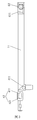
- FIG. 1 is a schematic structural view of a self-tightening elastic wire ligature according to the present invention
- Figure 2 is a cross-sectional view of the self-tightening elastic line ligator of the present invention
- Figure 3 is a schematic structural view of the inner barrel of the present invention.
- FIG. 4 is a schematic structural view of a limiting shaft body in the inner and outer barrel misalignment mechanism according to the present invention.
- FIG. 5 is a schematic view showing the structure of the gun body tube according to the present invention.
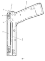
- Figure 6 is a cross-sectional view of the gun body of the self-tightening elastic line ligator of the present invention.
- Figure 7 is a schematic structural view of the automatic connecting wire of the elastic line automatic tensioning mechanism of the present invention.
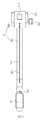
- Figure 8 is a cross-sectional view of the barrel of the self-tightening elastic line ligator of the present invention.
- Figure 9 is another cross-sectional view of the barrel of the self-tightening elastic line ligator of the present invention.
- FIG. 10 is a schematic structural view of a spring line connecting end of an elastic line automatic tensioning mechanism according to the present invention.
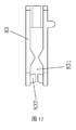
- FIG. 11 is a schematic structural view showing a elastic wire connecting end of a spring line automatic tensioning mechanism according to the present invention.
- FIG. 12 is a schematic structural view of a power pulling end of the elastic line automatic tensioning mechanism according to the present invention.
- the present invention provides a method for setting an automatic tightening elastic line of a ligator, comprising: adding at least one elastic line 30 along an outer wall of the outer barrel 22 of the ligator, The front end of the elastic wire 30 is formed on the outer wall of the front end of the inner barrel 21, and the end of the elastic wire 30 is connected with the automatic connecting member 80 of the ligature, and the automatic connecting member 80 of the cable is connected. The other end is connected to a self-tightening wrench 100 through a telescopic spring 90. At this time, the elastic wire 30 is in a stretched state. When the tail end of the elastic wire 30 is pulled, the self-tightening wrench 100 releases the resistance to the telescopic spring 90. Then, the pull wire automatic connecting member 80 pulls the elastic force wire 30 backwards under the driving force of the telescopic spring 90, so that the ring sleeve diameter at the front end of the elastic wire 30 is rapidly reduced.
- the elastic line 30 forms a loop by a pirate knot that only allows the elastic line 30 to be pulled in one direction, and the outer barrel 22 of the ligator can be opposite to the inner barrel 21 or the inner barrel 21
- the outer barrel 22 is displaced, the inner diameter of the outer barrel 22 is matched with the outer diameter of the inner barrel 21, and in the initial state, the nozzle of the inner barrel 21 protrudes from the outer barrel 22 nozzle settings.
- the tube wall of the outer barrel 22 pushes the elastic line 30 out of the tube of the inner barrel 21.
- the contraction stroke of the cable automatic connecting member 80 is set to be greater than the maximum tensioning length of the elastic wire 30. Therefore, the power pulling end can stretch the elastic wire 30 to the maximum tensioning length, so that the diameter of the loop sleeve at the front end of the elastic wire 30 is reduced.
- the loop of the elastic line 30 is in the process of gradually necrosis and falling off of the target tissue. It also shrinks until the target tissue is necrotic and shedding, and the formed ulcer surface is extremely small, thereby reducing the chance of postoperative bleeding.
- the above method can be applied to a medical device, and the self-tightening elastic line ligator using the above-mentioned elastic line 30 setting method, as shown in FIG. 1 and FIG. 2, includes a gun body 10 and a barrel 20, wherein the barrel 20 includes an inner barrel 21 and an outer barrel 22, and at least one elastic line 30 disposed along an outer wall of the outer barrel 22 of the ligature, the front end of the elastic line 30 forming an aperture adjustable
- the loop sleeve is sleeved on the outer wall of the front end of the inner barrel 21, and the tail end of the elastic wire 30 is connected with the wire automatic connecting member 80 of the ligature.
- the other end of the cable automatic connecting member 80 is connected to a self-tightening wrench 100 through a telescopic spring 90.
- a self-tightening wrench 100 releases the abutment of the telescopic spring 90, and the cable automatic connecting member is pulled.
- the elastic line 30 is tensioned backward by the restoring force of the telescopic spring 90, so that the aperture of the loop sleeve at the front end of the elastic line 30 is rapidly reduced.
- the elastic wire 30 is composed of inner and outer layers; the inner layer (elastic strip) is a strip-shaped special polymer material with high elasticity; the outer layer (wrapped layer) is a mesh braid layer wrapped around the inner layer surface. It is also made of special polymer material, which can relax with the stretching of the inner elastic strip; the special double layer structure of elastic line 30 not only has good elasticity, but also can withstand strong axial tension without breaking.
- the aperture can be further tightened due to its own elastic force; in addition, the elastic thread 30 is not easy to age and fatigue when in the non-stretched state, and has a long service life. Can improve the ligation effect.
- the gun body 10 is provided with a gun body tube 11 .
- the front end of the gun body tube 11 communicates with the inner barrel 21 , and the tail end communicates with the negative pressure air tube, that is, the inner barrel 21 is under negative pressure under working condition. , adsorption shrinkage of the target tissue.
- the elastic line 30 is fastened to the outer barrel 22 to provide a spring line bayonet 221, and the tail end of the elastic line 30 is connected to the pull cord automatic connecting member 80 of the ligature through the elastic line bayonet 221, and the elastic force is connected.
- the line bayonet 221 is against the pirate knot of the loop sleeve.
- the outer barrel 22 When the target tissue is sucked up, the outer barrel 22 is displaced relative to the inner barrel 21 or the inner barrel 21 relative to the outer barrel 22, and the tube of the outer barrel 22 is The wall pushes the elastic wire loop sleeve out of the tube body of the inner barrel 21, causing the elastic wire 30 to fall off the barrel 20, and the target tissue sucked into the nozzle of the inner barrel 21 is tightened.
- the inner barrel is controlled to be displaced relative to the outer barrel by a dislocation mechanism, and the dislocation mechanism is disposed at the rear end of the gun body.
- the inner barrel includes a reset button 40 and a misalignment button 50.
- the reset button 40 is coaxially connected with the tail end of the gun body tube 11.
- the reset button 40 and the gun body 10 are provided with a lateral elastic member 41 for providing a resilient force.
- the lateral elastic member 41 is The reset button 40 provides a returning elastic force for the backward movement; at the same time, the reset button 40 is provided with a limiting hole 42 extending longitudinally through the limiting hole 42 and passing through a longitudinal elastic member 51.
- the body of the dislocation button 50 is connected to the gun body 10, and the body of the dislocation button 50 is provided with a limiting shaft body 52 having a diameter matching with the diameter of the limiting hole 42; wherein the limiting hole 42 The diameter is larger than the above
- the misalignment button 50 moves downward, the limiting shaft body 52 and the limiting hole 42 are misaligned, so that the gun body tube 11 drives the inner barrel 21 to be displaced relative to the outer barrel 22.
- the inner body tube 11 is provided with a first elastic ferrule end 411
- the gun body 10 is provided with a second elastic ferrule end 412
- the lateral elastic member 41 is set
- the distance between the first elastic ferrule end 411 and the second elastic ferrule end 412, and the distance between the first elastic ferrule end 411 and the second elastic ferrule end 412 is greater than the free state length of the second elastic member. Therefore, the second elastic member is in an expanded state, which provides a relative displacement resilience between the gun body tube 11 and the gun body 10, and provides the direction of the reset button 40 while keeping the gun body 10 stationary. Resilience of the back movement.
- the limiting hole 42 includes a first limiting hole 421 and a second limiting hole 422.
- the diameter of the first limiting hole 421 is larger than the diameter of the second limiting hole 422.
- the second limiting hole 422 is located at the front end of the first limiting hole 421 in the lateral direction of the gun body 10.
- the limiting shaft body 52 includes a first limiting shaft body 521 and a second limiting shaft body 522.
- the diameters of the first limiting shaft body 521 and the second limiting shaft body 522 are respectively Cooperating with the diameters of the first limiting hole 421 and the second limiting hole 422, and in the longitudinal direction perpendicular to the gun body 10, the first limiting shaft body 521 is disposed on the second limiting shaft body 522.
- the first limiting shaft body 521 is longitudinally displaced from the first limiting hole 421, and the second limit is driven by the return elastic force of the second elastic member.
- the shaft body 522 abuts against the second limiting hole 422.
- the gun body tube 11 drives the backward displacement of the inner barrel 21 relative to the outer barrel 22, and the elastic coil of the front end of the inner barrel 21 is disposed.
- the elastic line bayonet 221 is slid down from the inner barrel 21 under the brake to realize the ligation of the target tissue.
- the second limiting shaft body 522 and the second limiting hole 422 are laterally displaced, and the first limit is driven by the return elastic force of the first elastic member.
- the longitudinal movement of the shaft body 521 abuts against the first limiting hole 421, and at the same time, the gun body tube 11 moves forward relative to the gun body 10 to the initial position for the next installation of the barrel 20.
- the elastic wire 30 automatic tensioning mechanism provided on the ligature device pulls the elastic wire 30 backward, so that the diameter of the loop sleeve at the front end of the elastic wire 30 is rapidly reduced.
- the elastic line 30 automatic tensioning mechanism includes a cable automatic connecting member 80 that passes through the elastic line bayonet 221 and is connected to the tail end of the elastic line 30; one end abuts against the gun body 10, and the other end abuts against the cable
- the telescopic spring 90 of the automatic connecting member 80 a self-tightening wrench 100 that is buckled at the free end of the automatic connecting member 80; when the self-tightening wrench 100 releases the buckle of the free end of the automatic connecting member 80, the cable is automatically connected.
- Pieces 80 The telescopic spring 90 rebounds backward, and the aperture of the loop sleeve that pulls the front end of the elastic coil is rapidly reduced.
- the gun body 10 of the ligature is provided with a tension stroke groove 101, and the wire automatic connecting member 80 is built in the tension stroke groove 101, and the tail end of the elastic wire 30 is along
- the outer wall of the outer barrel 22 is connected to the pull wire automatic connecting member 80 through a through hole provided in the elastic line stroke groove 102.
- One side of the tension stroke groove 101 is provided with a spring groove disposed in parallel therewith, and the telescopic spring 90 is disposed in the spring groove.
- the free end 81 of the wire automatic connecting member 80 extends laterally.
- a set of posts 82 is formed, one end of the telescopic spring 90 abutting in the spring slot, and the other end being fitted on the sleeve 82.
- the self-tightening wrench 100 is disposed under the tensioning stroke groove 101, and a pivoting return spring is disposed on the fulcrum 100a to provide a counterclockwise returning elastic force to the self-tightening wrench 100.
- the self-tightening wrench 100 communicates with the tension stroke groove 101 through a through groove 101a.
- the self-tightening wrench 100 When the minimum contraction stroke end of the telescopic spring 90 is reached, the self-tightening wrench 100 is popped counterclockwise to abut the free end 81 of the cable automatic connecting member 80; when the self-tightening wrench 100 is buckled clockwise, the automatic connection of the pull wire is released.
- the cable automatic connecting member 80 rebounds backwards under the action of the resilience of the telescopic spring 90, and the aperture of the loop sleeve pulling the front end of the elastic wire 30 is rapidly reduced, and at the same time, the automatic connecting member 80 of the cable is contracted.
- the stroke is greater than the maximum tension length of the elastic line 30. Therefore, the cable automatic connecting member 80 can stretch the elastic wire 30 to the maximum tensioning length, so that the loop diameter of the front end of the elastic thread 30 is reduced to a minimum aperture and close to zero, thereby A tighter ligation to the target organization is achieved.
- the free end 81 of the cable automatic connecting member 80 protrudes longitudinally from the two sides of the gun body 10 and extends out of the manual self-tightening button 84.
- the manual self-tightening button 84 is provided. There is a friction surface, because the contraction stroke of the cable automatic connecting member 80 is greater than the maximum tension length of the elastic wire 30, when the telescopic spring 90 returns to the extended state, the free end 81 of the cable automatic connecting member 80 and the tension stroke groove There is still a stretchable distance between the ends of the 101.
- the manual self-tightening button 84 is manually pulled back to allow the loop of the front end of the elastic line 30.
- the aperture continues to shrink to a minimum aperture and is close to zero.
- the end of the elastic wire 30 is provided with a spring line connecting end 31.
- the outer wall of the outer barrel 22 of the ligature is provided with a spring line groove 102 that is in communication with the tensioning groove 101.
- the elastic line connecting end 31 is disposed in the elastic line stroke groove 102, and the elastic line connecting end 31 is disposed through the through hole provided in the elastic line stroke groove 102 and the end of the elastic line 30;
- Elastic line The connecting end 31 includes a connecting end portion 301 and a connecting end portion 302.
- a slot length and an elastic line groove 102 are oppositely disposed on the left and right slot walls of the elastic line stroke groove 102.
- the sliding end 311 extends longitudinally on both sides of the connecting end 302, and the guiding sliding fin 311 is sleeved in the connecting end guiding groove 102a.
- the elastic line connecting end 31 is ensured to maintain a horizontal linear motion; the connecting end front portion 301 passes through the through hole provided in the elastic line stroke groove 102, and extends along the outer wall of the outer barrel 22 to the elastic line bayonet 221, and wears
- the end of the elastic line 30 of the elastic line bayonet 221 is connected to shorten the elastic tension length of the elastic line 30 as much as possible, thereby minimizing the tensile loss of the elastic connecting member 80 to the elastic coil.
- the front end portion 301 of the elastic line connecting end 31 is provided with a slot 312 and a slot 314 with a pressing spring 316 disposed in the extending direction of the body.
- a sleeve 32 with a pulling cord 321 is disposed on the slot 312.
- the end of the elastic wire 30 is provided with a knot, and the knot is buckled in the slot 312 by the cover 32.
- the connecting end guiding groove 102a is a communication groove between the elastic wire stroke groove 102 and the outer wall of the outer barrel 22.
- the elastic wire connecting end 31 is provided with a pulling guiding channel 315, and the pulling guiding channel 315 is
- the slot 314 extends along the body of the elastic line connecting end 31 to the guiding sliding wing 311 of the connecting end rear portion 302.
- the other end of the pulling rope 321 passes through the connecting end guiding groove 102a and a pulling member along the pulling guiding passage 315.
- the connecting member 322 is abutted against the guiding sliding fin 311.
- the rear end of the wrap 32 is connected with the pressing spring 316 in the slot 314, and the pressing spring 316 presses the wrap 32 forward to prevent the wrap 32 from being used normally.
- One end of the pull wire automatic connecting member 80 connected to the elastic wire 30 is provided with a power pulling end 83, and the tensioning end of the power pulling end 83 corresponds to the front end of the elastic wire stroke groove 102, and the power pulling end 83
- the contraction stroke end corresponds to the end of the elastic line stroke groove 102.
- the power pulling end 83 is provided with a ferrule opening 831 having a certain tension.
- the upper and lower ends of the ferrule opening 831 are oppositely convexly provided with a ferrule point 832, and the ferrule point 832 Abutting the upper and lower sides, as shown in FIG. 10, the connecting end 302 of the elastic wire connecting end 31 is provided with a hole 313 for engaging with the ferrule point 832.
- the ferrule opening 831 of the power pulling end 83 is elastically connected.
- the end is abutted,
- the ferrule point 832 is sleeved up and down in the hole 313, and the power pulling end 83 is spliced and connected to the elastic line connecting end 31. That is, when the manual self-tightening button 84 is pulled to the minimum contraction stroke end of the telescopic spring 90, the cable automatic connecting member 80 extends into the elastic wire stroke groove 102, and the power pulling end 83 abuts the elastic wire connecting end 31. To the tensioning stroke terminal, and the zipper connection of the elastic wire connection end 31.
- the contraction stroke end of the power pulling end 83 is provided with a flare point 102b, that is, the end of the elastic thread stroke groove 102 is provided with a flare point 102b at which the power pull end 83 is oriented.
- the power pulling end 83 is widened, and the elastic line connecting end 31 is disengaged from the power pulling end 83.
- the expansion point 102b has a wedge shape, and the width of the expansion point 102b gradually increases along the contraction direction of the power pulling end 83, thereby supporting the upper and lower ferrule points 832 of the power pulling end 83.
- the opening is ejected from the hole 313 of the elastic wire connecting end 31.
- the top end of the elastic line stroke groove 102 corresponds to the tensioning stroke end of the power pulling end 83
- the end of the elastic line stroke groove 102 corresponds to the contraction stroke end of the power pulling end 83
- the power pulling The pull end 83 has a longitudinal free width at the tension stroke end and the contraction stroke end.
- the power pulling end 83 when the power pulling end 83 abuts the elastic line connecting end 31 to the tensioning stroke end, the power pulling end 83 is not limited by the longitudinal width of the elastic line stroke groove 102, and the card sleeve opening 831 The elastic connecting end abuts the longitudinal opening, so that the ferrule point 832 is sleeved up and down in the hole 313, and the power pulling end 83 is ferrule-connected with the elastic line connecting end 31.
- the power pulling end 83 When the power pulling end 83 is pulled back to the contraction stroke end, the power pulling end 83 is not limited by the longitudinal width of the elastic line stroke groove 102, and the ferrule opening 831 is expanded by the expansion point 102b, so that The spring line connection end 31 is disengaged from the power pull end 83.
- the barrel 20 is coupled to the gun body 10 by a ferrule structure 60, the ferrule structure 60 including an inner buckle member 61 disposed at the rear end of the inner barrel 21, and disposed in the A trip member 62 on the gun body tube 11 is provided with a card slot 611 provided in cooperation with the inner button member 61, and the trip member 62 is disposed opposite to the card slot 611.
- a sealing ring 63 is provided on the port of the inner end of the inner barrel 21 connected to the inner tube 11 for sealing the gap between the inner barrel 21 and the inner tube 11.
- the inner fastening component 61 When the inner barrel 21 is snap-fitted with the gun body tube 11, the inner fastening component 61 is buckled in the inner In the card slot 611, the seal ring 63 seals the gap between the inner barrel 21 and the communication port of the gun body tube 11 to ensure a negative pressure index in the inner barrel 21.
- the trip member 62 When the new barrel 20 needs to be replaced, the trip member 62 is pressed inwardly, and the inner button member 61 is pushed out of the slot 611 to untie the ferrule relationship between the inner barrel 21 and the gun body tube 11. Separating the barrel 20 from the gun body 10 facilitates the installation of a new barrel 20.
- the outer wall of the outer barrel 22 is also provided with a snap member, and the gun body 10 is provided with a bayonet slot which is engaged with the snap member, and the outer barrel 22 passes through the snap member.
- the buckle is attached to the gun body 10.
- the barrel 20 using the elastic line 30 can be detached from the gun body 10, and The manual self-tightening button 84 is pulled to the minimum contraction end of the telescopic spring 90.
- the self-tightening wrench 100 is popped counterclockwise to abut the cable automatic connecting member 80, and then the new barrel equipped with the elastic wire 30 is matched.
- 20 is sleeved on the gun body 10 by the ferrule structure 60 and the snap member.
- the power pulling end 83 abuts the elastic wire connecting end 31 to the tensioning stroke terminal, and the ferrule is connected to the connecting end of the elastic wire 30. Then, the installation of the new barrel 20 is completed, and the above ligation operation can be resumed.
- a limiting block 70 is disposed on the outer wall of the inner barrel 21, and an inner wall of the outer barrel 22 is recessed relative to the limiting block 70 to define a limiting slot 71.
- the slot 71 has a slot extending along the length of the gun body 10, and the limiting block 70 abuts against the limiting slot 71. Therefore, the inner barrel 21 can be displaced in the longitudinal direction relative to the outer barrel 22. However, it maintains a fixed relative positional relationship with the outer barrel 22 in the axial direction.
- the mouth of the ligature is provided with a limiting cap 72.
- the limiting cap 72 is sleeved on the outer wall of the inner barrel 21, and the elastic wire loop sleeve is buckled on the outer wall of the inner barrel 21.
- the diameters of the nozzles of the outer barrel 22 and the inner barrel 21 are both larger than the diameter of the tube body, and a displacement space is formed between the nozzle of the outer barrel 22 and the nozzle of the inner barrel 21,
- a limiting bolt 73 is disposed in the misalignment space, and the limiting bolt 73 passes through the wall of the outer barrel 22 and abuts against the wall of the inner barrel 21.
- the limiting cap 72 and the limiting bolt 73 are used to ensure that the loop sleeve does not fall out of the inner barrel 21 when not in use.
- the invention provides a method for setting an automatic tightening elastic line of a ligator and a self-tightening elastic line ligator, which provides a retro-recovering elastic force for the pull-wire automatic connecting member 80 through the telescopic spring 90, and the elastic line 30
- the doctor only needs to buckle the self-tightening wrench 100, so that the self-tightening wrench 100 releases the abutment of the telescopic spring 90, so that the cable automatic connecting member 80 can be elastically driven by the restoring force of the telescopic spring 90.
- the automatic tightening elastic line setting method and the self-tightening elastic line ligator of the ligating device of the invention have the advantages of simple structure and convenient operation, and are suitable for wide application.
Abstract
A ligator setup method for automatically tightening an elastic line and a self-tightening elastic line ligator. The self-tightening elastic line ligator comprises: at least one piece of an elastic line (30) disposed along an outer wall of an outer barrel (22) of the ligator. A front end of the elastic line (30) forms a size-adjustable loop loopingly disposed on an outer wall of a front end of an inner barrel (21). A distal end of the elastic line (30) connects to a line-retracting auto-connector (80) of the ligator. The other end of the line-retracting auto-connector (80) connects, via a compression spring (90), to a self-tightening trigger (100). When retracting the distal end of the elastic line (30), the self-tightening trigger (100) loosens the connection thereof to the compression spring (90). The line-retracting auto-connector (80) retracts and tightens the elastic line (30) by means of a recoiling force of the compression spring (90), rapidly reducing the size of the loop at the front end of the elastic line (30). The self-tightening elastic line ligator provides, via the compression spring (90), and to the line-retracting auto-connector, a recoiling force for retracting and tightening, automatically tightening the elastic line (30) so as to rapidly reduce the size of the loop at the front end of the elastic line (30) to a minimum or close to zero, thereby achieving a tighter and more secure ligature of a target tissue.
Description
本发明涉及一种医疗器械,具体涉及一种套扎器的自动收紧弹力线设置方法及自紧式弹力线套扎器。The invention relates to a medical device, in particular to a method for setting an automatic tightening elastic line of a ligator and a self-tightening elastic line ligator.
痔疮套扎术(又称痔疮胶圈套扎术、痔疮吸扎术等)是治疗痔疮的常用方法,疗效确切,其原理是将特制的胶圈(例如橡胶圈、乳胶圈、硅胶圈、弹力线圈等)套扎于内痔的根部(或基底部),籍此利用胶圈的弹性回缩力阻断痔疮血供,使之坏死、萎缩、脱落,从而达到治愈目的。Hemorrhoids ligation (also known as hemorrhoids acupuncture ligation, hemorrhoids ligation, etc.) is a common method for the treatment of hemorrhoids, the effect is exact, the principle is to make a special rubber ring (such as rubber ring, latex ring, silicone ring, elastic coil) The sleeve is tied to the root (or base) of the inner iliac crest, thereby utilizing the elastic retractive force of the apron to block the blood supply of the acne, causing necrosis, atrophy, and shedding, thereby achieving the purpose of healing.
既往用于施行套扎手术的传统器械极为简陋,操作费时,费力,容易发生并发症。为改变这一状况,近十年来出现了一种使套扎手术变得简单易行的自动化器械,即自动痔疮套扎器(又称连发式痔疮套扎器、连发式痔疮吸扎器等)。利用该器械进行套扎手术的优点是:操作简便、快捷、准确;单人可完成手术,耗时仅5~10分钟;且发生并发症的几率较低;患者一般不需要麻醉,痛苦轻微;多数病人也不需要住院,治疗费用低廉。Traditional instruments used for ligation have been extremely rudimentary, time consuming, laborious, and prone to complications. In order to change this situation, an automatic device that makes ligation surgery simple and easy has been used in the past ten years, namely automatic hemorrhoids ligation device (also known as continuous-type hemorrhoids ligation device, continuous-type hemorrhoids suction device). Wait). The advantage of using the device for ligation surgery is that the operation is simple, fast and accurate; the single person can complete the operation, which takes only 5 to 10 minutes; and the probability of complications is low; the patient generally does not need anesthesia, and the pain is slight; Most patients do not need to be hospitalized and the cost of treatment is low.
1.痔疮套扎器目前分两种类别:1. Acne ligation devices are currently divided into two categories:
A:胶圈痔疮套扎器 B:弹力线痔疮套扎器A: apron acne slinger B: elastic line acne slinger
A:胶圈痔疮套扎器:A: apron acne ligature:
胶圈痔疮吸扎器(又称痔疮套扎器)以及国内外其他类型的痔疮套扎器,都有一个共同的特点,即它们均采用“胶圈”作为套扎于痔疮根部的基本材料;而制作该胶圈可选用的原料包括天然橡胶、乳胶或硅胶等。Aprons acne applicators (also known as hemorrhoids ligatures) and other types of acne slings at home and abroad have a common feature, that is, they all use "aprons" as the basic material for ligating the roots of acne; The raw materials for making the apron include natural rubber, latex or silica gel.
痔疮胶圈套扎术的临床疗效与“胶圈的内孔径”和“胶圈的弹性回缩力”两项技术指标直接相关。而利用胶圈作为套扎材料具有一些固有的缺点:①由于天然橡胶(或乳胶、硅胶等)的固有特性,限制了胶圈的内孔径不能无限小,一般只能制成2.0~2.5mm(至少不得小于1.5mm),否则套扎拉伸时极易断裂。这就意味着在直径2.0~2.5mm(至少不小于1.5mm)的尺寸范围内,被
套扎的痔疮组织将不受到任何弹性回缩力的作用,最终组织坏死脱落后形成的溃疡范围也在2.0~2.5mm(至少不小于1.5mm)左右;②当胶圈以拉伸状态安装在套扎器上时,随着时间延长,容易逐渐发生疲劳而使内孔径变大;③受气候、环境等因素影响,胶圈容易随时间发生老化,从而使弹性回缩力变弱。The clinical efficacy of hemorrhoid apron ligation is directly related to the two technical indicators of "the inner diameter of the apron" and the elastic retraction force of the apron. The use of aprons as a ligation material has some inherent disadvantages: (1) Due to the inherent characteristics of natural rubber (or latex, silica gel, etc.), the inner diameter of the apron is not limited to infinitely small, and generally can only be made 2.0 to 2.5 mm ( At least not less than 1.5mm), otherwise it will be easily broken when the stretch is stretched. This means that within a size range of 2.0 to 2.5 mm in diameter (at least not less than 1.5 mm),
The ligation of the acne tissue will not be subjected to any elastic retractive force, and the ulcer formed after the necrosis of the tissue is also in the range of 2.0 to 2.5 mm (at least not less than 1.5 mm); 2 when the apron is stretched. When the ligature is used, as time goes on, it is easy to gradually fatigue and make the inner diameter become larger. 3 Due to the influence of climate and environment, the rubber ring is easy to age with time, and the elastic retracting force is weakened.
由于以上因素的影响,将可能导致以下后果:①术后短期内发生胶圈滑脱,致使治疗失败;②引起术后出血并发症(据统计,痔疮胶圈套扎术后的出血率为2%~5%);③痔块坏死不完全,溃疡面愈合延迟,影响疗效。Due to the above factors, it may lead to the following consequences: 1 apron slippage occurs in the short term after surgery, resulting in treatment failure; 2 causes postoperative bleeding complications (according to statistics, the bleeding rate after hemorrhoid apron ligation is 2% ~ 5%); 3 necrosis is incomplete, and the healing of the ulcer surface is delayed, which affects the curative effect.
B:弹力线痔疮套扎器的手动式弹力线痔疮套扎器B: Manual elastic line hemorrhoids ligation device for elastic line hemorrhoids ligation device
手动式弹力线痔疮吸扎器(又称自动弹力线套扎器)虽然能够克服胶圈套扎器胶圈扎不紧的缺陷,但对目标组织紧固的过程比较复杂,定位和弹出推线设计操作流程多,使用不太方便,该技术方案进行套扎操作时,只能先从发射头释放套扎组织,在释放推线管,人工拉紧推线管弹力线环套以结扎痔疮组织(或其他目标组织),容易导致操作过程中弹力线环套从组织上滑脱,影响治疗效果,术中人工拉紧套扎环不稳和持抢不稳都可能使环套从组织上滑脱,失去治疗效果,而且人工拉紧套扎环力度不好掌握,容易形成用力过小紧度不够,用力过大弹力线崩断。The manual elastic line acne suction device (also known as the automatic elastic line ligator) can overcome the shortcomings of the rubber ring ligature, but the process of fastening the target tissue is more complicated, positioning and pop-up push line design The operation flow is many and the use is not convenient. When the technical solution is used for the ligation operation, the ligation tissue can only be released from the launching head, and the push-wire tube is released, and the push-wire elastic wire loop sleeve is manually tightened to ligation the acne tissue ( Or other target organization), it is easy to cause the elastic wire loop sleeve to slip off the tissue during the operation, affecting the therapeutic effect. The artificial tensioning of the ligature ring during the operation and the instability of the tying ring may cause the ring sleeve to slip off the tissue and lose. The therapeutic effect, and the strength of the artificial tightening of the ligation ring is not easy to grasp, and it is easy to form a force that is too small and tight, and the force is too large to break the elastic line.
发明内容Summary of the invention
有鉴于此,有必要提供一种能够自动进行收紧动作,使弹力线前端的环套孔径迅速缩小至最小孔径并接近于零的套扎器的自动收紧弹力线设置方法及自紧式弹力线套扎器。In view of the above, it is necessary to provide an automatic tightening elastic line setting method and a self-tightening elastic force capable of automatically performing a tightening action to rapidly reduce the diameter of the loop sleeve at the front end of the elastic line to the minimum aperture and close to zero. Line ligature.
本发明提供一种套扎器的自动收紧弹力线设置方法,其包括沿套扎器的外枪管的外壁加设至少一根弹力线,所述弹力线的前端形成孔径可调的环套套于内枪管前端的外壁上,所述弹力线的尾端与套扎器的拉线自动连接件连接,所述拉线自动连接件的另一端通过一伸缩弹簧与一自紧扳手连接,抽拉弹力线尾端时,自紧扳手松开对伸缩弹簧的抵接,拉线自动连接件在伸缩弹簧回复力的带动下将弹力线向后拉紧,使得弹力线前端的环套孔径迅速缩小。The invention provides a method for setting an automatic tightening elastic line of a ligator, which comprises adding at least one elastic line along the outer wall of the outer barrel of the ligator, the front end of the elastic line forming a ring sleeve with an adjustable aperture On the outer wall of the front end of the inner barrel, the tail end of the elastic line is connected with the automatic connecting piece of the wire of the ligature, and the other end of the automatic connecting piece of the wire is connected with a self-tightening wrench through a telescopic spring, and the elastic force is pulled. At the end of the wire, the self-tightening wrench loosens the abutment of the telescopic spring, and the automatic connecting piece of the wire pulls the elastic wire backwards under the driving force of the telescopic spring, so that the diameter of the ring sleeve at the front end of the elastic wire is rapidly reduced.
一种自紧式弹力线套扎器,其包括枪体和枪管,其中,所述枪管包括内枪管和外枪管,以及至少一根弹力线,所述弹力线沿套扎器的外枪管的外壁设置,所述弹力线的前端形成孔径可调的环套套于内枪管前端的外壁上,所述弹力线
的尾端与套扎器的拉线自动连接件连接,所述拉线自动连接件的另一端通过一伸缩弹簧与一自紧扳手连接,抽拉弹力线尾端时,自紧扳手松开对伸缩弹簧的抵接,拉线自动连接件在伸缩弹簧回复力的带动下将弹力线向后拉紧,使得弹力线前端的环套孔径迅速缩小。A self-tightening elastic wire ligator comprising a gun body and a barrel, wherein the barrel comprises an inner barrel and an outer barrel, and at least one elastic line along the ligature The outer wall of the outer barrel is disposed, and the front end of the elastic line forms an annular sleeve with an adjustable aperture sleeve on the outer wall of the front end of the inner barrel, the elastic line
The tail end is connected with the wire automatic connecting piece of the ligature, and the other end of the wire automatic connecting piece is connected with a self-tightening wrench through a telescopic spring. When the end of the elastic wire is pulled, the self-tightening wrench releases the telescopic spring. The abutment, the automatic connecting piece of the pull wire pulls the elastic line backwards under the driving force of the telescopic spring, so that the diameter of the ring sleeve at the front end of the elastic line is rapidly reduced.
本发明提供一种套扎器的自动收紧弹力线设置方法及自紧式弹力线套扎器,其通过伸缩弹簧为拉线自动连接件提供向后拉紧的回复弹力,对弹力线进行自动拉紧,医生仅需要扣下自紧扳手,使自紧扳手松开对伸缩弹簧的抵接,即可使拉线自动连接件在伸缩弹簧回复力的带动下将弹力线向后拉紧,从而使弹力线前端的环套孔径迅速缩小至最小孔径并接近于零,进而实现对目标组织更为紧固的套扎,且由于弹力线具有良好的弹性收缩性,在目标组织逐渐坏死并脱落的过程中,弹力线的环套也随之缩小,直至目标组织坏死脱落后,形成的溃疡面极小,从而降低了术后并发出血的几率。本发明所述套扎器的自动收紧弹力线设置方法及自紧式弹力线套扎器,结构简单、操作方便,适于广泛应用。The invention provides a method for setting an automatic tightening elastic line of a ligator and a self-tightening elastic line ligator, which provides a retro-recovering elastic force for a pull-wire automatic connecting piece through a telescopic spring, and automatically pulls the elastic line. Tightly, the doctor only needs to fasten the self-tightening wrench so that the self-tightening wrench can loosen the abutment of the telescopic spring, so that the automatic connecting piece of the wire pulls the elastic wire backwards under the driving force of the telescopic spring, thereby making the elastic force The loop diameter at the front end of the wire is rapidly reduced to a minimum aperture and close to zero, thereby achieving a tighter tightening of the target tissue, and the elastic line has good elastic contraction, and the target tissue gradually necrotic and falls off. The loop of the elastic line is also reduced, until the target tissue is necrotic and shedding, the formed ulcer surface is extremely small, thereby reducing the chance of postoperative blood. The automatic tightening elastic line setting method and the self-tightening elastic line ligator of the ligating device of the invention have the advantages of simple structure and convenient operation, and are suitable for wide application.
图1为本发明所述自紧式弹力线套扎器的结构示意图;1 is a schematic structural view of a self-tightening elastic wire ligature according to the present invention;
图2为本发明所述自紧式弹力线套扎器的剖视图;Figure 2 is a cross-sectional view of the self-tightening elastic line ligator of the present invention;
图3为本发明所述内枪管的结构示意图;Figure 3 is a schematic structural view of the inner barrel of the present invention;
图4为本发明所述内外枪管错位机构中限位轴体的结构示意图;4 is a schematic structural view of a limiting shaft body in the inner and outer barrel misalignment mechanism according to the present invention;
图5为本发明所述枪体内管的结构示意图;Figure 5 is a schematic view showing the structure of the gun body tube according to the present invention;
图6为本发明所述自紧式弹力线套扎器的枪体的剖视图;Figure 6 is a cross-sectional view of the gun body of the self-tightening elastic line ligator of the present invention;
图7为本发明所述弹力线自动张紧机构的拉线自动连接件的结构示意图;Figure 7 is a schematic structural view of the automatic connecting wire of the elastic line automatic tensioning mechanism of the present invention;
图8为本发明所述自紧式弹力线套扎器的枪管的剖视图;Figure 8 is a cross-sectional view of the barrel of the self-tightening elastic line ligator of the present invention;
图9为本发明所述自紧式弹力线套扎器的枪管的另一剖视图;Figure 9 is another cross-sectional view of the barrel of the self-tightening elastic line ligator of the present invention;
图10为本发明所述弹力线自动张紧机构的弹力线连接端的结构示意图;10 is a schematic structural view of a spring line connecting end of an elastic line automatic tensioning mechanism according to the present invention;
图11为本发明所述弹力线自动张紧机构的弹力线连接端设有包套的结构示意图;11 is a schematic structural view showing a elastic wire connecting end of a spring line automatic tensioning mechanism according to the present invention;
图12为本发明所述弹力线自动张紧机构的动力牵拉端的结构示意图。
12 is a schematic structural view of a power pulling end of the elastic line automatic tensioning mechanism according to the present invention.
为了使本发明的目的、技术方案及优点更加清楚明白,以下结合附图及实施例,对本发明进行进一步详细说明,应当理解,此处所描述的具体实施例仅仅用以解释本发明,并不用于限定本发明。The present invention will be further described in detail below with reference to the accompanying drawings and embodiments. The invention is defined.
如图1和图2所示,本发明提供一种套扎器的自动收紧弹力线设置方法,其包括沿套扎器的外枪管22的外壁加设至少一根弹力线30,所述弹力线30的前端形成孔径可调的环套套于内枪管21前端的外壁上,所述弹力线30的尾端与套扎器的拉线自动连接件80连接,所述拉线自动连接件80的另一端通过一伸缩弹簧90与一自紧扳手100连接,此时,所述弹力线30处于拉伸状态,当抽拉弹力线30尾端时,自紧扳手100松开对伸缩弹簧90的抵接,拉线自动连接件80在伸缩弹簧90回复力的带动下将弹力线30向后拉紧,使得弹力线30前端的环套孔径迅速缩小。As shown in FIG. 1 and FIG. 2, the present invention provides a method for setting an automatic tightening elastic line of a ligator, comprising: adding at least one elastic line 30 along an outer wall of the outer barrel 22 of the ligator, The front end of the elastic wire 30 is formed on the outer wall of the front end of the inner barrel 21, and the end of the elastic wire 30 is connected with the automatic connecting member 80 of the ligature, and the automatic connecting member 80 of the cable is connected. The other end is connected to a self-tightening wrench 100 through a telescopic spring 90. At this time, the elastic wire 30 is in a stretched state. When the tail end of the elastic wire 30 is pulled, the self-tightening wrench 100 releases the resistance to the telescopic spring 90. Then, the pull wire automatic connecting member 80 pulls the elastic force wire 30 backwards under the driving force of the telescopic spring 90, so that the ring sleeve diameter at the front end of the elastic wire 30 is rapidly reduced.
在本实施例中,所述弹力线30通过只允许弹力线30单向抽拉的海盗结形成环套,所述套扎器的外枪管22能够相对内枪管21或内枪管21相对外枪管22发生位移,所述外枪管22的内径与所述内枪管21的外径相配合,且在初始状态时,所述内枪管21的管口突出于所述外枪管22的管口设置。当外枪管22相对内枪管21或内枪管21相对外枪管22发生位移时,所述外枪管22的管壁将弹力线30推出内枪管21的管体。In the present embodiment, the elastic line 30 forms a loop by a pirate knot that only allows the elastic line 30 to be pulled in one direction, and the outer barrel 22 of the ligator can be opposite to the inner barrel 21 or the inner barrel 21 The outer barrel 22 is displaced, the inner diameter of the outer barrel 22 is matched with the outer diameter of the inner barrel 21, and in the initial state, the nozzle of the inner barrel 21 protrudes from the outer barrel 22 nozzle settings. When the outer barrel 22 is displaced relative to the inner barrel 21 or the inner barrel 21 relative to the outer barrel 22, the tube wall of the outer barrel 22 pushes the elastic line 30 out of the tube of the inner barrel 21.
设置所述拉线自动连接件80的收缩行程大于弹力线30的最大张紧长度,因此,动力牵拉端能够将弹力线30拉伸至最大张紧长度,使弹力线30前端的环套孔径缩小至最小孔径并接近于零,进而实现对目标组织更为紧固的套扎,且由于弹力线30具有良好的弹性收缩性,在目标组织逐渐坏死并脱落的过程中,弹力线30的环套也随之缩小,直至目标组织坏死脱落后,形成的溃疡面极小,从而降低了术后并发出血的几率。The contraction stroke of the cable automatic connecting member 80 is set to be greater than the maximum tensioning length of the elastic wire 30. Therefore, the power pulling end can stretch the elastic wire 30 to the maximum tensioning length, so that the diameter of the loop sleeve at the front end of the elastic wire 30 is reduced. To the minimum aperture and close to zero, thereby achieving a more tight ligation of the target tissue, and because the elastic line 30 has good elastic contraction, the loop of the elastic line 30 is in the process of gradually necrosis and falling off of the target tissue. It also shrinks until the target tissue is necrotic and shedding, and the formed ulcer surface is extremely small, thereby reducing the chance of postoperative bleeding.
上述方法可应用在医疗器械上,使用上述弹力线30设置方法的自紧式弹力线套扎器,如图1和图2所示,包括枪体10和枪管20,其中,所述枪管20包括内枪管21和外枪管22,以及至少一根弹力线30,所述弹力线30沿套扎器的外枪管22的外壁设置,所述弹力线30的前端形成孔径可调的环套套于内枪管21前端的外壁上,所述弹力线30的尾端与套扎器的拉线自动连接件80连接,
所述拉线自动连接件80的另一端通过一伸缩弹簧90与一自紧扳手100连接,抽拉弹力线30尾端时,自紧扳手100松开对伸缩弹簧90的抵接,拉线自动连接件80在伸缩弹簧90回复力的带动下将弹力线30向后拉紧,使得弹力线30前端的环套孔径迅速缩小。The above method can be applied to a medical device, and the self-tightening elastic line ligator using the above-mentioned elastic line 30 setting method, as shown in FIG. 1 and FIG. 2, includes a gun body 10 and a barrel 20, wherein the barrel 20 includes an inner barrel 21 and an outer barrel 22, and at least one elastic line 30 disposed along an outer wall of the outer barrel 22 of the ligature, the front end of the elastic line 30 forming an aperture adjustable The loop sleeve is sleeved on the outer wall of the front end of the inner barrel 21, and the tail end of the elastic wire 30 is connected with the wire automatic connecting member 80 of the ligature.
The other end of the cable automatic connecting member 80 is connected to a self-tightening wrench 100 through a telescopic spring 90. When the tail end of the elastic wire 30 is pulled, the self-tightening wrench 100 releases the abutment of the telescopic spring 90, and the cable automatic connecting member is pulled. The elastic line 30 is tensioned backward by the restoring force of the telescopic spring 90, so that the aperture of the loop sleeve at the front end of the elastic line 30 is rapidly reduced.
所述弹力线30由内、外两层构成;内层(弹力条)为条带状具有高度弹性的特殊高分子材料;外层(包裹层)为网状编织层,包裹在内层表面,亦由特殊的高分子材料制作,能随内层弹力条的拉伸而舒张;弹力线30这种特殊的双层结构使其不仅具有良好的弹性,而且能够承受强大的轴向拉力而不断裂,当处于拉伸状态的弹力线环套被套于目标组织上时还能因为自身弹力被进一步抽紧而缩小孔径;此外弹力线30在处于非拉伸状态时也不易老化和疲劳,使用寿命长,可提高套扎效果。The elastic wire 30 is composed of inner and outer layers; the inner layer (elastic strip) is a strip-shaped special polymer material with high elasticity; the outer layer (wrapped layer) is a mesh braid layer wrapped around the inner layer surface. It is also made of special polymer material, which can relax with the stretching of the inner elastic strip; the special double layer structure of elastic line 30 not only has good elasticity, but also can withstand strong axial tension without breaking. When the elastic loop sleeve in the stretched state is sleeved on the target tissue, the aperture can be further tightened due to its own elastic force; in addition, the elastic thread 30 is not easy to age and fatigue when in the non-stretched state, and has a long service life. Can improve the ligation effect.
所述枪体10内设有枪体内管11,所述枪体内管11的前端与内枪管21连通,尾端与负压气管连通,即所述内枪管21在工作状态下为负压,对目标组织进行吸附收缩。所述弹力线30搭扣于外枪管22的位置设置一弹力线卡口221,弹力线30的尾端穿过所述弹力线卡口221与套扎器的拉线自动连接件80连接,弹力线卡口221抵住环套的海盗结,当目标组织被吸附提起时,外枪管22相对内枪管21或内枪管21相对外枪管22发生位移,所述外枪管22的管壁将弹力线环套推出内枪管21的管体,使弹力线30自枪管20上脱落,将吸入内枪管21管口的目标组织扎紧。同时,弹力线卡口221与弹力线环套之间发生相对位移,弹力线卡口221亦将弹力线30推出内枪管21的管体,使弹力线30自枪管20上脱落,且在进行环套孔径收缩时,弹力线卡口221能够抵住海盗结,避免环套自目标组织上滑落。The gun body 10 is provided with a gun body tube 11 . The front end of the gun body tube 11 communicates with the inner barrel 21 , and the tail end communicates with the negative pressure air tube, that is, the inner barrel 21 is under negative pressure under working condition. , adsorption shrinkage of the target tissue. The elastic line 30 is fastened to the outer barrel 22 to provide a spring line bayonet 221, and the tail end of the elastic line 30 is connected to the pull cord automatic connecting member 80 of the ligature through the elastic line bayonet 221, and the elastic force is connected. The line bayonet 221 is against the pirate knot of the loop sleeve. When the target tissue is sucked up, the outer barrel 22 is displaced relative to the inner barrel 21 or the inner barrel 21 relative to the outer barrel 22, and the tube of the outer barrel 22 is The wall pushes the elastic wire loop sleeve out of the tube body of the inner barrel 21, causing the elastic wire 30 to fall off the barrel 20, and the target tissue sucked into the nozzle of the inner barrel 21 is tightened. At the same time, a relative displacement occurs between the elastic line bayonet 221 and the elastic wire loop sleeve, and the elastic line bayonet 221 also pushes the elastic force line 30 out of the tube body of the inner barrel 21, so that the elastic force line 30 falls off from the barrel 20, and When the loop aperture is contracted, the spring line bayonet 221 can resist the pirate knot and prevent the loop from slipping off the target tissue.
所述内枪管通过一错位机构控制发生与外枪管的相对位移,所述错位机构设置于枪体后端,如图2所示,其包括一复位按键40和一错位按键50,所述复位按键40与所述枪体内管11的尾端同轴连接设置,所述复位按键40与枪体10之间设有提供回复弹力的横向弹性部件41,具体的,所述横向弹性部件41为所述复位按键40提供向后运动的回复弹力;同时,所述复位按键40上设有一限位孔42,所述错位按键50纵向穿过所述限位孔42,并通过一纵向弹性部件51(图中未标示出来)与枪体10连接,所述错位按键50的本体上设有直径与所述限位孔42直径相配合的限位轴体52;其中,所述限位孔42的直径大于所述
错位按键50的本体直径,当所述错位按键50向下移动,限位轴体52与限位孔42发生错位,使所述枪体内管11带动内枪管21相对外枪管22发生位移。The inner barrel is controlled to be displaced relative to the outer barrel by a dislocation mechanism, and the dislocation mechanism is disposed at the rear end of the gun body. As shown in FIG. 2, the inner barrel includes a reset button 40 and a misalignment button 50. The reset button 40 is coaxially connected with the tail end of the gun body tube 11. The reset button 40 and the gun body 10 are provided with a lateral elastic member 41 for providing a resilient force. Specifically, the lateral elastic member 41 is The reset button 40 provides a returning elastic force for the backward movement; at the same time, the reset button 40 is provided with a limiting hole 42 extending longitudinally through the limiting hole 42 and passing through a longitudinal elastic member 51. (not shown) is connected to the gun body 10, and the body of the dislocation button 50 is provided with a limiting shaft body 52 having a diameter matching with the diameter of the limiting hole 42; wherein the limiting hole 42 The diameter is larger than the above
When the misalignment button 50 moves downward, the limiting shaft body 52 and the limiting hole 42 are misaligned, so that the gun body tube 11 drives the inner barrel 21 to be displaced relative to the outer barrel 22.
如图3和图6所示,所述枪体内管11上设有第一弹力卡套端411,所述枪体10上设有第二弹力卡套端412,所述横向弹性部件41套装在第一弹力卡套端411与第二弹力卡套端412之间,且所述第一弹力卡套端411与第二弹力卡套端412之间的间距大于第二弹性部件的自由状态长度。因此,所述第二弹性部件处于扩张状态,其为枪体内管11与枪体10之间提供相对位移的回复弹力,在保持枪体10不动的情况下,为所述复位按键40提供向后运动的回复弹力。As shown in FIG. 3 and FIG. 6, the inner body tube 11 is provided with a first elastic ferrule end 411, and the gun body 10 is provided with a second elastic ferrule end 412, and the lateral elastic member 41 is set The distance between the first elastic ferrule end 411 and the second elastic ferrule end 412, and the distance between the first elastic ferrule end 411 and the second elastic ferrule end 412 is greater than the free state length of the second elastic member. Therefore, the second elastic member is in an expanded state, which provides a relative displacement resilience between the gun body tube 11 and the gun body 10, and provides the direction of the reset button 40 while keeping the gun body 10 stationary. Resilience of the back movement.
如图3所示,所述限位孔42包括相连通的第一限位孔421和第二限位孔422,所述第一限位孔421的直径大于第二限位孔422的直径,且在沿枪体10的横向方向上,所述第二限位孔422位于第一限位孔421的前端。As shown in FIG. 3, the limiting hole 42 includes a first limiting hole 421 and a second limiting hole 422. The diameter of the first limiting hole 421 is larger than the diameter of the second limiting hole 422. The second limiting hole 422 is located at the front end of the first limiting hole 421 in the lateral direction of the gun body 10.
如图4所示,所述限位轴体52包括第一限位轴体521和第二限位轴体522,所述第一限位轴体521和第二限位轴体522的直径分别与第一限位孔421、第二限位孔422的直径相配合,且在垂直于枪体10的纵向方向上,所述第一限位轴体521设置在第二限位轴体522的内侧。As shown in FIG. 4, the limiting shaft body 52 includes a first limiting shaft body 521 and a second limiting shaft body 522. The diameters of the first limiting shaft body 521 and the second limiting shaft body 522 are respectively Cooperating with the diameters of the first limiting hole 421 and the second limiting hole 422, and in the longitudinal direction perpendicular to the gun body 10, the first limiting shaft body 521 is disposed on the second limiting shaft body 522. Inside.
当所述错位按键50纵向向枪体10内运动,所述第一限位轴体521与第一限位孔421发生纵向错位,在第二弹性部件的回复弹力的带动下,第二限位轴体522抵接于第二限位孔422中,同时,所述枪体内管11带动内枪管21相对外枪管22发生向后的错位位移,套装在内枪管21前端的弹力线圈在弹力线卡口221的制动下自内枪管21上滑落,实现对目标组织进行套扎。When the misalignment button 50 is longitudinally moved into the gun body 10, the first limiting shaft body 521 is longitudinally displaced from the first limiting hole 421, and the second limit is driven by the return elastic force of the second elastic member. The shaft body 522 abuts against the second limiting hole 422. At the same time, the gun body tube 11 drives the backward displacement of the inner barrel 21 relative to the outer barrel 22, and the elastic coil of the front end of the inner barrel 21 is disposed. The elastic line bayonet 221 is slid down from the inner barrel 21 under the brake to realize the ligation of the target tissue.
当所述复位按键40横向向枪体10内运动,所述第二限位轴体522与第二限位孔422发生横向错位,在第一弹性部件的回复弹力的带动下,第一限位轴体521纵向上外运动抵接于第一限位孔421中,同时,所述枪体内管11相对枪体10向前运动至初始位置,进行下一次枪管20的安装。When the reset button 40 moves laterally into the gun body 10, the second limiting shaft body 522 and the second limiting hole 422 are laterally displaced, and the first limit is driven by the return elastic force of the first elastic member. The longitudinal movement of the shaft body 521 abuts against the first limiting hole 421, and at the same time, the gun body tube 11 moves forward relative to the gun body 10 to the initial position for the next installation of the barrel 20.
当弹力线环套将目标组织套住后,所述套扎器上设置的弹力线30自动张紧机构对弹力线30进行向后拉紧,使得弹力线30前端的环套孔径迅速缩小。所述弹力线30自动张紧机构包括穿过弹力线卡口221、与弹力线30尾端连接的拉线自动连接件80;一端抵接于所述枪体10,另一端抵接于所述拉线自动连接件80的伸缩弹簧90;一抵扣在所述拉线自动连接件80的自由端的自紧扳手100;当自紧扳手100松开对拉线自动连接件80的自由端的抵扣,拉线自动连接件80
被伸缩弹簧90向后回弹,拉动弹力线圈前端的环套孔径迅速缩小。After the elastic wire loop sleeve is wrapped around the target tissue, the elastic wire 30 automatic tensioning mechanism provided on the ligature device pulls the elastic wire 30 backward, so that the diameter of the loop sleeve at the front end of the elastic wire 30 is rapidly reduced. The elastic line 30 automatic tensioning mechanism includes a cable automatic connecting member 80 that passes through the elastic line bayonet 221 and is connected to the tail end of the elastic line 30; one end abuts against the gun body 10, and the other end abuts against the cable The telescopic spring 90 of the automatic connecting member 80; a self-tightening wrench 100 that is buckled at the free end of the automatic connecting member 80; when the self-tightening wrench 100 releases the buckle of the free end of the automatic connecting member 80, the cable is automatically connected. Pieces 80
The telescopic spring 90 rebounds backward, and the aperture of the loop sleeve that pulls the front end of the elastic coil is rapidly reduced.
具体的,如图2所示,所述套扎器的枪体10内设有一拉力行程槽101,所述拉线自动连接件80内置于所述拉力行程槽101内,弹力线30的尾端沿外枪管22外壁穿过弹力线行程槽102上设置的通孔与拉线自动连接件80连接。Specifically, as shown in FIG. 2, the gun body 10 of the ligature is provided with a tension stroke groove 101, and the wire automatic connecting member 80 is built in the tension stroke groove 101, and the tail end of the elastic wire 30 is along The outer wall of the outer barrel 22 is connected to the pull wire automatic connecting member 80 through a through hole provided in the elastic line stroke groove 102.
所述拉力行程槽101的一侧设有与其平行设置的弹簧槽,所述伸缩弹簧90设置在所述弹簧槽内,如图7所示,所述拉线自动连接件80的自由端81横向延伸出一套柱82,所述伸缩弹簧90一端抵接在所述弹簧槽内,另一端套装在所述套柱82上。One side of the tension stroke groove 101 is provided with a spring groove disposed in parallel therewith, and the telescopic spring 90 is disposed in the spring groove. As shown in FIG. 7, the free end 81 of the wire automatic connecting member 80 extends laterally. A set of posts 82 is formed, one end of the telescopic spring 90 abutting in the spring slot, and the other end being fitted on the sleeve 82.
同时,所述自紧扳手100设置在拉力行程槽101的下方,其支点100a上设有一旋转回复弹簧,为自紧扳手100提供逆时针的回复弹力。如图6所示,所述自紧扳手100通过一通槽101a与所述拉力行程槽101相连通,当拉动手动自紧键84使拉线自动连接件80的自由端81向枪管20后端移动至伸缩弹簧90的最小收缩行程端时,所述自紧扳手100逆时针弹出,抵接所述拉线自动连接件80的自由端81;当顺时针扣下自紧扳手100,解除对拉线自动连接件80的限制,则拉线自动连接件80在伸缩弹簧90的回复弹力的作用下向后回弹,并拉动弹力线30前端的环套孔径迅速缩小,同时,所述拉线自动连接件80的收缩行程大于弹力线30的最大张紧长度,因此,拉线自动连接件80能够将弹力线30拉伸至最大张紧长度,使弹力线30前端的环套孔径缩小至最小孔径并接近于零,进而实现对目标组织更为紧固的套扎。At the same time, the self-tightening wrench 100 is disposed under the tensioning stroke groove 101, and a pivoting return spring is disposed on the fulcrum 100a to provide a counterclockwise returning elastic force to the self-tightening wrench 100. As shown in FIG. 6, the self-tightening wrench 100 communicates with the tension stroke groove 101 through a through groove 101a. When the manual self-tightening button 84 is pulled, the free end 81 of the wire automatic connecting member 80 is moved toward the rear end of the barrel 20. When the minimum contraction stroke end of the telescopic spring 90 is reached, the self-tightening wrench 100 is popped counterclockwise to abut the free end 81 of the cable automatic connecting member 80; when the self-tightening wrench 100 is buckled clockwise, the automatic connection of the pull wire is released. According to the limitation of the member 80, the cable automatic connecting member 80 rebounds backwards under the action of the resilience of the telescopic spring 90, and the aperture of the loop sleeve pulling the front end of the elastic wire 30 is rapidly reduced, and at the same time, the automatic connecting member 80 of the cable is contracted. The stroke is greater than the maximum tension length of the elastic line 30. Therefore, the cable automatic connecting member 80 can stretch the elastic wire 30 to the maximum tensioning length, so that the loop diameter of the front end of the elastic thread 30 is reduced to a minimum aperture and close to zero, thereby A tighter ligation to the target organization is achieved.
如图1所示,所述拉线自动连接件80的自由端81向枪体10两侧纵向凸出所述拉力行程槽101并延伸出手动自紧键84,所述手动自紧键84上设有摩擦面,由于所述拉线自动连接件80的收缩行程大于弹力线30的最大张紧长度,当伸缩弹簧90回复至伸展状态时,所述拉线自动连接件80的自由端81与拉力行程槽101的末端之间仍具有一段可拉伸的距离,通过在手动自紧键84上设置摩擦面,使其作为施力点,手动向后拉动手动自紧键84,让弹力线30前端的环套孔径继续缩小至最小孔径并接近于零。As shown in FIG. 1 , the free end 81 of the cable automatic connecting member 80 protrudes longitudinally from the two sides of the gun body 10 and extends out of the manual self-tightening button 84. The manual self-tightening button 84 is provided. There is a friction surface, because the contraction stroke of the cable automatic connecting member 80 is greater than the maximum tension length of the elastic wire 30, when the telescopic spring 90 returns to the extended state, the free end 81 of the cable automatic connecting member 80 and the tension stroke groove There is still a stretchable distance between the ends of the 101. By setting the friction surface on the manual self-tightening button 84 as a point of application, the manual self-tightening button 84 is manually pulled back to allow the loop of the front end of the elastic line 30. The aperture continues to shrink to a minimum aperture and is close to zero.
所述弹力线30的尾端设有一弹力线连接端31,如图8所示,所述套扎器外枪管22的外壁设置有一与所述拉力行程槽101对接连通的弹力线行程槽102,所述弹力线连接端31设置在所述弹力线行程槽102内,所述弹力线连接端31穿过弹力线行程槽102上设置的通孔与弹力线30尾端绑套设置;所述弹力线连
接端31包括连接端前部301和连接端后部302,如图8和图9所示,所述弹力线行程槽102左右两侧槽壁上相对设有一槽体长度与弹力线行程槽102的长度相应的连接端导向槽102a,如图10所示,所述连接端后部302两侧纵向延伸出导向滑翅311,所述导向滑翅311卡套在连接端导向槽102a内,用于保证弹力线连接端31保持水平直线运动;所述连接端前部301穿过弹力线行程槽102上设置的通孔、并沿外枪管22外壁延伸至弹力线卡口221处,与穿过弹力线卡口221的弹力线30尾端连接,尽可能缩短弹力线30的弹性张力长度,从而尽量减少拉线自动连接件80对弹力线圈的拉力损耗。The end of the elastic wire 30 is provided with a spring line connecting end 31. As shown in FIG. 8, the outer wall of the outer barrel 22 of the ligature is provided with a spring line groove 102 that is in communication with the tensioning groove 101. The elastic line connecting end 31 is disposed in the elastic line stroke groove 102, and the elastic line connecting end 31 is disposed through the through hole provided in the elastic line stroke groove 102 and the end of the elastic line 30; Elastic line
The connecting end 31 includes a connecting end portion 301 and a connecting end portion 302. As shown in FIG. 8 and FIG. 9 , a slot length and an elastic line groove 102 are oppositely disposed on the left and right slot walls of the elastic line stroke groove 102. The length of the corresponding end guiding groove 102a, as shown in FIG. 10, the sliding end 311 extends longitudinally on both sides of the connecting end 302, and the guiding sliding fin 311 is sleeved in the connecting end guiding groove 102a. The elastic line connecting end 31 is ensured to maintain a horizontal linear motion; the connecting end front portion 301 passes through the through hole provided in the elastic line stroke groove 102, and extends along the outer wall of the outer barrel 22 to the elastic line bayonet 221, and wears The end of the elastic line 30 of the elastic line bayonet 221 is connected to shorten the elastic tension length of the elastic line 30 as much as possible, thereby minimizing the tensile loss of the elastic connecting member 80 to the elastic coil.
具体的,如图10和图11所示,所述弹力线连接端31的连接端前部301上设有沿本体延伸方向依次设置有槽一312以及内置有抵压弹簧316的槽二314,所述槽一312上套装有一带有牵拉绳321的包套32,所述弹力线30尾端设有绳结,所述绳结被包套32扣压设置在所述槽一312内。Specifically, as shown in FIG. 10 and FIG. 11 , the front end portion 301 of the elastic line connecting end 31 is provided with a slot 312 and a slot 314 with a pressing spring 316 disposed in the extending direction of the body. A sleeve 32 with a pulling cord 321 is disposed on the slot 312. The end of the elastic wire 30 is provided with a knot, and the knot is buckled in the slot 312 by the cover 32.
所述连接端导向槽102a为弹力线行程槽102与外枪管22外壁之间的连通槽,所述弹力线连接端31本体上设有一牵拉导向通道315,所述牵拉导向通道315由槽二314沿弹力线连接端31本体延伸至连接端后部302的导向滑翅311,所述牵拉绳321的另一端沿牵拉导向通道315穿过连接端导向槽102a与一牵拉部件322连接,所述牵拉部件322抵接于导向滑翅311设置。同时,所述包套32的后端与槽二314中的抵压弹簧316连接,所述抵压弹簧316将所述包套32向前抵压,避免包套32在不是正常使用的情况下造成意外脱落的问题。当弹力线圈收缩拉紧时,通过拉动牵拉部件322,带动包套32向后位移,使弹力线30尾端的绳结自槽一312中脱离,从而完成弹力线30的卸载。The connecting end guiding groove 102a is a communication groove between the elastic wire stroke groove 102 and the outer wall of the outer barrel 22. The elastic wire connecting end 31 is provided with a pulling guiding channel 315, and the pulling guiding channel 315 is The slot 314 extends along the body of the elastic line connecting end 31 to the guiding sliding wing 311 of the connecting end rear portion 302. The other end of the pulling rope 321 passes through the connecting end guiding groove 102a and a pulling member along the pulling guiding passage 315. The connecting member 322 is abutted against the guiding sliding fin 311. At the same time, the rear end of the wrap 32 is connected with the pressing spring 316 in the slot 314, and the pressing spring 316 presses the wrap 32 forward to prevent the wrap 32 from being used normally. Causes accidental shedding. When the elastic coil is contracted and tightened, the pulling sleeve 322 is pulled to drive the sleeve 32 to be displaced backward, so that the knot at the end of the elastic thread 30 is disengaged from the slot 312, thereby completing the unloading of the elastic thread 30.
所述拉线自动连接件80与弹力线30连接的一端设置一动力牵拉端83,所述动力牵拉端83的张紧行程终端对应弹力线行程槽102的前端,所述动力牵拉端83的收缩行程终端对应弹力线行程槽102的末端。One end of the pull wire automatic connecting member 80 connected to the elastic wire 30 is provided with a power pulling end 83, and the tensioning end of the power pulling end 83 corresponds to the front end of the elastic wire stroke groove 102, and the power pulling end 83 The contraction stroke end corresponds to the end of the elastic line stroke groove 102.
如图12所示,所述动力牵拉端83设有具有一定张力的卡套口831,所述卡套口831的上下两端相对凸出设有卡套点832,所述卡套点832上下相互抵接,如图10所示,所述弹力线连接端31的连接端后部302上设有与所述卡套点832配合的孔二313。As shown in FIG. 12, the power pulling end 83 is provided with a ferrule opening 831 having a certain tension. The upper and lower ends of the ferrule opening 831 are oppositely convexly provided with a ferrule point 832, and the ferrule point 832 Abutting the upper and lower sides, as shown in FIG. 10, the connecting end 302 of the elastic wire connecting end 31 is provided with a hole 313 for engaging with the ferrule point 832.
当所述动力牵拉端83将弹力线连接端31抵接至动力牵拉端83的张紧行程终端时,如图9所示,所述动力牵拉端83的卡套口831被弹力连接端抵接张开,
所述卡套点832上下相对卡套在所述孔二313内,所述动力牵拉端83与弹力线连接端31卡套连接。即当手动自紧键84拉至伸缩弹簧90的最小收缩行程端时,所述拉线自动连接件80伸入弹力线行程槽102中,所述动力牵拉端83将弹力线连接端31抵接至张紧行程终端,并对弹力线连接端31进行卡套连接。When the power pulling end 83 abuts the elastic wire connecting end 31 to the tensioning stroke end of the power pulling end 83, as shown in FIG. 9, the ferrule opening 831 of the power pulling end 83 is elastically connected. The end is abutted,
The ferrule point 832 is sleeved up and down in the hole 313, and the power pulling end 83 is spliced and connected to the elastic line connecting end 31. That is, when the manual self-tightening button 84 is pulled to the minimum contraction stroke end of the telescopic spring 90, the cable automatic connecting member 80 extends into the elastic wire stroke groove 102, and the power pulling end 83 abuts the elastic wire connecting end 31. To the tensioning stroke terminal, and the zipper connection of the elastic wire connection end 31.
其中,如图8所示,所述动力牵拉端83的收缩行程终端设置一扩开点102b,即弹力线行程槽102的末端设有一扩开点102b,在所述动力牵拉端83向后后拉至收缩行程终端时扩开所述动力牵拉端83,使弹力线连接端31脱离动力牵拉端83。优选的,所述扩开点102b呈楔型,所述扩开点102b的宽度沿动力牵拉端83的收缩方向逐渐增大,从而将动力牵拉端83的上下卡套点832向外撑开,自所述弹力线连接端31的孔二313中弹出。As shown in FIG. 8, the contraction stroke end of the power pulling end 83 is provided with a flare point 102b, that is, the end of the elastic thread stroke groove 102 is provided with a flare point 102b at which the power pull end 83 is oriented. When the rear end is pulled to the end of the contraction stroke, the power pulling end 83 is widened, and the elastic line connecting end 31 is disengaged from the power pulling end 83. Preferably, the expansion point 102b has a wedge shape, and the width of the expansion point 102b gradually increases along the contraction direction of the power pulling end 83, thereby supporting the upper and lower ferrule points 832 of the power pulling end 83. The opening is ejected from the hole 313 of the elastic wire connecting end 31.
所述弹力线行程槽102的顶端和末端的纵向宽度大于弹力线行程槽102槽体的纵向宽度。具体的,如图8所示,所述弹力线行程槽102前端设有上下自由槽口102c,所述弹力线行程槽102末端的下部槽壁向下凹陷出扩口槽102d,上部槽壁设有扩开口102e,所述弹力线行程槽102顶端对应于动力牵拉端83的张紧行程终端,所述弹力线行程槽102末端对应于动力牵拉端83的收缩行程终端,所述动力牵拉端83在张紧行程终端和收缩行程终端处具有纵向自由宽度。The longitudinal width of the top end and the end of the elastic line stroke groove 102 is greater than the longitudinal width of the groove of the elastic line stroke groove 102. Specifically, as shown in FIG. 8, the front end of the elastic line stroke groove 102 is provided with an upper and lower free notch 102c, and the lower groove wall at the end of the elastic line stroke groove 102 is recessed downwardly from the flared groove 102d, and the upper groove wall is provided. There is a flared opening 102e, the top end of the elastic line stroke groove 102 corresponds to the tensioning stroke end of the power pulling end 83, and the end of the elastic line stroke groove 102 corresponds to the contraction stroke end of the power pulling end 83, the power pulling The pull end 83 has a longitudinal free width at the tension stroke end and the contraction stroke end.
因此,当所述动力牵拉端83将弹力线连接端31抵接至张紧行程终端时,所述动力牵拉端83不会受到弹力线行程槽102纵向宽度的限制,其卡套口831被弹力连接端抵接纵向张开,使所述卡套点832上下相对卡套在所述孔二313内,实现动力牵拉端83与弹力线连接端31卡套连接。Therefore, when the power pulling end 83 abuts the elastic line connecting end 31 to the tensioning stroke end, the power pulling end 83 is not limited by the longitudinal width of the elastic line stroke groove 102, and the card sleeve opening 831 The elastic connecting end abuts the longitudinal opening, so that the ferrule point 832 is sleeved up and down in the hole 313, and the power pulling end 83 is ferrule-connected with the elastic line connecting end 31.
当所述动力牵拉端83后拉至收缩行程终端时,所述动力牵拉端83不会受到弹力线行程槽102纵向宽度的限制,其卡套口831被扩开点102b扩开,使弹力线连接端31脱离动力牵拉端83。When the power pulling end 83 is pulled back to the contraction stroke end, the power pulling end 83 is not limited by the longitudinal width of the elastic line stroke groove 102, and the ferrule opening 831 is expanded by the expansion point 102b, so that The spring line connection end 31 is disengaged from the power pull end 83.
如图2所示,所述枪管20通过一卡套结构60与枪体10连接,所述卡套结构60包括设置在所述内枪管21尾端的内扣部件61,和设置在所述枪体内管11上的解扣部件62,所述枪体内管11上设有与内扣部件61配合设置的卡槽611,所述解扣部件62相对所述卡槽611设置。优选的,所述内枪管21尾端与枪体内管11连接的端口上设有密封圈63,用于对内枪管21与枪体内管11之间的缝隙进行密封。As shown in FIG. 2, the barrel 20 is coupled to the gun body 10 by a ferrule structure 60, the ferrule structure 60 including an inner buckle member 61 disposed at the rear end of the inner barrel 21, and disposed in the A trip member 62 on the gun body tube 11 is provided with a card slot 611 provided in cooperation with the inner button member 61, and the trip member 62 is disposed opposite to the card slot 611. Preferably, a sealing ring 63 is provided on the port of the inner end of the inner barrel 21 connected to the inner tube 11 for sealing the gap between the inner barrel 21 and the inner tube 11.
当所述内枪管21与枪体内管11卡扣对接时,将所述内扣部件61内扣在所
述卡槽611中,所述密封圈63对内枪管21与枪体内管11的连通端口之间的缝隙进行密封,保证内枪管21中的负压指数。当需要更换新的枪管20时,将解扣部件62相对向内压扣,将内扣部件61抵出卡槽611,解开内枪管21与枪体内管11之间的卡套关系,实现枪管20与枪体10的分离,便于安装新的枪管20。同时,所述外枪管22的外壁上亦设有一卡扣部件,所述枪体10上设有与所述卡扣部件配合卡扣的卡口槽,所述外枪管22通过卡扣部件卡扣于枪体10上。When the inner barrel 21 is snap-fitted with the gun body tube 11, the inner fastening component 61 is buckled in the inner
In the card slot 611, the seal ring 63 seals the gap between the inner barrel 21 and the communication port of the gun body tube 11 to ensure a negative pressure index in the inner barrel 21. When the new barrel 20 needs to be replaced, the trip member 62 is pressed inwardly, and the inner button member 61 is pushed out of the slot 611 to untie the ferrule relationship between the inner barrel 21 and the gun body tube 11. Separating the barrel 20 from the gun body 10 facilitates the installation of a new barrel 20. At the same time, the outer wall of the outer barrel 22 is also provided with a snap member, and the gun body 10 is provided with a bayonet slot which is engaged with the snap member, and the outer barrel 22 passes through the snap member. The buckle is attached to the gun body 10.
当上述一支枪管20上的弹力线30使用完后,还要继续使用弹力线30进行套扎操作时,可将使用完弹力线30的枪管20自枪体10上拆卸下来,并将手动自紧键84拉至伸缩弹簧90的最小收缩行程端,此时,所述自紧扳手100逆时针弹出对拉线自动连接件80进行抵接,再将配套装有弹力线30的新枪管20通过卡套结构60和卡扣部件卡套在枪体10上,所述动力牵拉端83将弹力线连接端31抵接至张紧行程终端,对弹力线30连接端进行卡套连接,则完成新枪管20的安装,即可重新开始进行上述套扎操作。When the elastic line 30 on one of the barrels 20 is used, and the elastic line 30 is used for the ligation operation, the barrel 20 using the elastic line 30 can be detached from the gun body 10, and The manual self-tightening button 84 is pulled to the minimum contraction end of the telescopic spring 90. At this time, the self-tightening wrench 100 is popped counterclockwise to abut the cable automatic connecting member 80, and then the new barrel equipped with the elastic wire 30 is matched. 20 is sleeved on the gun body 10 by the ferrule structure 60 and the snap member. The power pulling end 83 abuts the elastic wire connecting end 31 to the tensioning stroke terminal, and the ferrule is connected to the connecting end of the elastic wire 30. Then, the installation of the new barrel 20 is completed, and the above ligation operation can be resumed.
如图2所示,所述内枪管21的外壁上设有一限位块70,所述外枪管22的内壁相对所述限位块70凹陷设有一限位槽71,所述限位槽71具有沿枪体10长度方向延伸的槽体,所述限位块70抵接于所述限位槽71内,因此,所述内枪管21能够相对外枪管22进行长度方向的位移运动,但在轴向上与外枪管22保持固定的相对位置关系。As shown in FIG. 2, a limiting block 70 is disposed on the outer wall of the inner barrel 21, and an inner wall of the outer barrel 22 is recessed relative to the limiting block 70 to define a limiting slot 71. The slot 71 has a slot extending along the length of the gun body 10, and the limiting block 70 abuts against the limiting slot 71. Therefore, the inner barrel 21 can be displaced in the longitudinal direction relative to the outer barrel 22. However, it maintains a fixed relative positional relationship with the outer barrel 22 in the axial direction.
同时,所述套扎器的管口设有一限位帽72,所述限位帽72外套于内枪管21的外壁上,将弹力线环套抵扣在内枪管21的外壁上。进一步的,所述外枪管22与内枪管21的管口直径均大于管体直径,所述外枪管22的管口与内枪管21的管口之间设有一错位空间,所述错位空间内设有一限位栓73,所述限位栓73穿过外枪管22的管壁并抵接于内枪管21的管壁。所述限位帽72和限位栓73用于保证环套在未使用的情况下不会自内枪管21中脱落。At the same time, the mouth of the ligature is provided with a limiting cap 72. The limiting cap 72 is sleeved on the outer wall of the inner barrel 21, and the elastic wire loop sleeve is buckled on the outer wall of the inner barrel 21. Further, the diameters of the nozzles of the outer barrel 22 and the inner barrel 21 are both larger than the diameter of the tube body, and a displacement space is formed between the nozzle of the outer barrel 22 and the nozzle of the inner barrel 21, A limiting bolt 73 is disposed in the misalignment space, and the limiting bolt 73 passes through the wall of the outer barrel 22 and abuts against the wall of the inner barrel 21. The limiting cap 72 and the limiting bolt 73 are used to ensure that the loop sleeve does not fall out of the inner barrel 21 when not in use.
本发明提供一种套扎器的自动收紧弹力线设置方法及自紧式弹力线套扎器,其通过伸缩弹簧90为拉线自动连接件80提供向后拉紧的回复弹力,对弹力线30进行自动拉紧,医生仅需要扣下自紧扳手100,使自紧扳手100松开对伸缩弹簧90的抵接,即可使拉线自动连接件80在伸缩弹簧90回复力的带动下将弹力线30向后拉紧,从而使弹力线30前端的环套孔径迅速缩小至最小孔径并接近于零,进而实现对目标组织更为紧固的套扎,且由于弹力线30具有良好
的弹性收缩性,在目标组织逐渐坏死并脱落的过程中,弹力线30的环套也随之缩小,直至目标组织坏死脱落后,形成的溃疡面极小,从而降低了术后并发出血的几率。本发明所述套扎器的自动收紧弹力线设置方法及自紧式弹力线套扎器,结构简单、操作方便,适于广泛应用。The invention provides a method for setting an automatic tightening elastic line of a ligator and a self-tightening elastic line ligator, which provides a retro-recovering elastic force for the pull-wire automatic connecting member 80 through the telescopic spring 90, and the elastic line 30 For automatic tightening, the doctor only needs to buckle the self-tightening wrench 100, so that the self-tightening wrench 100 releases the abutment of the telescopic spring 90, so that the cable automatic connecting member 80 can be elastically driven by the restoring force of the telescopic spring 90. 30 is tensioned backwards, so that the ring sleeve diameter at the front end of the elastic line 30 is rapidly reduced to a minimum aperture and close to zero, thereby achieving a more tight ligation of the target tissue, and since the elastic line 30 has good
The elastic contraction, during the process of gradual necrosis and shedding of the target tissue, the loop of the elastic line 30 is also reduced, until the target tissue is necrotic and detached, the formed ulcer surface is extremely small, thereby reducing the probability of postoperative bleeding. . The automatic tightening elastic line setting method and the self-tightening elastic line ligator of the ligating device of the invention have the advantages of simple structure and convenient operation, and are suitable for wide application.
以上所述仅为本发明的较佳实施例,并不用以限制本发明,凡在本发明的精神和原则之内,所作的任何修改、等同替换、改进等,均应包含在本发明的保护范围之内。
The above are only the preferred embodiments of the present invention, and are not intended to limit the present invention. Any modifications, equivalents, improvements, etc., which are within the spirit and scope of the present invention, should be included in the protection of the present invention. Within the scope.
Claims (15)
- 一种套扎器中的自动收紧弹力线设置方法,其特征在于,包括沿套扎器的外枪管的外壁加设至少一根弹力线,所述弹力线的前端形成孔径可调的环套套于内枪管前端的外壁上,所述弹力线的尾端与套扎器的拉线自动连接件连接,所述拉线自动连接件的另一端通过一伸缩弹簧与一自紧扳手连接,抽拉弹力线尾端时,自紧扳手松开对伸缩弹簧的抵接,拉线自动连接件在伸缩弹簧回复力的带动下将弹力线向后拉紧,使得弹力线前端的环套孔径迅速缩小。A method for setting an automatic tightening elastic line in a ligator, comprising: adding at least one elastic line along an outer wall of an outer barrel of the ligator, the front end of the elastic line forming an annular adjustable ring The sleeve is connected to the outer wall of the front end of the inner barrel, and the tail end of the elastic line is connected with the automatic connecting piece of the wire of the ligature, and the other end of the automatic connecting piece of the wire is connected with a self-tightening wrench through a telescopic spring, and is pulled When the end of the elastic wire ends, the self-tightening wrench loosens the abutment of the telescopic spring, and the automatic connecting piece of the wire pulls the elastic wire backwards under the driving force of the telescopic spring, so that the diameter of the ring sleeve at the front end of the elastic wire is rapidly reduced.
- 根据权利要求1所述套扎器中的自动收紧弹力线设置方法,其特征在于,设置套扎器的外枪管能够相对内枪管或内枪管相对外枪管发生位移,使弹力线自枪管上脱落。The method for setting an automatic tightening elastic line in the ligator according to claim 1, wherein the outer barrel of the ligating device is displaceable relative to the outer barrel or the inner barrel relative to the outer barrel, so that the elastic line is Falling off the barrel.
- 根据权利要求2所述套扎器中的自动收紧弹力线设置方法,其特征在于,设置所述外枪管的内径与所述内枪管的外径相配合,外枪管相对内枪管或内枪管相对外枪管发生位移时,所述外枪管的管壁将弹力线推出内枪管的管体。The method for setting an elastic tightening elastic line in the ligator according to claim 2, wherein an inner diameter of the outer barrel is matched with an outer diameter of the inner barrel, and an outer barrel is opposite to the inner barrel When the inner barrel is displaced relative to the outer barrel, the wall of the outer barrel pushes the elastic line out of the tube of the inner barrel.
- 根据权利要求1所述套扎器中的自动收紧弹力线设置方法,其特征在于,设置拉线自动连接件的收缩行程大于弹力线的最大张紧长度。The method for setting an automatic tightening elastic line in the ligature according to claim 1, wherein the tightening stroke of the automatic connecting piece of the wire is set to be larger than the maximum tensioning length of the elastic line.
- 一种自紧式弹力线套扎器,包括枪体和枪管,所述枪管包括内枪管和外枪管,其特征在于,还包括至少一根弹力线,所述弹力线沿套扎器的外枪管的外壁设置,所述弹力线的前端形成孔径可调的环套套于内枪管前端的外壁上,所述弹力线的尾端与套扎器的拉线自动连接件连接,所述拉线自动连接件的另一端通过一伸缩弹簧与一自紧扳手连接,抽拉弹力线尾端时,自紧扳手松开对伸缩弹簧的抵接,拉线自动连接件在伸缩弹簧回复力的带动下将弹力线向后拉紧,使得弹力线前端的环套孔径迅速缩小。A self-tightening elastic wire ligator comprising a gun body and a barrel, the barrel comprising an inner barrel and an outer barrel, characterized in that it further comprises at least one elastic line, the elastic line is ligated The outer wall of the outer barrel of the device is disposed, and the front end of the elastic line forms an outer sleeve of the front end of the inner barrel, and the end of the elastic line is connected with the automatic connecting piece of the cable of the ligature. The other end of the automatic connecting piece of the wire is connected with a self-tightening wrench through a telescopic spring. When the end of the elastic wire is pulled, the self-tightening wrench releases the abutment of the telescopic spring, and the automatic connecting piece of the wire is driven by the restoring force of the telescopic spring. The elastic line is pulled back backwards, so that the aperture of the loop sleeve at the front end of the elastic line is rapidly reduced.
- 根据权利要求5所述自紧式弹力线套扎器,其特征在于,所述拉线自动连接件的收缩行程大于弹力线的最大张紧长度。The self-tightening elastic wire ligature according to claim 5, wherein the wire drawing automatic connecting member has a contraction stroke greater than a maximum tensioning length of the elastic line.
- 根据权利要求5所述自紧式弹力线套扎器,其特征在于,所述外枪管的内径与所述内枪管的外径相配合,外枪管相对内枪管或内枪管相对外枪管发生位移时,所述外枪管的管壁将弹力线推出内枪管的管体。The self-tightening elastic wire ligator according to claim 5, wherein an inner diameter of the outer barrel matches an outer diameter of the inner barrel, and an outer barrel is opposite to the inner barrel or the inner barrel When the outer barrel is displaced, the wall of the outer barrel pushes the elastic line out of the tube of the inner barrel.
- 根据权利要求5所述自紧式弹力线套扎器,其特征在于,所述弹力线搭扣于外枪管的位置设置一弹力线卡口,所述弹力线穿过所述弹力线卡口与拉线 自动连接件连接。The self-tightening elastic line ferrule according to claim 5, wherein the elastic line buckle is disposed at a position of the outer barrel to provide a spring line bayonet, and the elastic line passes through the elastic line bayonet With cable Automatic connector connection.
- 根据权利要求5所述自紧式弹力线套扎器,其特征在于,所述枪管通过一卡套结构与枪体连接。The self-tightening elastic line ferrule according to claim 5, wherein the barrel is coupled to the gun body by a ferrule structure.
- 根据权利要求5所述自紧式弹力线套扎器,其特征在于,所述内枪管通过一错位机构控制发生与外枪管的相对位移,所述错位机构设置于枪体后端,其包括一复位按键和一错位按键,The self-tightening elastic wire tying device according to claim 5, wherein the inner barrel is controlled to be displaced relative to the outer barrel by a dislocation mechanism, and the dislocation mechanism is disposed at the rear end of the gun body, Including a reset button and a misalignment button,所述复位按键与所述枪体内管的尾端同轴连接设置,所述复位按键与枪体之间设有提供回复弹力的横向弹性部件,所述复位按键上设有一限位孔;The reset button is coaxially connected with the tail end of the gun body tube, and a lateral elastic member is provided between the reset button and the gun body for providing a resilient force, and the reset button is provided with a limiting hole;所述错位按键纵向穿过所述限位孔,并通过一纵向弹性部件与枪体连接,所述错位按键的本体上设有直径与所述限位孔直径相配合的限位轴体;The dislocation button longitudinally passes through the limiting hole and is connected to the gun body through a longitudinal elastic member, and the body of the dislocation button is provided with a limiting shaft body having a diameter matching the diameter of the limiting hole;其中,所述限位孔的直径大于所述错位按键的本体直径,当所述错位按键向下移动,限位轴体与限位孔发生错位,使所述枪体内管带动内枪管相对外枪管发生位移。Wherein, the diameter of the limiting hole is larger than the diameter of the body of the dislocation button, and when the dislocation button moves downward, the limiting shaft body and the limiting hole are misaligned, so that the inner tube of the gun drives the inner barrel relative to the outer tube. The barrel is displaced.
- 根据权利要求5所述自紧式弹力线套扎器,其特征在于,所述套扎器还包括一弹力线自动张紧机构,所述弹力线自动张紧机构包括,The self-tightening elastic wire tying device according to claim 5, wherein the ligature further comprises an elastic wire automatic tensioning mechanism, and the elastic wire automatic tensioning mechanism comprises绕过弹力线卡口、与弹力线尾端连接的拉线自动连接件;An automatic connecting piece for pulling the elastic line bayonet and connecting the end of the elastic line;一端抵接于所述枪体,另一端抵接于所述拉线自动连接件的伸缩弹簧;One end abuts against the gun body, and the other end abuts against the telescopic spring of the wire automatic connecting member;一抵扣在所述拉线自动连接件的自由端的自紧扳手;a self-tightening wrench that is buckled at the free end of the automatic connecting piece of the cable;自紧扳手松开对拉线自动连接件的自由端的抵扣,拉线自动连接件被伸缩弹簧向后回弹,拉动弹力线圈前端的环套孔径迅速缩小。The self-tightening wrench releases the buckle of the free end of the automatic connecting piece of the wire, and the automatic connecting piece of the wire is rebounded backward by the telescopic spring, and the aperture of the ring sleeve pulling the front end of the elastic coil is rapidly reduced.
- 根据权利要求11所述自紧式弹力线套扎器,其特征在于,所述枪体内设有一拉力行程槽,所述拉线自动连接件内置于所述拉力行程槽内,且其自由端向枪体两侧纵向凸出所述拉力行程槽,并延伸出自紧键。The self-tightening elastic wire tying device according to claim 11, wherein the gun body is provided with a pulling stroke groove, the wire automatic connecting member is built in the tensioning stroke groove, and the free end is directed to the gun. The tension stroke grooves are longitudinally protruded from both sides of the body, and the self-tightening keys are extended.
- 根据权利要求12所述自紧式弹力线套扎器,其特征在于,所述弹力线的尾端设有一弹力线连接端,所述套扎器外枪管的外壁设置有一与所述拉力行程槽对接连通的弹力线行程槽,所述弹力线连接端设置在所述弹力线行程槽内,所述弹力线连接端穿过弹力线行程槽上设置的通孔与弹力线尾端绑套设置;所述拉线自动连接件与弹力线连接的一端设置一动力牵拉端,所述动力牵拉端与弹力线连接端卡套连接。The self-tightening elastic wire tying device according to claim 12, wherein a tail end of the elastic wire is provided with a spring wire connecting end, and an outer wall of the outer barrel of the ligating device is provided with a pulling force stroke a slot line connecting the elastic line stroke slot, wherein the elastic line connection end is disposed in the elastic line stroke slot, and the elastic line connection end is disposed through the through hole provided on the elastic line stroke groove and the elastic line tail end sleeve setting One end of the pull wire automatic connecting piece connected to the elastic wire is provided with a power pulling end, and the power pulling end is connected with the elastic wire connecting end ferrule.
- 根据权利要求13所述自紧式弹力线套扎器,其特征在于,所述动力牵 拉端的收缩行程终端设置一扩开点,用于在所述动力牵拉端向后后拉至收缩行程终端时扩开所述动力牵拉端,使弹力线连接端脱离动力牵拉端。A self-tightening elastic line ferrule according to claim 13 wherein said power pull The contraction stroke end of the pull end is provided with a flare point for expanding the power pull end when the power pull end is pulled back to the contraction stroke end, so that the elastic line connection end is separated from the power pull end.
- 根据权利要求14所述自紧式弹力线套扎器,其特征在于,所述弹力线行程槽的顶端和末端的纵向宽度大于弹力线行程槽槽体的纵向宽度。 The self-tightening elastic wire ligature according to claim 14, wherein the longitudinal width of the top end and the end of the elastic linear stroke groove is greater than the longitudinal width of the elastic linear groove body.
Priority Applications (1)
| Application Number | Priority Date | Filing Date | Title |
|---|---|---|---|
| EP17819142.5A EP3476314B1 (en) | 2016-06-28 | 2017-06-21 | Self-tightening elastic line ligator |
Applications Claiming Priority (6)
| Application Number | Priority Date | Filing Date | Title |
|---|---|---|---|
| CN201610493057.9 | 2016-06-28 | ||
| CN201610488738.6A CN105997180B (en) | 2016-06-28 | 2016-06-28 | Automatic tensioning elastic thread arranging method of loop ligature device and self-tightening elastic thread loop ligature device |
| CN201610493057.9A CN106037860B (en) | 2016-06-28 | 2016-06-28 | The inside and outside gun barrel dislocation mechanism of self-tightening type elastic thread looping and binding device |
| CN201610493124.7A CN105997182B (en) | 2016-06-28 | 2016-06-28 | The elastic thread automatic tensioning mechanism of self-tightening type elastic thread looping and binding device |
| CN201610488738.6 | 2016-06-28 | ||
| CN201610493124.7 | 2016-06-28 |
Publications (1)
| Publication Number | Publication Date |
|---|---|
| WO2018001145A1 true WO2018001145A1 (en) | 2018-01-04 |
Family
ID=60786540
Family Applications (1)
| Application Number | Title | Priority Date | Filing Date |
|---|---|---|---|
| PCT/CN2017/089297 WO2018001145A1 (en) | 2016-06-28 | 2017-06-21 | Ligator setup method for automatically tightening elastic line and self-tightening elastic line ligator |
Country Status (2)
| Country | Link |
|---|---|
| EP (1) | EP3476314B1 (en) |
| WO (1) | WO2018001145A1 (en) |
Cited By (8)
| Publication number | Priority date | Publication date | Assignee | Title |
|---|---|---|---|---|
| CN109620339A (en) * | 2019-02-14 | 2019-04-16 | 河南省驼人医疗科技有限公司 | A kind of reusable type anal intestine looping and binding device |
| CN110353769A (en) * | 2019-07-19 | 2019-10-22 | 湖南灵康医疗科技有限公司 | A kind of elastic thread looping and binding device of single driving trimming |
| CN111904524A (en) * | 2020-09-18 | 2020-11-10 | 山东省千佛山医院 | Anorectal department one-hand tight-line and broken-line type hemorrhoid ligation device |
| CN113558704A (en) * | 2021-07-23 | 2021-10-29 | 苏州法兰克曼医疗器械有限公司 | Adjustable elastic thread ligation device |
| CN113712634A (en) * | 2021-09-22 | 2021-11-30 | 微尔创(武汉)医疗科技有限公司 | Elastic thread ligation gun with automatic thread breaking function |
| CN113729872A (en) * | 2021-09-22 | 2021-12-03 | 微尔创(武汉)医疗科技有限公司 | Automatic wire breaking device of ligation device |
| CN113729832A (en) * | 2021-09-29 | 2021-12-03 | 微尔创(武汉)医疗科技有限公司 | Simple elastic thread ligation anastomat |
| CN113558704B (en) * | 2021-07-23 | 2024-04-19 | 苏州法兰克曼医疗器械有限公司 | Adjustable elastic thread ligation device |
Families Citing this family (2)
| Publication number | Priority date | Publication date | Assignee | Title |
|---|---|---|---|---|
| CN110251206B (en) * | 2019-06-25 | 2020-09-01 | 微尔创(武汉)医疗科技有限公司 | Adjustable buckle structure of elastic thread ligation device |
| CN110251205B (en) * | 2019-06-25 | 2020-11-03 | 微尔创(武汉)医疗科技有限公司 | Adjustable elastic thread ligation device |
Citations (9)
| Publication number | Priority date | Publication date | Assignee | Title |
|---|---|---|---|---|
| US5792151A (en) * | 1996-01-24 | 1998-08-11 | The Ohio State University | Method and apparatus for ligating a blood vessel, tissue or other bodily duct |
| US5921993A (en) * | 1997-05-01 | 1999-07-13 | Yoon; Inbae | Methods of endoscopic tubal ligation |
| CN103519860A (en) * | 2013-09-18 | 2014-01-22 | 许瑞云 | Method for setting elastic threads in ligation device and automatic elastic thread ligation device |
| CN103519861A (en) * | 2013-10-12 | 2014-01-22 | 中国人民解放军第二军医大学 | Self-locking type half kidney loop ligature for minimally invasive surgery |
| CN105232107A (en) * | 2015-10-28 | 2016-01-13 | 于秋萍 | Elastic thread ligation device and elastic thread setting method |
| CN105997180A (en) * | 2016-06-28 | 2016-10-12 | 张慧 | Automatic tensioning elastic thread arranging method of loop ligature device and self-tightening elastic thread loop ligature device |
| CN105997182A (en) * | 2016-06-28 | 2016-10-12 | 张慧 | Automatic elastic line tightening mechanism of self-tightening type elastic line loop ligature device |
| CN106037860A (en) * | 2016-06-28 | 2016-10-26 | 张慧 | Inner and outer barrel dislocation mechanism of self-tightened elastic thread ligation apparatus |
| CN206102690U (en) * | 2016-06-28 | 2017-04-19 | 张慧 | From compact form elastic thread ligation device |
Family Cites Families (3)
| Publication number | Priority date | Publication date | Assignee | Title |
|---|---|---|---|---|
| GB292303A (en) * | 1927-04-20 | 1928-06-21 | Harold Gregory Gould | Improvements in or relating to devices for applying surgical ligatures |
| US6152936A (en) * | 1996-09-23 | 2000-11-28 | Esd Medical, Llc | Surgical loop delivery device |
| JP3845173B2 (en) * | 1997-04-15 | 2006-11-15 | ペンタックス株式会社 | Endoscope for ligation treatment |
-
2017
- 2017-06-21 WO PCT/CN2017/089297 patent/WO2018001145A1/en unknown
- 2017-06-21 EP EP17819142.5A patent/EP3476314B1/en active Active
Patent Citations (9)
| Publication number | Priority date | Publication date | Assignee | Title |
|---|---|---|---|---|
| US5792151A (en) * | 1996-01-24 | 1998-08-11 | The Ohio State University | Method and apparatus for ligating a blood vessel, tissue or other bodily duct |
| US5921993A (en) * | 1997-05-01 | 1999-07-13 | Yoon; Inbae | Methods of endoscopic tubal ligation |
| CN103519860A (en) * | 2013-09-18 | 2014-01-22 | 许瑞云 | Method for setting elastic threads in ligation device and automatic elastic thread ligation device |
| CN103519861A (en) * | 2013-10-12 | 2014-01-22 | 中国人民解放军第二军医大学 | Self-locking type half kidney loop ligature for minimally invasive surgery |
| CN105232107A (en) * | 2015-10-28 | 2016-01-13 | 于秋萍 | Elastic thread ligation device and elastic thread setting method |
| CN105997180A (en) * | 2016-06-28 | 2016-10-12 | 张慧 | Automatic tensioning elastic thread arranging method of loop ligature device and self-tightening elastic thread loop ligature device |
| CN105997182A (en) * | 2016-06-28 | 2016-10-12 | 张慧 | Automatic elastic line tightening mechanism of self-tightening type elastic line loop ligature device |
| CN106037860A (en) * | 2016-06-28 | 2016-10-26 | 张慧 | Inner and outer barrel dislocation mechanism of self-tightened elastic thread ligation apparatus |
| CN206102690U (en) * | 2016-06-28 | 2017-04-19 | 张慧 | From compact form elastic thread ligation device |
Non-Patent Citations (1)
| Title |
|---|
| See also references of EP3476314A4 * |
Cited By (13)
| Publication number | Priority date | Publication date | Assignee | Title |
|---|---|---|---|---|
| CN109620339A (en) * | 2019-02-14 | 2019-04-16 | 河南省驼人医疗科技有限公司 | A kind of reusable type anal intestine looping and binding device |
| CN109620339B (en) * | 2019-02-14 | 2024-01-12 | 河南省驼人医疗科技有限公司 | Reusable anorectal ligation device |
| CN110353769A (en) * | 2019-07-19 | 2019-10-22 | 湖南灵康医疗科技有限公司 | A kind of elastic thread looping and binding device of single driving trimming |
| CN111904524B (en) * | 2020-09-18 | 2023-06-23 | 山东省千佛山医院 | Single-hand tightening and breaking hemorrhoid ligation device for anorectal department |
| CN111904524A (en) * | 2020-09-18 | 2020-11-10 | 山东省千佛山医院 | Anorectal department one-hand tight-line and broken-line type hemorrhoid ligation device |
| CN113558704A (en) * | 2021-07-23 | 2021-10-29 | 苏州法兰克曼医疗器械有限公司 | Adjustable elastic thread ligation device |
| CN113558704B (en) * | 2021-07-23 | 2024-04-19 | 苏州法兰克曼医疗器械有限公司 | Adjustable elastic thread ligation device |
| WO2023045422A1 (en) * | 2021-09-22 | 2023-03-30 | 微尔创(武汉)医疗科技有限公司 | Elastic thread ligation gun having automatic thread breaking function |
| CN113729872A (en) * | 2021-09-22 | 2021-12-03 | 微尔创(武汉)医疗科技有限公司 | Automatic wire breaking device of ligation device |
| CN113712634A (en) * | 2021-09-22 | 2021-11-30 | 微尔创(武汉)医疗科技有限公司 | Elastic thread ligation gun with automatic thread breaking function |
| CN113712634B (en) * | 2021-09-22 | 2024-03-26 | 微尔创(武汉)医疗科技有限公司 | Elastic thread ligation gun with automatic thread breakage function |
| CN113729872B (en) * | 2021-09-22 | 2024-03-26 | 微尔创(武汉)医疗科技有限公司 | Automatic wire breaking device of ligature device |
| CN113729832A (en) * | 2021-09-29 | 2021-12-03 | 微尔创(武汉)医疗科技有限公司 | Simple elastic thread ligation anastomat |
Also Published As
| Publication number | Publication date |
|---|---|
| EP3476314A1 (en) | 2019-05-01 |
| EP3476314B1 (en) | 2023-07-26 |
| EP3476314A4 (en) | 2020-02-26 |
Similar Documents
| Publication | Publication Date | Title |
|---|---|---|
| WO2018001145A1 (en) | Ligator setup method for automatically tightening elastic line and self-tightening elastic line ligator | |
| WO2015039488A1 (en) | Method for setting elastic threads in ligation device and automatic elastic thread ligation device | |
| US8123763B2 (en) | Suture securement apparatus | |
| CN105997180B (en) | Automatic tensioning elastic thread arranging method of loop ligature device and self-tightening elastic thread loop ligature device | |
| US20030171651A1 (en) | Endoscopic accessory attachment mechanism | |
| AU2017412462B2 (en) | End portion execution instrument, end portion execution device, delivery device, and assembly box | |
| WO2018227592A1 (en) | Ligation device, unlocking method and ligation instrument | |
| RU2010111031A (en) | DEVICE FOR TRAINING MUSCLES AND BELT FOR TRAINING MUSCLES | |
| US2942604A (en) | Apparatus for applying an elastic tie | |
| CN110960278A (en) | Automatic elastic thread hemorrhoid ligation anastomat | |
| US9795386B2 (en) | Multiple band endoscopic ligation device | |
| CN206102690U (en) | From compact form elastic thread ligation device | |
| WO2016161613A1 (en) | Novel Ligation Device | |
| CN211658244U (en) | Automatic elastic thread hemorrhoid ligation anastomat | |
| CN210903244U (en) | Operation tightening mechanism and surgical instrument | |
| WO2023045422A1 (en) | Elastic thread ligation gun having automatic thread breaking function | |
| CN204931765U (en) | Umbilical cord bundle band | |
| CN209789961U (en) | Percussion reset device for anorectal ligation device | |
| US20230165581A1 (en) | Suture device, treatment device with suture device, and treatment system | |
| CN111166418A (en) | Negative pressure type automatic tightening ligation device | |
| CN208808565U (en) | A kind of improvement tourniquet | |
| CN109223115B (en) | Elastic thread ligation device | |
| CN217660021U (en) | Adjustable tourniquet | |
| CN213641047U (en) | Automatic ligation structure of ligation device | |
| CN218105972U (en) | A hepatic portal blocking device for laparoscopic surgery |
Legal Events
| Date | Code | Title | Description |
|---|---|---|---|
| 121 | Ep: the epo has been informed by wipo that ep was designated in this application |
Ref document number: 17819142 Country of ref document: EP Kind code of ref document: A1 |
|
| NENP | Non-entry into the national phase |
Ref country code: DE |
|
| ENP | Entry into the national phase |
Ref document number: 2017819142 Country of ref document: EP Effective date: 20190128 |