WO2017222012A1 - Strain wave gear speed reducer unit - Google Patents
Strain wave gear speed reducer unit Download PDFInfo
- Publication number
- WO2017222012A1 WO2017222012A1 PCT/JP2017/023029 JP2017023029W WO2017222012A1 WO 2017222012 A1 WO2017222012 A1 WO 2017222012A1 JP 2017023029 W JP2017023029 W JP 2017023029W WO 2017222012 A1 WO2017222012 A1 WO 2017222012A1
- Authority
- WO
- WIPO (PCT)
- Prior art keywords
- axial direction
- casing
- cam
- gear
- external gear
- Prior art date
Links
Images


Classifications
-
- F—MECHANICAL ENGINEERING; LIGHTING; HEATING; WEAPONS; BLASTING
- F16—ENGINEERING ELEMENTS AND UNITS; GENERAL MEASURES FOR PRODUCING AND MAINTAINING EFFECTIVE FUNCTIONING OF MACHINES OR INSTALLATIONS; THERMAL INSULATION IN GENERAL
- F16H—GEARING
- F16H1/00—Toothed gearings for conveying rotary motion
- F16H1/28—Toothed gearings for conveying rotary motion with gears having orbital motion
- F16H1/32—Toothed gearings for conveying rotary motion with gears having orbital motion in which the central axis of the gearing lies inside the periphery of an orbital gear
-
- F—MECHANICAL ENGINEERING; LIGHTING; HEATING; WEAPONS; BLASTING
- F16—ENGINEERING ELEMENTS AND UNITS; GENERAL MEASURES FOR PRODUCING AND MAINTAINING EFFECTIVE FUNCTIONING OF MACHINES OR INSTALLATIONS; THERMAL INSULATION IN GENERAL
- F16H—GEARING
- F16H49/00—Other gearings
- F16H49/001—Wave gearings, e.g. harmonic drive transmissions
-
- H—ELECTRICITY
- H02—GENERATION; CONVERSION OR DISTRIBUTION OF ELECTRIC POWER
- H02K—DYNAMO-ELECTRIC MACHINES
- H02K21/00—Synchronous motors having permanent magnets; Synchronous generators having permanent magnets
- H02K21/12—Synchronous motors having permanent magnets; Synchronous generators having permanent magnets with stationary armatures and rotating magnets
- H02K21/24—Synchronous motors having permanent magnets; Synchronous generators having permanent magnets with stationary armatures and rotating magnets with magnets axially facing the armatures, e.g. hub-type cycle dynamos
-
- H—ELECTRICITY
- H02—GENERATION; CONVERSION OR DISTRIBUTION OF ELECTRIC POWER
- H02K—DYNAMO-ELECTRIC MACHINES
- H02K7/00—Arrangements for handling mechanical energy structurally associated with dynamo-electric machines, e.g. structural association with mechanical driving motors or auxiliary dynamo-electric machines
- H02K7/10—Structural association with clutches, brakes, gears, pulleys or mechanical starters
- H02K7/116—Structural association with clutches, brakes, gears, pulleys or mechanical starters with gears
-
- F—MECHANICAL ENGINEERING; LIGHTING; HEATING; WEAPONS; BLASTING
- F16—ENGINEERING ELEMENTS AND UNITS; GENERAL MEASURES FOR PRODUCING AND MAINTAINING EFFECTIVE FUNCTIONING OF MACHINES OR INSTALLATIONS; THERMAL INSULATION IN GENERAL
- F16H—GEARING
- F16H49/00—Other gearings
- F16H49/001—Wave gearings, e.g. harmonic drive transmissions
- F16H2049/003—Features of the flexsplines therefor
Definitions
- the present invention relates to a wave gear reducer unit.
- Patent Document 1 discloses a reduction gear using a wave gear mechanism.
- This wave gear reducer is in contact with an elliptical wave generator via a bearing located on the outer periphery of the wave generator, and has a flexible flexure formed in a circular shape with spline-like teeth on the outer periphery.
- a spline, and a circular spline that has spline-like teeth larger than the number of teeth of the flexspline in a ring shape and meshes with and engages with the outer periphery of the flexspline.
- the wave gear reduction mechanism for example, when the input shaft is connected to the wave generator, the circular spline is fixed, and the flexspline is connected to the output shaft, the wave generator rotates once in the clockwise direction, The flexspline rotates counterclockwise by a difference in the number of teeth from the circular spline.
- the flexspline when the flexspline is fixed and the circular spline is connected to the output shaft, the circular spline rotates by a difference in the number of teeth from the flexspline.
- the rotation input to the wave generator is decelerated by the difference in the number of teeth between the circular spline and the flexspline, and is output from the flexspline or the circular spline.
- FIG. 1 of Patent Document 1 discloses a configuration in which a wave gear reducer is connected to a rotation shaft of a drive motor.
- the weight of the entire apparatus increases, and the entire apparatus increases in size and length due to the coupling portion that connects the wave gear reducer to the rotating shaft. Therefore, in the configuration disclosed in Patent Document 1, the entire device is made compact by integrating the speed reducer and the drive motor.
- the rotor of the drive motor and the wave generator of the speed reducer are integrally formed.
- the flexspline (external gear) and the cam are positioned at predetermined positions with respect to the circular spline (internal gear) of the reducer. It is necessary to accurately connect the rotating shaft of the drive motor to the cam.
- dimensional accuracy is required, so workability is not very good.
- An object of the present invention is to realize a compact configuration that can be easily attached to a drive motor in a wave gear reducer unit.
- a wave gear reducer unit is a wave gear reducer unit that is rotatably connected to the rotation shaft with respect to a motor having a rotation shaft extending in the axial direction.
- the wave gear reducer unit includes a cylindrical casing extending in the axial direction, an annular internal gear disposed in the casing so as to be relatively rotatable with respect to the casing, and having internal teeth on an inner peripheral side, A flexible annular external gear that is arranged radially inward of the internal gear and that has one side in the axial direction fixed to the casing and has external teeth that mesh with the internal teeth on the outer peripheral side.
- an elliptical cam that is arranged radially inward of the external gear and rotates together with the rotating shaft to deform the external gear in the radial direction, and inward of the external gear,
- a connecting portion formed integrally with the cam or fixed to the cam and connected to the rotating shaft of the motor; and a support portion connected to the casing and rotatably supporting the outer peripheral side of the connecting portion.
- a wave gear reducer unit that is easy to attach to the motor and has a compact configuration can be obtained.
- FIG. 1 is a cross-sectional view illustrating a schematic configuration of a power unit including a wave gear reducer unit according to an embodiment.
- FIG. 2 is a sectional view showing a schematic configuration of the motor unit.
- FIG. 3 is a diagram schematically illustrating a positional relationship between the rotor magnet and the coil core portion in the motor unit when the motor unit is viewed from the thickness direction.
- FIG. 4 is a cross-sectional view showing a schematic configuration of the wave gear reducer unit.
- FIG. 5 is a view of the external gear, the internal gear, and the cam as viewed from the other side in the axial direction.
- FIG. 6 is a sectional view showing a schematic configuration of a wave gear reducer unit according to another embodiment.
- the direction parallel to the rotation axis of the motor is “axial direction” or “height direction”
- the direction orthogonal to the rotation axis is “radial direction”
- the direction along the arc centered on the rotation axis is These are referred to as “circumferential directions”, respectively.
- the “parallel direction” includes a substantially parallel direction.
- the above-mentioned “orthogonal direction” includes a substantially orthogonal direction.
- FIG. 1 shows a schematic configuration of a power unit 1 including a wave gear reducer unit 2 according to an embodiment of the present invention.
- the power unit 1 includes a wave gear reducer unit 2 and a motor unit 3 (motor).
- the power unit 1 decelerates the rotation of a rotating shaft 52 (described later) of the motor unit 3 by the wave gear reducer unit 2 and outputs it.
- the power unit 1 can be used as a power source for driving wheels such as a robot joint and an electric wheelchair.
- the wave gear reducer unit 2 and the motor unit 3 are each cylindrical.
- the power unit 1 has a wave gear reducer unit 2 and a motor unit 3 stacked in the height direction (vertical direction in FIG. 1), and their outer peripheral sides are connected by a plurality of bolts 4.
- the power unit 1 has a cylindrical shape as a whole.
- the motor unit 3 is an axial gap type brushless motor. As shown in FIGS. 1 and 2, the motor unit 3 has a flat shape having a larger dimension in the radial direction (left and right direction in FIGS. 1 and 2) than in the height direction.
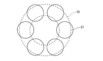
- the motor unit 3 includes a motor casing 51, a rotating shaft 52, rotor yokes 53 and 54, a rotor magnet 55, and a coil core portion 57.
- the motor casing 51 is formed in a bottomed cylindrical shape extending in the direction in which the axis X extends (hereinafter referred to as the axial direction). This axis X coincides with an axis X of the rotary shaft 52 described later.
- a rotating shaft 52, rotor yokes 53 and 54, a rotor magnet 55, and a coil core portion 57 are accommodated inside the motor casing 51.
- a plurality of bolt holes 51 a into which bolts 4 for connecting the motor unit 3 to the wave gear reducer unit 2 are inserted are formed on the outer peripheral side of the motor casing 51. As shown in FIG. 1, the motor casing 51 is attached to the wave gear reducer unit 2 such that the opening portion is located on the wave gear reducer unit 2 side.
- the rotating shaft 52 has a cylindrical shape extending in the axial direction.
- the rotating shaft 52 is disposed concentrically with the motor casing 51.
- the rotating shaft 52 is disposed in the motor casing 51 so that the other end portion in the axial direction is located on the opening side of the motor casing 51.
- the rotation shaft 52 has a through hole 52a into which a bolt 5 (see FIG. 1) for fixing the rotation shaft 52 and a connecting portion 12b of the rotating body 12 described later of the wave gear reducer unit 2 is inserted in the circumferential direction.
- a bolt 5 see FIG. 1
- the rotor yokes 53 and 54 are each an annular plate member.
- the rotor yokes 53 and 54 are fixed to both ends of the rotating shaft 52 in the axial direction. That is, the rotor yokes 53 and 54 are fixed to the rotary shaft 52 so as to extend radially outward from both ends of the rotary shaft 52 in the axial direction. Thereby, the rotor yokes 53 and 54 are disposed in parallel in the motor casing 51.
- the rotor yokes 53 and 54 are fixed to the rotating shaft 52 by bolts 5 (see FIG. 1) that pass through the through holes 52a of the rotating shaft 52.
- the rotor magnet 55 has an annular shape and is fixed to a surface of the rotor yoke 53 on the rotor yoke 54 side (see FIG. 2). Although not shown, the rotor magnet 55 has different magnetic poles alternately in the circumferential direction.
- the coil core portion 57 is formed in, for example, a cylindrical shape extending in the axial direction. As schematically shown in FIG. 3, a plurality of coil core portions 57 (six in the example of the present embodiment) are arranged in the motor casing 51 in the circumferential direction when the motor unit 3 is viewed from the height direction. . Each of the coil core portions 57 is sandwiched between the annular plates 58 in the axial direction. The outer peripheral surface of the annular plate 58 is fixed to the inner peripheral surface of the motor casing 51. That is, the coil core portion 57 and the annular plate 58 correspond to a stator of the motor.
- the coil core part 57 has a coil wound on the side surface, although not particularly shown.
- a gap is formed between the rotor magnet 55 and the coil core portion 57 in the axial direction of the rotary shaft 52.
- the axial gap type motor unit 3 having the above configuration is more compact in the height direction (axial direction) than the radial gap type motor having the same output performance.
- the wave gear reducer unit 2 is a flat having a larger dimension in the radial direction (horizontal direction in FIGS. 1 and 4) than in the height direction (vertical direction in FIGS. 1 and 4). It is formed in a shape.
- the wave gear reducer unit 2 applies a wave motion to the external gear 14 by the cam 12a that rotates together with the rotating shaft 52 of the motor unit 3, thereby rotating the cam 12a to the external gear 14 or the internal gear 15. introduce.
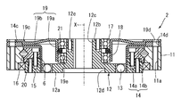
- the wave gear reducer unit 2 includes a casing 11, a rotating body 12, a bearing 13, an external gear 14, an internal gear 15, a cross roller bearing 16, and support bearings 17 and 18. And a support part 19.
- the casing 11 has a cylindrical shape extending in the direction in which the axis X extends (hereinafter referred to as the axial direction).
- the axis X coincides with the axis X of the rotation shaft 52 of the motor unit 3 in a state where the wave gear reducer unit 2 is attached to the motor unit 3. Therefore, the axial direction coincides with the axial direction of the rotating shaft 52 of the motor unit 3.
- the casing 11 is provided with a plurality of screw holes 11a penetrating the casing 11 in the axial direction in the circumferential direction.
- a bolt 4 (see FIG. 1) for connecting the motor unit 3 and the wave gear reducer unit 2 is inserted into the screw hole 11a.
- the screw hole 11a has an external gear 14 disposed on one side (motor unit 3 side) in the axial direction with respect to the casing 11 and a through hole 14d formed in a support portion 19 described later. It connects with 19d and the insertion hole of the volt
- the rotating body 12 is disposed inside the casing 11.
- the rotating body 12 is connected to the rotating shaft 52 of the motor unit 3 and rotates integrally with the rotating shaft 52.
- the rotating body 12 includes a flat cam 12a formed in an ellipse and a connection portion 12b.
- the cam 12a is formed in an elliptical shape when viewed from the axial direction.
- the connecting portion 12b is formed in a cylindrical shape extending in the thickness direction on one side (motor unit 3 side) in the thickness direction of the cam 12a.
- the rotating body 12 is arranged inside the casing 11 so that the thickness direction of the cam 12a coincides with the axial direction and the connecting portion 12b extends in the axial direction.
- the cam 12a and the connection portion 12b are a single component.
- the number of parts of the wave gear reducer unit 1 can be reduced, and the assembly workability of the wave gear reducer unit 1 can be improved.
- the rotating body 12 is formed with a through hole 12c that penetrates the connecting portion 12b and the cam 12a in the axial direction.
- the cam 12a has a recess 12d at the opening of the through hole 12c.
- connection portion 12b has one end portion (one side end portion) in the axial direction positioned inward in the axial direction in the support portion 19 to be described later, when viewed from a direction orthogonal to the axial direction. Thereby, it can prevent that the connection part 12b protrudes to the one of the said axial direction rather than the support part 19. FIG. Therefore, the wave gear reducer unit 1 can be downsized in the axial direction.
- the connecting portion 12b has a plurality of bolt holes 12e at the end opposite to the cam 12a.
- Bolts 5 that pass through the through holes 52a of the rotating shaft 52 in the motor unit 3 are fastened to the plurality of bolt holes 12e.
- the rotating body 12 rotates integrally with the rotating shaft 52 of the motor unit 3 by connecting the connecting portion 12 b and the rotating shaft 52 of the motor unit 3 with the bolt 5. Therefore, the cam 12a rotates around the axis X as seen from the axial direction.
- support bearings 17 and 18 are arranged side by side in the axial direction on the outer peripheral surface of the connecting portion 12b.
- the connection portion 12 b is supported in the axial direction and the radial direction of the casing 11 by a support portion 19 fixed to the casing 11 via these support bearings 17 and 18. That is, the support part 19 is connected to the casing 11 and rotatably supports the outer peripheral side of the connection part 12b.
- the rotary body 12 can be positioned with respect to the casing 11. Further, as described above, by arranging the support bearings 17 and 18 side by side in the axial direction on the outer peripheral surface of the connecting portion 12b, the rotating body 12 can be supported more reliably and stably in a rotatable state. Can do.
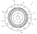
- FIG. 5 shows the positional relationship between the external gear 14, the internal gear 15 and the cam 12a when the wave gear reducer unit 1 is viewed from the other side in the axial direction.
- description of the casing 11 is abbreviate
- the bearing 13 is disposed between the cam 12a and the external gear 14 when viewed from the axial direction.
- the bearing 13 is disposed between the cam 12a and the external gear 14, and is movable in the radial direction of the cam 12a according to the rotation of the cam 12a.
- the external gear 14 is formed in a cylindrical shape with a flange by a flexible thin plate.
- the external gear 14 includes a cylindrical portion 14a that covers the cam 12a from the radially outer side, and a flange portion 14b that extends radially outward on one side of the cylindrical portion 14a in the axial direction.
- the cylindrical portion 14a has a plurality of external teeth 31 (see FIG. 5) formed on the outer peripheral surface at a constant pitch in the circumferential direction.
- the external teeth 31 are formed on the outer peripheral surface of the cylindrical portion 14a so as to extend in the axial direction.
- the inner peripheral surface of the cylindrical portion 14a is in contact with the bearing 13 disposed on the outer periphery of the cam 12a.
- the flange portion 14b is formed in an annular shape when viewed from the axial direction.
- the outer peripheral side of the flange portion 14 b is fixed to one side of the casing 11 in the axial direction.
- a thicker portion 14 c is formed on the outer peripheral side of the flange portion 14 b as compared with other portions of the external gear 14.
- a plurality of through holes 14d penetrating in the thickness direction are formed in the thick portion 14c in the circumferential direction.
- the through hole 14 d is provided at a position corresponding to the screw hole 11 a of the casing 11 in a state where the external gear 14 is disposed on one side of the casing 11 in the axial direction.
- the length of the flange portion 14b protruding radially outward from the cylindrical portion 14a has a length that can be easily deformed when the cylindrical portion 14a is pressed by the rotation of the cam 12a as described above.
- the internal gear 15 is an annular member, and a plurality of internal teeth 32 are formed on the inner peripheral surface at a constant pitch in the circumferential direction.
- the internal teeth 32 are formed on the inner peripheral surface of the internal gear 15 so as to extend in the axial direction.
- the internal gear 15 is disposed so as to surround the cam 12a, the bearing 13, and the cylindrical portion 14a of the external gear 14 from the radially outer side.
- the internal gear 15 is configured such that when the external gear 14 is deformed by being pressed in the radial direction by the end of the long axis direction of the cam 12a, the internal teeth 32 of the internal gear 15 are in relation to the external teeth 31 of the external gear 14.
- the external gear 14 has a predetermined gap in a part in the circumferential direction so as to mesh with each other.
- connection ring 20 is fixed to the internal gear 15 on one side in the axial direction.
- the connection ring 20 is rotatably supported by the inner surface of the casing 11 via a cross roller bearing 16.
- the connection ring 20 is fixed to the internal gear 15 by a plurality of bolts 6. Since the structure of the cross roller bearing 16 is the same as that of a general cross roller bearing, detailed description thereof is omitted.
- the number of the internal teeth 32 of the internal gear 15 is larger than the number of the external teeth 31 of the external gear 14.
- the external gear 14 is deformed in the radial direction by the rotation of the cam 12a, and the external teeth 31 of the external gear 14 are changed to the internal gear.
- the rotational speed of the internal gear 15 can be reduced with respect to the rotational speed of the cam 12a.
- the support part 19 is formed in a cylindrical shape with a flange by a plate-like member as shown in FIG.
- the support part 19 is arrange
- the cam 12 a can be positioned with respect to the casing 11 by the support portion 19. Further, by connecting the support part 19 to the casing 11 on one side in the axial direction from the external gear 14, the connection part 12b extending from the cam 12a to one side in the axial direction is connected to the casing 11 by the support part 19. It becomes possible to support from one side in the axial direction. Thereby, the cam 12a can be supported more reliably.
- the support portion 19 includes a cylindrical portion 19a (tubular portion) extending in the axial direction, and a flange portion 19b provided on one side of the cylindrical portion 19a in the axial direction.
- the cylindrical portion 19a supports the outer peripheral side of the connecting portion 12b in the rotating body 12 via support bearings 17 and 18. Specifically, the cylindrical portion 19a is positioned on the radially outer side of the connecting portion 12b with respect to the support bearings 17 and 18 attached on the outer peripheral surface of the connecting portion 12b. That is, the cylindrical portion 19a has a through hole 19e, and the connection portion 12b and the support bearings 17 and 18 are disposed in the through hole 19e.
- the cylindrical portion 19 a is prevented from falling off in the axial direction with respect to the support bearings 17 and 18 by a retaining member 21 disposed between the support bearings 17 and 18.
- the flange portion 19b extends radially outward from one side in the axial direction of the cylindrical portion 19a, and is fixed to the casing 11 on the outer peripheral side.
- the flange portion 19b is formed in an annular shape that covers the casing 11, the external gear 14, and the internal gear 15 from one side in the axial direction when viewed from one side in the axial direction.
- a bent portion 19c that is bent to one side in the axial direction is formed on the outer peripheral side of the flange portion 19b.
- the bent portion 19c is combined with the thick portion 14c provided on the outer peripheral side of the flange portion 14b of the external gear 14 when the support portion 19 is disposed on one side in the axial direction with respect to the external gear 14. It is done. Thereby, the support part 19 can be positioned with respect to the external gear 14 and the casing 11.
- a plurality of through holes 19d penetrating in the thickness direction are formed in the circumferential direction on the outer peripheral side of the bent portion 19c.
- the through hole 19d is a screw that is connected to the screw hole 11a of the casing 11 and the through hole 14d of the external gear 14 in a state where the external gear 14 and the support portion 19 are arranged on one side of the casing 11 in the axial direction. It is formed at a position corresponding to the hole 11a and the through hole 14d.
- the collar portion 19b is curved so that the inner peripheral side is located on one side in the axial direction as compared with the bent portion 19c side.
- the connection part 12b of the rotary body 12 can be urged
- FIG. Therefore, the rotating body 12 can be reliably supported by the support portion 19 in the axial direction.
- the rigidity of the support part 19 can be improved by making the collar part 19b into the above structures.
- the rotating body 12 having the cam 12a can be rotatably supported by the support portion 19 supported by the casing 11. Therefore, the rotating body 12 can be positioned in the axial direction and the radial direction in the casing 11. Thereby, when the wave gear reducer unit 2 is attached to the motor unit 3, it is not necessary to position the cam 12a by the rotating shaft 52.
- the rotating body 12 has the connecting portion 12b extending from the cam 12a toward one side in the axial direction, the rotating shaft 52 of the motor unit 3 can be easily connected to the connecting portion 12b.
- the wave gear reducer unit 2 can be easily attached to the motor unit 3.
- the cam 12a is disposed on the other side (the other side end) in the axial direction with respect to the casing 11, and the connecting portion 12b is provided so as to extend from the cam 12a toward one side in the axial direction.
- the connecting portion 12b is supported in the space formed on one side of the cam 12a in the axial direction by supporting the connecting portion 12b with the support portion 19 disposed on the one side in the axial direction with respect to the casing 11.
- the support part 19 can be arrange
- the wave gear reducer unit 1 that is easy to assemble with the motor unit 3 and has a compact configuration can be obtained.
- a wave gear reducer unit 2 is a wave gear reducer unit that is rotatably connected to a rotation shaft 52 with respect to a motor unit 3 (motor) having a rotation shaft 52 extending in the axial direction. is there.
- the wave gear reducer unit 2 includes a cylindrical casing 11 that extends in the axial direction, an annular inner casing that is disposed in the casing 11 so as to be rotatable relative to the casing 11, and has inner teeth 32 on the inner peripheral side.
- the elliptical cam 12a located inside the annular external gear 14 having flexibility rotates together with the rotating shaft 52 of the motor unit 3 to deform the external gear 14 in the radial direction (external teeth).
- the gear 14 can be waved from the inner periphery side). Accordingly, a part of the external teeth 31 of the external gear 14 meshes with the internal teeth 32 of the internal gear 15, so that the rotation of the cam 12 a can be transmitted to the internal gear 15 or the external gear 14. .
- the connecting portion 12b connected to the rotating shaft 52 of the motor unit 3 is formed integrally with the cam 12a or fixed to the cam 12a and connected to the casing 11. It can be unitized by supporting it rotatably by the support part 19.
- the cam 12a with the connecting portion 12b as described above, the cam 12a and the rotating shaft 52 of the motor unit 3 can be easily connected. Further, since the cam 12a is positioned by the support portion 19 and the connecting portion 12b, it is not necessary to position the cam by the rotation shaft of the motor as in the conventional case. Thus, the wave gear reducer can be unitized and easily attached to the motor unit 3.
- the connecting portion 12b is formed integrally with the cam 12a or fixed to the cam 12a inside the external gear 14, and is connected to the rotating shaft 52 of the motor unit 3, the axial direction of the external gear 14 is It does not protrude greatly outward. Therefore, since the connection structure with the motor unit 3 can be made into a compact structure, the wave gear reducer unit 2 having a compact structure can be obtained.
- the wave gear reducer unit 2 having a compact configuration that is easy to attach to the motor unit 3 can be obtained by the above-described configuration.
- the cam 12 a is disposed at the other end portion in the axial direction with respect to the external gear 14.
- the connecting portion 12b extends from the cam toward one side in the axial direction, and when viewed from a direction orthogonal to the axial direction, one end portion in the axial direction is in the axial direction of the support portion 19. Located inward.
- connecting portion 12b By providing the connecting portion 12b as described above, it is possible to prevent the connecting portion 12b from protruding in one of the axial directions from the support portion 19 when viewed from the direction orthogonal to the axial direction of the rotating shaft 52. Thereby, size reduction of the wave gear reducer unit 2 can be achieved in the axial direction.
- the support portion 19 is fixed to the casing 11 on one side in the axial direction from the external gear 14.
- the cam 12a can be positioned with respect to the casing 11. That is, the cam 12 a can be positioned with respect to the casing 11 by supporting the connecting portion 12 b formed integrally with the cam 12 a or fixed to the cam 12 a by the support portion 19 fixed to the casing 11.
- connection portion 12 b formed integrally with the cam 12 a or fixed to the cam 12 a is formed by the support portion 19. It is possible to support from one side in the axial direction. Thereby, the cam 12a can be supported more reliably.
- the wave gear reducer unit 2 further includes support bearings 17 and 18 (bearings) arranged on the outer peripheral surface of the connection portion 12b.
- the support portion 19 supports the support bearings 17 and 18 with respect to the casing 11.
- the connecting portion 12b formed integrally with the cam 12a or fixed to the cam 12a can be supported rotatably with respect to the casing 11.
- the support portion 19 includes a cylindrical portion 19a (tubular portion) having a through hole 19e in which the connection portion 12b and the support bearings 17 and 18 can be disposed, and a direction orthogonal to the axial direction from one side of the axial direction of the cylindrical portion 19a. And a flange portion 19b extending in the direction. The outer peripheral side of the flange portion 19 b is fixed to the casing 11. The cylindrical portion 19a supports the connection portion 12b via the support bearings 17 and 18.
- the connecting portion 12b formed integrally with the cam 12a or fixed to the cam 12b can be more reliably supported by the support portion 19 in a rotatable state.
- a plurality of support bearings 17 and 18 are arranged side by side in the axial direction. Thereby, the connection part 12b formed integrally with the cam 12a or fixed to the cam 12a can be more reliably supported by the support part 19 so as to be rotatable.
- the cam 12a and the connecting part 12b are a single part. Thereby, the number of parts of the wave gear reduction unit 2 can be reduced, and the assembly workability of the wave gear reduction unit 2 can be improved.
- the support portion 19 that supports the connection portion 12 b of the rotating body 12 is fixed to the casing 11 by the bolt 4 that connects the motor unit 3 and the wave gear reducer unit 2.
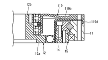
- a convex portion 119 d may be provided at the outer peripheral end portion of the flange portion 119 b in the support portion 119, and the convex portion 119 d may be fixed to the outer peripheral side of the casing 11.
- the cam 12a and the connecting portion 12b are integrally formed in the rotating body 12.
- the connecting portion is separate from the cam and may be fixed to the cam.
- the rotating body 12 is formed in a cylindrical shape.
- the rotating body may be cylindrical.
- the support portion 19 has a cylindrical portion 19a and a flange portion 19b.
- the support portion 19 may have any configuration.
- the motor unit 3 to which the wave gear reducer unit 2 is attached is an axial gap type motor.
- the motor unit to which the wave gear reducer unit 2 is attached may be a motor having another configuration such as a radial gap type motor.
- the present invention can be used for a wave gear reducer unit connected to a motor unit.
Abstract
A strain wave gear speed reducer unit 1 is provided with: a casing 11 with a cylindrical shape that extends in the axial direction; a ring-shaped internal gear 15 disposed so as to be rotatable relative to the casing 11 and having internal teeth 32 on the inner circumference; a flexible ring-shaped external gear 14, which is disposed to the inside of the internal gear 15 in the radial direction, one axial direction end of which is fixed to the casing 11, and which has external teeth 31 on the outer circumference for meshing with the internal teeth 32; an elliptical cam 12a, which is disposed to the inside of the external gear 14 in the radial direction and deforms the external gear 14 in the radial direction by rotating together with a rotating shaft 52 of a motor unit 3; a connecting part 12b formed integrally with the cam 12a and connected to the rotating shaft 52 on the inside of the external gear 14; and a support 19 connected to the casing 11 and rotatably supporting the periphery of the connecting part 12b.
Description
本発明は、波動歯車減速機ユニットに関する。
The present invention relates to a wave gear reducer unit.
従来より、電動機の回転軸の回転を減速して出力する減速機として、様々な構成の減速機が知られている。例えば特許文献1には、波動歯車機構を利用した減速機が開示されている。この波動歯車減速機は、楕円状のウェーブジェネレータと、該ウェーブジェネレータの外周に位置する軸受を介して接触するとともに、外周にスプライン状の歯を有し且つ円形に形成された可撓性のフレクスプラインと、該フレクスプラインの歯数よりも多いスプライン状の歯をリング状に有し且つ前記フレクスプラインの外周に噛み合って嵌合するサーキュラスプラインとを有する。
Conventionally, speed reducers with various configurations are known as speed reducers that decelerate and output the rotation of the rotating shaft of an electric motor. For example, Patent Document 1 discloses a reduction gear using a wave gear mechanism. This wave gear reducer is in contact with an elliptical wave generator via a bearing located on the outer periphery of the wave generator, and has a flexible flexure formed in a circular shape with spline-like teeth on the outer periphery. A spline, and a circular spline that has spline-like teeth larger than the number of teeth of the flexspline in a ring shape and meshes with and engages with the outer periphery of the flexspline.
上述の波動歯車減速機構では、例えば、前記ウェーブジェネレータに入力軸を接続し、前記サーキュラスプラインを固定し、前記フレクスプラインを出力軸に連結した場合、前記ウェーブジェネレータが時計方向に1回転すると、前記フレクスプラインが反時計方向に、前記サーキュラスプラインとの歯数差分だけ回転する。一方、前記フレクスプラインを固定し、前記サーキュラスプラインを出力軸に連結した場合には、前記サーキュラスプラインが、前記フレクスプラインとの歯数差分だけ回転する。
In the above-described wave gear reduction mechanism, for example, when the input shaft is connected to the wave generator, the circular spline is fixed, and the flexspline is connected to the output shaft, the wave generator rotates once in the clockwise direction, The flexspline rotates counterclockwise by a difference in the number of teeth from the circular spline. On the other hand, when the flexspline is fixed and the circular spline is connected to the output shaft, the circular spline rotates by a difference in the number of teeth from the flexspline.
このように、上述の波動歯車減速機では、前記ウェーブジェネレータに入力された回転を、前記サーキュラスプラインと前記フレクスプラインとの歯数差によって減速して、前記フレクスプラインまたは前記サーキュラスプラインから出力する。
Thus, in the above-described wave gear reducer, the rotation input to the wave generator is decelerated by the difference in the number of teeth between the circular spline and the flexspline, and is output from the flexspline or the circular spline.
前記特許文献1の図1には、波動歯車減速機が、駆動モータの回転軸に対して接続された構成が開示されている。図1の構成では、装置全体の重量が重くなるとともに、回転軸に波動歯車減速機を接続するカップリング部によって、装置全体の大きさが大きくなり且つ長さが長くなる。そのため、前記特許文献1に開示されている構成では、減速機と駆動モータとを一体化することにより、装置全体のコンパクト化を図っている。具体的には、前記特許文献1に開示されている構成では、駆動モータの回転子と、減速機のウェーブジェネレータとが一体で形成されている。
FIG. 1 of Patent Document 1 discloses a configuration in which a wave gear reducer is connected to a rotation shaft of a drive motor. In the configuration of FIG. 1, the weight of the entire apparatus increases, and the entire apparatus increases in size and length due to the coupling portion that connects the wave gear reducer to the rotating shaft. Therefore, in the configuration disclosed in Patent Document 1, the entire device is made compact by integrating the speed reducer and the drive motor. Specifically, in the configuration disclosed in Patent Document 1, the rotor of the drive motor and the wave generator of the speed reducer are integrally formed.
ところで、上述の特許文献1に開示されるように、減速機と駆動モータとを一体化する場合、専用の減速機及び駆動モータを個別に設計する必要がある。そのため、用途に合わせて、様々な種類の減速機及び駆動モータを設計する必要があり、汎用性という点で問題がある。
By the way, as disclosed in the above-mentioned Patent Document 1, when a reduction gear and a drive motor are integrated, it is necessary to individually design a dedicated reduction gear and a drive motor. Therefore, it is necessary to design various types of reduction gears and drive motors according to the application, which is problematic in terms of versatility.
一方、上述の特許文献1の図1に示すように、別体の駆動モータと減速機とを組み合わせる場合には、減速機の汎用性は確保できるものの、上述の特許文献1に記載されているように減速機及び駆動モータを組み合わせることによって得られる装置が大型化する。
On the other hand, as shown in FIG. 1 of Patent Document 1 described above, when a separate drive motor and a speed reducer are combined, the versatility of the speed reducer can be ensured, but is described in Patent Document 1 described above. Thus, the apparatus obtained by combining a reduction gear and a drive motor becomes large.
さらに、別体の減速機と駆動モータとを組み合わせる場合には、該減速機と駆動モータとの接続を精度良く行う必要があるため、組み立て作業性があまりよくない。具体的には、別体の駆動モータ及び減速機を組み合わせる場合、減速機のサーキュスプライン(内歯歯車)に対してフレクスプライン(外歯歯車)及びカムが所定の位置に位置付けられるように、該カムに駆動モータの回転軸を精度良く接続する必要がある。駆動モータと減速機とを接続する際には、寸法精度が要求されるため、作業性があまりよくない。
Furthermore, when combining a separate speed reducer and a drive motor, it is necessary to accurately connect the speed reducer and the drive motor, so that the assembly workability is not so good. Specifically, when combining a separate drive motor and reducer, the flexspline (external gear) and the cam are positioned at predetermined positions with respect to the circular spline (internal gear) of the reducer. It is necessary to accurately connect the rotating shaft of the drive motor to the cam. When connecting the drive motor and the speed reducer, dimensional accuracy is required, so workability is not very good.
本発明の目的は、波動歯車減速機ユニットにおいて、駆動モータに対する取り付けが容易で且つコンパクトな構成を実現することにある。
An object of the present invention is to realize a compact configuration that can be easily attached to a drive motor in a wave gear reducer unit.
本発明の一実施形態に係る波動歯車減速機ユニットは、軸線方向に延びる回転軸を有するモータに対し、前記回転軸に回転可能に接続される波動歯車減速機ユニットである。この波動歯車減速機ユニットは、前記軸線方向に延びる筒状のケーシングと、前記ケーシング内に該ケーシングに対して相対回転可能に配置され、内周側に内歯を有する環状の内歯歯車と、前記内歯歯車の径方向内方に配置されるとともに前記軸線方向の一方側が前記ケーシングに固定され、且つ、外周側に前記内歯と噛み合う外歯を有する、可撓性の環状の外歯歯車と、前記外歯歯車の径方向内方に配置され、前記回転軸とともに回転することによって、前記外歯歯車を径方向に変形させる楕円状のカムと、前記外歯歯車の内方において、前記カムと一体で形成または前記カムに固定され、前記モータの前記回転軸に接続される接続部と、前記ケーシングに接続されるとともに、前記接続部の外周側を回転可能に支持する支持部とを備える。
A wave gear reducer unit according to an embodiment of the present invention is a wave gear reducer unit that is rotatably connected to the rotation shaft with respect to a motor having a rotation shaft extending in the axial direction. The wave gear reducer unit includes a cylindrical casing extending in the axial direction, an annular internal gear disposed in the casing so as to be relatively rotatable with respect to the casing, and having internal teeth on an inner peripheral side, A flexible annular external gear that is arranged radially inward of the internal gear and that has one side in the axial direction fixed to the casing and has external teeth that mesh with the internal teeth on the outer peripheral side. And an elliptical cam that is arranged radially inward of the external gear and rotates together with the rotating shaft to deform the external gear in the radial direction, and inward of the external gear, A connecting portion formed integrally with the cam or fixed to the cam and connected to the rotating shaft of the motor; and a support portion connected to the casing and rotatably supporting the outer peripheral side of the connecting portion. Prepare
本発明の一実施形態に係る波動歯車減速機ユニットによれば、モータに対する取り付けが容易で且つコンパクトな構成を有する波動歯車減速機ユニットが得られる。
According to the wave gear reducer unit according to an embodiment of the present invention, a wave gear reducer unit that is easy to attach to the motor and has a compact configuration can be obtained.
以下、図面を参照し、本発明の実施の形態を詳しく説明する。なお、図中の同一または相当部分については同一の符号を付してその説明は繰り返さない。また、各図中の構成部材の寸法は、実際の構成部材の寸法及び各構成部材の寸法比率等を忠実に表したものではない。
Hereinafter, embodiments of the present invention will be described in detail with reference to the drawings. In addition, the same code | symbol is attached | subjected about the same or an equivalent part in a figure, and the description is not repeated. Moreover, the dimension of the structural member in each figure does not faithfully represent the actual dimension of the structural member, the dimensional ratio of each structural member, or the like.
なお、以下の説明では、電動機の回転軸と平行な方向を「軸線方向」または「高さ方向」、回転軸に直交する方向を「径方向」、回転軸を中心とする円弧に沿う方向を「周方向」、とそれぞれ称する。ただし、上記の「平行な方向」は略平行な方向も含むものとする。また、上記の「直交する方向」は略直交する方向も含むものとする。
In the following description, the direction parallel to the rotation axis of the motor is “axial direction” or “height direction”, the direction orthogonal to the rotation axis is “radial direction”, and the direction along the arc centered on the rotation axis is These are referred to as “circumferential directions”, respectively. However, the “parallel direction” includes a substantially parallel direction. In addition, the above-mentioned “orthogonal direction” includes a substantially orthogonal direction.
(全体構成)
図1に、本発明の実施形態に係る波動歯車減速機ユニット2を含む動力ユニット1の概略構成を示す。動力ユニット1は、波動歯車減速機ユニット2と、モータユニット3(モータ)とを備える。動力ユニット1は、モータユニット3の後述する回転軸52の回転を、波動歯車減速機ユニット2によって減速して、出力する。動力ユニット1は、例えば、ロボットの関節や電動車いす等の車輪を駆動させる動力源として利用可能である。 (overall structure)
FIG. 1 shows a schematic configuration of apower unit 1 including a wave gear reducer unit 2 according to an embodiment of the present invention. The power unit 1 includes a wave gear reducer unit 2 and a motor unit 3 (motor). The power unit 1 decelerates the rotation of a rotating shaft 52 (described later) of the motor unit 3 by the wave gear reducer unit 2 and outputs it. The power unit 1 can be used as a power source for driving wheels such as a robot joint and an electric wheelchair.
図1に、本発明の実施形態に係る波動歯車減速機ユニット2を含む動力ユニット1の概略構成を示す。動力ユニット1は、波動歯車減速機ユニット2と、モータユニット3(モータ)とを備える。動力ユニット1は、モータユニット3の後述する回転軸52の回転を、波動歯車減速機ユニット2によって減速して、出力する。動力ユニット1は、例えば、ロボットの関節や電動車いす等の車輪を駆動させる動力源として利用可能である。 (overall structure)
FIG. 1 shows a schematic configuration of a
波動歯車減速機ユニット2及びモータユニット3は、それぞれ、円柱状である。動力ユニット1は、波動歯車減速機ユニット2とモータユニット3とをそれらの高さ方向(図1における上下方向)に重ねた状態で、それらの外周側が複数のボルト4によって接続されている。動力ユニット1は、全体として円柱状である。
The wave gear reducer unit 2 and the motor unit 3 are each cylindrical. The power unit 1 has a wave gear reducer unit 2 and a motor unit 3 stacked in the height direction (vertical direction in FIG. 1), and their outer peripheral sides are connected by a plurality of bolts 4. The power unit 1 has a cylindrical shape as a whole.
(モータユニット)
モータユニット3は、アキシャルギャップ型のブラシレスモータである。モータユニット3は、図1及び図2に示すように、高さ方向よりも径方向(図1及び図2における左右方向)の寸法が大きい扁平状である。 (Motor unit)
Themotor unit 3 is an axial gap type brushless motor. As shown in FIGS. 1 and 2, the motor unit 3 has a flat shape having a larger dimension in the radial direction (left and right direction in FIGS. 1 and 2) than in the height direction.
モータユニット3は、アキシャルギャップ型のブラシレスモータである。モータユニット3は、図1及び図2に示すように、高さ方向よりも径方向(図1及び図2における左右方向)の寸法が大きい扁平状である。 (Motor unit)
The
図2に示すように、モータユニット3は、モータケーシング51と、回転軸52と、ロータヨーク53,54と、ロータマグネット55と、コイルコア部57とを備える。
As shown in FIG. 2, the motor unit 3 includes a motor casing 51, a rotating shaft 52, rotor yokes 53 and 54, a rotor magnet 55, and a coil core portion 57.
モータケーシング51は、軸線Xが延びる方向(以下、軸線方向という)に延びる有底円筒状に形成されている。この軸線Xは、後述する回転軸52の軸線Xと一致する。モータケーシング51の内方には、回転軸52、ロータヨーク53,54、ロータマグネット55及びコイルコア部57が収容されている。
The motor casing 51 is formed in a bottomed cylindrical shape extending in the direction in which the axis X extends (hereinafter referred to as the axial direction). This axis X coincides with an axis X of the rotary shaft 52 described later. A rotating shaft 52, rotor yokes 53 and 54, a rotor magnet 55, and a coil core portion 57 are accommodated inside the motor casing 51.
モータケーシング51の外周側には、モータユニット3を波動歯車減速機ユニット2と接続するためのボルト4が挿入されるボルト穴51aが複数形成されている。図1に示すように、モータケーシング51は、開口部分が波動歯車減速機ユニット2側に位置するように、波動歯車減速機ユニット2に取り付けられる。
A plurality of bolt holes 51 a into which bolts 4 for connecting the motor unit 3 to the wave gear reducer unit 2 are inserted are formed on the outer peripheral side of the motor casing 51. As shown in FIG. 1, the motor casing 51 is attached to the wave gear reducer unit 2 such that the opening portion is located on the wave gear reducer unit 2 side.
図2に示すように、回転軸52は、前記軸線方向に延びる円筒状である。回転軸52は、モータケーシング51と同心に配置されている。回転軸52は、軸線方向の他方の端部が、モータケーシング51の開口側に位置するように、モータケーシング51内に配置されている。回転軸52には、回転軸52と波動歯車減速機ユニット2の後述する回転体12の接続部12bとを固定するためのボルト5(図1参照)が挿入される貫通孔52aが、周方向に複数、設けられている。
As shown in FIG. 2, the rotating shaft 52 has a cylindrical shape extending in the axial direction. The rotating shaft 52 is disposed concentrically with the motor casing 51. The rotating shaft 52 is disposed in the motor casing 51 so that the other end portion in the axial direction is located on the opening side of the motor casing 51. The rotation shaft 52 has a through hole 52a into which a bolt 5 (see FIG. 1) for fixing the rotation shaft 52 and a connecting portion 12b of the rotating body 12 described later of the wave gear reducer unit 2 is inserted in the circumferential direction. Are provided in plurality.
ロータヨーク53,54は、それぞれ、円環状の板状部材である。ロータヨーク53,54は、回転軸52における前記軸線方向の両端部に固定されている。すなわち、ロータヨーク53,54は、回転軸52における前記軸線方向の両端部から、それぞれ、径方向外方に延びるように、回転軸52に固定されている。これにより、ロータヨーク53,54は、モータケーシング51内に平行に配置されている。なお、ロータヨーク53,54は、回転軸52の貫通孔52aを挿通するボルト5(図1参照)によって、回転軸52に対して固定されている。
The rotor yokes 53 and 54 are each an annular plate member. The rotor yokes 53 and 54 are fixed to both ends of the rotating shaft 52 in the axial direction. That is, the rotor yokes 53 and 54 are fixed to the rotary shaft 52 so as to extend radially outward from both ends of the rotary shaft 52 in the axial direction. Thereby, the rotor yokes 53 and 54 are disposed in parallel in the motor casing 51. The rotor yokes 53 and 54 are fixed to the rotating shaft 52 by bolts 5 (see FIG. 1) that pass through the through holes 52a of the rotating shaft 52.
ロータマグネット55は、円環状であり、ロータヨーク53におけるロータヨーク54側の面に、固定されている(図2参照)。図示しないが、ロータマグネット55は、周方向に交互に異なる磁極を有する。
The rotor magnet 55 has an annular shape and is fixed to a surface of the rotor yoke 53 on the rotor yoke 54 side (see FIG. 2). Although not shown, the rotor magnet 55 has different magnetic poles alternately in the circumferential direction.
コイルコア部57は、例えば、前記軸線方向に延びる円柱状に形成されている。コイルコア部57は、図3に模式的に示すように、モータユニット3を高さ方向から見て、モータケーシング51内に周方向に複数(本実施形態の例では6個)、配置されている。コイルコア部57は、それぞれ、円環状板58によって前記軸線方向に挟まれている。円環状板58の外周面は、前記モータケーシング51の内周面に固定されている。すなわち、コイルコア部57及び円環状板58は、モータの固定子に相当する。コイルコア部57は、特に図示しないが、側面上に巻かれたコイルを有する。
The coil core portion 57 is formed in, for example, a cylindrical shape extending in the axial direction. As schematically shown in FIG. 3, a plurality of coil core portions 57 (six in the example of the present embodiment) are arranged in the motor casing 51 in the circumferential direction when the motor unit 3 is viewed from the height direction. . Each of the coil core portions 57 is sandwiched between the annular plates 58 in the axial direction. The outer peripheral surface of the annular plate 58 is fixed to the inner peripheral surface of the motor casing 51. That is, the coil core portion 57 and the annular plate 58 correspond to a stator of the motor. The coil core part 57 has a coil wound on the side surface, although not particularly shown.
ロータマグネット55とコイルコア部57との間には、回転軸52の軸線方向に隙間が形成されている。以上のような構成を有するアキシャルギャップ型のモータユニット3は、同じ出力性能を有するラジアルギャップ型のモータに比べて、高さ方向(軸線方向)にコンパクトに構成されている。
A gap is formed between the rotor magnet 55 and the coil core portion 57 in the axial direction of the rotary shaft 52. The axial gap type motor unit 3 having the above configuration is more compact in the height direction (axial direction) than the radial gap type motor having the same output performance.
(波動歯車減速機ユニット)
図1及び図4に示すように、波動歯車減速機ユニット2は、高さ方向(図1及び図4における上下方向)よりも径方向(図1及び図4における左右方向)の寸法が大きい扁平状に形成されている。波動歯車減速機ユニット2は、モータユニット3の回転軸52とともに回転するカム12aによって、外歯歯車14に波動を与えることにより、該外歯歯車14または内歯歯車15に、カム12aの回転を伝達する。 (Wave gear reducer unit)
As shown in FIGS. 1 and 4, the wavegear reducer unit 2 is a flat having a larger dimension in the radial direction (horizontal direction in FIGS. 1 and 4) than in the height direction (vertical direction in FIGS. 1 and 4). It is formed in a shape. The wave gear reducer unit 2 applies a wave motion to the external gear 14 by the cam 12a that rotates together with the rotating shaft 52 of the motor unit 3, thereby rotating the cam 12a to the external gear 14 or the internal gear 15. introduce.
図1及び図4に示すように、波動歯車減速機ユニット2は、高さ方向(図1及び図4における上下方向)よりも径方向(図1及び図4における左右方向)の寸法が大きい扁平状に形成されている。波動歯車減速機ユニット2は、モータユニット3の回転軸52とともに回転するカム12aによって、外歯歯車14に波動を与えることにより、該外歯歯車14または内歯歯車15に、カム12aの回転を伝達する。 (Wave gear reducer unit)
As shown in FIGS. 1 and 4, the wave
具体的には、波動歯車減速機ユニット2は、ケーシング11と、回転体12と、軸受13と、外歯歯車14と、内歯歯車15と、クロスローラー軸受16と、支持軸受17,18と、支持部19とを備える。
Specifically, the wave gear reducer unit 2 includes a casing 11, a rotating body 12, a bearing 13, an external gear 14, an internal gear 15, a cross roller bearing 16, and support bearings 17 and 18. And a support part 19.
ケーシング11は、軸線Xが延びる方向(以下、軸線方向という)に延びる円筒状である。この軸線Xは、波動歯車減速機ユニット2がモータユニット3に取り付けられた状態で、モータユニット3の回転軸52の軸線Xと一致する。よって、前記軸線方向は、モータユニット3の回転軸52の軸線方向と一致する。
The casing 11 has a cylindrical shape extending in the direction in which the axis X extends (hereinafter referred to as the axial direction). The axis X coincides with the axis X of the rotation shaft 52 of the motor unit 3 in a state where the wave gear reducer unit 2 is attached to the motor unit 3. Therefore, the axial direction coincides with the axial direction of the rotating shaft 52 of the motor unit 3.
ケーシング11には、ケーシング11を前記軸線方向に貫通するネジ穴11aが、周方向に複数、設けられている。ネジ穴11aには、モータユニット3と波動歯車減速機ユニット2とを接続するためのボルト4(図1参照)が挿入される。なお、ネジ穴11aは、後述するようにケーシング11に対して前記軸線方向の一方側(モータユニット3側)に配置される外歯歯車14及び後述する支持部19に形成された貫通孔14d,19dと繋がって、ボルト4の挿入穴を構成する。
The casing 11 is provided with a plurality of screw holes 11a penetrating the casing 11 in the axial direction in the circumferential direction. A bolt 4 (see FIG. 1) for connecting the motor unit 3 and the wave gear reducer unit 2 is inserted into the screw hole 11a. As will be described later, the screw hole 11a has an external gear 14 disposed on one side (motor unit 3 side) in the axial direction with respect to the casing 11 and a through hole 14d formed in a support portion 19 described later. It connects with 19d and the insertion hole of the volt | bolt 4 is comprised.
回転体12は、ケーシング11の内方に配置されている。回転体12は、モータユニット3の回転軸52と接続されていて、回転軸52と一体で回転する。
The rotating body 12 is disposed inside the casing 11. The rotating body 12 is connected to the rotating shaft 52 of the motor unit 3 and rotates integrally with the rotating shaft 52.
詳しくは、回転体12は、楕円に形成された平板状のカム12aと、接続部12bとを有する。カム12aは、前記軸線方向から見て楕円状に形成されている。接続部12bは、カム12aの厚み方向の一方側(モータユニット3側)に、該厚み方向に延びる円筒状に形成されている。回転体12は、カム12aの厚み方向が前記軸線方向と一致し、接続部12bが前記軸線方向に延びるように、ケーシング11の内方に配置されている。
Specifically, the rotating body 12 includes a flat cam 12a formed in an ellipse and a connection portion 12b. The cam 12a is formed in an elliptical shape when viewed from the axial direction. The connecting portion 12b is formed in a cylindrical shape extending in the thickness direction on one side (motor unit 3 side) in the thickness direction of the cam 12a. The rotating body 12 is arranged inside the casing 11 so that the thickness direction of the cam 12a coincides with the axial direction and the connecting portion 12b extends in the axial direction.
本実施形態では、カム12aと接続部12bとは、単一の部品である。このようにカム12aと接続部12bとを一体で形成することにより、波動歯車減速機ユニット1の部品点数を減らすことができ、波動歯車減速機ユニット1の組み立て作業性を向上することができる。
In this embodiment, the cam 12a and the connection portion 12b are a single component. Thus, by integrally forming the cam 12a and the connecting portion 12b, the number of parts of the wave gear reducer unit 1 can be reduced, and the assembly workability of the wave gear reducer unit 1 can be improved.
回転体12には、接続部12b及びカム12aを前記軸線方向に貫通する貫通孔12cが形成されている。カム12aには、貫通孔12cの開口部分に凹部12dが形成されている。
The rotating body 12 is formed with a through hole 12c that penetrates the connecting portion 12b and the cam 12a in the axial direction. The cam 12a has a recess 12d at the opening of the through hole 12c.
接続部12bは、前記軸線方向に直交する方向から見て、前記軸線方向の一方の端部(一方側端部)が、後述する支持部19における前記軸線方向の内方に位置する。これにより、接続部12bが、支持部19よりも前記軸線方向の一方に突出することを防止できる。したがって、前記軸線方向において、波動歯車減速機ユニット1の小型化を図ることができる。
The connection portion 12b has one end portion (one side end portion) in the axial direction positioned inward in the axial direction in the support portion 19 to be described later, when viewed from a direction orthogonal to the axial direction. Thereby, it can prevent that the connection part 12b protrudes to the one of the said axial direction rather than the support part 19. FIG. Therefore, the wave gear reducer unit 1 can be downsized in the axial direction.
接続部12bは、カム12aとは反対側の端部に複数のボルト穴12eを有する。複数のボルト穴12eには、モータユニット3における回転軸52の貫通孔52aを挿通するボルト5が締結される。図1に示すように、接続部12bとモータユニット3の回転軸52とをボルト5によって接続することにより、回転体12は、モータユニット3の回転軸52と一体で回転する。したがって、カム12aは、前記軸線方向から見て、軸線Xを中心に回転する。
The connecting portion 12b has a plurality of bolt holes 12e at the end opposite to the cam 12a. Bolts 5 that pass through the through holes 52a of the rotating shaft 52 in the motor unit 3 are fastened to the plurality of bolt holes 12e. As shown in FIG. 1, the rotating body 12 rotates integrally with the rotating shaft 52 of the motor unit 3 by connecting the connecting portion 12 b and the rotating shaft 52 of the motor unit 3 with the bolt 5. Therefore, the cam 12a rotates around the axis X as seen from the axial direction.
図4に示すように、接続部12bの外周面上には、支持軸受17,18が前記軸線方向に並んで配置されている。接続部12bは、これらの支持軸受17,18を介して、ケーシング11に固定された支持部19により、前記軸線方向及びケーシング11の径方向に支持されている。つまり、支持部19は、ケーシング11に接続されるとともに、接続部12bの外周側を回転可能に支持している。これにより、回転体12をケーシング11に対して位置決めすることができる。また、上述のように、接続部12bの外周面上に、支持軸受17,18を前記軸線方向に並べて配置することにより、回転体12をより確実に且つ安定した状態で回転可能に支持することができる。
As shown in FIG. 4, support bearings 17 and 18 are arranged side by side in the axial direction on the outer peripheral surface of the connecting portion 12b. The connection portion 12 b is supported in the axial direction and the radial direction of the casing 11 by a support portion 19 fixed to the casing 11 via these support bearings 17 and 18. That is, the support part 19 is connected to the casing 11 and rotatably supports the outer peripheral side of the connection part 12b. Thereby, the rotary body 12 can be positioned with respect to the casing 11. Further, as described above, by arranging the support bearings 17 and 18 side by side in the axial direction on the outer peripheral surface of the connecting portion 12b, the rotating body 12 can be supported more reliably and stably in a rotatable state. Can do.
ケーシング11の内方には、回転体12のカム12aを囲むように、フランジ付きの円筒状に形成された外歯歯車14及び円環状に形成された内歯歯車15が配置されている。すなわち、カム12aの径方向外方には、外歯歯車14が位置し、外歯歯車14の径方向外方には内歯歯車15が配置されている。図5に、波動歯車減速機ユニット1を前記軸線方向の他方側から見た場合において、外歯歯車14、内歯歯車15及びカム12aの位置関係を示す。なお、図5では、ケーシング11の記載を省略している。
Inside the casing 11, an external gear 14 formed in a cylindrical shape with a flange and an internal gear 15 formed in an annular shape are disposed so as to surround the cam 12a of the rotating body 12. That is, the external gear 14 is located radially outward of the cam 12a, and the internal gear 15 is disposed radially outward of the external gear 14. FIG. 5 shows the positional relationship between the external gear 14, the internal gear 15 and the cam 12a when the wave gear reducer unit 1 is viewed from the other side in the axial direction. In addition, in FIG. 5, description of the casing 11 is abbreviate | omitted.
前記軸線方向から見て、カム12aと外歯歯車14との間には、軸受13が配置されている。軸受13は、カム12aと外歯歯車14との間に配置され、カム12aの回転に応じてカム12aの径方向に移動可能である。これにより、楕円状のカム12aが回転した際に、カム12aの長軸方向の端部が軸受13を介して外歯歯車14の内周側を径方向外方に向かって押圧する。
The bearing 13 is disposed between the cam 12a and the external gear 14 when viewed from the axial direction. The bearing 13 is disposed between the cam 12a and the external gear 14, and is movable in the radial direction of the cam 12a according to the rotation of the cam 12a. Thereby, when the elliptical cam 12 a rotates, the end portion in the major axis direction of the cam 12 a presses the inner peripheral side of the external gear 14 radially outward via the bearing 13.
外歯歯車14は、図4に示すように、可撓性を有する薄板によって、フランジ付きの円筒状に形成されている。具体的には、外歯歯車14は、カム12aを径方向外方から覆う円筒部14aと、円筒部14aにおける前記軸線方向の一方側に、径方向外方に向かって延びるフランジ部14bとを有する。
As shown in FIG. 4, the external gear 14 is formed in a cylindrical shape with a flange by a flexible thin plate. Specifically, the external gear 14 includes a cylindrical portion 14a that covers the cam 12a from the radially outer side, and a flange portion 14b that extends radially outward on one side of the cylindrical portion 14a in the axial direction. Have.
円筒部14aは、外周面に、複数の外歯31(図5参照)が周方向に一定のピッチで形成されている。外歯31は、円筒部14aの外周面に、前記軸線方向に延びるように形成されている。円筒部14aは、その内周面がカム12aの外周に配置された軸受13に接触している。これにより、楕円状のカム12aが回転することにより、カム12aの長軸方向の端部が、軸受13を介して、円筒部14aに径方向に変形を生じさせる。このように、楕円状のカム12aが回転することにより、外歯歯車14の円筒部14aに対して径方向に波動を与えることができる。
The cylindrical portion 14a has a plurality of external teeth 31 (see FIG. 5) formed on the outer peripheral surface at a constant pitch in the circumferential direction. The external teeth 31 are formed on the outer peripheral surface of the cylindrical portion 14a so as to extend in the axial direction. The inner peripheral surface of the cylindrical portion 14a is in contact with the bearing 13 disposed on the outer periphery of the cam 12a. Thereby, when the elliptical cam 12a rotates, the end portion in the major axis direction of the cam 12a causes the cylindrical portion 14a to deform in the radial direction via the bearing 13. Thus, by rotating the elliptical cam 12a, it is possible to give a wave in the radial direction to the cylindrical portion 14a of the external gear 14.
フランジ部14bは、図4に示すように、前記軸線方向から見て円環状に形成されている。フランジ部14bは、外周側がケーシング11における前記軸線方向の一方側に固定されている。フランジ部14bの外周側には、外歯歯車14の他の部分に比べて厚い厚肉部14cが形成されている。この厚肉部14cには、厚み方向に貫通する貫通孔14dが周方向に複数形成されている。貫通孔14dは、外歯歯車14をケーシング11における前記軸線方向の一方側に配置した状態で、ケーシング11のネジ穴11aに対応する位置に設けられる。
As shown in FIG. 4, the flange portion 14b is formed in an annular shape when viewed from the axial direction. The outer peripheral side of the flange portion 14 b is fixed to one side of the casing 11 in the axial direction. A thicker portion 14 c is formed on the outer peripheral side of the flange portion 14 b as compared with other portions of the external gear 14. A plurality of through holes 14d penetrating in the thickness direction are formed in the thick portion 14c in the circumferential direction. The through hole 14 d is provided at a position corresponding to the screw hole 11 a of the casing 11 in a state where the external gear 14 is disposed on one side of the casing 11 in the axial direction.
なお、円筒部14aから径方向外方に突出するフランジ部14bの長さは、上述のように円筒部14aがカム12aの回転によって押圧された場合に容易に変形可能な長さを有する。
Note that the length of the flange portion 14b protruding radially outward from the cylindrical portion 14a has a length that can be easily deformed when the cylindrical portion 14a is pressed by the rotation of the cam 12a as described above.
内歯歯車15は、図5に示すように、円環状の部材であり、内周面に、複数の内歯32が周方向に一定のピッチで形成されている。内歯32は、内歯歯車15の内周面に、前記軸線方向に延びるように形成されている。内歯歯車15は、カム12a、軸受13及び外歯歯車14の円筒部14aを、径方向外方から囲むように配置されている。内歯歯車15は、外歯歯車14がカム12aの長軸方向の端部によって径方向に押圧されて変形した場合に内歯歯車15の内歯32が外歯歯車14の外歯31に対して噛み合うように、外歯歯車14に対し、周方向の一部に所定の隙間を有する。
As shown in FIG. 5, the internal gear 15 is an annular member, and a plurality of internal teeth 32 are formed on the inner peripheral surface at a constant pitch in the circumferential direction. The internal teeth 32 are formed on the inner peripheral surface of the internal gear 15 so as to extend in the axial direction. The internal gear 15 is disposed so as to surround the cam 12a, the bearing 13, and the cylindrical portion 14a of the external gear 14 from the radially outer side. The internal gear 15 is configured such that when the external gear 14 is deformed by being pressed in the radial direction by the end of the long axis direction of the cam 12a, the internal teeth 32 of the internal gear 15 are in relation to the external teeth 31 of the external gear 14. The external gear 14 has a predetermined gap in a part in the circumferential direction so as to mesh with each other.
なお、図4に示すように、内歯歯車15には、前記軸線方向の一方側に、接続リング20が固定されている。この接続リング20は、クロスローラー軸受16を介してケーシング11の内面によって回転可能に支持されている。なお、接続リング20は、内歯歯車15に対して複数のボルト6によって固定されている。クロスローラー軸受16の構成は、一般的なクロスローラー軸受の構成と同様なので、詳しい説明を省略する。
As shown in FIG. 4, a connection ring 20 is fixed to the internal gear 15 on one side in the axial direction. The connection ring 20 is rotatably supported by the inner surface of the casing 11 via a cross roller bearing 16. The connection ring 20 is fixed to the internal gear 15 by a plurality of bolts 6. Since the structure of the cross roller bearing 16 is the same as that of a general cross roller bearing, detailed description thereof is omitted.
図5に示すように、内歯歯車15の内歯32の数は、外歯歯車14の外歯31の数よりも多い。このように外歯31の歯数と内歯32の歯数とが異なるため、カム12aの回転によって、外歯歯車14を径方向に変形させて外歯歯車14の外歯31を内歯歯車15の内歯32に順に噛み合わせることにより、内歯歯車15の回転速度を、カム12aの回転速度に対して減速させすることができる。
As shown in FIG. 5, the number of the internal teeth 32 of the internal gear 15 is larger than the number of the external teeth 31 of the external gear 14. Thus, since the number of teeth of the external teeth 31 and the number of teeth of the internal teeth 32 are different, the external gear 14 is deformed in the radial direction by the rotation of the cam 12a, and the external teeth 31 of the external gear 14 are changed to the internal gear. By meshing with the 15 internal teeth 32 in order, the rotational speed of the internal gear 15 can be reduced with respect to the rotational speed of the cam 12a.
支持部19は、図4に示すように、板状部材によって、フランジ付きの円筒状に形成されている。支持部19は、ケーシング11、外歯歯車14及び内歯歯車15を、前記軸線方向の一方側から覆うように、波動歯車減速機ユニット2における前記軸線方向の一方側の端部に配置されている。すなわち、支持部19は、外歯歯車14よりも前記軸線方向の一方側で、ケーシング11に固定されている。
The support part 19 is formed in a cylindrical shape with a flange by a plate-like member as shown in FIG. The support part 19 is arrange | positioned at the edge part of the one side of the said axial direction in the wave gear reducer unit 2 so that the casing 11, the external gear 14, and the internal gear 15 may be covered from the one side of the said axial direction. Yes. That is, the support portion 19 is fixed to the casing 11 on one side in the axial direction from the external gear 14.
これにより、支持部19によって、カム12aを、ケーシング11に対して位置決めすることができる。また、支持部19を外歯歯車14よりも前記軸線方向の一方側で、ケーシング11に接続することにより、カム12aから前記軸線方向の一方側に延びる接続部12bを、支持部19によって、前記軸線方向の一方側から支持することが可能になる。これにより、カム12aをより確実に支持することができる。
Thereby, the cam 12 a can be positioned with respect to the casing 11 by the support portion 19. Further, by connecting the support part 19 to the casing 11 on one side in the axial direction from the external gear 14, the connection part 12b extending from the cam 12a to one side in the axial direction is connected to the casing 11 by the support part 19. It becomes possible to support from one side in the axial direction. Thereby, the cam 12a can be supported more reliably.
支持部19は、前記軸線方向に延びる円筒部19a(筒部)と、円筒部19aにおける前記軸線方向の一方側に設けられた鍔部19bとを有する。
The support portion 19 includes a cylindrical portion 19a (tubular portion) extending in the axial direction, and a flange portion 19b provided on one side of the cylindrical portion 19a in the axial direction.
円筒部19aは、支持軸受17,18を介して、回転体12における接続部12bの外周側を支持している。詳しくは、円筒部19aは、接続部12bの外周面上に取り付けられた支持軸受17,18に対し、接続部12bの径方向外方側に位置付けられている。すなわち、円筒部19aは、貫通孔19eを有し、この貫通孔19e内に、接続部12b及び支持軸受17,18が配置される。
The cylindrical portion 19a supports the outer peripheral side of the connecting portion 12b in the rotating body 12 via support bearings 17 and 18. Specifically, the cylindrical portion 19a is positioned on the radially outer side of the connecting portion 12b with respect to the support bearings 17 and 18 attached on the outer peripheral surface of the connecting portion 12b. That is, the cylindrical portion 19a has a through hole 19e, and the connection portion 12b and the support bearings 17 and 18 are disposed in the through hole 19e.
なお、円筒部19aは、支持軸受17,18間に配置された抜け止め部材21によって、支持軸受17,18に対して前記軸線方向に抜け落ちることを防止されている。
The cylindrical portion 19 a is prevented from falling off in the axial direction with respect to the support bearings 17 and 18 by a retaining member 21 disposed between the support bearings 17 and 18.
鍔部19bは、円筒部19aにおける前記軸線方向の一方側から径方向外方に延びて、外周側で、ケーシング11に固定されている。鍔部19bは、前記軸線方向の一方側から見て、ケーシング11、外歯歯車14及び内歯歯車15を、前記軸線方向の一方側から覆う円環状に形成されている。
The flange portion 19b extends radially outward from one side in the axial direction of the cylindrical portion 19a, and is fixed to the casing 11 on the outer peripheral side. The flange portion 19b is formed in an annular shape that covers the casing 11, the external gear 14, and the internal gear 15 from one side in the axial direction when viewed from one side in the axial direction.
鍔部19bの外周側には、前記軸線方向の一方側に屈曲した屈曲部19cが形成されている。この屈曲部19cは、外歯歯車14に対して支持部19を前記軸線方向の一方側に配置した場合に、外歯歯車14におけるフランジ部14bの外周側に設けられた厚肉部14cに組み合わせられる。これにより、支持部19を外歯歯車14及びケーシング11に対して位置決めすることができる。
A bent portion 19c that is bent to one side in the axial direction is formed on the outer peripheral side of the flange portion 19b. The bent portion 19c is combined with the thick portion 14c provided on the outer peripheral side of the flange portion 14b of the external gear 14 when the support portion 19 is disposed on one side in the axial direction with respect to the external gear 14. It is done. Thereby, the support part 19 can be positioned with respect to the external gear 14 and the casing 11.
鍔部19bにおいて、屈曲部19cよりも外周側には、厚み方向に貫通する貫通孔19dが、周方向に複数形成されている。貫通孔19dは、ケーシング11における前記軸線方向の一方側に外歯歯車14及び支持部19を配置した状態で、ケーシング11のネジ穴11a及び外歯歯車14の貫通孔14dと繋がるように、ネジ穴11a及び貫通孔14dと対応する位置に形成されている。
In the flange portion 19b, a plurality of through holes 19d penetrating in the thickness direction are formed in the circumferential direction on the outer peripheral side of the bent portion 19c. The through hole 19d is a screw that is connected to the screw hole 11a of the casing 11 and the through hole 14d of the external gear 14 in a state where the external gear 14 and the support portion 19 are arranged on one side of the casing 11 in the axial direction. It is formed at a position corresponding to the hole 11a and the through hole 14d.
鍔部19bは、内周側が、屈曲部19c側に比べて前記軸線方向の一方側に位置するように湾曲している。これにより、支持部19の円筒部19aによって、支持軸受17,18を介して回転体12の接続部12bを前記軸線方向の他方側に付勢することができる。よって、支持部19によって、回転体12を前記軸線方向により確実に支持することができる。しかも、鍔部19bを上述のような構成にすることで、支持部19の剛性を向上することができる。
The collar portion 19b is curved so that the inner peripheral side is located on one side in the axial direction as compared with the bent portion 19c side. Thereby, the connection part 12b of the rotary body 12 can be urged | biased to the other side of the said axial direction via the support bearings 17 and 18 by the cylindrical part 19a of the support part 19. FIG. Therefore, the rotating body 12 can be reliably supported by the support portion 19 in the axial direction. And the rigidity of the support part 19 can be improved by making the collar part 19b into the above structures.
以上の構成により、カム12aを有する回転体12を、ケーシング11に支持された支持部19によって回転可能に支持することができる。よって、回転体12を、ケーシング11内で前記軸線方向及び径方向に位置決めすることができる。これにより、波動歯車減速機ユニット2をモータユニット3に取り付ける際に、回転軸52によってカム12aの位置決めを行う必要がない。
With the above configuration, the rotating body 12 having the cam 12a can be rotatably supported by the support portion 19 supported by the casing 11. Therefore, the rotating body 12 can be positioned in the axial direction and the radial direction in the casing 11. Thereby, when the wave gear reducer unit 2 is attached to the motor unit 3, it is not necessary to position the cam 12a by the rotating shaft 52.
しかも、回転体12はカム12aから前記軸線方向の一方に向かって延びる接続部12bを有するため、モータユニット3の回転軸52を接続部12bに対して容易に接続することができる。
Moreover, since the rotating body 12 has the connecting portion 12b extending from the cam 12a toward one side in the axial direction, the rotating shaft 52 of the motor unit 3 can be easily connected to the connecting portion 12b.
以上の点から、波動歯車減速機ユニット2をモータユニット3に対して容易に取り付けることができる。
From the above points, the wave gear reducer unit 2 can be easily attached to the motor unit 3.
また、カム12aを、ケーシング11に対して前記軸線方向の他方側(他方側端部)に配置するとともに、接続部12bを、カム12aから前記軸線方向の一方側に向かって延びるように設けて、接続部12bをケーシング11に対して前記軸線方向の一方側に配置された支持部19によって支持することにより、前記軸線方向において、カム12aの一方側に形成される空間内に、接続部12b及び支持部19を配置することができる。すなわち、接続部12b及び支持部19は、外歯歯車14の円筒部14aの内方に配置される。これにより、接続部12b及び支持部19は、外歯歯車14における前記軸線方向の外方に大きく突出しない。よって、波動歯車減速機ユニット2のコンパクト化を図れる。
Further, the cam 12a is disposed on the other side (the other side end) in the axial direction with respect to the casing 11, and the connecting portion 12b is provided so as to extend from the cam 12a toward one side in the axial direction. The connecting portion 12b is supported in the space formed on one side of the cam 12a in the axial direction by supporting the connecting portion 12b with the support portion 19 disposed on the one side in the axial direction with respect to the casing 11. And the support part 19 can be arrange | positioned. That is, the connection part 12 b and the support part 19 are disposed inside the cylindrical part 14 a of the external gear 14. Thereby, the connection part 12b and the support part 19 do not protrude largely outward in the axial direction in the external gear 14. Therefore, the wave gear reduction unit 2 can be made compact.
したがって、本実施形態の構成により、モータユニット3との組み立て作業が容易で且つコンパクトな構成を有する波動歯車減速機ユニット1が得られる。
Therefore, according to the configuration of the present embodiment, the wave gear reducer unit 1 that is easy to assemble with the motor unit 3 and has a compact configuration can be obtained.
本発明の一実施形態に係る波動歯車減速機ユニット2は、軸線方向に延びる回転軸52を有するモータユニット3(モータ)に対し、回転軸52に回転可能に接続される波動歯車減速機ユニットである。この波動歯車減速機ユニット2は、前記軸線方向に延びる筒状のケーシング11と、ケーシング11内に該ケーシング11に対して相対回転可能に配置され、内周側に内歯32を有する環状の内歯歯車15と、内歯歯車15の径方向内方に配置されるとともに前記軸線方向の一方側がケーシング11に固定され、且つ、外周側に内歯32と噛み合う外歯31を有する、可撓性の環状の外歯歯車14と、外歯歯車14の径方向内方に配置され、回転軸52とともに回転することによって、外歯歯車14を径方向に変形させる楕円状のカム12aと、外歯歯車14の内方において、カム12aと一体で形成またはカム12aに固定され、モータユニット3の回転軸52に接続される接続部12bと、ケーシング11に接続されるとともに、接続部12bの外周側を回転可能に支持する支持部19とを備える。
A wave gear reducer unit 2 according to an embodiment of the present invention is a wave gear reducer unit that is rotatably connected to a rotation shaft 52 with respect to a motor unit 3 (motor) having a rotation shaft 52 extending in the axial direction. is there. The wave gear reducer unit 2 includes a cylindrical casing 11 that extends in the axial direction, an annular inner casing that is disposed in the casing 11 so as to be rotatable relative to the casing 11, and has inner teeth 32 on the inner peripheral side. Flexibility which has the external gear 31 which is arrange | positioned in the radial direction inner side of the toothed gear 15, and the internal gear 15, and the one side of the said axial direction is fixed to the casing 11, and meshes with the internal tooth 32 on the outer peripheral side. An annular external gear 14, an elliptical cam 12 a that is disposed radially inward of the external gear 14, and that rotates together with the rotating shaft 52 to deform the external gear 14 in the radial direction, and an external tooth Inside the gear 14, it is formed integrally with the cam 12 a or fixed to the cam 12 a, and connected to the rotating shaft 52 of the motor unit 3, connected to the casing 11, and connected to the casing 11. The outer peripheral side of the 2b and a support portion 19 for rotatably supporting.
可撓性を有する環状の外歯歯車14の内方に位置する楕円状のカム12aが、モータユニット3の回転軸52とともに回転することにより、外歯歯車14を径方向に変形させる(外歯歯車14に内周側から波動を与える)ことができる。これにより、外歯歯車14の外歯31の一部が内歯歯車15の内歯32に対して噛み合うため、カム12aの回転を、内歯歯車15または外歯歯車14に伝達することができる。
The elliptical cam 12a located inside the annular external gear 14 having flexibility rotates together with the rotating shaft 52 of the motor unit 3 to deform the external gear 14 in the radial direction (external teeth). The gear 14 can be waved from the inner periphery side). Accordingly, a part of the external teeth 31 of the external gear 14 meshes with the internal teeth 32 of the internal gear 15, so that the rotation of the cam 12 a can be transmitted to the internal gear 15 or the external gear 14. .
上述のような構成を有する波動歯車減速機において、モータユニット3の回転軸52に接続される接続部12bを、カム12aと一体で形成またはカム12aに固定し、且つ、ケーシング11に接続された支持部19によって回転可能に支持することにより、ユニット化することができる。
In the wave gear reducer having the above-described configuration, the connecting portion 12b connected to the rotating shaft 52 of the motor unit 3 is formed integrally with the cam 12a or fixed to the cam 12a and connected to the casing 11. It can be unitized by supporting it rotatably by the support part 19.
すなわち、カム12aに上述のような接続部12bを設けることにより、カム12aとモータユニット3の回転軸52とを容易に接続することができる。また、カム12aは、支持部19及び接続部12bによって位置決めされるため、従来のようにモータの回転軸によってカムの位置決めを行う必要がなくなる。これにより、波動歯車減速機をユニット化して、モータユニット3に対して容易に取り付けることができる。
That is, by providing the cam 12a with the connecting portion 12b as described above, the cam 12a and the rotating shaft 52 of the motor unit 3 can be easily connected. Further, since the cam 12a is positioned by the support portion 19 and the connecting portion 12b, it is not necessary to position the cam by the rotation shaft of the motor as in the conventional case. Thus, the wave gear reducer can be unitized and easily attached to the motor unit 3.
しかも、接続部12bは、外歯歯車14の内方において、カム12aと一体で形成またはカム12aに固定され、モータユニット3の回転軸52に接続されるため、外歯歯車14における前記軸線方向の外方に大きく突出しない。よって、モータユニット3との接続構造をコンパクトな構成にすることができるため、コンパクトな構成を有する波動歯車減速機ユニット2が得られる。
Moreover, since the connecting portion 12b is formed integrally with the cam 12a or fixed to the cam 12a inside the external gear 14, and is connected to the rotating shaft 52 of the motor unit 3, the axial direction of the external gear 14 is It does not protrude greatly outward. Therefore, since the connection structure with the motor unit 3 can be made into a compact structure, the wave gear reducer unit 2 having a compact structure can be obtained.
以上より、上述の構成によって、モータユニット3に対する取り付けが容易で且つコンパクトな構成を有する波動歯車減速機ユニット2が得られる。
As described above, the wave gear reducer unit 2 having a compact configuration that is easy to attach to the motor unit 3 can be obtained by the above-described configuration.
カム12aは、外歯歯車14に対して、前記軸線方向の他方側端部に配置されている。接続部12bは、前記カムから前記軸線方向の一方側に向かって延び、且つ、前記軸線方向に直交する方向から見て、前記軸線方向の一方側端部が、支持部19における前記軸線方向の内方に位置する。
The cam 12 a is disposed at the other end portion in the axial direction with respect to the external gear 14. The connecting portion 12b extends from the cam toward one side in the axial direction, and when viewed from a direction orthogonal to the axial direction, one end portion in the axial direction is in the axial direction of the support portion 19. Located inward.
上述のように接続部12bを設けることにより、回転軸52の軸線方向に直交する方向から見て、接続部12bが、支持部19よりも前記軸線方向の一方に突出することを防止できる。これにより、前記軸線方向において、波動歯車減速機ユニット2の小型化を図れる。
By providing the connecting portion 12b as described above, it is possible to prevent the connecting portion 12b from protruding in one of the axial directions from the support portion 19 when viewed from the direction orthogonal to the axial direction of the rotating shaft 52. Thereby, size reduction of the wave gear reducer unit 2 can be achieved in the axial direction.
支持部19は、外歯歯車14よりも前記軸線方向の一方側で、ケーシング11に固定される。
The support portion 19 is fixed to the casing 11 on one side in the axial direction from the external gear 14.
これにより、カム12aを、ケーシング11に対して位置決めすることができる。すなわち、カム12aと一体で形成またはカム12aに固定された接続部12bを、ケーシング11に固定された支持部19によって支持することにより、カム12aをケーシング11に対して位置決めすることができる。
Thereby, the cam 12a can be positioned with respect to the casing 11. That is, the cam 12 a can be positioned with respect to the casing 11 by supporting the connecting portion 12 b formed integrally with the cam 12 a or fixed to the cam 12 a by the support portion 19 fixed to the casing 11.
また、支持部19を外歯歯車14よりも前記軸線方向の一方側で、ケーシング11に接続することにより、カム12aと一体で形成またはカム12aに固定された接続部12bを、支持部19によって、前記軸線方向の一方側から支持することが可能になる。これにより、カム12aをより確実に支持することができる。
Further, by connecting the support portion 19 to the casing 11 on one side in the axial direction from the external gear 14, the connection portion 12 b formed integrally with the cam 12 a or fixed to the cam 12 a is formed by the support portion 19. It is possible to support from one side in the axial direction. Thereby, the cam 12a can be supported more reliably.
波動歯車減速機ユニット2は、接続部12bの外周面上に配置された支持軸受17,18(軸受)をさらに備える。支持部19は、支持軸受17,18をケーシング11に対して支持する。
The wave gear reducer unit 2 further includes support bearings 17 and 18 (bearings) arranged on the outer peripheral surface of the connection portion 12b. The support portion 19 supports the support bearings 17 and 18 with respect to the casing 11.
これにより、カム12aと一体で形成またはカム12aに固定された接続部12bを、ケーシング11に対して回転可能に支持することができる。
Thereby, the connecting portion 12b formed integrally with the cam 12a or fixed to the cam 12a can be supported rotatably with respect to the casing 11.
支持部19は、接続部12b及び支持軸受17,18を配置可能な貫通孔19eを有する円筒部19a(筒部)と、円筒部19aにおける前記軸線方向の一方側から該軸線方向に直交する方向に延びる鍔部19bと、を有する。鍔部19bの外周側がケーシング11に固定される。円筒部19aが支持軸受17,18を介して接続部12bを支持する。
The support portion 19 includes a cylindrical portion 19a (tubular portion) having a through hole 19e in which the connection portion 12b and the support bearings 17 and 18 can be disposed, and a direction orthogonal to the axial direction from one side of the axial direction of the cylindrical portion 19a. And a flange portion 19b extending in the direction. The outer peripheral side of the flange portion 19 b is fixed to the casing 11. The cylindrical portion 19a supports the connection portion 12b via the support bearings 17 and 18.
これにより、支持部19によって、カム12aと一体で形成またはカム12bに固定された接続部12bを、回転可能な状態でより確実に支持することができる。
Thus, the connecting portion 12b formed integrally with the cam 12a or fixed to the cam 12b can be more reliably supported by the support portion 19 in a rotatable state.
支持軸受17,18は、前記軸線方向に並んで複数、配置されている。これにより、カム12aと一体で形成またはカム12aに固定された接続部12bを、支持部19によって、より確実に回転可能に支持することができる。
A plurality of support bearings 17 and 18 are arranged side by side in the axial direction. Thereby, the connection part 12b formed integrally with the cam 12a or fixed to the cam 12a can be more reliably supported by the support part 19 so as to be rotatable.
カム12a及び接続部12bは、単一の部品である。これにより、波動歯車減速ユニット2の部品点数を減らすことができ、該波動歯車減速機ユニット2の組立作業性の向上を図れる。
The cam 12a and the connecting part 12b are a single part. Thereby, the number of parts of the wave gear reduction unit 2 can be reduced, and the assembly workability of the wave gear reduction unit 2 can be improved.
(その他の実施形態)
以上、本発明の実施の形態を説明したが、上述した実施の形態は本発明を実施するための例示に過ぎない。よって、上述した実施の形態に限定されることなく、その趣旨を逸脱しない範囲内で上述した実施の形態を適宜変形して実施することが可能である。 (Other embodiments)
While the embodiments of the present invention have been described above, the above-described embodiments are merely examples for carrying out the present invention. Therefore, the present invention is not limited to the above-described embodiment, and the above-described embodiment can be appropriately modified and implemented without departing from the spirit of the invention.
前記実施形態では、回転体12の接続部12bを支持する支持部19が、モータユニット3と波動歯車減速機ユニット2とを接続するボルト4によって、ケーシング11に固定されている。しかしながら、図6に示すように、支持部119における鍔部119bの外周端部に凸部119dを設けて、該凸部119dをケーシング11の外周側に固定してもよい。これにより、波動歯車減速機ユニットにおいて、支持部119が脱離することを抑制できる。
In the above embodiment, the support portion 19 that supports the connection portion 12 b of the rotating body 12 is fixed to the casing 11 by the bolt 4 that connects the motor unit 3 and the wave gear reducer unit 2. However, as shown in FIG. 6, a convex portion 119 d may be provided at the outer peripheral end portion of the flange portion 119 b in the support portion 119, and the convex portion 119 d may be fixed to the outer peripheral side of the casing 11. Thereby, in the wave gear reducer unit, it is possible to prevent the support portion 119 from being detached.
前記実施形態では、回転体12においてカム12aと接続部12bとが一体形成されている。しかしながら、接続部は、カムとは別体であり、該カムに固定されていてもよい。
In the above embodiment, the cam 12a and the connecting portion 12b are integrally formed in the rotating body 12. However, the connecting portion is separate from the cam and may be fixed to the cam.
前記実施形態では、回転体12は、円筒状に形成されている。しかしながら、回転体は、円柱状であってもよい。
In the embodiment, the rotating body 12 is formed in a cylindrical shape. However, the rotating body may be cylindrical.
前記実施形態では、支持部19は、円筒部19aと、鍔部19bとを有する。しかしながら、回転体12の接続部12bの外周側を支持可能な構成であれば、支持部19はどのような構成であってもよい。
In the above embodiment, the support portion 19 has a cylindrical portion 19a and a flange portion 19b. However, as long as the outer peripheral side of the connection portion 12b of the rotating body 12 can be supported, the support portion 19 may have any configuration.
前記実施形態では、波動歯車減速機ユニット2が取り付けられるモータユニット3は、アキシャルギャップ型のモータである。しかしながら、波動歯車減速機ユニット2が取り付けられるモータユニットは、ラジアルギャップ型のモータなど、他の構成を有するモータであってもよい。
In the above embodiment, the motor unit 3 to which the wave gear reducer unit 2 is attached is an axial gap type motor. However, the motor unit to which the wave gear reducer unit 2 is attached may be a motor having another configuration such as a radial gap type motor.
本発明は、モータユニットに接続される波動歯車減速機ユニットに利用可能である。
The present invention can be used for a wave gear reducer unit connected to a motor unit.
2 波動歯車減速機ユニット
3 モータユニット(モータ)
11 ケーシング
12 回転体
12a カム
12b 接続部
13 軸受
14 外歯歯車
14a 円筒部
14b フランジ部
15 内歯歯車
17、18 支持軸受(軸受)
19 支持部
19a 円筒部(筒部)
19b 鍔部
31 外歯
32 内歯
X 軸線 2 Wavegear reducer unit 3 Motor unit (motor)
DESCRIPTION OFSYMBOLS 11 Casing 12 Rotating body 12a Cam 12b Connection part 13 Bearing 14 External gear 14a Cylindrical part 14b Flange part 15 Internal gears 17 and 18 Support bearing (bearing)
19Support part 19a Cylindrical part (cylinder part)
19b collar 31 outer tooth 32 inner tooth X axis
3 モータユニット(モータ)
11 ケーシング
12 回転体
12a カム
12b 接続部
13 軸受
14 外歯歯車
14a 円筒部
14b フランジ部
15 内歯歯車
17、18 支持軸受(軸受)
19 支持部
19a 円筒部(筒部)
19b 鍔部
31 外歯
32 内歯
X 軸線 2 Wave
DESCRIPTION OF
19
Claims (7)
- 軸線方向に延びる回転軸を有するモータに対し、前記回転軸に回転可能に接続される波動歯車減速機ユニットであって、
前記軸線方向に延びる筒状のケーシングと、
前記ケーシング内に該ケーシングに対して相対回転可能に配置され、内周側に内歯を有する環状の内歯歯車と、
前記内歯歯車の径方向内方に配置されるとともに前記軸線方向の一方側が前記ケーシングに固定され、且つ、外周側に前記内歯と噛み合う外歯を有する、可撓性の環状の外歯歯車と、
前記外歯歯車の径方向内方に配置され、前記回転軸とともに回転することによって、前記外歯歯車を径方向に変形させる楕円状のカムと、
前記外歯歯車の内方において、前記カムと一体で形成または前記カムに固定され、前記モータの前記回転軸に接続される接続部と、
前記ケーシングに接続されるとともに、前記接続部の外周側を回転可能に支持する支持部とを備える。 A wave gear reducer unit rotatably connected to the rotating shaft with respect to a motor having a rotating shaft extending in the axial direction,
A cylindrical casing extending in the axial direction;
An annular internal gear disposed in the casing so as to be relatively rotatable with respect to the casing and having internal teeth on the inner peripheral side;
A flexible annular external gear that is arranged radially inward of the internal gear and that has one side in the axial direction fixed to the casing and has external teeth that mesh with the internal teeth on the outer peripheral side. When,
An elliptical cam that is arranged radially inward of the external gear and rotates together with the rotary shaft to deform the external gear in the radial direction;
In the inside of the external gear, a connecting portion formed integrally with the cam or fixed to the cam and connected to the rotating shaft of the motor;
And a support portion that is connected to the casing and rotatably supports an outer peripheral side of the connection portion. - 請求項1に記載の波動歯車減速機ユニットであって、
前記カムは、前記外歯歯車に対して、前記軸線方向の他方側端部に配置され、
前記接続部は、前記カムから前記軸線方向の一方側に向かって延び、且つ、前記軸線方向に直交する方向から見て、前記軸線方向の一方側端部が、前記支持部における前記軸線方向の内方に位置する。 The wave gear reducer unit according to claim 1,
The cam is disposed at the other end portion in the axial direction with respect to the external gear,
The connecting portion extends from the cam toward one side in the axial direction, and when viewed from a direction orthogonal to the axial direction, one end portion in the axial direction is in the axial direction of the support portion. Located inward. - 請求項1または2に記載の波動歯車減速機ユニットであって、
前記支持部は、前記外歯歯車よりも前記軸線方向の一方側で、前記ケーシングに固定される。 The wave gear reducer unit according to claim 1 or 2,
The support portion is fixed to the casing on one side in the axial direction with respect to the external gear. - 請求項1から3のいずれか一つに記載の波動歯車減速機ユニットであって、
前記接続部の外周面上に配置された軸受をさらに備え、
前記支持部は、前記軸受を前記ケーシングに対して支持する。 The wave gear reducer unit according to any one of claims 1 to 3,
A bearing further disposed on the outer peripheral surface of the connecting portion;
The support portion supports the bearing with respect to the casing. - 請求項4に記載の波動歯車減速機ユニットであって、
前記支持部材は、
前記接続部及び前記軸受を配置可能な貫通孔を有する筒部と、
前記筒部における前記軸線方向の一方側から該軸線方向に直交する方向に延びる鍔部と、を有し、
前記鍔部の外周側が前記ケーシングに固定され、
前記筒部が前記軸受を介して前記接続部を支持する。 A wave gear reducer unit according to claim 4,
The support member is
A cylindrical portion having a through hole in which the connecting portion and the bearing can be disposed;
A flange extending in a direction perpendicular to the axial direction from one side of the axial direction of the cylindrical portion,
The outer peripheral side of the flange is fixed to the casing,
The cylindrical portion supports the connecting portion via the bearing. - 請求項5に記載の波動歯車減速機ユニットであって、
前記軸受は、前記軸線方向に並んで複数、配置されている。 The wave gear reducer unit according to claim 5,
A plurality of the bearings are arranged side by side in the axial direction. - 請求項1から6のいずれか一つに記載の波動歯車減速機ユニットであって、
前記カム及び前記接続部は、単一の部品である。 The wave gear reducer unit according to any one of claims 1 to 6,
The cam and the connecting part are a single part.
Priority Applications (2)
| Application Number | Priority Date | Filing Date | Title |
|---|---|---|---|
| US16/313,009 US11181178B2 (en) | 2016-06-24 | 2017-06-22 | Strain wave gear speed reducer unit and power unit |
| CN201780038420.0A CN109312822B (en) | 2016-06-24 | 2017-06-22 | Wave gear speed reducer unit |
Applications Claiming Priority (2)
| Application Number | Priority Date | Filing Date | Title |
|---|---|---|---|
| JP2016125730A JP2017227315A (en) | 2016-06-24 | 2016-06-24 | Wave gear speed reducer unit |
| JP2016-125730 | 2016-06-24 |
Publications (1)
| Publication Number | Publication Date |
|---|---|
| WO2017222012A1 true WO2017222012A1 (en) | 2017-12-28 |
Family
ID=60784140
Family Applications (1)
| Application Number | Title | Priority Date | Filing Date |
|---|---|---|---|
| PCT/JP2017/023029 WO2017222012A1 (en) | 2016-06-24 | 2017-06-22 | Strain wave gear speed reducer unit |
Country Status (4)
| Country | Link |
|---|---|
| US (1) | US11181178B2 (en) |
| JP (1) | JP2017227315A (en) |
| CN (1) | CN109312822B (en) |
| WO (1) | WO2017222012A1 (en) |
Families Citing this family (2)
| Publication number | Priority date | Publication date | Assignee | Title |
|---|---|---|---|---|
| JP6836343B2 (en) * | 2016-07-05 | 2021-02-24 | 日本電産シンポ株式会社 | Motor unit for strain wave gearing reducer |
| JPWO2021200631A1 (en) * | 2020-03-30 | 2021-10-07 |
Citations (4)
| Publication number | Priority date | Publication date | Assignee | Title |
|---|---|---|---|---|
| JPH09217798A (en) * | 1996-02-15 | 1997-08-19 | Harmonic Drive Syst Ind Co Ltd | Closed wave motion gear device |
| JPH09291983A (en) * | 1996-04-30 | 1997-11-11 | Harmonic Drive Syst Ind Co Ltd | Mounting structure of flexible external tooth gear for silk hat type bend engagement gear box |
| JP2008039037A (en) * | 2006-08-04 | 2008-02-21 | Nsk Ltd | Bearing for wave gear device |
| JP2012251603A (en) * | 2011-06-03 | 2012-12-20 | Ntn Corp | Friction drive-type wave transmission |
Family Cites Families (8)
| Publication number | Priority date | Publication date | Assignee | Title |
|---|---|---|---|---|
| JPS60166261A (en) | 1984-02-06 | 1985-08-29 | 黒崎窯業株式会社 | Refractory material for continuous casting apparatus member |
| WO2007125800A1 (en) * | 2006-04-25 | 2007-11-08 | Nabtesco Corporation | Rotation device |
| CN103987994B (en) * | 2012-12-12 | 2016-09-21 | 谐波传动系统有限公司 | The wave gear unit of tape input bearing |
| CN104379966B (en) * | 2013-06-20 | 2017-03-08 | 谐波传动系统有限公司 | Wave gear device |
| JP6067112B2 (en) * | 2013-07-01 | 2017-01-25 | 株式会社ハーモニック・ドライブ・システムズ | Hollow wave gear device |
| JP3187367U (en) * | 2013-09-11 | 2013-11-21 | 株式会社ハーモニック・ドライブ・システムズ | Cup-type wave gear unit |
| JP6836343B2 (en) * | 2016-07-05 | 2021-02-24 | 日本電産シンポ株式会社 | Motor unit for strain wave gearing reducer |
| JP6817841B2 (en) * | 2017-02-17 | 2021-01-20 | 日本電産シンポ株式会社 | Reducer with electric motor |
-
2016
- 2016-06-24 JP JP2016125730A patent/JP2017227315A/en active Pending
-
2017
- 2017-06-22 CN CN201780038420.0A patent/CN109312822B/en active Active
- 2017-06-22 US US16/313,009 patent/US11181178B2/en active Active
- 2017-06-22 WO PCT/JP2017/023029 patent/WO2017222012A1/en active Application Filing
Patent Citations (4)
| Publication number | Priority date | Publication date | Assignee | Title |
|---|---|---|---|---|
| JPH09217798A (en) * | 1996-02-15 | 1997-08-19 | Harmonic Drive Syst Ind Co Ltd | Closed wave motion gear device |
| JPH09291983A (en) * | 1996-04-30 | 1997-11-11 | Harmonic Drive Syst Ind Co Ltd | Mounting structure of flexible external tooth gear for silk hat type bend engagement gear box |
| JP2008039037A (en) * | 2006-08-04 | 2008-02-21 | Nsk Ltd | Bearing for wave gear device |
| JP2012251603A (en) * | 2011-06-03 | 2012-12-20 | Ntn Corp | Friction drive-type wave transmission |
Also Published As
| Publication number | Publication date |
|---|---|
| US20190226568A1 (en) | 2019-07-25 |
| JP2017227315A (en) | 2017-12-28 |
| CN109312822B (en) | 2022-08-16 |
| CN109312822A (en) | 2019-02-05 |
| US11181178B2 (en) | 2021-11-23 |
Similar Documents
| Publication | Publication Date | Title |
|---|---|---|
| WO2018008692A1 (en) | Motor unit for wave gear speed reducer | |
| CN109661528B (en) | Wave gear speed reducer with motor | |
| JP6599220B2 (en) | Reducer with electric motor | |
| JP4997121B2 (en) | Electric rotary joint | |
| US20190085906A1 (en) | Transmission and actuator | |
| WO2017222012A1 (en) | Strain wave gear speed reducer unit | |
| TWI577904B (en) | Driving device | |
| JP6563124B2 (en) | Rotary actuator with wave gear reducer | |
| WO2018194112A1 (en) | Wave gear speed reduction unit and power unit equipped with same | |
| TWI555310B (en) | Drive unit | |
| JP2015140910A (en) | drive unit | |
| JP6651267B2 (en) | Stator for rotating electric machine and method of manufacturing the same | |
| US10955039B2 (en) | Transmission and actuator | |
| JP7037619B2 (en) | Strain wave gear reducer unit | |
| JP7164791B2 (en) | Motor unit for strain wave gear reducer | |
| JP7250874B2 (en) | Power unit and robot having it | |
| JP2021061711A (en) | Motor structure with built-in sensor | |
| JP4701337B2 (en) | Double speed resolver | |
| JP4395415B2 (en) | Double speed resolver | |
| JP2022103575A (en) | Speed reducer with motor, speed reduction device, robot, and movable body | |
| JP2007178436A (en) | Relative rotational state detector |
Legal Events
| Date | Code | Title | Description |
|---|---|---|---|
| 121 | Ep: the epo has been informed by wipo that ep was designated in this application |
Ref document number: 17815478 Country of ref document: EP Kind code of ref document: A1 |
|
| NENP | Non-entry into the national phase |
Ref country code: DE |
|
| 122 | Ep: pct application non-entry in european phase |
Ref document number: 17815478 Country of ref document: EP Kind code of ref document: A1 |