WO2017221491A1 - Control device, control system, and control method - Google Patents
Control device, control system, and control method Download PDFInfo
- Publication number
- WO2017221491A1 WO2017221491A1 PCT/JP2017/011939 JP2017011939W WO2017221491A1 WO 2017221491 A1 WO2017221491 A1 WO 2017221491A1 JP 2017011939 W JP2017011939 W JP 2017011939W WO 2017221491 A1 WO2017221491 A1 WO 2017221491A1
- Authority
- WO
- WIPO (PCT)
- Prior art keywords
- line
- unit
- light source
- light
- control device
- Prior art date
Links
Images


Classifications
-
- G—PHYSICS
- G02—OPTICS
- G02B—OPTICAL ELEMENTS, SYSTEMS OR APPARATUS
- G02B7/00—Mountings, adjusting means, or light-tight connections, for optical elements
- G02B7/02—Mountings, adjusting means, or light-tight connections, for optical elements for lenses
- G02B7/04—Mountings, adjusting means, or light-tight connections, for optical elements for lenses with mechanism for focusing or varying magnification
-
- A—HUMAN NECESSITIES
- A61—MEDICAL OR VETERINARY SCIENCE; HYGIENE
- A61B—DIAGNOSIS; SURGERY; IDENTIFICATION
- A61B1/00—Instruments for performing medical examinations of the interior of cavities or tubes of the body by visual or photographical inspection, e.g. endoscopes; Illuminating arrangements therefor
- A61B1/06—Instruments for performing medical examinations of the interior of cavities or tubes of the body by visual or photographical inspection, e.g. endoscopes; Illuminating arrangements therefor with illuminating arrangements
- A61B1/0655—Control therefor
-
- A—HUMAN NECESSITIES
- A61—MEDICAL OR VETERINARY SCIENCE; HYGIENE
- A61B—DIAGNOSIS; SURGERY; IDENTIFICATION
- A61B1/00—Instruments for performing medical examinations of the interior of cavities or tubes of the body by visual or photographical inspection, e.g. endoscopes; Illuminating arrangements therefor
- A61B1/00002—Operational features of endoscopes
- A61B1/00004—Operational features of endoscopes characterised by electronic signal processing
- A61B1/00006—Operational features of endoscopes characterised by electronic signal processing of control signals
-
- A—HUMAN NECESSITIES
- A61—MEDICAL OR VETERINARY SCIENCE; HYGIENE
- A61B—DIAGNOSIS; SURGERY; IDENTIFICATION
- A61B1/00—Instruments for performing medical examinations of the interior of cavities or tubes of the body by visual or photographical inspection, e.g. endoscopes; Illuminating arrangements therefor
- A61B1/00002—Operational features of endoscopes
- A61B1/00059—Operational features of endoscopes provided with identification means for the endoscope
-
- A—HUMAN NECESSITIES
- A61—MEDICAL OR VETERINARY SCIENCE; HYGIENE
- A61B—DIAGNOSIS; SURGERY; IDENTIFICATION
- A61B1/00—Instruments for performing medical examinations of the interior of cavities or tubes of the body by visual or photographical inspection, e.g. endoscopes; Illuminating arrangements therefor
- A61B1/04—Instruments for performing medical examinations of the interior of cavities or tubes of the body by visual or photographical inspection, e.g. endoscopes; Illuminating arrangements therefor combined with photographic or television appliances
- A61B1/043—Instruments for performing medical examinations of the interior of cavities or tubes of the body by visual or photographical inspection, e.g. endoscopes; Illuminating arrangements therefor combined with photographic or television appliances for fluorescence imaging
-
- A—HUMAN NECESSITIES
- A61—MEDICAL OR VETERINARY SCIENCE; HYGIENE
- A61B—DIAGNOSIS; SURGERY; IDENTIFICATION
- A61B1/00—Instruments for performing medical examinations of the interior of cavities or tubes of the body by visual or photographical inspection, e.g. endoscopes; Illuminating arrangements therefor
- A61B1/04—Instruments for performing medical examinations of the interior of cavities or tubes of the body by visual or photographical inspection, e.g. endoscopes; Illuminating arrangements therefor combined with photographic or television appliances
- A61B1/045—Control thereof
-
- A—HUMAN NECESSITIES
- A61—MEDICAL OR VETERINARY SCIENCE; HYGIENE
- A61B—DIAGNOSIS; SURGERY; IDENTIFICATION
- A61B1/00—Instruments for performing medical examinations of the interior of cavities or tubes of the body by visual or photographical inspection, e.g. endoscopes; Illuminating arrangements therefor
- A61B1/06—Instruments for performing medical examinations of the interior of cavities or tubes of the body by visual or photographical inspection, e.g. endoscopes; Illuminating arrangements therefor with illuminating arrangements
- A61B1/0638—Instruments for performing medical examinations of the interior of cavities or tubes of the body by visual or photographical inspection, e.g. endoscopes; Illuminating arrangements therefor with illuminating arrangements providing two or more wavelengths
-
- G—PHYSICS
- G03—PHOTOGRAPHY; CINEMATOGRAPHY; ANALOGOUS TECHNIQUES USING WAVES OTHER THAN OPTICAL WAVES; ELECTROGRAPHY; HOLOGRAPHY
- G03F—PHOTOMECHANICAL PRODUCTION OF TEXTURED OR PATTERNED SURFACES, e.g. FOR PRINTING, FOR PROCESSING OF SEMICONDUCTOR DEVICES; MATERIALS THEREFOR; ORIGINALS THEREFOR; APPARATUS SPECIALLY ADAPTED THEREFOR
- G03F7/00—Photomechanical, e.g. photolithographic, production of textured or patterned surfaces, e.g. printing surfaces; Materials therefor, e.g. comprising photoresists; Apparatus specially adapted therefor
- G03F7/20—Exposure; Apparatus therefor
- G03F7/2002—Exposure; Apparatus therefor with visible light or UV light, through an original having an opaque pattern on a transparent support, e.g. film printing, projection printing; by reflection of visible or UV light from an original such as a printed image
-
- G—PHYSICS
- G11—INFORMATION STORAGE
- G11B—INFORMATION STORAGE BASED ON RELATIVE MOVEMENT BETWEEN RECORD CARRIER AND TRANSDUCER
- G11B7/00—Recording or reproducing by optical means, e.g. recording using a thermal beam of optical radiation by modifying optical properties or the physical structure, reproducing using an optical beam at lower power by sensing optical properties; Record carriers therefor
- G11B7/12—Heads, e.g. forming of the optical beam spot or modulation of the optical beam
- G11B7/125—Optical beam sources therefor, e.g. laser control circuitry specially adapted for optical storage devices; Modulators, e.g. means for controlling the size or intensity of optical spots or optical traces
- G11B7/126—Circuits, methods or arrangements for laser control or stabilisation
-
- H—ELECTRICITY
- H04—ELECTRIC COMMUNICATION TECHNIQUE
- H04N—PICTORIAL COMMUNICATION, e.g. TELEVISION
- H04N23/00—Cameras or camera modules comprising electronic image sensors; Control thereof
- H04N23/50—Constructional details
- H04N23/555—Constructional details for picking-up images in sites, inaccessible due to their dimensions or hazardous conditions, e.g. endoscopes or borescopes
-
- H—ELECTRICITY
- H04—ELECTRIC COMMUNICATION TECHNIQUE
- H04N—PICTORIAL COMMUNICATION, e.g. TELEVISION
- H04N23/00—Cameras or camera modules comprising electronic image sensors; Control thereof
- H04N23/56—Cameras or camera modules comprising electronic image sensors; Control thereof provided with illuminating means
-
- H—ELECTRICITY
- H04—ELECTRIC COMMUNICATION TECHNIQUE
- H04N—PICTORIAL COMMUNICATION, e.g. TELEVISION
- H04N23/00—Cameras or camera modules comprising electronic image sensors; Control thereof
- H04N23/70—Circuitry for compensating brightness variation in the scene
-
- H—ELECTRICITY
- H04—ELECTRIC COMMUNICATION TECHNIQUE
- H04N—PICTORIAL COMMUNICATION, e.g. TELEVISION
- H04N23/00—Cameras or camera modules comprising electronic image sensors; Control thereof
- H04N23/70—Circuitry for compensating brightness variation in the scene
- H04N23/73—Circuitry for compensating brightness variation in the scene by influencing the exposure time
-
- H—ELECTRICITY
- H04—ELECTRIC COMMUNICATION TECHNIQUE
- H04N—PICTORIAL COMMUNICATION, e.g. TELEVISION
- H04N23/00—Cameras or camera modules comprising electronic image sensors; Control thereof
- H04N23/70—Circuitry for compensating brightness variation in the scene
- H04N23/74—Circuitry for compensating brightness variation in the scene by influencing the scene brightness using illuminating means
-
- H—ELECTRICITY
- H04—ELECTRIC COMMUNICATION TECHNIQUE
- H04N—PICTORIAL COMMUNICATION, e.g. TELEVISION
- H04N25/00—Circuitry of solid-state image sensors [SSIS]; Control thereof
- H04N25/50—Control of the SSIS exposure
- H04N25/53—Control of the integration time
- H04N25/531—Control of the integration time by controlling rolling shutters in CMOS SSIS
-
- G—PHYSICS
- G02—OPTICS
- G02B—OPTICAL ELEMENTS, SYSTEMS OR APPARATUS
- G02B21/00—Microscopes
- G02B21/0004—Microscopes specially adapted for specific applications
- G02B21/0012—Surgical microscopes
-
- G—PHYSICS
- G02—OPTICS
- G02B—OPTICAL ELEMENTS, SYSTEMS OR APPARATUS
- G02B23/00—Telescopes, e.g. binoculars; Periscopes; Instruments for viewing the inside of hollow bodies; Viewfinders; Optical aiming or sighting devices
- G02B23/24—Instruments or systems for viewing the inside of hollow bodies, e.g. fibrescopes
- G02B23/2476—Non-optical details, e.g. housings, mountings, supports
- G02B23/2484—Arrangements in relation to a camera or imaging device
Definitions
- the present disclosure relates to a control device, a control system, and a control method.
- CMOS Complementary Metal Oxide Semiconductor
- Patent Document 1 describes a technique for irradiating light to a light source unit simultaneously with imaging.
- Patent Document 1 does not disclose a method for determining the length of the irradiation period. For this reason, in the technique described in Patent Document 1, the length of the irradiation period may be set inappropriately.
- the present disclosure proposes a new and improved control device, control system, and control method capable of appropriately determining an irradiation period in a scene where light is irradiated simultaneously with imaging.
- a period according to the exposure start timing of the first line in the image sensor and the exposure end timing of the second line in the image sensor is an irradiation period in which the light source unit is irradiated with light.
- a light source control unit that determines a period according to the irradiation period for irradiating the light source unit with light, and the second line is more sensitive to the start of exposure in one frame than the first line.
- a control system is provided that is an early line.
- irradiation for irradiating the light source unit with light for a period between the exposure start timing of the first line in the image sensor and the exposure end timing of the second line in the image sensor is provided.
- the second line is a line whose exposure start in one frame is earlier than the first line.
- FIG. 2 is a functional block diagram illustrating a configuration example of a camera head 105 according to the same embodiment. It is explanatory drawing which showed the subject by a well-known technique. It is the functional block diagram which showed the structural example of CCU139 by the embodiment. It is explanatory drawing which showed the example of determination of the highest line and the lowest line by the embodiment. It is explanatory drawing which showed the example of determination of the highest line and the lowest line by the embodiment. It is explanatory drawing which showed the example of determination of the irradiation period by the embodiment. It is explanatory drawing which showed the example of control of light irradiation by the embodiment.
- a plurality of constituent elements having substantially the same functional configuration may be distinguished by adding different alphabets after the same reference numeral.
- a plurality of configurations having substantially the same functional configuration are distinguished as necessary, such as an endoscope 101a and an endoscope 101b.
- only the same reference numerals are given.
- the endoscope 101a and the endoscope 101b they are simply referred to as the endoscope 101.
- Control system configuration >> The control system according to the embodiment of the present disclosure can be applied to various systems such as the endoscopic surgery system 10. Hereinafter, an example in which the control system is applied to the endoscopic surgery system 10 will be mainly described.
- FIG. 1 is a diagram illustrating an example of a schematic configuration of an endoscopic surgery system 10.
- an endoscopic surgery system 10 includes an endoscope 101, other surgical tools 117, a support arm device 127 that supports the endoscope 101, and various devices for endoscopic surgery. And a cart 137 on which is mounted.
- trocars 125a to 125d are punctured into the abdominal wall. Then, the lens barrel 103 of the endoscope 101 and other surgical tools 117 are inserted into the body cavity of the patient 171 from the trocars 125a to 125d.
- an insufflation tube 119, an energy treatment tool 121, and forceps 123 are inserted into the body cavity of the patient 171.
- the energy treatment device 121 is a treatment device that performs incision and peeling of a tissue, sealing of a blood vessel, or the like by a high-frequency current or ultrasonic vibration.
- the illustrated surgical tool 117 is merely an example, and as the surgical tool 117, various surgical tools generally used in endoscopic surgery, such as a lever and a retractor, may be used.
- the image of the surgical site in the body cavity of the patient 171 captured by the endoscope 101 is displayed on the display device 141.
- the surgeon 167 performs a treatment such as excision of the affected part using the energy treatment tool 121 and the forceps 123 while viewing the image of the surgical part displayed on the display device 141 in real time.
- the pneumoperitoneum tube 119, the energy treatment device 121, and the forceps 123 are supported by an operator 167 or an assistant during the operation.
- the support arm device 127 includes an arm portion 131 extending from the base portion 129.
- the arm unit 131 includes joint units 133a, 133b, and 133c and links 135a and 135b, and is driven by control from the arm control device 145.
- the endoscope 101 is supported by the arm part 131, and its position and posture are controlled. Thereby, the stable position fixing of the endoscope 101 can be realized.
- the endoscope 101 includes a lens barrel 103 in which a region having a predetermined length from the distal end is inserted into the body cavity of the patient 171, and a camera head 105 connected to the proximal end of the lens barrel 103.
- a lens barrel 103 in which a region having a predetermined length from the distal end is inserted into the body cavity of the patient 171, and a camera head 105 connected to the proximal end of the lens barrel 103.
- an endoscope 101 configured as a so-called rigid mirror having a rigid barrel 103 is illustrated, but the endoscope 101 is configured as a so-called flexible mirror having a flexible barrel 103. Also good.
- An opening into which an objective lens is fitted is provided at the tip of the lens barrel 103.
- a light source device 143 is connected to the endoscope 101, and light generated by the light source device 143 is guided to the tip of the lens barrel by a light guide extending inside the lens barrel 103, and the objective 101 Irradiation is performed toward the observation target in the body cavity of the patient 171 through the lens.
- the endoscope 101 may be a direct endoscope, a perspective mirror, or a side endoscope.
- An optical system and an image sensor are provided inside the camera head 105, and reflected light (observation light) from the observation target is condensed on the image sensor by the optical system. Observation light is photoelectrically converted by the imaging element, and an electrical signal corresponding to the observation light, that is, an image signal corresponding to the observation image is generated.
- the image signal is transmitted to a camera control unit (CCU: Camera Control Unit) 139 as RAW data.
- the camera head 105 has a function of adjusting the magnification and the focal length by appropriately driving the optical system.
- a plurality of image sensors may be provided in the camera head 105 in order to cope with, for example, stereoscopic viewing (3D display).
- a plurality of relay optical systems are provided inside the lens barrel 103 in order to guide the observation light to each of the plurality of imaging elements.
- the CCU 139 is an example of a control device according to the present disclosure.
- the CCU 139 is configured by a CPU (Central Processing Unit), a GPU (Graphics Processing Unit), and the like, and comprehensively controls operations of the endoscope 101 and the display device 141.
- the CCU 139 performs various types of image processing for displaying an image based on the image signal, such as development processing (demosaic processing), for example, on the image signal received from the camera head 105.
- the CCU 139 provides the display device 141 with the image signal subjected to the image processing. Further, the CCU 139 transmits a control signal to the camera head 105 to control the driving thereof.
- the control signal can include information regarding imaging conditions such as magnification and focal length.
- the display device 141 displays an image based on an image signal subjected to image processing by the CCU 139 under the control of the CCU 139.
- the endoscope 101 is compatible with high-resolution imaging such as 4K (horizontal pixel number 3840 ⁇ vertical pixel number 2160) or 8K (horizontal pixel number 7680 ⁇ vertical pixel number 4320), and / or 3D display
- high-resolution imaging such as 4K (horizontal pixel number 3840 ⁇ vertical pixel number 2160) or 8K (horizontal pixel number 7680 ⁇ vertical pixel number 4320)
- a display device 141 capable of high-resolution display and / or 3D display can be used.
- a more immersive feeling can be obtained by using a display device 141 having a size of 55 inches or more.
- a plurality of display devices 141 having different resolutions and sizes may be provided depending on applications.
- the light source device 143 is an example of a light source unit in the present disclosure.
- the light source device 143 may be configured by, for example, an LED (light emitting diode) or a laser light source.
- the light source device 143 supplies irradiation light to the endoscope 101 when photographing the surgical site.
- the arm control device 145 is configured by a processor such as a CPU, for example, and operates according to a predetermined program to control driving of the arm portion 131 of the support arm device 127 according to a predetermined control method.
- the input device 147 is an input interface for the endoscopic surgery system 10.
- the user can input various information and instructions to the endoscopic surgery system 10 via the input device 147.
- the user inputs various types of information related to the operation, such as the patient's physical information and information about the surgical technique, via the input device 147.
- the user instructs to drive the arm unit 131 via the input device 147, or to change the imaging conditions (type of irradiation light, magnification, focal length, etc.) by the endoscope 101.
- An instruction or the like for driving the energy treatment device 121 is input.
- the type of the input device 147 is not limited, and the input device 147 may be various known input devices.
- the input device 147 for example, a mouse, a keyboard, a touch panel, a switch, a foot switch 157, and / or a lever can be applied.
- the touch panel may be provided on the display surface of the display device 141.
- the input device 147 is a device worn by the user, such as a glasses-type wearable device or an HMD (Head Mounted Display), for example, and various inputs according to the user's gesture and line of sight detected by these devices. Is done.
- the input device 147 includes a camera capable of detecting a user's movement, and various inputs are performed according to a user's gesture and line of sight detected from an image captured by the camera.
- the input device 147 includes a microphone capable of collecting a user's voice, and various inputs are performed by voice through the microphone.
- the input device 147 is configured to be able to input various kinds of information without contact, so that a user belonging to the clean area (for example, the operator 167) operates the device belonging to the unclean area in a non-contact manner. Is possible.
- the user since the user can operate the device without releasing his / her hand from the surgical tool he / she has, the convenience for the user is improved.
- the treatment instrument control device 149 controls driving of the energy treatment instrument 121 for tissue cauterization, incision, blood vessel sealing, or the like.
- the insufflation apparatus 151 supplies gas into the body cavity through the insufflation tube 119.
- the recorder 153 is a device that can record various types of information related to surgery.
- the printer 155 is a device that can print various types of information related to surgery in various formats such as text, images, or graphs.
- the support arm device 127 includes a base portion 129 that is a base, and an arm portion 131 that extends from the base portion 129.
- the arm part 131 is composed of a plurality of joint parts 133a, 133b, 133c and a plurality of links 135a, 135b connected by the joint part 133b.
- FIG. The structure of the arm part 131 is simplified and shown. Actually, the shape, number and arrangement of the joint portions 133a to 133c and the links 135a and 135b, the direction of the rotation axis of the joint portions 133a to 133c, and the like are appropriately set so that the arm portion 131 has a desired degree of freedom. obtain.
- the arm part 131 can be preferably configured to have a degree of freedom of 6 degrees or more.
- the endoscope 101 can be freely moved within the movable range of the arm portion 131, so that the barrel 103 of the endoscope 101 can be inserted into the body cavity of the patient 171 from a desired direction. It becomes possible.
- the joints 133a to 133c are provided with actuators, and the joints 133a to 133c are configured to be rotatable around a predetermined rotation axis by driving the actuators.
- the drive of the actuator is controlled by the arm control device 145
- the rotation angle of each joint part 133a to 133c is controlled, and the drive of the arm part 131 is controlled.
- the arm control device 145 can control the driving of the arm unit 131 by various known control methods such as force control or position control.
- the arm control device 145 appropriately controls the driving of the arm unit 131 according to the operation input.
- the position and posture of the endoscope 101 may be controlled. With this control, the endoscope 101 at the tip of the arm portion 131 can be moved from an arbitrary position to an arbitrary position and then fixedly supported at the position after the movement.
- the arm part 131 may be operated by what is called a master slave system. In this case, the arm unit 131 can be remotely operated by the user via the input device 147 installed at a location away from the operating room.
- the arm control device 145 When force control is applied, the arm control device 145 receives the external force from the user, and moves the actuators of the joint portions 133a to 133c so that the arm portion 131 moves smoothly according to the external force. You may perform what is called power assist control to drive. Thereby, when the user moves the arm unit 131 while directly touching the arm unit 131, the arm unit 131 can be moved with a relatively light force. Therefore, the endoscope 101 can be moved more intuitively and with a simpler operation, and the convenience for the user can be improved.
- the endoscope 101 is supported by a doctor called a scopist.
- the position of the endoscope 101 can be more reliably fixed without relying on human hands, so that an image of the surgical site can be stably obtained. It becomes possible to perform the operation smoothly.
- the arm control device 145 is not necessarily provided in the cart 137. Further, the arm control device 145 is not necessarily a single device. For example, the arm control device 145 may be provided in each joint portion 133a to 133c of the arm portion 131 of the support arm device 127, and the arm control device 145 cooperates with each other to drive the arm portion 131. Control may be realized.
- the light source device 143 supplies irradiation light when causing the endoscope 101 to photograph a surgical site.
- the light source device 143 includes a white light source configured by, for example, an LED, a laser light source, or a combination thereof.
- the driving of the light source device 143 may be controlled so as to change the intensity of light to be output every predetermined time. Synchronously with the timing of changing the intensity of the light, the drive of the image sensor of the camera head 105 is controlled to acquire images in a time-sharing manner, and the images are synthesized, so that high dynamics without so-called blackout and overexposure are obtained. A range image can be generated.
- the light source device 143 is configured to be able to supply light (visible light and infrared light) in a predetermined wavelength band corresponding to special light observation.
- special light observation for example, by utilizing the wavelength dependence of light absorption in body tissue, the surface of the mucous membrane is irradiated by irradiating light in a narrow band compared to irradiation light (ie, white light) during normal observation.
- narrow band imaging is performed in which a predetermined tissue such as a blood vessel is imaged with high contrast.
- fluorescence observation may be performed in which an image is obtained by fluorescence generated by irradiating excitation light.
- the body tissue is irradiated with excitation light to observe fluorescence from the body tissue (autofluorescence observation), or a reagent such as indocyanine green (ICG) is locally administered to the body tissue and applied to the body tissue.
- a reagent such as indocyanine green (ICG)
- ICG indocyanine green
- the light source device 143 can be configured to be able to supply narrowband light and / or excitation light corresponding to such special light observation.
- FIG. 2 is a block diagram illustrating an example of a functional configuration of the camera head 105 illustrated in FIG.
- the camera head 105 includes a lens unit 107, an imaging unit 109, a driving unit 111, a communication unit 113, and a camera head control unit 115 as functions thereof.
- the camera head 105 and the CCU 139 are connected to each other by a transmission cable (not shown) so as to be able to communicate in both directions.
- the lens unit 107 is an optical system provided at a connection portion with the lens barrel 103. Observation light taken from the tip of the lens barrel 103 is guided to the camera head 105 and enters the lens unit 107.
- the lens unit 107 is configured by combining a plurality of lenses including a zoom lens and a focus lens. The optical characteristics of the lens unit 107 are adjusted so that the observation light is condensed on the light receiving surface of the image sensor of the imaging unit 109. Further, the zoom lens and the focus lens are configured such that their positions on the optical axis are movable in order to adjust the magnification and focus of the captured image.
- the image pickup unit 109 is configured by an image pickup device, and is arranged at the rear stage of the lens unit 107.
- the observation light that has passed through the lens unit 107 is collected on the light receiving surface of the image sensor, and an image signal corresponding to the observation image is generated by photoelectric conversion.
- the image signal generated by the imaging unit 109 is provided to the communication unit 113.
- the image sensor that constitutes the image capturing unit 109 is an image sensor having a rolling shutter mechanism, such as a CMOS, for example, and a sensor capable of color photographing having a Bayer array is used.
- CMOS complementary metal-oxide-semiconductor
- the imaging element for example, an element capable of capturing a high-resolution image of 4K or more may be used.
- the image sensor that configures the image capturing unit 109 is configured to include a pair of image sensors for acquiring right-eye and left-eye image signals corresponding to 3D display. By performing the 3D display, the operator 167 can more accurately grasp the depth of the living tissue in the surgical site.
- the imaging unit 109 is configured as a multi-plate type, a plurality of lens units 107 are also provided corresponding to each imaging element.
- the imaging unit 109 is not necessarily provided in the camera head 105.
- the imaging unit 109 may be provided inside the lens barrel 103 immediately after the objective lens.
- the driving unit 111 is constituted by an actuator, and moves the zoom lens and the focus lens of the lens unit 107 by a predetermined distance along the optical axis under the control of the camera head control unit 115. Thereby, the magnification and the focus of the image captured by the imaging unit 109 can be adjusted as appropriate.
- the communication unit 113 includes a communication device for transmitting and receiving various types of information to and from the CCU 139.
- the communication unit 113 transmits the image signal obtained from the imaging unit 109 to the CCU 139 as RAW data.
- the image signal is preferably transmitted by optical communication.
- the operator 167 performs the operation while observing the state of the affected part with the captured image, so that a moving image of the operated part is displayed in real time as much as possible for a safer and more reliable operation. Because it is required.
- the communication unit 113 is provided with a photoelectric conversion module that converts an electrical signal into an optical signal.
- the image signal is converted into an optical signal by the photoelectric conversion module, and then transmitted to the CCU 139 via a transmission cable.
- the communication unit 113 receives a control signal for controlling the driving of the camera head 105 from the CCU 139.
- the control signal includes, for example, information for designating the frame rate of the captured image, information for designating the exposure value at the time of imaging, and / or information for designating the magnification and focus of the captured image. Contains information about the condition.
- the communication unit 113 provides the received control signal to the camera head control unit 115.
- the control signal from the CCU 139 may also be transmitted by optical communication.
- the communication unit 113 is provided with a photoelectric conversion module that converts an optical signal into an electrical signal.
- the control signal is converted into an electrical signal by the photoelectric conversion module, and then provided to the camera head control unit 115.
- the imaging conditions such as the frame rate, exposure value, magnification, and focus are automatically set by the CCU 139 based on the acquired image signal. That is, a so-called AE (Auto Exposure) function, AF (Auto Focus) function, and AWB (Auto White Balance) function are mounted on the endoscope 101.
- AE Auto Exposure
- AF Automatic Focus
- AWB Automatic White Balance
- the camera head control unit 115 controls driving of the camera head 105 based on a control signal from the CCU 139 received via the communication unit 113. For example, the camera head control unit 115 controls driving of the imaging element of the imaging unit 109 based on information indicating that the frame rate of the captured image is specified and / or information indicating that the exposure at the time of imaging is specified. For example, the camera head control unit 115 appropriately moves the zoom lens and the focus lens of the lens unit 107 via the driving unit 111 based on information indicating that the magnification and the focus of the captured image are designated.
- the camera head control unit 115 may further have a function of storing information for identifying the lens barrel 103 and the camera head 105.
- the camera head 105 can be resistant to autoclave sterilization by arranging the lens unit 107, the imaging unit 109, and the like in a sealed structure with high airtightness and waterproofness.
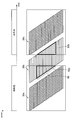
- FIG. 3 is an explanatory diagram showing this problem.
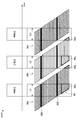
- FIG. 3 shows the time relationship between the exposure timing of the image sensor and the period during which the special light and the white light are respectively irradiated for each frame 30 according to a known technique.
- a frame in which two colors of special light and white light are mixed is generated in some lines 90 in the image sensor.
- the CCU 139 has been created with the above circumstances taken into consideration.
- the CCU 139 determines a period according to the exposure start timing of the lowest line in the image sensor and the exposure end timing of the uppermost line in the image sensor as an irradiation period for irradiating the light source device 143 with light. To do.
- the highest line is an example of the second line in the present disclosure
- the lowest line is an example of the first line in the present disclosure.
- the uppermost line is a line whose exposure starts earlier than the lowermost line in each frame.
- FIG. 4 is a functional block diagram showing a configuration example of the CCU 139 according to the present embodiment.
- the CCU 139 includes a signal processing unit 200, a synchronization control unit 204, and a light source control unit 206.
- the signal processing unit 200 includes a detection unit 202.
- the detection unit 202 is an example of a line determination unit in the present disclosure.
- the detection unit 202 determines the highest line and the lowest line in the imaging device of the imaging unit 109 based on a predetermined reference.
- the predetermined reference may include zoom information (such as zoom magnification) specified by the user.
- the detection unit 202 determines the line numbers of the highest line and the lowest line based on the designated zoom information. For example, when the zoom magnification is increased, the detection unit 202 determines each line number so that the interval between the uppermost line and the lowermost line becomes narrower.
- the detection unit 202 may specify the display area in the image sensor based on the designated zoom information, and may determine the highest line and the lowest line based on the specified display area.
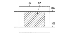
- FIG. 5A is an explanatory diagram showing an example of determining the highest line and the lowest line based on the display area 32 specified in the image sensor 40.
- the detection unit 202 determines the upper end of the display area 32 (or a line above the upper end by a predetermined line) as the uppermost line 300 and the lower end of the display area 32. (Or a line below the lower end by a predetermined line) is determined as the lowest line 302.
- the predetermined reference may include scope information of the endoscope 101.
- the scope information may include, for example, information on the ID of the lens barrel 103, the size of the diameter of the lens barrel 103, and / or the shape of the lens barrel 103.
- the detection unit 202 determines each line number so that the interval between the uppermost line and the lowermost line becomes wider as the diameter of the lens barrel 103 is larger.
- the predetermined reference may include information on a mask area in an image captured by the imaging unit 109.
- the mask area is an area (an area corresponding to the vignetting range) around the effective area in the image captured by the imaging unit 109.
- the image to be captured is an image of a surgical site in the body cavity of the patient 171
- the mask area is an area where no in-vivo video is shown, such as the left, right, top and bottom edges of the image.
- the detection unit 202 determines the highest line and the lowest line based on the boundary between the mask area and the effective area.
- FIG. 5B is an explanatory diagram showing an example of determining the highest line and the lowest line based on the mask area information.
- the detection unit 202 first specifies the effective region 34 in the image sensor 40 based on the mask region information. Then, the detection unit 202 determines the upper limit of the identified effective area 34 as the uppermost line 300 and determines the lower limit of the effective area 34 as the lowermost line 302.
- the mask area information may be specified by applying a predetermined image processing technique to an image picked up by the image pickup unit 109, or specified based on scope information of the endoscope 101. Also good. In the latter case, for example, the detection unit 202 may specify the mask region information by specifying the diameter of the lens barrel 103 corresponding to the scope ID of the endoscope 101, or the mask region information is It is registered in the table in association with the scope information, and the detection unit 202 may specify the mask area information using this table.
- the detection unit 202 may determine the highest line and the lowest line based on only one of the predetermined criteria described above, or any two or more of the predetermined criteria described above. The most significant line and the least significant line may be determined based on.
- the detection unit 202 can change the uppermost line and the lowermost line based on a change in the value indicated by the predetermined reference. For example, when it is determined that the zoom magnification has changed, the detection unit 202 changes the highest line and the lowest line based on the zoom magnification after the change. In addition, the detection part 202 can monitor whether the value which the predetermined reference
- the detection unit 202 can perform detection processing on the image signal for performing AE, AF, and AWB.
- the synchronization control unit 204 performs control for synchronizing the timing between the camera head 105 and the light source device 143.
- the synchronization control unit 204 provides a synchronization signal to the camera head 105 and the light source control unit 206.
- This synchronization signal may be a signal that indicates the exposure start timing of the first line in the image sensor in the corresponding frame.
- the light source control unit 206 determines an irradiation period for irradiating light to the light source device 143 based on the synchronization signal provided from the synchronization control unit 204, the highest line determined by the detection unit 202, and the lowest line. . More specifically, the light source control unit 206 determines a period corresponding to the exposure start timing of the lowest line and the exposure end timing of the highest line as the irradiation period.
- the exposure end timing of the uppermost line is the timing when the length of the exposure time of the uppermost line has elapsed from the exposure start timing of the uppermost line.
- FIG. 6 is an explanatory diagram showing an example of determining the illumination period L.
- the synchronization signal V shown in FIG. 6 can be provided for each frame by the synchronization control unit 204 as described above.
- the line exposure start signal H is a signal that instructs the start of exposure of each line. As shown in FIG. 6, the line exposure start signal H can be sequentially output for each line with a predetermined time delay from the synchronization signal V of the corresponding frame.
- the output start signal output timing of the uppermost line 300 is described as t1
- the output start signal output timing of the lowermost line 302 is described as b1.
- the light source control unit 206 can determine the length of the irradiation period of each frame to be the same as the length of the irradiation period calculated first.
- the light source control unit 206 recalculates the irradiation period based on the changed highest line and the changed lowest line.
- the light source control unit 206 causes the light source device 143 to irradiate light for the length of the determined irradiation period from the exposure start timing of the lowest line for each frame. In addition, the light source control unit 206 does not cause the light source device 143 to emit light during a period other than the irradiation period. For example, the light source control unit 206 transmits to the light source device 143 an irradiation start signal instructing to start light irradiation at the exposure start timing of the lowest line for each frame, and the exposure end timing of the highest line. To the light source device 143 is transmitted to the light source device 143. According to this control example, since the same amount of light is irradiated on each line in the imaging range (that is, the line between the highest line and the lowest line), the amount of light received differs from line to line. Can be prevented.
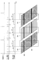
- FIG. 7 is an explanatory diagram showing an example of light irradiation control by the light source control unit 206.
- the light source control unit 206 irradiates the light source device 143 with white light and special light alternately for each frame, that is, performs surface sequential irradiation. Further, as shown in FIG. 7, the light source control unit 206 shortens the length of the irradiation period for each irradiation, and more than the known technique as shown in FIG.
- the light source device 143 is irradiated with white light and special light with high intensity. Thereby, it is possible to prevent white light and special light from being mixed in the imaging range while ensuring a sufficient exposure amount.
- the light source device 143 needs to be a type of light source that can switch the type of irradiation light at a high speed, for example, on the order of several milliseconds. Therefore, as shown in FIG. 8, the light source device 143 needs to use, for example, a laser light source or an LED instead of a xenon light source.
- the light source device 143 is more preferably a laser light source. In this case, as shown in FIG. 8, the light source device 143 can irradiate the observation target with light without unevenness even if the irradiation period is short.
- the camera head 105 can output only the data imaged in the imaging range to the subsequent signal processing.
- the light source control unit 206 can cause the light source device 143 to emit only white light in each frame (instead of the surface sequential irradiation).
- the following two effects can be obtained.
- the observation object is continuously irradiated with white light, the same effect as the flash photography can be obtained.
- the irradiation time is shortened because white light is irradiated with a limited line. And the effect of avoiding the risk of burns is also obtained.
- a clearer image with less motion blur can be taken (compared to the case where no white light is irradiated).
- the signal processing unit 200 performs various types of image processing on the image signal transmitted from the camera head 105 based on the highest line and the lowest line determined by the detection unit 202. For example, the signal processing unit 200 first determines an image processing range from the highest line to the lowest line in the image sensor. Then, the signal processing unit 200 extracts only the image signal corresponding to the determined image processing range from the image signals transmitted from the camera head 105, and performs various types of image processing on the extracted image signal. .
- the image processing includes various known signal processing such as development processing and high image quality processing (band enhancement processing, super-resolution processing, NR (Noise reduction) processing and / or camera shake correction processing), for example. .
- the signal processing unit 200 can perform a process of superimposing the special light captured image and the white light captured image. As a result, an image in which the special light captured image and the white light captured image are superimposed can be displayed on the display device 141.
- FIG. 9 is a flowchart showing an operation example according to the present embodiment. The operation shown in FIG. 9 is executed for each frame.
- the detection unit 202 of the CCU 139 monitors whether or not the uppermost line or the lowermost line in the imaging device of the imaging unit 109 should be changed based on a change in a predetermined reference value. (S101). When it is determined that the highest line and the lowest line should not be changed (S101: No), the CCU 139 performs the process of S109 described later.
- the detection unit 202 has a predetermined reference. Based on (for example, zoom magnification and scope information), the highest line and the lowest line are changed (S103).
- the synchronization control unit 204 provides a synchronization signal to the camera head 105 and the light source control unit 206. Then, the light source control unit 206 identifies the exposure start timing of the highest line and the exposure start timing of the lowest line changed in S103 based on the provided synchronization signal. Then, the light source control unit 206 determines the irradiation period based on the exposure start timing of the uppermost line, the exposure start timing of the lowermost line, and the length of the exposure time (for each line) (S105), and The period is changed to the determined period (S107).
- the imaging unit 109 of the camera head 105 starts exposure based on the provided synchronization signal. Further, the light source control unit 206 causes the light source device 143 to irradiate light (white light or special light) different from the previous frame based on the provided synchronization signal. Thereafter, the camera head 105 transmits the image signal obtained by the imaging unit 109 to the CCU 139 (S109).
- the signal processing unit 200 changes the current image processing range to a range from the highest line to the lowest line changed in S103 (S111).
- the signal processing unit 200 extracts an image signal corresponding to the image processing range set in S111 from the image signal received in S109, and performs various images on the extracted image signal. Processing is performed (S113).
- the CCU 139 has a period between the exposure start timing of the lowest line in the image sensor of the imaging unit 109 and the exposure end timing of the highest line in the image sensor. Is determined as an irradiation period during which the light source device 143 is irradiated with light. For this reason, it is possible to determine an appropriate irradiation period in a scene where light is irradiated during imaging using an imaging element having a rolling shutter mechanism.
- the CCU 139 alternately irradiates the light source device 143 with white light and special light for each frame, and irradiates the light source device 143 with light only during the irradiation period for each frame.
- the generation of mixed color frames can be prevented, so that a decrease in frame rate can be prevented.
- the light source device 143 can be constituted by a laser light source. For this reason, the type of irradiation light can be switched at high speed, and even when the irradiation period is short, light with no unevenness can be irradiated to the observation target. For example, it is possible to prevent the exposure amount from varying between frames.
- the technology according to the present disclosure can be applied to various products.
- the technology according to the present disclosure may be applied to a microscopic surgery system used for so-called microsurgery performed while magnifying and observing a fine part of a patient.
- FIG. 10 is a diagram illustrating an example of a schematic configuration of a microscopic surgery system 5300 to which the technology according to the present disclosure can be applied.
- the microscope operation system 5300 includes a microscope device 5301, a control device 5317, and a display device 5319.
- “user” means any medical staff who uses the microscope surgery system 5300, such as an operator and an assistant.
- the microscope apparatus 5301 includes a microscope unit 5303 for magnifying and observing an observation target (a patient's surgical site), an arm unit 5309 that supports the microscope unit 5303 at the distal end, and a base unit 5315 that supports the proximal end of the arm unit 5309. Have.
- the microscope unit 5303 includes a substantially cylindrical cylindrical part 5305, an imaging unit (not shown) provided inside the cylindrical part 5305, and an operation unit 5307 provided in a partial area on the outer periphery of the cylindrical part 5305. And.
- the microscope unit 5303 is an electronic imaging type microscope unit (so-called video type microscope unit) in which a captured image is electronically captured by the imaging unit.
- a cover glass that protects the internal imaging unit is provided on the opening surface at the lower end of the cylindrical part 5305.
- Light from the observation target (hereinafter also referred to as observation light) passes through the cover glass and enters the imaging unit inside the cylindrical part 5305.
- a light source such as an LED (Light Emitting Diode) may be provided inside the cylindrical portion 5305, and light is emitted from the light source to the observation target through the cover glass during imaging. May be.
- the imaging unit includes an optical system that collects the observation light and an image sensor that receives the observation light collected by the optical system.
- the optical system is configured by combining a plurality of lenses including a zoom lens and a focus lens, and the optical characteristics thereof are adjusted so that the observation light is imaged on the light receiving surface of the image sensor.
- the imaging element receives the observation light and photoelectrically converts it to generate a signal corresponding to the observation light, that is, an image signal corresponding to the observation image.
- an element having a Bayer array capable of color photography is used.
- the image sensor may be various known image sensors such as a CMOS (Complementary Metal Oxide Semiconductor) image sensor or a CCD (Charge Coupled Device) image sensor.
- the image signal generated by the image sensor is transmitted to the control device 5317 as RAW data.
- the transmission of the image signal may be preferably performed by optical communication.
- the surgeon performs the operation while observing the state of the affected area with the captured image.
- the moving image of the surgical site should be displayed in real time as much as possible. Because it is.
- a captured image can be displayed with low latency.
- the imaging unit may have a drive mechanism that moves the zoom lens and focus lens of the optical system along the optical axis. By appropriately moving the zoom lens and the focus lens by the drive mechanism, the enlargement magnification of the captured image and the focal length at the time of imaging can be adjusted.
- the imaging unit may be equipped with various functions that can be generally provided in an electronic imaging microscope unit, such as an AE (Auto Exposure) function and an AF (Auto Focus) function.
- the imaging unit may be configured as a so-called single-plate imaging unit having one imaging element, or may be configured as a so-called multi-plate imaging unit having a plurality of imaging elements.
- image signals corresponding to RGB may be generated by each imaging element, and a color image may be obtained by combining them.
- the said imaging part may be comprised so that it may have a pair of image sensor for each acquiring the image signal for right eyes and left eyes corresponding to a stereoscopic vision (3D display). By performing the 3D display, the surgeon can more accurately grasp the depth of the living tissue in the surgical site.
- a plurality of optical systems can be provided corresponding to each imaging element.
- the operation unit 5307 is configured by, for example, a cross lever or a switch, and is an input unit that receives a user operation input.
- the user can input an instruction to change the magnification of the observation image and the focal length to the observation target via the operation unit 5307.
- the magnification ratio and the focal length can be adjusted by appropriately moving the zoom lens and the focus lens by the drive mechanism of the imaging unit in accordance with the instruction.
- the user can input an instruction to switch the operation mode (all-free mode and fixed mode described later) of the arm unit 5309 via the operation unit 5307.
- the operation unit 5307 may be provided at a position where the user can easily operate with a finger while holding the tubular portion 5305 so that the operation portion 5307 can be operated while the tubular portion 5305 is moved. preferable.
- the arm portion 5309 is configured by a plurality of links (first link 5313a to sixth link 5313f) being connected to each other by a plurality of joint portions (first joint portion 5311a to sixth joint portion 5311f). Is done.
- the first joint portion 5311a has a substantially cylindrical shape, and at its tip (lower end), the upper end of the cylindrical portion 5305 of the microscope portion 5303 is a rotation axis (first axis) parallel to the central axis of the cylindrical portion 5305. O 1 ) is supported so as to be rotatable around.
- the first joint portion 5311a may be configured such that the first axis O 1 coincides with the optical axis of the imaging unit of the microscope unit 5303.
- the first link 5313a fixedly supports the first joint portion 5311a at the tip. More specifically, the first link 5313a is a rod-shaped member having a substantially L-shaped, while stretching in the direction in which one side of the front end side is perpendicular to the first axis O 1, the end portion of the one side is first It connects to the 1st joint part 5311a so that it may contact
- the second joint portion 5311b is connected to the end portion on the other side of the substantially L-shaped base end side of the first link 5313a.
- the second joint portion 5311b has a substantially cylindrical shape, and at the tip thereof, the base end of the first link 5313a can be rotated around a rotation axis (second axis O 2 ) orthogonal to the first axis O 1. To support.
- the distal end of the second link 5313b is fixedly connected to the proximal end of the second joint portion 5311b.
- the second link 5313b is a rod-shaped member having a substantially L-shaped, while stretching in the direction in which one side of the front end side is perpendicular to the second axis O 2, the ends of the one side of the second joint portion 5311b Fixedly connected to the proximal end.
- a third joint portion 5311c is connected to the other side of the base end side of the substantially L-shaped base of the second link 5313b.
- the third joint portion 5311c has a substantially cylindrical shape, and at its tip, the base end of the second link 5313b is a rotation axis (third axis O 3) orthogonal to the first axis O 1 and the second axis O 2. ) Support so that it can rotate around.
- the distal end of the third link 5313c is fixedly connected to the proximal end of the third joint portion 5311c.
- the microscope unit 5303 is moved so as to change the position of the microscope unit 5303 in the horizontal plane by rotating the configuration on the distal end side including the microscope unit 5303 around the second axis O 2 and the third axis O 3. Can be made. That is, by controlling the rotation around the second axis O 2 and the third axis O 3 , the field of view of the captured image can be moved in a plane.
- the third link 5313c is configured such that the distal end side thereof has a substantially cylindrical shape, and the proximal end of the third joint portion 5311c has substantially the same central axis at the distal end of the cylindrical shape. Fixedly connected.
- the proximal end side of the third link 5313c has a prismatic shape, and the fourth joint portion 5311d is connected to the end portion thereof.
- the fourth joint portion 5311d has a substantially cylindrical shape, and at the tip thereof, the base end of the third link 5313c can be rotated around a rotation axis (fourth axis O 4 ) orthogonal to the third axis O 3. To support.
- the distal end of the fourth link 5313d is fixedly connected to the proximal end of the fourth joint portion 5311d.
- Fourth link 5313d is a rod-shaped member extending substantially in a straight line, while stretched so as to be orthogonal to the fourth axis O 4, the end of the tip side of the substantially cylindrical shape of the fourth joint portion 5311d It is fixedly connected to the fourth joint portion 5311d so as to abut.
- the fifth joint portion 5311e is connected to the base end of the fourth link 5313d.
- the fifth joint portion 5311e has a substantially cylindrical shape, and on the distal end side thereof, the base end of the fourth link 5313d can be rotated around a rotation axis (fifth axis O 5 ) parallel to the fourth axis O 4. To support.
- the distal end of the fifth link 5313e is fixedly connected to the proximal end of the fifth joint portion 5311e.
- the fourth axis O 4 and the fifth axis O 5 are rotation axes that can move the microscope unit 5303 in the vertical direction.
- the fifth link 5313e includes a first member having a substantially L shape in which one side extends in the vertical direction and the other side extends in the horizontal direction, and a portion extending in the horizontal direction of the first member in a vertically downward direction. A rod-shaped second member that extends is combined.
- the proximal end of the fifth joint portion 5311e is fixedly connected in the vicinity of the upper end of the portion of the fifth link 5313e extending in the vertical direction of the first member.
- the sixth joint portion 5311f is connected to the proximal end (lower end) of the second member of the fifth link 5313e.
- the sixth joint portion 5311f has a substantially cylindrical shape, and supports the base end of the fifth link 5313e on the distal end side thereof so as to be rotatable about a rotation axis (sixth axis O 6 ) parallel to the vertical direction. .
- the distal end of the sixth link 5313f is fixedly connected to the proximal end of the sixth joint portion 5311f.
- the sixth link 5313f is a rod-like member extending in the vertical direction, and its base end is fixedly connected to the upper surface of the base portion 5315.
- the rotatable range of the first joint portion 5311a to the sixth joint portion 5311f is appropriately set so that the microscope portion 5303 can perform a desired movement.
- a total of 6 degrees of freedom of translational 3 degrees of freedom and 3 degrees of freedom of rotation can be realized with respect to the movement of the microscope unit 5303.
- the position and posture of the microscope unit 5303 can be freely controlled within the movable range of the arm unit 5309. It becomes possible. Therefore, the surgical site can be observed from any angle, and the surgery can be performed more smoothly.
- the configuration of the arm portion 5309 shown in the figure is merely an example, and the number and shape (length) of the links constituting the arm portion 5309, the number of joint portions, the arrangement position, the direction of the rotation axis, and the like are desired. It may be designed as appropriate so that the degree can be realized.
- the arm unit 5309 in order to freely move the microscope unit 5303, the arm unit 5309 is preferably configured to have six degrees of freedom, but the arm unit 5309 has a greater degree of freedom (ie, redundant freedom). Degree).
- the arm unit 5309 can change the posture of the arm unit 5309 while the position and posture of the microscope unit 5303 are fixed. Therefore, for example, control that is more convenient for the operator can be realized, such as controlling the posture of the arm unit 5309 so that the arm unit 5309 does not interfere with the field of view of the operator who views the display device 5319.
- the first joint portion 5311a to the sixth joint portion 5311f may be provided with actuators mounted with a drive mechanism such as a motor, an encoder for detecting a rotation angle at each joint portion, and the like. Then, the drive of each actuator provided in the first joint portion 5311a to the sixth joint portion 5311f is appropriately controlled by the control device 5317, whereby the posture of the arm portion 5309, that is, the position and posture of the microscope portion 5303 can be controlled. . Specifically, the control device 5317 grasps the current posture of the arm unit 5309 and the current position and posture of the microscope unit 5303 based on information about the rotation angle of each joint unit detected by the encoder. Can do.
- a drive mechanism such as a motor, an encoder for detecting a rotation angle at each joint portion, and the like.
- the control device 5317 calculates the control value (for example, rotation angle or generated torque) for each joint unit that realizes the movement of the microscope unit 5303 according to the operation input from the user, using the grasped information. And the drive mechanism of each joint part is driven according to the said control value.
- the control method of the arm unit 5309 by the control device 5317 is not limited, and various known control methods such as force control or position control may be applied.
- the drive of the arm unit 5309 is appropriately controlled by the control device 5317 according to the operation input, and the position and posture of the microscope unit 5303 are controlled. May be.
- the microscope unit 5303 can be moved from an arbitrary position to an arbitrary position and then fixedly supported at the position after the movement.
- an input device that can be operated even if the operator has a surgical tool in his / her hand.
- non-contact operation input may be performed based on gesture detection or gaze detection using a wearable device or a camera provided in an operating room.
- the arm portion 5309 may be operated by a so-called master slave method.
- the arm unit 5309 can be remotely operated by the user via an input device installed at a location away from the operating room.
- the actuators of the first joint portion 5311a to the sixth joint portion 5311f are driven so that the external force from the user is received and the arm portion 5309 moves smoothly according to the external force.
- so-called power assist control may be performed.
- the driving of the arm portion 5309 may be controlled so as to perform a pivoting operation.
- the pivoting operation is an operation of moving the microscope unit 5303 so that the optical axis of the microscope unit 5303 always faces a predetermined point in space (hereinafter referred to as a pivot point). According to the pivot operation, the same observation position can be observed from various directions, so that more detailed observation of the affected area is possible.
- the pivot operation is performed in a state where the distance between the microscope unit 5303 and the pivot point is fixed. In this case, the distance between the microscope unit 5303 and the pivot point may be adjusted to a fixed focal length of the microscope unit 5303.
- the microscope unit 5303 moves on a hemispherical surface (schematically illustrated in FIG. 10) having a radius corresponding to the focal length centered on the pivot point, and is clear even if the observation direction is changed. A captured image is obtained.
- the microscope unit 5303 is configured to be adjustable in focal length
- the pivot operation may be performed in a state where the distance between the microscope unit 5303 and the pivot point is variable.
- the control device 5317 calculates the distance between the microscope unit 5303 and the pivot point based on the information about the rotation angle of each joint unit detected by the encoder, and based on the calculation result, the microscope 5317
- the focal length of the unit 5303 may be automatically adjusted.
- the microscope unit 5303 is provided with an AF function
- the focal length may be automatically adjusted by the AF function every time the distance between the microscope unit 5303 and the pivot point is changed by the pivot operation. .
- the first joint portion 5311a to the sixth joint portion 5311f may be provided with a brake that restrains the rotation thereof.
- the operation of the brake can be controlled by the control device 5317.
- the control device 5317 activates the brake of each joint unit. Accordingly, since the posture of the arm unit 5309, that is, the position and posture of the microscope unit 5303 can be fixed without driving the actuator, power consumption can be reduced.
- the control device 5317 may release the brake of each joint unit and drive the actuator according to a predetermined control method.
- Such an operation of the brake can be performed according to an operation input by the user via the operation unit 5307 described above.
- the user wants to move the position and posture of the microscope unit 5303, the user operates the operation unit 5307 to release the brakes of the joint units.
- the operation mode of the arm part 5309 shifts to a mode (all free mode) in which the rotation at each joint part can be freely performed.
- the user wants to fix the position and posture of the microscope unit 5303, the user operates the operation unit 5307 to activate the brakes of the joint units.
- the operation mode of the arm part 5309 shifts to a mode (fixed mode) in which rotation at each joint part is restricted.
- the control device 5317 comprehensively controls the operation of the microscope operation system 5300 by controlling the operations of the microscope device 5301 and the display device 5319.
- the control device 5317 controls the driving of the arm portion 5309 by operating the actuators of the first joint portion 5311a to the sixth joint portion 5311f according to a predetermined control method.
- the control device 5317 changes the operation mode of the arm portion 5309 by controlling the brake operation of the first joint portion 5311a to the sixth joint portion 5311f.
- the control device 5317 performs various kinds of signal processing on the image signal acquired by the imaging unit of the microscope unit 5303 of the microscope device 5301 to generate image data for display and display the image data. It is displayed on the device 5319.
- the signal processing for example, development processing (demosaic processing), high image quality processing (band enhancement processing, super-resolution processing, NR (Noise reduction) processing and / or camera shake correction processing, etc.) and / or enlargement processing (that is, Various known signal processing such as electronic zoom processing may be performed.
- communication between the control device 5317 and the microscope unit 5303 and communication between the control device 5317 and the first joint unit 5311a to the sixth joint unit 5311f may be wired communication or wireless communication.
- wired communication communication using electrical signals may be performed, or optical communication may be performed.
- a transmission cable used for wired communication can be configured as an electric signal cable, an optical fiber, or a composite cable thereof depending on the communication method.
- wireless communication there is no need to lay a transmission cable in the operating room, so that the situation where the transmission cable prevents the medical staff from moving in the operating room can be eliminated.
- the control device 5317 may be a processor such as a CPU (Central Processing Unit) or a GPU (Graphics Processing Unit), or a microcomputer or a control board in which a processor and a storage element such as a memory are mixedly mounted.
- the various functions described above can be realized by the processor of the control device 5317 operating according to a predetermined program.
- the control device 5317 is provided as a separate device from the microscope device 5301, but the control device 5317 is installed inside the base portion 5315 of the microscope device 5301 and integrated with the microscope device 5301. May be configured.
- the control device 5317 may be configured by a plurality of devices.
- a microcomputer, a control board, and the like are arranged in the microscope unit 5303 and the first joint unit 5311a to the sixth joint unit 5311f of the arm unit 5309, and these are communicably connected to each other. Similar functions may be realized.
- the display device 5319 is provided in the operating room, and displays an image corresponding to the image data generated by the control device 5317 under the control of the control device 5317. In other words, the display device 5319 displays an image of the surgical part taken by the microscope unit 5303.
- the display device 5319 may display various types of information related to the surgery, such as information about the patient's physical information and the surgical technique, for example, instead of or together with the image of the surgical site. In this case, the display of the display device 5319 may be switched as appropriate by a user operation.
- a plurality of display devices 5319 may be provided, and each of the plurality of display devices 5319 may display an image of the surgical site and various types of information regarding surgery.
- various known display devices such as a liquid crystal display device or an EL (Electro Luminescence) display device may be applied.
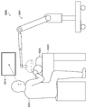
- FIG. 11 is a diagram showing a state of surgery using the microscope surgery system 5300 shown in FIG.
- a state in which an operator 5321 performs an operation on a patient 5325 on a patient bed 5323 using a microscope operation system 5300 is schematically shown.
- the control device 5317 is omitted from the configuration of the microscope surgery system 5300 and the microscope device 5301 is illustrated in a simplified manner.
- an image of the surgical part taken by the microscope apparatus 5301 is enlarged and displayed on the display device 5319 installed on the wall of the operating room using the microscope operation system 5300.
- the display device 5319 is installed at a position facing the surgeon 5321, and the surgeon 5321 observes the state of the surgical site by an image projected on the display device 5319, for example, the surgical site such as excision of the affected site.
- Various treatments are performed on
- the microscopic surgery system 5300 to which the technology according to the present disclosure can be applied has been described.
- the microscopic surgery system 5300 has been described as an example, but a system to which the technology according to the present disclosure can be applied is not limited to such an example.
- the microscope apparatus 5301 can function as a support arm apparatus that supports another observation apparatus or another surgical tool instead of the microscope unit 5303 at the tip.
- an endoscope can be applied.
- the other surgical tools forceps, a lever, an insufflation tube for insufflation, or an energy treatment instrument for incising a tissue or sealing a blood vessel by cauterization can be applied.
- the technology according to the present disclosure may be applied to a support arm device that supports a configuration other than the microscope unit.
- the configuration according to the present embodiment is not limited to the example shown in FIG.
- the light source control unit 206 may be provided in the light source device 143 instead of the CCU 139.
- the CCU 139 can provide the determined line numbers of the highest line and the lowest line to the light source device 143.
- the light source device 143 (the light source control unit 206 in the light source device 143) can control light irradiation based on the provided line numbers of the uppermost line and the lowermost line.
- each step in the operation of the above-described embodiment does not necessarily have to be processed in the order described.
- the steps may be processed by changing the order as appropriate.
- Each step may be processed in parallel or individually instead of being processed in time series. Further, some of the described steps may be omitted, or another step may be further added.
- hardware such as processors, such as CPU and GPU, and memory elements, such as a memory, is made to exhibit a function equivalent to each structure of CCU139 by this embodiment mentioned above.
- a computer program can also be provided.
- a recording medium on which the computer program is recorded is also provided.
- a light source control unit that determines a period according to the exposure start timing of the first line in the image sensor and the exposure end timing of the second line in the image sensor as an irradiation period for irradiating the light source unit with light; With The control device, wherein the second line is a line whose exposure start in one frame is earlier than the first line.
- the light source control unit determines a period between an exposure start timing of the first line and an exposure end timing of the second line as the irradiation period.
- the exposure end timing of the second line is a timing at which an exposure time of the second line has elapsed from an exposure start timing of the second line.
- the light source control unit determines the length of the irradiation period for each frame to be the same length.
- the control device further includes a line determination unit that determines the first line and the second line based on a predetermined criterion. apparatus.
- the line determination unit changes the first line or the second line based on a change in a value indicated by the predetermined criterion, When the first line or the second line is changed, the light source control unit determines the length of the irradiation period based on the changed first line and the changed second line.
- the predetermined reference includes scope information of an endoscope having the imaging element.
- the control device according to any one of (5) to (8), wherein the predetermined reference includes information on a mask region in an image captured by an imaging unit having the imaging element.
- the information on the mask area is specified based on scope information of an endoscope including the imaging unit.
- the information on the mask area is specified by predetermined image processing on an image captured by the imaging unit.
- the light source control unit further causes the light source unit to emit light during the irradiation period for each frame.
- the light source control unit does not cause the light source unit to emit light during a period other than the irradiation period.
- the control device (14) The control device according to (13), wherein the light source control unit causes the light source unit to alternately emit the first light and the second light for each frame.
- the first light is white light;
- the control device (14), wherein the second light is special light.
- the said light source control part is a control apparatus as described in said (13) which irradiates the same kind of light to the said light source part for every flame
- the control device according to any one of (1) to (17), wherein the light source unit is a semiconductor light source.
- a light source unit An imaging unit; An irradiation period for irradiating the light source unit with light during a period corresponding to the exposure start timing of the first line in the image sensor included in the image sensor and the exposure end timing of the second line in the image sensor
- a light source control unit determined as: With The control system in which the second line is a line whose exposure start in one frame is earlier than the first line. (20) The processor determines a period corresponding to the exposure start timing of the first line in the image sensor and the exposure end timing of the second line in the image sensor as an irradiation period for irradiating the light source unit with light; Including The control method, wherein the second line is a line whose exposure start in one frame is earlier than the first line.
Abstract
[Problem] To provide a control device, a control system, and a control method that can suitably determine an irradiation period in setting in which light emission occurs simultaneously with imaging. [Solution] A control device that comprises a light source control unit to determine that a period corresponding to the interval between when a first line exposure starts in an imaging element and when a second line exposure ends in the imaging element is an irradiation period in which light is emitted from a light source unit, wherein the second line is the line for which exposure in a frame starts earlier than the first line.
Description
本開示は、制御装置、制御システム、および制御方法に関する。
The present disclosure relates to a control device, a control system, and a control method.
従来、例えばCMOS(Complementary Metal Oxide Semiconductor)などの、ローリングシャッター機構を有する撮像素子が広く普及している。このような撮像素子における画素読み出しは、例えばラインごとに所定時間ずつ遅れて実行される。
Conventionally, image sensors having a rolling shutter mechanism such as CMOS (Complementary Metal Oxide Semiconductor) have been widely used. Such pixel readout in the image sensor is executed with a delay of a predetermined time for each line, for example.
また、下記特許文献1には、撮像と同時に光源部に光を照射させる技術が記載されている。
Further, Patent Document 1 below describes a technique for irradiating light to a light source unit simultaneously with imaging.
しかしながら、特許文献1には、照射期間の長さの決定方法が開示されていない。このため、特許文献1に記載の技術では、照射期間の長さが不適切に設定される恐れがある。
However, Patent Document 1 does not disclose a method for determining the length of the irradiation period. For this reason, in the technique described in Patent Document 1, the length of the irradiation period may be set inappropriately.
そこで、本開示では、撮像と同時に光を照射させる場面において、照射期間を適切に決定することが可能な、新規かつ改良された制御装置、制御システム、および制御方法を提案する。
Therefore, the present disclosure proposes a new and improved control device, control system, and control method capable of appropriately determining an irradiation period in a scene where light is irradiated simultaneously with imaging.
本開示によれば、撮像素子における第1のラインの露光開始タイミングと、前記撮像素子における第2のラインの露光終了タイミングとの間に応じた期間を、光源部に光を照射させる照射期間として決定する光源制御部、を備え、前記第2のラインは、一枚のフレームにおける露光の開始が前記第1のラインよりも早いラインである、制御装置が提供される。
According to the present disclosure, a period according to the exposure start timing of the first line in the image sensor and the exposure end timing of the second line in the image sensor is an irradiation period in which the light source unit is irradiated with light. And a light source control unit for determining, wherein the second line is a line whose exposure start in one frame is earlier than the first line.
また、本開示によれば、光源部と、撮像部と、前記撮像部に含まれる撮像素子における第1のラインの露光開始タイミングと、前記撮像素子における第2のラインの露光終了タイミングとの間に応じた期間を、前記光源部に光を照射させる照射期間として決定する光源制御部と、を備え、前記第2のラインは、一枚のフレームにおける露光の開始が前記第1のラインよりも早いラインである、制御システムが提供される。
Further, according to the present disclosure, between the light source unit, the imaging unit, the exposure start timing of the first line in the imaging device included in the imaging unit, and the exposure end timing of the second line in the imaging device. A light source control unit that determines a period according to the irradiation period for irradiating the light source unit with light, and the second line is more sensitive to the start of exposure in one frame than the first line. A control system is provided that is an early line.
また、本開示によれば、撮像素子における第1のラインの露光開始タイミングと、前記撮像素子における第2のラインの露光終了タイミングとの間に応じた期間を、光源部に光を照射させる照射期間としてプロセッサが決定すること、を含み、前記第2のラインは、一枚のフレームにおける露光の開始が前記第1のラインよりも早いラインである、制御方法が提供される。
In addition, according to the present disclosure, irradiation for irradiating the light source unit with light for a period between the exposure start timing of the first line in the image sensor and the exposure end timing of the second line in the image sensor. A control method is provided in which the second line is a line whose exposure start in one frame is earlier than the first line.
以上説明したように本開示によれば、撮像と同時に光を照射させる場面において、照射期間を適切に決定することができる。なお、ここに記載された効果は必ずしも限定されるものではなく、本開示中に記載されたいずれかの効果であってもよい。
As described above, according to the present disclosure, it is possible to appropriately determine an irradiation period in a scene where light is irradiated simultaneously with imaging. Note that the effects described here are not necessarily limited, and may be any of the effects described in the present disclosure.
以下に添付図面を参照しながら、本開示の好適な実施の形態について詳細に説明する。なお、本明細書及び図面において、実質的に同一の機能構成を有する構成要素については、同一の符号を付することにより重複説明を省略する。
Hereinafter, preferred embodiments of the present disclosure will be described in detail with reference to the accompanying drawings. In addition, in this specification and drawing, about the component which has the substantially same function structure, duplication description is abbreviate | omitted by attaching | subjecting the same code | symbol.
また、本明細書及び図面において、実質的に同一の機能構成を有する複数の構成要素を、同一の符号の後に異なるアルファベットを付して区別する場合もある。例えば、実質的に同一の機能構成を有する複数の構成を、必要に応じて内視鏡101aおよび内視鏡101bのように区別する。ただし、実質的に同一の機能構成を有する複数の構成要素の各々を特に区別する必要がない場合、同一符号のみを付する。例えば、内視鏡101aおよび内視鏡101bを特に区別する必要が無い場合には、単に内視鏡101と称する。
In the present specification and drawings, a plurality of constituent elements having substantially the same functional configuration may be distinguished by adding different alphabets after the same reference numeral. For example, a plurality of configurations having substantially the same functional configuration are distinguished as necessary, such as an endoscope 101a and an endoscope 101b. However, when it is not necessary to particularly distinguish each of a plurality of constituent elements having substantially the same functional configuration, only the same reference numerals are given. For example, when there is no need to particularly distinguish the endoscope 101a and the endoscope 101b, they are simply referred to as the endoscope 101.
また、以下に示す項目順序に従って当該「発明を実施するための形態」を説明する。
1.制御システムの構成
2.実施形態の詳細な説明
3.応用例
4.変形例 Further, the “DETAILED DESCRIPTION OF THE INVENTION” will be described according to the following item order.
1. 1. Configuration of control system 2. Detailed Description of Embodiments Application example 4. Modified example
1.制御システムの構成
2.実施形態の詳細な説明
3.応用例
4.変形例 Further, the “DETAILED DESCRIPTION OF THE INVENTION” will be described according to the following item order.
1. 1. Configuration of control system 2. Detailed Description of Embodiments Application example 4. Modified example
<<1.制御システムの構成>>
本開示の実施形態による制御システムは、例えば内視鏡手術システム10など、多様なシステムに適用され得る。以下では、当該制御システムが、内視鏡手術システム10に適用される例を中心として説明する。 << 1. Control system configuration >>
The control system according to the embodiment of the present disclosure can be applied to various systems such as theendoscopic surgery system 10. Hereinafter, an example in which the control system is applied to the endoscopic surgery system 10 will be mainly described.
本開示の実施形態による制御システムは、例えば内視鏡手術システム10など、多様なシステムに適用され得る。以下では、当該制御システムが、内視鏡手術システム10に適用される例を中心として説明する。 << 1. Control system configuration >>
The control system according to the embodiment of the present disclosure can be applied to various systems such as the
図1は、内視鏡手術システム10の概略的な構成の一例を示す図である。図1では、術者(医師)167が、内視鏡手術システム10を用いて、患者ベッド169上の患者171に手術を行っている様子が図示されている。図示するように、内視鏡手術システム10は、内視鏡101と、その他の術具117と、内視鏡101を支持する支持アーム装置127と、内視鏡下手術のための各種の装置が搭載されたカート137と、から構成される。
FIG. 1 is a diagram illustrating an example of a schematic configuration of an endoscopic surgery system 10. In FIG. 1, a state in which an operator (doctor) 167 performs an operation on a patient 171 on a patient bed 169 using the endoscopic operation system 10 is illustrated. As shown in the figure, an endoscopic surgery system 10 includes an endoscope 101, other surgical tools 117, a support arm device 127 that supports the endoscope 101, and various devices for endoscopic surgery. And a cart 137 on which is mounted.
内視鏡手術では、腹壁を切って開腹する代わりに、トロッカ125a~125dと呼ばれる筒状の開孔器具が腹壁に複数穿刺される。そして、トロッカ125a~125dから、内視鏡101の鏡筒103や、その他の術具117が患者171の体腔内に挿入される。図示する例では、その他の術具117として、気腹チューブ119、エネルギー処置具121及び鉗子123が、患者171の体腔内に挿入されている。また、エネルギー処置具121は、高周波電流や超音波振動により、組織の切開及び剥離、又は血管の封止等を行う処置具である。ただし、図示する術具117はあくまで一例であり、術具117としては、例えば攝子、レトラクタ等、一般的に内視鏡下手術において用いられる各種の術具が用いられてよい。
In endoscopic surgery, instead of cutting and opening the abdominal wall, a plurality of cylindrical opening devices called trocars 125a to 125d are punctured into the abdominal wall. Then, the lens barrel 103 of the endoscope 101 and other surgical tools 117 are inserted into the body cavity of the patient 171 from the trocars 125a to 125d. In the illustrated example, as other surgical tools 117, an insufflation tube 119, an energy treatment tool 121, and forceps 123 are inserted into the body cavity of the patient 171. The energy treatment device 121 is a treatment device that performs incision and peeling of a tissue, sealing of a blood vessel, or the like by a high-frequency current or ultrasonic vibration. However, the illustrated surgical tool 117 is merely an example, and as the surgical tool 117, various surgical tools generally used in endoscopic surgery, such as a lever and a retractor, may be used.
内視鏡101によって撮影された患者171の体腔内の術部の画像が、表示装置141に表示される。術者167は、表示装置141に表示された術部の画像をリアルタイムで見ながら、エネルギー処置具121や鉗子123を用いて、例えば患部を切除する等の処置を行う。なお、図示は省略しているが、気腹チューブ119、エネルギー処置具121及び鉗子123は、手術中に、術者167又は助手等によって支持される。
The image of the surgical site in the body cavity of the patient 171 captured by the endoscope 101 is displayed on the display device 141. The surgeon 167 performs a treatment such as excision of the affected part using the energy treatment tool 121 and the forceps 123 while viewing the image of the surgical part displayed on the display device 141 in real time. Although not shown, the pneumoperitoneum tube 119, the energy treatment device 121, and the forceps 123 are supported by an operator 167 or an assistant during the operation.
<1-1.支持アーム装置>
支持アーム装置127は、ベース部129から延伸するアーム部131を備える。図示する例では、アーム部131は、関節部133a、133b、133c、及びリンク135a、135bから構成されており、アーム制御装置145からの制御により駆動される。アーム部131によって内視鏡101が支持され、その位置及び姿勢が制御される。これにより、内視鏡101の安定的な位置の固定が実現され得る。 <1-1. Support arm device>
Thesupport arm device 127 includes an arm portion 131 extending from the base portion 129. In the illustrated example, the arm unit 131 includes joint units 133a, 133b, and 133c and links 135a and 135b, and is driven by control from the arm control device 145. The endoscope 101 is supported by the arm part 131, and its position and posture are controlled. Thereby, the stable position fixing of the endoscope 101 can be realized.
支持アーム装置127は、ベース部129から延伸するアーム部131を備える。図示する例では、アーム部131は、関節部133a、133b、133c、及びリンク135a、135bから構成されており、アーム制御装置145からの制御により駆動される。アーム部131によって内視鏡101が支持され、その位置及び姿勢が制御される。これにより、内視鏡101の安定的な位置の固定が実現され得る。 <1-1. Support arm device>
The
<1-2.内視鏡>
内視鏡101は、先端から所定の長さの領域が患者171の体腔内に挿入される鏡筒103と、鏡筒103の基端に接続されるカメラヘッド105と、から構成される。図示する例では、硬性の鏡筒103を有するいわゆる硬性鏡として構成される内視鏡101を図示しているが、内視鏡101は、軟性の鏡筒103を有するいわゆる軟性鏡として構成されてもよい。 <1-2. Endoscope>
Theendoscope 101 includes a lens barrel 103 in which a region having a predetermined length from the distal end is inserted into the body cavity of the patient 171, and a camera head 105 connected to the proximal end of the lens barrel 103. In the illustrated example, an endoscope 101 configured as a so-called rigid mirror having a rigid barrel 103 is illustrated, but the endoscope 101 is configured as a so-called flexible mirror having a flexible barrel 103. Also good.
内視鏡101は、先端から所定の長さの領域が患者171の体腔内に挿入される鏡筒103と、鏡筒103の基端に接続されるカメラヘッド105と、から構成される。図示する例では、硬性の鏡筒103を有するいわゆる硬性鏡として構成される内視鏡101を図示しているが、内視鏡101は、軟性の鏡筒103を有するいわゆる軟性鏡として構成されてもよい。 <1-2. Endoscope>
The
鏡筒103の先端には、対物レンズが嵌め込まれた開口部が設けられている。内視鏡101には光源装置143が接続されており、当該光源装置143によって生成された光が、鏡筒103の内部に延設されるライトガイドによって当該鏡筒の先端まで導光され、対物レンズを介して患者171の体腔内の観察対象に向かって照射される。なお、内視鏡101は、直視鏡であってもよいし、斜視鏡又は側視鏡であってもよい。
An opening into which an objective lens is fitted is provided at the tip of the lens barrel 103. A light source device 143 is connected to the endoscope 101, and light generated by the light source device 143 is guided to the tip of the lens barrel by a light guide extending inside the lens barrel 103, and the objective 101 Irradiation is performed toward the observation target in the body cavity of the patient 171 through the lens. The endoscope 101 may be a direct endoscope, a perspective mirror, or a side endoscope.
カメラヘッド105の内部には光学系及び撮像素子が設けられており、観察対象からの反射光(観察光)は当該光学系によって当該撮像素子に集光される。当該撮像素子によって観察光が光電変換され、観察光に対応する電気信号、すなわち観察像に対応する画像信号が生成される。当該画像信号は、RAWデータとしてカメラコントロールユニット(CCU:Camera Control Unit)139に送信される。なお、カメラヘッド105には、その光学系を適宜駆動させることにより、倍率及び焦点距離を調整する機能が搭載される。
An optical system and an image sensor are provided inside the camera head 105, and reflected light (observation light) from the observation target is condensed on the image sensor by the optical system. Observation light is photoelectrically converted by the imaging element, and an electrical signal corresponding to the observation light, that is, an image signal corresponding to the observation image is generated. The image signal is transmitted to a camera control unit (CCU: Camera Control Unit) 139 as RAW data. The camera head 105 has a function of adjusting the magnification and the focal length by appropriately driving the optical system.
なお、例えば立体視(3D表示)等に対応するために、カメラヘッド105には撮像素子が複数設けられてもよい。この場合、鏡筒103の内部には、当該複数の撮像素子のそれぞれに観察光を導光するために、リレー光学系が複数系統設けられる。
Note that a plurality of image sensors may be provided in the camera head 105 in order to cope with, for example, stereoscopic viewing (3D display). In this case, a plurality of relay optical systems are provided inside the lens barrel 103 in order to guide the observation light to each of the plurality of imaging elements.
<1-3.カートに搭載される各種の装置>
CCU139は、本開示における制御装置の一例である。CCU139は、CPU(Central Processing Unit)やGPU(Graphics Processing Unit)等によって構成され、内視鏡101及び表示装置141の動作を統括的に制御する。具体的には、CCU139は、カメラヘッド105から受け取った画像信号に対して、例えば現像処理(デモザイク処理)等の、当該画像信号に基づく画像を表示するための各種の画像処理を施す。CCU139は、当該画像処理を施した画像信号を表示装置141に提供する。また、CCU139は、カメラヘッド105に対して制御信号を送信し、その駆動を制御する。当該制御信号には、倍率や焦点距離等、撮像条件に関する情報が含まれ得る。 <1-3. Various devices mounted on cart>
TheCCU 139 is an example of a control device according to the present disclosure. The CCU 139 is configured by a CPU (Central Processing Unit), a GPU (Graphics Processing Unit), and the like, and comprehensively controls operations of the endoscope 101 and the display device 141. Specifically, the CCU 139 performs various types of image processing for displaying an image based on the image signal, such as development processing (demosaic processing), for example, on the image signal received from the camera head 105. The CCU 139 provides the display device 141 with the image signal subjected to the image processing. Further, the CCU 139 transmits a control signal to the camera head 105 to control the driving thereof. The control signal can include information regarding imaging conditions such as magnification and focal length.
CCU139は、本開示における制御装置の一例である。CCU139は、CPU(Central Processing Unit)やGPU(Graphics Processing Unit)等によって構成され、内視鏡101及び表示装置141の動作を統括的に制御する。具体的には、CCU139は、カメラヘッド105から受け取った画像信号に対して、例えば現像処理(デモザイク処理)等の、当該画像信号に基づく画像を表示するための各種の画像処理を施す。CCU139は、当該画像処理を施した画像信号を表示装置141に提供する。また、CCU139は、カメラヘッド105に対して制御信号を送信し、その駆動を制御する。当該制御信号には、倍率や焦点距離等、撮像条件に関する情報が含まれ得る。 <1-3. Various devices mounted on cart>
The
表示装置141は、CCU139からの制御により、当該CCU139によって画像処理が施された画像信号に基づく画像を表示する。内視鏡101が例えば4K(水平画素数3840×垂直画素数2160)又は8K(水平画素数7680×垂直画素数4320)等の高解像度の撮影に対応したものである場合、及び/又は3D表示に対応したものである場合には、表示装置141としては、それぞれに対応して、高解像度の表示が可能なもの、及び/又は3D表示可能なものが用いられ得る。4K又は8K等の高解像度の撮影に対応したものである場合、表示装置141として55インチ以上のサイズのものを用いることで一層の没入感が得られる。また、用途に応じて、解像度、サイズが異なる複数の表示装置141が設けられてもよい。
The display device 141 displays an image based on an image signal subjected to image processing by the CCU 139 under the control of the CCU 139. When the endoscope 101 is compatible with high-resolution imaging such as 4K (horizontal pixel number 3840 × vertical pixel number 2160) or 8K (horizontal pixel number 7680 × vertical pixel number 4320), and / or 3D display In the case of the display device 141, a display device 141 capable of high-resolution display and / or 3D display can be used. In the case of 4K or 8K high resolution imaging, a more immersive feeling can be obtained by using a display device 141 having a size of 55 inches or more. Further, a plurality of display devices 141 having different resolutions and sizes may be provided depending on applications.
光源装置143は、本開示における光源部の一例である。光源装置143は、例えばLED(light emitting diode)やレーザ光源などから構成され得る。この光源装置143は、術部を撮影する際の照射光を内視鏡101に供給する。
The light source device 143 is an example of a light source unit in the present disclosure. The light source device 143 may be configured by, for example, an LED (light emitting diode) or a laser light source. The light source device 143 supplies irradiation light to the endoscope 101 when photographing the surgical site.
アーム制御装置145は、例えばCPU等のプロセッサによって構成され、所定のプログラムに従って動作することにより、所定の制御方式に従って支持アーム装置127のアーム部131の駆動を制御する。
The arm control device 145 is configured by a processor such as a CPU, for example, and operates according to a predetermined program to control driving of the arm portion 131 of the support arm device 127 according to a predetermined control method.
入力装置147は、内視鏡手術システム10に対する入力インタフェースである。ユーザは、入力装置147を介して、内視鏡手術システム10に対して各種の情報の入力や指示入力を行うことができる。例えば、ユーザは、入力装置147を介して、患者の身体情報や、手術の術式についての情報等、手術に関する各種の情報を入力する。また、例えば、ユーザは、入力装置147を介して、アーム部131を駆動させる旨の指示や、内視鏡101による撮像条件(照射光の種類、倍率及び焦点距離等)を変更する旨の指示、エネルギー処置具121を駆動させる旨の指示等を入力する。
The input device 147 is an input interface for the endoscopic surgery system 10. The user can input various information and instructions to the endoscopic surgery system 10 via the input device 147. For example, the user inputs various types of information related to the operation, such as the patient's physical information and information about the surgical technique, via the input device 147. Further, for example, the user instructs to drive the arm unit 131 via the input device 147, or to change the imaging conditions (type of irradiation light, magnification, focal length, etc.) by the endoscope 101. An instruction or the like for driving the energy treatment device 121 is input.
入力装置147の種類は限定されず、入力装置147は各種の公知の入力装置であってよい。入力装置147としては、例えば、マウス、キーボード、タッチパネル、スイッチ、フットスイッチ157及び/又はレバー等が適用され得る。入力装置147としてタッチパネルが用いられる場合には、当該タッチパネルは表示装置141の表示面上に設けられてもよい。
The type of the input device 147 is not limited, and the input device 147 may be various known input devices. As the input device 147, for example, a mouse, a keyboard, a touch panel, a switch, a foot switch 157, and / or a lever can be applied. When a touch panel is used as the input device 147, the touch panel may be provided on the display surface of the display device 141.
あるいは、入力装置147は、例えばメガネ型のウェアラブルデバイスやHMD(Head Mounted Display)等の、ユーザによって装着されるデバイスであり、これらのデバイスによって検出されるユーザのジェスチャや視線に応じて各種の入力が行われる。また、入力装置147は、ユーザの動きを検出可能なカメラを含み、当該カメラによって撮像された映像から検出されるユーザのジェスチャや視線に応じて各種の入力が行われる。更に、入力装置147は、ユーザの声を収音可能なマイクロフォンを含み、当該マイクロフォンを介して音声によって各種の入力が行われる。このように、入力装置147が非接触で各種の情報を入力可能に構成されることにより、特に清潔域に属するユーザ(例えば術者167)が、不潔域に属する機器を非接触で操作することが可能となる。また、ユーザは、所持している術具から手を離すことなく機器を操作することが可能となるため、ユーザの利便性が向上する。
Alternatively, the input device 147 is a device worn by the user, such as a glasses-type wearable device or an HMD (Head Mounted Display), for example, and various inputs according to the user's gesture and line of sight detected by these devices. Is done. The input device 147 includes a camera capable of detecting a user's movement, and various inputs are performed according to a user's gesture and line of sight detected from an image captured by the camera. Furthermore, the input device 147 includes a microphone capable of collecting a user's voice, and various inputs are performed by voice through the microphone. As described above, the input device 147 is configured to be able to input various kinds of information without contact, so that a user belonging to the clean area (for example, the operator 167) operates the device belonging to the unclean area in a non-contact manner. Is possible. In addition, since the user can operate the device without releasing his / her hand from the surgical tool he / she has, the convenience for the user is improved.
処置具制御装置149は、組織の焼灼、切開又は血管の封止等のためのエネルギー処置具121の駆動を制御する。気腹装置151は、内視鏡101による視野の確保及び術者の作業空間の確保の目的で、患者171の体腔を膨らめるために、気腹チューブ119を介して当該体腔内にガスを送り込む。レコーダ153は、手術に関する各種の情報を記録可能な装置である。プリンタ155は、手術に関する各種の情報を、テキスト、画像又はグラフ等各種の形式で印刷可能な装置である。
The treatment instrument control device 149 controls driving of the energy treatment instrument 121 for tissue cauterization, incision, blood vessel sealing, or the like. In order to inflate the body cavity of the patient 171 for the purpose of securing the visual field by the endoscope 101 and securing the operator's work space, the insufflation apparatus 151 supplies gas into the body cavity through the insufflation tube 119. Send in. The recorder 153 is a device that can record various types of information related to surgery. The printer 155 is a device that can print various types of information related to surgery in various formats such as text, images, or graphs.
以下、内視鏡手術システム10において特に特徴的な構成について、更に詳細に説明する。
Hereinafter, a particularly characteristic configuration in the endoscopic surgery system 10 will be described in more detail.
<1-4.支持アーム装置>
支持アーム装置127は、基台であるベース部129と、ベース部129から延伸するアーム部131と、を備える。図示する例では、アーム部131は、複数の関節部133a、133b、133cと、関節部133bによって連結される複数のリンク135a、135bと、から構成されているが、図1では、簡単のため、アーム部131の構成を簡略化して図示している。実際には、アーム部131が所望の自由度を有するように、関節部133a~133c及びリンク135a、135bの形状、数及び配置、並びに関節部133a~133cの回転軸の方向等が適宜設定され得る。例えば、アーム部131は、好適に、6自由度以上の自由度を有するように構成され得る。これにより、アーム部131の可動範囲内において内視鏡101を自由に移動させることが可能になるため、所望の方向から内視鏡101の鏡筒103を患者171の体腔内に挿入することが可能になる。 <1-4. Support arm device>
Thesupport arm device 127 includes a base portion 129 that is a base, and an arm portion 131 that extends from the base portion 129. In the illustrated example, the arm part 131 is composed of a plurality of joint parts 133a, 133b, 133c and a plurality of links 135a, 135b connected by the joint part 133b. However, in FIG. The structure of the arm part 131 is simplified and shown. Actually, the shape, number and arrangement of the joint portions 133a to 133c and the links 135a and 135b, the direction of the rotation axis of the joint portions 133a to 133c, and the like are appropriately set so that the arm portion 131 has a desired degree of freedom. obtain. For example, the arm part 131 can be preferably configured to have a degree of freedom of 6 degrees or more. As a result, the endoscope 101 can be freely moved within the movable range of the arm portion 131, so that the barrel 103 of the endoscope 101 can be inserted into the body cavity of the patient 171 from a desired direction. It becomes possible.
支持アーム装置127は、基台であるベース部129と、ベース部129から延伸するアーム部131と、を備える。図示する例では、アーム部131は、複数の関節部133a、133b、133cと、関節部133bによって連結される複数のリンク135a、135bと、から構成されているが、図1では、簡単のため、アーム部131の構成を簡略化して図示している。実際には、アーム部131が所望の自由度を有するように、関節部133a~133c及びリンク135a、135bの形状、数及び配置、並びに関節部133a~133cの回転軸の方向等が適宜設定され得る。例えば、アーム部131は、好適に、6自由度以上の自由度を有するように構成され得る。これにより、アーム部131の可動範囲内において内視鏡101を自由に移動させることが可能になるため、所望の方向から内視鏡101の鏡筒103を患者171の体腔内に挿入することが可能になる。 <1-4. Support arm device>
The
関節部133a~133cにはアクチュエータが設けられており、関節部133a~133cは当該アクチュエータの駆動により所定の回転軸まわりに回転可能に構成されている。当該アクチュエータの駆動がアーム制御装置145によって制御されることにより、各関節部133a~133cの回転角度が制御され、アーム部131の駆動が制御される。これにより、内視鏡101の位置及び姿勢の制御が実現され得る。この際、アーム制御装置145は、力制御又は位置制御等、各種の公知の制御方式によってアーム部131の駆動を制御することができる。
The joints 133a to 133c are provided with actuators, and the joints 133a to 133c are configured to be rotatable around a predetermined rotation axis by driving the actuators. When the drive of the actuator is controlled by the arm control device 145, the rotation angle of each joint part 133a to 133c is controlled, and the drive of the arm part 131 is controlled. Thereby, control of the position and posture of the endoscope 101 can be realized. At this time, the arm control device 145 can control the driving of the arm unit 131 by various known control methods such as force control or position control.
例えば、術者167が、入力装置147(フットスイッチ157を含む)を介して適宜操作入力を行うことにより、当該操作入力に応じてアーム制御装置145によってアーム部131の駆動が適宜制御され、内視鏡101の位置及び姿勢が制御されてよい。当該制御により、アーム部131の先端の内視鏡101を任意の位置から任意の位置まで移動させた後、その移動後の位置で固定的に支持することができる。なお、アーム部131は、いわゆるマスタースレイブ方式で操作されてもよい。この場合、アーム部131は、手術室から離れた場所に設置される入力装置147を介してユーザによって遠隔操作され得る。
For example, when the operator 167 appropriately inputs an operation via the input device 147 (including the foot switch 157), the arm control device 145 appropriately controls the driving of the arm unit 131 according to the operation input. The position and posture of the endoscope 101 may be controlled. With this control, the endoscope 101 at the tip of the arm portion 131 can be moved from an arbitrary position to an arbitrary position and then fixedly supported at the position after the movement. In addition, the arm part 131 may be operated by what is called a master slave system. In this case, the arm unit 131 can be remotely operated by the user via the input device 147 installed at a location away from the operating room.
また、力制御が適用される場合には、アーム制御装置145は、ユーザからの外力を受け、その外力にならってスムーズにアーム部131が移動するように、各関節部133a~133cのアクチュエータを駆動させる、いわゆるパワーアシスト制御を行ってもよい。これにより、ユーザが直接アーム部131に触れながらアーム部131を移動させる際に、比較的軽い力で当該アーム部131を移動させることができる。従って、より直感的に、より簡易な操作で内視鏡101を移動させることが可能となり、ユーザの利便性を向上させることができる。
When force control is applied, the arm control device 145 receives the external force from the user, and moves the actuators of the joint portions 133a to 133c so that the arm portion 131 moves smoothly according to the external force. You may perform what is called power assist control to drive. Thereby, when the user moves the arm unit 131 while directly touching the arm unit 131, the arm unit 131 can be moved with a relatively light force. Therefore, the endoscope 101 can be moved more intuitively and with a simpler operation, and the convenience for the user can be improved.
ここで、一般的に、内視鏡下手術では、スコピストと呼ばれる医師によって内視鏡101が支持されていた。これに対して、支持アーム装置127を用いることにより、人手によらずに内視鏡101の位置をより確実に固定することが可能になるため、術部の画像を安定的に得ることができ、手術を円滑に行うことが可能になる。
Here, in general, in an endoscopic operation, the endoscope 101 is supported by a doctor called a scopist. In contrast, by using the support arm device 127, the position of the endoscope 101 can be more reliably fixed without relying on human hands, so that an image of the surgical site can be stably obtained. It becomes possible to perform the operation smoothly.
なお、アーム制御装置145は必ずしもカート137に設けられなくてもよい。また、アーム制御装置145は必ずしも1つの装置でなくてもよい。例えば、アーム制御装置145は、支持アーム装置127のアーム部131の各関節部133a~133cにそれぞれ設けられてもよく、複数のアーム制御装置145が互いに協働することにより、アーム部131の駆動制御が実現されてもよい。
Note that the arm control device 145 is not necessarily provided in the cart 137. Further, the arm control device 145 is not necessarily a single device. For example, the arm control device 145 may be provided in each joint portion 133a to 133c of the arm portion 131 of the support arm device 127, and the arm control device 145 cooperates with each other to drive the arm portion 131. Control may be realized.
<1-5.光源装置>
光源装置143は、内視鏡101に術部を撮影させる際の照射光を供給する。光源装置143は、例えばLED、レーザ光源又はこれらの組み合わせによって構成される白色光源から構成される。 <1-5. Light source device>
Thelight source device 143 supplies irradiation light when causing the endoscope 101 to photograph a surgical site. The light source device 143 includes a white light source configured by, for example, an LED, a laser light source, or a combination thereof.
光源装置143は、内視鏡101に術部を撮影させる際の照射光を供給する。光源装置143は、例えばLED、レーザ光源又はこれらの組み合わせによって構成される白色光源から構成される。 <1-5. Light source device>
The
また、光源装置143は、出力する光の強度を所定の時間ごとに変更するようにその駆動が制御されてもよい。その光の強度の変更のタイミングに同期してカメラヘッド105の撮像素子の駆動を制御して時分割で画像を取得し、その画像を合成することにより、いわゆる黒つぶれ及び白とびのない高ダイナミックレンジの画像を生成することができる。
Further, the driving of the light source device 143 may be controlled so as to change the intensity of light to be output every predetermined time. Synchronously with the timing of changing the intensity of the light, the drive of the image sensor of the camera head 105 is controlled to acquire images in a time-sharing manner, and the images are synthesized, so that high dynamics without so-called blackout and overexposure are obtained. A range image can be generated.
また、光源装置143は、特殊光観察に対応した所定の波長帯域の光(可視光および赤外光)を供給可能に構成される。特殊光観察では、例えば、体組織における光の吸収の波長依存性を利用して、通常の観察時における照射光(すなわち、白色光)に比べて狭帯域の光を照射することにより、粘膜表層の血管等の所定の組織を高コントラストで撮影する、いわゆる狭帯域光観察(Narrow Band Imaging)が行われる。あるいは、特殊光観察では、励起光を照射することにより発生する蛍光により画像を得る蛍光観察が行われてもよい。蛍光観察では、体組織に励起光を照射し当該体組織からの蛍光を観察するもの(自家蛍光観察)、又はインドシアニングリーン(ICG)等の試薬を体組織に局注するとともに当該体組織にその試薬の蛍光波長に対応した励起光を照射し蛍光像を得るもの等が行われ得る。光源装置143は、このような特殊光観察に対応した狭帯域光及び/又は励起光を供給可能に構成され得る。
Further, the light source device 143 is configured to be able to supply light (visible light and infrared light) in a predetermined wavelength band corresponding to special light observation. In special light observation, for example, by utilizing the wavelength dependence of light absorption in body tissue, the surface of the mucous membrane is irradiated by irradiating light in a narrow band compared to irradiation light (ie, white light) during normal observation. So-called narrow band imaging is performed in which a predetermined tissue such as a blood vessel is imaged with high contrast. Alternatively, in special light observation, fluorescence observation may be performed in which an image is obtained by fluorescence generated by irradiating excitation light. In fluorescence observation, the body tissue is irradiated with excitation light to observe fluorescence from the body tissue (autofluorescence observation), or a reagent such as indocyanine green (ICG) is locally administered to the body tissue and applied to the body tissue. What obtains a fluorescence image by irradiating excitation light corresponding to the fluorescence wavelength of the reagent can be performed. The light source device 143 can be configured to be able to supply narrowband light and / or excitation light corresponding to such special light observation.
<1-6.カメラヘッド>
図2を参照して、内視鏡101のカメラヘッド105の機能についてより詳細に説明する。図2は、図1に示すカメラヘッド105の機能構成の一例を示すブロック図である。 <1-6. Camera head>
The function of thecamera head 105 of the endoscope 101 will be described in more detail with reference to FIG. FIG. 2 is a block diagram illustrating an example of a functional configuration of the camera head 105 illustrated in FIG.
図2を参照して、内視鏡101のカメラヘッド105の機能についてより詳細に説明する。図2は、図1に示すカメラヘッド105の機能構成の一例を示すブロック図である。 <1-6. Camera head>
The function of the
図2を参照すると、カメラヘッド105は、その機能として、レンズユニット107と、撮像部109と、駆動部111と、通信部113と、カメラヘッド制御部115と、を有する。なお、カメラヘッド105とCCU139とは、伝送ケーブル(図示せず)によって双方向に通信可能に接続されている。
Referring to FIG. 2, the camera head 105 includes a lens unit 107, an imaging unit 109, a driving unit 111, a communication unit 113, and a camera head control unit 115 as functions thereof. The camera head 105 and the CCU 139 are connected to each other by a transmission cable (not shown) so as to be able to communicate in both directions.
レンズユニット107は、鏡筒103との接続部に設けられる光学系である。鏡筒103の先端から取り込まれた観察光は、カメラヘッド105まで導光され、当該レンズユニット107に入射する。レンズユニット107は、ズームレンズ及びフォーカスレンズを含む複数のレンズが組み合わされて構成される。レンズユニット107は、撮像部109の撮像素子の受光面上に観察光を集光するように、その光学特性が調整されている。また、ズームレンズ及びフォーカスレンズは、撮像画像の倍率及び焦点の調整のため、その光軸上の位置が移動可能に構成される。
The lens unit 107 is an optical system provided at a connection portion with the lens barrel 103. Observation light taken from the tip of the lens barrel 103 is guided to the camera head 105 and enters the lens unit 107. The lens unit 107 is configured by combining a plurality of lenses including a zoom lens and a focus lens. The optical characteristics of the lens unit 107 are adjusted so that the observation light is condensed on the light receiving surface of the image sensor of the imaging unit 109. Further, the zoom lens and the focus lens are configured such that their positions on the optical axis are movable in order to adjust the magnification and focus of the captured image.
撮像部109は撮像素子によって構成され、レンズユニット107の後段に配置される。レンズユニット107を通過した観察光は、当該撮像素子の受光面に集光され、光電変換によって、観察像に対応した画像信号が生成される。撮像部109によって生成された画像信号は、通信部113に提供される。
The image pickup unit 109 is configured by an image pickup device, and is arranged at the rear stage of the lens unit 107. The observation light that has passed through the lens unit 107 is collected on the light receiving surface of the image sensor, and an image signal corresponding to the observation image is generated by photoelectric conversion. The image signal generated by the imaging unit 109 is provided to the communication unit 113.
撮像部109を構成する撮像素子は、例えばCMOSなどの、ローリングシャッター機構を有するイメージセンサであり、Bayer配列を有するカラー撮影可能なものが用いられる。なお、当該撮像素子としては、例えば4K以上の高解像度の画像の撮影に対応可能なものが用いられてもよい。術部の画像が高解像度で得られることにより、術者167は、当該術部の様子をより詳細に把握することができ、手術をより円滑に進行することが可能となる。
The image sensor that constitutes the image capturing unit 109 is an image sensor having a rolling shutter mechanism, such as a CMOS, for example, and a sensor capable of color photographing having a Bayer array is used. In addition, as the imaging element, for example, an element capable of capturing a high-resolution image of 4K or more may be used. By obtaining a high-resolution image of the surgical site, the surgeon 167 can grasp the state of the surgical site in more detail, and can proceed with the surgery more smoothly.
また、撮像部109を構成する撮像素子は、3D表示に対応する右目用及び左目用の画像信号をそれぞれ取得するための1対の撮像素子を有するように構成される。3D表示が行われることにより、術者167は術部における生体組織の奥行きをより正確に把握することが可能になる。なお、撮像部109が多板式で構成される場合には、各撮像素子に対応して、レンズユニット107も複数系統設けられる。
Also, the image sensor that configures the image capturing unit 109 is configured to include a pair of image sensors for acquiring right-eye and left-eye image signals corresponding to 3D display. By performing the 3D display, the operator 167 can more accurately grasp the depth of the living tissue in the surgical site. When the imaging unit 109 is configured as a multi-plate type, a plurality of lens units 107 are also provided corresponding to each imaging element.
また、撮像部109は、必ずしもカメラヘッド105に設けられなくてもよい。例えば、撮像部109は、鏡筒103の内部に、対物レンズの直後に設けられてもよい。
Further, the imaging unit 109 is not necessarily provided in the camera head 105. For example, the imaging unit 109 may be provided inside the lens barrel 103 immediately after the objective lens.
駆動部111は、アクチュエータによって構成され、カメラヘッド制御部115からの制御により、レンズユニット107のズームレンズ及びフォーカスレンズを光軸に沿って所定の距離だけ移動させる。これにより、撮像部109による撮像画像の倍率及び焦点が適宜調整され得る。
The driving unit 111 is constituted by an actuator, and moves the zoom lens and the focus lens of the lens unit 107 by a predetermined distance along the optical axis under the control of the camera head control unit 115. Thereby, the magnification and the focus of the image captured by the imaging unit 109 can be adjusted as appropriate.
通信部113は、CCU139との間で各種の情報を送受信するための通信装置によって構成される。通信部113は、撮像部109から得た画像信号をRAWデータとしてCCU139に送信する。この際、術部の撮像画像を低レイテンシで表示するために、当該画像信号は光通信によって送信されることが好ましい。手術の際には、術者167が撮像画像によって患部の状態を観察しながら手術を行うため、より安全で確実な手術のためには、術部の動画像が可能な限りリアルタイムに表示されることが求められるからである。光通信が行われる場合には、通信部113には、電気信号を光信号に変換する光電変換モジュールが設けられる。画像信号は当該光電変換モジュールによって光信号に変換された後、伝送ケーブルを介してCCU139に送信される。
The communication unit 113 includes a communication device for transmitting and receiving various types of information to and from the CCU 139. The communication unit 113 transmits the image signal obtained from the imaging unit 109 to the CCU 139 as RAW data. At this time, in order to display a captured image of the surgical site with low latency, the image signal is preferably transmitted by optical communication. During the operation, the operator 167 performs the operation while observing the state of the affected part with the captured image, so that a moving image of the operated part is displayed in real time as much as possible for a safer and more reliable operation. Because it is required. When optical communication is performed, the communication unit 113 is provided with a photoelectric conversion module that converts an electrical signal into an optical signal. The image signal is converted into an optical signal by the photoelectric conversion module, and then transmitted to the CCU 139 via a transmission cable.
また、通信部113は、CCU139から、カメラヘッド105の駆動を制御するための制御信号を受信する。当該制御信号には、例えば、撮像画像のフレームレートを指定する旨の情報、撮像時の露出値を指定する旨の情報、並びに/又は撮像画像の倍率及び焦点を指定する旨の情報等、撮像条件に関する情報が含まれる。通信部113は、受信した制御信号をカメラヘッド制御部115に提供する。なお、CCU139からの制御信号も、光通信によって伝送されてもよい。この場合、通信部113には、光信号を電気信号に変換する光電変換モジュールが設けられ、制御信号は当該光電変換モジュールによって電気信号に変換された後、カメラヘッド制御部115に提供される。
Also, the communication unit 113 receives a control signal for controlling the driving of the camera head 105 from the CCU 139. The control signal includes, for example, information for designating the frame rate of the captured image, information for designating the exposure value at the time of imaging, and / or information for designating the magnification and focus of the captured image. Contains information about the condition. The communication unit 113 provides the received control signal to the camera head control unit 115. Note that the control signal from the CCU 139 may also be transmitted by optical communication. In this case, the communication unit 113 is provided with a photoelectric conversion module that converts an optical signal into an electrical signal. The control signal is converted into an electrical signal by the photoelectric conversion module, and then provided to the camera head control unit 115.
なお、上記のフレームレートや露出値、倍率、焦点等の撮像条件は、取得された画像信号に基づいてCCU139によって自動的に設定される。つまり、いわゆるAE(Auto Exposure)機能、AF(Auto Focus)機能及びAWB(Auto White Balance)機能が内視鏡101に搭載される。
Note that the imaging conditions such as the frame rate, exposure value, magnification, and focus are automatically set by the CCU 139 based on the acquired image signal. That is, a so-called AE (Auto Exposure) function, AF (Auto Focus) function, and AWB (Auto White Balance) function are mounted on the endoscope 101.
カメラヘッド制御部115は、通信部113を介して受信したCCU139からの制御信号に基づいて、カメラヘッド105の駆動を制御する。例えば、カメラヘッド制御部115は、撮像画像のフレームレートを指定する旨の情報及び/又は撮像時の露光を指定する旨の情報に基づいて、撮像部109の撮像素子の駆動を制御する。また、例えば、カメラヘッド制御部115は、撮像画像の倍率及び焦点を指定する旨の情報に基づいて、駆動部111を介してレンズユニット107のズームレンズ及びフォーカスレンズを適宜移動させる。カメラヘッド制御部115は、更に、鏡筒103やカメラヘッド105を識別するための情報を記憶する機能を備えてもよい。
The camera head control unit 115 controls driving of the camera head 105 based on a control signal from the CCU 139 received via the communication unit 113. For example, the camera head control unit 115 controls driving of the imaging element of the imaging unit 109 based on information indicating that the frame rate of the captured image is specified and / or information indicating that the exposure at the time of imaging is specified. For example, the camera head control unit 115 appropriately moves the zoom lens and the focus lens of the lens unit 107 via the driving unit 111 based on information indicating that the magnification and the focus of the captured image are designated. The camera head control unit 115 may further have a function of storing information for identifying the lens barrel 103 and the camera head 105.
なお、レンズユニット107や撮像部109等の構成を、気密性及び防水性が高い密閉構造内に配置することで、カメラヘッド105について、オートクレーブ滅菌処理に対する耐性を持たせることができる。
It should be noted that the camera head 105 can be resistant to autoclave sterilization by arranging the lens unit 107, the imaging unit 109, and the like in a sealed structure with high airtightness and waterproofness.
<1-7.課題の整理>
以上、第1の実施形態による制御システムの構成について説明した。ところで、昨今、例えば、ICG血管造影や5-ALA PDD蛍光観察などの目的で、特殊光と白色光とを面順次照射しつつ撮影を行い、そして、撮影された特殊光撮影画像と白色光撮影画像とを重畳表示する技術が提案されている。この重畳表示によれば、血管や病変部位など注目領域の視認性を向上させるとともに、特殊光撮影のみでは見え難くなる、注目領域以外の領域の視認性を向上させることができる。その結果、手術手技を効率化させることができる。 <1-7. Organizing issues>
The configuration of the control system according to the first embodiment has been described above. By the way, recently, for the purpose of, for example, ICG angiography and 5-ALA PDD fluorescence observation, photographing is performed while irradiating special light and white light in a surface sequential manner, and the photographed special light photographing image and white light photographing are performed. A technique for superimposing and displaying an image has been proposed. According to this superimposed display, it is possible to improve the visibility of a region of interest such as a blood vessel or a lesion site, and to improve the visibility of a region other than the region of interest that is difficult to see only by special light imaging. As a result, the surgical technique can be made more efficient.
しかしながら、公知の技術では、ローリングシャッター機構を有する撮像素子を用いて面順次撮影を行うと、特殊光と白色光との2色が混色するフレームが生じるという問題がある。図3は、この問題を示した説明図である。図3では、公知の技術による、フレーム30ごとの、撮像素子の露光タイミングと、特殊光および白色光がそれぞれ照射される期間との時間関係を示している。図3に示したフレーム30bのように、公知の技術では、撮像素子内の一部のライン90において特殊光と白色光との2色が混色するフレームが生じてしまう。より具体的には、フレーム30bでは、一部のライン90において、露光期間92aでは特殊光が照射され、かつ、露光期間92bでは白色光が照射される。そして、通常、このような混色フレームは使用されず、廃棄されるので、提示フレームレートが低下してしまう。
However, in the known technology, there is a problem that a frame in which two colors of special light and white light are mixed is generated when frame-sequential shooting is performed using an image sensor having a rolling shutter mechanism. FIG. 3 is an explanatory diagram showing this problem. FIG. 3 shows the time relationship between the exposure timing of the image sensor and the period during which the special light and the white light are respectively irradiated for each frame 30 according to a known technique. As in the frame 30b shown in FIG. 3, in the known technique, a frame in which two colors of special light and white light are mixed is generated in some lines 90 in the image sensor. More specifically, in the frame 30b, in some lines 90, special light is irradiated during the exposure period 92a, and white light is irradiated during the exposure period 92b. In general, such a mixed color frame is not used and is discarded, so that the presentation frame rate is lowered.
そこで、上記事情を一着眼点にして、本実施形態によるCCU139を創作するに至った。本実施形態では、撮像部109の撮像素子に含まれる全てのラインのうち、最上位ラインから最下位ラインまでのラインのみが撮像範囲として扱われる。そして、CCU139は、当該撮像素子における最下位ラインの露光開始タイミングと、当該撮像素子における最上位ラインの露光終了タイミングとの間に応じた期間を、光源装置143に光を照射させる照射期間として決定する。これにより、面順次撮影を行う場面において、混色フレームの発生を防止することができる。なお、最上位ラインは、本開示における第2のラインの一例であり、また、最下位ラインは、本開示における第1のラインの一例である。また、最上位ラインは、各フレームにおいて、露光の開始が最下位ラインよりも早いラインである。
Accordingly, the CCU 139 according to the present embodiment has been created with the above circumstances taken into consideration. In the present embodiment, among all the lines included in the image sensor of the imaging unit 109, only the lines from the highest line to the lowest line are handled as the imaging range. Then, the CCU 139 determines a period according to the exposure start timing of the lowest line in the image sensor and the exposure end timing of the uppermost line in the image sensor as an irradiation period for irradiating the light source device 143 with light. To do. As a result, it is possible to prevent the generation of mixed color frames in a scene where frame sequential shooting is performed. Note that the highest line is an example of the second line in the present disclosure, and the lowest line is an example of the first line in the present disclosure. The uppermost line is a line whose exposure starts earlier than the lowermost line in each frame.
<<2.実施形態の詳細な説明>>
<2-1.構成>
次に、本実施形態によるCCU139の構成について詳細に説明する。図4は、本実施形態によるCCU139の構成例を示した機能ブロック図である。図4に示すように、CCU139は、信号処理部200、同期制御部204、および、光源制御部206を有する。また、信号処理部200は、検波部202を有する。 << 2. Detailed Description of Embodiment >>
<2-1. Configuration>
Next, the configuration of theCCU 139 according to the present embodiment will be described in detail. FIG. 4 is a functional block diagram showing a configuration example of the CCU 139 according to the present embodiment. As illustrated in FIG. 4, the CCU 139 includes a signal processing unit 200, a synchronization control unit 204, and a light source control unit 206. In addition, the signal processing unit 200 includes a detection unit 202.
<2-1.構成>
次に、本実施形態によるCCU139の構成について詳細に説明する。図4は、本実施形態によるCCU139の構成例を示した機能ブロック図である。図4に示すように、CCU139は、信号処理部200、同期制御部204、および、光源制御部206を有する。また、信号処理部200は、検波部202を有する。 << 2. Detailed Description of Embodiment >>
<2-1. Configuration>
Next, the configuration of the
{2-1-1.検波部202}
(2-1-1-1.ラインの決定)
検波部202は、本開示におけるライン決定部の一例である。検波部202は、撮像部109の撮像素子における最上位ラインおよび最下位ラインを所定の基準に基づいて決定する。 {2-1-1. Detector 202}
(2-1-1-1. Determination of line)
Thedetection unit 202 is an example of a line determination unit in the present disclosure. The detection unit 202 determines the highest line and the lowest line in the imaging device of the imaging unit 109 based on a predetermined reference.
(2-1-1-1.ラインの決定)
検波部202は、本開示におけるライン決定部の一例である。検波部202は、撮像部109の撮像素子における最上位ラインおよび最下位ラインを所定の基準に基づいて決定する。 {2-1-1. Detector 202}
(2-1-1-1. Determination of line)
The
例えば、所定の基準は、ユーザが指定したズーム情報(ズーム倍率など)を含み得る。この場合、検波部202は、指定されたズーム情報に基づいて、最上位ラインおよび最下位ラインそれぞれのライン番号を決定する。例えば、ズーム倍率が拡大された場合には、検波部202は、最上位ラインと最下位ラインとの間隔がより狭くなるように、それぞれのライン番号を決定する。または、検波部202は、指定されたズーム情報に基づいて撮像素子における表示領域を特定し、そして、特定した表示領域に基づいて最上位ラインおよび最下位ラインを決定してもよい。
For example, the predetermined reference may include zoom information (such as zoom magnification) specified by the user. In this case, the detection unit 202 determines the line numbers of the highest line and the lowest line based on the designated zoom information. For example, when the zoom magnification is increased, the detection unit 202 determines each line number so that the interval between the uppermost line and the lowermost line becomes narrower. Alternatively, the detection unit 202 may specify the display area in the image sensor based on the designated zoom information, and may determine the highest line and the lowest line based on the specified display area.
図5Aは、撮像素子40において特定された表示領域32に基づく最上位ラインおよび最下位ラインの決定例を示した説明図である。図5Aに示したように、例えば、検波部202は、表示領域32の上端(または、上端よりも所定のラインだけ上方のライン)を最上位ライン300に決定し、かつ、表示領域32の下端(または、下端よりも所定のラインだけ下方のライン)を最下位ライン302に決定する。
FIG. 5A is an explanatory diagram showing an example of determining the highest line and the lowest line based on the display area 32 specified in the image sensor 40. As illustrated in FIG. 5A, for example, the detection unit 202 determines the upper end of the display area 32 (or a line above the upper end by a predetermined line) as the uppermost line 300 and the lower end of the display area 32. (Or a line below the lower end by a predetermined line) is determined as the lowest line 302.
または、所定の基準は、内視鏡101のスコープ情報を含み得る。ここで、スコープ情報は、例えば、鏡筒103のID、鏡筒103の径の大きさ、および/または、鏡筒103の形状の情報などを含み得る。例えば、鏡筒103の径が大きいほど、検波部202は、最上位ラインと最下位ラインとの間隔がより広くなるように、それぞれのライン番号を決定する。
Alternatively, the predetermined reference may include scope information of the endoscope 101. Here, the scope information may include, for example, information on the ID of the lens barrel 103, the size of the diameter of the lens barrel 103, and / or the shape of the lens barrel 103. For example, the detection unit 202 determines each line number so that the interval between the uppermost line and the lowermost line becomes wider as the diameter of the lens barrel 103 is larger.
または、所定の基準は、撮像部109により撮像される画像におけるマスク領域の情報を含み得る。ここで、マスク領域は、撮像部109により撮像される画像のうち有効領域の周りの領域(ケラレ範囲に相当する領域)である。例えば、撮像される画像が、患者171の体腔内の術部の画像である場合、マスク領域は、当該画像における左右上下の端など、生体内映像が映らない領域である。例えば、検波部202は、マスク領域と有効領域との境界に基づいて、最上位ラインおよび最下位ラインを決定する。
Alternatively, the predetermined reference may include information on a mask area in an image captured by the imaging unit 109. Here, the mask area is an area (an area corresponding to the vignetting range) around the effective area in the image captured by the imaging unit 109. For example, when the image to be captured is an image of a surgical site in the body cavity of the patient 171, the mask area is an area where no in-vivo video is shown, such as the left, right, top and bottom edges of the image. For example, the detection unit 202 determines the highest line and the lowest line based on the boundary between the mask area and the effective area.
図5Bは、マスク領域情報に基づく最上位ラインおよび最下位ラインの決定例を示した説明図である。例えば、検波部202は、まず、マスク領域情報に基づいて、撮像素子40における有効領域34を特定する。そして、検波部202は、特定した有効領域34の上限を最上位ライン300に決定し、かつ、有効領域34の下限を最下位ライン302に決定する。
FIG. 5B is an explanatory diagram showing an example of determining the highest line and the lowest line based on the mask area information. For example, the detection unit 202 first specifies the effective region 34 in the image sensor 40 based on the mask region information. Then, the detection unit 202 determines the upper limit of the identified effective area 34 as the uppermost line 300 and determines the lower limit of the effective area 34 as the lowermost line 302.
なお、マスク領域情報は、撮像部109により撮像される画像に対して所定の画像処理技術を適用することにより特定されてもよいし、または、内視鏡101のスコープ情報に基づいて特定されてもよい。後者の場合、例えば、検波部202は、内視鏡101のスコープIDに対応する鏡筒103の径を特定することにより、マスク領域情報を特定してもよいし、または、マスク領域情報は、当該スコープ情報に対応付けてテーブルに登録されており、かつ、検波部202は、このテーブルを用いてマスク領域情報を特定してもよい。
Note that the mask area information may be specified by applying a predetermined image processing technique to an image picked up by the image pickup unit 109, or specified based on scope information of the endoscope 101. Also good. In the latter case, for example, the detection unit 202 may specify the mask region information by specifying the diameter of the lens barrel 103 corresponding to the scope ID of the endoscope 101, or the mask region information is It is registered in the table in association with the scope information, and the detection unit 202 may specify the mask area information using this table.
なお、検波部202は、上述した所定の基準のうちの一つのみに基づいて最上位ラインおよび最下位ラインを決定してもよいし、または、上述した所定の基準のうちのいずれか二以上に基づいて最上位ラインおよび最下位ラインを決定してもよい。
Note that the detection unit 202 may determine the highest line and the lowest line based on only one of the predetermined criteria described above, or any two or more of the predetermined criteria described above. The most significant line and the least significant line may be determined based on.
(2-1-1-2.ラインの変更)
また、検波部202は、上述した所定の基準が示す値の変化に基づいて、最上位ラインおよび最下位ラインを変更することが可能である。例えば、ズーム倍率が変化したと判定される場合には、検波部202は、変化後のズーム倍率に基づいて、最上位ラインおよび最下位ラインを変更する。なお、検波部202は、フレームごとに、上述した所定の基準が示す値が変化したか否かを監視し得る。 (2-1-1-2. Line change)
In addition, thedetection unit 202 can change the uppermost line and the lowermost line based on a change in the value indicated by the predetermined reference. For example, when it is determined that the zoom magnification has changed, the detection unit 202 changes the highest line and the lowest line based on the zoom magnification after the change. In addition, the detection part 202 can monitor whether the value which the predetermined reference | standard mentioned above changed for every flame | frame.
また、検波部202は、上述した所定の基準が示す値の変化に基づいて、最上位ラインおよび最下位ラインを変更することが可能である。例えば、ズーム倍率が変化したと判定される場合には、検波部202は、変化後のズーム倍率に基づいて、最上位ラインおよび最下位ラインを変更する。なお、検波部202は、フレームごとに、上述した所定の基準が示す値が変化したか否かを監視し得る。 (2-1-1-2. Line change)
In addition, the
(2-1-1-3.検波処理)
また、検波部202は、AE、AF及びAWBを行うための、画像信号に対する検波処理を行うことが可能である。 (2-1-1-3. Detection processing)
Thedetection unit 202 can perform detection processing on the image signal for performing AE, AF, and AWB.
また、検波部202は、AE、AF及びAWBを行うための、画像信号に対する検波処理を行うことが可能である。 (2-1-1-3. Detection processing)
The
{2-1-2.同期制御部204}
同期制御部204は、カメラヘッド105と光源装置143との間でタイミングを同期させるための制御を行う。例えば、同期制御部204は、同期信号をカメラヘッド105および光源制御部206へ提供する。この同期信号は、該当のフレームにおいて、撮像素子における先頭のラインの露光開始タイミングを指示する信号であり得る。 {2-1-2. Synchronization control unit 204}
Thesynchronization control unit 204 performs control for synchronizing the timing between the camera head 105 and the light source device 143. For example, the synchronization control unit 204 provides a synchronization signal to the camera head 105 and the light source control unit 206. This synchronization signal may be a signal that indicates the exposure start timing of the first line in the image sensor in the corresponding frame.
同期制御部204は、カメラヘッド105と光源装置143との間でタイミングを同期させるための制御を行う。例えば、同期制御部204は、同期信号をカメラヘッド105および光源制御部206へ提供する。この同期信号は、該当のフレームにおいて、撮像素子における先頭のラインの露光開始タイミングを指示する信号であり得る。 {2-1-2. Synchronization control unit 204}
The
{2-1-3.光源制御部206}
(2-1-3-1.照射期間の決定)
光源制御部206は、同期制御部204から提供される同期信号、検波部202により決定された最上位ライン、および、最下位ラインに基づいて、光源装置143に光を照射させる照射期間を決定する。より具体的には、光源制御部206は、最下位ラインの露光開始タイミングと、最上位ラインの露光終了タイミングとの間に応じた期間を照射期間として決定する。ここで、最上位ラインの露光終了タイミングは、最上位ラインの露光開始タイミングから最上位ラインの露光時間の長さが経過したタイミングである。 {2-1-3. Light source controller 206}
(2-1-3-1. Determination of irradiation period)
The lightsource control unit 206 determines an irradiation period for irradiating light to the light source device 143 based on the synchronization signal provided from the synchronization control unit 204, the highest line determined by the detection unit 202, and the lowest line. . More specifically, the light source control unit 206 determines a period corresponding to the exposure start timing of the lowest line and the exposure end timing of the highest line as the irradiation period. Here, the exposure end timing of the uppermost line is the timing when the length of the exposure time of the uppermost line has elapsed from the exposure start timing of the uppermost line.
(2-1-3-1.照射期間の決定)
光源制御部206は、同期制御部204から提供される同期信号、検波部202により決定された最上位ライン、および、最下位ラインに基づいて、光源装置143に光を照射させる照射期間を決定する。より具体的には、光源制御部206は、最下位ラインの露光開始タイミングと、最上位ラインの露光終了タイミングとの間に応じた期間を照射期間として決定する。ここで、最上位ラインの露光終了タイミングは、最上位ラインの露光開始タイミングから最上位ラインの露光時間の長さが経過したタイミングである。 {2-1-3. Light source controller 206}
(2-1-3-1. Determination of irradiation period)
The light
図6は、照明期間Lの決定例を示した説明図である。なお、図6に示した同期信号Vは、上述したように、同期制御部204によりフレームごとに提供され得る。また、ライン露光開始信号Hは、各ラインの露光の開始を指示する信号である。図6に示したように、ライン露光開始信号Hは、ラインごとに、該当のフレームの同期信号Vから所定の時間ずつ遅れて順々に出力され得る。なお、図6に示した例では、フレーム30aに関して、最上位ライン300の露光開始信号の出力タイミングをt1、および、最下位ライン302の露光開始信号の出力タイミングをb1とそれぞれ記載している。また、露光時間valid信号は、各ラインの露光時間の長さ(=Δt)を規定する信号である。なお、例えばフレームレートが60Hzの場合にはΔt=約16.66秒に定められるなど、露光時間valid信号は、撮像部109のフレームレートの設定情報に基づいて自動的に設定され得る。
FIG. 6 is an explanatory diagram showing an example of determining the illumination period L. Note that the synchronization signal V shown in FIG. 6 can be provided for each frame by the synchronization control unit 204 as described above. The line exposure start signal H is a signal that instructs the start of exposure of each line. As shown in FIG. 6, the line exposure start signal H can be sequentially output for each line with a predetermined time delay from the synchronization signal V of the corresponding frame. In the example shown in FIG. 6, for the frame 30a, the output start signal output timing of the uppermost line 300 is described as t1, and the output start signal output timing of the lowermost line 302 is described as b1. The exposure time valid signal is a signal that defines the length of exposure time (= Δt) of each line. For example, when the frame rate is 60 Hz, the exposure time valid signal can be automatically set based on the frame rate setting information of the image capturing unit 109, such as Δt = about 16.66 seconds.
図6に示した例において、光源制御部206は、以下の数式(1)のように、最上位ラインの露光開始タイミング(=t1)、最下位ラインの露光開始タイミング(=b1)、および、露光時間の長さ(=Δt)に基づいて照射期間L1を算出する。
In the example shown in FIG. 6, the light source control unit 206, as in the following formula (1), the exposure start timing (= t1) of the uppermost line, the exposure start timing (= b1) of the lowermost line, and The irradiation period L1 is calculated based on the length of the exposure time (= Δt).

なお、最上位ラインおよび最下位ラインが変更されない限り、光源制御部206は、各フレームの照射期間の長さを、最初に算出した照射期間の長さと同一に定め得る。また、検波部202により最上位ラインまたは最下位ラインが変更された場合には、光源制御部206は、変更後の最上位ラインおよび変更後の最下位ラインに基づいて照射期間を再算出する。
As long as the highest line and the lowest line are not changed, the light source control unit 206 can determine the length of the irradiation period of each frame to be the same as the length of the irradiation period calculated first. When the highest line or the lowest line is changed by the detection unit 202, the light source control unit 206 recalculates the irradiation period based on the changed highest line and the changed lowest line.
(2-1-3-2.制御例1)
また、光源制御部206は、フレームごとに、最下位ラインの露光開始タイミングから、決定した照射期間の長さだけ光源装置143に光を照射させる。また、光源制御部206は、照射期間以外の期間には光源装置143に光を照射させない。例えば、光源制御部206は、フレームごとに、最下位ラインの露光開始タイミングに光の照射を開始するように指示する照射開始信号を光源装置143へ送信し、かつ、最上位ラインの露光終了タイミングに光の照射を終了するように指示する照射終了信号を光源装置143へ送信する。この制御例によれば、撮像範囲(つまり、最上位ラインから最下位ラインまでの間のライン)内の各ラインにおいて同一の光量が照射されるようになるので、ラインごとの受光量が異なることを防止することができる。 (2-1-3-2. Control example 1)
Further, the lightsource control unit 206 causes the light source device 143 to irradiate light for the length of the determined irradiation period from the exposure start timing of the lowest line for each frame. In addition, the light source control unit 206 does not cause the light source device 143 to emit light during a period other than the irradiation period. For example, the light source control unit 206 transmits to the light source device 143 an irradiation start signal instructing to start light irradiation at the exposure start timing of the lowest line for each frame, and the exposure end timing of the highest line. To the light source device 143 is transmitted to the light source device 143. According to this control example, since the same amount of light is irradiated on each line in the imaging range (that is, the line between the highest line and the lowest line), the amount of light received differs from line to line. Can be prevented.
また、光源制御部206は、フレームごとに、最下位ラインの露光開始タイミングから、決定した照射期間の長さだけ光源装置143に光を照射させる。また、光源制御部206は、照射期間以外の期間には光源装置143に光を照射させない。例えば、光源制御部206は、フレームごとに、最下位ラインの露光開始タイミングに光の照射を開始するように指示する照射開始信号を光源装置143へ送信し、かつ、最上位ラインの露光終了タイミングに光の照射を終了するように指示する照射終了信号を光源装置143へ送信する。この制御例によれば、撮像範囲(つまり、最上位ラインから最下位ラインまでの間のライン)内の各ラインにおいて同一の光量が照射されるようになるので、ラインごとの受光量が異なることを防止することができる。 (2-1-3-2. Control example 1)
Further, the light
図7は、光源制御部206による光の照射の制御例を示した説明図である。図7に示したように、例えば、光源制御部206は、フレームごとに、白色光と特殊光とを交互に光源装置143に照射させる、つまり、面順次照射させる。また、図7に示したように、光源制御部206は、例えば図3に示したような公知の技術と比較して、一回の照射ごとの照射期間の長さを短くし、かつ、より強い強度で、白色光および特殊光を光源装置143に照射させる。これにより、撮像範囲において、露光量を十分確保しつつ、白色光と特殊光とが混色することを防止できる。
FIG. 7 is an explanatory diagram showing an example of light irradiation control by the light source control unit 206. As illustrated in FIG. 7, for example, the light source control unit 206 irradiates the light source device 143 with white light and special light alternately for each frame, that is, performs surface sequential irradiation. Further, as shown in FIG. 7, the light source control unit 206 shortens the length of the irradiation period for each irradiation, and more than the known technique as shown in FIG. The light source device 143 is irradiated with white light and special light with high intensity. Thereby, it is possible to prevent white light and special light from being mixed in the imaging range while ensuring a sufficient exposure amount.
なお、このような照射制御を実現するためには、光源装置143は、例えば数ミリ秒オーダーなどの高速で、照射光の種類を切り替え可能な種類の光源であることが必要となる。そこで、図8に示したように、光源装置143には、キセノン光源ではなく、例えばレーザ光源やLEDが用いられる必要がある。そして、光源装置143は、レーザ光源であることがより望ましい。この場合、図8に示したように、光源装置143は、照射期間が短くてもムラのない光を観察対象に対して照射することができる。
In order to realize such irradiation control, the light source device 143 needs to be a type of light source that can switch the type of irradiation light at a high speed, for example, on the order of several milliseconds. Therefore, as shown in FIG. 8, the light source device 143 needs to use, for example, a laser light source or an LED instead of a xenon light source. The light source device 143 is more preferably a laser light source. In this case, as shown in FIG. 8, the light source device 143 can irradiate the observation target with light without unevenness even if the irradiation period is short.
なお、図7に示した例では、フレーム30aにおいて、撮像範囲外の一部のライン94では、露光期間96aでは特殊光が照射され、かつ、露光期間96bでは白色光が照射される。しかしながら、ライン94は撮像範囲外であるので、ライン94で撮像されるデータは、(例えば信号処理部200による)後段の信号処理により廃棄される。従って、得られる画像の画質に影響しない。あるいは、カメラヘッド105は、撮像範囲で撮像されるデータだけを後段の信号処理に出力することも可能である。
In the example shown in FIG. 7, in the frame 30a, a part of the lines 94 outside the imaging range is irradiated with special light during the exposure period 96a and with white light during the exposure period 96b. However, since the line 94 is out of the imaging range, data captured by the line 94 is discarded by subsequent signal processing (for example, by the signal processing unit 200). Therefore, the image quality of the obtained image is not affected. Alternatively, the camera head 105 can output only the data imaged in the imaging range to the subsequent signal processing.
(2-1-3-3.制御例2)
変形例として、光源制御部206は、(面順次照射の代わりに)各フレームで、光源装置143に白色光のみを照射させることも可能である。この制御例によれば、以下の2点の効果が得られる。第1に、観察対象に対して白色光を連続して照射するので、ストロボ撮影と同様の効果が得られる。なお、医療においては熱傷のリスクが懸念されるので、照射時間を極力短くすることが望まれるが、本変形例によれば、ラインを限定して白色光を照射するので、照射時間を短くすることができ、熱傷のリスクを回避できる効果も得られる。第2に、(白色光を全く照射しない場合と比較して)動きボケの少ない、より鮮明な画像を撮影することができる。 (2-1-3-3. Control example 2)
As a modification, the lightsource control unit 206 can cause the light source device 143 to emit only white light in each frame (instead of the surface sequential irradiation). According to this control example, the following two effects can be obtained. First, since the observation object is continuously irradiated with white light, the same effect as the flash photography can be obtained. In addition, since there is a concern about the risk of burns in medical care, it is desirable to shorten the irradiation time as much as possible. However, according to this modification, the irradiation time is shortened because white light is irradiated with a limited line. And the effect of avoiding the risk of burns is also obtained. Secondly, a clearer image with less motion blur can be taken (compared to the case where no white light is irradiated).
変形例として、光源制御部206は、(面順次照射の代わりに)各フレームで、光源装置143に白色光のみを照射させることも可能である。この制御例によれば、以下の2点の効果が得られる。第1に、観察対象に対して白色光を連続して照射するので、ストロボ撮影と同様の効果が得られる。なお、医療においては熱傷のリスクが懸念されるので、照射時間を極力短くすることが望まれるが、本変形例によれば、ラインを限定して白色光を照射するので、照射時間を短くすることができ、熱傷のリスクを回避できる効果も得られる。第2に、(白色光を全く照射しない場合と比較して)動きボケの少ない、より鮮明な画像を撮影することができる。 (2-1-3-3. Control example 2)
As a modification, the light
{2-1-4.信号処理部200}
信号処理部200は、検波部202により決定された最上位ラインおよび最下位ラインに基づいて、カメラヘッド105から送信される画像信号に対して各種の画像処理を施す。例えば、信号処理部200は、まず、撮像素子における最上位ラインから最下位ラインまでの間を画像処理範囲として決定する。そして、信号処理部200は、カメラヘッド105から送信される画像信号のうち、決定した画像処理範囲に対応する画像信号のみを抽出し、そして、抽出した画像信号に対して各種の画像処理を行う。当該画像処理としては、例えば現像処理や高画質化処理(帯域強調処理、超解像処理、NR(Noise reduction)処理及び/又は手ブレ補正処理等)等、各種の公知の信号処理が含まれる。 {2-1-4. Signal processor 200}
Thesignal processing unit 200 performs various types of image processing on the image signal transmitted from the camera head 105 based on the highest line and the lowest line determined by the detection unit 202. For example, the signal processing unit 200 first determines an image processing range from the highest line to the lowest line in the image sensor. Then, the signal processing unit 200 extracts only the image signal corresponding to the determined image processing range from the image signals transmitted from the camera head 105, and performs various types of image processing on the extracted image signal. . The image processing includes various known signal processing such as development processing and high image quality processing (band enhancement processing, super-resolution processing, NR (Noise reduction) processing and / or camera shake correction processing), for example. .
信号処理部200は、検波部202により決定された最上位ラインおよび最下位ラインに基づいて、カメラヘッド105から送信される画像信号に対して各種の画像処理を施す。例えば、信号処理部200は、まず、撮像素子における最上位ラインから最下位ラインまでの間を画像処理範囲として決定する。そして、信号処理部200は、カメラヘッド105から送信される画像信号のうち、決定した画像処理範囲に対応する画像信号のみを抽出し、そして、抽出した画像信号に対して各種の画像処理を行う。当該画像処理としては、例えば現像処理や高画質化処理(帯域強調処理、超解像処理、NR(Noise reduction)処理及び/又は手ブレ補正処理等)等、各種の公知の信号処理が含まれる。 {2-1-4. Signal processor 200}
The
また、信号処理部200は、特殊光撮像画像と白色光撮像画像とを重畳する処理を行うことが可能である。これにより、特殊光撮像画像と白色光撮像画像とを重畳した画像を表示装置141に表示させることが可能になる。
Further, the signal processing unit 200 can perform a process of superimposing the special light captured image and the white light captured image. As a result, an image in which the special light captured image and the white light captured image are superimposed can be displayed on the display device 141.
<2-2.動作>
以上、本実施形態による構成について説明した。次に、本実施形態による動作について、図9を参照して説明する。図9は、本実施形態による動作例を示したフローチャートである。なお、図9に示した動作は、フレームごとに実行される。 <2-2. Operation>
The configuration according to this embodiment has been described above. Next, the operation according to the present embodiment will be described with reference to FIG. FIG. 9 is a flowchart showing an operation example according to the present embodiment. The operation shown in FIG. 9 is executed for each frame.
図9に示したように、まず、CCU139の検波部202は、所定の基準の値の変化に基づいて、撮像部109の撮像素子における最上位ラインまたは最下位ラインを変更すべきか否かを監視する(S101)。最上位ラインおよび最下位ラインを変更すべきではないと判定された場合には(S101:No)、CCU139は、後述するS109の処理を行う。
As shown in FIG. 9, first, the detection unit 202 of the CCU 139 monitors whether or not the uppermost line or the lowermost line in the imaging device of the imaging unit 109 should be changed based on a change in a predetermined reference value. (S101). When it is determined that the highest line and the lowest line should not be changed (S101: No), the CCU 139 performs the process of S109 described later.
一方、最上位ラインまたは最下位ラインを変更すべきと判定された場合、または、最上位ラインおよび最下位ラインが未設定である場合には(S101:Yes)、検波部202は、所定の基準(例えばズーム倍率やスコープ情報など)に基づいて、最上位ラインおよび最下位ラインを変更する(S103)。
On the other hand, when it is determined that the most significant line or the least significant line should be changed, or when the most significant line and the least significant line are not set (S101: Yes), the detection unit 202 has a predetermined reference. Based on (for example, zoom magnification and scope information), the highest line and the lowest line are changed (S103).
続いて、同期制御部204は、同期信号をカメラヘッド105および光源制御部206へ提供する。そして、光源制御部206は、提供された同期信号に基づいて、S103で変更された最上位ラインの露光開始タイミングおよび最下位ラインの露光開始タイミングを特定する。そして、光源制御部206は、最上位ラインの露光開始タイミング、最下位ラインの露光開始タイミング、および、(各ラインの)露光時間の長さに基づいて、照射期間を決定し(S105)、そして、決定した期間に変更する(S107)。
Subsequently, the synchronization control unit 204 provides a synchronization signal to the camera head 105 and the light source control unit 206. Then, the light source control unit 206 identifies the exposure start timing of the highest line and the exposure start timing of the lowest line changed in S103 based on the provided synchronization signal. Then, the light source control unit 206 determines the irradiation period based on the exposure start timing of the uppermost line, the exposure start timing of the lowermost line, and the length of the exposure time (for each line) (S105), and The period is changed to the determined period (S107).
続いて、カメラヘッド105の撮像部109は、提供された同期信号に基づいて露光を開始する。また、光源制御部206は、提供された同期信号に基づいて、前のフレームとは異なる光(白色光もしくは特殊光)を光源装置143に照射させる。その後、カメラヘッド105は、撮像部109により得られた画像信号をCCU139へ送信する(S109)。
Subsequently, the imaging unit 109 of the camera head 105 starts exposure based on the provided synchronization signal. Further, the light source control unit 206 causes the light source device 143 to irradiate light (white light or special light) different from the previous frame based on the provided synchronization signal. Thereafter, the camera head 105 transmits the image signal obtained by the imaging unit 109 to the CCU 139 (S109).
また、S103の後に、信号処理部200は、現在の画像処理範囲を、S103で変更された最上位ラインから最下位ラインまでの範囲に変更する(S111)。
Further, after S103, the signal processing unit 200 changes the current image processing range to a range from the highest line to the lowest line changed in S103 (S111).
S109およびS111の後、信号処理部200は、S109で受信された画像信号から、S111で設定された画像処理範囲に対応する画像信号を抽出し、そして、抽出した画像信号に対して各種の画像処理を行う(S113)。
After S109 and S111, the signal processing unit 200 extracts an image signal corresponding to the image processing range set in S111 from the image signal received in S109, and performs various images on the extracted image signal. Processing is performed (S113).
<2-3.効果>
以上説明したように、本実施形態によれば、CCU139は、撮像部109の撮像素子における最下位ラインの露光開始タイミングと、当該撮像素子における最上位ラインの露光終了タイミングとの間に応じた期間を、光源装置143に光を照射させる照射期間として決定する。このため、ローリングシャッター機構を有する撮像素子を用いた撮像時に光を照射させる場面において、適切な照射期間を決定することができる。 <2-3. Effect>
As described above, according to the present embodiment, theCCU 139 has a period between the exposure start timing of the lowest line in the image sensor of the imaging unit 109 and the exposure end timing of the highest line in the image sensor. Is determined as an irradiation period during which the light source device 143 is irradiated with light. For this reason, it is possible to determine an appropriate irradiation period in a scene where light is irradiated during imaging using an imaging element having a rolling shutter mechanism.
以上説明したように、本実施形態によれば、CCU139は、撮像部109の撮像素子における最下位ラインの露光開始タイミングと、当該撮像素子における最上位ラインの露光終了タイミングとの間に応じた期間を、光源装置143に光を照射させる照射期間として決定する。このため、ローリングシャッター機構を有する撮像素子を用いた撮像時に光を照射させる場面において、適切な照射期間を決定することができる。 <2-3. Effect>
As described above, according to the present embodiment, the
また、CCU139は、フレームごとに、白色光と特殊光とを光源装置143に交互に照射させ、かつ、フレームごとの照射期間にのみ光源装置143に光を照射させる。これにより、混色フレームの発生を防止することができるので、フレームレートの低下を防止することができる。
Also, the CCU 139 alternately irradiates the light source device 143 with white light and special light for each frame, and irradiates the light source device 143 with light only during the irradiation period for each frame. As a result, the generation of mixed color frames can be prevented, so that a decrease in frame rate can be prevented.
また、光源装置143は、レーザ光源によって構成され得る。このため、照射光の種類を高速に切り替えることができ、かつ、照射期間が短くてもムラのない光を観察対象に対して照射することができる。例えば、フレーム間で露光量がバラつくことを防止することができる。
Further, the light source device 143 can be constituted by a laser light source. For this reason, the type of irradiation light can be switched at high speed, and even when the irradiation period is short, light with no unevenness can be irradiated to the observation target. For example, it is possible to prevent the exposure amount from varying between frames.
<<3.応用例>>
なお、本開示に係る技術は、様々な製品へ応用することができる。例えば、本開示に係る技術は、患者の微細部位を拡大観察しながら行う、いわゆるマイクロサージェリーに用いられる顕微鏡手術システムに適用されてもよい。 << 3. Application example >>
The technology according to the present disclosure can be applied to various products. For example, the technology according to the present disclosure may be applied to a microscopic surgery system used for so-called microsurgery performed while magnifying and observing a fine part of a patient.
図10は、本開示に係る技術が適用され得る顕微鏡手術システム5300の概略的な構成の一例を示す図である。図10を参照すると、顕微鏡手術システム5300は、顕微鏡装置5301と、制御装置5317と、表示装置5319と、から構成される。なお、以下の顕微鏡手術システム5300についての説明において、「ユーザ」とは、術者及び助手等、顕微鏡手術システム5300を使用する任意の医療スタッフのことを意味する。
FIG. 10 is a diagram illustrating an example of a schematic configuration of a microscopic surgery system 5300 to which the technology according to the present disclosure can be applied. Referring to FIG. 10, the microscope operation system 5300 includes a microscope device 5301, a control device 5317, and a display device 5319. In the following description of the microscope surgery system 5300, “user” means any medical staff who uses the microscope surgery system 5300, such as an operator and an assistant.
顕微鏡装置5301は、観察対象(患者の術部)を拡大観察するための顕微鏡部5303と、顕微鏡部5303を先端で支持するアーム部5309と、アーム部5309の基端を支持するベース部5315と、を有する。
The microscope apparatus 5301 includes a microscope unit 5303 for magnifying and observing an observation target (a patient's surgical site), an arm unit 5309 that supports the microscope unit 5303 at the distal end, and a base unit 5315 that supports the proximal end of the arm unit 5309. Have.
顕微鏡部5303は、略円筒形状の筒状部5305と、当該筒状部5305の内部に設けられる撮像部(図示せず)と、筒状部5305の外周の一部領域に設けられる操作部5307と、から構成される。顕微鏡部5303は、撮像部によって電子的に撮像画像を撮像する、電子撮像式の顕微鏡部(いわゆるビデオ式の顕微鏡部)である。
The microscope unit 5303 includes a substantially cylindrical cylindrical part 5305, an imaging unit (not shown) provided inside the cylindrical part 5305, and an operation unit 5307 provided in a partial area on the outer periphery of the cylindrical part 5305. And. The microscope unit 5303 is an electronic imaging type microscope unit (so-called video type microscope unit) in which a captured image is electronically captured by the imaging unit.
筒状部5305の下端の開口面には、内部の撮像部を保護するカバーガラスが設けられる。観察対象からの光(以下、観察光ともいう)は、当該カバーガラスを通過して、筒状部5305の内部の撮像部に入射する。なお、筒状部5305の内部には例えばLED(Light Emitting Diode)等からなる光源が設けられてもよく、撮像時には、当該カバーガラスを介して、当該光源から観察対象に対して光が照射されてもよい。
A cover glass that protects the internal imaging unit is provided on the opening surface at the lower end of the cylindrical part 5305. Light from the observation target (hereinafter also referred to as observation light) passes through the cover glass and enters the imaging unit inside the cylindrical part 5305. A light source such as an LED (Light Emitting Diode) may be provided inside the cylindrical portion 5305, and light is emitted from the light source to the observation target through the cover glass during imaging. May be.
撮像部は、観察光を集光する光学系と、当該光学系が集光した観察光を受光する撮像素子と、から構成される。当該光学系は、ズームレンズ及びフォーカスレンズを含む複数のレンズが組み合わされて構成され、その光学特性は、観察光を撮像素子の受光面上に結像するように調整されている。当該撮像素子は、観察光を受光して光電変換することにより、観察光に対応した信号、すなわち観察像に対応した画像信号を生成する。当該撮像素子としては、例えばBayer配列を有するカラー撮影可能なものが用いられる。当該撮像素子は、CMOS(Complementary Metal Oxide Semiconductor)イメージセンサ又はCCD(Charge Coupled Device)イメージセンサ等、各種の公知の撮像素子であってよい。撮像素子によって生成された画像信号は、RAWデータとして制御装置5317に送信される。ここで、この画像信号の送信は、好適に光通信によって行われてもよい。手術現場では、術者が撮像画像によって患部の状態を観察しながら手術を行うため、より安全で確実な手術のためには、術部の動画像が可能な限りリアルタイムに表示されることが求められるからである。光通信で画像信号が送信されることにより、低レイテンシで撮像画像を表示することが可能となる。
The imaging unit includes an optical system that collects the observation light and an image sensor that receives the observation light collected by the optical system. The optical system is configured by combining a plurality of lenses including a zoom lens and a focus lens, and the optical characteristics thereof are adjusted so that the observation light is imaged on the light receiving surface of the image sensor. The imaging element receives the observation light and photoelectrically converts it to generate a signal corresponding to the observation light, that is, an image signal corresponding to the observation image. As the imaging element, for example, an element having a Bayer array capable of color photography is used. The image sensor may be various known image sensors such as a CMOS (Complementary Metal Oxide Semiconductor) image sensor or a CCD (Charge Coupled Device) image sensor. The image signal generated by the image sensor is transmitted to the control device 5317 as RAW data. Here, the transmission of the image signal may be preferably performed by optical communication. At the surgical site, the surgeon performs the operation while observing the state of the affected area with the captured image. For safer and more reliable surgery, the moving image of the surgical site should be displayed in real time as much as possible. Because it is. By transmitting an image signal by optical communication, a captured image can be displayed with low latency.
なお、撮像部は、その光学系のズームレンズ及びフォーカスレンズを光軸に沿って移動させる駆動機構を有してもよい。当該駆動機構によってズームレンズ及びフォーカスレンズが適宜移動されることにより、撮像画像の拡大倍率及び撮像時の焦点距離が調整され得る。また、撮像部には、AE(Auto Exposure)機能やAF(Auto Focus)機能等、一般的に電子撮像式の顕微鏡部に備えられ得る各種の機能が搭載されてもよい。
The imaging unit may have a drive mechanism that moves the zoom lens and focus lens of the optical system along the optical axis. By appropriately moving the zoom lens and the focus lens by the drive mechanism, the enlargement magnification of the captured image and the focal length at the time of imaging can be adjusted. The imaging unit may be equipped with various functions that can be generally provided in an electronic imaging microscope unit, such as an AE (Auto Exposure) function and an AF (Auto Focus) function.
また、撮像部は、1つの撮像素子を有するいわゆる単板式の撮像部として構成されてもよいし、複数の撮像素子を有するいわゆる多板式の撮像部として構成されてもよい。撮像部が多板式で構成される場合には、例えば各撮像素子によってRGBそれぞれに対応する画像信号が生成され、それらが合成されることによりカラー画像が得られてもよい。あるいは、当該撮像部は、立体視(3D表示)に対応する右目用及び左目用の画像信号をそれぞれ取得するための1対の撮像素子を有するように構成されてもよい。3D表示が行われることにより、術者は術部における生体組織の奥行きをより正確に把握することが可能になる。なお、当該撮像部が多板式で構成される場合には、各撮像素子に対応して、光学系も複数系統が設けられ得る。
In addition, the imaging unit may be configured as a so-called single-plate imaging unit having one imaging element, or may be configured as a so-called multi-plate imaging unit having a plurality of imaging elements. When the imaging unit is configured as a multi-plate type, for example, image signals corresponding to RGB may be generated by each imaging element, and a color image may be obtained by combining them. Or the said imaging part may be comprised so that it may have a pair of image sensor for each acquiring the image signal for right eyes and left eyes corresponding to a stereoscopic vision (3D display). By performing the 3D display, the surgeon can more accurately grasp the depth of the living tissue in the surgical site. When the imaging unit is configured as a multi-plate type, a plurality of optical systems can be provided corresponding to each imaging element.
操作部5307は、例えば十字レバー又はスイッチ等によって構成され、ユーザの操作入力を受け付ける入力手段である。例えば、ユーザは、操作部5307を介して、観察像の拡大倍率及び観察対象までの焦点距離を変更する旨の指示を入力することができる。当該指示に従って撮像部の駆動機構がズームレンズ及びフォーカスレンズを適宜移動させることにより、拡大倍率及び焦点距離が調整され得る。また、例えば、ユーザは、操作部5307を介して、アーム部5309の動作モード(後述するオールフリーモード及び固定モード)を切り替える旨の指示を入力することができる。なお、ユーザが顕微鏡部5303を移動させようとする場合には、当該ユーザは筒状部5305を握るように把持した状態で当該顕微鏡部5303を移動させる様態が想定される。従って、操作部5307は、ユーザが筒状部5305を移動させている間でも操作可能なように、ユーザが筒状部5305を握った状態で指によって容易に操作しやすい位置に設けられることが好ましい。
The operation unit 5307 is configured by, for example, a cross lever or a switch, and is an input unit that receives a user operation input. For example, the user can input an instruction to change the magnification of the observation image and the focal length to the observation target via the operation unit 5307. The magnification ratio and the focal length can be adjusted by appropriately moving the zoom lens and the focus lens by the drive mechanism of the imaging unit in accordance with the instruction. Further, for example, the user can input an instruction to switch the operation mode (all-free mode and fixed mode described later) of the arm unit 5309 via the operation unit 5307. Note that when the user attempts to move the microscope unit 5303, it is assumed that the user moves the microscope unit 5303 while holding the cylindrical unit 5305. Therefore, the operation unit 5307 may be provided at a position where the user can easily operate with a finger while holding the tubular portion 5305 so that the operation portion 5307 can be operated while the tubular portion 5305 is moved. preferable.
アーム部5309は、複数のリンク(第1リンク5313a~第6リンク5313f)が、複数の関節部(第1関節部5311a~第6関節部5311f)によって互いに回動可能に連結されることによって構成される。
The arm portion 5309 is configured by a plurality of links (first link 5313a to sixth link 5313f) being connected to each other by a plurality of joint portions (first joint portion 5311a to sixth joint portion 5311f). Is done.
第1関節部5311aは、略円柱形状を有し、その先端(下端)で、顕微鏡部5303の筒状部5305の上端を、当該筒状部5305の中心軸と平行な回転軸(第1軸O1)まわりに回動可能に支持する。ここで、第1関節部5311aは、第1軸O1が顕微鏡部5303の撮像部の光軸と一致するように構成され得る。これにより、第1軸O1まわりに顕微鏡部5303を回動させることにより、撮像画像を回転させるように視野を変更することが可能になる。
The first joint portion 5311a has a substantially cylindrical shape, and at its tip (lower end), the upper end of the cylindrical portion 5305 of the microscope portion 5303 is a rotation axis (first axis) parallel to the central axis of the cylindrical portion 5305. O 1 ) is supported so as to be rotatable around. Here, the first joint portion 5311a may be configured such that the first axis O 1 coincides with the optical axis of the imaging unit of the microscope unit 5303. Thus, by rotating the microscope section 5303 to the first about the shaft O 1, it is possible to change the view to rotate the captured image.
第1リンク5313aは、先端で第1関節部5311aを固定的に支持する。具体的には、第1リンク5313aは略L字形状を有する棒状の部材であり、その先端側の一辺が第1軸O1と直交する方向に延伸しつつ、当該一辺の端部が第1関節部5311aの外周の上端部に当接するように、第1関節部5311aに接続される。第1リンク5313aの略L字形状の基端側の他辺の端部に第2関節部5311bが接続される。
The first link 5313a fixedly supports the first joint portion 5311a at the tip. More specifically, the first link 5313a is a rod-shaped member having a substantially L-shaped, while stretching in the direction in which one side of the front end side is perpendicular to the first axis O 1, the end portion of the one side is first It connects to the 1st joint part 5311a so that it may contact | abut to the upper end part of the outer periphery of the joint part 5311a. The second joint portion 5311b is connected to the end portion on the other side of the substantially L-shaped base end side of the first link 5313a.
第2関節部5311bは、略円柱形状を有し、その先端で、第1リンク5313aの基端を、第1軸O1と直交する回転軸(第2軸O2)まわりに回動可能に支持する。第2関節部5311bの基端には、第2リンク5313bの先端が固定的に接続される。
The second joint portion 5311b has a substantially cylindrical shape, and at the tip thereof, the base end of the first link 5313a can be rotated around a rotation axis (second axis O 2 ) orthogonal to the first axis O 1. To support. The distal end of the second link 5313b is fixedly connected to the proximal end of the second joint portion 5311b.
第2リンク5313bは、略L字形状を有する棒状の部材であり、その先端側の一辺が第2軸O2と直交する方向に延伸しつつ、当該一辺の端部が第2関節部5311bの基端に固定的に接続される。第2リンク5313bの略L字形状の基端側の他辺には、第3関節部5311cが接続される。
The second link 5313b is a rod-shaped member having a substantially L-shaped, while stretching in the direction in which one side of the front end side is perpendicular to the second axis O 2, the ends of the one side of the second joint portion 5311b Fixedly connected to the proximal end. A third joint portion 5311c is connected to the other side of the base end side of the substantially L-shaped base of the second link 5313b.
第3関節部5311cは、略円柱形状を有し、その先端で、第2リンク5313bの基端を、第1軸O1及び第2軸O2と互いに直交する回転軸(第3軸O3)まわりに回動可能に支持する。第3関節部5311cの基端には、第3リンク5313cの先端が固定的に接続される。第2軸O2及び第3軸O3まわりに顕微鏡部5303を含む先端側の構成を回動させることにより、水平面内での顕微鏡部5303の位置を変更するように、当該顕微鏡部5303を移動させることができる。つまり、第2軸O2及び第3軸O3まわりの回転を制御することにより、撮像画像の視野を平面内で移動させることが可能になる。
The third joint portion 5311c has a substantially cylindrical shape, and at its tip, the base end of the second link 5313b is a rotation axis (third axis O 3) orthogonal to the first axis O 1 and the second axis O 2. ) Support so that it can rotate around. The distal end of the third link 5313c is fixedly connected to the proximal end of the third joint portion 5311c. The microscope unit 5303 is moved so as to change the position of the microscope unit 5303 in the horizontal plane by rotating the configuration on the distal end side including the microscope unit 5303 around the second axis O 2 and the third axis O 3. Can be made. That is, by controlling the rotation around the second axis O 2 and the third axis O 3 , the field of view of the captured image can be moved in a plane.
第3リンク5313cは、その先端側が略円柱形状を有するように構成されており、当該円柱形状の先端に、第3関節部5311cの基端が、両者が略同一の中心軸を有するように、固定的に接続される。第3リンク5313cの基端側は角柱形状を有し、その端部に第4関節部5311dが接続される。
The third link 5313c is configured such that the distal end side thereof has a substantially cylindrical shape, and the proximal end of the third joint portion 5311c has substantially the same central axis at the distal end of the cylindrical shape. Fixedly connected. The proximal end side of the third link 5313c has a prismatic shape, and the fourth joint portion 5311d is connected to the end portion thereof.
第4関節部5311dは、略円柱形状を有し、その先端で、第3リンク5313cの基端を、第3軸O3と直交する回転軸(第4軸O4)まわりに回動可能に支持する。第4関節部5311dの基端には、第4リンク5313dの先端が固定的に接続される。
The fourth joint portion 5311d has a substantially cylindrical shape, and at the tip thereof, the base end of the third link 5313c can be rotated around a rotation axis (fourth axis O 4 ) orthogonal to the third axis O 3. To support. The distal end of the fourth link 5313d is fixedly connected to the proximal end of the fourth joint portion 5311d.
第4リンク5313dは、略直線状に延伸する棒状の部材であり、第4軸O4と直交するように延伸しつつ、その先端の端部が第4関節部5311dの略円柱形状の側面に当接するように、第4関節部5311dに固定的に接続される。第4リンク5313dの基端には、第5関節部5311eが接続される。
Fourth link 5313d is a rod-shaped member extending substantially in a straight line, while stretched so as to be orthogonal to the fourth axis O 4, the end of the tip side of the substantially cylindrical shape of the fourth joint portion 5311d It is fixedly connected to the fourth joint portion 5311d so as to abut. The fifth joint portion 5311e is connected to the base end of the fourth link 5313d.
第5関節部5311eは、略円柱形状を有し、その先端側で、第4リンク5313dの基端を、第4軸O4と平行な回転軸(第5軸O5)まわりに回動可能に支持する。第5関節部5311eの基端には、第5リンク5313eの先端が固定的に接続される。第4軸O4及び第5軸O5は、顕微鏡部5303を上下方向に移動させ得る回転軸である。第4軸O4及び第5軸O5まわりに顕微鏡部5303を含む先端側の構成を回動させることにより、顕微鏡部5303の高さ、すなわち顕微鏡部5303と観察対象との距離を調整することができる。
The fifth joint portion 5311e has a substantially cylindrical shape, and on the distal end side thereof, the base end of the fourth link 5313d can be rotated around a rotation axis (fifth axis O 5 ) parallel to the fourth axis O 4. To support. The distal end of the fifth link 5313e is fixedly connected to the proximal end of the fifth joint portion 5311e. The fourth axis O 4 and the fifth axis O 5 are rotation axes that can move the microscope unit 5303 in the vertical direction. By rotating the distal end of the side structure including a microscope unit 5303 about the fourth shaft O 4 and the fifth axis O 5, the height of the microscope unit 5303, i.e. by adjusting the distance between the observation target and the microscope section 5303 Can do.
第5リンク5313eは、一辺が鉛直方向に延伸するとともに他辺が水平方向に延伸する略L字形状を有する第1の部材と、当該第1の部材の水平方向に延伸する部位から鉛直下向きに延伸する棒状の第2の部材と、が組み合わされて構成される。第5リンク5313eの第1の部材の鉛直方向に延伸する部位の上端近傍に、第5関節部5311eの基端が固定的に接続される。第5リンク5313eの第2の部材の基端(下端)には、第6関節部5311fが接続される。
The fifth link 5313e includes a first member having a substantially L shape in which one side extends in the vertical direction and the other side extends in the horizontal direction, and a portion extending in the horizontal direction of the first member in a vertically downward direction. A rod-shaped second member that extends is combined. The proximal end of the fifth joint portion 5311e is fixedly connected in the vicinity of the upper end of the portion of the fifth link 5313e extending in the vertical direction of the first member. The sixth joint portion 5311f is connected to the proximal end (lower end) of the second member of the fifth link 5313e.
第6関節部5311fは、略円柱形状を有し、その先端側で、第5リンク5313eの基端を、鉛直方向と平行な回転軸(第6軸O6)まわりに回動可能に支持する。第6関節部5311fの基端には、第6リンク5313fの先端が固定的に接続される。
The sixth joint portion 5311f has a substantially cylindrical shape, and supports the base end of the fifth link 5313e on the distal end side thereof so as to be rotatable about a rotation axis (sixth axis O 6 ) parallel to the vertical direction. . The distal end of the sixth link 5313f is fixedly connected to the proximal end of the sixth joint portion 5311f.
第6リンク5313fは鉛直方向に延伸する棒状の部材であり、その基端はベース部5315の上面に固定的に接続される。
The sixth link 5313f is a rod-like member extending in the vertical direction, and its base end is fixedly connected to the upper surface of the base portion 5315.
第1関節部5311a~第6関節部5311fの回転可能範囲は、顕微鏡部5303が所望の動きを可能であるように適宜設定されている。これにより、以上説明した構成を有するアーム部5309においては、顕微鏡部5303の動きに関して、並進3自由度及び回転3自由度の計6自由度の動きが実現され得る。このように、顕微鏡部5303の動きに関して6自由度が実現されるようにアーム部5309を構成することにより、アーム部5309の可動範囲内において顕微鏡部5303の位置及び姿勢を自由に制御することが可能になる。従って、あらゆる角度から術部を観察することが可能となり、手術をより円滑に実行することができる。
The rotatable range of the first joint portion 5311a to the sixth joint portion 5311f is appropriately set so that the microscope portion 5303 can perform a desired movement. As a result, in the arm portion 5309 having the above-described configuration, a total of 6 degrees of freedom of translational 3 degrees of freedom and 3 degrees of freedom of rotation can be realized with respect to the movement of the microscope unit 5303. In this way, by configuring the arm unit 5309 so that six degrees of freedom are realized with respect to the movement of the microscope unit 5303, the position and posture of the microscope unit 5303 can be freely controlled within the movable range of the arm unit 5309. It becomes possible. Therefore, the surgical site can be observed from any angle, and the surgery can be performed more smoothly.
なお、図示するアーム部5309の構成はあくまで一例であり、アーム部5309を構成するリンクの数及び形状(長さ)、並びに関節部の数、配置位置及び回転軸の方向等は、所望の自由度が実現され得るように適宜設計されてよい。例えば、上述したように、顕微鏡部5303を自由に動かすためには、アーム部5309は6自由度を有するように構成されることが好ましいが、アーム部5309はより大きな自由度(すなわち、冗長自由度)を有するように構成されてもよい。冗長自由度が存在する場合には、アーム部5309においては、顕微鏡部5303の位置及び姿勢が固定された状態で、アーム部5309の姿勢を変更することが可能となる。従って、例えば表示装置5319を見る術者の視界にアーム部5309が干渉しないように当該アーム部5309の姿勢を制御する等、術者にとってより利便性の高い制御が実現され得る。
The configuration of the arm portion 5309 shown in the figure is merely an example, and the number and shape (length) of the links constituting the arm portion 5309, the number of joint portions, the arrangement position, the direction of the rotation axis, and the like are desired. It may be designed as appropriate so that the degree can be realized. For example, as described above, in order to freely move the microscope unit 5303, the arm unit 5309 is preferably configured to have six degrees of freedom, but the arm unit 5309 has a greater degree of freedom (ie, redundant freedom). Degree). When there is a redundant degree of freedom, the arm unit 5309 can change the posture of the arm unit 5309 while the position and posture of the microscope unit 5303 are fixed. Therefore, for example, control that is more convenient for the operator can be realized, such as controlling the posture of the arm unit 5309 so that the arm unit 5309 does not interfere with the field of view of the operator who views the display device 5319.
ここで、第1関節部5311a~第6関節部5311fには、モータ等の駆動機構、及び各関節部における回転角度を検出するエンコーダ等が搭載されたアクチュエータが設けられ得る。そして、第1関節部5311a~第6関節部5311fに設けられる各アクチュエータの駆動が制御装置5317によって適宜制御されることにより、アーム部5309の姿勢、すなわち顕微鏡部5303の位置及び姿勢が制御され得る。具体的には、制御装置5317は、エンコーダによって検出された各関節部の回転角度についての情報に基づいて、アーム部5309の現在の姿勢、並びに顕微鏡部5303の現在の位置及び姿勢を把握することができる。制御装置5317は、把握したこれらの情報を用いて、ユーザからの操作入力に応じた顕微鏡部5303の移動を実現するような各関節部に対する制御値(例えば、回転角度又は発生トルク等)を算出し、当該制御値に応じて各関節部の駆動機構を駆動させる。なお、この際、制御装置5317によるアーム部5309の制御方式は限定されず、力制御又は位置制御等、各種の公知の制御方式が適用されてよい。
Here, the first joint portion 5311a to the sixth joint portion 5311f may be provided with actuators mounted with a drive mechanism such as a motor, an encoder for detecting a rotation angle at each joint portion, and the like. Then, the drive of each actuator provided in the first joint portion 5311a to the sixth joint portion 5311f is appropriately controlled by the control device 5317, whereby the posture of the arm portion 5309, that is, the position and posture of the microscope portion 5303 can be controlled. . Specifically, the control device 5317 grasps the current posture of the arm unit 5309 and the current position and posture of the microscope unit 5303 based on information about the rotation angle of each joint unit detected by the encoder. Can do. The control device 5317 calculates the control value (for example, rotation angle or generated torque) for each joint unit that realizes the movement of the microscope unit 5303 according to the operation input from the user, using the grasped information. And the drive mechanism of each joint part is driven according to the said control value. At this time, the control method of the arm unit 5309 by the control device 5317 is not limited, and various known control methods such as force control or position control may be applied.
例えば、術者が、図示しない入力装置を介して適宜操作入力を行うことにより、当該操作入力に応じて制御装置5317によってアーム部5309の駆動が適宜制御され、顕微鏡部5303の位置及び姿勢が制御されてよい。当該制御により、顕微鏡部5303を任意の位置から任意の位置まで移動させた後、その移動後の位置で固定的に支持することができる。なお、当該入力装置としては、術者の利便性を考慮して、例えばフットスイッチ等、術者が手に術具を有していても操作可能なものが適用されることが好ましい。また、ウェアラブルデバイスや手術室内に設けられるカメラを用いたジェスチャ検出や視線検出に基づいて、非接触で操作入力が行われてもよい。これにより、清潔域に属するユーザであっても、不潔域に属する機器をより自由度高く操作することが可能になる。あるいは、アーム部5309は、いわゆるマスタースレイブ方式で操作されてもよい。この場合、アーム部5309は、手術室から離れた場所に設置される入力装置を介してユーザによって遠隔操作され得る。
For example, when a surgeon performs an appropriate operation input via an input device (not shown), the drive of the arm unit 5309 is appropriately controlled by the control device 5317 according to the operation input, and the position and posture of the microscope unit 5303 are controlled. May be. By this control, the microscope unit 5303 can be moved from an arbitrary position to an arbitrary position and then fixedly supported at the position after the movement. In consideration of the convenience of the operator, it is preferable to use an input device that can be operated even if the operator has a surgical tool in his / her hand. Further, non-contact operation input may be performed based on gesture detection or gaze detection using a wearable device or a camera provided in an operating room. Thereby, even a user belonging to a clean area can operate a device belonging to an unclean area with a higher degree of freedom. Alternatively, the arm portion 5309 may be operated by a so-called master slave method. In this case, the arm unit 5309 can be remotely operated by the user via an input device installed at a location away from the operating room.
また、力制御が適用される場合には、ユーザからの外力を受け、その外力にならってスムーズにアーム部5309が移動するように第1関節部5311a~第6関節部5311fのアクチュエータが駆動される、いわゆるパワーアシスト制御が行われてもよい。これにより、ユーザが、顕微鏡部5303を把持して直接その位置を移動させようとする際に、比較的軽い力で顕微鏡部5303を移動させることができる。従って、より直感的に、より簡易な操作で顕微鏡部5303を移動させることが可能となり、ユーザの利便性を向上させることができる。
When force control is applied, the actuators of the first joint portion 5311a to the sixth joint portion 5311f are driven so that the external force from the user is received and the arm portion 5309 moves smoothly according to the external force. In other words, so-called power assist control may be performed. Thus, when the user grips the microscope unit 5303 and tries to move the position directly, the microscope unit 5303 can be moved with a relatively light force. Accordingly, the microscope unit 5303 can be moved more intuitively and with a simpler operation, and the convenience for the user can be improved.
また、アーム部5309は、ピボット動作をするようにその駆動が制御されてもよい。ここで、ピボット動作とは、顕微鏡部5303の光軸が空間上の所定の点(以下、ピボット点という)を常に向くように、顕微鏡部5303を移動させる動作である。ピボット動作によれば、同一の観察位置を様々な方向から観察することが可能となるため、より詳細な患部の観察が可能となる。なお、顕微鏡部5303が、その焦点距離を調整不可能に構成される場合には、顕微鏡部5303とピボット点との距離が固定された状態でピボット動作が行われることが好ましい。この場合には、顕微鏡部5303とピボット点との距離を、顕微鏡部5303の固定的な焦点距離に調整しておけばよい。これにより、顕微鏡部5303は、ピボット点を中心とする焦点距離に対応する半径を有する半球面(図10に概略的に図示する)上を移動することとなり、観察方向を変更しても鮮明な撮像画像が得られることとなる。一方、顕微鏡部5303が、その焦点距離を調整可能に構成される場合には、顕微鏡部5303とピボット点との距離が可変な状態でピボット動作が行われてもよい。この場合には、例えば、制御装置5317は、エンコーダによって検出された各関節部の回転角度についての情報に基づいて、顕微鏡部5303とピボット点との距離を算出し、その算出結果に基づいて顕微鏡部5303の焦点距離を自動で調整してもよい。あるいは、顕微鏡部5303にAF機能が設けられる場合であれば、ピボット動作によって顕微鏡部5303とピボット点との距離が変化するごとに、当該AF機能によって自動で焦点距離の調整が行われてもよい。
Also, the driving of the arm portion 5309 may be controlled so as to perform a pivoting operation. Here, the pivoting operation is an operation of moving the microscope unit 5303 so that the optical axis of the microscope unit 5303 always faces a predetermined point in space (hereinafter referred to as a pivot point). According to the pivot operation, the same observation position can be observed from various directions, so that more detailed observation of the affected area is possible. Note that in the case where the microscope unit 5303 is configured such that its focal length cannot be adjusted, it is preferable that the pivot operation is performed in a state where the distance between the microscope unit 5303 and the pivot point is fixed. In this case, the distance between the microscope unit 5303 and the pivot point may be adjusted to a fixed focal length of the microscope unit 5303. As a result, the microscope unit 5303 moves on a hemispherical surface (schematically illustrated in FIG. 10) having a radius corresponding to the focal length centered on the pivot point, and is clear even if the observation direction is changed. A captured image is obtained. On the other hand, when the microscope unit 5303 is configured to be adjustable in focal length, the pivot operation may be performed in a state where the distance between the microscope unit 5303 and the pivot point is variable. In this case, for example, the control device 5317 calculates the distance between the microscope unit 5303 and the pivot point based on the information about the rotation angle of each joint unit detected by the encoder, and based on the calculation result, the microscope 5317 The focal length of the unit 5303 may be automatically adjusted. Alternatively, if the microscope unit 5303 is provided with an AF function, the focal length may be automatically adjusted by the AF function every time the distance between the microscope unit 5303 and the pivot point is changed by the pivot operation. .
また、第1関節部5311a~第6関節部5311fには、その回転を拘束するブレーキが設けられてもよい。当該ブレーキの動作は、制御装置5317によって制御され得る。例えば、顕微鏡部5303の位置及び姿勢を固定したい場合には、制御装置5317は各関節部のブレーキを作動させる。これにより、アクチュエータを駆動させなくてもアーム部5309の姿勢、すなわち顕微鏡部5303の位置及び姿勢が固定され得るため、消費電力を低減することができる。顕微鏡部5303の位置及び姿勢を移動したい場合には、制御装置5317は、各関節部のブレーキを解除し、所定の制御方式に従ってアクチュエータを駆動させればよい。
Also, the first joint portion 5311a to the sixth joint portion 5311f may be provided with a brake that restrains the rotation thereof. The operation of the brake can be controlled by the control device 5317. For example, when it is desired to fix the position and posture of the microscope unit 5303, the control device 5317 activates the brake of each joint unit. Accordingly, since the posture of the arm unit 5309, that is, the position and posture of the microscope unit 5303 can be fixed without driving the actuator, power consumption can be reduced. When it is desired to move the position and posture of the microscope unit 5303, the control device 5317 may release the brake of each joint unit and drive the actuator according to a predetermined control method.
このようなブレーキの動作は、上述した操作部5307を介したユーザによる操作入力に応じて行われ得る。ユーザは、顕微鏡部5303の位置及び姿勢を移動したい場合には、操作部5307を操作し、各関節部のブレーキを解除させる。これにより、アーム部5309の動作モードが、各関節部における回転を自由に行えるモード(オールフリーモード)に移行する。また、ユーザは、顕微鏡部5303の位置及び姿勢を固定したい場合には、操作部5307を操作し、各関節部のブレーキを作動させる。これにより、アーム部5309の動作モードが、各関節部における回転が拘束されたモード(固定モード)に移行する。
Such an operation of the brake can be performed according to an operation input by the user via the operation unit 5307 described above. When the user wants to move the position and posture of the microscope unit 5303, the user operates the operation unit 5307 to release the brakes of the joint units. Thereby, the operation mode of the arm part 5309 shifts to a mode (all free mode) in which the rotation at each joint part can be freely performed. In addition, when the user wants to fix the position and posture of the microscope unit 5303, the user operates the operation unit 5307 to activate the brakes of the joint units. Thereby, the operation mode of the arm part 5309 shifts to a mode (fixed mode) in which rotation at each joint part is restricted.
制御装置5317は、顕微鏡装置5301及び表示装置5319の動作を制御することにより、顕微鏡手術システム5300の動作を統括的に制御する。例えば、制御装置5317は、所定の制御方式に従って第1関節部5311a~第6関節部5311fのアクチュエータを動作させることにより、アーム部5309の駆動を制御する。また、例えば、制御装置5317は、第1関節部5311a~第6関節部5311fのブレーキの動作を制御することにより、アーム部5309の動作モードを変更する。また、例えば、制御装置5317は、顕微鏡装置5301の顕微鏡部5303の撮像部によって取得された画像信号に各種の信号処理を施すことにより、表示用の画像データを生成するとともに、当該画像データを表示装置5319に表示させる。当該信号処理では、例えば現像処理(デモザイク処理)、高画質化処理(帯域強調処理、超解像処理、NR(Noise reduction)処理及び/又は手ブレ補正処理等)及び/又は拡大処理(すなわち、電子ズーム処理)等、各種の公知の信号処理が行われてよい。
The control device 5317 comprehensively controls the operation of the microscope operation system 5300 by controlling the operations of the microscope device 5301 and the display device 5319. For example, the control device 5317 controls the driving of the arm portion 5309 by operating the actuators of the first joint portion 5311a to the sixth joint portion 5311f according to a predetermined control method. Further, for example, the control device 5317 changes the operation mode of the arm portion 5309 by controlling the brake operation of the first joint portion 5311a to the sixth joint portion 5311f. Further, for example, the control device 5317 performs various kinds of signal processing on the image signal acquired by the imaging unit of the microscope unit 5303 of the microscope device 5301 to generate image data for display and display the image data. It is displayed on the device 5319. In the signal processing, for example, development processing (demosaic processing), high image quality processing (band enhancement processing, super-resolution processing, NR (Noise reduction) processing and / or camera shake correction processing, etc.) and / or enlargement processing (that is, Various known signal processing such as electronic zoom processing may be performed.
なお、制御装置5317と顕微鏡部5303との通信、及び制御装置5317と第1関節部5311a~第6関節部5311fとの通信は、有線通信であってもよいし無線通信であってもよい。有線通信の場合には、電気信号による通信が行われてもよいし、光通信が行われてもよい。この場合、有線通信に用いられる伝送用のケーブルは、その通信方式に応じて電気信号ケーブル、光ファイバ、又はこれらの複合ケーブルとして構成され得る。一方、無線通信の場合には、手術室内に伝送ケーブルを敷設する必要がなくなるため、当該伝送ケーブルによって医療スタッフの手術室内の移動が妨げられる事態が解消され得る。
Note that communication between the control device 5317 and the microscope unit 5303 and communication between the control device 5317 and the first joint unit 5311a to the sixth joint unit 5311f may be wired communication or wireless communication. In the case of wired communication, communication using electrical signals may be performed, or optical communication may be performed. In this case, a transmission cable used for wired communication can be configured as an electric signal cable, an optical fiber, or a composite cable thereof depending on the communication method. On the other hand, in the case of wireless communication, there is no need to lay a transmission cable in the operating room, so that the situation where the transmission cable prevents the medical staff from moving in the operating room can be eliminated.
制御装置5317は、CPU(Central Processing Unit)、GPU(Graphics Processing Unit)等のプロセッサ、又はプロセッサとメモリ等の記憶素子が混載されたマイコン若しくは制御基板等であり得る。制御装置5317のプロセッサが所定のプログラムに従って動作することにより、上述した各種の機能が実現され得る。なお、図示する例では、制御装置5317は、顕微鏡装置5301と別個の装置として設けられているが、制御装置5317は、顕微鏡装置5301のベース部5315の内部に設置され、顕微鏡装置5301と一体的に構成されてもよい。あるいは、制御装置5317は、複数の装置によって構成されてもよい。例えば、顕微鏡部5303や、アーム部5309の第1関節部5311a~第6関節部5311fにそれぞれマイコンや制御基板等が配設され、これらが互いに通信可能に接続されることにより、制御装置5317と同様の機能が実現されてもよい。
The control device 5317 may be a processor such as a CPU (Central Processing Unit) or a GPU (Graphics Processing Unit), or a microcomputer or a control board in which a processor and a storage element such as a memory are mixedly mounted. The various functions described above can be realized by the processor of the control device 5317 operating according to a predetermined program. In the illustrated example, the control device 5317 is provided as a separate device from the microscope device 5301, but the control device 5317 is installed inside the base portion 5315 of the microscope device 5301 and integrated with the microscope device 5301. May be configured. Alternatively, the control device 5317 may be configured by a plurality of devices. For example, a microcomputer, a control board, and the like are arranged in the microscope unit 5303 and the first joint unit 5311a to the sixth joint unit 5311f of the arm unit 5309, and these are communicably connected to each other. Similar functions may be realized.
表示装置5319は、手術室内に設けられ、制御装置5317からの制御により、当該制御装置5317によって生成された画像データに対応する画像を表示する。つまり、表示装置5319には、顕微鏡部5303によって撮影された術部の画像が表示される。なお、表示装置5319は、術部の画像に代えて、又は術部の画像とともに、例えば患者の身体情報や手術の術式についての情報等、手術に関する各種の情報を表示してもよい。この場合、表示装置5319の表示は、ユーザによる操作によって適宜切り替えられてよい。あるいは、表示装置5319は複数設けられてもよく、複数の表示装置5319のそれぞれに、術部の画像や手術に関する各種の情報が、それぞれ表示されてもよい。なお、表示装置5319としては、液晶ディスプレイ装置又はEL(Electro Luminescence)ディスプレイ装置等、各種の公知の表示装置が適用されてよい。
The display device 5319 is provided in the operating room, and displays an image corresponding to the image data generated by the control device 5317 under the control of the control device 5317. In other words, the display device 5319 displays an image of the surgical part taken by the microscope unit 5303. Note that the display device 5319 may display various types of information related to the surgery, such as information about the patient's physical information and the surgical technique, for example, instead of or together with the image of the surgical site. In this case, the display of the display device 5319 may be switched as appropriate by a user operation. Alternatively, a plurality of display devices 5319 may be provided, and each of the plurality of display devices 5319 may display an image of the surgical site and various types of information regarding surgery. Note that as the display device 5319, various known display devices such as a liquid crystal display device or an EL (Electro Luminescence) display device may be applied.
図11は、図10に示す顕微鏡手術システム5300を用いた手術の様子を示す図である。図11では、術者5321が、顕微鏡手術システム5300を用いて、患者ベッド5323上の患者5325に対して手術を行っている様子を概略的に示している。なお、図11では、簡単のため、顕微鏡手術システム5300の構成のうち制御装置5317の図示を省略するとともに、顕微鏡装置5301を簡略化して図示している。
FIG. 11 is a diagram showing a state of surgery using the microscope surgery system 5300 shown in FIG. In FIG. 11, a state in which an operator 5321 performs an operation on a patient 5325 on a patient bed 5323 using a microscope operation system 5300 is schematically shown. In FIG. 11, for the sake of simplicity, the control device 5317 is omitted from the configuration of the microscope surgery system 5300 and the microscope device 5301 is illustrated in a simplified manner.
図11に示すように、手術時には、顕微鏡手術システム5300を用いて、顕微鏡装置5301によって撮影された術部の画像が、手術室の壁面に設置される表示装置5319に拡大表示される。表示装置5319は、術者5321と対向する位置に設置されており、術者5321は、表示装置5319に映し出された映像によって術部の様子を観察しながら、例えば患部の切除等、当該術部に対して各種の処置を行う。
As shown in FIG. 11, at the time of surgery, an image of the surgical part taken by the microscope apparatus 5301 is enlarged and displayed on the display device 5319 installed on the wall of the operating room using the microscope operation system 5300. The display device 5319 is installed at a position facing the surgeon 5321, and the surgeon 5321 observes the state of the surgical site by an image projected on the display device 5319, for example, the surgical site such as excision of the affected site. Various treatments are performed on
以上、本開示に係る技術が適用され得る顕微鏡手術システム5300の一例について説明した。なお、ここでは、一例として顕微鏡手術システム5300について説明したが、本開示に係る技術が適用され得るシステムはかかる例に限定されない。例えば、顕微鏡装置5301は、その先端に顕微鏡部5303に代えて他の観察装置や他の術具を支持する、支持アーム装置としても機能し得る。当該他の観察装置としては、例えば内視鏡が適用され得る。また、当該他の術具としては、鉗子、攝子、気腹のための気腹チューブ、又は焼灼によって組織の切開や血管の封止を行うエネルギー処置具等が適用され得る。これらの観察装置や術具を支持アーム装置によって支持することにより、医療スタッフが人手で支持する場合に比べて、より安定的に位置を固定することが可能となるとともに、医療スタッフの負担を軽減することが可能となる。本開示に係る技術は、このような顕微鏡部以外の構成を支持する支持アーム装置に適用されてもよい。
Heretofore, an example of the microscopic surgery system 5300 to which the technology according to the present disclosure can be applied has been described. Here, the microscopic surgery system 5300 has been described as an example, but a system to which the technology according to the present disclosure can be applied is not limited to such an example. For example, the microscope apparatus 5301 can function as a support arm apparatus that supports another observation apparatus or another surgical tool instead of the microscope unit 5303 at the tip. As the other observation device, for example, an endoscope can be applied. In addition, as the other surgical tools, forceps, a lever, an insufflation tube for insufflation, or an energy treatment instrument for incising a tissue or sealing a blood vessel by cauterization can be applied. By supporting these observation devices and surgical tools with the support arm device, it is possible to fix the position more stably and reduce the burden on the medical staff than when the medical staff supports it manually. It becomes possible to do. The technology according to the present disclosure may be applied to a support arm device that supports a configuration other than the microscope unit.
<<4.変形例>>
以上、添付図面を参照しながら本開示の好適な実施形態について詳細に説明したが、本開示はかかる例に限定されない。本開示の属する技術の分野における通常の知識を有する者であれば、請求の範囲に記載された技術的思想の範疇内において、各種の変更例または修正例に想到し得ることは明らかであり、これらについても、当然に本開示の技術的範囲に属するものと了解される。 << 4. Modification >>
The preferred embodiments of the present disclosure have been described in detail above with reference to the accompanying drawings, but the present disclosure is not limited to such examples. It is obvious that a person having ordinary knowledge in the technical field to which the present disclosure belongs can come up with various changes or modifications within the scope of the technical idea described in the claims. Of course, it is understood that these also belong to the technical scope of the present disclosure.
例えば、本実施形態による構成は、図4に示した例に限定されない。一例として、光源制御部206は、CCU139の代わりに、光源装置143内に設けられてもよい。この場合、CCU139は、決定した最上位ラインおよび最下位ラインのライン番号を光源装置143へ提供することが可能である。そして、光源装置143(内の光源制御部206)は、提供された最上位ラインおよび最下位ラインのライン番号に基づいて、光の照射を制御することが可能である。
For example, the configuration according to the present embodiment is not limited to the example shown in FIG. As an example, the light source control unit 206 may be provided in the light source device 143 instead of the CCU 139. In this case, the CCU 139 can provide the determined line numbers of the highest line and the lowest line to the light source device 143. The light source device 143 (the light source control unit 206 in the light source device 143) can control light irradiation based on the provided line numbers of the uppermost line and the lowermost line.
また、上述した実施形態の動作における各ステップは、必ずしも記載された順序に沿って処理されなくてもよい。例えば、各ステップは、適宜順序が変更されて処理されてもよい。また、各ステップは、時系列的に処理される代わりに、一部並列的に又は個別的に処理されてもよい。また、記載されたステップのうちの一部が省略されたり、または、別のステップがさらに追加されてもよい。
Further, each step in the operation of the above-described embodiment does not necessarily have to be processed in the order described. For example, the steps may be processed by changing the order as appropriate. Each step may be processed in parallel or individually instead of being processed in time series. Further, some of the described steps may be omitted, or another step may be further added.
また、上述した各実施形態によれば、CPUやGPU等のプロセッサ、および、メモリ等の記憶素子などのハードウェアを、上述した本実施形態によるCCU139の各構成と同等の機能を発揮させるためのコンピュータプログラムも提供可能である。また、該コンピュータプログラムが記録された記録媒体も提供される。
Moreover, according to each embodiment mentioned above, hardware, such as processors, such as CPU and GPU, and memory elements, such as a memory, is made to exhibit a function equivalent to each structure of CCU139 by this embodiment mentioned above. A computer program can also be provided. A recording medium on which the computer program is recorded is also provided.
また、本明細書に記載された効果は、あくまで説明的または例示的なものであって限定的ではない。つまり、本開示に係る技術は、上記の効果とともに、または上記の効果に代えて、本明細書の記載から当業者には明らかな他の効果を奏しうる。
In addition, the effects described in this specification are merely illustrative or illustrative, and are not limited. That is, the technology according to the present disclosure can exhibit other effects that are apparent to those skilled in the art from the description of the present specification in addition to or instead of the above effects.
なお、以下のような構成も本開示の技術的範囲に属する。
(1)
撮像素子における第1のラインの露光開始タイミングと、前記撮像素子における第2のラインの露光終了タイミングとの間に応じた期間を、光源部に光を照射させる照射期間として決定する光源制御部、
を備え、
前記第2のラインは、一枚のフレームにおける露光の開始が前記第1のラインよりも早いラインである、制御装置。
(2)
前記光源制御部は、前記第1のラインの露光開始タイミングと、前記第2のラインの露光終了タイミングとの間の期間を前記照射期間として決定する、前記(1)に記載の制御装置。
(3)
前記第2のラインの露光終了タイミングは、前記第2のラインの露光開始タイミングから前記第2のラインの露光時間が経過したタイミングである、前記(2)に記載の制御装置。
(4)
前記光源制御部は、フレームごとの前記照射期間の長さを同一の長さに決定する、前記(1)~(3)のいずれか一項に記載の制御装置。
(5)
前記制御装置は、所定の基準に基づいて、前記第1のラインおよび前記第2のラインを決定するライン決定部をさらに備える、前記(1)~(4)のいずれか一項に記載の制御装置。
(6)
前記ライン決定部は、前記所定の基準が示す値の変化に基づいて、前記第1のラインまたは前記第2のラインを変更し、
前記第1のラインまたは前記第2のラインが変更された場合には、前記光源制御部は、変更後の前記第1のラインおよび変更後の前記第2のラインに基づいて前記照射期間の長さを変更する、前記(5)に記載の制御装置。
(7)
前記所定の基準は、前記撮像素子を有する撮像部のズーム情報を含む、前記(5)または(6)に記載の制御装置。
(8)
前記所定の基準は、前記撮像素子を有する内視鏡のスコープ情報を含む、前記(5)~(7)のいずれか一項に記載の制御装置。
(9)
前記所定の基準は、前記撮像素子を有する撮像部により撮像される画像におけるマスク領域の情報を含む、前記(5)~(8)のいずれか一項に記載の制御装置。
(10)
前記マスク領域の情報は、前記撮像部を含む内視鏡のスコープ情報に基づいて特定される、前記(9)に記載の制御装置。
(11)
前記マスク領域の情報は、前記撮像部により撮像される画像に対する所定の画像処理により特定される、前記(9)に記載の制御装置。
(12)
前記光源制御部は、さらに、フレームごとの前記照射期間に前記光源部に光を照射させる、前記(1)~(11)のいずれか一項に記載の制御装置。
(13)
前記光源制御部は、前記照射期間以外の期間には前記光源部に光を照射させない、前記(12)に記載の制御装置。
(14)
前記光源制御部は、フレームごとに、第1の光と第2の光とを前記光源部に交互に照射させる、前記(13)に記載の制御装置。
(15)
前記第1の光は、白色光であり、
前記第2の光は、特殊光である、前記(14)に記載の制御装置。
(16)
前記光源制御部は、フレームごとに、同じ種類の光を前記光源部に照射させる、前記(13)に記載の制御装置。
(17)
前記光源部は、レーザ光源である、前記(1)~(16)のいずれか一項に記載の制御装置。
(18)
前記光源部は、半導体光源である、前記(1)~(17)のいずれか一項に記載の制御装置。
(19)
光源部と、
撮像部と、
前記撮像部に含まれる撮像素子における第1のラインの露光開始タイミングと、前記撮像素子における第2のラインの露光終了タイミングとの間に応じた期間を、前記光源部に光を照射させる照射期間として決定する光源制御部と、
を備え、
前記第2のラインは、一枚のフレームにおける露光の開始が前記第1のラインよりも早いラインである、制御システム。
(20)
撮像素子における第1のラインの露光開始タイミングと、前記撮像素子における第2のラインの露光終了タイミングとの間に応じた期間を、光源部に光を照射させる照射期間としてプロセッサが決定すること、
を含み、
前記第2のラインは、一枚のフレームにおける露光の開始が前記第1のラインよりも早いラインである、制御方法。 The following configurations also belong to the technical scope of the present disclosure.
(1)
A light source control unit that determines a period according to the exposure start timing of the first line in the image sensor and the exposure end timing of the second line in the image sensor as an irradiation period for irradiating the light source unit with light;
With
The control device, wherein the second line is a line whose exposure start in one frame is earlier than the first line.
(2)
The control device according to (1), wherein the light source control unit determines a period between an exposure start timing of the first line and an exposure end timing of the second line as the irradiation period.
(3)
The control device according to (2), wherein the exposure end timing of the second line is a timing at which an exposure time of the second line has elapsed from an exposure start timing of the second line.
(4)
The control device according to any one of (1) to (3), wherein the light source control unit determines the length of the irradiation period for each frame to be the same length.
(5)
The control according to any one of (1) to (4), wherein the control device further includes a line determination unit that determines the first line and the second line based on a predetermined criterion. apparatus.
(6)
The line determination unit changes the first line or the second line based on a change in a value indicated by the predetermined criterion,
When the first line or the second line is changed, the light source control unit determines the length of the irradiation period based on the changed first line and the changed second line. The control device according to (5), wherein the control unit is changed.
(7)
The control device according to (5) or (6), wherein the predetermined reference includes zoom information of an imaging unit having the imaging element.
(8)
The control device according to any one of (5) to (7), wherein the predetermined reference includes scope information of an endoscope having the imaging element.
(9)
The control device according to any one of (5) to (8), wherein the predetermined reference includes information on a mask region in an image captured by an imaging unit having the imaging element.
(10)
The control device according to (9), wherein the information on the mask area is specified based on scope information of an endoscope including the imaging unit.
(11)
The control device according to (9), wherein the information on the mask area is specified by predetermined image processing on an image captured by the imaging unit.
(12)
The control device according to any one of (1) to (11), wherein the light source control unit further causes the light source unit to emit light during the irradiation period for each frame.
(13)
The control device according to (12), wherein the light source control unit does not cause the light source unit to emit light during a period other than the irradiation period.
(14)
The control device according to (13), wherein the light source control unit causes the light source unit to alternately emit the first light and the second light for each frame.
(15)
The first light is white light;
The control device according to (14), wherein the second light is special light.
(16)
The said light source control part is a control apparatus as described in said (13) which irradiates the same kind of light to the said light source part for every flame | frame.
(17)
The control device according to any one of (1) to (16), wherein the light source unit is a laser light source.
(18)
The control device according to any one of (1) to (17), wherein the light source unit is a semiconductor light source.
(19)
A light source unit;
An imaging unit;
An irradiation period for irradiating the light source unit with light during a period corresponding to the exposure start timing of the first line in the image sensor included in the image sensor and the exposure end timing of the second line in the image sensor A light source control unit determined as:
With
The control system in which the second line is a line whose exposure start in one frame is earlier than the first line.
(20)
The processor determines a period corresponding to the exposure start timing of the first line in the image sensor and the exposure end timing of the second line in the image sensor as an irradiation period for irradiating the light source unit with light;
Including
The control method, wherein the second line is a line whose exposure start in one frame is earlier than the first line.
(1)
撮像素子における第1のラインの露光開始タイミングと、前記撮像素子における第2のラインの露光終了タイミングとの間に応じた期間を、光源部に光を照射させる照射期間として決定する光源制御部、
を備え、
前記第2のラインは、一枚のフレームにおける露光の開始が前記第1のラインよりも早いラインである、制御装置。
(2)
前記光源制御部は、前記第1のラインの露光開始タイミングと、前記第2のラインの露光終了タイミングとの間の期間を前記照射期間として決定する、前記(1)に記載の制御装置。
(3)
前記第2のラインの露光終了タイミングは、前記第2のラインの露光開始タイミングから前記第2のラインの露光時間が経過したタイミングである、前記(2)に記載の制御装置。
(4)
前記光源制御部は、フレームごとの前記照射期間の長さを同一の長さに決定する、前記(1)~(3)のいずれか一項に記載の制御装置。
(5)
前記制御装置は、所定の基準に基づいて、前記第1のラインおよび前記第2のラインを決定するライン決定部をさらに備える、前記(1)~(4)のいずれか一項に記載の制御装置。
(6)
前記ライン決定部は、前記所定の基準が示す値の変化に基づいて、前記第1のラインまたは前記第2のラインを変更し、
前記第1のラインまたは前記第2のラインが変更された場合には、前記光源制御部は、変更後の前記第1のラインおよび変更後の前記第2のラインに基づいて前記照射期間の長さを変更する、前記(5)に記載の制御装置。
(7)
前記所定の基準は、前記撮像素子を有する撮像部のズーム情報を含む、前記(5)または(6)に記載の制御装置。
(8)
前記所定の基準は、前記撮像素子を有する内視鏡のスコープ情報を含む、前記(5)~(7)のいずれか一項に記載の制御装置。
(9)
前記所定の基準は、前記撮像素子を有する撮像部により撮像される画像におけるマスク領域の情報を含む、前記(5)~(8)のいずれか一項に記載の制御装置。
(10)
前記マスク領域の情報は、前記撮像部を含む内視鏡のスコープ情報に基づいて特定される、前記(9)に記載の制御装置。
(11)
前記マスク領域の情報は、前記撮像部により撮像される画像に対する所定の画像処理により特定される、前記(9)に記載の制御装置。
(12)
前記光源制御部は、さらに、フレームごとの前記照射期間に前記光源部に光を照射させる、前記(1)~(11)のいずれか一項に記載の制御装置。
(13)
前記光源制御部は、前記照射期間以外の期間には前記光源部に光を照射させない、前記(12)に記載の制御装置。
(14)
前記光源制御部は、フレームごとに、第1の光と第2の光とを前記光源部に交互に照射させる、前記(13)に記載の制御装置。
(15)
前記第1の光は、白色光であり、
前記第2の光は、特殊光である、前記(14)に記載の制御装置。
(16)
前記光源制御部は、フレームごとに、同じ種類の光を前記光源部に照射させる、前記(13)に記載の制御装置。
(17)
前記光源部は、レーザ光源である、前記(1)~(16)のいずれか一項に記載の制御装置。
(18)
前記光源部は、半導体光源である、前記(1)~(17)のいずれか一項に記載の制御装置。
(19)
光源部と、
撮像部と、
前記撮像部に含まれる撮像素子における第1のラインの露光開始タイミングと、前記撮像素子における第2のラインの露光終了タイミングとの間に応じた期間を、前記光源部に光を照射させる照射期間として決定する光源制御部と、
を備え、
前記第2のラインは、一枚のフレームにおける露光の開始が前記第1のラインよりも早いラインである、制御システム。
(20)
撮像素子における第1のラインの露光開始タイミングと、前記撮像素子における第2のラインの露光終了タイミングとの間に応じた期間を、光源部に光を照射させる照射期間としてプロセッサが決定すること、
を含み、
前記第2のラインは、一枚のフレームにおける露光の開始が前記第1のラインよりも早いラインである、制御方法。 The following configurations also belong to the technical scope of the present disclosure.
(1)
A light source control unit that determines a period according to the exposure start timing of the first line in the image sensor and the exposure end timing of the second line in the image sensor as an irradiation period for irradiating the light source unit with light;
With
The control device, wherein the second line is a line whose exposure start in one frame is earlier than the first line.
(2)
The control device according to (1), wherein the light source control unit determines a period between an exposure start timing of the first line and an exposure end timing of the second line as the irradiation period.
(3)
The control device according to (2), wherein the exposure end timing of the second line is a timing at which an exposure time of the second line has elapsed from an exposure start timing of the second line.
(4)
The control device according to any one of (1) to (3), wherein the light source control unit determines the length of the irradiation period for each frame to be the same length.
(5)
The control according to any one of (1) to (4), wherein the control device further includes a line determination unit that determines the first line and the second line based on a predetermined criterion. apparatus.
(6)
The line determination unit changes the first line or the second line based on a change in a value indicated by the predetermined criterion,
When the first line or the second line is changed, the light source control unit determines the length of the irradiation period based on the changed first line and the changed second line. The control device according to (5), wherein the control unit is changed.
(7)
The control device according to (5) or (6), wherein the predetermined reference includes zoom information of an imaging unit having the imaging element.
(8)
The control device according to any one of (5) to (7), wherein the predetermined reference includes scope information of an endoscope having the imaging element.
(9)
The control device according to any one of (5) to (8), wherein the predetermined reference includes information on a mask region in an image captured by an imaging unit having the imaging element.
(10)
The control device according to (9), wherein the information on the mask area is specified based on scope information of an endoscope including the imaging unit.
(11)
The control device according to (9), wherein the information on the mask area is specified by predetermined image processing on an image captured by the imaging unit.
(12)
The control device according to any one of (1) to (11), wherein the light source control unit further causes the light source unit to emit light during the irradiation period for each frame.
(13)
The control device according to (12), wherein the light source control unit does not cause the light source unit to emit light during a period other than the irradiation period.
(14)
The control device according to (13), wherein the light source control unit causes the light source unit to alternately emit the first light and the second light for each frame.
(15)
The first light is white light;
The control device according to (14), wherein the second light is special light.
(16)
The said light source control part is a control apparatus as described in said (13) which irradiates the same kind of light to the said light source part for every flame | frame.
(17)
The control device according to any one of (1) to (16), wherein the light source unit is a laser light source.
(18)
The control device according to any one of (1) to (17), wherein the light source unit is a semiconductor light source.
(19)
A light source unit;
An imaging unit;
An irradiation period for irradiating the light source unit with light during a period corresponding to the exposure start timing of the first line in the image sensor included in the image sensor and the exposure end timing of the second line in the image sensor A light source control unit determined as:
With
The control system in which the second line is a line whose exposure start in one frame is earlier than the first line.
(20)
The processor determines a period corresponding to the exposure start timing of the first line in the image sensor and the exposure end timing of the second line in the image sensor as an irradiation period for irradiating the light source unit with light;
Including
The control method, wherein the second line is a line whose exposure start in one frame is earlier than the first line.
10 内視鏡手術システム
101 内視鏡
105 カメラヘッド
107 レンズユニット
109 撮像部
111 駆動部
113 通信部
115 カメラヘッド制御部
139 CCU
143 光源装置
200 信号処理部
202 検波部
204 同期制御部
206 光源制御部 DESCRIPTION OFSYMBOLS 10 Endoscopic surgery system 101 Endoscope 105 Camera head 107 Lens unit 109 Imaging part 111 Drive part 113 Communication part 115 Camera head control part 139 CCU
143Light source device 200 Signal processing unit 202 Detection unit 204 Synchronization control unit 206 Light source control unit
101 内視鏡
105 カメラヘッド
107 レンズユニット
109 撮像部
111 駆動部
113 通信部
115 カメラヘッド制御部
139 CCU
143 光源装置
200 信号処理部
202 検波部
204 同期制御部
206 光源制御部 DESCRIPTION OF
143
Claims (20)
- 撮像素子における第1のラインの露光開始タイミングと、前記撮像素子における第2のラインの露光終了タイミングとの間に応じた期間を、光源部に光を照射させる照射期間として決定する光源制御部、
を備え、
前記第2のラインは、一枚のフレームにおける露光の開始が前記第1のラインよりも早いラインである、制御装置。 A light source control unit that determines a period according to the exposure start timing of the first line in the image sensor and the exposure end timing of the second line in the image sensor as an irradiation period for irradiating the light source unit with light;
With
The control device, wherein the second line is a line whose exposure start in one frame is earlier than the first line. - 前記光源制御部は、前記第1のラインの露光開始タイミングと、前記第2のラインの露光終了タイミングとの間の期間を前記照射期間として決定する、請求項1に記載の制御装置。 The control apparatus according to claim 1, wherein the light source control unit determines a period between an exposure start timing of the first line and an exposure end timing of the second line as the irradiation period.
- 前記第2のラインの露光終了タイミングは、前記第2のラインの露光開始タイミングから前記第2のラインの露光時間が経過したタイミングである、請求項2に記載の制御装置。 3. The control device according to claim 2, wherein the exposure end timing of the second line is a timing at which an exposure time of the second line has elapsed from an exposure start timing of the second line.
- 前記光源制御部は、フレームごとの前記照射期間の長さを同一の長さに決定する、請求項1に記載の制御装置。 The control device according to claim 1, wherein the light source control unit determines the length of the irradiation period for each frame to be the same length.
- 前記制御装置は、所定の基準に基づいて、前記第1のラインおよび前記第2のラインを決定するライン決定部をさらに備える、請求項1に記載の制御装置。 The control device according to claim 1, further comprising a line determination unit that determines the first line and the second line based on a predetermined reference.
- 前記ライン決定部は、前記所定の基準が示す値の変化に基づいて、前記第1のラインまたは前記第2のラインを変更し、
前記第1のラインまたは前記第2のラインが変更された場合には、前記光源制御部は、変更後の前記第1のラインおよび変更後の前記第2のラインに基づいて前記照射期間の長さを変更する、請求項5に記載の制御装置。 The line determination unit changes the first line or the second line based on a change in a value indicated by the predetermined criterion,
When the first line or the second line is changed, the light source control unit determines the length of the irradiation period based on the changed first line and the changed second line. The control device according to claim 5, wherein the control device is changed. - 前記所定の基準は、前記撮像素子を有する撮像部のズーム情報を含む、請求項5に記載の制御装置。 The control device according to claim 5, wherein the predetermined reference includes zoom information of an imaging unit having the imaging element.
- 前記所定の基準は、前記撮像素子を有する内視鏡のスコープ情報を含む、請求項5に記載の制御装置。 The control device according to claim 5, wherein the predetermined reference includes scope information of an endoscope having the image sensor.
- 前記所定の基準は、前記撮像素子を有する撮像部により撮像される画像におけるマスク領域の情報を含む、請求項5に記載の制御装置。 The control device according to claim 5, wherein the predetermined reference includes information on a mask region in an image captured by an imaging unit having the imaging element.
- 前記マスク領域の情報は、前記撮像部を含む内視鏡のスコープ情報に基づいて特定される、請求項9に記載の制御装置。 The control device according to claim 9, wherein the information on the mask area is specified based on scope information of an endoscope including the imaging unit.
- 前記マスク領域の情報は、前記撮像部により撮像される画像に対する所定の画像処理により特定される、請求項9に記載の制御装置。 10. The control device according to claim 9, wherein the information on the mask area is specified by predetermined image processing on an image captured by the imaging unit.
- 前記光源制御部は、さらに、フレームごとの前記照射期間に前記光源部に光を照射させる、請求項1に記載の制御装置。 The control device according to claim 1, wherein the light source control unit further causes the light source unit to emit light during the irradiation period for each frame.
- 前記光源制御部は、前記照射期間以外の期間には前記光源部に光を照射させない、請求項12に記載の制御装置。 The control device according to claim 12, wherein the light source control unit does not cause the light source unit to emit light during a period other than the irradiation period.
- 前記光源制御部は、フレームごとに、第1の光と第2の光とを前記光源部に交互に照射させる、請求項13に記載の制御装置。 The control device according to claim 13, wherein the light source control unit causes the light source unit to alternately emit the first light and the second light for each frame.
- 前記第1の光は、白色光であり、
前記第2の光は、特殊光である、請求項14に記載の制御装置。 The first light is white light;
The control device according to claim 14, wherein the second light is special light. - 前記光源制御部は、フレームごとに、同じ種類の光を前記光源部に照射させる、請求項13に記載の制御装置。 The control device according to claim 13, wherein the light source control unit irradiates the light source unit with the same type of light for each frame.
- 前記光源部は、レーザ光源である、請求項1に記載の制御装置。 The control device according to claim 1, wherein the light source unit is a laser light source.
- 前記光源部は、半導体光源である、請求項1に記載の制御装置。 The control device according to claim 1, wherein the light source unit is a semiconductor light source.
- 光源部と、
撮像部と、
前記撮像部に含まれる撮像素子における第1のラインの露光開始タイミングと、前記撮像素子における第2のラインの露光終了タイミングとの間に応じた期間を、前記光源部に光を照射させる照射期間として決定する光源制御部と、
を備え、
前記第2のラインは、一枚のフレームにおける露光の開始が前記第1のラインよりも早いラインである、制御システム。 A light source unit;
An imaging unit;
An irradiation period for irradiating the light source unit with light during a period corresponding to the exposure start timing of the first line in the image sensor included in the image sensor and the exposure end timing of the second line in the image sensor A light source control unit determined as:
With
The control system in which the second line is a line whose exposure start in one frame is earlier than the first line. - 撮像素子における第1のラインの露光開始タイミングと、前記撮像素子における第2のラインの露光終了タイミングとの間に応じた期間を、光源部に光を照射させる照射期間としてプロセッサが決定すること、
を含み、
前記第2のラインは、一枚のフレームにおける露光の開始が前記第1のラインよりも早いラインである、制御方法。 The processor determines a period corresponding to the exposure start timing of the first line in the image sensor and the exposure end timing of the second line in the image sensor as an irradiation period for irradiating the light source unit with light;
Including
The control method, wherein the second line is a line whose exposure start in one frame is earlier than the first line.
Priority Applications (1)
| Application Number | Priority Date | Filing Date | Title |
|---|---|---|---|
| US16/308,525 US20190154953A1 (en) | 2016-06-23 | 2017-03-24 | Control apparatus, control system, and control method |
Applications Claiming Priority (2)
| Application Number | Priority Date | Filing Date | Title |
|---|---|---|---|
| JP2016-124423 | 2016-06-23 | ||
| JP2016124423 | 2016-06-23 |
Publications (1)
| Publication Number | Publication Date |
|---|---|
| WO2017221491A1 true WO2017221491A1 (en) | 2017-12-28 |
Family
ID=60783993
Family Applications (1)
| Application Number | Title | Priority Date | Filing Date |
|---|---|---|---|
| PCT/JP2017/011939 WO2017221491A1 (en) | 2016-06-23 | 2017-03-24 | Control device, control system, and control method |
Country Status (2)
| Country | Link |
|---|---|
| US (1) | US20190154953A1 (en) |
| WO (1) | WO2017221491A1 (en) |
Cited By (2)
| Publication number | Priority date | Publication date | Assignee | Title |
|---|---|---|---|---|
| JP2020068965A (en) * | 2018-10-30 | 2020-05-07 | ソニー・オリンパスメディカルソリューションズ株式会社 | Medical observation apparatus and medical observation system |
| JP2020137614A (en) * | 2019-02-27 | 2020-09-03 | Hoya株式会社 | Electronic endoscope system |
Citations (3)
| Publication number | Priority date | Publication date | Assignee | Title |
|---|---|---|---|---|
| JP2015070937A (en) * | 2013-10-03 | 2015-04-16 | 富士フイルム株式会社 | Endoscope apparatus |
| WO2015114906A1 (en) * | 2014-01-29 | 2015-08-06 | オリンパス株式会社 | Imaging system and imaging device |
| JP2015160013A (en) * | 2014-02-27 | 2015-09-07 | 富士フイルム株式会社 | Endoscope system, endoscope system processor device, operation method for endoscope system, and operation method for endoscope system processor device |
-
2017
- 2017-03-24 WO PCT/JP2017/011939 patent/WO2017221491A1/en active Application Filing
- 2017-03-24 US US16/308,525 patent/US20190154953A1/en not_active Abandoned
Patent Citations (3)
| Publication number | Priority date | Publication date | Assignee | Title |
|---|---|---|---|---|
| JP2015070937A (en) * | 2013-10-03 | 2015-04-16 | 富士フイルム株式会社 | Endoscope apparatus |
| WO2015114906A1 (en) * | 2014-01-29 | 2015-08-06 | オリンパス株式会社 | Imaging system and imaging device |
| JP2015160013A (en) * | 2014-02-27 | 2015-09-07 | 富士フイルム株式会社 | Endoscope system, endoscope system processor device, operation method for endoscope system, and operation method for endoscope system processor device |
Cited By (3)
| Publication number | Priority date | Publication date | Assignee | Title |
|---|---|---|---|---|
| JP2020068965A (en) * | 2018-10-30 | 2020-05-07 | ソニー・オリンパスメディカルソリューションズ株式会社 | Medical observation apparatus and medical observation system |
| JP7277108B2 (en) | 2018-10-30 | 2023-05-18 | ソニー・オリンパスメディカルソリューションズ株式会社 | Medical Observation System and Method of Operating Medical Observation System |
| JP2020137614A (en) * | 2019-02-27 | 2020-09-03 | Hoya株式会社 | Electronic endoscope system |
Also Published As
| Publication number | Publication date |
|---|---|
| US20190154953A1 (en) | 2019-05-23 |
Similar Documents
| Publication | Publication Date | Title |
|---|---|---|
| US11463629B2 (en) | Medical system, medical apparatus, and control method | |
| CN112584743A (en) | Medical system, information processing apparatus, and information processing method | |
| WO2018088113A1 (en) | Joint driving actuator and medical system | |
| WO2018088105A1 (en) | Medical support arm and medical system | |
| JP7095693B2 (en) | Medical observation system | |
| JP2019084334A (en) | Medical holding apparatus, medical arm system, and drape mounting mechanism | |
| JPWO2019239942A1 (en) | Surgical observation device, surgical observation method, surgical light source device, and surgical light irradiation method | |
| WO2017221491A1 (en) | Control device, control system, and control method | |
| US11553838B2 (en) | Endoscope and arm system | |
| WO2020203225A1 (en) | Medical system, information processing device, and information processing method | |
| WO2018142993A1 (en) | Light emission control device, light emission control method, program, light-emitting device, and imaging device | |
| WO2021256168A1 (en) | Medical image-processing system, surgical image control device, and surgical image control method | |
| WO2020203164A1 (en) | Medical system, information processing device, and information processing method | |
| US20220022728A1 (en) | Medical system, information processing device, and information processing method | |
| JPWO2020045014A1 (en) | Medical system, information processing device and information processing method | |
| WO2018043205A1 (en) | Medical image processing device, medical image processing method, and program | |
| WO2022004250A1 (en) | Medical system, information processing device, and information processing method | |
| WO2021044900A1 (en) | Operation system, image processing device, image processing method, and program | |
| JP7207404B2 (en) | MEDICAL SYSTEM, CONNECTION STRUCTURE AND CONNECTION METHOD | |
| WO2020084917A1 (en) | Medical system and information processing method | |
| WO2020050187A1 (en) | Medical system, information processing device, and information processing method |
Legal Events
| Date | Code | Title | Description |
|---|---|---|---|
| 121 | Ep: the epo has been informed by wipo that ep was designated in this application |
Ref document number: 17814963 Country of ref document: EP Kind code of ref document: A1 |
|
| NENP | Non-entry into the national phase |
Ref country code: DE |
|
| 122 | Ep: pct application non-entry in european phase |
Ref document number: 17814963 Country of ref document: EP Kind code of ref document: A1 |
|
| NENP | Non-entry into the national phase |
Ref country code: JP |