WO2017217060A1 - 通信装置、通信システム、通信方法、及びコンピュータプログラム - Google Patents
通信装置、通信システム、通信方法、及びコンピュータプログラム Download PDFInfo
- Publication number
- WO2017217060A1 WO2017217060A1 PCT/JP2017/011658 JP2017011658W WO2017217060A1 WO 2017217060 A1 WO2017217060 A1 WO 2017217060A1 JP 2017011658 W JP2017011658 W JP 2017011658W WO 2017217060 A1 WO2017217060 A1 WO 2017217060A1
- Authority
- WO
- WIPO (PCT)
- Prior art keywords
- frame
- communication channel
- communication
- destination node
- transmission
- Prior art date
- Legal status (The legal status is an assumption and is not a legal conclusion. Google has not performed a legal analysis and makes no representation as to the accuracy of the status listed.)
- Ceased
Links
Images










Classifications
-
- H—ELECTRICITY
- H04—ELECTRIC COMMUNICATION TECHNIQUE
- H04W—WIRELESS COMMUNICATION NETWORKS
- H04W28/00—Network traffic management; Network resource management
- H04W28/02—Traffic management, e.g. flow control or congestion control
- H04W28/04—Error control
-
- H—ELECTRICITY
- H04—ELECTRIC COMMUNICATION TECHNIQUE
- H04W—WIRELESS COMMUNICATION NETWORKS
- H04W74/00—Wireless channel access
- H04W74/04—Scheduled access
- H04W74/06—Scheduled access using polling
-
- H—ELECTRICITY
- H04—ELECTRIC COMMUNICATION TECHNIQUE
- H04W—WIRELESS COMMUNICATION NETWORKS
- H04W84/00—Network topologies
- H04W84/02—Hierarchically pre-organised networks, e.g. paging networks, cellular networks, WLAN [Wireless Local Area Network] or WLL [Wireless Local Loop]
- H04W84/10—Small scale networks; Flat hierarchical networks
- H04W84/12—WLAN [Wireless Local Area Networks]
Definitions
- the present invention relates to a communication device, a communication system, a communication method, and a computer program.
- CSMA / CA Carrier Sense Multiple Access / Collision Avoidance
- WLAN Wireless Local Area Network
- IEEE 802.11 series As a WLAN communication standard, for example, the IEEE 802.11 series is known.
- a node that can be either an AP (Access Point) or a STA (station, base station) starts CS (carrier sensing, carrier sense, carrier sense) before starting transmission on a shared communication medium. ) To detect whether another transmission is being performed. A node waits for its own transmission for a random time when another transmission is detected. The random waiting time is called BO (backoff). BO reduces the likelihood that two or more standby nodes will start their transmissions at the same time as the end of transmission detected by CS, reducing the occurrence of collisions.
- BO backoff
- the destination node when the destination node (destination node) succeeds in receiving the frame requiring the confirmation response, as shown in FIG. 28, the destination node (destination node) returns a MAC level confirmation response (ACK) to the source node (source node).
- ACK MAC level confirmation response
- the destination node When frame aggregation is used, the destination node returns BA (Block ACK, block ACK).
- BA Block ACK, block ACK
- TXOP transmission opportunity, transmission opportunity
- NAV Network Allocation Vector, network allocation vector
- TXOP protection is implemented by, for example, IEEE 802.11a / g “Signal field” included in the PHY header, or L-SIG such as IEEE 802.11n and IEEE 802.11ac.
- L-SIG such as IEEE 802.11n and IEEE 802.11ac.
- NAV is a protection function that logically exists in the MAC header, and provides a virtual CS that expands physical carrier sensing. NAV protection can be set using either the RTS / CTS (Request To Send / Clear To Send) mechanism or the Duration field in the MAC header of the frame. Each MAC frame carries a time value in the Duration field used to update the NAV of the other node sharing the communication channel, and the other node waits for its transmission until the next ACK / BA is completed.
- RTS / CTS Request To Send / Clear To Send
- Patent Document 1 discloses a NAV protection method.
- the source node AP corresponds to each of the destination nodes STA1, STA2, and STA3 with the data packet included in the same data frame to each of the different destination nodes STA1, STA2, and STA3. It transmits by communication channel CH1, CH2 and CH3.
- the destination nodes STA1, STA2, and STA3 share the communication channel CH4 as a communication channel to the transmission source node AP. Therefore, each destination node STA1, STA2, and STA3 simultaneously returns ACK packets ACK1, ACK2, and ACK3 as confirmation response signals for the data packets included in the same data frame through the same communication channel CH4. For this reason, collision of ACK packets ACK1, ACK2, and ACK3 occurs in communication channel CH4.
- the transmission source node transmits the data packet to the destination node using the first shared communication medium.
- the destination node returns an ACK / BA packet as an acknowledgment signal for the data packet through the second shared communication medium.
- the second shared communication medium is shared with a third party node.
- the third party node does not use the first shared communication medium. For this reason, in the PHY layer, the third party node does not receive the TXOP of the data packet transmitted from the transmission source node through the first shared communication medium, and therefore does not wait for the transmission in the TXOP protection period. This may cause a collision between the ACK / BA packet transmitted by the destination node and the data packet transmitted by the third party node during the TXOP protection period.
- the third-party node does not receive the NAV of the data packet transmitted from the transmission source node through the first shared communication medium, and therefore does not wait for transmission in the NAV protection period. This may cause a collision between the ACK / BA packet transmitted by the destination node and the data packet transmitted by the third party node during the NAV protection period.
- the present invention has been made in view of such circumstances.
- a communication channel in which a transmission source node transmits a data signal to a destination node, and a response signal for the data signal returned from the transmission destination node to the transmission source node. It is an object of the present invention to provide a communication device, a communication system, a communication method, and a computer program that can improve the success rate of reception of the response signal at a transmission source node when the communication channel to be transmitted is different.
- a first frame generation unit that generates a first frame including a data signal to be transmitted to each of a plurality of destination nodes, and a response signal for the data signal included in the first frame
- a second frame generating unit that generates a second frame representing a reference of different timing at which each of the plurality of destination nodes transmits a third frame including the first frame, and the first frame corresponds to each of the plurality of destination nodes
- a transmission unit that transmits the second frame by a second communication channel that is different from the first communication channel and is used for transmission of the third frame; And a receiving unit that receives the third frame through a communication channel.
- the first frame is the different timing at which each of the plurality of destination nodes transmits the third frame
- the second frame The communication apparatus includes response timing information indicating timing based on the reference represented by the frame.
- the second frame is the different timing at which each of the plurality of destination nodes transmits the third frame
- the second frame The communication apparatus includes response timing information indicating timing based on the reference represented by the frame.
- One aspect of the present invention is the communication apparatus according to (1), wherein the second frame includes frame identification information of the first frame.
- the second frame is a plurality of communication channels that can be used for transmission of the third frame.
- the communication device includes response channel information for designating a second communication channel.
- One aspect of the present invention is the communication device according to (5), wherein the second communication channel is different between the first destination node and the second destination node among the plurality of destination nodes. .
- One aspect of the present invention is the communication device according to any one of (1) to (6), wherein the third frame includes a data signal transmitted by the destination node to the communication device. Device.
- a first frame including a data signal transmitted from a transmission source node to each of a plurality of destination nodes is received by a first communication channel corresponding to the communication device, and the first frame is included in the first frame.
- the third frame generating unit that generates the third frame, and the criterion represented by the second frame And a transmission unit that transmits the third frame.
- a first frame generation unit that generates a first frame including a data signal to be transmitted to each of a plurality of destination nodes, and a response signal for the data signal included in the first frame
- a second frame generating unit that generates a second frame representing a reference of different timing at which each of the plurality of destination nodes transmits a third frame including the first frame, and the first frame corresponds to each of the plurality of destination nodes
- a first transmission unit that transmits by a first communication channel and transmits the second frame by a second communication channel that is a communication channel different from the first communication channel and is used for transmission of the third frame;
- a first receiving unit that receives the third frame through a second communication channel, and the first frame corresponding to a self-destination node.
- a second reception unit that receives the first frame through the second communication channel; a third frame generation unit that generates the third frame; and the reference that the second frame represents.
- a destination node comprising: a second transmission unit that transmits the third frame at the timing of the own destination node.
- a transmission source node generates a first frame including a data signal to be transmitted to each of a plurality of destination nodes, and the transmission source node includes the first frame
- a second frame generating step for generating a second frame representing a different timing reference for transmitting each of the plurality of destination nodes by a third frame including a response signal for a data signal included in the frame; and
- the first frame is transmitted by a first communication channel corresponding to each of the plurality of destination nodes, and the second frame is a communication channel different from the first communication channel and is used for transmission of the third frame.
- a first transmission step of transmitting by the second communication channel, and the destination node corresponds to the first frame corresponding to the first destination node of the first frame.
- a second reception step of receiving the second frame through the second communication channel, a third frame generation step in which the destination node generates the third frame, and the destination node A second transmission step of transmitting the third frame at a timing of the self-destination node based on the criterion represented by the second frame; and a first of the transmission source node receiving the third frame by the second communication channel And a receiving step.
- a first frame including a data signal to be transmitted to each of a plurality of destination nodes is generated in a computer of a communication device, and a response signal for the data signal included in the first frame Generating a second frame representing a different timing reference for transmitting each of the plurality of destination nodes, and transmitting the first frame through a first communication channel corresponding to each of the plurality of destination nodes.
- the second frame is transmitted by a second communication channel that is different from the first communication channel and used for transmitting the third frame, and the third frame is received by the second communication channel.
- a first frame including a data signal transmitted from a transmission source node to each of a plurality of destination nodes is received by a computer of a communication device through a first communication channel corresponding to the communication device.
- a second frame representing a different timing reference at which each of the plurality of destination nodes transmits a third frame including a response signal for the data signal included in the first frame is different from the first communication channel.
- a communication channel that is received by a second communication channel used for transmission of the third frame generates the third frame, and at the timing of the communication device based on the reference represented by the second frame, It is a computer program for transmitting 3 frames and realizing processing.
- the transmission source node when the communication channel in which the transmission source node transmits a data signal to the destination node is different from the communication channel in which the destination node returns a response signal for the data signal to the transmission source node, the transmission source node The response signal reception success rate can be improved.
- FIG. 1 is a diagram illustrating a configuration example of a wireless communication system 1 according to an embodiment.
- the wireless communication system 1 includes a base station device 10 and a terminal device 30.
- the wireless communication system 1 constructs, for example, a WLAN (wireless LAN).
- the WLAN is, for example, an IEEE 802.11 series WLAN.
- the base station apparatus 10 is an IEEE 802.11 series WLAN access point (AP)
- the terminal apparatus 30 is an IEEE 802.11 series WLAN terminal apparatus.
- the base station device 10 and the terminal device 30 communicate using the first shared communication medium and the second shared communication medium.
- the first shared communication medium and the second shared communication medium are different communication media.
- a relatively high frequency band may be used as the first shared communication medium among a plurality of frequency bands that can be used by the wireless communication system 1
- the first shared communication medium may be used as the second shared communication medium.
- a relatively low frequency band different from the frequency band may be used.
- the first shared communication medium may include a plurality of continuous frequency bands among a plurality of frequency bands that can be used by the wireless communication system 1, or may include a plurality of discontinuous frequency bands.
- the second shared communication medium may include a plurality of continuous frequency bands among a plurality of frequency bands that can be used by the wireless communication system 1, or may include a plurality of discontinuous frequency bands.
- the first shared communication medium may be mainly used for transmission of a data signal in the direction from the base station apparatus 10 to the terminal apparatus 30, and the second shared communication medium is mainly used for the terminal apparatus 30. May be used to transmit a data signal in a direction from the base station apparatus 10 to the base station apparatus 10.
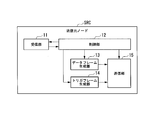
- FIG. 2 is a diagram illustrating a configuration example of the transmission source node SRC according to the present embodiment.
- the base station apparatus 10 (communication apparatus) shown in FIG. 1 has the configuration of the transmission source node SRC shown in FIG.
- the transmission source node SRC includes a reception unit 11, a control unit 12, a data frame generation unit 13, a trigger frame generation unit 14, and a transmission unit 15.
- the data frame generation unit 13 generates a data frame including a data signal to be transmitted to each of a plurality of destination nodes.
- the data frame corresponds to the first frame.
- the trigger frame generation unit 14 generates a trigger frame.
- the trigger frame is a frame that represents a different timing reference at which each of a plurality of destination nodes transmits an ACK frame.
- the ACK frame is a frame including an acknowledgment signal for a data signal included in the data frame.
- the trigger frame corresponds to the second frame.
- the ACK frame corresponds to the third frame.
- the transmission unit 15 transmits the data frame through the first communication channel corresponding to each of the plurality of destination nodes.
- the transmission unit 15 transmits the trigger frame through the second communication channel.
- the second communication channel is a communication channel that is different from the first communication channel and is used for transmission of the ACK frame.
- the receiving unit 11 receives an ACK frame through the second communication channel.
- the control unit 12 controls the transmission source node SRC.
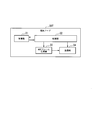
- FIG. 3 is a diagram illustrating a configuration example of the destination node DST according to the present embodiment.
- the terminal device 30 (communication device) shown in FIG. 1 has the configuration of the destination node DST shown in FIG.
- the destination node DST includes a reception unit 31, a control unit 32, an ACK frame generation unit 33, and a transmission unit 34.
- the receiving unit 31 receives a data frame including a data signal transmitted from the transmission source node SRC to each of the plurality of destination nodes through the first communication channel corresponding to the own destination node DST.
- the receiving unit 31 receives the trigger frame through the second communication channel.
- the ACK frame generation unit 33 generates an ACK frame.
- the transmission unit 34 transmits the ACK frame through the second communication channel at the timing of the self-destination node based on the criterion represented by the trigger frame.
- the control unit 32 controls the destination node DST.
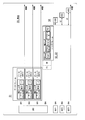
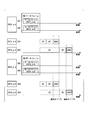
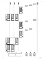
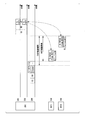
- FIG. 4 is an explanatory diagram of an example of the communication method according to the present embodiment.
- the source node SRC transmits the data packet to the M destination nodes DST.
- M is 3, and the transmission source node SRC transmits the data packet to the three destination nodes DST1, DST2, and DST3.
- the destination nodes DST1, DST2, and DST3 have the configuration of the destination node DST shown in FIG.
- the source node SRC and the destination nodes DST1, DST2, and DST3 communicate using the first shared communication medium and the second shared communication medium.
- the first shared communication medium and the second shared communication medium are different communication media.
- the first shared communication medium is a relatively high frequency band
- the second shared communication medium is different from the frequency band of the first shared communication medium. May be a low frequency band.
- Communication channels CH1, CH2, and CH3 are provided in the first shared communication medium.
- the communication channel CH4 is provided in the second shared communication medium.
- the source node SRC uses communication channels CH1, CH2, CH3, and CH4.
- the destination node DST1 uses communication channels CH1 and CH4.
- the destination node DST2 uses communication channels CH2 and CH4.
- the destination node DST3 uses communication channels CH3 and CH4.
- Step S1 In the transmission source node SRC, the data frame generation unit 13 generates a data frame including a data packet to be transmitted to each of the destination nodes DST1, DST2, and DST3.
- the data packet corresponds to a data signal.
- the transmission unit 15 transmits the data frame through communication channels CH1, CH2, and CH3 corresponding to the destination nodes DST1, DST2, and DST3, respectively.
- the control unit 12 instructs the reception unit 11 on CS (carrier sense) of the communication channels CH1, CH2, and CH3 before the transmission unit 15 transmits the data frame through the communication channels CH1, CH2, and CH3.
- the reception unit 11 performs CS on the communication channels CH1, CH2, and CH3.
- the control unit 12 has confirmed the idle states of the communication channels CH1, CH2, and CH3 by the CS of the reception unit 11.
- the control unit 12 instructs the transmission unit 15 to transmit data frames on the communication channels CH1, CH2, and CH3.
- the transmission part 15 transmits a data frame by communication channel CH1, CH2 and CH3 by which idle state was confirmed by CS of the receiving part 11.
- the source node SRC waits for transmission of the data frame by BO (backoff), and performs channel access. Find the next opportunity to win.
- the source node SRC waits for transmission of a data frame by BO, and then the idle state
- the data frame may be transmitted through the communication channel.
- Step S2 In the transmission source node SRC, the trigger frame generation unit 14 generates a trigger frame.
- the transmission unit 15 transmits a trigger frame to the destination nodes DST1, DST2, and DST3 through the communication channel CH4.
- the control unit 12 instructs the reception unit 11 about CS of the communication channel CH4 before the transmission unit 15 transmits the trigger frame through the communication channel CH4.
- the reception unit 11 performs CS on the communication channel CH4.
- the control unit 12 confirms the idle state of the communication channel CH ⁇ b> 4 by the CS of the reception unit 11.
- the control unit 12 instructs the transmission unit 15 to transmit a trigger frame on the communication channel CH4.
- the transmission unit 15 transmits a trigger frame through the communication channel CH4 after waiting for BO after the CS of the reception unit 11 confirms the idle state of the communication channel CH4.
- the transmission source node SRC waits for the transmission of the trigger frame by the BO and searches for the next opportunity to acquire channel access.
- the CS of the communication channel CH4 may be started after the transmission of the data frame is completed, or may be started before the transmission of the data frame is completed. However, when the CS of the communication channel CH4 is started before the transmission of the data frame is completed, the control unit 12 transmits the trigger frame in the communication channel CH4 after the transmission of the data frame is completed. To control.
- Step S3 In the transmission source node SRC, when the transmission of the trigger frame is completed, the control unit 12 starts a timer waiting for ACK. If the source node SRC receives ACK from all of the destination nodes DST1, DST2, and DST3 before the ACK waiting timer times out, the source node SRC proceeds to step S1 described above. On the other hand, when the ACK wait timer times out before receiving the ACK from all of the destination nodes DST1, DST2, and DST3, the transmission source node SRC executes step S5 described later.
- Step S4 In each of the destination nodes DST1, DST2, and DST3, the receiving unit 31 receives a data frame through a communication channel corresponding to the own destination node.
- the destination node DST1 receives a data frame through the communication channel CH1
- the destination node DST2 receives a data frame through the communication channel CH2
- the destination node DST3 receives a data frame through the communication channel CH3.
- the control unit 32 instructs the ACK frame generation unit 33 to generate an ACK frame.
- the ACK frame generation unit 33 generates an ACK frame in response to an instruction from the control unit 32.
- the ACK frame is a frame including an ACK packet for a data packet included in the data frame.
- the ACK packet corresponds to an acknowledgment signal.
- the receiving unit 31 receives the trigger frame through the communication channel CH4.
- the control unit 32 instructs the transmission unit 34 to transmit the ACK frame through the communication channel CH4 at the timing of the own destination node with reference to the timing at which the trigger frame is received.
- the transmission unit 34 transmits an ACK frame through the communication channel CH4 at the timing of the own destination node.
- the destination node DST1 transmits the ACK frame ACK1 through the communication channel CH4 after the time t1 has elapsed from the timing when the trigger frame has been received, and the destination node DST2 ACKs after the time t2 has elapsed from the timing when the trigger frame has been received
- the frame ACK2 is transmitted through the communication channel CH4
- the destination node DST3 transmits the ACK frame ACK3 through the communication channel CH4 after elapse of time t3 from the timing when the reception of the trigger frame is completed.
- the time t2 is longer than the total time of the time t1 and the time required for transmitting the ACK frame ACK1.
- the time t3 is longer than the total time of the time t2 and the time required for transmitting the ACK frame ACK2.
- Times t1, t2, and t3 are indicated by the response timing information.
- the response timing information indicating the time t1 is included in the data packet received by the destination node DST1.
- the control unit 32 of the destination node DST1 acquires response timing information from the data packet and recognizes the time t1.
- Response timing information indicating the time t2 is included in the data packet received by the destination node DST2.
- the control unit 32 of the destination node DST2 acquires response timing information from the data packet and recognizes the time t2.
- the response timing information indicating the time t3 is included in the data packet received by the destination node DST3.
- the control unit 32 of the destination node DST3 acquires response timing information from the data packet and recognizes the time t3.
- Each destination node DST1, DST2, and DST3 transmits an ACK frame when the decoding of its own data packet is successful, and does not transmit an ACK frame when the decoding of its own data packet fails.
- Step S5 When the source node SRC times out the ACK wait timer before receiving the ACK frame from the destination nodes DST1, DST2, and DST3 through the communication channel CH4, the source node SRC In contrast, the data packet is retransmitted.
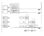
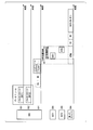
- FIG. 5 is a diagram illustrating a configuration example of a data frame according to the present embodiment.
- FIG. 6 is a diagram illustrating a configuration example of a trigger frame according to the present embodiment.
- FIG. 5 shows a configuration example for one data packet stored in a data frame.
- M 3 in the example of FIG. 4
- the data frame includes M data packet configurations shown in FIG.
- the data frame includes a PHY (physical) header, a MAC header, a payload (Payload), and an FCS (FrameSCheck Sequence).
- the MAC header of the data frame includes at least a data frame ID field and a relative duration field.
- the data frame ID field is a field for storing data frame identification information (data frame ID).
- the Relative Duration field is a field for storing response timing information.
- the MAC header of the data frame may further include an MCS_ACK field.
- the MCS_ACK field is a field for storing information of MCS (Modulation and Coding Scheme) used by the destination node DST for the ACK frame. Note that the MCS that the destination node DST uses for the ACK frame may be determined in advance between the source node SRC and the destination node DST.
- the arrangement of the data frame ID field, the relative duration field, and the MCS_ACK field may be determined in advance in any location in the MAC header.
- the data frame ID included in the data frame is used by the destination node DST for comparison with the data frame ID included in the trigger frame.
- the destination node DST uses a trigger frame including the same data frame ID as the data frame ID included in the data frame as a reference for the timing of returning an ACK frame for the data frame.
- the MCS_ACK field stores information indicating the MCS used by the destination node DST for transmitting the ACK frame.
- the lowest rate MCS is selected as an initial value from the given MCS set.
- the MCS is updated according to the RSSI (Received Signal Strength Indicator) of the ACK received by the transmission source node SRC. If the RSSI indicates that a higher rate MCS is acceptable, it is updated to the next higher rate MCS and a new MCS is specified in the next data packet.
- the selected MCS is the MCS at a rate below both the maximum rate MCS in a given MCS set and the maximum allowed rate MCS indicated by the previous RSSI and background noise.
- the Relative Duration field stores response timing information.
- the response Duration information indicating the time t1 is stored in the Relevant Duration field of the data packet to the destination node DST1.
- the Relative Duration field of the data packet to the destination node DST2 stores response timing information indicating the time t2.
- the relative duration field of the data packet to the destination node DST3 stores response timing information indicating the time t3.
- t_ACK2 (ACK2 size) / (ACK2 transmission rate)
- SIFS Short Inter Frame Space
- t_ACK1 is the time required to transmit the ACK frame ACK1.
- t_ACK2 is the time required to transmit the ACK frame ACK2.
- the size of the ACK frame is the same.
- the transmission rate of the ACK frame is determined by the MCS specified in the MCS_ACK field.
- the trigger frame includes a PHY header, a MAC header, and an FCS.
- the trigger frame has the following three functions.
- a communication channel (FIG. 4) used for transmission of a trigger frame and the next ACK for both the trigger frame and the next ACK by CS and BO performed before transmission of the trigger frame.
- the access right of the communication channel CH4 is acquired.
- the trigger frame PHY header provides TXOP protection for other nodes that can decode the trigger frame PHY header.
- next ACK can be protected from interference of a communication device such as a conventional legacy Wi-Fi device that can decode at least the PHY header of the trigger frame.
- a communication device such as a conventional legacy Wi-Fi device that can decode at least the PHY header of the trigger frame.
- the MAC header of the trigger frame provides NAV protection for other nodes that can decode the trigger frame.
- the PHY header of the trigger frame has the same configuration as the PHY header of the legacy Wi-Fi packet.
- the legacy Wi-Fi device can recognize the PHY header of the trigger frame.
- the Signal field of the PHY header of the trigger frame stores RATE and LENGTH.
- the waiting time can be calculated using the RATE and LENGTH.
- RATE is set to 6 Mbps, for example, and LENGTH is set to be a waiting time that can cover up to the final ACK returned for the data frame based on the RATE “6 Mbps”.
- the waiting time applied to the Signal field of the PHY header of the trigger frame is “t_trigger + t3 + t_ACK3” or more.
- t_trigger is the duration from the end of the Signal field of the PHY header of the trigger frame to the end of the trigger frame.
- the MAC header of the trigger frame includes at least a FrameControl field, a Duration field, and a data frame ID field.
- the FrameControl field stores information that identifies the function of the frame.
- the FrameControl field of the trigger frame stores information indicating that the frame is the trigger frame.
- the Duration field stores the NAV value.
- the NAV value stored in the Duration field of the trigger frame is a value at which NAV protection is continued from the completion of transmission of the trigger frame to the completion of transmission of the final ACK.
- the value of the NAV stored in the Duration field of the trigger frame is “t3 + t_ACK3” or more.
- the data frame ID field stores the data frame ID.
- the data frame ID stored in the data frame ID field of the trigger frame is the data frame ID of the data frame corresponding to the trigger frame.
- the destination node DST determines whether the data frame ID stored in the data frame ID field of the received trigger frame is the same as the data frame ID of the previously received data frame. If they are the same as a result of the determination, the destination node DST is indicated by the response timing information stored in the Relative Duration field of the data frame with the same data frame ID with reference to the completion timing of reception of the trigger frame.
- the ACK frame for the data frame with the same data frame ID is returned at the same timing.
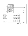
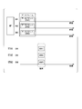
- FIG. 7 is an explanatory diagram of Application Example 1 according to the present embodiment.
- it is applied to immediate ACK (Immediate ACK). If immediate ACK is applied, the source node SRC receives all ACK frames for the transmitted data frame or until the ACK wait timer for any ACK frame times out, The data frame cannot be transmitted.
- the source node SRC and the destination nodes DST1, DST2, and DST3 communicate using the first shared communication medium and the second shared communication medium.
- Communication channels CH1, CH2 and CH3 are provided in the first shared communication medium.
- the communication channel CH4 is provided in the second shared communication medium.
- the source node SRC uses communication channels CH1, CH2, CH3, and CH4.
- the destination node DST1 uses communication channels CH1 and CH4.
- the destination node DST2 uses communication channels CH2 and CH4.
- the destination node DST3 uses communication channels CH3 and CH4.
- the first example of FIG. 7 is a case where the idle state of the communication channels CH1 and CH2 and the busy of the communication channel CH3 are confirmed by the CS before transmission of the first data frame.
- the first data frame includes a data packet to the destination node DST1 and a data packet to the destination node DST2.
- the transmission source node SRC transmits the first data frame through the communication channels CH1 and CH2.
- the transmission source node SRC transmits a first trigger frame corresponding to the first data frame through the communication channel CH4.
- Each data packet of the first data frame and the first trigger frame include the same data frame ID1.
- the destination node DST1 receives the first data frame through the communication channel CH1, and then receives the first trigger frame through the communication channel CH4.
- the destination node DST2 receives the first data frame via the communication channel CH2, and then receives the first trigger frame via the communication channel CH4.
- the destination node DST1 transmits the ACK frame ACK1 for the first data frame through the communication channel CH4 at the timing of its own response timing information based on the completion timing of reception of the first trigger frame.
- the destination node DST2 transmits the ACK frame ACK2 for the first data frame through the communication channel CH4 at the timing of its own response timing information based on the timing of completion of reception of the first trigger frame.
- the ACK frame ACK2 of the destination node DST2 is transmitted after the transmission of the ACK frame ACK1 of the destination node DST1 is completed for the first data frame in the communication channel CH4. Thereby, in communication channel CH4, the collision between ACK frame ACK1 and ACK frame ACK2 is avoided for the first data frame.
- the next example of FIG. 7 is a case where the idle state of the communication channel CH3 and the busyness of the communication channels CH1 and CH2 are confirmed by the CS before transmission of the second data frame.
- the second data frame includes a data packet to the destination node DST3.
- the transmission source node SRC transmits the second data frame through the communication channel CH3.
- the source node SRC transmits a second trigger frame corresponding to the second data frame through the communication channel CH4.
- the data packet of the second data frame and the second trigger frame include the same data frame ID1.
- the destination node DST3 receives the second data frame via the communication channel CH3 and then receives the second trigger frame via the communication channel CH4.
- the destination node DST3 transmits the ACK frame ACK3 for the second data frame through the communication channel CH4 at the timing of its own response timing information based on the completion timing of reception of the second trigger frame.
- the next example of FIG. 7 is a case where the idle state of the communication channels CH1, CH2, and CH3 is confirmed by the CS before transmission of the third data frame.
- a communication channel whose idle state has been confirmed by CS is used for communication, and a communication channel whose busy has been confirmed by CS is not used for communication.
- the third data frame includes a data packet to the destination node DST1, a data packet to the destination node DST2, and a data packet to the destination node DST3.
- the source node SRC transmits the third data frame through the communication channels CH1, CH2, and CH3.
- the source node SRC transmits a third trigger frame corresponding to the third data frame through the communication channel CH4.
- Each data packet of the third data frame and the third trigger frame include the same data frame ID1.
- the destination node DST1 receives the third data frame through the communication channel CH1, and then receives the third trigger frame through the communication channel CH4.
- the destination node DST2 receives the third data frame via the communication channel CH2, and then receives the third trigger frame via the communication channel CH4.
- the destination node DST3 receives the third data frame via the communication channel CH3 and then receives the third trigger frame via the communication channel CH4.
- the destination node DST1 transmits the ACK frame ACK1 for the third data frame through the communication channel CH4 at the timing of its own response timing information based on the timing of completion of reception of the third trigger frame.
- the destination node DST2 transmits the ACK frame ACK2 for the third data frame through the communication channel CH4 at the timing of its own response timing information based on the timing of completion of reception of the third trigger frame.
- the destination node DST3 transmits the ACK frame ACK3 for the third data frame through the communication channel CH4 at the timing of its own response timing information based on the timing of completion of reception of the third trigger frame.
- the data frame IDs of the first data frame, the second data frame, and the third data frame are all the same, but the data frame ID of each data frame may be different.
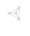
- FIG. 8 is a diagram showing a network topology of application example 2 according to the present embodiment.
- a source node SRC for example, a source node SRC, destination nodes DST1 and DST2, and a conventional Wi-Fi device.
- the signal of the other party can be detected between the source node SRC and each of the destination nodes DST1 and DST2.
- the signal of the other party can be detected between the source node SRC and the Wi-Fi device.
- the other party's signal can be detected between the destination node DST1 and the destination node DST2.
- the partner signal cannot be detected between each of the destination nodes DST1 and DST2 and the Wi-Fi device.
- a conventional Wi-Fi device will be described as an example of a communication device that can decode at least the PHY header of the trigger frame.
- the communication device other than the conventional Wi-Fi device may be used. Is also applicable.
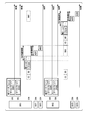
- FIG. 9 is an explanatory diagram of a conventional communication method for explaining an application example 2 according to the present embodiment.
- FIG. 10 is an explanatory diagram of the communication method of the application example 2 according to the present embodiment. 9 and 10, communication channels CH1 and CH2 are provided in the first shared communication medium. The communication channel CH4 is provided in the second shared communication medium.
- the source node SRC_old is the source node SRC in the network topology of FIG. 8
- the destination node DST1_old is the destination node DST1 in the network topology of FIG. 8
- the destination node DST2_old is the destination node DST2 in the network topology of FIG.
- the Wi-Fi device corresponds to the Wi-Fi device in the network topology of FIG. 8 in each signal detection state (whether or not the partner signal can be detected).
- the data frame includes a data packet to the destination node DST1_old and a data packet to the destination node DST2_old.
- the source node SRC_old transmits a data frame through the communication channels CH1 and CH2.
- the destination node DST1_old receives the data frame through the communication channel CH1.
- the destination node DST2_old receives the data frame through the communication channel CH2.
- the destination node DST1_old performs CS and BO in the communication channel CH4 after completing the reception of the data frame, and then transmits the ACK frame ACK1 through the communication channel CH4.
- Destination node DST2_old performs BO after performing CS on communication channel CH4, and performs CS and BO after transmission of ACK frame ACK1 of destination node DST1_old is completed, and then transmits ACK frame ACK2 through communication channel CH4. Thereby, in communication channel CH4, collision between ACK frame ACK1 and ACK frame ACK2 is avoided.
- the other party's signal cannot be detected between the destination nodes DST1_old and DST2_old and the Wi-Fi device.
- the Wi-Fi device cannot detect the use of the communication channel CH4 of the destination nodes DST1_old and DST2_old even if CS is performed on the communication channel CH4.
- each destination node DST1_old and DST2_old cannot detect the use of the communication channel CH4 of the Wi-Fi device even if CS is performed on the communication channel CH4. Therefore, as shown in FIG. 9, a collision (collision type 1) occurs between the ACK frames ACK1 and ACK2 transmitted by the destination nodes DST1_old and DST2_old and the data frame transmitted by the Wi-Fi device in the communication channel CH4. There was a possibility.
- the data frame includes a data packet to the destination node DST1 and a data packet to the destination node DST2.
- the source node SRC transmits the data frame after performing CS and BO in the communication channels CH1 and CH2.
- the source node SRC performs CS and BO in the communication channel CH4, and then transmits a trigger frame corresponding to the data frame through the communication channel CH4.
- Each data packet of the data frame and the trigger frame include the same data frame ID.
- the destination node DST1 receives the data frame via the communication channel CH1, and then receives the trigger frame via the communication channel CH4.
- the destination node DST2 receives the data frame via the communication channel CH2, and then receives the trigger frame via the communication channel CH4.
- the destination node DST1 transmits the ACK frame ACK1 for the data frame through the communication channel CH4 at the timing of its own response timing information based on the timing of completion of reception of the trigger frame.
- the destination node DST2 transmits the ACK frame ACK2 for the data frame through the communication channel CH4 at the timing of its own response timing information based on the timing of completion of reception of the trigger frame.
- the ACK frame ACK2 of the destination node DST2 is transmitted after the transmission of the ACK frame ACK1 of the destination node DST1 is completed for the same data frame in the communication channel CH4. Thereby, in communication channel CH4, the collision between ACK frame ACK1 and ACK frame ACK2 is avoided for the same data frame.
- the partner signal can be detected between the Wi-Fi device and the source node SRC.
- the Wi-Fi device detects the trigger frame transmitted by the transmission source node SRC in the communication channel CH4.
- the Wi-Fi device waits for its own transmission on the communication channel CH4 for the waiting time indicated by the Signal field of the trigger frame.
- the transmission of the Wi-Fi device is waited on the communication channel CH4 until the TXOP protection period by the trigger frame ends.
- the TXOP protection period by the trigger frame continues until the destination nodes DST1 and DST2 complete the transmission of the ACK frames ACK1 and ACK2.
- the Wi-Fi device waits for its own transmission for the waiting time indicated by the Signal field of the trigger frame, then performs CS and BO on the communication channel CH4, and then transmits the data frame on the communication channel CH4.
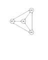
- FIG. 11 is a diagram showing a network topology of application example 3 according to the present embodiment.
- FIG. 11 there are a source node SRC and destination nodes DST1, DST2, and DST3.
- the signal of the other party can be detected between the source node SRC and each of the destination nodes DST1, DST2, and DST3.
- FIG. 11 as indicated by the solid line of the double-pointed arrow, the signal of the other party can be detected between the source node SRC and each of the destination nodes DST1, DST2, and DST3.
- FIG. 12 is an explanatory diagram of a conventional communication method for explaining an application example 3 according to the present embodiment.
- FIG. 13 is an explanatory diagram of the communication method of the application example 3 according to the present embodiment. 12 and 13, communication channels CH1, CH2, and CH3 are provided in the first shared communication medium. The communication channel CH4 is provided in the second shared communication medium.
- the source node SRC_old is the source node SRC in the network topology of FIG. 11
- the destination node DST1_old is the destination node DST1 in the network topology of FIG. 11
- the destination node DST2_old is the destination node DST2 in the network topology of FIG.
- the destination node DST3_old corresponds to the destination node DST3 in the network topology of FIG. 11 in each signal detection state (whether or not the partner signal can be detected).
- the data frame includes a data packet to the destination node DST1_old, a data packet to the destination node DST2_old, and a data packet to the destination node DST3_old.
- the source node SRC_old transmits a data frame through the communication channels CH1, CH2, and CH3.
- the destination node DST1_old receives the data frame through the communication channel CH1.
- the destination node DST2_old receives the data frame through the communication channel CH2.
- the destination node DST3_old receives the data frame through the communication channel CH3.
- Each destination node DST1_old, DST2_old, and DST3_old performs CS on the communication channel CH4 after completing the reception of the data frame.
- the destination nodes DST1_old, DST2_old, and DST3_old are in a state where they cannot detect each other's signals, even if other destination nodes transmit on the communication channel CH4, the transmission is not detected. Therefore, as shown in FIG. 12, each destination node DST1_old, DST2_old, and DST3_old performs CS and BO on the communication channel CH4 after completing the reception of the data frame, and then transmits each ACK frame ACK1, ACK2, and ACK3 to the communication channel. Transmit on CH4. As a result, there is a possibility that a collision (collision type 2) occurs between the ACK frames ACK1, ACK2, and ACK3.
- collision type 2 occurs between the ACK frames ACK1, ACK2, and ACK3.
- the data frame includes a data packet to the destination node DST1, a data packet to the destination node DST2, and a data packet to the destination node DST3.
- the source node SRC transmits the data frame through the communication channels CH1, CH2, and CH3 after performing CS and BO.
- the source node SRC performs CS and BO in the communication channel CH4, and then transmits a trigger frame corresponding to the data frame through the communication channel CH4.
- Each data packet of the data frame and the trigger frame include the same data frame ID.
- the destination node DST1 receives the data frame via the communication channel CH1, and then receives the trigger frame via the communication channel CH4.
- the destination node DST2 receives the data frame via the communication channel CH2, and then receives the trigger frame via the communication channel CH4.
- the destination node DST3 receives the data frame via the communication channel CH3 and then receives the trigger frame via the communication channel CH4.
- the destination node DST1 transmits the ACK frame ACK1 for the data frame through the communication channel CH4 at the timing of its own response timing information based on the timing of completion of reception of the trigger frame.
- the destination node DST2 transmits the ACK frame ACK2 for the data frame through the communication channel CH4 at the timing of its own response timing information based on the timing of completion of reception of the trigger frame.
- the destination node DST3 transmits the ACK frame ACK3 for the data frame through the communication channel CH4 at the timing of its own response timing information based on the timing of completion of reception of the trigger frame.
- ACK frame ACK2 of destination node DST2 is transmitted after transmission of ACK frame ACK1 of destination node DST1, and after transmission of ACK frame ACK2 of destination node DST2 is completed
- the ACK frame ACK3 of the destination node DST3 is transmitted. Thereby, in the communication channel CH4, the collision between the ACK frames ACK1, ACK2, and ACK3 is avoided for the same data frame.
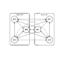
- FIG. 14 is a diagram showing a network topology of application example 4 according to the present embodiment.
- source nodes SRC1 and SRC2 and destination nodes DST1, DST2, DST5, and DST6 exist.
- the source node SRC1 and the destination nodes DST1 and DST2 belong to group 1.
- the source node SRC2 and the destination nodes DST5 and DST6 belong to the group 2.
- the source nodes SRC1 and SRC2 have the configuration of the source node SRC shown in FIG.
- the destination nodes DST1, DST2, DST5, and DST6 have the configuration of the destination node DST shown in FIG.
- the destination nodes belonging to different groups that is, between the destination node DST1 and each of the destination nodes DST5 and DST6, and between the destination node DST2 and each of the destination nodes DST5 and DST6 cannot be detected. is there.
- FIG. 15 is an explanatory diagram of a conventional communication method for explaining an application example 4 according to the present embodiment.
- FIG. 16 is an explanatory diagram of the communication method of the application example 4 according to the present embodiment. 15 and 16, communication channels CH1, CH2, CH5, and CH6 are provided in the first shared communication medium. The communication channel CH4 is provided in the second shared communication medium.
- the source node SRC1_old is the source node SRC1 in the network topology of FIG. 14
- the source node SRC2_old is the source node SRC2 in the network topology of FIG. 14
- the destination node DST1_old is the destination node in the network topology of FIG. DST1
- destination node DST2_old is the destination node DST2 in the network topology of FIG. 14
- destination node DST5_old is the destination node DST5 in the network topology of FIG. 14
- destination node DST6_old is the destination node DST6 in the network topology of FIG.
- the signal detection state (whether or not the partner signal can be detected) corresponds.
- the first data frame includes a data packet to the destination node DST1_old and a data packet to the destination node DST2_old.
- the transmission source node SRC1_old transmits the first data frame through the communication channels CH1 and CH2 after performing CS and BO.
- the destination node DST1_old receives the first data frame through the communication channel CH1.
- the destination node DST2_old receives the first data frame through the communication channel CH2.
- the second data frame includes a data packet to the destination node DST5_old and a data packet to the destination node DST6_old.
- the transmission source node SRC2_old transmits the second data frame through the communication channels CH5 and CH6 after performing CS and BO.
- the destination node DST5_old receives the second data frame through the communication channel CH5.
- the destination node DST6_old receives the second data frame through the communication channel CH6.
- Each destination node DST1_old, DST2_old, DST5_old, and DST6_old performs CS on the communication channel CH4 after completing the reception of the data frame. Since the other party's signal can be detected between the destination nodes belonging to the same group, transmission of another destination node can be detected by CS. For this reason, collision between ACK frames is avoided by performing CS and BO in the communication channel CH4 between destination nodes belonging to the same group. However, since the other party's signal cannot be detected between the destination nodes belonging to different groups, transmission of other destination nodes is not detected even if CS is performed. For this reason, there is a possibility that collision between ACK frames (collision type 3) may occur between destination nodes belonging to different groups even if CS and BO are performed on the communication channel CH4 as shown in FIG. It was.
- collision type 3 collision type 3
- the first data frame includes a data packet to the destination node DST1 and a data packet to the destination node DST2.
- the transmission source node SRC1 transmits the first data frame through the communication channels CH1 and CH2 after performing CS and BO.
- the source node SRC1 performs CS and BO on the communication channel CH4 next to the first data frame, and then transmits the first trigger frame corresponding to the first data frame on the communication channel CH4.
- Each data packet of the first data frame and the first trigger frame include the same data frame ID.
- the destination node DST1 receives the first data frame through the communication channel CH1, and then receives the first trigger frame through the communication channel CH4.
- the destination node DST2 receives the first data frame via the communication channel CH2, and then receives the first trigger frame via the communication channel CH4.
- the destination node DST1 transmits the ACK frame ACK1 for the first data frame through the communication channel CH4 at the timing of its own response timing information based on the completion timing of reception of the first trigger frame.
- the destination node DST2 transmits the ACK frame ACK2 for the first data frame through the communication channel CH4 at the timing of its own response timing information based on the timing of completion of reception of the first trigger frame.
- the ACK frame ACK2 of the destination node DST2 is transmitted after the transmission of the ACK frame ACK1 of the destination node DST1 is completed for the first data frame in the communication channel CH4. Thereby, in communication channel CH4, the collision between ACK frame ACK1 and ACK frame ACK2 is avoided for the first data frame.
- the second data frame includes a data packet to the destination node DST5 and a data packet to the destination node DST6.
- the transmission source node SRC2 transmits the second data frame through the communication channels CH5 and CH6 after performing CS and BO.
- the transmission source node SRC2 performs CS and BO on the communication channel CH4 before transmitting the second trigger frame corresponding to the second data frame.
- the source node SRC2 detects the first trigger frame transmitted from the source node SRC1 in the communication channel CH4 by performing the CS and the BO. Then, the transmission source node SRC2 waits for transmission on the communication channel CH4 until the TXOP protection period and the NAV protection period by the first trigger frame are ended.
- the TXOP protection period and the NAV protection period by the first trigger frame continue until the destination nodes DST1 and DST2 complete the transmission of the ACK frames ACK1 and ACK2.
- collision between the ACK frames ACK1 and ACK2 transmitted by the destination nodes DST1 and DST2 and transmission from the transmission source node SRC2 is avoided.
- the source node SRC2 waits for its transmission until the TXOP protection period and the NAV protection period by the first trigger frame end, and then performs CS and BO on the communication channel CH4 and then communicates the second trigger frame. Transmit by channel CH4.
- Each data packet of the second data frame and the second trigger frame include the same data frame ID.
- the destination node DST5 receives the second data frame through the communication channel CH5, and then receives the second trigger frame through the communication channel CH4.
- the destination node DST6 receives the second data frame via the communication channel CH6 and then receives the second trigger frame via the communication channel CH4.
- the destination node DST5 transmits the ACK frame ACK5 for the second data frame through the communication channel CH4 at the timing of its own response timing information based on the completion timing of reception of the second trigger frame.
- the destination node DST6 transmits the ACK frame ACK6 for the second data frame through the communication channel CH4 at the timing of its own response timing information based on the completion timing of reception of the second trigger frame.
- the ACK frame ACK6 of the destination node DST6 is transmitted on the communication channel CH4 after the transmission of the ACK frame ACK5 of the destination node DST5 is completed for the second data frame.
- the collision between the ACK frame ACK5 and the ACK frame ACK6 is avoided for the second data frame.
- the transmission completion of each ACK frame ACK5 and ACK6 by each destination node DST5 and DST6 is protected by the TXOP protection period and the NAV protection period by the second trigger frame.
- FIG. 17 is a diagram illustrating a network topology of Application Example 5 according to the present embodiment.
- a source node SRC and destination nodes DST1, DST2, and DST3 exist in the network topology shown in FIG. 17, as indicated by the solid line of the bidirectional arrow, the signal of the other party can be detected between the source node SRC and each of the destination nodes DST1, DST2, and DST3.
- FIG. 18 is an explanatory diagram of a conventional communication method for explaining an application example 5 according to the present embodiment.
- FIG. 19 is an explanatory diagram of a communication method of Application Example 5 according to the present embodiment. 18 and 19, communication channels CH1, CH2, and CH3 are provided in the first shared communication medium. The communication channel CH4 is provided in the second shared communication medium.
- the source node SRC_old is the source node SRC in the network topology of FIG. 17
- the destination node DST1_old is the destination node DST1 in the network topology of FIG. 17
- the destination node DST2_old is the destination node DST2 in the network topology of FIG.
- the destination node DST3_old corresponds to the destination node DST3 in the network topology of FIG. 17 in each signal detection state (whether or not the partner signal can be detected).
- the data frame includes a data packet to the destination node DST1_old, a data packet to the destination node DST2_old, and a data packet to the destination node DST3_old.
- the source node SRC_old transmits a data frame through the communication channels CH1, CH2, and CH3.
- the destination node DST1_old receives the data frame through the communication channel CH1.
- the destination node DST2_old receives the data frame through the communication channel CH2.
- the destination node DST3_old receives the data frame through the communication channel CH3.
- Each destination node DST1_old, DST2_old, and DST3_old performs CS on the communication channel CH4 after completing the reception of the data frame. Since the destination nodes DST1_old, DST2_old, and DST3_old can detect each other's signal, the transmission can be detected when another destination node transmits on the communication channel CH4. Therefore, as shown in FIG. 12, each destination node DST1_old, DST2_old, and DST3_old performs CS and BO on the communication channel CH4 after completing the reception of the data frame, and then transmits each ACK frame ACK1, ACK2, and ACK3 to the communication channel. Transmit on CH4. As a result, in the example of FIG.
- the ACK frame ACK2 of the destination node DST2_old is transmitted after the transmission of the ACK frame ACK1 of the destination node DST1_old is completed for the same data frame in the communication channel CH4, and the ACK frame ACK2 of the destination node DST2_old is transmitted. After the transmission of ACK frame ACK3 of destination node DST3_old is transmitted. As a result, in the communication channel CH4, collisions between the ACK frame ACK1, the ACK frame ACK2, and the ACK frame ACK3 are avoided for the same data frame.
- each destination node DST1_old, DST2_old, and DST3_old performs CS and BO in the communication channel CH4 before transmitting its own ACK frame
- the utilization efficiency of the communication channel CH4 decreases.
- the total time of BO increases accordingly.
- the transmission source node will retransmit the corresponding data packet. Communication efficiency decreases.
- the data frame includes a data packet to the destination node DST1, a data packet to the destination node DST2, and a data packet to the destination node DST3.
- the source node SRC transmits the data frame through the communication channels CH1, CH2, and CH3 after performing CS and BO.
- the source node SRC performs CS and BO in the communication channel CH4, and then transmits a trigger frame corresponding to the data frame through the communication channel CH4.
- Each data packet of the data frame and the trigger frame include the same data frame ID.
- the destination node DST1 receives the data frame via the communication channel CH1, and then receives the trigger frame via the communication channel CH4.
- the destination node DST2 receives the data frame via the communication channel CH2, and then receives the trigger frame via the communication channel CH4.
- the destination node DST3 receives the data frame via the communication channel CH3 and then receives the trigger frame via the communication channel CH4.
- the destination node DST1 transmits the ACK frame ACK1 for the data frame through the communication channel CH4 at the timing of its own response timing information based on the timing of completion of reception of the trigger frame.
- the destination node DST2 transmits the ACK frame ACK2 for the data frame through the communication channel CH4 at the timing of its own response timing information based on the timing of completion of reception of the trigger frame.
- the destination node DST3 transmits the ACK frame ACK3 for the data frame through the communication channel CH4 at the timing of its own response timing information based on the timing of completion of reception of the trigger frame.
- ACK frame ACK2 of destination node DST2 is transmitted after transmission of ACK frame ACK1 of destination node DST1, and after transmission of ACK frame ACK2 of destination node DST2 is completed
- the ACK frame ACK3 of the destination node DST3 is transmitted. Thereby, in the communication channel CH4, the collision between the ACK frames ACK1, ACK2, and ACK3 is avoided for the same data frame.
- each destination node DST1, DST2, and DST3 does not perform CS and BO on the communication channel CH4 before transmitting its own ACK frame.
- the utilization efficiency of communication channel CH4 improves compared with the conventional communication method shown in FIG.
- the time required for BO is only one time before transmission of the trigger frame. For this reason, it can be suppressed that the time required to complete the transmission of the ACK frame of all the destination nodes is longer than the timeout time of the ACK waiting timer in the transmission source node. As a result, it is possible to reduce the occurrence of data packet retransmission at the transmission source node and to prevent a decrease in communication efficiency.
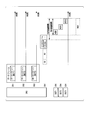
- FIG. 20 is an explanatory diagram of an application example 6 according to the present embodiment.
- Application example 6 applies to delayed ACK (Delayed ACK).
- the source node SRC can transmit the next data frame without waiting for the ACK frame for the transmitted data frame.
- the source node SRC and the destination nodes DST1, DST2, and DST3 communicate using the first shared communication medium and the second shared communication medium.
- Communication channels CH1, CH2 and CH3 are provided in the first shared communication medium.
- the communication channel CH4 is provided in the second shared communication medium.
- the source node SRC uses communication channels CH1, CH2, CH3, and CH4.
- the destination node DST1 uses communication channels CH1 and CH4.
- the destination node DST2 uses communication channels CH2 and CH4.
- the destination node DST3 uses communication channels CH3 and CH4.
- the first data frame includes a data packet to the destination node DST1 and a data packet to the destination node DST2.
- the second data frame includes a data packet to the destination node DST1 and a data packet to the destination node DST3.
- the transmission source node SRC transmits the first data frame through the communication channels CH1 and CH2.
- the source node SRC transmits the second data frame through the communication channels CH1 and CH3.
- the transmission source node SRC transmits a first trigger frame corresponding to the first data frame through the communication channel CH4.
- Each data packet of the first data frame and the first trigger frame include the same data frame ID1.
- Each data packet of the second data frame includes a data frame ID2.
- the destination node DST1 receives the first data frame via the communication channel CH1, then receives the second data frame via the communication channel CH1, and then receives the first trigger frame via the communication channel CH4.
- the destination node DST2 receives the first data frame via the communication channel CH2, and then receives the first trigger frame via the communication channel CH4.
- the destination node DST3 receives the second data frame via the communication channel CH3 and then receives the first trigger frame via the communication channel CH4.
- the destination node DST1 transmits the ACK frame ACK1 for the first data frame through the communication channel CH4 at the timing of its own response timing information based on the timing of completion of reception of the first trigger frame.
- the destination node DST2 transmits the ACK frame ACK2 for the first data frame through the communication channel CH4 at the timing of its own response timing information based on the timing of completion of reception of the first trigger frame.
- the destination node DST3 receives the first trigger frame, but the data frame ID1 included in the first trigger frame is different from the data frame ID2 included in the second data frame. For this reason, the destination node DST3 has not yet transmitted the ACK frame ACK3 for the second data frame. In the example of FIG.
- the ACK frame ACK2 of the destination node DST2 is transmitted after the transmission of the ACK frame ACK1 of the destination node DST1 is completed for the first data frame in the communication channel CH4. Thereby, in communication channel CH4, the collision between ACK frame ACK1 and ACK frame ACK2 is avoided for the first data frame.
- the source node SRC transmits a second trigger frame corresponding to the second data frame through the communication channel CH4.
- the second trigger frame includes a data frame ID2.
- Each destination node DST1, DST2, and DST3 receives the second trigger frame through the communication channel CH4.
- the destination node DST1 transmits the ACK frame ACK1 for the second data frame through the communication channel CH4 at the timing of its own response timing information based on the completion timing of reception of the second trigger frame.
- the destination node DST3 transmits the ACK frame ACK3 for the second data frame through the communication channel CH4 at the timing of its own response timing information based on the completion timing of reception of the second trigger frame.
- the destination node DST2 receives the second trigger frame, but does not receive the second data frame corresponding to the data frame ID2 included in the second trigger frame, so transmits the ACK frame ACK2 for the second data frame. do not do.
- the ACK frame ACK3 of the destination node DST3 is transmitted after the transmission of the ACK frame ACK1 of the destination node DST1 is completed for the second data frame in the communication channel CH4. Thereby, in communication channel CH4, the collision between ACK frame ACK1 and ACK frame ACK3 is avoided for the second data frame.
- the third data frame includes a data packet to the destination node DST1, a data packet to the destination node DST2, and a data packet to the destination node DST3.
- the source node SRC transmits the third data frame through the communication channels CH1, CH2, and CH3 after performing CS and BO.
- the transmission source node SRC transmits the third trigger frame corresponding to the third data frame through the communication channel CH4.
- Each data packet of the third data frame and the third trigger frame include the same data frame ID3.
- the destination node DST1 receives the third data frame through the communication channel CH1, and then receives the third trigger frame through the communication channel CH4.
- the destination node DST2 receives the third data frame via the communication channel CH2, and then receives the third trigger frame via the communication channel CH4.
- the destination node DST3 receives the third data frame via the communication channel CH3 and then receives the third trigger frame via the communication channel CH4.
- the destination node DST1 transmits the ACK frame ACK1 for the third data frame through the communication channel CH4 at the timing of its own response timing information based on the timing of completion of reception of the third trigger frame.
- the destination node DST2 transmits the ACK frame ACK2 for the third data frame through the communication channel CH4 at the timing of its own response timing information based on the timing of completion of reception of the third trigger frame.
- the destination node DST3 transmits the ACK frame ACK3 for the third data frame through the communication channel CH4 at the timing of its own response timing information based on the timing of completion of reception of the third trigger frame.
- the source node SRC when the source node SRC retransmits the data packet to the destination node DST3 that is transmitted in the second data frame, the source node SRC sends the data packet to the destination node DST3 in the third data frame. You may include and transmit.
- FIG. 21 is an explanatory diagram of Modification 1 according to the present embodiment.
- FIG. 22 is a diagram illustrating a configuration example of the trigger frame of the first modification according to the present embodiment.
- a plurality of communication channels that can be used for transmitting an ACK frame are provided.
- two communication channels CH7 and CH8 are provided as communication channels that can be used for transmission of the ACK frame.
- the source node SRC and the destination nodes DST1 and DST2 communicate using the first shared communication medium and the second shared communication medium.
- Communication channels CH1 and CH2 are provided in the first shared communication medium.
- Communication channels CH7 and CH8 are provided in the second shared communication medium.
- the source node SRC uses communication channels CH1, CH2, CH7, and CH8.
- the destination node DST1 uses communication channels CH1, CH7, and CH8.
- the destination node DST2 uses communication channels CH2, CH7, and CH8.
- the communication channel CH7 is designated as a primary channel.
- the destination nodes DST1 and DST2 set at least a primary channel as a communication channel to be received.
- the data frame includes a data packet to the destination node DST1 and a data packet to the destination node DST2.
- the transmission source node SRC transmits the data frame through the communication channels CH1 and CH2 after performing CS and BO. Next, the source node SRC performs CS on the communication channels CH7 and CH8. Due to this CS, in the example of FIG. 21, the communication channel CH7 is in an idle state and the communication channel CH8 is busy.
- the transmission source node SRC performs BO on the communication channel CH7, and then transmits a trigger frame corresponding to the data frame through the communication channel CH7. Each data packet of the data frame and the trigger frame include the same data frame ID.
- the transmission source node SRC delays the transmission of the trigger frame.
- the destination node DST1 receives the data frame through the communication channel CH1, and then receives the trigger frame through the communication channel CH7.
- the destination node DST2 receives the data frame through the communication channel CH2, and then receives the trigger frame through the communication channel CH7.
- the destination node DST1 transmits the ACK frame ACK1 for the data frame through the communication channel CH7 at the timing of its own response timing information based on the completion timing of the trigger frame reception.
- the destination node DST2 transmits the ACK frame ACK2 for the data frame through the communication channel CH7 at the timing of its own response timing information based on the timing of completion of reception of the trigger frame.
- the ACK frame ACK2 of the destination node DST2 is transmitted after the transmission of the ACK frame ACK1 of the destination node DST1 is completed for the same data frame in the communication channel CH7. Thereby, in communication channel CH7, the collision between ACK frame ACK1 and ACK frame ACK2 is avoided for the same data frame.
- FIG. 22 a configuration example of the trigger frame of Modification 1 according to the present embodiment will be described.
- fields DST1 and DST2 corresponding to the destination nodes DST1 and DST2 are further provided in the configuration example of the trigger frame shown in FIG. Except for this point, the configuration is the same as that of the trigger frame shown in FIG.
- the field DST1 is a field for storing information notified to the destination node DST1, and includes a RelativeDuration field.
- the Relative Duration field of the field DST1 is a field for storing response timing information notified to the destination node DST1.
- the field DST1 is a field for storing information to be notified to the destination node DST1, and may include an MCS_ACK field.
- the MCS_ACK field of the field DST1 is a field for storing MCS information used for the ACK frame by the destination node DST1.
- the field DST2 is a field for storing information to be notified to the destination node DST2, and includes a Relative Duration field.
- the field DST2 is a field for storing information notified to the destination node DST2, and may include an MCS_ACK field.
- the MCS used for the ACK frame that is, the transmission rate of the ACK frame is also not determined, and therefore the response timing information is not determined.
- a relative duration field is provided in the trigger frame. Further, when the MCS_ACK field is provided, the MCS_ACK field is provided in the trigger frame. On the other hand, the relative duration field and the MCS_ACK field may not be provided in the data frame.
- FIG. 23 is an explanatory diagram of Modification 2 according to the present embodiment.
- FIG. 24 is a diagram illustrating a configuration example of the trigger frame of the second modification according to the present embodiment.
- a plurality of communication channels that can be used for transmission of the ACK frame are provided.
- two communication channels CH7 and CH8 are provided as communication channels that can be used for transmission of the ACK frame.
- a plurality of destination nodes DST may transmit ACK frames using a plurality of communication channels.
- the source node SRC and the destination nodes DST1 and DST2 communicate using the first shared communication medium and the second shared communication medium.
- Communication channels CH1 and CH2 are provided in the first shared communication medium.
- Communication channels CH7 and CH8 are provided in the second shared communication medium.
- the source node SRC uses communication channels CH1, CH2, CH7, and CH8.
- the destination node DST1 uses communication channels CH1, CH7, and CH8.
- the destination node DST2 uses communication channels CH2, CH7, and CH8.
- the communication channel CH7 is designated as the primary channel.
- the destination nodes DST1 and DST2 set at least a primary channel as a communication channel to be received.
- the data frame includes a data packet to the destination node DST1 and a data packet to the destination node DST2.
- the transmission source node SRC transmits the data frame through the communication channels CH1 and CH2 after performing CS and BO.
- the source node SRC performs CS on the communication channels CH7 and CH8.
- both communication channels CH7 and CH8 are in an idle state.
- the transmission source node SRC performs BO in the communication channel CH7, which is the primary channel, and then transmits a trigger frame corresponding to the data frame through the communication channel CH7.
- Each data packet of the data frame and the trigger frame include the same data frame ID.
- the transmission source node SRC delays the transmission of the trigger frame.
- the destination node DST1 receives the data frame through the communication channel CH1, and then receives the trigger frame through the communication channel CH7.
- the destination node DST2 receives the data frame through the communication channel CH2, and then receives the trigger frame through the communication channel CH7.
- the destination node DST1 transmits the ACK frame ACK1 for the data frame through its own communication channel at the timing of its own response timing information based on the completion timing of the trigger frame reception.
- the destination node DST2 transmits the ACK frame ACK2 for the data frame through its own communication channel at the timing of its own response timing information based on the timing of completion of reception of the trigger frame.
- ACK channel information indicating a communication channel through which each destination node DST1 and DST2 transmits an ACK frame is included in the trigger frame.
- the destination node DST1 transmits an ACK frame ACK1 through the communication channel CH7, while the destination node DST2 transmits an ACK frame ACK2 through the communication channel CH8.
- the trigger frame of Modification 2 shown in FIG. 24 is further provided with CH_ACK fields corresponding to the destination nodes DST1 and DST2 in addition to the configuration of the trigger frame of Modification 1 shown in FIG. Except this point, it is the same as the configuration example of the trigger frame of the first modification shown in FIG.
- the CH_ACK field corresponding to the destination node DST1 is provided in the field DST1.
- the CH_ACK field of field DST1 is a field for storing ACK channel information to be notified to destination node DST1.
- the ACK channel information is information indicating a communication channel that transmits an ACK frame.
- a CH_ACK field corresponding to destination node DST2 is provided in field DST2.
- the CH_ACK field of field DST2 is a field for storing ACK channel information notified to destination node DST2.
- FIG. 25 is an explanatory diagram of Modification 3 according to the present embodiment.
- a plurality of communication channels that can be used for transmission of the ACK frame are provided, and a plurality of destination nodes DST may transmit the ACK frame through the plurality of communication channels.
- two communication channels CH7 and CH8 are provided as communication channels that can be used for transmission of the ACK frame.
- the trigger frame may be transmitted through a plurality of communication channels.
- the source node SRC and the destination nodes DST1 and DST2 communicate using the first shared communication medium and the second shared communication medium.
- Communication channels CH1 and CH2 are provided in the first shared communication medium.
- Communication channels CH7 and CH8 are provided in the second shared communication medium.
- the source node SRC uses communication channels CH1, CH2, CH7, and CH8.
- the destination node DST1 uses communication channels CH1, CH7, and CH8.
- the destination node DST2 uses communication channels CH2, CH7, and CH8.
- the communication channel CH7 is designated as the primary channel.
- the destination nodes DST1 and DST2 set at least a primary channel as a communication channel to be received.
- the data frame includes a data packet to the destination node DST1 and a data packet to the destination node DST2.
- the transmission source node SRC transmits the data frame through the communication channels CH1 and CH2 after performing CS and BO.
- the source node SRC performs CS on the communication channels CH7 and CH8.
- both the communication channels CH7 and CH8 are in an idle state.
- the transmission source node SRC transmits the trigger frame corresponding to the data frame through both the communication channels CH7 and CH8 after performing BO.
- Each data packet of the data frame and the trigger frame include the same data frame ID.
- the transmission source node SRC delays the transmission of the trigger frame.
- the destination node DST1 receives the data frame through the communication channel CH1, and then receives the trigger frame through at least the communication channel CH7 which is the primary channel.
- the destination node DST2 receives the data frame through the communication channel CH2, and then receives the trigger frame through the communication channel CH7 that is at least the primary channel.
- the destination node DST1 transmits the ACK frame ACK1 for the data frame through its own communication channel at the timing of its own response timing information based on the completion timing of the trigger frame reception.
- the destination node DST2 transmits the ACK frame ACK2 for the data frame through its own communication channel at the timing of its own response timing information based on the timing of completion of reception of the trigger frame.
- ACK channel information indicating a communication channel through which each destination node DST1 and DST2 transmits an ACK frame is included in the trigger frame.
- destination node DST1 transmits ACK frame ACK1 via communication channel CH7
- destination node DST2 transmits ACK frame ACK2 via communication channel CH8.
- the configuration example of the trigger frame of Modification 2 shown in FIG. 24 described above can be applied to the trigger frame of Modification 3.
- FIG. 26 is an explanatory diagram of Modification 4 according to the present embodiment.
- the source node SRC and the destination nodes DST1 and DST2 communicate using the first shared communication medium and the second shared communication medium. Communication channels CH1 and CH2 are provided in the first shared communication medium.
- the communication channel CH4 is provided in the second shared communication medium.
- the source node SRC uses communication channels CH1, CH2 and CH4.
- the destination node DST1 uses communication channels CH1 and CH4.
- the destination node DST2 uses communication channels CH2 and CH4.
- the DL frame includes ULACK and DL-DATA.
- the UL frame includes DLACK and UL-DATA.
- the DL frame is a downlink (DL) frame in a direction from the transmission source node to the destination node.
- the UL frame is an uplink (UL) frame in a direction from the destination node to the transmission source node.
- UL-DATA is a UL data signal packet.
- DL-DATA is a DL data signal packet.
- ULACK is an ACK signal for UL-DATA.
- DLACK is an ACK signal for DL-DATA.
- the UL-DATA will piggyback on DLACK.
- DL-DATA piggybacks on ULACK.
- the UL frame (m) includes DLACK1 for DL-DATA1 in the DL frame (n) and DL-DATA1 in the UL frame (m).
- the UL frame (m + 1) includes DLACK2 for DL-DATA2 in the DL frame (n) and DL-DATA2 in the UL frame (m + 1).
- the transmission source node SRC transmits the DL frame (n) through the communication channels CH1 and CH2. Next, the source node SRC performs CS and BO in the communication channel CH4, and then transmits a trigger frame corresponding to the DL frame (n) through the communication channel CH4.
- Each DL-DATA of the DL frame (n) and the trigger frame include the same data frame ID.
- the destination node DST1 receives the DL frame (n) through the communication channel CH1, and then receives the trigger frame through the communication channel CH4.
- the destination node DST2 receives the DL frame (n) through the communication channel CH2, and then receives the trigger frame through the communication channel CH4.
- the destination node DST1 transmits the UL frame (m) through the communication channel CH4 at the timing of its own response timing information based on the completion timing of reception of the trigger frame.
- the destination node DST1 includes DLACK1 for DL-DATA1 in the DL frame (n) and UL-DATA1 in the UL frame (m) in the UL frame (m).
- the destination node DST2 transmits the UL frame (m + 1) through the communication channel CH4 at the timing of its own response timing information based on the completion timing of the trigger frame reception.
- the destination node DST2 includes DLACK2 for DL-DATA2 in the DL frame (n) and UL-DATA2 in the UL frame (m + 1) in the UL frame (m + 1).
- the transmission source node SRC receives the UL frame (m) and the UL frame (m + 1) through the communication channel CH4. Next, the source node SRC performs CS and BO in the communication channels CH1 and CH2, and then transmits the DL frame (n + 1) through the communication channels CH1 and CH2.
- the source node SRC includes, in DL frame (n + 1), ULACK1 for UL-DATA1 of UL frame (m), DL-DATA1 in DL frame (n + 1), and ULACK2 for UL-DATA2 in UL frame (m + 1). And DL-DATA1 in the DL frame (n + 1).
- the destination node DST notifies the source node SRC of the existence of its own UL-DATA.
- information indicating the presence of UL-DATA may be included in the DLACK.
- the source node SRC recognizes the presence of the UL-DATA of the destination node DST, the source node SRC adjusts the TXOP protection period and the NAV protection period by the trigger frame so as to protect the transmission of the UL-DATA.
- FIG. 27 is an explanatory diagram of Modification 5 according to the present embodiment.
- the source node SRC and the destination nodes DST1 and DST2 communicate using the first shared communication medium and the second shared communication medium. Communication channels CH1 and CH2 are provided in the first shared communication medium. The communication channel CH4 is provided in the second shared communication medium.
- the source node SRC uses communication channels CH1, CH2 and CH4.
- the destination node DST1 uses communication channels CH1 and CH4.
- the destination node DST2 uses communication channels CH2 and CH4.
- the transmission source node SRC notifies the transmission timing of UL-DATA to the destination node DST by the trigger frame, and protects the transmission of UL-DATA.
- the source node SRC performs CS and BO on the communication channel CH4 and then transmits a trigger frame on the communication channel CH4.
- Each destination node DST1 and DST2 receives the trigger frame via the communication channel CH4.
- the destination node DST1 transmits the UL frame (m) through the communication channel CH4 at the timing of its own response timing information based on the completion timing of reception of the trigger frame.
- the destination node DST2 transmits the UL frame (m + 1) through the communication channel CH4 at the timing of its own response timing information based on the timing of completion of reception of the trigger frame.
- the configuration example of the trigger frame of Modification 1 shown in FIG. 22 described above can be applied to the trigger frame of Modification 5.
- the transmission source node SRC receives the UL frame (m) and the UL frame (m + 1) through the communication channel CH4. Next, the source node SRC performs CS and BO on the communication channels CH1 and CH2, and then transmits ULACK1 for the UL-DATA1 of the UL frame (m) to the UL-DATA2 of the UL frame (m + 1) through the communication channel CH1. Are transmitted through the communication channel CH2.
- PCF Point Coordination Function
- HCCA Hybrid coordination function Controlled Channel Access
- PCF is implemented during CFP (Contention Free Period) but faces at least two limitations.
- Potential delays are introduced in both PCF and DCF (Distributed Coordination Function) traffic, which can severely impact delay sensitive traffic.
- DCF Distributed Coordination Function
- HCCA can be implemented in both CFP and CP (Contention Period), but if multiple coexisting BSSs regularly attempt to acquire the right to access the second shared communication medium, the frequency of UL data packets You may face a collision.
- the above-described modified examples 4 and 5 are communication methods based on competition. Therefore, dividing the CFP repetition period into CFP and CP can solve the problem that occurs in the PCF. Secondly, since the BO is performed before the transmission of the trigger frame, even if the transmission opportunities of the plurality of trigger frames overlap, the possibility that the plurality of trigger frames are transmitted simultaneously can be significantly reduced.
- a communication channel in which a transmission source node transmits a data frame to a destination node is different from a communication channel in which the destination node returns an ACK frame for the data frame to the transmission source node.
- the transmission of the ACK frame can be protected by the trigger frame. Thereby, the effect that the success rate of receiving the ACK frame at the transmission source node can be improved is obtained.
- the acknowledgment signal is used as the response signal, but a negative response signal (NACK) may be used as the response signal. Moreover, both an acknowledgment signal (ACK) and a negative acknowledgment signal (NACK) may be used as the response signal.
- the computer program for realizing the function of the transmission source node SRC or the destination node DST is recorded on a computer-readable recording medium, and the program recorded on the recording medium is read into the computer system and executed. You may do it.
- the “computer system” may include an OS and hardware such as peripheral devices.
- “Computer-readable recording medium” refers to a flexible disk, a magneto-optical disk, a ROM, a writable nonvolatile memory such as a flash memory, a portable medium such as a DVD (Digital Versatile Disc), and a built-in computer system.
- a storage device such as a hard disk.
- the “computer-readable recording medium” means a volatile memory (for example, DRAM (Dynamic DRAM) in a computer system that becomes a server or a client when a program is transmitted through a network such as the Internet or a communication line such as a telephone line. Random Access Memory)), etc., which hold programs for a certain period of time.
- the program may be transmitted from a computer system storing the program in a storage device or the like to another computer system via a transmission medium or by a transmission wave in the transmission medium.
- the “transmission medium” for transmitting the program refers to a medium having a function of transmitting information, such as a network (communication network) such as the Internet or a communication line (communication line) such as a telephone line.
- the program may be for realizing a part of the functions described above. Furthermore, what can implement
- the transmission source node when the communication channel in which the transmission source node transmits a data signal to the destination node is different from the communication channel in which the destination node returns a response signal for the data signal to the transmission source node, the transmission source node The response signal reception success rate can be improved.
Landscapes
- Engineering & Computer Science (AREA)
- Computer Networks & Wireless Communication (AREA)
- Signal Processing (AREA)
- Mobile Radio Communication Systems (AREA)
Abstract
複数の宛先ノードの各々に送信するデータ信号を含む第1フレームを生成する第1フレーム生成部と、前記第1フレームに含まれる前記データ信号についての応答信号を含む第3フレームを前記複数の宛先ノードの各々が送信する異なるタイミングの基準を表す第2フレームを生成する第2フレーム生成部と、前記第1フレームを前記複数の宛先ノードの各々に対応する第1通信チャネルにより送信し、前記第2フレームを前記第1通信チャネルとは異なる通信チャネルであって前記第3フレームの伝送に使用される第2通信チャネルにより送信する送信部と、前記第2通信チャネルにより前記第3フレームを受信する受信部と、を備える。
Description
本発明は、通信装置、通信システム、通信方法、及びコンピュータプログラムに関する。
本願は、2016年6月17日に、日本に出願された特願2016-120871号に基づき優先権を主張し、その内容をここに援用する。
本願は、2016年6月17日に、日本に出願された特願2016-120871号に基づき優先権を主張し、その内容をここに援用する。
従来、MAC(Medium Access Control、媒体アクセス制御)プロトコルとして、例えばCSMA/CA(Carrier Sense Multiple Access/Collision Avoidance、搬送波感知多重アクセス/衝突回避)が知られている。CSMA/CAは、WLAN(Wireless Local Area Network、無線ローカルエリアネットワーク)において幅広く使用される。WLANの通信規格として、例えばIEEE802.11シリーズが知られている。
CSMA/CAでは、AP(Access Point、アクセスポイント)又はSTA(station、基地局)のいずれかとなり得るノードが、共有通信媒体における送信を開始する前に、CS(carrier sensing、キャリアセンス、搬送波感知)によって他の送信が行われているか否かを検出する。ノードは、他の送信が検出されると、ランダムな時間だけ自己の送信を待機する。そのランダムな待機時間は、BO(backoff、バックオフ)と称される。BOによって、CSで検出された送信の終了と同時に2つ以上の待機ノードが自らの送信を開始する可能性が低減し、衝突の発生が減少する。
WLANにおいて、宛先ノード(destination node)は、確認応答を要するフレームの受信に成功すると、図28に示すとおり、送信元ノード(source node)に、MACレベルの確認応答(ACK)を返信する。またフレーム・アグリゲーション(frame aggregation)が使用される場合には、宛先ノードは、BA(Block ACK、ブロックACK)を返信する。送信元ノードがACK/BAを正しく受信するためには、宛先ノードが共有通信媒体のアクセス権を獲得し、さらにACK/BAの送信が中断されないことが必要である。
WLANにおいて、共有通信媒体のアクセス権の獲得は、送信元ノードがデータパケットの送信前にCS及びBOを実施することにより行われる。またACK/BAの送信の中断回避は、TXOP(transmission opportunity、送信機会)保護及びNAV(NetworkAllocation Vector、ネットワーク割当ベクタ)保護によって実現される。TXOP保護及びNAV保護は、データパケットにより実装される。
IEEE802.11シリーズのWLANにおいて、TXOP保護は、例えば、PHYヘッダに含まれるIEEE802.11a/gの「Signalフィールド」、又は、IEEE802.11n及びIEEE802.11ac等のL-SIGによって実装される。共有通信媒体を使用する第三者ノードが「Signalフィールド」を受信した場合、図28に示すとおり、次のACK/BAが終了するまでの特定の時間間隔だけ、送信が待機される。該特定の時間間隔は、Signalフィールドにおいて指示されるLENGTH及びRATEから得ることができる。
NAVは、MACヘッダ内に論理的に存在する保護機能であり、物理的な搬送波感知を拡大する仮想CSを提供する。RTS/CTS(Request To Send/Clear To Send、送信要求/送信可)機構又はフレームのMACヘッダにおけるDurationフィールドのいずれかを使用して、NAV保護を設定することができる。各MACフレームは、通信チャネルを共有する他のノードのNAVを更新するために用いられるDurationフィールドにおいて時間値を搬送し、他のノードが次のACK/BAが終了するまで自らの送信を待機させる。例えば特許文献1にはNAV保護方法が開示されている。
しかし、上述した従来の技術では、パケットの衝突が発生する場合があった。
図29に示す第1のケースでは、送信元ノードAPは、異なる宛先ノードSTA1、STA2及びSTA3の各々へ、同一のデータフレームに含まれるデータパケットを宛先ノードSTA1、STA2及びSTA3の各々に対応する通信チャネルCH1、CH2及びCH3により送信する。一方、宛先ノードSTA1、STA2及びSTA3は、送信元ノードAPへの通信チャネルとして通信チャネルCH4を共有する。このため、各宛先ノードSTA1、STA2及びSTA3は、同一のデータフレームに含まれるデータパケットについての確認応答信号としてACKパケットACK1、ACK2及びACK3を同時に同じ通信チャネルCH4により返信する。このため、通信チャネルCH4において、ACKパケットACK1、ACK2及びACK3の衝突が発生する。
図30に示す第2のケースでは、送信元ノードは、宛先ノードへ、データパケットを第1共有通信媒体により送信する。一方、宛先ノードは、データパケットについての確認応答信号としてACK/BAパケットを第2共有通信媒体により返信する。該第2共有通信媒体は、第三者ノードと共有されている。該第三者ノードは、第1共有通信媒体を使用しない。このため、PHYレイヤーにおいては、第三者ノードは、送信元ノードから第1共有通信媒体により送信されたデータパケットのTXOPを受信しないので、該TXOP保護期間にて送信を待機しない。これにより、該TXOP保護期間において、宛先ノードが送信するACK/BAパケットと、第三者ノードが送信するデータパケットとの衝突が発生する可能性がある。またMACレイヤーにおいては、第三者ノードは、送信元ノードから第1共有通信媒体により送信されたデータパケットのNAVを受信しないので、該NAV保護期間にて送信を待機しない。これにより、該NAV保護期間において、宛先ノードが送信するACK/BAパケットと、第三者ノードが送信するデータパケットとの衝突が発生する可能性がある。
本発明は、このような事情を考慮してなされたものであり、送信元ノードが宛先ノードへデータ信号を送信する通信チャネルと、宛先ノードが送信元ノードへ該データ信号についての応答信号を返信する通信チャネルとが異なる場合に、送信元ノードにおける該応答信号の受信成功率を向上させることができる、通信装置、通信システム、通信方法、及びコンピュータプログラムを提供することを課題とする。
(1)本発明の一態様は、複数の宛先ノードの各々に送信するデータ信号を含む第1フレームを生成する第1フレーム生成部と、前記第1フレームに含まれる前記データ信号についての応答信号を含む第3フレームを前記複数の宛先ノードの各々が送信する異なるタイミングの基準を表す第2フレームを生成する第2フレーム生成部と、前記第1フレームを前記複数の宛先ノードの各々に対応する第1通信チャネルにより送信し、前記第2フレームを前記第1通信チャネルとは異なる通信チャネルであって前記第3フレームの伝送に使用される第2通信チャネルにより送信する送信部と、前記第2通信チャネルにより前記第3フレームを受信する受信部と、を備える通信装置である。
(2)本発明の一態様は、上記(1)の通信装置において、前記第1フレームは、前記第3フレームを前記複数の宛先ノードの各々が送信する異なる前記タイミングであって、前記第2フレームが表す前記基準に基づくタイミングを表す応答タイミング情報を含む、通信装置である。
(3)本発明の一態様は、上記(1)の通信装置において、前記第2フレームは、前記第3フレームを前記複数の宛先ノードの各々が送信する異なる前記タイミングであって、前記第2フレームが表す前記基準に基づくタイミングを表す応答タイミング情報を含む、通信装置である。
(4)本発明の一態様は、上記(1)の通信装置において、前記第2フレームは、前記第1フレームのフレーム識別情報を含む、通信装置である。
(5)本発明の一態様は、上記(1)から(4)のいずれかの通信装置において、前記第2フレームは、前記第3フレームの伝送に使用可能な複数の通信チャネルの中から前記第2通信チャネルを指定する応答チャネル情報を含む、通信装置である。
(6)本発明の一態様は、上記(5)の通信装置において、前記第2通信チャネルは、前記複数の宛先ノードのうち第1宛先ノードと第2宛先ノードとで異なる、通信装置である。
(7)本発明の一態様は、上記(1)から(6)のいずれかの通信装置において、前記第3フレームは、自通信装置に対して前記宛先ノードが送信するデータ信号を含む、通信装置である。
(2)本発明の一態様は、上記(1)の通信装置において、前記第1フレームは、前記第3フレームを前記複数の宛先ノードの各々が送信する異なる前記タイミングであって、前記第2フレームが表す前記基準に基づくタイミングを表す応答タイミング情報を含む、通信装置である。
(3)本発明の一態様は、上記(1)の通信装置において、前記第2フレームは、前記第3フレームを前記複数の宛先ノードの各々が送信する異なる前記タイミングであって、前記第2フレームが表す前記基準に基づくタイミングを表す応答タイミング情報を含む、通信装置である。
(4)本発明の一態様は、上記(1)の通信装置において、前記第2フレームは、前記第1フレームのフレーム識別情報を含む、通信装置である。
(5)本発明の一態様は、上記(1)から(4)のいずれかの通信装置において、前記第2フレームは、前記第3フレームの伝送に使用可能な複数の通信チャネルの中から前記第2通信チャネルを指定する応答チャネル情報を含む、通信装置である。
(6)本発明の一態様は、上記(5)の通信装置において、前記第2通信チャネルは、前記複数の宛先ノードのうち第1宛先ノードと第2宛先ノードとで異なる、通信装置である。
(7)本発明の一態様は、上記(1)から(6)のいずれかの通信装置において、前記第3フレームは、自通信装置に対して前記宛先ノードが送信するデータ信号を含む、通信装置である。
(8)本発明の一態様は、送信元ノードが複数の宛先ノードの各々に送信するデータ信号を含む第1フレームを自通信装置に対応する第1通信チャネルにより受信し、前記第1フレームに含まれる前記データ信号についての応答信号を含む第3フレームを前記複数の宛先ノードの各々が送信する異なるタイミングの基準を表す第2フレームを、前記第1通信チャネルとは異なる通信チャネルであって前記第3フレームの伝送に使用される第2通信チャネルにより受信する受信部と、前記第3フレームを生成する第3フレーム生成部と、前記第2フレームが表す基準に基づく前記自通信装置のタイミングで前記第3フレームを送信する送信部と、を備える通信装置である。
(9)本発明の一態様は、複数の宛先ノードの各々に送信するデータ信号を含む第1フレームを生成する第1フレーム生成部と、前記第1フレームに含まれる前記データ信号についての応答信号を含む第3フレームを前記複数の宛先ノードの各々が送信する異なるタイミングの基準を表す第2フレームを生成する第2フレーム生成部と、前記第1フレームを前記複数の宛先ノードの各々に対応する第1通信チャネルにより送信し、前記第2フレームを前記第1通信チャネルとは異なる通信チャネルであって前記第3フレームの伝送に使用される第2通信チャネルにより送信する第1送信部と、前記第2通信チャネルにより前記第3フレームを受信する第1受信部と、を備える送信元ノードと、前記第1フレームを自宛先ノードに対応する前記第1通信チャネルにより受信し、前記第2フレームを前記第2通信チャネルにより受信する第2受信部と、前記第3フレームを生成する第3フレーム生成部と、前記第2フレームが表す前記基準に基づく前記自宛先ノードのタイミングで前記第3フレームを送信する第2送信部と、を備える宛先ノードと、を備える通信システムである。
(10)本発明の一態様は、送信元ノードが、複数の宛先ノードの各々に送信するデータ信号を含む第1フレームを生成する第1フレーム生成ステップと、前記送信元ノードが、前記第1フレームに含まれるデータ信号についての応答信号を含む第3フレームを前記複数の宛先ノードの各々が送信する異なるタイミングの基準を表す第2フレームを生成する第2フレーム生成ステップと、前記送信元ノードが、前記第1フレームを前記複数の宛先ノードの各々に対応する第1通信チャネルにより送信し、前記第2フレームを前記第1通信チャネルとは異なる通信チャネルであって前記第3フレームの伝送に使用される第2通信チャネルにより送信する第1送信ステップと、宛先ノードが、前記第1フレームを自宛先ノードに対応する前記第1通信チャネルにより受信し、前記第2フレームを前記第2通信チャネルにより受信する第2受信ステップと、前記宛先ノードが、前記第3フレームを生成する第3フレーム生成ステップと、前記宛先ノードが、前記第2フレームが表す前記基準に基づく前記自宛先ノードのタイミングで前記第3フレームを送信する第2送信ステップと、前記送信元ノードが、前記第2通信チャネルにより前記第3フレームを受信する第1受信ステップと、を含む通信方法である。
(11)本発明の一態様は、通信装置のコンピュータに、複数の宛先ノードの各々に送信するデータ信号を含む第1フレームを生成し、前記第1フレームに含まれる前記データ信号についての応答信号を含む第3フレームを前記複数の宛先ノードの各々が送信する異なるタイミングの基準を表す第2フレームを生成し、前記第1フレームを前記複数の宛先ノードの各々に対応する第1通信チャネルにより送信し、前記第2フレームを前記第1通信チャネルとは異なる通信チャネルであって前記第3フレームの伝送に使用される第2通信チャネルにより送信し、前記第2通信チャネルにより前記第3フレームを受信する、処理を実現させるコンピュータプログラムである。
(12)本発明の一態様は、通信装置のコンピュータに、送信元ノードが複数の宛先ノードの各々に送信するデータ信号を含む第1フレームを自通信装置に対応する第1通信チャネルにより受信し、前記第1フレームに含まれる前記データ信号についての応答信号を含む第3フレームを前記複数の宛先ノードの各々が送信する異なるタイミングの基準を表す第2フレームを、前記第1通信チャネルとは異なる通信チャネルであって前記第3フレームの伝送に使用される第2通信チャネルにより受信し、前記第3フレームを生成し、前記第2フレームが表す前記基準に基づく前記自通信装置のタイミングで前記第3フレームを送信する、処理を実現させるコンピュータプログラムである。
(12)本発明の一態様は、通信装置のコンピュータに、送信元ノードが複数の宛先ノードの各々に送信するデータ信号を含む第1フレームを自通信装置に対応する第1通信チャネルにより受信し、前記第1フレームに含まれる前記データ信号についての応答信号を含む第3フレームを前記複数の宛先ノードの各々が送信する異なるタイミングの基準を表す第2フレームを、前記第1通信チャネルとは異なる通信チャネルであって前記第3フレームの伝送に使用される第2通信チャネルにより受信し、前記第3フレームを生成し、前記第2フレームが表す前記基準に基づく前記自通信装置のタイミングで前記第3フレームを送信する、処理を実現させるコンピュータプログラムである。
本発明によれば、送信元ノードが宛先ノードへデータ信号を送信する通信チャネルと、宛先ノードが送信元ノードへ該データ信号についての応答信号を返信する通信チャネルとが異なる場合に、送信元ノードにおける該応答信号の受信成功率を向上させることができるという効果が得られる。
以下、図面を参照し、本発明の実施形態について説明する。
図1は、一実施形態に係る無線通信システム1の構成例を示す図である。図1において、無線通信システム1は、基地局装置10と端末装置30とを備える。無線通信システム1は、例えばWLAN(無線LAN)を構築する。該WLANは、例えばIEEE802.11シリーズのWLANである。例えば、基地局装置10はIEEE802.11シリーズのWLANのアクセスポイント(Access Point:AP)であり、端末装置30はIEEE802.11シリーズのWLANの端末装置である。
図1は、一実施形態に係る無線通信システム1の構成例を示す図である。図1において、無線通信システム1は、基地局装置10と端末装置30とを備える。無線通信システム1は、例えばWLAN(無線LAN)を構築する。該WLANは、例えばIEEE802.11シリーズのWLANである。例えば、基地局装置10はIEEE802.11シリーズのWLANのアクセスポイント(Access Point:AP)であり、端末装置30はIEEE802.11シリーズのWLANの端末装置である。
基地局装置10と端末装置30とは、第1共有通信媒体及び第2共有通信媒体を使用して通信を行う。第1共有通信媒体と第2共有通信媒体とは異なる通信媒体である。例えば、無線通信システム1が利用可能な複数の周波数帯のうち、第1共有通信媒体として比較的高い周波数帯が利用されてもよく、また、第2共有通信媒体として、第1共有通信媒体の周波数帯とは異なる比較的低い周波数帯が利用されてもよい。また、第1共有通信媒体は、無線通信システム1が利用可能な複数の周波数帯のうち、複数の連続する周波数帯を含んでもよく、又は、複数の非連続の周波数帯を含んでもよい。また、第2共有通信媒体は、無線通信システム1が利用可能な複数の周波数帯のうち、複数の連続する周波数帯を含んでもよく、又は、複数の非連続の周波数帯を含んでもよい。
例えば、第1共有通信媒体は、主に、基地局装置10から端末装置30へ向かう方向のデータ信号の伝送に使用されてもよく、また、第2共有通信媒体は、主に、端末装置30から基地局装置10へ向かう方向のデータ信号の伝送に使用されてもよい。
図2は、本実施形態に係る送信元ノードSRCの構成例を示す図である。図1に示す基地局装置10(通信装置)は、図2に示す送信元ノードSRCの構成を備える。図2において、送信元ノードSRCは、受信部11と、制御部12と、データフレーム生成部13と、トリガフレーム生成部14と、送信部15とを備える。
データフレーム生成部13は、複数の宛先ノードの各々に送信するデータ信号を含むデータフレームを生成する。本実施形態において、データフレームは、第1フレームに対応する。トリガフレーム生成部14は、トリガフレームを生成する。トリガフレームは、ACKフレームを複数の宛先ノードの各々が送信する異なるタイミングの基準を表すフレームである。ACKフレームは、データフレームに含まれるデータ信号についての確認応答信号を含むフレームである。本実施形態において、トリガフレームは、第2フレームに対応する。本実施形態において、ACKフレームは、第3フレームに対応する。
送信部15は、データフレームを複数の宛先ノードの各々に対応する第1通信チャネルにより送信する。送信部15は、トリガフレームを第2通信チャネルにより送信する。第2通信チャネルは、第1通信チャネルとは異なる通信チャネルであってACKフレームの伝送に使用される通信チャネルである。受信部11は、第2通信チャネルによりACKフレームを受信する。制御部12は、送信元ノードSRCの制御を行う。
図3は、本実施形態に係る宛先ノードDSTの構成例を示す図である。図1に示す端末装置30(通信装置)は、図3に示す宛先ノードDSTの構成を備える。図3において、宛先ノードDSTは、受信部31と、制御部32と、ACKフレーム生成部33と、送信部34とを備える。
受信部31は、送信元ノードSRCが複数の宛先ノードの各々に送信するデータ信号を含むデータフレームを自宛先ノードDSTに対応する第1通信チャネルにより受信する。
受信部31は、トリガフレームを第2通信チャネルにより受信する。ACKフレーム生成部33は、ACKフレームを生成する。送信部34は、トリガフレームが表す基準に基づく自宛先ノードのタイミングでACKフレームを第2通信チャネルにより送信する。制御部32は、宛先ノードDSTの制御を行う。
受信部31は、トリガフレームを第2通信チャネルにより受信する。ACKフレーム生成部33は、ACKフレームを生成する。送信部34は、トリガフレームが表す基準に基づく自宛先ノードのタイミングでACKフレームを第2通信チャネルにより送信する。制御部32は、宛先ノードDSTの制御を行う。
次に図4を参照して本実施形態に係る通信方法の例を説明する。図4は、本実施形態に係る通信方法の例の説明図である。送信元ノードSRCは、M個の宛先ノードDSTへ、データパケットを送信する。図4の例では、Mは3であり、送信元ノードSRCは、3個の宛先ノードDST1、DST2及びDST3へ、データパケットを送信する。宛先ノードDST1、DST2及びDST3は、図3に示す宛先ノードDSTの構成を備える。
送信元ノードSRCと宛先ノードDST1、DST2及びDST3とは、第1共有通信媒体と第2共有通信媒体とを使用して通信を行う。第1共有通信媒体と第2共有通信媒体とは異なる通信媒体である。例えば、無線通信システム1が利用可能な複数の周波数帯のうち、第1共有通信媒体は比較的高い周波数帯であって、第2共有通信媒体は第1共有通信媒体の周波数帯とは異なる比較的低い周波数帯であってもよい。
通信チャネルCH1、CH2及びCH3は第1共有通信媒体に設けられている。通信チャネルCH4は第2共有通信媒体に設けられている。送信元ノードSRCは、通信チャネルCH1、CH2、CH3及びCH4を使用する。宛先ノードDST1は、通信チャネルCH1及びCH4を使用する。宛先ノードDST2は、通信チャネルCH2及びCH4を使用する。宛先ノードDST3は、通信チャネルCH3及びCH4を使用する。
(ステップS1)送信元ノードSRCにおいて、データフレーム生成部13は、宛先ノードDST1、DST2及びDST3の各々に送信するデータパケットを含むデータフレームを生成する。本実施形態において、データパケットは、データ信号に対応する。送信部15は、該データフレームを宛先ノードDST1、DST2及びDST3の各々に対応する通信チャネルCH1、CH2及びCH3により送信する。
制御部12は、送信部15がデータフレームを通信チャネルCH1、CH2及びCH3により送信する前に、受信部11に対して通信チャネルCH1、CH2及びCH3のCS(キャリアセンス)を指示する。受信部11は、該制御部12からの指示に応じて、通信チャネルCH1、CH2及びCH3においてCSを実施する。図4の例では、制御部12は、受信部11のCSによって通信チャネルCH1、CH2及びCH3のアイドル状態を確認した。次いで、制御部12は、送信部15へ、通信チャネルCH1、CH2及びCH3におけるデータフレームの送信を指示する。これにより、送信部15は、受信部11のCSによってアイドル状態が確認された通信チャネルCH1、CH2及びCH3により、データフレームを送信する。
なお、通信チャネルCH1、CH2及びCH3のCSにおいて、通信チャネルCH1、CH2及びCH3の全てがビジーである場合、送信元ノードSRCは、BO(バックオフ)だけデータフレームの送信を待機し、チャンネルアクセス獲得の次の機会を探す。一方、通信チャネルCH1、CH2及びCH3のCSにおいて、通信チャネルCH1、CH2又はCH3のいずれかがアイドル状態である場合、送信元ノードSRCは、BOだけデータフレームの送信を待機した後に、該アイドル状態の通信チャネルによりデータフレームを送信してもよい。
(ステップS2)送信元ノードSRCにおいて、トリガフレーム生成部14は、トリガフレームを生成する。送信部15は、宛先ノードDST1、DST2及びDST3へ、トリガフレームを通信チャネルCH4により送信する。
制御部12は、送信部15がトリガフレームを通信チャネルCH4により送信する前に、受信部11に対して通信チャネルCH4のCSを指示する。受信部11は、該制御部12からの指示に応じて、通信チャネルCH4においてCSを実施する。図4の例では、制御部12は、受信部11のCSによって通信チャネルCH4のアイドル状態を確認した。
次いで、制御部12は、BOだけ待機してから、送信部15へ、通信チャネルCH4におけるトリガフレームの送信を指示する。これにより、送信部15は、受信部11のCSによって通信チャネルCH4のアイドル状態が確認されてからBOだけ待機した後に、通信チャネルCH4によりトリガフレームを送信する。一方、通信チャネルCH4のCSによって通信チャネルCH4のビジーが確認された場合、送信元ノードSRCは、BOだけトリガフレームの送信を待機し、チャンネルアクセス獲得の次の機会を探す。
次いで、制御部12は、BOだけ待機してから、送信部15へ、通信チャネルCH4におけるトリガフレームの送信を指示する。これにより、送信部15は、受信部11のCSによって通信チャネルCH4のアイドル状態が確認されてからBOだけ待機した後に、通信チャネルCH4によりトリガフレームを送信する。一方、通信チャネルCH4のCSによって通信チャネルCH4のビジーが確認された場合、送信元ノードSRCは、BOだけトリガフレームの送信を待機し、チャンネルアクセス獲得の次の機会を探す。
なお、通信チャネルCH4のCSは、データフレームの送信完了後に開始してもよく、又は、データフレームの送信完了前に開始してもよい。但し、通信チャネルCH4のCSがデータフレームの送信完了前に開始される場合には、制御部12は、通信チャネルCH4におけるトリガフレームの送信完了がデータフレームの送信完了後になるように、送信部15を制御する。
(ステップS3)送信元ノードSRCにおいて、制御部12は、トリガフレームの送信が完了すると、ACK待ちのタイマーを起動する。送信元ノードSRCは、ACK待ちのタイマーがタイムアウトする前に宛先ノードDST1、DST2及びDST3の全てからのACKを受信した場合には、上述したステップS1に進む。一方、送信元ノードSRCは、宛先ノードDST1、DST2及びDST3の全てからのACKを受信する前に、ACK待ちのタイマーがタイムアウトした場合には、後述するステップS5を実行する。
(ステップS4)各宛先ノードDST1、DST2及びDST3において、受信部31は、データフレームを自宛先ノードに対応する通信チャネルにより受信する。図4の例では、宛先ノードDST1は通信チャネルCH1によりデータフレームを受信し、宛先ノードDST2は通信チャネルCH2によりデータフレームを受信し、宛先ノードDST3は通信チャネルCH3によりデータフレームを受信する。
次いで、各宛先ノードDST1、DST2及びDST3において、制御部32は、ACKフレーム生成部33へ、ACKフレームの生成を指示する。ACKフレーム生成部33は、該制御部32からの指示に応じて、ACKフレームを生成する。該ACKフレームは、データフレームに含まれるデータパケットについてのACKパケットを含むフレームである。本実施形態において、ACKパケットは、確認応答信号に対応する。
次いで、各宛先ノードDST1、DST2及びDST3において、受信部31は、トリガフレームを通信チャネルCH4により受信する。制御部32は、該トリガフレームを受信したタイミングを基準にして自宛先ノードのタイミングでACKフレームを通信チャネルCH4により送信するように、送信部34へ指示する。送信部34は、該制御部32からの指示に応じて、該自宛先ノードのタイミングでACKフレームを通信チャネルCH4により送信する。
図4の例では、宛先ノードDST1はトリガフレームを受信完了したタイミングから時間t1経過後にACKフレームACK1を通信チャネルCH4により送信し、宛先ノードDST2はトリガフレームを受信完了したタイミングから時間t2経過後にACKフレームACK2を通信チャネルCH4により送信し、宛先ノードDST3はトリガフレームを受信完了したタイミングから時間t3経過後にACKフレームACK3を通信チャネルCH4により送信する。時間t2は、時間t1とACKフレームACK1の送信に要する時間との合計の時間よりも長い時間である。時間t3は、時間t2とACKフレームACK2の送信に要する時間との合計の時間よりも長い時間である。これにより、通信チャネルCH4において、各宛先ノードDST1、DST2及びDST3から送信されるACKフレームACK1、ACK2及びACK3の衝突が回避される。
時間t1、t2及びt3は応答タイミング情報によって示される。時間t1を示す応答タイミング情報は、宛先ノードDST1が受信するデータパケットに含まれている。宛先ノードDST1の制御部32は、該データパケットから応答タイミング情報を取得して時間t1を認識する。時間t2を示す応答タイミング情報は、宛先ノードDST2が受信するデータパケットに含まれている。宛先ノードDST2の制御部32は、該データパケットから応答タイミング情報を取得して時間t2を認識する。時間t3を示す応答タイミング情報は、宛先ノードDST3が受信するデータパケットに含まれている。宛先ノードDST3の制御部32は、該データパケットから応答タイミング情報を取得して時間t3を認識する。
なお、各宛先ノードDST1、DST2及びDST3は、自己のデータパケットの復号に成功した場合にACKフレームを送信し、一方、自己のデータパケットの復号に失敗した場合にはACKフレームを送信しない。
(ステップS5)送信元ノードSRCは、宛先ノードDST1、DST2及びDST3の全てから通信チャネルCH4によりACKフレームを受信する前に、ACK待ちのタイマーがタイムアウトすると、ACKフレームを受信しなかった宛先ノードに対してデータパケットの再送を行う。
次に図5及び図6を参照して、本実施形態に係るデータフレーム及びトリガフレームの構成例を説明する。図5は、本実施形態に係るデータフレームの構成例を示す図である。
図6は、本実施形態に係るトリガフレームの構成例を示す図である。
図6は、本実施形態に係るトリガフレームの構成例を示す図である。
まずデータフレームの構成例を説明する。図5には、データフレームに格納される一つのデータパケットについての構成例が示されている。M個のデータパケットが一つのデータフレームに格納される場合(図4の例では、M=3)、該データフレームは、図5に示されるデータパケットの構成をM個含む。
図5において、データフレームは、PHY(物理)ヘッダとMACヘッダとペイロード(Payload)とFCS(Frame Check Sequence)とを含む。データフレームのMACヘッダは、少なくとも、データフレームIDフィールドと、RelativeDurationフィールドとを含む。データフレームIDフィールドは、データフレームの識別情報(データフレームID)を格納するフィールドである。RelativeDurationフィールドは、応答タイミング情報を格納するフィールドである。
データフレームのMACヘッダは、さらに、MCS_ACKフィールドを含んでもよい。MCS_ACKフィールドは、宛先ノードDSTがACKフレームに使用するMCS(Modulation and Coding Scheme、変調及び符号化方式)の情報を格納するフィールドである。なお、宛先ノードDSTがACKフレームに使用するMCSは、予め、送信元ノードSRCと宛先ノードDSTとの間で決定されてもよい。データフレームのMACヘッダにおいて、データフレームIDフィールド、RelativeDurationフィールド及びMCS_ACKフィールドの配置は、予め、該MACヘッダ内の任意の場所に決定されていればよい。
データフレームに含まれるデータフレームIDは、宛先ノードDSTにより、トリガフレームに含まれるデータフレームIDとの比較に使用される。宛先ノードDSTは、データフレームに含まれるデータフレームIDと同じデータフレームIDを含むトリガフレームを該データフレームについてのACKフレームを返信するタイミングの基準に使用する。
MCS_ACKフィールドは、宛先ノードDSTがACKフレームの送信に使用するMCSを示す情報を格納する。ACKのためのMCSを判定する種々のアルゴリズムが存在し、以下に該アルゴリズムの一例を示すが、これに限定されるものではない。
(MCS選択のためのアルゴリズムの例)
与えられたMCSセットの中から、最低レートのMCSを初期値として選択する。次いで、送信元ノードSRCが受信したACKのRSSI(Received Signal Strength Indicator、受信信号強度)に応じてMCSを更新する。より高いレートのMCSが許容可能であることをRSSIが示す場合、一つ高いレートのMCSに更新され、新たなMCSが次のデータパケットで指定される。選択されるMCSは、与えられたMCSセットの中の最大レートのMCSと、前回のRSSI及び背景ノイズによって示される最大許容レートのMCSとの両方を下回るレートのMCSである。
以上がMCS選択のためのアルゴリズムの例の説明である。
与えられたMCSセットの中から、最低レートのMCSを初期値として選択する。次いで、送信元ノードSRCが受信したACKのRSSI(Received Signal Strength Indicator、受信信号強度)に応じてMCSを更新する。より高いレートのMCSが許容可能であることをRSSIが示す場合、一つ高いレートのMCSに更新され、新たなMCSが次のデータパケットで指定される。選択されるMCSは、与えられたMCSセットの中の最大レートのMCSと、前回のRSSI及び背景ノイズによって示される最大許容レートのMCSとの両方を下回るレートのMCSである。
以上がMCS選択のためのアルゴリズムの例の説明である。
RelativeDurationフィールドは、応答タイミング情報を格納する。図4に示す例では、宛先ノードDST1へのデータパケットのRelativeDurationフィールドは、時間t1を示す応答タイミング情報を格納する。また、宛先ノードDST2へのデータパケットのRelativeDurationフィールドは、時間t2を示す応答タイミング情報を格納する。また、宛先ノードDST3へのデータパケットのRelativeDurationフィールドは、時間t3を示す応答タイミング情報を格納する。
応答タイミング情報が示す時間を算出する種々のアルゴリズムが存在してもよく、以下に該アルゴリズムの一例を示すが、これに限定されるものではない。
(応答タイミング情報の算出アルゴリズムの例)
ここでは、図4の例を挙げて、時間t1、t2及びt3を算出する場合について説明する。
t1=SIFS
t2=t1+t_ACK1+SIFS
t3=t2+t_ACK2+SIFS
t_ACK1=(ACK1のサイズ)/(ACK1の送信レート)
t_ACK2=(ACK2のサイズ)/(ACK2の送信レート)
但し、SIFS(Short Inter Frame Space)は、ACKフレームを送信する前の待ち時間である。t_ACK1は、ACKフレームACK1の送信に要する時間である。t_ACK2は、ACKフレームACK2の送信に要する時間である。ACKフレームのサイズは同一である。ACKフレームの送信レートは、MCS_ACKフィールドで指定されるMCSによって決まる。
以上が応答タイミング情報の算出アルゴリズムの例の説明である。
ここでは、図4の例を挙げて、時間t1、t2及びt3を算出する場合について説明する。
t1=SIFS
t2=t1+t_ACK1+SIFS
t3=t2+t_ACK2+SIFS
t_ACK1=(ACK1のサイズ)/(ACK1の送信レート)
t_ACK2=(ACK2のサイズ)/(ACK2の送信レート)
但し、SIFS(Short Inter Frame Space)は、ACKフレームを送信する前の待ち時間である。t_ACK1は、ACKフレームACK1の送信に要する時間である。t_ACK2は、ACKフレームACK2の送信に要する時間である。ACKフレームのサイズは同一である。ACKフレームの送信レートは、MCS_ACKフィールドで指定されるMCSによって決まる。
以上が応答タイミング情報の算出アルゴリズムの例の説明である。
次にトリガフレームの構成例を説明する。図6において、トリガフレームは、PHYヘッダとMACヘッダとFCSとを含む。本実施形態において、トリガフレームに関し、以下の3つの機能を有する。
第1の機能として、トリガフレームの送信前に実施されるCS及びBOによって、トリガフレームと次のACKとの両方のために、トリガフレームと次のACKの伝送に使用される通信チャネル(図4の例では通信チャネルCH4)のアクセス権を獲得する。
第2の機能として、トリガフレームのPHYヘッダは、トリガフレームのPHYヘッダを復号することのできる他のノードに対するTXOP保護を提供する。これにより、トリガフレームの少なくともPHYヘッダを復号することができる例えば従来のレガシーWi-Fiデバイス等の通信デバイスの干渉から、次のACKを保護することができる。
第3の機能として、トリガフレームのMACヘッダは、トリガフレームを復号することができる他のノードに対するNAV保護を提供する。
第1の機能として、トリガフレームの送信前に実施されるCS及びBOによって、トリガフレームと次のACKとの両方のために、トリガフレームと次のACKの伝送に使用される通信チャネル(図4の例では通信チャネルCH4)のアクセス権を獲得する。
第2の機能として、トリガフレームのPHYヘッダは、トリガフレームのPHYヘッダを復号することのできる他のノードに対するTXOP保護を提供する。これにより、トリガフレームの少なくともPHYヘッダを復号することができる例えば従来のレガシーWi-Fiデバイス等の通信デバイスの干渉から、次のACKを保護することができる。
第3の機能として、トリガフレームのMACヘッダは、トリガフレームを復号することができる他のノードに対するNAV保護を提供する。
トリガフレームのPHYヘッダは、レガシーWi-FiパケットのPHYヘッダと同じ構成である。これにより、レガシーWi-FiデバイスはトリガフレームのPHYヘッダを認識できる。図6に示すとおり、トリガフレームのPHYヘッダのSignalフィールドはRATE及びLENGTHを格納する。該RATE及びLENGTHを使用して待機時間を算出することができる。レガシーWi-Fiデバイスは、トリガフレーム内のSignalフィールドを検出すると、該SignalフィールドのRATE及びLENGTHを使用して算出した待機時間だけ、自己の送信を待機する。
RATEは例えば6Mbpsに設定され、LENGTHは、該RATE「6Mbps」に基づいて、データフレームに対して返信される最終ACKまでをカバーできる待機時間になるように設定される。図4の例においては、トリガフレームのPHYヘッダのSignalフィールドに適用される待機時間は、「t_trigger+t3+t_ACK3」以上である。但し、t_triggerは、トリガフレームのPHYヘッダのSignalフィールドの終わりからトリガフレームの終わりまでの継続時間である。t_ACK3は、ACKフレームACK3の送信に要する時間であり、「t_ACK3=(ACK3のサイズ)/(ACK3の送信レート)」である。
トリガフレームのMACヘッダは、少なくとも、FrameControlフィールドと、Durationフィールドと、データフレームIDフィールドとを含む。FrameControlフィールドは、フレームの機能を識別する情報を格納する。トリガフレームのFrameControlフィールドは、当該フレームがトリガフレームであることを示す情報を格納する。
Durationフィールドは、NAVの値を格納する。トリガフレームのDurationフィールドに格納されるNAVの値は、トリガフレームの送信完了から最終ACKの送信完了までNAV保護が継続される値である。図4の例では、トリガフレームのDurationフィールドに格納されるNAVの値は、「t3+t_ACK3」以上である。
データフレームIDフィールドは、データフレームIDを格納する。トリガフレームのデータフレームIDフィールドに格納されるデータフレームIDは、該トリガフレームに対応するデータフレームのデータフレームIDである。宛先ノードDSTは、受信したトリガフレームのデータフレームIDフィールドに格納されるデータフレームIDが以前に受信したデータフレームのデータフレームIDと同一であるか否かを判断する。該判断の結果、同一である場合に、宛先ノードDSTは、該トリガフレームの受信完了のタイミングを基準にして、該同一のデータフレームIDのデータフレームのRelativeDurationフィールドに格納される応答タイミング情報で示されるタイミングで、該同一のデータフレームIDのデータフレームについてのACKフレームを返信する。
次に本実施形態に係る適用例を説明する。
(適用例1)
図7を参照して本実施形態に係る適用例1を説明する。図7は、本実施形態に係る適用例1の説明図である。適用例1では、即時ACK(Immediate ACK)に適用する。即時ACKが適用される場合、送信元ノードSRCは、送信したデータフレームについての全てのACKフレームを受信するか、又は、いずれかのACKフレームについてのACK待ちのタイマーがタイムアウトするまでは、次のデータフレームを送信することができない。
図7を参照して本実施形態に係る適用例1を説明する。図7は、本実施形態に係る適用例1の説明図である。適用例1では、即時ACK(Immediate ACK)に適用する。即時ACKが適用される場合、送信元ノードSRCは、送信したデータフレームについての全てのACKフレームを受信するか、又は、いずれかのACKフレームについてのACK待ちのタイマーがタイムアウトするまでは、次のデータフレームを送信することができない。
送信元ノードSRCと宛先ノードDST1、DST2及びDST3とは、第1共有通信媒体と、第2共有通信媒体とを使用して通信を行う。通信チャネルCH1、CH2及びCH3は第1共有通信媒体に設けられている。通信チャネルCH4は第2共有通信媒体に設けられている。送信元ノードSRCは、通信チャネルCH1、CH2、CH3及びCH4を使用する。宛先ノードDST1は、通信チャネルCH1及びCH4を使用する。宛先ノードDST2は、通信チャネルCH2及びCH4を使用する。宛先ノードDST3は、通信チャネルCH3及びCH4を使用する。
図7の最初の例は、第1データフレームの送信前のCSによって、通信チャネルCH1及びCH2のアイドル状態と、通信チャネルCH3のビジーとが確認された場合である。
第1データフレームは、宛先ノードDST1へのデータパケットと、宛先ノードDST2へのデータパケットとを含む。送信元ノードSRCは、通信チャネルCH1及びCH2により第1データフレームを送信する。次いで、送信元ノードSRCは、該第1データフレームに対応する第1トリガフレームを通信チャネルCH4により送信する。第1データフレームの各データパケットと第1トリガフレームとは、同一のデータフレームID1を含む。
第1データフレームは、宛先ノードDST1へのデータパケットと、宛先ノードDST2へのデータパケットとを含む。送信元ノードSRCは、通信チャネルCH1及びCH2により第1データフレームを送信する。次いで、送信元ノードSRCは、該第1データフレームに対応する第1トリガフレームを通信チャネルCH4により送信する。第1データフレームの各データパケットと第1トリガフレームとは、同一のデータフレームID1を含む。
宛先ノードDST1は、通信チャネルCH1により第1データフレームを受信し、次いで通信チャネルCH4により第1トリガフレームを受信する。宛先ノードDST2は、通信チャネルCH2により第1データフレームを受信し、次いで通信チャネルCH4により第1トリガフレームを受信する。宛先ノードDST1は、第1トリガフレームの受信完了のタイミングに基づく自己の応答タイミング情報のタイミングで、第1データフレームについてのACKフレームACK1を通信チャネルCH4により送信する。宛先ノードDST2は、第1トリガフレームの受信完了のタイミングに基づく自己の応答タイミング情報のタイミングで、第1データフレームについてのACKフレームACK2を通信チャネルCH4により送信する。図7の例では、通信チャネルCH4において、第1データフレームに関し、宛先ノードDST1のACKフレームACK1の送信完了後に、宛先ノードDST2のACKフレームACK2が送信される。これにより、通信チャネルCH4において、第1データフレームに関し、ACKフレームACK1とACKフレームACK2との衝突が回避される。
図7の次の例は、第2データフレームの送信前のCSによって、通信チャネルCH3のアイドル状態と、通信チャネルCH1及びCH2のビジーとが確認された場合である。
第2データフレームは、宛先ノードDST3へのデータパケットを含む。送信元ノードSRCは、通信チャネルCH3により第2データフレームを送信する。次いで、送信元ノードSRCは、該第2データフレームに対応する第2トリガフレームを通信チャネルCH4により送信する。第2データフレームのデータパケットと第2トリガフレームとは、同一のデータフレームID1を含む。
第2データフレームは、宛先ノードDST3へのデータパケットを含む。送信元ノードSRCは、通信チャネルCH3により第2データフレームを送信する。次いで、送信元ノードSRCは、該第2データフレームに対応する第2トリガフレームを通信チャネルCH4により送信する。第2データフレームのデータパケットと第2トリガフレームとは、同一のデータフレームID1を含む。
宛先ノードDST3は、通信チャネルCH3により第2データフレームを受信し、次いで通信チャネルCH4により第2トリガフレームを受信する。宛先ノードDST3は、第2トリガフレームの受信完了のタイミングに基づく自己の応答タイミング情報のタイミングで、第2データフレームについてのACKフレームACK3を通信チャネルCH4により送信する。
図7の次の例は、第3データフレームの送信前のCSによって、通信チャネルCH1、CH2及びCH3のアイドル状態が確認された場合である。なお、CSによってアイドル状態が確認された通信チャネルは通信に使用され、CSによってビジーが確認された通信チャネルは通信に使用されない。
第3データフレームは、宛先ノードDST1へのデータパケットと、宛先ノードDST2へのデータパケットと、宛先ノードDST3へのデータパケットとを含む。送信元ノードSRCは、通信チャネルCH1、CH2及びCH3により第3データフレームを送信する。次いで、送信元ノードSRCは、該第3データフレームに対応する第3トリガフレームを通信チャネルCH4により送信する。第3データフレームの各データパケットと第3トリガフレームとは、同一のデータフレームID1を含む。
第3データフレームは、宛先ノードDST1へのデータパケットと、宛先ノードDST2へのデータパケットと、宛先ノードDST3へのデータパケットとを含む。送信元ノードSRCは、通信チャネルCH1、CH2及びCH3により第3データフレームを送信する。次いで、送信元ノードSRCは、該第3データフレームに対応する第3トリガフレームを通信チャネルCH4により送信する。第3データフレームの各データパケットと第3トリガフレームとは、同一のデータフレームID1を含む。
宛先ノードDST1は、通信チャネルCH1により第3データフレームを受信し、次いで通信チャネルCH4により第3トリガフレームを受信する。宛先ノードDST2は、通信チャネルCH2により第3データフレームを受信し、次いで通信チャネルCH4により第3トリガフレームを受信する。宛先ノードDST3は、通信チャネルCH3により第3データフレームを受信し、次いで通信チャネルCH4により第3トリガフレームを受信する。
宛先ノードDST1は、第3トリガフレームの受信完了のタイミングに基づく自己の応答タイミング情報のタイミングで、第3データフレームについてのACKフレームACK1を通信チャネルCH4により送信する。宛先ノードDST2は、第3トリガフレームの受信完了のタイミングに基づく自己の応答タイミング情報のタイミングで、第3データフレームについてのACKフレームACK2を通信チャネルCH4により送信する。宛先ノードDST3は、第3トリガフレームの受信完了のタイミングに基づく自己の応答タイミング情報のタイミングで、第3データフレームについてのACKフレームACK3を通信チャネルCH4により送信する。図7の例では、通信チャネルCH4において、第3データフレームに関し、宛先ノードDST1のACKフレームACK1の送信完了後に、宛先ノードDST2のACKフレームACK2が送信され、該宛先ノードDST2のACKフレームACK2の送信完了後に、宛先ノードDST3のACKフレームACK3が送信される。これにより、通信チャネルCH4において、第3データフレームに関し、ACKフレームACK1とACKフレームACK2とACKフレームACK3との衝突が回避される。
なお、図7の例では、第1データフレーム、第2データフレーム及び第3データフレームのデータフレームIDは全て同一であるが、各データフレームのデータフレームIDは異なってもよい。
(適用例2)
図8、図9及び図10を参照して本実施形態に係る適用例2を説明する。図8は、本実施形態に係る適用例2のネットワークトポロジーを示す図である。図8に示すネットワークトポロジーでは、送信元ノードSRCと、宛先ノードDST1及びDST2と、従来のWi-Fiデバイスとが存在する。図8において、双方向矢印の実線で示されるとおり、送信元ノードSRCと各宛先ノードDST1及びDST2との間は相手の信号を検出できる状態にある。同様に、双方向矢印の実線で示されるとおり、送信元ノードSRCとWi-Fiデバイスとの間は相手の信号を検出できる状態にある。同様に、双方向矢印の実線で示されるとおり、宛先ノードDST1と宛先ノードDST2との間は相手の信号を検出できる状態にある。一方、図8において、双方向矢印の破線で示されるとおり、各宛先ノードDST1及びDST2とWi-Fiデバイスとの間は相手の信号を検出できない状態にある。なお、本適用例2では、トリガフレームの少なくともPHYヘッダを復号することのできる通信デバイスの一例として、従来のWi-Fiデバイスを挙げて説明するが、従来のWi-Fiデバイス以外の通信デバイスにも適用できる。
図8、図9及び図10を参照して本実施形態に係る適用例2を説明する。図8は、本実施形態に係る適用例2のネットワークトポロジーを示す図である。図8に示すネットワークトポロジーでは、送信元ノードSRCと、宛先ノードDST1及びDST2と、従来のWi-Fiデバイスとが存在する。図8において、双方向矢印の実線で示されるとおり、送信元ノードSRCと各宛先ノードDST1及びDST2との間は相手の信号を検出できる状態にある。同様に、双方向矢印の実線で示されるとおり、送信元ノードSRCとWi-Fiデバイスとの間は相手の信号を検出できる状態にある。同様に、双方向矢印の実線で示されるとおり、宛先ノードDST1と宛先ノードDST2との間は相手の信号を検出できる状態にある。一方、図8において、双方向矢印の破線で示されるとおり、各宛先ノードDST1及びDST2とWi-Fiデバイスとの間は相手の信号を検出できない状態にある。なお、本適用例2では、トリガフレームの少なくともPHYヘッダを復号することのできる通信デバイスの一例として、従来のWi-Fiデバイスを挙げて説明するが、従来のWi-Fiデバイス以外の通信デバイスにも適用できる。
図9は、本実施形態に係る適用例2を説明するための従来の通信方法の説明図である。
図10は、本実施形態に係る適用例2の通信方法の説明図である。図9及び図10において、通信チャネルCH1及びCH2は第1共有通信媒体に設けられている。通信チャネルCH4は第2共有通信媒体に設けられている。
図10は、本実施形態に係る適用例2の通信方法の説明図である。図9及び図10において、通信チャネルCH1及びCH2は第1共有通信媒体に設けられている。通信チャネルCH4は第2共有通信媒体に設けられている。
まず図9を参照して従来の通信方法を説明する。図9において、送信元ノードSRC_oldは図8のネットワークトポロジーにおける送信元ノードSRCに、宛先ノードDST1_oldは図8のネットワークトポロジーにおける宛先ノードDST1に、宛先ノードDST2_oldは図8のネットワークトポロジーにおける宛先ノードDST2に、Wi-Fiデバイスは図8のネットワークトポロジーにおけるWi-Fiデバイスに、それぞれの信号検出状態(相手の信号を検出可能か否か)が対応する。
データフレームは、宛先ノードDST1_oldへのデータパケットと、宛先ノードDST2_oldへのデータパケットとを含む。送信元ノードSRC_oldは、通信チャネルCH1及びCH2によりデータフレームを送信する。宛先ノードDST1_oldは、通信チャネルCH1によりデータフレームを受信する。宛先ノードDST2_oldは、通信チャネルCH2によりデータフレームを受信する。
宛先ノードDST1_oldは、データフレームの受信完了後に、通信チャネルCH4においてCS及びBOを実施してから、ACKフレームACK1を通信チャネルCH4により送信する。宛先ノードDST2_oldは、通信チャネルCH4においてCSを実施後にBOを実施し、宛先ノードDST1_oldのACKフレームACK1の送信完了後にCS及びBOを実施してから、ACKフレームACK2を通信チャネルCH4により送信する。これにより、通信チャネルCH4において、ACKフレームACK1とACKフレームACK2との衝突は回避される。
しかしながら、各宛先ノードDST1_old及びDST2_oldとWi-Fiデバイスとの間は、相手の信号を検出できない状態にある。このため、Wi-Fiデバイスは、通信チャネルCH4においてCSを実施しても、宛先ノードDST1_old及びDST2_oldの通信チャネルCH4の使用を検出できない。また、各宛先ノードDST1_old及びDST2_oldは、通信チャネルCH4においてCSを実施しても、Wi-Fiデバイスの通信チャネルCH4の使用を検出できない。このため、図9に示すとおり、通信チャネルCH4において、各宛先ノードDST1_old及びDST2_oldが送信したACKフレームACK1及びACK2と、Wi-Fiデバイスが送信したデータフレームとの衝突(衝突タイプ1)が発生する可能性があった。
次に図10を参照して、本実施形態に係る適用例2の通信方法を説明する。データフレームは、宛先ノードDST1へのデータパケットと、宛先ノードDST2へのデータパケットとを含む。送信元ノードSRCは、通信チャネルCH1及びCH2においてCS及びBOを実施してから、データフレームを送信する。次いで、送信元ノードSRCは、通信チャネルCH4においてCS及びBOを実施してから、該データフレームに対応するトリガフレームを通信チャネルCH4により送信する。該データフレームの各データパケットと該トリガフレームとは、同一のデータフレームIDを含む。
宛先ノードDST1は、通信チャネルCH1によりデータフレームを受信し、次いで通信チャネルCH4によりトリガフレームを受信する。宛先ノードDST2は、通信チャネルCH2によりデータフレームを受信し、次いで通信チャネルCH4によりトリガフレームを受信する。宛先ノードDST1は、トリガフレームの受信完了のタイミングに基づく自己の応答タイミング情報のタイミングで、データフレームについてのACKフレームACK1を通信チャネルCH4により送信する。宛先ノードDST2は、トリガフレームの受信完了のタイミングに基づく自己の応答タイミング情報のタイミングで、データフレームについてのACKフレームACK2を通信チャネルCH4により送信する。図10の例では、通信チャネルCH4において、同じデータフレームに関し、宛先ノードDST1のACKフレームACK1の送信完了後に、宛先ノードDST2のACKフレームACK2が送信される。これにより、通信チャネルCH4において、同じデータフレームに関し、ACKフレームACK1とACKフレームACK2との衝突が回避される。
また、Wi-Fiデバイスと送信元ノードSRCとの間は相手の信号を検出できる状態にある。このため、Wi-Fiデバイスは、通信チャネルCH4において、送信元ノードSRCが送信したトリガフレームを検出する。Wi-Fiデバイスは、該トリガフレームのSignalフィールドで示される待機時間だけ、通信チャネルCH4において自己の送信を待機する。これにより、図10に示すとおり、トリガフレームによるTXOP保護期間が終了するまでは、通信チャネルCH4において、Wi-Fiデバイスの送信が待機される。該トリガフレームによるTXOP保護期間は、各宛先ノードDST1及びDST2がACKフレームACK1及びACK2を送信完了するまで継続する。この結果、通信チャネルCH4において、各宛先ノードDST1及びDST2が送信したACKフレームACK1及びACK2と、Wi-Fiデバイスからの送信との衝突が回避される。Wi-Fiデバイスは、該トリガフレームのSignalフィールドで示される待機時間だけ自己の送信を待機した後に、通信チャネルCH4においてCS及びBOを実施してから、データフレームを通信チャネルCH4により送信する。
(適用例3)
図11、図12及び図13を参照して本実施形態に係る適用例3を説明する。図11は、本実施形態に係る適用例3のネットワークトポロジーを示す図である。図11に示すネットワークトポロジーでは、送信元ノードSRCと、宛先ノードDST1、DST2及びDST3とが存在する。図11において、双方向矢印の実線で示されるとおり、送信元ノードSRCと各宛先ノードDST1、DST2及びDST3との間は相手の信号を検出できる状態にある。一方、図11において、双方向矢印の破線で示されるとおり、宛先ノードDST1と宛先ノードDST2との間、宛先ノードDST1と宛先ノードDST3との間、及び、宛先ノードDST2と宛先ノードDST3との間は、相手の信号を検出できない状態にある。
図11、図12及び図13を参照して本実施形態に係る適用例3を説明する。図11は、本実施形態に係る適用例3のネットワークトポロジーを示す図である。図11に示すネットワークトポロジーでは、送信元ノードSRCと、宛先ノードDST1、DST2及びDST3とが存在する。図11において、双方向矢印の実線で示されるとおり、送信元ノードSRCと各宛先ノードDST1、DST2及びDST3との間は相手の信号を検出できる状態にある。一方、図11において、双方向矢印の破線で示されるとおり、宛先ノードDST1と宛先ノードDST2との間、宛先ノードDST1と宛先ノードDST3との間、及び、宛先ノードDST2と宛先ノードDST3との間は、相手の信号を検出できない状態にある。
図12は、本実施形態に係る適用例3を説明するための従来の通信方法の説明図である。図13は、本実施形態に係る適用例3の通信方法の説明図である。図12及び図13において、通信チャネルCH1、CH2及びCH3は第1共有通信媒体に設けられている。通信チャネルCH4は第2共有通信媒体に設けられている。
まず図12を参照して従来の通信方法を説明する。図12において、送信元ノードSRC_oldは図11のネットワークトポロジーにおける送信元ノードSRCに、宛先ノードDST1_oldは図11のネットワークトポロジーにおける宛先ノードDST1に、宛先ノードDST2_oldは図11のネットワークトポロジーにおける宛先ノードDST2に、宛先ノードDST3_oldは図11のネットワークトポロジーにおける宛先ノードDST3に、それぞれの信号検出状態(相手の信号を検出可能か否か)が対応する。
データフレームは、宛先ノードDST1_oldへのデータパケットと、宛先ノードDST2_oldへのデータパケットと、宛先ノードDST3_oldへのデータパケットとを含む。送信元ノードSRC_oldは、通信チャネルCH1、CH2及びCH3によりデータフレームを送信する。宛先ノードDST1_oldは、通信チャネルCH1によりデータフレームを受信する。宛先ノードDST2_oldは、通信チャネルCH2によりデータフレームを受信する。宛先ノードDST3_oldは、通信チャネルCH3によりデータフレームを受信する。
各宛先ノードDST1_old、DST2_old及びDST3_oldは、データフレームの受信完了後に、通信チャネルCH4においてCSを実施する。しかし、宛先ノードDST1_old、DST2_old及びDST3_oldにおいては、互いに相手の信号を検出できない状態にあるので、たとえ他の宛先ノードが通信チャネルCH4において送信を行っても該送信が検出されない。このため、各宛先ノードDST1_old、DST2_old及びDST3_oldは、図12に示すとおり、データフレームの受信完了後に、通信チャネルCH4においてCS及びBOを実施してから、各ACKフレームACK1、ACK2及びACK3を通信チャネルCH4により送信する。この結果、該ACKフレームACK1、ACK2及びACK3同士の衝突(衝突タイプ2)が発生する可能性があった。
次に図13を参照して、本実施形態に係る適用例3の通信方法を説明する。データフレームは、宛先ノードDST1へのデータパケットと、宛先ノードDST2へのデータパケットと、宛先ノードDST3へのデータパケットとを含む。送信元ノードSRCは、CS及びBOを実施してから通信チャネルCH1、CH2及びCH3によりデータフレームを送信する。次いで、送信元ノードSRCは、通信チャネルCH4においてCS及びBOを実施してから、該データフレームに対応するトリガフレームを通信チャネルCH4により送信する。該データフレームの各データパケットと該トリガフレームとは、同一のデータフレームIDを含む。
宛先ノードDST1は、通信チャネルCH1によりデータフレームを受信し、次いで通信チャネルCH4によりトリガフレームを受信する。宛先ノードDST2は、通信チャネルCH2によりデータフレームを受信し、次いで通信チャネルCH4によりトリガフレームを受信する。宛先ノードDST3は、通信チャネルCH3によりデータフレームを受信し、次いで通信チャネルCH4によりトリガフレームを受信する。宛先ノードDST1は、トリガフレームの受信完了のタイミングに基づく自己の応答タイミング情報のタイミングで、データフレームについてのACKフレームACK1を通信チャネルCH4により送信する。宛先ノードDST2は、トリガフレームの受信完了のタイミングに基づく自己の応答タイミング情報のタイミングで、データフレームについてのACKフレームACK2を通信チャネルCH4により送信する。宛先ノードDST3は、トリガフレームの受信完了のタイミングに基づく自己の応答タイミング情報のタイミングで、データフレームについてのACKフレームACK3を通信チャネルCH4により送信する。図13の例では、通信チャネルCH4において、同じデータフレームに関し、宛先ノードDST1のACKフレームACK1の送信完了後に宛先ノードDST2のACKフレームACK2が送信され、該宛先ノードDST2のACKフレームACK2の送信完了後に宛先ノードDST3のACKフレームACK3が送信される。これにより、通信チャネルCH4において、同じデータフレームに関し、ACKフレームACK1、ACK2及びACK3同士の衝突が回避される。
(適用例4)
図14、図15及び図16を参照して本実施形態に係る適用例4を説明する。図14は、本実施形態に係る適用例4のネットワークトポロジーを示す図である。図14に示すネットワークトポロジーでは、送信元ノードSRC1及びSRC2と、宛先ノードDST1、DST2、DST5及びDST6とが存在する。送信元ノードSRC1と宛先ノードDST1及びDST2とはグループ1に属する。送信元ノードSRC2と宛先ノードDST5及びDST6とはグループ2に属する。送信元ノードSRC1及びSRC2は、図2に示す送信元ノードSRCの構成を備える。宛先ノードDST1、DST2、DST5及びDST6は、図3に示す宛先ノードDSTの構成を備える。
図14、図15及び図16を参照して本実施形態に係る適用例4を説明する。図14は、本実施形態に係る適用例4のネットワークトポロジーを示す図である。図14に示すネットワークトポロジーでは、送信元ノードSRC1及びSRC2と、宛先ノードDST1、DST2、DST5及びDST6とが存在する。送信元ノードSRC1と宛先ノードDST1及びDST2とはグループ1に属する。送信元ノードSRC2と宛先ノードDST5及びDST6とはグループ2に属する。送信元ノードSRC1及びSRC2は、図2に示す送信元ノードSRCの構成を備える。宛先ノードDST1、DST2、DST5及びDST6は、図3に示す宛先ノードDSTの構成を備える。
図14において、双方向矢印の実線で示されるとおり、送信元ノードSRC1と送信元ノードSRC2との間、送信元ノードSRC1と各宛先ノードDST1、DST2、DST5及びDST6との間、並びに、送信元ノードSRC2と各宛先ノードDST1、DST2、DST5及びDST6との間は相手の信号を検出できる状態にある。また、同じグループに属する宛先ノード同士、つまり、宛先ノードDST1と宛先ノードDST2との間、及び、宛先ノードDST5と宛先ノードDST5との間は相手の信号を検出できる状態にある。一方、異なるグループに属する宛先ノード同士、つまり、宛先ノードDST1と各宛先ノードDST5及びDST6との間、並びに、宛先ノードDST2と各宛先ノードDST5及びDST6との間は相手の信号を検出できない状態にある。
図15は、本実施形態に係る適用例4を説明するための従来の通信方法の説明図である。図16は、本実施形態に係る適用例4の通信方法の説明図である。図15及び図16において、通信チャネルCH1、CH2、CH5及びCH6は第1共有通信媒体に設けられている。通信チャネルCH4は第2共有通信媒体に設けられている。
まず図15を参照して従来の通信方法を説明する。図15において、送信元ノードSRC1_oldは図14のネットワークトポロジーにおける送信元ノードSRC1に、送信元ノードSRC2_oldは図14のネットワークトポロジーにおける送信元ノードSRC2に、宛先ノードDST1_oldは図14のネットワークトポロジーにおける宛先ノードDST1に、宛先ノードDST2_oldは図14のネットワークトポロジーにおける宛先ノードDST2に、宛先ノードDST5_oldは図14のネットワークトポロジーにおける宛先ノードDST5に、宛先ノードDST6_oldは図14のネットワークトポロジーにおける宛先ノードDST6に、それぞれの信号検出状態(相手の信号を検出可能か否か)が対応する。
第1データフレームは、宛先ノードDST1_oldへのデータパケットと、宛先ノードDST2_oldへのデータパケットとを含む。送信元ノードSRC1_oldは、CS及びBOを実施してから通信チャネルCH1及びCH2により第1データフレームを送信する。宛先ノードDST1_oldは、通信チャネルCH1により第1データフレームを受信する。宛先ノードDST2_oldは、通信チャネルCH2により第1データフレームを受信する。
第2データフレームは、宛先ノードDST5_oldへのデータパケットと、宛先ノードDST6_oldへのデータパケットとを含む。送信元ノードSRC2_oldは、CS及びBOを実施してから通信チャネルCH5及びCH6により第2データフレームを送信する。宛先ノードDST5_oldは、通信チャネルCH5により第2データフレームを受信する。宛先ノードDST6_oldは、通信チャネルCH6により第2データフレームを受信する。
各宛先ノードDST1_old、DST2_old、DST5_old及びDST6_oldは、データフレームの受信完了後に、通信チャネルCH4においてCSを実施する。同じグループに属する宛先ノード同士の間は相手の信号を検出できる状態にあるので、CSにより他の宛先ノードの送信を検出できる。このため、同じグループに属する宛先ノード同士の間では、通信チャネルCH4においてCS及びBOを実施することによって、ACKフレーム同士の衝突が回避される。しかし、異なるグループに属する宛先ノード同士の間は相手の信号を検出できない状態にあるので、CSを実施しても他の宛先ノードの送信が検出されない。このため、異なるグループに属する宛先ノード同士の間では、図15に示すとおり、通信チャネルCH4においてCS及びBOを実施しても、ACKフレーム同士の衝突(衝突タイプ3)が発生する可能性があった。
次に図16を参照して、本実施形態に係る適用例4の通信方法を説明する。第1データフレームは、宛先ノードDST1へのデータパケットと、宛先ノードDST2へのデータパケットとを含む。送信元ノードSRC1は、CS及びBOを実施してから通信チャネルCH1及びCH2により第1データフレームを送信する。送信元ノードSRC1は、該第1データフレームの次に、通信チャネルCH4においてCS及びBOを実施してから、該第1データフレームに対応する第1トリガフレームを通信チャネルCH4により送信する。該第1データフレームの各データパケットと該第1トリガフレームとは、同一のデータフレームIDを含む。
宛先ノードDST1は、通信チャネルCH1により第1データフレームを受信し、次いで通信チャネルCH4により第1トリガフレームを受信する。宛先ノードDST2は、通信チャネルCH2により第1データフレームを受信し、次いで通信チャネルCH4により第1トリガフレームを受信する。宛先ノードDST1は、第1トリガフレームの受信完了のタイミングに基づく自己の応答タイミング情報のタイミングで、第1データフレームについてのACKフレームACK1を通信チャネルCH4により送信する。宛先ノードDST2は、第1トリガフレームの受信完了のタイミングに基づく自己の応答タイミング情報のタイミングで、第1データフレームについてのACKフレームACK2を通信チャネルCH4により送信する。図16の例では、通信チャネルCH4において、第1データフレームに関し、宛先ノードDST1のACKフレームACK1の送信完了後に宛先ノードDST2のACKフレームACK2が送信される。これにより、通信チャネルCH4において、第1データフレームに関し、ACKフレームACK1とACKフレームACK2との衝突が回避される。
第2データフレームは、宛先ノードDST5へのデータパケットと、宛先ノードDST6へのデータパケットとを含む。送信元ノードSRC2は、CS及びBOを実施してから通信チャネルCH5及びCH6により第2データフレームを送信する。次いで、送信元ノードSRC2は、該第2データフレームに対応する第2トリガフレームの送信前に、通信チャネルCH4においてCS及びBOを実施する。送信元ノードSRC2は、該CS及びBOの実施により、通信チャネルCH4において送信元ノードSRC1から送信された第1トリガフレームを検出する。そして、送信元ノードSRC2は、該第1トリガフレームによるTXOP保護期間及びNAV保護期間が終了するまでは、通信チャネルCH4において自己の送信を待機する。該第1トリガフレームによるTXOP保護期間及びNAV保護期間は、各宛先ノードDST1及びDST2がACKフレームACK1及びACK2を送信完了するまで継続する。この結果、通信チャネルCH4において、各宛先ノードDST1及びDST2が送信したACKフレームACK1及びACK2と、送信元ノードSRC2からの送信との衝突が回避される。送信元ノードSRC2は、該第1トリガフレームによるTXOP保護期間及びNAV保護期間が終了するまで自己の送信を待機した後に、通信チャネルCH4においてCS及びBOを実施してから、第2トリガフレームを通信チャネルCH4により送信する。第2データフレームの各データパケットと第2トリガフレームとは、同一のデータフレームIDを含む。
宛先ノードDST5は、通信チャネルCH5により第2データフレームを受信し、次いで通信チャネルCH4により第2トリガフレームを受信する。宛先ノードDST6は、通信チャネルCH6により第2データフレームを受信し、次いで通信チャネルCH4により第2トリガフレームを受信する。宛先ノードDST5は、第2トリガフレームの受信完了のタイミングに基づく自己の応答タイミング情報のタイミングで、第2データフレームについてのACKフレームACK5を通信チャネルCH4により送信する。宛先ノードDST6は、第2トリガフレームの受信完了のタイミングに基づく自己の応答タイミング情報のタイミングで、第2データフレームについてのACKフレームACK6を通信チャネルCH4により送信する。図16の例では、通信チャネルCH4において、第2データフレームに関し、宛先ノードDST5のACKフレームACK5の送信完了後に宛先ノードDST6のACKフレームACK6が送信される。これにより、通信チャネルCH4において、第2データフレームに関し、ACKフレームACK5とACKフレームACK6との衝突が回避される。また、第2トリガフレームによるTXOP保護期間及びNAV保護期間によって、各宛先ノードDST5及びDST6による各ACKフレームACK5及びACK6の送信完了が保護される。
(適用例5)
図17、図18及び図19を参照して本実施形態に係る適用例5を説明する。図17は、本実施形態に係る適用例5のネットワークトポロジーを示す図である。図17に示すネットワークトポロジーでは、送信元ノードSRCと、宛先ノードDST1、DST2及びDST3とが存在する。図17において、双方向矢印の実線で示されるとおり、送信元ノードSRCと各宛先ノードDST1、DST2及びDST3との間は相手の信号を検出できる状態にある。また、同様に、双方向矢印の実線で示されるとおり、宛先ノードDST1と宛先ノードDST2との間、宛先ノードDST1と宛先ノードDST3との間、及び、宛先ノードDST2と宛先ノードDST3との間は、相手の信号を検出できる状態にある。
図17、図18及び図19を参照して本実施形態に係る適用例5を説明する。図17は、本実施形態に係る適用例5のネットワークトポロジーを示す図である。図17に示すネットワークトポロジーでは、送信元ノードSRCと、宛先ノードDST1、DST2及びDST3とが存在する。図17において、双方向矢印の実線で示されるとおり、送信元ノードSRCと各宛先ノードDST1、DST2及びDST3との間は相手の信号を検出できる状態にある。また、同様に、双方向矢印の実線で示されるとおり、宛先ノードDST1と宛先ノードDST2との間、宛先ノードDST1と宛先ノードDST3との間、及び、宛先ノードDST2と宛先ノードDST3との間は、相手の信号を検出できる状態にある。
図18は、本実施形態に係る適用例5を説明するための従来の通信方法の説明図である。図19は、本実施形態に係る適用例5の通信方法の説明図である。図18及び図19において、通信チャネルCH1、CH2及びCH3は第1共有通信媒体に設けられている。
通信チャネルCH4は第2共有通信媒体に設けられている。
通信チャネルCH4は第2共有通信媒体に設けられている。
まず図18を参照して従来の通信方法を説明する。図18において、送信元ノードSRC_oldは図17のネットワークトポロジーにおける送信元ノードSRCに、宛先ノードDST1_oldは図17のネットワークトポロジーにおける宛先ノードDST1に、宛先ノードDST2_oldは図17のネットワークトポロジーにおける宛先ノードDST2に、宛先ノードDST3_oldは図17のネットワークトポロジーにおける宛先ノードDST3に、それぞれの信号検出状態(相手の信号を検出可能か否か)が対応する。
データフレームは、宛先ノードDST1_oldへのデータパケットと、宛先ノードDST2_oldへのデータパケットと、宛先ノードDST3_oldへのデータパケットとを含む。送信元ノードSRC_oldは、通信チャネルCH1、CH2及びCH3によりデータフレームを送信する。宛先ノードDST1_oldは、通信チャネルCH1によりデータフレームを受信する。宛先ノードDST2_oldは、通信チャネルCH2によりデータフレームを受信する。宛先ノードDST3_oldは、通信チャネルCH3によりデータフレームを受信する。
各宛先ノードDST1_old、DST2_old及びDST3_oldは、データフレームの受信完了後に、通信チャネルCH4においてCSを実施する。宛先ノードDST1_old、DST2_old及びDST3_oldは、互いに相手の信号を検出できる状態にあるので、他の宛先ノードが通信チャネルCH4において送信を行うと該送信を検出できる。このため、各宛先ノードDST1_old、DST2_old及びDST3_oldは、図12に示すとおり、データフレームの受信完了後に、通信チャネルCH4においてCS及びBOを実施してから、各ACKフレームACK1、ACK2及びACK3を通信チャネルCH4により送信する。この結果、図18の例では、通信チャネルCH4において、同じデータフレームに関し、宛先ノードDST1_oldのACKフレームACK1の送信完了後に、宛先ノードDST2_oldのACKフレームACK2が送信され、該宛先ノードDST2_oldのACKフレームACK2の送信完了後に、宛先ノードDST3_oldのACKフレームACK3が送信される。これにより、通信チャネルCH4において、同じデータフレームに関し、ACKフレームACK1とACKフレームACK2とACKフレームACK3との衝突が回避される。
しかしながら、各宛先ノードDST1_old、DST2_old及びDST3_oldが、自己のACKフレームを送信する前に、通信チャネルCH4においてCS及びBOを実施するために、通信チャネルCH4の利用効率が低下する。また、同一のデータフレームについての宛先ノードの数が増えると、その増えた分、BOの合計時間も長くなる。
また、全ての宛先ノードのACKフレームの送信完了までに要する時間が送信元ノードにおけるACK待ちのタイマーのタイムアウト時間よりも長くなると、送信元ノードは該当するデータパケットを再送信することになるので、通信効率が低下する。
また、全ての宛先ノードのACKフレームの送信完了までに要する時間が送信元ノードにおけるACK待ちのタイマーのタイムアウト時間よりも長くなると、送信元ノードは該当するデータパケットを再送信することになるので、通信効率が低下する。
次に図19を参照して、本実施形態に係る適用例5の通信方法を説明する。データフレームは、宛先ノードDST1へのデータパケットと、宛先ノードDST2へのデータパケットと、宛先ノードDST3へのデータパケットとを含む。送信元ノードSRCは、CS及びBOを実施してから通信チャネルCH1、CH2及びCH3によりデータフレームを送信する。次いで、送信元ノードSRCは、通信チャネルCH4においてCS及びBOを実施してから、該データフレームに対応するトリガフレームを通信チャネルCH4により送信する。該データフレームの各データパケットと該トリガフレームとは、同一のデータフレームIDを含む。
宛先ノードDST1は、通信チャネルCH1によりデータフレームを受信し、次いで通信チャネルCH4によりトリガフレームを受信する。宛先ノードDST2は、通信チャネルCH2によりデータフレームを受信し、次いで通信チャネルCH4によりトリガフレームを受信する。宛先ノードDST3は、通信チャネルCH3によりデータフレームを受信し、次いで通信チャネルCH4によりトリガフレームを受信する。宛先ノードDST1は、トリガフレームの受信完了のタイミングに基づく自己の応答タイミング情報のタイミングで、データフレームについてのACKフレームACK1を通信チャネルCH4により送信する。宛先ノードDST2は、トリガフレームの受信完了のタイミングに基づく自己の応答タイミング情報のタイミングで、データフレームについてのACKフレームACK2を通信チャネルCH4により送信する。宛先ノードDST3は、トリガフレームの受信完了のタイミングに基づく自己の応答タイミング情報のタイミングで、データフレームについてのACKフレームACK3を通信チャネルCH4により送信する。図19の例では、通信チャネルCH4において、同じデータフレームに関し、宛先ノードDST1のACKフレームACK1の送信完了後に宛先ノードDST2のACKフレームACK2が送信され、該宛先ノードDST2のACKフレームACK2の送信完了後に宛先ノードDST3のACKフレームACK3が送信される。これにより、通信チャネルCH4において、同じデータフレームに関し、ACKフレームACK1、ACK2及びACK3同士の衝突が回避される。
また、各宛先ノードDST1、DST2及びDST3は、自己のACKフレームを送信する前に、通信チャネルCH4においてCS及びBOを実施しない。これにより、上述した図18に示す従来の通信方法に比して、通信チャネルCH4の利用効率が向上する。また、同一のデータフレームについての宛先ノードの数が増えても、BOの時間はトリガフレームの送信前の1回分だけで済む。このため、全ての宛先ノードのACKフレームの送信完了までに要する時間が送信元ノードにおけるACK待ちのタイマーのタイムアウト時間よりも長くなることを抑制できる。これにより、送信元ノードにおけるデータパケットの再送信の発生を低減し、通信効率の低下を防止する効果が得られる。
(適用例6)
図20を参照して本実施形態に係る適用例6を説明する。図20は、本実施形態に係る適用例6の説明図である。適用例6では、遅延ACK(Delayed ACK)に適用する。遅延ACKが適用される場合、上述した即時ACKとは異なり、送信元ノードSRCは、送信したデータフレームについてのACKフレームを待たずに、次のデータフレームを送信することができる。
図20を参照して本実施形態に係る適用例6を説明する。図20は、本実施形態に係る適用例6の説明図である。適用例6では、遅延ACK(Delayed ACK)に適用する。遅延ACKが適用される場合、上述した即時ACKとは異なり、送信元ノードSRCは、送信したデータフレームについてのACKフレームを待たずに、次のデータフレームを送信することができる。
送信元ノードSRCと宛先ノードDST1、DST2及びDST3とは、第1共有通信媒体と第2共有通信媒体とを使用して通信を行う。通信チャネルCH1、CH2及びCH3は第1共有通信媒体に設けられている。通信チャネルCH4は第2共有通信媒体に設けられている。送信元ノードSRCは、通信チャネルCH1、CH2、CH3及びCH4を使用する。宛先ノードDST1は、通信チャネルCH1及びCH4を使用する。宛先ノードDST2は、通信チャネルCH2及びCH4を使用する。宛先ノードDST3は、通信チャネルCH3及びCH4を使用する。
第1データフレームは、宛先ノードDST1へのデータパケットと、宛先ノードDST2へのデータパケットとを含む。第2データフレームは、宛先ノードDST1へのデータパケットと、宛先ノードDST3へのデータパケットとを含む。送信元ノードSRCは、通信チャネルCH1及びCH2により第1データフレームを送信する。次いで、送信元ノードSRCは、通信チャネルCH1及びCH3により第2データフレームを送信する。次いで、送信元ノードSRCは、第1データフレームに対応する第1トリガフレームを通信チャネルCH4により送信する。第1データフレームの各データパケットと第1トリガフレームとは、同一のデータフレームID1を含む。第2データフレームの各データパケットは、データフレームID2を含む。
宛先ノードDST1は、通信チャネルCH1により第1データフレームを受信し、次いで通信チャネルCH1により第2データフレームを受信し、次いで通信チャネルCH4により第1トリガフレームを受信する。宛先ノードDST2は、通信チャネルCH2により第1データフレームを受信し、次いで通信チャネルCH4により第1トリガフレームを受信する。宛先ノードDST3は、通信チャネルCH3により第2データフレームを受信し、次いで通信チャネルCH4により第1トリガフレームを受信する。
宛先ノードDST1は、第1トリガフレームの受信完了のタイミングに基づく自己の応答タイミング情報のタイミングで、第1データフレームについてのACKフレームACK1を通信チャネルCH4により送信する。宛先ノードDST2は、第1トリガフレームの受信完了のタイミングに基づく自己の応答タイミング情報のタイミングで、第1データフレームについてのACKフレームACK2を通信チャネルCH4により送信する。宛先ノードDST3は、第1トリガフレームを受信するが、該第1トリガフレームに含まれるデータフレームID1は第2データフレームに含まれるデータフレームID2とは異なる。このため、宛先ノードDST3は、第2データフレームについてのACKフレームACK3をまだ送信しない。図20の例では、通信チャネルCH4において、第1データフレームに関し、宛先ノードDST1のACKフレームACK1の送信完了後に、宛先ノードDST2のACKフレームACK2が送信される。これにより、通信チャネルCH4において、第1データフレームに関し、ACKフレームACK1とACKフレームACK2との衝突が回避される。
次いで、送信元ノードSRCは、第2データフレームに対応する第2トリガフレームを通信チャネルCH4により送信する。第2トリガフレームは、データフレームID2を含む。各宛先ノードDST1、DST2及びDST3は、通信チャネルCH4により第2トリガフレームを受信する。宛先ノードDST1は、第2トリガフレームの受信完了のタイミングに基づく自己の応答タイミング情報のタイミングで、第2データフレームについてのACKフレームACK1を通信チャネルCH4により送信する。宛先ノードDST3は、第2トリガフレームの受信完了のタイミングに基づく自己の応答タイミング情報のタイミングで、第2データフレームについてのACKフレームACK3を通信チャネルCH4により送信する。宛先ノードDST2は、第2トリガフレームを受信するが、該第2トリガフレームに含まれるデータフレームID2に対応する第2データフレームを受信していないので、第2データフレームについてのACKフレームACK2を送信しない。図20の例では、通信チャネルCH4において、第2データフレームに関し、宛先ノードDST1のACKフレームACK1の送信完了後に、宛先ノードDST3のACKフレームACK3が送信される。これにより、通信チャネルCH4において、第2データフレームに関し、ACKフレームACK1とACKフレームACK3との衝突が回避される。
第3データフレームは、宛先ノードDST1へのデータパケットと、宛先ノードDST2へのデータパケットと、宛先ノードDST3へのデータパケットとを含む。送信元ノードSRCは、CS及びBOを実施してから通信チャネルCH1、CH2及びCH3により第3データフレームを送信する。次いで、送信元ノードSRCは、第3データフレームに対応する第3トリガフレームを通信チャネルCH4により送信する。第3データフレームの各データパケットと第3トリガフレームとは、同一のデータフレームID3を含む。
宛先ノードDST1は、通信チャネルCH1により第3データフレームを受信し、次いで通信チャネルCH4により第3トリガフレームを受信する。宛先ノードDST2は、通信チャネルCH2により第3データフレームを受信し、次いで通信チャネルCH4により第3トリガフレームを受信する。宛先ノードDST3は、通信チャネルCH3により第3データフレームを受信し、次いで通信チャネルCH4により第3トリガフレームを受信する。
宛先ノードDST1は、第3トリガフレームの受信完了のタイミングに基づく自己の応答タイミング情報のタイミングで、第3データフレームについてのACKフレームACK1を通信チャネルCH4により送信する。宛先ノードDST2は、第3トリガフレームの受信完了のタイミングに基づく自己の応答タイミング情報のタイミングで、第3データフレームについてのACKフレームACK2を通信チャネルCH4により送信する。宛先ノードDST3は、第3トリガフレームの受信完了のタイミングに基づく自己の応答タイミング情報のタイミングで、第3データフレームについてのACKフレームACK3を通信チャネルCH4により送信する。図20の例では、通信チャネルCH4において、第3データフレームに関し、宛先ノードDST1のACKフレームACK1の送信完了後に、宛先ノードDST2のACKフレームACK2が送信され、該宛先ノードDST2のACKフレームACK2の送信完了後に、宛先ノードDST3のACKフレームACK3が送信される。これにより、通信チャネルCH4において、第3データフレームに関し、ACKフレームACK1とACKフレームACK2とACKフレームACK3との衝突が回避される。
なお、例えば、送信元ノードSRCが第2データフレームに含めて送信した宛先ノードDST3へのデータパケットを再送信する場合、送信元ノードSRCは、第3データフレームに宛先ノードDST3へのデータパケットを含めて送信してもよい。
次に本実施形態に係る変形例を説明する。
(変形例1)
図21及び図22を参照して本実施形態に係る変形例1を説明する。図21は、本実施形態に係る変形例1の説明図である。図22は、本実施形態に係る変形例1のトリガフレームの構成例を示す図である。変形例1では、ACKフレームの伝送に使用可能な通信チャネルが複数設けられる。図21の例では、ACKフレームの伝送に使用可能な通信チャネルとして、2つの通信チャネルCH7及びCH8が設けられる。
図21及び図22を参照して本実施形態に係る変形例1を説明する。図21は、本実施形態に係る変形例1の説明図である。図22は、本実施形態に係る変形例1のトリガフレームの構成例を示す図である。変形例1では、ACKフレームの伝送に使用可能な通信チャネルが複数設けられる。図21の例では、ACKフレームの伝送に使用可能な通信チャネルとして、2つの通信チャネルCH7及びCH8が設けられる。
図21を参照して、本実施形態に係る変形例1の通信方法を説明する。送信元ノードSRCと宛先ノードDST1及びDST2とは、第1共有通信媒体と、第2共有通信媒体とを使用して通信を行う。通信チャネルCH1及びCH2は第1共有通信媒体に設けられている。通信チャネルCH7及びCH8は第2共有通信媒体に設けられている。送信元ノードSRCは、通信チャネルCH1、CH2、CH7及びCH8を使用する。宛先ノードDST1は、通信チャネルCH1、CH7及びCH8を使用する。宛先ノードDST2は、通信チャネルCH2、CH7及びCH8を使用する。第2共有通信媒体に設けられる通信チャネルCH7及びCH8のうち、通信チャネルCH7はプライマリ・チャネル(primary channel)に指定されている。宛先ノードDST1及びDST2は、受信対象の通信チャネルとして、少なくともプライマリ・チャネルを設定する。
データフレームは、宛先ノードDST1へのデータパケットと、宛先ノードDST2へのデータパケットとを含む。送信元ノードSRCは、CS及びBOを実施してから通信チャネルCH1及びCH2によりデータフレームを送信する。次いで、送信元ノードSRCは、通信チャネルCH7及びCH8においてCSを実施する。このCSにより、図21の例では、通信チャネルCH7はアイドル状態であり、通信チャネルCH8はビジーであった。送信元ノードSRCは、通信チャネルCH7においてBOを実施してから、該データフレームに対応するトリガフレームを通信チャネルCH7により送信する。該データフレームの各データパケットと該トリガフレームとは、同一のデータフレームIDを含む。なお、プライマリ・チャネルである通信チャネルCH7がビジーである場合、送信元ノードSRCは、トリガフレームの送信を遅延させる。
宛先ノードDST1は、通信チャネルCH1によりデータフレームを受信し、次いで通信チャネルCH7によりトリガフレームを受信する。宛先ノードDST2は、通信チャネルCH2によりデータフレームを受信し、次いで通信チャネルCH7によりトリガフレームを受信する。宛先ノードDST1は、トリガフレームの受信完了のタイミングに基づく自己の応答タイミング情報のタイミングで、データフレームについてのACKフレームACK1を通信チャネルCH7により送信する。宛先ノードDST2は、トリガフレームの受信完了のタイミングに基づく自己の応答タイミング情報のタイミングで、データフレームについてのACKフレームACK2を通信チャネルCH7により送信する。図21の例では、通信チャネルCH7において、同じデータフレームに関し、宛先ノードDST1のACKフレームACK1の送信完了後に、宛先ノードDST2のACKフレームACK2が送信される。これにより、通信チャネルCH7において、同じデータフレームに関し、ACKフレームACK1とACKフレームACK2との衝突が回避される。
図22を参照して、本実施形態に係る変形例1のトリガフレームの構成例を説明する。
図22に示す変形例1のトリガフレームには、上述した図6に示すトリガフレームの構成例に対して、さらに各宛先ノードDST1及びDST2に対応する各フィールドDST1及びDST2が設けられる。この点以外は上述した図6に示すトリガフレームの構成例と同じである。
図22に示す変形例1のトリガフレームには、上述した図6に示すトリガフレームの構成例に対して、さらに各宛先ノードDST1及びDST2に対応する各フィールドDST1及びDST2が設けられる。この点以外は上述した図6に示すトリガフレームの構成例と同じである。
フィールドDST1は、宛先ノードDST1に通知する情報を格納するフィールドであってRelativeDurationフィールドを含む。フィールドDST1のRelativeDurationフィールドは、宛先ノードDST1へ通知する応答タイミング情報を格納するフィールドである。フィールドDST1は、さらに宛先ノードDST1に通知する情報を格納するフィールドであってMCS_ACKフィールドを含んでもよい。フィールドDST1のMCS_ACKフィールドは、宛先ノードDST1がACKフレームに使用するMCSの情報を格納するフィールドである。同様に、フィールドDST2は、宛先ノードDST2に通知する情報を格納するフィールドであってRelativeDurationフィールドを含む。さらに、フィールドDST2は、宛先ノードDST2に通知する情報を格納するフィールドであってMCS_ACKフィールドを含んでもよい。
本変形例1では、ACKフレームの伝送に使用可能な通信チャネルのうち、どの通信チャネルを実際に使用するのかはトリガフレームの送信前のCSによって決まる。したがって、データフレームの送信時点では、ACKフレームの伝送に使用する通信チャネルが未定であるので、ACKフレームに使用するMCS、つまりACKフレームの送信レートも未定であり、よって応答タイミング情報が決まらない。このため、本変形例1では、トリガフレームにRelativeDurationフィールドが設けられる。また、MCS_ACKフィールドを設ける場合には、トリガフレームにMCS_ACKフィールドが設けられる。一方、データフレームには、RelativeDurationフィールドやMCS_ACKフィールドを設けなくてもよい。
(変形例2)
図23及び図24を参照して本実施形態に係る変形例2を説明する。図23は、本実施形態に係る変形例2の説明図である。図24は、本実施形態に係る変形例2のトリガフレームの構成例を示す図である。変形例2では、上述した変形例1と同様に、ACKフレームの伝送に使用可能な通信チャネルが複数設けられる。図23の例では、上述した図21の例と同様に、ACKフレームの伝送に使用可能な通信チャネルとして、2つの通信チャネルCH7及びCH8が設けられる。但し、本変形例2では、複数の宛先ノードDSTが複数の通信チャネルによりACKフレームを送信してもよい。
図23及び図24を参照して本実施形態に係る変形例2を説明する。図23は、本実施形態に係る変形例2の説明図である。図24は、本実施形態に係る変形例2のトリガフレームの構成例を示す図である。変形例2では、上述した変形例1と同様に、ACKフレームの伝送に使用可能な通信チャネルが複数設けられる。図23の例では、上述した図21の例と同様に、ACKフレームの伝送に使用可能な通信チャネルとして、2つの通信チャネルCH7及びCH8が設けられる。但し、本変形例2では、複数の宛先ノードDSTが複数の通信チャネルによりACKフレームを送信してもよい。
図23を参照して、本実施形態に係る変形例2の通信方法を説明する。送信元ノードSRCと宛先ノードDST1及びDST2とは、第1共有通信媒体と、第2共有通信媒体とを使用して通信を行う。通信チャネルCH1及びCH2は第1共有通信媒体に設けられている。通信チャネルCH7及びCH8は第2共有通信媒体に設けられている。送信元ノードSRCは、通信チャネルCH1、CH2、CH7及びCH8を使用する。宛先ノードDST1は、通信チャネルCH1、CH7及びCH8を使用する。宛先ノードDST2は、通信チャネルCH2、CH7及びCH8を使用する。第2共有通信媒体に設けられる通信チャネルCH7及びCH8のうち、通信チャネルCH7はプライマリ・チャネルに指定されている。宛先ノードDST1及びDST2は、受信対象の通信チャネルとして、少なくともプライマリ・チャネルを設定する。
データフレームは、宛先ノードDST1へのデータパケットと、宛先ノードDST2へのデータパケットとを含む。送信元ノードSRCは、CS及びBOを実施してから通信チャネルCH1及びCH2によりデータフレームを送信する。次いで、送信元ノードSRCは、通信チャネルCH7及びCH8においてCSを実施する。このCSにより、図23の例では、通信チャネルCH7及びCH8の両方がアイドル状態であった。送信元ノードSRCは、プライマリ・チャネルである通信チャネルCH7においてBOを実施してから、該データフレームに対応するトリガフレームを通信チャネルCH7により送信する。該データフレームの各データパケットと該トリガフレームとは、同一のデータフレームIDを含む。なお、プライマリ・チャネルである通信チャネルCH7がビジーである場合、送信元ノードSRCは、トリガフレームの送信を遅延させる。
宛先ノードDST1は、通信チャネルCH1によりデータフレームを受信し、次いで通信チャネルCH7によりトリガフレームを受信する。宛先ノードDST2は、通信チャネルCH2によりデータフレームを受信し、次いで通信チャネルCH7によりトリガフレームを受信する。
宛先ノードDST1は、トリガフレームの受信完了のタイミングに基づく自己の応答タイミング情報のタイミングで、データフレームについてのACKフレームACK1を自己の通信チャネルにより送信する。宛先ノードDST2は、トリガフレームの受信完了のタイミングに基づく自己の応答タイミング情報のタイミングで、データフレームについてのACKフレームACK2を自己の通信チャネルにより送信する。各宛先ノードDST1及びDST2がACKフレームを送信する通信チャネルを示すACKチャネル情報は、トリガフレームに含まれる。図23の例では、同じデータフレームに関し、宛先ノードDST1は通信チャネルCH7によりACKフレームACK1を送信し、一方、宛先ノードDST2は通信チャネルCH8によりACKフレームACK2を送信する。つまり、トリガフレームには、ACKフレームの送信に使用する通信チャネルとして、宛先ノードDST1に対して通信チャネルCH7を指定するACKチャネル情報と、宛先ノードDST2に対して通信チャネルCH8を指定するACKチャネル情報とが含まれる。これにより、同じデータフレームに関し、ACKフレームACK1とACKフレームACK2との衝突が回避される。
図24を参照して、本実施形態に係る変形例2のトリガフレームの構成例を説明する。
図24に示す変形例2のトリガフレームには、上述した図22に示す変形例1のトリガフレームの構成例に対して、さらに各宛先ノードDST1及びDST2に対応するCH_ACKフィールドが設けられる。この点以外は上述した図22に示す変形例1のトリガフレームの構成例と同じである。
図24に示す変形例2のトリガフレームには、上述した図22に示す変形例1のトリガフレームの構成例に対して、さらに各宛先ノードDST1及びDST2に対応するCH_ACKフィールドが設けられる。この点以外は上述した図22に示す変形例1のトリガフレームの構成例と同じである。
宛先ノードDST1に対応するCH_ACKフィールドはフィールドDST1内に設けられる。フィールドDST1のCH_ACKフィールドは、宛先ノードDST1へ通知するACKチャネル情報を格納するフィールドである。ACKチャネル情報は、ACKフレームを送信する通信チャネルを示す情報である。同様に、宛先ノードDST2に対応するCH_ACKフィールドはフィールドDST2内に設けられる。フィールドDST2のCH_ACKフィールドは、宛先ノードDST2へ通知するACKチャネル情報を格納するフィールドである。各宛先ノードDST1及びDST2は、トリガフレームに含まれる自己のACKチャネル情報によって、自己がACKフレームを送信する通信チャネルを認識する。
(変形例3)
図25を参照して本実施形態に係る変形例3を説明する。図25は、本実施形態に係る変形例3の説明図である。変形例3では、上述した変形例2と同様に、ACKフレームの伝送に使用可能な通信チャネルが複数設けられると共に、複数の宛先ノードDSTが複数の通信チャネルによりACKフレームが送信されてもよい。図25の例では、上述した図23の例と同様に、ACKフレームの伝送に使用可能な通信チャネルとして、2つの通信チャネルCH7及びCH8が設けられる。但し、本変形例3では、トリガフレームが複数の通信チャネルにより送信されてもよい。
図25を参照して本実施形態に係る変形例3を説明する。図25は、本実施形態に係る変形例3の説明図である。変形例3では、上述した変形例2と同様に、ACKフレームの伝送に使用可能な通信チャネルが複数設けられると共に、複数の宛先ノードDSTが複数の通信チャネルによりACKフレームが送信されてもよい。図25の例では、上述した図23の例と同様に、ACKフレームの伝送に使用可能な通信チャネルとして、2つの通信チャネルCH7及びCH8が設けられる。但し、本変形例3では、トリガフレームが複数の通信チャネルにより送信されてもよい。
図25を参照して、本実施形態に係る変形例3の通信方法を説明する。送信元ノードSRCと宛先ノードDST1及びDST2とは、第1共有通信媒体と、第2共有通信媒体とを使用して通信を行う。通信チャネルCH1及びCH2は第1共有通信媒体に設けられている。通信チャネルCH7及びCH8は第2共有通信媒体に設けられている。送信元ノードSRCは、通信チャネルCH1、CH2、CH7及びCH8を使用する。宛先ノードDST1は、通信チャネルCH1、CH7及びCH8を使用する。宛先ノードDST2は、通信チャネルCH2、CH7及びCH8を使用する。第2共有通信媒体に設けられる通信チャネルCH7及びCH8のうち、通信チャネルCH7はプライマリ・チャネルに指定されている。宛先ノードDST1及びDST2は、受信対象の通信チャネルとして、少なくともプライマリ・チャネルを設定する。
データフレームは、宛先ノードDST1へのデータパケットと、宛先ノードDST2へのデータパケットとを含む。送信元ノードSRCは、CS及びBOを実施してから通信チャネルCH1及びCH2によりデータフレームを送信する。次いで、送信元ノードSRCは、通信チャネルCH7及びCH8においてCSを実施する。このCSにより、図25の例では、通信チャネルCH7及びCH8の両方がアイドル状態であった。送信元ノードSRCは、BOを実施してから、該データフレームに対応するトリガフレームを通信チャネルCH7及びCH8の両方により送信する。該データフレームの各データパケットと該トリガフレームとは、同一のデータフレームIDを含む。なお、プライマリ・チャネルである通信チャネルCH7がビジーである場合、送信元ノードSRCは、トリガフレームの送信を遅延させる。
宛先ノードDST1は、通信チャネルCH1によりデータフレームを受信し、次いで、少なくともプライマリ・チャネルである通信チャネルCH7によりトリガフレームを受信する。宛先ノードDST2は、通信チャネルCH2によりデータフレームを受信し、次いで、少なくともプライマリ・チャネルである通信チャネルCH7によりトリガフレームを受信する。
宛先ノードDST1は、トリガフレームの受信完了のタイミングに基づく自己の応答タイミング情報のタイミングで、データフレームについてのACKフレームACK1を自己の通信チャネルにより送信する。宛先ノードDST2は、トリガフレームの受信完了のタイミングに基づく自己の応答タイミング情報のタイミングで、データフレームについてのACKフレームACK2を自己の通信チャネルにより送信する。各宛先ノードDST1及びDST2がACKフレームを送信する通信チャネルを示すACKチャネル情報は、トリガフレームに含まれる。図25の例では、同じデータフレームに関し、宛先ノードDST1は通信チャネルCH7によりACKフレームACK1を送信し、一方、宛先ノードDST2は通信チャネルCH8によりACKフレームACK2を送信する。つまり、トリガフレームには、ACKフレームの送信に使用する通信チャネルとして、宛先ノードDST1に対して通信チャネルCH7を指定するACKチャネル情報と、宛先ノードDST2に対して通信チャネルCH8を指定するACKチャネル情報とが含まれる。これにより、同じデータフレームに関し、ACKフレームACK1とACKフレームACK2との衝突が回避される。また、通信チャネルCH7のトリガフレームによるTXOP保護期間及びNAV保護期間によって、通信チャネルCH7において、宛先ノードDST1によるACKフレームACK1の送信完了が保護される。同様に、通信チャネルCH8のトリガフレームによるTXOP保護期間及びNAV保護期間によって、通信チャネルCH8において、宛先ノードDST2によるACKフレームACK2の送信完了が保護される。
本変形例3のトリガフレームには、上述した図24に示す変形例2のトリガフレームの構成例を適用できる。
(変形例4)
図26を参照して本実施形態に係る変形例4を説明する。図26は、本実施形態に係る変形例4の説明図である。送信元ノードSRCと宛先ノードDST1及びDST2とは、第1共有通信媒体と、第2共有通信媒体とを使用して通信を行う。通信チャネルCH1及びCH2は第1共有通信媒体に設けられている。通信チャネルCH4は第2共有通信媒体に設けられている。送信元ノードSRCは、通信チャネルCH1、CH2及びCH4を使用する。宛先ノードDST1は、通信チャネルCH1及びCH4を使用する。宛先ノードDST2は、通信チャネルCH2及びCH4を使用する。
図26を参照して本実施形態に係る変形例4を説明する。図26は、本実施形態に係る変形例4の説明図である。送信元ノードSRCと宛先ノードDST1及びDST2とは、第1共有通信媒体と、第2共有通信媒体とを使用して通信を行う。通信チャネルCH1及びCH2は第1共有通信媒体に設けられている。通信チャネルCH4は第2共有通信媒体に設けられている。送信元ノードSRCは、通信チャネルCH1、CH2及びCH4を使用する。宛先ノードDST1は、通信チャネルCH1及びCH4を使用する。宛先ノードDST2は、通信チャネルCH2及びCH4を使用する。
変形例4では、DLフレームは、ULACKとDL-DATAとを含む。また、ULフレームは、DLACKとUL-DATAとを含む。DLフレームは、送信元ノードから宛先ノードへ向かう方向の下りリンク(Downlink:DL)のフレームである。ULフレームは、宛先ノードから送信元ノードへ向かう方向の上りリンク(Uplink:UL)のフレームである。UL-DATAは、ULのデータ信号のパケットである。DL-DATAは、DLのデータ信号のパケットである。ULACKは、UL-DATAについてのACK信号である。DLACKは、DL-DATAについてのACK信号である。
UL-DATAは、DLACKにピギーバック(piggyback、相乗り)する。DL-DATAは、ULACKにピギーバックする。ULフレーム(m)には、DLフレーム(n)のDL-DATA1についてのDLACK1と、ULフレーム(m)におけるDL-DATA1とが含まれる。ULフレーム(m+1)には、DLフレーム(n)のDL-DATA2についてのDLACK2と、ULフレーム(m+1)におけるDL-DATA2とが含まれる。
送信元ノードSRCは、通信チャネルCH1及びCH2によりDLフレーム(n)を送信する。次いで、送信元ノードSRCは、通信チャネルCH4においてCS及びBOを実施してから、該DLフレーム(n)に対応するトリガフレームを通信チャネルCH4により送信する。該DLフレーム(n)の各DL-DATAと該トリガフレームとは、同一のデータフレームIDを含む。
宛先ノードDST1は、通信チャネルCH1によりDLフレーム(n)を受信し、次いで通信チャネルCH4によりトリガフレームを受信する。宛先ノードDST2は、通信チャネルCH2によりDLフレーム(n)を受信し、次いで通信チャネルCH4によりトリガフレームを受信する。宛先ノードDST1は、トリガフレームの受信完了のタイミングに基づく自己の応答タイミング情報のタイミングで、ULフレーム(m)を通信チャネルCH4により送信する。宛先ノードDST1は、ULフレーム(m)に、DLフレーム(n)のDL-DATA1についてのDLACK1と、ULフレーム(m)におけるUL-DATA1とを含める。
宛先ノードDST2は、トリガフレームの受信完了のタイミングに基づく自己の応答タイミング情報のタイミングで、ULフレーム(m+1)を通信チャネルCH4により送信する。宛先ノードDST2は、ULフレーム(m+1)に、DLフレーム(n)のDL-DATA2についてのDLACK2と、ULフレーム(m+1)におけるUL-DATA2とを含める。
送信元ノードSRCは、通信チャネルCH4により、ULフレーム(m)及びULフレーム(m+1)を受信する。次いで、送信元ノードSRCは、通信チャネルCH1及びCH2においてCS及びBOを実施してから、DLフレーム(n+1)を通信チャネルCH1及びCH2により送信する。送信元ノードSRCは、DLフレーム(n+1)に、ULフレーム(m)のUL-DATA1についてのULACK1と、DLフレーム(n+1)におけるDL-DATA1と、ULフレーム(m+1)のUL-DATA2についてのULACK2と、DLフレーム(n+1)におけるDL-DATA1とを含める。
本変形例4によれば、通信チャネルCH4において、DLACK及びUL-DATAの衝突が回避される。
なお、宛先ノードDSTは、自己のUL-DATAの存在を送信元ノードSRCへ通知する。例えば、UL-DATAの存在を示す情報をDLACKに含めてもよい。送信元ノードSRCは、宛先ノードDSTのUL-DATAの存在を認識すると、トリガフレームによるTXOP保護期間及びNAV保護期間を、該UL-DATAの送信を保護するように調整する。
(変形例5)
図27を参照して本実施形態に係る変形例5を説明する。図27は、本実施形態に係る変形例5の説明図である。送信元ノードSRCと宛先ノードDST1及びDST2とは、第1共有通信媒体と、第2共有通信媒体とを使用して通信を行う。通信チャネルCH1及びCH2は第1共有通信媒体に設けられている。通信チャネルCH4は第2共有通信媒体に設けられている。送信元ノードSRCは、通信チャネルCH1、CH2及びCH4を使用する。宛先ノードDST1は、通信チャネルCH1及びCH4を使用する。宛先ノードDST2は、通信チャネルCH2及びCH4を使用する。変形例5では、送信元ノードSRCは、トリガフレームによって、UL-DATAの送信タイミングを宛先ノードDSTへ通知し、UL-DATAの送信を保護する。
図27を参照して本実施形態に係る変形例5を説明する。図27は、本実施形態に係る変形例5の説明図である。送信元ノードSRCと宛先ノードDST1及びDST2とは、第1共有通信媒体と、第2共有通信媒体とを使用して通信を行う。通信チャネルCH1及びCH2は第1共有通信媒体に設けられている。通信チャネルCH4は第2共有通信媒体に設けられている。送信元ノードSRCは、通信チャネルCH1、CH2及びCH4を使用する。宛先ノードDST1は、通信チャネルCH1及びCH4を使用する。宛先ノードDST2は、通信チャネルCH2及びCH4を使用する。変形例5では、送信元ノードSRCは、トリガフレームによって、UL-DATAの送信タイミングを宛先ノードDSTへ通知し、UL-DATAの送信を保護する。
送信元ノードSRCは、通信チャネルCH4においてCS及びBOを実施してから、トリガフレームを通信チャネルCH4により送信する。各宛先ノードDST1及びDST2は、通信チャネルCH4によりトリガフレームを受信する。宛先ノードDST1は、トリガフレームの受信完了のタイミングに基づく自己の応答タイミング情報のタイミングで、ULフレーム(m)を通信チャネルCH4により送信する。宛先ノードDST2は、トリガフレームの受信完了のタイミングに基づく自己の応答タイミング情報のタイミングで、ULフレーム(m+1)を通信チャネルCH4により送信する。本変形例5のトリガフレームには、上述した図22に示す変形例1のトリガフレームの構成例を適用できる。
送信元ノードSRCは、通信チャネルCH4により、ULフレーム(m)及びULフレーム(m+1)を受信する。次いで、送信元ノードSRCは、通信チャネルCH1及びCH2においてCS及びBOを実施してから、ULフレーム(m)のUL-DATA1についてのULACK1を通信チャネルCH1により、ULフレーム(m+1)のUL-DATA2についてのULACK2を通信チャネルCH2により、それぞれ送信する。
上述した変形例4、5によれば以下に示す効果が得られる。
従来のWi-FiプロトコルにおけるPCF(Point Coordination Function)及びHCCA(Hybrid coordination function Controlled Channel Access)は、ULデータパケットの衝突問題をある程度緩和することができるが、以下に示すような制限がある。
従来のWi-FiプロトコルにおけるPCF(Point Coordination Function)及びHCCA(Hybrid coordination function Controlled Channel Access)は、ULデータパケットの衝突問題をある程度緩和することができるが、以下に示すような制限がある。
PCFは、CFP(Contention Free Period)中に実施されるが、少なくとも2つの制限に直面する。第1に、PCF及びDCF(Distributed Coordination Function)の両方のトラフィックに潜在的遅延がもたらされ、遅延に厳しいトラフィックに深刻な影響を与え得る。第2に、共存するBSS(Basic Service Set)のCFPの総継続期間が各BSSにおけるCFP反復間隔よりも長い場合、PCFによって提供されるサービス保証が達成されない。
HCCAは、CFP及びCP(Contention Period)の両方において実施可能であるが、複数の共存するBSSが第2共有通信媒体のアクセス権の獲得を規則的に試みている場合、ULデータパケットの頻繁な衝突に直面する可能性がある。
これに対して上述した変形例4、5によれば、以下に示すように、PCF及びHCCAの両方の制限を緩和することができる。
第1に、PCFとは異なり、上述した変形例4、5は競合に基づく通信方法である。従って、CFP反復期間をCFP及びCPに分割することによって、PCFに生じる問題を解決することができる。第2に、トリガフレームの送信前にBOが実施されるため、複数のトリガフレームの送信機会が重なったとしても、該複数のトリガフレームが同時に送信される可能性を著しく低減することができる。
上述したように本実施形態によれば、送信元ノードが宛先ノードへデータフレームを送信する通信チャネルと、宛先ノードが送信元ノードへ該データフレームについてのACKフレームを返信する通信チャネルとが異なる場合に、トリガフレームによって、ACKフレームの送信を保護することができる。これにより、送信元ノードにおけるACKフレームの受信成功率を向上させることができるという効果が得られる。
なお、上述した実施形態では、応答信号として確認応答信号(ACK)を使用したが、応答信号として否定応答信号(NACK)が使用されてもよい。また、応答信号として確認応答信号(ACK)及び否定応答信号(NACK)の両方が使用されてもよい。
また、上述した送信元ノードSRC又は宛先ノードDSTの機能を実現するためのコンピュータプログラムをコンピュータ読み取り可能な記録媒体に記録して、この記録媒体に記録されたプログラムをコンピュータシステムに読み込ませ、実行するようにしてもよい。なお、ここでいう「コンピュータシステム」とは、OSや周辺機器等のハードウェアを含むものであってもよい。
また、「コンピュータ読み取り可能な記録媒体」とは、フレキシブルディスク、光磁気ディスク、ROM、フラッシュメモリ等の書き込み可能な不揮発性メモリ、DVD(Digital Versatile Disc)等の可搬媒体、コンピュータシステムに内蔵されるハードディスク等の記憶装置のことをいう。
また、「コンピュータ読み取り可能な記録媒体」とは、フレキシブルディスク、光磁気ディスク、ROM、フラッシュメモリ等の書き込み可能な不揮発性メモリ、DVD(Digital Versatile Disc)等の可搬媒体、コンピュータシステムに内蔵されるハードディスク等の記憶装置のことをいう。
さらに「コンピュータ読み取り可能な記録媒体」とは、インターネット等のネットワークや電話回線等の通信回線を介してプログラムが送信された場合のサーバやクライアントとなるコンピュータシステム内部の揮発性メモリ(例えばDRAM(Dynamic Random Access Memory))のように、一定時間プログラムを保持しているものも含むものとする。
また、上記プログラムは、このプログラムを記憶装置等に格納したコンピュータシステムから、伝送媒体を介して、あるいは、伝送媒体中の伝送波により他のコンピュータシステムに伝送されてもよい。ここで、プログラムを伝送する「伝送媒体」は、インターネット等のネットワーク(通信網)や電話回線等の通信回線(通信線)のように情報を伝送する機能を有する媒体のことをいう。
また、上記プログラムは、前述した機能の一部を実現するためのものであっても良い。
さらに、前述した機能をコンピュータシステムにすでに記録されているプログラムとの組み合わせで実現できるもの、いわゆる差分ファイル(差分プログラム)であっても良い。
また、上記プログラムは、このプログラムを記憶装置等に格納したコンピュータシステムから、伝送媒体を介して、あるいは、伝送媒体中の伝送波により他のコンピュータシステムに伝送されてもよい。ここで、プログラムを伝送する「伝送媒体」は、インターネット等のネットワーク(通信網)や電話回線等の通信回線(通信線)のように情報を伝送する機能を有する媒体のことをいう。
また、上記プログラムは、前述した機能の一部を実現するためのものであっても良い。
さらに、前述した機能をコンピュータシステムにすでに記録されているプログラムとの組み合わせで実現できるもの、いわゆる差分ファイル(差分プログラム)であっても良い。
以上、本発明の実施形態について図面を参照して詳述してきたが、具体的な構成はこの実施形態に限られるものではなく、本発明の要旨を逸脱しない範囲の設計変更等も含まれる。
本発明によれば、送信元ノードが宛先ノードへデータ信号を送信する通信チャネルと、宛先ノードが送信元ノードへ該データ信号についての応答信号を返信する通信チャネルとが異なる場合に、送信元ノードにおける該応答信号の受信成功率を向上させることができるという効果が得られる。
1…無線通信システム、10…基地局装置、11,31…受信部、12,32…制御部、13…データフレーム生成部、14…トリガフレーム生成部、15,34…送信部、30…端末装置、33…ACKフレーム生成部、DST…宛先ノード、SRC…送信元ノード
Claims (12)
- 複数の宛先ノードの各々に送信するデータ信号を含む第1フレームを生成する第1フレーム生成部と、
前記第1フレームに含まれる前記データ信号についての応答信号を含む第3フレームを前記複数の宛先ノードの各々が送信する異なるタイミングの基準を表す第2フレームを生成する第2フレーム生成部と、
前記第1フレームを前記複数の宛先ノードの各々に対応する第1通信チャネルにより送信し、前記第2フレームを前記第1通信チャネルとは異なる通信チャネルであって前記第3フレームの伝送に使用される第2通信チャネルにより送信する送信部と、
前記第2通信チャネルにより前記第3フレームを受信する受信部と、
を備える通信装置。 - 前記第1フレームは、前記第3フレームを前記複数の宛先ノードの各々が送信する異なる前記タイミングであって、前記第2フレームが表す前記基準に基づくタイミングを表す応答タイミング情報を含む、
請求項1に記載の通信装置。 - 前記第2フレームは、前記第3フレームを前記複数の宛先ノードの各々が送信する異なる前記タイミングであって、前記第2フレームが表す前記基準に基づくタイミングを表す応答タイミング情報を含む、
請求項1に記載の通信装置。 - 前記第2フレームは、前記第1フレームのフレーム識別情報を含む、
請求項1又は2のいずれか1項に記載の通信装置。 - 前記第2フレームは、前記第3フレームの伝送に使用可能な複数の通信チャネルの中から前記第2通信チャネルを指定する応答チャネル情報を含む、
請求項1から4のいずれか1項に記載の通信装置。 - 前記第2通信チャネルは、前記複数の宛先ノードのうち第1宛先ノードと第2宛先ノードとで異なる、
請求項5に記載の通信装置。 - 前記第3フレームは、自通信装置に対して前記宛先ノードが送信するデータ信号を含む、
請求項1から6のいずれか1項に記載の通信装置。 - 送信元ノードが複数の宛先ノードの各々に送信するデータ信号を含む第1フレームを自通信装置に対応する第1通信チャネルにより受信し、前記第1フレームに含まれる前記データ信号についての応答信号を含む第3フレームを前記複数の宛先ノードの各々が送信する異なるタイミングの基準を表す第2フレームを、前記第1通信チャネルとは異なる通信チャネルであって前記第3フレームの伝送に使用される第2通信チャネルにより受信する受信部と、
前記第3フレームを生成する第3フレーム生成部と、
前記第2フレームが表す基準に基づく前記自通信装置のタイミングで前記第3フレームを送信する送信部と、
を備える通信装置。 - 複数の宛先ノードの各々に送信するデータ信号を含む第1フレームを生成する第1フレーム生成部と、
前記第1フレームに含まれる前記データ信号についての応答信号を含む第3フレームを前記複数の宛先ノードの各々が送信する異なるタイミングの基準を表す第2フレームを生成する第2フレーム生成部と、
前記第1フレームを前記複数の宛先ノードの各々に対応する第1通信チャネルにより送信し、前記第2フレームを前記第1通信チャネルとは異なる通信チャネルであって前記第3フレームの伝送に使用される第2通信チャネルにより送信する第1送信部と、
前記第2通信チャネルにより前記第3フレームを受信する第1受信部と、を備える送信元ノードと、
前記第1フレームを自宛先ノードに対応する前記第1通信チャネルにより受信し、前記第2フレームを前記第2通信チャネルにより受信する第2受信部と、
前記第3フレームを生成する第3フレーム生成部と、
前記第2フレームが表す前記基準に基づく前記自宛先ノードのタイミングで前記第3フレームを送信する第2送信部と、を備える宛先ノードと、
を備える通信システム。 - 送信元ノードが、複数の宛先ノードの各々に送信するデータ信号を含む第1フレームを生成する第1フレーム生成ステップと、
前記送信元ノードが、前記第1フレームに含まれるデータ信号についての応答信号を含む第3フレームを前記複数の宛先ノードの各々が送信する異なるタイミングの基準を表す第2フレームを生成する第2フレーム生成ステップと、
前記送信元ノードが、前記第1フレームを前記複数の宛先ノードの各々に対応する第1通信チャネルにより送信し、前記第2フレームを前記第1通信チャネルとは異なる通信チャネルであって前記第3フレームの伝送に使用される第2通信チャネルにより送信する第1送信ステップと、
宛先ノードが、前記第1フレームを自宛先ノードに対応する前記第1通信チャネルにより受信し、前記第2フレームを前記第2通信チャネルにより受信する第2受信ステップと、
前記宛先ノードが、前記第3フレームを生成する第3フレーム生成ステップと、
前記宛先ノードが、前記第2フレームが表す前記基準に基づく前記自宛先ノードのタイミングで前記第3フレームを送信する第2送信ステップと、
前記送信元ノードが、前記第2通信チャネルにより前記第3フレームを受信する第1受信ステップと、
を含む通信方法。 - 通信装置のコンピュータに、
複数の宛先ノードの各々に送信するデータ信号を含む第1フレームを生成し、
前記第1フレームに含まれる前記データ信号についての応答信号を含む第3フレームを前記複数の宛先ノードの各々が送信する異なるタイミングの基準を表す第2フレームを生成し、
前記第1フレームを前記複数の宛先ノードの各々に対応する第1通信チャネルにより送信し、前記第2フレームを前記第1通信チャネルとは異なる通信チャネルであって前記第3フレームの伝送に使用される第2通信チャネルにより送信し、
前記第2通信チャネルにより前記第3フレームを受信する、
処理を実現させるコンピュータプログラム。 - 通信装置のコンピュータに、
送信元ノードが複数の宛先ノードの各々に送信するデータ信号を含む第1フレームを自通信装置に対応する第1通信チャネルにより受信し、前記第1フレームに含まれる前記データ信号についての応答信号を含む第3フレームを前記複数の宛先ノードの各々が送信する異なるタイミングの基準を表す第2フレームを、前記第1通信チャネルとは異なる通信チャネルであって前記第3フレームの伝送に使用される第2通信チャネルにより受信し、
前記第3フレームを生成し、
前記第2フレームが表す前記基準に基づく前記自通信装置のタイミングで前記第3フレームを送信する、
処理を実現させるコンピュータプログラム。
Applications Claiming Priority (2)
| Application Number | Priority Date | Filing Date | Title |
|---|---|---|---|
| JP2016-120871 | 2016-06-17 | ||
| JP2016120871A JP6636864B2 (ja) | 2016-06-17 | 2016-06-17 | 通信装置、通信システム、通信方法、及びコンピュータプログラム |
Publications (1)
| Publication Number | Publication Date |
|---|---|
| WO2017217060A1 true WO2017217060A1 (ja) | 2017-12-21 |
Family
ID=60663152
Family Applications (1)
| Application Number | Title | Priority Date | Filing Date |
|---|---|---|---|
| PCT/JP2017/011658 Ceased WO2017217060A1 (ja) | 2016-06-17 | 2017-03-23 | 通信装置、通信システム、通信方法、及びコンピュータプログラム |
Country Status (2)
| Country | Link |
|---|---|
| JP (1) | JP6636864B2 (ja) |
| WO (1) | WO2017217060A1 (ja) |
Citations (3)
| Publication number | Priority date | Publication date | Assignee | Title |
|---|---|---|---|---|
| JP2013537739A (ja) * | 2010-07-20 | 2013-10-03 | インテル コーポレイション | マルチユーザ伝送のためのメディアアクセス手法 |
| WO2016052197A1 (ja) * | 2014-09-30 | 2016-04-07 | 株式会社 東芝 | 無線通信用集積回路、無線通信端末および無線通信方法 |
| US20160100421A1 (en) * | 2014-10-03 | 2016-04-07 | Qualcomm Incorporated | Uplink data fragmentation for multi-user networks |
Family Cites Families (1)
| Publication number | Priority date | Publication date | Assignee | Title |
|---|---|---|---|---|
| US8855063B2 (en) * | 2010-05-18 | 2014-10-07 | Intel Corporation | Method and apparatus for response scheduling in a downlink multiple-user multiple input multiple output network |
-
2016
- 2016-06-17 JP JP2016120871A patent/JP6636864B2/ja active Active
-
2017
- 2017-03-23 WO PCT/JP2017/011658 patent/WO2017217060A1/ja not_active Ceased
Patent Citations (3)
| Publication number | Priority date | Publication date | Assignee | Title |
|---|---|---|---|---|
| JP2013537739A (ja) * | 2010-07-20 | 2013-10-03 | インテル コーポレイション | マルチユーザ伝送のためのメディアアクセス手法 |
| WO2016052197A1 (ja) * | 2014-09-30 | 2016-04-07 | 株式会社 東芝 | 無線通信用集積回路、無線通信端末および無線通信方法 |
| US20160100421A1 (en) * | 2014-10-03 | 2016-04-07 | Qualcomm Incorporated | Uplink data fragmentation for multi-user networks |
Non-Patent Citations (1)
| Title |
|---|
| REZA HEDAYAT ET AL.: "Uplink ACK and BA Multiplexing", IEEE 802.11-15/829R3, 16 July 2015 (2015-07-16) * |
Also Published As
| Publication number | Publication date |
|---|---|
| JP2017225079A (ja) | 2017-12-21 |
| JP6636864B2 (ja) | 2020-01-29 |
Similar Documents
| Publication | Publication Date | Title |
|---|---|---|
| US11991032B2 (en) | Multi-user(MU) transmission for soliciting acknowledgement(ACK) from a target base station | |
| US12302397B2 (en) | Controlling transmissions from multiple user devices via a request-clear technique | |
| US10623219B2 (en) | Multi-user communication in wireless networks | |
| JP6387132B2 (ja) | 同時送受信ネットワークモードのための装置および方法 | |
| EP3139680B1 (en) | Channel access method, system and computer readable storage medium | |
| TW202203629A (zh) | 用於非授權頻段中fbe操作的方法及用戶設備 | |
| US20140078940A1 (en) | System and method for full-duplex media access control using request-to-send signaling | |
| US10602512B2 (en) | Method for transmitting and receiving frame in wireless local area network system and apparatus for the same | |
| US10117272B2 (en) | Data transmission method and device in wireless LAN system supporting downlink oriented channel | |
| WO2015194727A1 (ko) | 프레임을 전송하는 방법 및 장치 | |
| JP2005510130A (ja) | IEEE802.11eハイブリッドコーディネータの回復及びバックオフ規則を定める装置及び方法 | |
| JP2005510130A6 (ja) | IEEE802.11eハイブリッドコーディネータの回復及びバックオフ規則を定める装置及び方法 | |
| KR20110058712A (ko) | 다중 사용자 기반 무선통신 시스템에서의 응답 요청 프레임 및 응답 프레임의 전송방법 | |
| US20170041961A1 (en) | Adjustment of medium access parameters based at least in part on reverse link delay | |
| GB2562601B (en) | Improved contention mechanism for access to random resource units in an 802.11 channel | |
| WO2018094279A2 (en) | Slotted ofdma based channel access | |
| CN113475152B (zh) | 通信装置和方法 | |
| JP2013219687A (ja) | 無線通信装置、無線通信方法 | |
| WO2016192510A1 (zh) | 一种信道接入方法、站点和系统 | |
| JP5559753B2 (ja) | 基地局装置および無線通信方法 | |
| US10051656B2 (en) | Operation method using downlink oriented channel in wireless LAN system | |
| JP5780654B2 (ja) | アクセス制御方法、アクセス制御システム及び無線通信装置 | |
| JP6636864B2 (ja) | 通信装置、通信システム、通信方法、及びコンピュータプログラム | |
| JP5731366B2 (ja) | 無線通信装置、及び無線通信方法 | |
| KR102328895B1 (ko) | 무선랜 시스템에서 프레임 송수신 방법 및 장치 |
Legal Events
| Date | Code | Title | Description |
|---|---|---|---|
| 121 | Ep: the epo has been informed by wipo that ep was designated in this application |
Ref document number: 17812966 Country of ref document: EP Kind code of ref document: A1 |
|
| NENP | Non-entry into the national phase |
Ref country code: DE |
|
| 122 | Ep: pct application non-entry in european phase |
Ref document number: 17812966 Country of ref document: EP Kind code of ref document: A1 |