WO2017217044A1 - 視認方向推定装置 - Google Patents
視認方向推定装置 Download PDFInfo
- Publication number
- WO2017217044A1 WO2017217044A1 PCT/JP2017/010227 JP2017010227W WO2017217044A1 WO 2017217044 A1 WO2017217044 A1 WO 2017217044A1 JP 2017010227 W JP2017010227 W JP 2017010227W WO 2017217044 A1 WO2017217044 A1 WO 2017217044A1
- Authority
- WO
- WIPO (PCT)
- Prior art keywords
- time
- viewing direction
- driver
- vehicle
- probability
- Prior art date
- Legal status (The legal status is an assumption and is not a legal conclusion. Google has not performed a legal analysis and makes no representation as to the accuracy of the status listed.)
- Ceased
Links
Images










Classifications
-
- G—PHYSICS
- G06—COMPUTING OR CALCULATING; COUNTING
- G06V—IMAGE OR VIDEO RECOGNITION OR UNDERSTANDING
- G06V20/00—Scenes; Scene-specific elements
- G06V20/50—Context or environment of the image
- G06V20/59—Context or environment of the image inside of a vehicle, e.g. relating to seat occupancy, driver state or inner lighting conditions
- G06V20/597—Recognising the driver's state or behaviour, e.g. attention or drowsiness
-
- B—PERFORMING OPERATIONS; TRANSPORTING
- B60—VEHICLES IN GENERAL
- B60W—CONJOINT CONTROL OF VEHICLE SUB-UNITS OF DIFFERENT TYPE OR DIFFERENT FUNCTION; CONTROL SYSTEMS SPECIALLY ADAPTED FOR HYBRID VEHICLES; ROAD VEHICLE DRIVE CONTROL SYSTEMS FOR PURPOSES NOT RELATED TO THE CONTROL OF A PARTICULAR SUB-UNIT
- B60W40/00—Estimation or calculation of non-directly measurable driving parameters for road vehicle drive control systems not related to the control of a particular sub unit, e.g. by using mathematical models
- B60W40/08—Estimation or calculation of non-directly measurable driving parameters for road vehicle drive control systems not related to the control of a particular sub unit, e.g. by using mathematical models related to drivers or passengers
- B60W40/09—Driving style or behaviour
-
- G—PHYSICS
- G06—COMPUTING OR CALCULATING; COUNTING
- G06F—ELECTRIC DIGITAL DATA PROCESSING
- G06F18/00—Pattern recognition
- G06F18/20—Analysing
- G06F18/29—Graphical models, e.g. Bayesian networks
- G06F18/295—Markov models or related models, e.g. semi-Markov models; Markov random fields; Networks embedding Markov models
-
- G—PHYSICS
- G06—COMPUTING OR CALCULATING; COUNTING
- G06T—IMAGE DATA PROCESSING OR GENERATION, IN GENERAL
- G06T7/00—Image analysis
- G06T7/20—Analysis of motion
- G06T7/246—Analysis of motion using feature-based methods, e.g. the tracking of corners or segments
- G06T7/251—Analysis of motion using feature-based methods, e.g. the tracking of corners or segments involving models
-
- G—PHYSICS
- G06—COMPUTING OR CALCULATING; COUNTING
- G06T—IMAGE DATA PROCESSING OR GENERATION, IN GENERAL
- G06T7/00—Image analysis
- G06T7/70—Determining position or orientation of objects or cameras
- G06T7/73—Determining position or orientation of objects or cameras using feature-based methods
- G06T7/75—Determining position or orientation of objects or cameras using feature-based methods involving models
-
- G—PHYSICS
- G06—COMPUTING OR CALCULATING; COUNTING
- G06V—IMAGE OR VIDEO RECOGNITION OR UNDERSTANDING
- G06V10/00—Arrangements for image or video recognition or understanding
- G06V10/70—Arrangements for image or video recognition or understanding using pattern recognition or machine learning
- G06V10/84—Arrangements for image or video recognition or understanding using pattern recognition or machine learning using probabilistic graphical models from image or video features, e.g. Markov models or Bayesian networks
- G06V10/85—Markov-related models; Markov random fields
-
- G—PHYSICS
- G06—COMPUTING OR CALCULATING; COUNTING
- G06V—IMAGE OR VIDEO RECOGNITION OR UNDERSTANDING
- G06V40/00—Recognition of biometric, human-related or animal-related patterns in image or video data
- G06V40/10—Human or animal bodies, e.g. vehicle occupants or pedestrians; Body parts, e.g. hands
- G06V40/18—Eye characteristics, e.g. of the iris
- G06V40/19—Sensors therefor
-
- G—PHYSICS
- G08—SIGNALLING
- G08G—TRAFFIC CONTROL SYSTEMS
- G08G1/00—Traffic control systems for road vehicles
- G08G1/16—Anti-collision systems
-
- G—PHYSICS
- G08—SIGNALLING
- G08G—TRAFFIC CONTROL SYSTEMS
- G08G1/00—Traffic control systems for road vehicles
- G08G1/16—Anti-collision systems
- G08G1/165—Anti-collision systems for passive traffic, e.g. including static obstacles, trees
-
- G—PHYSICS
- G08—SIGNALLING
- G08G—TRAFFIC CONTROL SYSTEMS
- G08G1/00—Traffic control systems for road vehicles
- G08G1/16—Anti-collision systems
- G08G1/166—Anti-collision systems for active traffic, e.g. moving vehicles, pedestrians, bikes
Definitions
- Embodiment of this invention is related with a visual recognition direction estimation apparatus.
- the driver learns the correspondence between the driving environment risk of a moving object and the driving operation of the driver who drives the moving object, and uses a hidden Markov model (HMM) based on the learning model that is the learning result.
- HMM hidden Markov model
- the gazing point data indicating the position of the gazing point that the driver of the vehicle is gazing at
- the gazing point data that is considered to be gazing at the specific gazing target object is selected and the selected gazing point data is selected.
- the state transition between the driver's risk recognition states is greatly influenced by the learning model, and the driver's risk recognition state frequently changes. In such a case, the estimation of the risk recognition state of the driver may not be able to follow the change.
- the technology for determining whether or not a specific gaze target is being gazeed using gaze point data is robust to changes in the gaze target, but the gaze point data contains errors. If the error of the gaze point data changes greatly depending on the external environment, there is a possibility that the accuracy of determination as to whether or not the specific gaze target is being watched is lowered.
- the viewing direction estimation device of the embodiment includes, as an example, a storage unit that stores the transition probability between the viewing directions of the driver of the vehicle, a receiving unit that receives observation values related to the face or line of sight of the driver of the vehicle, An update unit that updates the transition probability from the viewing direction at the first time to the viewing direction at the second time based on the observed value at the first time and the observed value at the second time after the first time; and a hidden Markov According to the updated transition probability, the model calculates a state probability of transitioning from the viewing direction at the first time to the viewing direction at the second time, and the time after the second time based on the calculated state probability. And an estimation unit for estimating the viewing direction. Therefore, as an example, it is possible to follow the estimation result of the viewing direction with respect to a quick change in the viewing direction.
- an update part is the visual recognition direction of the 4th time before the 2nd time and after the 3rd time from the visual recognition direction of the 3rd time before the 2nd time.
- the probability density function of the difference between the observed value at the third time and the observed value at the fourth time when the state transition to ⁇ ⁇ ⁇ ⁇ occurs is obtained by a mixed Gaussian model, and the transition probability is updated based on the probability density function. Therefore, as an example, the estimation accuracy of the viewing direction using the transition probability can be increased.
- the visual recognition direction estimation device updates the transition probability based on the probability density function each time the update unit estimates the visual recognition direction. Therefore, as an example, the estimation accuracy of the viewing direction can be further increased.
- the viewing direction estimation device has an observation value of a vehicle driver's face angle, a vehicle driver's gaze angle, a vehicle driver's face movement speed, or a vehicle driver's face speed.
- the degree of eye opening Therefore, as an example, it is possible to follow the estimation result of the viewing direction with respect to a quick change in the viewing direction.
- the said visual recognition direction estimation apparatus as an example, the visual recognition direction is the left side view which is visually recognizing the left direction in the state where the driver is seated on the vehicle seat, and the driver is seated on the vehicle seat.
- the visual recognition direction In front, while looking forward, in a state where the driver is seated in the vehicle's seat, in a right-side view where the driver is sitting in the right direction, or in a state where the driver is seated in the vehicle's seat It is the downward view which is visually recognizing. Therefore, as an example, the visual direction estimation result can be made to follow a quick change in the visual direction to the left side look, the front, the right side look, or the downward view.
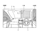
- FIG. 1 is a perspective view showing a state in which a part of a compartment of a vehicle according to the present embodiment is seen through.
- FIG. 2 is a diagram illustrating an example of the arrangement of the imaging devices included in the vehicle according to the present embodiment.
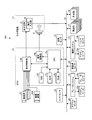
- FIG. 3 is a block diagram illustrating an example of a configuration of a viewing direction estimation system included in the vehicle according to the present embodiment.
- FIG. 4 is a block diagram illustrating a functional configuration of the ECU included in the vehicle according to the present embodiment.
- FIG. 5 is a diagram for explaining an example of the viewing direction estimated by the ECU of the vehicle according to the present embodiment.
- FIG. 6 is a diagram for explaining an example of the transition probability stored by the ECU of the vehicle according to the present embodiment.
- FIG. 1 is a perspective view showing a state in which a part of a compartment of a vehicle according to the present embodiment is seen through.
- FIG. 2 is a diagram illustrating an example of the arrangement of the imaging devices included in the vehicle according to the
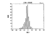
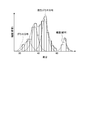
- FIG. 7A is a diagram illustrating an example of a distribution diagram of differences in line-of-sight angles calculated in the ECU of the vehicle according to the present embodiment.
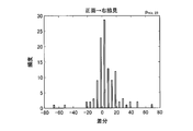
- FIG. 7B is a diagram illustrating an example of a distribution diagram of differences in line-of-sight angles calculated in the ECU of the vehicle according to the present embodiment.
- FIG. 7C is a diagram illustrating an example of a distribution diagram of differences in line-of-sight angles calculated in the ECU of the vehicle according to the present embodiment.
- FIG. 7D is a diagram illustrating an example of a distribution diagram of differences in line-of-sight angles calculated in the ECU of the vehicle according to the present embodiment.
- FIG. 7A is a diagram illustrating an example of a distribution diagram of differences in line-of-sight angles calculated in the ECU of the vehicle according to the present embodiment.
- FIG. 7B is a diagram illustrating an example of a distribution diagram of differences in line-of-sight angles calculated in the ECU of the vehicle according to the present
- FIG. 7E is a diagram illustrating an example of a distribution diagram of differences in line-of-sight angles calculated in the ECU of the vehicle according to the present embodiment.
- FIG. 7F is a diagram illustrating an example of a distribution diagram of differences in line-of-sight angles calculated in the ECU of the vehicle according to the present embodiment.
- FIG. 7G is a diagram illustrating an example of a distribution diagram of differences in line-of-sight angles calculated in the ECU of the vehicle according to the present embodiment.
- FIG. 7H is a diagram illustrating an example of a distribution diagram of differences in line-of-sight angles calculated in the ECU of the vehicle according to the present embodiment.
- FIG. 7E is a diagram illustrating an example of a distribution diagram of differences in line-of-sight angles calculated in the ECU of the vehicle according to the present embodiment.
- FIG. 7F is a diagram illustrating an example of a distribution diagram of differences in line-of-sight angles calculated in the ECU of the vehicle according to the present
- FIG. 7I is a diagram illustrating an example of a distribution diagram of differences in line-of-sight angles calculated in the ECU of the vehicle according to the present embodiment.
- FIG. 8 is a diagram for explaining an example of a method for calculating a mixed Gaussian distribution in the ECU of the vehicle according to the present embodiment.
- FIG. 9 is a flowchart illustrating an example of a state probability calculation process performed by the ECU of the vehicle according to the present embodiment.
- FIG. 10 is a diagram for explaining an example of a state probability calculation process performed by the ECU of the vehicle according to the present embodiment.
- FIG. 11 is a diagram illustrating an example of the calculation result of the state probability by the ECU of the vehicle according to the present embodiment.
- FIG. 12 is a diagram illustrating an example of a correspondence relationship between the relevance ratio in the visual direction and the recall ratio by the ECU of the vehicle according to the present embodiment.
- the vehicle 1 may be, for example, an automobile (an internal combustion engine automobile) using an internal combustion engine (engine, not shown) as a drive source, or an electric motor (motor, not shown) as a drive source.
- the vehicle may be a vehicle (electric vehicle, fuel cell vehicle, etc.) or a vehicle (hybrid vehicle) using both of them as drive sources.
- the vehicle 1 can be mounted with various transmissions, and various devices (systems, components, etc.) necessary for driving the internal combustion engine and the electric motor.
- the method, number, layout, and the like of the device related to driving of the wheels 3 in the vehicle 1 can be variously set.
- the vehicle body 2 of the vehicle 1 has a passenger compartment 2a in which a driver (not shown) gets.
- a steering section 4 and the like are provided in the passenger compartment 2a so as to face the driver's seat 2b as a passenger.
- the steering unit 4 is a steering wheel that protrudes from a dashboard (instrument panel) 12.
- the vehicle 1 is a four-wheeled vehicle (four-wheeled vehicle), and has two left and right front wheels 3F and two left and right rear wheels 3R. Furthermore, in this embodiment, these four wheels 3 are provided so that all can be steered (to be able to steer).
- a monitor device 11 is provided in the vehicle width direction of the dashboard 12 in the passenger compartment 2a, that is, in the center in the left-right direction.
- the monitor device 11 is provided with a display device 8 (see FIG. 3) and an audio output device 9 (see FIG. 3).
- the display device 8 is, for example, an LCD (Liquid Crystal Display), an OELD (Organic Electroluminescent Display), or the like.
- the audio output device 9 is, for example, a speaker.
- the display device is covered with a transparent operation input unit 10 (see FIG. 3) such as 8, for example, a touch panel.
- the occupant can visually recognize an image displayed on the display screen of the display device 8 via the operation input unit 10.
- the occupant can execute an operation input by touching, pushing, or moving the operation input unit 10 with a finger or the like at a position corresponding to the image displayed on the display screen of the display device 8. .
- an imaging device 201 is installed in the handle column 202.
- the imaging device 201 is, for example, a CCD (Charge Coupled Device) camera or the like.
- the imaging device 201 is adjusted in view angle and posture so that the face of the driver 302 seated on the seat 2b is positioned at the center of the view.
- the imaging device 201 sequentially captures the face of the driver 302 and sequentially outputs image data regarding images obtained by the imaging.
- FIG. 3 is a block diagram illustrating an example of a configuration of a viewing direction estimation system included in the vehicle according to the present embodiment.
- a viewing direction estimation system 100 in addition to an ECU (Engine Control Unit) 14, a monitor device 11, a steering system 13, distance measuring units 16 and 17, a brake system 18 and a steering angle sensor 19.
- the accelerator sensor 20, the shift sensor 21, the wheel speed sensor 22, and the like are electrically connected via an in-vehicle network 23 as an electric communication line.
- the in-vehicle network 23 is configured as, for example, a CAN (Controller Area Network).
- the ECU 14 sends a control signal through the in-vehicle network 23 to control the steering system 13, the brake system 18, etc., and drive the actuators 13 a and 18 a. Further, the ECU 14 detects the detection results of the torque sensor 13b, the brake sensor 18b, the rudder angle sensor 19, the distance measuring units 16, 17, the accelerator sensor 20, the shift sensor 21, the wheel speed sensor 22 and the like via the in-vehicle network 23, An operation signal from the operation input unit can be received.
- the ECU 14 is an example of a visual recognition direction estimation device.
- the ECU 14 includes, for example, a CPU 14a (Central Processing Unit), a ROM 14b (Read Only Memory), a RAM 14c (Random Access Memory), a display control unit 14d, an audio control unit 14e, an SSD 14f (Solid State Drive, a flash memory), and the like. Yes.
- the CPU 14a controls the entire vehicle 1.
- the CPU 14a can read a program installed and stored in a non-volatile storage device such as the ROM 14b and execute arithmetic processing according to the program.
- the RAM 14c temporarily stores various types of data used in computations by the CPU 14a.
- the display control unit 14d is an image process using image data obtained by imaging of the imaging unit 15 provided so as to be able to capture an image of the outside of the vehicle 1 in a calculation process in the ECU 14, or a display device.
- the composition of the displayed image data is executed.
- the voice control unit 14e mainly performs processing of voice data output from the voice output device among the calculation processes in the ECU 14.
- the SSD 14f is a rewritable nonvolatile storage unit that can store data even when the ECU 14 is powered off.
- the CPU 14a, the ROM 14b, the RAM 14c, and the like can be integrated in the same package.
- the ECU 14 may have a configuration in which another logical operation processor such as a DSP (Digital Signal Processor) or a logic circuit is used instead of the CPU 14a.
- another logical operation processor such as a DSP (Digital Signal Processor) or a logic circuit is used instead of the CPU 14a.
- an HDD Hard Disk Drive
- the SSD 14f and the HDD may be provided separately from the ECU 14.
- the configuration, arrangement, electrical connection form, and the like of the various sensors and actuators described above are examples, and can be set (changed) in various ways.
- FIG. 4 is a block diagram showing a functional configuration of the ECU of the vehicle according to the present embodiment.
- the ECU 14 mainly includes a storage unit 400, an input information calculation unit 401, a transition probability update unit 402, a state probability calculation unit 403, and a visual recognition direction estimation unit 404.
- the input information calculation unit 401, transition probability update unit 402, state probability calculation unit 403, and visual recognition direction estimation unit 404 shown in FIG. 4 are realized by the CPU 14a of the ECU 14 executing a program stored in the ROM 14b.
- the These configurations may be realized by hardware.
- the storage unit 400 is secured in a storage medium such as the RAM 14c or the SSD 14f. In the present embodiment, as will be described later, the storage unit 400 stores the transition probability between the viewing directions of the driver of the vehicle 1 and input information that is observation values related to the face or line of sight of the driver of the vehicle 1. .
- the storage unit 400 stores an observation value (so-called learning data) at time t-2 and an observation value (so-called learning data) at time t-1 after the time t-2.
- the storage unit 400 stores a transition probability a ij from the viewing direction of the driver of the vehicle 1 at time t ⁇ 1 to the viewing direction at time t after time t ⁇ 1.
- the viewing direction is an internal state that cannot be observed in the hidden Markov model.
- i is a value representing the viewing direction at time t ⁇ 1 (hereinafter referred to as an output value).
- j is an output value representing the viewing direction at time t.
- the ECU 14 calculates a state probability ⁇ t (j) of transition from each viewing direction at time t ⁇ 1 to each viewing direction at time t according to the transition probability a ij stored in the storage unit 400 using the hidden Markov model. And the visual recognition direction of the time after time t is estimated based on the said state probability (alpha) t (j).
- FIG. 5 is a diagram for explaining an example of the viewing direction estimated by the ECU of the vehicle according to the present embodiment.
- FIG. 6 is a diagram for explaining an example of the transition probability stored by the ECU of the vehicle according to the present embodiment.
- the viewing direction estimated by the ECU 14 is a left-side look (output value: 1) in which the driver is viewing the left direction while sitting on the seat 2 b, the driver.
- the front side (output value: 2) in which the driver is seated on the seat 2b and the right side look (output value: 3).
- the viewing direction estimated by the ECU 14 is a left side look, a front view, and a right side look, but is not limited thereto. For example, a downward view when the driver of the vehicle 1 is seated on the seat 2b and a downward view when the driver of the vehicle 1 is seated on the seat 2b, or an upward direction when the driver of the vehicle 1 is seated on the seat 2b.
- the viewing direction may be a viewing direction estimated by the ECU 14.
- the input information calculation unit 401 calculates an observation value related to the face or line of sight of the driver of the vehicle 1.
- the input information calculation unit 401 is configured such that the face angle of the driver of the vehicle 1 (hereinafter referred to as a face angle), the angle of line of sight of the driver of the vehicle 1 (hereinafter referred to as a line-of-sight angle), or a vehicle
- the moving speed of one driver's face is calculated as an observed value.
- the face angle is an angle obtained by rotating the face of the driver of the vehicle 1 in the horizontal direction with reference to the face angle (0 °) when the driver of the vehicle 1 is viewing the front.
- the line-of-sight angle is an angle at which the line of sight of the driver of the vehicle 1 moves in the horizontal direction with reference to the line-of-sight angle (0 °) when the driver of the vehicle 1 is viewing the front. Then, the input information calculation unit 401 transmits input information representing the calculated observation value to the transition probability update unit 402.
- the storage medium such as the SSD 14f stores the three-dimensional face model.
- the three-dimensional face model is a statistical face shape model, and has the average three-dimensional face shape of the subject and the positions of face parts such as the eyes, mouth, and nose of the subject.
- a three-dimensional face model for example, CLM (Constrained Local Model), AAM (Active Appearance Model), ASM (Active Shape Model) can be used, but is not limited thereto.
- the input information calculation unit 401 uses the three-dimensional face model stored in the storage medium such as the SSD 14f to track the face image included in the captured image data obtained by the imaging device 201, and the face angle Then, the line-of-sight angle or the moving speed is calculated.
- the input information calculation unit 401 calculates a face angle, a line-of-sight angle, or a moving speed as an example of an observation value, but calculates an observation value related to the face or line of sight of the driver of the vehicle 1.
- the present invention is not limited to this, and for example, the degree of eye opening of the driver of the vehicle 1 may be calculated as an observation value.
- the transition probability update unit 402 functions as a reception unit that receives input information from the input information calculation unit 401.
- the transition probability update unit 402 then observes the observation value calculated by the input information calculation unit 401 at a time before time t (in this embodiment, the observation value calculated at time t-2 and the time t ⁇ 1).
- the transition probability a ij stored in the storage unit 400 is updated based on the calculated observation value) and the observation value calculated at the time t by the input information calculation unit 401.
- the transition probability update unit 402 generates a state transition from the viewing direction at time t-2 in the time before time t to the viewing direction at time t-1 in the time before time t.
- the transition probability update unit 402 updates the transition probability a ij based on the obtained probability density function.
- the transition probability update unit 402 updates the transition probability a ij based on the probability density function every time the viewing direction is estimated. Thereby, since the viewing direction is estimated using the transition probability a ij reflecting the driver's habit or the like when estimating the viewing direction, it is possible to further improve the estimation accuracy of the viewing direction.
- the transition probability update unit 402 obtains a probability density function in advance prior to the update of the transition probability a ij . As a result, when estimating the viewing direction, the viewing direction can be estimated without waiting for the time required to calculate the probability density function, so that the time required for estimating the viewing direction can be shortened.
- FIGS. 7A to 7I are diagrams illustrating examples of frequency distribution diagrams for each difference generated between the line-of-sight angles calculated in the ECU of the vehicle according to the present embodiment.
- FIG. 8 is a diagram for explaining an example of a method for calculating a mixed Gaussian distribution in the ECU of the vehicle according to the present embodiment.
- the transition probability update unit 402 is calculated at time t-2 when transitioning from the viewing direction at time t-2 to each viewing direction at time t-1.
- a distribution map for each difference x t generated between the viewing angle ⁇ t ⁇ 2 and the viewing angle ⁇ t ⁇ 1 calculated at time t ⁇ 1 is obtained.
- the frequency of the difference x t occurs it is different. For example, as shown in FIG.
- the transition probability update unit 402 looks at the time t-2 when the type of state transition occurs.
- a probability density function of a difference x t between the angle ⁇ t ⁇ 2 and the line-of-sight angle ⁇ t ⁇ 1 at time t ⁇ 1 is obtained by a mixed Gaussian model.
- the transition probability update unit 402 determines the line-of-sight angle ⁇ t-2 at time t-2 and the time when the state transition from the viewing direction at time t-2 to the viewing direction at time t-1 occurs.
- the transition probability update unit 402 obtains a probability density function of the obtained frequency distribution according to the mixed Gaussian model.
- the transition probability update unit 402 obtains a Gaussian distribution of each peak of the frequency distribution.
- the transition probability update unit 402 calculates a function representing a mixed Gaussian distribution obtained by combining the Gaussian distributions of the peaks of the frequency distribution using a mixed Gaussian model as a probability density function.
- the transition probability update unit 402 obtains a probability density function p mix, ij (x t , ⁇ ) according to the following equation (1).
- pr is the mixing ratio
- h (x t , ⁇ t ) is the Gaussian distribution of each peak of the frequency distribution
- R is the number of Gaussian distributions to be superimposed
- ⁇ is a predetermined parameter.
- the transition probability update unit 402 updates the transition probability a ij based on the probability density function.
- the transition probability update unit 402 updated transition probabilities a ij probability of the state transition represented by the density function p mix, ij (x t, ⁇ ) selected.
- the transition probability updating unit 402 out of the probability density represented by the selected probability density function p mix, ij (x t , ⁇ ), the line-of-sight angle ⁇ t-1 at time t ⁇ 1 and the line-of-sight angle ⁇ t at time t.
- the transition probability a ij to be updated is updated using the probability density at the difference x t with respect to.
- the transition probability update unit 402 obtains a transition probability a t, ij (x t ) obtained by updating the transition probability a ij according to the following formula (2) or formula (3). Specifically, when the transition probability a ij to be updated is a fixed value, the transition probability update unit 402 obtains the updated transition probability a t, ij (x t ) according to the following equation (2). On the other hand, when the transition probability updating unit 402 uses the transition probability a ij to be updated as the last updated transition probability, the updated transition probability a t, ij (x t ) according to the following equation (3). Ask for. Here, the transition probability updated last is the transition probability a t ⁇ 1, ij (x t ⁇ 1 ) used to calculate the state probability of transitioning to the viewing direction at time t ⁇ 1.
- the state probability calculation unit 403 uses the hidden Markov model to transition from each viewing direction at time t ⁇ 1 to each viewing direction at time t according to the updated transition probability a t, ij (x t ).
- the state probability ⁇ t (j) to be calculated is calculated.
- the state probability calculation unit 403 performs state probability ⁇ t (j) according to the transition probability a t, ij (x t ) updated by the transition probability update unit 402 as shown in the following equation (4). ) Is calculated.
- ⁇ t-1 (i) is the state probability in each viewing direction at time t ⁇ 1
- b ( ⁇ t , x t ) is the observed value ⁇ t in each viewing direction at time t. Is the output probability calculated.
- the viewing direction estimation unit 404 estimates the viewing direction at the time t or the time t + 1 based on the state probability ⁇ t (j) calculated by the state probability calculation unit 403. Thereby, when a change occurs in the observed value, it is possible to easily detect the change in the viewing direction, and thus it is possible to follow the change in the viewing direction quickly.
- the viewing direction estimation unit 404 calculates time based on the state probability ⁇ t ⁇ 1 (i) of each viewing direction (left side look, front view, right side look) estimated at time t ⁇ 1.
- the viewing direction with the highest state probability ⁇ t (j) at t is estimated as the viewing direction at time t.
- the viewing direction estimation unit 404 calculates the state probability ⁇ t + at time t + 1, which is calculated based on the state probability ⁇ t (i) of each viewing direction (left side look, front, right side look) estimated at time t. 1
- the viewing direction with the highest (j) is estimated as the viewing direction at time t + 1.
- FIG. 9 is a flowchart illustrating an example of a state probability calculation process performed by the ECU of the vehicle according to the present embodiment.
- FIG. 10 is a diagram for explaining an example of a state probability calculation process performed by the ECU of the vehicle according to the present embodiment.
- FIG. 11 is a diagram illustrating an example of the calculation result of the state probability by the ECU of the vehicle according to the present embodiment.
- the input information calculation unit 401 calculates a face angle, a line-of-sight angle, or a moving speed as an observation value (step S901). Specifically, the input information calculation unit 401 adapts the image data obtained by imaging by the imaging device 201 and the 3D face structure data constituting the 3D face model. In other words, the input information calculation unit 401 calculates an observation value by performing model fitting and model tracking.
- the imaging device 201 repeats imaging of the driver of the vehicle 1 every preset time. Therefore, the input information calculation unit 401 performs model fitting and model tracking each time an image is picked up by the image pickup apparatus 201.
- Model fitting uses an average face model of a three-dimensional face model, which is a statistical face shape model, as an initial state, and positions feature points of the model in each part of the face of the picked-up image.
- a three-dimensional face model approximating the driver's face imaged by is generated.
- Model tracking continuously adapts the 3D model so that the face generated by model fitting matches the face in the driver's image data that is periodically imaged. Then, the input information calculation unit 401 calculates an observation value based on the three-dimensional model obtained by model tracking.
- the transition probability update unit 402 includes a difference x t between the observed value calculated at the time t ⁇ 2 by the input information calculating unit 401 and the observed value calculated at the time t ⁇ 1, and Based on the observation value calculated at time t by the input information calculation unit 401, the transition probability a t, ij (x t ) from the viewing direction at time t-1 to each viewing direction at time t is updated (step) S902). Furthermore, as shown in FIG. 11, the state probability calculation unit 403 uses the hidden Markov model according to the updated transition probability a t, ij (x t ), from the viewing direction at time t ⁇ 1 to each viewing at time t.
- a state probability ⁇ t (j) for transition in the direction is calculated (step S903). Thereafter, the viewing direction estimation unit 404 estimates the viewing direction at the time t or the time t + 1 based on the calculated state probability ⁇ t (j) (step S904).
- FIG. 12 is a diagram illustrating an example of a correspondence relationship between the relevance ratio and the recall ratio in the viewing direction by the ECU of the vehicle according to the present embodiment.
- the vertical axis represents the recall and the horizontal axis represents the precision.
- the relevance ratio is a ratio of the viewing direction (right side look) correctly estimated in the viewing direction (for example, right side look) estimated by the viewing direction estimation system 100.
- the recall is the ratio of the actual visual direction (for example, the right side look) of the driver of the vehicle 1 that the correct visual direction (right side look) is estimated by the visual direction estimation system 100. As shown in FIG.
- both the precision and recall of the viewing direction estimation process by the ECU 14 according to the present embodiment are higher than the precision and recall of the viewing direction estimation process performed by the conventional viewing direction estimation system. It has become.
- the transition probability update unit 402 obtains a mixed Gaussian distribution every time the viewing direction is estimated. Thereby, the relevance rate and recall rate of the estimated viewing direction can be further improved.
- the viewing direction estimation system 100 due to changes or caused be the observed value for the state change of the viewing direction, by dynamically changing the transition probability a ij, quick Since the estimation result of the viewing direction can be made to follow the change in the viewing direction, it is possible to improve the matching rate and the recall rate of the viewing direction estimation process.
- the program executed by the ECU 14 of the present embodiment is provided by being incorporated in advance in the ROM 14b or the like, but the program executed by the ECU 14 of the present embodiment is an installable format or an executable format file.
- the recording medium may be provided by being recorded on a computer-readable recording medium such as a CD-ROM, a flexible disk (FD), a CD-R, or a DVD (Digital Versatile Disk).
- the program executed by the ECU 14 of the present embodiment may be stored on a computer connected to a network such as the Internet and provided by being downloaded via the network. Moreover, you may comprise so that the program run by ECU14 of this embodiment may be provided or distributed via networks, such as the internet.
- the program executed by the ECU 14 of the present embodiment has a module configuration including the above-described units (the input information calculation unit 401, the transition probability update unit 402, the state probability calculation unit 403, and the viewing direction estimation unit 404).
- the CPU 14a reads the program from the ROM 14b and executes it, so that the above-described units are loaded on the main storage device.
- the input information calculation unit 401, the transition probability update unit 402, the state probability calculation unit 403, and the visual recognition A direction estimation unit 404 is generated on the main storage device.
Landscapes
- Engineering & Computer Science (AREA)
- Physics & Mathematics (AREA)
- Theoretical Computer Science (AREA)
- General Physics & Mathematics (AREA)
- Multimedia (AREA)
- Computer Vision & Pattern Recognition (AREA)
- Software Systems (AREA)
- Data Mining & Analysis (AREA)
- Health & Medical Sciences (AREA)
- Artificial Intelligence (AREA)
- Evolutionary Computation (AREA)
- General Health & Medical Sciences (AREA)
- Computing Systems (AREA)
- Ophthalmology & Optometry (AREA)
- Databases & Information Systems (AREA)
- Probability & Statistics with Applications (AREA)
- Life Sciences & Earth Sciences (AREA)
- Bioinformatics & Cheminformatics (AREA)
- Bioinformatics & Computational Biology (AREA)
- Evolutionary Biology (AREA)
- General Engineering & Computer Science (AREA)
- Medical Informatics (AREA)
- Human Computer Interaction (AREA)
- Automation & Control Theory (AREA)
- Mathematical Physics (AREA)
- Transportation (AREA)
- Mechanical Engineering (AREA)
- Traffic Control Systems (AREA)
- Image Analysis (AREA)
- Fittings On The Vehicle Exterior For Carrying Loads, And Devices For Holding Or Mounting Articles (AREA)
Abstract
実施形態の視認方向推定装置は、一例として、車両の運転者の視認方向間の遷移確率を記憶する記憶部と、車両の運転者の顔または視線に関わる観測値を受信する受信部と、第1時刻の観測値、および第1時刻より後の第2時刻の観測値に基づいて、第1時刻の視認方向から、第2時刻の視認方向への遷移確率を更新する更新部と、隠れマルコフモデルによって、更新後の遷移確率に従って、第1時刻の視認方向から、第2時刻の視認方向へ遷移する状態確率を算出する算出部と、算出した状態確率に基づいて、第2時刻以降の時刻の視認方向を推定する推定部と、を備える。
Description
本発明の実施形態は、視認方向推定装置に関する。
移動体の走行環境リスクと当該移動体を運転するドライバの運転操作との対応を学習し、その学習結果である学習モデルに基づいて、隠れマルコフモデル(HMM:Hidden Markov Model)を用いて、ドライバのリスク認識状態を内部状態として推定する技術がある。また、車両の運転手が注視している注視点の位置を示す注視点データの中から、特定の注視対象物を注視しているとみなされる注視点データを選択し、当該選択した注視点データに基づいて、当該特定の注視対象物に対応する範囲を定め、注視点データが示す位置が当該範囲に属する場合、運転手が特定の注視対象物を注視していると判定する技術がある。
しかしながら、隠れマルコフモデルを用いてドライバのリスク認識状態を推定する技術では、ドライバのリスク認識状態間の状態遷移が、学習モデルに大きく影響を受けるとともに、ドライバのリスク認識状態の変更が頻繁に発生する場合に、ドライバのリスク認識状態の推定がその変更に対して追従できない場合がある。また、注視点データを用いて特定の注視対象物を注視しているか否かを判定する技術は、注視対象物の変化に対してはロバスト性を有するが、注視点データに誤差が含まれたり、当該注視点データの誤差が外部環境によって大きく変化したりすると、特定の注視対象物を注視しているか否かの判定精度の低下を招く可能性がある。
実施形態の視認方向推定装置は、一例として、車両の運転者の視認方向間の遷移確率を記憶する記憶部と、車両の運転者の顔または視線に関わる観測値を受信する受信部と、第1時刻の観測値、および第1時刻より後の第2時刻の観測値に基づいて、第1時刻の視認方向から、第2時刻の視認方向への遷移確率を更新する更新部と、隠れマルコフモデルによって、更新後の遷移確率に従って、第1時刻の視認方向から、第2時刻の視認方向へ遷移する状態確率を算出する算出部と、算出した状態確率に基づいて、第2時刻以降の時刻の視認方向を推定する推定部と、を備える。よって、一例として、すばやい視認方向の変化に対して、視認方向の推定結果を追従させることができる。
また、上記視認方向推定装置は、一例として、更新部が、第2時刻より前の第3時刻の視認方向から、第2時刻より前でありかつ第3時刻より後の第4時刻の視認方向への状態遷移が発生した場合における、第3時刻の観測値と第4時刻の観測値との差分の確率密度関数を混合ガウスモデルによって求め、確率密度関数に基づいて、遷移確率を更新する。よって、一例として、遷移確率を用いた視認方向の推定精度を高めることができる。
また、上記視認方向推定装置は、一例として、更新部が、視認方向を推定する度に、確率密度関数に基づいて、遷移確率を更新する。よって、一例として、視認方向の推定精度をより高めることができる。
また、上記視認方向推定装置は、一例として、観測値が、車両の運転者の顔の角度、車両の運転者の視線の角度、車両の運転者の顔の移動速度、または車両の運転者の開眼度である。よって、一例として、すばやい視認方向の変化に対して、視認方向の推定結果を追従させることができる。
また、上記視認方向推定装置は、一例として、視認方向が、運転者が車両の座席に着座している状態で左方向を視認している左脇見、運転者が車両の座席に着座している状態で前方を視認している正面、運転者が車両の座席に着座している状態で右方向を視認している右脇見、または運転者が車両の座席に着座している状態で下方向を視認している下方視である。よって、一例として、左脇見、正面、右脇見、または下方視へのすばやい視認方向の変化に対して、視認方向の推定結果を追従させることができる。
以下、添付の図面を用いて、本実施形態の視認方向推定装置を車両に搭載した例をあげて説明する。
本実施形態では、車両1は、例えば、内燃機関(エンジン、図示されず)を駆動源とする自動車(内燃機関自動車)であってもよいし、電動機(モータ、図示されず)を駆動源とする自動車(電気自動車、燃料電池自動車等)であってもよいし、それらの双方を駆動源とする自動車(ハイブリッド自動車)であってもよい。また、車両1は、種々の変速装置を搭載することができるし、内燃機関や電動機を駆動するのに必要な種々の装置(システム、部品等)を搭載することができる。また、車両1における車輪3の駆動に関わる装置の方式や、数、レイアウト等は、種々に設定することができる。
図1に示されるように、車両1の車体2は、運転者(不図示)が乗車する車室2aを有する。車室2a内には、乗員としての運転者の座席2bに臨む状態で、操舵部4等が設けられている。本実施形態では、一例として、操舵部4は、ダッシュボード(インストルメントパネル)12から突出したステアリングホイールである。
また、図1に示されるように、本実施形態では、一例として、車両1は、四輪車(四輪自動車)であり、左右二つの前輪3Fと、左右二つの後輪3Rとを有する。さらに、本実施形態では、これら四つの車輪3は、いずれも操舵されうるように(転舵可能に)設けられている。
また、車室2a内のダッシュボード12の車幅方向すなわち左右方向の中央部には、モニタ装置11が設けられている。モニタ装置11には、表示装置8(図3参照)や音声出力装置9(図3参照)が設けられている。表示装置8は、例えば、LCD(Liquid Crystal Display)や、OELD(Organic Electroluminescent Display)等である。音声出力装置9は、例えば、スピーカである。また、表示装置は8、例えば、タッチパネル等、透明な操作入力部10(図3参照)で覆われている。乗員は、操作入力部10を介して表示装置8の表示画面に表示される画像を視認することができる。また、乗員は、表示装置8の表示画面に表示される画像に対応した位置において手指等で操作入力部10を触れたり押したり動かしたりして操作することで、操作入力を実行することができる。
また、図2に示すように、ハンドルコラム202には、撮像装置201が設置されている。この撮像装置201は、例えば、CCD(Charge Coupled Device)カメラ等である。撮像装置201は、座席2bに着座する運転者302の顔が、視野中心に位置するように、視野角および姿勢が調整されている。この撮像装置201は、運転者302の顔を順次撮像し、撮像により得た画像についての画像データを順次出力する。
次に、図3を用いて、本実施形態にかかる車両が有する視認方向推定システムについて説明する。図3は、本実施形態にかかる車両が有する視認方向推定システムの構成の一例を示すブロック図である。図3に例示されるように、視認方向推定システム100では、ECU(Engine Control Unit)14、モニタ装置11、操舵システム13、測距部16,17等の他、ブレーキシステム18、舵角センサ19、アクセルセンサ20、シフトセンサ21、車輪速センサ22等が、電気通信回線としての車内ネットワーク23を介して電気的に接続されている。車内ネットワーク23は、例えば、CAN(Controller Area Network)として構成されている。ECU14は、車内ネットワーク23を通じて制御信号を送ることで、操舵システム13、ブレーキシステム18等を制御して、アクチュエータ13a,18aを駆動させる。また、ECU14は、車内ネットワーク23を介して、トルクセンサ13b、ブレーキセンサ18b、舵角センサ19、測距部16,17、アクセルセンサ20、シフトセンサ21、車輪速センサ22等の検出結果や、操作入力部等の操作信号等を、受け取ることができる。ここで、ECU14は、視認方向推定装置の一例である。
ECU14は、例えば、CPU14a(Central Processing Unit)、ROM14b(Read Only Memory)、RAM14c(Random Access Memory)、表示制御部14d、音声制御部14e、SSD14f(Solid State Drive、フラッシュメモリ)等を有している。CPU14aは、車両1全体の制御を行う。CPU14aは、ROM14b等の不揮発性の記憶装置にインストールされ記憶されたプログラムを読み出し、当該プログラムにしたがって演算処理を実行できる。RAM14cは、CPU14aでの演算で用いられる各種のデータを一時的に記憶する。また、表示制御部14dは、ECU14での演算処理のうち、主として、車両1の外部を撮像可能に設けられた撮像部15の撮像で得られた画像データを用いた画像処理や、表示装置で表示される画像データの合成等を実行する。また、音声制御部14eは、ECU14での演算処理のうち、主として、音声出力装置で出力される音声データの処理を実行する。また、SSD14fは、書き換え可能な不揮発性の記憶部であって、ECU14の電源がオフされた場合にあってもデータを記憶することができる。なお、CPU14aや、ROM14b、RAM14c等は、同一パッケージ内に集積されうる。また、ECU14は、CPU14aに替えて、DSP(Digital Signal Processor)等の他の論理演算プロセッサや論理回路等が用いられる構成であってもよい。また、SSD14fに替えてHDD(Hard Disk Drive)が設けられてもよいし、SSD14fやHDDは、ECU14とは別に設けられてもよい。上述した各種センサやアクチュエータの構成や、配置、電気的な接続形態等は、一例であって、種々に設定(変更)することができる。
図4は、本実施形態にかかる車両が有するECUの機能的構成を示すブロック図である。図4に示されるように、ECU14は、記憶部400と、入力情報算出部401と、遷移確率更新部402と、状態確率算出部403と、視認方向推定部404と、を主に備えている。図4に示す、入力情報算出部401、遷移確率更新部402、状態確率算出部403、および視認方向推定部404は、ECU14が有するCPU14aが、ROM14bに記憶されたプログラムを実行することで実現される。これらの構成は、ハードウェアで実現するように構成しても良い。記憶部400は、RAM14cやSSD14f等の記憶媒体に確保される。本実施形態では、記憶部400は、後述するように、車両1の運転者の視認方向間の遷移確率、および車両1の運転者の顔または視線に関わる観測値である入力情報等を記憶する。
具体的には、記憶部400は、時刻t-2における観測値(所謂、学習データ)および当該時刻t-2より後の時刻t-1における観測値(所謂、学習データ)を記憶する。また、記憶部400は、時刻t-1における車両1の運転者の視認方向から、時刻t-1より後の時刻tにおける視認方向への遷移確率aijを記憶する。ここで、視認方向は、隠れマルコフモデルにおける、観測できない内部状態とする。また、iは、時刻t-1における視認方向を表す値(以下、出力値と言う)である。jは、時刻tにおける視認方向を表す出力値である。そして、ECU14は、隠れマルコフモデルによって、記憶部400に記憶された遷移確率aijに従って、時刻t-1の各視認方向から時刻tの各視認方向へ遷移する状態確率αt(j)を算出し、当該状態確率αt(j)に基づいて、時刻t以降の時刻の視認方向を推定する。
図5は、本実施形態にかかる車両が有するECUによって推定する視認方向の一例を説明するための図である。図6は、本実施形態にかかる車両が有するECUによって記憶する遷移確率の一例を説明するための図である。本実施形態では、図5に示すように、ECU14によって推定する視認方向を、運転者が座席2bに着座している状態で左方向を視認している左脇見(出力値:1)、運転者が座席2bに着座している状態で前方を視認している正面(出力値:2)、および運転者が座席2bに着座している状態で右方向を視認している右脇見(出力値:3)とする。よって、本実施形態では、時刻t-1において視認方向がとり得る3個の出力値それぞれに対して、時刻t以降の時刻で視認方向がとり得る3個の出力値への遷移確率aijが存在することになる。そのため、遷移確率aijは、図6に示すように、3×3のマルコフ行列により表される。本実施形態では、ECU14によって推定する視認方向を、左脇見、正面、および右脇見としているが、これに限定するものではない。例えば、車両1の運転者が座席2bに着座している状態で下方向を視認している下方視や、車両1の運転者が座席2bに着座している状態で上方向を視認している上方視を、ECU14によって推定する視認方向としても良い。
入力情報算出部401は、車両1の運転者の顔または視線に関わる観測値を算出する。本実施形態では、入力情報算出部401は、車両1の運転者の顔の角度(以下、顔角度と言う)、車両1の運転者の視線の角度(以下、視線角度と言う)、または車両1の運転者の顔の移動速度を観測値として算出する。ここで、顔角度は、車両1の運転者が正面を視認している場合における顔角度(0°)を基準として、車両1の運転者の顔が水平方向へ回転した角度である。また、視線角度は、車両1の運転者が正面を視認している場合における視線角度(0°)を基準として、車両1の運転手の視線が水平方向に移動した角度である。そして、入力情報算出部401は、算出した観測値を表す入力情報を、遷移確率更新部402に送信する。
具体的には、SSD14f等の記憶媒体が、三次元顔モデルを記憶している。三次元顔モデルは、統計的顔形状モデルであり、平均的な被験者の三次元顔形状と、被験者の目や口、鼻等の顔部品の位置とを有している。三次元顔モデルは、一例として、CLM(Constrained Local Model)、AAM(Active Appearance Model)、ASM(Active Shape Model)を用いることができるが、これらに限定されるものではない。そして、入力情報算出部401は、SSD14f等の記憶媒体に記憶された三次元顔モデルを用いて、撮像装置201の撮像により得られた撮像画像データに含まれる顔画像を追跡しながら、顔角度、視線角度、または移動速度を算出する。本実施形態では、入力情報算出部401は、顔角度、視線角度、または移動速度を観測値の一例として算出しているが、車両1の運転者の顔または視線に関わる観測値を算出するものであれば、これに限定するものではなく、例えば、車両1の運転者の開眼度を観測値として算出しても良い。
遷移確率更新部402は、入力情報算出部401から入力情報を受信する受信部として機能する。そして、遷移確率更新部402は、入力情報算出部401によって時刻tより前の時刻に算出された観測値(本実施形態では、時刻t-2に算出された観測値、および時刻t-1に算出された観測値)と、入力情報算出部401によって時刻tに算出された観測値と、に基づいて、記憶部400に記憶された遷移確率aijを更新する。本実施形態では、遷移確率更新部402は、時刻tより前の時刻のうち時刻t-2の視認方向から、時刻tより前の時刻のうち時刻t-1の視認方向への状態遷移が発生した場合における、時刻t-2に算出された観測値と時刻t-1に算出された観測値との差分xtの確率密度関数を混合ガウス分布によって求める。そして、遷移確率更新部402は、求めた確率密度関数に基づいて、遷移確率aijを更新する。これにより、観測値にノイズが含まれていても、当該ノイズによる遷移確率aijへの影響を小さくすることができるので、遷移確率aijを用いた視認方向の推定精度を高めることができる。
本実施形態では、遷移確率更新部402は、視認方向を推定する度に、確率密度関数に基づいて、遷移確率aijを更新する。これにより、視認方向を推定する際の運転者の癖等が反映された遷移確率aijを用いて視認方向が推定されるので、視認方向の推定精度をより高めることができる。また、本実施形態では、遷移確率更新部402は、遷移確率aijの更新に先立って、確率密度関数を予め求めておくものとする。これにより、視認方向を推定する際に、確率密度関数の算出に要する時間を待つことなく、視認方向を推定することができるので、視認方向の推定に要する時間を短縮することができる。
ここで、図7A~7I、および図8を用いて、遷移確率aijの更新方法について説明する。以下の説明では、入力情報算出部401において算出された視線角度を観測値として用いて遷移確率aijを更新する方法について説明するが、顔角度または移動速度を観測値として用いて遷移確率aijを更新する場合も同様である。図7A~7Iは、本実施形態にかかる車両が有するECUにおいて算出する視線角度間に生じる差分毎の頻度の分布図の一例を示す図である。図7A~7Iにおいて、横軸は、時刻t-2に算出された視線角度ωt-2と、時刻t-1に算出された視線角度ωt-1との間に生じる差分xtを表している。図7A~7Iにおいて、縦軸は、差分xtの頻度を表している。図8は、本実施形態にかかる車両が有するECUにおける混合ガウス分布の算出方法の一例を説明するための図である。
本実施形態では、遷移確率更新部402は、図7A~7Iに示すように、時刻t-2の視認方向から時刻t-1の各視認方向へ遷移した場合に、時刻t-2に算出される視線角度ωt-2と、時刻t-1において算出される視線角度ωt-1との間に生じる差分xt毎の分布図を求める。この分布図によれば、時刻t-2の視認方向から時刻t-1の視認方向への状態遷移の種類毎に、差分xtが生じる頻度が異なる。例えば、図7Aに示すように、時刻t-2の視認方向が左脇見でありかつ時刻t-1の視認方向が左脇見である場合、差分xt=-40°が生じる頻度が「50」である。一方、図7Bに示すように、時刻t-2の視認方向が左脇見でありかつ時刻t-1の視認方向が正面である場合、差分xt=-40°が生じる頻度が「3」である。また、図7Cに示すように、時刻t-2の視認方向が左脇見でありかつ時刻t-1の視認方向が右脇見である場合、差分xt=-40°が生じる頻度が「0」である。
そこで、遷移確率更新部402は、時刻t-2の視認方向から時刻t-1の視認方向への状態遷移の種類毎に、当該種類の状態遷移が発生した場合における、時刻t-2の視線角度ωt-2と時刻t-1の視線角度ωt-1との差分xtの確率密度関数を、混合ガウスモデルによって求める。具体的には、遷移確率更新部402は、時刻t-2の視認方向から時刻t-1の視認方向への状態遷移が発生した場合における、時刻t-2の視線角度ωt-2と時刻t-1の視線角度ωt-1との差分xt毎の頻度(または確率)の分布(以下、頻度分布と言う)を求める。次いで、遷移確率更新部402は、混合ガウスモデルに従って、求めた頻度分布の確率密度関数を求める。
より具体的には、図8に示すように、遷移確率更新部402は、頻度分布の各ピークのガウス分布を求める。次いで、図8に示すように、遷移確率更新部402は、頻度分布の各ピークのガウス分布を、混合ガウスモデルによって結合した混合ガウス分布を表す関数を、確率密度関数として算出する。
例えば、遷移確率更新部402は、下記の式(1)に従って、確率密度関数pmix,ij(xt,θ)を求める。式(1)において、prは混合比であり、h(xt,ωt)は頻度分布の各ピークのガウス分布であり、Rは重ね合わせるガウス分布の数であり、θは所定のパラメータ{(pr,ωt):1≦r≦R}である。

そして、遷移確率更新部402は、確率密度関数に基づいて、遷移確率aijを更新する。本実施形態では、遷移確率更新部402は、更新対象の遷移確率aijが表す状態遷移の確率密度関数pmix,ij(xt,θ)を選択する。次いで、遷移確率更新部402は、選択した確率密度関数pmix,ij(xt,θ)が表す確率密度のうち、時刻t-1の視線角度ωt-1と時刻tの視線角度ωtとの差分xtでの確率密度を用いて、更新対象の遷移確率aijを更新する。
例えば、遷移確率更新部402は、下記の式(2)または式(3)に従って、遷移確率aijを更新した遷移確率at,ij(xt)を求める。具体的には、遷移確率更新部402は、更新対象の遷移確率aijを固定値とする場合、下記の式(2)に従って、更新後の遷移確率at,ij(xt)を求める。一方、遷移確率更新部402は、更新対象の遷移確率aijを、最後に更新された遷移確率とする場合、下記の式(3)に従って、更新後の遷移確率at,ij(xt)を求める。ここで、最後に更新された遷移確率は、時刻t-1の視認方向へ遷移する状態確率の算出に用いた遷移確率at-1,ij(xt-1)である。


図4に戻り、状態確率算出部403は、隠れマルコフモデルによって、更新後の遷移確率at,ij(xt)に従って、時刻t-1の各視認方向から、時刻tの各視認方向へ遷移する状態確率αt(j)を算出する。本実施形態では、状態確率算出部403は、下記の式(4)に示すように、遷移確率更新部402によって更新された遷移確率at,ij(xt)に従って、状態確率αt(j)を算出する。式(4)において、αt-1(i)は、時刻t-1における各視認方向の状態確率であり、b(ωt,xt)は、時刻tにおいて各視認方向で観測値ωtが算出される出力確率である。

視認方向推定部404は、状態確率算出部403により算出された状態確率αt(j)に基づいて、時刻tまたは時刻t+1における視認方向を推定する。これにより、観測値に変化が生じた際に、視認方向の変化を検出し易くすることができるので、素早い視認方向の変化に対して追従させることができる。本実施形態では、視認方向推定部404は、時刻t-1において推定された各視認方向(左脇見、正面、右脇見)の状態確率αt-1(i)に基づいて計算される、時刻tにおける状態確率αt(j)が最も高い視認方向を、時刻tにおける視認方向と推定する。また、視認方向推定部404は、時刻tにおいて推定された各視認方向(左脇見、正面、右脇見)の状態確率αt(i)に基づいて計算される、時刻t+1における状態確率αt+1(j)が最も高い視認方向を、時刻t+1における視認方向と推定する。
次に、図9~11を用いて、本実施形態にかかるECU14による状態確率αt(j)の算出処理の流れについて説明する。図9は、本実施形態にかかる車両が有するECUによる状態確率の算出処理の流れの一例を示すフローチャートである。図10は、本実施形態にかかる車両が有するECUによる状態確率の算出処理の一例を説明するための図である。図11は、本実施形態にかかる車両が有するECUによる状態確率の算出結果の一例を示す図である。
本実施形態では、入力情報算出部401は、顔角度、視線角度、または移動速度を観測値として算出する(ステップS901)。具体的には、入力情報算出部401は、撮像装置201の撮像により得られた画像データと、三次元顔モデルを構成する三次元顔構造データとを適合させる。言い換えると、入力情報算出部401は、モデルフィッティングとモデルトラッキングを行うことにより、観測値を算出する。本実施形態では、撮像装置201は、予め設定された時間毎に、車両1の運転者の撮像を繰り返す。そのため、入力情報算出部401は、撮像装置201により撮像が行われる度に、モデルフィッティングおよびモデルトラッキングを行う。
モデルフィッティングは、統計的顔形状モデルである三次元顔モデルの平均的な顔のモデルを初期状態として用い、該モデルの特徴点を撮像画像の顔の各部分に位置させることにより、撮像装置201により撮像した運転者の顔に近似した三次元顔モデルを生成する。モデルトラッキングは、モデルフィッティングにより生成された顔を、周期的に撮像される運転者の画像データ中の顔に合うように三次元モデルを継続的に適合させる。そして、入力情報算出部401は、モデルトラッキングにより得られた三次元モデルに基づいて、観測値を算出する。
次いで、遷移確率更新部402は、図10に示すように、入力情報算出部401によって時刻t-2に算出された観測値と時刻t-1に算出された観測値との差分xt、および入力情報算出部401によって時刻tに算出された観測値に基づいて、時刻t-1における視認方向から、時刻tにおける各視認方向への遷移確率at,ij(xt)を更新する(ステップS902)。さらに、状態確率算出部403は、図11に示すように、隠れマルコフモデルによって、更新後の遷移確率at,ij(xt)に従って、時刻t-1における視認方向から、時刻tにおける各視認方向へ遷移する状態確率αt(j)を算出する(ステップS903)。その後、視認方向推定部404は、算出した状態確率αt(j)に基づいて、時刻tまたは時刻t+1における視認方向を推定する(ステップS904)。
図12は、本実施形態にかかる車両が有するECUによる視認方向の適合率と再現率の対応関係の一例を示す図である。図12において、縦軸が再現率を表し、横軸が適合率を表す。ここで、適合率は、視認方向推定システム100により推定された視認方向(例えば、右脇見)のうち正しく推定された視認方向(右脇見)の割合である。再現率は、車両1の運転手の実際の視認方向(例えば、右脇見)のうち視認方向推定システム100により正しい視認方向(右脇見)を推定した割合である。図12に示すように、本実施形態にかかるECU14による視認方向の推定処理の適合率および再現率は、共に、従来の視認方向推定システムによる視認方向の推定処理の適合率および再現率よりも高くなっている。本実施形態では、遷移確率更新部402は、視認方向を推定する度に、混合ガウス分布を求めなおす。これにより、推定する視認方向の適合率および再現率をより向上させることができる。
このように、本実施形態にかかる視認方向推定システム100によれば、観測値に変化か生じることによる、視認方向の状態変化に対して、遷移確率aijを動的に変化させることで、すばやい視認方向の変化に対して、視認方向の推定結果を追従させることができるので、視認方向の推定処理の適合率および再現率を向上させることができる。
なお、本実施形態のECU14で実行されるプログラムは、ROM14b等に予め組み込まれて提供されるが、本実施形態のECU14で実行されるプログラムは、インストール可能な形式又は実行可能な形式のファイルでCD-ROM、フレキシブルディスク(FD)、CD-R、DVD(Digital Versatile Disk)等のコンピュータで読み取り可能な記録媒体に記録して提供するように構成してもよい。
さらに、本実施形態のECU14で実行されるプログラムを、インターネット等のネットワークに接続されたコンピュータ上に格納し、ネットワーク経由でダウンロードさせることにより提供するように構成しても良い。また、本実施形態のECU14で実行されるプログラムをインターネット等のネットワーク経由で提供または配布するように構成しても良い。
本実施形態のECU14で実行されるプログラムは、上述した各部(入力情報算出部401、遷移確率更新部402、状態確率算出部403、および視認方向推定部404)を含むモジュール構成となっており、実際のハードウェアとしてはCPU14aが上記ROM14bからプログラムを読み出して実行することにより上記各部が主記憶装置上にロードされ、入力情報算出部401、遷移確率更新部402、状態確率算出部403、および視認方向推定部404が主記憶装置上に生成されるようになっている。
以上、本発明の実施形態を例示したが、上記実施形態は、例として提示したものであり、発明の範囲を限定することは意図していない。上記実施形態は、その他の様々な形態で実施されることが可能であり、発明の要旨を逸脱しない範囲で、種々の省略、置き換え、変更を行うことができる。この実施形態は、発明の範囲や要旨に含まれるとともに、特許請求の範囲に記載された発明とその均等の範囲に含まれる。
Claims (5)
- 車両の運転者の視認方向間の遷移確率を記憶する記憶部と、
車両の運転者の顔または視線に関わる観測値を受信する受信部と、
第1時刻の前記観測値、および前記第1時刻より後の第2時刻の前記観測値に基づいて、前記第1時刻の前記視認方向から、第2時刻の前記視認方向への前記遷移確率を更新する更新部と、
隠れマルコフモデルによって、更新後の前記遷移確率に従って、前記第1時刻の前記視認方向から、前記第2時刻の前記視認方向へ遷移する状態確率を算出する算出部と、
算出した前記状態確率に基づいて、前記第2時刻以降の時刻の前記視認方向を推定する推定部と、
を備えた視認方向推定装置。 - 前記更新部は、前記第2時刻より前の第3時刻の前記視認方向から、前記第2時刻より前でありかつ前記第3時刻より後の第4時刻の前記視認方向への状態遷移が発生した場合における、前記第3時刻の前記観測値と前記第4時刻の前記観測値との差分の確率密度関数を混合ガウスモデルによって求め、前記確率密度関数に基づいて、前記遷移確率を更新する請求項1に記載の視認方向推定装置。
- 前記更新部は、前記視認方向を推定する度に、前記確率密度関数に基づいて、前記遷移確率を更新する請求項2に記載の視認方向推定装置。
- 前記観測値は、車両の運転者の顔の角度、車両の運転者の視線の角度、車両の運転者の顔の移動速度、または車両の運転者の開眼度である請求項1から3のいずれか一に記載の視認方向推定装置。
- 前記視認方向は、運転者が車両の座席に着座している状態で左方向を視認している左脇見、運転者が車両の座席に着座している状態で前方を視認している正面、運転者が車両の座席に着座している状態で右方向を視認している右脇見、または運転者が車両の座席に着座している状態で下方向を視認している下方視である請求項1から4のいずれか一に記載の視認方向推定装置。
Priority Applications (1)
| Application Number | Priority Date | Filing Date | Title |
|---|---|---|---|
| US16/309,525 US20190164311A1 (en) | 2016-06-17 | 2017-03-14 | Viewing direction estimation device |
Applications Claiming Priority (2)
| Application Number | Priority Date | Filing Date | Title |
|---|---|---|---|
| JP2016-121219 | 2016-06-17 | ||
| JP2016121219A JP6759743B2 (ja) | 2016-06-17 | 2016-06-17 | 視認方向推定装置 |
Publications (1)
| Publication Number | Publication Date |
|---|---|
| WO2017217044A1 true WO2017217044A1 (ja) | 2017-12-21 |
Family
ID=60664048
Family Applications (1)
| Application Number | Title | Priority Date | Filing Date |
|---|---|---|---|
| PCT/JP2017/010227 Ceased WO2017217044A1 (ja) | 2016-06-17 | 2017-03-14 | 視認方向推定装置 |
Country Status (3)
| Country | Link |
|---|---|
| US (1) | US20190164311A1 (ja) |
| JP (1) | JP6759743B2 (ja) |
| WO (1) | WO2017217044A1 (ja) |
Cited By (2)
| Publication number | Priority date | Publication date | Assignee | Title |
|---|---|---|---|---|
| CN109840515A (zh) * | 2019-03-06 | 2019-06-04 | 百度在线网络技术(北京)有限公司 | 面部姿态调整方法、装置和终端 |
| CN110562261A (zh) * | 2019-09-26 | 2019-12-13 | 长安大学 | 一种基于马尔可夫模型检测驾驶员风险等级的方法 |
Families Citing this family (1)
| Publication number | Priority date | Publication date | Assignee | Title |
|---|---|---|---|---|
| US11235776B2 (en) * | 2019-01-31 | 2022-02-01 | Toyota Motor Engineering & Manufacturing North America, Inc. | Systems and methods for controlling a vehicle based on driver engagement |
Citations (3)
| Publication number | Priority date | Publication date | Assignee | Title |
|---|---|---|---|---|
| JP2002331850A (ja) * | 2001-05-07 | 2002-11-19 | Nissan Motor Co Ltd | 運転行動意図検出装置 |
| JP2008228759A (ja) * | 2007-03-16 | 2008-10-02 | Toyota Central R&D Labs Inc | 意識低下判定装置及びプログラム |
| JP2009098900A (ja) * | 2007-10-16 | 2009-05-07 | Toyota Motor Corp | 脇見状態判定装置 |
Family Cites Families (11)
| Publication number | Priority date | Publication date | Assignee | Title |
|---|---|---|---|---|
| AU2003269772A1 (en) * | 2002-10-15 | 2004-05-04 | Volvo Technology Corporation | Method and arrangement for interpreting a subjects head and eye activity |
| US7394393B2 (en) * | 2005-08-02 | 2008-07-01 | Gm Global Technology Operations, Inc. | Adaptive driver workload estimator |
| BRPI0712837B8 (pt) * | 2006-06-11 | 2021-06-22 | Volvo Tech Corporation | método para determinação e análise de uma localização de interesse visual |
| US9460601B2 (en) * | 2009-09-20 | 2016-10-04 | Tibet MIMAR | Driver distraction and drowsiness warning and sleepiness reduction for accident avoidance |
| DE102013213236A1 (de) * | 2013-07-05 | 2015-01-08 | Robert Bosch Gmbh | Verfahren zum Ermitteln eines Aufmerksamkeitsgrads eines Fahrzeugführers |
| DE102013224026A1 (de) * | 2013-11-25 | 2015-05-28 | Robert Bosch Gmbh | Verfahren zur Bewertung des Fahrerverhaltens in einem Fahrzeug |
| US9714037B2 (en) * | 2014-08-18 | 2017-07-25 | Trimble Navigation Limited | Detection of driver behaviors using in-vehicle systems and methods |
| US10026317B2 (en) * | 2016-02-25 | 2018-07-17 | Ford Global Technologies, Llc | Autonomous probability control |
| US10407078B2 (en) * | 2016-04-26 | 2019-09-10 | Sivalogeswaran Ratnasingam | Dynamic learning driving system and method |
| JP6786921B2 (ja) * | 2016-07-12 | 2020-11-18 | 株式会社デンソー | 運転支援システム及び運転支援方法 |
| JP2019535089A (ja) * | 2016-08-19 | 2019-12-05 | マサチューセッツ インスティテュート オブ テクノロジー | 視覚配分管理を提供するシステムおよび方法 |
-
2016
- 2016-06-17 JP JP2016121219A patent/JP6759743B2/ja active Active
-
2017
- 2017-03-14 WO PCT/JP2017/010227 patent/WO2017217044A1/ja not_active Ceased
- 2017-03-14 US US16/309,525 patent/US20190164311A1/en not_active Abandoned
Patent Citations (3)
| Publication number | Priority date | Publication date | Assignee | Title |
|---|---|---|---|---|
| JP2002331850A (ja) * | 2001-05-07 | 2002-11-19 | Nissan Motor Co Ltd | 運転行動意図検出装置 |
| JP2008228759A (ja) * | 2007-03-16 | 2008-10-02 | Toyota Central R&D Labs Inc | 意識低下判定装置及びプログラム |
| JP2009098900A (ja) * | 2007-10-16 | 2009-05-07 | Toyota Motor Corp | 脇見状態判定装置 |
Cited By (3)
| Publication number | Priority date | Publication date | Assignee | Title |
|---|---|---|---|---|
| CN109840515A (zh) * | 2019-03-06 | 2019-06-04 | 百度在线网络技术(北京)有限公司 | 面部姿态调整方法、装置和终端 |
| CN110562261A (zh) * | 2019-09-26 | 2019-12-13 | 长安大学 | 一种基于马尔可夫模型检测驾驶员风险等级的方法 |
| CN110562261B (zh) * | 2019-09-26 | 2021-07-23 | 长安大学 | 一种基于马尔可夫模型检测驾驶员风险等级的方法 |
Also Published As
| Publication number | Publication date |
|---|---|
| JP6759743B2 (ja) | 2020-09-23 |
| US20190164311A1 (en) | 2019-05-30 |
| JP2017224254A (ja) | 2017-12-21 |
Similar Documents
| Publication | Publication Date | Title |
|---|---|---|
| US9902323B2 (en) | Periphery surveillance apparatus and program | |
| EP3033999B1 (en) | Apparatus and method for determining the state of a driver | |
| JP6507626B2 (ja) | 車両周辺監視装置 | |
| JP6380002B2 (ja) | 周辺監視装置 | |
| CN111284498B (zh) | 驾驶支援装置、系统、方法、可穿戴装置以及存储介质 | |
| JP6361382B2 (ja) | 車両の制御装置 | |
| US9902427B2 (en) | Parking assistance device, parking assistance method, and non-transitory computer readable medium storing program | |
| US11527013B2 (en) | Camera parameter estimating device, camera parameter estimating method, and camera parameter estimating program | |
| CN107791951B (zh) | 显示控制装置 | |
| WO2018150642A1 (ja) | 周辺監視装置 | |
| WO2020116352A1 (ja) | 路面検出装置および路面検出プログラム | |
| JP2016115117A (ja) | 判定装置および判定方法 | |
| JP7263734B2 (ja) | 視認対象判定装置 | |
| US20210097305A1 (en) | Periphery monitoring device and periphery monitoring program | |
| US12384299B2 (en) | Vehicle camera system for view creation of viewing locations | |
| JP2016115118A (ja) | 下方視判定装置および下方視判定方法 | |
| JP6759743B2 (ja) | 視認方向推定装置 | |
| JP2016115120A (ja) | 開閉眼判定装置および開閉眼判定方法 | |
| JP2019032751A (ja) | カメラ運動推定装置、カメラ運動推定方法及びプログラム | |
| US12498235B2 (en) | Vehicle camera system for view creation of viewing locations | |
| WO2018025441A1 (ja) | 周辺監視装置 | |
| EP4681995A1 (en) | Vehicle control device | |
| JP6699462B2 (ja) | 周辺監視装置 | |
| WO2025142311A1 (ja) | 車両制御方法および車両制御装置 | |
| JP2018206037A (ja) | 安全確認装置、及び安全確認方法 |
Legal Events
| Date | Code | Title | Description |
|---|---|---|---|
| 121 | Ep: the epo has been informed by wipo that ep was designated in this application |
Ref document number: 17812950 Country of ref document: EP Kind code of ref document: A1 |
|
| NENP | Non-entry into the national phase |
Ref country code: DE |
|
| 122 | Ep: pct application non-entry in european phase |
Ref document number: 17812950 Country of ref document: EP Kind code of ref document: A1 |