WO2017212752A1 - Magnetic sensor, current sensor, and method for manufacturing magnetic sensor - Google Patents
Magnetic sensor, current sensor, and method for manufacturing magnetic sensor Download PDFInfo
- Publication number
- WO2017212752A1 WO2017212752A1 PCT/JP2017/013159 JP2017013159W WO2017212752A1 WO 2017212752 A1 WO2017212752 A1 WO 2017212752A1 JP 2017013159 W JP2017013159 W JP 2017013159W WO 2017212752 A1 WO2017212752 A1 WO 2017212752A1
- Authority
- WO
- WIPO (PCT)
- Prior art keywords
- substrate
- pole pieces
- magnetic sensor
- magnetoresistive elements
- layer
- Prior art date
Links
Images


Classifications
-
- G—PHYSICS
- G01—MEASURING; TESTING
- G01R—MEASURING ELECTRIC VARIABLES; MEASURING MAGNETIC VARIABLES
- G01R15/00—Details of measuring arrangements of the types provided for in groups G01R17/00 - G01R29/00, G01R33/00 - G01R33/26 or G01R35/00
- G01R15/14—Adaptations providing voltage or current isolation, e.g. for high-voltage or high-current networks
- G01R15/20—Adaptations providing voltage or current isolation, e.g. for high-voltage or high-current networks using galvano-magnetic devices, e.g. Hall-effect devices, i.e. measuring a magnetic field via the interaction between a current and a magnetic field, e.g. magneto resistive or Hall effect devices
-
- G—PHYSICS
- G01—MEASURING; TESTING
- G01R—MEASURING ELECTRIC VARIABLES; MEASURING MAGNETIC VARIABLES
- G01R33/00—Arrangements or instruments for measuring magnetic variables
- G01R33/02—Measuring direction or magnitude of magnetic fields or magnetic flux
-
- G—PHYSICS
- G01—MEASURING; TESTING
- G01R—MEASURING ELECTRIC VARIABLES; MEASURING MAGNETIC VARIABLES
- G01R33/00—Arrangements or instruments for measuring magnetic variables
- G01R33/02—Measuring direction or magnitude of magnetic fields or magnetic flux
- G01R33/06—Measuring direction or magnitude of magnetic fields or magnetic flux using galvano-magnetic devices
- G01R33/09—Magnetoresistive devices
-
- H—ELECTRICITY
- H10—SEMICONDUCTOR DEVICES; ELECTRIC SOLID-STATE DEVICES NOT OTHERWISE PROVIDED FOR
- H10N—ELECTRIC SOLID-STATE DEVICES NOT OTHERWISE PROVIDED FOR
- H10N50/00—Galvanomagnetic devices
- H10N50/01—Manufacture or treatment
-
- H—ELECTRICITY
- H10—SEMICONDUCTOR DEVICES; ELECTRIC SOLID-STATE DEVICES NOT OTHERWISE PROVIDED FOR
- H10N—ELECTRIC SOLID-STATE DEVICES NOT OTHERWISE PROVIDED FOR
- H10N50/00—Galvanomagnetic devices
- H10N50/10—Magnetoresistive devices
Definitions
- the present invention relates to a magnetic sensor including a plurality of magnetoresistive elements constituting a bridge circuit, a current sensor, and a method for manufacturing the magnetic sensor.
- Patent Document 1 JP-A-7-324933
- a plurality of ferromagnetic cores for concentrating geomagnetism are arranged in a circumferential direction with a predetermined gap on a substrate, and the magnetic field direction in the gap is substantially the same.
- Magnetoresistive elements are arranged in each of the gaps so as to be orthogonal to each other.
- the plurality of ferromagnetic cores and magnetoresistive elements are formed and formed on a substrate.
- a magnetoresistive element is applied to a magnetic field direction in a gap between adjacent ferromagnetic cores among a plurality of ferromagnetic cores arranged in the circumferential direction.
- This is a configuration in which the magnetoresistive element is arranged in the gap.
- the magnetoresistive element cannot be arranged in the central portion of the region surrounded by the plurality of ferromagnetic cores, and the magnetoresistive element cannot be arranged efficiently with respect to the substrate.
- the interval between the ferromagnetic cores is narrow and the magnetoresistive element generates heat, it is difficult to release the heat to the outside.
- the present invention has been made in view of the above problems, and an object of the present invention is to secure heat dissipation while adjusting the direction of the magnetic field applied to the magnetoresistive element, and to efficiently magnetize on the substrate.
- An object of the present invention is to provide a magnetic sensor, a current sensor, and a method for manufacturing the magnetic sensor in which a resistive element can be arranged.
- a magnetic sensor includes a substrate, a plurality of magnetoresistive elements provided on the substrate and constituting a bridge circuit, and provided side by side along the first direction on the substrate.
- a plurality of pole pieces for adjusting the direction of a magnetic field applied to the element, and at least one of the plurality of magnetoresistive elements is positioned between adjacent pole pieces.
- the plurality of pole pieces may include a pair of pole pieces. In this case, it is preferable that the plurality of magnetoresistive elements are located between the pair of pole pieces.
- the plurality of pole pieces may include three pole pieces.
- the magnetoresistive element includes two magnetoresistive elements constituting the first half bridge circuit in the bridge circuit and the other two magnetoresistive elements constituting the second half bridge circuit in the bridge circuit. Also good.
- the two magnetoresistive elements are preferably located between the pole piece located at one end and the pole piece located in the center. It is preferable that the other two magnetoresistive elements are located between the pole piece located in the center and the pole piece located on the other end side.
- the plurality of pole pieces may include five pole pieces.
- each of the plurality of magnetoresistive elements is preferably located between adjacent pole pieces.
- the virtual planes parallel to the first direction passing through the center height in the normal direction of the substrate of each of the adjacent pole pieces are adjacent to each other. It is preferable to pass through the magnetoresistive element located between the pieces.
- the magnetic sensor according to the present invention may further include a magnet for applying a bias magnetic field to the plurality of magnetoresistive elements.
- a magnet for applying a bias magnetic field to the plurality of magnetoresistive elements.
- the plurality of pole pieces adjust the direction of the bias magnetic field generated by the magnet.
- the plurality of magnetoresistive elements overlap the magnet when viewed from the normal direction of the substrate.
- the plurality of pole pieces may be generated from the outside and adjust directions of magnetic fields input to the plurality of magnetoresistive elements.
- a current sensor according to the present invention includes any one of the magnetic sensors described above.
- a method of manufacturing a magnetic sensor according to the present invention uses a step of preparing a substrate, a step of forming a plurality of magnetoresistive elements constituting a bridge circuit on the substrate using a photolithography method, and a selective plating method. And forming the plurality of pole pieces on the substrate so that the plurality of pole pieces for adjusting the directions of the magnetic fields applied to the plurality of magnetoresistive elements are aligned along the first direction.
- the step of forming the plurality of pole pieces on the substrate is performed after the step of forming the plurality of magnetoresistive elements on the substrate, and the step of forming the plurality of pole pieces on the substrate, The plurality of pole pieces are formed such that at least one of the plurality of magnetoresistive elements is positioned between adjacent pole pieces.
- a method of manufacturing a magnetic sensor according to the present invention uses a step of preparing a substrate, a step of forming a plurality of magnetoresistive elements constituting a bridge circuit on the substrate using a photolithography method, and a selective plating method. And forming the plurality of pole pieces on the substrate so that the plurality of pole pieces for adjusting the directions of the magnetic fields applied to the plurality of magnetoresistive elements are aligned along the first direction.
- the step of forming the plurality of magnetoresistive elements on the substrate is performed after the step of forming the plurality of pole pieces on the substrate, and the step of forming the plurality of magnetoresistive elements on the substrate.
- the plurality of magnetoresistive elements are formed such that at least one of the plurality of magnetoresistive elements is positioned between adjacent pole pieces.
- FIG. 3 is a plan view of the magnetic sensor according to Embodiment 1.
- FIG. 2 is a plan view showing a magnetic detection unit of the magnetic sensor according to Embodiment 1.
- FIG. 1 is a schematic sectional view of a magnetic sensor according to a first embodiment. It is a top view which shows the state with which the magnet of the magnetic sensor which concerns on Embodiment 1 was shifted and attached with respect to the board
- FIG. 6 is a schematic cross-sectional view of a magnetic sensor according to Embodiment 2.
- FIG. 6 is a figure which shows the manufacture flow of the magnetic sensor which concerns on Embodiment 2.
- FIG. 6 is a schematic cross-sectional view of a magnetic sensor according to Embodiment 3.
- FIG. 6 is a plan view of a magnetic sensor according to Embodiment 4.
- FIG. 10 is a plan view of a magnetic sensor according to a fifth embodiment.
- FIG. 10 is a perspective view of a current sensor according to a sixth embodiment.
- FIG. 10 is a plan view of a current sensor according to a sixth embodiment.
- FIG. 10 is a front view of a current sensor according to a sixth embodiment.
- FIG. 10 is a plan view of a magnetic sensor according to a seventh embodiment. It is a figure which shows the result of the simulation performed using the magnetic sensor which concerns on Embodiment 1 and Embodiment 4.
- FIG. 10 is a plan view of a magnetic sensor according to a fifth embodiment.
- FIG. 10 is a perspective view of a current sensor according to a sixth embodiment.
- FIG. 10 is a plan view of a current sensor according to a sixth embodiment.
- FIG. 10 is a front view of a current sensor according to a sixth embodiment.
- FIG. 10 is a plan view of a magnetic sensor according to a seventh embodiment. It is a figure
- FIG. 1 is a plan view of the magnetic sensor according to the first embodiment.
- FIG. 2 is a plan view illustrating a magnetic detection unit of the magnetic sensor according to the first embodiment.
- FIG. 3 is a schematic cross-sectional view of the magnetic sensor according to the first embodiment. In FIG. 3, only a part of the magnetoresistive element is shown for convenience. In FIG. 3, the bias magnetic field generated by the magnet is indicated by a broken line.
- a magnetic sensor 1 according to the first embodiment will be described with reference to FIGS.
- the magnetic sensor 1 includes a substrate 10, a magnetic detection unit R, and a pair of pole pieces 31 and 32.
- the substrate 10 has a rectangular shape when viewed from the normal direction.
- the pair of pole pieces 31 and 32 are provided side by side along the first direction on the substrate 10.
- One pole piece 31 of the pair of pole pieces 31 and 32 is provided on one end side of the substrate 10.
- the other pole piece 32 of the pair of pole pieces 31 and 32 is provided on the other end side of the substrate 10.
- the pair of pole pieces 31 and 32 extend in a direction perpendicular to the first direction.
- the pair of pole pieces 31 and 32 adjust the direction of the magnetic field applied to a plurality of magnetoresistive elements R1, R2, R3, and R4 (see FIG. 2) described later.
- the magnetic detection unit R is provided between a pair of pole pieces 31 and 32.
- the magnetic detection unit R includes a plurality of magnetoresistive elements R1, R2, R3, R4 of the magnetoresistive elements R1, R2, R3, R4.
- Each of the plurality of magnetoresistive elements R1, R2, R3, R4 is formed in a meander shape by alternately connecting a long substantially strip-like pattern and a short substantially strip-like pattern.
- the long substantially strip-shaped pattern intersects with the first direction in which the pair of pole pieces 31 and 32 are arranged at an angle of about 45 degrees.
- the plurality of magnetoresistive elements R1, R2, R3, and R4 form a full bridge circuit.
- One end of the magnetoresistive element R1 is electrically connected to an electrode pad P1 for taking out the output voltage Vout1.
- the other end of the magnetoresistive element R1 is electrically connected to an electrode pad P3 for applying the power supply voltage Vcc.
- One end side of the magnetoresistive element R2 is electrically connected to an electrode pad P3 for applying the power supply voltage Vcc.
- the other end of the magnetoresistive element R2 is electrically connected to an electrode pad P2 for taking out the output voltage Vout2.
- One end side of the magnetoresistive element R3 is electrically connected to an electrode pad P1 for taking out the output voltage Vout1.
- the other end of the magnetoresistive element R3 is electrically connected to an electrode pad P4 connected to the ground.
- the one end side of the magnetoresistive element R4 is electrically connected to the electrode pad P4 connected to the ground.
- the other end side of the magnetoresistive element R4 is electrically connected to an electrode pad P2 for taking out the output voltage Vout2.
- the first series circuit (half-bridge circuit) is formed by connecting the magnetoresistive elements R1 and R3 in series via the electrode pad P1.
- the magnetoresistive elements R2 and R4 are connected in series via the electrode pad P2, thereby forming a second series circuit (half bridge circuit).
- a full bridge circuit is formed by connecting the first series circuit (half-bridge circuit) and the second series circuit (half-bridge circuit) in parallel via the electrode pads P3 and P4.
- the magnetoresistive elements R1 and R3 have a positive output property, and the magnetoresistive elements R2 and R4 have a negative output property.
- the output voltage Vout1 is extracted from the electrode pad P1 and the output voltage Vout2 is extracted from the electrode pad P2 according to the magnetic field strength.
- the output voltages Vout1 and Vout2 are differentially amplified through a differential amplifier (not shown).
- the magnetic sensor 1 includes a magnet 40, insulating layers 11 and 12, a base layer 21, a magnetosensitive layer 20 (magnetoresistance element), A protective layer 22, a spacer layer 13, an adhesion layer 14, and a seed layer 15 are provided.
- the substrate 10 has a front surface 10a and a back surface 10b.
- the substrate 10 has a magnetoresistive element forming region R11 where a magnetoresistive element is formed and a pole piece forming region R12 where a pole piece is formed.
- the magnetoresistive element formation region R ⁇ b> 11 is provided in the central portion of the substrate 10.
- the pole piece forming region R12 is provided at both ends of the substrate 10.
- the pole piece forming region R12 is provided with a concave portion formed by the concave surface 10a of the substrate 10.
- the concave portion is provided on one end side and the other end side in the first direction.
- a step portion 10c is provided between the surface in the magnetoresistive element forming region R11 located on the center side of the substrate 10 and the surface in the pole piece forming region R12 located on both ends of the substrate 10.
- the back surface 10b of the substrate 10 is configured to be substantially flat.
- a silicon substrate is used as the substrate 10.
- an insulating substrate such as a glass substrate may be used as the substrate 10, and in this case, the insulating layers 11 and 12 can be omitted.
- the thickness of the center of the substrate 10 is approximately 250 ⁇ m.
- the insulating layer 11 is provided on the surface 10a of the substrate 10 in the magnetoresistive element formation region R11.
- the insulating layer 11 is made of, for example, silicon oxide (SiO 2 ) or aluminum oxide (Al 2 O 3 ).
- the thickness of the insulating layer 11 is approximately 0.7 ⁇ m.
- the insulating layer 12 is provided on the back surface 10 b of the substrate 10.
- the insulating layer 12 is provided so as to cover almost the entire area of the back surface 10 b of the substrate 10.
- the insulating layer 12 is made of, for example, silicon oxide (SiO 2 ) or aluminum oxide (Al 2 O 3 ).
- the thickness of the insulating layer 12 is approximately 0.7 ⁇ m.
- the foundation layer 21 is provided on the insulating layer 11.
- the underlayer 21 is formed in a meander shape according to the shape of the magnetoresistive element.
- the underlayer 21 is provided for properly growing the magnetosensitive layer 20.
- the underlayer 21 is composed of one metal layer made of a metal such as Ta, W, Mo, Cr, Ti, or Zr.
- the thickness of the foundation layer 21 is approximately 2 nm. The underlayer 21 can be omitted if the magnetosensitive layer 20 can be properly grown.
- the magnetosensitive layer 20 is provided on the base layer 21.
- the magnetosensitive layer 20 constitutes the magnetoresistive elements R1, R2, R3, R4 described above.
- the magnetosensitive layer 20 is made of Ni 80 Fe 20 or an alloy containing Ni and Fe having a composition close to that of Ni 80 Fe 20 .
- the thickness of the magnetosensitive layer 20 is approximately 30 nm.
- the protective layer 22 is provided on the magnetosensitive layer 20.
- the protective layer 22 protects the magnetosensitive layer 20.
- the protective layer 22 is composed of one metal layer made of a metal such as Ta, W, Mo, Cr, Ti, or Zr.
- the thickness of the foundation layer 21 is approximately 2 nm. The protective layer 22 can be omitted if the characteristics of the magnetic sensor 1 are not affected.
- the spacer layer 13 is provided on the insulating layer 11 so as to cover the magnetosensitive layer 20.
- the spacer layer 13 insulates the seed layer 15 and the magnetosensitive layer 20 from each other.
- the spacer layer 13 is made of silicon oxide (SiO 2 ), aluminum oxide (Al 2 O 3 ), titanium oxide (TiO 2 ), zirconium oxide (ZrO 2 ), or the like.
- the thickness of the spacer layer is approximately 0.7 ⁇ m.
- the adhesion layer 14 is provided on the surface 10 a of the substrate 10 so as to cover the protective layer 22.
- the adhesion layer 14 enhances the adhesion between the seed layer 15 and the surface 10 a of the substrate 10.
- the adhesion layer 14 is composed of a metal layer such as Ti or Cr.
- the thickness of the adhesion layer 14 is approximately 5 nm. The adhesion layer 14 can be omitted as long as the adhesion between the seed layer 15 and the substrate 10 can be secured.
- the seed layer 15 is provided so as to cover the adhesion layer 14.
- the seed layer 15 functions as a seed for selectively plating the magnetic plating layers constituting the pole pieces 31 and 32.
- the seed layer 15 is composed of a metal layer such as Cu or Au.
- the thickness of the seed layer 15 is approximately 20 nm.
- the pole pieces 31 and 32 are provided on both end sides of the seed layer 15.
- the pole pieces 31 and 32 are made of a magnetic layer such as Ni 45 Fe 55 or a magnetic plating layer containing Ni and Fe having a composition close to that of Ni 45 Fe 55 .
- the magnetic layer may be a magnetic plating layer composed of an FeCoNi alloy, an FeCo alloy, or the like.
- the pole pieces 31 and 32 have a thickness of 30 ⁇ m.
- the virtual plane parallel to the first direction passing through the center heights H1 and H2 in the normal direction of the substrate 10 of each of the adjacent pole pieces 31 and 32 is located between the adjacent pole pieces 31 and 32. Passes through the magnetoresistive element (the magnetosensitive layer 20).
- the magnet 40 has a plate shape having a short direction and a long direction.
- the magnet 40 has substantially the same outer shape as the substrate 10 when viewed from the normal direction of the substrate 10.
- the magnet 40 is fixed to the insulating layer 12 on the back surface 10b side of the substrate 10 with an adhesive or the like.
- the one end side (pole piece 31 side) of the magnet 40 is configured with an N pole, and the other end side (pole piece 32 side) of the magnet 40 is configured with an S pole.
- a bias magnetic field from the pole piece 31 toward the pole piece 32 is generated as indicated by a broken line in FIG.
- the center line C1 of the magnet 40 along the longitudinal direction of the magnet 40 coincides with the center line C2 of the substrate 10 along the longitudinal direction of the substrate 10 (the first direction in which the pole piece 31 and the pole piece 32 are aligned).
- the direction of the bias magnetic field applied to the magnetoresistive element intersects with the long, substantially strip-shaped pattern of the magnetoresistive element at 45 degrees.
- the position of the magnet 40 is shifted, and the center line C ⁇ b> 1 of the magnet 40 along the longitudinal direction of the magnet 40 is relative to the center line C ⁇ b> 2 along the longitudinal direction of the substrate 10. May tilt. Even in such a case, by providing the pair of pole pieces 31 and 32 as in the first embodiment, the direction of the bias magnetic field from the magnet 40 applied to the magnetoresistive element can be aligned as will be described later. it can.
- FIG. 4 is a plan view showing a state in which the magnet of the magnetic sensor according to the first embodiment is attached with being shifted from the substrate.
- the center line C ⁇ b> 1 of the magnet 40 along the longitudinal direction of the magnet 40 is inclined to the left in FIG. 4 with respect to the center line C ⁇ b> 2 of the substrate 10 along the longitudinal direction of the substrate 10.
- the center line C1 of the magnet 40 is inclined, the direction of the bias magnetic field changes.
- FIG. 5 is a diagram showing a bias magnetic field applied by the magnet in the state shown in FIG.
- the bias magnetic field applied by the magnet 40 in the state shown in FIG. 4 will be described with reference to FIG.
- the direction of the magnetic field B1 inclined with respect to the first direction is adjusted by the pair of pole pieces 31 and 32 so as to approach the first direction.
- the magnetic field B2 adjusted by the pair of pole pieces 31 and 32 intersects the long approximately strip-shaped pattern of the magnetoresistive element at an angle close to 45 degrees. Thereby, the shift
- FIG. 6 is a diagram showing the relationship between the output voltage and the magnetic field of the magnetic sensor according to the first embodiment in the state of FIG. 6 indicates the relationship between the output voltage of the magnetic sensor and the magnetic field when the center line C1 of the magnet 40 and the center line C2 of the substrate 10 coincide. Referring to FIG. 6, the relationship between the output voltage and magnetic field of magnetic sensor 1 according to the first embodiment in the state of FIG. 5 is shown.
- the pole piece reduces the deviation of the direction of the magnetic field applied to the magnetoresistive elements R1, R2, R3, R4. .
- the position of the intersection of the solid lines A11, B11, and C11 is only slightly moved from the position of the intersection of the broken lines A10, B10, and C10, and the temperature dependence of the offset voltage can be reduced.
- FIG. 7 is a plan view showing a state in which the magnet of the magnetic sensor according to the comparative example is attached with being shifted from the substrate.
- a magnetic sensor 1X according to a comparative example will be described with reference to FIG.
- the magnetic sensor 1X according to the comparative example is different from the magnetic sensor 1 according to the first embodiment in that the pair of pole pieces 31 and 32 are not provided. Other configurations are almost the same.
- the center line C ⁇ b> 1 of the magnet 40 along the longitudinal direction of the magnet 40 is inclined to the left in FIG. 8 with respect to the center line C ⁇ b> 2 of the substrate 10 along the longitudinal direction of the substrate 10. .
- the direction of the bias magnetic field changes. Note that the inclination of the center line C1 of the magnet 40 shown in FIG. 8 is substantially the same as the inclination of the center line C1 of the magnet 40 shown in FIG.
- FIG. 8 is a diagram showing the relationship between the output voltage and the magnetic field of the magnetic sensor according to the comparative example in the state of FIG. 8 indicates the relationship between the output voltage of the magnetic sensor and the magnetic field when the center line C1 of the magnet 40 and the center line C2 of the substrate 10 coincide with each other.
- FIG. 8 the relationship between the output voltage and magnetic field of the magnetic sensor according to the comparative example in the state of FIG. 7 will be described.
- FIG. 9 is a diagram illustrating a manufacturing flow of the magnetic sensor according to the first embodiment. With reference to FIG. 9, the manufacturing method of the magnetic sensor 1 which concerns on Embodiment 1 is demonstrated.
- the substrate 10 is prepared in step (S1).
- the substrate 10 has a flat plate shape.
- Thermal oxide films (insulating films) are formed on the front side and the back side of the substrate 10.
- step (S2) a plurality of magnetoresistive elements R1, R2, R3, and R4 that form a bridge circuit are formed on the substrate 10 by using a photolithography method. Specifically, a base film that becomes the base layer 21, a magnetic film that becomes the magnetosensitive layer 20, and a protective film that becomes the protective layer 22 are formed on the surface of the substrate 10 by sputtering, CVD, vacuum deposition, or the like. Laminate to. Thereby, a laminated film is formed on the surface of the substrate 10.
- a resist such as a photosensitive resin film is applied to the entire substrate 10 on which the laminated film is formed by spin coating.
- the photosensitive resin film may be a positive type or a negative type.
- the photosensitive resist is patterned by photolithography (exposure / development).
- the laminated film is wet-etched or dry-etched to form the underlayer 21, the magnetosensitive layer 20, and the protective layer 22 having a meander shape.
- a plurality of magnetoresistive elements R1, R2, R3, R4 are formed on the substrate 10.
- Electrode pads P1, P2, P3, and P4 are formed by patterning the electrode film into a predetermined shape.
- the spacer layer 13 is formed in the step (S3). Specifically, an insulating material that becomes the spacer layer 13 is applied by screen printing or the like so as to cover the underlayer 21, the magnetosensitive layer 20 (magnetoresistive element), and the protective layer 22, and is dried. . Thereafter, the spacer film, the insulating material, and the substrate 10 are processed by dry etching. As a result, the spacer layer 13 and the insulating layer 11 are formed, and recesses are formed at both ends of the substrate 10.
- the seed layer 15 is formed. Specifically, the adhesion layer 14 and the seed layer 15 are laminated on the entire substrate by a sputtering method, a CVD method, a vacuum deposition method, or the like so as to cover the patterned laminated film (magnetoresistance element).
- the plurality of pole pieces 31, 32 for adjusting the direction of the magnetic field applied to the plurality of magnetoresistive elements R1, R2, R3, R4 using the selective plating method are in the first direction.
- a plurality of pole pieces 31 and 32 are formed on the substrate 10 so as to line up along the line.
- a resist such as a photosensitive resin film is applied on the seed layer 15 by spin coating.
- the photosensitive resin film may be a positive type or a negative type.
- the photosensitive resist is patterned by photolithography (exposure / development).
- a magnetic layer is formed by plating on the portion where the resist has been removed.
- a pair of pole pieces 31 and 32 are formed on the substrate 10 by removing the resist by etching.
- the plurality of pole pieces 31, 32 are formed such that the plurality of magnetoresistive elements R1, R2, R3, R4 are positioned between the adjacent pole pieces 31, 32. To do.
- the magnet 40 is fixed to the back surface 10b side of the substrate 10. Specifically, the magnet 40 using an adhesive is used so that the center line C1 of the magnet 40 along the longitudinal direction of the magnet 40 and the center line C2 of the substrate 10 along the longitudinal direction of the substrate 10 substantially coincide. Is fixed to the substrate 10.
- the magnetic sensor 1 according to the first embodiment can be manufactured through the above steps.
- the two pole pieces are provided so as to be aligned in the first direction, and the four magnetic elements constituting the full bridge circuit between the adjacent pole pieces.
- the direction of the bias magnetic field from the magnet applied to the magnetoresistance element by the pole pieces 31 and 32 can be adjusted.
- the two pole pieces 31 and 32 are arranged on both end sides of the substrate 10, and the interval between the two pole pieces can be increased. Thereby, even if it is a case where a magnetoresistive element heat
- the pole pieces 31 and 32 have a shape extending in the longitudinal direction and having a shape parallel to the side portion of the substrate 10, the range for adjusting the direction of the bias magnetic field can be widened.
- heat dissipation is ensured while adjusting the direction of the magnetic field applied to the magnetoresistive element, and the substrate is efficiently formed on the substrate.
- a magnetoresistive element can be arranged.
- FIG. 10 is a schematic cross-sectional view of the magnetic sensor according to the second embodiment. 10 is a cross-sectional view of a portion corresponding to FIG. 3. In FIG. 10, only a part of the magnetoresistive element is shown for convenience. A magnetic sensor 1A according to the second embodiment will be described with reference to FIG.
- the magnetic sensor 1 ⁇ / b> A according to the second embodiment is different from the magnetic sensor 1 according to the first embodiment in the arrangement and configuration of each layer constituting the magnetic sensor. Other configurations are almost the same.
- the magnetic sensor 1A includes a magnet 40, an adhesion layer 14A, a seed layer 15A, a spacer layer 13A, an underlayer 21, a magnetosensitive layer 20 (magnetoresistive element), and a protection. Layer 22 is provided.
- the substrate 10 has a flat plate shape.
- the substrate 10 has a front surface 10a and a back surface 10b. Both the front surface 10a and the back surface 10b of the substrate 10 are substantially flat.
- the adhesion layer 14 ⁇ / b> A is provided so as to cover the surface 10 a of the substrate 10.
- the adhesion layer 14 ⁇ / b> A is provided on the surface 10 a of the substrate 10.
- the adhesion layer 14A is made of a metal film such as Ti or Cr.
- the thickness of the adhesion layer 14A is approximately 5 nm.
- the adhesion layer 14 can be omitted as long as the adhesion between the seed layer 15A and the substrate 10 can be secured.
- the seed layer 15A is provided so as to cover the adhesion layer 14A.
- the seed layer 15A is provided on the adhesion layer 14A.
- the seed layer 15A is made of a metal film such as Cu or Au.
- the thickness of the seed layer 15A is approximately 20 nm.
- the pole pieces 31 and 32 are provided on both end sides of the seed layer 15A.
- the pole pieces 31 and 32 are made of a magnetic film such as Ni 45 Fe 55 or a magnetic plating film containing Ni and Fe having a composition close to that of Ni 45 Fe 55 .
- the magnetic film may be a magnetic plating film made of an FeCoNi alloy, an FeCo alloy, or the like.
- the pole pieces 31 and 32 have a thickness of 30 ⁇ m.
- the spacer layer 13 ⁇ / b> A is provided on the seed layer 15 ⁇ / b> A so as to cover the pair of pole pieces 31 and 32.
- the spacer layer 13 ⁇ / b> A has a recess 111 in a portion located between the pair of pole pieces 31 and 32.
- a magnetoresistive element is formed in the recess 111.
- the spacer layer 13A insulates the seed layer 15A and the magnetosensitive layer 20 from each other.
- the spacer layer 13A includes a silicon oxide film (SiO 2 ), an aluminum oxide film (Al 2 O 3 ), a titanium oxide film (TiO 2 ), a zirconium oxide film (ZrO 2 ), and the like.
- the spacer layer 13A has a thickness of about 15 ⁇ m.
- the foundation layer 21 is provided on the spacer layer 13A. More specifically, the foundation layer 21 is provided in the recess 111 of the spacer layer 13A.
- the underlayer 21 is formed in a meander shape according to the shape of the magnetoresistive element.
- the underlayer 21 is composed of one metal film made of a metal such as Ta, W, Mo, Cr, Ti, or Zr.
- the thickness of the foundation layer 21 is approximately 2 nm. The underlayer 21 can be omitted if the magnetosensitive layer 20 can be properly grown.
- the magnetosensitive layer 20 is provided on the base layer 21.
- the magnetosensitive layer 20 constitutes the magnetoresistive elements R1, R2, R3, R4 described above.
- the magnetosensitive layer 20 is made of Ni 80 Fe 20 or an alloy containing Ni and Fe having a composition close to that of Ni 80 Fe 20 .
- the thickness of the magnetosensitive layer 20 is approximately 30 nm.
- the protective layer 22 is provided on the magnetosensitive layer 20.
- the protective layer 22 protects the magnetosensitive layer 20.
- the protective layer 22 is composed of one metal film made of a metal such as Ta, W, Mo, Cr, Ti, or Zr.
- the thickness of the foundation layer 21 is approximately 2 nm. The protective layer 22 can be omitted if the characteristics of the magnetic sensor 1 are not affected.
- the virtual plane parallel to the first direction passing through the center heights H1 and H2 in the normal direction of the substrate 10 of each of the adjacent pole pieces 31 and 32 is located between the adjacent pole pieces 31 and 32. Passes through the magnetoresistive element (the magnetosensitive layer 20).
- the magnet 40 has a plate shape having a short direction and a long direction.
- the magnet 40 has substantially the same outer shape as the substrate 10 when viewed from the normal direction of the substrate 10.
- the magnet 40 is fixed to the back surface 10b of the substrate 10 with an adhesive or the like.
- the one end side (pole piece 31 side) of the magnet 40 is configured with an N pole, and the other end side (pole piece 32 side) of the magnet 40 is configured with an S pole.
- a bias magnetic field from the pole piece 31 toward the pole piece 32 is generated.
- the direction of the bias magnetic field generated by the magnet 40 is adjusted by the pole piece 31 and the pole piece 32.
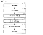
- FIG. 11 is a diagram illustrating a manufacturing flow of the magnetic sensor according to the second embodiment. A method for manufacturing the magnetic sensor 1A according to the second embodiment will be described with reference to FIG.
- the substrate 10 is prepared in step (S11).
- the substrate 10 has a flat plate shape.
- a seed layer 15A is formed. Specifically, the adhesion layer 14A and the seed layer 15A are laminated on the entire substrate by a sputtering method, a CVD method, a vacuum deposition method, or the like so as to cover the patterned laminated film (magnetoresistance element).
- the plurality of pole pieces 31, 32 for adjusting the direction of the magnetic field applied to the plurality of magnetoresistive elements R1, R2, R3, R4 using the selective plating method are in the first direction.
- a plurality of pole pieces 31 and 32 are formed on the substrate 10 so as to line up along the line.
- a resist such as a photosensitive resin film is applied on the seed layer 15A by spin coating.
- the photosensitive resin film may be a positive type or a negative type.
- the photosensitive resist is patterned by photolithography (exposure / development).
- a magnetic layer is formed by plating on the portion where the resist has been removed.
- a pair of pole pieces 31 and 32 are formed on the substrate 10 by removing the resist by etching.
- step (S14) the spacer layer 13A is formed. Specifically, an insulating material to be the spacer layer 13A is applied to the entire substrate 10 so as to cover the pair of pole pieces 31 and 32 by screen printing or the like, and is dried. Thereby, the spacer layer 13 ⁇ / b> A provided with the recess 111 is formed.
- the thickness of the spacer layer 13A is made larger than the thickness of the insulating layer 11 according to the first embodiment.
- the center positions of the plurality of pole pieces in the thickness direction and the center positions of the plurality of magnetoresistive elements in the thickness direction can be aligned at the same height position.
- step (S15) a plurality of magnetoresistive elements R1, R2, R3, and R4 constituting a bridge circuit are formed on the substrate 10 by using a photolithography method.
- the underlayer film that becomes the underlayer 21, the magnetosensitive film that becomes the magnetosensitive layer 20, and the protective film that becomes the protective layer 22 are formed on the spacer layer 13A by sputtering, CVD, vacuum deposition, or the like. Laminate to. Thereby, a laminated film is formed on the spacer layer 13A.
- a resist such as a photosensitive resin film is applied to the entire substrate 10 on which the laminated film is formed by spin coating.
- the photosensitive resin film may be a positive type or a negative type.
- the photosensitive resist is patterned by photolithography (exposure / development).
- the laminated film is wet-etched or dry-etched to form the underlayer 21, the magnetosensitive layer 20, and the protective layer 22 having a meander shape.
- a plurality of magnetoresistive elements R1, R2, R3, and R4 are formed on the substrate 10 by removing the resist.
- Electrode pads P1, P2, P3, and P4 are formed by patterning the electrode film into a predetermined shape.
- the magnet 40 is fixed to the back surface 10b side of the substrate 10. Specifically, the magnet 40 using an adhesive is used so that the center line C1 of the magnet 40 along the longitudinal direction of the magnet 40 and the center line C2 of the substrate 10 along the longitudinal direction of the substrate 10 substantially coincide. Is fixed to the substrate 10.
- the magnetic sensor 1A according to the second embodiment can be manufactured.
- the magnetic sensor 1A according to the second embodiment can obtain substantially the same effect as the magnetic sensor 1 according to the first embodiment.
- FIG. 12 is a schematic cross-sectional view of the magnetic sensor according to the third embodiment.
- a magnetic sensor 1B according to the third embodiment will be described with reference to FIG.
- the magnetic sensor 1B according to the third embodiment is different in arrangement and configuration of each layer constituting the magnetic sensor. Other configurations are almost the same.
- the magnetic sensor 1B includes a magnet 40, insulating layers 11 and 12, a base layer 21, a magnetosensitive layer 20 (magnetoresistance element), A protective layer 22, a spacer layer 13B, an adhesion layer 14B, and a seed layer 15B are provided.
- the substrate 10 has a front surface 10a and a back surface 10b.
- the substrate 10 has a magnetoresistive element forming region R11 where a magnetoresistive element is formed and a pole piece forming region R12 where a pole piece is formed.
- the magnetoresistive element formation region R ⁇ b> 11 is provided in the central portion of the substrate 10.
- the pole piece forming region R12 is provided at both ends of the substrate 10.
- the pole piece forming region R12 is provided with a concave portion formed by the concave surface 10a of the substrate 10.
- the concave portion is provided on one end side and the other end side in the first direction.
- a step portion 10c is provided between the surface in the magnetoresistive element forming region R11 located on the center side of the substrate 10 and the surface in the pole piece forming region R12 located on both ends of the substrate 10.
- the back surface 10b of the substrate 10 is configured to be substantially flat.
- the adhesion layer 14 ⁇ / b> B is provided so as to cover the surface 10 a of the substrate 10. That is, the adhesion layer 14B is provided so as to cover both the magnetoresistive element formation region R11 and the pole piece formation region R12.
- the adhesion layer 14 ⁇ / b> B is provided on the surface 10 a of the substrate 10.
- the adhesion layer 14B is made of a metal film such as Ti or Cr.
- the thickness of the adhesion layer 14B is approximately 5 nm. Note that the adhesion layer 14B can be omitted as long as the adhesion between the seed layer 15B and the substrate 10 can be secured.
- the seed layer 15B is provided so as to cover the adhesion layer 14B.
- the seed layer 15B is provided on the adhesion layer 14B.
- the seed layer 15B is made of a metal film such as Cu or Au.
- the thickness of the seed layer 15B is approximately 20 nm.
- the pole pieces 31 and 32 are provided on both end sides of the seed layer 15B.
- the pole pieces 31 and 32 are made of a magnetic film such as Ni 45 Fe 55 or a magnetic plating film containing Ni and Fe having a composition close to that of Ni 45 Fe 55 .
- the magnetic film may be a magnetic plating film made of an FeCoNi alloy, an FeCo alloy, or the like.
- the pole pieces 31 and 32 have a thickness of 30 ⁇ m.
- the spacer layer 13B is provided on the seed layer 15B so as to cover the pair of pole pieces 31 and 32.
- the spacer layer 13 ⁇ / b> B has a recess 111 in a portion located between the pair of pole pieces 31 and 32.
- a magnetoresistive element is formed in the recess 111.
- the spacer layer 13B insulates the seed layer 15B and the magnetosensitive layer 20 from each other.
- the spacer layer 13B includes a silicon oxide film (SiO 2 ), an aluminum oxide film (Al 2 O 3 ), a titanium oxide film (TiO 2 ), a zirconium oxide film (ZrO 2 ), and the like.
- the thickness of the spacer layer 13B is approximately 0.7 ⁇ m.
- the foundation layer 21 is provided on the spacer layer 13B. More specifically, the foundation layer 21 is provided in the recess 111 of the spacer layer 13B.
- the underlayer 21 is formed in a meander shape according to the shape of the magnetoresistive element.
- the underlayer 21 is composed of one metal film made of a metal such as Ta, W, Mo, Cr, Ti, or Zr.
- the thickness of the foundation layer 21 is approximately 2 nm. The underlayer 21 can be omitted if the magnetosensitive layer 20 can be properly grown.
- the magnetosensitive layer 20 is provided on the base layer 21.
- the magnetosensitive layer 20 constitutes the magnetoresistive elements R1, R2, R3, R4 described above.
- the magnetosensitive layer 20 is made of Ni 80 Fe 20 or an alloy containing Ni and Fe having a composition close to that of Ni 80 Fe 20 .
- the thickness of the magnetosensitive layer 20 is approximately 30 nm.
- the protective layer 22 is provided on the magnetosensitive layer 20.
- the protective layer 22 protects the magnetosensitive layer 20.
- the protective layer 22 is composed of one metal film made of a metal such as Ta, W, Mo, Cr, Ti, or Zr.
- the thickness of the foundation layer 21 is approximately 2 nm. The protective layer 22 can be omitted if the characteristics of the magnetic sensor 1 are not affected.
- the virtual plane parallel to the first direction passing through the center heights H1 and H2 in the normal direction of the substrate 10 of each of the adjacent pole pieces 31 and 32 is located between the adjacent pole pieces 31 and 32. Passes through the magnetoresistive element (the magnetosensitive layer 20).
- the magnet 40 has a plate shape having a short direction and a long direction.
- the magnet 40 has substantially the same outer shape as the substrate 10 when viewed from the normal direction of the substrate 10.
- the magnet 40 is fixed to the back surface 10b of the substrate 10 with an adhesive or the like.
- the one end side (pole piece 31 side) of the magnet 40 is configured with an N pole, and the other end side (pole piece 32 side) of the magnet 40 is configured with an S pole.
- a bias magnetic field from the pole piece 31 toward the pole piece 32 is generated.
- the direction of the bias magnetic field generated by the magnet 40 is adjusted by the pole piece 31 and the pole piece 32.
- the magnetic sensor 1B according to the third embodiment is basically manufactured according to the method for manufacturing the magnetic sensor 1A according to the second embodiment.
- recesses are formed at both ends of the substrate 10 by dry etching. This recessed portion is a region where the pole pieces 31 and 32 are provided. Thereafter, substantially the same processing as in steps (S12) to (S16) according to the second embodiment is performed. Thereby, the magnetic sensor 1B is manufactured.
- the magnetic sensor 1B according to the third embodiment can obtain substantially the same effect as the magnetic sensor 1 according to the first embodiment.
- FIG. 13 is a plan view of the magnetic sensor according to the fourth embodiment.
- a magnetic sensor 1C according to the fourth embodiment will be described with reference to FIG.
- the magnetic sensor 1C according to the fourth embodiment differs from the magnetic sensor 1 according to the first embodiment in the number of pole pieces and the arrangement of magnetoresistive elements. Other configurations are almost the same.
- three pole pieces 31, 32, and 33 are provided.
- the three pole pieces 31, 32, 33 are arranged along the first direction.
- the pole piece 31 is provided on one end side in the first direction.
- the pole piece 33 is provided on the other end side in the first direction.
- the pole piece 32 is provided between the pole piece 31 and the pole piece 33.
- the pole piece 32 is provided at the center of the pole piece 31 and the pole piece 33 in the first direction.
- the magnetoresistive elements R1 and R3 constituting the first half bridge circuit are located between the pole piece 31 located on one end side in the first direction and the pole piece 32 located in the center.
- Magnetoresistive elements R2 and R4 constituting the second half bridge circuit are located between the pole piece 32 located in the center and the pole piece 33 located on the other end side in the first direction.
- the magnetic sensor 1C according to the fourth embodiment can obtain substantially the same effect as the magnetic sensor 1 according to the first embodiment. Further, since the number of pole pieces increases, the interval between adjacent pole pieces can be narrowed, and the direction of bias magnetization can be adjusted more effectively than in the first embodiment. Note that the interval between the pole pieces adjacent to each other is large enough to sufficiently dissipate heat from the magnetoresistive element, and heat dissipation is ensured.
- the magnetic sensor 1C according to the fourth embodiment can be manufactured based on a manufacturing method according to any one of the manufacturing methods of the magnetic sensor according to the first to third embodiments.
- FIG. 14 is a plan view of the magnetic sensor according to the fifth embodiment.
- a magnetic sensor 1D according to the fifth embodiment will be described with reference to FIG.
- the magnetic sensor 1D according to the fifth embodiment is different from the magnetic sensor 1 according to the first embodiment in the number of pole pieces and the arrangement of magnetoresistive elements. Other configurations are almost the same.
- five pole pieces 31, 32, 33, 34, and 35 are provided.
- the five pole pieces 31, 32, 33, 34, and 35 are provided in order from one end side along the first direction.
- Each of the plurality of magnetoresistive elements is located between adjacent pole pieces. Specifically, the magnetoresistive element R ⁇ b> 1 is located between the pole piece 31 and the pole piece 32. The magnetoresistive element R ⁇ b> 2 is located between the pole piece 32 and the pole piece 33. The magnetoresistive element R ⁇ b> 3 is located between the pole piece 33 and the pole piece 34. The magnetoresistive element R ⁇ b> 4 is located between the pole piece 34 and the pole piece 35.
- the magnetic sensor 1D according to the fifth embodiment can obtain substantially the same effect as the magnetic sensor 1 according to the first embodiment.
- the number of pole pieces increases, the interval between adjacent pole pieces can be narrowed, and the direction of bias magnetization can be adjusted more effectively than in the first embodiment. Note that the interval between the pole pieces adjacent to each other is large enough to sufficiently dissipate heat from the magnetoresistive element, and heat dissipation is ensured.
- the magnetic sensor 1D according to the fifth embodiment can be manufactured based on a manufacturing method according to any one of the manufacturing methods of the magnetic sensor according to the first to third embodiments.
- FIG. 15 is a perspective view of a current sensor according to the sixth embodiment.
- FIG. 16 is a plan view of a current sensor according to the sixth embodiment.
- FIG. 17 is a front view of a current sensor according to the sixth embodiment.
- the current sensor 200 includes a support substrate 150 and two magnetic sensors 151 and 152.
- the current sensor 200 detects a current flowing through the detection target under magnetic detection by the magnetic sensors 151 and 152.
- the two magnetic sensors 151 and 152 have substantially the same configuration as the magnetic sensor 1 according to the first embodiment.
- the support substrate 150 is constituted by an integrated chip, for example. Two magnetic sensors 151 and 152 are mounted on the support substrate 150.
- the support substrate 150 is provided with a circuit (not shown) that performs predetermined signal processing (differential amplification or the like) on signals output from the two magnetic sensors 151 and 152.
- the current sensor 200 is arranged such that one end side in the left-right direction in FIG. 17 is located above the bus bar 210 and the other end side in the left-right direction in FIG. 17 is located below the bus bar 220.
- the current sensor 200 is disposed in a step space S formed between the bus bar 210 and the bus bar 220, which is indicated by a two-dot chain line shown in FIG.
- the current to be measured flows through the bus bars 210 and 220.
- the bus bar 210 and the bus bar 220 are juxtaposed when viewed from the normal direction.
- the bus bar 210 and the bus bar 220 are arranged so as to be displaced in the vertical direction.
- the bus bars 210 and 220 are configured, for example, by branching a bar conductor for power supply connected to an in-vehicle battery.
- the current sensor 200 detects the magnetism (magnetic field) applied from the bus bars 210 and 220 by the two magnetic sensors 151 and 152.
- the magnetic sensors 151 and 152 are arranged so that the pair of pole pieces 31 and 32 are arranged in the front-rear direction in FIG. 17 (the direction perpendicular to the paper surface in FIG. 17). That is, the direction of the bias magnetic field applied from the magnet 40 to the magnetoresistive element is the front-rear direction in FIG.
- the magnetic detection direction of the current sensor 200 is the left-right direction in FIG.
- bus bar 210 When the bus bar 210 is positioned on the back surface side of the support substrate 150 and the bus bar 220 is positioned on the front surface side of the support substrate 150, current flows through the bus bars 210 and 220 in the direction of the arrow shown in FIG. A magnetic vector in a direction parallel to the surface (left and right direction in FIG. 17) and different (reciprocal) directions from each other is applied to the magnetic sensor 151 and the magnetic sensor 152 (a dashed-dotted arrow in FIG. 17). reference).
- the bus bar 210 and the bus bar 220 are based on the differential amplification value of each detected magnetic vector (voltage value). Can be detected (differential detection).
- the bias magnetic field applied to each of the two magnetic sensors 151 and 152 is arranged by being shifted so as to rotate in the in-plane direction. There may be cases where the orientation is deviated.
- each of the two magnetic sensors 151 and 152 is provided with two pole pieces so as to be aligned in the first direction, and four magnetoresistors constituting a full bridge circuit between adjacent pole pieces.
- the bias magnetic field applied to each of the two magnetic sensors 151 and 152 can be reduced.
- the deviation of the characteristics of the two magnetic sensors 151 and 152 can be reduced, and good detection accuracy can be maintained.
- FIG. 18 is a plan view of the magnetic sensor according to the seventh embodiment.
- a magnetic sensor 1E according to the seventh embodiment will be described with reference to FIG.
- One pole piece 51 of the other pair of pole pieces 51 and 52 is provided on one end side of the substrate 10 in the second direction.
- the other pole piece 52 of the other pair of pole pieces 51 and 52 is provided on the other end side of the substrate 10 in the second direction.
- the other pair of pole pieces 51 and 52 extend along the first direction.
- a plurality of magnetoresistive elements R1, R2, R3, and R4 are disposed between the other pair of pole pieces 51 and 52.
- the other pair of pole pieces 51, 52 are generated from the outside and adjust the direction of the magnetic field applied to the plurality of magnetoresistive elements R1, R2, R3, R4 (see FIG. 2).
- the magnetic sensor 1E according to the seventh embodiment can obtain substantially the same effect as the magnetic sensor 1 according to the first embodiment.
- the direction of the magnetic field applied from the bus bars 210 and 220 to the two magnetic sensors 151 and 152 can be adjusted. Thereby, the influence of disturbance (disturbance magnetic field) is more canceled (cancelled), and the detection accuracy can be further improved.
- FIG. 19 is a diagram illustrating a result of a simulation performed using the magnetic sensor according to the first embodiment and the fourth embodiment. Specifically, FIG. 19 shows the relationship between the angle deviation after correction by the pole piece and the pole piece film thickness. With reference to FIG. 19, the result of the simulation performed using the magnetic sensor according to the first embodiment and the fourth embodiment will be described.
- the deviation is set to 100%, a simulation was performed to determine how much the deviation of the direction of the magnetic field passing between adjacent pole pieces is reduced.
- the dimension of the substrate 10 in the first direction is 2.5 mm
- the dimension of the substrate 10 in the second direction orthogonal to the first direction of the substrate is 2.0 mm
- the material of the pole piece is Ni 45 Fe 45
- the saturation magnetization of the magnet 40 was 0.44 T
- the thickness of the magnet 40 was 250 ⁇ m
- the thickness of the central portion of the substrate 10 was 250 ⁇ m.
- the distance between the pair of pole pieces 31 and 32 is 1.2 mm, and the pair of pole pieces 31 and 32 in the first direction is used.
- Each dimension of the pole pieces 31 and 32 was 0.6 mm, and each dimension of the pair of pole pieces 31 and 32 in the second direction was 1.9 mm.
- the interval between adjacent pole pieces is 0.6 mm, and the pole pieces 31 in the first direction are
- Each dimension of 32 and 33 was 0.4 mm, and each dimension of the pole pieces 31, 32 and 33 in the second direction was 1.9 mm.
- the deviation of the direction of the magnetic field passing between the adjacent pole pieces can be reduced.
- the deviation of the direction of the magnetic field passing between the adjacent pole pieces can be reduced.
- the deviation of the direction of the magnetic field passing between adjacent pole pieces can be further reduced. did it.
- the direction in which the pair of pole pieces 31 and 32 are arranged is the first direction and the direction in which the other pair of pole pieces 51 and 52 is arranged is the second direction has been described as an example.
- the present invention is not limited to this, and the direction in which the other pair of pole pieces 51 and 52 are arranged may be the first direction, and the direction in which the pair of pole pieces 31 and 32 are arranged may be the second direction.
- the other pair of pole pieces 51 and 52 arranged along the first direction adjust the direction of the magnetic field generated from the outside and input to the plurality of magnetoresistive elements. The deviation of the direction of the magnetic field passing between the adjacent pole pieces could be reduced.
- the magnetic sensor includes four magnetoresistive elements R1, R2, R3, and R4, and a full bridge circuit is formed by the four magnetoresistive elements R1, R2, R3, and R4.
- the magnetic sensor may include two magnetoresistive elements, and the two magnetic sensors may constitute a half bridge circuit.
- 1, 1A, 1B, 1D, 1E, 1F, 1X magnetic sensor 10 substrate, 10a surface, 10b back surface, 10c stepped portion, 11, 12 insulating layer, 13, 13A, 13B spacer layer, 14, 14A, 14B adhesion layer 15, 15A, 15B seed layer, 20 magnetosensitive layer, 21 underlayer, 22 protective layer, 31, 32, 33, 34, 35 pole piece, 40 magnet, 51, 52 pole piece, 111 recess, 150 support substrate, 151, 152 Magnetic sensor, 200 Current sensor, 210, 220 Bus bar.
Abstract
A magnetic sensor (1) is provided with: a substrate (10); a plurality of magnetoresistive elements, which are provided on the substrate (10), and which constitute a bridge circuit; and a plurality of pole pieces (31, 32), which are provided on the substrate (10) by being aligned with each other in the first direction, and which adjust the directions of magnetic fields to be applied to the magnetoresistive elements. At least one of the magnetoresistive elements is positioned between the pole pieces (31, 32) which are adjacent to each other.
Description
本発明は、ブリッジ回路を構成する複数の磁気抵抗素子を含む磁気センサ、電流センサ、および磁気センサの製造方法に関する。
The present invention relates to a magnetic sensor including a plurality of magnetoresistive elements constituting a bridge circuit, a current sensor, and a method for manufacturing the magnetic sensor.
従来の磁気センサが、開示された文献として、たとえば特開平7-324933号公報(特許文献1)が挙げられる。
As a document in which a conventional magnetic sensor is disclosed, for example, JP-A-7-324933 (Patent Document 1) can be cited.
特許文献1に開示の磁気センサにあっては、基板上に、地磁気を収束する複数の強磁性体コアが所定のギャップをもって周方向に配置されており、この当該ギャップにおける磁界方向に対して略直交するように、当該ギャップの各々に磁気抵抗効果素子が配置されている。これら、複数の強磁性体コアおよび磁気抵抗素子は、基板上に成膜成形されている。
In the magnetic sensor disclosed in Patent Document 1, a plurality of ferromagnetic cores for concentrating geomagnetism are arranged in a circumferential direction with a predetermined gap on a substrate, and the magnetic field direction in the gap is substantially the same. Magnetoresistive elements are arranged in each of the gaps so as to be orthogonal to each other. The plurality of ferromagnetic cores and magnetoresistive elements are formed and formed on a substrate.
しかしながら、特許文献1に開示の磁気センサにあっては、周方向に配置された複数の強磁性体コアのうち互いに隣り合う強磁性体コアの間の隙間における磁界方向に対して、磁気抵抗素子の向きを規定し、当該隙間に磁気抵抗素子を配置する構成である。このため、複数の強磁性体コアによって囲まれる領域の中央部においては、磁気抵抗素子を配置することができず、基板に対して効率よく磁気抵抗素子を配置することができない。加えて、強磁性体コアの間隔が狭く、磁気抵抗素子が発熱した場合には、熱を外部に放出しにくくなるため、熱によって検知精度が低下することが懸念される。
However, in the magnetic sensor disclosed in Patent Document 1, a magnetoresistive element is applied to a magnetic field direction in a gap between adjacent ferromagnetic cores among a plurality of ferromagnetic cores arranged in the circumferential direction. This is a configuration in which the magnetoresistive element is arranged in the gap. For this reason, the magnetoresistive element cannot be arranged in the central portion of the region surrounded by the plurality of ferromagnetic cores, and the magnetoresistive element cannot be arranged efficiently with respect to the substrate. In addition, when the interval between the ferromagnetic cores is narrow and the magnetoresistive element generates heat, it is difficult to release the heat to the outside.
本発明は、上記のような問題に鑑みてなされたものであり、本発明の目的は、磁気抵抗素子に印加される磁界の方向を調整しつつ放熱性を確保し、基板上に効率よく磁気抵抗素子を配置することができる磁気センサ、電流センサ、および磁気センサの製造方法を提供することにある。
The present invention has been made in view of the above problems, and an object of the present invention is to secure heat dissipation while adjusting the direction of the magnetic field applied to the magnetoresistive element, and to efficiently magnetize on the substrate. An object of the present invention is to provide a magnetic sensor, a current sensor, and a method for manufacturing the magnetic sensor in which a resistive element can be arranged.
本発明に基づく磁気センサは、基板と、上記基板上に設けられ、ブリッジ回路を構成する複数の磁気抵抗素子と、上記基板上に第1方向に沿って並んで設けられ、上記複数の磁気抵抗素子に印加される磁界の方向を調整する複数のポールピースと、を備え、互いに隣り合うポールピースの間に、上記複数の磁気抵抗素子のうち少なくともいずれかの磁気抵抗素子が位置する。
A magnetic sensor according to the present invention includes a substrate, a plurality of magnetoresistive elements provided on the substrate and constituting a bridge circuit, and provided side by side along the first direction on the substrate. A plurality of pole pieces for adjusting the direction of a magnetic field applied to the element, and at least one of the plurality of magnetoresistive elements is positioned between adjacent pole pieces.
上記本発明に基づく磁気センサにあっては、上記複数のポールピースは、一対のポールピースを含んでいてもよい。この場合には、上記一対のポールピースの間に、上記複数の磁気抵抗素子が位置することが好ましい。
In the magnetic sensor according to the present invention, the plurality of pole pieces may include a pair of pole pieces. In this case, it is preferable that the plurality of magnetoresistive elements are located between the pair of pole pieces.
上記本発明に基づく磁気センサにあっては、上記複数のポールピースは、3つのポールピースを含んでいてもよい。また、上記ブリッジ回路のうち第1のハーフブリッジ回路を構成する2つの磁気抵抗素子と、上記ブリッジ回路のうち第2のハーフブリッジ回路を構成する他の2つの磁気抵抗素子と、を含んでいてもよい。この場合には、上記第1方向において、一端側に位置するポールピースと中央に位置するポールピースとの間に、上記2つの磁気抵抗素子が位置することが好ましく、上記第1方向において、上記中央に位置するポールピースと他端側に位置するポールピースとの間に、上記他の2つの磁気抵抗素子が位置することが好ましい。
In the magnetic sensor according to the present invention, the plurality of pole pieces may include three pole pieces. In addition, the magnetoresistive element includes two magnetoresistive elements constituting the first half bridge circuit in the bridge circuit and the other two magnetoresistive elements constituting the second half bridge circuit in the bridge circuit. Also good. In this case, in the first direction, the two magnetoresistive elements are preferably located between the pole piece located at one end and the pole piece located in the center. It is preferable that the other two magnetoresistive elements are located between the pole piece located in the center and the pole piece located on the other end side.
上記本発明に基づく磁気センサにあっては、上記複数のポールピースは、5つのポールピースを含んでいてもよい。この場合には、上記複数の磁気抵抗素子の各々が、互いに隣り合うポールピースの間に位置することが好ましい。
In the magnetic sensor according to the present invention, the plurality of pole pieces may include five pole pieces. In this case, each of the plurality of magnetoresistive elements is preferably located between adjacent pole pieces.
上記本発明に基づく磁気センサにあっては、上記互いに隣り合うポールピースの各々の上記基板の法線方向における中心高さを通過する上記第1方向に平行な仮想平面が、上記互いに隣り合うポールピースの間に位置する上記磁気抵抗素子を通過することが好ましい。
In the magnetic sensor according to the present invention, the virtual planes parallel to the first direction passing through the center height in the normal direction of the substrate of each of the adjacent pole pieces are adjacent to each other. It is preferable to pass through the magnetoresistive element located between the pieces.
上記本発明に基づく磁気センサは、上記複数の磁気抵抗素子にバイアス磁界を印加するための磁石をさらに備えていてもよい。この場合には、上記複数のポールピースは、上記磁石によって発生する上記バイアス磁界の方向を調整することが好ましい。
The magnetic sensor according to the present invention may further include a magnet for applying a bias magnetic field to the plurality of magnetoresistive elements. In this case, it is preferable that the plurality of pole pieces adjust the direction of the bias magnetic field generated by the magnet.
上記本発明に基づく磁気センサにあっては、上記基板の法線方向から見た場合に、上記複数の磁気抵抗素子は、上記磁石と重なることが好ましい。
In the magnetic sensor according to the present invention, it is preferable that the plurality of magnetoresistive elements overlap the magnet when viewed from the normal direction of the substrate.
上記本発明に基づく磁気センサにあっては、上記複数のポールピースは、外部から発生し、上記複数の磁気抵抗素子に入力される磁界の方向を調整してもよい。
In the magnetic sensor according to the present invention, the plurality of pole pieces may be generated from the outside and adjust directions of magnetic fields input to the plurality of magnetoresistive elements.
本発明に基づく電流センサは、上記のいずれかに記載の磁気センサを備えている。
本発明に基づく磁気センサの製造方法は、基板を準備する工程と、フォトリソグラフィ法を用いて、ブリッジ回路を構成する複数の磁気抵抗素子を上記基板上に形成する工程と、選択めっき法を用いて、上記複数の磁気抵抗素子に印加される磁界の方向を調整する複数のポールピースが第1方向に沿って並ぶように、上記複数のポールピースを上記基板上に形成する工程と、を備え、上記複数のポールピースを上記基板上に形成する工程は、上記複数の磁気抵抗素子を上記基板上に形成する工程の後に実施され、上記複数のポールピースを上記基板上に形成する工程において、互いに隣り合うポールピースの間に、上記複数の磁気抵抗素子のうち少なくともいずれかの磁気抵抗素子が位置するように、上記複数のポールピースを形成する。 A current sensor according to the present invention includes any one of the magnetic sensors described above.
A method of manufacturing a magnetic sensor according to the present invention uses a step of preparing a substrate, a step of forming a plurality of magnetoresistive elements constituting a bridge circuit on the substrate using a photolithography method, and a selective plating method. And forming the plurality of pole pieces on the substrate so that the plurality of pole pieces for adjusting the directions of the magnetic fields applied to the plurality of magnetoresistive elements are aligned along the first direction. The step of forming the plurality of pole pieces on the substrate is performed after the step of forming the plurality of magnetoresistive elements on the substrate, and the step of forming the plurality of pole pieces on the substrate, The plurality of pole pieces are formed such that at least one of the plurality of magnetoresistive elements is positioned between adjacent pole pieces.
本発明に基づく磁気センサの製造方法は、基板を準備する工程と、フォトリソグラフィ法を用いて、ブリッジ回路を構成する複数の磁気抵抗素子を上記基板上に形成する工程と、選択めっき法を用いて、上記複数の磁気抵抗素子に印加される磁界の方向を調整する複数のポールピースが第1方向に沿って並ぶように、上記複数のポールピースを上記基板上に形成する工程と、を備え、上記複数の磁気抵抗素子を上記基板上に形成する工程は、上記複数のポールピースを上記基板上に形成する工程の後に実施され、上記複数の磁気抵抗素子を上記基板上に形成する工程において、互いに隣り合うポールピースの間に、上記複数の磁気抵抗素子のうち少なくともいずれかの磁気抵抗素子が位置するように、上記複数の磁気抵抗素子を形成する。
A method of manufacturing a magnetic sensor according to the present invention uses a step of preparing a substrate, a step of forming a plurality of magnetoresistive elements constituting a bridge circuit on the substrate using a photolithography method, and a selective plating method. And forming the plurality of pole pieces on the substrate so that the plurality of pole pieces for adjusting the directions of the magnetic fields applied to the plurality of magnetoresistive elements are aligned along the first direction. The step of forming the plurality of magnetoresistive elements on the substrate is performed after the step of forming the plurality of pole pieces on the substrate, and the step of forming the plurality of magnetoresistive elements on the substrate. The plurality of magnetoresistive elements are formed such that at least one of the plurality of magnetoresistive elements is positioned between adjacent pole pieces.
本発明によれば、磁気抵抗素子に印加される磁界の方向を調整しつつ放熱性を確保し、基板上に効率よく磁気抵抗素子を配置することができる磁気センサ、電流センサ、および磁気センサの製造方法を提供することができる。
ADVANTAGE OF THE INVENTION According to this invention, heat dissipation is ensured, adjusting the direction of the magnetic field applied to a magnetoresistive element, the magnetic sensor which can arrange | position a magnetoresistive element on a board | substrate efficiently, a current sensor, and a magnetic sensor A manufacturing method can be provided.
以下、本発明の実施の形態について、図を参照して詳細に説明する。なお、以下に示す実施の形態においては、同一のまたは共通する部分について図中同一の符号を付し、その説明は繰り返さない。
Hereinafter, embodiments of the present invention will be described in detail with reference to the drawings. In the following embodiments, the same or common parts are denoted by the same reference numerals in the drawings, and description thereof will not be repeated.
[実施の形態1]
(磁気センサ)
図1は、実施の形態1に係る磁気センサの平面図である。図2は、実施の形態1に係る磁気センサの磁気検知部を示す平面図である。図3は、実施の形態1に係る磁気センサの概略断面図である。なお、図3においては、便宜上のため磁気抵抗素子の一部のみを図示している。また、図3において、磁石によって発生するバイアス磁界を破線にて示している。図1から図3を参照して、実施の形態1に係る磁気センサ1について説明する。 [Embodiment 1]
(Magnetic sensor)
FIG. 1 is a plan view of the magnetic sensor according to the first embodiment. FIG. 2 is a plan view illustrating a magnetic detection unit of the magnetic sensor according to the first embodiment. FIG. 3 is a schematic cross-sectional view of the magnetic sensor according to the first embodiment. In FIG. 3, only a part of the magnetoresistive element is shown for convenience. In FIG. 3, the bias magnetic field generated by the magnet is indicated by a broken line. Amagnetic sensor 1 according to the first embodiment will be described with reference to FIGS.
(磁気センサ)
図1は、実施の形態1に係る磁気センサの平面図である。図2は、実施の形態1に係る磁気センサの磁気検知部を示す平面図である。図3は、実施の形態1に係る磁気センサの概略断面図である。なお、図3においては、便宜上のため磁気抵抗素子の一部のみを図示している。また、図3において、磁石によって発生するバイアス磁界を破線にて示している。図1から図3を参照して、実施の形態1に係る磁気センサ1について説明する。 [Embodiment 1]
(Magnetic sensor)
FIG. 1 is a plan view of the magnetic sensor according to the first embodiment. FIG. 2 is a plan view illustrating a magnetic detection unit of the magnetic sensor according to the first embodiment. FIG. 3 is a schematic cross-sectional view of the magnetic sensor according to the first embodiment. In FIG. 3, only a part of the magnetoresistive element is shown for convenience. In FIG. 3, the bias magnetic field generated by the magnet is indicated by a broken line. A
図1に示すように、実施の形態1に係る磁気センサ1は、基板10と、磁気検知部Rと、一対のポールピース31,32とを備える。基板10は、法線方向から見た場合に、矩形形状を有する。
As shown in FIG. 1, the magnetic sensor 1 according to the first embodiment includes a substrate 10, a magnetic detection unit R, and a pair of pole pieces 31 and 32. The substrate 10 has a rectangular shape when viewed from the normal direction.
一対のポールピース31,32は、基板10上に第1方向に沿って並んで設けられている。一対のポールピース31,32のうち一方のポールピース31は、基板10の一端側に設けられている。一対のポールピース31,32のうち他方のポールピース32は、基板10の他端側に設けられている。
The pair of pole pieces 31 and 32 are provided side by side along the first direction on the substrate 10. One pole piece 31 of the pair of pole pieces 31 and 32 is provided on one end side of the substrate 10. The other pole piece 32 of the pair of pole pieces 31 and 32 is provided on the other end side of the substrate 10.
一対のポールピース31,32は、上記第1方向に垂直な方向に延在する。一対のポールピース31,32は、後述する複数の磁気抵抗素子R1,R2,R3,R4(図2参照)に印加される磁界の方向を調整する。
The pair of pole pieces 31 and 32 extend in a direction perpendicular to the first direction. The pair of pole pieces 31 and 32 adjust the direction of the magnetic field applied to a plurality of magnetoresistive elements R1, R2, R3, and R4 (see FIG. 2) described later.
図1および図2に示すように、磁気検知部Rは、一対のポールピース31,32の間に設けられている。磁気検知部Rは、複数の磁気抵抗素子R1,R2,R3,R4の磁気抵抗素子R1,R2,R3,R4を含む。複数の磁気抵抗素子R1,R2,R3,R4のそれぞれは、長い略短冊状のパターンと短い略短冊状のパターンを交互に接続することで、ミアンダ状に形成される。長い略短冊状のパターンは、一対のポールピース31,32が並ぶ第1方向に対して略45度の角度で交差する。
1 and 2, the magnetic detection unit R is provided between a pair of pole pieces 31 and 32. The magnetic detection unit R includes a plurality of magnetoresistive elements R1, R2, R3, R4 of the magnetoresistive elements R1, R2, R3, R4. Each of the plurality of magnetoresistive elements R1, R2, R3, R4 is formed in a meander shape by alternately connecting a long substantially strip-like pattern and a short substantially strip-like pattern. The long substantially strip-shaped pattern intersects with the first direction in which the pair of pole pieces 31 and 32 are arranged at an angle of about 45 degrees.
複数の磁気抵抗素子R1,R2,R3,R4は、フルブリッジ回路を形成する。磁気抵抗素子R1の一端側は、出力電圧Vout1を取り出すための電極パッドP1に電気的に接続される。磁気抵抗素子R1の他端側は、電源電圧Vccを印加するための電極パッドP3と電気的に接続される。
The plurality of magnetoresistive elements R1, R2, R3, and R4 form a full bridge circuit. One end of the magnetoresistive element R1 is electrically connected to an electrode pad P1 for taking out the output voltage Vout1. The other end of the magnetoresistive element R1 is electrically connected to an electrode pad P3 for applying the power supply voltage Vcc.
磁気抵抗素子R2の一端側は、電源電圧Vccを印加するための電極パッドP3と電気的に接続される。磁気抵抗素子R2の他端側は、出力電圧Vout2を取り出すための電極パッドP2に電気的に接続される。
One end side of the magnetoresistive element R2 is electrically connected to an electrode pad P3 for applying the power supply voltage Vcc. The other end of the magnetoresistive element R2 is electrically connected to an electrode pad P2 for taking out the output voltage Vout2.
磁気抵抗素子R3の一端側は、出力電圧Vout1を取り出すための電極パッドP1に電気的に接続される。磁気抵抗素子R3の他端側は、グランドに接続される電極パッドP4と電気的に接続される。
One end side of the magnetoresistive element R3 is electrically connected to an electrode pad P1 for taking out the output voltage Vout1. The other end of the magnetoresistive element R3 is electrically connected to an electrode pad P4 connected to the ground.
磁気抵抗素子R4の一端側は、グランドに接続される電極パッドP4と電気的に接続される。磁気抵抗素子R4の他端側は、出力電圧Vout2を取り出すための電極パッドP2に電気的に接続される。
The one end side of the magnetoresistive element R4 is electrically connected to the electrode pad P4 connected to the ground. The other end side of the magnetoresistive element R4 is electrically connected to an electrode pad P2 for taking out the output voltage Vout2.
磁気抵抗素子R1,R3が、電極パッドP1を介して直列接続されることにより、第1の直列回路(ハーフブリッジ回路)が形成される。磁気抵抗素子R2,R4が、電極パッドP2を介して直列接続されることにより、第2の直列回路(ハーフブリッジ回路)が形成される。
The first series circuit (half-bridge circuit) is formed by connecting the magnetoresistive elements R1 and R3 in series via the electrode pad P1. The magnetoresistive elements R2 and R4 are connected in series via the electrode pad P2, thereby forming a second series circuit (half bridge circuit).
第1の直列回路(ハーフブリッジ回路)および第2の直列回路(ハーフブリッジ回路)が、電極パッドP3,P4を介して並列接続されることにより、フルブリッジ回路が形成される。磁気抵抗素子R1,R3は、正出力性を有し、磁気抵抗素子R2,R4は負出力性を有する。
A full bridge circuit is formed by connecting the first series circuit (half-bridge circuit) and the second series circuit (half-bridge circuit) in parallel via the electrode pads P3 and P4. The magnetoresistive elements R1 and R3 have a positive output property, and the magnetoresistive elements R2 and R4 have a negative output property.
電極パッドP3と電極パッドP4との間に電源電圧Vccを印加すると、磁界強度に応じて、電極パッドP1から出力電圧Vout1が取出され、電極パッドP2から出力電圧Vout2が取り出される。出力電圧Vout1,Vout2は、差動増幅器(不図示)を介して差動増幅される。
When the power supply voltage Vcc is applied between the electrode pad P3 and the electrode pad P4, the output voltage Vout1 is extracted from the electrode pad P1 and the output voltage Vout2 is extracted from the electrode pad P2 according to the magnetic field strength. The output voltages Vout1 and Vout2 are differentially amplified through a differential amplifier (not shown).
図3に示すように、磁気センサ1は、基板10、および一対のポールピース31,32に加えて、磁石40、絶縁層11、12、下地層21、感磁層20(磁気抵抗素子)、保護層22、スペーサ層13、密着層14、シード層15を備える。
As shown in FIG. 3, in addition to the substrate 10 and the pair of pole pieces 31 and 32, the magnetic sensor 1 includes a magnet 40, insulating layers 11 and 12, a base layer 21, a magnetosensitive layer 20 (magnetoresistance element), A protective layer 22, a spacer layer 13, an adhesion layer 14, and a seed layer 15 are provided.
基板10は、表面10aおよび裏面10bを有する。基板10は、磁気抵抗素子が形成される磁気抵抗素子形成領域R11およびポールピースが形成されるポールピース形成領域R12を有する。磁気抵抗素子形成領域R11は、基板10の中央部に設けられている。ポールピース形成領域R12は、基板10の両端に設けられている。ポールピース形成領域R12には、基板10の表面10aが凹むことにより構成される凹部が設けられている。
The substrate 10 has a front surface 10a and a back surface 10b. The substrate 10 has a magnetoresistive element forming region R11 where a magnetoresistive element is formed and a pole piece forming region R12 where a pole piece is formed. The magnetoresistive element formation region R <b> 11 is provided in the central portion of the substrate 10. The pole piece forming region R12 is provided at both ends of the substrate 10. The pole piece forming region R12 is provided with a concave portion formed by the concave surface 10a of the substrate 10.
当該凹部は、第1方向の一端側および他端側に設けられる。これにより、基板10の中央側に位置する磁気抵抗素子形成領域R11における表面と、基板10の両端側に位置するポールピース形成領域R12における表面との間には、段差部10cが設けられている。基板10の裏面10bは、略平坦に構成されている。
The concave portion is provided on one end side and the other end side in the first direction. Thus, a step portion 10c is provided between the surface in the magnetoresistive element forming region R11 located on the center side of the substrate 10 and the surface in the pole piece forming region R12 located on both ends of the substrate 10. . The back surface 10b of the substrate 10 is configured to be substantially flat.
基板10としては、たとえばシリコン基板が用いられる。なお、基板10として、ガラス基板等の絶縁基板を用いてもよく、この場合には、絶縁層11,12を省略することができる。基板10の中央の厚さは、略250μmである。
For example, a silicon substrate is used as the substrate 10. Note that an insulating substrate such as a glass substrate may be used as the substrate 10, and in this case, the insulating layers 11 and 12 can be omitted. The thickness of the center of the substrate 10 is approximately 250 μm.
絶縁層11は、磁気抵抗素子形成領域R11における基板10の表面10a上に設けられている。絶縁層11は、たとえばシリコン酸化(SiO2)や酸化アルミ(Al2O3)によって構成される。絶縁層11の厚さは、略0.7μmである。
The insulating layer 11 is provided on the surface 10a of the substrate 10 in the magnetoresistive element formation region R11. The insulating layer 11 is made of, for example, silicon oxide (SiO 2 ) or aluminum oxide (Al 2 O 3 ). The thickness of the insulating layer 11 is approximately 0.7 μm.
絶縁層12は、基板10の裏面10b上に設けられている。絶縁層12は、基板10の裏面10bのほぼ全域を覆うように設けられている。絶縁層12は、たとえばシリコン酸化(SiO2)や酸化アルミ(Al2O3)によって構成される。絶縁層12の厚さは、略0.7μmである。
The insulating layer 12 is provided on the back surface 10 b of the substrate 10. The insulating layer 12 is provided so as to cover almost the entire area of the back surface 10 b of the substrate 10. The insulating layer 12 is made of, for example, silicon oxide (SiO 2 ) or aluminum oxide (Al 2 O 3 ). The thickness of the insulating layer 12 is approximately 0.7 μm.
下地層21は、絶縁層11上に設けられている。下地層21は、磁気抵抗素子の形状に応じてミアンダ状に形成される。下地層21は、感磁層20を適切に成長させるために設けられている。
The foundation layer 21 is provided on the insulating layer 11. The underlayer 21 is formed in a meander shape according to the shape of the magnetoresistive element. The underlayer 21 is provided for properly growing the magnetosensitive layer 20.
下地層21は、Ta、W、Mo、Cr、Ti、Zr等の金属からなる1つの金属層によって構成される。下地層21の厚さは、略2nmである。なお、下地層21は、感磁層20を適切に成長させることができる場合には、省略することができる。
The underlayer 21 is composed of one metal layer made of a metal such as Ta, W, Mo, Cr, Ti, or Zr. The thickness of the foundation layer 21 is approximately 2 nm. The underlayer 21 can be omitted if the magnetosensitive layer 20 can be properly grown.
感磁層20は、下地層21上に設けられている。感磁層20は、上述の磁気抵抗素子R1,R2,R3,R4を構成する。感磁層20は、Ni80Fe20、または、Ni80Fe20に近い組成を有するNiとFeとを含む合金によって構成されている。感磁層20の厚さは、略30nmである。
The magnetosensitive layer 20 is provided on the base layer 21. The magnetosensitive layer 20 constitutes the magnetoresistive elements R1, R2, R3, R4 described above. The magnetosensitive layer 20 is made of Ni 80 Fe 20 or an alloy containing Ni and Fe having a composition close to that of Ni 80 Fe 20 . The thickness of the magnetosensitive layer 20 is approximately 30 nm.
保護層22は、感磁層20上に設けられている。保護層22は、感磁層20を保護する。保護層22は、Ta、W、Mo、Cr、Ti、Zr等の金属からなる1つの金属層によって構成される。下地層21の厚さは、略2nmである。なお、保護層22は、磁気センサ1の特性に影響がない場合には、省略することができる。
The protective layer 22 is provided on the magnetosensitive layer 20. The protective layer 22 protects the magnetosensitive layer 20. The protective layer 22 is composed of one metal layer made of a metal such as Ta, W, Mo, Cr, Ti, or Zr. The thickness of the foundation layer 21 is approximately 2 nm. The protective layer 22 can be omitted if the characteristics of the magnetic sensor 1 are not affected.
スペーサ層13は、感磁層20を覆うように、絶縁層11上に設けられる。スペーサ層13は、シード層15と感磁層20とを絶縁する。スペーサ層13は、シリコン酸化(SiO2)、酸化アルミ(Al2O3)、酸化チタン(TiO2)および酸化ジルコニウム(ZrO2)等によって構成されている。スペーサ層の厚みは、略0.7μmである。
The spacer layer 13 is provided on the insulating layer 11 so as to cover the magnetosensitive layer 20. The spacer layer 13 insulates the seed layer 15 and the magnetosensitive layer 20 from each other. The spacer layer 13 is made of silicon oxide (SiO 2 ), aluminum oxide (Al 2 O 3 ), titanium oxide (TiO 2 ), zirconium oxide (ZrO 2 ), or the like. The thickness of the spacer layer is approximately 0.7 μm.
密着層14は、保護層22を覆うように基板10の表面10a上に設けられている。密着層14は、シード層15と基板10の表面10aとの密着性を高める。密着層14は、Ti,Cr等の金属層によって構成される。密着層14の厚さは、略5nmである。なお、密着層14は、シード層15と基板10との密着性を確保できる限り、省略することができる。
The adhesion layer 14 is provided on the surface 10 a of the substrate 10 so as to cover the protective layer 22. The adhesion layer 14 enhances the adhesion between the seed layer 15 and the surface 10 a of the substrate 10. The adhesion layer 14 is composed of a metal layer such as Ti or Cr. The thickness of the adhesion layer 14 is approximately 5 nm. The adhesion layer 14 can be omitted as long as the adhesion between the seed layer 15 and the substrate 10 can be secured.
シード層15は、密着層14を覆うように設けられている。シード層15は、ポールピース31,32を構成する磁性めっき層を選択めっきするためのシードとして機能する。シード層15は、Cu,Au等の金属層によって構成される。シード層15の厚さは、略20nmである。
The seed layer 15 is provided so as to cover the adhesion layer 14. The seed layer 15 functions as a seed for selectively plating the magnetic plating layers constituting the pole pieces 31 and 32. The seed layer 15 is composed of a metal layer such as Cu or Au. The thickness of the seed layer 15 is approximately 20 nm.
ポールピース31,32は、シード層15の両端側に設けられている。ポールピース31,32は、Ni45Fe55、または、Ni45Fe55に近い組成を有するNiとFeとを含む磁性めっき層等の磁性層によって構成される。磁性層は、FeCoNi系合金、FeCo系合金等によって構成される磁性めっき層であってもよい。ポールピース31,32の厚さは、30μmである。
The pole pieces 31 and 32 are provided on both end sides of the seed layer 15. The pole pieces 31 and 32 are made of a magnetic layer such as Ni 45 Fe 55 or a magnetic plating layer containing Ni and Fe having a composition close to that of Ni 45 Fe 55 . The magnetic layer may be a magnetic plating layer composed of an FeCoNi alloy, an FeCo alloy, or the like. The pole pieces 31 and 32 have a thickness of 30 μm.
互いに隣り合うポールピース31,32の各々の基板10の法線方向における中心高さH1,H2を通過する第1方向に平行な仮想平面は、互いに隣り合うポールピース31,32の間に位置する磁気抵抗素子(感磁層20)を通過する。
The virtual plane parallel to the first direction passing through the center heights H1 and H2 in the normal direction of the substrate 10 of each of the adjacent pole pieces 31 and 32 is located between the adjacent pole pieces 31 and 32. Passes through the magnetoresistive element (the magnetosensitive layer 20).
磁石40は、短手方向および長手方向を有する板状形状を有する。磁石40は、基板10の法線方向から見た場合に、基板10とほぼ同じ外形を有する。磁石40は、基板10の裏面10b側の絶縁層12に接着剤等によって固定されている。
The magnet 40 has a plate shape having a short direction and a long direction. The magnet 40 has substantially the same outer shape as the substrate 10 when viewed from the normal direction of the substrate 10. The magnet 40 is fixed to the insulating layer 12 on the back surface 10b side of the substrate 10 with an adhesive or the like.
磁石40の一端側(ポールピース31側)は、N極で構成され、磁石40の他端側(ポールピース32側)は、S極で構成される。これにより、図3中の破線に示すようにポールピース31からポールピース32に向かうバイアス磁界が発生する。
The one end side (pole piece 31 side) of the magnet 40 is configured with an N pole, and the other end side (pole piece 32 side) of the magnet 40 is configured with an S pole. As a result, a bias magnetic field from the pole piece 31 toward the pole piece 32 is generated as indicated by a broken line in FIG.
磁石40の長手方向に沿った磁石40の中心線C1と、基板10の長手方向(ポールピース31とポールピース32とが並ぶ第1方向)に沿った基板10の中心線C2とが一致する場合には、磁気抵抗素子に印加されるバイアス磁界の方向は、磁気抵抗素子の長い略短冊状のパターンに対して45度で交差する。
When the center line C1 of the magnet 40 along the longitudinal direction of the magnet 40 coincides with the center line C2 of the substrate 10 along the longitudinal direction of the substrate 10 (the first direction in which the pole piece 31 and the pole piece 32 are aligned). First, the direction of the bias magnetic field applied to the magnetoresistive element intersects with the long, substantially strip-shaped pattern of the magnetoresistive element at 45 degrees.
なお、磁石40を絶縁層12に固定する際に磁石40の位置がズレて、磁石40の長手方向に沿った磁石40の中心線C1が、基板10の長手方向に沿った中心線C2に対して傾斜する場合がある。このような場合においても、実施の形態1のように一対のポールピース31,32を設けることにより、後述するように、磁気抵抗素子に印加される磁石40からのバイアス磁界の方向を揃えることができる。
When the magnet 40 is fixed to the insulating layer 12, the position of the magnet 40 is shifted, and the center line C <b> 1 of the magnet 40 along the longitudinal direction of the magnet 40 is relative to the center line C <b> 2 along the longitudinal direction of the substrate 10. May tilt. Even in such a case, by providing the pair of pole pieces 31 and 32 as in the first embodiment, the direction of the bias magnetic field from the magnet 40 applied to the magnetoresistive element can be aligned as will be described later. it can.
図4は、実施の形態1に係る磁気センサの磁石が基板に対してずれて取り付けられた状態を示す平面図である。図4に示すように、磁石40の長手方向に沿った磁石40の中心線C1が、基板10の長手方向に沿った基板10の中心線C2に対して図4中の左側に傾斜している。磁石40の中心線C1が傾斜することにより、バイアス磁界の方向が変化する。
FIG. 4 is a plan view showing a state in which the magnet of the magnetic sensor according to the first embodiment is attached with being shifted from the substrate. As shown in FIG. 4, the center line C <b> 1 of the magnet 40 along the longitudinal direction of the magnet 40 is inclined to the left in FIG. 4 with respect to the center line C <b> 2 of the substrate 10 along the longitudinal direction of the substrate 10. . As the center line C1 of the magnet 40 is inclined, the direction of the bias magnetic field changes.
図5は、図4に示す状態において磁石によって印加されるバイアス磁界を示す図である。図5を参照して、図4に示す状態において磁石40によって印加されるバイアス磁界について説明する。
FIG. 5 is a diagram showing a bias magnetic field applied by the magnet in the state shown in FIG. The bias magnetic field applied by the magnet 40 in the state shown in FIG. 4 will be described with reference to FIG.
図5に示すように、磁石40の中心線C1の傾斜に応じて、第1方向に対して傾斜した磁界B1は、一対のポールピース31,32によって第1方向に近づくように向きを調整される。一対のポールピース31,32によって調整された磁界B2は、磁気抵抗素子の長い略短冊状のパターンに対して45度に近い角度で交差する。これにより、磁気抵抗素子に印加される磁界の向きのずれを、一対のポールピース31,32が無い場合を比較して、軽減することができる。
As shown in FIG. 5, according to the inclination of the center line C1 of the magnet 40, the direction of the magnetic field B1 inclined with respect to the first direction is adjusted by the pair of pole pieces 31 and 32 so as to approach the first direction. The The magnetic field B2 adjusted by the pair of pole pieces 31 and 32 intersects the long approximately strip-shaped pattern of the magnetoresistive element at an angle close to 45 degrees. Thereby, the shift | offset | difference of the direction of the magnetic field applied to a magnetoresistive element can be reduced compared with the case where there is no pair of pole pieces 31 and 32. FIG.
図6は、図5の状態における実施の形態1に係る磁気センサの出力電圧と磁場との関係を示す図である。なお、図6の破線は、磁石40の中心線C1と基板10の中心線C2とが一致する場合における磁気センサの出力電圧と磁場との関係を示している。図6を参照して、図5の状態における実施の形態1に係る磁気センサ1の出力電圧と磁場との関係を示す。
FIG. 6 is a diagram showing the relationship between the output voltage and the magnetic field of the magnetic sensor according to the first embodiment in the state of FIG. 6 indicates the relationship between the output voltage of the magnetic sensor and the magnetic field when the center line C1 of the magnet 40 and the center line C2 of the substrate 10 coincide. Referring to FIG. 6, the relationship between the output voltage and magnetic field of magnetic sensor 1 according to the first embodiment in the state of FIG. 5 is shown.
磁石40の中心線C1と基板10の中心線C2とが一致する場合において、低温環境下における出力電圧と磁場との関係、室温環境下における出力電圧と磁場との関係、および高温環境下における出力電圧と磁場との関係を、それぞれ破線A10、B10、およびC10にて示している。
When the center line C1 of the magnet 40 and the center line C2 of the substrate 10 coincide, the relationship between the output voltage and the magnetic field in a low temperature environment, the relationship between the output voltage and the magnetic field in a room temperature environment, and the output in a high temperature environment The relationship between the voltage and the magnetic field is indicated by broken lines A10, B10, and C10, respectively.
一方、磁石40の中心線C1と基板10の中心線C2とがずれた場合において、低温環境下における出力電圧と磁場との関係、室温環境下における出力電圧と磁場との関係、および高温環境下における出力電圧と磁場との関係を、それぞれ実線A11、B11、およびC11にて示している。
On the other hand, when the center line C1 of the magnet 40 and the center line C2 of the substrate 10 are shifted, the relationship between the output voltage and the magnetic field in a low temperature environment, the relationship between the output voltage and the magnetic field in a room temperature environment, and the high temperature environment The solid lines A11, B11, and C11 indicate the relationship between the output voltage and the magnetic field in FIG.
磁石40の中心線C1と基板10の中心線C2とがずれた場合であっても、ポールピースによって、磁気抵抗素子R1,R2,R3,R4に印加される磁界の方向のずれが軽減される。これにより、実線A11,B11,C11の交点の位置は、破線A10,B10,C10の交点の位置よりもわずかに移動するだけであり、オフセット電圧の温度依存性を小さくすることができる。
Even when the center line C1 of the magnet 40 and the center line C2 of the substrate 10 are deviated, the pole piece reduces the deviation of the direction of the magnetic field applied to the magnetoresistive elements R1, R2, R3, R4. . Thereby, the position of the intersection of the solid lines A11, B11, and C11 is only slightly moved from the position of the intersection of the broken lines A10, B10, and C10, and the temperature dependence of the offset voltage can be reduced.
(比較例)
図7は、比較例に係る磁気センサの磁石が基板に対してずれて取り付けられた状態を示す平面図である。図7を参照して、比較例に係る磁気センサ1Xについて説明する。 (Comparative example)
FIG. 7 is a plan view showing a state in which the magnet of the magnetic sensor according to the comparative example is attached with being shifted from the substrate. Amagnetic sensor 1X according to a comparative example will be described with reference to FIG.
図7は、比較例に係る磁気センサの磁石が基板に対してずれて取り付けられた状態を示す平面図である。図7を参照して、比較例に係る磁気センサ1Xについて説明する。 (Comparative example)
FIG. 7 is a plan view showing a state in which the magnet of the magnetic sensor according to the comparative example is attached with being shifted from the substrate. A
図7に示すように、比較例に係る磁気センサ1Xは、実施の形態1に係る磁気センサ1と比較した場合に、一対のポールピース31,32が設けられていない点において相違する。その他の構成については、ほぼ同様である。
As shown in FIG. 7, the magnetic sensor 1X according to the comparative example is different from the magnetic sensor 1 according to the first embodiment in that the pair of pole pieces 31 and 32 are not provided. Other configurations are almost the same.
図7に示すように、磁石40の長手方向に沿った磁石40の中心線C1が、基板10の長手方向に沿った基板10の中心線C2に対して図8中の左側に傾斜している。磁石40の中心線C1が傾斜することにより、バイアス磁界の方向が変化する。なお、図8に示す、磁石40の中心線C1の傾斜具合と、図4に示す磁石40の中心線C1の傾斜具合はほぼ同じである。
As shown in FIG. 7, the center line C <b> 1 of the magnet 40 along the longitudinal direction of the magnet 40 is inclined to the left in FIG. 8 with respect to the center line C <b> 2 of the substrate 10 along the longitudinal direction of the substrate 10. . As the center line C1 of the magnet 40 is inclined, the direction of the bias magnetic field changes. Note that the inclination of the center line C1 of the magnet 40 shown in FIG. 8 is substantially the same as the inclination of the center line C1 of the magnet 40 shown in FIG.
図8は、図7の状態における比較例に係る磁気センサの出力電圧と磁場との関係を示す図である。なお、図8の破線は、磁石40の中心線C1と基板10の中心線C2とが一致する場合における磁気センサの出力電圧と磁場との関係を示している。図8を参照して、図7の状態における比較例に係る磁気センサの出力電圧と磁場との関係について説明する。
FIG. 8 is a diagram showing the relationship between the output voltage and the magnetic field of the magnetic sensor according to the comparative example in the state of FIG. 8 indicates the relationship between the output voltage of the magnetic sensor and the magnetic field when the center line C1 of the magnet 40 and the center line C2 of the substrate 10 coincide with each other. With reference to FIG. 8, the relationship between the output voltage and magnetic field of the magnetic sensor according to the comparative example in the state of FIG. 7 will be described.
磁石40の中心線C1と基板10の中心線C2とが一致する場合において、低温環境下における出力電圧と磁場との関係、室温環境下における出力電圧と磁場との関係、および高温環境下における出力電圧と磁場との関係を、それぞれ破線A10、B10、およびC10にて示している。
When the center line C1 of the magnet 40 and the center line C2 of the substrate 10 coincide, the relationship between the output voltage and the magnetic field in a low temperature environment, the relationship between the output voltage and the magnetic field in a room temperature environment, and the output in a high temperature environment The relationship between the voltage and the magnetic field is indicated by broken lines A10, B10, and C10, respectively.
一方、磁石40の中心線C1と基板10の中心線C2とがずれた場合において、低温環境下における出力電圧と磁場との関係、室温環境下における出力電圧と磁場との関係、および高温環境下における出力電圧と磁場との関係を、それぞれ実線A12、B12、およびC12にて示している。
On the other hand, when the center line C1 of the magnet 40 and the center line C2 of the substrate 10 are shifted, the relationship between the output voltage and the magnetic field in a low temperature environment, the relationship between the output voltage and the magnetic field in a room temperature environment, and the high temperature environment The relationship between the output voltage and the magnetic field at is indicated by solid lines A12, B12, and C12, respectively.
比較例にあっては、磁気抵抗素子を挟み込むようにポールピースが設けられていないため、磁石40の中心線C1と基板10の中心線C2とがずれた場合には、磁気抵抗素子R1,R2,R3,R4に印加される磁界の方向のずれを軽減することができない。これにより、実線A12,B12,C12の交点の位置は、破線A10,B10,C10の交点の位置よりも大きく移動し、オフセット電圧の温度依存性が大きくなる。
In the comparative example, since no pole piece is provided so as to sandwich the magnetoresistive element, when the center line C1 of the magnet 40 and the center line C2 of the substrate 10 are shifted, the magnetoresistive elements R1 and R2 , R3, R4, the deviation of the direction of the magnetic field applied cannot be reduced. Thereby, the position of the intersection of the solid lines A12, B12, and C12 moves more than the position of the intersection of the broken lines A10, B10, and C10, and the temperature dependence of the offset voltage becomes large.
(磁気センサの製造方法)
図9は、実施の形態1に係る磁気センサの製造フローを示す図である。図9を参照して、実施の形態1に係る磁気センサ1の製造方法について説明する。 (Magnetic sensor manufacturing method)
FIG. 9 is a diagram illustrating a manufacturing flow of the magnetic sensor according to the first embodiment. With reference to FIG. 9, the manufacturing method of themagnetic sensor 1 which concerns on Embodiment 1 is demonstrated.
図9は、実施の形態1に係る磁気センサの製造フローを示す図である。図9を参照して、実施の形態1に係る磁気センサ1の製造方法について説明する。 (Magnetic sensor manufacturing method)
FIG. 9 is a diagram illustrating a manufacturing flow of the magnetic sensor according to the first embodiment. With reference to FIG. 9, the manufacturing method of the
図9に示すように、磁気センサ1を製造するに際して、まず、工程(S1)にて、基板10を準備する。基板10は、平坦な板状形状を有している。基板10の表面側および裏面側には、熱酸化膜(絶縁膜)が形成されている。
As shown in FIG. 9, when manufacturing the magnetic sensor 1, first, the substrate 10 is prepared in step (S1). The substrate 10 has a flat plate shape. Thermal oxide films (insulating films) are formed on the front side and the back side of the substrate 10.
次に、工程(S2)にて、フォトリソグラフィ法を用いて、ブリッジ回路を構成する複数の磁気抵抗素子R1,R2,R3,R4を基板10上に形成する。具体的には、スパッタリング法、CVD法、真空蒸着法等により、下地層21となる下地膜、感磁層20となる感磁膜、および、保護層22となる保護膜を、基板10の表面に積層する。これにより、基板10の表面上に積層膜を形成する。
Next, in step (S2), a plurality of magnetoresistive elements R1, R2, R3, and R4 that form a bridge circuit are formed on the substrate 10 by using a photolithography method. Specifically, a base film that becomes the base layer 21, a magnetic film that becomes the magnetosensitive layer 20, and a protective film that becomes the protective layer 22 are formed on the surface of the substrate 10 by sputtering, CVD, vacuum deposition, or the like. Laminate to. Thereby, a laminated film is formed on the surface of the substrate 10.
続いて、積層膜が成膜された基板10全体に、スピンコーティング法により、感光性樹脂膜等のレジストを塗布する。感光性樹脂膜は、ポジ型であってもよいし、ネガ型であってもよい。その後、フォトリソグラフィ(露光・現像)によって感光性レジストをパターニングする。続いて、レジストをマスクとして、積層膜をウェットエッチング又はドライエッチングすることにより、ミアンダ形状を有する下地層21、感磁層20、および保護層22が形成される。これにより、基板10上に複数の磁気抵抗素子R1,R2,R3,R4が形成される。
Subsequently, a resist such as a photosensitive resin film is applied to the entire substrate 10 on which the laminated film is formed by spin coating. The photosensitive resin film may be a positive type or a negative type. Thereafter, the photosensitive resist is patterned by photolithography (exposure / development). Subsequently, by using the resist as a mask, the laminated film is wet-etched or dry-etched to form the underlayer 21, the magnetosensitive layer 20, and the protective layer 22 having a meander shape. Thereby, a plurality of magnetoresistive elements R1, R2, R3, R4 are formed on the substrate 10.
続いて、パターニングされた積層膜を覆うように、Al、Cu、Au等の導電率の良い電極膜を成膜する。電極膜を所定の形状にパターニングすることにより、電極パッドP1,P2,P3,P4を形成する。
Subsequently, an electrode film having good conductivity such as Al, Cu, Au or the like is formed so as to cover the patterned laminated film. Electrode pads P1, P2, P3, and P4 are formed by patterning the electrode film into a predetermined shape.
次に、工程(S3)にて、スペーサ層13を形成する。具体的には、スクリーン印刷等により、下地層21、感磁層20(磁気抵抗素子)、および保護層22を覆うように、スペーサ層13となる絶縁性材料を塗布して、これを乾燥させる。その後、ドライエッチングにより、スペーサ膜、絶縁性材料および基板10を加工する。これにより、スペーサ層13、および絶縁層11が形成されるとともに、基板10の両端に凹部が形成される。
Next, the spacer layer 13 is formed in the step (S3). Specifically, an insulating material that becomes the spacer layer 13 is applied by screen printing or the like so as to cover the underlayer 21, the magnetosensitive layer 20 (magnetoresistive element), and the protective layer 22, and is dried. . Thereafter, the spacer film, the insulating material, and the substrate 10 are processed by dry etching. As a result, the spacer layer 13 and the insulating layer 11 are formed, and recesses are formed at both ends of the substrate 10.
次に、工程(S4)にて、シード層15を形成する。具体的には、スパッタリング法、CVD法、真空蒸着法等により、上記パターニングされた積層膜(磁気抵抗素子)を覆うように、基板全体に密着層14およびシード層15を積層する。
Next, in the step (S4), the seed layer 15 is formed. Specifically, the adhesion layer 14 and the seed layer 15 are laminated on the entire substrate by a sputtering method, a CVD method, a vacuum deposition method, or the like so as to cover the patterned laminated film (magnetoresistance element).
次に、工程(S5)にて、選択めっき法を用いて、複数の磁気抵抗素子R1,R2,R3,R4に印加される磁界の方向を調整する複数のポールピース31,32が第1方向に沿って並ぶように、複数のポールピース31,32を基板10上に形成する。
Next, in the step (S5), the plurality of pole pieces 31, 32 for adjusting the direction of the magnetic field applied to the plurality of magnetoresistive elements R1, R2, R3, R4 using the selective plating method are in the first direction. A plurality of pole pieces 31 and 32 are formed on the substrate 10 so as to line up along the line.
具体的には、シード層15上に、スピンコーティング法により、感光性樹脂膜等のレジストを塗布する。感光性樹脂膜は、ポジ型であってもよいし、ネガ型であってもよい。その後、フォトリソグラフィ(露光・現像)によって感光性レジストをパターニングする。続いて、レジストが除去された部分に、めっきにより磁性層を形成する。続いて、エッチングにより、レジストを除去することにより、一対のポールピース31,32が基板10上に形成される。
Specifically, a resist such as a photosensitive resin film is applied on the seed layer 15 by spin coating. The photosensitive resin film may be a positive type or a negative type. Thereafter, the photosensitive resist is patterned by photolithography (exposure / development). Subsequently, a magnetic layer is formed by plating on the portion where the resist has been removed. Subsequently, a pair of pole pieces 31 and 32 are formed on the substrate 10 by removing the resist by etching.
複数のポールピース31,32を形成する工程においては、互いに隣り合うポールピース31,32の間に、複数の磁気抵抗素子R1,R2,R3,R4が位置するように、複数のポールピースを形成する。
In the step of forming the plurality of pole pieces 31, 32, the plurality of pole pieces are formed such that the plurality of magnetoresistive elements R1, R2, R3, R4 are positioned between the adjacent pole pieces 31, 32. To do.
次に、工程(S6)にて、磁石40を基板10の裏面10b側に固定する。具体的には、磁石40の長手方向に沿った磁石40の中心線C1と、基板10の長手方向に沿った基板10の中心線C2とがほぼ一致するように、接着剤を用いて磁石40を基板10に固定する。
Next, in the step (S6), the magnet 40 is fixed to the back surface 10b side of the substrate 10. Specifically, the magnet 40 using an adhesive is used so that the center line C1 of the magnet 40 along the longitudinal direction of the magnet 40 and the center line C2 of the substrate 10 along the longitudinal direction of the substrate 10 substantially coincide. Is fixed to the substrate 10.
以上のような工程を経ることにより、実施の形態1に係る磁気センサ1を製造することができる。
The magnetic sensor 1 according to the first embodiment can be manufactured through the above steps.
以上のように、実施の形態1に係る磁気センサ1にあっては、第1方向に並ぶように2つのポールピースを設け、互いに隣り合うポールピースの間にフルブリッジ回路を構成する4つの磁気抵抗素子を配置した構成とすることにより、ポールピース31,32によって磁気抵抗素子に印加される磁石からのバイアス磁界の方向を調整することができる。
As described above, in the magnetic sensor 1 according to the first embodiment, the two pole pieces are provided so as to be aligned in the first direction, and the four magnetic elements constituting the full bridge circuit between the adjacent pole pieces. With the configuration in which the resistance element is arranged, the direction of the bias magnetic field from the magnet applied to the magnetoresistance element by the pole pieces 31 and 32 can be adjusted.
また、2つのポールピース31,32が基板10の両端側に配置される構成となり、2つのポールピースの間の間隔を大きくすることができる。これにより、磁気抵抗素子が発熱した場合であっても、発生した熱を外部に十分に放出することができ、放熱性を十分に確保することができる。
Also, the two pole pieces 31 and 32 are arranged on both end sides of the substrate 10, and the interval between the two pole pieces can be increased. Thereby, even if it is a case where a magnetoresistive element heat | fever-generates, the generated heat | fever can fully be discharge | released outside and heat dissipation can fully be ensured.
また、2つのポールピースの間の間隔を十分に確保することができるため、基板に対して効率よく複数の磁気抵抗素子を配置することができる。
In addition, since a sufficient interval between the two pole pieces can be secured, a plurality of magnetoresistive elements can be efficiently arranged on the substrate.
さらに、ポールピース31,32を長手方向に延在する形状とし、基板10の辺部に平行な形状とすることにより、バイアス磁界の向きを調整する範囲を広くすることができる。
Furthermore, by making the pole pieces 31 and 32 have a shape extending in the longitudinal direction and having a shape parallel to the side portion of the substrate 10, the range for adjusting the direction of the bias magnetic field can be widened.
このように、実施の形態1に係る磁気センサ1および磁気センサ1の製造方法にあっては、磁気抵抗素子に印加される磁界の方向を調整しつつ放熱性を確保し、基板上に効率よく磁気抵抗素子を配置することができる。
As described above, in the magnetic sensor 1 and the method for manufacturing the magnetic sensor 1 according to the first embodiment, heat dissipation is ensured while adjusting the direction of the magnetic field applied to the magnetoresistive element, and the substrate is efficiently formed on the substrate. A magnetoresistive element can be arranged.
[実施の形態2]
(磁気センサ)
図10は、実施の形態2に係る磁気センサの概略断面図である。なお、図10は、図3に対応する部分の断面図であり、図10においては、便宜上のため磁気抵抗素子の一部のみを図示している。図10を参照して、実施の形態2に係る磁気センサ1Aについて説明する。 [Embodiment 2]
(Magnetic sensor)
FIG. 10 is a schematic cross-sectional view of the magnetic sensor according to the second embodiment. 10 is a cross-sectional view of a portion corresponding to FIG. 3. In FIG. 10, only a part of the magnetoresistive element is shown for convenience. A magnetic sensor 1A according to the second embodiment will be described with reference to FIG.
図10に示すように、実施の形態2に係る磁気センサ1Aは、実施の形態1に係る磁気センサ1と比較した場合に、磁気センサを構成する各層の配置、および構成が相違する。その他の構成については、ほぼ同様である。
As shown in FIG. 10, the magnetic sensor 1 </ b> A according to the second embodiment is different from the magnetic sensor 1 according to the first embodiment in the arrangement and configuration of each layer constituting the magnetic sensor. Other configurations are almost the same.
磁気センサ1Aは、基板10、および一対のポールピース31,32に加えて、磁石40、密着層14A、シード層15A、スペーサ層13A、下地層21、感磁層20(磁気抵抗素子)、保護層22を備える。
In addition to the substrate 10 and the pair of pole pieces 31 and 32, the magnetic sensor 1A includes a magnet 40, an adhesion layer 14A, a seed layer 15A, a spacer layer 13A, an underlayer 21, a magnetosensitive layer 20 (magnetoresistive element), and a protection. Layer 22 is provided.
基板10は、平坦な板状形状を有する。基板10は、表面10aおよび裏面10bを有する。基板10の表面10aおよび裏面10bは、いずれも略平坦に構成されている。
The substrate 10 has a flat plate shape. The substrate 10 has a front surface 10a and a back surface 10b. Both the front surface 10a and the back surface 10b of the substrate 10 are substantially flat.
密着層14Aは、基板10の表面10aを覆うように設けられている。密着層14Aは、基板10の表面10a上に設けられている。密着層14Aは、Ti,Cr等の金属膜によって構成される。密着層14Aの厚さは、略5nmである。なお、密着層14は、シード層15Aと基板10との密着性を確保できる限り、省略することができる。
The adhesion layer 14 </ b> A is provided so as to cover the surface 10 a of the substrate 10. The adhesion layer 14 </ b> A is provided on the surface 10 a of the substrate 10. The adhesion layer 14A is made of a metal film such as Ti or Cr. The thickness of the adhesion layer 14A is approximately 5 nm. The adhesion layer 14 can be omitted as long as the adhesion between the seed layer 15A and the substrate 10 can be secured.
シード層15Aは、密着層14Aを覆うように設けられている。シード層15Aは、密着層14A上に設けられている。シード層15Aは、Cu,Au等の金属膜によって構成される。シード層15Aの厚さは、略20nmである。
The seed layer 15A is provided so as to cover the adhesion layer 14A. The seed layer 15A is provided on the adhesion layer 14A. The seed layer 15A is made of a metal film such as Cu or Au. The thickness of the seed layer 15A is approximately 20 nm.
ポールピース31,32は、シード層15Aの両端側に設けられている。ポールピース31,32は、Ni45Fe55、または、Ni45Fe55に近い組成を有するNiとFeとを含む磁性めっき膜等の磁性膜によって構成される。磁性膜は、FeCoNi系合金、FeCo系合金等によって構成される磁性めっき膜であってもよい。ポールピース31,32の厚さは、30μmである。
The pole pieces 31 and 32 are provided on both end sides of the seed layer 15A. The pole pieces 31 and 32 are made of a magnetic film such as Ni 45 Fe 55 or a magnetic plating film containing Ni and Fe having a composition close to that of Ni 45 Fe 55 . The magnetic film may be a magnetic plating film made of an FeCoNi alloy, an FeCo alloy, or the like. The pole pieces 31 and 32 have a thickness of 30 μm.
スペーサ層13Aは、一対のポールピース31,32を覆うように、シード層15A上に設けられている。スペーサ層13Aは、一対のポールピース31,32の間に位置する部分に凹部111を有する。当該凹部111に磁気抵抗素子が形成される。
The spacer layer 13 </ b> A is provided on the seed layer 15 </ b> A so as to cover the pair of pole pieces 31 and 32. The spacer layer 13 </ b> A has a recess 111 in a portion located between the pair of pole pieces 31 and 32. A magnetoresistive element is formed in the recess 111.
スペーサ層13Aは、シード層15Aと感磁層20とを絶縁する。スペーサ層13Aは、シリコン酸化膜(SiO2)、酸化アルミ膜(Al2O3)、酸化チタン膜(TiO2)および酸化ジルコニウム膜(ZrO2)等によって構成されている。スペーサ層13Aの厚みは、略15μmである。
The spacer layer 13A insulates the seed layer 15A and the magnetosensitive layer 20 from each other. The spacer layer 13A includes a silicon oxide film (SiO 2 ), an aluminum oxide film (Al 2 O 3 ), a titanium oxide film (TiO 2 ), a zirconium oxide film (ZrO 2 ), and the like. The spacer layer 13A has a thickness of about 15 μm.
下地層21は、スペーサ層13A上に設けられている。より具体的には、下地層21は、スペーサ層13Aの凹部111内に設けられている。下地層21は、磁気抵抗素子の形状に応じてミアンダ状に形成される。
The foundation layer 21 is provided on the spacer layer 13A. More specifically, the foundation layer 21 is provided in the recess 111 of the spacer layer 13A. The underlayer 21 is formed in a meander shape according to the shape of the magnetoresistive element.
下地層21は、Ta、W、Mo、Cr、Ti、Zr等の金属からなる1つの金属膜によって構成される。下地層21の厚さは、略2nmである。なお、下地層21は、感磁層20を適切に成長させることができる場合には、省略することができる。
The underlayer 21 is composed of one metal film made of a metal such as Ta, W, Mo, Cr, Ti, or Zr. The thickness of the foundation layer 21 is approximately 2 nm. The underlayer 21 can be omitted if the magnetosensitive layer 20 can be properly grown.
感磁層20は、下地層21上に設けられている。感磁層20は、上述の磁気抵抗素子R1,R2,R3,R4を構成する。感磁層20は、Ni80Fe20、または、Ni80Fe20に近い組成を有するNiとFeとを含む合金によって構成されている。感磁層20の厚さは、略30nmである。
The magnetosensitive layer 20 is provided on the base layer 21. The magnetosensitive layer 20 constitutes the magnetoresistive elements R1, R2, R3, R4 described above. The magnetosensitive layer 20 is made of Ni 80 Fe 20 or an alloy containing Ni and Fe having a composition close to that of Ni 80 Fe 20 . The thickness of the magnetosensitive layer 20 is approximately 30 nm.
保護層22は、感磁層20上に設けられている。保護層22は、感磁層20を保護する。保護層22は、Ta、W、Mo、Cr、Ti、Zr等の金属からなる1つの金属膜によって構成される。下地層21の厚さは、略2nmである。なお、保護層22は、磁気センサ1の特性に影響がない場合には、省略することができる。
The protective layer 22 is provided on the magnetosensitive layer 20. The protective layer 22 protects the magnetosensitive layer 20. The protective layer 22 is composed of one metal film made of a metal such as Ta, W, Mo, Cr, Ti, or Zr. The thickness of the foundation layer 21 is approximately 2 nm. The protective layer 22 can be omitted if the characteristics of the magnetic sensor 1 are not affected.
互いに隣り合うポールピース31,32の各々の基板10の法線方向における中心高さH1,H2を通過する第1方向に平行な仮想平面は、互いに隣り合うポールピース31,32の間に位置する磁気抵抗素子(感磁層20)を通過する。
The virtual plane parallel to the first direction passing through the center heights H1 and H2 in the normal direction of the substrate 10 of each of the adjacent pole pieces 31 and 32 is located between the adjacent pole pieces 31 and 32. Passes through the magnetoresistive element (the magnetosensitive layer 20).
磁石40は、短手方向および長手方向を有する板状形状を有する。磁石40は、基板10の法線方向から見た場合に、基板10とほぼ同じ外形を有する。磁石40は、基板10の裏面10bに接着剤等によって固定されている。
The magnet 40 has a plate shape having a short direction and a long direction. The magnet 40 has substantially the same outer shape as the substrate 10 when viewed from the normal direction of the substrate 10. The magnet 40 is fixed to the back surface 10b of the substrate 10 with an adhesive or the like.
磁石40の一端側(ポールピース31側)は、N極で構成され、磁石40の他端側(ポールピース32側)は、S極で構成される。これにより、ポールピース31からポールピース32に向かうバイアス磁界が発生する。磁石40によって発生するバイアス磁界の向きは、ポールピース31とポールピース32とによって調整される。
The one end side (pole piece 31 side) of the magnet 40 is configured with an N pole, and the other end side (pole piece 32 side) of the magnet 40 is configured with an S pole. As a result, a bias magnetic field from the pole piece 31 toward the pole piece 32 is generated. The direction of the bias magnetic field generated by the magnet 40 is adjusted by the pole piece 31 and the pole piece 32.
(磁気センサの製造方法)
図11は、実施の形態2に係る磁気センサの製造フローを示す図である。図11を参照して、実施の形態2に係る磁気センサ1Aの製造方法について説明する。 (Magnetic sensor manufacturing method)
FIG. 11 is a diagram illustrating a manufacturing flow of the magnetic sensor according to the second embodiment. A method for manufacturing the magnetic sensor 1A according to the second embodiment will be described with reference to FIG.
図11に示すように、磁気センサ1Aを製造するに際して、まず、工程(S11)にて、基板10を準備する。基板10は、平坦な板状形状を有している。
As shown in FIG. 11, when manufacturing the magnetic sensor 1A, first, the substrate 10 is prepared in step (S11). The substrate 10 has a flat plate shape.
次に、工程(S12)にて、シード層15Aを形成する。具体的には、スパッタリング法、CVD法、真空蒸着法等により、上記パターニングされた積層膜(磁気抵抗素子)を覆うように、基板全体に密着層14Aおよびシード層15Aを積層する。
Next, in step (S12), a seed layer 15A is formed. Specifically, the adhesion layer 14A and the seed layer 15A are laminated on the entire substrate by a sputtering method, a CVD method, a vacuum deposition method, or the like so as to cover the patterned laminated film (magnetoresistance element).
次に、工程(S13)にて、選択めっき法を用いて、複数の磁気抵抗素子R1,R2,R3,R4に印加される磁界の方向を調整する複数のポールピース31,32が第1方向に沿って並ぶように、複数のポールピース31,32を基板10上に形成する。
Next, in the step (S13), the plurality of pole pieces 31, 32 for adjusting the direction of the magnetic field applied to the plurality of magnetoresistive elements R1, R2, R3, R4 using the selective plating method are in the first direction. A plurality of pole pieces 31 and 32 are formed on the substrate 10 so as to line up along the line.
具体的には、シード層15A上に、スピンコーティング法により、感光性樹脂膜等のレジストを塗布する。感光性樹脂膜は、ポジ型であってもよいし、ネガ型であってもよい。その後、フォトリソグラフィ(露光・現像)によって感光性レジストをパターニングする。続いて、レジストが除去された部分に、めっきにより磁性層を形成する。続いて、エッチングにより、レジストを除去することにより、一対のポールピース31,32が基板10上に形成される。
Specifically, a resist such as a photosensitive resin film is applied on the seed layer 15A by spin coating. The photosensitive resin film may be a positive type or a negative type. Thereafter, the photosensitive resist is patterned by photolithography (exposure / development). Subsequently, a magnetic layer is formed by plating on the portion where the resist has been removed. Subsequently, a pair of pole pieces 31 and 32 are formed on the substrate 10 by removing the resist by etching.
次に、工程(S14)にて、スペーサ層13Aを形成する。具体的には、スクリーン印刷等により、一対のポールピース31,32を覆うように、スペーサ層13Aとなる絶縁性材料を基板10全体に塗布して、これを乾燥させる。これにより、凹部111が設けられたスペーサ層13Aが形成される。
Next, in step (S14), the spacer layer 13A is formed. Specifically, an insulating material to be the spacer layer 13A is applied to the entire substrate 10 so as to cover the pair of pole pieces 31 and 32 by screen printing or the like, and is dried. Thereby, the spacer layer 13 </ b> A provided with the recess 111 is formed.
なお、実施の形態2においては、基板10の両端に凹部が形成されないため、スペーサ層13Aの厚さを、実施の形態1に係る絶縁層11の厚さよりも厚くしている。スペーサ層13Aの厚さを厚くすることにより、厚み方向における複数のポールピースの中心位置と、厚み方向における複数の磁気抵抗素子の中心位置とを、同一の高さ位置に揃えることができる。
In the second embodiment, since no recess is formed at both ends of the substrate 10, the thickness of the spacer layer 13A is made larger than the thickness of the insulating layer 11 according to the first embodiment. By increasing the thickness of the spacer layer 13A, the center positions of the plurality of pole pieces in the thickness direction and the center positions of the plurality of magnetoresistive elements in the thickness direction can be aligned at the same height position.
次に、工程(S15)にて、フォトリソグラフィ法を用いて、ブリッジ回路を構成する複数の磁気抵抗素子R1,R2,R3,R4を基板10上に形成する。具体的には、スパッタリング法、CVD法、真空蒸着法等により、下地層21となる下地膜、感磁層20となる感磁膜、および、保護層22となる保護膜を、スペーサ層13A上に積層する。これにより、スペーサ層13A上に積層膜を形成する。
Next, in step (S15), a plurality of magnetoresistive elements R1, R2, R3, and R4 constituting a bridge circuit are formed on the substrate 10 by using a photolithography method. Specifically, the underlayer film that becomes the underlayer 21, the magnetosensitive film that becomes the magnetosensitive layer 20, and the protective film that becomes the protective layer 22 are formed on the spacer layer 13A by sputtering, CVD, vacuum deposition, or the like. Laminate to. Thereby, a laminated film is formed on the spacer layer 13A.
続いて、積層膜が成膜された基板10全体に、スピンコーティング法により、感光性樹脂膜等のレジストを塗布する。感光性樹脂膜は、ポジ型であってもよいし、ネガ型であってもよい。その後、フォトリソグラフィ(露光・現像)によって感光性レジストをパターニングする。続いて、レジストをマスクとして、積層膜をウェットエッチング又はドライエッチングすることにより、ミアンダ形状を有する下地層21、感磁層20、および保護層22が形成される。続いて、レジストを除去することにより、基板10上に複数の磁気抵抗素子R1,R2,R3,R4が形成される。
Subsequently, a resist such as a photosensitive resin film is applied to the entire substrate 10 on which the laminated film is formed by spin coating. The photosensitive resin film may be a positive type or a negative type. Thereafter, the photosensitive resist is patterned by photolithography (exposure / development). Subsequently, by using the resist as a mask, the laminated film is wet-etched or dry-etched to form the underlayer 21, the magnetosensitive layer 20, and the protective layer 22 having a meander shape. Subsequently, a plurality of magnetoresistive elements R1, R2, R3, and R4 are formed on the substrate 10 by removing the resist.
続いて、パターニングされた積層膜を覆うように、Al、Cu、Au等の導電率の良い電極膜を成膜する。電極膜を所定の形状にパターニングすることにより、電極パッドP1,P2,P3,P4を形成する。
Subsequently, an electrode film having good conductivity such as Al, Cu, Au or the like is formed so as to cover the patterned laminated film. Electrode pads P1, P2, P3, and P4 are formed by patterning the electrode film into a predetermined shape.
次に、工程(S16)にて、磁石40を基板10の裏面10b側に固定する。具体的には、磁石40の長手方向に沿った磁石40の中心線C1と、基板10の長手方向に沿った基板10の中心線C2とがほぼ一致するように、接着剤を用いて磁石40を基板10に固定する。
Next, in the step (S16), the magnet 40 is fixed to the back surface 10b side of the substrate 10. Specifically, the magnet 40 using an adhesive is used so that the center line C1 of the magnet 40 along the longitudinal direction of the magnet 40 and the center line C2 of the substrate 10 along the longitudinal direction of the substrate 10 substantially coincide. Is fixed to the substrate 10.
以上のような工程を経ることにより、実施の形態2に係る磁気センサ1Aを製造することができる。
Through the steps as described above, the magnetic sensor 1A according to the second embodiment can be manufactured.
このように構成される場合であっても、実施の形態2に係る磁気センサ1Aは、実施の形態1に係る磁気センサ1とほぼ同様の効果が得られる。
Even in such a configuration, the magnetic sensor 1A according to the second embodiment can obtain substantially the same effect as the magnetic sensor 1 according to the first embodiment.
[実施の形態3]
(磁気センサ)
図12は、実施の形態3に係る磁気センサの概略断面図である。図12を参照して、実施の形態3に係る磁気センサ1Bについて説明する。 [Embodiment 3]
(Magnetic sensor)
FIG. 12 is a schematic cross-sectional view of the magnetic sensor according to the third embodiment. A magnetic sensor 1B according to the third embodiment will be described with reference to FIG.
図12に示すように、実施の形態3に係る磁気センサ1Bは、実施の形態1に係る磁気センサ1と比較した場合に、磁気センサを構成する各層の配置、および構成が相違する。その他の構成については、ほぼ同様である。
As shown in FIG. 12, when compared with the magnetic sensor 1 according to the first embodiment, the magnetic sensor 1B according to the third embodiment is different in arrangement and configuration of each layer constituting the magnetic sensor. Other configurations are almost the same.
図12に示すように、磁気センサ1Bは、基板10、および一対のポールピース31,32に加えて、磁石40、絶縁層11、12、下地層21、感磁層20(磁気抵抗素子)、保護層22、スペーサ層13B、密着層14B、シード層15Bを備える。
As shown in FIG. 12, in addition to the substrate 10 and the pair of pole pieces 31 and 32, the magnetic sensor 1B includes a magnet 40, insulating layers 11 and 12, a base layer 21, a magnetosensitive layer 20 (magnetoresistance element), A protective layer 22, a spacer layer 13B, an adhesion layer 14B, and a seed layer 15B are provided.
基板10は、表面10aおよび裏面10bを有する。基板10は、磁気抵抗素子が形成される磁気抵抗素子形成領域R11およびポールピースが形成されるポールピース形成領域R12を有する。磁気抵抗素子形成領域R11は、基板10の中央部に設けられている。ポールピース形成領域R12は、基板10の両端に設けられている。ポールピース形成領域R12には、基板10の表面10aが凹むことにより構成される凹部が設けられている。
The substrate 10 has a front surface 10a and a back surface 10b. The substrate 10 has a magnetoresistive element forming region R11 where a magnetoresistive element is formed and a pole piece forming region R12 where a pole piece is formed. The magnetoresistive element formation region R <b> 11 is provided in the central portion of the substrate 10. The pole piece forming region R12 is provided at both ends of the substrate 10. The pole piece forming region R12 is provided with a concave portion formed by the concave surface 10a of the substrate 10.
当該凹部は、第1方向の一端側および他端側に設けられる。これにより、基板10の中央側に位置する磁気抵抗素子形成領域R11における表面と、基板10の両端側に位置するポールピース形成領域R12における表面との間には、段差部10cが設けられている。基板10の裏面10bは、略平坦に構成されている。
The concave portion is provided on one end side and the other end side in the first direction. Thus, a step portion 10c is provided between the surface in the magnetoresistive element forming region R11 located on the center side of the substrate 10 and the surface in the pole piece forming region R12 located on both ends of the substrate 10. . The back surface 10b of the substrate 10 is configured to be substantially flat.
密着層14Bは、基板10の表面10aを覆うように設けられている。すなわち、密着層14Bは、磁気抵抗素子形成領域R11およびポールピース形成領域R12のいずれも覆うように設けられている。
The adhesion layer 14 </ b> B is provided so as to cover the surface 10 a of the substrate 10. That is, the adhesion layer 14B is provided so as to cover both the magnetoresistive element formation region R11 and the pole piece formation region R12.
密着層14Bは、基板10の表面10a上に設けられている。密着層14Bは、Ti,Cr等の金属膜によって構成される。密着層14Bの厚さは、略5nmである。なお、密着層14Bは、シード層15Bと基板10との密着性を確保できる限り、省略することができる。
The adhesion layer 14 </ b> B is provided on the surface 10 a of the substrate 10. The adhesion layer 14B is made of a metal film such as Ti or Cr. The thickness of the adhesion layer 14B is approximately 5 nm. Note that the adhesion layer 14B can be omitted as long as the adhesion between the seed layer 15B and the substrate 10 can be secured.
シード層15Bは、密着層14Bを覆うように設けられている。シード層15Bは、密着層14B上に設けられている。シード層15Bは、Cu,Au等の金属膜によって構成される。シード層15Bの厚さは、略20nmである。
The seed layer 15B is provided so as to cover the adhesion layer 14B. The seed layer 15B is provided on the adhesion layer 14B. The seed layer 15B is made of a metal film such as Cu or Au. The thickness of the seed layer 15B is approximately 20 nm.
ポールピース31,32は、シード層15Bの両端側に設けられている。ポールピース31,32は、Ni45Fe55、または、Ni45Fe55に近い組成を有するNiとFeとを含む磁性めっき膜等の磁性膜によって構成される。磁性膜は、FeCoNi系合金、FeCo系合金等によって構成される磁性めっき膜であってもよい。ポールピース31,32の厚さは、30μmである。
The pole pieces 31 and 32 are provided on both end sides of the seed layer 15B. The pole pieces 31 and 32 are made of a magnetic film such as Ni 45 Fe 55 or a magnetic plating film containing Ni and Fe having a composition close to that of Ni 45 Fe 55 . The magnetic film may be a magnetic plating film made of an FeCoNi alloy, an FeCo alloy, or the like. The pole pieces 31 and 32 have a thickness of 30 μm.
スペーサ層13Bは、一対のポールピース31,32を覆うように、シード層15B上に設けられている。スペーサ層13Bは、一対のポールピース31,32の間に位置する部分に凹部111を有する。当該凹部111に磁気抵抗素子が形成される。
The spacer layer 13B is provided on the seed layer 15B so as to cover the pair of pole pieces 31 and 32. The spacer layer 13 </ b> B has a recess 111 in a portion located between the pair of pole pieces 31 and 32. A magnetoresistive element is formed in the recess 111.
スペーサ層13Bは、シード層15Bと感磁層20とを絶縁する。スペーサ層13Bは、シリコン酸化膜(SiO2)、酸化アルミ膜(Al2O3)、酸化チタン膜(TiO2)および酸化ジルコニウム膜(ZrO2)等によって構成されている。スペーサ層13Bの厚みは、略0.7μmである。
The spacer layer 13B insulates the seed layer 15B and the magnetosensitive layer 20 from each other. The spacer layer 13B includes a silicon oxide film (SiO 2 ), an aluminum oxide film (Al 2 O 3 ), a titanium oxide film (TiO 2 ), a zirconium oxide film (ZrO 2 ), and the like. The thickness of the spacer layer 13B is approximately 0.7 μm.
下地層21は、スペーサ層13B上に設けられている。より具体的には、下地層21は、スペーサ層13Bの凹部111内に設けられている。下地層21は、磁気抵抗素子の形状に応じてミアンダ状に形成される。
The foundation layer 21 is provided on the spacer layer 13B. More specifically, the foundation layer 21 is provided in the recess 111 of the spacer layer 13B. The underlayer 21 is formed in a meander shape according to the shape of the magnetoresistive element.
下地層21は、Ta、W、Mo、Cr、Ti、Zr等の金属からなる1つの金属膜によって構成される。下地層21の厚さは、略2nmである。なお、下地層21は、感磁層20を適切に成長させることができる場合には、省略することができる。
The underlayer 21 is composed of one metal film made of a metal such as Ta, W, Mo, Cr, Ti, or Zr. The thickness of the foundation layer 21 is approximately 2 nm. The underlayer 21 can be omitted if the magnetosensitive layer 20 can be properly grown.
感磁層20は、下地層21上に設けられている。感磁層20は、上述の磁気抵抗素子R1,R2,R3,R4を構成する。感磁層20は、Ni80Fe20、または、Ni80Fe20に近い組成を有するNiとFeとを含む合金によって構成されている。感磁層20の厚さは、略30nmである。
The magnetosensitive layer 20 is provided on the base layer 21. The magnetosensitive layer 20 constitutes the magnetoresistive elements R1, R2, R3, R4 described above. The magnetosensitive layer 20 is made of Ni 80 Fe 20 or an alloy containing Ni and Fe having a composition close to that of Ni 80 Fe 20 . The thickness of the magnetosensitive layer 20 is approximately 30 nm.
保護層22は、感磁層20上に設けられている。保護層22は、感磁層20を保護する。保護層22は、Ta、W、Mo、Cr、Ti、Zr等の金属からなる1つの金属膜によって構成される。下地層21の厚さは、略2nmである。なお、保護層22は、磁気センサ1の特性に影響がない場合には、省略することができる。
The protective layer 22 is provided on the magnetosensitive layer 20. The protective layer 22 protects the magnetosensitive layer 20. The protective layer 22 is composed of one metal film made of a metal such as Ta, W, Mo, Cr, Ti, or Zr. The thickness of the foundation layer 21 is approximately 2 nm. The protective layer 22 can be omitted if the characteristics of the magnetic sensor 1 are not affected.
互いに隣り合うポールピース31,32の各々の基板10の法線方向における中心高さH1,H2を通過する第1方向に平行な仮想平面は、互いに隣り合うポールピース31,32の間に位置する磁気抵抗素子(感磁層20)を通過する。
The virtual plane parallel to the first direction passing through the center heights H1 and H2 in the normal direction of the substrate 10 of each of the adjacent pole pieces 31 and 32 is located between the adjacent pole pieces 31 and 32. Passes through the magnetoresistive element (the magnetosensitive layer 20).
磁石40は、短手方向および長手方向を有する板状形状を有する。磁石40は、基板10の法線方向から見た場合に、基板10とほぼ同じ外形を有する。磁石40は、基板10の裏面10bに接着剤等によって固定されている。
The magnet 40 has a plate shape having a short direction and a long direction. The magnet 40 has substantially the same outer shape as the substrate 10 when viewed from the normal direction of the substrate 10. The magnet 40 is fixed to the back surface 10b of the substrate 10 with an adhesive or the like.
磁石40の一端側(ポールピース31側)は、N極で構成され、磁石40の他端側(ポールピース32側)は、S極で構成される。これにより、ポールピース31からポールピース32に向かうバイアス磁界が発生する。磁石40によって発生するバイアス磁界の向きは、ポールピース31とポールピース32とによって調整される。
The one end side (pole piece 31 side) of the magnet 40 is configured with an N pole, and the other end side (pole piece 32 side) of the magnet 40 is configured with an S pole. As a result, a bias magnetic field from the pole piece 31 toward the pole piece 32 is generated. The direction of the bias magnetic field generated by the magnet 40 is adjusted by the pole piece 31 and the pole piece 32.
(磁気センサの製造方法)
実施の形態3に係る磁気センサ1Bは、基本的に、実施の形態2に係る磁気センサ1Aの製造方法に準じて製造される。実施の形態3においては、実施の形態3の工程(S11)に準拠した工程において、ドライエッチングにより基板10の両端に凹部を形成する。この凹部は、ポールピース31,32が設けられる領域となる。その後、実施の形態2に係る工程(S12)から工程(S16)とほぼ同様の処理が実施される。これにより、磁気センサ1Bが製造される。 (Magnetic sensor manufacturing method)
The magnetic sensor 1B according to the third embodiment is basically manufactured according to the method for manufacturing the magnetic sensor 1A according to the second embodiment. In the third embodiment, in the step conforming to the step (S11) of the third embodiment, recesses are formed at both ends of thesubstrate 10 by dry etching. This recessed portion is a region where the pole pieces 31 and 32 are provided. Thereafter, substantially the same processing as in steps (S12) to (S16) according to the second embodiment is performed. Thereby, the magnetic sensor 1B is manufactured.
実施の形態3に係る磁気センサ1Bは、基本的に、実施の形態2に係る磁気センサ1Aの製造方法に準じて製造される。実施の形態3においては、実施の形態3の工程(S11)に準拠した工程において、ドライエッチングにより基板10の両端に凹部を形成する。この凹部は、ポールピース31,32が設けられる領域となる。その後、実施の形態2に係る工程(S12)から工程(S16)とほぼ同様の処理が実施される。これにより、磁気センサ1Bが製造される。 (Magnetic sensor manufacturing method)
The magnetic sensor 1B according to the third embodiment is basically manufactured according to the method for manufacturing the magnetic sensor 1A according to the second embodiment. In the third embodiment, in the step conforming to the step (S11) of the third embodiment, recesses are formed at both ends of the
このように構成される場合であっても、実施の形態3に係る磁気センサ1Bは、実施の形態1に係る磁気センサ1とほぼ同様の効果が得られる。
Even in such a configuration, the magnetic sensor 1B according to the third embodiment can obtain substantially the same effect as the magnetic sensor 1 according to the first embodiment.
[実施の形態4]
(磁気センサ)
図13は、実施の形態4に係る磁気センサの平面図である。図13を参照して、実施の形態4に係る磁気センサ1Cについて説明する。 [Embodiment 4]
(Magnetic sensor)
FIG. 13 is a plan view of the magnetic sensor according to the fourth embodiment. Amagnetic sensor 1C according to the fourth embodiment will be described with reference to FIG.
(磁気センサ)
図13は、実施の形態4に係る磁気センサの平面図である。図13を参照して、実施の形態4に係る磁気センサ1Cについて説明する。 [Embodiment 4]
(Magnetic sensor)
FIG. 13 is a plan view of the magnetic sensor according to the fourth embodiment. A
図13に示すように、実施の形態4に係る磁気センサ1Cは、実施の形態1に係る磁気センサ1と比較した場合に、ポールピースの数および磁気抵抗素子の配置が相違する。その他の構成については、ほぼ同様である。
As shown in FIG. 13, the magnetic sensor 1C according to the fourth embodiment differs from the magnetic sensor 1 according to the first embodiment in the number of pole pieces and the arrangement of magnetoresistive elements. Other configurations are almost the same.
実施の形態4においては、3つのポールピース31,32,33が設けられている。3つのポールピース31,32,33は、第1方向に沿って並んでいる。ポールピース31は、第1方向における一端側に設けられている。ポールピース33は、第1方向における他端側に設けられている。ポールピース32は、ポールピース31とポールピース33との間に設けられている。ポールピース32は、第1方向において、ポールピース31とポールピース33との中央に設けられている。
In the fourth embodiment, three pole pieces 31, 32, and 33 are provided. The three pole pieces 31, 32, 33 are arranged along the first direction. The pole piece 31 is provided on one end side in the first direction. The pole piece 33 is provided on the other end side in the first direction. The pole piece 32 is provided between the pole piece 31 and the pole piece 33. The pole piece 32 is provided at the center of the pole piece 31 and the pole piece 33 in the first direction.
第1方向の一端側に位置するポールピース31と、中央に位置するポールピース32との間に、第1のハーフブリッジ回路を構成する磁気抵抗素子R1,R3が位置する。中央に位置するポールピース32と第1方向の他端側に位置するポールピース33との間に、第2のハーフブリッジ回路を構成する磁気抵抗素子R2,R4が位置する。
The magnetoresistive elements R1 and R3 constituting the first half bridge circuit are located between the pole piece 31 located on one end side in the first direction and the pole piece 32 located in the center. Magnetoresistive elements R2 and R4 constituting the second half bridge circuit are located between the pole piece 32 located in the center and the pole piece 33 located on the other end side in the first direction.
このように構成される場合であっても、実施の形態4に係る磁気センサ1Cは、実施の形態1に係る磁気センサ1とほぼ同様の効果が得られる。また、ポールピースの数が増加することにより、互いに隣り合うポールピースの間の間隔を狭めることができ、実施の形態1よりも効果的にバイアス磁化の向きを調整することができる。なお、互いに隣り合うポールピースの間隔は、磁気抵抗素子からの熱を十分に放熱できるだけの大きさを有しており、放熱性は確保される。
Even in such a case, the magnetic sensor 1C according to the fourth embodiment can obtain substantially the same effect as the magnetic sensor 1 according to the first embodiment. Further, since the number of pole pieces increases, the interval between adjacent pole pieces can be narrowed, and the direction of bias magnetization can be adjusted more effectively than in the first embodiment. Note that the interval between the pole pieces adjacent to each other is large enough to sufficiently dissipate heat from the magnetoresistive element, and heat dissipation is ensured.
なお、実施の形態4に係る磁気センサ1Cは、実施の形態1から3に係る磁気センサの製造方法のいずれかに準じた製造方法に基づいて、製造することができる。
The magnetic sensor 1C according to the fourth embodiment can be manufactured based on a manufacturing method according to any one of the manufacturing methods of the magnetic sensor according to the first to third embodiments.
[実施の形態5]
(磁気センサ)
図14は、実施の形態5に係る磁気センサの平面図である。図14を参照して、実施の形態5に係る磁気センサ1Dについて説明する。 [Embodiment 5]
(Magnetic sensor)
FIG. 14 is a plan view of the magnetic sensor according to the fifth embodiment. Amagnetic sensor 1D according to the fifth embodiment will be described with reference to FIG.
(磁気センサ)
図14は、実施の形態5に係る磁気センサの平面図である。図14を参照して、実施の形態5に係る磁気センサ1Dについて説明する。 [Embodiment 5]
(Magnetic sensor)
FIG. 14 is a plan view of the magnetic sensor according to the fifth embodiment. A
図14に示すように、実施の形態5に係る磁気センサ1Dは、実施の形態1に係る磁気センサ1と比較して、ポールピースの数および磁気抵抗素子の配置が相違する。その他の構成については、ほぼ同様である。
As shown in FIG. 14, the magnetic sensor 1D according to the fifth embodiment is different from the magnetic sensor 1 according to the first embodiment in the number of pole pieces and the arrangement of magnetoresistive elements. Other configurations are almost the same.
実施の形態5においては、5つのポールピース31,32,33,34,35が設けられている。5つのポールピース31,32,33,34,35は、第1方向に沿って一端側から順に設けられている。
In the fifth embodiment, five pole pieces 31, 32, 33, 34, and 35 are provided. The five pole pieces 31, 32, 33, 34, and 35 are provided in order from one end side along the first direction.
複数の磁気抵抗素子の各々は、互いに隣り合うポールピースの間に位置する。具体的には、磁気抵抗素子R1は、ポールピース31とポールピース32との間に位置する。磁気抵抗素子R2は、ポールピース32とポールピース33との間に位置する。磁気抵抗素子R3は、ポールピース33とポールピース34との間に位置する。磁気抵抗素子R4は、ポールピース34とポールピース35との間に位置する。
Each of the plurality of magnetoresistive elements is located between adjacent pole pieces. Specifically, the magnetoresistive element R <b> 1 is located between the pole piece 31 and the pole piece 32. The magnetoresistive element R <b> 2 is located between the pole piece 32 and the pole piece 33. The magnetoresistive element R <b> 3 is located between the pole piece 33 and the pole piece 34. The magnetoresistive element R <b> 4 is located between the pole piece 34 and the pole piece 35.
このように構成される場合であっても、実施の形態5に係る磁気センサ1Dは、実施の形態1に係る磁気センサ1とほぼ同様の効果が得られる。また、ポールピースの数が増加し、互いに隣り合うポールピースの間の間隔を狭めることができ、実施の形態1よりも効果的にバイアス磁化の向きを調整することができる。なお、互いに隣り合うポールピースの間隔は、磁気抵抗素子からの熱を十分に放熱できるだけの大きさを有しており、放熱性は確保される。
Even in such a case, the magnetic sensor 1D according to the fifth embodiment can obtain substantially the same effect as the magnetic sensor 1 according to the first embodiment. In addition, the number of pole pieces increases, the interval between adjacent pole pieces can be narrowed, and the direction of bias magnetization can be adjusted more effectively than in the first embodiment. Note that the interval between the pole pieces adjacent to each other is large enough to sufficiently dissipate heat from the magnetoresistive element, and heat dissipation is ensured.
なお、実施の形態5に係る磁気センサ1Dは、実施の形態1から3に係る磁気センサの製造方法のいずれかに準じた製造方法に基づいて、製造することができる。
The magnetic sensor 1D according to the fifth embodiment can be manufactured based on a manufacturing method according to any one of the manufacturing methods of the magnetic sensor according to the first to third embodiments.
[実施の形態6]
(電流センサ)
図15は、実施の形態6に係る電流センサの斜視図である。図16は、実施の形態6に係る電流センサの平面図である。図17は、実施の形態6に係る電流センサの正面図である。 [Embodiment 6]
(Current sensor)
FIG. 15 is a perspective view of a current sensor according to the sixth embodiment. FIG. 16 is a plan view of a current sensor according to the sixth embodiment. FIG. 17 is a front view of a current sensor according to the sixth embodiment.
図15から図17に示すように、電流センサ200は、支持基板150、2つの磁気センサ151,152を備える。電流センサ200は、磁気センサ151,152による磁気検出のもとに被検出体に流れる電流を検出する。
15 to 17, the current sensor 200 includes a support substrate 150 and two magnetic sensors 151 and 152. The current sensor 200 detects a current flowing through the detection target under magnetic detection by the magnetic sensors 151 and 152.
2つの磁気センサ151,152は、実施の形態1に係る磁気センサ1とほぼ同様の構成を有する。
The two magnetic sensors 151 and 152 have substantially the same configuration as the magnetic sensor 1 according to the first embodiment.
支持基板150は、たとえば、集積チップにより構成される。支持基板150には、2つの磁気センサ151,152が搭載されている。支持基板150には、2つの磁気センサ151,152の各々から出力される信号に対して所定の信号処理(差動増幅等)を施す回路(図示略)が設けられている。
The support substrate 150 is constituted by an integrated chip, for example. Two magnetic sensors 151 and 152 are mounted on the support substrate 150. The support substrate 150 is provided with a circuit (not shown) that performs predetermined signal processing (differential amplification or the like) on signals output from the two magnetic sensors 151 and 152.
電流センサ200は、図17中左右方向における一端側がバスバー210の上方に位置し、図17中左右方向における他端側がバスバー220の下方に位置するように配置されている。電流センサ200は、図17中に示す二点鎖線にて示される、バスバー210とバスバー220との間に形成される段差空間Sに配置されている。
The current sensor 200 is arranged such that one end side in the left-right direction in FIG. 17 is located above the bus bar 210 and the other end side in the left-right direction in FIG. 17 is located below the bus bar 220. The current sensor 200 is disposed in a step space S formed between the bus bar 210 and the bus bar 220, which is indicated by a two-dot chain line shown in FIG.
バスバー210,220には、測定対象の電流が流れる。バスバー210およびバスバー220は、その法線方向から見た場合に並設されている。バスバー210およびバスバー220は、上下方向にずれた配置されている。バスバー210,220は、たとえば、車載バッテリに接続された電源供給用の棒状導体が分岐されることにより構成されている。
The current to be measured flows through the bus bars 210 and 220. The bus bar 210 and the bus bar 220 are juxtaposed when viewed from the normal direction. The bus bar 210 and the bus bar 220 are arranged so as to be displaced in the vertical direction. The bus bars 210 and 220 are configured, for example, by branching a bar conductor for power supply connected to an in-vehicle battery.
電流センサ200は、バスバー210,220から付与される磁気(磁界)を2つの磁気センサ151,152によって検出する。この場合において、磁気センサ151,152は、一対のポールピース31,32が図17中の前後方向(図17中の紙面垂直方向)に並ぶように配置される。すなわち、磁石40から磁気抵抗素子に印加されるバイアス磁界の方向が、図17中の前後方向となる。電流センサ200の磁気検出方向は、図17中の左右方向となる。
The current sensor 200 detects the magnetism (magnetic field) applied from the bus bars 210 and 220 by the two magnetic sensors 151 and 152. In this case, the magnetic sensors 151 and 152 are arranged so that the pair of pole pieces 31 and 32 are arranged in the front-rear direction in FIG. 17 (the direction perpendicular to the paper surface in FIG. 17). That is, the direction of the bias magnetic field applied from the magnet 40 to the magnetoresistive element is the front-rear direction in FIG. The magnetic detection direction of the current sensor 200 is the left-right direction in FIG.
バスバー210が支持基板150の裏面側に位置し、バスバー220が支持基板150の表面側に位置することにより、バスバー210,220に、図16に示す矢印方向に電流が流れると、支持基板150の表面に平行な方向(図17中左右方向)で、且つ、互いに異なる(相反する)方向の磁気ベクトルが、磁気センサ151および磁気センサ152に対して付与される(図17中の一点鎖線矢印を参照)。
When the bus bar 210 is positioned on the back surface side of the support substrate 150 and the bus bar 220 is positioned on the front surface side of the support substrate 150, current flows through the bus bars 210 and 220 in the direction of the arrow shown in FIG. A magnetic vector in a direction parallel to the surface (left and right direction in FIG. 17) and different (reciprocal) directions from each other is applied to the magnetic sensor 151 and the magnetic sensor 152 (a dashed-dotted arrow in FIG. 17). reference).
磁気センサ151および磁気センサ152によって、磁気ベクトルを各々電圧値(ホール電圧)として検出することにより、これら各検出される磁気ベクトル(電圧値)の差動増幅値に基づいて、バスバー210およびバスバー220に流れる電流を検出(差動検出)することができる。
By detecting the magnetic vector as a voltage value (Hall voltage) by the magnetic sensor 151 and the magnetic sensor 152, the bus bar 210 and the bus bar 220 are based on the differential amplification value of each detected magnetic vector (voltage value). Can be detected (differential detection).
このように磁気ベクトルの差分値をとる(減算する)ことで、外乱(外乱磁界)の影響が相殺(キャンセル)、除去され、上記被検出体(バスバー)に電流が流れることに起因した磁気(磁界)に対応する信号成分のみが抽出、検出される。
By taking (subtracting) the difference value of the magnetic vectors in this way, the influence of the disturbance (disturbance magnetic field) is canceled (cancelled) and removed, and the magnetism caused by the current flowing through the detected object (bus bar) (bus bar) Only the signal component corresponding to the magnetic field is extracted and detected.
支持基板150に2つの磁気センサ151,152を搭載する際に、が面内方向に回転するようにずれて配置されることにより、2つの磁気センサ151,152の各々に印加されるバイアス磁界の向きがずれた場合が起こり得る。
When the two magnetic sensors 151 and 152 are mounted on the support substrate 150, the bias magnetic field applied to each of the two magnetic sensors 151 and 152 is arranged by being shifted so as to rotate in the in-plane direction. There may be cases where the orientation is deviated.
実施の形態6においては、2つの磁気センサ151,152の各々が、第1方向に並ぶように2つのポールピースを設け、互いに隣り合うポールピースの間にフルブリッジ回路を構成する4つの磁気抵抗素子を配置した構成を有することにより、ポールピース31,32によって磁気抵抗素子に印加される磁石からのバイアス磁界の方向を調整することができる。
In the sixth embodiment, each of the two magnetic sensors 151 and 152 is provided with two pole pieces so as to be aligned in the first direction, and four magnetoresistors constituting a full bridge circuit between adjacent pole pieces. By having the configuration in which the element is arranged, the direction of the bias magnetic field from the magnet applied to the magnetoresistive element by the pole pieces 31 and 32 can be adjusted.
これにより、上記のように、2つの磁気センサ151,152が面内方向に回転するようにずれて配置された場合であっても、2つの磁気センサ151,152の各々に印加されるバイアス磁界の向きのずれを軽減することができる。この結果、2つの磁気センサ151,152の特性のずれを軽減することができ、良好な検出精度を維持することができる。
As a result, as described above, even when the two magnetic sensors 151 and 152 are arranged so as to rotate in the in-plane direction, the bias magnetic field applied to each of the two magnetic sensors 151 and 152. Can be reduced. As a result, the deviation of the characteristics of the two magnetic sensors 151 and 152 can be reduced, and good detection accuracy can be maintained.
[実施の形態7]
(磁気センサ)
図18は、実施の形態7に係る磁気センサの平面図である。図18を参照して、実施の形態7に係る磁気センサ1Eについて説明する。 [Embodiment 7]
(Magnetic sensor)
FIG. 18 is a plan view of the magnetic sensor according to the seventh embodiment. A magnetic sensor 1E according to the seventh embodiment will be described with reference to FIG.
(磁気センサ)
図18は、実施の形態7に係る磁気センサの平面図である。図18を参照して、実施の形態7に係る磁気センサ1Eについて説明する。 [Embodiment 7]
(Magnetic sensor)
FIG. 18 is a plan view of the magnetic sensor according to the seventh embodiment. A magnetic sensor 1E according to the seventh embodiment will be described with reference to FIG.
図18に示すように、実施の形態7に係る磁気センサ1Eについては、第1方向に直交する第2方向に沿って並ぶ他の一対のポールピース51,52が、基板10上に設けられている点において相違する。その他の構成については、ほぼ同様である。
As shown in FIG. 18, for the magnetic sensor 1E according to the seventh embodiment, another pair of pole pieces 51 and 52 arranged along the second direction orthogonal to the first direction are provided on the substrate 10. Is different. Other configurations are almost the same.
他の一対のポールピース51,52のうち一方のポールピース51は、第2方向における基板10の一方端側に設けられている。他の一対のポールピース51,52のうち他方のポールピース52は、第2方向における基板10の他方端側に設けられている。
One pole piece 51 of the other pair of pole pieces 51 and 52 is provided on one end side of the substrate 10 in the second direction. The other pole piece 52 of the other pair of pole pieces 51 and 52 is provided on the other end side of the substrate 10 in the second direction.
他の一対のポールピース51,52は、第1方向に沿って延在する。他の一対のポールピース51,52の間に、複数の磁気抵抗素子R1,R2,R3,R4が配置されている。他の一対のポールピース51,52は、磁石40とは異なり、外部から発生し、複数の磁気抵抗素子R1,R2,R3,R4(図2参照)に印加される磁界の方向を調整する。
The other pair of pole pieces 51 and 52 extend along the first direction. A plurality of magnetoresistive elements R1, R2, R3, and R4 are disposed between the other pair of pole pieces 51 and 52. Unlike the magnet 40, the other pair of pole pieces 51, 52 are generated from the outside and adjust the direction of the magnetic field applied to the plurality of magnetoresistive elements R1, R2, R3, R4 (see FIG. 2).
このように構成される場合であっても、実施の形態7に係る磁気センサ1Eは、実施の形態1に係る磁気センサ1とほぼ同様の効果が得られる。
Even in such a configuration, the magnetic sensor 1E according to the seventh embodiment can obtain substantially the same effect as the magnetic sensor 1 according to the first embodiment.
また、磁気センサ1Eを、実施の形態6に係る電流センサ200に用いた場合には、2つの磁気センサ151,152にバスバー210,220から印加される磁界の向きを調整することができる。これにより、外乱(外乱磁界)の影響がより相殺(キャンセル)されることとなり、さらに検出精度を高めることができる。
When the magnetic sensor 1E is used for the current sensor 200 according to Embodiment 6, the direction of the magnetic field applied from the bus bars 210 and 220 to the two magnetic sensors 151 and 152 can be adjusted. Thereby, the influence of disturbance (disturbance magnetic field) is more canceled (cancelled), and the detection accuracy can be further improved.
[実験結果]
図19は、実施の形態1および実施の形態4に係る磁気センサを用いて行なったシミュレーションの結果を示す図である。具体的には、図19は、ポールピースによって補正された後の角度ズレとポールピース膜厚との関係を示す。図19を参照して、実施の形態1および実施の形態4に係る磁気センサを用いて行なったシミュレーションの結果について説明する。 [Experimental result]
FIG. 19 is a diagram illustrating a result of a simulation performed using the magnetic sensor according to the first embodiment and the fourth embodiment. Specifically, FIG. 19 shows the relationship between the angle deviation after correction by the pole piece and the pole piece film thickness. With reference to FIG. 19, the result of the simulation performed using the magnetic sensor according to the first embodiment and the fourth embodiment will be described.
実施の形態1に係る磁気センサ1および実施の形態4に係る磁気センサ1Cにおいて、磁石40の中心線C1を基板10の中心線C2に対して所定の角度傾斜させた場合におけるバイアス磁界の向きのずれを100%とした場合に、互いに隣り合うポールピース間を通過する磁界の向きのずれが何%まで低減されるかをシミュレーションした。
In the magnetic sensor 1 according to the first embodiment and the magnetic sensor 1C according to the fourth embodiment, the direction of the bias magnetic field when the center line C1 of the magnet 40 is inclined at a predetermined angle with respect to the center line C2 of the substrate 10. When the deviation is set to 100%, a simulation was performed to determine how much the deviation of the direction of the magnetic field passing between adjacent pole pieces is reduced.
シミュレーションでは、第1方向における基板10の寸法を2.5mmとし、基板の第1方向に直交する第2方向における基板10の寸法を2.0mmとし、ポールピースの材質をNi45Fe45とし、磁石40の飽和磁化を0.44Tとし、磁石40の厚さを250μmとし、基板10の中央部の厚さを250μmとした。
In the simulation, the dimension of the substrate 10 in the first direction is 2.5 mm, the dimension of the substrate 10 in the second direction orthogonal to the first direction of the substrate is 2.0 mm, the material of the pole piece is Ni 45 Fe 45 , The saturation magnetization of the magnet 40 was 0.44 T, the thickness of the magnet 40 was 250 μm, and the thickness of the central portion of the substrate 10 was 250 μm.
また、一対のポールピース31、32を設けた場合(2列にポールピースを設けた場合)においては、一対のポールピース31、32の間の間隔を1.2mmとし、第1方向における一対のポールピース31、32の各々の寸法を0.6mmとし、上記第2方向における一対のポールピース31、32の各々の寸法を1.9mmとした。
When a pair of pole pieces 31 and 32 is provided (when pole pieces are provided in two rows), the distance between the pair of pole pieces 31 and 32 is 1.2 mm, and the pair of pole pieces 31 and 32 in the first direction is used. Each dimension of the pole pieces 31 and 32 was 0.6 mm, and each dimension of the pair of pole pieces 31 and 32 in the second direction was 1.9 mm.
また、3つのポールピース31、32、33を設けた場合(3列にポールピースを設けた場合)においては、隣り合うポールピースの間隔をそれぞれ0.6mmとし、第1方向におけるポールピース31、32、33の各々の寸法を0.4mmとし、第2方向におけるポールピース31、32、33の各々の寸法を1.9mmとした。
When three pole pieces 31, 32, and 33 are provided (when pole pieces are provided in three rows), the interval between adjacent pole pieces is 0.6 mm, and the pole pieces 31 in the first direction are Each dimension of 32 and 33 was 0.4 mm, and each dimension of the pole pieces 31, 32 and 33 in the second direction was 1.9 mm.
実施の形態1に係る磁気センサ1においては、ポールピース31,32の膜厚を厚くするにつれて、互いに隣り合うポールピース間を通過する磁界の向きのずれを低減することができた。
In the magnetic sensor 1 according to the first embodiment, as the thickness of the pole pieces 31 and 32 is increased, the deviation of the direction of the magnetic field passing between the adjacent pole pieces can be reduced.
実施の形態4に係る磁気センサ1Cにおいても、ポールピース31,32の膜厚を厚くするにつれて、互いに隣り合うポールピース間を通過する磁界の向きのずれを低減することができた。
Also in the magnetic sensor 1C according to the fourth embodiment, as the thickness of the pole pieces 31 and 32 is increased, the deviation of the direction of the magnetic field passing between the adjacent pole pieces can be reduced.
また、実施の形態4に係る磁気センサ1Cにあっては、実施の形態1に係る磁気センサ1と比較して、互いに隣り合うポールピース間を通過する磁界の向きのずれをより低減することができた。
Further, in the magnetic sensor 1C according to the fourth embodiment, as compared with the magnetic sensor 1 according to the first embodiment, the deviation of the direction of the magnetic field passing between adjacent pole pieces can be further reduced. did it.
なお、実施の形態7においては、一対のポールピース31,32が並ぶ方向を第1方向として、他の一対のポールピース51,52が並ぶ方向を第2方向とする場合を例示して説明したが、これに限定されず、他の一対のポールピース51,52が並ぶ方向を第1方向とし、一対のポールピース31,32が並ぶ方向を第2方向としてもよい。この場合においては、第1方向に沿って並ぶ他の一対のポールピース51,52が、外部から発生し、複数の磁気抵抗素子に入力される磁界の方向を調整する。互いに隣り合うポールピース間を通過する磁界の向きのずれを低減することができた。
In the seventh embodiment, the case where the direction in which the pair of pole pieces 31 and 32 are arranged is the first direction and the direction in which the other pair of pole pieces 51 and 52 is arranged is the second direction has been described as an example. However, the present invention is not limited to this, and the direction in which the other pair of pole pieces 51 and 52 are arranged may be the first direction, and the direction in which the pair of pole pieces 31 and 32 are arranged may be the second direction. In this case, the other pair of pole pieces 51 and 52 arranged along the first direction adjust the direction of the magnetic field generated from the outside and input to the plurality of magnetoresistive elements. The deviation of the direction of the magnetic field passing between the adjacent pole pieces could be reduced.
上述した実施の形態1から6,8にあっては、磁気センサが4つの磁気抵抗素子R1,R2,R3,R4を備え、4つの磁気抵抗素子R1,R2,R3,R4によってフルブリッジ回路が構成される場合を例示して説明したが、これに限定されず、磁気センサが2つの磁気抵抗素子を備え、この2つの磁気センサによってハーフブリッジ回路が構成されていてもよい。
In the first to sixth and eighth embodiments described above, the magnetic sensor includes four magnetoresistive elements R1, R2, R3, and R4, and a full bridge circuit is formed by the four magnetoresistive elements R1, R2, R3, and R4. However, the present invention is not limited to this. The magnetic sensor may include two magnetoresistive elements, and the two magnetic sensors may constitute a half bridge circuit.
以上、本発明の実施の形態について説明したが、今回開示された実施の形態はすべての点で例示であって制限的なものではない。本発明の範囲は請求の範囲によって示され、請求の範囲と均等の意味および範囲内でのすべての変更が含まれる。
As mentioned above, although embodiment of this invention was described, embodiment disclosed this time is an illustration and restrictive at no points. The scope of the present invention is defined by the terms of the claims, and includes meanings equivalent to the terms of the claims and all changes within the scope.
1,1A,1B,1D,1E,1F,1X 磁気センサ、10 基板、10a 表面、10b 裏面、10c 段差部、11,12 絶縁層、13,13A,13B スペーサ層、14,14A,14B 密着層、15,15A,15B シード層、20 感磁層、21 下地層、22 保護層、31,32,33,34,35 ポールピース、40 磁石、51,52 ポールピース、111 凹部、150 支持基板、151,152 磁気センサ、200 電流センサ、210,220 バスバー。
1, 1A, 1B, 1D, 1E, 1F, 1X magnetic sensor, 10 substrate, 10a surface, 10b back surface, 10c stepped portion, 11, 12 insulating layer, 13, 13A, 13B spacer layer, 14, 14A, 14B adhesion layer 15, 15A, 15B seed layer, 20 magnetosensitive layer, 21 underlayer, 22 protective layer, 31, 32, 33, 34, 35 pole piece, 40 magnet, 51, 52 pole piece, 111 recess, 150 support substrate, 151, 152 Magnetic sensor, 200 Current sensor, 210, 220 Bus bar.
Claims (11)
- 基板と、
前記基板上に設けられ、ブリッジ回路を構成する複数の磁気抵抗素子と、
前記基板上に第1方向に沿って並んで設けられ、前記複数の磁気抵抗素子に印加される磁界の方向を調整する複数のポールピースと、を備え、
互いに隣り合うポールピースの間に、前記複数の磁気抵抗素子のうち少なくともいずれかの磁気抵抗素子が位置する、磁気センサ。 A substrate,
A plurality of magnetoresistive elements provided on the substrate and constituting a bridge circuit;
A plurality of pole pieces that are provided side by side along the first direction on the substrate and adjust the direction of the magnetic field applied to the plurality of magnetoresistive elements;
A magnetic sensor in which at least one of the plurality of magnetoresistive elements is positioned between adjacent pole pieces. - 前記複数のポールピースは、一対のポールピースを含み、
前記一対のポールピースの間に、前記複数の磁気抵抗素子が位置する、請求項1に記載の磁気センサ。 The plurality of pole pieces include a pair of pole pieces,
The magnetic sensor according to claim 1, wherein the plurality of magnetoresistive elements are located between the pair of pole pieces. - 前記複数のポールピースは、3つのポールピースを含み、
前記複数の磁気抵抗素子は、
前記ブリッジ回路のうち第1のハーフブリッジ回路を構成する2つの磁気抵抗素子と、
前記ブリッジ回路のうち第2のハーフブリッジ回路を構成する他の2つの磁気抵抗素子と、を含み、
前記第1方向において、一端側に位置するポールピースと中央に位置するポールピースとの間に、前記2つの磁気抵抗素子が位置し、
前記第1方向において、前記中央に位置するポールピースと他端側に位置するポールピースとの間に、前記他の2つの磁気抵抗素子が位置する、請求項1に記載の磁気センサ。 The plurality of pole pieces includes three pole pieces,
The plurality of magnetoresistive elements are:
Two magnetoresistive elements constituting a first half-bridge circuit of the bridge circuit;
Two other magnetoresistive elements that constitute a second half-bridge circuit of the bridge circuit,
In the first direction, the two magnetoresistive elements are located between a pole piece located on one end side and a pole piece located in the center,
2. The magnetic sensor according to claim 1, wherein, in the first direction, the other two magnetoresistive elements are located between the pole piece located at the center and the pole piece located at the other end side. - 前記複数のポールピースは、5つのポールピースを含み、
前記複数の磁気抵抗素子の各々が、互いに隣り合うポールピースの間に位置する、請求項1に記載の磁気センサ。 The plurality of pole pieces includes five pole pieces,
The magnetic sensor according to claim 1, wherein each of the plurality of magnetoresistive elements is located between adjacent pole pieces. - 前記互いに隣り合うポールピースの各々の前記基板の法線方向における中心高さを通過する前記第1方向に平行な仮想平面が、前記互いに隣り合うポールピースの間に位置する前記磁気抵抗素子を通過する、請求項1から4のいずれか1項に記載の磁気センサ。 A virtual plane parallel to the first direction passing through the center height in the normal direction of the substrate of each of the adjacent pole pieces passes through the magnetoresistive element positioned between the adjacent pole pieces. The magnetic sensor according to any one of claims 1 to 4.
- 前記複数の磁気抵抗素子にバイアス磁界を印加するための磁石をさらに備え、
前記複数のポールピースは、前記磁石によって発生する前記バイアス磁界の方向を調整する、請求項1から5のいずれか1項に記載の磁気センサ。 A magnet for applying a bias magnetic field to the plurality of magnetoresistive elements;
The magnetic sensor according to claim 1, wherein the plurality of pole pieces adjust a direction of the bias magnetic field generated by the magnet. - 前記基板の法線方向から見た場合に、前記複数の磁気抵抗素子は、前記磁石と重なる、請求項6に記載の磁気センサ。 The magnetic sensor according to claim 6, wherein the plurality of magnetoresistive elements overlap the magnet when viewed from the normal direction of the substrate.
- 前記複数のポールピースは、外部から発生し、前記複数の磁気抵抗素子に入力される磁界の方向を調整する、請求項1から5のいずれか1項に記載の磁気センサ。 The magnetic sensor according to any one of claims 1 to 5, wherein the plurality of pole pieces are generated from outside and adjust directions of magnetic fields input to the plurality of magnetoresistive elements.
- 請求項1から8のいずれか1項に記載の磁気センサを備えた、電流センサ。 A current sensor comprising the magnetic sensor according to any one of claims 1 to 8.
- 基板を準備する工程と、
フォトリソグラフィ法を用いて、ブリッジ回路を構成する複数の磁気抵抗素子を前記基板上に形成する工程と、
選択めっき法を用いて、前記複数の磁気抵抗素子に印加される磁界の方向を調整する複数のポールピースが第1方向に沿って並ぶように、前記複数のポールピースを前記基板上に形成する工程と、を備え、
前記複数のポールピースを前記基板上に形成する工程は、前記複数の磁気抵抗素子を前記基板上に形成する工程の後に実施され、
前記複数のポールピースを前記基板上に形成する工程において、互いに隣り合うポールピースの間に、前記複数の磁気抵抗素子のうち少なくともいずれかの磁気抵抗素子が位置するように、前記複数のポールピースを形成する、磁気センサの製造方法。 Preparing a substrate;
Forming a plurality of magnetoresistive elements constituting a bridge circuit on the substrate using a photolithography method;
Using the selective plating method, the plurality of pole pieces are formed on the substrate such that the plurality of pole pieces for adjusting the direction of the magnetic field applied to the plurality of magnetoresistive elements are arranged along the first direction. A process,
The step of forming the plurality of pole pieces on the substrate is performed after the step of forming the plurality of magnetoresistive elements on the substrate,
In the step of forming the plurality of pole pieces on the substrate, the plurality of pole pieces are arranged such that at least one of the plurality of magnetoresistive elements is positioned between adjacent pole pieces. A method for manufacturing a magnetic sensor. - 基板を準備する工程と、
フォトリソグラフィ法を用いて、ブリッジ回路を構成する複数の磁気抵抗素子を前記基板上に形成する工程と、
選択めっき法を用いて、前記複数の磁気抵抗素子に印加される磁界の方向を調整する複数のポールピースが第1方向に沿って並ぶように、前記複数のポールピースを前記基板上に形成する工程と、を備え、
前記複数の磁気抵抗素子を前記基板上に形成する工程は、前記複数のポールピースを前記基板上に形成する工程の後に実施され、
前記複数の磁気抵抗素子を前記基板上に形成する工程において、互いに隣り合うポールピースの間に、前記複数の磁気抵抗素子のうち少なくともいずれかの磁気抵抗素子が位置するように、前記複数の磁気抵抗素子を形成する、磁気センサの製造方法。 Preparing a substrate;
Forming a plurality of magnetoresistive elements constituting a bridge circuit on the substrate using a photolithography method;
Using the selective plating method, the plurality of pole pieces are formed on the substrate such that the plurality of pole pieces for adjusting the direction of the magnetic field applied to the plurality of magnetoresistive elements are arranged along the first direction. A process,
The step of forming the plurality of magnetoresistive elements on the substrate is performed after the step of forming the plurality of pole pieces on the substrate,
In the step of forming the plurality of magnetoresistive elements on the substrate, the plurality of magnetoresistive elements are positioned such that at least one of the plurality of magnetoresistive elements is positioned between adjacent pole pieces. A method of manufacturing a magnetic sensor, wherein a resistance element is formed.
Priority Applications (1)
| Application Number | Priority Date | Filing Date | Title |
|---|---|---|---|
| JP2018522344A JP6597895B2 (en) | 2016-06-06 | 2017-03-30 | Magnetic sensor, current sensor, and magnetic sensor manufacturing method |
Applications Claiming Priority (2)
| Application Number | Priority Date | Filing Date | Title |
|---|---|---|---|
| JP2016-112753 | 2016-06-06 | ||
| JP2016112753 | 2016-06-06 |
Publications (1)
| Publication Number | Publication Date |
|---|---|
| WO2017212752A1 true WO2017212752A1 (en) | 2017-12-14 |
Family
ID=60577758
Family Applications (1)
| Application Number | Title | Priority Date | Filing Date |
|---|---|---|---|
| PCT/JP2017/013159 WO2017212752A1 (en) | 2016-06-06 | 2017-03-30 | Magnetic sensor, current sensor, and method for manufacturing magnetic sensor |
Country Status (2)
| Country | Link |
|---|---|
| JP (1) | JP6597895B2 (en) |
| WO (1) | WO2017212752A1 (en) |
Citations (3)
| Publication number | Priority date | Publication date | Assignee | Title |
|---|---|---|---|---|
| JPH0875403A (en) * | 1994-08-31 | 1996-03-22 | Teikoku Tsushin Kogyo Co Ltd | Infinitesimal position change quantity detector |
| JP2013200253A (en) * | 2012-03-26 | 2013-10-03 | Panasonic Corp | Power measurement device |
| JP2014515470A (en) * | 2011-04-06 | 2014-06-30 | ジャンス マルチディメンショナル テクノロジー シーオー., エルティーディー | Single chip 2-axis bridge type magnetic field sensor |
-
2017
- 2017-03-30 WO PCT/JP2017/013159 patent/WO2017212752A1/en active Application Filing
- 2017-03-30 JP JP2018522344A patent/JP6597895B2/en active Active
Patent Citations (3)
| Publication number | Priority date | Publication date | Assignee | Title |
|---|---|---|---|---|
| JPH0875403A (en) * | 1994-08-31 | 1996-03-22 | Teikoku Tsushin Kogyo Co Ltd | Infinitesimal position change quantity detector |
| JP2014515470A (en) * | 2011-04-06 | 2014-06-30 | ジャンス マルチディメンショナル テクノロジー シーオー., エルティーディー | Single chip 2-axis bridge type magnetic field sensor |
| JP2013200253A (en) * | 2012-03-26 | 2013-10-03 | Panasonic Corp | Power measurement device |
Also Published As
| Publication number | Publication date |
|---|---|
| JP6597895B2 (en) | 2019-10-30 |
| JPWO2017212752A1 (en) | 2019-02-14 |
Similar Documents
| Publication | Publication Date | Title |
|---|---|---|
| US7842334B2 (en) | Magnetic sensor using giant magnetoresistive elements and methods for manufacturing the same | |
| JP4614061B2 (en) | Magnetic sensor using giant magnetoresistive element and method of manufacturing the same | |
| TWI360243B (en) | Three-axis magnetic sensor and manufacturing metho | |
| JP6747836B2 (en) | Magnetic sensor and manufacturing method thereof | |
| JP5843079B2 (en) | Magnetic sensor and magnetic sensor system | |
| JP5532166B1 (en) | Magnetic sensor and magnetic sensor system | |
| JP2002299728A (en) | Magnetic sensor and manufacturing method therefor | |
| WO2013129276A1 (en) | Magnetic sensor element | |
| JP2015219227A (en) | Magnetic sensor | |
| JP2007024598A (en) | Magnetic sensor | |
| JP5853316B2 (en) | Current sensor | |
| US10816615B2 (en) | Magnetic sensor | |
| WO2019146347A1 (en) | Magnetic sensor and electric current sensor | |
| JP4940565B2 (en) | Manufacturing method of magnetic sensor | |
| US11686787B2 (en) | Magnetic sensor | |
| JP2006010579A (en) | Magnetic sensor | |
| JP6597895B2 (en) | Magnetic sensor, current sensor, and magnetic sensor manufacturing method | |
| JP4329745B2 (en) | Magnetic sensor using giant magnetoresistive element and method of manufacturing the same | |
| WO2011111747A1 (en) | Current sensor provided with magnetic detection element | |
| JP4953569B2 (en) | Thin film magnetoresistive element and magnetic sensor using thin film magnetoresistive element | |
| JP2016223825A (en) | Magnetic field detector | |
| JP5453198B2 (en) | Magnetic sensor | |
| JP2015001467A (en) | Magnetic sensor | |
| JP6080555B2 (en) | Rotation detecting device and manufacturing method thereof | |
| JP3835445B2 (en) | Magnetic sensor |
Legal Events
| Date | Code | Title | Description |
|---|---|---|---|
| WWE | Wipo information: entry into national phase |
Ref document number: 2018522344 Country of ref document: JP |
|
| 121 | Ep: the epo has been informed by wipo that ep was designated in this application |
Ref document number: 17809935 Country of ref document: EP Kind code of ref document: A1 |
|
| NENP | Non-entry into the national phase |
Ref country code: DE |
|
| 122 | Ep: pct application non-entry in european phase |
Ref document number: 17809935 Country of ref document: EP Kind code of ref document: A1 |