WO2017211705A1 - A hermetic compressor comprising a partially-elastic suction muffler - Google Patents
A hermetic compressor comprising a partially-elastic suction muffler Download PDFInfo
- Publication number
- WO2017211705A1 WO2017211705A1 PCT/EP2017/063423 EP2017063423W WO2017211705A1 WO 2017211705 A1 WO2017211705 A1 WO 2017211705A1 EP 2017063423 W EP2017063423 W EP 2017063423W WO 2017211705 A1 WO2017211705 A1 WO 2017211705A1
- Authority
- WO
- WIPO (PCT)
- Prior art keywords
- duct
- compressor
- muffler
- refrigerant
- disposed
- Prior art date
- Legal status (The legal status is an assumption and is not a legal conclusion. Google has not performed a legal analysis and makes no representation as to the accuracy of the status listed.)
- Ceased
Links
Images





Classifications
-
- F—MECHANICAL ENGINEERING; LIGHTING; HEATING; WEAPONS; BLASTING
- F04—POSITIVE - DISPLACEMENT MACHINES FOR LIQUIDS; PUMPS FOR LIQUIDS OR ELASTIC FLUIDS
- F04B—POSITIVE-DISPLACEMENT MACHINES FOR LIQUIDS; PUMPS
- F04B39/00—Component parts, details, or accessories, of pumps or pumping systems specially adapted for elastic fluids, not otherwise provided for in, or of interest apart from, groups F04B25/00 - F04B37/00
- F04B39/0027—Pulsation and noise damping means
- F04B39/0055—Pulsation and noise damping means with a special shape of fluid passage, e.g. bends, throttles, diameter changes, pipes
- F04B39/0061—Pulsation and noise damping means with a special shape of fluid passage, e.g. bends, throttles, diameter changes, pipes using muffler volumes
Definitions
- the present invention relates to a hermetic compressor suitable for use in cooling devices.
- hermetic compressors In hermetic compressors, the refrigerant is sucked from and pumped back to the refrigeration cycle by means of a piston running in a cylinder.
- One of the important factors determining the operating performance of hermetic compressors is the amount and temperature of the refrigerant gas entering the cylinder during the sucking action of the piston. Increased temperature of the refrigerant gas sucked from the refrigeration cycle causes a reduction in the amount of refrigerant gas entering the compression chamber of the cylinder, resulting in decrease in the volumetric efficiency and capacity of the compressor. Excessively increased temperature at the inlet of the cylinder causes an increase also in the body temperature of the cylinder, adversely affecting the compression process.
- a suction muffler (12') is used to reduce the level of the noise originating from the refrigerant sucked from the refrigeration cycle.
- the refrigerant gas flowing from the refrigeration cycle into the suction muffler (12') in the compressor (1') is transmitted by means of a suction plenum (8') (muffler head) into the cylinder (4').
- the suction muffler (12') is structurally positioned in the vicinity of the motor (3') due to the space constraint and the temperature of the refrigerant gas passing through the suction muffler (12') excessively increases due to the heat transfer from the motor (3').
- the suction muffler (12') has a hollow structure and is produced from a hard plastic material, and occupies a considerable space in the casing (2'), and may sustain damage by hitting the casing (2') due to the shock occurring during the operation of the compressor (1') and transportation of the cooling device.
- the International Patent Application No. WO2007015223 relates to a hermetic compressor wherein a refrigerant-tight connection is provided between a connection tube produced from a soft and elastic material and the muffler inlet tube produced from hard plastic.
- the International Patent Application No. WO2015039204 relates to a hermetic compressor comprising a suction muffler.
- US2009038329 relates to a hermetic compressor comprising a suction muffler
- the International Patent Application No. WO2013086592 relates to a hermetic compressor comprising an acoustic filter.
- the aim of the present invention is the realization of a compressor comprising a partially-elastic suction muffler that provides the attenuation of the noise arising from the refrigerant fluid returning from the refrigeration cycle.
- the suction muffler used in the compressor of the present invention comprises a refrigerant flow duct that is produced from a hard plastic material and that connects the inlet tube providing the entry of the refrigerant in gas state returning from the refrigeration cycle into the casing and the suction plenum that delivers the refrigerant to the cylinder, and muffler chambers in "balloon" form, that are mounted onto the side walls of the said duct.
- Porous or grill-shaped noise attenuators that are produced from metal or hard plastic are disposed in the muffler chambers.
- the muffler chambers expand and shrink with the effect of the varying flow rate and pressure of the refrigerant gas and provide the attenuation of the flow-induced noise by equalizing the pressure.
- the noise attenuators placed in the muffler chambers prevent the flow-induced noise and the temperature of the refrigerant gas from increasing and function as a skeleton that prevents the deformation of the muffler chambers.
- Figure 1 - is the cross-sectional view of a state of the art compressor.
- Figure 2 – is the cross-sectional view of the compressor of the present invention.
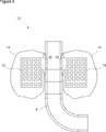
- Figure 3 - is the front view of a refrigerant flow duct and a suction muffler with muffler chambers in balloon structure disposed on both sides thereof.
- Figure 4 - is the perspective view of a suction muffler having a rectangular refrigerant flow duct.
- Figure 5 - is the perspective view of a compressor motor and a mounted suction muffler.
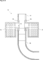
- Figure 6 — is the cross-sectional view of a suction muffler in an embodiment of the present invention.
- Figure 7 - is the front view of the suction muffler comprising a muffler chamber in cylindrical balloon structure that is fitted on the duct.
- Figure 8 - is the exploded view of the suction muffler in Figure 7.
- the hermetic compressor (1) suitable for use for circulation of the refrigerant fluid in cooling devices, for example refrigerators comprises a casing (2); an electric motor (3) composed of a stator and a rotor (referred briefly as the motor (3) hereinafter); a cylinder (4) that is disposed in the casing (2) and that enables the refrigerant to be sucked and pumped; a piston (5) that is operated in the cylinder (4); a cylinder head (6) that enables the refrigerant sucked and pumped into the cylinder (4) by means of the piston (5) to be directed; an inlet tube (7) that provides the intake of the refrigerant coming from the refrigeration cycle into the casing (2), and a hollow suction plenum (8) (also called "muffler head”) that extends from inside the cylinder head (6) toward the cylinder (4), that is produced from a hard plastic material and that enables the refrigerant to be delivered to the cylinder (4).
- a hollow suction plenum (8) also called "
- the compressor (1) of the present invention comprises a suction muffler (12) that has
- duct (9) a refrigerant flow duct (9) (referred briefly as the "duct (9)" hereinafter) that is produced from a hard plastic material and that connects the inlet tube (7) and the suction plenum (8) to so as to enable the refrigerant to be transferred from the inlet tube (7) to the suction plenum (8),
- the interior volume of the muffler chamber (11) changing by inflating and shrinking with the effect of the varying pressure of the sucked refrigerant in gas state depending on the speed of the motor (3) and/or the sucking and pumping actions of the piston (5).
- the muffler chamber (11) is produced from a "balloon" material such as rubber, latex, neoprene or polychloroprene.
- the suction muffler (12) comprises at least one porous or grill-shaped noise attenuator (13) that is disposed in the muffler chamber (11) ( Figure 2, Figure 3, Figure 4).
- the noise attenuator (13) is produced from metal or hard plastic material.
- the suction muffler (12) comprises two muffler chambers (11) that are disposed symmetrically on both sides of the duct (9) and form a " t " together with the duct (9), and two noise attenuators (13) that are disposed in the said muffler chambers (11) ( Figure 2, Figure 3, Figure 4).
- the refrigerant in gas state leaving the evaporator (not shown in figures) disposed in the refrigeration cycle is sucked through the inlet tube (7) into the casing (2) of the compressor (1) and passes through the duct (9) of the suction muffler (12) and is transferred directly to the cylinder (4) by means of the suction plenum (8).
- the flow rate and pressure of the sucked refrigerant in gas state change depending on the varying speed of the motor (3) and/or the sucking-pumping action of the piston (5) according to the refrigeration need during the operation of the compressor (1).
- the sucked refrigerant fills in the muffler chambers (11), and the muffler chambers (11) in "balloon" form inflate and shrink and thus equalize the pressure of the refrigerant in gas state flowing between the inlet tube (7) and the suction plenum (8), thus, providing the attenuation of the flow-induced noise.
- the refrigerant flowing through the duct (9) in reverse direction to the suction during the compression action of the piston (5) fills into and inflates the muffler chambers (11) and thus the level of noise is reduced.
- the duct (9) has a rectangular cross-section and the muffler chambers (11) and the noise attenuators (13) are oppositely disposed onto the outer surfaces of the two parallel side walls of the duct (9) ( Figure 4).
- the duct (9) is produced in two pieces as the upper duct piece (14) and the lower duct piece (15), and the muffler chambers (11) and the noise attenuators (13) are mounted by being squeezed between the upper duct piece (14) and the lower duct piece (15).
- each noise attenuator (13) comprises more than one clamping extension (16) that enables the noise attenuator (13) to be snap-fitted between the upper duct piece (14) and the lower duct piece (15) ( Figure 6).
- the suction muffler (12) comprises a cylindrical duct (9), more than one opening (10) disposed on the cylindrical side wall of the duct (9), and a muffler chamber (11) in form of a cylindrical balloon that is fitted onto the duct (9) like a sheath and surrounds the mid-section of the duct (9) where the openings (10) are disposed so as to form a closed volume around the duct (9) ( Figure 7, Figure 8).
- the suction muffler (12) comprises two O-ring grooves (18) that are disposed on the upper side and the lower side of the openings (10) and that enable the muffler chamber (11) to be fitted around the duct (9) by using O-rings (17) ( Figure 8).
- the suction chamber (11) is fixed onto the duct (9) by being adhered from the top and the bottom or by using clamps produced from metal or plastic material.
- the muffler chamber (11) in "balloon" form that is disposed in the suction muffler (12) and the noise attenuator (13) that is disposed into the muffler chamber (11) provide the reduction of the noise arising from the flow of the refrigerant.
- the porous or grill-shaped noise attenuator (13) forms a rigid skeleton in the muffler chamber (11) and prevents the elastic wall of the muffler chamber (11) from excessively shrinking and being deformed in addition to the noise level reduction function thereof.
Landscapes
- Engineering & Computer Science (AREA)
- Mechanical Engineering (AREA)
- General Engineering & Computer Science (AREA)
- Compressor (AREA)
Abstract
The present invention relates to a hermetic compressor (1) that is suitable for use for circulation of the refrigerant fluid in cooling devices, for example refrigerators, comprising a casing (2); a motor (3); a cylinder (4) that is disposed in the casing (2) and that enables the refrigerant to be sucked and pumped; a piston (5) that is operated in the cylinder (4); a cylinder head (6) that enables the refrigerant sucked and pumped into the cylinder (4) by means of the piston (5) to be directed; an inlet tube (7) that provides the intake of the refrigerant coming from the refrigeration cycle into the casing (2); a suction plenum (8) that enables the refrigerant to be delivered to the cylinder (4), and a partially-elastic suction muffler (12).
Description
The present invention relates to a hermetic compressor suitable for use in cooling devices.
In hermetic compressors, the refrigerant is sucked from and pumped back to the refrigeration cycle by means of a piston running in a cylinder. One of the important factors determining the operating performance of hermetic compressors is the amount and temperature of the refrigerant gas entering the cylinder during the sucking action of the piston. Increased temperature of the refrigerant gas sucked from the refrigeration cycle causes a reduction in the amount of refrigerant gas entering the compression chamber of the cylinder, resulting in decrease in the volumetric efficiency and capacity of the compressor. Excessively increased temperature at the inlet of the cylinder causes an increase also in the body temperature of the cylinder, adversely affecting the compression process.
In a state of the art hermetic compressor (1') shown in Figure 1, a suction muffler (12') is used to reduce the level of the noise originating from the refrigerant sucked from the refrigeration cycle. The refrigerant gas flowing from the refrigeration cycle into the suction muffler (12') in the compressor (1') is transmitted by means of a suction plenum (8') (muffler head) into the cylinder (4'). In the state of the art, the suction muffler (12') is structurally positioned in the vicinity of the motor (3') due to the space constraint and the temperature of the refrigerant gas passing through the suction muffler (12') excessively increases due to the heat transfer from the motor (3'). The suction muffler (12') has a hollow structure and is produced from a hard plastic material, and occupies a considerable space in the casing (2'), and may sustain damage by hitting the casing (2') due to the shock occurring during the operation of the compressor (1') and transportation of the cooling device.
The International Patent Application No. WO2007015223 relates to a hermetic compressor wherein a refrigerant-tight connection is provided between a connection tube produced from a soft and elastic material and the muffler inlet tube produced from hard plastic.
The International Patent Application No. WO2015039204 relates to a hermetic compressor comprising a suction muffler.
The United States Patent Application No. US2009038329 relates to a hermetic compressor comprising a suction muffler
The International Patent Application No. WO2013086592 relates to a hermetic compressor comprising an acoustic filter.
The aim of the present invention is the realization of a compressor comprising a partially-elastic suction muffler that provides the attenuation of the noise arising from the refrigerant fluid returning from the refrigeration cycle.
The compressor realized in order to attain the aim of the present invention is explicated in the claims.
The suction muffler used in the compressor of the present invention comprises a refrigerant flow duct that is produced from a hard plastic material and that connects the inlet tube providing the entry of the refrigerant in gas state returning from the refrigeration cycle into the casing and the suction plenum that delivers the refrigerant to the cylinder, and muffler chambers in "balloon" form, that are mounted onto the side walls of the said duct.
Porous or grill-shaped noise attenuators that are produced from metal or hard plastic are disposed in the muffler chambers.
The muffler chambers expand and shrink with the effect of the varying flow rate and pressure of the refrigerant gas and provide the attenuation of the flow-induced noise by equalizing the pressure.
The noise attenuators placed in the muffler chambers prevent the flow-induced noise and the temperature of the refrigerant gas from increasing and function as a skeleton that prevents the deformation of the muffler chambers.
The compressor realized in order to attain the aim of the present invention is illustrated in the attached figures, where:
Figure 1 - is the cross-sectional view of a state of the art compressor.
Figure 2 – is the cross-sectional view of the compressor of the present invention.
Figure 3 - is the front view of a refrigerant flow duct and a suction muffler with muffler chambers in balloon structure disposed on both sides thereof.
Figure 4 - is the perspective view of a suction muffler having a rectangular refrigerant flow duct.
Figure 5 - is the perspective view of a compressor motor and a mounted suction muffler.
Figure 6 – is the cross-sectional view of a suction muffler in an embodiment of the present invention.
Figure 7 - is the front view of the suction muffler comprising a muffler chamber in cylindrical balloon structure that is fitted on the duct.
Figure 8 - is the exploded view of the suction muffler in Figure 7.
The elements illustrated in the figures are numbered as follows:
1. Compressor
2. Casing
3. Motor
4. Cylinder
5. Piston
6. Cylinder head
7. Inlet tube
8. Suction plenum
9. Duct
10. Opening
11. Muffler chamber
12. Suction muffler
13. Noise attenuator
14. Upper duct piece
15. Lower duct piece
16. Clamping extension
17. O-ring
18. O-ring groove
1' Compressor in the prior art
2' Casing in the prior art
3'. Motor in the prior art
4’. Cylinder in the prior art
8'. Suction plenum in the prior art
12. Suction muffler in the prior art
The hermetic compressor (1) suitable for use for circulation of the refrigerant fluid in cooling devices, for example refrigerators, comprises a casing (2); an electric motor (3) composed of a stator and a rotor (referred briefly as the motor (3) hereinafter); a cylinder (4) that is disposed in the casing (2) and that enables the refrigerant to be sucked and pumped; a piston (5) that is operated in the cylinder (4); a cylinder head (6) that enables the refrigerant sucked and pumped into the cylinder (4) by means of the piston (5) to be directed; an inlet tube (7) that provides the intake of the refrigerant coming from the refrigeration cycle into the casing (2), and a hollow suction plenum (8) (also called "muffler head") that extends from inside the cylinder head (6) toward the cylinder (4), that is produced from a hard plastic material and that enables the refrigerant to be delivered to the cylinder (4).
The compressor (1) of the present invention comprises a suction muffler (12) that has
- a refrigerant flow duct (9) (referred briefly as the "duct (9)" hereinafter) that is produced from a hard plastic material and that connects the inlet tube (7) and the suction plenum (8) to so as to enable the refrigerant to be transferred from the inlet tube (7) to the suction plenum (8),
- at least one opening (10) that is disposed on the side wall of the duct (9), and
- at least one muffler chamber (11) that is attached to the outer surface of the side wall of the duct (9) around the opening (10), that extends from the duct (9) toward the interior volume of the casing (2), that receives the refrigerant from the duct (9) by means of the opening (10), that is produced from an elastic material, the interior volume of the muffler chamber (11) changing by inflating and shrinking with the effect of the varying pressure of the sucked refrigerant in gas state depending on the speed of the motor (3) and/or the sucking and pumping actions of the piston (5).
In an embodiment of the present invention, the muffler chamber (11) is produced from a "balloon" material such as rubber, latex, neoprene or polychloroprene.
In another embodiment of the present invention, the suction muffler (12) comprises at least one porous or grill-shaped noise attenuator (13) that is disposed in the muffler chamber (11) (Figure 2, Figure 3, Figure 4). The noise attenuator (13) is produced from metal or hard plastic material.
In another embodiment of the present invention, the suction muffler (12) comprises two muffler chambers (11) that are disposed symmetrically on both sides of the duct (9) and form a "t" together with the duct (9), and two noise attenuators (13) that are disposed in the said muffler chambers (11) (Figure 2, Figure 3, Figure 4).
The refrigerant in gas state leaving the evaporator (not shown in figures) disposed in the refrigeration cycle is sucked through the inlet tube (7) into the casing (2) of the compressor (1) and passes through the duct (9) of the suction muffler (12) and is transferred directly to the cylinder (4) by means of the suction plenum (8). The flow rate and pressure of the sucked refrigerant in gas state change depending on the varying speed of the motor (3) and/or the sucking-pumping action of the piston (5) according to the refrigeration need during the operation of the compressor (1). The sucked refrigerant fills in the muffler chambers (11), and the muffler chambers (11) in "balloon" form inflate and shrink and thus equalize the pressure of the refrigerant in gas state flowing between the inlet tube (7) and the suction plenum (8), thus, providing the attenuation of the flow-induced noise. The refrigerant flowing through the duct (9) in reverse direction to the suction during the compression action of the piston (5) fills into and inflates the muffler chambers (11) and thus the level of noise is reduced.
In an embodiment of the present invention, the duct (9) has a rectangular cross-section and the muffler chambers (11) and the noise attenuators (13) are oppositely disposed onto the outer surfaces of the two parallel side walls of the duct (9) (Figure 4).
In another embodiment of the present invention, the duct (9) is produced in two pieces as the upper duct piece (14) and the lower duct piece (15), and the muffler chambers (11) and the noise attenuators (13) are mounted by being squeezed between the upper duct piece (14) and the lower duct piece (15). In this embodiment, each noise attenuator (13) comprises more than one clamping extension (16) that enables the noise attenuator (13) to be snap-fitted between the upper duct piece (14) and the lower duct piece (15) (Figure 6).
In another embodiment of the present invention, the suction muffler (12) comprises a cylindrical duct (9), more than one opening (10) disposed on the cylindrical side wall of the duct (9), and a muffler chamber (11) in form of a cylindrical balloon that is fitted onto the duct (9) like a sheath and surrounds the mid-section of the duct (9) where the openings (10) are disposed so as to form a closed volume around the duct (9) (Figure 7, Figure 8).
In an embodiment of the present invention, the suction muffler (12) comprises two O-ring grooves (18) that are disposed on the upper side and the lower side of the openings (10) and that enable the muffler chamber (11) to be fitted around the duct (9) by using O-rings (17) (Figure 8). In other similar embodiments, the suction chamber (11) is fixed onto the duct (9) by being adhered from the top and the bottom or by using clamps produced from metal or plastic material.
In the compressor (1) of the present invention, the muffler chamber (11) in "balloon" form that is disposed in the suction muffler (12) and the noise attenuator (13) that is disposed into the muffler chamber (11) provide the reduction of the noise arising from the flow of the refrigerant. The porous or grill-shaped noise attenuator (13) forms a rigid skeleton in the muffler chamber (11) and prevents the elastic wall of the muffler chamber (11) from excessively shrinking and being deformed in addition to the noise level reduction function thereof. By reducing the temperature of the sucked refrigerant, in the compressor (1) the volumetric efficiency and the performance are increased and the COP (coefficient of performance) value is improved.
Claims (11)
- A hermetic compressor (1) suitable for use in cooling devices, comprising a casing (2); a motor (3) composed of a stator and a rotor; a cylinder (4) that is disposed in the casing (2) and that enables the refrigerant to be sucked and pumped; a piston (5) that is operated in the cylinder (4); a cylinder head (6) that enables the refrigerant sucked and pumped into the cylinder (4) by means of the piston (5) to be directed; an inlet tube (7) that provides the intake of the refrigerant coming from the refrigeration cycle into the casing (2), and a hollow suction plenum (8) that extends from inside the cylinder head (6) toward the cylinder (4), that is produced from a hard plastic material and that enables the refrigerant to be delivered to the cylinder (4), characterized by a suction muffler (12) having- a duct (9) that connects the inlet tube (7) and the suction plenum (8) and that is produced from a hard plastic material,- at least one opening (10) that is disposed on the side wall of the duct (9), and- at least one muffler chamber (11) that is attached to the outer surface of the side wall of the duct (9) around the opening (10), that extends from the duct (9) toward the interior volume of the casing (2), that receives the refrigerant from the duct (9) by means of the opening (10), that is produced from an elastic material, the interior volume of the muffler chamber (11) changing by inflating and shrinking with the effect of the varying pressure of the sucked refrigerant in gas state.
- A compressor (1) as in Claim 1, characterized by the muffler chamber (11) that is produced from a "balloon" material such as rubber, latex, neoprene or polychloroprene.
- A compressor (1) as in Claim 1 or 2, characterized by at least one porous or grill-shaped noise attenuator (13) that is disposed in the muffler chamber (11).
- A compressor (1) as in Claim 3, characterized by the noise attenuator (13) that is produced from a metal or hard plastic material.
- A compressor (1) as in Claim 1 or 2, characterized by two muffler chambers (11) that are disposed symmetrically on both sides of the duct (9), that form a "t" together with the duct (9), and two noise attenuators (13) that are disposed in the said muffler chambers (11).
- A compressor (1) as in Claim 5, characterized by a rectangular duct (9) and the muffler chambers (11) and the noise attenuators (13) that are oppositely disposed on the outer surfaces of the two parallel side walls of the duct (9).
- A compressor (1) as in Claim 1 or 2, characterized by a duct (9) that is produced in two pieces as an upper duct piece (14) and a lower duct piece (15), and the muffler chambers (11) and the noise attenuators (13) that are mounted by being squeezed between the upper duct piece (14) and the lower duct piece (15).
- A compressor (1) as in Claim 1 or 2, characterized by the noise attenuator (13) comprising more than one clamping extension (16) that enables the noise attenuator (13) to be snap-fitted between the upper duct piece (14) and the lower duct piece (15).
- A compressor (1) as in Claim 1 or 2, characterized by a cylindrical duct (9), more than one opening (10) that is disposed on the cylindrical side wall of the duct (9), and a muffler chamber (11) in cylindrical balloon form that is fitted on the duct (9) like a sheath, that surrounds all around the mid-section of the duct (9) where the openings (10) are disposed so as to form a closed volume around the duct (9).
- A compressor (1) as in Claim 1 or 2, characterized by two O-ring grooves (18) that are disposed on the upper and lower sides of the openings (10) and that enable the muffler chamber (11) to be fitted around the duct (9) by using O-rings (17).
- A refrigerator characterized by a compressor (1) comprising a suction muffler (12) as in Claim 1.
Applications Claiming Priority (2)
| Application Number | Priority Date | Filing Date | Title |
|---|---|---|---|
| TR201607689 | 2016-06-07 | ||
| TRA2016/07689 | 2016-06-07 |
Publications (1)
| Publication Number | Publication Date |
|---|---|
| WO2017211705A1 true WO2017211705A1 (en) | 2017-12-14 |
Family
ID=59061972
Family Applications (1)
| Application Number | Title | Priority Date | Filing Date |
|---|---|---|---|
| PCT/EP2017/063423 Ceased WO2017211705A1 (en) | 2016-06-07 | 2017-06-02 | A hermetic compressor comprising a partially-elastic suction muffler |
Country Status (1)
| Country | Link |
|---|---|
| WO (1) | WO2017211705A1 (en) |
Citations (8)
| Publication number | Priority date | Publication date | Assignee | Title |
|---|---|---|---|---|
| DE19520229A1 (en) * | 1994-07-05 | 1996-01-11 | Necchi Compressori | Muffler for engine compressors of cooling devices |
| AT7696U1 (en) * | 2004-04-28 | 2005-07-25 | Verdichter Oe Ges M B H | REFRIGERANT COMPRESSOR |
| WO2007015223A2 (en) | 2005-08-04 | 2007-02-08 | Arcelik Anonim Sirketi | A compressor |
| US20080118374A1 (en) * | 2006-11-20 | 2008-05-22 | Min Cheul Yun | Hermetic type compressor with suction pressure adjusting device |
| US20090038329A1 (en) | 2005-05-03 | 2009-02-12 | Whirlpool S.A. | Suction muffler for a refrigeration compressor |
| WO2013086592A1 (en) | 2011-12-15 | 2013-06-20 | Whirlpool S.A. | Acoustic filter for compressor |
| WO2014086882A1 (en) * | 2012-12-05 | 2014-06-12 | Arcelik Anonim Sirketi | A hermetic compressor with suction muffler |
| WO2015039204A1 (en) | 2013-09-19 | 2015-03-26 | Whirlpool S.A. | Constructive arrangement introduced in acoustic filter of hermetic compressor |
-
2017
- 2017-06-02 WO PCT/EP2017/063423 patent/WO2017211705A1/en not_active Ceased
Patent Citations (8)
| Publication number | Priority date | Publication date | Assignee | Title |
|---|---|---|---|---|
| DE19520229A1 (en) * | 1994-07-05 | 1996-01-11 | Necchi Compressori | Muffler for engine compressors of cooling devices |
| AT7696U1 (en) * | 2004-04-28 | 2005-07-25 | Verdichter Oe Ges M B H | REFRIGERANT COMPRESSOR |
| US20090038329A1 (en) | 2005-05-03 | 2009-02-12 | Whirlpool S.A. | Suction muffler for a refrigeration compressor |
| WO2007015223A2 (en) | 2005-08-04 | 2007-02-08 | Arcelik Anonim Sirketi | A compressor |
| US20080118374A1 (en) * | 2006-11-20 | 2008-05-22 | Min Cheul Yun | Hermetic type compressor with suction pressure adjusting device |
| WO2013086592A1 (en) | 2011-12-15 | 2013-06-20 | Whirlpool S.A. | Acoustic filter for compressor |
| WO2014086882A1 (en) * | 2012-12-05 | 2014-06-12 | Arcelik Anonim Sirketi | A hermetic compressor with suction muffler |
| WO2015039204A1 (en) | 2013-09-19 | 2015-03-26 | Whirlpool S.A. | Constructive arrangement introduced in acoustic filter of hermetic compressor |
Similar Documents
| Publication | Publication Date | Title |
|---|---|---|
| CN101835978B (en) | Linear compressor | |
| JP4769280B2 (en) | Suction device in reciprocating hermetic compressor | |
| KR20090095104A (en) | Muffler for compressor | |
| KR20090077289A (en) | Noise reduction device of hermetic compressor | |
| EP3343033A1 (en) | Linear compressor | |
| WO2017211704A1 (en) | A hermetic compressor comprising an elastic suction muffler | |
| WO2017211705A1 (en) | A hermetic compressor comprising a partially-elastic suction muffler | |
| WO2016066213A1 (en) | Improved suction muffler for use in a hermetically sealed compressor of a refrigeration appliance | |
| WO2017194516A1 (en) | A hermetic compressor with improved sealing | |
| US7150605B2 (en) | Reciprocating compressor | |
| KR101996488B1 (en) | Muffler for Hermetic Compressor | |
| KR101698084B1 (en) | Hermetic type compressor | |
| WO2013182409A1 (en) | A compressor comprising a cylinder head | |
| WO2011154474A1 (en) | A hermetic compressor | |
| WO2017194492A1 (en) | A hermetic compressor with reduced noise level | |
| WO2017191228A1 (en) | A hermetic compressor with increased performance | |
| WO2016155799A1 (en) | Suction muffler for use in a hermetic compressor | |
| KR100788423B1 (en) | Suction Muffler and Compressor Having the Same | |
| KR100862296B1 (en) | Refrigeration cycle device and refrigerator provided therewith | |
| KR20220107707A (en) | Refrigerator | |
| WO2017191229A1 (en) | A hermetic compressor with increased performance | |
| KR100724394B1 (en) | 2-cylinder reciprocating compressor and refrigeration unit using the same | |
| EP4634529A1 (en) | A compressor | |
| WO2024129011A1 (en) | A compressor | |
| KR100685758B1 (en) | Discharge muffler of compressor |
Legal Events
| Date | Code | Title | Description |
|---|---|---|---|
| 121 | Ep: the epo has been informed by wipo that ep was designated in this application |
Ref document number: 17730083 Country of ref document: EP Kind code of ref document: A1 |
|
| NENP | Non-entry into the national phase |
Ref country code: DE |
|
| 122 | Ep: pct application non-entry in european phase |
Ref document number: 17730083 Country of ref document: EP Kind code of ref document: A1 |