WO2017208721A1 - Information processing device, optical storage device, information processing method, and program - Google Patents
Information processing device, optical storage device, information processing method, and program Download PDFInfo
- Publication number
- WO2017208721A1 WO2017208721A1 PCT/JP2017/017116 JP2017017116W WO2017208721A1 WO 2017208721 A1 WO2017208721 A1 WO 2017208721A1 JP 2017017116 W JP2017017116 W JP 2017017116W WO 2017208721 A1 WO2017208721 A1 WO 2017208721A1
- Authority
- WO
- WIPO (PCT)
- Prior art keywords
- signal
- adaptive
- equalization
- input
- output
- Prior art date
Links
Images


Classifications
-
- G—PHYSICS
- G11—INFORMATION STORAGE
- G11B—INFORMATION STORAGE BASED ON RELATIVE MOVEMENT BETWEEN RECORD CARRIER AND TRANSDUCER
- G11B20/00—Signal processing not specific to the method of recording or reproducing; Circuits therefor
- G11B20/10—Digital recording or reproducing
- G11B20/10009—Improvement or modification of read or write signals
- G11B20/10046—Improvement or modification of read or write signals filtering or equalising, e.g. setting the tap weights of an FIR filter
-
- G—PHYSICS
- G11—INFORMATION STORAGE
- G11B—INFORMATION STORAGE BASED ON RELATIVE MOVEMENT BETWEEN RECORD CARRIER AND TRANSDUCER
- G11B20/00—Signal processing not specific to the method of recording or reproducing; Circuits therefor
- G11B20/10—Digital recording or reproducing
- G11B20/10009—Improvement or modification of read or write signals
- G11B20/10305—Improvement or modification of read or write signals signal quality assessment
- G11B20/10314—Improvement or modification of read or write signals signal quality assessment amplitude of the recorded or reproduced signal
-
- G—PHYSICS
- G11—INFORMATION STORAGE
- G11B—INFORMATION STORAGE BASED ON RELATIVE MOVEMENT BETWEEN RECORD CARRIER AND TRANSDUCER
- G11B7/00—Recording or reproducing by optical means, e.g. recording using a thermal beam of optical radiation by modifying optical properties or the physical structure, reproducing using an optical beam at lower power by sensing optical properties; Record carriers therefor
- G11B7/004—Recording, reproducing or erasing methods; Read, write or erase circuits therefor
- G11B7/005—Reproducing
-
- G—PHYSICS
- G11—INFORMATION STORAGE
- G11B—INFORMATION STORAGE BASED ON RELATIVE MOVEMENT BETWEEN RECORD CARRIER AND TRANSDUCER
- G11B7/00—Recording or reproducing by optical means, e.g. recording using a thermal beam of optical radiation by modifying optical properties or the physical structure, reproducing using an optical beam at lower power by sensing optical properties; Record carriers therefor
- G11B7/12—Heads, e.g. forming of the optical beam spot or modulation of the optical beam
- G11B7/13—Optical detectors therefor
- G11B7/133—Shape of individual detector elements
Definitions
- the present disclosure relates to an information processing device, an optical storage device, an information processing method, and a program. More specifically, the present invention relates to an information processing apparatus, an optical storage apparatus, an information processing method, and a program that realize high-quality data reproduction from a disk on which high-density data recording has been performed.
- optical disks such as DVD (Digital Versatile Disc) and BD (Blu-ray (registered trademark) Disc) are widely used.
- optical discs such as BDs are required to perform high-density information recording.
- a method of increasing the density of an optical disc there are a method of shortening a channel bit length, that is, a mark length and increasing the density in the linear density direction, and a method of narrowing a track pitch.
- Patent Document 1 Japanese Patent Application Laid-Open No. 2005-322367
- Patent Document 2 Japanese Patent Application Laid-Open No. 2002-183970
- Patent Document 3 Japanese Patent Application Laid-Open No. 2002-183970
- Patent Document 1 discloses a noise reduction processing configuration to which an analog division method is applied.
- Patent Document 2 discloses a noise reduction processing configuration based on an analog multiplication method.
- Patent Document 3 discloses a noise reduction processing configuration to which a transversal filter adaptive feedback method is applied.
- these conventional techniques have a problem in terms of the feasibility of a wideband analog multiplier circuit, a divider circuit, and a delay adjustment circuit for exhibiting a sufficient noise reduction effect.
- the present disclosure has been made in view of, for example, the above-described problems.
- an information processing apparatus and an optical storage that reduce laser noise included in a reproduction signal of an optical disc and realize acquisition of a high-quality reproduction signal.
- An object is to provide an apparatus, an information processing method, and a program.
- the first aspect of the present disclosure is: A photodetector that outputs a signal based on the reflected light from the disk with respect to the light emitted from the laser diode; A front monitor that outputs a reference signal based on light emitted from the laser diode; A data detection processing unit that inputs an output signal of the photodetector and generates a reproduction signal; The data detection processing unit A reproduction signal-adaptive adaptive equalizer that inputs an output signal of the photodetector and outputs an equalized signal by adaptive equalization processing based on the input signal; A laser noise adaptive equalizer that inputs a laser noise signal included in a reference signal output from the front monitor and outputs an equalized signal by an adaptive equalization process based on the input signal; An arithmetic unit for performing arithmetic processing between the output of the adaptive equalizer for reproduction signal and the output of the adaptive equalizer for laser noise; The information processing apparatus includes a signal identification unit that generates an identification signal based on the output of the arithmetic unit
- the second aspect of the present disclosure is: An information processing method executed in an information processing apparatus, A process in which the photodetector outputs a signal based on the reflected light from the disk with respect to the light emitted from the laser diode; A process in which a front monitor outputs a reference signal based on light emitted from the laser diode; A data detection processing unit inputs an output signal of the photodetector and executes data detection processing for generating a reproduction signal, In the data detection processing, the data detection processing unit, A process of generating a reproduction signal-corresponding equalization signal by an adaptive equalization process based on the output signal of the photodetector; A process of generating an equalization signal corresponding to a laser noise by an adaptive equalization process based on a laser noise signal included in a reference signal output from the front monitor; Arithmetic processing of the reproduction signal-corresponding equalization signal and the laser noise-corresponding equalization signal; In the information processing method for executing the identification signal generation processing based on the calculation processing result.
- the third aspect of the present disclosure is: A program for executing information processing in an information processing apparatus;
- the information processing apparatus includes: A photodetector that outputs a signal based on the reflected light from the disk with respect to the light emitted from the laser diode; A front monitor that outputs a reference signal based on light emitted from the laser diode; A data detection processing unit for executing a data detection process for generating a reproduction signal by inputting an output signal of the photodetector;
- the program is stored in the data detection processing unit.
- the program of the present disclosure is a program that can be provided by, for example, a storage medium or a communication medium provided in a computer-readable format to an information processing apparatus or a computer system that can execute various program codes.
- a program in a computer-readable format, processing corresponding to the program is realized on the information processing apparatus or the computer system.
- system is a logical set configuration of a plurality of devices, and is not limited to one in which the devices of each configuration are in the same casing.
- an apparatus and a method for generating a reproduction signal with reduced laser noise are realized. Specifically, a photodetector (PD) that irradiates a disk with laser light and outputs a signal based on light reflected from the disk, a front monitor that outputs a reference signal based on light emitted from the laser diode, and an output signal from the PD Is input to generate a reproduction signal.
- PD photodetector
- a data detection processing unit includes a reproduction signal adaptive equalizer that outputs an equalized signal by an adaptive equalization process based on a PD output signal, and a laser noise compatible adaptive equalizer that outputs an equalized signal by an adaptive equalization process based on a laser noise signal Then, a reproduction signal with reduced laser noise is generated based on the calculation result of the output of the adaptive equalizer corresponding to the reproduction signal and the output of the adaptive equalizer corresponding to the laser noise.
- a reproduction signal with reduced laser noise is generated based on the calculation result of the output of the adaptive equalizer corresponding to the reproduction signal and the output of the adaptive equalizer corresponding to the laser noise.
- FIG. 1 is a block diagram illustrating a configuration example of an information processing apparatus such as an optical storage apparatus that executes data reproduction processing and recording processing from an optical disc 10.
- the information processing apparatus includes an optical pickup 11 that records and reproduces information with respect to an optical disk 10 as an optical recording medium, and a spindle motor 12 that rotates the optical disk 10.
- a thread (feed motor) 13 is provided to move the optical pickup 11 in the radial direction of the optical disk 10.
- the optical disc 10 is a high-density optical disc such as a BD (Blu-ray (registered trademark) Disc).
- the BD is, for example, a high-density optical disc having a recording capacity of about 25 GB on a single layer on one side and about 50 GB on two layers on one side.
- the light source wavelength is set to 405 nm and the numerical aperture NA (Numerical Aperture) of the objective lens is increased to 0.85.
- NA numerical aperture
- the spot diameter can be reduced to 0.58 ⁇ m.
- the channel bit length that is, the mark length
- the density is increased in the linear density direction compared to BD (Blu-ray (registered trademark) Disc), and the capacity is increased to 100 GB for 3 layers and 128 GB for 4 layers.
- BDXL registered trademark
- a method for recording data on both the groove track and the land track is being adopted.
- a groove set along the recording track of the disk is a groove (G), and a track formed by the groove is called a groove track.
- an area that becomes a mountain portion sandwiched between two grooves (grooves) is a land (L), and a track formed by the land is called a land track.
- a high-density recording type disc data is recorded in both the groove (G) and the land (L). With this configuration, more data can be recorded on the disc.
- a high-density recording disk has a problem that the possibility of occurrence of crosstalk in data reproduction processing is increased. That is, there is a problem that crosstalk in which the data of the adjacent track is mixed as noise easily occurs in the read data of the read target track.
- the spindle motor 12 rotates at a constant linear velocity (CLV) or a constant angular velocity (CAV) during recording / reproduction.
- CLV constant linear velocity
- CAV constant angular velocity
- the mark information recorded on the track on the optical disk 10 is read by the optical pickup (optical head) 11.
- changes in brightness (reflectance) and reflection phase (complex reflectance) such as phase change marks or dye change marks are recorded on the tracks on the optical disk 10 by the optical pickup 11. As recorded.
- a recording mark by a phase change mark is recorded on a track formed by a wobbling groove.
- the phase change mark is an RLL (1, 7) PP modulation method (RLL; Run Length Limited, PP). : Parity preserve / Prohibit rmtr (repeated minimum transition runlength)), etc., in the case of 23.3 GB BD per layer, recorded at a linear density of 0.12 ⁇ m / bit, 0.08 ⁇ m / channel bit.
- the inner peripheral area of the optical disc 10 for example, physical information of the disc is recorded as embossed pits or wobbling grooves as reproduction-only management information. Reading of these pieces of information is also performed by the optical pickup 11. Further, the ADIP information embedded as wobbling of the groove track on the optical disc 10 is also read by the optical pickup 11.
- the optical pickup 11 includes a laser diode 51 serving as a laser light source, a laser driver 41 that supplies a driving current to the laser diode 51, a polarization beam splitter 53 that guides an optical path of light emitted from the laser diode 51 and reflected light from the disk 10. And a front monitor 42 for obtaining a monitoring signal (reference light) of the light emitted from the laser diode 51 and generating a feedback control signal for the laser driver 41. Further, a photodetector 56 for detecting reflected light from the disk 10, an objective lens serving as an output end of the laser light, and an optical for irradiating the disk recording surface with the laser light through the objective lens and guiding the reflected light to the photodetector. A system is constructed.
- the objective lens is held so as to be movable in the tracking direction and the focus direction by a biaxial mechanism.
- the entire optical pickup 11 can be moved in the radial direction of the disk by a thread mechanism 13.
- a drive current from the laser driver 41 is supplied to the laser diode of the optical pickup 11, and the laser diode generates a laser.
- the matrix circuit 14 includes a current-voltage conversion circuit, a matrix calculation / amplification circuit, and the like corresponding to output currents from a plurality of light receiving elements as photodetectors, and generates necessary signals by matrix calculation processing.
- a current-voltage conversion circuit may be formed in the photodetector element.
- a reproduction information signal (RF signal) corresponding to reproduction data, a focus error signal for servo control, a tracking error signal, and the like are generated.
- a push-pull signal is generated as a signal related to groove wobbling, that is, a signal for detecting wobbling.
- the reproduction information signal output from the matrix circuit 14 is supplied to the data detection processing unit 15, the focus error signal and the tracking error signal are supplied to the optical block servo circuit 21, and the push-pull signal is supplied to the wobble signal processing unit 16. .
- the data detection processing unit 15 performs binarization processing of the reproduction information signal. For example, the data detection processing unit 15 performs RF signal A / D conversion processing, PLL reproduction clock generation processing, PR (Partial Response) equalization processing, Viterbi decoding (maximum likelihood decoding), etc., and partial response maximum likelihood decoding processing A binary data string is obtained by (PRML detection method: Partial Response Maximum Likelihood detection method). The data detection processing unit 15 supplies a binary data string as information read from the optical disc 10 to the subsequent encoding / decoding unit 17.
- PRML detection method Partial Response Maximum Likelihood detection method
- the encoding / decoding unit 17 performs demodulation of reproduction data during reproduction and modulation processing of recording data during recording. That is, data demodulation, deinterleaving, ECC decoding, address decoding, etc. are performed during reproduction, and ECC encoding, interleaving, data modulation, etc. are performed during recording.
- the binary data string decoded by the data detection processing unit 15 is supplied to the encoding / decoding unit 17.
- the encoding / decoding unit 17 performs demodulation processing on the binary data string and obtains reproduction data from the optical disc 10. For example, a demodulating process for data recorded on the optical disk 10 that has been subjected to run-length limited code modulation such as RLL (1, 7) PP modulation and an ECC decoding process for error correction are performed. Get playback data.
- the data decoded to the reproduction data by the encoding / decoding unit 17 is transferred to the host interface 18 and transferred to the host device 30 based on an instruction from the system controller 20.
- the host device 30 is, for example, a computer device or an AV (Audio-Visual) system device.
- a clock synchronized with the push-pull signal is generated by the PLL processing.
- the wobble data is demodulated by the ADIP demodulation processing unit 26 into a data stream constituting an ADIP address and supplied to the address decoder 19.
- the address decoder 19 decodes the supplied data, obtains an address value, and supplies it to the system controller 20.
- recording data is transferred from the host device 30, and the recording data is supplied to the encoding / decoding unit 17 via the host interface 18.
- the encoding / decoding unit 17 performs error correction code addition (ECC encoding), interleaving, subcode addition, and the like as recording data encoding processing.
- ECC encoding error correction code addition
- the data subjected to these processes is subjected to run-length limited code modulation such as the RLL (1-7) PP method.
- the recording data processed by the encoding / decoding unit 17 is supplied to the write strategy unit 24.
- the write strategy unit 24 performs laser drive pulse waveform adjustment for recording layer characteristics, laser beam spot shape, recording linear velocity, and the like as recording compensation processing. Then, the laser drive pulse is output to the laser driver 41.
- the laser driver 41 Based on the laser driving pulse subjected to the recording compensation process, the laser driver 41 sends a current to the laser diode in the optical pickup 11 to emit laser light. As a result, a mark corresponding to the recording data is formed on the optical disc 10.
- the optical block servo circuit 21 generates various servo drive signals for focus, tracking, and thread from the focus error signal and tracking error signal from the matrix circuit 14 and executes the servo operation. That is, a focus drive signal and a tracking drive signal are generated according to the focus error signal and the tracking error signal, and the driver 28 drives the focus coil and tracking coil of the biaxial mechanism in the optical pickup 11.
- an optical pickup 11, a matrix circuit 14, an optical block servo circuit 21, a driver 28, a tracking servo loop and a focus servo loop by a biaxial mechanism are formed.
- the optical block servo circuit 21 turns off the tracking servo loop and outputs a jump drive signal in response to a track jump command from the system controller 20 to execute a track jump operation. Furthermore, the optical block servo circuit 21 generates a thread drive signal based on a thread error signal obtained as a low frequency component of the tracking error signal, access execution control from the system controller 20, and the like, and the thread driver 25 causes the thread mechanism 13. Drive.
- the spindle servo circuit 22 controls the spindle motor 12 to perform CLV rotation or CAV rotation.
- the spindle servo circuit 22 obtains the clock generated by the PLL for the wobble signal as the current rotational speed information of the spindle motor 12, and compares it with predetermined reference speed information to generate a spindle error signal.
- the spindle is compared by comparing this with predetermined reference speed information. An error signal is generated.
- the spindle servo circuit 22 outputs a spindle drive signal generated according to the spindle error signal, and causes the spindle driver 27 to execute CLV rotation or CAV rotation of the spindle motor 12.
- the spindle servo circuit 22 generates a spindle drive signal in response to a spindle kick / brake control signal from the system controller 20, and executes operations such as starting, stopping, acceleration, and deceleration of the spindle motor 12.
- a system controller 20 formed by a microcomputer.
- the system controller 20 executes various processes in accordance with commands from the host device 30 given via the host interface 18. For example, when a write command (write command) is issued from the host device 30, the system controller 20 first moves the optical pickup 11 to an address to be written. Then, the encoding / decoding unit 17 causes the encoding process to be performed on the data (for example, video data, audio data, etc.) transferred from the host device 30 as described above. Then, the laser driver 41 drives laser emission according to the encoded data, and recording is executed.
- a write command write command
- the system controller 20 first moves the optical pickup 11 to an address to be written.
- the encoding / decoding unit 17 causes the encoding process to be performed on the data (for example, video data, audio data, etc.) transferred from the host device 30 as described above.
- the laser driver 41 drives laser emission according to the encoded data, and recording is executed.
- the system controller 20 when a read command for requesting transfer of certain data recorded on the optical disc 10 is supplied from the host device 30, the system controller 20 first performs seek operation control for the instructed address. That is, a command is issued to the optical block servo circuit 21, and the access operation of the optical pickup 11 targeting the address specified by the seek command is executed. Thereafter, operation control necessary for transferring the data in the designated data section to the host device 30 is performed. That is, data is read from the optical disk 10 and reproduction processing in the data detection processing unit 15 and the encoding / decoding unit 17 is executed to transfer the requested data.
- FIG. 1 has been described as an optical disk device connected to the host device 30, the optical disk device may not be connected to other devices.
- an operation unit and a display unit are provided, and the configuration of the interface part for data input / output is different from that in FIG. That is, it is only necessary that recording and reproduction are performed in accordance with a user operation and a terminal unit for inputting / outputting various data is formed.
- various other examples of the configuration of the optical disc apparatus are conceivable.
- the optical pickup 11 records information on the optical disc 10 and reproduces information from the optical disc 10 using, for example, laser light (beam) having a wavelength ⁇ of 405 nm.
- the optical pickup 11 includes the laser diode 51 serving as a laser light source, the laser driver 41 that supplies a drive current to the laser diode 51, the light emitted from the laser diode 51, and the disk 10.
- a polarization beam splitter 53 that guides the optical path of the reflected light from the laser beam, a monitoring signal (reference light) of the light emitted from the laser diode 51, and a front monitor 42 that generates a feedback control signal for the laser driver 41.
- Laser light is emitted from a laser diode (LD) 51 that is a semiconductor laser.
- Laser light passes through a collimator lens 52, a polarizing beam splitter (PBS) 53, and an objective lens 54 and is irradiated onto the optical disk 10.
- the polarization beam splitter 53 has a separation surface that transmits approximately 100% of P-polarized light and reflects approximately 100% of S-polarized light.
- the reflected light from the recording layer of the optical disc 10 returns along the same optical path and enters the polarization beam splitter 53.
- the incident laser light is reflected by the polarization beam splitter 53 by approximately 100%.
- the laser beam reflected by the polarization beam splitter 53 is condensed on the light receiving surface of the photodetector 56 via the lens 55.
- the photodetector 56 has a light receiving cell for photoelectrically converting incident light on the light receiving surface.
- FIG. 2 shows the following three types of examples.
- A 1 signal output type without division
- B 3 signal output type corresponding to divided area
- C 5 signal output type corresponding to divided area
- the non-division 1-signal output type outputs one electrical signal corresponding to the amount of light received by the light receiving cells on the entire surface of the photodetector 56.
- the three-region output type corresponding to the divided region is constituted by a light receiving cell in which the light receiving surface of the photodetector 56 is divided, and outputs three electric signals corresponding to the amount of light received by the light receiving cell in each divided region.
- the five-signal output type corresponding to the divided area is also constituted by light receiving cells in which the light receiving surface of the photodetector 56 is divided, and outputs five electric signals corresponding to the amount of light received by the light receiving cells in each divided area.
- the three-signal output type corresponding to the divided area and the (C) five-signal output type light receiving cell corresponding to the divided area are divided lines extending in the radial direction (disc radial direction) of the optical disc 10 or in the tangential direction (track direction). Is divided into a plurality of regions. These divided photodetectors 56 output a plurality of channels of electrical signals in accordance with the amount of light received in each region of the light receiving cell. In addition to these, various configurations are possible for the divided configuration.
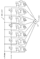
- FIG. 3 shows a detailed configuration of the (C) five-signal output type photodetector 56 corresponding to the divided area shown in FIG.
- the photodetector 56 includes a light receiving cell divided into a plurality of regions.
- A1, A2, B, C, D1, D2, D3, E1, E2, and E3 are divided into these areas.
- an electric signal corresponding to the amount of received light is individually output.
- signals applied to the generation of the reproduction signal are the following five signals corresponding to the five channels.
- Signal A A1 + A2 Signal
- B B
- Signal C C
- Signal D D1 + D2 + D3
- E E1 + E2 + E3
- a reproduction signal is generated using these five signals.
- region it is good also as a structure which produces
- A p * A1 + q * A2
- the output signal may be generated by multiplying the weighting factors p and q as described above.
- a high-quality reproduction signal can be obtained by performing an adaptive equalization process on each signal using a multi-input adaptive equalizer using such a split photodetector.
- An adaptive equalization processing configuration using a multi-input adaptive equalizer will be described later.
- Each of the signals A to E is a characteristic signal corresponding to the light receiving area, such as a signal containing a large amount of signal components of the track to be read or a signal having a high ratio of crosstalk signals of adjacent tracks.
- a reproduction signal generation processing configuration using such a split photodetector is disclosed in Patent Document 1 (International Publication WO2016 / 006157) which is an earlier application of the present applicant.
- the multiple-signal output type photo detector used in the present disclosure has the same configuration as those disclosed in these publications, and sets the multiple signals output from the photo detector and inputs each of the multiple signals to the multi-input adaptive equalizer.
- the configuration and processing for obtaining the equalized signal and the binarized signal are similarly applied to the present disclosure.
- the configuration of the optical pickup 11 shown in FIG. 2 shows the minimum components for explaining the present disclosure.
- the focus error signal and tracking output to the optical block servo circuit 21 via the matrix circuit 14 are shown.
- An error signal, a signal for generating a push-pull signal output to the wobble signal processing circuit 16 via the matrix circuit 14, and the like are omitted.
- various configurations other than the configuration shown in FIG. 2 are possible.
- the embodiment of the present disclosure described below will be described mainly as an example using the five-signal output type photodetector corresponding to the divided region described with reference to FIG. 3.
- the process of the present disclosure is not limited to the five-signal output type photodetector corresponding to the divided region described with reference to FIG. 3, but the one-signal output type without division, the three-signal output type corresponding to the divided region illustrated in FIG.
- the present invention can also be applied to a configuration using a photodetector having a different division configuration.
- the light beam of the return beam from the optical disc 10 is divided into a plurality of regions.
- Corresponding multiple channel reproduction information signals can be obtained.
- a high-quality reproduction signal can be obtained by data processing using the signals of these area units.
- a method for obtaining a reproduction information signal for each region a method other than the method of dividing the photodetector 56 can be used.
- an optical path conversion element for separating a plurality of regions is disposed in an optical path that passes through the objective lens 54 and reaches the photodetector 56, and a plurality of optical path conversion elements separated by the optical path conversion element are arranged. Any method that provides a beam to different photodetectors can be used.
- a diffraction element such as a holographic optical element, a refractive element such as a microlens array or a microprism, or the like can be used.
- the data detection processing unit 15 has an A / D converter 61 to which a reproduction information signal supplied from the matrix circuit 14 is supplied.
- FIG. 4 is a configuration example of the data detection processing unit 15 that inputs the five signals A to E obtained by using the divided-region-corresponding five-signal output type photo detector 56 shown in FIG. 3 and generates a reproduction signal. .
- a clock for the A / D converter 61 is formed by the PLL 62.
- the reproduction information signal supplied from the matrix circuit 14 is converted into digital data by the A / D converter 61.
- the digitized 5-channel reproduction information signals of the signals A to E are denoted by Sa to Se.
- a signal obtained by adding the reproduction information signals Sa to Se by the addition circuit 67 is supplied to the PLL 62.
- Signals A to E are electrical signals corresponding to the amounts of received light in the following areas described above with reference to FIG.
- Signal A A1 + A2
- B B
- Signal C C
- D D1 + D2 + D3
- E E1 + E2 + E3
- the data detection processing unit 15 includes a multi-input adaptive equalizer 63, a binarization detector 64, a PR (Partial Response) convolution unit 65, and an equalization error calculator 66.
- the multi-input adaptive equalizer 63 performs PR adaptive equalization processing based on the reproduction information signals Sa to Se.
- the reproduction information signals Sa to Se are output through the adaptive equalizer and equalized so that the added equalized signal y0 approximates a target PR waveform.
- the output of the multi-input adaptive equalizer may be used as a signal input to the PLL 62.
- the initial coefficient of the multi-input adaptive equalizer is set to a predetermined value.
- the binarization detector 64 is a Viterbi decoder, for example, and performs maximum likelihood decoding on the equalized signal y0 that has been PR-equalized to obtain binarized data DT.
- the binarized data DT is supplied to the encoding / decoding unit 17 shown in FIG. 1 to perform reproduction data demodulation processing.
- Viterbi decoding uses a Viterbi detector composed of a plurality of states configured in units of consecutive bits of a predetermined length and branches represented by transitions between them, and all possible bit sequences are used. A desired bit sequence is efficiently detected from the inside.
- the flow of the bit sequence leading to that state called the path memory register, the register that stores the partial response sequence and the signal path metric up to that state, called the path metric register, for each state
- the path metric register Two registers of the register for storing are prepared. Further, for each branch, there is prepared an arithmetic unit called a branch metric unit for calculating a partial response sequence and a signal path metric at the bit.
- various bit sequences can be associated in a one-to-one relationship by one of the paths passing through the state.
- the path metric between the partial response sequence that passes through these paths and the actual signal (reproduced signal) is the transition between the states that constitute the above path, that is, the branch metrics described above in the branch sequentially. It is obtained by adding.
- the PR convolution unit 65 performs a convolution process on the binarization result to generate a target signal Zk.
- This target signal Zk is an ideal signal without noise since it is a convolution of the binary detection result.
- PR (1, 2, 2, 2, 1) the value P for each channel clock is (1, 2, 2, 2, 1).
- the restraint length is 5.
- PR (1, 2, 3, 3, 3, 2, 1) the value P for each channel clock is (1, 2, 3, 3, 3, 2, 1).
- the restraint length is 7.
- the equalization error calculator 66 obtains an equalization error ek from the equalization signal y0 from the multi-input adaptive equalizer 63 and the target signal Zk, and this equalization error ek is supplied to the multi-input adaptive equalizer 63 for tap coefficient control. To supply. As shown in FIG. 7, the equalization error calculator 66 includes a subtracter 91 and a coefficient multiplier 92. The subtracter 81 subtracts the target signal Zk from the equalized signal y0. An equalization error ek is generated by multiplying the subtraction result by a predetermined coefficient a by the coefficient multiplier 82.
- the multi-input adaptive equalizer 63 includes adaptive equalizers 71 to 75 and an adder 76 as shown in FIG.
- the reproduction information signal Sa described above is input to the adaptive equalizer 71
- the reproduction information signal Sb is input to the adaptive equalizer 72
- the reproduction information signal Sc is input to the adaptive equalizer 73
- the reproduction information signal Sd is input to the adaptive equalizer 74
- the reproduction information signal Se is input to the adaptive equalizer 75.
- An adaptive equalizer is provided corresponding to the number of divided signals A to E obtained from the divided areas.
- the adaptive equalizers 71 to 75 include, for example, a LMSTVF (Least Means Square Transverse Filter) including a FIR (Finite Impulse Response) filter and a tap coefficient calculation unit that executes a tap coefficient update calculation process by the least square method.
- LMSTVF Local Means Square Transverse Filter
- FIR Finite Impulse Response
- Each of the adaptive equalizers 71 to 75 has parameters for the number of FIR (Finite Impulse Response) filter taps, the calculation accuracy (bit resolution), and the update gain of the adaptive calculation, and an optimum value is set for each.
- Each of the equalizers 71 to 75 is supplied with an equalization error ek as a coefficient control value for adaptive control.
- the outputs y1 to y5 of the adaptive equalizers 71 to 75 are added by the adder 76 and output as the equalized signal y0 of the multi-input adaptive equalizer 63.
- the output target of the multi-input adaptive equalizer 63 is an ideal PR waveform in which the binary detection result is convoluted with PR (partial response).
- the adaptive equalizer 71 is composed of, for example, an FIR filter as shown in FIG.
- the adaptive equalizer 71 is a filter having n + 1 stages of taps including delay elements 80-1 to 80-n, coefficient multipliers 81-0 to 81-n, and an adder 84.
- Coefficient multipliers 81-0 to 81-n respectively multiply tap coefficients C0 to Cn for the input x at each time point.
- the outputs of the coefficient multipliers 81-0 to 81-n are added by an adder 84 and taken out as an output y.
- the tap coefficients C0 to Cn are controlled.
- computing units 82-0 to 82-n that perform an operation by inputting an equalization error ek and each tap input.
- integrators 83-0 to 83-n for integrating the outputs of the respective computing units 82-0 to 82-n are provided.
- Each of the computing units 82-0 to 82-n performs, for example, computation of ⁇ 1 ⁇ ek ⁇ x.
- the outputs of the arithmetic units 82-0 to 82-n are integrated by the integrators 83-0 to 83-n, and the tap coefficients C0 to Cn of the coefficient multipliers 81-0 to 81-n are changed and controlled according to the integration results.
- the reason why the integrators 83-0 to 83-n are integrated is to adjust the response of the adaptive coefficient control.
- binarized data is decoded after unnecessary signals such as crosstalk are reduced.
- the other adaptive equalizers 72 to 75 shown in FIG. 5 have the same configuration as that of the adaptive equalizer 71.
- a common equalization error ek is supplied to the adaptive equalizers 71 to 75 to perform adaptive equalization. That is, the adaptive equalizers 71 to 75 optimize the error and phase distortion of the input signal frequency components of the reproduction information signals Sa, Sb, Sc, Sd, and Se, that is, perform adaptive PR equalization. That is, the tap coefficients C0 to Cn are adjusted according to the calculation result of ⁇ 1 ⁇ ek ⁇ x in the calculators 82-0 to 82-n. This means that the tap coefficients C0 to Cn are adjusted in the direction of eliminating the equalization error.
- the tap coefficients C0 to Cn are adaptively controlled using the equalization error ek in a direction in which the target frequency characteristics are obtained.
- the equalized signal y0 of the multi-input adaptive equalizer 63 obtained by adding the outputs y1, y2, y3, y4, and y5 of the adaptive equalizers 71 to 75 by the adder 76 is a signal with reduced crosstalk and the like.
- a specific example of tap coefficient control processing according to each signal A to E is described in the above-mentioned Patent Document 1 (International Publication WO2016 / 006157), which is a prior application of the same applicant as the present applicant. ing. Even in the configuration of the present application, the tap coefficient setting process corresponding to each signal similar to that described in the prior application can be applied.
- the laser light is irradiated from the optical pickup 11 and the reflected light component of the laser light is analyzed.
- noise included in the laser light itself irradiated by the optical pickup 11 that is, so-called laser noise, contributes to the deterioration of the quality of the reproduction signal.
- laser noise included in a reproduction signal is reduced and a high-quality reproduction signal can be generated will be described.
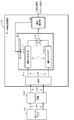
- FIG. 8 is a diagram showing a simplified configuration of the data detection processing unit 15 described above with reference to FIG.
- the optical pickup 101 is the optical pickup 101 in which the light receiving area is divided.
- the optical pickup 101 detects the reflected light from the optical disk of the irradiation laser light. Detection signals corresponding to the respective divided areas of the optical pickup 101 are supplied to the matrix circuit 102, and reproduction signals (n-channel reproduction signals) of a plurality of channels corresponding to the respective areas are obtained.
- the multi-channel playback signal (n-channel playback signal) is input to the A / D converter (ADC) 111 of the data detection processing unit 110, converted into a digital signal, and input to the multi-input adaptive equalizer 112.
- ADC A / D converter
- the multi-input adaptive equalizer 112 has n adaptive equalizers 112-1 to 112-n corresponding to each input signal (n-channel signal), and each channel signal is input to each of the adaptive equalizers 112-1 to 112-n.
- the adaptive equalizers 112-1 to 112-n have the FIR configuration described above with reference to FIG. 6, and are adaptively controlled using the equalization error ek so that the tap coefficients C0 to Cn become the target frequency characteristics.
- the outputs of the adaptive equalizers 121-1 to 121-n are added by the adder 113, and the equalized signal of the multi-input adaptive equalizer 112, which is the added signal, becomes a signal with reduced crosstalk and the like.
- the signal identification unit 114 illustrated in FIG. 8 includes the binarization detection unit 64, the PR convolution unit 65, and the equalization error calculator 66 illustrated in FIG.
- the processing in the data detection processing unit 110 illustrated in FIG. 8 can be executed under the control of a control unit including a CPU that executes a program stored in the storage unit of the information processing apparatus, for example.
- the configuration of the data detection processing unit 110 illustrated in FIG. 8 has an effect of reducing the crosstalk component from the adjacent track
- the configuration for performing the processing for reducing the laser noise included in the laser signal output from the optical pickup 110 is as follows. is not. Therefore, the output signal of the data detection processing unit 110 having the configuration shown in FIG. 8, that is, the binarized signal (binary signal) shown in FIG. 8 is a reproduction signal containing laser noise. In order to further improve the quality of the reproduction signal, it is necessary to remove or reduce the laser noise component.
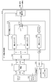
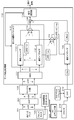
- FIG. 9 is a diagram showing a configuration example in which a configuration for reducing laser noise is added to the configuration of FIG. 8 described above as a basic configuration.
- the optical pickup 101, the matrix circuit 102, the A / D converter (ADC) 111 of the data detection unit 110, the multi-input adaptive equalizer 112, and the signal identification unit 114 are the same as those shown in FIG. It is a configuration.
- the optical pickup 101 is the optical pickup 101 in which the light receiving area is divided.
- the optical pickup 101 detects the reflected light from the optical disk of the irradiation laser light. Detection signals corresponding to the respective divided areas of the optical pickup 101 are supplied to the matrix circuit 102, and reproduction signals (n-channel reproduction signals) of a plurality of channels corresponding to the respective areas are obtained.
- the multi-channel playback signal (n-channel playback signal) is input to the A / D converter (ADC) 111 of the data detection processing unit 110, converted into a digital signal, and input to the multi-input adaptive equalizer 112.
- ADC A / D converter
- the multi-input adaptive equalizer 112 has n adaptive equalizers 112-1 to 112-n corresponding to each input signal (n-channel signal), and each channel signal is input to each of the adaptive equalizers 112-1 to 112-n.
- the adaptive equalizers 112-1 to 112-n are configured by, for example, a LMSTVF (Least Means Square Transversal Filter) including a FIR (Finite Impulse Response) filter and a tap coefficient calculation unit that executes a tap coefficient update calculation process by the least square method. Is done.
- LMSTVF Local Means Square Transversal Filter
- FIR Finite Impulse Response
- each of the adaptive equalizers 112-1 to 112-n has the FIR configuration described above with reference to FIG. 6, and the tap coefficients C0 to Cn have the target frequency characteristics using the equalization error ek. Is adaptively controlled.
- the outputs of the adaptive equalizers 121-1 to 121-n are added by the adder 113, and the equalized signal of the multi-input adaptive equalizer 112, which is the added signal, is input to the signal identification unit 114 via the subtractor 126.
- the equalized signal output from the multi-input adaptive equalizer 112 is a signal with reduced crosstalk and the like.
- the signal identification unit 114 shown in FIG. 9 includes the binarization detection unit 64, the PR convolution unit 65, and the equalization error calculator 66 shown in FIG.
- the signal discriminating unit 114 generates a binary signal for generating a final reproduction signal, and generates an equalization error signal that is fed back to the adaptive equalizer. These processes will be described later.
- FIG. 9 has the following configuration not shown in FIG. Front monitor 122, AC coupling unit 123, A / D converter (ADC) 124, Adaptive equalizer 125, Adder 121, Subtractor 126,
- the reproduction signal is generated based on the binarized signal (binary signal) output from the signal identification unit 114 shown in FIG.
- the front monitor 122 is a monitoring circuit for laser light that is configured in the optical pickup 101 and is output from a laser diode in the optical pickup 101.
- the front monitor 122 acquires a monitor signal of a laser signal (emitted light) output from the laser diode inside the optical pickup 101, and outputs a reference signal based on the emitted light from the laser diode.
- This monitor signal is the same component as the laser beam component irradiated on the optical disc 10 and is a laser beam including a noise component.
- the front monitor 122 outputs this monitor laser signal to the AC coupling unit 123.
- the AC coupling unit 123 separates a noise component and a DC component other than noise from the monitor laser signal, and extracts a noise signal from which the DC component has been removed.
- the noise component signal in the laser light extracted by the AC coupling unit 123 is input to the A / D converter (ADC) 124 of the data detection unit 110 and converted into a digital signal.
- ADC A / D converter
- the sampling frequency (fs2) of the ADC 124 that converts the laser noise signal into a digital signal is the sampling frequency (fs1) of the ADC 111 of the data detection processing unit 110 that converts the reproduction signal (n-channel reproduction signal) described above into a digital signal. ) It is preferable to set the frequency above. That is, fs2 ⁇ fs1 And This is a setting for reliably detecting and removing the laser noise signal contained in the reproduction signal.
- the laser noise signal (LNin) converted into a digital signal is input to the adaptive equalizer 125, and the adaptive equalizer 125 performs adaptive equalization processing and outputs an output signal (LNout).
- the input signal to the adaptive equalizer 125 is (LNin)
- the output from the adaptive equalizer 125 is (LNout).
- the adaptive equalizer 125 has the FIR configuration described above with reference to FIG. As described above with reference to FIG. 6, the adaptive equalizer uses the equalization error ek to adaptively control the tap coefficients C0 to Cn in the direction where the target frequency characteristic is obtained, and generates an output signal.
- the input LNin for the adaptive equalizer 125 shown in FIG. 9 corresponds to the input signal (xi) for the FIR configuration shown in FIG.
- the output LNout from the adaptive equalizer 125 corresponds to the output signal (yi) from the FIR configuration shown in FIG.
- the adaptive equalizer 125 shown in FIG. 9 inputs the addition signals ( ⁇ LMS-e1 to en) generated in the adder 121 as the equalization error signal (ek) having the configuration shown in FIG.
- the LMS-e1 to LMS-en signals are equalized error signals input to the adaptive equalizers 112-1 to 112-n that perform adaptive equalization processing of the n-channel signals of the optical pickup 101, that is, FIG. This corresponds to the equalization error (ek) shown in FIG.
- the adaptive equalizer 125 shown in FIG. 9 receives the equalization error signal addition signals ( ⁇ LMS-e1 to en) input to the adaptive equalizers 112-1 to 112-n and performs adaptive equalization. . That is, the adaptive equalizer 125 optimizes the error and phase distortion of the input laser noise signal (LNin) by adjusting the tap coefficient in the direction to eliminate the equalization error ( ⁇ LMS-e1 to en), that is, the adaptive PR. Equalization is performed to generate and output a laser noise output (LNout) close to a true noise component from which an error component included in the input laser noise signal (LNin) is excluded.
- LNout laser noise output
- the output signal (LNout) after adaptive equalization output from the adaptive equalizer 125 is a signal close to the true noise component in the laser light. This output signal (LNout) is input to the subtractor 126.
- the subtractor 126 outputs the output from the adaptive equalizer 125 from the addition value of the adaptive equalization signals that are the outputs of the adaptive equalizers 112-1 to 112-n that execute the adaptive equalization processing of the n-channel signals of the optical pickup 101. That is, a process of subtracting the noise signal (LNout) included in the laser light is executed. By this subtraction process, the laser noise component is subtracted from the adaptive equalization signal obtained as the reproduction signal, and the adaptive equalization signal with less noise is input to the signal identification unit 114.
- the signal identification unit 114 includes the binarization detection unit 64, the PR convolution unit 65, and the equalization error calculator 66 shown in FIG.
- the binarization detector 64 is a Viterbi decoder, for example, and performs maximum likelihood decoding on the PR equalized signal to generate binarized data.
- the binarized data is supplied to the encoding / decoding unit 17 shown in FIG. 1, and reproduction data demodulation processing is performed.
- Viterbi decoding uses a Viterbi detector composed of a plurality of states configured in units of consecutive bits of a predetermined length and branches represented by transitions between them, and all possible bit sequences are used. A desired bit sequence is efficiently detected from the inside.
- the PR convolution unit 65 performs a convolution process on the binarization result to generate a target signal Zk.
- the equalization error calculator 66 obtains an equalization error ek from the equalization signal y0 from the multi-input adaptive equalizer and the target signal Zk, and taps this equalization error ek to the multi-input adaptive equalizer 112 shown in FIG. Supply for coefficient control.
- the equalization error calculator 66 includes a subtractor 91 and a coefficient multiplier 92.
- the subtracter 81 subtracts the target signal Zk from the equalized signal y0.
- An equalization error ek is generated by multiplying the subtraction result by a predetermined coefficient a by the coefficient multiplier 82.
- the configuration of the first embodiment illustrated in FIG. 9 includes the adaptive equalizer 125 illustrated in FIG. 9 in order to obtain an accurate value of the laser noise included in the laser light output from the optical pickup 101.
- the adaptive equalizer 125 shown in FIG. 9 uses the equalization error signal input to the adaptive equalizers 112-1 to 112-n for executing the adaptive equalization processing of each signal of the n channel of the optical pickup 101, and performs adaptive equalization processing. Execute.
- the adaptive equalizer 125 adjusts the tap coefficient in the direction to eliminate the equalization error ( ⁇ LMS-e1 to en) to optimize the error and phase distortion of the input laser noise signal (LNin) and thereby correct the true noise component.
- a laser noise output (LNout) close to is generated.
- the output signal (LNout) after the adaptive equalization output from the adaptive equalizer 125 is subtracted from the addition value of the adaptive equalization signals output from the adaptive equalizers 112-1 to 112-n in the subtractor 126.
- the laser noise component is subtracted from the adaptive equalization signal obtained as the reproduction signal, and an adaptive equalization signal with less noise is generated.
- an equalization error signal with a reduced laser noise component is supplied to the adaptive equalizers 112-1 to 112-n that execute the adaptive equalization processing of each n-channel signal of the optical pickup 101.
- the adaptive equalization signal and the reproduction signal obtained in the above are high-quality reproduction signals with reduced laser noise components.
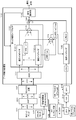
- FIG. 10 is also a diagram illustrating a configuration example in which a configuration for reducing laser noise is added based on the configuration of FIG. 8 described above as a basic configuration, similarly to FIG. 9.
- the optical pickup 101, the matrix circuit 102, the AD converter (ADC) 111 of the data detection unit 110, and the signal identification unit 114 are the same as the configuration illustrated in FIG.
- the optical pickup 101 is the optical pickup 101 in which the light receiving area is divided.
- the optical pickup 101 detects the reflected light from the optical disk of the irradiation laser light. Detection signals corresponding to the respective divided areas of the optical pickup 101 are supplied to the matrix circuit 102, and reproduction signals (n-channel reproduction signals) of a plurality of channels corresponding to the respective areas are obtained.
- the multi-channel playback signal (n-channel playback signal) is input to the A / D converter (ADC) 111 of the data detection processing unit 110, converted into a digital signal, and input to the multi-input adaptive equalizer 112.
- ADC A / D converter
- the multi-input adaptive equalizer 112 of the second embodiment receives each input signal (n channel signal) and performs n adaptive equalizers 112-1 to 112-n for performing adaptive equalization processing of each channel signal, and FIG.
- An adaptive equalizer 125 that performs an adaptive equalization process of laser noise similar to that described with reference to FIG.
- An input signal (Lnin) to the adaptive equalizer 125 is a signal generated via the front monitor 122, the AC coupling unit 123, and the A / D converter (ADC) 124, and is the same signal as described with reference to FIG. It is.
- the front monitor 122 is a monitoring circuit for laser light that is configured in the optical pickup 101 and is output from a laser diode in the optical pickup 101.
- the front monitor 122 acquires a monitor signal of a laser signal (emitted light) output from the laser diode inside the optical pickup 101, and outputs a reference signal based on the emitted light from the laser diode.
- This monitor signal is the same component as the laser beam component irradiated on the optical disc 10 and is a laser beam including a noise component.
- the front monitor 122 outputs this monitor laser signal to the AC coupling unit 123.
- the AC coupling unit 123 separates a noise component and a DC component other than noise from the monitor laser signal, and extracts a noise signal from which the DC component has been removed.
- the noise component signal in the laser light extracted by the AC coupling unit 123 is input to the A / D converter (ADC) 124 of the data detection unit 110 and converted into a digital signal.
- ADC A / D converter
- the sampling frequency (fs2) of the ADC 124 that converts the laser noise signal into a digital signal is preferably equal to or higher than the sampling frequency (fs1) of the ADC 111 corresponding to the reproduction signal (n-channel reproduction signal). That is, fs2 ⁇ fs1 And This is a setting for reliably detecting and removing the laser noise signal contained in the reproduction signal.
- a laser noise signal (LNin) converted into a digital signal is input to the adaptive equalizer 125.
- the adaptive equalizer 125 performs adaptive equalization processing on the input signal (LNin) and outputs an output signal (LNout).
- the adaptive equalizers 112-1 to 112-n that perform adaptive equalization processing for each channel signal corresponding to the read signal of the pickup 101 and the adaptive equalizer 125 that performs adaptive equalization processing for laser noise (LNin) are both, for example, , An FIR (Finite Impulse Response) filter and a LMSTVF (Least Means Square Transversal Filter) provided with a tap coefficient calculation unit that executes a tap coefficient update calculation process by the least square method.
- An FIR Finite Impulse Response
- LMSTVF Least Means Square Transversal Filter
- the outputs of the adaptive equalizers 121-1 to 121-n and the output of the adaptive equalizer 125 are added by the adder 113, and this added signal is input to the signal identification unit 114.
- 10 is configured to include the binarization detection unit 64, the PR convolution unit 65, and the equalization error calculator 66 shown in FIG.
- the signal discriminating unit 114 generates a binary signal for generating a final reproduction signal, and generates an equalization error signal that is fed back to the adaptive equalizer.
- the binarization detector 64 is a Viterbi decoder, for example, and performs maximum likelihood decoding on the PR equalized signal to generate binarized data.
- the binarized data is supplied to the encoding / decoding unit 17 shown in FIG. 1, and reproduction data demodulation processing is performed.
- Viterbi decoding uses a Viterbi detector composed of a plurality of states configured in units of consecutive bits of a predetermined length and branches represented by transitions between them, and all possible bit sequences are used. A desired bit sequence is efficiently detected from the inside.
- the PR convolution unit 65 performs a convolution process on the binarization result to generate a target signal Zk.
- the equalization error calculator 66 obtains an equalization error ek from the equalization signal y0 from the multi-input adaptive equalizer and the target signal Zk, and this equalization error ek is applied to the multi-input adaptive equalizer 112 shown in FIG. Supplied for control.
- the equalization error calculator 66 includes a subtractor 91 and a coefficient multiplier 92.
- the subtracter 81 subtracts the target signal Zk from the equalized signal y0.
- An equalization error ek is generated by multiplying the subtraction result by a predetermined coefficient a by the coefficient multiplier 82.
- the adaptive equalizers 112-1 to 112-n that execute adaptive equalization processing of each channel signal that is an element of the reproduction signal and the adaptive equalizer 125 that performs laser noise adaptive equalization processing are configured in parallel. ing. That is, the adaptive equalizers 121-1 to 121-n and the adaptive equalizer 125 shown in FIG. 10 are all equalized error signals (see FIG. 7) generated by the equalization error calculator (see FIG. 7) set in the signal identifying unit 114. ek) is input to perform adaptive equalization processing.
- Each of the adaptive equalizers 112-1 to n, 125 is composed of, for example, the FIR filter as shown in FIG. That is, as shown in FIG. 6, each adaptive equalizer 112-1 to n, 125 is an n + 1 stage tap having delay elements 80-1 to 80-n, coefficient multipliers 81-0 to 81-n, and an adder 84.
- tap coefficients C0 to Cn are multiplied for the input x at each time point, respectively.
- Outputs of the coefficient multipliers 81-0 to 81-n are added by an adder 84 to become an output y.
- the tap coefficients C0 to Cn are controlled.
- computing units 82-0 to 82-n that perform an operation by inputting an equalization error ek and each tap input.
- integrators 83-0 to 83-n for integrating the outputs of the respective computing units 82-0 to 82-n are provided.
- each of the calculators 82-0 to 82-n for example, calculation of ⁇ 1 ⁇ ek ⁇ x is performed.
- the outputs of the arithmetic units 82-0 to 82-n are integrated by the integrators 83-0 to 83-n, and the tap coefficients C0 to Cn of the coefficient multipliers 81-0 to 81-n are changed and controlled according to the integration results.
- the reason why the integrators 83-0 to 83-n are integrated is to adjust the response of the adaptive coefficient control. Using the above configuration, the binarized data is decoded after crosstalk cancellation and laser noise reduction processing are performed.
- Each of the adaptive equalizers 112-1 to n, 125 has the configuration shown in FIG. 6, and the same equalization error ek is supplied to perform adaptive equalization.
- the adaptive equalizers 112-1 to 112-n to which the channel signal corresponding to the reproduction signal is input optimizes the error and phase distortion of the input signal frequency component of the reproduction channel signal, that is, performs adaptive PR equalization. This is the same as a normal adaptive equalizer. That is, tap coefficients C0 to Cn are adjusted according to the calculation result of ⁇ 1 ⁇ ek ⁇ x in each of the calculators 82-0 to 82-n shown in FIG. 6, and taps are performed in a direction to eliminate equalization errors. The coefficients C0 to Cn are adjusted.
- the adaptive equalizer 125 that inputs laser noise (LNin)
- the output target is uncorrelated with the reproduction signal.
- the adaptive equalizer 125 performs an operation to cancel the correlation component, that is, the laser noise component. That is, in the case of the adaptive equalizer 125, the tap coefficients C0 to Cn are adjusted according to the calculation result of ⁇ 1 ⁇ ek ⁇ x in each of the calculators 82-0 to 82-n, and the addition result of the adder 113 in FIG.
- the tap coefficients C0 to Cn are adjusted so that the frequency characteristics in the direction of eliminating the noise component can be obtained.
- the tap coefficients C0 to Cn are adaptively controlled using the equalization error ek in the direction of the target frequency characteristics, while in the adaptive equalizer 125, the equalization error is also the same.
- the tap coefficients C0 to Cn are automatically controlled using ek in a direction that provides frequency characteristics effective for laser noise reduction.
- the multi-input adaptive equalizer 112 has a configuration in which an adaptive equalizer corresponding to each channel of a reproduction signal and an adaptive equalizer corresponding to laser noise are provided in parallel.
- the adaptive coefficient corresponding to the reproduction signal adaptively controls the tap coefficients C0 to Cn in the direction of the target frequency characteristic, and the adaptive equalizer 125 corresponding to the laser noise.
- the tap coefficients C0 to Cn are controlled in a direction that provides frequency characteristics that reduce laser noise.
- FIG. 11 is a diagram for explaining the configuration of this embodiment.
- the configuration shown in FIG. 11 is a diagram in which the configuration shown in FIG. 9 described above as the first embodiment is changed to a configuration that performs 2T sampling.
- recording is performed at a density corresponding to the channel bit length according to the disc type.
- the channel clock period is “T”
- the mark length is 2T to 8T.
- FIG. 11 is a diagram illustrating a detailed configuration in the case where the configuration illustrated in FIG. 9 described as the first embodiment is configured to perform 2T sampling.
- AAF Anti-alias filter
- DFF Digital flip-flop
- FIR filter 214 FIR filter 214
- DFF Digital flip-flop
- the anti-alias filter (AAF) 201 is a filter for limiting input signals to the adaptive equalizers 112-1 to 112-n to reproduced signals having a mark length of 2T or more.
- the optical pickup 101 is the optical pickup 101 in which the light receiving area is divided.
- the optical pickup 101 detects the reflected light from the optical disk of the irradiation laser light.
- a detection signal corresponding to each divided area of the optical pickup 101 is input to the anti-alias filter (AAF) 201.
- the anti-alias filter (AAF) 201 functions as a noise removal filter that removes a signal having a mark length of 2T or less as noise.
- the output of the anti-alias filter (AAF) 201 is a reproduction signal having a mark length of 2T or more, that is, a 2T sampling reproduction signal.
- the 2T sampling reproduction signal is supplied to the matrix circuit 102, and a plurality of channels of reproduction signals (n-channel reproduction signals) corresponding to each region are obtained.
- the multi-channel reproduction signal (n-channel reproduction signal) generated by the matrix circuit 102 is input to the A / D converter (ADC) 111 of the data detection processing unit 110, converted into a digital signal, and input to the multi-input adaptive equalizer 112.
- ADC A / D converter
- the multi-input adaptive equalizer 112 has n adaptive equalizers 112-1 to 112-n corresponding to each input signal (n-channel signal), and each channel signal is input to each of the adaptive equalizers 112-1 to 112-n.
- the adaptive equalizers 112-1 to 112-n are configured by, for example, a LMSTVF (Least Means Square Transversal Filter) including a FIR (Finite Impulse Response) filter and a tap coefficient calculation unit that executes a tap coefficient update calculation process by the least square method. Is done.
- LMSTVF Local Means Square Transversal Filter
- FIR Finite Impulse Response
- each of the adaptive equalizers 112-1 to 112-n has the FIR configuration described above with reference to FIG. 6, and the tap coefficients C0 to Cn have the target frequency characteristics using the equalization error ek. Is adaptively controlled.
- the outputs of the adaptive equalizers 121-1 to 121-n are added by the adder 113, and the equalized signal of the multi-input adaptive equalizer 112, which is the added signal, is input to the signal identification unit 114 via the subtractor 126.
- the equalized signal output from the multi-input adaptive equalizer 112 is a signal with reduced crosstalk and the like.
- the 11 includes the binarization detection unit 64, the PR convolution unit 65, and the equalization error calculator 66 shown in FIG.
- the signal discriminating unit 114 generates a binary signal for generating a final reproduction signal, and generates an equalization error signal that is fed back to the adaptive equalizer. These processes will be described later.
- the front monitor 122 is a monitoring circuit for laser light that is configured in the optical pickup 101 and is output from a laser diode in the optical pickup 101.
- the front monitor 122 acquires a monitor signal of a laser signal (emitted light) output from the laser diode inside the optical pickup 101, and outputs a reference signal based on the emitted light from the laser diode.
- This monitor signal is the same component as the laser beam component irradiated on the optical disc 10 and is a laser beam including a noise component.
- the AC coupling unit 123 separates the noise component and the DC component other than the noise, and extracts the noise signal from which the DC component is removed.
- the noise component signal in the laser light extracted by the AC coupling unit 123 is input to the slicer 212.
- the slicer 212 generates a binary signal to which a predetermined threshold is applied. That is, digital signal generation processing is performed.
- the laser noise binary signal generated by the slicer 212 is input to the adaptive equalizer 125 via the digital flip-flop (DFF) 213, the FIR filter 214, and the digital flip-flop (DFF) 215.
- the digital flip-flop (DFF) 213 executes sampling processing by 1T sampling of the laser noise binary signal generated by the slicer 212.
- the FIR filter 214 performs a filtering process on the 1T sampling signal generated by the DFF 213 and performs a smoothing process on the sampling data. For example, a smoothing process is executed by a finite impulse response filtering process in which the number of filters (1, 2, 1) is set. Further, the 1T sampling smoothed laser noise signal generated by the FIR filter 214 is input to a digital flip-flop (DFF) 215.
- DFF digital flip-flop
- the digital flip-flop (DFF) 215 executes 2T sampling processing on the 1T sampling smoothed laser noise signal generated by the FIR filter 214. That is, with these configurations, a 2T sampling laser noise signal (LNin) corresponding to the 2T sampling reproduction signal is generated and input to the adaptive equalizer 125.
- LNin 2T sampling laser noise signal
- the adaptive equalizer 125 performs adaptive equalization processing and outputs an output signal (LNout).
- the adaptive equalizer 125 has the FIR configuration described above with reference to FIG.
- the adaptive equalizer uses the equalization error ek to adaptively control the tap coefficients C0 to Cn in the direction where the target frequency characteristic is obtained, and generates an output signal.
- the input LNin for the adaptive equalizer 125 shown in FIG. 11 corresponds to the input signal (xi) for the FIR configuration shown in FIG.
- the output LNout from the adaptive equalizer 125 corresponds to the output signal (yi) from the FIR configuration shown in FIG.
- the adaptive equalizer 125 shown in FIG. 11 inputs the addition signals ( ⁇ LMS-e1 to en) generated in the adder 121 as the equalization error signal (ek) having the configuration shown in FIG.
- the LMS-e1 to LMS-en signals are equalized error signals input to the adaptive equalizers 112-1 to 112-n that perform adaptive equalization processing of the n-channel signals of the optical pickup 101, that is, FIG. This corresponds to the equalization error (ek) shown in FIG.
- the adaptive equalizer 125 shown in FIG. 11 receives the equalization error signal addition signals ( ⁇ LMS-e1 to en) input to the adaptive equalizers 112-1 to 112-n and performs adaptive equalization. . That is, the adaptive equalizer 125 optimizes the error and phase distortion of the input laser noise signal (LNin) by adjusting the tap coefficient in the direction to eliminate the equalization error ( ⁇ LMS-e1 to en), that is, the adaptive PR. Equalization is performed to generate and output a laser noise output (LNout) close to a true noise component from which an error component included in the input laser noise signal (LNin) is excluded.
- LNout laser noise output
- the output signal (LNout) after adaptive equalization output from the adaptive equalizer 125 is a signal close to the true noise component in the laser light. This output signal (LNout) is input to the subtractor 126.
- the subtractor 126 outputs the output from the adaptive equalizer 125 from the addition value of the adaptive equalization signals that are the outputs of the adaptive equalizers 112-1 to 112-n that execute the adaptive equalization processing of the n-channel signals of the optical pickup 101. That is, a process of subtracting the noise signal (LNout) included in the laser light is executed. By this subtraction process, the laser noise component is subtracted from the adaptive equalization signal obtained as the reproduction signal, and the adaptive equalization signal with less noise is input to the signal identification unit 114.
- the signal identification unit 114 includes the binarization detection unit 64, the PR convolution unit 65, and the equalization error calculator 66 shown in FIG.
- the binarization detector 64 is a Viterbi decoder, for example, and performs maximum likelihood decoding on the PR equalized signal to generate binarized data.
- the binarized data is supplied to the encoding / decoding unit 17 shown in FIG. 1, and reproduction data demodulation processing is performed.
- Viterbi decoding uses a Viterbi detector composed of a plurality of states configured in units of consecutive bits of a predetermined length and branches represented by transitions between them, and all possible bit sequences are used. A desired bit sequence is efficiently detected from the inside.
- the PR convolution unit 65 performs a convolution process on the binarization result to generate a target signal Zk.
- the equalization error calculator 66 obtains an equalization error ek from the equalization signal y0 from the multi-input adaptive equalizer and the target signal Zk, and taps this equalization error ek to the multi-input adaptive equalizer 112 shown in FIG. Supply for coefficient control.
- the equalization error calculator 66 includes a subtractor 91 and a coefficient multiplier 92.
- the subtracter 81 subtracts the target signal Zk from the equalized signal y0.
- An equalization error ek is generated by multiplying the subtraction result by a predetermined coefficient a by the coefficient multiplier 82.
- the configuration of the third embodiment illustrated in FIG. 11 is illustrated in FIG. 11 in order to obtain an accurate value of the laser noise included in the laser beam output from the optical pickup 101 in the configuration in which the 2T sampling reproduction process is performed. It has a configuration including an adaptive equalizer 125.
- the adaptive equalizer 125 shown in FIG. 11 uses the equalization error signal input to the adaptive equalizers 112-1 to 112-n for executing the adaptive equalization processing of each signal of the n channel of the optical pickup 101, and performs adaptive equalization processing. Execute.
- the adaptive equalizer 125 adjusts the tap coefficient in the direction to eliminate the equalization error ( ⁇ LMS-e1 to en) to optimize the error and phase distortion of the input laser noise signal (LNin) and thereby correct the true noise component.
- a laser noise output (LNout) close to is generated.
- the output signal (LNout) after the adaptive equalization output from the adaptive equalizer 125 is subtracted from the addition value of the adaptive equalization signals output from the adaptive equalizers 112-1 to 112-n in the subtractor 126.
- the laser noise component is subtracted from the adaptive equalization signal obtained as the reproduction signal, and an adaptive equalization signal with less noise is generated.
- the adaptive equalizers 112-1 to 112-n that execute the adaptive equalization processing of the n-channel signals of the optical pickup 101 are supplied with equalization error signals with reduced laser noise components.
- FIG. 12 is a diagram for explaining the configuration of this embodiment.
- the configuration illustrated in FIG. 12 is a diagram in which the configuration illustrated in FIG. 10 described above as the second embodiment is changed to a configuration that performs 2T sampling.
- AAF Anti-alias filter
- BW Bandwidth limiting unit
- DFF Digital flip-flop
- FIR filter 214 FIR filter 214
- DFF Digital flip-flop
- the anti-alias filter (AAF) 201 is a filter for limiting the input signals to the adaptive equalizers 112-1 to 112-n to reproduced signals having a mark length of 2T or more.
- the optical pickup 101 is the optical pickup 101 in which the light receiving area is divided.
- the optical pickup 101 detects the reflected light from the optical disk of the irradiation laser light.
- a detection signal corresponding to each divided area of the optical pickup 101 is input to the anti-alias filter (AAF) 201.
- the anti-alias filter (AAF) 201 functions as a noise removal filter that removes a signal having a mark length of 2T or less as noise.
- the output of the anti-alias filter (AAF) 201 is a reproduction signal having a mark length of 2T or more, that is, a 2T sampling reproduction signal.
- the 2T sampling reproduction signal is supplied to the matrix circuit 102, and a plurality of channels of reproduction signals (n-channel reproduction signals) corresponding to each region are obtained.
- the multi-channel reproduction signal (n-channel reproduction signal) generated by the matrix circuit 102 is input to the A / D converter (ADC) 111 of the data detection processing unit 110, converted into a digital signal, and input to the multi-input adaptive equalizer 112.
- ADC A / D converter
- the multi-input adaptive equalizer 112 has n adaptive equalizers 112-1 to 112-n corresponding to each input signal (n-channel signal), and each channel signal is input to each of the adaptive equalizers 112-1 to 112-n.
- the multi-input adaptive equalizer 112 receives each input signal (n-channel signal) and performs adaptive equalization processing on each channel signal.
- the front monitor 122 is a monitoring circuit for laser light that is configured in the optical pickup 101 and is output from a laser diode in the optical pickup 101.
- the front monitor 122 acquires a monitor signal of a laser signal (emitted light) output from the laser diode inside the optical pickup 101, and outputs a reference signal based on the emitted light from the laser diode.
- This monitor signal is the same component as the laser beam component irradiated on the optical disc 10 and is a laser beam including a noise component.
- the AC coupling unit 123 separates the noise component and the DC component other than the noise, and extracts the noise signal from which the DC component is removed.
- the noise component signal in the laser light extracted by the AC coupling unit 123 is input to the slicer 212.
- the slicer 212 generates a binary signal to which a predetermined threshold is applied. That is, digital signal generation processing is performed.
- the laser noise binary signal generated by the slicer 212 is input to the adaptive equalizer 125 via the digital flip-flop (DFF) 213, the FIR filter 214, and the digital flip-flop (DFF) 215.
- the digital flip-flop (DFF) 213 executes sampling processing by 1T sampling of the laser noise binary signal generated by the slicer 212.
- the FIR filter 214 performs a filtering process on the 1T sampling signal generated by the DFF 213 and performs a smoothing process on the sampling data. For example, a smoothing process is executed by a finite impulse response filtering process in which the number of filters (1, 2, 1) is set. Further, the 1T sampling smoothed laser noise signal generated by the FIR filter 214 is input to a digital flip-flop (DFF) 215.
- DFF digital flip-flop
- the digital flip-flop (DFF) 215 executes 2T sampling processing on the 1T sampling smoothed laser noise signal generated by the FIR filter 214. That is, with these configurations, a 2T sampling laser noise signal (LNin) corresponding to the 2T sampling reproduction signal is generated and input to the adaptive equalizer 125.
- LNin 2T sampling laser noise signal
- the adaptive equalizer 125 performs an adaptive equalization process on the input signal (LNin) and outputs an output signal (LNout).
- the adaptive equalizers 112-1 to 112-n that perform adaptive equalization processing for each channel signal corresponding to the read signal of the pickup 101 and the adaptive equalizer 125 that performs adaptive equalization processing for laser noise (LNin) are both, for example, , An FIR (Finite Impulse Response) filter and a LMSTVF (Least Means Square Transversal Filter) provided with a tap coefficient calculation unit that executes a tap coefficient update calculation process by the least square method.
- An FIR Finite Impulse Response
- LMSTVF Least Means Square Transversal Filter
- the outputs of the adaptive equalizers 121-1 to 121-n and the output of the adaptive equalizer 125 are added by the adder 113, and this added signal is input to the signal identification unit 114.
- the signal identification unit 114 shown in FIG. 12 includes the binarization detection unit 64, the PR convolution unit 65, and the equalization error calculator 66 shown in FIG.
- the signal discriminating unit 114 generates a binary signal for generating a final reproduction signal, and generates an equalization error signal that is fed back to the adaptive equalizer.
- the binarization detector 64 is a Viterbi decoder, for example, and performs maximum likelihood decoding on the PR equalized signal to generate binarized data.
- the binarized data is supplied to the encoding / decoding unit 17 shown in FIG. 1, and reproduction data demodulation processing is performed.
- Viterbi decoding uses a Viterbi detector composed of a plurality of states configured in units of consecutive bits of a predetermined length and branches represented by transitions between them, and all possible bit sequences are used. A desired bit sequence is efficiently detected from the inside.
- the PR convolution unit 65 performs a convolution process on the binarization result to generate a target signal Zk.
- the equalization error calculator 66 obtains an equalization error ek from the equalization signal y0 from the multi-input adaptive equalizer and the target signal Zk, and this equalization error ek is applied to the multi-input adaptive equalizer 112 shown in FIG. Supplied for control.
- the equalization error calculator 66 includes a subtractor 91 and a coefficient multiplier 92.
- the subtracter 81 subtracts the target signal Zk from the equalized signal y0.
- An equalization error ek is generated by multiplying the subtraction result by a predetermined coefficient a by the coefficient multiplier 82.
- adaptive equalizers 112-1 to 112-n that perform adaptive equalization processing of each channel signal that is an element of the reproduction signal, and laser noise adaptive equalization processing
- An adaptive equalizer 125 for performing is configured in parallel. That is, the adaptive equalizers 121-1 to 121-n and the adaptive equalizer 125 shown in FIG. 12 are all equalized error signals (see FIG. 7) generated by the equalization error calculator (see FIG. 7) set in the signal identifying unit 114. ek) is input to perform adaptive equalization processing.
- Each of the adaptive equalizers 112-1 to n, 125 is composed of, for example, the FIR filter as shown in FIG. That is, as shown in FIG. 6, each adaptive equalizer 112-1 to n, 125 is an n + 1 stage tap having delay elements 80-1 to 80-n, coefficient multipliers 81-0 to 81-n, and an adder 84.
- tap coefficients C0 to Cn are multiplied for the input x at each time point, respectively.
- Outputs of the coefficient multipliers 81-0 to 81-n are added by an adder 84 to become an output y.
- the tap coefficients C0 to Cn are controlled.
- computing units 82-0 to 82-n that perform an operation by inputting an equalization error ek and each tap input.
- integrators 83-0 to 83-n for integrating the outputs of the respective computing units 82-0 to 82-n are provided.
- each of the calculators 82-0 to 82-n for example, calculation of ⁇ 1 ⁇ ek ⁇ x is performed.
- the outputs of the arithmetic units 82-0 to 82-n are integrated by the integrators 83-0 to 83-n, and the tap coefficients C0 to Cn of the coefficient multipliers 81-0 to 81-n are changed and controlled according to the integration results.
- the reason why the integrators 83-0 to 83-n are integrated is to adjust the response of the adaptive coefficient control. Using the above configuration, the binarized data is decoded after crosstalk cancellation and laser noise reduction processing are performed.
- Each of the adaptive equalizers 112-1 to n, 125 has the configuration shown in FIG. 6, and the same equalization error ek is supplied to perform adaptive equalization.
- the adaptive equalizers 112-1 to 112-n to which the channel signal corresponding to the reproduction signal is input optimizes the error and phase distortion of the input signal frequency component of the reproduction channel signal, that is, performs adaptive PR equalization. This is the same as a normal adaptive equalizer. That is, tap coefficients C0 to Cn are adjusted according to the calculation result of ⁇ 1 ⁇ ek ⁇ x in each of the calculators 82-0 to 82-n shown in FIG. 6, and taps are performed in a direction to eliminate equalization errors. The coefficients C0 to Cn are adjusted.
- the adaptive equalizer 125 that inputs laser noise (LNin)
- the output target is uncorrelated with the reproduction signal.
- the adaptive equalizer 125 performs an operation to cancel the correlation component, that is, the laser noise component. That is, in the case of the adaptive equalizer 125, the tap coefficients C0 to Cn are adjusted according to the calculation result of ⁇ 1 ⁇ ek ⁇ x in each of the calculators 82-0 to 82-n, and the addition result of the adder 113 in FIG.
- the tap coefficients C0 to Cn are adjusted so that the frequency characteristics in the direction of eliminating the noise component can be obtained.
- the tap coefficients C0 to Cn are adaptively controlled using the equalization error ek in the direction of the target frequency characteristics, while in the adaptive equalizer 125, the equalization error is also the same.
- the tap coefficients C0 to Cn are automatically controlled using ek in a direction that provides frequency characteristics effective for laser noise reduction.
- the multi-input adaptive equalizer 112 is arranged in parallel with the adaptive equalizer corresponding to each channel of the reproduction signal and the adaptive equalizer corresponding to the laser noise. It has a configuration with.
- the equalization error signal (ek) is input to these adaptive equalizers, and the tap coefficients C0 to Cn are adaptively controlled in the direction corresponding to the target frequency characteristics in the adaptive equalizer corresponding to the reproduction signal, and in the adaptive equalizer 125 corresponding to the laser noise.
- the tap coefficients C0 to Cn are controlled in a direction that provides frequency characteristics that reduce laser noise.
- FIG. 13 is a diagram for explaining the configuration of this embodiment.
- FIG. 13 is a diagram illustrating a configuration in which the 2T sampling configuration illustrated in FIG. 11 described as the third embodiment is changed to a configuration for performing 1T sampling.
- a detection signal corresponding to each divided area of the optical pickup 101 is input to the anti-alias filter (AAF) 201.
- the anti-alias filter (AAF) 201 functions as a noise removal filter that removes a signal having a mark length of 1T or less as noise.
- the output of the anti-alias filter (AAF) 201 is a reproduction signal having a mark length of 1T or more, that is, a 1T sampling reproduction signal.
- the 1T sampling reproduction signal is supplied to the matrix circuit 102, and a plurality of channels of reproduction signals (n-channel reproduction signals) corresponding to each region are obtained.
- the multi-channel reproduction signal (n-channel reproduction signal) generated by the matrix circuit 102 is input to the A / D converter (ADC) 111 of the data detection processing unit 110, converted into a digital signal, and input to the multi-input adaptive equalizer 112.
- ADC A / D converter
- the multi-input adaptive equalizer 112 has n adaptive equalizers 112-1 to 112-n corresponding to each input signal (n-channel signal), and each channel signal is input to each of the adaptive equalizers 112-1 to 112-n.
- the adaptive equalizers 112-1 to 112-n are configured by, for example, a LMSTVF (Least Means Square Transversal Filter) including a FIR (Finite Impulse Response) filter and a tap coefficient calculation unit that executes a tap coefficient update calculation process by the least square method. Is done.
- LMSTVF Local Means Square Transversal Filter
- FIR Finite Impulse Response
- each of the adaptive equalizers 112-1 to 112-n has the FIR configuration described above with reference to FIG. 6, and the tap coefficients C0 to Cn have the target frequency characteristics using the equalization error ek. Is adaptively controlled.
- the outputs of the adaptive equalizers 121-1 to 121-n are added by the adder 113, and the equalized signal of the multi-input adaptive equalizer 112, which is the added signal, is input to the signal identification unit 114 via the subtractor 126.
- the equalized signal output from the multi-input adaptive equalizer 112 is a signal with reduced crosstalk and the like.
- the signal discriminating unit 114 generates a binary signal for generating a final reproduction signal, and generates an equalization error signal that is fed back to the adaptive equalizer. These processes will be described later.
- the front monitor 122 is a monitoring circuit for laser light that is configured in the optical pickup 101 and is output from a laser diode in the optical pickup 101.
- the front monitor 122 acquires a monitor signal of a laser signal (emitted light) output from the laser diode inside the optical pickup 101, and outputs a reference signal based on the emitted light from the laser diode.
- This monitor signal is the same component as the laser beam component irradiated on the optical disc 10 and is a laser beam including a noise component.
- the AC coupling unit 123 separates the noise component and the DC component other than the noise, and extracts the noise signal from which the DC component is removed.
- the noise component signal in the laser light extracted by the AC coupling unit 123 is input to the slicer 212.
- the slicer 212 generates a binary signal to which a predetermined threshold is applied. That is, digital signal generation processing is performed.
- the laser noise binary signal generated by the slicer 212 is input to the adaptive equalizer 125 via a digital flip-flop (DFF) 312.
- the digital flip-flop (DFF) 312 executes sampling processing by 1T sampling of the laser noise binary signal generated by the slicer 212. That is, with these configurations, a 1T sampling laser noise signal (LNin) corresponding to the 1T sampling reproduction signal is generated and input to the adaptive equalizer 125.
- LNin 1T sampling laser noise signal
- the adaptive equalizer 125 performs adaptive equalization processing on the input signal (LNin) and outputs an output signal (LNout).
- the adaptive equalizer 125 has the FIR configuration described above with reference to FIG.
- the adaptive equalizer uses the equalization error ek to adaptively control the tap coefficients C0 to Cn in the direction where the target frequency characteristic is obtained, and generates an output signal.
- the input LNin for the adaptive equalizer 125 shown in FIG. 13 corresponds to the input signal (xi) for the FIR configuration shown in FIG.
- the output LNout from the adaptive equalizer 125 corresponds to the output signal (yi) from the FIR configuration shown in FIG.
- the adaptive equalizer 125 shown in FIG. 13 inputs the addition signals ( ⁇ LMS-e1 to en) generated in the adder 121 as the equalization error signal (ek) having the configuration shown in FIG.
- the LMS-e1 to LMS-en signals are equalized error signals input to the adaptive equalizers 112-1 to 112-n that perform adaptive equalization processing of the n-channel signals of the optical pickup 101, that is, FIG. This corresponds to the equalization error (ek) shown in FIG.
- the adaptive equalizer 125 shown in FIG. 13 receives the addition signals ( ⁇ LMS-e1 to en) of the equalization error signals input to the adaptive equalizers 112-1 to 112-n and performs adaptive equalization. . That is, the adaptive equalizer 125 optimizes the error and phase distortion of the input laser noise signal (LNin) by adjusting the tap coefficient in the direction to eliminate the equalization error ( ⁇ LMS-e1 to en), that is, the adaptive PR. Equalization is performed to generate and output a laser noise output (LNout) close to a true noise component from which an error component included in the input laser noise signal (LNin) is excluded.
- LNout laser noise output
- the output signal (LNout) after adaptive equalization output from the adaptive equalizer 125 is a signal close to the true noise component in the laser light. This output signal (LNout) is input to the subtractor 126.
- the subtractor 126 outputs the output from the adaptive equalizer 125 from the addition value of the adaptive equalization signals that are the outputs of the adaptive equalizers 112-1 to 112-n that execute the adaptive equalization processing of the n-channel signals of the optical pickup 101. That is, a process of subtracting the noise signal (LNout) included in the laser light is executed. By this subtraction process, the laser noise component is subtracted from the adaptive equalization signal obtained as the reproduction signal, and the adaptive equalization signal with less noise is input to the signal identification unit 114.
- the signal identification unit 114 includes the binarization detection unit 64, the PR convolution unit 65, and the equalization error calculator 66 shown in FIG.
- the binarization detector 64 is a Viterbi decoder, for example, and performs maximum likelihood decoding on the PR equalized signal to generate binarized data.
- the binarized data is supplied to the encoding / decoding unit 17 shown in FIG. 1, and reproduction data demodulation processing is performed.
- Viterbi decoding uses a Viterbi detector composed of a plurality of states configured in units of consecutive bits of a predetermined length and branches represented by transitions between them, and all possible bit sequences are used. A desired bit sequence is efficiently detected from the inside.
- the PR convolution unit 65 performs a convolution process on the binarization result to generate a target signal Zk.
- the equalization error calculator 66 obtains an equalization error ek from the equalization signal y0 from the multi-input adaptive equalizer and the target signal Zk, and taps this equalization error ek to the multi-input adaptive equalizer 112 shown in FIG. Supply for coefficient control.
- the equalization error calculator 66 includes a subtractor 91 and a coefficient multiplier 92.
- the subtracter 81 subtracts the target signal Zk from the equalized signal y0.
- An equalization error ek is generated by multiplying the subtraction result by a predetermined coefficient a by the coefficient multiplier 82.
- the configuration of the fifth embodiment illustrated in FIG. 13 is illustrated in FIG. 11 in order to obtain an accurate value of the laser noise included in the laser beam output from the optical pickup 101 in the configuration in which the 1T sampling reproduction process is performed.
- It has a configuration including an adaptive equalizer 125.
- the adaptive equalizer 125 shown in FIG. 11 uses the equalization error signal input to the adaptive equalizers 112-1 to 112-n for executing the adaptive equalization processing of each signal of the n channel of the optical pickup 101, and performs adaptive equalization processing. Execute.
- the adaptive equalizer 125 adjusts the tap coefficient in the direction to eliminate the equalization error ( ⁇ LMS-e1 to en) to optimize the error and phase distortion of the input laser noise signal (LNin) and thereby correct the true noise component.
- a laser noise output (LNout) close to is generated.
- the output signal (LNout) after the adaptive equalization output from the adaptive equalizer 125 is subtracted from the addition value of the adaptive equalization signals output from the adaptive equalizers 112-1 to 112-n in the subtractor 126.
- the laser noise component is subtracted from the adaptive equalization signal obtained as the reproduction signal, and an adaptive equalization signal with less noise is generated.
- the adaptive equalizers 112-1 to 112-n that execute the adaptive equalization processing of the n-channel signals of the optical pickup 101 are supplied with equalization error signals with reduced laser noise components.
- FIG. 14 is a diagram for explaining the configuration of the present embodiment.
- FIG. 14 is a diagram illustrating a detailed configuration in which the 2T sampling configuration illustrated in FIG. 12 described as the fourth embodiment is changed to a configuration for performing 1T sampling.
- a detection signal corresponding to each divided area of the optical pickup 101 is input to the anti-alias filter (AAF) 201.
- the anti-alias filter (AAF) 201 functions as a noise removal filter that removes a signal having a mark length of 1T or less as noise.
- the output of the anti-alias filter (AAF) 201 is a reproduction signal having a mark length of 1T or more, that is, a 1T sampling reproduction signal.
- the 1T sampling reproduction signal is supplied to the matrix circuit 102, and a plurality of channels of reproduction signals (n-channel reproduction signals) corresponding to each region are obtained.
- the multi-channel reproduction signal (n-channel reproduction signal) generated by the matrix circuit 102 is input to the A / D converter (ADC) 111 of the data detection processing unit 110, converted into a digital signal, and input to the multi-input adaptive equalizer 112.
- ADC A / D converter
- the multi-input adaptive equalizer 112 has n adaptive equalizers 112-1 to 112-n corresponding to each input signal (n-channel signal), and each channel signal is input to each of the adaptive equalizers 112-1 to 112-n.
- the multi-input adaptive equalizer 112 receives each input signal (n-channel signal) and performs adaptive equalization processing on each channel signal.
- the front monitor 122 is a monitoring circuit for laser light that is configured in the optical pickup 101 and is output from a laser diode in the optical pickup 101.
- the front monitor 122 acquires a monitor signal of a laser signal (emitted light) output from the laser diode inside the optical pickup 101, and outputs a reference signal based on the emitted light from the laser diode.
- This monitor signal is the same component as the laser beam component irradiated on the optical disc 10 and is a laser beam including a noise component.
- the AC coupling unit 123 separates the noise component and the DC component other than the noise, and extracts the noise signal from which the DC component is removed.
- the noise component signal in the laser light extracted by the AC coupling unit 123 is input to the slicer 212.
- the slicer 212 generates a binary signal to which a predetermined threshold is applied. That is, digital signal generation processing is performed.
- the laser noise binary signal generated by the slicer 212 is input to the adaptive equalizer 125 via a digital flip-flop (DFF) 312.
- the digital flip-flop (DFF) 312 executes sampling processing by 1T sampling of the laser noise binary signal generated by the slicer 212. That is, with these configurations, a 1T sampling laser noise signal (LNin) corresponding to the 1T sampling reproduction signal is generated and input to the adaptive equalizer 125.
- LNin 1T sampling laser noise signal
- the adaptive equalizer 125 performs an adaptive equalization process on the input signal (LNin) and outputs an output signal (LNout).
- the adaptive equalizers 112-1 to 112-n that perform adaptive equalization processing for each channel signal corresponding to the read signal of the pickup 101 and the adaptive equalizer 125 that performs adaptive equalization processing for laser noise (LNin) are both, for example, , An FIR (Finite Impulse Response) filter and a LMSTVF (Least Means Square Transversal Filter) provided with a tap coefficient calculation unit that executes a tap coefficient update calculation process by the least square method.
- An FIR Finite Impulse Response
- LMSTVF Least Means Square Transversal Filter
- the outputs of the adaptive equalizers 121-1 to 121-n and the output of the adaptive equalizer 125 are added by the adder 113, and this added signal is input to the signal identification unit 114.
- 14 is configured to include the binarization detection unit 64, the PR convolution unit 65, and the equalization error calculator 66 shown in FIG.
- the signal discriminating unit 114 generates a binary signal for generating a final reproduction signal, and generates an equalization error signal that is fed back to the adaptive equalizer.
- the binarization detector 64 is a Viterbi decoder, for example, and performs maximum likelihood decoding on the PR equalized signal to generate binarized data.
- the binarized data is supplied to the encoding / decoding unit 17 shown in FIG. 1, and reproduction data demodulation processing is performed.
- Viterbi decoding uses a Viterbi detector composed of a plurality of states configured in units of consecutive bits of a predetermined length and branches represented by transitions between them, and all possible bit sequences are used. A desired bit sequence is efficiently detected from the inside.
- the PR convolution unit 65 performs a convolution process on the binarization result to generate a target signal Zk.
- the equalization error calculator 66 obtains an equalization error ek from the equalization signal y0 from the multi-input adaptive equalizer and the target signal Zk, and this equalization error ek is applied to the multi-input adaptive equalizer 112 shown in FIG. Supplied for control.
- the equalization error calculator 66 includes a subtractor 91 and a coefficient multiplier 92.
- the subtracter 81 subtracts the target signal Zk from the equalized signal y0.
- An equalization error ek is generated by multiplying the subtraction result by a predetermined coefficient a by the coefficient multiplier 82.
- adaptive equalizers 112-1 to 112-n for performing adaptive equalization processing of each channel signal that is an element of the reproduction signal, and laser noise adaptive equalization processing
- An adaptive equalizer 125 for performing is configured in parallel. That is, the adaptive equalizers 121-1 to 121-n and the adaptive equalizer 125 shown in FIG. 14 are all equalized error signals (see FIG. 7) generated by the equalization error calculator (see FIG. 7) set in the signal identifying unit 114. ek) is input to perform adaptive equalization processing.
- Each of the adaptive equalizers 112-1 to n, 125 is composed of, for example, the FIR filter as shown in FIG. That is, as shown in FIG. 6, each adaptive equalizer 112-1 to n, 125 is an n + 1 stage tap having delay elements 80-1 to 80-n, coefficient multipliers 81-0 to 81-n, and an adder 84.
- tap coefficients C0 to Cn are multiplied for the input x at each time point, respectively.
- Outputs of the coefficient multipliers 81-0 to 81-n are added by an adder 84 to become an output y.
- the tap coefficients C0 to Cn are controlled.
- computing units 82-0 to 82-n that perform an operation by inputting an equalization error ek and each tap input.
- integrators 83-0 to 83-n for integrating the outputs of the respective computing units 82-0 to 82-n are provided.
- each of the calculators 82-0 to 82-n for example, calculation of ⁇ 1 ⁇ ek ⁇ x is performed.
- the outputs of the arithmetic units 82-0 to 82-n are integrated by the integrators 83-0 to 83-n, and the tap coefficients C0 to Cn of the coefficient multipliers 81-0 to 81-n are changed and controlled according to the integration results.
- the reason why the integrators 83-0 to 83-n are integrated is to adjust the response of the adaptive coefficient control. Using the above configuration, the binarized data is decoded after crosstalk cancellation and laser noise reduction processing are performed.
- Each of the adaptive equalizers 112-1 to n, 125 has the configuration shown in FIG. 6, and the same equalization error ek is supplied to perform adaptive equalization.
- the adaptive equalizers 112-1 to 112-n to which the channel signal corresponding to the reproduction signal is input optimizes the error and phase distortion of the input signal frequency component of the reproduction channel signal, that is, performs adaptive PR equalization. This is the same as a normal adaptive equalizer. That is, tap coefficients C0 to Cn are adjusted according to the calculation result of ⁇ 1 ⁇ ek ⁇ x in each of the calculators 82-0 to 82-n shown in FIG. 6, and taps are performed in a direction to eliminate equalization errors. The coefficients C0 to Cn are adjusted.
- the adaptive equalizer 125 that inputs laser noise (LNin)
- the output target is uncorrelated with the reproduction signal.
- the adaptive equalizer 125 performs an operation to cancel the correlation component, that is, the laser noise component. That is, in the case of the adaptive equalizer 125, the tap coefficients C0 to Cn are adjusted according to the calculation result of ⁇ 1 ⁇ ek ⁇ x in each of the calculators 82-0 to 82-n, and the addition result of the adder 113 in FIG.
- the tap coefficients C0 to Cn are adjusted so that the frequency characteristics in the direction of eliminating the noise component can be obtained.
- the tap coefficients C0 to Cn are adaptively controlled using the equalization error ek in the direction of the target frequency characteristics, while in the adaptive equalizer 125, the equalization error is also the same.
- the tap coefficients C0 to Cn are automatically controlled using ek in a direction that provides frequency characteristics effective for laser noise reduction.
- the multi-input adaptive equalizer 112 has a configuration in which an adaptive equalizer corresponding to each channel of the reproduction signal and an adaptive equalizer corresponding to laser noise are provided in parallel.
- the equalization error signal (ek) is input to these adaptive equalizers, and the tap coefficients C0 to Cn are adaptively controlled in the direction corresponding to the target frequency characteristics in the adaptive equalizer corresponding to the reproduction signal, and in the adaptive equalizer 125 corresponding to the laser noise.
- the tap coefficients C0 to Cn are controlled in a direction that provides frequency characteristics that reduce laser noise.
- the optical pickup uses an optical pickup that divides the light receiving area described with reference to FIG. 3 and generates a reproduction signal based on a channel signal corresponding to the amount of light received in each divided area.
- the optical pickup shown in FIG. 3 is an example, and the laser noise reduction processing configuration of the present disclosure is applicable not only to the area division type pickup shown in FIG. 3 but also to a configuration using optical pickups of various modes. It is. Specifically, the processing of the present disclosure can be applied to a configuration using an area-division type optical pickup such as a 3-division type or a 5-division type, or a 0-division type optical pickup having no divisional area.
- each of the plurality of channel signals obtained from the optical pickup is input to the adaptive equalizers 112-1 to 112-n.
- one reproduction signal input from the optical pickup may be input to one adaptive equalizer 112-1, and laser noise may be input to another adaptive equalizer 125. . Even in such a configuration, it is possible to obtain a high-quality reproduction signal in which laser noise is reduced from the reproduction signal.
- the laser noise included in the playback signal is described as an embodiment in which the playback configuration of the optical disc is all.
- the laser noise reduction processing configuration of the present disclosure is not limited to playback of the optical disc, It can be used in various other laser light application fields.
- the present invention can be applied to a laser communication configuration using laser light.
- a laser communication system having a transmitter for outputting a communication signal on a laser beam and a receiver for receiving a laser beam transmitted from the transmitter and analyzing a communication signal included in the laser beam, the transmitter or the receiver
- the laser noise removal configuration described above can be used in the apparatus.
- the adaptive equalizer 112-1 ( ⁇ n) corresponding to the channel, which is the reproduction signal in each embodiment described above, is set as the adaptive equalizer corresponding to the communication data included in the communication laser light, and the laser noise response in each embodiment described above.
- the adaptive equalizer 125 is set as an adaptive equalizer for noise included in the communication laser beam.
- High-quality laser communication that reduces laser noise from laser light communicated between the transmitting device and the receiving device by executing the same processing as in each of the above-described embodiments using the adaptive equalizer having such a setting. Data can be extracted.
- the technology disclosed in this specification can take the following configurations.
- a front monitor that outputs a reference signal based on light emitted from the laser diode;
- a data detection processing unit that inputs an output signal of the photodetector and generates a reproduction signal;
- the data detection processing unit A reproduction signal-adaptive adaptive equalizer that inputs an output signal of the photodetector and outputs an equalized signal by adaptive equalization processing based on the input signal;
- a laser noise adaptive equalizer that inputs a laser noise signal included in a reference signal output from the front monitor and outputs an equalized signal by an adaptive equalization process based on the input signal;
- An arithmetic unit for performing arithmetic processing between the output of the adaptive equalizer for reproduction signal and the output of the adaptive equalizer for laser noise;
- An information processing apparatus having a signal identification unit
- the signal identification unit includes: Based on the input of the arithmetic unit, generate an equalization error signal to be applied to the adaptive equalization process in the reproduction signal-compatible adaptive equalizer, and output to the reproduction signal-compatible adaptive equalizer,
- the laser noise-adaptive adaptive equalizer is The information processing apparatus according to (1), wherein a sum of equalization error signals input to the reproduction signal-compatible adaptive equalizer is input as an equalization error signal applied to adaptive equalization processing in the laser noise-compatible adaptive equalizer.
- the photodetector is A multi-channel signal output type photodetector that outputs a plurality of channel signals according to the amount of light received in units of divided areas, (2) The information processing apparatus according to (2), wherein the reproduction signal-compatible adaptive equalizer is a multi-input adaptive equalizer configured by a plurality of adaptive equalizers that input a plurality of channel signals output from the photodetector.
- the laser noise-adaptive adaptive equalizer is: The sum of equalization error signals input to a plurality of adaptive equalizers configured in the multi-input adaptive equalizer is input as an equalization error signal to be applied to adaptive equalization processing in the laser noise adaptive adaptive equalizer (3).
- the calculation unit includes: From the sum of the outputs of a plurality of adaptive equalizers configured in the multi-input adaptive equalizer, The information processing apparatus according to (3) or (4), wherein the information processing apparatus subtracts an output value of the adaptive equalizer for laser noise.
- the signal identification unit Based on the input of the arithmetic unit, the reproduction signal-corresponding adaptive equalizer and an equalization error signal to be applied to adaptive equalization processing in the laser noise-corresponding equalizer are generated, the reproduction signal-corresponding adaptive equalizer, and the laser Output to noise-adaptive adaptive equalizer,
- the adaptive equalizer for reproduction signal and the adaptive equalizer for laser noise are: The information processing apparatus according to any one of (1) to (5), wherein adaptive equalization processing to which the equalization error signal is applied is executed.
- the photodetector is A multi-channel signal output type photodetector that outputs a plurality of channel signals according to the amount of light received in units of divided areas, (6)
- the information processing apparatus according to (6), wherein the reproduction signal-compatible adaptive equalizer is a multi-input adaptive equalizer configured by a plurality of adaptive equalizers that input each of a plurality of channel signals output from the photodetector.
- the calculation unit includes: Outputs of a plurality of adaptive equalizers configured in the multi-input adaptive equalizer; The information processing apparatus according to (7), wherein the information processing apparatus is an arithmetic unit that performs an addition process with an output value of the laser noise adaptive equalizer.
- the adaptive equalizer for playback signal is: A configuration in which a digital signal obtained by converting the output signal of the photodetector in a reproduction signal compatible A / D converter (ADC) is input;
- the laser noise-adaptive adaptive equalizer is The information processing apparatus according to any one of (1) to (8), wherein a digital signal obtained by converting a laser noise signal obtained as an analog signal from the front monitor into a laser noise corresponding A / D converter (ADC) is input. .
- the signal identification unit includes: The information processing apparatus according to any one of (1) to (10), further including a binarization processing unit that generates a reproduction signal by executing binarization processing based on an output signal of the arithmetic unit.
- the signal identification unit includes: A PR (Partial Response) convolution unit that generates an equalization target signal based on the binarized signal generated by the binarization processing unit; An equalization error calculator that calculates an equalization error from the equalization target signal and an output signal of the calculator; The information processing apparatus according to (11) or (12), wherein the reproduction signal-corresponding adaptive equalizer inputs the equalization error and executes adaptive equalization processing.
- PR Physical Response
- the photodetector is It is a photodetector that outputs multiple signals according to the amount of light received in units of divided areas.
- the output of the photodetector is input to a matrix arithmetic circuit,
- the matrix operation circuit is configured to output a plurality of signals according to the amount of light received in units of divided regions of the photodetector,
- the reproduction signal compatible adaptive equalizer is: A multi-input adaptive equalizer having a plurality of adaptive equalizers that respectively input a plurality of signals output from the matrix arithmetic circuit and configured to output equalized signals by adaptive equalization processing based on the input signals (1) to (13 )
- the information processing apparatus according to any one of the above.
- An optical storage device having any one of the configurations (1) to (14).
- An information processing method executed in the information processing apparatus A process in which the photodetector outputs a signal based on the reflected light from the disk with respect to the light emitted from the laser diode; A process in which a front monitor outputs a reference signal based on light emitted from the laser diode; A data detection processing unit inputs an output signal of the photodetector and executes data detection processing for generating a reproduction signal, In the data detection processing, the data detection processing unit, A process of generating a reproduction signal-corresponding equalization signal by an adaptive equalization process based on the output signal of the photodetector; A process of generating an equalization signal corresponding to a laser noise by an adaptive equalization process based on a laser noise signal included in a reference signal output from the front monitor; Arithmetic processing of the reproduction signal-corresponding equalization signal and the laser noise-corresponding equalization signal; An information processing method for executing identification signal generation processing based on the calculation processing result.
- a program for executing information processing in an information processing device includes: A photodetector that outputs a signal based on the reflected light from the disk with respect to the light emitted from the laser diode; A front monitor that outputs a reference signal based on light emitted from the laser diode; A data detection processing unit for executing a data detection process for generating a reproduction signal by inputting an output signal of the photodetector; The program is stored in the data detection processing unit.
- the series of processes described in the specification can be executed by hardware, software, or a combined configuration of both.
- the program recording the processing sequence is installed in a memory in a computer incorporated in dedicated hardware and executed, or the program is executed on a general-purpose computer capable of executing various processing. It can be installed and run.
- the program can be recorded in advance on a recording medium.
- the program can be received via a network such as a LAN (Local Area Network) or the Internet and installed on a recording medium such as a built-in hard disk.
- the various processes described in the specification are not only executed in time series according to the description, but may be executed in parallel or individually according to the processing capability of the apparatus that executes the processes or as necessary.
- the system is a logical set configuration of a plurality of devices, and the devices of each configuration are not limited to being in the same casing.
- an apparatus and a method for generating a reproduction signal with reduced laser noise are realized. Specifically, a photodetector (PD) that irradiates a disk with laser light and outputs a signal based on light reflected from the disk, a front monitor that outputs a reference signal based on light emitted from the laser diode, and an output signal from the PD Is input to generate a reproduction signal.
- PD photodetector
- a data detection processing unit includes a reproduction signal adaptive equalizer that outputs an equalized signal by an adaptive equalization process based on a PD output signal, and a laser noise compatible adaptive equalizer that outputs an equalized signal by an adaptive equalization process based on a laser noise signal Then, a reproduction signal with reduced laser noise is generated based on the calculation result of the output of the adaptive equalizer corresponding to the reproduction signal and the output of the adaptive equalizer corresponding to the laser noise.
Abstract
Provided are a device and a method for generating a reproduction signal with less laser noise. The device includes: a photodetector (PD) that irradiates a disc with laser light and outputs a signal based on the reflection light from the disc; a front monitor that outputs a reference signal based on the emission light from a laser diode; and a data detection processing unit that receives an output signal from the PD and generates a reproduction signal. The data detection processing unit generates a reproduction signal with less laser noise on the basis of calculation results using the output from an adaptive reproduction signal equalizer for outputting an equalized signal using adaptive equalization processing based on a PD output signal and the output from an adaptive laser noise equalizer for outputting an equalized signal using adaptive equalization processing based on a laser noise signal.
Description
本開示は、情報処理装置、光ストレージ装置、および情報処理方法、並びにプログラムに関する。さらに詳細には、高密度なデータ記録が行われたディスクから品質の高いデータ再生を実現する情報処理装置、光ストレージ装置、および情報処理方法、並びにプログラムに関する。
The present disclosure relates to an information processing device, an optical storage device, an information processing method, and a program. More specifically, the present invention relates to an information processing apparatus, an optical storage apparatus, an information processing method, and a program that realize high-quality data reproduction from a disk on which high-density data recording has been performed.
画像、プログラム他、様々なデータを記録するメディアとして、DVD(Digital Versatile Disc)や、BD(Blu-ray(登録商標) Disc)等の光ディスクが多く利用されている。
As media for recording various data such as images, programs, etc., optical disks such as DVD (Digital Versatile Disc) and BD (Blu-ray (registered trademark) Disc) are widely used.
これらBD等の光ディスクは、高密度な情報記録を行うことが求められている。
光ディスクの高密度化をはかる方法として、チャンネルビット長、すなわち、マーク長を短くし、線密度方向に高密度化をはかる方法、およびトラックピッチを狭くする方法がある。 These optical discs such as BDs are required to perform high-density information recording.
As a method of increasing the density of an optical disc, there are a method of shortening a channel bit length, that is, a mark length and increasing the density in the linear density direction, and a method of narrowing a track pitch.
光ディスクの再生には、レーザ光を照射し、ディスクからの反射光を解析する処理が行われるが、照射するレーザ光自身に含まれるノイズ、いわゆるレーザノイズが、再生信号の品質低下の一因となっている。
In the reproduction of an optical disk, a process of irradiating a laser beam and analyzing the reflected light from the disk is performed. Noise included in the irradiated laser beam itself, so-called laser noise, is a cause of deterioration in the quality of a reproduced signal. It has become.
再生信号に含まれるレーザノイズの除去構成を開示した従来技術として、例えば特許文献1(特開2005-322367号公報)、特許文献2(特開2002-183970号公報)、特許文献3(特開2006-79772号公報)等がある。
For example, Patent Document 1 (Japanese Patent Application Laid-Open No. 2005-322367), Patent Document 2 (Japanese Patent Application Laid-Open No. 2002-183970), and Patent Document 3 (Japanese Patent Application Laid-Open No. 2002-183970) are disclosed as conventional techniques that disclose a configuration for removing laser noise contained in a reproduction signal. 2006-79772).
特許文献1は、アナログ除算方式を適用したノイズ低減処理構成を開示している。、
また、特許文献2は、アナログ乗算方式によるノイズ低減処理構成を開示している。
さらに、特許文献3は、トランスバーサルフィルタ適応フィードバック方式を適用したノイズ低減処理構成を開示している。
しかし、これらの従来技術は、十分なノイズ低減効果を発揮させるための広帯域アナログ乗算回路や除算回路、遅延調整回路の実現性の点で課題がある。Patent Document 1 discloses a noise reduction processing configuration to which an analog division method is applied. ,
Patent Document 2 discloses a noise reduction processing configuration based on an analog multiplication method.
Further, Patent Document 3 discloses a noise reduction processing configuration to which a transversal filter adaptive feedback method is applied.
However, these conventional techniques have a problem in terms of the feasibility of a wideband analog multiplier circuit, a divider circuit, and a delay adjustment circuit for exhibiting a sufficient noise reduction effect.
また、特許文献2は、アナログ乗算方式によるノイズ低減処理構成を開示している。
さらに、特許文献3は、トランスバーサルフィルタ適応フィードバック方式を適用したノイズ低減処理構成を開示している。
しかし、これらの従来技術は、十分なノイズ低減効果を発揮させるための広帯域アナログ乗算回路や除算回路、遅延調整回路の実現性の点で課題がある。
Further, Patent Document 3 discloses a noise reduction processing configuration to which a transversal filter adaptive feedback method is applied.
However, these conventional techniques have a problem in terms of the feasibility of a wideband analog multiplier circuit, a divider circuit, and a delay adjustment circuit for exhibiting a sufficient noise reduction effect.
本開示は、例えば、上述の問題点に鑑みてなされたものであり、例えば、光ディスクの再生信号に含まれるレーザノイズを低減し、高品質な再生信号の取得を実現する情報処理装置、光ストレージ装置、および情報処理方法、並びにプログラムを提供することを目的とする。
The present disclosure has been made in view of, for example, the above-described problems. For example, an information processing apparatus and an optical storage that reduce laser noise included in a reproduction signal of an optical disc and realize acquisition of a high-quality reproduction signal. An object is to provide an apparatus, an information processing method, and a program.
本開示の第1の側面は、
レーザダイオードの出射光に対するディスクからの反射光に基づく信号を出力するフォトディテクタと、
前記レーザダイオードの出射光に基づく参照信号を出力するフロントモニタと、
前記フォトディテクタの出力信号を入力して、再生信号を生成するデータ検出処理部を有し、
前記データ検出処理部は、
前記フォトディテクタの出力信号を入力し、入力信号に基づく適応等化処理により等化信号を出力する再生信号対応適応イコライザと、
前記フロントモニタから出力される参照信号に含まれるレーザノイズ信号を入力し、入力信号に基づく適応等化処理により等化信号を出力するレーザノイズ対応適応イコライザと、
前記再生信号対応適応イコライザの出力と、前記レーザノイズ対応適応イコライザの出力との演算処理を実行する演算部と、
前記演算部の出力に基づいて識別信号を生成する信号識別部を有する情報処理装置にある。 The first aspect of the present disclosure is:
A photodetector that outputs a signal based on the reflected light from the disk with respect to the light emitted from the laser diode;
A front monitor that outputs a reference signal based on light emitted from the laser diode;
A data detection processing unit that inputs an output signal of the photodetector and generates a reproduction signal;
The data detection processing unit
A reproduction signal-adaptive adaptive equalizer that inputs an output signal of the photodetector and outputs an equalized signal by adaptive equalization processing based on the input signal;
A laser noise adaptive equalizer that inputs a laser noise signal included in a reference signal output from the front monitor and outputs an equalized signal by an adaptive equalization process based on the input signal;
An arithmetic unit for performing arithmetic processing between the output of the adaptive equalizer for reproduction signal and the output of the adaptive equalizer for laser noise;
The information processing apparatus includes a signal identification unit that generates an identification signal based on the output of the arithmetic unit.
さらに、本開示の第2の側面は、
情報処理装置において実行する情報処理方法であり、
フォトディテクタが、レーザダイオードの出射光に対するディスクからの反射光に基づく信号を出力する処理と、
フロントモニタが、前記レーザダイオードの出射光に基づく参照信号を出力する処理と、
データ検出処理部が、前記フォトディテクタの出力信号を入力して、再生信号を生成するデータ検出処理を実行し、
前記データ検出処理部は、前記データ検出処理において、
前記フォトディテクタの出力信号に基づく適応等化処理による再生信号対応等化信号を生成する処理と、
前記フロントモニタから出力される参照信号に含まれるレーザノイズ信号に基づく適応等化処理によりレーザノイズ対応等化信号を生成する処理と、
前記再生信号対応等化信号と、前記レーザノイズ対応等化信号との演算処理と、
前記演算処理結果に基づく識別信号生成処理を実行する情報処理方法にある。 Furthermore, the second aspect of the present disclosure is:
An information processing method executed in an information processing apparatus,
A process in which the photodetector outputs a signal based on the reflected light from the disk with respect to the light emitted from the laser diode;
A process in which a front monitor outputs a reference signal based on light emitted from the laser diode;
A data detection processing unit inputs an output signal of the photodetector and executes data detection processing for generating a reproduction signal,
In the data detection processing, the data detection processing unit,
A process of generating a reproduction signal-corresponding equalization signal by an adaptive equalization process based on the output signal of the photodetector;
A process of generating an equalization signal corresponding to a laser noise by an adaptive equalization process based on a laser noise signal included in a reference signal output from the front monitor;
Arithmetic processing of the reproduction signal-corresponding equalization signal and the laser noise-corresponding equalization signal;
In the information processing method for executing the identification signal generation processing based on the calculation processing result.
さらに、本開示の第3の側面は、
情報処理装置において情報処理を実行させるプログラムであり、
前記情報処理装置は、
レーザダイオードの出射光に対するディスクからの反射光に基づく信号を出力するフォトディテクタと、
前記レーザダイオードの出射光に基づく参照信号を出力するフロントモニタと、
前記フォトディテクタの出力信号を入力して、再生信号を生成するデータ検出処理を実行するデータ検出処理部を有し、
前記プログラムは、前記データ検出処理部に、
前記フォトディテクタの出力信号に基づく適応等化処理による再生信号対応等化信号を生成する処理と、
前記フロントモニタから出力される参照信号に含まれるレーザノイズ信号に基づく適応等化処理によりレーザノイズ対応等化信号を生成する処理と、
前記再生信号対応等化信号と、前記レーザノイズ対応等化信号との演算処理と、
前記演算処理結果に基づく識別信号生成処理を実行させるプログラムにある。 Furthermore, the third aspect of the present disclosure is:
A program for executing information processing in an information processing apparatus;
The information processing apparatus includes:
A photodetector that outputs a signal based on the reflected light from the disk with respect to the light emitted from the laser diode;
A front monitor that outputs a reference signal based on light emitted from the laser diode;
A data detection processing unit for executing a data detection process for generating a reproduction signal by inputting an output signal of the photodetector;
The program is stored in the data detection processing unit.
A process of generating a reproduction signal-corresponding equalization signal by an adaptive equalization process based on the output signal of the photodetector;
A process of generating an equalization signal corresponding to a laser noise by an adaptive equalization process based on a laser noise signal included in a reference signal output from the front monitor;
Arithmetic processing of the reproduction signal-corresponding equalization signal and the laser noise-corresponding equalization signal;
In the program for executing the identification signal generation process based on the calculation process result.
なお、本開示のプログラムは、例えば、様々なプログラム・コードを実行可能な情報処理装置やコンピュータ・システムに対して、コンピュータ可読な形式で提供する記憶媒体、通信媒体によって提供可能なプログラムである。このようなプログラムをコンピュータ可読な形式で提供することにより、情報処理装置やコンピュータ・システム上でプログラムに応じた処理が実現される。
Note that the program of the present disclosure is a program that can be provided by, for example, a storage medium or a communication medium provided in a computer-readable format to an information processing apparatus or a computer system that can execute various program codes. By providing such a program in a computer-readable format, processing corresponding to the program is realized on the information processing apparatus or the computer system.
本開示のさらに他の目的、特徴や利点は、後述する本開示の実施例や添付する図面に基づくより詳細な説明によって明らかになるであろう。なお、本明細書においてシステムとは、複数の装置の論理的集合構成であり、各構成の装置が同一筐体内にあるものには限らない。
Further objects, features, and advantages of the present disclosure will become apparent from a more detailed description based on embodiments of the present disclosure described below and the accompanying drawings. In this specification, the system is a logical set configuration of a plurality of devices, and is not limited to one in which the devices of each configuration are in the same casing.
本開示の一実施例の構成によれば、レーザノイズを低減した再生信号を生成する装置、方法が実現される。
具体的には、レーザ光をディスクに照射し、ディスクからの反射光に基づく信号を出力するフォトディテクタ(PD)と、レーザダイオードの出射光に基づく参照信号を出力するフロントモニタと、PDの出力信号を入力して再生信号を生成するデータ検出処理部を有する。データ検出処理部は、PD出力信号に基づく適応等化処理により等化信号を出力する再生信号対応適応イコライザと、レーザノイズ信号に基づく適応等化処理により等化信号を出力するレーザノイズ対応適応イコライザと、再生信号対応適応イコライザの出力と、レーザノイズ対応適応イコライザの出力との演算結果に基づいてレーザノイズの低減された再生信号を生成する。
本構成により、レーザノイズを低減した再生信号を生成する装置、方法が実現される。
なお、本明細書に記載された効果はあくまで例示であって限定されるものではなく、また付加的な効果があってもよい。 According to the configuration of an embodiment of the present disclosure, an apparatus and a method for generating a reproduction signal with reduced laser noise are realized.
Specifically, a photodetector (PD) that irradiates a disk with laser light and outputs a signal based on light reflected from the disk, a front monitor that outputs a reference signal based on light emitted from the laser diode, and an output signal from the PD Is input to generate a reproduction signal. A data detection processing unit includes a reproduction signal adaptive equalizer that outputs an equalized signal by an adaptive equalization process based on a PD output signal, and a laser noise compatible adaptive equalizer that outputs an equalized signal by an adaptive equalization process based on a laser noise signal Then, a reproduction signal with reduced laser noise is generated based on the calculation result of the output of the adaptive equalizer corresponding to the reproduction signal and the output of the adaptive equalizer corresponding to the laser noise.
With this configuration, an apparatus and method for generating a reproduction signal with reduced laser noise is realized.
Note that the effects described in the present specification are merely examples and are not limited, and may have additional effects.
以下、図面を参照しながら本開示の情報処理装置、光ストレージ装置、および情報処理方法、並びにプログラムの詳細について説明する。なお、説明は以下の項目に従って行なう。
1.情報処理装置の構成と再生処理例について
1-1.光ピックアップの構成例について
1-2.データ検出処理部の構成例について
2.再生信号に含まれる光ピックアップのレーザノイズの低減構成について
3.再生信号からのレーザノイズ低減を実現する構成と処理について
3-1.(実施例1)再生信号からレーザノイズを低減させる情報処理装置の実施例
3-2.(実施例2)再生信号からレーザノイズを低減させる情報処理装置の実施例
3-3.(実施例3)再生信号からレーザノイズを低減させる2Tサンプリング構成を持つ情報処理装置の実施例
3-4.(実施例4)再生信号からレーザノイズを低減させる2Tサンプリング構成を持つ情報処理装置の実施例
3-5.(実施例5)再生信号からレーザノイズを低減させる1Tサンプリング構成を持つ情報処理装置の実施例
3-6.(実施例6)再生信号からレーザノイズを低減させる1Tサンプリング構成を持つ情報処理装置の実施例
4.その他の実施例について
5.本開示の構成のまとめ The details of the information processing apparatus, the optical storage apparatus, the information processing method, and the program according to the present disclosure will be described below with reference to the drawings. The description will be made according to the following items.
1. 1. Information processing apparatus configuration and reproduction processing example 1-1. Configuration example of optical pickup 1-2. 1. Configuration example of datadetection processing unit 2. A configuration for reducing laser noise of an optical pickup included in a reproduction signal 3. Configuration and processing for realizing laser noise reduction from playback signal 3-1. (Embodiment 1) Embodiment of an information processing apparatus for reducing laser noise from a reproduction signal 3-2. (Embodiment 2) Embodiment of information processing apparatus for reducing laser noise from reproduction signal 3-3. (Embodiment 3) Embodiment of information processing apparatus having 2T sampling configuration for reducing laser noise from reproduction signal 3-4. (Embodiment 4) Embodiment of information processing apparatus having 2T sampling configuration for reducing laser noise from reproduction signal 3-5. (Embodiment 5) Embodiment of information processing apparatus having 1T sampling configuration for reducing laser noise from reproduction signal 3-6. (Embodiment 6) Embodiment of information processing apparatus having 1T sampling configuration for reducing laser noise from reproduction signal 4. Other examples Summary of composition of this disclosure
1.情報処理装置の構成と再生処理例について
1-1.光ピックアップの構成例について
1-2.データ検出処理部の構成例について
2.再生信号に含まれる光ピックアップのレーザノイズの低減構成について
3.再生信号からのレーザノイズ低減を実現する構成と処理について
3-1.(実施例1)再生信号からレーザノイズを低減させる情報処理装置の実施例
3-2.(実施例2)再生信号からレーザノイズを低減させる情報処理装置の実施例
3-3.(実施例3)再生信号からレーザノイズを低減させる2Tサンプリング構成を持つ情報処理装置の実施例
3-4.(実施例4)再生信号からレーザノイズを低減させる2Tサンプリング構成を持つ情報処理装置の実施例
3-5.(実施例5)再生信号からレーザノイズを低減させる1Tサンプリング構成を持つ情報処理装置の実施例
3-6.(実施例6)再生信号からレーザノイズを低減させる1Tサンプリング構成を持つ情報処理装置の実施例
4.その他の実施例について
5.本開示の構成のまとめ The details of the information processing apparatus, the optical storage apparatus, the information processing method, and the program according to the present disclosure will be described below with reference to the drawings. The description will be made according to the following items.
1. 1. Information processing apparatus configuration and reproduction processing example 1-1. Configuration example of optical pickup 1-2. 1. Configuration example of data
[1.情報処理装置の構成と再生処理例について]
まず、光ディスク、例えばBD(Blu-ray(登録商標) Disc)を適用したデータ記録再生処理を実行する情報処理装置の構成と処理例について説明する。 [1. Information processor configuration and playback process example]
First, the configuration and processing example of an information processing apparatus that executes data recording / playback processing using an optical disc, for example, BD (Blu-ray (registered trademark) Disc) will be described.
図1は、光ディスク10からのデータ再生処理や記録処理を実行する光ストレージ装置等の情報処理装置の構成例を示すブロック図である。
図1に示すように、情報処理装置は、光記録媒体としての光ディスク10に対して情報の記録再生を行う光ピックアップ11と、光ディスク10を回転させるスピンドルモータ12とを備えている。
光ピックアップ11を光ディスク10の径方向に移動させるために、スレッド(送りモータ)13が設けられている。 FIG. 1 is a block diagram illustrating a configuration example of an information processing apparatus such as an optical storage apparatus that executes data reproduction processing and recording processing from anoptical disc 10.
As shown in FIG. 1, the information processing apparatus includes anoptical pickup 11 that records and reproduces information with respect to an optical disk 10 as an optical recording medium, and a spindle motor 12 that rotates the optical disk 10.
A thread (feed motor) 13 is provided to move theoptical pickup 11 in the radial direction of the optical disk 10.
図1に示すように、情報処理装置は、光記録媒体としての光ディスク10に対して情報の記録再生を行う光ピックアップ11と、光ディスク10を回転させるスピンドルモータ12とを備えている。
光ピックアップ11を光ディスク10の径方向に移動させるために、スレッド(送りモータ)13が設けられている。 FIG. 1 is a block diagram illustrating a configuration example of an information processing apparatus such as an optical storage apparatus that executes data reproduction processing and recording processing from an
As shown in FIG. 1, the information processing apparatus includes an
A thread (feed motor) 13 is provided to move the
光ディスク10は、例えば、BD(Blu-ray (登録商標)Disc)等の高密度光ディスクである。
BDは、例えば、片面単層で約25Gバイト、片面2層で約50Gバイトの記録容量を有する高密度光ディスクである。 Theoptical disc 10 is a high-density optical disc such as a BD (Blu-ray (registered trademark) Disc).
The BD is, for example, a high-density optical disc having a recording capacity of about 25 GB on a single layer on one side and about 50 GB on two layers on one side.
BDは、例えば、片面単層で約25Gバイト、片面2層で約50Gバイトの記録容量を有する高密度光ディスクである。 The
The BD is, for example, a high-density optical disc having a recording capacity of about 25 GB on a single layer on one side and about 50 GB on two layers on one side.
なお、BD規格では、ビームスポット径を小とするために、光源波長を405nmとし、対物レンズの開口数NA(Numerical Aperture)を0.85と大きくしている。BD規格では、スポット径を0.58μmまで絞ることができる。
In the BD standard, in order to reduce the beam spot diameter, the light source wavelength is set to 405 nm and the numerical aperture NA (Numerical Aperture) of the objective lens is increased to 0.85. In the BD standard, the spot diameter can be reduced to 0.58 μm.
さらに、近年、BD(Blu-ray (登録商標)Disc)に対し、チャンネルビット長すなわちマーク長を短くし、線密度方向に高密度化をはかり、3層で100GBおよび4層で128GBの大容量化を実現したBDXL(登録商標)が実用化されている。
Furthermore, in recent years, the channel bit length, that is, the mark length, is shortened and the density is increased in the linear density direction compared to BD (Blu-ray (registered trademark) Disc), and the capacity is increased to 100 GB for 3 layers and 128 GB for 4 layers. BDXL (registered trademark) that has been realized has been put into practical use.
さらに、記録容量の増大のため、グルーブトラックおよびランドトラックの両方にデータを記録する方法(ランド/グルーブ記録方式)も採用されつつある。
なお、ディスクの記録トラックに添って設定される溝がグルーブ(G)であり、グルーブにより形成されるトラックをグルーブトラックと呼ぶ。
また、2つのグルーブ(溝)間に挟まれた山部分となるエリアがランド(L)であり、ランドにより形成されるトラックをランドトラックと呼ぶ。 Furthermore, in order to increase the recording capacity, a method (land / groove recording method) for recording data on both the groove track and the land track is being adopted.
A groove set along the recording track of the disk is a groove (G), and a track formed by the groove is called a groove track.
Further, an area that becomes a mountain portion sandwiched between two grooves (grooves) is a land (L), and a track formed by the land is called a land track.
高密度記録型ディスクでは、グルーブ(G)、ランド(L)の何れにもデータを記録する。この構成により、より多くのデータをディスクに記録することができる。
しかし、このような高密度記録ディスクでは、データ再生処理におけるクロストークの発生可能性が高くなるという問題がある。
すなわち、読み出し対象トラックの読み出しデータに、隣接トラックのデータがノイズとして混入するクロストークが発生しやすくなるという問題がある。 In a high-density recording type disc, data is recorded in both the groove (G) and the land (L). With this configuration, more data can be recorded on the disc.
However, such a high-density recording disk has a problem that the possibility of occurrence of crosstalk in data reproduction processing is increased.
That is, there is a problem that crosstalk in which the data of the adjacent track is mixed as noise easily occurs in the read data of the read target track.
光ディスク10が情報処理装置に装填されると、記録/再生時においてスピンドルモータ12によって一定線速度(CLV)または一定角速度(CAV)で回転駆動される。
ウォブルグルーブの位相を光ディスク10の半径方向で揃えるためには、CAVまたはゾーンCAVが好ましい。
再生時には、光ピックアップ(光学ヘッド)11によって光ディスク10上のトラックに記録されたマーク情報の読出が行われる。
光ディスク10に対してのデータ記録時には、光ピックアップ11によって光ディスク10上のトラックに、ユーザーデータがフェイズチェンジマークもしくは色素変化マーク等の、明るさ(反射率)や反射位相(複素反射率)の変化として記録される。 When theoptical disk 10 is loaded into the information processing apparatus, the spindle motor 12 rotates at a constant linear velocity (CLV) or a constant angular velocity (CAV) during recording / reproduction.
In order to align the wobble groove phase in the radial direction of theoptical disk 10, CAV or zone CAV is preferable.
During reproduction, the mark information recorded on the track on theoptical disk 10 is read by the optical pickup (optical head) 11.
At the time of data recording on theoptical disk 10, changes in brightness (reflectance) and reflection phase (complex reflectance) such as phase change marks or dye change marks are recorded on the tracks on the optical disk 10 by the optical pickup 11. As recorded.
ウォブルグルーブの位相を光ディスク10の半径方向で揃えるためには、CAVまたはゾーンCAVが好ましい。
再生時には、光ピックアップ(光学ヘッド)11によって光ディスク10上のトラックに記録されたマーク情報の読出が行われる。
光ディスク10に対してのデータ記録時には、光ピックアップ11によって光ディスク10上のトラックに、ユーザーデータがフェイズチェンジマークもしくは色素変化マーク等の、明るさ(反射率)や反射位相(複素反射率)の変化として記録される。 When the
In order to align the wobble groove phase in the radial direction of the
During reproduction, the mark information recorded on the track on the
At the time of data recording on the
記録可能型ディスクの場合、ウォブリンググルーブによって形成されるトラック上にはフェイズチェンジマークによるレコーディングマークが記録されるが、フェイズチェンジマークはRLL(1,7)PP変調方式(RLL;Run Length Limited、PP:Parity preserve/Prohibit rmtr(repeated minimum transition runlength))等により、1層あたり23.3GBのBDの場合で線密度0.12μm/bit、0.08μm/channel bitで記録される。
In the case of a recordable disc, a recording mark by a phase change mark is recorded on a track formed by a wobbling groove. The phase change mark is an RLL (1, 7) PP modulation method (RLL; Run Length Limited, PP). : Parity preserve / Prohibit rmtr (repeated minimum transition runlength)), etc., in the case of 23.3 GB BD per layer, recorded at a linear density of 0.12 μm / bit, 0.08 μm / channel bit.
同様に、25GB/層のBDの場合、0.0745μm/channel bit、32GB/層のBDXL(登録商標)の場合、0.05826μm/channel bit、33.4 GB/層のBDXL(登録商標)の場合、0.05587μm/channel bit というように、ディスク種別に応じてチャンネルビット長に対応した密度での記録が行われる。
チャネルクロック周期を「T」とすると、マーク長は2Tから8Tとなる。
再生専用ディスクの場合、グルーブは形成されないが、同様にRLL(1,7)PP変調方式で変調されたデータがエンボスピット列として記録されている。 Similarly, in the case of 25 GB / layer BD, 0.0745 μm / channel bit, in the case of 32 GB / layer BDXL®, 0.05826 μm / channel bit, 33.4 GB / layer BDXL® In this case, recording is performed at a density corresponding to the channel bit length according to the disc type, such as 0.05587 μm / channel bit.
When the channel clock period is “T”, the mark length is 2T to 8T.
In the case of a read-only disc, no groove is formed, but similarly data modulated by the RLL (1, 7) PP modulation method is recorded as an embossed pit string.
光ディスク10の内周エリア等には、再生専用の管理情報として例えばディスクの物理情報等がエンボスピットまたはウォブリンググルーブによって記録される。
これらの情報の読出も光ピックアップ11により行われる。
さらに、光ピックアップ11によって光ディスク10上のグルーブトラックのウォブリングとして埋め込まれたADIP情報の読み出しもおこなわれる。 In the inner peripheral area of theoptical disc 10, for example, physical information of the disc is recorded as embossed pits or wobbling grooves as reproduction-only management information.
Reading of these pieces of information is also performed by theoptical pickup 11.
Further, the ADIP information embedded as wobbling of the groove track on theoptical disc 10 is also read by the optical pickup 11.
これらの情報の読出も光ピックアップ11により行われる。
さらに、光ピックアップ11によって光ディスク10上のグルーブトラックのウォブリングとして埋め込まれたADIP情報の読み出しもおこなわれる。 In the inner peripheral area of the
Reading of these pieces of information is also performed by the
Further, the ADIP information embedded as wobbling of the groove track on the
光ピックアップ11は、レーザ光源となるレーザダイオード51、レーザダイオード51に対する駆動電流を供給するレーザドライバ41、レーザダイオード51からの出射光や、ディスク10からの反射光の光路を誘導する偏光ビームスプリッタ53、レーザダイオード51の出射光のモニタリング信号(参照光)を取得し、レーザドライバ41に対するフィードバック制御信号を生成するフロントモニタ42等を有する。
さらに、ディスク10からの反射光を検出するためのフォトディテクタ56、レーザ光の出力端となる対物レンズ、対物レンズを介してディスク記録面にレーザ光を照射し、またその反射光をフォトディテクタに導く光学系等が構成される。 Theoptical pickup 11 includes a laser diode 51 serving as a laser light source, a laser driver 41 that supplies a driving current to the laser diode 51, a polarization beam splitter 53 that guides an optical path of light emitted from the laser diode 51 and reflected light from the disk 10. And a front monitor 42 for obtaining a monitoring signal (reference light) of the light emitted from the laser diode 51 and generating a feedback control signal for the laser driver 41.
Further, aphotodetector 56 for detecting reflected light from the disk 10, an objective lens serving as an output end of the laser light, and an optical for irradiating the disk recording surface with the laser light through the objective lens and guiding the reflected light to the photodetector. A system is constructed.
さらに、ディスク10からの反射光を検出するためのフォトディテクタ56、レーザ光の出力端となる対物レンズ、対物レンズを介してディスク記録面にレーザ光を照射し、またその反射光をフォトディテクタに導く光学系等が構成される。 The
Further, a
光ピックアップ11内において対物レンズは二軸機構によってトラッキング方向およびフォーカス方向に移動可能に保持されている。
光ピックアップ11全体はスレッド機構13によりディスク半径方向に移動可能とされている。
光ピックアップ11のレーザダイオードに対して、レーザドライバ41からの駆動電流が供給され、レーザダイオードがレーザを発生する。 In theoptical pickup 11, the objective lens is held so as to be movable in the tracking direction and the focus direction by a biaxial mechanism.
The entireoptical pickup 11 can be moved in the radial direction of the disk by a thread mechanism 13.
A drive current from thelaser driver 41 is supplied to the laser diode of the optical pickup 11, and the laser diode generates a laser.
光ピックアップ11全体はスレッド機構13によりディスク半径方向に移動可能とされている。
光ピックアップ11のレーザダイオードに対して、レーザドライバ41からの駆動電流が供給され、レーザダイオードがレーザを発生する。 In the
The entire
A drive current from the
光ディスク10からの反射光がフォトディテクタによって検出され、受光光量に応じた電気信号とされてマトリクス回路14に供給される。
マトリクス回路14には、フォトディテクタとしての複数の受光素子からの出力電流に対応して電流電圧変換回路、マトリクス演算/増幅回路等を備え、マトリクス演算処理により必要な信号を生成する。
信号伝送品質を考慮し、電流電圧変換回路をフォトディテクタ素子内に形成するようにしてもよい。 Reflected light from theoptical disk 10 is detected by a photodetector, and is converted into an electric signal corresponding to the amount of received light and supplied to the matrix circuit 14.
Thematrix circuit 14 includes a current-voltage conversion circuit, a matrix calculation / amplification circuit, and the like corresponding to output currents from a plurality of light receiving elements as photodetectors, and generates necessary signals by matrix calculation processing.
In consideration of signal transmission quality, a current-voltage conversion circuit may be formed in the photodetector element.
マトリクス回路14には、フォトディテクタとしての複数の受光素子からの出力電流に対応して電流電圧変換回路、マトリクス演算/増幅回路等を備え、マトリクス演算処理により必要な信号を生成する。
信号伝送品質を考慮し、電流電圧変換回路をフォトディテクタ素子内に形成するようにしてもよい。 Reflected light from the
The
In consideration of signal transmission quality, a current-voltage conversion circuit may be formed in the photodetector element.
例えば再生データに相当する再生情報信号(RF信号)、サーボ制御のためのフォーカスエラー信号、トラッキングエラー信号などを生成する。
さらに、グルーブのウォブリングに係る信号、すなわち、ウォブリングを検出する信号としてプッシュプル信号を生成する。 For example, a reproduction information signal (RF signal) corresponding to reproduction data, a focus error signal for servo control, a tracking error signal, and the like are generated.
Further, a push-pull signal is generated as a signal related to groove wobbling, that is, a signal for detecting wobbling.
マトリクス回路14から出力される再生情報信号はデータ検出処理部15へ供給され、フォーカスエラー信号およびトラッキングエラー信号は光学ブロックサーボ回路21へ供給され、プッシュプル信号はウォブル信号処理部16へ供給される。
The reproduction information signal output from the matrix circuit 14 is supplied to the data detection processing unit 15, the focus error signal and the tracking error signal are supplied to the optical block servo circuit 21, and the push-pull signal is supplied to the wobble signal processing unit 16. .
データ検出処理部15は、再生情報信号の2値化処理を行う。
例えばデータ検出処理部15では、RF信号のA/D変換処理、PLLによる再生クロック生成処理、PR(Partial Response)等化処理、ビタビ復号(最尤復号)等を行い、パーシャルレスポンス最尤復号処理(PRML検出方式: Partial Response Maximum Likelihood検出方式)により、2値データ列を得るようになされる。
データ検出処理部15は、光ディスク10から読み出した情報としての2値データ列を、後段のエンコード/デコード部17に対して供給する。 The datadetection processing unit 15 performs binarization processing of the reproduction information signal.
For example, the datadetection processing unit 15 performs RF signal A / D conversion processing, PLL reproduction clock generation processing, PR (Partial Response) equalization processing, Viterbi decoding (maximum likelihood decoding), etc., and partial response maximum likelihood decoding processing A binary data string is obtained by (PRML detection method: Partial Response Maximum Likelihood detection method).
The datadetection processing unit 15 supplies a binary data string as information read from the optical disc 10 to the subsequent encoding / decoding unit 17.
例えばデータ検出処理部15では、RF信号のA/D変換処理、PLLによる再生クロック生成処理、PR(Partial Response)等化処理、ビタビ復号(最尤復号)等を行い、パーシャルレスポンス最尤復号処理(PRML検出方式: Partial Response Maximum Likelihood検出方式)により、2値データ列を得るようになされる。
データ検出処理部15は、光ディスク10から読み出した情報としての2値データ列を、後段のエンコード/デコード部17に対して供給する。 The data
For example, the data
The data
エンコード/デコード部17は、再生時における再生データの復調と、記録時における記録データの変調処理を行う。
すなわち、再生時にはデータ復調、デインターリーブ、ECCデコード、アドレスデコード等を行い、記録時には、ECCエンコード、インターリーブ、データ変調等を行う。 The encoding /decoding unit 17 performs demodulation of reproduction data during reproduction and modulation processing of recording data during recording.
That is, data demodulation, deinterleaving, ECC decoding, address decoding, etc. are performed during reproduction, and ECC encoding, interleaving, data modulation, etc. are performed during recording.
すなわち、再生時にはデータ復調、デインターリーブ、ECCデコード、アドレスデコード等を行い、記録時には、ECCエンコード、インターリーブ、データ変調等を行う。 The encoding /
That is, data demodulation, deinterleaving, ECC decoding, address decoding, etc. are performed during reproduction, and ECC encoding, interleaving, data modulation, etc. are performed during recording.
再生時においては、データ検出処理部15で復号された2値データ列がエンコード/デコード部17に供給される。
エンコード/デコード部17では、2値データ列に対する復調処理を行い、光ディスク10からの再生データを得る。
例えばRLL(1,7)PP変調等のランレングスリミテッドコード変調が施されて光ディスク10に記録されたデータに対しての復調処理と、エラー訂正を行うECCデコード処理を行って、光ディスク10からの再生データを得る。 At the time of reproduction, the binary data string decoded by the datadetection processing unit 15 is supplied to the encoding / decoding unit 17.
The encoding /decoding unit 17 performs demodulation processing on the binary data string and obtains reproduction data from the optical disc 10.
For example, a demodulating process for data recorded on theoptical disk 10 that has been subjected to run-length limited code modulation such as RLL (1, 7) PP modulation and an ECC decoding process for error correction are performed. Get playback data.
エンコード/デコード部17では、2値データ列に対する復調処理を行い、光ディスク10からの再生データを得る。
例えばRLL(1,7)PP変調等のランレングスリミテッドコード変調が施されて光ディスク10に記録されたデータに対しての復調処理と、エラー訂正を行うECCデコード処理を行って、光ディスク10からの再生データを得る。 At the time of reproduction, the binary data string decoded by the data
The encoding /
For example, a demodulating process for data recorded on the
エンコード/デコード部17で再生データにまでデコードされたデータは、ホストインターフェース18に転送され、システムコントローラ20の指示に基づいてホスト機器30に転送される。
ホスト機器30は、例えばコンピュータ装置やAV(Audio-Visual)システム機器などである。 The data decoded to the reproduction data by the encoding /decoding unit 17 is transferred to the host interface 18 and transferred to the host device 30 based on an instruction from the system controller 20.
The host device 30 is, for example, a computer device or an AV (Audio-Visual) system device.
ホスト機器30は、例えばコンピュータ装置やAV(Audio-Visual)システム機器などである。 The data decoded to the reproduction data by the encoding /
The host device 30 is, for example, a computer device or an AV (Audio-Visual) system device.
光ディスク10に対する記録/再生時には、ADIP情報の処理が行われる。
すなわち、グルーブのウォブリングに係る信号としてマトリクス回路14から出力されるプッシュプル信号は、ウォブル信号処理回路16においてデジタル化されたウォブルデータとされる。 At the time of recording / reproducing with respect to theoptical disc 10, processing of ADIP information is performed.
That is, the push-pull signal output from thematrix circuit 14 as a signal related to groove wobbling is converted into wobble data digitized by the wobble signal processing circuit 16.
すなわち、グルーブのウォブリングに係る信号としてマトリクス回路14から出力されるプッシュプル信号は、ウォブル信号処理回路16においてデジタル化されたウォブルデータとされる。 At the time of recording / reproducing with respect to the
That is, the push-pull signal output from the
PLL処理によりプッシュプル信号に同期したクロックが生成される。
ウォブルデータは、ADIP復調処理部26で、ADIPアドレスを構成するデータストリームに復調されてアドレスデコーダ19に供給される。
アドレスデコーダ19は、供給されるデータについてのデコードを行い、アドレス値を得て、システムコントローラ20に供給する。 A clock synchronized with the push-pull signal is generated by the PLL processing.
The wobble data is demodulated by the ADIPdemodulation processing unit 26 into a data stream constituting an ADIP address and supplied to the address decoder 19.
The address decoder 19 decodes the supplied data, obtains an address value, and supplies it to thesystem controller 20.
ウォブルデータは、ADIP復調処理部26で、ADIPアドレスを構成するデータストリームに復調されてアドレスデコーダ19に供給される。
アドレスデコーダ19は、供給されるデータについてのデコードを行い、アドレス値を得て、システムコントローラ20に供給する。 A clock synchronized with the push-pull signal is generated by the PLL processing.
The wobble data is demodulated by the ADIP
The address decoder 19 decodes the supplied data, obtains an address value, and supplies it to the
記録時には、ホスト機器30から記録データが転送されてくるが、その記録データはホストインターフェース18を介してエンコード/デコード部17に供給される。
エンコード/デコード部17は、記録データのエンコード処理として、エラー訂正コード付加(ECCエンコード)やインターリーブ、サブコードの付加等を行う。
これらの処理を施したデータに対して、RLL(1-7)PP方式等のランレングスリミテッドコード変調を施す。 At the time of recording, recording data is transferred from the host device 30, and the recording data is supplied to the encoding /decoding unit 17 via the host interface 18.
The encoding /decoding unit 17 performs error correction code addition (ECC encoding), interleaving, subcode addition, and the like as recording data encoding processing.
The data subjected to these processes is subjected to run-length limited code modulation such as the RLL (1-7) PP method.
エンコード/デコード部17は、記録データのエンコード処理として、エラー訂正コード付加(ECCエンコード)やインターリーブ、サブコードの付加等を行う。
これらの処理を施したデータに対して、RLL(1-7)PP方式等のランレングスリミテッドコード変調を施す。 At the time of recording, recording data is transferred from the host device 30, and the recording data is supplied to the encoding /
The encoding /
The data subjected to these processes is subjected to run-length limited code modulation such as the RLL (1-7) PP method.
エンコード/デコード部17で処理された記録データは、ライトストラテジ部24に供給される。
ライトストラテジ部24では、記録補償処理として、記録層の特性、レーザ光のスポット形状、記録線速度等に対するレーザ駆動パルス波形調整を行う。
そして、レーザ駆動パルスをレーザドライバ41に出力する。 The recording data processed by the encoding /decoding unit 17 is supplied to the write strategy unit 24.
The write strategy unit 24 performs laser drive pulse waveform adjustment for recording layer characteristics, laser beam spot shape, recording linear velocity, and the like as recording compensation processing.
Then, the laser drive pulse is output to thelaser driver 41.
ライトストラテジ部24では、記録補償処理として、記録層の特性、レーザ光のスポット形状、記録線速度等に対するレーザ駆動パルス波形調整を行う。
そして、レーザ駆動パルスをレーザドライバ41に出力する。 The recording data processed by the encoding /
The write strategy unit 24 performs laser drive pulse waveform adjustment for recording layer characteristics, laser beam spot shape, recording linear velocity, and the like as recording compensation processing.
Then, the laser drive pulse is output to the
レーザドライバ41は、記録補償処理したレーザ駆動パルスに基づいて、光ピックアップ11内のレーザダイオードに電流を流し、レーザ発光を行う。
これにより光ディスク10に、記録データに応じたマークが形成されることになる。 Based on the laser driving pulse subjected to the recording compensation process, thelaser driver 41 sends a current to the laser diode in the optical pickup 11 to emit laser light.
As a result, a mark corresponding to the recording data is formed on theoptical disc 10.
これにより光ディスク10に、記録データに応じたマークが形成されることになる。 Based on the laser driving pulse subjected to the recording compensation process, the
As a result, a mark corresponding to the recording data is formed on the
光学ブロックサーボ回路21は、マトリクス回路14からのフォーカスエラー信号、トラッキングエラー信号から、フォーカス、トラッキング、スレッドの各種サーボドライブ信号を生成しサーボ動作を実行させる。
すなわち、フォーカスエラー信号、トラッキングエラー信号に応じてフォーカスドライブ信号、トラッキングドライブ信号を生成し、ドライバ28により光ピックアップ11内の二軸機構のフォーカスコイル、トラッキングコイルを駆動することになる。
これによって、光ピックアップ11、マトリクス回路14、光学ブロックサーボ回路21、ドライバ28、二軸機構によるトラッキングサーボループおよびフォーカスサーボループが形成される。 The optical block servo circuit 21 generates various servo drive signals for focus, tracking, and thread from the focus error signal and tracking error signal from thematrix circuit 14 and executes the servo operation.
That is, a focus drive signal and a tracking drive signal are generated according to the focus error signal and the tracking error signal, and thedriver 28 drives the focus coil and tracking coil of the biaxial mechanism in the optical pickup 11.
As a result, anoptical pickup 11, a matrix circuit 14, an optical block servo circuit 21, a driver 28, a tracking servo loop and a focus servo loop by a biaxial mechanism are formed.
すなわち、フォーカスエラー信号、トラッキングエラー信号に応じてフォーカスドライブ信号、トラッキングドライブ信号を生成し、ドライバ28により光ピックアップ11内の二軸機構のフォーカスコイル、トラッキングコイルを駆動することになる。
これによって、光ピックアップ11、マトリクス回路14、光学ブロックサーボ回路21、ドライバ28、二軸機構によるトラッキングサーボループおよびフォーカスサーボループが形成される。 The optical block servo circuit 21 generates various servo drive signals for focus, tracking, and thread from the focus error signal and tracking error signal from the
That is, a focus drive signal and a tracking drive signal are generated according to the focus error signal and the tracking error signal, and the
As a result, an
さらに、光学ブロックサーボ回路21は、システムコントローラ20からのトラックジャンプ指令に応じて、トラッキングサーボループをオフとし、ジャンプドライブ信号を出力することで、トラックジャンプ動作を実行させる。
さらに、光学ブロックサーボ回路21は、トラッキングエラー信号の低域成分として得られるスレッドエラー信号や、システムコントローラ20からのアクセス実行制御などに基づいてスレッドドライブ信号を生成し、スレッドドライバ25によりスレッド機構13を駆動する。 Further, the optical block servo circuit 21 turns off the tracking servo loop and outputs a jump drive signal in response to a track jump command from thesystem controller 20 to execute a track jump operation.
Furthermore, the optical block servo circuit 21 generates a thread drive signal based on a thread error signal obtained as a low frequency component of the tracking error signal, access execution control from thesystem controller 20, and the like, and the thread driver 25 causes the thread mechanism 13. Drive.
さらに、光学ブロックサーボ回路21は、トラッキングエラー信号の低域成分として得られるスレッドエラー信号や、システムコントローラ20からのアクセス実行制御などに基づいてスレッドドライブ信号を生成し、スレッドドライバ25によりスレッド機構13を駆動する。 Further, the optical block servo circuit 21 turns off the tracking servo loop and outputs a jump drive signal in response to a track jump command from the
Furthermore, the optical block servo circuit 21 generates a thread drive signal based on a thread error signal obtained as a low frequency component of the tracking error signal, access execution control from the
スピンドルサーボ回路22はスピンドルモータ12をCLV回転またはCAV回転させる制御を行う。
スピンドルサーボ回路22は、ウォブル信号に対するPLLで生成されるクロックを、現在のスピンドルモータ12の回転速度情報として得、これを所定の基準速度情報と比較することで、スピンドルエラー信号を生成する。 The spindle servo circuit 22 controls thespindle motor 12 to perform CLV rotation or CAV rotation.
The spindle servo circuit 22 obtains the clock generated by the PLL for the wobble signal as the current rotational speed information of thespindle motor 12, and compares it with predetermined reference speed information to generate a spindle error signal.
スピンドルサーボ回路22は、ウォブル信号に対するPLLで生成されるクロックを、現在のスピンドルモータ12の回転速度情報として得、これを所定の基準速度情報と比較することで、スピンドルエラー信号を生成する。 The spindle servo circuit 22 controls the
The spindle servo circuit 22 obtains the clock generated by the PLL for the wobble signal as the current rotational speed information of the
さらに、データ再生時においては、データ検出処理部15内のPLLによって生成される再生クロックが、現在のスピンドルモータ12の回転速度情報となるため、これを所定の基準速度情報と比較することでスピンドルエラー信号が生成される。
そして、スピンドルサーボ回路22は、スピンドルエラー信号に応じて生成したスピンドルドライブ信号を出力し、スピンドルドライバ27によりスピンドルモータ12のCLV回転またはCAV回転を実行させる。 Further, at the time of data reproduction, since the reproduction clock generated by the PLL in the datadetection processing unit 15 becomes the current rotation speed information of the spindle motor 12, the spindle is compared by comparing this with predetermined reference speed information. An error signal is generated.
The spindle servo circuit 22 outputs a spindle drive signal generated according to the spindle error signal, and causes thespindle driver 27 to execute CLV rotation or CAV rotation of the spindle motor 12.
そして、スピンドルサーボ回路22は、スピンドルエラー信号に応じて生成したスピンドルドライブ信号を出力し、スピンドルドライバ27によりスピンドルモータ12のCLV回転またはCAV回転を実行させる。 Further, at the time of data reproduction, since the reproduction clock generated by the PLL in the data
The spindle servo circuit 22 outputs a spindle drive signal generated according to the spindle error signal, and causes the
スピンドルサーボ回路22は、システムコントローラ20からのスピンドルキック/ブレーキ制御信号に応じてスピンドルドライブ信号を発生させ、スピンドルモータ12の起動、停止、加速、減速などの動作も実行させる。
The spindle servo circuit 22 generates a spindle drive signal in response to a spindle kick / brake control signal from the system controller 20, and executes operations such as starting, stopping, acceleration, and deceleration of the spindle motor 12.
以上のようなサーボ系および記録再生系の各種動作はマイクロコンピュータによって形成されたシステムコントローラ20により制御される。
システムコントローラ20は、ホストインターフェース18を介して与えられるホスト機器30からのコマンドに応じて各種処理を実行する。
例えばホスト機器30から書込命令(ライトコマンド)が出されると、システムコントローラ20は、まず書き込むべきアドレスに光ピックアップ11を移動させる。
そしてエンコード/デコード部17により、ホスト機器30から転送されてきたデータ(例えばビデオデータやオーディオデータ等)について上述したようにエンコード処理を実行させる。
そして、エンコードされたデータに応じてレーザドライバ41がレーザ発光を駆動することで記録が実行される。 Various operations of the servo system and the recording / reproducing system as described above are controlled by asystem controller 20 formed by a microcomputer.
Thesystem controller 20 executes various processes in accordance with commands from the host device 30 given via the host interface 18.
For example, when a write command (write command) is issued from the host device 30, thesystem controller 20 first moves the optical pickup 11 to an address to be written.
Then, the encoding /decoding unit 17 causes the encoding process to be performed on the data (for example, video data, audio data, etc.) transferred from the host device 30 as described above.
Then, thelaser driver 41 drives laser emission according to the encoded data, and recording is executed.
システムコントローラ20は、ホストインターフェース18を介して与えられるホスト機器30からのコマンドに応じて各種処理を実行する。
例えばホスト機器30から書込命令(ライトコマンド)が出されると、システムコントローラ20は、まず書き込むべきアドレスに光ピックアップ11を移動させる。
そしてエンコード/デコード部17により、ホスト機器30から転送されてきたデータ(例えばビデオデータやオーディオデータ等)について上述したようにエンコード処理を実行させる。
そして、エンコードされたデータに応じてレーザドライバ41がレーザ発光を駆動することで記録が実行される。 Various operations of the servo system and the recording / reproducing system as described above are controlled by a
The
For example, when a write command (write command) is issued from the host device 30, the
Then, the encoding /
Then, the
さらに、例えばホスト機器30から、光ディスク10に記録されている或るデータの転送を求めるリードコマンドが供給された場合は、システムコントローラ20はまず指示されたアドレスを目的としてシーク動作制御を行う。
すなわち、光学ブロックサーボ回路21に指令を出し、シークコマンドにより指定されたアドレスをターゲットとする光ピックアップ11のアクセス動作を実行させる。
その後、その指示されたデータ区間のデータをホスト機器30に転送するために必要な動作制御を行う。
すなわち、光ディスク10からのデータ読出を行い、データ検出処理部15、エンコード/デコード部17における再生処理を実行させ、要求されたデータを転送する。 Further, for example, when a read command for requesting transfer of certain data recorded on theoptical disc 10 is supplied from the host device 30, the system controller 20 first performs seek operation control for the instructed address.
That is, a command is issued to the optical block servo circuit 21, and the access operation of theoptical pickup 11 targeting the address specified by the seek command is executed.
Thereafter, operation control necessary for transferring the data in the designated data section to the host device 30 is performed.
That is, data is read from theoptical disk 10 and reproduction processing in the data detection processing unit 15 and the encoding / decoding unit 17 is executed to transfer the requested data.
すなわち、光学ブロックサーボ回路21に指令を出し、シークコマンドにより指定されたアドレスをターゲットとする光ピックアップ11のアクセス動作を実行させる。
その後、その指示されたデータ区間のデータをホスト機器30に転送するために必要な動作制御を行う。
すなわち、光ディスク10からのデータ読出を行い、データ検出処理部15、エンコード/デコード部17における再生処理を実行させ、要求されたデータを転送する。 Further, for example, when a read command for requesting transfer of certain data recorded on the
That is, a command is issued to the optical block servo circuit 21, and the access operation of the
Thereafter, operation control necessary for transferring the data in the designated data section to the host device 30 is performed.
That is, data is read from the
なお、図1の例は、ホスト機器30に接続される光ディスク装置として説明したが、光ディスク装置としては他の機器に接続されない形態もあり得る。
その場合は、操作部や表示部が設けられたり、データ入出力のインターフェース部位の構成が、図1とは異なるものとなる。
つまり、ユーザーの操作に応じて記録や再生が行われると共に、各種データの入出力のための端子部が形成されればよい。
もちろん光ディスク装置の構成例としては他にも多様に考えられる。 Although the example of FIG. 1 has been described as an optical disk device connected to the host device 30, the optical disk device may not be connected to other devices.
In this case, an operation unit and a display unit are provided, and the configuration of the interface part for data input / output is different from that in FIG.
That is, it is only necessary that recording and reproduction are performed in accordance with a user operation and a terminal unit for inputting / outputting various data is formed.
Of course, various other examples of the configuration of the optical disc apparatus are conceivable.
[1-1.光ピックアップの構成例について]
次に、上述した光ディスク装置に用いられる光ピックアップ11の具体的構成例について、図2を参照して説明する。
光ピックアップ11は、例えば波長λが405nmのレーザ光(ビーム)を用いて、光ディスク10に情報を記録し、光ディスク10から情報を再生する。
先に図1を参照して説明したように、光ピックアップ11は、レーザ光源となるレーザダイオード51、レーザダイオード51に対する駆動電流を供給するレーザドライバ41、レーザダイオード51からの出射光や、ディスク10からの反射光の光路を誘導する偏光ビームスプリッタ53、レーザダイオード51の出射光のモニタリング信号(参照光)を取得し、レーザドライバ41に対するフィードバック制御信号を生成するフロントモニタ42等を有する。 [1-1. Example of optical pickup configuration]
Next, a specific configuration example of theoptical pickup 11 used in the above-described optical disc apparatus will be described with reference to FIG.
Theoptical pickup 11 records information on the optical disc 10 and reproduces information from the optical disc 10 using, for example, laser light (beam) having a wavelength λ of 405 nm.
As described above with reference to FIG. 1, theoptical pickup 11 includes the laser diode 51 serving as a laser light source, the laser driver 41 that supplies a drive current to the laser diode 51, the light emitted from the laser diode 51, and the disk 10. A polarization beam splitter 53 that guides the optical path of the reflected light from the laser beam, a monitoring signal (reference light) of the light emitted from the laser diode 51, and a front monitor 42 that generates a feedback control signal for the laser driver 41.
次に、上述した光ディスク装置に用いられる光ピックアップ11の具体的構成例について、図2を参照して説明する。
光ピックアップ11は、例えば波長λが405nmのレーザ光(ビーム)を用いて、光ディスク10に情報を記録し、光ディスク10から情報を再生する。
先に図1を参照して説明したように、光ピックアップ11は、レーザ光源となるレーザダイオード51、レーザダイオード51に対する駆動電流を供給するレーザドライバ41、レーザダイオード51からの出射光や、ディスク10からの反射光の光路を誘導する偏光ビームスプリッタ53、レーザダイオード51の出射光のモニタリング信号(参照光)を取得し、レーザドライバ41に対するフィードバック制御信号を生成するフロントモニタ42等を有する。 [1-1. Example of optical pickup configuration]
Next, a specific configuration example of the
The
As described above with reference to FIG. 1, the
レーザ光は、半導体レーザであるレーザダイオード(LD:Laser Diode)51から出射される。
レーザ光がコリメータレンズ52と、偏光ビームスプリッタ(PBS:Polarizing BeamSplitter )53と、対物レンズ54とを通過して光ディスク10上に照射される。
偏光ビームスプリッタ53は、例えばP偏光を略々100%透過させ、S偏光を略々100%反射する分離面を有する。
光ディスク10の記録層からの反射光は同じ光路を戻り、偏光ビームスプリッタ53へと入射する。
図示しないλ/4素子を介在させることによって、入射したレーザ光は偏光ビームスプリッタ53で略100%反射される。 Laser light is emitted from a laser diode (LD) 51 that is a semiconductor laser.
Laser light passes through acollimator lens 52, a polarizing beam splitter (PBS) 53, and an objective lens 54 and is irradiated onto the optical disk 10.
For example, thepolarization beam splitter 53 has a separation surface that transmits approximately 100% of P-polarized light and reflects approximately 100% of S-polarized light.
The reflected light from the recording layer of theoptical disc 10 returns along the same optical path and enters the polarization beam splitter 53.
By interposing a λ / 4 element (not shown), the incident laser light is reflected by thepolarization beam splitter 53 by approximately 100%.
レーザ光がコリメータレンズ52と、偏光ビームスプリッタ(PBS:Polarizing BeamSplitter )53と、対物レンズ54とを通過して光ディスク10上に照射される。
偏光ビームスプリッタ53は、例えばP偏光を略々100%透過させ、S偏光を略々100%反射する分離面を有する。
光ディスク10の記録層からの反射光は同じ光路を戻り、偏光ビームスプリッタ53へと入射する。
図示しないλ/4素子を介在させることによって、入射したレーザ光は偏光ビームスプリッタ53で略100%反射される。 Laser light is emitted from a laser diode (LD) 51 that is a semiconductor laser.
Laser light passes through a
For example, the
The reflected light from the recording layer of the
By interposing a λ / 4 element (not shown), the incident laser light is reflected by the
偏光ビームスプリッタ53で反射されたレーザ光は、レンズ55を介してフォトディテクタ56の受光面に集光される。
フォトディテクタ56は、受光面上に、入射した光を光電変換する受光セルを有する。 The laser beam reflected by thepolarization beam splitter 53 is condensed on the light receiving surface of the photodetector 56 via the lens 55.
Thephotodetector 56 has a light receiving cell for photoelectrically converting incident light on the light receiving surface.
フォトディテクタ56は、受光面上に、入射した光を光電変換する受光セルを有する。 The laser beam reflected by the
The
フォトディテクタ56には、図2に示すように、様々なタイプがある。図2には、以下の3タイプの例を示している。
(A)分割なし1信号出力型
(B)分割領域対応3信号出力型
(C)分割領域対応5信号出力型 There are various types ofphotodetectors 56 as shown in FIG. FIG. 2 shows the following three types of examples.
(A) 1 signal output type without division (B) 3 signal output type corresponding to divided area (C) 5 signal output type corresponding to divided area
(A)分割なし1信号出力型
(B)分割領域対応3信号出力型
(C)分割領域対応5信号出力型 There are various types of
(A) 1 signal output type without division (B) 3 signal output type corresponding to divided area (C) 5 signal output type corresponding to divided area
(A)分割なし1信号出力型は、フォトディテクタ56全面の受光セルによって受光された光量に応じた1つの電気信号を出力する。
(B)分割領域対応3信号出力型は、フォトディテクタ56の受光面が分割された受光セルによって構成され、各分割領域の受光セルが受光した光量に応じた3つの電気信号を出力する。
(C)分割領域対応5信号出力型も、フォトディテクタ56の受光面が分割された受光セルによって構成され、各分割領域の受光セルが受光した光量に応じた5つの電気信号を出力する。 (A) The non-division 1-signal output type outputs one electrical signal corresponding to the amount of light received by the light receiving cells on the entire surface of thephotodetector 56.
(B) The three-region output type corresponding to the divided region is constituted by a light receiving cell in which the light receiving surface of thephotodetector 56 is divided, and outputs three electric signals corresponding to the amount of light received by the light receiving cell in each divided region.
(C) The five-signal output type corresponding to the divided area is also constituted by light receiving cells in which the light receiving surface of thephotodetector 56 is divided, and outputs five electric signals corresponding to the amount of light received by the light receiving cells in each divided area.
(B)分割領域対応3信号出力型は、フォトディテクタ56の受光面が分割された受光セルによって構成され、各分割領域の受光セルが受光した光量に応じた3つの電気信号を出力する。
(C)分割領域対応5信号出力型も、フォトディテクタ56の受光面が分割された受光セルによって構成され、各分割領域の受光セルが受光した光量に応じた5つの電気信号を出力する。 (A) The non-division 1-signal output type outputs one electrical signal corresponding to the amount of light received by the light receiving cells on the entire surface of the
(B) The three-region output type corresponding to the divided region is constituted by a light receiving cell in which the light receiving surface of the
(C) The five-signal output type corresponding to the divided area is also constituted by light receiving cells in which the light receiving surface of the
(B)分割領域対応3信号出力型や、(C)分割領域対応5信号出力型の受光セルは、光ディスク10のラジアル方向(ディスク径方向)や、タンジェンシャル方向(トラック方向)に延びる分割線によって複数の領域に分割されている。
これらの分割型フォトディテクタ56は、受光セルの各領域の受光量に応じて複数チャンネルの電気信号を出力する。
なお、分割構成は、これらの他にも様々な構成が可能である。 (B) The three-signal output type corresponding to the divided area and the (C) five-signal output type light receiving cell corresponding to the divided area are divided lines extending in the radial direction (disc radial direction) of theoptical disc 10 or in the tangential direction (track direction). Is divided into a plurality of regions.
These dividedphotodetectors 56 output a plurality of channels of electrical signals in accordance with the amount of light received in each region of the light receiving cell.
In addition to these, various configurations are possible for the divided configuration.
これらの分割型フォトディテクタ56は、受光セルの各領域の受光量に応じて複数チャンネルの電気信号を出力する。
なお、分割構成は、これらの他にも様々な構成が可能である。 (B) The three-signal output type corresponding to the divided area and the (C) five-signal output type light receiving cell corresponding to the divided area are divided lines extending in the radial direction (disc radial direction) of the
These divided
In addition to these, various configurations are possible for the divided configuration.
図2に示す(C)分割領域対応5信号出力型のフォトディテクタ56の詳細構成を図3に示す。
図3に示すように、フォトディテクタ56は、複数の領域に分割された受光セルから構成される。
図3に示す例では、A1,A2,B,C,D1,D2,D3、E1,E2,E3、これらの領域に分割されている。
各分割領域では、各々、個別に受光量に応じた電気信号を出力する。 FIG. 3 shows a detailed configuration of the (C) five-signaloutput type photodetector 56 corresponding to the divided area shown in FIG.
As shown in FIG. 3, thephotodetector 56 includes a light receiving cell divided into a plurality of regions.
In the example shown in FIG. 3, A1, A2, B, C, D1, D2, D3, E1, E2, and E3 are divided into these areas.
In each divided region, an electric signal corresponding to the amount of received light is individually output.
図3に示すように、フォトディテクタ56は、複数の領域に分割された受光セルから構成される。
図3に示す例では、A1,A2,B,C,D1,D2,D3、E1,E2,E3、これらの領域に分割されている。
各分割領域では、各々、個別に受光量に応じた電気信号を出力する。 FIG. 3 shows a detailed configuration of the (C) five-signal
As shown in FIG. 3, the
In the example shown in FIG. 3, A1, A2, B, C, D1, D2, D3, E1, E2, and E3 are divided into these areas.
In each divided region, an electric signal corresponding to the amount of received light is individually output.
ただし、再生信号の生成に適用する信号は、以下の5つのチャンネル対応の5信号となる。
信号A=A1+A2
信号B=B
信号C=C
信号D=D1+D2+D3
信号E=E1+E2+E3
これら5つの信号を用いて、再生信号を生成する。 However, signals applied to the generation of the reproduction signal are the following five signals corresponding to the five channels.
Signal A = A1 + A2
Signal B = B
Signal C = C
Signal D = D1 + D2 + D3
Signal E = E1 + E2 + E3
A reproduction signal is generated using these five signals.
なお、複数領域の加算信号からなる信号については、予め設定した領域単位の重み係数を乗算して信号を生成する構成としてもよい。
例えば、
A=p*A1+q*A2
上記のような重み係数p,qを乗算して出力信号を生成してもよい。 In addition, about the signal which consists of the addition signal of a several area | region, it is good also as a structure which produces | generates a signal by multiplying the weighting coefficient of the preset area unit.
For example,
A = p * A1 + q * A2
The output signal may be generated by multiplying the weighting factors p and q as described above.
このような分割型フォトディテクタを用いて、各信号を、多入力適応イコライザを用いて適応等化処理を行うことで、高品質な再生信号を得ることができる。
多入力適応イコライザを用いた適応等化処理構成については後述する。 A high-quality reproduction signal can be obtained by performing an adaptive equalization process on each signal using a multi-input adaptive equalizer using such a split photodetector.
An adaptive equalization processing configuration using a multi-input adaptive equalizer will be described later.
信号A~Eの各々は、読み取り対象トラックの信号成分を多く含む信号や、隣接トラックのクロストーク信号の比率が高い信号等、受光領域に応じた特徴的な信号となる。これらの各信号の特性に応じた適応等化処理を実行することで高品質な再生信号を得ることができる。
なお、このような分割型フォトディテクタを用いた再生信号の生成処理構成については、本出願人の先の出願である特許文献1(国際公開WO2016/006157号公報)において開示している。
本開示において用いる複数信号出力型のフォトディテクタは、これらの公報に開示された構成と同様のものであり、フォトディテクタから出力される複数信号の設定や、複数信号の各々を多入力適応イコライザに入力して等化信号、2値化信号を得る構成や処理は、本開示においても同様に適用される。 Each of the signals A to E is a characteristic signal corresponding to the light receiving area, such as a signal containing a large amount of signal components of the track to be read or a signal having a high ratio of crosstalk signals of adjacent tracks. By executing adaptive equalization processing according to the characteristics of each signal, a high-quality reproduction signal can be obtained.
Note that a reproduction signal generation processing configuration using such a split photodetector is disclosed in Patent Document 1 (International Publication WO2016 / 006157) which is an earlier application of the present applicant.
The multiple-signal output type photo detector used in the present disclosure has the same configuration as those disclosed in these publications, and sets the multiple signals output from the photo detector and inputs each of the multiple signals to the multi-input adaptive equalizer. The configuration and processing for obtaining the equalized signal and the binarized signal are similarly applied to the present disclosure.
なお、図2に示す光ピックアップ11の構成は、本開示を説明するための最小限の構成要素を示しており、マトリクス回路14を介して光学ブロックサーボ回路21に出力されるフォーカスエラー信号、トラッキングエラー信号や、マトリクス回路14を介してウォブル信号処理回路16に出力されるプッシュプル信号を生成するための信号等については省略している。
その他、図2に示す構成以外の種々の構成が可能である。 Note that the configuration of theoptical pickup 11 shown in FIG. 2 shows the minimum components for explaining the present disclosure. The focus error signal and tracking output to the optical block servo circuit 21 via the matrix circuit 14 are shown. An error signal, a signal for generating a push-pull signal output to the wobble signal processing circuit 16 via the matrix circuit 14, and the like are omitted.
In addition, various configurations other than the configuration shown in FIG. 2 are possible.
その他、図2に示す構成以外の種々の構成が可能である。 Note that the configuration of the
In addition, various configurations other than the configuration shown in FIG. 2 are possible.
なお、以下に説明する本開示の実施例は、主に図3を参照して説明した分割領域対応5信号出力型のフォトディテクタを利用した例として説明する。
ただし、本開示の処理は、図3を参照して説明した分割領域対応5信号出力型のフォトディテクタに限らず、図2に示す分割なし1信号出力型、分割領域対応3信号出力型、その他、異なる分割構成を持つフォトディテクタを利用した構成でも適用可能である。 The embodiment of the present disclosure described below will be described mainly as an example using the five-signal output type photodetector corresponding to the divided region described with reference to FIG. 3.
However, the process of the present disclosure is not limited to the five-signal output type photodetector corresponding to the divided region described with reference to FIG. 3, but the one-signal output type without division, the three-signal output type corresponding to the divided region illustrated in FIG. The present invention can also be applied to a configuration using a photodetector having a different division configuration.
分割領域対応3信号出力型フォトディテクタや、分割領域対応5信号出力型フォトディテクダ等の分割型フォトディテクタを利用した場合、光ディスク10からの戻りビームの光束を複数の領域に分割して、各領域に対応する複数チャンネルの再生情報信号を得ることができる。
これらの領域単位の信号を用いたデータ処理によって、高品質な再生信号を得ることができる。 When a split type photodetector such as a three-region output type photodetector corresponding to a divided region or a five-signal output type photodetector corresponding to a divided region is used, the light beam of the return beam from theoptical disc 10 is divided into a plurality of regions. Corresponding multiple channel reproduction information signals can be obtained.
A high-quality reproduction signal can be obtained by data processing using the signals of these area units.
これらの領域単位の信号を用いたデータ処理によって、高品質な再生信号を得ることができる。 When a split type photodetector such as a three-region output type photodetector corresponding to a divided region or a five-signal output type photodetector corresponding to a divided region is used, the light beam of the return beam from the
A high-quality reproduction signal can be obtained by data processing using the signals of these area units.
なお、領域毎の再生情報信号を得る方法としては、フォトディテクタ56を分割する方法以外の方法も使用可能である。
例えば、図2に示す光ピックアップ11において、対物レンズ54を通過し、フォトディテクタ56に至る光路中に、複数の領域を分離するための光路変換素子を配置し、光路変換素子によって分離された複数のビームを異なるフォトディテクタに供給する方法を使用することができる。
光路変換素子としては、ホログラフィック光学素子等の回折素子や、マイクロレンズアレイ、マイクロプリズム等の屈折素子等が使用可能である。 As a method for obtaining a reproduction information signal for each region, a method other than the method of dividing thephotodetector 56 can be used.
For example, in theoptical pickup 11 shown in FIG. 2, an optical path conversion element for separating a plurality of regions is disposed in an optical path that passes through the objective lens 54 and reaches the photodetector 56, and a plurality of optical path conversion elements separated by the optical path conversion element are arranged. Any method that provides a beam to different photodetectors can be used.
As the optical path conversion element, a diffraction element such as a holographic optical element, a refractive element such as a microlens array or a microprism, or the like can be used.
例えば、図2に示す光ピックアップ11において、対物レンズ54を通過し、フォトディテクタ56に至る光路中に、複数の領域を分離するための光路変換素子を配置し、光路変換素子によって分離された複数のビームを異なるフォトディテクタに供給する方法を使用することができる。
光路変換素子としては、ホログラフィック光学素子等の回折素子や、マイクロレンズアレイ、マイクロプリズム等の屈折素子等が使用可能である。 As a method for obtaining a reproduction information signal for each region, a method other than the method of dividing the
For example, in the
As the optical path conversion element, a diffraction element such as a holographic optical element, a refractive element such as a microlens array or a microprism, or the like can be used.
[1-2.データ検出処理部の構成例について]
次に、図1に示す構成中のデータ検出処理部15の構成例について、図4を参照して説明する。
上述したように、光ピックアップ11により光ディスク10から再生され、各領域に対応する検出信号がマトリクス回路14に供給され、各領域に対応する複数チャンネルの再生情報信号とされる。 [1-2. About configuration example of data detection processing unit]
Next, a configuration example of the datadetection processing unit 15 in the configuration shown in FIG. 1 will be described with reference to FIG.
As described above, theoptical pickup 11 reproduces the signal from the optical disc 10, and the detection signal corresponding to each area is supplied to the matrix circuit 14 to obtain a reproduction information signal of a plurality of channels corresponding to each area.
次に、図1に示す構成中のデータ検出処理部15の構成例について、図4を参照して説明する。
上述したように、光ピックアップ11により光ディスク10から再生され、各領域に対応する検出信号がマトリクス回路14に供給され、各領域に対応する複数チャンネルの再生情報信号とされる。 [1-2. About configuration example of data detection processing unit]
Next, a configuration example of the data
As described above, the
データ検出処理部15は、図4に示すように、マトリクス回路14から供給される再生情報信号が供給されるA/Dコンバータ61を有する。
なお、図4は、図3に示す分割領域対応5信号出力型フォトディテクタ56を用いて得られた5つの信号A~Eを入力して再生信号を生成するデータ検出処理部15の構成例である。 As shown in FIG. 4, the datadetection processing unit 15 has an A / D converter 61 to which a reproduction information signal supplied from the matrix circuit 14 is supplied.
FIG. 4 is a configuration example of the datadetection processing unit 15 that inputs the five signals A to E obtained by using the divided-region-corresponding five-signal output type photo detector 56 shown in FIG. 3 and generates a reproduction signal. .
なお、図4は、図3に示す分割領域対応5信号出力型フォトディテクタ56を用いて得られた5つの信号A~Eを入力して再生信号を生成するデータ検出処理部15の構成例である。 As shown in FIG. 4, the data
FIG. 4 is a configuration example of the data
A/Dコンバータ61に対するクロックがPLL62によって形成される。
マトリクス回路14から供給される再生情報信号は、A/Dコンバータ61でデジタルデータに変換される。
信号A~Eのデジタル化された5チャンネルの再生情報信号をSa~Seと表記する。
PLL62には、再生情報信号Sa~Seを加算回路67によって加算した信号が供給される。 A clock for the A /D converter 61 is formed by the PLL 62.
The reproduction information signal supplied from thematrix circuit 14 is converted into digital data by the A / D converter 61.
The digitized 5-channel reproduction information signals of the signals A to E are denoted by Sa to Se.
A signal obtained by adding the reproduction information signals Sa to Se by theaddition circuit 67 is supplied to the PLL 62.
マトリクス回路14から供給される再生情報信号は、A/Dコンバータ61でデジタルデータに変換される。
信号A~Eのデジタル化された5チャンネルの再生情報信号をSa~Seと表記する。
PLL62には、再生情報信号Sa~Seを加算回路67によって加算した信号が供給される。 A clock for the A /
The reproduction information signal supplied from the
The digitized 5-channel reproduction information signals of the signals A to E are denoted by Sa to Se.
A signal obtained by adding the reproduction information signals Sa to Se by the
なお、信号A~Eは、先に図3を参照して説明した以下の領域の受光量に応じた電気信号である。
信号A=A1+A2
信号B=B
信号C=C
信号D=D1+D2+D3
信号E=E1+E2+E3 Signals A to E are electrical signals corresponding to the amounts of received light in the following areas described above with reference to FIG.
Signal A = A1 + A2
Signal B = B
Signal C = C
Signal D = D1 + D2 + D3
Signal E = E1 + E2 + E3
信号A=A1+A2
信号B=B
信号C=C
信号D=D1+D2+D3
信号E=E1+E2+E3 Signals A to E are electrical signals corresponding to the amounts of received light in the following areas described above with reference to FIG.
Signal A = A1 + A2
Signal B = B
Signal C = C
Signal D = D1 + D2 + D3
Signal E = E1 + E2 + E3
図4に示すように、データ検出処理部15は、多入力適応イコライザ63、2値化検出器64、PR(Pertial Response)畳込器65、等化誤差演算器66を有する。
多入力適応イコライザ63は、再生情報信号Sa~SeをもとにPR適応等化処理を行う。 As shown in FIG. 4, the datadetection processing unit 15 includes a multi-input adaptive equalizer 63, a binarization detector 64, a PR (Partial Response) convolution unit 65, and an equalization error calculator 66.
The multi-inputadaptive equalizer 63 performs PR adaptive equalization processing based on the reproduction information signals Sa to Se.
多入力適応イコライザ63は、再生情報信号Sa~SeをもとにPR適応等化処理を行う。 As shown in FIG. 4, the data
The multi-input
すなわち、再生情報信号Sa~Seが適応イコライザを介して出力され、加算された等化信号y0を目標とするPR波形に近似するように等化される。
なお、PLL62へ入力する信号として、多入力適応イコライザの出力を用いても良い。この場合には、多入力適応イコライザの初期係数をあらかじめ定められた値に設定しておく。 That is, the reproduction information signals Sa to Se are output through the adaptive equalizer and equalized so that the added equalized signal y0 approximates a target PR waveform.
Note that the output of the multi-input adaptive equalizer may be used as a signal input to thePLL 62. In this case, the initial coefficient of the multi-input adaptive equalizer is set to a predetermined value.
なお、PLL62へ入力する信号として、多入力適応イコライザの出力を用いても良い。この場合には、多入力適応イコライザの初期係数をあらかじめ定められた値に設定しておく。 That is, the reproduction information signals Sa to Se are output through the adaptive equalizer and equalized so that the added equalized signal y0 approximates a target PR waveform.
Note that the output of the multi-input adaptive equalizer may be used as a signal input to the
2値化検出器64は例えばビタビデコーダとされ、PR等化された等化信号y0に対して最尤復号処理を行って2値化データDTを得る。
この2値化データDTは、図1に示したエンコード/デコード部17に供給されて再生データ復調処理が行われることになる。
ビタビ復号は、所定の長さの連続ビットを単位として構成される複数のステートと、それらの間の遷移によって表されるブランチで構成されるビタビ検出器が用いられ、全ての可能なビット系列の中から、効率よく所望のビット系列を検出するように構成されている。 Thebinarization detector 64 is a Viterbi decoder, for example, and performs maximum likelihood decoding on the equalized signal y0 that has been PR-equalized to obtain binarized data DT.
The binarized data DT is supplied to the encoding /decoding unit 17 shown in FIG. 1 to perform reproduction data demodulation processing.
Viterbi decoding uses a Viterbi detector composed of a plurality of states configured in units of consecutive bits of a predetermined length and branches represented by transitions between them, and all possible bit sequences are used. A desired bit sequence is efficiently detected from the inside.
この2値化データDTは、図1に示したエンコード/デコード部17に供給されて再生データ復調処理が行われることになる。
ビタビ復号は、所定の長さの連続ビットを単位として構成される複数のステートと、それらの間の遷移によって表されるブランチで構成されるビタビ検出器が用いられ、全ての可能なビット系列の中から、効率よく所望のビット系列を検出するように構成されている。 The
The binarized data DT is supplied to the encoding /
Viterbi decoding uses a Viterbi detector composed of a plurality of states configured in units of consecutive bits of a predetermined length and branches represented by transitions between them, and all possible bit sequences are used. A desired bit sequence is efficiently detected from the inside.
実際の回路では、各ステートに対してパスメトリックレジスタとよばれるそのステートに至るまでのパーシャルレスポンス系列と信号のパスメトリックを記憶するレジスタ、パスメモリレジスタと呼ばれるそのステートにいたるまでのビット系列の流れを記憶するレジスタの2つのレジスタが用意される。
さらに、各ブランチに対してはブランチメトリックユニットとよばれるそのビットにおけるパーシャルレスポンス系列と信号のパスメトリックを計算する演算ユニットが用意されている。 In an actual circuit, the flow of the bit sequence leading to that state called the path memory register, the register that stores the partial response sequence and the signal path metric up to that state, called the path metric register, for each state Two registers of the register for storing are prepared.
Further, for each branch, there is prepared an arithmetic unit called a branch metric unit for calculating a partial response sequence and a signal path metric at the bit.
このビタビ復号器では、さまざまなビット系列を、ステートを通過するパスのひとつによって一対一の関係で対応付けることができる。
また、これらのパスを通過するようなパーシャルレスポンス系列と、実際の信号(再生信号)との間のパスメトリックは、上記のパスを構成するステート間遷移、すなわち、ブランチにおける前述のブランチメトリックを順次加算していくことで得られる。 In this Viterbi decoder, various bit sequences can be associated in a one-to-one relationship by one of the paths passing through the state.
In addition, the path metric between the partial response sequence that passes through these paths and the actual signal (reproduced signal) is the transition between the states that constitute the above path, that is, the branch metrics described above in the branch sequentially. It is obtained by adding.
さらに、パスメトリックを最小にするようなパスを選択するには、この各ステートにおいて到達する2つ以下のブランチが有するパスメトリックの大小を比較しながら、パスメトリックの小さいパスを順次選択することで実現できる。
この選択情報をパスメモリレジスタに転送することで、各ステートに到達するパスをビット系列で表現する情報が記憶される。
パスメモリレジスタの値は、順次更新されながら最終的にパスメトリックを最小にするようなビット系列に収束していくので、その結果を出力する。 Furthermore, in order to select a path that minimizes the path metric, by sequentially selecting paths with smaller path metrics while comparing the magnitudes of the path metrics of two or less branches that arrive in each state. realizable.
By transferring this selection information to the path memory register, information representing the path reaching each state in a bit sequence is stored.
The value of the path memory register converges into a bit sequence that finally updates the path metric while being sequentially updated, and the result is output.
PR畳込器65では、2値化結果の畳み込み処理を行って目標信号Zkを生成する。
この目標信号Zkは、2値検出結果を畳み込んだものであるためノイズのない理想信号である。
例えばPR(1,2,2,2,1)の場合、チャンネルクロック毎の値Pが(1,2,2,2,1)となる。拘束長が5である。
さらに、PR(1,2,3,3,3,2,1)の場合、チャンネルクロック毎の値Pが(1,2,3,3,3,2,1)となる。拘束長が7である。 ThePR convolution unit 65 performs a convolution process on the binarization result to generate a target signal Zk.
This target signal Zk is an ideal signal without noise since it is a convolution of the binary detection result.
For example, in the case of PR (1, 2, 2, 2, 1), the value P for each channel clock is (1, 2, 2, 2, 1). The restraint length is 5.
Further, in the case of PR (1, 2, 3, 3, 3, 2, 1), the value P for each channel clock is (1, 2, 3, 3, 3, 2, 1). The restraint length is 7.
この目標信号Zkは、2値検出結果を畳み込んだものであるためノイズのない理想信号である。
例えばPR(1,2,2,2,1)の場合、チャンネルクロック毎の値Pが(1,2,2,2,1)となる。拘束長が5である。
さらに、PR(1,2,3,3,3,2,1)の場合、チャンネルクロック毎の値Pが(1,2,3,3,3,2,1)となる。拘束長が7である。 The
This target signal Zk is an ideal signal without noise since it is a convolution of the binary detection result.
For example, in the case of PR (1, 2, 2, 2, 1), the value P for each channel clock is (1, 2, 2, 2, 1). The restraint length is 5.
Further, in the case of PR (1, 2, 3, 3, 3, 2, 1), the value P for each channel clock is (1, 2, 3, 3, 3, 2, 1). The restraint length is 7.
レーザ光の波長λ=405nmで、対物レンズのNA=0.85にて、トラックピッチを0.32μm一定として、容量が35GBを超える程度に記録密度を高くした場合、パーシャルレスポンスの拘束長5から7に長くして検出能力を高くしないと、検出が難しくなる。
When the recording density is increased so that the capacity exceeds 35 GB with the laser light wavelength λ = 405 nm, the objective lens NA = 0.85, the track pitch is constant 0.32 μm, the partial response constraint length 5 If the detection capability is not increased by increasing the length to 7, detection becomes difficult.
等化誤差演算器66は、多入力適応イコライザ63からの等化信号y0と、目標信号Zkから、等化誤差ekを求め、この等化誤差ekを多入力適応イコライザ63にタップ係数制御のために供給する。
図7に示すように、等化誤差演算器66は、減算器91と係数乗算器92とを備える。
減算器81は、等化信号y0から目標信号Zkを減算する。
この減算結果に対して、係数乗算器82によって所定の係数aを乗算することで等化誤差ekが生成される。 Theequalization error calculator 66 obtains an equalization error ek from the equalization signal y0 from the multi-input adaptive equalizer 63 and the target signal Zk, and this equalization error ek is supplied to the multi-input adaptive equalizer 63 for tap coefficient control. To supply.
As shown in FIG. 7, theequalization error calculator 66 includes a subtracter 91 and a coefficient multiplier 92.
Thesubtracter 81 subtracts the target signal Zk from the equalized signal y0.
An equalization error ek is generated by multiplying the subtraction result by a predetermined coefficient a by thecoefficient multiplier 82.
図7に示すように、等化誤差演算器66は、減算器91と係数乗算器92とを備える。
減算器81は、等化信号y0から目標信号Zkを減算する。
この減算結果に対して、係数乗算器82によって所定の係数aを乗算することで等化誤差ekが生成される。 The
As shown in FIG. 7, the
The
An equalization error ek is generated by multiplying the subtraction result by a predetermined coefficient a by the
多入力適応イコライザ63は、図5に示すように、適応イコライザ71~75、および加算器76を有する。
上述した再生情報信号Saが適応イコライザ71に入力され、再生情報信号Sbが適応イコライザ72に入力され、再生情報信号Scが適応イコライザ73に入力され、再生情報信号Sdが適応イコライザ74に入力され、再生情報信号Seは適応イコライザ75に入力される。
分割領域から得られる分割信号数A~Eに対応して適応イコライザが備えられる。 The multi-inputadaptive equalizer 63 includes adaptive equalizers 71 to 75 and an adder 76 as shown in FIG.
The reproduction information signal Sa described above is input to theadaptive equalizer 71, the reproduction information signal Sb is input to the adaptive equalizer 72, the reproduction information signal Sc is input to the adaptive equalizer 73, and the reproduction information signal Sd is input to the adaptive equalizer 74, The reproduction information signal Se is input to the adaptive equalizer 75.
An adaptive equalizer is provided corresponding to the number of divided signals A to E obtained from the divided areas.
上述した再生情報信号Saが適応イコライザ71に入力され、再生情報信号Sbが適応イコライザ72に入力され、再生情報信号Scが適応イコライザ73に入力され、再生情報信号Sdが適応イコライザ74に入力され、再生情報信号Seは適応イコライザ75に入力される。
分割領域から得られる分割信号数A~Eに対応して適応イコライザが備えられる。 The multi-input
The reproduction information signal Sa described above is input to the
An adaptive equalizer is provided corresponding to the number of divided signals A to E obtained from the divided areas.
適応イコライザ71~75は、例えば、FIR(Finite Impulse Response)フィルタと、最小二乗法によるタップ係数の更新演算処理を実行するタップ係数演算部を備えたLMSTVF(Least Means Square Transversal Filter)によって構成される。
The adaptive equalizers 71 to 75 include, for example, a LMSTVF (Least Means Square Transverse Filter) including a FIR (Finite Impulse Response) filter and a tap coefficient calculation unit that executes a tap coefficient update calculation process by the least square method. .
適応イコライザ71~75の各々は、FIR(Finite Impulse Response)フィルタタップ数、その演算精度(ビット分解能)、適応演算の更新ゲインのパラメータを持ち、各々に最適な値が設定されている。
適応イコライザ71~75の各々には、適応制御のための係数制御値として等化誤差ekが供給される。 Each of theadaptive equalizers 71 to 75 has parameters for the number of FIR (Finite Impulse Response) filter taps, the calculation accuracy (bit resolution), and the update gain of the adaptive calculation, and an optimum value is set for each.
Each of theequalizers 71 to 75 is supplied with an equalization error ek as a coefficient control value for adaptive control.
適応イコライザ71~75の各々には、適応制御のための係数制御値として等化誤差ekが供給される。 Each of the
Each of the
適応イコライザ71~75の出力y1~y5は、加算器76で加算されて多入力適応イコライザ63の等化信号y0として出力される。
この多入力適応イコライザ63の出力目標は、2値検出結果をPR(パーシャルレスポンス)に畳みこんだ理想PR波形となっている。 The outputs y1 to y5 of theadaptive equalizers 71 to 75 are added by the adder 76 and output as the equalized signal y0 of the multi-input adaptive equalizer 63.
The output target of the multi-inputadaptive equalizer 63 is an ideal PR waveform in which the binary detection result is convoluted with PR (partial response).
この多入力適応イコライザ63の出力目標は、2値検出結果をPR(パーシャルレスポンス)に畳みこんだ理想PR波形となっている。 The outputs y1 to y5 of the
The output target of the multi-input
適応イコライザ71は、例えば図6に示すようなFIRフィルタで構成される。
適応イコライザ71は、遅延素子80-1~80-n、係数乗算器81-0~81-n、加算器84を有するn+1段のタップを有するフィルタとされる。
係数乗算器81-0~81-nは、それぞれ各時点の入力xに対してタップ係数C0~Cnの乗算を行う。
係数乗算器81-0~81-nの出力が加算器84で加算されて出力yとして取り出される。 Theadaptive equalizer 71 is composed of, for example, an FIR filter as shown in FIG.
Theadaptive equalizer 71 is a filter having n + 1 stages of taps including delay elements 80-1 to 80-n, coefficient multipliers 81-0 to 81-n, and an adder 84.
Coefficient multipliers 81-0 to 81-n respectively multiply tap coefficients C0 to Cn for the input x at each time point.
The outputs of the coefficient multipliers 81-0 to 81-n are added by anadder 84 and taken out as an output y.
適応イコライザ71は、遅延素子80-1~80-n、係数乗算器81-0~81-n、加算器84を有するn+1段のタップを有するフィルタとされる。
係数乗算器81-0~81-nは、それぞれ各時点の入力xに対してタップ係数C0~Cnの乗算を行う。
係数乗算器81-0~81-nの出力が加算器84で加算されて出力yとして取り出される。 The
The
Coefficient multipliers 81-0 to 81-n respectively multiply tap coefficients C0 to Cn for the input x at each time point.
The outputs of the coefficient multipliers 81-0 to 81-n are added by an
適応型の等化処理を行うため、タップ係数C0~Cnの制御が行われる。
このために、等化誤差ekと、各タップ入力が入力されて演算を行う演算器82-0~82-nが設けられる。
また各演算器82-0~82-nの出力を積分する積分器83-0~83-nが設けられる。
演算器82-0~82-nのそれぞれでは、例えば-1×ek×xの演算が行われる。
この演算器82-0~82-nの出力は積分器83-0~83-nで積分され、その積分結果により係数乗算器81-0~81-nのタップ係数C0~Cnが変更制御される。
なお、積分器83-0~83-nの積分を行うのは、適応係数制御の応答性を調整するためである。 In order to perform an adaptive equalization process, the tap coefficients C0 to Cn are controlled.
For this purpose, there are provided computing units 82-0 to 82-n that perform an operation by inputting an equalization error ek and each tap input.
Further, integrators 83-0 to 83-n for integrating the outputs of the respective computing units 82-0 to 82-n are provided.
Each of the computing units 82-0 to 82-n performs, for example, computation of −1 × ek × x.
The outputs of the arithmetic units 82-0 to 82-n are integrated by the integrators 83-0 to 83-n, and the tap coefficients C0 to Cn of the coefficient multipliers 81-0 to 81-n are changed and controlled according to the integration results. The
The reason why the integrators 83-0 to 83-n are integrated is to adjust the response of the adaptive coefficient control.
以上の構成のデータ検出処理部15では、クロストーク等の不要な信号の低減が行われたうえで2値化データの復号が行われることになる。
In the data detection processing unit 15 having the above configuration, binarized data is decoded after unnecessary signals such as crosstalk are reduced.
図5に示すその他の適応イコライザ72~75も、適応イコライザ71と同様の構成を有する。
適応イコライザ71~75に対して共通の等化誤差ekが供給されて適応等化が行われる。
すなわち、適応イコライザ71~75では、再生情報信号Sa、Sb、Sc、Sd、Seの入力信号周波数成分の誤差、位相歪みを最適化、すなわち適応PR等化をおこなう。
すなわち、演算器82-0~82-nでの-1×ek×xの演算結果に応じてタップ係数C0~Cnが調整される。
このことは、等化誤差を解消していく方向にタップ係数C0~Cnが調整されることである。 The otheradaptive equalizers 72 to 75 shown in FIG. 5 have the same configuration as that of the adaptive equalizer 71.
A common equalization error ek is supplied to theadaptive equalizers 71 to 75 to perform adaptive equalization.
That is, theadaptive equalizers 71 to 75 optimize the error and phase distortion of the input signal frequency components of the reproduction information signals Sa, Sb, Sc, Sd, and Se, that is, perform adaptive PR equalization.
That is, the tap coefficients C0 to Cn are adjusted according to the calculation result of −1 × ek × x in the calculators 82-0 to 82-n.
This means that the tap coefficients C0 to Cn are adjusted in the direction of eliminating the equalization error.
適応イコライザ71~75に対して共通の等化誤差ekが供給されて適応等化が行われる。
すなわち、適応イコライザ71~75では、再生情報信号Sa、Sb、Sc、Sd、Seの入力信号周波数成分の誤差、位相歪みを最適化、すなわち適応PR等化をおこなう。
すなわち、演算器82-0~82-nでの-1×ek×xの演算結果に応じてタップ係数C0~Cnが調整される。
このことは、等化誤差を解消していく方向にタップ係数C0~Cnが調整されることである。 The other
A common equalization error ek is supplied to the
That is, the
That is, the tap coefficients C0 to Cn are adjusted according to the calculation result of −1 × ek × x in the calculators 82-0 to 82-n.
This means that the tap coefficients C0 to Cn are adjusted in the direction of eliminating the equalization error.
このように、適応イコライザ71~75では、等化誤差ekを用いてタップ係数C0~Cnが、目標の周波数特性となる方向に適応制御される。
適応イコライザ71~75の出力y1,y2,y3,y4,y5が加算器76で加算されて得られる多入力適応イコライザ63の等化信号y0は、クロストーク等が低減された信号となる。
なお、各信号A~Eに応じたタップ係数制御処理等の具体例については、本出願人と同一出願人の先行出願である前述の特許文献1(国際公開WO2016/006157号公報)に記載されている。本願構成でも、この先願に記載されたと同様の各信号対応のタップ係数設定処理を適用することができる。 As described above, in theadaptive equalizers 71 to 75, the tap coefficients C0 to Cn are adaptively controlled using the equalization error ek in a direction in which the target frequency characteristics are obtained.
The equalized signal y0 of the multi-inputadaptive equalizer 63 obtained by adding the outputs y1, y2, y3, y4, and y5 of the adaptive equalizers 71 to 75 by the adder 76 is a signal with reduced crosstalk and the like.
A specific example of tap coefficient control processing according to each signal A to E is described in the above-mentioned Patent Document 1 (International Publication WO2016 / 006157), which is a prior application of the same applicant as the present applicant. ing. Even in the configuration of the present application, the tap coefficient setting process corresponding to each signal similar to that described in the prior application can be applied.
適応イコライザ71~75の出力y1,y2,y3,y4,y5が加算器76で加算されて得られる多入力適応イコライザ63の等化信号y0は、クロストーク等が低減された信号となる。
なお、各信号A~Eに応じたタップ係数制御処理等の具体例については、本出願人と同一出願人の先行出願である前述の特許文献1(国際公開WO2016/006157号公報)に記載されている。本願構成でも、この先願に記載されたと同様の各信号対応のタップ係数設定処理を適用することができる。 As described above, in the
The equalized signal y0 of the multi-input
A specific example of tap coefficient control processing according to each signal A to E is described in the above-mentioned Patent Document 1 (International Publication WO2016 / 006157), which is a prior application of the same applicant as the present applicant. ing. Even in the configuration of the present application, the tap coefficient setting process corresponding to each signal similar to that described in the prior application can be applied.
[2.再生信号に含まれる光ピックアップのレーザノイズの低減構成について]
次に、再生信号に含まれる光ピックアップのレーザノイズの低減構成について説明する。 [2. About the configuration to reduce the laser noise of the optical pickup included in the playback signal]
Next, a configuration for reducing the laser noise of the optical pickup included in the reproduction signal will be described.
次に、再生信号に含まれる光ピックアップのレーザノイズの低減構成について説明する。 [2. About the configuration to reduce the laser noise of the optical pickup included in the playback signal]
Next, a configuration for reducing the laser noise of the optical pickup included in the reproduction signal will be described.
図1に示す情報処理装置において光ディスク10からのデータ再生を実行する場合、光ピックアップ11からレーザ光が照射され、そのレーザ光の反射光成分を解析することになる。
しかし、光ピックアップ11が照射するレーザ光自身に含まれるノイズ、いわゆるレーザノイズが、再生信号の品質低下の一因となる。
以下、再生信号に含まれるレーザノイズを低減させ、高品質な再生信号を生成可能とした構成について説明する。 When the data reproduction from theoptical disk 10 is executed in the information processing apparatus shown in FIG. 1, the laser light is irradiated from the optical pickup 11 and the reflected light component of the laser light is analyzed.
However, noise included in the laser light itself irradiated by theoptical pickup 11, that is, so-called laser noise, contributes to the deterioration of the quality of the reproduction signal.
Hereinafter, a configuration in which laser noise included in a reproduction signal is reduced and a high-quality reproduction signal can be generated will be described.
しかし、光ピックアップ11が照射するレーザ光自身に含まれるノイズ、いわゆるレーザノイズが、再生信号の品質低下の一因となる。
以下、再生信号に含まれるレーザノイズを低減させ、高品質な再生信号を生成可能とした構成について説明する。 When the data reproduction from the
However, noise included in the laser light itself irradiated by the
Hereinafter, a configuration in which laser noise included in a reproduction signal is reduced and a high-quality reproduction signal can be generated will be described.
図1に示す構成中のデータ検出処理部15の構成例について、先に図4を参照して説明した。
データ検出処理部15は、先に図4を参照して説明したように、分割型フォトディテクタからの各信号を多入力適応イコライザに入力し、適応等化処理を行うことで、高品質な再生信号を生成する。
図8は、先に図4を参照して説明したデータ検出処理部15の構成を簡略化して示した図である。 The configuration example of the datadetection processing unit 15 in the configuration illustrated in FIG. 1 has been described above with reference to FIG.
As described above with reference to FIG. 4, the datadetection processing unit 15 inputs each signal from the split photodetector to a multi-input adaptive equalizer, and performs adaptive equalization processing, whereby a high-quality reproduction signal is obtained. Is generated.
FIG. 8 is a diagram showing a simplified configuration of the datadetection processing unit 15 described above with reference to FIG.
データ検出処理部15は、先に図4を参照して説明したように、分割型フォトディテクタからの各信号を多入力適応イコライザに入力し、適応等化処理を行うことで、高品質な再生信号を生成する。
図8は、先に図4を参照して説明したデータ検出処理部15の構成を簡略化して示した図である。 The configuration example of the data
As described above with reference to FIG. 4, the data
FIG. 8 is a diagram showing a simplified configuration of the data
光ピックアップ101は、先に図2、図3を参照して説明したように、受光領域が、領域分割された光ピックアップ101である。光ピックアップ101は、照射レーザ光の光ディスクからの反射光を検出する。光ピックアップ101の各分割領域に対応する検出信号がマトリクス回路102に供給され、各領域に対応する複数チャンネルの再生信号(nチャンネル再生信号)が得られる。
As described above with reference to FIGS. 2 and 3, the optical pickup 101 is the optical pickup 101 in which the light receiving area is divided. The optical pickup 101 detects the reflected light from the optical disk of the irradiation laser light. Detection signals corresponding to the respective divided areas of the optical pickup 101 are supplied to the matrix circuit 102, and reproduction signals (n-channel reproduction signals) of a plurality of channels corresponding to the respective areas are obtained.
複数チャンネルの再生信号(nチャンネル再生信号)は、データ検出処理部110のA/Dコンバータ(ADC)111に入力されデジタル信号に変換されて多入力適応イコライザ112に入力される。
The multi-channel playback signal (n-channel playback signal) is input to the A / D converter (ADC) 111 of the data detection processing unit 110, converted into a digital signal, and input to the multi-input adaptive equalizer 112.
多入力適応イコライザ112は、各入力信号(nチャンネル信号)の各々に対応するn個の適応イコライザ112-1~nを有し、各チャンネル信号は各、適応イコライザ112-1~nに入力される。
適応イコライザ112-1~nは、先に図6を参照して説明したFIR構成を有し、等化誤差ekを用いてタップ係数C0~Cnが、目標の周波数特性となる方向に適応制御される。
適応イコライザ121-1~nの出力は加算器113で加算され、この加算信号である多入力適応イコライザ112の等化信号は、クロストーク等が低減された信号となる。
図8に示す信号識別部114は、図4に示す二値化検出部64、PR畳込器65、等化誤差演算器66を含む構成である。 The multi-inputadaptive equalizer 112 has n adaptive equalizers 112-1 to 112-n corresponding to each input signal (n-channel signal), and each channel signal is input to each of the adaptive equalizers 112-1 to 112-n. The
The adaptive equalizers 112-1 to 112-n have the FIR configuration described above with reference to FIG. 6, and are adaptively controlled using the equalization error ek so that the tap coefficients C0 to Cn become the target frequency characteristics. The
The outputs of the adaptive equalizers 121-1 to 121-n are added by theadder 113, and the equalized signal of the multi-input adaptive equalizer 112, which is the added signal, becomes a signal with reduced crosstalk and the like.
Thesignal identification unit 114 illustrated in FIG. 8 includes the binarization detection unit 64, the PR convolution unit 65, and the equalization error calculator 66 illustrated in FIG.
適応イコライザ112-1~nは、先に図6を参照して説明したFIR構成を有し、等化誤差ekを用いてタップ係数C0~Cnが、目標の周波数特性となる方向に適応制御される。
適応イコライザ121-1~nの出力は加算器113で加算され、この加算信号である多入力適応イコライザ112の等化信号は、クロストーク等が低減された信号となる。
図8に示す信号識別部114は、図4に示す二値化検出部64、PR畳込器65、等化誤差演算器66を含む構成である。 The multi-input
The adaptive equalizers 112-1 to 112-n have the FIR configuration described above with reference to FIG. 6, and are adaptively controlled using the equalization error ek so that the tap coefficients C0 to Cn become the target frequency characteristics. The
The outputs of the adaptive equalizers 121-1 to 121-n are added by the
The
なお、図8に示すデータ検出処理部110における処理は、例えば情報処理装置の記憶部に格納されたプログラムを実行するCPU等を備えた制御部の制御下において実行可能である。
この図8に示す構成を有するデータ検出処理部110の出力信号、すなわち、図8に示す二値化信号(バイナリ信号)は、多入力適応イコライザ112の処理等によって、クロストーク、すなわち、隣接トラックからのノイズ成分が低減された信号となる。 Note that the processing in the datadetection processing unit 110 illustrated in FIG. 8 can be executed under the control of a control unit including a CPU that executes a program stored in the storage unit of the information processing apparatus, for example.
The output signal of the datadetection processing unit 110 having the configuration shown in FIG. 8, that is, the binarized signal (binary signal) shown in FIG. From which the noise component is reduced.
この図8に示す構成を有するデータ検出処理部110の出力信号、すなわち、図8に示す二値化信号(バイナリ信号)は、多入力適応イコライザ112の処理等によって、クロストーク、すなわち、隣接トラックからのノイズ成分が低減された信号となる。 Note that the processing in the data
The output signal of the data
しかし、図8に示すデータ検出処理部110の構成は、隣接トラックからのクロストーク成分の低減効果は有するが、光ピックアップ110の出力するレーザ信号に含まれるレーザノイズの低減処理を行う構成とはなっていない。
従って、図8に示す構成を有するデータ検出処理部110の出力信号、すなわち、図8に示す二値化信号(バイナリ信号)には、レーザノイズが含まれた再生信号となる。
再生信号のさらなる品質向上のためには、レーザノイズ成分の除去、あるいは低減処理が必要となる。 However, although the configuration of the datadetection processing unit 110 illustrated in FIG. 8 has an effect of reducing the crosstalk component from the adjacent track, the configuration for performing the processing for reducing the laser noise included in the laser signal output from the optical pickup 110 is as follows. is not.
Therefore, the output signal of the datadetection processing unit 110 having the configuration shown in FIG. 8, that is, the binarized signal (binary signal) shown in FIG. 8 is a reproduction signal containing laser noise.
In order to further improve the quality of the reproduction signal, it is necessary to remove or reduce the laser noise component.
従って、図8に示す構成を有するデータ検出処理部110の出力信号、すなわち、図8に示す二値化信号(バイナリ信号)には、レーザノイズが含まれた再生信号となる。
再生信号のさらなる品質向上のためには、レーザノイズ成分の除去、あるいは低減処理が必要となる。 However, although the configuration of the data
Therefore, the output signal of the data
In order to further improve the quality of the reproduction signal, it is necessary to remove or reduce the laser noise component.
図9以下を参照して、図8に示すデータ検出処理部110の構成を基本構成として、再生信号から、光ピックアップ101のレーザノイズ成分を除去、または低減させる構成について説明する。
With reference to FIG. 9 and subsequent figures, a configuration for removing or reducing the laser noise component of the optical pickup 101 from the reproduction signal will be described using the configuration of the data detection processing unit 110 shown in FIG. 8 as a basic configuration.
[3.再生信号からのレーザノイズ低減を実現する構成と処理について]
以下、光ディスクの再生信号から、光ピックアップ101のレーザノイズ成分を除去、または低減させる構成の複数の実施例について説明する。 [3. Configuration and processing for reducing laser noise from playback signals]
Hereinafter, a plurality of embodiments configured to remove or reduce the laser noise component of theoptical pickup 101 from the reproduction signal of the optical disc will be described.
以下、光ディスクの再生信号から、光ピックアップ101のレーザノイズ成分を除去、または低減させる構成の複数の実施例について説明する。 [3. Configuration and processing for reducing laser noise from playback signals]
Hereinafter, a plurality of embodiments configured to remove or reduce the laser noise component of the
[3-1.(実施例1)再生信号からレーザノイズを低減させる情報処理装置の実施例]
まず、図9を参照して、実施例1として、光ディスイクの再生信号からレーザノイズを低減させる情報処理装置の実施例について説明する。 [3-1. (Embodiment 1) Embodiment of information processing apparatus for reducing laser noise from reproduction signal]
First, an embodiment of an information processing apparatus that reduces laser noise from an optical disc reproduction signal will be described as a first embodiment with reference to FIG.
図9は、先に説明した図8の構成を基本構成として、レーザノイズを低減させるための構成を追加した構成例を示す図である。
FIG. 9 is a diagram showing a configuration example in which a configuration for reducing laser noise is added to the configuration of FIG. 8 described above as a basic configuration.
図9に示す構成中、光ピックアップ101、マトリクス回路102、さらにデータ検出部110のA/Dコンバータ(ADC)111、多入力適応イコライザ112、信号識別部114は、図8に示す構成と同様の構成である。
In the configuration shown in FIG. 9, the optical pickup 101, the matrix circuit 102, the A / D converter (ADC) 111 of the data detection unit 110, the multi-input adaptive equalizer 112, and the signal identification unit 114 are the same as those shown in FIG. It is a configuration.
光ピックアップ101は、先に図2、図3を参照して説明したように、受光領域が、領域分割された光ピックアップ101である。光ピックアップ101は、照射レーザ光の光ディスクからの反射光を検出する。光ピックアップ101の各分割領域に対応する検出信号がマトリクス回路102に供給され、各領域に対応する複数チャンネルの再生信号(nチャンネル再生信号)が得られる。
As described above with reference to FIGS. 2 and 3, the optical pickup 101 is the optical pickup 101 in which the light receiving area is divided. The optical pickup 101 detects the reflected light from the optical disk of the irradiation laser light. Detection signals corresponding to the respective divided areas of the optical pickup 101 are supplied to the matrix circuit 102, and reproduction signals (n-channel reproduction signals) of a plurality of channels corresponding to the respective areas are obtained.
複数チャンネルの再生信号(nチャンネル再生信号)は、データ検出処理部110のA/Dコンバータ(ADC)111に入力されデジタル信号に変換されて多入力適応イコライザ112に入力される。
The multi-channel playback signal (n-channel playback signal) is input to the A / D converter (ADC) 111 of the data detection processing unit 110, converted into a digital signal, and input to the multi-input adaptive equalizer 112.
多入力適応イコライザ112は、各入力信号(nチャンネル信号)の各々に対応するn個の適応イコライザ112-1~nを有し、各チャンネル信号は各、適応イコライザ112-1~nに入力される。
The multi-input adaptive equalizer 112 has n adaptive equalizers 112-1 to 112-n corresponding to each input signal (n-channel signal), and each channel signal is input to each of the adaptive equalizers 112-1 to 112-n. The
適応イコライザ112-1~nは、例えば、FIR(Finite Impulse Response)フィルタと、最小二乗法によるタップ係数の更新演算処理を実行するタップ係数演算部を備えたLMSTVF(Least Means Square Transversal Filter)によって構成される。
The adaptive equalizers 112-1 to 112-n are configured by, for example, a LMSTVF (Least Means Square Transversal Filter) including a FIR (Finite Impulse Response) filter and a tap coefficient calculation unit that executes a tap coefficient update calculation process by the least square method. Is done.
すなわち、適応イコライザ112-1~nの各々は、先に図6を参照して説明したFIR構成を有し、等化誤差ekを用いてタップ係数C0~Cnが、目標の周波数特性となる方向に適応制御される。
適応イコライザ121-1~nの出力は加算器113で加算され、この加算信号である多入力適応イコライザ112の等化信号が、減算器126を介して信号識別部114に入力される。多入力適応イコライザ112の出力する等化信号は、クロストーク等が低減された信号となる。 That is, each of the adaptive equalizers 112-1 to 112-n has the FIR configuration described above with reference to FIG. 6, and the tap coefficients C0 to Cn have the target frequency characteristics using the equalization error ek. Is adaptively controlled.
The outputs of the adaptive equalizers 121-1 to 121-n are added by theadder 113, and the equalized signal of the multi-input adaptive equalizer 112, which is the added signal, is input to the signal identification unit 114 via the subtractor 126. The equalized signal output from the multi-input adaptive equalizer 112 is a signal with reduced crosstalk and the like.
適応イコライザ121-1~nの出力は加算器113で加算され、この加算信号である多入力適応イコライザ112の等化信号が、減算器126を介して信号識別部114に入力される。多入力適応イコライザ112の出力する等化信号は、クロストーク等が低減された信号となる。 That is, each of the adaptive equalizers 112-1 to 112-n has the FIR configuration described above with reference to FIG. 6, and the tap coefficients C0 to Cn have the target frequency characteristics using the equalization error ek. Is adaptively controlled.
The outputs of the adaptive equalizers 121-1 to 121-n are added by the
なお、図9に示す信号識別部114は、図4に示す二値化検出部64、PR畳込器65、等化誤差演算器66を含む構成である。
信号識別部114において最終的な再生信号生成のための二値化信号が生成され、また、適応イコライザに対してフィードバック入力される等化誤差信号の生成が行われる。これらの処理については後述する。 Thesignal identification unit 114 shown in FIG. 9 includes the binarization detection unit 64, the PR convolution unit 65, and the equalization error calculator 66 shown in FIG.
Thesignal discriminating unit 114 generates a binary signal for generating a final reproduction signal, and generates an equalization error signal that is fed back to the adaptive equalizer. These processes will be described later.
信号識別部114において最終的な再生信号生成のための二値化信号が生成され、また、適応イコライザに対してフィードバック入力される等化誤差信号の生成が行われる。これらの処理については後述する。 The
The
図9には、図8に示さない以下の構成を有する。
フロントモニタ122、
ACカプリング部123、
A/Dコンバータ(ADC)124、
適応イコライザ125、
加算器121、
減算器126、 9 has the following configuration not shown in FIG.
Front monitor 122,
AC coupling unit 123,
A / D converter (ADC) 124,
Adaptive equalizer 125,
Adder 121,
Subtractor 126,
フロントモニタ122、
ACカプリング部123、
A/Dコンバータ(ADC)124、
適応イコライザ125、
加算器121、
減算器126、 9 has the following configuration not shown in FIG.
A / D converter (ADC) 124,
以下、これらの構成を利用した処理、すなわち、再生信号に含まれる光ピックアップ101のレーザノイズ成分の低減を実現する処理について説明する。
なお、再生信号は、図9に示す信号識別部114の出力する二値化信号(バイナリ信号)に基づいて生成される。 Hereinafter, a process using these configurations, that is, a process for realizing a reduction in the laser noise component of theoptical pickup 101 included in the reproduction signal will be described.
Note that the reproduction signal is generated based on the binarized signal (binary signal) output from thesignal identification unit 114 shown in FIG.
なお、再生信号は、図9に示す信号識別部114の出力する二値化信号(バイナリ信号)に基づいて生成される。 Hereinafter, a process using these configurations, that is, a process for realizing a reduction in the laser noise component of the
Note that the reproduction signal is generated based on the binarized signal (binary signal) output from the
フロントモニタ122は、光ピックアップ101内に構成され、光ピックアップ101内のレーザダイオードが出力するレーザ光のモニタリング回路である。フロントモニタ122は、光ピックアップ101内部のレーザダイオードの出力するレーザ信号(出射光)のモニタ信号を取得し、レーザダイオードの出射光に基づく参照信号を出力する。
このモニタ信号は、光ディスク10に照射されるレーザ光成分と同一成分であり、ノイズ成分が含まれるレーザ光である。 Thefront monitor 122 is a monitoring circuit for laser light that is configured in the optical pickup 101 and is output from a laser diode in the optical pickup 101. The front monitor 122 acquires a monitor signal of a laser signal (emitted light) output from the laser diode inside the optical pickup 101, and outputs a reference signal based on the emitted light from the laser diode.
This monitor signal is the same component as the laser beam component irradiated on theoptical disc 10 and is a laser beam including a noise component.
このモニタ信号は、光ディスク10に照射されるレーザ光成分と同一成分であり、ノイズ成分が含まれるレーザ光である。 The
This monitor signal is the same component as the laser beam component irradiated on the
フロントモニタ122は、このモニタレーザ信号をACカプリング部123に出力する。
ACカプリング部123は、モニタレーザ信号からノイズ成分と、ノイズ以外のDC成分の分離処理を行ない、DC成分を除去したノイズ信号を抽出する。 Thefront monitor 122 outputs this monitor laser signal to the AC coupling unit 123.
TheAC coupling unit 123 separates a noise component and a DC component other than noise from the monitor laser signal, and extracts a noise signal from which the DC component has been removed.
ACカプリング部123は、モニタレーザ信号からノイズ成分と、ノイズ以外のDC成分の分離処理を行ない、DC成分を除去したノイズ信号を抽出する。 The
The
ACカプリング部123が抽出したレーザ光中のノイズ成分信号は、データ検出部110のA/Dコンバータ(ADC)124に入力され、デジタル信号に変換される。
なお、レーザノイズ信号をデジタル信号に変換するADC124のサンプリング周波数(fs2)は、先に説明した再生信号(nチャンネル再生信号)をデジタル信号に変換するデータ検出処理部110のADC111のサンプリング周波数(fs1)以上の周波数とすることが好ましい。すなわち、
fs2≧fs1
とする。
これは、再生信号中に含まれるレーザノイズ信号を確実に検出して除去するための設定である。 The noise component signal in the laser light extracted by theAC coupling unit 123 is input to the A / D converter (ADC) 124 of the data detection unit 110 and converted into a digital signal.
Note that the sampling frequency (fs2) of theADC 124 that converts the laser noise signal into a digital signal is the sampling frequency (fs1) of the ADC 111 of the data detection processing unit 110 that converts the reproduction signal (n-channel reproduction signal) described above into a digital signal. ) It is preferable to set the frequency above. That is,
fs2 ≧ fs1
And
This is a setting for reliably detecting and removing the laser noise signal contained in the reproduction signal.
なお、レーザノイズ信号をデジタル信号に変換するADC124のサンプリング周波数(fs2)は、先に説明した再生信号(nチャンネル再生信号)をデジタル信号に変換するデータ検出処理部110のADC111のサンプリング周波数(fs1)以上の周波数とすることが好ましい。すなわち、
fs2≧fs1
とする。
これは、再生信号中に含まれるレーザノイズ信号を確実に検出して除去するための設定である。 The noise component signal in the laser light extracted by the
Note that the sampling frequency (fs2) of the
fs2 ≧ fs1
And
This is a setting for reliably detecting and removing the laser noise signal contained in the reproduction signal.
デジタル信号とされたレーザノイズ信号(LNin)は、適応イコライザ125に入力され、適応イコライザ125は、適応等化処理を行ない、出力信号(LNout)を出力する。
図9に示すように、適応イコライザ125に対する入力信号を(LNin)とし、適応イコライザ125からの出力を(LNout)とする。 The laser noise signal (LNin) converted into a digital signal is input to theadaptive equalizer 125, and the adaptive equalizer 125 performs adaptive equalization processing and outputs an output signal (LNout).
As shown in FIG. 9, the input signal to theadaptive equalizer 125 is (LNin), and the output from the adaptive equalizer 125 is (LNout).
図9に示すように、適応イコライザ125に対する入力信号を(LNin)とし、適応イコライザ125からの出力を(LNout)とする。 The laser noise signal (LNin) converted into a digital signal is input to the
As shown in FIG. 9, the input signal to the
適応イコライザ125は、先に図6を参照して説明したFIR構成を有する。
先に図6を参照して説明したように、適応イコライザは、等化誤差ekを用いてタップ係数C0~Cnが、目標の周波数特性となる方向に適応制御して、出力信号を生成する。 Theadaptive equalizer 125 has the FIR configuration described above with reference to FIG.
As described above with reference to FIG. 6, the adaptive equalizer uses the equalization error ek to adaptively control the tap coefficients C0 to Cn in the direction where the target frequency characteristic is obtained, and generates an output signal.
先に図6を参照して説明したように、適応イコライザは、等化誤差ekを用いてタップ係数C0~Cnが、目標の周波数特性となる方向に適応制御して、出力信号を生成する。 The
As described above with reference to FIG. 6, the adaptive equalizer uses the equalization error ek to adaptively control the tap coefficients C0 to Cn in the direction where the target frequency characteristic is obtained, and generates an output signal.
図9に示す適応イコライザ125に対する入力LNinは、図6に示すFIR構成に対する入力信号(xi)に対応する。
適応イコライザ125からの出力LNoutは、図6に示すFIR構成からの出力信号(yi)に対応する。 The input LNin for theadaptive equalizer 125 shown in FIG. 9 corresponds to the input signal (xi) for the FIR configuration shown in FIG.
The output LNout from theadaptive equalizer 125 corresponds to the output signal (yi) from the FIR configuration shown in FIG.
適応イコライザ125からの出力LNoutは、図6に示すFIR構成からの出力信号(yi)に対応する。 The input LNin for the
The output LNout from the
さらに、図9に示す適応イコライザ125は、加算器121において生成される加算信号(ΣLMS-e1~en)を図6に示す構成の等化誤差信号(ek)として入力する。
LMS-e1~LMS-enの各信号は、光ピックアップ101のnチャンネル各信号の適応等化処理を実行する適応イコライザ112-1~112-nに入力される等化誤差信号、すなわち、図6に示す等化誤差(ek)に相当する。 Further, theadaptive equalizer 125 shown in FIG. 9 inputs the addition signals (ΣLMS-e1 to en) generated in the adder 121 as the equalization error signal (ek) having the configuration shown in FIG.
The LMS-e1 to LMS-en signals are equalized error signals input to the adaptive equalizers 112-1 to 112-n that perform adaptive equalization processing of the n-channel signals of theoptical pickup 101, that is, FIG. This corresponds to the equalization error (ek) shown in FIG.
LMS-e1~LMS-enの各信号は、光ピックアップ101のnチャンネル各信号の適応等化処理を実行する適応イコライザ112-1~112-nに入力される等化誤差信号、すなわち、図6に示す等化誤差(ek)に相当する。 Further, the
The LMS-e1 to LMS-en signals are equalized error signals input to the adaptive equalizers 112-1 to 112-n that perform adaptive equalization processing of the n-channel signals of the
このように、図9に示す適応イコライザ125には、適応イコライザ112-1~112-nに入力される等化誤差信号の加算信号(ΣLMS-e1~en)が入力され適応等化が行われる。
すなわち、適応イコライザ125は、等化誤差(ΣLMS-e1~en)を解消していく方向にタップ係数を調整して入力するレーザノイズ信号(LNin)の誤差、位相歪みを最適化、すなわち適応PR等化を行い、入力するレーザノイズ信号(LNin)に含まれる誤差成分等を排除した真のノイズ成分に近いレーザノイズ出力(LNout)を生成して出力する。 As described above, theadaptive equalizer 125 shown in FIG. 9 receives the equalization error signal addition signals (ΣLMS-e1 to en) input to the adaptive equalizers 112-1 to 112-n and performs adaptive equalization. .
That is, theadaptive equalizer 125 optimizes the error and phase distortion of the input laser noise signal (LNin) by adjusting the tap coefficient in the direction to eliminate the equalization error (ΣLMS-e1 to en), that is, the adaptive PR. Equalization is performed to generate and output a laser noise output (LNout) close to a true noise component from which an error component included in the input laser noise signal (LNin) is excluded.
すなわち、適応イコライザ125は、等化誤差(ΣLMS-e1~en)を解消していく方向にタップ係数を調整して入力するレーザノイズ信号(LNin)の誤差、位相歪みを最適化、すなわち適応PR等化を行い、入力するレーザノイズ信号(LNin)に含まれる誤差成分等を排除した真のノイズ成分に近いレーザノイズ出力(LNout)を生成して出力する。 As described above, the
That is, the
適応イコライザ125から出力される適応等化後の出力信号(LNout)は、レーザ光中の真のノイズ成分に近い信号となる。
この出力信号(LNout)は、減算器126に入力される。 The output signal (LNout) after adaptive equalization output from theadaptive equalizer 125 is a signal close to the true noise component in the laser light.
This output signal (LNout) is input to thesubtractor 126.
この出力信号(LNout)は、減算器126に入力される。 The output signal (LNout) after adaptive equalization output from the
This output signal (LNout) is input to the
減算器126は、光ピックアップ101のnチャンネル各信号の適応等化処理を実行する適応イコライザ112-1~112-nの出力である適応等化信号の加算値から、適応イコライザ125からの出力、すなわちレーザ光に含まれるノイズ信号(LNout)を減算する処理を実行する。
この減算処理により、再生信号として得られる適応等化信号からレーザノイズ成分が減算され、ノイズの少ない適応等化信号が信号識別部114に入力される。 Thesubtractor 126 outputs the output from the adaptive equalizer 125 from the addition value of the adaptive equalization signals that are the outputs of the adaptive equalizers 112-1 to 112-n that execute the adaptive equalization processing of the n-channel signals of the optical pickup 101. That is, a process of subtracting the noise signal (LNout) included in the laser light is executed.
By this subtraction process, the laser noise component is subtracted from the adaptive equalization signal obtained as the reproduction signal, and the adaptive equalization signal with less noise is input to thesignal identification unit 114.
この減算処理により、再生信号として得られる適応等化信号からレーザノイズ成分が減算され、ノイズの少ない適応等化信号が信号識別部114に入力される。 The
By this subtraction process, the laser noise component is subtracted from the adaptive equalization signal obtained as the reproduction signal, and the adaptive equalization signal with less noise is input to the
先に説明したように、信号識別部114は、図4に示す二値化検出部64、PR畳込器65、等化誤差演算器66を含む構成である。
2値化検出器64は例えばビタビデコーダとされ、PR等化された信号に対して最尤復号処理を行って2値化データを生成する。なお、この2値化データは、図1に示したエンコード/デコード部17に供給されて再生データ復調処理が行われることになる。
ビタビ復号は、所定の長さの連続ビットを単位として構成される複数のステートと、それらの間の遷移によって表されるブランチで構成されるビタビ検出器が用いられ、全ての可能なビット系列の中から、効率よく所望のビット系列を検出するように構成されている。 As described above, thesignal identification unit 114 includes the binarization detection unit 64, the PR convolution unit 65, and the equalization error calculator 66 shown in FIG.
Thebinarization detector 64 is a Viterbi decoder, for example, and performs maximum likelihood decoding on the PR equalized signal to generate binarized data. The binarized data is supplied to the encoding / decoding unit 17 shown in FIG. 1, and reproduction data demodulation processing is performed.
Viterbi decoding uses a Viterbi detector composed of a plurality of states configured in units of consecutive bits of a predetermined length and branches represented by transitions between them, and all possible bit sequences are used. A desired bit sequence is efficiently detected from the inside.
2値化検出器64は例えばビタビデコーダとされ、PR等化された信号に対して最尤復号処理を行って2値化データを生成する。なお、この2値化データは、図1に示したエンコード/デコード部17に供給されて再生データ復調処理が行われることになる。
ビタビ復号は、所定の長さの連続ビットを単位として構成される複数のステートと、それらの間の遷移によって表されるブランチで構成されるビタビ検出器が用いられ、全ての可能なビット系列の中から、効率よく所望のビット系列を検出するように構成されている。 As described above, the
The
Viterbi decoding uses a Viterbi detector composed of a plurality of states configured in units of consecutive bits of a predetermined length and branches represented by transitions between them, and all possible bit sequences are used. A desired bit sequence is efficiently detected from the inside.
PR畳込器65では、2値化結果の畳み込み処理を行って目標信号Zkを生成する。
等化誤差演算器66は、多入力適応イコライザからの等化信号y0と、目標信号Zkから、等化誤差ekを求め、この等化誤差ekを、図9に示す多入力適応イコライザ112にタップ係数制御のために供給する。
なお、先に図7を参照して説明したように、等化誤差演算器66は、減算器91と係数乗算器92とを備える。
減算器81は、等化信号y0から目標信号Zkを減算する。
この減算結果に対して、係数乗算器82によって所定の係数aを乗算することで等化誤差ekが生成される。 ThePR convolution unit 65 performs a convolution process on the binarization result to generate a target signal Zk.
Theequalization error calculator 66 obtains an equalization error ek from the equalization signal y0 from the multi-input adaptive equalizer and the target signal Zk, and taps this equalization error ek to the multi-input adaptive equalizer 112 shown in FIG. Supply for coefficient control.
As described above with reference to FIG. 7, theequalization error calculator 66 includes a subtractor 91 and a coefficient multiplier 92.
Thesubtracter 81 subtracts the target signal Zk from the equalized signal y0.
An equalization error ek is generated by multiplying the subtraction result by a predetermined coefficient a by thecoefficient multiplier 82.
等化誤差演算器66は、多入力適応イコライザからの等化信号y0と、目標信号Zkから、等化誤差ekを求め、この等化誤差ekを、図9に示す多入力適応イコライザ112にタップ係数制御のために供給する。
なお、先に図7を参照して説明したように、等化誤差演算器66は、減算器91と係数乗算器92とを備える。
減算器81は、等化信号y0から目標信号Zkを減算する。
この減算結果に対して、係数乗算器82によって所定の係数aを乗算することで等化誤差ekが生成される。 The
The
As described above with reference to FIG. 7, the
The
An equalization error ek is generated by multiplying the subtraction result by a predetermined coefficient a by the
このように、図9に示す実施例1の構成は、光ピックアップ101出力するレーザ光に含まれるレーザノイズの正確な値を得るために、図9に示す適応イコライザ125を備えた構成を持つ。
図9に示す適応イコライザ125は、光ピックアップ101のnチャンネル各信号の適応等化処理を実行する適応イコライザ112-1~112-nに入力される等化誤差信号を用いて、適応等化処理を実行する。 As described above, the configuration of the first embodiment illustrated in FIG. 9 includes theadaptive equalizer 125 illustrated in FIG. 9 in order to obtain an accurate value of the laser noise included in the laser light output from the optical pickup 101.
Theadaptive equalizer 125 shown in FIG. 9 uses the equalization error signal input to the adaptive equalizers 112-1 to 112-n for executing the adaptive equalization processing of each signal of the n channel of the optical pickup 101, and performs adaptive equalization processing. Execute.
図9に示す適応イコライザ125は、光ピックアップ101のnチャンネル各信号の適応等化処理を実行する適応イコライザ112-1~112-nに入力される等化誤差信号を用いて、適応等化処理を実行する。 As described above, the configuration of the first embodiment illustrated in FIG. 9 includes the
The
すなわち、適応イコライザ125は、等化誤差(ΣLMS-e1~en)を解消していく方向にタップ係数を調整して入力レーザノイズ信号(LNin)の誤差、位相歪みを最適化して真のノイズ成分に近いレーザノイズ出力(LNout)を生成する。
適応イコライザ125から出力される適応等化後の出力信号(LNout)は、減算器126において、適応イコライザ112-1~112-nの出力である適応等化信号の加算値から減算される。
この減算処理により、再生信号として得られる適応等化信号からレーザノイズ成分が減算され、ノイズの少ない適応等化信号が生成される。 In other words, theadaptive equalizer 125 adjusts the tap coefficient in the direction to eliminate the equalization error (ΣLMS-e1 to en) to optimize the error and phase distortion of the input laser noise signal (LNin) and thereby correct the true noise component. A laser noise output (LNout) close to is generated.
The output signal (LNout) after the adaptive equalization output from theadaptive equalizer 125 is subtracted from the addition value of the adaptive equalization signals output from the adaptive equalizers 112-1 to 112-n in the subtractor 126.
By this subtraction processing, the laser noise component is subtracted from the adaptive equalization signal obtained as the reproduction signal, and an adaptive equalization signal with less noise is generated.
適応イコライザ125から出力される適応等化後の出力信号(LNout)は、減算器126において、適応イコライザ112-1~112-nの出力である適応等化信号の加算値から減算される。
この減算処理により、再生信号として得られる適応等化信号からレーザノイズ成分が減算され、ノイズの少ない適応等化信号が生成される。 In other words, the
The output signal (LNout) after the adaptive equalization output from the
By this subtraction processing, the laser noise component is subtracted from the adaptive equalization signal obtained as the reproduction signal, and an adaptive equalization signal with less noise is generated.
また、光ピックアップ101のnチャンネル各信号の適応等化処理を実行する適応イコライザ112-1~112-nには、レーザノイズ成分を低減した等化誤差信号が供給されることになり、最終的に得られる適応等化信号、および再生信号は、レーザノイズ成分が低減した高品質な再生信号となる。
Further, an equalization error signal with a reduced laser noise component is supplied to the adaptive equalizers 112-1 to 112-n that execute the adaptive equalization processing of each n-channel signal of the optical pickup 101. The adaptive equalization signal and the reproduction signal obtained in the above are high-quality reproduction signals with reduced laser noise components.
[3-2.(実施例2)再生信号からレーザノイズを低減させる情報処理装置の実施例]
次に、図10を参照して、実施例2として、光ディスイクの再生信号からレーザノイズを低減させる情報処理装置の実施例について説明する。 [3-2. (Embodiment 2) Embodiment of information processing apparatus for reducing laser noise from reproduction signal]
Next, referring to FIG. 10, an embodiment of an information processing apparatus for reducing laser noise from an optical disc reproduction signal will be described as a second embodiment.
図10に示す構成も、図9と同様、先に説明した図8の構成を基本構成として、レーザノイズを低減させるための構成を追加した構成例を示す図である。
10 is also a diagram illustrating a configuration example in which a configuration for reducing laser noise is added based on the configuration of FIG. 8 described above as a basic configuration, similarly to FIG. 9.
図10に示す構成中、光ピックアップ101、マトリクス回路102、さらにデータ検出部110のADコンバータ(ADC)111、信号識別部114は、図8に示す構成と同様の構成である。
10, the optical pickup 101, the matrix circuit 102, the AD converter (ADC) 111 of the data detection unit 110, and the signal identification unit 114 are the same as the configuration illustrated in FIG.
光ピックアップ101は、先に図2、図3を参照して説明したように、受光領域が、領域分割された光ピックアップ101である。光ピックアップ101は、照射レーザ光の光ディスクからの反射光を検出する。光ピックアップ101の各分割領域に対応する検出信号がマトリクス回路102に供給され、各領域に対応する複数チャンネルの再生信号(nチャンネル再生信号)が得られる。
As described above with reference to FIGS. 2 and 3, the optical pickup 101 is the optical pickup 101 in which the light receiving area is divided. The optical pickup 101 detects the reflected light from the optical disk of the irradiation laser light. Detection signals corresponding to the respective divided areas of the optical pickup 101 are supplied to the matrix circuit 102, and reproduction signals (n-channel reproduction signals) of a plurality of channels corresponding to the respective areas are obtained.
複数チャンネルの再生信号(nチャンネル再生信号)は、データ検出処理部110のA/Dコンバータ(ADC)111に入力されデジタル信号に変換されて多入力適応イコライザ112に入力される。
The multi-channel playback signal (n-channel playback signal) is input to the A / D converter (ADC) 111 of the data detection processing unit 110, converted into a digital signal, and input to the multi-input adaptive equalizer 112.
本実施例2の多入力適応イコライザ112には、各入力信号(nチャンネル信号)を入力して、各チャンネル信号の適応等化処理を行なうn個の適応イコライザ112-1~nと、図9を参照して説明したと同様のレーザノイズの適応等化処理を行なう適応イコライザ125が含まれる。
The multi-input adaptive equalizer 112 of the second embodiment receives each input signal (n channel signal) and performs n adaptive equalizers 112-1 to 112-n for performing adaptive equalization processing of each channel signal, and FIG. An adaptive equalizer 125 that performs an adaptive equalization process of laser noise similar to that described with reference to FIG.
適応イコライザ125に対する入力信号(Lnin)は、フロントモニタ122、ACカプリング部123、A/Dコンバータ(ADC)124を介して生成された信号であり、図9を参照して説明したと同様の信号である。
An input signal (Lnin) to the adaptive equalizer 125 is a signal generated via the front monitor 122, the AC coupling unit 123, and the A / D converter (ADC) 124, and is the same signal as described with reference to FIG. It is.
フロントモニタ122は、光ピックアップ101内に構成され、光ピックアップ101内のレーザダイオードが出力するレーザ光のモニタリング回路である。フロントモニタ122は、光ピックアップ101内部のレーザダイオードの出力するレーザ信号(出射光)のモニタ信号を取得し、レーザダイオードの出射光に基づく参照信号を出力する。
このモニタ信号は、光ディスク10に照射されるレーザ光成分と同一成分であり、ノイズ成分が含まれるレーザ光である。
フロントモニタ122は、このモニタレーザ信号をACカプリング部123に出力する。 Thefront monitor 122 is a monitoring circuit for laser light that is configured in the optical pickup 101 and is output from a laser diode in the optical pickup 101. The front monitor 122 acquires a monitor signal of a laser signal (emitted light) output from the laser diode inside the optical pickup 101, and outputs a reference signal based on the emitted light from the laser diode.
This monitor signal is the same component as the laser beam component irradiated on theoptical disc 10 and is a laser beam including a noise component.
Thefront monitor 122 outputs this monitor laser signal to the AC coupling unit 123.
このモニタ信号は、光ディスク10に照射されるレーザ光成分と同一成分であり、ノイズ成分が含まれるレーザ光である。
フロントモニタ122は、このモニタレーザ信号をACカプリング部123に出力する。 The
This monitor signal is the same component as the laser beam component irradiated on the
The
ACカプリング部123は、モニタレーザ信号からノイズ成分と、ノイズ以外のDC成分の分離処理を行ない、DC成分を除去したノイズ信号を抽出する。
ACカプリング部123が抽出したレーザ光中のノイズ成分信号は、データ検出部110のA/Dコンバータ(ADC)124に入力され、デジタル信号に変換される。 TheAC coupling unit 123 separates a noise component and a DC component other than noise from the monitor laser signal, and extracts a noise signal from which the DC component has been removed.
The noise component signal in the laser light extracted by theAC coupling unit 123 is input to the A / D converter (ADC) 124 of the data detection unit 110 and converted into a digital signal.
ACカプリング部123が抽出したレーザ光中のノイズ成分信号は、データ検出部110のA/Dコンバータ(ADC)124に入力され、デジタル信号に変換される。 The
The noise component signal in the laser light extracted by the
なお、レーザノイズ信号をデジタル信号に変換するADC124のサンプリング周波数(fs2)は、再生信号(nチャンネル再生信号)対応のADC111のサンプリング周波数(fs1)以上の周波数とすることが好ましい。すなわち、
fs2≧fs1
とする。
これは、再生信号中に含まれるレーザノイズ信号を確実に検出して除去するための設定である。 Note that the sampling frequency (fs2) of theADC 124 that converts the laser noise signal into a digital signal is preferably equal to or higher than the sampling frequency (fs1) of the ADC 111 corresponding to the reproduction signal (n-channel reproduction signal). That is,
fs2 ≧ fs1
And
This is a setting for reliably detecting and removing the laser noise signal contained in the reproduction signal.
fs2≧fs1
とする。
これは、再生信号中に含まれるレーザノイズ信号を確実に検出して除去するための設定である。 Note that the sampling frequency (fs2) of the
fs2 ≧ fs1
And
This is a setting for reliably detecting and removing the laser noise signal contained in the reproduction signal.
デジタル信号とされたレーザノイズ信号(LNin)が、適応イコライザ125に入力される。
適応イコライザ125は、入力信号(LNin)に対する適応等化処理を行ない、出力信号(LNout)を出力する。 A laser noise signal (LNin) converted into a digital signal is input to theadaptive equalizer 125.
Theadaptive equalizer 125 performs adaptive equalization processing on the input signal (LNin) and outputs an output signal (LNout).
適応イコライザ125は、入力信号(LNin)に対する適応等化処理を行ない、出力信号(LNout)を出力する。 A laser noise signal (LNin) converted into a digital signal is input to the
The
ピックアップ101の読み取り信号に相当する各チャンネル信号に対する適応等化処理を実行する適応イコライザ112-1~n、および、レーザノイズ(LNin)に対する適応等化処理を実行する適応イコライザ125は、いずれも例えば、FIR(Finite Impulse Response)フィルタと、最小二乗法によるタップ係数の更新演算処理を実行するタップ係数演算部を備えたLMSTVF(Least Means Square Transversal Filter)によって構成される。
The adaptive equalizers 112-1 to 112-n that perform adaptive equalization processing for each channel signal corresponding to the read signal of the pickup 101 and the adaptive equalizer 125 that performs adaptive equalization processing for laser noise (LNin) are both, for example, , An FIR (Finite Impulse Response) filter and a LMSTVF (Least Means Square Transversal Filter) provided with a tap coefficient calculation unit that executes a tap coefficient update calculation process by the least square method.
適応イコライザ121-1~nの出力と、適応イコライザ125の出力は加算器113で加算され、この加算信号が、信号識別部114に入力される。
なお、図10に示す信号識別部114は、図4に示す二値化検出部64、PR畳込器65、等化誤差演算器66を含む構成である。
信号識別部114において最終的な再生信号生成のための二値化信号が生成され、また、適応イコライザに対してフィードバック入力される等化誤差信号の生成が行われる。 The outputs of the adaptive equalizers 121-1 to 121-n and the output of theadaptive equalizer 125 are added by the adder 113, and this added signal is input to the signal identification unit 114.
10 is configured to include thebinarization detection unit 64, the PR convolution unit 65, and the equalization error calculator 66 shown in FIG.
Thesignal discriminating unit 114 generates a binary signal for generating a final reproduction signal, and generates an equalization error signal that is fed back to the adaptive equalizer.
なお、図10に示す信号識別部114は、図4に示す二値化検出部64、PR畳込器65、等化誤差演算器66を含む構成である。
信号識別部114において最終的な再生信号生成のための二値化信号が生成され、また、適応イコライザに対してフィードバック入力される等化誤差信号の生成が行われる。 The outputs of the adaptive equalizers 121-1 to 121-n and the output of the
10 is configured to include the
The
2値化検出器64は例えばビタビデコーダとされ、PR等化された信号に対して最尤復号処理を行って2値化データを生成する。なお、この2値化データは、図1に示したエンコード/デコード部17に供給されて再生データ復調処理が行われることになる。
ビタビ復号は、所定の長さの連続ビットを単位として構成される複数のステートと、それらの間の遷移によって表されるブランチで構成されるビタビ検出器が用いられ、全ての可能なビット系列の中から、効率よく所望のビット系列を検出するように構成されている。 Thebinarization detector 64 is a Viterbi decoder, for example, and performs maximum likelihood decoding on the PR equalized signal to generate binarized data. The binarized data is supplied to the encoding / decoding unit 17 shown in FIG. 1, and reproduction data demodulation processing is performed.
Viterbi decoding uses a Viterbi detector composed of a plurality of states configured in units of consecutive bits of a predetermined length and branches represented by transitions between them, and all possible bit sequences are used. A desired bit sequence is efficiently detected from the inside.
ビタビ復号は、所定の長さの連続ビットを単位として構成される複数のステートと、それらの間の遷移によって表されるブランチで構成されるビタビ検出器が用いられ、全ての可能なビット系列の中から、効率よく所望のビット系列を検出するように構成されている。 The
Viterbi decoding uses a Viterbi detector composed of a plurality of states configured in units of consecutive bits of a predetermined length and branches represented by transitions between them, and all possible bit sequences are used. A desired bit sequence is efficiently detected from the inside.
PR畳込器65では、2値化結果の畳み込み処理を行って目標信号Zkを生成する。
等化誤差演算器66は、多入力適応イコライザからの等化信号y0と、目標信号Zkから、等化誤差ekを求め、この等化誤差ekが図10に示す多入力適応イコライザ112にタップ係数制御のために供給される。
なお、先に図7を参照して説明したように、等化誤差演算器66は、減算器91と係数乗算器92とを備える。
減算器81は、等化信号y0から目標信号Zkを減算する。
この減算結果に対して、係数乗算器82によって所定の係数aを乗算することで等化誤差ekが生成される。 ThePR convolution unit 65 performs a convolution process on the binarization result to generate a target signal Zk.
Theequalization error calculator 66 obtains an equalization error ek from the equalization signal y0 from the multi-input adaptive equalizer and the target signal Zk, and this equalization error ek is applied to the multi-input adaptive equalizer 112 shown in FIG. Supplied for control.
As described above with reference to FIG. 7, theequalization error calculator 66 includes a subtractor 91 and a coefficient multiplier 92.
Thesubtracter 81 subtracts the target signal Zk from the equalized signal y0.
An equalization error ek is generated by multiplying the subtraction result by a predetermined coefficient a by thecoefficient multiplier 82.
等化誤差演算器66は、多入力適応イコライザからの等化信号y0と、目標信号Zkから、等化誤差ekを求め、この等化誤差ekが図10に示す多入力適応イコライザ112にタップ係数制御のために供給される。
なお、先に図7を参照して説明したように、等化誤差演算器66は、減算器91と係数乗算器92とを備える。
減算器81は、等化信号y0から目標信号Zkを減算する。
この減算結果に対して、係数乗算器82によって所定の係数aを乗算することで等化誤差ekが生成される。 The
The
As described above with reference to FIG. 7, the
The
An equalization error ek is generated by multiplying the subtraction result by a predetermined coefficient a by the
この図10に示す構成では、再生信号の要素となる各チャンネル信号の適応等化処理を実行する適応イコライザ112-1~nと、レーザノイズ適応等化処理を行なう適応イコライザ125が並列に構成されている。
すなわち、図10に示す適応イコライザ121-1~nと、適応イコライザ125は、いずれも、信号識別部114内に設定される等化誤差演算器(図7参照)の生成した等化誤差信号(ek)を入力して適応等化処理を実行する。 In the configuration shown in FIG. 10, the adaptive equalizers 112-1 to 112-n that execute adaptive equalization processing of each channel signal that is an element of the reproduction signal and theadaptive equalizer 125 that performs laser noise adaptive equalization processing are configured in parallel. ing.
That is, the adaptive equalizers 121-1 to 121-n and theadaptive equalizer 125 shown in FIG. 10 are all equalized error signals (see FIG. 7) generated by the equalization error calculator (see FIG. 7) set in the signal identifying unit 114. ek) is input to perform adaptive equalization processing.
すなわち、図10に示す適応イコライザ121-1~nと、適応イコライザ125は、いずれも、信号識別部114内に設定される等化誤差演算器(図7参照)の生成した等化誤差信号(ek)を入力して適応等化処理を実行する。 In the configuration shown in FIG. 10, the adaptive equalizers 112-1 to 112-n that execute adaptive equalization processing of each channel signal that is an element of the reproduction signal and the
That is, the adaptive equalizers 121-1 to 121-n and the
各適応イコライザ112-1~n,125は、例えば先に説明した図6に示すようなFIRフィルタで構成される。
即ち各適応イコライザ112-1~n,125は、図6に示すように、遅延素子80-1~80-n、係数乗算器81-0~81-n、加算器84を有するn+1段のタップを有するフィルタとされる。 Each of the adaptive equalizers 112-1 to n, 125 is composed of, for example, the FIR filter as shown in FIG.
That is, as shown in FIG. 6, each adaptive equalizer 112-1 to n, 125 is an n + 1 stage tap having delay elements 80-1 to 80-n, coefficient multipliers 81-0 to 81-n, and anadder 84. A filter having
即ち各適応イコライザ112-1~n,125は、図6に示すように、遅延素子80-1~80-n、係数乗算器81-0~81-n、加算器84を有するn+1段のタップを有するフィルタとされる。 Each of the adaptive equalizers 112-1 to n, 125 is composed of, for example, the FIR filter as shown in FIG.
That is, as shown in FIG. 6, each adaptive equalizer 112-1 to n, 125 is an n + 1 stage tap having delay elements 80-1 to 80-n, coefficient multipliers 81-0 to 81-n, and an
係数乗算器81-0~81-nでは、それぞれ各時点の入力xに対してタップ係数C0~Cnの乗算を行う。
係数乗算器81-0~81-nの出力が加算器84で加算されて出力yとなる。
適応型の等化処理を行うため、タップ係数C0~Cnの制御が行われる。このために、等化誤差ekと、各タップ入力が入力されて演算を行う演算器82-0~82-nが設けられる。また各演算器82-0~82-nの出力を積分する積分器83-0~83-nが設けられる。 In the coefficient multipliers 81-0 to 81-n, tap coefficients C0 to Cn are multiplied for the input x at each time point, respectively.
Outputs of the coefficient multipliers 81-0 to 81-n are added by anadder 84 to become an output y.
In order to perform an adaptive equalization process, the tap coefficients C0 to Cn are controlled. For this purpose, there are provided computing units 82-0 to 82-n that perform an operation by inputting an equalization error ek and each tap input. Further, integrators 83-0 to 83-n for integrating the outputs of the respective computing units 82-0 to 82-n are provided.
係数乗算器81-0~81-nの出力が加算器84で加算されて出力yとなる。
適応型の等化処理を行うため、タップ係数C0~Cnの制御が行われる。このために、等化誤差ekと、各タップ入力が入力されて演算を行う演算器82-0~82-nが設けられる。また各演算器82-0~82-nの出力を積分する積分器83-0~83-nが設けられる。 In the coefficient multipliers 81-0 to 81-n, tap coefficients C0 to Cn are multiplied for the input x at each time point, respectively.
Outputs of the coefficient multipliers 81-0 to 81-n are added by an
In order to perform an adaptive equalization process, the tap coefficients C0 to Cn are controlled. For this purpose, there are provided computing units 82-0 to 82-n that perform an operation by inputting an equalization error ek and each tap input. Further, integrators 83-0 to 83-n for integrating the outputs of the respective computing units 82-0 to 82-n are provided.
各演算器82-0~82-nでは、例えば-1×ek×xの演算が行われる。この演算器82-0~82-nの出力は積分器83-0~83-nで積分され、その積分結果により係数乗算器81-0~81-nのタップ係数C0~Cnが変更制御される。なお積分器83-0~83-nの積分を行うのは、適応係数制御の応答性を調整するためである。
以上の構成を用いて、クロストークキャンセルおよびレーザノイズ低減処理が行われたうえで2値化データの復号が行われることになる。 In each of the calculators 82-0 to 82-n, for example, calculation of −1 × ek × x is performed. The outputs of the arithmetic units 82-0 to 82-n are integrated by the integrators 83-0 to 83-n, and the tap coefficients C0 to Cn of the coefficient multipliers 81-0 to 81-n are changed and controlled according to the integration results. The The reason why the integrators 83-0 to 83-n are integrated is to adjust the response of the adaptive coefficient control.
Using the above configuration, the binarized data is decoded after crosstalk cancellation and laser noise reduction processing are performed.
適応イコライザ112-1~n,125の各々は、いずれも図6に示す構成を有し、同じ等化誤差ekが供給されて適応等化が行われる。
まず再生信号対応のチャンネル信号が入力されている適応イコライザ112-1~nでは、再生チャンネル信号の入力信号周波数成分の誤差、位相歪みを最適化、すなわち適応PR等化をおこなう。これは通常の適応イコライザの働きと同じである。
すなわち、図6に示す各演算器82-0~82-nでの-1×ek×xの演算結果に応じてタップ係数C0~Cnが調整され、等化誤差を解消していく方向にタップ係数C0~Cnが調整される。 Each of the adaptive equalizers 112-1 to n, 125 has the configuration shown in FIG. 6, and the same equalization error ek is supplied to perform adaptive equalization.
First, the adaptive equalizers 112-1 to 112-n to which the channel signal corresponding to the reproduction signal is input optimizes the error and phase distortion of the input signal frequency component of the reproduction channel signal, that is, performs adaptive PR equalization. This is the same as a normal adaptive equalizer.
That is, tap coefficients C0 to Cn are adjusted according to the calculation result of −1 × ek × x in each of the calculators 82-0 to 82-n shown in FIG. 6, and taps are performed in a direction to eliminate equalization errors. The coefficients C0 to Cn are adjusted.
一方、レーザノイズ(LNin)を入力する適応イコライザ125では、出力目標が、再生信号と無相関である。このことから、適応イコライザ125では、相関成分、即ちレーザノイズ成分を打ち消すような演算が行われる事になる。
即ち適応イコライザ125の場合、各演算器82-0~82-nでの-1×ek×xの演算結果に応じてタップ係数C0~Cnが調整され、図10の加算器113の加算結果においてノイズ成分を解消していく方向の周波数特性が得られるようにタップ係数C0~Cnが調整される。 On the other hand, in theadaptive equalizer 125 that inputs laser noise (LNin), the output target is uncorrelated with the reproduction signal. For this reason, the adaptive equalizer 125 performs an operation to cancel the correlation component, that is, the laser noise component.
That is, in the case of theadaptive equalizer 125, the tap coefficients C0 to Cn are adjusted according to the calculation result of −1 × ek × x in each of the calculators 82-0 to 82-n, and the addition result of the adder 113 in FIG. The tap coefficients C0 to Cn are adjusted so that the frequency characteristics in the direction of eliminating the noise component can be obtained.
即ち適応イコライザ125の場合、各演算器82-0~82-nでの-1×ek×xの演算結果に応じてタップ係数C0~Cnが調整され、図10の加算器113の加算結果においてノイズ成分を解消していく方向の周波数特性が得られるようにタップ係数C0~Cnが調整される。 On the other hand, in the
That is, in the case of the
このように、適応イコライザ112-1~nでは、等化誤差ekを用いてタップ係数C0~Cnが、目標の周波数特性となる方向に適応制御される一方、適応イコライザ125では、同じく等化誤差ekを用いてタップ係数C0~Cnがレーザノイズ低減に効果的な周波数特性となる方向に自動制御される。これによって、各適応イコライザ112-1~n,125の出力が加算器113で加算されて得られる多入力適応イコライザ112の等化信号y0は、レーザノイズの低減された信号となる。
As described above, in the adaptive equalizers 112-1 to 112-n, the tap coefficients C0 to Cn are adaptively controlled using the equalization error ek in the direction of the target frequency characteristics, while in the adaptive equalizer 125, the equalization error is also the same. The tap coefficients C0 to Cn are automatically controlled using ek in a direction that provides frequency characteristics effective for laser noise reduction. Thus, the equalized signal y0 of the multi-input adaptive equalizer 112 obtained by adding the outputs of the adaptive equalizers 112-1 to n, 125 by the adder 113 becomes a signal with reduced laser noise.
このように本実施例2、すなわち図10に示す構成においては、多入力適応イコライザ112を、再生信号の各チャンネル対応の適応イコライザと、レーザノイズ対応の適応イコライザを並列に備えた構成としている。
これらの適応イコライザに等化誤差信号(ek)を入力すると、再生信号対応の適応イコライザではタップ係数C0~Cnを、目標の周波数特性となる方向に適応制御し、レーザノイズ対応の適応イコライザ125では、タップ係数C0~Cnを、レーザノイズを低減させる周波数特性となる方向に制御する。
このような適応等化処理を行なうことで、レーザノイズを低減した高品質な再生信号を生成することが可能となる。 As described above, in the configuration of the second embodiment, that is, the configuration shown in FIG. 10, the multi-inputadaptive equalizer 112 has a configuration in which an adaptive equalizer corresponding to each channel of a reproduction signal and an adaptive equalizer corresponding to laser noise are provided in parallel.
When the equalization error signal (ek) is input to these adaptive equalizers, the adaptive coefficient corresponding to the reproduction signal adaptively controls the tap coefficients C0 to Cn in the direction of the target frequency characteristic, and theadaptive equalizer 125 corresponding to the laser noise. The tap coefficients C0 to Cn are controlled in a direction that provides frequency characteristics that reduce laser noise.
By performing such adaptive equalization processing, it is possible to generate a high-quality reproduction signal with reduced laser noise.
これらの適応イコライザに等化誤差信号(ek)を入力すると、再生信号対応の適応イコライザではタップ係数C0~Cnを、目標の周波数特性となる方向に適応制御し、レーザノイズ対応の適応イコライザ125では、タップ係数C0~Cnを、レーザノイズを低減させる周波数特性となる方向に制御する。
このような適応等化処理を行なうことで、レーザノイズを低減した高品質な再生信号を生成することが可能となる。 As described above, in the configuration of the second embodiment, that is, the configuration shown in FIG. 10, the multi-input
When the equalization error signal (ek) is input to these adaptive equalizers, the adaptive coefficient corresponding to the reproduction signal adaptively controls the tap coefficients C0 to Cn in the direction of the target frequency characteristic, and the
By performing such adaptive equalization processing, it is possible to generate a high-quality reproduction signal with reduced laser noise.
[3-3.(実施例3)再生信号からレーザノイズを低減させる2Tサンプリング構成を持つ情報処理装置の実施例]
次に、実施例3として、再生信号からレーザノイズを低減させる2Tサンプリング構成を持つ情報処理装置の実施例について説明する。 [3-3. (Embodiment 3) Embodiment of information processing apparatus having 2T sampling configuration for reducing laser noise from reproduction signal]
Next, as an example 3, an example of an information processing apparatus having a 2T sampling configuration that reduces laser noise from a reproduction signal will be described.
図11は、本実施例の構成を説明する図である。
図11に示す構成は、先に実施例1として説明した図9に示す構成を、2Tサンプリングを行う構成に変更して示した図である。 FIG. 11 is a diagram for explaining the configuration of this embodiment.
The configuration shown in FIG. 11 is a diagram in which the configuration shown in FIG. 9 described above as the first embodiment is changed to a configuration that performs 2T sampling.
先に図1を参照して説明したように、高密度光ディスクでは、ディスク種別に応じてチャンネルビット長に対応した密度での記録が行われる。
例えば、25GB/層のBDの場合、0.0745μm/channel bit、32GB/層のBDXL(登録商標)の場合、0.05826μm/channel bit、33.4 GB/層のBDXL(登録商標)の場合、0.05587μm/channel bit というように、ディスク種別に応じてチャンネルビット長に対応した密度での記録が行われる。チャネルクロック周期を「T」とすると、マーク長は2Tから8Tとなる。 As described above with reference to FIG. 1, in a high-density optical disc, recording is performed at a density corresponding to the channel bit length according to the disc type.
For example, in the case of 25 GB / layer BD, 0.0745 μm / channel bit, 32 GB / layer BDXL (registered trademark), 0.05826 μm / channel bit, 33.4 GB / layer BDXL (registered trademark) , 0.05587 μm / channel bit, and recording is performed at a density corresponding to the channel bit length according to the disc type. When the channel clock period is “T”, the mark length is 2T to 8T.
すなわち、光ディスク10に記録されたマーク長2T以上の記録データの読み取りを行うことで再生処理が行なわれる。このような再生処理を2Tサンプリングと呼ぶ。
図11は、先に実施例1として説明した図9に示す構成を、2Tサンプリングを行う構成とした場合の詳細構成を示す図である。 That is, the reproduction process is performed by reading the record data having a mark length of 2T or more recorded on theoptical disc 10. Such a reproduction process is called 2T sampling.
FIG. 11 is a diagram illustrating a detailed configuration in the case where the configuration illustrated in FIG. 9 described as the first embodiment is configured to perform 2T sampling.
図11は、先に実施例1として説明した図9に示す構成を、2Tサンプリングを行う構成とした場合の詳細構成を示す図である。 That is, the reproduction process is performed by reading the record data having a mark length of 2T or more recorded on the
FIG. 11 is a diagram illustrating a detailed configuration in the case where the configuration illustrated in FIG. 9 described as the first embodiment is configured to perform 2T sampling.
図11に示す構成中、図9に記載のない新たな構成は、以下の構成である。
アンチ・エリアス・フィルタ(AAF)201、
帯域制限部(B.W.=fcck/2)211、
スライサ212、
デジタルフリップフロップ(DFF)213、
FIRフィルタ214、
デジタルフリップフロップ(DFF)215、
これらの構成は、いずれも、適応イコライザに対する入力信号をマーク長2T以上の再生データ対応の信号に制御する処理を行なうための追加構成である。 Among the configurations shown in FIG. 11, new configurations not shown in FIG. 9 are the following configurations.
Anti-alias filter (AAF) 201,
Bandwidth limiting unit (BW = fcck / 2) 211,
Slicer 212,
Digital flip-flop (DFF) 213,
FIR filter 214,
Digital flip-flop (DFF) 215,
Each of these configurations is an additional configuration for performing processing for controlling an input signal to the adaptive equalizer to a signal corresponding to reproduction data having a mark length of 2T or more.
アンチ・エリアス・フィルタ(AAF)201、
帯域制限部(B.W.=fcck/2)211、
スライサ212、
デジタルフリップフロップ(DFF)213、
FIRフィルタ214、
デジタルフリップフロップ(DFF)215、
これらの構成は、いずれも、適応イコライザに対する入力信号をマーク長2T以上の再生データ対応の信号に制御する処理を行なうための追加構成である。 Among the configurations shown in FIG. 11, new configurations not shown in FIG. 9 are the following configurations.
Anti-alias filter (AAF) 201,
Bandwidth limiting unit (BW = fcck / 2) 211,
Digital flip-flop (DFF) 213,
Digital flip-flop (DFF) 215,
Each of these configurations is an additional configuration for performing processing for controlling an input signal to the adaptive equalizer to a signal corresponding to reproduction data having a mark length of 2T or more.
例えば、アンチ・エリアス・フィルタ(AAF)201は、適応イコライザ112-1~nに対する入力信号をマーク長2T以上の再生信号に限定するためのフィルタである。
また、帯域制限部(B.W.=fcck/2)211~デジタルフリップフロップ(DFF)215の構成は、適応フィルタ125に入力するレーザノイズ信号(LNin)を、マーク長2T以上の再生信号に影響のあるレーザノイズ信号に限定するための処理を実行する構成である。 For example, the anti-alias filter (AAF) 201 is a filter for limiting input signals to the adaptive equalizers 112-1 to 112-n to reproduced signals having a mark length of 2T or more.
Further, the configuration of the band limiting unit (BW = fcck / 2) 211 to the digital flip-flop (DFF) 215 converts the laser noise signal (LNin) input to theadaptive filter 125 into a reproduction signal having a mark length of 2T or more. In this configuration, processing for limiting the laser noise signal to influence is executed.
また、帯域制限部(B.W.=fcck/2)211~デジタルフリップフロップ(DFF)215の構成は、適応フィルタ125に入力するレーザノイズ信号(LNin)を、マーク長2T以上の再生信号に影響のあるレーザノイズ信号に限定するための処理を実行する構成である。 For example, the anti-alias filter (AAF) 201 is a filter for limiting input signals to the adaptive equalizers 112-1 to 112-n to reproduced signals having a mark length of 2T or more.
Further, the configuration of the band limiting unit (BW = fcck / 2) 211 to the digital flip-flop (DFF) 215 converts the laser noise signal (LNin) input to the
光ピックアップ101は、先に図2、図3を参照して説明したように、受光領域が、領域分割された光ピックアップ101である。光ピックアップ101は、照射レーザ光の光ディスクからの反射光を検出する。
As described above with reference to FIGS. 2 and 3, the optical pickup 101 is the optical pickup 101 in which the light receiving area is divided. The optical pickup 101 detects the reflected light from the optical disk of the irradiation laser light.
光ピックアップ101の各分割領域に対応する検出信号がアンチ・エリアス・フィルタ(AAF)201に入力される。アンチ・エリアス・フィルタ(AAF)201は、マーク長2T以下の信号をノイズとして除去するノイズ除去フィルタとして機能する。
アンチ・エリアス・フィルタ(AAF)201の出力は、マーク長2T以上の再生信号、すなわち2Tサンプリング再生信号となる。
2Tサンプリング再生信号は、マトリクス回路102に供給され、各領域に対応する複数チャンネルの再生信号(nチャンネル再生信号)が得られる。 A detection signal corresponding to each divided area of theoptical pickup 101 is input to the anti-alias filter (AAF) 201. The anti-alias filter (AAF) 201 functions as a noise removal filter that removes a signal having a mark length of 2T or less as noise.
The output of the anti-alias filter (AAF) 201 is a reproduction signal having a mark length of 2T or more, that is, a 2T sampling reproduction signal.
The 2T sampling reproduction signal is supplied to thematrix circuit 102, and a plurality of channels of reproduction signals (n-channel reproduction signals) corresponding to each region are obtained.
アンチ・エリアス・フィルタ(AAF)201の出力は、マーク長2T以上の再生信号、すなわち2Tサンプリング再生信号となる。
2Tサンプリング再生信号は、マトリクス回路102に供給され、各領域に対応する複数チャンネルの再生信号(nチャンネル再生信号)が得られる。 A detection signal corresponding to each divided area of the
The output of the anti-alias filter (AAF) 201 is a reproduction signal having a mark length of 2T or more, that is, a 2T sampling reproduction signal.
The 2T sampling reproduction signal is supplied to the
マトリクス回路102の生成した複数チャンネルの再生信号(nチャンネル再生信号)は、データ検出処理部110のA/Dコンバータ(ADC)111に入力されデジタル信号に変換されて多入力適応イコライザ112に入力される。
The multi-channel reproduction signal (n-channel reproduction signal) generated by the matrix circuit 102 is input to the A / D converter (ADC) 111 of the data detection processing unit 110, converted into a digital signal, and input to the multi-input adaptive equalizer 112. The
多入力適応イコライザ112は、各入力信号(nチャンネル信号)の各々に対応するn個の適応イコライザ112-1~nを有し、各チャンネル信号は各、適応イコライザ112-1~nに入力される。
The multi-input adaptive equalizer 112 has n adaptive equalizers 112-1 to 112-n corresponding to each input signal (n-channel signal), and each channel signal is input to each of the adaptive equalizers 112-1 to 112-n. The
適応イコライザ112-1~nは、例えば、FIR(Finite Impulse Response)フィルタと、最小二乗法によるタップ係数の更新演算処理を実行するタップ係数演算部を備えたLMSTVF(Least Means Square Transversal Filter)によって構成される。
The adaptive equalizers 112-1 to 112-n are configured by, for example, a LMSTVF (Least Means Square Transversal Filter) including a FIR (Finite Impulse Response) filter and a tap coefficient calculation unit that executes a tap coefficient update calculation process by the least square method. Is done.
すなわち、適応イコライザ112-1~nの各々は、先に図6を参照して説明したFIR構成を有し、等化誤差ekを用いてタップ係数C0~Cnが、目標の周波数特性となる方向に適応制御される。
適応イコライザ121-1~nの出力は加算器113で加算され、この加算信号である多入力適応イコライザ112の等化信号が、減算器126を介して信号識別部114に入力される。多入力適応イコライザ112の出力する等化信号は、クロストーク等が低減された信号となる。 That is, each of the adaptive equalizers 112-1 to 112-n has the FIR configuration described above with reference to FIG. 6, and the tap coefficients C0 to Cn have the target frequency characteristics using the equalization error ek. Is adaptively controlled.
The outputs of the adaptive equalizers 121-1 to 121-n are added by theadder 113, and the equalized signal of the multi-input adaptive equalizer 112, which is the added signal, is input to the signal identification unit 114 via the subtractor 126. The equalized signal output from the multi-input adaptive equalizer 112 is a signal with reduced crosstalk and the like.
適応イコライザ121-1~nの出力は加算器113で加算され、この加算信号である多入力適応イコライザ112の等化信号が、減算器126を介して信号識別部114に入力される。多入力適応イコライザ112の出力する等化信号は、クロストーク等が低減された信号となる。 That is, each of the adaptive equalizers 112-1 to 112-n has the FIR configuration described above with reference to FIG. 6, and the tap coefficients C0 to Cn have the target frequency characteristics using the equalization error ek. Is adaptively controlled.
The outputs of the adaptive equalizers 121-1 to 121-n are added by the
なお、図11に示す信号識別部114は、図4に示す二値化検出部64、PR畳込器65、等化誤差演算器66を含む構成である。
信号識別部114において最終的な再生信号生成のための二値化信号が生成され、また、適応イコライザに対してフィードバック入力される等化誤差信号の生成が行われる。これらの処理については後述する。 11 includes thebinarization detection unit 64, the PR convolution unit 65, and the equalization error calculator 66 shown in FIG.
Thesignal discriminating unit 114 generates a binary signal for generating a final reproduction signal, and generates an equalization error signal that is fed back to the adaptive equalizer. These processes will be described later.
信号識別部114において最終的な再生信号生成のための二値化信号が生成され、また、適応イコライザに対してフィードバック入力される等化誤差信号の生成が行われる。これらの処理については後述する。 11 includes the
The
フロントモニタ122は、光ピックアップ101内に構成され、光ピックアップ101内のレーザダイオードが出力するレーザ光のモニタリング回路である。フロントモニタ122は、光ピックアップ101内部のレーザダイオードの出力するレーザ信号(出射光)のモニタ信号を取得し、レーザダイオードの出射光に基づく参照信号を出力する。
このモニタ信号は、光ディスク10に照射されるレーザ光成分と同一成分であり、ノイズ成分が含まれるレーザ光である。 Thefront monitor 122 is a monitoring circuit for laser light that is configured in the optical pickup 101 and is output from a laser diode in the optical pickup 101. The front monitor 122 acquires a monitor signal of a laser signal (emitted light) output from the laser diode inside the optical pickup 101, and outputs a reference signal based on the emitted light from the laser diode.
This monitor signal is the same component as the laser beam component irradiated on theoptical disc 10 and is a laser beam including a noise component.
このモニタ信号は、光ディスク10に照射されるレーザ光成分と同一成分であり、ノイズ成分が含まれるレーザ光である。 The
This monitor signal is the same component as the laser beam component irradiated on the
フロントモニタ122は、このモニタレーザ信号を帯域制限部(B.W.=fcck/2)211に入力する。
帯域制限部(B.W.=fcck/2)211は、チャンネルクロック周波数(fcck)の1/2の周波数帯域による帯域制限処理を実行する。
これは、2Tサンプリング再生処理において再生対象となる帯域より高い周波数に相当するレーザ光成分を除去するための処理である。 Thefront monitor 122 inputs this monitor laser signal to the band limiting unit (BW = fcck / 2) 211.
The band limiting unit (BW = fcck / 2) 211 executes band limiting processing using a frequency band that is ½ of the channel clock frequency (fcck).
This is a process for removing a laser beam component corresponding to a frequency higher than the band to be reproduced in the 2T sampling reproduction process.
帯域制限部(B.W.=fcck/2)211は、チャンネルクロック周波数(fcck)の1/2の周波数帯域による帯域制限処理を実行する。
これは、2Tサンプリング再生処理において再生対象となる帯域より高い周波数に相当するレーザ光成分を除去するための処理である。 The
The band limiting unit (BW = fcck / 2) 211 executes band limiting processing using a frequency band that is ½ of the channel clock frequency (fcck).
This is a process for removing a laser beam component corresponding to a frequency higher than the band to be reproduced in the 2T sampling reproduction process.
次に、帯域制限部(B.W.=fcck/2)211の生成した帯域制限レーザ光信号は、ACカプリング部123に入力される。
ACカプリング部123は、ノイズ成分と、ノイズ以外のDC成分の分離処理を行ない、DC成分を除去したノイズ信号を抽出する。 Next, the band limited laser light signal generated by the band limiting unit (BW = fcck / 2) 211 is input to theAC coupling unit 123.
TheAC coupling unit 123 separates the noise component and the DC component other than the noise, and extracts the noise signal from which the DC component is removed.
ACカプリング部123は、ノイズ成分と、ノイズ以外のDC成分の分離処理を行ない、DC成分を除去したノイズ信号を抽出する。 Next, the band limited laser light signal generated by the band limiting unit (BW = fcck / 2) 211 is input to the
The
ACカプリング部123が抽出したレーザ光中のノイズ成分信号は、スライサ212に入力される。スライサ212は規定のしきい値を適用した2値信号を生成する。すなわちデジタル信号の生成処理を行なう。
The noise component signal in the laser light extracted by the AC coupling unit 123 is input to the slicer 212. The slicer 212 generates a binary signal to which a predetermined threshold is applied. That is, digital signal generation processing is performed.
スライサ212の生成したレーザノイズ2値信号は、デジタルフリップフロップ(DFF)213、FIRフィルタ214、デジタルフリップフロップ(DFF)215を介して適応イコライザ125に入力される。
デジタルフリップフロップ(DFF)213は、スライサ212の生成したレーザノイズ2値信号の1Tサンプリングによるサンプリング処理を実行する。 The laser noise binary signal generated by theslicer 212 is input to the adaptive equalizer 125 via the digital flip-flop (DFF) 213, the FIR filter 214, and the digital flip-flop (DFF) 215.
The digital flip-flop (DFF) 213 executes sampling processing by 1T sampling of the laser noise binary signal generated by theslicer 212.
デジタルフリップフロップ(DFF)213は、スライサ212の生成したレーザノイズ2値信号の1Tサンプリングによるサンプリング処理を実行する。 The laser noise binary signal generated by the
The digital flip-flop (DFF) 213 executes sampling processing by 1T sampling of the laser noise binary signal generated by the
FIRフィルタ214は、DFF213の生成した1Tサンプリング信号に対するフィルタリング処理を実行し、サンプリングデータの平滑化処理を行なう。例えば、フィルタ数(1,2,1)を設定した有限インパルス応答フィルタリング処理による平滑化処理を実行する。
さらに、FIRフィルタ214の生成した1Tサンプリング平滑化レーザノイズ信号は、デジタルフリップフロップ(DFF)215に入力される。 TheFIR filter 214 performs a filtering process on the 1T sampling signal generated by the DFF 213 and performs a smoothing process on the sampling data. For example, a smoothing process is executed by a finite impulse response filtering process in which the number of filters (1, 2, 1) is set.
Further, the 1T sampling smoothed laser noise signal generated by theFIR filter 214 is input to a digital flip-flop (DFF) 215.
さらに、FIRフィルタ214の生成した1Tサンプリング平滑化レーザノイズ信号は、デジタルフリップフロップ(DFF)215に入力される。 The
Further, the 1T sampling smoothed laser noise signal generated by the
デジタルフリップフロップ(DFF)215は、FIRフィルタ214の生成した1Tサンプリング平滑化レーザノイズ信号に対する2Tサンプリング処理を実行する。
すなわち、これらの構成により、2Tサンプリング再生信号に対応する2Tサンプリングレーザノイズ信号(LNin)を生成して適応イコライザ125に入力する。 The digital flip-flop (DFF) 215 executes 2T sampling processing on the 1T sampling smoothed laser noise signal generated by theFIR filter 214.
That is, with these configurations, a 2T sampling laser noise signal (LNin) corresponding to the 2T sampling reproduction signal is generated and input to theadaptive equalizer 125.
すなわち、これらの構成により、2Tサンプリング再生信号に対応する2Tサンプリングレーザノイズ信号(LNin)を生成して適応イコライザ125に入力する。 The digital flip-flop (DFF) 215 executes 2T sampling processing on the 1T sampling smoothed laser noise signal generated by the
That is, with these configurations, a 2T sampling laser noise signal (LNin) corresponding to the 2T sampling reproduction signal is generated and input to the
適応イコライザ125は、適応等化処理を行ない、出力信号(LNout)を出力する。
適応イコライザ125は、先に図6を参照して説明したFIR構成を有する。
先に図6を参照して説明したように、適応イコライザは、等化誤差ekを用いてタップ係数C0~Cnが、目標の周波数特性となる方向に適応制御して、出力信号を生成する。 Theadaptive equalizer 125 performs adaptive equalization processing and outputs an output signal (LNout).
Theadaptive equalizer 125 has the FIR configuration described above with reference to FIG.
As described above with reference to FIG. 6, the adaptive equalizer uses the equalization error ek to adaptively control the tap coefficients C0 to Cn in the direction where the target frequency characteristic is obtained, and generates an output signal.
適応イコライザ125は、先に図6を参照して説明したFIR構成を有する。
先に図6を参照して説明したように、適応イコライザは、等化誤差ekを用いてタップ係数C0~Cnが、目標の周波数特性となる方向に適応制御して、出力信号を生成する。 The
The
As described above with reference to FIG. 6, the adaptive equalizer uses the equalization error ek to adaptively control the tap coefficients C0 to Cn in the direction where the target frequency characteristic is obtained, and generates an output signal.
図11に示す適応イコライザ125に対する入力LNinは、図6に示すFIR構成に対する入力信号(xi)に対応する。
適応イコライザ125からの出力LNoutは、図6に示すFIR構成からの出力信号(yi)に対応する。 The input LNin for theadaptive equalizer 125 shown in FIG. 11 corresponds to the input signal (xi) for the FIR configuration shown in FIG.
The output LNout from theadaptive equalizer 125 corresponds to the output signal (yi) from the FIR configuration shown in FIG.
適応イコライザ125からの出力LNoutは、図6に示すFIR構成からの出力信号(yi)に対応する。 The input LNin for the
The output LNout from the
さらに、図11に示す適応イコライザ125は、加算器121において生成される加算信号(ΣLMS-e1~en)を図6に示す構成の等化誤差信号(ek)として入力する。
LMS-e1~LMS-enの各信号は、光ピックアップ101のnチャンネル各信号の適応等化処理を実行する適応イコライザ112-1~112-nに入力される等化誤差信号、すなわち、図6に示す等化誤差(ek)に相当する。 Further, theadaptive equalizer 125 shown in FIG. 11 inputs the addition signals (ΣLMS-e1 to en) generated in the adder 121 as the equalization error signal (ek) having the configuration shown in FIG.
The LMS-e1 to LMS-en signals are equalized error signals input to the adaptive equalizers 112-1 to 112-n that perform adaptive equalization processing of the n-channel signals of theoptical pickup 101, that is, FIG. This corresponds to the equalization error (ek) shown in FIG.
LMS-e1~LMS-enの各信号は、光ピックアップ101のnチャンネル各信号の適応等化処理を実行する適応イコライザ112-1~112-nに入力される等化誤差信号、すなわち、図6に示す等化誤差(ek)に相当する。 Further, the
The LMS-e1 to LMS-en signals are equalized error signals input to the adaptive equalizers 112-1 to 112-n that perform adaptive equalization processing of the n-channel signals of the
このように、図11に示す適応イコライザ125には、適応イコライザ112-1~112-nに入力される等化誤差信号の加算信号(ΣLMS-e1~en)が入力され適応等化が行われる。
すなわち、適応イコライザ125は、等化誤差(ΣLMS-e1~en)を解消していく方向にタップ係数を調整して入力するレーザノイズ信号(LNin)の誤差、位相歪みを最適化、すなわち適応PR等化を行い、入力するレーザノイズ信号(LNin)に含まれる誤差成分等を排除した真のノイズ成分に近いレーザノイズ出力(LNout)を生成して出力する。 In this manner, theadaptive equalizer 125 shown in FIG. 11 receives the equalization error signal addition signals (ΣLMS-e1 to en) input to the adaptive equalizers 112-1 to 112-n and performs adaptive equalization. .
That is, theadaptive equalizer 125 optimizes the error and phase distortion of the input laser noise signal (LNin) by adjusting the tap coefficient in the direction to eliminate the equalization error (ΣLMS-e1 to en), that is, the adaptive PR. Equalization is performed to generate and output a laser noise output (LNout) close to a true noise component from which an error component included in the input laser noise signal (LNin) is excluded.
すなわち、適応イコライザ125は、等化誤差(ΣLMS-e1~en)を解消していく方向にタップ係数を調整して入力するレーザノイズ信号(LNin)の誤差、位相歪みを最適化、すなわち適応PR等化を行い、入力するレーザノイズ信号(LNin)に含まれる誤差成分等を排除した真のノイズ成分に近いレーザノイズ出力(LNout)を生成して出力する。 In this manner, the
That is, the
適応イコライザ125から出力される適応等化後の出力信号(LNout)は、レーザ光中の真のノイズ成分に近い信号となる。
この出力信号(LNout)は、減算器126に入力される。 The output signal (LNout) after adaptive equalization output from theadaptive equalizer 125 is a signal close to the true noise component in the laser light.
This output signal (LNout) is input to thesubtractor 126.
この出力信号(LNout)は、減算器126に入力される。 The output signal (LNout) after adaptive equalization output from the
This output signal (LNout) is input to the
減算器126は、光ピックアップ101のnチャンネル各信号の適応等化処理を実行する適応イコライザ112-1~112-nの出力である適応等化信号の加算値から、適応イコライザ125からの出力、すなわちレーザ光に含まれるノイズ信号(LNout)を減算する処理を実行する。
この減算処理により、再生信号として得られる適応等化信号からレーザノイズ成分が減算され、ノイズの少ない適応等化信号が信号識別部114に入力される。 Thesubtractor 126 outputs the output from the adaptive equalizer 125 from the addition value of the adaptive equalization signals that are the outputs of the adaptive equalizers 112-1 to 112-n that execute the adaptive equalization processing of the n-channel signals of the optical pickup 101. That is, a process of subtracting the noise signal (LNout) included in the laser light is executed.
By this subtraction process, the laser noise component is subtracted from the adaptive equalization signal obtained as the reproduction signal, and the adaptive equalization signal with less noise is input to thesignal identification unit 114.
この減算処理により、再生信号として得られる適応等化信号からレーザノイズ成分が減算され、ノイズの少ない適応等化信号が信号識別部114に入力される。 The
By this subtraction process, the laser noise component is subtracted from the adaptive equalization signal obtained as the reproduction signal, and the adaptive equalization signal with less noise is input to the
先に説明したように、信号識別部114は、図4に示す二値化検出部64、PR畳込器65、等化誤差演算器66を含む構成である。
2値化検出器64は例えばビタビデコーダとされ、PR等化された信号に対して最尤復号処理を行って2値化データを生成する。なお、この2値化データは、図1に示したエンコード/デコード部17に供給されて再生データ復調処理が行われることになる。
ビタビ復号は、所定の長さの連続ビットを単位として構成される複数のステートと、それらの間の遷移によって表されるブランチで構成されるビタビ検出器が用いられ、全ての可能なビット系列の中から、効率よく所望のビット系列を検出するように構成されている。 As described above, thesignal identification unit 114 includes the binarization detection unit 64, the PR convolution unit 65, and the equalization error calculator 66 shown in FIG.
Thebinarization detector 64 is a Viterbi decoder, for example, and performs maximum likelihood decoding on the PR equalized signal to generate binarized data. The binarized data is supplied to the encoding / decoding unit 17 shown in FIG. 1, and reproduction data demodulation processing is performed.
Viterbi decoding uses a Viterbi detector composed of a plurality of states configured in units of consecutive bits of a predetermined length and branches represented by transitions between them, and all possible bit sequences are used. A desired bit sequence is efficiently detected from the inside.
2値化検出器64は例えばビタビデコーダとされ、PR等化された信号に対して最尤復号処理を行って2値化データを生成する。なお、この2値化データは、図1に示したエンコード/デコード部17に供給されて再生データ復調処理が行われることになる。
ビタビ復号は、所定の長さの連続ビットを単位として構成される複数のステートと、それらの間の遷移によって表されるブランチで構成されるビタビ検出器が用いられ、全ての可能なビット系列の中から、効率よく所望のビット系列を検出するように構成されている。 As described above, the
The
Viterbi decoding uses a Viterbi detector composed of a plurality of states configured in units of consecutive bits of a predetermined length and branches represented by transitions between them, and all possible bit sequences are used. A desired bit sequence is efficiently detected from the inside.
PR畳込器65では、2値化結果の畳み込み処理を行って目標信号Zkを生成する。
等化誤差演算器66は、多入力適応イコライザからの等化信号y0と、目標信号Zkから、等化誤差ekを求め、この等化誤差ekを、図11に示す多入力適応イコライザ112にタップ係数制御のために供給する。
なお、先に図7を参照して説明したように、等化誤差演算器66は、減算器91と係数乗算器92とを備える。
減算器81は、等化信号y0から目標信号Zkを減算する。
この減算結果に対して、係数乗算器82によって所定の係数aを乗算することで等化誤差ekが生成される。 ThePR convolution unit 65 performs a convolution process on the binarization result to generate a target signal Zk.
Theequalization error calculator 66 obtains an equalization error ek from the equalization signal y0 from the multi-input adaptive equalizer and the target signal Zk, and taps this equalization error ek to the multi-input adaptive equalizer 112 shown in FIG. Supply for coefficient control.
As described above with reference to FIG. 7, theequalization error calculator 66 includes a subtractor 91 and a coefficient multiplier 92.
Thesubtracter 81 subtracts the target signal Zk from the equalized signal y0.
An equalization error ek is generated by multiplying the subtraction result by a predetermined coefficient a by thecoefficient multiplier 82.
等化誤差演算器66は、多入力適応イコライザからの等化信号y0と、目標信号Zkから、等化誤差ekを求め、この等化誤差ekを、図11に示す多入力適応イコライザ112にタップ係数制御のために供給する。
なお、先に図7を参照して説明したように、等化誤差演算器66は、減算器91と係数乗算器92とを備える。
減算器81は、等化信号y0から目標信号Zkを減算する。
この減算結果に対して、係数乗算器82によって所定の係数aを乗算することで等化誤差ekが生成される。 The
The
As described above with reference to FIG. 7, the
The
An equalization error ek is generated by multiplying the subtraction result by a predetermined coefficient a by the
このように、図11に示す実施例3の構成は、2Tサンプリング再生処理を実行する構成において、光ピックアップ101出力するレーザ光に含まれるレーザノイズの正確な値を得るために、図11に示す適応イコライザ125を備えた構成を持つ。
図11に示す適応イコライザ125は、光ピックアップ101のnチャンネル各信号の適応等化処理を実行する適応イコライザ112-1~112-nに入力される等化誤差信号を用いて、適応等化処理を実行する。 As described above, the configuration of the third embodiment illustrated in FIG. 11 is illustrated in FIG. 11 in order to obtain an accurate value of the laser noise included in the laser beam output from theoptical pickup 101 in the configuration in which the 2T sampling reproduction process is performed. It has a configuration including an adaptive equalizer 125.
Theadaptive equalizer 125 shown in FIG. 11 uses the equalization error signal input to the adaptive equalizers 112-1 to 112-n for executing the adaptive equalization processing of each signal of the n channel of the optical pickup 101, and performs adaptive equalization processing. Execute.
図11に示す適応イコライザ125は、光ピックアップ101のnチャンネル各信号の適応等化処理を実行する適応イコライザ112-1~112-nに入力される等化誤差信号を用いて、適応等化処理を実行する。 As described above, the configuration of the third embodiment illustrated in FIG. 11 is illustrated in FIG. 11 in order to obtain an accurate value of the laser noise included in the laser beam output from the
The
すなわち、適応イコライザ125は、等化誤差(ΣLMS-e1~en)を解消していく方向にタップ係数を調整して入力レーザノイズ信号(LNin)の誤差、位相歪みを最適化して真のノイズ成分に近いレーザノイズ出力(LNout)を生成する。
適応イコライザ125から出力される適応等化後の出力信号(LNout)は、減算器126において、適応イコライザ112-1~112-nの出力である適応等化信号の加算値から減算される。
この減算処理により、再生信号として得られる適応等化信号からレーザノイズ成分が減算され、ノイズの少ない適応等化信号が生成される。 In other words, theadaptive equalizer 125 adjusts the tap coefficient in the direction to eliminate the equalization error (ΣLMS-e1 to en) to optimize the error and phase distortion of the input laser noise signal (LNin) and thereby correct the true noise component. A laser noise output (LNout) close to is generated.
The output signal (LNout) after the adaptive equalization output from theadaptive equalizer 125 is subtracted from the addition value of the adaptive equalization signals output from the adaptive equalizers 112-1 to 112-n in the subtractor 126.
By this subtraction processing, the laser noise component is subtracted from the adaptive equalization signal obtained as the reproduction signal, and an adaptive equalization signal with less noise is generated.
適応イコライザ125から出力される適応等化後の出力信号(LNout)は、減算器126において、適応イコライザ112-1~112-nの出力である適応等化信号の加算値から減算される。
この減算処理により、再生信号として得られる適応等化信号からレーザノイズ成分が減算され、ノイズの少ない適応等化信号が生成される。 In other words, the
The output signal (LNout) after the adaptive equalization output from the
By this subtraction processing, the laser noise component is subtracted from the adaptive equalization signal obtained as the reproduction signal, and an adaptive equalization signal with less noise is generated.
この処理により、光ピックアップ101のnチャンネル各信号の適応等化処理を実行する適応イコライザ112-1~112-nでは、レーザノイズ成分を低減した等化誤差信号が供給されることになり、最終的に得られる適応等化信号、および再生信号は、レーザノイズ成分の低減した高品質な再生信号となる。
With this processing, the adaptive equalizers 112-1 to 112-n that execute the adaptive equalization processing of the n-channel signals of the optical pickup 101 are supplied with equalization error signals with reduced laser noise components. The adaptive equalization signal and the reproduction signal that are obtained automatically become a high-quality reproduction signal with a reduced laser noise component.
[3-4.(実施例4)再生信号からレーザノイズを低減させる2Tサンプリング構成を持つ情報処理装置の実施例]
次に、図12を参照して、実施例4として、光ディスイクの再生信号からレーザノイズを低減させる2Tサンプリング構成を持つもう1つの情報処理装置の実施例について説明する。 [3-4. (Embodiment 4) Embodiment of information processing apparatus having 2T sampling configuration for reducing laser noise from reproduction signal]
Next, with reference to FIG. 12, an embodiment of another information processing apparatus having a 2T sampling configuration for reducing laser noise from an optical disk reproduction signal will be described as a fourth embodiment.
図12は、本実施例の構成を説明する図である。
図12に示す構成は、先に実施例2として説明した図10に示す構成を、2Tサンプリングを行う構成に変更して示した図である。 FIG. 12 is a diagram for explaining the configuration of this embodiment.
The configuration illustrated in FIG. 12 is a diagram in which the configuration illustrated in FIG. 10 described above as the second embodiment is changed to a configuration that performs 2T sampling.
図12に示す構成中、図10に記載のない新たな構成は、以下の構成である。
アンチ・エリアス・フィルタ(AAF)201、
帯域制限部(B.W.=fcck/2)211、
スライサ212、
デジタルフリップフロップ(DFF)213、
FIRフィルタ214、
デジタルフリップフロップ(DFF)215、
これらの構成は、いずれも、適応イコライザに対する入力信号を2Tサンプリング対応の信号とするための処理構成である。 Among the configurations shown in FIG. 12, new configurations not shown in FIG. 10 are the following configurations.
Anti-alias filter (AAF) 201,
Bandwidth limiting unit (BW = fcck / 2) 211,
Slicer 212,
Digital flip-flop (DFF) 213,
FIR filter 214,
Digital flip-flop (DFF) 215,
Each of these configurations is a processing configuration for making an input signal to the adaptive equalizer a signal corresponding to 2T sampling.
アンチ・エリアス・フィルタ(AAF)201、
帯域制限部(B.W.=fcck/2)211、
スライサ212、
デジタルフリップフロップ(DFF)213、
FIRフィルタ214、
デジタルフリップフロップ(DFF)215、
これらの構成は、いずれも、適応イコライザに対する入力信号を2Tサンプリング対応の信号とするための処理構成である。 Among the configurations shown in FIG. 12, new configurations not shown in FIG. 10 are the following configurations.
Anti-alias filter (AAF) 201,
Bandwidth limiting unit (BW = fcck / 2) 211,
Digital flip-flop (DFF) 213,
Digital flip-flop (DFF) 215,
Each of these configurations is a processing configuration for making an input signal to the adaptive equalizer a signal corresponding to 2T sampling.
すなわち、アンチ・エリアス・フィルタ(AAF)201は、適応イコライザ112-1~nに対する入力信号をマーク長2T以上の再生信号に限定するためのフィルタである。
また、帯域制限部(B.W.=fcck/2)211~デジタルフリップフロップ(DFF)215の構成は、適応フィルタ125に入力するレーザノイズ信号(LNin)を、マーク長2T以上の再生信号に影響のあるレーザノイズ信号に限定するための処理を実行する構成である。 That is, the anti-alias filter (AAF) 201 is a filter for limiting the input signals to the adaptive equalizers 112-1 to 112-n to reproduced signals having a mark length of 2T or more.
Further, the configuration of the band limiting unit (BW = fcck / 2) 211 to the digital flip-flop (DFF) 215 converts the laser noise signal (LNin) input to theadaptive filter 125 into a reproduction signal having a mark length of 2T or more. In this configuration, processing for limiting the laser noise signal to influence is executed.
また、帯域制限部(B.W.=fcck/2)211~デジタルフリップフロップ(DFF)215の構成は、適応フィルタ125に入力するレーザノイズ信号(LNin)を、マーク長2T以上の再生信号に影響のあるレーザノイズ信号に限定するための処理を実行する構成である。 That is, the anti-alias filter (AAF) 201 is a filter for limiting the input signals to the adaptive equalizers 112-1 to 112-n to reproduced signals having a mark length of 2T or more.
Further, the configuration of the band limiting unit (BW = fcck / 2) 211 to the digital flip-flop (DFF) 215 converts the laser noise signal (LNin) input to the
光ピックアップ101は、先に図2、図3を参照して説明したように、受光領域が、領域分割された光ピックアップ101である。光ピックアップ101は、照射レーザ光の光ディスクからの反射光を検出する。
As described above with reference to FIGS. 2 and 3, the optical pickup 101 is the optical pickup 101 in which the light receiving area is divided. The optical pickup 101 detects the reflected light from the optical disk of the irradiation laser light.
光ピックアップ101の各分割領域に対応する検出信号がアンチ・エリアス・フィルタ(AAF)201に入力される。アンチ・エリアス・フィルタ(AAF)201は、マーク長2T以下の信号をノイズとして除去するノイズ除去フィルタとして機能する。
アンチ・エリアス・フィルタ(AAF)201の出力は、マーク長2T以上の再生信号、すなわち2Tサンプリング再生信号となる。
2Tサンプリング再生信号は、マトリクス回路102に供給され、各領域に対応する複数チャンネルの再生信号(nチャンネル再生信号)が得られる。 A detection signal corresponding to each divided area of theoptical pickup 101 is input to the anti-alias filter (AAF) 201. The anti-alias filter (AAF) 201 functions as a noise removal filter that removes a signal having a mark length of 2T or less as noise.
The output of the anti-alias filter (AAF) 201 is a reproduction signal having a mark length of 2T or more, that is, a 2T sampling reproduction signal.
The 2T sampling reproduction signal is supplied to thematrix circuit 102, and a plurality of channels of reproduction signals (n-channel reproduction signals) corresponding to each region are obtained.
アンチ・エリアス・フィルタ(AAF)201の出力は、マーク長2T以上の再生信号、すなわち2Tサンプリング再生信号となる。
2Tサンプリング再生信号は、マトリクス回路102に供給され、各領域に対応する複数チャンネルの再生信号(nチャンネル再生信号)が得られる。 A detection signal corresponding to each divided area of the
The output of the anti-alias filter (AAF) 201 is a reproduction signal having a mark length of 2T or more, that is, a 2T sampling reproduction signal.
The 2T sampling reproduction signal is supplied to the
マトリクス回路102の生成した複数チャンネルの再生信号(nチャンネル再生信号)は、データ検出処理部110のA/Dコンバータ(ADC)111に入力されデジタル信号に変換されて多入力適応イコライザ112に入力される。
The multi-channel reproduction signal (n-channel reproduction signal) generated by the matrix circuit 102 is input to the A / D converter (ADC) 111 of the data detection processing unit 110, converted into a digital signal, and input to the multi-input adaptive equalizer 112. The
多入力適応イコライザ112は、各入力信号(nチャンネル信号)の各々に対応するn個の適応イコライザ112-1~nを有し、各チャンネル信号は各、適応イコライザ112-1~nに入力される。
The multi-input adaptive equalizer 112 has n adaptive equalizers 112-1 to 112-n corresponding to each input signal (n-channel signal), and each channel signal is input to each of the adaptive equalizers 112-1 to 112-n. The
本実施例4の多入力適応イコライザ112には、先に図10を参照して説明した実施例2と同様、各入力信号(nチャンネル信号)を入力して、各チャンネル信号の適応等化処理を行なうn個の適応イコライザ112-1~nと、図9を参照して説明したと同様のレーザノイズの適応等化処理を行なう適応イコライザ125が含まれる。
As in the second embodiment described above with reference to FIG. 10, the multi-input adaptive equalizer 112 according to the fourth embodiment receives each input signal (n-channel signal) and performs adaptive equalization processing on each channel signal. N adaptive equalizers 112-1 to 112-n for performing the above and an adaptive equalizer 125 for performing an adaptive equalization process of laser noise similar to that described with reference to FIG.
適応イコライザ125に対する入力信号(Lnin)は、フロントモニタ122、帯域制限部(B.W.=fcck/2)211、ACカプリング部123、スライサ212、デジタルフリップフロップ(DFF)213、FIRフィルタ214、デジタルフリップフロップ(DFF)215を介して生成された信号であり、図11を参照して説明したと同様の信号である。
An input signal (Lnin) to the adaptive equalizer 125 includes a front monitor 122, a band limiting unit (BW = fcck / 2) 211, an AC coupling unit 123, a slicer 212, a digital flip-flop (DFF) 213, an FIR filter 214, This signal is generated through a digital flip-flop (DFF) 215, and is the same signal as described with reference to FIG.
フロントモニタ122は、光ピックアップ101内に構成され、光ピックアップ101内のレーザダイオードが出力するレーザ光のモニタリング回路である。フロントモニタ122は、光ピックアップ101内部のレーザダイオードの出力するレーザ信号(出射光)のモニタ信号を取得し、レーザダイオードの出射光に基づく参照信号を出力する。
このモニタ信号は、光ディスク10に照射されるレーザ光成分と同一成分であり、ノイズ成分が含まれるレーザ光である。
フロントモニタ122は、このモニタレーザ信号を、帯域制限部(B.W.=fcck/2)211に入力する。
帯域制限部(B.W.=fcck/2)211は、チャンネルクロック周波数(fcck)の1/2の周波数帯域による帯域制限処理を実行する。
これは、2Tサンプリング再生処理において再生対象となる帯域より高い周波数に相当するレーザ光成分を除去するための処理である。 Thefront monitor 122 is a monitoring circuit for laser light that is configured in the optical pickup 101 and is output from a laser diode in the optical pickup 101. The front monitor 122 acquires a monitor signal of a laser signal (emitted light) output from the laser diode inside the optical pickup 101, and outputs a reference signal based on the emitted light from the laser diode.
This monitor signal is the same component as the laser beam component irradiated on theoptical disc 10 and is a laser beam including a noise component.
Thefront monitor 122 inputs this monitor laser signal to the band limiting unit (BW = fcck / 2) 211.
The band limiting unit (BW = fcck / 2) 211 executes band limiting processing using a frequency band that is ½ of the channel clock frequency (fcck).
This is a process for removing a laser beam component corresponding to a frequency higher than the band to be reproduced in the 2T sampling reproduction process.
このモニタ信号は、光ディスク10に照射されるレーザ光成分と同一成分であり、ノイズ成分が含まれるレーザ光である。
フロントモニタ122は、このモニタレーザ信号を、帯域制限部(B.W.=fcck/2)211に入力する。
帯域制限部(B.W.=fcck/2)211は、チャンネルクロック周波数(fcck)の1/2の周波数帯域による帯域制限処理を実行する。
これは、2Tサンプリング再生処理において再生対象となる帯域より高い周波数に相当するレーザ光成分を除去するための処理である。 The
This monitor signal is the same component as the laser beam component irradiated on the
The
The band limiting unit (BW = fcck / 2) 211 executes band limiting processing using a frequency band that is ½ of the channel clock frequency (fcck).
This is a process for removing a laser beam component corresponding to a frequency higher than the band to be reproduced in the 2T sampling reproduction process.
次に、帯域制限部(B.W.=fcck/2)211の生成した帯域制限レーザ光信号は、ACカプリング部123に入力される。
ACカプリング部123は、ノイズ成分と、ノイズ以外のDC成分の分離処理を行ない、DC成分を除去したノイズ信号を抽出する。 Next, the band limited laser light signal generated by the band limiting unit (BW = fcck / 2) 211 is input to theAC coupling unit 123.
TheAC coupling unit 123 separates the noise component and the DC component other than the noise, and extracts the noise signal from which the DC component is removed.
ACカプリング部123は、ノイズ成分と、ノイズ以外のDC成分の分離処理を行ない、DC成分を除去したノイズ信号を抽出する。 Next, the band limited laser light signal generated by the band limiting unit (BW = fcck / 2) 211 is input to the
The
ACカプリング部123が抽出したレーザ光中のノイズ成分信号は、スライサ212に入力される。スライサ212は規定のしきい値を適用した2値信号を生成する。すなわちデジタル信号の生成処理を行なう。
The noise component signal in the laser light extracted by the AC coupling unit 123 is input to the slicer 212. The slicer 212 generates a binary signal to which a predetermined threshold is applied. That is, digital signal generation processing is performed.
スライサ212の生成したレーザノイズ2値信号は、デジタルフリップフロップ(DFF)213、FIRフィルタ214、デジタルフリップフロップ(DFF)215を介して適応イコライザ125に入力される。
デジタルフリップフロップ(DFF)213は、スライサ212の生成したレーザノイズ2値信号の1Tサンプリングによるサンプリング処理を実行する。 The laser noise binary signal generated by theslicer 212 is input to the adaptive equalizer 125 via the digital flip-flop (DFF) 213, the FIR filter 214, and the digital flip-flop (DFF) 215.
The digital flip-flop (DFF) 213 executes sampling processing by 1T sampling of the laser noise binary signal generated by theslicer 212.
デジタルフリップフロップ(DFF)213は、スライサ212の生成したレーザノイズ2値信号の1Tサンプリングによるサンプリング処理を実行する。 The laser noise binary signal generated by the
The digital flip-flop (DFF) 213 executes sampling processing by 1T sampling of the laser noise binary signal generated by the
FIRフィルタ214は、DFF213の生成した1Tサンプリング信号に対するフィルタリング処理を実行し、サンプリングデータの平滑化処理を行なう。例えば、フィルタ数(1,2,1)を設定した有限インパルス応答フィルタリング処理による平滑化処理を実行する。
さらに、FIRフィルタ214の生成した1Tサンプリング平滑化レーザノイズ信号は、デジタルフリップフロップ(DFF)215に入力される。 TheFIR filter 214 performs a filtering process on the 1T sampling signal generated by the DFF 213 and performs a smoothing process on the sampling data. For example, a smoothing process is executed by a finite impulse response filtering process in which the number of filters (1, 2, 1) is set.
Further, the 1T sampling smoothed laser noise signal generated by theFIR filter 214 is input to a digital flip-flop (DFF) 215.
さらに、FIRフィルタ214の生成した1Tサンプリング平滑化レーザノイズ信号は、デジタルフリップフロップ(DFF)215に入力される。 The
Further, the 1T sampling smoothed laser noise signal generated by the
デジタルフリップフロップ(DFF)215は、FIRフィルタ214の生成した1Tサンプリング平滑化レーザノイズ信号に対する2Tサンプリング処理を実行する。
すなわち、これらの構成により、2Tサンプリング再生信号に対応する2Tサンプリングレーザノイズ信号(LNin)を生成して適応イコライザ125に入力する。 The digital flip-flop (DFF) 215 executes 2T sampling processing on the 1T sampling smoothed laser noise signal generated by theFIR filter 214.
That is, with these configurations, a 2T sampling laser noise signal (LNin) corresponding to the 2T sampling reproduction signal is generated and input to theadaptive equalizer 125.
すなわち、これらの構成により、2Tサンプリング再生信号に対応する2Tサンプリングレーザノイズ信号(LNin)を生成して適応イコライザ125に入力する。 The digital flip-flop (DFF) 215 executes 2T sampling processing on the 1T sampling smoothed laser noise signal generated by the
That is, with these configurations, a 2T sampling laser noise signal (LNin) corresponding to the 2T sampling reproduction signal is generated and input to the
適応イコライザ125は、入力信号(LNin)に対する適応等化処理を行ない、出力信号(LNout)を出力する。
The adaptive equalizer 125 performs an adaptive equalization process on the input signal (LNin) and outputs an output signal (LNout).
ピックアップ101の読み取り信号に相当する各チャンネル信号に対する適応等化処理を実行する適応イコライザ112-1~n、および、レーザノイズ(LNin)に対する適応等化処理を実行する適応イコライザ125は、いずれも例えば、FIR(Finite Impulse Response)フィルタと、最小二乗法によるタップ係数の更新演算処理を実行するタップ係数演算部を備えたLMSTVF(Least Means Square Transversal Filter)によって構成される。
The adaptive equalizers 112-1 to 112-n that perform adaptive equalization processing for each channel signal corresponding to the read signal of the pickup 101 and the adaptive equalizer 125 that performs adaptive equalization processing for laser noise (LNin) are both, for example, , An FIR (Finite Impulse Response) filter and a LMSTVF (Least Means Square Transversal Filter) provided with a tap coefficient calculation unit that executes a tap coefficient update calculation process by the least square method.
適応イコライザ121-1~nの出力と、適応イコライザ125の出力は加算器113で加算され、この加算信号が、信号識別部114に入力される。
なお、図12に示す信号識別部114は、図4に示す二値化検出部64、PR畳込器65、等化誤差演算器66を含む構成である。
信号識別部114において最終的な再生信号生成のための二値化信号が生成され、また、適応イコライザに対してフィードバック入力される等化誤差信号の生成が行われる。 The outputs of the adaptive equalizers 121-1 to 121-n and the output of theadaptive equalizer 125 are added by the adder 113, and this added signal is input to the signal identification unit 114.
Thesignal identification unit 114 shown in FIG. 12 includes the binarization detection unit 64, the PR convolution unit 65, and the equalization error calculator 66 shown in FIG.
Thesignal discriminating unit 114 generates a binary signal for generating a final reproduction signal, and generates an equalization error signal that is fed back to the adaptive equalizer.
なお、図12に示す信号識別部114は、図4に示す二値化検出部64、PR畳込器65、等化誤差演算器66を含む構成である。
信号識別部114において最終的な再生信号生成のための二値化信号が生成され、また、適応イコライザに対してフィードバック入力される等化誤差信号の生成が行われる。 The outputs of the adaptive equalizers 121-1 to 121-n and the output of the
The
The
2値化検出器64は例えばビタビデコーダとされ、PR等化された信号に対して最尤復号処理を行って2値化データを生成する。なお、この2値化データは、図1に示したエンコード/デコード部17に供給されて再生データ復調処理が行われることになる。
ビタビ復号は、所定の長さの連続ビットを単位として構成される複数のステートと、それらの間の遷移によって表されるブランチで構成されるビタビ検出器が用いられ、全ての可能なビット系列の中から、効率よく所望のビット系列を検出するように構成されている。 Thebinarization detector 64 is a Viterbi decoder, for example, and performs maximum likelihood decoding on the PR equalized signal to generate binarized data. The binarized data is supplied to the encoding / decoding unit 17 shown in FIG. 1, and reproduction data demodulation processing is performed.
Viterbi decoding uses a Viterbi detector composed of a plurality of states configured in units of consecutive bits of a predetermined length and branches represented by transitions between them, and all possible bit sequences are used. A desired bit sequence is efficiently detected from the inside.
ビタビ復号は、所定の長さの連続ビットを単位として構成される複数のステートと、それらの間の遷移によって表されるブランチで構成されるビタビ検出器が用いられ、全ての可能なビット系列の中から、効率よく所望のビット系列を検出するように構成されている。 The
Viterbi decoding uses a Viterbi detector composed of a plurality of states configured in units of consecutive bits of a predetermined length and branches represented by transitions between them, and all possible bit sequences are used. A desired bit sequence is efficiently detected from the inside.
PR畳込器65では、2値化結果の畳み込み処理を行って目標信号Zkを生成する。
等化誤差演算器66は、多入力適応イコライザからの等化信号y0と、目標信号Zkから、等化誤差ekを求め、この等化誤差ekが図12に示す多入力適応イコライザ112にタップ係数制御のために供給される。
なお、先に図7を参照して説明したように、等化誤差演算器66は、減算器91と係数乗算器92とを備える。
減算器81は、等化信号y0から目標信号Zkを減算する。
この減算結果に対して、係数乗算器82によって所定の係数aを乗算することで等化誤差ekが生成される。 ThePR convolution unit 65 performs a convolution process on the binarization result to generate a target signal Zk.
Theequalization error calculator 66 obtains an equalization error ek from the equalization signal y0 from the multi-input adaptive equalizer and the target signal Zk, and this equalization error ek is applied to the multi-input adaptive equalizer 112 shown in FIG. Supplied for control.
As described above with reference to FIG. 7, theequalization error calculator 66 includes a subtractor 91 and a coefficient multiplier 92.
Thesubtracter 81 subtracts the target signal Zk from the equalized signal y0.
An equalization error ek is generated by multiplying the subtraction result by a predetermined coefficient a by thecoefficient multiplier 82.
等化誤差演算器66は、多入力適応イコライザからの等化信号y0と、目標信号Zkから、等化誤差ekを求め、この等化誤差ekが図12に示す多入力適応イコライザ112にタップ係数制御のために供給される。
なお、先に図7を参照して説明したように、等化誤差演算器66は、減算器91と係数乗算器92とを備える。
減算器81は、等化信号y0から目標信号Zkを減算する。
この減算結果に対して、係数乗算器82によって所定の係数aを乗算することで等化誤差ekが生成される。 The
The
As described above with reference to FIG. 7, the
The
An equalization error ek is generated by multiplying the subtraction result by a predetermined coefficient a by the
この図12に示す構成では、2Tサンプリング再生処理を実行する構成において、再生信号の要素となる各チャンネル信号の適応等化処理を実行する適応イコライザ112-1~nと、レーザノイズ適応等化処理を行なう適応イコライザ125が並列に構成されている。
すなわち、図12に示す適応イコライザ121-1~nと、適応イコライザ125は、いずれも、信号識別部114内に設定される等化誤差演算器(図7参照)の生成した等化誤差信号(ek)を入力して適応等化処理を実行する。 In the configuration shown in FIG. 12, in the configuration in which 2T sampling reproduction processing is performed, adaptive equalizers 112-1 to 112-n that perform adaptive equalization processing of each channel signal that is an element of the reproduction signal, and laser noise adaptive equalization processing Anadaptive equalizer 125 for performing is configured in parallel.
That is, the adaptive equalizers 121-1 to 121-n and theadaptive equalizer 125 shown in FIG. 12 are all equalized error signals (see FIG. 7) generated by the equalization error calculator (see FIG. 7) set in the signal identifying unit 114. ek) is input to perform adaptive equalization processing.
すなわち、図12に示す適応イコライザ121-1~nと、適応イコライザ125は、いずれも、信号識別部114内に設定される等化誤差演算器(図7参照)の生成した等化誤差信号(ek)を入力して適応等化処理を実行する。 In the configuration shown in FIG. 12, in the configuration in which 2T sampling reproduction processing is performed, adaptive equalizers 112-1 to 112-n that perform adaptive equalization processing of each channel signal that is an element of the reproduction signal, and laser noise adaptive equalization processing An
That is, the adaptive equalizers 121-1 to 121-n and the
各適応イコライザ112-1~n,125は、例えば先に説明した図6に示すようなFIRフィルタで構成される。
即ち各適応イコライザ112-1~n,125は、図6に示すように、遅延素子80-1~80-n、係数乗算器81-0~81-n、加算器84を有するn+1段のタップを有するフィルタとされる。 Each of the adaptive equalizers 112-1 to n, 125 is composed of, for example, the FIR filter as shown in FIG.
That is, as shown in FIG. 6, each adaptive equalizer 112-1 to n, 125 is an n + 1 stage tap having delay elements 80-1 to 80-n, coefficient multipliers 81-0 to 81-n, and anadder 84. A filter having
即ち各適応イコライザ112-1~n,125は、図6に示すように、遅延素子80-1~80-n、係数乗算器81-0~81-n、加算器84を有するn+1段のタップを有するフィルタとされる。 Each of the adaptive equalizers 112-1 to n, 125 is composed of, for example, the FIR filter as shown in FIG.
That is, as shown in FIG. 6, each adaptive equalizer 112-1 to n, 125 is an n + 1 stage tap having delay elements 80-1 to 80-n, coefficient multipliers 81-0 to 81-n, and an
係数乗算器81-0~81-nでは、それぞれ各時点の入力xに対してタップ係数C0~Cnの乗算を行う。
係数乗算器81-0~81-nの出力が加算器84で加算されて出力yとなる。
適応型の等化処理を行うため、タップ係数C0~Cnの制御が行われる。このために、等化誤差ekと、各タップ入力が入力されて演算を行う演算器82-0~82-nが設けられる。また各演算器82-0~82-nの出力を積分する積分器83-0~83-nが設けられる。 In the coefficient multipliers 81-0 to 81-n, tap coefficients C0 to Cn are multiplied for the input x at each time point, respectively.
Outputs of the coefficient multipliers 81-0 to 81-n are added by anadder 84 to become an output y.
In order to perform an adaptive equalization process, the tap coefficients C0 to Cn are controlled. For this purpose, there are provided computing units 82-0 to 82-n that perform an operation by inputting an equalization error ek and each tap input. Further, integrators 83-0 to 83-n for integrating the outputs of the respective computing units 82-0 to 82-n are provided.
係数乗算器81-0~81-nの出力が加算器84で加算されて出力yとなる。
適応型の等化処理を行うため、タップ係数C0~Cnの制御が行われる。このために、等化誤差ekと、各タップ入力が入力されて演算を行う演算器82-0~82-nが設けられる。また各演算器82-0~82-nの出力を積分する積分器83-0~83-nが設けられる。 In the coefficient multipliers 81-0 to 81-n, tap coefficients C0 to Cn are multiplied for the input x at each time point, respectively.
Outputs of the coefficient multipliers 81-0 to 81-n are added by an
In order to perform an adaptive equalization process, the tap coefficients C0 to Cn are controlled. For this purpose, there are provided computing units 82-0 to 82-n that perform an operation by inputting an equalization error ek and each tap input. Further, integrators 83-0 to 83-n for integrating the outputs of the respective computing units 82-0 to 82-n are provided.
各演算器82-0~82-nでは、例えば-1×ek×xの演算が行われる。この演算器82-0~82-nの出力は積分器83-0~83-nで積分され、その積分結果により係数乗算器81-0~81-nのタップ係数C0~Cnが変更制御される。なお積分器83-0~83-nの積分を行うのは、適応係数制御の応答性を調整するためである。
以上の構成を用いて、クロストークキャンセルおよびレーザノイズ低減処理が行われたうえで2値化データの復号が行われることになる。 In each of the calculators 82-0 to 82-n, for example, calculation of −1 × ek × x is performed. The outputs of the arithmetic units 82-0 to 82-n are integrated by the integrators 83-0 to 83-n, and the tap coefficients C0 to Cn of the coefficient multipliers 81-0 to 81-n are changed and controlled according to the integration results. The The reason why the integrators 83-0 to 83-n are integrated is to adjust the response of the adaptive coefficient control.
Using the above configuration, the binarized data is decoded after crosstalk cancellation and laser noise reduction processing are performed.
以上の構成を用いて、クロストークキャンセルおよびレーザノイズ低減処理が行われたうえで2値化データの復号が行われることになる。 In each of the calculators 82-0 to 82-n, for example, calculation of −1 × ek × x is performed. The outputs of the arithmetic units 82-0 to 82-n are integrated by the integrators 83-0 to 83-n, and the tap coefficients C0 to Cn of the coefficient multipliers 81-0 to 81-n are changed and controlled according to the integration results. The The reason why the integrators 83-0 to 83-n are integrated is to adjust the response of the adaptive coefficient control.
Using the above configuration, the binarized data is decoded after crosstalk cancellation and laser noise reduction processing are performed.
適応イコライザ112-1~n,125の各々は、いずれも図6に示す構成を有し、同じ等化誤差ekが供給されて適応等化が行われる。
まず再生信号対応のチャンネル信号が入力されている適応イコライザ112-1~nでは、再生チャンネル信号の入力信号周波数成分の誤差、位相歪みを最適化、すなわち適応PR等化をおこなう。これは通常の適応イコライザの働きと同じである。
すなわち、図6に示す各演算器82-0~82-nでの-1×ek×xの演算結果に応じてタップ係数C0~Cnが調整され、等化誤差を解消していく方向にタップ係数C0~Cnが調整される。 Each of the adaptive equalizers 112-1 to n, 125 has the configuration shown in FIG. 6, and the same equalization error ek is supplied to perform adaptive equalization.
First, the adaptive equalizers 112-1 to 112-n to which the channel signal corresponding to the reproduction signal is input optimizes the error and phase distortion of the input signal frequency component of the reproduction channel signal, that is, performs adaptive PR equalization. This is the same as a normal adaptive equalizer.
That is, tap coefficients C0 to Cn are adjusted according to the calculation result of −1 × ek × x in each of the calculators 82-0 to 82-n shown in FIG. 6, and taps are performed in a direction to eliminate equalization errors. The coefficients C0 to Cn are adjusted.
まず再生信号対応のチャンネル信号が入力されている適応イコライザ112-1~nでは、再生チャンネル信号の入力信号周波数成分の誤差、位相歪みを最適化、すなわち適応PR等化をおこなう。これは通常の適応イコライザの働きと同じである。
すなわち、図6に示す各演算器82-0~82-nでの-1×ek×xの演算結果に応じてタップ係数C0~Cnが調整され、等化誤差を解消していく方向にタップ係数C0~Cnが調整される。 Each of the adaptive equalizers 112-1 to n, 125 has the configuration shown in FIG. 6, and the same equalization error ek is supplied to perform adaptive equalization.
First, the adaptive equalizers 112-1 to 112-n to which the channel signal corresponding to the reproduction signal is input optimizes the error and phase distortion of the input signal frequency component of the reproduction channel signal, that is, performs adaptive PR equalization. This is the same as a normal adaptive equalizer.
That is, tap coefficients C0 to Cn are adjusted according to the calculation result of −1 × ek × x in each of the calculators 82-0 to 82-n shown in FIG. 6, and taps are performed in a direction to eliminate equalization errors. The coefficients C0 to Cn are adjusted.
一方、レーザノイズ(LNin)を入力する適応イコライザ125では、出力目標が、再生信号と無相関である。このことから、適応イコライザ125では、相関成分、即ちレーザノイズ成分を打ち消すような演算が行われる事になる。
即ち適応イコライザ125の場合、各演算器82-0~82-nでの-1×ek×xの演算結果に応じてタップ係数C0~Cnが調整され、図10の加算器113の加算結果においてノイズ成分を解消していく方向の周波数特性が得られるようにタップ係数C0~Cnが調整される。 On the other hand, in theadaptive equalizer 125 that inputs laser noise (LNin), the output target is uncorrelated with the reproduction signal. For this reason, the adaptive equalizer 125 performs an operation to cancel the correlation component, that is, the laser noise component.
That is, in the case of theadaptive equalizer 125, the tap coefficients C0 to Cn are adjusted according to the calculation result of −1 × ek × x in each of the calculators 82-0 to 82-n, and the addition result of the adder 113 in FIG. The tap coefficients C0 to Cn are adjusted so that the frequency characteristics in the direction of eliminating the noise component can be obtained.
即ち適応イコライザ125の場合、各演算器82-0~82-nでの-1×ek×xの演算結果に応じてタップ係数C0~Cnが調整され、図10の加算器113の加算結果においてノイズ成分を解消していく方向の周波数特性が得られるようにタップ係数C0~Cnが調整される。 On the other hand, in the
That is, in the case of the
このように、適応イコライザ112-1~nでは、等化誤差ekを用いてタップ係数C0~Cnが、目標の周波数特性となる方向に適応制御される一方、適応イコライザ125では、同じく等化誤差ekを用いてタップ係数C0~Cnがレーザノイズ低減に効果的な周波数特性となる方向に自動制御される。これによって、各適応イコライザ112-1~n,125の出力が加算器113で加算されて得られる多入力適応イコライザ112の等化信号y0は、レーザノイズの低減された信号となる。
As described above, in the adaptive equalizers 112-1 to 112-n, the tap coefficients C0 to Cn are adaptively controlled using the equalization error ek in the direction of the target frequency characteristics, while in the adaptive equalizer 125, the equalization error is also the same. The tap coefficients C0 to Cn are automatically controlled using ek in a direction that provides frequency characteristics effective for laser noise reduction. Thus, the equalized signal y0 of the multi-input adaptive equalizer 112 obtained by adding the outputs of the adaptive equalizers 112-1 to n, 125 by the adder 113 becomes a signal with reduced laser noise.
このように本実施例4、すなわち図12に示す構成においては、2Tサンプリング再生構成において、多入力適応イコライザ112を、再生信号の各チャンネル対応の適応イコライザと、レーザノイズ対応の適応イコライザを並列に備えた構成としている。
これらの適応イコライザに等化誤差信号(ek)を入力し、再生信号対応の適応イコライザではタップ係数C0~Cnを、目標の周波数特性となる方向に適応制御し、レーザノイズ対応の適応イコライザ125では、タップ係数C0~Cnを、レーザノイズを低減させる周波数特性となる方向に制御する。このような適応等化処理を行なうことで、レーザノイズの低減された高品質な再生信号を生成することが可能となる。 As described above, in the fourth embodiment, that is, in the configuration shown in FIG. 12, in the 2T sampling reproduction configuration, the multi-inputadaptive equalizer 112 is arranged in parallel with the adaptive equalizer corresponding to each channel of the reproduction signal and the adaptive equalizer corresponding to the laser noise. It has a configuration with.
The equalization error signal (ek) is input to these adaptive equalizers, and the tap coefficients C0 to Cn are adaptively controlled in the direction corresponding to the target frequency characteristics in the adaptive equalizer corresponding to the reproduction signal, and in theadaptive equalizer 125 corresponding to the laser noise. The tap coefficients C0 to Cn are controlled in a direction that provides frequency characteristics that reduce laser noise. By performing such adaptive equalization processing, it is possible to generate a high-quality playback signal with reduced laser noise.
これらの適応イコライザに等化誤差信号(ek)を入力し、再生信号対応の適応イコライザではタップ係数C0~Cnを、目標の周波数特性となる方向に適応制御し、レーザノイズ対応の適応イコライザ125では、タップ係数C0~Cnを、レーザノイズを低減させる周波数特性となる方向に制御する。このような適応等化処理を行なうことで、レーザノイズの低減された高品質な再生信号を生成することが可能となる。 As described above, in the fourth embodiment, that is, in the configuration shown in FIG. 12, in the 2T sampling reproduction configuration, the multi-input
The equalization error signal (ek) is input to these adaptive equalizers, and the tap coefficients C0 to Cn are adaptively controlled in the direction corresponding to the target frequency characteristics in the adaptive equalizer corresponding to the reproduction signal, and in the
[3-5.(実施例5)再生信号からレーザノイズを低減させる1Tサンプリング構成を持つ情報処理装置の実施例]
次に、図13を参照して、実施例5として、光ディスイクの再生信号からレーザノイズを低減させる1Tサンプリング構成を持つ情報処理装置の実施例について説明する。 [3-5. (Embodiment 5) Embodiment of information processing apparatus having 1T sampling configuration for reducing laser noise from reproduction signal]
Next, an embodiment of an information processing apparatus having a 1T sampling configuration for reducing laser noise from an optical disc reproduction signal will be described as a fifth embodiment with reference to FIG.
本実施例5は、チャネルクロック周期を「T」としたとき、光ディスク10に記録されたマーク長1T以上の記録データの読み取りを行って再生処理を実行する1Tサンプリングを行う構成において、レーザノイズを低減した再生信号を出力する実施例である。
In the fifth embodiment, when the channel clock period is “T”, laser noise is reduced in a configuration in which 1T sampling is performed in which recorded data having a mark length of 1T or more recorded on the optical disc 10 is read and reproduction processing is performed. This is an embodiment for outputting a reduced reproduction signal.
図13は、本実施例の構成を説明する図である。
図13は、先に実施例3として説明した図11に示す2Tサンプリング構成を、1Tサンプリングを行う構成に変更した構成を示す図である。 FIG. 13 is a diagram for explaining the configuration of this embodiment.
FIG. 13 is a diagram illustrating a configuration in which the 2T sampling configuration illustrated in FIG. 11 described as the third embodiment is changed to a configuration for performing 1T sampling.
光ピックアップ101の各分割領域に対応する検出信号がアンチ・エリアス・フィルタ(AAF)201に入力される。アンチ・エリアス・フィルタ(AAF)201は、マーク長1T以下の信号をノイズとして除去するノイズ除去フィルタとして機能する。
アンチ・エリアス・フィルタ(AAF)201の出力は、マーク長1T以上の再生信号、すなわち1Tサンプリング再生信号となる。
1Tサンプリング再生信号は、マトリクス回路102に供給され、各領域に対応する複数チャンネルの再生信号(nチャンネル再生信号)が得られる。 A detection signal corresponding to each divided area of theoptical pickup 101 is input to the anti-alias filter (AAF) 201. The anti-alias filter (AAF) 201 functions as a noise removal filter that removes a signal having a mark length of 1T or less as noise.
The output of the anti-alias filter (AAF) 201 is a reproduction signal having a mark length of 1T or more, that is, a 1T sampling reproduction signal.
The 1T sampling reproduction signal is supplied to thematrix circuit 102, and a plurality of channels of reproduction signals (n-channel reproduction signals) corresponding to each region are obtained.
アンチ・エリアス・フィルタ(AAF)201の出力は、マーク長1T以上の再生信号、すなわち1Tサンプリング再生信号となる。
1Tサンプリング再生信号は、マトリクス回路102に供給され、各領域に対応する複数チャンネルの再生信号(nチャンネル再生信号)が得られる。 A detection signal corresponding to each divided area of the
The output of the anti-alias filter (AAF) 201 is a reproduction signal having a mark length of 1T or more, that is, a 1T sampling reproduction signal.
The 1T sampling reproduction signal is supplied to the
マトリクス回路102の生成した複数チャンネルの再生信号(nチャンネル再生信号)は、データ検出処理部110のA/Dコンバータ(ADC)111に入力されデジタル信号に変換されて多入力適応イコライザ112に入力される。
The multi-channel reproduction signal (n-channel reproduction signal) generated by the matrix circuit 102 is input to the A / D converter (ADC) 111 of the data detection processing unit 110, converted into a digital signal, and input to the multi-input adaptive equalizer 112. The
多入力適応イコライザ112は、各入力信号(nチャンネル信号)の各々に対応するn個の適応イコライザ112-1~nを有し、各チャンネル信号は各、適応イコライザ112-1~nに入力される。
The multi-input adaptive equalizer 112 has n adaptive equalizers 112-1 to 112-n corresponding to each input signal (n-channel signal), and each channel signal is input to each of the adaptive equalizers 112-1 to 112-n. The
適応イコライザ112-1~nは、例えば、FIR(Finite Impulse Response)フィルタと、最小二乗法によるタップ係数の更新演算処理を実行するタップ係数演算部を備えたLMSTVF(Least Means Square Transversal Filter)によって構成される。
The adaptive equalizers 112-1 to 112-n are configured by, for example, a LMSTVF (Least Means Square Transversal Filter) including a FIR (Finite Impulse Response) filter and a tap coefficient calculation unit that executes a tap coefficient update calculation process by the least square method. Is done.
すなわち、適応イコライザ112-1~nの各々は、先に図6を参照して説明したFIR構成を有し、等化誤差ekを用いてタップ係数C0~Cnが、目標の周波数特性となる方向に適応制御される。
適応イコライザ121-1~nの出力は加算器113で加算され、この加算信号である多入力適応イコライザ112の等化信号が、減算器126を介して信号識別部114に入力される。多入力適応イコライザ112の出力する等化信号は、クロストーク等が低減された信号となる。 That is, each of the adaptive equalizers 112-1 to 112-n has the FIR configuration described above with reference to FIG. 6, and the tap coefficients C0 to Cn have the target frequency characteristics using the equalization error ek. Is adaptively controlled.
The outputs of the adaptive equalizers 121-1 to 121-n are added by theadder 113, and the equalized signal of the multi-input adaptive equalizer 112, which is the added signal, is input to the signal identification unit 114 via the subtractor 126. The equalized signal output from the multi-input adaptive equalizer 112 is a signal with reduced crosstalk and the like.
適応イコライザ121-1~nの出力は加算器113で加算され、この加算信号である多入力適応イコライザ112の等化信号が、減算器126を介して信号識別部114に入力される。多入力適応イコライザ112の出力する等化信号は、クロストーク等が低減された信号となる。 That is, each of the adaptive equalizers 112-1 to 112-n has the FIR configuration described above with reference to FIG. 6, and the tap coefficients C0 to Cn have the target frequency characteristics using the equalization error ek. Is adaptively controlled.
The outputs of the adaptive equalizers 121-1 to 121-n are added by the
なお、図13に示す信号識別部114は、図4に示す二値化検出部64、PR畳込器65、等化誤差演算器66を含む構成である。
信号識別部114において最終的な再生信号生成のための二値化信号が生成され、また、適応イコライザに対してフィードバック入力される等化誤差信号の生成が行われる。これらの処理については後述する。 13 includes thebinarization detection unit 64, the PR convolution unit 65, and the equalization error calculator 66 shown in FIG.
Thesignal discriminating unit 114 generates a binary signal for generating a final reproduction signal, and generates an equalization error signal that is fed back to the adaptive equalizer. These processes will be described later.
信号識別部114において最終的な再生信号生成のための二値化信号が生成され、また、適応イコライザに対してフィードバック入力される等化誤差信号の生成が行われる。これらの処理については後述する。 13 includes the
The
フロントモニタ122は、光ピックアップ101内に構成され、光ピックアップ101内のレーザダイオードが出力するレーザ光のモニタリング回路である。フロントモニタ122は、光ピックアップ101内部のレーザダイオードの出力するレーザ信号(出射光)のモニタ信号を取得し、レーザダイオードの出射光に基づく参照信号を出力する。
このモニタ信号は、光ディスク10に照射されるレーザ光成分と同一成分であり、ノイズ成分が含まれるレーザ光である。 Thefront monitor 122 is a monitoring circuit for laser light that is configured in the optical pickup 101 and is output from a laser diode in the optical pickup 101. The front monitor 122 acquires a monitor signal of a laser signal (emitted light) output from the laser diode inside the optical pickup 101, and outputs a reference signal based on the emitted light from the laser diode.
This monitor signal is the same component as the laser beam component irradiated on theoptical disc 10 and is a laser beam including a noise component.
このモニタ信号は、光ディスク10に照射されるレーザ光成分と同一成分であり、ノイズ成分が含まれるレーザ光である。 The
This monitor signal is the same component as the laser beam component irradiated on the
フロントモニタ122は、このモニタレーザ信号を、帯域制限部(B.W.=fcck)311に入力する。
帯域制限部(B.W.=fcck)311は、チャンネルクロック周波数(fcck)の周波数帯域による帯域制限処理を実行する。
これは、1Tサンプリング再生処理において再生対象となる帯域より高い周波数に相当するレーザ光成分を除去するための処理である。 Thefront monitor 122 inputs this monitor laser signal to the band limiting unit (BW = fcck) 311.
The band limiting unit (BW = fcck) 311 executes band limiting processing based on the frequency band of the channel clock frequency (fcck).
This is a process for removing a laser beam component corresponding to a frequency higher than the band to be reproduced in the 1T sampling reproduction process.
帯域制限部(B.W.=fcck)311は、チャンネルクロック周波数(fcck)の周波数帯域による帯域制限処理を実行する。
これは、1Tサンプリング再生処理において再生対象となる帯域より高い周波数に相当するレーザ光成分を除去するための処理である。 The
The band limiting unit (BW = fcck) 311 executes band limiting processing based on the frequency band of the channel clock frequency (fcck).
This is a process for removing a laser beam component corresponding to a frequency higher than the band to be reproduced in the 1T sampling reproduction process.
次に、帯域制限部(B.W.=fcck)311の生成した帯域制限レーザ光信号は、ACカプリング部123に入力される。
ACカプリング部123は、ノイズ成分と、ノイズ以外のDC成分の分離処理を行ない、DC成分を除去したノイズ信号を抽出する。 Next, the band limited laser light signal generated by the band limiting unit (BW = fcck) 311 is input to theAC coupling unit 123.
TheAC coupling unit 123 separates the noise component and the DC component other than the noise, and extracts the noise signal from which the DC component is removed.
ACカプリング部123は、ノイズ成分と、ノイズ以外のDC成分の分離処理を行ない、DC成分を除去したノイズ信号を抽出する。 Next, the band limited laser light signal generated by the band limiting unit (BW = fcck) 311 is input to the
The
ACカプリング部123が抽出したレーザ光中のノイズ成分信号は、スライサ212に入力される。スライサ212は規定のしきい値を適用した2値信号を生成する。すなわちデジタル信号の生成処理を行なう。
The noise component signal in the laser light extracted by the AC coupling unit 123 is input to the slicer 212. The slicer 212 generates a binary signal to which a predetermined threshold is applied. That is, digital signal generation processing is performed.
スライサ212の生成したレーザノイズ2値信号は、デジタルフリップフロップ(DFF)312を介して適応イコライザ125に入力される。
デジタルフリップフロップ(DFF)312は、スライサ212の生成したレーザノイズ2値信号の1Tサンプリングによるサンプリング処理を実行する。
すなわち、これらの構成により、1Tサンプリング再生信号に対応する1Tサンプリングレーザノイズ信号(LNin)が生成されて適応イコライザ125に入力される。 The laser noise binary signal generated by theslicer 212 is input to the adaptive equalizer 125 via a digital flip-flop (DFF) 312.
The digital flip-flop (DFF) 312 executes sampling processing by 1T sampling of the laser noise binary signal generated by theslicer 212.
That is, with these configurations, a 1T sampling laser noise signal (LNin) corresponding to the 1T sampling reproduction signal is generated and input to theadaptive equalizer 125.
デジタルフリップフロップ(DFF)312は、スライサ212の生成したレーザノイズ2値信号の1Tサンプリングによるサンプリング処理を実行する。
すなわち、これらの構成により、1Tサンプリング再生信号に対応する1Tサンプリングレーザノイズ信号(LNin)が生成されて適応イコライザ125に入力される。 The laser noise binary signal generated by the
The digital flip-flop (DFF) 312 executes sampling processing by 1T sampling of the laser noise binary signal generated by the
That is, with these configurations, a 1T sampling laser noise signal (LNin) corresponding to the 1T sampling reproduction signal is generated and input to the
適応イコライザ125は、入力信号(LNin)に対する適応等化処理を行ない、出力信号(LNout)を出力する。
適応イコライザ125は、先に図6を参照して説明したFIR構成を有する。
先に図6を参照して説明したように、適応イコライザは、等化誤差ekを用いてタップ係数C0~Cnが、目標の周波数特性となる方向に適応制御して、出力信号を生成する。 Theadaptive equalizer 125 performs adaptive equalization processing on the input signal (LNin) and outputs an output signal (LNout).
Theadaptive equalizer 125 has the FIR configuration described above with reference to FIG.
As described above with reference to FIG. 6, the adaptive equalizer uses the equalization error ek to adaptively control the tap coefficients C0 to Cn in the direction where the target frequency characteristic is obtained, and generates an output signal.
適応イコライザ125は、先に図6を参照して説明したFIR構成を有する。
先に図6を参照して説明したように、適応イコライザは、等化誤差ekを用いてタップ係数C0~Cnが、目標の周波数特性となる方向に適応制御して、出力信号を生成する。 The
The
As described above with reference to FIG. 6, the adaptive equalizer uses the equalization error ek to adaptively control the tap coefficients C0 to Cn in the direction where the target frequency characteristic is obtained, and generates an output signal.
図13に示す適応イコライザ125に対する入力LNinは、図6に示すFIR構成に対する入力信号(xi)に対応する。
適応イコライザ125からの出力LNoutは、図6に示すFIR構成からの出力信号(yi)に対応する。 The input LNin for theadaptive equalizer 125 shown in FIG. 13 corresponds to the input signal (xi) for the FIR configuration shown in FIG.
The output LNout from theadaptive equalizer 125 corresponds to the output signal (yi) from the FIR configuration shown in FIG.
適応イコライザ125からの出力LNoutは、図6に示すFIR構成からの出力信号(yi)に対応する。 The input LNin for the
The output LNout from the
さらに、図13に示す適応イコライザ125は、加算器121において生成される加算信号(ΣLMS-e1~en)を図6に示す構成の等化誤差信号(ek)として入力する。
LMS-e1~LMS-enの各信号は、光ピックアップ101のnチャンネル各信号の適応等化処理を実行する適応イコライザ112-1~112-nに入力される等化誤差信号、すなわち、図6に示す等化誤差(ek)に相当する。 Further, theadaptive equalizer 125 shown in FIG. 13 inputs the addition signals (ΣLMS-e1 to en) generated in the adder 121 as the equalization error signal (ek) having the configuration shown in FIG.
The LMS-e1 to LMS-en signals are equalized error signals input to the adaptive equalizers 112-1 to 112-n that perform adaptive equalization processing of the n-channel signals of theoptical pickup 101, that is, FIG. This corresponds to the equalization error (ek) shown in FIG.
LMS-e1~LMS-enの各信号は、光ピックアップ101のnチャンネル各信号の適応等化処理を実行する適応イコライザ112-1~112-nに入力される等化誤差信号、すなわち、図6に示す等化誤差(ek)に相当する。 Further, the
The LMS-e1 to LMS-en signals are equalized error signals input to the adaptive equalizers 112-1 to 112-n that perform adaptive equalization processing of the n-channel signals of the
このように、図13に示す適応イコライザ125には、適応イコライザ112-1~112-nに入力される等化誤差信号の加算信号(ΣLMS-e1~en)が入力され適応等化が行われる。
すなわち、適応イコライザ125は、等化誤差(ΣLMS-e1~en)を解消していく方向にタップ係数を調整して入力するレーザノイズ信号(LNin)の誤差、位相歪みを最適化、すなわち適応PR等化を行い、入力するレーザノイズ信号(LNin)に含まれる誤差成分等を排除した真のノイズ成分に近いレーザノイズ出力(LNout)を生成して出力する。 As described above, theadaptive equalizer 125 shown in FIG. 13 receives the addition signals (ΣLMS-e1 to en) of the equalization error signals input to the adaptive equalizers 112-1 to 112-n and performs adaptive equalization. .
That is, theadaptive equalizer 125 optimizes the error and phase distortion of the input laser noise signal (LNin) by adjusting the tap coefficient in the direction to eliminate the equalization error (ΣLMS-e1 to en), that is, the adaptive PR. Equalization is performed to generate and output a laser noise output (LNout) close to a true noise component from which an error component included in the input laser noise signal (LNin) is excluded.
すなわち、適応イコライザ125は、等化誤差(ΣLMS-e1~en)を解消していく方向にタップ係数を調整して入力するレーザノイズ信号(LNin)の誤差、位相歪みを最適化、すなわち適応PR等化を行い、入力するレーザノイズ信号(LNin)に含まれる誤差成分等を排除した真のノイズ成分に近いレーザノイズ出力(LNout)を生成して出力する。 As described above, the
That is, the
適応イコライザ125から出力される適応等化後の出力信号(LNout)は、レーザ光中の真のノイズ成分に近い信号となる。
この出力信号(LNout)は、減算器126に入力される。 The output signal (LNout) after adaptive equalization output from theadaptive equalizer 125 is a signal close to the true noise component in the laser light.
This output signal (LNout) is input to thesubtractor 126.
この出力信号(LNout)は、減算器126に入力される。 The output signal (LNout) after adaptive equalization output from the
This output signal (LNout) is input to the
減算器126は、光ピックアップ101のnチャンネル各信号の適応等化処理を実行する適応イコライザ112-1~112-nの出力である適応等化信号の加算値から、適応イコライザ125からの出力、すなわちレーザ光に含まれるノイズ信号(LNout)を減算する処理を実行する。
この減算処理により、再生信号として得られる適応等化信号からレーザノイズ成分が減算され、ノイズの少ない適応等化信号が信号識別部114に入力される。 Thesubtractor 126 outputs the output from the adaptive equalizer 125 from the addition value of the adaptive equalization signals that are the outputs of the adaptive equalizers 112-1 to 112-n that execute the adaptive equalization processing of the n-channel signals of the optical pickup 101. That is, a process of subtracting the noise signal (LNout) included in the laser light is executed.
By this subtraction process, the laser noise component is subtracted from the adaptive equalization signal obtained as the reproduction signal, and the adaptive equalization signal with less noise is input to thesignal identification unit 114.
この減算処理により、再生信号として得られる適応等化信号からレーザノイズ成分が減算され、ノイズの少ない適応等化信号が信号識別部114に入力される。 The
By this subtraction process, the laser noise component is subtracted from the adaptive equalization signal obtained as the reproduction signal, and the adaptive equalization signal with less noise is input to the
先に説明したように、信号識別部114は、図4に示す二値化検出部64、PR畳込器65、等化誤差演算器66を含む構成である。
2値化検出器64は例えばビタビデコーダとされ、PR等化された信号に対して最尤復号処理を行って2値化データを生成する。なお、この2値化データは、図1に示したエンコード/デコード部17に供給されて再生データ復調処理が行われることになる。
ビタビ復号は、所定の長さの連続ビットを単位として構成される複数のステートと、それらの間の遷移によって表されるブランチで構成されるビタビ検出器が用いられ、全ての可能なビット系列の中から、効率よく所望のビット系列を検出するように構成されている。 As described above, thesignal identification unit 114 includes the binarization detection unit 64, the PR convolution unit 65, and the equalization error calculator 66 shown in FIG.
Thebinarization detector 64 is a Viterbi decoder, for example, and performs maximum likelihood decoding on the PR equalized signal to generate binarized data. The binarized data is supplied to the encoding / decoding unit 17 shown in FIG. 1, and reproduction data demodulation processing is performed.
Viterbi decoding uses a Viterbi detector composed of a plurality of states configured in units of consecutive bits of a predetermined length and branches represented by transitions between them, and all possible bit sequences are used. A desired bit sequence is efficiently detected from the inside.
2値化検出器64は例えばビタビデコーダとされ、PR等化された信号に対して最尤復号処理を行って2値化データを生成する。なお、この2値化データは、図1に示したエンコード/デコード部17に供給されて再生データ復調処理が行われることになる。
ビタビ復号は、所定の長さの連続ビットを単位として構成される複数のステートと、それらの間の遷移によって表されるブランチで構成されるビタビ検出器が用いられ、全ての可能なビット系列の中から、効率よく所望のビット系列を検出するように構成されている。 As described above, the
The
Viterbi decoding uses a Viterbi detector composed of a plurality of states configured in units of consecutive bits of a predetermined length and branches represented by transitions between them, and all possible bit sequences are used. A desired bit sequence is efficiently detected from the inside.
PR畳込器65では、2値化結果の畳み込み処理を行って目標信号Zkを生成する。
等化誤差演算器66は、多入力適応イコライザからの等化信号y0と、目標信号Zkから、等化誤差ekを求め、この等化誤差ekを、図13に示す多入力適応イコライザ112にタップ係数制御のために供給する。
なお、先に図7を参照して説明したように、等化誤差演算器66は、減算器91と係数乗算器92とを備える。
減算器81は、等化信号y0から目標信号Zkを減算する。
この減算結果に対して、係数乗算器82によって所定の係数aを乗算することで等化誤差ekが生成される。 ThePR convolution unit 65 performs a convolution process on the binarization result to generate a target signal Zk.
Theequalization error calculator 66 obtains an equalization error ek from the equalization signal y0 from the multi-input adaptive equalizer and the target signal Zk, and taps this equalization error ek to the multi-input adaptive equalizer 112 shown in FIG. Supply for coefficient control.
As described above with reference to FIG. 7, theequalization error calculator 66 includes a subtractor 91 and a coefficient multiplier 92.
Thesubtracter 81 subtracts the target signal Zk from the equalized signal y0.
An equalization error ek is generated by multiplying the subtraction result by a predetermined coefficient a by thecoefficient multiplier 82.
等化誤差演算器66は、多入力適応イコライザからの等化信号y0と、目標信号Zkから、等化誤差ekを求め、この等化誤差ekを、図13に示す多入力適応イコライザ112にタップ係数制御のために供給する。
なお、先に図7を参照して説明したように、等化誤差演算器66は、減算器91と係数乗算器92とを備える。
減算器81は、等化信号y0から目標信号Zkを減算する。
この減算結果に対して、係数乗算器82によって所定の係数aを乗算することで等化誤差ekが生成される。 The
The
As described above with reference to FIG. 7, the
The
An equalization error ek is generated by multiplying the subtraction result by a predetermined coefficient a by the
このように、図13に示す実施例5の構成は、1Tサンプリング再生処理を実行する構成において、光ピックアップ101出力するレーザ光に含まれるレーザノイズの正確な値を得るために、図11に示す適応イコライザ125を備えた構成を持つ。
図11に示す適応イコライザ125は、光ピックアップ101のnチャンネル各信号の適応等化処理を実行する適応イコライザ112-1~112-nに入力される等化誤差信号を用いて、適応等化処理を実行する。 As described above, the configuration of the fifth embodiment illustrated in FIG. 13 is illustrated in FIG. 11 in order to obtain an accurate value of the laser noise included in the laser beam output from theoptical pickup 101 in the configuration in which the 1T sampling reproduction process is performed. It has a configuration including an adaptive equalizer 125.
Theadaptive equalizer 125 shown in FIG. 11 uses the equalization error signal input to the adaptive equalizers 112-1 to 112-n for executing the adaptive equalization processing of each signal of the n channel of the optical pickup 101, and performs adaptive equalization processing. Execute.
図11に示す適応イコライザ125は、光ピックアップ101のnチャンネル各信号の適応等化処理を実行する適応イコライザ112-1~112-nに入力される等化誤差信号を用いて、適応等化処理を実行する。 As described above, the configuration of the fifth embodiment illustrated in FIG. 13 is illustrated in FIG. 11 in order to obtain an accurate value of the laser noise included in the laser beam output from the
The
すなわち、適応イコライザ125は、等化誤差(ΣLMS-e1~en)を解消していく方向にタップ係数を調整して入力レーザノイズ信号(LNin)の誤差、位相歪みを最適化して真のノイズ成分に近いレーザノイズ出力(LNout)を生成する。
適応イコライザ125から出力される適応等化後の出力信号(LNout)は、減算器126において、適応イコライザ112-1~112-nの出力である適応等化信号の加算値から減算される。
この減算処理により、再生信号として得られる適応等化信号からレーザノイズ成分が減算され、ノイズの少ない適応等化信号が生成される。 In other words, theadaptive equalizer 125 adjusts the tap coefficient in the direction to eliminate the equalization error (ΣLMS-e1 to en) to optimize the error and phase distortion of the input laser noise signal (LNin) and thereby correct the true noise component. A laser noise output (LNout) close to is generated.
The output signal (LNout) after the adaptive equalization output from theadaptive equalizer 125 is subtracted from the addition value of the adaptive equalization signals output from the adaptive equalizers 112-1 to 112-n in the subtractor 126.
By this subtraction processing, the laser noise component is subtracted from the adaptive equalization signal obtained as the reproduction signal, and an adaptive equalization signal with less noise is generated.
適応イコライザ125から出力される適応等化後の出力信号(LNout)は、減算器126において、適応イコライザ112-1~112-nの出力である適応等化信号の加算値から減算される。
この減算処理により、再生信号として得られる適応等化信号からレーザノイズ成分が減算され、ノイズの少ない適応等化信号が生成される。 In other words, the
The output signal (LNout) after the adaptive equalization output from the
By this subtraction processing, the laser noise component is subtracted from the adaptive equalization signal obtained as the reproduction signal, and an adaptive equalization signal with less noise is generated.
この処理により、光ピックアップ101のnチャンネル各信号の適応等化処理を実行する適応イコライザ112-1~112-nでは、レーザノイズ成分を低減した等化誤差信号が供給されることになり、最終的に得られる適応等化信号、および再生信号は、レーザノイズ成分の低減した高品質な再生信号となる。
With this processing, the adaptive equalizers 112-1 to 112-n that execute the adaptive equalization processing of the n-channel signals of the optical pickup 101 are supplied with equalization error signals with reduced laser noise components. The adaptive equalization signal and the reproduction signal that are obtained automatically become a high-quality reproduction signal with a reduced laser noise component.
[3-6.(実施例6)再生信号からレーザノイズを低減させる1Tサンプリング構成を持つ情報処理装置の実施例]
次に、図14を参照して、実施例6として、光ディスイクの再生信号からレーザノイズを低減させる1Tサンプリング構成を持つ情報処理装置の実施例について説明する。 [3-6. (Embodiment 6) Embodiment of information processing apparatus having 1T sampling configuration for reducing laser noise from reproduction signal]
Next, an embodiment of an information processing apparatus having a 1T sampling configuration for reducing laser noise from an optical disk reproduction signal will be described as a sixth embodiment with reference to FIG.
本実施例6は、チャネルクロック周期を「T」としたとき、光ディスク10に記録されたマーク長1T以上の記録データの読み取りを行って再生処理を実行する1Tサンプリングを行う構成において、レーザノイズを低減した再生信号を出力する実施例である。
In the sixth embodiment, when the channel clock cycle is set to “T”, laser noise is reduced in a configuration in which 1T sampling is performed in which recorded data having a mark length of 1T or more recorded on the optical disc 10 is read and reproduction processing is performed. This is an embodiment for outputting a reduced reproduction signal.
図14は、本実施例の構成を説明する図である。
図14は、先に実施例4として説明した図12に示す2Tサンプリング構成を、1Tサンプリングを行う構成に変更した詳細構成を示す図である。 FIG. 14 is a diagram for explaining the configuration of the present embodiment.
FIG. 14 is a diagram illustrating a detailed configuration in which the 2T sampling configuration illustrated in FIG. 12 described as the fourth embodiment is changed to a configuration for performing 1T sampling.
光ピックアップ101の各分割領域に対応する検出信号がアンチ・エリアス・フィルタ(AAF)201に入力される。アンチ・エリアス・フィルタ(AAF)201は、マーク長1T以下の信号をノイズとして除去するノイズ除去フィルタとして機能する。
アンチ・エリアス・フィルタ(AAF)201の出力は、マーク長1T以上の再生信号、すなわち1Tサンプリング再生信号となる。
1Tサンプリング再生信号は、マトリクス回路102に供給され、各領域に対応する複数チャンネルの再生信号(nチャンネル再生信号)が得られる。 A detection signal corresponding to each divided area of theoptical pickup 101 is input to the anti-alias filter (AAF) 201. The anti-alias filter (AAF) 201 functions as a noise removal filter that removes a signal having a mark length of 1T or less as noise.
The output of the anti-alias filter (AAF) 201 is a reproduction signal having a mark length of 1T or more, that is, a 1T sampling reproduction signal.
The 1T sampling reproduction signal is supplied to thematrix circuit 102, and a plurality of channels of reproduction signals (n-channel reproduction signals) corresponding to each region are obtained.
アンチ・エリアス・フィルタ(AAF)201の出力は、マーク長1T以上の再生信号、すなわち1Tサンプリング再生信号となる。
1Tサンプリング再生信号は、マトリクス回路102に供給され、各領域に対応する複数チャンネルの再生信号(nチャンネル再生信号)が得られる。 A detection signal corresponding to each divided area of the
The output of the anti-alias filter (AAF) 201 is a reproduction signal having a mark length of 1T or more, that is, a 1T sampling reproduction signal.
The 1T sampling reproduction signal is supplied to the
マトリクス回路102の生成した複数チャンネルの再生信号(nチャンネル再生信号)は、データ検出処理部110のA/Dコンバータ(ADC)111に入力されデジタル信号に変換されて多入力適応イコライザ112に入力される。
The multi-channel reproduction signal (n-channel reproduction signal) generated by the matrix circuit 102 is input to the A / D converter (ADC) 111 of the data detection processing unit 110, converted into a digital signal, and input to the multi-input adaptive equalizer 112. The
多入力適応イコライザ112は、各入力信号(nチャンネル信号)の各々に対応するn個の適応イコライザ112-1~nを有し、各チャンネル信号は各、適応イコライザ112-1~nに入力される。
The multi-input adaptive equalizer 112 has n adaptive equalizers 112-1 to 112-n corresponding to each input signal (n-channel signal), and each channel signal is input to each of the adaptive equalizers 112-1 to 112-n. The
本実施例6の多入力適応イコライザ112には、先に図10を参照して説明した実施例2と同様、各入力信号(nチャンネル信号)を入力して、各チャンネル信号の適応等化処理を行なうn個の適応イコライザ112-1~nと、図9を参照して説明したと同様のレーザノイズの適応等化処理を行なう適応イコライザ125が含まれる。
As in the second embodiment described above with reference to FIG. 10, the multi-input adaptive equalizer 112 according to the sixth embodiment receives each input signal (n-channel signal) and performs adaptive equalization processing on each channel signal. N adaptive equalizers 112-1 to 112-n for performing the above and an adaptive equalizer 125 for performing an adaptive equalization process of laser noise similar to that described with reference to FIG.
適応イコライザ125に対する入力信号(Lnin)は、フロントモニタ122、帯域制限部(B.W.=fcck)311、ACカプリング部123、スライサ212、デジタルフリップフロップ(DFF)312を介して生成された信号である。
An input signal (Lnin) to the adaptive equalizer 125 is a signal generated via the front monitor 122, a band limiting unit (BW = fcck) 311, an AC coupling unit 123, a slicer 212, and a digital flip-flop (DFF) 312. It is.
フロントモニタ122は、光ピックアップ101内に構成され、光ピックアップ101内のレーザダイオードが出力するレーザ光のモニタリング回路である。フロントモニタ122は、光ピックアップ101内部のレーザダイオードの出力するレーザ信号(出射光)のモニタ信号を取得し、レーザダイオードの出射光に基づく参照信号を出力する。
このモニタ信号は、光ディスク10に照射されるレーザ光成分と同一成分であり、ノイズ成分が含まれるレーザ光である。
フロントモニタ122は、このモニタレーザ信号を、帯域制限部(B.W.=fcck)311に入力する。
帯域制限部(B.W.=fcck)311は、チャンネルクロック周波数(fcck)の周波数帯域による帯域制限処理を実行する。
これは、1Tサンプリング再生処理において再生対象となる帯域より高い周波数に相当するレーザ光成分を除去するための処理である。 Thefront monitor 122 is a monitoring circuit for laser light that is configured in the optical pickup 101 and is output from a laser diode in the optical pickup 101. The front monitor 122 acquires a monitor signal of a laser signal (emitted light) output from the laser diode inside the optical pickup 101, and outputs a reference signal based on the emitted light from the laser diode.
This monitor signal is the same component as the laser beam component irradiated on theoptical disc 10 and is a laser beam including a noise component.
Thefront monitor 122 inputs this monitor laser signal to the band limiting unit (BW = fcck) 311.
The band limiting unit (BW = fcck) 311 executes band limiting processing based on the frequency band of the channel clock frequency (fcck).
This is a process for removing a laser beam component corresponding to a frequency higher than the band to be reproduced in the 1T sampling reproduction process.
このモニタ信号は、光ディスク10に照射されるレーザ光成分と同一成分であり、ノイズ成分が含まれるレーザ光である。
フロントモニタ122は、このモニタレーザ信号を、帯域制限部(B.W.=fcck)311に入力する。
帯域制限部(B.W.=fcck)311は、チャンネルクロック周波数(fcck)の周波数帯域による帯域制限処理を実行する。
これは、1Tサンプリング再生処理において再生対象となる帯域より高い周波数に相当するレーザ光成分を除去するための処理である。 The
This monitor signal is the same component as the laser beam component irradiated on the
The
The band limiting unit (BW = fcck) 311 executes band limiting processing based on the frequency band of the channel clock frequency (fcck).
This is a process for removing a laser beam component corresponding to a frequency higher than the band to be reproduced in the 1T sampling reproduction process.
次に、帯域制限部(B.W.=fcck)311の生成した帯域制限レーザ光信号は、ACカプリング部123に入力される。
ACカプリング部123は、ノイズ成分と、ノイズ以外のDC成分の分離処理を行ない、DC成分を除去したノイズ信号を抽出する。 Next, the band limited laser light signal generated by the band limiting unit (BW = fcck) 311 is input to theAC coupling unit 123.
TheAC coupling unit 123 separates the noise component and the DC component other than the noise, and extracts the noise signal from which the DC component is removed.
ACカプリング部123は、ノイズ成分と、ノイズ以外のDC成分の分離処理を行ない、DC成分を除去したノイズ信号を抽出する。 Next, the band limited laser light signal generated by the band limiting unit (BW = fcck) 311 is input to the
The
ACカプリング部123が抽出したレーザ光中のノイズ成分信号は、スライサ212に入力される。スライサ212は規定のしきい値を適用した2値信号を生成する。すなわちデジタル信号の生成処理を行なう。
The noise component signal in the laser light extracted by the AC coupling unit 123 is input to the slicer 212. The slicer 212 generates a binary signal to which a predetermined threshold is applied. That is, digital signal generation processing is performed.
スライサ212の生成したレーザノイズ2値信号は、デジタルフリップフロップ(DFF)312を介して適応イコライザ125に入力される。
デジタルフリップフロップ(DFF)312は、スライサ212の生成したレーザノイズ2値信号の1Tサンプリングによるサンプリング処理を実行する。
すなわち、これらの構成により、1Tサンプリング再生信号に対応する1Tサンプリングレーザノイズ信号(LNin)が生成されて適応イコライザ125に入力される。 The laser noise binary signal generated by theslicer 212 is input to the adaptive equalizer 125 via a digital flip-flop (DFF) 312.
The digital flip-flop (DFF) 312 executes sampling processing by 1T sampling of the laser noise binary signal generated by theslicer 212.
That is, with these configurations, a 1T sampling laser noise signal (LNin) corresponding to the 1T sampling reproduction signal is generated and input to theadaptive equalizer 125.
デジタルフリップフロップ(DFF)312は、スライサ212の生成したレーザノイズ2値信号の1Tサンプリングによるサンプリング処理を実行する。
すなわち、これらの構成により、1Tサンプリング再生信号に対応する1Tサンプリングレーザノイズ信号(LNin)が生成されて適応イコライザ125に入力される。 The laser noise binary signal generated by the
The digital flip-flop (DFF) 312 executes sampling processing by 1T sampling of the laser noise binary signal generated by the
That is, with these configurations, a 1T sampling laser noise signal (LNin) corresponding to the 1T sampling reproduction signal is generated and input to the
適応イコライザ125は、入力信号(LNin)に対する適応等化処理を行ない、出力信号(LNout)を出力する。
The adaptive equalizer 125 performs an adaptive equalization process on the input signal (LNin) and outputs an output signal (LNout).
ピックアップ101の読み取り信号に相当する各チャンネル信号に対する適応等化処理を実行する適応イコライザ112-1~n、および、レーザノイズ(LNin)に対する適応等化処理を実行する適応イコライザ125は、いずれも例えば、FIR(Finite Impulse Response)フィルタと、最小二乗法によるタップ係数の更新演算処理を実行するタップ係数演算部を備えたLMSTVF(Least Means Square Transversal Filter)によって構成される。
The adaptive equalizers 112-1 to 112-n that perform adaptive equalization processing for each channel signal corresponding to the read signal of the pickup 101 and the adaptive equalizer 125 that performs adaptive equalization processing for laser noise (LNin) are both, for example, , An FIR (Finite Impulse Response) filter and a LMSTVF (Least Means Square Transversal Filter) provided with a tap coefficient calculation unit that executes a tap coefficient update calculation process by the least square method.
適応イコライザ121-1~nの出力と、適応イコライザ125の出力は加算器113で加算され、この加算信号が、信号識別部114に入力される。
なお、図14に示す信号識別部114は、図4に示す二値化検出部64、PR畳込器65、等化誤差演算器66を含む構成である。
信号識別部114において最終的な再生信号生成のための二値化信号が生成され、また、適応イコライザに対してフィードバック入力される等化誤差信号の生成が行われる。 The outputs of the adaptive equalizers 121-1 to 121-n and the output of theadaptive equalizer 125 are added by the adder 113, and this added signal is input to the signal identification unit 114.
14 is configured to include thebinarization detection unit 64, the PR convolution unit 65, and the equalization error calculator 66 shown in FIG.
Thesignal discriminating unit 114 generates a binary signal for generating a final reproduction signal, and generates an equalization error signal that is fed back to the adaptive equalizer.
なお、図14に示す信号識別部114は、図4に示す二値化検出部64、PR畳込器65、等化誤差演算器66を含む構成である。
信号識別部114において最終的な再生信号生成のための二値化信号が生成され、また、適応イコライザに対してフィードバック入力される等化誤差信号の生成が行われる。 The outputs of the adaptive equalizers 121-1 to 121-n and the output of the
14 is configured to include the
The
2値化検出器64は例えばビタビデコーダとされ、PR等化された信号に対して最尤復号処理を行って2値化データを生成する。なお、この2値化データは、図1に示したエンコード/デコード部17に供給されて再生データ復調処理が行われることになる。
ビタビ復号は、所定の長さの連続ビットを単位として構成される複数のステートと、それらの間の遷移によって表されるブランチで構成されるビタビ検出器が用いられ、全ての可能なビット系列の中から、効率よく所望のビット系列を検出するように構成されている。 Thebinarization detector 64 is a Viterbi decoder, for example, and performs maximum likelihood decoding on the PR equalized signal to generate binarized data. The binarized data is supplied to the encoding / decoding unit 17 shown in FIG. 1, and reproduction data demodulation processing is performed.
Viterbi decoding uses a Viterbi detector composed of a plurality of states configured in units of consecutive bits of a predetermined length and branches represented by transitions between them, and all possible bit sequences are used. A desired bit sequence is efficiently detected from the inside.
ビタビ復号は、所定の長さの連続ビットを単位として構成される複数のステートと、それらの間の遷移によって表されるブランチで構成されるビタビ検出器が用いられ、全ての可能なビット系列の中から、効率よく所望のビット系列を検出するように構成されている。 The
Viterbi decoding uses a Viterbi detector composed of a plurality of states configured in units of consecutive bits of a predetermined length and branches represented by transitions between them, and all possible bit sequences are used. A desired bit sequence is efficiently detected from the inside.
PR畳込器65では、2値化結果の畳み込み処理を行って目標信号Zkを生成する。
等化誤差演算器66は、多入力適応イコライザからの等化信号y0と、目標信号Zkから、等化誤差ekを求め、この等化誤差ekが図14に示す多入力適応イコライザ112にタップ係数制御のために供給される。
なお、先に図7を参照して説明したように、等化誤差演算器66は、減算器91と係数乗算器92とを備える。
減算器81は、等化信号y0から目標信号Zkを減算する。
この減算結果に対して、係数乗算器82によって所定の係数aを乗算することで等化誤差ekが生成される。 ThePR convolution unit 65 performs a convolution process on the binarization result to generate a target signal Zk.
Theequalization error calculator 66 obtains an equalization error ek from the equalization signal y0 from the multi-input adaptive equalizer and the target signal Zk, and this equalization error ek is applied to the multi-input adaptive equalizer 112 shown in FIG. Supplied for control.
As described above with reference to FIG. 7, theequalization error calculator 66 includes a subtractor 91 and a coefficient multiplier 92.
Thesubtracter 81 subtracts the target signal Zk from the equalized signal y0.
An equalization error ek is generated by multiplying the subtraction result by a predetermined coefficient a by thecoefficient multiplier 82.
等化誤差演算器66は、多入力適応イコライザからの等化信号y0と、目標信号Zkから、等化誤差ekを求め、この等化誤差ekが図14に示す多入力適応イコライザ112にタップ係数制御のために供給される。
なお、先に図7を参照して説明したように、等化誤差演算器66は、減算器91と係数乗算器92とを備える。
減算器81は、等化信号y0から目標信号Zkを減算する。
この減算結果に対して、係数乗算器82によって所定の係数aを乗算することで等化誤差ekが生成される。 The
The
As described above with reference to FIG. 7, the
The
An equalization error ek is generated by multiplying the subtraction result by a predetermined coefficient a by the
この図14に示す構成では、1Tサンプリング再生処理を実行する構成において、再生信号の要素となる各チャンネル信号の適応等化処理を実行する適応イコライザ112-1~nと、レーザノイズ適応等化処理を行なう適応イコライザ125が並列に構成されている。
すなわち、図14に示す適応イコライザ121-1~nと、適応イコライザ125は、いずれも、信号識別部114内に設定される等化誤差演算器(図7参照)の生成した等化誤差信号(ek)を入力して適応等化処理を実行する。 In the configuration shown in FIG. 14, in the configuration for performing 1T sampling reproduction processing, adaptive equalizers 112-1 to 112-n for performing adaptive equalization processing of each channel signal that is an element of the reproduction signal, and laser noise adaptive equalization processing Anadaptive equalizer 125 for performing is configured in parallel.
That is, the adaptive equalizers 121-1 to 121-n and theadaptive equalizer 125 shown in FIG. 14 are all equalized error signals (see FIG. 7) generated by the equalization error calculator (see FIG. 7) set in the signal identifying unit 114. ek) is input to perform adaptive equalization processing.
すなわち、図14に示す適応イコライザ121-1~nと、適応イコライザ125は、いずれも、信号識別部114内に設定される等化誤差演算器(図7参照)の生成した等化誤差信号(ek)を入力して適応等化処理を実行する。 In the configuration shown in FIG. 14, in the configuration for performing 1T sampling reproduction processing, adaptive equalizers 112-1 to 112-n for performing adaptive equalization processing of each channel signal that is an element of the reproduction signal, and laser noise adaptive equalization processing An
That is, the adaptive equalizers 121-1 to 121-n and the
各適応イコライザ112-1~n,125は、例えば先に説明した図6に示すようなFIRフィルタで構成される。
即ち各適応イコライザ112-1~n,125は、図6に示すように、遅延素子80-1~80-n、係数乗算器81-0~81-n、加算器84を有するn+1段のタップを有するフィルタとされる。 Each of the adaptive equalizers 112-1 to n, 125 is composed of, for example, the FIR filter as shown in FIG.
That is, as shown in FIG. 6, each adaptive equalizer 112-1 to n, 125 is an n + 1 stage tap having delay elements 80-1 to 80-n, coefficient multipliers 81-0 to 81-n, and anadder 84. A filter having
即ち各適応イコライザ112-1~n,125は、図6に示すように、遅延素子80-1~80-n、係数乗算器81-0~81-n、加算器84を有するn+1段のタップを有するフィルタとされる。 Each of the adaptive equalizers 112-1 to n, 125 is composed of, for example, the FIR filter as shown in FIG.
That is, as shown in FIG. 6, each adaptive equalizer 112-1 to n, 125 is an n + 1 stage tap having delay elements 80-1 to 80-n, coefficient multipliers 81-0 to 81-n, and an
係数乗算器81-0~81-nでは、それぞれ各時点の入力xに対してタップ係数C0~Cnの乗算を行う。
係数乗算器81-0~81-nの出力が加算器84で加算されて出力yとなる。
適応型の等化処理を行うため、タップ係数C0~Cnの制御が行われる。このために、等化誤差ekと、各タップ入力が入力されて演算を行う演算器82-0~82-nが設けられる。また各演算器82-0~82-nの出力を積分する積分器83-0~83-nが設けられる。 In the coefficient multipliers 81-0 to 81-n, tap coefficients C0 to Cn are multiplied for the input x at each time point, respectively.
Outputs of the coefficient multipliers 81-0 to 81-n are added by anadder 84 to become an output y.
In order to perform an adaptive equalization process, the tap coefficients C0 to Cn are controlled. For this purpose, there are provided computing units 82-0 to 82-n that perform an operation by inputting an equalization error ek and each tap input. Further, integrators 83-0 to 83-n for integrating the outputs of the respective computing units 82-0 to 82-n are provided.
係数乗算器81-0~81-nの出力が加算器84で加算されて出力yとなる。
適応型の等化処理を行うため、タップ係数C0~Cnの制御が行われる。このために、等化誤差ekと、各タップ入力が入力されて演算を行う演算器82-0~82-nが設けられる。また各演算器82-0~82-nの出力を積分する積分器83-0~83-nが設けられる。 In the coefficient multipliers 81-0 to 81-n, tap coefficients C0 to Cn are multiplied for the input x at each time point, respectively.
Outputs of the coefficient multipliers 81-0 to 81-n are added by an
In order to perform an adaptive equalization process, the tap coefficients C0 to Cn are controlled. For this purpose, there are provided computing units 82-0 to 82-n that perform an operation by inputting an equalization error ek and each tap input. Further, integrators 83-0 to 83-n for integrating the outputs of the respective computing units 82-0 to 82-n are provided.
各演算器82-0~82-nでは、例えば-1×ek×xの演算が行われる。この演算器82-0~82-nの出力は積分器83-0~83-nで積分され、その積分結果により係数乗算器81-0~81-nのタップ係数C0~Cnが変更制御される。なお積分器83-0~83-nの積分を行うのは、適応係数制御の応答性を調整するためである。
以上の構成を用いて、クロストークキャンセルおよびレーザノイズ低減処理が行われたうえで2値化データの復号が行われることになる。 In each of the calculators 82-0 to 82-n, for example, calculation of −1 × ek × x is performed. The outputs of the arithmetic units 82-0 to 82-n are integrated by the integrators 83-0 to 83-n, and the tap coefficients C0 to Cn of the coefficient multipliers 81-0 to 81-n are changed and controlled according to the integration results. The The reason why the integrators 83-0 to 83-n are integrated is to adjust the response of the adaptive coefficient control.
Using the above configuration, the binarized data is decoded after crosstalk cancellation and laser noise reduction processing are performed.
以上の構成を用いて、クロストークキャンセルおよびレーザノイズ低減処理が行われたうえで2値化データの復号が行われることになる。 In each of the calculators 82-0 to 82-n, for example, calculation of −1 × ek × x is performed. The outputs of the arithmetic units 82-0 to 82-n are integrated by the integrators 83-0 to 83-n, and the tap coefficients C0 to Cn of the coefficient multipliers 81-0 to 81-n are changed and controlled according to the integration results. The The reason why the integrators 83-0 to 83-n are integrated is to adjust the response of the adaptive coefficient control.
Using the above configuration, the binarized data is decoded after crosstalk cancellation and laser noise reduction processing are performed.
適応イコライザ112-1~n,125の各々は、いずれも図6に示す構成を有し、同じ等化誤差ekが供給されて適応等化が行われる。
まず再生信号対応のチャンネル信号が入力されている適応イコライザ112-1~nでは、再生チャンネル信号の入力信号周波数成分の誤差、位相歪みを最適化、すなわち適応PR等化をおこなう。これは通常の適応イコライザの働きと同じである。
すなわち、図6に示す各演算器82-0~82-nでの-1×ek×xの演算結果に応じてタップ係数C0~Cnが調整され、等化誤差を解消していく方向にタップ係数C0~Cnが調整される。 Each of the adaptive equalizers 112-1 to n, 125 has the configuration shown in FIG. 6, and the same equalization error ek is supplied to perform adaptive equalization.
First, the adaptive equalizers 112-1 to 112-n to which the channel signal corresponding to the reproduction signal is input optimizes the error and phase distortion of the input signal frequency component of the reproduction channel signal, that is, performs adaptive PR equalization. This is the same as a normal adaptive equalizer.
That is, tap coefficients C0 to Cn are adjusted according to the calculation result of −1 × ek × x in each of the calculators 82-0 to 82-n shown in FIG. 6, and taps are performed in a direction to eliminate equalization errors. The coefficients C0 to Cn are adjusted.
まず再生信号対応のチャンネル信号が入力されている適応イコライザ112-1~nでは、再生チャンネル信号の入力信号周波数成分の誤差、位相歪みを最適化、すなわち適応PR等化をおこなう。これは通常の適応イコライザの働きと同じである。
すなわち、図6に示す各演算器82-0~82-nでの-1×ek×xの演算結果に応じてタップ係数C0~Cnが調整され、等化誤差を解消していく方向にタップ係数C0~Cnが調整される。 Each of the adaptive equalizers 112-1 to n, 125 has the configuration shown in FIG. 6, and the same equalization error ek is supplied to perform adaptive equalization.
First, the adaptive equalizers 112-1 to 112-n to which the channel signal corresponding to the reproduction signal is input optimizes the error and phase distortion of the input signal frequency component of the reproduction channel signal, that is, performs adaptive PR equalization. This is the same as a normal adaptive equalizer.
That is, tap coefficients C0 to Cn are adjusted according to the calculation result of −1 × ek × x in each of the calculators 82-0 to 82-n shown in FIG. 6, and taps are performed in a direction to eliminate equalization errors. The coefficients C0 to Cn are adjusted.
一方、レーザノイズ(LNin)を入力する適応イコライザ125では、出力目標が、再生信号と無相関である。このことから、適応イコライザ125では、相関成分、即ちレーザノイズ成分を打ち消すような演算が行われる事になる。
即ち適応イコライザ125の場合、各演算器82-0~82-nでの-1×ek×xの演算結果に応じてタップ係数C0~Cnが調整され、図10の加算器113の加算結果においてノイズ成分を解消していく方向の周波数特性が得られるようにタップ係数C0~Cnが調整される。 On the other hand, in theadaptive equalizer 125 that inputs laser noise (LNin), the output target is uncorrelated with the reproduction signal. For this reason, the adaptive equalizer 125 performs an operation to cancel the correlation component, that is, the laser noise component.
That is, in the case of theadaptive equalizer 125, the tap coefficients C0 to Cn are adjusted according to the calculation result of −1 × ek × x in each of the calculators 82-0 to 82-n, and the addition result of the adder 113 in FIG. The tap coefficients C0 to Cn are adjusted so that the frequency characteristics in the direction of eliminating the noise component can be obtained.
即ち適応イコライザ125の場合、各演算器82-0~82-nでの-1×ek×xの演算結果に応じてタップ係数C0~Cnが調整され、図10の加算器113の加算結果においてノイズ成分を解消していく方向の周波数特性が得られるようにタップ係数C0~Cnが調整される。 On the other hand, in the
That is, in the case of the
このように、適応イコライザ112-1~nでは、等化誤差ekを用いてタップ係数C0~Cnが、目標の周波数特性となる方向に適応制御される一方、適応イコライザ125では、同じく等化誤差ekを用いてタップ係数C0~Cnがレーザノイズ低減に効果的な周波数特性となる方向に自動制御される。これによって、各適応イコライザ112-1~n,125の出力が加算器113で加算されて得られる多入力適応イコライザ112の等化信号y0は、レーザノイズの低減された信号となる。
As described above, in the adaptive equalizers 112-1 to 112-n, the tap coefficients C0 to Cn are adaptively controlled using the equalization error ek in the direction of the target frequency characteristics, while in the adaptive equalizer 125, the equalization error is also the same. The tap coefficients C0 to Cn are automatically controlled using ek in a direction that provides frequency characteristics effective for laser noise reduction. Thus, the equalized signal y0 of the multi-input adaptive equalizer 112 obtained by adding the outputs of the adaptive equalizers 112-1 to n, 125 by the adder 113 becomes a signal with reduced laser noise.
このように本実施例6、すなわち図14に示す構成においては、多入力適応イコライザ112を、再生信号の各チャンネル対応の適応イコライザと、レーザノイズ対応の適応イコライザを並列に備えた構成としている。
これらの適応イコライザに等化誤差信号(ek)を入力し、再生信号対応の適応イコライザではタップ係数C0~Cnを、目標の周波数特性となる方向に適応制御し、レーザノイズ対応の適応イコライザ125では、タップ係数C0~Cnを、レーザノイズを低減させる周波数特性となる方向に制御する。このような適応等化処理を行なうことで、レーザノイズの低減された高品質な再生信号を生成することが可能となる。 As described above, in the configuration of the sixth embodiment, that is, the configuration shown in FIG. 14, the multi-inputadaptive equalizer 112 has a configuration in which an adaptive equalizer corresponding to each channel of the reproduction signal and an adaptive equalizer corresponding to laser noise are provided in parallel.
The equalization error signal (ek) is input to these adaptive equalizers, and the tap coefficients C0 to Cn are adaptively controlled in the direction corresponding to the target frequency characteristics in the adaptive equalizer corresponding to the reproduction signal, and in theadaptive equalizer 125 corresponding to the laser noise. The tap coefficients C0 to Cn are controlled in a direction that provides frequency characteristics that reduce laser noise. By performing such adaptive equalization processing, it is possible to generate a high-quality playback signal with reduced laser noise.
これらの適応イコライザに等化誤差信号(ek)を入力し、再生信号対応の適応イコライザではタップ係数C0~Cnを、目標の周波数特性となる方向に適応制御し、レーザノイズ対応の適応イコライザ125では、タップ係数C0~Cnを、レーザノイズを低減させる周波数特性となる方向に制御する。このような適応等化処理を行なうことで、レーザノイズの低減された高品質な再生信号を生成することが可能となる。 As described above, in the configuration of the sixth embodiment, that is, the configuration shown in FIG. 14, the multi-input
The equalization error signal (ek) is input to these adaptive equalizers, and the tap coefficients C0 to Cn are adaptively controlled in the direction corresponding to the target frequency characteristics in the adaptive equalizer corresponding to the reproduction signal, and in the
[4.その他の実施例について]
上述した実施例では、光ピックアップとして、図3を参照して説明した受光領域を領域分割し、各分割領域の受光量に応じたチャンネル信号に基づく再生信号を生成する光ピックアップを用いた実施例について説明した。 [4. About other embodiments]
In the above-described embodiment, the optical pickup uses an optical pickup that divides the light receiving area described with reference to FIG. 3 and generates a reproduction signal based on a channel signal corresponding to the amount of light received in each divided area. Explained.
図3に示す光ピックアップは、一例であり、本開示のレーザノイズ低減処理構成は、図3に示す態様の領域分割型ピックアップに限らず、様々な態様の光ピックアップをも用いた構成に適用可能である。具体的には、3分割型、5分割型等の領域分割型光ピックアップや、分割領域を持たない0分割型の光ピックアップを用いた構成においても本開示の処理は適用可能である。
The optical pickup shown in FIG. 3 is an example, and the laser noise reduction processing configuration of the present disclosure is applicable not only to the area division type pickup shown in FIG. 3 but also to a configuration using optical pickups of various modes. It is. Specifically, the processing of the present disclosure can be applied to a configuration using an area-division type optical pickup such as a 3-division type or a 5-division type, or a 0-division type optical pickup having no divisional area.
図9~図14を参照して説明した実施例では、光ピックアップから得られる複数のチャンネル信号の各々を適応イコライザ112-1~nに入力する構成としていたが、例えば、分割領域を持たない0分割型の光ピックアップを用いた構成では、光ピックアップから入力する1つの再生信号を1つの適応イコライザ112-1に入力し、レーザノイズを、もう1つの適応イコライザ125に入力する構成とすればよい。
このような構成においても、再生信号からレーザノイズを低減した高品質な再生信号を得ることができる。 In the embodiment described with reference to FIGS. 9 to 14, each of the plurality of channel signals obtained from the optical pickup is input to the adaptive equalizers 112-1 to 112-n. In the configuration using the split optical pickup, one reproduction signal input from the optical pickup may be input to one adaptive equalizer 112-1, and laser noise may be input to anotheradaptive equalizer 125. .
Even in such a configuration, it is possible to obtain a high-quality reproduction signal in which laser noise is reduced from the reproduction signal.
このような構成においても、再生信号からレーザノイズを低減した高品質な再生信号を得ることができる。 In the embodiment described with reference to FIGS. 9 to 14, each of the plurality of channel signals obtained from the optical pickup is input to the adaptive equalizers 112-1 to 112-n. In the configuration using the split optical pickup, one reproduction signal input from the optical pickup may be input to one adaptive equalizer 112-1, and laser noise may be input to another
Even in such a configuration, it is possible to obtain a high-quality reproduction signal in which laser noise is reduced from the reproduction signal.
さらに、上述した実施例では、全て光ディスクの再生構成において、再生信号に含まれるレーザノイズを低減する実施例として説明したが、本開示のレーザノイズの低減処理構成は、光ディスクの再生のみならず、その他の様々なレーザ光利用分野で利用可能である。
Furthermore, in the above-described embodiments, the laser noise included in the playback signal is described as an embodiment in which the playback configuration of the optical disc is all. However, the laser noise reduction processing configuration of the present disclosure is not limited to playback of the optical disc, It can be used in various other laser light application fields.
例えばレーザ光を用いたレーザ通信構成に適用することができる。
通信信号をレーザ光に載せて出力する送信装置と、送信装置の送信するレーザ光を受信して、レーザ光に含まれる通信信号を解析する受信装置を持つレーザ通信システムにおいて、送信装置、あるいは受信装置に、上述したレーザノイズ除去構成を利用することができる。 For example, the present invention can be applied to a laser communication configuration using laser light.
In a laser communication system having a transmitter for outputting a communication signal on a laser beam and a receiver for receiving a laser beam transmitted from the transmitter and analyzing a communication signal included in the laser beam, the transmitter or the receiver The laser noise removal configuration described above can be used in the apparatus.
上述した各実施例における再生信号であるチャンネル対応の適応イコライザ112-1(~n)を、通信用レーザ光に含まれる通信データ対応の適応イコライザとして設定し、上述した各実施例におけるレーザノイズ対応の適応イコライザ125を、通信用レーザ光に含まれるノイズ対応の適応イコライザとして設定する。
The adaptive equalizer 112-1 (˜n) corresponding to the channel, which is the reproduction signal in each embodiment described above, is set as the adaptive equalizer corresponding to the communication data included in the communication laser light, and the laser noise response in each embodiment described above. The adaptive equalizer 125 is set as an adaptive equalizer for noise included in the communication laser beam.
このような設定の適応イコライザを利用して、上述した各実施例と同様の処理を実行することで、送信装置と受信装置間で通信されるレーザ光からレーザノイズを低減した高品質なレーザ通信データを抽出することが可能となる。
High-quality laser communication that reduces laser noise from laser light communicated between the transmitting device and the receiving device by executing the same processing as in each of the above-described embodiments using the adaptive equalizer having such a setting. Data can be extracted.
[5.本開示の構成のまとめ]
以上、特定の実施例を参照しながら、本開示の実施例について詳解してきた。しかしながら、本開示の要旨を逸脱しない範囲で当業者が実施例の修正や代用を成し得ることは自明である。すなわち、例示という形態で本発明を開示してきたのであり、限定的に解釈されるべきではない。本開示の要旨を判断するためには、特許請求の範囲の欄を参酌すべきである。 [5. Summary of composition of the present disclosure]
As described above, the embodiments of the present disclosure have been described in detail with reference to specific embodiments. However, it is obvious that those skilled in the art can make modifications and substitutions of the embodiments without departing from the gist of the present disclosure. In other words, the present invention has been disclosed in the form of exemplification, and should not be interpreted in a limited manner. In order to determine the gist of the present disclosure, the claims should be taken into consideration.
なお、本明細書において開示した技術は、以下のような構成をとることができる。
(1) レーザダイオードの出射光に対するディスクからの反射光に基づく信号を出力するフォトディテクタと、
前記レーザダイオードの出射光に基づく参照信号を出力するフロントモニタと、
前記フォトディテクタの出力信号を入力して、再生信号を生成するデータ検出処理部を有し、
前記データ検出処理部は、
前記フォトディテクタの出力信号を入力し、入力信号に基づく適応等化処理により等化信号を出力する再生信号対応適応イコライザと、
前記フロントモニタから出力される参照信号に含まれるレーザノイズ信号を入力し、入力信号に基づく適応等化処理により等化信号を出力するレーザノイズ対応適応イコライザと、
前記再生信号対応適応イコライザの出力と、前記レーザノイズ対応適応イコライザの出力との演算処理を実行する演算部と、
前記演算部の出力に基づいて識別信号を生成する信号識別部を有する情報処理装置。 The technology disclosed in this specification can take the following configurations.
(1) a photodetector that outputs a signal based on the reflected light from the disk with respect to the light emitted from the laser diode;
A front monitor that outputs a reference signal based on light emitted from the laser diode;
A data detection processing unit that inputs an output signal of the photodetector and generates a reproduction signal;
The data detection processing unit
A reproduction signal-adaptive adaptive equalizer that inputs an output signal of the photodetector and outputs an equalized signal by adaptive equalization processing based on the input signal;
A laser noise adaptive equalizer that inputs a laser noise signal included in a reference signal output from the front monitor and outputs an equalized signal by an adaptive equalization process based on the input signal;
An arithmetic unit for performing arithmetic processing between the output of the adaptive equalizer for reproduction signal and the output of the adaptive equalizer for laser noise;
An information processing apparatus having a signal identification unit that generates an identification signal based on an output of the arithmetic unit.
(2) 前記信号識別部は、
前記演算部の入力に基づいて、前記再生信号対応適応イコライザにおける適応等化処理に適用する等化誤差信号を生成して、前記再生信号対応適応イコライザに出力し、
前記レーザノイズ対応適応イコライザは、
前記再生信号対応適応イコライザに入力される等化誤差信号の総和を、前記レーザノイズ対応適応イコライザにおける適応等化処理に適用する等化誤差信号として入力する(1)に記載の情報処理装置。 (2) The signal identification unit includes:
Based on the input of the arithmetic unit, generate an equalization error signal to be applied to the adaptive equalization process in the reproduction signal-compatible adaptive equalizer, and output to the reproduction signal-compatible adaptive equalizer,
The laser noise-adaptive adaptive equalizer is
The information processing apparatus according to (1), wherein a sum of equalization error signals input to the reproduction signal-compatible adaptive equalizer is input as an equalization error signal applied to adaptive equalization processing in the laser noise-compatible adaptive equalizer.
(3) 前記フォトディテクタは、
分割領域単位の受光量に応じた複数のチャンネル信号を出力する複数チャンネル信号出力型フォトディテクタであり、
再生信号対応適応イコライザは、前記フォトディテクタの出力する複数チャンネル信号の各々を入力する複数の適応イコライザによって構成される多入力適応イコライザである(2)に記載の情報処理装置。 (3) The photodetector is
A multi-channel signal output type photodetector that outputs a plurality of channel signals according to the amount of light received in units of divided areas,
(2) The information processing apparatus according to (2), wherein the reproduction signal-compatible adaptive equalizer is a multi-input adaptive equalizer configured by a plurality of adaptive equalizers that input a plurality of channel signals output from the photodetector.
(4) 前記レーザノイズ対応適応イコライザは、
前記多入力適応イコライザ内に構成される複数の適応イコライザに入力される等化誤差信号の総和を、前記レーザノイズ対応適応イコライザにおける適応等化処理に適用する等化誤差信号として入力する(3)に記載の情報処理装置。 (4) The laser noise-adaptive adaptive equalizer is:
The sum of equalization error signals input to a plurality of adaptive equalizers configured in the multi-input adaptive equalizer is input as an equalization error signal to be applied to adaptive equalization processing in the laser noise adaptive adaptive equalizer (3). The information processing apparatus described in 1.
(5) 前記演算部は、
前記多入力適応イコライザ内に構成される複数の適応イコライザの出力の加算値から、
前記レーザノイズ対応適応イコライザの出力値を減算する演算部である(3)または(4)に記載の情報処理装置。 (5) The calculation unit includes:
From the sum of the outputs of a plurality of adaptive equalizers configured in the multi-input adaptive equalizer,
The information processing apparatus according to (3) or (4), wherein the information processing apparatus subtracts an output value of the adaptive equalizer for laser noise.
(6) 前記信号識別部は、
前記演算部の入力に基づいて、前記再生信号対応適応イコライザ、および前記レーザノイズ対応適応イコライザにおける適応等化処理に適用する等化誤差信号を生成して、前記再生信号対応適応イコライザと、前記レーザノイズ対応適応イコライザに出力し、
、前記再生信号対応適応イコライザと、前記レーザノイズ対応適応イコライザは、
前記等化誤差信号を適用した適応等化処理を実行する(1)~(5)いずれかに記載の情報処理装置。 (6) The signal identification unit
Based on the input of the arithmetic unit, the reproduction signal-corresponding adaptive equalizer and an equalization error signal to be applied to adaptive equalization processing in the laser noise-corresponding equalizer are generated, the reproduction signal-corresponding adaptive equalizer, and the laser Output to noise-adaptive adaptive equalizer,
The adaptive equalizer for reproduction signal and the adaptive equalizer for laser noise are:
The information processing apparatus according to any one of (1) to (5), wherein adaptive equalization processing to which the equalization error signal is applied is executed.
(7) 前記フォトディテクタは、
分割領域単位の受光量に応じた複数のチャンネル信号を出力する複数チャンネル信号出力型フォトディテクタであり、
再生信号対応適応イコライザは、前記フォトディテクタの出力する複数チャンネル信号の各々を入力する複数の適応イコライザによって構成される多入力適応イコライザである(6)に記載の情報処理装置。 (7) The photodetector is
A multi-channel signal output type photodetector that outputs a plurality of channel signals according to the amount of light received in units of divided areas,
(6) The information processing apparatus according to (6), wherein the reproduction signal-compatible adaptive equalizer is a multi-input adaptive equalizer configured by a plurality of adaptive equalizers that input each of a plurality of channel signals output from the photodetector.
(8) 前記演算部は、
前記多入力適応イコライザ内に構成される複数の適応イコライザの出力と、
前記レーザノイズ対応適応イコライザの出力値との加算処理を実行する演算部である(7)に記載の情報処理装置。 (8) The calculation unit includes:
Outputs of a plurality of adaptive equalizers configured in the multi-input adaptive equalizer;
The information processing apparatus according to (7), wherein the information processing apparatus is an arithmetic unit that performs an addition process with an output value of the laser noise adaptive equalizer.
(9) 前記再生信号対応適応イコライザは、
前記フォトディテクタの出力信号を、再生信号対応A/D変換部(ADC)において変換したデジタル信号を入力する構成であり、
前記レーザノイズ対応適応イコライザは、
前記フロントモニタからアナログ信号として得られるレーザノイズ信号をレーザノイズ対応A/D変換部(ADC)において変換したデジタル信号を入力する構成である(1)~(8)いずれかに記載の情報処理装置。 (9) The adaptive equalizer for playback signal is:
A configuration in which a digital signal obtained by converting the output signal of the photodetector in a reproduction signal compatible A / D converter (ADC) is input;
The laser noise-adaptive adaptive equalizer is
The information processing apparatus according to any one of (1) to (8), wherein a digital signal obtained by converting a laser noise signal obtained as an analog signal from the front monitor into a laser noise corresponding A / D converter (ADC) is input. .
(10) 前記再生信号対応A/D変換部(ADC)のサンプリング周波数(fs1)と、
前記レーザノイズ対応A/D変換部のサンプリング周波数(fs2)との関係は、
fs2≧fs1
である(9)に記載の情報処理装置。 (10) a sampling frequency (fs1) of the reproduction signal-compatible A / D converter (ADC);
The relationship with the sampling frequency (fs2) of the laser noise compliant A / D converter is:
fs2 ≧ fs1
The information processing apparatus according to (9).
(11) 前記信号識別部は、
前記演算部の出力信号に基づく2値化処理を実行して、再生信号を生成する2値化処理部を有する(1)~(10)いずれかに記載の情報処理装置。 (11) The signal identification unit includes:
The information processing apparatus according to any one of (1) to (10), further including a binarization processing unit that generates a reproduction signal by executing binarization processing based on an output signal of the arithmetic unit.
(12) 前記2値化処理部は、前記演算部の出力信号についての2値化処理として最尤復号処理を実行する(11)に記載の情報処理装置。
(12) The information processing apparatus according to (11), wherein the binarization processing unit executes a maximum likelihood decoding process as a binarization process for the output signal of the arithmetic unit.
(13) 前記信号識別部は、
前記2値化処理部の生成する2値化信号に基づいて等化目標信号を生成するPR(Pertial Response)畳込部と、
前記等化目標信号と、前記演算部の出力信号とから等化誤差を算出する等化誤差演算部を有し、
前記再生信号対応適応イコライザは、前記等化誤差を入力して適応等化処理を実行する(11)または(12)に記載の情報処理装置。 (13) The signal identification unit includes:
A PR (Partial Response) convolution unit that generates an equalization target signal based on the binarized signal generated by the binarization processing unit;
An equalization error calculator that calculates an equalization error from the equalization target signal and an output signal of the calculator;
The information processing apparatus according to (11) or (12), wherein the reproduction signal-corresponding adaptive equalizer inputs the equalization error and executes adaptive equalization processing.
(14) 前記フォトディテクタは、
分割領域単位の受光量に応じた複数信号を出力するフォトディテクタであり、
前記フォトディテクタの出力は、マトリクス演算回路に入力され、
前記マトリクス演算回路は、前記フォトディテクタの分割領域単位の受光量に応じた複数信号を出力する構成であり、
前記再生信号対応適応イコライザは、
前記マトリクス演算回路の出力する複数信号を各々入力する複数の適応イコライザを有する多入力適応イコライザであり、入力信号に基づく適応等化処理により等化信号を出力する構成である(1)~(13)いずれかに記載の情報処理装置。 (14) The photodetector is
It is a photodetector that outputs multiple signals according to the amount of light received in units of divided areas.
The output of the photodetector is input to a matrix arithmetic circuit,
The matrix operation circuit is configured to output a plurality of signals according to the amount of light received in units of divided regions of the photodetector,
The reproduction signal compatible adaptive equalizer is:
A multi-input adaptive equalizer having a plurality of adaptive equalizers that respectively input a plurality of signals output from the matrix arithmetic circuit and configured to output equalized signals by adaptive equalization processing based on the input signals (1) to (13 ) The information processing apparatus according to any one of the above.
(15)前記(1)~(14)いずれかの構成を有する光ストレージ装置。
(15) An optical storage device having any one of the configurations (1) to (14).
(16) 情報処理装置において実行する情報処理方法であり、
フォトディテクタが、レーザダイオードの出射光に対するディスクからの反射光に基づく信号を出力する処理と、
フロントモニタが、前記レーザダイオードの出射光に基づく参照信号を出力する処理と、
データ検出処理部が、前記フォトディテクタの出力信号を入力して、再生信号を生成するデータ検出処理を実行し、
前記データ検出処理部は、前記データ検出処理において、
前記フォトディテクタの出力信号に基づく適応等化処理による再生信号対応等化信号を生成する処理と、
前記フロントモニタから出力される参照信号に含まれるレーザノイズ信号に基づく適応等化処理によりレーザノイズ対応等化信号を生成する処理と、
前記再生信号対応等化信号と、前記レーザノイズ対応等化信号との演算処理と、
前記演算処理結果に基づく識別信号生成処理を実行する情報処理方法。 (16) An information processing method executed in the information processing apparatus,
A process in which the photodetector outputs a signal based on the reflected light from the disk with respect to the light emitted from the laser diode;
A process in which a front monitor outputs a reference signal based on light emitted from the laser diode;
A data detection processing unit inputs an output signal of the photodetector and executes data detection processing for generating a reproduction signal,
In the data detection processing, the data detection processing unit,
A process of generating a reproduction signal-corresponding equalization signal by an adaptive equalization process based on the output signal of the photodetector;
A process of generating an equalization signal corresponding to a laser noise by an adaptive equalization process based on a laser noise signal included in a reference signal output from the front monitor;
Arithmetic processing of the reproduction signal-corresponding equalization signal and the laser noise-corresponding equalization signal;
An information processing method for executing identification signal generation processing based on the calculation processing result.
(17) 情報処理装置において情報処理を実行させるプログラムであり、
前記情報処理装置は、
レーザダイオードの出射光に対するディスクからの反射光に基づく信号を出力するフォトディテクタと、
前記レーザダイオードの出射光に基づく参照信号を出力するフロントモニタと、
前記フォトディテクタの出力信号を入力して、再生信号を生成するデータ検出処理を実行するデータ検出処理部を有し、
前記プログラムは、前記データ検出処理部に、
前記フォトディテクタの出力信号に基づく適応等化処理による再生信号対応等化信号を生成する処理と、
前記フロントモニタから出力される参照信号に含まれるレーザノイズ信号に基づく適応等化処理によりレーザノイズ対応等化信号を生成する処理と、
前記再生信号対応等化信号と、前記レーザノイズ対応等化信号との演算処理と、
前記演算処理結果に基づく識別信号生成処理を実行させるプログラム。 (17) A program for executing information processing in an information processing device,
The information processing apparatus includes:
A photodetector that outputs a signal based on the reflected light from the disk with respect to the light emitted from the laser diode;
A front monitor that outputs a reference signal based on light emitted from the laser diode;
A data detection processing unit for executing a data detection process for generating a reproduction signal by inputting an output signal of the photodetector;
The program is stored in the data detection processing unit.
A process of generating a reproduction signal-corresponding equalization signal by an adaptive equalization process based on the output signal of the photodetector;
A process of generating an equalization signal corresponding to a laser noise by an adaptive equalization process based on a laser noise signal included in a reference signal output from the front monitor;
Arithmetic processing of the reproduction signal-corresponding equalization signal and the laser noise-corresponding equalization signal;
A program for executing identification signal generation processing based on the calculation processing result.
また、明細書中において説明した一連の処理はハードウェア、またはソフトウェア、あるいは両者の複合構成によって実行することが可能である。ソフトウェアによる処理を実行する場合は、処理シーケンスを記録したプログラムを、専用のハードウェアに組み込まれたコンピュータ内のメモリにインストールして実行させるか、あるいは、各種処理が実行可能な汎用コンピュータにプログラムをインストールして実行させることが可能である。例えば、プログラムは記録媒体に予め記録しておくことができる。記録媒体からコンピュータにインストールする他、LAN(Local Area Network)、インターネットといったネットワークを介してプログラムを受信し、内蔵するハードディスク等の記録媒体にインストールすることができる。
Further, the series of processes described in the specification can be executed by hardware, software, or a combined configuration of both. When executing processing by software, the program recording the processing sequence is installed in a memory in a computer incorporated in dedicated hardware and executed, or the program is executed on a general-purpose computer capable of executing various processing. It can be installed and run. For example, the program can be recorded in advance on a recording medium. In addition to being installed on a computer from a recording medium, the program can be received via a network such as a LAN (Local Area Network) or the Internet and installed on a recording medium such as a built-in hard disk.
なお、明細書に記載された各種の処理は、記載に従って時系列に実行されるのみならず、処理を実行する装置の処理能力あるいは必要に応じて並列的にあるいは個別に実行されてもよい。また、本明細書においてシステムとは、複数の装置の論理的集合構成であり、各構成の装置が同一筐体内にあるものには限らない。
In addition, the various processes described in the specification are not only executed in time series according to the description, but may be executed in parallel or individually according to the processing capability of the apparatus that executes the processes or as necessary. Further, in this specification, the system is a logical set configuration of a plurality of devices, and the devices of each configuration are not limited to being in the same casing.
以上、説明したように、本開示の一実施例の構成によれば、レーザノイズを低減した再生信号を生成する装置、方法が実現される。
具体的には、レーザ光をディスクに照射し、ディスクからの反射光に基づく信号を出力するフォトディテクタ(PD)と、レーザダイオードの出射光に基づく参照信号を出力するフロントモニタと、PDの出力信号を入力して再生信号を生成するデータ検出処理部を有する。データ検出処理部は、PD出力信号に基づく適応等化処理により等化信号を出力する再生信号対応適応イコライザと、レーザノイズ信号に基づく適応等化処理により等化信号を出力するレーザノイズ対応適応イコライザと、再生信号対応適応イコライザの出力と、レーザノイズ対応適応イコライザの出力との演算結果に基づいてレーザノイズの低減された再生信号を生成する。
本構成により、レーザノイズを低減した再生信号を生成する装置、方法が実現される。 As described above, according to the configuration of an embodiment of the present disclosure, an apparatus and a method for generating a reproduction signal with reduced laser noise are realized.
Specifically, a photodetector (PD) that irradiates a disk with laser light and outputs a signal based on light reflected from the disk, a front monitor that outputs a reference signal based on light emitted from the laser diode, and an output signal from the PD Is input to generate a reproduction signal. A data detection processing unit includes a reproduction signal adaptive equalizer that outputs an equalized signal by an adaptive equalization process based on a PD output signal, and a laser noise compatible adaptive equalizer that outputs an equalized signal by an adaptive equalization process based on a laser noise signal Then, a reproduction signal with reduced laser noise is generated based on the calculation result of the output of the adaptive equalizer corresponding to the reproduction signal and the output of the adaptive equalizer corresponding to the laser noise.
With this configuration, an apparatus and method for generating a reproduction signal with reduced laser noise is realized.
10 ディスク
11 光ピックアップ
12 スピンドルモータ
13 スレッド
14 マトリクス回路
15 データ検出処理部
16 ウォブル信号処理部
17 ENC/DEC
18 ホストI/F
19 アドレスデコーダ
20 システムコントローラ
21 光学ブロックサーボ回路
22 スピンドルサーボ回路
24 ライトストラテジ
25 スレッドドライバ
26 ADIP復調処理部
27 スピンドルドライバ
28 ドライバ
30 ホスト機器
41 レーザドライバ
42 フロントモニタ
51 レーザダイオード
52 コリメータレンズ
53 偏光ビームスプリッタ
54 対物レンズ
55 レンズ
56 フォトディテクタ
61 ADC
62 PLL
63 多入力適応イコライザ
64 二値化検出器
65 PR畳込器
66 等化誤差演算器
67 加算回路
71~75 適応イコライザ
76 加算器
80 遅延素子
81 係数乗算器
82 演算器
83 積分器
84 加算器
91 減算器
92 係数乗算器
101 光ピックアップ
102 マトリクス回路
110データ検出処理部
111 ADC
112 多入力適応イコライザ
112-1~n 適応イコライザ
113 加算器
114 信号識別部
121 加算器
122 フロントモニタ
123 ACカプリング部
124 ADC
125 適応イコライザ
126 減算器
211 帯域制限部
212 スライサ
213 DFF
214 FIRフィルタ
215 DFF
311 帯域制限部
312 DFF 10disk 11 optical pickup 12 spindle motor 13 thread 14 matrix circuit 15 data detection processing unit 16 wobble signal processing unit 17 ENC / DEC
18 Host I / F
19Address Decoder 20 System Controller 21 Optical Block Servo Circuit 22 Spindle Servo Circuit 24 Write Strategy 25 Thread Driver 26 ADIP Demodulation Processing Unit 27 Spindle Driver 28 Driver 30 Host Device 41 Laser Driver 42 Front Monitor 51 Laser Diode 52 Collimator Lens 53 Polarizing Beam Splitter 54 Objective Lens 55 Lens 56 Photodetector 61 ADC
62 PLL
63 Multi-inputadaptive equalizer 64 Binarization detector 65 PR convolution unit 66 Equalization error calculator 67 Adder circuit 71 to 75 Adaptive equalizer 76 Adder 80 Delay element 81 Coefficient multiplier 82 Calculator 83 Integrator 84 Adder 91 Subtractor 92 Coefficient multiplier 101 Optical pickup 102 Matrix circuit 110 Data detection processing unit 111 ADC
112 Multi-Input Adaptive Equalizer 112-1 to nAdaptive Equalizer 113 Adder 114 Signal Identification Unit 121 Adder 122 Front Monitor 123 AC Coupling Unit 124 ADC
125Adaptive equalizer 126 Subtractor 211 Band limiter 212 Slicer 213 DFF
214FIR filter 215 DFF
311Band limiting unit 312 DFF
11 光ピックアップ
12 スピンドルモータ
13 スレッド
14 マトリクス回路
15 データ検出処理部
16 ウォブル信号処理部
17 ENC/DEC
18 ホストI/F
19 アドレスデコーダ
20 システムコントローラ
21 光学ブロックサーボ回路
22 スピンドルサーボ回路
24 ライトストラテジ
25 スレッドドライバ
26 ADIP復調処理部
27 スピンドルドライバ
28 ドライバ
30 ホスト機器
41 レーザドライバ
42 フロントモニタ
51 レーザダイオード
52 コリメータレンズ
53 偏光ビームスプリッタ
54 対物レンズ
55 レンズ
56 フォトディテクタ
61 ADC
62 PLL
63 多入力適応イコライザ
64 二値化検出器
65 PR畳込器
66 等化誤差演算器
67 加算回路
71~75 適応イコライザ
76 加算器
80 遅延素子
81 係数乗算器
82 演算器
83 積分器
84 加算器
91 減算器
92 係数乗算器
101 光ピックアップ
102 マトリクス回路
110データ検出処理部
111 ADC
112 多入力適応イコライザ
112-1~n 適応イコライザ
113 加算器
114 信号識別部
121 加算器
122 フロントモニタ
123 ACカプリング部
124 ADC
125 適応イコライザ
126 減算器
211 帯域制限部
212 スライサ
213 DFF
214 FIRフィルタ
215 DFF
311 帯域制限部
312 DFF 10
18 Host I / F
19
62 PLL
63 Multi-input
112 Multi-Input Adaptive Equalizer 112-1 to n
125
214
311
Claims (17)
- レーザダイオードの出射光に対するディスクからの反射光に基づく信号を出力するフォトディテクタと、
前記レーザダイオードの出射光に基づく参照信号を出力するフロントモニタと、
前記フォトディテクタの出力信号を入力して、再生信号を生成するデータ検出処理部を有し、
前記データ検出処理部は、
前記フォトディテクタの出力信号を入力し、入力信号に基づく適応等化処理により等化信号を出力する再生信号対応適応イコライザと、
前記フロントモニタから出力される参照信号に含まれるレーザノイズ信号を入力し、入力信号に基づく適応等化処理により等化信号を出力するレーザノイズ対応適応イコライザと、
前記再生信号対応適応イコライザの出力と、前記レーザノイズ対応適応イコライザの出力との演算処理を実行する演算部と、
前記演算部の出力に基づいて識別信号を生成する信号識別部を有する情報処理装置。 A photodetector that outputs a signal based on the reflected light from the disk with respect to the light emitted from the laser diode;
A front monitor that outputs a reference signal based on light emitted from the laser diode;
A data detection processing unit that inputs an output signal of the photodetector and generates a reproduction signal;
The data detection processing unit
A reproduction signal-adaptive adaptive equalizer that inputs an output signal of the photodetector and outputs an equalized signal by adaptive equalization processing based on the input signal;
A laser noise adaptive equalizer that inputs a laser noise signal included in a reference signal output from the front monitor and outputs an equalized signal by an adaptive equalization process based on the input signal;
An arithmetic unit for performing arithmetic processing between the output of the adaptive equalizer for reproduction signal and the output of the adaptive equalizer for laser noise;
An information processing apparatus having a signal identification unit that generates an identification signal based on an output of the arithmetic unit. - 前記信号識別部は、
前記演算部の入力に基づいて、前記再生信号対応適応イコライザにおける適応等化処理に適用する等化誤差信号を生成して、前記再生信号対応適応イコライザに出力し、
前記レーザノイズ対応適応イコライザは、
前記再生信号対応適応イコライザに入力される等化誤差信号の総和を、前記レーザノイズ対応適応イコライザにおける適応等化処理に適用する等化誤差信号として入力する請求項1に記載の情報処理装置。 The signal identification unit is
Based on the input of the arithmetic unit, generate an equalization error signal to be applied to the adaptive equalization process in the reproduction signal-compatible adaptive equalizer, and output to the reproduction signal-compatible adaptive equalizer,
The laser noise-adaptive adaptive equalizer is
The information processing apparatus according to claim 1, wherein a sum of equalization error signals input to the reproduction signal-corresponding adaptive equalizer is input as an equalization error signal applied to adaptive equalization processing in the laser noise-corresponding adaptive equalizer. - 前記フォトディテクタは、
分割領域単位の受光量に応じた複数のチャンネル信号を出力する複数チャンネル信号出力型フォトディテクタであり、
再生信号対応適応イコライザは、前記フォトディテクタの出力する複数チャンネル信号の各々を入力する複数の適応イコライザによって構成される多入力適応イコライザである請求項2に記載の情報処理装置。 The photodetector is
A multi-channel signal output type photodetector that outputs a plurality of channel signals according to the amount of light received in units of divided areas,
The information processing apparatus according to claim 2, wherein the reproduction signal-compatible adaptive equalizer is a multi-input adaptive equalizer configured by a plurality of adaptive equalizers that input each of a plurality of channel signals output from the photodetector. - 前記レーザノイズ対応適応イコライザは、
前記多入力適応イコライザ内に構成される複数の適応イコライザに入力される等化誤差信号の総和を、前記レーザノイズ対応適応イコライザにおける適応等化処理に適用する等化誤差信号として入力する請求項3に記載の情報処理装置。 The laser noise-adaptive adaptive equalizer is
4. The sum of equalization error signals input to a plurality of adaptive equalizers configured in the multi-input adaptive equalizer is input as an equalization error signal to be applied to adaptive equalization processing in the laser noise adaptive adaptive equalizer. The information processing apparatus described in 1. - 前記演算部は、
前記多入力適応イコライザ内に構成される複数の適応イコライザの出力の加算値から、
前記レーザノイズ対応適応イコライザの出力値を減算する演算部である請求項3に記載の情報処理装置。 The computing unit is
From the sum of the outputs of a plurality of adaptive equalizers configured in the multi-input adaptive equalizer,
The information processing apparatus according to claim 3, wherein the information processing apparatus is a calculation unit that subtracts an output value of the adaptive equalizer for laser noise. - 前記信号識別部は、
前記演算部の入力に基づいて、前記再生信号対応適応イコライザ、および前記レーザノイズ対応適応イコライザにおける適応等化処理に適用する等化誤差信号を生成して、前記再生信号対応適応イコライザと、前記レーザノイズ対応適応イコライザに出力し、
、前記再生信号対応適応イコライザと、前記レーザノイズ対応適応イコライザは、
前記等化誤差信号を適用した適応等化処理を実行する請求項1に記載の情報処理装置。 The signal identification unit is
Based on the input of the arithmetic unit, the reproduction signal-corresponding adaptive equalizer and an equalization error signal to be applied to adaptive equalization processing in the laser noise-corresponding equalizer are generated, the reproduction signal-corresponding adaptive equalizer, and the laser Output to noise-adaptive adaptive equalizer,
The adaptive equalizer for reproduction signal and the adaptive equalizer for laser noise are:
The information processing apparatus according to claim 1, wherein an adaptive equalization process using the equalization error signal is executed. - 前記フォトディテクタは、
分割領域単位の受光量に応じた複数のチャンネル信号を出力する複数チャンネル信号出力型フォトディテクタであり、
再生信号対応適応イコライザは、前記フォトディテクタの出力する複数チャンネル信号の各々を入力する複数の適応イコライザによって構成される多入力適応イコライザである請求項6に記載の情報処理装置。 The photodetector is
A multi-channel signal output type photodetector that outputs a plurality of channel signals according to the amount of light received in units of divided areas,
The information processing apparatus according to claim 6, wherein the reproduction signal-compatible adaptive equalizer is a multi-input adaptive equalizer configured by a plurality of adaptive equalizers that input each of a plurality of channel signals output from the photodetector. - 前記演算部は、
前記多入力適応イコライザ内に構成される複数の適応イコライザの出力と、
前記レーザノイズ対応適応イコライザの出力値との加算処理を実行する演算部である請求項7に記載の情報処理装置。 The computing unit is
Outputs of a plurality of adaptive equalizers configured in the multi-input adaptive equalizer;
The information processing apparatus according to claim 7, wherein the information processing apparatus is an arithmetic unit that executes addition processing with an output value of the adaptive equalizer for laser noise. - 前記再生信号対応適応イコライザは、
前記フォトディテクタの出力信号を、再生信号対応A/D変換部(ADC)において変換したデジタル信号を入力する構成であり、
前記レーザノイズ対応適応イコライザは、
前記フロントモニタからアナログ信号として得られるレーザノイズ信号をレーザノイズ対応A/D変換部(ADC)において変換したデジタル信号を入力する構成である請求項1に記載の情報処理装置。 The reproduction signal compatible adaptive equalizer is:
A configuration in which a digital signal obtained by converting the output signal of the photodetector in a reproduction signal compatible A / D converter (ADC) is input;
The laser noise-adaptive adaptive equalizer is
The information processing apparatus according to claim 1, wherein a digital signal obtained by converting a laser noise signal obtained as an analog signal from the front monitor in a laser noise corresponding A / D converter (ADC) is input. - 前記再生信号対応A/D変換部(ADC)のサンプリング周波数(fs1)と、
前記レーザノイズ対応A/D変換部のサンプリング周波数(fs2)との関係は、
fs2≧fs1
である請求項9に記載の情報処理装置。 A sampling frequency (fs1) of the reproduction signal corresponding A / D converter (ADC);
The relationship with the sampling frequency (fs2) of the laser noise compliant A / D converter is:
fs2 ≧ fs1
The information processing apparatus according to claim 9. - 前記信号識別部は、
前記演算部の出力信号に基づく2値化処理を実行して、再生信号を生成する2値化処理部を有する請求項1に記載の情報処理装置。 The signal identification unit is
The information processing apparatus according to claim 1, further comprising: a binarization processing unit that executes a binarization process based on an output signal of the arithmetic unit and generates a reproduction signal. - 前記2値化処理部は、前記演算部の出力信号についての2値化処理として最尤復号処理を実行する請求項11に記載の情報処理装置。 The information processing apparatus according to claim 11, wherein the binarization processing unit executes a maximum likelihood decoding process as a binarization process for the output signal of the arithmetic unit.
- 前記信号識別部は、
前記2値化処理部の生成する2値化信号に基づいて等化目標信号を生成するPR(Pertial Response)畳込部と、
前記等化目標信号と、前記演算部の出力信号とから等化誤差を算出する等化誤差演算部を有し、
前記再生信号対応適応イコライザは、前記等化誤差を入力して適応等化処理を実行する請求項11に記載の情報処理装置。 The signal identification unit is
A PR (Partial Response) convolution unit that generates an equalization target signal based on the binarized signal generated by the binarization processing unit;
An equalization error calculator that calculates an equalization error from the equalization target signal and an output signal of the calculator;
The information processing apparatus according to claim 11, wherein the reproduction signal-corresponding adaptive equalizer inputs the equalization error and executes adaptive equalization processing. - 前記フォトディテクタは、
分割領域単位の受光量に応じた複数信号を出力するフォトディテクタであり、
前記フォトディテクタの出力は、マトリクス演算回路に入力され、
前記マトリクス演算回路は、前記フォトディテクタの分割領域単位の受光量に応じた複数信号を出力する構成であり、
前記再生信号対応適応イコライザは、
前記マトリクス演算回路の出力する複数信号を各々入力する複数の適応イコライザを有する多入力適応イコライザであり、入力信号に基づく適応等化処理により等化信号を出力する構成である請求項1に記載の情報処理装置。 The photodetector is
It is a photodetector that outputs multiple signals according to the amount of light received in units of divided areas.
The output of the photodetector is input to a matrix arithmetic circuit,
The matrix operation circuit is configured to output a plurality of signals according to the amount of light received in units of divided regions of the photodetector,
The reproduction signal compatible adaptive equalizer is:
The multi-input adaptive equalizer having a plurality of adaptive equalizers that respectively input a plurality of signals output from the matrix arithmetic circuit, and configured to output an equalized signal by adaptive equalization processing based on the input signals. Information processing device. - 前記請求項1~14いずれかの構成を有する光ストレージ装置。 15. An optical storage apparatus having the configuration according to claim 1.
- 情報処理装置において実行する情報処理方法であり、
フォトディテクタが、レーザダイオードの出射光に対するディスクからの反射光に基づく信号を出力する処理と、
フロントモニタが、前記レーザダイオードの出射光に基づく参照信号を出力する処理と、
データ検出処理部が、前記フォトディテクタの出力信号を入力して、再生信号を生成するデータ検出処理を実行し、
前記データ検出処理部は、前記データ検出処理において、
前記フォトディテクタの出力信号に基づく適応等化処理による再生信号対応等化信号を生成する処理と、
前記フロントモニタから出力される参照信号に含まれるレーザノイズ信号に基づく適応等化処理によりレーザノイズ対応等化信号を生成する処理と、
前記再生信号対応等化信号と、前記レーザノイズ対応等化信号との演算処理と、
前記演算処理結果に基づく識別信号生成処理を実行する情報処理方法。 An information processing method executed in an information processing apparatus,
A process in which the photodetector outputs a signal based on the reflected light from the disk with respect to the light emitted from the laser diode;
A process in which a front monitor outputs a reference signal based on light emitted from the laser diode;
A data detection processing unit inputs an output signal of the photodetector and executes data detection processing for generating a reproduction signal,
In the data detection processing, the data detection processing unit,
A process of generating a reproduction signal-corresponding equalization signal by an adaptive equalization process based on the output signal of the photodetector;
A process of generating an equalization signal corresponding to a laser noise by an adaptive equalization process based on a laser noise signal included in a reference signal output from the front monitor;
Arithmetic processing of the reproduction signal-corresponding equalization signal and the laser noise-corresponding equalization signal;
An information processing method for executing identification signal generation processing based on the calculation processing result. - 情報処理装置において情報処理を実行させるプログラムであり、
前記情報処理装置は、
レーザダイオードの出射光に対するディスクからの反射光に基づく信号を出力するフォトディテクタと、
前記レーザダイオードの出射光に基づく参照信号を出力するフロントモニタと、
前記フォトディテクタの出力信号を入力して、再生信号を生成するデータ検出処理を実行するデータ検出処理部を有し、
前記プログラムは、前記データ検出処理部に、
前記フォトディテクタの出力信号に基づく適応等化処理による再生信号対応等化信号を生成する処理と、
前記フロントモニタから出力される参照信号に含まれるレーザノイズ信号に基づく適応等化処理によりレーザノイズ対応等化信号を生成する処理と、
前記再生信号対応等化信号と、前記レーザノイズ対応等化信号との演算処理と、
前記演算処理結果に基づく識別信号生成処理を実行させるプログラム。 A program for executing information processing in an information processing apparatus;
The information processing apparatus includes:
A photodetector that outputs a signal based on the reflected light from the disk with respect to the light emitted from the laser diode;
A front monitor that outputs a reference signal based on light emitted from the laser diode;
A data detection processing unit for executing a data detection process for generating a reproduction signal by inputting an output signal of the photodetector;
The program is stored in the data detection processing unit.
A process of generating a reproduction signal-corresponding equalization signal by an adaptive equalization process based on the output signal of the photodetector;
A process of generating an equalization signal corresponding to a laser noise by an adaptive equalization process based on a laser noise signal included in a reference signal output from the front monitor;
Arithmetic processing of the reproduction signal-corresponding equalization signal and the laser noise-corresponding equalization signal;
A program for executing identification signal generation processing based on the calculation processing result.
Priority Applications (2)
| Application Number | Priority Date | Filing Date | Title |
|---|---|---|---|
| US16/304,873 US10978107B2 (en) | 2016-05-31 | 2017-05-01 | Information processing apparatus, optical storage apparatus, and method for processing information |
| JP2018520737A JP6881445B2 (en) | 2016-05-31 | 2017-05-01 | Information processing equipment, optical storage equipment, information processing methods, and programs |
Applications Claiming Priority (2)
| Application Number | Priority Date | Filing Date | Title |
|---|---|---|---|
| JP2016108412 | 2016-05-31 | ||
| JP2016-108412 | 2016-05-31 |
Publications (1)
| Publication Number | Publication Date |
|---|---|
| WO2017208721A1 true WO2017208721A1 (en) | 2017-12-07 |
Family
ID=60478352
Family Applications (1)
| Application Number | Title | Priority Date | Filing Date |
|---|---|---|---|
| PCT/JP2017/017116 WO2017208721A1 (en) | 2016-05-31 | 2017-05-01 | Information processing device, optical storage device, information processing method, and program |
Country Status (3)
| Country | Link |
|---|---|
| US (1) | US10978107B2 (en) |
| JP (1) | JP6881445B2 (en) |
| WO (1) | WO2017208721A1 (en) |
Citations (3)
| Publication number | Priority date | Publication date | Assignee | Title |
|---|---|---|---|---|
| JP2005310218A (en) * | 2004-04-19 | 2005-11-04 | Sony Corp | Laser noise cancellation circuit and optical disk device |
| JP2006079772A (en) * | 2004-09-13 | 2006-03-23 | Victor Co Of Japan Ltd | Optical disk device |
| WO2016006157A1 (en) * | 2014-07-11 | 2016-01-14 | ソニー株式会社 | Optical medium reproduction device and optical medium reproduction method |
Family Cites Families (11)
| Publication number | Priority date | Publication date | Assignee | Title |
|---|---|---|---|---|
| JP3224844B2 (en) * | 1991-09-09 | 2001-11-05 | 株式会社東芝 | Optical disk drive |
| JP3622373B2 (en) * | 1996-10-18 | 2005-02-23 | ソニー株式会社 | Optical disc player |
| JPH10134372A (en) * | 1996-10-31 | 1998-05-22 | Sony Corp | Reproducing device and method |
| JP4318015B2 (en) | 2000-12-11 | 2009-08-19 | ソニー株式会社 | Optical disc reproducing apparatus, optical disc recording / reproducing apparatus, and laser noise canceling circuit |
| US7194674B2 (en) * | 2002-07-29 | 2007-03-20 | Sharp Kabushiki Kaisha | Adaptive waveform equalization for viterbi-decodable signal and signal quality evaluation of viterbi-decodable signal |
| US6998905B2 (en) | 2004-05-05 | 2006-02-14 | Elantec Semiconductor, Inc. | Noise cancellation circuits and methods |
| JP4045269B2 (en) * | 2004-10-20 | 2008-02-13 | 株式会社日立製作所 | Recording method and optical disc apparatus |
| JP2006155698A (en) * | 2004-11-26 | 2006-06-15 | Hitachi Ltd | Optical recording and reproducing device |
| JP4826438B2 (en) * | 2006-11-15 | 2011-11-30 | 株式会社日立製作所 | Optical disc recording apparatus and optical disc recording method. |
| JP4384239B2 (en) * | 2008-05-28 | 2009-12-16 | 株式会社東芝 | Optical disc apparatus and optical disc reproducing method |
| WO2014054246A1 (en) * | 2012-10-05 | 2014-04-10 | パナソニック株式会社 | Information reading device and information reading method |
-
2017
- 2017-05-01 US US16/304,873 patent/US10978107B2/en active Active
- 2017-05-01 WO PCT/JP2017/017116 patent/WO2017208721A1/en active Application Filing
- 2017-05-01 JP JP2018520737A patent/JP6881445B2/en active Active
Patent Citations (3)
| Publication number | Priority date | Publication date | Assignee | Title |
|---|---|---|---|---|
| JP2005310218A (en) * | 2004-04-19 | 2005-11-04 | Sony Corp | Laser noise cancellation circuit and optical disk device |
| JP2006079772A (en) * | 2004-09-13 | 2006-03-23 | Victor Co Of Japan Ltd | Optical disk device |
| WO2016006157A1 (en) * | 2014-07-11 | 2016-01-14 | ソニー株式会社 | Optical medium reproduction device and optical medium reproduction method |
Also Published As
| Publication number | Publication date |
|---|---|
| JPWO2017208721A1 (en) | 2019-03-22 |
| US10978107B2 (en) | 2021-04-13 |
| US20200327906A1 (en) | 2020-10-15 |
| JP6881445B2 (en) | 2021-06-02 |
Similar Documents
| Publication | Publication Date | Title |
|---|---|---|
| US8913475B2 (en) | Data detecting device, reproducing device, and data detecting method | |
| US9892754B2 (en) | Data detection device, playback device, and data detection method | |
| US20190325908A1 (en) | Information processing device, information processing method, and program | |
| JP6311711B2 (en) | Optical medium reproducing apparatus and optical medium reproducing method | |
| EP3035332B1 (en) | Optical medium reproduction device and optical medium reproduction method | |
| US8873358B2 (en) | Skew detection method and optical disc device | |
| US11749307B2 (en) | Signal processing device, signal processing method, and program | |
| WO2017208721A1 (en) | Information processing device, optical storage device, information processing method, and program | |
| US11070238B2 (en) | Decoding device and decoding method | |
| JP6036798B2 (en) | Data detection device, playback device, and data detection method | |
| JP5623097B2 (en) | Information reproducing method and apparatus, and optical disc apparatus |
Legal Events
| Date | Code | Title | Description |
|---|---|---|---|
| ENP | Entry into the national phase |
Ref document number: 2018520737 Country of ref document: JP Kind code of ref document: A |
|
| 121 | Ep: the epo has been informed by wipo that ep was designated in this application |
Ref document number: 17806280 Country of ref document: EP Kind code of ref document: A1 |
|
| NENP | Non-entry into the national phase |
Ref country code: DE |
|
| 122 | Ep: pct application non-entry in european phase |
Ref document number: 17806280 Country of ref document: EP Kind code of ref document: A1 |