WO2017208588A1 - Charging apparatus, charging method, power storage apparatus, electronic device, electric vehicle, and power system - Google Patents
Charging apparatus, charging method, power storage apparatus, electronic device, electric vehicle, and power system Download PDFInfo
- Publication number
- WO2017208588A1 WO2017208588A1 PCT/JP2017/011986 JP2017011986W WO2017208588A1 WO 2017208588 A1 WO2017208588 A1 WO 2017208588A1 JP 2017011986 W JP2017011986 W JP 2017011986W WO 2017208588 A1 WO2017208588 A1 WO 2017208588A1
- Authority
- WO
- WIPO (PCT)
- Prior art keywords
- charging
- charge
- battery
- voltage
- pulse
- Prior art date
Links
Images


Classifications
-
- B—PERFORMING OPERATIONS; TRANSPORTING
- B60—VEHICLES IN GENERAL
- B60L—PROPULSION OF ELECTRICALLY-PROPELLED VEHICLES; SUPPLYING ELECTRIC POWER FOR AUXILIARY EQUIPMENT OF ELECTRICALLY-PROPELLED VEHICLES; ELECTRODYNAMIC BRAKE SYSTEMS FOR VEHICLES IN GENERAL; MAGNETIC SUSPENSION OR LEVITATION FOR VEHICLES; MONITORING OPERATING VARIABLES OF ELECTRICALLY-PROPELLED VEHICLES; ELECTRIC SAFETY DEVICES FOR ELECTRICALLY-PROPELLED VEHICLES
- B60L50/00—Electric propulsion with power supplied within the vehicle
- B60L50/50—Electric propulsion with power supplied within the vehicle using propulsion power supplied by batteries or fuel cells
- B60L50/60—Electric propulsion with power supplied within the vehicle using propulsion power supplied by batteries or fuel cells using power supplied by batteries
-
- H—ELECTRICITY
- H02—GENERATION; CONVERSION OR DISTRIBUTION OF ELECTRIC POWER
- H02J—CIRCUIT ARRANGEMENTS OR SYSTEMS FOR SUPPLYING OR DISTRIBUTING ELECTRIC POWER; SYSTEMS FOR STORING ELECTRIC ENERGY
- H02J7/00—Circuit arrangements for charging or depolarising batteries or for supplying loads from batteries
- H02J7/02—Circuit arrangements for charging or depolarising batteries or for supplying loads from batteries for charging batteries from ac mains by converters
- H02J7/04—Regulation of charging current or voltage
-
- H—ELECTRICITY
- H01—ELECTRIC ELEMENTS
- H01M—PROCESSES OR MEANS, e.g. BATTERIES, FOR THE DIRECT CONVERSION OF CHEMICAL ENERGY INTO ELECTRICAL ENERGY
- H01M10/00—Secondary cells; Manufacture thereof
- H01M10/42—Methods or arrangements for servicing or maintenance of secondary cells or secondary half-cells
- H01M10/44—Methods for charging or discharging
-
- H—ELECTRICITY
- H01—ELECTRIC ELEMENTS
- H01M—PROCESSES OR MEANS, e.g. BATTERIES, FOR THE DIRECT CONVERSION OF CHEMICAL ENERGY INTO ELECTRICAL ENERGY
- H01M10/00—Secondary cells; Manufacture thereof
- H01M10/42—Methods or arrangements for servicing or maintenance of secondary cells or secondary half-cells
- H01M10/48—Accumulators combined with arrangements for measuring, testing or indicating the condition of cells, e.g. the level or density of the electrolyte
-
- Y—GENERAL TAGGING OF NEW TECHNOLOGICAL DEVELOPMENTS; GENERAL TAGGING OF CROSS-SECTIONAL TECHNOLOGIES SPANNING OVER SEVERAL SECTIONS OF THE IPC; TECHNICAL SUBJECTS COVERED BY FORMER USPC CROSS-REFERENCE ART COLLECTIONS [XRACs] AND DIGESTS
- Y02—TECHNOLOGIES OR APPLICATIONS FOR MITIGATION OR ADAPTATION AGAINST CLIMATE CHANGE
- Y02E—REDUCTION OF GREENHOUSE GAS [GHG] EMISSIONS, RELATED TO ENERGY GENERATION, TRANSMISSION OR DISTRIBUTION
- Y02E60/00—Enabling technologies; Technologies with a potential or indirect contribution to GHG emissions mitigation
- Y02E60/10—Energy storage using batteries
-
- Y—GENERAL TAGGING OF NEW TECHNOLOGICAL DEVELOPMENTS; GENERAL TAGGING OF CROSS-SECTIONAL TECHNOLOGIES SPANNING OVER SEVERAL SECTIONS OF THE IPC; TECHNICAL SUBJECTS COVERED BY FORMER USPC CROSS-REFERENCE ART COLLECTIONS [XRACs] AND DIGESTS
- Y02—TECHNOLOGIES OR APPLICATIONS FOR MITIGATION OR ADAPTATION AGAINST CLIMATE CHANGE
- Y02T—CLIMATE CHANGE MITIGATION TECHNOLOGIES RELATED TO TRANSPORTATION
- Y02T10/00—Road transport of goods or passengers
- Y02T10/60—Other road transportation technologies with climate change mitigation effect
- Y02T10/70—Energy storage systems for electromobility, e.g. batteries
-
- Y—GENERAL TAGGING OF NEW TECHNOLOGICAL DEVELOPMENTS; GENERAL TAGGING OF CROSS-SECTIONAL TECHNOLOGIES SPANNING OVER SEVERAL SECTIONS OF THE IPC; TECHNICAL SUBJECTS COVERED BY FORMER USPC CROSS-REFERENCE ART COLLECTIONS [XRACs] AND DIGESTS
- Y02—TECHNOLOGIES OR APPLICATIONS FOR MITIGATION OR ADAPTATION AGAINST CLIMATE CHANGE
- Y02T—CLIMATE CHANGE MITIGATION TECHNOLOGIES RELATED TO TRANSPORTATION
- Y02T10/00—Road transport of goods or passengers
- Y02T10/60—Other road transportation technologies with climate change mitigation effect
- Y02T10/7072—Electromobility specific charging systems or methods for batteries, ultracapacitors, supercapacitors or double-layer capacitors
-
- Y—GENERAL TAGGING OF NEW TECHNOLOGICAL DEVELOPMENTS; GENERAL TAGGING OF CROSS-SECTIONAL TECHNOLOGIES SPANNING OVER SEVERAL SECTIONS OF THE IPC; TECHNICAL SUBJECTS COVERED BY FORMER USPC CROSS-REFERENCE ART COLLECTIONS [XRACs] AND DIGESTS
- Y02—TECHNOLOGIES OR APPLICATIONS FOR MITIGATION OR ADAPTATION AGAINST CLIMATE CHANGE
- Y02T—CLIMATE CHANGE MITIGATION TECHNOLOGIES RELATED TO TRANSPORTATION
- Y02T90/00—Enabling technologies or technologies with a potential or indirect contribution to GHG emissions mitigation
- Y02T90/10—Technologies relating to charging of electric vehicles
- Y02T90/14—Plug-in electric vehicles
Definitions
- the present technology relates to a charging device and a charging method used to charge a power storage device that uses, for example, a lithium ion secondary battery.
- CCCV Constant Current Constant Voltage
- CV charging constant voltage charging
- Charging method is known.
- CCCV charging method charging is performed at a constant current until the battery voltage reaches a predetermined voltage (hereinafter referred to as a standard charging voltage), and charging is performed at a constant voltage after reaching the predetermined voltage. Charging is completed when the charging current converges to almost zero.
- constant current charging is performed at 500 mA in a region where the battery voltage is less than 4.2 V ( 0.5C charge).
- the battery voltage rises due to charging, and when the battery voltage reaches 4.2 V, the charging power source is switched to the constant voltage control operation.
- the charging current gradually decreases, and charging is completed when the charging current approaches zero.
- charging methods other than the CCCV charging method as a charging method for a secondary battery such as a lithium ion secondary battery, but in any case, the last stage is often CV charging at a standard charging voltage.
- pre-stage charging charging until the CV charging starts
- rear-stage charging charging until the CV charging starts
- CC charging is pre-stage charging
- CV charging is post-stage charging.
- the battery voltage is regulated to a voltage V1 higher than the standard charging voltage V2 and constant current charging is performed, so that the charging time is shortened, and the battery performance is deteriorated by pulse charging that repeats charging and resting. Is to prevent.
- Non-Patent Document 1 reports that the multi-step CC charging optimized using integer linear programming has increased the charging time by 21% without applying a voltage exceeding the standard charging voltage. Is described.
- Patent Document 1 By using the method described in Patent Document 1, it is possible to shorten the charging time while preventing a decrease in battery performance due to overcharging. However, since a voltage exceeding the standard charging voltage is applied, there is a demerit that the risk of smoke and ignition due to overcharging cannot be completely eliminated.
- Non-Patent Document 1 Speaking of a method for preventing a decrease in battery performance while keeping the voltage below the standard charging voltage, there is an approach to change the current pattern as described in Non-Patent Document 1, but the optimum current pattern in this approach is the battery. Not only depends on the type, but also depends on the ambient temperature and the degree of deterioration. In other words, there is no universal optimum current pattern that can be applied to any state of any battery, and it is effective unless combined with a method for generating the optimum current pattern on the spot. There was a demerit that it could not be expected.
- the charging time is shortened by electrically promoting this diffusion.
- One of the factors hindering diffusion is an adsorption phenomenon of lithium ions on the surface of the active material particles of the negative electrode. This is a phenomenon in which the active material particles of the negative electrode behave like a stationary phase of adsorption chromatography, and lithium ions are preferentially adsorbed on the active material particles on the surface layer (separator side) of the negative electrode.
- This technology applies a discharge pulse that exceeds the electric double layer capacity of the negative electrode at the timing of switching from the former stage charge to the latter stage charge where the concentration difference in the thickness direction of the negative electrode is maximized, thereby desorbing the adsorbed lithium ions.
- the diffusion of lithium ions in the thickness direction is promoted.
- the high-level state of the pulse is CV charging at the standard charging voltage, and no voltage exceeding the standard charging voltage is applied.
- the low level state of the pulse is not a resting state but a discharging state in which a charge exceeding the electric double layer capacity of the negative electrode flows, so that lithium ions are reliably desorbed.
- the present technology is a charging device that performs first-stage charging for a battery and performs second-stage charging when the voltage of the battery reaches a standard charging voltage,
- the present technology is a charging method in which the battery is charged in the first stage and the second stage charging is performed when the standard charging voltage of the battery is reached, A pulse in which the high-level state is CV charge at the standard charge voltage and the low-level state is a discharge state in which charge exceeding the electric double layer capacity of the negative electrode is passed to the battery at or near the timing when switching from the former stage charge to the latter stage charge. It is the charge method which applies.
- the present technology is a power storage device that can be charged by a charging device,
- the power storage device performs first-stage charging for the battery, and performs second-stage charging when the battery voltage reaches the standard charging voltage.
- It is an electrical storage apparatus provided with the pulse supply part which applies.
- the present technology is an electronic device that is supplied with electric power from the power storage device described above. Furthermore, the present technology includes the above-described power storage device, a conversion device that receives power supplied from the power storage device and converts the power into a driving force of the vehicle, and a control device that performs information processing related to vehicle control based on information related to the power storage device. It is an electric vehicle having. Furthermore, the present technology is an electric power system that receives supply of electric power from the power storage device described above.
- the charging time can be shortened.
- a voltage exceeding the standard charging voltage is not applied to the battery, and the risk of smoke and ignition due to overcharging is not increased.
- the concentration difference in the thickness direction of the negative electrode is maximized because it is the timing of switching from the former stage charging to the latter stage charging in any temperature environment or any battery in a deteriorated state. It is not necessary to use a complicated method to grasp the state of the battery on the spot and generate an optimal current pattern, and it can always be applied in the same way to any state of any battery. it can. Note that the effects described here are not necessarily limited, and may be any of the effects described in the present technology.
- reference numeral 1 denotes a battery to be charged, for example, a lithium ion secondary battery.
- the voltage of the battery 1 is detected by the voltage detection unit 2, and the detected battery voltage is supplied to the control unit 3.
- the current of the battery 1 is detected by the current detection unit 4, and the detection signal of the current detection unit 4 is supplied to the control unit 3 and the current integration unit 5.
- the current integrating unit 5 integrates the charging / discharging current for the battery 1, and the integrated value is supplied to the control unit 3.
- the control unit 3 includes a CPU (Central Processing Unit), a RAM (Random Access Memory), a ROM (Read Only Memory), and the like, and controls the entire operation of the charging device according to a program stored in advance in the ROM. It is.
- the time information formed by the time measuring unit 6 is supplied to the control unit 3.
- a CV charging unit 8 with a current limit and a CC charging unit 9 are connected to a power source 7 formed by rectifying a commercial power source. Furthermore, a CC discharge unit 10 is provided, and a load 11 is connected to the output of the CC discharge unit 10.
- the output of the current-restricted CV charging unit 8 is supplied to the battery 1 via the selector 12 and the current detection unit 4.
- the output of the CC charging unit 9 is supplied to the battery 1 via the selector 12 and the current detection unit 4.
- the discharge output of the battery 1 is connected to the load 11 via the current detection unit 4, the selector 12, and the CC discharge unit 10.
- the selector 12 is controlled by the control unit 3.
- the selector 12 selects the output of the CV charging unit 8 with current limitation during the high level period of the pulse operation, the battery 1 is CV charged, and the selector 12 selects the input of the CC discharging unit 10 during the low level period.
- the battery 1 is CC discharged.
- Step ST1 Charging is started.
- Step ST2 CC charging for charging the battery 1 with a predetermined charging current is performed by the CC charging unit 9.
- Step ST3 It is determined whether or not the battery voltage has reached the upper limit voltage during CC charging. The battery voltage is detected by the voltage detector 2. CC charging is performed until the battery voltage reaches the upper limit voltage. Note that the standard charging voltage of the battery is used as the upper limit voltage here.
- Step ST4 Reset the integrated value of the current integrating unit 5.
- Step ST5 Current integration is started.
- Step ST6 Time measurement is started.
- Step ST7 The selector 12 is in a state of selecting the CV charging unit 8 with current limitation, and the high level state (charging) of the pulse operation is performed.
- Step ST8 Based on the time information of the time measuring unit 7, it is determined whether or not the time t1 has elapsed since the voltage became high level. Time t1 is the high level time of the pulse.
- Step ST7 (CV charging with current limitation) is continued until the time t1 elapses.
- Step ST9 After the elapse of time t1, the selector 12 selects the CC discharge unit 10, and CC discharge is performed.
- the pulse operation is in the low level state.
- Step ST10 It is determined whether or not the current integrated value by the current integrating unit 5 has become zero. For example, the charging current is integrated in the + direction during charging, and the discharging current is integrated in the-direction during discharging. A current integrated value of zero means that the amount of charge is zero. If it is not determined that the current integrated value has become zero, the process returns to step ST9 (CC discharge), and CC discharge (low level state) continues.
- Step ST11 When it is determined that the current integrated value has become zero, it is determined whether time T2 has elapsed since the start of the pulse operation. If the time period T2 has not elapsed, the process returns to step ST7 (CV charging with current limitation). High level state of pulse operation.
- Step ST12 When it is determined that the time T2 has elapsed, the current integration operation (pulse operation) is stopped.
- Step ST13 The selector 12 is in a state of selecting the CV charging unit 8 with current limitation, and CV charging with current limitation is performed.
- Step ST14 It is determined whether or not the current is not more than a specified value.
- Step ST15 When the current is determined to be equal to or less than the specified value, the charging is finished. Although the case where the current is equal to or less than the specified value is detected as full charge, full charge may be detected by another method.
- FIG. 3A shows changes in charging current and charging capacity in the charging operation of the embodiment
- FIG. 3B shows enlarged changes in charging current, charging capacity, and voltage over time in the pulse operation section.
- CC charging is performed with a charging current of 40 (mA), for example, from the start of charging (step ST2).
- the battery voltage reaches the standard charging voltage (about 4.2 V)
- the CC charging is finished, and the pulsed CV charging (high level state) is performed (step ST7).
- step ST9 When the time t1 has elapsed, the state transits to the low level state of the pulse operation, and CC discharge is performed, for example, at ⁇ 20 mA (step ST9).
- the total accumulated current value of the high-level integrated current and the low-level integrated current is exactly zero, that is, when the net charge capacity for one cycle of the pulse is zero, the low-level Return to the level state (step ST7). Therefore, the state of charge (State ⁇ ⁇ ⁇ of Charge) during the pulse operation period is kept almost constant when viewed macroscopically.
- the pulse operation is stopped. Then, CV charging is performed at a standard charging voltage (about 4.2 V) (step ST13). In this case, controlling so as not to exceed the standard charging voltage is not to increase the risk of smoke and ignition due to overcharging, and also prevents side reactions such as gas generation from progressing and deterioration of the battery. Because.
- FIG. 4 schematically shows how lithium ions diffuse in the thickness direction of the negative electrode.
- CC charging which is the first stage charging
- concentration difference in the thickness direction of the negative electrode continues to increase. This is because the active material particles on the surface layer (separator side) of the negative electrode preferentially adsorb lithium ions.
- the timing at which the CC charging is switched to the CV charging is the timing at which the density difference in the thickness direction is maximized. If the volume density of the negative electrode is small and there are sufficient gaps for the electrolyte to penetrate, the concentration difference in the thickness direction will not be as great as the difference.
- many lithium ion batteries currently on the market are often designed to have a higher energy density, which results in a higher volume density and thus a shorter charge time for lithium ion batteries with such a design. It can be said that the effect of the conversion is great.
- the present technology repeats CV charging in a high level state of a pulse and CC discharge in a low level state.
- the time (time T1) of this CC discharge and the discharge current are calculated.
- the value of the multiplied capacity exceeds the electric double layer capacity of the negative electrode.
- this CC discharge exceeding the electric double layer capacity lithium ions adsorbed on the surface of the active material particles of the negative electrode are once released into the electrolyte solution that fills the gaps between the particles. Lithium ions released into the electrolytic solution diffuse in the gaps between the particles, and part of them move from the surface layer to the back.
- the difference in lithium ion concentration in the thickness direction of the negative electrode is quickly reduced, and the time for subsequent CV charging is shortened.
- the diffusion phenomenon of lithium ions by this technology can be considered as a kind of random walk type diffusion. Therefore, the concentration distribution of the lithium ions in the thickness direction decreases and the concentration distribution expands at a square root ( ⁇ n) with respect to the number of pulses n.
- the total charging time which is the sum of the time for the former stage charging and the latter stage charging, was increased by 11%.
- This technology is as simple as inserting a CCCV mixed pulse with a net charge capacity of zero before CV charging, and it is complicated to generate an optimal current pattern by grasping the state of the battery on the spot. Therefore, the present invention can be applied in the same manner to any state of any battery. In addition, a voltage exceeding the standard charging voltage is not applied to the battery, and the risk of smoke emission due to overcharging is not increased.
- FIG. 5A shows the pulse mode 0.
- the pulse mode 0 is a mode for outputting CC pulses (currents I1 and I2).
- the high level period is t1
- the low level period is t2.
- mode A to mode E are defined according to the condition for transition from high level to low level and the condition for transition from low level to high level.
- FIG. 5B shows pulse mode 1.
- the pulse mode 1 is a mode (CCCV mixed pulse) in which the current I1 is output during the high level period t1 and the voltage V2 is output during the low level period t2.
- modes F to J are defined according to the conditions for transition from high level to low level and the conditions for transition from low level to high level.
- FIG. 5C shows pulse mode 2.
- the pulse mode 2 is a mode (CCCV mixed pulse) in which the voltage V1 is output in the high level period t1 and the current I2 is output in the low level period t2.
- mode K to mode O are defined according to the condition for transition from high level to low level and the condition for transition from low level to high level.
- FIG. 5D shows pulse mode 3.
- the pulse mode 3 is a mode (CCCV mixed pulse) in which the voltage V1 is output in the high level period t1 and the voltage V2 is output in the low level period t2.
- mode P to mode T are defined according to the condition for transition from high level to low level and the condition for transition from low level to high level.
- the multi-function charger / discharger used in the experiment can generate any of the pulses in modes 0 to 3 described above. Moreover, the measurement program for examining CCCV mixing pulse was created using this multifunctional charger / discharger.
- pulse application uses the transition mode N of pulse mode 2 (CVCC mixed pulse) shown in FIG. 5C, the average current Iave for one pulse period is set to 0, and the net charge capacity during pulse application is It was set to zero. That is, it is a pulse that is neither charged nor discharged macroscopically.
- the pulse application conditions (variables T1, I, and T2 in FIG. 5C) were set to the following three levels, respectively, so that all combinations were tested (a total of 27 conditions).
- the trial order (27 conditions) was tried at random.
- a normal CCCV charging cycle is inserted between two cycles of applying a pulse so that the effects of applying the pulse can be easily compared.
- the flow of the charge / discharge cycle test is “discard discharge” ⁇ “pulse charge / discharge” ⁇ “normal charge / discharge”. Each flow is as follows. “Flow of discarded discharge” 1. CC discharge (-20mA, 3.0V cut) 2. Rest (20 min) ⁇ To pulse charge / discharge
- Each of the above pulse application conditions (variables T1, I, and T2 in FIG. 5C) is set to 3 levels, all combinations (total of 27 conditions) are set to level 1 to level 27, and all level tests are randomly performed.
- 6, 7, 8, and 9 show the measurement results when the measurement is performed.
- FIGS. 6 and 7 show the results of a series of trials, which are divided into two due to the drawing space.
- FIG. 8 and FIG. 9 show the results of a series of trials, but they are divided into two due to the drawing space.
- 6 and 7 “discarding discharge” is performed in the first cycle 0, and 26 normal charging / discharging and 27 pulse charging / discharging are performed from the next cycle 1 to the last cycle 53 (FIG. 8). The same applies to FIG. 9).
- 6 and 7 the experiment is performed in the order of level 5 ⁇ level 20 ⁇ level 10 ⁇ ..., And in the experiment results of FIGS. 8 and 9, level 7 ⁇ level 10 ⁇ level 20 ⁇ . ⁇ Experiment will be done in
- FIG. 10 shows the degree of shortening of the charging time for the experimental results of FIG. 6 and FIG. 7 after the cycle No2 excluding the result of the cycle No1.
- FIG. 11 shows the degree of shortening of the charging time for the experimental results of FIG. 8 and FIG. 9 after the cycle No2 excluding the result of the cycle No1.
- T1, I, and T2 There are a total of 27 conditions for changing the three variables T1, I, and T2 in the pulse charge / discharge conditions.
- FIGS. 10 and 11 show these systematically reorganized figures.
- the degree of speeding up of the total charging time indicates that the higher the value, the higher the speed.
- T1 and I have a random behavior, and the trend cannot be observed.
- T2 of the pulse application the effect at 1 min was the highest, and thereafter a tendency of decreasing in order of 2 min and 4 min was observed.
- the present technology described above can shorten the CV charging time.
- An experiment using a coin-type lithium ion battery showed that the total charging time, which is the sum of the time for the former stage charging and the latter stage charging, was increased by 11%.
- the control according to the present technology is as simple as inserting a CCCV mixed pulse with a net charge capacity of zero before CV charging, and generating an optimal current pattern by grasping the state of the battery on the spot. It is not necessary to use a complicated method, and it can always be applied in the same manner to any state of any battery. In addition, a voltage exceeding the standard charging voltage is not applied to the battery, and the risk of smoke emission due to overcharging is not increased.
- the power storage device that employs the charging device or the charging method according to the embodiment of the present technology described above can be used for mounting or supplying power to a device such as an electronic device, an electric vehicle, or a power storage device.
- Examples of electronic devices include notebook computers, smartphones, tablet terminals, PDAs (personal digital assistants), mobile phones, wearable terminals, cordless phones, video movies, digital still cameras, electronic books, electronic dictionaries, music players, radios, Headphones, game consoles, navigation systems, memory cards, pacemakers, hearing aids, electric tools, electric shavers, refrigerators, air conditioners, TVs, stereos, water heaters, microwave ovens, dishwashers, washing machines, dryers, lighting equipment, toys, medical Examples include equipment, robots, road conditioners, and traffic lights.
- examples of the electric vehicle include a railway vehicle, a golf cart, an electric cart, an electric vehicle (including a hybrid vehicle), and the like, and these are used as a driving power source or an auxiliary power source.
- Examples of power storage devices include power storage power sources for buildings such as houses or power generation facilities.
- the first power storage system is a power storage system in which a power storage device is charged by a power generation device that generates power from renewable energy.
- the second power storage system is a power storage system that includes a power storage device and supplies power to an electronic device connected to the power storage device.
- the third power storage system is an electronic device that receives power supply from the power storage device.
- the fourth power storage system includes an electric vehicle having a conversion device that receives power supplied from the power storage device and converts the power into a driving force of the vehicle, and a control device that performs information processing related to vehicle control based on information related to the power storage device. It is.
- the fifth power storage system is a power system that includes a power information transmission / reception unit that transmits / receives signals to / from other devices via a network, and performs charge / discharge control of the power storage device described above based on information received by the transmission / reception unit.
- the sixth power storage system is a power system that receives power from the power storage device described above or supplies power from the power generation device or the power network to the power storage device.
- Power storage system in houses An example in which a power storage device using a battery of the present technology is applied to a residential power storage system will be described with reference to FIG.
- the power storage system 100 for the house 101 electric power is stored from the centralized power system 102 such as the thermal power generation 102a, the nuclear power generation 102b, and the hydroelectric power generation 102c through the power network 109, the information network 112, the smart meter 107, the power hub 108, and the like. Supplied to the device 103.
- power is supplied to the power storage device 103 from an independent power source such as the power generation device 104 in the home.
- the electric power supplied to the power storage device 103 is stored. Electric power used in the house 101 is fed using the power storage device 103.
- the same power storage system can be used not only for the house 101 but also for buildings.
- the house 101 is provided with a power generation device 104, a power consumption device 105, a power storage device 103, a control device 110 that controls each device, a smart meter 107, and a sensor 111 that acquires various types of information.
- Each device is connected by a power network 109 and an information network 112.
- a solar cell, a fuel cell, or the like is used as the power generation device 104, and the generated power is supplied to the power consumption device 105 and / or the power storage device 103.
- the power consuming device 105 includes a refrigerator 105a, an air conditioner 105b that is an air conditioner, a television 105c that is a television receiver, a bath (bath) 105d, and the like.
- the electric power consumption device 105 includes an electric vehicle 106.
- the electric vehicle 106 is an electric vehicle 106a, a hybrid car 106b, and an electric motorcycle 106c.
- the battery of the present technology is applied to the power storage device 103.
- the battery of the present technology may be configured by, for example, the above-described lithium ion secondary battery.
- the smart meter 107 has a function of measuring the usage amount of commercial power and transmitting the measured usage amount to an electric power company.
- the power network 109 may be any one or a combination of DC power supply, AC power supply, and non-contact power supply.
- the various sensors 111 are, for example, human sensors, illuminance sensors, object detection sensors, power consumption sensors, vibration sensors, contact sensors, temperature sensors, infrared sensors, and the like. Information acquired by various sensors 111 is transmitted to the control device 110. Based on the information from the sensor 111, the weather state, the state of a person, and the like can be grasped, and the power consumption device 105 can be automatically controlled to minimize the energy consumption. Furthermore, the control device 110 can transmit information regarding the house 101 to an external power company or the like via the Internet.
- the power hub 108 performs processing such as branching of power lines and DC / AC conversion.
- a communication method of the one information network 112 connected to the control device 110 a method using a communication interface such as UART (Universal Asynchronous Receiver-Transmitter), Bluetooth (registered trademark), ZigBee (registered trademark).
- a sensor network based on a wireless communication standard such as Wi-Fi.
- the Bluetooth (registered trademark) system is applied to multimedia communication and can perform one-to-many connection communication.
- ZigBee uses the physical layer of IEEE (Institute of Electrical and Electronics Electronics) (802.15.4). IEEE 802.15.4 is the name of a short-range wireless network standard called PAN (Personal Area Network) or W (Wireless) PAN.
- the control device 110 is connected to an external server 113.
- the server 113 may be managed by any one of the house 101, the power company, and the service provider.
- the information transmitted and received by the server 113 is, for example, information related to power consumption information, life pattern information, power charges, weather information, natural disaster information, and power transactions. These pieces of information may be transmitted / received from a power consuming device (for example, a television receiver) in the home, or may be transmitted / received from a device outside the home (for example, a mobile phone). Such information may be displayed on a device having a display function, such as a television receiver, a mobile phone, or a PDA (Personal Digital Assistant).
- the control device 110 that controls each unit includes a CPU (Central Processing Unit), a RAM (Random Access Memory), a ROM (Read Only Memory), and the like, and is stored in the power storage device 103 in this example.
- the control device 110 is connected to the power storage device 103, the home power generation device 104, the power consumption device 105, the various sensors 111, the server 113, and the information network 112, and adjusts, for example, the amount of commercial power used and the amount of power generation It has a function to do. In addition, you may provide the function etc. which carry out an electric power transaction in an electric power market.
- the power is generated not only from the centralized power system 102 such as the thermal power generation 102a, the nuclear power generation 102b, and the hydropower generation 102c but also from the power generation device 104 (solar power generation, wind power generation) in the home. Can be stored. Therefore, even if the generated power of the power generation device 104 in the home fluctuates, it is possible to perform control such that the amount of power transmitted to the outside is constant or the discharge is performed as necessary.
- the electric power obtained by solar power generation is stored in the power storage device 103, and midnight power with a low charge is stored in the power storage device 103 at night, and the power stored by the power storage device 103 is discharged during a high daytime charge. You can also use it.
- control device 110 is stored in the power storage device 103 .
- control device 110 may be stored in the smart meter 107 or may be configured independently.
- the power storage system 100 may be used for a plurality of homes in an apartment house, or may be used for a plurality of detached houses.
- FIG. 13 schematically shows an example of the configuration of a hybrid vehicle that employs a series hybrid system to which the present technology is applied.
- a series hybrid system is a vehicle that runs on an electric power driving force conversion device using electric power generated by a generator driven by an engine or electric power that is temporarily stored in a battery.
- the hybrid vehicle 200 includes an engine 201, a generator 202, a power driving force conversion device 203, driving wheels 204a, driving wheels 204b, wheels 205a, wheels 205b, a battery 208, a vehicle control device 209, various sensors 210, and a charging port 211. Is installed. The present technology described above is applied to the battery 208.
- Hybrid vehicle 200 travels using electric power / driving force conversion device 203 as a power source.
- An example of the power driving force conversion device 203 is a motor.
- the electric power / driving force converter 203 is operated by the electric power of the battery 208, and the rotational force of the electric power / driving force converter 203 is transmitted to the drive wheels 204a and 204b.
- DC-AC DC-AC
- AC-DC conversion AC-DC conversion
- the power driving force converter 203 can be applied to either an AC motor or a DC motor.
- the various sensors 210 control the engine speed via the vehicle control device 209 and control the opening (throttle opening) of a throttle valve (not shown).
- the various sensors 210 include a speed sensor, an acceleration sensor, an engine speed sensor, and the like.
- Rotational force of the engine 201 is transmitted to the generator 202, and electric power generated by the generator 202 by the rotational force can be stored in the battery 208.
- the resistance force at the time of deceleration is applied as a rotational force to the electric power driving force conversion device 203, and the regenerative electric power generated by the electric power driving force conversion device 203 by this rotational force is the battery 208. Accumulated in.
- the battery 208 is connected to a power source outside the hybrid vehicle 200, so that it can receive power from the external power source using the charging port 211 as an input port and store the received power.
- an information processing device that performs information processing related to vehicle control based on information related to the secondary battery may be provided.
- an information processing apparatus for example, there is an information processing apparatus that displays a remaining battery level based on information on the remaining battery level.
- the present technology is also effective for a parallel hybrid vehicle in which the engine and motor outputs are both driving sources, and the system is switched between the three modes of driving with only the engine, driving with the motor, and engine and motor. Applicable. Furthermore, the present technology can be effectively applied to a so-called electric vehicle that travels only by a drive motor without using an engine.
- this technique can also take the following structures.
- a charging device that performs first-stage charging for a battery and performs second-stage charging when the voltage of the battery reaches a standard charging voltage
- Charger provided with the pulse supply part which applies.
- a power storage device that can be charged by a charging device, The charging device performs the first stage charging, performs the second stage charging when the battery voltage reaches the standard charging voltage, A pulse in which the high-level state is CV charge at the standard charge voltage and the low-level state is a discharge state in which charge exceeding the electric double layer capacity of the negative electrode is passed to the battery at or near the timing when switching from the former stage charge to the latter stage charge.
- a power storage device including a pulse supply unit for applying a voltage.
- Electronic equipment that receives supply of electric power from the power storage device according to (5).
- the power storage device A conversion device that receives supply of electric power from the power storage device and converts it into driving force of a vehicle;
- An electric vehicle comprising: a control device that performs information processing related to vehicle control based on information related to the power storage device.
- An electric power system that receives supply of electric power from the power storage device according to (5).
Landscapes
- Engineering & Computer Science (AREA)
- Power Engineering (AREA)
- Manufacturing & Machinery (AREA)
- Chemical & Material Sciences (AREA)
- Chemical Kinetics & Catalysis (AREA)
- Electrochemistry (AREA)
- General Chemical & Material Sciences (AREA)
- Life Sciences & Earth Sciences (AREA)
- Sustainable Development (AREA)
- Sustainable Energy (AREA)
- Transportation (AREA)
- Mechanical Engineering (AREA)
- Charge And Discharge Circuits For Batteries Or The Like (AREA)
- Secondary Cells (AREA)
- Electric Propulsion And Braking For Vehicles (AREA)
Abstract
This charging apparatus executes pre-charging for a battery, and post-charging when the voltage of the battery reaches a standard charging voltage, and is provided with a pulse supply unit that applies a pulse to the battery at or near the time of switching from the pre-charging to the post-charging, the pulse being such that the high-level state is CV charging in the standard charging voltage and the low-level state is the discharging state of supplying a charge larger than the capacity of the electric double-layer of a negative electrode.
Description
本技術は例えばリチウムイオン二次電池を使用する蓄電装置を充電するのに使用される充電装置及び充電方法に関する。
The present technology relates to a charging device and a charging method used to charge a power storage device that uses, for example, a lithium ion secondary battery.
二次電池例えばリチウムイオン二次電池の充電方式として定電流充電(以下、CC充電と称する)と定電圧充電(以下、CV充電と称する)を組み合わせたCCCV(Constant Current Constant Voltage:定電流定電圧)充電方式が知られている。CCCV充電方式では、電池電圧が所定の電圧(以下、標準充電電圧と称する)に到達するまでは定電流で充電し、所定電圧に達した後は定電圧で充電する。そして、充電電流がほぼ0に収束した時点で充電が完了する。
As a charging method for a secondary battery, for example, a lithium ion secondary battery, CCCV (Constant Current Constant Voltage) is a combination of constant current charging (hereinafter referred to as CC charging) and constant voltage charging (hereinafter referred to as CV charging). ) Charging method is known. In the CCCV charging method, charging is performed at a constant current until the battery voltage reaches a predetermined voltage (hereinafter referred to as a standard charging voltage), and charging is performed at a constant voltage after reaching the predetermined voltage. Charging is completed when the charging current converges to almost zero.
例えば、電池容量が1000mAhで標準充電電圧が4.2Vの単一の電池にCCCV充電方式で充電をする場合、まず、電池電圧が4.2V未満の領域では500mAにて定電流充電を行う(0.5C充電)。充電によって電池電圧が上昇し、電池電圧が4.2Vに達すると充電電源を定電圧制御の動作に切り替える。次第に充電電流が減少し、充電電流がほぼ0に近づくと充電を完了する。
For example, when charging a single battery having a battery capacity of 1000 mAh and a standard charging voltage of 4.2 V by the CCCV charging method, first, constant current charging is performed at 500 mA in a region where the battery voltage is less than 4.2 V ( 0.5C charge). The battery voltage rises due to charging, and when the battery voltage reaches 4.2 V, the charging power source is switched to the constant voltage control operation. The charging current gradually decreases, and charging is completed when the charging current approaches zero.
二次電池例えばリチウムイオン二次電池の充電方式として、CCCV充電方式以外の充電方式もあるが、いずれの場合も、最後の段階は標準充電電圧におけるCV充電になっていることが多い。本明細書では、このCV充電で終わる充電方法に関して、CV充電が始まるまでの充電を「前段充電」、その後のCV充電を「後段充電」と称する。例えばCCCV充電方式では、CC充電が前段充電、CV充電が後段充電である。
There are charging methods other than the CCCV charging method as a charging method for a secondary battery such as a lithium ion secondary battery, but in any case, the last stage is often CV charging at a standard charging voltage. In this specification, regarding the charging method ending with the CV charging, charging until the CV charging starts is referred to as “pre-stage charging”, and the subsequent CV charging is referred to as “rear-stage charging”. For example, in the CCCV charging method, CC charging is pre-stage charging, and CV charging is post-stage charging.
過充電による電池性能の低下を防止しつつ、充電時間を短縮する充電方法として、標準充電電圧を上回る電圧の印加とパルス充電とを組み合わせて使用するものが提案されている(特許文献1参照)。すなわち、電池電圧が第1の電圧V1に上昇するまでは定電流充電して、その後、ローレベル状態を休止状態とするパルス充電を行い、最後に、第1の電圧V1より低い第2の電圧V2で定電圧充電するようにした充電方法が記載されている。
As a charging method for shortening the charging time while preventing deterioration of battery performance due to overcharging, a method using a combination of voltage application exceeding the standard charging voltage and pulse charging has been proposed (see Patent Document 1). . That is, constant current charging is performed until the battery voltage rises to the first voltage V1, and then pulse charging is performed in which the low level state is set to the resting state. Finally, the second voltage lower than the first voltage V1 is performed. A charging method in which constant voltage charging is performed at V2 is described.
かかる特許文献1に記載のものは、標準充電電圧V2より高い電圧V1に電池電圧を規制して定電流充電することによって、充電時間を短縮し、充電と休止を繰り返すパルス充電によって電池性能の低下を防止するものである。
In the device disclosed in Patent Document 1, the battery voltage is regulated to a voltage V1 higher than the standard charging voltage V2 and constant current charging is performed, so that the charging time is shortened, and the battery performance is deteriorated by pulse charging that repeats charging and resting. Is to prevent.
また非特許文献1には、整数線形計画法を用いて最適化された多段ステップのCC充電によって、標準充電電圧を上回る電圧の印加を印加することなく、充電時間を21%高速化したという報告が記載されている。
Non-Patent Document 1 reports that the multi-step CC charging optimized using integer linear programming has increased the charging time by 21% without applying a voltage exceeding the standard charging voltage. Is described.
特許文献1に記載の方法を用いることにより、過充電による電池性能の低下を防止しつつ、充電時間を短縮することができる。しかしながら、標準充電電圧を上回る電圧の印加するため、過充電による発煙発火のリスクを完全に排除することができないというデメリットがあった。
By using the method described in Patent Document 1, it is possible to shorten the charging time while preventing a decrease in battery performance due to overcharging. However, since a voltage exceeding the standard charging voltage is applied, there is a demerit that the risk of smoke and ignition due to overcharging cannot be completely eliminated.
電圧を標準充電電圧以下に留めつつ電池性能の低下も防止する方法と言えば、非特許文献1に記載のような電流パターンを変化させるアプローチがあるが、このアプローチにおける最適な電流パターンは、電池の種類によって異なるばかりか、周囲の温度や劣化度合いによっても異なる。すなわち、どのような電池のどのような状態にも適用できるユニバーサルな最適電流パターンというものが存在せず、別途、最適電流パターンをその場で生成していく方法と組み合わせない限り、十分な効果を期待することが出来ないというデメリットがあった。
Speaking of a method for preventing a decrease in battery performance while keeping the voltage below the standard charging voltage, there is an approach to change the current pattern as described in Non-Patent Document 1, but the optimum current pattern in this approach is the battery. Not only depends on the type, but also depends on the ambient temperature and the degree of deterioration. In other words, there is no universal optimum current pattern that can be applied to any state of any battery, and it is effective unless combined with a method for generating the optimum current pattern on the spot. There was a demerit that it could not be expected.
本技術は、充電時間を長くしている原因の一つが、負極の厚み方向のリチウム拡散の遅さであることに着目して、この拡散を電気的に促すことによって充電時間の短縮化を図るものである。拡散を阻んでいる要因の一つに、負極の活物質粒子表面におけるリチウムイオンの吸着現象が挙げられる。これは、負極の活物質粒子が、あたかも吸着クロマトグラフィーの固定相の様に振る舞い、リチウムイオンが負極の表層(セパレータ側)にある活物質粒子に優先的に吸着してしまう現象である。本技術は、負極の厚み方向の濃度差が最大となる前段充電から後段充電への切り替えのタイミングで、負極の電気二重層容量を超える放電パルスを印加し、これにより吸着したリチウムイオンを脱着し、以て、リチウムイオンの厚さ方向への拡散を促すものである。かかる本技術は、特許文献1と異なり、まず、パルスのハイレベル状態が標準充電電圧におけるCV充電であり、標準充電電圧を上回る電圧が印加されることがない。また、パルスのローレベル状態は休止状態ではなく、負極の電気二重層容量を超える電荷を流す放電状態となっており、リチウムイオンが確実に脱着されるようになっている。
With this technology, focusing on the fact that one of the reasons for increasing the charging time is the slow diffusion of lithium in the thickness direction of the negative electrode, the charging time is shortened by electrically promoting this diffusion. Is. One of the factors hindering diffusion is an adsorption phenomenon of lithium ions on the surface of the active material particles of the negative electrode. This is a phenomenon in which the active material particles of the negative electrode behave like a stationary phase of adsorption chromatography, and lithium ions are preferentially adsorbed on the active material particles on the surface layer (separator side) of the negative electrode. This technology applies a discharge pulse that exceeds the electric double layer capacity of the negative electrode at the timing of switching from the former stage charge to the latter stage charge where the concentration difference in the thickness direction of the negative electrode is maximized, thereby desorbing the adsorbed lithium ions. Thus, the diffusion of lithium ions in the thickness direction is promoted. In the present technology, unlike Patent Document 1, first, the high-level state of the pulse is CV charging at the standard charging voltage, and no voltage exceeding the standard charging voltage is applied. Further, the low level state of the pulse is not a resting state but a discharging state in which a charge exceeding the electric double layer capacity of the negative electrode flows, so that lithium ions are reliably desorbed.
上述した課題を解決するために、本技術は、電池に対して前段充電を行い、電池の電圧が標準充電電圧に達すると後段充電を行う充電装置であって、
前段充電から後段充電に切り替わるタイミング、若しくはその近傍で電池に対して、ハイレベル状態が標準充電電圧におけるCV充電でありローレベル状態が負極の電気二重層容量を超える電荷を流す放電状態であるパルスを印加するパルス供給部を備える充電装置である。
また、本技術は、電池に対して前段充電を行い、電池の標準充電電圧に達すると後段充電を行う充電方法であって、
前段充電から後段充電に切り替わるタイミング、若しくはその近傍で電池に対して、ハイレベル状態が標準充電電圧におけるCV充電でありローレベル状態が負極の電気二重層容量を超える電荷を流す放電状態であるパルスを印加する充電方法である。 In order to solve the above-described problem, the present technology is a charging device that performs first-stage charging for a battery and performs second-stage charging when the voltage of the battery reaches a standard charging voltage,
A pulse in which the high-level state is CV charge at the standard charge voltage and the low-level state is a discharge state in which charge exceeding the electric double layer capacity of the negative electrode is passed to the battery at or near the timing when switching from the former stage charge to the latter stage charge. It is a charging device provided with the pulse supply part which applies.
In addition, the present technology is a charging method in which the battery is charged in the first stage and the second stage charging is performed when the standard charging voltage of the battery is reached,
A pulse in which the high-level state is CV charge at the standard charge voltage and the low-level state is a discharge state in which charge exceeding the electric double layer capacity of the negative electrode is passed to the battery at or near the timing when switching from the former stage charge to the latter stage charge. It is the charge method which applies.
また、本技術は、充電装置によって充電可能な蓄電装置であって、
蓄電装置は、電池に対して前段充電を行い、電池の電圧が標準充電電圧に達すると後段充電を行い、
前段充電から後段充電に切り替わるタイミング、若しくはその近傍で電池に対して、ハイレベル状態が標準充電電圧におけるCV充電でありローレベル状態が負極の電気二重層容量を超える電荷を流す放電状態であるパルスを印加するパルス供給部を備える蓄電装置である。 Further, the present technology is a power storage device that can be charged by a charging device,
The power storage device performs first-stage charging for the battery, and performs second-stage charging when the battery voltage reaches the standard charging voltage.
A pulse in which the high-level state is CV charge at the standard charge voltage and the low-level state is a discharge state in which charge exceeding the electric double layer capacity of the negative electrode is passed to the battery at or near the timing when switching from the former stage charge to the latter stage charge. It is an electrical storage apparatus provided with the pulse supply part which applies.
さらに、本技術は、上述した蓄電装置から電力の供給を受ける電子機器である。
さらに、本技術は、上述した蓄電装置と、蓄電装置から電力の供給を受けて車両の駆動力に変換する変換装置と、蓄電装置に関する情報に基づいて車両制御に関する情報処理を行う制御装置とを有する電動車両である。
さらに、本技術は、上述した蓄電装置から電力の供給を受ける電力システムである。 Furthermore, the present technology is an electronic device that is supplied with electric power from the power storage device described above.
Furthermore, the present technology includes the above-described power storage device, a conversion device that receives power supplied from the power storage device and converts the power into a driving force of the vehicle, and a control device that performs information processing related to vehicle control based on information related to the power storage device. It is an electric vehicle having.
Furthermore, the present technology is an electric power system that receives supply of electric power from the power storage device described above.
少なくとも一つの実施形態によれば、充電時間を短縮化することができる。本充電制御の方法では、標準充電電圧を上回る電圧が電池に印加されることがなく、過充電による発煙発火のリスクを高めることがない。また、負極の厚み方向の濃度差が最大となるのは、どのような温度環境や劣化状態にあるどのような電池であっても、前段充電から後段充電への切り替えのタイミングであることから、電池の状態をその場で把握して最適な電流パターンを生成するような複雑な方法を用いる必要がなく、どのような電池のどのような状態に対しても、常に同じように適用することができる。なお、ここに記載された効果は必ずしも限定されるものではなく、本技術中に記載されたいずれかの効果であっても良い。
According to at least one embodiment, the charging time can be shortened. In this charging control method, a voltage exceeding the standard charging voltage is not applied to the battery, and the risk of smoke and ignition due to overcharging is not increased. In addition, the concentration difference in the thickness direction of the negative electrode is maximized because it is the timing of switching from the former stage charging to the latter stage charging in any temperature environment or any battery in a deteriorated state. It is not necessary to use a complicated method to grasp the state of the battery on the spot and generate an optimal current pattern, and it can always be applied in the same way to any state of any battery. it can. Note that the effects described here are not necessarily limited, and may be any of the effects described in the present technology.
以下に説明する実施の形態は、本技術の好適な具体例であり、技術的に好ましい種々の限定が付されている。しかしながら、本技術の範囲は、以下の説明において、特に本技術を限定する旨の記載がない限り、これらの実施の形態に限定されないものとする。
なお、本技術の説明は、下記の順序にしたがってなされる。
<1.一実施の形態>
<2.応用例>
<3.変形例> The embodiments described below are preferred specific examples of the present technology, and various technically preferable limitations are given. However, the scope of the present technology is not limited to these embodiments unless otherwise specified in the following description.
In addition, description of this technique is made according to the following order.
<1. Embodiment>
<2. Application example>
<3. Modification>
<1.一実施の形態>
「充電装置の構成」
本技術の一実施の形態による充電装置について、図1を参照して説明する。図1において、1が充電対象の電池例えばリチウムイオン二次電池である。電池1の電圧が電圧検出部2によって検出され、検出された電池電圧が制御部3に供給される。電池1の電流が電流検出部4によって検出され、電流検出部4の検出信号が制御部3及び電流積算部5に対して供給される。電流積算部5は、電池1に対する充放電電流を積算し、積算値が制御部3に供給される。 <1. Embodiment>
`` Charging device configuration ''
A charging device according to an embodiment of the present technology will be described with reference to FIG. In FIG. 1,reference numeral 1 denotes a battery to be charged, for example, a lithium ion secondary battery. The voltage of the battery 1 is detected by the voltage detection unit 2, and the detected battery voltage is supplied to the control unit 3. The current of the battery 1 is detected by the current detection unit 4, and the detection signal of the current detection unit 4 is supplied to the control unit 3 and the current integration unit 5. The current integrating unit 5 integrates the charging / discharging current for the battery 1, and the integrated value is supplied to the control unit 3.
「充電装置の構成」
本技術の一実施の形態による充電装置について、図1を参照して説明する。図1において、1が充電対象の電池例えばリチウムイオン二次電池である。電池1の電圧が電圧検出部2によって検出され、検出された電池電圧が制御部3に供給される。電池1の電流が電流検出部4によって検出され、電流検出部4の検出信号が制御部3及び電流積算部5に対して供給される。電流積算部5は、電池1に対する充放電電流を積算し、積算値が制御部3に供給される。 <1. Embodiment>
`` Charging device configuration ''
A charging device according to an embodiment of the present technology will be described with reference to FIG. In FIG. 1,
制御部3は、CPU(Central Processing Unit)、RAM(Random Access Memory)、ROM(Read Only Memory)等で構成され、ROMに予め格納されているプログラムにしたがって充電装置の全体の動作を制御するものである。制御部3に対して時間計測部6により形成された時間情報が供給される。
The control unit 3 includes a CPU (Central Processing Unit), a RAM (Random Access Memory), a ROM (Read Only Memory), and the like, and controls the entire operation of the charging device according to a program stored in advance in the ROM. It is. The time information formed by the time measuring unit 6 is supplied to the control unit 3.
商用電源を整流する等によって形成された電源7に対して電流制限付きCV充電部8及びCC充電部9が接続されている。さらに、CC放電部10が設けられ、CC放電部10の出力に負荷11が接続されている。電流制限付きCV充電部8の出力がセレクタ12及び電流検出部4を介して電池1に供給される。CC充電部9の出力がセレクタ12及び電流検出部4を介して電池1に供給される。電池1の放電出力が電流検出部4、セレクタ12及びCC放電部10を介して負荷11に接続される。セレクタ12が制御部3によって制御される。パルス動作のハイレベルの期間ではセレクタ12が電流制限付きCV充電部8の出力を選択するので、電池1がCV充電され、ローレベルの期間ではセレクタ12がCC放電部10の入力を選択するので、電池1がCC放電される。
A CV charging unit 8 with a current limit and a CC charging unit 9 are connected to a power source 7 formed by rectifying a commercial power source. Furthermore, a CC discharge unit 10 is provided, and a load 11 is connected to the output of the CC discharge unit 10. The output of the current-restricted CV charging unit 8 is supplied to the battery 1 via the selector 12 and the current detection unit 4. The output of the CC charging unit 9 is supplied to the battery 1 via the selector 12 and the current detection unit 4. The discharge output of the battery 1 is connected to the load 11 via the current detection unit 4, the selector 12, and the CC discharge unit 10. The selector 12 is controlled by the control unit 3. Since the selector 12 selects the output of the CV charging unit 8 with current limitation during the high level period of the pulse operation, the battery 1 is CV charged, and the selector 12 selects the input of the CC discharging unit 10 during the low level period. The battery 1 is CC discharged.
「充電装置の動作」
制御部3の制御のもとで行われる充電動作について図2のフローチャートを参照して説明する。
ステップST1:充電が開始される。
ステップST2:CC充電部9によって所定の充電電流で電池1を充電するCC充電がなされる。
ステップST3:CC充電の際の上限電圧に電池電圧が達したかどうかが判定される。電池電圧は、電圧検出部2によって検出される。電池電圧が上限電圧に達するまでCC充電がなされる。なお、ここでの上限電圧は、該電池の標準充電電圧が用いられる。 "Operation of the charger"
A charging operation performed under the control of thecontrol unit 3 will be described with reference to a flowchart of FIG.
Step ST1: Charging is started.
Step ST2: CC charging for charging thebattery 1 with a predetermined charging current is performed by the CC charging unit 9.
Step ST3: It is determined whether or not the battery voltage has reached the upper limit voltage during CC charging. The battery voltage is detected by thevoltage detector 2. CC charging is performed until the battery voltage reaches the upper limit voltage. Note that the standard charging voltage of the battery is used as the upper limit voltage here.
制御部3の制御のもとで行われる充電動作について図2のフローチャートを参照して説明する。
ステップST1:充電が開始される。
ステップST2:CC充電部9によって所定の充電電流で電池1を充電するCC充電がなされる。
ステップST3:CC充電の際の上限電圧に電池電圧が達したかどうかが判定される。電池電圧は、電圧検出部2によって検出される。電池電圧が上限電圧に達するまでCC充電がなされる。なお、ここでの上限電圧は、該電池の標準充電電圧が用いられる。 "Operation of the charger"
A charging operation performed under the control of the
Step ST1: Charging is started.
Step ST2: CC charging for charging the
Step ST3: It is determined whether or not the battery voltage has reached the upper limit voltage during CC charging. The battery voltage is detected by the
ステップST4:電流積算部5の積算値をリセットする。
ステップST5:電流積算が開始される。
ステップST6:時間の計測が開始される。
ステップST7:セレクタ12が電流制限付きCV充電部8を選択する状態とされ、パルス動作のハイレベル状態(充電)がなされる。
ステップST8:時間計測部7の時間情報に基づいて電圧がハイレベルとなってからt1の時間、経過したかどうかが判定される。時間t1がパルスのハイレベルの時間である。t1の時間経過するまでは、ステップST7(電流制限付きCV充電)が継続される。 Step ST4: Reset the integrated value of the current integratingunit 5.
Step ST5: Current integration is started.
Step ST6: Time measurement is started.
Step ST7: Theselector 12 is in a state of selecting the CV charging unit 8 with current limitation, and the high level state (charging) of the pulse operation is performed.
Step ST8: Based on the time information of thetime measuring unit 7, it is determined whether or not the time t1 has elapsed since the voltage became high level. Time t1 is the high level time of the pulse. Step ST7 (CV charging with current limitation) is continued until the time t1 elapses.
ステップST5:電流積算が開始される。
ステップST6:時間の計測が開始される。
ステップST7:セレクタ12が電流制限付きCV充電部8を選択する状態とされ、パルス動作のハイレベル状態(充電)がなされる。
ステップST8:時間計測部7の時間情報に基づいて電圧がハイレベルとなってからt1の時間、経過したかどうかが判定される。時間t1がパルスのハイレベルの時間である。t1の時間経過するまでは、ステップST7(電流制限付きCV充電)が継続される。 Step ST4: Reset the integrated value of the current integrating
Step ST5: Current integration is started.
Step ST6: Time measurement is started.
Step ST7: The
Step ST8: Based on the time information of the
ステップST9:時間t1の経過後にセレクタ12がCC放電部10を選択し、CC放電がなされる。パルス動作のローレベル状態となる。
ステップST10:電流積算部5による電流積算値がゼロになったどうかが判定される。例えば充電時に+方向に充電電流が積算され、放電時に-方向に放電電流が積算される。電流積算値がゼロであることは、充電量がゼロであることを意味している。電流積算値がゼロになったと判定されない場合は、処理がステップST9(CC放電)に戻り、CC放電(ローレベル状態)が継続する。 Step ST9: After the elapse of time t1, theselector 12 selects the CC discharge unit 10, and CC discharge is performed. The pulse operation is in the low level state.
Step ST10: It is determined whether or not the current integrated value by the current integratingunit 5 has become zero. For example, the charging current is integrated in the + direction during charging, and the discharging current is integrated in the-direction during discharging. A current integrated value of zero means that the amount of charge is zero. If it is not determined that the current integrated value has become zero, the process returns to step ST9 (CC discharge), and CC discharge (low level state) continues.
ステップST10:電流積算部5による電流積算値がゼロになったどうかが判定される。例えば充電時に+方向に充電電流が積算され、放電時に-方向に放電電流が積算される。電流積算値がゼロであることは、充電量がゼロであることを意味している。電流積算値がゼロになったと判定されない場合は、処理がステップST9(CC放電)に戻り、CC放電(ローレベル状態)が継続する。 Step ST9: After the elapse of time t1, the
Step ST10: It is determined whether or not the current integrated value by the current integrating
ステップST11:電流積算値がゼロになったと判定されると、パルス動作開始から時間T2経過したかどうかが判定される。T2の時間経過していない場合には、処理がステップST7(電流制限付きCV充電)に戻る。パルス動作のハイレベル状態となる。
ステップST12:時間T2経過したと判定されると、電流積算動作(パルス動作)を停止する。
ステップST13:セレクタ12が電流制限付きCV充電部8を選択する状態とされ、電流制限付きCV充電がなされる。
ステップST14:電流が規定値以下かどうかが判定される。
ステップST15:電流が規定値以下と判定されると、充電が終了する。電流が規定値以下の場合を満充電として検出しているが、他の方法によって満充電を検出するようにしてもよい。 Step ST11: When it is determined that the current integrated value has become zero, it is determined whether time T2 has elapsed since the start of the pulse operation. If the time period T2 has not elapsed, the process returns to step ST7 (CV charging with current limitation). High level state of pulse operation.
Step ST12: When it is determined that the time T2 has elapsed, the current integration operation (pulse operation) is stopped.
Step ST13: Theselector 12 is in a state of selecting the CV charging unit 8 with current limitation, and CV charging with current limitation is performed.
Step ST14: It is determined whether or not the current is not more than a specified value.
Step ST15: When the current is determined to be equal to or less than the specified value, the charging is finished. Although the case where the current is equal to or less than the specified value is detected as full charge, full charge may be detected by another method.
ステップST12:時間T2経過したと判定されると、電流積算動作(パルス動作)を停止する。
ステップST13:セレクタ12が電流制限付きCV充電部8を選択する状態とされ、電流制限付きCV充電がなされる。
ステップST14:電流が規定値以下かどうかが判定される。
ステップST15:電流が規定値以下と判定されると、充電が終了する。電流が規定値以下の場合を満充電として検出しているが、他の方法によって満充電を検出するようにしてもよい。 Step ST11: When it is determined that the current integrated value has become zero, it is determined whether time T2 has elapsed since the start of the pulse operation. If the time period T2 has not elapsed, the process returns to step ST7 (CV charging with current limitation). High level state of pulse operation.
Step ST12: When it is determined that the time T2 has elapsed, the current integration operation (pulse operation) is stopped.
Step ST13: The
Step ST14: It is determined whether or not the current is not more than a specified value.
Step ST15: When the current is determined to be equal to or less than the specified value, the charging is finished. Although the case where the current is equal to or less than the specified value is detected as full charge, full charge may be detected by another method.
上述した一実施の形態の動作について図3を参照してさらに説明する。図3Aに一実施の形態の充電動作における充電電流及び充電容量の変化を示し、図3Bにパルス動作の区間の充電電流、充電容量及び電圧の時間変化を拡大して示す。充電開始時から例えば40(mA)の充電電流によってCC充電がなされる(ステップST2)。そして、電池電圧が標準充電電圧(約4.2V)になると、CC充電が終了し、パルス動作のCV充電(ハイレベル状態)がなされる(ステップST7)。
The operation of the above-described embodiment will be further described with reference to FIG. FIG. 3A shows changes in charging current and charging capacity in the charging operation of the embodiment, and FIG. 3B shows enlarged changes in charging current, charging capacity, and voltage over time in the pulse operation section. CC charging is performed with a charging current of 40 (mA), for example, from the start of charging (step ST2). When the battery voltage reaches the standard charging voltage (about 4.2 V), the CC charging is finished, and the pulsed CV charging (high level state) is performed (step ST7).
時間t1経過したらパルス動作のローレベル状態に遷移し、例えば-20mAにてCC放電がなされる(ステップST9)。ハイレベル状態の積算電流とローレベル状態の積算電流とを合計した全積算電流値がちょうどゼロになったら、すなわち、パルス一周期分の正味の充電容量がゼロになったら、ローレベル状態からハイレベル状態(ステップST7)へと戻る。したがって、パルス動作期間の充電状態(State of Charge)は巨視的に見ればほぼ一定に保たれる。パルス動作開始から時間T2経過したらパルス動作を停止する。そして、標準充電電圧(約4.2V)にてCV充電がなされる(ステップST13)。この場合、標準充電電圧を超えないように制御することは、過充電による発煙発火のリスクを高めないためであり、また、ガス発生等の副反応が進行して電池が劣化するのを防止するためである。
When the time t1 has elapsed, the state transits to the low level state of the pulse operation, and CC discharge is performed, for example, at −20 mA (step ST9). When the total accumulated current value of the high-level integrated current and the low-level integrated current is exactly zero, that is, when the net charge capacity for one cycle of the pulse is zero, the low-level Return to the level state (step ST7). Therefore, the state of charge (State パ ル ス of Charge) during the pulse operation period is kept almost constant when viewed macroscopically. When the time T2 has elapsed from the start of the pulse operation, the pulse operation is stopped. Then, CV charging is performed at a standard charging voltage (about 4.2 V) (step ST13). In this case, controlling so as not to exceed the standard charging voltage is not to increase the risk of smoke and ignition due to overcharging, and also prevents side reactions such as gas generation from progressing and deterioration of the battery. Because.
「充電時間の短縮化」
上述した本技術の一実施の形態によれば、パルス動作を行うことによって、CV充電に要する時間を短くし、全体として充電時間を短縮することができる。この点について図4を参照して説明する。 "Reduce charging time"
According to the embodiment of the present technology described above, by performing the pulse operation, the time required for CV charging can be shortened, and the charging time can be shortened as a whole. This point will be described with reference to FIG.
図4は、リチウムイオンが、負極の厚み方向に対して拡散して行く様子を模式的に表している。前段充電であるCC充電をしている間、負極の厚み方向の濃度差は増加し続ける。これは、負極の表層(セパレータ側)にある活物質粒子がリチウムイオンを優先的に吸着するためである。そして、CC充電からCV充電に切り替わるタイミングが、この厚み方向の濃度差が最大になるタイミングである。もし、負極の体積密度が小さく、電解液が浸み込む隙間が十分に存在するならば、厚み方向の濃度差は差ほど大きくはならないであろう。しかし、現在市場に出回っている多くのリチウムイオン電池はエネルギー密度が高くなるよう設計されているものが多く、そのため体積密度も高くなり、よってそのような設計のリチウムイオン電池ほど、充電時間の短縮化の効果も大きいと言える。
FIG. 4 schematically shows how lithium ions diffuse in the thickness direction of the negative electrode. During CC charging, which is the first stage charging, the concentration difference in the thickness direction of the negative electrode continues to increase. This is because the active material particles on the surface layer (separator side) of the negative electrode preferentially adsorb lithium ions. The timing at which the CC charging is switched to the CV charging is the timing at which the density difference in the thickness direction is maximized. If the volume density of the negative electrode is small and there are sufficient gaps for the electrolyte to penetrate, the concentration difference in the thickness direction will not be as great as the difference. However, many lithium ion batteries currently on the market are often designed to have a higher energy density, which results in a higher volume density and thus a shorter charge time for lithium ion batteries with such a design. It can be said that the effect of the conversion is great.
本技術は、パルスのハイレベル状態であるCV充電と、ローレベル状態であるCC放電とを繰り返すものであるが、本技術によれば、このCC放電の時間(時間T1)と放電電流とを掛け合わせた容量の値は、負極の電気二重層容量を超えるものとされる。この電気二重層容量を超えるCC放電によって、負極の活物質粒子表面に吸着したリチウムイオンが一旦、粒子間の間隙を満たしている電解液へと放出される。電解液に放出されたリチウムイオンは、粒子間の間隙を拡散し、その一部は表層からより奥へと移動していく。このようなパルスを繰り返し印加することにより、負極の厚み方向のリチウムイオンの濃度差は速やかに減少し、その後のCV充電の時間が短縮される。
The present technology repeats CV charging in a high level state of a pulse and CC discharge in a low level state. According to the present technology, the time (time T1) of this CC discharge and the discharge current are calculated. The value of the multiplied capacity exceeds the electric double layer capacity of the negative electrode. By this CC discharge exceeding the electric double layer capacity, lithium ions adsorbed on the surface of the active material particles of the negative electrode are once released into the electrolyte solution that fills the gaps between the particles. Lithium ions released into the electrolytic solution diffuse in the gaps between the particles, and part of them move from the surface layer to the back. By repeatedly applying such a pulse, the difference in lithium ion concentration in the thickness direction of the negative electrode is quickly reduced, and the time for subsequent CV charging is shortened.
パルスの発生回数と濃度差減少との関係について、本技術によるリチウムイオンの拡散現象はランダムウォーク型の拡散の一種であると考えることが出来る。よって、厚み方向のリチウムイオンの濃度差が減少し濃度分布が拡がっていく度合いは、パルス回数nに対してその平方根(√n)で濃度分布が拡がる。
Regarding the relationship between the number of pulse generations and the decrease in concentration difference, the diffusion phenomenon of lithium ions by this technology can be considered as a kind of random walk type diffusion. Therefore, the concentration distribution of the lithium ions in the thickness direction decreases and the concentration distribution expands at a square root (√n) with respect to the number of pulses n.
後述するように、市販のコイン型リチウムイオン電池を用いた実験で、前段充電と後段充電の時間を足した全充電時間が11%高速化することを示した。本技術は、CV充電の前に正味の充電容量がゼロのCCCV混合パルスを挿入するだけという単純なものであり、電池の状態をその場で把握して最適な電流パターンを生成するような複雑な方法を用いる必要がなく、どのような電池のどのような状態に対しても、常に同じように適用することができる。また、標準充電電圧を上回る電圧が電池に印加されることがなく、過充電による発煙発火のリスクを高めることがない。
As will be described later, in an experiment using a commercially available coin-type lithium ion battery, it was shown that the total charging time, which is the sum of the time for the former stage charging and the latter stage charging, was increased by 11%. This technology is as simple as inserting a CCCV mixed pulse with a net charge capacity of zero before CV charging, and it is complicated to generate an optimal current pattern by grasping the state of the battery on the spot. Therefore, the present invention can be applied in the same manner to any state of any battery. In addition, a voltage exceeding the standard charging voltage is not applied to the battery, and the risk of smoke emission due to overcharging is not increased.
「実験」
本技術のCCCV混合パルスを発生させる充電装置(充電方法)の実験結果について説明する。実験は、コイン型リチウムイオン電池LIR2032(40mAh)を使用した。実験を行うに当たり、まず、充放電アルゴリズムを自在にプログラミングすることができる充放電器を製作した。この充放電器は、電圧-2.5~4.9V、電流-51~51mの範囲での4象限動作が可能、かつADコンバータを2台搭載し、50ms間隔での電圧電流同時測定が可能な装置である。また、実験は一定温度環境下にて行った。充放電器は、通常のCC充放電、CV充放電だけでなく、図5A~図5Dに示すように、4種類のモードのパルスを発生することができる。各モードについて以下に説明する。 "Experiment"
An experimental result of the charging device (charging method) that generates the CCCV mixing pulse of the present technology will be described. In the experiment, a coin-type lithium ion battery LIR2032 (40 mAh) was used. In conducting the experiment, we first created a charger / discharger that can be programmed freely with a charge / discharge algorithm. This charger / discharger is capable of four-quadrant operation in the range of voltage -2.5 to 4.9 V and current -51 to 51 m, and is equipped with two AD converters, allowing simultaneous measurement of voltage and current at 50 ms intervals. Device. The experiment was performed in a constant temperature environment. The charger / discharger can generate not only normal CC charging / discharging and CV charging / discharging, but also pulses of four types of modes as shown in FIGS. 5A to 5D. Each mode will be described below.
図5Aはパルスモード0を示す。パルスモード0は、CCパルス(電流I1及びI2)を出力するモードである。ハイレベルの期間がt1であり、ローレベルの期間がt2である。ハイレベルからローレベルに遷移する条件とローレベルからハイレベルに遷移する条件に応じて下記の表1に示すように、モードAからモードEまでが規定されている。
FIG. 5A shows the pulse mode 0. The pulse mode 0 is a mode for outputting CC pulses (currents I1 and I2). The high level period is t1, and the low level period is t2. As shown in Table 1 below, mode A to mode E are defined according to the condition for transition from high level to low level and the condition for transition from low level to high level.

図5Bはパルスモード1を示す。パルスモード1は、ハイレベルの期間t1で電流I1を出力し、ローレベルの期間t2で電圧V2を出力するモード(CCCV混合パルス)である。ハイレベルからローレベルに遷移する条件とローレベルからハイレベルに遷移する条件に応じて下記の表2に示すように、モードFからモードJまでが規定されている。
FIG. 5B shows pulse mode 1. The pulse mode 1 is a mode (CCCV mixed pulse) in which the current I1 is output during the high level period t1 and the voltage V2 is output during the low level period t2. As shown in Table 2 below, modes F to J are defined according to the conditions for transition from high level to low level and the conditions for transition from low level to high level.

図5Cはパルスモード2を示す。パルスモード2は、ハイレベルの期間t1で電圧V1を出力し、ローレベルの期間t2で電流I2を出力するモード(CCCV混合パルス)である。ハイレベルからローレベルに遷移する条件とローレベルからハイレベルに遷移する条件に応じて下記の表3に示すように、モードKからモードOまでが規定されている。
FIG. 5C shows pulse mode 2. The pulse mode 2 is a mode (CCCV mixed pulse) in which the voltage V1 is output in the high level period t1 and the current I2 is output in the low level period t2. As shown in Table 3 below, mode K to mode O are defined according to the condition for transition from high level to low level and the condition for transition from low level to high level.
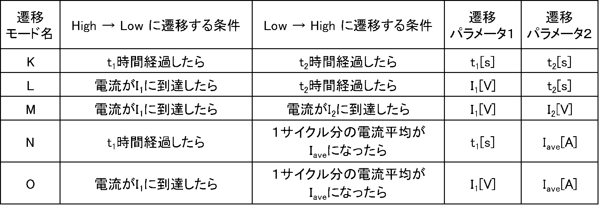
図5Dはパルスモード3を示す。パルスモード3は、ハイレベルの期間t1で電圧V1を出力し、ローレベルの期間t2で電圧V2を出力するモード(CCCV混合パルス)である。ハイレベルからローレベルに遷移する条件とローレベルからハイレベルに遷移する条件に応じて下記の表4に示すように、モードPからモードTまでが規定されている。
FIG. 5D shows pulse mode 3. The pulse mode 3 is a mode (CCCV mixed pulse) in which the voltage V1 is output in the high level period t1 and the voltage V2 is output in the low level period t2. As shown in Table 4 below, mode P to mode T are defined according to the condition for transition from high level to low level and the condition for transition from low level to high level.

実験に使用した多機能充放電器は、上述したモード0~3のいずれのパルスも発生することができる。また、この多機能充放電器を用いてCCCV混合パルスの検討を行うための測定プログラムを作成した。
The multi-function charger / discharger used in the experiment can generate any of the pulses in modes 0 to 3 described above. Moreover, the measurement program for examining CCCV mixing pulse was created using this multifunctional charger / discharger.
充放電実験は、下記の条件にて充放電サイクル試験を行った。一例として、パルス印加は、図5Cに示すパルスモード2(CVCC混合パルス)の遷移モードNを使用し、パルス一周期分の平均電流Iaveを0に設定し、パルス印加中の正味の充電容量がゼロになるようにした。すなわち、巨視的に見て充電も放電もしないパルスである。
In the charge / discharge experiment, a charge / discharge cycle test was performed under the following conditions. As an example, pulse application uses the transition mode N of pulse mode 2 (CVCC mixed pulse) shown in FIG. 5C, the average current Iave for one pulse period is set to 0, and the net charge capacity during pulse application is It was set to zero. That is, it is a pulse that is neither charged nor discharged macroscopically.
パルス印加の条件(図5C中の変数T1,I,T2)については、それぞれ以下の3水準とし、全ての組み合わせの試験が行われるようにした(合計27個の条件)。27個の条件)の試行順序について、パルス印加の効果とサイクルに伴う容量劣化現象との交互作用を排除するため、ランダムに試行するようにした。また、パルスを印加する2つのサイクルの間に、通常のCCCV充電のサイクルを挿入し、パルス印加の効果を比較し易いようにした。
The pulse application conditions (variables T1, I, and T2 in FIG. 5C) were set to the following three levels, respectively, so that all combinations were tested (a total of 27 conditions). In order to eliminate the interaction between the effect of applying the pulse and the capacity deterioration phenomenon associated with the cycle, the trial order (27 conditions) was tried at random. In addition, a normal CCCV charging cycle is inserted between two cycles of applying a pulse so that the effects of applying the pulse can be easily compared.
4.2VでのCV充電の時間T1=(5,10,15)s
CC放電の電流I=(-5,-10,-15)mA
パルス印加の保持時間T2=(1,2,4)min Time of CV charging at 4.2V T1 = (5, 10, 15) s
CC discharge current I = (− 5, −10, −15) mA
Pulse application holding time T2 = (1,2,4) min
CC放電の電流I=(-5,-10,-15)mA
パルス印加の保持時間T2=(1,2,4)min Time of CV charging at 4.2V T1 = (5, 10, 15) s
CC discharge current I = (− 5, −10, −15) mA
Pulse application holding time T2 = (1,2,4) min
充放電サイクル試験の流れは、「捨て放電」→「パルス充放電」→「通常充放電」である。それぞれの流れは以下に示すものである。
「捨て放電の流れ」
1.CC放電(-20mA,3.0Vカット)
2.休止(20min)
→パルス充放電へ The flow of the charge / discharge cycle test is “discard discharge” → “pulse charge / discharge” → “normal charge / discharge”. Each flow is as follows.
"Flow of discarded discharge"
1. CC discharge (-20mA, 3.0V cut)
2. Rest (20 min)
→ To pulse charge / discharge
「パルス充放電の流れ」
3.CC充電(40mA,4.2Vカット)
4.パルス印加(4.2V×T1sのCV充電と1mAのCC放電の混合パルス、パルス印加をT2min間保持)
5.CV充電(4.2V,1mAカット)
6.休止(20min)
7.CC放電(-20mA,3.0Vカット)
8.休止(20min)
→通常充放電へ "Flow of pulse charge / discharge"
3. CC charging (40mA, 4.2V cut)
4). Pulse application (mixed pulse of 4.2V x T1s CV charge and 1mA CC discharge, hold pulse application for T2min)
5). CV charging (4.2V, 1mA cut)
6). Rest (20 min)
7). CC discharge (-20mA, 3.0V cut)
8). Rest (20 min)
→ Normal charge / discharge
「通常充放電の流れ」
9.CC充電(40mA,4.2Vカット)
10.CV充電(4.2V,1mAカット)
11.休止(20min)
12.CC放電(-20mA,3.0Vカット)
13.休止(20min)
→パルス充放電へ "Normal charge / discharge flow"
9. CC charging (40mA, 4.2V cut)
10. CV charging (4.2V, 1mA cut)
11. Rest (20 min)
12 CC discharge (-20mA, 3.0V cut)
13. Rest (20 min)
→ To pulse charge / discharge
9.CC充電(40mA,4.2Vカット)
10.CV充電(4.2V,1mAカット)
11.休止(20min)
12.CC放電(-20mA,3.0Vカット)
13.休止(20min)
→パルス充放電へ "Normal charge / discharge flow"
9. CC charging (40mA, 4.2V cut)
10. CV charging (4.2V, 1mA cut)
11. Rest (20 min)
12 CC discharge (-20mA, 3.0V cut)
13. Rest (20 min)
→ To pulse charge / discharge
上述したパルス印加の条件(図5C中の変数T1,I,T2)のそれぞれを3水準とし、全ての組み合わせ(合計27個の条件)を水準1~水準27とし、全ての水準の試験をランダムに行った場合の測定結果を図6、図7、図8及び図9に示す。図6及び図7は、一連の試行の結果を示すものであるが、作図スペースの関係で2分割されている。同様に図8及び図9は、一連の試行の結果を示すものであるが、作図スペースの関係で2分割されている。図6及び図7では、最初のサイクル0で「捨て放電」がなされ、次のサイクル1から最後のサイクル53まで、26回の通常充放電と27回のパルス充放電がなされている(図8及び図9も同様)。図6及び図7の実験結果では、水準5→水準20→水準10→・・・の順序で実験がなされ、図8及び図9の実験結果では、水準7→水準10→水準20→・・・の順序で実験がなされる。
Each of the above pulse application conditions (variables T1, I, and T2 in FIG. 5C) is set to 3 levels, all combinations (total of 27 conditions) are set to level 1 to level 27, and all level tests are randomly performed. 6, 7, 8, and 9 show the measurement results when the measurement is performed. FIGS. 6 and 7 show the results of a series of trials, which are divided into two due to the drawing space. Similarly, FIG. 8 and FIG. 9 show the results of a series of trials, but they are divided into two due to the drawing space. 6 and 7, “discarding discharge” is performed in the first cycle 0, and 26 normal charging / discharging and 27 pulse charging / discharging are performed from the next cycle 1 to the last cycle 53 (FIG. 8). The same applies to FIG. 9). 6 and 7, the experiment is performed in the order of level 5 → level 20 → level 10 →..., And in the experiment results of FIGS. 8 and 9, level 7 → level 10 → level 20 →.・ Experiment will be done in the order.
「パルス充放電」のサイクルにおいて、上述したような(CC充電→パルス印加→CV充電→休止→CC放電→休止)が順になされる。「通常充放電」のサイクルにおいて、(CC充電→CV充電→休止→CC放電→休止)が順になされる。この二つの充放電動作において、充電時間の長短は、最初のCC充電の期間の長さがほぼ等しいので、「パルス充放電」の(パルス印加+CV充電)の期間の長さと、「通常充放電」の(CV充電)の期間の長さに基づいて判断できる。
In the “pulse charge / discharge” cycle, the above-described (CC charge → pulse application → CV charge → pause → CC discharge → pause) is performed in this order. In the “normal charge / discharge” cycle, (CC charge → CV charge → pause → CC discharge → pause) is sequentially performed. In these two charging / discharging operations, the length of the charging time is approximately equal to the length of the first CC charging period, so the length of the “pulse charging / discharging” period (pulse application + CV charging) and “normal charging / discharging” "(CV charging) period".
上述した充放電試験の結果において、CC充電時間とCC放電時間について、サイクルが進むにつれて徐々に減少した。これは、充放電サイクルに伴うコイン型電池の容量劣化の影響である。次に、パルス充放電と通常充放電との比較について、パルス充放電を行っているサイクルの直前、又は直後には必ず通常充放電のサイクルが存在するが、それら直近同士で充電時間の比較を行うと、最初のパルス充放電(サイクルNo1)を除き、すべてのケースにおいて、パルス充放電のサイクルの充電時間の方が直前、又は直後の通常充放電のサイクルの充電時間に比して短かった。但し、サイクルNo1の充放電サイクルにおいては、CV充電時間が次のサイクルNo2の通常充放電に比して長くなっていた。これは、パルスを印加したことによる効果ではなく、初回充電に特有な、SEI形成などの後続化学反応が生じたためであると考えられる。
In the results of the charge / discharge test described above, the CC charge time and CC discharge time gradually decreased as the cycle progressed. This is an influence of the capacity deterioration of the coin-type battery accompanying the charge / discharge cycle. Next, with regard to comparison between pulse charge / discharge and normal charge / discharge, there is always a normal charge / discharge cycle immediately before or immediately after the cycle in which pulse charge / discharge is performed. In all cases except for the first pulse charge / discharge (cycle No1), the charge time of the pulse charge / discharge cycle was shorter than the charge time of the normal charge / discharge cycle immediately before or immediately after. . However, in the charge / discharge cycle of cycle No1, the CV charge time was longer than that of the normal charge / discharge of the next cycle No2. This is considered to be due to the subsequent chemical reaction such as SEI formation, which is characteristic of the initial charge, not the effect of applying the pulse.
サイクルNo1の結果を除く、サイクルNo2以降の図6及び図7の実験結果について充電時間の短縮化の度合いを図10に示す。また、サイクルNo1の結果を除く、サイクルNo2以降の図8及び図9の実験結果について充電時間の短縮化の度合いを図11に示す。パルス充放電の条件には、3つの変数T1,I,T2を変えた計27の条件があるが、これを系統立てて纏め直した図を図10及び図11に示す。全充電時間の高速化の度合いは、値が大きいほど高速なことを表している。
10 shows the degree of shortening of the charging time for the experimental results of FIG. 6 and FIG. 7 after the cycle No2 excluding the result of the cycle No1. Further, FIG. 11 shows the degree of shortening of the charging time for the experimental results of FIG. 8 and FIG. 9 after the cycle No2 excluding the result of the cycle No1. There are a total of 27 conditions for changing the three variables T1, I, and T2 in the pulse charge / discharge conditions. FIGS. 10 and 11 show these systematically reorganized figures. The degree of speeding up of the total charging time indicates that the higher the value, the higher the speed.
図10及び図11において、T1及びIについては、ランダムな挙動をしており、傾向を見て取ることはできなかった。一方、パルス印加の保持時間T2については、1minの時の効果が最も高く、その後2min、4minと、順に低くなっていく傾向が見て取れた。
10 and 11, T1 and I have a random behavior, and the trend cannot be observed. On the other hand, with respect to the holding time T2 of the pulse application, the effect at 1 min was the highest, and thereafter a tendency of decreasing in order of 2 min and 4 min was observed.
上述した本技術は、CV充電時間を短縮することができる。コイン型リチウムイオン電池を用いた実験は、前段充電と後段充電の時間を足した全充電時間が11%高速化することを示した。本技術による制御は、CV充電の前に正味の充電容量がゼロのCCCV混合パルスを挿入するだけという単純なものであり、電池の状態をその場で把握して最適な電流パターンを生成するような複雑な方法を用いる必要がなく、どのような電池のどのような状態に対しても、常に同じように適用することができる。また、標準充電電圧を上回る電圧が電池に印加されることがなく、過充電による発煙発火のリスクを高めることがない。
The present technology described above can shorten the CV charging time. An experiment using a coin-type lithium ion battery showed that the total charging time, which is the sum of the time for the former stage charging and the latter stage charging, was increased by 11%. The control according to the present technology is as simple as inserting a CCCV mixed pulse with a net charge capacity of zero before CV charging, and generating an optimal current pattern by grasping the state of the battery on the spot. It is not necessary to use a complicated method, and it can always be applied in the same manner to any state of any battery. In addition, a voltage exceeding the standard charging voltage is not applied to the battery, and the risk of smoke emission due to overcharging is not increased.
<2.応用例>
上述した本技術の一実施の形態に係る充電装置又は充電方法を採用する蓄電装置は、例えば電子機器や電動車両、蓄電装置などの機器に搭載又は電力を供給するために使用することができる。 <2. Application example>
The power storage device that employs the charging device or the charging method according to the embodiment of the present technology described above can be used for mounting or supplying power to a device such as an electronic device, an electric vehicle, or a power storage device.
電子機器として、例えばノート型パソコン、スマートフォン、タブレット端末、PDA(携帯情報端末)、携帯電話、ウェアラブル端末、コードレスフォン子機、ビデオムービー、デジタルスチルカメラ、電子書籍、電子辞書、音楽プレイヤー、ラジオ、ヘッドホン、ゲーム機、ナビゲーションシステム、メモリーカード、ペースメーカー、補聴器、電動工具、電気シェーバー、冷蔵庫、エアコン、テレビ、ステレオ、温水器、電子レンジ、食器洗い器、洗濯機、乾燥器、照明機器、玩具、医療機器、ロボット、ロードコンディショナー、信号機などが挙げられる。
Examples of electronic devices include notebook computers, smartphones, tablet terminals, PDAs (personal digital assistants), mobile phones, wearable terminals, cordless phones, video movies, digital still cameras, electronic books, electronic dictionaries, music players, radios, Headphones, game consoles, navigation systems, memory cards, pacemakers, hearing aids, electric tools, electric shavers, refrigerators, air conditioners, TVs, stereos, water heaters, microwave ovens, dishwashers, washing machines, dryers, lighting equipment, toys, medical Examples include equipment, robots, road conditioners, and traffic lights.
また、電動車両としては鉄道車両、ゴルフカート、電動カート、電気自動車(ハイブリッド自動車を含む)などが挙げられ、これらの駆動用電源又は補助用電源として用いられる。
Also, examples of the electric vehicle include a railway vehicle, a golf cart, an electric cart, an electric vehicle (including a hybrid vehicle), and the like, and these are used as a driving power source or an auxiliary power source.
蓄電装置としては、住宅をはじめとする建築物用又は発電設備用の電力貯蔵用電源などが挙げられる。
Examples of power storage devices include power storage power sources for buildings such as houses or power generation facilities.
以下では、上述した適用例のうち、上述した本技術の蓄電装置を用いた蓄電システムの具体例を説明する。
Hereinafter, among the application examples described above, a specific example of a power storage system using the above-described power storage device of the present technology will be described.
この蓄電システムは、例えば下記の様な構成が挙げられる。第1の蓄電システムは、再生可能エネルギーから発電を行う発電装置によって蓄電装置が充電される蓄電システムである。第2の蓄電システムは、蓄電装置を有し、蓄電装置に接続される電子機器に電力を供給する蓄電システムである。第3の蓄電システムは、蓄電装置から、電力の供給を受ける電子機器である。これらの蓄電システムは、外部の電力供給網と協働して電力の効率的な供給を図るシステムとして実施される。
This power storage system has the following configuration, for example. The first power storage system is a power storage system in which a power storage device is charged by a power generation device that generates power from renewable energy. The second power storage system is a power storage system that includes a power storage device and supplies power to an electronic device connected to the power storage device. The third power storage system is an electronic device that receives power supply from the power storage device. These power storage systems are implemented as a system for efficiently supplying power in cooperation with an external power supply network.
さらに、第4の蓄電システムは、蓄電装置から電力の供給を受けて車両の駆動力に変換する変換装置と、蓄電装置に関する情報に基づいて車両制御に関する情報処理を行なう制御装置とを有する電動車両である。第5の蓄電システムは、他の機器とネットワークを介して信号を送受信する電力情報送受信部とを備え、送受信部が受信した情報に基づき、上述した蓄電装置の充放電制御を行う電力システムである。第6の蓄電システムは、上述した蓄電装置から、電力の供給を受け、又は発電装置又は電力網から蓄電装置に電力を供給する電力システムである。
Furthermore, the fourth power storage system includes an electric vehicle having a conversion device that receives power supplied from the power storage device and converts the power into a driving force of the vehicle, and a control device that performs information processing related to vehicle control based on information related to the power storage device. It is. The fifth power storage system is a power system that includes a power information transmission / reception unit that transmits / receives signals to / from other devices via a network, and performs charge / discharge control of the power storage device described above based on information received by the transmission / reception unit. . The sixth power storage system is a power system that receives power from the power storage device described above or supplies power from the power generation device or the power network to the power storage device.
「住宅における蓄電システム」
本技術の電池を用いた蓄電装置を住宅用の蓄電システムに適用した例について、図12を参照して説明する。例えば住宅101用の蓄電システム100においては、火力発電102a、原子力発電102b、水力発電102cなどの集中型電力系統102から電力網109、情報網112、スマートメータ107、パワーハブ108などを介し、電力が蓄電装置103に供給される。これと共に、家庭内の発電装置104などの独立電源から電力が蓄電装置103に供給される。蓄電装置103に供給された電力が蓄電される。蓄電装置103を使用して、住宅101で使用する電力が給電される。住宅101に限らずビルに関しても同様の蓄電システムを使用できる。 "Power storage system in houses"
An example in which a power storage device using a battery of the present technology is applied to a residential power storage system will be described with reference to FIG. For example, in thepower storage system 100 for the house 101, electric power is stored from the centralized power system 102 such as the thermal power generation 102a, the nuclear power generation 102b, and the hydroelectric power generation 102c through the power network 109, the information network 112, the smart meter 107, the power hub 108, and the like. Supplied to the device 103. At the same time, power is supplied to the power storage device 103 from an independent power source such as the power generation device 104 in the home. The electric power supplied to the power storage device 103 is stored. Electric power used in the house 101 is fed using the power storage device 103. The same power storage system can be used not only for the house 101 but also for buildings.
本技術の電池を用いた蓄電装置を住宅用の蓄電システムに適用した例について、図12を参照して説明する。例えば住宅101用の蓄電システム100においては、火力発電102a、原子力発電102b、水力発電102cなどの集中型電力系統102から電力網109、情報網112、スマートメータ107、パワーハブ108などを介し、電力が蓄電装置103に供給される。これと共に、家庭内の発電装置104などの独立電源から電力が蓄電装置103に供給される。蓄電装置103に供給された電力が蓄電される。蓄電装置103を使用して、住宅101で使用する電力が給電される。住宅101に限らずビルに関しても同様の蓄電システムを使用できる。 "Power storage system in houses"
An example in which a power storage device using a battery of the present technology is applied to a residential power storage system will be described with reference to FIG. For example, in the
住宅101には、発電装置104、電力消費装置105、蓄電装置103、各装置を制御する制御装置110、スマートメータ107、各種情報を取得するセンサ111が設けられている。各装置は、電力網109及び情報網112によって接続されている。発電装置104として、太陽電池、燃料電池などが利用され、発電した電力が電力消費装置105及び/又は蓄電装置103に供給される。電力消費装置105は、冷蔵庫105a、空調装置であるエアコン105b、テレビジョン受信機であるテレビ105c、バス(風呂)105dなどである。さらに、電力消費装置105には、電動車両106が含まれる。電動車両106は、電気自動車106a、ハイブリッドカー106b、電気バイク106cである。
The house 101 is provided with a power generation device 104, a power consumption device 105, a power storage device 103, a control device 110 that controls each device, a smart meter 107, and a sensor 111 that acquires various types of information. Each device is connected by a power network 109 and an information network 112. A solar cell, a fuel cell, or the like is used as the power generation device 104, and the generated power is supplied to the power consumption device 105 and / or the power storage device 103. The power consuming device 105 includes a refrigerator 105a, an air conditioner 105b that is an air conditioner, a television 105c that is a television receiver, a bath (bath) 105d, and the like. Furthermore, the electric power consumption device 105 includes an electric vehicle 106. The electric vehicle 106 is an electric vehicle 106a, a hybrid car 106b, and an electric motorcycle 106c.
蓄電装置103に対して、本技術の電池が適用される。本技術の電池は、例えば上述したリチウムイオン二次電池によって構成されていてもよい。スマートメータ107は、商用電力の使用量を測定し、測定された使用量を、電力会社に送信する機能を備えている。電力網109は、直流給電、交流給電、非接触給電の何れか一つ又は複数を組み合わせても良い。
The battery of the present technology is applied to the power storage device 103. The battery of the present technology may be configured by, for example, the above-described lithium ion secondary battery. The smart meter 107 has a function of measuring the usage amount of commercial power and transmitting the measured usage amount to an electric power company. The power network 109 may be any one or a combination of DC power supply, AC power supply, and non-contact power supply.
各種のセンサ111は、例えば人感センサ、照度センサ、物体検知センサ、消費電力センサ、振動センサ、接触センサ、温度センサ、赤外線センサなどである。各種のセンサ111により取得された情報は、制御装置110に送信される。センサ111からの情報によって、気象の状態、人の状態などが把握されて電力消費装置105を自動的に制御してエネルギー消費を最小とすることができる。さらに、制御装置110は、住宅101に関する情報をインターネットを介して外部の電力会社などに送信することができる。
The various sensors 111 are, for example, human sensors, illuminance sensors, object detection sensors, power consumption sensors, vibration sensors, contact sensors, temperature sensors, infrared sensors, and the like. Information acquired by various sensors 111 is transmitted to the control device 110. Based on the information from the sensor 111, the weather state, the state of a person, and the like can be grasped, and the power consumption device 105 can be automatically controlled to minimize the energy consumption. Furthermore, the control device 110 can transmit information regarding the house 101 to an external power company or the like via the Internet.
パワーハブ108によって、電力線の分岐、直流交流変換などの処理がなされる。制御装置110と接続される1報網112の通信方式としては、UART(Universal Asynchronous Receiver-Transmitter:非同期シリアル通信用送受信回路)などの通信インターフェースを使う方法、Bluetooth(登録商標)、ZigBee(登録商標)、Wi-Fiなどの無線通信規格によるセンサーネットワークを利用する方法がある。Bluetooth(登録商標)方式は、マルチメディア通信に適用され、一対多接続の通信を行うことができる。ZigBeeは、IEEE(Institute of Electrical and Electronics Engineers)802.15.4の物理層を使用するものである。IEEE802.15.4は、PAN(Personal Area Network)又はW(Wireless)PANと呼ばれる短距離無線ネットワーク規格の名称である。
The power hub 108 performs processing such as branching of power lines and DC / AC conversion. As a communication method of the one information network 112 connected to the control device 110, a method using a communication interface such as UART (Universal Asynchronous Receiver-Transmitter), Bluetooth (registered trademark), ZigBee (registered trademark). There is a method of using a sensor network based on a wireless communication standard such as Wi-Fi. The Bluetooth (registered trademark) system is applied to multimedia communication and can perform one-to-many connection communication. ZigBee uses the physical layer of IEEE (Institute of Electrical and Electronics Electronics) (802.15.4). IEEE 802.15.4 is the name of a short-range wireless network standard called PAN (Personal Area Network) or W (Wireless) PAN.
制御装置110は、外部のサーバ113と接続されている。このサーバ113は、住宅101、電力会社、サービスプロバイダーの何れかによって管理されていても良い。サーバ113が送受信する情報は、たとえば、消費電力情報、生活パターン情報、電力料金、天気情報、天災情報、電力取引に関する情報である。これらの情報は、家庭内の電力消費装置(たとえばテレビジョン受信機)から送受信しても良いが、家庭外の装置(たとえば、携帯電話機など)から送受信しても良い。これらの情報は、表示機能を持つ機器、たとえば、テレビジョン受信機、携帯電話機、PDA(Personal Digital Assistants)などに、表示されても良い。
The control device 110 is connected to an external server 113. The server 113 may be managed by any one of the house 101, the power company, and the service provider. The information transmitted and received by the server 113 is, for example, information related to power consumption information, life pattern information, power charges, weather information, natural disaster information, and power transactions. These pieces of information may be transmitted / received from a power consuming device (for example, a television receiver) in the home, or may be transmitted / received from a device outside the home (for example, a mobile phone). Such information may be displayed on a device having a display function, such as a television receiver, a mobile phone, or a PDA (Personal Digital Assistant).
各部を制御する制御装置110は、CPU(Central Processing Unit)、RAM(Random Access Memory)、ROM(Read Only Memory)などで構成され、この例では、蓄電装置103に格納されている。制御装置110は、蓄電装置103、家庭内の発電装置104、電力消費装置105、各種のセンサ111、サーバ113と情報網112により接続され、例えば、商用電力の使用量と、発電量とを調整する機能を有している。なお、その他にも、電力市場で電力取引を行う機能などを備えていても良い。
The control device 110 that controls each unit includes a CPU (Central Processing Unit), a RAM (Random Access Memory), a ROM (Read Only Memory), and the like, and is stored in the power storage device 103 in this example. The control device 110 is connected to the power storage device 103, the home power generation device 104, the power consumption device 105, the various sensors 111, the server 113, and the information network 112, and adjusts, for example, the amount of commercial power used and the amount of power generation It has a function to do. In addition, you may provide the function etc. which carry out an electric power transaction in an electric power market.
以上のように、電力が火力発電102a、原子力発電102b、水力発電102cなどの集中型電力系統102のみならず、家庭内の発電装置104(太陽光発電、風力発電)の発電電力を蓄電装置103に蓄えることができる。したがって、家庭内の発電装置104の発電電力が変動しても、外部に送出する電力量を一定にしたり、又は、必要なだけ放電するといった制御を行うことができる。例えば、太陽光発電で得られた電力を蓄電装置103に蓄えると共に、夜間は料金が安い深夜電力を蓄電装置103に蓄え、昼間の料金が高い時間帯に蓄電装置103によって蓄電した電力を放電して利用するといった使い方もできる。
As described above, the power is generated not only from the centralized power system 102 such as the thermal power generation 102a, the nuclear power generation 102b, and the hydropower generation 102c but also from the power generation device 104 (solar power generation, wind power generation) in the home. Can be stored. Therefore, even if the generated power of the power generation device 104 in the home fluctuates, it is possible to perform control such that the amount of power transmitted to the outside is constant or the discharge is performed as necessary. For example, the electric power obtained by solar power generation is stored in the power storage device 103, and midnight power with a low charge is stored in the power storage device 103 at night, and the power stored by the power storage device 103 is discharged during a high daytime charge. You can also use it.
なお、この例では、制御装置110が蓄電装置103内に格納される例を説明したが、スマートメータ107内に格納されても良いし、単独で構成されていても良い。さらに、蓄電システム100は、集合住宅における複数の家庭を対象として用いられてもよいし、複数の戸建て住宅を対象として用いられてもよい。
In this example, the example in which the control device 110 is stored in the power storage device 103 has been described. However, the control device 110 may be stored in the smart meter 107 or may be configured independently. Furthermore, the power storage system 100 may be used for a plurality of homes in an apartment house, or may be used for a plurality of detached houses.
「車両における蓄電システム」
本技術を車両用の蓄電システムに適用した例について、図13を参照して説明する。図13に、本技術が適用されるシリーズハイブリッドシステムを採用するハイブリッド車両の構成の一例を概略的に示す。シリーズハイブリッドシステムはエンジンで動かす発電機で発電された電力、あるいはそれをバッテリに一旦貯めておいた電力を用いて、電力駆動力変換装置で走行する車である。 "Power storage system in vehicles"
An example in which the present technology is applied to a power storage system for a vehicle will be described with reference to FIG. FIG. 13 schematically shows an example of the configuration of a hybrid vehicle that employs a series hybrid system to which the present technology is applied. A series hybrid system is a vehicle that runs on an electric power driving force conversion device using electric power generated by a generator driven by an engine or electric power that is temporarily stored in a battery.
このハイブリッド車両200には、エンジン201、発電機202、電力駆動力変換装置203、駆動輪204a、駆動輪204b、車輪205a、車輪205b、バッテリ208、車両制御装置209、各種センサ210、充電口211が搭載されている。バッテリ208に対して、上述した本技術が適用される。
The hybrid vehicle 200 includes an engine 201, a generator 202, a power driving force conversion device 203, driving wheels 204a, driving wheels 204b, wheels 205a, wheels 205b, a battery 208, a vehicle control device 209, various sensors 210, and a charging port 211. Is installed. The present technology described above is applied to the battery 208.
ハイブリッド車両200は、電力駆動力変換装置203を動力源として走行する。電力駆動力変換装置203の一例は、モータである。バッテリ208の電力によって電力駆動力変換装置203が作動し、この電力駆動力変換装置203の回転力が駆動輪204a、204bに伝達される。なお、必要な個所に直流-交流(DC-AC)あるいは逆変換(AC-DC変換)を用いることによって、電力駆動力変換装置203が交流モータでも直流モータでも適用可能である。各種センサ210は、車両制御装置209を介してエンジン回転数を制御したり、図示しないスロットルバルブの開度(スロットル開度)を制御したりする。各種センサ210には、速度センサ、加速度センサ、エンジン回転数センサなどが含まれる。
Hybrid vehicle 200 travels using electric power / driving force conversion device 203 as a power source. An example of the power driving force conversion device 203 is a motor. The electric power / driving force converter 203 is operated by the electric power of the battery 208, and the rotational force of the electric power / driving force converter 203 is transmitted to the drive wheels 204a and 204b. It should be noted that by using DC-AC (DC-AC) or reverse conversion (AC-DC conversion) at a required place, the power driving force converter 203 can be applied to either an AC motor or a DC motor. The various sensors 210 control the engine speed via the vehicle control device 209 and control the opening (throttle opening) of a throttle valve (not shown). The various sensors 210 include a speed sensor, an acceleration sensor, an engine speed sensor, and the like.
エンジン201の回転力は発電機202に伝えられ、その回転力によって発電機202により生成された電力をバッテリ208に蓄積することが可能である。
Rotational force of the engine 201 is transmitted to the generator 202, and electric power generated by the generator 202 by the rotational force can be stored in the battery 208.
図示しない制動機構によりハイブリッド車両200が減速すると、その減速時の抵抗力が電力駆動力変換装置203に回転力として加わり、この回転力によって電力駆動力変換装置203により生成された回生電力がバッテリ208に蓄積される。
When the hybrid vehicle 200 is decelerated by a braking mechanism (not shown), the resistance force at the time of deceleration is applied as a rotational force to the electric power driving force conversion device 203, and the regenerative electric power generated by the electric power driving force conversion device 203 by this rotational force is the battery 208. Accumulated in.
バッテリ208は、ハイブリッド車両200の外部の電源に接続されることで、その外部電源から充電口211を入力口として電力供給を受け、受けた電力を蓄積することも可能である。
The battery 208 is connected to a power source outside the hybrid vehicle 200, so that it can receive power from the external power source using the charging port 211 as an input port and store the received power.
図示しないが、二次電池に関する情報に基づいて車両制御に関する情報処理を行なう情報処理装置を備えていても良い。このような情報処理装置としては、例えば、電池の残量に関する情報に基づき、電池残量表示を行う情報処理装置などがある。
Although not shown, an information processing device that performs information processing related to vehicle control based on information related to the secondary battery may be provided. As such an information processing apparatus, for example, there is an information processing apparatus that displays a remaining battery level based on information on the remaining battery level.
なお、以上は、エンジンで動かす発電機で発電された電力、或いはそれをバッテリに一旦貯めておいた電力を用いて、モータで走行するシリーズハイブリッド車を例として説明した。しかしながら、エンジンとモータの出力がいずれも駆動源とし、エンジンのみで走行、モータのみで走行、エンジンとモータ走行という3つの方式を適宜切り替えて使用するパラレルハイブリッド車に対しても本技術は有効に適用可能である。さらに、エンジンを用いず駆動モータのみによる駆動で走行する所謂、電動車両に対しても本技術は有効に適用可能である。
In the above description, the series hybrid vehicle that runs on the motor using the electric power generated by the generator driven by the engine or the electric power stored once in the battery has been described as an example. However, the present technology is also effective for a parallel hybrid vehicle in which the engine and motor outputs are both driving sources, and the system is switched between the three modes of driving with only the engine, driving with the motor, and engine and motor. Applicable. Furthermore, the present technology can be effectively applied to a so-called electric vehicle that travels only by a drive motor without using an engine.
<3.変形例>
以上、本技術の一実施の形態について具体的に説明したが、本技術は、上述の一実施の形態に限定されるものではなく、本技術の技術的思想に基づく各種の変形が可能である。例えば、上述の実施形態において挙げた構成、方法、工程、形状、材料及び数値などはあくまでも例に過ぎず、必要に応じてこれと異なる構成、方法、工程、形状、材料及び数値などを用いてもよい。 <3. Modification>
Although one embodiment of the present technology has been specifically described above, the present technology is not limited to the above-described embodiment, and various modifications based on the technical idea of the present technology are possible. . For example, the configurations, methods, processes, shapes, materials, numerical values, and the like given in the above-described embodiments are merely examples, and different configurations, methods, processes, shapes, materials, numerical values, and the like are used as necessary. Also good.
なお、本技術は、以下のような構成も取ることができる。
(1)
電池に対して前段充電を行い、電池の電圧が標準充電電圧に達すると後段充電を行う充電装置であって、
前段充電から後段充電に切り替わるタイミング、若しくはその近傍で電池に対して、ハイレベル状態が標準充電電圧におけるCV充電でありローレベル状態が負極の電気二重層容量を超える電荷を流す放電状態であるパルスを印加するパルス供給部を備える充電装置。
(2)
前記ハイレベル状態の期間が所定の期間となると、前記ローレベル状態の期間への遷移し、
充電電流と、放電電流の合計積算値がほぼゼロとなると、前記ローレベル状態の期間から前記ハイレベル状態の期間に遷移する(1)に記載の充電装置。
(3)
前記パルス供給部による複数のパルス供給の期間が所定の期間となると、充電動作に切り替えられる(1)に記載の充電装置。
(4)
電池に対して前段充電を行い、電池の標準充電電圧に達すると後段充電を行う充電方法であって、
前段充電から後段充電に切り替わるタイミング、若しくはその近傍で電池に対して、ハイレベル状態が標準充電電圧におけるCV充電でありローレベル状態が負極の電気二重層容量を超える電荷を流す放電状態であるパルスを印加する充電方法。
(5)
充電装置によって充電可能な蓄電装置であって、
前記充電装置は、前段充電を行い、電池の電圧が標準充電電圧に達すると後段充電を行い、
前段充電から後段充電に切り替わるタイミング、若しくはその近傍で電池に対して、ハイレベル状態が標準充電電圧におけるCV充電でありローレベル状態が負極の電気二重層容量を超える電荷を流す放電状態であるパルスを印加するパルス供給部を備える蓄電装置。
(6)
(5)に記載の蓄電装置から電力の供給を受ける電子機器。
(7)
(5)に記載の蓄電装置と、
前記蓄電装置から電力の供給を受けて車両の駆動力に変換する変換装置と、
前記蓄電装置に関する情報に基づいて車両制御に関する情報処理を行う制御装置と
を有する電動車両。
(8)
(5)に記載の蓄電装置から電力の供給を受ける電力システム。 In addition, this technique can also take the following structures.
(1)
A charging device that performs first-stage charging for a battery and performs second-stage charging when the voltage of the battery reaches a standard charging voltage,
A pulse in which the high-level state is CV charge at the standard charge voltage and the low-level state is a discharge state in which charge exceeding the electric double layer capacity of the negative electrode is passed to the battery at or near the timing when switching from the former stage charge to the latter stage charge. Charger provided with the pulse supply part which applies.
(2)
When the period of the high level state becomes a predetermined period, the transition to the period of the low level state,
The charging device according to (1), wherein when the total integrated value of the charging current and the discharging current becomes substantially zero, the transition from the low level state period to the high level state period is performed.
(3)
The charging device according to (1), wherein when the plurality of pulse supply periods by the pulse supply unit reach a predetermined period, the charging operation is switched.
(4)
It is a charging method that performs first-stage charging for a battery and performs second-stage charging when the standard charging voltage of the battery is reached,
A pulse in which the high-level state is CV charge at the standard charge voltage and the low-level state is a discharge state in which charge exceeding the electric double layer capacity of the negative electrode is passed to the battery at or near the timing when switching from the former stage charge to the latter stage charge. Charging method to apply.
(5)
A power storage device that can be charged by a charging device,
The charging device performs the first stage charging, performs the second stage charging when the battery voltage reaches the standard charging voltage,
A pulse in which the high-level state is CV charge at the standard charge voltage and the low-level state is a discharge state in which charge exceeding the electric double layer capacity of the negative electrode is passed to the battery at or near the timing when switching from the former stage charge to the latter stage charge. A power storage device including a pulse supply unit for applying a voltage.
(6)
Electronic equipment that receives supply of electric power from the power storage device according to (5).
(7)
The power storage device according to (5),
A conversion device that receives supply of electric power from the power storage device and converts it into driving force of a vehicle;
An electric vehicle comprising: a control device that performs information processing related to vehicle control based on information related to the power storage device.
(8)
An electric power system that receives supply of electric power from the power storage device according to (5).
(1)
電池に対して前段充電を行い、電池の電圧が標準充電電圧に達すると後段充電を行う充電装置であって、
前段充電から後段充電に切り替わるタイミング、若しくはその近傍で電池に対して、ハイレベル状態が標準充電電圧におけるCV充電でありローレベル状態が負極の電気二重層容量を超える電荷を流す放電状態であるパルスを印加するパルス供給部を備える充電装置。
(2)
前記ハイレベル状態の期間が所定の期間となると、前記ローレベル状態の期間への遷移し、
充電電流と、放電電流の合計積算値がほぼゼロとなると、前記ローレベル状態の期間から前記ハイレベル状態の期間に遷移する(1)に記載の充電装置。
(3)
前記パルス供給部による複数のパルス供給の期間が所定の期間となると、充電動作に切り替えられる(1)に記載の充電装置。
(4)
電池に対して前段充電を行い、電池の標準充電電圧に達すると後段充電を行う充電方法であって、
前段充電から後段充電に切り替わるタイミング、若しくはその近傍で電池に対して、ハイレベル状態が標準充電電圧におけるCV充電でありローレベル状態が負極の電気二重層容量を超える電荷を流す放電状態であるパルスを印加する充電方法。
(5)
充電装置によって充電可能な蓄電装置であって、
前記充電装置は、前段充電を行い、電池の電圧が標準充電電圧に達すると後段充電を行い、
前段充電から後段充電に切り替わるタイミング、若しくはその近傍で電池に対して、ハイレベル状態が標準充電電圧におけるCV充電でありローレベル状態が負極の電気二重層容量を超える電荷を流す放電状態であるパルスを印加するパルス供給部を備える蓄電装置。
(6)
(5)に記載の蓄電装置から電力の供給を受ける電子機器。
(7)
(5)に記載の蓄電装置と、
前記蓄電装置から電力の供給を受けて車両の駆動力に変換する変換装置と、
前記蓄電装置に関する情報に基づいて車両制御に関する情報処理を行う制御装置と
を有する電動車両。
(8)
(5)に記載の蓄電装置から電力の供給を受ける電力システム。 In addition, this technique can also take the following structures.
(1)
A charging device that performs first-stage charging for a battery and performs second-stage charging when the voltage of the battery reaches a standard charging voltage,
A pulse in which the high-level state is CV charge at the standard charge voltage and the low-level state is a discharge state in which charge exceeding the electric double layer capacity of the negative electrode is passed to the battery at or near the timing when switching from the former stage charge to the latter stage charge. Charger provided with the pulse supply part which applies.
(2)
When the period of the high level state becomes a predetermined period, the transition to the period of the low level state,
The charging device according to (1), wherein when the total integrated value of the charging current and the discharging current becomes substantially zero, the transition from the low level state period to the high level state period is performed.
(3)
The charging device according to (1), wherein when the plurality of pulse supply periods by the pulse supply unit reach a predetermined period, the charging operation is switched.
(4)
It is a charging method that performs first-stage charging for a battery and performs second-stage charging when the standard charging voltage of the battery is reached,
A pulse in which the high-level state is CV charge at the standard charge voltage and the low-level state is a discharge state in which charge exceeding the electric double layer capacity of the negative electrode is passed to the battery at or near the timing when switching from the former stage charge to the latter stage charge. Charging method to apply.
(5)
A power storage device that can be charged by a charging device,
The charging device performs the first stage charging, performs the second stage charging when the battery voltage reaches the standard charging voltage,
A pulse in which the high-level state is CV charge at the standard charge voltage and the low-level state is a discharge state in which charge exceeding the electric double layer capacity of the negative electrode is passed to the battery at or near the timing when switching from the former stage charge to the latter stage charge. A power storage device including a pulse supply unit for applying a voltage.
(6)
Electronic equipment that receives supply of electric power from the power storage device according to (5).
(7)
The power storage device according to (5),
A conversion device that receives supply of electric power from the power storage device and converts it into driving force of a vehicle;
An electric vehicle comprising: a control device that performs information processing related to vehicle control based on information related to the power storage device.
(8)
An electric power system that receives supply of electric power from the power storage device according to (5).
1・・・電池
2・・・電圧検出部
3・・・制御部
4・・・電流検出部
5・・・電流積算部
6・・・時間計測部
8・・・電流制限付きCV充電部
9・・・CC充電部
10・・・CC放電部 DESCRIPTION OFSYMBOLS 1 ... Battery 2 ... Voltage detection part 3 ... Control part 4 ... Current detection part 5 ... Current integration part 6 ... Time measurement part 8 ... CV charging part 9 with a current limitation 9 ... CC charging part 10 ... CC discharging part
2・・・電圧検出部
3・・・制御部
4・・・電流検出部
5・・・電流積算部
6・・・時間計測部
8・・・電流制限付きCV充電部
9・・・CC充電部
10・・・CC放電部 DESCRIPTION OF
Claims (8)
- 電池に対して前段充電を行い、電池の電圧が標準充電電圧に達すると後段充電を行う充電装置であって、
前段充電から後段充電に切り替わるタイミング、若しくはその近傍で電池に対して、ハイレベル状態が標準充電電圧におけるCV充電でありローレベル状態が負極の電気二重層容量を超える電荷を流す放電状態であるパルスを印加するパルス供給部を備える充電装置。 A charging device that performs first-stage charging for a battery and performs second-stage charging when the voltage of the battery reaches a standard charging voltage,
A pulse in which the high-level state is CV charge at the standard charge voltage and the low-level state is a discharge state in which charge exceeding the electric double layer capacity of the negative electrode is passed to the battery at or near the timing when switching from the former stage charge to the latter stage charge. Charger provided with the pulse supply part which applies. - 前記ハイレベル状態の期間が所定の期間となると、前記ローレベル状態の期間への遷移し、
充電電流と、放電電流の合計積算値がほぼゼロとなると、前記ローレベル状態の期間から前記ハイレベル状態の期間に遷移する請求項1に記載の充電装置。 When the period of the high level state becomes a predetermined period, the transition to the period of the low level state,
2. The charging device according to claim 1, wherein when the total integrated value of the charging current and the discharging current becomes substantially zero, the charging device transitions from the low level state period to the high level state period. - 前記パルス供給部による複数のパルス供給の期間が所定の期間となると、充電動作に切り替えられる請求項1に記載の充電装置。 The charging device according to claim 1, wherein the charging operation is switched to a charging operation when a plurality of pulse supply periods by the pulse supply unit reach a predetermined period.
- 電池に対して前段充電を行い、電池の標準充電電圧に達すると後段充電を行う充電方法であって、
前段充電から後段充電に切り替わるタイミング、若しくはその近傍で電池に対して、ハイレベル状態が標準充電電圧におけるCV充電でありローレベル状態が負極の電気二重層容量を超える電荷を流す放電状態であるパルスを印加する充電方法。 It is a charging method that performs first-stage charging for a battery and performs second-stage charging when the standard charging voltage of the battery is reached,
A pulse in which the high-level state is CV charge at the standard charge voltage and the low-level state is a discharge state in which charge exceeding the electric double layer capacity of the negative electrode is passed to the battery at or near the timing when switching from the former stage charge to the latter stage charge. Charging method to apply. - 充電装置によって充電可能な蓄電装置であって、
前記充電装置は、前段充電を行い、電池の電圧が標準充電電圧に達すると後段充電を行い、
前段充電から後段充電に切り替わるタイミング、若しくはその近傍で電池に対して、ハイレベル状態が標準充電電圧におけるCV充電でありローレベル状態が負極の電気二重層容量を超える電荷を流す放電状態であるパルスを印加するパルス供給部を備える蓄電装置。 A power storage device that can be charged by a charging device,
The charging device performs the first stage charging, performs the second stage charging when the battery voltage reaches the standard charging voltage,
A pulse in which the high-level state is CV charge at the standard charge voltage and the low-level state is a discharge state in which charge exceeding the electric double layer capacity of the negative electrode is passed to the battery at or near the timing when switching from the former stage charge to the latter stage charge. A power storage device including a pulse supply unit for applying a voltage. - 請求項5に記載の蓄電装置から電力の供給を受ける電子機器。 An electronic device that receives power supply from the power storage device according to claim 5.
- 請求項5に記載の蓄電装置と、
前記蓄電装置から電力の供給を受けて車両の駆動力に変換する変換装置と、
前記蓄電装置に関する情報に基づいて車両制御に関する情報処理を行う制御装置と
を有する電動車両。 The power storage device according to claim 5;
A conversion device that receives supply of electric power from the power storage device and converts it into driving force of a vehicle;
An electric vehicle comprising: a control device that performs information processing related to vehicle control based on information related to the power storage device. - 請求項5に記載の蓄電装置から電力の供給を受ける電力システム。 An electric power system that receives supply of electric power from the power storage device according to claim 5.
Priority Applications (1)
| Application Number | Priority Date | Filing Date | Title |
|---|---|---|---|
| JP2018520676A JP6658880B2 (en) | 2016-06-02 | 2017-03-24 | Charging device, charging method, power storage device, electronic device, electric vehicle, and power system |
Applications Claiming Priority (2)
| Application Number | Priority Date | Filing Date | Title |
|---|---|---|---|
| JP2016-111048 | 2016-06-02 | ||
| JP2016111048 | 2016-06-02 |
Publications (1)
| Publication Number | Publication Date |
|---|---|
| WO2017208588A1 true WO2017208588A1 (en) | 2017-12-07 |
Family
ID=60478236
Family Applications (1)
| Application Number | Title | Priority Date | Filing Date |
|---|---|---|---|
| PCT/JP2017/011986 WO2017208588A1 (en) | 2016-06-02 | 2017-03-24 | Charging apparatus, charging method, power storage apparatus, electronic device, electric vehicle, and power system |
Country Status (2)
| Country | Link |
|---|---|
| JP (1) | JP6658880B2 (en) |
| WO (1) | WO2017208588A1 (en) |
Cited By (1)
| Publication number | Priority date | Publication date | Assignee | Title |
|---|---|---|---|---|
| CN108054454A (en) * | 2017-12-27 | 2018-05-18 | 安徽嘉熠智能科技有限公司 | A kind of battery preliminary filling control method and its system |
Citations (2)
| Publication number | Priority date | Publication date | Assignee | Title |
|---|---|---|---|---|
| JP2010011586A (en) * | 2008-06-25 | 2010-01-14 | Panasonic Corp | Method of charging alkaline storage battery, and battery charger |
| JP2014068527A (en) * | 2012-09-26 | 2014-04-17 | Samsung Electronics Co Ltd | Charging apparatus and charging method for secondary cell |
Family Cites Families (1)
| Publication number | Priority date | Publication date | Assignee | Title |
|---|---|---|---|---|
| JP5407893B2 (en) * | 2010-01-21 | 2014-02-05 | トヨタ自動車株式会社 | Secondary battery system and hybrid vehicle |
-
2017
- 2017-03-24 JP JP2018520676A patent/JP6658880B2/en active Active
- 2017-03-24 WO PCT/JP2017/011986 patent/WO2017208588A1/en active Application Filing
Patent Citations (2)
| Publication number | Priority date | Publication date | Assignee | Title |
|---|---|---|---|---|
| JP2010011586A (en) * | 2008-06-25 | 2010-01-14 | Panasonic Corp | Method of charging alkaline storage battery, and battery charger |
| JP2014068527A (en) * | 2012-09-26 | 2014-04-17 | Samsung Electronics Co Ltd | Charging apparatus and charging method for secondary cell |
Cited By (1)
| Publication number | Priority date | Publication date | Assignee | Title |
|---|---|---|---|---|
| CN108054454A (en) * | 2017-12-27 | 2018-05-18 | 安徽嘉熠智能科技有限公司 | A kind of battery preliminary filling control method and its system |
Also Published As
| Publication number | Publication date |
|---|---|
| JP6658880B2 (en) | 2020-03-04 |
| JPWO2017208588A1 (en) | 2019-03-07 |
Similar Documents
| Publication | Publication Date | Title |
|---|---|---|
| Haq et al. | Development of battery management system for cell monitoring and protection | |
| JP5812025B2 (en) | Power storage system for stationary use and control method | |
| WO2019087018A1 (en) | Capacity estimation method and capacity estimation system for power storage device | |
| JP6185597B2 (en) | Apparatus and method for estimating depth of discharge of secondary battery | |
| US20140300311A1 (en) | Portable power bank and battery booster | |
| CN103178308A (en) | Method for charging lithium ion secondary battery and battery charger | |
| JP2014110131A (en) | Control device, control method, control system, and electric vehicle | |
| EP2228882A3 (en) | Charging control device and method, charging device, as well as, program | |
| CN103683359B (en) | The battery equalization method of battery pack and battery management system | |
| JP7040601B2 (en) | Battery control device, battery control method, uninterruptible power supply, power system and electric vehicle | |
| RU2461102C1 (en) | Method for operation of lithium-ion accumulator battery in autonomous power supply system | |
| EP2555008A4 (en) | Method for detecting battery capacity of secondary battery | |
| EP2595236A1 (en) | Secondary battery system and method for charging/discharging same | |
| JP2009080939A (en) | Power source system and control method of battery assembly | |
| US9209645B2 (en) | Method and apparatus for controlling charging of secondary battery | |
| JP2009089569A (en) | Power supply system | |
| CN101692582A (en) | Charge/discharge control circuit and battery device | |
| KR101177455B1 (en) | Battery charging apparatus, battery pack, battery charging system and battery charging method | |
| CN105431994A (en) | Electricity storage device, electricity storage system, and method for controlling electricity storage device | |
| US20120161564A1 (en) | Device and Method of Recycling Energy | |
| EP2919359B1 (en) | Voltage equalization apparatus and electricity storage apparatus | |
| De Freige et al. | Power & energy ratings optimization in a fast-charging station for PHEV batteries | |
| Ananda-Rao et al. | Battery energy storage system assessment in a designed battery controller for load leveling and peak shaving applications | |
| CN103378631A (en) | Charging device, control method of the charging device, electric-powered vehicle, energy storage device and power system | |
| WO2017208588A1 (en) | Charging apparatus, charging method, power storage apparatus, electronic device, electric vehicle, and power system |
Legal Events
| Date | Code | Title | Description |
|---|---|---|---|
| ENP | Entry into the national phase |
Ref document number: 2018520676 Country of ref document: JP Kind code of ref document: A |
|
| NENP | Non-entry into the national phase |
Ref country code: DE |
|
| 121 | Ep: the epo has been informed by wipo that ep was designated in this application |
Ref document number: 17806149 Country of ref document: EP Kind code of ref document: A1 |
|
| 122 | Ep: pct application non-entry in european phase |
Ref document number: 17806149 Country of ref document: EP Kind code of ref document: A1 |