WO2017208369A1 - データ生成プログラム、データ生成方法および道路管理装置 - Google Patents
データ生成プログラム、データ生成方法および道路管理装置 Download PDFInfo
- Publication number
- WO2017208369A1 WO2017208369A1 PCT/JP2016/066071 JP2016066071W WO2017208369A1 WO 2017208369 A1 WO2017208369 A1 WO 2017208369A1 JP 2016066071 W JP2016066071 W JP 2016066071W WO 2017208369 A1 WO2017208369 A1 WO 2017208369A1
- Authority
- WO
- WIPO (PCT)
- Prior art keywords
- range
- road
- measurement result
- dividing
- data type
- Prior art date
- Legal status (The legal status is an assumption and is not a legal conclusion. Google has not performed a legal analysis and makes no representation as to the accuracy of the status listed.)
- Ceased
Links
Images






Classifications
-
- G—PHYSICS
- G08—SIGNALLING
- G08G—TRAFFIC CONTROL SYSTEMS
- G08G1/00—Traffic control systems for road vehicles
- G08G1/01—Detecting movement of traffic to be counted or controlled
-
- G—PHYSICS
- G08—SIGNALLING
- G08G—TRAFFIC CONTROL SYSTEMS
- G08G1/00—Traffic control systems for road vehicles
- G08G1/123—Traffic control systems for road vehicles indicating the position of vehicles, e.g. scheduled vehicles; Managing passenger vehicles circulating according to a fixed timetable, e.g. buses, trains, trams
- G08G1/127—Traffic control systems for road vehicles indicating the position of vehicles, e.g. scheduled vehicles; Managing passenger vehicles circulating according to a fixed timetable, e.g. buses, trains, trams to a central station ; Indicators in a central station
- G08G1/13—Traffic control systems for road vehicles indicating the position of vehicles, e.g. scheduled vehicles; Managing passenger vehicles circulating according to a fixed timetable, e.g. buses, trains, trams to a central station ; Indicators in a central station the indicator being in the form of a map
Definitions
- the present invention relates to a data generation program, a data generation method, and a road management device.
- the management system is often different for each measurement item.
- the pavement state and the pavement performance are managed by dividing the road route in units of, for example, 100 m
- the traffic volume is managed by separating a link indicating the range from the intersection to the intersection.
- the data generation program receives first data in which a road position, a first range based on the position, and a measurement result value for the first range are associated with each other. Is executed on the computer.
- the data generation program executes a process of dividing and / or combining the first range so as to match a road position and a second range based on the position, and the dividing and / or combining the first range.
- a computer is caused to execute a process of executing a process of dividing and / or combining road measurement result values associated with each first range in accordance with a ratio of each first range.
- the data generation program executes a process of associating the result of dividing and / or combining the road measurement result values with each of the second ranges, and executing the process of storing the executed result in the storage unit in the computer
- measurement items of roads having different management systems can be handled in a unified manner.
- FIG. 9 is a diagram illustrating an example of information stored in the time-varying DB.
- FIG. 10 is a diagram for explaining division by latitude and longitude.
- FIG. 11 is a diagram illustrating an example of extracting a change with time of a specific position.
- FIG. 12 is a diagram for explaining an example of extracting a change with time from the section aggregation.
- FIG. 13 is a diagram for explaining an example of a result display.
- FIG. 14 is a flowchart for explaining the flow of the counting process.
- FIG. 15 is a flowchart showing the flow of display processing.
- FIG. 16 is a diagram illustrating an example in which a link is associated with a section.
- FIG. 17 is a diagram illustrating an example of associating data before conversion with a section.
- FIG. 18 is a diagram illustrating a hardware configuration example.
- the road management server 10 receives the data type A managed in the first format and the data type B managed in the second format different from the first format, and generates the statistical data. It is an example.
- the data type A is managed by “position information (latitude / longitude), measurement result” for each road
- the data type B is managed by “position information (link information), measurement result” for each road.
- the measurement results are, for example, vehicle speed, acceleration, number of sudden braking, traffic volume, pavement state, road image, etc. Any information can be adopted as long as it is information obtained from probe data.
- link information is information which shows the range from an intersection to an intersection, and may be described as link ID.
- the road management server 10 associates the position of the road, the first range based on the position (for example, latitude / longitude or link ID), and the value of the measurement result for the first range. Data type A or data type B is accepted. Then, the road management server 10 executes processing for dividing and / or combining the first range so as to match the position of the road and a predetermined second range (for example, section ID) based on the position. Further, the road management server 10 divides and / or combines the road measurement result values associated with the first ranges in accordance with the ratios of the first ranges to be divided and / or combined. Thereafter, the road management server 10 executes a process of associating the result of dividing and / or combining road measurement result values with each of the second ranges, and stores the execution result in the storage unit.
- the position for example, latitude / longitude or link ID
- the road management server 10 executes processing for dividing and / or combining the first range so as to match the position of the road and
- the road management server 10 divides and combines the latitude and longitude of the data type A and the measurement result so that the data type A managed by the latitude and longitude is associated with the section ID that identifies the section of the road. Then, the data type A managed by the section ID is converted. Similarly, the road management server 10 divides and combines the link information and the measurement result of the data type B so that the data type B managed by the link information is associated with the section ID, thereby obtaining the section ID. To data type B managed by
- the road management server 10 generates the data type A and the data type B managed by the same section ID, and from these data types, each measurement result corresponding to the section ID of the road to be managed is obtained. Extract.
- the road management server 10 can manage a plurality of measurement results managed by different management systems and manage the measurement results in time series. Therefore, the road management server 10 can handle the measurement items of roads having different management systems in a unified manner.
- the communication unit 11 is a processing unit that controls communication of other devices, and is, for example, a communication interface.
- the communication unit 11 receives probe data and various data from a vehicle or a management server.
- the communication unit 11 may employ various types of wireless or various types of wires.
- the storage unit 12 stores programs and data executed by the control unit 20.
- the storage unit 12 includes a definition information DB 13, a measurement result DB 14, a conversion result DB 15, a section tabulation result DB 16, a period tabulation result DB 17, and a time-change DB 18.
- the measurement result DB 14 is a database that stores road measurement results managed by other management servers. Information stored here may be received at any time from an external management server, or can be manually registered by an administrator or the like.
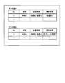
- FIG. 4 is a diagram illustrating an example of information stored in the measurement result DB 14.
- the measurement result DB 14 stores a data type A database and a data type B database.
- the data type A stores “No, time, position information, measurement result” in association with each other. “No” stored here is an identifier for identifying a record in the DB. “Time” indicates the time and date of measurement. “Position information” is latitude and longitude indicating the measurement position.
- the “measurement result” is a measurement result at a position on the road specified by the position information, and an acceleration value is taken as an example in the present embodiment.
- Data type B stores “No, time, link information, measurement result” in association with each other. “No” stored here is an identifier for identifying a record in the DB. “Time” indicates the time and date of measurement. “Link information” is link information indicating a measurement position. The “measurement result” is a measurement result at a position on the road specified by the position information. In this embodiment, the number of sudden braking is taken as an example.
- the conversion result DB 15 is a database that stores data types after converting each data type stored in the measurement result DB 14 into a predetermined condition.
- FIG. 5 is a diagram illustrating an example of information stored in the conversion result DB 15. As shown in FIG. 5, the conversion result DB 15 stores a data type A and a data type B as in the measurement result DB 14. The difference from FIG. 4 is that the position information of the data type B is converted from the link information to the position information of latitude and longitude.
- the section count result DB 16 is a database that stores evaluation results in section units for each data type.
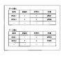
- FIG. 6 is a diagram illustrating an example of information stored in the section count result DB 16. As illustrated in FIG. 6, the section count result DB 16 stores the count result of the data type A and the count result of the data type B stored in the conversion result DB 15.
- Each of the data type A and the data type B stores “time, route ID, section ID, evaluation” in association with each other.
- the “time” stored here indicates an aggregation date or measurement date or time.
- “Route ID” is an identifier that uniquely identifies a road.
- the “section ID” is an identifier that uniquely identifies a section arbitrarily divided on the road.
- “Evaluation” is an evaluation value calculated using a measurement result, and can be arbitrarily set and changed, for example, an average value, a variance value, a maximum value, or a minimum value. In this embodiment, the average value will be described as an example.
- the period tabulation result DB 17 is a database that stores evaluation results for a certain period for each data type.
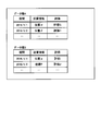
- FIG. 7 is a diagram illustrating an example of information stored in the period totaling result DB 17. As illustrated in FIG. 7, the period totaling result DB 17 stores the totaling result of the data type A and the totaling result of the data type B stored in the conversion result DB 15.
- Each of the data type A and the data type B stores “period, position information, and evaluation” in association with each other.
- the “period” stored here indicates a period to be counted, and can be arbitrarily set and changed, for example, a day, a date, a predetermined day to a predetermined day, or the like.
- “Position information” indicates the latitude and longitude of the measurement position.
- “Evaluation” is an evaluation value calculated using a measurement result, and can be arbitrarily set and changed, for example, an average value, a variance value, a maximum value, or a minimum value. In this embodiment, the average value will be described as an example.
- the data type A indicates that the average value of acceleration measured at “position ⁇ ” of “2016/1/1” is “evaluation G”.
- the average value of the number of sudden brakings measured at “position ⁇ ” of “2016/1/1” is “evaluation I”.
- the time-change DB 18 is a database that stores changes over time in evaluation and measurement results in a certain section of a road. The information stored here is generated using the section total result and the period total result. Specifically, the time-dependent change DB 18 includes a comparison result of specific dates and times of a plurality of data types, a time-dependent change of specific positions of the plurality of data types, a time-dependent change for each period of the plurality of data types, and a time-dependent change for each evaluation result of the data types Memorize etc.
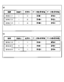
- FIG. 8 and 9 are diagrams showing examples of information stored in the time-change DB 18.
- a of FIG. 8 shows a temporal change in which “period, route ID, section ID, data type A evaluation value, data type B evaluation value” are associated, and the evaluation value and data of data type A for different section IDs. The result of comparing the evaluation value of seed B with a specific date and time is shown.
- the evaluation value of the seed B is “evaluation 5”. That is, the measurement results of each data type in “route, section” are tabulated for each “period”.
- FIG. 9 shows a change over time in which “route ID, section ID, data type A evaluation value, data type B evaluation value” is associated with each “period”, and data for each period for different section IDs. The result of comparing the evaluation value of seed A with the evaluation value of data seed B is shown.
- FIG. 9 shows a temporal change in which “route ID, section ID, data type A evaluation value, data type B evaluation value” is associated with each “period”, and different section IDs for each data type. Indicates the change in evaluation value over a period.
- the control unit 20 is a processing unit that controls the processing of the entire road management server 10, and includes a conversion storage unit 21, an extraction unit 22, and a display control unit 26.
- the conversion storage unit 21, the extraction unit 22, and the display control unit 26 are an example of an electronic circuit included in the processor and an example of a process executed by the processor.
- the conversion storage unit 21 is an example of a reception unit
- the extraction unit 22 is an example of a data processing unit, an association unit, and a storage unit.
- the conversion storage unit 21 divides the distance between the start point and the end point for each latitude xd, and also divides the measurement result from the start point to the end point by the number of divisions by latitude.
- FIG. 10 is an example in which the distance is divided into 11 pieces.
- the position information (x, y) in FIG. 10A is (x1 + xd ⁇ 3, y1 + (y2 ⁇ y1) / 10 ⁇ 3). It becomes.
- the conversion storage unit 21 also divides the measurement result into 11, and the data type in which each latitude and longitude obtained by the division is associated with the divided measurement result. Convert to
- the measurement result is a cumulative number such as the number of sudden braking, it can be simply divided, but it cannot be divided in the case of an image or the like.
- the image captured at the position coordinates is associated with the divided pieces of position information (latitude and longitude).
- an image captured from the start point to the end point is associated with each of the 11 pieces of divided position information (latitude and longitude).
- the conversion storage unit 21 can dynamically determine whether or not such division is possible using the data type of the measurement result. For example, the conversion storage unit 21 stores the data type and the division method of the data type in association with each other, and can divide the data, use the same data, or use the average value of the data.
- the conversion storage unit 21 when the conversion storage unit 21 has data only in an extremely short distance unit such as a route instead of link information, the conversion storage unit 21 combines the distances into one latitude and longitude based on the latitude and longitude of the start point and end point. Data conversion can also be performed by associating.
- the conversion storage unit 21 is a DB managed by the data type B using position coordinates instead of link information. 1 position coordinates and No. 1 record. It is assumed that the difference (distance) from the position coordinates of the second record is less than the threshold value. In this case, the conversion storage unit 21 is set to No. 1 position coordinates and No. 1 record. The intermediate point of the position coordinates of the second record is specified as new position information (position coordinates). Then, the conversion storage unit 21 stores the specified position information (position coordinates), No. No. 1 measurement result and No. 1 record. It converts into the new data which matched the value which added the measurement result of 2 records.
- the section evaluation unit 23 is a processing unit that aggregates data in units of defined sections. Specifically, the section evaluation unit 23 totals the measurement results for each section stored in the definition information DB 13 for each data type stored in the conversion result DB 15, and evaluates the evaluation value using the totaled measurement results. Is calculated. Then, the section evaluation unit 23 generates the DB illustrated in FIG. 6 and stores it in the section count result DB 16.
- the period totaling unit 24 is a processing unit that totals data in a period such as a date. Specifically, the period totaling unit 24 totals the measurement results for each data type stored in the conversion result DB 15 at each time when the date and time can be specified, and calculates the evaluation value using the totaled measurement results. . And the section evaluation part 23 produces
- the generation unit 25 is a processing unit that generates a change with time according to conditions specified by the administrator. Specifically, the generation unit 25 extracts information that matches the conditions specified by the administrator from each information stored in the section total result DB 16 and the period total result DB 17, and displays various information shown in FIGS. 8 and 9. Information is generated and stored in the time-change DB 18.
- FIG. 11 is a diagram for explaining an example of extracting a change with time of a specific position.
- FIG. 12 is a diagram for explaining an example in which a change with time is extracted from the section aggregation.
- the measurement results measured during are extracted.
- the information shown in (a) can be extracted.
- the information shown in FIG. 8B can be extracted.
- the display control unit 26 is a processing unit that displays changes over time. Specifically, when a certain section on the road is selected by the administrator, the display control unit 26 displays a temporal change associated with the section. For example, the display control unit 26 can display a change over time on an administrator terminal or an operation management server, and can transmit a change over time corresponding to a vehicle traveling in a selected section and display it on the in-vehicle device. You can also.
- FIG. 13 is a diagram for explaining an example of the result display.
- the displayed temporal change is a database indicating the temporal change generated in advance by the generation unit 25 and stored in the temporal change DB 18.
- the display control unit 26 displays the conditions when the change over time is displayed first or receives a designation in advance to display the change over time. You can also let the administrator choose changes. Further, the display control unit 26 can identify the route ID and the section ID of the clicked road by associating the “route ID” and the “section ID” with each road on the map.
- FIG. 14 is a flowchart for explaining the flow of the counting process.
- the conversion storage unit 21 selects one data type from the measurement result DB 14 (S102), and the position information format of the selected data type Is specified (S103).
- the conversion storage unit 21 stores the selected data type as it is in the conversion result DB 15 (S105).
- the conversion storage unit 21 converts the position information to latitude / longitude (S106), and stores the converted data type in the conversion result DB 15. (S107).
- the extraction unit 22 changes the position information of each data type into a section according to the definition information stored in the definition information DB 13 (S109). Subsequently, when receiving the evaluation condition and the generation condition (S110: Yes), the extraction unit 22 generates a section count, a period count, a change with time, and the like from the data type after the section change according to the received condition (S111). .
- FIG. 15 is a flowchart showing the flow of display processing. As shown in FIG. 15, when a display instruction for a map is received (S201: Yes), the display control unit 26 displays a map (S202) and determines whether a road selection is received on the map (S203). ).
- the display control unit 26 identifies the section on the received road (S204), and determines whether the period is designated in advance or at any timing. (S205).
- the display control unit 26 identifies and displays the change over time of the specified period (S206). On the other hand, when the period is not specified (S205: No), the display control unit 26 specifies and displays the latest temporal change (S207), and ends the process.
- the road management server 10 can perform data management in a unified unit even if the measurement data has different ranges as units. Even if multiple types of data are input in different distance / time units, they can be converted into a unified unit and stored to output analysis results in the range corresponding to the range input by the customer. . For example, a route search using data managed in different units can be performed, an optimum route search can be realized, and user satisfaction can be improved. Therefore, the introduction of a road management platform including the road management server 10 can be promoted.
- each of the data type A and the data type B is associated with the section ID after being converted into the latitude and longitude.
- the present invention is not limited to this, and without being converted into the latitude and longitude, It can also be associated with the section ID.
- each data type stored in the measurement result DB 14 shown in FIG. 4 is changed to a data type associated with the section according to the definition information stored in the definition information DB 13 shown in FIG. Can do.
- the data type A can be associated by the same method as in the first embodiment.
- FIG. 17 is a diagram illustrating an example of associating data before conversion with a section. As shown in FIG. 17, it is assumed that data type A holds measurement results with position information in units of 100 m, data type B holds measurement results with links in units of 25 m, and sections are managed with position information in units of 50 m. .
- the road management server 10 divides the position information into units of 50 m according to the section, and also divides the measurement result according to this division. For example, the road management server 10 divides “1 m to 100 m” into “1 m to 50 m” and “51 m to 100 m”, and divides the measurement result “A” from “1 m to 100 m” into “A / 2”. . Similarly, the road management server 10 divides “101 m to 200 m” into “101 m to 150 m” and “151 m to 200 m”, and divides the measurement result “B” of “101 m to 200 m” into “B / 2”. To do.
- the road management server 10 combines the position information in units of 50 m in accordance with the sections, and also combines the measurement results in accordance with this combination. For example, the road management server 10 combines “1 m to 25 m” and “26 m to 50 m”, and obtains a measurement result “C1” of “1 m to 25 m” and a measurement result “C2” of “26 m to 50 m”. Join. Similarly, the road management server 10 combines “51 m to 75 m” and “76 m to 100 m”, and “51 m to 75 m” measurement results “C3” and “76 m to 100 m” measurement results “C4”. Join.
- the road management server 10 combines “101 m to 125 m” and “126 m to 150 m”, and obtains the measurement result “C5” of “101 m to 125 m” and the measurement result “C6” of “126 m to 150 m”. Join. Similarly, the road management server 10 combines “151 m to 175 m” and “176 m to 200 m”, and measures “C7” and “176 m to 200 m” as a measurement result “C8”. Join.
- the road management server 10 can integrate DBs of different management systems on the same basis without converting latitude and longitude.
- the above division example is an example, and the ratio and the like are changed according to the ratio at the time of division or combination. For example, when the position information of the data type A is divided into 2/3 and 1/3, the measurement result is also divided by the ratio. In addition, when 2/3 of 1 to 50 m and 1/3 of 51 to 100 m are combined as one section, an addition value of 2A / 3 and B / 3 becomes a measurement result. Such a ratio is the same for the bonds.
- the condition for extracting the display target can be arbitrarily changed.
- the data type to be extracted, the period, the unit of period (for example, day unit), the position, the evaluation, the route, and the section can be arbitrarily combined.
- the latitude and longitude are exemplified as the position information.
- the present invention is not limited to this.
- a narrow range such as a mesh can be processed similarly.
- the conditions accepted by the generation unit 25 can also be accepted within a mesh-like range. Even in this case, the same processing as the above processing can be performed.
- position information is not limited to latitude and longitude, and altitude and the like can be processed in the same manner.
- each component of each illustrated apparatus does not necessarily have to be physically configured as illustrated.
- the specific form of distribution / integration of each device is not limited to that shown in the figure, and all or a part thereof may be functionally or physically distributed or arbitrarily distributed in arbitrary units according to various loads or usage conditions. Can be integrated and configured.
- the conversion storage unit 21, the extraction unit 22, and the display control unit 26 may be connected as an external device of the road management server 10 via a network.
- the functions of the road management server 10 described above may be realized by having the conversion storage unit 21, the extraction unit 22, and the display control unit 26, respectively, which are connected to the network and cooperate. .
- the road management server 10 can be realized by a computer having the following hardware configuration, for example.
- FIG. 18 is a diagram illustrating a hardware configuration example. As shown in FIG. 18, the road management server 10 includes a communication interface 10a, a display device 10b, an HDD (Hard Disk Drive) 10c, a memory 10d, and a processor 10e.
- a communication interface 10a As shown in FIG. 18, the road management server 10 includes a communication interface 10a, a display device 10b, an HDD (Hard Disk Drive) 10c, a memory 10d, and a processor 10e.
- HDD Hard Disk Drive
- An example of the communication interface 10a is a network interface card.
- An example of the display device 10b is a display or a touch panel.
- the HDD 10c is a storage device that stores programs, data, and the like.
- Examples of the memory 10d include RAM (Random Access Memory) such as SDRAM (Synchronous Dynamic Random Access Memory), ROM (Read Only Memory), flash memory, and the like.
- Examples of the processor 10e include a CPU, a DSP (Digital Signal Processor), an FPGA (Field Programmable Gate Array), and a PLD (Programmable Logic Device).
- This program can be distributed via a network such as the Internet.
- This program is recorded on a computer-readable recording medium such as a hard disk, flexible disk (FD), CD-ROM, MO (Magneto-Optical disk), DVD (Digital Versatile Disc), and the like. It can be executed by being read.
Landscapes
- Physics & Mathematics (AREA)
- General Physics & Mathematics (AREA)
- Engineering & Computer Science (AREA)
- Radar, Positioning & Navigation (AREA)
- Remote Sensing (AREA)
- Traffic Control Systems (AREA)
- Navigation (AREA)
Abstract
道路管理サーバは、道路の位置と該位置を基準とする第1の範囲と該第1の範囲についての測定結果の値とが対応付けられた第1のデータについて、道路の位置と該位置を基準とする第2の範囲に合致するように第1の範囲を分割及び/又は結合するとともに、該分割及び/又は結合する前記第1の範囲のそれぞれの割合に応じて前記第1の範囲毎に対応付けられた道路の測定結果の値を分割及び/又は結合する。道路管理サーバは、第2の範囲のそれぞれに、道路の測定結果の値を分割及び/又は結合した結果を対応付け、実行した結果を記憶部に格納する。
Description
本発明は、データ生成プログラム、データ生成方法および道路管理装置に関する。
道路については、舗装状態、舗装性能、交通量など複数の測定項目が存在し、測定項目ごとに管理体系が異なることが多い。例えば、同じ道路であっても、舗装状態や舗装性能については、道路の路線を例えば100m単位で区切って管理し、交通量については、交差点から交差点までの範囲を示すリンクを一区切りとして管理する。
しかしながら、道路について総合的に管理しようした場合、管理体系が異なる道路の測定項目を統一的に取り扱うことができない。例えば、ルート検索を行う場合に、舗装性能と交通量の両方を考慮してルート検索を行いたいが、管理体系が異なることから、いずれか一方しか考慮できず、最適なルート検索を行えない。
1つの側面では、管理体系が異なる道路の測定項目を統一的に取り扱うことができるデータ生成プログラム、データ生成方法および道路管理装置を提供することを目的とする。
第1の案では、データ生成プログラムは、道路の位置と該位置を基準とする第1の範囲と該第1の範囲についての測定結果の値とが対応付けられた第1のデータを受け付ける処理をコンピュータに実行させる。データ生成プログラムは、道路の位置と該位置を基準とする第2の範囲に合致するように前記第1の範囲を分割及び/又は結合する処理を実行するとともに、該分割及び/又は結合する前記第1の範囲のそれぞれの割合に応じて前記第1の範囲毎に対応付けられた道路の測定結果の値を分割及び/又は結合する処理を実行する処理をコンピュータに実行させる。データ生成プログラムは、前記第2の範囲のそれぞれに、前記道路の測定結果の値を分割及び/又は結合した結果を対応付ける処理を実行し、実行した結果を記憶部に格納する処理をコンピュータに実行させる。
一実施形態によれば、管理体系が異なる道路の測定項目を統一的に取り扱うことができる。
以下に、本発明にかかるデータ生成プログラム、データ生成方法および道路管理装置の実施例を図面に基づいて詳細に説明する。なお、この実施例によりこの発明が限定されるものではない。なお、各実施例は、矛盾のない範囲内で適宜組み合わせることができる。
[全体構成]
図1は、実施例1にかかるシステムの全体構成例を説明する図である。図1に示すシステムは、道路管理サーバ10が異なる形式で管理される複数のデータベースを統合的に管理する道路管理プラットフォームを実現するシステムである。
図1は、実施例1にかかるシステムの全体構成例を説明する図である。図1に示すシステムは、道路管理サーバ10が異なる形式で管理される複数のデータベースを統合的に管理する道路管理プラットフォームを実現するシステムである。
道路管理サーバ10は、第1の形式で管理されるデータ種Aと、第1の形式とは異なる第2の形式で管理されるデータ種Bとを受け付けて、統計データを生成するサーバ装置の一例である。
ここで、各データ種は、道路に関する各種管理情報を保持するデータベースであり、デジタルタコグラフ、いわゆるデジタコを搭載する車両装置を有する各車両から送信されたプローブデータに基づいて生成されたデータベースの一例である。
例えば、データ種Aは、各道路について、「位置情報(緯度・経度)、測定結果」で管理し、データ種Bは、各道路について、「位置情報(リンク情報)、測定結果」で管理する。つまり、データ種Aとデータ種Bには、同じ道路についての測定結果が別々の位置情報で管理される。なお、測定結果は、例えば車両の速度、加速度、急ブレーキの回数、交通量、舗装状態、道路の画像などであり、プローブデータから得られる情報であればどのような情報も採用することができる。また、リンク情報は、交差点から交差点までの範囲を示す情報であり、リンクIDと記載される場合もある。
このように、道路管理サーバ10は、道路の位置と該位置を基準とする第1の範囲(例えば緯度経度またはリンクID)と該第1の範囲についての測定結果の値とが対応付けられたデータ種Aまたはデータ種Bを受け付ける。そして、道路管理サーバ10は、道路の位置と該位置を基準とする所定の第2の範囲(例えば区間ID)に合致するように第1の範囲を分割及び/又は結合する処理を実行する。さらに、道路管理サーバ10は、分割及び/又は結合する第1の範囲のそれぞれの割合に応じて第1の範囲毎に対応付けられた道路の測定結果の値を分割及び/又は結合する。その後、道路管理サーバ10は、第2の範囲のそれぞれに道路の測定結果の値を分割及び/又は結合した結果を対応付ける処理を実行し、実行した結果を記憶部に格納する。
例えば、道路管理サーバ10は、緯度経度で管理されるデータ種Aを、道路の区間を特定する区間IDに対応付けられるように、データ種Aの緯度経度や測定結果を分割したり結合したりして、区間IDで管理されるデータ種Aに変換する。同様に、道路管理サーバ10は、リンク情報で管理されるデータ種Bを、区間IDに対応付けられるように、データ種Bのリンク情報や測定結果を分割したり結合したりして、区間IDで管理されるデータ種Bに変換する。
このようにして、道路管理サーバ10は、同じ区間IDで管理されるデータ種Aとデータ種Bとを生成し、これらのデータ種から、管理対象の道路の区間IDに対応する各測定結果を抽出する。この結果、道路管理サーバ10は、異なる管理体系で管理される複数の測定結果を突合させて、測定結果を時系列等で管理することができる。したがって、道路管理サーバ10は、管理体系が異なる道路の測定項目を統一的に取り扱うことができる。
[機能構成]
図2は、実施例1にかかる道路管理サーバ10の機能構成を示す機能ブロック図である。図2に示すように、道路管理サーバ10は、通信部11、記憶部12、制御部20を有する。なお、記憶部12は、例えばハードディスクやメモリなどの記憶装置であり、制御部20は、CPU(Central Processing Unit)などのプロセッサなどである。
図2は、実施例1にかかる道路管理サーバ10の機能構成を示す機能ブロック図である。図2に示すように、道路管理サーバ10は、通信部11、記憶部12、制御部20を有する。なお、記憶部12は、例えばハードディスクやメモリなどの記憶装置であり、制御部20は、CPU(Central Processing Unit)などのプロセッサなどである。
通信部11は、他の装置の通信を制御する処理部であり、例えば通信インタフェースなどである。例えば、通信部11は、プローブデータや各種データを、車両や管理サーバなどから受信する。なお、通信部11には、各種無線や各種有線を採用することができる。
記憶部12は、制御部20が実行するプログラムやデータなどを記憶する。また、記憶部12は、定義情報DB13、測定結果DB14、変換結果DB15、区間集計結果DB16、期間集計結果DB17、経時変化DB18を有する。
定義情報DB13は、予め路線上の区間の定義を記憶するデータベースである。図3は、定義情報DB13に記憶される情報の例を示す図である。図3に示すように、定義情報DB13は、「路線ID、区間ID、始点位置、終点位置」を対応付けて記憶する。
ここで記憶される「路線ID」は、道路を一意に特定する識別子である。「区間ID」は、道路上で任意に区切られた区間を一意に特定する識別子である。「始点位置」は、区間の開始位置を示す位置情報であり、例えば緯度経度である。「終点位置」は、区間の終了位置を示す位置情報であり、例えば緯度経度である。図3の場合、「路線ID=1」で識別される道路上の「区間ID=1」の区間は、(緯度A、経度A)から(緯度B、経度B)までであることを示す。なお、定義情報DB13は、リンクとリンクの開始から終了までの緯度経度とを対応付けた情報をさらに記憶することもできる。
測定結果DB14は、他の管理サーバ等が管理する道路の測定結果を記憶するデータベースである。ここで記憶される情報は、外部の管理サーバから随時受信してもよく、管理者等が手動で登録することもできる。
図4は、測定結果DB14に記憶される情報の例を示す図である。図4に示すように、測定結果DB14は、データ種Aのデータベースとデータ種Bのデータベースを記憶する。データ種Aは、「No、時刻、位置情報、測定結果」を対応付けて記憶する。ここで記憶される「No」は、DB内のレコードを識別する識別子である。「時刻」は、測定時の時刻や日時を示す。「位置情報」は、測定位置を示す緯度経度である。「測定結果」は、位置情報で特定される道路上の位置における測定結果であり、本実施例では加速度値を例にする。
データ種Bは、「No、時刻、リンク情報、測定結果」を対応付けて記憶する。ここで記憶される「No」は、DB内のレコードを識別する識別子である。「時刻」は、測定時の時刻や日時を示す。「リンク情報」は、測定位置を示すリンク情報である。「測定結果」は、位置情報で特定される道路上の位置における測定結果であり、本実施例では急ブレーキ回数を例にする。
図4の例では、データ種Aのレコード「No=1」は、位置情報(緯度G、経度G)の位置で「時刻t1」で特定された加速度値が「加速度X」であることを示す。同様に、データ種Bのレコード「No=1」は、位置情報(リンク情報=1)の位置で「時刻t1」で特定された加速度値が「急ブレーキ回数Y」であることを示す。
このように、測定結果DB14には、ある道路の測定結果(加速度)を緯度経度で管理するデータ種Aと、ある道路の測定結果(急ブレーキ回数)をリンク情報で管理するデータ種Bとが記憶される。つまり、測定結果DB14は、管理体系の異なる複数のデータ種(データベース)を記憶する。なお、本実施例では、2つのデータ種が記憶されている例で説明するが、これに限定されるものではなく、3つ以上であってもよい。
変換結果DB15は、測定結果DB14に記憶される各データ種を所定の条件に変換した後のデータ種を記憶するデータベースである。図5は、変換結果DB15に記憶される情報の例を示す図である。図5に示すように、変換結果DB15は、測定結果DB14と同様、データ種Aとデータ種Bとを記憶する。図4と異なる点は、データ種Bの位置情報がリンク情報から緯度経度の位置情報に変換されている点である。
区間集計結果DB16は、各データ種について、区間単位の評価結果を記憶するデータベースである。図6は、区間集計結果DB16に記憶される情報の例を示す図である。図6に示すように、区間集計結果DB16は、変換結果DB15に記憶されるデータ種Aの集計結果とデータ種Bの集計結果とを記憶する。
データ種Aとデータ種Bのそれぞれは、「時刻、路線ID、区間ID、評価」を対応付けて記憶する。ここで記憶される「時刻」は、集計日時または測定日時を示す。「路線ID」は、道路を一意に特定する識別子である。「区間ID」は、道路上で任意に区切られた区間を一意に特定する識別子である。「評価」は、測定結果を用いて算出される評価値であり、例えば平均値、分散値、最大値、最小値など任意に設定変更することができる。なお、本実施例では、平均値を例にして説明する。
図6の例では、データ種Aについては、「時刻t1」において「路線ID=1」の道路の「区間ID=1」の区間で測定された加速度の平均値が「評価1」であることを示す。また、データ種Bについては、「時刻t1」において「路線ID=1」の道路の「区間ID=1」の区間で測定された急ブレーキの回数の平均値が「評価3」であることを示す。
期間集計結果DB17は、各データ種について、ある期間の評価結果を記憶するデータベースである。図7は、期間集計結果DB17に記憶される情報の例を示す図である。図7に示すように、期間集計結果DB17は、変換結果DB15に記憶されるデータ種Aの集計結果とデータ種Bの集計結果とを記憶する。
データ種Aとデータ種Bのそれぞれは、「期間、位置情報、評価」を対応付けて記憶する。ここで記憶される「期間」は、集計対象の期間を示し、例えば日、日時、所定日から所定日などのように、任意に設定変更することができる。「位置情報」は、測定位置の緯度経度を示す。「評価」は、測定結果を用いて算出される評価値であり、例えば平均値、分散値、最大値、最小値など任意に設定変更することができる。なお、本実施例では、平均値を例にして説明する。
図7の例では、データ種Aについては、「2016/1/1」の「位置α」で測定された加速度の平均値が「評価G」であることを示す。また、データ種Bについては、「2016/1/1」の「位置α」で測定された急ブレーキの回数の平均値が「評価I」であることを示す。
経時変化DB18は、ある道路のある区間における評価や測定結果の経時変化を記憶するデータベースである。ここで記憶される情報は、区間集計結果や期間集計結果を用いて生成される。具体的には、経時変化DB18は、複数データ種の特定日時の比較結果、複数データ種の特定位置の経時変化、複数データ種の期間ごとの経時変化、複数データ種の評価結果ごとの経時変化などを記憶する。
図8と図9は、経時変化DB18に記憶される情報の例を示す図である。図8の(a)は、「期間、路線ID、区間ID、データ種A評価値、データ種B評価値」を対応付けた経時変化を示し、異なる区間IDについてデータ種Aの評価値とデータ種Bの評価値とを特定日時で比較した結果を示す。図8の(a)の一例では、「2016/1/1」の測定結果を示しており、「路線ID=1」の道路の「区間ID=1」の区間におけるデータ種Aの評価値が「評価1」でデータ種Bの評価値が「評価2」であり、「路線ID=1」の道路の「区間ID=2」の区間におけるデータ種Aの評価値が「評価4」でデータ種Bの評価値が「評価5」であることを示す。つまり、「期間」ごとに「路線、区間」における各データ種の測定結果を集計したものである。
図8の(b)は、「期間、路線ID、区間ID、データ種A評価値、データ種B評価値」を対応付けた経時変化を示し、同じ区間IDについてデータ種Aの評価値とデータ種Bの評価値とを比較した結果を示す。図8の(b)の一例では、「路線ID=1」の道路の「区間ID=1」の区間について、「2016/1/1」のデータ種Aの評価値が「評価1」でデータ種Bの評価値が「評価3」であり、「2016/2/1」のデータ種Aの評価値が「評価1」でデータ種Bの評価値が「評価7」であることを示す。つまり、「路線、区間」ごとに「期間」における各データ種の測定結果を集計したものである。
図9の(a)は、「期間」ごとに「路線ID、区間ID、データ種A評価値、データ種B評価値」を対応付けた経時変化を示し、異なる区間IDについて、期間ごとのデータ種Aの評価値とデータ種Bの評価値とを比較した結果を示す。図9の(a)では、「路線ID=1、区間ID=1」、「路線ID=1、区間ID=2」、「路線ID=1、区間ID=3」のそれぞれについて、「2016/1/1」のデータ種Aの評価値およびデータ種Bの評価値と、「2016/2/1」のデータ種Aの評価値およびデータ種Bの評価値とを示す。
図9の(b)は、「期間」ごとに「路線ID、区間ID、データ種A評価値、データ種B評価値」を対応付けた経時変化を示し、異なる区間IDについて、データ種ごとにある期間の評価値の変化を示す。図9の(b)では、「路線ID=1、区間ID=1」、「路線ID=1、区間ID=2」、「路線ID=1、区間ID=3」のそれぞれについて、データ種Aの「2016/1/1」の評価値および「2016/2/1」の評価値と、データ種Bの「2016/1/1」の評価値および「2016/2/1」の評価値とを示す。
制御部20は、道路管理サーバ10全体の処理を司る処理部であり、変換格納部21、抽出部22、表示制御部26を有する。なお、変換格納部21、抽出部22、表示制御部26は、プロセッサが有する電子回路の一例やプロセッサが実行するプロセスの一例である。なお、変換格納部21は、受付部の一例であり、抽出部22は、データ処理部と対応付け部と格納部の一例である。
変換格納部21は、管理体系が異なるデータ種を受け付けて測定結果DB14に格納し、各データ種を予め定めた位置情報に変換する処理部である。具体的には、変換格納部21は、測定結果DB14に記憶される各データ種について、緯度経度以外の位置情報で管理されるデータ種を緯度経度に変換して、変換結果DB15に格納する。例えば、変換格納部21は、図4に示したデータ種Aについては、位置情報が緯度経度であることから、変換処理を行わずに、そのまま変換結果DB15に格納する。一方、変換格納部21は、図4に示したデータ種Bについては、位置情報がリンク情報であることから、リンク情報を緯度経度に変換した後に、変換結果DB15に格納する。
より詳細には、変換格納部21は、元のデータ種の位置情報を緯度経度に変換し、その位置情報に対応付けられる測定結果を分割または結合して、緯度経度のデータ種に変換する。例えば、変換格納部21は、リンク情報で特定される交差点から交差点の間のうち中央の緯度経度を特定し、特定した緯度経度を位置情報に変換する。
また、変換格納部21は、リンク情報ではなく、例えば路線などある程度長い距離単位でのみデータを持っている場合は、始点終点の緯度経度を基に任意の長さで分割し、その緯度経度で格納する。図10は、緯度経度による分割を説明する図である。図10に示すように、あるデータ種の位置情報が始点(x1、y1)から終点(x2、y2)の座標で管理されているとする。つまり、図4のデータ種Bが、リンク情報の代わりに、「位置座標=「始点(x1、y1)-終点(x2、y2)」」で管理されているとする。
この場合、変換格納部21は、始点と終点の距離を緯度xdごとに分割し、始点から終点までの測定結果も緯度による分割数で分割する。例えば、図10は、当該距離を11個に分割した例であり、例えば図10の(a)の位置情報(x、y)は(x1+xd×3、y1+(y2-y1)/10×3)となる。また、変換格納部21は、緯度xdで当該距離を11個に分割した場合、測定結果も11個に分割し、分割で得られた各緯度経度と分割した測定結果とを対応付けたデータ種に変換する。
ここで、測定結果が急ブレーキ回数などの累計数である場合は、単純に分割することができるが、画像などの場合は分割することができない。その場合は、当該位置座標で撮像された画像を、分割した各位置情報(緯度経度)に対応付ける。図10の例では、分割した11個の位置情報(緯度経度)それぞれに、始点から終点まで撮像された画像を対応付ける。
このような分割可能か否かの判定は、変換格納部21が測定結果のデータ種別を用いて動的に判断することができる。例えば、変換格納部21は、データ種別と当該データ種別の分割方法を対応付けて記憶し、データを分割したり、同じデータを使用したり、データの平均値を用いたりすることができる。
さらに、変換格納部21は、リンク情報ではなく、例えば路線など極端に短い距離単位でのみデータを持っている場合は、始点終点の緯度経度を基に、距離を結合して1つの緯度経度に対応付けることで、データ変換を行うこともできる。
例えば、変換格納部21は、データ種Bがリンク情報の代わりに位置座標で管理するDBであり、No.1のレコードの位置座標とNo.2のレコードの位置座標との差(距離)が閾値未満であるとする。この場合、変換格納部21は、No.1のレコードの位置座標とNo.2のレコードの位置座標の中間地点を新たな位置情報(位置座標)として特定する。そして、変換格納部21は、特定した位置情報(位置座標)と、No.1のレコードの測定結果とNo.2のレコードの測定結果とを加算した値とを対応付けた新たなデータに変換する。
ここで、分割時と同様、測定結果が急ブレーキ回数などの累計数である場合は、単純に加算することができるが、画像などの場合は加算することができない。その場合は、当該位置座標で撮像された画像のいずれかを選択するなど、任意の手法で対応付けを行う。なお、対応付ける手法等は、分割時で例示した手法と同様の手法を採用することができる。
図2に戻り、抽出部22は、ユーザ等によって指定された条件にしたがって、変換結果DB15に記憶される各DBから該当データを抽出する処理部である。この抽出部22は、区間評価部23、期間集計部24、生成部25を有し、これらによって該当データの抽出を実行する。
区間評価部23は、定義される区間単位でデータ集計する処理部である。具体的には、区間評価部23は、変換結果DB15に記憶される各データ種に対して、定義情報DB13に記憶される区間ごとに測定結果を集計し、集計した測定結果を用いて評価値を算出する。そして、区間評価部23は、図6に示したDBを生成して、区間集計結果DB16に格納する。
例えば、図3から図6に示したデータ種Aを用いて説明する。区間評価部23は、定義情報DB13から「路線ID=1、区間ID=1」の始点位置(緯度A、経度A)と終点位置(緯度B、経度B)を特定する。そして、区間評価部23は、データ種の各位置情報を参照して、始点位置から終点位置までに含まれるデータ種Aの測定結果を抽出する。そして、区間評価部23は、抽出した測定結果から評価値を算出する。その後、区間評価部23は、集計日時と、「路線ID=1、区間ID=1」と、評価値とを対応付けたデータ種A(集計結果)を生成して、区間集計結果DB16に格納する。このようにして、区間評価部23は、「路線ID、区間ID」の組み合わせごとに、測定結果を集計することができる。
このとき、区間評価部23は、「路線ID=1、区間ID=1」の始点位置から終点位置までに含まれるデータ種Aの測定結果を抽出する際に、「時刻=t1」の測定結果を抽出することもできる。この場合、区間評価部23は、「時刻=t1」と、「路線ID=1、区間ID=1」と、「時刻t1の評価値」とを対応付けたデータ種A(集計結果)を生成して、区間集計結果DB16に格納する。つまり、区間評価部23は、同じ時刻に測定された測定結果に着目して集計することもできる。
期間集計部24は、年月日等の期間でデータを集計する処理部である。具体的には、期間集計部24は、変換結果DB15に記憶される各データ種に対して、日時が特定できる時刻ごとに測定結果を集計し、集計した測定結果を用いて評価値を算出する。そして、区間評価部23は、図7に示したDBを生成して、期間集計結果DB17に格納する。
例えば、図3から図7に示したデータ種Aを用いて説明する。期間集計部24は、変換結果DB15に記憶されるデータ種Aから、時刻が期間「2016/1/1」かつ位置情報が「位置α=(緯度A、経度A)」に該当する測定結果を集計する。そして、期間集計部24は、抽出した測定結果から評価値を算出する。その後、期間集計部24は、「期間=2016/1/1」、「位置情報=位置α(緯度A、経度A)」と、評価値とを対応付けたデータ種A(集計結果)を生成して、期間集計結果DB17に格納する。このようにして、期間集計部24は、「期間、位置情報」の組み合わせごとに、測定結果を集計することができる。
生成部25は、管理者が指定した条件にしたがって、経時変化を生成する処理部である。具体的には、生成部25は、区間集計結果DB16や期間集計結果DB17に記憶される各情報から、管理者が指定した条件に合致する情報を抽出し、図8や図9に示した各種情報を生成して経時変化DB18に格納する。
図11は、特定位置の経時変化を抽出する例を説明する図である。図11に示すように、生成部25は、管理者から「データ種=データ種B、期間=2016/1/1から2016/1/3、位置=位置α」の条件指定を受け付けると、変換結果DB15に記憶されるデータ種Bから期間が「2016/1/1から2016/1/3」で位置が「位置α」に該当するデータ「評価3、評価6、評価9」を抽出する。そして、生成部25は、「2016/1/1、位置α、評価3」、「2016/1/2、位置α、評価6」、「2016/1/3、位置α、評価9」とする経時変化を生成する。
図12は、区間集計から経時変化を抽出する例を説明する図である。図12に示すように、生成部25は、管理者から「データ種=データ種A、路線ID=1、区間ID=1から3、期間=2016/1/1から2016/1/3」と、「データ種=データ種B、路線ID=1、区間ID=1から3、期間=2016/1/1から2016/1/3」の条件指定を受け付ける。
そして、生成部25は、変換結果DB15に記憶されるデータ種Aから、「路線ID=1、区間ID=1」に該当する測定結果のうち「2016/1/1から2016/1/3」の間に測定された測定結果を抽出する。また、生成部25は、「路線ID=1、区間ID=2」に該当する測定結果のうち「2016/1/1から2016/1/3」の間に測定された測定結果と、「路線ID=1、区間ID=3」に該当する測定結果のうち「2016/1/1から2016/1/3」の間に測定された測定結果とを抽出する。その後、生成部25は、データ種Aについての経時変化として、抽出結果を区間ごとに時系列に並べたDBを生成する。
同様に、生成部25は、変換結果DB15に記憶されるデータ種Bから、「路線ID=1、区間ID=1」に該当する測定結果のうち「2016/1/1から2016/1/3」の間に測定された測定結果を抽出する。また、生成部25は、「路線ID=1、区間ID=2」に該当する測定結果のうち「2016/1/1から2016/1/3」の間に測定された測定結果と、「路線ID=1、区間ID=3」に該当する測定結果のうち「2016/1/1から2016/1/3」の間に測定された測定結果とを抽出する。その後、生成部25は、データ種Bについての経時変化として、抽出結果を区間ごとに時系列に並べたDBを生成する。
別例としては、生成部25は、「期間=2016/1/1、区間ID=1から3、データ種=データ種Aおよびデータ種B」の条件指定を受け付けて抽出した場合は、図8の(a)に示す情報を抽出することができる。また、生成部25は、「期間=2016/1/1、2016/2/1、2016/3/1、区間ID=1、データ種=データ種Aおよびデータ種B」の条件指定を受け付けて抽出した場合は、図8の(b)に示す情報を抽出することができる。
また、生成部25は、「路線ID=1、区間ID=1から3、期間=2016/1/1かつデータ種=データ種Aおよびデータ種B、期間=2016/2/1かつデータ種=データ種Aおよびデータ種B、期間=2016/3/1かつデータ種=データ種Aおよびデータ種B」の条件指定を受け付けて抽出した場合は、図9の(a)に示す情報を抽出することができる。また、生成部25は、「路線ID=1、区間ID=1から3、データ種=データ種Aで期間=2016/1/1と2016/2/1、データ種=データ種Bで期間=2016/1/1と2016/2/1」の条件指定を受け付けて抽出した場合は、図9の(b)に示す情報を抽出することができる。
表示制御部26は、経時変化を表示させる処理部である。具体的には、表示制御部26は、管理者から道路上のある区間が選択されたときに、当該区間に対応付けられる経時変化を表示する。例えば、表示制御部26は、管理者端末や運転管理サーバ上で経時変化を表示させることもでき、選択された区間を走行する車両に該当する経時変化を送信して車載装置上で表示させることもできる。
図13は、結果表示の例を説明する図である。図13に示すように、表示制御部26は、ディスプレイ等に表示される地図上である道路の区間がクリックされたことを検出すると、選択された道路が路線ID=1に該当するとともに、選択された区間が区間ID=1に該当することを特定する。そして、表示制御部26は、「路線ID=1かつ区間ID=1」に対応付けられる経時変化を経時変化DB18から抽出して、地図上に重畳させて表示する。
なお、表示される経時変化は、生成部25によって事前に生成されて経時変化DB18に記憶される経時変化を示すデータベースである。また、表示制御部26は、複数の経時変化が経時変化DB18に記憶されている場合は、経時変化を生成した時の条件を先に表示させたり、予め指定を受け付けたりして、表示する経時変化を管理者に選択させることもできる。また、表示制御部26は、地図上の各道路に「路線ID」と「区間ID」とを対応付けておくことで、クリックされた道路の路線IDと区間IDを特定することができる。
[処理の流れ]
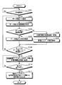
次に、図14と図15を用いて、上記集計処理と表示処理とについて説明する。図14は、集計処理の流れを説明するフローチャートである。
次に、図14と図15を用いて、上記集計処理と表示処理とについて説明する。図14は、集計処理の流れを説明するフローチャートである。
図14に示すように、変換格納部21は、処理の開始指示を受け付けると(S101:Yes)、測定結果DB14からデータ種を1つ選択し(S102)、選択したデータ種の位置情報の形式を特定する(S103)。
続いて、変換格納部21は、選択したデータ種の位置情報が緯度経度である場合(S104:Yes)、選択したデータ種を変換結果DB15にそのまま格納する(S105)。一方、変換格納部21は、選択したデータ種の位置情報が緯度経度ではない場合(S104:No)、位置情報を緯度経度に変換し(S106)、変換後のデータ種を変換結果DB15に格納する(S107)。
そして、すべてのデータ種についてS102からS107の処理が終了した場合(S108:Yes)、S109以降が実行される。一方で、未処理のデータ種が存在する場合(S108:No)、未処理のデータ種についてS102以降が繰り返される。
その後、抽出部22は、定義情報DB13に記憶される定義情報にしたがって各データ種の位置情報を区間に変更する(S109)。続いて、抽出部22は、評価条件や生成条件を受け付けると(S110:Yes)、受け付けた条件にしたがって、区間変更後のデータ種から区間集計、期間集計、経時変化などを生成する(S111)。
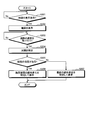
図15は、表示処理の流れを示すフローチャートである。図15に示すように、地図の表示指示を受け付けると(S201:Yes)、表示制御部26は、地図を表示し(S202)、地図上で道路の選択を受け付けたか否かを判定する(S203)。
そして、表示制御部26は、道路の選択を受け付けた場合(S203:Yes)、受け付けた道路上の区間を特定し(S204)、期間が事前もしくはいずれかのタイミングで指定されているかを判定する(S205)。
期間が指定されている場合(S205:Yes)、表示制御部26は、指定期間の経時変化を特定して表示する(S206)。一方で、期間が指定されていない場合(S205:No)、表示制御部26は、最新の経時変化を特定して表示し(S207)、処理を終了する。
[効果]
上述したように、道路管理サーバ10は、異なる範囲を単位とする測定データであっても、統一した単位でデータ管理を行うことができる。異なる距離・時間の単位で入力された複数種類のデータであっても、統一された単位に変換して格納することにより、顧客が入力する範囲に対応する範囲の分析結果を出力することができる。例えば、異なる単位で管理されるデータを用いたルート検索を行うことができ、最適なルート検索を実現できるとともに、ユーザの満足度の向上を図れる。したがって、道路管理サーバ10を含む道路管理プラットフォームの導入の促進が図れる。
上述したように、道路管理サーバ10は、異なる範囲を単位とする測定データであっても、統一した単位でデータ管理を行うことができる。異なる距離・時間の単位で入力された複数種類のデータであっても、統一された単位に変換して格納することにより、顧客が入力する範囲に対応する範囲の分析結果を出力することができる。例えば、異なる単位で管理されるデータを用いたルート検索を行うことができ、最適なルート検索を実現できるとともに、ユーザの満足度の向上を図れる。したがって、道路管理サーバ10を含む道路管理プラットフォームの導入の促進が図れる。
例えば、実施例1では、データ種Aとデータ種Bのそれぞれを緯度経度に変換した後に区間IDに対応付ける例を説明したが、これに限定されるものではなく、緯度経度に変換することなく、区間IDに対応付けることもできる。
より詳細には、図4に示した測定結果DB14に記憶される各データ種を、図3に示した定義情報DB13に記憶される定義情報にしたがって、区間と対応付けられるデータ種に変更することができる。例えば、データ種Aについては、実施例1と同様の手法によって対応付けることができる。図16は、リンクを区間に対応付ける例を説明する図である。図16に示すように、区間1が緯度A経度Aから緯度B経度Bの範囲を示し、区間2が緯度C経度C-緯度D経度Dを示し、区間1に該当する範囲が、リンクID=1とリンクID=2とに跨っている場合、跨っている比率に応じて測定結果を分割して区間に対応付ける。
具体的には、リンクID=1のリンクの2/3とリンクID=2のリンクの2/3とが区間1に対応する場合、リンクID=1の測定結果の2/3とリンクID=2の測定結果の2/3とを加算した値を区間1の測定結果とする。また、区間2内にリンクID=3のリンクとリンクID=4のリンクとが含まれる場合は、各リンクの測定結果を結合する。なお、測定結果に限らず、位置情報についても、区間にあわせて分割や結合を行うこともできる。
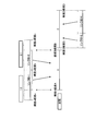
分割および結合について別例を説明する。図17は、変換前のデータを区間に対応付ける例を説明する図である。図17に示すように、データ種Aは100mの単位の位置情報で測定結果を保持し、データ種Bは25m単位のリンクで測定結果を保持し、区間は50m単位の位置情報で管理するとする。
この場合、道路管理サーバ10は、データ種Aについては、区間にあわせて位置情報を50m単位に分割するとともに、この分割にあわせて測定結果も分割する。例えば、道路管理サーバ10は、「1mから100m」を「1mから50m」と「51mから100m」に分割し、「1mから100m」の測定結果「A」を「A/2」ずつに分割する。同様に、道路管理サーバ10は、「101mから200m」を「101mから150m」と「151mから200m」に分割し、「101mから200m」の測定結果「B」を「B/2」ずつに分割する。そして、道路管理サーバ10は、区間1に「位置情報=1~50、測定結果=A/2」を対応付け、区間2に「位置情報=51~100、測定結果=A/2」を対応付け、区間3に「位置情報=101~150、測定結果=B/2」を対応付け、区間4に「位置情報=151~200、測定結果=B/2」を対応付ける。
また、道路管理サーバ10は、データ種Bについては、区間にあわせて位置情報を50m単位になるように結合するとともに、この結合にあわせて測定結果も結合する。例えば、道路管理サーバ10は、「1mから25m」と「26mから50m」とを結合するとともに、「1mから25m」の測定結果「C1」と「26mから50m」の測定結果「C2」とを結合する。同様に、道路管理サーバ10は、「51mから75m」と「76mから100m」とを結合するとともに、「51mから75m」の測定結果「C3」と「76mから100m」の測定結果「C4」とを結合する。
さらに、道路管理サーバ10は、「101mから125m」と「126mから150m」とを結合するとともに、「101mから125m」の測定結果「C5」と「126mから150m」の測定結果「C6」とを結合する。同様に、道路管理サーバ10は、「151mから175m」と「176mから200m」とを結合するとともに、「151mから175m」の測定結果「C7」と「176mから200m」の測定結果「C8」とを結合する。
そして、道路管理サーバ10は、区間1に「位置情報=1~50、測定結果=C1+C2」を対応付け、区間2に「位置情報=51~100、測定結果=C3+C4」を対応付け、区間3に「位置情報=101~150、測定結果=C5+C6」を対応付け、区間4に「位置情報=151~200、測定結果=C7+C8」を対応付ける。
このようにすることで、道路管理サーバ10は、緯度経度の変換を行うことなく、異なる管理体系のDBを同じ基準で統合することができる。なお、上記分割例は一例であり、比率等は、分割や結合時の比率に応じて変更される。例えば、データ種Aの位置情報を2/3と1/3に分割する場合は、その比率で測定結果も分割する。また、1~50mの2/3と51~100mの1/3とが1つの区間として結合される場合は、2A/3とB/3との加算値が測定結果となる。このような比率は結合についても同様である。
さて、これまで本発明の実施例について説明したが、本発明は上述した実施例以外にも、種々の異なる形態にて実施されてよいものである。
[情報の選択]
上記実施例では、位置情報と時刻の両方を有するデータ種を用いて説明したが、いずれか一方だけを有するデータ種であっても同様に処理することができる。例えば、定義情報において区間ではなく時刻によって範囲が指定されている場合、各データ種を時刻を用いて分割や結合を行う。
上記実施例では、位置情報と時刻の両方を有するデータ種を用いて説明したが、いずれか一方だけを有するデータ種であっても同様に処理することができる。例えば、定義情報において区間ではなく時刻によって範囲が指定されている場合、各データ種を時刻を用いて分割や結合を行う。
[指定条件]
表示対象を抽出する条件は、任意に設定変更することができる。例えば、抽出対象のデータ種、期間、期間の単位(例えば日単位)、位置、評価、路線、区間を任意に組み合わせることができる。
表示対象を抽出する条件は、任意に設定変更することができる。例えば、抽出対象のデータ種、期間、期間の単位(例えば日単位)、位置、評価、路線、区間を任意に組み合わせることができる。
[位置情報]
上記実施例では、位置情報として緯度経度を例示したが、これに限定されず、例えばメッシュのような狭い範囲であっても同様に処理することができる。また、生成部25が受け付ける条件もメッシュのような範囲で受け付けることもできる。この場合であっても、上記処理と同様の処理を行うことができる。また、位置情報は、緯度経度に限らず、高度なども同様に処理することができる。
上記実施例では、位置情報として緯度経度を例示したが、これに限定されず、例えばメッシュのような狭い範囲であっても同様に処理することができる。また、生成部25が受け付ける条件もメッシュのような範囲で受け付けることもできる。この場合であっても、上記処理と同様の処理を行うことができる。また、位置情報は、緯度経度に限らず、高度なども同様に処理することができる。
[線とエリアの対応付け]
上記実施例では、距離やリンクなどの線の情報を区間などの線の情報に対応付ける例を説明したが、これに限定されるものではなく、複数の緯度経度で特定されるエリアを区間に対応付けることができる。例えば、エリア内に存在する道路に、当該エリアで測定された測定結果を対応付けることで、エリアの測定結果を道路の測定結果に変換し、その後は上記処理と同様の処理を実行することができる。
上記実施例では、距離やリンクなどの線の情報を区間などの線の情報に対応付ける例を説明したが、これに限定されるものではなく、複数の緯度経度で特定されるエリアを区間に対応付けることができる。例えば、エリア内に存在する道路に、当該エリアで測定された測定結果を対応付けることで、エリアの測定結果を道路の測定結果に変換し、その後は上記処理と同様の処理を実行することができる。
[分散および統合]
また、図示した各装置の各構成要素は、必ずしも物理的に図示の如く構成されておらずともよい。すなわち、各装置の分散・統合の具体的形態は図示のものに限られず、その全部または一部を、各種の負荷や使用状況などに応じて、任意の単位で機能的または物理的に分散・統合して構成することができる。例えば、変換格納部21、抽出部22、表示制御部26を道路管理サーバ10の外部装置としてネットワーク経由で接続するようにしてもよい。また、変換格納部21、抽出部22、表示制御部26を別の装置がそれぞれ有し、ネットワーク接続されて協働することで、上記の道路管理サーバ10の機能を実現するようにしてもよい。
また、図示した各装置の各構成要素は、必ずしも物理的に図示の如く構成されておらずともよい。すなわち、各装置の分散・統合の具体的形態は図示のものに限られず、その全部または一部を、各種の負荷や使用状況などに応じて、任意の単位で機能的または物理的に分散・統合して構成することができる。例えば、変換格納部21、抽出部22、表示制御部26を道路管理サーバ10の外部装置としてネットワーク経由で接続するようにしてもよい。また、変換格納部21、抽出部22、表示制御部26を別の装置がそれぞれ有し、ネットワーク接続されて協働することで、上記の道路管理サーバ10の機能を実現するようにしてもよい。
また、本実施例において説明した各処理のうち、自動的におこなわれるものとして説明した処理の全部または一部を手動的におこなうこともできる。あるいは、手動的におこなわれるものとして説明した処理の全部または一部を公知の方法で自動的におこなうこともできる。この他、上記文書中や図面中で示した処理手順、制御手順、具体的名称、各種のデータやパラメータを含む情報については、特記する場合を除いて任意に変更することができる。
[ハードウェア]
上記道路管理サーバ10は、例えば、次のようなハードウェア構成を有するコンピュータにより実現することができる。図18は、ハードウェア構成例を説明する図である。図18に示すように、道路管理サーバ10は、通信インタフェース10a、表示装置10b、HDD(Hard Disk Drive)10c、メモリ10d、プロセッサ10eを有する。
上記道路管理サーバ10は、例えば、次のようなハードウェア構成を有するコンピュータにより実現することができる。図18は、ハードウェア構成例を説明する図である。図18に示すように、道路管理サーバ10は、通信インタフェース10a、表示装置10b、HDD(Hard Disk Drive)10c、メモリ10d、プロセッサ10eを有する。
通信インタフェース10aの一例としては、ネットワークインタフェースカードなどである。表示装置10bの一例としては、ディスプレイやタッチパネルなどである。HDD10cは、プログラムやデータなどを記憶する記憶装置である。
メモリ10dの一例としては、SDRAM(Synchronous Dynamic Random Access Memory)等のRAM(Random Access Memory)、ROM(Read Only Memory)、フラッシュメモリ等が挙げられる。プロセッサ10eの一例としては、CPU、DSP(Digital Signal Processor)、FPGA(Field Programmable Gate Array)、PLD(Programmable Logic Device)等が挙げられる。
また、道路管理サーバ10は、プログラムを読み出して実行することでデータ生成方法を実行する情報処理装置として動作する。つまり、道路管理サーバ10は、変換格納部21、抽出部22、表示制御部26と同様の機能を実行するプログラムを実行する。この結果、道路管理サーバ10は、変換格納部21、抽出部22、表示制御部26と同様の機能を実行するプロセスを実行することができる。なお、この他の実施例でいうプログラムは、道路管理サーバ10によって実行されることに限定されるものではない。例えば、他のコンピュータまたはサーバがプログラムを実行する場合や、これらが協働してプログラムを実行するような場合にも、本発明を同様に適用することができる。
このプログラムは、インターネットなどのネットワークを介して配布することができる。また、このプログラムは、ハードディスク、フレキシブルディスク(FD)、CD-ROM、MO(Magneto-Optical disk)、DVD(Digital Versatile Disc)などのコンピュータで読み取り可能な記録媒体に記録され、コンピュータによって記録媒体から読み出されることによって実行することができる。
10 道路管理サーバ
11 通信部
12 記憶部
13 定義情報DB
14 測定結果DB
15 変換結果DB
16 区間集計結果DB
17 期間集計結果DB
18 経時変化DB
20 制御部
21 変換格納部
22 抽出部
23 区間評価部
24 期間集計部
25 生成部
26 表示制御部
11 通信部
12 記憶部
13 定義情報DB
14 測定結果DB
15 変換結果DB
16 区間集計結果DB
17 期間集計結果DB
18 経時変化DB
20 制御部
21 変換格納部
22 抽出部
23 区間評価部
24 期間集計部
25 生成部
26 表示制御部
Claims (8)
- 道路の位置と該位置を基準とする第1の範囲と該第1の範囲についての測定結果の値とが対応付けられた第1のデータを受け付け、
道路の位置と該位置を基準とする第2の範囲に合致するように前記第1の範囲を分割及び/又は結合する処理を実行するとともに、該分割及び/又は結合する前記第1の範囲のそれぞれの割合に応じて前記第1の範囲毎に対応付けられた道路の測定結果の値を分割及び/又は結合する処理を実行し、
前記第2の範囲のそれぞれに、前記道路の測定結果の値を分割及び/又は結合した結果を対応付ける処理を実行し、
実行した結果を記憶部に格納する
処理をコンピュータに実行させるデータ生成プログラム。 - 前記記憶部に記憶される、前記道路の位置と前記第2の範囲と前記第1の範囲の測定結果を分割及び/または結合して得られた処理結果とから、指定された指定範囲に対応付けられる処理結果を抽出し、
抽出した前記処理結果を用いて、前記指定範囲の道路を評価する評価値を算出する処理を前記コンピュータに実行させることを特徴とする請求項1に記載のデータ生成プログラム。 - 前記第1のデータの前記第1の範囲を前記基準に対応する緯度経度に変換し、緯度経度を用いて範囲が指定される前記第2の範囲内に該当する、前記第1のデータの前記測定結果の値から前記第2の範囲に対応付ける測定結果の値を生成する処理を前記コンピュータに実行させることを特徴とする請求項1に記載のデータ生成プログラム。
- 前記第1のデータの前記第1の範囲を指定する始点の緯度経度と終点の緯度経度とが所定距離以上離れている場合、前記始点から前記終点までを所定の距離で分割した複数の分割距離と、前記複数の分割距離の分割数に応じて前記測定結果の値を分割した複数の分割値とを生成し、
前記複数の分割距離から前記第2の範囲に合致する分割距離を選択するとともに、合致する前記分割距離に対応付けられる分割値を前記複数の分割値から選択して、前記第2の範囲のそれぞれへの対応付けを実行する処理を前記コンピュータに実行させることを特徴とする請求項1に記載のデータ生成プログラム。 - 道路の位置と、該位置を基準とする、前記第1の範囲および前記第2の範囲とは異なる第3の範囲と、該第3の範囲についての測定結果の値とが対応付けられた第2のデータを受け付け、
前記第2の範囲に合致するように前記第3の範囲を分割及び/又は結合する処理を実行するとともに、該分割及び/又は結合する前記第3の範囲のそれぞれの割合に応じて前記第3の範囲毎に対応付けられた道路の測定結果の値を分割及び/又は結合する処理を実行し、
前記第2の範囲のそれぞれに、前記道路の測定結果の値を分割及び/又は結合した結果を対応付ける処理を実行し、
前記第2の範囲のそれぞれに対応付けられる、前記第1の範囲から得られた測定結果の値および前記第3の範囲から得られた測定結果の値を所定の表示部に表示する処理をコンピュータに実行させる請求項1に記載のデータ生成プログラム。 - 道路の位置と該位置で測定された測定結果の値と該測定が行われた時刻を基準とする第1の範囲とが対応付けられた第1のデータを受け付け、
道路の位置と所定時刻を基準とする第2の範囲に合致するように前記第1の範囲を分割及び/又は結合する処理を実行するとともに、該分割及び/又は結合する前記第1の範囲のそれぞれの割合に応じて前記第1の範囲毎に対応付けられた道路の測定結果の値を分割及び/又は結合する処理を実行し、
前記第2の範囲のそれぞれに、前記道路の測定結果の値を分割及び/又は結合した結果を対応付ける処理を実行し、
実行した結果を記憶部に格納する
処理をコンピュータに実行させるデータ生成プログラム。 - 道路の位置と該位置を基準とする第1の範囲と該第1の範囲についての測定結果の値とが対応付けられた第1のデータを受け付け、
道路の位置と該位置を基準とする第2の範囲に合致するように前記第1の範囲を分割及び/又は結合する処理を実行するとともに、該分割及び/又は結合する前記第1の範囲のそれぞれの割合に応じて前記第1の範囲毎に対応付けられた道路の測定結果の値を分割及び/又は結合する処理を実行し、
前記第2の範囲のそれぞれに、前記道路の測定結果の値を分割及び/又は結合した結果を対応付ける処理を実行し、
実行した結果を記憶部に格納する
処理をコンピュータが実行するデータ生成方法。 - 道路の位置と該位置を基準とする第1の範囲と該第1の範囲についての測定結果の値とが対応付けられた第1のデータを受け付ける受付部と、
道路の位置と該位置を基準とする第2の範囲に合致するように前記第1の範囲を分割及び/又は結合する処理を実行するとともに、該分割及び/又は結合する前記第1の範囲のそれぞれの割合に応じて前記第1の範囲毎に対応付けられた道路の測定結果の値を分割及び/又は結合する処理を実行するデータ処理部と、
前記第2の範囲のそれぞれに、前記道路の測定結果の値を分割及び/又は結合した結果を対応付ける処理を実行する対応付け部と、
実行した結果を記憶部に格納する格納部と
有することを特徴とする道路管理装置。
Priority Applications (2)
| Application Number | Priority Date | Filing Date | Title |
|---|---|---|---|
| PCT/JP2016/066071 WO2017208369A1 (ja) | 2016-05-31 | 2016-05-31 | データ生成プログラム、データ生成方法および道路管理装置 |
| JP2018520261A JP6769483B2 (ja) | 2016-05-31 | 2016-05-31 | データ生成プログラム、データ生成方法および道路管理装置 |
Applications Claiming Priority (1)
| Application Number | Priority Date | Filing Date | Title |
|---|---|---|---|
| PCT/JP2016/066071 WO2017208369A1 (ja) | 2016-05-31 | 2016-05-31 | データ生成プログラム、データ生成方法および道路管理装置 |
Publications (1)
| Publication Number | Publication Date |
|---|---|
| WO2017208369A1 true WO2017208369A1 (ja) | 2017-12-07 |
Family
ID=60478247
Family Applications (1)
| Application Number | Title | Priority Date | Filing Date |
|---|---|---|---|
| PCT/JP2016/066071 Ceased WO2017208369A1 (ja) | 2016-05-31 | 2016-05-31 | データ生成プログラム、データ生成方法および道路管理装置 |
Country Status (2)
| Country | Link |
|---|---|
| JP (1) | JP6769483B2 (ja) |
| WO (1) | WO2017208369A1 (ja) |
Citations (2)
| Publication number | Priority date | Publication date | Assignee | Title |
|---|---|---|---|---|
| JP2004164373A (ja) * | 2002-11-14 | 2004-06-10 | Nippon Telegr & Teleph Corp <Ntt> | 交通渋滞情報変換方法、交通渋滞情報変換装置、交通渋滞情報変換プログラムおよびそのプログラムを記録した記録媒体 |
| JP2010140135A (ja) * | 2008-12-10 | 2010-06-24 | Panasonic Corp | 交通情報提供システム、交通情報生成サーバ装置、車載用ナビゲーション装置 |
Family Cites Families (1)
| Publication number | Priority date | Publication date | Assignee | Title |
|---|---|---|---|---|
| JP3873148B2 (ja) * | 2002-09-19 | 2007-01-24 | 株式会社福山コンサルタント | 計測地点データの作成方法、データ処理方法、データ処理装置及びデータ処理システム、並びにプログラム及び情報記憶媒体 |
-
2016
- 2016-05-31 JP JP2018520261A patent/JP6769483B2/ja not_active Expired - Fee Related
- 2016-05-31 WO PCT/JP2016/066071 patent/WO2017208369A1/ja not_active Ceased
Patent Citations (2)
| Publication number | Priority date | Publication date | Assignee | Title |
|---|---|---|---|---|
| JP2004164373A (ja) * | 2002-11-14 | 2004-06-10 | Nippon Telegr & Teleph Corp <Ntt> | 交通渋滞情報変換方法、交通渋滞情報変換装置、交通渋滞情報変換プログラムおよびそのプログラムを記録した記録媒体 |
| JP2010140135A (ja) * | 2008-12-10 | 2010-06-24 | Panasonic Corp | 交通情報提供システム、交通情報生成サーバ装置、車載用ナビゲーション装置 |
Also Published As
| Publication number | Publication date |
|---|---|
| JPWO2017208369A1 (ja) | 2019-02-07 |
| JP6769483B2 (ja) | 2020-10-14 |
Similar Documents
| Publication | Publication Date | Title |
|---|---|---|
| JP5627702B2 (ja) | 位置情報集計装置及び位置情報集計方法 | |
| US20160042388A1 (en) | Tracking and analyzing mobile device activity related to mobile display campaigns | |
| CN106170962B (zh) | 用于探测数据管理的设备及方法 | |
| TW201514718A (zh) | 執行具有定義草圖精確度分佈之集合運算的系統與方法 | |
| CN104572957B (zh) | 一种基于聚类的poi名称确定系统及方法 | |
| JPWO2019069505A1 (ja) | 情報処理装置、結合条件生成方法および結合条件生成プログラム | |
| EP3583519A1 (en) | Segmentation platform | |
| WO2017133539A1 (zh) | 业务数据的处理方法、装置及系统 | |
| EP3776432A1 (en) | Processor systems to estimate audience sizes and impression counts for different frequency intervals | |
| CN114416817B (zh) | 用于处理数据的方法、装置、设备、系统及存储介质 | |
| CN106528559B (zh) | 一种位置信息的提供方法和设备 | |
| JP6658879B2 (ja) | 道路画像表示プログラム、道路画像表示方法および道路管理装置 | |
| CN111209487B (zh) | 用户数据分析方法、服务器及计算机可读存储介质 | |
| JP6715705B2 (ja) | 不良原因探索システム、及び不良要因探索方法 | |
| WO2019207771A1 (ja) | Ipアドレスに基づくユーザ属性推定システム | |
| CN106294515B (zh) | 推广信息处理方法和装置 | |
| JP6769483B2 (ja) | データ生成プログラム、データ生成方法および道路管理装置 | |
| JP5806364B1 (ja) | バースト領域抽出装置、バースト領域抽出方法及びバースト領域抽出プログラム | |
| JP7014946B2 (ja) | データ生成プログラム、データ生成方法、及びデータ生成装置 | |
| CN113568967B (zh) | 时序指标数据动态提取方法、电子设备及存储介质 | |
| JP2015022614A (ja) | 位置推定方法、位置推定プログラム、及び、位置推定装置 | |
| WO2024034124A1 (ja) | 端末装置、計算システム、計算方法、およびコンピュータ可読媒体 | |
| CN115221184A (zh) | 基础地理数据发送方法、装置、设备和计算机可读介质 | |
| CN105488698B (zh) | 一种空间区域客户密度的分析方法及设备 | |
| JP7046423B1 (ja) | 情報処理装置、情報処理方法、及びプログラム |
Legal Events
| Date | Code | Title | Description |
|---|---|---|---|
| WWE | Wipo information: entry into national phase |
Ref document number: 2018520261 Country of ref document: JP |
|
| 121 | Ep: the epo has been informed by wipo that ep was designated in this application |
Ref document number: 16903995 Country of ref document: EP Kind code of ref document: A1 |
|
| NENP | Non-entry into the national phase |
Ref country code: DE |
|
| 122 | Ep: pct application non-entry in european phase |
Ref document number: 16903995 Country of ref document: EP Kind code of ref document: A1 |