WO2017208356A1 - IoT制御システム、IoT制御方法及びプログラム - Google Patents
IoT制御システム、IoT制御方法及びプログラム Download PDFInfo
- Publication number
- WO2017208356A1 WO2017208356A1 PCT/JP2016/066042 JP2016066042W WO2017208356A1 WO 2017208356 A1 WO2017208356 A1 WO 2017208356A1 JP 2016066042 W JP2016066042 W JP 2016066042W WO 2017208356 A1 WO2017208356 A1 WO 2017208356A1
- Authority
- WO
- WIPO (PCT)
- Prior art keywords
- control system
- data
- iot control
- sensor
- display unit
- Prior art date
- Legal status (The legal status is an assumption and is not a legal conclusion. Google has not performed a legal analysis and makes no representation as to the accuracy of the status listed.)
- Ceased
Links
Images




Classifications
-
- H—ELECTRICITY
- H04—ELECTRIC COMMUNICATION TECHNIQUE
- H04Q—SELECTING
- H04Q9/00—Arrangements in telecontrol or telemetry systems for selectively calling a substation from a main station, in which substation desired apparatus is selected for applying a control signal thereto or for obtaining measured values therefrom
Definitions
- the present invention relates to an IoT control system, an IoT control method, and a program connected to a sensor device, a computer, and a smart device via a network.
- IoT Internet of Things
- smart devices such as information terminals via a network such as the Internet.
- the data acquired by the IoT device is transmitted to the smart device.
- the smart device receives this data and displays it.
- cloud computing exists as a computer connected to a smart device via a network.
- the smart device transmits various data to the cloud computing, and the cloud computing performs calculation or analysis of this data.
- Cloud computing transmits an execution result to a smart device, and the smart device displays the execution result.
- Patent Document 1 or 2 is a configuration that is executed by the IoT device and the communication terminal, or a configuration that is executed by the cloud computing and the communication terminal, and the IoT device, the communication terminal, and the computer are independent. Each process was executed. That is, data acquisition by the IoT device, calculation by cloud computing, and display by the communication terminal are performed independently, and it is necessary for the user to instruct execution, so that the convenience is low.
- An object of the present invention is to provide an IoT control system, an IoT control method, and a program with improved convenience.
- the present invention provides the following solutions.
- An invention is an IoT control system connected to a sensor device, a computer, and a smart device via a network, Obtaining means for obtaining sensor data from the sensor device; Calculation command means for causing the computer to calculate the acquired sensor data; Calculation result display command means for displaying the calculated result on the display unit of the smart device; An IoT control system is provided.
- the IoT control system connected to the sensor device, the computer, and the smart device via the network acquires sensor data from the sensor device, and the acquired sensor data is The calculation is performed by the computer, and the calculated result is displayed on the display unit of the smart device.
- the invention according to the first feature is a category of the IoT control system, but also in other categories such as a method and a program, the same actions and effects corresponding to the category are exhibited.
- the invention according to the second feature is the notification display command means for displaying a notification on the display unit when the calculated result satisfies a predetermined condition;
- the IoT control system which is invention which concerns on the 1st characteristic characterized by providing is provided.
- the IoT control system displays a notification on the display unit when the calculated result satisfies a predetermined condition.
- the invention according to a third aspect is a setting reception unit that receives an input of a setting for the condition;
- the IoT control system which is invention which concerns on the 2nd characteristic characterized by providing is provided.
- the IoT control system that is the invention pertaining to the second feature accepts input of settings for the condition.
- the calculation result display command means causes the display unit to display the calculated result as a graph display.
- the IoT control system displays the calculated result on the display unit as a graph display.
- the invention according to a fifth aspect is a request receiving means for receiving a request regarding information to be displayed on the display unit; With The calculation result display command means causes the display unit to display only information related to the accepted request from the calculated results.
- the IoT control system which is invention which concerns on the 1st characteristic characterized by the above is provided.
- the IoT control system receives a request regarding information to be displayed on the display unit, and receives the received request from the calculated results. Only the information related to is displayed on the display unit.
- the calculation result display command means displays the calculated result in association with the position information of the sensor device on the map data displayed on the display unit.
- the IoT control system provides the position information of the sensor device on the map data displayed on the display unit with the calculated result. Display in association with.
- the calculation result display command means applies the calculation result to an object reflected in the camera image on the camera image of the sensor device displayed on the display unit. Display in association, The IoT control system which is invention which concerns on the 1st characteristic characterized by the above is provided.
- the IoT control system provides the calculated result on the camera image of the sensor device displayed on the display unit. Display in association with the object shown in the image.
- the invention according to an eighth feature is a purchasing means for purchasing an application related to the sensor data;
- the IoT control system which is invention which concerns on the 1st characteristic characterized by providing is provided.
- the IoT control system purchases an application related to the sensor data.
- the invention according to the ninth aspect comprises a code input receiving means for receiving an input of a program code; Program association means for associating the received program code with a predetermined program;
- the IoT control system which is invention which concerns on the 1st characteristic characterized by providing is provided.
- the IoT control system receives an input of a program code, and associates the received program code with a predetermined program.
- the calculation result display command means causes the display unit to display the calculated result as a list in association with the sensor device.
- the IoT control system which is invention which concerns on the 1st characteristic characterized by the above is provided.
- the IoT control system which is the first aspect of the invention causes the display unit to display the calculated result as a list in association with the sensor device.
- the calculation command means selects and calculates an optimal computer according to the type of the acquired sensor data.
- the IoT control system which is invention which concerns on the 1st characteristic characterized by the above is provided.
- the IoT control system selects and calculates an optimum computer according to the type of the acquired sensor data.
- the calculation result display command means includes voice data in the calculated result
- the voice data is displayed on the display unit as text.
- the IoT control system according to the first aspect of the invention provides the display unit with the voice data as text when the calculated result includes voice data. Display.
- the invention according to a thirteenth aspect includes login accepting means for logging in the user; With The calculation result display command means displays the calculated result on a display unit of a smart device associated with the login information.
- the IoT control system which is invention which concerns on the 1st characteristic characterized by the above is provided.
- the IoT control system causes a user to log in, and the calculated result is displayed on the smart device display unit associated with the login information. To display.
- the invention according to the fourteenth feature is the connection status display command means for displaying the network connection status of the sensor device as a network map on the display unit;
- the IoT control system which is invention which concerns on the 1st characteristic characterized by providing is provided.
- the IoT control system displays the network connection status of the sensor device on the display unit as a network map.
- the acquisition unit acquires sensor data having a data size smaller than an original data size from the sensor device.
- the IoT control system which is invention which concerns on the 1st characteristic characterized by the above is provided.
- the IoT control system acquires sensor data having a data size smaller than the original data size from the sensor device.
- the acquisition means extracts and acquires only desired sensor data from the sensor device.
- the IoT control system which is invention which concerns on the 1st characteristic characterized by the above is provided.
- the IoT control system extracts and acquires only desired sensor data from the sensor device.
- the invention according to a seventeenth aspect provides the IoT control system according to the first aspect, wherein the acquisition unit, the calculation command unit, and the calculation result display command unit are implemented in an operating system of a predetermined server To do.
- the IoT control system according to the first aspect of the invention is implemented in an operating system of a predetermined server.
- An invention according to an eighteenth aspect is an IoT control method connected to a sensor device, a computer, and a smart device via a network, Obtaining sensor data from the sensor device; Causing the computer to calculate the acquired sensor data; Displaying the calculated result on a display unit of the smart device; An IoT control method is provided.
- the invention according to the nineteenth aspect is directed to an IoT control system connected to a sensor device, a computer, and a smart device via a network. Obtaining sensor data from the sensor device; Causing the computer to calculate the acquired sensor data; Displaying the calculated result on a display unit of the smart device; A program characterized in that is executed is provided.
- FIG. 1 is a diagram showing an outline of the IoT control system 1.
- FIG. 2 is an overall configuration diagram of the IoT control system 1.
- FIG. 3 is a functional block diagram of the server 10, the sensor device 100, the computer 200, and the smart device 300.
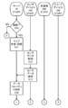
- FIG. 4 is a flowchart showing an IoT control process executed by the server 10, the sensor device 100, the computer 200, and the smart device 300.
- FIG. 5 is a flowchart showing an IoT control process executed by the server 10, the sensor device 100, the computer 200, and the smart device 300.
- FIG. 6 is a flowchart showing an IoT control process executed by the server 10, the sensor device 100, the computer 200, and the smart device 300.
- FIG. 7 is a flowchart illustrating notification display processing executed by the server 10 and the smart device 300.
- FIG. 8 is a flowchart showing purchase notification display processing executed by the server 10 and the smart device 300.
- FIG. 9 is a flowchart showing code input processing executed by the server 10 and the smart device 300.
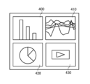
- FIG. 10 is a diagram illustrating an example of a widget displayed by the smart device 300.
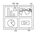
- FIG. 11 is a diagram illustrating an example of notification.
- FIG. 1 is a diagram for explaining an overview of an IoT control system 1 which is a preferred embodiment of the present invention.
- the IoT control system 1 includes a server 10, a sensor device 100, a computer 200, and a smart device 300.
- the number of sensor devices 100, computers 200, and smart devices 300 is not limited to one, and may be plural. Each process described below may be realized by any one or a combination of the server 10, the sensor device 100, the computer 200, and the smart device 300.
- the server 10 is a server device capable of data communication with the sensor device 100, the computer 200, and the smart device 300.
- the sensor device 100 is a device such as a network camera or a drone that can perform data communication with the server 10, and various image sensors, human sensors, pressure sensors, temperature sensors, odor sensors, taste sensors, acceleration sensors, gyroscopes, and the like. It is an IoT device such as a sensor.
- the sensor device 100 acquires a camera image captured by a network camera, a camera image captured by a drone, a flight history of the drone, and data detected by various sensors.
- the computer 200 is cloud computing capable of data communication with the server 10.
- the computer 200 performs calculations such as analysis, statisticalization, graphing, and calculation of various data.
- the smart device 300 is a terminal device capable of data communication with the server 10.
- the smart device 300 is a mobile phone, a portable information terminal, a tablet terminal, a terminal device such as a netbook terminal, a slate terminal, an electronic book terminal, a portable music player, a wearable terminal such as a smart glass or a head-mounted display, Other articles.
- the server 10 acquires sensor data from the sensor device 100 (step S01).
- the sensor data is image data, action history data, data detected by a sensor, and the like.
- the structure which acquires the positional information on the sensor device 100 at this time may be sufficient.
- the sensor data acquired by the server 10 may have a changed data size. For example, it may be configured to acquire sensor data that is smaller than the original data size. In this case, sensor data that has undergone a change in resolution of image data, a change in bit rate or sampling frequency of audio data, and the like may be acquired from the sensor device 100.
- the sensor data acquired by the server 10 may be configured to extract and acquire only desired sensor data. For example, only data of a specific object included in the image data may be extracted and acquired.
- the server 10 transmits the acquired sensor data to the computer 200 and causes the computer 200 to calculate (step S02).
- the calculations executed by the computer 200 include analysis, analysis, statistics, graphing, data format discrimination, and the like of various data.
- the server 10 may be configured to perform statistical processing, visualization, and monitoring, such as person detection, pest detection, person count, gender analysis, biometric authentication, and the like as calculations.
- the server 10 may be configured to select an optimal computer 200 existing on the network according to the type of sensor data and cause the selected computer 200 to calculate. What is necessary is just to perform discrimination
- the server 10 acquires the calculation result executed by the computer 200, transmits the calculation result to the smart device 300, and displays it on the display unit of the smart device 300 (step S03).
- the calculation result may be displayed when a condition set by the user or a condition set in advance is satisfied.
- the structure of receiving the request of the calculation result displayed on a display part from a user, and displaying only the information relevant to this received request may be sufficient.
- Examples of the display on the display unit include, for example, a configuration in which the calculation result is displayed in a graph, a configuration in which map data is displayed and the positional information of the sensor device 100 and the calculation result are displayed in association with the map data, and the sensor device.
- the IoT control system 1 may be configured to execute an application purchase process related to sensor data. For example, the user may purchase an application related to the image data and install the application on the smart device 300.
- the IoT control system 1 may be configured to accept an input of a program code and associate the received program code with a predetermined program.
- the IoT control system 1 may be configured to display the network connection status of the sensor device 100 on the display unit of the smart device 300 as a network map.
- FIG. 2 is a diagram showing a system configuration of the IoT control system 1 which is a preferred embodiment of the present invention.
- the IoT control system 1 includes a server 10, a sensor device 100, a computer 200, a smart device 300, and a public line network (Internet network, third and fourth generation communication network, etc.) 5.
- the sensor device 100, the computer 200, and the smart device 300 are not limited to one, and may be a plurality. Each process described below may be realized by any one or a combination of the server 10, the sensor device 100, the computer 200, and the smart device 300. Each device may be realized by a real device or a virtual device.
- the server 10 is the server device described above having the functions described below.
- the sensor device 100 is the above-described IoT device having the functions described later.
- the computer 200 is the above-described cloud computing having the functions described later.
- the smart device 300 is the above-described terminal device having the functions described below.
- FIG. 3 is a functional block diagram of the server 10, the sensor device 100, the computer 200, and the smart device 300.
- the server 10 includes a CPU (Central Processing Unit), a RAM (Random Access Memory), a ROM (Read Only Memory), etc. as the control unit 11, and a device for enabling communication with other devices as the communication unit 12.
- a WiFi (Wireless Fidelity) compatible device compliant with IEEE 802.11 is provided.
- the server 10 also includes a data storage unit such as a hard disk, a semiconductor memory, a recording medium, or a memory card as the storage unit 13.
- the control unit 11 when the control unit 11 reads a predetermined program, the connection detection module 20, the data transmission / reception module 21, the data determination module 22, and the authentication module 23 are realized in cooperation with the communication unit 12. In the server 10, the control unit 11 reads a predetermined program, thereby realizing the network map creation module 30 and the program module 31 in cooperation with the storage unit 13.
- the sensor device 100 includes a CPU, a RAM, a ROM, and the like as the control unit 110, and a device for enabling communication with other devices as the control unit 110, similarly to the server 10.
- the sensor device 100 receives, as the acquisition unit 150, a device that acquires various sensor data, for example, an imaging device that captures an image such as a moving image or a still image, a sound collection device that collects sound, and text input. It includes a text input device, a history acquisition device that acquires action history data of a device such as a drone, a data acquisition device that acquires data corresponding to various sensors, and the like.
- the data transmission / reception module 160 is realized in cooperation with the communication unit 120. Further, in the sensor device 100, the data acquisition module 190 is realized in cooperation with the acquisition unit 150 by the control unit 110 reading a predetermined program.
- the computer 200 includes a CPU, RAM, ROM, and the like as the control unit 210, and a device for enabling communication with other devices as the communication unit 220.
- the computer 200 uses the calculation unit 250 based on a device that calculates sensor data, for example, an analysis device that analyzes sensor data, an analysis device that analyzes sensor data, a statistical device that statisticalizes sensor data, and sensor data.
- a graphing device that creates a graph, a detection device that detects an object included in the sensor data, a biometric authentication device that biometrically authenticates the sensor data, and the like.
- the control unit 210 when the control unit 210 reads a predetermined program, the data transmission / reception module 260 is realized in cooperation with the communication unit 220. In the computer 200, the control unit 210 reads a predetermined program, thereby realizing the calculation module 290 in cooperation with the calculation unit 250.
- the smart device 300 includes a CPU, a RAM, a ROM, and the like as the control unit 310, and a device for enabling communication with other devices as the communication unit 320.
- the smart device 300 includes, as the input / output unit 340, a display unit that outputs and displays data and images controlled by the control unit 110, an input unit such as a touch panel, a keyboard, and a mouse that receives input from the user.
- the control unit 310 when the control unit 310 reads a predetermined program, the data transmission / reception module 360 is realized in cooperation with the communication unit 320. In the smart device 300, the control unit 310 reads a predetermined program, thereby realizing the display module 370 and the input reception module 371 in cooperation with the input / output unit 340.
- the sensor device 100, the computer 200, and the smart device 300 are described as having one device, but it goes without saying that the processing can be executed even when there are a plurality of devices. Absent.
- FIGS. 4 to 6 are flowcharts of IoT control processing executed by the server 10, the sensor device 100, the computer 200, and the smart device 300. The processing executed by the modules of each device described above will be described together with this processing.
- the connection detection module 20 determines whether or not the sensor device 100 is connected (step S10).
- step S10 for example, the connection detection module 20 detects whether the sensor device 100 is connected to the network, or whether the sensor device 100 having a device-specific identifier such as model information or an IP address registered in advance is detected. Judging.
- the connection detection module 20 may be configured to determine whether or not the sensor device 100 is connected by another configuration.
- step S10 when the connection detection module 20 determines that the sensor device 100 is not connected (NO in step S10), the process ends.
- the network map creation module 30 creates a list of currently connected sensor devices 100 as a network map. And memorize (step S11).
- the network map creation module 30 stores an IP address and position information in association with the name of the sensor device 100.
- the IP address and position information of the sensor device 100 may be configured to be acquired when the server 10 detects connection.
- the server 10 may have a configuration for acquiring information or the like necessary for creating a network map by another configuration.
- the server 10 may transmit the created network map data to the smart device 300, and at this stage, the network connection status of the sensor device 100 may be displayed as a network map.
- the network map may be appropriately transmitted according to a request from the smart device 300 and displayed on the smart device 300.
- the data acquisition module 190 acquires sensor data (step S12).
- the data acquisition module 190 uses an image picked up by the image pickup device, voice collected by a microphone, text such as characters and symbols accepted by a touch panel, data related to its own activation and behavior, and various sensors.
- the detected data is acquired as sensor data.
- the data acquisition module 190 may be configured to acquire sensor data with the data size changed. For example, when the data acquisition module 190 acquires image data, the size, resolution, color tone, spatial frequency, etc. of the image data are changed, and image data with a data size smaller than the original data size is acquired. There may be. Further, the data acquisition module 190 may be configured to acquire data with a reduced data size, even for data other than image data. By doing so, even when the amount of sensor data acquired increases, it becomes easy to maintain a sufficient speed while retaining necessary information when transmitting and receiving data.
- the data acquisition module 190 may be configured to extract and acquire only desired sensor data from the sensor data. For example, when the data acquisition module 190 acquires image data, the image acquisition module 190 extracts only image data such as a person, an article, and a place included in the image data, and acquires the extracted image data. Also good. Similarly, the data acquisition module 190 may be configured to extract and acquire only the data that is the object even if it is data other than image data. By doing in this way, the same effect as the data size change described above can be obtained.
- the data transmission / reception module 160 transmits the sensor data to the server 10 (step S13).
- the data transmission / reception module 21 receives sensor data.
- the server 10 acquires sensor data from the sensor device 100 through the processing of step S12 and step S13 described above.
- the data discrimination module 22 discriminates the data format of the acquired sensor data (step S14).
- the data determination module 22 performs determination based on the format, content, extension, various formats, and the like of the acquired sensor data. Note that the data determination module 22 may be configured to determine the data format based on other configurations.
- the data discrimination module 22 selects the computer 200 that is optimal for the discriminated data format (step S15).
- step S15 the data discrimination module 22 selects the optimal computer 200 based on a database or the like that stores the data format and the computer 200 optimal for this data format in association with each other.
- the data discrimination module 22 may be configured to select the optimal computer 200 according to other configurations.
- the data transmission / reception module 21 transmits the sensor data to the selected computer 200 (step S16).
- the data transmission / reception module 21 transmits a calculation instruction for the sensor data together with the sensor data.
- the calculation instruction includes, for example, analysis of image data, statisticalization of numerical data, graphing of numerical data, conversion of voice data into text, analysis of data detected by various sensors, and the like.
- the analysis of image data includes, for example, counting the number of persons included in the image data, biometric authentication of persons, detection of objects (suspicious persons, pests, etc.), and gender analysis.
- the statisticalization of numerical data includes integration and analysis of various data.
- Numerical data graphing means creation of various graphs such as a pie graph, a bar graph, and a line graph.
- conversion of voice data into text means, for example, converting voice into text. That is, in the present invention, the calculation executed by the computer 200 means various processes executed by the computer 200.
- the data transmission / reception module 260 receives sensor data.
- the calculation module 290 performs calculation based on the sensor data (step S17). In step S ⁇ b> 17, the calculation module 290 performs the above-described calculation based on the calculation instruction, and acquires the calculation result.
- the server 10 causes the computer 200 to calculate the acquired sensor data by the processing in steps S14 to S17 described above.
- the data transmission / reception module 260 transmits calculation result data indicating the calculation result to the server 10 (step S18).
- the data transmission / reception module 21 receives calculation result data.
- the data transmission / reception module 21 determines whether or not an input of login information has been received from the smart device 300 (step S19).
- step S ⁇ b> 19 the data transmission / reception module 21 determines whether or not the server 10 has received an input such as an identifier for identifying a user such as a user ID, a password, etc., necessary for the server 10 to authenticate the smart device 300. to decide.
- the login information includes model information such as the manufacturing number, IP address, and MAC address of the smart device 300 in addition to the identifier and password. If the data transmission / reception module 21 determines that the input of login information has not been accepted (step S19, NO), this process is repeated.
- the configuration may be such that the processing in step S20 and subsequent steps is executed regardless of the input of login information. In this case, any configuration may be used as long as the calculation result data is transmitted to the smart device 300 associated in advance.
- step S20 the login process is that the server 10 authenticates the smart device 300 as a data transmission destination.
- the authentication module 23 specifies the smart device 300 that transmits data by allowing the user to log in.
- the data transmission / reception module 21 transmits the calculation result data to the identified smart device 300 (step S21).
- Data transmission / reception module 360 receives calculation result data.
- the display module 370 displays the calculation result based on the calculation result data (step S22).
- the input reception module 371 receives a request for a calculation result to be displayed from calculation results displayed in advance by the display module 370 from the user, and displays only information related to the request.
- the request is, for example, the presence / absence of a suspicious person, the presence / absence of a pest, a graph, the number of persons, and the like. Note that the configuration may be such that all the calculation results are displayed based on the calculation result data without accepting the request.
- the display module 370 displays as a graph display, displays the map data acquired from an external server or the like in association with the position information of the sensor device 100, or captures the camera image captured by the sensor device 100.
- displaying in association with the object reflected in the camera image displaying in association with the sensor device 100, displaying audio data as text, receiving a network map from the server 10, On this network map, display in association with the sensor device 100 is executed.
- the display module 370 displays such a calculation result as a widget.
- the display module 370 may be displayed with a configuration different from that of the widget.
- the display module 370 may be configured to start a corresponding application and display a calculation result, or may be displayed using another configuration.
- FIG. 10 is a diagram illustrating an example of a widget displayed by the display module 370.
- the display module 370 is a diagram showing a state in which a plurality of widgets are displayed.
- the display module 370 displays a bar graph widget 400, a line graph widget 410, a pie graph widget 420, and a moving image widget 430.
- the display module 370 displays the calculation result in a widget corresponding to the calculation result.
- the widget is not limited to a graph or a video, and may be a widget that displays each display mode described above.
- a widget displaying the sensor device 100 at a corresponding position on the map data a widget displaying a camera image and displaying an object reflected in the camera image, a widget displaying the sensor device 100, text data Or a widget that displays a network map and displays it in association with the sensor device 100.
- the server 10 displays the calculation result on the smart device 300 by the processes of S21 and S22 described above.
- the server 10 may be configured to store the acquired sensor data and calculation result data as a past log and transmit the past log interest in response to a request from the computer 200 or the smart device 300.
- the server 10 can also display a plurality of calculation results in a composite manner on the smart device 300.
- the sensor device 100 can be displayed on the map data, and the calculation result of the sensor data acquired by the sensor device 100 can be displayed.
- FIG. 7 is a flowchart of notification display processing executed by the server 10 and the smart device 300. The processing executed by the modules of each device described above will be described together with this processing.
- this process is a process performed when calculation result data is acquired in the above-mentioned IoT control process.
- the data determination module 22 determines whether the calculation result data satisfies a preset condition (step S30).
- step S ⁇ b> 30 the data determination module 22 receives setting input by a user, an administrator, or the like, and sets conditions based on the received setting.
- the conditions in step S30 are, for example, that a specific person is detected, a pest is detected, a suspicious person is detected, a voice data is displayed as text, a graph is displayed, a numerical value is changed, and a detected numerical value is calculated. Is exceeding the border value.
- the input of this setting may be a configuration in which the smart device 300 receives the input and transmits it to the server 10, or may have another configuration.
- step S30 when the data determination module 22 determines that the condition is not satisfied (step S30: NO), the process ends.
- the data transmission / reception module 21 transmits a notification indicating that the condition is satisfied to the smart device 300 (Ste S31).
- the notification is, for example, data such as a character string, voice, and icon.
- the data transmission / reception module 360 receives the notification.
- the display module 370 displays the received notification (step S32).
- the display module 370 pastes the notification on the widget on the standby screen and displays it. In this way, the user can easily observe on a daily basis without performing complicated operations.
- FIG. 11 is a diagram illustrating an example of a notification displayed by the display module 370. 11, the display module 370 displays the notification icon 500 on the widget screen in FIG. 10 described above.
- the notification icon 500 is an icon for drawing the user's attention in the calculation result.
- the notification displayed by the display module 370 is not limited to an icon, and may be another configuration described above.
- FIG. 8 is a flowchart of purchase processing executed by the server 10 and the smart device 300. The processing executed by the modules of each device described above will be described together with this processing.
- the input reception module 371 determines whether or not an application purchase input has been received (step S40).
- the application in step S40 is an application related to sensor data or calculation result data, and executes, for example, analysis, analysis, visualization, graphing, data browsing, and the like.
- the smart device 300 accesses an application store, an application server operated by an application provider, and receives a purchase input of an application desired by the user.
- the smart device 300 accepts input of payment information such as a user ID, password, model information, name, credit card number, and expiration date as purchase input.
- step S40 when the input receiving module 371 determines that the purchase input is not received (step S40 NO), the process is terminated.
- step S40 determines in step S40 that the purchase input has been received (step S40 YES)
- the data transmission / reception module 360 transmits purchase information to the server 10 (step S41).
- the purchase information is various information input in the purchase input described above.
- the data transmission / reception module 21 receives purchase information.
- the data transmission / reception module 21 accepts provision of an application from the application server that provides this application based on the purchase information (step S42).
- the application provided by the server 10 may be an application corresponding to the computer 200. In this case, the computer 200 is newly added.
- the application server executes a payment process necessary for purchasing the application.
- the data transmission / reception module 21 transmits this application to the smart device 300 (step S43).
- the data transmission / reception module 21 transmits the application including the installation instruction of the application.
- the data transmission / reception module 360 receives and installs the application (step S44).
- the purchase process may be executed only by the smart device 300 without using the server 10.
- the smart device 300 may be configured to transmit purchase information directly to the application server, download the application from the application server, and install it.
- FIG. 9 is a diagram illustrating a flowchart of code input processing executed by the server 10 and the smart device 300. The processing executed by the modules of each device described above will be described together with this processing.
- the input receiving module 371 determines whether or not an input of a program code has been received (step S50). In step S50, the input reception module 371 determines whether or not the source code of the program has been received as input in a predetermined program language, for example, C language, Perl, Java, Ruby, Python, or the like.
- a predetermined program language for example, C language, Perl, Java, Ruby, Python, or the like.
- step S50 when the input receiving module 371 determines that the code input is not received (NO in step S50), the process is terminated.
- step S50 determines in step S50 that code input has been received (step S50 YES)
- the data transmitting / receiving module 360 transmits the code data of the received program code to the server 10 (step S50). S51).
- the data transmission / reception module 21 receives code data.
- the program module 31 associates a predetermined program based on the received code data (step S52).
- the program module 31 executes rewriting or addition of a part or all of the source program specified in the code data.
- the code input process is executed by the server 10 and the smart device 300, but may be configured to be executed by another terminal. Moreover, the structure performed by adding another terminal to the IoT control system 1 mentioned above may be sufficient.
- the means and functions described above are realized by a computer (including a CPU, an information processing apparatus, and various terminals) reading and executing a predetermined program.
- the program is provided in a form recorded on a computer-readable recording medium such as a flexible disk, CD (CD-ROM, etc.), DVD (DVD-ROM, DVD-RAM, etc.).
- the computer reads the program from the recording medium, transfers it to the internal storage device or the external storage device, stores it, and executes it.
- the program may be recorded in advance in a storage device (recording medium) such as a magnetic disk, an optical disk, or a magneto-optical disk, and provided from the storage device to a computer via a communication line.
- IoT control system 10 servers, 100 sensor devices, 200 computers, 300 smart devices
Landscapes
- Engineering & Computer Science (AREA)
- Computer Networks & Wireless Communication (AREA)
- User Interface Of Digital Computer (AREA)
Abstract
【課題】利便性を向上させたIoT制御システム、IoT制御方法及びプログラムを提供することを目的とする。 【解決手段】センサデバイス100、計算機200及びスマートデバイス300と、ネットワークを介して接続されたIoT制御システム1は、センサデバイス100から、センサデータを取得し、取得したセンサデータを、計算機200に計算させ、計算させた結果を、スマートデバイス300の表示部に表示させる。
Description
本発明は、センサデバイス、計算機及びスマートデバイスと、ネットワークを介して接続されたIoT制御システム、IoT制御方法及びプログラムに関する。
近年、情報端末等のスマートデバイスと、インターネット等のネットワークを介して接続するセンサデバイスとして、IoT(Internet of Things)機器が存在する。このようなIoT機器において、このIoT機器が取得したデータを、スマートデバイスに送信する。スマートデバイスは、このデータを受信し、表示することが行われている。
また、スマートデバイスと、ネットワークを介して接続する計算機として、クラウドコンピューティングが存在する。このようなクラウドコンピューティングにおいて、スマートデバイスは、様々なデータをクラウドコンピューティングに送信し、クラウドコンピューティングは、このデータの計算又は解析等を実行する。クラウドコンピューティングは、実行結果をスマートデバイスに送信し、スマートデバイスは、実行結果を表示することが行われている。
このようなIoT機器において、通信端末からの要求に応じて、機器の使用状況又は部品の情報等を含んだ機器情報を、通信端末に提供する構成が開示されている(特許文献1参照)。
また、給与等の計算を、クラウドコンピューティングにより実行する構成が開示されている(特許文献2参照)。
しかしながら、特許文献1又は2に記載の構成は、IoT機器と通信端末とが実行する構成や、クラウドコンピューティングと通信端末とが実行する構成であり、IoT機器、通信端末、計算機が独立して各処理を実行するものであった。すなわち、IoT機器によるデータの取得、クラウドコンピューティングによる計算、通信端末による表示は、独立して行われ、ユーザが実行を指示する必要があるため、利便性が低かった。
本発明は、利便性を向上させたIoT制御システム、IoT制御方法及びプログラムを提供することを目的とする。
本発明では、以下のような解決手段を提供する。
第1の特徴に係る発明は、センサデバイス、計算機及びスマートデバイスと、ネットワークを介して接続されたIoT制御システムであって、
前記センサデバイスから、センサデータを取得する取得手段と、
前記取得したセンサデータを、前記計算機に計算させる計算指令手段と、
前記計算させた結果を、前記スマートデバイスの表示部に表示させる計算結果表示指令手段と、
を備えることを特徴とするIoT制御システムを提供する。
前記センサデバイスから、センサデータを取得する取得手段と、
前記取得したセンサデータを、前記計算機に計算させる計算指令手段と、
前記計算させた結果を、前記スマートデバイスの表示部に表示させる計算結果表示指令手段と、
を備えることを特徴とするIoT制御システムを提供する。
第1の特徴に係る発明によれば、センサデバイス、計算機及びスマートデバイスと、ネットワークを介して接続されたIoT制御システムは、前記センサデバイスから、センサデータを取得し、前記取得したセンサデータを、前記計算機に計算させ、前記計算させた結果を、前記スマートデバイスの表示部に表示させる。
第1の特徴に係る発明は、IoT制御システムのカテゴリであるが、方法及びプログラム等の他のカテゴリにおいても、そのカテゴリに応じた同様の作用・効果を発揮する。
第2の特徴に係る発明は、前記計算させた結果が、所定の条件を満たす場合に、前記表示部に通知を表示させる通知表示指令手段と、
を備えることを特徴とする第1の特徴に係る発明であるIoT制御システムを提供する。
を備えることを特徴とする第1の特徴に係る発明であるIoT制御システムを提供する。
第2の特徴に係る発明によれば、第1の特徴に係る発明であるIoT制御システムは、前記計算させた結果が、所定の条件を満たす場合に、前記表示部に通知を表示させる。
第3の特徴に係る発明は、前記条件について、設定の入力を受け付ける設定受付手段と、
を備えることを特徴とする第2の特徴に係る発明であるIoT制御システムを提供する。
を備えることを特徴とする第2の特徴に係る発明であるIoT制御システムを提供する。
第3の特徴に係る発明によれば、第2の特徴に係る発明であるIoT制御システムは、前記条件について、設定の入力を受け付ける。
第4の特徴に係る発明は、前記計算結果表示指令手段が、前記計算させた結果をグラフ表示として、前記表示部に表示させる、
ことを特徴とする第1の特徴に係る発明であるIoT制御システムを提供する。
ことを特徴とする第1の特徴に係る発明であるIoT制御システムを提供する。
第4の特徴に係る発明によれば、第1の特徴に係る発明であるIoT制御システムは、前記計算させた結果をグラフ表示として、前記表示部に表示させる。
第5の特徴に係る発明は、前記表示部に表示させる情報に関するリクエストを受け付けるリクエスト受付手段と、
を備え、
前記計算結果表示指令手段が、前記計算させた結果の中から、前記受け付けたリクエストに関連する情報だけを、前記表示部に表示させる、
ことを特徴とする第1の特徴に係る発明であるIoT制御システムを提供する。
を備え、
前記計算結果表示指令手段が、前記計算させた結果の中から、前記受け付けたリクエストに関連する情報だけを、前記表示部に表示させる、
ことを特徴とする第1の特徴に係る発明であるIoT制御システムを提供する。
第5の特徴に係る発明によれば、第1の特徴に係る発明であるIoT制御システムは、前記表示部に表示させる情報に関するリクエストを受け付け、前記計算させた結果の中から、前記受け付けたリクエストに関連する情報だけを、前記表示部に表示させる。
第6の特徴に係る発明は、前記計算結果表示指令手段が、前記計算させた結果を、前記表示部に表示された地図データ上に、前記センサデバイスの位置情報と関連付けて表示させる、
ことを特徴とする第1の特徴に係る発明であるIoT制御システムを提供する。
ことを特徴とする第1の特徴に係る発明であるIoT制御システムを提供する。
第6の特徴に係る発明によれば、第1の特徴に係る発明であるIoT制御システムは、前記計算させた結果を、前記表示部に表示された地図データ上に、前記センサデバイスの位置情報と関連付けて表示させる。
第7の特徴に係る発明は、前記計算結果表示指令手段が、前記計算させた結果を、前記表示部に表示された前記センサデバイスのカメラ画像上に、当該カメラ画像に映っている対象物に関連付けて表示させる、
ことを特徴とする第1の特徴に係る発明であるIoT制御システムを提供する。
ことを特徴とする第1の特徴に係る発明であるIoT制御システムを提供する。
第7の特徴に係る発明によれば、第1の特徴に係る発明であるIoT制御システムは、前記計算させた結果を、前記表示部に表示された前記センサデバイスのカメラ画像上に、当該カメラ画像に映っている対象物に関連付けて表示させる。
第8の特徴に係る発明は、前記センサデータに関連するアプリケーションを購入する購入手段と、
を備えることを特徴とする第1の特徴に係る発明であるIoT制御システムを提供する。
を備えることを特徴とする第1の特徴に係る発明であるIoT制御システムを提供する。
第8の特徴に係る発明によれば、第1の特徴に係る発明であるIoT制御システムは、前記センサデータに関連するアプリケーションを購入する。
第9の特徴に係る発明は、プログラムコードの入力を受け付けるコード入力受付手段と、
前記受け付けたプログラムコードと、所定のプログラムとを関連付けるプログラム関連付手段と、
を備えることを特徴とする第1の特徴に係る発明であるIoT制御システムを提供する。
前記受け付けたプログラムコードと、所定のプログラムとを関連付けるプログラム関連付手段と、
を備えることを特徴とする第1の特徴に係る発明であるIoT制御システムを提供する。
第9の特徴に係る発明によれば、第1の特徴に係る発明であるIoT制御システムは、プログラムコードの入力を受け付け、前記受け付けたプログラムコードと、所定のプログラムとを関連付ける。
第10の特徴に係る発明は、前記計算結果表示指令手段が、前記計算させた結果を、前記表示部に、前記センサデバイスと関連付けて一覧として表示させる、
ことを特徴とする第1の特徴に係る発明であるIoT制御システムを提供する。
ことを特徴とする第1の特徴に係る発明であるIoT制御システムを提供する。
第10の特徴に係る発明によれば、第1の特徴に係る発明であるIoT制御システムは、前記計算させた結果を、前記表示部に、前記センサデバイスと関連付けて一覧として表示させる。
第11の特徴に係る発明は、前記計算指令手段が、前記取得したセンサデータの種類に応じて、最適な計算機を選択して計算させる、
ことを特徴とする第1の特徴に係る発明であるIoT制御システムを提供する。
ことを特徴とする第1の特徴に係る発明であるIoT制御システムを提供する。
第11の特徴に係る発明によれば、第1の特徴に係る発明であるIoT制御システムは、前記取得したセンサデータの種類に応じて、最適な計算機を選択して計算させる。
第12の特徴に係る発明は、前記計算結果表示指令手段が、前記計算させた結果に音声データがあった場合に、当該音声データをテキストとして、前記表示部に表示させる、
ことを特徴とする第1の特徴に係る発明であるIoT制御システムを提供する。
ことを特徴とする第1の特徴に係る発明であるIoT制御システムを提供する。
第12の特徴に係る発明によれば、第1の特徴に係る発明であるIoT制御システムは、前記計算させた結果に音声データがあった場合に、当該音声データをテキストとして、前記表示部に表示させる。
第13の特徴に係る発明は、ユーザにログインさせるログイン受付手段と、
を備え、
前記計算結果表示指令手段が、前記計算させた結果を、前記ログインの情報に関連付けられたスマートデバイスの表示部に表示させる、
ことを特徴とする第1の特徴に係る発明であるIoT制御システムを提供する。
を備え、
前記計算結果表示指令手段が、前記計算させた結果を、前記ログインの情報に関連付けられたスマートデバイスの表示部に表示させる、
ことを特徴とする第1の特徴に係る発明であるIoT制御システムを提供する。
第13の特徴に係る発明によれば、第1の特徴に係る発明であるIoT制御システムは、ユーザにログインさせ、前記計算させた結果を、前記ログインの情報に関連付けられたスマートデバイスの表示部に表示させる。
第14の特徴に係る発明は、前記センサデバイスのネットワーク接続状況を、ネットワークマップとして、前記表示部に表示させる接続状況表示指令手段と、
を備えることを特徴とする第1の特徴に係る発明であるIoT制御システムを提供する。
を備えることを特徴とする第1の特徴に係る発明であるIoT制御システムを提供する。
第14の特徴に係る発明によれば、第1の特徴に係る発明であるIoT制御システムは、前記センサデバイスのネットワーク接続状況を、ネットワークマップとして、前記表示部に表示させる。
第15の特徴に係る発明は、前記取得手段が、前記センサデバイスから、元のデータサイズよりもデータサイズを小さくしたセンサデータを取得する、
ことを特徴とする第1の特徴に係る発明であるIoT制御システムを提供する。
ことを特徴とする第1の特徴に係る発明であるIoT制御システムを提供する。
第15の特徴に係る発明によれば、第1の特徴に係る発明であるIoT制御システムは、前記センサデバイスから、元のデータサイズよりもデータサイズを小さくしたセンサデータを取得する。
第16の特徴に係る発明は、前記取得手段が、前記センサデバイスから、所望のセンサデータのみを抜き出して取得する、
ことを特徴とする第1の特徴に係る発明であるIoT制御システムを提供する。
ことを特徴とする第1の特徴に係る発明であるIoT制御システムを提供する。
第16の特徴に係る発明によれば、第1の特徴に係る発明であるIoT制御システムは、前記センサデバイスから、所望のセンサデータのみを抜き出して取得する。
第17の特徴に係る発明は、前記取得手段、前記計算指令手段及び前記計算結果表示指令手段が、所定のサーバのオペレーティングシステムに実装された第1の特徴に係る発明であるIoT制御システムを提供する。
第17の特徴に係る発明によれば、第1の特徴に係る発明であるIoT制御システムは、所定のサーバのオペレーティングシステムに実装される。
第18の特徴に係る発明は、センサデバイス、計算機及びスマートデバイスと、ネットワークを介して接続されたIoT制御方法であって、
前記センサデバイスから、センサデータを取得するステップと、
前記取得したセンサデータを、前記計算機に計算させるステップと、
前記計算させた結果を、前記スマートデバイスの表示部に表示させるステップと、
を備えることを特徴とするIoT制御方法を提供する。
前記センサデバイスから、センサデータを取得するステップと、
前記取得したセンサデータを、前記計算機に計算させるステップと、
前記計算させた結果を、前記スマートデバイスの表示部に表示させるステップと、
を備えることを特徴とするIoT制御方法を提供する。
第19の特徴に係る発明は、センサデバイス、計算機及びスマートデバイスと、ネットワークを介して接続されたIoT制御システムに、
前記センサデバイスから、センサデータを取得するステップ、
前記取得したセンサデータを、前記計算機に計算させるステップ、
前記計算させた結果を、前記スマートデバイスの表示部に表示させるステップ、
を実行させることを特徴とするプログラムを提供する。
前記センサデバイスから、センサデータを取得するステップ、
前記取得したセンサデータを、前記計算機に計算させるステップ、
前記計算させた結果を、前記スマートデバイスの表示部に表示させるステップ、
を実行させることを特徴とするプログラムを提供する。
本発明によれば、利便性を向上させたIoT制御システム、IoT制御方法及びプログラムを提供することが可能となる。
以下、本発明を実施するための最良の形態について図を参照しながら説明する。なお、これはあくまでも一例であって、本発明の技術的範囲はこれに限られるものではない。
[IoT制御システム1の概要]
本発明の概要について、図1に基づいて説明する。図1は、本発明の好適な実施形態であるIoT制御システム1の概要を説明するための図である。IoT制御システム1は、サーバ10、センサデバイス100、計算機200、スマートデバイス300から構成される。センサデバイス100、計算機200、スマートデバイス300の数は、1つに限らず複数であってもよい。また、後述する各処理は、サーバ10、センサデバイス100、計算機200、スマートデバイス300のいずれか又は複数の組み合わせにより実現されてもよい。
本発明の概要について、図1に基づいて説明する。図1は、本発明の好適な実施形態であるIoT制御システム1の概要を説明するための図である。IoT制御システム1は、サーバ10、センサデバイス100、計算機200、スマートデバイス300から構成される。センサデバイス100、計算機200、スマートデバイス300の数は、1つに限らず複数であってもよい。また、後述する各処理は、サーバ10、センサデバイス100、計算機200、スマートデバイス300のいずれか又は複数の組み合わせにより実現されてもよい。
サーバ10は、センサデバイス100、計算機200、スマートデバイス300とデータ通信可能なサーバ装置である。
センサデバイス100は、サーバ10とデータ通信可能な、ネットワークカメラ、ドローン等の装置や、各種イメージセンサ、人感センサ、圧力センサ、温度センサ、においセンサ、味覚センサ、加速度センサ、ジャイロスコープ等の各種センサといったIoT機器である。センサデバイス100は、ネットワークカメラが撮像したカメラ画像や、ドローンが撮像したカメラ画像や、ドローンの飛行履歴や、各種センサが検出するデータを取得する。
計算機200は、サーバ10とデータ通信可能なクラウドコンピューティングである。計算機200は、各種データの分析、統計化、グラフ化、演算等の計算を実行する。
スマートデバイス300は、サーバ10とデータ通信可能な端末装置である。スマートデバイス300は、携帯電話、携帯情報端末、タブレット端末に加え、ネットブック端末、スレート端末、電子書籍端末、携帯型音楽プレーヤ等の端末装置や、スマートグラス、ヘッドマウントディスプレイ等のウェアラブル端末や、その他の物品である。
はじめに、サーバ10は、センサデバイス100からセンサデータを取得する(ステップS01)。センサデータとは、画像データ、行動履歴データ、センサが検出したデータ等である。なお、このとき、センサデバイス100の位置情報を取得する構成であってもよい。また、サーバ10が取得するセンサデータは、データサイズが変更されたものであってもよい。例えば、元のデータサイズよりも小さくしたセンサデータを取得する構成であってもよい。この場合、画像データの解像度の変更、音声データのビットレートやサンプリング周波数の変更等が行われたセンサデータをセンサデバイス100から取得すればよい。また、サーバ10が取得するセンサデータは、所望のセンサデータのみを抜き出して取得する構成であってもよい。例えば、画像データに含まれる特定の対象物のデータのみを抜き出して取得してもよい。
サーバ10は、取得したセンサデータを、計算機200に送信し、計算機200に計算させる(ステップS02)。計算機200が実行する計算とは、各種データの分析、解析、統計化、グラフ化、データフォーマットの判別等である。サーバ10は、計算として、人物の検出、病害虫の検出、人物数のカウント、性別分析、生体認証等、統計処理、視覚化、監視を行う構成であってもよい。なお、サーバ10は、センサデータの種類に応じて、ネットワーク上に存在する最適な計算機200を選択し、選択した計算機200に計算させる構成であってもよい。センサデータの種類の判別としては、例えば、音声データ、画像データ、数字データ、テキストデータ等のデータフォーマットを判別することにより実行すればよい。
サーバ10は、計算機200が実行した計算結果を取得し、計算結果を、スマートデバイス300に送信し、このスマートデバイス300の表示部に表示させる(ステップS03)。なお、この計算結果は、ユーザが設定した条件や、予め設定した条件を満たす場合に表示させる構成であってもよい。また、ユーザから表示部に表示させる計算結果のリクエストを受け付け、この受け付けたリクエストに関連する情報だけを、表示させる構成であってもよい。表示部に表示する例としては、例えば、計算結果をグラフ表示させる構成や、地図データを表示しこの地図データ上にセンサデバイス100の位置情報と計算結果とを関連付けて表示させる構成や、センサデバイス100のカメラ画像上に、このカメラ画像に映っている対象物と計算結果とを関連付けて表示させる構成や、計算結果とデータを取得したセンサデバイス100とを関連付けて一覧として表示させる構成や、計算結果が音声データであった場合に、この音声データをテキストとして表示させる構成や、ユーザがログインしたスマートデバイス300の表示部に、計算結果を表示させる構成であってもよい。
また、IoT制御システム1は、センサデータに関連するアプリケーションの購入処理を実行する構成であってもよい。例えば、画像データに関連するアプリケーションをユーザが購入することにより、スマートデバイス300にこのアプリケーションをインストールさせる構成であってもよい。また、IoT制御システム1は、プログラムコードの入力を受け付け、受け付けたプログラムコードと、所定のプログラムを関連付ける構成であってもよい。また、IoT制御システム1は、センサデバイス100のネットワーク接続状況を、ネットワークマップとして、スマートデバイス300の表示部に表示させる構成であってもよい。
以上が、IoT制御システム1の概要である。
[IoT制御システム1のシステム構成]
図2に基づいて、IoT制御システム1のシステム構成について説明する。図2は、本発明の好適な実施形態であるIoT制御システム1のシステム構成を示す図である。IoT制御システム1は、サーバ10、センサデバイス100、計算機200、スマートデバイス300、公衆回線網(インターネット網や、第3、第4世代通信網等)5から構成される。なお、センサデバイス100、計算機200、スマートデバイス300は、1つに限らず、複数であってもよい。また、後述する各処理は、サーバ10、センサデバイス100、計算機200、スマートデバイス300のいずれか又は複数の組み合わせにより実現されてもよい。また、各装置は、実在する装置又は仮想的な装置により実現されてもよい。
図2に基づいて、IoT制御システム1のシステム構成について説明する。図2は、本発明の好適な実施形態であるIoT制御システム1のシステム構成を示す図である。IoT制御システム1は、サーバ10、センサデバイス100、計算機200、スマートデバイス300、公衆回線網(インターネット網や、第3、第4世代通信網等)5から構成される。なお、センサデバイス100、計算機200、スマートデバイス300は、1つに限らず、複数であってもよい。また、後述する各処理は、サーバ10、センサデバイス100、計算機200、スマートデバイス300のいずれか又は複数の組み合わせにより実現されてもよい。また、各装置は、実在する装置又は仮想的な装置により実現されてもよい。
サーバ10は、後述の機能を備えた上述したサーバ装置である。
センサデバイス100は、後述の機能を備えた上述したIoT機器である。
計算機200は、後述の機能を備えた上述したクラウドコンピューティングである。
スマートデバイス300は、後述の機能を備えた上述した端末装置である。
[各機能の説明]
図3に基づいて、IoT制御システム1の機能について説明する。図3は、サーバ10、センサデバイス100、計算機200、スマートデバイス300の機能ブロック図を示す図である。
図3に基づいて、IoT制御システム1の機能について説明する。図3は、サーバ10、センサデバイス100、計算機200、スマートデバイス300の機能ブロック図を示す図である。
サーバ10は、制御部11として、CPU(Central Processing Unit)、RAM(Random Access Memory)、ROM(Read Only Memory)等を備え、通信部12として、他の機器と通信可能にするためのデバイス、例えば、IEEE802.11に準拠したWiFi(Wireless Fidelity)対応デバイスを備える。また、サーバ10は、記憶部13として、ハードディスクや半導体メモリ、記録媒体、メモリカード等によるデータのストレージ部を備える。
サーバ10において、制御部11が所定のプログラムを読み込むことにより、通信部12と協働して、接続検知モジュール20、データ送受信モジュール21、データ判別モジュール22、認証モジュール23を実現する。また、サーバ10において、制御部11が所定のプログラムを読み込むことにより、記憶部13と協働して、ネットワークマップ作成モジュール30、プログラムモジュール31を実現する。
センサデバイス100は、サーバ10と同様に、制御部110として、CPU、RAM、ROM等を備え、通信部120として、他の機器と通信可能にするためのデバイス等を備える。また、センサデバイス100は、取得部150として、各種センサデータを取得するデバイス、例えば、動画や静止画等の画像を撮像する撮像デバイス、音声を集音する集音デバイス、テキスト等の入力を受け付けるテキスト入力デバイス、ドローン等の装置の行動履歴データ等を取得する履歴取得デバイス、各種センサに対応するデータを取得するデータ取得デバイス等を備える。
センサデバイス100において、制御部110が所定のプログラムを読み込むことにより、通信部120と協働して、データ送受信モジュール160を実現する。また、センサデバイス100において、制御部110が所定のプログラムを読み込むことにより、取得部150と協働して、データ取得モジュール190を実現する。
計算機200は、サーバ10と同様に、制御部210として、CPU、RAM、ROM等を備え、通信部220として、他の機器と通信可能にするためのデバイス等を備える。また、計算機200は、計算部250として、センサデータを計算するデバイス、例えば、センサデータを分析する分析デバイス、センサデータを解析する解析デバイス、センサデータを統計化する統計化デバイス、センサデータに基づいてグラフを作成するグラフ化デバイス等、センサデータに含まれる対象物を検出する検出デバイス、センサデータを生体認証する生体認証デバイス等を備える。
計算機200において、制御部210が所定のプログラムを読み込むことにより、通信部220と協働して、データ送受信モジュール260を実現する。また、計算機200において、制御部210が所定のプログラムを読み込むことにより、計算部250と協働して、計算モジュール290を実現する。
スマートデバイス300は、サーバ10と同様に、制御部310として、CPU、RAM、ROM等を備え、通信部320として、他の機器と通信可能にするためのデバイス等を備える。また、スマートデバイス300は、入出力部340として、制御部110で制御したデータや画像を出力表示する表示部や、ユーザからの入力を受け付けるタッチパネルやキーボード、マウス等の入力部等を備える。
スマートデバイス300において、制御部310が所定のプログラムを読み込むことにより、通信部320と協働して、データ送受信モジュール360を実現する。また、スマートデバイス300において、制御部310が所定のプログラムを読み込むことにより、入出力部340と協働して、表示モジュール370、入力受付モジュール371を実現する。
なお、以下の説明において、センサデバイス100、計算機200、スマートデバイス300の各装置は1つであるものとして説明しているが、複数であっても本処理は実行可能であることはいうまでもない。
[IoT制御処理]
図4乃至図6に基づいて、IoT制御システム1が実行するIoT制御処理について説明する。図4乃至図6は、サーバ10、センサデバイス100、計算機200、スマートデバイス300が実行するIoT制御処理のフローチャートを示す図である。上述した各装置のモジュールが実行する処理について、本処理に併せて説明する。
図4乃至図6に基づいて、IoT制御システム1が実行するIoT制御処理について説明する。図4乃至図6は、サーバ10、センサデバイス100、計算機200、スマートデバイス300が実行するIoT制御処理のフローチャートを示す図である。上述した各装置のモジュールが実行する処理について、本処理に併せて説明する。
接続検知モジュール20は、センサデバイス100が接続されたか否かを判断する(ステップS10)。ステップS10において、接続検知モジュール20は、例えば、センサデバイス100がネットワークに接続されたことや、予め登録された機種情報やIPアドレス等の機器固有の識別子を有するセンサデバイス100を検知したか否かを判断する。なお、ステップS10において、接続検知モジュール20は、その他の構成により、センサデバイス100の接続の有無を判断する構成であってもよい。
ステップS10において、接続検知モジュール20は、センサデバイス100が接続されていないと判断した場合(ステップS10 NO)、本処理を終了する。
一方、ステップS10において、接続検知モジュール20は、センサデバイス100が接続されたと判断した場合(ステップS10 YES)、ネットワークマップ作成モジュール30は、現在接続中のセンサデバイス100の一覧を、ネットワークマップとして作成し、記憶する(ステップS11)。ネットワークマップ作成モジュール30は、センサデバイス100の名称に加え、IPアドレスや位置情報を関連付けて記憶する。センサデバイス100のIPアドレスや位置情報は、サーバ10が、接続されたことを検知した際に、取得する構成であればよい。なお、サーバ10は、他の構成により、ネットワークマップの作成に必要な情報等を取得する構成であってもよい。また、ステップS11において、サーバ10は、作成したネットワークマップデータを、スマートデバイス300に送信し、この段階において、センサデバイス100のネットワーク接続状況を、ネットワークマップとして表示させる構成であってもよい。また、このネットワークマップは、スマートデバイス300からの要求に応じて、適宜送信し、スマートデバイス300に表示させる構成であってもよい。
データ取得モジュール190は、センサデータを取得する(ステップS12)。ステップS12において、データ取得モジュール190は、撮像装置により撮像した画像、マイク等により集音した音声、タッチパネル等により入力を受け付けた文字や記号等のテキスト、自身の起動や行動に関するデータ、各種センサにより検出したデータ等をセンサデータとして取得する。
なお、データ取得モジュール190は、データサイズを変更した状態のセンサデータを取得する構成であってもよい。例えば、データ取得モジュール190が画像データを取得する場合、この画像データの寸法、解像度、色調、空間周波数等を変更し、データサイズを、元のデータサイズよりも小さくした画像データを取得する構成であってもよい。また、データ取得モジュール190は、画像データ以外のデータであっても同様に、データサイズを小さくしたデータを取得する構成であってもよい。このようにすることにより、センサデータの取得量が増大した場合であっても、データの送受信に際して、必要な情報を保持しつつ、十分な速度を維持することが容易となる。
また、データ取得モジュール190は、センサデータのうち、所望のセンサデータのみを抜き出して取得する構成であってもよい。例えば、データ取得モジュール190が画像データを取得する場合、画像データに含まれる、対象物とする人物、物品、場所等の画像データのみを抽出し、この抽出した画像データを取得する構成であってもよい。また、データ取得モジュール190は、画像データ以外のデータであっても同様に、対象物とするデータのみを抽出し、取得する構成であってもよい。このようにすることにより、上述したデータサイズの変更と同様の効果が得られる。
データ送受信モジュール160は、センサデータをサーバ10に送信する(ステップS13)。
データ送受信モジュール21は、センサデータを受信する。
サーバ10は、上述したステップS12及びステップS13の処理により、センサデバイス100からセンサデータを取得する。
データ判別モジュール22は、取得したセンサデータのデータフォーマットを判別する(ステップS14)。ステップS14において、データ判別モジュール22は、取得したセンサデータの形式、内容、拡張子、各種フォーマット等に基づいて判別する。なお、データ判別モジュール22は、その他の構成によりデータフォーマットを判別する構成であってもよい。
データ判別モジュール22は、判別したデータフォーマットに最適な計算機200を選択する(ステップS15)。ステップS15において、データ判別モジュール22は、予めデータフォーマットとこのデータフォーマットに最適な計算機200とを関連付けて記憶したデータベース等に基づいて、最適な計算機200を選択する。なお、データ判別モジュール22は、その他の構成により最適な計算機200を選択する構成であってもよい。
データ送受信モジュール21は、選択した計算機200に、センサデータを送信する(ステップS16)。ステップS16において、データ送受信モジュール21は、センサデータとともに、このセンサデータに対する計算指示を送信する。計算指示とは、例えば、画像データの分析、数値データの統計化、数値データのグラフ化、音声データのテキスト化、各種センサが検出したデータの分析等である。画像データの分析とは、例えば、画像データ内に含まれる人物数のカウント、人物の生体認証、対象物(不審人物、病害虫等)の検出、性別分析等である。また、数値データの統計化とは、各種データの統廃合、分析等である。また、数値データのグラフ化とは、円グラフ、棒グラフ、折れ線グラフ等の各種グラフの作成である。また、音声データのテキスト化とは、音声をテキスト変換すること等である。すなわち、本発明において、計算機200が実行する計算とは、計算機200が実行する様々な処理を意味する。
データ送受信モジュール260は、センサデータを受信する。計算モジュール290は、センサデータに基づいて計算を実行する(ステップS17)。ステップS17において、計算モジュール290は、計算指示に基づいて、上述した計算を実行し、計算結果を取得する。
サーバ10は、上述したステップS14乃至ステップS17の処理により、計算機200に、取得したセンサデータを計算させる。
データ送受信モジュール260は、計算の結果を示す計算結果データを、サーバ10に送信する(ステップS18)。
データ送受信モジュール21は、計算結果データを受信する。データ送受信モジュール21は、スマートデバイス300からログイン情報の入力を受け付けたか否かを判断する(ステップS19)。ステップS19において、データ送受信モジュール21は、ログイン情報として、サーバ10がスマートデバイス300の認証を実行するために必要な、ユーザID等のユーザを識別する識別子、パスワード等の入力を受け付けたか否かを判断する。ログイン情報には、識別子やパスワードに加え、スマートデバイス300の製造番号、IPアドレス、MACアドレス等の機種情報が含まれる。データ送受信モジュール21は、ログイン情報の入力を受け付けていないと判断した場合(ステップS19 NO)、本処理を繰り返す。なお、ステップS19において、ログイン情報の入力に関わらず、ステップS20以下の処理を実行する構成であってもよい。この場合、予め関連付けられたスマートデバイス300に、計算結果データを送信する構成であればよい。
一方、データ送受信モジュール21は、ログイン情報の入力を受け付けたと判断した場合(ステップS19 YES)、認証モジュール23は、ログイン処理を実行する(ステップS20)。ステップS20において、ログイン処理とは、サーバ10がスマートデバイス300をデータの送信先として認証することである。認証モジュール23は、ユーザにログインさせることにより、データを送信するスマートデバイス300を特定する。
データ送受信モジュール21は、特定したスマートデバイス300に、計算結果データを送信する(ステップS21)。
データ送受信モジュール360は、計算結果データを受信する。表示モジュール370は、計算結果データに基づいて、計算結果を表示する(ステップS22)。ステップS22において、入力受付モジュール371がユーザから、予め表示モジュール370が表示する計算結果のうち、表示する計算結果のリクエストを受け付け、このリクエストに関連する情報のみを表示する。リクエストとは、例えば、不審人物の有無、病害虫の有無、グラフ、人数等である。なお、リクエストを受け付けず、計算結果データに基づいて、計算結果の全てを表示する構成であってもよい。
ステップS22において、表示モジュール370は、グラフ表示として表示することや、外部サーバ等から取得した地図データ上に、センサデバイス100の位置情報と関連付けて表示することや、センサデバイス100が撮像するカメラ画像上に、このカメラ画像に映っている対象物に関連付けて表示することや、センサデバイス100と関連付けて表示することや、音声データをテキストとして表示することや、サーバ10からネットワークマップを受信し、このネットワークマップ上に、センサデバイス100と関連付けて表示することを実行する。表示モジュール370は、このような計算結果を、ウィジェットとして表示する。なお、表示モジュール370は、ウィジェットとは異なる構成により表示してもよい。例えば、表示モジュール370は、対応するアプリケーションを起動し、計算結果を表示する構成であってもよいし、その他の構成により表示してもよい。
図10は、表示モジュール370が表示するウィジェットの一例を示す図である。図10において、表示モジュール370は、ウィジェットを複数表示した状態を示す図である。表示モジュール370は、棒グラフウィジェット400、折れ線グラフウィジェット410、円グラフウィジェット420、動画ウィジェット430を表示する。表示モジュール370は、計算結果に対応したウィジェットにおいて、計算結果を表示する。
なお、ウィジェットは、グラフや動画に限らず、上述した各表示態様を表示するウィジェットであってもよい。例えば、地図データ上の対応する位置にセンサデバイス100を表示したウィジェットや、カメラ画像を表示しこのカメラ画像に映っている対象物を表示するウィジェットや、センサデバイス100を表示するウィジェットや、テキストデータを表示するウィジェットや、ネットワークマップを表示しセンサデバイス100と関連付けて表示するウィジェットであってもよい。
サーバ10は、上述したS21及びステップS22の処理により、スマートデバイス300に計算結果を表示させる。
なお、サーバ10は、取得したセンサデータ、計算結果データを、過去ログとして記憶しておき、計算機200、スマートデバイス300の求めに応じてこの過去ログ利を送信する構成であってもよい。また、サーバ10は、スマートデバイス300に複数の計算結果を複合的に表示させることも可能である。例えば、地図データ上にセンサデバイス100を表示するとともに、このセンサデバイス100が取得したセンサデータの計算結果を表示することも可能である。
以上が、IoT制御処理である。
[通知表示処理]
次に、図7に基づいて、IoT制御システム1が実行する通知表示処理について説明する。図7は、サーバ10、スマートデバイス300が実行する通知表示処理のフローチャートを示す図である。上述した各装置のモジュールが実行する処理について、本処理に併せて説明する。
次に、図7に基づいて、IoT制御システム1が実行する通知表示処理について説明する。図7は、サーバ10、スマートデバイス300が実行する通知表示処理のフローチャートを示す図である。上述した各装置のモジュールが実行する処理について、本処理に併せて説明する。
なお、本処理は、上述したIoT制御処理において、計算結果データを取得した時に実行する処理である。
データ判別モジュール22は、計算結果データが、予め設定された条件を満たしているか否かを判断する(ステップS30)。ステップS30において、データ判別モジュール22は、ユーザや管理者等による設定の入力を受け付け、受け付けた設定に基づいて、条件を設定する。ステップS30における条件とは、例えば、計算結果として、特定の人物を検出したこと、病害虫を検出したこと、不審人物を検出したこと、音声データのテキスト表示、グラフの表示、数値変化、検出した数値がボーダー値を超過したこと等である。この設定の入力は、スマートデバイス300が入力を受け付け、サーバ10に送信することにより受け付ける構成であってもよいし、その他の構成であってもよい。
ステップS30において、データ判別モジュール22は、条件を満たしていないと判断した場合(ステップS30 NO)、本処理を終了する。
一方、ステップS30において、データ判別モジュール22は、条件を満たしていると判断した場合(ステップS30 YES)、データ送受信モジュール21は、条件を満たしたことを示す通知を、スマートデバイス300に送信する(ステップS31)。通知とは、例えば、文字列、音声、アイコン等のデータである。
データ送受信モジュール360は、通知を受信する。表示モジュール370は、受信した通知を表示する(ステップS32)。ステップS32において、表示モジュール370は、待ち受け画面上のウィジェットに通知を貼り付け、表示する。このようにすることにより、ユーザは、煩雑な操作をせずとも、日常的に観察することが容易となる。
図11は、表示モジュール370が表示する通知の一例を示す図である。図11において、表示モジュール370は、上述した図10におけるウィジェット画面上に、通知アイコン500を表示する。この通知アイコン500は、この計算結果において、ユーザの注意を引くためのアイコンである。
なお、表示モジュール370が表示する通知は、アイコンに限らず、上述した他の構成であってもよい。
以上が、通知表示処理である。
[購入処理]
次に、図8に基づいて、IoT制御システム1が実行するアプリケーション購入処理について説明する。図8は、サーバ10、スマートデバイス300が実行する購入処理のフローチャートを示す図である。上述した各装置のモジュールが実行する処理について、本処理に併せて説明する。
次に、図8に基づいて、IoT制御システム1が実行するアプリケーション購入処理について説明する。図8は、サーバ10、スマートデバイス300が実行する購入処理のフローチャートを示す図である。上述した各装置のモジュールが実行する処理について、本処理に併せて説明する。
入力受付モジュール371は、アプリケーションの購入入力を受け付けたか否かを判断する(ステップS40)。ステップS40におけるアプリケーションとは、センサデータや計算結果データに関連するアプリケーションであり、例えば、分析、解析、可視化、グラフ化、データの閲覧等を実行するものである。スマートデバイス300は、アプリケーションストアや、アプリケーションの提供元が運営するアプリケーションサーバ等にアクセスし、ユーザが所望するアプリケーションの購入入力を受け付ける。スマートデバイス300は、購入入力として、ユーザID、パスワード、機種情報、氏名やクレジットカードの番号や有効期限等の決済情報の入力を受け付ける。
ステップS40において、入力受付モジュール371は、購入入力を受け付けていないと判断した場合(ステップS40 NO)、本処理を終了する。
一方、ステップS40において、入力受付モジュール371は、購入入力を受け付けたと判断した場合(ステップS40 YES)、データ送受信モジュール360は、購入情報を、サーバ10に送信する(ステップS41)。購入情報とは、上述した購入入力において入力された各種情報である。
データ送受信モジュール21は、購入情報を受信する。データ送受信モジュール21は、購入情報に基づいて、このアプリケーションを提供するアプリケーションサーバからアプリケーションの提供を受け付ける(ステップS42)。なお、ステップS42において、サーバ10が提供を受けるアプリケーションは、計算機200に対応するアプリケーションであってもよく、この場合、計算機200を新たに追加する。また、ステップS42において、アプリケーションサーバが、アプリケーションの購入に必要な決済処理を実行する。
データ送受信モジュール21は、このアプリケーションをスマートデバイス300に送信する(ステップS43)。ステップS43において、データ送受信モジュール21は、このアプリケーションのインストール指示を含めてアプリケーションを送信する。
データ送受信モジュール360は、アプリケーションを受信し、インストールする(ステップS44)。
以上が、購入処理である。
なお、購入処理は、サーバ10を介さずに、スマートデバイス300のみにより実行される構成であってもよい。この場合、スマートデバイス300は、購入情報を、直接アプリケーションサーバに送信し、アプリケーションサーバからアプリケーションをダウンロードし、インストールする構成であればよい。
[コード入力処理]
次に、図9に基づいて、IoT制御システム1が実行するコード入力処理について説明する。図9は、サーバ10、スマートデバイス300が実行するコード入力処理のフローチャートを示す図である。上述した各装置のモジュールが実行する処理について、本処理に併せて説明する。
次に、図9に基づいて、IoT制御システム1が実行するコード入力処理について説明する。図9は、サーバ10、スマートデバイス300が実行するコード入力処理のフローチャートを示す図である。上述した各装置のモジュールが実行する処理について、本処理に併せて説明する。
入力受付モジュール371は、プログラムのコードの入力を受け付けたか否かを判断する(ステップS50)。ステップS50において、入力受付モジュール371は、プログラムのソースコードを所定のプログラム言語、例えば、C言語、Perl、Java、Ruby、Python等によるコードの入力を受け付けたか否かを判断する。
ステップS50において、入力受付モジュール371は、コードの入力を受け付けていないと判断した場合(ステップS50 NO)、本処理を終了する。
一方、ステップS50において、入力受付モジュール371は、コードの入力を受け付けたと判断した場合(ステップS50 YES)、データ送受信モジュール360は、受け付けたプログラムのコードのコードデータを、サーバ10に送信する(ステップS51)。
データ送受信モジュール21は、コードデータを受信する。プログラムモジュール31は、受信したコードデータに基づいて、所定のプログラムを関連付ける(ステップS52)。プログラムモジュール31は、コードデータにおいて指定されたソースプログラムの一部又は全部の書き換え、追加等を実行する。
なお、コード入力処理は、サーバ10とスマートデバイス300とにより実行されているが、他の端末により実行される構成であってもよい。また、上述したIoT制御システム1に他の端末を追加して実行される構成であってもよい。
上述した手段、機能は、コンピュータ(CPU、情報処理装置、各種端末を含む)が、所定のプログラムを読み込んで、実行することによって実現される。プログラムは、例えば、フレキシブルディスク、CD(CD-ROMなど)、DVD(DVD-ROM、DVD-RAMなど)等のコンピュータ読取可能な記録媒体に記録された形態で提供される。この場合、コンピュータはその記録媒体からプログラムを読み取って内部記憶装置又は外部記憶装置に転送し記憶して実行する。また、そのプログラムを、例えば、磁気ディスク、光ディスク、光磁気ディスク等の記憶装置(記録媒体)に予め記録しておき、その記憶装置から通信回線を介してコンピュータに提供するようにしてもよい。
以上、本発明の実施形態について説明したが、本発明は上述したこれらの実施形態に限るものではない。また、本発明の実施形態に記載された効果は、本発明から生じる最も好適な効果を列挙したに過ぎず、本発明による効果は、本発明の実施形態に記載されたものに限定されるものではない。
1 IoT制御システム、10 サーバ、100 センサデバイス、200 計算機、300 スマートデバイス
Claims (19)
- センサデバイス、計算機及びスマートデバイスと、ネットワークを介して接続されたIoT制御システムであって、
前記センサデバイスから、センサデータを取得する取得手段と、
前記取得したセンサデータを、前記計算機に計算させる計算指令手段と、
前記計算させた結果を、前記スマートデバイスの表示部に表示させる計算結果表示指令手段と、
を備えることを特徴とするIoT制御システム。 - 前記計算させた結果が、所定の条件を満たす場合に、前記表示部に通知を表示させる通知表示指令手段と、
を備えることを特徴とする請求項1に記載のIoT制御システム。 - 前記条件について、設定の入力を受け付ける設定受付手段と、
を備えることを特徴とする請求項2に記載のIoT制御システム。 - 前記計算結果表示指令手段は、前記計算させた結果をグラフ表示として、前記表示部に表示させる、
ことを特徴とする請求項1に記載のIoT制御システム。 - 前記表示部に表示させる情報に関するリクエストを受け付けるリクエスト受付手段と、
を備え、
前記計算結果表示指令手段は、前記計算させた結果の中から、前記受け付けたリクエストに関連する情報だけを、前記表示部に表示させる、
ことを特徴とする請求項1に記載のIoT制御システム。 - 前記計算結果表示指令手段は、前記計算させた結果を、前記表示部に表示された地図データ上に、前記センサデバイスの位置情報と関連付けて表示させる、
ことを特徴とする請求項1に記載のIoT制御システム。 - 前記計算結果表示指令手段は、前記計算させた結果を、前記表示部に表示された前記センサデバイスのカメラ画像上に、当該カメラ画像に映っている対象物に関連付けて表示させる、
ことを特徴とする請求項1に記載のIoT制御システム。 - 前記センサデータに関連するアプリケーションを購入する購入手段と、
を備えることを特徴とする請求項1に記載のIoT制御システム。 - プログラムコードの入力を受け付けるコード入力受付手段と、
前記受け付けたプログラムコードと、所定のプログラムとを関連付けるプログラム関連付手段と、
を備えることを特徴とする請求項1に記載のIoT制御システム。 - 前記計算結果表示指令手段は、前記計算させた結果を、前記表示部に、前記センサデバイスと関連付けて一覧として表示させる、
ことを特徴とする請求項1に記載のIoT制御システム。 - 前記計算指令手段は、前記取得したセンサデータの種類に応じて、最適な計算機を選択して計算させる、
ことを特徴とする請求項1に記載のIoT制御システム。 - 前記計算結果表示指令手段は、前記計算させた結果に音声データがあった場合に、当該音声データをテキストとして、前記表示部に表示させる、
ことを特徴とする請求項1に記載のIoT制御システム。 - ユーザにログインさせるログイン受付手段と、
を備え、
前記計算結果表示指令手段は、前記計算させた結果を、前記ログインの情報に関連付けられたスマートデバイスの表示部に表示させる、
ことを特徴とする請求項1に記載のIoT制御システム。 - 前記センサデバイスのネットワーク接続状況を、ネットワークマップとして、前記表示部に表示させる接続状況表示指令手段と、
を備えることを特徴とする請求項1に記載のIoT制御システム。 - 前記取得手段は、前記センサデバイスから、元のデータサイズよりもデータサイズを小さくしたセンサデータを取得する、
ことを特徴とする請求項1に記載のIoT制御システム。 - 前記取得手段は、前記センサデバイスから、所望のセンサデータのみを抜き出して取得する、
ことを特徴とする請求項1に記載のIoT制御システム。 - 前記取得手段、前記計算指令手段及び前記計算結果表示指令手段は、所定のサーバのオペレーティングシステムに実装された請求項1に記載のIoT制御システム。
- センサデバイス、計算機及びスマートデバイスと、ネットワークを介して接続されたIoT制御方法であって、
前記センサデバイスから、センサデータを取得するステップと、
前記取得したセンサデータを、前記計算機に計算させるステップと、
前記計算させた結果を、前記スマートデバイスの表示部に表示させるステップと、
を備えることを特徴とするIoT制御方法。 - センサデバイス、計算機及びスマートデバイスと、ネットワークを介して接続されたIoT制御システムに、
前記センサデバイスから、センサデータを取得するステップ、
前記取得したセンサデータを、前記計算機に計算させるステップ、
前記計算させた結果を、前記スマートデバイスの表示部に表示させるステップ、
を実行させることを特徴とするプログラム。
Priority Applications (1)
| Application Number | Priority Date | Filing Date | Title |
|---|---|---|---|
| PCT/JP2016/066042 WO2017208356A1 (ja) | 2016-05-31 | 2016-05-31 | IoT制御システム、IoT制御方法及びプログラム |
Applications Claiming Priority (1)
| Application Number | Priority Date | Filing Date | Title |
|---|---|---|---|
| PCT/JP2016/066042 WO2017208356A1 (ja) | 2016-05-31 | 2016-05-31 | IoT制御システム、IoT制御方法及びプログラム |
Publications (1)
| Publication Number | Publication Date |
|---|---|
| WO2017208356A1 true WO2017208356A1 (ja) | 2017-12-07 |
Family
ID=60478147
Family Applications (1)
| Application Number | Title | Priority Date | Filing Date |
|---|---|---|---|
| PCT/JP2016/066042 Ceased WO2017208356A1 (ja) | 2016-05-31 | 2016-05-31 | IoT制御システム、IoT制御方法及びプログラム |
Country Status (1)
| Country | Link |
|---|---|
| WO (1) | WO2017208356A1 (ja) |
Cited By (2)
| Publication number | Priority date | Publication date | Assignee | Title |
|---|---|---|---|---|
| WO2019187367A1 (ja) * | 2018-03-30 | 2019-10-03 | パナソニックIpマネジメント株式会社 | 管理システム、管理方法、プログラム |
| JP2021514548A (ja) * | 2019-01-24 | 2021-06-10 | 北京明略軟件系統有限公司Mininglamp Software Systems Co., Ltd. | 目標対象物の監視方法、装置及びシステム |
Citations (11)
| Publication number | Priority date | Publication date | Assignee | Title |
|---|---|---|---|---|
| JP2003123177A (ja) * | 2001-10-18 | 2003-04-25 | Omron Corp | 情報処理装置、センサネットワークシステム、情報処理プログラム、および情報処理プログラムを記録したコンピュータ読み取り可能な記録媒体 |
| JP2004272506A (ja) * | 2003-03-07 | 2004-09-30 | Japan Radio Co Ltd | センサデータ伝送システム及びその観測局装置 |
| JP2005100072A (ja) * | 2003-09-25 | 2005-04-14 | Yokogawa Electric Corp | センサ情報表示システム |
| JP2011244406A (ja) * | 2010-05-21 | 2011-12-01 | Hitachi Ltd | ノード装置およびその処理方法 |
| JP2012044449A (ja) * | 2010-08-19 | 2012-03-01 | Nippon Telegr & Teleph Corp <Ntt> | センサノード、センサデータ処理方法、およびプログラム |
| JP2013225248A (ja) * | 2012-04-23 | 2013-10-31 | Nec Corp | 音識別システム、音識別装置、音識別方法およびプログラム |
| JP2014534487A (ja) * | 2011-09-19 | 2014-12-18 | タタ コンサルタンシー サービシズ リミテッドTATA Consultancy Services Limited | センサーデータベースのアプリケーションおよびサービスの開発および配備のための演算プラットフォーム |
| JP2015220758A (ja) * | 2014-05-20 | 2015-12-07 | アライドテレシスホールディングス株式会社 | センサベース検出システム |
| JP2016010162A (ja) * | 2014-06-25 | 2016-01-18 | アライドテレシスホールディングス株式会社 | センサベースメッセージング方法およびシステム |
| JP2016028466A (ja) * | 2014-05-20 | 2016-02-25 | アライドテレシスホールディングス株式会社 | センサベース検出システムのための再生装置 |
| JP2016081091A (ja) * | 2014-10-09 | 2016-05-16 | パナソニックIpマネジメント株式会社 | 行動管理装置、行動管理方法、プログラム |
-
2016
- 2016-05-31 WO PCT/JP2016/066042 patent/WO2017208356A1/ja not_active Ceased
Patent Citations (11)
| Publication number | Priority date | Publication date | Assignee | Title |
|---|---|---|---|---|
| JP2003123177A (ja) * | 2001-10-18 | 2003-04-25 | Omron Corp | 情報処理装置、センサネットワークシステム、情報処理プログラム、および情報処理プログラムを記録したコンピュータ読み取り可能な記録媒体 |
| JP2004272506A (ja) * | 2003-03-07 | 2004-09-30 | Japan Radio Co Ltd | センサデータ伝送システム及びその観測局装置 |
| JP2005100072A (ja) * | 2003-09-25 | 2005-04-14 | Yokogawa Electric Corp | センサ情報表示システム |
| JP2011244406A (ja) * | 2010-05-21 | 2011-12-01 | Hitachi Ltd | ノード装置およびその処理方法 |
| JP2012044449A (ja) * | 2010-08-19 | 2012-03-01 | Nippon Telegr & Teleph Corp <Ntt> | センサノード、センサデータ処理方法、およびプログラム |
| JP2014534487A (ja) * | 2011-09-19 | 2014-12-18 | タタ コンサルタンシー サービシズ リミテッドTATA Consultancy Services Limited | センサーデータベースのアプリケーションおよびサービスの開発および配備のための演算プラットフォーム |
| JP2013225248A (ja) * | 2012-04-23 | 2013-10-31 | Nec Corp | 音識別システム、音識別装置、音識別方法およびプログラム |
| JP2015220758A (ja) * | 2014-05-20 | 2015-12-07 | アライドテレシスホールディングス株式会社 | センサベース検出システム |
| JP2016028466A (ja) * | 2014-05-20 | 2016-02-25 | アライドテレシスホールディングス株式会社 | センサベース検出システムのための再生装置 |
| JP2016010162A (ja) * | 2014-06-25 | 2016-01-18 | アライドテレシスホールディングス株式会社 | センサベースメッセージング方法およびシステム |
| JP2016081091A (ja) * | 2014-10-09 | 2016-05-16 | パナソニックIpマネジメント株式会社 | 行動管理装置、行動管理方法、プログラム |
Cited By (5)
| Publication number | Priority date | Publication date | Assignee | Title |
|---|---|---|---|---|
| WO2019187367A1 (ja) * | 2018-03-30 | 2019-10-03 | パナソニックIpマネジメント株式会社 | 管理システム、管理方法、プログラム |
| TWI692231B (zh) * | 2018-03-30 | 2020-04-21 | 日商松下知識產權經營股份有限公司 | 管理系統、管理方法、及記憶媒體 |
| JPWO2019187367A1 (ja) * | 2018-03-30 | 2020-08-20 | パナソニックIpマネジメント株式会社 | 管理システム、管理方法、プログラム |
| JP2021514548A (ja) * | 2019-01-24 | 2021-06-10 | 北京明略軟件系統有限公司Mininglamp Software Systems Co., Ltd. | 目標対象物の監視方法、装置及びシステム |
| JP7018462B2 (ja) | 2019-01-24 | 2022-02-10 | 北京明略軟件系統有限公司 | 目標対象物の監視方法、装置及びシステム |
Similar Documents
| Publication | Publication Date | Title |
|---|---|---|
| EP3447632B1 (en) | Electronic device for displaying application and operating method thereof | |
| EP3906553B1 (en) | Electronic device for providing graphic data based on voice and operating method thereof | |
| WO2019101015A1 (zh) | 音频信号处理方法、装置和存储介质 | |
| CN106126174B (zh) | 一种场景音效的控制方法、及电子设备 | |
| CN109240577B (zh) | 一种截屏方法及终端 | |
| CN111723003B (zh) | 一种灰度测试方法、装置、电子设备及存储介质 | |
| CN108551521B (zh) | 一种登录信息提示方法及移动终端 | |
| CN114626036B (zh) | 基于人脸识别的信息处理方法、装置、存储介质及终端 | |
| CN110555171B (zh) | 一种信息处理方法、装置、存储介质及系统 | |
| CN110381204B (zh) | 一种信息显示方法、移动终端及计算机可读存储介质 | |
| CN113190646B (zh) | 一种用户名样本的标注方法、装置、电子设备及存储介质 | |
| CN112236767A (zh) | 用于通过输入单元向应用提供与图像相关的信息的电子装置和方法 | |
| CN107908765B (zh) | 一种游戏资源处理方法、移动终端及服务器 | |
| CN113159757A (zh) | 一种支付码生成方法及装置 | |
| CN110069407B (zh) | 一种应用程序的功能测试方法和装置 | |
| JPWO2018092226A1 (ja) | コンピュータシステム、api提供方法及びプログラム | |
| CN111007980A (zh) | 一种信息录入方法及终端设备 | |
| CN114519579B (zh) | 一种人脸支付方法、装置、电子设备和存储介质 | |
| CN111752688B (zh) | 一种数据获取方法、装置、电子设备及存储介质 | |
| WO2017208356A1 (ja) | IoT制御システム、IoT制御方法及びプログラム | |
| CN111310248A (zh) | 隐私保护方法及电子设备 | |
| CN115328770A (zh) | 应用程序的测试方法、装置、电子设备及存储介质 | |
| CN109857300A (zh) | 多媒体服务提供方法及装置 | |
| CN110650210B (zh) | 影像数据获取方法、装置及存储介质 | |
| CN110007836B (zh) | 一种账单生成方法及移动终端 |
Legal Events
| Date | Code | Title | Description |
|---|---|---|---|
| NENP | Non-entry into the national phase |
Ref country code: DE |
|
| 121 | Ep: the epo has been informed by wipo that ep was designated in this application |
Ref document number: 16903984 Country of ref document: EP Kind code of ref document: A1 |
|
| 32PN | Ep: public notification in the ep bulletin as address of the adressee cannot be established |
Free format text: NOTING OF LOSS OF RIGHTS PURSUANT TO RULE 112(1) EPC (EPO FORM 1205A DATED 11/03/2019) |
|
| NENP | Non-entry into the national phase |
Ref country code: JP |
|
| 122 | Ep: pct application non-entry in european phase |
Ref document number: 16903984 Country of ref document: EP Kind code of ref document: A1 |