WO2017208331A1 - Thermally insulated container - Google Patents
Thermally insulated container Download PDFInfo
- Publication number
- WO2017208331A1 WO2017208331A1 PCT/JP2016/065984 JP2016065984W WO2017208331A1 WO 2017208331 A1 WO2017208331 A1 WO 2017208331A1 JP 2016065984 W JP2016065984 W JP 2016065984W WO 2017208331 A1 WO2017208331 A1 WO 2017208331A1
- Authority
- WO
- WIPO (PCT)
- Prior art keywords
- heat insulating
- flat plate
- vacuum heat
- insulating material
- plate
- Prior art date
Links
Images


Classifications
-
- B—PERFORMING OPERATIONS; TRANSPORTING
- B65—CONVEYING; PACKING; STORING; HANDLING THIN OR FILAMENTARY MATERIAL
- B65D—CONTAINERS FOR STORAGE OR TRANSPORT OF ARTICLES OR MATERIALS, e.g. BAGS, BARRELS, BOTTLES, BOXES, CANS, CARTONS, CRATES, DRUMS, JARS, TANKS, HOPPERS, FORWARDING CONTAINERS; ACCESSORIES, CLOSURES, OR FITTINGS THEREFOR; PACKAGING ELEMENTS; PACKAGES
- B65D81/00—Containers, packaging elements, or packages, for contents presenting particular transport or storage problems, or adapted to be used for non-packaging purposes after removal of contents
- B65D81/38—Containers, packaging elements, or packages, for contents presenting particular transport or storage problems, or adapted to be used for non-packaging purposes after removal of contents with thermal insulation
Definitions
- This invention relates to a heat insulating container provided with a vacuum heat insulating material.
- Patent Document 1 describes a refrigerator.
- the refrigerator described in Patent Document 1 includes a vacuum heat insulating material.
- the vacuum heat insulating material is supported by a number of fixing members denoted by reference numeral k1.
- the vacuum heat insulating material is supported by a rod-shaped fixing member.
- a vacuum heat insulating material is provided with glass fiber and a film, for example.
- the glass fiber is covered by a film.
- the thermal conductivity of the film surrounding the glass fiber is higher than that of the glass fiber.
- the objective of this invention is providing the heat insulation container which can support a vacuum heat insulating material in a desired position, and can suppress the heat insulation fall.
- the heat insulating container according to the present invention is provided between a box-shaped outer case in which a through-hole is formed, a box-shaped inner case arranged inside the outer case, an edge of the outer case, and an edge of the inner case. And a vacuum heat insulating material disposed between the outer case and the inner case, and a foam heat insulating material provided between the vacuum heat insulating material and the outer case.
- the outer case includes a first flat plate and a first cylindrical body provided on an edge of the first flat plate.
- the inner case includes a second flat plate and a second cylindrical body provided on an edge of the second flat plate and disposed inside the first cylindrical body.
- a vacuum heat insulating material is arrange
- the heat insulating container according to the present invention is provided between a box-shaped outer case, a box-shaped inner case disposed inside the outer case, an edge of the outer case, and an edge of the inner case, and a through hole is formed. And a vacuum heat insulating material disposed between the outer case and the inner case, and a foam heat insulating material provided between the vacuum heat insulating material and the outer case.
- the outer case includes a first flat plate and a first cylindrical body provided on an edge of the first flat plate.
- the inner case includes a second flat plate and a second cylindrical body provided on an edge of the second flat plate and disposed inside the first cylindrical body.
- a vacuum heat insulating material is arrange
- the heat insulating container according to the present invention is provided between a box-shaped outer case, a box-shaped inner case disposed inside the outer case and having a through hole, and an edge of the outer case and an edge of the inner case. And a vacuum heat insulating material disposed between the outer case and the inner case, and a foam heat insulating material provided between the vacuum heat insulating material and the inner case.
- the outer case includes a first flat plate and a first cylindrical body provided on an edge of the first flat plate.
- the inner case includes a second flat plate and a second cylindrical body provided on an edge of the second flat plate and disposed inside the first cylindrical body.
- a vacuum heat insulating material is arrange
- a heat insulating container includes a box-shaped outer case, a box-shaped inner case, an edge of the outer case, and a closing body provided between the edges of the inner case.
- a vacuum heat insulating material is disposed between the outer case and the inner case.
- a through hole is formed in the outer case, the inner case, or the closing body. The foam heat insulating material is visible from the through hole. If it is the heat insulation container which concerns on this invention, a vacuum heat insulating material can be supported in a desired position, and the heat insulation fall can be suppressed.
- FIG. 6 is a view showing a CC cross section of FIG. 5.
- FIG. 2 is a diagram showing a part of a BB cross section of FIG. 1.
- FIG. 8 is a diagram showing another example of the DD cross section of FIG. 7.
- FIG. 8 is a diagram showing another example of the DD cross section of FIG. 7.
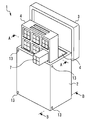
- FIG. 1 is a perspective view showing an example of a heat insulating container 1 according to Embodiment 1 of the present invention.
- the heat insulating container 1 includes a container 2, a lid 3 and a storage shelf 4.
- the container 2 has a box shape.
- FIG. 1 shows an example in which the outer shape of the container 2 is a rectangular parallelepiped shape.
- the outer shape of the container 2 is not limited to the example shown in FIG.
- the outer shape of the container 2 may be a cylindrical shape.
- the lid 3 closes the opening formed in the container 2.
- the lid 3 is detachable from the container 2, for example. When the lid 3 is attached to the container 2, the space formed inside the container 2 is sealed.
- FIG. 1 shows an example in which two storage shelves 4 are stored in a container 2.
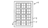
- FIG. 2 is a diagram showing an example of the storage shelf 4.
- the storage shelf 4 includes, for example, a frame 5 and a partition 6.
- the outer shape of the frame 5 is matched to the inner shape of the container 2. 1 and 2 show an example in which the outer shape of the frame 5 viewed from the front is a quadrangle.
- the partition 6 is fixed to the frame 5.
- the space formed inside the frame 5 is partitioned by a partition 6. 1 and 2 show an example in which the partition 6 has a lattice shape.
- the article 7 is arranged in the space partitioned by the partition 6.
- the heat insulating container 1 is used to keep the temperature of the article 7 constant.
- article 7 contains a vaccine preparation
- the vaccine preparation is placed, for example, in a dedicated container.
- the container containing the vaccine preparation is wrapped in a cushioning material or the like.
- article 7 includes a vaccine formulation, a container and a cushioning material.
- the container for the vaccine formulation may be part of a syringe that is used in performing the vaccination.
- an article 7 containing a vaccine preparation is put in a heat insulating container 1 at a base or the like, and is carried to a vaccine inoculation site by a motorbike or the like.
- the temperature at which the vaccine formulation is stored must be, for example, 2 ° C to 8 ° C.
- the article 7 is not limited to the one containing the vaccine preparation. You may utilize the heat insulation container 1 in a cold chain. In such a case, the article 7 may include fresh food, frozen food, medicine, electronic parts, or the like.
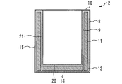
- FIG. 3 is a view showing a cross section of the container 2.
- FIG. 3 is a view corresponding to the AA cross section shown in FIG.
- the container 2 includes, for example, an outer case 8, an inner case 9, a closing body 10, a vacuum heat insulating material 11, and a foam heat insulating material 12.
- FIG. 4 is an exploded perspective view of the container 2. In FIG. 4, illustration of the foam heat insulating material 12 is omitted.
- the outer case 8 is box-shaped. The opening of the outer case 8 faces upward.
- a through hole 13 is formed in the outer case 8.
- FIG. 4 shows an example in which eight through holes 13 are formed in the outer case 8. The number of through holes 13 is not limited to the example shown in FIG. For example, only one through hole 13 may be formed.
- the through hole 13 is a hole into which the foam heat insulating material 12 is injected when the container 2 is manufactured.
- the outer case 8 includes a flat plate 14 and a cylinder 15.
- the cylinder 15 is provided on the edge of the flat plate 14.
- the cylinder 15 is disposed so as to extend upward from the edge of the flat plate 14.
- the flat plate 14 has a quadrangular shape.
- the flat plate 14 has a rectangular shape.
- the cross section of the cylinder 15 parallel to the flat plate 14 is rectangular.
- the cylinder 15 is provided at the edge of the flat plate 14 at the lower end.
- the cylinder 15 includes a flat plate 16, a flat plate 17, a flat plate 18, and a flat plate 19, for example.
- the flat plate 17 faces the flat plate 16.
- the flat plate 17 is parallel to the flat plate 16.
- the flat plate 18 is provided between the flat plate 16 and the flat plate 17.
- the flat plate 18 is orthogonal to the flat plate 16.
- the flat plate 19 is provided between the flat plate 16 and the flat plate 17.
- the flat plate 19 faces the flat plate 18.
- the flat plate 19 is parallel to the flat plate 18.
- the flat plate 19 is orthogonal to the flat plate 16.
- the inner case 9 is box-shaped.
- the inner case 9 is disposed inside the outer case 8.
- the opening of the inner case 9 faces upward.
- the inner case 9 includes a flat plate 20 and a cylindrical body 21.
- the flat plate 20 faces the flat plate 14.
- the flat plate 20 is parallel to the flat plate 14.
- the cylinder 21 is provided on the edge of the flat plate 20.
- the cylindrical body 21 is disposed so as to extend upward from the edge of the flat plate 20.
- the cylinder body 21 is disposed inside the cylinder body 15.
- the flat plate 20 has a quadrangular shape. Specifically, the flat plate 20 has a rectangular shape.
- the cross section of the cylindrical body 21 parallel to the flat plate 20 is rectangular.
- the cylindrical body 21 is provided at the edge of the flat plate 20 at the lower end.
- the cylinder 21 includes a flat plate 22, a flat plate 23, a flat plate 24, and a flat plate 25, for example. If nothing is put in the container 2, the flat plate 23 faces the flat plate 22. In the example shown in FIG. 4, the flat plate 23 is parallel to the flat plate 22. Considering only the outer case 8 and the inner case 9, the flat plate 22 faces the flat plate 16. The flat plate 22 is parallel to the flat plate 16. The flat plate 23 faces the flat plate 17. The flat plate 23 is parallel to the flat plate 17.
- the flat plate 24 is provided between the flat plate 22 and the flat plate 23.
- the flat plate 24 is orthogonal to the flat plate 22.
- the flat plate 25 is provided between the flat plate 22 and the flat plate 23. If nothing is put in the container 2, the flat plate 25 faces the flat plate 24.
- the flat plate 25 is parallel to the flat plate 24.
- the flat plate 25 is orthogonal to the flat plate 22. Considering only the outer case 8 and the inner case 9, the flat plate 24 faces the flat plate 18.
- the flat plate 24 is parallel to the flat plate 18.
- the flat plate 25 faces the flat plate 19.
- the flat plate 25 is parallel to the flat plate 19.
- the closing body 10 is provided between the edge of the outer case 8 and the edge of the inner case 9.
- the closing body 10 closes the gap between the edge of the outer case 8 and the edge of the inner case 9.
- the closing body 10 has a quadrangular annular shape.
- the closing body 10 is provided between the edge of the cylinder body 15 and the edge of the cylinder body 21.
- the closing body 10 closes the gap between the edge of the cylinder 15 and the edge of the cylinder 21.
- the vacuum heat insulating material 11 is disposed between the outer case 8 and the inner case 9.
- the vacuum heat insulating material 11 is disposed at least between the flat plate 14 and the flat plate 20 and between the cylindrical body 15 and the cylindrical body 21.
- the vacuum heat insulating material 11 includes a vacuum heat insulating plate 26, a vacuum heat insulating plate 27, a vacuum heat insulating plate 28, a vacuum heat insulating plate 29, and a vacuum heat insulating plate 30.
- the vacuum heat insulating plate 26 is disposed between the flat plate 14 and the flat plate 20.
- the vacuum heat insulating plate 27 is disposed between the flat plate 16 and the flat plate 22.
- the vacuum heat insulating plate 28 is disposed between the flat plate 17 and the flat plate 23.
- the vacuum heat insulating plate 29 is disposed between the flat plate 18 and the flat plate 24.
- the vacuum heat insulating plate 30 is disposed between the flat plate 19 and the flat plate 25. Therefore, the article 7 placed in the container 2 is surrounded by the vacuum heat insulating material 11 on the lower side and the four sides.
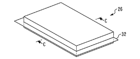
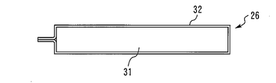
- FIG. 5 is a perspective view showing an example of the vacuum heat insulating plate 26.
- 6 is a cross-sectional view taken along the line CC of FIG.
- the vacuum heat insulating plate 26 includes glass fibers 31 and a film 32.
- the film 32 is a resin film, for example.
- a plate-like glass fiber 31 covered with a film 32 is a vacuum heat insulating plate 26.
- the glass fiber 31 is covered with the film 32, for example, the inside air is attracted
- the thermal conductivity of the vacuum heat insulating plate 26 is, for example, 0.003 [W / mK].
- the configuration of the vacuum heat insulating plate 27 to the vacuum heat insulating plate 30 is the same as that of the vacuum heat insulating plate 26.
- the foam heat insulating material 12 is filled from the through hole 13 into the space surrounded by the outer case 8, the inner case 9 and the closing body 10 after the outer case 8, the inner case 9 and the closing body 10 are assembled.
- the vacuum heat insulating material 11 is already disposed between the outer case 8 and the inner case 9.
- FIG. 3 shows an example in which the foamed heat insulating material 12 is filled in all the portions other than the vacuum heat insulating material 11 in the space surrounded by the outer case 8, the inner case 9 and the closing body 10.
- a part of the foam heat insulating material 12 is provided between the outer case 8 and the vacuum heat insulating material 11.
- a part of the foam heat insulating material 12 is provided between the inner case 9 and the vacuum heat insulating material 11. A part of the foam heat insulating material 12 is provided between the closing body 10 and the vacuum heat insulating material 11. A part of the foam heat insulating material 12 is provided between adjacent vacuum heat insulating plates.
- FIG. 7 is a view showing a part of the BB cross section of FIG.
- the position of the lower through hole 13 formed in the flat plate 19 is indicated by a broken line.
- the edge 26a of the vacuum heat insulating plate 26 faces the vacuum heat insulating plate 27 side.
- the vacuum heat insulating plate 26 is disposed such that a gap with a certain width is provided between the edge 26 a and the vacuum heat insulating plate 27.
- the through hole 13 faces a gap formed between adjacent vacuum heat insulating plates. If the through-hole 13 is formed in such a position, the foam heat insulating material 12 can be easily filled in the gap between the adjacent vacuum heat insulating plates.
- FIG. 8 is a diagram showing an example of a DD cross section of FIG.
- FIG. 8 is a view showing an example of the filled foam heat insulating material 12.
- the foam heat insulating material 12 may be disposed only in a space surrounded by the outer case 8, the inner case 9, and the closing body 10.
- FIG. 9 is a diagram showing another example of the DD cross section of FIG. As shown in FIG. 9, a part of the foam heat insulating material 12 may be disposed in the through hole 13.
- FIG. 10 is a diagram showing another example of the DD cross section of FIG. As shown in FIG.
- the through hole 13 may be closed by the foam heat insulating material 12.
- the surface of the portion of the foam heat insulating material 12 disposed in the through hole 13 is flush with the surface of the outer case 8.
- FIGS. 8 to 10 show examples of arrangement obtained by injecting the foam heat insulating material 12 from the through hole 13.
- FIG. 7 shows an example in which the foam heat insulating material 12 is provided between the vacuum heat insulating material 11 and the outer case 8 and between the vacuum heat insulating material 11 and the inner case 9.
- the arrangement of the vacuum heat insulating material 11 is not limited to the example shown in FIG. FIGS. 11, 12, and 13 are diagrams illustrating other arrangement examples of the vacuum heat insulating material 11.
- FIG. 11 shows an example in which the vacuum heat insulating material 11 faces the inner case 9.
- the vacuum heat insulating plate 26 faces the flat plate 20 of the inner case 9.
- the vacuum heat insulating plate 26 may be adhered to the flat plate 20.
- the foam heat insulating material 12 is provided between the vacuum heat insulating plate 26 and the flat plate 14 of the outer case 8.
- the vacuum heat insulating plate 27 faces the flat plate 22 of the inner case 9.
- the vacuum heat insulating plate 27 may be adhered to the flat plate 22.
- the foam heat insulating material 12 is provided between the vacuum heat insulating plate 27 and the flat plate 16 of the outer case 8. The same applies to other vacuum heat insulating plates. If it is an example shown in FIG. 11, the quantity of the required vacuum heat insulating material 11 can be reduced.
- FIG. 12 shows an example in which the vacuum heat insulating material 11 faces the outer case 8.
- the vacuum heat insulating plate 26 faces the flat plate 14 of the outer case 8.
- the vacuum heat insulating plate 26 may be adhered to the flat plate 14.
- the foam heat insulating material 12 is provided between the vacuum heat insulating plate 26 and the flat plate 20 of the inner case 9.
- the vacuum heat insulating plate 27 faces the flat plate 16 of the outer case 8.
- the vacuum heat insulating plate 27 may be adhered to the flat plate 16.
- the foam heat insulating material 12 is provided between the vacuum heat insulating plate 27 and the flat plate 22 of the inner case 9. The same applies to other vacuum heat insulating plates.
- FIG. 13 shows an example in which some of the vacuum heat insulating materials 11 are arranged in a double manner.
- the vacuum heat insulating material 11 further includes a vacuum heat insulating plate 33 bent into an L shape.
- the vacuum heat insulating plate 26 is disposed such that a gap having a certain width is provided between the edge 26 a and the vacuum heat insulating plate 27.
- the vacuum heat insulating plate 33 is disposed so as to cover the gap from the outer case 8 side.
- the vacuum heat insulating plate 33 is disposed between the edge 26 a of the vacuum heat insulating plate 26, the edge 27 a of the vacuum heat insulating plate 27 closest to the gap and the edge 26 a, and the outer case 8.
- the vacuum heat insulating plate 33 may be disposed so as to cover the gap from the inner case 9 side.
- the vacuum heat insulating plate 33 is disposed between the edge 26 a of the vacuum heat insulating plate 26, the gap and the edge 27 a of the vacuum heat insulating plate 27 and the inner case 9. If it is an example shown in FIG. 13, the heat leak from the clearance gap between the vacuum heat insulation board 26 and the vacuum heat insulation board 27 can be suppressed.
- the vacuum heat insulating material 11 may be disposed in a double manner for other portions adjacent to the vacuum heat insulating plate.
- FIG. 4 shows an example in which the through hole 13 is formed in the cylindrical body 15 of the outer case 8.
- the position where the through hole 13 is formed is not limited to the example shown in FIG. 14, FIG. 15, FIG. 16 and FIG. 17 are diagrams showing other examples of positions where the through holes 13 are formed.
- FIG. 14 shows an example in which a through hole 13 is formed at the center of each flat plate provided in the outer case 8.
- the through hole 13 may be formed in a part of the flat plate provided in the outer case 8.
- the example shown in FIG. 14 is suitable when the vacuum heat insulating material 11 is opposed to the inner case 9 as shown in FIG.
- FIG. 15 shows an example in which through holes 13 are formed at each boundary portion of a flat plate provided in the outer case 8.
- the through hole 13 may be formed at a part of the boundary portion.
- the example shown in FIG. 15 is also suitable when the vacuum heat insulating material 11 is opposed to the inner case 9. In the example shown in FIG. 15, the edge of the vacuum heat insulating plate can be reliably suppressed by the foam heat insulating material 12.
- FIG. 16 shows an example in which the through hole 13 is formed in the closing body 10.
- FIG. 16 shows an example in which through holes 13 are formed at the four corners of the closing body 10.
- the through hole 13 may be further formed in the outer case 8.
- the through hole 13 may be formed in the flat plate 14.
- FIG. 17 shows an example in which the through hole 13 is formed in each flat plate provided in the inner case 9.
- the through hole 13 may be formed in a part of the flat plate provided in the inner case 9.
- the example shown in FIG. 17 is suitable when the vacuum heat insulating material 11 is opposed to the outer case 8 as shown in FIG.
- the through hole 13 may be further formed in the closing body 10.
- the through hole 13 may be further formed in the outer case 8.
- the foam heat insulating material 12 is filled from the through hole 13. For this reason, the foam heat insulating material 12 is visible from the through hole 13. A part of the foam heat insulating material 12 may be disposed in the through hole 13, or the through hole 13 may be blocked by the foam heat insulating material 12.
- FIG. 5 and 6 show an example in which the vacuum heat insulating plate 26 includes a glass fiber 31 and a film 32.
- FIG. The vacuum heat insulation board 26 is not limited to the example shown in FIG.5 and FIG.6.
- the thermal conductivity of the film 32 is higher than the thermal conductivity of the glass fiber 31.
- the thermal conductivity of the film 32 is higher than the thermal conductivity of the foam heat insulating material 12.
- the vacuum heat insulating plate 26 may further include means for suppressing heat transfer through the film 32.
- 18 and 19 are diagrams showing another example of the vacuum heat insulating plate 26.
- FIG. 18 shows an example in which the vacuum heat insulating plate 26 further includes a heat insulating sheet 34 in addition to the glass fiber 31 and the film 32.
- the heat insulating sheet 34 is provided on the film 32.
- the heat insulating sheet 34 is disposed outside the film 32 so as to further wrap the film 32 that wraps the glass fiber 31.
- the thermal conductivity of the heat insulating sheet 34 is lower than the thermal conductivity of the film 32. In the example shown in FIG. 18, heat can be prevented from being transmitted through the film 32.
- FIG. 19 shows an example in which the vacuum heat insulating plate 26 further includes a heat insulating film 35 in addition to the glass fiber 31 and the film 32.
- the glass fiber 31 is covered from above and below by two films 32.
- the heat insulating film 35 is disposed between the upper film 32 and the lower film 32. Since the heat insulating film 35 exists, the upper film 32 and the lower film 32 are not in direct contact with each other. For example, the heat conductivity of the heat insulating film 35 is lower than the heat conductivity of the film 32. In the example shown in FIG. 19, heat can be prevented from being transmitted through the film 32.
- the vacuum heat insulating material 11 is supported by the foam heat insulating material 12.
- the foam heat insulating material 12 injected from the through hole 13 is provided both between the vacuum heat insulating material 11 and the outer case 8 and between the vacuum heat insulating material 11 and the inner case 9.
- the foam heat insulating material 12 injected from the through hole 13 is provided between the vacuum heat insulating material 11 and the outer case 8, and the vacuum heat insulating material 11 is attached to the inner case 9 by the foam heat insulating material 12. Pressed.
- FIG. 7 the foam heat insulating material 12 injected from the through hole 13 is provided both between the vacuum heat insulating material 11 and the outer case 8 and between the vacuum heat insulating material 11 and the inner case 9.
- the foam heat insulating material 12 injected from the through hole 13 is provided between the vacuum heat insulating material 11 and the outer case 8, and the vacuum heat insulating material 11 is attached to the inner case 9 by the foam heat insulating material 12. Pressed.
- FIG. 7 the foam heat insul
- the foam heat insulating material 12 injected from the through hole 13 is provided between the vacuum heat insulating material 11 and the inner case 9, and the vacuum heat insulating material 11 is pressed against the outer case 8 by the foam heat insulating material 12. .
- the vacuum heat insulating material 11 can be supported in a desired position, and a heat insulation fall can be suppressed.
- the insulated container 1 shown in the present embodiment is suitable when the temperature of the article 7 needs to be strictly controlled, for example, when the article 7 includes a vaccine preparation.
- the lid 3 is also provided with a vacuum heat insulating material like the container 2.
- the lid 3 may have a cooling function. Both the lid 3 having a cooling function and the lid 3 not having a cooling function may be detachable from the container 2.
- the lid 3 is not an essential element for the heat insulating container 1. For example, when the storage shelf 4 is disposed inside the container 2, a part of the storage shelf 4 may have the function of the lid 3.
- FIG. 20 is a perspective view showing another example of the heat insulating container 1 according to Embodiment 1 of the present invention.
- FIG. 1 shows an example in which the opening of the container 2 is upward.
- FIG. 20 shows an example in which the opening of the container 2 is sideways.
- the heat insulation container 1 may be used sideways as shown in FIG.
- the heat insulating container according to the present invention is used for keeping the article warm or cold.
Landscapes
- Engineering & Computer Science (AREA)
- Mechanical Engineering (AREA)
- Packages (AREA)
Abstract
This thermally insulated container (1) is provided with a box-shaped outer case (8), a box-shaped inner case (9), a closing body (10), a vacuum thermal insulation material (11), and a foamed thermal insulation material (12). A through-hole (13) is formed in the outer case (8). The vacuum thermal insulation material (11) is disposed between the outer case (8) and the inner case (9). The foamed thermal insulation material (12) is provided, for example, between the vacuum thermal insulation material (11) and the outer case (8). The foamed thermal insulation material (12) is visible through the through-hole (13). In the thermally insulated container (1), the vacuum thermal insulation material (11) can be supported at a desired position and a decrease in thermal insulation properties can be suppressed.
Description
この発明は、真空断熱材を備えた断熱容器に関する。
This invention relates to a heat insulating container provided with a vacuum heat insulating material.
特許文献1に冷蔵庫が記載されている。特許文献1に記載された冷蔵庫は、真空断熱材を備える。真空断熱材は、符号k1で示される多数の固定部材によって支持される。
Patent Document 1 describes a refrigerator. The refrigerator described in Patent Document 1 includes a vacuum heat insulating material. The vacuum heat insulating material is supported by a number of fixing members denoted by reference numeral k1.
特許文献1に記載された冷蔵庫では、真空断熱材が棒状の固定部材によって支持される。真空断熱材は、例えばガラス繊維とフィルムとを備える。ガラス繊維は、フィルムによって覆われる。ガラス繊維を包むフィルムの熱伝導率はガラス繊維の熱伝導率より高い。このため、真空断熱材を棒状の固定部材で支持すると、熱がフィルムと固定部材とを伝わり、断熱性が低下するといった問題があった。
In the refrigerator described in Patent Document 1, the vacuum heat insulating material is supported by a rod-shaped fixing member. A vacuum heat insulating material is provided with glass fiber and a film, for example. The glass fiber is covered by a film. The thermal conductivity of the film surrounding the glass fiber is higher than that of the glass fiber. For this reason, when the vacuum heat insulating material is supported by the rod-shaped fixing member, there is a problem that heat is transmitted through the film and the fixing member, and the heat insulating property is lowered.
この発明は、上述のような課題を解決するためになされた。この発明の目的は、真空断熱材を所望の位置で支持でき、且つ断熱性の低下を抑制できる断熱容器を提供することである。
This invention has been made to solve the above-described problems. The objective of this invention is providing the heat insulation container which can support a vacuum heat insulating material in a desired position, and can suppress the heat insulation fall.
この発明に係る断熱容器は、貫通孔が形成された箱状の外ケースと、外ケースの内側に配置された箱状の内ケースと、外ケースの縁及び内ケースの縁の間に設けられた閉塞体と、外ケース及び内ケースの間に配置された真空断熱材と、真空断熱材及び外ケースの間に設けられた発泡断熱材と、を備える。外ケースは、第1平板と、第1平板の縁に設けられた第1筒体と、を備える。内ケースは、第2平板と、第2平板の縁に設けられ、第1筒体の内側に配置された第2筒体と、を備える。真空断熱材は、第1平板と第2平板との間及び第1筒体と第2筒体との間に配置される。貫通孔から発泡断熱材が視認可能である。
The heat insulating container according to the present invention is provided between a box-shaped outer case in which a through-hole is formed, a box-shaped inner case arranged inside the outer case, an edge of the outer case, and an edge of the inner case. And a vacuum heat insulating material disposed between the outer case and the inner case, and a foam heat insulating material provided between the vacuum heat insulating material and the outer case. The outer case includes a first flat plate and a first cylindrical body provided on an edge of the first flat plate. The inner case includes a second flat plate and a second cylindrical body provided on an edge of the second flat plate and disposed inside the first cylindrical body. A vacuum heat insulating material is arrange | positioned between a 1st flat plate and a 2nd flat plate, and between a 1st cylinder and a 2nd cylinder. The foam heat insulating material is visible from the through hole.
この発明に係る断熱容器は、箱状の外ケースと、外ケースの内側に配置された箱状の内ケースと、外ケースの縁及び内ケースの縁の間に設けられ、貫通孔が形成された閉塞体と、外ケース及び内ケースの間に配置された真空断熱材と、真空断熱材及び外ケースの間に設けられた発泡断熱材と、を備える。外ケースは、第1平板と、第1平板の縁に設けられた第1筒体と、を備える。内ケースは、第2平板と、第2平板の縁に設けられ、第1筒体の内側に配置された第2筒体と、を備える。真空断熱材は、第1平板と第2平板との間及び第1筒体と第2筒体との間に配置される。貫通孔から発泡断熱材が視認可能である。
The heat insulating container according to the present invention is provided between a box-shaped outer case, a box-shaped inner case disposed inside the outer case, an edge of the outer case, and an edge of the inner case, and a through hole is formed. And a vacuum heat insulating material disposed between the outer case and the inner case, and a foam heat insulating material provided between the vacuum heat insulating material and the outer case. The outer case includes a first flat plate and a first cylindrical body provided on an edge of the first flat plate. The inner case includes a second flat plate and a second cylindrical body provided on an edge of the second flat plate and disposed inside the first cylindrical body. A vacuum heat insulating material is arrange | positioned between a 1st flat plate and a 2nd flat plate, and between a 1st cylinder and a 2nd cylinder. The foam heat insulating material is visible from the through hole.
この発明に係る断熱容器は、箱状の外ケースと、外ケースの内側に配置され、貫通孔が形成された箱状の内ケースと、外ケースの縁及び内ケースの縁の間に設けられた閉塞体と、外ケース及び内ケースの間に配置された真空断熱材と、真空断熱材及び内ケースの間に設けられた発泡断熱材と、を備える。外ケースは、第1平板と、第1平板の縁に設けられた第1筒体と、を備える。内ケースは、第2平板と、第2平板の縁に設けられ、第1筒体の内側に配置された第2筒体と、を備える。真空断熱材は、第1平板と第2平板との間及び第1筒体と第2筒体との間に配置される。貫通孔から発泡断熱材が視認可能である。
The heat insulating container according to the present invention is provided between a box-shaped outer case, a box-shaped inner case disposed inside the outer case and having a through hole, and an edge of the outer case and an edge of the inner case. And a vacuum heat insulating material disposed between the outer case and the inner case, and a foam heat insulating material provided between the vacuum heat insulating material and the inner case. The outer case includes a first flat plate and a first cylindrical body provided on an edge of the first flat plate. The inner case includes a second flat plate and a second cylindrical body provided on an edge of the second flat plate and disposed inside the first cylindrical body. A vacuum heat insulating material is arrange | positioned between a 1st flat plate and a 2nd flat plate, and between a 1st cylinder and a 2nd cylinder. The foam heat insulating material is visible from the through hole.
この発明に係る断熱容器は、箱状の外ケースと箱状の内ケースと外ケースの縁及び内ケースの縁の間に設けられた閉塞体とを備える。外ケース及び内ケースの間に真空断熱材が配置される。また、外ケース、内ケース又は閉塞体に貫通孔が形成される。貫通孔から発泡断熱材が視認可能である。この発明に係る断熱容器であれば、真空断熱材を所望の位置で支持でき、且つ断熱性の低下を抑制できる。
A heat insulating container according to the present invention includes a box-shaped outer case, a box-shaped inner case, an edge of the outer case, and a closing body provided between the edges of the inner case. A vacuum heat insulating material is disposed between the outer case and the inner case. In addition, a through hole is formed in the outer case, the inner case, or the closing body. The foam heat insulating material is visible from the through hole. If it is the heat insulation container which concerns on this invention, a vacuum heat insulating material can be supported in a desired position, and the heat insulation fall can be suppressed.
添付の図面を参照し、本発明を説明する。重複する説明は、適宜簡略化或いは省略する。各図において、同一の符号は同一の部分又は相当する部分を示す。
The present invention will be described with reference to the accompanying drawings. The overlapping description will be simplified or omitted as appropriate. In each figure, the same reference numerals indicate the same or corresponding parts.
実施の形態1.
図1は、この発明の実施の形態1における断熱容器1の例を示す斜視図である。断熱容器1は、容器2、蓋3及び収納棚4を備える。 Embodiment 1 FIG.
FIG. 1 is a perspective view showing an example of a heat insulating container 1 according to Embodiment 1 of the present invention. The heat insulating container 1 includes acontainer 2, a lid 3 and a storage shelf 4.
図1は、この発明の実施の形態1における断熱容器1の例を示す斜視図である。断熱容器1は、容器2、蓋3及び収納棚4を備える。 Embodiment 1 FIG.
FIG. 1 is a perspective view showing an example of a heat insulating container 1 according to Embodiment 1 of the present invention. The heat insulating container 1 includes a
容器2は、箱状である。図1は、容器2の外形が直方体形状である例を示す。容器2の外形は図1に示す例に限定されない。例えば、容器2の外形は円柱形状でも良い。
The container 2 has a box shape. FIG. 1 shows an example in which the outer shape of the container 2 is a rectangular parallelepiped shape. The outer shape of the container 2 is not limited to the example shown in FIG. For example, the outer shape of the container 2 may be a cylindrical shape.
蓋3は、容器2に形成された開口を塞ぐ。蓋3は、例えば容器2に着脱可能である。蓋3が容器2に取り付けられると、容器2の内側に形成された空間が密閉される。
The lid 3 closes the opening formed in the container 2. The lid 3 is detachable from the container 2, for example. When the lid 3 is attached to the container 2, the space formed inside the container 2 is sealed.
収納棚4は、容器2の内部に配置される。蓋3は、収納棚4が容器2に入れられた状態で容器2に取り付けられる。図1は、2つの収納棚4が容器2に収容される例を示す。
The storage shelf 4 is arranged inside the container 2. The lid 3 is attached to the container 2 with the storage shelf 4 placed in the container 2. FIG. 1 shows an example in which two storage shelves 4 are stored in a container 2.
図2は、収納棚4の例を示す図である。収納棚4は、例えば枠5及び仕切り6を備える。枠5の外形は、容器2の内側の形状に合わせられる。図1及び図2は、正面から見た枠5の外形が四角形である例を示す。仕切り6は枠5に固定される。枠5の内側に形成された空間は仕切り6によって仕切られる。図1及び図2は、仕切り6が格子状である例を示す。仕切り6によって仕切られた空間に物品7が配置される。断熱容器1は、物品7の温度を一定に保つために利用される。
FIG. 2 is a diagram showing an example of the storage shelf 4. The storage shelf 4 includes, for example, a frame 5 and a partition 6. The outer shape of the frame 5 is matched to the inner shape of the container 2. 1 and 2 show an example in which the outer shape of the frame 5 viewed from the front is a quadrangle. The partition 6 is fixed to the frame 5. The space formed inside the frame 5 is partitioned by a partition 6. 1 and 2 show an example in which the partition 6 has a lattice shape. The article 7 is arranged in the space partitioned by the partition 6. The heat insulating container 1 is used to keep the temperature of the article 7 constant.
以下においては、物品7がワクチン製剤を含む例を示す。ワクチン製剤は、例えば専用の入れ物に入れられる。ワクチン製剤が入れられた入れ物は、緩衝材等に包まれる。この例であれば、物品7はワクチン製剤、入れ物及び緩衝材を含む。ワクチン製剤の入れ物は、ワクチン接種を行う際に使用される注射器の一部でも良い。
In the following, an example in which article 7 contains a vaccine preparation is shown. The vaccine preparation is placed, for example, in a dedicated container. The container containing the vaccine preparation is wrapped in a cushioning material or the like. In this example, article 7 includes a vaccine formulation, a container and a cushioning material. The container for the vaccine formulation may be part of a syringe that is used in performing the vaccination.
例えば、発展途上国では、拠点等においてワクチン製剤を含む物品7が断熱容器1に入れられ、モータバイク等によってワクチンの接種会場に運ばれる。ワクチン製剤を保管する温度は例えば2℃から8℃でなければならない。断熱容器1に入れられた物品7を上記温度範囲で保管できる時間が長いほど、拠点からの一回の出動によってより多くの会場にワクチン製剤を届けることができる。例えば、発展途上国では、物品7を数日間上記温度範囲で保管できることが望ましい。
For example, in developing countries, an article 7 containing a vaccine preparation is put in a heat insulating container 1 at a base or the like, and is carried to a vaccine inoculation site by a motorbike or the like. The temperature at which the vaccine formulation is stored must be, for example, 2 ° C to 8 ° C. The longer the time in which the article 7 placed in the heat insulating container 1 can be stored in the above temperature range, the more the vaccine preparation can be delivered to more venues by one turnout from the base. For example, in developing countries, it is desirable to be able to store the article 7 in the above temperature range for several days.
なお、物品7はワクチン製剤を含むものに限定されない。断熱容器1をコールドチェーンにおいて利用しても良い。かかる場合、物品7は、生鮮食品、冷凍食品、医薬品或いは電子部品等を含んでも良い。
In addition, the article 7 is not limited to the one containing the vaccine preparation. You may utilize the heat insulation container 1 in a cold chain. In such a case, the article 7 may include fresh food, frozen food, medicine, electronic parts, or the like.
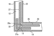
図3は、容器2の断面を示す図である。図3は、図1に示すA-A断面に相当する図である。容器2は、例えば外ケース8、内ケース9、閉塞体10、真空断熱材11及び発泡断熱材12を備える。図4は、容器2の分解斜視図である。図4では、発泡断熱材12の図示を省略している。
FIG. 3 is a view showing a cross section of the container 2. FIG. 3 is a view corresponding to the AA cross section shown in FIG. The container 2 includes, for example, an outer case 8, an inner case 9, a closing body 10, a vacuum heat insulating material 11, and a foam heat insulating material 12. FIG. 4 is an exploded perspective view of the container 2. In FIG. 4, illustration of the foam heat insulating material 12 is omitted.
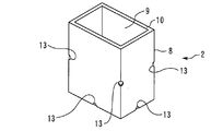
外ケース8は箱状である。外ケース8の開口は上方を向く。外ケース8に貫通孔13が形成される。図4は、外ケース8に8つの貫通孔13が形成される例を示す。貫通孔13の数は、図4に示す例に限定されない。例えば、貫通孔13は1つしか形成されなくても良い。貫通孔13は、容器2を製造する際に発泡断熱材12が注入される孔である。
The outer case 8 is box-shaped. The opening of the outer case 8 faces upward. A through hole 13 is formed in the outer case 8. FIG. 4 shows an example in which eight through holes 13 are formed in the outer case 8. The number of through holes 13 is not limited to the example shown in FIG. For example, only one through hole 13 may be formed. The through hole 13 is a hole into which the foam heat insulating material 12 is injected when the container 2 is manufactured.
外ケース8は、平板14と筒体15とを備える。筒体15は、平板14の縁に設けられる。筒体15は、平板14の縁から上方に延びるように配置される。図4に示す例では、平板14は四角形状である。具体的に、平板14は長方形状である。平板14に平行な筒体15の断面は長方形状である。筒体15は、下端が平板14の縁に設けられる。
The outer case 8 includes a flat plate 14 and a cylinder 15. The cylinder 15 is provided on the edge of the flat plate 14. The cylinder 15 is disposed so as to extend upward from the edge of the flat plate 14. In the example shown in FIG. 4, the flat plate 14 has a quadrangular shape. Specifically, the flat plate 14 has a rectangular shape. The cross section of the cylinder 15 parallel to the flat plate 14 is rectangular. The cylinder 15 is provided at the edge of the flat plate 14 at the lower end.
筒体15は、例えば平板16、平板17、平板18及び平板19を備える。外ケース8のみを考慮すると、平板17は平板16に対向する。図4に示す例では、平板17は平板16に平行である。平板18は、平板16と平板17との間に設けられる。図4に示す例では、平板18は平板16に直交する。平板19は、平板16と平板17との間に設けられる。外ケース8のみを考慮すると、平板19は平板18に対向する。図4に示す例では、平板19は平板18に平行である。また、平板19は、平板16に直交する。
The cylinder 15 includes a flat plate 16, a flat plate 17, a flat plate 18, and a flat plate 19, for example. Considering only the outer case 8, the flat plate 17 faces the flat plate 16. In the example shown in FIG. 4, the flat plate 17 is parallel to the flat plate 16. The flat plate 18 is provided between the flat plate 16 and the flat plate 17. In the example shown in FIG. 4, the flat plate 18 is orthogonal to the flat plate 16. The flat plate 19 is provided between the flat plate 16 and the flat plate 17. Considering only the outer case 8, the flat plate 19 faces the flat plate 18. In the example shown in FIG. 4, the flat plate 19 is parallel to the flat plate 18. The flat plate 19 is orthogonal to the flat plate 16.
内ケース9は箱状である。内ケース9は、外ケース8の内側に配置される。内ケース9の開口は上方を向く。
The inner case 9 is box-shaped. The inner case 9 is disposed inside the outer case 8. The opening of the inner case 9 faces upward.
内ケース9は、平板20と筒体21とを備える。外ケース8及び内ケース9のみを考慮すると、平板20は平板14に対向する。図3及び図4に示す例では、平板20は平板14に平行である。筒体21は、平板20の縁に設けられる。筒体21は、平板20の縁から上方に延びるように配置される。筒体21は、筒体15の内側に配置される。図4に示す例では、平板20は四角形状である。具体的に、平板20は長方形状である。平板20に平行な筒体21の断面は長方形状である。筒体21は、下端が平板20の縁に設けられる。
The inner case 9 includes a flat plate 20 and a cylindrical body 21. Considering only the outer case 8 and the inner case 9, the flat plate 20 faces the flat plate 14. In the example shown in FIGS. 3 and 4, the flat plate 20 is parallel to the flat plate 14. The cylinder 21 is provided on the edge of the flat plate 20. The cylindrical body 21 is disposed so as to extend upward from the edge of the flat plate 20. The cylinder body 21 is disposed inside the cylinder body 15. In the example shown in FIG. 4, the flat plate 20 has a quadrangular shape. Specifically, the flat plate 20 has a rectangular shape. The cross section of the cylindrical body 21 parallel to the flat plate 20 is rectangular. The cylindrical body 21 is provided at the edge of the flat plate 20 at the lower end.
筒体21は、例えば平板22、平板23、平板24及び平板25を備える。容器2に何も入れられていなければ、平板23は平板22に対向する。図4に示す例では、平板23は平板22に平行である。外ケース8及び内ケース9のみを考慮すると、平板22は平板16に対向する。平板22は平板16に平行である。また、平板23は平板17に対向する。平板23は平板17に平行である。
The cylinder 21 includes a flat plate 22, a flat plate 23, a flat plate 24, and a flat plate 25, for example. If nothing is put in the container 2, the flat plate 23 faces the flat plate 22. In the example shown in FIG. 4, the flat plate 23 is parallel to the flat plate 22. Considering only the outer case 8 and the inner case 9, the flat plate 22 faces the flat plate 16. The flat plate 22 is parallel to the flat plate 16. The flat plate 23 faces the flat plate 17. The flat plate 23 is parallel to the flat plate 17.
平板24は、平板22と平板23との間に設けられる。図4に示す例では、平板24は平板22に直交する。平板25は、平板22と平板23との間に設けられる。容器2に何も入れられていなければ、平板25は平板24に対向する。図4に示す例では、平板25は平板24に平行である。また、平板25は、平板22に直交する。外ケース8及び内ケース9のみを考慮すると、平板24は平板18に対向する。平板24は平板18に平行である。また、平板25は平板19に対向する。平板25は平板19に平行である。
The flat plate 24 is provided between the flat plate 22 and the flat plate 23. In the example shown in FIG. 4, the flat plate 24 is orthogonal to the flat plate 22. The flat plate 25 is provided between the flat plate 22 and the flat plate 23. If nothing is put in the container 2, the flat plate 25 faces the flat plate 24. In the example shown in FIG. 4, the flat plate 25 is parallel to the flat plate 24. The flat plate 25 is orthogonal to the flat plate 22. Considering only the outer case 8 and the inner case 9, the flat plate 24 faces the flat plate 18. The flat plate 24 is parallel to the flat plate 18. The flat plate 25 faces the flat plate 19. The flat plate 25 is parallel to the flat plate 19.
閉塞体10は、外ケース8の縁と内ケース9の縁との間に設けられる。閉塞体10により、外ケース8の縁と内ケース9の縁との隙間が塞がれる。図4に示す例では、閉塞体10は四角形の環状である。閉塞体10は、筒体15の縁と筒体21の縁との間に設けられる。閉塞体10により、筒体15の縁と筒体21の縁との隙間が塞がれる。
The closing body 10 is provided between the edge of the outer case 8 and the edge of the inner case 9. The closing body 10 closes the gap between the edge of the outer case 8 and the edge of the inner case 9. In the example shown in FIG. 4, the closing body 10 has a quadrangular annular shape. The closing body 10 is provided between the edge of the cylinder body 15 and the edge of the cylinder body 21. The closing body 10 closes the gap between the edge of the cylinder 15 and the edge of the cylinder 21.
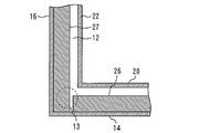
真空断熱材11は、外ケース8と内ケース9との間に配置される。真空断熱材11は、少なくとも、平板14と平板20との間並びに筒体15と筒体21との間に配置される。図4に示す例では、真空断熱材11は、真空断熱板26、真空断熱板27、真空断熱板28、真空断熱板29及び真空断熱板30を備える。
The vacuum heat insulating material 11 is disposed between the outer case 8 and the inner case 9. The vacuum heat insulating material 11 is disposed at least between the flat plate 14 and the flat plate 20 and between the cylindrical body 15 and the cylindrical body 21. In the example shown in FIG. 4, the vacuum heat insulating material 11 includes a vacuum heat insulating plate 26, a vacuum heat insulating plate 27, a vacuum heat insulating plate 28, a vacuum heat insulating plate 29, and a vacuum heat insulating plate 30.
真空断熱板26は、平板14と平板20との間に配置される。真空断熱板27は、平板16と平板22との間に配置される。真空断熱板28は、平板17と平板23との間に配置される。真空断熱板29は、平板18と平板24との間に配置される。真空断熱板30は、平板19と平板25との間に配置される。したがって、容器2に入れられた物品7は、下方及び四方が真空断熱材11によって囲まれる。
The vacuum heat insulating plate 26 is disposed between the flat plate 14 and the flat plate 20. The vacuum heat insulating plate 27 is disposed between the flat plate 16 and the flat plate 22. The vacuum heat insulating plate 28 is disposed between the flat plate 17 and the flat plate 23. The vacuum heat insulating plate 29 is disposed between the flat plate 18 and the flat plate 24. The vacuum heat insulating plate 30 is disposed between the flat plate 19 and the flat plate 25. Therefore, the article 7 placed in the container 2 is surrounded by the vacuum heat insulating material 11 on the lower side and the four sides.
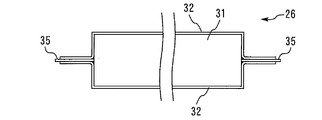
図5は、真空断熱板26の例を示す斜視図である。図6は、図5のC-C断面を示す図である。真空断熱板26は、ガラス繊維31とフィルム32とを備える。フィルム32は、例えば樹脂フィルムである。板状のガラス繊維31をフィルム32で覆ったものが真空断熱板26である。真空断熱板26を製造する場合は、例えばガラス繊維31をフィルム32で覆い、中の空気を吸引して真空度を上げる。所望の真空度が得られたら、フィルム32の縁を完全に接合する。これにより、真空断熱板26を得ることができる。真空断熱板26の熱伝導率は、例えば0.003[W/mK]である。真空断熱板27から真空断熱板30の構成は、真空断熱板26の構成と同様である。
FIG. 5 is a perspective view showing an example of the vacuum heat insulating plate 26. 6 is a cross-sectional view taken along the line CC of FIG. The vacuum heat insulating plate 26 includes glass fibers 31 and a film 32. The film 32 is a resin film, for example. A plate-like glass fiber 31 covered with a film 32 is a vacuum heat insulating plate 26. When manufacturing the vacuum heat insulation board 26, the glass fiber 31 is covered with the film 32, for example, the inside air is attracted | sucked and a vacuum degree is raised. Once the desired degree of vacuum is obtained, the edges of the film 32 are fully joined. Thereby, the vacuum heat insulation board 26 can be obtained. The thermal conductivity of the vacuum heat insulating plate 26 is, for example, 0.003 [W / mK]. The configuration of the vacuum heat insulating plate 27 to the vacuum heat insulating plate 30 is the same as that of the vacuum heat insulating plate 26.
発泡断熱材12は、外ケース8、内ケース9及び閉塞体10が組み立てられた後に、外ケース8、内ケース9及び閉塞体10によって囲まれた空間に貫通孔13から充填される。発泡断熱材12が充填される際に、真空断熱材11は外ケース8と内ケース9との間に既に配置されている。図3は、外ケース8、内ケース9及び閉塞体10によって囲まれた空間のうち、真空断熱材11以外の全ての部分に発泡断熱材12が充填される例を示す。図3に示す例では、発泡断熱材12の一部は、外ケース8と真空断熱材11との間に設けられる。発泡断熱材12の一部は、内ケース9と真空断熱材11との間に設けられる。発泡断熱材12の一部は、閉塞体10と真空断熱材11との間に設けられる。また、発泡断熱材12の一部は、隣接する真空断熱板の間に設けられる。
The foam heat insulating material 12 is filled from the through hole 13 into the space surrounded by the outer case 8, the inner case 9 and the closing body 10 after the outer case 8, the inner case 9 and the closing body 10 are assembled. When the foam heat insulating material 12 is filled, the vacuum heat insulating material 11 is already disposed between the outer case 8 and the inner case 9. FIG. 3 shows an example in which the foamed heat insulating material 12 is filled in all the portions other than the vacuum heat insulating material 11 in the space surrounded by the outer case 8, the inner case 9 and the closing body 10. In the example shown in FIG. 3, a part of the foam heat insulating material 12 is provided between the outer case 8 and the vacuum heat insulating material 11. A part of the foam heat insulating material 12 is provided between the inner case 9 and the vacuum heat insulating material 11. A part of the foam heat insulating material 12 is provided between the closing body 10 and the vacuum heat insulating material 11. A part of the foam heat insulating material 12 is provided between adjacent vacuum heat insulating plates.
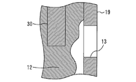
図7は、図1のB-B断面の一部を示す図である。図7では、平板19に形成された下側の貫通孔13の位置を破線で示している。例えば、真空断熱板26の縁26aは、真空断熱板27側を向く。真空断熱板26は、縁26aと真空断熱板27との間に一定の幅の隙間が空くように配置される。例えば、発泡断熱材12が充填される前であれば、貫通孔13は、隣接する真空断熱板の間に形成された隙間に対向する。このような位置に貫通孔13を形成しておけば、隣接する真空断熱板の隙間に発泡断熱材12を容易に充填することができる。
FIG. 7 is a view showing a part of the BB cross section of FIG. In FIG. 7, the position of the lower through hole 13 formed in the flat plate 19 is indicated by a broken line. For example, the edge 26a of the vacuum heat insulating plate 26 faces the vacuum heat insulating plate 27 side. The vacuum heat insulating plate 26 is disposed such that a gap with a certain width is provided between the edge 26 a and the vacuum heat insulating plate 27. For example, before the foam heat insulating material 12 is filled, the through hole 13 faces a gap formed between adjacent vacuum heat insulating plates. If the through-hole 13 is formed in such a position, the foam heat insulating material 12 can be easily filled in the gap between the adjacent vacuum heat insulating plates.
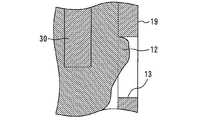
上述したように、発泡断熱材12は貫通孔13から注入される。このため、発泡断熱材12は貫通孔13から視認可能である。図8は、図7のD-D断面の一例を示す図である。図8は、充填された発泡断熱材12の一例を示す図である。発泡断熱材12は、外ケース8、内ケース9及び閉塞体10によって囲まれた空間のみに配置されても良い。図9は、図7のD-D断面の他の例を示す図である。図9に示すように、発泡断熱材12は、一部が貫通孔13に配置されても良い。図10は、図7のD-D断面の他の例を示す図である。図10に示すように、発泡断熱材12によって貫通孔13が塞がれても良い。かかる場合、発泡断熱材12のうち貫通孔13に配置された部分の表面は、外ケース8の表面と面一であることが好適である。図8から図10は、発泡断熱材12を貫通孔13から注入することによって得られる配置例を示す。
As described above, the foam heat insulating material 12 is injected from the through hole 13. For this reason, the foam heat insulating material 12 is visible from the through hole 13. FIG. 8 is a diagram showing an example of a DD cross section of FIG. FIG. 8 is a view showing an example of the filled foam heat insulating material 12. The foam heat insulating material 12 may be disposed only in a space surrounded by the outer case 8, the inner case 9, and the closing body 10. FIG. 9 is a diagram showing another example of the DD cross section of FIG. As shown in FIG. 9, a part of the foam heat insulating material 12 may be disposed in the through hole 13. FIG. 10 is a diagram showing another example of the DD cross section of FIG. As shown in FIG. 10, the through hole 13 may be closed by the foam heat insulating material 12. In such a case, it is preferable that the surface of the portion of the foam heat insulating material 12 disposed in the through hole 13 is flush with the surface of the outer case 8. FIGS. 8 to 10 show examples of arrangement obtained by injecting the foam heat insulating material 12 from the through hole 13.
図7は、真空断熱材11と外ケース8との間及び真空断熱材11と内ケース9との間の双方に発泡断熱材12が設けられる例を示す。真空断熱材11の配置は、図7に示す例に限定されない。図11、図12及び図13は、真空断熱材11の他の配置例を示す図である。
FIG. 7 shows an example in which the foam heat insulating material 12 is provided between the vacuum heat insulating material 11 and the outer case 8 and between the vacuum heat insulating material 11 and the inner case 9. The arrangement of the vacuum heat insulating material 11 is not limited to the example shown in FIG. FIGS. 11, 12, and 13 are diagrams illustrating other arrangement examples of the vacuum heat insulating material 11.
図11は、真空断熱材11が内ケース9に対向する例を示す。図11に示す例では、真空断熱板26が内ケース9の平板20に対向する。真空断熱板26を平板20に密着させても良い。発泡断熱材12は、真空断熱板26と外ケース8の平板14との間に設けられる。同様に、真空断熱板27は内ケース9の平板22に対向する。真空断熱板27を平板22に密着させても良い。発泡断熱材12は、真空断熱板27と外ケース8の平板16との間に設けられる。他の真空断熱板についても同様である。図11に示す例であれば、必要な真空断熱材11の量を低減できる。
FIG. 11 shows an example in which the vacuum heat insulating material 11 faces the inner case 9. In the example shown in FIG. 11, the vacuum heat insulating plate 26 faces the flat plate 20 of the inner case 9. The vacuum heat insulating plate 26 may be adhered to the flat plate 20. The foam heat insulating material 12 is provided between the vacuum heat insulating plate 26 and the flat plate 14 of the outer case 8. Similarly, the vacuum heat insulating plate 27 faces the flat plate 22 of the inner case 9. The vacuum heat insulating plate 27 may be adhered to the flat plate 22. The foam heat insulating material 12 is provided between the vacuum heat insulating plate 27 and the flat plate 16 of the outer case 8. The same applies to other vacuum heat insulating plates. If it is an example shown in FIG. 11, the quantity of the required vacuum heat insulating material 11 can be reduced.
図12は、真空断熱材11が外ケース8に対向する例を示す。図12に示す例では、真空断熱板26が外ケース8の平板14に対向する。真空断熱板26を平板14に密着させても良い。発泡断熱材12は、真空断熱板26と内ケース9の平板20との間に設けられる。同様に、真空断熱板27は外ケース8の平板16に対向する。真空断熱板27を平板16に密着させても良い。発泡断熱材12は、真空断熱板27と内ケース9の平板22と間に設けられる。他の真空断熱板についても同様である。
FIG. 12 shows an example in which the vacuum heat insulating material 11 faces the outer case 8. In the example shown in FIG. 12, the vacuum heat insulating plate 26 faces the flat plate 14 of the outer case 8. The vacuum heat insulating plate 26 may be adhered to the flat plate 14. The foam heat insulating material 12 is provided between the vacuum heat insulating plate 26 and the flat plate 20 of the inner case 9. Similarly, the vacuum heat insulating plate 27 faces the flat plate 16 of the outer case 8. The vacuum heat insulating plate 27 may be adhered to the flat plate 16. The foam heat insulating material 12 is provided between the vacuum heat insulating plate 27 and the flat plate 22 of the inner case 9. The same applies to other vacuum heat insulating plates.
図13は、一部の真空断熱材11が二重に配置される例を示す。例えば、真空断熱材11は、L字形状に折れ曲がった真空断熱板33を更に備える。真空断熱板26は、図7に示す例と同様に、縁26aと真空断熱板27との間に一定の幅の隙間が空くように配置される。真空断熱板33は、上記隙間を外ケース8側から覆うように配置される。例えば、真空断熱板33は、真空断熱板26の縁26a、上記隙間及び縁26aに最も近い真空断熱板27の縁27aと外ケース8との間に配置される。真空断熱板33は、上記隙間を内ケース9側から覆うように配置されても良い。例えば、真空断熱板33は、真空断熱板26の縁26a、上記隙間及び真空断熱板27の縁27aと内ケース9との間に配置される。図13に示す例であれば、真空断熱板26と真空断熱板27との隙間からの熱漏洩を抑制できる。真空断熱板が隣接する他の部分についても、真空断熱材11を二重に配置しても良い。
FIG. 13 shows an example in which some of the vacuum heat insulating materials 11 are arranged in a double manner. For example, the vacuum heat insulating material 11 further includes a vacuum heat insulating plate 33 bent into an L shape. Similarly to the example shown in FIG. 7, the vacuum heat insulating plate 26 is disposed such that a gap having a certain width is provided between the edge 26 a and the vacuum heat insulating plate 27. The vacuum heat insulating plate 33 is disposed so as to cover the gap from the outer case 8 side. For example, the vacuum heat insulating plate 33 is disposed between the edge 26 a of the vacuum heat insulating plate 26, the edge 27 a of the vacuum heat insulating plate 27 closest to the gap and the edge 26 a, and the outer case 8. The vacuum heat insulating plate 33 may be disposed so as to cover the gap from the inner case 9 side. For example, the vacuum heat insulating plate 33 is disposed between the edge 26 a of the vacuum heat insulating plate 26, the gap and the edge 27 a of the vacuum heat insulating plate 27 and the inner case 9. If it is an example shown in FIG. 13, the heat leak from the clearance gap between the vacuum heat insulation board 26 and the vacuum heat insulation board 27 can be suppressed. The vacuum heat insulating material 11 may be disposed in a double manner for other portions adjacent to the vacuum heat insulating plate.
図4は、外ケース8の筒体15に貫通孔13が形成される例を示す。貫通孔13を形成する位置は、図4に示す例に限定されない。図14、図15、図16及び図17は、貫通孔13を形成する位置の他の例を示す図である。
FIG. 4 shows an example in which the through hole 13 is formed in the cylindrical body 15 of the outer case 8. The position where the through hole 13 is formed is not limited to the example shown in FIG. 14, FIG. 15, FIG. 16 and FIG. 17 are diagrams showing other examples of positions where the through holes 13 are formed.
図14は、外ケース8に備えられた各平板の中央部に貫通孔13が形成される例を示す。貫通孔13は、外ケース8に備えられた一部の平板に形成されても良い。図14に示す例は、図11に示すように真空断熱材11を内ケース9に対向させる場合に好適である。図15は、外ケース8に備えられた平板の各境界部に貫通孔13が形成される例を示す。貫通孔13は、一部の境界部に形成されても良い。図15に示す例も、真空断熱材11を内ケース9に対向させる場合に好適である。図15に示す例であれば、真空断熱板の縁を発泡断熱材12で確実に抑えることができる。
FIG. 14 shows an example in which a through hole 13 is formed at the center of each flat plate provided in the outer case 8. The through hole 13 may be formed in a part of the flat plate provided in the outer case 8. The example shown in FIG. 14 is suitable when the vacuum heat insulating material 11 is opposed to the inner case 9 as shown in FIG. FIG. 15 shows an example in which through holes 13 are formed at each boundary portion of a flat plate provided in the outer case 8. The through hole 13 may be formed at a part of the boundary portion. The example shown in FIG. 15 is also suitable when the vacuum heat insulating material 11 is opposed to the inner case 9. In the example shown in FIG. 15, the edge of the vacuum heat insulating plate can be reliably suppressed by the foam heat insulating material 12.
図16は、閉塞体10に貫通孔13が形成される例を示す。図16は、閉塞体10の四隅に貫通孔13が形成される例を示す。閉塞体10に貫通孔13を形成する場合は、貫通孔13を外ケース8に更に形成しても良い。例えば、平板14に貫通孔13を形成しても良い。
FIG. 16 shows an example in which the through hole 13 is formed in the closing body 10. FIG. 16 shows an example in which through holes 13 are formed at the four corners of the closing body 10. When the through hole 13 is formed in the closing body 10, the through hole 13 may be further formed in the outer case 8. For example, the through hole 13 may be formed in the flat plate 14.
図17は、内ケース9に備えられた各平板に貫通孔13が形成される例を示す。貫通孔13は、内ケース9に備えられた一部の平板に形成されても良い。図17に示す例は、図12に示すように真空断熱材11を外ケース8に対向させる場合に好適である。内ケース9に貫通孔13を形成する場合は、貫通孔13を閉塞体10に更に形成しても良い。また、内ケース9に貫通孔13を形成する場合は、貫通孔13を外ケース8に更に形成しても良い。
FIG. 17 shows an example in which the through hole 13 is formed in each flat plate provided in the inner case 9. The through hole 13 may be formed in a part of the flat plate provided in the inner case 9. The example shown in FIG. 17 is suitable when the vacuum heat insulating material 11 is opposed to the outer case 8 as shown in FIG. When the through hole 13 is formed in the inner case 9, the through hole 13 may be further formed in the closing body 10. When the through hole 13 is formed in the inner case 9, the through hole 13 may be further formed in the outer case 8.
図14、図15、図16及び図17に示す例においても、発泡断熱材12は貫通孔13から充填される。このため、発泡断熱材12は貫通孔13から視認可能である。発泡断熱材12の一部が貫通孔13に配置されても良いし、発泡断熱材12によって貫通孔13が塞がれても良い。
14, 15, 16, and 17, the foam heat insulating material 12 is filled from the through hole 13. For this reason, the foam heat insulating material 12 is visible from the through hole 13. A part of the foam heat insulating material 12 may be disposed in the through hole 13, or the through hole 13 may be blocked by the foam heat insulating material 12.
図5及び図6は、真空断熱板26がガラス繊維31とフィルム32とを備える例を示す。真空断熱板26は、図5及び図6に示す例に限定されない。例えば、フィルム32の熱伝導率は、ガラス繊維31の熱伝導率より高い。また、フィルム32の熱伝導率は、発泡断熱材12の熱伝導率より高い。このため、真空断熱板26は、フィルム32を介して熱が伝わることを抑制するための手段を更に備えても良い。図18及び図19は、真空断熱板26の他の例を示す図である。
5 and 6 show an example in which the vacuum heat insulating plate 26 includes a glass fiber 31 and a film 32. FIG. The vacuum heat insulation board 26 is not limited to the example shown in FIG.5 and FIG.6. For example, the thermal conductivity of the film 32 is higher than the thermal conductivity of the glass fiber 31. Moreover, the thermal conductivity of the film 32 is higher than the thermal conductivity of the foam heat insulating material 12. For this reason, the vacuum heat insulating plate 26 may further include means for suppressing heat transfer through the film 32. 18 and 19 are diagrams showing another example of the vacuum heat insulating plate 26. FIG.
図18は、真空断熱板26がガラス繊維31及びフィルム32に加え、断熱シート34を更に備える例を示す。断熱シート34は、フィルム32に設けられる。断熱シート34は、ガラス繊維31を包み込むフィルム32を更に包むようにフィルム32の外側に配置される。例えば、断熱シート34の熱伝導率は、フィルム32の熱伝導率より低い。図18に示す例であれば、フィルム32を介して熱が伝わることを抑制できる。
FIG. 18 shows an example in which the vacuum heat insulating plate 26 further includes a heat insulating sheet 34 in addition to the glass fiber 31 and the film 32. The heat insulating sheet 34 is provided on the film 32. The heat insulating sheet 34 is disposed outside the film 32 so as to further wrap the film 32 that wraps the glass fiber 31. For example, the thermal conductivity of the heat insulating sheet 34 is lower than the thermal conductivity of the film 32. In the example shown in FIG. 18, heat can be prevented from being transmitted through the film 32.
図19は、真空断熱板26がガラス繊維31及びフィルム32に加え、断熱フィルム35を更に備える例を示す。図19に示す例では、ガラス繊維31が2枚のフィルム32によって上下から覆われる。断熱フィルム35は、上側のフィルム32と下側のフィルム32との間に配置される。断熱フィルム35が存在するため、上側のフィルム32と下側のフィルム32とは直接接触しない。例えば、断熱フィルム35の熱伝導率は、フィルム32の熱伝導率より低い。図19に示す例であれば、フィルム32を介して熱が伝わることを抑制できる。
FIG. 19 shows an example in which the vacuum heat insulating plate 26 further includes a heat insulating film 35 in addition to the glass fiber 31 and the film 32. In the example shown in FIG. 19, the glass fiber 31 is covered from above and below by two films 32. The heat insulating film 35 is disposed between the upper film 32 and the lower film 32. Since the heat insulating film 35 exists, the upper film 32 and the lower film 32 are not in direct contact with each other. For example, the heat conductivity of the heat insulating film 35 is lower than the heat conductivity of the film 32. In the example shown in FIG. 19, heat can be prevented from being transmitted through the film 32.
図18に示す例及び図19に示す例は、真空断熱板27から真空断熱板30に適用できる。
18 and the example shown in FIG. 19 can be applied from the vacuum heat insulating plate 27 to the vacuum heat insulating plate 30.
本実施の形態に示す断熱容器1では、真空断熱材11が発泡断熱材12によって支持される。図7に示す例では、貫通孔13から注入された発泡断熱材12が、真空断熱材11と外ケース8との間及び真空断熱材11と内ケース9との間の双方に設けられる。また、図11に示す例では、貫通孔13から注入された発泡断熱材12が真空断熱材11と外ケース8との間に設けられ、発泡断熱材12によって真空断熱材11が内ケース9に押し付けられる。図12に示す例では、貫通孔13から注入された発泡断熱材12が真空断熱材11と内ケース9との間に設けられ、発泡断熱材12によって真空断熱材11が外ケース8に押し付けられる。このため、真空断熱材11を所望の位置で支持でき、且つ断熱性の低下を抑制できる。本実施の形態に示す断熱容器1は、物品7の温度を厳しく管理する必要がある場合、例えば物品7がワクチン製剤を含む場合に好適である。
In the heat insulating container 1 shown in the present embodiment, the vacuum heat insulating material 11 is supported by the foam heat insulating material 12. In the example shown in FIG. 7, the foam heat insulating material 12 injected from the through hole 13 is provided both between the vacuum heat insulating material 11 and the outer case 8 and between the vacuum heat insulating material 11 and the inner case 9. In the example shown in FIG. 11, the foam heat insulating material 12 injected from the through hole 13 is provided between the vacuum heat insulating material 11 and the outer case 8, and the vacuum heat insulating material 11 is attached to the inner case 9 by the foam heat insulating material 12. Pressed. In the example shown in FIG. 12, the foam heat insulating material 12 injected from the through hole 13 is provided between the vacuum heat insulating material 11 and the inner case 9, and the vacuum heat insulating material 11 is pressed against the outer case 8 by the foam heat insulating material 12. . For this reason, the vacuum heat insulating material 11 can be supported in a desired position, and a heat insulation fall can be suppressed. The insulated container 1 shown in the present embodiment is suitable when the temperature of the article 7 needs to be strictly controlled, for example, when the article 7 includes a vaccine preparation.
なお、蓋3も容器2のように真空断熱材を備えることが望ましい。蓋3に冷却機能を備えても良い。冷却機能を備える蓋3と冷却機能を備えていない蓋3との双方が容器2に着脱可能であっても良い。また、蓋3は断熱容器1に必須の要素ではなく、例えば、収納棚4を容器2の内部に配置すると収納棚4の一部が蓋3の機能を備えても良い。
In addition, it is desirable that the lid 3 is also provided with a vacuum heat insulating material like the container 2. The lid 3 may have a cooling function. Both the lid 3 having a cooling function and the lid 3 not having a cooling function may be detachable from the container 2. The lid 3 is not an essential element for the heat insulating container 1. For example, when the storage shelf 4 is disposed inside the container 2, a part of the storage shelf 4 may have the function of the lid 3.
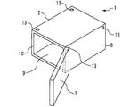
図20は、この発明の実施の形態1における断熱容器1の他の例を示す斜視図である。図1は、容器2の開口が上向きである例を示す。一方、図20は、容器2の開口が横向きである例を示す。断熱容器1は、図20に示すように横向きに使用されるものであっても構わない。
FIG. 20 is a perspective view showing another example of the heat insulating container 1 according to Embodiment 1 of the present invention. FIG. 1 shows an example in which the opening of the container 2 is upward. On the other hand, FIG. 20 shows an example in which the opening of the container 2 is sideways. The heat insulation container 1 may be used sideways as shown in FIG.
この発明に係る断熱容器は、物品を保温或いは保冷するために利用される。
The heat insulating container according to the present invention is used for keeping the article warm or cold.
1 断熱容器、 2 容器、 3 蓋、 4 収納棚、 5 枠、 6 仕切り、 7 物品、 8 外ケース、 9 内ケース、 10 閉塞体、 11 真空断熱材、 12 発泡断熱材、 13 貫通孔、 14 平板(第1平板)、 15 筒体(第1筒体)、 16 平板(第3平板)、 17 平板(第4平板)、 18 平板(第5平板)、 19 平板(第6平板)、 20 平板(第2平板)、 21 筒体(第2筒体)、 22 平板(第7平板)、 23 平板(第8平板)、 24 平板(第9平板)、 25 平板(第10平板)、 26 真空断熱板、 26a 縁、 27 真空断熱板、 27a 縁、 28 真空断熱板、 29 真空断熱板、 30 真空断熱板、 31 ガラス繊維、 32 フィルム、 33 真空断熱板、 34 断熱シート、 35 断熱フィルム
1 heat insulation container, 2 containers, 3 lids, 4 storage shelves, 5 frames, 6 partitions, 7 articles, 8 outer cases, 9 inner cases, 10 closed bodies, 11 vacuum insulation materials, 12 foam insulation materials, 13 through holes, 14 Flat plate (first flat plate), 15 cylinder (first cylindrical body), 16 flat plate (third flat plate), 17 flat plate (fourth flat plate), 18 flat plate (fifth flat plate), 19 flat plate (sixth flat plate), 20 Flat plate (second flat plate), 21 cylinder (second cylindrical body), 22 flat plate (seventh flat plate), 23 flat plate (eighth flat plate), 24 flat plate (9th flat plate), 25 flat plate (tenth flat plate), 26 Vacuum insulation plate, 26a rim, 27 vacuum insulation plate, 27a rim, 28 vacuum insulation plate, 29 vacuum insulation plate, 30 vacuum insulation plate, 31 glass fiber, 32 fiber Beam, 33 a vacuum insulation board, 34 insulation sheet, 35 insulation film
Claims (10)
- 貫通孔が形成された箱状の外ケースと、
前記外ケースの内側に配置された箱状の内ケースと、
前記外ケースの縁及び前記内ケースの縁の間に設けられた閉塞体と、
前記外ケース及び前記内ケースの間に配置された真空断熱材と、
前記真空断熱材及び前記外ケースの間に設けられた発泡断熱材と、
を備え、
前記外ケースは、
第1平板と、
前記第1平板の縁に設けられた第1筒体と、
を備え、
前記内ケースは、
第2平板と、
前記第2平板の縁に設けられ、前記第1筒体の内側に配置された第2筒体と、
を備え、
前記真空断熱材は、前記第1平板と前記第2平板との間及び前記第1筒体と前記第2筒体との間に配置され、
前記貫通孔から前記発泡断熱材が視認可能な断熱容器。 A box-shaped outer case with a through hole;
A box-shaped inner case disposed inside the outer case;
A closure provided between an edge of the outer case and an edge of the inner case;
A vacuum heat insulating material disposed between the outer case and the inner case;
A foam heat insulating material provided between the vacuum heat insulating material and the outer case;
With
The outer case is
A first flat plate;
A first cylinder provided on an edge of the first flat plate;
With
The inner case is
A second flat plate;
A second cylinder provided on an edge of the second flat plate and disposed inside the first cylinder;
With
The vacuum heat insulating material is disposed between the first flat plate and the second flat plate and between the first cylindrical body and the second cylindrical body,
A heat-insulating container in which the foamed heat insulating material is visible from the through hole. - 箱状の外ケースと、
前記外ケースの内側に配置された箱状の内ケースと、
前記外ケースの縁及び前記内ケースの縁の間に設けられ、貫通孔が形成された閉塞体と、
前記外ケース及び前記内ケースの間に配置された真空断熱材と、
前記真空断熱材及び前記外ケースの間に設けられた発泡断熱材と、
を備え、
前記外ケースは、
第1平板と、
前記第1平板の縁に設けられた第1筒体と、
を備え、
前記内ケースは、
第2平板と、
前記第2平板の縁に設けられ、前記第1筒体の内側に配置された第2筒体と、
を備え、
前記真空断熱材は、前記第1平板と前記第2平板との間及び前記第1筒体と前記第2筒体との間に配置され、
前記貫通孔から前記発泡断熱材が視認可能な断熱容器。 A box-shaped outer case,
A box-shaped inner case disposed inside the outer case;
A closing body provided between an edge of the outer case and an edge of the inner case, and having a through hole;
A vacuum heat insulating material disposed between the outer case and the inner case;
A foam heat insulating material provided between the vacuum heat insulating material and the outer case;
With
The outer case is
A first flat plate;
A first cylinder provided on an edge of the first flat plate;
With
The inner case is
A second flat plate;
A second cylinder provided on an edge of the second flat plate and disposed inside the first cylinder;
With
The vacuum heat insulating material is disposed between the first flat plate and the second flat plate and between the first cylindrical body and the second cylindrical body,
A heat-insulating container in which the foamed heat insulating material is visible from the through hole. - 前記外ケースに第2貫通孔が形成され、
前記第2貫通孔から前記発泡断熱材が視認可能な請求項2に記載の断熱容器。 A second through hole is formed in the outer case;
The heat insulating container according to claim 2, wherein the foamed heat insulating material is visible from the second through hole. - 前記発泡断熱材は、前記真空断熱材と前記内ケースとの間にも設けられた請求項1から請求項3の何れか一項に記載の断熱容器。 The heat insulation container according to any one of claims 1 to 3, wherein the foam heat insulating material is also provided between the vacuum heat insulating material and the inner case.
- 前記真空断熱材は、
第1真空断熱板と、
前記第1真空断熱板側を向く縁が前記第1真空断熱板との間に隙間を空けて配置された第2真空断熱板と、
前記第1真空断熱板の一部、前記隙間及び前記第2真空断熱板の前記縁と前記外ケースとの間に配置された第3真空断熱板と、
を備えた請求項1から請求項4の何れか一項に記載の断熱容器。 The vacuum heat insulating material is
A first vacuum insulation plate;
A second vacuum heat insulating plate arranged with a gap between the edge facing the first vacuum heat insulating plate and the first vacuum heat insulating plate;
A third vacuum heat insulating plate disposed between a part of the first vacuum heat insulating plate, the gap and the edge of the second vacuum heat insulating plate and the outer case;
The heat insulation container as described in any one of Claims 1-4 provided with. - 箱状の外ケースと、
前記外ケースの内側に配置され、貫通孔が形成された箱状の内ケースと、
前記外ケースの縁及び前記内ケースの縁の間に設けられた閉塞体と、
前記外ケース及び前記内ケースの間に配置された真空断熱材と、
前記真空断熱材及び前記内ケースの間に設けられた発泡断熱材と、
を備え、
前記外ケースは、
第1平板と、
前記第1平板の縁に設けられた第1筒体と、
を備え、
前記内ケースは、
第2平板と、
前記第2平板の縁に設けられ、前記第1筒体の内側に配置された第2筒体と、
を備え、
前記真空断熱材は、前記第1平板と前記第2平板との間及び前記第1筒体と前記第2筒体との間に配置され、
前記貫通孔から前記発泡断熱材が視認可能な断熱容器。 A box-shaped outer case,
A box-like inner case disposed inside the outer case and having a through hole;
A closure provided between an edge of the outer case and an edge of the inner case;
A vacuum heat insulating material disposed between the outer case and the inner case;
A foam heat insulating material provided between the vacuum heat insulating material and the inner case;
With
The outer case is
A first flat plate;
A first cylinder provided on an edge of the first flat plate;
With
The inner case is
A second flat plate;
A second cylinder provided on an edge of the second flat plate and disposed inside the first cylinder;
With
The vacuum heat insulating material is disposed between the first flat plate and the second flat plate and between the first cylindrical body and the second cylindrical body,
A heat-insulating container in which the foamed heat insulating material is visible from the through hole. - 前記真空断熱材は、
第1真空断熱板と、
前記第1真空断熱板側を向く縁が前記第1真空断熱板との間に隙間を空けて配置された第2真空断熱板と、
前記第1真空断熱板の一部、前記隙間及び前記第2真空断熱板の前記縁と前記内ケースとの間に配置された第3真空断熱板と、
を備えた請求項6に記載の断熱容器。 The vacuum heat insulating material is
A first vacuum insulation plate;
A second vacuum heat insulating plate arranged with a gap between the edge facing the first vacuum heat insulating plate and the first vacuum heat insulating plate;
A third vacuum heat insulating plate disposed between a part of the first vacuum heat insulating plate, the gap and the edge of the second vacuum heat insulating plate and the inner case;
The heat insulation container according to claim 6 provided with. - 前記貫通孔に前記発泡断熱材が配置された請求項1から請求項7の何れか一項に記載の断熱容器。 The heat insulating container according to any one of claims 1 to 7, wherein the foamed heat insulating material is disposed in the through hole.
- 前記貫通孔は、前記発泡断熱材によって塞がれた請求項1から請求項7の何れか一項に記載の断熱容器。 The heat insulating container according to any one of claims 1 to 7, wherein the through hole is closed by the foam heat insulating material.
- 前記第1平板は四角形状であり、
前記第1筒体は、第3平板と前記第3平板に平行な第4平板と前記第3平板及び前記第4平板の間に設けられた第5平板と前記第5平板に平行な第6平板とを備え、
前記第2平板は四角形状であり、
前記第2筒体は、第7平板と前記第7平板に平行な第8平板と前記第7平板及び前記第8平板の間に設けられた第9平板と前記第9平板に平行な第10平板とを備え、
前記真空断熱材は、前記第3平板と前記第7平板との間、前記第4平板と前記第8平板との間、前記第5平板と前記第9平板との間及び前記第6平板と前記第10平板との間に配置された請求項1から請求項9の何れか一項に記載の断熱容器。 The first flat plate has a quadrangular shape;
The first cylinder includes a third flat plate, a fourth flat plate parallel to the third flat plate, a fifth flat plate provided between the third flat plate and the fourth flat plate, and a sixth flat plate parallel to the fifth flat plate. With a flat plate,
The second flat plate has a quadrangular shape,
The second cylindrical body includes a seventh flat plate, an eighth flat plate parallel to the seventh flat plate, a ninth flat plate provided between the seventh flat plate and the eighth flat plate, and a tenth parallel to the ninth flat plate. With a flat plate,
The vacuum heat insulating material is between the third flat plate and the seventh flat plate, between the fourth flat plate and the eighth flat plate, between the fifth flat plate and the ninth flat plate, and the sixth flat plate. The heat insulation container as described in any one of Claims 1-9 arrange | positioned between the said 10th flat plates.
Priority Applications (2)
| Application Number | Priority Date | Filing Date | Title |
|---|---|---|---|
| JP2018520235A JP6551605B2 (en) | 2016-05-31 | 2016-05-31 | Insulated container |
| PCT/JP2016/065984 WO2017208331A1 (en) | 2016-05-31 | 2016-05-31 | Thermally insulated container |
Applications Claiming Priority (1)
| Application Number | Priority Date | Filing Date | Title |
|---|---|---|---|
| PCT/JP2016/065984 WO2017208331A1 (en) | 2016-05-31 | 2016-05-31 | Thermally insulated container |
Publications (1)
| Publication Number | Publication Date |
|---|---|
| WO2017208331A1 true WO2017208331A1 (en) | 2017-12-07 |
Family
ID=60479210
Family Applications (1)
| Application Number | Title | Priority Date | Filing Date |
|---|---|---|---|
| PCT/JP2016/065984 WO2017208331A1 (en) | 2016-05-31 | 2016-05-31 | Thermally insulated container |
Country Status (2)
| Country | Link |
|---|---|
| JP (1) | JP6551605B2 (en) |
| WO (1) | WO2017208331A1 (en) |
Citations (4)
| Publication number | Priority date | Publication date | Assignee | Title |
|---|---|---|---|---|
| JPS61178870A (en) * | 1985-01-30 | 1986-08-11 | 川北 弘明 | Heat-insulating vessel |
| JP2001165389A (en) * | 1999-12-10 | 2001-06-22 | Matsushita Refrig Co Ltd | Insulated box body |
| JP2015169372A (en) * | 2014-03-06 | 2015-09-28 | 大日本印刷株式会社 | Heat insulation container, and method of manufacturing heat insulation container |
| JP2015168465A (en) * | 2014-03-06 | 2015-09-28 | 大日本印刷株式会社 | Heat insulating container, and method for repairing heat insulating container |
Family Cites Families (1)
| Publication number | Priority date | Publication date | Assignee | Title |
|---|---|---|---|---|
| JP2015168765A (en) * | 2014-03-07 | 2015-09-28 | 第一工業製薬株式会社 | Energy ray-curable resin composition |
-
2016
- 2016-05-31 WO PCT/JP2016/065984 patent/WO2017208331A1/en active Application Filing
- 2016-05-31 JP JP2018520235A patent/JP6551605B2/en active Active
Patent Citations (4)
| Publication number | Priority date | Publication date | Assignee | Title |
|---|---|---|---|---|
| JPS61178870A (en) * | 1985-01-30 | 1986-08-11 | 川北 弘明 | Heat-insulating vessel |
| JP2001165389A (en) * | 1999-12-10 | 2001-06-22 | Matsushita Refrig Co Ltd | Insulated box body |
| JP2015169372A (en) * | 2014-03-06 | 2015-09-28 | 大日本印刷株式会社 | Heat insulation container, and method of manufacturing heat insulation container |
| JP2015168465A (en) * | 2014-03-06 | 2015-09-28 | 大日本印刷株式会社 | Heat insulating container, and method for repairing heat insulating container |
Also Published As
| Publication number | Publication date |
|---|---|
| JP6551605B2 (en) | 2019-07-31 |
| JPWO2017208331A1 (en) | 2018-09-13 |
Similar Documents
| Publication | Publication Date | Title |
|---|---|---|
| WO2014118821A1 (en) | Thermal insulation box | |
| EP2900568B1 (en) | Convection based temperature assured packaging system | |
| KR200471021Y1 (en) | Box-type packaging which can control the internal temperature | |
| WO1999032374A1 (en) | Insulated shipping container | |
| KR101910860B1 (en) | Packaging box for cooling | |
| JP7378979B2 (en) | Temperature storage container | |
| JP2019137458A (en) | Heat insulation container, and transportation method using the same | |
| JP2018164484A5 (en) | ||
| WO2017208331A1 (en) | Thermally insulated container | |
| JP3211437U (en) | Cold box | |
| KR101176077B1 (en) | Panel made of expanded synthetic resins and packaging using the same | |
| JP2013119426A (en) | Freezer | |
| KR20180001317A (en) | Ice box | |
| KR20150000671U (en) | Box-type packaging which can control the internal temperature | |
| JP2015193388A (en) | Cool box | |
| WO2015063820A1 (en) | Heat-insulated box | |
| JP2017044352A (en) | Cool box | |
| WO2020105178A1 (en) | Refrigerator | |
| US11768024B2 (en) | Constant temperature container | |
| WO2020255888A1 (en) | Isothermal container | |
| KR102634834B1 (en) | Modular connecting structure of the refrigerant pack | |
| JP7170297B2 (en) | cold insulation container | |
| KR101982638B1 (en) | Superchilling packaging system for fresh delivery | |
| ES2632434T3 (en) | Isothermal container, method | |
| JP3196828U (en) | Cold storage container |
Legal Events
| Date | Code | Title | Description |
|---|---|---|---|
| ENP | Entry into the national phase |
Ref document number: 2018520235 Country of ref document: JP Kind code of ref document: A |
|
| 121 | Ep: the epo has been informed by wipo that ep was designated in this application |
Ref document number: 16903959 Country of ref document: EP Kind code of ref document: A1 |
|
| NENP | Non-entry into the national phase |
Ref country code: DE |
|
| 122 | Ep: pct application non-entry in european phase |
Ref document number: 16903959 Country of ref document: EP Kind code of ref document: A1 |