WO2017204228A1 - Laminate, and front panel of image display device, image display device, mirror with image display function, resistance film type touch panel, and capacitive touch panel all including said laminate - Google Patents
Laminate, and front panel of image display device, image display device, mirror with image display function, resistance film type touch panel, and capacitive touch panel all including said laminate Download PDFInfo
- Publication number
- WO2017204228A1 WO2017204228A1 PCT/JP2017/019277 JP2017019277W WO2017204228A1 WO 2017204228 A1 WO2017204228 A1 WO 2017204228A1 JP 2017019277 W JP2017019277 W JP 2017019277W WO 2017204228 A1 WO2017204228 A1 WO 2017204228A1
- Authority
- WO
- WIPO (PCT)
- Prior art keywords
- layer
- image display
- resin film
- laminate
- group
- Prior art date
Links
- 239000010410 layer Substances 0.000 claims abstract description 602
- 229920005989 resin Polymers 0.000 claims abstract description 249
- 239000011347 resin Substances 0.000 claims abstract description 248
- 230000003746 surface roughness Effects 0.000 claims abstract description 51
- 239000004820 Pressure-sensitive adhesive Substances 0.000 claims abstract description 27
- 150000001875 compounds Chemical class 0.000 claims description 279
- 239000000203 mixture Substances 0.000 claims description 159
- 239000012790 adhesive layer Substances 0.000 claims description 93
- 239000004973 liquid crystal related substance Substances 0.000 claims description 87
- 239000004986 Cholesteric liquid crystals (ChLC) Substances 0.000 claims description 85
- 238000005259 measurement Methods 0.000 claims description 21
- 230000000007 visual effect Effects 0.000 claims description 18
- 239000003505 polymerization initiator Substances 0.000 claims description 12
- 238000005401 electroluminescence Methods 0.000 claims description 7
- 230000002441 reversible effect Effects 0.000 abstract description 5
- 239000010408 film Substances 0.000 description 363
- 238000000034 method Methods 0.000 description 94
- 150000003254 radicals Chemical class 0.000 description 94
- NIXOWILDQLNWCW-UHFFFAOYSA-M Acrylate Chemical compound [O-]C(=O)C=C NIXOWILDQLNWCW-UHFFFAOYSA-M 0.000 description 82
- -1 acryl Chemical group 0.000 description 81
- 229910052751 metal Inorganic materials 0.000 description 50
- 239000002184 metal Substances 0.000 description 50
- 230000015572 biosynthetic process Effects 0.000 description 49
- 239000003999 initiator Substances 0.000 description 46
- 239000000758 substrate Substances 0.000 description 46
- 238000005755 formation reaction Methods 0.000 description 44
- 230000006870 function Effects 0.000 description 40
- 239000011521 glass Substances 0.000 description 40
- 230000002093 peripheral effect Effects 0.000 description 38
- 125000002091 cationic group Chemical group 0.000 description 37
- 238000004519 manufacturing process Methods 0.000 description 37
- 239000000463 material Substances 0.000 description 36
- 125000003647 acryloyl group Chemical group O=C([*])C([H])=C([H])[H] 0.000 description 35
- 239000000243 solution Substances 0.000 description 34
- 230000000052 comparative effect Effects 0.000 description 33
- 239000000047 product Substances 0.000 description 31
- LYCAIKOWRPUZTN-UHFFFAOYSA-N Ethylene glycol Chemical compound OCCO LYCAIKOWRPUZTN-UHFFFAOYSA-N 0.000 description 30
- 239000000853 adhesive Substances 0.000 description 30
- 230000001070 adhesive effect Effects 0.000 description 30
- 239000002245 particle Substances 0.000 description 30
- 238000006243 chemical reaction Methods 0.000 description 29
- 239000010954 inorganic particle Substances 0.000 description 29
- 238000001035 drying Methods 0.000 description 26
- 239000007787 solid Substances 0.000 description 26
- 239000002904 solvent Substances 0.000 description 26
- 239000000126 substance Substances 0.000 description 26
- 238000006116 polymerization reaction Methods 0.000 description 23
- 238000001723 curing Methods 0.000 description 22
- 125000004122 cyclic group Chemical group 0.000 description 22
- 235000019589 hardness Nutrition 0.000 description 22
- XEKOWRVHYACXOJ-UHFFFAOYSA-N Ethyl acetate Chemical compound CCOC(C)=O XEKOWRVHYACXOJ-UHFFFAOYSA-N 0.000 description 21
- 238000000576 coating method Methods 0.000 description 21
- 238000012360 testing method Methods 0.000 description 21
- 238000005266 casting Methods 0.000 description 20
- 239000012792 core layer Substances 0.000 description 20
- 125000000623 heterocyclic group Chemical group 0.000 description 20
- 230000003287 optical effect Effects 0.000 description 20
- 229920000642 polymer Polymers 0.000 description 20
- 238000002360 preparation method Methods 0.000 description 19
- 239000011164 primary particle Substances 0.000 description 19
- UWCWUCKPEYNDNV-LBPRGKRZSA-N 2,6-dimethyl-n-[[(2s)-pyrrolidin-2-yl]methyl]aniline Chemical compound CC1=CC=CC(C)=C1NC[C@H]1NCCC1 UWCWUCKPEYNDNV-LBPRGKRZSA-N 0.000 description 18
- 239000011248 coating agent Substances 0.000 description 18
- 229920000139 polyethylene terephthalate Polymers 0.000 description 18
- 239000005020 polyethylene terephthalate Substances 0.000 description 18
- 229910001111 Fine metal Inorganic materials 0.000 description 17
- VYPSYNLAJGMNEJ-UHFFFAOYSA-N Silicium dioxide Chemical compound O=[Si]=O VYPSYNLAJGMNEJ-UHFFFAOYSA-N 0.000 description 17
- CERQOIWHTDAKMF-UHFFFAOYSA-N Methacrylic acid Chemical compound CC(=C)C(O)=O CERQOIWHTDAKMF-UHFFFAOYSA-N 0.000 description 16
- NIXOWILDQLNWCW-UHFFFAOYSA-N acrylic acid group Chemical group C(C=C)(=O)O NIXOWILDQLNWCW-UHFFFAOYSA-N 0.000 description 16
- 238000012663 cationic photopolymerization Methods 0.000 description 16
- 230000003098 cholesteric effect Effects 0.000 description 16
- 238000001816 cooling Methods 0.000 description 16
- ZFSLODLOARCGLH-UHFFFAOYSA-N isocyanuric acid Chemical compound OC1=NC(O)=NC(O)=N1 ZFSLODLOARCGLH-UHFFFAOYSA-N 0.000 description 16
- 229920000728 polyester Polymers 0.000 description 16
- IJGRMHOSHXDMSA-UHFFFAOYSA-N Atomic nitrogen Chemical compound N#N IJGRMHOSHXDMSA-UHFFFAOYSA-N 0.000 description 15
- 230000008569 process Effects 0.000 description 15
- 239000004593 Epoxy Substances 0.000 description 14
- 239000002519 antifouling agent Substances 0.000 description 14
- 239000003795 chemical substances by application Substances 0.000 description 14
- 125000003700 epoxy group Chemical group 0.000 description 14
- ODIGIKRIUKFKHP-UHFFFAOYSA-N (n-propan-2-yloxycarbonylanilino) acetate Chemical compound CC(C)OC(=O)N(OC(C)=O)C1=CC=CC=C1 ODIGIKRIUKFKHP-UHFFFAOYSA-N 0.000 description 13
- ZWEHNKRNPOVVGH-UHFFFAOYSA-N 2-Butanone Chemical compound CCC(C)=O ZWEHNKRNPOVVGH-UHFFFAOYSA-N 0.000 description 13
- 239000004925 Acrylic resin Substances 0.000 description 13
- 229920000178 Acrylic resin Polymers 0.000 description 13
- 125000002723 alicyclic group Chemical group 0.000 description 13
- QVGXLLKOCUKJST-UHFFFAOYSA-N atomic oxygen Chemical compound [O] QVGXLLKOCUKJST-UHFFFAOYSA-N 0.000 description 13
- 239000001913 cellulose Substances 0.000 description 13
- 229920002678 cellulose Polymers 0.000 description 13
- 238000001914 filtration Methods 0.000 description 13
- 229910052731 fluorine Inorganic materials 0.000 description 13
- 150000002430 hydrocarbons Chemical group 0.000 description 13
- 239000003607 modifier Substances 0.000 description 13
- 239000001301 oxygen Substances 0.000 description 13
- 229910052760 oxygen Inorganic materials 0.000 description 13
- 229940059574 pentaerithrityl Drugs 0.000 description 13
- WXZMFSXDPGVJKK-UHFFFAOYSA-N pentaerythritol Chemical compound OCC(CO)(CO)CO WXZMFSXDPGVJKK-UHFFFAOYSA-N 0.000 description 13
- 239000002994 raw material Substances 0.000 description 13
- 239000010409 thin film Substances 0.000 description 13
- YCKRFDGAMUMZLT-UHFFFAOYSA-N Fluorine atom Chemical compound [F] YCKRFDGAMUMZLT-UHFFFAOYSA-N 0.000 description 12
- 239000000654 additive Substances 0.000 description 12
- 239000011737 fluorine Substances 0.000 description 12
- 238000010438 heat treatment Methods 0.000 description 12
- GOOHAUXETOMSMM-UHFFFAOYSA-N Propylene oxide Chemical compound CC1CO1 GOOHAUXETOMSMM-UHFFFAOYSA-N 0.000 description 11
- BQCADISMDOOEFD-UHFFFAOYSA-N Silver Chemical compound [Ag] BQCADISMDOOEFD-UHFFFAOYSA-N 0.000 description 11
- 210000004027 cell Anatomy 0.000 description 11
- 125000000524 functional group Chemical group 0.000 description 11
- 230000010287 polarization Effects 0.000 description 11
- 229920000058 polyacrylate Polymers 0.000 description 11
- 229920000515 polycarbonate Polymers 0.000 description 11
- 239000011112 polyethylene naphthalate Substances 0.000 description 11
- 229910052709 silver Inorganic materials 0.000 description 11
- 239000004332 silver Substances 0.000 description 11
- 238000004544 sputter deposition Methods 0.000 description 11
- OKKJLVBELUTLKV-UHFFFAOYSA-N Methanol Chemical compound OC OKKJLVBELUTLKV-UHFFFAOYSA-N 0.000 description 10
- 239000006096 absorbing agent Substances 0.000 description 10
- 238000011156 evaluation Methods 0.000 description 10
- 238000010030 laminating Methods 0.000 description 10
- 238000002844 melting Methods 0.000 description 10
- 230000008018 melting Effects 0.000 description 10
- 229920003229 poly(methyl methacrylate) Polymers 0.000 description 10
- 239000004417 polycarbonate Substances 0.000 description 10
- 239000004926 polymethyl methacrylate Substances 0.000 description 10
- 239000011241 protective layer Substances 0.000 description 10
- 239000006097 ultraviolet radiation absorber Substances 0.000 description 10
- 229920002799 BoPET Polymers 0.000 description 9
- 230000000996 additive effect Effects 0.000 description 9
- IISBACLAFKSPIT-UHFFFAOYSA-N bisphenol A Chemical compound C=1C=C(O)C=CC=1C(C)(C)C1=CC=C(O)C=C1 IISBACLAFKSPIT-UHFFFAOYSA-N 0.000 description 9
- 125000004432 carbon atom Chemical group C* 0.000 description 9
- 239000003431 cross linking reagent Substances 0.000 description 9
- 239000012948 isocyanate Substances 0.000 description 9
- 229920003207 poly(ethylene-2,6-naphthalate) Polymers 0.000 description 9
- 239000002356 single layer Substances 0.000 description 9
- OZAIFHULBGXAKX-UHFFFAOYSA-N 2-(2-cyanopropan-2-yldiazenyl)-2-methylpropanenitrile Chemical compound N#CC(C)(C)N=NC(C)(C)C#N OZAIFHULBGXAKX-UHFFFAOYSA-N 0.000 description 8
- TXBCBTDQIULDIA-UHFFFAOYSA-N 2-[[3-hydroxy-2,2-bis(hydroxymethyl)propoxy]methyl]-2-(hydroxymethyl)propane-1,3-diol Chemical compound OCC(CO)(CO)COCC(CO)(CO)CO TXBCBTDQIULDIA-UHFFFAOYSA-N 0.000 description 8
- BRLQWZUYTZBJKN-UHFFFAOYSA-N Epichlorohydrin Chemical compound ClCC1CO1 BRLQWZUYTZBJKN-UHFFFAOYSA-N 0.000 description 8
- ZJCCRDAZUWHFQH-UHFFFAOYSA-N Trimethylolpropane Chemical compound CCC(CO)(CO)CO ZJCCRDAZUWHFQH-UHFFFAOYSA-N 0.000 description 8
- 238000005299 abrasion Methods 0.000 description 8
- 229910045601 alloy Inorganic materials 0.000 description 8
- 239000000956 alloy Substances 0.000 description 8
- 125000005647 linker group Chemical group 0.000 description 8
- 239000007788 liquid Substances 0.000 description 8
- 238000002156 mixing Methods 0.000 description 8
- 229910052757 nitrogen Inorganic materials 0.000 description 8
- QJGQUHMNIGDVPM-UHFFFAOYSA-N nitrogen group Chemical group [N] QJGQUHMNIGDVPM-UHFFFAOYSA-N 0.000 description 8
- 229920001225 polyester resin Polymers 0.000 description 8
- 239000004645 polyester resin Substances 0.000 description 8
- 125000001931 aliphatic group Chemical group 0.000 description 7
- 239000000839 emulsion Substances 0.000 description 7
- 230000000670 limiting effect Effects 0.000 description 7
- 239000000155 melt Substances 0.000 description 7
- 238000006068 polycondensation reaction Methods 0.000 description 7
- PEDCQBHIVMGVHV-UHFFFAOYSA-N Glycerine Chemical compound OCC(O)CO PEDCQBHIVMGVHV-UHFFFAOYSA-N 0.000 description 6
- PPBRXRYQALVLMV-UHFFFAOYSA-N Styrene Chemical compound C=CC1=CC=CC=C1 PPBRXRYQALVLMV-UHFFFAOYSA-N 0.000 description 6
- KKEYFWRCBNTPAC-UHFFFAOYSA-N Terephthalic acid Chemical compound OC(=O)C1=CC=C(C(O)=O)C=C1 KKEYFWRCBNTPAC-UHFFFAOYSA-N 0.000 description 6
- WYURNTSHIVDZCO-UHFFFAOYSA-N Tetrahydrofuran Chemical compound C1CCOC1 WYURNTSHIVDZCO-UHFFFAOYSA-N 0.000 description 6
- YXFVVABEGXRONW-UHFFFAOYSA-N Toluene Chemical compound CC1=CC=CC=C1 YXFVVABEGXRONW-UHFFFAOYSA-N 0.000 description 6
- MPIAGWXWVAHQBB-UHFFFAOYSA-N [3-prop-2-enoyloxy-2-[[3-prop-2-enoyloxy-2,2-bis(prop-2-enoyloxymethyl)propoxy]methyl]-2-(prop-2-enoyloxymethyl)propyl] prop-2-enoate Chemical compound C=CC(=O)OCC(COC(=O)C=C)(COC(=O)C=C)COCC(COC(=O)C=C)(COC(=O)C=C)COC(=O)C=C MPIAGWXWVAHQBB-UHFFFAOYSA-N 0.000 description 6
- 125000002947 alkylene group Chemical group 0.000 description 6
- 125000003118 aryl group Chemical group 0.000 description 6
- 229910052799 carbon Inorganic materials 0.000 description 6
- 239000003054 catalyst Substances 0.000 description 6
- 150000001768 cations Chemical class 0.000 description 6
- 239000007795 chemical reaction product Substances 0.000 description 6
- 229940125782 compound 2 Drugs 0.000 description 6
- UAOMVDZJSHZZME-UHFFFAOYSA-N diisopropylamine Chemical compound CC(C)NC(C)C UAOMVDZJSHZZME-UHFFFAOYSA-N 0.000 description 6
- 239000006185 dispersion Substances 0.000 description 6
- 230000000694 effects Effects 0.000 description 6
- 238000005886 esterification reaction Methods 0.000 description 6
- 150000002148 esters Chemical class 0.000 description 6
- 150000002513 isocyanates Chemical class 0.000 description 6
- 238000003475 lamination Methods 0.000 description 6
- 239000003960 organic solvent Substances 0.000 description 6
- 230000001681 protective effect Effects 0.000 description 6
- 230000002829 reductive effect Effects 0.000 description 6
- 125000001424 substituent group Chemical group 0.000 description 6
- XLYOFNOQVPJJNP-UHFFFAOYSA-N water Substances O XLYOFNOQVPJJNP-UHFFFAOYSA-N 0.000 description 6
- SMZOUWXMTYCWNB-UHFFFAOYSA-N 2-(2-methoxy-5-methylphenyl)ethanamine Chemical compound COC1=CC=C(C)C=C1CCN SMZOUWXMTYCWNB-UHFFFAOYSA-N 0.000 description 5
- OKTJSMMVPCPJKN-UHFFFAOYSA-N Carbon Chemical compound [C] OKTJSMMVPCPJKN-UHFFFAOYSA-N 0.000 description 5
- 241000951471 Citrus junos Species 0.000 description 5
- RYGMFSIKBFXOCR-UHFFFAOYSA-N Copper Chemical compound [Cu] RYGMFSIKBFXOCR-UHFFFAOYSA-N 0.000 description 5
- 102100029765 DNA polymerase lambda Human genes 0.000 description 5
- 101710177421 DNA polymerase lambda Proteins 0.000 description 5
- LFQSCWFLJHTTHZ-UHFFFAOYSA-N Ethanol Chemical compound CCO LFQSCWFLJHTTHZ-UHFFFAOYSA-N 0.000 description 5
- NTIZESTWPVYFNL-UHFFFAOYSA-N Methyl isobutyl ketone Chemical compound CC(C)CC(C)=O NTIZESTWPVYFNL-UHFFFAOYSA-N 0.000 description 5
- 150000001252 acrylic acid derivatives Chemical class 0.000 description 5
- 229910052782 aluminium Inorganic materials 0.000 description 5
- XAGFODPZIPBFFR-UHFFFAOYSA-N aluminium Chemical compound [Al] XAGFODPZIPBFFR-UHFFFAOYSA-N 0.000 description 5
- 238000010538 cationic polymerization reaction Methods 0.000 description 5
- 229910052802 copper Inorganic materials 0.000 description 5
- 239000010949 copper Substances 0.000 description 5
- 238000004132 cross linking Methods 0.000 description 5
- 238000001514 detection method Methods 0.000 description 5
- 239000007789 gas Substances 0.000 description 5
- 238000005227 gel permeation chromatography Methods 0.000 description 5
- 230000001965 increasing effect Effects 0.000 description 5
- 239000012299 nitrogen atmosphere Substances 0.000 description 5
- 239000011148 porous material Substances 0.000 description 5
- 238000003786 synthesis reaction Methods 0.000 description 5
- 125000000391 vinyl group Chemical group [H]C([*])=C([H])[H] 0.000 description 5
- HRPVXLWXLXDGHG-UHFFFAOYSA-N Acrylamide Chemical compound NC(=O)C=C HRPVXLWXLXDGHG-UHFFFAOYSA-N 0.000 description 4
- HEDRZPFGACZZDS-UHFFFAOYSA-N Chloroform Chemical compound ClC(Cl)Cl HEDRZPFGACZZDS-UHFFFAOYSA-N 0.000 description 4
- 239000005057 Hexamethylene diisocyanate Substances 0.000 description 4
- UIHCLUNTQKBZGK-UHFFFAOYSA-N Methyl isobutyl ketone Natural products CCC(C)C(C)=O UIHCLUNTQKBZGK-UHFFFAOYSA-N 0.000 description 4
- SECXISVLQFMRJM-UHFFFAOYSA-N N-Methylpyrrolidone Chemical compound CN1CCCC1=O SECXISVLQFMRJM-UHFFFAOYSA-N 0.000 description 4
- XBDQKXXYIPTUBI-UHFFFAOYSA-M Propionate Chemical compound CCC([O-])=O XBDQKXXYIPTUBI-UHFFFAOYSA-M 0.000 description 4
- 229910004298 SiO 2 Inorganic materials 0.000 description 4
- QYKIQEUNHZKYBP-UHFFFAOYSA-N Vinyl ether Chemical group C=COC=C QYKIQEUNHZKYBP-UHFFFAOYSA-N 0.000 description 4
- 229920006243 acrylic copolymer Polymers 0.000 description 4
- 125000000217 alkyl group Chemical group 0.000 description 4
- ADCOVFLJGNWWNZ-UHFFFAOYSA-N antimony trioxide Chemical compound O=[Sb]O[Sb]=O ADCOVFLJGNWWNZ-UHFFFAOYSA-N 0.000 description 4
- CQEYYJKEWSMYFG-UHFFFAOYSA-N butyl acrylate Chemical compound CCCCOC(=O)C=C CQEYYJKEWSMYFG-UHFFFAOYSA-N 0.000 description 4
- 238000005229 chemical vapour deposition Methods 0.000 description 4
- 239000013065 commercial product Substances 0.000 description 4
- 239000002131 composite material Substances 0.000 description 4
- 239000004020 conductor Substances 0.000 description 4
- 125000000113 cyclohexyl group Chemical group [H]C1([H])C([H])([H])C([H])([H])C([H])(*)C([H])([H])C1([H])[H] 0.000 description 4
- 229920001971 elastomer Polymers 0.000 description 4
- 238000000295 emission spectrum Methods 0.000 description 4
- 238000001125 extrusion Methods 0.000 description 4
- 239000010419 fine particle Substances 0.000 description 4
- 125000006162 fluoroaliphatic group Chemical group 0.000 description 4
- RRAMGCGOFNQTLD-UHFFFAOYSA-N hexamethylene diisocyanate Chemical compound O=C=NCCCCCCN=C=O RRAMGCGOFNQTLD-UHFFFAOYSA-N 0.000 description 4
- XMBWDFGMSWQBCA-UHFFFAOYSA-N hydrogen iodide Chemical class I XMBWDFGMSWQBCA-UHFFFAOYSA-N 0.000 description 4
- 230000001678 irradiating effect Effects 0.000 description 4
- 150000002576 ketones Chemical class 0.000 description 4
- 238000004898 kneading Methods 0.000 description 4
- YMWUJEATGCHHMB-UHFFFAOYSA-N methylene chloride Substances ClCCl YMWUJEATGCHHMB-UHFFFAOYSA-N 0.000 description 4
- 239000000178 monomer Substances 0.000 description 4
- 239000005304 optical glass Substances 0.000 description 4
- 125000003566 oxetanyl group Chemical group 0.000 description 4
- 230000036961 partial effect Effects 0.000 description 4
- 229920005668 polycarbonate resin Polymers 0.000 description 4
- 239000004431 polycarbonate resin Substances 0.000 description 4
- 229920006254 polymer film Polymers 0.000 description 4
- 238000010992 reflux Methods 0.000 description 4
- 239000005060 rubber Substances 0.000 description 4
- 238000003756 stirring Methods 0.000 description 4
- 150000005846 sugar alcohols Polymers 0.000 description 4
- 150000003505 terpenes Chemical class 0.000 description 4
- 235000007586 terpenes Nutrition 0.000 description 4
- XOLBLPGZBRYERU-UHFFFAOYSA-N tin dioxide Chemical compound O=[Sn]=O XOLBLPGZBRYERU-UHFFFAOYSA-N 0.000 description 4
- 229910001887 tin oxide Inorganic materials 0.000 description 4
- BTJPUDCSZVCXFQ-UHFFFAOYSA-N 2,4-diethylthioxanthen-9-one Chemical compound C1=CC=C2C(=O)C3=CC(CC)=CC(CC)=C3SC2=C1 BTJPUDCSZVCXFQ-UHFFFAOYSA-N 0.000 description 3
- 125000003903 2-propenyl group Chemical group [H]C([*])([H])C([H])=C([H])[H] 0.000 description 3
- CSCPPACGZOOCGX-UHFFFAOYSA-N Acetone Chemical compound CC(C)=O CSCPPACGZOOCGX-UHFFFAOYSA-N 0.000 description 3
- 229920002284 Cellulose triacetate Polymers 0.000 description 3
- 229940126062 Compound A Drugs 0.000 description 3
- IAYPIBMASNFSPL-UHFFFAOYSA-N Ethylene oxide Chemical compound C1CO1 IAYPIBMASNFSPL-UHFFFAOYSA-N 0.000 description 3
- NLDMNSXOCDLTTB-UHFFFAOYSA-N Heterophylliin A Natural products O1C2COC(=O)C3=CC(O)=C(O)C(O)=C3C3=C(O)C(O)=C(O)C=C3C(=O)OC2C(OC(=O)C=2C=C(O)C(O)=C(O)C=2)C(O)C1OC(=O)C1=CC(O)=C(O)C(O)=C1 NLDMNSXOCDLTTB-UHFFFAOYSA-N 0.000 description 3
- GWEVSGVZZGPLCZ-UHFFFAOYSA-N Titan oxide Chemical compound O=[Ti]=O GWEVSGVZZGPLCZ-UHFFFAOYSA-N 0.000 description 3
- RTAQQCXQSZGOHL-UHFFFAOYSA-N Titanium Chemical compound [Ti] RTAQQCXQSZGOHL-UHFFFAOYSA-N 0.000 description 3
- 239000007983 Tris buffer Substances 0.000 description 3
- NNLVGZFZQQXQNW-ADJNRHBOSA-N [(2r,3r,4s,5r,6s)-4,5-diacetyloxy-3-[(2s,3r,4s,5r,6r)-3,4,5-triacetyloxy-6-(acetyloxymethyl)oxan-2-yl]oxy-6-[(2r,3r,4s,5r,6s)-4,5,6-triacetyloxy-2-(acetyloxymethyl)oxan-3-yl]oxyoxan-2-yl]methyl acetate Chemical compound O([C@@H]1O[C@@H]([C@H]([C@H](OC(C)=O)[C@H]1OC(C)=O)O[C@H]1[C@@H]([C@@H](OC(C)=O)[C@H](OC(C)=O)[C@@H](COC(C)=O)O1)OC(C)=O)COC(=O)C)[C@@H]1[C@@H](COC(C)=O)O[C@@H](OC(C)=O)[C@H](OC(C)=O)[C@H]1OC(C)=O NNLVGZFZQQXQNW-ADJNRHBOSA-N 0.000 description 3
- KXKVLQRXCPHEJC-UHFFFAOYSA-N acetic acid trimethyl ester Natural products COC(C)=O KXKVLQRXCPHEJC-UHFFFAOYSA-N 0.000 description 3
- 239000004840 adhesive resin Substances 0.000 description 3
- 150000004703 alkoxides Chemical class 0.000 description 3
- 229910052787 antimony Inorganic materials 0.000 description 3
- WATWJIUSRGPENY-UHFFFAOYSA-N antimony atom Chemical compound [Sb] WATWJIUSRGPENY-UHFFFAOYSA-N 0.000 description 3
- GHPGOEFPKIHBNM-UHFFFAOYSA-N antimony(3+);oxygen(2-) Chemical compound [O-2].[O-2].[O-2].[Sb+3].[Sb+3] GHPGOEFPKIHBNM-UHFFFAOYSA-N 0.000 description 3
- 230000005540 biological transmission Effects 0.000 description 3
- 238000007664 blowing Methods 0.000 description 3
- 229940125904 compound 1 Drugs 0.000 description 3
- 230000007797 corrosion Effects 0.000 description 3
- 238000005260 corrosion Methods 0.000 description 3
- 229920006037 cross link polymer Polymers 0.000 description 3
- 230000006866 deterioration Effects 0.000 description 3
- 238000007607 die coating method Methods 0.000 description 3
- 235000014113 dietary fatty acids Nutrition 0.000 description 3
- MTHSVFCYNBDYFN-UHFFFAOYSA-N diethylene glycol Chemical compound OCCOCCO MTHSVFCYNBDYFN-UHFFFAOYSA-N 0.000 description 3
- 208000028659 discharge Diseases 0.000 description 3
- AFOSIXZFDONLBT-UHFFFAOYSA-N divinyl sulfone Chemical compound C=CS(=O)(=O)C=C AFOSIXZFDONLBT-UHFFFAOYSA-N 0.000 description 3
- 229940052303 ethers for general anesthesia Drugs 0.000 description 3
- 230000001747 exhibiting effect Effects 0.000 description 3
- 239000000194 fatty acid Substances 0.000 description 3
- 229930195729 fatty acid Natural products 0.000 description 3
- 150000004665 fatty acids Chemical class 0.000 description 3
- 125000001046 glycoluril group Chemical group [H]C12N(*)C(=O)N(*)C1([H])N(*)C(=O)N2* 0.000 description 3
- 238000007756 gravure coating Methods 0.000 description 3
- 238000009499 grossing Methods 0.000 description 3
- 229910052736 halogen Inorganic materials 0.000 description 3
- 150000002367 halogens Chemical class 0.000 description 3
- 229930195733 hydrocarbon Natural products 0.000 description 3
- 125000004435 hydrogen atom Chemical class [H]* 0.000 description 3
- 125000002887 hydroxy group Chemical group [H]O* 0.000 description 3
- 239000012535 impurity Substances 0.000 description 3
- 230000005865 ionizing radiation Effects 0.000 description 3
- 125000002950 monocyclic group Chemical group 0.000 description 3
- 239000011146 organic particle Substances 0.000 description 3
- 229920006255 plastic film Polymers 0.000 description 3
- 239000002985 plastic film Substances 0.000 description 3
- 229920006289 polycarbonate film Polymers 0.000 description 3
- 229920001451 polypropylene glycol Polymers 0.000 description 3
- 230000009467 reduction Effects 0.000 description 3
- 235000012239 silicon dioxide Nutrition 0.000 description 3
- 238000001228 spectrum Methods 0.000 description 3
- 229920002803 thermoplastic polyurethane Polymers 0.000 description 3
- 229910052719 titanium Inorganic materials 0.000 description 3
- 239000010936 titanium Substances 0.000 description 3
- 238000000411 transmission spectrum Methods 0.000 description 3
- 238000007740 vapor deposition Methods 0.000 description 3
- PAPBSGBWRJIAAV-UHFFFAOYSA-N ε-Caprolactone Chemical compound O=C1CCCCCO1 PAPBSGBWRJIAAV-UHFFFAOYSA-N 0.000 description 3
- DTGKSKDOIYIVQL-WEDXCCLWSA-N (+)-borneol Chemical group C1C[C@@]2(C)[C@@H](O)C[C@@H]1C2(C)C DTGKSKDOIYIVQL-WEDXCCLWSA-N 0.000 description 2
- QNODIIQQMGDSEF-UHFFFAOYSA-N (1-hydroxycyclohexyl)-phenylmethanone Chemical group C=1C=CC=CC=1C(=O)C1(O)CCCCC1 QNODIIQQMGDSEF-UHFFFAOYSA-N 0.000 description 2
- JYEUMXHLPRZUAT-UHFFFAOYSA-N 1,2,3-triazine Chemical group C1=CN=NN=C1 JYEUMXHLPRZUAT-UHFFFAOYSA-N 0.000 description 2
- 239000012956 1-hydroxycyclohexylphenyl-ketone Substances 0.000 description 2
- WMYINDVYGQKYMI-UHFFFAOYSA-N 2-[2,2-bis(hydroxymethyl)butoxymethyl]-2-ethylpropane-1,3-diol Chemical compound CCC(CO)(CO)COCC(CC)(CO)CO WMYINDVYGQKYMI-UHFFFAOYSA-N 0.000 description 2
- BBITXNWQALLODC-UHFFFAOYSA-N 2-[4-(4-oxo-3,1-benzoxazin-2-yl)phenyl]-3,1-benzoxazin-4-one Chemical compound C1=CC=C2C(=O)OC(C3=CC=C(C=C3)C=3OC(C4=CC=CC=C4N=3)=O)=NC2=C1 BBITXNWQALLODC-UHFFFAOYSA-N 0.000 description 2
- FDSUVTROAWLVJA-UHFFFAOYSA-N 2-[[3-hydroxy-2,2-bis(hydroxymethyl)propoxy]methyl]-2-(hydroxymethyl)propane-1,3-diol;prop-2-enoic acid Chemical compound OC(=O)C=C.OC(=O)C=C.OC(=O)C=C.OC(=O)C=C.OC(=O)C=C.OCC(CO)(CO)COCC(CO)(CO)CO FDSUVTROAWLVJA-UHFFFAOYSA-N 0.000 description 2
- PTJWCLYPVFJWMP-UHFFFAOYSA-N 2-[[3-hydroxy-2-[[3-hydroxy-2,2-bis(hydroxymethyl)propoxy]methyl]-2-(hydroxymethyl)propoxy]methyl]-2-(hydroxymethyl)propane-1,3-diol Chemical compound OCC(CO)(CO)COCC(CO)(CO)COCC(CO)(CO)CO PTJWCLYPVFJWMP-UHFFFAOYSA-N 0.000 description 2
- ONIKNECPXCLUHT-UHFFFAOYSA-N 2-chlorobenzoyl chloride Chemical compound ClC(=O)C1=CC=CC=C1Cl ONIKNECPXCLUHT-UHFFFAOYSA-N 0.000 description 2
- VVBLNCFGVYUYGU-UHFFFAOYSA-N 4,4'-Bis(dimethylamino)benzophenone Chemical compound C1=CC(N(C)C)=CC=C1C(=O)C1=CC=C(N(C)C)C=C1 VVBLNCFGVYUYGU-UHFFFAOYSA-N 0.000 description 2
- FYYIUODUDSPAJQ-UHFFFAOYSA-N 7-oxabicyclo[4.1.0]heptan-4-ylmethyl 2-methylprop-2-enoate Chemical compound C1C(COC(=O)C(=C)C)CCC2OC21 FYYIUODUDSPAJQ-UHFFFAOYSA-N 0.000 description 2
- 229910002012 Aerosil® Inorganic materials 0.000 description 2
- KEZMCJSANLMLHJ-UHFFFAOYSA-N C(C(=C)C)(=O)OC1C(C(CCC1)OC(C(=C)C)=O)OC(C(=C)C)=O Chemical compound C(C(=C)C)(=O)OC1C(C(CCC1)OC(C(=C)C)=O)OC(C(=C)C)=O KEZMCJSANLMLHJ-UHFFFAOYSA-N 0.000 description 2
- 239000004215 Carbon black (E152) Substances 0.000 description 2
- VYZAMTAEIAYCRO-UHFFFAOYSA-N Chromium Chemical compound [Cr] VYZAMTAEIAYCRO-UHFFFAOYSA-N 0.000 description 2
- 229920000089 Cyclic olefin copolymer Polymers 0.000 description 2
- RWSOTUBLDIXVET-UHFFFAOYSA-N Dihydrogen sulfide Chemical class S RWSOTUBLDIXVET-UHFFFAOYSA-N 0.000 description 2
- JOYRKODLDBILNP-UHFFFAOYSA-N Ethyl urethane Chemical compound CCOC(N)=O JOYRKODLDBILNP-UHFFFAOYSA-N 0.000 description 2
- 239000005264 High molar mass liquid crystal Substances 0.000 description 2
- LRHPLDYGYMQRHN-UHFFFAOYSA-N N-Butanol Chemical compound CCCCO LRHPLDYGYMQRHN-UHFFFAOYSA-N 0.000 description 2
- UFWIBTONFRDIAS-UHFFFAOYSA-N Naphthalene Chemical group C1=CC=CC2=CC=CC=C21 UFWIBTONFRDIAS-UHFFFAOYSA-N 0.000 description 2
- 239000004988 Nematic liquid crystal Substances 0.000 description 2
- PXHVJJICTQNCMI-UHFFFAOYSA-N Nickel Chemical compound [Ni] PXHVJJICTQNCMI-UHFFFAOYSA-N 0.000 description 2
- NBIIXXVUZAFLBC-UHFFFAOYSA-N Phosphoric acid Chemical compound OP(O)(O)=O NBIIXXVUZAFLBC-UHFFFAOYSA-N 0.000 description 2
- 239000004721 Polyphenylene oxide Substances 0.000 description 2
- 239000004793 Polystyrene Substances 0.000 description 2
- 239000006087 Silane Coupling Agent Substances 0.000 description 2
- XUIMIQQOPSSXEZ-UHFFFAOYSA-N Silicon Chemical compound [Si] XUIMIQQOPSSXEZ-UHFFFAOYSA-N 0.000 description 2
- WQDUMFSSJAZKTM-UHFFFAOYSA-N Sodium methoxide Chemical compound [Na+].[O-]C WQDUMFSSJAZKTM-UHFFFAOYSA-N 0.000 description 2
- 229910000831 Steel Inorganic materials 0.000 description 2
- 244000028419 Styrax benzoin Species 0.000 description 2
- 235000000126 Styrax benzoin Nutrition 0.000 description 2
- 235000008411 Sumatra benzointree Nutrition 0.000 description 2
- ATJFFYVFTNAWJD-UHFFFAOYSA-N Tin Chemical compound [Sn] ATJFFYVFTNAWJD-UHFFFAOYSA-N 0.000 description 2
- 239000005083 Zinc sulfide Substances 0.000 description 2
- FYYIUODUDSPAJQ-XVBQNVSMSA-N [(1S,6R)-7-oxabicyclo[4.1.0]heptan-3-yl]methyl 2-methylprop-2-enoate Chemical compound CC(=C)C(=O)OCC1CC[C@H]2O[C@H]2C1 FYYIUODUDSPAJQ-XVBQNVSMSA-N 0.000 description 2
- YPCHGLDQZXOZFW-UHFFFAOYSA-N [2-[[4-methyl-3-[[3-prop-2-enoyloxy-2,2-bis(prop-2-enoyloxymethyl)propoxy]carbonylamino]phenyl]carbamoyloxymethyl]-3-prop-2-enoyloxy-2-(prop-2-enoyloxymethyl)propyl] prop-2-enoate Chemical compound CC1=CC=C(NC(=O)OCC(COC(=O)C=C)(COC(=O)C=C)COC(=O)C=C)C=C1NC(=O)OCC(COC(=O)C=C)(COC(=O)C=C)COC(=O)C=C YPCHGLDQZXOZFW-UHFFFAOYSA-N 0.000 description 2
- 239000002253 acid Substances 0.000 description 2
- DZBUGLKDJFMEHC-UHFFFAOYSA-N acridine Chemical compound C1=CC=CC2=CC3=CC=CC=C3N=C21 DZBUGLKDJFMEHC-UHFFFAOYSA-N 0.000 description 2
- 125000005073 adamantyl group Chemical group C12(CC3CC(CC(C1)C3)C2)* 0.000 description 2
- 229920006223 adhesive resin Polymers 0.000 description 2
- 150000001298 alcohols Chemical class 0.000 description 2
- 125000003545 alkoxy group Chemical group 0.000 description 2
- 125000000129 anionic group Chemical group 0.000 description 2
- 239000007864 aqueous solution Substances 0.000 description 2
- 125000004069 aziridinyl group Chemical group 0.000 description 2
- ISAOCJYIOMOJEB-UHFFFAOYSA-N benzoin Chemical compound C=1C=CC=CC=1C(O)C(=O)C1=CC=CC=C1 ISAOCJYIOMOJEB-UHFFFAOYSA-N 0.000 description 2
- 239000012965 benzophenone Substances 0.000 description 2
- 239000012964 benzotriazole Substances 0.000 description 2
- PXKLMJQFEQBVLD-UHFFFAOYSA-N bisphenol F Chemical compound C1=CC(O)=CC=C1CC1=CC=C(O)C=C1 PXKLMJQFEQBVLD-UHFFFAOYSA-N 0.000 description 2
- WERYXYBDKMZEQL-UHFFFAOYSA-N butane-1,4-diol Chemical compound OCCCCO WERYXYBDKMZEQL-UHFFFAOYSA-N 0.000 description 2
- 150000001721 carbon Chemical group 0.000 description 2
- 229920002301 cellulose acetate Polymers 0.000 description 2
- 239000012295 chemical reaction liquid Substances 0.000 description 2
- 229910052804 chromium Inorganic materials 0.000 description 2
- 239000011651 chromium Substances 0.000 description 2
- 230000001143 conditioned effect Effects 0.000 description 2
- 238000007766 curtain coating Methods 0.000 description 2
- JHIVVAPYMSGYDF-UHFFFAOYSA-N cyclohexanone Chemical compound O=C1CCCCC1 JHIVVAPYMSGYDF-UHFFFAOYSA-N 0.000 description 2
- 238000000354 decomposition reaction Methods 0.000 description 2
- 238000013461 design Methods 0.000 description 2
- SWXVUIWOUIDPGS-UHFFFAOYSA-N diacetone alcohol Chemical compound CC(=O)CC(C)(C)O SWXVUIWOUIDPGS-UHFFFAOYSA-N 0.000 description 2
- 239000012954 diazonium Substances 0.000 description 2
- 150000001989 diazonium salts Chemical class 0.000 description 2
- 229940043279 diisopropylamine Drugs 0.000 description 2
- 150000002009 diols Chemical class 0.000 description 2
- 238000003618 dip coating Methods 0.000 description 2
- 238000005566 electron beam evaporation Methods 0.000 description 2
- 239000003480 eluent Substances 0.000 description 2
- 239000003822 epoxy resin Substances 0.000 description 2
- 125000001495 ethyl group Chemical group [H]C([H])([H])C([H])([H])* 0.000 description 2
- 238000007765 extrusion coating Methods 0.000 description 2
- 239000004744 fabric Substances 0.000 description 2
- 239000005357 flat glass Substances 0.000 description 2
- 230000004927 fusion Effects 0.000 description 2
- 230000009477 glass transition Effects 0.000 description 2
- PCHJSUWPFVWCPO-UHFFFAOYSA-N gold Chemical compound [Au] PCHJSUWPFVWCPO-UHFFFAOYSA-N 0.000 description 2
- 229910052737 gold Inorganic materials 0.000 description 2
- 239000010931 gold Substances 0.000 description 2
- 235000019382 gum benzoic Nutrition 0.000 description 2
- 239000001257 hydrogen Substances 0.000 description 2
- 229910052739 hydrogen Inorganic materials 0.000 description 2
- WGCNASOHLSPBMP-UHFFFAOYSA-N hydroxyacetaldehyde Natural products OCC=O WGCNASOHLSPBMP-UHFFFAOYSA-N 0.000 description 2
- 150000007975 iminium salts Chemical class 0.000 description 2
- 230000006872 improvement Effects 0.000 description 2
- 229910003437 indium oxide Inorganic materials 0.000 description 2
- PJXISJQVUVHSOJ-UHFFFAOYSA-N indium(iii) oxide Chemical compound [O-2].[O-2].[O-2].[In+3].[In+3] PJXISJQVUVHSOJ-UHFFFAOYSA-N 0.000 description 2
- 239000003112 inhibitor Substances 0.000 description 2
- 239000012212 insulator Substances 0.000 description 2
- ZXEKIIBDNHEJCQ-UHFFFAOYSA-N isobutanol Chemical compound CC(C)CO ZXEKIIBDNHEJCQ-UHFFFAOYSA-N 0.000 description 2
- IQPQWNKOIGAROB-UHFFFAOYSA-N isocyanate group Chemical group [N-]=C=O IQPQWNKOIGAROB-UHFFFAOYSA-N 0.000 description 2
- QQVIHTHCMHWDBS-UHFFFAOYSA-N isophthalic acid Chemical compound OC(=O)C1=CC=CC(C(O)=O)=C1 QQVIHTHCMHWDBS-UHFFFAOYSA-N 0.000 description 2
- 239000011254 layer-forming composition Substances 0.000 description 2
- 239000004611 light stabiliser Substances 0.000 description 2
- RLSSMJSEOOYNOY-UHFFFAOYSA-N m-cresol Chemical compound CC1=CC=CC(O)=C1 RLSSMJSEOOYNOY-UHFFFAOYSA-N 0.000 description 2
- QSHDDOUJBYECFT-UHFFFAOYSA-N mercury Chemical compound [Hg] QSHDDOUJBYECFT-UHFFFAOYSA-N 0.000 description 2
- 229910052753 mercury Inorganic materials 0.000 description 2
- 229910001507 metal halide Inorganic materials 0.000 description 2
- 150000005309 metal halides Chemical class 0.000 description 2
- 125000002496 methyl group Chemical group [H]C([H])([H])* 0.000 description 2
- 125000005487 naphthalate group Chemical group 0.000 description 2
- 125000006574 non-aromatic ring group Chemical group 0.000 description 2
- TWNQGVIAIRXVLR-UHFFFAOYSA-N oxo(oxoalumanyloxy)alumane Chemical compound O=[Al]O[Al]=O TWNQGVIAIRXVLR-UHFFFAOYSA-N 0.000 description 2
- 238000000059 patterning Methods 0.000 description 2
- 239000008188 pellet Substances 0.000 description 2
- 239000010702 perfluoropolyether Substances 0.000 description 2
- 125000001997 phenyl group Chemical group [H]C1=C([H])C([H])=C(*)C([H])=C1[H] 0.000 description 2
- 238000005240 physical vapour deposition Methods 0.000 description 2
- 229920000647 polyepoxide Polymers 0.000 description 2
- 229920000570 polyether Polymers 0.000 description 2
- 229920005862 polyol Polymers 0.000 description 2
- 150000003077 polyols Chemical class 0.000 description 2
- 229920001296 polysiloxane Polymers 0.000 description 2
- 229920002223 polystyrene Polymers 0.000 description 2
- 229920002635 polyurethane Polymers 0.000 description 2
- 239000004814 polyurethane Substances 0.000 description 2
- 108010001861 pregnancy-associated glycoprotein 1 Proteins 0.000 description 2
- 238000003825 pressing Methods 0.000 description 2
- 238000007639 printing Methods 0.000 description 2
- 238000004080 punching Methods 0.000 description 2
- 230000005855 radiation Effects 0.000 description 2
- 238000010526 radical polymerization reaction Methods 0.000 description 2
- 239000011541 reaction mixture Substances 0.000 description 2
- 238000007142 ring opening reaction Methods 0.000 description 2
- 229930195734 saturated hydrocarbon Natural products 0.000 description 2
- 230000035945 sensitivity Effects 0.000 description 2
- 239000010703 silicon Substances 0.000 description 2
- 229910052710 silicon Inorganic materials 0.000 description 2
- 239000000377 silicon dioxide Substances 0.000 description 2
- 239000010959 steel Substances 0.000 description 2
- 230000035882 stress Effects 0.000 description 2
- 125000005504 styryl group Chemical group 0.000 description 2
- 239000004094 surface-active agent Substances 0.000 description 2
- 229920003051 synthetic elastomer Polymers 0.000 description 2
- KKEYFWRCBNTPAC-UHFFFAOYSA-L terephthalate(2-) Chemical compound [O-]C(=O)C1=CC=C(C([O-])=O)C=C1 KKEYFWRCBNTPAC-UHFFFAOYSA-L 0.000 description 2
- YLQBMQCUIZJEEH-UHFFFAOYSA-N tetrahydrofuran Natural products C=1C=COC=1 YLQBMQCUIZJEEH-UHFFFAOYSA-N 0.000 description 2
- 238000002834 transmittance Methods 0.000 description 2
- QXJQHYBHAIHNGG-UHFFFAOYSA-N trimethylolethane Chemical compound OCC(C)(CO)CO QXJQHYBHAIHNGG-UHFFFAOYSA-N 0.000 description 2
- 238000009281 ultraviolet germicidal irradiation Methods 0.000 description 2
- 238000011144 upstream manufacturing Methods 0.000 description 2
- 238000001771 vacuum deposition Methods 0.000 description 2
- 238000004804 winding Methods 0.000 description 2
- 210000002268 wool Anatomy 0.000 description 2
- 229910052984 zinc sulfide Inorganic materials 0.000 description 2
- UNMJLQGKEDTEKJ-UHFFFAOYSA-N (3-ethyloxetan-3-yl)methanol Chemical compound CCC1(CO)COC1 UNMJLQGKEDTEKJ-UHFFFAOYSA-N 0.000 description 1
- KLDXJTOLSGUMSJ-BXKVDMCESA-N (3s,3as,6s,6as)-2,3,3a,5,6,6a-hexahydrofuro[3,2-b]furan-3,6-diol Chemical class O[C@H]1CO[C@H]2[C@@H](O)CO[C@H]21 KLDXJTOLSGUMSJ-BXKVDMCESA-N 0.000 description 1
- UROHSXQUJQQUOO-UHFFFAOYSA-M (4-benzoylphenyl)methyl-trimethylazanium;chloride Chemical compound [Cl-].C1=CC(C[N+](C)(C)C)=CC=C1C(=O)C1=CC=CC=C1 UROHSXQUJQQUOO-UHFFFAOYSA-M 0.000 description 1
- OAKFFVBGTSPYEG-UHFFFAOYSA-N (4-prop-2-enoyloxycyclohexyl) prop-2-enoate Chemical compound C=CC(=O)OC1CCC(OC(=O)C=C)CC1 OAKFFVBGTSPYEG-UHFFFAOYSA-N 0.000 description 1
- XVSBDEPLEQHLTE-UHFFFAOYSA-N 1,1-bis(ethenoxy)cyclohexane Chemical compound C=COC1(OC=C)CCCCC1 XVSBDEPLEQHLTE-UHFFFAOYSA-N 0.000 description 1
- WTBVSWPUNJVDHW-UHFFFAOYSA-N 1,1-bis(ethenoxy)nonane Chemical compound CCCCCCCCC(OC=C)OC=C WTBVSWPUNJVDHW-UHFFFAOYSA-N 0.000 description 1
- HIYIGPVBMDKPCR-UHFFFAOYSA-N 1,1-bis(ethenoxymethyl)cyclohexane Chemical compound C=COCC1(COC=C)CCCCC1 HIYIGPVBMDKPCR-UHFFFAOYSA-N 0.000 description 1
- CYIGRWUIQAVBFG-UHFFFAOYSA-N 1,2-bis(2-ethenoxyethoxy)ethane Chemical compound C=COCCOCCOCCOC=C CYIGRWUIQAVBFG-UHFFFAOYSA-N 0.000 description 1
- MSAHTMIQULFMRG-UHFFFAOYSA-N 1,2-diphenyl-2-propan-2-yloxyethanone Chemical compound C=1C=CC=CC=1C(OC(C)C)C(=O)C1=CC=CC=C1 MSAHTMIQULFMRG-UHFFFAOYSA-N 0.000 description 1
- XDWRKTULOHXYGN-UHFFFAOYSA-N 1,3-bis(ethenoxy)-2,2-bis(ethenoxymethyl)propane Chemical compound C=COCC(COC=C)(COC=C)COC=C XDWRKTULOHXYGN-UHFFFAOYSA-N 0.000 description 1
- MWZJGRDWJVHRDV-UHFFFAOYSA-N 1,4-bis(ethenoxy)butane Chemical compound C=COCCCCOC=C MWZJGRDWJVHRDV-UHFFFAOYSA-N 0.000 description 1
- WEERVPDNCOGWJF-UHFFFAOYSA-N 1,4-bis(ethenyl)benzene Chemical compound C=CC1=CC=C(C=C)C=C1 WEERVPDNCOGWJF-UHFFFAOYSA-N 0.000 description 1
- QIABNQHWGHBJEE-UHFFFAOYSA-N 1,4-bis(ethenyl)cyclohexane Chemical compound C=CC1CCC(C=C)CC1 QIABNQHWGHBJEE-UHFFFAOYSA-N 0.000 description 1
- JOSFJABFAXRZJQ-UHFFFAOYSA-N 1,6-bis(ethenoxy)hexane Chemical compound C=COCCCCCCOC=C JOSFJABFAXRZJQ-UHFFFAOYSA-N 0.000 description 1
- DKEGCUDAFWNSSO-UHFFFAOYSA-N 1,8-dibromooctane Chemical compound BrCCCCCCCCBr DKEGCUDAFWNSSO-UHFFFAOYSA-N 0.000 description 1
- ALVZNPYWJMLXKV-UHFFFAOYSA-N 1,9-Nonanediol Chemical compound OCCCCCCCCCO ALVZNPYWJMLXKV-UHFFFAOYSA-N 0.000 description 1
- UWFRVQVNYNPBEF-UHFFFAOYSA-N 1-(2,4-dimethylphenyl)propan-1-one Chemical compound CCC(=O)C1=CC=C(C)C=C1C UWFRVQVNYNPBEF-UHFFFAOYSA-N 0.000 description 1
- VKQJCUYEEABXNK-UHFFFAOYSA-N 1-chloro-4-propoxythioxanthen-9-one Chemical compound S1C2=CC=CC=C2C(=O)C2=C1C(OCCC)=CC=C2Cl VKQJCUYEEABXNK-UHFFFAOYSA-N 0.000 description 1
- CZAVRNDQSIORTH-UHFFFAOYSA-N 1-ethenoxy-2,2-bis(ethenoxymethyl)butane Chemical compound C=COCC(CC)(COC=C)COC=C CZAVRNDQSIORTH-UHFFFAOYSA-N 0.000 description 1
- SDRZFSPCVYEJTP-UHFFFAOYSA-N 1-ethenylcyclohexene Chemical compound C=CC1=CCCCC1 SDRZFSPCVYEJTP-UHFFFAOYSA-N 0.000 description 1
- ARXJGSRGQADJSQ-UHFFFAOYSA-N 1-methoxypropan-2-ol Chemical compound COCC(C)O ARXJGSRGQADJSQ-UHFFFAOYSA-N 0.000 description 1
- AUXIEQKHXAYAHG-UHFFFAOYSA-N 1-phenylcyclohexane-1-carbonitrile Chemical class C=1C=CC=CC=1C1(C#N)CCCCC1 AUXIEQKHXAYAHG-UHFFFAOYSA-N 0.000 description 1
- OOLUVSIJOMLOCB-UHFFFAOYSA-N 1633-22-3 Chemical compound C1CC(C=C2)=CC=C2CCC2=CC=C1C=C2 OOLUVSIJOMLOCB-UHFFFAOYSA-N 0.000 description 1
- PIZHFBODNLEQBL-UHFFFAOYSA-N 2,2-diethoxy-1-phenylethanone Chemical compound CCOC(OCC)C(=O)C1=CC=CC=C1 PIZHFBODNLEQBL-UHFFFAOYSA-N 0.000 description 1
- LTMRRSWNXVJMBA-UHFFFAOYSA-L 2,2-diethylpropanedioate Chemical compound CCC(CC)(C([O-])=O)C([O-])=O LTMRRSWNXVJMBA-UHFFFAOYSA-L 0.000 description 1
- CZZVAVMGKRNEAT-UHFFFAOYSA-N 2,2-dimethylpropane-1,3-diol;3-hydroxy-2,2-dimethylpropanoic acid Chemical compound OCC(C)(C)CO.OCC(C)(C)C(O)=O CZZVAVMGKRNEAT-UHFFFAOYSA-N 0.000 description 1
- YAJYJWXEWKRTPO-UHFFFAOYSA-N 2,3,3,4,4,5-hexamethylhexane-2-thiol Chemical compound CC(C)C(C)(C)C(C)(C)C(C)(C)S YAJYJWXEWKRTPO-UHFFFAOYSA-N 0.000 description 1
- OVSKIKFHRZPJSS-UHFFFAOYSA-N 2,4-D Chemical compound OC(=O)COC1=CC=C(Cl)C=C1Cl OVSKIKFHRZPJSS-UHFFFAOYSA-N 0.000 description 1
- BRKORVYTKKLNKX-UHFFFAOYSA-N 2,4-di(propan-2-yl)thioxanthen-9-one Chemical compound C1=CC=C2C(=O)C3=CC(C(C)C)=CC(C(C)C)=C3SC2=C1 BRKORVYTKKLNKX-UHFFFAOYSA-N 0.000 description 1
- UXCIJKOCUAQMKD-UHFFFAOYSA-N 2,4-dichlorothioxanthen-9-one Chemical compound C1=CC=C2C(=O)C3=CC(Cl)=CC(Cl)=C3SC2=C1 UXCIJKOCUAQMKD-UHFFFAOYSA-N 0.000 description 1
- VZSRBBMJRBPUNF-UHFFFAOYSA-N 2-(2,3-dihydro-1H-inden-2-ylamino)-N-[3-oxo-3-(2,4,6,7-tetrahydrotriazolo[4,5-c]pyridin-5-yl)propyl]pyrimidine-5-carboxamide Chemical compound C1C(CC2=CC=CC=C12)NC1=NC=C(C=N1)C(=O)NCCC(N1CC2=C(CC1)NN=N2)=O VZSRBBMJRBPUNF-UHFFFAOYSA-N 0.000 description 1
- UZUNCLSDTUBVCN-UHFFFAOYSA-N 2-(benzotriazol-2-yl)-6-(2-phenylpropan-2-yl)-4-(2,4,4-trimethylpentan-2-yl)phenol Chemical compound C=1C(C(C)(C)CC(C)(C)C)=CC(N2N=C3C=CC=CC3=N2)=C(O)C=1C(C)(C)C1=CC=CC=C1 UZUNCLSDTUBVCN-UHFFFAOYSA-N 0.000 description 1
- KMNCBSZOIQAUFX-UHFFFAOYSA-N 2-ethoxy-1,2-diphenylethanone Chemical compound C=1C=CC=CC=1C(OCC)C(=O)C1=CC=CC=C1 KMNCBSZOIQAUFX-UHFFFAOYSA-N 0.000 description 1
- ZNQVEEAIQZEUHB-UHFFFAOYSA-N 2-ethoxyethanol Chemical compound CCOCCO ZNQVEEAIQZEUHB-UHFFFAOYSA-N 0.000 description 1
- UKQBWWAPJNHIQR-UHFFFAOYSA-N 2-ethyl-2-(hydroxymethyl)propane-1,3-diol;prop-2-enoic acid Chemical compound OC(=O)C=C.CCC(CO)(CO)CO UKQBWWAPJNHIQR-UHFFFAOYSA-N 0.000 description 1
- LJKDOMVGKKPJBH-UHFFFAOYSA-N 2-ethylhexyl dihydrogen phosphate Chemical compound CCCCC(CC)COP(O)(O)=O LJKDOMVGKKPJBH-UHFFFAOYSA-N 0.000 description 1
- IJBSPUKPEDBNKQ-UHFFFAOYSA-N 2-hydroxy-2-methyl-1-(4-prop-1-en-2-ylphenyl)propan-1-one Chemical compound CC(=C)C1=CC=C(C(=O)C(C)(C)O)C=C1 IJBSPUKPEDBNKQ-UHFFFAOYSA-N 0.000 description 1
- XMLYCEVDHLAQEL-UHFFFAOYSA-N 2-hydroxy-2-methyl-1-phenylpropan-1-one Chemical compound CC(C)(O)C(=O)C1=CC=CC=C1 XMLYCEVDHLAQEL-UHFFFAOYSA-N 0.000 description 1
- ZWVHTXAYIKBMEE-UHFFFAOYSA-N 2-hydroxyacetophenone Chemical class OCC(=O)C1=CC=CC=C1 ZWVHTXAYIKBMEE-UHFFFAOYSA-N 0.000 description 1
- BQZJOQXSCSZQPS-UHFFFAOYSA-N 2-methoxy-1,2-diphenylethanone Chemical compound C=1C=CC=CC=1C(OC)C(=O)C1=CC=CC=C1 BQZJOQXSCSZQPS-UHFFFAOYSA-N 0.000 description 1
- LWRBVKNFOYUCNP-UHFFFAOYSA-N 2-methyl-1-(4-methylsulfanylphenyl)-2-morpholin-4-ylpropan-1-one Chemical compound C1=CC(SC)=CC=C1C(=O)C(C)(C)N1CCOCC1 LWRBVKNFOYUCNP-UHFFFAOYSA-N 0.000 description 1
- 125000003504 2-oxazolinyl group Chemical group O1C(=NCC1)* 0.000 description 1
- WLNDDIWESXCXHM-UHFFFAOYSA-N 2-phenyl-1,4-dioxane Chemical class C1OCCOC1C1=CC=CC=C1 WLNDDIWESXCXHM-UHFFFAOYSA-N 0.000 description 1
- OXPDQFOKSZYEMJ-UHFFFAOYSA-N 2-phenylpyrimidine Chemical class C1=CC=CC=C1C1=NC=CC=N1 OXPDQFOKSZYEMJ-UHFFFAOYSA-N 0.000 description 1
- UDXXYUDJOHIIDZ-UHFFFAOYSA-N 2-phosphonooxyethyl prop-2-enoate Chemical compound OP(O)(=O)OCCOC(=O)C=C UDXXYUDJOHIIDZ-UHFFFAOYSA-N 0.000 description 1
- KTALPKYXQZGAEG-UHFFFAOYSA-N 2-propan-2-ylthioxanthen-9-one Chemical compound C1=CC=C2C(=O)C3=CC(C(C)C)=CC=C3SC2=C1 KTALPKYXQZGAEG-UHFFFAOYSA-N 0.000 description 1
- BVYRHLPUAHNHKR-UHFFFAOYSA-N 3-[[1-amino-2-[[1-amino-1-(2-carboxyethylimino)-2-methylpropan-2-yl]diazenyl]-2-methylpropylidene]amino]propanoic acid;hydrate Chemical compound O.OC(=O)CCNC(=N)C(C)(C)N=NC(C)(C)C(=N)NCCC(O)=O BVYRHLPUAHNHKR-UHFFFAOYSA-N 0.000 description 1
- BIDWUUDRRVHZLQ-UHFFFAOYSA-N 3-ethyl-3-(2-ethylhexoxymethyl)oxetane Chemical compound CCCCC(CC)COCC1(CC)COC1 BIDWUUDRRVHZLQ-UHFFFAOYSA-N 0.000 description 1
- JUXZNIDKDPLYBY-UHFFFAOYSA-N 3-ethyl-3-(phenoxymethyl)oxetane Chemical compound C=1C=CC=CC=1OCC1(CC)COC1 JUXZNIDKDPLYBY-UHFFFAOYSA-N 0.000 description 1
- LMIOYAVXLAOXJI-UHFFFAOYSA-N 3-ethyl-3-[[4-[(3-ethyloxetan-3-yl)methoxymethyl]phenyl]methoxymethyl]oxetane Chemical compound C=1C=C(COCC2(CC)COC2)C=CC=1COCC1(CC)COC1 LMIOYAVXLAOXJI-UHFFFAOYSA-N 0.000 description 1
- VATRWWPJWVCZTA-UHFFFAOYSA-N 3-oxo-n-[2-(trifluoromethyl)phenyl]butanamide Chemical compound CC(=O)CC(=O)NC1=CC=CC=C1C(F)(F)F VATRWWPJWVCZTA-UHFFFAOYSA-N 0.000 description 1
- KHJBJHGLAJOTTL-UHFFFAOYSA-N 3-oxopent-4-enyl 4-ethenylbenzoate Chemical compound C=CC(=O)CCOC(=O)C1=CC=C(C=C)C=C1 KHJBJHGLAJOTTL-UHFFFAOYSA-N 0.000 description 1
- CFXPUPHOOWUQRH-UHFFFAOYSA-N 4-(7-oxabicyclo[4.1.0]heptan-4-yl)-7-oxabicyclo[4.1.0]heptane Chemical compound C1CC2OC2CC1C1CCC2OC2C1 CFXPUPHOOWUQRH-UHFFFAOYSA-N 0.000 description 1
- IKVYHNPVKUNCJM-UHFFFAOYSA-N 4-propan-2-ylthioxanthen-9-one Chemical compound S1C2=CC=CC=C2C(=O)C2=C1C(C(C)C)=CC=C2 IKVYHNPVKUNCJM-UHFFFAOYSA-N 0.000 description 1
- RBHIUNHSNSQJNG-UHFFFAOYSA-N 6-methyl-3-(2-methyloxiran-2-yl)-7-oxabicyclo[4.1.0]heptane Chemical compound C1CC2(C)OC2CC1C1(C)CO1 RBHIUNHSNSQJNG-UHFFFAOYSA-N 0.000 description 1
- GZVHEAJQGPRDLQ-UHFFFAOYSA-N 6-phenyl-1,3,5-triazine-2,4-diamine Chemical compound NC1=NC(N)=NC(C=2C=CC=CC=2)=N1 GZVHEAJQGPRDLQ-UHFFFAOYSA-N 0.000 description 1
- YXALYBMHAYZKAP-UHFFFAOYSA-N 7-oxabicyclo[4.1.0]heptan-4-ylmethyl 7-oxabicyclo[4.1.0]heptane-4-carboxylate Chemical compound C1CC2OC2CC1C(=O)OCC1CC2OC2CC1 YXALYBMHAYZKAP-UHFFFAOYSA-N 0.000 description 1
- IKHGUXGNUITLKF-UHFFFAOYSA-N Acetaldehyde Chemical compound CC=O IKHGUXGNUITLKF-UHFFFAOYSA-N 0.000 description 1
- 229910018072 Al 2 O 3 Inorganic materials 0.000 description 1
- 102100033806 Alpha-protein kinase 3 Human genes 0.000 description 1
- 101710082399 Alpha-protein kinase 3 Proteins 0.000 description 1
- QGZKDVFQNNGYKY-UHFFFAOYSA-O Ammonium Chemical compound [NH4+] QGZKDVFQNNGYKY-UHFFFAOYSA-O 0.000 description 1
- WPYMKLBDIGXBTP-UHFFFAOYSA-N Benzoic acid Natural products OC(=O)C1=CC=CC=C1 WPYMKLBDIGXBTP-UHFFFAOYSA-N 0.000 description 1
- 239000005711 Benzoic acid Substances 0.000 description 1
- LSNNMFCWUKXFEE-UHFFFAOYSA-M Bisulfite Chemical compound OS([O-])=O LSNNMFCWUKXFEE-UHFFFAOYSA-M 0.000 description 1
- CPELXLSAUQHCOX-UHFFFAOYSA-M Bromide Chemical compound [Br-] CPELXLSAUQHCOX-UHFFFAOYSA-M 0.000 description 1
- WKBOTKDWSSQWDR-UHFFFAOYSA-N Bromine atom Chemical group [Br] WKBOTKDWSSQWDR-UHFFFAOYSA-N 0.000 description 1
- DKPFZGUDAPQIHT-UHFFFAOYSA-N Butyl acetate Natural products CCCCOC(C)=O DKPFZGUDAPQIHT-UHFFFAOYSA-N 0.000 description 1
- CTOASIMVJLGMQB-UHFFFAOYSA-N CC1=C(C(=O)C2=C(C(=C(C=C2)O)C2=CC=CC=C2)C(C2=C(C=C(C=C2C)C)C)=O)C(=CC(=C1)C)C Chemical compound CC1=C(C(=O)C2=C(C(=C(C=C2)O)C2=CC=CC=C2)C(C2=C(C=C(C=C2C)C)C)=O)C(=CC(=C1)C)C CTOASIMVJLGMQB-UHFFFAOYSA-N 0.000 description 1
- 229920001634 Copolyester Polymers 0.000 description 1
- XDTMQSROBMDMFD-UHFFFAOYSA-N Cyclohexane Chemical group C1CCCCC1 XDTMQSROBMDMFD-UHFFFAOYSA-N 0.000 description 1
- FBPFZTCFMRRESA-FSIIMWSLSA-N D-Glucitol Natural products OC[C@H](O)[C@H](O)[C@@H](O)[C@H](O)CO FBPFZTCFMRRESA-FSIIMWSLSA-N 0.000 description 1
- LCGLNKUTAGEVQW-UHFFFAOYSA-N Dimethyl ether Chemical compound COC LCGLNKUTAGEVQW-UHFFFAOYSA-N 0.000 description 1
- 108010010803 Gelatin Proteins 0.000 description 1
- 244000043261 Hevea brasiliensis Species 0.000 description 1
- UFHFLCQGNIYNRP-UHFFFAOYSA-N Hydrogen Chemical compound [H][H] UFHFLCQGNIYNRP-UHFFFAOYSA-N 0.000 description 1
- KLDXJTOLSGUMSJ-JGWLITMVSA-N Isosorbide Chemical compound O[C@@H]1CO[C@@H]2[C@@H](O)CO[C@@H]21 KLDXJTOLSGUMSJ-JGWLITMVSA-N 0.000 description 1
- 239000004640 Melamine resin Substances 0.000 description 1
- 229920000877 Melamine resin Polymers 0.000 description 1
- CERQOIWHTDAKMF-UHFFFAOYSA-M Methacrylate Chemical compound CC(=C)C([O-])=O CERQOIWHTDAKMF-UHFFFAOYSA-M 0.000 description 1
- VVQNEPGJFQJSBK-UHFFFAOYSA-N Methyl methacrylate Chemical compound COC(=O)C(C)=C VVQNEPGJFQJSBK-UHFFFAOYSA-N 0.000 description 1
- ZOKXTWBITQBERF-UHFFFAOYSA-N Molybdenum Chemical compound [Mo] ZOKXTWBITQBERF-UHFFFAOYSA-N 0.000 description 1
- AFCARXCZXQIEQB-UHFFFAOYSA-N N-[3-oxo-3-(2,4,6,7-tetrahydrotriazolo[4,5-c]pyridin-5-yl)propyl]-2-[[3-(trifluoromethoxy)phenyl]methylamino]pyrimidine-5-carboxamide Chemical compound O=C(CCNC(=O)C=1C=NC(=NC=1)NCC1=CC(=CC=C1)OC(F)(F)F)N1CC2=C(CC1)NN=N2 AFCARXCZXQIEQB-UHFFFAOYSA-N 0.000 description 1
- GVWYWOOPVZRLSP-UHFFFAOYSA-N N1CC1.N1CC1.N1CC1.OCC(CO)(CC)CO Chemical class N1CC1.N1CC1.N1CC1.OCC(CO)(CC)CO GVWYWOOPVZRLSP-UHFFFAOYSA-N 0.000 description 1
- VHJZBTHZNREAJT-UHFFFAOYSA-N N=1N(N=C2C=1C=CC=C2)C1=C(C(=CC(=C1)C(CC(C)(C)C)(C)C)C(CC)C1=CC=CC=C1)O Chemical compound N=1N(N=C2C=1C=CC=C2)C1=C(C(=CC(=C1)C(CC(C)(C)C)(C)C)C(CC)C1=CC=CC=C1)O VHJZBTHZNREAJT-UHFFFAOYSA-N 0.000 description 1
- 238000005481 NMR spectroscopy Methods 0.000 description 1
- CTQNGGLPUBDAKN-UHFFFAOYSA-N O-Xylene Chemical compound CC1=CC=CC=C1C CTQNGGLPUBDAKN-UHFFFAOYSA-N 0.000 description 1
- GEIAQOFPUVMAGM-UHFFFAOYSA-N Oxozirconium Chemical compound [Zr]=O GEIAQOFPUVMAGM-UHFFFAOYSA-N 0.000 description 1
- OFSAUHSCHWRZKM-UHFFFAOYSA-N Padimate A Chemical compound CC(C)CCOC(=O)C1=CC=C(N(C)C)C=C1 OFSAUHSCHWRZKM-UHFFFAOYSA-N 0.000 description 1
- WYWZRNAHINYAEF-UHFFFAOYSA-N Padimate O Chemical compound CCCCC(CC)COC(=O)C1=CC=C(N(C)C)C=C1 WYWZRNAHINYAEF-UHFFFAOYSA-N 0.000 description 1
- PCNDJXKNXGMECE-UHFFFAOYSA-N Phenazine Natural products C1=CC=CC2=NC3=CC=CC=C3N=C21 PCNDJXKNXGMECE-UHFFFAOYSA-N 0.000 description 1
- 229920003171 Poly (ethylene oxide) Polymers 0.000 description 1
- 229930182556 Polyacetal Natural products 0.000 description 1
- 239000005062 Polybutadiene Substances 0.000 description 1
- 239000004698 Polyethylene Substances 0.000 description 1
- 239000004743 Polypropylene Substances 0.000 description 1
- 239000004372 Polyvinyl alcohol Substances 0.000 description 1
- 229920000297 Rayon Polymers 0.000 description 1
- BLRPTPMANUNPDV-UHFFFAOYSA-N Silane Chemical compound [SiH4] BLRPTPMANUNPDV-UHFFFAOYSA-N 0.000 description 1
- 239000002042 Silver nanowire Substances 0.000 description 1
- DBMJMQXJHONAFJ-UHFFFAOYSA-M Sodium laurylsulphate Chemical compound [Na+].CCCCCCCCCCCCOS([O-])(=O)=O DBMJMQXJHONAFJ-UHFFFAOYSA-M 0.000 description 1
- 229910010413 TiO 2 Inorganic materials 0.000 description 1
- GSEJCLTVZPLZKY-UHFFFAOYSA-N Triethanolamine Chemical compound OCCN(CCO)CCO GSEJCLTVZPLZKY-UHFFFAOYSA-N 0.000 description 1
- SLINHMUFWFWBMU-UHFFFAOYSA-N Triisopropanolamine Chemical compound CC(O)CN(CC(C)O)CC(C)O SLINHMUFWFWBMU-UHFFFAOYSA-N 0.000 description 1
- DAKWPKUUDNSNPN-UHFFFAOYSA-N Trimethylolpropane triacrylate Chemical compound C=CC(=O)OCC(CC)(COC(=O)C=C)COC(=O)C=C DAKWPKUUDNSNPN-UHFFFAOYSA-N 0.000 description 1
- QCWXUUIWCKQGHC-UHFFFAOYSA-N Zirconium Chemical compound [Zr] QCWXUUIWCKQGHC-UHFFFAOYSA-N 0.000 description 1
- LFOXEOLGJPJZAA-UHFFFAOYSA-N [(2,6-dimethoxybenzoyl)-(2,4,4-trimethylpentyl)phosphoryl]-(2,6-dimethoxyphenyl)methanone Chemical compound COC1=CC=CC(OC)=C1C(=O)P(=O)(CC(C)CC(C)(C)C)C(=O)C1=C(OC)C=CC=C1OC LFOXEOLGJPJZAA-UHFFFAOYSA-N 0.000 description 1
- DBHQYYNDKZDVTN-UHFFFAOYSA-N [4-(4-methylphenyl)sulfanylphenyl]-phenylmethanone Chemical compound C1=CC(C)=CC=C1SC1=CC=C(C(=O)C=2C=CC=CC=2)C=C1 DBHQYYNDKZDVTN-UHFFFAOYSA-N 0.000 description 1
- LOCXTTRLSIDGPS-UHFFFAOYSA-N [[1-oxo-1-(4-phenylsulfanylphenyl)octan-2-ylidene]amino] benzoate Chemical compound C=1C=C(SC=2C=CC=CC=2)C=CC=1C(=O)C(CCCCCC)=NOC(=O)C1=CC=CC=C1 LOCXTTRLSIDGPS-UHFFFAOYSA-N 0.000 description 1
- 238000000862 absorption spectrum Methods 0.000 description 1
- 150000001242 acetic acid derivatives Chemical class 0.000 description 1
- 125000000218 acetic acid group Chemical group C(C)(=O)* 0.000 description 1
- 125000005396 acrylic acid ester group Chemical group 0.000 description 1
- 239000003522 acrylic cement Substances 0.000 description 1
- 229920000800 acrylic rubber Polymers 0.000 description 1
- XECAHXYUAAWDEL-UHFFFAOYSA-N acrylonitrile butadiene styrene Chemical compound C=CC=C.C=CC#N.C=CC1=CC=CC=C1 XECAHXYUAAWDEL-UHFFFAOYSA-N 0.000 description 1
- 229920000122 acrylonitrile butadiene styrene Polymers 0.000 description 1
- 239000004676 acrylonitrile butadiene styrene Substances 0.000 description 1
- 230000009471 action Effects 0.000 description 1
- 125000002252 acyl group Chemical group 0.000 description 1
- 230000032683 aging Effects 0.000 description 1
- 238000007754 air knife coating Methods 0.000 description 1
- 229920000180 alkyd Polymers 0.000 description 1
- 150000001350 alkyl halides Chemical class 0.000 description 1
- 229910000147 aluminium phosphate Inorganic materials 0.000 description 1
- 150000001408 amides Chemical class 0.000 description 1
- 125000003277 amino group Chemical group 0.000 description 1
- 150000003863 ammonium salts Chemical class 0.000 description 1
- 238000010539 anionic addition polymerization reaction Methods 0.000 description 1
- GVFOJDIFWSDNOY-UHFFFAOYSA-N antimony tin Chemical compound [Sn].[Sb] GVFOJDIFWSDNOY-UHFFFAOYSA-N 0.000 description 1
- 239000003963 antioxidant agent Substances 0.000 description 1
- 230000003078 antioxidant effect Effects 0.000 description 1
- 239000012298 atmosphere Substances 0.000 description 1
- 125000005337 azoxy group Chemical group [N+]([O-])(=N*)* 0.000 description 1
- 238000007611 bar coating method Methods 0.000 description 1
- 230000008901 benefit Effects 0.000 description 1
- 235000010233 benzoic acid Nutrition 0.000 description 1
- 150000001558 benzoic acid derivatives Chemical class 0.000 description 1
- 229960002130 benzoin Drugs 0.000 description 1
- RWCCWEUUXYIKHB-UHFFFAOYSA-N benzophenone Chemical compound C=1C=CC=CC=1C(=O)C1=CC=CC=C1 RWCCWEUUXYIKHB-UHFFFAOYSA-N 0.000 description 1
- 150000008366 benzophenones Chemical class 0.000 description 1
- QRUDEWIWKLJBPS-UHFFFAOYSA-N benzotriazole Chemical compound C1=CC=C2N[N][N]C2=C1 QRUDEWIWKLJBPS-UHFFFAOYSA-N 0.000 description 1
- 150000001565 benzotriazoles Chemical class 0.000 description 1
- 125000003354 benzotriazolyl group Chemical group N1N=NC2=C1C=CC=C2* 0.000 description 1
- YAPLJTTXTVEZJE-UHFFFAOYSA-N benzyl benzoate;2-butyl-2-ethylpropane-1,3-diol;n-butyl-n-phenylacetamide Chemical compound CCCCC(CC)(CO)CO.CCCCN(C(C)=O)C1=CC=CC=C1.C=1C=CC=CC=1C(=O)OCC1=CC=CC=C1 YAPLJTTXTVEZJE-UHFFFAOYSA-N 0.000 description 1
- 125000001797 benzyl group Chemical group [H]C1=C([H])C([H])=C(C([H])=C1[H])C([H])([H])* 0.000 description 1
- NDKBVBUGCNGSJJ-UHFFFAOYSA-M benzyltrimethylammonium hydroxide Chemical compound [OH-].C[N+](C)(C)CC1=CC=CC=C1 NDKBVBUGCNGSJJ-UHFFFAOYSA-M 0.000 description 1
- 125000002619 bicyclic group Chemical group 0.000 description 1
- 230000001588 bifunctional effect Effects 0.000 description 1
- ZDZHCHYQNPQSGG-UHFFFAOYSA-N binaphthyl group Chemical group C1(=CC=CC2=CC=CC=C12)C1=CC=CC2=CC=CC=C12 ZDZHCHYQNPQSGG-UHFFFAOYSA-N 0.000 description 1
- 239000011230 binding agent Substances 0.000 description 1
- 230000033228 biological regulation Effects 0.000 description 1
- ZLSMCQSGRWNEGX-UHFFFAOYSA-N bis(4-aminophenyl)methanone Chemical compound C1=CC(N)=CC=C1C(=O)C1=CC=C(N)C=C1 ZLSMCQSGRWNEGX-UHFFFAOYSA-N 0.000 description 1
- DJUWPHRCMMMSCV-UHFFFAOYSA-N bis(7-oxabicyclo[4.1.0]heptan-4-ylmethyl) hexanedioate Chemical compound C1CC2OC2CC1COC(=O)CCCCC(=O)OCC1CC2OC2CC1 DJUWPHRCMMMSCV-UHFFFAOYSA-N 0.000 description 1
- MQDJYUACMFCOFT-UHFFFAOYSA-N bis[2-(1-hydroxycyclohexyl)phenyl]methanone Chemical compound C=1C=CC=C(C(=O)C=2C(=CC=CC=2)C2(O)CCCCC2)C=1C1(O)CCCCC1 MQDJYUACMFCOFT-UHFFFAOYSA-N 0.000 description 1
- QDVNNDYBCWZVTI-UHFFFAOYSA-N bis[4-(ethylamino)phenyl]methanone Chemical compound C1=CC(NCC)=CC=C1C(=O)C1=CC=C(NCC)C=C1 QDVNNDYBCWZVTI-UHFFFAOYSA-N 0.000 description 1
- HXTBYXIZCDULQI-UHFFFAOYSA-N bis[4-(methylamino)phenyl]methanone Chemical compound C1=CC(NC)=CC=C1C(=O)C1=CC=C(NC)C=C1 HXTBYXIZCDULQI-UHFFFAOYSA-N 0.000 description 1
- OHJMTUPIZMNBFR-UHFFFAOYSA-N biuret Chemical compound NC(=O)NC(N)=O OHJMTUPIZMNBFR-UHFFFAOYSA-N 0.000 description 1
- 230000000740 bleeding effect Effects 0.000 description 1
- CDQSJQSWAWPGKG-UHFFFAOYSA-N butane-1,1-diol Chemical compound CCCC(O)O CDQSJQSWAWPGKG-UHFFFAOYSA-N 0.000 description 1
- QHIWVLPBUQWDMQ-UHFFFAOYSA-N butyl prop-2-enoate;methyl 2-methylprop-2-enoate;prop-2-enoic acid Chemical compound OC(=O)C=C.COC(=O)C(C)=C.CCCCOC(=O)C=C QHIWVLPBUQWDMQ-UHFFFAOYSA-N 0.000 description 1
- 239000002041 carbon nanotube Substances 0.000 description 1
- 229910021393 carbon nanotube Inorganic materials 0.000 description 1
- 125000003178 carboxy group Chemical group [H]OC(*)=O 0.000 description 1
- 125000002843 carboxylic acid group Chemical group 0.000 description 1
- 239000012461 cellulose resin Substances 0.000 description 1
- 239000012986 chain transfer agent Substances 0.000 description 1
- 229910052801 chlorine Inorganic materials 0.000 description 1
- 125000001309 chloro group Chemical group Cl* 0.000 description 1
- 229920006026 co-polymeric resin Polymers 0.000 description 1
- 239000003086 colorant Substances 0.000 description 1
- 229920001940 conductive polymer Polymers 0.000 description 1
- 229920001577 copolymer Polymers 0.000 description 1
- 238000007334 copolymerization reaction Methods 0.000 description 1
- 238000003851 corona treatment Methods 0.000 description 1
- 210000002858 crystal cell Anatomy 0.000 description 1
- 125000004093 cyano group Chemical group *C#N 0.000 description 1
- 125000004802 cyanophenyl group Chemical group 0.000 description 1
- 125000000753 cycloalkyl group Chemical group 0.000 description 1
- 125000001995 cyclobutyl group Chemical group [H]C1([H])C([H])([H])C([H])(*)C1([H])[H] 0.000 description 1
- 125000000582 cycloheptyl group Chemical group [H]C1([H])C([H])([H])C([H])([H])C([H])([H])C([H])(*)C([H])([H])C1([H])[H] 0.000 description 1
- 125000001511 cyclopentyl group Chemical group [H]C1([H])C([H])([H])C([H])([H])C([H])(*)C1([H])[H] 0.000 description 1
- 230000006378 damage Effects 0.000 description 1
- 238000010586 diagram Methods 0.000 description 1
- 239000010432 diamond Substances 0.000 description 1
- 229910003460 diamond Inorganic materials 0.000 description 1
- 239000012955 diaryliodonium Substances 0.000 description 1
- QDOXWKRWXJOMAK-UHFFFAOYSA-N dichromium trioxide Chemical compound O=[Cr]O[Cr]=O QDOXWKRWXJOMAK-UHFFFAOYSA-N 0.000 description 1
- 239000003989 dielectric material Substances 0.000 description 1
- 150000005690 diesters Chemical class 0.000 description 1
- 239000000539 dimer Substances 0.000 description 1
- 229910001873 dinitrogen Inorganic materials 0.000 description 1
- VFHVQBAGLAREND-UHFFFAOYSA-N diphenylphosphoryl-(2,4,6-trimethylphenyl)methanone Chemical compound CC1=CC(C)=CC(C)=C1C(=O)P(=O)(C=1C=CC=CC=1)C1=CC=CC=C1 VFHVQBAGLAREND-UHFFFAOYSA-N 0.000 description 1
- SZXQTJUDPRGNJN-UHFFFAOYSA-N dipropylene glycol Chemical compound OCCCOCCCO SZXQTJUDPRGNJN-UHFFFAOYSA-N 0.000 description 1
- 238000004821 distillation Methods 0.000 description 1
- KGGOIDKBHYYNIC-UHFFFAOYSA-N ditert-butyl 4-[3,4-bis(tert-butylperoxycarbonyl)benzoyl]benzene-1,2-dicarboperoxoate Chemical compound C1=C(C(=O)OOC(C)(C)C)C(C(=O)OOC(C)(C)C)=CC=C1C(=O)C1=CC=C(C(=O)OOC(C)(C)C)C(C(=O)OOC(C)(C)C)=C1 KGGOIDKBHYYNIC-UHFFFAOYSA-N 0.000 description 1
- 238000010894 electron beam technology Methods 0.000 description 1
- 239000003995 emulsifying agent Substances 0.000 description 1
- 230000001804 emulsifying effect Effects 0.000 description 1
- 230000007613 environmental effect Effects 0.000 description 1
- 230000032050 esterification Effects 0.000 description 1
- 238000005530 etching Methods 0.000 description 1
- NKSJNEHGWDZZQF-UHFFFAOYSA-N ethenyl(trimethoxy)silane Chemical compound CO[Si](OC)(OC)C=C NKSJNEHGWDZZQF-UHFFFAOYSA-N 0.000 description 1
- LDLDYFCCDKENPD-UHFFFAOYSA-N ethenylcyclohexane Chemical compound C=CC1CCCCC1 LDLDYFCCDKENPD-UHFFFAOYSA-N 0.000 description 1
- 150000002170 ethers Chemical class 0.000 description 1
- ORBFAMHUKZLWSD-UHFFFAOYSA-N ethyl 2-(dimethylamino)benzoate Chemical compound CCOC(=O)C1=CC=CC=C1N(C)C ORBFAMHUKZLWSD-UHFFFAOYSA-N 0.000 description 1
- UHESRSKEBRADOO-UHFFFAOYSA-N ethyl carbamate;prop-2-enoic acid Chemical class OC(=O)C=C.CCOC(N)=O UHESRSKEBRADOO-UHFFFAOYSA-N 0.000 description 1
- 238000002474 experimental method Methods 0.000 description 1
- 230000009969 flowable effect Effects 0.000 description 1
- 125000001153 fluoro group Chemical group F* 0.000 description 1
- 238000004817 gas chromatography Methods 0.000 description 1
- 239000000499 gel Substances 0.000 description 1
- 239000008273 gelatin Substances 0.000 description 1
- 229920000159 gelatin Polymers 0.000 description 1
- 235000019322 gelatine Nutrition 0.000 description 1
- 235000011852 gelatine desserts Nutrition 0.000 description 1
- 125000003055 glycidyl group Chemical group C(C1CO1)* 0.000 description 1
- 239000005400 gorilla glass Substances 0.000 description 1
- 230000005484 gravity Effects 0.000 description 1
- CJNBYAVZURUTKZ-UHFFFAOYSA-N hafnium(iv) oxide Chemical compound O=[Hf]=O CJNBYAVZURUTKZ-UHFFFAOYSA-N 0.000 description 1
- 125000005843 halogen group Chemical group 0.000 description 1
- LNEPOXFFQSENCJ-UHFFFAOYSA-N haloperidol Chemical compound C1CC(O)(C=2C=CC(Cl)=CC=2)CCN1CCCC(=O)C1=CC=C(F)C=C1 LNEPOXFFQSENCJ-UHFFFAOYSA-N 0.000 description 1
- 125000005842 heteroatom Chemical group 0.000 description 1
- 150000002391 heterocyclic compounds Chemical class 0.000 description 1
- UOYPNWSDSPYOSN-UHFFFAOYSA-N hexahelicene Chemical compound C1=CC=CC2=C(C=3C(=CC=C4C=CC=5C(C=34)=CC=CC=5)C=C3)C3=CC=C21 UOYPNWSDSPYOSN-UHFFFAOYSA-N 0.000 description 1
- ACCCMOQWYVYDOT-UHFFFAOYSA-N hexane-1,1-diol Chemical compound CCCCCC(O)O ACCCMOQWYVYDOT-UHFFFAOYSA-N 0.000 description 1
- XXMIOPMDWAUFGU-UHFFFAOYSA-N hexane-1,6-diol Chemical compound OCCCCCCO XXMIOPMDWAUFGU-UHFFFAOYSA-N 0.000 description 1
- FUZZWVXGSFPDMH-UHFFFAOYSA-M hexanoate Chemical compound CCCCCC([O-])=O FUZZWVXGSFPDMH-UHFFFAOYSA-M 0.000 description 1
- BDAGIHXWWSANSR-NJFSPNSNSA-N hydroxyformaldehyde Chemical compound O[14CH]=O BDAGIHXWWSANSR-NJFSPNSNSA-N 0.000 description 1
- 230000003100 immobilizing effect Effects 0.000 description 1
- 238000010348 incorporation Methods 0.000 description 1
- AMGQUBHHOARCQH-UHFFFAOYSA-N indium;oxotin Chemical compound [In].[Sn]=O AMGQUBHHOARCQH-UHFFFAOYSA-N 0.000 description 1
- 230000001939 inductive effect Effects 0.000 description 1
- 239000011229 interlayer Substances 0.000 description 1
- 238000007733 ion plating Methods 0.000 description 1
- 238000010884 ion-beam technique Methods 0.000 description 1
- JEIPFZHSYJVQDO-UHFFFAOYSA-N iron(III) oxide Inorganic materials O=[Fe]O[Fe]=O JEIPFZHSYJVQDO-UHFFFAOYSA-N 0.000 description 1
- 230000001788 irregular Effects 0.000 description 1
- 229960002479 isosorbide Drugs 0.000 description 1
- 229910052746 lanthanum Inorganic materials 0.000 description 1
- FZLIPJUXYLNCLC-UHFFFAOYSA-N lanthanum atom Chemical compound [La] FZLIPJUXYLNCLC-UHFFFAOYSA-N 0.000 description 1
- 239000004816 latex Substances 0.000 description 1
- 229920000126 latex Polymers 0.000 description 1
- 239000002346 layers by function Substances 0.000 description 1
- 239000011777 magnesium Substances 0.000 description 1
- UEGPKNKPLBYCNK-UHFFFAOYSA-L magnesium acetate Chemical compound [Mg+2].CC([O-])=O.CC([O-])=O UEGPKNKPLBYCNK-UHFFFAOYSA-L 0.000 description 1
- 229940069446 magnesium acetate Drugs 0.000 description 1
- 235000011285 magnesium acetate Nutrition 0.000 description 1
- 239000011654 magnesium acetate Substances 0.000 description 1
- ORUIBWPALBXDOA-UHFFFAOYSA-L magnesium fluoride Chemical compound [F-].[F-].[Mg+2] ORUIBWPALBXDOA-UHFFFAOYSA-L 0.000 description 1
- 238000001755 magnetron sputter deposition Methods 0.000 description 1
- 238000010309 melting process Methods 0.000 description 1
- 239000012528 membrane Substances 0.000 description 1
- 229910044991 metal oxide Inorganic materials 0.000 description 1
- 150000004706 metal oxides Chemical class 0.000 description 1
- 239000002923 metal particle Substances 0.000 description 1
- 150000002739 metals Chemical class 0.000 description 1
- 125000005641 methacryl group Chemical group 0.000 description 1
- FQPSGWSUVKBHSU-UHFFFAOYSA-N methacrylamide Chemical compound CC(=C)C(N)=O FQPSGWSUVKBHSU-UHFFFAOYSA-N 0.000 description 1
- 125000005397 methacrylic acid ester group Chemical group 0.000 description 1
- 125000005395 methacrylic acid group Chemical group 0.000 description 1
- OLUGOCOUXQGYQN-UHFFFAOYSA-N methyl 2-benzoylbenzoate;phenyl-(4-phenylphenyl)methanone Chemical compound COC(=O)C1=CC=CC=C1C(=O)C1=CC=CC=C1.C=1C=C(C=2C=CC=CC=2)C=CC=1C(=O)C1=CC=CC=C1 OLUGOCOUXQGYQN-UHFFFAOYSA-N 0.000 description 1
- 230000005012 migration Effects 0.000 description 1
- 238000013508 migration Methods 0.000 description 1
- 230000004048 modification Effects 0.000 description 1
- 238000012986 modification Methods 0.000 description 1
- 229910052750 molybdenum Inorganic materials 0.000 description 1
- 239000011733 molybdenum Substances 0.000 description 1
- 125000000896 monocarboxylic acid group Chemical group 0.000 description 1
- PHQOGHDTIVQXHL-UHFFFAOYSA-N n'-(3-trimethoxysilylpropyl)ethane-1,2-diamine Chemical compound CO[Si](OC)(OC)CCCNCCN PHQOGHDTIVQXHL-UHFFFAOYSA-N 0.000 description 1
- ZIUHHBKFKCYYJD-UHFFFAOYSA-N n,n'-methylenebisacrylamide Chemical compound C=CC(=O)NCNC(=O)C=C ZIUHHBKFKCYYJD-UHFFFAOYSA-N 0.000 description 1
- 125000006606 n-butoxy group Chemical group 0.000 description 1
- RXOHFPCZGPKIRD-UHFFFAOYSA-N naphthalene-2,6-dicarboxylic acid Chemical compound C1=C(C(O)=O)C=CC2=CC(C(=O)O)=CC=C21 RXOHFPCZGPKIRD-UHFFFAOYSA-N 0.000 description 1
- 229920003052 natural elastomer Polymers 0.000 description 1
- 229920001194 natural rubber Polymers 0.000 description 1
- SLCVBVWXLSEKPL-UHFFFAOYSA-N neopentyl glycol Chemical compound OCC(C)(C)CO SLCVBVWXLSEKPL-UHFFFAOYSA-N 0.000 description 1
- 229910052759 nickel Inorganic materials 0.000 description 1
- ZKATWMILCYLAPD-UHFFFAOYSA-N niobium pentoxide Inorganic materials O=[Nb](=O)O[Nb](=O)=O ZKATWMILCYLAPD-UHFFFAOYSA-N 0.000 description 1
- URLJKFSTXLNXLG-UHFFFAOYSA-N niobium(5+);oxygen(2-) Chemical compound [O-2].[O-2].[O-2].[O-2].[O-2].[Nb+5].[Nb+5] URLJKFSTXLNXLG-UHFFFAOYSA-N 0.000 description 1
- 125000000449 nitro group Chemical group [O-][N+](*)=O 0.000 description 1
- 125000004433 nitrogen atom Chemical group N* 0.000 description 1
- JFNLZVQOOSMTJK-KNVOCYPGSA-N norbornene Chemical compound C1[C@@H]2CC[C@H]1C=C2 JFNLZVQOOSMTJK-KNVOCYPGSA-N 0.000 description 1
- 125000002868 norbornyl group Chemical group C12(CCC(CC1)C2)* 0.000 description 1
- OEDAJYOQELMMFC-UHFFFAOYSA-N octadecanoic acid;prop-2-enoic acid Chemical compound OC(=O)C=C.CCCCCCCCCCCCCCCCCC(O)=O OEDAJYOQELMMFC-UHFFFAOYSA-N 0.000 description 1
- OTLDLKLSNZMTTA-UHFFFAOYSA-N octahydro-1h-4,7-methanoindene-1,5-diyldimethanol Chemical compound C1C2C3C(CO)CCC3C1C(CO)C2 OTLDLKLSNZMTTA-UHFFFAOYSA-N 0.000 description 1
- 239000003921 oil Substances 0.000 description 1
- 239000012788 optical film Substances 0.000 description 1
- 238000001579 optical reflectometry Methods 0.000 description 1
- 229910000489 osmium tetroxide Inorganic materials 0.000 description 1
- 239000012285 osmium tetroxide Substances 0.000 description 1
- 150000004866 oxadiazoles Chemical class 0.000 description 1
- AICOOMRHRUFYCM-ZRRPKQBOSA-N oxazine, 1 Chemical compound C([C@@H]1[C@H](C(C[C@]2(C)[C@@H]([C@H](C)N(C)C)[C@H](O)C[C@]21C)=O)CC1=CC2)C[C@H]1[C@@]1(C)[C@H]2N=C(C(C)C)OC1 AICOOMRHRUFYCM-ZRRPKQBOSA-N 0.000 description 1
- 230000003647 oxidation Effects 0.000 description 1
- 238000007254 oxidation reaction Methods 0.000 description 1
- AUONHKJOIZSQGR-UHFFFAOYSA-N oxophosphane Chemical compound P=O AUONHKJOIZSQGR-UHFFFAOYSA-N 0.000 description 1
- 125000004430 oxygen atom Chemical group O* 0.000 description 1
- BPUBBGLMJRNUCC-UHFFFAOYSA-N oxygen(2-);tantalum(5+) Chemical compound [O-2].[O-2].[O-2].[O-2].[O-2].[Ta+5].[Ta+5] BPUBBGLMJRNUCC-UHFFFAOYSA-N 0.000 description 1
- RVTZCBVAJQQJTK-UHFFFAOYSA-N oxygen(2-);zirconium(4+) Chemical compound [O-2].[O-2].[Zr+4] RVTZCBVAJQQJTK-UHFFFAOYSA-N 0.000 description 1
- AZQWKYJCGOJGHM-UHFFFAOYSA-N para-benzoquinone Natural products O=C1C=CC(=O)C=C1 AZQWKYJCGOJGHM-UHFFFAOYSA-N 0.000 description 1
- FZUGPQWGEGAKET-UHFFFAOYSA-N parbenate Chemical compound CCOC(=O)C1=CC=C(N(C)C)C=C1 FZUGPQWGEGAKET-UHFFFAOYSA-N 0.000 description 1
- OPYYWWIJPHKUDZ-UHFFFAOYSA-N phenyl cyclohexanecarboxylate Chemical class C1CCCCC1C(=O)OC1=CC=CC=C1 OPYYWWIJPHKUDZ-UHFFFAOYSA-N 0.000 description 1
- HPAFOABSQZMTHE-UHFFFAOYSA-N phenyl-(2,4,6-trimethylphenyl)methanone Chemical compound CC1=CC(C)=CC(C)=C1C(=O)C1=CC=CC=C1 HPAFOABSQZMTHE-UHFFFAOYSA-N 0.000 description 1
- 125000002467 phosphate group Chemical group [H]OP(=O)(O[H])O[*] 0.000 description 1
- 150000003016 phosphoric acids Chemical class 0.000 description 1
- XNGIFLGASWRNHJ-UHFFFAOYSA-L phthalate(2-) Chemical compound [O-]C(=O)C1=CC=CC=C1C([O-])=O XNGIFLGASWRNHJ-UHFFFAOYSA-L 0.000 description 1
- 230000000704 physical effect Effects 0.000 description 1
- 238000007747 plating Methods 0.000 description 1
- 229920000765 poly(2-oxazolines) Polymers 0.000 description 1
- 229920002857 polybutadiene Polymers 0.000 description 1
- 150000004291 polyenes Chemical class 0.000 description 1
- 229940113115 polyethylene glycol 200 Drugs 0.000 description 1
- 229940068886 polyethylene glycol 300 Drugs 0.000 description 1
- 229940068918 polyethylene glycol 400 Drugs 0.000 description 1
- 229940057847 polyethylene glycol 600 Drugs 0.000 description 1
- 239000002685 polymerization catalyst Substances 0.000 description 1
- 229920005672 polyolefin resin Polymers 0.000 description 1
- 229920006324 polyoxymethylene Polymers 0.000 description 1
- 229920001155 polypropylene Polymers 0.000 description 1
- 229920006295 polythiol Polymers 0.000 description 1
- 229920002451 polyvinyl alcohol Polymers 0.000 description 1
- 108010001843 pregnancy-associated glycoprotein 2 Proteins 0.000 description 1
- 238000012545 processing Methods 0.000 description 1
- 230000002250 progressing effect Effects 0.000 description 1
- BDERNNFJNOPAEC-UHFFFAOYSA-N propan-1-ol Chemical compound CCCO BDERNNFJNOPAEC-UHFFFAOYSA-N 0.000 description 1
- WREHAFOLOOKAOW-UHFFFAOYSA-N propane-1,2,3-triol prop-2-enoic acid Chemical compound OC(=O)C=C.OC(=O)C=C.OC(=O)C=C.OCC(O)CO.OCC(O)CO.OCC(O)CO.OCC(O)CO.OCC(O)CO WREHAFOLOOKAOW-UHFFFAOYSA-N 0.000 description 1
- 238000010926 purge Methods 0.000 description 1
- 239000010453 quartz Substances 0.000 description 1
- 239000007870 radical polymerization initiator Substances 0.000 description 1
- 239000002964 rayon Substances 0.000 description 1
- 230000009257 reactivity Effects 0.000 description 1
- 230000003014 reinforcing effect Effects 0.000 description 1
- 239000013557 residual solvent Substances 0.000 description 1
- 239000005268 rod-like liquid crystal Substances 0.000 description 1
- 238000007761 roller coating Methods 0.000 description 1
- 238000005096 rolling process Methods 0.000 description 1
- 238000007127 saponification reaction Methods 0.000 description 1
- 229920006395 saturated elastomer Polymers 0.000 description 1
- 238000007650 screen-printing Methods 0.000 description 1
- 239000011163 secondary particle Substances 0.000 description 1
- 229910000077 silane Inorganic materials 0.000 description 1
- RMAQACBXLXPBSY-UHFFFAOYSA-N silicic acid Chemical compound O[Si](O)(O)O RMAQACBXLXPBSY-UHFFFAOYSA-N 0.000 description 1
- LIVNPJMFVYWSIS-UHFFFAOYSA-N silicon monoxide Chemical compound [Si-]#[O+] LIVNPJMFVYWSIS-UHFFFAOYSA-N 0.000 description 1
- 229910052814 silicon oxide Inorganic materials 0.000 description 1
- 238000007767 slide coating Methods 0.000 description 1
- 238000009751 slip forming Methods 0.000 description 1
- 239000002002 slurry Substances 0.000 description 1
- 235000019333 sodium laurylsulphate Nutrition 0.000 description 1
- 239000000600 sorbitol Substances 0.000 description 1
- 125000006850 spacer group Chemical group 0.000 description 1
- 238000004528 spin coating Methods 0.000 description 1
- 238000005507 spraying Methods 0.000 description 1
- 239000010935 stainless steel Substances 0.000 description 1
- 229910001220 stainless steel Inorganic materials 0.000 description 1
- 238000003860 storage Methods 0.000 description 1
- 229910000018 strontium carbonate Inorganic materials 0.000 description 1
- 238000006467 substitution reaction Methods 0.000 description 1
- QAOWNCQODCNURD-UHFFFAOYSA-L sulfate group Chemical group S(=O)(=O)([O-])[O-] QAOWNCQODCNURD-UHFFFAOYSA-L 0.000 description 1
- 125000000542 sulfonic acid group Chemical group 0.000 description 1
- 150000003462 sulfoxides Chemical class 0.000 description 1
- 238000001308 synthesis method Methods 0.000 description 1
- 229920003002 synthetic resin Polymers 0.000 description 1
- 239000005061 synthetic rubber Substances 0.000 description 1
- PBCFLUZVCVVTBY-UHFFFAOYSA-N tantalum pentoxide Inorganic materials O=[Ta](=O)O[Ta](=O)=O PBCFLUZVCVVTBY-UHFFFAOYSA-N 0.000 description 1
- 235000019587 texture Nutrition 0.000 description 1
- 238000012719 thermal polymerization Methods 0.000 description 1
- 150000003606 tin compounds Chemical class 0.000 description 1
- 239000004408 titanium dioxide Substances 0.000 description 1
- 239000005341 toughened glass Substances 0.000 description 1
- ILJSQTXMGCGYMG-UHFFFAOYSA-N triacetic acid Chemical compound CC(=O)CC(=O)CC(O)=O ILJSQTXMGCGYMG-UHFFFAOYSA-N 0.000 description 1
- 125000005409 triarylsulfonium group Chemical group 0.000 description 1
- 150000003918 triazines Chemical class 0.000 description 1
- ZIBGPFATKBEMQZ-UHFFFAOYSA-N triethylene glycol Chemical compound OCCOCCOCCO ZIBGPFATKBEMQZ-UHFFFAOYSA-N 0.000 description 1
- WVLBCYQITXONBZ-UHFFFAOYSA-N trimethyl phosphate Chemical compound COP(=O)(OC)OC WVLBCYQITXONBZ-UHFFFAOYSA-N 0.000 description 1
- 229930195735 unsaturated hydrocarbon Natural products 0.000 description 1
- 208000008918 voyeurism Diseases 0.000 description 1
- 230000037303 wrinkles Effects 0.000 description 1
- 229910052724 xenon Inorganic materials 0.000 description 1
- FHNFHKCVQCLJFQ-UHFFFAOYSA-N xenon atom Chemical compound [Xe] FHNFHKCVQCLJFQ-UHFFFAOYSA-N 0.000 description 1
- 239000008096 xylene Substances 0.000 description 1
- DRDVZXDWVBGGMH-UHFFFAOYSA-N zinc;sulfide Chemical compound [S-2].[Zn+2] DRDVZXDWVBGGMH-UHFFFAOYSA-N 0.000 description 1
- 229910052726 zirconium Inorganic materials 0.000 description 1
- 229910001928 zirconium oxide Inorganic materials 0.000 description 1
Images


Classifications
-
- B—PERFORMING OPERATIONS; TRANSPORTING
- B32—LAYERED PRODUCTS
- B32B—LAYERED PRODUCTS, i.e. PRODUCTS BUILT-UP OF STRATA OF FLAT OR NON-FLAT, e.g. CELLULAR OR HONEYCOMB, FORM
- B32B17/00—Layered products essentially comprising sheet glass, or glass, slag, or like fibres
- B32B17/06—Layered products essentially comprising sheet glass, or glass, slag, or like fibres comprising glass as the main or only constituent of a layer, next to another layer of a specific material
- B32B17/10—Layered products essentially comprising sheet glass, or glass, slag, or like fibres comprising glass as the main or only constituent of a layer, next to another layer of a specific material of synthetic resin
-
- B—PERFORMING OPERATIONS; TRANSPORTING
- B32—LAYERED PRODUCTS
- B32B—LAYERED PRODUCTS, i.e. PRODUCTS BUILT-UP OF STRATA OF FLAT OR NON-FLAT, e.g. CELLULAR OR HONEYCOMB, FORM
- B32B23/00—Layered products comprising a layer of cellulosic plastic substances, i.e. substances obtained by chemical modification of cellulose, e.g. cellulose ethers, cellulose esters, viscose
- B32B23/04—Layered products comprising a layer of cellulosic plastic substances, i.e. substances obtained by chemical modification of cellulose, e.g. cellulose ethers, cellulose esters, viscose comprising such cellulosic plastic substance as the main or only constituent of a layer, which is next to another layer of the same or of a different material
- B32B23/08—Layered products comprising a layer of cellulosic plastic substances, i.e. substances obtained by chemical modification of cellulose, e.g. cellulose ethers, cellulose esters, viscose comprising such cellulosic plastic substance as the main or only constituent of a layer, which is next to another layer of the same or of a different material of synthetic resin
-
- B—PERFORMING OPERATIONS; TRANSPORTING
- B32—LAYERED PRODUCTS
- B32B—LAYERED PRODUCTS, i.e. PRODUCTS BUILT-UP OF STRATA OF FLAT OR NON-FLAT, e.g. CELLULAR OR HONEYCOMB, FORM
- B32B23/00—Layered products comprising a layer of cellulosic plastic substances, i.e. substances obtained by chemical modification of cellulose, e.g. cellulose ethers, cellulose esters, viscose
- B32B23/20—Layered products comprising a layer of cellulosic plastic substances, i.e. substances obtained by chemical modification of cellulose, e.g. cellulose ethers, cellulose esters, viscose comprising esters
-
- B—PERFORMING OPERATIONS; TRANSPORTING
- B32—LAYERED PRODUCTS
- B32B—LAYERED PRODUCTS, i.e. PRODUCTS BUILT-UP OF STRATA OF FLAT OR NON-FLAT, e.g. CELLULAR OR HONEYCOMB, FORM
- B32B27/00—Layered products comprising a layer of synthetic resin
-
- B—PERFORMING OPERATIONS; TRANSPORTING
- B32—LAYERED PRODUCTS
- B32B—LAYERED PRODUCTS, i.e. PRODUCTS BUILT-UP OF STRATA OF FLAT OR NON-FLAT, e.g. CELLULAR OR HONEYCOMB, FORM
- B32B27/00—Layered products comprising a layer of synthetic resin
- B32B27/06—Layered products comprising a layer of synthetic resin as the main or only constituent of a layer, which is next to another layer of the same or of a different material
- B32B27/08—Layered products comprising a layer of synthetic resin as the main or only constituent of a layer, which is next to another layer of the same or of a different material of synthetic resin
-
- B—PERFORMING OPERATIONS; TRANSPORTING
- B32—LAYERED PRODUCTS
- B32B—LAYERED PRODUCTS, i.e. PRODUCTS BUILT-UP OF STRATA OF FLAT OR NON-FLAT, e.g. CELLULAR OR HONEYCOMB, FORM
- B32B27/00—Layered products comprising a layer of synthetic resin
- B32B27/12—Layered products comprising a layer of synthetic resin next to a fibrous or filamentary layer
-
- B—PERFORMING OPERATIONS; TRANSPORTING
- B32—LAYERED PRODUCTS
- B32B—LAYERED PRODUCTS, i.e. PRODUCTS BUILT-UP OF STRATA OF FLAT OR NON-FLAT, e.g. CELLULAR OR HONEYCOMB, FORM
- B32B27/00—Layered products comprising a layer of synthetic resin
- B32B27/30—Layered products comprising a layer of synthetic resin comprising vinyl (co)polymers; comprising acrylic (co)polymers
- B32B27/302—Layered products comprising a layer of synthetic resin comprising vinyl (co)polymers; comprising acrylic (co)polymers comprising aromatic vinyl (co)polymers, e.g. styrenic (co)polymers
-
- B—PERFORMING OPERATIONS; TRANSPORTING
- B32—LAYERED PRODUCTS
- B32B—LAYERED PRODUCTS, i.e. PRODUCTS BUILT-UP OF STRATA OF FLAT OR NON-FLAT, e.g. CELLULAR OR HONEYCOMB, FORM
- B32B27/00—Layered products comprising a layer of synthetic resin
- B32B27/30—Layered products comprising a layer of synthetic resin comprising vinyl (co)polymers; comprising acrylic (co)polymers
- B32B27/308—Layered products comprising a layer of synthetic resin comprising vinyl (co)polymers; comprising acrylic (co)polymers comprising acrylic (co)polymers
-
- B—PERFORMING OPERATIONS; TRANSPORTING
- B32—LAYERED PRODUCTS
- B32B—LAYERED PRODUCTS, i.e. PRODUCTS BUILT-UP OF STRATA OF FLAT OR NON-FLAT, e.g. CELLULAR OR HONEYCOMB, FORM
- B32B27/00—Layered products comprising a layer of synthetic resin
- B32B27/32—Layered products comprising a layer of synthetic resin comprising polyolefins
-
- B—PERFORMING OPERATIONS; TRANSPORTING
- B32—LAYERED PRODUCTS
- B32B—LAYERED PRODUCTS, i.e. PRODUCTS BUILT-UP OF STRATA OF FLAT OR NON-FLAT, e.g. CELLULAR OR HONEYCOMB, FORM
- B32B27/00—Layered products comprising a layer of synthetic resin
- B32B27/36—Layered products comprising a layer of synthetic resin comprising polyesters
- B32B27/365—Layered products comprising a layer of synthetic resin comprising polyesters comprising polycarbonates
-
- B—PERFORMING OPERATIONS; TRANSPORTING
- B32—LAYERED PRODUCTS
- B32B—LAYERED PRODUCTS, i.e. PRODUCTS BUILT-UP OF STRATA OF FLAT OR NON-FLAT, e.g. CELLULAR OR HONEYCOMB, FORM
- B32B37/00—Methods or apparatus for laminating, e.g. by curing or by ultrasonic bonding
- B32B37/12—Methods or apparatus for laminating, e.g. by curing or by ultrasonic bonding characterised by using adhesives
-
- C—CHEMISTRY; METALLURGY
- C08—ORGANIC MACROMOLECULAR COMPOUNDS; THEIR PREPARATION OR CHEMICAL WORKING-UP; COMPOSITIONS BASED THEREON
- C08L—COMPOSITIONS OF MACROMOLECULAR COMPOUNDS
- C08L101/00—Compositions of unspecified macromolecular compounds
-
- C—CHEMISTRY; METALLURGY
- C09—DYES; PAINTS; POLISHES; NATURAL RESINS; ADHESIVES; COMPOSITIONS NOT OTHERWISE PROVIDED FOR; APPLICATIONS OF MATERIALS NOT OTHERWISE PROVIDED FOR
- C09J—ADHESIVES; NON-MECHANICAL ASPECTS OF ADHESIVE PROCESSES IN GENERAL; ADHESIVE PROCESSES NOT PROVIDED FOR ELSEWHERE; USE OF MATERIALS AS ADHESIVES
- C09J201/00—Adhesives based on unspecified macromolecular compounds
-
- C—CHEMISTRY; METALLURGY
- C09—DYES; PAINTS; POLISHES; NATURAL RESINS; ADHESIVES; COMPOSITIONS NOT OTHERWISE PROVIDED FOR; APPLICATIONS OF MATERIALS NOT OTHERWISE PROVIDED FOR
- C09J—ADHESIVES; NON-MECHANICAL ASPECTS OF ADHESIVE PROCESSES IN GENERAL; ADHESIVE PROCESSES NOT PROVIDED FOR ELSEWHERE; USE OF MATERIALS AS ADHESIVES
- C09J7/00—Adhesives in the form of films or foils
- C09J7/20—Adhesives in the form of films or foils characterised by their carriers
- C09J7/22—Plastics; Metallised plastics
-
- C—CHEMISTRY; METALLURGY
- C09—DYES; PAINTS; POLISHES; NATURAL RESINS; ADHESIVES; COMPOSITIONS NOT OTHERWISE PROVIDED FOR; APPLICATIONS OF MATERIALS NOT OTHERWISE PROVIDED FOR
- C09J—ADHESIVES; NON-MECHANICAL ASPECTS OF ADHESIVE PROCESSES IN GENERAL; ADHESIVE PROCESSES NOT PROVIDED FOR ELSEWHERE; USE OF MATERIALS AS ADHESIVES
- C09J7/00—Adhesives in the form of films or foils
- C09J7/20—Adhesives in the form of films or foils characterised by their carriers
- C09J7/29—Laminated material
-
- C—CHEMISTRY; METALLURGY
- C09—DYES; PAINTS; POLISHES; NATURAL RESINS; ADHESIVES; COMPOSITIONS NOT OTHERWISE PROVIDED FOR; APPLICATIONS OF MATERIALS NOT OTHERWISE PROVIDED FOR
- C09J—ADHESIVES; NON-MECHANICAL ASPECTS OF ADHESIVE PROCESSES IN GENERAL; ADHESIVE PROCESSES NOT PROVIDED FOR ELSEWHERE; USE OF MATERIALS AS ADHESIVES
- C09J7/00—Adhesives in the form of films or foils
- C09J7/30—Adhesives in the form of films or foils characterised by the adhesive composition
- C09J7/38—Pressure-sensitive adhesives [PSA]
- C09J7/381—Pressure-sensitive adhesives [PSA] based on macromolecular compounds obtained by reactions involving only carbon-to-carbon unsaturated bonds
- C09J7/385—Acrylic polymers
-
- G—PHYSICS
- G02—OPTICS
- G02B—OPTICAL ELEMENTS, SYSTEMS OR APPARATUS
- G02B1/00—Optical elements characterised by the material of which they are made; Optical coatings for optical elements
- G02B1/10—Optical coatings produced by application to, or surface treatment of, optical elements
- G02B1/14—Protective coatings, e.g. hard coatings
-
- G—PHYSICS
- G02—OPTICS
- G02B—OPTICAL ELEMENTS, SYSTEMS OR APPARATUS
- G02B5/00—Optical elements other than lenses
- G02B5/30—Polarising elements
-
- G—PHYSICS
- G02—OPTICS
- G02F—OPTICAL DEVICES OR ARRANGEMENTS FOR THE CONTROL OF LIGHT BY MODIFICATION OF THE OPTICAL PROPERTIES OF THE MEDIA OF THE ELEMENTS INVOLVED THEREIN; NON-LINEAR OPTICS; FREQUENCY-CHANGING OF LIGHT; OPTICAL LOGIC ELEMENTS; OPTICAL ANALOGUE/DIGITAL CONVERTERS
- G02F1/00—Devices or arrangements for the control of the intensity, colour, phase, polarisation or direction of light arriving from an independent light source, e.g. switching, gating or modulating; Non-linear optics
- G02F1/01—Devices or arrangements for the control of the intensity, colour, phase, polarisation or direction of light arriving from an independent light source, e.g. switching, gating or modulating; Non-linear optics for the control of the intensity, phase, polarisation or colour
- G02F1/13—Devices or arrangements for the control of the intensity, colour, phase, polarisation or direction of light arriving from an independent light source, e.g. switching, gating or modulating; Non-linear optics for the control of the intensity, phase, polarisation or colour based on liquid crystals, e.g. single liquid crystal display cells
- G02F1/133—Constructional arrangements; Operation of liquid crystal cells; Circuit arrangements
- G02F1/1333—Constructional arrangements; Manufacturing methods
- G02F1/1335—Structural association of cells with optical devices, e.g. polarisers or reflectors
-
- G—PHYSICS
- G06—COMPUTING; CALCULATING OR COUNTING
- G06F—ELECTRIC DIGITAL DATA PROCESSING
- G06F3/00—Input arrangements for transferring data to be processed into a form capable of being handled by the computer; Output arrangements for transferring data from processing unit to output unit, e.g. interface arrangements
- G06F3/01—Input arrangements or combined input and output arrangements for interaction between user and computer
- G06F3/03—Arrangements for converting the position or the displacement of a member into a coded form
- G06F3/041—Digitisers, e.g. for touch screens or touch pads, characterised by the transducing means
-
- G—PHYSICS
- G09—EDUCATION; CRYPTOGRAPHY; DISPLAY; ADVERTISING; SEALS
- G09F—DISPLAYING; ADVERTISING; SIGNS; LABELS OR NAME-PLATES; SEALS
- G09F9/00—Indicating arrangements for variable information in which the information is built-up on a support by selection or combination of individual elements
-
- H—ELECTRICITY
- H05—ELECTRIC TECHNIQUES NOT OTHERWISE PROVIDED FOR
- H05B—ELECTRIC HEATING; ELECTRIC LIGHT SOURCES NOT OTHERWISE PROVIDED FOR; CIRCUIT ARRANGEMENTS FOR ELECTRIC LIGHT SOURCES, IN GENERAL
- H05B33/00—Electroluminescent light sources
- H05B33/02—Details
-
- B—PERFORMING OPERATIONS; TRANSPORTING
- B32—LAYERED PRODUCTS
- B32B—LAYERED PRODUCTS, i.e. PRODUCTS BUILT-UP OF STRATA OF FLAT OR NON-FLAT, e.g. CELLULAR OR HONEYCOMB, FORM
- B32B2250/00—Layers arrangement
- B32B2250/03—3 layers
-
- B—PERFORMING OPERATIONS; TRANSPORTING
- B32—LAYERED PRODUCTS
- B32B—LAYERED PRODUCTS, i.e. PRODUCTS BUILT-UP OF STRATA OF FLAT OR NON-FLAT, e.g. CELLULAR OR HONEYCOMB, FORM
- B32B2250/00—Layers arrangement
- B32B2250/04—4 layers
-
- B—PERFORMING OPERATIONS; TRANSPORTING
- B32—LAYERED PRODUCTS
- B32B—LAYERED PRODUCTS, i.e. PRODUCTS BUILT-UP OF STRATA OF FLAT OR NON-FLAT, e.g. CELLULAR OR HONEYCOMB, FORM
- B32B2250/00—Layers arrangement
- B32B2250/05—5 or more layers
-
- B—PERFORMING OPERATIONS; TRANSPORTING
- B32—LAYERED PRODUCTS
- B32B—LAYERED PRODUCTS, i.e. PRODUCTS BUILT-UP OF STRATA OF FLAT OR NON-FLAT, e.g. CELLULAR OR HONEYCOMB, FORM
- B32B2250/00—Layers arrangement
- B32B2250/24—All layers being polymeric
-
- B—PERFORMING OPERATIONS; TRANSPORTING
- B32—LAYERED PRODUCTS
- B32B—LAYERED PRODUCTS, i.e. PRODUCTS BUILT-UP OF STRATA OF FLAT OR NON-FLAT, e.g. CELLULAR OR HONEYCOMB, FORM
- B32B2250/00—Layers arrangement
- B32B2250/24—All layers being polymeric
- B32B2250/244—All polymers belonging to those covered by group B32B27/36
-
- B—PERFORMING OPERATIONS; TRANSPORTING
- B32—LAYERED PRODUCTS
- B32B—LAYERED PRODUCTS, i.e. PRODUCTS BUILT-UP OF STRATA OF FLAT OR NON-FLAT, e.g. CELLULAR OR HONEYCOMB, FORM
- B32B2255/00—Coating on the layer surface
- B32B2255/10—Coating on the layer surface on synthetic resin layer or on natural or synthetic rubber layer
-
- B—PERFORMING OPERATIONS; TRANSPORTING
- B32—LAYERED PRODUCTS
- B32B—LAYERED PRODUCTS, i.e. PRODUCTS BUILT-UP OF STRATA OF FLAT OR NON-FLAT, e.g. CELLULAR OR HONEYCOMB, FORM
- B32B2255/00—Coating on the layer surface
- B32B2255/26—Polymeric coating
-
- B—PERFORMING OPERATIONS; TRANSPORTING
- B32—LAYERED PRODUCTS
- B32B—LAYERED PRODUCTS, i.e. PRODUCTS BUILT-UP OF STRATA OF FLAT OR NON-FLAT, e.g. CELLULAR OR HONEYCOMB, FORM
- B32B2305/00—Condition, form or state of the layers or laminate
- B32B2305/55—Liquid crystals
-
- B—PERFORMING OPERATIONS; TRANSPORTING
- B32—LAYERED PRODUCTS
- B32B—LAYERED PRODUCTS, i.e. PRODUCTS BUILT-UP OF STRATA OF FLAT OR NON-FLAT, e.g. CELLULAR OR HONEYCOMB, FORM
- B32B2307/00—Properties of the layers or laminate
- B32B2307/40—Properties of the layers or laminate having particular optical properties
- B32B2307/416—Reflective
-
- B—PERFORMING OPERATIONS; TRANSPORTING
- B32—LAYERED PRODUCTS
- B32B—LAYERED PRODUCTS, i.e. PRODUCTS BUILT-UP OF STRATA OF FLAT OR NON-FLAT, e.g. CELLULAR OR HONEYCOMB, FORM
- B32B2307/00—Properties of the layers or laminate
- B32B2307/40—Properties of the layers or laminate having particular optical properties
- B32B2307/42—Polarizing, birefringent, filtering
-
- B—PERFORMING OPERATIONS; TRANSPORTING
- B32—LAYERED PRODUCTS
- B32B—LAYERED PRODUCTS, i.e. PRODUCTS BUILT-UP OF STRATA OF FLAT OR NON-FLAT, e.g. CELLULAR OR HONEYCOMB, FORM
- B32B2307/00—Properties of the layers or laminate
- B32B2307/50—Properties of the layers or laminate having particular mechanical properties
- B32B2307/536—Hardness
-
- B—PERFORMING OPERATIONS; TRANSPORTING
- B32—LAYERED PRODUCTS
- B32B—LAYERED PRODUCTS, i.e. PRODUCTS BUILT-UP OF STRATA OF FLAT OR NON-FLAT, e.g. CELLULAR OR HONEYCOMB, FORM
- B32B2307/00—Properties of the layers or laminate
- B32B2307/50—Properties of the layers or laminate having particular mechanical properties
- B32B2307/538—Roughness
-
- B—PERFORMING OPERATIONS; TRANSPORTING
- B32—LAYERED PRODUCTS
- B32B—LAYERED PRODUCTS, i.e. PRODUCTS BUILT-UP OF STRATA OF FLAT OR NON-FLAT, e.g. CELLULAR OR HONEYCOMB, FORM
- B32B2307/00—Properties of the layers or laminate
- B32B2307/70—Other properties
- B32B2307/732—Dimensional properties
-
- B—PERFORMING OPERATIONS; TRANSPORTING
- B32—LAYERED PRODUCTS
- B32B—LAYERED PRODUCTS, i.e. PRODUCTS BUILT-UP OF STRATA OF FLAT OR NON-FLAT, e.g. CELLULAR OR HONEYCOMB, FORM
- B32B2419/00—Buildings or parts thereof
-
- B—PERFORMING OPERATIONS; TRANSPORTING
- B32—LAYERED PRODUCTS
- B32B—LAYERED PRODUCTS, i.e. PRODUCTS BUILT-UP OF STRATA OF FLAT OR NON-FLAT, e.g. CELLULAR OR HONEYCOMB, FORM
- B32B2457/00—Electrical equipment
- B32B2457/20—Displays, e.g. liquid crystal displays, plasma displays
- B32B2457/208—Touch screens
-
- B—PERFORMING OPERATIONS; TRANSPORTING
- B32—LAYERED PRODUCTS
- B32B—LAYERED PRODUCTS, i.e. PRODUCTS BUILT-UP OF STRATA OF FLAT OR NON-FLAT, e.g. CELLULAR OR HONEYCOMB, FORM
- B32B2605/00—Vehicles
- B32B2605/006—Transparent parts other than made from inorganic glass, e.g. polycarbonate glazings
-
- C—CHEMISTRY; METALLURGY
- C09—DYES; PAINTS; POLISHES; NATURAL RESINS; ADHESIVES; COMPOSITIONS NOT OTHERWISE PROVIDED FOR; APPLICATIONS OF MATERIALS NOT OTHERWISE PROVIDED FOR
- C09J—ADHESIVES; NON-MECHANICAL ASPECTS OF ADHESIVE PROCESSES IN GENERAL; ADHESIVE PROCESSES NOT PROVIDED FOR ELSEWHERE; USE OF MATERIALS AS ADHESIVES
- C09J2203/00—Applications of adhesives in processes or use of adhesives in the form of films or foils
- C09J2203/318—Applications of adhesives in processes or use of adhesives in the form of films or foils for the production of liquid crystal displays
-
- C—CHEMISTRY; METALLURGY
- C09—DYES; PAINTS; POLISHES; NATURAL RESINS; ADHESIVES; COMPOSITIONS NOT OTHERWISE PROVIDED FOR; APPLICATIONS OF MATERIALS NOT OTHERWISE PROVIDED FOR
- C09J—ADHESIVES; NON-MECHANICAL ASPECTS OF ADHESIVE PROCESSES IN GENERAL; ADHESIVE PROCESSES NOT PROVIDED FOR ELSEWHERE; USE OF MATERIALS AS ADHESIVES
- C09J2301/00—Additional features of adhesives in the form of films or foils
- C09J2301/30—Additional features of adhesives in the form of films or foils characterized by the chemical, physicochemical or physical properties of the adhesive or the carrier
- C09J2301/312—Additional features of adhesives in the form of films or foils characterized by the chemical, physicochemical or physical properties of the adhesive or the carrier parameters being the characterizing feature
-
- G—PHYSICS
- G02—OPTICS
- G02F—OPTICAL DEVICES OR ARRANGEMENTS FOR THE CONTROL OF LIGHT BY MODIFICATION OF THE OPTICAL PROPERTIES OF THE MEDIA OF THE ELEMENTS INVOLVED THEREIN; NON-LINEAR OPTICS; FREQUENCY-CHANGING OF LIGHT; OPTICAL LOGIC ELEMENTS; OPTICAL ANALOGUE/DIGITAL CONVERTERS
- G02F1/00—Devices or arrangements for the control of the intensity, colour, phase, polarisation or direction of light arriving from an independent light source, e.g. switching, gating or modulating; Non-linear optics
- G02F1/01—Devices or arrangements for the control of the intensity, colour, phase, polarisation or direction of light arriving from an independent light source, e.g. switching, gating or modulating; Non-linear optics for the control of the intensity, phase, polarisation or colour
- G02F1/13—Devices or arrangements for the control of the intensity, colour, phase, polarisation or direction of light arriving from an independent light source, e.g. switching, gating or modulating; Non-linear optics for the control of the intensity, phase, polarisation or colour based on liquid crystals, e.g. single liquid crystal display cells
- G02F1/133—Constructional arrangements; Operation of liquid crystal cells; Circuit arrangements
- G02F1/1333—Constructional arrangements; Manufacturing methods
- G02F1/133302—Rigid substrates, e.g. inorganic substrates
-
- G—PHYSICS
- G02—OPTICS
- G02F—OPTICAL DEVICES OR ARRANGEMENTS FOR THE CONTROL OF LIGHT BY MODIFICATION OF THE OPTICAL PROPERTIES OF THE MEDIA OF THE ELEMENTS INVOLVED THEREIN; NON-LINEAR OPTICS; FREQUENCY-CHANGING OF LIGHT; OPTICAL LOGIC ELEMENTS; OPTICAL ANALOGUE/DIGITAL CONVERTERS
- G02F1/00—Devices or arrangements for the control of the intensity, colour, phase, polarisation or direction of light arriving from an independent light source, e.g. switching, gating or modulating; Non-linear optics
- G02F1/01—Devices or arrangements for the control of the intensity, colour, phase, polarisation or direction of light arriving from an independent light source, e.g. switching, gating or modulating; Non-linear optics for the control of the intensity, phase, polarisation or colour
- G02F1/13—Devices or arrangements for the control of the intensity, colour, phase, polarisation or direction of light arriving from an independent light source, e.g. switching, gating or modulating; Non-linear optics for the control of the intensity, phase, polarisation or colour based on liquid crystals, e.g. single liquid crystal display cells
- G02F1/133—Constructional arrangements; Operation of liquid crystal cells; Circuit arrangements
- G02F1/1333—Constructional arrangements; Manufacturing methods
- G02F1/1335—Structural association of cells with optical devices, e.g. polarisers or reflectors
- G02F1/133528—Polarisers
- G02F1/133541—Circular polarisers
-
- G—PHYSICS
- G02—OPTICS
- G02F—OPTICAL DEVICES OR ARRANGEMENTS FOR THE CONTROL OF LIGHT BY MODIFICATION OF THE OPTICAL PROPERTIES OF THE MEDIA OF THE ELEMENTS INVOLVED THEREIN; NON-LINEAR OPTICS; FREQUENCY-CHANGING OF LIGHT; OPTICAL LOGIC ELEMENTS; OPTICAL ANALOGUE/DIGITAL CONVERTERS
- G02F2202/00—Materials and properties
- G02F2202/28—Adhesive materials or arrangements
-
- G—PHYSICS
- G06—COMPUTING; CALCULATING OR COUNTING
- G06F—ELECTRIC DIGITAL DATA PROCESSING
- G06F2203/00—Indexing scheme relating to G06F3/00 - G06F3/048
- G06F2203/041—Indexing scheme relating to G06F3/041 - G06F3/045
- G06F2203/04112—Electrode mesh in capacitive digitiser: electrode for touch sensing is formed of a mesh of very fine, normally metallic, interconnected lines that are almost invisible to see. This provides a quite large but transparent electrode surface, without need for ITO or similar transparent conductive material
-
- G—PHYSICS
- G06—COMPUTING; CALCULATING OR COUNTING
- G06F—ELECTRIC DIGITAL DATA PROCESSING
- G06F3/00—Input arrangements for transferring data to be processed into a form capable of being handled by the computer; Output arrangements for transferring data from processing unit to output unit, e.g. interface arrangements
- G06F3/01—Input arrangements or combined input and output arrangements for interaction between user and computer
- G06F3/03—Arrangements for converting the position or the displacement of a member into a coded form
- G06F3/041—Digitisers, e.g. for touch screens or touch pads, characterised by the transducing means
- G06F3/044—Digitisers, e.g. for touch screens or touch pads, characterised by the transducing means by capacitive means
- G06F3/0445—Digitisers, e.g. for touch screens or touch pads, characterised by the transducing means by capacitive means using two or more layers of sensing electrodes, e.g. using two layers of electrodes separated by a dielectric layer
-
- G—PHYSICS
- G06—COMPUTING; CALCULATING OR COUNTING
- G06F—ELECTRIC DIGITAL DATA PROCESSING
- G06F3/00—Input arrangements for transferring data to be processed into a form capable of being handled by the computer; Output arrangements for transferring data from processing unit to output unit, e.g. interface arrangements
- G06F3/01—Input arrangements or combined input and output arrangements for interaction between user and computer
- G06F3/03—Arrangements for converting the position or the displacement of a member into a coded form
- G06F3/041—Digitisers, e.g. for touch screens or touch pads, characterised by the transducing means
- G06F3/044—Digitisers, e.g. for touch screens or touch pads, characterised by the transducing means by capacitive means
- G06F3/0446—Digitisers, e.g. for touch screens or touch pads, characterised by the transducing means by capacitive means using a grid-like structure of electrodes in at least two directions, e.g. using row and column electrodes
-
- G—PHYSICS
- G06—COMPUTING; CALCULATING OR COUNTING
- G06F—ELECTRIC DIGITAL DATA PROCESSING
- G06F3/00—Input arrangements for transferring data to be processed into a form capable of being handled by the computer; Output arrangements for transferring data from processing unit to output unit, e.g. interface arrangements
- G06F3/01—Input arrangements or combined input and output arrangements for interaction between user and computer
- G06F3/03—Arrangements for converting the position or the displacement of a member into a coded form
- G06F3/041—Digitisers, e.g. for touch screens or touch pads, characterised by the transducing means
- G06F3/045—Digitisers, e.g. for touch screens or touch pads, characterised by the transducing means using resistive elements, e.g. a single continuous surface or two parallel surfaces put in contact
-
- H—ELECTRICITY
- H10—SEMICONDUCTOR DEVICES; ELECTRIC SOLID-STATE DEVICES NOT OTHERWISE PROVIDED FOR
- H10K—ORGANIC ELECTRIC SOLID-STATE DEVICES
- H10K50/00—Organic light-emitting devices
- H10K50/80—Constructional details
- H10K50/84—Passivation; Containers; Encapsulations
-
- H—ELECTRICITY
- H10—SEMICONDUCTOR DEVICES; ELECTRIC SOLID-STATE DEVICES NOT OTHERWISE PROVIDED FOR
- H10K—ORGANIC ELECTRIC SOLID-STATE DEVICES
- H10K50/00—Organic light-emitting devices
- H10K50/80—Constructional details
- H10K50/85—Arrangements for extracting light from the devices
-
- H—ELECTRICITY
- H10—SEMICONDUCTOR DEVICES; ELECTRIC SOLID-STATE DEVICES NOT OTHERWISE PROVIDED FOR
- H10K—ORGANIC ELECTRIC SOLID-STATE DEVICES
- H10K59/00—Integrated devices, or assemblies of multiple devices, comprising at least one organic light-emitting element covered by group H10K50/00
- H10K59/40—OLEDs integrated with touch screens
-
- H—ELECTRICITY
- H10—SEMICONDUCTOR DEVICES; ELECTRIC SOLID-STATE DEVICES NOT OTHERWISE PROVIDED FOR
- H10K—ORGANIC ELECTRIC SOLID-STATE DEVICES
- H10K59/00—Integrated devices, or assemblies of multiple devices, comprising at least one organic light-emitting element covered by group H10K50/00
- H10K59/80—Constructional details
- H10K59/8791—Arrangements for improving contrast, e.g. preventing reflection of ambient light
-
- H—ELECTRICITY
- H10—SEMICONDUCTOR DEVICES; ELECTRIC SOLID-STATE DEVICES NOT OTHERWISE PROVIDED FOR
- H10K—ORGANIC ELECTRIC SOLID-STATE DEVICES
- H10K59/00—Integrated devices, or assemblies of multiple devices, comprising at least one organic light-emitting element covered by group H10K50/00
- H10K59/80—Constructional details
- H10K59/88—Dummy elements, i.e. elements having non-functional features
Definitions
- the present invention relates to a laminate and a front plate of an image display apparatus having the same, an image display apparatus, a mirror with an image display function, a resistive touch panel, and a capacitive touch panel.
- glass such as chemically tempered glass is used for the purpose of preventing cracks and scratches.
- this glass substitute plastic film (hereinafter also simply referred to as film) has a quality close to that of glass in terms of appearance and texture (so-called glass “ It means “luxury.”
- this quality is called “glass quality.”).
- Patent Document 1 describes an acrylic elastomer resin film having transparency and a smooth surface appearance.
- the glass quality has a correlation with unevenness in a macro area of the film surface.
- the smoothness of a film relates to the unevenness of a microscopic region (for example, a measurement visual field of 120 ⁇ m ⁇ ).
- the glass quality is influenced by unevenness in a macro region (for example, on the order of 4 mm ⁇ 5 mm), not micro, and the higher the smoothness of the macro unevenness, the closer to a high-class feeling like glass. .
- the inventors of the present application further studied the glass substitute plastic film, even if the film is smooth, the smoothness of the film is lowered in the form of being laminated on another member to form a display, and the glass is used. It has been found that the appearance is worse than that of the case, and that a high-grade feeling like glass cannot be obtained.
- the present invention relates to a laminate exhibiting excellent glass quality even when laminated on other members, a front plate of an image display device showing excellent glass quality, an image display device, a mirror with an image display function, and a resistance film It is an object to provide a touch panel and a capacitive touch panel.
- the glass quality is affected by the physical properties of the pressure-sensitive adhesive used for lamination with other members, and further, a pressure-sensitive adhesive layer having a specific thickness and loss tangent, and a macro It has been found that a laminate with a resin film having a surface roughness in a certain region having a specific value or less exhibits excellent glass quality even when laminated on other members. In addition, it has been found that by using the above laminate, it is possible to provide a front plate of an image display device, an image display device, a mirror with an image display function, a resistive touch panel, and a capacitive touch panel that exhibit excellent glass quality. It was. The present invention has been further studied based on these findings and has been completed.
- a laminate having at least a resin film and an adhesive layer disposed on one surface of the resin film In the laminated state in the laminate, the resin film has a surface roughness Sa of 30 mm or less at a measurement visual field of 4 mm ⁇ 5 mm on the surface opposite to the surface having the adhesive layer,
- the pressure-sensitive adhesive layer is a laminate having a thickness of 100 ⁇ m or less, a loss tangent maximum value at a frequency of 1 Hz in a temperature range of 0 ° C. to ⁇ 40 ° C., and a maximum value of 1.3 or more.
- the resin film has a surface roughness Sa on a surface opposite to the surface having the adhesive layer in a measurement visual field of 120 ⁇ m ⁇ 120 ⁇ m of 20 nm or less. body.
- the laminate according to (4), wherein the thickness of the hard coat layer is 10 ⁇ m or more and 50 ⁇ m or less.
- the circularly polarized light reflection layer is a layer formed by curing a liquid crystal composition containing at least one cholesteric liquid crystal layer, and the cholesteric liquid crystal layer containing a polymerizable liquid crystal compound and a polymerization initiator. body.
- a front plate of an image display device comprising the laminate according to any one of (1) to (8).
- An image display device comprising the front plate according to (9) and an image display element.
- the image display device according to (10), wherein the image display element is a liquid crystal display element.
- the image display element is an organic electroluminescence display element.
- the image display device according to any one of (10) to (12), wherein the image display element is an in-cell touch panel display element.
- the image display device according to any one of (10) to (12), wherein the image display element is an on-cell touch panel display element.
- a numerical range expressed using “to” means a range including numerical values described before and after “to” as a lower limit value and an upper limit value.
- acryl or “(meth) acryl” is simply described, it means methacryl and / or acryl.
- acryloyl or “(meth) acryloyl” simply means methacryloyl and / or acryloyl.
- the weight average molecular weight (Mw) can be measured as a molecular weight in terms of polystyrene by GPC unless otherwise specified.
- GPC device HLC-8220 manufactured by Tosoh Corporation
- G3000HXL + G2000HXL is used as the column
- the flow rate is 1 mL / min at 23 ° C.
- detection is performed by RI.
- the eluent can be selected from THF (tetrahydrofuran), chloroform, NMP (N-methyl-2-pyrrolidone), m-cresol / chloroform (manufactured by Shonan Wako Pure Chemical Industries, Ltd.) and dissolves. If present, use THF.
- the thickness, surface roughness and loss tangent (tan ⁇ ) of each layer are measured by the methods described in the examples.
- the laminated body of the present invention can exhibit excellent glass quality even when laminated on other members.
- the front plate of the image display device, the image display device, the mirror with an image display function, the resistive touch panel, and the capacitive touch panel having the laminate of the present invention can exhibit excellent glass quality.
- FIG. 1 is a longitudinal sectional view showing the structure of the laminate of the present invention.
- FIG. 2 is a longitudinal sectional view showing an embodiment of the configuration of the laminate of the present invention having a hard coat layer.
- FIG. 3 is a schematic cross-sectional view showing an embodiment of a capacitive touch panel.
- FIG. 4 is a schematic view of a conductive film for a touch panel.
- FIG. 5 is a schematic view showing the intersection of the first electrode 11 and the second electrode 21 in FIG.
- FIG. 6 is a schematic diagram showing an embodiment of the first dummy electrode 11A that the first conductive layer 8 in the active area S1 in FIG. 4 may have.
- FIG. 1 A preferred embodiment of the laminate of the present invention is shown in FIG.
- the laminated body 4A shown in FIG. 1 is disposed on at least a resin film 1A and a laminated body having an adhesive layer 2A on one surface of the resin film (that is, the resin film 1A and one surface of the resin film 1A).
- the resin film in the laminated body has a measurement visual field of 4 mm on the surface opposite to the surface having the adhesive layer (that is, the surface of the resin film 1A on the opposite side to the surface in contact with the adhesive layer 2A in FIG. 1).
- the surface roughness Sa at ⁇ 5 mm is 30 nm or less
- the adhesive layer in the laminate has a thickness of 100 ⁇ m or less
- the maximum value of the loss tangent at a frequency of 1 Hz is in the temperature range of 0 ° C. to ⁇ 40 ° C. And this local maximum is 1.3 or more.
- the laminated body of this invention has the said structure, when laminated
- OCA Optical Clear Adhesive
- the pressure-sensitive adhesive and the film are pressure-bonded with a roller or the like, so that uneven pressure is expected to occur. At that time, it is considered that the glass quality deteriorates because the strongly pressed portion is deformed to a size that can be visually recognized as unevenness.
- the adhesive layer has a maximum loss tangent (tan ⁇ ) value within a specific temperature range, the adhesive layer converts the pressure in the bonding process into heat instead of deformation. Can be consumed. In combination with this, the thickness of the pressure-sensitive adhesive layer is reduced to a certain extent to reduce the absolute amount of the pressure-sensitive adhesive, and it is presumed that the unevenness of the resin film can be effectively suppressed.
- the surface roughness Sa of the resin film in the laminate is the surface roughness of the surface opposite to the surface having the adhesive layer in a state where the resin film and the adhesive layer are laminated (hereinafter simply referred to as surface roughness). It is also referred to as Sa.) and is different from the surface roughness of a single resin film described later.
- the surface roughness Sa of the resin film is 30 nm or less, preferably 20 nm or less, more preferably less than 15 nm, still more preferably less than 10 nm, still more preferably 9 nm or less, still more preferably 8 nm or less, with a measurement visual field of 4 mm ⁇ 5 mm.
- the surface roughness Sa of the resin film has a measurement visual field of 120 ⁇ m ⁇ 120 ⁇ m, preferably 20 nm or less, more preferably 5 nm or less, and further preferably 3 nm or less.
- the lower limit is practically 1 nm or more.
- the above “resin film” “Surface roughness Sa” means the surface roughness Sa of the resin film measured in the state of the laminate in which the resin film is located on the outermost surface on the viewing side of the laminate. That is, in the laminate of the present invention having a hard coat layer, the surface roughness Sa of the resin film in the state of the laminate of the resin film and the adhesive layer before the hard coat layer is laminated on the resin film is means.
- the thickness of the resin film is preferably 80 ⁇ m or more, more preferably 90 ⁇ m or more, and further preferably 100 ⁇ m or more.
- the upper limit is practically 300 ⁇ m or less.
- Resin film resin film material If the resin film used in the present invention has a laminated body and the surface roughness Sa of the resin film in a laminated state with a measurement visual field of 4 mm ⁇ 5 mm is 30 nm or less, the material is particularly It is not limited.
- the resin film examples include an acrylic resin film, a polycarbonate (PC) resin film, a triacetyl cellulose (TAC) resin film, a polyethylene terephthalate (PET) resin film, a polyolefin resin film, a polyester resin film, and Acrylonitrile-butadiene-styrene copolymer film, and a resin film selected from an acrylic resin film, a triacetyl cellulose resin film, a polyethylene terephthalate resin film, and a polycarbonate resin film is preferable.
- the acrylic resin film refers to a polymer or copolymer resin film formed from one or more compounds selected from the group consisting of acrylic acid esters and methacrylic acid esters.
- An example of the acrylic resin film is a polymethyl methacrylate resin (PMMA) film.
- the structure of a resin film is not limited, either a single layer film may be sufficient and the laminated film which consists of two or more layers may be sufficient, However, The laminated film of two or more layers is preferable.
- the number of laminated films is preferably 2 to 10 layers, more preferably 2 to 5 layers, and even more preferably 2 or 3 layers. In the case of three or more layers, a film having a composition different from that of the outer layer and a layer other than the outer layer (core layer or the like) is preferable.
- the outer layers are preferably films having the same composition.
- a film having a laminated structure of TAC-a / TAC-b / TAC-a, acrylic-a / PC / acryl-a and PET-a / PET-b / PET-a, and polycarbonate resin A single layer film may be mentioned.
- a film for example, Tac-a
- a film with the same symbol (a or b) indicates a film having the same composition.
- the resin film may contain an additive in addition to the above-described resin.
- the additive include inorganic particles, matte particles, ultraviolet absorbers, fluorine-containing compounds, surface conditioners, leveling agents and the like described in the hard coat layer described later.
- a resin melt obtained by mixing and melting the additive and the resin is used.
- a solvent described in the hard coat described later can be used
- the resin and the above.
- a dope solution mixed with an additive can be used to form a resin film.
- the surface roughness of the resin film alone at a measurement visual field of 4 mm ⁇ 5 mm is 30 nm or less, more preferably 20 nm or less, still more preferably 10 nm or less, and most preferably 5 nm or less. preferable.
- the surface roughness of the resin film alone in a measurement visual field of 120 ⁇ m ⁇ 120 ⁇ m is preferably 20 nm or less, more preferably 5 nm or less, and even more preferably 3 nm or less. Since the resin film alone has the preferred surface roughness, even in a laminate of the specific adhesive layer and the resin film used in the present invention, the resin film tends to have the specific surface roughness Sa, The laminate tends to show excellent glass quality.
- the thickness of the resin film alone before laminating the resin film and the adhesive layer is preferably 80 ⁇ m or more, more preferably 90 ⁇ m or more, and further preferably 100 ⁇ m or more from the viewpoint of pencil hardness and keystroke durability.
- the upper limit is practically 300 ⁇ m or less.
- the resin film used for this invention may have an easily bonding layer.
- the easy-adhesion layer the contents of the polarizer-side easy-adhesion layer and the method for producing the polarizer-side easy-adhesion layer described in paragraphs 0098 to 0133 of JP-A-2015-224267 are described in the present specification in accordance with the present invention. Can be incorporated.
- the resin film may be formed by any method as long as the surface roughness Sa of the resin film (preferably, the surface roughness Sa of the resin film and the surface roughness of the resin film alone) is within the above range. Examples thereof include a melt film forming method and a solution film forming method.
- a melt film forming method smoothing>
- a melt resin filtration step may be provided after the melt step, or cooling may be performed when extruding into a sheet.
- the method for producing the resin film includes a melting step of melting the resin with an extruder, a filtration step of filtering the molten resin through a filtration device provided with a filter, and extruding the filtered resin from a die into a sheet shape, It includes a film forming step of forming a non-stretched resin film by being cooled and solidified by being brought into close contact with the cooling drum, and a stretching step of stretching the unstretched resin film uniaxially or biaxially.
- a resin film can be manufactured. It is preferable that the pore size of the filter used in the melted resin filtration step is 1 ⁇ m or less because foreign matters can be sufficiently removed. As a result, the surface roughness of the obtained resin film in the film width direction can be controlled.
- the method for forming a resin film can include the following steps.
- the method for producing the resin film includes a melting step of melting the resin with an extruder. It is preferable to dry a resin or a mixture of a resin and an additive to a moisture content of 200 ppm or less, and then introduce the resin into a uniaxial (uniaxial) or biaxial extruder and melt it. At this time, in order to suppress decomposition of the resin, it is also preferable to melt in nitrogen or vacuum.
- the detailed conditions can be carried out according to these publications with the aid of [0051] to [0052] (US 2013/0100378 publication [0085] to [0086]) in Japanese Patent No. 4926661. The contents described are incorporated herein.
- the extruder is preferably a single screw kneading extruder. Furthermore, it is also preferable to use a gear pump in order to increase the delivery accuracy of the molten resin (melt).
- the method for producing the resin film includes a filtration step of filtering the molten resin through a filtration device provided with a filter, and the pore size of the filter used in the filtration step is preferably 1 ⁇ m or less. Only one set of filtration devices having such a filter having a pore diameter range may be installed in the filtration step, or two or more sets may be installed.
- the manufacturing method of the said resin film includes the film formation process which cools and solidifies by extruding the filtered resin from a die
- the melted (and kneaded) and filtered resin (melt containing resin) is extruded from the die into a sheet, it may be extruded as a single layer or multiple layers.
- a layer containing an ultraviolet absorber and a layer not containing an ultraviolet absorber may be laminated, and the three-layer structure with an inner layer containing an ultraviolet absorber suppresses the deterioration of the polarizer due to ultraviolet rays. , Because it can suppress bleeding out of the ultraviolet absorber.
- the thickness of the inner layer of the obtained resin film with respect to the thickness of the entire layer is preferably 50% or more and 98% or less, more preferably 50% or more and 95% or less. Is from 60% to 95%, particularly preferably from 60% to 90%, most preferably from 70% to 85%.
- Such lamination can be performed by using a feed block die and a multi-manifold die.
- JP 2009-269301 A a resin extruded from a die (sheet-containing melt) is extruded onto a cooling drum (casting drum), cooled and solidified, and an unstretched resin film (raw fabric) Is preferred.
- the temperature of the resin extruded from the die is preferably 280 ° C. or higher and 320 ° C. or lower, and more preferably 285 ° C. or higher and 310 ° C. or lower. That the temperature of the resin extruded from the die in the melting step is 280 ° C. or more reduces the remaining residue of the raw material resin and suppresses the generation of foreign matters, and reduces the surface roughness in the film width direction in the subsequent transverse stretching step. As a result, the glass quality of the laminate can be improved, which is preferable. That the temperature of the resin extruded from the die in the melting step is 320 ° C.
- the temperature of the resin extruded from the die can be measured in a non-contact manner by using a radiation thermometer (manufactured by Hayashi Denko, model number: RT61-2, used at an emissivity of 0.95).
- the resin film forming step of the resin film manufacturing method it is preferable to use an electrostatic application electrode when the resin is brought into close contact with the cooling drum.
- the resin can be tightly adhered onto the cooling drum so that the film surface shape is not roughened, and the surface roughness in the film width direction can be suppressed to a small level in the subsequent transverse stretching step.
- the glass quality of the body can be improved.
- the temperature of the resin when it is brought into close contact with the cooling drum is preferably 280 ° C. or higher.
- the electrical conductivity of the resin is increased, the resin can be strongly adhered to the cooling drum by electrostatic application, and the film surface roughness can be suppressed, so that the glass quality of the laminate can be improved.
- the temperature of the resin when in close contact with the cooling drum is measured in a non-contact manner by using a radiation thermometer (manufactured by Hayashi Denko, model number: RT61-2, used at an emissivity of 0.95). be able to.
- the method for producing the resin film includes a stretching step of uniaxially or biaxially stretching an unstretched resin film.
- the longitudinal stretching step step of stretching in the same direction as the film transport direction
- the resin film is heated and the roller group has a difference in peripheral speed (that is, the transport speed is different). Is stretched in the conveying direction.
- the preheating temperature in the longitudinal stretching step is preferably Tg ⁇ 40 ° C. or more and Tg + 60 ° C. or less, more preferably Tg ⁇ 20 ° C. or more and Tg + 40 ° C. or less, more preferably Tg or more, Tg + 30 ° C. with respect to the glass transition temperature (Tg) of the resin film. More preferred are:
- the stretching temperature in the longitudinal stretching step is preferably Tg or more and Tg + 60 ° C. or less, more preferably Tg + 2 ° C. or more and Tg + 40 ° C. or less, and further preferably Tg + 5 ° C. or more and Tg + 30 ° C. or less.
- the draw ratio in the machine direction is preferably 1.0 to 2.5 times, more preferably 1.1 to 2 times.
- the film is stretched in the width direction by a lateral stretching process (a process of stretching in a direction perpendicular to the film transport direction).
- a lateral stretching process a process of stretching in a direction perpendicular to the film transport direction.
- a tenter can be preferably used. The tenter grips both ends of the resin film in the width direction with clips and stretches in the transverse direction.
- the transverse stretching is preferably carried out using a tenter, and the preferred stretching temperature is preferably Tg or more and Tg + 60 ° C. or less, more preferably Tg + 2 ° C. or more and Tg + 40 ° C. or less with respect to the glass transition temperature (Tg) of the resin film. More preferably, they are Tg + 4 degreeC or more and Tg + 30 degreeC or less.
- the draw ratio is preferably 1.0 to 5.0 times, more preferably 1.1 to 4.0 times. It is also preferable to relax in the longitudinal direction, the lateral direction, or both after the transverse stretching.
- the variation of the thickness depending on the position in the width direction and the longitudinal direction is 10% or less, preferably 8% or less, more preferably 6% or less, further preferably 4% or less, and most preferably 2% or less. preferable.
- the variation in thickness can be obtained as follows.
- the stretched resin film is sampled 10 m (meter), 20% of both ends in the film width direction are removed, 50 points are sampled at equal intervals from the center of the film in the width direction and the longitudinal direction, and the thickness is measured.
- Th TD-av A thickness average value Th TD-av , a maximum value Th TD-max , and a minimum value Th TD-min in the width direction are obtained, (Th TD-max -Th TD-min ) ⁇ Th TD-av ⁇ 100 [%] Is the variation in thickness in the width direction.
- the thickness average value Th MD-av in the longitudinal direction, the maximum value Th MD-max , and the minimum value Th MD-min are obtained, (Th MD-max -Th MD-min ) ⁇ Th MD-av ⁇ 100 [%] Is the variation of the thickness in the longitudinal direction.
- the stretching process can improve the thickness accuracy of the resin film and can reduce the surface roughness of the resin film alone.
- the stretched resin film can be wound into a roll in the winding process. At that time, the winding tension of the resin film is preferably 0.02 kg / mm 2 or less.
- melt film formation is the same as described in [0134]-[0148] of JP-A-2015-224267, and the stretching process is the same as described in JP-A-2007-137028. It can be incorporated herein according to the invention.
- a method of performing a gentle drying by setting the drying rate of the cast film to 300% by mass or less ( 5% by mass / s) in terms of the amount of solvent contained on a dry basis.
- a method of rapidly drying the cast film to form a film on the surface of the cast film, smoothing the surface by the leveling effect of the formed film, a method of stretching the cast film, and the like are also preferable. .
- the adhesive layer used in the present invention has a maximum value of loss tangent (tan ⁇ ) at a frequency of 1 Hz in the temperature range of 0 ° C. to ⁇ 40 ° C. and a maximum value of 1.3 or more.
- the material is not particularly limited, and may be an adhesive or an adhesive. Examples include acrylic adhesives, urethane adhesives, synthetic rubber adhesives, natural rubber adhesives, and silicon adhesives, with acrylic adhesives being preferred.
- an ionizing radiation curable group meaning a functional group that can be cured by a polymerization reaction or a cross-linking reaction by irradiation with ionizing radiation, such as (meth) acryloyl group, vinyl group, allyl group). And an ethylenically unsaturated bond group (—CH ⁇ CH 2 ) and an epoxy group, etc.).
- the adhesive layer has a thickness of 100 ⁇ m or less, preferably 50 ⁇ m or less, and more preferably 15 ⁇ m or less.
- An acrylic pressure-sensitive adhesive containing a component (hereinafter referred to as “crosslinked polymer”) crosslinked with (meth) acrylic acid ester polymer B having an average molecular weight of 8000 to 300,000 can be mentioned.
- the stress relaxation rate of the adhesive layer can be increased, and the stress relaxation rate of the adhesive layer can be lowered by reducing the ratio.
- the proportion of the (meth) acrylate polymer B to 100 parts by weight of the (meth) acrylate polymer A is preferably in the range of 5 to 50 parts by weight. More preferably, it is in the range of ⁇ 30 parts by mass.
- paragraphs 0020 to 0046 of JP2012-214545A can be referred to.
- paragraphs 0049 to 0058 of JP2012-214545A for details of the crosslinking agent for crosslinking them, reference can be made to paragraphs 0049 to 0058 of JP2012-214545A.
- the acrylic pressure-sensitive adhesive can and preferably contains a silane coupling agent.
- silane coupling agent refer to paragraphs 0059 to 0061 of JP2012-214545A.
- paragraphs 0062 to 0071 of JP2012-214545A can be referred to.
- the acrylic pressure-sensitive adhesive can be applied to a release-treated surface of a release sheet that has been subjected to a release treatment and dried to form an adhesive layer, thereby forming an adhesive sheet containing the adhesive layer.
- the laminated body of this invention can be formed by bonding the adhesive layer of this adhesive sheet to the said resin film.
- the laminate 4B of the present invention has at least a hard coat layer (hereinafter referred to as “HC layer” on the surface opposite to the surface having the adhesive layer 2A of the resin film 1A. 3A (that is, at least the adhesive layer 2A, the resin film 1A disposed on one surface of the adhesive layer 2A, and the HC layer 3A disposed on the resin film 1A) Is also preferable.
- the HC layer may be made of any material as long as the desired pencil hardness can be imparted to the laminate.
- this invention is not limited to the following aspect.
- HC layer obtained by curing a curable composition for forming a hard coat layer (HC layer)
- the HC layer used in the present invention can be obtained by curing the curable composition for forming an HC layer by irradiating it with active energy rays.
- active energy rays refer to ionizing radiation, and include X-rays, ultraviolet rays, visible light, infrared rays, electron beams, ⁇ rays, ⁇ rays, ⁇ rays and the like.
- the curable composition for HC layer formation used for forming the HC layer includes at least one component having a property of being cured by irradiation with active energy rays (hereinafter also referred to as “active energy ray curable component”).
- the active energy ray-curable component is preferably at least one polymerizable compound selected from the group consisting of radical polymerizable compounds and cationic polymerizable compounds.
- the “polymerizable compound” is a compound containing one or more polymerizable groups in one molecule.
- the polymerizable group is a group that can participate in the polymerization reaction, and specific examples include groups contained in various polymerizable compounds described below.
- the HC layer used in the present invention may have a single layer structure or a laminated structure of two or more layers, but an HC layer having a single layer structure or a laminated structure of two or more layers described in detail below is preferable.
- the curable composition for forming an HC layer having a one-layer structure As a preferred embodiment of the curable composition for forming an HC layer having a one-layer structure, as a first embodiment, at least one polymerizable compound having two or more ethylenically unsaturated groups in one molecule is used.
- the curable composition for HC layer formation containing can be mentioned.
- An ethylenically unsaturated group means a functional group containing an ethylenically unsaturated double bond.
- the 2nd aspect can mention the curable composition for HC layer formation containing an at least 1 type of radically polymerizable compound and an at least 1 type of cationically polymerizable compound.
- an ester compound of a polyhydric alcohol and (meth) acrylic acid For example, ethylene glycol di (meth) acrylate, butanediol di (meth) acrylate, hexanediol di (meth) acrylate, (cyclohexane-1,4-diyl) diacrylate, pentaerythritol tetra (meth) acrylate, pentaerythritol tris (Meth) acrylate, trimethylolpropane tri (meth) acrylate, trimethylolethane tri (meth) acrylate, dipentaerythritol tetra (meth) acrylate, dipentaerythritol tetra (meth) acrylate, dipentaerythri
- (meth) acrylate described in the present specification is used in the meaning of one or both of acrylate and methacrylate.
- the “(meth) acryloyl group” described later is used to mean one or both of an acryloyl group and a methacryloyl group.
- “(Meth) acryl” is used to mean one or both of acrylic and methacrylic.
- As said polymeric compound only 1 type may be used and 2 or more types from which a structure differs may be used together.
- each component described in this specification may be used alone or in combination of two or more different structures.
- content of each component means those total content, when using 2 or more types from which a structure differs.
- Polymerization of the polymerizable compound having an ethylenically unsaturated group can be performed by irradiation with active energy rays in the presence of a radical photopolymerization initiator.
- a radical photopolymerization initiator described later is preferably applied.
- the content ratio of the radical photopolymerization initiator to the polymerizable compound having an ethylenically unsaturated group in the curable composition for HC layer formation the content of the radical photopolymerization initiator to the radical polymerizable compound described later is included. The description of the quantitative ratio is preferably applied.
- the curable composition for forming an HC layer according to the second embodiment includes at least one radical polymerizable compound and at least one cationic polymerizable compound.
- the HC layer forming curable composition more preferably contains a radical photopolymerization initiator and a cationic photopolymerization initiator.
- this embodiment is referred to as a second embodiment (1).
- the radical polymerizable compound preferably contains one or more urethane bonds in one molecule together with two or more radical polymerizable groups in one molecule.
- this embodiment is referred to as a second embodiment (2).
- the HC layer obtained by curing the curable composition for forming an HC layer of the second aspect (2) preferably has a structure derived from a) of 15 to 15 when the total solid content of the HC layer is 100% by mass. 70% by mass, 25-80% by mass of the structure derived from b), 0.1-10% by mass of the structure derived from c), and 0.1-10% by mass of the structure derived from d). .
- the HC layer-forming curable composition of the second embodiment (2) has the above a) when the total solid content of the HC layer-forming curable composition is 100% by mass.
- the content is preferably 15 to 70% by mass.
- the “alicyclic epoxy group” means a monovalent functional group having a cyclic structure in which an epoxy ring and a saturated hydrocarbon ring are condensed.
- the curable composition for forming an HC layer according to the second embodiment includes at least one radical polymerizable compound and at least one cationic polymerizable compound.
- the radically polymerizable compound in the second embodiment (1) contains two or more radically polymerizable groups selected from the group consisting of an acryloyl group and a methacryloyl group in one molecule.
- the radical polymerizable compound may contain, for example, 2 to 10 radical polymerizable groups selected from the group consisting of an acryloyl group and a methacryloyl group, preferably 2 to 6 in a molecule. Can do.
- radical polymerizable compound a radical polymerizable compound having a molecular weight of 200 or more and less than 1000 is preferable.
- molecular weight means a weight average molecular weight measured in terms of polystyrene by gel permeation chromatography (GPC) for a multimer. The following measurement conditions can be mentioned as an example of the specific measurement conditions of a weight average molecular weight.
- GPC device HLC-8120 (manufactured by Tosoh Corporation) Column: TSK gel Multipore HXL-M (manufactured by Tosoh Corporation, inner diameter 7.8 mm ⁇ column length 30.0 cm)
- Eluent Tetrahydrofuran
- the radical polymerizable compound preferably contains one or more urethane bonds in one molecule.
- the number of urethane bonds contained in one molecule of the radical polymerizable compound is preferably 1 or more, more preferably 2 or more, and further preferably 2 to 5, for example, 2. be able to.
- a radically polymerizable compound containing two urethane bonds in one molecule a radically polymerizable group selected from the group consisting of an acryloyl group and a methacryloyl group is bonded to only one urethane bond directly or via a linking group. It may be bonded to two urethane bonds directly or via a linking group.
- it is preferable that one or more radically polymerizable groups selected from the group consisting of acryloyl group and methacryloyl group are bonded to two urethane bonds bonded via a linking group.
- the radically polymerizable group selected from the group consisting of a urethane bond and an acryloyl group and a methacryloyl group may be directly bonded, and from the group consisting of a urethane bond and an acryloyl group and a methacryloyl group.
- the linking group is not particularly limited, and examples thereof include a linear or branched saturated or unsaturated hydrocarbon group, a cyclic group, and a group composed of a combination of two or more thereof.
- the number of carbon atoms of the hydrocarbon group is, for example, about 2 to 20, but is not particularly limited.
- Examples of the cyclic structure contained in the cyclic group include an aliphatic ring (such as a cyclohexane ring) and an aromatic ring (such as a benzene ring and a naphthalene ring).
- the above group may be unsubstituted or may have a substituent.
- the group described may have a substituent or may be unsubstituted.
- examples of the substituent include an alkyl group (for example, an alkyl group having 1 to 6 carbon atoms), a hydroxyl group, an alkoxy group (for example, an alkoxy group having 1 to 6 carbon atoms), a halogen atom (for example, a fluorine atom) , Chlorine atom, bromine atom), cyano group, amino group, nitro group, acyl group, carboxy group and the like.
- the radically polymerizable compound described above can be synthesized by a known method. Moreover, it is also possible to obtain as a commercial item. For example, as an example of a synthesis method, alcohol, polyol, and / or a method of reacting a hydroxyl group-containing compound such as hydroxyl group-containing (meth) acrylic acid with an isocyanate, and, if necessary, a urethane compound obtained by the above reaction The method of esterifying with (meth) acrylic acid can be mentioned. “(Meth) acrylic acid” means one or both of acrylic acid and methacrylic acid.
- UV-1400B UV-1700B, UV-6300B, UV-7550B , UV-7600B, UV-7605B, UV-7610B, UV-7620EA, UV-7630B, UV-76 0B, UV-6630B, UV-7000B, UV-7510B, UV-7461TE, UV-3000B, UV-3200B, UV-3210EA, UV-3210EA, UV-3310EA, UV-3310B, UV-3310B 3500BA, UV-3520TL, UV-3700B, UV-6100B, UV-6640B, UV-2000B, UV-2010B, UV-2250EA.
- the radical polymerizable compound containing one or more urethane bonds in one molecule has been described above.
- the radically polymerizable compound containing two or more radically polymerizable groups selected from the group consisting of an acryloyl group and a methacryloyl group in one molecule may have no urethane bond.
- the curable composition for HC layer formation of the second aspect (1) is added to a radical polymerizable compound containing two or more radical polymerizable groups selected from the group consisting of acryloyl group and methacryloyl group in one molecule.
- One or more radically polymerizable compounds other than the radically polymerizable compound may be contained.
- a radically polymerizable compound containing two or more radically polymerizable groups selected from the group consisting of acryloyl group and methacryloyl group in one molecule and one or more urethane bonds in one molecule It is not a first radical polymerizable compound regardless of whether or not it contains two or more radical polymerizable groups selected from the group consisting of an acryloyl group and a methacryloyl group.
- the radical polymerizable compound is referred to as “second radical polymerizable compound”.
- the second radical polymerizable compound may or may not have one or more urethane bonds in one molecule.
- first radical polymerizable compound / second radical polymerizable compound 3/1 to 1/30
- the ratio is 2/1 to 1/20, more preferably 1/1 to 1/10.
- the radically polymerizable compound (urethane bond-containing compound) containing two or more radically polymerizable groups selected from the group consisting of acryloyl groups and methacryloyl groups in the curable composition for forming an HC layer of the second aspect (1).
- the content of is preferably 30% by mass or more, more preferably 50% by mass or more, and further preferably 70% by mass or more with respect to 100% by mass of the total composition.
- the radically polymerizable compound (urethane which contains two or more radically polymerizable groups selected from the group consisting of acryloyl group and methacryloyl group in the curable composition for forming the HC layer of the second aspect (1) in one molecule
- the content is preferably 98% by mass or less, more preferably 95% by mass or less, and still more preferably 90% by mass or less with respect to 100% by mass of the total composition.
- the content of the first radical polymerizable compound in the curable composition for forming an HC layer of the second aspect (1) is preferably 30% by mass or more with respect to 100% by mass of the total composition. More preferably, it is 50 mass% or more, More preferably, it is 70 mass% or more.
- the content of the first radical polymerizable compound is preferably 98% by mass or less, more preferably 95% by mass or less, and 90% by mass or less with respect to 100% by mass of the total composition. More preferably it is.
- the second radical polymerizable compound is preferably a radical polymerizable compound having two or more radical polymerizable groups in one molecule and having no urethane bond.
- the radically polymerizable group contained in the second radically polymerizable compound is preferably an ethylenically unsaturated group, and in one aspect, a vinyl group is preferable.
- the ethylenically unsaturated group is preferably a radical polymerizable group selected from the group consisting of an acryloyl group and a methacryloyl group.
- the second radical polymerizable compound preferably has at least one radical polymerizable group selected from the group consisting of an acryloyl group and a methacryloyl group in one molecule and does not have a urethane bond.
- the second radical polymerizable compound includes one or more radical polymerizable groups selected from the group consisting of acryloyl group and methacryloyl group in one molecule as radical polymerizable compounds, and radical polymerizable groups other than these. Or more.
- the number of radical polymerizable groups contained in one molecule of the second radical polymerizable compound is preferably at least 2, more preferably 3 or more, and further preferably 4 or more.
- the number of radical polymerizable groups contained in one molecule of the second radical polymerizable compound is, for example, 10 or less in one embodiment, but may be more than 10.
- the second radical polymerizable compound is preferably a radical polymerizable compound having a molecular weight of 200 or more and less than 1000.
- Examples of the second radical polymerizable compound include the following. However, the present invention is not limited to the following exemplified compounds.
- polyethylene glycol 200 di (meth) acrylate, polyethylene glycol 300 di (meth) acrylate, polyethylene glycol 400 di (meth) acrylate, polyethylene glycol 600 di (meth) acrylate, triethylene glycol di (meth) acrylate, epichlorohydrin modified ethylene Glycol di (meth) acrylate (commercially available, for example, trade name: Denacol DA-811 manufactured by Nagase Sangyo Co., Ltd.), polypropylene glycol 200 di (meth) acrylate, polypropylene glycol 400 di (meth) acrylate, polypropylene glycol 700 di ( (Meth) acrylate, ethylene oxide (EO; Ethylene Oxide, hereinafter abbreviated as “EO”), propylene oxide (PO) Propylene Oxide (hereinafter also abbreviated as “PO”) Block polyether di (meth) acrylate (commercially available, for example, product name: Blenmer PET series manufactured by NO
- a hexafunctional (meth) acrylate is mentioned.
- Two or more kinds of the second radical polymerizable compounds may be used in combination.
- a mixture “DPHA” (trade name, manufactured by Nippon Kayaku Co., Ltd.) of dipentaerythritol pentaacrylate and dipentaerythritol hexaacrylate can be preferably used.
- polyester (meth) acrylate and epoxy (meth) acrylate having a weight average molecular weight of 200 to less than 1000 are also preferable.
- Commercially available products include polyester (meth) acrylate, trade name Beam Set 700 series (for example, Beam Set 700 (6 functional), Beam Set 710 (4 functional), Beam Set 720 (3 functional)) manufactured by Arakawa Chemical Industries, Ltd. Is mentioned.
- epoxy (meth) acrylate trade name SP series (for example, SP-1506, 500, SP-1507, 480), VR series (for example, VR-77) manufactured by Showa Polymer Co., Ltd., Shin-Nakamura Chemical Co., Ltd.
- the second radical polymerizable compound examples include the following exemplified compounds A-9 to A-11.
- the curable composition for forming an HC layer according to the second aspect (2) which is a preferred aspect of the second aspect, comprises b) a radically polymerizable compound containing 3 or more ethylenically unsaturated groups in one molecule.
- a compound containing 3 or more ethylenically unsaturated groups in one molecule is also referred to as “component b” below.
- the component b) include esters of polyhydric alcohol and (meth) acrylic acid, vinylbenzene and its derivatives, vinyl sulfone, (meth) acrylamide, and the like.
- a radical polymerizable compound containing three or more radical polymerizable groups selected from the group consisting of acryloyl group and methacryloyl group in one molecule is preferable.
- a specific example is an ester of polyhydric alcohol and (meth) acrylic acid, and a compound having three or more ethylenically unsaturated groups in one molecule.
- a resin containing three or more radically polymerizable groups selected from the group consisting of acryloyl groups and methacryloyl groups in one molecule is also preferred.
- the resin containing three or more radically polymerizable groups selected from the group consisting of acryloyl group and methacryloyl group in one molecule include polyester resins, polyether resins, acrylic resins, epoxy resins, and urethane resins.
- polymers such as polyfunctional compounds such as alkyd resins, spiroacetal resins, polybutadiene resins, polythiol polyene resins and polyhydric alcohols.
- radical polymerizable compound containing 3 or more radical polymerizable groups selected from the group consisting of acryloyl group and methacryloyl group in one molecule include the exemplified compounds shown in paragraph 0096 of JP-A-2007-256844. Etc.
- radical polymerizable compound containing 3 or more radical polymerizable groups selected from the group consisting of acryloyl group and methacryloyl group in one molecule are all trade names, KAYARAD DPHA manufactured by Nippon Kayaku Co., Ltd., DPHA-2C, PET-30, TMPTA, TPA-320, TPA-330, RP-1040, T-1420, D-310, DPCA-20, DPCA-30, DPCA -60, GPO-303, Osaka Organic Chemical Industries, Ltd. V # 400, V # 36095D, and the like, and esterified products of polyol and (meth) acrylic acid.
- the HC layer obtained by curing the curable composition for forming an HC layer of the second aspect (2) is preferably derived from the above a) when the total solid content of the HC layer is 100% by mass. 15 to 70% by mass of the structure, 25 to 80% by mass of the structure derived from b), 0.1 to 10% by mass of the structure derived from c), and 0.1 to 10% by mass of the structure derived from d) Can be included.
- the structure derived from b) is preferably contained in an amount of 40 to 75% by mass, more preferably 60 to 75% by mass, when the total solid content of the HC layer is 100% by mass.
- the HC layer-forming curable composition of the second aspect (2) has a component b) of 40 to 75% by mass when the total solid content of the HC layer-forming curable composition is 100% by mass. %, Preferably 60 to 75% by mass.
- the curable composition for forming an HC layer according to the second embodiment includes at least one radical polymerizable compound and at least one cationic polymerizable compound.
- Any cationically polymerizable compound can be used without any limitation as long as it has a polymerizable group capable of cationic polymerization (cationic polymerizable group).
- the number of cationically polymerizable groups contained in one molecule is at least one.
- the cationic polymerizable compound may be a monofunctional compound containing one cationic polymerizable group in one molecule, or may be a polyfunctional compound containing two or more.
- the number of cationically polymerizable groups contained in the polyfunctional compound is not particularly limited, but is 2 to 6 per molecule, for example. Further, two or more cationically polymerizable groups contained in one molecule of the polyfunctional compound may be the same or two or more different in structure.
- the cationically polymerizable compound preferably has one or more radically polymerizable groups in one molecule together with the cationically polymerizable group.
- the above description of the radically polymerizable compound can be referred to.
- it is an ethylenically unsaturated group
- the ethylenically unsaturated group is more preferably a radical polymerizable group selected from the group consisting of a vinyl group, an acryloyl group, and a methacryloyl group.
- the number of radically polymerizable groups in one molecule of the cationically polymerizable compound having a radically polymerizable group is at least 1, preferably 1 to 3, and more preferably 1.
- Preferred examples of the cationic polymerizable group include an oxygen-containing heterocyclic group and a vinyl ether group.
- the cationically polymerizable compound may contain one or more oxygen-containing heterocyclic groups and one or more vinyl ether groups in one molecule.
- the oxygen-containing heterocycle may be a single ring or a condensed ring. Those having a bicyclo skeleton are also preferred.
- the oxygen-containing heterocycle may be a non-aromatic ring or an aromatic ring, and is preferably a non-aromatic ring.
- Specific examples of the monocycle include an epoxy ring, a tetrahydrofuran ring, and an oxetane ring.
- an oxabicyclo ring can be mentioned as what has a bicyclo skeleton.
- the cationically polymerizable group containing an oxygen-containing heterocyclic ring is contained in the cationically polymerizable compound as a monovalent substituent or a divalent or higher polyvalent substituent.
- the above condensed ring is a product in which one or more oxygen-containing heterocycles and one or more ring structures other than the oxygen-containing heterocycle are condensed, even if two or more oxygen-containing heterocycles are condensed.
- the ring structure other than the oxygen-containing heterocycle include, but are not limited to, cycloalkane rings such as a cyclohexane ring.
- the cationically polymerizable compound may contain a partial structure other than the cationically polymerizable group.
- a partial structure is not particularly limited, and may be a linear structure, a branched structure, or a cyclic structure. These partial structures may contain one or more heteroatoms such as oxygen atoms and nitrogen atoms.
- a compound containing a cyclic structure (hereinafter also referred to as “cyclic structure-containing compound”) as the cationically polymerizable group or as a partial structure other than the cationically polymerizable group is exemplified. It can.
- the cyclic structure contained in the cyclic structure-containing compound is, for example, one per molecule and may be two or more.
- the number of cyclic structures contained in the cyclic structure-containing compound is preferably, for example, 1 to 5 per molecule, but is not particularly limited.
- a compound containing two or more cyclic structures in one molecule may contain the same cyclic structure, or may contain two or more types of cyclic structures having different structures.
- cyclic structure contained in the cyclic structure-containing compound is an oxygen-containing heterocyclic ring. The details are as described above.
- Cationic polymerizability obtained by dividing the molecular weight (hereinafter referred to as “B”) by the number of cationic polymerizable groups (hereinafter referred to as “C”) contained in one molecule of the cationic polymerizable compound.
- the cation polymerizable group equivalent is preferably 50 or more.
- requires a cation polymerizable group equivalent is an epoxy group (epoxy ring). That is, in one aspect, the cationically polymerizable compound is an epoxy ring-containing compound.
- the epoxy ring-containing compound is obtained by dividing the molecular weight by the number of epoxy rings contained in one molecule from the viewpoint of improving the adhesion between the HC layer obtained by curing the HC layer forming curable composition and the resin film.
- the epoxy group equivalent is preferably less than 150. Moreover, it is preferable that the epoxy group equivalent of an epoxy ring containing compound is 50 or more, for example.
- the molecular weight of the cationic polymerizable compound is preferably 500 or less, and more preferably 300 or less. Although there is no restriction
- the cationically polymerizable compound having a molecular weight in the above range tends to easily penetrate into the resin film, and can contribute to improving the adhesion between the HC layer obtained by curing the curable composition for HC layer formation and the resin film. I guess.
- the curable composition for HC layer formation of the second aspect (2) includes a) an alicyclic epoxy group and an ethylenically unsaturated group, and the number of alicyclic epoxy groups contained in one molecule is one. And the number of ethylenically unsaturated groups contained in one molecule is 1, and the cationically polymerizable compound having a molecular weight of 300 or less is included.
- the a) will be referred to as “a) component”.
- Examples of the ethylenically unsaturated group include radical polymerizable groups including an acryloyl group, a methacryloyl group, a vinyl group, a styryl group, and an allyl group. Among them, an acryloyl group, a methacryloyl group, or C (O) OCH ⁇ CH 2 Preferably, an acryloyl group or a methacryloyl group is more preferable.
- the number of alicyclic epoxy groups and ethylenically unsaturated groups in one molecule is preferably one each.
- the molecular weight of the component is 300 or less, preferably 210 or less, and more preferably 200 or less. Although there is no restriction
- R represents a monocyclic hydrocarbon group or a bridged hydrocarbon group
- L represents a single bond or a divalent linking group
- Q represents an ethylenically unsaturated group.
- R represents the entire ring indicated by a broken line, and forms a condensed ring structure with the epoxy ring described in the general formula (1).
- R in the general formula (1) is a monocyclic hydrocarbon group
- the monocyclic hydrocarbon group is preferably an alicyclic hydrocarbon group, and particularly an alicyclic group having 4 to 10 carbon atoms. Is more preferable, an alicyclic group having 5 to 7 carbon atoms is further preferable, and an alicyclic group having 6 carbon atoms is particularly preferable.
- Preferable specific examples include a cyclobutyl group, a cyclopentyl group, a cyclohexyl group, and a cycloheptyl group, and a cyclohexyl group is more preferable.
- R in the general formula (1) is a bridged hydrocarbon group
- the bridged hydrocarbon group is preferably a bicyclic bridged hydrocarbon (bicyclo ring) group or a tricyclic bridged hydrocarbon (tricyclo ring) group.
- Specific examples include a bridged hydrocarbon group having 5 to 20 carbon atoms, such as a norbornyl group, a bornyl group, an isobornyl group, a tricyclodecyl group, a dicyclopentenyl group, a dicyclopentanyl group, and a tricyclopentenyl group.
- the divalent linking group is preferably a divalent aliphatic hydrocarbon group.
- the carbon number of the divalent aliphatic hydrocarbon group is preferably in the range of 1 to 6, more preferably in the range of 1 to 3, and still more preferably 1.
- the divalent aliphatic hydrocarbon group is preferably a linear, branched or cyclic alkylene group, more preferably a linear or branched alkylene group, and even more preferably a linear alkylene group.
- Examples of Q include ethylenically unsaturated groups including acryloyl group, methacryloyl group, vinyl group, styryl group, allyl group, etc. Among them, acryloyl group, methacryloyl group or C (O) OCH ⁇ CH 2 is preferable, and acryloyl A group or a methacryloyl group is more preferred.
- component a) examples include various compounds exemplified in JP-A-10-17614, paragraph 0015, compounds represented by the following general formula (1A) or (1B), 1,2-epoxy-4- A vinyl cyclohexane etc. can be mentioned. Especially, the compound represented by the following general formula (1A) or (1B) is more preferable. In addition, the compound represented by the following general formula (1A) is also preferably an isomer thereof.
- R 1 represents a hydrogen atom or a methyl group
- L 2 represents a divalent aliphatic hydrocarbon group having 1 to 6 carbon atoms.
- the carbon number of the divalent aliphatic hydrocarbon group represented by L 2 in the general formulas (1A) and (1B) is in the range of 1 to 6, and more preferably in the range of 1 to 3. More preferably, it has 1 carbon.
- the divalent aliphatic hydrocarbon group is preferably a linear, branched or cyclic alkylene group, more preferably a linear or branched alkylene group, and even more preferably a linear alkylene group.
- the HC layer obtained by curing the curable composition for forming an HC layer of the second aspect (2) preferably has a structure derived from a) of 15 to 15 when the total solid content of the HC layer is 100% by mass.
- the content is preferably 70% by mass, more preferably 18 to 50% by mass, and still more preferably 22 to 40% by mass.
- the HC layer-forming curable composition of the second aspect (2) is 15 to 70 masses when the a) component is 100 mass% of the total solid content of the HC layer-forming curable composition. %, Preferably 18 to 50% by mass, more preferably 22 to 40% by mass.
- a nitrogen-containing heterocyclic ring As another example of the cyclic structure contained in the cyclic structure-containing compound, a nitrogen-containing heterocyclic ring can be mentioned.
- the nitrogen-containing heterocyclic ring-containing compound is a preferred cationically polymerizable compound from the viewpoint of improving the adhesion between the HC layer obtained by curing the HC layer forming curable composition and the resin film.
- the nitrogen-containing heterocycle-containing compound include isocyanurate rings (nitrogen-containing heterocycles contained in the exemplified compounds B-1 to B-3 described later) and glycoluril rings (nitrogen-containing heterocycles contained in the exemplified compound B-10 described later).
- a compound having at least one nitrogen-containing heterocyclic ring selected from the group consisting of (ring) per molecule is preferable.
- a compound containing an isocyanurate ring (hereinafter also referred to as “isocyanurate ring-containing compound”) is more preferable from the viewpoint of improving the adhesion between the HC layer obtained by curing the curable composition for HC layer formation and the resin film.
- Preferred cationically polymerizable compounds Preferred cationically polymerizable compounds. The present inventors infer that this is because the isocyanurate ring is excellent in affinity with the resin constituting the resin film. From this point, a resin film including an acrylic resin film is more preferable, and a surface directly in contact with the HC layer obtained by curing the curable composition for forming an HC layer is more preferably an acrylic resin film surface.
- an alicyclic structure can be exemplified.
- the alicyclic structure include a cyclo ring, a dicyclo ring, and a tricyclo ring structure, and specific examples include a dicyclopentanyl ring and a cyclohexane ring.
- the cationically polymerizable compound described above can be synthesized by a known method. Moreover, it is also possible to obtain as a commercial item.
- the cationically polymerizable compound containing an oxygen-containing heterocycle as the cationically polymerizable group include, for example, 3,4-epoxycyclohexylmethyl methacrylate (trade name: manufactured by Daicel Corporation: commercial product such as Cyclomer M100), 3, 4-epoxycyclohexylmethyl-3 ′, 4′-epoxycyclohexanecarboxylate (for example, commercial products such as trade names: UVR6105, UVR6110 and trade name: CELLOXIDE 2021 manufactured by Union Carbide), bis (3 , 4-epoxycyclohexylmethyl) adipate (for example, trade name: UVR6128 manufactured by Union Carbide), vinylcyclohexene monoepoxide (for example, trade name: CELLOXIDE 2000 manufactured by Daicel Chemical Industries), ⁇ -caprolactone modified , 4-epoxycyclohexylmethyl 3 ′, 4′-epoxycyclohexanecarboxylate
- the cationic polymerizable compound containing a vinyl ether group examples include 1,4-butanediol divinyl ether, 1,6-hexanediol divinyl ether, nonanediol divinyl ether, and cyclohexanediol divinyl ether. , Cyclohexanedimethanol divinyl ether, triethylene glycol divinyl ether, trimethylolpropane trivinyl ether, pentaerythritol tetravinyl ether, and the like.
- the cationically polymerizable compound containing a vinyl ether group those having an alicyclic structure are also preferable.
- JP-A-8-143806, JP-A-8-283320, JP-A-2000-186079, JP-A-2000-327672, JP-A-2004-315778, Compounds exemplified in Kaikai 2005-29632 and the like can also be used.
- exemplary compounds B-1 to B-14 are shown as specific examples of the cationically polymerizable compound, but the present invention is not limited to the following specific examples.
- preferred embodiments of the HC layer forming curable composition include the following (1) to (4). Can be mentioned. It is more preferable to satisfy one or more of the following aspects, it is more preferable to satisfy two or more, still more preferable to satisfy three or more, and still more preferable to satisfy all. In addition, it is also preferable that one cationically polymerizable compound satisfy
- a nitrogen-containing heterocyclic ring-containing compound is included.
- the nitrogen-containing heterocycle of the nitrogen-containing heterocycle-containing compound is selected from the group consisting of an isocyanurate ring and a glycoluril ring.
- the nitrogen-containing heterocyclic ring-containing compound is more preferably an isocyanurate ring-containing compound. More preferably, the isocyanurate ring-containing compound is an epoxy ring-containing compound containing one or more epoxy rings in one molecule.
- the cationic polymerizable compound includes a cationic polymerizable compound having a cationic polymerizable group equivalent of less than 150.
- an epoxy group-containing compound having an epoxy group equivalent of less than 150 is included.
- the cationically polymerizable compound contains an ethylenically unsaturated group.
- an oxetane ring-containing compound containing one or more oxetane rings in one molecule is included together with other cationically polymerizable compounds.
- the oxetane ring-containing compound is a compound that does not contain a nitrogen-containing heterocycle.
- the lower limit of the content of the cationic polymerizable compound in the HC layer forming curable composition is preferably 10 parts by mass or more with respect to 100 parts by mass of the total content of the radical polymerizable compound and the cationic polymerizable compound. More preferably, it is 15 mass parts or more, More preferably, it is 20 mass parts or more. Further, the upper limit of the content of the cationic polymerizable compound in the HC layer forming curable composition is 50 parts by mass or less with respect to 100 parts by mass of the total content of the radical polymerizable compound and the cationic polymerizable compound.
- the lower limit of the content of the cationic polymerizable compound in the HC layer forming curable composition is 100 parts by mass of the total content of the first radical polymerizable compound and the cationic polymerizable compound.
- the amount is preferably 0.05 parts by mass or more, more preferably 0.1 parts by mass or more, and still more preferably 1 part by mass or more.
- the upper limit of the content of the cationic polymerizable compound is preferably 50 parts by mass or less with respect to 100 parts by mass of the total content of the first radical polymerizable compound and the cationic polymerizable compound. 40 parts by mass or less is more preferable.
- the compound which has both a cationically polymerizable group and a radically polymerizable group shall be classified into a cationically polymerizable compound, and shall prescribe
- the curable composition for HC layer formation preferably contains a polymerization initiator, and more preferably contains a photopolymerization initiator.
- the curable composition for forming an HC layer containing a radical polymerizable compound preferably contains a radical photopolymerization initiator, and the curable composition for forming an HC layer containing a cationic polymerizable compound contains a cationic photopolymerization initiator. It is preferable. Only one radical photopolymerization initiator may be used, or two or more radical photopolymerization initiators having different structures may be used in combination. The same applies to the cationic photopolymerization initiator. Hereafter, each photoinitiator is demonstrated one by one.
- the radical photopolymerization initiator may be any radical photopolymerization initiator as long as it can generate a radical as an active species by light irradiation, and a known radical photopolymerization initiator can be used without any limitation. it can.
- Specific examples include, for example, diethoxyacetophenone, 2-hydroxy-2-methyl-1-phenylpropan-1-one, benzyldimethyl ketal, 4- (2-hydroxyethoxy) phenyl- (2-hydroxy-2-propyl) ) Ketone, 1-hydroxycyclohexyl phenyl ketone, 2-methyl-2-morpholino-1- [4- (methylthio) phenyl] propan-1-one, 2-benzyl-2-dimethylamino-1- (4-morpholinophenyl) ) -1-butanone, 2-hydroxy-2-methyl-1- [4- (1-methylvinyl) phenyl] -1-propanone oligomer, 2-hydroxy-1- ⁇ 4- [4- (2-hydroxy Acetophenones such as -2-methyl-propionyl) benzyl] phenyl ⁇ -2-methyl-propan-1-one 1,2-octanedione, 1- [4- (phenylthio) pheny
- triethanolamine, triisopropanolamine, 4,4′-dimethylaminobenzophenone (Michler ketone), 4,4′-diethylaminobenzophenone, ethyl 2-dimethylaminobenzoate, 4- Ethyl dimethylaminobenzoate, ethyl 4-dimethylaminobenzoate (n-butoxy), isoamyl 4-dimethylaminobenzoate, 2-ethylhexyl 4-dimethylaminobenzoate, 2,4-diethylthioxanthone, 2,4- Diisopropylthioxanthone or the like may be used in combination.
- radical photopolymerization initiators and auxiliaries can be synthesized by known methods, and can also be obtained as commercial products.
- Preferred examples include Esacure (KIP100F, KB1, EB3, BP, X33, KT046, KT37, KIP150, TZT, etc.) manufactured by Sartomer.
- the content of the radical photopolymerization initiator in the curable composition for forming an HC layer may be appropriately adjusted within a range in which the polymerization reaction (radical polymerization) of the radical polymerizable compound proceeds well, and is particularly limited. is not.
- the amount is, for example, in the range of 0.1 to 20 parts by weight, preferably 0.5 to 10 parts by weight, more preferably 1 to 100 parts by weight of the radical polymerizable compound contained in the curable composition for forming an HC layer. It is in the range of ⁇ 10 parts by mass.
- Any cationic photopolymerization initiator may be used as long as it can generate a cation as an active species by light irradiation, and any known cationic photopolymerization initiator can be used without any limitation. it can. Specific examples include known sulfonium salts, ammonium salts, iodonium salts (for example, diaryl iodonium salts), triaryl sulfonium salts, diazonium salts, iminium salts, and the like.
- cationic photopolymerization initiators represented by formulas (25) to (28) shown in paragraphs 0050 to 0053 of JP-A-8-143806, paragraphs of JP-A-8-283320
- the cationic photopolymerization initiator can be synthesized by a known method, and is also available as a commercial product. Examples of commercially available products include, for example, CI-1370, CI-2064, CI-2397, CI-2624, CI-2638, CI-2734, CI-2758, CI-2823 manufactured by Nippon Soda Co., Ltd. CI-2855 and CI-5102, Rhodia PHOTOINITIATOR 2047, Union Carbide UVI-6974, UVI-6990, and San Apro CPI-10P can be used.
- a diazonium salt, an iodonium salt, a sulfonium salt, and an iminium salt are preferable from the viewpoints of sensitivity of the photopolymerization initiator to light and stability of the compound. In terms of weather resistance, iodonium salts are most preferred.
- iodonium salt-based cationic photopolymerization initiators include, for example, B2380 manufactured by Tokyo Chemical Industry Co., Ltd., BBI-102 manufactured by Midori Chemical Co., and WPI manufactured by Wako Pure Chemical Industries, Ltd. -113, WPI-124, WPI-169, WPI-170 and DTBPI-PFBS manufactured by Toyo Gosei Chemical.
- the content of the cationic photopolymerization initiator in the curable composition for forming an HC layer may be appropriately adjusted as long as the polymerization reaction (cationic polymerization) of the cationic polymerizable compound proceeds well, and is particularly limited. is not. For example, it is in the range of 0.1 to 200 parts by weight, preferably 1 to 150 parts by weight, and more preferably 2 to 100 parts by weight with respect to 100 parts by weight of the cationically polymerizable compound.
- photopolymerization initiators As other photopolymerization initiators, the photopolymerization initiators described in paragraphs 0052 to 0055 of JP-A-2009-204725 can also be mentioned, and the contents of this publication are incorporated in the present invention.
- the curable composition for HC layer formation contains at least 1 type of component which has a property hardened
- the curable composition for HC layer formation can contain the inorganic particle whose average primary particle diameter is less than 2 micrometers. From the viewpoint of improving the hardness of the front plate having the HC layer obtained by curing the curable composition for forming the HC layer (and further improving the hardness of the liquid crystal panel having the front plate), the curable composition for forming the HC layer and this composition are used.
- the HC layer obtained by curing the material preferably contains inorganic particles having an average primary particle size of less than 2 ⁇ m.
- the average primary particle size of the inorganic particles is preferably in the range of 10 nm to 1 ⁇ m, more preferably in the range of 10 nm to 100 nm, and still more preferably in the range of 10 nm to 50 nm.
- the particles were observed with a transmission electron microscope (magnification 500,000 to 2,000,000 times), and 100 randomly selected particles (primary particles) were observed.
- the average primary particle size is determined by the average value of the particle sizes.
- examples of the inorganic particles include silica particles, titanium dioxide particles, zirconium oxide particles, and aluminum oxide particles. Of these, silica particles are preferred.
- the surface of the inorganic particles is preferably treated with a surface modifier containing an organic segment in order to increase the affinity with the organic component contained in the HC layer forming curable composition.
- a surface modifier those having a functional group capable of forming a bond with the inorganic particle or adsorbing to the inorganic particle and a functional group having high affinity with the organic component in the same molecule are preferable.
- the surface modifier having a functional group capable of binding or adsorbing to inorganic particles include a silane surface modifier, a metal alkoxide surface modifier having a metal alkoxide group such as aluminum, titanium, and zirconium, or a phosphate group and a sulfate group.
- a surface modifier having an anionic group such as a sulfonic acid group or a carboxylic acid group is preferred.
- the functional group having high affinity with the organic component include a functional group having hydrophilicity / hydrophobicity similar to that of the organic component, a functional group capable of being chemically bonded to the organic component, and the like.
- a functional group that can be chemically bonded to an organic component is preferable, and an ethylenically unsaturated group or a ring-opening polymerizable group is more preferable.
- a preferred inorganic particle surface modifier is a polymerizable compound having a metal alkoxide group or an anionic group and an ethylenically unsaturated group or a ring-opening polymerizable group in the same molecule.
- These surface modifiers can increase the crosslink density of the HC layer by chemically bonding inorganic particles and organic components. As a result, the hardness of the front plate (and also the hardness of the liquid crystal panel including this front plate) ) Can be improved.
- Specific examples of the surface modifier include the following exemplified compounds S-1 to S-8.
- X represents a hydrogen atom or a methyl group
- the surface modification of the inorganic particles with the surface modifier is preferably performed in a solution.
- a surface modifier is present together, or after inorganic particles are mechanically dispersed, the surface modifier is added and stirred, or the inorganic particles are mechanically dispersed.
- the surface may be modified before heating (if necessary, heated, dried and then heated, or changed in pH (power of hydrogen)), and then dispersed.
- the solvent for dissolving the surface modifier an organic solvent having a large polarity is preferable. Specific examples include known solvents such as alcohols, ketones and esters.
- the content of the inorganic particles is preferably 5 to 40% by mass, more preferably 10 to 30% by mass when the total solid content in the HC layer forming curable composition is 100% by mass.
- the shape of the primary particles of the inorganic particles may be spherical or non-spherical, but the primary particles of the inorganic particles are preferably spherical, and in the HC layer obtained by curing the curable composition for HC layer formation, It is more preferable from the viewpoint of further improving the hardness that it is present as higher-order particles of non-spherical secondary particles in which ⁇ 10 inorganic particles (primary particles) are connected.
- inorganic particles are trade names, such as ELCOM V-8802 (spherical silica particles having an average primary particle size of 15 nm manufactured by JGC Catalysts and Chemicals), ELCOM V-8803 (variant shape manufactured by JGC Catalysts and Chemicals).
- Silica particles MiBK-SD (spherical silica particles having an average primary particle size of 10 to 20 nm manufactured by Nissan Chemical Industries), MEK-AC-2140Z (spherical silica particles having an average primary particle size of 10 to 20 nm manufactured by Nissan Chemical Industries, Ltd.) ), MEK-AC-4130 (spherical silica particles having an average primary particle size of 45 nm manufactured by Nissan Chemical Industries, Ltd.), MiBK-SD-L (spherical silica particles having an average primary particle size of 40 to 50 nm manufactured by Nissan Chemical Industries, Ltd.), And MEK-AC-5140Z (spherical silica particles having an average primary particle size of 85 nm manufactured by Nissan Chemical Industries, Ltd.).
- ELCOM V-8802 manufactured by JGC Catalysts & Chemicals is preferred from the viewpoint of further improving the hardness.
- the curable composition for HC layer formation can also contain matte particles.
- the mat particles mean particles having an average primary particle size of 2 ⁇ m or more, and may be inorganic particles, organic particles, or inorganic and organic composite material particles.
- the shape of the mat particles may be spherical or non-spherical.
- the average primary particle size of the mat particles is preferably in the range of 2 to 20 ⁇ m, more preferably in the range of 4 to 14 ⁇ m, and still more preferably in the range of 6 to 10 ⁇ m.
- the mat particles include inorganic particles such as silica particles and TiO 2 particles, and organic particles such as crosslinked acrylic particles, crosslinked acrylic-styrene particles, crosslinked styrene particles, melamine resin particles, and benzoguanamine resin particles.
- the mat particles are preferably organic particles, and more preferably crosslinked acrylic particles, crosslinked acrylic-styrene particles or crosslinked styrene particles.
- the mat particles preferably have a content per unit volume in the HC layer obtained by curing the curable composition for forming an HC layer of 0.10 g / cm 3 or more, and 0.10 g / cm 3 to 0.40 g / More preferably, it is cm 3 , and even more preferably 0.10 g / cm 3 to 0.30 g / cm 3 .
- the curable composition for HC layer formation contains a ultraviolet absorber.
- the ultraviolet absorber include benzotriazole compounds and triazine compounds.
- the benzotriazole compound is a compound having a benzotriazole ring, and specific examples include various benzotriazole ultraviolet absorbers described in paragraph 0033 of JP2013-111835A.
- the triazine compound is a compound having a triazine ring, and specific examples thereof include various triazine-based UV absorbers described in paragraph 0033 of JP2013-111835A.
- the content of the ultraviolet absorber in the HC layer is, for example, about 0.1 to 10 parts by mass with respect to 100 parts by mass of the resin contained in the HC layer, but is not particularly limited.
- the UV absorber reference can also be made to paragraph 0032 of JP2013-111835A.
- the ultraviolet rays in the present invention and the present specification mean light having a light emission center wavelength in a wavelength band of 200 to 380 nm.
- the curable composition for HC layer formation contains fluorine-containing compounds, such as a leveling agent and an antifouling agent.
- a fluorine-containing polymer is preferably used. Examples thereof include fluoroaliphatic group-containing polymers described in Japanese Patent No. 5175831.
- the fluoroaliphatic group-containing polymer in which the content of the fluoroaliphatic group-containing monomer represented by the general formula (1) in the patent is 50% by mass or less in all the polymerized units constituting the fluoroaliphatic group-containing polymer. Can also be used as a leveling agent.
- the antifouling agent preferably contains a fluorine-containing compound.
- the fluorine-containing compound preferably has a perfluoropolyether group and a polymerizable group (preferably a radically polymerizable group), has a perfluoropolyether group and a polymerizable group, and one molecule of the polymerizable group. It is more preferable to have a plurality of them inside. By setting it as such a structure, the effect of abrasion resistance improvement can be exhibited more effectively.
- the antifouling agent has a polymerizable group, it is treated as not corresponding to the polymerizable compounds 1 to 3 and other polymerizable compounds described later.
- the fluorine-containing compound may be any of a monomer, an oligomer and a polymer, but is preferably an oligomer (fluorine-containing oligomer).
- a leveling agent and an antifouling agent described in (vi) other components described later can also be contained.
- the antifouling agent that can be used in the present invention, in addition to the above, materials described in paragraphs 0012 to 0101 of JP2012-088699A can be used, and the contents of this gazette are incorporated in this specification. .
- As an antifouling agent demonstrated above what was synthesize
- As commercially available products, RS-90, RS-78 (trade name) manufactured by DIC, etc. can be preferably used.
- the content is preferably 0.01 to 7% by mass of the total solid content in the curable composition for HC layer formation, 0.05 to 5% by mass is more preferable, and 0.1 to 2% by mass is more preferable.
- the curable composition for HC layer formation may contain only 1 type of antifouling agents, and may contain 2 or more types. When 2 or more types are contained, it is preferable that the total amount becomes the said range.
- the curable composition for HC layer formation can also be set as the structure which does not contain an antifouling agent substantially.
- the curable composition for HC layer formation contains a solvent.
- a solvent an organic solvent is preferable, and one or more organic solvents can be mixed and used in an arbitrary ratio.
- the organic solvent include, for example, alcohols such as methanol, ethanol, propanol, n-butanol, and iso-butanol; ketones such as acetone, methyl isobutyl ketone, methyl ethyl ketone, and cyclohexanone; cellosolves such as ethyl cellosolve; toluene And aromatics such as xylene; glycol ethers such as propylene glycol monomethyl ether; acetates such as methyl acetate, ethyl acetate and butyl acetate; diacetone alcohol and the like.
- methyl ethyl ketone, methyl isobutyl ketone, or methyl acetate is preferable, and it is more preferable to use methyl ethyl ketone, methyl isobutyl ketone, and methyl acetate mixed in an arbitrary ratio.
- the amount of the solvent in the curable composition for forming the HC layer can be appropriately adjusted as long as the application suitability of the composition can be ensured.
- the solvent can be 50 to 500 parts by mass, preferably 80 to 200 parts by mass with respect to 100 parts by mass of the total amount of the polymerizable compound and the photopolymerization initiator.
- the solid content in the HC-forming curable composition is preferably 10 to 90% by mass, more preferably 50 to 80% by mass, and particularly preferably 65 to 75% by mass.
- the curable composition for HC layer formation can contain 1 or more types of well-known additive in arbitrary quantity.
- the additive include a surface conditioner, a leveling agent, a polymerization inhibitor, and a polyrotaxane.
- a commercially available antifouling agent or an antifouling agent that can be prepared by a known method can also be included.
- the additive is not limited to these, and various additives that can be generally added to the curable composition for HC layer formation can be used.
- the curable composition for HC layer formation can also contain a well-known solvent in arbitrary quantity other than the said (v) solvent.
- the curable composition for HC layer formation can be prepared by mixing the various components described above simultaneously or sequentially in an arbitrary order.
- the preparation method is not particularly limited, and a known stirrer or the like can be used for the preparation.
- the laminated body of the present invention preferably has an embodiment in which the HC layer 3A in FIG. 2 has at least the first HC layer and the second HC layer in this order from the resin film 1A side. Even if the 1st HC layer is located in the surface of 1 A of resin films, you may have another layer in between. Similarly, even if the second HC layer is located on the surface of the first HC layer, another layer may be provided therebetween. From the viewpoint of improving the adhesion between the first HC layer and the second HC layer, the second HC layer is located on the surface of the first HC layer, that is, both layers are at least part of the film surface. It is preferable to contact.
- first HC layer and the second HC layer may each be one layer or two or more layers, but one layer is preferable. Furthermore, as described in detail later, when the laminate of the present invention is used for a touch panel, it is preferable to arrange the laminate so that the second HC layer is on the front side of the image display element. In order to achieve excellent abrasion resistance and punching performance, the second HC layer is preferably disposed on the surface side of the laminate, particularly on the outermost surface.
- the first HC layer used in the present invention is formed from the first curable composition for HC layer formation.
- the first curable composition for forming an HC layer is different from the polymerizable compound 1 having a radical polymerizable group, and having a cationic polymerizable group and a radical polymerizable group in the same molecule, and different from the polymerizable compound 1.
- the content of the polymerizable compound 2 is 51% by mass or more.
- the first curable composition for HC layer formation may have another polymerizable compound different from the polymerizable compound 1 and the polymerizable compound 2.
- the other polymerizable compound is preferably a polymerizable compound having a cationic polymerizable group.
- the cationic polymerizable group has the same meaning as the cationic polymerizable group described in the polymerizable compound 2, and the preferred range is also the same.
- a nitrogen-containing heterocyclic ring-containing compound containing a cationic polymerizable group is preferable as the other polymerizable compound.
- the adhesiveness between the resin film and the first HC layer can be improved more effectively.
- the nitrogen-containing heterocycle include isocyanurate rings (nitrogen-containing heterocycles contained in the aforementioned exemplary compounds B-1 to B-3) and glycoluril rings (nitrogen-containing heterocycles contained in the aforementioned exemplary compound B-10).
- a nitrogen-containing heterocyclic ring selected from the group consisting of is exemplified, and an isocyanurate ring is more preferable.
- the number of cationic groups possessed by other polymerizable compounds is preferably 1 to 10, more preferably 2 to 5.
- the resin film is preferably a resin film including an acrylic resin film. By setting it as such a structure, it exists in the tendency for the adhesiveness of a resin film and a 1st HC layer to improve more.
- Specific examples of the other polymerizable compounds include the above-described exemplary compounds B-1 to B-14, but the present invention is not limited to the specific examples described above.
- the description of the above-mentioned polymerization initiator, inorganic particles, matte particles, ultraviolet absorbers, fluorine-containing compounds, solvents and other components can be preferably applied.
- the first HC layer forming curable composition preferably includes a solvent
- the second HC layer forming curable composition preferably includes an antifouling agent.
- the thickness of the HC layer is preferably 3 ⁇ m to 100 ⁇ m, more preferably 5 ⁇ m to 70 ⁇ m, and even more preferably 10 ⁇ m to 50 ⁇ m.
- HC layer pencil hardness The higher the pencil hardness of the HC layer, the better. Specifically, 5H or higher is preferable, and 7H or higher is more preferable. The pencil hardness can be measured by the method described in the examples.
- the HC layer can be formed by applying the curable composition for forming the HC layer directly on the resin film or through another layer such as an easy-adhesion layer and irradiating with active energy rays.
- the coating can be performed by a known coating method such as a dip coating method, an air knife coating method, a curtain coating method, a roller coating method, a die coating method, a wire bar coating method, or a gravure coating method.
- the HC layer can also be formed as an HC layer having a laminated structure of two or more layers (for example, about 2 to 5 layers) by simultaneously or sequentially applying two or more kinds of compositions having different compositions.
- An HC layer can be formed by irradiating the applied curable composition for forming an HC layer with active energy rays.
- the curable composition for HC layer formation contains a radical polymerizable compound, a cationic polymerizable compound, a radical photopolymerization initiator, and a cationic photopolymerization initiator
- the polymerization reaction of the radical polymerizable compound and the cationic polymerizable compound is performed.
- Each can be initiated and advanced by the action of a radical photopolymerization initiator and a cationic photopolymerization initiator. What is necessary is just to determine the wavelength of the light to irradiate according to the kind of polymeric compound and polymerization initiator to be used.
- Light sources for light irradiation include high-pressure mercury lamps, ultra-high pressure mercury lamps, carbon arc lamps, metal halide lamps, xenon lamps, chemical lamps, electrodeless discharge lamps, and LEDs (Light Emitting Diodes) that emit light in the 150 to 450 nm wavelength band. Etc.
- the light irradiation amount is generally in the range of 30 ⁇ 3000mJ / cm 2, preferably in the range of 100 ⁇ 1500mJ / cm 2.
- the heating temperature may be set to a temperature at which the solvent can be removed by drying, and is not particularly limited.
- the heating temperature means the temperature of warm air or the atmospheric temperature in the heating furnace.
- an antireflection layer may be provided on the side of the HC layer opposite to the resin film.
- the antireflection layer is not particularly limited, and examples thereof include a layer in which a plurality of low refractive index layers and high refractive index layers are laminated.
- the order of lamination of the low refractive index layer and the high refractive index layer is not particularly limited, but the layer farthest from the resin film (air side layer) is preferably a low refractive index layer.
- a plurality of low refractive index layers and high refractive index layers are laminated, and a plurality of low refractive index layers and high refractive index layers are alternately laminated. More preferably.
- a material constituting the low refractive index layer a material having a lower refractive index than the material constituting the high refractive index layer, for example, aluminum oxide (Al 2 O 3 ), silicon dioxide (SiO 2 ), non-stoichiometric oxidation. Examples thereof include silicon (SiO 2 ⁇ X , 0 ⁇ X ⁇ 1), magnesium fluoride (MgF 2 ), and a mixture thereof. Of these, silicon oxide is preferable.
- the refractive index of the low refractive index layer is preferably 1.35 or more and 1.5 or less, and more preferably 1.38 or more and 1.47 or less.
- the optical thickness of the low refractive index layer when the design wavelength lambda 0 was 500 nm, is preferably 0.44Ramuda 0 or less, more preferably 0.35Ramuda 0 or less, 0.14Ramuda 0 More preferably, it is as follows.
- High refractive index layer As a material constituting the high refractive index layer, a material having a higher refractive index than the material constituting the low refractive index layer, for example, tantalum pentoxide (Ta 2 O 5 ), niobium pentoxide (Nb 2 O 5 ), titanium, and the like.
- the refractive index of the high refractive index layer is preferably 1.7 or more and 2.5 or less, and more preferably 1.8 or more and 2.2 or less.
- the optical thickness of the high refractive index layer, when the design wavelength lambda 0 and 500 nm, preferably 0.036 ⁇ is 0 or more 0.54Ramuda 0 or less, 0.072Ramuda 0 or 0.43Ramuda 0 below More preferably.
- the method for forming the low refractive index layer and the high refractive index layer is not particularly limited, and any of wet coating method and dry coating method may be used. Since the adjustment of the thickness of the thin film is easy, dry coating methods such as vacuum deposition, CVD (Chemical Vapor Deposition), sputtering, and electron beam evaporation are preferable, and sputtering or electron beam evaporation is particularly preferable.
- Articles having a laminate As an article containing the laminate of the present invention, it is required to improve the abrasion resistance in various industries including the home appliance industry, the electrical and electronic industry, the automobile industry, and the housing industry. Various articles can be mentioned. Specific examples include an image display device such as a touch sensor, a touch panel, and a liquid crystal display device, a window glass of an automobile, a window glass of a house, and the like. By providing the laminate of the present invention on these articles, preferably as a surface protective film, it is possible to provide an article exhibiting excellent glass quality.
- the laminate of the present invention is preferably used as a laminate used for a front plate for an image display device, and more preferably a laminate used for a front plate of an image display element of a touch panel.
- the touch panel that can use the laminate of the present invention is not particularly limited and can be appropriately selected depending on the purpose. For example, a surface capacitive touch panel, a projected capacitive touch panel, a resistive touch panel Etc. Details will be described later.
- the touch panel includes a so-called touch sensor.
- the layer structure of the touch panel sensor electrode part in the touch panel is a bonding method in which two transparent electrodes are bonded, a method in which transparent electrodes are provided on both surfaces of a single substrate, a single-sided jumper method, a through-hole method, and a single-area layer method. Either is acceptable.
- the image display device of the present invention is an image display device having a front plate having the laminate of the present invention and an image display element.
- Examples of the image display device include an image display device such as a liquid crystal display (LCD), a plasma display panel, an electroluminescence display, a cathode tube display, and a touch panel.
- a TN (Twisted Nematic) type As the liquid crystal display device, a TN (Twisted Nematic) type, a STN (Super-Twisted Nematic) type, a TSTN (Triple Super Twisted Nematic) type, a multi-domain type, a VA (Vertical Alignment In) type, an IPS type, an IPS type OCB (Optically Compensated Bend) type etc. are mentioned.
- the image display device preferably has improved brittleness and excellent handling properties, does not impair display quality due to surface smoothness and wrinkles, and can reduce light leakage during a wet heat test. That is, in the image display device of the present invention, the image display element is preferably a liquid crystal display element.
- the image display element having a liquid crystal display element there can be mentioned, for example, “Experia P” (trade name) manufactured by Sony Ericsson.
- the image display element is also preferably an organic electroluminescence (EL) display element.
- EL organic electroluminescence
- a known technique can be applied to the organic electroluminescence display element without any limitation.
- Examples of the image display device having an organic electroluminescence display element include a product manufactured by SAMSUNG Corporation and GALAXY SII (trade name).
- the image display element is an in-cell touch panel display element.
- the in-cell touch panel display element has a touch panel function built into the image display element cell.
- publicly known techniques such as Japanese Unexamined Patent Application Publication No. 2011-76602 and Japanese Unexamined Patent Application Publication No. 2011-222009 can be applied without any limitation.
- EXPERIA P trade name manufactured by Sony Ericsson.
- the image display element is preferably an on-cell touch panel display element.
- the on-cell touch panel display element is one in which a touch panel function is arranged outside the image display element cell.
- a known technique such as JP 2012-88683 A can be applied without any limitation.
- Examples of the image display device having an on-cell touch panel display element include GALXY SII (trade name) manufactured by SAMSUNG.
- the touch panel of the present invention is a touch panel including a touch sensor by bonding a touch sensor film to the adhesive layer in the laminate of the present invention.
- a touch sensor film it is a conductive film in which the conductive layer was formed.
- the conductive film is preferably a conductive film in which a conductive layer is formed on an arbitrary support.
- the material of the conductive layer is not particularly limited.
- ITO indium tin oxide
- tin oxide tin / titanium composite oxide
- Antimony Tin composite oxide Antimony Tin composite oxide
- Oxide ATO
- copper silver, aluminum, nickel, chromium, and alloys thereof.
- the conductive layer preferably has an electrode pattern. It is also preferable to have a transparent electrode pattern.
- the electrode pattern may be a pattern of a transparent conductive material layer or a pattern of an opaque conductive material layer.
- oxides such as ITO and ATO, silver nanowires, carbon nanotubes, and conductive polymers can be used.
- the opaque conductive material layer is a metal layer.
- the metal constituting the metal layer any metal having conductivity can be used, and silver, copper, gold, aluminum and the like are preferably used.
- the metal layer may be a single metal or alloy, or may be one in which metal particles are bound by a binder. Moreover, the blackening process, the antirust process, etc. may be applied with respect to the metal surface as needed. In the case of using metal, it is possible to form a substantially transparent sensor part and a peripheral wiring part at once.
- the conductive layer preferably includes a plurality of fine metal wires. It is preferable that the fine metal wire is made of silver or an alloy containing silver. There is no restriction
- the conductive layer is made of an oxide.
- the oxide is more preferably made of indium oxide containing tin oxide or tin oxide containing antimony.
- a conductive layer in which a conductive layer consists of an oxide A well-known conductive layer can be used.
- the conductive layer preferably includes a plurality of fine metal wires, and the fine metal wires are preferably arranged in a mesh shape or a random shape, and the fine metal wires are more preferably arranged in a mesh shape.
- the fine metal wires are arranged in a mesh shape, and the fine metal wires are made of silver or an alloy containing silver.
- the touch sensor film also preferably has a conductive layer on both sides.
- the resistive film type touch panel of the present invention is a resistive film type touch panel having the front plate of the present invention.
- the resistive touch panel has a basic configuration in which a conductive film of a pair of upper and lower substrates having a conductive film is disposed via a spacer so that the conductive films face each other.
- the configuration of the resistive touch panel is known, and any known technique can be applied without any limitation in the present invention.
- the capacitive touch panel of the present invention is a capacitive touch panel having the front plate of the present invention.
- Examples of the capacitive touch panel system include a surface capacitive type and a projected capacitive type.
- the projected capacitive touch panel has a basic configuration in which an X-axis electrode and a Y-axis electrode orthogonal to the X electrode are arranged via an insulator.
- an aspect in which the X electrode and the Y electrode are formed on different surfaces on a single substrate, an aspect in which the X electrode, the insulator layer, and the Y electrode are formed in the above order on a single substrate.
- Examples include an embodiment in which an X electrode is formed on one substrate and a Y electrode is formed on another substrate (in this embodiment, a configuration in which two substrates are bonded together is the above basic configuration).
- the configuration of the capacitive touch panel is known, and any known technique can be applied without any limitation in the present invention.
- FIG. 3 an example of a structure of embodiment of an electrostatic capacitance type touch panel is shown.
- the touch panel 2 is used in combination with a display device.
- the display device is arranged and used on the protective layer 7B side in FIG. 3, that is, on the display device side.
- the resin film 3 side is the viewing side (that is, the side on which the operator of the touch panel visually recognizes the image on the display device).
- the laminate of the present invention (represented by reference numeral 4 ⁇ / b> C in FIG. 3) is used by bonding the conductive film 1 for a touch panel onto the adhesive layer 4.
- the conductive film 1 for a touch panel has a conductive member 6A (first conductive layer 8) and a conductive member 6B (second conductive layer 9) on both surfaces of a flexible transparent insulating substrate 5, respectively.
- the conductive member 6A and the conductive member 6B constitute at least an electrode as a touch panel, a peripheral wiring, an external connection terminal, and a connector part, which will be described later.
- the transparent protective layer 7A and the protective layer 7B are disposed so as to cover the conductive member 6A and the conductive member 6B for the purpose of flattening or protecting the conductive members 6A and 6B. Good.
- a decorative layer that shields a peripheral region S2 to be described later may be formed on the stacked body 4C.
- the material of the transparent insulating substrate 5 for example, glass, PET (polyethylene terephthalate), PEN (polyethylene naphthalate), COP (cycloolefin polymer), COC (cycloolefin copolymer), PC (polycarbonate), or the like can be used.
- the thickness of the transparent insulating substrate 5 is preferably 20 to 200 ⁇ m.
- an optical transparent adhesive sheet Optical Clear Adhesive
- an optical transparent adhesive resin Optical Clear Resin
- the preferred film thickness of the pressure-sensitive adhesive layer 4 is 10 to 100 ⁇ m.
- the 8146 series manufactured by 3M can be preferably used as the optically transparent adhesive sheet.
- a preferable value of the relative dielectric constant of the adhesive layer 4 is 4.0 to 6.0, and more preferably 5.0 to 6.0.
- the protective layer 7A and the protective layer 7B for example, organic films such as gelatin, acrylic resin, and urethane resin, and inorganic films such as silicon dioxide can be used.
- the film thickness is preferably 10 nm or more and 100 nm or less.
- the relative dielectric constant is preferably 2.5 to 4.5.
- the concentration of the halogen impurity in the protective layer 7A and the protective layer 7B is preferably 50 ppm or less, and more preferably contains no halogen impurity. According to this aspect, corrosion of the conductive member 6A and the conductive member 6B can be suppressed.
- a transparent active area S ⁇ b> 1 is defined in the conductive film for touch panel 1, and a peripheral area S ⁇ b> 2 is defined outside the active area S ⁇ b> 1.
- a first conductive layer 8 formed on the surface (first surface) of the transparent insulating substrate 5 and a second conductive layer 9 formed on the back surface (second surface) of the transparent insulating substrate 5 are provided. Are arranged so as to overlap each other. The first conductive layer 8 and the second conductive layer 9 are arranged in a state of being insulated from each other via the transparent insulating substrate 5.
- the first conductive layer 8 on the surface of the transparent insulating substrate 5 extends in the first direction D1 and is arranged in parallel in the second direction D2 perpendicular to the first direction D1.
- the second conductive layer 9 on the back surface of the transparent insulating substrate 5 forms a plurality of second electrodes 21 that respectively extend along the second direction D2 and are arranged in parallel in the first direction D1. Yes.
- the plurality of first electrodes 11 and the plurality of second electrodes 21 constitute detection electrodes of the touch panel 2.
- the electrode width of the first electrode 11 and the second electrode 21 is preferably 1 to 5 mm, and the pitch between the electrodes is preferably 3 to 6 mm.
- first peripheral wirings 12 connected to the plurality of first electrodes 11 are formed on the surface of the transparent insulating substrate 5 in the peripheral region S2, and a plurality of first external connections are formed at the edge of the transparent insulating substrate 5.
- Terminals 13 are arranged and first connector portions 14 are formed at both ends of each first electrode 11.
- One end portion of the corresponding first peripheral wiring 12 is connected to the first connector portion 14, and the other end portion of the first peripheral wiring 12 is connected to the corresponding first external connection terminal 13.
- a plurality of second peripheral wirings 22 connected to the plurality of second electrodes 21 are formed on the back surface of the transparent insulating substrate 5 in the peripheral region S2, and a plurality of second external wirings are formed at the edge of the transparent insulating substrate 5.
- the connection terminals 23 are arranged and the second connector portions 24 are formed at both ends of the respective second electrodes 21.
- One end portion of the corresponding second peripheral wiring 22 is connected to the second connector portion 24, and the other end portion of the second peripheral wiring 22 is connected to the corresponding second external connection terminal 23.
- the conductive film 1 for a touch panel has a conductive member 6A including a first electrode 11, a first peripheral wiring 12, a first external connection terminal 13, and a first connector portion 14 on the surface of the transparent insulating substrate 5, and a transparent insulating substrate.
- 5 has a conductive member 6 ⁇ / b> B including a second electrode 21, a second peripheral wiring 22, a second external connection terminal 23, and a second connector portion 24.
- the first electrode 11 and the first peripheral wiring 12 are connected via the first connector portion 14, but the first electrode 11 and the first peripheral wiring 12 are not provided without providing the first connector portion 14.
- the configuration may be such that the and are directly connected.
- the second electrode 21 and the second peripheral wiring 22 may be directly connected without providing the second connector portion 24.
- the widths of the first connector part 14 and the second connector part 24 are preferably not less than 1/3 of the width of the electrode to be connected and not more than the width of the electrode.
- the shape of the first connector portion 14 and the second connector portion 24 may be a solid film shape, or may be a frame shape or a mesh shape as shown in International Publication No. 2013/088905.
- the first peripheral wiring 12 and the second peripheral wiring 22 preferably have a wiring width of 10 ⁇ m or more and 200 ⁇ m or less, and a minimum wiring interval (minimum wiring distance) of 20 ⁇ m or more and 100 ⁇ m or less.
- Each peripheral wiring may be covered with a protective insulating film made of urethane resin, acrylic resin, epoxy resin or the like. By providing the protective insulating film, migration and rust of peripheral wiring can be prevented.
- the insulating film does not contain a halogen impurity.
- the thickness of the protective insulating film is preferably 1 to 20 ⁇ m.
- the first external connection terminal 13 and the second external connection terminal 23 are formed with a terminal width larger than the wiring width of the first peripheral wiring 12 and the second peripheral wiring 22 for the purpose of improving electrical connection with the flexible wiring board.
- the terminal width of the first external connection terminal 13 and the second external connection terminal 23 is preferably 0.1 mm to 0.6 mm, and the terminal length is preferably 0.5 mm to 2.0 mm.
- the transparent insulating substrate 5 corresponds to a substrate having a first surface and a second surface facing the first surface, the first conductive layer 8 is disposed on the first surface (surface), and the second surface.
- the second conductive layer 9 is disposed on the (back surface).
- the transparent insulating substrate 5, the first conductive layer 8, and the second conductive layer 9 are shown in direct contact with each other, but the transparent insulating substrate 5, the first conductive layer 8, and the second conductive layer are shown.
- one or more functional layers such as an adhesion reinforcing layer, an undercoat layer, a hard coat layer, and an optical adjustment layer can be formed.
- FIG. 5 shows an intersection between the first electrode 11 and the second electrode 21.
- the first electrode 11 disposed on the surface of the transparent insulating substrate 5 is formed by a mesh pattern M1 composed of the first thin metal wires 15, and the second electrode 21 disposed on the back surface of the transparent insulating substrate 5 is also It is formed by a mesh pattern M ⁇ b> 2 composed of the second fine metal wires 25.
- a mesh pattern M ⁇ b> 2 composed of the second fine metal wires 25.
- the second metal fine wire 25 is shown by a dotted line. It is formed with a line.
- a pattern in which the same meshes (standard cells) as shown in FIG. 5 are repeatedly arranged is preferable. It may be a regular hexagon or another polygon.
- the narrow angle of the rhombus is preferably 20 ° or more and 70 ° or less from the viewpoint of reducing moire with the pixels of the display device.
- the distance between mesh centers (mesh pitch) is preferably 100 to 600 ⁇ m from the viewpoint of visibility.
- the mesh pattern M1 composed of the first fine metal wires 15 and the mesh pattern M2 composed of the second fine metal wires 25 have the same shape. Further, as shown in FIG. 5, the mesh pattern M1 made of the first fine metal wires 15 and the mesh pattern M2 made of the second fine metal wires 25 are shifted by a distance corresponding to half the mesh pitch, and the mesh pitch is viewed from the viewing side. It is preferable from a viewpoint of visibility to arrange
- the shape of the mesh is a random pattern, or a regular cell that gives a randomness of about 10% to the pitch of a rhombus regular cell as disclosed in JP2013-214545A
- a semi-random shape imparted with a certain randomness in the shape may also be used.
- a dummy mesh pattern is formed between the first electrodes 11 adjacent to each other and between the second electrodes 21 adjacent to each other, insulated from the electrodes formed by the first metal thin wires 15 and the second metal thin wires 25, respectively. It may be.
- the dummy mesh pattern is preferably formed in the same mesh shape as the mesh pattern forming the electrodes.
- the method of bonding the touch panel 2 and the display device includes a method of directly bonding using a transparent adhesive (direct bonding method) and a method of bonding only the periphery of the touch panel 2 and the display device using a double-sided tape ( There is an air gap method), but either method may be used.
- a protective film may be separately provided on the conductive member 6B or the protective layer 7B.
- the protective film for example, a PET film with a hard coat (thickness 20 to 150 ⁇ m) is used, and an optical transparent adhesive sheet (Optical Clear Adhesive) can be used to be attached to the conductive member 6B or the protective layer 7B. .
- an optical transparent adhesive sheet (Optical Clear Adhesive) or an optical transparent adhesive resin (Optical Clear Resin) can be used in the same manner as the transparent adhesive layer 4 described above, and a preferable film thickness is 10 ⁇ m. It is 100 ⁇ m or less.
- the optical transparent adhesive sheet for example, 8146 series manufactured by 3M Company can be preferably used.
- the transparent dielectric used in the direct bonding method has a relative dielectric constant smaller than that of the transparent adhesive layer 4 described above.
- a preferable value of the relative dielectric constant of the transparent adhesive used in the direct bonding method is 2.0 to 3.0.
- the visible light reflectance of each of the surface on the viewing side of the first metal fine wire 15 and the surface on the viewing side of the second metal fine wire 25 is 5% or less in that the effect of the present invention is more excellent. Preferably, it is less than 1%.
- the method for measuring the visible light reflectance include the following methods. First, using a UV-visible spectrophotometer V660 (single reflection measurement unit SLM-721) manufactured by JASCO Corporation, a reflection spectrum is measured at a measurement wavelength of 350 nm to 800 nm and an incident angle of 5 degrees. The regular reflection light of the aluminum vapor deposition plane mirror is used as the baseline. The Y value (color matching function JIS Z9701-1999) of the XYZ color system D65 light source 2 degree visual field is calculated from the obtained reflection spectrum using a color calculation program manufactured by JASCO Corporation, and is set as the visible light reflectance.
- the first metal fine wire 15 and the second metal fine wire 25 As a material constituting the first metal fine wire 15 and the second metal fine wire 25, metals such as silver, aluminum, copper, gold, molybdenum, chromium, and alloys thereof can be used, and these can be used as a single layer or a laminate. Can be used. From the viewpoint of the appearance of fine metal wires and the reduction of moire, the first metal fine wires 15 and the second metal fine wires 25 preferably have a line width of 0.5 ⁇ m or more and 5 ⁇ m or less. The first metal fine wire 15 and the second metal fine wire 25 may be straight, broken, curved, or wavy.
- the film thickness of the 1st metal fine wire 15 and the 2nd metal fine wire 25 is 0.1 micrometer or more from a viewpoint of resistance value, and it is preferable that it is 3 micrometers or less from a viewpoint of the visibility from an oblique direction. As a more preferable film thickness, it is more preferable to be 1/2 or less with respect to the line width of the fine metal wire from the viewpoint of visibility from an oblique direction and the patterning workability. Further, in order to reduce the visible light reflectance of the first metal fine wire 15 and the second metal fine wire 25, a blackening layer may be provided on the viewing side of the first metal fine wire 15 and the second metal fine wire 25.
- the conductive member 6 ⁇ / b> A including the first electrode 11, the first peripheral wiring 12, the first external connection terminal 13, and the first connector portion 14 can be formed of a material constituting the first metal thin wire 15. Therefore, the conductive members 6A including the first electrode 11, the first peripheral wiring 12, the first external connection terminal 13, and the first connector portion 14 are all formed of the same metal and with the same thickness, and can be formed simultaneously. The same applies to the conductive member 6B including the second electrode 21, the second peripheral wiring 22, the second external connection terminal 23, and the second connector portion 24.
- the sheet resistance of the first electrode 11 and the second electrode 21 is preferably 0.1 ⁇ / ⁇ or more and 200 ⁇ / ⁇ or less, particularly 10 ⁇ / ⁇ or more and 100 ⁇ / ⁇ or less when used for a projected capacitive touch panel. It is preferable that
- the first conductive layer 8 disposed on the surface of the transparent insulating substrate 5 in the active area S ⁇ b> 1 has a plurality of first electrodes disposed between the plurality of first electrodes 11.
- One dummy electrode 11A may be provided. These first dummy electrodes 11 ⁇ / b> A are insulated from the plurality of first electrodes 11, and have a first mesh pattern M ⁇ b> 1 composed of a large number of first cells C ⁇ b> 1, similarly to the first electrode 11.
- the first dummy electrode 11A adjacent to the first electrode 11 is electrically insulated by providing a disconnection having a width of 5 ⁇ m or more and 30 ⁇ m or less on a thin metal wire arranged along the continuous first mesh pattern M1. is doing.
- the second conductive layer 9 disposed on the back surface of the transparent insulating substrate 5 in the active area S1 includes a plurality of second dummy electrodes respectively disposed between the plurality of second electrodes 21. You may have. These second dummy electrodes are insulated from the plurality of second electrodes 21 and, like the second electrodes 21, have a second mesh pattern M2 composed of a large number of second cells C2.
- the second dummy electrode adjacent to the second electrode 21 is electrically insulated by providing a disconnection having a width of 5 ⁇ m or more and 30 ⁇ m or less on a thin metal wire arranged along the continuous second mesh pattern M2. ing.
- the shape may be such that a break is formed only at the boundary line between the second electrode 21 and the adjacent second dummy electrode, but the break is formed on all or part of the sides of the second cell C2 in the second dummy electrode. May be.
- the conductive film 1 for a touch panel forms the conductive member 6 ⁇ / b> A including the first electrode 11, the first peripheral wiring 12, the first external connection terminal 13, and the first connector portion 14 on the surface of the transparent insulating substrate 5.
- the conductive member 6 ⁇ / b> B including the second electrode 21, the second peripheral wiring 22, the second external connection terminal 23, and the second connector portion 24 is formed on the back surface of the transparent insulating substrate 5.
- the 1st electrode 11 consists of the 1st conductive layer 8 in which the 1st metal fine wire 15 is arranged along the 1st mesh pattern M1, and the 2nd electrode 21 is the 2nd along the 2nd mesh pattern M2.
- the second conductive layer 9 in which the fine metal wires 25 are arranged, and the first conductive layer 8 and the second conductive layer 9 are arranged so as to overlap each other in the active area S1 as shown in FIG. Shall be.
- the formation method of these conductive members 6A and 6B is not particularly limited. For example, [0067] to [0083] of Japanese Patent Laid-Open No. 2012-185813, [0115] to [0126] of Japanese Patent Laid-Open No. 2014-209332, or [0216] to [0215 of Japanese Patent Laid-Open No. 2015-5495.
- the conductive members 6A and 6B can be formed by exposing and developing a photosensitive material having an emulsion layer containing a photosensitive silver halide salt as described in the above.
- a metal thin film is formed on each of the front and back surfaces of the transparent insulating substrate 5, and a resist is printed in a pattern on each metal thin film, or the resist applied on the entire surface is exposed and developed to be patterned,
- These conductive members can also be formed by etching the metal in the opening.
- a method of printing a paste containing fine particles of the material constituting the conductive member on the front and back surfaces of the transparent insulating substrate 5 and metal plating the paste, and an ink containing fine particles of the material constituting the conductive member A method using an ink jet method using a liquid, a method of forming ink containing fine particles of a material constituting a conductive member by screen printing, a method of forming a groove in the transparent insulating substrate 5 and applying a conductive ink to the groove, microcontact A printing patterning method or the like can be used.
- the conductive member 6 ⁇ / b> A including the first electrode 11, the first peripheral wiring 12, the first external connection terminal 13, and the first connector portion 14 is disposed on the surface of the transparent insulating substrate 5, and the transparent insulating substrate 5.
- the conductive member 6 ⁇ / b> B including the second electrode 21, the second peripheral wiring 22, the second external connection terminal 23, and the second connector portion 24 is disposed on the back surface of the substrate, but is not limited thereto.
- the conductive member 6A and the conductive member 6B may be arranged on one surface side of the transparent insulating substrate 5 via an interlayer insulating film. Furthermore, it can also be set as the structure of 2 sheets.
- the conductive member 6A is disposed on the surface of the first transparent insulating substrate
- the conductive member 6B is disposed on the surface of the second transparent insulating substrate
- the first transparent insulating substrate and the second transparent insulating substrate are optically transparent. It can also be used by sticking together using an adhesive sheet (Optical Clear Adhesive).
- the conductive member 6A and the conductive member 6B may be arranged on the surface on the adhesive layer 4 side in the laminated body 4C shown in FIG.
- the shape of the electrode pattern of the capacitive touch panel in addition to the so-called bar and stripe electrode pattern shape shown in FIG. 4, for example, the diamond pattern disclosed in FIG. 16 of International Publication No. 2010/012179, The electrode pattern shape disclosed in FIG. 7 or FIG. 20 of Japanese Patent Publication No. 2013/094728 can be applied, and other shapes of capacitive touch panel electrode patterns can also be applied. Further, the present invention can also be applied to a touch panel having a configuration in which a detection electrode is only on one side of a substrate, such as an electrode configuration without an intersection disclosed in US2012 / 0262414.
- the touch panel can be used in combination with other functional films, and is a function for improving image quality that prevents Nizimura using a substrate having a high retardation value disclosed in Japanese Patent Application Laid-Open No. 2014-13264.
- a combination with a circularly polarizing plate for improving the visibility of an electrode of a film or a touch panel disclosed in Japanese Patent Application Laid-Open No. 2014-142462 is also possible.
- the laminate of the present invention may have a reflective layer (a linearly polarized reflective layer or a circularly polarized reflective layer) on the surface of the adhesive layer opposite to the surface having the resin film.
- a reflective layer a linearly polarized reflective layer or a circularly polarized reflective layer
- Such a laminate is preferably used as a laminate used for a front plate of a mirror with an image display function by being combined with an image display element.
- a laminate having a linearly polarized light reflecting layer or a circularly polarized light reflecting layer used for a front plate of a mirror with an image display function may be referred to as a “half mirror”.
- the image display element used in the mirror with an image display function is not particularly limited, and examples thereof include an image display element suitably used in the above-described image display device.
- the mirror with an image display function is configured by arranging an image display element on the side of the half mirror having the linearly polarized light reflecting layer or the circularly polarized light reflecting layer.
- the half mirror and the image display element may be in direct contact, or another layer may be interposed between the half mirror and the image display element.
- an air layer may be present or an adhesive layer may be present between the image display element and the half mirror.
- the surface on the half mirror side with respect to the image display element may be referred to as the front surface.
- the mirror with an image display function can be used, for example, as a vehicle rearview mirror (inner mirror).
- the mirror with an image display function may have a frame, a housing, a support arm for attaching to the vehicle body, and the like for use as a rearview mirror.
- the mirror with an image display function may be formed for incorporation into a rearview mirror. In such a mirror with an image display function, it is possible to specify the vertical and horizontal directions during normal use.
- the mirror with an image display function may be a plate shape or a film shape, and may have a curved surface.
- the front surface of the mirror with an image display function may be flat or curved. It is possible to form a wide mirror that can be viewed in a wide angle by making the convex curved surface the front side by curving. Such a curved front surface can be produced using a curved half mirror.
- the curve may be in the vertical direction, the horizontal direction, or the vertical direction and the horizontal direction.
- the curvature of the curvature may be 500 to 3000 mm, and more preferably 1000 to 2500 mm.
- the radius of curvature is the radius of the circumscribed circle when the circumscribed circle of the curved portion is assumed in the cross section.
- Reflection layer a reflective layer that can function as a transflective layer may be used. That is, at the time of image display, the reflective layer functions so that an image is displayed on the front surface of the mirror with an image display function by transmitting light emitted from a light source included in the image display element, while image non-display is performed. Sometimes, the reflection layer functions to reflect at least a part of incident light from the front surface direction and transmit the reflected light from the image display element so that the front surface of the mirror with an image display function becomes a mirror. That's fine.
- a polarizing reflection layer is used as the reflection layer.
- the polarization reflection layer may be a linear polarization reflection layer or a circular polarization reflection layer.
- Linear polarization reflection layer Examples of the linearly polarized light reflecting layer include (i) a linearly polarized light reflecting plate having a multilayer structure, (ii) a polarizer formed by laminating thin films having different birefringence, (iii) a wire grid type polarizer, and (iv) a polarizing prism. And (v) a scattering anisotropic polarizing plate.
- a multilayer laminated thin film in which dielectric materials having different refractive indexes are laminated on a support from an oblique direction by a vacuum vapor deposition method or a sputtering method can be mentioned.
- the number of types is not limited to two or more. It may be.
- the number of laminated layers is preferably 2 to 20 layers, more preferably 2 to 12 layers, still more preferably 4 to 10 layers, and particularly preferably 6 to 8 layers.
- the method for forming the dielectric thin film is not particularly limited and may be appropriately selected depending on the purpose.
- a vacuum vapor deposition method such as ion plating and ion beam
- a physical vapor deposition method such as sputtering ( PVD method) and chemical vapor deposition method (CVD method).
- the vacuum evaporation method or the sputtering method is preferable, and the sputtering method is particularly preferable.
- a polarizer formed by laminating thin films having different birefringence for example, a polarizer described in JP-T-9-506837 can be used.
- a polarizer can be formed using a wide variety of materials by processing under conditions selected to obtain a desired refractive index relationship.
- one of the first materials needs to have a different refractive index than the second material in the chosen direction.
- This difference in refractive index can be achieved by various methods in processes such as film formation, stretching after film formation, extrusion molding, and coating.
- a commercial product can be used as a polarizer in which thin films having different birefringence are laminated. Examples of the commercial product include DBEF (registered trademark) (manufactured by 3M).
- a wire grid type polarizer is a polarizer that transmits one of polarized light and reflects the other by birefringence of a fine metal wire.
- the wire grid type polarizer is a metal wire periodically arranged, and is mainly used as a polarizer in a terahertz wave band. In order for the wire grid to function as a polarizer, the wire interval needs to be sufficiently smaller than the wavelength of the incident electromagnetic wave.
- metal wires are arranged at equal intervals. The polarization component in the polarization direction parallel to the longitudinal direction of the metal wire is reflected by the wire grid polarizer, and the polarization component in the perpendicular polarization direction is transmitted through the wire grid polarizer.
- wire grid polarizer Commercially available products can be used as the wire grid polarizer, and examples of commercially available products include wire grid polarizing filter 50 ⁇ 50, NT46-636 (trade name) manufactured by Edmund Optics.
- the circularly polarized light reflecting layer examples include a circularly polarized light reflecting layer including a linearly polarized light reflecting plate and a quarter wavelength plate, and a circularly polarized light reflecting layer including a cholesteric liquid crystal layer (hereinafter, for the sake of distinction, “Pol ⁇ / 4 circularly polarized light reflecting layer ”and“ cholesteric circularly polarized light reflecting layer ”).
- the linearly polarized light reflecting plate and the quarter wavelength plate are arranged so that the slow axis of the ⁇ / 4 wavelength plate is 45 ° with respect to the polarized light reflecting axis of the linearly polarized light reflecting plate. Just do it.
- the quarter wave plate and the linearly polarized light reflecting plate may be bonded by, for example, an adhesive layer.
- the linearly polarized light reflecting plate is arranged so as to be a surface close to the image display element.
- the quarter wavelength plate and the linearly polarized light reflecting plate are arranged in this order with respect to the adhesive layer.
- the light for image display from the image display element can be efficiently converted into circularly polarized light and emitted from the front surface of the mirror with an image display function.
- the polarization reflection axis of the linearly polarized light reflecting plate may be adjusted so as to transmit this linearly polarized light.
- the film thickness of the Pol ⁇ / 4 circularly polarized light reflecting layer is preferably in the range of 2.0 ⁇ m to 300 ⁇ m, and more preferably in the range of 8.0 ⁇ m to 200 ⁇ m.
- the linearly polarized light reflecting plate those described above as the linearly polarized light reflecting layer can be used.
- the quarter wavelength plate a quarter wavelength plate described later can be used.
- the cholesteric circularly polarized light reflection layer includes at least one cholesteric liquid crystal layer.
- the cholesteric liquid crystal layer included in the cholesteric circularly polarized light reflection layer may be any layer that exhibits selective reflection in the visible light region.
- the circularly polarized light reflecting layer may include two or more cholesteric liquid crystal layers, and may include other layers such as an alignment layer.
- the circularly polarized light reflecting layer is preferably composed only of a cholesteric liquid crystal layer. Further, when the circularly polarized light reflection layer includes a plurality of cholesteric liquid crystal layers, it is preferable that adjacent cholesteric liquid crystal layers are in direct contact with each other.
- the circularly polarized light reflection layer includes three or more cholesteric liquid crystal layers such as three layers and four layers.
- the film thickness of the cholesteric circularly polarized light reflecting layer is preferably in the range of 2.0 ⁇ m to 300 ⁇ m, and more preferably in the range of 8.0 to 200 ⁇ m.
- the “cholesteric liquid crystal layer” means a layer in which a cholesteric liquid crystal phase is fixed.
- the cholesteric liquid crystal layer is sometimes simply referred to as a liquid crystal layer.
- the cholesteric liquid crystal phase selectively reflects the circularly polarized light of either the right circularly polarized light or the left circularly polarized light in a specific wavelength range and selectively transmits the circularly polarized light of the other sense. It is known to show.
- the circularly polarized light selective reflection is sometimes simply referred to as selective reflection.
- the cholesteric liquid crystal layer may be a layer that maintains the orientation of the liquid crystal compound that is in the cholesteric liquid crystal phase.
- a polymerizable liquid crystal compound is brought into an orientation state of a cholesteric liquid crystal phase, and then polymerized and cured by ultraviolet irradiation, heating, etc. to form a non-flowable layer, and simultaneously aligned by an external field or an external force. Any layer may be used as long as the shape is not changed.
- the cholesteric liquid crystal layer it is sufficient that the optical properties of the cholesteric liquid crystal phase are maintained in the layer, and the liquid crystal compound in the layer may no longer exhibit liquid crystallinity.
- the polymerizable liquid crystal compound may have a high molecular weight due to a curing reaction and may no longer have liquid crystallinity.
- the central wavelength and the half width of selective reflection of the cholesteric liquid crystal layer can be obtained as follows.
- the center wavelength and half width of selective reflection can be expressed by the following formula.
- Center wavelength of selective reflection ( ⁇ 1 + ⁇ 2) / 2
- Half width ( ⁇ 2- ⁇ 1)
- center wavelength of selective reflection means the center wavelength when measured from the normal direction of the cholesteric liquid crystal layer.
- the center wavelength of selective reflection can be adjusted by adjusting the pitch of the helical structure.
- the n value and the P value it is possible to adjust the center wavelength ⁇ for selectively reflecting either the right circularly polarized light or the left circularly polarized light with respect to light having a desired wavelength.
- n ⁇ P the center wavelength of selective reflection when a light ray passes at an angle of ⁇ 2 with respect to the normal direction of the cholesteric liquid crystal layer (the spiral axis direction of the cholesteric liquid crystal layer) is ⁇ d
- ⁇ d n 2 ⁇ P ⁇ cos ⁇ 2
- the center wavelength of selective reflection of the cholesteric liquid crystal layer included in the circularly polarized light reflecting layer it is possible to prevent the visibility of the image from being viewed obliquely. Also, the visibility of the image from an oblique direction can be intentionally reduced. This is useful, for example, in smartphones and personal computers because peeping can be prevented.
- the mirror with an image display function of the present invention may appear in the image and the mirror reflection image viewed from an oblique direction. By including a cholesteric liquid crystal layer having a central wavelength of selective reflection in the infrared light region in the circularly polarized light reflecting layer, it is possible to prevent such a color.
- the center wavelength of selective reflection in the infrared region is specifically 780 to 900 nm, preferably 780 to 850 nm.
- the cholesteric liquid crystal layer having the selective reflection center wavelength in the infrared light region it is preferable to provide the cholesteric liquid crystal layer having the selective reflection central wavelength in the visible light region most on the image display element side.
- the pitch of the cholesteric liquid crystal phase depends on the type of chiral agent used together with the polymerizable liquid crystal compound or the concentration of the chiral agent, a desired pitch can be obtained by adjusting these.
- the methods described in “Introduction to Liquid Crystal Chemistry Experiments” edited by the Japanese Liquid Crystal Society, Sigma Publishing 2007, page 46, and “Liquid Crystal Handbook” Liquid Crystal Handbook Editorial Committee, Maruzen, page 196 Can be used.
- the circularly polarized light reflection layer includes a cholesteric liquid crystal layer having a central wavelength of selective reflection in the wavelength range of red light and a cholesteric liquid crystal layer having a central wavelength of selective reflection in the wavelength range of green light. And a cholesteric liquid crystal layer having a center wavelength of selective reflection in the wavelength range of blue light.
- the reflective layer is, for example, a cholesteric liquid crystal layer having a central wavelength of selective reflection in 400 nm to 500 nm, a cholesteric liquid crystal layer having a central wavelength of selective reflection in 500 nm to 580 nm, and a cholesteric liquid crystal having a central wavelength of selective reflection in 580 nm to 700 nm. It is preferable to include a layer.
- the circularly polarized light reflection layer includes a plurality of cholesteric liquid crystal layers
- the cholesteric liquid crystal layer closer to the image display element has a longer selective reflection center wavelength.
- the central wavelength of selective reflection that each cholesteric liquid crystal layer has is 5 nm or more with the peak wavelength of light emission of the image display element. It is preferable to make them different. This difference is more preferably 10 nm or more.
- the peak wavelength may be a peak wavelength in the visible light region of the emission spectrum.
- the above-described red light emission peak wavelength ⁇ R, green light emission peak wavelength ⁇ G, and blue light emission peak wavelength ⁇ B of the image display element Any one or more selected from the group consisting of:
- the selective reflection center wavelength of the cholesteric liquid crystal layer is different from the above-described red light emission peak wavelength ⁇ R, green light emission peak wavelength ⁇ G, and blue light emission peak wavelength ⁇ B of the image display element by 5 nm or more. It is preferable that the difference is 10 nm or more.
- the central wavelength of selective reflection of all the cholesteric liquid crystal layers is different from the peak wavelength of light emitted from the image display element by 5 nm or more, preferably 10 nm or more. do it.
- the image display element is a display element for full color display showing an emission peak wavelength ⁇ R for red light, an emission peak wavelength ⁇ G for green light, and an emission peak wavelength ⁇ B for blue light in the emission spectrum during white display.
- the central wavelengths of all selective reflections of the cholesteric liquid crystal layer may be different from each other by ⁇ R, ⁇ G, and ⁇ B by 5 nm or more, preferably by 10 nm or more.
- the central wavelength of selective reflection of the cholesteric liquid crystal layer to be used according to the emission wavelength range of the image display element and the usage mode of the circularly polarized light reflection layer, a bright image can be displayed with high light utilization efficiency.
- the usage mode of the circularly polarized light reflecting layer include an incident angle of light to the circularly polarized light reflecting layer, an image observation direction, and the like.
- each cholesteric liquid crystal layer a cholesteric liquid crystal layer whose spiral sense is either right or left is used.
- the sense of reflected circularly polarized light in the cholesteric liquid crystal layer coincides with the sense of a spiral.
- the spiral senses of the plurality of cholesteric liquid crystal layers may all be the same or different. That is, either the right or left sense cholesteric liquid crystal layer may be included, or both the right and left sense cholesteric liquid crystal layers may be included.
- the spiral senses of the plurality of cholesteric liquid crystal layers are all the same.
- the spiral sense at that time may be determined according to the sense of circularly polarized light of the sense obtained as each cholesteric liquid crystal layer that is emitted from the image display element and transmitted through the quarter-wave plate.
- a cholesteric liquid crystal layer having a spiral sense that transmits the circularly polarized light of the sense obtained from the image display element and transmitted through the quarter-wave plate may be used.
- ⁇ n can be adjusted by adjusting the kind of the polymerizable liquid crystal compound and the mixing ratio thereof, or by controlling the temperature at the time of fixing the alignment.
- a plurality of cholesteric liquid crystal layers having the same period P and the same spiral sense may be stacked. By laminating cholesteric liquid crystal layers having the same period P and the same spiral sense, the circularly polarized light selectivity at a specific wavelength can be increased.
- the half mirror may further include a quarter wavelength plate, a high Re (in-plane retardation) retardation film, a cholesteric circularly polarizing reflection layer, It is preferable that the 1 ⁇ 4 wavelength plate is included in this order.
- a quarter-wave plate between the image display element and the cholesteric circularly polarized reflection layer in particular, the light from the image display element displaying an image by linearly polarized light is converted into circularly polarized light and reflected by cholesteric circularly polarized light. It is possible to enter the layer.
- the light reflected by the circularly polarized light reflection layer and returning to the image display element side can be greatly reduced, and a bright image can be displayed.
- a cholesteric circularly polarized light reflection layer can be configured not to generate sense circularly polarized light reflected to the image display element side by using a quarter wavelength plate, an image by multiple reflection between the image display element and the half mirror is possible. Display quality is unlikely to deteriorate. That is, for example, the central wavelength of selective reflection of the cholesteric liquid crystal layer included in the cholesteric circularly polarized light reflection layer is substantially the same as the emission peak wavelength of blue light in the emission spectrum when the image display element displays white (for example, the difference is less than 5 nm). Even in this case, the light emitted from the image display element can be transmitted to the front side without causing the circularly polarized light reflection layer to generate the sense circularly polarized light reflected to the image display side.
- the quarter-wave plate used in combination with the cholesteric circularly polarized reflective layer is preferably angle-adjusted so that the image becomes brightest when bonded to the image display element. That is, the relationship between the polarization direction of the linearly polarized light (transmission axis) and the slow axis of the quarter-wave plate so that the linearly polarized light is transmitted best, particularly for an image display element displaying an image by linearly polarized light. Is preferably adjusted. For example, in the case of a single layer type quarter wave plate, it is preferable that the transmission axis and the slow axis form an angle of 45 °.
- the light emitted from the image display element displaying an image by linearly polarized light is circularly polarized light of either right or left sense after passing through the quarter wavelength plate.
- the circularly polarized light reflecting layer may be formed of a cholesteric liquid crystal layer having a twist direction that transmits the circularly polarized light having the above-described sense.
- the quarter wavelength plate may be a retardation layer that functions as a quarter wavelength plate in the visible light region.
- the quarter-wave plate include a single-layer quarter-wave plate and a broadband quarter-wave plate in which a quarter-wave plate and a half-wave retardation plate are stacked.
- the front phase difference of the former 1 ⁇ 4 wavelength plate may be a length that is 1 ⁇ 4 of the emission wavelength of the image display element. Therefore, for example, when the emission wavelength of the image display element is 450 nm, 530 nm, and 640 nm, the wavelength of 450 nm is 112.5 nm ⁇ 10 nm, preferably 112.5 nm ⁇ 5 nm, more preferably 112.5 nm, and 530 nm.
- reverse dispersion such that the phase difference is 160 nm ⁇ 10 nm, preferably 160 nm ⁇ 5 nm, more preferably 160 nm at a wavelength of 640 nm.
- a retardation layer is most preferable as a quarter-wave plate, but a retardation plate having a small retardation wavelength dispersion or a forward dispersion plate can also be used.
- Reverse dispersion means the property that the absolute value of the phase difference becomes larger as the wavelength becomes longer, and “forward dispersion” means the property that the absolute value of the phase difference becomes larger as the wavelength becomes shorter.
- the laminated quarter-wave plate is formed by laminating a quarter-wave plate and a half-wave retardation plate at an angle of 60 ° with the slow axis, and the side of the half-wave retardation plate is linearly polarized. It is arranged on the incident side and the slow axis of the half-wave retardation plate is used so as to cross 15 ° or 75 ° with respect to the polarization plane of the incident linearly polarized light. Can be suitably used because of its good resistance.
- ⁇ / 4 wavelength plate is not particularly limited and can be appropriately selected depending on the purpose.
- a quartz plate a stretched polycarbonate film, a stretched norbornene polymer film, a transparent film oriented containing inorganic particles having birefringence such as strontium carbonate, and an inorganic dielectric obliquely on a support
- a deposited thin film For example, a deposited thin film.
- ⁇ / 4 wavelength plate for example, (1) a birefringent film having a large retardation and a birefringence having a small retardation described in JP-A-5-27118 and JP-A-5-27119 A retardation film obtained by laminating the optical films so that their optical axes are orthogonal to each other, (2) a polymer film having a ⁇ / 4 wavelength at a specific wavelength described in JP-A-10-68816 And a retardation film which can be obtained by laminating a polymer film made of the same material and having a ⁇ / 2 wavelength at the same wavelength to obtain a ⁇ / 4 wavelength in a wide wavelength region, (3) JP-A-10-90521 (4) International Publication No.
- a commercially available product can be used as the ⁇ / 4 wavelength plate. Examples of the commercially available product include Pure Ace (registered trademark) WR (polycarbonate film manufactured by Teijin Limited).
- the quarter wavelength plate may be formed by arranging and fixing a polymerizable liquid crystal compound or a polymer liquid crystal compound.
- a quarter-wave plate is formed by applying a liquid crystal composition on the surface of a temporary support, an alignment film, or a front plate, and forming a polymerizable liquid crystal compound in the liquid crystal composition in a nematic alignment in a liquid crystal state. It can be formed by immobilization by thermal crosslinking. Details of the liquid crystal composition and the production method will be described later.
- a quarter-wave plate is formed by applying a liquid crystal composition on a surface of a temporary support, an alignment film, or a front plate, forming a nematic alignment in a liquid crystal state, and then cooling the composition containing a polymer liquid crystal compound. It may be a layer obtained by immobilizing.
- the ⁇ / 4 wave plate may be in direct contact with the cholesteric circularly polarized light reflection layer, may be adhered by an adhesive layer, and is preferably in direct contact.
- a preparation material and a preparation method of a quarter-wave plate formed from a cholesteric liquid crystal layer and a liquid crystal composition will be described.
- the material used for forming the quarter wavelength plate include a liquid crystal composition containing a polymerizable liquid crystal compound.
- the material used for forming the cholesteric liquid crystal layer include a liquid crystal composition containing a polymerizable liquid crystal compound and a chiral agent (optically active compound).
- the above liquid crystal composition mixed with a surfactant and a polymerization initiator and dissolved in a solvent or the like is used as a temporary support, a support, an alignment film, a high Re retardation film, and a cholesteric liquid crystal serving as a lower layer.
- a cholesteric liquid crystal layer and / or a quarter-wave plate can be formed by applying to a layer, a quarter-wave plate, and the like, and after fixing the alignment and aging, by fixing the liquid crystal composition.
- a polymerizable rod-shaped liquid crystal compound may be used.
- the polymerizable rod-like liquid crystal compound include rod-like nematic liquid crystal compounds.
- rod-like nematic liquid crystal compounds include azomethines, azoxys, cyanobiphenyls, cyanophenyl esters, benzoic acid esters, cyclohexanecarboxylic acid phenyl esters, cyanophenylcyclohexanes, cyano-substituted phenylpyrimidines, alkoxy-substituted phenylpyrimidines.
- Phenyldioxanes, tolanes and alkenylcyclohexylbenzonitriles are preferably used. Not only low-molecular liquid crystal compounds but also high-molecular liquid crystal compounds can be used.
- the polymerizable liquid crystal compound can be obtained by introducing a polymerizable group into the liquid crystal compound.
- the polymerizable group include an unsaturated polymerizable group, an epoxy group, and an aziridinyl group, preferably an unsaturated polymerizable group, and particularly preferably an ethylenically unsaturated polymerizable group.
- the polymerizable group can be introduced into the molecule of the liquid crystal compound by various methods.
- the number of polymerizable groups possessed by the polymerizable liquid crystal compound is preferably 1 to 6, more preferably 1 to 3. Examples of polymerizable liquid crystal compounds are described in Makromol. Chem. 190, 2255 (1989), Advanced Materials, 5, 107 (1993), US Pat. No.
- the content of the polymerizable liquid crystal compound in the liquid crystal composition is preferably 80 to 99.9% by mass, and preferably 85 to 99% with respect to the solid content mass (mass excluding the solvent) of the liquid crystal composition. It is more preferably 5% by mass, particularly preferably 90 to 99% by mass.
- the material used for forming the cholesteric liquid crystal layer preferably contains a chiral agent.
- the chiral agent has a function of inducing a helical structure of a cholesteric liquid crystal phase.
- the chiral agent may be selected according to the purpose because the helical sense or helical pitch induced by the compound is different.
- the chiral agent is not particularly limited, and is a compound that is usually used (for example, Liquid Crystal Device Handbook, Chapter 3-4-3, TN, chiral agent for STN, 199 pages, Japan Society for the Promotion of Science, 142nd Committee, 1989. ), Isosorbide and isomannide derivatives can be used.
- a chiral agent generally contains an asymmetric carbon atom, but an axially asymmetric compound or a planar asymmetric compound containing no asymmetric carbon atom can also be used as the chiral agent.
- the axial asymmetric compound or the planar asymmetric compound include binaphthyl, helicene, paracyclophane, and derivatives thereof.
- the chiral agent may have a polymerizable group. When both the chiral agent and the liquid crystal compound have a polymerizable group, they are derived from the repeating unit derived from the polymerizable liquid crystal compound and the chiral agent by a polymerization reaction between the polymerizable chiral agent and the polymerizable liquid crystal compound.
- the polymerizable group possessed by the polymerizable chiral agent is preferably the same group as the polymerizable group possessed by the polymerizable liquid crystal compound. Therefore, the polymerizable group of the chiral agent is also preferably an unsaturated polymerizable group, an epoxy group or an aziridinyl group, more preferably an unsaturated polymerizable group, and an ethylenically unsaturated polymerizable group. Particularly preferred.
- the chiral agent may be a liquid crystal compound.
- the content of the chiral agent in the liquid crystal composition is preferably 0.01 mol to 200 mol, and more preferably 1 mol to 30 mol, per 100 mol of the polymerizable liquid crystal compound.
- the liquid crystal composition used in the present invention preferably contains a polymerization initiator.
- the polymerization initiator to be used is preferably a photopolymerization initiator that can start the polymerization reaction by ultraviolet irradiation.
- photopolymerization initiators include ⁇ -carbonyl compounds (described in US Pat. No. 2,367,661 and US Pat. No. 2,367,670), acyloin ethers (described in US Pat. No. 2,448,828), ⁇ -hydrocarbons.
- a substituted aromatic acyloin compound (described in US Pat. No.
- the content of the photopolymerization initiator in the liquid crystal composition is preferably 0.1 to 20 parts by mass, more preferably 0.5 to 5 parts by mass with respect to 100 parts by mass of the polymerizable liquid crystal compound. .
- the liquid crystal composition may optionally contain a crosslinking agent in order to improve the film strength after curing and improve the durability.
- a crosslinking agent one that can be cured by ultraviolet rays, heat, moisture, or the like can be suitably used.
- polyfunctional acrylate compounds such as trimethylolpropane tri (meth) acrylate and pentaerythritol tri (meth) acrylate
- epoxy compounds such as glycidyl (meth) acrylate and ethylene glycol diglycidyl ether
- 2,2-bishydroxymethylbutanol-tris Aziridine compounds such as [3- (1-aziridinyl) propionate] and 4,4-bis (ethyleneiminocarbonylamino) diphenylmethane
- Isocyanate compounds such as hexamethylene diisocyanate and biuret type isocyanate
- Polyoxazoline compound having an oxazoline group in the side chain And alkoxysilane compounds such as vinyltrimethoxysilane and N- (2-aminoethyl) 3-aminopropyltrimethoxysilane And the like.
- the catalyst normally used can be used according to the reactivity of a crosslinking agent, and productivity can be improved in addition to film
- the content of the crosslinking agent in the liquid crystal composition is preferably 3% by mass to 20% by mass, and more preferably 5% by mass to 15% by mass. When the content of the crosslinking agent is not less than the above lower limit, an effect of improving the crosslinking density can be obtained. Moreover, the stability of the layer formed can be maintained by setting it as the said upper limit or less.
- an alignment control agent that contributes to stable or rapid planar alignment may be added.
- the alignment control agent include fluorine (meth) acrylate polymers described in paragraphs [0018] to [0043] of JP-A-2007-272185, and paragraphs [0031] to [0034] of JP-A-2012-203237. And compounds represented by the formulas (I) to (IV) as described above.
- 1 type may be used independently and 2 or more types may be used together.
- the addition amount of the alignment control agent in the liquid crystal composition is preferably 0.01 to 10 parts by weight, more preferably 0.01 to 5 parts by weight, based on a total of 100 parts by weight of all polymerizable liquid crystal compounds. 0.02 to 1 part by mass is particularly preferable.
- the liquid crystal composition may contain at least one selected from a surfactant for adjusting the surface tension of the coating film to make the film thickness uniform, and various additives such as a polymerizable monomer.
- a polymerization inhibitor, an antioxidant, an ultraviolet absorber, a light stabilizer, a colorant, metal oxide fine particles, and the like may be added as long as the optical performance is not deteriorated. Can be added.
- organic solvent is used preferably.
- the organic solvent is not particularly limited and may be appropriately selected depending on the intended purpose. Examples thereof include ketones, alkyl halides, amides, sulfoxides, heterocyclic compounds, hydrocarbons, esters and ethers. It is done. These may be used individually by 1 type and may use 2 or more types together. Among these, ketones are particularly preferable in consideration of environmental load.
- the method for applying the liquid crystal composition to the temporary support, the alignment film, the high Re retardation film, the quarter wavelength plate, and / or the lower cholesteric liquid crystal layer is not particularly limited and is appropriately selected according to the purpose. can do. Examples include wire bar coating, curtain coating, extrusion coating, direct gravure coating, reverse gravure coating, die coating, spin coating, dip coating, spray coating, and slide coating. It can also be carried out by transferring a liquid crystal composition separately coated on a support. The liquid crystal molecules are aligned by heating the applied liquid crystal composition. In forming the cholesteric liquid crystal layer, cholesteric alignment may be performed, and in forming the quarter-wave plate, nematic alignment is preferable.
- the heating temperature is preferably 200 ° C. or lower, and more preferably 130 ° C. or lower.
- the heating temperature is preferably 25 ° C. to 120 ° C., more preferably 30 ° C. to 100 ° C.
- the aligned liquid crystal compound can be further polymerized to cure the liquid crystal composition.
- the polymerization may be either thermal polymerization or photopolymerization by light irradiation, but photopolymerization is preferred. It is preferable to use ultraviolet rays for light irradiation.
- the irradiation energy is preferably 20mJ / cm 2 ⁇ 50J / cm 2, 100mJ / cm 2 ⁇ 1,500mJ / cm 2 is more preferable.
- light irradiation may be performed under heating conditions or in a nitrogen atmosphere.
- the irradiation ultraviolet wavelength is preferably 350 nm to 430 nm.
- the polymerization reaction rate is preferably high from the viewpoint of stability, specifically, 70% or more is preferable, and 80% or more is more preferable.
- the polymerization reaction rate can be determined by measuring the consumption ratio of the polymerizable functional group using an IR absorption spectrum.
- each cholesteric liquid crystal layer is not particularly limited as long as it exhibits the above characteristics, but is preferably in the range of 1.0 to 150 ⁇ m, more preferably in the range of 2.5 to 100 ⁇ m.
- the thickness of the quarter-wave plate formed from the liquid crystal composition is not particularly limited, but is preferably 0.2 to 10 ⁇ m, more preferably 0.5 to 2 ⁇ m.
- Phthalate oligomer A weight average molecular weight: 750
- UV absorber represented by Formula II Formula II:
- outer layer cellulose acylate dope 10 parts by mass of the following inorganic particle-containing composition was added to 90 parts by mass of the above core layer cellulose acylate dope to prepare an outer layer cellulose acylate dope.
- Inorganic particle-containing composition --------------------------------------------------------------------------------------------------------------------------------------------- Silica particles with an average primary particle size of 20 nm (manufactured by Nippon Aerosil Co., Ltd., trade name: AEROSIL R972) 2 parts by mass Methylene chloride (first solvent) 76 parts by mass Methanol (second solvent) 11 parts by mass Core layer cellulose acylate dope 1 part by mass ----------------------------------------------------------------------------------------------------------------------------------------------------------------------------
- the material was made of SUS316, and a casting band having sufficient corrosion resistance and strength was used.
- the thickness unevenness of the entire casting band was 0.5% or less.
- An initial film was formed on the obtained cast film by applying quick dry air having a wind speed of 8 m / s, a gas concentration of 16%, and a temperature of 60 ° C. to the cast film surface. Thereafter, 140 ° C. drying air was blown from the upstream side of the upper part of the casting band. From the downstream side, 120 ° C. drying air and 60 ° C. drying air were blown. After the residual solvent amount was about 33% by mass, it was peeled off from the band.
- the water-dispersed pressure-sensitive adhesive composition prepared above was dried on the release-treated surface of a release sheet (trade name: SP-PET3811, manufactured by Lintec Co., Ltd.) obtained by releasing one side of a polyethylene terephthalate film with a silicone-based release agent.
- the film was applied to a thickness of 15 ⁇ m and heated at an ambient temperature of 100 ° C. for 1 minute to form an adhesive layer.
- This adhesive layer is bonded to the release surface of another release sheet (trade name: SP-PET3801 manufactured by Lintec Co., Ltd.) on one side of the polyethylene terephthalate film with a silicone release agent.
- a pressure-sensitive adhesive sheet was prepared in the order of / release sheet.
- Example 2 In the production of the resin film, a laminate was produced in the same manner as in Example 1 except that the stretching ratio in the transverse direction was 1.09 times to produce the laminate of Example 2 having the configuration shown in FIG. [Example 3] In the production of the resin film, except that the transverse draw ratio was 1.12 times, a film was produced in the same manner as in Example 1 to produce a laminate of Example 3 having the configuration of FIG. [Example 4] In the production of the resin film, a laminate was produced in the same manner as in Example 1 except that the stretching ratio in the transverse direction was 1.18 times, and the laminate of Example 4 having the configuration shown in FIG.
- Example 5 In the production of the resin film, a laminate was produced in the same manner as in Example 1 except that the stretching ratio in the transverse direction was 1.25 times, and a laminate of Example 5 having the configuration of FIG. 1 was produced.
- Example 8 Production of resin film (PMMA / PC / PMMA)> The pellets of Sumitomo Chemical Co., Ltd. acrylic resin (trade name: Sumipex EX) were extruded into a single screw extruder with an extrusion diameter of 65 mm, and the polycarbonate resin (trade name: Caliber 301-10) manufactured by Sumika Styron Polycarbonate Co., Ltd. was extruded. Each is fed into a 45 mm single screw extruder and melted, melted and integrated by a multi-manifold system, and the thickness of each layer after drying is controlled to be 35 ⁇ m / 230 ⁇ m / 35 ⁇ m. And extruded through a T-die.
- Example 8 having the configuration shown in FIG. 1 was produced in the same manner as in Example 1 except that the above resin film (PMMA / PC / PMMA) was used instead of the resin film (TAC-1). did.
- composition for easily bonding layer formation (1) Preparation of polyester resin A polymerizable compound having the following composition was copolymerized to obtain a sulfonic acid aqueous dispersion of a polyester resin.
- (Acid component) terephthalic acid / isophthalic acid / 5-sodium sulfoisophthalic acid // (diol component) ethylene glycol / diethylene glycol 44/46/10 // 84/16 (molar ratio)
- crosslinking agent isocyanate compound A
- a four-necked flask (reactor) equipped with a stirrer, a thermometer, a reflux condenser, and a nitrogen blowing tube was put in a nitrogen atmosphere, and HDI ( Hexamethylene diisocyanate) 1000 parts by mass, trimethylolpropane (molecular weight 134) 22 parts by mass, which is a trihydric alcohol, was charged and stirred for 1 hour while maintaining the reaction liquid temperature in the reactor at 90 ° C. to perform urethanization. .
- HDI Hexamethylene diisocyanate 1000 parts by mass, trimethylolpropane (molecular weight 134) 22 parts by mass, which is a trihydric alcohol
- reaction solution temperature was cooled to 60 ° C.
- 72 parts by mass of diethyl malonate and 0.88 part by mass of a 28 mass% methanol solution of sodium methylate were added and stirred for 4 hours while maintaining the reaction solution temperature.
- 0.86 parts by weight of 2-ethylhexyl acid phosphate (mono-, di-ester mixture) was added.
- 43.3 parts by mass of diisopropylamine was added, and the mixture was stirred for 5 hours while maintaining the reaction solution temperature at 70 ° C.
- This reaction solution was analyzed by gas chromatography, and it was confirmed that the reaction rate of diisopropylamine was 70%.
- isocyanate compound A was obtained (solid content concentration 70% by mass, effective NCO group 5.3% by mass).
- Solid content 4.0 parts by mass (solid content) of the isocyanate compound A prepared above, 0.7 parts by mass of an organic tin compound (manufactured by Daiichi Kogyo Seiyaku Co., Ltd., trade name: Elastron Cat.21), 8.1 parts by mass (solid content) of silica sol having an average primary particle size of 80 nm was mixed, and diluted with water so that the solid content was 8.9 parts by mass to prepare a composition for forming an easy adhesion layer.
- an organic tin compound manufactured by Daiichi Kogyo Seiyaku Co., Ltd., trade name: Elastron Cat.21
- silica sol having an average primary particle size of 80 nm was mixed, and diluted with water so that the solid content was 8.9 parts by mass to prepare a composition for forming an easy adhesion layer.
- an ethylene glycol solution of antimony trioxide was continuously supplied, and the reaction was carried out with stirring at a temperature in the reaction vessel of 250 ° C. and an average residence time of about 4.3 hours.
- antimony trioxide was continuously added so that the Sb addition amount was 150 mass ppm (mass parts per million) in terms of element.
- This reaction product was transferred to a second esterification reaction vessel and reacted with stirring at a temperature in the reaction vessel of 250 ° C. and an average residence time of 1.2 hours.
- this reaction product was transferred to the second polycondensation reaction tank, and with stirring, the reaction tank temperature was 276 ° C., the reaction tank pressure was 5 torr (6.67 ⁇ 10 ⁇ 4 MPa), and the residence time was about 1.2 hours.
- the reaction (polycondensation) was performed under the conditions.
- this reaction product was further transferred to a third polycondensation reaction tank, under conditions of a reaction tank temperature of 278 ° C., a reaction tank pressure of 1.5 torr (2.0 ⁇ 10 ⁇ 4 MPa), and a residence time of 1.5 hours.
- PET polyethylene terephthalate
- a dried UV absorber (2,2 ′-(1,4-phenylene) bis (4H-3,1-benzoxazin-4-one)
- polyester resin film having a three-layer structure (I layer / II layer / III layer) was produced by the following method. By drying the composition for the second layer shown below until the water content becomes 20 mass ppm or less, and then charging it into the hopper of a uniaxial kneading extruder having a diameter of 50 mm and melting it at 300 ° C. with the extruder. A resin melt was prepared for forming a second layer located between the first and third layers.
- Raw Material Polyester 1 Raw material polyester 2 containing 90% by mass of UV absorber (2,2 ′-(1,4-phenylene) bis (4H-3,1-benzoxazin-4-one)) 10 parts by mass --------------------------------------------------------------------------------------------------------------- After drying the raw material polyester 1 until the water content becomes 20 ppm by mass or less, it is put into a hopper of a uniaxial kneading extruder having a diameter of 30 mm, and melted at 300 ° C. by the extruder, whereby the first layer and the first layer A resin melt for forming the III layer was prepared.
- the film after cooling was peeled from the drum using a peeling roll disposed opposite to the cooling cast drum to obtain an unstretched film.
- the discharge rate of each of the above extruders was adjusted so that the ratio of the thicknesses of the first layer, the second layer, and the third layer in the unstretched film was 10:80:10.
- the unstretched film is heated using a heated roll group and an infrared heater so that the film surface temperature is 95 ° C., and then in a roll group with a difference in peripheral speed in a direction perpendicular to the film transport direction.
- the resin film (laminated film) having a thickness of 80 ⁇ m was stretched by 4.0 times.
- Example 10 Instead of the resin film (TAC-1), a polycarbonate (PC) film having a thickness of 300 ⁇ m produced by referring to [Example 3] of Japanese Patent No. 3325560 (the in-plane retardation at 550 nm was 140 nm). A laminate of Example 10 having the configuration of FIG. 1 was produced in the same manner as in Example 1 except that was used.
- PC polycarbonate
- Example 11 Except that the thickness of the adhesive layer was 50 ⁇ m, a film was formed in the same manner as in Example 6 to produce a laminate of Example 11 having the configuration of FIG. [Example 12] Except that the thickness of the adhesive layer was 75 ⁇ m, a film was formed in the same manner as in Example 6 to prepare a laminate of Example 12 having the configuration of FIG. [Example 13] Except having made the thickness of the adhesion layer into 100 micrometers, it formed into a film like Example 6 and the laminated body of Example 13 which has the structure of FIG. 1 was produced.
- Example 14 A film was formed in the same manner as in Example 6 except that the blending amount of the aromatic modified terpene resin emulsion (trade name: Nanolet R-1050, manufactured by Yasuhara Chemical Co., Ltd., softening point: 100 ° C.) was 16 parts by solid content. The laminated body of Example 14 which has a structure was produced.
- Example 15 A film was formed in the same manner as in Example 6 except that the blending amount of the aromatic modified terpene resin emulsion (trade name: Nanolet R-1050, manufactured by Yashara Chemical Co., Ltd., softening point 100 ° C.) was 11 parts by solid content.
- a laminate of Example 15 having the configuration of FIG. 1 was produced.
- Example 16 A film was formed in the same manner as in Example 6 except that the blending amount of the aromatic modified terpene resin emulsion (trade name: Nanolet R-1050, manufactured by Yasuhara Chemical Co., Ltd., softening point 100 ° C.) was 4 parts by solid content. A laminate of Example 16 having the configuration of FIG. 1 was produced.
- the aromatic modified terpene resin emulsion trade name: Nanolet R-1050, manufactured by Yasuhara Chemical Co., Ltd., softening point 100 ° C.
- Examples 17 to 22 Using any of the curable compositions A-1 to A-4 for forming a hard coat layer (HC layer) shown in Table 1 below, with the hard coat layer having the configuration shown in FIG. A laminate was produced. Details of each step in the production of the laminate with a hard coat layer and an explanation of the compounds used are shown below.
- composition for forming hard coat layer > The components shown in Table 1 below were mixed and filtered through a polypropylene filter having a pore size of 10 ⁇ m to prepare HC layer forming curable compositions A-1 to A-4.
- DPHA Mixture of dipentaerythritol pentaacrylate and dipentaerythritol hexaacrylate (manufactured by Nippon Kayaku Co., Ltd., trade name: KAYARAD DPHA)
- Cyclomer M100 3,4-epoxycyclohexylmethyl methacrylate (product name, manufactured by Daicel)
- MEK-AC-2140Z Organosilica sol, particle size 10-15 nm (trade name, manufactured by Nissan Chemical Industries, Ltd.)
- UV (ultraviolet) absorber > TINUVIN 928: 2- (2H-benzotriazol-2-yl) -6-(-methyl-1-phenylethyl) -4- (1,1,3,3-tetramethylbutyl) phenol
- RS-90 antifouling agent, manufactured by DIC, fluorine-containing oligomer having radical polymerizable group P-112: leveling agent, compound P-112 described in paragraph 0053 of Japanese Patent No. 575831
- the curable composition for HC layer formation was applied and cured to form a hard coat layer.
- Examples 17 to 22 A laminate was prepared. Specifically, the coating and curing methods were as follows. In the die coating method using the slot die described in Example 1 of Japanese Patent Application Laid-Open No. 2006-122889, the HC layer forming curable composition was applied at a conveyance speed of 30 m / min, and dried at an ambient temperature of 60 ° C. for 150 seconds. did.
- the coated curable composition for forming an HC layer was cured to form a hard coat layer, and then wound up.
- Example 23 On the surface of the hard coat layer (referred to as the first HC layer) of Example 21, the curable composition A-4 for forming an HC layer shown in Table 1 was used, and the film thicknesses shown in Table 2 were used.
- a second HC layer was formed by coating, drying and curing under the same conditions as in the formation of the hard coat layer of Example 21, except that the layered body of Example 23 having the configuration of FIG. 2 was produced.
- Example 53 Using the laminate of Example 23, the second HC layer was exposed in the chamber of the magnetron sputtering apparatus.
- a low refractive index layer 1 (refractive index: 1.47, thickness: 20 nm) was formed on the second HC layer by sputtering SiO 2 .
- high refractive index layer 1 (refractive index: 2.33, thickness: 17 nm) was formed on low refractive index layer 1 by sputtering Nb 2 O 5 .
- a low refractive index layer 2 (refractive index: 1.47, thickness: 42 nm) was formed on the high refractive index layer 1 by sputtering SiO 2 .
- high refractive index layer 2 (refractive index: 2.33, thickness: 30 nm) was formed on low refractive index layer 2 by sputtering Nb 2 O 5 .
- a low refractive index layer 3 (refractive index: 1.47, thickness: 110 nm) was formed on the high refractive index layer 2 by sputtering SiO 2, and a laminate of Example 53 was produced.
- a reactor equipped with a stirrer, a reflux condenser, a thermometer, and a nitrogen introduction tube was charged with 95 parts by mass of methyl methacrylate (MMA), 5 parts by mass of acrylamide (AM) and 100 parts by mass of toluene (To). While introducing the gas, the temperature was raised to 110 ° C. and stirred. Next, 2 parts by mass of azobisisobutyronitrile (AIBN) was added, and a polymerization reaction was performed at 70 ° C. for 5 hours in a nitrogen atmosphere. After completion of the reaction, the reaction mixture was diluted with ethyl acetate (EtAc) to obtain (meth) acrylic copolymer B having a weight average molecular weight of 20,000.
- MMA methyl methacrylate
- AM acrylamide
- To toluene
- the pressure-sensitive adhesive layer was bonded to another release-treated surface of a 38 ⁇ m PET film subjected to a release treatment, and aged at 23 ° C. for 7 days, and laminated in the order of release sheet / adhesive layer / release sheet.
- An adhesive sheet was prepared.
- Comparative Example 3 A laminate of Comparative Example 3 was produced in the same manner as in Example 4 except that the thickness of the adhesive layer was 110 ⁇ m.
- Comparative Example 4 A laminate of Comparative Example 4 was prepared in the same manner as Comparative Example 2, except that the resin film was the resin film (PMMA / PC / PMMA) prepared in Example 8.
- the laminated body of the comparative example 5 was produced similarly to the comparative example 2 except having made the resin film into the resin film (PET) produced in Example 9.
- Comparative Example 6 A laminate of Comparative Example 6 was prepared in the same manner as Comparative Example 2, except that the resin film was the resin film (PC) prepared in Example 10.
- Reference Example 1 A glass plate (gorilla glass, manufactured by Corning, 50 mm ⁇ 100 mm ⁇ thickness 0.7 mm) was used as Reference Example 1.
- Example 1 to 23 and 47 to 53 are laminates of the present invention
- Comparative Examples 1 to 6 are comparative laminates.
- the “viewing side” in the laminate means a surface opposite to the surface on which the adhesive layer is bonded to the resin film.
- the surface roughness described in the column of the laminated body of following Table 2 is the surface roughness of the resin film by the side of visual recognition in the state by which the resin film and the adhesion layer were laminated
- the surface roughness in the state of the laminate of the resin film and the adhesive layer before forming the HC layer is used.
- the light of the fluorescent lamp was projected onto the outermost surface on the viewing side of this laminate, and the reflected image of the fluorescent lamp was observed, and evaluated as follows.
- Pencil Hardness Pencil hardness was evaluated in accordance with JIS (JIS is Japanase Industrial Standards) K 5400. Each laminate was stripped of the release sheet to expose the adhesive layer. The exposed adhesive layer and a glass plate (Corning, trade name: Eagle XG, thickness 1 mm) were bonded together while applying a load of 2 kg with a rubber roller, and conditioned for 2 hours at a temperature of 25 ° C. and a relative humidity of 60%. . Thereafter, the five different portions on the outermost surface on the viewing side of the laminate were scratched with a load of 4.9 N using 6B to 9H test pencils defined in JIS S 6006. Thereafter, the pencil hardness having the highest hardness among the pencil hardnesses having 0 to 2 scratches visually recognized was taken as the evaluation result. As the pencil hardness is higher, the higher the numerical value described before “H”, the higher the hardness.
- Test Example 7 Keystroke Durability Each laminate was stripped of the release sheet to expose the adhesive layer.
- the exposed adhesive layer and a glass plate (Corning, trade name: Eagle XG, thickness 1 mm) were bonded together while applying a load of 2 kg with a rubber roller, and conditioned for 2 hours at a temperature of 25 ° C. and a relative humidity of 60%. .
- the test was performed under the conditions of times / minute and load: 250 g, and evaluated according to the following criteria.
- the laminate of Comparative Example 1 in which the surface roughness Sa (measurement field of view: 4 mm ⁇ 5 mm) of the resin film on the viewing side in the laminated state was rough did not show glass-like quality.
- the laminates of Comparative Examples 2 and 4 to 6 each having an adhesive layer having a maximum value of tan ⁇ (frequency 1 Hz) at 0 ° C. to ⁇ 40 ° C. smaller than 1.3 are each Example 6 using the same resin film. And for 8-10 showed low glass quality.
- the laminated body of the comparative example 3 whose thickness of an adhesion layer is too thick with 110 micrometers did not show the quality like glass.
- the surface roughness Sa (measurement visual field: 4 mm ⁇ 5 mm) of the resin film on the viewing side in the laminated state is in a specific range
- the thickness of the adhesive layer is equal to or less than the specific thickness
- the laminates of Examples 17 to 23 and 47 to 53 in which the HC layer was laminated on the resin film had excellent pencil hardness and abrasion resistance.
- Examples 24-46 and Comparative Examples 7-12 A laminated body with a reflective layer having either the mirror reflective layer A or the mirror reflective layer B shown below as a reflective layer was produced. Details of each step in the production of the laminate with a reflective layer and an explanation of the compounds used are shown below.
- Coating solution 1 was prepared for a quarter-wave plate, and coating solution 2, coating solution 3, and coating solution 4 were prepared with the compositions shown in Table 4 below for forming a cholesteric liquid crystal layer. Note that the parts by mass are omitted.
- Compound 2 was produced by the method described in JP-A-2005-99248.
- a temporary support (280 mm ⁇ 85 mm) is a PET film (trade name: Cosmo Shine A4100, thickness: 100 ⁇ m) manufactured by Toyobo Co., Ltd., and is rubbed (rayon cloth, pressure: 0.1 kgf). (0.98N), rotation speed: 1000 rpm, conveyance speed: 10 m / min, number of times: 1 reciprocation).
- (3) Preparation of mirror reflection layer A The coating liquid 1 was applied to the surface of the PET film that had been rubbed using a wire bar, and then dried, and the PET film was hot-plated on a hot plate at 30 ° C.
- the mirror reflection layer A has a structure in which 630 nm, 540 nm, and 450 nm cholesteric liquid crystal layers are laminated in this order on a quarter-wave plate.
- the monolayer films of 2,6-polyethylene naphthalate (PEN) and coPEN were each extruded and then stretched at a stretch ratio of 5: 1 at about 150 ° C. It was confirmed that the refractive index of PEN with respect to the orientation axis was about 1.88, the refractive index with respect to the transverse axis was 1.64, and the refractive indices with respect to the orientation axis and the transverse axis of the coPEN film were both about 1.64. .
- the PEN and coPEN supplied to the standard extrusion die are coextruded using a 50-slot supply block, whereby a PEN layer having a film thickness shown in Table 5 (1) below (hereinafter referred to as a PEN layer).
- a reflection layer B1 was formed in which a total of 50 layers of layers and coPEN layers (hereinafter referred to as coPEN layers) were alternately laminated. Subsequently, the reflective layers B2 to B5 were formed in the same manner as the reflective layer B1 except that the film thickness was changed to the following Tables 5 (2) to (5).
- the obtained reflective layers B1 to B5 are laminated in this order so that the PEN layer and the coPEN layer of each reflective layer are alternately arranged, and the PEN layer of the reflective layer B1 and the coPEN layer of the reflective layer B5 are the outermost surface.
- the reflection layer B All in which a total of 250 layers was laminated was formed.
- the obtained reflective layer B All was stretched and then thermally cured at about 230 ° C. for 30 seconds in an air oven to obtain a mirror reflective layer B.
- Examples 24 to 46 are laminates with a reflective layer of the present invention
- Comparative Examples 7 to 12 are comparative laminates with a reflective layer.
- the “viewing side” in the laminate means a surface opposite to the surface on which the adhesive layer is bonded to the resin film.
- b Almost no distortion of the reflected image of the fluorescent lamp was observed.
- c Although distortion of the reflected image of the fluorescent lamp was recognized, it was very slight.
- d Distortion of the reflected image of the fluorescent lamp was recognized but slight.
- e The reflected image of the fluorescent lamp was greatly distorted.
- b Almost no irregular skin-like surface quality unevenness was observed in the reflected image of the fluorescent lamp.
- c Yuzu skin-like surface unevenness in the reflected image of the fluorescent lamp was observed but very slight.
- d Yuzu skin-like surface unevenness in the reflected image of the fluorescent lamp was observed but slight.
- e The surface irregularity of the skin-like surface of the reflected image of the fluorescent lamp was strong, and the mirror quality was deteriorated.
- the surface roughness Sa (measurement field of view: 4 mm ⁇ 5 mm) of the resin film on the viewing side in the laminated state is rough, and the laminate with the mirror reflective layer of Comparative Example 7 has a mirror-like quality. (Mirror quality) was not shown.
- the laminates of Comparative Examples 8 and 10 to 12 each having an adhesive layer having a maximum value of tan ⁇ (frequency 1 Hz) at 0 ° C. to ⁇ 40 ° C. smaller than 1.3 were each Example 29 using the same resin film. And low mirror quality for 31-33.
- the surface roughness Sa (measurement visual field: 4 mm ⁇ 5 mm) of the resin film on the viewing side in the laminated state is in a specific range
- the thickness of the adhesive layer is equal to or less than the specific thickness
- the laminate of the present invention When the laminate of the present invention is used for a front plate of an image display device, an image display device, a mirror with an image display function, a resistive touch panel, and a capacitive touch panel, the front plate and the like are excellent glass.
- the laminate of the present invention has an HC layer, it also has excellent pencil hardness and abrasion resistance, and when the laminate of the present invention has a reflective layer, it exhibits excellent mirror quality. it is conceivable that.
Abstract
Description
例えば、特許文献1には、透明性と平滑な表面外観を有する、アクリル系エラストマー樹脂フィルムが記載されている。 On the outermost surface of an image display device such as a touch panel, glass such as chemically tempered glass is used for the purpose of preventing cracks and scratches. In recent years, from the viewpoints of thinning, lightening, and bendability, replacement with a plastic film is progressing as an alternative material for the glass. In addition to functional requirements such as hardness and abrasion resistance equivalent to glass, this glass substitute plastic film (hereinafter also simply referred to as film) has a quality close to that of glass in terms of appearance and texture (so-called glass “ It means “luxury.” Hereinafter, this quality is called “glass quality.”).
For example,
本願発明者らがガラス代替プラスチックフィルムの検討をさらに進めたところ、フィルムとしては平滑であっても、他の部材に積層してディスプレイとした形態では、フィルムの平滑性が低下し、ガラスを用いた場合に比べて外観が悪くなり、ガラスのような高級感が得られないという問題が生じることがわかった。 As a result of studies by the inventors of the present application, it has been found that the glass quality has a correlation with unevenness in a macro area of the film surface. In general, the smoothness of a film relates to the unevenness of a microscopic region (for example, a measurement visual field of 120 μm □). However, it has been found that the glass quality is influenced by unevenness in a macro region (for example, on the order of 4 mm × 5 mm), not micro, and the higher the smoothness of the macro unevenness, the closer to a high-class feeling like glass. .
When the inventors of the present application further studied the glass substitute plastic film, even if the film is smooth, the smoothness of the film is lowered in the form of being laminated on another member to form a display, and the glass is used. It has been found that the appearance is worse than that of the case, and that a high-grade feeling like glass cannot be obtained.
(1)樹脂フィルムと、樹脂フィルムの一方の面に配した粘着層とを少なくとも有する積層体であり、
積層体における積層状態において、樹脂フィルムは、粘着層を有する面とは反対側の面の、測定視野4mm×5mmでの表面粗さSaが30nm以下であり、
粘着層は、厚みが100μm以下であって、周波数1Hzにおける損失正接の極大値が0℃~-40℃の温度領域にあり、かつ極大値が1.3以上である積層体。
(2)積層体における積層状態において、樹脂フィルムは、粘着層を有する面とは反対側の面の、測定視野120μm×120μmでの表面粗さSaが20nm以下である(1)に記載の積層体。
(3)樹脂フィルムの厚みが80μm以上である(1)または(2)に記載の積層体。
(4)樹脂フィルムの、粘着層を有する面とは反対側の面にハードコート層を有する(1)~(3)のいずれか1つに記載の積層体。
(5)ハードコート層の厚みが10μm以上50μm以下である(4)に記載の積層体。(6)ハードコート層の鉛筆硬度が5H以上である(4)または(5)に記載の積層体。
(7)粘着層の、樹脂フィルムを有する面とは反対側の面に、直線偏光反射層または円偏光反射層を有する(1)~(6)のいずれか1つに記載の積層体。
(8)円偏光反射層が、コレステリック液晶層を少なくとも1層含み、コレステリック液晶層が重合性液晶化合物および重合開始剤を含む液晶組成物を硬化してなる層である(7)に記載の積層体。
(9) (1)~(8)のいずれか1つに記載の積層体を有する、画像表示装置の前面板。
(10) (9)に記載の前面板と、画像表示素子とを有する画像表示装置。
(11)画像表示素子が液晶表示素子である、(10)に記載の画像表示装置。
(12)画像表示素子が有機エレクトロルミネッセンス表示素子である、(10)に記載の画像表示装置。
(13)画像表示素子がインセルタッチパネル表示素子である、(10)~(12)のいずれか1つに記載の画像表示装置。
(14)画像表示素子がオンセルタッチパネル表示素子である、(10)~(12)のいずれか1つに記載の画像表示装置。
(15) (9)に記載の前面板を有する抵抗膜式タッチパネル。
(16) (9)に記載の前面板を有する静電容量式タッチパネル。
(17) (10)に記載の画像表示装置を用いた画像表示機能付きミラー。 That is, the above problem has been solved by the following means.
(1) A laminate having at least a resin film and an adhesive layer disposed on one surface of the resin film,
In the laminated state in the laminate, the resin film has a surface roughness Sa of 30 mm or less at a measurement visual field of 4 mm × 5 mm on the surface opposite to the surface having the adhesive layer,
The pressure-sensitive adhesive layer is a laminate having a thickness of 100 μm or less, a loss tangent maximum value at a frequency of 1 Hz in a temperature range of 0 ° C. to −40 ° C., and a maximum value of 1.3 or more.
(2) In the laminated state in the laminated body, the resin film has a surface roughness Sa on a surface opposite to the surface having the adhesive layer in a measurement visual field of 120 μm × 120 μm of 20 nm or less. body.
(3) The laminate according to (1) or (2), wherein the resin film has a thickness of 80 μm or more.
(4) The laminate according to any one of (1) to (3), wherein the resin film has a hard coat layer on the surface opposite to the surface having the adhesive layer.
(5) The laminate according to (4), wherein the thickness of the hard coat layer is 10 μm or more and 50 μm or less. (6) The laminate according to (4) or (5), wherein the pencil hardness of the hard coat layer is 5H or more.
(7) The laminate according to any one of (1) to (6), wherein the pressure-sensitive adhesive layer has a linearly polarized light reflecting layer or a circularly polarized light reflecting layer on the surface opposite to the surface having the resin film.
(8) The laminate according to (7), wherein the circularly polarized light reflection layer is a layer formed by curing a liquid crystal composition containing at least one cholesteric liquid crystal layer, and the cholesteric liquid crystal layer containing a polymerizable liquid crystal compound and a polymerization initiator. body.
(9) A front plate of an image display device, comprising the laminate according to any one of (1) to (8).
(10) An image display device comprising the front plate according to (9) and an image display element.
(11) The image display device according to (10), wherein the image display element is a liquid crystal display element.
(12) The image display device according to (10), wherein the image display element is an organic electroluminescence display element.
(13) The image display device according to any one of (10) to (12), wherein the image display element is an in-cell touch panel display element.
(14) The image display device according to any one of (10) to (12), wherein the image display element is an on-cell touch panel display element.
(15) A resistive touch panel having the front plate according to (9).
(16) A capacitive touch panel having the front plate according to (9).
(17) A mirror with an image display function using the image display device according to (10).
本明細書において、単に「アクリル」又は「(メタ)アクリル」と記載するときは、メタクリル及び/又はアクリルを意味する。また、単に「アクリロイル」又は「(メタ)アクリロイル」と記載するときは、メタクリロイル及び/又はアクリロイルを意味する。 In the present specification, a numerical range expressed using “to” means a range including numerical values described before and after “to” as a lower limit value and an upper limit value.
In the present specification, when “acryl” or “(meth) acryl” is simply described, it means methacryl and / or acryl. The term “acryloyl” or “(meth) acryloyl” simply means methacryloyl and / or acryloyl.
本明細書において、各層の厚み、表面粗さおよび損失正接(tanδ)は、実施例記載の方法により測定されるものである。 In the present specification, the weight average molecular weight (Mw) can be measured as a molecular weight in terms of polystyrene by GPC unless otherwise specified. At this time, GPC device HLC-8220 (manufactured by Tosoh Corporation) is used, G3000HXL + G2000HXL is used as the column, the flow rate is 1 mL / min at 23 ° C., and detection is performed by RI. The eluent can be selected from THF (tetrahydrofuran), chloroform, NMP (N-methyl-2-pyrrolidone), m-cresol / chloroform (manufactured by Shonan Wako Pure Chemical Industries, Ltd.) and dissolves. If present, use THF.
In the present specification, the thickness, surface roughness and loss tangent (tan δ) of each layer are measured by the methods described in the examples.
本発明の上記および他の特徴および利点は、適宜添付の図面を参照して、下記の記載からより明らかになるであろう。 The laminated body of the present invention can exhibit excellent glass quality even when laminated on other members. In addition, the front plate of the image display device, the image display device, the mirror with an image display function, the resistive touch panel, and the capacitive touch panel having the laminate of the present invention can exhibit excellent glass quality.
The above and other features and advantages of the present invention will become more apparent from the following description, with reference where appropriate to the accompanying drawings.
[積層体]
本発明の積層体の好ましい実施形態を図1に示す。図1に示す積層体4Aは、少なくとも、樹脂フィルム1Aと、樹脂フィルムの一方の面に粘着層2Aとを有する積層体(すなわち、樹脂フィルム1Aと、この樹脂フィルム1Aの一方の面に配した粘着層2Aとを少なくとも有する積層体)である。積層体における樹脂フィルムは、粘着層を有する面とは反対側の面(すなわち、図1においては、粘着層2Aが接している面とは反対側の樹脂フィルム1Aの面)の、測定視野4mm×5mmでの表面粗さSaが30nm以下であり、積層体における粘着層は、厚みが100μm以下であって、周波数1Hzにおける損失正接の極大値が0℃~-40℃の温度領域にあり、かつこの極大値が1.3以上である。
本発明の積層体が上記構成を有することにより、他の部材に積層した際にも、優れたガラス品質を示すことができる。この理由は定かではないが、以下のように考えられる。
一般に、フィルムと他の部材を積層する際には、OCA(Optical Clear Adhesive)などの粘着剤で貼合される。この貼合プロセスでは、粘着剤とフィルムをローラー等で圧着するため、圧力のムラが生じると予想される。その際、強く圧力がかかった部分が凹凸として目視できるサイズまで変形するため、ガラス品質が悪化すると考えられる。
他方、粘着層が、特定温度範囲内に、特定の値以上の損失正接(tanδ)の極大値を有する場合には、粘着層は、上記貼合プロセスでの圧力を変形でなく熱に変換して消費できるようになる。このことと、粘着層の厚みを一定程度小さくして粘着剤の絶対量を低減することとが相俟って、樹脂フィルムの凹凸の発生が効果的に抑えられるものと推定される。 <Preferred embodiment>
[Laminate]
A preferred embodiment of the laminate of the present invention is shown in FIG. The laminated
When the laminated body of this invention has the said structure, when laminated | stacked on another member, the outstanding glass quality can be shown. The reason for this is not clear, but can be considered as follows.
Generally, when laminating a film and another member, it is bonded with an adhesive such as OCA (Optical Clear Adhesive). In this bonding process, the pressure-sensitive adhesive and the film are pressure-bonded with a roller or the like, so that uneven pressure is expected to occur. At that time, it is considered that the glass quality deteriorates because the strongly pressed portion is deformed to a size that can be visually recognized as unevenness.
On the other hand, when the adhesive layer has a maximum loss tangent (tan δ) value within a specific temperature range, the adhesive layer converts the pressure in the bonding process into heat instead of deformation. Can be consumed. In combination with this, the thickness of the pressure-sensitive adhesive layer is reduced to a certain extent to reduce the absolute amount of the pressure-sensitive adhesive, and it is presumed that the unevenness of the resin film can be effectively suppressed.
上記積層体における樹脂フィルムの表面粗さSaとは、樹脂フィルムと粘着層とが積層された状態での、粘着層を有する面とは反対側の面の表面粗さ(以下、単に表面粗さSaとも称す。)を意味し、後述する樹脂フィルム単体の表面粗さとは異なる。
樹脂フィルムの表面粗さSaは、測定視野4mm×5mmで、30nm以下であり、20nm以下が好ましく、15nm未満がより好ましく、10nm未満がさらに好ましく、9nm以下がさらに好ましく、8nm以下がさらに好ましく、7nm以下がさらに好ましく、6nm以下が特に好ましく、5nm以下が最も好ましい。下限値は1nm以上であることが実際的である。また、樹脂フィルムの表面粗さSaは、測定視野120μm×120μmで、20nm以下が好ましく、5nm以下がより好ましく、3nm以下がさらに好ましい。下限値は1nm以上であることが実際的である。
なお、樹脂フィルムが、粘着層を有する面とは反対側の面(以下、視認側の面とも称す。)に、後述するハードコート層等のその他の層を有する場合には、上記「樹脂フィルムの表面粗さSa」は、樹脂フィルムが積層体の視認側最表面に位置する積層体の状態で測定される、樹脂フィルムの表面粗さSaを意味する。すなわち、ハードコート層を有する本発明の積層体においては、ハードコート層が樹脂フィルム上に積層される前の、樹脂フィルムと粘着層の積層体の状態での、樹脂フィルムの表面粗さSaを意味する。
(樹脂フィルムの厚み)
樹脂フィルムの厚みは、80μm以上が好ましく、90μm以上がより好ましく、100μm以上がさらに好ましい。上限値は300μm以下であることが実際的である。
以下、本発明の積層体を構成する各層について、詳細を説明する。 (Surface roughness Sa of the resin film in the laminate)
The surface roughness Sa of the resin film in the laminate is the surface roughness of the surface opposite to the surface having the adhesive layer in a state where the resin film and the adhesive layer are laminated (hereinafter simply referred to as surface roughness). It is also referred to as Sa.) and is different from the surface roughness of a single resin film described later.
The surface roughness Sa of the resin film is 30 nm or less, preferably 20 nm or less, more preferably less than 15 nm, still more preferably less than 10 nm, still more preferably 9 nm or less, still more preferably 8 nm or less, with a measurement visual field of 4 mm × 5 mm. It is more preferably 7 nm or less, particularly preferably 6 nm or less, and most preferably 5 nm or less. The lower limit is practically 1 nm or more. Further, the surface roughness Sa of the resin film has a measurement visual field of 120 μm × 120 μm, preferably 20 nm or less, more preferably 5 nm or less, and further preferably 3 nm or less. The lower limit is practically 1 nm or more.
In the case where the resin film has other layers such as a hard coat layer to be described later on the surface opposite to the surface having the adhesive layer (hereinafter also referred to as “viewing surface”), the above “resin film” "Surface roughness Sa" means the surface roughness Sa of the resin film measured in the state of the laminate in which the resin film is located on the outermost surface on the viewing side of the laminate. That is, in the laminate of the present invention having a hard coat layer, the surface roughness Sa of the resin film in the state of the laminate of the resin film and the adhesive layer before the hard coat layer is laminated on the resin film is means.
(Resin film thickness)
The thickness of the resin film is preferably 80 μm or more, more preferably 90 μm or more, and further preferably 100 μm or more. The upper limit is practically 300 μm or less.
Hereinafter, details of each layer constituting the laminate of the present invention will be described.
(樹脂フィルムの材質)
本発明に用いられる樹脂フィルムは、積層体を形成した場合に、測定視野4mm×5mmでの、積層状態での樹脂フィルムの表面粗さSaが30nm以下となるものであれば、その材質は特に限定されない。
樹脂フィルムは、例えば、アクリル系樹脂フィルム、ポリカーボネート(PC)系樹脂フィルム、トリアセチルセルロース(TAC)系樹脂フィルム、ポリエチレンテレフタラート(PET)系樹脂フィルム、ポリオレフィン系樹脂フィルム、ポリエステル系樹脂フィルム、および、アクリロニトリル-ブタジエン-スチレン共重合体フィルムを挙げることができ、アクリル系樹脂フィルム、トリアセチルセルロース系樹脂フィルム、ポリエチレンテレフタラート系樹脂フィルムおよびポリカーボネート系樹脂フィルムから選択される樹脂フィルムが好ましい。
尚、アクリル系樹脂フィルムとは、アクリル酸エステルおよびメタクリル酸エステルからなる群から選択される1種以上の化合物から形成される重合体または共重合体の樹脂フィルムをいう。アクリル系樹脂フィルムの例としては、ポリメタクリル酸メチル樹脂(PMMA)フィルムが挙げられる。 (1) Resin film (resin film material)
If the resin film used in the present invention has a laminated body and the surface roughness Sa of the resin film in a laminated state with a measurement visual field of 4 mm × 5 mm is 30 nm or less, the material is particularly It is not limited.
Examples of the resin film include an acrylic resin film, a polycarbonate (PC) resin film, a triacetyl cellulose (TAC) resin film, a polyethylene terephthalate (PET) resin film, a polyolefin resin film, a polyester resin film, and Acrylonitrile-butadiene-styrene copolymer film, and a resin film selected from an acrylic resin film, a triacetyl cellulose resin film, a polyethylene terephthalate resin film, and a polycarbonate resin film is preferable.
The acrylic resin film refers to a polymer or copolymer resin film formed from one or more compounds selected from the group consisting of acrylic acid esters and methacrylic acid esters. An example of the acrylic resin film is a polymethyl methacrylate resin (PMMA) film.
また、樹脂フィルムの構成も限定されず、単層のフィルムであってもよく、2層以上からなる積層フィルムであってもよいが、2層以上の積層フィルムが好ましい。積層フィルムの積層数は、2~10層が好ましく、2~5層がより好ましく、2層または3層がさらに好ましい。3層以上の場合、外層と外層以外の層(コア層等)とは、異なる組成のフィルムが好ましい。また、外層同士は、同じ組成のフィルムが好ましい。
具体的には、TAC-a/TAC-b/TAC-a、アクリル-a/PC/アクリル-aおよびPET-a/PET-b/PET-aの積層構造を有するフィルム、ならびに、ポリカーボネート系樹脂単層のフィルムが挙げられる。ここで、同じ符号(a又はb)を付けたフィルム(例えば、Tac-a)は、同じ組成のフィルムを示す。 (Configuration of resin film)
Moreover, the structure of a resin film is not limited, either a single layer film may be sufficient and the laminated film which consists of two or more layers may be sufficient, However, The laminated film of two or more layers is preferable. The number of laminated films is preferably 2 to 10 layers, more preferably 2 to 5 layers, and even more preferably 2 or 3 layers. In the case of three or more layers, a film having a composition different from that of the outer layer and a layer other than the outer layer (core layer or the like) is preferable. The outer layers are preferably films having the same composition.
Specifically, a film having a laminated structure of TAC-a / TAC-b / TAC-a, acrylic-a / PC / acryl-a and PET-a / PET-b / PET-a, and polycarbonate resin A single layer film may be mentioned. Here, a film (for example, Tac-a) with the same symbol (a or b) indicates a film having the same composition.
樹脂フィルムは、上述の樹脂の他に添加剤を含有してもよい。添加剤としては、後述のハードコート層で記載する、無機粒子、マット粒子、紫外線吸収剤、含フッ素化合物、表面調整剤、レベリング剤等が挙げられる。
後述の溶融製膜法では、上記添加剤と樹脂とを混合溶融した樹脂溶融物を、また、後述の溶液製膜法では、溶媒(後述のハードコートにおける記載を適用できる。)と樹脂と上記添加剤とを混合したドープ液を、樹脂フィルムの形成に用いることができる。 (Additive)
The resin film may contain an additive in addition to the above-described resin. Examples of the additive include inorganic particles, matte particles, ultraviolet absorbers, fluorine-containing compounds, surface conditioners, leveling agents and the like described in the hard coat layer described later.
In the melt film forming method described later, a resin melt obtained by mixing and melting the additive and the resin is used. In the solution film forming method described later, a solvent (described in the hard coat described later can be used), the resin, and the above. A dope solution mixed with an additive can be used to form a resin film.
樹脂フィルムと粘着層とを積層する前の、樹脂フィルム単体の、測定視野4mm×5mmでの表面粗さは、30nm以下であり、20nm以下がより好ましく、10nm以下がさらに好ましく、5nm以下が最も好ましい。また、測定視野120μm×120μmでの、樹脂フィルム単体の表面粗さは20nm以下が好ましく、5nm以下がより好ましく、3nm以下がさらに好ましい。樹脂フィルム単体が、上記好ましい表面粗さを有することで、本発明に用いられる特定の粘着層と樹脂フィルムとの積層体においても、樹脂フィルムは上記特定の表面粗さSaを有しやすくなり、積層体が優れたガラス品質を示しやすくなる。 (Surface roughness of single resin film)
Before laminating the resin film and the adhesive layer, the surface roughness of the resin film alone at a measurement visual field of 4 mm × 5 mm is 30 nm or less, more preferably 20 nm or less, still more preferably 10 nm or less, and most preferably 5 nm or less. preferable. In addition, the surface roughness of the resin film alone in a measurement visual field of 120 μm × 120 μm is preferably 20 nm or less, more preferably 5 nm or less, and even more preferably 3 nm or less. Since the resin film alone has the preferred surface roughness, even in a laminate of the specific adhesive layer and the resin film used in the present invention, the resin film tends to have the specific surface roughness Sa, The laminate tends to show excellent glass quality.
本発明の積層体の作製前後で、樹脂フィルムの厚みはほとんど変化しない。そのため、樹脂フィルムと粘着層とを積層する前の、樹脂フィルム単体の厚みは、鉛筆硬度や打鍵耐久性の観点から、80μm以上が好ましく、90μm以上がより好ましく、100μm以上がさらに好ましい。上限値は300μm以下であることが実際的である。 (Thickness of resin film alone)
The thickness of the resin film hardly changes before and after the production of the laminate of the present invention. Therefore, the thickness of the resin film alone before laminating the resin film and the adhesive layer is preferably 80 μm or more, more preferably 90 μm or more, and further preferably 100 μm or more from the viewpoint of pencil hardness and keystroke durability. The upper limit is practically 300 μm or less.
また、本発明に用いられる樹脂フィルムは、易接着層を有していてもよい。易接着層は、特開2015-224267号公報の段落0098~0133に記載された偏光子側易接着層および偏光子側易接着層の製造方法の内容を、本発明にあわせて本明細書に組み込むことができる。 (Easily adhesive layer)
Moreover, the resin film used for this invention may have an easily bonding layer. For the easy-adhesion layer, the contents of the polarizer-side easy-adhesion layer and the method for producing the polarizer-side easy-adhesion layer described in paragraphs 0098 to 0133 of JP-A-2015-224267 are described in the present specification in accordance with the present invention. Can be incorporated.
樹脂フィルムは、樹脂フィルムの表面粗さSa(好ましくは、樹脂フィルムの表面粗さSaおよび樹脂フィルム単体での表面粗さ)が上記範囲内になれば、いずれの方法で製膜してもよく、例えば溶融製膜法および溶液製膜法が挙げられる。 (Resin film production method)
The resin film may be formed by any method as long as the surface roughness Sa of the resin film (preferably, the surface roughness Sa of the resin film and the surface roughness of the resin film alone) is within the above range. Examples thereof include a melt film forming method and a solution film forming method.
樹脂フィルムを溶融製膜法で製膜する場合、樹脂を押出機で溶融する溶融工程と、溶融した樹脂をダイからシート状に押し出す工程と、フィルム状に成形する工程とを含むことが好ましい。樹脂の材質によっては、溶融工程の後に溶融樹脂のろ過工程を設けてもよく、シート状に押し出す際に冷却してもよい。
以下、具体的な溶膜製膜法を説明するが、本発明はこれに限定されるものではない。 <Melt film forming method, smoothing>
When forming a resin film by a melt film forming method, it is preferable to include a melting step of melting the resin with an extruder, a step of extruding the molten resin from a die into a sheet shape, and a step of forming the film into a film shape. Depending on the material of the resin, a melt resin filtration step may be provided after the melt step, or cooling may be performed when extruding into a sheet.
Hereinafter, although the specific film forming method is demonstrated, this invention is not limited to this.
上記樹脂フィルムの製造方法は、樹脂を押出機で溶融する溶融工程と、溶融した樹脂をフィルターが設置されたろ過装置に通してろ過するろ過工程と、ろ過した樹脂をダイからシート状に押し出し、冷却ドラムの上に密着させることにより冷却固化して未延伸の樹脂フィルムを成形するフィルム成形工程と、未延伸の樹脂フィルムを、1軸又は2軸延伸する延伸工程とを含む。
このような構成により、樹脂フィルムを製造することができる。溶融した樹脂のろ過工程で使用されるフィルターの孔径が1μm以下であると、異物を十分に取り除くことができるため好ましい。その結果、得られる樹脂フィルムのフィルム幅方向の表面粗さを制御することができる。
具体的には、樹脂フィルムの形成方法は下記工程を含むことができる。 [Method for forming resin film]
The method for producing the resin film includes a melting step of melting the resin with an extruder, a filtration step of filtering the molten resin through a filtration device provided with a filter, and extruding the filtered resin from a die into a sheet shape, It includes a film forming step of forming a non-stretched resin film by being cooled and solidified by being brought into close contact with the cooling drum, and a stretching step of stretching the unstretched resin film uniaxially or biaxially.
With such a configuration, a resin film can be manufactured. It is preferable that the pore size of the filter used in the melted resin filtration step is 1 μm or less because foreign matters can be sufficiently removed. As a result, the surface roughness of the obtained resin film in the film width direction can be controlled.
Specifically, the method for forming a resin film can include the following steps.
上記樹脂フィルムの製造方法は、樹脂を押出機で溶融する溶融工程を含む。
樹脂、または樹脂と添加剤の混合物を含水率200ppm以下に乾燥した後、一軸(単軸)あるいは二軸の押出機に導入し溶融させることが好ましい。この時、樹脂の分解を抑制するために、窒素中あるいは真空中で溶融することも好ましい。詳細な条件は、特許第4962661号明細書の[0051]~[0052](US2013/0100378号公報の[0085]~[0086])を援用して、これらの公報に従い実施でき、これらの公報に記載された内容は本明細書に組み込まれる。
押出機は、一軸混練押出機が好ましい。
さらに、溶融樹脂(メルト)の送り出し精度を上げるためギアポンプを使用することも好ましい。 <Melting process>
The method for producing the resin film includes a melting step of melting the resin with an extruder.
It is preferable to dry a resin or a mixture of a resin and an additive to a moisture content of 200 ppm or less, and then introduce the resin into a uniaxial (uniaxial) or biaxial extruder and melt it. At this time, in order to suppress decomposition of the resin, it is also preferable to melt in nitrogen or vacuum. The detailed conditions can be carried out according to these publications with the aid of [0051] to [0052] (US 2013/0100378 publication [0085] to [0086]) in Japanese Patent No. 4926661. The contents described are incorporated herein.
The extruder is preferably a single screw kneading extruder.
Furthermore, it is also preferable to use a gear pump in order to increase the delivery accuracy of the molten resin (melt).
上記樹脂フィルムの製造方法は、溶融した樹脂をフィルターが設置されたろ過装置に通してろ過するろ過工程を含み、ろ過工程で使用されるフィルターの孔径は1μm以下が好ましい。
このような孔径の範囲のフィルターを有するろ過装置は、ろ過工程において1セットのみ設置してもよく、2セット以上設置してもよい。 <Filtration process>
The method for producing the resin film includes a filtration step of filtering the molten resin through a filtration device provided with a filter, and the pore size of the filter used in the filtration step is preferably 1 μm or less.
Only one set of filtration devices having such a filter having a pore diameter range may be installed in the filtration step, or two or more sets may be installed.
上記樹脂フィルムの製造方法は、ろ過した樹脂をダイからシート状に押し出し、冷却ドラムの上に密着させることにより冷却固化して未延伸の樹脂フィルムを成形するフィルム成形工程を含む。 <Film forming process>
The manufacturing method of the said resin film includes the film formation process which cools and solidifies by extruding the filtered resin from a die | dye in a sheet form, and closely_contact | adheres on a cooling drum, and shape | molds an unstretched resin film.
樹脂フィルムが多層で押出されて製造されてなる場合、全層の厚みに対する得られる樹脂フィルムの内層の厚みは、50%以上98%以下が好ましく、50%以上95%以下がより好ましく、さらに好ましくは60%以上95%以下、特に好ましくは60%以上90%以下、最も好ましくは70%以上85%以下である。このような積層は、フィードブロックダイ及びマルチマニホールドダイ等を用いることで実施できる。 When the melted (and kneaded) and filtered resin (melt containing resin) is extruded from the die into a sheet, it may be extruded as a single layer or multiple layers. When extruding in multiple layers, for example, a layer containing an ultraviolet absorber and a layer not containing an ultraviolet absorber may be laminated, and the three-layer structure with an inner layer containing an ultraviolet absorber suppresses the deterioration of the polarizer due to ultraviolet rays. , Because it can suppress bleeding out of the ultraviolet absorber.
When the resin film is produced by extrusion with multiple layers, the thickness of the inner layer of the obtained resin film with respect to the thickness of the entire layer is preferably 50% or more and 98% or less, more preferably 50% or more and 95% or less. Is from 60% to 95%, particularly preferably from 60% to 90%, most preferably from 70% to 85%. Such lamination can be performed by using a feed block die and a multi-manifold die.
ダイから押し出される樹脂の温度は、放射温度計(林電工製、型番:RT61-2、放射率0.95で使用)を用いることで、樹脂の表面を非接触で測定することができる。 In the method for producing the resin film, the temperature of the resin extruded from the die is preferably 280 ° C. or higher and 320 ° C. or lower, and more preferably 285 ° C. or higher and 310 ° C. or lower. That the temperature of the resin extruded from the die in the melting step is 280 ° C. or more reduces the remaining residue of the raw material resin and suppresses the generation of foreign matters, and reduces the surface roughness in the film width direction in the subsequent transverse stretching step. As a result, the glass quality of the laminate can be improved, which is preferable. That the temperature of the resin extruded from the die in the melting step is 320 ° C. or less reduces the decomposition of the resin and suppresses the generation of foreign matters, and suppresses the surface roughness in the film width direction to be small in the subsequent transverse stretching step. As a result, the glass quality of the laminate can be improved, which is preferable.
The temperature of the resin extruded from the die can be measured in a non-contact manner by using a radiation thermometer (manufactured by Hayashi Denko, model number: RT61-2, used at an emissivity of 0.95).
冷却ドラムの上に密着させる際の樹脂の温度は、放射温度計(林電工製、型番:RT61-2、放射率0.95で使用)を用いることで、樹脂の表面を非接触で測定することができる。 In the method for producing the resin film, the temperature of the resin when it is brought into close contact with the cooling drum (the point at which the molten resin extruded from the die first comes into contact with the cooling drum) is preferably 280 ° C. or higher. Thereby, the electrical conductivity of the resin is increased, the resin can be strongly adhered to the cooling drum by electrostatic application, and the film surface roughness can be suppressed, so that the glass quality of the laminate can be improved.
The temperature of the resin when in close contact with the cooling drum is measured in a non-contact manner by using a radiation thermometer (manufactured by Hayashi Denko, model number: RT61-2, used at an emissivity of 0.95). be able to.
上記樹脂フィルムの製造方法は、未延伸の樹脂フィルムを、1軸又は2軸延伸する延伸工程を含む。
縦延伸工程(フィルムの搬送方向と同じ方向に延伸する工程)では、樹脂フィルムが予熱された後、樹脂フィルムが加熱された状態で、周速差のある(すなわち、搬送速度の異なる)ローラー群で搬送方向に延伸される。 <Extension process>
The method for producing the resin film includes a stretching step of uniaxially or biaxially stretching an unstretched resin film.
In the longitudinal stretching step (step of stretching in the same direction as the film transport direction), after the resin film is preheated, the resin film is heated and the roller group has a difference in peripheral speed (that is, the transport speed is different). Is stretched in the conveying direction.
(ThTD-max-ThTD-min)÷ ThTD-av×100 [%]
が幅方向の厚みの変動である。 A thickness average value Th TD-av , a maximum value Th TD-max , and a minimum value Th TD-min in the width direction are obtained,
(Th TD-max -Th TD-min ) ÷ Th TD-av × 100 [%]
Is the variation in thickness in the width direction.
(ThMD-max-ThMD-min)÷ ThMD-av×100 [%]
が長手方向の厚みの変動である。 Further, the thickness average value Th MD-av in the longitudinal direction, the maximum value Th MD-max , and the minimum value Th MD-min are obtained,
(Th MD-max -Th MD-min ) ÷ Th MD-av × 100 [%]
Is the variation of the thickness in the longitudinal direction.
樹脂フィルムを溶液製膜法で製膜する場合、ドープ液を流延バンド上に流延し、流延膜を形成する工程と、流延膜に乾燥する工程と、流延膜を延伸する工程とを含むことが好ましい。具体的には、特許第4889335号明細書に記載の方法によって製膜するのが好ましい。
本発明では、溶液製膜によって得られた樹脂フィルムの表面粗さSaが上記特定の範囲内になるように、以下の方法を採用することが好ましい。
例えば、特開平11-123732号公報に記載の、流延膜の乾燥速度を乾量基準の含有溶媒量で300質量%/min(=5質量%/s)以下とし、緩やかな乾燥を行う方法が挙げられる。また、特開2003-276037号公報に記載の、中間層であるコア層の両表面にスキン層(外層)を有する多層構造の流延膜の共流延法において、コア層を形成するドープ液の粘度を高めて流延膜の強度を確保するとともに外層を形成するドープの粘度を低くする方法が挙げられる。さらに、流延膜を急乾燥して流延膜表面に膜を形成し、形成された膜のレベリング効果により面状を平滑化する方法、及び、流延膜を延伸する方法なども好ましく挙げられる。 <Solution casting method, smoothing>
When a resin film is formed by a solution casting method, a step of casting a dope solution on a casting band to form a casting film, a step of drying the casting film, and a step of stretching the casting film Are preferably included. Specifically, it is preferable to form a film by the method described in Japanese Patent No. 4889335.
In this invention, it is preferable to employ | adopt the following methods so that the surface roughness Sa of the resin film obtained by solution casting may be in the said specific range.
For example, as described in JP-A No. 11-123732, a method of performing a gentle drying by setting the drying rate of the cast film to 300% by mass or less (= 5% by mass / s) in terms of the amount of solvent contained on a dry basis. Is mentioned. Further, a dope solution for forming a core layer in the co-casting method of a multi-layer cast film having skin layers (outer layers) on both surfaces of a core layer as an intermediate layer described in JP-A-2003-276037 And increasing the viscosity of the dope to ensure the strength of the cast film and lowering the viscosity of the dope forming the outer layer. Furthermore, a method of rapidly drying the cast film to form a film on the surface of the cast film, smoothing the surface by the leveling effect of the formed film, a method of stretching the cast film, and the like are also preferable. .
本発明に用いられる粘着層は、周波数1Hzにおける損失正接(tanδ)の極大値が0℃~-40℃の温度領域にあり、かつ極大値が1.3以上となるものであれば、その材質は特に限定されず、粘着剤でも接着剤でもよい。例えば、アクリル系粘着剤、ウレタン系粘着剤、合成ゴム系粘着剤、天然ゴム系粘着剤およびシリコン系粘着剤が挙げられ、アクリル系粘着剤が好ましい。なかでも、生産性の観点から、電離放射線硬化基(電離放射線の照射により重合反応又は架橋反応等が進行し、硬化可能な官能基を意味し、例えば、(メタ)アクリロイル基、ビニル基、アリル基等のエチレン性不飽和結合基(-CH=CH2)およびエポキシ基等が挙げられる。)を含有し、電離放射線硬化性であることが好ましい。
粘着層は、厚みが100μm以下であり、50μm以下が好ましく、15μm以下がより好ましい。粘着層の厚みが大きすぎると、樹脂フィルムと粘着層とをローラーなどで圧着して積層体を形成した場合に、圧力ムラが生じて、所定の表面粗さSaを有する積層体を得られない場合がある。
以下、具体的態様として、アクリル系粘着剤を含む粘着層について説明するが、本発明は下記具体的態様に限定されるものではない。 (2) Adhesive layer The adhesive layer used in the present invention has a maximum value of loss tangent (tan δ) at a frequency of 1 Hz in the temperature range of 0 ° C. to −40 ° C. and a maximum value of 1.3 or more. If it exists, the material is not particularly limited, and may be an adhesive or an adhesive. Examples include acrylic adhesives, urethane adhesives, synthetic rubber adhesives, natural rubber adhesives, and silicon adhesives, with acrylic adhesives being preferred. Among these, from the viewpoint of productivity, an ionizing radiation curable group (meaning a functional group that can be cured by a polymerization reaction or a cross-linking reaction by irradiation with ionizing radiation, such as (meth) acryloyl group, vinyl group, allyl group). And an ethylenically unsaturated bond group (—CH═CH 2 ) and an epoxy group, etc.).
The adhesive layer has a thickness of 100 μm or less, preferably 50 μm or less, and more preferably 15 μm or less. When the thickness of the adhesive layer is too large, when a laminate is formed by pressing the resin film and the adhesive layer with a roller or the like, pressure unevenness occurs, and a laminate having a predetermined surface roughness Sa cannot be obtained. There is a case.
Hereinafter, although the adhesion layer containing an acrylic adhesive is demonstrated as a specific aspect, this invention is not limited to the following specific aspect.
アクリル系粘着剤の一例としては、重量平均分子量が50万~300万の(メタ)アクリル酸エステル重合体Aを少なくとも含むアクリル系粘着剤、および、上記(メタ)アクリル酸エステル重合体Aと重量平均分子量が8000~30万の(メタ)アクリル酸エステル重合体Bとが架橋した成分(以下、「架橋重合体」と称す。)を含むアクリル系粘着剤を挙げることができる。
架橋重合体を構成する(メタ)アクリル酸エステル重合体Aと(メタ)アクリル酸エステル重合体Bのうち、重量平均分子量がより小さい(メタ)アクリル酸エステル重合体Bが占める割合を増すことにより粘着層の応力緩和率を高くすることができ、その割合を減らすことにより粘着層の応力緩和率を低くすることができる。上記の架橋重合体の構成成分において、(メタ)アクリル酸エステル重合体A100質量部に対する(メタ)アクリル酸エステル重合体Bの占める割合は、5~50質量部の範囲であることが好ましく、10~30質量部の範囲であることがより好ましい。 (Specific embodiment of adhesive layer)
As an example of the acrylic pressure-sensitive adhesive, an acrylic pressure-sensitive adhesive containing at least a (meth) acrylic acid ester polymer A having a weight average molecular weight of 500,000 to 3,000,000, and the (meth) acrylic acid ester polymer A and the weight An acrylic pressure-sensitive adhesive containing a component (hereinafter referred to as “crosslinked polymer”) crosslinked with (meth) acrylic acid ester polymer B having an average molecular weight of 8000 to 300,000 can be mentioned.
By increasing the proportion of the (meth) acrylic acid ester polymer B having a smaller weight average molecular weight among the (meth) acrylic acid ester polymer A and the (meth) acrylic acid ester polymer B constituting the crosslinked polymer. The stress relaxation rate of the adhesive layer can be increased, and the stress relaxation rate of the adhesive layer can be lowered by reducing the ratio. In the component of the above-mentioned crosslinked polymer, the proportion of the (meth) acrylate polymer B to 100 parts by weight of the (meth) acrylate polymer A is preferably in the range of 5 to 50 parts by weight. More preferably, it is in the range of ˜30 parts by mass.
別の好ましい態様として、本発明の積層体4Bは、図2に示すように、少なくとも、樹脂フィルム1Aの、粘着層2Aを有する面とは反対側の面にハードコート層(以下、「HC層」とも称す。)3Aを有すること(すなわち、粘着層2Aと、この粘着層2Aの一方の面に配した樹脂フィルム1Aと、この樹脂フィルム1A上に配したHC層3Aとを少なくとも有すること)も好ましい。HC層は、積層体に所望の鉛筆硬度を付与できれば、いずれの材質から構成されてもよい。
以下、HC層の具体的態様を説明するが、本発明は下記態様に限定されるものではない。 (3) Hard coat layer (HC layer)
As another preferred embodiment, as shown in FIG. 2, the laminate 4B of the present invention has at least a hard coat layer (hereinafter referred to as “HC layer” on the surface opposite to the surface having the
Hereinafter, although the specific aspect of HC layer is demonstrated, this invention is not limited to the following aspect.
本発明に用いられるHC層は、HC層形成用硬化性組成物に活性エネルギー線を照射することにより硬化することで得ることができる。なお本発明および本明細書において、「活性エネルギー線」とは、電離放射線をいい、X線、紫外線、可視光、赤外線、電子線、α線、β線、γ線等が包含される。 (HC layer obtained by curing a curable composition for forming a hard coat layer (HC layer))
The HC layer used in the present invention can be obtained by curing the curable composition for forming an HC layer by irradiating it with active energy rays. In the present invention and the present specification, “active energy rays” refer to ionizing radiation, and include X-rays, ultraviolet rays, visible light, infrared rays, electron beams, α rays, β rays, γ rays and the like.
本発明に用いられるHC層は、1層構造でも2層以上の積層構造であってもよいが、下記に詳細を記載する1層構造または2層以上の積層構造からなるHC層が好ましい。 The curable composition for HC layer formation used for forming the HC layer includes at least one component having a property of being cured by irradiation with active energy rays (hereinafter also referred to as “active energy ray curable component”). . The active energy ray-curable component is preferably at least one polymerizable compound selected from the group consisting of radical polymerizable compounds and cationic polymerizable compounds. In the present invention and the present specification, the “polymerizable compound” is a compound containing one or more polymerizable groups in one molecule. The polymerizable group is a group that can participate in the polymerization reaction, and specific examples include groups contained in various polymerizable compounds described below. Examples of the polymerization reaction include various polymerization reactions such as radical polymerization, cationic polymerization, and anionic polymerization.
The HC layer used in the present invention may have a single layer structure or a laminated structure of two or more layers, but an HC layer having a single layer structure or a laminated structure of two or more layers described in detail below is preferable.
1層構造のHC層形成用硬化性組成物の好ましい態様としては、第一の態様として、1分子中に2個以上のエチレン性不飽和基を有する重合性化合物を少なくとも一種含むHC層形成用硬化性組成物を挙げることができる。エチレン性不飽和基とは、エチレン性不飽和二重結合を含有する官能基をいう。また、第二の態様として、少なくとも一種のラジカル重合性化合物と少なくとも一種のカチオン重合性化合物とを含むHC層形成用硬化性組成物を挙げることができる。 1) One-layer structure As a preferred embodiment of the curable composition for forming an HC layer having a one-layer structure, as a first embodiment, at least one polymerizable compound having two or more ethylenically unsaturated groups in one molecule is used. The curable composition for HC layer formation containing can be mentioned. An ethylenically unsaturated group means a functional group containing an ethylenically unsaturated double bond. Moreover, the 2nd aspect can mention the curable composition for HC layer formation containing an at least 1 type of radically polymerizable compound and an at least 1 type of cationically polymerizable compound.
第一の態様のHC層形成用硬化性組成物に含まれる1分子中に2個以上のエチレン性不飽和基を有する重合性化合物としては、多価アルコールと(メタ)アクリル酸とのエステル化合物〔例えば、エチレングリコールジ(メタ)アクリレート、ブタンジオールジ(メタ)アクリレート、ヘキサンジオールジ(メタ)アクリレート、(シクロヘキサン-1,4-ジイル)ジアクリレート、ペンタエリスリトールテトラ(メタ)アクリレート、ペンタエリスリトールトリ(メタ)アクリレート、トリメチロールプロパントリ(メタ)アクリレート、トリメチロールエタントリ(メタ)アクリレート、ジペンタエリスリトールテトラ(メタ)アクリレート、ジペンタエリスリトールペンタ(メタ)アクリレート、ジペンタエリスリトールヘキサ(メタ)アクリレート、ペンタエリスリトールヘキサ(メタ)アクリレート、(シクロヘキサン-1,2,3-トリイル)トリメタクリレート、ポリウレタンポリアクリレート、ポリエステルポリアクリレート〕、上記のエステル化合物のエチレンオキサイド変性体、ポリエチレンオキサイド変性体およびカプロラクトン変性体、ビニルベンゼンおよびその誘導体〔例えば、1,4-ジビニルベンゼン、4-ビニル安息香酸-2-アクリロイルエチルエステル、1,4-ジビニルシクロヘキサン〕、ビニルスルホン〔例えば、ジビニルスルホン〕、アクリルアミド〔例えば、メチレンビスアクリルアミド〕ならびにメタクリルアミドが挙げられる。
なお本明細書に記載の「(メタ)アクリレート」とは、アクリレートとメタクリレートの一方または両方の意味で用いられる。また、後述の「(メタ)アクリロイル基」は、アクリロイル基とメタクリロイル基の一方または両方の意味で用いられる。「(メタ)アクリル」は、アクリルとメタクリルの一方または両方の意味で用いられる。
上記の重合性化合物としては、一種のみ用いてもよく、構造の異なる二種以上を併用してもよい。なお、同様に、本明細書に記載の各成分は、この成分を、一種のみ用いてもよく、構造の異なる二種以上を併用してもよい。また、各成分の含有量は、構造の異なる二種以上を併用する場合には、それらの合計含有量を意味する。 Hereinafter, the curable composition for HC layer formation of a 1st aspect is demonstrated.
As the polymerizable compound having two or more ethylenically unsaturated groups in one molecule contained in the curable composition for forming an HC layer of the first aspect, an ester compound of a polyhydric alcohol and (meth) acrylic acid [For example, ethylene glycol di (meth) acrylate, butanediol di (meth) acrylate, hexanediol di (meth) acrylate, (cyclohexane-1,4-diyl) diacrylate, pentaerythritol tetra (meth) acrylate, pentaerythritol tris (Meth) acrylate, trimethylolpropane tri (meth) acrylate, trimethylolethane tri (meth) acrylate, dipentaerythritol tetra (meth) acrylate, dipentaerythritol penta (meth) acrylate, dipentaerythritol hexa (meth) ) Acrylate, pentaerythritol hexa (meth) acrylate, (cyclohexane-1,2,3-triyl) trimethacrylate, polyurethane polyacrylate, polyester polyacrylate], ethylene oxide modified products, polyethylene oxide modified products and caprolactone of the above ester compounds Modified products, vinylbenzene and derivatives thereof (for example, 1,4-divinylbenzene, 4-vinylbenzoic acid-2-acryloylethyl ester, 1,4-divinylcyclohexane), vinyl sulfone (for example, divinyl sulfone), acrylamide (for example, , Methylenebisacrylamide] and methacrylamide.
In addition, “(meth) acrylate” described in the present specification is used in the meaning of one or both of acrylate and methacrylate. Further, the “(meth) acryloyl group” described later is used to mean one or both of an acryloyl group and a methacryloyl group. “(Meth) acryl” is used to mean one or both of acrylic and methacrylic.
As said polymeric compound, only 1 type may be used and 2 or more types from which a structure differs may be used together. Similarly, each component described in this specification may be used alone or in combination of two or more different structures. Moreover, content of each component means those total content, when using 2 or more types from which a structure differs.
第二の態様のHC層形成用硬化性組成物は、少なくとも一種のラジカル重合性化合物と少なくとも一種のカチオン重合性化合物とを含む。好ましい態様としては、
アクリロイル基およびメタクリロイル基からなる群から選ばれるラジカル重合性基を1分子中に2個以上含むラジカル重合性化合物と;
カチオン重合性化合物と;
を含むHC層形成用硬化性組成物を挙げることができる。 Next, the curable composition for HC layer formation of the 2nd aspect is demonstrated.
The curable composition for forming an HC layer according to the second embodiment includes at least one radical polymerizable compound and at least one cationic polymerizable compound. As a preferred embodiment,
A radically polymerizable compound containing two or more radically polymerizable groups selected from the group consisting of an acryloyl group and a methacryloyl group in one molecule;
A cationically polymerizable compound;
And a curable composition for forming an HC layer.
アクリロイル基およびメタクリロイル基からなる群から選ばれるラジカル重合性基を1分子中に2個以上含むラジカル重合性化合物と;
カチオン重合性化合物と;
ラジカル光重合開始剤と;
カチオン光重合開始剤と;
を含むHC層形成用硬化性組成物を挙げることができる。以下において、本態様を、第二の態様(1)と記載する。 The HC layer forming curable composition more preferably contains a radical photopolymerization initiator and a cationic photopolymerization initiator. As a preferable aspect of the second aspect,
A radically polymerizable compound containing two or more radically polymerizable groups selected from the group consisting of an acryloyl group and a methacryloyl group in one molecule;
A cationically polymerizable compound;
A radical photopolymerization initiator;
A cationic photopolymerization initiator;
And a curable composition for forming an HC layer. Hereinafter, this embodiment is referred to as a second embodiment (1).
a)脂環式エポキシ基およびエチレン性不飽和基を含み、1分子中に含まれる脂環式エポキシ基の数が1個であり、かつ1分子中に含まれるエチレン性不飽和基の数が1個であり、分子量が300以下であるカチオン重合性化合物と;
b)1分子中に3個以上のエチレン性不飽和基を含むラジカル重合性化合物と;
c)ラジカル重合開始剤と;
d)カチオン重合開始剤と;
を含むHC層形成用硬化性組成物を挙げることができる。以下において、本態様を、第二の態様(2)と記載する。第二の態様(2)のHC層形成用硬化性組成物を硬化したHC層は、好ましくは、HC層の全固形分を100質量%とした場合に、上記a)由来の構造を15~70質量%、上記b)由来の構造を25~80質量%、上記c)由来の構造を0.1~10質量%、上記d)由来の構造を0.1~10質量%含むことができる。また、一態様では、第二の態様(2)のHC層形成用硬化性組成物は、このHC層形成用硬化性組成物の全固形分を100質量%とした場合に、上記a)を15~70質量%含むことが好ましい。なお、「脂環式エポキシ基」とは、エポキシ環と飽和炭化水素環とが縮合した環状構造を有する1価の官能基を意味する。 In another preferred embodiment of the second aspect,
a) Including alicyclic epoxy group and ethylenically unsaturated group, the number of alicyclic epoxy groups contained in one molecule is one, and the number of ethylenically unsaturated groups contained in one molecule is One cationically polymerizable compound having a molecular weight of 300 or less;
b) a radically polymerizable compound containing 3 or more ethylenically unsaturated groups in one molecule;
c) a radical polymerization initiator;
d) a cationic polymerization initiator;
And a curable composition for forming an HC layer. Hereinafter, this embodiment is referred to as a second embodiment (2). The HC layer obtained by curing the curable composition for forming an HC layer of the second aspect (2) preferably has a structure derived from a) of 15 to 15 when the total solid content of the HC layer is 100% by mass. 70% by mass, 25-80% by mass of the structure derived from b), 0.1-10% by mass of the structure derived from c), and 0.1-10% by mass of the structure derived from d). . In one embodiment, the HC layer-forming curable composition of the second embodiment (2) has the above a) when the total solid content of the HC layer-forming curable composition is 100% by mass. The content is preferably 15 to 70% by mass. The “alicyclic epoxy group” means a monovalent functional group having a cyclic structure in which an epoxy ring and a saturated hydrocarbon ring are condensed.
第二の態様のHC層形成用硬化性組成物は、少なくとも一種のラジカル重合性化合物と少なくとも一種のカチオン重合性化合物とを含む。
(第二の態様(1)におけるラジカル重合性化合物)
第二の態様(1)におけるラジカル重合性化合物は、アクリロイル基およびメタクリロイル基からなる群から選ばれるラジカル重合性基を1分子中に2個以上含む。上記ラジカル重合性化合物は、アクリロイル基およびメタクリロイル基からなる群から選ばれるラジカル重合性基を、1分子中に、好ましくは例えば2~10個含むことができ、より好ましくは2~6個含むことができる。 -Radically polymerizable compounds-
The curable composition for forming an HC layer according to the second embodiment includes at least one radical polymerizable compound and at least one cationic polymerizable compound.
(Radical polymerizable compound in the second embodiment (1))
The radically polymerizable compound in the second aspect (1) contains two or more radically polymerizable groups selected from the group consisting of an acryloyl group and a methacryloyl group in one molecule. The radical polymerizable compound may contain, for example, 2 to 10 radical polymerizable groups selected from the group consisting of an acryloyl group and a methacryloyl group, preferably 2 to 6 in a molecule. Can do.
GPC装置:HLC-8120(東ソー社製)
カラム:TSK gel Multipore HXL-M(東ソー社製、内径7.8mm×カラム長30.0cm)
溶離液:テトラヒドロフラン As the radical polymerizable compound, a radical polymerizable compound having a molecular weight of 200 or more and less than 1000 is preferable. In the present invention and the present specification, “molecular weight” means a weight average molecular weight measured in terms of polystyrene by gel permeation chromatography (GPC) for a multimer. The following measurement conditions can be mentioned as an example of the specific measurement conditions of a weight average molecular weight.
GPC device: HLC-8120 (manufactured by Tosoh Corporation)
Column: TSK gel Multipore HXL-M (manufactured by Tosoh Corporation, inner diameter 7.8 mm × column length 30.0 cm)
Eluent: Tetrahydrofuran


また、第二の態様(1)のHC層形成用硬化性組成物中の第一のラジカル重合性化合物の含有量は、組成物全量100質量%に対して、好ましくは30質量%以上であり、より好ましくは50質量%以上であり、更に好ましくは70質量%以上である。一方、第一のラジカル重合性化合物の含有量は、組成物全量100質量%に対して、98質量%以下であることが好ましく、95質量%以下であることがより好ましく、90質量%以下であることが更に好ましい。 The radically polymerizable compound (urethane bond-containing compound) containing two or more radically polymerizable groups selected from the group consisting of acryloyl groups and methacryloyl groups in the curable composition for forming an HC layer of the second aspect (1). The content of (regardless of presence or absence) is preferably 30% by mass or more, more preferably 50% by mass or more, and further preferably 70% by mass or more with respect to 100% by mass of the total composition. Moreover, the radically polymerizable compound (urethane which contains two or more radically polymerizable groups selected from the group consisting of acryloyl group and methacryloyl group in the curable composition for forming the HC layer of the second aspect (1) in one molecule The content is preferably 98% by mass or less, more preferably 95% by mass or less, and still more preferably 90% by mass or less with respect to 100% by mass of the total composition. .
Further, the content of the first radical polymerizable compound in the curable composition for forming an HC layer of the second aspect (1) is preferably 30% by mass or more with respect to 100% by mass of the total composition. More preferably, it is 50 mass% or more, More preferably, it is 70 mass% or more. On the other hand, the content of the first radical polymerizable compound is preferably 98% by mass or less, more preferably 95% by mass or less, and 90% by mass or less with respect to 100% by mass of the total composition. More preferably it is.
第二のラジカル重合性化合物の1分子中に含まれるラジカル重合性基の数は、好ましくは、少なくとも2個であり、より好ましくは3個以上であり、更に好ましくは4個以上である。また、第二のラジカル重合性化合物の1分子中に含まれるラジカル重合性基の数は、一態様では、例えば10個以下であるが、10個超であってもよい。また、第二のラジカル重合性化合物としては、分子量が200以上1000未満のラジカル重合性化合物が好ましい。 In one embodiment, the second radical polymerizable compound is preferably a radical polymerizable compound having two or more radical polymerizable groups in one molecule and having no urethane bond. The radically polymerizable group contained in the second radically polymerizable compound is preferably an ethylenically unsaturated group, and in one aspect, a vinyl group is preferable. In another aspect, the ethylenically unsaturated group is preferably a radical polymerizable group selected from the group consisting of an acryloyl group and a methacryloyl group. That is, the second radical polymerizable compound preferably has at least one radical polymerizable group selected from the group consisting of an acryloyl group and a methacryloyl group in one molecule and does not have a urethane bond. In addition, the second radical polymerizable compound includes one or more radical polymerizable groups selected from the group consisting of acryloyl group and methacryloyl group in one molecule as radical polymerizable compounds, and radical polymerizable groups other than these. Or more.
The number of radical polymerizable groups contained in one molecule of the second radical polymerizable compound is preferably at least 2, more preferably 3 or more, and further preferably 4 or more. The number of radical polymerizable groups contained in one molecule of the second radical polymerizable compound is, for example, 10 or less in one embodiment, but may be more than 10. The second radical polymerizable compound is preferably a radical polymerizable compound having a molecular weight of 200 or more and less than 1000.
第二のラジカル重合性化合物は2種以上併用してもよい。この場合、ジペンタエリスリトールペンタアクリレートとジペンタエリスリトールヘキサアクリレートの混合物“DPHA”(商品名、日本化薬社製)などを好ましく用いることができる。 Also, trimethylolpropane tri (meth) acrylate and its EO, PO, epichlorohydrin modified product, pentaerythritol tri (meth) acrylate, glycerol tri (meth) acrylate and its EO, PO, epichlorohydrin modified product, isocyanuric acid EO modified tri ( (Meth) acrylate (commercially available, for example, trade name: Aronix M-315 manufactured by Toa Gosei Co., Ltd.), tris (meth) acryloyloxyethyl phosphate, hydrogen phthalate- (2,2,2-tri- (meth)) Acryloyloxymethyl) ethyl, glycerol tri (meth) acrylate, and its trifunctional (meth) acrylate compounds such as EO, PO, epichlorohydrin modified product; pentaerythritol tetra (meth) acrylate, and its EO, P , Epichlorohydrin modified products, tetrafunctional (meth) acrylate compounds such as ditrimethylolpropane tetra (meth) acrylate; dipentaerythritol penta (meth) acrylate and pentafunctional (e.g., EO, PO, epichlorohydrin, fatty acid, alkyl modified products) (Meth) acrylate compounds; dipentaerythritol hexa (meth) acrylate, and its EO, PO, epichlorohydrin, fatty acid, alkyl-modified product, sorbitol hexa (meth) acrylate, and its EO, PO, epichlorohydrin, fatty acid, alkyl-modified product, etc. A hexafunctional (meth) acrylate is mentioned.
Two or more kinds of the second radical polymerizable compounds may be used in combination. In this case, a mixture “DPHA” (trade name, manufactured by Nippon Kayaku Co., Ltd.) of dipentaerythritol pentaacrylate and dipentaerythritol hexaacrylate can be preferably used.

第二の態様の好ましい一態様である第二の態様(2)のHC層形成用硬化性組成物は、b)1分子中に3個以上のエチレン性不飽和基を含むラジカル重合性化合物を含む。b)1分子中に3個以上のエチレン性不飽和基を含む化合物を、以下において「b)成分」とも記載する。
b)成分としては、多価アルコールと(メタ)アクリル酸とのエステル、ビニルベンゼンおよびその誘導体、ビニルスルホン、(メタ)アクリルアミド等が挙げられる。中でも、アクリロイル基およびメタクリロイル基からなる群から選ばれるラジカル重合性基を1分子中に3個以上含むラジカル重合性化合物が好ましい。具体例としては、多価アルコールと(メタ)アクリル酸とのエステルであって、1分子中に3個以上のエチレン性不飽和基を有する化合物を挙げることができる。より詳しくは、例えば、(ジ)ペンタエリスリトールテトラ(メタ)アクリレート、(ジ)ペンタエリスリトールトリ(メタ)アクリレート、トリメチロールプロパントリ(メタ)アクリレート、EO変性トリメチロールプロパントリ(メタ)アクリレート、PO変性トリメチロールプロパントリ(メタ)アクリレート、EO変性リン酸トリ(メタ)アクリレート、トリメチロールエタントリ(メタ)アクリレート、ジトリメチロールプロパンテトラ(メタ)アクリレート、ジペンタエリスリトールテトラ(メタ)アクリレート、(ジ)ペンタエリスリトールペンタ(メタ)アクリレート、ジペンタエリスリトールヘキサ(メタ)アクリレート、ペンタエリスリトールヘキサ(メタ)アクリレート、(シクロヘキサン-1,2,3-トリイル)トリメタクリレート、ポリウレタンポリアクリレート、ポリエステルポリアクリレート、カプロラクトン変性トリス(アクリロキシエチル)イソシアヌレート、トリペンタエリスリトールトリアクリレート、トリペンタエリスリトールヘキサトリアクリレート、(シクロヘキサン-1,2,4-トリイル)トリ(メタ)アクリレート、ペンタグリセロールトリアクリレート等が挙げられる。なお上記の「(ジ)ペンタエリスリトール」とは、ペンタエリスリトールとジペンタエリスリトールの一方または両方の意味で用いられる。 (Radical polymerizable compound in the second embodiment (2))
The curable composition for forming an HC layer according to the second aspect (2), which is a preferred aspect of the second aspect, comprises b) a radically polymerizable compound containing 3 or more ethylenically unsaturated groups in one molecule. Including. b) A compound containing 3 or more ethylenically unsaturated groups in one molecule is also referred to as “component b” below.
Examples of the component b) include esters of polyhydric alcohol and (meth) acrylic acid, vinylbenzene and its derivatives, vinyl sulfone, (meth) acrylamide, and the like. Among these, a radical polymerizable compound containing three or more radical polymerizable groups selected from the group consisting of acryloyl group and methacryloyl group in one molecule is preferable. A specific example is an ester of polyhydric alcohol and (meth) acrylic acid, and a compound having three or more ethylenically unsaturated groups in one molecule. More specifically, for example, (di) pentaerythritol tetra (meth) acrylate, (di) pentaerythritol tri (meth) acrylate, trimethylolpropane tri (meth) acrylate, EO-modified trimethylolpropane tri (meth) acrylate, PO-modified Trimethylolpropane tri (meth) acrylate, EO-modified phosphoric acid tri (meth) acrylate, trimethylolethane tri (meth) acrylate, ditrimethylolpropane tetra (meth) acrylate, dipentaerythritol tetra (meth) acrylate, (di) penta Erythritol penta (meth) acrylate, dipentaerythritol hexa (meth) acrylate, pentaerythritol hexa (meth) acrylate, (cyclohexane-1,2,3-triyl Trimethacrylate, polyurethane polyacrylate, polyester polyacrylate, caprolactone-modified tris (acryloxyethyl) isocyanurate, tripentaerythritol triacrylate, tripentaerythritol hexatriacrylate, (cyclohexane-1,2,4-triyl) tri (meth) Examples include acrylate and pentaglycerol triacrylate. The above “(di) pentaerythritol” is used to mean one or both of pentaerythritol and dipentaerythritol.
アクリロイル基およびメタクリロイル基からなる群から選ばれるラジカル重合性基を1分子中に3個以上含む樹脂としては、例えば、ポリエステル系樹脂、ポリエーテル系樹脂、アクリル系樹脂、エポキシ系樹脂、ウレタン系樹脂、アルキド系樹脂、スピロアセタール系樹脂、ポリブタジエン系樹脂、ポリチオールポリエン系樹脂、多価アルコール等の多官能化合物等の重合体等も挙げられる。 Furthermore, a resin containing three or more radically polymerizable groups selected from the group consisting of acryloyl groups and methacryloyl groups in one molecule is also preferred.
Examples of the resin containing three or more radically polymerizable groups selected from the group consisting of acryloyl group and methacryloyl group in one molecule include polyester resins, polyether resins, acrylic resins, epoxy resins, and urethane resins. And polymers such as polyfunctional compounds such as alkyd resins, spiroacetal resins, polybutadiene resins, polythiol polyene resins and polyhydric alcohols.
更に、アクリロイル基およびメタクリロイル基からなる群から選ばれるラジカル重合性基を1分子中に3個以上含むラジカル重合性化合物の具体例としては、いずれも商品名で、日本化薬社製KAYARAD DPHA、同DPHA-2C、同PET-30、同TMPTA、同TPA-320、同TPA-330、同RP-1040、同T-1420、同D-310、同DPCA-20、同DPCA-30、同DPCA-60、同GPO-303、大阪有機化学工業社製V#400、V#36095D等のポリオールと(メタ)アクリル酸のエステル化物を挙げることができる。また、いずれも商品名で、紫光UV-1400B、同UV-1700B、同UV-6300B、同UV-7550B、同UV-7600B、同UV-7605B、同UV-7610B、同UV-7620EA、同UV-7630B、同UV-7640B、同UV-6630B、同UV-7000B、同UV-7510B、同UV-7461TE、同UV-3000B、同UV-3200B、同UV-3210EA、同UV-3310EA、同UV-3310B、同UV-3500BA、同UV-3520TL、同UV-3700B、同UV-6100B、同UV-6640B、同UV-2000B、同UV-2010B、同UV-2250EA、同UV-2750B(日本合成化学社製)、UL-503LN(共栄社化学社製)、ユニディック17-806、同17-813、同V-4030、同V-4000BA(大日本インキ化学工業社製)、EB-1290K、EB-220、EB-5129、EB-1830,EB-4358(ダイセルUCB社製)、ハイコープAU-2010、同AU-2020(トクシキ社製)、アロニックスM-1960(東亜合成社製)、アートレジンUN-3320HA、UN-3320HC、UN-3320HS、UN-904、HDP-4T等の3官能以上のウレタンアクリレート化合物、アロニックスM-8100、M-8030、M-9050(東亜合成社製)、KBM-8307(ダイセルサイテック社製)の3官能以上のポリエステル化合物なども好適に使用することができる。
また、b)成分としては、一種のみ用いてもよく、構造の異なる二種以上を併用してもよい。 Specific examples of the radical polymerizable compound containing 3 or more radical polymerizable groups selected from the group consisting of acryloyl group and methacryloyl group in one molecule include the exemplified compounds shown in paragraph 0096 of JP-A-2007-256844. Etc.
Furthermore, specific examples of the radical polymerizable compound containing 3 or more radical polymerizable groups selected from the group consisting of acryloyl group and methacryloyl group in one molecule are all trade names, KAYARAD DPHA manufactured by Nippon Kayaku Co., Ltd., DPHA-2C, PET-30, TMPTA, TPA-320, TPA-330, RP-1040, T-1420, D-310, DPCA-20, DPCA-30, DPCA -60, GPO-303, Osaka Organic Chemical Industries, Ltd. V # 400, V # 36095D, and the like, and esterified products of polyol and (meth) acrylic acid. In addition, all of them are trade names: Purple light UV-1400B, UV-1700B, UV-6300B, UV-7550B, UV-7600B, UV-7605B, UV-7605B, UV-7610B, UV-7620EA, UV. -7630B, UV-7640B, UV-6630B, UV-7000B, UV-7510B, UV-7461TE, UV-3000B, UV-3000B, UV-3200B, UV-3210EA, UV-3310EA, UV-3310EA -3310B, UV-3500BA, UV-3520TL, UV-3700B, UV-6100B, UV-6640B, UV-2000B, UV-2010B, UV-2250EA, UV-2750B Chemical), UL-503LN (Kyoeisha Chemical), Unid 17-806, 17-813, V-4030, V-4000BA (Dainippon Ink & Chemicals), EB-1290K, EB-220, EB-5129, EB-1830, EB-4358 (Daicel UCB) ), High Corp AU-2010, AU-2020 (manufactured by Tokushi Co., Ltd.), Aronix M-1960 (manufactured by Toagosei Co., Ltd.), Art Resin UN-3320HA, UN-3320HC, UN-3320HS, UN-904, HDP- Trifunctional or higher functional urethane acrylate compounds such as 4T, Aronix M-8100, M-8030, M-9050 (manufactured by Toa Gosei Co., Ltd.), KBM-8307 (manufactured by Daicel Cytec Co., Ltd.), etc. are also suitable. Can be used.
Moreover, as a component b), only 1 type may be used and 2 or more types from which a structure differs may be used together.
第二の態様のHC層形成用硬化性組成物は、少なくとも一種のラジカル重合性化合物と少なくとも一種のカチオン重合性化合物とを含む。カチオン重合性化合物としては、カチオン重合可能な重合性基(カチオン重合性基)を有するものであれば、何ら制限なく用いることができる。また、1分子中に含まれるカチオン重合性基の数は、少なくとも1個である。カチオン重合性化合物は、カチオン重合性基を1分子中に1個含む単官能化合物であってもよく、2個以上含む多官能化合物であってもよい。多官能化合物に含まれるカチオン重合性基の数は、特に限定されるものではないが、例えば1分子中に2~6個である。また、多官能化合物の1分子中に2個以上含まれるカチオン重合性基は、同一であってもよく、構造が異なる二種以上であってもよい。 -Cationically polymerizable compounds-
The curable composition for forming an HC layer according to the second embodiment includes at least one radical polymerizable compound and at least one cationic polymerizable compound. Any cationically polymerizable compound can be used without any limitation as long as it has a polymerizable group capable of cationic polymerization (cationic polymerizable group). The number of cationically polymerizable groups contained in one molecule is at least one. The cationic polymerizable compound may be a monofunctional compound containing one cationic polymerizable group in one molecule, or may be a polyfunctional compound containing two or more. The number of cationically polymerizable groups contained in the polyfunctional compound is not particularly limited, but is 2 to 6 per molecule, for example. Further, two or more cationically polymerizable groups contained in one molecule of the polyfunctional compound may be the same or two or more different in structure.


(1)カチオン重合性化合物として、含窒素複素環含有化合物を含む。好ましくは、含窒素複素環含有化合物が有する含窒素複素環は、イソシアヌレート環およびグリコールウリル環からなる群から選択される。含窒素複素環含有化合物は、より好ましくは、イソシアヌレート環含有化合物である。更に好ましくは、イソシアヌレート環含有化合物は、1分子中に1つ以上のエポキシ環を含むエポキシ環含有化合物である。
(2)カチオン重合性化合物として、カチオン重合性基当量が150未満のカチオン重合性化合物を含む。好ましくは、エポキシ基当量が150未満のエポキシ基含有化合物を含む。
(3)カチオン重合性化合物が、エチレン性不飽和基を含む。
(4)カチオン重合性化合物として、1分子中に1個以上のオキセタン環を含むオキセタン環含有化合物を、他のカチオン重合性化合物とともに含む。好ましくは、オキセタン環含有化合物は、含窒素複素環を含まない化合物である。 From the viewpoint of improving the adhesion between the HC layer obtained by curing the HC layer forming curable composition and the resin film, preferred embodiments of the HC layer forming curable composition include the following (1) to (4). Can be mentioned. It is more preferable to satisfy one or more of the following aspects, it is more preferable to satisfy two or more, still more preferable to satisfy three or more, and still more preferable to satisfy all. In addition, it is also preferable that one cationically polymerizable compound satisfy | fills several aspects. For example, it can be illustrated as a preferred embodiment that the nitrogen-containing heterocyclic ring-containing compound has a cation polymerizable group equivalent of less than 150.
(1) As a cationically polymerizable compound, a nitrogen-containing heterocyclic ring-containing compound is included. Preferably, the nitrogen-containing heterocycle of the nitrogen-containing heterocycle-containing compound is selected from the group consisting of an isocyanurate ring and a glycoluril ring. The nitrogen-containing heterocyclic ring-containing compound is more preferably an isocyanurate ring-containing compound. More preferably, the isocyanurate ring-containing compound is an epoxy ring-containing compound containing one or more epoxy rings in one molecule.
(2) The cationic polymerizable compound includes a cationic polymerizable compound having a cationic polymerizable group equivalent of less than 150. Preferably, an epoxy group-containing compound having an epoxy group equivalent of less than 150 is included.
(3) The cationically polymerizable compound contains an ethylenically unsaturated group.
(4) As a cationically polymerizable compound, an oxetane ring-containing compound containing one or more oxetane rings in one molecule is included together with other cationically polymerizable compounds. Preferably, the oxetane ring-containing compound is a compound that does not contain a nitrogen-containing heterocycle.
また、上記HC層形成用硬化性組成物中のカチオン重合性化合物の含有量の下限値は、第一のラジカル重合性化合物の含有量とカチオン重合性化合物との合計含有量100質量部に対して、好ましくは0.05質量部以上であり、より好ましくは0.1質量部以上であり、更に好ましくは1質量部以上である。一方、カチオン重合性化合物の含有量の上限値は、第一のラジカル重合性化合物の含有量とカチオン重合性化合物との合計含有量100質量部に対して、50質量部以下であることが好ましく、40質量部以下であることがより好ましい。
なお本発明および本明細書において、カチオン重合性基とラジカル重合性基をともに有する化合物は、カチオン重合性化合物に分類し、HC層形成用硬化性組成物における含有量を規定するものとする。 The lower limit of the content of the cationic polymerizable compound in the HC layer forming curable composition is preferably 10 parts by mass or more with respect to 100 parts by mass of the total content of the radical polymerizable compound and the cationic polymerizable compound. More preferably, it is 15 mass parts or more, More preferably, it is 20 mass parts or more. Further, the upper limit of the content of the cationic polymerizable compound in the HC layer forming curable composition is 50 parts by mass or less with respect to 100 parts by mass of the total content of the radical polymerizable compound and the cationic polymerizable compound. It is preferable that
The lower limit of the content of the cationic polymerizable compound in the HC layer forming curable composition is 100 parts by mass of the total content of the first radical polymerizable compound and the cationic polymerizable compound. The amount is preferably 0.05 parts by mass or more, more preferably 0.1 parts by mass or more, and still more preferably 1 part by mass or more. On the other hand, the upper limit of the content of the cationic polymerizable compound is preferably 50 parts by mass or less with respect to 100 parts by mass of the total content of the first radical polymerizable compound and the cationic polymerizable compound. 40 parts by mass or less is more preferable.
In addition, in this invention and this specification, the compound which has both a cationically polymerizable group and a radically polymerizable group shall be classified into a cationically polymerizable compound, and shall prescribe | regulate content in the curable composition for HC layer formation.
HC層形成用硬化性組成物は重合開始剤を含むことが好ましく、光重合開始剤を含むことがより好ましい。ラジカル重合性化合物を含むHC層形成用硬化性組成物は、ラジカル光重合開始剤を含むことが好ましく、カチオン重合性化合物を含むHC層形成用硬化性組成物は、カチオン光重合開始剤を含むことが好ましい。なおラジカル光重合開始剤は一種のみ用いてもよく、構造の異なる二種以上を併用してもよい。この点は、カチオン光重合開始剤についても同様である。
以下、各光重合開始剤について、順次説明する。 -Polymerization initiator-
The curable composition for HC layer formation preferably contains a polymerization initiator, and more preferably contains a photopolymerization initiator. The curable composition for forming an HC layer containing a radical polymerizable compound preferably contains a radical photopolymerization initiator, and the curable composition for forming an HC layer containing a cationic polymerizable compound contains a cationic photopolymerization initiator. It is preferable. Only one radical photopolymerization initiator may be used, or two or more radical photopolymerization initiators having different structures may be used in combination. The same applies to the cationic photopolymerization initiator.
Hereafter, each photoinitiator is demonstrated one by one.
ラジカル光重合開始剤としては、光照射により活性種としてラジカルを発生することができるものであればよく、公知のラジカル光重合開始剤を、何ら制限なく用いることができる。具体例としては、例えば、ジエトキシアセトフェノン、2-ヒドロキシ-2-メチル-1-フェニルプロパン-1-オン、ベンジルジメチルケタール、4-(2-ヒドロキシエトキシ)フェニル-(2-ヒドロキシ-2-プロピル)ケトン、1-ヒドロキシシクロヘキシルフェニルケトン、2-メチル-2-モルホリノ-1-[4-(メチルチオ)フェニル]プロパン-1-オン、2-ベンジル-2-ジメチルアミノ-1-(4-モルホリノフェニル)-1-ブタノン、2-ヒドロキシ-2-メチル-1-[4-(1-メチルビニル)フェニル]-1-プロパノンオリゴマー、2-ヒロドキシ-1-{4-[4-(2-ヒドロキシ-2-メチル-プロピオニル)ベンジル]フェニル}-2-メチル-プロパン-1-オン等のアセトフェノン類;1,2-オクタンジオン,1-[4-(フェニルチオ)フェニル]-,2-(O-ベンゾイルオキシム)、エタノン,1-[9-エチル-6-(2-メチルベンゾイル)-9H-カルバゾール-3-イル]-,1-(O-アセチルオキシム)等のオキシムエステル類;ベンゾイン、ベンゾインメチルエーテル、ベンゾインエチルエーテル、ベンゾインイソプロピルエーテル、ベンゾインイソブチルエーテル等のベンゾイン類;ベンゾフェノン、オルト-ベンゾイル安息香酸メチル、4-フェニルベンゾフェノン、4-ベンゾイル-4’-メチル-ジフェニルサルファイド、3,3’,4,4’-テトラ(t-ブチルパーオキシカルボニル)ベンゾフェノン、2,4,6-トリメチルベンゾフェノン、4-ベンゾイル-N,N-ジメチル-N-[2-(1-オキソ-2-プロペニルオキシ)エチル]ベンゼンメタナミニウムブロミド、(4-ベンゾイルベンジル)トリメチルアンモニウムクロリド等のベンゾフェノン類;2-イソプロピルチオキサントン、4-イソプロピルチオキサントン、2,4-ジエチルチオキサントン、2,4-ジクロロチオキサントン、1-クロロ-4-プロポキシチオキサントン、2-(3-ジメチルアミノ-2-ヒドロキシ)-3,4-ジメチル-9H-チオキサントン-9-オンメソクロリド等のチオキサントン類;2,4,6-トリメチルベンゾイル-ジフェニルフォスフィンオキサイド、ビス(2,6-ジメトキシベンゾイル)-2,4,4-トリメチル-ペンチルフォスフィンオキサイド、ビス(2,4,6-トリメチルベンゾイル)-フェニルフォスフィンオキサイド等のアシルフォスフォンオキサイド類;等が挙げられる。
また、ラジカル光重合開始剤の助剤として、トリエタノールアミン、トリイソプロパノールアミン、4,4’-ジメチルアミノベンゾフェノン(ミヒラーケトン)、4,4’-ジエチルアミノベンゾフェノン、2-ジメチルアミノ安息香酸エチル、4-ジメチルアミノ安息香酸エチル、4-ジメチルアミノ安息香酸(n-ブトキシ)エチル、4-ジメチルアミノ安息香酸イソアミル、4-ジメチルアミノ安息香酸2-エチルヘキシル、2,4-ジエチルチオキサンソン、2,4-ジイソプロピルチオキサンソン等を併用してもよい。
以上のラジカル光重合開始剤および助剤は、公知の方法で合成可能であり、市販品として入手も可能である。市販のラジカル光重合開始剤としては、いずれも商品名で、BASF社製のイルガキュア(127,651,184,819,907,1870(CGI-403/Irg184=7/3混合開始剤)、500,369,1173,2959,4265,4263、OXE01等)、日本化薬社製のKAYACURE(DETX-S,BP-100,BDMK,CTX,BMS,2-EAQ,ABQ,CPTX,EPD,ITX,QTX,BTC,MCA等)、サートマー社製のEsacure(KIP100F,KB1,EB3,BP,X33,KT046,KT37,KIP150,TZT等)等を好ましい例として挙げられる。 (I) Radical photopolymerization initiator The radical photopolymerization initiator may be any radical photopolymerization initiator as long as it can generate a radical as an active species by light irradiation, and a known radical photopolymerization initiator can be used without any limitation. it can. Specific examples include, for example, diethoxyacetophenone, 2-hydroxy-2-methyl-1-phenylpropan-1-one, benzyldimethyl ketal, 4- (2-hydroxyethoxy) phenyl- (2-hydroxy-2-propyl) ) Ketone, 1-hydroxycyclohexyl phenyl ketone, 2-methyl-2-morpholino-1- [4- (methylthio) phenyl] propan-1-one, 2-benzyl-2-dimethylamino-1- (4-morpholinophenyl) ) -1-butanone, 2-hydroxy-2-methyl-1- [4- (1-methylvinyl) phenyl] -1-propanone oligomer, 2-hydroxy-1- {4- [4- (2-hydroxy Acetophenones such as -2-methyl-propionyl) benzyl] phenyl} -2-methyl-propan-1-one 1,2-octanedione, 1- [4- (phenylthio) phenyl]-, 2- (O-benzoyloxime), ethanone, 1- [9-ethyl-6- (2-methylbenzoyl) -9H-carbazole- Oxime esters such as 3-yl]-, 1- (O-acetyloxime); benzoins such as benzoin, benzoin methyl ether, benzoin ethyl ether, benzoin isopropyl ether, benzoin isobutyl ether; benzophenone, methyl ortho-benzoylbenzoate 4-phenylbenzophenone, 4-benzoyl-4′-methyl-diphenyl sulfide, 3,3 ′, 4,4′-tetra (t-butylperoxycarbonyl) benzophenone, 2,4,6-trimethylbenzophenone, 4- Benzoyl-N, N-dimethyl-N- [ -(1-oxo-2-propenyloxy) ethyl] benzenemethananium bromide, (4-benzoylbenzyl) trimethylammonium chloride and other benzophenones; 2-isopropylthioxanthone, 4-isopropylthioxanthone, 2,4-diethylthioxanthone, Thioxanthones such as 2,4-dichlorothioxanthone, 1-chloro-4-propoxythioxanthone, 2- (3-dimethylamino-2-hydroxy) -3,4-dimethyl-9H-thioxanthone-9-one mesochloride; 2 , 4,6-Trimethylbenzoyl-diphenylphosphine oxide, bis (2,6-dimethoxybenzoyl) -2,4,4-trimethyl-pentylphosphine oxide, bis (2,4,6-trimethylbenzoyl) -phenylphenol Acylphosphine oxides such as phosphine oxide; and the like.
Further, as an auxiliary for the radical photopolymerization initiator, triethanolamine, triisopropanolamine, 4,4′-dimethylaminobenzophenone (Michler ketone), 4,4′-diethylaminobenzophenone, ethyl 2-dimethylaminobenzoate, 4- Ethyl dimethylaminobenzoate, ethyl 4-dimethylaminobenzoate (n-butoxy), isoamyl 4-dimethylaminobenzoate, 2-ethylhexyl 4-dimethylaminobenzoate, 2,4-diethylthioxanthone, 2,4- Diisopropylthioxanthone or the like may be used in combination.
The above radical photopolymerization initiators and auxiliaries can be synthesized by known methods, and can also be obtained as commercial products. Commercially available radical photopolymerization initiators are all trade names of Irgacure (127,651,184,819,907,1870 (CGI-403 / Irg184 = 7/3 mixed initiator), 500, 369, 1173, 2959, 4265, 4263, OXE01, etc.), KAYACURE (DETX-S, BP-100, BDKM, CTX, BMS, 2-EAQ, ABQ, CPTX, EPD, ITX, QTX, manufactured by Nippon Kayaku Co., Ltd. Preferred examples include Esacure (KIP100F, KB1, EB3, BP, X33, KT046, KT37, KIP150, TZT, etc.) manufactured by Sartomer.
カチオン光重合開始剤としては、光照射により活性種としてカチオンを発生することができるものであればよく、公知のカチオン光重合開始剤を、何ら制限なく用いることができる。具体例としては、公知のスルホニウム塩、アンモニウム塩、ヨードニウム塩(例えばジアリールヨードニウム塩)、トリアリールスルホニウム塩、ジアゾニウム塩、イミニウム塩などが挙げられる。より具体的には、例えば、特開平8-143806号公報段落0050~0053に示されている式(25)~(28)で表されるカチオン光重合開始剤、特開平8-283320号公報段落0020にカチオン重合触媒として例示されているもの等を挙げることができる。また、カチオン光重合開始剤は、公知の方法で合成可能であり、市販品としても入手可能である。市販品としては、例えば、いずれも商品名で、日本曹達社製のCI-1370、CI-2064、CI-2397、CI-2624、CI-2639、CI-2734、CI-2758、CI-2823、CI-2855およびCI-5102等、ローディア社製のPHOTOINITIATOR2047等、ユニオンカーバイト社製のUVI-6974、UVI-6990、サンアプロ社製のCPI-10Pを用いることができる。 (Ii) Cationic Photopolymerization Initiator Any cationic photopolymerization initiator may be used as long as it can generate a cation as an active species by light irradiation, and any known cationic photopolymerization initiator can be used without any limitation. it can. Specific examples include known sulfonium salts, ammonium salts, iodonium salts (for example, diaryl iodonium salts), triaryl sulfonium salts, diazonium salts, iminium salts, and the like. More specifically, for example, cationic photopolymerization initiators represented by formulas (25) to (28) shown in paragraphs 0050 to 0053 of JP-A-8-143806, paragraphs of JP-A-8-283320 Examples of the cationic polymerization catalyst shown in FIG. The cationic photopolymerization initiator can be synthesized by a known method, and is also available as a commercial product. Examples of commercially available products include, for example, CI-1370, CI-2064, CI-2397, CI-2624, CI-2638, CI-2734, CI-2758, CI-2823 manufactured by Nippon Soda Co., Ltd. CI-2855 and CI-5102, Rhodia PHOTOINITIATOR 2047, Union Carbide UVI-6974, UVI-6990, and San Apro CPI-10P can be used.


HC層形成用硬化性組成物は、活性エネルギー線の照射により硬化する性質を有する少なくとも一種の成分を含み、任意に少なくとも一種の重合開始剤を含むことができ、含むことが好ましい。それらの詳細は、先に記載した通りである。
次に、HC層形成用硬化性組成物に任意に含まれ得る各種成分について説明する。 -Components optionally contained in the curable composition for HC layer formation-
The curable composition for HC layer formation contains at least 1 type of component which has a property hardened | cured by irradiation of an active energy ray, and can contain arbitrarily at least 1 type of polymerization initiator, It is preferable to contain. Details thereof are as described above.
Next, various components that can be optionally contained in the curable composition for forming an HC layer will be described.
HC層形成用硬化性組成物は、平均一次粒径が2μm未満の無機粒子を含むことができる。HC層形成用硬化性組成物を硬化したHC層を有する前面板の硬度向上(更にはこの前面板を有する液晶パネルの硬度向上)の観点からは、HC層形成用硬化性組成物およびこの組成物を硬化したHC層は、平均一次粒径が2μm未満の無機粒子を含むことが好ましい。無機粒子の平均一次粒径は、10nm~1μmの範囲であることが好ましく、10nm~100nmの範囲であることがより好ましく、10nm~50nmの範囲であることが更に好ましい。
無機粒子および後述のマット粒子の平均一次粒径については、透過型電子顕微鏡(倍率50万~200万倍)で粒子の観察を行い、無作為に選択した粒子(一次粒子)100個を観察し、それらの粒径の平均値をもって平均一次粒径とする。 (I) Inorganic particle The curable composition for HC layer formation can contain the inorganic particle whose average primary particle diameter is less than 2 micrometers. From the viewpoint of improving the hardness of the front plate having the HC layer obtained by curing the curable composition for forming the HC layer (and further improving the hardness of the liquid crystal panel having the front plate), the curable composition for forming the HC layer and this composition are used. The HC layer obtained by curing the material preferably contains inorganic particles having an average primary particle size of less than 2 μm. The average primary particle size of the inorganic particles is preferably in the range of 10 nm to 1 μm, more preferably in the range of 10 nm to 100 nm, and still more preferably in the range of 10 nm to 50 nm.
Regarding the average primary particle size of the inorganic particles and the matte particles described later, the particles were observed with a transmission electron microscope (magnification 500,000 to 2,000,000 times), and 100 randomly selected particles (primary particles) were observed. The average primary particle size is determined by the average value of the particle sizes.
S-1 H2C=C(X)COOC3H6Si(OCH3)3
S-2 H2C=C(X)COOC2H4OTi(OC2H5)3
S-3 H2C=C(X)COOC2H4OCOC5H10OPO(OH)2
S-4 (H2C=C(X)COOC2H4OCOC5H10O)2POOH
S-5 H2C=C(X)COOC2H4OSO3H
S-6 H2C=C(X)COO(C5H10COO)2H
S-7 H2C=C(X)COOC5H10COOH
S-8 CH2=CH(O)CH2OC3H6Si(OCH3)3
(Xは、水素原子またはメチル基を表す) Specific examples of the surface modifier include the following exemplified compounds S-1 to S-8.
S-1 H 2 C═C (X) COOC 3 H 6 Si (OCH 3 ) 3
S-2 H 2 C═C (X) COOC 2 H 4 OTi (OC 2 H 5 ) 3
S-3 H 2 C═C (X) COOC 2 H 4 OCOC 5 H 10 OPO (OH) 2
S-4 (H 2 C═C (X) COOC 2 H 4 OCOC 5 H 10 O) 2 POOH
S-5 H 2 C═C (X) COOC 2 H 4 OSO 3 H
S-6 H 2 C═C (X) COO (C 5 H 10 COO) 2 H
S-7 H 2 C═C (X) COOC 5 H 10 COOH
S-8 CH 2 ═CH (O) CH 2 OC 3 H 6 Si (OCH 3 ) 3
(X represents a hydrogen atom or a methyl group)
HC層形成用硬化性組成物は、マット粒子を含むこともできる。マット粒子とは、平均一次粒径が2μm以上の粒子を意味し、無機粒子であっても有機粒子であってもよく、または無機、有機の複合材料の粒子であってもよい。マット粒子の形状は、球形、非球形を問わない。マット粒子の平均一次粒径は、2~20μmの範囲であることが好ましく、4~14μmの範囲であることがより好ましく、6~10μmの範囲であることが更に好ましい。 (Ii) Matte particles The curable composition for HC layer formation can also contain matte particles. The mat particles mean particles having an average primary particle size of 2 μm or more, and may be inorganic particles, organic particles, or inorganic and organic composite material particles. The shape of the mat particles may be spherical or non-spherical. The average primary particle size of the mat particles is preferably in the range of 2 to 20 μm, more preferably in the range of 4 to 14 μm, and still more preferably in the range of 6 to 10 μm.
HC層形成用硬化性組成物は、紫外線吸収剤を含有することも好ましい。紫外線吸収剤としては、例えば、ベンゾトリアゾール化合物、トリアジン化合物を挙げることができる。ここでベンゾトリアゾール化合物とは、ベンゾトリアゾール環を有する化合物であり、具体例としては、例えば特開2013-111835号公報段落0033に記載されている各種ベンゾトリアゾール系紫外線吸収剤を挙げることができる。トリアジン化合物とは、トリアジン環を有する化合物であり、具体例としては、例えば特開2013-111835号公報段落0033に記載されている各種トリアジン系紫外線吸収剤を挙げることができる。HC層中の紫外線吸収剤の含有量は、例えばHC層に含まれる樹脂100質量部に対して0.1~10質量部程度であるが、特に限定されるものではない。また、紫外線吸収剤については、特開2013-111835号公報段落0032も参照できる。なお本発明および本明細書における紫外線とは200~380nmの波長帯域に発光中心波長を有する光を意味する。 (Iii) Ultraviolet absorber It is also preferable that the curable composition for HC layer formation contains a ultraviolet absorber. Examples of the ultraviolet absorber include benzotriazole compounds and triazine compounds. Here, the benzotriazole compound is a compound having a benzotriazole ring, and specific examples include various benzotriazole ultraviolet absorbers described in paragraph 0033 of JP2013-111835A. The triazine compound is a compound having a triazine ring, and specific examples thereof include various triazine-based UV absorbers described in paragraph 0033 of JP2013-111835A. The content of the ultraviolet absorber in the HC layer is, for example, about 0.1 to 10 parts by mass with respect to 100 parts by mass of the resin contained in the HC layer, but is not particularly limited. Regarding the UV absorber, reference can also be made to paragraph 0032 of JP2013-111835A. The ultraviolet rays in the present invention and the present specification mean light having a light emission center wavelength in a wavelength band of 200 to 380 nm.
HC層形成用硬化性組成物は、レベリング剤および防汚剤等の含フッ素化合物を含有することも好ましい。
レベリング剤としては、含フッ素ポリマーが好ましく用いられる。例えば、特許第5175831号明細書に記載されているフルオロ脂肪族基含有ポリマーが挙げられる。また、フルオロ脂肪族基含有ポリマーを構成する全重合単位中、同特許における一般式(1)で表されるフルオロ脂肪族基含有モノマーの含有量が50質量%以下であるフルオロ脂肪族基含有ポリマーをレベリング剤として用いることもできる。
HC層が防汚剤を含むと、指紋や汚れの付着を低減し、また、付着した汚れの拭き取り
を容易にすることができる。また、表面のすべり性を向上させる事により耐擦性をより向上させることも可能になる。
防汚剤は、含フッ素化合物を含有することが好ましい。この含フッ素化合物は、パーフルオロポリエーテル基および重合性基(好ましくは、ラジカル重合性基)を有することが好ましく、パーフルオロポリエーテル基および重合性基を有し、かつ重合性基を一分子中に複数有することがより好ましい。このような構成とすることにより、耐擦性改良という効果をより効果的に発揮させることができる。
尚、本明細書では、防汚剤が、重合性基を有する場合であっても、後述の重合性化合物1~3および他の重合性化合物には該当しないものとして扱う。
上記含フッ素化合物は、モノマー、オリゴマーおよびポリマーのいずれであってもよいが、オリゴマー(含フッ素オリゴマー)であることが好ましい。
なお、後述の(vi)その他の成分に記載するリベリング剤および防汚剤も、上記に加えて含有することができる。 (Iv) Fluorine-containing compound It is also preferable that the curable composition for HC layer formation contains fluorine-containing compounds, such as a leveling agent and an antifouling agent.
As the leveling agent, a fluorine-containing polymer is preferably used. Examples thereof include fluoroaliphatic group-containing polymers described in Japanese Patent No. 5175831. The fluoroaliphatic group-containing polymer in which the content of the fluoroaliphatic group-containing monomer represented by the general formula (1) in the patent is 50% by mass or less in all the polymerized units constituting the fluoroaliphatic group-containing polymer. Can also be used as a leveling agent.
When the HC layer contains an antifouling agent, adhesion of fingerprints and dirt can be reduced, and the attached dirt can be easily wiped off. Further, it is possible to further improve the abrasion resistance by improving the slip property of the surface.
The antifouling agent preferably contains a fluorine-containing compound. The fluorine-containing compound preferably has a perfluoropolyether group and a polymerizable group (preferably a radically polymerizable group), has a perfluoropolyether group and a polymerizable group, and one molecule of the polymerizable group. It is more preferable to have a plurality of them inside. By setting it as such a structure, the effect of abrasion resistance improvement can be exhibited more effectively.
In the present specification, even if the antifouling agent has a polymerizable group, it is treated as not corresponding to the
The fluorine-containing compound may be any of a monomer, an oligomer and a polymer, but is preferably an oligomer (fluorine-containing oligomer).
In addition to the above, a leveling agent and an antifouling agent described in (vi) other components described later can also be contained.
以上説明した防汚剤としては、公知の方法で合成したものを用いてもよく、市販品を用いてもよい。市販品としては、DIC社製のRS-90、RS-78(商品名)などを好ましく用いることができる。 As for the antifouling agent that can be used in the present invention, in addition to the above, materials described in paragraphs 0012 to 0101 of JP2012-088699A can be used, and the contents of this gazette are incorporated in this specification. .
As an antifouling agent demonstrated above, what was synthesize | combined by the well-known method may be used, and a commercial item may be used. As commercially available products, RS-90, RS-78 (trade name) manufactured by DIC, etc. can be preferably used.
HC層形成用硬化性組成物は、防汚剤を、1種のみ含んでいても良いし、2種以上含んでいても良い。2種以上含まれている場合、その合計量が上記範囲となることが好ましい。
また、HC層形成用硬化性組成物は、防汚剤を実質的に含まない構成とすることもできる。 When the curable composition for HC layer formation contains an antifouling agent, the content is preferably 0.01 to 7% by mass of the total solid content in the curable composition for HC layer formation, 0.05 to 5% by mass is more preferable, and 0.1 to 2% by mass is more preferable.
The curable composition for HC layer formation may contain only 1 type of antifouling agents, and may contain 2 or more types. When 2 or more types are contained, it is preferable that the total amount becomes the said range.
Moreover, the curable composition for HC layer formation can also be set as the structure which does not contain an antifouling agent substantially.
HC層形成用硬化性組成物は、溶媒を含むことも好ましい。溶媒としては、有機溶媒が好ましく、有機溶媒の1種または2種以上を任意の割合で混合して用いることができる。有機溶媒の具体例としては、例えば、メタノール、エタノール、プロパノール、n-ブタノール、iso-ブタノール等のアルコール類;アセトン、メチルイソブチルケトン、メチルエチルケトン、シクロヘキサノン等のケトン類;エチルセロソルブ等のセロソルブ類;トルエン、キシレン等の芳香族類;プロピレングリコールモノメチルエーテル等のグリコールエーテル類;酢酸メチル、酢酸エチル、酢酸ブチル等の酢酸エステル類;ジアセトンアルコール等が挙げられる。これらの中でも、メチルエチルケトン、メチルイソブチルケトンまたは酢酸メチルが好ましく、メチルエチルケトン、メチルイソブチルケトンおよび酢酸メチルを任意の割合で混合して用いることがより好ましい。このような構成とすることにより、耐擦性、打抜き性および密着性により優れた積層体が得られる。 (V) Solvent It is also preferable that the curable composition for HC layer formation contains a solvent. As the solvent, an organic solvent is preferable, and one or more organic solvents can be mixed and used in an arbitrary ratio. Specific examples of the organic solvent include, for example, alcohols such as methanol, ethanol, propanol, n-butanol, and iso-butanol; ketones such as acetone, methyl isobutyl ketone, methyl ethyl ketone, and cyclohexanone; cellosolves such as ethyl cellosolve; toluene And aromatics such as xylene; glycol ethers such as propylene glycol monomethyl ether; acetates such as methyl acetate, ethyl acetate and butyl acetate; diacetone alcohol and the like. Among these, methyl ethyl ketone, methyl isobutyl ketone, or methyl acetate is preferable, and it is more preferable to use methyl ethyl ketone, methyl isobutyl ketone, and methyl acetate mixed in an arbitrary ratio. By setting it as such a structure, the laminated body excellent in abrasion resistance, punching property, and adhesiveness is obtained.
また、HC形成用硬化性組成物中の固形分量は、10~90質量%であることが好ましく、50~80質量%であることがより好ましく、65~75質量%であることが特に好ましい。 The amount of the solvent in the curable composition for forming the HC layer can be appropriately adjusted as long as the application suitability of the composition can be ensured. For example, the solvent can be 50 to 500 parts by mass, preferably 80 to 200 parts by mass with respect to 100 parts by mass of the total amount of the polymerizable compound and the photopolymerization initiator.
The solid content in the HC-forming curable composition is preferably 10 to 90% by mass, more preferably 50 to 80% by mass, and particularly preferably 65 to 75% by mass.
HC層形成用硬化性組成物は、上記成分に加えて、公知の添加剤の一種以上を任意の量で含むことができる。添加剤としては、表面調整剤、レベリング剤、重合禁止剤、ポリロタキサン等を挙げることができる。それらの詳細については、例えば特開2012-229412号公報の段落0032~0034を参照できる。また、市販の防汚剤または公知の方法で調製可能な防汚剤を含むこともできる。ただし添加剤はこれらに限らず、HC層形成用硬化性組成物に一般に添加され得る各種添加剤を用いることができる。また、HC層形成用硬化性組成物は、上記(v)溶媒の他に、公知の溶媒を任意の量で含むこともできる。 (Vi) Other components In addition to the said component, the curable composition for HC layer formation can contain 1 or more types of well-known additive in arbitrary quantity. Examples of the additive include a surface conditioner, a leveling agent, a polymerization inhibitor, and a polyrotaxane. For details of these, reference can be made, for example, to paragraphs 0032 to 0034 of JP2012-229212A. Moreover, a commercially available antifouling agent or an antifouling agent that can be prepared by a known method can also be included. However, the additive is not limited to these, and various additives that can be generally added to the curable composition for HC layer formation can be used. Moreover, the curable composition for HC layer formation can also contain a well-known solvent in arbitrary quantity other than the said (v) solvent.
本発明の積層体は、図2におけるHC層3Aが、少なくとも、第1のHC層、および第2のHC層を樹脂フィルム1A側から順に有する態様も好ましい。
樹脂フィルム1Aの表面に、第1のHC層が位置していても、間に他の層を有していてもよい。同様に、第1のHC層の表面に、第2のHC層が位置していても、間に他の層を有していても良い。第1のHC層と第2のHC層の密着性を高める観点からは、第1のHC層の表面に第2のHC層が位置する、すなわち、両層は、膜面の少なくとも一部において接していることが好ましい。 2) Laminated structure of two or more layers The laminated body of the present invention preferably has an embodiment in which the HC layer 3A in FIG. 2 has at least the first HC layer and the second HC layer in this order from the
Even if the 1st HC layer is located in the surface of 1 A of resin films, you may have another layer in between. Similarly, even if the second HC layer is located on the surface of the first HC layer, another layer may be provided therebetween. From the viewpoint of improving the adhesion between the first HC layer and the second HC layer, the second HC layer is located on the surface of the first HC layer, that is, both layers are at least part of the film surface. It is preferable to contact.
さらに、詳細を後述するとおり、本発明の積層体をタッチパネルに用いる場合、上記第2のHC層が画像表示素子の前面側となるように積層体を配置することが好ましいが、積層体表面の耐擦性、打抜き性を優れたものにするためには、上記第2のHC層が積層体の表面側、特に、最表面に配置されることが好ましい。 Further, the first HC layer and the second HC layer may each be one layer or two or more layers, but one layer is preferable.
Furthermore, as described in detail later, when the laminate of the present invention is used for a touch panel, it is preferable to arrange the laminate so that the second HC layer is on the front side of the image display element. In order to achieve excellent abrasion resistance and punching performance, the second HC layer is preferably disposed on the surface side of the laminate, particularly on the outermost surface.
本発明に用いられる第1のHC層は、第1のHC層形成用硬化性組成物から形成される。
第1のHC層形成用硬化性組成物は、ラジカル重合性基を有する重合性化合物1と、同一分子内にカチオン重合性基とラジカル重合性基を有し、かつ重合性化合物1とは異なる重合性化合物2とを含有し、第1のHC層形成用硬化性組成物に含まれる重合性化合物中、重合性化合物2の含有量が51質量%以上である。 <First HC layer, first curable composition for HC layer formation>
The first HC layer used in the present invention is formed from the first curable composition for HC layer formation.
The first curable composition for forming an HC layer is different from the
重合性化合物1としては、前述のラジカル重合性化合物の記載が好ましく適用され、重合性化合物2としては、前述のカチオン重合性化合物におけるa)成分の記載が好ましく適用される。
また、第1のHC層形成用硬化性組成物は、重合性化合物1とも重合性化合物2とも異なる他の重合性化合物を有していてもよい。
上記他の重合性化合物は、カチオン重合性基を有する重合性化合物であることが好ましい。上記カチオン重合性基としては、重合性化合物2で述べたカチオン重合性基と同義であり、好ましい範囲も同様である。特に、本発明では、他の重合性化合物として、カチオン重合性基を含む、含窒素複素環含有化合物が好ましい。このような化合物を用いることにより、樹脂フィルムと第1のHC層の密着性をより効果的に向上させることができる。
含窒素複素環としては、イソシアヌレート環(前述の例示化合物B-1~B-3に含まれる含窒素複素環)およびグリコールウリル環(前述の例示化合物B-10に含まれる含窒素複素環)からなる群から選ばれる含窒素複素環が例示され、イソシアヌレート環がより好ましい。他の重合性化合物が有するカチオン性基の数は、1~10が好ましく、2~5がより好ましい。また、他の重合性化合物として、カチオン重合性基と含窒素複素環構造を有する重合性化合物を用いる場合、樹脂フィルムは、アクリル系樹脂フィルムを含む樹脂フィルムが好ましい。このような構成とすることにより、樹脂フィルムと第1のHC層の密着性がより向上する傾向にある。
他の重合性化合物の具体例としては、前述の例示化合物B-1~B-14が挙げられるが、本発明は前述の具体例に限定されるものではない。 (Polymerizable compound)
As the
The first curable composition for HC layer formation may have another polymerizable compound different from the
The other polymerizable compound is preferably a polymerizable compound having a cationic polymerizable group. The cationic polymerizable group has the same meaning as the cationic polymerizable group described in the
Examples of the nitrogen-containing heterocycle include isocyanurate rings (nitrogen-containing heterocycles contained in the aforementioned exemplary compounds B-1 to B-3) and glycoluril rings (nitrogen-containing heterocycles contained in the aforementioned exemplary compound B-10). A nitrogen-containing heterocyclic ring selected from the group consisting of is exemplified, and an isocyanurate ring is more preferable. The number of cationic groups possessed by other polymerizable compounds is preferably 1 to 10, more preferably 2 to 5. Further, when a polymerizable compound having a cationic polymerizable group and a nitrogen-containing heterocyclic structure is used as the other polymerizable compound, the resin film is preferably a resin film including an acrylic resin film. By setting it as such a structure, it exists in the tendency for the adhesiveness of a resin film and a 1st HC layer to improve more.
Specific examples of the other polymerizable compounds include the above-described exemplary compounds B-1 to B-14, but the present invention is not limited to the specific examples described above.
その他、前述の、重合開始剤、無機粒子、マット粒子、紫外線吸収剤、含フッ素化合物、溶媒およびその他の成分の記載を好ましく適用することができる。
特に第1のHC層形成用硬化性組成物は、溶媒を含むことが好ましく、第2のHC層形成用硬化性組成物は、防汚剤を含むことが好ましい。 (Other)
In addition, the description of the above-mentioned polymerization initiator, inorganic particles, matte particles, ultraviolet absorbers, fluorine-containing compounds, solvents and other components can be preferably applied.
In particular, the first HC layer forming curable composition preferably includes a solvent, and the second HC layer forming curable composition preferably includes an antifouling agent.
HC層の厚みは、3μm以上100μm以下が好ましく、5μm以上70μm以下がより好ましく、10μm以上50μm以下がさらに好ましい。
(HC層の鉛筆硬度)
HC層の鉛筆硬度は、硬いほどよく、具体的には5H以上が好ましく、7H以上がより好ましい。
鉛筆硬度は、実施例に記載の方法で測定することができる。 (HC layer thickness)
The thickness of the HC layer is preferably 3 μm to 100 μm, more preferably 5 μm to 70 μm, and even more preferably 10 μm to 50 μm.
(HC layer pencil hardness)
The higher the pencil hardness of the HC layer, the better. Specifically, 5H or higher is preferable, and 7H or higher is more preferable.
The pencil hardness can be measured by the method described in the examples.
HC層形成用硬化性組成物を、樹脂フィルム上に直接、または易接着層等の他の層を介して、塗布し、活性エネルギー線を照射することにより、HC層を形成することができる。塗布は、ディップコート法、エアーナイフコート法、カーテンコート法、ローラーコート法、ダイコート法、ワイヤーバーコート法、グラビアコート法等の公知の塗布方法により行うことができる。なおHC層は、二種以上の異なる組成の組成物を同時または逐次塗布することにより二層以上(例えば二層~五層程度)の積層構造のHC層として形成することもできる。 -HC layer formation method-
The HC layer can be formed by applying the curable composition for forming the HC layer directly on the resin film or through another layer such as an easy-adhesion layer and irradiating with active energy rays. The coating can be performed by a known coating method such as a dip coating method, an air knife coating method, a curtain coating method, a roller coating method, a die coating method, a wire bar coating method, or a gravure coating method. The HC layer can also be formed as an HC layer having a laminated structure of two or more layers (for example, about 2 to 5 layers) by simultaneously or sequentially applying two or more kinds of compositions having different compositions.
本発明のHC層を有する積層体においては、HC層の樹脂フィルムと反対側には、反射防止層を設けてもよい。反射防止層は特に限定されないが、例えば低屈折率層と高屈折率層とが複数積層されたものが挙げられる。上記の低屈折率層と高屈折率層の積層順序も特に限定されないが、樹脂フィルムから最も遠い層(空気側の層)は低屈折率層であることが好ましい。また、反射防止性能向上の観点から、低屈折率層と高屈折率層とがそれぞれ複数層積層されていることが好ましく、低屈折率層と高屈折率層とが交互に複数層積層されていることがより好ましい。 (Antireflection layer)
In the laminate having the HC layer of the present invention, an antireflection layer may be provided on the side of the HC layer opposite to the resin film. The antireflection layer is not particularly limited, and examples thereof include a layer in which a plurality of low refractive index layers and high refractive index layers are laminated. The order of lamination of the low refractive index layer and the high refractive index layer is not particularly limited, but the layer farthest from the resin film (air side layer) is preferably a low refractive index layer. Further, from the viewpoint of improving antireflection performance, it is preferable that a plurality of low refractive index layers and high refractive index layers are laminated, and a plurality of low refractive index layers and high refractive index layers are alternately laminated. More preferably.
低屈折率層を構成する材料としては、高屈折率層を構成する材料よりも低屈折率な材料、例えば、酸化アルミニウム(Al2O3)、二酸化ケイ素(SiO2)、不定比性の酸化ケイ素(SiO2-X,0≦X<1)、フッ化マグネシウム(MgF2)、およびそれらの混合物等が挙げられ、なかでも酸化ケイ素が好ましい。 ―Low refractive index layer―
As a material constituting the low refractive index layer, a material having a lower refractive index than the material constituting the high refractive index layer, for example, aluminum oxide (Al 2 O 3 ), silicon dioxide (SiO 2 ), non-stoichiometric oxidation. Examples thereof include silicon (SiO 2−X , 0 ≦ X <1), magnesium fluoride (MgF 2 ), and a mixture thereof. Of these, silicon oxide is preferable.
高屈折率層を構成する材料としては、低屈折率層を構成する材料よりも高屈折率な材料、例えば、五酸化タンタル(Ta2O5)、五酸化ニオブ(Nb2O5)、チタン酸ランタン(LaTiO3)、酸化ハフニウム(HfO2)、酸化チタン(TiO2)、酸化クロム(Cr2O3)、酸化ジルコニウム(ZrO)、硫化亜鉛(ZnS)、スズドープ酸化インジウム(ITO)、アンチモンドープ酸化スズ(ATO)、およびそれらの混合物等が挙げられる。 ―High refractive index layer―
As a material constituting the high refractive index layer, a material having a higher refractive index than the material constituting the low refractive index layer, for example, tantalum pentoxide (Ta 2 O 5 ), niobium pentoxide (Nb 2 O 5 ), titanium, and the like. Lanthanum acid (LaTiO 3 ), hafnium oxide (HfO 2 ), titanium oxide (TiO 2 ), chromium oxide (Cr 2 O 3 ), zirconium oxide (ZrO), zinc sulfide (ZnS), tin-doped indium oxide (ITO), antimony Examples thereof include doped tin oxide (ATO) and mixtures thereof.
本発明の積層体を含む物品としては、家電業界、電気電子業界、自動車業界、住宅業界をはじめとする様々な産業界において耐擦性を向上することが求められる各種物品を挙げることができる。具体例としては、タッチセンサ、タッチパネル、液晶表示装置等の画像表示装置、自動車の窓ガラス、住居の窓ガラス等を挙げることができる。これら物品に、好ましくは表面保護フィルムとして本発明の積層体を設けることにより、優れたガラス品質を示す物品を提供することが可能となる。本発明の積層体は、画像表示装置用の前面板に用いられる積層体として好ましく用いられ、タッチパネルの画像表示素子の前面板に用いられる積層体であることがより好ましい。
本発明の積層体を用いることができるタッチパネルは特に制限はなく、目的に応じて適宜選択することができ、例えば、表面型静電容量式タッチパネル、投影型静電容量式タッチパネル、抵抗膜式タッチパネルなどが挙げられる。詳細については、後述する。
なお、タッチパネルとは、いわゆるタッチセンサを含むものとする。タッチパネルにおけるタッチパネルセンサー電極部の層構成は、2枚の透明電極を貼合する貼合方式、1枚の基板の両面に透明電極を具備する方式、片面ジャンパー方式、スルーホール方式および片面積層方式のいずれでもよい。 (4) Articles having a laminate As an article containing the laminate of the present invention, it is required to improve the abrasion resistance in various industries including the home appliance industry, the electrical and electronic industry, the automobile industry, and the housing industry. Various articles can be mentioned. Specific examples include an image display device such as a touch sensor, a touch panel, and a liquid crystal display device, a window glass of an automobile, a window glass of a house, and the like. By providing the laminate of the present invention on these articles, preferably as a surface protective film, it is possible to provide an article exhibiting excellent glass quality. The laminate of the present invention is preferably used as a laminate used for a front plate for an image display device, and more preferably a laminate used for a front plate of an image display element of a touch panel.
The touch panel that can use the laminate of the present invention is not particularly limited and can be appropriately selected depending on the purpose. For example, a surface capacitive touch panel, a projected capacitive touch panel, a resistive touch panel Etc. Details will be described later.
The touch panel includes a so-called touch sensor. The layer structure of the touch panel sensor electrode part in the touch panel is a bonding method in which two transparent electrodes are bonded, a method in which transparent electrodes are provided on both surfaces of a single substrate, a single-sided jumper method, a through-hole method, and a single-area layer method. Either is acceptable.
本発明の画像表示装置は、本発明の積層体を有する前面板と、画像表示素子とを有する画像表示装置である。
画像表示装置としては、液晶表示装置(Liquid Crystal Display;LCD)、プラズマディスプレイパネル、エレクトロルミネッセンスディスプレイ、陰極管表示装置およびタッチパネルのような画像表示装置が挙げられる。
液晶表示装置としては、TN(Twisted Nematic)型、STN(Super-Twisted Nematic)型、TSTN(Triple Super Twisted Nematic)型、マルチドメイン型、VA(Vertical Alignment)型、IPS(In Plane Switching)型、OCB(Optically CompensatedBend)型等が挙げられる。
画像表示装置は、脆性が改良されハンドリング性に優れ、表面平滑性やシワによる表示品位を損なう事が無く、湿熱試験時の光漏れを低減できることが好ましい。
すなわち、本発明の画像表示装置は、画像表示素子が液晶表示素子であることが好ましい。液晶表示素子を有する画像表示装置としては、ソニーエリクソン社製、エクスペリアP(商品名)などを挙げることができる。 << Image display device >>
The image display device of the present invention is an image display device having a front plate having the laminate of the present invention and an image display element.
Examples of the image display device include an image display device such as a liquid crystal display (LCD), a plasma display panel, an electroluminescence display, a cathode tube display, and a touch panel.
As the liquid crystal display device, a TN (Twisted Nematic) type, a STN (Super-Twisted Nematic) type, a TSTN (Triple Super Twisted Nematic) type, a multi-domain type, a VA (Vertical Alignment In) type, an IPS type, an IPS type OCB (Optically Compensated Bend) type etc. are mentioned.
The image display device preferably has improved brittleness and excellent handling properties, does not impair display quality due to surface smoothness and wrinkles, and can reduce light leakage during a wet heat test.
That is, in the image display device of the present invention, the image display element is preferably a liquid crystal display element. As an image display device having a liquid crystal display element, there can be mentioned, for example, “Experia P” (trade name) manufactured by Sony Ericsson.
有機エレクトロルミネッセンス表示素子は、公知技術を、何ら制限なく適用することができる。有機エレクトロルミネッセンス表示素子を有する画像表示装置としては、SAMSUNG社製、GALAXY SII(商品名)などを挙げることができる。 In the image display device of the present invention, the image display element is also preferably an organic electroluminescence (EL) display element.
A known technique can be applied to the organic electroluminescence display element without any limitation. Examples of the image display device having an organic electroluminescence display element include a product manufactured by SAMSUNG Corporation and GALAXY SII (trade name).
インセルタッチパネル表示素子は、例えば、特開2011-76602号公報、特開2011-222009号公報等の公知技術を、何ら制限なく適用することができる。インセルタッチパネル表示素子を有する画像表示装置としては、ソニーエリクソン社製、エクスペリアP(商品名)などを挙げることができる。 In the image display device of the present invention, it is also preferable that the image display element is an in-cell touch panel display element. The in-cell touch panel display element has a touch panel function built into the image display element cell.
For the in-cell touch panel display element, for example, publicly known techniques such as Japanese Unexamined Patent Application Publication No. 2011-76602 and Japanese Unexamined Patent Application Publication No. 2011-222009 can be applied without any limitation. As an image display device having an in-cell touch panel display element, there can be mentioned, for example, EXPERIA P (trade name) manufactured by Sony Ericsson.
オンセルタッチパネル表示素子は、例えば、特開2012-88683号公報等の公知技術を、何ら制限なく適用することができる。オンセルタッチパネル表示素子を有する画像表示装置としては、SAMSUNG社製、GALAXY SII(商品名)などを挙げることができる。 In the image display device of the present invention, the image display element is preferably an on-cell touch panel display element. The on-cell touch panel display element is one in which a touch panel function is arranged outside the image display element cell.
For the on-cell touch panel display element, for example, a known technique such as JP 2012-88683 A can be applied without any limitation. Examples of the image display device having an on-cell touch panel display element include GALXY SII (trade name) manufactured by SAMSUNG.
本発明のタッチパネルは、本発明の積層体における粘着層にタッチセンサーフィルムを貼り合わせてタッチセンサを含むタッチパネルである。
タッチセンサーフィルムとしては特に制限はないが、導電層が形成された導電性フィルムであることが好ましい。
導電性フィルムは、任意の支持体の上に導電層が形成された導電性フィルムであることが好ましい。 << Touch panel >>
The touch panel of the present invention is a touch panel including a touch sensor by bonding a touch sensor film to the adhesive layer in the laminate of the present invention.
Although there is no restriction | limiting in particular as a touch sensor film, It is preferable that it is a conductive film in which the conductive layer was formed.
The conductive film is preferably a conductive film in which a conductive layer is formed on an arbitrary support.
導電層は、電極パターンを有することが好ましい。また、透明電極パターンを有することも好ましい。電極パターンは透明導電材料層をパターニングしたものでもよく、不透明な導電材料の層をパターン形成したものでもよい。 The material of the conductive layer is not particularly limited. For example, indium tin oxide (ITO), tin oxide, tin / titanium composite oxide, antimony / tin composite oxide (Antimony Tin composite oxide). Oxide (ATO), copper, silver, aluminum, nickel, chromium, and alloys thereof.
The conductive layer preferably has an electrode pattern. It is also preferable to have a transparent electrode pattern. The electrode pattern may be a pattern of a transparent conductive material layer or a pattern of an opaque conductive material layer.
金属細線が銀または銀を含む合金からなることが好ましい。金属細線が銀または銀を含む合金からなる導電層としては特に制限は無く、公知の導電層を用いることができる。例えば、特開2014-168886号公報の段落0040~0041に記載の導電層を用いることが好ましく、この公報の内容は本明細書に組み込まれる。
金属細線が銅または銅を含む合金からなることも好ましい。上記合金は、特に制限は無く、公知の導電層を用いることができる。例えば、特開2015-49852号公報の段落0038~0059に記載の導電層を用いることが好ましく、この公報の内容は本明細書に組み込まれる。 The conductive layer preferably includes a plurality of fine metal wires.
It is preferable that the fine metal wire is made of silver or an alloy containing silver. There is no restriction | limiting in particular as a conductive layer which a metal fine wire consists of silver or the alloy containing silver, A well-known conductive layer can be used. For example, it is preferable to use a conductive layer described in paragraphs 0040 to 0041 of Japanese Patent Application Laid-Open No. 2014-168886, and the contents of this publication are incorporated in this specification.
It is also preferable that the fine metal wire is made of copper or an alloy containing copper. The alloy is not particularly limited, and a known conductive layer can be used. For example, it is preferable to use a conductive layer described in paragraphs 0038 to 0059 of Japanese Patent Laid-Open No. 2015-49852, and the content of this publication is incorporated in this specification.
タッチセンサーフィルムは、両面に導電層を有することも好ましい。 Among the conductive layers having these configurations, the conductive layer preferably includes a plurality of fine metal wires, and the fine metal wires are preferably arranged in a mesh shape or a random shape, and the fine metal wires are more preferably arranged in a mesh shape. preferable. Among these, it is particularly preferable that the fine metal wires are arranged in a mesh shape, and the fine metal wires are made of silver or an alloy containing silver.
The touch sensor film also preferably has a conductive layer on both sides.
本発明の抵抗膜式タッチパネルは、本発明の前面板を有する抵抗膜式タッチパネルである。
抵抗膜式タッチパネルは、導電性膜を有する上下1対の基板の導電性膜同士が対向するようにスペーサーを介して配置された基本構成からなるものである。なお抵抗膜式タッチパネルの構成は公知であり、本発明では公知技術を何ら制限なく適用することができる。 << Resistive film type touch panel >>
The resistive film type touch panel of the present invention is a resistive film type touch panel having the front plate of the present invention.
The resistive touch panel has a basic configuration in which a conductive film of a pair of upper and lower substrates having a conductive film is disposed via a spacer so that the conductive films face each other. The configuration of the resistive touch panel is known, and any known technique can be applied without any limitation in the present invention.
本発明の静電容量式タッチパネルは、本発明の前面板を有する静電容量式タッチパネルである。
静電容量式タッチパネルの方式としては、表面型静電容量式、投影型静電容量式等が挙げられる。投影型の静電容量式タッチパネルは、X軸電極と、X電極と直交するY軸電極とを絶縁体を介して配置した基本構成からなる。具体的態様としては、X電極およびY電極が、1枚の基板上の別々の面に形成される態様、1枚の基板上にX電極、絶縁体層、Y電極を上記順で形成する態様、1枚の基板上にX電極を形成し、別の基板上にY電極を形成する態様(この態様では、2枚の基板を貼り合わせた構成が上記基本構成となる)等が挙げられる。なお静電容量式タッチパネルの構成は公知であり、本発明では公知技術を何ら制限なく適用することができる。 << Capacitive touch panel >>
The capacitive touch panel of the present invention is a capacitive touch panel having the front plate of the present invention.
Examples of the capacitive touch panel system include a surface capacitive type and a projected capacitive type. The projected capacitive touch panel has a basic configuration in which an X-axis electrode and a Y-axis electrode orthogonal to the X electrode are arranged via an insulator. As a specific aspect, an aspect in which the X electrode and the Y electrode are formed on different surfaces on a single substrate, an aspect in which the X electrode, the insulator layer, and the Y electrode are formed in the above order on a single substrate. Examples include an embodiment in which an X electrode is formed on one substrate and a Y electrode is formed on another substrate (in this embodiment, a configuration in which two substrates are bonded together is the above basic configuration). The configuration of the capacitive touch panel is known, and any known technique can be applied without any limitation in the present invention.
また、図3に示すように、平坦化または、導電部材6Aおよび6Bを保護する目的で、導電部材6Aおよび導電部材6Bを覆うように透明な保護層7Aおよび保護層7Bが配置されていてもよい。
積層体4Cには、後述する周辺領域S2を遮光する加飾層を形成してもよい。
透明絶縁基板5の材質としては、例えば、ガラス、PET(ポリエチレンテレフタレート)、PEN(ポリエチレンナフタレート)、COP(シクロオレフィンポリマー)、COC(シクロオレフィンコポリマー)、PC(ポリカーボネート)等が使用できる。また、透明絶縁基板5の厚さは20~200μmが好ましい。
粘着層4としては、本発明に用いられる粘着層の規定を満たす、光学透明粘着シート(Optical Clear Adhesive)または光学透明粘着樹脂(Optical Clear Resin)が使用できる。粘着層4の好ましい膜厚は10~100μmである。光学透明粘着シートとしては、一般的には、例えば3M社製の8146シリーズが好ましく使用できる。粘着層4の比誘電率の好ましい値は4.0~6.0であり、より好ましくは5.0~6.0である。
保護層7Aおよび保護層7Bとしては、例えば、ゼラチン、アクリル樹脂、ウレタン樹脂等の有機膜、および、二酸化シリコン等の無機膜を使用できる。膜厚としては、10nm以上100nm以下が好ましい。比誘電率は、2.5~4.5が好ましい。
保護層7Aおよび保護層7B中のハロゲン不純物の濃度は、50ppm以下であることが好ましく、ハロゲン不純物は含有しないことがより好ましい。この態様によれば、導電部材6Aおよび導電部材6Bの腐食を抑制できる。 In FIG. 3, an example of a structure of embodiment of an electrostatic capacitance type touch panel is shown. The
Moreover, as shown in FIG. 3, even if the transparent
A decorative layer that shields a peripheral region S2 to be described later may be formed on the
As the material of the transparent insulating
As the
As the
The concentration of the halogen impurity in the
アクティブエリアS1内には、透明絶縁基板5の表面(第1面)上に形成された第1導電層8と透明絶縁基板5の裏面(第2面)上に形成された第2導電層9とが互いに重なるように配置されている。なお、第1導電層8および第2導電層9は、透明絶縁基板5を介して、互いに絶縁された状態で配置されている。
透明絶縁基板5の表面上の第1導電層8により、それぞれ第1の方向D1に沿って延び且つ第1の方向D1に直交する第2の方向D2に並列配置された複数の第1電極11が形成され、透明絶縁基板5の裏面上の第2導電層9により、それぞれ第2の方向D2に沿って延び且つ第1の方向D1に並列配置された複数の第2電極21が形成されている。
これら複数の第1電極11および複数の第2電極21は、タッチパネル2の検出電極を構成するものである。第1電極11および第2電極21の電極幅は1~5mmが好ましく、電極間ピッチは3~6mmであることが好ましい。 As shown in FIG. 4, a transparent active area S <b> 1 is defined in the conductive film for
In the active area S1, a first
The first
The plurality of
同様に、周辺領域S2における透明絶縁基板5の裏面上に、複数の第2電極21に接続された複数の第2周辺配線22が形成され、透明絶縁基板5の縁部に複数の第2外部接続端子23が配列形成されると共に、それぞれの第2電極21の両端に第2コネクタ部24が形成されている。第2コネクタ部24に、対応する第2周辺配線22の一端部が接続され、第2周辺配線22の他端部は、対応する第2外部接続端子23に接続されている。
タッチパネル用導電フィルム1は、透明絶縁基板5の表面上に第1電極11、第1周辺配線12、第1外部接続端子13および第1コネクタ部14を含む導電部材6Aを有すると共に、透明絶縁基板5の裏面上に第2電極21、第2周辺配線22、第2外部接続端子23および第2コネクタ部24を含む導電部材6Bを有する。 On the other hand, a plurality of first
Similarly, a plurality of second
The
第1コネクタ部14および第2コネクタ部24を設けることで、電極と周辺配線との接続箇所での電気的導通を良くすることができる効果がある。特に、電極と周辺配線の材料が異なる場合は、第1コネクタ部14および第2コネクタ部24を設けることが好ましい。第1コネクタ部14および第2コネクタ部24の幅は、それぞれ接続される電極の幅の1/3以上、電極の幅以下であることが好ましい。第1コネクタ部14および第2コネクタ部24の形状はベタ膜形状でもよいし、国際公開2013/089085号公報に示されているような枠形状、またはメッシュ形状でもよい。
第1周辺配線12および第2周辺配線22の配線幅は10μm以上200μm以下であり、最小配線間隔(最小配線間距離)は20μm以上100μm以下であることが好ましい。
各周辺配線は、ウレタン樹脂、アクリル樹脂、エポキシ樹脂等からなる保護絶縁膜で覆ってもよい。保護絶縁膜を設けることにより、周辺配線のマイグレーション、錆び等を防止できる。なお、周辺配線の腐食を引きこす可能性があるので、絶縁膜中にはハロゲン不純物を含有しないことが好ましい。保護絶縁膜の膜厚は1~20μmが好ましい。
タッチパネル用導電フィルム1をタッチパネルとして使用する場合、第1外部接続端子13と第2外部接続端子23とは異方性導電フィルム(Anisotropic Conductive Film)を介してフレキブル配線基板(Flexible Printed Circuits)と電気的に接続される。フレキシブル配線基板は、駆動機能と位置検出機能とを有するタッチパネル制御基板に接続される。
第1外部接続端子13と第2外部接続端子23はフレキシブル配線基板との電気接続性を良くする目的で、第1周辺配線12および第2周辺配線22の配線幅より大きい端子幅で形成される。具体的には、第1外部接続端子13と第2外部接続端子23の端子幅は0.1mm以上0.6mm以下が好ましく、端子長さは0.5mm以上2.0mm以下が好ましい。 In FIG. 4, the
By providing the
The first
Each peripheral wiring may be covered with a protective insulating film made of urethane resin, acrylic resin, epoxy resin or the like. By providing the protective insulating film, migration and rust of peripheral wiring can be prevented. In addition, since there is a possibility of causing corrosion of peripheral wiring, it is preferable that the insulating film does not contain a halogen impurity. The thickness of the protective insulating film is preferably 1 to 20 μm.
When the
The first
メッシュパターンの形状としては、図5のような同一のメッシュ(定形セル)が繰り返し配置されたパターンが好ましく、メッシュの形状はひし形が特に好ましいが、平行四辺形、正方形、長方形等の四角形でも良く、正六角形や他の多角形であっても良い。ひし形の場合、そのひし形の狭角角度は20°以上70°以下であることが表示装置の画素とのモアレ低減の観点から好ましい。メッシュの中心間距離(メッシュピッチ)は100~600μmであることが視認性の観点から好ましい。第1金属細線15からなるメッシュパターンM1と第2金属細線25からなるメッシュパターンM2が同一形状であることが好ましい。さらに、図5のように、第1金属細線15からなるメッシュパターンM1と第2金属細線25からなるメッシュパターンM2とを、メッシュピッチ半分相当の距離だけずらして配置し、視認側からはメッシュピッチが半分になるメッシュパターンを形成するように配置することが、視認性の観点から好ましい。別の形態としては、メッシュの形状はランダムなパターン、または特開2013-214545号公報に示されているようなひし形の定形セルのピッチに10%程度のランダム性を付与するような、定形セル形状にある一定のランダム性を付与したセミランダム形状であっても良い。
また、互いに隣り合う第1電極11の間、互いに隣り合う第2電極21の間に、それぞれ第1金属細線15、第2金属細線25で形成された電極と絶縁されたダミーメッシュパターンを有していてもよい。ダミーメッシュパターンは、電極を形成するメッシュパターンと同一のメッシュ形状で形成することが好ましい。 FIG. 5 shows an intersection between the
As the shape of the mesh pattern, a pattern in which the same meshes (standard cells) as shown in FIG. 5 are repeatedly arranged is preferable. It may be a regular hexagon or another polygon. In the case of a rhombus, the narrow angle of the rhombus is preferably 20 ° or more and 70 ° or less from the viewpoint of reducing moire with the pixels of the display device. The distance between mesh centers (mesh pitch) is preferably 100 to 600 μm from the viewpoint of visibility. It is preferable that the mesh pattern M1 composed of the first
Further, a dummy mesh pattern is formed between the
ダイレクトボンディング方式に使用される透明な粘着剤は前述の透明な粘着層4と同じく、光学透明粘着シート(Optical Clear Adhesive)または光学透明粘着樹脂(Optical Clear Resin)が使用でき、好ましい膜厚として10μm以上100μm以下である。光学透明粘着シートとしては、例えば同じく3M社製の8146シリーズが好ましく使用できる。ダイレクトボンディング方式に使用される透明な粘着剤の比誘電率は、前述の透明な粘着層4の比誘電率より小さいものを使用することがタッチパネル2の検出感度を向上させる点で好ましい。ダイレクトボンディング方式に使用される透明な粘着剤の比誘電率の好ましい値は、2.0~3.0である。 The method of bonding the
As the transparent
上記可視光反射率の測定方法としては、以下の方法が挙げられる。先ず、日本分光社製紫外可視分光光度計V660(1回反射測定ユニットSLM-721)を使用し、測定波長350nmから800nm、入射角5度で反射スペクトルを測定する。なお、アルミ蒸着平面鏡の正反射光をベースラインとする。得られた反射スペクトルからXYZ表色系D65光源2度視野のY値(等色関数JIS Z9701-1999)を、日本分光社製色彩計算プログラムを用いて計算し、可視光反射率とする。 Moreover, the visible light reflectance of each of the surface on the viewing side of the first metal
Examples of the method for measuring the visible light reflectance include the following methods. First, using a UV-visible spectrophotometer V660 (single reflection measurement unit SLM-721) manufactured by JASCO Corporation, a reflection spectrum is measured at a measurement wavelength of 350 nm to 800 nm and an incident angle of 5 degrees. The regular reflection light of the aluminum vapor deposition plane mirror is used as the baseline. The Y value (color matching function JIS Z9701-1999) of the XYZ color system D65
第1金属細線15を構成する材料で、第1電極11、第1周辺配線12、第1外部接続端子13および第1コネクタ部14を含む導電部材6Aを形成することができる。よって、第1電極11、第1周辺配線12、第1外部接続端子13および第1コネクタ部14を含む導電部材6Aはすべて同じ金属で同じ厚みで形成され、同時形成することができる。
第2電極21、第2周辺配線22、第2外部接続端子23および第2コネクタ部24を含む導電部材6Bに関しても同様である。 As a material constituting the first metal
The conductive member 6 </ b> A including the
The same applies to the
なお、第1電極11と隣接する第1ダミー電極11Aとは、連続的な第1メッシュパターンM1に沿って配置された金属細線に幅5μm以上30μm以下の断線を設けることにより、電気的に絶縁している。図6は、第1電極11と隣接する第1ダミー電極11Aとの境界線のみに断線を形成した形状であるが、第1ダミー電極11A内の第1セルC1の辺の全てに、または部分的に断線を形成してもよい。
また、図示しないが、アクティブエリアS1内における透明絶縁基板5の裏面上に配置されている第2導電層9は、複数の第2電極21の間にそれぞれ配置された複数の第2ダミー電極を有していてもよい。これらの第2ダミー電極は、複数の第2電極21から絶縁されており、第2電極21と同様に、多数の第2セルC2で構成された第2メッシュパターンM2を有している。
なお、第2電極21と隣接する第2ダミー電極とは、連続的な第2メッシュパターンM2に沿って配置された金属細線に幅5μm以上30μm以下の断線を設けることにより、電気的に絶縁している。第2電極21と隣接する第2ダミー電極との境界線のみに断線を形成した形状でもよいが、第2ダミー電極内の第2セルC2の辺の全てに、または部分的に断線を形成してもよい。 As shown in FIG. 6, the first
The
Although not shown, the second
The second dummy electrode adjacent to the
このとき、第1電極11は、第1メッシュパターンM1に沿って第1金属細線15が配置された第1導電層8からなり、第2電極21は、第2メッシュパターンM2に沿って第2金属細線25が配置された第2導電層9からなり、第1導電層8と第2導電層9とが透明絶縁基板5を挟んで図4のようにアクティブエリアS1内で互いに重なるように配置されるものとする。
これら導電部材6Aおよび導電部材6Bの形成方法は、特に限定されるものではない。例えば、特開2012-185813号公報の[0067]~[0083]、特開2014-209332号公報の[0115]~[0126]、または、特開2015-5495号公報の[0216]~[0215]に記載されているように感光性ハロゲン化銀塩を含有する乳剤層を有する感光材料を露光し、現像処理を施すことによって、導電部材6Aおよび6Bを形成することができる。 As described above, the
At this time, the
The formation method of these
例えば、透明絶縁基板5の一方の面側に、導電部材6Aと導電部材6Bが層間絶縁膜を介して配置される構成とすることもできる。
さらに、2枚基板の構成とすることもできる。すなわち、第1透明絶縁基板の表面上に導電部材6Aを配置し、第2透明絶縁基板の表面上に導電部材6Bを配置し、これら第1透明絶縁基板および第2透明絶縁基板を、光学透明粘着シート(Optical Clear Adhesive)を用いて貼り合わせて使用することもできる。
さらに、透明絶縁基板5を用いずに、図3に示した積層体4Cにおける粘着層4側の表面上に導電部材6Aと導電部材6Bが層間絶縁膜を介して配置される構成としてもよい。 In the above description, the conductive member 6 </ b> A including the
For example, the
Furthermore, it can also be set as the structure of 2 sheets. That is, the
Furthermore, without using the transparent insulating
また、US2012/0262414号公報等に開示されている交差部がない電極構成のように、検出電極が基板の片側にしかない構成のタッチパネルにも適用できる。
さらに、タッチパネルは他の機能フィルムとの組合せでの使用も可能である、特開2014-13264号公報に開示されている高レターデーション値を有する基板を用いたニジムラを防止する画像品位向上用機能フィルム、特開2014-142462号公報に開示されているタッチパネルの電極の視認性改善の為の円偏光板との組合せ等も可能である。 As the shape of the electrode pattern of the capacitive touch panel, in addition to the so-called bar and stripe electrode pattern shape shown in FIG. 4, for example, the diamond pattern disclosed in FIG. 16 of International Publication No. 2010/012179, The electrode pattern shape disclosed in FIG. 7 or FIG. 20 of Japanese Patent Publication No. 2013/094728 can be applied, and other shapes of capacitive touch panel electrode patterns can also be applied.
Further, the present invention can also be applied to a touch panel having a configuration in which a detection electrode is only on one side of a substrate, such as an electrode configuration without an intersection disclosed in US2012 / 0262414.
In addition, the touch panel can be used in combination with other functional films, and is a function for improving image quality that prevents Nizimura using a substrate having a high retardation value disclosed in Japanese Patent Application Laid-Open No. 2014-13264. A combination with a circularly polarizing plate for improving the visibility of an electrode of a film or a touch panel disclosed in Japanese Patent Application Laid-Open No. 2014-142462 is also possible.
本発明の積層体は、粘着層の、樹脂フィルムを有する面とは反対側の面に、反射層(直線偏光反射層または円偏光反射層)を有してもよい。かかる積層体は、画像表示素子と組み合わせることにより、画像表示機能付きミラーの前面板に用いられる積層体として好ましく用いられる。本明細書において、画像表示機能付きミラーの前面板に用いられる、直線偏光反射層または円偏光反射層を有する積層体を「ハーフミラー」と称することがある。 << Mirror with image display function >>
The laminate of the present invention may have a reflective layer (a linearly polarized reflective layer or a circularly polarized reflective layer) on the surface of the adhesive layer opposite to the surface having the resin film. Such a laminate is preferably used as a laminate used for a front plate of a mirror with an image display function by being combined with an image display element. In this specification, a laminate having a linearly polarized light reflecting layer or a circularly polarized light reflecting layer used for a front plate of a mirror with an image display function may be referred to as a “half mirror”.
湾曲は、上下方向、左右方向、または上下方向および左右方向にあればよい。また、湾曲は、曲率半径が500~3000mmであればよく、1000~2500mmであることがより好ましい。曲率半径は、断面で湾曲部分の外接円を仮定した場合の、この外接円の半径である。 The mirror with an image display function may be a plate shape or a film shape, and may have a curved surface. The front surface of the mirror with an image display function may be flat or curved. It is possible to form a wide mirror that can be viewed in a wide angle by making the convex curved surface the front side by curving. Such a curved front surface can be produced using a curved half mirror.
The curve may be in the vertical direction, the horizontal direction, or the vertical direction and the horizontal direction. In addition, the curvature of the curvature may be 500 to 3000 mm, and more preferably 1000 to 2500 mm. The radius of curvature is the radius of the circumscribed circle when the circumscribed circle of the curved portion is assumed in the cross section.
反射層としては、半透過半反射層として機能できる反射層を用いればよい。すなわち、反射層は、画像表示時には、画像表示素子が備える光源からの出射光を透過させることにより、画像表示機能付きミラーの前面に画像が表示されるように機能し、一方で、画像非表示時には、反射層は、前面方向からの入射光の少なくとも一部を反射するとともに、画像表示素子からの反射光を透過させ、画像表示機能付きミラーの前面がミラーとなるように機能するものであればよい。
反射層としては、偏光反射層が用いられる。偏光反射層は、直線偏光反射層または円偏光反射層であればよい。 << Reflection layer >>
As the reflective layer, a reflective layer that can function as a transflective layer may be used. That is, at the time of image display, the reflective layer functions so that an image is displayed on the front surface of the mirror with an image display function by transmitting light emitted from a light source included in the image display element, while image non-display is performed. Sometimes, the reflection layer functions to reflect at least a part of incident light from the front surface direction and transmit the reflected light from the image display element so that the front surface of the mirror with an image display function becomes a mirror. That's fine.
A polarizing reflection layer is used as the reflection layer. The polarization reflection layer may be a linear polarization reflection layer or a circular polarization reflection layer.
直線偏光反射層としては、例えば、(i)多層構造の直線偏光反射板、(ii)複屈折の異なる薄膜を積層してなる偏光子、(iii)ワイヤーグリッド型偏光子、(iv)偏光プリズムおよび(v)散乱異方性型偏光板が挙げられる。 [Linear polarization reflection layer]
Examples of the linearly polarized light reflecting layer include (i) a linearly polarized light reflecting plate having a multilayer structure, (ii) a polarizer formed by laminating thin films having different birefringence, (iii) a wire grid type polarizer, and (iv) a polarizing prism. And (v) a scattering anisotropic polarizing plate.
誘電体薄膜の成膜方法としては、特に制限はなく、目的に応じて適宜選択することができ、例えば、イオンプレーティングおよびイオンビーム等の真空蒸着法、スパッタリング等の物理的気相成長法(PVD法)ならびに化学的気相成長法(CVD法)が挙げられる。これらの中でも、真空蒸着法またはスパッタリング法が好ましく、スパッタリング法が特に好ましい。 (I) As the linearly polarized light reflecting plate having a multilayer structure, a multilayer laminated thin film in which dielectric materials having different refractive indexes are laminated on a support from an oblique direction by a vacuum vapor deposition method or a sputtering method can be mentioned. In order to obtain a wavelength selective reflection film, it is preferable to alternately stack a plurality of high-refractive-index dielectric thin films and low-refractive-index dielectric thin films. However, the number of types is not limited to two or more. It may be. The number of laminated layers is preferably 2 to 20 layers, more preferably 2 to 12 layers, still more preferably 4 to 10 layers, and particularly preferably 6 to 8 layers. If the number of stacked layers exceeds 20, the production efficiency may be reduced, and the object and effect of the present invention may not be achieved.
The method for forming the dielectric thin film is not particularly limited and may be appropriately selected depending on the purpose. For example, a vacuum vapor deposition method such as ion plating and ion beam, a physical vapor deposition method such as sputtering ( PVD method) and chemical vapor deposition method (CVD method). Among these, the vacuum evaporation method or the sputtering method is preferable, and the sputtering method is particularly preferable.
複屈折の異なる薄膜を積層した偏光子としては、市販品を用いることができ、市販品としては、例えば、DBEF(登録商標)(3M社製)が挙げられる。 (Ii) As a polarizer formed by laminating thin films having different birefringence, for example, a polarizer described in JP-T-9-506837 can be used. In addition, a polarizer can be formed using a wide variety of materials by processing under conditions selected to obtain a desired refractive index relationship. In general, one of the first materials needs to have a different refractive index than the second material in the chosen direction. This difference in refractive index can be achieved by various methods in processes such as film formation, stretching after film formation, extrusion molding, and coating. Furthermore, it is preferred to have similar rheological properties (eg, melt viscosity) so that the two materials can be coextruded.
A commercial product can be used as a polarizer in which thin films having different birefringence are laminated. Examples of the commercial product include DBEF (registered trademark) (manufactured by 3M).
ワイヤーグリッド型偏光子は、金属ワイヤーを周期的に配列したもので、テラヘルツ波帯域で主に偏光子として用いられる。ワイヤーグリッドが偏光子として機能するためには、ワイヤー間隔が入射電磁波の波長よりも十分小さいことが必要となる。
ワイヤーグリッド型偏光子では、金属ワイヤーが等間隔に配列されている。金属ワイヤーの長手方向と平行な偏光方向の偏光成分はワイヤーグリッド型偏光子において反射され、垂直な偏光方向の偏光成分はワイヤーグリッド型偏光子を透過する。 (Iii) A wire grid type polarizer is a polarizer that transmits one of polarized light and reflects the other by birefringence of a fine metal wire.
The wire grid type polarizer is a metal wire periodically arranged, and is mainly used as a polarizer in a terahertz wave band. In order for the wire grid to function as a polarizer, the wire interval needs to be sufficiently smaller than the wavelength of the incident electromagnetic wave.
In the wire grid polarizer, metal wires are arranged at equal intervals. The polarization component in the polarization direction parallel to the longitudinal direction of the metal wire is reflected by the wire grid polarizer, and the polarization component in the perpendicular polarization direction is transmitted through the wire grid polarizer.
ハーフミラーに円偏光反射層を用いることにより、前面側からの入射光を円偏光として反射させ、画像表示素子からの入射光を円偏光として透過させることができる。そのため、円偏光反射層を用いた画像表示機能付きミラーでは、偏光サングラスを介しても、画像表示機能付きミラーの方向に依存せずに、表示画像およびミラー反射像の観察を行うことができる。 [Circularly polarized reflective layer]
By using a circularly polarized light reflection layer for the half mirror, incident light from the front side can be reflected as circularly polarized light, and incident light from the image display element can be transmitted as circularly polarized light. Therefore, in a mirror with an image display function using a circularly polarized reflection layer, a display image and a mirror reflection image can be observed without depending on the direction of the mirror with an image display function, even through polarized sunglasses.
Polλ/4円偏光反射層において、直線偏光反射板と1/4波長板とは直線偏光反射板の偏光反射軸に対しλ/4波長板の遅相軸が45°となるように配置されていればよい。また、1/4波長板と直線偏光反射板とは、例えば、接着層により接着されていればよい。
Polλ/4円偏光反射層において、直線偏光反射板が画像表示素子に近い面となるように配置して使用する、つまり、粘着層に対し1/4波長板および直線偏光反射板をこの順に配置して使用することで、画像表示素子からの画像表示のための光を効率よく円偏光に変換して、画像表示機能付きミラー前面から出射させることができる。画像表示素子からの画像表示のための光が直線偏光であるとき、この直線偏光を透過するように直線偏光反射板の偏光反射軸を調整すればよい。
Polλ/4円偏光反射層の膜厚は2.0μm~300μmの範囲が好ましく、8.0μm~200μmの範囲がより好ましい。
直線偏光反射板としては、上記で直線偏光反射層として説明したものを用いることができる。
1/4波長板としては、後述する1/4波長板を用いることができる。 [[Polλ / 4 circularly polarized reflective layer]]
In the Pol λ / 4 circularly polarized light reflecting layer, the linearly polarized light reflecting plate and the quarter wavelength plate are arranged so that the slow axis of the λ / 4 wavelength plate is 45 ° with respect to the polarized light reflecting axis of the linearly polarized light reflecting plate. Just do it. Moreover, the quarter wave plate and the linearly polarized light reflecting plate may be bonded by, for example, an adhesive layer.
In the Polλ / 4 circularly polarized light reflecting layer, the linearly polarized light reflecting plate is arranged so as to be a surface close to the image display element. In other words, the quarter wavelength plate and the linearly polarized light reflecting plate are arranged in this order with respect to the adhesive layer. Thus, the light for image display from the image display element can be efficiently converted into circularly polarized light and emitted from the front surface of the mirror with an image display function. When the light for image display from the image display element is linearly polarized light, the polarization reflection axis of the linearly polarized light reflecting plate may be adjusted so as to transmit this linearly polarized light.
The film thickness of the Polλ / 4 circularly polarized light reflecting layer is preferably in the range of 2.0 μm to 300 μm, and more preferably in the range of 8.0 μm to 200 μm.
As the linearly polarized light reflecting plate, those described above as the linearly polarized light reflecting layer can be used.
As the quarter wavelength plate, a quarter wavelength plate described later can be used.
コレステリック円偏光反射層は、コレステリック液晶層を少なくとも1層含む。コレステリック円偏光反射層に含まれるコレステリック液晶層は可視光領域で選択反射を示すものであればよい。
円偏光反射層は2層以上のコレステリック液晶層を含んでいてもよく、配向層などの他の層を含んでいてもよい。円偏光反射層はコレステリック液晶層のみからなることが好ましい。また、円偏光反射層が複数のコレステリック液晶層を含むときは、隣接するコレステリック液晶層同士が直接接していることが好ましい。円偏光反射層は、3層および4層など、3層以上のコレステリック液晶層を含んでいることが好ましい。
コレステリック円偏光反射層の膜厚は、2.0μm~300μmの範囲が好ましく、8.0~200μmの範囲がより好ましい。 [Cholesteric circularly polarized reflective layer]
The cholesteric circularly polarized light reflection layer includes at least one cholesteric liquid crystal layer. The cholesteric liquid crystal layer included in the cholesteric circularly polarized light reflection layer may be any layer that exhibits selective reflection in the visible light region.
The circularly polarized light reflecting layer may include two or more cholesteric liquid crystal layers, and may include other layers such as an alignment layer. The circularly polarized light reflecting layer is preferably composed only of a cholesteric liquid crystal layer. Further, when the circularly polarized light reflection layer includes a plurality of cholesteric liquid crystal layers, it is preferable that adjacent cholesteric liquid crystal layers are in direct contact with each other. It is preferable that the circularly polarized light reflection layer includes three or more cholesteric liquid crystal layers such as three layers and four layers.
The film thickness of the cholesteric circularly polarized light reflecting layer is preferably in the range of 2.0 μm to 300 μm, and more preferably in the range of 8.0 to 200 μm.
コレステリック液晶相は、特定の波長域において右円偏光および左円偏光のいずれか一方のセンスの円偏光を選択的に反射させるとともに、他方のセンスの円偏光を選択的に透過する円偏光選択反射を示すことが知られている。本明細書において、円偏光選択反射を単に選択反射ということもある。 In the present specification, the “cholesteric liquid crystal layer” means a layer in which a cholesteric liquid crystal phase is fixed. The cholesteric liquid crystal layer is sometimes simply referred to as a liquid crystal layer.
The cholesteric liquid crystal phase selectively reflects the circularly polarized light of either the right circularly polarized light or the left circularly polarized light in a specific wavelength range and selectively transmits the circularly polarized light of the other sense. It is known to show. In this specification, the circularly polarized light selective reflection is sometimes simply referred to as selective reflection.
分光光度計UV3150(島津製作所社製、商品名)を用いて反射層の透過スペクトル(コレステリック液晶層の法線方向から測定したもの)を測定すると、選択反射領域に透過率の低下ピークがみられる。この最も大きいピーク高さの1/2の高さの透過率となる2つの波長のうち、短波長側の波長の値をλ1(nm)、長波長側の波長の値をλ2(nm)とすると、選択反射の中心波長と半値幅は下記式で表すことができる。
選択反射の中心波長=(λ1+λ2)/2
半値幅=(λ2-λ1)
上記のように求められる、コレステリック液晶層が有する選択反射の中心波長λは、コレステリック液晶層の法線方向から測定した円偏光反射スペクトルの反射ピークの重心位置にある波長と通常一致する。なお、本明細書において、「選択反射の中心波長」はコレステリック液晶層の法線方向から測定した時の中心波長を意味する。
上記式から分かるように、螺旋構造のピッチを調節することによって、選択反射の中心波長を調整できる。n値とP値を調節することにより、所望の波長の光に対して右円偏光および左円偏光のいずれか一方を選択的に反射させるための、中心波長λを調節することができる。 The central wavelength λ of selective reflection of the cholesteric liquid crystal layer depends on the pitch P (= spiral period) of the helical structure in the cholesteric liquid crystal phase, and follows the relationship between the average refractive index n of the cholesteric liquid crystal layer and λ = n × P. The central wavelength and the half width of selective reflection of the cholesteric liquid crystal layer can be obtained as follows.
When the transmission spectrum of the reflective layer (measured from the normal direction of the cholesteric liquid crystal layer) is measured using a spectrophotometer UV3150 (manufactured by Shimadzu Corporation, trade name), a decrease in transmittance peak is observed in the selective reflection region. . Of the two wavelengths having a transmittance of 1/2 the maximum peak height, the wavelength value on the short wavelength side is λ1 (nm) and the wavelength value on the long wavelength side is λ2 (nm). Then, the center wavelength and half width of selective reflection can be expressed by the following formula.
Center wavelength of selective reflection = (λ1 + λ2) / 2
Half width = (λ2-λ1)
The center wavelength λ of selective reflection possessed by the cholesteric liquid crystal layer, obtained as described above, usually coincides with the wavelength at the center of gravity of the reflection peak of the circularly polarized reflection spectrum measured from the normal direction of the cholesteric liquid crystal layer. In the present specification, “center wavelength of selective reflection” means the center wavelength when measured from the normal direction of the cholesteric liquid crystal layer.
As can be seen from the above equation, the center wavelength of selective reflection can be adjusted by adjusting the pitch of the helical structure. By adjusting the n value and the P value, it is possible to adjust the center wavelength λ for selectively reflecting either the right circularly polarized light or the left circularly polarized light with respect to light having a desired wavelength.
λd=n2×P×cosθ2 When light is incident on the cholesteric liquid crystal layer at an angle, the center wavelength of selective reflection is shifted to the short wavelength side. Therefore, it is preferable to adjust n × P so that λ calculated according to the above formula of λ = n × P becomes a long wavelength with respect to the center wavelength of selective reflection required for image display. . In the cholesteric liquid crystal layer having a refractive index n 2 , the center wavelength of selective reflection when a light ray passes at an angle of θ 2 with respect to the normal direction of the cholesteric liquid crystal layer (the spiral axis direction of the cholesteric liquid crystal layer) is λ d Then, λ d is expressed by the following equation.
λ d = n 2 × P × cos θ 2
赤外光領域に選択反射の中心波長を有するコレステリック液晶層を設ける場合は、可視光領域に選択反射の中心波長をそれぞれ有するコレステリック液晶層すべてに対し、最も画像表示素子側に設けることが好ましい。 In consideration of the above, by designing the center wavelength of selective reflection of the cholesteric liquid crystal layer included in the circularly polarized light reflecting layer, it is possible to prevent the visibility of the image from being viewed obliquely. Also, the visibility of the image from an oblique direction can be intentionally reduced. This is useful, for example, in smartphones and personal computers because peeping can be prevented. In addition, due to the selective reflection property described above, the mirror with an image display function of the present invention may appear in the image and the mirror reflection image viewed from an oblique direction. By including a cholesteric liquid crystal layer having a central wavelength of selective reflection in the infrared light region in the circularly polarized light reflecting layer, it is possible to prevent such a color. In this case, the center wavelength of selective reflection in the infrared region is specifically 780 to 900 nm, preferably 780 to 850 nm.
When the cholesteric liquid crystal layer having the selective reflection center wavelength in the infrared light region is provided, it is preferable to provide the cholesteric liquid crystal layer having the selective reflection central wavelength in the visible light region most on the image display element side.
選択反射の中心波長が同一の1種のコレステリック液晶層の形成のために、周期Pが同じで、同じ螺旋のセンスのコレステリック液晶層を複数積層してもよい。周期Pが同じで、同じ螺旋のセンスのコレステリック液晶層を積層することによって、特定の波長での円偏光選択性を高くすることができる。 The half width Δλ (nm) of the selective reflection band showing selective reflection depends on the birefringence Δn of the liquid crystal compound and the pitch P, and follows the relationship of Δλ = Δn × P. Therefore, the width of the selective reflection band can be controlled by adjusting Δn. Δn can be adjusted by adjusting the kind of the polymerizable liquid crystal compound and the mixing ratio thereof, or by controlling the temperature at the time of fixing the alignment.
In order to form one type of cholesteric liquid crystal layer having the same central wavelength of selective reflection, a plurality of cholesteric liquid crystal layers having the same period P and the same spiral sense may be stacked. By laminating cholesteric liquid crystal layers having the same period P and the same spiral sense, the circularly polarized light selectivity at a specific wavelength can be increased.
コレステリック円偏光反射層を用いた画像表示機能付きミラーにおいて、ハーフミラーはさらに1/4波長板を含んでいてもよく、高Re(面内レターデーション)位相差膜と、コレステリック円偏光反射層と、1/4波長板とをこの順に含むことが好ましい。
画像表示素子とコレステリック円偏光反射層との間に1/4波長板を含むことによって、特に、直線偏光により画像表示している画像表示素子からの光を円偏光に変換してコレステリック円偏光反射層に入射させることが可能となる。そのため、円偏光反射層において反射されて画像表示素子側に戻る光を大幅に減らすことができ、明るい画像の表示が可能となる。また、1/4波長板の利用によりコレステリック円偏光反射層において画像表示素子側に反射するセンスの円偏光を生じさせない構成が可能であるため、画像表示素子およびハーフミラーの間の多重反射による画像表示品質の低下が生じにくい。
すなわち、例えば、コレステリック円偏光反射層に含まれるコレステリック液晶層の選択反射の中心波長が、画像表示素子の白表示時の発光スペクトルにおける青色光の発光ピーク波長と略同一(例えば差異が5nm未満)であったとしても、円偏光反射層において画像表示側に反射するセンスの円偏光を生じさせることなく、画像表示素子の出射光を前面側に透過させることができる。 (¼ wavelength plate)
In the mirror with an image display function using a cholesteric circularly polarizing reflection layer, the half mirror may further include a quarter wavelength plate, a high Re (in-plane retardation) retardation film, a cholesteric circularly polarizing reflection layer, It is preferable that the ¼ wavelength plate is included in this order.
By including a quarter-wave plate between the image display element and the cholesteric circularly polarized reflection layer, in particular, the light from the image display element displaying an image by linearly polarized light is converted into circularly polarized light and reflected by cholesteric circularly polarized light. It is possible to enter the layer. Therefore, the light reflected by the circularly polarized light reflection layer and returning to the image display element side can be greatly reduced, and a bright image can be displayed. In addition, since a cholesteric circularly polarized light reflection layer can be configured not to generate sense circularly polarized light reflected to the image display element side by using a quarter wavelength plate, an image by multiple reflection between the image display element and the half mirror is possible. Display quality is unlikely to deteriorate.
That is, for example, the central wavelength of selective reflection of the cholesteric liquid crystal layer included in the cholesteric circularly polarized light reflection layer is substantially the same as the emission peak wavelength of blue light in the emission spectrum when the image display element displays white (for example, the difference is less than 5 nm). Even in this case, the light emitted from the image display element can be transmitted to the front side without causing the circularly polarized light reflection layer to generate the sense circularly polarized light reflected to the image display side.
前者の1/4波長板の正面位相差は、画像表示素子の発光波長の1/4の長さであればよい。それゆえ、例えば画像表示素子の発光波長が450nm、530nmおよび640nmの場合は、450nmの波長で112.5nm±10nm、好ましくは112.5nm±5nm、より好ましくは112.5nm、530nmの波長で132.5nm±10nm、好ましくは132.5nm±5nm、より好ましくは132.5nm、640nmの波長で160nm±10nm、好ましくは160nm±5nm、より好ましくは160nmの位相差であるような逆分散性の位相差層が、1/4波長板として最も好ましいが、位相差の波長分散性の小さい位相差板または順分散性の位相差板も用いることができる。なお、「逆分散性」とは長波長になるほど位相差の絶対値が大きくなる性質を意味し、「順分散性」とは短波長になるほど位相差の絶対値が大きくなる性質を意味する。 The quarter wavelength plate may be a retardation layer that functions as a quarter wavelength plate in the visible light region. Examples of the quarter-wave plate include a single-layer quarter-wave plate and a broadband quarter-wave plate in which a quarter-wave plate and a half-wave retardation plate are stacked.
The front phase difference of the former ¼ wavelength plate may be a length that is ¼ of the emission wavelength of the image display element. Therefore, for example, when the emission wavelength of the image display element is 450 nm, 530 nm, and 640 nm, the wavelength of 450 nm is 112.5 nm ± 10 nm, preferably 112.5 nm ± 5 nm, more preferably 112.5 nm, and 530 nm. .5 nm ± 10 nm, preferably 132.5 nm ± 5 nm, more preferably 132.5 nm, reverse dispersion such that the phase difference is 160 nm ± 10 nm, preferably 160 nm ± 5 nm, more preferably 160 nm at a wavelength of 640 nm. A retardation layer is most preferable as a quarter-wave plate, but a retardation plate having a small retardation wavelength dispersion or a forward dispersion plate can also be used. “Reverse dispersion” means the property that the absolute value of the phase difference becomes larger as the wavelength becomes longer, and “forward dispersion” means the property that the absolute value of the phase difference becomes larger as the wavelength becomes shorter.
λ/4波長板としては、市販品を用いることもでき、市販品としては、例えば、ピュアエース(登録商標) WR(帝人株式会社製ポリカーボネートフィルム)が挙げられる。 As the λ / 4 wavelength plate, for example, (1) a birefringent film having a large retardation and a birefringence having a small retardation described in JP-A-5-27118 and JP-A-5-27119 A retardation film obtained by laminating the optical films so that their optical axes are orthogonal to each other, (2) a polymer film having a λ / 4 wavelength at a specific wavelength described in JP-A-10-68816 And a retardation film which can be obtained by laminating a polymer film made of the same material and having a λ / 2 wavelength at the same wavelength to obtain a λ / 4 wavelength in a wide wavelength region, (3) JP-A-10-90521 (4) International Publication No. 00/26705 pamphlet, which can achieve λ / 4 wavelength in a wide wavelength region by laminating two polymer films. A retardation plate capable of achieving a λ / 4 wavelength in a wide wavelength region using a modified polycarbonate film, and (5) a wide range using a cellulose acetate film described in WO 00/65384 Examples thereof include a retardation plate capable of achieving λ / 4 wavelength in the wavelength region.
As the λ / 4 wavelength plate, a commercially available product can be used. Examples of the commercially available product include Pure Ace (registered trademark) WR (polycarbonate film manufactured by Teijin Limited).
λ/4波長板はコレステリック円偏光反射層と、直接接していてもよく、接着層により接着されていてもよく、直接接していることが好ましい。 The quarter wavelength plate may be formed by arranging and fixing a polymerizable liquid crystal compound or a polymer liquid crystal compound. For example, a quarter-wave plate is formed by applying a liquid crystal composition on the surface of a temporary support, an alignment film, or a front plate, and forming a polymerizable liquid crystal compound in the liquid crystal composition in a nematic alignment in a liquid crystal state. It can be formed by immobilization by thermal crosslinking. Details of the liquid crystal composition and the production method will be described later. A quarter-wave plate is formed by applying a liquid crystal composition on a surface of a temporary support, an alignment film, or a front plate, forming a nematic alignment in a liquid crystal state, and then cooling the composition containing a polymer liquid crystal compound. It may be a layer obtained by immobilizing.
The λ / 4 wave plate may be in direct contact with the cholesteric circularly polarized light reflection layer, may be adhered by an adhesive layer, and is preferably in direct contact.
以下、コレステリック液晶層および液晶組成物から形成される1/4波長板の作製材料および作製方法について説明する。
上記1/4波長板の形成に用いる材料としては、重合性液晶化合物を含む液晶組成物などが挙げられる。上記コレステリック液晶層の形成に用いる材料としては、重合性液晶化合物と、さらにキラル剤(光学活性化合物)とを含む液晶組成物などが挙げられる。必要に応じて、さらに界面活性剤及び重合開始剤などと混合して溶媒などに溶解した上記液晶組成物を、仮支持体、支持体、配向膜、高Re位相差膜、下層となるコレステリック液晶層及び1/4波長板などに塗布し、配向熟成後、液晶組成物の硬化により固定化して、コレステリック液晶層および/または1/4波長板を形成することができる。 (Method for producing quarter-wave plate formed from cholesteric liquid crystal layer and liquid crystal composition)
Hereinafter, a preparation material and a preparation method of a quarter-wave plate formed from a cholesteric liquid crystal layer and a liquid crystal composition will be described.
Examples of the material used for forming the quarter wavelength plate include a liquid crystal composition containing a polymerizable liquid crystal compound. Examples of the material used for forming the cholesteric liquid crystal layer include a liquid crystal composition containing a polymerizable liquid crystal compound and a chiral agent (optically active compound). If necessary, the above liquid crystal composition mixed with a surfactant and a polymerization initiator and dissolved in a solvent or the like is used as a temporary support, a support, an alignment film, a high Re retardation film, and a cholesteric liquid crystal serving as a lower layer. A cholesteric liquid crystal layer and / or a quarter-wave plate can be formed by applying to a layer, a quarter-wave plate, and the like, and after fixing the alignment and aging, by fixing the liquid crystal composition.
重合性液晶化合物としては、重合性の棒状液晶化合物を用いればよい。
重合性の棒状液晶化合物の例としては、棒状ネマチック液晶化合物が挙げられる。棒状ネマチック液晶化合物としては、アゾメチン類、アゾキシ類、シアノビフェニル類、シアノフェニルエステル類、安息香酸エステル類、シクロヘキサンカルボン酸フェニルエステル類、シアノフェニルシクロヘキサン類、シアノ置換フェニルピリミジン類、アルコキシ置換フェニルピリミジン類、フェニルジオキサン類、トラン類およびアルケニルシクロヘキシルベンゾニトリル類が好ましく用いられる。低分子液晶化合物だけではなく、高分子液晶化合物も用いることができる。 -Polymerizable liquid crystal compounds-
As the polymerizable liquid crystal compound, a polymerizable rod-shaped liquid crystal compound may be used.
Examples of the polymerizable rod-like liquid crystal compound include rod-like nematic liquid crystal compounds. Examples of rod-like nematic liquid crystal compounds include azomethines, azoxys, cyanobiphenyls, cyanophenyl esters, benzoic acid esters, cyclohexanecarboxylic acid phenyl esters, cyanophenylcyclohexanes, cyano-substituted phenylpyrimidines, alkoxy-substituted phenylpyrimidines. , Phenyldioxanes, tolanes and alkenylcyclohexylbenzonitriles are preferably used. Not only low-molecular liquid crystal compounds but also high-molecular liquid crystal compounds can be used.
コレステリック液晶層の形成に用いる材料はキラル剤を含んでいることが好ましい。キラル剤はコレステリック液晶相の螺旋構造を誘起する機能を有する。キラル剤は、化合物によって誘起する螺旋のセンスまたは螺旋ピッチが異なるため、目的に応じて選択すればよい。
キラル剤としては、特に制限はなく、通常用いられる化合物(例えば、液晶デバイスハンドブック、第3章4-3項、TN、STN用カイラル剤、199頁、日本学術振興会第142委員会編、1989に記載)、イソソルビドおよびイソマンニド誘導体を用いることができる。
キラル剤は、一般に不斉炭素原子を含むが、不斉炭素原子を含まない軸性不斉化合物あるいは面性不斉化合物もキラル剤として用いることができる。軸性不斉化合物または面性不斉化合物の例には、ビナフチル、ヘリセン、パラシクロファンおよびこれらの誘導体が含まれる。キラル剤は、重合性基を有していてもよい。キラル剤と液晶化合物とがいずれも重合性基を有する場合は、重合性キラル剤と重合性液晶化合物との重合反応により、重合性液晶化合物から誘導される繰り返し単位と、キラル剤から誘導される繰り返し単位とを有するポリマーを形成することができる。この態様では、重合性キラル剤が有する重合性基は、重合性液晶化合物が有する重合性基と、同種の基であることが好ましい。従って、キラル剤の重合性基も、不飽和重合性基、エポキシ基またはアジリジニル基であることが好ましく、不飽和重合性基であることがさらに好ましく、エチレン性不飽和重合性基であることが特に好ましい。
また、キラル剤は、液晶化合物であってもよい。 -Chiral agents: optically active compounds-
The material used for forming the cholesteric liquid crystal layer preferably contains a chiral agent. The chiral agent has a function of inducing a helical structure of a cholesteric liquid crystal phase. The chiral agent may be selected according to the purpose because the helical sense or helical pitch induced by the compound is different.
The chiral agent is not particularly limited, and is a compound that is usually used (for example, Liquid Crystal Device Handbook, Chapter 3-4-3, TN, chiral agent for STN, 199 pages, Japan Society for the Promotion of Science, 142nd Committee, 1989. ), Isosorbide and isomannide derivatives can be used.
A chiral agent generally contains an asymmetric carbon atom, but an axially asymmetric compound or a planar asymmetric compound containing no asymmetric carbon atom can also be used as the chiral agent. Examples of the axial asymmetric compound or the planar asymmetric compound include binaphthyl, helicene, paracyclophane, and derivatives thereof. The chiral agent may have a polymerizable group. When both the chiral agent and the liquid crystal compound have a polymerizable group, they are derived from the repeating unit derived from the polymerizable liquid crystal compound and the chiral agent by a polymerization reaction between the polymerizable chiral agent and the polymerizable liquid crystal compound. A polymer having repeating units can be formed. In this aspect, the polymerizable group possessed by the polymerizable chiral agent is preferably the same group as the polymerizable group possessed by the polymerizable liquid crystal compound. Therefore, the polymerizable group of the chiral agent is also preferably an unsaturated polymerizable group, an epoxy group or an aziridinyl group, more preferably an unsaturated polymerizable group, and an ethylenically unsaturated polymerizable group. Particularly preferred.
The chiral agent may be a liquid crystal compound.
本発明に用いられる液晶組成物は、重合開始剤を含有していることが好ましい。紫外線照射により重合反応を進行させる態様では、使用する重合開始剤は、紫外線照射によって重合反応を開始可能な光重合開始剤であることが好ましい。光重合開始剤の例には、α-カルボニル化合物(米国特許第2367661号、米国特許第2367670号の各明細書記載)、アシロインエーテル(米国特許第2448828号明細書記載)、α-炭化水素置換芳香族アシロイン化合物(米国特許第2722512号明細書記載)、多核キノン化合物(米国特許第3046127号、米国特許第2951758号の各明細書記載)、トリアリールイミダゾールダイマーとp-アミノフェニルケトンとの組み合わせ(米国特許第3549367号明細書記載)、アクリジンおよびフェナジン化合物(特開昭60-105667号公報、米国特許第4239850号明細書記載)、アシルフォスフィンオキシド化合物(特公昭63-40799号公報、特公平5-29234号公報、特開平10-95788号公報、特開平10-29997号公報記載)、オキシム化合物(特開2000-66385号公報、日本特許第4454067号明細書記載)、ならびにオキサジアゾール化合物(米国特許第4212970号明細書記載)等が挙げられる。
液晶組成物中の光重合開始剤の含有量は、重合性液晶化合物100質量部に対して0.1~20質量部であることが好ましく、0.5~5質量部であることがさらに好ましい。 -Polymerization initiator-
The liquid crystal composition used in the present invention preferably contains a polymerization initiator. In the embodiment in which the polymerization reaction is advanced by ultraviolet irradiation, the polymerization initiator to be used is preferably a photopolymerization initiator that can start the polymerization reaction by ultraviolet irradiation. Examples of photopolymerization initiators include α-carbonyl compounds (described in US Pat. No. 2,367,661 and US Pat. No. 2,367,670), acyloin ethers (described in US Pat. No. 2,448,828), α-hydrocarbons. A substituted aromatic acyloin compound (described in US Pat. No. 2,722,512), a polynuclear quinone compound (described in US Pat. Nos. 3,046,127 and 2,951,758), a triarylimidazole dimer and p-aminophenylketone Combination (described in U.S. Pat. No. 3,549,367), acridine and phenazine compound (JP-A-60-105667, U.S. Pat. No. 4,239,850), acylphosphine oxide compound (JP-B 63-40799), Japanese Patent Publication No. 5-29234, JP 10 -95788, JP-A-10-29997, oxime compounds (JP-A 2000-66385, Japanese Patent No. 4454667), and oxadiazole compounds (US Pat. No. 4,221,970) ) And the like.
The content of the photopolymerization initiator in the liquid crystal composition is preferably 0.1 to 20 parts by mass, more preferably 0.5 to 5 parts by mass with respect to 100 parts by mass of the polymerizable liquid crystal compound. .
液晶組成物は、硬化後の膜強度向上、耐久性向上のため、任意に架橋剤を含有していてもよい。架橋剤としては、紫外線、熱、湿気等で硬化するものが好適に使用できる。
架橋剤としては、特に制限はなく、目的に応じて適宜選択することができる。例えばトリメチロールプロパントリ(メタ)アクリレートおよびペンタエリスリトールトリ(メタ)アクリレート等の多官能アクリレート化合物;グリシジル(メタ)アクリレートおよびエチレングリコールジグリシジルエーテル等のエポキシ化合物;2,2-ビスヒドロキシメチルブタノール-トリス[3-(1-アジリジニル)プロピオネート]および4,4-ビス(エチレンイミノカルボニルアミノ)ジフェニルメタン等のアジリジン化合物;ヘキサメチレンジイソシアネートおよびビウレット型イソシアネート等のイソシアネート化合物;オキサゾリン基を側鎖に有するポリオキサゾリン化合物;ならびにビニルトリメトキシシランおよびN-(2-アミノエチル)3-アミノプロピルトリメトキシシラン等のアルコキシシラン化合物が挙げられる。また、架橋剤の反応性に応じて通常用いられる触媒を用いることができ、膜強度および耐久性向上に加えて生産性を向上させることができる。これらは、1種単独で使用してもよいし、2種以上を併用してもよい。
液晶組成物中における架橋剤の含有量は3質量%~20質量%が好ましく、5質量%~15質量%がより好ましい。架橋剤の含有量が、上記下限値以上であることにより、架橋密度向上の効果を得ることができる。また、上記上限値以下とすることにより、形成される層の安定性を維持することができる。 -Crosslinking agent-
The liquid crystal composition may optionally contain a crosslinking agent in order to improve the film strength after curing and improve the durability. As the cross-linking agent, one that can be cured by ultraviolet rays, heat, moisture, or the like can be suitably used.
There is no restriction | limiting in particular as a crosslinking agent, According to the objective, it can select suitably. For example, polyfunctional acrylate compounds such as trimethylolpropane tri (meth) acrylate and pentaerythritol tri (meth) acrylate; epoxy compounds such as glycidyl (meth) acrylate and ethylene glycol diglycidyl ether; 2,2-bishydroxymethylbutanol-tris Aziridine compounds such as [3- (1-aziridinyl) propionate] and 4,4-bis (ethyleneiminocarbonylamino) diphenylmethane; Isocyanate compounds such as hexamethylene diisocyanate and biuret type isocyanate; Polyoxazoline compound having an oxazoline group in the side chain And alkoxysilane compounds such as vinyltrimethoxysilane and N- (2-aminoethyl) 3-aminopropyltrimethoxysilane And the like. Moreover, the catalyst normally used can be used according to the reactivity of a crosslinking agent, and productivity can be improved in addition to film | membrane strength and durability improvement. These may be used individually by 1 type and may use 2 or more types together.
The content of the crosslinking agent in the liquid crystal composition is preferably 3% by mass to 20% by mass, and more preferably 5% by mass to 15% by mass. When the content of the crosslinking agent is not less than the above lower limit, an effect of improving the crosslinking density can be obtained. Moreover, the stability of the layer formed can be maintained by setting it as the said upper limit or less.
液晶組成物中には、安定的にまたは迅速にプレーナー配向とするために寄与する配向制御剤を添加してもよい。配向制御剤の例としては特開2007-272185号公報の段落〔0018〕~〔0043〕等に記載のフッ素(メタ)アクリレート系ポリマーならびに特開2012-203237号公報の段落〔0031〕~〔0034〕等に記載の式(I)~(IV)で表される化合物などが挙げられる。
なお、配向制御剤としては1種を単独で用いてもよいし、2種以上を併用してもよい。 -Orientation control agent-
In the liquid crystal composition, an alignment control agent that contributes to stable or rapid planar alignment may be added. Examples of the alignment control agent include fluorine (meth) acrylate polymers described in paragraphs [0018] to [0043] of JP-A-2007-272185, and paragraphs [0031] to [0034] of JP-A-2012-203237. And compounds represented by the formulas (I) to (IV) as described above.
In addition, as an orientation control agent, 1 type may be used independently and 2 or more types may be used together.
その他、液晶組成物は、塗膜の表面張力を調整し膜厚を均一にするための界面活性剤、および重合性モノマー等の種々の添加剤から選ばれる少なくとも1種を含有していてもよい。また、液晶組成物中には、必要に応じて、さらに重合禁止剤、酸化防止剤、紫外線吸収剤、光安定化剤、色材、金属酸化物微粒子等を、光学的性能を低下させない範囲で添加することができる。 -Other additives-
In addition, the liquid crystal composition may contain at least one selected from a surfactant for adjusting the surface tension of the coating film to make the film thickness uniform, and various additives such as a polymerizable monomer. . Further, in the liquid crystal composition, if necessary, a polymerization inhibitor, an antioxidant, an ultraviolet absorber, a light stabilizer, a colorant, metal oxide fine particles, and the like may be added as long as the optical performance is not deteriorated. Can be added.
液晶組成物の調製に使用する溶媒としては、特に制限はなく、目的に応じて適宜選択することができるが、有機溶媒が好ましく用いられる。
有機溶媒としては、特に制限はなく、目的に応じて適宜選択することができ、例えばケトン類、アルキルハライド類、アミド類、スルホキシド類、ヘテロ環化合物、炭化水素類、エステル類およびエーテル類が挙げられる。これらは、1種単独で使用してもよいし、2種以上を併用してもよい。これらの中でも、環境への負荷を考慮した場合にはケトン類が特に好ましい。 -solvent-
There is no restriction | limiting in particular as a solvent used for preparation of a liquid-crystal composition, Although it can select suitably according to the objective, An organic solvent is used preferably.
The organic solvent is not particularly limited and may be appropriately selected depending on the intended purpose. Examples thereof include ketones, alkyl halides, amides, sulfoxides, heterocyclic compounds, hydrocarbons, esters and ethers. It is done. These may be used individually by 1 type and may use 2 or more types together. Among these, ketones are particularly preferable in consideration of environmental load.
仮支持体、配向膜、高Re位相差膜、1/4波長板、及び/又は下層となるコレステリック液晶層などへの液晶組成物の塗布方法は、特に制限はなく、目的に応じて適宜選択することができる。例えば、ワイヤーバーコーティング法、カーテンコーティング法、押し出しコーティング法、ダイレクトグラビアコーティング法、リバースグラビアコーティング法、ダイコーティング法、スピンコーティング法、ディップコーティング法、スプレーコーティング法およびスライドコーティング法などが挙げられる。また、別途支持体上に塗設した液晶組成物を転写することによっても実施できる。塗布した液晶組成物を加熱することにより、液晶分子を配向させる。コレステリック液晶層形成の際はコレステリック配向させればよく、1/4波長板形成の際は、ネマチック配向させることが好ましい。コレステリック配向の際、加熱温度は、200℃以下が好ましく、130℃以下がより好ましい。この配向処理により、重合性液晶化合物が、フィルム面に対して実質的に垂直な方向に螺旋軸を有するように捩れ配向している光学薄膜が得られる。ネマチック配向の際、加熱温度は、25℃~120℃が好ましく、30℃~100℃がより好ましい。 -Coating, orientation, polymerization-
The method for applying the liquid crystal composition to the temporary support, the alignment film, the high Re retardation film, the quarter wavelength plate, and / or the lower cholesteric liquid crystal layer is not particularly limited and is appropriately selected according to the purpose. can do. Examples include wire bar coating, curtain coating, extrusion coating, direct gravure coating, reverse gravure coating, die coating, spin coating, dip coating, spray coating, and slide coating. It can also be carried out by transferring a liquid crystal composition separately coated on a support. The liquid crystal molecules are aligned by heating the applied liquid crystal composition. In forming the cholesteric liquid crystal layer, cholesteric alignment may be performed, and in forming the quarter-wave plate, nematic alignment is preferable. In the cholesteric orientation, the heating temperature is preferably 200 ° C. or lower, and more preferably 130 ° C. or lower. By this alignment treatment, an optical thin film in which the polymerizable liquid crystal compound is twisted and aligned so as to have a helical axis in a direction substantially perpendicular to the film surface is obtained. In the nematic orientation, the heating temperature is preferably 25 ° C. to 120 ° C., more preferably 30 ° C. to 100 ° C.
[実施例1]
<1.樹脂フィルムの作製>
(1)コア層セルロースアシレートドープ液の調製
下記の組成物をミキシングタンクに投入して撹拌し、コア層セルロースアシレートドープ溶液を調製した。
----------------------------------
コア層セルロースアシレートドープ液
----------------------------------
・アセチル置換度2.88、重量平均分子量260,000のセルロースアセテート
100質量部
・下記構造のフタル酸エステルオリゴマーA 10質量部
・下記式Iで表される化合物(A-1) 4質量部
・下記式IIで表される紫外線吸収剤(BASF社製) 2.7質量部
・光安定剤(BASF社製、商品名:TINUVIN123)
0.18質量部
・N-アルケニルプロピレンジアミン3酢酸(ナガセケムテックス社製、商品名:テークランDO)
0.02質量部
・メチレンクロライド(第1溶媒) 430質量部
・メタノール(第2溶媒) 64質量部
---------------------------------- <Example>
[Example 1]
<1. Production of resin film>
(1) Preparation of core layer cellulose acylate dope The following composition was put into a mixing tank and stirred to prepare a core layer cellulose acylate dope solution.
---------------------------------
Core layer cellulose acylate dope solution --------------------------------
-100 parts by mass of cellulose acetate having an acetyl substitution degree of 2.88 and a weight average molecular weight of 260,000-10 parts by mass of phthalate ester oligomer A having the following structure-4 parts by mass of compound (A-1) represented by the following formula I UV absorber represented by the following formula II (manufactured by BASF) 2.7 parts by mass / light stabilizer (manufactured by BASF, trade name: TINUVIN123)
0.18 parts by mass / N-alkenylpropylenediamine triacetic acid (manufactured by Nagase ChemteX Corporation, trade name: Tekran DO)
0.02 parts by mass-methylene chloride (first solvent) 430 parts by mass-methanol (second solvent) 64 parts by mass ----------------------- ----------
フタル酸エステルオリゴマーA(重量平均分子量:750) The compounds used are shown below.
Phthalate oligomer A (weight average molecular weight: 750)

式I: Compound (A-1) represented by the following formula I
Formula I:

式II: UV absorber represented by Formula II Formula II:

上記のコア層セルロースアシレートドープ液90質量部に下記の無機粒子含有組成物を10質量部加え、外層セルロースアシレートドープ液を調製した。
----------------------------------
無機粒子含有組成物
----------------------------------
平均一次粒径20nmのシリカ粒子(日本アエロジル社製、商品名:AEROSIL R972)
2質量部
メチレンクロライド(第1溶媒) 76質量部
メタノール(第2溶媒) 11質量部
コア層セルロースアシレートドープ液 1質量部
---------------------------------- (2) Preparation of outer layer cellulose acylate dope 10 parts by mass of the following inorganic particle-containing composition was added to 90 parts by mass of the above core layer cellulose acylate dope to prepare an outer layer cellulose acylate dope.
---------------------------------
Inorganic particle-containing composition ---------------------------------
Silica particles with an average primary particle size of 20 nm (manufactured by Nippon Aerosil Co., Ltd., trade name: AEROSIL R972)
2 parts by mass Methylene chloride (first solvent) 76 parts by mass Methanol (second solvent) 11 parts by mass Core layer
外層セルロースアシレートドープ液がコア層セルロースアシレートドープ液の両側に配されるように、外層セルロースアシレートドープ液、コア層セルロースアシレートドープ液、および外層セルロースアシレートドープ液の3種を、流延口から表面温度20℃の流延バンド上に同時に流延した。
流延バンドとして幅2.1mで長さが70mのステンレス製のエンドレスバンドを利用した。流延バンドは、厚みが1.5mm、表面粗さが0.05μm以下になるように研磨した。その材質はSUS316製であり、十分な耐腐食性と強度を有する流延バンドを用いた。流延バンドの全体の厚みムラは0.5%以下であった。
得られた流延膜に、風速が8m/s、ガス濃度が16%、温度が60℃の急速乾燥風を流延膜表面に当てて初期膜を形成した。その後、流延バンド上部の上流側からは140℃の乾燥風を送風した。また下流側からは120℃の乾燥風および60℃の乾燥風を送風した。
残留溶媒量を約33質量%にした後、バンドから剥ぎ取った。次いで、得られたフィルムの幅方向の両端をテンタークリップで固定し、溶媒残留量が3~15質量%のフィルムを、横方向に1.06倍延伸しつつ乾燥した。その後、熱処理装置のロール間を搬送することにより、更に乾燥し、厚さが80μm(外層/コア層/外層=3μm/74μm/3μm)である樹脂フィルム(TAC-1)を作製した。 (3) Production of resin film (TAC-1) The outer layer cellulose acylate dope solution, the core layer cellulose acylate dope solution, the core layer cellulose acylate dope solution, so that the outer layer cellulose acylate dope solution is disposed on both sides of the core layer cellulose acylate dope solution, Three types of the outer layer cellulose acylate dope were simultaneously cast from a casting port onto a casting band having a surface temperature of 20 ° C.
A stainless steel endless band having a width of 2.1 m and a length of 70 m was used as a casting band. The casting band was polished so that the thickness was 1.5 mm and the surface roughness was 0.05 μm or less. The material was made of SUS316, and a casting band having sufficient corrosion resistance and strength was used. The thickness unevenness of the entire casting band was 0.5% or less.
An initial film was formed on the obtained cast film by applying quick dry air having a wind speed of 8 m / s, a gas concentration of 16%, and a temperature of 60 ° C. to the cast film surface. Thereafter, 140 ° C. drying air was blown from the upstream side of the upper part of the casting band. From the downstream side, 120 ° C. drying air and 60 ° C. drying air were blown.
After the residual solvent amount was about 33% by mass, it was peeled off from the band. Next, both ends in the width direction of the obtained film were fixed with a tenter clip, and a film having a solvent residual amount of 3 to 15% by mass was dried while being stretched 1.06 times in the transverse direction. Thereafter, the resin film (TAC-1) having a thickness of 80 μm (outer layer / core layer / outer layer = 3 μm / 74 μm / 3 μm) was produced by conveying between rolls of a heat treatment apparatus.
〔合成例1:水分散型(メタ)アクリル系重合体(A)の合成〕
冷却管、窒素導入管、温度計及び攪拌機を備えた反応容器に、ブチルアクリレート(BA)96部、アクリル酸(AA)4部、t-ドデカンチオール(連鎖移動剤)0.08部、ポリオキシエチレンラウリル硫酸ナトリウム(乳化剤)2部、及びイオン交換水153部を乳化したもの(すなわち、モノマー原料のエマルション)を仕込み、窒素ガスを導入しながら、室温(25℃)で1時間攪拌した。 <2. Production of adhesive sheet>
[Synthesis Example 1: Synthesis of water-dispersed (meth) acrylic polymer (A)]
In a reaction vessel equipped with a cooling pipe, a nitrogen introduction pipe, a thermometer and a stirrer, 96 parts of butyl acrylate (BA), 4 parts of acrylic acid (AA), 0.08 part of t-dodecanethiol (chain transfer agent), polyoxy An emulsion obtained by emulsifying 2 parts of sodium lauryl sulfate (emulsifier) and 153 parts of ion-exchanged water (that is, an emulsion of a monomer raw material) was added and stirred at room temperature (25 ° C.) for 1 hour while introducing nitrogen gas.
粘着シートにおける片方の剥離シートを剥がして粘着層をむき出しにした。むき出しにした粘着層と樹脂フィルム(TAC-1)を、樹脂フィルム(TAC-1)の流延バンドと接していた面と粘着層とが隣接するように、ゴムローラーで2kgの荷重を掛けながら貼り合わせ、図1の構成を有する実施例1の積層体を作製した。 <3. Production of laminated body (bonding of adhesive layer)>
One of the release sheets in the adhesive sheet was peeled off to expose the adhesive layer. While applying a load of 2 kg with a rubber roller, the exposed adhesive layer and the resin film (TAC-1) are placed adjacent to the surface of the resin film (TAC-1) in contact with the casting band and the adhesive layer. The laminated body of Example 1 which has the structure of FIG.
樹脂フィルムの作製において、横方向の延伸倍率を1.09倍にした以外は、実施例1と同様に製膜し、図1の構成を有する実施例2の積層体を作製した。
[実施例3]
樹脂フィルムの作製において、横方向の延伸倍率を1.12倍にした以外は、実施例1と同様に製膜し、図1の構成を有する実施例3の積層体を作製した。
[実施例4]
樹脂フィルムの作製において、横方向の延伸倍率を1.18倍にした以外は、実施例1と同様に製膜し、図1の構成を有する実施例4の積層体を作製した。
[実施例5]
樹脂フィルムの作製において、横方向の延伸倍率を1.25倍にした以外は、実施例1と同様に製膜し、図1の構成を有する実施例5の積層体を作製した。
[実施例6]
樹脂フィルムの乾燥後の膜厚を100μm(外層/コア層/外層=3μm/94μm/3μm)とした以外は、実施例4と同様に製膜し、図1の構成を有する実施例6の積層体を作製した。
[実施例7]
樹脂フィルムの乾燥後の膜厚を120μm(外層/コア層/外層=3μm/114μm/3μm)とした以外は、実施例4と同様に製膜し、図1の構成を有する実施例7の積層体を作製した。 [Example 2]
In the production of the resin film, a laminate was produced in the same manner as in Example 1 except that the stretching ratio in the transverse direction was 1.09 times to produce the laminate of Example 2 having the configuration shown in FIG.
[Example 3]
In the production of the resin film, except that the transverse draw ratio was 1.12 times, a film was produced in the same manner as in Example 1 to produce a laminate of Example 3 having the configuration of FIG.
[Example 4]
In the production of the resin film, a laminate was produced in the same manner as in Example 1 except that the stretching ratio in the transverse direction was 1.18 times, and the laminate of Example 4 having the configuration shown in FIG.
[Example 5]
In the production of the resin film, a laminate was produced in the same manner as in Example 1 except that the stretching ratio in the transverse direction was 1.25 times, and a laminate of Example 5 having the configuration of FIG. 1 was produced.
[Example 6]
Lamination of Example 6 having the same structure as in Example 4 except that the film thickness after drying of the resin film was 100 μm (outer layer / core layer / outer layer = 3 μm / 94 μm / 3 μm). The body was made.
[Example 7]
Lamination of Example 7 having the same structure as in Example 4 except that the film thickness after drying of the resin film was 120 μm (outer layer / core layer / outer layer = 3 μm / 114 μm / 3 μm). The body was made.
<1.樹脂フィルム(PMMA/PC/PMMA)の作製>
住友化学社製のアクリル系樹脂(商品名:スミペックスEX)のペレットを押出径65mmの1軸押出機に、住化スタイロンポリカーボネート社製のポリカーボネート系樹脂(商品名:カリバー301-10)を押出径45mmの1軸押出機に、それぞれ投入して溶融し、マルチマニホールド方式にて溶融積層一体化させ、乾燥後の各層の膜厚が35μm/230μm/35μmとなるよう制御して、設定温度260℃のT型ダイスを介して押出した。得られたフィルム状物を1対の金属製ロールの間に挟み込んで成形することにより、厚さが300μmである、アクリル系樹脂フィルム/ポリカーボネート系樹脂フィルム/アクリル系樹脂フィルムの3層構成からなる樹脂フィルム(PMMA/PC/PMMA)を作製した。
<2.積層体の作製>
樹脂フィルム(TAC-1)の代わりに上記の樹脂フィルム(PMMA/PC/PMMA)を使用した以外は、実施例1と同様の方法で、図1の構成を有する実施例8の積層体を作製した。 [Example 8]
<1. Production of resin film (PMMA / PC / PMMA)>
The pellets of Sumitomo Chemical Co., Ltd. acrylic resin (trade name: Sumipex EX) were extruded into a single screw extruder with an extrusion diameter of 65 mm, and the polycarbonate resin (trade name: Caliber 301-10) manufactured by Sumika Styron Polycarbonate Co., Ltd. was extruded. Each is fed into a 45 mm single screw extruder and melted, melted and integrated by a multi-manifold system, and the thickness of each layer after drying is controlled to be 35 μm / 230 μm / 35 μm. And extruded through a T-die. The obtained film-like material is sandwiched between a pair of metal rolls and molded to form a three-layer structure of an acrylic resin film / polycarbonate resin film / acrylic resin film having a thickness of 300 μm. A resin film (PMMA / PC / PMMA) was produced.
<2. Fabrication of laminate>
A laminate of Example 8 having the configuration shown in FIG. 1 was produced in the same manner as in Example 1 except that the above resin film (PMMA / PC / PMMA) was used instead of the resin film (TAC-1). did.
<1.易接着層形成用組成物の調製>
(1)ポリエステル系樹脂の調製
下記組成の重合性化合物を共重合し、ポリエステル系樹脂のスルホン酸系水分散体を得た。
(酸成分)テレフタル酸/イソフタル酸/5-ソジウムスルホイソフタル酸//(ジオール成分)エチレングリコール/ジエチレングリコール=44/46/10//84/16(モル比) [Example 9]
<1. Preparation of composition for easily bonding layer formation>
(1) Preparation of polyester resin A polymerizable compound having the following composition was copolymerized to obtain a sulfonic acid aqueous dispersion of a polyester resin.
(Acid component) terephthalic acid / isophthalic acid / 5-sodium sulfoisophthalic acid // (diol component) ethylene glycol / diethylene glycol = 44/46/10 // 84/16 (molar ratio)
撹拌器、温度計、還流冷却管、窒素吹き込み管を取り付けた4ツ口フラスコ(反応器)内を窒素雰囲気にし、この反応器に、HDI(ヘキサメチレンジイソシアネート)1000質量部、3価アルコールであるトリメチロールプロパン(分子量134)22質量部を仕込み、反応器内の反応液温度を90℃に保持しながら1時間撹拌し、ウレタン化を行った。その後、反応液温度を60℃に保持しながら撹拌している反応液に、イソシアヌレート化触媒であるトリメチルベンジルアンモニウムハイドロオキサイドを加え、イソシアヌレート転化率が48%になった時点でリン酸を添加し反応を停止した。次いで、反応液を濾過した後、未反応のHDIを薄膜蒸留装置により除去し、イソシアネート系化合物aを得た。
得られたイソシアネート系化合物aの25℃における粘度は25,000mPa・s、イソシアネート基含有量は19.9質量%、数平均分子量は1080、イソシアネート基平均数は5.1であった。NMR(Nuclear Magnetic Resonance)測定により、ウレタン結合、アロファネート結合、イソシアヌレート結合の存在を確認した。
撹拌器、温度計、還流冷却管、窒素吹き込み管、滴下ロートを取り付けた4ツ口フラスコ(反応器)内を窒素雰囲気にし、この反応器に、上記で得られたイソシアネート系化合物a 100質量部、数平均分子量400のメトキシポリエチレングリコール42.3質量部、ジプロピレングリコールジメチルエーテル76.6質量部を仕込み、反応液温度を80℃に保持しながら6時間撹拌した。その後、反応液温度を60℃に冷却し、マロン酸ジエチル72質量部、ナトリウムメチラートの28質量%メタノール溶液0.88質量部を添加し、反応液温度を保持しながら4時間撹拌した後、2-エチルヘキシルアシッドホスフェート(モノ-、ジ-エステル混合物)0.86質量部を添加した。次いで、ジイソプロピルアミン43.3質量部を添加し、反応液温度を70℃で保持しながら5時間撹拌した。この反応液をガスクロマトグラフで分析し、ジイソプロピルアミンの反応率が70%であることを確認し、イソシアネート系化合物Aを得た(固形分濃度70質量%、有効NCO基5.3質量%)。 (2) Preparation of crosslinking agent (isocyanate compound A) A four-necked flask (reactor) equipped with a stirrer, a thermometer, a reflux condenser, and a nitrogen blowing tube was put in a nitrogen atmosphere, and HDI ( Hexamethylene diisocyanate) 1000 parts by mass, trimethylolpropane (molecular weight 134) 22 parts by mass, which is a trihydric alcohol, was charged and stirred for 1 hour while maintaining the reaction liquid temperature in the reactor at 90 ° C. to perform urethanization. . Then, trimethylbenzylammonium hydroxide as an isocyanurate conversion catalyst is added to the reaction solution stirred while maintaining the reaction solution temperature at 60 ° C., and phosphoric acid is added when the isocyanurate conversion rate reaches 48%. The reaction was stopped. Subsequently, after filtering a reaction liquid, unreacted HDI was removed with the thin film distillation apparatus, and the isocyanate type compound a was obtained.
The obtained isocyanate compound a had a viscosity at 25 ° C. of 25,000 mPa · s, an isocyanate group content of 19.9% by mass, a number average molecular weight of 1080, and an average number of isocyanate groups of 5.1. The presence of a urethane bond, an allophanate bond and an isocyanurate bond was confirmed by NMR (Nuclear Magnetic Resonance) measurement.
A four-necked flask (reactor) equipped with a stirrer, thermometer, reflux condenser, nitrogen blowing tube, and dropping funnel was placed in a nitrogen atmosphere, and 100 parts by mass of the isocyanate compound a obtained above was added to the reactor. Then, 42.3 parts by mass of methoxypolyethylene glycol having a number average molecular weight of 400 and 76.6 parts by mass of dipropylene glycol dimethyl ether were charged and stirred for 6 hours while maintaining the reaction solution temperature at 80 ° C. Thereafter, the reaction solution temperature was cooled to 60 ° C., 72 parts by mass of diethyl malonate and 0.88 part by mass of a 28 mass% methanol solution of sodium methylate were added and stirred for 4 hours while maintaining the reaction solution temperature. 0.86 parts by weight of 2-ethylhexyl acid phosphate (mono-, di-ester mixture) was added. Next, 43.3 parts by mass of diisopropylamine was added, and the mixture was stirred for 5 hours while maintaining the reaction solution temperature at 70 ° C. This reaction solution was analyzed by gas chromatography, and it was confirmed that the reaction rate of diisopropylamine was 70%. Thus, isocyanate compound A was obtained (solid content concentration 70% by mass, effective NCO group 5.3% by mass).
ケン化度77%、重合度600のカルボン酸変性ポリビニルアルコール樹脂(クラレ社製)57.6質量部、上記で作製したポリエステル系樹脂28.8質量部(固形分量)、上記で作製したイソシアネート系化合物A 4.0質量部(固形分量)、有機スズ系化合物(第1工業製薬社製、商品名:エラストロンCat・21)0.7質量部、平均一次粒径80nmのシリカゾル8.1質量部(固形分量)を混合し、固形分が8.9質量部になるよう水で希釈し、易接着層形成用組成物を調製した。 (3) Preparation of easy-adhesion layer forming composition 57.6 parts by mass of a carboxylic acid-modified polyvinyl alcohol resin (manufactured by Kuraray Co., Ltd.) having a saponification degree of 77% and a polymerization degree of 600, and 28.8 masses of the polyester resin prepared above. Parts (solid content), 4.0 parts by mass (solid content) of the isocyanate compound A prepared above, 0.7 parts by mass of an organic tin compound (manufactured by Daiichi Kogyo Seiyaku Co., Ltd., trade name: Elastron Cat.21), 8.1 parts by mass (solid content) of silica sol having an average primary particle size of 80 nm was mixed, and diluted with water so that the solid content was 8.9 parts by mass to prepare a composition for forming an easy adhesion layer.
(1)原料ポリエステル1の調製
以下に示すように、テレフタル酸およびエチレングリコールを直接反応させて水を留去し、エステル化した後、減圧下で重縮合を行う直接エステル化法を用いて、連続重合装置により原料ポリエステル1(Sb触媒系PET)を得た。
(1-1)エステル化反応
高純度テレフタル酸4.7トンとエチレングリコール1.8トンを90分かけて混合してスラリー形成させ、3800kg/hの流量で連続的に第1エステル化反応槽に供給した。更に三酸化アンチモンのエチレングリコール溶液を連続的に供給し、撹拌下、反応槽内温度250℃、平均滞留時間約4.3時間で反応を行なった。このとき、三酸化アンチモンはSb添加量が元素換算値で150質量ppm(mass parts per million)となるように連続的に添加した。
この反応物を第2エステル化反応槽に移送し、撹拌下、反応槽内温度250℃、平均滞留時間1.2時間で反応させた。第2エステル化反応槽には、酢酸マグネシウムのエチレングリコール溶液と、リン酸トリメチルのエチレングリコール溶液を、Mg添加量およびP添加量が元素換算値でそれぞれ65質量ppm、35質量ppmになるように連続的に供給した。
(1-2)重縮合反応
上記で得られたエステル化反応生成物を連続的に第1重縮合反応槽に供給し、撹拌下、反応温度270℃、反応槽内圧力20torr(2.67×10⁻⁴MPa、1Torrは約133.3224Pa)、平均滞留時間約1.8時間で重縮合させた。
更に、この反応物を第2重縮合反応槽に移送し、撹拌下、反応槽内温度276℃、反応槽内圧力5torr(6.67×10⁻⁴MPa)、滞留時間約1.2時間の条件で反応(重縮合)させた。
次いで、この反応物を更に第3重縮合反応槽に移送し、反応槽内温度278℃、反応槽内圧力1.5torr(2.0×10⁻⁴MPa)、滞留時間1.5時間の条件で反応(重縮合)させ、反応物(ポリエチレンテレフタラート(PET))を得た。
(1-3)原料ポリエステル1の調製
次に、得られた反応物を、冷水にストランド状に吐出し、直ちにカッティングしてポリエステルのペレット<断面:長径約4mm、短径約2mm、長さ:約3mm>を作製した。得られたポリマーは、IV(Intrinsic Viscosity;固有粘度)=0.63dL/gであった。このポリマーを原料ポリエステル1とした。 <2. Production of resin film (PET)>
(1) Preparation of
(1-1) Esterification reaction The first esterification reaction tank was continuously formed at a flow rate of 3800 kg / h by mixing 4.7 tons of high-purity terephthalic acid and 1.8 tons of ethylene glycol over 90 minutes to form a slurry. Supplied to. Further, an ethylene glycol solution of antimony trioxide was continuously supplied, and the reaction was carried out with stirring at a temperature in the reaction vessel of 250 ° C. and an average residence time of about 4.3 hours. At this time, antimony trioxide was continuously added so that the Sb addition amount was 150 mass ppm (mass parts per million) in terms of element.
This reaction product was transferred to a second esterification reaction vessel and reacted with stirring at a temperature in the reaction vessel of 250 ° C. and an average residence time of 1.2 hours. In the second esterification reaction vessel, an ethylene glycol solution of magnesium acetate and an ethylene glycol solution of trimethyl phosphate are added so that the Mg addition amount and the P addition amount are 65 mass ppm and 35 mass ppm, respectively, in terms of element. Continuously fed.
(1-2) Polycondensation Reaction The esterification reaction product obtained above was continuously supplied to the first polycondensation reaction tank, and with stirring, the reaction temperature was 270 ° C., the reaction tank pressure was 20 torr (2.67 × 10 −4 MPa, 1 Torr was about 133.3224 Pa), and polycondensation was performed with an average residence time of about 1.8 hours.
Further, this reaction product was transferred to the second polycondensation reaction tank, and with stirring, the reaction tank temperature was 276 ° C., the reaction tank pressure was 5 torr (6.67 × 10 −4 MPa), and the residence time was about 1.2 hours. The reaction (polycondensation) was performed under the conditions.
Next, this reaction product was further transferred to a third polycondensation reaction tank, under conditions of a reaction tank temperature of 278 ° C., a reaction tank pressure of 1.5 torr (2.0 × 10 −4 MPa), and a residence time of 1.5 hours. To obtain a reaction product (polyethylene terephthalate (PET)).
(1-3) Preparation of
乾燥させた紫外線吸収剤(2,2’-(1,4-フェニレン)ビス(4H-3,1-ベンズオキサジン-4-オン))10質量部、原料ポリエステル1(IV=0.63dL/g)90質量部を混合し、混練押出機を用い、原料ポリエステル1の調製と同様にしてペレット化して、紫外線吸収剤を含有する原料ポリエステル2を得た。 (2) Preparation of
3層構成(第I層/第II層/第III層)のポリエステル系樹脂フィルム(積層フィルム)を、以下の方法で作製した。
以下に示す第II層用組成物を、含水率が20質量ppm以下となるまで乾燥させた後、直径50mmの1軸混練押出機のホッパーに投入し、押出機で300℃に溶融することにより、第I層と第III層との間に位置する第II層を形成するための樹脂溶融物を調製した。
----------------------------------
第II層用組成物
----------------------------------
原料ポリエステル1 90質量部
紫外線吸収剤(2,2’-(1,4-フェニレン)ビス(4H-3,1-ベンズオキサジン-4-オン))を10質量%含有する原料ポリエステル2
10質量部
----------------------------------
原料ポリエステル1を、含水率が20質量ppm以下となるまで乾燥させた後、直径30mmの1軸混練押出機のホッパーに投入し、押出機で300℃に溶融することにより、第I層および第III層を形成するための樹脂溶融物を調製した。
これらの2種の樹脂溶融物を、それぞれギアポンプ、濾過器(孔径1μm)に通した後、2種3層合流ブロックにて、第II層用押出機から押出された樹脂溶融物が内部の層に、第I層用および第III層用押出機から押出された樹脂溶融物が外層になるように積層し、幅120mmのダイよりシート状に押し出した。
ダイから押出した溶融樹脂シートを、表面温度25℃に設定された冷却キャストドラム上に押出し、静電印加法を用い冷却キャストドラムに密着させた。冷却キャストドラムに対向配置された剥ぎ取りロールを用いて、冷却後のフィルムをドラムから剥離し、未延伸フィルムを得た。未延伸フィルムにおける第I層、第II層、第III層の厚みの比が10:80:10となるように、上記各押出機の吐出量を調整した。
未延伸フィルムを、加熱されたロール群および赤外線ヒーターを用いて、フィルム表面温度が95℃になるように加熱し、その後、周速差のあるロール群でフィルムの搬送方向に対して垂直方向に4.0倍延伸して、厚さが80μmである樹脂フィルム(積層フィルム)を作製した。 (3) Production of PET film A polyester resin film (laminated film) having a three-layer structure (I layer / II layer / III layer) was produced by the following method.
By drying the composition for the second layer shown below until the water content becomes 20 mass ppm or less, and then charging it into the hopper of a uniaxial kneading extruder having a diameter of 50 mm and melting it at 300 ° C. with the extruder. A resin melt was prepared for forming a second layer located between the first and third layers.
---------------------------------
Composition for the second layer ---------------------------------
10 parts by mass ---------------------------------
After drying the
These two types of resin melts are respectively passed through a gear pump and a filter (pore diameter: 1 μm), and then the resin melt extruded from the second-layer extruder in the two-layer / three-layer confluence block is the inner layer. The resin melt extruded from the extruder for the I layer and the III layer was laminated so as to become an outer layer, and extruded from a die having a width of 120 mm into a sheet shape.
The molten resin sheet extruded from the die was extruded onto a cooling cast drum set at a surface temperature of 25 ° C., and was brought into close contact with the cooling cast drum using an electrostatic application method. The film after cooling was peeled from the drum using a peeling roll disposed opposite to the cooling cast drum to obtain an unstretched film. The discharge rate of each of the above extruders was adjusted so that the ratio of the thicknesses of the first layer, the second layer, and the third layer in the unstretched film was 10:80:10.
The unstretched film is heated using a heated roll group and an infrared heater so that the film surface temperature is 95 ° C., and then in a roll group with a difference in peripheral speed in a direction perpendicular to the film transport direction. The resin film (laminated film) having a thickness of 80 μm was stretched by 4.0 times.
上記で作製した樹脂フィルムの片面に、500J/m2の処理量でコロナ放電処理を実施した。その後、リバースロール法にて、コロナ放電処理面に上記で作製した易接着層形成用組成物を乾燥後の厚さが0.1μmになるように調整しながら塗布し、易接着層付き樹脂フィルム(PET)を作製した。
<3.積層体の作製>
樹脂フィルム(TAC-1)の代わりに易接着層付き樹脂フィルム(PET)を使用した以外は、実施例1と同様の方法で、易接着層/樹脂フィルム/粘着層/剥離フィルムの順に積層された、図1の構成を有する実施例9の積層体を作製した。 (4) Production of Resin Film with Easy Adhesive Layer (PET) A corona discharge treatment was performed on one side of the resin film produced above at a treatment amount of 500 J / m 2 . Thereafter, the easy-adhesion layer-forming composition prepared above was applied to the corona discharge-treated surface by a reverse roll method while adjusting the thickness after drying to 0.1 μm, and a resin film with an easy-adhesion layer (PET) was prepared.
<3. Fabrication of laminate>
The easy adhesive layer / resin film / adhesive layer / release film were laminated in the same manner as in Example 1 except that a resin film (PET) with an easy adhesive layer was used instead of the resin film (TAC-1). A laminate of Example 9 having the configuration shown in FIG. 1 was produced.
樹脂フィルム(TAC-1)の代わりに、特許第3325560号明細書の[実施例3]を参考に作製した、厚み300μmのポリカーボネート(PC)フィルム(550nmにおける面内レターデーションは140nmだった。)を使用した以外、実施例1と同様の方法で、図1の構成を有する実施例10の積層体を作製した。 [Example 10]
Instead of the resin film (TAC-1), a polycarbonate (PC) film having a thickness of 300 μm produced by referring to [Example 3] of Japanese Patent No. 3325560 (the in-plane retardation at 550 nm was 140 nm). A laminate of Example 10 having the configuration of FIG. 1 was produced in the same manner as in Example 1 except that was used.
粘着層の厚みを50μmにした以外、実施例6と同様に製膜し、図1の構成を有する実施例11の積層体を作製した。
[実施例12]
粘着層の厚みを75μmにした以外、実施例6と同様に製膜し、図1の構成を有する実施例12の積層体を作製した。
[実施例13]
粘着層の厚みを100μmにした以外、実施例6と同様に製膜し、図1の構成を有する実施例13の積層体を作製した。
[実施例14]
芳香族変性テルペン樹脂エマルション(商品名:ナノレットR-1050、ヤスハラケミカル社製、軟化点100℃)の配合量を固形分量で16部にした以外、実施例6と同様に製膜し、図1の構成を有する実施例14の積層体を作製した。
[実施例15]
芳香族変性テルペン樹脂エマルション(商品名:ナノレットR-1050、ヤスハラケミカル(株)社製、軟化点100℃)の配合量を固形分量で11部にした以外、実施例6と同様に製膜し、図1の構成を有する実施例15の積層体を作製した。
[実施例16]
芳香族変性テルペン樹脂エマルション(商品名:ナノレットR-1050、ヤスハラケミカル(株)社製、軟化点100℃)の配合量を固形分量で4部にした以外、実施例6と同様に製膜し、図1の構成を有する実施例16の積層体を作製した。 [Example 11]
Except that the thickness of the adhesive layer was 50 μm, a film was formed in the same manner as in Example 6 to produce a laminate of Example 11 having the configuration of FIG.
[Example 12]
Except that the thickness of the adhesive layer was 75 μm, a film was formed in the same manner as in Example 6 to prepare a laminate of Example 12 having the configuration of FIG.
[Example 13]
Except having made the thickness of the adhesion layer into 100 micrometers, it formed into a film like Example 6 and the laminated body of Example 13 which has the structure of FIG. 1 was produced.
[Example 14]
A film was formed in the same manner as in Example 6 except that the blending amount of the aromatic modified terpene resin emulsion (trade name: Nanolet R-1050, manufactured by Yasuhara Chemical Co., Ltd., softening point: 100 ° C.) was 16 parts by solid content. The laminated body of Example 14 which has a structure was produced.
[Example 15]
A film was formed in the same manner as in Example 6 except that the blending amount of the aromatic modified terpene resin emulsion (trade name: Nanolet R-1050, manufactured by Yashara Chemical Co., Ltd., softening point 100 ° C.) was 11 parts by solid content. A laminate of Example 15 having the configuration of FIG. 1 was produced.
[Example 16]
A film was formed in the same manner as in Example 6 except that the blending amount of the aromatic modified terpene resin emulsion (trade name: Nanolet R-1050, manufactured by Yasuhara Chemical Co., Ltd., softening point 100 ° C.) was 4 parts by solid content. A laminate of Example 16 having the configuration of FIG. 1 was produced.
下記表1に示す、ハードコート層(HC層)形成用硬化性組成物A-1~A-4のいずれかを使用し、以下に示す方法で、図2の構成を有する、ハードコート層付き積層体を作製した。
ハードコート層付き積層体の作製における各工程の詳細と、使用した化合物の説明を以下に示す。 [Examples 17 to 22]
Using any of the curable compositions A-1 to A-4 for forming a hard coat layer (HC layer) shown in Table 1 below, with the hard coat layer having the configuration shown in FIG. A laminate was produced.
Details of each step in the production of the laminate with a hard coat layer and an explanation of the compounds used are shown below.
下記表1に示す組成で各成分を混合し、孔径10μmのポリプロピレン製フィルターでろ過して、HC層形成用硬化性組成物A-1~A-4を調製した。 <1. Preparation of composition for forming hard coat layer (HC layer)>
The components shown in Table 1 below were mixed and filtered through a polypropylene filter having a pore size of 10 μm to prepare HC layer forming curable compositions A-1 to A-4.

表1に記載した各化合物の詳細を以下に示す。 In the said Table 1, it describes so that the total amount of solid content and a solvent might be 100 mass%, respectively.
The detail of each compound described in Table 1 is shown below.
DPHA:ジペンタエリスリトールペンタアクリレートとジペンタエリスリトールヘキサアクリレートの混合物(日本化薬社製、商品名:KAYARAD DPHA) <Polymerizable compound>
DPHA: Mixture of dipentaerythritol pentaacrylate and dipentaerythritol hexaacrylate (manufactured by Nippon Kayaku Co., Ltd., trade name: KAYARAD DPHA)
MEK-AC-2140Z:オルガノシリカゾル、粒子径10~15nm(日産化学工業社製、商品名) <Inorganic particles>
MEK-AC-2140Z: Organosilica sol, particle size 10-15 nm (trade name, manufactured by Nissan Chemical Industries, Ltd.)
Irg184:1-ヒドロキシ-シクロヘキシル-フェニル-ケトン(α-ヒドロキシアルキルフェノン系のラジカル光重合開始剤、BASF社製、商品名:IRGACURE184)
PAG-1:以下に示すヨードニウム塩化合物であるカチオン光重合開始剤 <Polymerization initiator>
Irg184: 1-hydroxy-cyclohexyl-phenyl-ketone (α-hydroxyalkylphenone radical photopolymerization initiator, manufactured by BASF, trade name: IRGACURE 184)
PAG-1: a cationic photopolymerization initiator which is an iodonium salt compound shown below

TINUVIN928:2-(2H-ベンゾトリアゾール-2-イル)-6-(-メチル-1-フェニルエチル)-4-(1,1,3,3-テトラメチルブチル)フェノール <UV (ultraviolet) absorber>
TINUVIN 928: 2- (2H-benzotriazol-2-yl) -6-(-methyl-1-phenylethyl) -4- (1,1,3,3-tetramethylbutyl) phenol
RS-90:防汚剤、DIC社製、ラジカル重合性基を有する含フッ素オリゴマー
P-112:レベリング剤、特許第5175831号明細書の段落0053に記載の化合物P-112 <Fluorine-containing compounds>
RS-90: antifouling agent, manufactured by DIC, fluorine-containing oligomer having radical polymerizable group P-112: leveling agent, compound P-112 described in paragraph 0053 of Japanese Patent No. 575831
MEK:メチルエチルケトン
MIBK:メチルイソブチルケトン <Solvent>
MEK: Methyl ethyl ketone MIBK: Methyl isobutyl ketone
実施例6で作製した積層体の、粘着層とは逆側の樹脂フィルム表面上に、HC層形成用硬化性組成物を塗布し、硬化させてハードコート層を形成し、実施例17~22の積層体を作製した。
塗布および硬化の方法は、具体的には、次の通りとした。特開2006-122889号公報の実施例1記載のスロットダイを用いたダイコート法で、搬送速度30m/分の条件でHC層形成用硬化性組成物を塗布し、雰囲気温度60℃で150秒間乾燥した。その後、更に窒素パージ下、酸素濃度約0.1体積%で160W/cmの空冷メタルハライドランプ(アイグラフィックス社製)を用いて、照度20mW/cm2、照射量30mJ/cm2の紫外線を照射して、塗布したHC層形成用硬化性組成物を硬化させてハードコート層を形成した後、巻き取りを行った。 <2. Production of laminate (formation of hard coat layer)>
On the resin film surface opposite to the adhesive layer of the laminate produced in Example 6, the curable composition for HC layer formation was applied and cured to form a hard coat layer. Examples 17 to 22 A laminate was prepared.
Specifically, the coating and curing methods were as follows. In the die coating method using the slot die described in Example 1 of Japanese Patent Application Laid-Open No. 2006-122889, the HC layer forming curable composition was applied at a conveyance speed of 30 m / min, and dried at an ambient temperature of 60 ° C. for 150 seconds. did. After that, under an atmosphere of nitrogen purge, using an air-cooled metal halide lamp (manufactured by Eye Graphics Co., Ltd.) having an oxygen concentration of about 0.1% by volume, irradiating ultraviolet rays with an illuminance of 20 mW / cm 2 and an irradiation amount of 30 mJ / cm 2. Then, the coated curable composition for forming an HC layer was cured to form a hard coat layer, and then wound up.
実施例21のハードコート層(第1のHC層とする。)の表面に、表1に記載のHC層形成用硬化性組成物A-4を用い、膜厚を表2に記載の膜厚にした以外は実施例21のハードコート層の形成と同じ条件で、塗布、乾燥および硬化して第2のHC層を形成し、図2の構成を有する実施例23の積層体を作製した。 [Example 23]
On the surface of the hard coat layer (referred to as the first HC layer) of Example 21, the curable composition A-4 for forming an HC layer shown in Table 1 was used, and the film thicknesses shown in Table 2 were used. A second HC layer was formed by coating, drying and curing under the same conditions as in the formation of the hard coat layer of Example 21, except that the layered body of Example 23 having the configuration of FIG. 2 was produced.
樹脂フィルムの乾燥後の膜厚を70μm(外層/コア層/外層=3μm/64μm/3μm)とした以外は、実施例4と同様に製膜し、図1の構成を有する実施例47の積層体を作製した。 [Example 47]
Lamination of Example 47 having the same structure as in Example 4 except that the film thickness after drying of the resin film was 70 μm (outer layer / core layer / outer layer = 3 μm / 64 μm / 3 μm). The body was made.
樹脂フィルムの乾燥後の膜厚を80μm(外層/コア層/外層=3μm/74μm/3μm)とした以外は実施例23と同様にして、図2の構成を有する実施例48の積層体を作製した。 [Example 48]
A laminated body of Example 48 having the configuration of FIG. 2 was produced in the same manner as in Example 23 except that the thickness of the resin film after drying was 80 μm (outer layer / core layer / outer layer = 3 μm / 74 μm / 3 μm). did.
樹脂フィルムの乾燥後の膜厚を120μm(外層/コア層/外層=3μm/114μm/3μm)とした以外は実施例23と同様にして、図2の構成を有する実施例49の積層体を作製した。 [Example 49]
A laminated body of Example 49 having the configuration of FIG. 2 was produced in the same manner as in Example 23 except that the film thickness after drying of the resin film was 120 μm (outer layer / core layer / outer layer = 3 μm / 114 μm / 3 μm). did.
樹脂フィルムの乾燥後の膜厚を150μm(外層/コア層/外層=3μm/144μm/3μm)とした以外は実施例23と同様にして、図2の構成を有する実施例50の積層体を作製した。 [Example 50]
A laminated body of Example 50 having the configuration of FIG. 2 was produced in the same manner as in Example 23 except that the film thickness after drying of the resin film was 150 μm (outer layer / core layer / outer layer = 3 μm / 144 μm / 3 μm). did.
樹脂フィルムの乾燥後の膜厚を200μm(外層/コア層/外層=3μm/194μm/3μm)とした以外は実施例23と同様にして、図2の構成を有する実施例51の積層体を作製した。 [Example 51]
A laminate of Example 51 having the configuration of FIG. 2 was produced in the same manner as in Example 23 except that the film thickness after drying of the resin film was 200 μm (outer layer / core layer / outer layer = 3 μm / 194 μm / 3 μm). did.
樹脂フィルムの乾燥後の膜厚を300μm(外層/コア層/外層=3μm/294μm/3μm)とした以外は実施例23と同様にして、図2の構成を有する実施例52の積層体を作製した。 [Example 52]
A laminate of Example 52 having the configuration of FIG. 2 was produced in the same manner as in Example 23 except that the film thickness after drying of the resin film was 300 μm (outer layer / core layer / outer layer = 3 μm / 294 μm / 3 μm). did.
実施例23の積層体を用い、マグネトロンスパッタリング装置のチャンバー内に、第2のHC層がむき出しになるように配置した。SiO2をスパッタリングすることにより、第2のHC層上に低屈折率層1(屈折率:1.47、厚み:20nm)を形成した。さらに、Nb2O5をスパッタリングすることにより、低屈折率層1上に高屈折率層1(屈折率:2.33、厚み:17nm)を形成した。さらに、SiO2をスパッタリングすることにより、高屈折率層1上に低屈折率層2(屈折率:1.47、厚み:42nm)を形成した。さらに、Nb2O5をスパッタリングすることにより、低屈折率層2上に高屈折率層2(屈折率:2.33、厚み:30nm)を形成した。さらに、SiO2をスパッタリングすることにより、高屈折率層2上に低屈折率層3(屈折率:1.47、厚み:110nm)を形成し、実施例53の積層体を作製した。 [Example 53]
Using the laminate of Example 23, the second HC layer was exposed in the chamber of the magnetron sputtering apparatus. A low refractive index layer 1 (refractive index: 1.47, thickness: 20 nm) was formed on the second HC layer by sputtering SiO 2 . Further, high refractive index layer 1 (refractive index: 2.33, thickness: 17 nm) was formed on low
[比較例1]
実施例1の樹脂フィルム(TAC-1)の作製において、得られた流延膜に乾燥風を当てず、流延バンド上部の上流側から送風する乾燥風の温度を80℃にし、また下流側からは60℃の乾燥風を送風するだけにした以外は、実施例1と同様に製膜し、比較例1の樹脂フィルム(TAC-2)を作製した。
樹脂フィルム(TAC-1)の代わりに樹脂フィルム(TAC-2)を使用した以外、実施例1と同様にして、比較例1の積層体を作製した。 <Comparative example>
[Comparative Example 1]
In the production of the resin film (TAC-1) of Example 1, no drying air was applied to the obtained casting film, the temperature of the drying air blown from the upstream side of the upper part of the casting band was set to 80 ° C., and the downstream side The film was formed in the same manner as in Example 1 except that only 60 ° C. dry air was blown to produce a resin film (TAC-2) of Comparative Example 1.
A laminate of Comparative Example 1 was produced in the same manner as in Example 1 except that the resin film (TAC-2) was used instead of the resin film (TAC-1).
<1.粘着シートの作製>
撹拌機、還流冷却器、温度計及び窒素導入管を備えた反応装置に、ブチルアクリレート(BA)90質量部、アクリル酸(AA)10質量部及び、酢酸エチル(EtAc)120質量部を仕込み窒素ガスを導入しながら70℃に昇温し、撹拌した。次いで、アゾビスイソブチロニトリル(AIBN)0.2質量部を加え、窒素雰囲気下、70℃で5時間重合反応を行なった。反応終了後、酢酸エチル(EtAc)にて希釈し、重量平均分子量60万の(メタ)アクリル系共重合体Aを得た。 [Comparative Example 2]
<1. Production of adhesive sheet>
A reactor equipped with a stirrer, reflux condenser, thermometer and nitrogen introduction tube was charged with 90 parts by mass of butyl acrylate (BA), 10 parts by mass of acrylic acid (AA) and 120 parts by mass of ethyl acetate (EtAc). While introducing the gas, the temperature was raised to 70 ° C. and stirred. Next, 0.2 part by mass of azobisisobutyronitrile (AIBN) was added, and a polymerization reaction was performed at 70 ° C. for 5 hours in a nitrogen atmosphere. After completion of the reaction, the reaction mixture was diluted with ethyl acetate (EtAc) to obtain a (meth) acrylic copolymer A having a weight average molecular weight of 600,000.
実施例4における粘着シートに代えて上記で作製した比較例2の粘着シートを使用した以外、実施例4と同様に製膜し、比較例2の積層体を作製した。 <2. Production of laminated body (bonding of adhesive layer)>
A laminated body of Comparative Example 2 was produced in the same manner as in Example 4 except that the adhesive sheet of Comparative Example 2 produced above was used instead of the adhesive sheet in Example 4.
粘着層の厚みを110μmにした以外、実施例4と同様に、比較例3の積層体を作製した。
[比較例4]
樹脂フィルムを実施例8で作製した樹脂フィルム(PMMA/PC/PMMA)にした以外、比較例2と同様に、比較例4の積層体を作製した。
[比較例5]
樹脂フィルムを実施例9で作製した樹脂フィルム(PET)にした以外、比較例2と同様に、比較例5の積層体を作製した。
[比較例6]
樹脂フィルムを実施例10で作製した樹脂フィルム(PC)にした以外、比較例2と同様に、比較例6の積層体を作製した。 [Comparative Example 3]
A laminate of Comparative Example 3 was produced in the same manner as in Example 4 except that the thickness of the adhesive layer was 110 μm.
[Comparative Example 4]
A laminate of Comparative Example 4 was prepared in the same manner as Comparative Example 2, except that the resin film was the resin film (PMMA / PC / PMMA) prepared in Example 8.
[Comparative Example 5]
The laminated body of the comparative example 5 was produced similarly to the comparative example 2 except having made the resin film into the resin film (PET) produced in Example 9.
[Comparative Example 6]
A laminate of Comparative Example 6 was prepared in the same manner as Comparative Example 2, except that the resin film was the resin film (PC) prepared in Example 10.
ガラス板(ゴリラガラス、コーニング社製、50mm×100mm×厚さ0.7mm)を参考例1として使用した。 [Reference Example 1]
A glass plate (gorilla glass, manufactured by Corning, 50 mm × 100 mm × thickness 0.7 mm) was used as Reference Example 1.
上記で作製した積層体及びガラス板について、以下の試験を行った。試験結果を下記表2及び3にまとめて記載する。ここで、実施例1~23、47~53が本発明の積層体であり、比較例1~6が比較の積層体である。なお、各試験において、積層体における「視認側」とは、樹脂フィルムに対して、粘着層が貼り合わされた面とは逆側の面を意味する。 <Test>
The following test was done about the laminated body and glass plate which were produced above. The test results are summarized in Tables 2 and 3 below. Here, Examples 1 to 23 and 47 to 53 are laminates of the present invention, and Comparative Examples 1 to 6 are comparative laminates. In each test, the “viewing side” in the laminate means a surface opposite to the surface on which the adhesive layer is bonded to the resin film.
視認側の樹脂フィルム表面について、Vertscan2.0(株式会社菱化システム社製)を用い、レンズ倍率×2.5、鏡筒倍率×0.5、Waveモードにて、視野サイズ3724μm×4965μmでの表面粗さSaを測定した。
[試験例1-2]表面粗さ(120μm×120μm)
視認側の樹脂フィルム表面について、Vertscan2.0(株式会社菱化システム社製)を用い、レンズ倍率×10、Phaseモードにて、視野サイズ120μm×120μmでの表面粗さSaを測定した。
なお、下記表2の樹脂フィルムの欄に記載する表面粗さは、樹脂フィルムと粘着層とを積層する前の、樹脂フィルム単体の表面粗さであり、積層体とした際に視認側となる表面の粗さである。
また、下記表2の積層体の欄に記載する表面粗さは、樹脂フィルムと粘着層が積層された状態での、視認側の樹脂フィルムの表面粗さである。積層体がHC層を有する場合は、HC層を形成する前の、樹脂フィルムと粘着層の積層体の状態での表面粗さとする。 [Test Example 1-1] Surface roughness (4 mm x 5 mm)
With respect to the resin film surface on the viewing side, using Vertscan 2.0 (manufactured by Ryoka System Co., Ltd.), lens magnification x 2.5, lens barrel magnification x 0.5, in the wave mode, the visual field size is 3724 μm x 4965 μm The surface roughness Sa was measured.
[Test Example 1-2] Surface roughness (120 μm × 120 μm)
With respect to the resin film surface on the viewing side, the surface roughness Sa at a field size of 120 μm × 120 μm was measured using Vertscan 2.0 (manufactured by Ryoka System Co., Ltd.) with a lens magnification of × 10 and Phase mode.
In addition, the surface roughness described in the column of the resin film in Table 2 below is the surface roughness of the resin film before the resin film and the adhesive layer are laminated, and becomes the visual recognition side when the laminate is formed. The roughness of the surface.
Moreover, the surface roughness described in the column of the laminated body of following Table 2 is the surface roughness of the resin film by the side of visual recognition in the state by which the resin film and the adhesion layer were laminated | stacked. When the laminate has an HC layer, the surface roughness in the state of the laminate of the resin film and the adhesive layer before forming the HC layer is used.
各積層体を、ミクロトームで切削して断面を切り出し、約3質量%の四酸化オスミウム水溶液で1晩染色した後、再度断面を切り出して、断面をSEM(Scanning Electron Miceoscope、走査型電子顕微鏡)を用いて観察した。各層について、断面画像から無作為に10箇所を抽出して厚みを測定し、その平均を厚みとした。 [Test Example 2] Layer thickness Each laminate was cut with a microtome to cut out a cross section, dyed with about 3% by mass of an osmium tetroxide aqueous solution overnight, then cut out the cross section again, and the cross section was scanned with SEM (Scanning Electron). Observation was performed using a Micescope (scanning electron microscope). About each layer, ten places were extracted from the cross-sectional image at random, the thickness was measured, and the average was made into thickness.
各積層体に使用した粘着剤組成物を用い、面積10mm×100mm、厚み25μmの粘着層を作製した。この粘着層を団子状に丸め、粘着層の損失弾性率E”、貯蔵弾性率E’およびtanδを、-10℃環境下で、動的粘弾性測定装置DVA-225(アイティー計測制御株式会社製、商品名)を用いて、せん断モード、周波数1Hzにて、-100℃から50℃の温度領域に渡って測定した。0℃~-40℃における、tanδの極大値を下記表2に記載した。 [Test Example 3] Loss tangent (tan δ)
Using the pressure-sensitive adhesive composition used for each laminate, an adhesive layer having an area of 10 mm × 100 mm and a thickness of 25 μm was prepared. The adhesive layer was rolled into a dumpling shape, and the loss elastic modulus E ″, storage elastic modulus E ′ and tan δ of the adhesive layer were measured in a dynamic viscoelasticity measuring device DVA-225 (IT Measurement Control Co., Ltd.) at −10 ° C. The product was measured in a shear mode at a frequency of 1 Hz over a temperature range from −100 ° C. to 50 ° C. The maximum value of tan δ from 0 ° C. to −40 ° C. is shown in Table 2 below. did.
積層体のガラス品質を以下の手順により評価した。
積層体の剥離シートを剥がして粘着層をむき出しにし、積層体と液晶セル用光学ガラス(Corning社製、商品名:イーグルXG、厚み400μm)を、粘着層と光学ガラスが隣接するように、ゴムローラーで2kgの荷重を掛けながら貼り合わせた。この光学ガラスの、積層体のフィルムが貼り合わされていない側の面に、粘着剤付き黒色PETフィルム(商品名:くっきりミエール、巴川製紙所社製)を、光学ガラスと粘着剤が隣接するように、ゴムローラーで2kgの荷重を掛けながら貼り合わせた。この積層体の視認側の最表面に蛍光灯の光を投射し、蛍光灯の反射像を観察して、以下の通り評価した。
<評価基準>
A:蛍光灯の反射像にゆがみがなかった(ガラスと同様の品質だった)。
B:蛍光灯の反射像のゆがみがほとんど認められなかった。
C:蛍光灯の反射像のゆがみが認められたが極僅かであった。
D:蛍光灯の反射像のゆがみが認められたが僅かであった。
E:蛍光灯の反射像が大きくゆがんでいた。 [Test Example 4] Quality The glass quality of the laminate was evaluated by the following procedure.
The release sheet of the laminate is peeled off to expose the adhesive layer, and the laminate and the optical glass for liquid crystal cell (Corning Co., Ltd., trade name: Eagle XG, thickness 400 μm) are placed so that the adhesive layer and the optical glass are adjacent to each other. Bonding was performed while applying a load of 2 kg with a roller. A black PET film with a pressure-sensitive adhesive (trade name: Clear Meyer, manufactured by Yodogawa Paper Co., Ltd.) is placed on the surface of the optical glass on which the laminated film is not bonded so that the optical glass and the pressure-sensitive adhesive are adjacent to each other. They were bonded together while applying a load of 2 kg with a rubber roller. The light of the fluorescent lamp was projected onto the outermost surface on the viewing side of this laminate, and the reflected image of the fluorescent lamp was observed, and evaluated as follows.
<Evaluation criteria>
A: The reflection image of the fluorescent lamp was not distorted (the quality was the same as glass).
B: Almost no distortion of the reflected image of the fluorescent lamp was observed.
C: Although distortion of the reflected image of the fluorescent lamp was recognized, it was very slight.
D: Although distortion of the reflected image of the fluorescent lamp was recognized, it was slight.
E: The reflected image of the fluorescent lamp was greatly distorted.
JIS(JISは、Japanease Indusustrial Standards(日本工業規格)である) K 5400に従い鉛筆硬度を評価した。
各積層体を、剥離シートを剥がして粘着層をむき出しにした。むき出しにした粘着層とガラス板(Corning社製、商品名:イーグル XG、厚み1mm)を、ゴムローラーで2kgの荷重を掛けながら貼り合わせ、温度25℃、相対湿度60%で2時間調湿した。その後、積層体の視認側最表面の異なる5箇所について、JIS S 6006に規定する6B~9Hの試験用鉛筆を用いて、4.9Nの荷重にて引っ掻いた。その後、目視で認められる傷が0~2箇所であった鉛筆の硬度のうち、最も硬度の高い鉛筆硬度を評価結果とした。鉛筆硬度は、「H」の前に記載される数値が高いほど、硬度が高く好ましい。 Test Example 5 Pencil Hardness Pencil hardness was evaluated in accordance with JIS (JIS is Japanase Industrial Standards) K 5400.
Each laminate was stripped of the release sheet to expose the adhesive layer. The exposed adhesive layer and a glass plate (Corning, trade name: Eagle XG,
ラビングテスター(テスター産業株式会社製)を用いて、温度25℃、相対湿度60%の環境下で、評価対象(積層体)と接触するテスターの擦り先端部(1cm×1cm)にスチールウール(日本スチールウール社製、No.0)を巻いて動かないようバンド固定し、各積層体の、視認側最表面を以下の条件で擦った。
移動距離(片道):13cm、こすり速度:13cm/秒、荷重:1000g、先端部接触面積:1cm×1cm。
試験後の各積層体の視認側と逆側の最表面に油性黒インキを塗り、反射光を目視観察して、スチールウールと接触していた部分に傷が入ったときの擦り回数を計測し、以下の基準で評価した。
<評価基準>
A:10000回擦っても傷が付かない。
B:1000回を超え10000回擦る間に、初めて傷が付いた。
C:100回を超え1000回擦る間に、初めて傷が付いた。
D:10回を超え100回擦る間に、初めて傷が付いた。
E:10回擦る間に傷が付いた。 [Test Example 6] Rubbing resistance Using a rubbing tester (manufactured by Tester Sangyo Co., Ltd.), the rubbing tip (1 cm) of the tester that comes into contact with the evaluation object (laminated body) in an environment at a temperature of 25 ° C and a relative humidity of 60% A steel wool (made by Nippon Steel Wool Co., No. 0) was wound around the × 1 cm) and fixed so as not to move, and the outermost surface of each laminate was rubbed under the following conditions.
Movement distance (one way): 13 cm, rubbing speed: 13 cm / sec, load: 1000 g, tip contact area: 1 cm × 1 cm.
Apply oil-based black ink to the outermost surface of each laminate after the test, and visually observe the reflected light to measure the number of rubs when the part in contact with the steel wool is scratched. The evaluation was based on the following criteria.
<Evaluation criteria>
A: No damage even after rubbing 10,000 times.
B: Scratches were made for the first time during rubbing more than 1000 times and 10,000 times.
C: Scratches were made for the first time during rubbing more than 100 times and 1000 times.
D: Scratches were first made during rubbing more than 10 times and 100 times.
E: Scratches occurred during rubbing 10 times.
各積層体を、剥離シートを剥がして粘着層をむき出しにした。むき出しにした粘着層とガラス板(Corning社製、商品名:イーグル XG、厚み1mm)を、ゴムローラーで2kgの荷重を掛けながら貼り合わせ、温度25℃、相対湿度60%で2時間調湿した。その後、打鍵試験機(株式会社YSC製)を用いて、ガラス板とは反対側の上方から、入力ペン(ペン先材料はポリアセタール、R=0.8mm、ワコム株式会社製)を打鍵速度:2回/分、荷重:250gの条件で押し当て、以下の基準で評価した。
<評価基準>
A:50000回打鍵しても凹みが発生しなかった
B:打鍵回数10000回を超え50000回押し当てる間に凹みが発生した。
C:打鍵回数1000回を超え10000回押し当てる間に凹みが発生した。
D:打鍵回数100回を超え1000回押し当てる間に凹みが発生した。
E:打鍵回数100回押し当てる間に凹みが発生した。 Test Example 7 Keystroke Durability Each laminate was stripped of the release sheet to expose the adhesive layer. The exposed adhesive layer and a glass plate (Corning, trade name: Eagle XG,
<Evaluation criteria>
A: No dent was generated even when the key was pressed 50,000 times. B: A dent was generated while the key was pressed more than 10,000 times and pressed 50,000 times.
C: A dent occurred while the key was pressed more than 1000 times and pressed 10,000 times.
D: A dent occurred while the key was pressed more than 100 times and pressed 1000 times.
E: A dent occurred while the key was pressed 100 times.


これに対して、積層状態での視認側の樹脂フィルムの表面粗さSa(測定視野:4mm×5mm)が特定の範囲にあり、粘着層の厚みが特定の厚み以下であり、粘着層の0℃~-40℃におけるtanδ(周波数1Hz)の極大値が特定の値以上である本発明の積層体は、いずれも優れたガラス品質を示した。 As described in Table 2, the laminate of Comparative Example 1 in which the surface roughness Sa (measurement field of view: 4 mm × 5 mm) of the resin film on the viewing side in the laminated state was rough did not show glass-like quality. The laminates of Comparative Examples 2 and 4 to 6 each having an adhesive layer having a maximum value of tan δ (
On the other hand, the surface roughness Sa (measurement visual field: 4 mm × 5 mm) of the resin film on the viewing side in the laminated state is in a specific range, the thickness of the adhesive layer is equal to or less than the specific thickness, and 0 of the adhesive layer The laminates of the present invention in which the maximum value of tan δ (frequency: 1 Hz) at -40 ° C. to -40 ° C. was a specific value or more showed excellent glass quality.

以下に示すミラー反射層Aおよびミラー反射層Bのいずれかを反射層として有する、反射層付き積層体を作製した。
反射層付き積層体の作製における各工程の詳細と、使用した化合物の説明を以下に示す。 [Examples 24-46 and Comparative Examples 7-12]
A laminated body with a reflective layer having either the mirror reflective layer A or the mirror reflective layer B shown below as a reflective layer was produced.
Details of each step in the production of the laminate with a reflective layer and an explanation of the compounds used are shown below.
(1)塗布液の調製
1/4波長板用として塗布液1を、また、コレステリック液晶層形成用として塗布液2、塗布液3および塗布液4を、下記表4に示す組成で調製した。なお、質量部は省略して記載する。 <1. Production of Mirror Reflective Layer A (Cholesteric Liquid Crystal Layer)>
(1) Preparation of coating

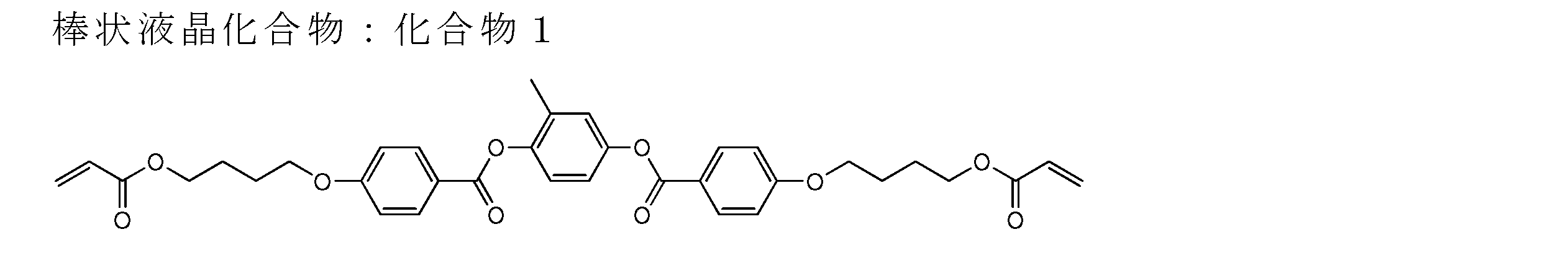

仮支持体(280mm×85mm)は、東洋紡社製PETフィルム(商品名:コスモシャインA4100、厚み:100μm)を使用し、ラビング処理(レーヨン布、圧力:0.1kgf(0.98N)、回転数:1000rpm、搬送速度:10m/min、回数:1往復)を施した。
(3)ミラー反射層Aの作製
塗布液1を、ワイヤーバーを用いて上記PETフィルムのラビング処理を施した表面に塗布した後、乾燥させて、30℃のホットプレート上にPETフィルムがホットプレートと接するように置き、フュージョンUVシステムズ株式会社製無電極ランプ「Dバルブ」(商品名、60mW/cm2)にて、6秒間UV(ultraviolet)照射し、液晶相を固定して、膜厚0.8μmの1/4波長板を形成した。形成した1/4波長板の表面に塗布液2をワイヤーバーを用いて塗布した後、乾燥させて、30℃のホットプレート上にPETフィルムがホットプレートと接するように置き、フュージョンUVシステムズ株式会社製無電極ランプ「Dバルブ」(60mW/cm2)にて6秒間UV照射し、コレステリック液晶相を固定して、膜厚3.5μmのコレステリック液晶層を得た。さらに塗布液3および塗布液4を順に用いて同様の工程を繰り返し、1/4波長板と3層のコレステリック液晶層とを積層し、PETフィルムを剥離することで、ミラー反射層A(塗布液3の層の膜厚:3.0μm、塗布液4の層の膜厚:2.7μm)を作製した。ミラー反射層Aは、1/4波長板の上に、630nm、540nmおよび450nmのコレステリック液晶層がこの順に積層された構造を有する。ミラー反射層Aの透過スペクトルを分光光度計(日本分光株式会社製、商品名:V-670)で測定したところ、630nm、540nm、450nmに選択反射の中心波長を有する透過スペクトルが得られた。 (2) Preparation of Temporary Support A temporary support (280 mm × 85 mm) is a PET film (trade name: Cosmo Shine A4100, thickness: 100 μm) manufactured by Toyobo Co., Ltd., and is rubbed (rayon cloth, pressure: 0.1 kgf). (0.98N), rotation speed: 1000 rpm, conveyance speed: 10 m / min, number of times: 1 reciprocation).
(3) Preparation of mirror reflection layer A The
特表平9-506837号公報に記載された方法に基づき、直線偏光反射層を作製した。2,6-ポリエチレンナフタレート(PEN)を、2,6-ナフタレンジカルボン酸とエチレングリコールを用いて、標準ポリエステル樹脂合成釜において合成した。また、ナフタレートおよびテレフタレートのコポリエステル(coPEN、共重合質量比はナフタレート:テレフタレート=70:30)を、ジオールとしてエチレングリコールを用いて、標準ポリエステル樹脂合成釜において合成した。2,6-ポリエチレンナフタレート(PEN)およびcoPENの単層フィルムをそれぞれ押出成型した後、約150℃において、延伸比5:1で延伸した。配向軸に関するPENの屈折率は、約1.88、横断軸に関する屈折率は、1.64、coPENフィルムの配向軸および横断軸に関する屈折率は、いずれも約1.64となることを確認した。
標準押出ダイに供給した上記のPENおよびcoPENを、50スロット供給ブロックを用いて同時押出することにより、下記表5(1)に示す膜厚を有するPENの層(以下、PEN層と称す。)とcoPENの層(以下、coPEN層と称す。)とが、交互に合計50層積層した反射層B1を形成した。続いて、膜厚を下記表5(2)~(5)に変更した以外は反射層B1の形成と同様にして、各反射層B2~B5を形成した。得られた反射層B1~B5を、各反射層のPEN層とcoPEN層が交互になり、反射層B1のPEN層および反射層B5のcoPEN層が最表面となるように、この順に積層して、合計250層が積層された反射層BAllを形成した。得られた反射層BAllを延伸し、続いて、エアーオーブン内において、約230℃で30秒間熱硬化し、ミラー反射層Bを得た。 <2. Production of Mirror Reflection Layer B (Linear Polarized Reflection Layer)>
A linearly polarized light reflecting layer was prepared based on the method described in JP-T-9-506837. 2,6-polyethylene naphthalate (PEN) was synthesized in a standard polyester resin synthesis kettle using 2,6-naphthalenedicarboxylic acid and ethylene glycol. Further, a copolyester of naphthalate and terephthalate (coPEN, copolymerization mass ratio is naphthalate: terephthalate = 70: 30) was synthesized in a standard polyester resin synthesis kettle using ethylene glycol as a diol. The monolayer films of 2,6-polyethylene naphthalate (PEN) and coPEN were each extruded and then stretched at a stretch ratio of 5: 1 at about 150 ° C. It was confirmed that the refractive index of PEN with respect to the orientation axis was about 1.88, the refractive index with respect to the transverse axis was 1.64, and the refractive indices with respect to the orientation axis and the transverse axis of the coPEN film were both about 1.64. .
The PEN and coPEN supplied to the standard extrusion die are coextruded using a 50-slot supply block, whereby a PEN layer having a film thickness shown in Table 5 (1) below (hereinafter referred to as a PEN layer). A reflection layer B1 was formed in which a total of 50 layers of layers and coPEN layers (hereinafter referred to as coPEN layers) were alternately laminated. Subsequently, the reflective layers B2 to B5 were formed in the same manner as the reflective layer B1 except that the film thickness was changed to the following Tables 5 (2) to (5). The obtained reflective layers B1 to B5 are laminated in this order so that the PEN layer and the coPEN layer of each reflective layer are alternately arranged, and the PEN layer of the reflective layer B1 and the coPEN layer of the reflective layer B5 are the outermost surface. The reflection layer B All in which a total of 250 layers was laminated was formed. The obtained reflective layer B All was stretched and then thermally cured at about 230 ° C. for 30 seconds in an air oven to obtain a mirror reflective layer B.

実施例1~23および比較例1~6の積層体とミラー反射層Aとを、積層体の粘着層とミラー反射層Aの1/4波長板とが隣接するように貼合して、実施例24~46および比較例7~12のミラー反射層A付き積層体をそれぞれ作製した。
また、実施例1~23および比較例1~6の積層体とミラー反射層Bとを、積層体の粘着層とミラー反射層BのPEN層とが隣接するように貼合して、実施例24~46および比較例7~12のミラー反射層B付き積層体をそれぞれ作製した。
なお、積層体は、積層体の剥離シートを剥がして粘着層をむき出しにして上記貼合に用いた。 <3. Production of laminate (pasting of reflection layer)>
The laminates of Examples 1 to 23 and Comparative Examples 1 to 6 and the mirror reflection layer A were bonded so that the adhesive layer of the laminate and the quarter wavelength plate of the mirror reflection layer A were adjacent to each other. The laminates with the mirror reflective layer A of Examples 24-46 and Comparative Examples 7-12 were prepared.
Further, the laminates of Examples 1 to 23 and Comparative Examples 1 to 6 and the mirror reflection layer B were bonded so that the adhesive layer of the laminate and the PEN layer of the mirror reflection layer B were adjacent to each other. Laminated bodies with mirror reflecting layers B of 24-46 and Comparative Examples 7-12 were prepared.
In addition, the laminated body peeled off the peeling sheet of the laminated body, and exposed the adhesion layer, and used it for the said bonding.
上記で作製したミラー反射層A付き積層体およびミラー反射層B付き積層体について、以下の試験を行った。試験結果を下記表6にまとめて記載する。ここで、実施例24~46が本発明の反射層付き積層体であり、比較例7~12が比較の反射層付き積層体である。なお、各試験において、積層体における「視認側」とは、樹脂フィルムに対して、粘着層が貼り合わされた面とは逆側の面を意味する。 <Test>
The following tests were conducted on the laminate with mirror reflection layer A and the laminate with mirror reflection layer B produced above. The test results are summarized in Table 6 below. Here, Examples 24 to 46 are laminates with a reflective layer of the present invention, and Comparative Examples 7 to 12 are comparative laminates with a reflective layer. In each test, the “viewing side” in the laminate means a surface opposite to the surface on which the adhesive layer is bonded to the resin film.
積層体のミラー品質を以下の手順により評価した。
積層体の視認側の最表面に蛍光灯の光を投射し、京浜光膜工業社製の銀ミラー(以下、Agミラーと称す。)と比較し、蛍光灯の反射像のミラー品質を、以下の通り評価した。ミラー品質には、反射像のゆがみの他に、ゆず肌状の面質悪化も、ミラー品質低下に関係することから、ゆがみ評価とゆず肌評価を合わせて評価した。
<ゆがみ評価基準>
a:蛍光灯の反射像にゆがみが無く、Agミラーと同様の品質だった。
b:蛍光灯の反射像のゆがみがほとんど認められなかった。
c:蛍光灯の反射像のゆがみが認められたが極僅かであった。
d:蛍光灯の反射像のゆがみが認められたが僅かであった。
e:蛍光灯の反射像が大きくゆがんでいた。
<ゆず肌評価基準>
a:蛍光灯の反射像にゆず肌状の面質ムラが無く、Agミラーと同様の品質だった。
b:蛍光灯の反射像のゆず肌状の面質ムラがほとんど認められなかった。
c:蛍光灯の反射像のゆず肌状の面質ムラが認められたが極僅かであった。
d:蛍光灯の反射像のゆず肌状の面質ムラが認められたが僅かであった。
e:蛍光灯の反射像のゆず肌状の面質ムラが強く、ミラー品質が低下していた。 [Test Example 8] Mirror quality The mirror quality of the laminate was evaluated by the following procedure.
The light of the fluorescent lamp is projected on the outermost surface on the viewing side of the laminate, and the mirror quality of the reflected image of the fluorescent lamp is as follows, compared with a silver mirror (hereinafter referred to as an Ag mirror) manufactured by Keihin Komoku Kogyo Co., Ltd. It evaluated as follows. The mirror quality was evaluated by combining the distortion evaluation and the Yuzu skin evaluation because the deterioration of the surface quality of the Yuzu skin was related to the deterioration of the mirror quality in addition to the distortion of the reflected image.
<Distortion evaluation criteria>
a: The reflection image of the fluorescent lamp was not distorted, and was the same quality as the Ag mirror.
b: Almost no distortion of the reflected image of the fluorescent lamp was observed.
c: Although distortion of the reflected image of the fluorescent lamp was recognized, it was very slight.
d: Distortion of the reflected image of the fluorescent lamp was recognized but slight.
e: The reflected image of the fluorescent lamp was greatly distorted.
<Yuzu skin evaluation criteria>
a: The reflected image of the fluorescent lamp did not have any uneven skin-like surface quality, and had the same quality as the Ag mirror.
b: Almost no irregular skin-like surface quality unevenness was observed in the reflected image of the fluorescent lamp.
c: Yuzu skin-like surface unevenness in the reflected image of the fluorescent lamp was observed but very slight.
d: Yuzu skin-like surface unevenness in the reflected image of the fluorescent lamp was observed but slight.
e: The surface irregularity of the skin-like surface of the reflected image of the fluorescent lamp was strong, and the mirror quality was deteriorated.

これに対して、積層状態での視認側の樹脂フィルムの表面粗さSa(測定視野:4mm×5mm)が特定の範囲にあり、粘着層の厚みが特定の厚み以下であり、粘着層の0℃~-40℃におけるtanδ(周波数1Hz)の極大値が特定の値以上である本発明の積層体は、いずれも優れたミラー品質を示した。 As described in Table 6, the surface roughness Sa (measurement field of view: 4 mm × 5 mm) of the resin film on the viewing side in the laminated state is rough, and the laminate with the mirror reflective layer of Comparative Example 7 has a mirror-like quality. (Mirror quality) was not shown. The laminates of Comparative Examples 8 and 10 to 12 each having an adhesive layer having a maximum value of tan δ (
On the other hand, the surface roughness Sa (measurement visual field: 4 mm × 5 mm) of the resin film on the viewing side in the laminated state is in a specific range, the thickness of the adhesive layer is equal to or less than the specific thickness, and 0 of the adhesive layer All the laminates of the present invention in which the maximum value of tan δ (frequency: 1 Hz) at from −40 ° C. to −40 ° C. was a specific value or more showed excellent mirror quality.
2A:粘着層
3A:ハードコート層(HC層)
4A、4B:積層体
1:タッチパネル用導電フィルム
2:タッチパネル
3:樹脂フィルム
4:粘着層
4C:積層体
5:透明絶縁基板
6A、6B:導電部材
7A、7B:保護層
8:第1導電層
9:第2導電層
11A:第1ダミー電極
11:第1電極
12:第1周辺配線
13:第1外部接続端子
14:第1コネクタ部
15:第1金属細線
21:第2電極
22:第2周辺配線
23:第2外部接続端子
24:第2コネクタ部
25:第2金属細線
C1:第1セル
C2:第2セル
D1:第1の方向
D2:第2の方向
M1:第1メッシュパターン
M2:第2メッシュパターン
S1:アクティブエリア
S2:周辺領域 1A:
4A, 4B: Laminate 1: Conductive film for touch panel 2: Touch panel 3: Resin film 4:
Claims (17)
- 樹脂フィルムと、該樹脂フィルムの一方の面に配した粘着層とを少なくとも有する積層体であり、
前記積層体における積層状態において、前記樹脂フィルムは、前記粘着層を有する面とは反対側の面の、測定視野4mm×5mmでの表面粗さSaが30nm以下であり、
前記粘着層は、厚みが100μm以下であって、周波数1Hzにおける損失正接の極大値が0℃~-40℃の温度領域にあり、かつ前記極大値が1.3以上である積層体。 A laminate having at least a resin film and an adhesive layer disposed on one surface of the resin film,
In the laminated state in the laminate, the resin film has a surface roughness Sa at a measurement visual field of 4 mm × 5 mm on the side opposite to the side having the adhesive layer, of 30 nm or less,
The adhesive layer has a thickness of 100 μm or less, a loss tangent maximum value at a frequency of 1 Hz is in a temperature range of 0 ° C. to −40 ° C., and the maximum value is 1.3 or more. - 前記積層体における積層状態において、前記樹脂フィルムは、前記粘着層を有する面とは反対側の面の、測定視野120μm×120μmでの表面粗さSaが20nm以下である請求項1に記載の積層体。 2. The laminate according to claim 1, wherein, in the laminated state of the laminate, the resin film has a surface roughness Sa of a surface opposite to the surface having the adhesive layer at a measurement visual field of 120 μm × 120 μm of 20 nm or less. body.
- 前記樹脂フィルムの厚みが80μm以上である請求項1または2に記載の積層体。 The laminate according to claim 1 or 2, wherein the resin film has a thickness of 80 µm or more.
- 前記樹脂フィルムの、前記粘着層を有する面とは反対側の面にハードコート層を有する請求項1~3のいずれか1項に記載の積層体。 The laminate according to any one of claims 1 to 3, wherein the resin film has a hard coat layer on a surface opposite to the surface having the adhesive layer.
- 前記ハードコート層の厚みが10μm以上50μm以下である請求項4に記載の積層体。 The laminate according to claim 4, wherein the hard coat layer has a thickness of 10 μm to 50 μm.
- 前記ハードコート層の鉛筆硬度が5H以上である請求項4または5に記載の積層体。 The laminate according to claim 4 or 5, wherein the hard coat layer has a pencil hardness of 5H or more.
- 前記粘着層の、前記樹脂フィルムを有する面とは反対側の面に、直線偏光反射層または円偏光反射層を有する請求項1~6のいずれか1項に記載の積層体。 The laminate according to any one of claims 1 to 6, wherein the pressure-sensitive adhesive layer has a linearly polarized light reflecting layer or a circularly polarized light reflecting layer on a surface opposite to the surface having the resin film.
- 前記円偏光反射層が、コレステリック液晶層を少なくとも1層含み、前記コレステリック液晶層が重合性液晶化合物および重合開始剤を含む液晶組成物を硬化してなる層である請求項7に記載の積層体。 The laminate according to claim 7, wherein the circularly polarizing reflection layer is a layer formed by curing a liquid crystal composition containing at least one cholesteric liquid crystal layer, and the cholesteric liquid crystal layer containing a polymerizable liquid crystal compound and a polymerization initiator. .
- 請求項1~8のいずれか1項に記載の積層体を有する、画像表示装置の前面板。 A front plate of an image display device comprising the laminate according to any one of claims 1 to 8.
- 請求項9に記載の前面板と、画像表示素子とを有する画像表示装置。 An image display device comprising the front plate according to claim 9 and an image display element.
- 前記画像表示素子が液晶表示素子である、請求項10に記載の画像表示装置。 The image display device according to claim 10, wherein the image display element is a liquid crystal display element.
- 前記画像表示素子が有機エレクトロルミネッセンス表示素子である、請求項10に記載の画像表示装置。 The image display device according to claim 10, wherein the image display element is an organic electroluminescence display element.
- 前記画像表示素子がインセルタッチパネル表示素子である、請求項10~12のいずれか1項に記載の画像表示装置。 The image display device according to any one of claims 10 to 12, wherein the image display element is an in-cell touch panel display element.
- 前記画像表示素子がオンセルタッチパネル表示素子である、請求項10~12のいずれか1項に記載の画像表示装置。 The image display device according to any one of claims 10 to 12, wherein the image display element is an on-cell touch panel display element.
- 請求項9に記載の前面板を有する抵抗膜式タッチパネル。 A resistive touch panel having the front plate according to claim 9.
- 請求項9に記載の前面板を有する静電容量式タッチパネル。 A capacitive touch panel having the front plate according to claim 9.
- 請求項10に記載の画像表示装置を用いた画像表示機能付きミラー。 A mirror with an image display function using the image display device according to claim 10.
Priority Applications (4)
| Application Number | Priority Date | Filing Date | Title |
|---|---|---|---|
| CN201780032006.9A CN109312198A (en) | 2016-05-24 | 2017-05-23 | Front panel, image display device, the reflecting mirror with image display function, resistive touch panel and the capacitive touch panel of laminated body and the image display device using the laminated body |
| JP2018519567A JP6751438B2 (en) | 2016-05-24 | 2017-05-23 | Laminated body and front plate of image display device having the same, image display device, mirror with image display function, resistive film type touch panel and capacitance type touch panel |
| KR1020187035549A KR102187815B1 (en) | 2016-05-24 | 2017-05-23 | Multilayer body and front plate of image display device having same, image display device, mirror with image display function, resistive touch panel and capacitive touch panel |
| US16/197,582 US20190091970A1 (en) | 2016-05-24 | 2018-11-21 | Laminate and front panel of image display apparatus, image display apparatus, mirror with image display function, resistive film-type touch panel, and capacitance-type touch panel having laminate |
Applications Claiming Priority (6)
| Application Number | Priority Date | Filing Date | Title |
|---|---|---|---|
| JP2016-103762 | 2016-05-24 | ||
| JP2016103762 | 2016-05-24 | ||
| JP2016-123240 | 2016-06-22 | ||
| JP2016123240 | 2016-06-22 | ||
| JP2016-183179 | 2016-09-20 | ||
| JP2016183179 | 2016-09-20 |
Related Child Applications (1)
| Application Number | Title | Priority Date | Filing Date |
|---|---|---|---|
| US16/197,582 Continuation US20190091970A1 (en) | 2016-05-24 | 2018-11-21 | Laminate and front panel of image display apparatus, image display apparatus, mirror with image display function, resistive film-type touch panel, and capacitance-type touch panel having laminate |
Publications (1)
| Publication Number | Publication Date |
|---|---|
| WO2017204228A1 true WO2017204228A1 (en) | 2017-11-30 |
Family
ID=60412754
Family Applications (1)
| Application Number | Title | Priority Date | Filing Date |
|---|---|---|---|
| PCT/JP2017/019277 WO2017204228A1 (en) | 2016-05-24 | 2017-05-23 | Laminate, and front panel of image display device, image display device, mirror with image display function, resistance film type touch panel, and capacitive touch panel all including said laminate |
Country Status (5)
| Country | Link |
|---|---|
| US (1) | US20190091970A1 (en) |
| JP (1) | JP6751438B2 (en) |
| KR (1) | KR102187815B1 (en) |
| CN (1) | CN109312198A (en) |
| WO (1) | WO2017204228A1 (en) |
Cited By (5)
| Publication number | Priority date | Publication date | Assignee | Title |
|---|---|---|---|---|
| JP2019149012A (en) * | 2018-02-27 | 2019-09-05 | 日東電工株式会社 | Transparent conductive film laminate and method for producing transparent conductive film |
| KR20200041264A (en) | 2018-10-11 | 2020-04-21 | 스미또모 가가꾸 가부시키가이샤 | Optical laminate and display |
| KR20200060878A (en) * | 2018-11-23 | 2020-06-02 | 주식회사 엘엠에스 | Adhesive sheet and adhesive material using the same |
| EP3869245A4 (en) * | 2018-10-17 | 2021-12-15 | FUJIFILM Corporation | Projection image display member, windshield glass, and head-up display system |
| TWI796380B (en) * | 2017-12-13 | 2023-03-21 | 日商富士軟片股份有限公司 | Conductive member, touch panel and display device |
Families Citing this family (12)
| Publication number | Priority date | Publication date | Assignee | Title |
|---|---|---|---|---|
| US10401553B2 (en) * | 2017-03-21 | 2019-09-03 | Keiwa Inc. | Liquid crystal display device and turning film for liquid crystal display device |
| CN109735246A (en) * | 2018-12-29 | 2019-05-10 | 苏州艾科迪新材料科技有限公司 | A kind of cell phone rear cover film and preparation method thereof |
| KR102178886B1 (en) * | 2019-02-26 | 2020-11-17 | 재단법인 구미전자정보기술원 | The polymer dispersed liquid crystal display device |
| CN109917961B (en) * | 2019-02-28 | 2022-06-24 | 京东方科技集团股份有限公司 | Pressure detection device, display panel and display device |
| JP6945586B2 (en) * | 2019-04-17 | 2021-10-06 | 住友化学株式会社 | Laminated body and image display device |
| JP7081676B2 (en) * | 2019-05-31 | 2022-06-07 | 東洋紡株式会社 | Base film for surface protective film of image display device with fingerprint authentication sensor, surface protective film and image display device |
| KR20210016124A (en) | 2019-07-31 | 2021-02-15 | 삼성디스플레이 주식회사 | Display device |
| TWI740515B (en) | 2019-12-23 | 2021-09-21 | 長春人造樹脂廠股份有限公司 | Liquid crystal polymer film and laminate comprising the same |
| JP2021105668A (en) * | 2019-12-26 | 2021-07-26 | Tianma Japan株式会社 | Liquid crystal display device and electronic instrument |
| EP4116389A4 (en) * | 2020-03-03 | 2024-03-20 | Dexerials Corp | Method for manufacturing image display device |
| KR102461794B1 (en) * | 2020-08-13 | 2022-11-02 | 한국과학기술연구원 | Ag nanowire mesh electrode and manufacturing method thereof |
| CN113071122A (en) * | 2021-04-06 | 2021-07-06 | 山东胜通光学材料科技有限公司 | Preparation process and equipment of base film for polarizer protective film |
Citations (3)
| Publication number | Priority date | Publication date | Assignee | Title |
|---|---|---|---|---|
| JP2012238467A (en) * | 2011-05-11 | 2012-12-06 | Nitto Denko Corp | Transparent conductive laminate and touch panel |
| WO2015178391A1 (en) * | 2014-05-20 | 2015-11-26 | 日本合成化学工業株式会社 | Resin sheet, resin sheet with adhesive layer, and use of same |
| JP2016020415A (en) * | 2014-07-14 | 2016-02-04 | 三菱レイヨン株式会社 | Processing aid for acrylic elastomer resin, acrylic elastomer resin composition and molded body |
Family Cites Families (10)
| Publication number | Priority date | Publication date | Assignee | Title |
|---|---|---|---|---|
| WO1997023580A1 (en) * | 1995-12-21 | 1997-07-03 | Philips Electronics N.V. | Method of manufacturing a switchable cholesteric filter as well as a luminaire having such a filter |
| JP2002235059A (en) * | 2001-02-09 | 2002-08-23 | Dainippon Ink & Chem Inc | Highly transparent double-sided pressure-sensitive adhesive sheet |
| JP2005288831A (en) * | 2004-03-31 | 2005-10-20 | Dainippon Printing Co Ltd | Hard coat laminate |
| CN101258050A (en) * | 2005-09-05 | 2008-09-03 | 皇家飞利浦电子股份有限公司 | Mirror device with a switchable cholesteric filter |
| CN102033347B (en) * | 2009-09-30 | 2012-12-19 | 群康科技(深圳)有限公司 | In-cell touch liquid crystal display (LCD) |
| JP5359774B2 (en) * | 2009-10-22 | 2013-12-04 | 大日本印刷株式会社 | Protective film for optical film |
| JP5927532B2 (en) * | 2011-03-22 | 2016-06-01 | 株式会社Joled | Display device and electronic device |
| JP2013020130A (en) * | 2011-07-12 | 2013-01-31 | Keiwa Inc | Hard coat film and touch panel using the same |
| EP2799956B1 (en) * | 2011-11-07 | 2018-06-27 | Oji Holdings Corporation | Display device with capacitive touch panel, capacitive touch panel |
| JP2016090715A (en) * | 2014-10-31 | 2016-05-23 | 富士フイルム株式会社 | Optical member and image display device |
-
2017
- 2017-05-23 CN CN201780032006.9A patent/CN109312198A/en active Pending
- 2017-05-23 WO PCT/JP2017/019277 patent/WO2017204228A1/en active Application Filing
- 2017-05-23 KR KR1020187035549A patent/KR102187815B1/en active IP Right Grant
- 2017-05-23 JP JP2018519567A patent/JP6751438B2/en active Active
-
2018
- 2018-11-21 US US16/197,582 patent/US20190091970A1/en not_active Abandoned
Patent Citations (3)
| Publication number | Priority date | Publication date | Assignee | Title |
|---|---|---|---|---|
| JP2012238467A (en) * | 2011-05-11 | 2012-12-06 | Nitto Denko Corp | Transparent conductive laminate and touch panel |
| WO2015178391A1 (en) * | 2014-05-20 | 2015-11-26 | 日本合成化学工業株式会社 | Resin sheet, resin sheet with adhesive layer, and use of same |
| JP2016020415A (en) * | 2014-07-14 | 2016-02-04 | 三菱レイヨン株式会社 | Processing aid for acrylic elastomer resin, acrylic elastomer resin composition and molded body |
Cited By (8)
| Publication number | Priority date | Publication date | Assignee | Title |
|---|---|---|---|---|
| TWI796380B (en) * | 2017-12-13 | 2023-03-21 | 日商富士軟片股份有限公司 | Conductive member, touch panel and display device |
| JP2019149012A (en) * | 2018-02-27 | 2019-09-05 | 日東電工株式会社 | Transparent conductive film laminate and method for producing transparent conductive film |
| JP7219006B2 (en) | 2018-02-27 | 2023-02-07 | 日東電工株式会社 | Transparent conductive film laminate and method for producing transparent conductive film |
| KR20200041264A (en) | 2018-10-11 | 2020-04-21 | 스미또모 가가꾸 가부시키가이샤 | Optical laminate and display |
| EP3869245A4 (en) * | 2018-10-17 | 2021-12-15 | FUJIFILM Corporation | Projection image display member, windshield glass, and head-up display system |
| US11892627B2 (en) | 2018-10-17 | 2024-02-06 | Fujifilm Corporation | Projection image display member, windshield glass, and head-up display system |
| KR20200060878A (en) * | 2018-11-23 | 2020-06-02 | 주식회사 엘엠에스 | Adhesive sheet and adhesive material using the same |
| KR102188402B1 (en) | 2018-11-23 | 2020-12-08 | 주식회사 엘엠에스 | Adhesive sheet and adhesive material using the same |
Also Published As
| Publication number | Publication date |
|---|---|
| JPWO2017204228A1 (en) | 2019-04-18 |
| CN109312198A (en) | 2019-02-05 |
| JP6751438B2 (en) | 2020-09-02 |
| US20190091970A1 (en) | 2019-03-28 |
| KR102187815B1 (en) | 2020-12-08 |
| KR20190006183A (en) | 2019-01-17 |
Similar Documents
| Publication | Publication Date | Title |
|---|---|---|
| JP6751438B2 (en) | Laminated body and front plate of image display device having the same, image display device, mirror with image display function, resistive film type touch panel and capacitance type touch panel | |
| CN110177687B (en) | Optical film, front panel, image display device, mirror, resistive touch panel, and capacitive touch panel | |
| JP6782305B2 (en) | Optical film and front plate of image display device having it, image display device, mirror with image display function, resistive touch panel and capacitive touch panel | |
| US11016223B2 (en) | Hardcoat film and application thereof | |
| WO2018179893A1 (en) | Optical film, and front panel of image display device, image display device, mirror with image display function, resistive touch panel and capacitive touch panel each of which comprises said optical film | |
| US11435502B2 (en) | Optical film and front panel of image display apparatus, image display apparatus, mirror with image display function, resistive film-type touch panel, and capacitance-type touch panel having optical film | |
| JP6721783B2 (en) | Antireflection laminate, polarizing plate having the same, and image display device | |
| WO2017115641A1 (en) | Hard coat film and application of same | |
| JP6446564B2 (en) | Hard coat film, front plate of image display element, resistive touch panel, capacitive touch panel, and image display device | |
| KR102368291B1 (en) | Optical film and front panel of image display device having same, image display device, mirror with image display function, resistive touch panel and capacitive touch panel | |
| CN112585527A (en) | Liquid crystal panel and image display device |
Legal Events
| Date | Code | Title | Description |
|---|---|---|---|
| ENP | Entry into the national phase |
Ref document number: 2018519567 Country of ref document: JP Kind code of ref document: A |
|
| NENP | Non-entry into the national phase |
Ref country code: DE |
|
| 121 | Ep: the epo has been informed by wipo that ep was designated in this application |
Ref document number: 17802814 Country of ref document: EP Kind code of ref document: A1 |
|
| ENP | Entry into the national phase |
Ref document number: 20187035549 Country of ref document: KR Kind code of ref document: A |
|
| 122 | Ep: pct application non-entry in european phase |
Ref document number: 17802814 Country of ref document: EP Kind code of ref document: A1 |