WO2017199786A1 - Monitoring system - Google Patents
Monitoring system Download PDFInfo
- Publication number
- WO2017199786A1 WO2017199786A1 PCT/JP2017/017470 JP2017017470W WO2017199786A1 WO 2017199786 A1 WO2017199786 A1 WO 2017199786A1 JP 2017017470 W JP2017017470 W JP 2017017470W WO 2017199786 A1 WO2017199786 A1 WO 2017199786A1
- Authority
- WO
- WIPO (PCT)
- Prior art keywords
- measurement point
- monitoring
- marker group
- point marker
- space
- Prior art date
Links
Images


Classifications
-
- G—PHYSICS
- G01—MEASURING; TESTING
- G01S—RADIO DIRECTION-FINDING; RADIO NAVIGATION; DETERMINING DISTANCE OR VELOCITY BY USE OF RADIO WAVES; LOCATING OR PRESENCE-DETECTING BY USE OF THE REFLECTION OR RERADIATION OF RADIO WAVES; ANALOGOUS ARRANGEMENTS USING OTHER WAVES
- G01S17/00—Systems using the reflection or reradiation of electromagnetic waves other than radio waves, e.g. lidar systems
- G01S17/02—Systems using the reflection of electromagnetic waves other than radio waves
- G01S17/06—Systems determining position data of a target
- G01S17/08—Systems determining position data of a target for measuring distance only
- G01S17/10—Systems determining position data of a target for measuring distance only using transmission of interrupted, pulse-modulated waves
-
- G—PHYSICS
- G01—MEASURING; TESTING
- G01V—GEOPHYSICS; GRAVITATIONAL MEASUREMENTS; DETECTING MASSES OR OBJECTS; TAGS
- G01V8/00—Prospecting or detecting by optical means
- G01V8/10—Detecting, e.g. by using light barriers
- G01V8/12—Detecting, e.g. by using light barriers using one transmitter and one receiver
- G01V8/18—Detecting, e.g. by using light barriers using one transmitter and one receiver using mechanical scanning systems
-
- G—PHYSICS
- G02—OPTICS
- G02B—OPTICAL ELEMENTS, SYSTEMS OR APPARATUS
- G02B26/00—Optical devices or arrangements for the control of light using movable or deformable optical elements
- G02B26/08—Optical devices or arrangements for the control of light using movable or deformable optical elements for controlling the direction of light
- G02B26/10—Scanning systems
- G02B26/101—Scanning systems with both horizontal and vertical deflecting means, e.g. raster or XY scanners
-
- G—PHYSICS
- G06—COMPUTING; CALCULATING OR COUNTING
- G06F—ELECTRIC DIGITAL DATA PROCESSING
- G06F3/00—Input arrangements for transferring data to be processed into a form capable of being handled by the computer; Output arrangements for transferring data from processing unit to output unit, e.g. interface arrangements
- G06F3/01—Input arrangements or combined input and output arrangements for interaction between user and computer
- G06F3/048—Interaction techniques based on graphical user interfaces [GUI]
- G06F3/0484—Interaction techniques based on graphical user interfaces [GUI] for the control of specific functions or operations, e.g. selecting or manipulating an object, an image or a displayed text element, setting a parameter value or selecting a range
-
- G—PHYSICS
- G08—SIGNALLING
- G08B—SIGNALLING OR CALLING SYSTEMS; ORDER TELEGRAPHS; ALARM SYSTEMS
- G08B13/00—Burglar, theft or intruder alarms
- G08B13/18—Actuation by interference with heat, light, or radiation of shorter wavelength; Actuation by intruding sources of heat, light, or radiation of shorter wavelength
- G08B13/181—Actuation by interference with heat, light, or radiation of shorter wavelength; Actuation by intruding sources of heat, light, or radiation of shorter wavelength using active radiation detection systems
- G08B13/187—Actuation by interference with heat, light, or radiation of shorter wavelength; Actuation by intruding sources of heat, light, or radiation of shorter wavelength using active radiation detection systems by interference of a radiation field
Definitions
- the present invention relates to a monitoring system that monitors an object by scanning and projecting, for example, a laser beam.
- a monitoring device that uses a distance image has been proposed as a monitoring device for detecting an intruder or the like in a monitoring space.
- the distance image has distance information as a pixel value.
- a laser beam or the like is sent out to a monitoring space, and monitoring is performed to measure the distance to an object in the monitoring space from the time from the sending to reception of reflected light.
- the device is known.
- distance information regarding a plurality of directions facing the monitoring space can be obtained by sequentially changing the transmission direction of a measurement medium such as a laser beam and scanning the monitoring space two-dimensionally.
- a distance image can be formed.
- a distance image (background image) as a background in which no moving object exists is obtained in advance, the obtained background image is compared with the input distance image (current image), and the background image A so-called background difference method is used in which a pixel corresponding to a closer distance is extracted to obtain a change region. Accordingly, it is possible to determine whether or not the moving object is the target detection target based on the size / shape of the change area and the distance information in the current image.
- the distance image includes information such as the direction of the object viewed from the transmission / reception unit such as a laser beam and the distance to the object. Therefore, the size and shape of the object can be known from the distance image. For example, in an intruder detection application, it is possible to distinguish a relatively large person in the distance from small animals in the vicinity (such as a frog or a cat). It becomes possible, and the detection accuracy of an intruder can be improved.
- a monitoring area is set at the entrance of a specific facility and the like. There is a request to issue an alarm for the first time when a human invades.
- a monitoring device it is often impossible to know in advance what range is to be the monitoring region, so it is necessary to set a monitoring region for each monitoring device installed by the operator.
- a monitoring device that uses invisible light such as infrared rays, it is difficult to confirm whether or not the monitoring device can be installed to monitor the intended area.
- Patent Literature 2 by specifying the coordinates of the terminal and the imaging direction of the imaging means in the portable setting terminal, the coordinates of each position in the obtained captured image (real space image). (Coordinates in real space) is specified, and this makes it possible to generate a composite image by more accurately incorporating the boundary image into the position specified by the boundary position data and display it. It is possible to visually grasp where the boundary (for example, the monitoring area) is set together with the object existing in the real space, and the boundary in the real space without performing special data analysis etc. Discloses a technique that can determine whether or not is set at an appropriate position.
- GPS Global Positioning System
- gyro sensor are required to detect the coordinates and direction in the real space of the portable setting terminal, and a composite image is generated by incorporating the captured image and the boundary image. There was a problem that the system would be complicated.
- the present invention has been made in view of the above circumstances, and provides a monitoring system capable of intuitively and easily setting a monitoring area in a virtual space while comparing the monitoring space to be monitored with the displayed measurement point marker group.
- the purpose is to provide.
- a monitoring system reflecting one aspect of the present invention.
- a light projecting / receiving unit comprising: an emitting unit that emits a light beam; a scanning unit that scans the light beam in a monitoring space; and a light receiving unit that receives a light beam reflected from an object in the monitoring space; Processing a signal from the light projecting / receiving unit to measure a distance to the object and output a measurement point marker group to which three-dimensional distance information is given for each measurement point;
- a user interface for setting a monitoring area in the virtual space by a user operation;
- a display device that displays the set monitoring area together with the measurement point marker group in the virtual space when the monitoring area is set via the user interface;
- the processing unit outputs an alarm signal when an object enters the monitoring area during monitoring.
- a monitoring system capable of intuitively and easily setting a monitoring area in a virtual space while comparing the monitoring space to be monitored with the displayed measurement point marker group.
- monitoring apparatus MD It is sectional drawing of monitoring apparatus MD concerning this embodiment. It is a figure which shows the state which scans the inside of the monitoring space of the monitoring apparatus MD with the laser spot light SB (it shows by hatching) radiate
- FIG. 1 is a cross-sectional view of a monitoring device MD according to the present embodiment, and is shown in a state where the monitoring device MD is attached to an inclined wall surface. In FIG. 1, it is assumed that the monitoring device MD is installed with the top and bottom reversed.
- the monitoring device MD includes, for example, a pulsed semiconductor laser LD that emits a laser beam, a collimating lens CL that converts divergent light from the semiconductor laser LD into parallel light, and laser light that is collimated by the collimating lens CL.
- a mirror unit MU that scans and projects light toward the monitoring space by a rotating mirror surface, reflects reflected light from the object, and a lens LS that collects reflected light from the object reflected by the mirror unit MU; , A photodiode PD that receives the light collected by the lens LS, a processing circuit (processing unit) PROC that obtains distance information according to the time difference between the emission timing of the semiconductor laser LD and the light reception timing of the photodiode PD, and a mirror It has a motor MT that rotationally drives the unit MU, and a housing CS that houses them.
- the photodiode PD has a plurality of pixels arranged in the Y direction.
- the semiconductor laser LD and the collimating lens CL constitute an emission part LPS
- the lens LS and the photodiode PD constitute a light receiving part RPS
- the mirror unit MU constitutes a scanning part.
- the optical axes of the emission part LPS and the light receiving part RPS are preferably orthogonal to the rotation axis RO of the mirror unit MU.
- a box-shaped housing CS fixed to a rigid wall WL or the like has an upper wall CSa, a lower wall CSb facing the upper wall CSa, and a side wall CSc connecting the upper wall CSa and the lower wall CSb.
- An opening CSd is formed in a part of the side wall CSc, and a transparent plate TR is attached to the opening CSd.
- the mirror unit MU has a shape in which two quadrangular pyramids are joined together in opposite directions, that is, four pairs of mirror surfaces M1 and M2 tilted in a direction facing each other (but not limited to four pairs).
- the mirror surfaces M1 and M2 are preferably formed by depositing a reflective film on the surface of a resin material (for example, PC) in the shape of a mirror unit.
- the mirror unit MU is connected to the shaft MTa of the motor MT fixed to the casing CS and is driven to rotate.
- the axis line (rotation axis) of the axis MTa extends in the Y direction inclined with respect to the vertical direction, and the ZX plane formed by the Z direction and the X direction orthogonal to the Y direction is relative to the horizontal plane. Although tilted, the axis of the axis MTa may coincide with the vertical direction.
- the processing circuit PROC includes a central processing unit CPU, a read-only memory ROM, a random access memory RAM, and a hard disk HDD that is a non-volatile memory.
- the semiconductor laser LD, the photodiode PD, the wiring HS, etc. are connected.
- the central processing unit CPU uses the random access memory RAM to process programs and data stored in the read-only memory ROM and the hard disk HDD, thereby performing predetermined control and information processing.
- divergent light intermittently emitted in a pulse form from a semiconductor laser LD is converted into a parallel light beam by a collimating lens CL, enters a first mirror surface M1 of a rotating mirror unit MU, and is reflected there. Further, after being reflected by the second mirror surface M2, the light is scanned and projected as a laser spot light having, for example, a vertically long rectangular cross section through the transparent plate TR and toward the external monitoring space.
- the direction in which the emitted laser spot light is reflected by the object and returned as reflected light is referred to as the light projecting / receiving direction.
- Laser spot light beams traveling in the same light projecting / receiving direction are detected by the same pixel.
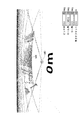
- FIG. 2 is a diagram illustrating a state in which the monitoring space of the monitoring device MD is scanned with the laser spot light SB (indicated by hatching) emitted according to the rotation of the mirror unit MU.
- the crossing angles are different.
- the laser light is sequentially reflected by the rotating first mirror surface M1 and second mirror surface M2.
- the laser light reflected by the first pair of the first mirror surface M1 and the second mirror surface M2 moves from the left to the right in the horizontal direction in the uppermost area Ln1 in accordance with the rotation of the mirror unit MU. Is scanned.
- the laser light reflected by the second pair of the first mirror surface M1 and the second mirror surface M2 passes from the left in the horizontal direction to the second region Ln2 from the top of the monitoring space according to the rotation of the mirror unit MU. Scan to the right.
- the laser light reflected by the third pair of the first mirror surface M1 and the second mirror surface M2 passes from the left in the horizontal direction to the third region Ln3 from the top of the monitoring space according to the rotation of the mirror unit MU.
- the laser light reflected by the fourth pair of the first mirror surface M1 and the second mirror surface is moved horizontally from left to right in the lowermost region Ln4 of the monitoring space according to the rotation of the mirror unit MU. Scanned.
- one scan of the entire monitoring space that can be monitored by the monitoring device MD is completed.
- the laser spot light beam is scanned two-dimensionally without any gap (when the trajectories of the scanned laser spot light beam are adjacent (for example, the region Ln1 and the region Ln2), the adjacent locus is in contact with no gap.
- the monitoring device MD is set, a distance image that allows the user US to intuitively grasp the space is obtained, which is preferable.
- a single frame FL is obtained by combining images obtained by scanning the regions Ln1 to Ln4. If the first pair of the first mirror surface M1 and the second mirror surface M2 return after one rotation of the mirror unit MU, the region from the uppermost region Ln1 to the lowermost region Ln4 is again displayed. Scanning is repeated to obtain the next frame FL.
- a part of the laser beam reflected and reflected by the object out of the scanned and projected light passes through the transparent plate TR again and enters the second mirror surface M2 of the mirror unit MU in the housing CS.
- the light is reflected here, is further reflected by the first mirror surface M1, is collected by the lens LS, and is detected for each pixel by the light receiving surface of the photodiode PD.
- the processing circuit PROC as a processing unit obtains distance information according to the time difference between the emission timing of the semiconductor laser LD and the light reception timing of the photodiode PD.
- the object is detected in the entire area in the monitoring space, and a frame FL (hereinafter referred to as a measurement point marker group) having distance information (three-dimensional distance information) for each pixel (measurement point). (See FIG. 2).
- the shape of the measurement point markers constituting the measurement point marker group is the same as the shape of the spot light beam SB that is actually scanned.
- a signal from the processing circuit PROC is output to a personal computer PC, which will be described later, at the time of installation. At the time of monitoring, the signal is transmitted to a remote monitor via a network (not shown) or the like, and can be stored in a storage device.
- a monitoring area setting method in the monitoring device MD will be described below.
- the displayed measurement point marker group is applied to the monitoring space. Thereby, the monitoring area setting of the user US is facilitated.
- FIG. 3 is a perspective view of the monitoring device MD.
- the rotation axis direction is the Y direction
- the direction orthogonal to the Y direction and facing the front of the monitoring device MD is the Z direction
- the direction orthogonal to the Y direction and the Z direction is the X direction.
- the relative rotation around the Y direction is expressed as YAW (yaw angle)
- the relative rotation around the Z direction is expressed as ROLL (roll angle)
- PITCH pitch angle
- FIG. 4 is a diagram showing an installation state of the monitoring device MD
- FIG. 5 is a diagram showing a personal computer displaying measurement point marker groups.
- the processing circuit PROC of the monitoring device MD is connected to the personal computer PC by a wiring HS.
- a controller (user interface) AC having an analog input unit such as a joystick that can be operated by the user US is connected to the personal computer PC.
- the monitoring device MD, the personal computer PC, and the controller AC constitute a monitoring system.
- the monitoring device MD is installed on the wall WL so as to look down obliquely at a predetermined angle from above. Therefore, the monitoring range of the monitoring device MD is a fan-shaped range as shown by hatching in FIG. This is the background BG.
- the background BG if the laser beam is infrared light, the user US cannot visually observe the background BG that is the irradiation range of the beam, but it can be estimated from which direction the monitoring device MD is irradiated.
- the user US operates the controller AC while comparing the ground surface, which is a substantially horizontal plane including the background BG, with the display DPL of the personal computer PC as a display device, and actually displays the virtual space including the displayed measurement point marker group. It applies to the background.
- the monitoring device MD Since the monitoring device MD does not have a position sensor or the like, it cannot detect its own posture when it is installed on the side surface of the wall WL. Therefore, it is assumed that the virtual space is applied to the actual background using the measurement point marker group output from the monitoring device MD. More specifically, the monitoring device MD detects an actual background BG (here, the ground surface) in the initial state.
- the signal processed by the processing circuit PROC is transmitted to the personal computer PC through the wiring HS and displayed on the display DPL as a measurement point marker group in the virtual space.
- the displayed virtual space can be arbitrarily rotated, translated, and moved by the user US via operation buttons and levers of the controller AC.
- the measurement point marker group is preferably displayed in a different color depending on the distance to the measurement point, for example, the measurement point far from the monitoring device MD is blue and the near measurement point is red. In addition, the measurement point marker group may have a different color depending on the intensity of reflected light from the measurement point.
- the shape of the measurement point marker is preferably the same as the actual laser spot shape, but may be any shape such as a square, a circle or an asterisk.
- FIGS. 6 to 11 are diagrams showing examples of measurement point marker groups on the virtual space displayed on the display DPL, and the numerical value (10 m) in the figure indicates the distance from the monitoring device MD for reference. .
- FIG. 6 the state seen from monitoring apparatus MD along the Z direction by the input of controller AC is shown.
- the values of the yaw angle, roll angle, pitch angle, and height offset of the virtual space are displayed in the lower right of the display DPL. However, since they are in the initial state, they are all zero in FIG. These values change according to provisional information input described below, and support adjustment by the user US.
- the user US can estimate that the top and bottom in the Y direction is reversed.
- the upside down in the Y direction is also reversed.
- the background BG is a substantially horizontal plane, it may be estimated that the top and bottom in the Y direction are reversed.
- the user US operates the controller AC to instruct to change the roll angle of the virtual space together with the measurement point marker group (for the posture of the real object (background BG) in the monitoring space
- the personal computer PC performs coordinate conversion, and the measurement point marker group MK is in the Y direction as shown in FIG. Display with the top and bottom of the screen reversed. That is, here, “temporary installation information” means that the top and bottom of the virtual space including the measurement point marker group is reversed (rotated).
- the user US finely adjusts the controller AC to adjust the posture of the measurement point marker group MK.
- the roll angle of the virtual space is ⁇ 180 ° with respect to the initial state.
- the display DPL displays the measurement point marker group MK shown in FIG.
- the user US who compares the display of FIG. 8 with the background BG recognizes that the background BG is a substantially horizontal plane, and therefore can clearly estimate that the virtual space is inclined. Therefore, the user US operates the controller AC to instruct to change the pitch angle of the virtual space together with the measurement point marker group (corresponding to the posture of the real object (background BG) in the monitoring space).
- the personal computer PC performs coordinate conversion to level the measurement point marker group MK as shown in FIG. The display is displayed with the tilt returned.
- the “provisional posture information” here means changing (rotating) the pitch angle of the virtual space including the measurement point marker group. While viewing the displayed measurement point marker group MK, the user US finely adjusts the controller AC to adjust the posture of the measurement point marker group MK.
- the pitch angle of the virtual space is ⁇ 22.2 ° with respect to the initial state.
- the user US since the user US comparing the display of FIG. 9 with the background BG recognizes that the background BG is the ground surface, the user US is low with respect to the horizontal plane (reference plane) VL based on the monitoring device MD itself in the virtual space. It can be judged that it is too much. Therefore, the user US operates the controller AC to instruct to change the height offset of the virtual space together with the measurement point marker group (corresponding to the position of the real object (background BG) in the monitoring space)
- the temporary posture information is input so that the relative position of the measurement point marker group MK to the reference plane VL in the virtual space is close), the personal computer PC performs coordinate conversion, and the measurement point marker group MK as shown in FIG. Is displayed in a state of relatively moving.
- the “provisional posture information” here means that the measurement point marker group is shifted in the virtual space. While viewing the displayed measurement point marker group MK, the user US finely adjusts the controller AC to adjust the position of the measurement point marker group MK. Here, after adjustment, the height offset of the virtual space is +12.5 m with respect to the initial state.
- the virtual space three-dimensional data thus coordinate-converted is stored in the nonvolatile memory HDD incorporated in the processing circuit PROC of FIG. 12, and a monitoring image is displayed on a monitor (not shown) during actual monitoring. Used when.
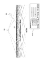
- the user US operates the controller AC to set the monitoring area. Specifically, as shown in FIG. 11, the viewpoint movement (change of the viewpoint position) is instructed so as to see the monitoring device MD from the background side along the Z direction. Then, since the display DPL displays the measurement point marker group MK as shown in FIG. 11 from the changed viewpoint position, if the user US further operates the setting button SB (FIG. 5) of the controller AC from this state, A box-shaped monitoring area DA (in this case, a dotted line) is displayed on the upper right side of.
- the user US inputs the setting data of the monitoring area DA via the controller AC.
- the size (width, height, depth) of the monitoring area DA is arbitrarily changed by operating the size adjustment button ZB shown in FIG. 5, and the monitoring area in the virtual space is operated by operating the rotation button RB.
- the center of the monitoring area DA is set to a desired position (x coordinate, y coordinate, z coordinate).
- the numerical value in the information field INFO indicating the setting data of the monitoring area DA displayed on the display DPL may be changed according to the input from the controller AC.
- the user US may directly input a numerical value via a keyboard or a mouse instead of the controller AC.
- the user US can intuitively and easily apply the virtual space of the monitoring device MD to the actual background BG using the controller AC while viewing the displayed measurement point marker group MK. . Furthermore, the user US can intuitively and easily set the monitoring area DA at a desired position while comparing with the actual background BG. In addition, during actual monitoring, if an intruder enters the monitoring area DA, the processing circuit PROC determines that there is a high probability of entering the facility, and issues an emergency alarm signal. An alarm can be displayed on the monitor shown to call attention.
- provisional posture information is input so that the posture and position of the measurement point marker group can be made to follow the posture and position of the ground surface as an actual horizontal plane in the monitoring space.
- temporary posture information may be input so that the posture and position of the measurement point marker group can be made to follow the posture and position of a wall surface or a standing tree as an actual vertical surface in the monitoring space.
- the monitoring area DA to be set is a box shape, it can be various shapes such as a spherical shape, an annular shape, or a boundary line.
- the number of monitoring areas DA that can be set is not limited to one, but may be plural.
Abstract
Provided is a monitoring system with which a monitored area can be intuitively and easily set within a virtual space, while comparing a space to be monitored, and a displayed group of measurement point markers. This monitoring system is provided with: a light projection/reception unit provided with an emission unit which emits a light beam, a scanning unit which scans the light beam within a monitored space, and a light reception unit which receives a light beam reflected from an object within the monitored space; a processing unit which processes a signal from the light projection/reception unit to measure the distance to the object, and outputs a group of measurement point markers which assign three-dimensional distance information to each measurement point; a user interface which sets a monitored area in a virtual space as a result of being operated by a user; and a display device which displays, in the virtual space, when the monitored area has been set via the user interface, the set monitored area and the group of measurement point markers. The processing unit outputs an alarm signal when an object enters the monitored area during monitoring.
Description
本発明は、例えばレーザー光等を走査投光して物体を監視する監視システムに関する。
The present invention relates to a monitoring system that monitors an object by scanning and projecting, for example, a laser beam.
監視空間への侵入者等を検出する監視装置として、距離画像を用いるものが提案されている。ここで距離画像とは、画素値として距離情報を有するものである。具体的には、特許文献1に示すように、レーザー光等を監視空間へ向けて送出し、その送出から反射光の受光までの時間などから監視空間内の対象物までの距離を計測する監視装置が知られている。かかる監視装置では、レーザー光等の測定媒体の送出方向を順次変えて監視空間内を二次元的に走査することにより、監視空間を向いた複数の方向に関する距離情報を得ることができ、これにより距離画像を形成できる。
A monitoring device that uses a distance image has been proposed as a monitoring device for detecting an intruder or the like in a monitoring space. Here, the distance image has distance information as a pixel value. Specifically, as shown in Patent Document 1, a laser beam or the like is sent out to a monitoring space, and monitoring is performed to measure the distance to an object in the monitoring space from the time from the sending to reception of reflected light. The device is known. In such a monitoring apparatus, distance information regarding a plurality of directions facing the monitoring space can be obtained by sequentially changing the transmission direction of a measurement medium such as a laser beam and scanning the monitoring space two-dimensionally. A distance image can be formed.
距離画像を用いた監視装置では、移動物体が存在しない背景となる距離画像(背景画像)を予め求め、得られた背景画像と、入力された距離画像(現画像)とを比較し、背景画像より近い距離に相当する画素を抽出して変化領域を求める、いわゆる背景差分法が用いられる。これにより、変化領域の大きさ・形状及び現画像における距離情報に基づいて、移動物体が目的とする検知対象物であるか否かを判定することができる。
In a monitoring device using a distance image, a distance image (background image) as a background in which no moving object exists is obtained in advance, the obtained background image is compared with the input distance image (current image), and the background image A so-called background difference method is used in which a pixel corresponding to a closer distance is extracted to obtain a change region. Accordingly, it is possible to determine whether or not the moving object is the target detection target based on the size / shape of the change area and the distance information in the current image.
距離画像は、レーザー光束等の送受部から見た物体の方向と、当該物体までの距離という情報を有する。よって、距離画像により、物体の大きさ・形状を知ることができ、例えば、侵入者検知の用途においては、遠方の比較的大きな人物と近傍の小動物(鼠や猫等)とを区別することが可能となり、侵入者の検出精度を向上させることができる。
The distance image includes information such as the direction of the object viewed from the transmission / reception unit such as a laser beam and the distance to the object. Therefore, the size and shape of the object can be known from the distance image. For example, in an intruder detection application, it is possible to distinguish a relatively large person in the distance from small animals in the vicinity (such as a frog or a cat). It becomes possible, and the detection accuracy of an intruder can be improved.
ところで、公衆が往来する場所を監視空間とする場合においては、全ての人間を監視対象とすることは煩雑且つ困難であるから、例えば特定施設の入口などに監視領域を設定し、その監視領域内に人間が侵入したときに初めてアラーム発報を行いたいという要請がある。しかるに、監視装置を設置するにあたり、いかなる範囲を監視領域とするかを事前に把握できないことが多いから、作業者が設置する監視装置毎に現場合わせで監視領域を設定する必要がある。しかしながら、赤外線のような不可視光を使用する監視装置の設置の場合、意図したエリアを監視するよう設置できているかの確認は困難である。
By the way, in the case where the public traffic is used as a monitoring space, it is complicated and difficult to monitor all humans. For example, a monitoring area is set at the entrance of a specific facility and the like. There is a request to issue an alarm for the first time when a human invades. However, when installing a monitoring device, it is often impossible to know in advance what range is to be the monitoring region, so it is necessary to set a monitoring region for each monitoring device installed by the operator. However, in the case of installation of a monitoring device that uses invisible light such as infrared rays, it is difficult to confirm whether or not the monitoring device can be installed to monitor the intended area.
これに対し、特許文献2においては、携帯型設定端末内において当該端末の座標と撮像手段の撮像方向とを特定することにより、得られた撮像画像(実空間の画像)内の各位置の座標(実空間内での座標)を特定し、これにより境界位置データによって特定される位置に境界画像をより正確に組み込んで合成画像を生成して、これを表示できるようになるから、実空間内のどの位置に境界(例えば監視領域)が設定されるかを、実空間内に存在する物と合わせて視覚的に把握できるようになり、特別なデータ解析等を行わずとも実空間内において境界が適切な位置に設定されているか否かを判断できる技術が開示されている。しかしながら、携帯型設定端末の実空間内での座標や方向を検出するためにGPS(Global Positioning System)やジャイロセンサが必要であり、また、撮像画像と境界画像を組み込んで合成画像を生成するなど、システムが複雑となってしまうという問題があった。
On the other hand, in Patent Literature 2, by specifying the coordinates of the terminal and the imaging direction of the imaging means in the portable setting terminal, the coordinates of each position in the obtained captured image (real space image). (Coordinates in real space) is specified, and this makes it possible to generate a composite image by more accurately incorporating the boundary image into the position specified by the boundary position data and display it. It is possible to visually grasp where the boundary (for example, the monitoring area) is set together with the object existing in the real space, and the boundary in the real space without performing special data analysis etc. Discloses a technique that can determine whether or not is set at an appropriate position. However, GPS (Global Positioning System) and gyro sensor are required to detect the coordinates and direction in the real space of the portable setting terminal, and a composite image is generated by incorporating the captured image and the boundary image. There was a problem that the system would be complicated.
本発明は、上記事情に鑑みなされたものであり、監視すべき監視空間と、表示された測定点マーカー群とを見比べながら、仮想空間内に直感的且つ容易に監視領域を設定できる監視システムを提供することを目的とする。
The present invention has been made in view of the above circumstances, and provides a monitoring system capable of intuitively and easily setting a monitoring area in a virtual space while comparing the monitoring space to be monitored with the displayed measurement point marker group. The purpose is to provide.
上述した目的のうち少なくとも一つを実現するために、本発明の一側面を反映した監視システムは、
光束を出射する出射部と、前記光束を監視空間内で走査する走査部と、前記監視空間内の対象物から反射した光束を受光する受光部とを備えた投受光ユニットと、
前記投受光ユニットからの信号を処理することで、前記対象物までの距離を測定し、測定点毎に3次元距離情報を付与した測定点マーカー群を出力する処理部と、
ユーザーが操作することで仮想空間に監視領域を設定するユーザーインターフェースと、
前記ユーザーインターフェースを介して前記監視領域が設定されたとき、設定された前記監視領域を前記測定点マーカー群と共に、前記仮想空間に表示する表示装置と、を有し、
前記処理部は、監視中に前記監視領域内に対象物が侵入したときは、アラーム信号を出力するものである。 In order to achieve at least one of the above-described objects, a monitoring system reflecting one aspect of the present invention is provided.
A light projecting / receiving unit comprising: an emitting unit that emits a light beam; a scanning unit that scans the light beam in a monitoring space; and a light receiving unit that receives a light beam reflected from an object in the monitoring space;
Processing a signal from the light projecting / receiving unit to measure a distance to the object and output a measurement point marker group to which three-dimensional distance information is given for each measurement point;
A user interface for setting a monitoring area in the virtual space by a user operation;
A display device that displays the set monitoring area together with the measurement point marker group in the virtual space when the monitoring area is set via the user interface;
The processing unit outputs an alarm signal when an object enters the monitoring area during monitoring.
本発明によれば、監視すべき監視空間と、表示された測定点マーカー群とを見比べながら、仮想空間内に直感的且つ容易に監視領域を設定できる監視システムを提供することができる。
According to the present invention, it is possible to provide a monitoring system capable of intuitively and easily setting a monitoring area in a virtual space while comparing the monitoring space to be monitored with the displayed measurement point marker group.
以下、添付した図面を参照しながら、本発明の実施形態を説明する。図1は、本実施形態にかかる監視装置MDの断面図であり、傾いた壁面に取り付けられた状態で示しているが、構成要素の形状や長さ等、実際と異なる場合がある。又、図1では監視装置MDが天地を逆にした状態で設置されているものとする。
Hereinafter, embodiments of the present invention will be described with reference to the accompanying drawings. FIG. 1 is a cross-sectional view of a monitoring device MD according to the present embodiment, and is shown in a state where the monitoring device MD is attached to an inclined wall surface. In FIG. 1, it is assumed that the monitoring device MD is installed with the top and bottom reversed.
監視装置MDは、例えば、レーザー光束を出射するパルス式の半導体レーザーLDと、半導体レーザーLDからの発散光を平行光に変換するコリメートレンズCLと、コリメートレンズCLで平行とされたレーザー光を、回転するミラー面により監視空間に向かって走査投光すると共に、対象物からの反射光を反射させるミラーユニットMUと、ミラーユニットMUで反射された対象物からの反射光を集光するレンズLSと、レンズLSにより集光された光を受光するフォトダイオードPDと、半導体レーザーLDの出射タイミングとフォトダイオードPDの受光タイミングとの時間差に応じて距離情報を求める処理回路(処理部)PROCと、ミラーユニットMUを回転駆動するモーターMTと、これらを収容する筐体CSとを有する。フォトダイオードPDは、Y方向に並んだ複数の画素を有する。
The monitoring device MD includes, for example, a pulsed semiconductor laser LD that emits a laser beam, a collimating lens CL that converts divergent light from the semiconductor laser LD into parallel light, and laser light that is collimated by the collimating lens CL. A mirror unit MU that scans and projects light toward the monitoring space by a rotating mirror surface, reflects reflected light from the object, and a lens LS that collects reflected light from the object reflected by the mirror unit MU; , A photodiode PD that receives the light collected by the lens LS, a processing circuit (processing unit) PROC that obtains distance information according to the time difference between the emission timing of the semiconductor laser LD and the light reception timing of the photodiode PD, and a mirror It has a motor MT that rotationally drives the unit MU, and a housing CS that houses them. The photodiode PD has a plurality of pixels arranged in the Y direction.
本実施形態において、半導体レーザーLDとコリメートレンズCLとで出射部LPSを構成し、レンズLSとフォトダイオードPDとで受光部RPSを構成し、ミラーユニットMUが走査部を構成し、更にこれらで投受光ユニットを構成する。出射部LPS、受光部RPSの光軸は、ミラーユニットMUの回転軸ROに対して直交していると好ましい。
In this embodiment, the semiconductor laser LD and the collimating lens CL constitute an emission part LPS, the lens LS and the photodiode PD constitute a light receiving part RPS, and the mirror unit MU constitutes a scanning part. Configure the light receiving unit. The optical axes of the emission part LPS and the light receiving part RPS are preferably orthogonal to the rotation axis RO of the mirror unit MU.
剛体である壁WL等に固定されたボックス状の筐体CSは、上壁CSaと、これに対向する下壁CSbと、上壁CSaと下壁CSbとを連結する側壁CScとを有する。側壁CScの一部に開口CSdが形成され、開口CSdには透明板TRが取り付けられている。
A box-shaped housing CS fixed to a rigid wall WL or the like has an upper wall CSa, a lower wall CSb facing the upper wall CSa, and a side wall CSc connecting the upper wall CSa and the lower wall CSb. An opening CSd is formed in a part of the side wall CSc, and a transparent plate TR is attached to the opening CSd.
ミラーユニットMUは、2つの四角錐を逆向きに接合して一体化した形状を有し、すなわち対になって向き合う方向に傾いたミラー面M1、M2を4対(但し4対に限られない)有している。ミラー面M1、M2は、ミラーユニットの形状をした樹脂素材(例えばPC)の表面に、反射膜を蒸着することにより形成されていると好ましい。
The mirror unit MU has a shape in which two quadrangular pyramids are joined together in opposite directions, that is, four pairs of mirror surfaces M1 and M2 tilted in a direction facing each other (but not limited to four pairs). ) The mirror surfaces M1 and M2 are preferably formed by depositing a reflective film on the surface of a resin material (for example, PC) in the shape of a mirror unit.
ミラーユニットMUは、筐体CSに固定されたモーターMTの軸MTaに連結され、回転駆動されるようになっている。本実施形態では、軸MTaの軸線(回転軸線)が鉛直方向に対して傾いたY方向に延在しており、またY方向に直交するZ方向及びX方向によりなすZX平面が水平面に対して傾いているが、軸MTaの軸線を鉛直方向に一致させても良い。
The mirror unit MU is connected to the shaft MTa of the motor MT fixed to the casing CS and is driven to rotate. In the present embodiment, the axis line (rotation axis) of the axis MTa extends in the Y direction inclined with respect to the vertical direction, and the ZX plane formed by the Z direction and the X direction orthogonal to the Y direction is relative to the horizontal plane. Although tilted, the axis of the axis MTa may coincide with the vertical direction.
処理回路PROCは、図12のように、中央演算処理部CPUと、読み出し専用メモリROMと、ランダムアクセスメモリRAMと、不揮発性メモリであるハードディスクHDDと、を有し、インターフェースを介してモーターMT、半導体レーザーLD、フォトダイオードPD、配線HS等と接続されている。そして、読み出し専用メモリROMやハードディスクHDDに格納されているプログラム及びデータを中央演算処理部CPUがランダムアクセスメモリRAMを用いて処理することにより、所定の制御、情報処理を行うようになっている。
As shown in FIG. 12, the processing circuit PROC includes a central processing unit CPU, a read-only memory ROM, a random access memory RAM, and a hard disk HDD that is a non-volatile memory. The semiconductor laser LD, the photodiode PD, the wiring HS, etc. are connected. The central processing unit CPU uses the random access memory RAM to process programs and data stored in the read-only memory ROM and the hard disk HDD, thereby performing predetermined control and information processing.
次に、監視装置MDの対象物検出原理について説明する。図1において、半導体レーザーLDからパルス状に間欠的に出射された発散光は、コリメートレンズCLで平行光束に変換され、回転するミラーユニットMUの第1ミラー面M1に入射し、ここで反射され、更に第2ミラー面M2で反射した後、透明板TRを透過して外部の監視空間に向けて、例えば縦長の矩形断面を持つレーザースポット光として走査投光される。尚、出射されたレーザースポット光が対象物で反射し、反射光として戻ってくる方向を投受光方向という。同一投受光方向に進行するレーザースポット光束は、同一の画素で検出される。
Next, the object detection principle of the monitoring device MD will be described. In FIG. 1, divergent light intermittently emitted in a pulse form from a semiconductor laser LD is converted into a parallel light beam by a collimating lens CL, enters a first mirror surface M1 of a rotating mirror unit MU, and is reflected there. Further, after being reflected by the second mirror surface M2, the light is scanned and projected as a laser spot light having, for example, a vertically long rectangular cross section through the transparent plate TR and toward the external monitoring space. The direction in which the emitted laser spot light is reflected by the object and returned as reflected light is referred to as the light projecting / receiving direction. Laser spot light beams traveling in the same light projecting / receiving direction are detected by the same pixel.
図2は、ミラーユニットMUの回転に応じて、出射するレーザースポット光SB(ハッチングで示す)で、監視装置MDの監視空間内を走査する状態を示す図である。ここで、ミラーユニットMUの第1ミラー面M1と第2ミラー面M2の組み合わせにおいて、それぞれ交差角が異なっている。レーザー光は、回転する第1ミラー面M1と第2ミラー面M2にて、順次反射される。まず1番対の第1ミラー面M1と第2ミラー面M2にて反射したレーザー光は、ミラーユニットMUの回転に応じて、監視空間の一番上の領域Ln1を水平方向に左から右へと走査される。次に、2番対の第1ミラー面M1と第2ミラー面M2で反射したレーザー光は、ミラーユニットMUの回転に応じて、監視空間の上から二番目の領域Ln2を水平方向に左から右へと走査される。次に、3番対の第1ミラー面M1と第2ミラー面M2で反射したレーザー光は、ミラーユニットMUの回転に応じて、監視空間の上から三番目の領域Ln3を水平方向に左から右へと走査される。次に、4番対の第1ミラー面M1と第2ミラー面で反射したレーザー光は、ミラーユニットMUの回転に応じて、監視空間の最も下の領域Ln4を水平方向に左から右へと走査される。これにより監視装置MDが監視可能な監視空間全体の1回の走査が完了する。このようにレーザースポット光束が二次元的に隙間なく走査される(走査されたレーザースポット光束の軌跡が隣接する場合(例えば領域Ln1と領域Ln2)において、隣接する軌跡が隙間なく接することをいうが、一部重なり合う場合を含む)と、監視装置MDの設定時に、ユーザーUSが直感的に空間把握しやすい距離画像が得られる事となり、好ましい。この領域Ln1~Ln4の走査により得られた画像を組み合わせて、1つのフレームFLが得られることとなる。そして、ミラーユニットMUが1回転した後、1番対の第1ミラー面M1と第2ミラー面M2が戻ってくれば、再び監視空間の一番上の領域Ln1から最も下の領域Ln4までの走査を繰り返し、次のフレームFLが得られる。
FIG. 2 is a diagram illustrating a state in which the monitoring space of the monitoring device MD is scanned with the laser spot light SB (indicated by hatching) emitted according to the rotation of the mirror unit MU. Here, in the combination of the first mirror surface M1 and the second mirror surface M2 of the mirror unit MU, the crossing angles are different. The laser light is sequentially reflected by the rotating first mirror surface M1 and second mirror surface M2. First, the laser light reflected by the first pair of the first mirror surface M1 and the second mirror surface M2 moves from the left to the right in the horizontal direction in the uppermost area Ln1 in accordance with the rotation of the mirror unit MU. Is scanned. Next, the laser light reflected by the second pair of the first mirror surface M1 and the second mirror surface M2 passes from the left in the horizontal direction to the second region Ln2 from the top of the monitoring space according to the rotation of the mirror unit MU. Scan to the right. Next, the laser light reflected by the third pair of the first mirror surface M1 and the second mirror surface M2 passes from the left in the horizontal direction to the third region Ln3 from the top of the monitoring space according to the rotation of the mirror unit MU. Scan to the right. Next, the laser light reflected by the fourth pair of the first mirror surface M1 and the second mirror surface is moved horizontally from left to right in the lowermost region Ln4 of the monitoring space according to the rotation of the mirror unit MU. Scanned. Thus, one scan of the entire monitoring space that can be monitored by the monitoring device MD is completed. In this way, the laser spot light beam is scanned two-dimensionally without any gap (when the trajectories of the scanned laser spot light beam are adjacent (for example, the region Ln1 and the region Ln2), the adjacent locus is in contact with no gap. When the monitoring device MD is set, a distance image that allows the user US to intuitively grasp the space is obtained, which is preferable. A single frame FL is obtained by combining images obtained by scanning the regions Ln1 to Ln4. If the first pair of the first mirror surface M1 and the second mirror surface M2 return after one rotation of the mirror unit MU, the region from the uppermost region Ln1 to the lowermost region Ln4 is again displayed. Scanning is repeated to obtain the next frame FL.
図1において、走査投光された光束のうち対象物に当たって反射したレーザー光の一部は、再び透明板TRを透過して筐体CS内のミラーユニットMUの第2ミラー面M2に入射し、ここで反射され、更に第1ミラー面M1で反射されて、レンズLSにより集光され、それぞれフォトダイオードPDの受光面で画素毎に検知されることとなる。更に、処理部である処理回路PROCが、半導体レーザーLDの出射タイミングとフォトダイオードPDの受光タイミングとの時間差に応じて距離情報を求める。これにより監視空間内の全領域で対象物の検出を行って、画素(測定点)毎に距離情報(3次元距離情報)を持つ距離画像(以下、測定点マーカー群という)としてのフレームFL(図2参照)を得ることができる。測定点マーカー群を構成する測定点マーカーの形状は、実際に走査されるスポット光束SBの形状と同じである。処理回路PROCからの信号は、設置時に後述するパソコンPCに出力され、監視時には不図示のネットワークなどを介して遠方のモニタに送信されて表示されたり、また記憶装置に記憶できる。
In FIG. 1, a part of the laser beam reflected and reflected by the object out of the scanned and projected light passes through the transparent plate TR again and enters the second mirror surface M2 of the mirror unit MU in the housing CS. The light is reflected here, is further reflected by the first mirror surface M1, is collected by the lens LS, and is detected for each pixel by the light receiving surface of the photodiode PD. Further, the processing circuit PROC as a processing unit obtains distance information according to the time difference between the emission timing of the semiconductor laser LD and the light reception timing of the photodiode PD. As a result, the object is detected in the entire area in the monitoring space, and a frame FL (hereinafter referred to as a measurement point marker group) having distance information (three-dimensional distance information) for each pixel (measurement point). (See FIG. 2). The shape of the measurement point markers constituting the measurement point marker group is the same as the shape of the spot light beam SB that is actually scanned. A signal from the processing circuit PROC is output to a personal computer PC, which will be described later, at the time of installation. At the time of monitoring, the signal is transmitted to a remote monitor via a network (not shown) or the like, and can be stored in a storage device.
次に、監視装置MDにおける監視領域の設定方法について、以下に説明する。監視領域の設定にあたり、まず監視空間に対して、表示された測定点マーカー群を当てはめることとする。これにより、ユーザーUSの監視領域設定が容易になる。
Next, a monitoring area setting method in the monitoring device MD will be described below. In setting the monitoring area, first, the displayed measurement point marker group is applied to the monitoring space. Thereby, the monitoring area setting of the user US is facilitated.
図3は、監視装置MDの斜視図である。図3において、回転軸線方向をY方向とし、Y方向に直交し且つ監視装置MDの前方を向いた方向をZ方向とし、Y方向及びZ方向に直交する方向をX方向とする。又、Y方向回りの相対回転をYAW(ヨー角)、Z方向回りの相対回転をROLL(ロール角)、X方向回りの相対回転をPITCH(ピッチ角)で表すものとする。
FIG. 3 is a perspective view of the monitoring device MD. In FIG. 3, the rotation axis direction is the Y direction, the direction orthogonal to the Y direction and facing the front of the monitoring device MD is the Z direction, and the direction orthogonal to the Y direction and the Z direction is the X direction. Further, the relative rotation around the Y direction is expressed as YAW (yaw angle), the relative rotation around the Z direction is expressed as ROLL (roll angle), and the relative rotation around the X direction is expressed as PITCH (pitch angle).
図4は、監視装置MDの設置状態を示す図であり、図5は、測定点マーカー群を表示したパソコンを示す図である。図4に示すように、監視装置MDの処理回路PROCは、配線HSによりパソコンPCに接続されている。又、図5に示すように、パソコンPCには、ユーザーUSが操作可能なジョイスティックなどのアナログ入力部を備えたコントローラ(ユーザーインターフェース)ACが接続されている。尚、監視装置MDとパソコンPCとコントローラACとで、監視システムを構成する。
FIG. 4 is a diagram showing an installation state of the monitoring device MD, and FIG. 5 is a diagram showing a personal computer displaying measurement point marker groups. As shown in FIG. 4, the processing circuit PROC of the monitoring device MD is connected to the personal computer PC by a wiring HS. As shown in FIG. 5, a controller (user interface) AC having an analog input unit such as a joystick that can be operated by the user US is connected to the personal computer PC. The monitoring device MD, the personal computer PC, and the controller AC constitute a monitoring system.
図4において、監視装置MDは上方から所定の角度で斜めに見下ろすような状態で壁WLに設置されている。従って、監視装置MDの監視範囲は、図4にハッチングで示すような扇形の範囲である。これを背景BGとする。但し、レーザー光束が赤外光であると、ユーザーUSは光束の照射範囲である背景BGを目視することはできないが、監視装置MDの向きから、どのあたりに照射されているかの推定はできる。ユーザーUSは、背景BGを含む略水平面である地上面と、表示装置としてのパソコンPCのディスプレイDPLを見比べながら、コントローラACを操作して、表示された測定点マーカー群を含む仮想空間を実際の背景に当てはめるのである。
In FIG. 4, the monitoring device MD is installed on the wall WL so as to look down obliquely at a predetermined angle from above. Therefore, the monitoring range of the monitoring device MD is a fan-shaped range as shown by hatching in FIG. This is the background BG. However, if the laser beam is infrared light, the user US cannot visually observe the background BG that is the irradiation range of the beam, but it can be estimated from which direction the monitoring device MD is irradiated. The user US operates the controller AC while comparing the ground surface, which is a substantially horizontal plane including the background BG, with the display DPL of the personal computer PC as a display device, and actually displays the virtual space including the displayed measurement point marker group. It applies to the background.
監視装置MDは位置センサ等を有していないので、壁WLの側面に設置した状態では、自己の姿勢を検出することはできない。そこで、監視装置MDから出力された測定点マーカー群を用いて、その仮想空間を実際の背景に当てはめるものとする。より具体的に説明すると、初期状態で監視装置MDが実際の背景BG(ここでは地上面)を検出する。処理回路PROCで処理された信号は、配線HSによりパソコンPCに送信され、仮想空間における測定点マーカー群としてディスプレイDPLに表示されることとなる。表示された仮想空間は、コントローラACの操作ボタンやレバーを介して、ユーザーUSが任意に回転、平行移動、視点移動などを行えるようになっている。尚、測定点マーカー群は、例えば監視装置MDから遠い測定点は青色、近い測定点は赤色というように、測定点までの距離に応じて異なる色で表示すると好ましい。又、測定点マーカー群は、測定点からの反射光強度に応じて異なる色を付しても良い。又、測定点マーカーの形状は、実際のレーザースポット形状と同じである方が好ましいが、例えば四角や丸、アスタリスクなど任意のものでよい。
Since the monitoring device MD does not have a position sensor or the like, it cannot detect its own posture when it is installed on the side surface of the wall WL. Therefore, it is assumed that the virtual space is applied to the actual background using the measurement point marker group output from the monitoring device MD. More specifically, the monitoring device MD detects an actual background BG (here, the ground surface) in the initial state. The signal processed by the processing circuit PROC is transmitted to the personal computer PC through the wiring HS and displayed on the display DPL as a measurement point marker group in the virtual space. The displayed virtual space can be arbitrarily rotated, translated, and moved by the user US via operation buttons and levers of the controller AC. The measurement point marker group is preferably displayed in a different color depending on the distance to the measurement point, for example, the measurement point far from the monitoring device MD is blue and the near measurement point is red. In addition, the measurement point marker group may have a different color depending on the intensity of reflected light from the measurement point. The shape of the measurement point marker is preferably the same as the actual laser spot shape, but may be any shape such as a square, a circle or an asterisk.
図6~11は、ディスプレイDPLに表示された仮想空間上の測定点マーカー群の例を示す図であるが、図中の数値(10m)は監視装置MDからの距離を参考的に示している。図6においては、コントローラACの入力によりZ方向に沿って監視装置MDから見た状態を示す。尚、ディスプレイDPLの右下には、仮想空間のヨー角、ロール角、ピッチ角、高さオフセットの値を表示しているが、初期状態であるため、図6では全てゼロとしている。これらの値は、以下に述べる仮情報入力に従って変化し、ユーザーUSによる調整を支援する。
FIGS. 6 to 11 are diagrams showing examples of measurement point marker groups on the virtual space displayed on the display DPL, and the numerical value (10 m) in the figure indicates the distance from the monitoring device MD for reference. . In FIG. 6, the state seen from monitoring apparatus MD along the Z direction by the input of controller AC is shown. Note that the values of the yaw angle, roll angle, pitch angle, and height offset of the virtual space are displayed in the lower right of the display DPL. However, since they are in the initial state, they are all zero in FIG. These values change according to provisional information input described below, and support adjustment by the user US.
ここでユーザーUSは、背景BG内に立木TRE(図4)など鉛直方向に延在する対象物があった場合、その向きからY方向の天地が逆であると推定できる。あるいは、監視装置MDが天地逆に設置されている事は設置された状態を見れば明らかであるので、その事からもY方向の天地が逆であると推定できる。更に背景BGが略水平面ということを用いて、Y方向の天地が逆であると推定しても良い。かかる場合、ユーザーUSはコントローラACを操作して、測定点マーカー群とともに、仮想空間のロール角を変更するように指示する(監視空間における実在の対象物(背景BG)の姿勢に対して、それに対応する測定点マーカー群MKの仮想空間における姿勢を倣わせるように仮設置姿勢を入力する)と、パソコンPCは座標変換を行って、図7に示すように測定点マーカー群MKがY方向の天地が逆になった状態で表示する。つまり、ここで「仮設置情報」とは、測定点マーカー群を含む仮想空間の天地を逆にする(回転する)ということである。表示された測定点マーカー群MKを見ながら、ユーザーUSはコントローラACを微調整して、測定点マーカー群MKの姿勢を調整する。ここでは調整後に、仮想空間のロール角は初期状態に対して-180°となった。
Here, if there is an object extending in the vertical direction, such as a standing tree TRE (FIG. 4), in the background BG, the user US can estimate that the top and bottom in the Y direction is reversed. Alternatively, since it is obvious from the installed state that the monitoring device MD is installed upside down, it can be presumed that the upside down in the Y direction is also reversed. Furthermore, using the fact that the background BG is a substantially horizontal plane, it may be estimated that the top and bottom in the Y direction are reversed. In such a case, the user US operates the controller AC to instruct to change the roll angle of the virtual space together with the measurement point marker group (for the posture of the real object (background BG) in the monitoring space, When the temporary installation posture is input so as to follow the posture of the corresponding measurement point marker group MK in the virtual space), the personal computer PC performs coordinate conversion, and the measurement point marker group MK is in the Y direction as shown in FIG. Display with the top and bottom of the screen reversed. That is, here, “temporary installation information” means that the top and bottom of the virtual space including the measurement point marker group is reversed (rotated). While viewing the displayed measurement point marker group MK, the user US finely adjusts the controller AC to adjust the posture of the measurement point marker group MK. Here, after the adjustment, the roll angle of the virtual space is −180 ° with respect to the initial state.
次に、ユーザーUSは、コントローラACによりX方向の視点から見た状態に視点移動を指示すると、ディスプレイDPLは図8に示す測定点マーカー群MKを表示する。図8の表示を背景BGと見比べたユーザーUSは、背景BGが略水平面だと認識しているので、明らかに仮想空間が傾いていると推定できる。そこで、ユーザーUSはコントローラACを操作して、測定点マーカー群と共に仮想空間のピッチ角を変更するように指示する(監視空間における実在の対象物(背景BG)の姿勢に対して、それに対応する測定点マーカー群MKの仮想空間上における姿勢を倣わせるように仮姿勢情報を入力する)と、パソコンPCは座標変換を行って、図9に示すように測定点マーカー群MKを水平になるよう傾きを戻した状態で表示する。つまり、ここで「仮姿勢情報」とは、測定点マーカー群を含む仮想空間のピッチ角を変更する(回転する)ということである。表示された測定点マーカー群MKを見ながら、ユーザーUSはコントローラACを微調整して、測定点マーカー群MKの姿勢を調整する。ここでは調整後に、仮想空間のピッチ角は初期状態に対して-22.2°となった。
Next, when the user US instructs the viewpoint to move from the viewpoint in the X direction by the controller AC, the display DPL displays the measurement point marker group MK shown in FIG. The user US who compares the display of FIG. 8 with the background BG recognizes that the background BG is a substantially horizontal plane, and therefore can clearly estimate that the virtual space is inclined. Therefore, the user US operates the controller AC to instruct to change the pitch angle of the virtual space together with the measurement point marker group (corresponding to the posture of the real object (background BG) in the monitoring space). When temporary posture information is input so that the posture of the measurement point marker group MK in the virtual space is imitated), the personal computer PC performs coordinate conversion to level the measurement point marker group MK as shown in FIG. The display is displayed with the tilt returned. That is, the “provisional posture information” here means changing (rotating) the pitch angle of the virtual space including the measurement point marker group. While viewing the displayed measurement point marker group MK, the user US finely adjusts the controller AC to adjust the posture of the measurement point marker group MK. Here, after adjustment, the pitch angle of the virtual space is −22.2 ° with respect to the initial state.
更に、図9の表示を背景BGと見比べたユーザーUSは、背景BGが地上面だと認識しているので、仮想空間における監視装置MD自身を基準とした水平面(基準面)VLに対して低すぎると判断できる。そこで、ユーザーUSはコントローラACを操作して、測定点マーカー群と共に仮想空間の高さオフセットを変更するように指示する(監視空間における実在の対象物(背景BG)の位置に対して、それに対応する測定点マーカー群MKの仮想空間上における基準面VLに対する相対位置を近づけるように仮姿勢情報を入力する)と、パソコンPCは座標変換を行って、図10に示すように測定点マーカー群MKを相対的に平行移動させた状態で表示する。つまり、ここで「仮姿勢情報」とは、測定点マーカー群を仮想空間内でシフトさせるということである。表示された測定点マーカー群MKを見ながら、ユーザーUSはコントローラACを微調整して、測定点マーカー群MKの位置を調整する。ここでは調整後に、仮想空間の高さオフセットは初期状態に対して+12.5mとなった。このようにして座標変換された仮想空間の3次元データは、図12の処理回路PROCに内蔵された不揮発性メモリHDDに記憶され、実際の監視時にモニタ(不図示)に監視画像が表示される際に使用される。
Furthermore, since the user US comparing the display of FIG. 9 with the background BG recognizes that the background BG is the ground surface, the user US is low with respect to the horizontal plane (reference plane) VL based on the monitoring device MD itself in the virtual space. It can be judged that it is too much. Therefore, the user US operates the controller AC to instruct to change the height offset of the virtual space together with the measurement point marker group (corresponding to the position of the real object (background BG) in the monitoring space) The temporary posture information is input so that the relative position of the measurement point marker group MK to the reference plane VL in the virtual space is close), the personal computer PC performs coordinate conversion, and the measurement point marker group MK as shown in FIG. Is displayed in a state of relatively moving. That is, the “provisional posture information” here means that the measurement point marker group is shifted in the virtual space. While viewing the displayed measurement point marker group MK, the user US finely adjusts the controller AC to adjust the position of the measurement point marker group MK. Here, after adjustment, the height offset of the virtual space is +12.5 m with respect to the initial state. The virtual space three-dimensional data thus coordinate-converted is stored in the nonvolatile memory HDD incorporated in the processing circuit PROC of FIG. 12, and a monitoring image is displayed on a monitor (not shown) during actual monitoring. Used when.
更に、ユーザーUSがコントローラACを操作して、監視領域を設定するものとする。具体的には、図11に示すように、Z方向に沿って背景側から監視装置MDを見るように視点移動(視点位置の変更)を指示する。すると、ディスプレイDPLは変更された視点位置より図11に示すごとく測定点マーカー群MKを表示するので、かかる状態から更にユーザーUSが、コントローラACの設定ボタンSB(図5)を操作すると、画面上の斜め右上にボックス状の監視領域DA(ここでは点線)が表示される。
Furthermore, it is assumed that the user US operates the controller AC to set the monitoring area. Specifically, as shown in FIG. 11, the viewpoint movement (change of the viewpoint position) is instructed so as to see the monitoring device MD from the background side along the Z direction. Then, since the display DPL displays the measurement point marker group MK as shown in FIG. 11 from the changed viewpoint position, if the user US further operates the setting button SB (FIG. 5) of the controller AC from this state, A box-shaped monitoring area DA (in this case, a dotted line) is displayed on the upper right side of.
その後ユーザーUSは、コントローラACを介して監視領域DAの設定データを入力する。具体的には、図5に示すサイズ調整ボタンZBの操作により、監視領域DAの大きさ(幅、高さ、奥行き)を任意に変更し、回転ボタンRBの操作により、仮想空間内で監視領域DAを任意の角度(設置角度)に回転させ、位置調整ボタンPBの操作により、図11の実線で示すように、仮想空間内で監視領域DAの中心を所望の位置(x座標、y座標、z座標)へと移動させることができる。
After that, the user US inputs the setting data of the monitoring area DA via the controller AC. Specifically, the size (width, height, depth) of the monitoring area DA is arbitrarily changed by operating the size adjustment button ZB shown in FIG. 5, and the monitoring area in the virtual space is operated by operating the rotation button RB. By rotating the DA to an arbitrary angle (installation angle) and operating the position adjustment button PB, as shown by the solid line in FIG. 11, the center of the monitoring area DA is set to a desired position (x coordinate, y coordinate, z coordinate).
このとき、ディスプレイDPLに表示された、監視領域DAの設定データを示す情報欄INFO内の数値を、コントローラACからの入力に応じて変更するようにしても良い。或いはユーザーUSがコントローラACの代わりにキーボートやマウスなどを介して、数値を直接入力するようにしても良い。
At this time, the numerical value in the information field INFO indicating the setting data of the monitoring area DA displayed on the display DPL may be changed according to the input from the controller AC. Alternatively, the user US may directly input a numerical value via a keyboard or a mouse instead of the controller AC.
本実施形態によれば、ユーザーUSは表示された測定点マーカー群MKを見ながら、コントローラACを用いて、直感的に且つ容易に監視装置MDの仮想空間を実際の背景BGに当てはめることができる。更にユーザーUSは、実際の背景BGと見比べながら、直感的に且つ容易に所望の位置に監視領域DAを設定することができる。加えて、実際の監視時において、処理回路PROCは、監視領域DA内に侵入者が侵入した場合、施設等への侵入の蓋然性が高いと判断して、緊急アラーム信号等を発報し、不図示のモニタに警報表示を行って注意を喚起することができる。
According to the present embodiment, the user US can intuitively and easily apply the virtual space of the monitoring device MD to the actual background BG using the controller AC while viewing the displayed measurement point marker group MK. . Furthermore, the user US can intuitively and easily set the monitoring area DA at a desired position while comparing with the actual background BG. In addition, during actual monitoring, if an intruder enters the monitoring area DA, the processing circuit PROC determines that there is a high probability of entering the facility, and issues an emergency alarm signal. An alarm can be displayed on the monitor shown to call attention.
本発明は、明細書に記載の実施形態に限定されるものではなく、他の実施形態・変形例を含むことは、本明細書に記載された実施形態や技術思想から本分野の当業者にとって明らかである。明細書の記載及び実施形態は、あくまでも例証を目的としており、本発明の範囲は後述するクレームによって示されている。例えば、以上の実施形態では、監視空間における実在の水平面としての地上面の姿勢や位置に対して、測定点マーカー群の姿勢や位置を倣わせるように、仮姿勢情報の入力を行っているが、例えば監視空間における実在の鉛直面としての壁面、或いは立木等の姿勢や位置に対して、測定点マーカー群の姿勢や位置を倣わせるように、仮姿勢情報の入力を行っても良い。又、設定する監視領域DAをボックス状としたが、球状、環状、又は境界線など種々の形とすることができる。或いは、設定可能な監視領域DAの数は、単数に限らず複数であって良い。
The present invention is not limited to the embodiments described in the specification, and other embodiments and modifications are included for those skilled in the art from the embodiments and technical ideas described in the present specification. it is obvious. The description and the embodiments are for illustrative purposes only, and the scope of the present invention is indicated by the following claims. For example, in the above embodiment, provisional posture information is input so that the posture and position of the measurement point marker group can be made to follow the posture and position of the ground surface as an actual horizontal plane in the monitoring space. However, for example, temporary posture information may be input so that the posture and position of the measurement point marker group can be made to follow the posture and position of a wall surface or a standing tree as an actual vertical surface in the monitoring space. . Further, although the monitoring area DA to be set is a box shape, it can be various shapes such as a spherical shape, an annular shape, or a boundary line. Alternatively, the number of monitoring areas DA that can be set is not limited to one, but may be plural.
AC コントローラ
BG 背景
CL コリメートレンズ
CS 筐体
CSa 上壁
CSb 下壁
CSc 側壁
CSd 開口
FL フレーム
DA 監視領域
LD 半導体レーザー
LPS 出射部
LS レンズ
M1、M2 ミラー面
MD 監視装置
MT モーター
MTa 軸
MU ミラーユニット
OBJ 侵入者
PC パソコン
PD フォトダイオード
PROC 処理回路
RO 回転軸
RPS 受光部
SB レーザースポット光
TR 透明板
WL 壁 AC controller BG Background CL Collimator lens CS Housing CSa Upper wall CSb Lower wall CSc Side wall CSd Opening FL Frame DA Monitoring area LD Semiconductor laser LPS Emitting part LS Lens M1, M2 Mirror surface MD Monitoring device MT Motor MTa Axis MU Mirror unit OBJ Intrusion PC PC Photodiode PROC Processing circuit RO Rotating axis RPS Light receiving part SB Laser spot light TR Transparent plate WL Wall
Claims (7)
- 光束を出射する出射部と、前記光束を監視空間内で走査する走査部と、前記監視空間内の対象物から反射した光束を受光する受光部とを備えた投受光ユニットと、
前記投受光ユニットからの信号を処理することで、前記対象物までの距離を測定し、測定点毎に3次元距離情報を付与した測定点マーカー群を出力する処理部と、
ユーザーが操作することで仮想空間に監視領域を設定するユーザーインターフェースと、
前記ユーザーインターフェースを介して前記監視領域が設定されたとき、設定された前記監視領域を前記測定点マーカー群と共に、前記仮想空間に表示する表示装置と、を有し、
前記処理部は、監視中に前記監視領域内に対象物が侵入したときは、アラーム信号を出力する監視システム。 A light projecting / receiving unit comprising: an emitting unit that emits a light beam; a scanning unit that scans the light beam in a monitoring space; and a light receiving unit that receives a light beam reflected from an object in the monitoring space;
Processing a signal from the light projecting / receiving unit to measure a distance to the object and output a measurement point marker group to which three-dimensional distance information is given for each measurement point;
A user interface for setting a monitoring area in the virtual space by a user operation;
A display device that displays the set monitoring area together with the measurement point marker group in the virtual space when the monitoring area is set via the user interface;
The monitoring unit outputs an alarm signal when an object enters the monitoring area during monitoring. - 前記表示装置に表示される前記測定点マーカー群の姿勢又は位置を調整するように、前記ユーザーインターフェースを介して仮姿勢情報の入力が可能となっており、前記表示装置は、入力された前記仮姿勢情報に基づいて、少なくとも前記測定点マーカー群に対して座標変換を行い、座標変換が行われた後の前記測定点マーカー群を前記仮想空間と共に表示する請求項1に記載の監視システム。 Temporary posture information can be input via the user interface so as to adjust the posture or position of the measurement point marker group displayed on the display device, and the display device can input the temporary position information. The monitoring system according to claim 1, wherein coordinate conversion is performed on at least the measurement point marker group based on posture information, and the measurement point marker group after the coordinate conversion is performed is displayed together with the virtual space.
- 前記測定点マーカー群は、前記測定点の距離又は反射光強度に応じて異なる色で表示される請求項1又は2に記載の監視システム。 The monitoring system according to claim 1 or 2, wherein the measurement point marker group is displayed in a different color according to a distance of the measurement point or reflected light intensity.
- 前記ユーザーインターフェースを介して視点位置を変更する指示が行われたときは、前記表示装置は、変更後の視点位置で前記測定点マーカー群を表示する請求項1~3のいずれかに記載の監視システム。 The monitoring according to any one of claims 1 to 3, wherein when an instruction to change a viewpoint position is issued via the user interface, the display device displays the measurement point marker group at the changed viewpoint position. system.
- 前記走査部は、前記光束を監視空間内で二次元的に走査する請求項1~4のいずれかに記載の監視システム。 The monitoring system according to any one of claims 1 to 4, wherein the scanning unit scans the light beam two-dimensionally in a monitoring space.
- 走査された前記光束の軌跡が隣接する場合において、隣接する前記軌跡が隙間なく接している請求項5に記載の監視システム。 The monitoring system according to claim 5, wherein when the trajectories of the scanned light beams are adjacent to each other, the adjacent trajectories are in contact with each other without a gap.
- 前記測定点マーカー群を構成する測定点マーカーの形状は、実際に走査される前記光束の形状と同じである請求項1~6のいずれかに記載の監視システム。 The monitoring system according to any one of claims 1 to 6, wherein the shape of the measurement point markers constituting the measurement point marker group is the same as the shape of the light beam actually scanned.
Priority Applications (3)
| Application Number | Priority Date | Filing Date | Title |
|---|---|---|---|
| US16/300,403 US11199627B2 (en) | 2016-05-17 | 2017-05-09 | Monitoring system |
| JP2018518227A JP6825624B2 (en) | 2016-05-17 | 2017-05-09 | Monitoring system |
| EP17799211.2A EP3460773B1 (en) | 2016-05-17 | 2017-05-09 | Monitoring system |
Applications Claiming Priority (2)
| Application Number | Priority Date | Filing Date | Title |
|---|---|---|---|
| JP2016098629 | 2016-05-17 | ||
| JP2016-098629 | 2016-05-17 |
Publications (1)
| Publication Number | Publication Date |
|---|---|
| WO2017199786A1 true WO2017199786A1 (en) | 2017-11-23 |
Family
ID=60325941
Family Applications (1)
| Application Number | Title | Priority Date | Filing Date |
|---|---|---|---|
| PCT/JP2017/017470 WO2017199786A1 (en) | 2016-05-17 | 2017-05-09 | Monitoring system |
Country Status (4)
| Country | Link |
|---|---|
| US (1) | US11199627B2 (en) |
| EP (1) | EP3460773B1 (en) |
| JP (1) | JP6825624B2 (en) |
| WO (1) | WO2017199786A1 (en) |
Families Citing this family (2)
| Publication number | Priority date | Publication date | Assignee | Title |
|---|---|---|---|---|
| CN110927731B (en) * | 2019-11-15 | 2021-12-17 | 深圳市镭神智能系统有限公司 | Three-dimensional protection method, three-dimensional detection device and computer readable storage medium |
| US11935377B1 (en) * | 2021-06-03 | 2024-03-19 | Ambarella International Lp | Security cameras integrating 3D sensing for virtual security zone |
Citations (6)
| Publication number | Priority date | Publication date | Assignee | Title |
|---|---|---|---|---|
| JP2007122507A (en) | 2005-10-28 | 2007-05-17 | Secom Co Ltd | Intrusion detection apparatus |
| JP2011002339A (en) * | 2009-06-18 | 2011-01-06 | Panasonic Electric Works Co Ltd | Object detection device |
| JP2011185664A (en) * | 2010-03-05 | 2011-09-22 | Panasonic Electric Works Co Ltd | Object detector |
| JP2012093834A (en) * | 2010-10-25 | 2012-05-17 | Optex Co Ltd | Detection area display device, detection area display method, detection area display program, recording medium with recorded detection area display program, and object detection system |
| JP2012213042A (en) | 2011-03-31 | 2012-11-01 | Denso Wave Inc | Mobile setting terminal and monitoring system |
| JP2014062795A (en) * | 2012-09-20 | 2014-04-10 | Sumitomo (Shi) Construction Machinery Co Ltd | Periphery monitoring device for operating machine |
Family Cites Families (5)
| Publication number | Priority date | Publication date | Assignee | Title |
|---|---|---|---|---|
| EP0845765A1 (en) * | 1996-12-02 | 1998-06-03 | Cerberus Ag | Intrusion detection system |
| JP2001183461A (en) * | 1999-12-27 | 2001-07-06 | Minolta Co Ltd | Distance-measuring device |
| US8294881B2 (en) * | 2008-08-26 | 2012-10-23 | Honeywell International Inc. | Security system using LADAR-based sensors |
| US9707892B2 (en) * | 2012-04-25 | 2017-07-18 | Gentex Corporation | Multi-focus optical system |
| DE102013114821B3 (en) * | 2013-12-23 | 2014-10-23 | Jenoptik Robot Gmbh | Method for aligning a laser scanner to a roadway |
-
2017
- 2017-05-09 US US16/300,403 patent/US11199627B2/en active Active
- 2017-05-09 JP JP2018518227A patent/JP6825624B2/en active Active
- 2017-05-09 EP EP17799211.2A patent/EP3460773B1/en active Active
- 2017-05-09 WO PCT/JP2017/017470 patent/WO2017199786A1/en active Application Filing
Patent Citations (6)
| Publication number | Priority date | Publication date | Assignee | Title |
|---|---|---|---|---|
| JP2007122507A (en) | 2005-10-28 | 2007-05-17 | Secom Co Ltd | Intrusion detection apparatus |
| JP2011002339A (en) * | 2009-06-18 | 2011-01-06 | Panasonic Electric Works Co Ltd | Object detection device |
| JP2011185664A (en) * | 2010-03-05 | 2011-09-22 | Panasonic Electric Works Co Ltd | Object detector |
| JP2012093834A (en) * | 2010-10-25 | 2012-05-17 | Optex Co Ltd | Detection area display device, detection area display method, detection area display program, recording medium with recorded detection area display program, and object detection system |
| JP2012213042A (en) | 2011-03-31 | 2012-11-01 | Denso Wave Inc | Mobile setting terminal and monitoring system |
| JP2014062795A (en) * | 2012-09-20 | 2014-04-10 | Sumitomo (Shi) Construction Machinery Co Ltd | Periphery monitoring device for operating machine |
Non-Patent Citations (1)
| Title |
|---|
| See also references of EP3460773A4 |
Also Published As
| Publication number | Publication date |
|---|---|
| US11199627B2 (en) | 2021-12-14 |
| EP3460773A4 (en) | 2019-05-22 |
| JP6825624B2 (en) | 2021-02-03 |
| EP3460773A1 (en) | 2019-03-27 |
| US20190094365A1 (en) | 2019-03-28 |
| JPWO2017199786A1 (en) | 2019-03-14 |
| EP3460773B1 (en) | 2021-09-22 |
Similar Documents
| Publication | Publication Date | Title |
|---|---|---|
| US10401143B2 (en) | Method for optically measuring three-dimensional coordinates and controlling a three-dimensional measuring device | |
| US9417317B2 (en) | Three-dimensional measurement device having three-dimensional overview camera | |
| US9342890B2 (en) | Registering of a scene disintegrating into clusters with visualized clusters | |
| US9989353B2 (en) | Registering of a scene disintegrating into clusters with position tracking | |
| US11335182B2 (en) | Methods and systems for detecting intrusions in a monitored volume | |
| US9869755B2 (en) | Laser scanner and method of registering a scene | |
| JP2019101000A (en) | Distance measurement point group data measurement system and control program | |
| US20200105043A1 (en) | Point cloud data display system | |
| WO2017199785A1 (en) | Monitoring system setting method, and monitoring system | |
| WO2020121634A1 (en) | Safety management assistance system, and control program | |
| EP3452848A1 (en) | Monitoring method using a camera system with an area movement detection | |
| US20180217235A1 (en) | Projection System for a Time-of-Flight Sensor and Method of Operation of Same | |
| WO2017199786A1 (en) | Monitoring system | |
| US9245346B2 (en) | Registering of a scene disintegrating into clusters with pairs of scans | |
| WO2017195754A1 (en) | Surveillance system | |
| US20220120863A1 (en) | Three-dimensional scanning and image reconstruction thereof | |
| EP4095561A1 (en) | Reality capture device | |
| US20210080577A1 (en) | Three-dimensional survey apparatus, three-dimensional survey method, and three-dimensional survey program | |
| JP7336927B2 (en) | Three-dimensional surveying device, three-dimensional surveying method and three-dimensional surveying program | |
| WO2019093372A1 (en) | Object detecting system and object detecting program | |
| WO2017195755A1 (en) | Surveillance system | |
| JP2018067764A (en) | Monitoring device and program |
Legal Events
| Date | Code | Title | Description |
|---|---|---|---|
| WWE | Wipo information: entry into national phase |
Ref document number: 2018518227 Country of ref document: JP |
|
| NENP | Non-entry into the national phase |
Ref country code: DE |
|
| 121 | Ep: the epo has been informed by wipo that ep was designated in this application |
Ref document number: 17799211 Country of ref document: EP Kind code of ref document: A1 |
|
| ENP | Entry into the national phase |
Ref document number: 2017799211 Country of ref document: EP Effective date: 20181217 |