WO2017199719A1 - 電動作業機および電動作業機用電圧抑制回路 - Google Patents
電動作業機および電動作業機用電圧抑制回路 Download PDFInfo
- Publication number
- WO2017199719A1 WO2017199719A1 PCT/JP2017/016592 JP2017016592W WO2017199719A1 WO 2017199719 A1 WO2017199719 A1 WO 2017199719A1 JP 2017016592 W JP2017016592 W JP 2017016592W WO 2017199719 A1 WO2017199719 A1 WO 2017199719A1
- Authority
- WO
- WIPO (PCT)
- Prior art keywords
- energization path
- semiconductor switching
- switching element
- voltage
- bypass
- Prior art date
- Legal status (The legal status is an assumption and is not a legal conclusion. Google has not performed a legal analysis and makes no representation as to the accuracy of the status listed.)
- Ceased
Links
Images
Classifications
-
- A—HUMAN NECESSITIES
- A01—AGRICULTURE; FORESTRY; ANIMAL HUSBANDRY; HUNTING; TRAPPING; FISHING
- A01D—HARVESTING; MOWING
- A01D34/00—Mowers; Mowing apparatus of harvesters
- A01D34/01—Mowers; Mowing apparatus of harvesters characterised by features relating to the type of cutting apparatus
- A01D34/412—Mowers; Mowing apparatus of harvesters characterised by features relating to the type of cutting apparatus having rotating cutters
- A01D34/63—Mowers; Mowing apparatus of harvesters characterised by features relating to the type of cutting apparatus having rotating cutters having cutters rotating about a vertical axis
- A01D34/82—Other details
- A01D34/828—Safety devices
-
- H—ELECTRICITY
- H02—GENERATION; CONVERSION OR DISTRIBUTION OF ELECTRIC POWER
- H02H—EMERGENCY PROTECTIVE CIRCUIT ARRANGEMENTS
- H02H3/00—Emergency protective circuit arrangements for automatic disconnection directly responsive to an undesired change from normal electric working condition with or without subsequent reconnection ; integrated protection
- H02H3/20—Emergency protective circuit arrangements for automatic disconnection directly responsive to an undesired change from normal electric working condition with or without subsequent reconnection ; integrated protection responsive to excess voltage
-
- B—PERFORMING OPERATIONS; TRANSPORTING
- B23—MACHINE TOOLS; METAL-WORKING NOT OTHERWISE PROVIDED FOR
- B23B—TURNING; BORING
- B23B45/00—Hand-held or like portable drilling machines, e.g. drill guns; Equipment therefor
- B23B45/02—Hand-held or like portable drilling machines, e.g. drill guns; Equipment therefor driven by electric power
-
- B—PERFORMING OPERATIONS; TRANSPORTING
- B25—HAND TOOLS; PORTABLE POWER-DRIVEN TOOLS; MANIPULATORS
- B25F—COMBINATION OR MULTI-PURPOSE TOOLS NOT OTHERWISE PROVIDED FOR; DETAILS OR COMPONENTS OF PORTABLE POWER-DRIVEN TOOLS NOT PARTICULARLY RELATED TO THE OPERATIONS PERFORMED AND NOT OTHERWISE PROVIDED FOR
- B25F5/00—Details or components of portable power-driven tools not particularly related to the operations performed and not otherwise provided for
-
- H—ELECTRICITY
- H02—GENERATION; CONVERSION OR DISTRIBUTION OF ELECTRIC POWER
- H02H—EMERGENCY PROTECTIVE CIRCUIT ARRANGEMENTS
- H02H7/00—Emergency protective circuit arrangements specially adapted for specific types of electric machines or apparatus or for sectionalised protection of cable or line systems, and effecting automatic switching in the event of an undesired change from normal working conditions
- H02H7/10—Emergency protective circuit arrangements specially adapted for specific types of electric machines or apparatus or for sectionalised protection of cable or line systems, and effecting automatic switching in the event of an undesired change from normal working conditions for converters; for rectifiers
- H02H7/12—Emergency protective circuit arrangements specially adapted for specific types of electric machines or apparatus or for sectionalised protection of cable or line systems, and effecting automatic switching in the event of an undesired change from normal working conditions for converters; for rectifiers for static converters or rectifiers
- H02H7/122—Emergency protective circuit arrangements specially adapted for specific types of electric machines or apparatus or for sectionalised protection of cable or line systems, and effecting automatic switching in the event of an undesired change from normal working conditions for converters; for rectifiers for static converters or rectifiers for inverters, i.e. DC/AC converters
-
- H—ELECTRICITY
- H02—GENERATION; CONVERSION OR DISTRIBUTION OF ELECTRIC POWER
- H02P—CONTROL OR REGULATION OF ELECTRIC MOTORS, ELECTRIC GENERATORS OR DYNAMO-ELECTRIC CONVERTERS; CONTROLLING TRANSFORMERS, REACTORS OR CHOKE COILS
- H02P27/00—Arrangements or methods for the control of AC motors characterised by the kind of supply voltage
- H02P27/04—Arrangements or methods for the control of AC motors characterised by the kind of supply voltage using variable-frequency supply voltage, e.g. inverter or converter supply voltage
- H02P27/06—Arrangements or methods for the control of AC motors characterised by the kind of supply voltage using variable-frequency supply voltage, e.g. inverter or converter supply voltage using DC to AC converters or inverters
-
- H—ELECTRICITY
- H02—GENERATION; CONVERSION OR DISTRIBUTION OF ELECTRIC POWER
- H02H—EMERGENCY PROTECTIVE CIRCUIT ARRANGEMENTS
- H02H7/00—Emergency protective circuit arrangements specially adapted for specific types of electric machines or apparatus or for sectionalised protection of cable or line systems, and effecting automatic switching in the event of an undesired change from normal working conditions
- H02H7/10—Emergency protective circuit arrangements specially adapted for specific types of electric machines or apparatus or for sectionalised protection of cable or line systems, and effecting automatic switching in the event of an undesired change from normal working conditions for converters; for rectifiers
- H02H7/12—Emergency protective circuit arrangements specially adapted for specific types of electric machines or apparatus or for sectionalised protection of cable or line systems, and effecting automatic switching in the event of an undesired change from normal working conditions for converters; for rectifiers for static converters or rectifiers
- H02H7/122—Emergency protective circuit arrangements specially adapted for specific types of electric machines or apparatus or for sectionalised protection of cable or line systems, and effecting automatic switching in the event of an undesired change from normal working conditions for converters; for rectifiers for static converters or rectifiers for inverters, i.e. DC/AC converters
- H02H7/1222—Emergency protective circuit arrangements specially adapted for specific types of electric machines or apparatus or for sectionalised protection of cable or line systems, and effecting automatic switching in the event of an undesired change from normal working conditions for converters; for rectifiers for static converters or rectifiers for inverters, i.e. DC/AC converters responsive to abnormalities in the input circuit, e.g. transients in the DC input
-
- H—ELECTRICITY
- H02—GENERATION; CONVERSION OR DISTRIBUTION OF ELECTRIC POWER
- H02P—CONTROL OR REGULATION OF ELECTRIC MOTORS, ELECTRIC GENERATORS OR DYNAMO-ELECTRIC CONVERTERS; CONTROLLING TRANSFORMERS, REACTORS OR CHOKE COILS
- H02P29/00—Arrangements for regulating or controlling electric motors, appropriate for both AC and DC motors
- H02P29/02—Providing protection against overload without automatic interruption of supply
- H02P29/024—Detecting a fault condition, e.g. short circuit, locked rotor, open circuit or loss of load
-
- Y—GENERAL TAGGING OF NEW TECHNOLOGICAL DEVELOPMENTS; GENERAL TAGGING OF CROSS-SECTIONAL TECHNOLOGIES SPANNING OVER SEVERAL SECTIONS OF THE IPC; TECHNICAL SUBJECTS COVERED BY FORMER USPC CROSS-REFERENCE ART COLLECTIONS [XRACs] AND DIGESTS
- Y02—TECHNOLOGIES OR APPLICATIONS FOR MITIGATION OR ADAPTATION AGAINST CLIMATE CHANGE
- Y02P—CLIMATE CHANGE MITIGATION TECHNOLOGIES IN THE PRODUCTION OR PROCESSING OF GOODS
- Y02P70/00—Climate change mitigation technologies in the production process for final industrial or consumer products
- Y02P70/10—Greenhouse gas [GHG] capture, material saving, heat recovery or other energy efficient measures, e.g. motor control, characterised by manufacturing processes, e.g. for rolling metal or metal working
Definitions
- the present disclosure relates to an electric work machine configured such that a motor is driven by electric power of a battery.
- an electric grinder, an electric circular saw, an electric driver, an electric brush cutter, and the like are configured such that the motor is driven by the electric power of the battery, and the work machine element (for example, a driver bit in the electric driver) is driven by the driving force of the motor.
- the work machine element for example, a driver bit in the electric driver
- Various types of electric working machines are known.
- a switching drive system is known as a motor drive system.
- a semiconductor switching element is provided in the energization path from the battery to the motor, and the motor is driven by controlling on / off of the semiconductor switching element (for example, duty control).
- an inductance component exists inside the battery.
- an inductance component exists not only in the battery but also in the energization path from the battery to the motor. Therefore, in the electric working machine configured to drive the motor by the switching drive method, when the semiconductor switching element is switched from the on state to the off state, due to the inductance component inside the battery or outside the battery, A so-called spike voltage having a voltage value higher than the voltage value of the battery is generated.
- Patent Document 1 a technique of providing an electrolytic capacitor in parallel with a battery is known. By providing an electrolytic capacitor in parallel with the battery, voltage fluctuation can be suppressed by the electrolytic capacitor, and spike voltage can be suppressed.
- One aspect of the present disclosure is desirably capable of effectively suppressing spike voltage generated due to switching of a semiconductor switching element for driving a motor while suppressing increase in size of an electric working machine.
- An electric working machine includes a main energization path provided between a positive electrode and a negative electrode of a battery, a drive unit provided in the main energization path, and a control unit.
- the drive unit includes a motor and at least one first semiconductor switching element.
- the motor is provided in the main energization path.
- At least one semiconductor switching element is provided on the upstream side and / or downstream side of the motor in the main energization path.
- the control unit is configured to control driving of the motor by turning on or off the at least one first semiconductor switching element.
- the electric working machine further includes a bypass energization path provided in parallel to the drive unit, a second semiconductor switching element provided in the bypass energization path and configured to conduct or block the bypass energization path, A switch driving unit.
- the switch driving unit interrupts the bypass energization path by the second semiconductor switching element when the voltage value of the driving voltage applied to the driving unit is less than the threshold value, and the second voltage when the voltage value of the driving voltage is equal to or more than the threshold value.
- the bypass energization path is made conductive by the semiconductor switching element.
- the spike voltage generated due to the switching of the first semiconductor switching element for driving the motor is effectively suppressed while suppressing the enlargement of the electric working machine. Can be suppressed.
- the switch driving unit may be configured to conduct the bypass energization path by operating the second semiconductor switching element in the active region when the voltage value of the driving voltage is equal to or greater than the threshold value.
- the switch driving unit may include a Zener diode and a resistor connected in series. More specifically, the Zener diode includes an anode and a cathode connected to the upstream end of the bypass energization path. The resistor includes a first end connected to the anode of the Zener diode and a second end connected to the downstream end of the bypass energization path. The switch driving unit is configured such that the Zener diode breaks down when the voltage value of the driving voltage is equal to or greater than the threshold value.
- the switch driving unit is configured such that an input voltage from the first end of the resistor is input to the second semiconductor switching element.
- the second semiconductor switching element is configured to conduct the bypass energization path by an input voltage input to the second semiconductor switching element when the Zener diode breaks down.
- the second semiconductor switching element is placed in the active region when the voltage value of the drive voltage becomes equal to or greater than the threshold value using a simple configuration including a Zener diode and a resistor connected in series.
- the bypass energization path can be made conductive by operating at.
- a switch unit may be provided between the positive electrode of the battery and the drive unit in the main energization path.
- the switch unit is configured to be turned on or off according to an operation of the user of the electric work machine to conduct or cut off the main energization path.
- a voltage suppression circuit for an electric working machine is mounted on the electric working machine including the main energization path, the drive unit, and the control unit, and is at least driven with respect to the main energization path. Provided in parallel with the unit. And this voltage suppression circuit is provided with the above-mentioned bypass electricity supply path, the 2nd semiconductor switching element, and a switch drive part.
- the spike voltage generated due to the switching of the first semiconductor switching element for driving the motor is effectively suppressed while suppressing the enlargement of the electric working machine. It becomes possible to suppress.
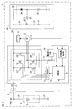
- the electric working machine 1 of the present embodiment shown in FIG. 1 includes, for example, an electric grinder, electric circular saw, electric jigsaw, electric reciprocating saw, electric driver, electric impact driver, electric driver drill, electric It is configured as one of various electric working machines such as a brush cutter or an electric hedge trimmer.
- the electric working machine 1 includes a motor 2, a battery 3, a motor driving device 4, an operation switch 5, and a voltage suppression circuit 30.
- the motor 2 is a drive source for driving the work machine element 10, and is a brushless motor in the present embodiment.
- the work machine element 10 varies depending on the type of the electric work machine 1. For example, when the electric working machine 1 is an electric circular saw, the working machine element 10 is a rotary blade (so-called tip saw). For example, when the electric work machine 1 is an electric driver, the work machine element 10 is a driver bit.
- the motor 2 is provided with a rotation sensor 6 for detecting the rotational position of the motor 2.
- the rotation sensor 6 of this embodiment is a hall sensor, for example.
- the rotation sensor 6 generates a rotation detection signal corresponding to the rotation position of the motor 2 and outputs the rotation detection signal to the rotation information detection unit 14 in the motor driving device 4.
- the battery 3 is a direct current power source for driving the motor 2.
- the battery 3 of the present embodiment is a lithium ion secondary battery including a plurality of cells connected in series. In the battery 3, for example, a plurality of cells may be connected in series.
- the battery 3 may include a plurality of cell groups connected in series, and each of the cell groups may include a plurality of cells connected in parallel.
- the number of cells in the battery 3 is not limited to a specific number, and the connection form of the cells in the battery 3 is not limited to a specific form.
- the battery 3 may be a secondary battery other than the lithium ion secondary battery, or may be a primary battery.
- the battery 3 may be built in the electric working machine 1 or may be detachable from the main body of the electric working machine 1.
- the battery 3 has an internal resistance, and also has an inductance component 3a as shown in FIG. Therefore, for example, when the discharge from the battery 3 is suddenly interrupted, a large voltage (so-called spike voltage) may be instantaneously generated due to the inductance component 3a.
- a main energization path 21 for flowing current from the positive electrode to the negative electrode of the battery 3 is connected. More specifically, the main energization path 21 is changed from the positive electrode of the battery 3 to the negative electrode of the battery 3 through the operation switch 5, the switching circuit 11 in the motor driving device 4, the motor 2, the resistor 16, and the ground (ground) line. It is an energizing route to reach.
- the operation switch 5 is provided in the main energization path 21 on the upstream side of the motor drive device 4 (that is, on the positive electrode side of the battery 3 than the motor control device 4).
- the operation switch 5 is turned on or off according to the operation of the user of the electric work machine 1.
- the operation switch 5 is turned on, the main energization path 21 is conducted, and when the operation switch 5 is turned off, the main energization path 21 is interrupted.
- the operation switch 5 is electrically connected to the control unit 12 in the motor drive device 4.
- the operation switch 5 is configured to input operation information indicating the operation state of the operation switch 5 to the control unit 12.
- the operation information includes information indicating whether the operation switch 5 is turned on or off.
- the electric working machine 1 is configured such that the user can switch the rotation speed of the motor 2 continuously or stepwise by operating the operation switch 5.
- the operation information input from the operation switch 5 to the control unit 12 includes rotation speed instruction information for instructing the control unit 12 of the rotation speed of the motor 2.
- the motor drive device 4 includes a switching circuit 11, a control unit 12, a gate drive unit 13, a rotation information detection unit 14, a current detection circuit 15, and a resistor 16.
- the switching circuit 11 is provided on the downstream side of the operation switch 5 in the main energization path 21.
- the resistor 16 is provided on the downstream side of the switching circuit 11 in the main energization path 21.
- the switching circuit 11 is a circuit for energizing or interrupting the U phase, V phase, and W phase of the motor 2.
- the switching circuit 11 is provided on the downstream side of the motor 2 in the main energization path 21 and the three switching elements (so-called high-side switches) Q1, Q2, and Q3 provided on the upstream side of the motor 2 in the main energization path 21.
- These six switching elements Q1 to Q6 are N-channel MOSFETs in this embodiment.
- a current detection circuit 15 is connected to both ends of the resistor 16.
- the current detection circuit 15 detects the current value of the current flowing through the motor 2 based on the voltage across the resistor 16, and outputs current detection information indicating the detected current value to the control unit 12.
- the rotation information detection unit 14 detects the rotation position (in other words, the rotation angle) of the motor 2 based on the rotation detection signal input from the rotation sensor 6.
- the rotation information detection unit 14 outputs rotation information indicating the detected rotation position to the control unit 12.
- control unit 12 includes a microcomputer having a CPU, a memory, and the like.
- the memory includes at least one of various semiconductor memories such as RAM, ROM, and flash memory.
- Various functions of the control unit 12 are realized by the CPU executing a program stored in a non-transitional physical recording medium.
- the memory corresponds to a non-transitional tangible recording medium that stores a program.
- control unit 12 may include a single microcomputer or a plurality of microcomputers.
- method of realizing the function of the control unit 12 is not limited to software, and part or all of the function may be realized using hardware that combines a logic circuit, an analog circuit, and the like.
- the control unit 12 executes drive control of the motor 2 in accordance with operation information input from the operation switch 5.
- the control unit 12 drives the motor 2 so that the rotation speed of the motor 2 becomes the rotation speed indicated by the rotation speed instruction information included in the operation information.
- the control unit 12 outputs a drive command for switching the on and off states of the switching elements Q1 to Q6 in the switching circuit 11 to the gate drive unit 13.
- the gate drive unit 13 individually switches the on and off states of the switching elements Q1 to Q6 according to the drive command input from the control unit 12. As a result, the motor 2 is energized and the motor 2 rotates. When the motor 2 rotates, the work machine element 10 is driven, and the work by the electric work machine 1 can be performed.
- the control unit 12 controls the rotation speed of the motor 2 by performing PWM control on the current flowing through the motor 2 using the switching circuit 11. Further, the control unit 12 monitors the current detection information input from the current detection circuit 15, and stops energization of the motor 2 when the current value of the current flowing through the motor 2 exceeds the overcurrent threshold.
- the voltage suppression circuit 30 is connected in parallel to the motor drive device 4 with respect to the main energization path 21.
- a drive voltage is input from the battery 3 through the operation switch 5 to the motor drive device 4 and the voltage suppression circuit 30.
- the voltage value Vd of the drive voltage when the operation switch 5 is turned on is equal to or substantially equal to the voltage value Vbat of the battery voltage of the battery 3.
- the voltage suppression circuit 30 bypasses a part of the current flowing from the battery 3 to the main energization path 21 to the voltage suppression circuit 30 when the voltage value Vd becomes equal to or higher than a predetermined threshold value, so that the voltage value Vd becomes the threshold value. Suppresses becoming higher.
- the battery 3 includes the inductance component 3a.
- the main energization path 21 itself also contains an inductance component. Therefore, a spike voltage is generated when the motor 2 is driven by switching the on and off states of the switching elements Q1 to Q6 of the switching circuit 11. That is, a state occurs in which the voltage value Vd is higher than the voltage value Vbat.
- the spike voltage is generated when the current flowing to the motor 2 is cut off when at least one of the switching elements Q1 to Q6 is switched from the on state to the off state.
- the switching elements Q1 to Q6 and / or other circuit elements in the switching circuit 11 may be destroyed.
- the electric working machine 1 of the present embodiment is provided with a voltage suppression circuit 30 in parallel with the motor drive device 4, and is configured such that the voltage control circuit 30 suppresses the generation of spike voltage.
- the voltage suppression circuit 30 includes a bypass energization path 31 that is an energization path for bypassing part of the current flowing through the main energization path 21.
- the bypass energization path 31 is connected to the main energization path 21 in parallel.
- the bypass energization path 31 is provided with a switch Q10 for conducting and blocking the bypass energization path 31.
- the switch Q10 is an N-channel MOSFET in this embodiment.
- the switch Q10 is provided so that a drive voltage is applied to the drain.
- the source of the switch Q10 is connected to the ground line via the resistor 34.
- the voltage suppression circuit 30 includes a switch drive unit 32.
- the switch drive unit 32 turns off the switch Q10 and blocks the bypass energization path 31. Therefore, when the voltage value Vd is less than the threshold value, no current flows from the main energization path 21 into the voltage suppression circuit 30.
- the switch driving unit 32 turns on the switch Q10 to make the bypass energization path 31 conductive.
- the bypass energization path 31 is conducted, a part of the current flowing through the main energization path 21 is bypassed to the bypass energization path 31.
- the switch driver 32 of the present embodiment bypasses the switch Q10 by operating it in the active region rather than completely turning on the switch Q10 (that is, operating in the saturation region) when the voltage value Vd is equal to or greater than the threshold value.
- the energization path 31 is configured to conduct. Note that the operation of the switch Q10 here in the active region means that the switch Q10 is always operated in the active region when the bypass energization path 31 is conducted, that is, there is a period during which the switch Q10 operates in the saturation region.
- the present invention is not limited to this, and includes a case where the operation time in the active region is longer than the operation time in the saturation region over the entire operation period of the switch Q10.
- the switch driving unit 32 includes a Zener diode 36 and a resistor 37 connected in series as shown in FIG.
- the cathode of the Zener diode 36 is connected to the upstream end of the bypass energization path 31 (that is, connected to the drain of the switch Q10).
- the anode of the Zener diode 36 is connected to the first end of the resistor 37.
- the second end of the resistor 37 is connected to the ground line.
- the anode of the Zener diode 36 is connected to the gate of the switch Q10 via the resistor 33. That is, the voltage at the first end of the resistor 37 is applied to the gate of the switch Q10 via the resistor 33.
- the switch driving unit 32 is configured such that the Zener diode 36 does not breakdown when the voltage value Vd is less than the threshold value, and the Zener diode 36 breakdowns when the voltage value Vd is equal to or greater than the threshold value.
- the threshold value is substantially the same value as the sum of the Zener voltage, which is the voltage at which the Zener diode 36 breaks down, and the gate-source voltage (hereinafter referred to as gate-on voltage) required to turn on the switch Q10. is there.
- turning on the switch Q10 includes shifting the state of the switch Q10 to a state in which a drain current flows through the switch Q10 and the switch Q10 operates in an active region.
- the Zener diode 36 breaks down, and a voltage drop occurs in the resistor 37.
- the voltage value Vd is clamped to substantially the same value as the sum of the Zener voltage and the gate-on voltage. During this time, part of the power supplied from the battery 3 via the main energization path 21 is consumed by the switch Q10 and the resistor 34.
- the bypass energization path 31 is conducted in the voltage suppression circuit 30, and thereby a part of the current energized from the battery 3 is bypassed to the bypass energization path 31. This suppresses the voltage value Vd from further rising beyond the threshold value.
- the spike voltage can be suppressed by the voltage suppression circuit 30 smaller than the large-capacity electrolytic capacitor without providing the large-capacity electrolytic capacitor as in the prior art. Therefore, an increase in the size of the electric working machine 1 is suppressed, and a spike voltage generated when the switching elements Q1 to Q6 for driving the motor 2 are switched between the on state and the off state is effectively suppressed.
- the switch driving unit 32 causes the bypass energization path 31 to conduct by operating the switch Q10 in the active region. Therefore, when the current flowing through the main energization path 21 is bypassed to the bypass energization path 31, an excessive current flowing through the bypass energization path 31 is suppressed by the operation in the active region by the switch Q10.
- the switch driving unit 32 includes a Zener diode 36 and a resistor 37 that are connected in series. When the voltage value Vd exceeds a threshold value, the Zener diode 36 breaks down, and the switch Q10 is in the active region. It is configured to be operated. Therefore, the switch drive unit 32 has a simple configuration including the Zener diode 36 and the resistor 37 connected in series, and operates the switch Q10 in the active region when the voltage value Vd becomes equal to or higher than the threshold value, thereby bypassing the energization path. 31 can be made conductive.
- the switching elements Q1 to Q6 in the switching circuit 11 correspond to an example of a first semiconductor switching element in the present disclosure.
- the switch Q10 in the voltage suppression circuit 30 corresponds to an example of a second semiconductor switching element in the present disclosure.
- the operation switch 5 corresponds to an example of a switch unit in the present disclosure.
- a combination of the switching circuit 11 and the motor 2 corresponds to an example of a drive unit in the present disclosure.
- the switching elements Q1 to Q6 and the switch Q10 in the switching circuit 11 are, for example, N-channel MOSFETs.
- switching elements Q1-Q6 and switch Q10 may be semiconductor switching elements other than N-channel MOSFETs.
- the switching elements Q1 to Q6 and the switch Q10 may be, for example, a P-channel MOSFET, a bipolar transistor, a thyristor, or an IGBT.
- a voltage control circuit having another circuit configuration having the same function as the voltage suppression circuit 30 may be adopted.
- the switch drive unit 32 includes the Zener diode 36 as in the above embodiment.
- the switch drive unit 32 may operate the switch Q10 using a circuit element other than the Zener diode 36.
- the switch drive unit 32 may operate the switch Q10 in a saturation region, for example.
- the switch driving unit 32 may include, for example, a comparator instead of the Zener diode 36.
- the switch driver 32 may compare the voltage value Vd with the threshold value, and if the voltage value Vd is equal to or greater than the threshold value, the switch driver 32 outputs an H level signal from the comparator to the switch Q10 to turn on the switch Q10. Good.
- the motor 2 that is the drive source of the work machine element 10 may be a motor other than the brushless motor. That is, the motor 2 may be, for example, an AC motor other than the brushless motor or a brushed DC motor.
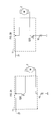
- the switching circuit 11 may include at least one semiconductor switching element Q20 provided on the upstream side of the motor 2 as shown in FIG. As shown in FIG. 2B, at least one semiconductor switching element Q20 provided on the downstream side of the motor 2 may be provided.
- the functions of one component in the above embodiment may be distributed as a plurality of components, or the functions of a plurality of components may be integrated into one component.
- at least a part of the configuration of the above embodiment may be replaced with a known configuration having the same function.
- at least a part of the configuration of the above embodiment may be added to or replaced with the configuration of the other embodiment.
- a system including the electric working machine as a constituent element, a voltage suppressing circuit in the electric working machine, and voltage suppression used in the voltage suppressing circuit among the electric working machines.
- the present disclosure can also be realized in various forms such as a method.
Landscapes
- Engineering & Computer Science (AREA)
- Power Engineering (AREA)
- Mechanical Engineering (AREA)
- Life Sciences & Earth Sciences (AREA)
- Environmental Sciences (AREA)
- Control Of Electric Motors In General (AREA)
- Control Of Ac Motors In General (AREA)
- Portable Power Tools In General (AREA)
- Control Of Direct Current Motors (AREA)
- Harvester Elements (AREA)
Abstract
本開示の1つの局面における電動作業機は、主通電経路と、モータ及び少なくとも1つの第1の半導体スイッチング素子を備える駆動ユニットと、制御部と、バイパス通電経路と、第2の半導体スイッチング素子と、スイッチ駆動部とを備える。主通電経路は、バッテリの正極と負極との間に設けられる。駆動ユニットは、主通電経路に設けられる。バイパス通電経路は、駆動ユニットに対して並列に設けられる。第2の半導体スイッチング素子は、バイパス通電経路に設けられる。スイッチ駆動部は、駆動ユニットに印加される駆動電圧の電圧値が閾値未満の場合は第2の半導体スイッチング素子によってバイパス通電経路を遮断させ、電圧値が閾値以上の場合は第2の半導体スイッチング素子によってバイパス通電経路を導通させる。
Description
本国際出願は、2016年5月20日に日本国特許庁に出願された日本国特許出願第2016-101620号に基づく優先権を主張するものであり、日本国特許出願第2016-101620号の全内容を本国際出願に参照により援用する。
本開示は、バッテリの電力によりモータが駆動されるよう構成された電動作業機に関する。
例えば電動グラインダ、電動丸のこ、電動ドライバ、電動刈払機など、バッテリの電力によってモータが駆動され、そのモータの駆動力によって作業機要素(例えば電動ドライバにおけるドライバビット)が駆動されるよう構成された各種の電動作業機が知られている。
また、モータの駆動方式として、スイッチング駆動方式が知られている。スイッチング駆動方式では、バッテリからモータへの通電経路に半導体スイッチング素子を設け、この半導体スイッチング素子のオン及びオフを制御(例えばデューティー制御)してモータを駆動させる。
一般に、バッテリの内部には、インダクタンス成分が存在している。また、バッテリに限らず、バッテリからモータへの通電経路にもインダクタンス成分が存在している。そのため、スイッチング駆動方式にてモータが駆動されるよう構成された電動作業機においては、半導体スイッチング素子がオン状態からオフ状態に切り替わると、バッテリの内部またはバッテリの外部のインダクタンス成分に起因して、バッテリの電圧値よりも高い電圧値のいわゆるスパイク電圧が発生する。
スパイク電圧が発生すると、半導体スイッチング素子やその他の回路素子が破壊されてしまうおそれがある。
これに対し、例えば下記の特許文献1に記載されているように、バッテリと並列に電解コンデンサを設ける技術が知られている。バッテリと並列に電解コンデンサを設けることで、電解コンデンサによって電圧の変動を抑制でき、スパイク電圧を抑制することが可能となる。
これに対し、例えば下記の特許文献1に記載されているように、バッテリと並列に電解コンデンサを設ける技術が知られている。バッテリと並列に電解コンデンサを設けることで、電解コンデンサによって電圧の変動を抑制でき、スパイク電圧を抑制することが可能となる。
しかし、電解コンデンサによって電圧変動を抑制するためには、容量の大きい大型の電解コンデンサを用いる必要がある。したがって、電動作業機内に電解コンデンサを設けるための広いスペースが必要となって、電動作業機の大型化を招く。さらに、使用者の操作によってスイッチがオンされることによりバッテリからモータへの通電が開始されるように構成された電動作業機の場合、バッテリからの放電開始時、電解コンデンサに一時的に大電流が流れ、これによりスイッチの接点が溶着する可能性もある。
本開示の1つの局面は、電動作業機の大型化を抑制しつつ、モータ駆動用の半導体スイッチング素子のスイッチングに起因して発生するスパイク電圧を効果的に抑制できることが望ましい。
本開示の1つの局面における電動作業機は、バッテリの正極と負極との間に設けられた主通電経路と、この主通電経路に設けられる駆動ユニットと、制御部とを備える。
駆動ユニットは、モータと、少なくとも1つの第1の半導体スイッチング素子とを備える。モータは、主通電経路に設けられる。少なくとも1つの半導体スイッチング素子は、主通電経路におけるモータの上流側及び/又は下流側に設けられる。制御部は、上記少なくとも1つの第1の半導体スイッチング素子をオンまたはオフすることによりモータの駆動を制御するように構成されている。
駆動ユニットは、モータと、少なくとも1つの第1の半導体スイッチング素子とを備える。モータは、主通電経路に設けられる。少なくとも1つの半導体スイッチング素子は、主通電経路におけるモータの上流側及び/又は下流側に設けられる。制御部は、上記少なくとも1つの第1の半導体スイッチング素子をオンまたはオフすることによりモータの駆動を制御するように構成されている。
電動作業機は、さらに、駆動ユニットに対して並列に設けられたバイパス通電経路と、バイパス通電経路に設けられてバイパス通電経路を導通または遮断するように構成された第2の半導体スイッチング素子と、スイッチ駆動部とを備える。
スイッチ駆動部は、駆動ユニットに印加される駆動電圧の電圧値が閾値未満の場合は第2の半導体スイッチング素子によってバイパス通電経路を遮断させ、駆動電圧の電圧値が閾値以上の場合は第2の半導体スイッチング素子によってバイパス通電経路を導通させるように構成されている。
このような電動作業機では、第1の半導体スイッチング素子がオン状態からオフ状態に切り替わる際にスパイク電圧が発生して、駆動ユニットに印加される駆動電圧の電圧値が上昇しても、駆動電圧の電圧値が閾値以上になればバイパス通電経路が導通される。これにより、駆動電圧を上昇させるエネルギーがバイパス通電経路によって消費され、駆動電圧の電圧値が閾値を超えてさらに上昇することが抑制される。
従って、上記のように構成された電動作業機によれば、電動作業機の大型化を抑制しつつ、モータ駆動用の第1の半導体スイッチング素子のスイッチングに起因して発生するスパイク電圧を効果的に抑制することが可能となる。
スイッチ駆動部は、駆動電圧の電圧値が閾値以上の場合、第2の半導体スイッチング素子を能動領域で動作させることによってバイパス通電経路を導通させるように構成されていてもよい。
第2の半導体スイッチング素子を能動領域で動作させると、バイパス通電経路に過大な電流が流れるのを抑制できる。
スイッチ駆動部は、直列接続されたツェナーダイオードと抵抗器とを備えてもよい。より具体的に、ツェナーダイオードは、アノードと、バイパス通電経路の上流側端部に接続されたカソードとを備える。抵抗器は、ツェナーダイオードのアノードに接続された第1端と、バイパス通電経路の下流側端部に接続された第2端とを備える。そして、スイッチ駆動部は、駆動電圧の電圧値が閾値以上の場合にツェナーダイオードが降伏するように構成されている。さらに、スイッチ駆動部は、抵抗器の第1端からの入力電圧が第2の半導体スイッチング素子に入力されるように構成されている。そして、第2の半導体スイッチング素子は、ツェナーダイオードの降伏時に当該第2の半導体スイッチング素子に入力される入力電圧によってバイパス通電経路を導通させるように構成されている。
スイッチ駆動部は、直列接続されたツェナーダイオードと抵抗器とを備えてもよい。より具体的に、ツェナーダイオードは、アノードと、バイパス通電経路の上流側端部に接続されたカソードとを備える。抵抗器は、ツェナーダイオードのアノードに接続された第1端と、バイパス通電経路の下流側端部に接続された第2端とを備える。そして、スイッチ駆動部は、駆動電圧の電圧値が閾値以上の場合にツェナーダイオードが降伏するように構成されている。さらに、スイッチ駆動部は、抵抗器の第1端からの入力電圧が第2の半導体スイッチング素子に入力されるように構成されている。そして、第2の半導体スイッチング素子は、ツェナーダイオードの降伏時に当該第2の半導体スイッチング素子に入力される入力電圧によってバイパス通電経路を導通させるように構成されている。
このような構成によれば、直列接続されたツェナーダイオードと抵抗器とを備えるという簡素な構成を用いて、駆動電圧の電圧値が閾値以上となった場合に第2の半導体スイッチング素子を能動領域で動作させてバイパス通電経路を導通させることができる。
なお、主通電経路における、バッテリの正極と駆動ユニットとの間には、スイッチ部が設けられていてもよい。このスイッチ部は、当該電動作業機の使用者の操作に従ってオンまたはオフされることにより主通電経路を導通または遮断させるように構成されている。
また、本開示の別の1つの局面における電動作業機用電圧抑制回路は、前述の主通電経路、駆動ユニット、及び制御部を備えた電動作業機に搭載され、主通電経路に対して少なくとも駆動ユニットと並列になるように設けられる。そして、この電圧抑制回路は、前述のバイパス通電経路、第2の半導体スイッチング素子、及びスイッチ駆動部を備える。
従って、このように構成された電圧抑制回路によれば、電動作業機の大型化を抑制しつつ、モータ駆動用の第1の半導体スイッチング素子のスイッチングに起因して発生するスパイク電圧を効果的に抑制することが可能となる。
1…電動作業機、2…モータ、3…バッテリ、4…モータ駆動装置、5…操作スイッチ、6…回転センサ、10…作業機要素、11…スイッチング回路、12…制御部、13…ゲート駆動部、14…回転情報検出部、15…電流検出回路、16,33,34,37…抵抗器、21…主通電経路、30…電圧抑制回路、31…バイパス通電経路、32…スイッチ駆動部、36…ツェナーダイオード、Q1~Q6,Q20…スイッチング素子、Q10…スイッチ
以下、本開示の例示的な実施形態について図面を参照しながら説明する。
(1)電動作業機の全体構成
図1に示す本実施形態の電動作業機1は、例えば電動グラインダ、電動丸のこ、電動ジグソー、電動レシプロソー、電動ドライバ、電動インパクトドライバ、電動ドライバドリル、電動刈払機、電動ヘッジトリマなどの、各種の電動作業機のいずれかとして構成されている。
(1)電動作業機の全体構成
図1に示す本実施形態の電動作業機1は、例えば電動グラインダ、電動丸のこ、電動ジグソー、電動レシプロソー、電動ドライバ、電動インパクトドライバ、電動ドライバドリル、電動刈払機、電動ヘッジトリマなどの、各種の電動作業機のいずれかとして構成されている。
図1に示すように、本実施形態の電動作業機1は、モータ2と、バッテリ3と、モータ駆動装置4と、操作スイッチ5と、電圧抑制回路30とを備えている。
モータ2は、作業機要素10を駆動させるための駆動源であり、本実施形態ではブラシレスモータである。なお、作業機要素10は、電動作業機1の種類によって異なる。例えば電動作業機1が電動丸のこである場合は、作業機要素10は回転刃(いわゆるチップソー)である。例えば電動作業機1が電動ドライバである場合は、作業機要素10はドライバビットである。
モータ2は、作業機要素10を駆動させるための駆動源であり、本実施形態ではブラシレスモータである。なお、作業機要素10は、電動作業機1の種類によって異なる。例えば電動作業機1が電動丸のこである場合は、作業機要素10は回転刃(いわゆるチップソー)である。例えば電動作業機1が電動ドライバである場合は、作業機要素10はドライバビットである。
モータ2には、モータ2の回転位置を検出するための回転センサ6が設けられている。本実施形態の回転センサ6は、例えばホールセンサである。回転センサ6は、モータ2の回転位置に応じた回転検出信号を生成して、その回転検出信号をモータ駆動装置4内の回転情報検出部14へ出力する。
バッテリ3は、モータ2を駆動させるための直流電源である。本実施形態のバッテリ3は、直列接続された複数のセルを備えるリチウムイオン二次電池である。なお、バッテリ3では、例えば、複数のセルが直列接続されていてもよい。また、バッテリ3では、直列接続された複数のセル群を備え、セル群の各々は、並列接続された複数のセルを備えてもよい。バッテリ3におけるセルの数は、特定の数に限定されず、また、バッテリ3におけるセルの接続形態は、特定の形態に限定されない。また、バッテリ3は、リチウムイオン二次電池以外の他の二次電池であってもよいし、一次電池であってもよい。また、バッテリ3は、電動作業機1に内蔵されていてもよいし、電動作業機1の本体に対して着脱可能であってもよい。
バッテリ3は、内部抵抗を有し、さらに、図1に示すようにインダクタンス成分3aも有している。そのため、例えばバッテリ3からの放電が急に遮断されると、インダクタンス成分3aに起因して瞬間的に大きな電圧(いわゆるスパイク電圧)が発生することがある。
バッテリ3の正極と負極との間には、バッテリ3の正極から負極へ電流を流すための主通電経路21が接続されている。主通電経路21は、より詳しくは、バッテリ3の正極から、操作スイッチ5、モータ駆動装置4内のスイッチング回路11とモータ2、抵抗器16、及びグランド(接地)ラインを経てバッテリ3の負極に至る通電経路である。
操作スイッチ5は、主通電経路21における、モータ駆動装置4よりも上流側(即ちモータ制御装置4よりもバッテリ3の正極側)に設けられている。操作スイッチ5は、電動作業機1の使用者の操作に従ってオン又はオフされる。操作スイッチ5がオンされると主通電経路21が導通され、操作スイッチ5がオフされると主通電経路21が遮断される。
操作スイッチ5は、モータ駆動装置4内の制御部12と電気的に接続されている。操作スイッチ5は、操作スイッチ5の操作状態を示す操作情報を制御部12へ入力するように構成されている。操作情報には、操作スイッチ5がオンされているのか、あるいはオフされているのかを示す情報が含まれる。
なお、本実施形態の電動作業機1は、使用者が、操作スイッチ5を操作することによってモータ2の回転数を連続的又は段階的に切り替えることが可能に構成されている。操作スイッチ5から制御部12へ入力される操作情報には、モータ2の回転数を制御部12へ指示するための回転数指示情報も含まれる。
モータ駆動装置4は、スイッチング回路11と、制御部12と、ゲート駆動部13と、回転情報検出部14と、電流検出回路15と、抵抗器16とを備えている。
スイッチング回路11は、主通電経路21における、操作スイッチ5の下流側に設けられている。抵抗器16は、主通電経路21において、スイッチング回路11の下流側に設けられている。
スイッチング回路11は、主通電経路21における、操作スイッチ5の下流側に設けられている。抵抗器16は、主通電経路21において、スイッチング回路11の下流側に設けられている。
スイッチング回路11は、モータ2のU相,V相,W相を通電または遮断するための回路である。スイッチング回路11は、主通電経路21におけるモータ2よりも上流側に設けられた3つのスイッチング素子(いわゆるハイサイドスイッチ)Q1,Q2,Q3と、主通電経路21におけるモータ2よりも下流側に設けられた3つのスイッチング素子(いわゆるローサイドスイッチ)Q4,Q5,Q6とを備える。これら6つのスイッチング素子Q1~Q6は、本実施形態ではNチャネルMOSFETである。
抵抗器16の両端には、電流検出回路15が接続されている。電流検出回路15は、抵抗器16の両端間の電圧に基づいて、モータ2に流れる電流の電流値を検出し、その検出した電流値を示す電流検出情報を制御部12へ出力する。
回転情報検出部14は、回転センサ6から入力される回転検出信号に基づき、モータ2の回転位置(換言すれば回転角度)を検出する。回転情報検出部14は、検出した回転位置を示す回転情報を制御部12へ出力する。
制御部12は、本実施形態では、CPU、メモリ等を有するマイクロコンピュータを備えている。メモリには、RAM、ROM、フラッシュメモリ等の各種半導体メモリの少なくとも1つが含まれる。制御部12の各種機能は、CPUが非遷移的実体的記録媒体に格納されたプログラムを実行することにより実現される。この例では、メモリが、プログラムを格納した非遷移的実体的記録媒体に該当する。
なお、制御部12は、1つのマイクロコンピュータを備えてもよいし、複数のマイクロコンピュータを備えてもよい。また、制御部12が有する機能の実現方法は、ソフトウェアに限定されるものではなく、機能の一部又は全部は、論理回路やアナログ回路等を組み合わせたハードウェアを用いて実現されてもよい。
制御部12は、操作スイッチ5から入力される操作情報に従い、モータ2の駆動制御を実行する。操作スイッチ5がオンされた場合、制御部12は、モータ2の回転数が、操作情報に含まれている回転数指示情報が示す回転数となるように、モータ2を駆動させる。具体的に、制御部12は、スイッチング回路11内の各スイッチング素子Q1~Q6のオン状態及びオフ状態を切り替えるための駆動指令をゲート駆動部13へ出力する。
ゲート駆動部13は、制御部12から入力される駆動指令に従って各スイッチング素子Q1~Q6のオン状態及びオフ状態を個別に切り替える。これにより、モータ2への通電が行われ、モータ2が回転する。モータ2が回転すると、作業機要素10が駆動され、これにより当該電動作業機1による作業が可能となる。
なお、制御部12は、スイッチング回路11を用いてモータ2に流れる電流をPWM制御することにより、モータ2の回転数を制御する。また、制御部12は、電流検出回路15から入力される電流検出情報を監視し、モータ2に流れる電流の電流値が過電流閾値を超えた場合は、モータ2への通電を停止させる。
電圧抑制回路30は、主通電経路21に対し、モータ駆動装置4と並列に接続されている。モータ駆動装置4及び電圧抑制回路30には、バッテリ3から操作スイッチ5を経て駆動電圧が入力される。なお、本実施形態では、操作スイッチ5がオンされているときの駆動電圧の電圧値Vdは、バッテリ3のバッテリ電圧の電圧値Vbatと等しいか若しくはほぼ等しい値である。
電圧抑制回路30は、電圧値Vdが所定の閾値以上となった場合に、バッテリ3から主通電経路21に流れる電流の一部を当該電圧抑制回路30にバイパスさせることで、電圧値Vdが閾値より高くなることを抑制する。
既述の通り、バッテリ3にはインダクタンス成分3aが含まれている。また、主通電経路21自体にもインダクタンス成分が含まれている。そのため、スイッチング回路11の各スイッチング素子Q1~Q6のオン状態及びオフ状態が切り替えられることによってモータ2が駆動される際、スパイク電圧が発生する。即ち、電圧値Vdが電圧値Vbatよりも高くなる状態が発生する。スパイク電圧は、各スイッチング素子Q1~Q6の少なくとも1つがオン状態からオフ状態に切り替わることによりモータ2へ流れる電流が遮断された際に発生する。スパイク電圧が発生すると、そのスパイク電圧の電圧値によっては、スイッチング回路11におけるスイッチング素子Q1~Q6及び/又はその他の回路素子が破壊されてしまう可能性がある。
そこで、本実施形態の電動作業機1は、モータ駆動装置4と並列に電圧抑制回路30が設けられており、電圧制御回路30によってスパイク電圧の発生が抑制されるように構成されている。
(2)電圧抑制回路の詳細構成及び機能の説明
電圧抑制回路30は、主通電経路21に流れる電流の一部をバイパスさせるための通電経路であるバイパス通電経路31を備える。バイパス通電経路31は、主通電経路21に並列に接続されている。
電圧抑制回路30は、主通電経路21に流れる電流の一部をバイパスさせるための通電経路であるバイパス通電経路31を備える。バイパス通電経路31は、主通電経路21に並列に接続されている。
バイパス通電経路31には、当該バイパス通電経路31を導通及び遮断するためのスイッチQ10が設けられている。スイッチQ10は、本実施形態ではNチャネルMOSFETである。
スイッチQ10は、ドレインに駆動電圧が印加されるように設けられている。また、スイッチQ10のソースは、抵抗器34を介してグランドラインに接続されている。
また、電圧抑制回路30は、スイッチ駆動部32を備える。スイッチ駆動部32は、電圧値Vdが閾値未満の場合はスイッチQ10をオフさせてバイパス通電経路31を遮断させる。そのため、電圧値Vdが閾値未満の場合は電圧抑制回路30には主通電経路21から電流が流入しない。一方、スイッチ駆動部32は、電圧値Vdが閾値以上の場合は、スイッチQ10をオンさせることによりバイパス通電経路31を導通させる。バイパス通電経路31が導通されると、主通電経路21に流れる電流の一部がバイパス通電経路31にバイパスされる。
また、電圧抑制回路30は、スイッチ駆動部32を備える。スイッチ駆動部32は、電圧値Vdが閾値未満の場合はスイッチQ10をオフさせてバイパス通電経路31を遮断させる。そのため、電圧値Vdが閾値未満の場合は電圧抑制回路30には主通電経路21から電流が流入しない。一方、スイッチ駆動部32は、電圧値Vdが閾値以上の場合は、スイッチQ10をオンさせることによりバイパス通電経路31を導通させる。バイパス通電経路31が導通されると、主通電経路21に流れる電流の一部がバイパス通電経路31にバイパスされる。
本実施形態のスイッチ駆動部32は、電圧値Vdが閾値以上の場合に、スイッチQ10を完全にオンさせる(即ち飽和領域で動作させる)のではなく、スイッチQ10を能動領域で動作させることによってバイパス通電経路31を導通させるように構成されている。なお、ここでいうスイッチQ10を能動領域で動作させる、とは、バイパス通電経路31を導通させる際にスイッチQ10を常に能動領域で動作させること、つまり、スイッチQ10を飽和領域で動作させる期間が全くないことに限定されるのではなく、スイッチQ10の動作期間全体において、飽和領域での動作時間よりも能動領域での動作時間の方が長い場合を含む。
スイッチ駆動部32は、より具体的には、図1に示すように、直列接続されたツェナーダイオード36と抵抗器37とを備えている。ツェナーダイオード36のカソードは、バイパス通電経路31の上流側の端部に接続(つまりスイッチQ10のドレインに接続)されている。ツェナーダイオード36のアノードは、抵抗器37の第1端に接続されている。抵抗器37の第2端はグランドラインに接続されている。
また、ツェナーダイオード36のアノードは、抵抗器33を介してスイッチQ10のゲートに接続されている。つまり、抵抗器37の第1端の電圧が、抵抗器33を介してスイッチQ10のゲートに印加される。
スイッチ駆動部32は、電圧値Vdが閾値未満の場合はツェナーダイオード36が降伏せず、電圧値Vdが閾値以上の場合にツェナーダイオード36が降伏するように構成されている。つまり、本実施形態では、閾値は、ツェナーダイオード36が降伏する電圧であるツェナー電圧と、スイッチQ10をオンさせるために必要なゲート・ソース間電圧(以下、ゲートオン電圧)との和とほぼ同値である。なお、スイッチQ10を「オン」させるとは、スイッチQ10にドレイン電流が流れてスイッチQ10が能動領域で動作する状態にスイッチQ10の状態を移行させることを含む。
このような構成により、電圧値Vdが閾値未満の場合は、ツェナーダイオード36は降伏せず、スイッチQ10はオフされる。この場合、バイパス通電経路31は遮断され、主通電経路21に流れる電流はバイパス通電経路31にはバイパスされない。
一方、電圧値Vdが閾値以上になると、ツェナーダイオード36が降伏し、抵抗器37に電圧降下が生じて、抵抗器37の第1端の電圧の値、即ちスイッチQ10のゲート電圧の値は、スイッチQ10を能動領域で動作させることが可能な値となる。この場合、スイッチQ10がオンされてバイパス通電経路31が導通し、主通電経路21に流れる電流の一部がバイパス通電経路31にバイパスされる。
バイパス通電経路31に電流が流れている間は、電圧値Vdは、ツェナー電圧とゲートオン電圧との和とほぼ同値にクランプされる。この間、バッテリ3から主通電経路21を介して供給される電力の一部は、スイッチQ10及び抵抗器34で消費される。
(3)実施形態の効果
以上説明した実施形態によれば、以下の効果が得られる。
(3a)スイッチング回路11における各スイッチング素子Q1~Q6のオン及びオフが制御される際、そのオン及びオフの制御に起因してスパイク電圧が発生し、電圧値Vdが上昇する。しかし、電圧値Vdが閾値以上になれば、電圧抑制回路30によって、電圧値Vdの上昇が抑制される。
以上説明した実施形態によれば、以下の効果が得られる。
(3a)スイッチング回路11における各スイッチング素子Q1~Q6のオン及びオフが制御される際、そのオン及びオフの制御に起因してスパイク電圧が発生し、電圧値Vdが上昇する。しかし、電圧値Vdが閾値以上になれば、電圧抑制回路30によって、電圧値Vdの上昇が抑制される。
即ち、電圧値Vdが閾値以上になると、電圧抑制回路30においてバイパス通電経路31が導通され、これによりバッテリ3から通電される電流の一部がバイパス通電経路31にバイパスされる。これにより、電圧値Vdが閾値を超えてさらに上昇することが抑制される。
つまり、本実施形態の電動作業機1では、従来のように大容量の電解コンデンサを設けることなく、その大容量の電解コンデンサよりも小さい電圧抑制回路30によって、スパイク電圧を抑制できる。そのため、電動作業機1の大型化が抑えられると共に、モータ2を駆動するためのスイッチング素子Q1~Q6のオン状態及びオフ状態が切り替わることによって発生するスパイク電圧が効果的に抑制される。
(3b)スイッチ駆動部32は、電圧値Vdが閾値以上の場合、スイッチQ10を能動領域で動作させることによってバイパス通電経路31を導通させる。そのため、主通電経路21に流れる電流がバイパス通電経路31へバイパスされる際、スイッチQ10による能動領域での動作によって、バイパス通電経路31に過大な電流が流れることが抑制される。
これにより、スイッチQ10に直列接続される抵抗器34として、抵抗値が小さく且つ定格電力の小さい抵抗器を用いることができる。
(3c)スイッチ駆動部32は、直列接続されたツェナーダイオード36と抵抗器37とを備え、電圧値Vdが閾値以上となった場合に、ツェナーダイオード36が降伏して、スイッチQ10が能動領域で動作されるように構成されている。そのため、スイッチ駆動部32は、直列接続されたツェナーダイオード36と抵抗器37とを備える簡素な構成によって、電圧値Vdが閾値以上となった場合にスイッチQ10を能動領域で動作させてバイパス通電経路31を導通させることができる。
(3c)スイッチ駆動部32は、直列接続されたツェナーダイオード36と抵抗器37とを備え、電圧値Vdが閾値以上となった場合に、ツェナーダイオード36が降伏して、スイッチQ10が能動領域で動作されるように構成されている。そのため、スイッチ駆動部32は、直列接続されたツェナーダイオード36と抵抗器37とを備える簡素な構成によって、電圧値Vdが閾値以上となった場合にスイッチQ10を能動領域で動作させてバイパス通電経路31を導通させることができる。
なお、スイッチング回路11におけるスイッチング素子Q1~Q6は、本開示における第1の半導体スイッチング素子の一例に相当する。電圧抑制回路30内のスイッチQ10は、本開示における第2の半導体スイッチング素子の一例に相当する。操作スイッチ5は、本開示におけるスイッチ部の一例に相当する。スイッチング回路11とモータ2との組合せが、本開示における駆動ユニットの一例に相当する。
[他の実施形態]
以上、本開示の実施形態について説明したが、本開示は上述の実施形態に限定されることなく、種々変形して実施することができる。
以上、本開示の実施形態について説明したが、本開示は上述の実施形態に限定されることなく、種々変形して実施することができる。
(1)上記実施形態では、スイッチング回路11におけるスイッチング素子Q1~Q6、及びスイッチQ10が、例えばNチャネルMOSFETであった。しかし、スイッチング素子Q1~Q6及びスイッチQ10は、NチャネルMOSFET以外の他の半導体スイッチング素子であってもよい。具体的に、スイッチング素子Q1~Q6及びスイッチQ10は、例えば、PチャネルMOSFET、バイポーラトランジスタ、サイリスタ、又はIGBTなどであってもよい。
(2)上記実施形態の電圧抑制回路30に代えて、電圧抑制回路30と同等の機能を有する他の回路構成の電圧制御回路を採用してもよい。具体的に、スイッチ駆動部32が、上記実施形態のようにツェナーダイオード36を備えることは必須ではない。スイッチ駆動部32は、ツェナーダイオード36以外の他の回路素子を用いてスイッチQ10を作動させてもよい。
また、スイッチ駆動部32がスイッチQ10を能動領域で動作させることについても必須ではない。スイッチ駆動部32は、スイッチQ10を例えば飽和領域で動作させてもよい。具体的に、スイッチ駆動部32は、ツェナーダイオード36に代えて例えばコンパレータを備えていてもよい。この場合、スイッチ駆動部32は、コンパレータが電圧値Vdと閾値とを比較して、電圧値Vdが閾値以上の場合にコンパレータからスイッチQ10へHレベル信号を出力してスイッチQ10をオンさせてもよい。
(3)作業機要素10の駆動源であるモータ2は、ブラシレスモータ以外の他のモータであってもよい。即ち、モータ2は、例えば、ブラシレスモータ以外の他の交流モータであってもよいし、ブラシ付き直流モータであってもよい。
(4)モータへの通電を制御するために用いる半導体スイッチング素子の数や位置は適宜決めてもよい。例えば、モータ2がブラシ付き直流モータである場合、スイッチング回路11は、図2Aに示すように、モータ2の上流側に設けられた少なくとも1つの半導体スイッチング素子Q20を備えてもよいし、あるいは、図2Bに示すように、モータ2の下流側に設けられた少なくとも1つの半導体スイッチング素子Q20を備えてもよい。
(5)その他、上記実施形態における1つの構成要素が有する機能を複数の構成要素として分散させたり、複数の構成要素が有する機能を1つの構成要素に統合させたりしてもよい。また、上記実施形態の構成の少なくとも一部を、同様の機能を有する公知の構成に置き換えてもよい。また、上記実施形態の構成の一部を省略してもよい。また、上記実施形態の構成の少なくとも一部を、他の上記実施形態の構成に対して付加又は置換してもよい。
(6)また、上述した電動作業機の他、当該電動作業機を構成要素とするシステム、当該電動作業機における電圧抑制回路、当該電動作業機のうち特に電圧抑制回路で用いられている電圧抑制方法など、種々の形態で本開示を実現することもできる。
Claims (5)
- バッテリの正極と負極との間に設けられた主通電経路と、
前記主通電経路に設けられる駆動ユニットであって、前記主通電経路に設けられるモータと、前記主通電経路における前記モータの上流側及び/又は下流側に設けられる少なくとも1つの第1の半導体スイッチング素子と、を備える駆動ユニットと、
前記少なくとも1つの第1の半導体スイッチング素子をオンまたはオフすることにより前記モータの駆動を制御するように構成された制御部と、
前記駆動ユニットに対して並列に設けられたバイパス通電経路と、
前記バイパス通電経路に設けられ、このバイパス通電経路を導通または遮断するように構成された第2の半導体スイッチング素子と、
前記駆動ユニットに印加される駆動電圧の電圧値が閾値未満の場合は前記第2の半導体スイッチング素子によって前記バイパス通電経路を遮断させ、前記電圧値が前記閾値以上の場合は前記第2の半導体スイッチング素子によって前記バイパス通電経路を導通させるように構成されたスイッチ駆動部と、
を備える電動作業機。 - 請求項1に記載の電動作業機であって、
前記スイッチ駆動部は、前記電圧値が前記閾値以上の場合、前記第2の半導体スイッチング素子を能動領域で動作させることにより前記バイパス通電経路を導通させるように構成されている、電動作業機。 - 請求項2に記載の電動作業機であって、
前記スイッチ駆動部は、
アノードと、前記バイパス通電経路の上流側端部に接続されたカソードとを備えるツェナーダイオードと、
前記ツェナーダイオードの前記アノードに接続された第1端と、前記バイパス通電経路の下流側端部に接続された第2端とを備える抵抗器と、
を備え、
前記スイッチ駆動部は、前記電圧値が前記閾値以上の場合に前記ツェナーダイオードが降伏するように構成され、
前記スイッチ駆動部は、前記抵抗器の前記第1端からの入力電圧が前記第2の半導体スイッチング素子に入力されるように構成されており、
前記第2の半導体スイッチング素子は、前記ツェナーダイオードの降伏時に前記第2の半導体スイッチング素子に入力される前記入力電圧によって前記バイパス通電経路を導通させるように構成されている、
電動作業機。 - 請求項1~請求項3の何れか1項に記載の電動作業機であって、
前記主通電経路における、前記バッテリの前記正極と前記駆動ユニットとの間に設けられ、当該電動作業機の使用者の操作に従ってオンまたはオフされることにより前記主通電経路を導通または遮断させるように構成されたスイッチ部を備える、電動作業機。 - バッテリの正極と負極との間に設けられた主通電経路と、
前記主通電経路に設けられる駆動ユニットであって、前記主通電経路に設けられるモータと、前記主通電経路における前記モータの上流側及び/又は下流側に設けられる少なくとも1つの第1の半導体スイッチング素子と、を備える駆動ユニットと、
前記少なくとも1つの第1の半導体スイッチング素子をオンまたはオフすることにより前記モータの駆動を制御するように構成された制御部と、
を備えた電動作業機に搭載され、前記主通電経路に対して少なくとも前記駆動ユニットと並列になるように設けられる電圧抑制回路であって、
前記駆動ユニットに対して並列に設けられたバイパス通電経路と、
前記バイパス通電経路に設けられ、このバイパス通電経路を導通または遮断するように構成された第2の半導体スイッチング素子と、
前記駆動ユニットに印加される駆動電圧の電圧値が閾値未満の場合は前記第2の半導体スイッチング素子によって前記バイパス通電経路を遮断させ、前記電圧値が前記閾値以上の場合は前記第2の半導体スイッチング素子によって前記バイパス通電経路を導通させるように構成されたスイッチ駆動部と、
を備える、電動作業機用電圧抑制回路。
Priority Applications (3)
| Application Number | Priority Date | Filing Date | Title |
|---|---|---|---|
| CN201780031272.XA CN109153113B (zh) | 2016-05-20 | 2017-04-26 | 电动工作机和用于电动工作机的电压抑制电路 |
| DE112017002139.1T DE112017002139T5 (de) | 2016-05-20 | 2017-04-26 | Elektrische Arbeitsmaschine und Spannungsentstörungsschaltung für selbige |
| US16/099,219 US11031770B2 (en) | 2016-05-20 | 2017-04-26 | Electric working machine and voltage suppressor circuit for electric working machine |
Applications Claiming Priority (2)
| Application Number | Priority Date | Filing Date | Title |
|---|---|---|---|
| JP2016101620A JP6628687B2 (ja) | 2016-05-20 | 2016-05-20 | 電動作業機および電動作業機用電圧抑制回路 |
| JP2016-101620 | 2016-05-20 |
Publications (1)
| Publication Number | Publication Date |
|---|---|
| WO2017199719A1 true WO2017199719A1 (ja) | 2017-11-23 |
Family
ID=60326307
Family Applications (1)
| Application Number | Title | Priority Date | Filing Date |
|---|---|---|---|
| PCT/JP2017/016592 Ceased WO2017199719A1 (ja) | 2016-05-20 | 2017-04-26 | 電動作業機および電動作業機用電圧抑制回路 |
Country Status (5)
| Country | Link |
|---|---|
| US (1) | US11031770B2 (ja) |
| JP (1) | JP6628687B2 (ja) |
| CN (1) | CN109153113B (ja) |
| DE (1) | DE112017002139T5 (ja) |
| WO (1) | WO2017199719A1 (ja) |
Families Citing this family (4)
| Publication number | Priority date | Publication date | Assignee | Title |
|---|---|---|---|---|
| TWI854385B (zh) * | 2022-12-05 | 2024-09-01 | 車王電子股份有限公司 | 電動工具之電源管理裝置 |
| DE102024210022A1 (de) * | 2024-10-16 | 2026-04-16 | Robert Bosch Gesellschaft mit beschränkter Haftung | Elektrowerkzeugmaschine und Verfahren zum Betrieb einer Elektrowerkzeugmaschine |
| DE102024210026A1 (de) * | 2024-10-16 | 2026-04-16 | Robert Bosch Gesellschaft mit beschränkter Haftung | Elektrowerkzeugmaschine und Verfahren zum Betrieb einer Elektrowerkzeugmaschine |
| CN119183784B (zh) * | 2024-11-06 | 2026-05-05 | 青岛理工大学 | 一种智能高效低损蒜薹收获机 |
Citations (2)
| Publication number | Priority date | Publication date | Assignee | Title |
|---|---|---|---|---|
| JP2011020187A (ja) * | 2009-07-13 | 2011-02-03 | Hitachi Koki Co Ltd | 電動工具 |
| JP2015131380A (ja) * | 2014-01-15 | 2015-07-23 | 株式会社マキタ | 電動作業機器 |
Family Cites Families (13)
| Publication number | Priority date | Publication date | Assignee | Title |
|---|---|---|---|---|
| JP3052648B2 (ja) * | 1993-02-21 | 2000-06-19 | 日産自動車株式会社 | 半導体装置 |
| US5640071A (en) * | 1995-10-10 | 1997-06-17 | Malaspina; Francis P. | Transient charge recovery circuit |
| JP4438608B2 (ja) * | 2004-02-16 | 2010-03-24 | 株式会社デンソー | Hブリッジ回路の駆動装置及びhブリッジ回路の保護方法 |
| JP2007135252A (ja) * | 2005-11-08 | 2007-05-31 | Hitachi Ltd | 電力変換装置 |
| US20090268359A1 (en) * | 2008-04-25 | 2009-10-29 | International Business Machines Corporation | Electrostatic discharge power clamp with improved electrical overstress robustness |
| US8743523B2 (en) * | 2010-07-28 | 2014-06-03 | General Electric Company | Systems, methods, and apparatus for limiting voltage across a switch |
| EP2706665A1 (en) * | 2012-09-06 | 2014-03-12 | ABB Oy | Active clamp for a semiconductor switch |
| JP6085488B2 (ja) | 2013-01-28 | 2017-02-22 | 株式会社マキタ | 電動工具 |
| US9623545B2 (en) * | 2013-02-08 | 2017-04-18 | Milwaukee Electric Tool Corporation | Apparatus with active software clamping of supply voltage |
| US8941341B2 (en) * | 2013-03-14 | 2015-01-27 | Hamilton Sundstrand Corporation | Rotating diode assembly including overvoltage protection circuit |
| US9735725B2 (en) * | 2014-01-21 | 2017-08-15 | Regal Beloit America, Inc. | Methods and systems for transient voltage protection |
| JP6006282B2 (ja) | 2014-11-28 | 2016-10-12 | 渡辺精機株式会社 | 球状野菜等の分割切断方法及び分割切断装置 |
| US10340686B2 (en) * | 2014-12-11 | 2019-07-02 | Denso Corporation | Electronic device |
-
2016
- 2016-05-20 JP JP2016101620A patent/JP6628687B2/ja active Active
-
2017
- 2017-04-26 DE DE112017002139.1T patent/DE112017002139T5/de active Pending
- 2017-04-26 US US16/099,219 patent/US11031770B2/en active Active
- 2017-04-26 CN CN201780031272.XA patent/CN109153113B/zh active Active
- 2017-04-26 WO PCT/JP2017/016592 patent/WO2017199719A1/ja not_active Ceased
Patent Citations (2)
| Publication number | Priority date | Publication date | Assignee | Title |
|---|---|---|---|---|
| JP2011020187A (ja) * | 2009-07-13 | 2011-02-03 | Hitachi Koki Co Ltd | 電動工具 |
| JP2015131380A (ja) * | 2014-01-15 | 2015-07-23 | 株式会社マキタ | 電動作業機器 |
Also Published As
| Publication number | Publication date |
|---|---|
| CN109153113B (zh) | 2021-08-10 |
| JP6628687B2 (ja) | 2020-01-15 |
| DE112017002139T5 (de) | 2019-01-03 |
| US20190157857A1 (en) | 2019-05-23 |
| CN109153113A (zh) | 2019-01-04 |
| JP2017205849A (ja) | 2017-11-24 |
| US11031770B2 (en) | 2021-06-08 |
Similar Documents
| Publication | Publication Date | Title |
|---|---|---|
| US11509129B2 (en) | Electric working machine and method for smoothing AC power supplied thereto | |
| US9246416B2 (en) | Braking apparatus for three-phase brushless motor, and motor-driven appliance provided with same | |
| JP6283161B2 (ja) | 操作棹を有する作業機 | |
| US10348227B2 (en) | Electric power tool | |
| JP6579402B2 (ja) | 電動工具 | |
| US20200260643A1 (en) | Electric working machine and method for controlling motor of electric working machine | |
| US10644634B2 (en) | Electric power tool | |
| CN110858724B (zh) | 电压供给装置 | |
| JP6628687B2 (ja) | 電動作業機および電動作業機用電圧抑制回路 | |
| JP5660997B2 (ja) | 電動機制御装置 | |
| JP6092480B1 (ja) | 車両用電力供給システム、および車両用電力供給システムの制御方法 | |
| KR102313672B1 (ko) | 전동식 파워 스티어링 시스템의 모터 구동 회로 | |
| JP7500388B2 (ja) | 電動作業機 | |
| JP5660996B2 (ja) | 電動機制御装置 | |
| JP2020198661A (ja) | 動力工具 | |
| US11955874B2 (en) | Electric powered work machine | |
| US20240088804A1 (en) | Device and method for motor braking | |
| JP2020093460A (ja) | 往復動作業機 | |
| JP2025163936A (ja) | 電動作業機 | |
| JP6618381B2 (ja) | 電動作業機 | |
| CN116488443A (zh) | 平滑电容器的放电电路及电力转换电路 |
Legal Events
| Date | Code | Title | Description |
|---|---|---|---|
| 121 | Ep: the epo has been informed by wipo that ep was designated in this application |
Ref document number: 17799149 Country of ref document: EP Kind code of ref document: A1 |
|
| 122 | Ep: pct application non-entry in european phase |
Ref document number: 17799149 Country of ref document: EP Kind code of ref document: A1 |