WO2017199404A1 - 排ガス測定装置 - Google Patents
排ガス測定装置 Download PDFInfo
- Publication number
- WO2017199404A1 WO2017199404A1 PCT/JP2016/064920 JP2016064920W WO2017199404A1 WO 2017199404 A1 WO2017199404 A1 WO 2017199404A1 JP 2016064920 W JP2016064920 W JP 2016064920W WO 2017199404 A1 WO2017199404 A1 WO 2017199404A1
- Authority
- WO
- WIPO (PCT)
- Prior art keywords
- gas
- measurement
- flow path
- measured
- flow rate
- Prior art date
- Legal status (The legal status is an assumption and is not a legal conclusion. Google has not performed a legal analysis and makes no representation as to the accuracy of the status listed.)
- Ceased
Links
Images

Classifications
-
- G—PHYSICS
- G01—MEASURING; TESTING
- G01N—INVESTIGATING OR ANALYSING MATERIALS BY DETERMINING THEIR CHEMICAL OR PHYSICAL PROPERTIES
- G01N1/00—Sampling; Preparing specimens for investigation
- G01N1/02—Devices for withdrawing samples
- G01N1/22—Devices for withdrawing samples in the gaseous state
-
- G—PHYSICS
- G01—MEASURING; TESTING
- G01N—INVESTIGATING OR ANALYSING MATERIALS BY DETERMINING THEIR CHEMICAL OR PHYSICAL PROPERTIES
- G01N15/00—Investigating characteristics of particles; Investigating permeability, pore-volume or surface-area of porous materials
- G01N15/02—Investigating particle size or size distribution
Definitions
- the present invention relates to an exhaust gas measuring apparatus that takes in an exhaust gas of an automobile as a sample gas and measures the number of particles contained in the sample gas.
- the sample gas is diluted with a dilution gas such as air, and the mixed gas is introduced into the particle number measurement device.
- a dilution gas such as air
- the mixed gas is introduced into the particle number measurement device.
- the particle number measuring device of such a system for example, a particle measuring device for classifying and measuring particles in a sample gas according to their size is used (see Patent Document 1).
- the system includes a flow meter that measures the flow rate of the mixed gas from the mixing unit that mixes the sample gas and the dilution gas, and a flow meter that measures the flow rate of the dilution gas supplied to the mixing unit.
- the flow rate of the sample gas introduced into the particle number measuring device and the dilution rate thereof are controlled to be constant based on the measured value of the meter.
- the flow rate of the sample gas introduced into the particle number measuring device is obtained by subtracting the measured value of the dilution gas flow rate from the measured value of the mixed gas flow rate, and the flow rate is kept constant.
- the valve provided on the sample gas side is controlled. Therefore, in order to control the sample gas flow rate, it is necessary to use the measured values of two flow meters, that is, a flow meter for the mixed gas and a flow meter for the dilution gas.
- the dilution rate is 10 times and the flow rate of the mixed gas is 9 L / min. If the flow rate of the working gas is set to 8.1 L / min, the actual mixed gas flow rate is 9 ⁇ 0.1 L / min, the dilution gas flow rate is 8.1 ⁇ 0.1 L / min, and the sample gas flow rate is 0.9 ⁇ 0.2 L / min. This means that an error of about 20% at the maximum appears from the set value of the original sample gas flow rate. Since the error in the sample gas flow rate has a great influence on the measurement accuracy, it is desirable to control the flow rate of the sample gas with higher accuracy.
- a flow meter is installed on the flow path for introducing exhaust gas into the mixing section and the flow rate of the sample gas is controlled based on the measured value of the flow meter, the flow rate of the sample gas is adjusted based on the measured value of one flow meter. Can be controlled.
- the flow meter is contaminated and the measurement accuracy of the flow meter is reduced, or particulate matter in the exhaust gas is deposited in the flow meter. There is a concern that the particles to be introduced into the measurement unit may be lost.
- an object of the present invention is to provide an exhaust gas analyzer that can control the flow rate of a sample gas with high accuracy while preventing the loss of particles in the sample gas.
- One embodiment of the exhaust gas measuring apparatus includes a mixing unit, an inlet channel, a measuring unit, a measuring gas channel, a measured gas channel, a dilution gas channel, a discharge channel, a gas purification unit, a pump, A discharge flow rate measurement unit and a discharge flow rate control unit are provided.
- the mixing unit mixes the sample gas and the dilution gas to make a measurement gas.
- the inlet channel introduces the sample gas into the mixing unit, and the measurement gas channel introduces the measuring gas composed of the sample gas and the dilution gas mixed in the mixing unit into the measuring unit.
- the measurement unit measures the measurement gas.
- the measured gas that has passed through the measurement unit flows, and the dilution channel and the discharge channel are connected to the downstream end of the measured gas channel.
- the dilution gas flow path is a flow path that guides a part of the measured gas to the mixing unit as a dilution gas
- the discharge flow path is a flow path that discharges the measured gas other than the dilution gas to the outside.
- the gas purifying unit purifies at least the dilution gas among the measured gases.
- the pump comprises a sample gas flow flowing through the inlet flow channel, a measurement gas flow flowing through the measurement gas flow channel, a measured gas flow flowing through the measured gas flow channel, a dilution gas flow flowing through the dilution gas flow channel, and a discharge flow channel.
- a flowing measured gas stream is formed.
- the discharge flow rate measurement unit measures the gas flow rate flowing through the discharge flow channel, and the discharge flow rate control unit controls the gas flow rate flowing through the discharge flow channel to a preset flow rate based on the measurement value of the discharge flow rate measurement unit.
- a part of the measured gas that has passed through the measuring unit is led to the mixing unit as a dilution gas, and the remaining gas of the measured gas is discharged to the outside through the discharge channel.
- the sample gas having the same flow rate as the gas discharged to the outside flows in from the inlet channel.
- a discharge flow rate measurement unit and a discharge flow rate control unit are provided on the discharge flow channel, and the gas flow rate flowing through the discharge flow channel is controlled based on the measurement value of the discharge flow rate measurement unit.
- the flow rate of gas can be controlled by the discharge flow rate control unit based on the measurement value of the discharge flow rate measurement unit. Since the sample gas flow rate can be controlled by one flow meter (exhaust flow rate measurement unit), the accuracy of flow rate control can be improved compared to the method of taking the difference between the measured values of the two flow meters.
- the measuring apparatus is enlarged because a pump for introducing the dilution gas into the mixing unit is required in addition to the pump for introducing the sample gas into the mixing unit. It was.
- the sample gas flow flowing through the inlet flow channel, the measurement gas flow flowing through the measurement gas flow channel, the measured gas flow flowing through the measured gas flow channel, and for dilution can be formed by a single pump provided on the measured gas flow path or on the measured gas flow path. Therefore, a plurality of pumps are not required, and the apparatus can be reduced in size.
- the discharge flow rate control unit there is a valve whose opening degree is adjusted based on the measured value of the discharge flow rate measurement unit.
- the gas purification unit is preferably provided on the measured gas flow path. In this way, the gas whose flow rate is measured by the discharge flow rate measurement unit can be made into clean air purified by the gas purification unit, preventing internal contamination of the discharge flow rate measurement unit and reducing the measurement accuracy or the flow meter. Failure can be prevented.
- the apparatus may further include a measured gas flow rate switching unit that is provided in the middle of the measured gas channel and switches whether or not at least a part of the measured gas flowing through the measured gas channel is discharged to the outside. preferable. If it does so, the flow volume of the measured gas which flows through a measured gas flow path can be made variable, and the flow volume of the gas for dilution can be changed by switching of the measured gas flow volume switching part. The dilution rate of the sample gas can be changed by changing the flow rate of the dilution gas.
- a charging device for charging particles in the measurement gas on the measurement gas flow path includes a measurement channel through which the measurement gas flows, a plate-like classification electrode provided along the inside of the measurement channel, and an array along the measurement gas flow that faces the classification electrode and flows through the measurement channel.
- a plurality of measurement electrodes that are electrically insulated from each other, and by applying a voltage between the classification electrode and the measurement electrode to generate an electric field, the charged particles are classified according to their particle diameters.
- a particle classification measuring device that captures on a measuring electrode and counts the number thereof can be mentioned.
- Such a particle classification measuring apparatus is disclosed in Patent Document 1, and has a movable structure in addition to the air blowing mechanism and has a simple and robust structure, and is therefore portable. Therefore, by using such a particle classification measurement device, the exhaust gas measurement device can be further reduced in size, and a portable exhaust gas measurement device can also be realized.
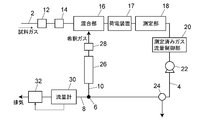
- the exhaust gas measuring apparatus of this embodiment introduces a sample gas into the mixing unit 16 through the inlet channel 2, and dilutes the sample gas with a diluting gas in the mixing unit 16. And the measurement gas is introduced into the measurement unit 18 through the measurement gas channel 3.
- the measured gas measured by the measuring unit 18 flows through the measured gas channel 4, and mixed at the branching unit 6 through the dilution gas channel 10 with the exhaust gas discharged outside through the discharge channel 8. Divided into dilution gas introduced into the section 16.
- the heater 12 for heating the sample gas and the sample gas are sucked through the slit, and particles having a certain size or more are immediately after the slit.
- An impactor 14 is provided which is adjusted so as to be removed by colliding with a plate disposed on the plate.
- the heater 12 removes volatile substances such as moisture and oil adhering to the particles in the sample gas.
- a charging device 17 for charging particles in the measurement gas introduced into the measurement unit 18 is provided on the measurement gas channel 3 between the mixing unit 16 and the measurement unit 18.
- the measurement unit 18 of this embodiment includes a plurality of measurement electrodes arranged in the flow direction of the measurement gas, classified according to particle size, and counted. Therefore, a charging device 17 is provided.
- the measuring unit 18 does not necessarily need to be such a measuring device, and a particle number measuring device as shown in Patent Document 2 can also be used. In such a case, the charging device 17 is not necessary.
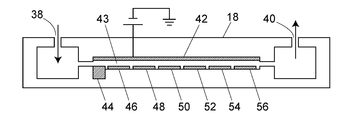
- FIG. 1 An example of the measurement unit 18 is shown in FIG. 1
- the measurement unit 18 has a measurement channel 43 inside, and the measurement gas flowing in from the gas inlet 38 flows through the measurement channel 43 and flows out from the gas outlet 40.
- the measurement gas flow path 3 (see FIG. 1) is connected to the gas inlet 38, and the measured gas flow path 4 (see FIG. 1) is connected to the gas outlet 40.
- a classification electrode 42, a trap electrode 44, measurement electrodes 46, 48, 50, 52, 54 and 56 are provided inside the measurement flow path 43.
- the classification electrode 42 is a flat plate electrode provided so as to extend from the upstream side to the downstream side along the measurement gas flow in the measurement flow path 43.
- the trap electrode 44 is disposed opposite to the classification electrode 42 on the upstream end side of the measurement channel 43.
- Each of the measurement electrodes 46, 48, 50, 52, 54, and 56 is opposed to the classification electrode 42 and is disposed along the measurement flow path 43 at a distance from each other.
- the trap electrode 44 and the measurement electrodes 46, 48, 50, 52, 54 and 56 are electrically insulated from each other.
- An electric field for classification is applied between the classification electrode 42 and the trap electrode 44 and each of the measurement electrodes 46, 48, 50, 52, 54 and 56, and charged particles in the measurement gas are classified for each particle diameter. Are captured by each measurement electrode 46, 48, 50, 52, 54 and 56, and the number thereof is counted.
- the measured gas flow rate control unit 20, the pump 22, the three-way valve 24, the purification column 26, and the purification column 26 are arranged on the measured gas flow path 4 through which the measured gas passed through the measuring unit 18 flows.
- a filter 28 is provided.
- the measured gas flow rate control unit 20 includes a flow meter that measures the flow rate of the measured gas and a flow rate control valve whose opening degree is controlled so that the measured value of the flow meter becomes a preset value.
- the pump 22 is a diaphragm pump, for example, and is driven constantly. The flow rate of the measurement gas (sample gas + dilution gas) introduced into the measurement unit 18 is controlled by the measured gas flow rate control unit 20.
- the flow of gas in the exhaust gas measuring apparatus that is, the flow of the sample gas introduced from the inlet channel 2 into the mixing unit, the flow of the measuring gas introduced into the measuring unit 18, and the dilution gas channel 10 to the mixing unit 16.
- the flow of the diluted gas introduced and the flow of the measured gas discharged from the discharge flow path 8 are all formed by one pump 22. Thereby, it is not necessary to provide a dilution gas introduction pump separately from the sample gas introduction pump, and the apparatus can be miniaturized.
- the pump 22 may be provided on the measurement gas channel 3.
- the purification column 26 and the filter 28 constitute a gas purification unit that purifies the measured gas to clean air.
- the purification column 26 is filled with, for example, silica gel for removing moisture in the measured gas and activated carbon for removing nitrogen oxides and hydrocarbons in the measured gas.
- the filter 28 removes solids containing particles in the measured gas.
- the downstream end of the measured gas flow path 4 is a branch section 6 that branches into a discharge flow path 8 and a dilution gas flow path 10.
- a part of the measured gas that has reached the branching section 6 is discharged to the outside through the discharge channel 8, and the remaining measured gas is supplied to the mixing unit 16 through the dilution gas channel 10 as a dilution gas. Since the dilution gas supplied to the mixing unit 16 is obtained by purifying the measured gas, it is not always necessary to remove the moisture by further introducing the dilution gas into the heater. When a separate dilution gas is introduced from the outside, it is necessary to provide a heater for removing moisture in the dilution gas separately from the sample gas heater. By not providing the heater, it is possible to further reduce the size of the apparatus. As indicated by broken lines in the figure, a heater 29 may be provided on the dilution gas flow path 10 in order to prevent moisture aggregation.
- a flow meter 30 (discharge flow rate measurement unit) and a discharge flow rate control valve 32 (discharge flow rate control unit) are provided on the discharge flow path 8, and the flow rate of the measured gas discharged through the discharge flow path 8 is set in advance.
- the opening degree of the discharge flow rate control valve 32 is adjusted based on the measured value of the flow meter 30 so that the flow rate becomes the same.
- the flow rate of the measurement gas flowing through the measurement unit 18 is the total flow rate of the flow rate of the sample gas from the inlet channel 2 supplied to the mixing unit 16 and the flow rate of the dilution gas from the dilution gas channel 10. Since the flow rate of the dilution gas from the dilution gas flow channel 10 is obtained by subtracting the flow rate of the measured gas discharged through the discharge flow channel 8 from the flow rate of the measurement gas, the sample gas supplied to the mixing unit 16 Is equal to the flow rate of the measured gas discharged from the discharge flow path 8. That is, in the system of this embodiment, the flow rate of the sample gas from the inlet channel 2 is controlled based on the measurement value of one flow meter 30.
- the flow rate of the sample gas introduced into the measurement unit 18 can be controlled based only on the measurement value of one flow meter 30, the flow rate of the sample gas is controlled based on the difference between the measurement values of the two flow meters. Compared with the case, the control with higher accuracy becomes possible.
- the set value of the measured gas flow rate control unit 20 is set to 9 L / min and the dilution rate is set to 10 times, it is necessary to control the flow rate of the sample gas to 0.9 L / min.
- the accuracy of the flow meter 30 is ⁇ 1% with respect to the full scale of 10 L / min
- the flow rate of the sample gas is controlled based only on the measured value of the flow meter 30, so the error in the sample gas flow rate is 0. It is about 1 L / min and is about 10%.
- the configuration of this embodiment can improve the control accuracy of the sample gas flow rate.
- a three-way valve 24 for switching whether to dilute the sample gas is provided.
- the sample gas is diluted.
- the measured gas flowing through the measured gas flow path 4 is transferred to the branching section 6 by switching the three-way valve 24. It can be discharged outside without reaching it.
- the dilution gas is not supplied from the dilution gas flow path 10 to the mixing unit 16, and thus the sample having the flow rate set by the measured gas flow rate control unit 20.
- the gas is introduced into the measurement unit 18 without being diluted.
- a valve 25 for adjusting the flow rate of the measured gas discharged to the outside is provided on the flow path connected to the three-way valve 24 for discharging the measured gas to the outside.
- a part of the measured gas flowing through the measured gas passage 4 may be discharged to the outside. Then, the flow rate of the dilution gas introduced into the mixing unit 16 through the dilution gas channel 10 changes, and the flow rate of the sample gas introduced into the mixing unit 16 from the inlet channel 2 changes accordingly. The dilution rate of the sample gas can be changed.
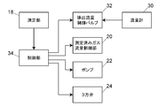
- the measured gas flow rate control unit 20, the pump 22, the three-way valve 24, and the discharge flow rate control valve 32 are configured to operate based on information given from the control unit 34.
- the user sets measurement conditions such as a sample gas flow rate and a dilution rate to be introduced into the measurement unit 18 to the control unit 34, and the set values are measured gas flow rate control unit 20, pump 22, three-way valve 24, and discharge flow rate.
- a control valve 32 is provided.
- the discharge flow rate control valve 32 adjusts the opening degree so that the measured value of the flow meter 30 becomes the set value given from the control unit 34. Measurement data 18 obtained by the measurement unit 18 is taken into the control unit 34.
- the control unit 34 is realized by a dedicated computer such as a system controller or a general-purpose personal computer, for example.
- the purification column 26 and the filter 28 may be provided on the dilution gas flow path 10 as shown in FIG.
- a gas containing materials such as moisture and nitrogen oxides is introduced into the flow meter 30 and the discharge flow rate control valve 32.
- the gas flowing through the discharge channel is diluted, Compared with the case where a flow meter and a valve are provided on the inlet channel 2, the influence of these substances is small compared to the exhaust gas flowing through the channel 2.
Landscapes
- Health & Medical Sciences (AREA)
- Chemical & Material Sciences (AREA)
- Life Sciences & Earth Sciences (AREA)
- Biochemistry (AREA)
- Physics & Mathematics (AREA)
- Analytical Chemistry (AREA)
- General Health & Medical Sciences (AREA)
- General Physics & Mathematics (AREA)
- Immunology (AREA)
- Pathology (AREA)
- Dispersion Chemistry (AREA)
- Engineering & Computer Science (AREA)
- Biomedical Technology (AREA)
- Molecular Biology (AREA)
- Sampling And Sample Adjustment (AREA)
Abstract
排ガス測定装置の一実施形態は、入口流路、混合部、測定ガス流路、測定部、測定済みガス流路、希釈用ガス流路、ガス精製部、排出流量測定部及び排出流量制御部を備えている。入口流路から流入した試料ガスと希釈用ガスとが混合部で混合され測定ガスとなる。測定ガスは測定部に導入され、測定部を経た測定済みガスが測定済みガス流路を流れる。測定済みガス流路の下流端は希釈用ガス流路と排出流路とに分岐しており、測定済みガスの一部が希釈用ガスとして希釈用ガス流路を通じて混合部に導入される。測定済みガスの残りのガスは排出流路を通じて外部へ排出される。ガス精製部は、測定済みガスのうち少なくとも希釈用ガスの精製を行なうものである。排出流量測定部は排出流路を流れるガス流量を測定し、排出流量制御部は排出流量測定部の測定値に基づいて、排出流路を流れるガス流量を予め設定された流量に制御する。
Description
本発明は、自動車の排ガス等を試料ガスとして取り込み、その試料ガス中に含まれる粒子数を測定する排ガス測定装置に関するものである。
自動車のエンジン等から排出されるガス中の粒子状物質の数を計測するために、試料ガスにエアなどの希釈用ガスを混合して希釈し、混合されたガスを粒子数計測装置に導入して、排ガス中に含まれる粒子数を計測するように構成されているシステムがある。かかるシステムの粒子数計測装置には、例えば試料ガス中の微粒子をその大きさによって分級して測定する微粒子測定装置が用いられる(特許文献1参照)。
上記システムでは、試料ガスと希釈用ガスとを混合する混合部からの混合ガスの流量を測定する流量計と混合部に供給される希釈用ガスの流量を測定する流量計を備え、これらの流量計の測定値に基づいて、粒子数計測装置に導入される試料ガスの流量とその希釈率を一定に制御することが一般的である。
上記のガス流量制御方法では、粒子数計測装置に導入される試料ガスの流量を、混合ガス流量の測定値から希釈用ガス流路流量の測定値を差し引くことによって求め、その流量が一定流量になるように試料ガス側に設けられたバルブを制御することとなる。そのため、試料ガス流量の制御のために、混合ガスのための流量計と希釈用ガスのための流量計の2つの流量計の測定値を用いる必要がある。
流量計として、例えばフルスケールが10L/minの流量計を使用し、その精度がフルスケールに対して±1%である場合に、希釈率を10倍として混合ガスの流量を9L/min、希釈用ガスの流量を8.1L/minに設定したとすると、実際の混合ガス流量は9±0.1L/min、希釈用ガス流量は8.1±0.1L/minとなり、試料ガス流量は0.9±0.2L/minとなる。これは、本来の試料ガス流量の設定値から最大で20%程度の誤差が出ることを意味する。試料ガス流量の誤差は測定精度に大きな影響を与えるものであるため、試料ガスの流量制御をより高精度に行なうことが望ましい。
また、排ガスを混合部に導入する流路上に流量計を設置し、その流量計の測定値に基づいて試料ガスの流量を制御すれば、1つの流量計の測定値に基づいて試料ガス流量を制御することはできる。しかし、油分や粒子物質を含んだ高濃度の排ガスを流量計に導入すると、流量計の内部が汚染されて流量計の測定精度が低下したり、排ガス中の粒子物質が流量計内に沈着して測定部に導入されるべき粒子が失われたりすることが懸念される。
そこで、本発明は、試料ガス中の粒子の損失を防止しつつ、試料ガス流量の制御を高精度に行なうことができる排ガス分析装置を提供することを目的とするものである。
本発明に係る排ガス測定装置の一実施形態は、混合部、入口流路、測定部、測定ガス流路、測定済みガス流路、希釈用ガス流路、排出流路、ガス精製部、ポンプ、排出流量測定部及び排出流量制御部を備えている。混合部は試料ガスと希釈用ガスを混合して測定ガスにするものである。入口流路は試料ガスを混合部に導入するものであり、測定ガス流路は混合部で混合された試料ガス及び希釈用ガスからなる測定ガスを測定部に導入するものである。測定部は測定ガスの測定を行なう。測定済みガス流路は、測定部を経た測定済みガスが流れ、希釈流路と排出流路が、測定済みガス流路の下流端に接続されている。希釈用ガス流路は測定済みガスの一部を希釈用ガスとして混合部へ導く流路であり、排出流路は測定済みガスのうち希釈用ガス以外のガスを外部へ排出する流路である。ガス精製部は、測定済みガスのうち少なくとも希釈用ガスの精製を行なうものである。ポンプは、入口流路を流れる試料ガス流、測定ガス流路を流れる測定ガス流、測定済みガス流路を流れる測定済みガス流、希釈用ガス流路を流れる希釈用ガス流及び排出流路を流れる測定済みガス流を形成する。排出流量測定部は排出流路を流れるガス流量を測定し、排出流量制御部は排出流量測定部の測定値に基づいて、排出流路を流れるガス流量を予め設定された流量に制御する。
本発明に係る排ガス測定装置の一実施形態では、測定部を経た測定済みガスの一部が希釈用ガスとして混合部へ導かれ、測定済みガスの残りのガスが排出流路を通じて外部へ排出されるように構成されているので、外部へ排出されるガスと同じ流量の試料ガスが入口流路から流入するようになる。そして、排出流路上には排出流量測定部及び排出流量制御部が設けられ、排出流量測定部の測定値に基づいて排出流路を流れるガス流量が制御されるので、入口流路から流入する試料ガスの流量を排出流量測定部の測定値に基づいて排出流量制御部により制御することができる。1つの流量計(排出流量測定部)によって試料ガス流量を制御できるため、2つの流量計の測定値の差分をとる方法に比べて、流量制御の精度を高めることができる。
希釈用ガスを外部から取り込む従来の方式では、試料ガスを混合部に導入するためのポンプとは別に希釈用ガスを混合部に導入するためのポンプが必要であるために測定装置が大型化していた。
これに対し、本発明に係る排ガス測定装置の一実施形態では、入口流路を流れる試料ガス流、測定ガス流路を流れる測定ガス流、測定済みガス流路を流れる測定済みガス流、希釈用ガス流路を流れる希釈用ガス流及び排出流路を流れる測定済みガス流を、測定ガス流路上又は測定済みガス流路上に設けられた単一のポンプによって形成することができる。そのため、複数のポンプを必要とせず、装置の小型化を図ることができる。
これに対し、本発明に係る排ガス測定装置の一実施形態では、入口流路を流れる試料ガス流、測定ガス流路を流れる測定ガス流、測定済みガス流路を流れる測定済みガス流、希釈用ガス流路を流れる希釈用ガス流及び排出流路を流れる測定済みガス流を、測定ガス流路上又は測定済みガス流路上に設けられた単一のポンプによって形成することができる。そのため、複数のポンプを必要とせず、装置の小型化を図ることができる。
排出流量制御部として、排出流量測定部の測定値に基づいて開度が調節されるバルブが挙げられる。
本発明に係る排ガス測定装置の一実施形態において、ガス精製部は測定済みガス流路上に設けられていることが好ましい。そうすれば、排出流量測定部で流量を測定するガスを、ガス精製部により精製されたクリーンエアにすることができ、排出流量測定部の内部汚染を防止して測定精度の低下や流量計の故障を防止することができる。
また、測定済みガス流路の途中に設けられ、測定済みガス流路を流れる測定済みガスの少なくとも一部を外部へ排出するか否かを切り替える測定済みガス流量切替部をさらに備えていることが好ましい。そうすれば、測定済みガス流路を流れる測定済みガスの流量を可変にすることができ、測定済みガス流量切替部の切替えによって希釈用ガスの流量を変えることができる。希釈用ガスの流量を変更することで、試料ガスの希釈率を変更することができる。
測定ガス流路上に測定ガス中の粒子を帯電させる荷電装置をさらに備え、
測定部としては、測定ガスが流れる測定流路、その測定流路の内側に沿って設けられた平板状の分級電極、及び分級電極と対向し、測定流路を流れる測定ガス流に沿って配列され、互いに電気的に絶縁された複数の測定電極を備え、分級電極と測定電極との間に電圧を印加して電界を発生させることにより、帯電した粒子をその粒径ごとに分級して各測定電極に捕捉し、その個数をカウントする粒子分級測定装置を挙げることができる。かかる粒子分級測定装置は特許文献1に示されているものであり、送風機構以外に可動部をもたず、単純で堅牢な構造を有するものであるため、携帯可能である。したがって、かかる粒子分級測定装置を用いることで、排ガス測定装置のさらなる小型化が図られ、携帯可能な排ガス測定装置を実現することもできる。
測定部としては、測定ガスが流れる測定流路、その測定流路の内側に沿って設けられた平板状の分級電極、及び分級電極と対向し、測定流路を流れる測定ガス流に沿って配列され、互いに電気的に絶縁された複数の測定電極を備え、分級電極と測定電極との間に電圧を印加して電界を発生させることにより、帯電した粒子をその粒径ごとに分級して各測定電極に捕捉し、その個数をカウントする粒子分級測定装置を挙げることができる。かかる粒子分級測定装置は特許文献1に示されているものであり、送風機構以外に可動部をもたず、単純で堅牢な構造を有するものであるため、携帯可能である。したがって、かかる粒子分級測定装置を用いることで、排ガス測定装置のさらなる小型化が図られ、携帯可能な排ガス測定装置を実現することもできる。
排ガス測定装置の一実施例について図面を用いて説明する。
図1に示されているように、この実施例の排ガス測定装置は、入口流路2を通じて試料ガスを混合部16に導入し、混合部16で試料ガスを希釈用ガスによって希釈して測定ガスとし、その測定ガスを測定ガス流路3を通じて測定部18へ導入する。測定部18で測定された測定済みガスは測定済みガス流路4を流れ、分岐部6において、排出流路8を介して外部へ排出される排出ガスと希釈用ガス流路10を介して混合部16に導入される希釈用ガスに分けられる。
入口流路2上における混合部16よりも上流側に、試料ガスの加熱を行なうヒータ12と、試料ガスを、細隙を通して吸引し、一定以上の大きさをもつ粒子を、その細隙の直後に配置した板に衝突させて除去するように調整されたインパクタ14が設けられている。ヒータ12は、試料ガス中の粒子に付着した水分や油分などの揮発性物質を除去するものである。混合部16に導入される試料ガスを加熱するヒータ12を設けることで、試料ガス中の粒子が凝縮して大きな粒子になり粒子数が減少することや、混合部16内に粒子が付着することを防止し、測定精度の向上に繋がる。混合部16と測定部18の間の測定ガス流路3上に、測定部18に導入される測定ガス中の粒子を帯電させるための荷電装置17が設けられている。
なお、この実施例の測定部18は、後述のように、複数の測定電極が測定ガスの流れ方向に沿って配列され、粒子の大きさごとに分級してその数をカウントする粒子分級測定装置であるために、荷電装置17が設けられている。しかし、測定部18は必ずしもそのような測定装置である必要はなく、特許文献2に示されているような粒子数計測装置を用いることもできる。そのような場合には荷電装置17は不要である。
測定部18の一例を図4に示す。
測定部18は内部に測定流路43を有し、ガス入口38から流入した測定ガスが測定流路43を流れてガス出口40から流出する。ガス入口38には測定ガス流路3(図1参照)が接続され、ガス出口40には測定済みガス流路4(図1参照)が接続されている。
測定流路43の内側に、分級電極42、トラップ電極44、測定電極46、48、50、52、54及び56が設けられている。分級電極42は測定流路43の測定ガス流に沿って上流側から下流側へ伸びるように設けられた平板電極である。トラップ電極44は測定流路43の上流端側で分級電極42と対向して配置されている。各測定電極46、48、50、52、54及び56は分級電極42と対向するとともに、測定流路43に沿って互いに間隔をもって配置されている。トラップ電極44、測定電極46、48、50、52、54及び56は互いに電気的に絶縁されている。
分級電極42とトラップ電極44、各測定電極46、48、50、52、54及び56との間には分級用の電界がかけられ、測定ガス中の荷電された粒子が粒径ごとに分級されて各測定電極46、48、50、52、54及び56に捕捉され、その数がカウントされる。
図1に戻って、測定部18を経た測定済みガスが流れる測定済みガス流路4上には、上流側から、測定済みガス流量制御部20、ポンプ22、3方弁24、精製カラム26及びフィルタ28が設けられている。測定済みガス流量制御部20は、測定済みガスの流量を測定する流量計とその流量計の測定値が予め設定された値になるように開度が制御される流量制御弁により構成されている。ポンプ22は例えばダイヤフラムポンプであり、一定駆動される。測定部18に導入される測定ガス(試料ガス+希釈用ガス)の流量は測定済みガス流量制御部20により制御される。
この排ガス測定装置におけるガスの流れ、すなわち、入口流路2から混合部に導入される試料ガスの流れ、測定部18に導入される測定ガスの流れ、希釈用ガス流路10から混合部16に導入される希釈用ガスの流れ、及び排出流路8から排出される測定済みガスの流れは、すべて1台のポンプ22によって形成される。これにより、試料ガス導入用のポンプとは別に希釈用ガス導入用のポンプを設ける必要がなく、装置の小型化を図ることができる。なお、ポンプ22は測定ガス流路3上に設けられていてもよい。
精製カラム26及びフィルタ28は、測定済みガスを精製してクリーンエアにするガス精製部を構成するものである。精製カラム26には、例えば、測定済みガス中の水分を除去するためのシリカゲルと、測定済みガス中の窒素酸化物や炭化水素を除去するための活性炭が充填されている。フィルタ28は、測定済みガス中の粒子を含む固形物を除去するものである。
測定済みガス流路4の下流端は、排出流路8と希釈用ガス流路10に分岐する分岐部6となっている。分岐部6に到達した測定済みガスの一部は排出流路8を通じて外部へ排出され、残りの測定済みガスが希釈用ガスとして希釈用ガス流路10を通じて混合部16に供給される。混合部16に供給される希釈用ガスは測定済みガスを精製したものであるため、希釈用ガスをさらにヒータに導入して水分の除去を行なうことは必ずしも必要ではない。外部から別途希釈用ガスを導入する場合には希釈用ガス中の水分を除去するためのヒータを試料ガス用のヒータとは別に設ける必要があるが、この実施例のように、希釈用ガス専用のヒータを設けないことで、装置の小型化をさらに図ることができる。なお、図において破線で示されているように、水分の凝集を防ぐために、希釈用ガス流路10上にヒータ29を設けてもよい。
排出流路8上に流量計30(排出流量測定部)及び排出流量制御バルブ32(排出流量制御部)が設けられており、排出流路8を通じて排出される測定済みガスの流量が予め設定された流量となるように、流量計30の測定値に基づいて排出流量制御バルブ32の開度が調節される。
測定部18を流れる測定ガスの流量は、混合部16に供給される入口流路2からの試料ガスの流量と希釈用ガス流路10からの希釈用ガスの流量の合計の流量である。希釈用ガス流路10からの希釈用ガスの流量は、測定ガスの流量から排出流路8を通じて排出される測定済みガスの流量を差し引いたものであるから、混合部16に供給される試料ガスの流量は排出流路8から排出される測定済みガスの流量に等しい。すなわち、この実施例のシステムでは、1つの流量計30の測定値に基づいて入口流路2からの試料ガスの流量の制御がなされることになる。
したがって、測定部18に導入する試料ガスの流量を1つの流量計30の測定値のみに基づいて制御することができるため、2つの流量計の測定値の差分に基づいて試料ガスの流量を制御する場合に比べて、より高精度の制御が可能になる。
例えば、測定済みガス流量制御部20の設定値を9L/min、希釈率を10倍に設定した場合には、試料ガスの流量を0.9L/minに制御する必要がある。流量計30の精度がフルスケール10L/minに対して±1%であったとすると、試料ガスの流量は流量計30の測定値にのみ基づいて制御されるため、試料ガス流量の誤差は0.1L/min程度であり、約10%である。これに対し、同じ条件で2つの流量計の測定値の差分に基づいて制御する場合には、既述のように約20%の誤差が生じることになる。したがって、この実施例の構成により、試料ガス流量の制御精度の向上を図ることができる。
さらに、この実施例の構成では、精製カラム26及びフィルタ28によって精製されたクリーンエアが流量計30及び排出流量制御バルブ32を流れるため、流量計30や流量制御バルブ32内に、試料ガス中に含まれていた油分や粒子物質が沈着するなどの問題が生じることはない。
この実施例では、試料ガスの希釈を行なうか否かを切り替えるための3方弁24が設けられている。以上における説明では、試料ガスの希釈を行なうことを前提として説明しているが、この実施例では、3方弁24の切替えによって、測定済みガス流路4を流れる測定済みガスを分岐部6に到達させることなく、外部へ排出することができるようになっている。測定済みガス流路4の途中で測定済みガスを排出すると、混合部16には希釈用ガス流路10から希釈用ガスが供給されないため、測定済みガス流量制御部20で設定された流量の試料ガスが希釈されずに測定部18に導入されることとなる。
なお、図において破線で示されているように、外部へ測定済みガスを排出するために3方弁24に接続された流路上に、外部へ排出する測定済みガスの流量を調節するバルブ25を設け、3方弁24の切替えによって測定済みガス流路4を流れる測定済みガスの一部を外部へ排出することができるようにしてもよい。そうすれば、希釈用ガス流路10を通じて混合部16に導入される希釈用ガスの流量が変化し、それに応じて入口流路2から混合部16に導入される試料ガスの流量も変化するため、試料ガスの希釈率を変更することができるようになる。
図2を用いてこの実施例の制御系統の一例について説明する。
測定済みガス流量制御部20、ポンプ22、3方弁24及び排出流量制御バルブ32は制御部34から与えられた情報に基づいた動作を行なうようになっている。ユーザは、測定部18に導入する試料ガス流量や希釈率といった測定条件を制御部34に対して設定し、その設定値が測定済みガス流量制御部20、ポンプ22、3方弁24及び排出流量制御バルブ32に与えられる。排出流量制御バルブ32は、流量計30の測定値が制御部34から与えられた設定値となるように開度の調節を行なう。測定部18で得られた測定データ18は制御部34に取り込まれる。
制御部34は、例えばシステムコントローラなどの専用のコンピュータ又は汎用のパーソナルコンピュータによって実現されるものである。
他の実施形態として、図3に示されているように、精製カラム26及びフィルタ28を希釈用ガス流路10上に設けてもよい。この場合、流量計30及び排出流量制御バルブ32には、水分や窒素酸化物等の物資を含むガスが導入されることとなるが、排出流路を流れるガスは希釈されているため、入口流路2を流れる排ガスに比べて低濃度になっており、入口流路2上に流量計やバルブを設ける場合に比べて、それらの物質による影響は小さい。
2 入口流路
3 測定ガス流路
4 測定済みガス流路
6 分岐部
8 排出流路
10 希釈用ガス流路
12,29 ヒータ
14 インパクタ
16 混合部
17 荷電装置
18 測定部
20 測定済みガス流量制御部
22 ポンプ
24 3方弁
25 バルブ
26 精製カラム
28 フィルタ
30 流量計(排出流量測定部)
32 排出流量制御バルブ(排出流量制御部)
34 制御部
38 ガス入口
40 ガス出口
42 分級電極
43 測定流路
44 トラップ電極
46,48,50,52,54,56 測定電極
3 測定ガス流路
4 測定済みガス流路
6 分岐部
8 排出流路
10 希釈用ガス流路
12,29 ヒータ
14 インパクタ
16 混合部
17 荷電装置
18 測定部
20 測定済みガス流量制御部
22 ポンプ
24 3方弁
25 バルブ
26 精製カラム
28 フィルタ
30 流量計(排出流量測定部)
32 排出流量制御バルブ(排出流量制御部)
34 制御部
38 ガス入口
40 ガス出口
42 分級電極
43 測定流路
44 トラップ電極
46,48,50,52,54,56 測定電極
Claims (6)
- 試料ガスと希釈用ガスとを混合して測定ガスにする混合部と、
試料ガスを前記混合部に導入する入口流路と、
前記混合部からの測定ガスの測定を行なう測定部と、
前記混合部で混合された試料ガス及び希釈用ガスからなる測定ガスを前記測定部へ導入する測定ガス流路と、
前記測定部を経た測定済みガスが流れる測定済みガス流路と、
前記測定済みガス流路の下流端に接続され、前記測定済みガスの一部を希釈用ガスとして前記混合部へ導く希釈用ガス流路と、
前記測定済みガス流路の下流端に接続され、前記測定済みガスのうち前記希釈用ガス以外のガスを外部へ排出するための排出流路と、
前記測定済みガスのうち少なくとも前記希釈用ガスの精製を行なうガス精製部と、
前記入口流路を流れる試料ガス流、前記測定ガス流路を流れる測定ガス流、前記測定済みガス流路を流れる測定済みガス流、前記希釈用ガス流路を流れる希釈用ガス流及び前記排出流路を流れる測定済みガス流を形成するためのポンプと、
前記排出流路を流れるガス流量を測定する排出流量測定部と、
前記排出流量測定部の測定値に基づいて、前記排出流路を流れるガス流量を予め設定された流量に制御する排出流量制御部と、を備えた排ガス測定装置。 - 前記ポンプは、前記測定ガス流路上又は前記測定済みガス流路上に設けられた単一のポンプである請求項1に記載の排ガス測定装置。
- 前記排出流量制御部は、前記排出流量測定部の測定値に基づいて開度が調節されるバルブである請求項1又は2に記載の排ガス測定装置。
- 前記ガス精製部は前記測定済みガス流路上に設けられている請求項1から3のいずれか一項に記載の排ガス測定装置。
- 前記測定済みガス流路の途中に設けられ、前記測定済みガス流路を流れる測定済みガスの少なくとも一部を外部へ排出するか否かを切り替える測定済みガス流量切替部をさらに備えている請求項1から4のいずれか一項に記載の排ガス測定装置。
- 前記測定ガス流路上に測定ガス中の粒子を帯電させる荷電装置をさらに備え、
前記測定部は、測定ガスが流れる測定流路、その測定流路の内側に沿って設けられた平板状の分級電極、及び前記分級電極と対向し、前記測定流路を流れる測定ガス流に沿って配列され、互いに電気的に絶縁された複数の測定電極を備え、前記分級電極と前記測定電極との間に電圧を印加して電界を発生させることにより、帯電した粒子をその粒径ごとに分級して各測定電極に捕捉し、その個数をカウントする粒子分級測定装置である請求項1から5のいずれか一項に記載の排ガス測定装置。
Priority Applications (2)
| Application Number | Priority Date | Filing Date | Title |
|---|---|---|---|
| JP2018518025A JP6536747B2 (ja) | 2016-05-19 | 2016-05-19 | 排ガス測定装置 |
| PCT/JP2016/064920 WO2017199404A1 (ja) | 2016-05-19 | 2016-05-19 | 排ガス測定装置 |
Applications Claiming Priority (1)
| Application Number | Priority Date | Filing Date | Title |
|---|---|---|---|
| PCT/JP2016/064920 WO2017199404A1 (ja) | 2016-05-19 | 2016-05-19 | 排ガス測定装置 |
Publications (1)
| Publication Number | Publication Date |
|---|---|
| WO2017199404A1 true WO2017199404A1 (ja) | 2017-11-23 |
Family
ID=60325066
Family Applications (1)
| Application Number | Title | Priority Date | Filing Date |
|---|---|---|---|
| PCT/JP2016/064920 Ceased WO2017199404A1 (ja) | 2016-05-19 | 2016-05-19 | 排ガス測定装置 |
Country Status (2)
| Country | Link |
|---|---|
| JP (1) | JP6536747B2 (ja) |
| WO (1) | WO2017199404A1 (ja) |
Cited By (2)
| Publication number | Priority date | Publication date | Assignee | Title |
|---|---|---|---|---|
| CN111579443A (zh) * | 2019-02-15 | 2020-08-25 | 黑拉有限责任两合公司 | 用于控制传感器装置的方法 |
| US20230133140A1 (en) * | 2020-04-08 | 2023-05-04 | Opus Inspection, Inc. | Gas measuring apparatus with a compact design |
Citations (3)
| Publication number | Priority date | Publication date | Assignee | Title |
|---|---|---|---|---|
| US5376163A (en) * | 1993-05-18 | 1994-12-27 | Andros Incorporated | Filter system |
| JP2002505421A (ja) * | 1998-02-25 | 2002-02-19 | マイクロトラック インク | 粒度分布測定のためのサンプリング及び希釈システム |
| JP2008096170A (ja) * | 2006-10-06 | 2008-04-24 | Shimadzu Corp | 荷電装置及び粒子分級装置 |
-
2016
- 2016-05-19 JP JP2018518025A patent/JP6536747B2/ja not_active Expired - Fee Related
- 2016-05-19 WO PCT/JP2016/064920 patent/WO2017199404A1/ja not_active Ceased
Patent Citations (3)
| Publication number | Priority date | Publication date | Assignee | Title |
|---|---|---|---|---|
| US5376163A (en) * | 1993-05-18 | 1994-12-27 | Andros Incorporated | Filter system |
| JP2002505421A (ja) * | 1998-02-25 | 2002-02-19 | マイクロトラック インク | 粒度分布測定のためのサンプリング及び希釈システム |
| JP2008096170A (ja) * | 2006-10-06 | 2008-04-24 | Shimadzu Corp | 荷電装置及び粒子分級装置 |
Cited By (4)
| Publication number | Priority date | Publication date | Assignee | Title |
|---|---|---|---|---|
| CN111579443A (zh) * | 2019-02-15 | 2020-08-25 | 黑拉有限责任两合公司 | 用于控制传感器装置的方法 |
| CN111579443B (zh) * | 2019-02-15 | 2024-11-15 | 黑拉有限责任两合公司 | 用于控制传感器装置的方法 |
| US20230133140A1 (en) * | 2020-04-08 | 2023-05-04 | Opus Inspection, Inc. | Gas measuring apparatus with a compact design |
| US12203910B2 (en) * | 2020-04-08 | 2025-01-21 | Opus Inspection, Inc. | Gas measuring apparatus with a compact design |
Also Published As
| Publication number | Publication date |
|---|---|
| JPWO2017199404A1 (ja) | 2018-11-08 |
| JP6536747B2 (ja) | 2019-07-03 |
Similar Documents
| Publication | Publication Date | Title |
|---|---|---|
| US11774421B2 (en) | Detector inlet and sampling method | |
| US9541488B2 (en) | Particle sampling and measurement in the ambient air | |
| JP6429590B2 (ja) | 排ガス分析システム及びポンプ装置 | |
| US6761752B2 (en) | Gas particle partitioner | |
| US20160139013A1 (en) | A method and apparatus for dilution of aerosols | |
| CN101611304A (zh) | 用于检测设备的气体预浓缩器 | |
| KR20090102805A (ko) | 검출 장치 | |
| WO2013080044A2 (en) | Sensor apparatus and method for use with gas ionization systems | |
| CN204396329U (zh) | 粒子分离装置以及粒子测定装置 | |
| KR102335707B1 (ko) | 수동 에어로졸 희석기 메커니즘 | |
| WO2017199404A1 (ja) | 排ガス測定装置 | |
| JP5094520B2 (ja) | イオンフィルタ、質量分析システムおよびイオン移動度分光計 | |
| CN101583867B (zh) | 检测设备 | |
| CA2663975A1 (en) | Faims apparatus comprising source of dry gas | |
| CA2525095A1 (en) | Ion mobility separation devices | |
| CN103854949B (zh) | 热解析进样器离子迁移谱气路 | |
| CN101663726A (zh) | 探测器和离子源 | |
| CN101583409A (zh) | 将含有微粒的气流分离成微粒部分和无微粒气流部分 | |
| JP3629512B2 (ja) | 微粒子分級装置及びその方法 | |
| US20100096547A1 (en) | Method for classifying and separating particles, and device for carrying out said method | |
| US3787123A (en) | Method and apparatus for measuring the weight of solid particles suspended in a carrier gas | |
| JP2017058173A (ja) | 排ガス測定装置 | |
| WO2013090583A1 (en) | Periodic field differential mobility analyzer | |
| US20190168955A1 (en) | Device and process for diluting an aerosol | |
| JP4066989B2 (ja) | エアロゾル分析装置 |
Legal Events
| Date | Code | Title | Description |
|---|---|---|---|
| WWE | Wipo information: entry into national phase |
Ref document number: 2018518025 Country of ref document: JP |
|
| NENP | Non-entry into the national phase |
Ref country code: DE |
|
| 121 | Ep: the epo has been informed by wipo that ep was designated in this application |
Ref document number: 16902423 Country of ref document: EP Kind code of ref document: A1 |
|
| 122 | Ep: pct application non-entry in european phase |
Ref document number: 16902423 Country of ref document: EP Kind code of ref document: A1 |