WO2017195776A1 - Terminal device and method - Google Patents
Terminal device and method Download PDFInfo
- Publication number
- WO2017195776A1 WO2017195776A1 PCT/JP2017/017541 JP2017017541W WO2017195776A1 WO 2017195776 A1 WO2017195776 A1 WO 2017195776A1 JP 2017017541 W JP2017017541 W JP 2017017541W WO 2017195776 A1 WO2017195776 A1 WO 2017195776A1
- Authority
- WO
- WIPO (PCT)
- Prior art keywords
- transmission
- subframe
- downlink
- terminal device
- uplink
- Prior art date
Links
Images


Classifications
-
- H—ELECTRICITY
- H04—ELECTRIC COMMUNICATION TECHNIQUE
- H04W—WIRELESS COMMUNICATION NETWORKS
- H04W72/00—Local resource management
- H04W72/04—Wireless resource allocation
- H04W72/044—Wireless resource allocation based on the type of the allocated resource
- H04W72/0446—Resources in time domain, e.g. slots or frames
-
- H—ELECTRICITY
- H04—ELECTRIC COMMUNICATION TECHNIQUE
- H04L—TRANSMISSION OF DIGITAL INFORMATION, e.g. TELEGRAPHIC COMMUNICATION
- H04L1/00—Arrangements for detecting or preventing errors in the information received
- H04L1/12—Arrangements for detecting or preventing errors in the information received by using return channel
- H04L1/16—Arrangements for detecting or preventing errors in the information received by using return channel in which the return channel carries supervisory signals, e.g. repetition request signals
- H04L1/18—Automatic repetition systems, e.g. Van Duuren systems
- H04L1/1812—Hybrid protocols; Hybrid automatic repeat request [HARQ]
-
- H—ELECTRICITY
- H04—ELECTRIC COMMUNICATION TECHNIQUE
- H04L—TRANSMISSION OF DIGITAL INFORMATION, e.g. TELEGRAPHIC COMMUNICATION
- H04L1/00—Arrangements for detecting or preventing errors in the information received
- H04L1/12—Arrangements for detecting or preventing errors in the information received by using return channel
- H04L1/16—Arrangements for detecting or preventing errors in the information received by using return channel in which the return channel carries supervisory signals, e.g. repetition request signals
- H04L1/18—Automatic repetition systems, e.g. Van Duuren systems
- H04L1/1829—Arrangements specially adapted for the receiver end
- H04L1/1854—Scheduling and prioritising arrangements
-
- H—ELECTRICITY
- H04—ELECTRIC COMMUNICATION TECHNIQUE
- H04L—TRANSMISSION OF DIGITAL INFORMATION, e.g. TELEGRAPHIC COMMUNICATION
- H04L1/00—Arrangements for detecting or preventing errors in the information received
- H04L1/12—Arrangements for detecting or preventing errors in the information received by using return channel
- H04L1/16—Arrangements for detecting or preventing errors in the information received by using return channel in which the return channel carries supervisory signals, e.g. repetition request signals
- H04L1/18—Automatic repetition systems, e.g. Van Duuren systems
- H04L1/1867—Arrangements specially adapted for the transmitter end
- H04L1/1887—Scheduling and prioritising arrangements
-
- H—ELECTRICITY
- H04—ELECTRIC COMMUNICATION TECHNIQUE
- H04L—TRANSMISSION OF DIGITAL INFORMATION, e.g. TELEGRAPHIC COMMUNICATION
- H04L27/00—Modulated-carrier systems
- H04L27/26—Systems using multi-frequency codes
- H04L27/2601—Multicarrier modulation systems
-
- H—ELECTRICITY
- H04—ELECTRIC COMMUNICATION TECHNIQUE
- H04W—WIRELESS COMMUNICATION NETWORKS
- H04W28/00—Network traffic management; Network resource management
- H04W28/02—Traffic management, e.g. flow control or congestion control
- H04W28/04—Error control
-
- H—ELECTRICITY
- H04—ELECTRIC COMMUNICATION TECHNIQUE
- H04W—WIRELESS COMMUNICATION NETWORKS
- H04W56/00—Synchronisation arrangements
- H04W56/004—Synchronisation arrangements compensating for timing error of reception due to propagation delay
- H04W56/0045—Synchronisation arrangements compensating for timing error of reception due to propagation delay compensating for timing error by altering transmission time
-
- H—ELECTRICITY
- H04—ELECTRIC COMMUNICATION TECHNIQUE
- H04W—WIRELESS COMMUNICATION NETWORKS
- H04W72/00—Local resource management
- H04W72/20—Control channels or signalling for resource management
- H04W72/21—Control channels or signalling for resource management in the uplink direction of a wireless link, i.e. towards the network
-
- H—ELECTRICITY
- H04—ELECTRIC COMMUNICATION TECHNIQUE
- H04W—WIRELESS COMMUNICATION NETWORKS
- H04W72/00—Local resource management
- H04W72/20—Control channels or signalling for resource management
- H04W72/23—Control channels or signalling for resource management in the downlink direction of a wireless link, i.e. towards a terminal
-
- H—ELECTRICITY
- H04—ELECTRIC COMMUNICATION TECHNIQUE
- H04L—TRANSMISSION OF DIGITAL INFORMATION, e.g. TELEGRAPHIC COMMUNICATION
- H04L5/00—Arrangements affording multiple use of the transmission path
- H04L5/14—Two-way operation using the same type of signal, i.e. duplex
-
- H—ELECTRICITY
- H04—ELECTRIC COMMUNICATION TECHNIQUE
- H04W—WIRELESS COMMUNICATION NETWORKS
- H04W56/00—Synchronisation arrangements
- H04W56/001—Synchronization between nodes
- H04W56/0015—Synchronization between nodes one node acting as a reference for the others
Definitions
- Embodiments described herein relate generally to a technology of a terminal device and a method for realizing efficient communication.
- This application claims priority on Japanese Patent Application No. 2016-096129 filed in Japan on May 12, 2016, the contents of which are incorporated herein by reference.
- EUTRA High-speed communication is realized by adopting OFDM (Orthogonal Frequency Frequency Division) Multiplexing (OFDM) communication method and flexible scheduling of predetermined frequency and time units called resource blocks.
- OFDM Orthogonal Frequency Frequency Division
- Evolved Universal Terrestrial Radio Access
- LTE Long Term Evolution
- A-EUTRA Advanced EUTRA
- EUTRA a communication system is premised on a network in which base station apparatuses have substantially the same cell configuration (cell size).
- base station apparatuses cells having different configurations are mixed in the same area.
- Communication systems based on existing networks heterogeneous wireless networks, heterogeneous networks are being studied.
- Non-Patent Document 1 a technique for reducing the processing time related to communication has been studied.
- a communication apparatus terminal apparatus and / or base station apparatus
- terminal apparatus and / or base station apparatus there are cases where efficient communication cannot be performed by conventional transmission power control or transmission control.
- An aspect of the present invention has been made in view of the above points, and an object thereof is to provide a terminal device and a method capable of performing transmission power control or transmission control for efficient communication. It is.
- a terminal device is a terminal device that communicates with a base station device, based on a measurement unit that measures a time difference between reception and transmission of the terminal device, and an event related to the measurement of the time difference.
- a transmission unit that reports a measurement result related to the time difference, and the transmission unit has a predetermined TTI (Transmission Time Interval) length set for the terminal device, and the measurement result is a predetermined value. When the threshold value is exceeded, the measurement result is reported.
- TTI Transmission Time Interval
- a method according to an aspect of the present invention is a method in a terminal apparatus that communicates with a base station apparatus, and is a method in a terminal apparatus that communicates with a base station apparatus, between reception and transmission of the terminal apparatus.
- the step of measuring the time difference a step of reporting the measurement result related to the time difference based on the event related to the measurement of the time difference, and when a predetermined TTI (Transmission Time Interval) length is set for the terminal device, And when the measurement result exceeds a predetermined threshold, reporting the measurement result.
- TTI Transmission Time Interval
- transmission efficiency can be improved in a wireless communication system in which a base station device and a terminal device communicate.
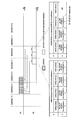
- FIG. 3 is a diagram illustrating an example of an uplink radio frame configuration according to the first embodiment. It is a figure which shows the correspondence with 2 symbol sPDSCH when the PUCCH format 1b with channel selection which concerns on 1st Embodiment is set to 7 symbols.
- FIG. 7 is a diagram showing mapping of sPDSCH in a subframe with a serving cell to HARQ-ACK (j) for PUCCH format 2b when one or more sPDSCHs can be detected in one subframe according to the first embodiment. .
- It is a figure which shows the transmission timing of HARQ-ACK with respect to sPDSCH which concerns on 1st Embodiment.
- a first embodiment of the present invention will be described below.
- a base station apparatus base station, node B, eNB (EUTRAN NodeB, evolved NodeB)
- a terminal apparatus terminal, mobile station, user apparatus, UE (User equipment)
- UE User equipment
- a channel means a medium used for signal transmission
- a physical channel means a physical medium used for signal transmission.
- a physical channel may be used synonymously with a physical signal.
- the physical channel may be added in the future in LTE, or its structure / configuration and format may be changed or added. However, even if the physical channel is changed or added, the description of each embodiment of the present invention is not affected.
- Frame structure type 1 is applied to FDD (Frequency Division Division Duplex). That is, FS1 is applied to cell operations in which FDD is supported.
- the FS1 can be applied to both FD-FDD (Full Duplex-FDD) and HD-FDD (Half Duplex-FDD).
- downlink transmission and uplink transmission are separated in the frequency domain.
- an operating band is defined for each of downlink transmission and uplink transmission. That is, different carrier frequencies are applied for downlink transmission and uplink transmission. Therefore, in FDD, 10 subframes can be used for each of downlink transmission and uplink transmission.
- the terminal device In the HD-FDD operation, the terminal device cannot simultaneously transmit and receive, but in the FD-FDD operation, the terminal device can simultaneously transmit and receive.
- the terminal device In the HD-FDD operation, the terminal device cannot simultaneously transmit and receive, but in the FD-FDD operation, the terminal device can simultaneously transmit and receive.
- the guard period is not received by the terminal device by not receiving the tail part (the last symbol) of the downlink subframe immediately before the uplink subframe from the same terminal device. Generated.
- the guard period referred to as the HD guard subframe, is the same by not receiving the downlink subframe immediately before the uplink subframe from the same terminal equipment, and the same It is generated by the terminal device by not receiving the downlink subframe immediately after the uplink subframe from the terminal device. That is, in the HD-FDD operation, the terminal apparatus generates a guard period by controlling the downlink subframe reception process.
- the symbol may include either an OFDM symbol or an SC-FDMA symbol.
- Frame structure type 2 (FS2) is applied to TDD (Time Division Division Duplex). That is, FS2 is applied to cell operations in which TDD is supported.
- Each radio frame is composed of two half frames.
- Each half frame is composed of five subframes.
- the UL-DL configuration in a cell may be changed between radio frames. Control of subframes in uplink or downlink transmission may be performed in the latest radio frame.
- the terminal device can acquire the UL-DL configuration in the latest radio frame via PDCCH or higher layer signaling.
- the UL-DL setting indicates the configuration of an uplink subframe, a downlink subframe, and a special subframe in TDD.
- the special subframe is composed of DwPTS (Downlink Pilot Time Slot) capable of downlink transmission, guard period (GP), and UpPTS (Uplink Pilot Time Slot) capable of uplink transmission.
- the configurations of DwPTS and UpPTS in the special subframe are managed in a table, and the terminal device can acquire the configurations via higher layer signaling.
- the special subframe is a switching point from the downlink to the uplink. That is, the terminal device transitions from reception to transmission at the switching point, and the base station device transitions from transmission to reception. Switching points have a 5 ms period and a 10 ms period. If the switching point is a 5 ms period, the special subframe is present in both half frames. When the switching point has a 10 ms period, the special subframe exists only in the first half frame.
- SRS and PRACH preamble format 4 can be arranged.
- eIMTA TDDTDenhanced Interference Management and Traffic Adaptation
- the eITMA considers the downlink and / or uplink traffic and interference, and dynamically switches the TDD setting (using the L1 level or L1 signaling) within the radio frame (that is, 10 This is a technique for performing optimal communication by changing the ratio of the downlink subframe and the uplink subframe in the subframe).
- NCP and ECP are applied to FS1 and FS2.
- Frame structure type 3 (FS3) is applied to LAA (Licensed Assisted Access) secondary cell operation. Further, only NCP may be applied to FS3.
- Ten subframes included in the radio frame are used for downlink transmission. Unless otherwise specified or unless downlink transmission is detected in the subframe, the terminal device does not assume that any signal is present in a subframe and processes the subframe as an empty subframe.
- a downlink transmission occupies one or more consecutive subframes.
- the continuous subframe includes a first subframe and a last subframe.
- the first subframe begins with any symbol or slot (eg, OFDM symbol # 0 or # 7) of that subframe.
- the last subframe is occupied by the full subframe (ie, 14 OFDM symbols) or the number of OFDM symbols indicated based on one of the DwPTS periods. Whether or not a certain subframe is the last subframe among consecutive subframes is indicated to the terminal device by a certain field included in the DCI format. The field may further indicate the number of OFDM symbols used in the subframe in which the field is detected or the next subframe.
- the base station apparatus performs a channel access procedure related to LBT before performing downlink transmission.
- FS3 supporting only downlink transmission may be defined as FS3-1 or FS3-A
- FS3 supporting downlink transmission and uplink transmission may be defined as FS3-2 or FS3-B.
- Terminal devices and base station devices that support FS3 may communicate in a frequency band that does not require a license.
- the operating band corresponding to the cell of LAA or FS3 may be managed together with the EUTRA operating band table.
- the EUTRA operating band index may be managed from 1 to 44, and the operating band index corresponding to LAA (or LAA frequency) may be managed at 46.
- the index 46 only the downlink frequency band may be defined.
- an uplink frequency band may be reserved in advance as reserved or specified in the future.
- the corresponding duplex mode may be a duplex mode different from FDD or TDD, or may be FDD or TDD.
- the frequency at which the LAA operation is possible is preferably 5 GHz or more, but may be 5 GHz or less. That is, LAA operation communication may be performed at an associated frequency as an operating band corresponding to LAA.
- FIG. 1 is a diagram illustrating an example of a downlink radio frame configuration according to the present embodiment.
- An OFDM access scheme is used for the downlink.
- the downlink physical channel is used to transmit information output from an upper layer.
- PBCH Physical Broadcast Channel
- PCFICH Physical Control Format Indicator Channel
- PHICH Physical Hybrid automatic repeat request Indicator Channel
- PDCCH Physical Downlink Control Channel
- EPDCCH Enhanced Physical Downlink Control Channel
- SPDCCH Short / shorter / shortened Physical Downlink Control Channel
- PDSCH Physical Downlink Shared Channel
- SPDSCH Short / shorter / shortened Physical Downlink Shared Channel
- PMCH Physical Multicast Channel
- the following downlink physical signals are used.
- the downlink physical signal is not used for transmitting information output from the upper layer, but is used by the physical layer.
- SS Synchronization signal
- DL RS Downlink Reference Signal
- DS Discovery Signal
- the following five types of downlink reference signals are used.
- -CRS Cell-specific Reference Signal
- URS UE-specific Reference Signal
- PDSCH PDSCH
- DMRS Demodulation Reference Signal
- EPDCCH Non-Zero Power Chanel State Information-Reference Signal
- ZP CSI-RS Zero Power Chanel State Information-Reference Signal
- MBSFN RS Multimedia Broadcast and Multicast Service over Single Frequency Network Reference signal
- PRS Positioning Reference Signal
- the downlink radio frame is composed of a downlink resource block (RB) pair.
- RB bandwidth a predetermined frequency band
- 2 slots 1 subframe.
- One downlink RB pair is composed of two downlink RBs (RB bandwidth ⁇ slot) that are continuous in the time domain.
- One downlink RB is composed of 12 subcarriers in the frequency domain. Further, in the time domain, it is composed of 7 OFDM symbols when NCP is added and 6 OFDM symbols when ECP having a CP length longer than NCP is added.
- a region defined by one subcarrier in the frequency domain and one OFDM symbol in the time domain is referred to as a resource element (RE).
- RE resource element
- the PDCCH / EPDCCH is a physical channel through which downlink control information (DCI) such as a terminal device identifier, PDSCH scheduling information, PUSCH (Physical-Uplink-Shared-Channel) scheduling information, modulation scheme, coding rate, and retransmission parameter is transmitted. is there.
- DCI downlink control information
- a terminal device identifier such as a terminal device identifier
- CC component carrier
- a downlink sub-frame is prescribed
- a downlink sub-frame is substantially synchronized between CC.
- “almost synchronized between CCs” means that when transmission is performed from a base station apparatus using a plurality of CCs, an error in transmission timing of each CC falls within a predetermined range.
- SS, PBCH, and DLRS may be arranged in the downlink subframe.
- DLRS includes CRS transmitted on the same antenna port (transmission port) as PDCCH, CSI-RS used for measurement of channel state information (CSI), UERS and EPDCCH transmitted on the same antenna port as some PDSCHs.
- CSI channel state information
- UERS UERS
- EPDCCH transmitted on the same antenna port as some PDSCHs.
- CSI channel state information
- positioned may be sufficient.
- a part of the CRS antenna ports for example, antenna port 0
- the antenna port may be referred to as a transmission port.
- “physical channel / physical signal is transmitted through an antenna port” includes the meaning that a physical channel / physical signal is transmitted using a radio resource or layer corresponding to the antenna port.
- the reception unit means receiving a physical channel or a physical signal from a radio resource or layer corresponding to the antenna port.
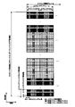
- FIG. 2 is a diagram illustrating an example of an uplink radio frame configuration according to the present embodiment.
- the SC-FDMA scheme is used for the uplink.
- the uplink physical channel is used for transmitting information output from an upper layer.
- -PUCCH Physical Uplink Control Channel
- SPUCCH Short / shorter / shortened Physical Uplink Control Channel, PUCCH for short TTI
- PUSCH Physical Uplink Shared Channel
- SPUSCH Short / shorter / shortened Physical Uplink Shared Channel
- PUSCH for short TTI ⁇ PRACH (Physical Random Access Channel)
- SPRACH Short / shorter / shortened Physical Random Access Channel, PRACH for short TTI
- uplink physical signals are used.
- the uplink physical signal is not used for transmitting information output from the upper layer, but is used by the physical layer.
- UL RS Uplink Reference Signal
- DMRS Demodulation Reference Signal
- SRS Sounding Reference Signal
- the uplink radio frame is composed of uplink RB pairs.
- One uplink RB pair is composed of two uplink RBs (RB bandwidth ⁇ slot) that are continuous in the time domain.
- One uplink RB is composed of 12 subcarriers in the frequency domain. In the time domain, it is composed of 7 SC-FDMA symbols when NCP is added and 6 when ECP is added.
- an uplink sub-frame may be defined for each CC.
- FIG. 1 and 2 show examples in which different physical channels / physical signals are frequency division multiplexed (FDM) and / or time division multiplexed (TDM).
- FDM frequency division multiplexed
- TDM time division multiplexed
- each physical channel and / or physical signal is sPDSCH, sPDCCH, sPUSCH, sPUCCH, respectively. , May be referred to as sPRACH.
- the number of OFDM symbols and / or SC-FDMA symbols constituting the physical channel is equal to or less than 14 symbols in NCP (12 symbols in ECP). Also good. Also, the number of symbols used for the physical channel for sTTI may be set using DCI and / or DCI format, or may be set using higher layer signaling. In addition to the number of symbols used in sTTI, a start symbol in the time direction may be set.
- STTI may also be transmitted within a specific bandwidth within the system bandwidth.
- the bandwidth set as sTTI may be set using DCI and / or DCI format, or may be set using higher layer signaling (RRC signaling, MAC CE).
- the bandwidth may be set using a start and end resource block index or frequency position, or may be set using a bandwidth and start resource block index / frequency position.
- a bandwidth to which sTTI is mapped may be referred to as an sTTI band.
- a physical channel mapped within the sTTI band may be referred to as a physical channel for sTTI.
- the physical channel for sTTI may include sPDSCH, sPDCCH, sPUSCH, sPUCCH, and sPRACH.
- those DCI and / or DCI formats may be scrambled using a specific RNTI, A CRC scrambled by the RNTI may be added to a bit string constituting the DCI format.
- the downlink physical channel and the downlink physical signal are collectively referred to as a downlink signal.
- the uplink physical channel and the uplink physical signal are collectively referred to as an uplink signal.
- the downlink physical channel and the uplink physical channel are also collectively referred to as a physical channel.
- the downlink physical signal and the uplink physical signal are collectively referred to as a physical signal.
- the PBCH is used to broadcast a master information block (MIB, “Broadcast” Channel: “BCH”) that is commonly used by terminal apparatuses.
- MIB master information block
- BCH Broadcast Channel
- PCFICH is used for transmitting information indicating a region (OFDM symbol) used for transmission of PDCCH.
- the PHICH is used to transmit an HARQ indicator (HARQ feedback, response information) indicating ACK (ACKnowledgement) or NACK (Negative ACKnowledgement) for uplink data (Uplink Shared Channel: UL-SCH) received by the base station apparatus. .
- HARQ indicator HARQ feedback, response information
- ACK acknowledgement
- NACK Negative ACKnowledgement
- the PDCCH may include an EPDCCH. Further, the PDCCH may include sPDCCH.
- a plurality of DCI formats may be defined for DCI transmitted by PDCCH, EPDCCH, and / or sPDCCH. That is, the field for DCI may be defined in the DCI format and mapped to information bits.
- the terminal device uses the PDCCH / mapped DCI format including information / parameters for setting sTTI.
- EPDCCH may be monitored. That is, the base station apparatus maps a DCI format including information / parameters for setting sTTI to PDCCH / EPDCCH for a terminal apparatus that supports transmission and / or reception of a physical channel using sTTI. May be transmitted.
- the DCI format for the downlink is also referred to as downlink DCI, downlink grant (DL grant), and / or downlink scheduling grant, and / or downlink assignment.
- the DCI format for uplink is also referred to as uplink DCI, uplink grant (UL grant), and / or uplink scheduling grant, and / or uplink assignment.
- a DCI format (for example, DCI format 1, DCI format 1A, and / or DCI format 1C) used for scheduling of one PDSCH in one cell may be defined as a downlink assignment.
- a DCI format (for example, DCI format 0 and / or DCI format 4 or a first UL grant) used for scheduling of one PUSCH in one cell is defined. Also good.
- the UL grant may include a carrier indicator field (CIF).
- the UL grant may include information related to a transmission power control command (TPC command) for the scheduled PUSCH.
- the UL grant may include information on a cyclic shift for DMRS (DMRS related to PUSCH transmission).
- the UL grant may include information on MCS (modulation and coding scheme) and / or information on the redundancy version.
- the UL grant may include information on resource block assignment (Resource (block assignment) and / or information on hopping resource assignment.
- the UL grant may include information (CSI request) used to request transmission of CSI.
- the UL grant may include information (SRS request) used to request transmission of SRS.
- the UL grant may be defined as a DCI common to a plurality of terminal devices and / or a DCI dedicated to a certain terminal device. That is, the UL grant may be transmitted in the common search space and / or the user equipment specific search space. Moreover, UL grant may be transmitted by PDCCH and / or EPDCCH. Further, the CRC parity bit added to the UL grant may be scrambled by RNTI, which will be described later.
- the UL grant may be used to define a setting for a certain subframe. That is, the UL grant may be used to indicate a setting commonly used in a certain subframe. That is, the setting indicated using the UL grant may be effective for each subframe. That is, the UL grant may be a subframe specific UL grant. That is, when a PUSCH is scheduled using the UL grant, the terminal apparatus may perform transmission on the scheduled PUSCH in a certain subframe (using all the subframes).
- uplink grant at least information related to frequency resource allocation to PUSCH, sPUSCH and / or sPDCCH (for example, information related to allocation of physical resource block to PUSCH, sPUSCH and / or sPDCCH) May be defined (hereinafter also referred to as a second UL grant or a second UL DCI). That is, the second UL grant may be used for scheduling of at least PUSCH, sPUSCH, and / or sPDCCH.
- the second UL grant may include information related to bandwidth for scheduled PUSCH, scheduled sPUSCH, and / or scheduled sPDCCH. That is, the second UL grant may include information related to scheduled bandwidth for transmission on PUSCH, transmission on sPUSCH, and / or transmission on sPDCCH.
- the second UL grant includes a scheduled PUSCH, a scheduled sPUSCH, and / or a physical resource block start position for the scheduled sPDCCH (and / or an end position, eg, a length from the start position. Information) may be included.
- the second UL grant may include information for indicating a physical resource block for the scheduled PUSCH, the scheduled sPUSCH, and the scheduled sPDCCH.
- the second UL grant may include a carrier indicator field (CIF). Further, the second UL grant may include information on a transmission power control command (TPC command) for the scheduled PUSCH. Further, the second UL grant may include information related to the transmission power command for the scheduled sPUSCH. Further, the second UL grant may include information on a cyclic shift for DMRS (PUSCH and / or DMRS related to transmission of sPUSCH). In addition, the second UL grant may include information on MCS and / or information on redundancy version. Further, the second UL grant may include information on resource block assignment (Resource block assignment) and / or information on hopping resource assignment. Also, the second UL grant may include information (CSI) request) used to request CSI transmission. The second UL grant may include information (SRSSrequest) used to request transmission of SRS.
- TPC command transmission power control command
- TPC command transmission power control command
- the second UL grant may include information related to the transmission power command for the scheduled sPUSCH.
- the information (partial or all information) transmitted using the second UL grant uses an upper layer signal (for example, a signal in the MAC layer and / or a signal in the RRC layer). May be transmitted.
- an upper layer signal for example, a signal in the MAC layer and / or a signal in the RRC layer. May be transmitted.
- the downlink control information as described above is transmitted using the second UL grant.
- the downlink control information transmitted using the second UL grant is an upper layer signal. May be used to transmit.
- the second UL grant may be defined as a common DCI (UL grant, Common ⁇ UL grant, Non-UE specific UL grant) for a plurality of terminal devices. That is, the second UL grant may be transmitted only in the common search space, which will be described later. Further, the second UL grant may be transmitted using only the PDCCH and / or the EPDCCH.
- the CRC parity bit added to the second UL grant may be scrambled by RNTI, which will be described later.
- the CRC parity bit added to the second UL grant may be scrambled by the first UL-RNTI.
- the search space (for example, common search space) in which the second UL grant is transmitted may be provided by at least the first UL-RNTI.
- the second UL grant may be used to define a setting for a certain subframe. That is, the second UL grant may be used to indicate a setting commonly used in a certain subframe. That is, the setting indicated using the second UL grant may be effective for one or more subframes.
- the second UL grant may be a subframe specific UL grant (a sub-frame specific UL grant). That is, when the PUSCH is scheduled using the second UL grant, the terminal apparatus may perform transmission on the scheduled PUSCH in a certain subframe (or using all the certain subframes). Good.
- the third UL grant may include information related to transmission time interval (TTI) allocation for transmission on PUSCH and / or sPUSCH. That is, the third UL grant may be used at least for scheduling of PUSCH and / or sPUSCH.
- TTI transmission time interval
- the third UL grant may include information related to the length of the TTI for the scheduled PUSCH and / or the scheduled sPUSCH. Also, the third UL grant may include information related to the location of the DMRS transmitted with the scheduled PUSCH. Also, the third UL grant may include information related to the location of the DMRS transmitted with the scheduled sPUSCH.
- the third UL grant may include information on DMRS (for example, information on cyclic shift of DMRS) transmitted together with the scheduled PUSCH.
- the third UL grant may include information regarding DMRS (for example, information regarding cyclic shift of DMRS) transmitted together with the scheduled sPUSCH.
- the third UL grant may include information (Grant to Tx delay offset) on delay for transmission on PUSCH and / or transmission on sPUSCH based on reception (detection) of the third UL grant. Good.
- the third UL grant may include a carrier indicator field (CIF). Further, the third UL grant may include information related to a transmission power command (TPC command) for the scheduled PUSCH. Further, the third UL grant may include information related to the transmission power command for the scheduled sPUSCH. In addition, the third UL grant may include information on a cyclic shift for DMRS (PUSCH and / or DMRS related to transmission of sPUSCH). Further, the third UL grant may include information on MCS and / or information on redundancy version. Further, the third UL grant may include information on resource block assignment (Resource block assignment) and / or information on hopping resource assignment. Further, the third UL grant may include information (CSI request) used to request transmission of CSI. Further, the third UL grant may include information (SRS request) used to request transmission of SRS. The third UL grant may include information (TTI ⁇ ⁇ ⁇ ⁇ index) related to a TTI index, which will be described later.
- TPC command transmission power command
- the third UL grant may be defined as a dedicated DCI (UL grant, UE-specific UL) for a certain terminal device. That is, the third UL grant may be transmitted only in the UE specific pace, which will be described later.
- the third UL grant may be transmitted on PDCCH, EPDCCH, and / or sPDCCH. Further, the third UL grant may be transmitted on the PDSCH.
- the CRC parity bit added to the third UL grant may be scrambled by RNTI, which will be described later.
- the CRC parity bit added to the third UL grant may be scrambled by the third UL-RNTI.
- the search space (for example, user equipment specific search space) in which the third UL grant is transmitted may be provided by at least the second UL-RNTI.
- the third UL grant may be used to specify a setting for a certain TTI. That is, the third UL grant may be used to indicate a setting used in a certain TTI. That is, the setting indicated using the third UL grant may be effective for one TTI. That is, the second UL grant may be a TTI-specific UL grant (a TTI specific UL grant). That is, when a PUSCH is scheduled using the third UL grant, the terminal apparatus may perform transmission on the scheduled PUSCH in a certain TTI (in a certain TTI in a certain subframe).
- the second UL grant may be used for scheduling of the sPDCCH in which the third UL grant is transmitted.
- the terminal device may receive (detect) the third UL grant by receiving (detecting) the second UL grant. Further, the terminal device monitors (decodes and detects) the PDCCH and / or EPDCCH to which the second UL grant is transmitted, thereby monitoring the PDCCH, EPDCCH and / or sPDCCH to which the third UL grant is transmitted ( Decoding, detection).
- the PDCCH and / or EPDCCH in which the second UL grant is transmitted is detected by monitoring by the terminal device 1, and the resources of the PDCCH, EPDCCH and / or sPDCCH in which the third UL grant is transmitted are the second
- the information may be directly indicated by information included in the UL grant.
- the PDCCH, EPDCCH and / or sPDCCH resources may include time resources and / or frequency resources. That is, the PDCCH, EPDCCH, and / or sPDCCH in which the third UL grant is transmitted may not be monitored by the terminal device.
- the uplink grant may include a first UL grant, a second UL grant, and / or a third UL grant.
- the terminal apparatus may receive the downlink data (DL-SCH) on the PDSCH based on the scheduling.
- the terminal apparatus uses the PUSCH to transmit uplink data (UL-SCH) and / or uplink control information (UCI) based on the scheduling. You may send it.
- a terminal device may transmit uplink data and / or uplink control information by sPUSCH based on scheduling.
- SPDSCH may be scheduled by a first DL grant detected on PDCCH and / or EPDCCH and a second DL grant detected on sPDCCH. Both the first DL grant and the second DL grant may be scrambled using a specific RNTI.
- SPDCCH may be configured to monitor sPDCCH (that is, downlink sTTI band) based on DCI included in the first DL grant detected by PDCCH and / or EPDCCH.
- sPDCCH that is, downlink sTTI band
- the resource of sPUCCH may be determined by DCI included in the second DL grant detected by sPDCCH.
- the terminal device may monitor a set of PDCCH candidates, EPDCCH candidates, and / or sPDCCH candidates.
- the PDCCH may include EPDDCH and / or sPDCCH.
- the PDCCH candidate may indicate a candidate that the PDCCH may be arranged and / or transmitted by the base station apparatus.
- monitoring may mean that the terminal device attempts to decode each PDCCH in the set of PDCCH candidates according to all the DCI formats to be monitored.
- the search space may include a common search space (CSS).
- the CSS may be defined as a common space for a plurality of terminal devices.
- the search space may include a user equipment specific search space (USS).
- USS user equipment specific search space
- the USS may be given based on at least a C-RNTI assigned to the terminal device.
- the terminal device may monitor the PDCCH and detect the PDCCH addressed to itself in CSS and / or USS.
- RNTI assigned by the base station apparatus to the terminal apparatus may be used for DCI transmission (transmission on the PDCCH).
- CRC Cyclic Redundancy Check
- DCI format which may be downlink control information
- the CRC parity bits may be scrambled by RNTI.
- the CRC parity bit added to the DCI format may be obtained from the payload of the DCI format.
- the “CRC parity bit”, “CRC bit”, and “CRC” may be the same.
- “PDCCH in which a DCI format with CRC parity bits added is transmitted” “PDCCH including CRC parity bits and including DCI format”, “PDCCH including CRC parity bits”, and “DCI format The “including PDCCH” may be the same.
- “PDCCH including X” and “PDCCH with X” may be the same.
- the terminal device may monitor the DCI format.
- the terminal device may monitor DCI.
- the terminal device may monitor the PDCCH.
- the terminal apparatus attempts to decode the DCI format to which the CRC parity bit scrambled by the RNTI is added, and detects the DCI format in which the CRC is successful as the DCI format addressed to itself (also referred to as blind decoding). ). That is, the terminal device may detect a PDCCH with a CRC scrambled by RNTI. Further, the terminal apparatus may detect a PDCCH accompanied by a DCI format to which a CRC parity bit scrambled by RNTI is added.
- the RNTI may include a C-RNTI (Cell-Radio Network Temporary Identifier).
- C-RNTI Cell-Radio Network Temporary Identifier
- the C-RNTI may be a unique (unique) identifier for the terminal device used for RRC connection and scheduling identification.
- C-RNTI may also be used for dynamically scheduled unicast transmissions.
- RNTI may include SPS C-RNTI (Semi-Persistent Scheduling C-RNTI).
- SPS C-RNTI is a unique (unique) identifier for a terminal device used for semi-persistent scheduling.
- SPS C-RNTI may also be used for semi-persistently scheduled unicast transmissions.
- semi-persistently scheduled transmission may include the meaning of periodically scheduled transmission.
- RNTI may include RA-RNTI (Random Access RNTI).
- RA-RNTI Random Access RNTI
- the RA-RNTI may be an identifier used for transmission of a random access response message. That is, RA-RNTI may be used for transmission of a random access response message in a random access procedure.
- the terminal apparatus may monitor the PDCCH with a CRC scrambled by RA-RNTI. Further, the terminal apparatus may receive a random access response on the PDSCH based on detection of the PDCCH accompanied by the CRC scrambled by the RA-RNTI.
- the PDCCH with CRC scrambled by C-RNTI may be transmitted in USS or CSS.
- PDCCH with CRC scrambled by SPS C-RNTI may be transmitted in USS or CSS.
- the PDCCH with CRC scrambled by RA-RNTI may be transmitted only in CSS.
- the RNTI that scrambles the CRC includes RA-RNTI, C-RNTI, SPS C-RNTI, temporary C-RNTI, eIMTA-RNTI, TPC-PUCCH-RNTI, TPC-PUSCH-RNTI, M-RNTI, P-RNTI, There is SI-RNTI.
- RA-RNTI, C-RNTI, SPS C-RNTI, eIMTA-RNTI, TPC-PUCCH-RNTI, and TPC-PUSCH-RNTI are set from the base station apparatus to the terminal apparatus via higher layer signaling.
- M-RNTI, P-RNTI and SI-RNTI correspond to one value.
- P-RNTI corresponds to PCH and PCCH and is used to notify changes in paging and system information.
- SI-RNTI corresponds to DL-SCH and BCCH and is used for reporting system information.
- RA-RNTI corresponds to DL-SCH and is used for a random access response.
- RA-RNTI, C-RNTI, SPS C-RNTI, temporary C-RNTI, eIMTA-RNTI, TPC-PUCCH-RNTI, and TPC-PUSCH-RNTI are set using higher layer signaling.
- Predetermined values are defined for M-RNTI, P-RNTI, and SI-RNTI.
- the PDCCH with CRC scrambled by each RNTI may have a different transport channel or logical channel depending on the value of the RNTI. That is, the information shown may differ depending on the value of RNTI.
- SI-RNTI One SI-RNTI is used to address SIB1, as with all SI messages.
- PDSCH is used to transmit downlink data (Downlink Shared Channel: DL-SCH).
- the PDSCH is used for transmitting a system information message.
- the system information message may be cell specific information.
- the system information may be included in RRC signaling.
- PDSCH may also be used to transmit RRC signaling and MAC control elements.
- the PDSCH may be used to transmit the third UL grant.
- the terminal device may receive (detect) the third UL grant (information included in the third UL grant) in the PDSCH scheduled by the base station device.
- PMCH is used to transmit multicast data (Multicast Channel: MCH).
- the synchronization signal is used for the terminal device to synchronize the downlink frequency domain and time domain.
- the synchronization signal is arranged in subframes 0, 1, 5, and 6 in the radio frame.
- the synchronization signal is arranged in subframes 0 and 5 in the radio frame.
- the downlink reference signal is used by the terminal device for channel correction of the downlink physical channel.
- the downlink reference signal is used for the terminal device to calculate downlink channel state information.
- the DS is used for time-frequency synchronization, cell identification, and RRM (Radio Resource Management) measurement (intra and / or inter frequency measurement) at frequencies for which parameters related to DS are set.
- the DS is composed of a plurality of signals, and these signals are transmitted in the same cycle.
- the DS may be configured using PSS / SSS / CRS resources, and may further be configured using CSI-RS resources.
- RSRP and RSRQ may be measured using resources to which CRS and CSI-RS are mapped.
- BCH, MCH, UL-SCH and DL-SCH are transport channels.
- a channel used in the medium access control (MAC) layer is called a transport channel.
- a transport channel unit used in the MAC layer is also referred to as a transport block (TB) or a MAC PDU (Protocol Data Unit).
- HARQ HybridbrAutomatic Repeat reQuest
- the transport block is a unit of data that the MAC layer delivers to the physical layer.
- the transport block is mapped to a code word, and an encoding process is performed for each code word.
- PUCCH and / or sPUCCH are used for transmitting (or feeding back) uplink control information (UCI).
- PUCCH may include sPUCCH.
- the UCI may include channel state information (CSI) used to indicate the state of the downlink channel.
- the UCI may also include a scheduling request (SR) used for requesting UL-SCH resources.
- the UCI may include HARQ-ACK (Hybrid Automatic Repeat request ACKnowledgement).
- HARQ-ACK may indicate HARQ-ACK for downlink data (Transport block, Medium Access Control, Protocol, Data, Unit: MAC-PDU, Downlink-Shared Channel: DL-SCH, Physical Downlink Shared Channel: PDSCH).
- HARQ-ACK may indicate ACK (Acknowledgement, positive-acknowledgment) or NACK (Negative-acknowledgement) for downlink data.
- the CSI may also be configured with a channel quality indicator (CQI), a precoding matrix indicator (PMI), and / or a rank indication (RI).
- CQI channel quality indicator
- PMI precoding matrix indicator
- RI rank indication
- the HARQ-ACK may be referred to as a HARQ-ACK response.
- the format of PUCCH may be specified according to the type and combination of UCI to be transmitted.
- PUCCH format 1 is used for transmitting positive SR.
- the PUCCH format 1a is used to transmit 1-bit HARQ-ACK, or 1-bit HARQ-ACK with positive SR in the case of FDD or FDD-TDD primary cell FS1.
- the FDD-TDD primary cell FS indicates the FS of the primary cell when performing FDD-TDD CA. In other words, it can be paraphrased as a primary cell of a certain FS in FDD-TDD CA. Moreover, it can show similarly about a secondary cell.
- the PUCCH format 1b is used to transmit 2-bit HARQ-ACK or 2-bit HARQ-ACK with positive SR.
- PUCCH format 1b is used to select up to 4 bits using channel selection when more than one serving cell is set in the terminal device, or in the case of TDD, when one serving cell is set in the terminal device. It may be used to transmit HARQ-ACK.
- -Channel selection can change the interpretation even if it is the value of the same bit by selecting any one among a plurality of PUCCH resources. For example, even if the first PUCCH resource and the second PUCCH resource have the same bit value, the contents shown may be different. With channel selection, HARQ-ACK can be extended by using a plurality of PUCCH resources.
- PUCCH format 2 is used to transmit a CSI report when HARQ-ACK is not multiplexed.
- PUCCH format 2 may be used to transmit a CSI report in which HARQ-ACK for ECP is multiplexed.
- the PUCCH format 2a is used for transmitting a CSI report in which 1-bit HARQ-ACK for NCP is multiplexed.
- the PUCCH format 2b is used to transmit a CSI report in which 2-bit HARQ-ACK for NCP is multiplexed.
- DMRS symbols can be used as symbols to which data can be allocated.
- PUCCH format 3 includes up to 10 bits of HARQ-ACK for FDD or FDD-TDD primary cell FS1, 20 bits of HARQ-ACK for TDD, and 21 bits of HARQ-ACK for FDD-TDD primary cell FS2. Used to send
- PUCCH format 3 includes 10-bit HARQ-ACK for FDD or FDD-TDD and up to 11-bit UCI corresponding to 1-bit positive / negative SR, and 20-bit HARQ-ACK for TDD. And 21-bit UCI corresponding to 1-bit positive / negative SR, and 22-bit UCI corresponding to HARQ-ACK and 1-bit positive / negative SR up to 21 bits for the FDD-TDD primary cell FS2, May be used to transmit.
- PUCCH format 3 includes 10-bit HARQ-ACK for FDD or FDD-TDD and up to 11-bit UCI corresponding to 1-bit positive / negative SR, and 20-bit HARQ-ACK for TDD. And 21-bit UCI corresponding to 1-bit positive / negative SR, and 22-bit UCI corresponding to HARQ-ACK and 1-bit positive / negative SR up to 21 bits for the FDD-TDD primary cell FS2, May be used to transmit.
- PUCCH format 3 may also be used to transmit HARQ-ACK and 1-bit positive / negative SR (if any) and CSI report.
- PUCCH format 4 is used to transmit more than 22 bits of UCI including HARQ-ACK, SR (if any) and periodic CSI report (if any).
- PUCCH format 4 may also be used to send more than one CSI report and SR (if any).
- PUCCH format 5 is used to send more than 22 bits of UCI including HARQ-ACK, SR (if any) and periodic CSI report (if any).
- PUCCH format 5 may also be used to send more than one CSI report and SR (if any).
- the number and arrangement of corresponding DMRSs may be different based on the PUCCH format. For example, when NCP is added, three DMRSs are arranged in one slot for PUCCH format 1 / 1a / 1b, and two in one slot for PUCCH format 2 / 2a / 2b / 3. DMRS is arranged, and one DMRS is arranged in one slot for PUCCH format 4/5.
- the PUCCH When the PUCCH is transmitted in the SRS subframe, in the PUCCH format to which the shortened format is applied (for example, formats 1, 1a, 1b, 3), the last one symbol to which SRS may be assigned or Two symbols (the last one symbol or two symbols of the second slot in the subframe) may be emptied, that is, the PUCCH may be transmitted in a shortened format.
- the PUCCH format to which the shortened format is applied for example, formats 1, 1a, 1b, 3
- Two symbols the last one symbol or two symbols of the second slot in the subframe
- the PUCCH format 1 / 1a / 1b and the PUCCH format 2 / 2a / 2b may be transmitted using the same RB.
- the cyclic shift for PUCCH format 1 / 1a / 1b in the RB used for transmission of PUCCH format 1 / 1a / 1b and PUCCH format 2 / 2a / 2b may be individually set.
- PUSCH and / or sPUSCH is used to transmit uplink data (Uplink-Shared Channel: UL-SCH).
- PUSCH may include sPUSCH.
- the PUSCH may also be used to transmit HARQ-ACK and / or CSI along with uplink data.
- the PUSCH may be used to transmit only CSI, or only HARQ-ACK and CSI. That is, PUSCH may be used to transmit only UCI.
- the base station apparatus and the terminal apparatus may exchange (transmit / receive) signals in a higher layer.
- the base station apparatus and the terminal apparatus may transmit and receive RRC signaling (also referred to as RRC message or RRC information) in a radio resource control (Radio Resource Control: RRC) layer.
- RRC Radio Resource Control
- the base station apparatus and the terminal apparatus may exchange (transmit / receive) MAC control elements in a MAC (Medium Access Control) layer.
- the RRC signaling and / or the MAC control element is also referred to as a higher layer signal.
- the “upper layer parameter”, “upper layer message”, “upper layer signal”, “upper layer information”, and “upper layer information element” are the same. It may be.
- PUSCH may be used for transmitting RRC signaling and MAC control element (MAC CE).
- the RRC signaling transmitted from the base station apparatus may be common signaling for a plurality of terminal apparatuses in the cell.
- the RRC signaling transmitted from the base station apparatus may be signaling dedicated to a certain terminal apparatus (also referred to as dedicated signaling). That is, the user apparatus specific information may be transmitted to a certain terminal apparatus using dedicated signaling.
- PRACH and / or sPRACH are used to transmit a random access preamble.
- PRACH may include sPRACH.
- PRACH (or random access procedure) is used mainly for the terminal device to synchronize the time domain with the base station device.
- PRACH (or random access procedure) includes initial connection establishment (initial connection establishment) procedure, handover procedure, connection re-establishment (connection re-establishment) procedure, synchronization for uplink transmission (timing adjustment), and scheduling request. It may also be used for transmission of (PUSCH resource request, UL-SCH resource request).
- DMRS relates to transmission of PUSCH, sPUSCH, and / or PUCCH. That is, DMRS may be time-multiplexed with PUSCH, sPUSCH, or PUCCH.
- the base station apparatus may use DMRS to perform PUSCH, sPUSCH, or PUCCH channel correction.
- the DMRS may have a different time-multiplexing arrangement or the number of DMRSs to be multiplexed.
- SRS is not related to PUSCH or PUCCH transmission.
- the base station apparatus may use SRS to measure uplink channel conditions or transmission timing.
- SRS a trigger type 0 SRS to be transmitted when a related parameter is set by an upper layer signal, and a related parameter is set by an upper layer signal, and transmission is performed by an SRS request included in the uplink grant.
- the LTE time unit T s is based on the subcarrier spacing (eg, 15 kHz) and the FFT size (eg, 2048). That is, T s is 1 / (15000 ⁇ 2048) seconds.
- the time length of one slot is 15360 ⁇ T s (that is, 0.5 ms).
- the time length of one subframe is 30720 ⁇ T s (that is, 1 ms).
- the time length of one radio frame is 307200 ⁇ T s (that is, 10 ms).
- the time length of one radio frame is 10 milliseconds (ms).
- One radio frame is composed of 10 subframes.
- one subframe is composed of two slots. That is, the time length of one subframe is 1 ms, and the time length of one slot is 0.5 ms.
- resource blocks are used as a minimum scheduling unit in which physical channels are allocated.
- a resource block is defined by a constant frequency region composed of a set of a plurality of subcarriers (for example, 12 subcarriers) and a region composed of a constant transmission time interval (TTI, slot, symbol) on the frequency axis. .
- One subframe may be referred to as one resource block pair.
- one TTI may be defined as one subframe or the number of symbols constituting one subframe.
- NCP Normal Cyclic Prefix
- one TTI may be composed of 14 symbols.
- ECP Extended CP
- one TTI may be composed of 12 symbols.
- TTI may be defined as a reception time interval on the reception side.
- the TTI may be defined as a transmission unit or a reception unit of a physical channel or a physical signal. That is, the time length of the physical channel or physical signal may be defined based on the length of TTI.
- the symbol may include an SC-FDMA symbol and / or an OFDM symbol.
- the length of TTI (TTI length) may be expressed by the number of symbols. Further, the TTI length may be expressed by a time length such as millisecond (ms) or microsecond ( ⁇ s).
- CP includes NCP and ECP, and ECP adds a longer sequence length than NCP.
- the sequence length related to the CP may be referred to as the CP length.
- one TTI may be configured with a number less than 14 symbols in NCP (12 symbols in ECP).
- the TTI length of one TTI may be configured with any number of symbols of 2, 3, and 7.
- a TTI composed of fewer symbols than 14 symbols in NCP (12 symbols in ECP) may be referred to as sTTI (short TTI, shorter TTI, shortened TTI).
- TTI with a TTI length of NCP and 14 symbols (12 symbols with ECP) may be simply referred to as TTI.
- TTI length of sTTI As the TTI length of sTTI (DL-sTTI) for downlink transmission, either 2 symbols or 7 symbols may be set.
- the TTI length of sTTI (UL-sTTI) for uplink transmission may be set to 2 symbols, 3 symbols, 4 symbols, or 7 symbols.
- SPDCCH and sPDSCH may be arranged in DL-sTTI. Note that the TTI lengths of sPUSCH, sPUCCH, and sPRACH may be set individually.
- the sPDSCH TTI length may include an sPDCCH symbol or a PDCCH symbol. Also, the TTI length of sPUSCH and / or sPUCCH may include a DMRS symbol or an SRS symbol.
- the subcarrier intervals of the various physical channels and / or physical signals described above may be individually defined / set for each physical channel and / or physical signal. Further, the time length of one symbol of various physical channels and / or physical signals may be individually defined / set for each physical channel and / or physical signal. That is, the TTI lengths of various physical channels and / or physical signals may be individually defined / set for each physical channel and / or physical signal.
- CA Carrier Aggregation in which communication is performed using a plurality of cells (component carriers corresponding to the cells) may be performed.
- a primary cell PCell
- a secondary cell that is added / changed / deleted / activated / deactivated using the primary cell.
- DC Dual Connectivity
- a group is comprised with the cell which belongs to each of two base station apparatuses (MeNB (Master
- the cell group that belongs to the MeNB and includes the primary cell is defined as MCG (Master Cell Group)
- the cell group that belongs to the SeNB and includes the primary secondary cell (PSCell) is defined as SCG (Secondary Cell Group).
- the primary secondary cell is a cell group that does not include the primary cell when a plurality of cell groups are set, that is, a cell having the same function as the primary cell (secondary cell, serving cell other than the primary cell) in the SCG. It is.
- the primary cell and the primary secondary cell play the role of a ply cell in each CG.
- the primary cell may be a cell to which a control channel corresponding to PUCCH and / or PUCCH can be transmitted and / or allocated, and is related to an initial access procedure / RRC connection procedure / initial connection establishment procedure.
- a cell having functions of a primary cell and / or a primary secondary cell may be referred to as a special cell.
- the primary cell / primary secondary cell / secondary cell may be defined similarly to the LTE.
- the time domain may be represented by a time length or the number of symbols.
- the frequency domain may be represented by a bandwidth, the number of subcarriers, the number of resource elements in the frequency direction, and the number of resource blocks.
- the TTI size may be changeable based on the subframe type, higher layer setting information, and control information included in L1 signaling.
- An access that does not require a grant is an access that does not use control information (DCI format, downlink grant, uplink grant) that indicates the schedule of PDSCH or PUSCH (a downlink or uplink shared channel / data channel). That is. That is, in the LR cell, an access method using PDCCH (downlink control channel) that does not perform dynamic resource allocation or transmission instruction may be applied.
- DCI format, downlink grant, uplink grant indicates the schedule of PDSCH or PUSCH (a downlink or uplink shared channel / data channel). That is.
- PDCCH downlink control channel
- the terminal device performs the same HARQ-ACK and / or CSI feedback corresponding to the downlink resource (signal, channel) based on the function (performance, capability) of the terminal device and the setting from the base station device. You may perform using the uplink resource (a signal, a channel) mapped by the sub-frame.
- the reference resource related to CSI for the CSI measurement result in a certain subframe may be CRS or CSI-RS of the same subframe.
- Such a subframe may be referred to as a self-contained subframe.
- a self-contained subframe may be composed of one or more consecutive subframes. That is, the self-contained subframe may be composed of a plurality of subframes, or may be one transmission burst composed of a plurality of subframes.
- the last subframe (the rear subframe including the last) constituting the self-contained subframe is preferably an uplink subframe or a special subframe. That is, it is preferable that an uplink signal / channel is transmitted in the last subframe.
- the HARQ-ACK for each of the plurality of downlink subframes is the one uplink subframe. It may be transmitted in UpPTS of a link subframe or special subframe.
- the communication device determines ACK or NACK for the signal based on whether or not the signal has been received (demodulated and decoded).
- ACK indicates that the communication device has received a signal
- NACK indicates that the communication device has not received a signal.
- the communication apparatus to which NACK is fed back may retransmit a signal that is NACK.
- the terminal apparatus determines whether to retransmit the PUSCH based on the content of HARQ-ACK for the PUSCH transmitted from the base station apparatus.
- the base station apparatus determines whether to retransmit the PDSCH based on the content of the HARQ-ACK for the PDSCH or PDCCH / EPDCCH transmitted from the terminal apparatus.
- the ACK / NACK for the PUSCH transmitted by the terminal device is fed back to the terminal device using PDCCH or PHICH.
- ACK / NACK for PDSCH or PDCCH / EPDCCH transmitted by the base station apparatus is fed back to the base station apparatus using PUCCH or PUSCH.
- the subframe indicates a transmission unit and / or a reception unit of the base station apparatus and / or the terminal apparatus.
- the base station apparatus determines that the terminal apparatus is an LR (Latency Reduction) device based on LCID (Logical Channel ID) for CCCH (Common Control Channel) and capability information (performance information, function information) of the terminal device. Also good.
- LCID Logical Channel ID
- CCCH Common Control Channel
- capability information performance information, function information
- the processing time (processing delay, latency) based on the length (number of symbols) of the TTI used for the received signal and / or the transmitted signal May be determined. That is, the processing time of the terminal device and / or base station device that supports the LR-related capability may be variable based on the TTI length for the received signal and / or the transmitted signal.
- S1 signaling has been expanded to include terminal radio capability information for paging.
- this paging-specific capability information is provided to the MME (Mobility Management Entity) by the base station device, the MME uses this information to instruct the base station device that the paging request from the MME relates to the LR terminal. May be.
- the identifier may be referred to as ID (Identity, Identifier).
- the terminal device capability information (UE radio access capability, UE UEEU capability) starts the procedure for the terminal device in the connection mode when the base station device (EUTRAN) needs the terminal device capability information.
- the base station apparatus inquires about the capability information of the terminal apparatus. In response to the inquiry, the terminal device transmits capability information of the terminal device.
- the base station apparatus determines whether or not it corresponds to the capability information, and when it corresponds, transmits the setting information corresponding to the capability information to the terminal apparatus using higher layer signaling or the like. When the setting information corresponding to the capability information is set, the terminal device determines that transmission / reception based on the function is possible.
- Parameters relating to physical channel and / or physical signal settings may be set in the terminal device via higher layer signaling as higher layer parameters.
- parameters related to the configuration of some physical channels and / or physical signals may be set in the terminal device via L1 signaling (physical layer signaling, for example, PDCCH / EPDCCH) such as DCI format and grant.
- L1 signaling physical layer signaling, for example, PDCCH / EPDCCH
- default parameters or default values for parameters related to physical channel and / or physical signal settings may be preset in the terminal device.
- the terminal device may update the default value when parameters related to the settings are notified using higher layer signaling.
- the type of higher layer signaling / message used to notify the setting may be different.
- the upper layer signaling / message may include an RRC message, broadcast information, system information, and the like.
- the base station apparatus may map data information and / or control information in the DS occasion.
- the data information and / or control information may include information regarding the LAA cell.
- the data information and / or control information may include the frequency to which the LAA cell belongs, the cell ID, the load and congestion status, the interference / transmission power, the channel exclusive time, and the buffer status regarding transmission data.
- the resources used for each signal included in the DS may be extended.
- CRS may use not only the antenna port 0 but also resources corresponding to the antenna ports 2 and 3.
- CSI-RS not only the antenna port 15 but also resources corresponding to the antenna ports 16 and 17 may be used.
- the terminal device when resources related to DS are set in the terminal device using higher layer signals (RRC signaling) or system information, L1 signaling (control information corresponding to a field having a PDCCH or DCI format) or L2 signaling Using the (control information corresponding to MAC CE), that is, the lower layer signal (the signal below the RRC layer), the terminal device may be dynamically instructed whether or not to receive the DS.
- RRC signaling higher layer signals
- L1 signaling control information corresponding to a field having a PDCCH or DCI format
- L2 signaling control information corresponding to MAC CE
- the RS for demodulation / decoding and the RS for CSI measurement may be a common resource or may be different resources when individually defined.
- a cell search is a procedure for performing time-frequency synchronization of a cell in which a terminal device is located and detecting a cell ID of the cell.
- EUTRA cell search supports a full scalable transmission bandwidth corresponding to 72 subcarriers or more.
- EUTRA cell search is performed on the downlink based on PSS and SSS.
- the PSS and SSS are transmitted using 72 subcarriers at the center of the bandwidth of the first subframe and the sixth subframe of each radio frame.
- the adjacent cell search is performed based on the same downlink signal as the initial cell search.
- physical layer measurements include intra-frequency and inter-frequency EUTRAN measurements (RSRP / RSRQ), terminal device reception and transmission time differences, and reference signal time differences used for terminal device positioning (RSTD)
- RSRP / RSRQ intra-frequency and inter-frequency EUTRAN measurements
- RSTD reference signal time differences used for terminal device positioning
- EUTRAN measurement includes a measurement performed by an idle mode terminal device and a measurement performed by a connection mode terminal device.
- the terminal device performs EUTRAN measurement in an appropriate measurement gap and is synchronized with the cell in which the EUTRAN measurement is performed. Since these measurements are performed by the terminal device, they may be referred to as terminal device measurements.
- the terminal device may support at least two physical quantities (RSRP, RSRQ) for measurement in EUTRAN. Further, the terminal device may support a physical quantity related to RSSI. The terminal device may perform a corresponding measurement based on a parameter relating to a physical quantity set as an upper layer parameter.
- RSRP physical quantities
- RSRQ physical quantity related to RSSI.
- the terminal device may perform a corresponding measurement based on a parameter relating to a physical quantity set as an upper layer parameter.
- the physical layer measurement is performed to support mobility.
- intra-frequency and inter-frequency measurement in EUTRAN RSRP / RSRQ
- time difference between reception and transmission of terminal device RSTD
- measurement of reference signal time difference used for positioning of terminal device RSTD
- inter-RAT EUTRAN
- EUTRAN-Measurement related to GERAN / UTRAN and measurement related to inter-system EUTRAN-non-3GPP RAT.
- physical layer measurements include measurements for intra and inter frequency handovers, measurements for inter RAT handovers, timing measurements, measurements for RRM, and measurements for positioning if positioning is supported.
- the measurement for inter-RAT handover is defined in support of handover to GSM (registered trademark), UTRA FDD, UTRA TDD, CDMA2000, 1xRTT, CDMA2000 HRPD, IEEE 802.11.
- EUTRAN measurements are also used to support mobility.
- the EUTRAN measurement includes a measurement performed by an idle mode terminal device and a measurement performed by a connection mode terminal device. For example, RSRP and RSRQ may be measured regardless of whether the terminal device is in an idle mode or a connected mode for each of intra and inter frequencies.
- the terminal device performs EUTRAN measurement in an appropriate measurement gap and is synchronized with the cell in which the EUTRAN measurement is performed.
- the measurement of the physical layer includes that the radio characteristics are measured by the terminal device and the base station device and reported to the upper layer of the network.
- processing time (latency) of the terminal device and / or the base station device according to the present embodiment will be described.
- CP is added to OFDM symbol and / or SC-FDMA symbol
- CP sequence is added to physical channel sequence transmitted by OFDM symbol and / or SC-FDMA symbol”. May be synonymous.
- the processing time is determined based on the time required to receive and decode the detected signal and the time required to generate (modulate or encode) the signal to be transmitted.
- the terminal apparatus when the terminal apparatus supports transmission and / or reception using sTTI, the terminal apparatus has a TTI composed of 14 symbols in which NCP is added to OFDM symbols and / or SC-FDMA symbols.
- the processing time can be shortened. Whether to reduce the processing time in TTI may be set via higher layer signaling. That is, when the base station apparatus determines that the terminal apparatus in the cell has the capability of supporting sTTI based on the capability information transmitted from the terminal apparatus, transmission and / or reception for TTI and / or sTTI It may be set to shorten the processing time for.
- the terminal device may support the capability regarding the reduction of processing time separately for transmission and reception.
- the terminal device may indicate whether or not the capability for reducing the processing time is supported for each of the processing time for transmission and the processing time for reception.
- the process related to transmission and the process related to consultation may be rephrased as a process related to uplink and a process related to downlink, respectively.
- Whether the processing time is dynamically changed for each TTI length of the physical channel or reduced based on higher layer parameters may be set by the base station device via higher layer signaling.
- the terminal device supports transmission using sTTI” is synonymous with that it supports transmission on at least one physical channel among sPUSCH, sPUCCH, and sPRACH. Further, “the terminal device supports reception using sTTI” is synonymous with support of reception on at least one physical channel of sPDSCH and sPDCCH.
- the terminal apparatus may indicate, using capability information, whether transmission and / or reception using sTTI is supported for each physical channel.
- NCP is added to the OFDM symbol and / or SC-FDMA symbol (that is, one slot is composed of 7 symbols, and one subframe is composed of 14 symbols).
- ECP is added.
- the transmission timing of HARQ-ACK for PDSCH and / or sPDSCH may be determined based on the TTI length of PDSCH and / or sPDSCH, that is, the number of symbols constituting PDSCH and / or sPDSCH. Note that sPDSCH may be synonymous with downlink sTTI.
- the terminal apparatus When the TSCH length of PDSCH and / or sPDSCH is 14 symbols, if the terminal apparatus detects PDSCH and / or sPDSCH in subframe n-4 for FDD, the terminal apparatus transmits a corresponding HARQ-ACK, Transmission is performed using PUCCH and / or sPUCCH in subframe n.
- the terminal apparatus transmits a corresponding HARQ-ACK on sPUCCH, based on the information included in the sPUCCH TTI length and / or higher layer parameters and / or DCI format, which sPUCCH in subframe n is to be transmitted May be shown.
- the terminal apparatus When the TTI length of sPDSCH is 7 symbols, when the terminal apparatus detects PDSCH and / or sPDSCH in subframe nk 1 for FDD, the terminal apparatus transmits the corresponding HARQ-ACK to subframe n Is transmitted using PUCCH and / or sPUCCH.
- the terminal apparatus When transmitting HARQ-ACK corresponding to sPDSCH on sPUCCH, it is transmitted on which sPUCCH in subframe n based on TTI length of sPUCCH and / or higher layer parameters and / or information included in DCI format. It may be shown.
- the value of k 1 is a value smaller than 4 and may be determined based on the TTI length of sPDSCH.
- the terminal apparatus When the TTI length of sPDSCH is 2 symbols, when the terminal apparatus detects PDSCH and / or sPDSCH in subframe nk 2 for FDD, the terminal apparatus transmits a corresponding HARQ-ACK to subframe n Is transmitted using PUCCH and / or sPUCCH.
- the terminal apparatus When transmitting the corresponding HARQ-ACK on the sPUCCH, it may be indicated how many sPUCCHs are transmitted in the subframe n based on the TTI length of the sPUCCH and / or higher layer parameters.
- the value of k 2 is smaller than k 1, it may be determined based on the TTI length of SPDSCH.
- the HARQ-ACK transmission timing for the sPDSCH may be determined based on not only the sPDSCH TTI length but also the sPUCCH TTI length. That is, the transmission timing may be determined in consideration of not only the processing time for the reception processing of the terminal device but also the processing time for the transmission processing of the terminal device.
- FIG. 7 is a diagram illustrating HARQ-ACK transmission timing for the sPDSCH according to the present embodiment.
- n f represents a radio frame number (system frame number).
- n s represents the slot number. By using the floor function, the subframe number is indicated from the slot number.
- l represents the start symbol number of downlink sTTI (DL sTTI) or sPDSCH.
- a candidate for the start symbol number of sPUCCH or sPUSCH corresponding to the transmission timing of HARQ-ACK for sPDSCH is obtained by adding a predetermined processing time k from the start symbol number of DL sTTI or sPDSCH.
- the candidate for the start symbol number of sPUCCH or sPUSCH corresponding to the HARQ-ACK transmission timing for sPDSCH may be the first uplink sTTI after DL sTTI or sPDSCH start symbol number + k.
- the value of k may be determined based on the DL sTTI or sPDSCH TTI length, may be determined based on the combination of the DL sTTI or sPDSCH TTI length and the set TA value, or may be determined based on the DL sTTI or It may be determined based on a combination of the sPDSCH TTI length and the uplink sTTI (UL sTTI) or sPUSCH / sPUCCH TTI length, or may be set as an upper layer parameter. Further, the value of k may include a value that takes into account the minimum processing time of the terminal device. Note that the value of k may include the reception time of the received signal.
- the retransmission timing of the sPDSCH may be determined based on the TTI length of the sPDSCH and the TTI length of the sPUCCH. That is, the HARQ RTT may be determined in consideration of not only the processing time for the reception processing and transmission processing of the terminal device but also the processing time for the reception processing and transmission processing of the base station device.
- the HARQ in the case where the processing time of the terminal device is set via higher layer signaling -Describe the ACK procedure.
- the terminal apparatus in subframe n-4, corresponds to the corresponding PDCCH and A HARQ-ACK for transmission of PDSCH and / or sPDSCH indicated by detection of sPDCCH is transmitted using PUCCH resource or sPUCCH in subframe n.
- the terminal apparatus detects PDSCH and / or sPDSCH in subframe n-4, it uses the PUCCH in the uplink subframe of subframe n to detect PDSCH and / or detected in subframe n-4.
- the PUCCH resource and / or the sPUCCH resource are determined based on the upper layer parameter related to the PUCCH setting and the lowest index of the CCE constituting the detected PDCCH or sPDCCH.
- the terminal device When the TSCH length of the PDSCH and / or sPDSCH is 14 symbols, and when the reduction of the processing time of the terminal device is set, the terminal device performs subframe n with respect to FDD and one set serving cell.
- transmission is performed using PUCCH resources or sPUCCH resources.
- k 1 may be determined based on the shortened processing time of the terminal device, or may be set as an upper layer parameter.
- the sPUCCH resource may be determined based on higher layer parameters related to the sPUCCH setting and the lowest index of the CCE that configures the detected sPDCCH.
- the terminal apparatus performs subframe nk 1 or subframe nk 2 (where k 2 is a value smaller than 4, that is, any value from 1 to 3, k in the same or smaller) than 1, the HARQ-ACK for sPDSCH transmission indicated by detection of the corresponding PDCCH and / or SPDCCH, in subframe n, transmitted using sPUCCH resources.
- k 2 may be determined based on the shortened processing time of the terminal device may be set as the upper layer parameter.
- the sPUCCH resource may be determined based on higher layer parameters related to the sPUCCH setting and the lowest index of the CCE that configures the detected sPDCCH.
- the format of the sPUCCH in the subframe n may be determined based on higher layer parameters, or a specified correspondence table May be determined based on the number of symbols constituting the sPUCCH.
- the format of sPUCCH may be defined based on the number of HARQ-ACKs for sPDSCH detected in a subframe (one subframe or two subframes) with one serving cell. For example, when the number of HARQ-ACK for sPDSCH detected in a subframe with one serving cell is one, the corresponding sPUCCH format may be referred to as a first sPUCCH format. Also, if the number of HARQ-ACKs for the sPDSCH detected in a subframe with one serving cell is greater than one, the corresponding sPUCCH format may be referred to as a second sPUCCH format. The case where the number of HARQ-ACKs for sPDSCH detected in one subframe is more than one includes that the number of sPDSCHs is more than one.
- the number of HARQ-ACKs for an sPDSCH that can be transmitted (feedback possible) in one sPUCCH is determined based on the number of symbols constituting the sPUCCH and the number of symbols constituting the sPDSCH. Also good. For example, when sPUCCH is composed of 7 symbols and sPDSCH is composed of 7 symbols and / or 14 symbols, the number of HARQ-ACKs for sPDSCH in one subframe transmitted by sPUCCH is 1 It may be one. Also, when the sPUCCH is configured with 7 symbols and when the sPDSCH is configured with 2 symbols, the number of HARQ-ACKs for the sPDSCH transmitted in sPUCCH in one subframe is greater than one. Good.
- PUCCH format 1b or channel selection is performed in subframe n.
- the corresponding HARQ-ACK may be transmitted using either the accompanying PUCCH format 1b or PUCCH format 3. That is, PUCCH format 1b or PUCCH format 3 is used to transmit HARQ-ACK of 2 bits or more for one subframe of one serving cell when sPDSCH and / or sPUCCH is set. Also good.
- subframe n uses PUCCH format 1, PUCCH format 1a, PUCCH format 1b, PUCCH format 1b with channel selection, or PUCCH format 3 depends on subframe n. It may be determined based on the number of sPDSCHs detected at ⁇ k and the corresponding number of HARQ-ACKs.
- HARQ-ACK corresponding to sPDSCH can be transmitted using a predetermined PUCCH format regardless of the TTI length of PUCCH, that is, PUCCH or sPUCCH.
- the terminal device When the terminal device detects one sPDSCH in subframe nk for one FDD cell, the terminal device may transmit the corresponding HARQ-ACK in subframe n using PUCCH format 1a.
- the terminal apparatus When the terminal apparatus detects two sPDSCHs in subframe nk for one FDD cell, it may transmit the corresponding HARQ-ACK in subframe n using PUCCH format 1b.
- the terminal apparatus When the terminal apparatus detects up to four sPDSCHs in one sub-frame nk for one FDD cell, the terminal apparatus transmits a corresponding HARQ-ACK in sub-frame n using PUCCH format 1b with channel selection. You may send it.
- FIG. 3 is a diagram showing a correspondence relationship with sPDSCH of 2 symbols when PUCCH format 1b with channel selection according to the present embodiment is set to 7 symbols.
- PUCCH format 1b with channel selection supports transmission of HARQ-ACK up to 4 bits using 4 sPUCCH resources.
- the PUCCH format 1b with channel selection transmitted on the sPUCCH of each slot is used to transmit HARQ-ACK for 4 or 3 sPDSCHs.
- a correspondence table as shown in FIG. 3 may be defined. This correspondence table may be set as an upper layer parameter or may be set as a field in the DCI format. Note that FIG. 3 assumes that the processing time of the shortened terminal apparatus is 2 subframes (2 ms).
- the terminal apparatus may transmit the corresponding HARQ-ACK using the PUCCH format 3 in the sub-frame n. Good.
- the terminal apparatus may transmit the corresponding HARQ-ACK using the PUCCH format 2b in the sub-frame n. Good.
- the terminal device can detect up to 7 sPDSCHs in subframe nk and / or can detect up to 7 sPDSCHs in subframe nk + 1 for one FDD cell.
- HARQ-ACK for the corresponding 7 sPDSCHs may be transmitted using PUCCH format 2b configured with 7 symbols (that is, sTTI of 7 symbols) in subframe n.
- Which sPDSCH of which subframe corresponds to which HARQ-ACK bit (HARQ-ACK (j)) corresponds may be indicated via higher layer signaling or may be defined in advance.
- the correspondence between HARQ-ACK bits and sPDSCH may be shown based on the correspondence table shown in FIG.
- the value of the HARQ-ACK bit may be set to a bit value corresponding to “1” when indicating ACK, and may be set to a bit value corresponding to “0” when indicating NACK. Also, the value of the HARQ-ACK bit does not have to set a corresponding bit when indicating DTX (Discontinuous Transmission). These are examples, and combinations other than this example may be used.
- FIG. 4 is a diagram showing mapping of sPDSCH in a subframe with a serving cell to HARQ-ACK (j) for PUCCH format 2b when one or more sPDSCHs can be detected in one subframe according to the present embodiment. It is. FIG. 4 shows a case where seven HARQ-ACK bits can be set in one PUCCH format 2b. Based on the index, the correspondence between each HARQ-ACK bit and sPDSCH may be defined. The index may be set as an upper layer parameter.
- the NA (not available, not available) in FIG.
- NA in FIG. 4 may indicate that there is a PDCCH and / or sPDCCH region.
- the terminal apparatus determines whether or not to transmit HARQ-ACK for a plurality of sPDSCHs in one FDD cell subframe nk using one PUCCH or one PUCCH format in subframe n. It may be determined based on.
- the terminal device can transmit time-multiplexed two PUCCH formats in subframe n.
- PUCCH format 1 / 1a / 1b / 3 set to 7 symbols PUCCH format 1 / 1a / 1b / 3 transmitted in the first slot of subframe n is set in subframe nk.
- PUCCH format 1 / 1a / 1b / 3 used to transmit HARQ-ACK for sPDSCH and transmitted in the second slot of subframe n transmits HARQ-ACK for sPDSCH in subframe nk + 1 May be used for
- the terminal apparatus can time-multiplex and transmit two PUCCH formats in subframe n.
- the PUCCH format 2 / 2a / 2b set to 7 symbols is set, the PUCCH format 2 / 2a / 2b transmitted in the first slot of the subframe n is the HARQ- for the sPDSCH in the subframe nk.
- PUCCH format 2 / 2a / 2b which is used to transmit ACK and transmitted in the second slot of subframe n, may be used to transmit HARQ-ACK for sPDSCH in subframe nk + 1. Good.
- the terminal device When the TTI length of the sPDSCH is shorter than the TTI length of the sPUCCH, that is, when the number of symbols is small, for example, when the TTI length of the sPDSCH is 2 symbols and the TTI length of the sPUCCH is 7 symbols, the terminal device has one A maximum of 7 sPDSCHs can be detected in a subframe.
- the terminal apparatus transmits HARQ-ACK for the seven sPDSCHs using one PUCCH format 3 or two PUCCH formats 1b with channel selection (ie, HARQ- for seven sPDSCHs). ACK may be transmitted in two groups) may be determined based on higher layer parameters.
- PUCCH format 3 PUCCH resources can be minimized, and when PUCCH format 1b is used, the number of HARQ-ACKs that can be transmitted is limited compared to PUCCH format 3, but faster than PUCCH format 3, HARQ-ACK to be transmitted can be transmitted.
- the terminal apparatus can detect a maximum of two sPDSCHs in one subframe. In such a case, the terminal apparatus may transmit HARQ-ACK for sPDSCH using PUCCH format 1a. By doing so, the terminal device can transmit the corresponding HARQ-ACK more quickly in accordance with the reduction of the processing time of the received signal.
- the sPUCCH or PUCCH for HARQ-ACK and the sPUCCH or PUCCH for CSI may be separately defined.
- sPUCCH or PUCCH for HARQ-ACK may be referred to as type 1 PUCCH / sPUCCH
- sPUCCH or PUCCH for CSI may be referred to as type 2 PUCCH / sPUCCH.
- Type 1 PUCCH and type 2 PUCCH may be different resources, that is, resources may be set individually. Further, the type 1 PUCCH and the type 2 PUCCH may have different TTI lengths, that is, the TTI lengths may be individually set.
- type 1 PUCCH and type 2 PUCCH may be transmitted using different antenna ports.
- the terminal apparatus may transmit HARQ-ACK for each sPDSCH using PUCCH format X1.
- PUCCH format X1 For example, when the PUCCH format X1 is composed of 7 symbols, HARQ-ACK up to 7 bits may be transmitted. Note that the PUCCH format X1 may be used when resources related to the PUCCH format X1 are set as higher layer parameters. Further, when the PUCCH format X1 is composed of 2 symbols, HARQ-ACK up to 2 bits may be transmitted. In addition, when the PUCCH format X1 is composed of two symbols, the number of PUCCH resources (resources in the frequency direction) may be increased in order to increase the number of HARQ-ACK bits that can be transmitted.
- the interpretation of the PUCCH format may change based on the set TTI length. For example, when the PUCCH format is set for sTTI (TTI length less than 14 symbols), that is, when the PUCCH format corresponding to sTTI is set, the PUCCH format includes at least HARQ-ACK for sPDSCH. May be. For example, the following contents may be added to the PUCCH format corresponding to sTTI.
- the PUCCH format 1b may be used to transmit HARQ-ACK up to 2 bits when configured for sTTI and when one serving cell is configured.
- the PUCCH format 1b may be used to transmit HARQ-ACK corresponding to each when, for example, two sPDSCHs are time-multiplexed in one subframe.
- PUCCH format 1b with channel selection When PUCCH format 1b with channel selection is set for sTTI and when one serving cell (one FDD cell) is set, HARQ-ACK up to 4 bits is transmitted with channel selection. May be used to The PUCCH format 1b with channel selection may be used to transmit HARQ-ACK corresponding to each of the four sPDSCHs when time-multiplexed in one subframe, for example. When more than four sPDSCHs are time-multiplexed in one subframe, PUCCH format 1b with two channel selections is time-multiplexed so that sPDSCHs with more than four can be supported. May be.
- PUCCH format 2 may be used to transmit HARQ-ACK up to 10 bits when configured for sTTI and when one serving cell (one FDD cell) is configured. PUCCH format 2 may be used to transmit HARQ-ACK corresponding to each when, for example, seven sPDSCHs are time-multiplexed in one subframe. For sTTI, only PUCCH format 2 may be supported. When 7 symbol sTTI is set for PUCCH format 2, it may be used to transmit HARQ-ACK up to 5 bits.
- the PUCCH format 2a may be used to transmit HARQ-ACK up to 11 bits when configured for sTTI and when one serving cell (one FDD cell) is configured.
- the PUCCH format 2a may be used to transmit HARQ-ACK corresponding to each when, for example, seven sPDSCHs are time-multiplexed in one subframe.
- For sTTI only PUCCH format 2a may be supported.
- 7-symbol sTTI is set for PUCCH format 2a, it may be used to transmit HARQ-ACK up to 6 bits.
- the PUCCH format 2b may be used to transmit HARQ-ACK up to 12 bits when configured for sTTI and when one serving cell is configured.
- the PUCCH format 2b may be used to transmit HARQ-ACK corresponding to each when, for example, seven sPDSCHs are time-multiplexed in one subframe.
- For sTTI only PUCCH format 2b may be supported.
- 7 symbol sTTI is set for PUCCH format 2b, it may be used to transmit HARQ-ACK up to 7 bits.
- PUCCH format 2 / 2a / 2b When PUCCH format 2 / 2a / 2b is composed of 7 symbols, frequency hopping within one subframe may be supported. Whether or not to perform frequency hopping in the 7-symbol PUCCH format 2 / 2a / 2b may be determined based on a certain upper layer parameter.
- HARQ-ACK transmission for sPDSCH can be performed appropriately.
- TA is used to adjust the transmission timing of the terminal device.
- the value of TA is set in the terminal device using a TA command. Based on the set TA value, the terminal apparatus transmits the timing by shifting the TA value from the subframe boundary of the uplink subframe.
- the TA value indicates the time difference between the transmission timing of the uplink radio frame i and the head of the corresponding downlink radio frame.
- the processing time of the terminal device and / or the base station device is shortened and the TA value is large, it is sufficient for the terminal device to receive the downlink signal and transmit the corresponding uplink signal In some cases, the processing time cannot be ensured and uplink signals cannot be transmitted.
- the terminal device and / or the base station device shares the TA value measured by the terminal device and / or the time difference between reception and transmission, thereby setting the processing time and the TTI length according to the TA value. Can do.
- the terminal device When an event related to the time difference measurement between reception and transmission (Rx-Tx Time difference measurement) is set for the terminal device, the terminal device sends the time difference measurement between reception and transmission to the base station device based on the event. Report the measurement results.
- Rx-Tx Time difference measurement an event related to the time difference measurement between reception and transmission
- Events related to time difference measurement between reception and transmission include the following events.
- the terminal device reports the measurement results. Also, event 1, the measurement result is the terminal device when in the range from a first threshold value T 1 of the predetermined predetermined second threshold value T 2 are, it may report the measurement results. Predetermined first threshold value T 1 and / or a predetermined second threshold value T 2 are may be set as the upper layer parameter. The predetermined second value T 2 are, may be less than the maximum value of TA. Terminal device, when the measurement result is greater than the threshold value T 2 of the predetermined second, using the signal of PRACH and the upper layer, may notify the base station apparatus.
- the terminal device reports the previous or subsequent measurement results.
- the predetermined value may be set as an upper layer parameter.
- the previous measurement result first measurement result
- the later measurement result second measurement result
- the later measurement result may be the measurement result after (immediately after) changing to a predetermined value as compared with the first measurement result.
- Event 3 may report the measurement result before (immediately before) the TTI length is changed and / or the measurement result after (immediately after) the TTI length is changed when the TTI length is changed.
- Event 5 may report the measurement result according to the reporting interval set as an upper layer parameter.
- the measurement results may be averaged within the reporting interval, or the measurement results measured immediately before reporting may be reported.
- the measurement result of the time difference measurement between reception and transmission may be reported based on the value set in the field included in the DCI format.
- the terminal apparatus reports the measurement result using PUSCH and / or sPUSCH. Also good.
- the terminal apparatus determines whether the measurement result is close to a predetermined threshold value.
- the indicated information (for example, 1-bit information) may be reported.
- the predetermined threshold may be set as an upper layer parameter.
- the base station apparatus may add an uplink delay field to a certain DCI format in consideration of the case where the terminal apparatus cannot transmit an uplink signal based on the TA value.
- a certain DCI format may be a DCI format related to sPUCCH transmission, a DCI format related to sPUSCH transmission, or a DCI format related to sPRACH transmission.
- the base station apparatus may set the value of the uplink delay field to a value corresponding to a predetermined number of symbols.
- the terminal apparatus may delay transmission of the uplink signal by the notified predetermined number of symbols.
- Whether the uplink delay field is added to the DCI format may be determined based on a certain upper layer parameter.
- the value of the uplink delay field may be set as an upper layer parameter.
- the value of the uplink delay field may be determined based on the value set in the TA command.
- the communicable range (communication area) of each frequency controlled by the base station apparatus is regarded as a cell.
- the communication area covered by the base station apparatus may have a different width and a different shape for each frequency.
- the area to cover may differ for every frequency.
- a wireless network in which cells having different types of base station apparatuses and different cell radii are mixed in areas of the same frequency and / or different frequencies to form one communication system is referred to as a heterogeneous network. .
- the terminal device is not connected to any network, such as immediately after the power is turned on (for example, at startup). Such a disconnected state is referred to as an idle mode (RRC idle).
- the terminal device in the idle mode needs to be connected to one of the networks in order to perform communication. That is, the terminal device needs to be in a connection mode (RRC connection).
- the network may include a base station device, an access point, a network server, a modem, and the like belonging to the network.
- the component carrier includes an uplink component carrier corresponding to the uplink (uplink cell) and a downlink component carrier corresponding to the downlink (downlink cell).
- frequency and frequency band may be used synonymously.
- a terminal device capable of CA may perform transmission and reception by regarding these as a frequency bandwidth of 100 MHz.
- the component carriers to be aggregated may be continuous frequencies, or may be frequencies at which all or part of them are discontinuous.
- the usable frequency band is 800 MHz band, 2 GHz band, and 3.5 GHz band
- one component carrier is transmitted in the 800 MHz band
- another component carrier is transmitted in the 2 GHz band
- another component carrier is transmitted in the 3.5 GHz band. It may be.
- the terminal device and / or the base station device may perform transmission and / or reception at the same time using component carriers (component carriers corresponding to cells) belonging to their operating bands.
- the frequency bandwidth of each component carrier may be a frequency bandwidth (for example, 5 MHz or 10 MHz) narrower than the receivable frequency bandwidth (for example, 20 MHz) of the terminal device, and the aggregated frequency bandwidth is different. Also good.
- the terminal device and / or base station device having the NX function may support both a cell having backward compatibility with the LTE cell and a cell having no backward compatibility.
- a terminal device and / or a base station device having an LR function may aggregate a plurality of component carriers (carrier types, cells) that are not backward compatible with LTE.
- component carriers carrier types, cells
- the number of uplink component carriers assigned (set or added) by the base station apparatus to the terminal apparatus may be the same as or less than the number of downlink component carriers.
- a cell composed of an uplink component carrier in which an uplink control channel is set for requesting a radio resource and a downlink component carrier that is cell-specifically connected to the uplink component carrier is referred to as a PCell.
- the cell comprised from component carriers other than PCell is called SCell.
- the terminal device performs reception of a paging message, detection of update of broadcast information, initial access procedure, setting of security information, and the like in the PCell, but does not have to be performed in the SCell.
- PCell is not subject to activation and deactivation control (that is, it is considered to be always activated), but SCell has a state of activation and deactivation, These state changes are explicitly specified by the base station apparatus, and the state is changed based on a timer set in the terminal apparatus for each component carrier.
- PCell and SCell are collectively referred to as a serving cell.
- the terminal device and the base station device supporting both the LTE cell and the LR cell perform communication using both the LTE cell and the LR cell
- the terminal device and the base station device configure a cell group related to the LTE cell and a cell group related to the LR cell. May be. That is, a cell corresponding to the PCell may be included in each of the cell group related to the LTE cell and the cell group related to the LR cell.
- CA is communication by a plurality of cells using a plurality of component carriers (frequency bands), and is also referred to as cell aggregation.
- the terminal device may be wirelessly connected (RRC connection) to the base station device via a relay station device (or repeater) for each frequency. That is, the base station apparatus of this embodiment may be replaced with a relay station apparatus.
- the base station apparatus manages a cell, which is an area in which the terminal apparatus can communicate with the base station apparatus, for each frequency.
- One base station apparatus may manage a plurality of cells.
- the cells are classified into a plurality of types according to the size (cell size) of the area communicable with the terminal device. For example, the cell is classified into a macro cell and a small cell. Further, small cells are classified into femtocells, picocells, and nanocells according to the size of the area.
- the terminal device can communicate with a certain base station device
- the cell set to be used for communication with the terminal device among the cells of the base station device is a serving cell, and for other communication Cells that are not used are called peripheral cells.
- a plurality of configured serving cells include one PCell and one or a plurality of SCells.
- PCell is a serving cell in which an initial connection establishment procedure (RRC connection procedure procedure) has been performed, a serving cell that has started a connection re-establishment procedure (RRC connection reestablishment procedure), or a cell designated as PCell in a handover procedure.
- PCell operates at the primary frequency.
- the SCell may be set when the connection is (re-) established or afterwards.
- the SCell operates at a secondary frequency.
- the connection may be referred to as an RRC connection.
- a terminal device supporting CA may be aggregated by one PCell and one or more SCells.
- the terminal apparatus may code transport block codes for at least a predetermined number of transport blocks for each serving cell. In response to block decoding failure, the received soft channel bits corresponding to at least a predetermined range are retained.
- the LAA terminal may support a function corresponding to two or more radio access technologies (RAT).
- RAT radio access technologies
- LAA terminal supports two or more operating bands. That is, the LAA terminal supports functions related to CA.
- the LAA terminal may support TDD (Time Division Duplex) and HD-FDD (Half Duplex Frequency Division Division). Also, the LAA terminal may support FD-FDD (Full Duplex FDD). The LAA terminal may indicate which duplex mode / frame structure type is supported via higher layer signaling such as capability information.
- the LAA terminal may be a category X (X is a predetermined value) LTE terminal.
- X is a predetermined value
- the maximum number of bits of the transport block that can be transmitted / received by one TTI may be expanded in the LAA terminal.
- 1 TTI corresponds to 1 subframe.
- the TTI and the subframe may be individually defined.
- the LAA terminal may support multiple duplex mode / frame structure types.
- Frame structure type 1 can be applied to both FD-FDD and HD-FDD.
- FDD 10 subframes can be used for each of downlink transmission and uplink transmission at intervals of 10 ms.
- uplink transmission and downlink transmission are divided in the frequency domain.
- the terminal device In the HD-FDD operation, the terminal device cannot transmit and receive at the same time, but there is no restriction in the FD-FDD operation.
- Re-tuning time time required for tuning (number of subframes or number of symbols) when frequency hopping or usage frequency is changed may be set by higher layer signaling.
- the number of supported downlink transmission modes may be reduced. That is, the base station apparatus, based on the capability information when the number of downlink transmission modes or the downlink transmission mode supported by the LAA terminal is indicated as capability information from the LAA terminal, Sets the downlink transmission mode. Note that, when a parameter for a downlink transmission mode that is not supported by the LAA terminal is set, the LAA terminal may ignore the setting. That is, the LAA terminal does not have to perform processing for the downlink transmission mode that is not supported.
- the downlink transmission mode is used to indicate a PDSCH transmission scheme corresponding to PDCCH / EPDCCH based on the set downlink transmission mode, RNTI type, DCI format, and search space.
- the terminal device can know whether PDSCH is transmitted at antenna port 0, transmitted at transmission diversity, or transmitted at a plurality of antenna ports.
- the terminal device can appropriately perform reception processing based on the information. Even if DCI related to PDSCH resource allocation is detected from the same type of DCI format, if the downlink transmission mode or RNTI type is different, the PDSCH is not always transmitted in the same transmission scheme.
- the timing at which PUSCH transmission occurs PUCCH and PUSCH may be repeatedly transmitted a predetermined number of times at the timing when PUCCH transmission occurs. That is, PUCCH and PUSCH may be transmitted simultaneously at the same timing (that is, the same subframe).
- the PUCCH may include a CSI report, HARQ-ACK, and SR.
- PCell all signals can be transmitted / received, but in SCell, there may be signals that cannot be transmitted / received.
- PUCCH is transmitted only by PCell.
- PRACH is transmitted only by PCell unless a plurality of TAGs (TimingTiAdvance Group) are set between cells.
- PBCH is transmitted only by PCell.
- MIB is transmitted only by PCell.
- the base station device transmits PUCCH or MIB to the terminal device by SCell (frequency corresponding to SCell). You may instruct it to do. That is, when the terminal device supports the function, the base station device may set a parameter for transmitting PUCCH or MIB by SCell to the terminal device.
- PCell RLF (Radio Link Failure) is detected.
- the SCell does not recognize that RLF is detected even if the condition for detecting RLF is satisfied.
- the lower layer of the PCell notifies the upper layer of the PCell that the RLF condition is satisfied.
- SPS Semi-Persistent Scheduling
- DRX Discontinuous Transmission
- SCell you may perform DRX same as PCell.
- information / parameters related to MAC settings are basically shared with PCells in the same cell group. Some parameters (for example, sTAG-Id) may be set for each SCell. Some timers and counters may be applied only to the PCell. Only applicable timers and counters may be set for the SCell.
- FIG. 5 is a schematic diagram illustrating an example of a block configuration of the base station apparatus 2 according to the present embodiment.
- the base station apparatus 2 includes an upper layer (upper layer control information notification unit) 501, a control unit (base station control unit) 502, a codeword generation unit 503, a downlink subframe generation unit 504, and an OFDM signal transmission unit (downlink transmission).
- the downlink subframe generation unit 504 includes a downlink reference signal generation unit 505.
- the uplink subframe processing unit 510 includes an uplink control information extraction unit (CSI acquisition unit / HARQ-ACK acquisition unit / SR acquisition unit) 511.
- the SC-FDMA signal receiving unit 509 also serves as a measurement unit for received signals, CCA, and interference noise power.
- the SC-FDMA signal receiving unit may be an OFDM signal receiving unit or may include an OFDM signal receiving unit when the terminal apparatus supports transmission of OFDM signals.
- the downlink subframe generation unit may be a downlink TTI generation unit or may include a downlink TTI generation unit.
- the downlink TTI generation unit may be a physical channel and / or physical signal generation unit constituting the downlink TTI.
- the base station apparatus may include a transmission unit that transmits a TA command.
- the base station apparatus may include a receiving unit that receives a measurement result related to a time difference between reception and transmission reported from the terminal apparatus.
- FIG. 6 is a schematic diagram illustrating an example of a block configuration of the terminal device 1 according to the present embodiment.
- the terminal device 1 includes a reception antenna (terminal reception antenna) 601, an OFDM signal reception unit (downlink reception unit) 602, a downlink subframe processing unit 603, a transport block extraction unit (data extraction unit) 605, a control unit (terminal) Control unit) 606, upper layer (upper layer control information acquisition unit) 607, channel state measurement unit (CSI generation unit) 608, uplink subframe generation unit 609, SC-FDMA signal transmission unit (UCI transmission unit) 611 and 612 And transmission antennas (terminal transmission antennas) 613 and 614.
- the downlink subframe processing unit 603 includes a downlink reference signal extraction unit 604.
- the uplink subframe generation unit 609 includes an uplink control information generation unit (UCI generation unit) 610.
- the OFDM signal receiving unit 602 also serves as a reception signal, CCA, and interference noise power measurement unit. That is, RRM measurement may be performed in the OFDM signal receiving unit 602.
- the SC-FDMA signal transmission unit may be an OFDM signal transmission unit or may include an OFDM signal transmission unit.
- the uplink subframe generation unit may be an uplink TTI generation unit or may include a downlink TTI generation unit.
- the terminal device may include a power control unit for controlling / setting the transmission power of the uplink signal.
- the terminal device may include a measurement unit for measuring a time difference between reception and transmission of the terminal device.
- the terminal device may include a transmission unit that reports the measurement result of the time difference.
- the upper layers may include a MAC (Medium Access Control) layer, an RLC (Radio Link Control) layer, a PDCP (Packet Data Convergence Protocol) layer, and an RRC (Radio Resource Control) layer.
- MAC Medium Access Control
- RLC Radio Link Control
- PDCP Packet Data Convergence Protocol
- RRC Radio Resource Control
- the RLC layer includes AM (Acknowledged Mode) data including an indication indicating that transmission of TM (Transparent Mode) data, UM (Unacknowledged Mode) data, and upper layer PDU (Packet Data Unit) has been successfully transmitted to the upper layer. Perform transmission. Further, the transmission opportunity is notified to the lower layer together with the data transmission and the total size of the RLC PDU transmitted at the transmission opportunity.
- AM Acknowledged Mode
- TM Transmission Mode
- UM Unacknowledged Mode
- PDU Packet Data Unit
- the RLC layer is a function related to the transmission of higher layer PDUs (only for AM data transmission), a function related to error correction via ARQ (Automatic Repeat reQuest), and (only for UM and AM data transmission)
- RLC SDU Service Data Unit
- UM Replace Data Unit
- Functions for duplicate detection only for UM and AM data transmission
- functions for discarding RLC SDU for UM and AM data transmission
- functions for re-establishing RLC Supports detection-related functions.
- the control unit 502 includes MCS (Modulation & Coding Scheme) indicating the modulation scheme and coding rate in the downlink, downlink resource allocation indicating RB used for data transmission, and information used for HARQ control ( The redundancy version, HARQ process number, and NDI (New Data Indicator) are held, and the codeword generation unit 503 and the downlink subframe generation unit 504 are controlled based on these.
- Downlink data also referred to as a downlink transport block, DL-SCH data, or DL-SCH transport block
- DL-SCH data Downlink data sent from the higher layer 501 is controlled by the control unit 502 in the codeword generation unit 503.
- the downlink subframe generation unit 504 generates a downlink subframe according to an instruction from the control unit 502.
- the codeword generated in the codeword generation unit 503 is converted into a modulation symbol sequence by a modulation process such as PSK (Phase Shift Keying) modulation or QAM (Quadrature Amplitude Modulation) modulation.
- the modulation symbol sequence is mapped to REs in some RBs, and a downlink subframe for each antenna port is generated by precoding processing.
- the transmission data sequence transmitted from the upper layer 501 includes upper layer control information which is control information (for example, dedicated (individual) RRC (Radio Resource Control) signaling) in the upper layer.
- the downlink reference signal generation section 505 generates a downlink reference signal.
- the downlink subframe generation unit 504 maps the downlink reference signal to the RE in the downlink subframe according to an instruction from the control unit 502.
- the downlink subframe generated by the downlink subframe generation unit 504 is modulated into an OFDM signal by the OFDM signal transmission unit 506 and transmitted via the transmission antenna 507.
- the downlink subframe generation unit 504 generates a physical layer downlink control channel such as a control channel / shared channel corresponding to PDCCH, EPDCCH, PDCCH, or EPDCCH, and maps it to an RE in the downlink subframe. Can also have.
- Each of the plurality of base station apparatuses transmits an individual downlink subframe.
- the OFDM signal is received by the OFDM signal receiving unit 602 via the receiving antenna 601 and subjected to OFDM demodulation processing.
- the downlink subframe processing unit 603 first detects a physical layer downlink control channel such as a control channel corresponding to PDCCH, EPDCCH, PDCCH, or EPDCCH. More specifically, the downlink subframe processing unit 603 transmits a control channel corresponding to PDCCH, EPDCCH, PDCCH, or EPDCCH in an area to which a control channel / shared channel corresponding to PDCCH, EPDCCH, PDCCH, or EPDCCH is allocated. And CRC (Cyclic Redundancy Check) bits added in advance are checked (blind decoding). That is, the downlink subframe processing unit 603 monitors a control channel / shared channel corresponding to PDCCH, EPDCCH, PDCCH, or EPDCCH.
- a physical layer downlink control channel such as a control channel corresponding to PDCCH, EPDCCH, PDCCH, or EPDCCH. More specifically, the downlink subframe processing unit 603 transmits a control channel corresponding to PDCCH, EPDCCH, PDCCH,
- One CRC bit is assigned to one terminal such as an ID (C-RNTI (Cell-Radio Network Temporary Identifier), SPS-C-RNTI (Semi-Persistent Scheduling-C-RNTI)) assigned in advance by the base station apparatus.
- C-RNTI Cell-Radio Network Temporary Identifier
- SPS-C-RNTI Semi-Persistent Scheduling-C-RNTI
- the downlink subframe processing unit 603 recognizes that the control channel / shared channel corresponding to the PDCCH, EPDCCH, PDCCH, or EPDCCH has been detected when the received UE-specific identifier (UEID) or Temporary C-RNTI) matches. Then, a data channel / shared channel corresponding to PDSCH or PDSCH is taken out using control information included in the detected control channel corresponding to PDCCH, EPDCCH, PDCCH, or EPDCCH.
- UEID UE-specific identifier
- the control unit 606 holds MCS indicating the modulation scheme and coding rate in the downlink based on the control information, downlink resource allocation indicating the RB used for downlink data transmission, and information used for HARQ control, based on these And controls the downlink subframe processing unit 603, the transport block extraction unit 605, and the like. More specifically, the control unit 606 performs control so as to perform RE demapping processing and demodulation processing corresponding to the RE mapping processing and modulation processing in the downlink subframe generation unit 504.
- the PDSCH extracted from the received downlink subframe is sent to the transport block extraction unit 605.
- the downlink reference signal extraction unit 604 in the downlink subframe processing unit 603 extracts DLRS from the downlink subframe.
- the transport block extraction unit 605 performs rate matching processing in the codeword generation unit 503, rate matching processing corresponding to error correction coding, error correction decoding, and the like, extracts transport blocks, and sends them to the upper layer 607. It is done.
- the transport block includes upper layer control information, and the upper layer 607 informs the control unit 606 of necessary physical layer parameters based on the upper layer control information.
- the plurality of base station apparatuses 2 transmit individual downlink subframes, and the terminal apparatus 1 receives these, so that the above processing is performed on the downlink subframes for each of the plurality of base station apparatuses 2. On the other hand, each may be performed.
- the terminal device 1 may or may not recognize that a plurality of downlink subframes are transmitted from the plurality of base station devices 2. When not recognizing, the terminal device 1 may simply recognize that a plurality of downlink subframes are transmitted in a plurality of cells. Further, the transport block extraction unit 605 determines whether or not the transport block has been correctly detected, and the determination result is sent to the control unit 606.
- the transport block extraction unit 605 may include a buffer unit (soft buffer unit).
- the buffer unit In the buffer unit, the extracted transport block information can be temporarily stored. For example, when the transport block extraction unit 605 receives the same transport block (retransmitted transport block), if the decoding of the data for this transport block is not successful, the transport block extraction unit 605 temporarily stores it in the buffer unit. The stored data for the transport block and the newly received data are combined (synthesized), and an attempt is made to decode the combined data. The buffer unit flushes the data when the temporarily stored data is no longer needed or when a predetermined condition is satisfied. The condition of data to be flushed differs depending on the type of transport block corresponding to the data.
- a buffer unit may be prepared for each type of data. For example, a message 3 buffer or a HARQ buffer may be prepared as the buffer unit, or may be prepared for each layer such as L1 / L2 / L3. Note that flushing information / data includes flushing a buffer storing information and data.
- the downlink reference signal extracted by the downlink reference signal extraction unit 604 is sent to the channel state measurement unit 608 under the instruction of the control unit 606, and the channel state measurement unit 608 performs channel state and / or interference. And CSI is calculated based on the measured channel conditions and / or interference.
- the control unit 606 sends the HARQ-ACK (DTX (untransmitted), ACK (successful detection), or NACK ( Detection failure)) and mapping to downlink subframes.
- the terminal device 1 performs these processes on the downlink subframes for each of a plurality of cells.
- Uplink control information generation section 610 generates a PUCCH including the calculated CSI and / or HARQ-ACK or a control channel / shared channel corresponding to PUCCH.
- a data channel / shared channel corresponding to PUSCH or PUSCH including uplink data sent from the higher layer 607 and a PUCCH or control channel generated in the uplink control information generation unit 610 are provided.
- An uplink subframe is generated by mapping to the RB in the uplink subframe.
- the SC-FDMA signal is received by the SC-FDMA signal receiving unit 509 via the receiving antenna 508, and SC-FDMA demodulation processing is performed.
- Uplink subframe processing section 510 extracts an RB to which PUCCH is mapped in accordance with an instruction from control section 502, and uplink control information extraction section 511 extracts CSI included in PUCCH.
- the extracted CSI is sent to the control unit 502.
- CSI is used for control of downlink transmission parameters (MCS, downlink resource allocation, HARQ, etc.) by the control unit 502.
- the SC-FDMA signal receiving unit may be an OFDM signal receiving unit. Further, the SC-FDMA signal receiving unit may include an OFDM signal receiving unit.
- the base station apparatus From the power headroom report, the base station apparatus assumes the maximum output power P CMAX set by the terminal apparatus, and assumes an upper limit value of power for each physical uplink channel based on the physical uplink channel received from the terminal apparatus. To do. Based on these assumptions, the base station apparatus determines the value of the transmission power control command for the physical uplink channel, and transmits it to the terminal apparatus using the PDCCH with the downlink control information format. By doing so, power adjustment of the transmission power of the physical uplink channel / signal (or uplink physical channel / physical signal) transmitted from the terminal device is performed.
- a base station apparatus When a base station apparatus transmits PDCCH (EPDCCH) / PDSCH (or a shared channel / control channel of an LR cell corresponding to these) to a terminal apparatus, the base station apparatus allocates the resource to PBCH (or a broadcast channel corresponding to PBCH) PDCCH / PDSCH resource allocation is performed so as not to occur.
- PDCCH EPDCCH
- PDSCH shared channel / control channel of an LR cell corresponding to these
- PDSCH may be used to transmit messages / information related to SIB / RAR / paging / unicast for terminal devices.
- the frequency hopping for PUSCH may be individually set according to the type of grant. For example, the parameter values used for PUSCH frequency hopping corresponding to each of the dynamic schedule grant, semi-persistent grant, and RAR grant may be set individually. Those parameters may not be indicated in the uplink grant. These parameters may also be set via higher layer signaling including system information.
- the various parameters described above may be set for each physical channel. Moreover, the various parameters described above may be set for each terminal device. Further, the parameters described above may be set in common between terminal devices. Here, the various parameters described above may be set using system information. The various parameters described above may be set using higher layer signaling (RRC signaling, MAC CE). The various parameters described above may be set using PDCCH / EPDCCH. The various parameters described above may be set as broadcast information. The various parameters described above may be set as unicast information.
- the power value required for each PUSCH transmission includes parameters set by higher layers, adjustment values determined by the number of PRBs assigned to the PUSCH transmission by resource assignment, downlink path loss, and In the above description, the calculation is based on a coefficient to be multiplied, an adjustment value determined by a parameter indicating an MCS offset applied to UCI, a correction value obtained by a TPC command, and the like.
- the power value required for each PUCCH transmission is used for parameters set by higher layers, downlink path loss, adjustment values determined by UCI transmitted on the PUCCH, adjustment values determined by PUCCH format, and transmission of the PUCCH.
- an upper limit is set for the required power value, and the minimum value between the value based on the above parameter and the upper limit (for example, P CMAX, c which is the maximum output power value in the serving cell c ) It can also be used as a value.
- a program that operates on a base station apparatus and a terminal apparatus is a program (computer) that controls a CPU (Central Processing Unit) so as to realize the functions of the above-described embodiments according to one aspect of the present invention. May be a program that functions). Information handled by these devices is temporarily stored in RAM (Random Access Memory) during processing, and then stored in various ROMs such as Flash ROM (Read Only Memory) and HDD (Hard Disk Drive). Reading, correction, and writing are performed by the CPU as necessary.
- RAM Random Access Memory
- ROMs Read Only Memory
- HDD Hard Disk Drive
- the program for realizing the control function may be recorded on a computer-readable recording medium, and the program recorded on the recording medium may be read by the computer system and executed.
- the “computer system” is a computer system built in a terminal device or a base station device, and includes an OS and hardware such as peripheral devices.
- the “computer-readable recording medium” refers to a storage device such as a flexible medium, a magneto-optical disk, a portable medium such as a ROM or a CD-ROM, and a hard disk incorporated in a computer system.
- the “computer-readable recording medium” is a medium that dynamically holds a program for a short time, such as a communication line when a program is transmitted via a network such as the Internet or a communication line such as a telephone line.
- a volatile memory inside a computer system that serves as a server or a client may also include a program that holds a program for a certain period of time.
- the program may be a program for realizing a part of the functions described above, and may be a program capable of realizing the functions described above in combination with a program already recorded in a computer system.
- the base station apparatus in the above-described embodiment can be realized as an aggregate (apparatus group) composed of a plurality of apparatuses.
- Each of the devices constituting the device group may include some or all of the functions or functional blocks of the base station device according to the above-described embodiment.
- As a device group it is only necessary to have each function or each functional block of the base station device.
- the terminal apparatus according to the above-described embodiment can communicate with the base station apparatus as an aggregate.
- the base station apparatus in the above-described embodiment may be EUTRAN (Evolved Universal Terrestrial Radio Access Network).
- EUTRAN Evolved Universal Terrestrial Radio Access Network
- the base station apparatus 2 in the above-described embodiment may have a part or all of the functions of the upper node for the eNodeB.
- part or all of the terminal device and the base station device in the above-described embodiment may be realized as an LSI that is typically an integrated circuit, or may be realized as a chip set. Each functional block of the terminal device and the base station device may be individually chipped, or a part or all of them may be integrated into a chip. Further, the method of circuit integration is not limited to LSI, and may be realized by a dedicated circuit or a general-purpose processor. In addition, when an integrated circuit technology that replaces LSI appears due to progress in semiconductor technology, an integrated circuit based on the technology can also be used.
- a cellular mobile station device (a mobile phone or a mobile terminal) is described as an example of a terminal device or a communication device.
- the present invention is not limited to this and is installed indoors and outdoors.
- On-board installation of stationary or non-movable electronic devices such as AV equipment, kitchen equipment (for example, refrigerators and microwave ovens), cleaning / washing equipment, air conditioning equipment, office equipment, vending machines, car navigation systems, etc.
- the present invention can also be applied to a terminal device or a communication device such as a machine or other daily equipment.
- one embodiment of the present invention has the following characteristics.
- a terminal apparatus is a terminal apparatus that communicates with a base station apparatus, a receiving unit that receives PDSCH (Physical Downlink Shared Shared Channel), and HARQ-ACK (Hybrid Auto Repeat Repeat request) for the PDSCH.
- PDSCH Physical Downlink Shared Shared Channel
- HARQ-ACK Hybrid Auto Repeat Repeat request
- -acknowledgement) using a PUCCH Physical-Uplink-Control-Channel
- the transmission unit is based on the fact that a predetermined TTI (Transmission Time Interval) length is set for the PDSCH
- TTI Transmission Time Interval
- a terminal apparatus is the terminal apparatus described above, and transmits a HARQ-ACK for the PDSCH using the PUCCH in subframe n, and includes the HARQ- included in the PUCCH.
- the total number of ACKs is determined based on the TTI length of the PDSCH in subframe nk.
- a terminal apparatus is the terminal apparatus described above, and when the TTI length for the PDSCH and the TTI length for the PUCCH are different, HARQ-ACK for the PDSCH is based on higher layer parameters. It is transmitted using the set PUCCH format.
- a method according to an aspect of the present invention is the above-described terminal device, which is a method in a terminal device that communicates with a base station device, receiving PDSCH (Physical Downlink Shared Channel), Based on a step of transmitting HARQ-ACK (Hybrid Auto Repeat request-acknowledgement) using PUCCH (Physical Uplink Control Channel) and setting a predetermined TTI (Transmission Time Interval) length for the PDSCH , The step of shortening the transmission timing of the HARQ-ACK for the PDSCH, and the step of determining the PUCCH format for transmitting the HARQ-ACK based on the TTI length of the PDSCH and the PUCCH.
- PDSCH Physical Downlink Shared Channel
- HARQ-ACK Hybrid Auto Repeat request-acknowledgement
- PUCCH Physical Uplink Control Channel
- TTI Transmission Time Interval
- a terminal device is a terminal device that communicates with a base station device, and is based on a measurement unit that measures a time difference between reception and transmission of the terminal device, and an event related to the measurement of the time difference. And a transmitter that reports a measurement result relating to the time difference, wherein the transmitter is configured to set a predetermined TTI (Transmission Time Interval) length for the terminal device, and the measurement result is predetermined. If the threshold is exceeded, the measurement result is reported.
- TTI Transmission Time Interval
- a terminal device is the terminal device described above, in which the transmission unit is configured such that a difference between the first measurement result and the second measurement result is greater than a predetermined value.
- the first measurement result is a measurement result reported last before the measurement result changes to the predetermined value, and the second measurement result is compared with the first measurement result. It is a measurement result immediately after changing from the value of.
- a terminal device is the terminal device described above, wherein the transmission unit reports the measurement result when a TTI length is set, and the TTI length is an uplink number. TTI length and / or downlink TTI length.
- a method is a method in a terminal apparatus that communicates with a base station apparatus, based on a step of measuring a time difference between reception and transmission of the terminal apparatus, and an event related to the measurement of the time difference. Reporting a measurement result related to the time difference, and when a predetermined TTI (Transmission Time Interval) length is set for the terminal device and the measurement result exceeds a predetermined threshold, the measurement result Reporting.
- TTI Transmission Time Interval
- One embodiment of the present invention is used in, for example, a communication system, a communication device (for example, a mobile phone device, a base station device, a wireless LAN device, or a sensor device), an integrated circuit (for example, a communication chip), a program, or the like. be able to.
- a communication device for example, a mobile phone device, a base station device, a wireless LAN device, or a sensor device
- an integrated circuit for example, a communication chip
- a program or the like.
Abstract
Description
本願は、2016年5月12日に日本に出願された特願2016-096129号について優先権を主張し、その内容をここに援用する。 Embodiments described herein relate generally to a technology of a terminal device and a method for realizing efficient communication.
This application claims priority on Japanese Patent Application No. 2016-096129 filed in Japan on May 12, 2016, the contents of which are incorporated herein by reference.
本発明の第1の実施形態について以下に説明する。基地局装置(基地局、ノードB、eNB(EUTRAN NodeB、evolved NodeB))と端末装置(端末、移動局、ユーザ装置、UE(User equipment))とが、セルにおいて通信する通信システムを用いて説明する。 <First Embodiment>
A first embodiment of the present invention will be described below. A base station apparatus (base station, node B, eNB (EUTRAN NodeB, evolved NodeB)) and a terminal apparatus (terminal, mobile station, user apparatus, UE (User equipment)) will be described using a communication system in a cell. To do.
・PBCH(Physical Broadcast Channel)
・PCFICH(Physical Control Format Indicator Channel)
・PHICH(Physical Hybrid automatic repeat request Indicator Channel)
・PDCCH(Physical Downlink Control Channel)
・EPDCCH(Enhanced Physical Downlink Control Channel)
・sPDCCH(short/shorter/shortened Physical Downlink Control Channel, PDCCH for sTTI)
・PDSCH(Physical Downlink Shared Channel)
・sPDSCH(short/shorter/shortened Physical Downlink Shared Channel, PDSCH for sTTI)
・PMCH(Physical Multicast Channel) In downlink radio communication from the base station apparatus to the terminal apparatus, the following downlink physical channels are used. Here, the downlink physical channel is used to transmit information output from an upper layer.
・ PBCH (Physical Broadcast Channel)
・ PCFICH (Physical Control Format Indicator Channel)
・ PHICH (Physical Hybrid automatic repeat request Indicator Channel)
・ PDCCH (Physical Downlink Control Channel)
・ EPDCCH (Enhanced Physical Downlink Control Channel)
・ SPDCCH (short / shorter / shortened Physical Downlink Control Channel, PDCCH for sTTI)
・ PDSCH (Physical Downlink Shared Channel)
・ SPDSCH (short / shorter / shortened Physical Downlink Shared Channel, PDSCH for sTTI)
・ PMCH (Physical Multicast Channel)
・同期信号(Synchronization signal: SS)
・下りリンク参照信号(Downlink Reference Signal: DL RS)
・DS(Discovery Signal) In downlink wireless communication, the following downlink physical signals are used. Here, the downlink physical signal is not used for transmitting information output from the upper layer, but is used by the physical layer.
・ Synchronization signal (SS)
・ Downlink Reference Signal (DL RS)
・ DS (Discovery Signal)
・CRS(Cell-specific Reference Signal)
・PDSCHに関連するURS(UE-specific Reference Signal)
・EPDCCHに関連するDMRS(Demodulation Reference Signal)
・NZP CSI-RS(Non-Zero Power Chanel State Information - Reference Signal)
・ZP CSI-RS(Zero Power Chanel State Information - Reference Signal)
・MBSFN RS(Multimedia Broadcast and Multicast Service over Single Frequency Network Reference signal)
・PRS(Positioning Reference Signal) In this embodiment, the following five types of downlink reference signals are used.
-CRS (Cell-specific Reference Signal)
-URS (UE-specific Reference Signal) related to PDSCH
DMRS (Demodulation Reference Signal) related to EPDCCH
NZP CSI-RS (Non-Zero Power Chanel State Information-Reference Signal)
・ ZP CSI-RS (Zero Power Chanel State Information-Reference Signal)
MBSFN RS (Multimedia Broadcast and Multicast Service over Single Frequency Network Reference signal)
・ PRS (Positioning Reference Signal)
・PUCCH(Physical Uplink Control Channel)
・sPUCCH(short/shorter/shortened Physical Uplink Control Channel, PUCCH for short TTI)
・PUSCH(Physical Uplink Shared Channel)
・sPUSCH(short/shorter/shortened Physical Uplink Shared Channel, PUSCH for short TTI)
・PRACH(Physical Random Access Channel)
・sPRACH(short/shorter/shortened Physical Random Access Channel, PRACH for short TTI) In uplink wireless communication from the terminal device to the base station device, the following uplink physical channels are used. Here, the uplink physical channel is used for transmitting information output from an upper layer.
-PUCCH (Physical Uplink Control Channel)
・ SPUCCH (short / shorter / shortened Physical Uplink Control Channel, PUCCH for short TTI)
・ PUSCH (Physical Uplink Shared Channel)
・ SPUSCH (short / shorter / shortened Physical Uplink Shared Channel, PUSCH for short TTI)
・ PRACH (Physical Random Access Channel)
・ SPRACH (short / shorter / shortened Physical Random Access Channel, PRACH for short TTI)
・上りリンク参照信号(Uplink Reference Signal : UL RS) In uplink wireless communication, the following uplink physical signals are used. Here, the uplink physical signal is not used for transmitting information output from the upper layer, but is used by the physical layer.
・ Uplink Reference Signal (UL RS)
・DMRS(Demodulation Reference Signal)
・SRS(Sounding Reference Signal) In this embodiment, the following two types of uplink reference signals are used.
DMRS (Demodulation Reference Signal)
・ SRS (Sounding Reference Signal)
502 制御部
503 コードワード生成部
504 下りリンクサブフレーム生成部
505 下りリンク参照信号生成部
506 OFDM信号送信部
507 送信アンテナ
508 受信アンテナ
509 SC-FDMA信号受信部
510 上りリンクサブフレーム処理部
511 上りリンク制御情報抽出部
601 受信アンテナ
602 OFDM信号受信部
603 下りリンクサブフレーム処理部
604 下りリンク参照信号抽出部
605 トランスポートブロック抽出部
606 制御部
607 上位層
608 チャネル状態測定部
609 上りリンクサブフレーム生成部
610 上りリンク制御情報生成部
611、612 SC-FDMA信号送信部
613、614 送信アンテナ 501
Claims (3)
- 基地局装置と通信する端末装置であって、
PDSCH(Physical Downlink Shared Channel)を受信する受信部と、
前記PDSCHに対応するHARQ(Hybrid Automatic Repeat reQuest)を送信する送信部と、
TA(Timing Advance)の最大値と上りリンクおよび下りリンクのTTI(Transmit Time Interval)長に基づいて、前記PDSCHと前記HARQ間の処理時間を決定する制御部と、を備える
端末装置。 A terminal device that communicates with a base station device,
A receiver that receives PDSCH (Physical Downlink Shared Channel);
A transmitter for transmitting HARQ (Hybrid Automatic Repeat reQuest) corresponding to the PDSCH;
And a control unit that determines a processing time between the PDSCH and the HARQ based on a maximum value of TA (Timing Advance) and uplink and downlink TTI (Transmit Time Interval) lengths. - 前記制御部は、
前記TAの最大値と前記上りリンクおよび下りリンクのTTI長に基づいて、上りリンクグラントと前記上りリンクグラントに対応するPUSCH(Physical Uplink Shared Channel)間の処理時間を決定する
請求項1記載の端末装置。 The controller is
The terminal according to claim 1, wherein a processing time between an uplink grant and a PUSCH (Physical Uplink Shared Channel) corresponding to the uplink grant is determined based on the maximum value of the TA and the TTI length of the uplink and downlink. apparatus. - 基地局装置と通信する端末装置における方法であって、
PDSCH(Physical Downlink Shared Channel)を受信するステップと、
前記PDSCHに対応するHARQ(Hybrid Automatic Repeat reQuest)を送信するステップと、
TA(Timing Advance)の最大値と上りリンクおよび下りリンクのTTI(Transmit Time Interval)長に基づいて、前記PDSCHと前記HARQ間の処理時間を決定するステップと、を含む
方法。 A method in a terminal apparatus that communicates with a base station apparatus,
Receiving PDSCH (Physical Downlink Shared Channel);
Transmitting HARQ (Hybrid Automatic Repeat reQuest) corresponding to the PDSCH;
Determining a processing time between the PDSCH and the HARQ based on a maximum value of TA (Timing Advance) and uplink and downlink TTI (Transmit Time Interval) lengths.
Priority Applications (6)
| Application Number | Priority Date | Filing Date | Title |
|---|---|---|---|
| CN201780029073.5A CN109155936B (en) | 2016-05-12 | 2017-05-09 | Terminal device and method |
| RU2018139470A RU2739526C2 (en) | 2016-05-12 | 2017-05-09 | Terminal device and method |
| KR1020187032330A KR102325776B1 (en) | 2016-05-12 | 2017-05-09 | Terminal device and method |
| EP17796137.2A EP3457740A4 (en) | 2016-05-12 | 2017-05-09 | Terminal device and method |
| US16/300,067 US11057884B2 (en) | 2016-05-12 | 2017-05-09 | Terminal apparatus and method |
| CA3023427A CA3023427A1 (en) | 2016-05-12 | 2017-05-09 | Terminal apparatus and method |
Applications Claiming Priority (2)
| Application Number | Priority Date | Filing Date | Title |
|---|---|---|---|
| JP2016-096129 | 2016-05-12 | ||
| JP2016096129A JP2019125817A (en) | 2016-05-12 | 2016-05-12 | Terminal device and method |
Publications (1)
| Publication Number | Publication Date |
|---|---|
| WO2017195776A1 true WO2017195776A1 (en) | 2017-11-16 |
Family
ID=60266650
Family Applications (1)
| Application Number | Title | Priority Date | Filing Date |
|---|---|---|---|
| PCT/JP2017/017541 WO2017195776A1 (en) | 2016-05-12 | 2017-05-09 | Terminal device and method |
Country Status (8)
| Country | Link |
|---|---|
| US (1) | US11057884B2 (en) |
| EP (1) | EP3457740A4 (en) |
| JP (1) | JP2019125817A (en) |
| KR (1) | KR102325776B1 (en) |
| CN (1) | CN109155936B (en) |
| CA (1) | CA3023427A1 (en) |
| RU (1) | RU2739526C2 (en) |
| WO (1) | WO2017195776A1 (en) |
Cited By (1)
| Publication number | Priority date | Publication date | Assignee | Title |
|---|---|---|---|---|
| CN109803430A (en) * | 2017-11-17 | 2019-05-24 | 华为技术有限公司 | A kind of wireless communications method and equipment |
Families Citing this family (14)
| Publication number | Priority date | Publication date | Assignee | Title |
|---|---|---|---|---|
| EP3455966B1 (en) * | 2016-05-13 | 2020-07-15 | Telefonaktiebolaget LM Ericsson (publ) | Adaptive transmission time interval length |
| WO2018072058A1 (en) * | 2016-10-17 | 2018-04-26 | Qualcomm Incorporated | Semi-autonomous transmissions |
| US20190215906A1 (en) * | 2016-11-04 | 2019-07-11 | Intel IP Corporation | Signaling to support reduced processing time |
| US20180131490A1 (en) * | 2016-11-04 | 2018-05-10 | Qualcomm Incorporated | Dynamic reference signal configuration for shortened transmission time interval wireless communications |
| KR102292994B1 (en) * | 2017-03-23 | 2021-08-26 | 삼성전자 주식회사 | Method and apparatus for adjusting a timing in a wireless communication system |
| IT201700055080A1 (en) * | 2017-05-22 | 2018-11-22 | Teko Telecom S R L | WIRELESS COMMUNICATION SYSTEM AND ITS METHOD FOR THE TREATMENT OF FRONTHAUL DATA BY UPLINK |
| CN112994844B (en) * | 2017-06-23 | 2023-02-14 | 华为技术有限公司 | Channel coding method, data receiving method and related equipment |
| WO2019013572A1 (en) * | 2017-07-12 | 2019-01-17 | Samsung Electronics Co., Ltd. | A method and apparatus for transmitting control and data signals based on a short tti in a wireless cellular communication system |
| JP7115843B2 (en) * | 2017-12-13 | 2022-08-09 | シャープ株式会社 | TERMINAL DEVICE, BASE STATION DEVICE, COMMUNICATION METHOD, AND INTEGRATED CIRCUIT |
| JP7121053B2 (en) * | 2018-01-11 | 2022-08-17 | 株式会社Nttドコモ | Terminal, wireless communication method, base station and system |
| US10959259B2 (en) * | 2018-05-25 | 2021-03-23 | Qualcomm Incorporated | Techniques for base and extended grants |
| US20220361142A1 (en) * | 2019-06-17 | 2022-11-10 | Lg Electronics Inc. | Positioning method and device using sidelink rtt in nr v2x |
| US20220078738A1 (en) * | 2020-09-04 | 2022-03-10 | Qualcomm Incorporated | Full duplex timing advance enhancements |
| CN115443673A (en) * | 2021-04-06 | 2022-12-06 | 苹果公司 | Method for idle channel access power signaling during channel occupancy time |
Family Cites Families (8)
| Publication number | Priority date | Publication date | Assignee | Title |
|---|---|---|---|---|
| US8295243B2 (en) | 2006-08-21 | 2012-10-23 | Qualcomm Incorporated | Method and apparatus for random access in an orthogonal multiple-access communication system |
| KR20100132464A (en) * | 2009-06-09 | 2010-12-17 | 엘지전자 주식회사 | Method and apparatus of adjusting tranmitting timing |
| JP6034885B2 (en) | 2012-02-21 | 2016-11-30 | テレフオンアクチーボラゲット エルエム エリクソン(パブル) | Processing time dependent control of data block transmission |
| JP6789211B2 (en) * | 2014-09-08 | 2020-11-25 | インターデイジタル パテント ホールディングス インコーポレイテッド | Systems and methods that operate with different transmission time interval (TTI) durations |
| WO2016064048A1 (en) * | 2014-10-21 | 2016-04-28 | Lg Electronics Inc. | Method for monitoring downlink control channel in wireless communication system and apparatus for the same |
| US10219292B2 (en) * | 2014-10-24 | 2019-02-26 | Qualcomm Incorporated | Flexible multiplexing and feedback for variable transmission time intervals |
| WO2017134943A1 (en) * | 2016-02-03 | 2017-08-10 | ソニー株式会社 | Terminal device, base station device, and communication method |
| JP6707892B2 (en) * | 2016-02-22 | 2020-06-10 | ソニー株式会社 | Base station apparatus and base station apparatus control method |
-
2016
- 2016-05-12 JP JP2016096129A patent/JP2019125817A/en active Pending
-
2017
- 2017-05-09 US US16/300,067 patent/US11057884B2/en active Active
- 2017-05-09 RU RU2018139470A patent/RU2739526C2/en active
- 2017-05-09 CA CA3023427A patent/CA3023427A1/en active Pending
- 2017-05-09 EP EP17796137.2A patent/EP3457740A4/en active Pending
- 2017-05-09 WO PCT/JP2017/017541 patent/WO2017195776A1/en unknown
- 2017-05-09 CN CN201780029073.5A patent/CN109155936B/en active Active
- 2017-05-09 KR KR1020187032330A patent/KR102325776B1/en active IP Right Grant
Non-Patent Citations (1)
| Title |
|---|
| HUAWEI ET AL.: "Processing time reduction for short TTI", 3GPP TSG-RAN WG1 MEETING #84B RL-162617, 1 April 2016 (2016-04-01), XP051080305, Retrieved from the Internet <URL:http://www.3gpp.org/ftp/tsg_ran/WG1_RL1/TSGR1_84b/Docs/R1-162617.zip> * |
Cited By (1)
| Publication number | Priority date | Publication date | Assignee | Title |
|---|---|---|---|---|
| CN109803430A (en) * | 2017-11-17 | 2019-05-24 | 华为技术有限公司 | A kind of wireless communications method and equipment |
Also Published As
| Publication number | Publication date |
|---|---|
| JP2019125817A (en) | 2019-07-25 |
| KR20190006956A (en) | 2019-01-21 |
| US20190150148A1 (en) | 2019-05-16 |
| CN109155936A (en) | 2019-01-04 |
| RU2739526C2 (en) | 2020-12-25 |
| EP3457740A4 (en) | 2020-01-08 |
| EP3457740A1 (en) | 2019-03-20 |
| CA3023427A1 (en) | 2017-11-16 |
| RU2018139470A (en) | 2020-06-18 |
| RU2018139470A3 (en) | 2020-07-03 |
| CN109155936B (en) | 2022-06-07 |
| US11057884B2 (en) | 2021-07-06 |
| KR102325776B1 (en) | 2021-11-11 |
Similar Documents
| Publication | Publication Date | Title |
|---|---|---|
| WO2017195769A1 (en) | Terminal device and method | |
| WO2018012424A1 (en) | Terminal device and method | |
| WO2017195776A1 (en) | Terminal device and method | |
| US10925006B2 (en) | Terminal apparatus and method | |
| WO2018012614A1 (en) | Terminal device and method | |
| US11399402B2 (en) | Base station apparatus, terminal apparatus, and communication method using downlink control information format and higher layer parameter | |
| WO2017195759A1 (en) | Terminal device and method | |
| CN106031257B (en) | Terminal device and method | |
| WO2017169301A1 (en) | Terminal device and method | |
| WO2017135077A1 (en) | Terminal device and method | |
| WO2017135044A1 (en) | Terminal device and communication system | |
| WO2015186824A1 (en) | Terminal device, base station device, and method | |
| WO2019160027A1 (en) | Base station device, terminal device, and method |
Legal Events
| Date | Code | Title | Description |
|---|---|---|---|
| ENP | Entry into the national phase |
Ref document number: 3023427 Country of ref document: CA |
|
| ENP | Entry into the national phase |
Ref document number: 20187032330 Country of ref document: KR Kind code of ref document: A |
|
| NENP | Non-entry into the national phase |
Ref country code: DE |
|
| 121 | Ep: the epo has been informed by wipo that ep was designated in this application |
Ref document number: 17796137 Country of ref document: EP Kind code of ref document: A1 |
|
| ENP | Entry into the national phase |
Ref document number: 2017796137 Country of ref document: EP Effective date: 20181212 |
|
| NENP | Non-entry into the national phase |
Ref country code: JP |