WO2017193860A1 - Heat pump air-conditioning system and electric vehicle - Google Patents
Heat pump air-conditioning system and electric vehicle Download PDFInfo
- Publication number
- WO2017193860A1 WO2017193860A1 PCT/CN2017/082951 CN2017082951W WO2017193860A1 WO 2017193860 A1 WO2017193860 A1 WO 2017193860A1 CN 2017082951 W CN2017082951 W CN 2017082951W WO 2017193860 A1 WO2017193860 A1 WO 2017193860A1
- Authority
- WO
- WIPO (PCT)
- Prior art keywords
- valve
- outlet
- inlet
- conditioning system
- heat pump
- Prior art date
Links
Images


Classifications
-
- B—PERFORMING OPERATIONS; TRANSPORTING
- B60—VEHICLES IN GENERAL
- B60H—ARRANGEMENTS OF HEATING, COOLING, VENTILATING OR OTHER AIR-TREATING DEVICES SPECIALLY ADAPTED FOR PASSENGER OR GOODS SPACES OF VEHICLES
- B60H1/00—Heating, cooling or ventilating [HVAC] devices
- B60H1/22—Heating, cooling or ventilating [HVAC] devices the heat being derived otherwise than from the propulsion plant
-
- F—MECHANICAL ENGINEERING; LIGHTING; HEATING; WEAPONS; BLASTING
- F25—REFRIGERATION OR COOLING; COMBINED HEATING AND REFRIGERATION SYSTEMS; HEAT PUMP SYSTEMS; MANUFACTURE OR STORAGE OF ICE; LIQUEFACTION SOLIDIFICATION OF GASES
- F25B—REFRIGERATION MACHINES, PLANTS OR SYSTEMS; COMBINED HEATING AND REFRIGERATION SYSTEMS; HEAT PUMP SYSTEMS
- F25B41/00—Fluid-circulation arrangements
- F25B41/20—Disposition of valves, e.g. of on-off valves or flow control valves
- F25B41/24—Arrangement of shut-off valves for disconnecting a part of the refrigerant cycle, e.g. an outdoor part
Definitions
- the present disclosure relates to an automotive air conditioning system, and in particular to a heat pump air conditioning system, and to an electric vehicle provided with the heat pump air conditioning system.
- Electric vehicles do not have the engine waste heat that traditional cars use to heat, and cannot provide heating sources. Therefore, the air conditioning system of an electric vehicle must have its own heating function, that is, a heat pump type air conditioning system and/or electric heating.
- the utility model patent published as CN102788397A discloses an electric vehicle heat pump air conditioning system.
- the heat pump air conditioning system can be used in various types of electric vehicles, the system uses two outdoor heat exchangers (an outdoor condenser and an outdoor evaporator), resulting in a large wind resistance of the front end module of the automobile, and the system structure is complicated and affects. Heating effect.
- the purpose of the present disclosure is to provide a heat pump air conditioning system and an electric vehicle to solve the problem that the pure electric vehicle or the hybrid vehicle without the engine waste heat circulation system uses the pure electric mode of the automobile heat pump air conditioning system, has low heating efficiency and cannot meet the requirements of defrost and defogging. Requirements, installation complexity and other issues.
- a heat pump air conditioning system including a compressor, an indoor condenser, an indoor evaporator, and an outdoor heat exchanger, an outlet of the compressor and the indoor condenser
- the inlet is in communication
- the outlet of the indoor condenser is selectively in communication with the inlet of the outdoor heat exchanger via a first throttle branch or a first flow branch, the outlet of the outdoor heat exchanger being selectively via
- a second flow branch is in communication with an inlet of the compressor or with an inlet of the indoor evaporator via a second throttle branch, the outlet of the indoor evaporator being in communication with an inlet of the compressor.
- the first through-flow branch is provided with a first on-off valve
- the first throttle branch is provided with a first expansion valve
- the heat pump air conditioning system further includes an expansion switch valve, an inlet of the expansion switch valve is in communication with an outlet of the indoor condenser, an outlet of the expansion switch valve and an inlet of the outdoor heat exchanger
- the first throttle branch is a throttle passage of the expansion switch valve
- the first through branch is a through flow passage of the expansion switch valve
- the second through-flow branch is provided with a second on-off valve
- the second throttle branch A second expansion valve is provided on the road.
- the outlet of the indoor evaporator is in communication with the inlet of the compressor via a one-way valve.
- the heat pump air conditioning system is applied to an electric vehicle, and the second through-flow branch is provided with a plate heat exchanger, which is simultaneously disposed in a motor cooling system of the electric vehicle .
- the second through-flow branch is provided with a second switching valve, and a refrigerant inlet of the plate heat exchanger is in communication with an outlet of the outdoor heat exchanger, the plate heat exchanger The refrigerant outlet is in communication with the inlet of the second switching valve.
- the motor cooling system includes a motor, a motor radiator, and a water pump that are connected in series with the plate heat exchanger to form a circuit.
- the heat pump air conditioning system further includes a gas-liquid separator, an outlet of the indoor evaporator is in communication with an inlet of the gas-liquid separator, and an outlet of the outdoor heat exchanger is via the first A two-flow branch is in communication with an inlet of the gas-liquid separator, and an outlet of the gas-liquid separator is in communication with an inlet of the compressor.
- the heat pump air conditioning system further includes a PTC heater for heating the wind flowing through the indoor condenser.
- the PTC heater is disposed on a windward side or a leeward side of the indoor condenser.
- an electric vehicle comprising the heat pump air conditioning system provided in accordance with the first aspect of the present disclosure.
- the heat pump air conditioning system provided by the present disclosure can realize the refrigeration and heating functions of the automobile air conditioning system and the defrosting function of the outdoor side heat exchanger without changing the direction of the refrigerant circulation, and can meet the requirements of simultaneous cooling and heating. In the process of bypassing the outdoor heat exchanger, the heating demand in the car can still be met.
- the heat pump air conditioning system of the present disclosure uses only one outdoor heat exchanger, the wind resistance of the front end module of the automobile can be reduced, and the pure electric vehicle or the hybrid vehicle without the engine waste heat circulation system can be used to use the pure electric mode automobile heat pump air conditioner.
- the system has low energy efficiency, can not meet the requirements of defrost and defogging regulations, and complicated installation, so as to reduce energy consumption, simplify system structure, and facilitate pipeline layout.
- the heat pump air conditioning system provided by the present disclosure has the characteristics of simple structure, and thus is easy to mass-produce.
- FIG. 1 is a schematic structural view of a heat pump air conditioning system according to an embodiment of the present disclosure
- FIG. 2 is a schematic structural view of a heat pump air conditioning system according to another embodiment of the present disclosure.
- FIG. 3 is a schematic structural view of a heat pump air conditioning system according to another embodiment of the present disclosure.
- FIG. 4 is a schematic structural view of a heat pump air conditioning system according to another embodiment of the present disclosure.
- FIG. 5 is a schematic structural view of a heat pump air conditioning system according to another embodiment of the present disclosure.
- FIG. 6 is a schematic top plan view of an expansion switch valve according to a preferred embodiment of the present disclosure.
- Figure 7 is a cross-sectional structural view taken along line AB-AB of Figure 6, wherein the first valve port and the second valve port are both in an open state;
- FIG. 8 is a schematic front elevational view of the expansion switch valve according to a preferred embodiment of the present disclosure along a viewing angle;
- Figure 9 is a cross-sectional structural view taken along line AB-AB of Figure 6, wherein the first valve port is in an open state and the second valve port is in a closed state;
- Figure 10 is a cross-sectional structural view taken along line AB-AB of Figure 6, wherein the first valve port is in a closed state, and the second valve port is in an open state;
- FIG. 11 is a front elevational view of the expansion switch valve according to a preferred embodiment of the present disclosure along another perspective;
- Figure 12 is a cross-sectional structural view taken along line AC-AC of Figure 11, wherein the first valve port is in an open state and the second valve port is in a closed state;
- FIG. 13 is a first internal structural diagram of an expansion switch valve according to a preferred embodiment of the present disclosure, wherein the first valve port and the second valve port are both in an open state;
- Figure 14 is a partial enlarged view of a portion A in Figure 13;
- 15 is a second internal structural diagram of an expansion switch valve according to a preferred embodiment of the present disclosure, wherein the first valve port is in an open state and the second valve port is in a closed state;
- 16 is a third internal structural diagram of an expansion switch valve according to a preferred embodiment of the present disclosure, wherein the first valve port is in a closed state and the second valve port is in an open state.
- orientation words used such as “up, down, left, and right" are generally relative to the drawing direction of the drawing, and the "upstream, downstream” is relative to The medium, for example, in the flow direction of the refrigerant, specifically, the flow direction toward the refrigerant is downstream, and the flow direction away from the refrigerant is upstream, and "inside and outside” means the inside and outside of the contour of the corresponding member.
- an electric vehicle may include a pure electric vehicle, a hybrid vehicle, and a fuel cell vehicle.
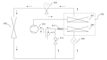
- FIG. 1 is a schematic structural view of a heat pump air conditioning system according to an embodiment of the present disclosure.
- the system can include: HVAC (Heating Ventilation and Air Conditioning) A 600 and damper mechanism (not shown) may be utilized, wherein the damper mechanism may be used to conduct air passages to the indoor evaporator 602 and the indoor condenser 601.
- the system also includes a compressor 604 and an outdoor heat exchanger 605.
- the HVAC assembly 600 can include an indoor condenser 601 and an indoor evaporator 602.
- the outlet of the compressor 604 is in communication with the inlet of the indoor condenser 601, and the outlet of the indoor condenser 601 is selectively in communication with the inlet of the outdoor heat exchanger 605 via the first throttle branch or the first through branch, outdoor heat exchange
- the outlet of the 605 is selectively in communication with the inlet of the indoor evaporator 602 via the second throttle branch or with the inlet of the compressor 604 via the second flow branch, the outlet of the indoor evaporator 602 and the inlet of the compressor 604 Connected.
- the outlet of the indoor condenser 601 is either in communication with the inlet of the outdoor heat exchanger 605 via the first throttle branch or with the inlet of the outdoor heat exchanger 605 via the first flow branch.
- the heat pump air conditioning system may further include an expansion switch valve 603 whose inlet is in communication with an outlet of the indoor condenser 601, and the outlet of the expansion switch valve 603 is The inlet of the outdoor heat exchanger 605 is in communication, wherein the first throttle branch is a throttle passage of the expansion switch valve 603, and the first flow branch is a through flow passage of the expansion switch valve 603.
- the expansion switch valve is a valve having both an expansion valve function (also referred to as an electronic expansion valve function) and an on-off valve function (also referred to as a solenoid valve function), which can be regarded as an on-off valve and expansion.
- Valve integration A through flow passage and a throttle passage are formed inside the expansion switch valve.
- the expansion switch valve is used as an on-off valve, the internal flow passage is electrically connected, and a through-flow branch is formed at this time;
- the internal throttling flow path is turned on, and a throttling branch is formed at this time.
- the heat pump air conditioning system may further include a first switching valve 608 and a first expansion valve 607, wherein the first switching branch is provided with a first switching valve 608, A first expansion valve 607 is disposed on the first throttle branch.
- the outlet of the indoor condenser 601 communicates with the inlet of the outdoor heat exchanger 605 via the first switching valve 608 to form a first through-flow branch, and the outlet of the indoor condenser 601 passes through the first expansion valve.
- 607 is in communication with the inlet of the outdoor heat exchanger 605 to form a first throttle branch.
- the first switching valve 608 When the system is in the high temperature cooling mode, the first switching valve 608 is turned on, the first expansion valve 607 is closed, and the outlet of the indoor condenser 601 is in communication with the inlet of the outdoor heat exchanger 605 via the first through branch.
- the first expansion valve 607 When the system is in the low temperature heating mode, the first expansion valve 607 is turned on, the first switching valve 608 is closed, and the outlet of the indoor condenser 601 is in communication with the inlet of the outdoor heat exchanger 605 via the first throttle branch.
- an expansion switch valve 603 that is, the embodiment shown in FIG. 1, in the heat pump air conditioning system provided by the present disclosure.
- the second through-flow branch is provided with a second on-off valve 610, the second section A second expansion valve 609 is provided on the flow branch.
- the outlet of the outdoor heat exchanger 605 is in communication with the inlet of the compressor 604 via the second switching valve 610 to form a second through branch, and the outlet of the outdoor heat exchanger 605 is via the second expansion valve. 609 and the inlet of the indoor evaporator 602 The ports are connected to form a second throttle branch.
- the second expansion valve 609 When the system is in the high temperature cooling mode, the second expansion valve 609 is open, the second switching valve 610 is closed, and the outlet of the outdoor heat exchanger 605 is in communication with the inlet of the indoor evaporator 602 via the second throttle branch.
- the second switching valve 610 When the system is in the low temperature heating mode, the second switching valve 610 is turned on, the second expansion valve 609 is closed, and the outlet of the outdoor heat exchanger 605 is in communication with the inlet of the compressor 604 via the second through branch.
- FIG. 3 shows a schematic structural view of a heat pump air conditioning system according to another embodiment of the present disclosure.
- the heat pump air conditioning system may further include a gas-liquid separator 611 and a check valve 615, wherein an outlet of the indoor evaporator 602 is in communication with an inlet of the gas-liquid separator 611, and an outlet of the gas-liquid separator 611 is The inlet of the compressor 604 is in communication.
- the refrigerant flowing out through the indoor evaporator 602 can be first subjected to gas-liquid separation through the gas-liquid separator 611, and the separated gas is returned to the compressor 604, thereby preventing the liquid refrigerant from entering the compressor 604 and damaging the compressor.
- the outlet of the indoor evaporator 602 is in communication with the inlet of the gas-liquid separator 611 through a one-way valve 615.
- the check valve 615 is provided to prevent the refrigerant from flowing back to the indoor evaporator 602 in the low temperature heating mode (described in detail below), thereby affecting the heating effect.
- FIG. 3 The cycle process and principle of the heat pump air conditioning system provided by the present disclosure in different working modes will be described in detail below by taking FIG. 3 as an example. It should be understood that the system cycle process and principle of other embodiments (for example, the embodiments shown in FIG. 1 to FIG. 3) are similar to those of FIG. 3, and will not be further described herein.
- Mode 1 High temperature cooling mode.
- the entire system forms a high temperature refrigeration cycle.
- the compressor 604 is compressed to discharge high temperature and high pressure gas, and the compressor 604 is connected to the indoor condenser 601.
- the wind is controlled by the damper mechanism without passing through the indoor condenser 601. Since no wind passes, heat exchange is not performed in the indoor condenser 601, and the indoor condenser 601 is only used as a flow path.
- the 601 exit is still a high temperature and high pressure gas.
- the outlet of the indoor condenser 601 is connected to the inlet of the expansion switch valve 603.
- the expansion switch valve 603 functions as a switching valve and flows only as a flow path.
- the outlet of the expansion switch valve 603 is still a high temperature and high pressure gas.
- the outlet of the expansion switch valve 603 is connected to the inlet of the outdoor heat exchanger 605.
- the outdoor heat exchanger 605 exchanges heat with the outdoor air to dissipate heat into the air, and the outlet of the outdoor heat exchanger 605 is a medium-temperature high-pressure liquid.
- the second switching valve 610 is closed, the outlet of the outdoor heat exchanger 605 is connected to the inlet of the second expansion valve 609, the second expansion valve 609 acts as a throttling element to throttle, and the outlet is a low temperature and low pressure liquid.
- the second expansion valve 609 opening degree can be set according to actual demand, and the opening degree can be calculated according to the pressure and temperature data collected by the pressure-temperature sensor installed between the outlet of the indoor evaporator 602 and the inlet of the gas-liquid separator 611.
- the evaporator outlet refrigerant superheat is adjusted.
- the outlet of the second expansion valve 609 is connected to the inlet of the indoor evaporator 602, and the low temperature and low pressure liquid is evaporated in the indoor evaporator 602 such that the outlet of the indoor evaporator 602 is a low temperature and low pressure gas.
- the outlet of the indoor evaporator 602 is connected to the inlet of the one-way valve 615, the outlet of the one-way valve 615 is connected to the inlet of the gas-liquid separator 611, and the unvaporized liquid is separated by the gas-liquid separator 611, and finally the low-temperature low-pressure gas Returning to compressor 604, a cycle is formed thereby.
- the HVAC assembly 600 stroke only flows through the indoor evaporator 602, and the indoor condenser 601 passes through the refrigerant flow path.
- Mode 2 Low temperature heating mode.
- the entire system forms a low temperature heating cycle.
- the compressor 604 is compressed to discharge high temperature and high pressure gas, and the compressor 604 is connected to the indoor condenser 601.
- the indoor condenser 601 has a wind passing through, and the high temperature and high pressure gas is in the indoor condenser 601. Condensation is carried out so that the outlet of the indoor condenser 601 is a medium-temperature high-pressure liquid.
- the outlet of the indoor condenser 601 is connected to the inlet of the expansion switch valve 603.
- the expansion switch valve 603 functions as an expansion valve, functions as a throttling element for throttling, and its outlet is a low temperature and low pressure liquid.
- the opening degree of the expansion switch valve 603 can be set according to actual demand, and the opening degree can be based on the temperature data collected by the pressure-temperature sensor installed at the outlet of the compressor 604 (ie, the compressor exhaust temperature). Adjustment.
- the outlet of the expansion switch valve 603 is connected to the inlet of the outdoor heat exchanger 605, the outdoor heat exchanger 605 absorbs the heat of the outdoor air, and the outlet of the outdoor heat exchanger 605 is a low temperature and low pressure gas.
- the second on-off valve 610 is opened, the second expansion valve 609 is closed, the refrigerant does not directly enter the gas-liquid separator 611 through the indoor evaporator 602, and the unvaporized liquid is separated by the gas-liquid separator 611, and finally the low-temperature low-pressure The gas is returned to the compressor 604, thereby forming a cycle.
- Mode 3 Simultaneous cooling and heating mode.
- the entire system forms a cooling and heating simultaneous opening and closing system.
- the compressor 604 is compressed to discharge high-temperature and high-pressure gas, and the compressor 604 is connected to the indoor condenser 601.
- the high-temperature and high-pressure gas is condensed in the indoor condenser 601, so that the outlet of the indoor condenser 601 is Medium temperature and high pressure liquid.
- the outlet of the indoor condenser 601 is connected to the inlet of the expansion switch valve 603.
- the expansion switch valve 603 functions as an expansion valve, functions as a throttling element for throttling, and its outlet is a low temperature and low pressure liquid.
- the opening degree of the expansion switch valve 603 can be set according to actual demand, and the opening degree can be based on the temperature data collected by the pressure-temperature sensor installed at the outlet of the compressor 604 (ie, the compressor exhaust temperature). Adjustment.
- the outlet of the expansion switch valve 603 is connected to the inlet of the outdoor heat exchanger 605, and the outlet of the outdoor heat exchanger 605 is a low temperature and low pressure liquid, and the outlet is kept in a low temperature and low pressure liquid state by incomplete evaporation.
- the second opening and closing valve 610 is closed, the second expansion valve 609 is opened, and the second expansion valve 609 is throttled once as a throttle element.
- the outlet of the second expansion valve 609 is connected to the inlet of the indoor evaporator 602, and the low temperature and low pressure liquid is evaporated in the indoor evaporator 602, so that the outlet of the indoor evaporator 602 is a low temperature and low pressure gas.
- the indoor evaporator 602 is connected to the gas-liquid separator 611, and the unvaporized liquid is separated by the gas-liquid separator 611, and finally the low-temperature low-pressure gas is returned to the compressor 604, thereby forming a cycle.
- the wind in the HVAC assembly 600 flows through the indoor condenser 601 and the indoor evaporator 602 at the same time.
- Mode 4 Defrost mode of outdoor heat exchanger.
- the compressor 604 is compressed to discharge high temperature and high pressure gas, and the compressor 604 is connected to the indoor condenser 601.
- the indoor condenser 601 flows only as a flow path, and the outlet of the indoor condenser 601 is still a high-temperature high-pressure gas.
- the outlet of the indoor condenser 601 is connected to the inlet of the expansion switch valve 603.
- the expansion switch valve 603 functions as a switching valve and flows only as a flow path.
- the outlet of the expansion switch valve 603 is still a high temperature and high pressure gas.
- the outlet of the expansion switch valve 603 is connected to the inlet of the outdoor heat exchanger 605.
- the outdoor heat exchanger 605 exchanges heat with the outdoor air to dissipate heat into the air, and the outlet of the outdoor heat exchanger 605 is a medium-temperature high-pressure liquid.
- the second The on-off valve 610 is closed, the second expansion valve 609 is open, the second expansion valve 609 acts as a throttling element for throttling, and its outlet is a low temperature, low pressure liquid.
- the second expansion valve 609 opening degree can be set according to actual demand, and the opening degree can be calculated according to the pressure and temperature data collected by the pressure-temperature sensor installed between the outlet of the indoor evaporator 602 and the inlet of the gas-liquid separator 611.
- the evaporator outlet refrigerant superheat is adjusted.
- the outlet of the second expansion valve 609 is connected to the inlet of the indoor evaporator 602, and the outlet of the indoor evaporator 602 is a low temperature and low pressure gas.
- the indoor evaporator 602 is connected to the gas-liquid separator 611, and the unvaporized liquid is separated by the gas-liquid separator 611, and finally the low-temperature low-pressure gas is returned to the compressor 604, thereby forming a cycle.
- the HVAC assembly 600 may not open.
- the heat pump air conditioning system provided by the present disclosure can realize the refrigeration and heating of the automobile air conditioning system and the defrosting function of the outdoor side heat exchanger without changing the direction of the refrigerant circulation, and can satisfy the simultaneous cooling and heating. demand. In the process of bypassing the outdoor heat exchanger, the heating demand in the car can still be met.
- the heat pump air conditioning system of the present disclosure uses only one outdoor heat exchanger, the wind resistance of the front end module of the automobile can be reduced, and the pure electric vehicle or the hybrid vehicle without the engine waste heat circulation system can be used to use the pure electric mode automobile heat pump air conditioner.
- the system has low energy efficiency, can not meet the requirements of defrost and defogging regulations, and complicated installation, so as to reduce energy consumption, simplify system structure, and facilitate pipeline layout.
- the heat pump air conditioning system provided by the present disclosure has the characteristics of simple structure, and thus is easy to mass-produce.
- a plate heat exchanger 612 is provided in the entire heat pump air conditioning system, and the plate heat exchanger 612 is also set.
- the plate heat exchanger 612 can be arbitrarily disposed upstream or downstream of the second switching valve 610. In the embodiment shown in FIG.
- the plate heat exchanger 612 is disposed upstream of the second switching valve 610, that is, the refrigerant inlet 612a of the plate heat exchanger 612 is in communication with the outlet of the outdoor heat exchanger 605, plate heat exchange The refrigerant outlet 612b of the 612 is in communication with the inlet of the second switching valve 610.
- the plate heat exchanger 612 is disposed downstream of the second switching valve 610, ie, the refrigerant inlet 612a of the plate heat exchanger 612 is in communication with the outlet of the second switching valve 610, The refrigerant outlet 612b of the plate heat exchanger 612 is in communication with the inlet of the gas-liquid separator 611.
- the plate heat exchanger 612 is simultaneously disposed in the motor cooling system.
- the motor cooling system can include a motor in series with the plate heat exchanger 612 to form a circuit, a motor radiator 613, and a water pump 614. In this way, the refrigerant can be heat exchanged with the coolant in the motor cooling system through the plate heat exchanger 612.
- various refrigerants such as R134a, R410a, R32, and R290 can be used, and a medium-high temperature refrigerant is preferred.
- FIG. 5 is a schematic structural view of a heat pump air conditioning system according to another embodiment of the present disclosure.
- the HVAC assembly 600 can also include a PTC heater 619 for heating the wind flowing through the indoor condenser 601.
- the PTC heater 619 can be a high voltage PTC (driven by a vehicle high voltage battery) with a voltage range of 200V-900V.
- the PTC heater 619 can also be a low voltage PTC (12V or 24V battery drive) with a voltage range of 9V-32V.
- the PTC heater 619 may be a complete core composed of several or several PTC ceramic chip modules and heat dissipating fins, or may be a strip or block PTC ceramic chip module with heat dissipating fins.
- the PTC heater 619 may be disposed on the windward side or the leeward side of the indoor condenser 601. Further, in order to improve the heating effect on the wind flowing through the indoor condenser 601, the PTC heater 619 may be disposed in parallel with the indoor condenser 601. In other embodiments, the PTC heater 619 may also be disposed at the blower tuyere and the defroster tuyere of the cabinet of the HVAC assembly 600, and may also be disposed at the tuyere of the defroster duct.
- the tank can be grooved in the casing, and the PTC heater 619 is vertically inserted into the casing. It is also possible to weld the bracket on the side plate of the indoor condenser 601, and the PTC heater 619 is fixed to the bracket of the indoor condenser 601 by screws. If the PTC heater 619 is disposed at the blower vent and the defrosting vent of the cabinet, or at the tuyere of the defrosting duct, it can be directly fixed to the air outlet of the cabinet and the tuyere of the air duct by screws.
- the PTC heater 619 can be operated to assist the heating, thereby eliminating the heat generation of the heat pump air conditioning system during low temperature heating.
- the vehicle is defrost and defogged, and the heating effect is not good.
- the expansion switching valve is a valve having both an expansion valve function and an on-off valve function, which can be regarded as an integration of an on-off valve and an expansion valve.
- An example embodiment of an expansion switch valve will be provided below.
- the above-mentioned expansion switch valve may include a valve body 500 in which an inlet 501, an outlet 502, and an internal flow communicating between the inlet 501 and the outlet 502 are formed.
- the first spool 503 and the second spool 504 are mounted on the inner flow passage.
- the first spool 503 directly connects or disconnects the inlet 501 and the outlet 502, and the second spool 504 allows the inlet 501 and the outlet 502 to pass through the section.
- the flow port 505 is connected or disconnected.
- the "direct communication" achieved by the first spool means that the refrigerant entering from the inlet 501 of the valve body 500 can flow directly to the outlet 502 of the valve body 500 through the internal flow passage without passing through the first spool.
- the "disconnected communication” achieved by the first spool means that the refrigerant entering from the inlet 501 of the valve body 500 cannot pass over the first spool and cannot flow through the internal passage to the outlet 502 of the valve body 500.
- the “connected through the orifice” realized by the second spool means that the refrigerant entering from the inlet 501 of the valve body 500 can flow over the second spool through the throttling of the orifice 505 to the outlet of the valve body 500.
- the "disconnected communication" achieved by the second spool means that the refrigerant entering from the inlet 501 of the valve body 500 cannot pass over the second spool and cannot flow through the orifice 505 to the outlet 502 of the valve body 500.
- the expansion switch valve of the present disclosure can cause the refrigerant entering from the inlet 501 to achieve at least three states. That is, 1) an off state; 2) a direct communication state over the first valve body 503; and 3) a throttle communication mode over the second valve body 504.
- the high-temperature high-pressure liquid refrigerant can be a low-temperature low-pressure mist-like liquid refrigerant after being throttled through the orifice 505, which can create conditions for the evaporation of the refrigerant, that is, the cross-sectional area of the orifice 505 is smaller than the outlet.
- the cross-sectional area of 502, and by controlling the second spool, the opening degree of the orifice 505 can be adjusted to control the flow rate through the orifice 505, to prevent insufficient refrigeration due to too little refrigerant, and to prevent Excessive refrigerant causes the compressor to produce a liquid hammer phenomenon. That is, the cooperation of the second spool 504 and the valve body 500 can cause the expansion switch valve to function as an expansion valve.
- the expansion switch valve provided by the present disclosure can reduce the refrigerant charge of the entire heat pump system, reduce the cost, simplify the pipeline connection, and facilitate the oil return of the heat pump system.
- the valve body 500 includes a valve seat 510 forming an internal flow passage and a first valve housing 511 mounted on the valve seat 510 and a second valve housing 512, a first electromagnetic driving portion 521 for driving the first valve body 503 is mounted in the first valve housing 511, and a second electromagnetic driving portion for driving the second valve core 504 is mounted in the second valve housing 512.
- the first spool 503 extends from the first valve housing 511 to the internal flow passage in the valve seat 510
- the second spool 504 extends from one end adjacent to the second valve housing 512 to the internal flow passage in the valve seat 510.
- the position of the first valve core 503 can be conveniently controlled by controlling the on/off power of the first electromagnetic driving portion 521 (eg, the electromagnetic coil), thereby controlling the direct connection or disconnection of the inlet 501 and the outlet 502;
- the control of the on/off of the second electromagnetic driving portion 522 e.g., the electromagnetic coil
- the electronic expansion valve and the solenoid valve sharing the inlet 501 and the outlet 502 are installed in parallel in the valve body 500, thereby enabling automatic control of the on/off and/or throttling of the expansion switch valve, and simplifying the course of the pipe.
- the valve seat 510 is formed into a polyhedral structure, the first valve housing 511, the second valve housing 512, the inlet 501 and the outlet 502 They are respectively disposed on different surfaces of the polyhedral structure, wherein the mounting directions of the first valve housing 511 and the second valve housing 512 are perpendicular to each other, and the opening directions of the inlet 501 and the outlet 502 are perpendicular to each other.
- the inlet and outlet pipes can be connected to different surfaces of the polyhedral structure, which can avoid the problem of messy and entangled pipe arrangement.
- the internal flow path includes a first flow path 506 and a second flow path 507 respectively communicating with the inlet 501, and the first flow path 506 is formed with
- the first valve port 503 is engaged with the first valve port 516, and the throttle port 505 is formed on the second flow path 507 to form a second valve port 517 that cooperates with the second valve body 504, the first flow path 506 and the second flow Lane 507 meets downstream of second valve port 517 and is in communication with outlet 502.
- the closing or opening of the first valve port 516 is achieved by changing the position of the first valve body 503, thereby controlling the cutting or conduction of the first flow path 506 connecting the inlet 501 and the outlet 502, so that the above described The function of connecting or disconnecting the solenoid valve.
- the second valve port 517 is realized by changing the position of the second valve body 504. It is cut off or turned on, so that the throttling function of the electronic expansion valve can be realized.
- the first flow path 506 and the second flow path 507 can communicate with the inlet 501 and the outlet 502 respectively in any suitable arrangement.
- the second flow path 507 is the same as the outlet 502.
- the first flow path 506 is formed as a first through hole 526 perpendicular to the second flow path 507, and the inlet 501 is connected to the second flow path 507 through the second through hole 527 opened in the sidewall of the second flow path 507.
- the first through hole 526 and the second through hole 527 are respectively in communication with the inlet 501.
- the first through hole 526 can be disposed in a vertical direction or in parallel with the second through hole 527, which is not limited by the disclosure, and is all within the protection scope of the present disclosure.
- the inlet 501 and the outlet 502 are perpendicular to each other on the valve body 500.
- the axis of the inlet 501, the axis of the outlet 502 (i.e., the axis of the second flow path 507), and the axis of the first flow path 506 are vertically arranged in space, thereby preventing the first
- the movement of the spool 503 and the second spool 504 causes interference and the internal space of the valve body 500 can be utilized to the maximum.
- the first valve core 503 is coaxially disposed with the first valve port 516 in the moving direction to selectively block or disengage the first valve. Port 516.
- the second spool 504 is disposed coaxially with the second valve port 517 in the direction of movement to selectively block or disengage the second valve port 517.
- the first valve core 503 may include a first valve stem 513 and a first end connected to the first valve stem 513.
- the second spool 504 includes a second valve stem 514 whose end is tapered.
- the head structure, the second valve port 517 is formed as a tapered hole structure that cooperates with the tapered head structure.
- the opening 505 opening of the expansion switch valve can be adjusted by the up and down movement of the second valve core 504, and the up and down movement of the second valve core 504 can be adjusted by the second electromagnetic driving portion 522. If the opening of the orifice 505 of the expansion switch valve is zero, as shown in FIG. 9, the second spool 504 is at the lowest position, and the second spool 504 blocks the second valve port 517, and the refrigerant is completely unable to pass the throttle. Port 505, that is, the second valve port 517; if the expansion switch valve throttle port 505 has an opening degree, as shown in FIG.
- the second solenoid 504 can be moved upward by controlling the second electromagnetic driving portion 522 to make the tapered head structure away from the throttle opening 505, thereby realizing the throttle opening 505.
- the opening degree becomes larger; on the contrary, when it is required to reduce the opening degree of the orifice 505 of the expansion switching valve, the second valve body 504 can be driven to move downward.
- the first The spool 503 When in use, when only the solenoid valve function of the expansion switch valve is required, as shown in FIG. 9, FIG. 12 and FIG. 15, the first The spool 503 is disengaged from the first valve port 516, the first valve port 516 is in an open state, the second valve core 504 is at a lowest position, and the second valve core 504 blocks the throttle hole 505 and flows from the inlet 501 to the internal flow path.
- the refrigerant can not pass through the orifice 505 at all, and can only flow into the outlet 502 through the first valve port 516 and the first through hole 526 in sequence.
- the first spool 503 moves to the left, the first plug 523 and the first valve port 516 are separated, the refrigerant can pass through the first through hole 526; when the solenoid valve is energized, the first spool 503 Moving to the right, the first plug 523 and the first valve port 516 are fitted together, and the refrigerant cannot pass through the first through hole 526.
- FIGS. 9 and 15 represents the circulation route and the tendency of the refrigerant when the solenoid valve function is used.
- the second valve port 517 that is, the throttle port 505 is in an open state
- the first valve body 503 blocks the first valve port 516.
- the refrigerant flowing from the inlet 501 to the internal flow passage cannot pass through the first through hole 526, and can only flow into the outlet 502 through the second through hole 527 and the throttle port 505 in sequence, and can move the second valve core 504 up and down.
- the size of the opening of the orifice 505 is adjusted.
- dashed arrows with arrows in FIGS. 10 and 16 represent the flow paths and directions of the refrigerant when the electronic expansion valve function is used.
- the first spool 503 Deviating from the first valve port 516, the first valve port 516 is in an open state, the throttle port 505 is in an open state, and the refrigerant flowing into the inner flow channel can flow along the first flow channel 506 and the second flow channel 507 to the outlet 502, respectively, thereby It also has a solenoid valve function and an electronic expansion valve function.
- the present disclosure also provides an electric vehicle including the above described heat pump air conditioning system provided in accordance with the present disclosure.
- the electric vehicle may include a pure electric vehicle, a hybrid vehicle, and a fuel cell vehicle.
Abstract
A heat pump air-conditioning system and an electric vehicle. The heat pump air-conditioning system comprises: an indoor condenser (601), an indoor evaporator (602), a compressor (604), and an outdoor heat exchanger (605). An outlet of the compressor (604) is in communication with an inlet of the indoor condenser (601); an outlet of the indoor condenser (601) is in communication with an inlet of the outdoor heat exchanger (605) via a first throttling branch or a first through-flow branch selectively; an outlet of the outdoor heat exchanger (605) is selectively in communication with an inlet of the compressor (604) via a second through-flow branch or in communication with an inlet of the indoor evaporator (602) via a second throttling branch; an outlet of the indoor evaporator (602) is in communication with the inlet of the compressor (604). The heat pump air-conditioning system improves heating energy efficiency and facilitates installation.
Description
本公开涉及汽车空调系统,具体地,涉及一种热泵空调系统,还涉及一种设置有该热泵空调系统的电动汽车。The present disclosure relates to an automotive air conditioning system, and in particular to a heat pump air conditioning system, and to an electric vehicle provided with the heat pump air conditioning system.
电动汽车没有传统汽车用来采暖的发动机余热,无法提供采暖热源。因此,电动汽车的空调系统必须自身具有供暖的功能,即采用热泵型空调系统和/或电加热供热。Electric vehicles do not have the engine waste heat that traditional cars use to heat, and cannot provide heating sources. Therefore, the air conditioning system of an electric vehicle must have its own heating function, that is, a heat pump type air conditioning system and/or electric heating.
公开号为CN102788397A的实用新型专利公开了一种电动汽车热泵空调系统。该热泵空调系统虽然可以在各类电动汽车中使用,但是该系统使用两个室外换热器(一个室外冷凝器和一个室外蒸发器),导致汽车前端模块风阻较大,系统结构较复杂,影响采暖效果。The utility model patent published as CN102788397A discloses an electric vehicle heat pump air conditioning system. Although the heat pump air conditioning system can be used in various types of electric vehicles, the system uses two outdoor heat exchangers (an outdoor condenser and an outdoor evaporator), resulting in a large wind resistance of the front end module of the automobile, and the system structure is complicated and affects. Heating effect.
发明内容Summary of the invention
本公开的目的是提供一种热泵空调系统及电动汽车,以解决无发动机余热循环系统的纯电动车或混合动力车使用纯电动模式的汽车热泵空调系统采暖能效低、无法满足除霜除雾法规要求、安装复杂等问题。The purpose of the present disclosure is to provide a heat pump air conditioning system and an electric vehicle to solve the problem that the pure electric vehicle or the hybrid vehicle without the engine waste heat circulation system uses the pure electric mode of the automobile heat pump air conditioning system, has low heating efficiency and cannot meet the requirements of defrost and defogging. Requirements, installation complexity and other issues.
为了实现上述目的,根据本公开的第一方面,提供一种热泵空调系统,包括压缩机、室内冷凝器、室内蒸发器和室外换热器,所述压缩机的出口与所述室内冷凝器的入口连通,所述室内冷凝器的出口选择性地经由第一节流支路或第一通流支路与所述室外换热器的入口连通,所述室外换热器的出口选择性地经由第二通流支路与所述压缩机的入口连通或经由第二节流支路与所述室内蒸发器的入口连通,所述室内蒸发器的出口与所述压缩机的入口连通。In order to achieve the above object, according to a first aspect of the present disclosure, a heat pump air conditioning system including a compressor, an indoor condenser, an indoor evaporator, and an outdoor heat exchanger, an outlet of the compressor and the indoor condenser The inlet is in communication, and the outlet of the indoor condenser is selectively in communication with the inlet of the outdoor heat exchanger via a first throttle branch or a first flow branch, the outlet of the outdoor heat exchanger being selectively via A second flow branch is in communication with an inlet of the compressor or with an inlet of the indoor evaporator via a second throttle branch, the outlet of the indoor evaporator being in communication with an inlet of the compressor.
根据本公开的一个实施例,所述第一通流支路上设置有第一开关阀,所述第一节流支路上设置有第一膨胀阀。According to an embodiment of the present disclosure, the first through-flow branch is provided with a first on-off valve, and the first throttle branch is provided with a first expansion valve.
根据本公开的一个实施例,所述热泵空调系统还包括膨胀开关阀,该膨胀开关阀的入口与所述室内冷凝器的出口连通,该膨胀开关阀的出口与所述室外换热器的入口连通,所述第一节流支路为所述膨胀开关阀的节流流道,所述第一通流支路为所述膨胀开关阀的通流流道。According to an embodiment of the present disclosure, the heat pump air conditioning system further includes an expansion switch valve, an inlet of the expansion switch valve is in communication with an outlet of the indoor condenser, an outlet of the expansion switch valve and an inlet of the outdoor heat exchanger In communication, the first throttle branch is a throttle passage of the expansion switch valve, and the first through branch is a through flow passage of the expansion switch valve.
根据本公开的一个实施例,所述第二通流支路上设置有第二开关阀,所述第二节流支
路上设置有第二膨胀阀。According to an embodiment of the present disclosure, the second through-flow branch is provided with a second on-off valve, the second throttle branch
A second expansion valve is provided on the road.
根据本公开的一个实施例,所述室内蒸发器的出口经由单向阀与所述压缩机的入口连通。According to an embodiment of the present disclosure, the outlet of the indoor evaporator is in communication with the inlet of the compressor via a one-way valve.
根据本公开的一个实施例,所述热泵空调系统应用于电动汽车,所述第二通流支路上设置有板式换热器,该板式换热器同时设置在所述电动汽车的电机冷却系统中。According to an embodiment of the present disclosure, the heat pump air conditioning system is applied to an electric vehicle, and the second through-flow branch is provided with a plate heat exchanger, which is simultaneously disposed in a motor cooling system of the electric vehicle .
根据本公开的一个实施例,所述第二通流支路上设置有第二开关阀,所述板式换热器的制冷剂入口与所述室外换热器的出口连通,所述板式换热器的制冷剂出口与所述第二开关阀的入口连通。According to an embodiment of the present disclosure, the second through-flow branch is provided with a second switching valve, and a refrigerant inlet of the plate heat exchanger is in communication with an outlet of the outdoor heat exchanger, the plate heat exchanger The refrigerant outlet is in communication with the inlet of the second switching valve.
根据本公开的一个实施例,所述电机冷却系统包括与所述板式换热器串联以形成回路的电机、电机散热器和水泵。According to an embodiment of the present disclosure, the motor cooling system includes a motor, a motor radiator, and a water pump that are connected in series with the plate heat exchanger to form a circuit.
根据本公开的一个实施例,所述热泵空调系统还包括气液分离器,所述室内蒸发器的出口与所述气液分离器的入口连通,所述室外换热器的出口经由所述第二通流支路与所述气液分离器的入口连通,所述气液分离器的出口与所述压缩机的入口连通。According to an embodiment of the present disclosure, the heat pump air conditioning system further includes a gas-liquid separator, an outlet of the indoor evaporator is in communication with an inlet of the gas-liquid separator, and an outlet of the outdoor heat exchanger is via the first A two-flow branch is in communication with an inlet of the gas-liquid separator, and an outlet of the gas-liquid separator is in communication with an inlet of the compressor.
根据本公开的一个实施例,所述热泵空调系统还包括PTC加热器,该PTC加热器用于加热流经所述室内冷凝器的风。According to an embodiment of the present disclosure, the heat pump air conditioning system further includes a PTC heater for heating the wind flowing through the indoor condenser.
根据本公开的一个实施例,所述PTC加热器设置在所述室内冷凝器的迎风侧或背风侧。According to an embodiment of the present disclosure, the PTC heater is disposed on a windward side or a leeward side of the indoor condenser.
根据本公开的第二方面,提供一种电动汽车,包括根据本公开的第一方面提供的所述热泵空调系统。According to a second aspect of the present disclosure, an electric vehicle is provided, comprising the heat pump air conditioning system provided in accordance with the first aspect of the present disclosure.
本公开提供的热泵空调系统,在不改变制冷剂循环方向的情况下即可实现汽车空调系统制冷和制热、室外侧换热器除霜功能,且能满足同时制冷采暖的需求。在室外换热器旁通除霜过程中,仍能满足车内采暖需求。此外,由于本公开的热泵空调系统仅采用一个室外换热器,因此能够减小汽车前端模块的风阻,解决了无发动机余热循环系统的纯电动车或混合动力车使用纯电动模式的汽车热泵空调系统采暖能效低、无法满足除霜除雾法规要求、安装复杂等问题,达到降低能耗、简化系统结构,方便管路布置的效果。本公开提供的热泵空调系统具有结构简单的特点,因此易于批量生产。The heat pump air conditioning system provided by the present disclosure can realize the refrigeration and heating functions of the automobile air conditioning system and the defrosting function of the outdoor side heat exchanger without changing the direction of the refrigerant circulation, and can meet the requirements of simultaneous cooling and heating. In the process of bypassing the outdoor heat exchanger, the heating demand in the car can still be met. In addition, since the heat pump air conditioning system of the present disclosure uses only one outdoor heat exchanger, the wind resistance of the front end module of the automobile can be reduced, and the pure electric vehicle or the hybrid vehicle without the engine waste heat circulation system can be used to use the pure electric mode automobile heat pump air conditioner. The system has low energy efficiency, can not meet the requirements of defrost and defogging regulations, and complicated installation, so as to reduce energy consumption, simplify system structure, and facilitate pipeline layout. The heat pump air conditioning system provided by the present disclosure has the characteristics of simple structure, and thus is easy to mass-produce.
本公开的其他特征和优点将在随后的具体实施方式部分予以详细说明。Other features and advantages of the present disclosure will be described in detail in the detailed description which follows.
附图是用来提供对本公开的进一步理解,并且构成说明书的一部分,与下面的具体实施方式一起用于解释本公开,但并不构成对本公开的限制。在附图中:The drawings are intended to provide a further understanding of the disclosure, and are in the In the drawing:
图1是根据本公开的一种实施方式的热泵空调系统的结构示意图;1 is a schematic structural view of a heat pump air conditioning system according to an embodiment of the present disclosure;
图2是根据本公开的另一种实施方式的热泵空调系统的结构示意图;
2 is a schematic structural view of a heat pump air conditioning system according to another embodiment of the present disclosure;
图3是根据本公开的另一种实施方式的热泵空调系统的结构示意图;3 is a schematic structural view of a heat pump air conditioning system according to another embodiment of the present disclosure;
图4是根据本公开的另一种实施方式的热泵空调系统的结构示意图;4 is a schematic structural view of a heat pump air conditioning system according to another embodiment of the present disclosure;
图5是根据本公开的另一种实施方式的热泵空调系统的结构示意图;5 is a schematic structural view of a heat pump air conditioning system according to another embodiment of the present disclosure;
图6是本公开优选实施方式提供的膨胀开关阀的俯视结构示意图;6 is a schematic top plan view of an expansion switch valve according to a preferred embodiment of the present disclosure;
图7是沿图6中线AB-AB所剖得的剖面结构示意图,其中,第一阀口和第二阀口均处于打开状态;Figure 7 is a cross-sectional structural view taken along line AB-AB of Figure 6, wherein the first valve port and the second valve port are both in an open state;
图8是本公开优选实施方式提供的膨胀开关阀的沿一个视角的正视结构示意图;8 is a schematic front elevational view of the expansion switch valve according to a preferred embodiment of the present disclosure along a viewing angle;
图9是沿图6中线AB-AB所剖得的剖面结构示意图,其中,第一阀口处于打开状态,第二阀口处于闭合状态;Figure 9 is a cross-sectional structural view taken along line AB-AB of Figure 6, wherein the first valve port is in an open state and the second valve port is in a closed state;
图10是沿图6中线AB-AB所剖得的剖面结构示意图,其中,第一阀口处于闭合状态,第二阀口处于打开状态;Figure 10 is a cross-sectional structural view taken along line AB-AB of Figure 6, wherein the first valve port is in a closed state, and the second valve port is in an open state;
图11是本公开优选实施方式提供的膨胀开关阀的沿另一个视角的正视结构示意图;11 is a front elevational view of the expansion switch valve according to a preferred embodiment of the present disclosure along another perspective;
图12是沿图11中线AC-AC所剖得的剖面结构示意图,其中,第一阀口处于打开状态,第二阀口处于闭合状态;Figure 12 is a cross-sectional structural view taken along line AC-AC of Figure 11, wherein the first valve port is in an open state and the second valve port is in a closed state;
图13是本公开优选实施方式提供的膨胀开关阀的第一内部结构示意图,其中,第一阀口和第二阀口均处于打开状态;13 is a first internal structural diagram of an expansion switch valve according to a preferred embodiment of the present disclosure, wherein the first valve port and the second valve port are both in an open state;
图14是图13中A部的局部放大图;Figure 14 is a partial enlarged view of a portion A in Figure 13;
图15是本公开优选实施方式提供的膨胀开关阀的第二内部结构示意图,其中,第一阀口处于打开状态,第二阀口处于关闭状态;15 is a second internal structural diagram of an expansion switch valve according to a preferred embodiment of the present disclosure, wherein the first valve port is in an open state and the second valve port is in a closed state;
图16是本公开优选实施方式提供的膨胀开关阀的第三内部结构示意图,其中,第一阀口处于关闭状态,第二阀口均处于打开状态。16 is a third internal structural diagram of an expansion switch valve according to a preferred embodiment of the present disclosure, wherein the first valve port is in a closed state and the second valve port is in an open state.
以下结合附图对本公开的具体实施方式进行详细说明。应当理解的是,此处所描述的具体实施方式仅用于说明和解释本公开,并不用于限制本公开。The specific embodiments of the present disclosure will be described in detail below with reference to the accompanying drawings. It is to be understood that the specific embodiments described herein are not to be construed
在本公开中,在未作相反说明的情况下,使用的方位词如“上、下、左、右”通常是相对于附图的图面方向而言的,“上游、下游”是相对于媒介,如,制冷剂的流动方向而言的,具体地,朝向制冷剂的流动方向为下游,背离制冷剂的流动方向为上游,“内、外”是指相应部件轮廓的内与外。In the present disclosure, the orientation words used, such as "up, down, left, and right", are generally relative to the drawing direction of the drawing, and the "upstream, downstream" is relative to The medium, for example, in the flow direction of the refrigerant, specifically, the flow direction toward the refrigerant is downstream, and the flow direction away from the refrigerant is upstream, and "inside and outside" means the inside and outside of the contour of the corresponding member.
在本公开中,电动汽车可以包括纯电动汽车、混合动力汽车、燃料电池汽车。In the present disclosure, an electric vehicle may include a pure electric vehicle, a hybrid vehicle, and a fuel cell vehicle.
图1是根据本公开的一种实施方式的热泵空调系统的结构示意图。如图1所示,该系统可以包括:HVAC(采暖通风及空调,Heating Ventilation and Air Conditioning)总
成600和风门机构(未示出),其中,风门机构可以用于导通通向室内蒸发器602和室内冷凝器601的风道。此外,所述系统还包括压缩机604和室外换热器605。其中,HVAC总成600可以包括室内冷凝器601和室内蒸发器602。压缩机604的出口与室内冷凝器601的入口连通,室内冷凝器601的出口选择性地经由第一节流支路或第一通流支路与室外换热器605的入口连通,室外换热器605的出口选择性地经由第二节流支路与室内蒸发器602的入口连通或经由第二通流支路与压缩机604的入口连通,室内蒸发器602的出口与压缩机604的入口连通。1 is a schematic structural view of a heat pump air conditioning system according to an embodiment of the present disclosure. As shown in Figure 1, the system can include: HVAC (Heating Ventilation and Air Conditioning)
A 600 and damper mechanism (not shown) may be utilized, wherein the damper mechanism may be used to conduct air passages to the indoor evaporator 602 and the indoor condenser 601. In addition, the system also includes a compressor 604 and an outdoor heat exchanger 605. Wherein, the HVAC assembly 600 can include an indoor condenser 601 and an indoor evaporator 602. The outlet of the compressor 604 is in communication with the inlet of the indoor condenser 601, and the outlet of the indoor condenser 601 is selectively in communication with the inlet of the outdoor heat exchanger 605 via the first throttle branch or the first through branch, outdoor heat exchange The outlet of the 605 is selectively in communication with the inlet of the indoor evaporator 602 via the second throttle branch or with the inlet of the compressor 604 via the second flow branch, the outlet of the indoor evaporator 602 and the inlet of the compressor 604 Connected.
在本公开中,室内冷凝器601的出口要么经由第一节流支路与室外换热器605的入口连通,要么经由第一通流支路与室外换热器605的入口连通。可以采用多种方式来实现这种连通方式。例如,在一种实施方式中,如图1所示,热泵空调系统还可以包括膨胀开关阀603,该膨胀开关阀603的入口与室内冷凝器601的出口连通,该膨胀开关阀603的出口与室外换热器605的入口连通,其中,第一节流支路为膨胀开关阀603的节流流道,第一通流支路为膨胀开关阀603的通流流道。In the present disclosure, the outlet of the indoor condenser 601 is either in communication with the inlet of the outdoor heat exchanger 605 via the first throttle branch or with the inlet of the outdoor heat exchanger 605 via the first flow branch. This connection can be implemented in a variety of ways. For example, in one embodiment, as shown in FIG. 1, the heat pump air conditioning system may further include an expansion switch valve 603 whose inlet is in communication with an outlet of the indoor condenser 601, and the outlet of the expansion switch valve 603 is The inlet of the outdoor heat exchanger 605 is in communication, wherein the first throttle branch is a throttle passage of the expansion switch valve 603, and the first flow branch is a through flow passage of the expansion switch valve 603.
在本公开中,膨胀开关阀是同时具有膨胀阀功能(亦可称为电子膨胀阀功能)和开关阀功能(亦可称为电磁阀功能)的阀门,可以将其视为是开关阀与膨胀阀的集成。在膨胀开关阀的内部形成有通流流道和节流流道,当膨胀开关阀作为开关阀使用时,其内部的通流流道导通,此时形成通流支路;当膨胀开关阀作为膨胀阀使用时,其内部的节流流道导通,此时形成节流支路。In the present disclosure, the expansion switch valve is a valve having both an expansion valve function (also referred to as an electronic expansion valve function) and an on-off valve function (also referred to as a solenoid valve function), which can be regarded as an on-off valve and expansion. Valve integration. A through flow passage and a throttle passage are formed inside the expansion switch valve. When the expansion switch valve is used as an on-off valve, the internal flow passage is electrically connected, and a through-flow branch is formed at this time; When used as an expansion valve, the internal throttling flow path is turned on, and a throttling branch is formed at this time.
作为另一种替换的实施方式,如图2所示,该热泵空调系统还可以包括第一开关阀608和第一膨胀阀607,其中,第一通流支路上设置有第一开关阀608,第一节流支路上设置有第一膨胀阀607。具体地,如图2所示,室内冷凝器601的出口经由第一开关阀608与室外换热器605的入口连通以形成第一通流支路,室内冷凝器601的出口经由第一膨胀阀607与室外换热器605的入口连通以形成第一节流支路。当系统处于高温制冷模式下时,第一开关阀608导通,第一膨胀阀607关闭,室内冷凝器601的出口经由第一通流支路与室外换热器605的入口连通。当系统处于低温采暖模式下时,第一膨胀阀607导通,第一开关阀608关闭,室内冷凝器601的出口经由第一节流支路与室外换热器605的入口连通。As another alternative embodiment, as shown in FIG. 2, the heat pump air conditioning system may further include a first switching valve 608 and a first expansion valve 607, wherein the first switching branch is provided with a first switching valve 608, A first expansion valve 607 is disposed on the first throttle branch. Specifically, as shown in FIG. 2, the outlet of the indoor condenser 601 communicates with the inlet of the outdoor heat exchanger 605 via the first switching valve 608 to form a first through-flow branch, and the outlet of the indoor condenser 601 passes through the first expansion valve. 607 is in communication with the inlet of the outdoor heat exchanger 605 to form a first throttle branch. When the system is in the high temperature cooling mode, the first switching valve 608 is turned on, the first expansion valve 607 is closed, and the outlet of the indoor condenser 601 is in communication with the inlet of the outdoor heat exchanger 605 via the first through branch. When the system is in the low temperature heating mode, the first expansion valve 607 is turned on, the first switching valve 608 is closed, and the outlet of the indoor condenser 601 is in communication with the inlet of the outdoor heat exchanger 605 via the first throttle branch.
为了方便管路布设,节省空间占用,优选地,在本公开提供的热泵空调系统中采用膨胀开关阀603,即,图1所示的实施方式。In order to facilitate pipe laying and space saving, it is preferred to employ an expansion switch valve 603, that is, the embodiment shown in FIG. 1, in the heat pump air conditioning system provided by the present disclosure.
与上述替换的实施方式中的第一通流支路和第一节流支路的实现方式相类似,如图1所示,第二通流支路上设置有第二开关阀610,第二节流支路上设置有第二膨胀阀609。具体地,如图3所示,室外换热器605的出口经由第二开关阀610与压缩机604的入口连通以形成第二通流支路,室外换热器605的出口经由第二膨胀阀609与室内蒸发器602的入
口连通以形成第二节流支路。当系统处于高温制冷模式下时,第二膨胀阀609导通,第二开关阀610关闭,室外换热器605的出口经由第二节流支路与室内蒸发器602的入口连通。当系统处于低温采暖模式下时,第二开关阀610导通,第二膨胀阀609关闭,室外换热器605的出口经由第二通流支路与压缩机604的入口连通。Similar to the implementation of the first through-flow branch and the first throttle branch in the above alternative embodiment, as shown in FIG. 1, the second through-flow branch is provided with a second on-off valve 610, the second section A second expansion valve 609 is provided on the flow branch. Specifically, as shown in FIG. 3, the outlet of the outdoor heat exchanger 605 is in communication with the inlet of the compressor 604 via the second switching valve 610 to form a second through branch, and the outlet of the outdoor heat exchanger 605 is via the second expansion valve. 609 and the inlet of the indoor evaporator 602
The ports are connected to form a second throttle branch. When the system is in the high temperature cooling mode, the second expansion valve 609 is open, the second switching valve 610 is closed, and the outlet of the outdoor heat exchanger 605 is in communication with the inlet of the indoor evaporator 602 via the second throttle branch. When the system is in the low temperature heating mode, the second switching valve 610 is turned on, the second expansion valve 609 is closed, and the outlet of the outdoor heat exchanger 605 is in communication with the inlet of the compressor 604 via the second through branch.
图3示出了根据本公开的另一实施方式的热泵空调系统的结构示意图。如图3所示,该热泵空调系统还可以包括气液分离器611和单向阀615,其中,室内蒸发器602的出口与气液分离器611的入口连通,气液分离器611的出口与压缩机604的入口连通。这样,经室内蒸发器602流出的制冷剂可以首先经过气液分离器611进行气液分离,分离出的气体再回流到压缩机604中,从而防止液态制冷剂进入到压缩机604而损坏压缩机604,从而可以延长压缩机604的使用寿命,并提高整个热泵空调系统的效率。室内蒸发器602的出口通过单向阀615与气液分离器611的入口连通。这里,设置单向阀615是为了防止在低温采暖模式(以下将详细描述)下制冷剂回流至室内蒸发器602,影响采暖效果。FIG. 3 shows a schematic structural view of a heat pump air conditioning system according to another embodiment of the present disclosure. As shown in FIG. 3, the heat pump air conditioning system may further include a gas-liquid separator 611 and a check valve 615, wherein an outlet of the indoor evaporator 602 is in communication with an inlet of the gas-liquid separator 611, and an outlet of the gas-liquid separator 611 is The inlet of the compressor 604 is in communication. Thus, the refrigerant flowing out through the indoor evaporator 602 can be first subjected to gas-liquid separation through the gas-liquid separator 611, and the separated gas is returned to the compressor 604, thereby preventing the liquid refrigerant from entering the compressor 604 and damaging the compressor. 604, thereby extending the life of the compressor 604 and increasing the efficiency of the entire heat pump air conditioning system. The outlet of the indoor evaporator 602 is in communication with the inlet of the gas-liquid separator 611 through a one-way valve 615. Here, the check valve 615 is provided to prevent the refrigerant from flowing back to the indoor evaporator 602 in the low temperature heating mode (described in detail below), thereby affecting the heating effect.
下面将以图3为例来详细描述本公开提供的热泵空调系统在不同的工作模式下的循环过程及原理。应当理解的是,其他实施方式(例如,图1至图3所示的实施方式)下的系统循环过程及原理与图3是相似的,此处就不再一一赘述。The cycle process and principle of the heat pump air conditioning system provided by the present disclosure in different working modes will be described in detail below by taking FIG. 3 as an example. It should be understood that the system cycle process and principle of other embodiments (for example, the embodiments shown in FIG. 1 to FIG. 3) are similar to those of FIG. 3, and will not be further described herein.
模式一:高温制冷模式。在系统处于该模式下时,整个系统形成一个高温制冷循环系统。如图3所示,首先,压缩机604经过压缩排出高温高压的气体,且压缩机604与室内冷凝器601相连。此时,通过风门机构控制风不经过室内冷凝器601,由于无风经过,因此,在室内冷凝器601内不会进行热交换,该室内冷凝器601仅作为流道使用,此时室内冷凝器601出口仍为高温高压的气体。室内冷凝器601出口与膨胀开关阀603入口相连,此时膨胀开关阀603起开关阀作用,仅作为流道流过,此时膨胀开关阀603出口仍为高温高压的气体。膨胀开关阀603出口与室外换热器605入口相连,室外换热器605与室外空气换热,把热量散发到空气中,室外换热器605出口为中温高压的液体。此时,第二开关阀610关闭,室外换热器605出口与第二膨胀阀609入口相连,第二膨胀阀609作为节流元件起到节流作用,其出口为低温低压液体。第二膨胀阀609开度可以根据实际需求来设定,此开度可以根据安装在室内蒸发器602的出口与气液分离器611的入口之间的压力-温度传感器采集的压力和温度数据计算蒸发器出口制冷剂过热度来调节。第二膨胀阀609出口与室内蒸发器602的入口相连,低温低压液体在室内蒸发器602内进行蒸发,使得室内蒸发器602出口为低温低压的气体。室内蒸发器602的出口与单向阀615的入口相连,单向阀615的出口与气液分离器611的入口相连,把未蒸发完的液体通过气液分离器611分离,最后低温低压的气体回到压缩机604中,由此形成一个循环。此时HVAC总成600中风仅流经室内蒸发器602,室内冷凝器601无风经过,仅作为制冷剂流道流过。
Mode 1: High temperature cooling mode. When the system is in this mode, the entire system forms a high temperature refrigeration cycle. As shown in FIG. 3, first, the compressor 604 is compressed to discharge high temperature and high pressure gas, and the compressor 604 is connected to the indoor condenser 601. At this time, the wind is controlled by the damper mechanism without passing through the indoor condenser 601. Since no wind passes, heat exchange is not performed in the indoor condenser 601, and the indoor condenser 601 is only used as a flow path. The 601 exit is still a high temperature and high pressure gas. The outlet of the indoor condenser 601 is connected to the inlet of the expansion switch valve 603. At this time, the expansion switch valve 603 functions as a switching valve and flows only as a flow path. At this time, the outlet of the expansion switch valve 603 is still a high temperature and high pressure gas. The outlet of the expansion switch valve 603 is connected to the inlet of the outdoor heat exchanger 605. The outdoor heat exchanger 605 exchanges heat with the outdoor air to dissipate heat into the air, and the outlet of the outdoor heat exchanger 605 is a medium-temperature high-pressure liquid. At this time, the second switching valve 610 is closed, the outlet of the outdoor heat exchanger 605 is connected to the inlet of the second expansion valve 609, the second expansion valve 609 acts as a throttling element to throttle, and the outlet is a low temperature and low pressure liquid. The second expansion valve 609 opening degree can be set according to actual demand, and the opening degree can be calculated according to the pressure and temperature data collected by the pressure-temperature sensor installed between the outlet of the indoor evaporator 602 and the inlet of the gas-liquid separator 611. The evaporator outlet refrigerant superheat is adjusted. The outlet of the second expansion valve 609 is connected to the inlet of the indoor evaporator 602, and the low temperature and low pressure liquid is evaporated in the indoor evaporator 602 such that the outlet of the indoor evaporator 602 is a low temperature and low pressure gas. The outlet of the indoor evaporator 602 is connected to the inlet of the one-way valve 615, the outlet of the one-way valve 615 is connected to the inlet of the gas-liquid separator 611, and the unvaporized liquid is separated by the gas-liquid separator 611, and finally the low-temperature low-pressure gas Returning to compressor 604, a cycle is formed thereby. At this time, the HVAC assembly 600 stroke only flows through the indoor evaporator 602, and the indoor condenser 601 passes through the refrigerant flow path.
模式二:低温采暖模式。在系统处于该模式下时,整个系统形成一个低温采暖循环系统。如图3所示,首先,压缩机604经过压缩排出高温高压的气体,且压缩机604与室内冷凝器601相连,此时,室内冷凝器601有风经过,高温高压的气体在室内冷凝器601内进行冷凝,使得室内冷凝器601出口为中温高压的液体。室内冷凝器601出口与膨胀开关阀603入口相连,此时膨胀开关阀603起膨胀阀的作用,作为节流元件起到节流作用,其出口为低温低压的液体。其中,膨胀开关阀603的开度可以根据实际需求来设定,此开度可以根据安装在压缩机604的出口处的压力-温度传感器采集的温度数据(即压缩机排气温度)的多少来调节。膨胀开关阀603出口与室外换热器605的入口相连,室外换热器605吸收室外空气的热量,室外换热器605出口为低温低压的气体。此时,第二开关阀610打开,第二膨胀阀609关闭,制冷剂不经过室内蒸发器602直接进入气液分离器611中,未蒸发完的液体通过气液分离器611分离,最后低温低压的气体回到压缩机604中,由此形成一个循环。Mode 2: Low temperature heating mode. When the system is in this mode, the entire system forms a low temperature heating cycle. As shown in FIG. 3, first, the compressor 604 is compressed to discharge high temperature and high pressure gas, and the compressor 604 is connected to the indoor condenser 601. At this time, the indoor condenser 601 has a wind passing through, and the high temperature and high pressure gas is in the indoor condenser 601. Condensation is carried out so that the outlet of the indoor condenser 601 is a medium-temperature high-pressure liquid. The outlet of the indoor condenser 601 is connected to the inlet of the expansion switch valve 603. At this time, the expansion switch valve 603 functions as an expansion valve, functions as a throttling element for throttling, and its outlet is a low temperature and low pressure liquid. Wherein, the opening degree of the expansion switch valve 603 can be set according to actual demand, and the opening degree can be based on the temperature data collected by the pressure-temperature sensor installed at the outlet of the compressor 604 (ie, the compressor exhaust temperature). Adjustment. The outlet of the expansion switch valve 603 is connected to the inlet of the outdoor heat exchanger 605, the outdoor heat exchanger 605 absorbs the heat of the outdoor air, and the outlet of the outdoor heat exchanger 605 is a low temperature and low pressure gas. At this time, the second on-off valve 610 is opened, the second expansion valve 609 is closed, the refrigerant does not directly enter the gas-liquid separator 611 through the indoor evaporator 602, and the unvaporized liquid is separated by the gas-liquid separator 611, and finally the low-temperature low-pressure The gas is returned to the compressor 604, thereby forming a cycle.
模式三:同时制冷采暖模式。在系统处于该模式下时,整个系统形成一个制冷采暖同时开循环系统。如图3所示,首先,压缩机604经过压缩排出高温高压的气体,且压缩机604与室内冷凝器601相连,高温高压的气体在室内冷凝器601内进行冷凝,使得室内冷凝器601出口为中温高压的液体。室内冷凝器601出口与膨胀开关阀603入口相连,此时膨胀开关阀603起膨胀阀的作用,作为节流元件起到节流作用,其出口为低温低压液体。其中,膨胀开关阀603的开度可以根据实际需求来设定,此开度可以根据安装在压缩机604的出口处的压力-温度传感器采集的温度数据(即压缩机排气温度)的多少来调节。膨胀开关阀603出口与室外换热器605入口相连,室外换热器605出口为低温低压的液体,通过不完全蒸发使其出口仍保持低温低压液体状态。此时,第二开关阀610关闭,第二膨胀阀609打开,第二膨胀阀609作为节流元件再节流一次。第二膨胀阀609出口与室内蒸发器602入口相连,低温低压的液体在室内蒸发器602内进行蒸发,使得室内蒸发器602出口为低温低压的气体。室内蒸发器602与气液分离器611相连,把未蒸发完的液体通过气液分离器611分离,最后低温低压的气体回到压缩机604中,由此形成一个循环。此时HVAC总成600中的风同时流经室内冷凝器601和室内蒸发器602。Mode 3: Simultaneous cooling and heating mode. When the system is in this mode, the entire system forms a cooling and heating simultaneous opening and closing system. As shown in FIG. 3, first, the compressor 604 is compressed to discharge high-temperature and high-pressure gas, and the compressor 604 is connected to the indoor condenser 601. The high-temperature and high-pressure gas is condensed in the indoor condenser 601, so that the outlet of the indoor condenser 601 is Medium temperature and high pressure liquid. The outlet of the indoor condenser 601 is connected to the inlet of the expansion switch valve 603. At this time, the expansion switch valve 603 functions as an expansion valve, functions as a throttling element for throttling, and its outlet is a low temperature and low pressure liquid. Wherein, the opening degree of the expansion switch valve 603 can be set according to actual demand, and the opening degree can be based on the temperature data collected by the pressure-temperature sensor installed at the outlet of the compressor 604 (ie, the compressor exhaust temperature). Adjustment. The outlet of the expansion switch valve 603 is connected to the inlet of the outdoor heat exchanger 605, and the outlet of the outdoor heat exchanger 605 is a low temperature and low pressure liquid, and the outlet is kept in a low temperature and low pressure liquid state by incomplete evaporation. At this time, the second opening and closing valve 610 is closed, the second expansion valve 609 is opened, and the second expansion valve 609 is throttled once as a throttle element. The outlet of the second expansion valve 609 is connected to the inlet of the indoor evaporator 602, and the low temperature and low pressure liquid is evaporated in the indoor evaporator 602, so that the outlet of the indoor evaporator 602 is a low temperature and low pressure gas. The indoor evaporator 602 is connected to the gas-liquid separator 611, and the unvaporized liquid is separated by the gas-liquid separator 611, and finally the low-temperature low-pressure gas is returned to the compressor 604, thereby forming a cycle. At this time, the wind in the HVAC assembly 600 flows through the indoor condenser 601 and the indoor evaporator 602 at the same time.
模式四:室外换热器除霜模式。如图3所示,首先,压缩机604经过压缩排出高温高压的气体,且压缩机604与室内冷凝器601相连。此时,室内冷凝器601仅作为流道流过,室内冷凝器601出口仍为高温高压的气体。室内冷凝器601出口与膨胀开关阀603入口相连,此时膨胀开关阀603起开关阀作用,仅作为流道流过,此时膨胀开关阀603出口仍为高温高压的气体。膨胀开关阀603出口与室外换热器605入口相连,室外换热器605与室外空气换热,把热量散发到空气中,室外换热器605出口为中温高压的液体。此时,第二
开关阀610关闭,第二膨胀阀609打开,第二膨胀阀609作为节流元件起到节流作用,其出口为低温低压液体。第二膨胀阀609开度可以根据实际需求来设定,此开度可以根据安装在室内蒸发器602的出口与气液分离器611的入口之间的压力-温度传感器采集的压力和温度数据计算蒸发器出口制冷剂过热度来调节。第二膨胀阀609出口与室内蒸发器602入口相连,室内蒸发器602出口为低温低压的气体。室内蒸发器602与气液分离器611相连,把未蒸发完的液体通过气液分离器611分离,最后低温低压的气体回到压缩机604中,由此形成一个循环。此时HVAC总成600可不开风。Mode 4: Defrost mode of outdoor heat exchanger. As shown in FIG. 3, first, the compressor 604 is compressed to discharge high temperature and high pressure gas, and the compressor 604 is connected to the indoor condenser 601. At this time, the indoor condenser 601 flows only as a flow path, and the outlet of the indoor condenser 601 is still a high-temperature high-pressure gas. The outlet of the indoor condenser 601 is connected to the inlet of the expansion switch valve 603. At this time, the expansion switch valve 603 functions as a switching valve and flows only as a flow path. At this time, the outlet of the expansion switch valve 603 is still a high temperature and high pressure gas. The outlet of the expansion switch valve 603 is connected to the inlet of the outdoor heat exchanger 605. The outdoor heat exchanger 605 exchanges heat with the outdoor air to dissipate heat into the air, and the outlet of the outdoor heat exchanger 605 is a medium-temperature high-pressure liquid. At this time, the second
The on-off valve 610 is closed, the second expansion valve 609 is open, the second expansion valve 609 acts as a throttling element for throttling, and its outlet is a low temperature, low pressure liquid. The second expansion valve 609 opening degree can be set according to actual demand, and the opening degree can be calculated according to the pressure and temperature data collected by the pressure-temperature sensor installed between the outlet of the indoor evaporator 602 and the inlet of the gas-liquid separator 611. The evaporator outlet refrigerant superheat is adjusted. The outlet of the second expansion valve 609 is connected to the inlet of the indoor evaporator 602, and the outlet of the indoor evaporator 602 is a low temperature and low pressure gas. The indoor evaporator 602 is connected to the gas-liquid separator 611, and the unvaporized liquid is separated by the gas-liquid separator 611, and finally the low-temperature low-pressure gas is returned to the compressor 604, thereby forming a cycle. At this point, the HVAC assembly 600 may not open.
综上所述,本公开提供的热泵空调系统,在不改变制冷剂循环方向的情况下即可实现汽车空调系统制冷和制热、室外侧换热器除霜功能,且能满足同时制冷采暖的需求。在室外换热器旁通除霜过程中,仍能满足车内采暖需求。此外,由于本公开的热泵空调系统仅采用一个室外换热器,因此能够减小汽车前端模块的风阻,解决了无发动机余热循环系统的纯电动车或混合动力车使用纯电动模式的汽车热泵空调系统采暖能效低、无法满足除霜除雾法规要求、安装复杂等问题,达到降低能耗、简化系统结构,方便管路布置的效果。本公开提供的热泵空调系统具有结构简单的特点,因此易于批量生产。In summary, the heat pump air conditioning system provided by the present disclosure can realize the refrigeration and heating of the automobile air conditioning system and the defrosting function of the outdoor side heat exchanger without changing the direction of the refrigerant circulation, and can satisfy the simultaneous cooling and heating. demand. In the process of bypassing the outdoor heat exchanger, the heating demand in the car can still be met. In addition, since the heat pump air conditioning system of the present disclosure uses only one outdoor heat exchanger, the wind resistance of the front end module of the automobile can be reduced, and the pure electric vehicle or the hybrid vehicle without the engine waste heat circulation system can be used to use the pure electric mode automobile heat pump air conditioner. The system has low energy efficiency, can not meet the requirements of defrost and defogging regulations, and complicated installation, so as to reduce energy consumption, simplify system structure, and facilitate pipeline layout. The heat pump air conditioning system provided by the present disclosure has the characteristics of simple structure, and thus is easy to mass-produce.
在低温采暖模式、以及同时制冷采暖模式下,为了提高采暖能力,优选地,如图4所示,在整个热泵空调系统中设置了板式换热器612,该板式换热器612同时也被设置在电动汽车的电机冷却系统中。这样,可以利用电机冷却系统的余热给空调系统制冷剂加热,从而可提高压缩机604的吸气温度和吸气量。板式换热器612可以任意设置在第二开关阀610的上游或下游。在图4示出的实施方式中,板式换热器612设置在第二开关阀610的上游,即,板式换热器612的制冷剂入口612a与室外换热器605的出口连通,板式换热器612的制冷剂出口612b与第二开关阀610的入口连通。在另一种实施方式中(未示出),板式换热器612设置在第二开关阀610的下游,即,板式换热器612的制冷剂入口612a与第二开关阀610的出口连通,板式换热器612的制冷剂出口612b与气液分离器611的入口连通。In the low temperature heating mode and the simultaneous cooling and heating mode, in order to improve the heating capacity, preferably, as shown in FIG. 4, a plate heat exchanger 612 is provided in the entire heat pump air conditioning system, and the plate heat exchanger 612 is also set. In the motor cooling system of electric vehicles. In this way, the residual heat of the motor cooling system can be utilized to heat the refrigerant of the air conditioning system, thereby increasing the intake temperature and the intake amount of the compressor 604. The plate heat exchanger 612 can be arbitrarily disposed upstream or downstream of the second switching valve 610. In the embodiment shown in FIG. 4, the plate heat exchanger 612 is disposed upstream of the second switching valve 610, that is, the refrigerant inlet 612a of the plate heat exchanger 612 is in communication with the outlet of the outdoor heat exchanger 605, plate heat exchange The refrigerant outlet 612b of the 612 is in communication with the inlet of the second switching valve 610. In another embodiment (not shown), the plate heat exchanger 612 is disposed downstream of the second switching valve 610, ie, the refrigerant inlet 612a of the plate heat exchanger 612 is in communication with the outlet of the second switching valve 610, The refrigerant outlet 612b of the plate heat exchanger 612 is in communication with the inlet of the gas-liquid separator 611.
与此同时,板式换热器612同时设置在电机冷却系统中。如图4所示,电机冷却系统可以包括与板式换热器612串联以形成回路的电机、电机散热器613和水泵614。这样,制冷剂能够通过板式换热器612与电机冷却系统中的冷却液进行热交换。At the same time, the plate heat exchanger 612 is simultaneously disposed in the motor cooling system. As shown in FIG. 4, the motor cooling system can include a motor in series with the plate heat exchanger 612 to form a circuit, a motor radiator 613, and a water pump 614. In this way, the refrigerant can be heat exchanged with the coolant in the motor cooling system through the plate heat exchanger 612.
在本公开提供的热泵空调系统中,可使用R134a、R410a、R32、R290等各种制冷剂,优先选用中高温制冷剂。In the heat pump air conditioning system provided by the present disclosure, various refrigerants such as R134a, R410a, R32, and R290 can be used, and a medium-high temperature refrigerant is preferred.
图5是根据本公开的另一实施方式的热泵空调系统的结构示意图。如图5所示,HVAC总成600还可以包括PTC加热器619,该PTC加热器619用于对流经室内冷凝器601的风进行加热。
FIG. 5 is a schematic structural view of a heat pump air conditioning system according to another embodiment of the present disclosure. As shown in FIG. 5, the HVAC assembly 600 can also include a PTC heater 619 for heating the wind flowing through the indoor condenser 601.
在本公开中,PTC加热器619可以为高压PTC(由整车高压电池驱动),电压范围:200V-900V。或者,PTC加热器619也可以为低压PTC(12V或24V蓄电池驱动),电压范围:9V-32V。另外,此PTC加热器619可以是由几条或几块PTC陶瓷片模块及散热翅片组成的一个完整的芯体,也可以为带散热翅片的条状或块状的PTC陶瓷片模块。In the present disclosure, the PTC heater 619 can be a high voltage PTC (driven by a vehicle high voltage battery) with a voltage range of 200V-900V. Alternatively, the PTC heater 619 can also be a low voltage PTC (12V or 24V battery drive) with a voltage range of 9V-32V. In addition, the PTC heater 619 may be a complete core composed of several or several PTC ceramic chip modules and heat dissipating fins, or may be a strip or block PTC ceramic chip module with heat dissipating fins.
在本公开中,该PTC加热器619可以布置在室内冷凝器601的迎风侧或背风侧。并且,为了提高对流经室内冷凝器601的风的加热效果,该PTC加热器619可以与室内冷凝器601平行设置。在其他实施方式中,该PTC加热器619也可以布置在HVAC总成600的箱体的吹脚风口及除霜风口处,还可以布置在除霜风道的风口处。In the present disclosure, the PTC heater 619 may be disposed on the windward side or the leeward side of the indoor condenser 601. Further, in order to improve the heating effect on the wind flowing through the indoor condenser 601, the PTC heater 619 may be disposed in parallel with the indoor condenser 601. In other embodiments, the PTC heater 619 may also be disposed at the blower tuyere and the defroster tuyere of the cabinet of the HVAC assembly 600, and may also be disposed at the tuyere of the defroster duct.
如果将PTC加热器619布置在箱体内室内冷凝器601的迎风侧或背风侧,与室内冷凝器601平行布置,可在箱体壳体上挖槽,PTC加热器619垂直插入放进箱体,也可以在室内冷凝器601边板上焊接支架,PTC加热器619通过螺钉固定在室内冷凝器601的支架上。如果将PTC加热器619布置在箱体的吹脚风口及除霜风口处,或布置在除霜风道的风口处,可通过螺钉直接固定在箱体出风口及风道的风口处。If the PTC heater 619 is disposed on the windward side or the leeward side of the indoor condenser 601 in the tank, and arranged in parallel with the indoor condenser 601, the tank can be grooved in the casing, and the PTC heater 619 is vertically inserted into the casing. It is also possible to weld the bracket on the side plate of the indoor condenser 601, and the PTC heater 619 is fixed to the bracket of the indoor condenser 601 by screws. If the PTC heater 619 is disposed at the blower vent and the defrosting vent of the cabinet, or at the tuyere of the defrosting duct, it can be directly fixed to the air outlet of the cabinet and the tuyere of the air duct by screws.
通过这一实施方式,当车外温度过低,热泵低温采暖的制热量不满足车内需求时,可运行PTC加热器619辅助采暖,由此可以消除热泵空调系统低温制热时制热量小,整车除霜除雾慢,采暖效果不佳等缺陷。Through this embodiment, when the outside temperature of the vehicle is too low, and the heating capacity of the low temperature heating of the heat pump does not meet the demand in the vehicle, the PTC heater 619 can be operated to assist the heating, thereby eliminating the heat generation of the heat pump air conditioning system during low temperature heating. The vehicle is defrost and defogged, and the heating effect is not good.
如上所述,在本公开中,膨胀开关阀是同时具有膨胀阀功能和开关阀功能的阀门,可以将其视为是开关阀与膨胀阀的集成。在下文中将提供一种膨胀开关阀的示例实施方式。As described above, in the present disclosure, the expansion switching valve is a valve having both an expansion valve function and an on-off valve function, which can be regarded as an integration of an on-off valve and an expansion valve. An example embodiment of an expansion switch valve will be provided below.
如图6和图7所示,上文提及的膨胀开关阀可以包括阀体500,其中,该阀体500上形成有进口501、出口502以及连通在进口501和出口502之间的内部流道,内部流道上安装有第一阀芯503和第二阀芯504,第一阀芯503使得进口501和出口502直接连通或断开连通,第二阀芯504使得进口501和出口502通过节流口505连通或断开连通。As shown in FIGS. 6 and 7, the above-mentioned expansion switch valve may include a valve body 500 in which an inlet 501, an outlet 502, and an internal flow communicating between the inlet 501 and the outlet 502 are formed. The first spool 503 and the second spool 504 are mounted on the inner flow passage. The first spool 503 directly connects or disconnects the inlet 501 and the outlet 502, and the second spool 504 allows the inlet 501 and the outlet 502 to pass through the section. The flow port 505 is connected or disconnected.
其中,第一阀芯所实现的“直接连通”是指从阀体500的进口501进入的制冷剂可以越过第一阀芯而通过内部流道不受影响地直接流到阀体500的出口502,第一阀芯所实现的“断开连通”是指从阀体500的进口501进入的制冷剂无法越过第一阀芯而不能通过内部流道流向阀体500的出口502。第二阀芯所实现的“通过节流口连通”是指从阀体500的进口501进入的制冷剂可以越过第二阀芯而通过节流口505的节流后流到阀体500的出口502,而第二阀芯所实现的“断开连通”是指从阀体500的进口501进入的制冷剂无法越过第二阀芯而不能通过节流口505流到阀体500的出口502。Wherein, the "direct communication" achieved by the first spool means that the refrigerant entering from the inlet 501 of the valve body 500 can flow directly to the outlet 502 of the valve body 500 through the internal flow passage without passing through the first spool. The "disconnected communication" achieved by the first spool means that the refrigerant entering from the inlet 501 of the valve body 500 cannot pass over the first spool and cannot flow through the internal passage to the outlet 502 of the valve body 500. The "connected through the orifice" realized by the second spool means that the refrigerant entering from the inlet 501 of the valve body 500 can flow over the second spool through the throttling of the orifice 505 to the outlet of the valve body 500. 502, and the "disconnected communication" achieved by the second spool means that the refrigerant entering from the inlet 501 of the valve body 500 cannot pass over the second spool and cannot flow through the orifice 505 to the outlet 502 of the valve body 500.
这样,通过对第一阀芯和第二阀芯的控制,本公开的膨胀开关阀可以使得从进口501进入的制冷剂至少实现三种状态。即,1)截止状态;2)越过第一阀芯503的直接连通状态;以及3)越过第二阀芯504的节流连通方式。
Thus, by controlling the first spool and the second spool, the expansion switch valve of the present disclosure can cause the refrigerant entering from the inlet 501 to achieve at least three states. That is, 1) an off state; 2) a direct communication state over the first valve body 503; and 3) a throttle communication mode over the second valve body 504.
其中,高温高压的液态制冷剂在经过节流口505节流后,可以成为低温低压的雾状的液态制冷剂,可以为制冷剂的蒸发创造条件,即节流口505的横截面积小于出口502的横截面积,并且通过控制第二阀芯,节流口505的开度大小可以调节,以控制流经节流口505的流量,防止因制冷剂过少产生的制冷不足,以及防止因制冷剂过多而使得压缩机产生液击现象。即,第二阀芯504和阀体500的配合可以使得膨胀开关阀具有膨胀阀的功能。Wherein, the high-temperature high-pressure liquid refrigerant can be a low-temperature low-pressure mist-like liquid refrigerant after being throttled through the orifice 505, which can create conditions for the evaporation of the refrigerant, that is, the cross-sectional area of the orifice 505 is smaller than the outlet. The cross-sectional area of 502, and by controlling the second spool, the opening degree of the orifice 505 can be adjusted to control the flow rate through the orifice 505, to prevent insufficient refrigeration due to too little refrigerant, and to prevent Excessive refrigerant causes the compressor to produce a liquid hammer phenomenon. That is, the cooperation of the second spool 504 and the valve body 500 can cause the expansion switch valve to function as an expansion valve.
这样,通过在同一阀体500的内部流道上安装第一阀芯503和第二阀芯504,以实现进口501和出口502的通断控制和/或节流控制功能,结构简单,易于生产和安装,且当本公开提供的膨胀开关阀应用于热泵系统时,可以减少整个热泵系统的制冷剂充注量,降低成本,简化管路连接,更利于热泵系统的回油。Thus, by installing the first spool 503 and the second spool 504 on the inner flow passage of the same valve body 500, the on-off control and/or the throttle control function of the inlet 501 and the outlet 502 are realized, and the structure is simple and easy to produce and When installed, the expansion switch valve provided by the present disclosure can reduce the refrigerant charge of the entire heat pump system, reduce the cost, simplify the pipeline connection, and facilitate the oil return of the heat pump system.
作为阀体500的一种示例性的内部安装结构,如图6至图11所示,阀体500包括形成内部流道的阀座510和安装在该阀座510上的第一阀壳511和第二阀壳512,第一阀壳511内安装有用于驱动第一阀芯503的第一电磁驱动部521,第二阀壳512内安装有用于驱动第二阀芯504的第二电磁驱动部522,第一阀芯503从第一阀壳511延伸至阀座510内的内部流道,第二阀芯504从靠近第二阀壳512的一端延伸至阀座510内的内部流道。As an exemplary internal mounting structure of the valve body 500, as shown in FIGS. 6 to 11, the valve body 500 includes a valve seat 510 forming an internal flow passage and a first valve housing 511 mounted on the valve seat 510 and a second valve housing 512, a first electromagnetic driving portion 521 for driving the first valve body 503 is mounted in the first valve housing 511, and a second electromagnetic driving portion for driving the second valve core 504 is mounted in the second valve housing 512. 522, the first spool 503 extends from the first valve housing 511 to the internal flow passage in the valve seat 510, and the second spool 504 extends from one end adjacent to the second valve housing 512 to the internal flow passage in the valve seat 510.
其中,通过对第一电磁驱动部521(如,电磁线圈)的通断电的控制能够方便地控制第一阀芯503的位置,进而控制进口501和出口502直接连通或断开连通;通过对第二电磁驱动部522(如,电磁线圈)的通断电的控制能够方便地控制第二阀芯504的位置,从而控制进口501和出口502是否与节流口505连通。换言之,阀体500内并联安装有共有进口501和出口502的电子膨胀阀和电磁阀,因而能够实现膨胀开关阀的通断和/或节流的自动化控制,且简化管路走向。Wherein, the position of the first valve core 503 can be conveniently controlled by controlling the on/off power of the first electromagnetic driving portion 521 (eg, the electromagnetic coil), thereby controlling the direct connection or disconnection of the inlet 501 and the outlet 502; The control of the on/off of the second electromagnetic driving portion 522 (e.g., the electromagnetic coil) can conveniently control the position of the second spool 504, thereby controlling whether the inlet 501 and the outlet 502 are in communication with the orifice 505. In other words, the electronic expansion valve and the solenoid valve sharing the inlet 501 and the outlet 502 are installed in parallel in the valve body 500, thereby enabling automatic control of the on/off and/or throttling of the expansion switch valve, and simplifying the course of the pipe.
为充分利用膨胀开关阀的各个方向的空间位置,避免膨胀开关阀和不同管路连接产生干涉,阀座510形成为多面体结构,第一阀壳511、第二阀壳512、进口501和出口502分别设置在该多面体结构的不同表面上,其中,第一阀壳511和第二阀壳512的安装方向相互垂直,进口501和出口502的开口方向相互垂直。这样,可以将进口、出口管路连接在多面体结构的不同表面上,能够避免管路布置凌乱、纠缠的问题。In order to make full use of the spatial position of the expansion switch valve in various directions, to avoid interference between the expansion switch valve and different pipeline connections, the valve seat 510 is formed into a polyhedral structure, the first valve housing 511, the second valve housing 512, the inlet 501 and the outlet 502 They are respectively disposed on different surfaces of the polyhedral structure, wherein the mounting directions of the first valve housing 511 and the second valve housing 512 are perpendicular to each other, and the opening directions of the inlet 501 and the outlet 502 are perpendicular to each other. In this way, the inlet and outlet pipes can be connected to different surfaces of the polyhedral structure, which can avoid the problem of messy and entangled pipe arrangement.
作为膨胀开关阀的一种典型的内部结构,如图6至图9所示,内部流道包括分别与进口501连通的第一流道506和第二流道507,第一流道506上形成有与第一阀芯503配合的第一阀口516,节流口505形成在第二流道507上以形成为与第二阀芯504配合的第二阀口517,第一流道506和第二流道507交汇于第二阀口517的下游并与出口502连通。As a typical internal structure of the expansion switch valve, as shown in FIGS. 6 to 9, the internal flow path includes a first flow path 506 and a second flow path 507 respectively communicating with the inlet 501, and the first flow path 506 is formed with The first valve port 503 is engaged with the first valve port 516, and the throttle port 505 is formed on the second flow path 507 to form a second valve port 517 that cooperates with the second valve body 504, the first flow path 506 and the second flow Lane 507 meets downstream of second valve port 517 and is in communication with outlet 502.
即,通过变换第一阀芯503的位置来实现对第一阀口516的关闭或打开,进而控制连通进口501和出口502的第一流道506的截断或导通,从而可以实现上文描述的电磁阀的连通或断开连通的功能。同样地,通过变换第二阀芯504的位置来实现对第二阀口517的
截断或导通,从而可以实现电子膨胀阀的节流功能。That is, the closing or opening of the first valve port 516 is achieved by changing the position of the first valve body 503, thereby controlling the cutting or conduction of the first flow path 506 connecting the inlet 501 and the outlet 502, so that the above described The function of connecting or disconnecting the solenoid valve. Similarly, the second valve port 517 is realized by changing the position of the second valve body 504.
It is cut off or turned on, so that the throttling function of the electronic expansion valve can be realized.
第一流道506和第二流道507能够以任意合适的布置方式分别连通进口501和出口502,为减少阀体500的整体占用空间,如图10所示,第二流道507与出口502同向开设,第一流道506形成为与第二流道507相互垂直的第一通孔526,进口501通过开设在第二流道507侧壁上的第二通孔527与第二流道507连通,第一通孔526和第二通孔527与进口501分别连通。其中,第一通孔526可以与第二通孔527在空间垂直设置或者平行设置,本公开对此不作限制,均属于本公开的保护范围之中。The first flow path 506 and the second flow path 507 can communicate with the inlet 501 and the outlet 502 respectively in any suitable arrangement. To reduce the overall occupied space of the valve body 500, as shown in FIG. 10, the second flow path 507 is the same as the outlet 502. To the opening, the first flow path 506 is formed as a first through hole 526 perpendicular to the second flow path 507, and the inlet 501 is connected to the second flow path 507 through the second through hole 527 opened in the sidewall of the second flow path 507. The first through hole 526 and the second through hole 527 are respectively in communication with the inlet 501. The first through hole 526 can be disposed in a vertical direction or in parallel with the second through hole 527, which is not limited by the disclosure, and is all within the protection scope of the present disclosure.
为进一步简化阀体500的整体占用空间,如图13至图16所示,进口501与出口502相互垂直地开设在阀体500上。这样,如图13至图15所示,进口501的轴线、出口502的轴线(即第二流道507的轴线),和第一流道506的轴线在空间两两垂直地布置,从而防止第一阀芯503和第二阀芯504的移动产生干涉,且能够最大化地利用阀体500的内部空间。To further simplify the overall footprint of the valve body 500, as shown in FIGS. 13-16, the inlet 501 and the outlet 502 are perpendicular to each other on the valve body 500. Thus, as shown in FIGS. 13 to 15, the axis of the inlet 501, the axis of the outlet 502 (i.e., the axis of the second flow path 507), and the axis of the first flow path 506 are vertically arranged in space, thereby preventing the first The movement of the spool 503 and the second spool 504 causes interference and the internal space of the valve body 500 can be utilized to the maximum.
如图9和图10所示,为便于实现第一阀口516的关闭和打开,第一阀芯503沿移动方向与第一阀口516同轴布设以可选择地封堵或脱离第一阀口516。As shown in FIGS. 9 and 10, in order to facilitate the closing and opening of the first valve port 516, the first valve core 503 is coaxially disposed with the first valve port 516 in the moving direction to selectively block or disengage the first valve. Port 516.
为便于实现第二阀口517的关闭和打开,第二阀芯504沿移动方向与第二阀口517同轴布设以可选择地封堵或脱离第二阀口517。To facilitate closing and opening of the second valve port 517, the second spool 504 is disposed coaxially with the second valve port 517 in the direction of movement to selectively block or disengage the second valve port 517.
其中,如图12所示,为保证第一阀芯503对第一流道506堵塞的可靠性,第一阀芯503可以包括第一阀杆513和连接在该第一阀杆513端部的第一堵头523,该第一堵头523用于密封压靠在第一阀口516的端面上以封堵第一流道506。Wherein, as shown in FIG. 12, in order to ensure the reliability of the first valve core 503 blocking the first flow passage 506, the first valve core 503 may include a first valve stem 513 and a first end connected to the first valve stem 513. A plug 523 for sealing against the end face of the first valve port 516 to block the first flow passage 506.
为便于调节膨胀开关阀的节流口505的开度大小,如图9和图10所示,第二阀芯504包括第二阀杆514,该第二阀杆514的端部形成为锥形头结构,第二阀口517形成为与该锥形头结构相配合的锥形孔结构。To facilitate adjustment of the opening of the orifice 505 of the expansion switch valve, as shown in FIGS. 9 and 10, the second spool 504 includes a second valve stem 514 whose end is tapered. The head structure, the second valve port 517 is formed as a tapered hole structure that cooperates with the tapered head structure.
其中,膨胀开关阀的节流口505开度可以通过第二阀芯504的上下移动来调节,而第二阀芯504的上下移动可以通过第二电磁驱动部522来调节。若膨胀开关阀的节流口505的开度为零,如图9所示,第二阀芯504处于最低位置,第二阀芯504封堵第二阀口517,制冷剂完全不能通过节流口505,即第二阀口517;若膨胀开关阀节流口505具有开度,如图10所示,第二阀芯504的端部的锥形头结构与节流口505之间具有空隙,制冷剂节流后再流至出口502。若需要增加膨胀开关阀的节流开度时,可以通过控制第二电磁驱动部522,使得第二阀芯504向上移动,以使得锥形头结构远离节流口505,从而实现节流口505开度的变大;相反,当需要减少膨胀开关阀的节流口505的开度时,可以驱使第二阀芯504向下移动即可。The opening 505 opening of the expansion switch valve can be adjusted by the up and down movement of the second valve core 504, and the up and down movement of the second valve core 504 can be adjusted by the second electromagnetic driving portion 522. If the opening of the orifice 505 of the expansion switch valve is zero, as shown in FIG. 9, the second spool 504 is at the lowest position, and the second spool 504 blocks the second valve port 517, and the refrigerant is completely unable to pass the throttle. Port 505, that is, the second valve port 517; if the expansion switch valve throttle port 505 has an opening degree, as shown in FIG. 10, there is a gap between the tapered head structure of the end portion of the second valve body 504 and the orifice 505 After the refrigerant is throttled, it flows to the outlet 502. If it is required to increase the throttle opening degree of the expansion switch valve, the second solenoid 504 can be moved upward by controlling the second electromagnetic driving portion 522 to make the tapered head structure away from the throttle opening 505, thereby realizing the throttle opening 505. The opening degree becomes larger; on the contrary, when it is required to reduce the opening degree of the orifice 505 of the expansion switching valve, the second valve body 504 can be driven to move downward.
使用时,当只需要使用膨胀开关阀的电磁阀功能时,如图9、图12和图15所示,第一
阀芯503脱离第一阀口516,第一阀口516处于打开状态,第二阀芯504处于最低位置,第二阀芯504将节流孔505封堵上,从进口501流入至内部流道的制冷剂完全不能通过节流孔505,只能依次通过第一阀口516、第一通孔526流入至出口502中。当电磁阀断电,第一阀芯503向左移动,第一堵头523和第一阀口516分离,制冷剂可以从第一通孔526中通过;当电磁阀通电,第一阀芯503向右移动,第一堵头523和第一阀口516贴合,制冷剂无法从第一通孔526中通过。When in use, when only the solenoid valve function of the expansion switch valve is required, as shown in FIG. 9, FIG. 12 and FIG. 15, the first
The spool 503 is disengaged from the first valve port 516, the first valve port 516 is in an open state, the second valve core 504 is at a lowest position, and the second valve core 504 blocks the throttle hole 505 and flows from the inlet 501 to the internal flow path. The refrigerant can not pass through the orifice 505 at all, and can only flow into the outlet 502 through the first valve port 516 and the first through hole 526 in sequence. When the solenoid valve is de-energized, the first spool 503 moves to the left, the first plug 523 and the first valve port 516 are separated, the refrigerant can pass through the first through hole 526; when the solenoid valve is energized, the first spool 503 Moving to the right, the first plug 523 and the first valve port 516 are fitted together, and the refrigerant cannot pass through the first through hole 526.
需要说明的是,图9和图15中的带箭头的虚线代表制冷剂在使用电磁阀功能时的流通路线以及走向。It should be noted that the dotted line with arrows in FIGS. 9 and 15 represents the circulation route and the tendency of the refrigerant when the solenoid valve function is used.
当只需要使用膨胀开关阀的电子膨胀阀功能时,如图10和图16所示,第二阀口517,即节流口505处于打开状态,第一阀芯503封堵第一阀口516,从进口501流入至内部流道的制冷剂无法通过第一通孔526,只能依次通过第二通孔527、节流口505流入至出口502中,并且可以上下移动第二阀芯504来调节节流口505的开度的大小。When only the electronic expansion valve function of the expansion switch valve is required, as shown in FIGS. 10 and 16, the second valve port 517, that is, the throttle port 505 is in an open state, and the first valve body 503 blocks the first valve port 516. The refrigerant flowing from the inlet 501 to the internal flow passage cannot pass through the first through hole 526, and can only flow into the outlet 502 through the second through hole 527 and the throttle port 505 in sequence, and can move the second valve core 504 up and down. The size of the opening of the orifice 505 is adjusted.
需要说明的是,图10和图16中的带箭头的虚线代表制冷剂在使用电子膨胀阀功能时的流通路线以及走向。It should be noted that the dashed arrows with arrows in FIGS. 10 and 16 represent the flow paths and directions of the refrigerant when the electronic expansion valve function is used.
当需要同时使用膨胀开关阀的电磁阀功能和电子膨胀阀功能时,如图7、图13和图14所示,其中,带箭头的虚线代表制冷剂的流动路线以及走向,第一阀芯503脱离第一阀口516,第一阀口516处于打开状态,节流口505处于打开状态,流入至内部流道的制冷剂可以分别沿第一流道506和第二流道507流向出口502,从而同时具有电磁阀功能和电子膨胀阀功能。When it is required to simultaneously use the solenoid valve function of the expansion switch valve and the electronic expansion valve function, as shown in FIGS. 7, 13, and 14, wherein the dotted line with an arrow represents the flow path and the direction of the refrigerant, the first spool 503 Deviating from the first valve port 516, the first valve port 516 is in an open state, the throttle port 505 is in an open state, and the refrigerant flowing into the inner flow channel can flow along the first flow channel 506 and the second flow channel 507 to the outlet 502, respectively, thereby It also has a solenoid valve function and an electronic expansion valve function.
应当理解的是,上述实施方式仅仅作为膨胀开关阀的其中一种示例,并且并不用于限制本公开,其他同时具有膨胀阀功能和开关阀功能的膨胀开关阀同样适用于本公开。It should be understood that the above-described embodiments are merely one example of an expansion switch valve, and are not intended to limit the present disclosure, and other expansion switch valves having both an expansion valve function and an on-off valve function are equally applicable to the present disclosure.
本公开还提供一种电动汽车,包括根据本公开提供的上述热泵空调系统。其中,该电动汽车可以包括纯电动汽车、混合动力汽车、燃料电池汽车。The present disclosure also provides an electric vehicle including the above described heat pump air conditioning system provided in accordance with the present disclosure. Among them, the electric vehicle may include a pure electric vehicle, a hybrid vehicle, and a fuel cell vehicle.
以上结合附图详细描述了本公开的优选实施方式,但是,本公开并不限于上述实施方式中的具体细节,在本公开的技术构思范围内,可以对本公开的技术方案进行多种简单变型,这些简单变型均属于本公开的保护范围。The preferred embodiments of the present disclosure have been described in detail above with reference to the accompanying drawings. However, the present disclosure is not limited to the specific details of the above embodiments, and various simple modifications can be made to the technical solutions of the present disclosure within the scope of the technical idea of the present disclosure. These simple variations are all within the scope of the disclosure.
另外需要说明的是,在上述具体实施方式中所描述的各个具体技术特征,在不矛盾的情况下,可以通过任何合适的方式进行组合。为了避免不必要的重复,本公开对各种可能的组合方式不再另行说明。It should be further noted that the specific technical features described in the above specific embodiments may be combined in any suitable manner without contradiction. In order to avoid unnecessary repetition, the present disclosure will not be further described in various possible combinations.
此外,本公开的各种不同的实施方式之间也可以进行任意组合,只要其不违背本公开的思想,其同样应当视为本公开所公开的内容。
In addition, any combination of various embodiments of the present disclosure may be made as long as it does not deviate from the idea of the present disclosure, and should also be regarded as the disclosure of the present disclosure.
Claims (12)
- 一种热泵空调系统,其特征在于,包括压缩机(604)、室内冷凝器(601)、室内蒸发器(602)和室外换热器(605),所述压缩机(604)的出口与所述室内冷凝器(601)的入口连通,所述室内冷凝器(601)的出口选择性地经由第一节流支路或第一通流支路与所述室外换热器(605)的入口连通,所述室外换热器(605)的出口选择性地经由第二通流支路与所述压缩机(604)的入口连通或经由第二节流支路与所述室内蒸发器(602)的入口连通,所述室内蒸发器(602)的出口与所述压缩机(604)的入口连通。A heat pump air conditioning system, comprising: a compressor (604), an indoor condenser (601), an indoor evaporator (602), and an outdoor heat exchanger (605), an outlet of the compressor (604) An inlet of the indoor condenser (601) is in communication, and an outlet of the indoor condenser (601) is selectively connected to the outdoor heat exchanger (605) via a first throttle branch or a first through branch In communication, the outlet of the outdoor heat exchanger (605) is selectively in communication with the inlet of the compressor (604) via a second flow branch or via the second throttle branch with the indoor evaporator (602) The inlet of the chamber is in communication, and the outlet of the indoor evaporator (602) is in communication with the inlet of the compressor (604).
- 根据权利要求1所述的热泵空调系统,其特征在于,所述第一通流支路上设置有第一开关阀(608),所述第一节流支路上设置有第一膨胀阀(607)。The heat pump air conditioning system according to claim 1, wherein the first through-flow branch is provided with a first switching valve (608), and the first throttle branch is provided with a first expansion valve (607) .
- 根据权利要求1所述的热泵空调系统,其特征在于,所述热泵空调系统还包括膨胀开关阀(603),所述膨胀开关阀(603)的入口与所述室内冷凝器(601)的出口连通,所述膨胀开关阀(603)的出口与所述室外换热器(605)的入口连通,所述第一节流支路为所述膨胀开关阀(603)的节流流道,所述第一通流支路为所述膨胀开关阀(603)的通流流道。The heat pump air conditioning system according to claim 1, wherein said heat pump air conditioning system further comprises an expansion switch valve (603), an inlet of said expansion switch valve (603) and an outlet of said indoor condenser (601) Connected, an outlet of the expansion switch valve (603) is in communication with an inlet of the outdoor heat exchanger (605), and the first throttle branch is a throttle passage of the expansion switch valve (603). The first flow branch is a through flow passage of the expansion switch valve (603).
- 根据权利要求1所述的热泵空调系统,其特征在于,所述第二通流支路上设置有第二开关阀(610),所述第二节流支路上设置有第二膨胀阀(609)。The heat pump air conditioning system according to claim 1, wherein the second through-flow branch is provided with a second switching valve (610), and the second throttle branch is provided with a second expansion valve (609) .
- 根据权利要求1所述的热泵空调系统,其特征在于,所述室内蒸发器(602)的出口经由单向阀(615)与所述压缩机(604)的入口连通。The heat pump air conditioning system of claim 1 wherein the outlet of the indoor evaporator (602) is in communication with the inlet of the compressor (604) via a one-way valve (615).
- 根据权利要求1所述的热泵空调系统,其特征在于,所述热泵空调系统应用于电动汽车,所述第二通流支路上设置有板式换热器(612),所述板式换热器(612)同时设置在所述电动汽车的电机冷却系统中。The heat pump air conditioning system according to claim 1, wherein said heat pump air conditioning system is applied to an electric vehicle, and said second throughflow branch is provided with a plate heat exchanger (612), said plate heat exchanger ( 612) is simultaneously disposed in the motor cooling system of the electric vehicle.
- 根据权利要求6所述的热泵空调系统,其特征在于,所述第二通流支路上设置有第二开关阀(610),所述板式换热器(612)的制冷剂入口(612a)与所述室外换热器(605)的出口连通,所述板式换热器(612)的制冷剂出口(612b)与所述第二开关阀(610)的入口连通。The heat pump air conditioning system according to claim 6, wherein the second through-flow branch is provided with a second switching valve (610), and a refrigerant inlet (612a) of the plate heat exchanger (612) is The outlet of the outdoor heat exchanger (605) is in communication, and the refrigerant outlet (612b) of the plate heat exchanger (612) is in communication with the inlet of the second switching valve (610).
- 根据权利要求6所述的热泵空调系统,其特征在于,所述电机冷却系统包括与所述板式换热器(612)串联以形成回路的电机、电机散热器(613)和水泵(614)。A heat pump air conditioning system according to claim 6 wherein said motor cooling system includes a motor in series with said plate heat exchanger (612) to form a circuit, a motor radiator (613) and a water pump (614).
- 根据权利要求1所述的热泵空调系统,其特征在于,所述热泵空调系统还包括气液分离器(611),所述室内蒸发器(602)的出口与所述气液分离器(611)的入口连通,所述室外换热器(605)的出口经由所述第二通流支路与所述气液分离器(611)的入口连通, 所述气液分离器(611)的出口与所述压缩机(604)的入口连通。The heat pump air conditioning system according to claim 1, wherein said heat pump air conditioning system further comprises a gas-liquid separator (611), an outlet of said indoor evaporator (602) and said gas-liquid separator (611) The inlet of the outdoor heat exchanger (605) is in communication with the inlet of the gas-liquid separator (611) via the second through-flow branch, An outlet of the gas-liquid separator (611) is in communication with an inlet of the compressor (604).
- 根据权利要求1所述的热泵空调系统,其特征在于,所述热泵空调系统还包括PTC加热器(619),所述PTC加热器(619)用于加热流经所述室内冷凝器(601)的风。The heat pump air conditioning system according to claim 1, wherein said heat pump air conditioning system further comprises a PTC heater (619) for heating to flow through said indoor condenser (601) wind of.
- 根据权利要求10所述的热泵空调系统,其特征在于,所述PTC加热器(619)设置在所述室内冷凝器(601)的迎风侧或背风侧。The heat pump air conditioning system according to claim 10, wherein the PTC heater (619) is disposed on a windward side or a leeward side of the indoor condenser (601).
- 一种电动汽车,其特征在于,包括根据权利要求1-11中任意一项所述的热泵空调系统。 An electric vehicle characterized by comprising the heat pump air conditioning system according to any one of claims 1-11.
Applications Claiming Priority (4)
| Application Number | Priority Date | Filing Date | Title |
|---|---|---|---|
| CN201610305666.7 | 2016-05-10 | ||
| CN201620423439.XU CN205784045U (en) | 2016-05-10 | 2016-05-10 | Heat pump type air conditioning system and electric automobile |
| CN201610305666.7A CN107356020B (en) | 2016-05-10 | 2016-05-10 | Heat pump air conditioning system and electric automobile |
| CN201620423439.X | 2016-05-10 |
Publications (1)
| Publication Number | Publication Date |
|---|---|
| WO2017193860A1 true WO2017193860A1 (en) | 2017-11-16 |
Family
ID=60266301
Family Applications (1)
| Application Number | Title | Priority Date | Filing Date |
|---|---|---|---|
| PCT/CN2017/082951 WO2017193860A1 (en) | 2016-05-10 | 2017-05-03 | Heat pump air-conditioning system and electric vehicle |
Country Status (1)
| Country | Link |
|---|---|
| WO (1) | WO2017193860A1 (en) |
Cited By (4)
| Publication number | Priority date | Publication date | Assignee | Title |
|---|---|---|---|---|
| CN108155439A (en) * | 2018-02-01 | 2018-06-12 | 湖南华强电气股份有限公司 | A kind of air-conditioning battery cooling list cooling system and control method |
| CN110332639A (en) * | 2019-08-08 | 2019-10-15 | 薛尚晋 | A kind of air conditioner heat exchange system |
| CN112781232A (en) * | 2019-11-01 | 2021-05-11 | 青岛经济技术开发区海尔热水器有限公司 | Low-temperature solar heat pump hot water system and control method |
| CN108155439B (en) * | 2018-02-01 | 2024-04-26 | 湖南华强电气股份有限公司 | Air conditioner battery cooling single cooling system and control method |
Citations (6)
| Publication number | Priority date | Publication date | Assignee | Title |
|---|---|---|---|---|
| US20040079096A1 (en) * | 2002-10-25 | 2004-04-29 | Satoshi Itoh | Vehicle air conditioning system |
| CN103121393A (en) * | 2011-11-17 | 2013-05-29 | 株式会社电装 | Configuration of vehicle heat exchanger |
| CN103717423A (en) * | 2011-08-08 | 2014-04-09 | 丰田自动车株式会社 | Vehicle air-conditioner apparatus |
| CN104290561A (en) * | 2014-09-11 | 2015-01-21 | 中国科学院理化技术研究所 | Method for recycling exhaust air heat of electric automobile and heat pump air-conditioning system adopting same |
| CN105121977A (en) * | 2013-04-18 | 2015-12-02 | 株式会社电装 | Refrigeration cycle device |
| CN205784045U (en) * | 2016-05-10 | 2016-12-07 | 比亚迪股份有限公司 | Heat pump type air conditioning system and electric automobile |
-
2017
- 2017-05-03 WO PCT/CN2017/082951 patent/WO2017193860A1/en active Application Filing
Patent Citations (6)
| Publication number | Priority date | Publication date | Assignee | Title |
|---|---|---|---|---|
| US20040079096A1 (en) * | 2002-10-25 | 2004-04-29 | Satoshi Itoh | Vehicle air conditioning system |
| CN103717423A (en) * | 2011-08-08 | 2014-04-09 | 丰田自动车株式会社 | Vehicle air-conditioner apparatus |
| CN103121393A (en) * | 2011-11-17 | 2013-05-29 | 株式会社电装 | Configuration of vehicle heat exchanger |
| CN105121977A (en) * | 2013-04-18 | 2015-12-02 | 株式会社电装 | Refrigeration cycle device |
| CN104290561A (en) * | 2014-09-11 | 2015-01-21 | 中国科学院理化技术研究所 | Method for recycling exhaust air heat of electric automobile and heat pump air-conditioning system adopting same |
| CN205784045U (en) * | 2016-05-10 | 2016-12-07 | 比亚迪股份有限公司 | Heat pump type air conditioning system and electric automobile |
Cited By (4)
| Publication number | Priority date | Publication date | Assignee | Title |
|---|---|---|---|---|
| CN108155439A (en) * | 2018-02-01 | 2018-06-12 | 湖南华强电气股份有限公司 | A kind of air-conditioning battery cooling list cooling system and control method |
| CN108155439B (en) * | 2018-02-01 | 2024-04-26 | 湖南华强电气股份有限公司 | Air conditioner battery cooling single cooling system and control method |
| CN110332639A (en) * | 2019-08-08 | 2019-10-15 | 薛尚晋 | A kind of air conditioner heat exchange system |
| CN112781232A (en) * | 2019-11-01 | 2021-05-11 | 青岛经济技术开发区海尔热水器有限公司 | Low-temperature solar heat pump hot water system and control method |
Similar Documents
| Publication | Publication Date | Title |
|---|---|---|
| WO2017193852A1 (en) | Heat pump air-conditioning system and electric vehicle | |
| WO2017193857A1 (en) | Heat pump air-conditioning system and electric vehicle | |
| WO2017193859A1 (en) | Heat pump air conditioning system and electric automobile | |
| US9751378B2 (en) | Air conditioning system and heat exchanger | |
| WO2017193858A1 (en) | Heat pump air conditioning system and electric automobile | |
| WO2017193856A1 (en) | Heat pump air-conditioning system and electric vehicle | |
| WO2017193853A1 (en) | Heat pump air conditioning system and electric automobile | |
| CN107351627B (en) | Automobile thermal management system and electric automobile | |
| WO2017193851A1 (en) | Heat pump air-conditioning system and electric vehicle | |
| CN107351695B (en) | Automobile thermal management system and electric automobile | |
| CN205980092U (en) | Heat pump air conditioning system and electric automobile | |
| CN205980466U (en) | Heat pump air conditioning system and electric automobile | |
| CN205980465U (en) | Heat pump air conditioning system and electric automobile | |
| CN107359382B (en) | automobile heat management system and electric automobile | |
| WO2017193854A1 (en) | Heat pump air-conditioning system and electric vehicle | |
| CN107351620B (en) | Automobile thermal management system and electric automobile | |
| CN108248331B (en) | Heat pump air conditioning system and electric automobile | |
| WO2017193860A1 (en) | Heat pump air-conditioning system and electric vehicle | |
| CN107356002B (en) | Heat pump air conditioning system and electric car | |
| CN107356020B (en) | Heat pump air conditioning system and electric automobile | |
| CN107356022B (en) | Heat pump air conditioning system and electric automobile | |
| CN205980091U (en) | Heat pump air conditioning system and electric automobile | |
| CN107356019B (en) | Heat pump air conditioning system and electric automobile | |
| CN108248333B (en) | Heat pump air conditioning system and electric automobile | |
| CN108248332B (en) | Heat pump air conditioning system and electric automobile |
Legal Events
| Date | Code | Title | Description |
|---|---|---|---|
| NENP | Non-entry into the national phase |
Ref country code: DE |
|
| 121 | Ep: the epo has been informed by wipo that ep was designated in this application |
Ref document number: 17795478 Country of ref document: EP Kind code of ref document: A1 |
|
| 122 | Ep: pct application non-entry in european phase |
Ref document number: 17795478 Country of ref document: EP Kind code of ref document: A1 |