WO2017188697A1 - 무선 통신 시스템에서 임의 접속을 수행하기 위한 방법 및 이를 지원하는 장치 - Google Patents
무선 통신 시스템에서 임의 접속을 수행하기 위한 방법 및 이를 지원하는 장치 Download PDFInfo
- Publication number
- WO2017188697A1 WO2017188697A1 PCT/KR2017/004368 KR2017004368W WO2017188697A1 WO 2017188697 A1 WO2017188697 A1 WO 2017188697A1 KR 2017004368 W KR2017004368 W KR 2017004368W WO 2017188697 A1 WO2017188697 A1 WO 2017188697A1
- Authority
- WO
- WIPO (PCT)
- Prior art keywords
- preamble
- base station
- terminal
- frequency resources
- interval
- Prior art date
Links
- 238000000034 method Methods 0.000 title claims abstract description 121
- 238000004891 communication Methods 0.000 title claims abstract description 24
- 230000005540 biological transmission Effects 0.000 claims abstract description 131
- 230000004044 response Effects 0.000 claims abstract description 49
- 230000003252 repetitive effect Effects 0.000 claims description 77
- 238000010586 diagram Methods 0.000 description 21
- 238000007726 management method Methods 0.000 description 20
- 230000006870 function Effects 0.000 description 17
- 230000000694 effects Effects 0.000 description 15
- 230000008569 process Effects 0.000 description 12
- 238000013468 resource allocation Methods 0.000 description 11
- 230000015654 memory Effects 0.000 description 8
- 238000012545 processing Methods 0.000 description 8
- 238000005516 engineering process Methods 0.000 description 6
- 230000011664 signaling Effects 0.000 description 6
- 238000001514 detection method Methods 0.000 description 5
- 238000010295 mobile communication Methods 0.000 description 5
- 238000012986 modification Methods 0.000 description 3
- 230000004048 modification Effects 0.000 description 3
- 230000036963 noncompetitive effect Effects 0.000 description 3
- 230000001960 triggered effect Effects 0.000 description 3
- 230000010267 cellular communication Effects 0.000 description 2
- 238000013461 design Methods 0.000 description 2
- 239000002360 explosive Substances 0.000 description 2
- 230000007774 longterm Effects 0.000 description 2
- 238000005259 measurement Methods 0.000 description 2
- 230000001151 other effect Effects 0.000 description 2
- 101000741965 Homo sapiens Inactive tyrosine-protein kinase PRAG1 Proteins 0.000 description 1
- 102100038659 Inactive tyrosine-protein kinase PRAG1 Human genes 0.000 description 1
- ATJFFYVFTNAWJD-UHFFFAOYSA-N Tin Chemical compound [Sn] ATJFFYVFTNAWJD-UHFFFAOYSA-N 0.000 description 1
- 230000008901 benefit Effects 0.000 description 1
- 230000003139 buffering effect Effects 0.000 description 1
- 125000004122 cyclic group Chemical group 0.000 description 1
- 238000013500 data storage Methods 0.000 description 1
- 230000009977 dual effect Effects 0.000 description 1
- 238000001914 filtration Methods 0.000 description 1
- 230000000977 initiatory effect Effects 0.000 description 1
- 238000000691 measurement method Methods 0.000 description 1
- 230000006855 networking Effects 0.000 description 1
- 230000003287 optical effect Effects 0.000 description 1
- 238000001228 spectrum Methods 0.000 description 1
- 230000007704 transition Effects 0.000 description 1
- CSRZQMIRAZTJOY-UHFFFAOYSA-N trimethylsilyl iodide Substances C[Si](C)(C)I CSRZQMIRAZTJOY-UHFFFAOYSA-N 0.000 description 1
- 230000005641 tunneling Effects 0.000 description 1
Images


Classifications
-
- H—ELECTRICITY
- H04—ELECTRIC COMMUNICATION TECHNIQUE
- H04W—WIRELESS COMMUNICATION NETWORKS
- H04W74/00—Wireless channel access
- H04W74/08—Non-scheduled access, e.g. ALOHA
- H04W74/0833—Random access procedures, e.g. with 4-step access
-
- H—ELECTRICITY
- H04—ELECTRIC COMMUNICATION TECHNIQUE
- H04B—TRANSMISSION
- H04B7/00—Radio transmission systems, i.e. using radiation field
- H04B7/02—Diversity systems; Multi-antenna system, i.e. transmission or reception using multiple antennas
- H04B7/04—Diversity systems; Multi-antenna system, i.e. transmission or reception using multiple antennas using two or more spaced independent antennas
- H04B7/0408—Diversity systems; Multi-antenna system, i.e. transmission or reception using multiple antennas using two or more spaced independent antennas using two or more beams, i.e. beam diversity
-
- H—ELECTRICITY
- H04—ELECTRIC COMMUNICATION TECHNIQUE
- H04B—TRANSMISSION
- H04B7/00—Radio transmission systems, i.e. using radiation field
- H04B7/02—Diversity systems; Multi-antenna system, i.e. transmission or reception using multiple antennas
- H04B7/04—Diversity systems; Multi-antenna system, i.e. transmission or reception using multiple antennas using two or more spaced independent antennas
- H04B7/06—Diversity systems; Multi-antenna system, i.e. transmission or reception using multiple antennas using two or more spaced independent antennas at the transmitting station
- H04B7/0613—Diversity systems; Multi-antenna system, i.e. transmission or reception using multiple antennas using two or more spaced independent antennas at the transmitting station using simultaneous transmission
- H04B7/0615—Diversity systems; Multi-antenna system, i.e. transmission or reception using multiple antennas using two or more spaced independent antennas at the transmitting station using simultaneous transmission of weighted versions of same signal
- H04B7/0617—Diversity systems; Multi-antenna system, i.e. transmission or reception using multiple antennas using two or more spaced independent antennas at the transmitting station using simultaneous transmission of weighted versions of same signal for beam forming
-
- H—ELECTRICITY
- H04—ELECTRIC COMMUNICATION TECHNIQUE
- H04W—WIRELESS COMMUNICATION NETWORKS
- H04W16/00—Network planning, e.g. coverage or traffic planning tools; Network deployment, e.g. resource partitioning or cells structures
- H04W16/24—Cell structures
- H04W16/28—Cell structures using beam steering
-
- H—ELECTRICITY
- H04—ELECTRIC COMMUNICATION TECHNIQUE
- H04W—WIRELESS COMMUNICATION NETWORKS
- H04W56/00—Synchronisation arrangements
- H04W56/001—Synchronization between nodes
-
- H—ELECTRICITY
- H04—ELECTRIC COMMUNICATION TECHNIQUE
- H04W—WIRELESS COMMUNICATION NETWORKS
- H04W72/00—Local resource management
- H04W72/04—Wireless resource allocation
- H04W72/044—Wireless resource allocation based on the type of the allocated resource
- H04W72/0446—Resources in time domain, e.g. slots or frames
-
- H—ELECTRICITY
- H04—ELECTRIC COMMUNICATION TECHNIQUE
- H04W—WIRELESS COMMUNICATION NETWORKS
- H04W72/00—Local resource management
- H04W72/04—Wireless resource allocation
- H04W72/044—Wireless resource allocation based on the type of the allocated resource
- H04W72/046—Wireless resource allocation based on the type of the allocated resource the resource being in the space domain, e.g. beams
-
- H—ELECTRICITY
- H04—ELECTRIC COMMUNICATION TECHNIQUE
- H04W—WIRELESS COMMUNICATION NETWORKS
- H04W74/00—Wireless channel access
- H04W74/08—Non-scheduled access, e.g. ALOHA
- H04W74/0866—Non-scheduled access, e.g. ALOHA using a dedicated channel for access
- H04W74/0891—Non-scheduled access, e.g. ALOHA using a dedicated channel for access for synchronized access
-
- H—ELECTRICITY
- H04—ELECTRIC COMMUNICATION TECHNIQUE
- H04W—WIRELESS COMMUNICATION NETWORKS
- H04W76/00—Connection management
- H04W76/10—Connection setup
- H04W76/11—Allocation or use of connection identifiers
-
- H—ELECTRICITY
- H04—ELECTRIC COMMUNICATION TECHNIQUE
- H04W—WIRELESS COMMUNICATION NETWORKS
- H04W88/00—Devices specially adapted for wireless communication networks, e.g. terminals, base stations or access point devices
- H04W88/02—Terminal devices
- H04W88/022—Selective call receivers
- H04W88/023—Selective call receivers with message or information receiving capability
-
- H—ELECTRICITY
- H04—ELECTRIC COMMUNICATION TECHNIQUE
- H04B—TRANSMISSION
- H04B7/00—Radio transmission systems, i.e. using radiation field
- H04B7/02—Diversity systems; Multi-antenna system, i.e. transmission or reception using multiple antennas
- H04B7/04—Diversity systems; Multi-antenna system, i.e. transmission or reception using multiple antennas using two or more spaced independent antennas
- H04B7/0404—Diversity systems; Multi-antenna system, i.e. transmission or reception using multiple antennas using two or more spaced independent antennas the mobile station comprising multiple antennas, e.g. to provide uplink diversity
Definitions
- the present invention relates to a method for a UE to perform random access in a wireless communication system, and more particularly, to a method for repeatedly transmitting a selected preamble by selecting a preamble from a preamble set configured for a random access and supporting the same. Relates to a device.
- Mobile communication systems have been developed to provide voice services while ensuring user activity.
- the mobile communication system has expanded not only voice but also data service.As a result of the explosive increase in traffic, a shortage of resources and users are demanding higher speed services, a more advanced mobile communication system is required. have.
- Another object of the present invention is to provide a method and apparatus for transmitting a preamble for a random access of a terminal through a beamforming technique.
- Another object of the present invention is to provide a method and apparatus for setting a preamble set according to the number of repetitive transmissions of preambles of a terminal.
- Another object of the present invention is to provide a method and apparatus for notifying a terminal of a method in which a preamble is repeatedly transmitted in response to a preamble transmission of a terminal.
- Another object of the present invention is to provide a method and apparatus for differently allocating frequency resources for transmission of a preamble according to an index of a beam where repetitive transmission of a preamble is started.
- Another object of the present invention is to provide a method and apparatus for differently allocating frequency resources for transmission of a preamble according to the repetitive transmission type of the preamble.
- Another object of the present invention is to provide a method and apparatus for differently allocating frequency resources for transmission of a preamble according to an index of a beam in which repetitive transmission of a preamble starts and a type of repetitive transmission.
- the present invention provides a method and apparatus for performing random access in a wireless communication system in order to solve the above problems.
- the random access method of the terminal the step of selecting a specific preamble from a plurality of preamble sets; Repeatedly transmitting the selected specific preamble to a base station through one or a plurality of different adjacent beams; And receiving, from the base station, in response to the preamble, a response message including a temporary identifier of the terminal and a repetitive transmission type indicating a transmission scheme of the specific preamble, wherein the selected specific preamble constitutes a subframe.
- a plurality of preamble sets are repeatedly transmitted on resources distinguished according to one or a plurality of different beams, and the plurality of preamble sets are set according to the number of repetitive transmissions of the preamble.
- the repetitive transmission type indicates whether the specific preamble is repeatedly transmitted through one beam or a plurality of different adjacent beams.
- the specific preamble is transmitted through different frequency resources
- the different frequency resources are the interval between the frequency resources according to the start beam to start the repetitive transmission, the interval between the frequency resources according to the repetitive transmission type, Is assigned by at least one of a preamble length, the repetitive transmission type, the start beam, or an index of the start beam.
- the present invention includes the steps of receiving a synchronization signal for downlink synchronization from the base station;
- the present invention may further include receiving resource information for the random access from the base station, wherein the resource information is OFDM symbol information, subframe information, frequency mapped to a beam for the base station to receive a signal. At least one of resource information, preamble information indicating the plurality of preamble sets, and scheme information indicating a combination scheme of beams for preamble transmission.
- the present invention further includes selecting the one or different multiple beams for transmitting the selected preamble among the available beam combinations.
- the communication unit for transmitting and receiving a wireless signal with the outside; And a processor operatively coupled to the communication unit, wherein the processor selects a specific preamble from a plurality of preamble sets and repeatedly transmits the selected specific preamble to one or more adjacent beams through a plurality of adjacent beams.
- a response message including a temporary identifier of the terminal and a repetitive transmission type indicating a transmission scheme of the specific preamble is received from the base station, wherein the selected specific preamble includes the one or each other that constitutes a subframe.
- a plurality of preamble sets are repeatedly transmitted on resources distinguished according to other multiple beams, and the plurality of preamble sets provide a terminal configured according to the number of repetitive transmissions of the preamble.
- the present invention has an effect of compensating for path attenuation that may occur in a high frequency band by preamble transmission through a beamforming technique in a high frequency band.
- the present invention by repeatedly transmitting the preamble for a random access in one or a plurality of sub-frames, there is an effect that can prevent the case that the terminal can not transmit the preamble through the beamforming technique according to the location.
- the present invention has the effect of preventing collision due to transmission of the same preamble by setting the preamble set only according to the number of repetitive transmissions of the preamble, and thus having a plurality of available preambles in each preamble set.
- the present invention has an effect that the base station can accurately detect the transmitted preamble by repeatedly transmitting the preamble through different frequency resources according to the index of the start beam and the repetitive transmission type for repetitive transmission of the preamble.
- FIG. 1 is a diagram illustrating an example of an EPS (Evolved Packet System) related to an LTE system to which the present invention can be applied.
- EPS Evolved Packet System
- FIG. 2 is a diagram illustrating an uplink resource allocation process of a terminal in a wireless communication system to which the present invention can be applied.
- FIG 3 shows an example of a random access procedure in an LTE system.
- FIG. 4 is a diagram illustrating an example of an analog beamforming and subframe structure to which the present invention can be applied.
- FIG. 5 is a diagram illustrating an example of a resource structure to which the present invention is applied.
- FIG. 6 is a diagram illustrating an example of a method of repeatedly transmitting a preamble for random access using adjacent beams or the same beam to which the present invention is applied.
- FIGS. 7 and 8 are diagrams illustrating an example of a method of allocating frequency resources according to a start index of a beam for repetitive transmission of a preamble to which the present invention is applied.
- FIGS. 9 and 10 are diagrams illustrating an example of a method of allocating frequency resources according to a repetitive transmission type of a preamble to which the present invention is applied.
- 11 and 12 are diagrams illustrating an example of a method of allocating frequency resources according to a start index of a beam for repetitive transmission and a repetitive transmission type of a preamble to which a preamble to which the present invention is applied.
- FIG. 13 is a flowchart illustrating an example of a method for repeatedly transmitting a preamble for a random access by a terminal to which the present invention is applied.
- FIG. 14 is a diagram illustrating an example of an internal block diagram of a wireless device to which the present invention can be applied.
- a base station has a meaning as a terminal node of a network that directly communicates with a terminal.
- the specific operation described as performed by the base station in this document may be performed by an upper node of the base station in some cases. That is, it is obvious that various operations performed for communication with a terminal in a network composed of a plurality of network nodes including a base station may be performed by the base station or other network nodes other than the base station.
- a base station (BS) is a fixed station, a Node B, an evolved-NodeB (eNB), a base transceiver system (BTS), an access point (AP), or a network node. May be replaced by the term.
- a 'terminal' may be fixed or mobile, and may include a user equipment (UE), a mobile station (MS), a user terminal (UT), a mobile subscriber station (MSS), a subscriber station (SS), and an AMS ( Advanced Mobile Station (WT), Wireless Terminal (WT), Machine-Type Communication (MTC) Device, Machine-to-Machine (M2M) Device, Device-to-Device (D2D) Device, etc.
- UE user equipment
- MS mobile station
- UT user terminal
- MSS mobile subscriber station
- SS subscriber station
- AMS Advanced Mobile Station
- WT Wireless Terminal
- MTC Machine-Type Communication
- M2M Machine-to-Machine
- D2D Device-to-Device
- downlink means communication from a base station to a terminal
- uplink means communication from a terminal to a base station.
- a transmitter may be part of a base station
- a receiver may be part of a terminal.
- a transmitter may be part of a terminal and a receiver may be part of a base station.
- CDMA code division multiple access
- FDMA frequency division multiple access
- TDMA time division multiple access
- OFDMA orthogonal frequency division multiple access
- SC-FDMA single carrier frequency division multiple access
- GSM global system for mobile communications
- GPRS general packet radio service
- EDGE enhanced data rates for GSM evolution
- OFDMA may be implemented in a wireless technology such as IEEE 802.11 (Wi-Fi), IEEE 802.16 (WiMAX), IEEE 802-20, evolved UTRA (E-UTRA).
- UTRA is part of a universal mobile telecommunications system (UMTS).
- 3rd generation partnership project (3GPP) long term evolution (LTE) is a part of evolved UMTS (E-UMTS) using E-UTRA, and employs OFDMA in downlink and SC-FDMA in uplink.
- LTE-A (advanced) is the evolution of 3GPP LTE.
- Embodiments of the present invention may be supported by standard documents disclosed in at least one of IEEE 802, 3GPP, and 3GPP2, which are wireless access systems. That is, steps or parts which are not described to clearly reveal the technical spirit of the present invention among the embodiments of the present invention may be supported by the above documents. In addition, all terms disclosed in the present document can be described by the above standard document.
- EPS stands for Evolved Packet System and means a core network supporting a Long Term Evolution (LTE) network.
- LTE Long Term Evolution
- UMTS evolved network
- PDN Public Data Network
- APN Access Point Name: A name of an access point managed in a network, which is provided to a UE. That is, the name (string) of the PDN. Based on the name of the access point, the corresponding PDN for the transmission and reception of data is determined.
- Tunnel Endpoint Identifier An end point ID of a tunnel established between nodes in a network, and is set for each section in bearer units of each UE.
- MME Mobility Management Entity
- a session is a channel for data transmission.
- the unit may be a PDN, a bearer, or an IP flow unit.
- the difference in each unit can be divided into the entire target network unit (APN or PDN unit), the QoS classification unit (Bearer unit), and the destination IP address unit as defined in 3GPP.
- APN or PDN unit the entire target network unit
- QoS classification unit the QoS classification unit
- destination IP address unit as defined in 3GPP.
- EPS Bearer Logical path created between the UE and the gateway through which various kinds of traffic are transmitted and received.
- Default EPS Bear As a logical path for data transmission and reception basically created when the terminal accesses the network, it may be maintained until the terminal exits from the network.
- Dedicated EPS Bearer A logical path created when needed to provide additional services after the Default EPS Bearer is created.
- IP flow Various kinds of traffic transmitted and received through a logical path between a terminal and a gateway.
- Service Data Flow The IP flow or combination of multiple IP flows of user traffic classified by service type.
- PDN connection (connection) A connection from the terminal to the PDN, that is, the association (connection) between the terminal represented by the IP address and the PDN represented by the APN.
- UE Context The context information of the UE used to manage the UE in the network, that is, the context information consisting of the UE id, mobility (current location, etc.), and attributes of the session (QoS, priority, etc.).
- P-TMSI Packet Temporary Mobile Subscriber
- GTP GPRS Tunneling Protocol
- TEID Tunnel Endpoint ID
- GUTI Globally Unique Temporary Identity, UE identifier known to the MME.
- FIG. 1 is a diagram illustrating an example of an EPS (Evolved Packet System) related to an LTE system to which the present invention can be applied.
- EPS Evolved Packet System
- the LTE system aims to provide seamless Internet Protocol connectivity between a user equipment (UE) and a pack data network (PDN) while the user does not interfere with the end user's use of the application on the go. .
- the LTE system completes the evolution of wireless access through the Evolved Universal Terrestrial Radio Access Network (E-UTRAN), which defines a radio protocol architecture between the user terminal and the base station, which is an Evolved Packet Core (EPC) network. It is also achieved through evolution in non-wireless terms by the inclusion of System Architecture Evolution (SAE).
- LTE and SAE include an Evolved Packet System (EPS).
- EPS Evolved Packet System
- the EPS uses the concept of EPS bearers to route IP traffic from the gateway to the user terminal in the PDN.
- a bearer is an IP packet flow having a specific Quality of Service (QoS) between the gateway and the user terminal.
- QoS Quality of Service
- E-UTRAN and EPC both set up and release bearers required by the application.
- EPC also called CN (core network)
- CN core network
- a node (logical or physical node) of an EPC of the SAE includes a mobility management entity (MME) 30, a PDN-GW or a PDN gateway (P-GW) 50, and an S-GW ( Serving Gateway (40), Policy and Charging Rules Function (PCRF) 60, Home Subscriber Server (HSS) 70, and the like.
- MME mobility management entity
- P-GW PDN gateway
- S-GW Serving Gateway
- PCRF Policy and Charging Rules Function
- HSS Home Subscriber Server
- the MME 30 is a control node that handles signaling between the UE 10 and the CN.
- the protocol exchanged between the UE 10 and the CN is known as a Non-Access Stratum (NAS) protocol.
- NAS Non-Access Stratum
- Examples of functions supported by the MME 30 include functions related to bearer management operated by the session management layer in the NAS protocol, including network setup, management, and release of bearers, network and It is manipulated by a connection layer or a mobility management layer in the NAS protocol layer including the establishment of a connection and security between the UEs 10.
- the MME 30 is an entity in which a function necessary for processing authentication and context information for a terminal is implemented, which has been described as an embodiment. Thus, other devices as well as the MME 30 may perform the corresponding function.
- the S-GW 40 serves as a local mobility anchor for the data bearer when the UE 10 moves between base stations (eNodeBs) 20. All user IP packets are sent via the S-GW 40. Also, the S-GW 40 is in an idle state where the UE 10 is known as the ECM-IDLE state, and the MME 30 performs paging of the UE 10 to re-establish the bearer. Maintain information related to the bearer when temporarily buffering downlink data during initiation. It also serves as a mobility anchor for inter-working with other 3GPP technologies such as General Packet Radio Service (GRPS) and Universal Mobile Telecommunications System (UMTS).
- GRPS General Packet Radio Service
- UMTS Universal Mobile Telecommunications System
- the S-GW 40 is an entity in which a function necessary for processing routing / forwarding of user data is implemented and described as an embodiment.
- other devices as well as the S-GW 40 may perform the corresponding function.
- the P-GW 50 performs IP address assignment for the UE and performs flow-based charging in accordance with QoS enforcement and rules from the PCRF 60.
- the P-GW 50 performs QoS enforcement for GBR bearers (Guaranteed Bit Rate (GBR) bearers). It also serves as a mobility anchor for interworking with non-3GPP technologies such as CDMA2000 and WiMAX networks.
- GBR bearers Guard Bit Rate (GBR) bearers
- the P-GW 50 is an entity in which a function necessary for processing routing / forwarding of user data is implemented and described as an embodiment.
- other devices as well as the P-GW 50 may perform the corresponding function.
- the PCRF 60 performs policy control decision-making and performs flow-based charging.
- the HSS 70 is also called a home location register (HLR), and includes SAE subscription data including information on EPS-subscribed QoS profiles and access control for roaming. It also includes information about the PDN that the user accesses. This information may be maintained in the form of an Access Point Name (APN), which is a Domain Name system (DNS) -based label that identifies the PDN address that represents the access point or subscribed IP address for the PDN.
- API Access Point Name
- DNS Domain Name system
- various interfaces such as S1-U, S1-MME, S5 / S8, S11, S6a, Gx, Rx, and SG may be defined between EPS network elements.
- Mobility Management is a procedure to reduce overhead on the E-UTRAN and processing at the UE.
- MME mobility management
- the UE can inform the network about the new location whenever it leaves the current tracking area (TA) so that the network can contact the UE in the ECM-IDLE state.
- This procedure may be called “Tracking Area Update”, which may be called “Routing Area Update” in universal terrestrial radio access network (UTRAN) or GSM EDGE Radio Access Network (GERAN) system.
- the MME performs the function of tracking the user's location while the UE is in the ECM-IDLE state.
- the MME transmits a paging message to all base stations (eNodeBs) on the tracking area (TA) where the UE is registered.
- eNodeBs base stations
- TA tracking area
- the base station then begins paging for the UE over a radio interface.
- a procedure for causing the state of the UE to transition to the ECM-CONNECTED state is performed.
- This procedure can be called a “Service Request Procedure”. Accordingly, information related to the UE is generated in the E-UTRAN, and all bearers are re-established.
- the MME is responsible for resetting the radio bearer and updating the UE context on the base station.
- a mobility management (MM) backoff timer may be further used.
- the UE may transmit a tracking area update (TAU) to update the TA, and the MME may reject the TAU request due to core network congestion, in which case the MM backoff timer You can provide a time value.
- the UE may activate the MM backoff timer.
- TAU tracking area update
- a scheduling-based data transmission / reception method of a base station is used to maximize resource utilization. This means that if there is data to be transmitted by the terminal, the base station may first request uplink resource allocation and transmit data using only uplink resources allocated from the base station.
- FIG. 2 is a diagram illustrating an uplink resource allocation process of a terminal in a wireless communication system to which the present invention can be applied.
- the base station In order to efficiently use the uplink radio resource, the base station must know what kind of data is transmitted by uplink for each user equipment. Accordingly, the terminal directly transmits information about uplink data to be transmitted by the terminal to the base station, and the base station may allocate uplink resources to the corresponding terminal based on the information. In this case, the information on the uplink data delivered to the base station by the terminal is the amount of uplink data stored in its buffer, which is called a buffer status report (BSR).
- the BSR is transmitted using a MAC control element when the terminal is allocated resources on the PUSCH in the current TTI and a reporting event is triggered.
- FIG. 2A illustrates an uplink resource allocation process for actual data when an uplink radio resource for buffer status reporting (BSR) is not allocated to a terminal. . That is, in the case of the UE that switches the state of the active mode in the DRX mode, since there is no data resource allocated in advance, it is required to request a resource for uplink data starting with the SR transmission through the PUCCH. Resource allocation procedures are used.
- BSR buffer status reporting
- the UE when a PUSCH resource for transmitting a BSR is not allocated, the UE first transmits a scheduling request (SR) to the base station in order to receive the PUSCH resource (S2010). ).
- SR scheduling request
- the scheduling request is used to request a base station to receive a PUSCH resource for uplink transmission when a reporting event occurs but the terminal is not scheduled with a radio resource on the PUSCH in the current TTI.
- the terminal transmits the SR on the PUCCH when the regular BSR is triggered but does not have an uplink radio resource for transmitting the BSR to the base station.
- the UE transmits the SR through PUCCH or initiates a random access procedure according to whether the PUCCH resource for the SR is configured.
- the PUCCH resource to which the SR can be transmitted is configured by a UE-specific higher layer (eg, an RRC layer), and the SR configuration is an SR periodicity and an SR subframe. Contains offset information.
- the terminal When the terminal receives the UL grant for the PUSCH resource for BSR transmission from the base station (S2020), and transmits the triggered BSR to the base station via the PUSCH resource allocated by the UL grant (S2030).
- the base station confirms the amount of data to be transmitted by the actual terminal to the uplink through the BSR and transmits a UL grant for the PUSCH resource for actual data transmission to the terminal (S2040).
- the terminal receiving the UL grant for the actual data transmission transmits the actual uplink data to the base station through the allocated PUSCH resources (S2050).
- 2B illustrates an uplink resource allocation process for actual data when an uplink radio resource for a BSR is allocated to the terminal.
- the UE when the UE is already allocated a PUSCH resource for BSR transmission, the UE transmits a BSR through the allocated PUSCH resource and transmits a scheduling request to the base station (S2110). ). Subsequently, the base station checks the amount of data to be transmitted by the actual terminal to the uplink through the BSR and transmits a UL grant for the PUSCH resource for actual data transmission to the terminal (S2120). The terminal receiving the UL grant for the actual data transmission transmits the actual uplink data to the base station through the allocated PUSCH resources (S2130).
- Random access process ( RACH procedure )
- FIG 3 shows an example of a random access procedure in an LTE system.
- the random access procedure includes an initial access in RRC_IDLE, an initial access after a radio link failure, a handover requiring a random access procedure, and an uplink or downlink requiring a random access procedure when the terminal is in the RRC_CONNECTED state but is not uplinked.
- RRC_IDLE When data is generated, it is performed for the location measurement when the location measurement method based on the uplink measurement is used, and for the scheduling request when there is no scheduling request resource specified on the PUCCH.
- Some RRC messages such as an RRC Connection Request message, a Cell Update message, and a UTRAN Registration Area (URA) Update message, are also transmitted using a random access procedure.
- the logical channels Common Control Channel (CCCH), Dedicated Control Channel (DCCH), and Dedicated Traffic Channel (DTCH) may be mapped to the transport channel RACH.
- the transport channel RACH is mapped to the physical channel physical random access channel (PRACH).
- PRACH physical channel physical random access channel
- the terminal physical layer When the MAC layer of the terminal instructs the terminal physical layer to transmit PRACH, the terminal physical layer first selects one access slot and one signature and transmits the PRACH preamble upward.
- the random access process is divided into contention based random access process and non-contention based random access process.
- FIG. 3A illustrates an example of a contention based random access procedure
- FIG. 3B illustrates an example of a non-contention based random access procedure.
- the terminal receives and stores information about the random access from the base station through the system information. Thereafter, when random access is required, the UE transmits a random access preamble (also called message 1) to the base station (S3010).
- a random access preamble also called message 1
- the base station When the base station receives the random access preamble from the terminal, the base station transmits a random access response message (also referred to as message 2) to the terminal (S3020).
- a random access response message (also referred to as message 2)
- downlink scheduling information on the random access response message may be CRC masked with a random access-radio network temporary identifier (RA-RNTI) and transmitted on an L1 or L2 control channel (PDCCH).
- RA-RNTI random access-radio network temporary identifier
- PDCCH L1 or L2 control channel
- the UE Upon receiving the downlink scheduling signal masked with the RA-RNTI, the UE may receive and decode a random access response message from a physical downlink shared channel (PDSCH). Thereafter, the terminal checks whether the random access response message includes random access response information indicated to the terminal.
- PDSCH physical downlink shared channel
- Whether the random access response information indicated to the presence of the self may be determined by whether there is a random access preamble (RAID) for the preamble transmitted by the terminal.
- RAID random access preamble
- the random access response information includes a TA (Timing Alignment) indicating timing offset information for synchronization, radio resource allocation information used for uplink, and a temporary identifier (eg, Temporary C-RNTI) for terminal identification.
- TA Timing Alignment
- radio resource allocation information used for uplink
- temporary identifier eg, Temporary C-RNTI
- the terminal When receiving the random access response information, the terminal performs uplink transmission (also referred to as message 3) on an uplink shared channel (SCH) according to radio resource allocation information included in the response information (S3030).
- the uplink transmission may be represented as scheduled transmission.
- the base station After receiving the uplink transmission from the terminal, the base station transmits a message for contention resolution (also referred to as message 4) to the terminal through a downlink shared channel (DL-SCH) (S3040). ).
- a message for contention resolution also referred to as message 4
- DL-SCH downlink shared channel
- the base station Before the UE transmits the random access preamble, the base station allocates a non-contention random access preamble to the UE (S3110).
- the non-competitive random access preamble may be allocated through dedicated signaling such as a handover command or a PDCCH.
- the terminal receives the non-competitive random access preamble, the UE transmits the non-competitive random access preamble allocated to the base station (S3120).
- the base station may transmit a random access response (also referred to as message 2) to the terminal similarly to step S7020 in the contention-based random access procedure (S3130).
- a random access response also referred to as message 2
- HARQ is not applied to the random access response, but HARQ may be applied to a message for uplink transmission or contention resolution for the random access response. Therefore, the UE does not need to transmit ACK or NACK for the random access response.
- the step of transmitting the preamble uses separate physical layer processing designed for random access, and the remaining steps use the same physical layer processing used for general downlink and uplink data transmission.
- FIG. 4 is a diagram illustrating an example of an analog beamforming and a subframe structure to which the present invention can be applied.
- subframes for random access may be distinguished in the time domain by analog beams.
- a high frequency band of 6 GHz or more has a very high path attenuation, and thus a beamforming technique is required to compensate for this.
- the antenna spacing can be reduced to include a large number of antennas in a small area.
- the digital beamforming technique that processes all antenna signals with a baseband process has a very high hardware complexity.
- Such a hybrid beamforming technique has a problem in that resources available at the same time may be limited because it uses an analog beamforming technique.
- the terminal exists in the region of the beam # 0
- the terminal cannot transmit and receive the preamble through the beam # 0.
- the present invention proposes a method of repeatedly transmitting a preamble for a random access.
- FIG. 5 is a diagram illustrating an example of a resource structure to which the present invention is applied.
- a subframe may be configured with a plurality of RACH resources to transmit a physical random access channel (PRACH) preamble for a random access procedure using the beamforming technique described with reference to FIG. 4.
- PRACH physical random access channel
- a subframe may have a plurality of RACH resource structures in order to use a suitable PRACH preamble for each cell having different coverages. Can be.
- FIG. 5A illustrates an example of a subframe composed of five RACH resources for transmitting a PRACH preamble.
- one subframe includes five RACH resources and guard time (GT) for transmitting and receiving a PRACH preamble. It can be composed of).
- GT guard time
- Each RACH resource is repeatedly transmitted and received in pairs with the CP and PRACH preamble sequence.
- each RACH resource includes two preamble sequences identical to two CPs.
- FIG. 5B illustrates an example of a subframe composed of four RACH resources for transmitting a PRACH preamble.
- one subframe includes four RACH resources and guard times for transmitting and receiving a PRACH preamble. It can be composed of).
- the length of one RACH resource is different from each other. This is because the length of the cyclic prefix (CP) constituting each RACH resource is different. Due to such different CP lengths, (a) and (b) of FIG. 5 may support different cell sizes. That is, the long CP length of Figure 5 (b) can support a larger cell size.
- the RACH preamble may be repeatedly transmitted through the RACH resource structure of a subframe configured differently according to the number of beams for transmitting the PRACH preamble.
- FIG. 6 is a diagram illustrating an example of a method of repeatedly transmitting a preamble for random access using adjacent beams or the same beam to which the present invention is applied.
- the preamble set may be set according to the number of repetitions of the PRACH preamble.
- the PRACH preamble set is set according to the number of repetitive transmissions and the beam combination of the PRACH preamble, various combinations may exist.
- the PRACH preamble set may be set according to the number of repetitive transmissions of the PRACH preamble irrespective of the beam combination.
- a collision occurrence probability may be reduced between the PRACH preambles transmitted by the UEs.
- Table 5 below shows an example of a PRACH preamble set set according to the number of repetitive transmissions of the PRACH preamble.
- UE 1 repeatedly transmits a PRACH preamble using beams 0 of different subframes, and UE 2 uses PRACH 0 and beam 1 of the same subframe. Repeat transmission of the preamble.
- a collision may occur between the PRACH preamble transmitted by UE 1 and UE 2 in beam 0 of subframe A.
- the base station may detect different beam combinations in which the terminal 1 and the terminal 2 transmits the PRACH preamble to detect the PRACH preamble transmitted by the terminal 1 and the terminal 2, and may randomly access the terminal 1 and the terminal 2. Send a response message.
- the base station may detect the PRACH preamble transmitted by UE 2 in beam 1 of subframe A.
- the PRACH preamble transmitted by UE 1 may be detected in beam 0 of subframe B.
- the base station may successfully detect the preamble in each beam and transmit a response message for random access to each terminal.
- the response message may include a temporary identifier for identifying each terminal and resource information indicating a resource allocated to the terminal.
- the base station may indirectly or explicitly inform that each detected preamble is repeatedly transmitted through the same beam or an adjacent beam through a response message transmitted to the terminal.
- the base station successfully detects the PRACH preamble transmitted by the terminal 2 in beam 1 of subframe A, and transmits a response message for random access to the terminal 2.
- the base station successfully detects the PRACH preamble transmitted by UE 1 in beam 0 of subframe B, and transmits a response message for random access to UE1.
- the response message transmitted from the base station to the terminal 1 and the terminal 2 includes a temporary identifier for identifying each terminal, and resource information indicating a resource allocated to each terminal.
- the base station may indirectly or explicitly inform that the PRACH preamble detected by the base station is a preamble repeatedly transmitted through the same beam or an adjacent beam through a response message.
- the terminal 2 can know whether the base station has detected the preamble transmitted by itself.
- An example of indirect notification may be informed through a TA (Timing Alignment) indicating timing offset information for synchronization included in a response message.
- TA Timing Alignment
- the UE may recognize that the PRACH preamble detected by the base station is a PRACH preamble repeatedly transmitted through the same beam.
- the base station may include a repetitive transmission type indicating whether the PRACH preamble detected in the response message is repeatedly transmitted through the same beam or the adjacent beam.
- the terminal may know whether the preamble detected by the base station is repeatedly transmitted through the same beam or the adjacent beam through the repetitive transmission type included in the response message received from the base station.
- the base station can detect the preamble in the resource region where each beam is transmitted, and whether the detected preamble is transmitted in the same beam or in an adjacent beam. By notifying the terminal through a response message, the terminal may know whether the base station has successfully detected the preamble repeatedly transmitted by the terminal.
- FIGS. 7 and 8 are diagrams illustrating an example of a method of allocating frequency resources according to a start index of a beam for repetitive transmission of a preamble to which the present invention is applied.
- the plurality of terminals may select a specific PRACH preamble from preamble sets set according to the number of repetitions described in FIG. 6, and may repeatedly transmit the selected PRACH preamble to the base station through the same or adjacent beams.
- an error may occur in the detection of the PRACH preamble of the base station.
- UE 1 repeatedly transmits a PRACH preamble through beams 0 of different subframes.
- the base station determines that the terminal 2 is substantially received when the PRACH preamble transmitted by the terminal 3 is strongly received in the beam 1 of the subframe A.
- the PRACH preamble has not been repeatedly transmitted, UE 2 may detect that the PRACH preamble has been repeatedly transmitted through beams 0 and 1 of subframe A.
- different resources may be allocated according to the index of a beam used by the UE to start repetitive transmission of the PRACH preamble.
- the same frequency resources may be allocated to terminals having the same indexes of beams that start repetitive transmission of the PRACH preamble, and different frequency resources may be allocated to different terminals whose indexes of the beams that initiate repeated transmission of the PRACH preamble are different.
- UE 1 and UE 2 having the same start beam for repeatedly transmitting the PRACH preamble may be allocated the same frequency resource F 0 , and UE 3 and UE 4 may be allocated F 1 .
- the frequency resource may be allocated through Equation 1 below.
- Equation 1 k denotes an index of frequency resources, and K interval denotes an interval between frequency resources according to a beam at which repetition of a PRACH preamble starts.
- N seq means the length of the selected PRACH preamble
- S start means the index of the beam at which repetitive transmission of the PRACH preamble starts.
- FIGS. 9 and 10 are diagrams illustrating an example of a method of allocating frequency resources according to a repetitive transmission type of a preamble to which the present invention is applied.
- the plurality of terminals may select a specific PRACH preamble from preamble sets set according to the number of repetitions described in FIG. 6, and may repeatedly transmit the selected PRACH preamble to the base station through the same or adjacent beams.
- the base station may recognize that the UE that does not actually transmit the PRACH preamble transmits the PRACH preamble and may cause unnecessary signaling.
- UE 1 repeatedly transmits a PRACH preamble using beam 0 of subframe A and beam 0 of subframe B.
- FIG. 9 UE 1 repeatedly transmits a PRACH preamble using beam 0 of subframe A and beam 0 of subframe B.
- the base station recognizes that the PRACH preamble is transmitted even in the beam 1 of the subframe A and does not actually transmit the PRACH preamble.
- UE 2 may detect that the PRACH preamble has been transmitted.
- the collision does not occur because only the terminal that transmits the PRACH preamble does not exist, but the base station transmits a response message to the terminal 2 that does not actually transmit the PRACH preamble, thereby allocating resources, thus causing unnecessary signaling and resources. .
- different resources may be allocated according to the repetitive transmission scheme of the PRACH preamble of the terminal in order to prevent the false detection of the base station.
- the same frequency resource or different frequency resources may be allocated according to whether the type of beam used for transmission of the PRACH preamble is the same beam or an adjacent beam.
- the terminal 1 and the terminal 3 using the same beam to repeatedly transmit a PRACH preamble is the same frequency resource F 1, UE 2 and UE 4 is allocated a F 0.
- the frequency resource may be allocated through Equation 2 below.
- Equation 2 k denotes an index of frequency resources, and K interval denotes an interval between frequency resources according to a repetitive transmission type.
- the repetitive transmission type indicates whether a beam used for repetitive transmission of the PRACH preamble is the same beam or an adjacent beam.
- N seq means the length of the selected PRACH preamble
- R type means a repetitive transmission type, and may have a value of '0' when using the same analog beam and '1' when using an adjacent analog beam.
- the K interval may be determined by the system in any number or set according to the length of the transmitted PRACH preamble.
- 11 and 12 are diagrams illustrating an example of a method of allocating frequency resources according to a start index of a beam for repetitive transmission and a repetitive transmission type of a preamble to which a preamble to which the present invention is applied.
- the UE when the UE repeatedly transmits a PRACH preamble using two or more adjacent PRACH reception beams or the same reception beam, the types of beams used for repetitive transmission and indexes of beams that start repetitive transmission are used. Accordingly, resources for transmitting the PRACH preamble may be allocated.
- the plurality of terminals may select a specific PRACH preamble from preamble sets set according to the number of repetitions described in FIG. 6, and may repeatedly transmit the selected PRACH preamble to the base station through the same or adjacent beams.
- the base station may recognize that the UE that has not actually transmitted the PRACH amble has transmitted the PRACH preamble.
- the base station may recognize that a UE that does not actually transmit the PRACH preamble transmits the PRACH preamble. Can be.
- UE 1 repeatedly transmits a PRACH preamble using beams 0 and 1 of a subframe.
- the base station recognizes that the PRACH preamble is transmitted even by the beam 2 of the subframe and does not actually transmit the PRACH preamble. It may be detected that 2 has sent a PRACH preamble.
- the collision does not occur because only the terminal that transmits the PRACH preamble does not exist, but the base station transmits a response message to the terminal 2 that does not actually transmit the PRACH preamble, thereby allocating resources, thus causing unnecessary signaling and resources. .
- different resources may be allocated according to the repetitive transmission scheme of the PRACH preamble of the terminal and the index of the beam starting the repetitive transmission in order to prevent the false detection of the base station.
- the same frequency resource or different frequency resources may be allocated according to whether the type of beam used for transmission of the PRACH preamble is the same beam or an adjacent beam and the index of the beam that starts the repeated transmission.
- UE 1 having a beam 0 as a starting beam is frequency resource F 2
- UE 2 having a beam 1 as a starting beam is frequency resource F 1.
- UE 3 using the second beam as a start beam may be allocated a frequency resource F 2 .
- the frequency resource may be allocated through Equation 3 below.
- Equation 3 k denotes an index of frequency resources, and K interval denotes an interval between frequency resources according to a repetitive transmission type.
- the repetitive transmission type indicates whether a beam used for repetitive transmission of the PRACH preamble is the same beam or an adjacent beam.
- N seq means the length of the selected PRACH preamble
- R type means a repetitive transmission type, and may have a value of '0' when using the same analog beam and '1' when using an adjacent analog beam.
- the K interval may be determined by the system in any number or set according to the length of the transmitted PRACH preamble.
- K ' interval denotes an interval between frequency resources according to a beam at which repetition of the PRACH preamble starts
- S start denotes an index of a beam at which repetitive transmission of the PRACH preamble starts.
- the frequency resources are differently allocated according to the type of beam used for repetitive transmission of the PRACH preamble and the index of the beam starting repetitive transmission. There is an effect that can prevent.
- 6 to 12 illustrate the subframe structure of FIG. 5A, but may be applied to various subframe structures as well as the subframe of FIG. 5B.
- FIG. 13 is a flowchart illustrating an example of a method for repeatedly transmitting a preamble for a random access by a terminal to which the present invention is applied.
- the terminal may repeatedly transmit a PRACH preamble by receiving a combination of beams for repeatedly transmitting the PRACH preamble and information related to the PRACH preamble set from the base station.
- the terminal may obtain a synchronization signal for downlink synchronization from the base station, and may obtain combinations of beams available for the terminal to transmit and receive data with the base station based on the synchronization signal (S13010).
- the terminal selects an optimal beam combination from among the available beam combinations and performs downlink synchronization with the base station to obtain downlink synchronization (S13020).
- the UE After acquiring downlink synchronization, the UE acquires resource information related to the RACH resource through the base station (S13030).
- signaling of the base station may be performed through a broadcast channel for transmitting system information and / or downlink control information (DCI) / RRC.
- DCI downlink control information
- the resource information related to the RACH resource may include a combination scheme of OFDM symbols and subframe information mapped to the reception beam of the base station, frequency resource information, preamble information, and beams usable for transmission of the PRACH preamble.
- the preamble information is information representing preamble sets set according to a specific condition in order to repeatedly transmit the PRACH preamble, and may include information of the preamble sets described with reference to FIG. 6.
- the preamble sets may be configured according to the number of repetitive transmissions of the PRACH preamble.
- the terminal selects a combination of beams for repeatedly transmitting the PRACH preamble among the obtained beam combinations, and selects a specific preamble from a preamble set mapped to a combination of selected beams among preamble sets set according to a specific condition (S13040).
- the terminal repeatedly transmits the selected specific preamble to the base station by using the OFDM symbol and the frequency resource mapped to the combination of the selected beam based on the RACH resource information (S13050).
- the frequency resources may be allocated differently according to beams through which the PRACH preamble is transmitted as described with reference to FIGS. 8 to 12.
- the base station may recognize the terminal through the preamble transmitted from the terminal.
- the base station transmits a response message including the temporary identifier and resource allocation information to the terminal, the terminal receives the response message transmitted from the base station (S13060).
- the base station may inform the terminal of what kind of beam the PRACH preamble detected by the base station is transmitted through the response message as described in FIG. 6.
- the base station may inform the UE indirectly or directly whether the PRACH preamble detected through the response message has been repeatedly transmitted through the same beam or adjacent beams.
- the base station may indirectly inform the UE of the transmission scheme of the PRACH preamble through a TA (Timing Alignment) indicating timing offset information for synchronization included in the response message.
- TA Timing Alignment
- the UE may recognize that the PRACH preamble detected by the base station is a PRACH preamble repeatedly transmitted through the same beam.
- the base station may directly inform the terminal of the transmission method of the PRACH preamble by transmitting a response message including a repetitive transmission type indicating whether the detected PRACH preamble is repeatedly transmitted through the same beam or the adjacent beam.
- the terminal may know whether the preamble detected by the base station is repeatedly transmitted through the same beam or the adjacent beam through the repetitive transmission type included in the response message received from the base station.
- the UE may recognize whether the base station has successfully detected the PRACH preamble transmitted by the UE.
- the UE when the UE repeatedly transmits a PRACH preamble through the same beam, if the response message received from the BS indicates that the PRACH preamble detected by the BS is transmitted through the same beam, the UE transmits the PRACH preamble through the same beam. It can be appreciated that the base station has successfully detected the PRACH preamble.
- the UE when the UE repeatedly transmits the PRACH preamble through the same beam, if the response message received from the BS indicates that the PRACH preamble detected by the BS is transmitted through the adjacent beam, the UE transmits the PRACH preamble transmitted by the UE. It can be recognized that the base station did not detect successfully.
- the UE may perform the random access procedure again by transmitting the PRACH preamble again.
- the terminal may perform the steps S3030 and S3040 described in FIG. 3 according to whether the contention-based random access procedure or the contention-free random access procedure.
- the PRACH preamble for random access is repeatedly transmitted to the base station by using the beam formed through the beamforming technique, thereby reducing path attenuation generated during beamforming.
- FIG. 14 is a diagram illustrating an example of an internal block diagram of a wireless device to which the present invention can be applied.
- the wireless device may be a base station and a terminal, and the base station includes both a macro base station and a small base station.
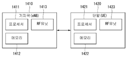
- the base station 1410 and the UE 1420 include a communication unit (transmitter and receiver, RF unit, 1413 and 1423), a processor 1411 and 1421, and a memory 1412 and 1422.
- the base station and the UE may further include an input unit and an output unit.
- the communication units 1413 and 1423, the processors 1411 and 1421, the input unit, the output unit, and the memory 1412 and 1422 are functionally connected to perform the method proposed herein.
- the communication unit transmitter / receiver unit or RF unit, 1413, 1423
- the communication unit receives information generated from the PHY protocol (Physical Layer Protocol)
- the received information is transferred to the RF-Radio-Frequency Spectrum, filtered, and amplified.
- the communication unit functions to move an RF signal (Radio Frequency Signal) received from the antenna to a band that can be processed by the PHY protocol and perform filtering.
- the communication unit may also include a switch function for switching the transmission and reception functions.
- Processors 1411 and 1421 implement the functions, processes, and / or methods proposed herein. Layers of the air interface protocol may be implemented by a processor.
- the processor may be represented by a controller, a controller, a control unit, a computer, or the like.
- the memories 1412 and 1422 are connected to a processor and store protocols or parameters for performing an uplink resource allocation method.
- Processors 1411 and 1421 may include application-specific integrated circuits (ASICs), other chipsets, logic circuits, and / or data processing devices.
- the memory may include read-only memory (ROM), random access memory (RAM), flash memory, memory card, storage medium and / or other storage device.
- the communication unit may include a baseband circuit for processing a wireless signal.
- the above-described technique may be implemented as a module (process, function, etc.) for performing the above-described function.
- the module may be stored in memory and executed by a processor.
- the memory may be internal or external to the processor and may be coupled to the processor by various well known means.
- the output unit (display unit or display unit) is controlled by a processor and outputs information output from the processor together with a key input signal generated at the key input unit and various information signals from the processor.
- Orientation-based device discovery method is not limited to the configuration and method of the embodiments described as described above, the embodiments are all or part of each of the embodiments is optional so that various modifications can be made It may be configured in combination.
- the direction-based device search method of the present specification may be implemented as processor-readable code in a processor-readable recording medium provided in a network device.
- the processor-readable recording medium includes all kinds of recording devices that store data that can be read by the processor. Examples of the processor-readable recording medium include ROM, RAM, CD-ROM, magnetic tape, floppy disk, optical data storage device, and the like, and may also be implemented in the form of a carrier wave such as transmission over the Internet. .
- the processor-readable recording medium can also be distributed over network coupled computer systems so that the processor-readable code is stored and executed in a distributed fashion.
- the RRC connection method has been described with reference to an example applied to the 3GPP LTE / LTE-A system.
- the RRC connection method may be applied to various wireless communication systems in addition to the 3GPP LTE / LTE-A system.
Landscapes
- Engineering & Computer Science (AREA)
- Computer Networks & Wireless Communication (AREA)
- Signal Processing (AREA)
- Mobile Radio Communication Systems (AREA)
Abstract
무선 통신 시스템에서 단말이 임의 접속을 수행하는 방법 및 장치에 관한 것이다. 본 발명에 의하면, 다수의 프리앰블 세트들에서 특정 프리앰블을 선택하고, 상기 선택된 특정 프리앰블을 하나 또는 서로 다른 다수의 인접 빔을 통해 반복해서 기지국으로 전송하며, 기지국으로부터 상기 프리앰블에 대한 응답으로 상기 단말의 임시 식별자 및 상기 특정 프리앰블의 전송 방식을 나타내는 반복 전송 타입을 포함하는 응답 메시지를 수신하되, 상기 선택된 특정 프리앰블은 서브 프레임을 구성하는 상기 하나 또는 서로 다른 다수의 빔에 따라 구별되는 자원들 상에서 반복 전송되고, 상기 다수의 프리앰블 세트들은 프리앰블의 반복 전송 횟수에 따라 설정되는 방법 및 장치를 제공할 수 있다.
Description
본 발명은 무선 통신시스템에서 단말이 임의 접속을 수행하기 위한 방법에 관한 것으로서, 보다 상세하게 단말이 임의접속을 위해서 설정된 프리앰블 세트에서 프리앰블을 선택하여 선택된 프리앰블을 반복해서 전송하기 위한 방법 및 이를 지원하는 장치에 관한 것이다.
이동 통신 시스템은 사용자의 활동성을 보장하면서 음성 서비스를 제공하기 위해 개발되었다. 그러나 이동통신 시스템은 음성뿐 아니라 데이터 서비스까지 영역을 확장하였으며, 현재에는 폭발적인 트래픽의 증가로 인하여 자원의 부족 현상이 야기되고 사용자들이 보다 고속의 서비스에 대한 요구하므로, 보다 발전된 이동 통신 시스템이 요구되고 있다.
차세대 이동 통신 시스템의 요구 조건은 크게 폭발적인 데이터 트래픽의 수용, 사용자 당 전송률의 획기적인 증가, 대폭 증가된 연결 디바이스 개수의 수용, 매우 낮은 단대단 지연(End-to-End Latency), 고 에너지 효율을 지원할 수 있어야 한다. 이를 위하여 이중 연결성(Dual Connectivity), 대규모 다중 입출력(Massive MIMO: Massive Multiple Input Multiple Output), 전이중(In-band Full Duplex), 비직교 다중접속(NOMA: Non-Orthogonal Multiple Access), 초 광대역(Super wideband) 지원, 단말 네트워킹(Device Networking) 등 다양한 기술들이 연구되고 있다.
본 발명은 임의 접속을 수행하기 위한 방법 및 장치를 제공함에 그 목적이 있다.
또한, 본 발명은 빔 형성 기법을 통해서 단말의 임의 접속을 위한 프리앰블을 전송하기 위한 방법 및 장치를 제공함에 그 목적이 있다.
또한, 본 발명은 단말의 프리앰블 반복 전송 횟수에 따라 프리앰블 셋을 설정하는 방법 및 장치를 제공함에 그 목적이 있다.
또한, 본 발명은 단말의 프리앰블 전송에 대한 응답으로 프리앰블이 반복 전송된 방식을 단말에게 알려주기 위한 방법 및 장치를 제공함에 그 목적이 있다.
또한, 본 발명은 프리앰블의 반복전송이 시작되는 빔의 인덱스에 따라 프리앰블의 전송을 위한 주파수 자원을 다르게 할당하는 방법 및 장치를 제공함에 그 목적이 있다.
또한, 본 발명은 프리앰블의 반복전송 타입에 따라 프리앰블의 전송을 위한 주파수 자원을 다르게 할당하는 방법 및 장치를 제공함에 그 목적이 있다.
또한, 본 발명은 프리앰블의 반복전송이 시작되는 빔의 인덱스 및 반복전송 타입에 따라 프리앰블의 전송을 위한 주파수 자원을 다르게 할당하는 방법 및 장치를 제공함에 그 목적이 있다.
본 명세서에서 이루고자 하는 기술적 과제들은 이상에서 언급한 기술적 과제들로 제한되지 않으며, 언급하지 않은 또 다른 기술적 과제들은 아래의 기재로부터 본 발명이 속하는 기술분야에서 통상의 지식을 가진 자에게 명확하게 이해될 수 있을 것이다.
본 발명에서는 상술한 문제점을 해결하기 위하여, 무선 통신 시스템에서 임의 접속을 수행하기 위한 방법 및 장치를 제공한다.
구체적으로, 본 발명의 일 실시 예에 따른 단말의 임의 접속 방법은, 다수의 프리앰블 세트들에서 특정 프리앰블을 선택하는 단계; 상기 선택된 특정 프리앰블을 하나 또는 서로 다른 다수의 인접 빔을 통해 반복해서 기지국으로 전송하는 단계; 및 기지국으로부터 상기 프리앰블에 대한 응답으로 상기 단말의 임시 식별자 및 상기 특정 프리앰블의 전송 방식을 나타내는 반복 전송 타입을 포함하는 응답 메시지를 수신하는 단계를 포함하되, 상기 선택된 특정 프리앰블은 서브 프레임을 구성하는 상기 하나 또는 서로 다른 다수의 빔에 따라 구별되는 자원들 상에서 반복 전송되고, 상기 다수의 프리앰블 세트들은 프리앰블의 반복 전송 횟수에 따라 설정되는 방법을 제공한다.
또한, 본 발명에서, 상기 반복 전송 타입은 상기 특정 프리앰블이 하나의 빔 또는 서로 다른 다수의 인접 빔을 통해 반복전송 되었는지 여부를 나타낸다.
또한, 본 발명에서, 상기 특정 프리앰블은 서로 다른 주파수 자원을 통해서 전송되고, 상기 서로 다른 주파수 자원은 반복 전송이 시작되는 시작 빔에 따른 주파수 자원 간의 간격, 상기 반복 전송 타입에 따른 주파수 자원 간의 간격, 프리앰블 길이, 상기 반복 전송 타입, 상기 시작 빔에 또는 상기 시작 빔의 인덱스 중 적어도 하나에 의해서 할당된다.
또한, 본 발명은, 상기 기지국으로부터 하향링크 동기화를 위한 동기 신호를 수신하는 단계;
상기 동기 신호에 기초하여 상기 단말이 이용 가능한 빔의 조합들을 획득하는 단계; 상기 이용 가능한 빔의 조합들 중에서 특정 빔의 조합을 선택하는 단계; 및 상기 선택된 빔의 조합을 이용하여 기지국의 하향링크 동기를 획득하는 단계를 더 포함한다.
또한, 본 발명은, 상기 기지국으로부터 상기 임의 접속을 위한 자원 정보를 수신하는 단계를 더 포함하되, 상기 자원 정보는 상기 기지국이 신호를 수신하기 위한 빔과 매핑되는 OFDM 심볼 정보 및 서브 프레임 정보, 주파수 자원 정보, 상기 다수의 프리앰블 세트들을 나타내는 프리앰블 정보, 프리앰블 전송을 위한 빔의 조합 방식을 나타내는 방식 정보 중 적어도 하나를 포함한다.
또한, 본 발명은, 상기 이용 가능한 빔의 조합들 중 상기 선택된 프리앰블을 전송하기 위한 상기 하나 또는 서로 다른 다수의 빔을 선택하는 단계를 더 포함한다.
또한, 본 발명은, 외부와 무선 신호를 송신 및 수신하는 통신부; 및 상기 통신부와 기능적으로 결합되어 있는 프로세서를 포함하되, 상기 프로세서는, 다수의 프리앰블 세트들에서 특정 프리앰블을 선택하고, 상기 선택된 특정 프리앰블을 하나 또는 서로 다른 다수의 인접 빔을 통해 반복해서 기지국으로 전송하며, 기지국으로부터 상기 프리앰블에 대한 응답으로 상기 단말의 임시 식별자 및 상기 특정 프리앰블의 전송 방식을 나타내는 반복 전송 타입을 포함하는 응답 메시지를 수신하되, 상기 선택된 특정 프리앰블은 서브 프레임을 구성하는 상기 하나 또는 서로 다른 다수의 빔에 따라 구별되는 자원들 상에서 반복 전송되고, 상기 다수의 프리앰블 세트들은 프리앰블의 반복 전송 횟수에 따라 설정되는 단말을 제공한다.
본 발명은 고주파 대역에서 빔 형성 기법을 통해서 프리앰블 전송함으로써, 고주파 대역에서 발생할 수 있는 경로 감쇄를 보완할 수 있는 효과가 있다.
또한, 본 발명은 임의 접속을 위한 프리앰블을 하나 또는 다수의 서브 프레임에서 반복 전송함으로써, 위치에 따라 단말이 빔 형성 기법을 통해 프리앰블을 전송할 수 없는 경우를 방지할 수 있는 효과가 있다.
또한, 본 발명은 프리앰블의 반복 전송 횟수에 따라서만 프리앰블 셋을 설정하여 각각의 프리앰블 셋에 다수의 가용한 프리앰들이 존재함으로써, 동일한 프리앰블의 전송으로 인한 충돌을 방지할 수 있는 효과가 있다.
또한, 본 발명은 프리앰블의 반복전송을 위한 시작 빔의 인덱스 및 반복 전송 타입에 따라 서로 다른 주파수 자원을 통해 프리앰블을 반복 전송 함으로써, 기지국이 전송되는 프리앰블을 정확하게 검출할 수 있는 효과가 있다.
본 명세서에서 얻을 수 있는 효과는 이상에서 언급한 효과들로 제한되지 않으며, 언급하지 않은 또 다른 효과들은 아래의 기재로부터 본 발명이 속하는 기술분야에서 통상의 지식을 가진 자에게 명확하게 이해될 수 있을 것이다.
도 1은 본 발명이 적용될 수 있는 LTE 시스템에 관련된 EPS(Evolved Packet System)의 일 예를 나타낸 도이다.
도 2는 본 발명이 적용될 수 있는 무선 통신 시스템에서 단말의 상향링크 자원 할당 과정을 예시하는 도면이다.
도 3은 LTE 시스템에서 랜덤 접속 과정(Random Access Procedure)의 일 예를 나타낸다.
도 4는 본 발명이 적용될 수 있는 아날로그 빔포밍(Beamforming)과 서브 프레임 구조의 일 예를 나타낸 도이다.
도 5는 본 발명이 적용되는 자원 구조의 일 예를 나타낸 도이다.
도 6은 본 발명이 적용되는 인접한 빔들 또는 동일한 빔을 이용하여 임의 접속을 위한 프리앰블을 반복 전송하는 방법의 일 예를 나타낸 도이다.
도 7 및 도 8은 본 발명이 적용되는 프리앰블을 반복 전송을 위한 빔의 시작 인덱스에 따라 주파수 자원을 할당하는 방법의 일 예를 나타낸 도이다.
도 9 및 도 10은 본 발명이 적용되는 프리앰블의 반복 전송 타입에 따라 주파수 자원을 할당하는 방법의 일 예를 나타낸 도이다.
도 11 및 도 12는 본 발명이 적용되는 프리앰블을 반복 전송을 위한 빔의 시작 인덱스 및 프리앰블의 반복 전송 타입에 따라 주파수 자원을 할당하는 방법의 일 예를 나타낸 도이다.
도 13은 본 발명이 적용되는 단말이 임의 접속을 위한 프리앰블을 반복 전송하는 방법의 일 예를 나타내는 순서도이다.
도 14는 본 발명이 적용될 수 있는 무선 장치의 내부 블록도의 일 예를 나타낸 도이다.
이하, 본 발명에 따른 바람직한 실시 형태를 첨부된 도면을 참조하여 상세하게 설명한다. 첨부된 도면과 함께 이하에 개시될 상세한 설명은 본 발명의 예시적인 실시형태를 설명하고자 하는 것이며, 본 발명이 실시될 수 있는 유일한 실시형태를 나타내고자 하는 것이 아니다. 이하의 상세한 설명은 본 발명의 완전한 이해를 제공하기 위해서 구체적 세부사항을 포함한다. 그러나, 당업자는 본 발명이 이러한 구체적 세부사항 없이도 실시될 수 있음을 안다.
몇몇 경우, 본 발명의 개념이 모호해지는 것을 피하기 위하여 공지의 구조 및 장치는 생략되거나, 각 구조 및 장치의 핵심기능을 중심으로 한 블록도 형식으로 도시될 수 있다.
본 명세서에서 기지국은 단말과 직접적으로 통신을 수행하는 네트워크의 종단 노드(terminal node)로서의 의미를 갖는다. 본 문서에서 기지국에 의해 수행되는 것으로 설명된 특정 동작은 경우에 따라서는 기지국의 상위 노드(upper node)에 의해 수행될 수도 있다. 즉, 기지국을 포함하는 다수의 네트워크 노드들(network nodes)로 이루어지는 네트워크에서 단말과의 통신을 위해 수행되는 다양한 동작들은 기지국 또는 기지국 이외의 다른 네트워크 노드들에 의해 수행될 수 있음은 자명하다. '기지국(BS: Base Station)'은 고정국(fixed station), Node B, eNB(evolved-NodeB), BTS(base transceiver system), 액세스 포인트(AP: Access Point), 네트워크 노드(network node) 등의 용어에 의해 대체될 수 있다. 또한, '단말(Terminal)'은 고정되거나 이동성을 가질 수 있으며, UE(User Equipment), MS(Mobile Station), UT(user terminal), MSS(Mobile Subscriber Station), SS(Subscriber Station), AMS(Advanced Mobile Station), WT(Wireless terminal), MTC(Machine-Type Communication) 장치, M2M(Machine-to-Machine) 장치, D2D(Device-to-Device) 장치 등의 용어로 대체될 수 있다.
이하에서, 하향링크(DL: downlink)는 기지국에서 단말로의 통신을 의미하며, 상향링크(UL: uplink)는 단말에서 기지국으로의 통신을 의미한다. 하향링크에서 송신기는 기지국의 일부이고, 수신기는 단말의 일부일 수 있다.
상향링크에서 송신기는 단말의 일부이고, 수신기는 기지국의 일부일 수 있다.
이하의 설명에서 사용되는 특정 용어들은 본 발명의 이해를 돕기 위해서 제공된 것이며, 이러한 특정 용어의 사용은 본 발명의 기술적 사상을 벗어나지 않는 범위에서 다른 형태로 변경될 수 있다.
이하의 기술은 CDMA(code division multiple access), FDMA(frequency division multiple access), TDMA(time division multiple access), OFDMA(orthogonal frequency division multiple access), SC-FDMA(single carrier frequency division multiple access), NOMA(non-orthogonal multiple access) 등과 같은 다양한 무선 접속 시스템에 이용될 수 있다. CDMA는 UTRA(universal terrestrial radio access)나 CDMA2000과 같은 무선 기술(radio technology)로 구현될 수 있다. TDMA는 GSM(global system for mobile communications)/GPRS(general packet radio service)/EDGE(enhanced data rates for GSM evolution)와 같은 무선 기술로 구현될 수 있다. OFDMA는 IEEE 802.11 (Wi-Fi), IEEE 802.16 (WiMAX), IEEE 802-20, E-UTRA(evolved UTRA) 등과 같은 무선 기술로 구현될 수 있다. UTRA는 UMTS(universal mobile telecommunications system)의 일부이다. 3GPP(3rd generation partnership project) LTE(long term evolution)은 E-UTRA를 사용하는 E-UMTS(evolved UMTS)의 일부로써, 하향링크에서 OFDMA를 채용하고 상향링크에서 SC-FDMA를 채용한다. LTE-A(advanced)는 3GPP LTE의 진화이다.
본 발명의 실시 예들은 무선 접속 시스템들인 IEEE 802, 3GPP 및 3GPP2 중 적어도 하나에 개시된 표준 문서들에 의해 뒷받침될 수 있다. 즉, 본 발명의 실시 예들 중 본 발명의 기술적 사상을 명확히 드러내기 위해 설명하지 않은 단계들 또는 부분들은 상기 문서들에 의해 뒷받침될 수 있다. 또한, 본 문서에서 개시하고 있는 모든 용어들은 상기 표준 문서에 의해 설명될 수 있다.
설명을 명확하게 하기 위해, 3GPP LTE/LTE-A를 위주로 기술하지만 본 발명의 기술적 특징이 이에 제한되는 것은 아니며, 5G 시스템에서도 적용될 수 있음은 물론이다.
이하 도면을 참조하여 설명하기 앞서, 본 발명의 이해를 돕고자, 본 명세서에서 사용되는 용어를 간략하게 정의하기로 한다.
EPS: Evolved Packet System의 약자로서, LTE(Long Term Evolution) 네트워크를 지원하는 코어 네트워크를 의미한다. UMTS가 진화된 형태의 네트워크
PDN (Public Data Network): 서비스를 제공하는 서버가 위치한 독립적인 망
APN (Access Point Name): 네트워크에서 관리하는 접속 포인트의 이름으로서 UE에게 제공된다. 즉, PDN의 이름(문자열)을 가리킴. 상기 접속 포인트의 이름에 기초하여, 데이터의 송수신을 위한 해당 PDN이 결정된다.
TEID(Tunnel Endpoint Identifier): 네트워크 내 노드들 간에 설정된 터널의 End point ID, 각 UE의 bearer 단위로 구간별로 설정된다.
MME: Mobility Management Entity의 약자로서, UE에 대한 세션과 이동성을 제공하기 위해 EPS 내에서 각 엔티티를 제어하는 역할을 한다.
세션(Session): 세션은 데이터 전송을 위한 통로로써 그 단위는 PDN, Bearer, IP flow 단위 등이 될 수 있다.
각 단위의 차이는 3GPP에서 정의한 것처럼 대상 네트워크 전체 단위(APN 또는 PDN 단위), 그 내에서 QoS로 구분하는 단위(Bearer 단위), 목적지 IP 주소 단위로 구분할 수 있다.
EPS Bearer: 다양한 종류의 트래픽이 송수신되는 단말과 게이트웨이 사이에 생성되는 논리적 경로.
Default EPS Bear: 단말이 망에 접속하면 기본적으로 생성되는 데이터 송수신을 위한 논리적 경로로써, 단말이 망에서 빠져나오기(Detach)전까지 유지될 수 있다.
Dedicated EPS Bearer: Default EPS Bearer 생성된 후 추가적으로 서비스를 제공하기 위해 필요한 경우 생성되는 논리적 경로.
IP flow: 단말과 게이트웨이간에 논리적 경로를 통해서 송수신되는 다양한 종류의 트래픽.
Service Data Flow(SDF): 서비스 타입에 따라 분류되는 사용자 트래픽의 IP flow 또는 다수의 IP flow의 결합.
PDN 연결(connection): 단말에서 PDN으로의 연결, 즉, ip 주소로 표현되는 단말과 APN으로 표현되는 PDN과의 연관(연결)을 나타낸다. 이는 세션이 형성될 수 있도록 코어 네트워크 내의 엔터티간 연결(단말-PDN GW)을 의미한다.
UE Context: 네크워크에서 UE를 관리하기 위해 사용되는 UE의 상황 정보, 즉, UE id, 이동성(현재 위치 등), 세션의 속성(QoS, 우선순위 등)으로 구성된 상황 정보
TIN: Temporary Identity used in Next update
P-TMSI: Packet Temporary Mobile Subscriber
TAU: Tracking Area Update
GBR: Guaranteed Bit Rate
GTP: GPRS Tunneling Protocol
TEID: Tunnel Endpoint ID
GUTI: Globally Unique Temporary Identity, MME에 알려진 UE 식별자.
도 1은 본 발명이 적용될 수 있는 LTE 시스템에 관련된 EPS(Evolved Packet System)의 일 예를 나타낸 도이다.
LTE 시스템은 사용자 단말(UE)과 PDN(pack data network) 간에, 사용자가 이동 중 최종 사용자의 응용프로그램 사용에 방해를 주지 않으면서, 끊김 없는 IP 연결성(Internet Protocol connectivity)을 제공하는 것을 목표로 한다. LTE 시스템은, 사용자 단말과 기지국 간의 무선 프로토콜 구조(radio protocol architecture)를 정의하는 E-UTRAN(Evolved Universal Terrestrial Radio Access Network)를 통한 무선 접속의 진화를 완수하며, 이는 EPC(Evolved Packet Core) 네트워크를 포함하는 SAE(System Architecture Evolution)에 의해 비-무선적 측면에서의 진화를 통해서도 달성된다. LTE와 SAE는 EPS(Evolved Packet System)를 포함한다.
EPS는 PDN 내에서 게이트웨이(gateway)로부터 사용자 단말로 IP 트래픽을 라우팅하기 위해 EPS 베어러(EPS bearers)라는 개념을 사용한다. 베어러(bearer)는 상기 게이트웨이와 사용자 단말 간에 특정한 QoS(Quality of Service)를 갖는 IP 패킷 플로우(IP packet flow)이다. E-UTRAN과 EPC는 응용 프로그램에 의해 요구되는 베어러를 함께 설정하거나 해제(release)한다.
EPC는 CN(core network)이라고도 불리며, UE를 제어하고, 베어러의 설정을 관리한다.
도 1에 도시된 바와 같이, 상기 SAE의 EPC의 노드(논리적 혹은 물리적 노드)는 MME(Mobility Management Entity) (30), PDN-GW 또는 P-GW(PDN gateway) (50), S-GW(Serving Gateway) (40), PCRF(Policy and Charging Rules Function) (60), HSS (Home subscriber Server) (70) 등을 포함한다.
MME(30)는 UE(10)와 CN 간의 시그널링을 처리하는 제어 노드이다. UE(10)와 CN 간에 교환되는 프로토콜은 NAS(Non-Access Stratum) 프로토콜로 알려져 있다. MME(30)에 의해 지원되는 기능들의 일례는, 베어러의 설정, 관리, 해제를 포함하여 NAS 프로토콜 내의 세션 관리 계층(session management layer)에 의해 조작되는 베어러 관리(bearer management)에 관련된 기능, 네트워크와 UE(10) 간의 연결(connection) 및 보안(Security)의 설립에 포함하여 NAS 프로토콜 계층에서 연결계층 또는 이동제어계층(mobility management layer)에 의해 조작된다.
본 발명에서, 상기 MME(30)는 단말에 대한 인증 및 context 정보를 처리하는데 필요한 기능이 구현된 개체이며, 하나의 실시 예로써 설명된 것이다. 따라서, 상기 MME (30)뿐만 아니라 다른 장치도 해당 기능을 수행할 수 있다.
S-GW(40)는 UE(10)가 기지국(eNodeB, 20) 간에 이동할 때 데이터 베어러를 위한 로컬 이동성 앵커(local mobility anchor)의 역할을 한다. 모든 사용자 IP 패킷은 S-GW(40)을 통해 송신된다. 또한 S-GW(40)는 UE(10)가 ECM-IDLE 상태로 알려진 유휴 상태(idle state)에 있고, MME(30)가 베어러를 재설정(re-establish)하기 위해 UE(10)의 페이징을 개시하는 동안 하향링크 데이터를 임시로 버퍼링할 때 베어러에 관련된 정보를 유지한다. 또한, GRPS(General Packet Radio Service), UMTS(Universal Mobile Telecommunications System)와 같은 다른 3GPP 기술과의 인터워킹(inter-working)을 위한 이동성 앵커(mobility anchor)의 역할을 수행한다.
본 발명에서, 상기 S-GW(40)는 사용자 데이터의 라우팅/포워딩을 처리하는데 필요한 기능이 구현된 개체이며, 실시 예로써 설명된 것이다. 따라서, 상기 S-GW(40)뿐만 아니라 다른 장치도 해당 기능을 수행할 수 있다.
P-GW(50)은 UE를 위한 IP 주소 할당을 수행하고, QoS 집행(Qos enforcement) 및 PCRF(60)로부터의 규칙에 따라 플로우-기반의 과금(flow-based charging)을 수행한다. P-GW(50)는 GBR 베어러(Guaranteed Bit Rate (GBR) bearers)를 위한 QoS 집행을 수행한다. 또한, CDMA2000이나 WiMAX 네트워크와 같은 비3GPP(non-3GPP) 기술과의 인터워킹을 위한 이동성 엥커(mobility anchor) 역할도 수행한다.
본 발명에서, 상기 P-GW(50)는 사용자 데이터의 라우팅/포워딩을 처리하는데 필요한 기능이 구현된 개체이며, 실시 예로써 설명된 것이다. 따라서, 상기 P-GW(50)뿐만 아니라 다른 장치도 해당 기능을 수행할 수 있다.
PCRF(60)는 정책 제어 의사결정(policy control decision-making)을 수행하고, 플로우-기반의 과금(flow-based charging)을 수행한다.
?HSS(70)는 HLR(Home Location Register)이라고도 불리며, EPS-subscribed QoS 프로파일(profile) 및 로밍을 위한 접속제어에 정보 등을 포함하는 SAE 가입 데이터(SAE subscription data)를 포함한다. 또한, 사용자가 접속하는 PDN에 대한 정보 역시 포함한다. 이러한 정보는 APN(Access Point Name) 형태로 유지될 수 있는데, APN는 DNS(Domain Name system) 기반의 레이블(label)로, PDN에 대한 엑세스 포인트 또는 가입된 IP 주소를 나타내는 PDN 주소를 설명하는 식별기법이다.
도 1에 도시된 바와 같이, EPS 네트워크 요소(EPS network elements)들 간에는 S1-U, S1-MME, S5/S8, S11, S6a, Gx, Rx 및 SG와 같은 다양한 인터페이스가 정의될 수 있다.
이하, 이동성 관리(mobility management; MM)의 개념과 이동선 관리(MM) 백오프 타이머(back-off timer)를 상세하게 설명한다. 이동성 관리(MM)는 E-UTRAN 상의 오버헤드와 UE에서의 프로세싱을 감소시키기 위한 절차이다.
이동성 관리(MM)가 적용되는 경우, 엑세스 네트워크에서 UE에 관련된 모든 정보는 데이터가 비활성화되는 기간 동안 해제될 수 있다. MME는 상기 Idle 구간 동안 UE 콘텍스트(context) 및 설정된 베어러에 관련된 정보를 유지할 수 있다.
네트워크가 ECM-IDLE 상태에 있는 UE에 접촉할 수 있도록, UE는 현재의 TA(Tracking Area)를 벗어날 때마다 네트워크에 새로운 위치에 관하여 알릴 수 있다. 이러한 절차는 “Tracking Area Update”라 불릴 수 있으며, 이 절차는 UTRAN(universal terrestrial radio access network)이나 GERAN(GSM EDGE Radio Access Network) 시스템에서 “Routing Area Update”라 불릴 수 있다. MME는 UE가 ECM-IDLE 상태에 있는 동안 사용자 위치를 추적하는 기능을 수행한다.
ECM-IDLE 상태에 있는 UE에게 전달해야 할 다운링크 데이터가 있는 경우, MME는 UE가 등록된 TA(tracking area) 상의 모든 기지국(eNodeB)에 페이징 메시지를 송신한다.
그 다음, 기지국은 무선 인터페이스(radio interface) 상으로 UE에 대해 페이징을 시작한다. 페이징 메시지가 수신됨에 따라, UE의 상태가 ECM-CONNECTED 상태로 천이하게 하는 절차를 수행한다. 이러한 절차는 “Service Request Procedure”라 부릴 수 있다. 이에 따라 UE에 관련된 정보는 E-UTRAN에서 생성되고, 모든 베어러는 재설정(re-establish)된다. MME는 라디오 베어러(radio bearer)의 재설정과, 기지국 상에서 UE 콘텍스트를 갱신하는 역할을 수행한다.
상술한 이동성 관리(MM) 절차가 수행되는 경우, MM(mobility management) 백오프 타이머가 추가로 사용될 수 있다. 구체적으로 UE는 TA를 갱신하기 위해 TAU(Tracking Area Update)를 송신할 수 있고, MME는 핵심 망의 혼잡(core network congestion)으로 인해 TAU 요청을 거절할 수 있는데, 이 경우 MM 백오프 타이머에 관련된 시간 값을 제공할 수 있다. 해당 시간 값을 수신함에 따라, UE는 MM 백오프 타이머를 활성화시킬 수 있다.
상향링크 자원 할당 절차
3GPP LTE/LTE-A 시스템의 경우, 자원의 활용을 최대화하기 위해 기지국의 스케줄링 기반의 데이터 송수신 방법을 사용한다. 이는 단말이 전송할 데이터가 있는 경우 우선적으로 기지국에게 상향링크 자원 할당을 요청하고, 기지국으로부터 할당된 상향링크 자원만을 이용하여 데이터를 전송할 수 있음을 의미한다.
도 2는 본 발명이 적용될 수 있는 무선 통신 시스템에서 단말의 상향링크 자원 할당 과정을 예시하는 도면이다.
상향링크의 무선 자원의 효율적인 사용을 위하여, 기지국은 각 단말 별로 어떤 종류의 데이터를 얼마만큼 상향링크로 전송할지를 알아야 한다. 따라서, 단말이 직접 자신이 전송하고자 하는 상향링크 데이터에 관한 정보를 기지국으로 전달하고, 기지국은 이에 기반하여 해당 단말에 상향링크 자원을 할당할 수 있다. 이 경우, 단말이 기지국으로 전달하는 상향링크 데이터에 관한 정보는 자신의 버퍼에 저장되어 있는 상향링크 데이터의 양으로서, 이를 버퍼 상태 보고(BSR: Buffer Status Report)라고 지칭한다. BSR은 단말이 현재 TTI에서 PUSCH 상의 자원이 할당되고 보고 이벤트(reporting event)가 트리거링된 경우, MAC 제어 요소(MAC control element)를 사용하여 전송된다.
상기 도 2의 (a)는 단말이 버퍼 상태 보고(BSR: buffer status reporting)를 위한 상향링크 무선 자원이 단말에 할당되지 않은 경우에 실제 데이터(actual data)를 위한 상향링크 자원 할당 과정을 예시한다. 즉, DRX 모드에서 액티브 모드의 상태를 전환하는 단말의 경우, 미리 할당 받은 데이터 자원이 없기 때문에, PUCCH를 통한 SR 전송을 시작으로 상향 데이터에 대한 자원을 요청해야 하며, 이 경우 5 단계의 상향링크 자원 할당 절차가 사용된다.
도 2의 (a)를 참조하면, 단말은 BSR를 전송하기 위한 PUSCH 자원이 할당되지 않은 경우로, 단말은 PUSCH 자원을 할당 받기 위하여 먼저 스케줄링 요청(SR: scheduling request)을 기지국에 전송한다(S2010).
스케줄링 요청은 보고 이벤트(reporting event)가 발생되었으나 단말이 현재 TTI에서 PUSCH 상에 무선 자원이 스케줄링되지 않은 경우, 단말이 상향링크 전송을 위한 PUSCH 자원을 할당 받기 위하여 기지국에 요청하기 위해 이용된다.
즉, 단말은 정규적 버퍼 상태 보고(regular BSR)가 트리거(trigger)되었으나 BSR을 기지국에 전송하기 위한 상향링크 무선 자원을 가지지 않을 때 PUCCH 상에 SR을 전송한다. 단말은 SR을 위한 PUCCH 자원이 설정되었는지 여부에 따라 단말은 PUCCH를 통해 SR을 전송하거나 또는 랜덤 액세스 절차를 개시한다. 구체적으로, SR이 전송될 수 있는 PUCCH 자원은 단말 특정적으로 상위 계층(예를 들어, RRC 계층)에 의하여 설정되며, SR 설정은(SR configuration)은 SR 전송주기(SR periodicity) 및 SR 서브프레임 오프셋 정보를 포함한다.
단말은 기지국으로부터 BSR 전송을 위한 PUSCH 자원에 대한 UL grant를 수신하면(S2020), UL grant에 의해 할당된 PUSCH 자원을 통해 트리거링된 BSR을 기지국으로 전송한다(S2030).
기지국은 BSR을 통해 실제 단말이 상향링크로 전송할 데이터의 양을 확인하고 실제 데이터 전송을 위한 PUSCH 자원에 대한 UL grant를 단말에 전송한다(S2040). 실제 데이터 전송을 위한 UL grant를 수신한 단말은 할당된 PUSCH 자원을 통해 실제 상향링크 데이터를 기지국으로 전송한다(S2050).
도 2의 (b)는 단말이 BSR를 위한 상향링크 무선 자원이 단말에 할당되어 있는 경우에 실제 데이터를 위한 상향링크 자원 할당 과정을 예시한다.
상기 도 2의 (b)를 참조하면, 단말이 BSR 전송을 위한 PUSCH 자원이 이미 할당된 경우로, 단말은 할당된 PUSCH 자원을 통해 BSR을 전송하며, 이와 함께 스케줄링 요청을 기지국에 전송한다(S2110). 이어, 기지국은 BSR을 통해 실제 단말이 상향링크로 전송할 데이터의 양을 확인하고 실제 데이터 전송을 위한 PUSCH 자원에 대한 UL grant를 단말에 전송한다(S2120). 실제 데이터 전송을 위한 UL grant를 수신한 단말은 할당된 PUSCH 자원을 통해 실제 상향링크 데이터를 기지국으로 전송한다(S2130).
랜덤 접속 과정(
RACH
프로시저
)
도 3은 LTE 시스템에서 랜덤 접속 과정(Random Access Procedure)의 일 예를 나타낸다.
랜덤 접속 과정은 RRC_IDLE에서의 초기 접속, 무선 링크 실패 후의 초기 접속, 랜덤 접속 과정을 요구하는 핸드오버, 단말이 RRC_CONNECTED 상태에 있으나 상향링크 동기화되지 않은 경우, 랜덤 접속 과정이 요구되는 상향링크 또는 하향링크 데이터 발생 시, 상향링크 측정을 기반으로 한 위치측정 방식을 사용하는 경우 위치 측정을 위해, PUCCH상으로 지정된 스케줄링 요청 자원이 없는 경우 스케줄링 요청을 위해 수행된다. RRC 연결 요청 메시지(RRC Connection Request Message)와 셀 갱신 메시지(Cell Update Message), URA(UTRAN Registration Area) 갱신 메시지(URA Update Message) 등의 일부 RRC 메시지도 랜덤 접속 과정을 이용하여 전송된다. 논리채널 CCCH(Common Control Channel), DCCH(Dedicated Control Channel), DTCH(Dedicated Traffic Channel)가 전송채널 RACH에 매핑될 수 있다. 전송채널 RACH는 물리채널 PRACH(Physical Random Access Channel)에 매핑된다.
단말의 MAC 계층이 단말 물리계층에 PRACH 전송을 지시하면, 단말 물리계층은 먼저 하나의 접속 슬롯(access slot)과 하나의 시그너처(signature)를 선택하여 PRACH 프리앰블을 상향으로 전송한다. 랜덤 접속 과정은 경쟁 기반(Contention based)의 랜덤 접속 과정과 비경쟁 기반(Non-contention based)의 랜덤 접속 과정으로 구분된다.
상기 도 3의 (a)는 경쟁 기반(Contention based)의 랜덤 접속 과정의 일 예를 나타내며, 상기 도 3의 (b)는 비경쟁 기반(Non-contention based)의 랜덤 접속 과정의 일 예를 나타낸다.
먼저, 경쟁 기반의 랜덤 접속 과정에 대해서 상기 도 7의 (a)를 참조하여 살펴보기로 한다.
단말은 시스템 정보를 통해 기지국으로부터 랜덤 접속에 관한 정보를 수신하여 저장한다. 이후, 랜덤 접속이 필요한 경우, 단말은 랜덤 접속 프리앰블(Random Access Preamble; 메시지 1이라고도 함)을 기지국으로 전송한다(S3010).
기지국이 상기 단말로부터 랜덤 접속 프리앰블을 수신하면, 상기 기지국은 랜덤 접속 응답 메시지(Random Access Response; 메시지 2라고도 함)를 단말에게 전송한다(S3020). 구체적으로, 상기 랜덤 접속 응답 메시지에 대한 하향 스케쥴링 정보는 RA-RNTI(Random Access-Radio Network Temporary Identifier)로 CRC 마스킹되어 L1 또는 L2 제어채널(PDCCH) 상에서 전송될 수 있다. RA-RNTI로 마스킹된 하향 스케쥴링 신호를 수신한 단말은 PDSCH(Physical Downlink Shared Channel)로부터 랜덤 접속 응답 메시지를 수신하여 디코딩할 수 있다. 이후, 단말은 상기 랜덤 접속 응답 메시지에 자신에게 지시된 랜덤 접속 응답 정보가 있는지 확인한다.
자신에게 지시된 랜덤 접속 응답 정보가 존재하는지 여부는 단말이 전송한 프리앰블에 대한 RAID(Random Access Preamble ID)가 존재하는지 여부로 확인될 수 있다.
상기 랜덤 접속 응답 정보는 동기화를 위한 타이밍 옵셋 정보를 나타내는 TA(Timing Alignment), 상향링크에 사용되는 무선자원 할당 정보, 단말 식별을 위한 임시 식별자(예: Temporary C-RNTI) 등을 포함한다.
단말은 랜덤 접속 응답 정보를 수신하는 경우, 상기 응답 정보에 포함된 무선자원 할당 정보에 따라 상향링크 SCH(Uplink Shared Channel)로 상향링크 전송(메시지 3이라고도 표현함)을 수행한다(S3030). 여기서, 상향링크 전송은 스케쥴된 전송(Scheduled Transmission)으로 표현될 수도 있다.
기지국은 단말로부터 상기 상향링크 전송을 수신한 후에, 경쟁 해결(contention resolution)을 위한 메시지(메시지 4라고도 표현함)를 하향링크 공유 채널(Downlink Shared Channel:DL-SCH)을 통해 단말에게 전송한다(S3040).
다음으로, 비경쟁 기반의 랜덤 접속 과정에 대해 상기 도 3의 (b)를 참조하여 살펴보기로 한다.
단말이 랜덤 접속 프리앰블을 전송하기 전에 기지국이 비경쟁 랜덤 접속 프리앰블(Non-contention Random Access Preamble)을 단말에게 할당한다(S3110).
비경쟁 랜덤 접속 프리앰블은 핸드오버 명령이나 PDCCH와 같은 전용 시그널링(Dedicated Signalling)을 통해 할당될 수 있다. 단말은 비경쟁 랜덤 접속 프리앰블을 할당 받은 경우, 기지국으로 할당된 비경쟁 랜덤 접속 프리앰블을 전송한다(S3120).
이후, 상기 기지국은 경쟁 기반 랜덤 접속 과정에서의 S7020단계와 유사하게 랜덤 접속 응답(Random Access Response; 메시지 2라고도 표현함)을 단말에게 전송할 수 있다(S3130).
상기 설명된 랜덤 접속 과정에서 랜덤 접속 응답에 대해서는 HARQ가 적용되지 않지만, 랜덤 접속 응답에 대한 상향링크 전송이나 경쟁 해결을 위한 메시지에 대해서는 HARQ가 적용될 수 있다. 따라서, 랜덤 접속 응답에 대해서 단말은 ACK 또는 NACK을 전송할 필요가 없다.
이와 같은 임의 접속 절차에서 프리앰블을 전송하는 단계는 임의 접속을 위해서 설계된 별도의 물리계층 프로세싱을 사용하고, 나머지 단계는 일반적인 하향링크 및 상향링크 데이터 전송에 사용되는 것과 동일한 물리계층 프로세싱을 사용한다.
도 4는 본 발명이 적용될 수 있는 아날로그 빔 포밍(Beamforming)과 서브 프레임 구조의 일 예를 나타낸 도이다.
도 4를 참조하면 임의 접속을 위한 서브 프레임은 아날로그 빔에 의해서 시간 영역에서 구별될 수 있다.
구체적으로, 셀룰러 통신 시스템의 대역인 6GHz 이하의 대역과 비교하였을 때, 6GHz 이상의 고주파 대역은 매우 높은 경로 감쇄를 갖기 때문에 이를 보완하기 위해서 빔 형성 기술이 필요하다.
고주파 대역의 경우, 안테나 간격을 작게 해주어서 작은 넓이에 많은 수의 안테나를 포함시킬 수 있다. 하지만, 모든 안테나 신호를 Baseband 프로세스로 처리하는 디지털 빔 형성 기법은 하드웨어 복잡도가 매우 높다.
따라서, 하드웨어 복잡도를 낮추면서 디지털 빔 형성 기법의 장점을 취하기 위해서 아날로그 빔 형성 기법과 디지털 빔 형성 기법을 복합적으로 이용하는 하이브리드(Hybrid) 빔 형성 기법이 고려되고 있다.
이와 같은 하이브리드 빔 형성 기법은 아날로그 빔 형성 기법을 이용하기 때문에 동일 시간에 사용 가능한 자원을 제약 받을 수 있다는 문제점이 있다.
또한, 도 4에 도시된 바와 같이 빔 형성 기법을 사용하는 경우, 빔의 폭이 좁기 때문에 단말이 이동을 하거나, 빔의 영역을 벗어나는 경우, 프리앰블을 전송할 수 없다는 문제점이 존재한다.
즉, 단말이 빔 #0의 영역에 존재하다 빔 #1의 영역으로 이동하는 경우, 단말은 빔 #0을 통해서 프리앰블을 송수신할 수 없다.
따라서, 본 발명은 이와 같은 문제점을 해결하기 위해서, 임의 접속을 위한 프리앰블을 여러 번 반복하여 전송하는 방법을 제안한다.
도 5는 본 발명이 적용되는 자원 구조의 일 예를 나타낸 도이다.
도 5를 참조하면, 도 4에서 설명한 빔 포밍 기법을 이용하여 임의 접속 절차를 위한 PRACH(Physical Random Access Channel) 프리앰블을 전송하기 위해서 서브 프레임은 다수의 RACH 자원으로 구성될 수 있다.
구체적으로, 도 5에 도시된 바와 같이 아날로그 빔 포밍 기술을 이용하는 고주파 대역의 셀룰러 통신 시스템에서 서브 프레임은 서로 다른 영역(coverage)를 갖는 셀마다 적합한 PRACH 프리앰블을 사용하기 위해서 다수의 RACH 자원 구조를 가질 수 있다.
도 5의 (a)는 PRACH 프리앰블을 전송하기 위해서 5개의 RACH 자원으로 구성된 서브 프레임의 일 예를 도시하고 있다. 도 5의 (a)에 도시된 바와 같이 도 4에서 살펴본 빔 포밍 기술에 의해서 형성된 빔이 5개인 경우, 하나의 서브 프레임은 PRACH 프리앰블을 송수신하기 위한 5개의 RACH 자원 및 가드 타임(Guard Time, GT)으로 구성될 수 있다.
각각의 RACH 자원은 CP와 PRACH 프리앰블 시퀀스가 쌍을 이루어 반복해서 송수신되게 된다.
즉, 각각의 RACH 자원은 2개의 CP와 동일한 2개의 프리앰블 시퀀스를 포함하게 된다.
도 5의 (b)는 PRACH 프리앰블을 전송하기 위해서 4개의 RACH 자원으로 구성된 서브 프레임의 일 예를 도시하고 있다. 도 5의 (b)에 도시된 바와 같이 도 4에서 살펴본 빔 포밍 기술에 의해서 형성된 빔이 4개인 경우, 하나의 서브 프레임은 PRACH 프리앰블을 송수신하기 위한 4개의 RACH 자원 및 가드 타임(Guard Time, GT)으로 구성될 수 있다.
또한, 도 5의 (a)와 (b)는 하나의 RACH 자원의 길이가 서로 다르다. 이는 각 RACH 자원을 구성하는 CP(Cyclic prefix)의 길이가 다르기 때문이다. 이러한 서로 다른 CP 길이에 의해 도 5의 (a)와 (b)는 지원 가능한 Cell의 크기가 다를 수 있다. 즉, CP 길이가 긴 도 5의 (b)가 더 큰 크기의 Cell을 지원할 수 있다.
이와 같이, PRACH 프리앰블을 전송하기 위한 빔의 개수에 따라 달리 구성되는 서브 프레임의 RACH 자원 구조를 통해서 RACH 프리앰블을 반복하여 전송할 수 있다.
도 6은 본 발명이 적용되는 인접한 빔들 또는 동일한 빔을 이용하여 임의 접속을 위한 프리앰블을 반복 전송하는 방법의 일 예를 나타낸 도이다.
도 6을 참조하면, 단말이 둘 이상의 인접한 PRACH 수신 빔 또는 동일한 수신 빔을 이용하여 PRACH 프리앰블을 반복 전송하는 경우, PRACH 프리앰블의 반복 횟수에 따라 프리앰블 셋을 설정할 수 있다.
구체적으로, PRACH 프리앰블의 반복 전송 횟수와 빔 조합에 따라서 PRACH 프리앰블 셋을 설정하는 경우, 다양한 조합이 존재할 수 있다.
이 경우, PRACH 프리앰블 셋의 설정을 위한 반복 전송 횟수와 빔의 조합의 수가 많아짐에 따라 각각의 조합에 대응하는 다수의 프리앰블 셋이 설정될 수 있기 때문에 각각의 프리앰블 셋을 구성하는 프리앰블들의 개수가 작아질 수 있다.
따라서, 다수의 단말들이 PRACH 프리앰블을 반복해서 전송하는 경우, 많은 수의 PRACH 프리앰블을 사용하지 않으면 단말들이 전송하는 PRACH 프리앰블들 간에 충돌이 발생한다는 문제점이 발생할 수 있다.
이러한 단말들 간에 전송하는 PRACH 프리앰블들 간의 충돌을 방지하기 위해서 빔 조합과는 상관 없이 PRACH 프리앰블의 반복 전송 횟수에 따라 PRACH 프리앰블 셋을 설정할 수 있다.
전송 빔과 상관 없이 PRACH 프리앰블의 반복 전송 횟수에 따라 PRACH 프링매블 셋을 설정하는 경우, 단말들이 전송하는 PRACH 프리앰블들 간에 충돌 발생 확률을 감소시킬 수 있으며, 충돌이 발생하더라도 기지국은 단말들이 PRACH 프리앰블을 전송한 빔의 조합을 탐지(detection)하여 어느 단말이 PRACH 프리앰블을 전송하였는지 인식할 수 있다.
아래 표 5는 PRACH 프리앰블의 반복 전송 횟수에 따라 설정된 PRACH 프리앰블 셋의 일 예를 나타낸 표이다.

예를 들면, 도 6에 도시된 바와 같이 단말 1이 서로 다른 서브 프레임의 0번 빔을 이용하여 PRACH 프리앰블을 반복 전송하고, 단말 2는 동일한 서브 프레임의 0번 빔 및 1번 빔을 이용하여 PRACH 프리앰블을 반복 전송한다.
이 경우, 서브 프레임 A의 0번 빔에서 단말 1과 단말 2가 전송하는 PRACH 프리앰블 간에 충돌이 발생할 수 있다. 하지만, 기지국은 단말 1과 단말 2가 PRACH 프리앰블을 전송하는 서로 다른 빔 조합을 탐지(detection)하여 단말 1 및 단말 2가 전송한 PRACH 프리앰블을 탐지할 수 있으며, 단말 1 및 단말 2에게 임의 접속을 위한 응답 메시지를 전송할 수 있다.
즉, 도 6에서 서브 프레임 A의 0번 빔에서 단말 1과 단말 2가 전송한 PRACH 프리앰블 간에 충돌이 발생하더라도, 기지국은 서브 프레임 A의 1번 빔에서 단말 2가 전송한 PRACH 프리앰블을 탐지할 수 있으며, 서브 프레임 B의 0번 빔에서 단말 1이 전송한 PRACH 프리앰블을 탐지할 수 있다.
기지국은 각각의 빔에서 프리앰블을 성공적으로 탐지하고, 각각의 단말에게 임의 접속을 위한 응답 메시지를 전송할 수 있다.
이때, 응답 메시지는 각각의 단말을 식별하기 위한 임시 식별자, 및 단말에게 할당된 자원을 나타내는 자원 정보를 포함할 수 있다.
또한, 기지국은 단말에게 전송하는 응답 메시지를 통해서 탐지된 각각의 프리앰블이 동일한 빔 또는 인접한 빔을 통해 반복 전송되었다는 것을 간접적 또는 명시적으로 알릴 수 있다.
즉, 기지국은 서브 프레임 A의 1번 빔에서 단말 2가 전송한 PRACH 프리앰블을 성공적으로 탐지하고, 단말 2로 임의 접속을 위한 응답 메시지를 전송한다.
또한, 기지국은 서브 프레임 B의 0번 빔에서 단말 1이 전송한 PRACH 프리앰블을 성공적으로 탐지하고, 단말 1로 임의 접속을 위한 응답 메시지를 전송한다.
이때, 기지국이 단말 1 및 단말 2에게 전송하는 응답 메시지는 각각의 단말을 식별하기 위한 임시 식별자, 및 각각의 단말에게 할당된 자원을 나타내는 자원 정보를 포함한다.
또한, 기지국은 응답 메시지를 통해서 기지국이 탐지한 PRACH 프리앰블이 동일 빔 또는 인접 빔을 통해 반복 전송된 프리앰블이라는 것을 간접적 또는 명시적으로 알릴 수 있다.
이를 통해 단말 2는 자신이 전송한 프리앰블을 기지국이 탐지하였는지 여부를 알 수 있다.
간접적으로 알리는 경우의 일 예로 응답 메시지에 포함되는 동기화를 위한 타이밍 옵셋 정보를 나타내는 TA(Timing Alignment)를 통해 알려 줄 수 있다.
예를 들면, 1개의 서브 프레임 이상에 대한 타이밍 옵셉 정보가 응답 메시지를 통해 전송되는 경우, 단말은 기지국이 탐지한 PRACH 프리앰블이 동일한 빔을 통해서 반복 전송된 PRACH 프리앰블이라고 알 수 있다.
명시적으로 알리는 경우의 일 예로 기지국은 응답 메시지에 탐지된 PRACH 프리앰블이 동일 빔 또는 인접 빔을 통해 반복 전송되었는지 여부를 나타내는 반복전송 타입을 포함시킬 수 있다.
단말은 기지국으로부터 수신된 응답 메시지에 포함된 반복전송 타입을 통해서 기지국이 탐지한 프리앰블이 동일 빔 또는 인접 빔을 통해서 반복 전송되었는지 여부를 알 수 있다.
이와 같은 방법을 통해서 다수의 단말이 동일한 프리앰블을 반복 전송하더라도 기지국은 각각의 빔이 전송되는 자원 영역에서 프리앰블을 탐지할 수 있으며, 탐지된 프리앰블이 동일 빔으로 전송되었는지, 인접한 빔으로 전송되었는지 여부를 단말에게 응답 메시지를 통해 알려줌으로써, 단말은 자신이 반복 전송한 프리앰블을 기지국이 성공적으로 탐지했는지 여부를 알 수 있다.
도 7 및 도 8은 본 발명이 적용되는 프리앰블을 반복 전송을 위한 빔의 시작 인덱스에 따라 주파수 자원을 할당하는 방법의 일 예를 나타낸 도이다.
도 7 및 도 8을 참조하면, 단말이 둘 이상의 인접한 PRACH 수신 빔 또는 동일한 수신 빔을 이용하여 PRACH 프리앰블을 반복 전송하는 경우, 반복 전송을 시작하는 빔의 인덱스에 따라 PRACH 프리앰블을 전송하기 위한 자원을 할당할 수 있다.
구체적으로, 다수의 단말들은 도 6에서 설명한 반복 횟수에 따라 설정된 프리앰블 셋들에서 특정 PRACH 프리앰블을 선택하고, 선택된 PRACH 프리앰블을 동일 또는 인접 빔을 통해서 기지국으로 반복 전송할 수 있다.
이 경우, 다수의 단말들이 PRACH 프리앰블의 반복 전송을 시작하기 위한 빔이 서로 다른 경우, 기지국의 PRACH 프리앰블 탐지에 오류가 발생할 수 있다.
예를 들면, 도 7에 도시된 바와 같이, 단말 1이 서로 다른 서브 프레임의 0번 빔을 통해서 PRACH 프리앰블을 반복 전송한다.
이때, 단말 3이 동일한 서브 프레임 A의 1번 및 2번 빔을 통해서 PRACH 프리앰블을 전송하는 경우, 기지국은 단말 3이 전송한 PRACH 프리앰블이 서브 프레임 A의 1번 빔에서 강하게 수신되면 단말 2가 실질적으로 PRACH 프리앰블을 반복 전송하지 않았음에도 불구하고 단말 2가 PRACH 프리앰블을 서브 프레임 A의 0번 빔 및 1번 빔을 통해 반복 전송했다고 탐지할 수 있다.
따라서, 이와 같은 기지국의 오 탐지를 방지하기 위해서 단말이 PRACH 프리앰블의 반복 전송을 시작하기 위해 사용하는 빔의 인덱스에 따라 서로 다른 자원을 할당할 수 있다.
즉, PRACH 프리앰블의 반복 전송을 시작 하는 빔의 인덱스가 동일한 단말들에게는 동일한 주파수 자원을 할당하고, PRACH 프리앰블의 반복 전송을 시작 하는 빔의 인덱스가 다른 단말들에게는 다른 주파수 자원을 할당할 수 있다.
예를 들면, 도 8에 도시된 바와 같이, PRACH 프리앰블을 반복 전송하기 위한 시작 빔이 동일한 단말 1 및 단말 2는 동일한 주파수 자원 F0, 단말 3 및 단말 4는 F1을 할당 받을 수 있다.
이때, 주파수 자원은 아래 수학식 1을 통해 할당될 수 있다.

수학식 1에서 k는 주파수 자원의 인덱스를 의미하고, Kinterval은 PRACH 프리앰블의 반복이 시작되는 빔에 따른 주파수 자원간의 간격을 의미한다.
Nseq은 선택된 PRACH 프리앰블의 길이를 의미하고, Sstart는 PRACH 프리앰블의 반복 전송이 시작되는 빔의 인덱스를 의미한다.
이와 같이 PRACH 프리앰블의 반복 전송이 시작되는 빔의 인덱스에 따라 주파수 자원을 다르게 할당함으로써 다수의 단말의 PRACH 프리앰블 반복 전송으로 인하여 발생할 수 있는 기지국의 PRACH 프리앰블의 잘못된 검출을 방지할 수 있는 효과가 있다.
도 9 및 도 10은 본 발명이 적용되는 프리앰블의 반복 전송 타입에 따라 주파수 자원을 할당하는 방법의 일 예를 나타낸 도이다.
도 9 및 도 10을 참조하면, 단말이 둘 이상의 인접한 PRACH 수신 빔 또는 동일한 수신 빔을 이용하여 PRACH 프리앰블을 반복 전송하는 경우, 반복 전송에 이용되는 빔의 종류에 따라 PRACH 프리앰블을 전송하기 위한 자원을 할당할 수 있다.
구체적으로, 다수의 단말들은 도 6에서 설명한 반복 횟수에 따라 설정된 프리앰블 셋들에서 특정 PRACH 프리앰블을 선택하고, 선택된 PRACH 프리앰블을 동일 또는 인접 빔을 통해서 기지국으로 반복 전송할 수 있다.
이 경우, 다수의 단말들이 PRACH 프리앰블의 반복 전송을 위해 사용되는 빔의 종류가 동일 빔인지 인접 빔인지 여부와 관계 없이 프리앰블 셋들을 설정하면 PRACH 프리앰블을 전송하는 단말들 간에 충돌이 발생할 수 있다.
또한, 기지국은 특정 단말이 전송한 PRACH 프리앰블이 강하게 수신되는 경우, 실제로 PRACH 프리앰블을 전송하지 않은 단말이 PRACH 프리앰블을 전송하였다고 인식하여 불필요한 시그널링을 유발할 수 있다.
예를 들면, 도 9에 도시된 바와 같이 단말 1은 서브 프레임 A의 0번 빔과 서브 프레임 B의 0번 빔을 이용하여 PRACH 프리앰블을 반복하여 전송한다.
이때, 단말 1이 서브 프레임 A의 0번 빔을 이용하여 전송하는 PRACH 프리앰블이 기지국에서 강하게 수신되는 경우, 기지국은 서브 프레임 A의 1번 빔에서도 PRACH 프리앰블이 전송된다고 인식하여 실제로 PRACH 프리앰블을 전송하지 않은 단말 2가 PRACH 프리앰블을 전송하였다고 탐지할 수 있다.
이 경우, PRACH 프리앰블을 전송한 단말만 존재하지 않아 충돌이 발생하지는 않지만, 기지국은 실제로 PRACH 프리앰블을 전송하지 않은 단말 2에게 응답 메시지를 전송하여 자원을 할당하게 되므로 불필요한 시그널링 발생 및 자원이 소모되게 된다.
따라서, 이와 같은 기지국의 오 탐지를 방지하기 위해서 단말의 PRACH 프리앰블의 반복 전송 방식에 따라서 서로 다른 자원을 할당할 수 있다.
즉, PRACH 프리앰블의 전송에 사용되는 빔의 종류가 동일한 빔 또는 인접한 빔인지 여부에 따라 동일한 주파수 자원 또는 서로 다른 주파수 자원을 할당할 수 있다.
예를 들면, 도 10에 도시된 바와 같이, PRACH 프리앰블을 반복 전송하기 위해서 동일한 빔을 이용하는 단말 1 및 단말 3은 동일한 주파수 자원 F1, 단말 2 및 단말 4는 F0을 할당 받을 수 있다.
이때, 주파수 자원은 아래 수학식 2를 통해 할당될 수 있다.

수학식 2에서 k는 주파수 자원의 인덱스를 의미하고, Kinterval은 반복 전송 타입에 따른 주파수 자원간의 간격이 을 의미한다.
이때, 반복 전송 타입은 PRACH 프리앰블의 반복 전송을 위해 사용되는 빔이 동일한 빔인지 또는 인접한 빔인지 여부를 나타낸다.
Nseq은 선택된 PRACH 프리앰블의 길이를 의미하고, Rtype은 반복 전송 타입을 의미하는 값으로써 동일한 아날로그 빔을 사용하는 경우 ‘0’, 인접한 아날로그 빔을 사용하는 경우 ‘1’의 값을 가질 수 있다.
Kinterval은 시스템에 의해서 임의의 수로 결정되거나, 전송되는 PRACH 프리앰블의 길이에 따라 설정될 수 있다.
이와 같이 PRACH 프리앰블을 반복 전송하는 빔의 종류에 따라 주파수 자원을 다르게 할당함으로써 다수의 단말의 PRACH 프리앰블 반복 전송으로 인하여 발생할 수 있는 PRACH 프리앰블의 충돌 및 기지국의 PRACH 프리앰블의 잘못된 검출을 방지할 수 있는 효과가 있다.
도 11 및 도 12는 본 발명이 적용되는 프리앰블을 반복 전송을 위한 빔의 시작 인덱스 및 프리앰블의 반복 전송 타입에 따라 주파수 자원을 할당하는 방법의 일 예를 나타낸 도이다.
도 11 및 도 12를 참조하면, 단말이 둘 이상의 인접한 PRACH 수신 빔 또는 동일한 수신 빔을 이용하여 PRACH 프리앰블을 반복 전송하는 경우, 반복 전송에 이용되는 빔의 종류 및 반복 전송을 시작하는 빔의 인덱스에 따라 PRACH 프리앰블을 전송하기 위한 자원을 할당할 수 있다.
구체적으로, 다수의 단말들은 도 6에서 설명한 반복 횟수에 따라 설정된 프리앰블 셋들에서 특정 PRACH 프리앰블을 선택하고, 선택된 PRACH 프리앰블을 동일 또는 인접 빔을 통해서 기지국으로 반복 전송할 수 있다.
이 경우, 기지국은 특정 빔에서 전송되는 PRACH 프리앰블의 수신 신호가 강하면 실제로 PRACH 앰블을 전송하지 않은 단말이 PRACH 프리앰블을 전송하였다고 인식할 수 있다.
즉, 동일한 서브 프레임의 인접 빔 이용하여 다수의 단말들이 PRACH 프리앰블의 반복 전송을 하는 경우, 특정 빔에서 PRACH 프리앰블이 강하게 수신되면 기지국은 실제로 PRACH 프리앰블을 전송하지 않은 단말이 PRACH 프리앰블을 전송하였다고 인식할 수 있다.
예를 들면, 도 11에 도시된 바와 같이 단말 1은 서브 프레임의 0번 빔과 1번 빔을 이용하여 PRACH 프리앰블을 반복하여 전송한다.
이때, 단말 1이 서브 프레임의 1번 빔을 이용하여 전송하는 PRACH 프리앰블이 기지국에서 강하게 수신되는 경우, 기지국은 서브 프레임의 2번 빔에서도 PRACH 프리앰블이 전송된다고 인식하여 실제로 PRACH 프리앰블을 전송하지 않은 단말 2가 PRACH 프리앰블을 전송하였다고 탐지할 수 있다.
이 경우, PRACH 프리앰블을 전송한 단말만 존재하지 않아 충돌이 발생하지는 않지만, 기지국은 실제로 PRACH 프리앰블을 전송하지 않은 단말 2에게 응답 메시지를 전송하여 자원을 할당하게 되므로 불필요한 시그널링 발생 및 자원이 소모되게 된다.
따라서, 이와 같은 기지국의 오 탐지를 방지하기 위해서 단말의 PRACH 프리앰블의 반복 전송 방식 및 반복 전송을 시작하는 빔의 인덱스에 따라서 서로 다른 자원을 할당할 수 있다.
즉, PRACH 프리앰블의 전송에 사용되는 빔의 종류가 동일한 빔 또는 인접한 빔인지 여부 및 반복 전송을 시작하는 빔의 인덱스에 따라 동일한 주파수 자원 또는 서로 다른 주파수 자원을 할당할 수 있다.
예를 들면, 도 12에 도시된 바와 같이, PRACH 프리앰블을 반복 전송하기 위해서 0번 빔을 시작 빔으로 하는 단말 1은 주파수 자원 F2, 1번 빔을 시작 빔으로 하는 단말 2는 주파수 자원 F1, 2번 빔을 시작 빔으로 하는 단말 3은 주파수 자원 F2를 할당 받을 수 있다.
이때, 주파수 자원은 아래 수학식 3을 통해 할당될 수 있다.

수학식 3에서 k는 주파수 자원의 인덱스를 의미하고, Kinterval은 반복 전송 타입에 따른 주파수 자원 간의 간격이 을 의미한다.
이때, 반복 전송 타입은 PRACH 프리앰블의 반복 전송을 위해 사용되는 빔이 동일한 빔인지 또는 인접한 빔인지 여부를 나타낸다.
Nseq은 선택된 PRACH 프리앰블의 길이를 의미하고, Rtype은 반복 전송 타입을 의미하는 값으로써 동일한 아날로그 빔을 사용하는 경우 ‘0’, 인접한 아날로그 빔을 사용하는 경우 ‘1’의 값을 가질 수 있다.
Kinterval은 시스템에 의해서 임의의 수로 결정되거나, 전송되는 PRACH 프리앰블의 길이에 따라 설정될 수 있다.
K’interval은 PRACH 프리앰블의 반복이 시작되는 빔에 따른 주파수 자원간의 간격을 의미하고, Sstart는 PRACH 프리앰블의 반복 전송이 시작되는 빔의 인덱스를 의미한다.
이와 같이 PRACH 프리앰블의 반복 전송에 이용되는 빔의 종류 및 반복 전송을 시작하는 빔의 인덱스에 따라 주파수 자원을 다르게 할당함으로써 다수의 단말의 PRACH 프리앰블 반복 전송으로 인하여 발생할 수 있는 기지국의 PRACH 프리앰블의 잘못된 검출을 방지할 수 있는 효과가 있다.
도 6 내지 도 12는 도 5의 (a)의 서브 프레임 구조를 예로 설명하였지만, 도 5의 (b)와 같은 서브 프레임뿐만 아니라 다양한 서브 프레임 구조에서도 적용될 수 있다.
도 13은 본 발명이 적용되는 단말이 임의 접속을 위한 프리앰블을 반복 전송하는 방법의 일 예를 나타내는 순서도이다.
도 13을 참조하면, 단말은 기지국으로부터 PRACH 프리앰블을 반복 전송하기 위한 빔의 조합 및 PRACH 프리앰블 셋과 관련된 정보를 수신하여 PRACH 프리앰블을 반복 해서 전송할 수 있다.
구체적으로, 단말은 기지국으로부터 하향링크 동기를 위한 동기신호를 획득할 수 있으며, 동기신호에 기초하여 단말이 기지국과 데이터를 송수신하기 위해서 이용 가능한 빔의 조합들을 획득할 수 있다(S13010).
단말은 이용 가능한 빔의 조합들 중에서 최적의 빔의 조합을 선택하여 기지국과 하향링크 동기화 절차를 수행하여 하향링크 동기를 획득한다(S13020).
하향링크 동기를 획득한 단말은 기지국의 통해서 RACH 자원과 관련된 자원 정보를 획득한다(S13030).
이때, 기지국의 시그널링은 시스템 정보를 전송하는 방송채널 또는/및 DCI(Downlink Control Information)/RRC를 통해서 수행될 수 있다.
RACH 자원과 관련된 자원 정보는 기지국의 수신 빔과 매핑(mapping)되는 OFDM 심볼 및 서브 프레임 정보, 주파수 자원 정보, 프리앰블 정보, PRACH 프리앰블의 전송을 위해서 사용 가능한 빔의 조합 방식을 포함할 수 있다.
프리앰블 정보는 PRACH 프리앰블을 반복 전송하기 위해서 특정 조건에 따라 설정된 프리앰블 세트들 나타내는 정보로써, 도 6에서 설명한 프리앰블 세트들의 정보를 포함할 수 있다.
예를 들면, 프리앰블 세트들은 PRACH 프리앰블의 반복 전송 횟수에 따라 구성될 수 있다.
단말은 획득한 빔 조합들 중에서 PRACH 프리앰블을 반복 전송하기 위한 빔의 조합을 선택하고, 특정 조건에 따라 설정된 프리앰블 세트들 중 선택된 빔의 조합과 매핑되는 프리앰블 세트에서 특정 프리앰블을 선택한다(S13040).
단말은 RACH 자원 정보에 기초하여 선택된 빔의 조합과 매핑되는 OFDM 심볼 및 주파수 자원을 이용하여 선택된 특정 프리앰블을 반복해서 기지국으로 전송한다(S13050).
이때, 주파수 자원은 도 8 내지 도 12에서 설명한 것과 같이 PRACH 프리앰블이 전송되는 빔에 따라 서로 다르게 할당될 수 있다.
기지국은 단말로부터 전송되는 프리앰블을 통해서 해당 단말을 인식할 수 있다.
기지국은 단말로 임시 식별자 및 자원할당 정보를 포함하는 응답 메시지를 전송하고, 단말은 기지국으로부터 전송된 응답 메시지를 수신한다(S13060).
이때, 기지국은 도 6에서 설명한 것과 같이 응답 메시지를 통해서 자신이 탐지(또는 수신)한 PRACH 프리앰블이 어떤 종류의 빔을 통해 전송된 것인지를 단말에게 알릴 수 있다.
즉, 기지국은 응답 메시지를 통해서 탐지된 PRACH 프리앰블이 동일한 빔 또는 인접한 빔을 통해서 반복 전송되었는지 여부를 간접적 또는 직접적으로 단말에게 알릴 수 있다.
예를 들면, 기지국은 응답 메시지에 포함되는 동기화를 위한 타이밍 옵셋 정보를 나타내는 TA(Timing Alignment)를 통해 단말에게 PRACH 프리앰블의 전송 방식을 간접으로 알려 줄 수 있다.
구체적으로, 1개의 서브 프레임 이상에 대한 타이밍 옵셉 정보가 응답 메시지를 통해 전송되는 경우, 단말은 기지국이 탐지한 PRACH 프리앰블이 동일한 빔을 통해서 반복 전송된 PRACH 프리앰블이라고 알 수 있다.
또는, 기지국은 탐지된 PRACH 프리앰블이 동일 빔 또는 인접 빔을 통해 반복 전송되었는지 여부를 나타내는 반복전송 타입을 포함하는 응답 메시지를 단말에게 전송하여 단말에게 PRACH 프리앰블의 전송 방식을 직접적으로 알려 줄 수 있다.
단말은 기지국으로부터 수신된 응답 메시지에 포함된 반복전송 타입을 통해서 기지국이 탐지한 프리앰블이 동일 빔 또는 인접 빔을 통해서 반복 전송되었는지 여부를 알 수 있다.
단말은 이를 통해서 자신이 전송한 PRACH 프리앰블을 기지국이 성공적으로 탐지했는지 여부를 인식할 수 있다.
예를 들면, 단말이 동일한 빔을 통해 PRACH 프리앰블을 중복 전송한 경우, 기지국으로부터 수신된 응답 메시지가 직접적 또는 간접적으로 기지국이 탐지한 PRACH 프리앰블이 동일 빔을 통해 전송되었다는 것을 나타내면 단말은 자신이 전송한 PRACH 프리앰블을 기지국이 성공적으로 탐지하였다는 것을 인식할 수 있다.
하지만, 단말이 동일한 빔을 통해 PRACH 프리앰블을 중복 전송한 경우, 기지국으로부터 수신된 응답 메시지가 직접적 또는 간접적으로 기지국이 탐지한 PRACH 프리앰블이 인접 빔을 통해 전송되었다는 것을 나타내면 단말은 자신이 전송한 PRACH 프리앰블을 기지국이 성공적으로 탐지하지 못했다는 것을 인식할 수 있다.
이 경우, 단말은 PRACH 프리앰블을 다시 전송하여 임의 접속 절차를 다시 수행할 수 있다.
이후, 단말은 경쟁 기반 임의 접속 절차인지 또는 비 경쟁 기반 임의 접속 절차인지 여부에 따라서 도 3에서 설명한 단계 S3030 및 단계 S3040을 수행할 수 있다.
이와 같은 방법을 통해서 빔 형성 기법을 통해 형성된 빔을 이용하여 임의 접속을 위한 PRACH 프리앰블을 반복해서 기지국으로 전송함으로써 빔 형성 시 발생하는 경로 감쇄를 줄일 수 있는 효과가 있다.
도 14은 본 발명이 적용될 수 있는 무선 장치의 내부 블록도의 일 예를 나타낸 도이다.
여기서, 상기 무선 장치는 기지국 및 단말일 수 있으며, 기지국은 매크로 기지국 및 스몰 기지국을 모두 포함한다.
상기 도 14에 도시된 바와 같이, 기지국(1410) 및 UE(1420)는 통신부(송수신부, RF 유닛, 1413, 1423), 프로세서(1411, 1421) 및 메모리(1412, 1422)를 포함한다.
이외에도 상기 기지국 및 UE는 입력부 및 출력부를 더 포함할 수 있다.
상기 통신부(1413, 1423), 프로세서(1411, 1421), 입력부, 출력부 및 메모리(1412, 1422)는 본 명세서에서 제안하는 방법을 수행하기 위해 기능적으로 연결되어 있다.
통신부(송수신부 또는 RF유닛, 1413,1423)는 PHY 프로토콜(Physical Layer Protocol)로부터 만들어진 정보를 수신하면, 수신한 정보를 RF 스펙트럼(Radio-Frequency Spectrum)으로 옮기고, 필터링(Filtering), 증폭(Amplification) 등을 수행하여 안테나로 송신한다. 또한, 통신부는 안테나에서 수신되는 RF 신호(Radio Frequency Signal)을 PHY 프로토콜에서 처리 가능한 대역으로 옮기고, 필터링을 수행하는 기능을 한다.
그리고, 통신부는 이러한 송신과 수신 기능을 전환하기 위한 스위치(Switch) 기능도 포함할 수 있다.
프로세서(1411,1421)는 본 명세서에서 제안된 기능, 과정 및/또는 방법을 구현한다. 무선 인터페이스 프로토콜의 계층들은 프로세서에 의해 구현될 수 있다.
상기 프로세서는 제어부, controller, 제어 유닛, 컴퓨터 등으로 표현될 수도 있다.
메모리(1412,1422)는 프로세서와 연결되어, 상향링크 자원 할당 방법을 수행하기 위한 프로토콜이나 파라미터를 저장한다.
프로세서(1411,1421)는 ASIC(application-specific integrated circuit), 다른 칩셋, 논리 회로 및/또는 데이터 처리 장치를 포함할 수 있다. 메모리는 ROM(read-only memory), RAM(random access memory), 플래쉬 메모리, 메모리 카드, 저장 매체 및/또는 다른 저장 장치를 포함할 수 있다. 통신부는 무선 신호를 처리하기 위한 베이스밴드 회로를 포함할 수 있다. 실시 예가 소프트웨어로 구현될 때, 상술한 기법은 상술한 기능을 수행하는 모듈(과정, 기능 등)로 구현될 수 있다.
모듈은 메모리에 저장되고, 프로세서에 의해 실행될 수 있다. 메모리는 프로세서 내부 또는 외부에 있을 수 있고, 잘 알려진 다양한 수단으로 프로세서와 연결될 수 있다.
출력부(디스플레이부 또는 표시부)는 프로세서에 의해 제어되며, 키 입력부에서 발생되는 키 입력 신호 및 프로세서로부터의 각종 정보 신호와 함께, 상기 프로세서에서 출력되는 정보들을 출력한다.
나아가, 설명의 편의를 위하여 각 도면을 나누어 설명하였으나, 각 도면에 서술되어 있는 실시 예들을 병합하여 새로운 실시 예를 구현하도록 설계하는 것도 가능하다. 그리고, 당업자의 필요에 따라, 이전에 설명된 실시 예들을 실행하기 위한 프로그램이 기록되어 있는 컴퓨터에서 판독 가능한 기록 매체를 설계하는 것도 본 발명의 권리범위에 속한다.
본 명세서에 따른 방향 기반 기기 검색 방법은 상기한 바와 같이 설명된 실시 예들의 구성과 방법이 한정되게 적용될 수 있는 것이 아니라, 상기 실시 예들은 다양한 변형이 이루어질 수 있도록 각 실시 예들의 전부 또는 일부가 선택적으로 조합되어 구성될 수도 있다.
한편, 본 명세서의 방향 기반 기기 검색 방법은 네트워크 디바이스에 구비된 프로세서가 읽을 수 있는 기록매체에 프로세서가 읽을 수 있는 코드로서 구현하는 것이 가능하다. 프로세서가 읽을 수 있는 기록매체는 프로세서에 의해 읽혀질 수 있는 데이터가 저장되는 모든 종류의 기록장치를 포함한다. 프로세서가 읽을 수 있는 기록 매체의 예로는 ROM, RAM, CD-ROM, 자기 테이프, 플로피디스크, 광 데이터 저장장치 등이 있으며, 또한, 인터넷을 통한 전송 등과 같은 캐리어 웨이브의 형태로 구현되는 것도 포함한다. 또한, 프로세서가 읽을 수 있는 기록매체는 네트워크로 연결된 컴퓨터 시스템에 분산되어, 분산방식으로 프로세서가 읽을 수 있는 코드가 저장되고 실행될 수 있다.
또한, 이상에서는 본 명세서의 바람직한 실시 예에 대하여 도시하고 설명하였지만, 본 명세서는 상술한 특정의 실시 예에 한정되지 아니하며, 청구범위에서 청구하는 본 발명의 요지를 벗어남이 없이 당해 발명이 속하는 기술분야에서 통상의 지식을 가진 자에 의해 다양한 변형실시가 가능한 것은 물론이고, 이러한 변형실시들은 본 발명의 기술적 사상이나 전망으로부터 개별적으로 이해돼서는 안 될 것이다.
그리고, 당해 명세서에서는 물건 발명과 방법 발명이 모두 설명되고 있으며, 필요에 따라 양 발명의 설명은 보충적으로 적용될 수가 있다.
본 발명의 무선 통신 시스템에서 RRC 연결 방법은 3GPP LTE/LTE-A 시스템에 적용되는 예를 중심으로 설명하였으나, 3GPP LTE/LTE-A 시스템 이외에도 다양한 무선 통신 시스템에 적용하는 것이 가능하다.
Claims (18)
- 무선 통신 시스템에서 단말이 임의 접속을 수행하는 방법에 있어서,다수의 프리앰블 세트들에서 특정 프리앰블을 선택하는 단계;상기 선택된 특정 프리앰블을 하나 또는 서로 다른 다수의 인접 빔을 통해 반복해서 기지국으로 전송하는 단계; 및기지국으로부터 상기 프리앰블에 대한 응답으로 상기 단말의 임시 식별자 및 상기 특정 프리앰블의 전송 방식을 나타내는 반복 전송 타입을 포함하는 응답 메시지를 수신하는 단계를 포함하되,상기 선택된 특정 프리앰블은 서브 프레임을 구성하는 상기 하나 또는 서로 다른 다수의 빔에 따라 구별되는 자원들 상에서 반복 전송되고,상기 다수의 프리앰블 세트들은 프리앰블의 반복 전송 횟수에 따라 설정되는 방법.
- 제 1 항에 있어서,상기 반복 전송 타입은 상기 특정 프리앰블이 하나의 빔 또는 서로 다른 다수의 인접 빔을 통해 반복전송 되었는지 여부를 나타내는 방법.
- 제 1 항에 있어서,상기 특정 프리앰블은 서로 다른 주파수 자원을 통해서 전송되고,상기 서로 다른 주파수 자원은 반복 전송이 시작되는 시작 빔에 따른 주파수 자원 간의 간격, 상기 반복 전송 타입에 따른 주파수 자원 간의 간격, 프리앰블 길이, 상기 반복 전송 타입, 또는 상기 시작 빔의 인덱스 중 적어도 하나에 의해서 할당되는 방법.
- 제 3 항에 있어서,상기 서로 다른 주파수 자원의 인덱스가 k이고, 상기 시작 빔에 따른 주파수 자원간의 간격이 Kinterval이며, 프리앰블 길이가 Nseq이고, 상기 시작 빔의 인덱스가 Sstart인 경우, 상기 k 값은 아래의 수학식을 통해서 결정되는 방법.

- 제 3 항에 있어서,상기 서로 다른 주파수 자원의 인덱스가 k이고, 상기 반복 전송 타입에 따른 주파수 자원간의 간격이 Kinterval이며, 프리앰블 길이가 Nseq이고, 상기 반복 전송 타입이 Rtype인 경우, 상기 k 값은 아래의 수학식을 통해서 결정되는 방법.

- 제 3 항에 있어서,상기 서로 다른 주파수 자원의 인덱스가 k이고, 상기 반복 전송 타입에 따른 주파수 자원간의 간격이 Kinterval이며, 프리앰블 길이가 Nseq이고, 상기 시작 빔에 따른 주파수 자원간의 간격이 K’interval이며, 상기 반복 전송 타입이 Rtype인 경우, 상기 k 값은 아래의 수학식을 통해서 결정되는 방법.

- 제 1 항에 있어서,상기 기지국으로부터 하향링크 동기화를 위한 동기 신호를 수신하는 단계;상기 동기 신호에 기초하여 상기 단말이 이용 가능한 빔의 조합들을 획득하는 단계;상기 이용 가능한 빔의 조합들 중에서 특정 빔의 조합을 선택하는 단계; 및상기 선택된 빔의 조합을 이용하여 기지국의 하향링크 동기를 획득하는 단계를 더 포함하는 방법.
- 제 7 항에 있어서,상기 기지국으로부터 상기 임의 접속을 위한 자원 정보를 수신하는 단계를 더 포함하되,상기 자원 정보는 상기 기지국이 신호를 수신하기 위한 빔과 매핑되는 OFDM 심볼 정보 및 서브 프레임 정보, 주파수 자원 정보, 상기 다수의 프리앰블 세트들을 나타내는 프리앰블 정보, 프리앰블 전송을 위한 빔의 조합 방식을 나타내는 방식 정보 중 적어도 하나를 포함하는 방법.
- 제 7 항에 있어서,상기 이용 가능한 빔의 조합들 중 상기 선택된 프리앰블을 전송하기 위한 상기 하나 또는 서로 다른 다수의 빔을 선택하는 단계를 더 포함하는 방법.
- 무선 통신 시스템에서 임의 접속을 수행하는 단말에 있어서,외부와 무선 신호를 송신 및 수신하는 통신부; 및상기 통신부와 기능적으로 결합되어 있는 프로세서를 포함하되, 상기 프로세서는,다수의 프리앰블 세트들에서 특정 프리앰블을 선택하고,상기 선택된 특정 프리앰블을 하나 또는 서로 다른 다수의 인접 빔을 통해 반복해서 기지국으로 전송하며,기지국으로부터 상기 프리앰블에 대한 응답으로 상기 단말의 임시 식별자 및 상기 특정 프리앰블의 전송 방식을 나타내는 반복 전송 타입을 포함하는 응답 메시지를 수신하되,상기 선택된 특정 프리앰블은 서브 프레임을 구성하는 상기 하나 또는 서로 다른 다수의 빔에 따라 구별되는 자원들 상에서 반복 전송되고,상기 다수의 프리앰블 세트들은 프리앰블의 반복 전송 횟수에 따라 설정되는 단말.
- 제 10 항에 있어서,상기 반복 전송 타입은 상기 특정 프리앰블이 하나의 빔 또는 서로 다른 다수의 인접 빔을 통해 반복전송 되었는지 여부를 나타내는 단말.
- 제 10 항에 있어서,상기 특정 프리앰블은 서로 다른 주파수 자원을 통해서 전송되고,상기 서로 다른 주파수 자원은 반복 전송이 시작되는 시작 빔에 따른 주파수 자원 간의 간격, 상기 반복 전송 타입에 따른 주파수 자원 간의 간격, 프리앰블 길이, 상기 반복 전송 타입, 상기 시작 빔에 또는 상기 시작 빔의 인덱스 중 적어도 하나에 의해서 할당되는 단말.
- 제 12 항에 있어서,상기 서로 다른 주파수 자원의 인덱스가 k이고, 상기 시작 빔에 따른 주파수 자원간의 간격이 Kinterval이며, 프리앰블 길이가 Nseq이고, 상기 시작 빔의 인덱스가 Sstart인 경우, 상기 k 값은 아래의 수학식을 통해서 결정되는 단말.

- 제 12 항에 있어서,상기 서로 다른 주파수 자원의 인덱스가 k이고, 상기 반복 전송 타입에 따른 주파수 자원간의 간격이 Kinterval이며, 프리앰블 길이가 Nseq이고, 상기 반복 전송 타입이 Rtype인 경우, 상기 k 값은 아래의 수학식을 통해서 결정되는 단말.

- 제 12 항에 있어서,상기 서로 다른 주파수 자원의 인덱스가 k이고, 상기 반복 전송 타입에 따른 주파수 자원간의 간격이 Kinterval이며, 프리앰블 길이가 Nseq이고, 상기 시작 빔에 따른 주파수 자원간의 간격이 K’interval이며, 상기 반복 전송 타입이 Rtype인 경우, 상기 k 값은 아래의 수학식을 통해서 결정되는 단말.

- 제 1 항에 있어서, 상기 프로세서는,상기 기지국으로부터 하향링크 동기화를 위한 동기 신호를 수신하고,상기 동기 신호에 기초하여 상기 단말이 이용 가능한 빔의 조합들을 획득하며,상기 이용 가능한 빔의 조합들 중에서 특정 빔의 조합을 선택하고,상기 선택된 빔의 조합을 이용하여 기지국의 하향링크 동기를 획득하는 단말.
- 제 16 항에 있어서, 상기 프로세서는,상기 기지국으로부터 상기 임의 접속을 위한 자원 정보를 수신하되,상기 자원 정보는 상기 기지국이 신호를 수신하기 위한 빔과 매핑되는 OFDM 심볼 정보 및 서브 프레임 정보, 주파수 자원 정보, 상기 다수의 프리앰블 세트들을 나타내는 프리앰블 정보, 프리앰블 전송을 위한 빔의 조합 방식을 나타내는 방식 정보 중 적어도 하나를 포함하는 단말.
- 제 16 항에 있어서, 상기 프로세서는상기 이용 가능한 빔의 조합들 중 상기 선택된 프리앰블을 전송하기 위한 상기 하나 또는 서로 다른 다수의 빔을 선택하는 단말.
Applications Claiming Priority (2)
| Application Number | Priority Date | Filing Date | Title |
|---|---|---|---|
| US201662328593P | 2016-04-27 | 2016-04-27 | |
| US62/328,593 | 2016-04-27 |
Publications (1)
| Publication Number | Publication Date |
|---|---|
| WO2017188697A1 true WO2017188697A1 (ko) | 2017-11-02 |
Family
ID=60159886
Family Applications (2)
| Application Number | Title | Priority Date | Filing Date |
|---|---|---|---|
| PCT/KR2017/004368 WO2017188697A1 (ko) | 2016-04-27 | 2017-04-25 | 무선 통신 시스템에서 임의 접속을 수행하기 위한 방법 및 이를 지원하는 장치 |
| PCT/KR2017/004518 WO2017188763A1 (ko) | 2016-04-27 | 2017-04-27 | 무선 통신 시스템에서 임의 접속을 수행하기 위한 방법 및 이를 지원하는 장치 |
Family Applications After (1)
| Application Number | Title | Priority Date | Filing Date |
|---|---|---|---|
| PCT/KR2017/004518 WO2017188763A1 (ko) | 2016-04-27 | 2017-04-27 | 무선 통신 시스템에서 임의 접속을 수행하기 위한 방법 및 이를 지원하는 장치 |
Country Status (2)
| Country | Link |
|---|---|
| US (1) | US10993266B2 (ko) |
| WO (2) | WO2017188697A1 (ko) |
Cited By (3)
| Publication number | Priority date | Publication date | Assignee | Title |
|---|---|---|---|---|
| CN110099458A (zh) * | 2018-01-30 | 2019-08-06 | 中国移动通信有限公司研究院 | 随机接入方法、网络侧设备及用户终端 |
| CN110337835A (zh) * | 2019-05-31 | 2019-10-15 | 北京小米移动软件有限公司 | 随机接入方法及装置、通信设备及存储介质 |
| CN112532309A (zh) * | 2020-12-21 | 2021-03-19 | 四川安迪科技实业有限公司 | 适用于简易卫星物联网终端的物理层传输方法及装置 |
Families Citing this family (9)
| Publication number | Priority date | Publication date | Assignee | Title |
|---|---|---|---|---|
| CN107733829B (zh) * | 2016-08-12 | 2021-11-02 | 大唐移动通信设备有限公司 | 一种发送和检测同步信号的方法、设备 |
| EP3522663A4 (en) * | 2016-09-29 | 2020-04-22 | NTT DoCoMo, Inc. | USER TERMINAL, WIRELESS BASE STATION AND WIRELESS COMMUNICATION METHOD |
| CN107919897B (zh) * | 2016-10-09 | 2022-05-17 | 株式会社Ntt都科摩 | 上行随机接入时执行的波束确定方法、用户设备和基站 |
| CN109923796B (zh) | 2016-11-04 | 2022-06-17 | 索尼移动通讯有限公司 | 能够进行网络接入的方法、用户设备、介质和基站 |
| US11259320B2 (en) * | 2017-07-21 | 2022-02-22 | Qualcomm Incorporated | Multiple-beam uplink random access channel messages |
| US11013036B2 (en) * | 2018-06-14 | 2021-05-18 | Samsung Electronics Co., Ltd. | Method and apparatus on enhancements of NR random access for unlicensed operations |
| CN112312538B (zh) * | 2020-11-04 | 2023-09-19 | 郑州大学体育学院 | 基于数字技术传输新媒体视频数据信息的方法及系统 |
| WO2023185652A1 (zh) * | 2022-04-02 | 2023-10-05 | 华为技术有限公司 | 通信方法及装置 |
| CN117639903B (zh) * | 2024-01-23 | 2024-05-07 | 南京控维通信科技有限公司 | 一种基于noma辅助的多用户卫星通信方法及系统 |
Citations (5)
| Publication number | Priority date | Publication date | Assignee | Title |
|---|---|---|---|---|
| US20120099532A1 (en) * | 2007-08-09 | 2012-04-26 | Lg Electronics Inc. | Method for constructing rach preamble and method for transmitting rach signal |
| KR20150000304A (ko) * | 2013-06-24 | 2015-01-02 | 삼성전자주식회사 | 무선 통신 시스템에서 랜덤 액세스를 위한 적응적 송신 빔 패턴 결정 장치 및 방법 |
| KR20150003827A (ko) * | 2012-04-16 | 2015-01-09 | 삼성전자주식회사 | 다수의 안테나들을 구비하는 시스템에서 랜덤 액세스에서 유연한 빔 통신을 위한 방법 및 장치 |
| WO2015056924A1 (ko) * | 2013-10-14 | 2015-04-23 | 주식회사 케이티 | 랜덤 액세스 프리앰블 송수신 방법 및 그 장치 |
| WO2015144208A1 (en) * | 2014-03-25 | 2015-10-01 | Telefonaktiebolaget L M Ericsson (Publ) | Enhanced prach preamble format |
Family Cites Families (9)
| Publication number | Priority date | Publication date | Assignee | Title |
|---|---|---|---|---|
| JP4757314B2 (ja) * | 2006-12-28 | 2011-08-24 | 富士通株式会社 | 無線通信システム及び基地局並びにランダムアクセスチャネル送信方法 |
| CN103916974B (zh) * | 2013-01-07 | 2018-06-05 | 华为技术有限公司 | 一种前导序列的传输方法、装置及系统 |
| US9451639B2 (en) * | 2013-07-10 | 2016-09-20 | Samsung Electronics Co., Ltd. | Method and apparatus for coverage enhancement for a random access process |
| JP6336728B2 (ja) * | 2013-08-20 | 2018-06-06 | 株式会社Nttドコモ | 同期信号送信方法及び基地局装置 |
| KR20150042689A (ko) * | 2013-10-10 | 2015-04-21 | 주식회사 케이티 | 랜덤 액세스 응답 송수신 방법 및 그 장치 |
| EP2897305A1 (en) * | 2014-01-21 | 2015-07-22 | Alcatel Lucent | Apparatuses, Methods and Computer Programs for a Base Station Transceiver and a Mobile Transceiver |
| CN107925605B (zh) * | 2015-09-10 | 2021-01-15 | 苹果公司 | 针对5g rat中的基于波束的无小区操作的随机接入过程 |
| US10039132B2 (en) * | 2015-09-24 | 2018-07-31 | Kt Corporation | Method and apparatus for receiving random access response for MTC UE |
| US10278160B2 (en) * | 2016-02-26 | 2019-04-30 | Samsung Electronics Co., Ltd. | Apparatus and method for performing random access in beam-formed system |
-
2017
- 2017-04-25 WO PCT/KR2017/004368 patent/WO2017188697A1/ko active Application Filing
- 2017-04-27 US US16/097,201 patent/US10993266B2/en active Active
- 2017-04-27 WO PCT/KR2017/004518 patent/WO2017188763A1/ko active Application Filing
Patent Citations (5)
| Publication number | Priority date | Publication date | Assignee | Title |
|---|---|---|---|---|
| US20120099532A1 (en) * | 2007-08-09 | 2012-04-26 | Lg Electronics Inc. | Method for constructing rach preamble and method for transmitting rach signal |
| KR20150003827A (ko) * | 2012-04-16 | 2015-01-09 | 삼성전자주식회사 | 다수의 안테나들을 구비하는 시스템에서 랜덤 액세스에서 유연한 빔 통신을 위한 방법 및 장치 |
| KR20150000304A (ko) * | 2013-06-24 | 2015-01-02 | 삼성전자주식회사 | 무선 통신 시스템에서 랜덤 액세스를 위한 적응적 송신 빔 패턴 결정 장치 및 방법 |
| WO2015056924A1 (ko) * | 2013-10-14 | 2015-04-23 | 주식회사 케이티 | 랜덤 액세스 프리앰블 송수신 방법 및 그 장치 |
| WO2015144208A1 (en) * | 2014-03-25 | 2015-10-01 | Telefonaktiebolaget L M Ericsson (Publ) | Enhanced prach preamble format |
Cited By (5)
| Publication number | Priority date | Publication date | Assignee | Title |
|---|---|---|---|---|
| CN110099458A (zh) * | 2018-01-30 | 2019-08-06 | 中国移动通信有限公司研究院 | 随机接入方法、网络侧设备及用户终端 |
| CN110337835A (zh) * | 2019-05-31 | 2019-10-15 | 北京小米移动软件有限公司 | 随机接入方法及装置、通信设备及存储介质 |
| CN110337835B (zh) * | 2019-05-31 | 2022-05-13 | 北京小米移动软件有限公司 | 随机接入方法及装置、通信设备及存储介质 |
| CN112532309A (zh) * | 2020-12-21 | 2021-03-19 | 四川安迪科技实业有限公司 | 适用于简易卫星物联网终端的物理层传输方法及装置 |
| CN112532309B (zh) * | 2020-12-21 | 2022-07-22 | 四川安迪科技实业有限公司 | 适用于简易卫星物联网终端的物理层传输方法及装置 |
Also Published As
| Publication number | Publication date |
|---|---|
| US20190141752A1 (en) | 2019-05-09 |
| WO2017188763A1 (ko) | 2017-11-02 |
| US10993266B2 (en) | 2021-04-27 |
Similar Documents
| Publication | Publication Date | Title |
|---|---|---|
| WO2017188697A1 (ko) | 무선 통신 시스템에서 임의 접속을 수행하기 위한 방법 및 이를 지원하는 장치 | |
| WO2019212243A1 (en) | Apparatus and method of transmitting and receiving message 3 protocol data unit | |
| WO2017126884A1 (ko) | 무선 통신 시스템에서 혼잡 제어 방법 및 이를 위한 장치 | |
| WO2018186677A1 (en) | Apparatus and method for performing a random access procedure | |
| WO2018080230A1 (ko) | 무선 통신 시스템에서 emm 모드를 결정하는 방법 및 이를 위한 장치 | |
| WO2017188758A1 (ko) | 무선 통신 시스템에서 nas 시그널링 유보/재개를 수행하기 위한 방법 및 이를 위한 장치 | |
| WO2017135779A1 (ko) | 무선 통신 시스템에서 rrc 연결 재개를 수행하는 방법 및 장치 | |
| WO2018186552A1 (ko) | 무선 통신 시스템에서 사이드링크 통신을 수행하기 위한 방법 및 이를 위한 장치 | |
| WO2016111590A1 (ko) | 무선 통신 시스템에서 페이징 전송 방법 및 이를 위한 장치 | |
| WO2017142363A1 (ko) | 서비스 요청 전송 및 사용자기기, 그리고 서비스 요청 수신 및 기지국 | |
| WO2016208997A1 (ko) | 무선 통신 시스템에서 단말의 영역 관리 방법 및 이를 위한 장치 | |
| WO2017082682A1 (ko) | 무선 통신 시스템에서의 데이터 전송 모드 선택 방법 및 이를 위한 장치 | |
| WO2015137632A1 (en) | Method for allocating temporary identifier to terminal in random access procedure in wireless communication system and apparatus tehrefor | |
| WO2014058242A1 (ko) | 페이징 처리 방법 및 다운링크 데이터 전달 방법 | |
| WO2016099138A1 (ko) | 무선 통신 시스템에서 페이징 전송 방법 및 이를 위한 장치 | |
| WO2017142171A1 (ko) | 차세대 이동통신에서 세션을 생성, 수정, 해제하는 방법 및 단말 | |
| WO2017159972A1 (ko) | 무선 통신 시스템에서 데이터를 송수신하기 위한 방법 및 이를 지원하는 장치 | |
| WO2017018838A1 (ko) | 무선 통신 시스템에서 다중의 위치 영역 관리 방법 및 이를 위한 장치 | |
| WO2015137631A1 (ko) | 근접 서비스 수행 방법 및 사용자 장치 | |
| WO2021141266A1 (en) | Apparatus and method of random access procedure | |
| WO2017126942A1 (ko) | 데이터 수신 방법 및 사용자기기와, 데이터 전송 방법 및 기지국 | |
| WO2022075782A1 (en) | Method for handling non small data transmission radio bearer during small data transmission and apparatus thereof | |
| WO2018230989A1 (en) | Method and apparatus for handling failure of system information request | |
| WO2022015108A1 (en) | Method and apparatus for random access procedure for small data transmission in wireless communication | |
| WO2016140403A1 (ko) | 무선 통신 시스템에서 단말의 rrc 연결 방법 및 장치 |
Legal Events
| Date | Code | Title | Description |
|---|---|---|---|
| NENP | Non-entry into the national phase |
Ref country code: DE |
|
| 121 | Ep: the epo has been informed by wipo that ep was designated in this application |
Ref document number: 17789881 Country of ref document: EP Kind code of ref document: A1 |
|
| 122 | Ep: pct application non-entry in european phase |
Ref document number: 17789881 Country of ref document: EP Kind code of ref document: A1 |