WO2017187789A1 - シフトレンジ制御装置 - Google Patents
シフトレンジ制御装置 Download PDFInfo
- Publication number
- WO2017187789A1 WO2017187789A1 PCT/JP2017/008699 JP2017008699W WO2017187789A1 WO 2017187789 A1 WO2017187789 A1 WO 2017187789A1 JP 2017008699 W JP2017008699 W JP 2017008699W WO 2017187789 A1 WO2017187789 A1 WO 2017187789A1
- Authority
- WO
- WIPO (PCT)
- Prior art keywords
- motor
- angle
- output shaft
- shift range
- idling
- Prior art date
- Legal status (The legal status is an assumption and is not a legal conclusion. Google has not performed a legal analysis and makes no representation as to the accuracy of the status listed.)
- Ceased
Links
Images




Classifications
-
- H—ELECTRICITY
- H02—GENERATION; CONVERSION OR DISTRIBUTION OF ELECTRIC POWER
- H02P—CONTROL OR REGULATION OF ELECTRIC MOTORS, ELECTRIC GENERATORS OR DYNAMO-ELECTRIC CONVERTERS; CONTROLLING TRANSFORMERS, REACTORS OR CHOKE COILS
- H02P6/00—Arrangements for controlling synchronous motors or other dynamo-electric motors using electronic commutation dependent on the rotor position; Electronic commutators therefor
- H02P6/14—Electronic commutators
- H02P6/15—Controlling commutation time
- H02P6/153—Controlling commutation time wherein the commutation is advanced from position signals phase in function of the speed
-
- F—MECHANICAL ENGINEERING; LIGHTING; HEATING; WEAPONS; BLASTING
- F16—ENGINEERING ELEMENTS AND UNITS; GENERAL MEASURES FOR PRODUCING AND MAINTAINING EFFECTIVE FUNCTIONING OF MACHINES OR INSTALLATIONS; THERMAL INSULATION IN GENERAL
- F16H—GEARING
- F16H59/00—Control inputs to control units of change-speed- or reversing-gearings for conveying rotary motion
- F16H59/02—Selector apparatus
- F16H59/04—Ratio selector apparatus
-
- F—MECHANICAL ENGINEERING; LIGHTING; HEATING; WEAPONS; BLASTING
- F16—ENGINEERING ELEMENTS AND UNITS; GENERAL MEASURES FOR PRODUCING AND MAINTAINING EFFECTIVE FUNCTIONING OF MACHINES OR INSTALLATIONS; THERMAL INSULATION IN GENERAL
- F16H—GEARING
- F16H61/00—Control functions within control units of change-speed- or reversing-gearings for conveying rotary motion ; Control of exclusively fluid gearing, friction gearing, gearings with endless flexible members or other particular types of gearing
- F16H61/12—Detecting malfunction or potential malfunction, e.g. fail safe ; Circumventing or fixing failures
-
- F—MECHANICAL ENGINEERING; LIGHTING; HEATING; WEAPONS; BLASTING
- F16—ENGINEERING ELEMENTS AND UNITS; GENERAL MEASURES FOR PRODUCING AND MAINTAINING EFFECTIVE FUNCTIONING OF MACHINES OR INSTALLATIONS; THERMAL INSULATION IN GENERAL
- F16H—GEARING
- F16H61/00—Control functions within control units of change-speed- or reversing-gearings for conveying rotary motion ; Control of exclusively fluid gearing, friction gearing, gearings with endless flexible members or other particular types of gearing
- F16H61/26—Generation or transmission of movements for final actuating mechanisms
- F16H61/28—Generation or transmission of movements for final actuating mechanisms with at least one movement of the final actuating mechanism being caused by a non-mechanical force, e.g. power-assisted
-
- F—MECHANICAL ENGINEERING; LIGHTING; HEATING; WEAPONS; BLASTING
- F16—ENGINEERING ELEMENTS AND UNITS; GENERAL MEASURES FOR PRODUCING AND MAINTAINING EFFECTIVE FUNCTIONING OF MACHINES OR INSTALLATIONS; THERMAL INSULATION IN GENERAL
- F16H—GEARING
- F16H61/00—Control functions within control units of change-speed- or reversing-gearings for conveying rotary motion ; Control of exclusively fluid gearing, friction gearing, gearings with endless flexible members or other particular types of gearing
- F16H61/26—Generation or transmission of movements for final actuating mechanisms
- F16H61/28—Generation or transmission of movements for final actuating mechanisms with at least one movement of the final actuating mechanism being caused by a non-mechanical force, e.g. power-assisted
- F16H61/32—Electric motors , actuators or related electrical control means therefor
-
- H—ELECTRICITY
- H02—GENERATION; CONVERSION OR DISTRIBUTION OF ELECTRIC POWER
- H02P—CONTROL OR REGULATION OF ELECTRIC MOTORS, ELECTRIC GENERATORS OR DYNAMO-ELECTRIC CONVERTERS; CONTROLLING TRANSFORMERS, REACTORS OR CHOKE COILS
- H02P29/00—Arrangements for regulating or controlling electric motors, appropriate for both AC and DC motors
-
- H—ELECTRICITY
- H02—GENERATION; CONVERSION OR DISTRIBUTION OF ELECTRIC POWER
- H02P—CONTROL OR REGULATION OF ELECTRIC MOTORS, ELECTRIC GENERATORS OR DYNAMO-ELECTRIC CONVERTERS; CONTROLLING TRANSFORMERS, REACTORS OR CHOKE COILS
- H02P6/00—Arrangements for controlling synchronous motors or other dynamo-electric motors using electronic commutation dependent on the rotor position; Electronic commutators therefor
- H02P6/28—Arrangements for controlling current
-
- F—MECHANICAL ENGINEERING; LIGHTING; HEATING; WEAPONS; BLASTING
- F16—ENGINEERING ELEMENTS AND UNITS; GENERAL MEASURES FOR PRODUCING AND MAINTAINING EFFECTIVE FUNCTIONING OF MACHINES OR INSTALLATIONS; THERMAL INSULATION IN GENERAL
- F16H—GEARING
- F16H61/00—Control functions within control units of change-speed- or reversing-gearings for conveying rotary motion ; Control of exclusively fluid gearing, friction gearing, gearings with endless flexible members or other particular types of gearing
- F16H61/26—Generation or transmission of movements for final actuating mechanisms
- F16H61/28—Generation or transmission of movements for final actuating mechanisms with at least one movement of the final actuating mechanism being caused by a non-mechanical force, e.g. power-assisted
- F16H61/32—Electric motors , actuators or related electrical control means therefor
- F16H2061/326—Actuators for range selection, i.e. actuators for controlling the range selector or the manual range valve in the transmission
-
- F—MECHANICAL ENGINEERING; LIGHTING; HEATING; WEAPONS; BLASTING
- F16—ENGINEERING ELEMENTS AND UNITS; GENERAL MEASURES FOR PRODUCING AND MAINTAINING EFFECTIVE FUNCTIONING OF MACHINES OR INSTALLATIONS; THERMAL INSULATION IN GENERAL
- F16H—GEARING
- F16H61/00—Control functions within control units of change-speed- or reversing-gearings for conveying rotary motion ; Control of exclusively fluid gearing, friction gearing, gearings with endless flexible members or other particular types of gearing
- F16H61/02—Control functions within control units of change-speed- or reversing-gearings for conveying rotary motion ; Control of exclusively fluid gearing, friction gearing, gearings with endless flexible members or other particular types of gearing characterised by the signals used
Definitions
- This disclosure relates to a shift range control device.
- a shift range switching device that switches a shift range by controlling a motor in response to a shift range switching request from a driver is known.
- a switched reluctance motor is used as a drive source for the shift range switching mechanism, and a detent lever integrated with the output shaft is rotated via a reduction gear.
- the inventors of the present application found the following. There is play such as gear backlash between the motor shaft and the output shaft. Therefore, if the motor shaft rotates at a high speed in the play section, there is a risk that a collision sound will be generated when the play section is completed.
- An object of the present disclosure is to provide a shift range control device that can suppress the generation of a collision sound at the time of shift range switching.
- the shift range control device switches the shift range by controlling the driving of the motor, and includes a free running determination unit and a current limiting unit.
- the free running determination unit determines whether or not the free running state in which the motor is rotating is within a range of play that exists between the motor shaft that is the rotating shaft of the motor and the output shaft to which the rotation of the motor is transmitted. .
- the current limiter limits the motor current when it is determined that the vehicle is idling.
- FIG. 1 is a perspective view showing a shift-by-wire system according to a first embodiment of the present disclosure
- FIG. 2 is a schematic configuration diagram showing the shift-by-wire system according to the first embodiment.
- FIG. 3 is a circuit diagram showing the motor and the motor driver according to the first embodiment.
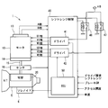
- FIG. 4 is a block diagram showing the shift range control apparatus according to the first embodiment.
- FIG. 5 is a schematic diagram for explaining a collision sound generated at the time of shift range switching according to the first embodiment.
- FIG. 6 is a flowchart for explaining the idling determination process according to the first embodiment.
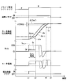
- FIG. 7 is a time chart for explaining the motor control process according to the first embodiment.
- FIG. 8 is a flowchart for explaining idle running determination processing according to the second embodiment of the present disclosure.
- FIGS. 1-10 A shift range control device according to a first embodiment of the present disclosure is shown in FIGS.
- the shift-by-wire system 1 includes a motor 10, a shift range switching mechanism 20, a parking lock mechanism 30, a shift range control device 40, and the like.
- the motor 10 rotates when power is supplied from a battery 45 (see FIG. 3) mounted on a vehicle (not shown), and functions as a drive source of the shift range switching mechanism 20.
- a motor that can change the magnitude of the current by feedback control and can change the command for each phase is used.
- the motor 10 of this embodiment is a permanent magnet type DC brushless motor.
- the motor 10 has two winding sets 11 and 12.
- the first winding set 11 includes a U1 coil 111, a V1 coil 112, and a W1 coil 113.
- the second winding set 12 includes a U2 coil 121, a V2 coil 122, and a W2 coil 123.
- the encoder 13 detects the rotational position of a rotor (not shown) of the motor 10.
- the encoder 13 is, for example, a magnetic rotary encoder, and includes a magnet that rotates integrally with the rotor, a Hall IC for magnetic detection, and the like.
- the encoder 13 outputs A-phase and B-phase pulse signals at every predetermined angle in synchronization with the rotation of the rotor.
- the speed reducer 14 is provided between the motor shaft of the motor 10 and the output shaft 15, and decelerates the rotation of the motor 10 and outputs it to the output shaft 15. Thereby, the rotation of the motor 10 is transmitted to the shift range switching mechanism 20.
- the output shaft 15 is provided with an output shaft sensor 16 that detects an output shaft angle ⁇ s that is an angle of the output shaft 15.
- the output shaft sensor 16 is, for example, a potentiometer.
- the shift range switching mechanism 20 includes a detent plate 21, a detent spring 25, and the like.
- the rotational driving force output from the speed reducer 14 is converted into a manual valve 28 and a parking lock mechanism 30. To communicate.
- the detent plate 21 is fixed to the output shaft 15 and driven by the motor 10.
- the direction in which the detent plate 21 moves away from the base portion of the detent spring 25 is defined as the forward rotation direction, and the direction approaching the base portion is defined as the reverse rotation direction.
- the detent plate 21 is provided with pins 24 that protrude in parallel with the output shaft 15.
- the pin 24 is connected to the manual valve 28.
- the shift range switching mechanism 20 converts the rotational motion of the motor 10 into a linear motion and transmits it to the manual valve 28.
- the manual valve 28 is provided on the valve body 29.
- the four recesses 22 for holding the manual valve 28 at positions corresponding to the respective ranges are provided on the detent spring 25 side of the detent plate 21.
- the recess 22 corresponds to each range of D (drive), N (neutral), R (reverse), and P (park) from the base side of the detent spring 25.
- the detent spring 25 is an elastically deformable plate-like member, and a detent roller 26 is provided at the tip.
- the detent roller 26 is fitted into one of the recesses 22.
- the detent spring 25 urges the detent roller 26 toward the rotation center side of the detent plate 21.
- the detent spring 25 is elastically deformed and the detent roller 26 moves in the recess 22.
- the swing of the detent plate 21 is restricted, the axial position of the manual valve 28 and the state of the parking lock mechanism 30 are determined, and the automatic transmission 5 The shift range is fixed.
- the parking lock mechanism 30 includes a parking rod 31, a cone 32, a parking lock pole 33, a shaft portion 34, and a parking gear 35.
- the parking rod 31 is formed in a substantially L shape, and one end 311 side is fixed to the detent plate 21.
- a conical body 32 is provided on the other end 312 side of the parking rod 31.
- the cone 32 is formed so as to decrease in diameter toward the other end 312 side.
- the parking lock pole 33 is in contact with the conical surface of the cone 32 and is provided so as to be able to swing around the shaft portion 34.
- a convex portion that can mesh with the parking gear 35. 331 is provided on the parking gear 35 side of the parking lock pole 33.
- the parking gear 35 is provided on an axle (not shown) and is provided so as to be able to mesh with the convex portion 331 of the parking lock pole 33.
- rotation of the axle is restricted.
- the shift range is a notP range that is a range other than P
- the parking gear 35 is not locked by the parking lock pole 33, and the rotation of the axle is not hindered by the parking lock mechanism 30.
- the shift range is the P range
- the parking gear 35 is locked by the parking lock pole 33 and the rotation of the axle is restricted.
- the shift range control device 40 includes motor drivers 41 and 42, an ECU 50, and the like.
- the motor driver 41 is a three-phase inverter that switches energization of the first winding set 11, and switching elements 411 to 416 are bridge-connected.
- One end of the U1 coil 111 is connected to a connection point between the U-phase switching elements 411 and 414 that form a pair.
- One end of the V1 coil 112 is connected to a connection point between the paired V-phase switching elements 412 and 415.
- One end of the W1 coil 113 is connected to a connection point between the paired W-phase switching elements 413 and 416.
- the other ends of the coils 111 to 113 are connected by a connection part 115.
- the motor driver 42 is a three-phase inverter that switches energization of the second winding set 12, and switching elements 421 to 426 are bridge-connected.
- One end of the U2 coil 121 is connected to a connection point between the U-phase switching elements 421 and 424 that form a pair.
- One end of the V2 coil 122 is connected to a connection point between the paired V-phase switching elements 422 and 425.
- One end of the W2 coil 123 is connected to a connection point between the paired W-phase switching elements 423 and 426.
- the other ends of the coils 121 to 123 are connected by a connection part 125.
- the switching elements 411 to 416 and 421 to 426 of the present embodiment are MOSFETs, but other elements such as IGBTs may be used.
- a motor relay 46 is provided between the motor driver 41 and the battery 45.
- a motor relay 47 is provided between the motor driver 42 and the battery 45. The motor relays 46 and 47 are turned on when a start switch such as an ignition switch is turned on, and power is supplied to the motor 10 side. Further, the motor relays 46 and 47 are turned off when the start switch is turned off, and the supply of electric power to the motor 10 side is cut off.
- the ECU 50 controls the driving of the motor 10 by controlling the on / off operation of the switching elements 411 to 416 and 421 to 426. Further, the ECU 50 controls the drive of the shift hydraulic control solenoid 6 based on the vehicle speed, the accelerator opening, the driver request shift range, and the like. The gear position is controlled by controlling the shift hydraulic control solenoid 6.
- the number of shift hydraulic control solenoids 6 is provided according to the number of shift stages. In the present embodiment, one ECU 50 controls the driving of the motor 10 and the solenoid 6, but the motor ECU for controlling the motor 10 and the AT-ECU for solenoid control may be separated.
- the drive control of the motor 10 will be mainly described.
- the ECU 50 includes an angle calculation unit 51, a feedback control unit 52, a stationary phase energization control unit 61, a switching control unit 65, a signal generation unit 66, and the like, and is configured mainly with a microcomputer or the like.
- Each process in the ECU 50 may be a software process by a CPU executing a program stored in advance in a substantial memory device such as a ROM, or may be a hardware process by a dedicated electronic circuit.
- the angle calculation unit 51 calculates the actual count value Cen that is the count value of the encoder 13 based on the A-phase and B-phase pulses output from the encoder 13.
- the actual count value Cen is a value corresponding to the actual mechanical angle and electrical angle of the motor 10. In the present embodiment, the actual count value Cen is set to “actual angle”.
- the speed reducer 14 is provided between the motor shaft of the motor 10 and the output shaft 15. Therefore, if the motor shaft rotates within the range of gear play of the speed reducer 14 when the start switch is off, the relative position between the motor shaft and the output shaft 15 is different when the start switch is off and on. There is a risk of deviation. Therefore, in the angle calculation unit 51, when the start switch is turned on, the count value of the encoder 13 is controlled by wall contact control in which the motor 10 is rotated in both directions and abuts against the walls on both sides of the gear with which the motor shaft is engaged. And an initial learning for associating the position of the output shaft 15 with each other, and a correction value is calculated.
- the actual count value Cen is a value after correction with the correction value.
- the feedback control unit 52 includes a phase advance filter 53, a subtractor 54, a controller 55, a free running determination unit 57, and a duty limiting unit 58 as a current limiting unit, and performs position feedback control.
- the phase advance filter 53 performs phase advance compensation for advancing the phase of the actual count value Cen, and calculates the phase advance value Cen_pl.
- the phase lead value Cen_pl subjected to the phase lead filter process is also included in the concept of “real angle”.
- the subtractor 54 calculates a deviation ⁇ Cen between the target count value Cen * and the phase advance value Cen_pl corresponding to the driver requested shift range input by operating a shift lever or the like (not shown).
- the controller 55 calculates the pre-limit duty Du_a by PI control or the like so that the deviation ⁇ Cen becomes 0 so that the target count value Cen * and the actual count value phase advance value Cen_pl coincide with each other.
- the magnitude of the current and torque flowing in the coils 111 to 113 and 121 to 123 can be changed by changing the duty by PWM control or the like.
- the drive of the motor 10 is controlled by rectangular wave control by 120 ° energization.
- the rectangular wave control by 120 ° energization the first-phase high-potential side switching element and the second-phase low-potential side switching element are turned on.
- an energized phase switches by changing the combination of a 1st phase and a 2nd phase for every electrical angle of 60 degrees.
- a rotating magnetic field is generated in the winding sets 11 and 12, and the motor 10 rotates.
- the rotation direction of the motor 10 when the output shaft 15 is rotated in the positive rotation direction is the positive direction.
- the duty when the motor 10 outputs a positive torque is positive
- the duty when the negative torque is output is negative
- a possible duty range is ⁇ 100 [%] to 100 [%]. That is, when the motor 10 is rotated forward, the duty is positive, and when the motor 10 is rotated reversely, the duty is negative.
- brake torque that is, negative torque
- the rotation direction of the motor 10 is the positive rotation direction, but the duty is negative.
- the brake torque is generated to stop the motor 10 that is rotating in the reverse direction, the duty is positive.
- the idle running determination unit 57 determines whether or not the rotation state of the motor 10 is an idle running state.
- the idling determination unit 57 turns on the current limit flag Flg_L and outputs it to the duty limit unit 58 when the rotation state of the motor 10 is the idling state.
- the duty limiter 58 limits the duty in order to limit the upper limit value of the motor current when the rotation state of the motor 10 is the idling state.
- the duty limiter 58 limits the upper limit value of the duty to the upper limit duty DH.
- the duty restriction unit 58 restricts the duty Du after restriction to the upper limit duty DH.
- the duty restriction unit 58 sets the duty Du_a before restriction as the duty Du after restriction.
- the sign of the post-limit duty is the same as the pre-limit duty.
- the pre-limit duty Du_a is directly used as the post-limit duty Du.
- the post-limit duty Du is output to the signal generator 66.
- the stationary phase energization control unit 61 performs stationary phase energization control.
- the stationary phase energization control is a control for stopping the rotation of the motor 10, and selects a stationary phase according to the electrical angle, so that the current flows in a predetermined direction of the selected stationary phase. 416 and 421 to 426 are controlled. Thereby, the excitation phase is fixed. When the excitation phase is fixed, the motor 10 stops at a predetermined electrical angle corresponding to the excitation phase.
- the stationary phase energization control unit 61 selects the stationary phase and the energization direction based on the actual count value Cen so as to stop the motor 10 at the electrical angle closest to the current rotor position.
- the stationary phase energization control is performed when the difference between the actual count value Cen and the target count value Cen * is equal to or less than the angle determination threshold value ENth. Therefore, when the stationary phase energization control is being performed, it can be considered that the actual count value Cen and the target count value Cen * are approximately the same. For this reason, the motor 10 can be stopped at a location that substantially matches the target count value Cen * by stopping at the stopable electrical angle closest to the current rotor position.
- the electrical angle corresponding to the target count value Cen * and the electrical angle at which the motor 10 is stopped by the fixed-phase energization control cause a deviation of the motor resolution at the maximum, but the reduction ratio of the reduction gear 14 Is large, the shift of the stop position of the output shaft 15 is small, so that it does not matter.
- the switching control unit 65 switches the control state of the motor 10.
- the switching control unit 65 switches between the position feedback control and the fixed phase energization control based on the target count value Cen * and the actual count value Cen.
- the switching control unit 65 sets the control state of the motor 10 to position feedback control when the driver requested shift range changes.
- the switching control unit 65 switches to fixed phase energization control.
- the switching control unit 65 continues the fixed phase energization control for a period from when switching to the fixed phase energization control to when the energization continuation time Ta elapses, and performs energization off control after the energization continuation time Ta elapses.
- the absolute value of the difference between the target count value Cen * and the actual count value Cen corresponds to the “difference value between the target angle and the actual angle”.
- the signal generation unit 66 generates a drive signal for switching on and off the switching elements 411 to 416 and 421 to 426 according to the control state selected by the switching control unit 65 and outputs the drive signal to the motor drivers 41 and 42. Thereby, the drive of the motor 10 is controlled.
- FIG. 5 schematically shows the relationship between the motor shaft and the output shaft.
- the rotation direction of the motor shaft and the output shaft is described as the vertical direction on the paper.
- a speed reducer 14 is provided between the motor shaft, which is the rotation shaft of the motor 10, and the output shaft 15, and gear backlash between the speed reducer 14 and the output shaft 15 is prevented.
- the motor 10 is a DC brushless motor
- the motor shaft rotates within the range of play due to the influence of cogging torque, etc.
- the output shaft 15 may be separated.
- the motor shaft rotates in a substantially no-load state within the range of play.
- the state in which the motor 10 is rotating within the range of play existing between the motor shaft and the output shaft 15 is referred to as “idle running state”.
- the case where the motor 10 is rotating while the gear of the speed reducer 14 and the output shaft 15 are separated in the rotation direction side will be mainly described as the idling state.
- a conversion value obtained by converting the rotation angle of the motor 10 according to the actual count value Cen by the gear ratio of the reduction gear 14 is referred to as “motor angle ⁇ m”.
- the motor angle ⁇ m and the output shaft angle ⁇ s match. . Therefore, when the motor shaft and the output shaft 15 rotate together, the motor angle change amount ⁇ m that is the change amount of the motor angle ⁇ m and the output shaft angle change amount ⁇ s that is the change amount of the output shaft angle ⁇ s are obtained. Match.
- the change amounts ⁇ m and ⁇ s are both difference values from the previous calculation values.
- the idling determination unit 57 determines that the rotation state of the motor 10 is the idling state.
- the absolute value of the difference between the output shaft angle change amount ⁇ s and the motor angle change amount ⁇ m is larger than the free running determination threshold value ⁇ th, it is determined that the vehicle is free running.
- the idling determination threshold ⁇ th is set to a small value (for example, 0.1 °) such that the output shaft angle change amount ⁇ s and the motor angle change amount ⁇ m can be regarded as matching.
- the actual count value Cen is described as being input to the idling determination unit 57, but the angle calculator 51 calculates the motor angle ⁇ m, and the calculated motor angle ⁇ m is idling. You may comprise so that it may input into the determination part 57.
- FIG. The motor angle change amount ⁇ m may be calculated as a difference value between the previous value and the current value of the motor angle ⁇ m, or by converting the difference value between the previous value and the current value of the actual count value Cen to a gear ratio. It may be calculated.
- the upper limit value of the motor current is limited and the rotation speed of the motor 10 is suppressed, thereby suppressing the collision sound.
- the upper limit value of the motor current is limited by limiting the duty.
- the idling determination process of this embodiment will be described based on the flowchart shown in FIG. This process is executed by the ECU 50 at a predetermined cycle while the start switch is on.
- the free running determination unit 57 determines whether or not the energization flag is turned on.
- the energization flag is turned on when the driver request shift range is changed, and is turned off when the stationary phase energization control is finished.
- S101: NO the following processing is not performed.
- S101: YES the process proceeds to S102.
- the free running determination unit 57 determines whether or not the output shaft angle ⁇ s has changed. When it is determined that the output shaft angle ⁇ s has changed (S102: YES), the process proceeds to S105. When it is determined that the output shaft angle ⁇ s has not changed (S102: NO), the process proceeds to S103.
- the idling determination unit 57 determines whether or not the output shaft angle change amount ⁇ s matches the motor angle change amount ⁇ m. When it is determined that the output shaft angle change amount ⁇ s and the motor angle change amount ⁇ m match (S103: YES), the motor 10 is regarded as not in the idling state, and the process proceeds to S105. When it is determined that the output shaft angle change amount ⁇ s and the motor angle change amount ⁇ m do not match (S103: NO), it is considered that the rotation state of the motor 10 is the idle running state, and the process proceeds to S104.
- the idling determination unit 57 turns on the current limit flag Flg_L and outputs it to the duty limit unit 58.
- the duty limiting unit 58 limits the upper limit value of the duty to the upper limit duty DH.
- the current limit flag Flg_L is turned off. Further, the duty limiter 58 does not limit the duty.
- FIG. 7 shows the driver request shift range, the energization flag, the motor angle ⁇ m and the output shaft angle ⁇ s, the duty, the motor current, and the current limit flag Flg_L with the common time axis as the horizontal axis.
- the motor 10 is rotated in the forward direction to switch the shift range from the P range to the D range.
- the target count value Cen * and the rotation direction of the motor 10 are also changed during other range switching. Except for the differences, etc., details such as idling determination and current limitation are the same.
- the motor angle ⁇ m_c, the output shaft angle ⁇ s_c, the duty, and the motor current when current limitation is not performed are indicated by broken lines. Further, in the motor angle ⁇ m and the output shaft angle ⁇ s in FIG. 7, ⁇ (Cen *) and ⁇ (ENth) are values obtained by converting the target count value Cen * and the angle determination threshold value ENth by the gear ratio of the speed reducer 14. . In addition, when the motor shaft and the output shaft 15 are rotated as a unit, the motor angle ⁇ m and the output shaft angle ⁇ s coincide with each other.
- the energization flag is switched from OFF to ON.
- the target count value Cen * corresponding to the driver request shift range is set.
- the difference between the target count value Cen * and the actual count value Cen is larger than the angle determination threshold value ENth, so the motor 10 is controlled by position feedback control.
- the responsiveness of the motor 10 is enhanced by performing position feedback control.
- the difference between the target count value Cen * and the actual count value Cen is large, and the pre-limit duty Du_a is 100%.
- the speed reducer 14 and the output shaft 15 are separated from each other when the motor 10 is started, the motor 10 rotates with the load being substantially zero. Therefore, as indicated by a broken line, when the motor 10 is started without limiting the duty, the reduction gear 14 and the output shaft 15 may collide with each other, which may cause a loud collision sound.
- the duty is limited from the time x1 to the time x2 when the rotation state of the motor 10 is the idle running state.
- the current limit flag Flg_L is turned on, and the upper limit value of the duty is limited to the upper limit duty DH.
- the motor current is limited, and the rotational speed of the motor 10 is reduced compared to the case where the duty is not limited, and the collision noise is suppressed.
- the motor current is limited until the idling state ends.
- the motor shaft and the output shaft 15 rotate together via the speed reducer 14, so that the collision occurs. No sound is generated. Therefore, after time x2, the current limit flag Flg_L is turned off to release the duty limit, and the motor 10 is controlled by position feedback control. As a result, the actual count value Cen approaches the target count value Cen *.
- the responsiveness can be further improved by feeding back the phase lead value Cen_pl subjected to the phase lead filter processing.
- the control state of the motor 10 is switched from position feedback control to fixed phase energization control.
- the motor 10 can be quickly stopped by using the stationary phase energization.
- the stationary phase energization control is continued during a period from time x3 to time x4 when the energization duration time Ta elapses.
- the switching control unit 65 sets the control state to energization off control. Also, the energization flag is turned off. Until the driver request shift range is changed again, the energization flag is kept off, and the energization off control is continued as the control state of the motor 10. Thereby, since the motor 10 is not energized except when the shift range is switched, the power consumption can be reduced as compared with the case where the energization is continued.
- the duty in the position feedback control is not used, but in the drawing, it is described as the duty being 0 for convenience.
- the motor angle ⁇ m and the output shaft angle ⁇ s in FIG. 7 if the period from the time x1 to the time x2 in which the rotation state of the motor 10 is the idle running state is the idle running period, the motor angle ⁇ m in the idle running period. And the output shaft angle ⁇ s are different. Further, since the motor angle ⁇ m changes during the idling period, the motor angle change amount ⁇ m ⁇ 0 and the output shaft angle ⁇ s is constant, so the output shaft angle change amount ⁇ s ⁇ 0. That is, during the idle running period, the motor angle change amount ⁇ m and the output shaft angle change amount ⁇ s are different.
- the shift range control device 40 switches the shift range by controlling the driving of the motor 10, and includes the idle running determination unit 57 and the duty limiting unit 58.
- the idle running determination unit 57 is an idle running state in which the motor 10 is rotating within the range of play existing between the motor shaft that is the rotating shaft of the motor 10 and the output shaft 15 to which the rotation of the motor 10 is transmitted. Determine whether or not.
- the duty limiter 58 limits the current of the motor 10 when it is determined that the vehicle is idling.
- the idling determination unit 57 determines whether or not the idling state is based on the motor angle ⁇ m that is an angle according to the rotation of the motor 10 and the output shaft angle ⁇ s that is an angle according to the rotation of the output shaft 15. .
- the idle running determination unit 57 determines that the vehicle is idling when the output shaft angle change amount ⁇ s and the motor angle change amount ⁇ m are different. Thereby, the idling state can be appropriately determined based on the motor angle ⁇ m and the output shaft angle ⁇ s.
- FIG. 1 A second embodiment of the present disclosure is shown in FIG.
- the idling determination unit 57 determines that the idling state is present when the motor angle change amount ⁇ m and the output shaft angle change amount ⁇ s do not match.
- the idle running determination unit 57 can determine that the rotation state of the motor 10 is the idle running state when the output shaft 15 is not rotating and the motor 10 is rotating.
- Whether or not the output shaft 15 is rotating can be determined by whether or not the output shaft angle ⁇ s has changed. Further, whether or not the motor 10 is rotating can be determined based on whether or not the motor angle ⁇ m has changed. The presence / absence of changes in the output shaft angle ⁇ s and the motor angle ⁇ m can be determined based on, for example, changes ⁇ s and ⁇ m that are difference values between the previous value and the current value. If the output shaft angle change amount ⁇ s is equal to or less than the determination threshold value set to a value close to 0, it is determined that the output shaft angle ⁇ s has not changed. Is possible. Further, instead of the output shaft angle change amount ⁇ s, the presence or absence of a change may be determined using a differential value of the output shaft angle ⁇ s or the like. The same applies to the motor angle ⁇ m.
- whether or not the motor 10 is rotating is determined by replacing the motor angle ⁇ m that is a value after the gear ratio conversion, omitting the gear ratio conversion, and using the actual count value Cen before the gear ratio conversion or the like. You may judge.
- the idling determination process of this embodiment will be described based on the flowchart shown in FIG. Similar to the process of FIG. 6, this process is executed by the ECU 50 at a predetermined cycle during the period when the start switch is on.
- S201, S202, S204, and S205 are the same as S101, S102, S104, and S105 in FIG.
- the motor 10 is rotating and the motor angle ⁇ m is changing during the idle running period.
- the output shaft 15 does not rotate and the output shaft angle ⁇ s is constant.
- the output shaft 15 rotates integrally with the motor shaft, so the output shaft angle ⁇ s changes in the same manner as the motor angle ⁇ m. Therefore, even when the determination is made as in the present embodiment, it is possible to appropriately determine whether or not the rotation state of the motor 10 is the idling state based on the motor angle ⁇ m and the output shaft angle ⁇ s.
- the idling determination unit 57 determines that the idling state is in the idling state when the output shaft angle ⁇ s has not changed and the motor angle ⁇ m has changed. Even in this case, the idling state can be appropriately determined based on the output shaft angle ⁇ s and the motor angle ⁇ m.
- the motor is a permanent magnet type three-phase brushless motor.
- the motor is not limited to a permanent magnet type three-phase brushless motor, and any motor capable of current limitation may be used.
- the motor is provided with two winding sets. In another embodiment, the number of winding sets of the motor may be one or more than three.
- rectangular wave control by 120 ° energization is performed in the position feedback control.
- the position feedback control may be rectangular wave control by 180 ° energization.
- PWM control using a triangular wave comparison method or an instantaneous vector selection method may be used.
- the position feedback control and the stationary phase energization control are switched as the motor control state.
- the motor drive control unit may set at least one of position feedback control and stationary phase energization control to different control states.
- position feedback control and stationary phase electricity supply control are switched.
- the motor drive state may be controlled in one control state such as position feedback control without switching the motor control state.
- the motor current is limited by limiting the duty. In other embodiments, the motor current may be limited by limiting parameters other than duty, such as a current command value, a voltage command value, or a torque command value.
- an encoder is used as a rotation angle sensor for detecting the rotation angle of the motor.
- the rotation angle sensor is not limited to an encoder, and any other device such as a resolver may be used.
- the count value of the encoder is subjected to phase advance filter processing and used for position feedback control.
- the position feedback control may be performed using the rotation angle of the motor itself or a value other than the encoder count value that can be converted into the rotation angle of the motor. The same applies to the selection of the stationary phase in the stationary phase energization control.
- the phase advance filter process may be omitted.
- the detent plate is provided with four recesses.
- the number of recesses is not limited to four and may be any number.
- the shift range switching mechanism, the parking lock mechanism, and the like may be different from those in the above embodiment.
- a speed reducer is provided between the motor shaft and the output shaft.
- the speed reducer between the motor shaft and the output shaft may be omitted, or a mechanism other than the speed reducer may be provided. That is, in the above embodiment, the description has been made mainly on the case where the “play” between the motor shaft and the output shaft exists between the gear of the reduction gear and the output shaft. It can be considered as the total of play and play existing between the shafts.
- the idling determination is not limited to the determination method of the above embodiment, and may be determined in any manner based on the output shaft angle and the motor angle. Further, in the idling determination process of the first embodiment, the process of S102 may be omitted.
- the motor shaft angle is converted into a gear ratio so as to coincide with the output shaft angle.
- the output shaft angle may be converted to a gear ratio so as to coincide with the motor shaft angle.
- the gear ratio conversion may be omitted as appropriate, for example, when a transmission is not provided between the motor shaft and the output shaft.
- each step is expressed as S101, for example. Further, each step can be divided into a plurality of sub-steps, while a plurality of steps can be combined into one step.
Landscapes
- Engineering & Computer Science (AREA)
- General Engineering & Computer Science (AREA)
- Mechanical Engineering (AREA)
- Power Engineering (AREA)
- Gear-Shifting Mechanisms (AREA)
- Control Of Transmission Device (AREA)
- Control Of Electric Motors In General (AREA)
- Control Of Vehicle Engines Or Engines For Specific Uses (AREA)
Abstract
モータ(10)の駆動を制御することでシフトレンジを切り替えるシフトレンジ制御装置は、モータの回転軸であるモータ軸とモータの回転が伝達される出力軸(15)との間に存在する遊びの範囲内でモータが回転している空走状態か否かを判定する空走判定部(57)と、空走状態であると判定された場合、モータの電流を制限する電流制限部(58)と、を備える。
Description
本出願は、2016年4月26日に出願された日本国特許出願2016-87741号に基づくものであり、ここにその記載内容を参照により援用する。
本開示は、シフトレンジ制御装置に関する。
従来、運転者からのシフトレンジ切り替え要求に応じてモータを制御することでシフトレンジを切り替えるシフトレンジ切替装置が知られている。例えば特許文献1では、シフトレンジ切替機構の駆動源として、スイッチトリラクタンスモータを用い、減速機を介して出力軸と一体のディテントレバーを回動させている。
本願発明者は下記を見出した。モータ軸と出力軸との間には、ギアバックラッシュ等の遊びが存在する。そのため、遊びの区間をモータ軸が高速で回転すると、遊びの区間が終了したとき、衝突音が発生する虞がある。
本開示の目的は、シフトレンジ切り替え時における衝突音の発生を抑制可能であるシフトレンジ制御装置を提供することにある。
本開示の一態様によるシフトレンジ制御装置は、モータの駆動を制御することでシフトレンジを切り替えるものであって、空走判定部と、電流制限部と、を備える。
空走判定部は、モータの回転軸であるモータ軸とモータの回転が伝達される出力軸との間に存在する遊びの範囲内でモータが回転している空走状態か否かを判定する。
電流制限部は、空走状態であると判定された場合、モータの電流を制限する。
これにより、シフトレンジ切り替え時における衝突音の発生を抑制することができる。
本開示についての上記および他の目的、特徴や利点は、添付図面を参照した下記詳細な説明から、より明確になる。添付図面において、
図1は、本開示の第1実施形態によるシフトバイワイヤシステムを示す斜視図であり、
図2は、第1実施形態によるシフトバイワイヤシステムを示す概略構成図であり、
図3は、第1実施形態によるモータおよびモータドライバを示す回路図であり、
図4は、第1実施形態によるシフトレンジ制御装置を示すブロック図であり、
図5は、第1実施形態によるシフトレンジ切り替え時に発生する衝突音を説明する模式図であり、
図6は、第1実施形態による空走判定処理を説明するフローチャートであり、
図7は、第1実施形態によるモータ制御処理を説明するタイムチャートであり、
図8は、本開示の第2実施形態による空走判定処理を説明するフローチャートである。
以下、本開示によるシフトレンジ制御装置を図面に基づいて説明する。以下、複数の実施形態において、実質的に同一の構成には同一の符号を付して説明を省略する。
(第1実施形態)
本開示の第1実施形態によるシフトレンジ制御装置を図1~図7に示す。
本開示の第1実施形態によるシフトレンジ制御装置を図1~図7に示す。
図1および図2に示すように、シフトバイワイヤシステム1は、モータ10、シフトレンジ切替機構20、パーキングロック機構30、および、シフトレンジ制御装置40等を備える。
モータ10は、図示しない車両に搭載されるバッテリ45(図3参照)から電力が供給されることで回転し、シフトレンジ切替機構20の駆動源として機能する。モータ10は、フィードバック制御により電流の大きさを変更可能であって、かつ、相ごとに指令を変更可能なものが用いられる。本実施形態のモータ10は、永久磁石式のDCブラシレスモータである。図3に示すように、モータ10は、2組の巻線組11、12を有する。第1巻線組11は、U1コイル111、V1コイル112、および、W1コイル113を有する。第2巻線組12は、U2コイル121、V2コイル122、および、W2コイル123を有する。
図2に示すように、エンコーダ13は、モータ10の図示しないロータの回転位置を検出する。エンコーダ13は、例えば磁気式のロータリーエンコーダであって、ロータと一体に回転する磁石と、磁気検出用のホールIC等により構成される。エンコーダ13は、ロータの回転に同期して、所定角度ごとにA相およびB相のパルス信号を出力する。
減速機14は、モータ10のモータ軸と出力軸15との間に設けられ、モータ10の回転を減速して出力軸15に出力する。これにより、モータ10の回転がシフトレンジ切替機構20に伝達される。出力軸15には、出力軸15の角度である出力軸角度θsを検出する出力軸センサ16が設けられる。出力軸センサ16は、例えばポテンショメータである。
図1に示すように、シフトレンジ切替機構20は、ディテントプレート21、および、ディテントスプリング25等を有し、減速機14から出力された回転駆動力を、マニュアルバルブ28、および、パーキングロック機構30へ伝達する。
ディテントプレート21は、出力軸15に固定され、モータ10により駆動される。本実施形態では、ディテントプレート21がディテントスプリング25の基部から離れる方向を正回転方向、基部に近づく方向を逆回転方向とする。
ディテントプレート21には、出力軸15と平行に突出するピン24が設けられる。ピン24は、マニュアルバルブ28と接続される。ディテントプレート21がモータ10によって駆動されることで、マニュアルバルブ28は軸方向に往復移動する。すなわち、シフトレンジ切替機構20は、モータ10の回転運動を直線運動に変換してマニュアルバルブ28に伝達する。マニュアルバルブ28は、バルブボディ29に設けられる。マニュアルバルブ28が軸方向に往復移動することで、図示しない油圧クラッチへの油圧供給路が切り替えられ、油圧クラッチの係合状態が切り替わることでシフトレンジが変更される。
ディテントプレート21のディテントスプリング25側には、マニュアルバルブ28を各レンジに対応する位置に保持するための4つの凹部22が設けられる。凹部22は、ディテントスプリング25の基部側から、D (drive)、N(neutral)、R(reverse)、P(park)の各レンジに対応している。
ディテントスプリング25は、弾性変形可能な板状部材であり、先端にディテントローラ26が設けられる。ディテントローラ26は、凹部22のいずれかに嵌まり込む。
ディテントスプリング25は、ディテントローラ26をディテントプレート21の回動中心側に付勢する。ディテントプレート21に所定以上の回転力が加わると、ディテントスプリング25が弾性変形し、ディテントローラ26が凹部22を移動する。ディテントローラ26が凹部22のいずれかに嵌まり込むことで、ディテントプレート21の揺動が規制され、マニュアルバルブ28の軸方向位置、および、パーキングロック機構30の状態が決定され、自動変速機5のシフトレンジが固定される。
パーキングロック機構30は、パーキングロッド31、円錐体32、パーキングロックポール33、軸部34、および、パーキングギア35を有する。
パーキングロッド31は、略L字形状に形成され、一端311側がディテントプレート21に固定される。パーキングロッド31の他端312側には、円錐体32が設けられる。円錐体32は、他端312側にいくほど縮径するように形成される。ディテントプレート21が逆回転方向に揺動すると、円錐体32が矢印Pの方向に移動する。
パーキングロックポール33は、円錐体32の円錐面と当接し、軸部34を中心に揺動可能に設けられる、パーキングロックポール33のパーキングギア35側には、パーキングギア35と噛み合い可能な凸部331が設けられる。ディテントプレート21が逆回転方向に回転し、円錐体32が矢印P方向に移動すると、パーキングロックポール33が押し上げられ、凸部331とパーキングギア35とが噛み合う。一方、ディテントプレート21が正回転方向に回転し、円錐体32が矢印notP方向に移動すると、凸部331とパーキングギア35との噛み合いが解除される。
パーキングギア35は、図示しない車軸に設けられ、パーキングロックポール33の凸部331と噛み合い可能に設けられる。パーキングギア35と凸部331とが噛み合うと、車軸の回転が規制される。シフトレンジがP以外のレンジであるnotPレンジのとき、パーキングギア35はパーキングロックポール33によりロックされず、車軸の回転は、パーキングロック機構30により妨げられない。また、シフトレンジがPレンジのとき、パーキングギア35はパーキングロックポール33によってロックされ、車軸の回転が規制される。
図2および図3に示すように、シフトレンジ制御装置40は、モータドライバ41、42、および、ECU50等を有する。
モータドライバ41は、第1巻線組11の通電を切り替える3相インバータであって、スイッチング素子411~416がブリッジ接続される。対になるU相のスイッチング素子411、414の接続点には、U1コイル111の一端が接続される。対になるV相のスイッチング素子412、415の接続点には、V1コイル112の一端が接続される。対になるW相のスイッチング素子413、416の接続点には、W1コイル113の一端が接続される。コイル111~113の他端は、結線部115で結線される。
モータドライバ42は、第2巻線組12の通電を切り替える3相インバータであって、スイッチング素子421~426がブリッジ接続される。対になるU相のスイッチング素子421、424の接続点には、U2コイル121の一端が接続される。対になるV相のスイッチング素子422、425の接続点には、V2コイル122の一端が接続される。対になるW相のスイッチング素子423、426の接続点には、W2コイル123の一端が接続される。コイル121~123の他端は、結線部125で結線される。
本実施形態のスイッチング素子411~416、421~426は、MOSFETであるが、IGBT等の他の素子を用いてもよい。
モータドライバ41とバッテリ45との間には、モータリレー46が設けられる。モータドライバ42とバッテリ45との間には、モータリレー47が設けられる。モータリレー46、47は、イグニッションスイッチ等である始動スイッチがオンされているときにオンされ、モータ10側へ電力が供給される。また、モータリレー46、47は、始動スイッチがオフされているときにオフされ、モータ10側への電力の供給が遮断される。
ECU50は、スイッチング素子411~416、421~426のオンオフ作動を制御することで、モータ10の駆動を制御する。また、ECU50は、車速、アクセル開度、および、ドライバ要求シフトレンジ等に基づき、変速用油圧制御ソレノイド6の駆動を制御する。変速用油圧制御ソレノイド6を制御することで、変速段が制御される。変速用油圧制御ソレノイド6は、変速段数等に応じた本数が設けられる。本実施形態では、1つのECU50がモータ10およびソレノイド6の駆動を制御するが、モータ10を制御するモータ制御用のモータECUと、ソレノイド制御用のAT-ECUとを分けてもよい。以下、モータ10の駆動制御を中心に説明する。
図4に示すように、ECU50は、角度演算部51、フィードバック制御部52、固定相通電制御部61、切替制御部65、および、信号生成部66等を備え、マイコン等を主体として構成される。ECU50における各処理は、ROM等の実体的なメモリ装置に予め記憶されたプログラムをCPUで実行することによるソフトウェア処理であってもよいし、専用の電子回路によるハードウェア処理であってもよい。
角度演算部51は、エンコーダ13から出力されるA相およびB相のパルスに基づき、エンコーダ13のカウント値である実カウント値Cenを演算する。実カウント値Cenは、モータ10の実際の機械角および電気角に応じた値である。本実施形態では、実カウント値Cenを「実角度」とする。
上述の通り、モータ10のモータ軸と出力軸15との間には、減速機14が設けられる。そのため、始動スイッチがオフされているときに減速機14のギアの遊びの範囲内にてモータ軸が回転すると、始動スイッチオフ時とオン時とで、モータ軸と出力軸15との相対位置がずれる虞がある。そのため、角度演算部51では、始動スイッチがオンされたとき、モータ10を両方向に回転させて、モータ軸が噛み合っているギアの両側の壁に当接させる壁当て制御により、エンコーダ13のカウント値と出力軸15の位置とを対応させる初期学習を行い、補正値を演算する。以下、実カウント値Cenは、補正値での補正後の値とする。
フィードバック制御部52は、位相進みフィルタ53、減算器54、制御器55、空走判定部57、および、電流制限部としてのデューティ制限部58を有し、位置フィードバック制御を行う。
位相進みフィルタ53は、実カウント値Cenの位相を進ませる位相進み補償を行い、位相進み値Cen_plを演算する。位相進みフィルタ処理を行った位相進み値Cen_plについても、「実角度」の概念に含まれるものとする。
減算器54は、図示しないシフトレバー等の操作により入力されるドライバ要求シフトレンジに応じた目標カウント値Cen*と位相進み値Cen_plとの偏差ΔCenを演算する。
制御器55は、目標カウント値Cen*と実カウント値位相進み値Cen_plとを一致させるべく、偏差ΔCenが0となるように、PI制御等により、制限前デューティDu_aを演算する。位置フィードバック制御では、PWM制御等によりデューティを変更することで、コイル111~113、121~123に流れる電流およびトルクの大きさを変更可能である。
本実施形態では、120°通電による矩形波制御により、モータ10の駆動を制御する。120°通電による矩形波制御では、第1相の高電位側のスイッチング素子と、第2相の低電位側のスイッチング素子をオンする。また、第1相および第2相の組み合わせを電気角60°ごとに入れ替えていくことで、通電相が切り替わる。これにより、巻線組11、12に回転磁界が発生し、モータ10が回転する。本実施形態では、出力軸15を正回転方向に回転させるときのモータ10の回転方向を正方向とする。また、モータ10が正のトルクを出力するときのデューティを正、負のトルクを出力するときのデューティを負とし、取り得るデューティ範囲を-100[%]~100[%]とする。すなわち、モータ10を正回転させるとき、デューティを正とし、逆回転させるとき、デューティを負とする。なお、正回転しているモータ10を停止させるべく、ブレーキトルク(すなわち負トルク)を発生させるとき、モータ10の回転方向は正回転方向であるが、デューティは負となる。同様に、逆回転しているモータ10を停止させるべく、ブレーキトルクを発生させるとき、デューティは正となる。
空走判定部57は、モータ10の回転状態が空走状態か否かを判定する。空走判定部57は、モータ10の回転状態が空走状態である場合、電流制限フラグFlg_Lをオンにし、デューティ制限部58に出力する。
空走判定の詳細は、後述する。
デューティ制限部58は、モータ10の回転状態が空走状態である場合、モータ電流の上限値を制限すべく、デューティを制限する。デューティ制限部58は、電流制限フラグFlg_Lがオンである場合、デューティの上限値を上限デューティDHに制限する。詳細には、デューティ制限部58は、制限前デューティDu_aの絶対値が上限デューティDHより大きい場合、制限後デューティDuを上限デューティDHに制限する。また、デューティ制限部58は、制限前デューティDu_aの絶対値が上限デューティDH以下の場合、制限前デューティDu_aを、制限後デューティDuとする。制限後デューティの正負は、制限前デューティに準じる。なお、電流制限フラグFlg_Lがオフである場合、制限前デューティDu_aをそのまま制限後デューティDuとする。
制限後デューティDuは、信号生成部66に出力される。
固定相通電制御部61は、固定相通電制御を行う。固定相通電制御は、モータ10の回転を停止させるための制御であって、電気角に応じた固定相を選択し、選択された固定相の所定方向に電流が流れるように、スイッチング素子411~416、421~426を制御する。これにより、励磁相が固定される。励磁相が固定されると、モータ10は、励磁相に応じた所定の電気角にて停止する。固定相通電制御部61は、現在のロータ位置から最も近い電気角でモータ10を停止させるように、実カウント値Cenに基づいて固定相および通電方向を選択する。
固定相通電制御は、実カウント値Cenと目標カウント値Cen*との差は角度判定閾値ENth以下となったときに行われる制御である。したがって、固定相通電制御が行われているとき、実カウント値Cenと目標カウント値Cen*とが概ね一致しているとみなせる。そのため、現在のロータ位置から最も近い停止可能な電気角で停止させることで、目標カウント値Cen*と略一致する箇所でモータ10を停止させることができる。厳密にいえば、目標カウント値Cen*に対応する電気角と、固定相通電制御にてモータ10を停止させる電気角とでは、最大でモータ分解能分のずれが生じるが、減速機14の減速比が大きければ、出力軸15の停止位置のずれは小さいため、差し支えない。
切替制御部65は、モータ10の制御状態を切り替える。特に、本実施形態では、切替制御部65は、目標カウント値Cen*と実カウント値Cenとに基づき、位置フィードバック制御とするか、固定相通電制御とするかを切り替える。
切替制御部65は、ドライバ要求シフトレンジが変化した場合、モータ10の制御状態を位置フィードバック制御とする。切替制御部65は、目標カウント値Cen*と実カウント値Cenとの差の絶対値が角度判定閾値ENth以下となった場合、固定相通電制御に切り替える。切替制御部65は、固定相通電制御に切り替わってから、通電継続時間Taが経過するまでの期間は、固定相通電制御を継続し、通電継続時間Ta経過後、通電オフ制御とする。通電オフ制御では、スイッチング素子411~416、421~426を全てオフにする。本実施形態では、目標カウント値Cen*と実カウント値Cenとの差の絶対値が、「目標角度と実角度との差分値」に対応する。
信号生成部66は、切替制御部65にて選択された制御状態に応じ、スイッチング素子411~416、421~426のオンオフを切り替える駆動信号を生成し、モータドライバ41、42に出力する。これにより、モータ10の駆動が制御される。
ここで、モータ10のモータ軸と出力軸15との関係を図5に基づいて説明する。図5は、モータ軸と出力軸との関係を模式的に示したものであって、図5中においては、モータ軸および出力軸の回転方向を、紙面上下方向として説明する。
図5に示すように、モータ10の回転軸であるモータ軸と出力軸15との間には、減速機14が設けられており、減速機14と出力軸15との間のギアバックラッシュを含む「遊び」が存在している。本実施形態では、モータ10はDCブラシレスモータであるので、モータ10への通電が停止されているとき、コギングトルク等の影響により、遊びの範囲内にてモータ軸が回転し、減速機14と出力軸15とが離間することがある。減速機14と出力軸15とが回転方向側に離間して停止している状態からモータ10を駆動すると、遊びの範囲内において、モータ軸が略無負荷状態で回転することになる。
以下、モータ軸と出力軸15との間に存在する遊びの範囲内でモータ10が回転している状態を、「空走状態」とする。本実施形態では、空走状態として、減速機14のギアと出力軸15とが回転方向側に離間している状態でモータ10が回転している場合を中心に説明する。
また、実カウント値Cenに応じたモータ10の回転角度を、減速機14のギア比で換算した換算値を「モータ角度θm」とする。上述の通り、実カウント値Cenは、初期学習により補正された値であるので、モータ軸と出力軸15とが一体に回転しているとき、モータ角度θmと出力軸角度θsとは、一致する。したがって、モータ軸と出力軸15とが一体に回転しているとき、モータ角度θmの変化量であるモータ角度変化量Δθmと、出力軸角度θsの変化量である出力軸角度変化量Δθsとが一致する。変化量Δθm、Δθsは、いずれもそれぞれの前回演算値との差分値とする。
そこで、空走判定部57は、出力軸角度変化量Δθsとモータ角度変化量Δθmとが異なっているとき、モータ10の回転状態が空走状態であると判定する。本実施形態では、出力軸角度変化量Δθsとモータ角度変化量Δθmとの差の絶対値が、空走判定閾値θthより大きい場合、空走状態であると判定する。空走判定閾値θthは、出力軸角度変化量Δθsとモータ角度変化量Δθmとが一致しているとみなせる程度の小さい値(例えば0.1°)に設定される。
なお、図4では、実カウント値Cenが空走判定部57に入力されるものとして記載しているが、角度演算部51にてモータ角度θmを演算し、演算されたモータ角度θmが空走判定部57に入力されるように構成してもよい。また、モータ角度変化量Δθmは、モータ角度θmの前回値と今回値の差分値として算出してもよいし、実カウント値Cenの前回値と今回値との差分値をギア比換算することで算出してもよい。
図5中に矢印Ymで示すように、モータ10が空走し、減速機14のギア内面と出力軸15とがぶつかると、衝突音が発生する。特に、遊びが大きい場合、モータ10が高速で空走すると、衝突音が大きくなる虞がある。なお、一旦、減速機14のギア内面と出力軸15とが当接すれば、モータ10が同方向の回転を継続している間は、減速機14と出力軸15とが一体となって回転するので、当該衝突音は発生しない。
そこで本実施形態では、モータ10の回転状態が空走状態であるとき、モータ電流の上限値を制限し、モータ10の回転速度を抑制することで、衝突音を抑制している。本実施形態では、デューティを制限することで、モータ電流の上限値を制限している。
本実施形態の空走判定処理を図6に示すフローチャートに基づいて説明する。この処理は、始動スイッチがオンされている期間に、ECU50にて所定の周期で実行される。
最初のS101では、空走判定部57は、通電フラグがオンされているか否かを判断する。通電フラグは、ドライバ要求シフトレンジが変化したときにオンされ、固定相通電制御が終了したときにオフされる。通電フラグがオフであると判断された場合(S101:NO)、以下の処理を行わない。通電フラグがオンであると判断された場合(S101:YES)、S102へ移行する。
S102では、空走判定部57は、出力軸角度θsが変化しているか否かを判断する。出力軸角度θsが変化していると判断された場合(S102:YES)、S105へ移行する。出力軸角度θsが変化していないと判断された場合(S102:NO)、S103へ移行する。
S103では、空走判定部57は、出力軸角度変化量Δθsとモータ角度変化量Δθmとが一致するか否かを判断する。出力軸角度変化量Δθsとモータ角度変化量Δθmとが一致すると判断された場合(S103:YES)、モータ10の回転状態が空走状態ではないとみなし、S105へ移行する。出力軸角度変化量Δθsとモータ角度変化量Δθmとが一致しないと判断された場合(S103:NO)、モータ10の回転状態が空走状態であるとみなし、S104へ移行する。
S104では、空走判定部57は、電流制限フラグFlg_Lをオンにし、デューティ制限部58へ出力する。また、デューティ制限部58は、デューティの上限値を上限デューティDHに制限する。
S105では、電流制限フラグFlg_Lをオフにする。また、デューティ制限部58は、デューティ制限を行わない。
本実施形態のモータ制御処理を図7のタイムチャートに基づいて説明する。図7は、共通時間軸を横軸とし、ドライバ要求シフトレンジ、通電フラグ、モータ角度θmおよび出力軸角度θs、デューティ、モータ電流、電流制限フラグFlg_Lを示す。ここでは、シフトレンジをPレンジからDレンジに切り替えるべく、モータ10を正方向に回転させる場合を例に説明するが、他のレンジ切替時についても、目標カウント値Cen*やモータ10の回転方向等が異なる点を除き、空走判定や電流制限等の詳細は同様である。
図7において、電流制限を行わない場合のモータ角度θm_c、出力軸角度θs_c、デューティ、および、モータ電流を破線で示した。また、図7のモータ角度θmおよび出力軸角度θsにおいて、θ(Cen*)およびθ(ENth)は、目標カウント値Cen*および角度判定閾値ENthを減速機14のギア比で換算した値である。また、モータ軸と出力軸15とが一体となって回転しているとき、モータ角度θmと出力軸角度θsとが一致するが、説明のため、図中では若干ずらして記載した。
図7に示すように、時刻x1にて、ドライバ要求シフトレンジがPレンジからDレンジに変更されると、通電フラグがオフからオンに切り替わる。ドライバ要求レンジが変更されると、ドライバ要求シフトレンジに応じた目標カウント値Cen*が設定される。ドライバ要求シフトレンジが変更された時刻x1の直後は、目標カウント値Cen*と実カウント値Cenとの差が角度判定閾値ENthより大きいので、位置フィードバック制御によりモータ10を制御する。
本実施形態では、位置フィードバック制御を行うことで、モータ10の応答性を高めている。モータ10の始動初期においては、目標カウント値Cen*と実カウント値Cenとの差が大きく、制限前デューティDu_aは100%となる。また、モータ10の始動時において、減速機14と出力軸15とが離間していると、モータ10は負荷が略0の状態で回転する。そのため、破線で示すように、デューティを制限せずにモータ10を始動すると、減速機14と出力軸15とが衝突することで、大きな衝突音が発生する虞がある。
そこで本実施形態では、モータ10の回転状態が空走状態である時刻x1から時刻x2までの間、デューティを制限する。具体的には、電流制限フラグFlg_Lをオンにし、デューティの上限値を、上限デューティDHに制限する。これにより、モータ電流が制限され、デューティを制限しない場合と比較し、モータ10の回転速度が小さくなり、衝突音が抑制される。本実施形態では、空走状態が終了するまでの間、モータ電流を制限する。
時刻x2において、空走状態が終了し、減速機14のギアと出力軸15とが当接すると、モータ軸と出力軸15とは、減速機14を介して一体となって回転するため、衝突音は発生しない。そのため、時刻x2以降は、電流制限フラグFlg_Lをオフとしてデューティ制限を解除し、位置フィードバック制御によりモータ10を制御する。これにより、実カウント値Cenが目標カウント値Cen*に近づく。ここで、位相進みフィルタ処理を行った位相進み値Cen_plをフィードバックすることで、応答性をより高めることができる。
また、時刻x3にて、目標カウント値Cen*と実カウント値Cenとの差が角度判定閾値ENth以下になると、モータ10の制御状態を、位置フィードバック制御から固定相通電制御に切り替える。固定相通電とすることでモータ10を速やかに停止させることができる。
時刻x3から通電継続時間Taが経過する時刻x4までの期間は、固定相通電制御を継続する。これにより、ハンチング等が抑制され、モータ10を確実に停止させることができるので、ディテントローラ26を所望の凹部に確実に嵌め込むことができる。
固定相通電制御の開始から通電継続時間Taが経過した時刻x4では、切替制御部65は、制御状態を通電オフ制御とする。また、通電フラグをオフにする。ドライバ要求シフトレンジが再度変更されるまでの間は、通電フラグのオフ状態が継続され、モータ10の制御状態として通電オフ制御が継続される。これにより、シフトレンジ切り替え時以外はモータ10に通電されないので、通電が継続される場合と比較して消費電力を低減することができる。
なお、固定相通電制御および通電オフ制御では、位置フィードバック制御におけるデューティは用いないが、図中では、便宜上、デューティが0であるものとして記載した。
図7のモータ角度θmおよび出力軸角度θsに示すように、モータ10の回転状態が空走状態である時刻x1から時刻x2までの期間を空走期間とすると、空走期間において、モータ角度θmと出力軸角度θsとが異なっている。また、空走期間において、モータ角度θmは変化しているので、モータ角度変化量Δθm≠0であり、出力軸角度θsは一定であるので、出力軸角度変化量Δθs≒0である。すなわち、空走期間において、モータ角度変化量Δθmと、出力軸角度変化量Δθsとは異なっている。
空走期間が終了すると、モータ角度θmと出力軸角度θsとが一致し、出力軸角度θsはモータ角度θmの変化に伴って同様に変化する。したがって、空走状態が終了すると、モータ角度変化量Δθmと出力軸角度変化量Δθsとが一致する。そこで本実施形態では、モータ角度変化量Δθmと出力軸角度変化量Δθsとが異なっているとき、空走状態であると判定する。これにより、モータ角度θmと出力軸角度θsとに基づき、モータ10の回転状態が空走状態か否かを適切に判断することができる。
以上説明したように、シフトレンジ制御装置40は、モータ10の駆動を制御することでシフトレンジを切り替えるものであって、空走判定部57と、デューティ制限部58と、を備える。
空走判定部57は、モータ10の回転軸であるモータ軸とモータ10の回転が伝達される出力軸15との間に存在する遊びの範囲内でモータ10が回転している空走状態か否かを判定する。
デューティ制限部58は、空走状態であると判断された場合、モータ10の電流を制限する。
これにより、シフトレンジ切り替え時における衝突音を低減することができる。
空走判定部57は、モータ10の回転に応じた角度であるモータ角度θm、および、出力軸15の回転に応じた角度である出力軸角度θsに基づき、空走状態か否かを判定する。
具体的には、空走判定部57は、出力軸角度変化量Δθsとモータ角度変化量Δθmとが異なっている場合、空走状態であると判定する。これにより、モータ角度θmおよび出力軸角度θsに基づき、空走状態を適切に判定することができる。
(第2実施形態)
本開示の第2実施形態を図8に示す。
本開示の第2実施形態を図8に示す。
上記実施形態では、空走判定部57は、モータ角度変化量Δθmと出力軸角度変化量Δθsとが一致していないとき、空走状態であると判定した。
モータ10の回転状態が空走状態である場合、モータ10の回転が出力軸15に伝達されないので、出力軸15は回転せず、出力軸角度θsが変化しない。そこで本実施形態では、空走判定部57は、出力軸15が回転しておらず、かつ、モータ10が回転している場合、モータ10の回転状態が空走状態であると判定可能する。
出力軸15が回転しているか否かは、出力軸角度θsの変化の有無にて判定可能である。また、モータ10が回転しているか否かは、モータ角度θmの変化の有無にて判定可能である。出力軸角度θsおよびモータ角度θmの変化の有無は、例えば前回値と今回値との差分値である変化量Δθs、Δθmに基づいて判定可能である。出力軸角度変化量Δθsが0に近い値に設定される判定閾値以下であれば、出力軸角度θsが変化しておらず、判定閾値より大きければ、出力軸角度θsが変化していると判定可能である。また、出力軸角度変化量Δθsに替えて、出力軸角度θsの微分値等を用いて変化の有無を判定してもよい。モータ角度θmについても同様である。
また、モータ10が回転しているか否かの判定は、ギア比換算後の値であるモータ角度θmに替えて、ギア比換算を省略し、ギア比換算前の実カウント値Cen等を用いて判定してもよい。
本実施形態の空走判定処理を図8に示すフローチャートに基づいて説明する。この処理は、図6の処理と同様、始動スイッチがオンされている期間に、ECU50にて所定の周期で実行される。
S201、S202、S204、S205の処理は、図6中のS101、S102、S104、S105と同様であるので詳細な説明を省略する。
出力軸角度θsが変化していないと判断された場合(S202:YES)に移行するS203では、モータ角度θmが変化しているか否かを判断する。モータ角度θmが変化していないと判断された場合(S203:NO)、S205へ移行する。モータ角度θmが変化していると判断された場合(S204:YES)、S204へ移行する。
すなわち本実施形態では、出力軸角度θsが変化しておらず(S202:NO)、かつ、モータ角度θmが変化している場合(S203:YES)、モータ10の回転状態が空走状態であるとみなし、電流制限フラグFlg_Lをオンにし、デューティを制限する(S204)。
図7のモータ角度θmおよび出力軸角度θsに示すように、空走期間において、モータ10は回転しており、モータ角度θmは変化している。一方、空走期間において、出力軸15は回転しておらず、出力軸角度θsは一定である。また、空走期間が終了すると、出力軸15はモータ軸と一体となって回転するので、出力軸角度θsはモータ角度θmと同様に変化する。したがって、本実施形態のように判定しても、モータ角度θmと出力軸角度θsとに基づき、モータ10の回転状態が空走状態か否かを適切に判断することができる。
本実施形態では、空走判定部57は、出力軸角度θsが変化しておらず、かつ、モータ角度θmが変化している場合、空走状態であると判定する。このようにしても、出力軸角度θsおよびモータ角度θmに基づき、空走状態を適切に判定することができる。
また、上記実施形態と同様の効果を奏する。
(他の実施形態)
上記実施形態では、モータは、永久磁石式の3相ブラシレスモータである。他の実施形態では、モータは、永久磁石式の3相ブラシレスモータに限らず、電流制限が可能などのようなモータを用いてもよい。また、上記実施形態では、モータに2組の巻線組が設けられる。他の実施形態では、モータの巻線組は、1組でもよいし3組以上であってもよい。
上記実施形態では、モータは、永久磁石式の3相ブラシレスモータである。他の実施形態では、モータは、永久磁石式の3相ブラシレスモータに限らず、電流制限が可能などのようなモータを用いてもよい。また、上記実施形態では、モータに2組の巻線組が設けられる。他の実施形態では、モータの巻線組は、1組でもよいし3組以上であってもよい。
上記実施形態では、位置フィードバック制御において、120°通電による矩形波制御を行う。他の実施形態では、位置フィードバック制御において、180°通電による矩形波制御としてもよい。また矩形波制御に限らず、三角波比較方式や瞬時ベクトル選択方式によるPWM制御としてもよい。
上記実施形態では、モータ制御状態として、位置フィードバック制御と固定相通電制御とを切り替える。他の実施形態では、モータ駆動制御部は、位置フィードバック制御および固定相通電制御の少なくとも一方を異なる制御状態としてもよい。また、上記実施形態では、位置フィードバック制御と固定相通電制御とを切り替える。他の実施形態では、モータの制御状態を切り替えず、例えば位置フィードバック制御等、1つの制御状態にてモータの駆動を制御するようにしてもよい。
上記実施形態では、デューティを制限することで、モータ電流を制限している。他の実施形態では、デューティ以外のパラメータ、例えば電流指令値、電圧指令値またはトルク指令値等を制限することで、モータ電流を制限するようにしてもよい。
上記実施形態では、モータの回転角を検出する回転角センサとして、エンコーダを用いる。他の実施形態では、回転角センサは、エンコーダに限らず、レゾルバ等、どのようなものを用いてもよい。上記実施形態では、エンコーダのカウント値を位相進みフィルタ処理を行い、位置フィードバック制御に用いる。他の実施形態では、モータの回転角そのもの、または、モータの回転角に換算可能なエンコーダカウント値以外の値を用いて位置フィードバック制御を行ってもよい。固定相通電制御における固定相の選択についても同様である。また他の実施形態では、位相進みフィルタ処理を省略してもよい。
上記実施形態では、ディテントプレートには4つの凹部が設けられる。他の実施形態では、凹部の数は4つに限らず、いくつであってもよい。例えば、ディテントプレートの凹部を2つとし、PレンジとnotPレンジとを切り替えるものとしてもよい。また、シフトレンジ切替機構やパーキングロック機構等は、上記実施形態と異なっていてもよい。
上記実施形態では、モータ軸と出力軸との間に減速機が設けられる。他の実施形態では、モータ軸と出力軸との間の減速機を省略してもよいし、減速機以外の機構を設けてもよい。すなわち、上記実施形態では、モータ軸と出力軸との間の「遊び」が減速機のギアと出力軸との間に存在するものを中心に説明したが、「遊び」とはモータ軸と出力軸との間に存在する遊びやガタ等の合計と捉えることができる。
他の実施形態では、空走判定については、上記実施形態の判定方法に限らず、出力軸角度およびモータ角度に基づき、どのように判定してもよい。また、第1実施形態の空走判定処理において、S102の処理を省略してもよい。
上記実施形態では、モータ軸角度をギア比換算し、出力軸角度と一致するようにしている。他の実施形態では、出力軸角度をギア比換算してモータ軸角度と一致するようにしてもよい。また、モータ軸と出力軸との間に変速機が設けられていない場合等、適宜、ギア比換算を省略してもよい。
ここで、この出願に記載されるフローチャート、あるいは、フローチャートの処理は、複数のステップ(あるいはセクションと言及される)から構成され、各ステップは、たとえば、S101と表現される。さらに、各ステップは、複数のサブステップに分割されることができる、一方、複数のステップが合わさって一つのステップにすることも可能である。
以上、本開示の一態様に係るシフトレンジ制御装置の実施形態、構成、態様を例示したが、本開示に係る実施形態、構成、態様は、上述した各実施形態、各構成、各態様に限定されるものではない。例えば、異なる実施形態、構成、態様にそれぞれ開示された技術的部を適宜組み合わせて得られる実施形態、構成、態様についても本開示に係る実施形態、構成、態様の範囲に含まれる。
Claims (4)
- モータ(10)の駆動を制御することでシフトレンジを切り替えるシフトレンジ制御装置であって、
前記モータの回転軸であるモータ軸と前記モータの回転が伝達される出力軸(15)との間に存在する遊びの範囲内で前記モータが回転している空走状態か否かを判定する空走判定部(57)と、
前記空走状態であると判定された場合、前記モータの電流を制限する電流制限部(58)と、
を備えるシフトレンジ制御装置。 - 前記空走判定部は、前記モータの回転に応じた角度であるモータ角度、および、前記出力軸の回転に応じた角度である出力軸角度に基づき、前記空走状態か否かを判定する請求項1に記載のシフトレンジ制御装置。
- 前記空走判定部は、前記出力軸角度の変化量である出力軸角度変化量と前記モータ角度の変化量であるモータ角度変化量とが異なっている場合、前記空走状態であると判定する請求項2に記載のシフトレンジ制御装置。
- 前記空走判定部は、前記出力軸角度が変化しておらず、かつ、前記モータ角度が変化している場合、前記空走状態であると判定する請求項2に記載のシフトレンジ制御装置。
Priority Applications (3)
| Application Number | Priority Date | Filing Date | Title |
|---|---|---|---|
| DE112017002201.0T DE112017002201B4 (de) | 2016-04-26 | 2017-03-06 | Schaltbereichssteuerungsvorrichtung |
| US16/096,054 US10615724B2 (en) | 2016-04-26 | 2017-03-06 | Shift range control apparatus |
| CN201780025410.3A CN109073074B (zh) | 2016-04-26 | 2017-03-06 | 换挡档位控制装置 |
Applications Claiming Priority (2)
| Application Number | Priority Date | Filing Date | Title |
|---|---|---|---|
| JP2016087741A JP6531707B2 (ja) | 2016-04-26 | 2016-04-26 | シフトレンジ制御装置 |
| JP2016-087741 | 2016-04-26 |
Publications (1)
| Publication Number | Publication Date |
|---|---|
| WO2017187789A1 true WO2017187789A1 (ja) | 2017-11-02 |
Family
ID=60160198
Family Applications (1)
| Application Number | Title | Priority Date | Filing Date |
|---|---|---|---|
| PCT/JP2017/008699 Ceased WO2017187789A1 (ja) | 2016-04-26 | 2017-03-06 | シフトレンジ制御装置 |
Country Status (5)
| Country | Link |
|---|---|
| US (1) | US10615724B2 (ja) |
| JP (1) | JP6531707B2 (ja) |
| CN (1) | CN109073074B (ja) |
| DE (1) | DE112017002201B4 (ja) |
| WO (1) | WO2017187789A1 (ja) |
Families Citing this family (8)
| Publication number | Priority date | Publication date | Assignee | Title |
|---|---|---|---|---|
| JP6760232B2 (ja) * | 2017-09-05 | 2020-09-23 | 株式会社デンソー | シフトレンジ制御装置 |
| JP7009936B2 (ja) * | 2017-11-06 | 2022-01-26 | 株式会社デンソー | シフトレンジ制御装置 |
| JP6985108B2 (ja) | 2017-11-06 | 2021-12-22 | 株式会社デンソー | シフトレンジ制御装置 |
| JP6939461B2 (ja) * | 2017-11-20 | 2021-09-22 | 株式会社デンソー | シフトレンジ切替システム |
| JP6939462B2 (ja) * | 2017-11-20 | 2021-09-22 | 株式会社デンソー | シフトレンジ切替システム |
| JP7017940B2 (ja) * | 2018-01-30 | 2022-02-09 | Ntn株式会社 | 電動式アクチュエータおよび電動ブレーキ装置 |
| JP2019158002A (ja) * | 2018-03-13 | 2019-09-19 | 株式会社デンソー | シフトレンジ制御装置 |
| DE112020001917T5 (de) * | 2019-05-17 | 2022-01-13 | Hitachi Astemo, Ltd. | Steuervorrichtung und steuerverfahren für rotierende elektrische maschine |
Citations (2)
| Publication number | Priority date | Publication date | Assignee | Title |
|---|---|---|---|---|
| JP2007255519A (ja) * | 2006-03-22 | 2007-10-04 | Aisin Aw Co Ltd | レンジ切換え装置 |
| JP2009177965A (ja) * | 2008-01-25 | 2009-08-06 | Denso Corp | モータ制御装置 |
Family Cites Families (12)
| Publication number | Priority date | Publication date | Assignee | Title |
|---|---|---|---|---|
| US6719076B1 (en) * | 1999-02-08 | 2004-04-13 | Toyota Jidosha Kabushiki Kaisha | Vehicle braked by motor torque and method of controlling the vehicle |
| US7161314B2 (en) | 2002-10-07 | 2007-01-09 | Denso Corporation | Motor control apparatus having current supply phase correction |
| JP4385768B2 (ja) | 2004-01-09 | 2009-12-16 | 株式会社デンソー | モータ制御装置 |
| JP5027062B2 (ja) * | 2008-06-18 | 2012-09-19 | トヨタ自動車株式会社 | 車両およびその制御方法 |
| DE102009044912A1 (de) * | 2009-09-23 | 2011-04-07 | Robert Bosch Gmbh | Motorsystem sowie ein Betriebsverfahren für ein solches Motorsystem |
| US9688301B2 (en) * | 2013-01-11 | 2017-06-27 | Nissan Motor Co., Ltd. | Steering control device and steering control method |
| US9573617B2 (en) * | 2013-01-11 | 2017-02-21 | Nissan Motor Co., Ltd. | Steering control device and steering control method |
| DE102013008956A1 (de) * | 2013-05-27 | 2014-11-27 | Knorr-Bremse Systeme für Nutzfahrzeuge GmbH | Stelleinrichtung für ein Kraftfahrzeuggetriebe oder eine Kraftfahrzeugkupplung |
| JP5762582B1 (ja) | 2014-02-04 | 2015-08-12 | 三菱電機株式会社 | シフトレンジ切り替え装置 |
| JP6318074B2 (ja) | 2014-11-05 | 2018-04-25 | ニフコプラント株式会社 | クーラント液の補充方法および装置 |
| WO2017179337A1 (ja) | 2016-04-15 | 2017-10-19 | 株式会社デンソー | シフトレンジ制御装置 |
| JP6569584B2 (ja) | 2016-04-15 | 2019-09-04 | 株式会社デンソー | シフトレンジ制御装置 |
-
2016
- 2016-04-26 JP JP2016087741A patent/JP6531707B2/ja active Active
-
2017
- 2017-03-06 DE DE112017002201.0T patent/DE112017002201B4/de active Active
- 2017-03-06 WO PCT/JP2017/008699 patent/WO2017187789A1/ja not_active Ceased
- 2017-03-06 US US16/096,054 patent/US10615724B2/en active Active
- 2017-03-06 CN CN201780025410.3A patent/CN109073074B/zh active Active
Patent Citations (2)
| Publication number | Priority date | Publication date | Assignee | Title |
|---|---|---|---|---|
| JP2007255519A (ja) * | 2006-03-22 | 2007-10-04 | Aisin Aw Co Ltd | レンジ切換え装置 |
| JP2009177965A (ja) * | 2008-01-25 | 2009-08-06 | Denso Corp | モータ制御装置 |
Also Published As
| Publication number | Publication date |
|---|---|
| US20190131897A1 (en) | 2019-05-02 |
| CN109073074A (zh) | 2018-12-21 |
| JP2017198250A (ja) | 2017-11-02 |
| DE112017002201B4 (de) | 2023-03-23 |
| CN109073074B (zh) | 2020-04-07 |
| US10615724B2 (en) | 2020-04-07 |
| DE112017002201T5 (de) | 2019-01-17 |
| JP6531707B2 (ja) | 2019-06-19 |
Similar Documents
| Publication | Publication Date | Title |
|---|---|---|
| US10948073B2 (en) | Shift range control device | |
| JP6531707B2 (ja) | シフトレンジ制御装置 | |
| JP6601322B2 (ja) | シフトレンジ切替装置 | |
| US11226033B2 (en) | Shift range control device | |
| CN109073073B (zh) | 换挡挡位控制装置 | |
| WO2017179337A1 (ja) | シフトレンジ制御装置 | |
| US10844954B2 (en) | Shift range control device | |
| JP6658416B2 (ja) | シフトレンジ制御装置 | |
| US11226037B2 (en) | Shift range control device | |
| US11655894B2 (en) | Shift range control device | |
| US11084493B2 (en) | Shift range control device | |
| WO2017208682A1 (ja) | シフトレンジ制御装置 | |
| WO2018047916A1 (ja) | シフトレンジ制御装置 |
Legal Events
| Date | Code | Title | Description |
|---|---|---|---|
| 121 | Ep: the epo has been informed by wipo that ep was designated in this application |
Ref document number: 17789078 Country of ref document: EP Kind code of ref document: A1 |
|
| 122 | Ep: pct application non-entry in european phase |
Ref document number: 17789078 Country of ref document: EP Kind code of ref document: A1 |