WO2017187615A1 - Sheath for flexible manipulator - Google Patents
Sheath for flexible manipulator Download PDFInfo
- Publication number
- WO2017187615A1 WO2017187615A1 PCT/JP2016/063428 JP2016063428W WO2017187615A1 WO 2017187615 A1 WO2017187615 A1 WO 2017187615A1 JP 2016063428 W JP2016063428 W JP 2016063428W WO 2017187615 A1 WO2017187615 A1 WO 2017187615A1
- Authority
- WO
- WIPO (PCT)
- Prior art keywords
- tube
- sheath
- protrusion
- inner tube
- lumen
- Prior art date
Links
Images


Classifications
-
- B—PERFORMING OPERATIONS; TRANSPORTING
- B25—HAND TOOLS; PORTABLE POWER-DRIVEN TOOLS; MANIPULATORS
- B25J—MANIPULATORS; CHAMBERS PROVIDED WITH MANIPULATION DEVICES
- B25J18/00—Arms
- B25J18/06—Arms flexible
Definitions
- the present invention relates to a sheath for a flexible manipulator.
- a manufactured multi-lumen tube is known (for example, see Patent Document 1).
- a wire for driving a movable portion provided at the distal end of the insertion portion is disposed through each lumen of the multi-lumen tube.
- the present invention has been made in view of the above-described circumstances, and can control the manipulator with high accuracy by suppressing fluctuations in the path length of the wire even when the tension applied to the wire penetrating the lumen is increased.
- An object of the present invention is to provide a sheath for a flexible manipulator.
- a flexible inner tube having a lumen that penetrates a wire along a longitudinal direction, and an outer peripheral surface of the inner tube are disposed so as to be more compressive than the inner tube.
- a plurality of protrusions that are provided on the outer peripheral surface of the inner tube with a radially outer tip closely attached to the inner surface of the outer tube, spaced apart in the circumferential direction.
- the wire when the movable portion of the manipulator provided at the distal end is driven by applying tension to the proximal end of the wire penetrating into the lumen, the wire is flexible due to friction between the wire and the inner surface of the lumen.
- the inner tube is likely to be deformed, but the inner tube is supported by the outer tube with higher compressive strength by closely attaching the protrusion provided on the outer peripheral surface to the inner surface of the outer tube. Deformation is avoided. As a result, even when the wire is pulled, fluctuations in the wire path length are suppressed, and the manipulator can be controlled with high accuracy.
- protrusion may consist of the protruding item
- the protrusion may extend continuously over the entire length of the inner tube.
- protrusion may extend intermittently over the full length of the said inner side tube.
- tip of the said protrusion may have the cross-sectional shape which consists of a convex curved surface.
- protrusion may have a cross-sectional shape extended incline with respect to radial direction from the outer peripheral surface of the said inner side tube.
- the protrusion that contacts the inner surface of the outer tube receives a force inward in the radial direction
- the cavity disposed radially inward of the protrusion is compressed, and the radial position of the protrusion is reduced in diameter. Displace inward direction.
- the inner tube is softly supported on the inner surface of the outer tube, and it is possible to improve the ease of inserting the inner tube into the outer tube and the ease of bending of the sheath.
- protrusion may be provided in the helical form twisted around a longitudinal axis.
- the inner tube includes a plurality of the lumens, each of the lumens is formed in a spiral shape that twists around the longitudinal axis and does not intersect with each other, and the protrusion has a center line of the inner tube. It may be arranged on the opposite side to each of the lumens. In this way, tension is applied to the wire, so that a force that deforms the lumen so as to approach a straight line acts on the spiral lumen that penetrates the wire from the wire.
- the force is effectively supported by the protrusion located on the opposite side of the lumen, and the movement of the inner tube within the outer tube can be prevented, and the variation in the path length can be more reliably prevented.
- the said outer side tube may be a coil tube, and the helical pitch of the said protrusion may be larger than the pitch of the said coil tube.
- the manipulator can be controlled with high accuracy by suppressing the fluctuation of the wire path length.
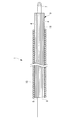
- FIG. 1 It is a whole lineblock diagram showing a flexible manipulator provided with a sheath for flexible manipulators concerning one embodiment of the present invention.
- FIG. 2 It is a cross-sectional view showing a second modification of the inner tube of FIG.
- the soft manipulator 100 is provided with a sheath 1 for a soft manipulator according to this embodiment, a manipulator 2 provided at the distal end of the sheath 1 for soft manipulator, and a proximal end of the manipulator 2.
- a drive unit 3 that generates power for operating the manipulator 2 and a wire 4 that transmits the power generated in the drive unit 3 to the manipulator 2 are provided.
- the manipulator 2 includes a movable part 5 having one or more joints, and an end effector 6 supported at the tip of the movable part 5.
- the drive unit 3 includes, for example, a motor (not shown) and a pulley 7 that transmits the power of the motor to the wire 4.
- the flexible manipulator sheath 1 includes a resin-made multi-lumen tube (inner tube) 9 including a plurality of lumens 8 penetrating in the longitudinal direction, and the multi-lumen tube 9.
- a coil tube (outer tube) 10 penetrating inward is provided.
- a wire 4 can be passed through each lumen 8 of the multi-lumen tube 9. Both ends of the wire 4 penetrating the lumen 8 are connected to the manipulator 2 at the distal end of the sheath 1 for the flexible manipulator and the drive unit 3 at the proximal end.
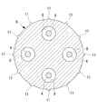
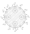
- a plurality of ridges (projections) 11 are provided on the outer peripheral surface of the multi-lumen tube 9 at equal intervals in the circumferential direction as shown in FIG.
- the ridges 11 are integrally formed as a part of the multi-lumen tube 9 with a resin constituting the multi-lumen tube 9 so that the outer peripheral surface of the multi-lumen tube 9 is raised radially outward.
- the multi-lumen tube 9 is manufactured by resin extrusion, and the lumen 8 and the ridges 11 are formed straight along the longitudinal direction.
- the cross-sectional shape of the ridge 11 is, for example, a rectangle.
- the flexible manipulator sheath 1 for the flexible manipulator when tension is applied to the wire 4 by the driving unit 3, the flexible multi-lumen tube 9 is caused by friction between the wire 4 and the inner surface of the lumen 8. Even if elastic deformation is attempted, the radially outer tip of the ridge 11 provided on the outer peripheral surface of the multi-lumen tube 9 is in close contact with the inner surface of the coil tube 10, so that the multi-lumen tube 9 is It is supported by the coil tube 10 via.
- the coil tube 10 has higher compression rigidity than the multi-lumen tube 9, deformation of the multi-lumen tube 9 is suppressed, and fluctuations in the path length of the wire 4 can be prevented.
- the path length of the other wire 4 varies, and the inconvenience of driving the manipulator 2 in an unintended direction is prevented, and the movable part 5 of the manipulator 2 is accurately There is an advantage that it can be controlled well.
- the multi-lumen tube 9 can be more reliably prevented from being deformed. It is difficult to insert the tube 9.
- the outer surface of the multi-lumen tube 9 is partially brought into contact with the inner surface of the coil tube 10 by the protruding ridges 11 spaced in the circumferential direction. Can be greatly reduced, the ease of insertion can be improved, and there is an advantage that assembly is easy.
- the ridges 11 are provided at equal intervals in the circumferential direction, the effect of preventing the variation in the path length of the wire 4 can be generated even when the sheath 1 for the flexible manipulator is bent in any direction. Further, since the ridges 11 are provided over the entire length of the multi-lumen tube 9 in the longitudinal direction, the effect of preventing the fluctuation of the path length of the wire 4 can be made uniform regardless of the position in the longitudinal direction of the sheath 1 for the flexible manipulator Can be generated.
- the dimension may be arbitrary.
- the width dimension of each convex strip 11 may be larger than FIG.
- the cross-sectional shape of the ridge 11 is not limited to a rectangle, and as shown in FIG. 5, a shape having a convex curved surface at the tip, for example, a semicircular cross-section may be adopted.
- the multi-lumen tube 9 extends from the outer peripheral surface of the multi-lumen tube 9 while being inclined with respect to the radial direction, and falls down along the outer peripheral surface of the multi-lumen tube 9 when inserted into the coil tube 10.
- the ridge 11 having a cross-sectional shape that is elastically deformed may be employed.
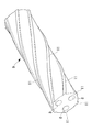
- line 11 was provided continuously over the full length of the longitudinal direction of the multi-lumen tube 9, it is not limited to this, It interrupts in a longitudinal direction It may be provided. Further, the ridges 11 may be formed in a spiral shape that rotates in the circumferential direction along the longitudinal direction of the multi-lumen tube 9. Thereby, the insertion ease at the time of inserting the multi-lumen tube 9 in the coil tube 10 can be improved.
- the pitch of the spiral ridges 11 is preferably different from the pitch of the coil tube 10. Thereby, it can prevent that the protruding item
- the multi-lumen tube 9 having four lumens 8 is illustrated as the inner tube, but instead, a single lumen tube having a single lumen 8 or an arbitrary number of two or more A multi-lumen tube having a plurality of lumens may be employed.
- the multi-lumen tube 9 in which the lumen 8 extends straight along the longitudinal direction is illustrated, but instead, a twisted multi-lumen in which the lumen 8 is twisted in one direction around the central axis.
- a tube may be employed.
- the ridges 11 may be formed straight along the longitudinal direction of the multi-lumen tube 9, but when manufactured by twisting after extrusion, the pitch is the same as the twist pitch of the lumen 8. It may be twisted.
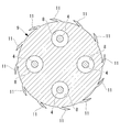
- each protrusion 11 is formed on the side opposite to the lumen 8 across the center line of the multi-lumen tube 9 as shown in FIG. It is possible to prevent the multi-lumen tube 9 from being deformed by receiving a force acting on the lumen 8 by the tension of the wire 4 so that the lumen 8 is straightened. As shown in FIG. 8, the number of ridges 11 may not be the same as the number of lumens 8.
- a hollow portion 12 may be provided at the base of each ridge 11, and the ridge 11 may be easily displaced in the radial direction. Thereby, the ease of insertion of the multi-lumen tube 9 into the coil tube 10 can be improved.
- the cavity 12 may be provided continuously over the entire length in the longitudinal direction, or may be provided intermittently.
Abstract
In order to suppress variation of wire path length to accurately control a manipulator even when the tensile force on the wire passing through a lumen increases, this flexible manipulator sheath (1) is provided with a flexible inside tube (9) having a lumen (8) through which a wire (4) is passed along the longitudinal direction, and a flexible outside tube (10) which is arranged so as to cover the outer peripheral surface of the inside tube (9) and which has higher compression rigidity than the inside tube (9), wherein, on the outer peripheral surface of the inside tube (9), multiple protrusions (11) are provided, spaced in the circumferential direction, with the radially outward tips of said protrusions brought into close contact with the inner surface of the outside tube (11).
Description
本発明は、軟性マニピュレータ用シースに関するものである。
The present invention relates to a sheath for a flexible manipulator.
湾曲した体腔内に挿入される軟性の挿入部の先端に可動部を備える軟性マニピュレータの挿入部に使用されるシースとして、可撓性の長尺材料の長手方向に貫通する複数のルーメンを有する樹脂製のマルチルーメンチューブが知られている(例えば、特許文献1参照。)。
このマルチルーメンチューブの各ルーメンには、挿入部の先端に設けられた可動部を駆動するためのワイヤが貫通して配置される。 Resin having a plurality of lumens penetrating in the longitudinal direction of a flexible long material as a sheath used for an insertion portion of a flexible manipulator having a movable portion at the tip of a flexible insertion portion to be inserted into a curved body cavity A manufactured multi-lumen tube is known (for example, see Patent Document 1).
A wire for driving a movable portion provided at the distal end of the insertion portion is disposed through each lumen of the multi-lumen tube.
特許文献1のシースでは、ワイヤを牽引すると、ワイヤからルーメン内面に与えられる摩擦力によってマルチルーメンチューブが湾曲あるいは圧縮変形してしまうので、他のルーメン内を貫通しているワイヤの経路長が変動し、可動部を精度よく制御することができないという不都合がある。
In the sheath of Patent Document 1, when the wire is pulled, the multi-lumen tube is bent or compressively deformed by the frictional force applied from the wire to the inner surface of the lumen, so that the path length of the wire penetrating the other lumen varies. However, there is an inconvenience that the movable part cannot be accurately controlled.
本発明は、上述した事情に鑑みてなされたものであって、ルーメン内に貫通させるワイヤにかかる張力が増大しても、ワイヤの経路長の変動を抑えて、精度よくマニピュレータを制御することができる軟性マニピュレータ用シースを提供することを目的としている。
The present invention has been made in view of the above-described circumstances, and can control the manipulator with high accuracy by suppressing fluctuations in the path length of the wire even when the tension applied to the wire penetrating the lumen is increased. An object of the present invention is to provide a sheath for a flexible manipulator.
本発明の一態様は、長手方向に沿ってワイヤを貫通させるルーメンを備えた可撓性を有する内側チューブと、該内側チューブの外周面を被覆するように配置され、前記内側チューブよりも圧縮剛性が高く可撓性を有する外側チューブとを備え、前記内側チューブの外周面に、径方向外方の先端が前記外側チューブの内面に密着させられる突起が、周方向に間隔をあけて複数設けられている軟性マニピュレータ用シースである。
In one embodiment of the present invention, a flexible inner tube having a lumen that penetrates a wire along a longitudinal direction, and an outer peripheral surface of the inner tube are disposed so as to be more compressive than the inner tube. A plurality of protrusions that are provided on the outer peripheral surface of the inner tube with a radially outer tip closely attached to the inner surface of the outer tube, spaced apart in the circumferential direction. A sheath for a flexible manipulator.
本態様によれば、ルーメン内に貫通させたワイヤの基端に張力を付与することにより、先端に設けられたマニピュレータの可動部を駆動する場合に、ワイヤとルーメンの内面との摩擦により可撓性を有する内側チューブが変形させられようとするが、内側チューブは、外周面に設けられた突起を外側チューブの内面に密着させることによって、より圧縮強度の高い外側チューブに支持されているので、変形が回避される。その結果、ワイヤの牽引によっても、ワイヤの経路長の変動が抑制され、マニピュレータを精度よく制御することができる。
According to this aspect, when the movable portion of the manipulator provided at the distal end is driven by applying tension to the proximal end of the wire penetrating into the lumen, the wire is flexible due to friction between the wire and the inner surface of the lumen. The inner tube is likely to be deformed, but the inner tube is supported by the outer tube with higher compressive strength by closely attaching the protrusion provided on the outer peripheral surface to the inner surface of the outer tube. Deformation is avoided. As a result, even when the wire is pulled, fluctuations in the wire path length are suppressed, and the manipulator can be controlled with high accuracy.
上記態様においては、前記突起が、前記内側チューブの長手方向に延びる凸条からなっていてもよい。
このようにすることで、突起によって内側チューブが外側チューブに長手方向に沿う長い範囲で支持され、より確実に経路長の変動を防止することができる。 In the said aspect, the said processus | protrusion may consist of the protruding item | line extended in the longitudinal direction of the said inner side tube.
By doing so, the inner tube is supported by the outer tube on the outer tube in a long range along the longitudinal direction, and the variation in the path length can be prevented more reliably.
また、前記突起が、前記内側チューブの全長にわたって連続的に延びていてもよい。
このようにすることで、突起によって内側チューブが外側チューブに全長にわたって支持され、より確実に経路長の変動を防止することができる。 The protrusion may extend continuously over the entire length of the inner tube.
By doing so, the inner tube is supported by the outer tube over the entire length by the protrusion, and the variation in the path length can be prevented more reliably.
また、上記態様においては、前記突起が、前記内側チューブの全長にわたって断続的に延びていてもよい。
このようにすることで、内側チューブが外側チューブに突起のある範囲において支持され、経路長の変動を防止することができる。凸条が断続していることで、湾曲容易性を向上することができる。 Moreover, in the said aspect, the said processus | protrusion may extend intermittently over the full length of the said inner side tube.
By doing in this way, an inner tube is supported in the range with a projection in an outer tube, and change of a path length can be prevented. The ease of bending can be improved by the intermittent protrusions.
また、上記態様においては、前記突起の先端が、凸曲面からなる横断面形状を有していてもよい。
このようにすることで、突起の先端と外側チューブの内面との接触面積を低減することができ、外側チューブへの内側チューブの挿入容易性を向上することができる。 Moreover, in the said aspect, the front-end | tip of the said protrusion may have the cross-sectional shape which consists of a convex curved surface.
By doing in this way, the contact area of the front-end | tip of protrusion and the inner surface of an outer tube can be reduced, and the ease of insertion of the inner tube to an outer tube can be improved.
また、上記態様においては、前記突起が、前記内側チューブの外周面から径方向に対して傾斜して延びる横断面形状を有してもよい。
このようにすることで、外側チューブの内面に接触する突起が弾性変形によって周方向に倒れることにより、内側チューブが外側チューブの内面に柔らかく支持され、外側チューブへの内側チューブの挿入容易性の向上およびシースの湾曲容易性の向上を図ることができる。 Moreover, in the said aspect, the said processus | protrusion may have a cross-sectional shape extended incline with respect to radial direction from the outer peripheral surface of the said inner side tube.
By doing so, the protrusion that contacts the inner surface of the outer tube falls in the circumferential direction due to elastic deformation, so that the inner tube is softly supported by the inner surface of the outer tube, and the ease of inserting the inner tube into the outer tube is improved. In addition, the ease of bending of the sheath can be improved.
また、上記態様においては、前記突起の径方向内方に空洞部を有していてもよい。
このようにすることで、外側チューブの内面に接触する突起が径方向内方に力を受けると、突起の径方向内方に配置されている空洞部が圧縮されて突起の径方向位置を径方向内方に変位させる。これにより、内側チューブが外側チューブの内面に柔らかく支持され、外側チューブへの内側チューブの挿入容易性の向上およびシースの湾曲容易性の向上を図ることができる。 Moreover, in the said aspect, you may have a cavity in the radial direction inner side of the said protrusion.
In this way, when the protrusion that contacts the inner surface of the outer tube receives a force inward in the radial direction, the cavity disposed radially inward of the protrusion is compressed, and the radial position of the protrusion is reduced in diameter. Displace inward direction. Thereby, the inner tube is softly supported on the inner surface of the outer tube, and it is possible to improve the ease of inserting the inner tube into the outer tube and the ease of bending of the sheath.
また、上記態様においては、前記突起が、長手軸回りに捻れる螺旋状に設けられていてもよい。
このようにすることで、内側チューブを外側チューブ内に挿入する際の摩擦抵抗を低減し、外側チューブへの内側チューブの挿入容易性の向上を図ることができる。 Moreover, in the said aspect, the said processus | protrusion may be provided in the helical form twisted around a longitudinal axis.
By doing in this way, the frictional resistance at the time of inserting an inner tube in an outer tube can be reduced, and the insertion ease of the inner tube to an outer tube can be aimed at.
また、上記態様においては、前記内側チューブが、前記ルーメンを複数備え、各該ルーメンが、長手軸回りに捻れて相互に交わらない螺旋状に形成され、前記突起が、前記内側チューブの中心線を挟んで各前記ルーメンとは反対側に配置されていてもよい。
このようにすることで、ワイヤに張力が付与されることにより、ワイヤから該ワイヤを貫通させる螺旋状のルーメンには、ルーメンを直線に近づけるように変形させる力が作用するが、中心線を挟んでルーメンとは反対側に位置する突起によって、その力が効果的に支持され、外側チューブ内での内側チューブの移動を防止して、より確実に経路長の変動を防止することができる。 Further, in the above aspect, the inner tube includes a plurality of the lumens, each of the lumens is formed in a spiral shape that twists around the longitudinal axis and does not intersect with each other, and the protrusion has a center line of the inner tube. It may be arranged on the opposite side to each of the lumens.
In this way, tension is applied to the wire, so that a force that deforms the lumen so as to approach a straight line acts on the spiral lumen that penetrates the wire from the wire. Thus, the force is effectively supported by the protrusion located on the opposite side of the lumen, and the movement of the inner tube within the outer tube can be prevented, and the variation in the path length can be more reliably prevented.
また、上記態様においては、前記外側チューブがコイルチューブであり、前記突起の螺旋形状のピッチが前記コイルチューブのピッチより大きくてもよい。
このようにすることで、突起がコイルチューブの内面の凹凸に部分的に噛み合うことが防止され、内側チューブを外側チューブの内面により確実に支持させることができる。 Moreover, in the said aspect, the said outer side tube may be a coil tube, and the helical pitch of the said protrusion may be larger than the pitch of the said coil tube.
By doing in this way, it is prevented that a protrusion partly meshes with the unevenness | corrugation of the inner surface of a coil tube, and an inner tube can be reliably supported by the inner surface of an outer tube.
本発明によれば、ルーメン内に貫通させるワイヤにかかる張力が増大しても、ワイヤの経路長の変動を抑えて、精度よくマニピュレータを制御することができるという効果を奏する。
According to the present invention, even if the tension applied to the wire penetrating into the lumen is increased, the manipulator can be controlled with high accuracy by suppressing the fluctuation of the wire path length.
以下、本発明の一実施形態に係る軟性マニピュレータ用シース1について、図面を参照して以下に説明する。
軟性マニピュレータ100は、図1に示されるように、本実施形態に係る軟性マニピュレータ用シース1と、該軟性マニピュレータ用シース1の先端に備えられたマニピュレータ2と、マニピュレータ2の基端に備えられ、マニピュレータ2を作動させる動力を発生する駆動部3と、該駆動部3において発生した動力をマニピュレータ2に伝達するワイヤ4とを備えている。 Hereinafter, asheath 1 for a flexible manipulator according to an embodiment of the present invention will be described with reference to the drawings.
As shown in FIG. 1, thesoft manipulator 100 is provided with a sheath 1 for a soft manipulator according to this embodiment, a manipulator 2 provided at the distal end of the sheath 1 for soft manipulator, and a proximal end of the manipulator 2. A drive unit 3 that generates power for operating the manipulator 2 and a wire 4 that transmits the power generated in the drive unit 3 to the manipulator 2 are provided.
軟性マニピュレータ100は、図1に示されるように、本実施形態に係る軟性マニピュレータ用シース1と、該軟性マニピュレータ用シース1の先端に備えられたマニピュレータ2と、マニピュレータ2の基端に備えられ、マニピュレータ2を作動させる動力を発生する駆動部3と、該駆動部3において発生した動力をマニピュレータ2に伝達するワイヤ4とを備えている。 Hereinafter, a
As shown in FIG. 1, the
マニピュレータ2は、1以上の関節を有する可動部5と、該可動部5の先端に支持されたエンドエフェクタ6とを備えている。
駆動部3は、例えば、図示しないモータと、該モータの動力をワイヤ4に伝達するプーリ7とを備えている。 Themanipulator 2 includes a movable part 5 having one or more joints, and an end effector 6 supported at the tip of the movable part 5.
Thedrive unit 3 includes, for example, a motor (not shown) and a pulley 7 that transmits the power of the motor to the wire 4.
駆動部3は、例えば、図示しないモータと、該モータの動力をワイヤ4に伝達するプーリ7とを備えている。 The
The
本実施形態に係る軟性マニピュレータ用シース1は、図2に示されるように、長手方向に貫通する複数のルーメン8を備える樹脂製のマルチルーメンチューブ(内側チューブ)9と、該マルチルーメンチューブ9を内側に貫通させるコイルチューブ(外側チューブ)10とを備えている。
マルチルーメンチューブ9の各ルーメン8には、ワイヤ4が貫通させられるようになっている。ルーメン8を貫通したワイヤ4は、軟性マニピュレータ用シース1の先端のマニピュレータ2と基端の駆動部3に両端が接続されている。 As shown in FIG. 2, theflexible manipulator sheath 1 according to this embodiment includes a resin-made multi-lumen tube (inner tube) 9 including a plurality of lumens 8 penetrating in the longitudinal direction, and the multi-lumen tube 9. A coil tube (outer tube) 10 penetrating inward is provided.
Awire 4 can be passed through each lumen 8 of the multi-lumen tube 9. Both ends of the wire 4 penetrating the lumen 8 are connected to the manipulator 2 at the distal end of the sheath 1 for the flexible manipulator and the drive unit 3 at the proximal end.
マルチルーメンチューブ9の各ルーメン8には、ワイヤ4が貫通させられるようになっている。ルーメン8を貫通したワイヤ4は、軟性マニピュレータ用シース1の先端のマニピュレータ2と基端の駆動部3に両端が接続されている。 As shown in FIG. 2, the
A
本実施形態においては、マルチルーメンチューブ9の外周面に、図3に示されるように、周方向に等間隔をあけて複数の凸条(突起)11が設けられている。凸条11は、マルチルーメンチューブ9の外周面を径方向外方に隆起させるように、マルチルーメンチューブ9を構成する樹脂によってマルチルーメンチューブ9の一部として一体的に構成されている。一般に、マルチルーメンチューブ9は、樹脂の押出加工によって製造され、ルーメン8および凸条11は、長手方向に沿って真っ直ぐに形成されている。凸条11の横断面形状は、例えば、長方形である。
In this embodiment, a plurality of ridges (projections) 11 are provided on the outer peripheral surface of the multi-lumen tube 9 at equal intervals in the circumferential direction as shown in FIG. The ridges 11 are integrally formed as a part of the multi-lumen tube 9 with a resin constituting the multi-lumen tube 9 so that the outer peripheral surface of the multi-lumen tube 9 is raised radially outward. In general, the multi-lumen tube 9 is manufactured by resin extrusion, and the lumen 8 and the ridges 11 are formed straight along the longitudinal direction. The cross-sectional shape of the ridge 11 is, for example, a rectangle.
このように構成された本実施形態に係る軟性マニピュレータ用シース1の作用について以下に説明する。
本実施形態に係る軟性マニピュレータ用シース1によれば、駆動部3によりワイヤ4に張力が印加されると、ワイヤ4とルーメン8の内面との摩擦によって、可撓性を有するマルチルーメンチューブ9が弾性変形させられようとしても、マルチルーメンチューブ9の外周面に設けられた凸条11の径方向外方の先端がコイルチューブ10の内面に密着しているので、マルチルーメンチューブ9が凸条11を介してコイルチューブ10によって支持される。 The operation of the thus configuredsheath 1 for the flexible manipulator according to this embodiment will be described below.
According to theflexible manipulator sheath 1 according to the present embodiment, when tension is applied to the wire 4 by the driving unit 3, the flexible multi-lumen tube 9 is caused by friction between the wire 4 and the inner surface of the lumen 8. Even if elastic deformation is attempted, the radially outer tip of the ridge 11 provided on the outer peripheral surface of the multi-lumen tube 9 is in close contact with the inner surface of the coil tube 10, so that the multi-lumen tube 9 is It is supported by the coil tube 10 via.
本実施形態に係る軟性マニピュレータ用シース1によれば、駆動部3によりワイヤ4に張力が印加されると、ワイヤ4とルーメン8の内面との摩擦によって、可撓性を有するマルチルーメンチューブ9が弾性変形させられようとしても、マルチルーメンチューブ9の外周面に設けられた凸条11の径方向外方の先端がコイルチューブ10の内面に密着しているので、マルチルーメンチューブ9が凸条11を介してコイルチューブ10によって支持される。 The operation of the thus configured
According to the
コイルチューブ10はマルチルーメンチューブ9より高い圧縮剛性を有しているので、マルチルーメンチューブ9の変形が抑制され、ワイヤ4の経路長の変動を防止することができる。その結果、一のワイヤ4に張力をかけたときに他のワイヤ4の経路長が変動してマニピュレータ2が意図しない方向に駆動される不都合の発生を防止し、マニピュレータ2の可動部5を精度よく制御することができるという利点がある。
Since the coil tube 10 has higher compression rigidity than the multi-lumen tube 9, deformation of the multi-lumen tube 9 is suppressed, and fluctuations in the path length of the wire 4 can be prevented. As a result, when a tension is applied to one wire 4, the path length of the other wire 4 varies, and the inconvenience of driving the manipulator 2 in an unintended direction is prevented, and the movable part 5 of the manipulator 2 is accurately There is an advantage that it can be controlled well.
また、マルチルーメンチューブ9の外周面全体をコイルチューブ10の内面に密着させることができれば、マルチルーメンチューブ9の変形をより確実に防止できるが、摩擦が過大となってコイルチューブ10内にマルチルーメンチューブ9を挿入していくことは困難である。本実施形態に係る軟性マニピュレータ用シース1によれば、周方向に間隔をあけた凸条11によってマルチルーメンチューブ9の外面をコイルチューブ10の内面に部分的に接触させるので、挿入時の摩擦抵抗を大幅に軽減して、挿入容易性を向上することができ、組み立て容易であるという利点がある。
Further, if the entire outer peripheral surface of the multi-lumen tube 9 can be brought into close contact with the inner surface of the coil tube 10, the multi-lumen tube 9 can be more reliably prevented from being deformed. It is difficult to insert the tube 9. According to the flexible manipulator sheath 1 according to the present embodiment, the outer surface of the multi-lumen tube 9 is partially brought into contact with the inner surface of the coil tube 10 by the protruding ridges 11 spaced in the circumferential direction. Can be greatly reduced, the ease of insertion can be improved, and there is an advantage that assembly is easy.
また、凸条11を周方向に等間隔をあけて設けているので、軟性マニピュレータ用シース1がいずれの方向に湾曲されてもワイヤ4の経路長変動防止効果を均一に発生させることができる。
また、凸条11がマルチルーメンチューブ9の長手方向の全長にわたって設けられているので、軟性マニピュレータ用シース1の長手方向のどの位置が湾曲させられてもワイヤ4の経路長変動防止効果を均一に発生させることができる。 In addition, since theridges 11 are provided at equal intervals in the circumferential direction, the effect of preventing the variation in the path length of the wire 4 can be generated even when the sheath 1 for the flexible manipulator is bent in any direction.
Further, since theridges 11 are provided over the entire length of the multi-lumen tube 9 in the longitudinal direction, the effect of preventing the fluctuation of the path length of the wire 4 can be made uniform regardless of the position in the longitudinal direction of the sheath 1 for the flexible manipulator Can be generated.
また、凸条11がマルチルーメンチューブ9の長手方向の全長にわたって設けられているので、軟性マニピュレータ用シース1の長手方向のどの位置が湾曲させられてもワイヤ4の経路長変動防止効果を均一に発生させることができる。 In addition, since the
Further, since the
なお、本実施形態においては、凸条11として横断面長方形のものを例示したが、その寸法は任意でよい。例えば、図4に示されるように、各凸条11の幅寸法が図3よりも大きくてもよい。
また、凸条11の横断面形状は長方形に限定されるものではなく、図5に示されるように、先端に凸曲面を有する形状、例えば、横断面半円形のものを採用してもよい。また、先端に向かって先細になる横断面が三角形のものを採用してもよい。このようにすることで、コイルチューブ10内面との接触面積を低減して、コイルチューブ10内への挿入容易性を向上することができる。 In addition, in this embodiment, although the thing of the cross-sectional rectangle was illustrated as the protruding item |line 11, the dimension may be arbitrary. For example, as FIG. 4 shows, the width dimension of each convex strip 11 may be larger than FIG.
Moreover, the cross-sectional shape of theridge 11 is not limited to a rectangle, and as shown in FIG. 5, a shape having a convex curved surface at the tip, for example, a semicircular cross-section may be adopted. Moreover, you may employ | adopt the thing whose cross section tapering toward a front-end | tip is a triangle. By doing in this way, a contact area with the inner surface of the coil tube 10 can be reduced, and the ease of insertion in the coil tube 10 can be improved.
また、凸条11の横断面形状は長方形に限定されるものではなく、図5に示されるように、先端に凸曲面を有する形状、例えば、横断面半円形のものを採用してもよい。また、先端に向かって先細になる横断面が三角形のものを採用してもよい。このようにすることで、コイルチューブ10内面との接触面積を低減して、コイルチューブ10内への挿入容易性を向上することができる。 In addition, in this embodiment, although the thing of the cross-sectional rectangle was illustrated as the protruding item |
Moreover, the cross-sectional shape of the
また、図6に示されるように、マルチルーメンチューブ9の外周面から径方向に対して傾斜して延び、コイルチューブ10内に挿入されたときにマルチルーメンチューブ9の外周面に沿うように倒れるように弾性変形する横断面形状を有する凸条11を採用してもよい。なお、図6においては同一方向に倒れるものを例示したが、交互に逆方向に倒れる形状を有することにしてもよい。
Further, as shown in FIG. 6, the multi-lumen tube 9 extends from the outer peripheral surface of the multi-lumen tube 9 while being inclined with respect to the radial direction, and falls down along the outer peripheral surface of the multi-lumen tube 9 when inserted into the coil tube 10. The ridge 11 having a cross-sectional shape that is elastically deformed may be employed. In addition, although the thing falling down in the same direction was illustrated in FIG. 6, you may decide to have a shape which falls in the reverse direction alternately.
また、本実施形態においては、凸条11がマルチルーメンチューブ9の長手方向の全長にわたって連続して設けられている場合について例示したが、これに限定されるものではなく、長手方向に断続して設けられていてもよい。また、凸条11がマルチルーメンチューブ9の長手方向に沿って周方向に回転する螺旋状に形成されていてもよい。これにより、コイルチューブ10内にマルチルーメンチューブ9を挿入する際の挿入容易性を向上することができる。
Moreover, in this embodiment, although illustrated about the case where the protruding item | line 11 was provided continuously over the full length of the longitudinal direction of the multi-lumen tube 9, it is not limited to this, It interrupts in a longitudinal direction It may be provided. Further, the ridges 11 may be formed in a spiral shape that rotates in the circumferential direction along the longitudinal direction of the multi-lumen tube 9. Thereby, the insertion ease at the time of inserting the multi-lumen tube 9 in the coil tube 10 can be improved.
この場合に、螺旋状の凸条11のピッチは、コイルチューブ10のピッチとは異なっていることが好ましい。これにより挿入の際に凸条11とコイルチューブ10とが噛み合ってしまうことを防止して挿入容易性を向上することができる。凸条11のピッチはコイルチューブ10のピッチに対して十分に大きいことが好ましい。また、凸条11の捻れ方向がコイルチューブ10の捻れ方向とは逆方向であってもよい。
In this case, the pitch of the spiral ridges 11 is preferably different from the pitch of the coil tube 10. Thereby, it can prevent that the protruding item | line 11 and the coil tube 10 mesh in the case of insertion, and can improve insertion ease. It is preferable that the pitch of the ridges 11 is sufficiently larger than the pitch of the coil tube 10. Further, the twist direction of the ridges 11 may be opposite to the twist direction of the coil tube 10.
また、本実施形態においては、内側チューブとして4個のルーメン8を有するマルチルーメンチューブ9を例示したが、これに代えて、単一のルーメン8を有するシングルルーメンチューブあるいは、2以上の任意の数の複数のルーメンを有するマルチルーメンチューブを採用してもよい。
In the present embodiment, the multi-lumen tube 9 having four lumens 8 is illustrated as the inner tube, but instead, a single lumen tube having a single lumen 8 or an arbitrary number of two or more A multi-lumen tube having a plurality of lumens may be employed.
また、本実施形態においては、ルーメン8が長手方向に沿って真っ直ぐに延びているマルチルーメンチューブ9を例示したが、これに代えて、ルーメン8が中心軸回りに一方向に捻れた捻れマルチルーメンチューブを採用してもよい。この場合に、凸条11は、マルチルーメンチューブ9の長手方向に沿って真っ直ぐに形成されていてもよいが、押出成形後に捻ることにより製造する場合には、ルーメン8の捩りピッチと同じピッチで捻れていてもよい。
In the present embodiment, the multi-lumen tube 9 in which the lumen 8 extends straight along the longitudinal direction is illustrated, but instead, a twisted multi-lumen in which the lumen 8 is twisted in one direction around the central axis. A tube may be employed. In this case, the ridges 11 may be formed straight along the longitudinal direction of the multi-lumen tube 9, but when manufactured by twisting after extrusion, the pitch is the same as the twist pitch of the lumen 8. It may be twisted.
この場合において、各凸条11は、図7に示されるように、マルチルーメンチューブ9の中心線を挟んでルーメン8とは反対側に形成されていることが好ましい。ワイヤ4の張力によってルーメン8に真っ直ぐに延ばされるように作用する力を凸条11で受けてマルチルーメンチューブ9が変形するのを抑えることができる。なお、図8に示されるように、凸条11の数は、ルーメン8の数と同じでなくてもよい。
In this case, it is preferable that each protrusion 11 is formed on the side opposite to the lumen 8 across the center line of the multi-lumen tube 9 as shown in FIG. It is possible to prevent the multi-lumen tube 9 from being deformed by receiving a force acting on the lumen 8 by the tension of the wire 4 so that the lumen 8 is straightened. As shown in FIG. 8, the number of ridges 11 may not be the same as the number of lumens 8.
また、図9に示されるように、各凸条11の根元に空洞部12を設け、凸条11が径方向に変位し易くしてもよい。これにより、コイルチューブ10へのマルチルーメンチューブ9の挿入容易性を向上することができる。空洞部12は、長手方向の全長にわたって連続して設けられていてもよいし、断続的に設けられていてもよい。
Further, as shown in FIG. 9, a hollow portion 12 may be provided at the base of each ridge 11, and the ridge 11 may be easily displaced in the radial direction. Thereby, the ease of insertion of the multi-lumen tube 9 into the coil tube 10 can be improved. The cavity 12 may be provided continuously over the entire length in the longitudinal direction, or may be provided intermittently.
また、本実施形態においては、マルチルーメンチューブ9の外周面に設ける突起を長手方向に沿って設けられた凸条11である場合について説明したが、これに代えて、周方向および長手方向に間隔をあけて複数設けられた突起であってもよい。
また、外側チューブとしてはコイルチューブ10に代えて、他の任意のチューブを用いてもよい。 Moreover, in this embodiment, although the case where the protrusion provided in the outer peripheral surface of themulti-lumen tube 9 was the protruding item | line 11 provided along the longitudinal direction was described, it replaced with this and it spaced apart in the circumferential direction and the longitudinal direction A plurality of protrusions may be provided with a gap.
Also, as the outer tube, any other tube may be used instead of thecoil tube 10.
また、外側チューブとしてはコイルチューブ10に代えて、他の任意のチューブを用いてもよい。 Moreover, in this embodiment, although the case where the protrusion provided in the outer peripheral surface of the
Also, as the outer tube, any other tube may be used instead of the
1 軟性マニピュレータ用シース
4 ワイヤ
8 ルーメン
9 マルチルーメンチューブ(内側チューブ)
10 コイルチューブ(外側チューブ)
11 凸条(突起)
12 空洞部 1 Sheath forflexible manipulator 4 Wire 8 Lumen 9 Multi-lumen tube (inner tube)
10 Coil tube (outer tube)
11 Projections (projections)
12 Cavity
4 ワイヤ
8 ルーメン
9 マルチルーメンチューブ(内側チューブ)
10 コイルチューブ(外側チューブ)
11 凸条(突起)
12 空洞部 1 Sheath for
10 Coil tube (outer tube)
11 Projections (projections)
12 Cavity
Claims (10)
- 長手方向に沿ってワイヤを貫通させるルーメンを備えた可撓性を有する内側チューブと、
該内側チューブの外周面を被覆するように配置され、前記内側チューブよりも圧縮剛性が高く可撓性を有する外側チューブとを備え、
前記内側チューブの外周面に、径方向外方の先端が前記外側チューブの内面に密着させられる突起が、周方向に間隔をあけて複数設けられている軟性マニピュレータ用シース。 A flexible inner tube with a lumen that penetrates the wire along the longitudinal direction;
An outer tube disposed so as to cover the outer peripheral surface of the inner tube, and having a higher compression rigidity and flexibility than the inner tube;
A sheath for a flexible manipulator, wherein a plurality of protrusions whose outer ends in the radial direction are brought into close contact with the inner surface of the outer tube are provided on the outer peripheral surface of the inner tube at intervals in the circumferential direction. - 前記突起が、前記内側チューブの長手方向に延びる凸条からなる請求項1に記載の軟性マニピュレータ用シース。 The sheath for a flexible manipulator according to claim 1, wherein the protrusion is formed of a ridge extending in the longitudinal direction of the inner tube.
- 前記突起が、前記内側チューブの全長にわたって連続的に延びている請求項2に記載の軟性マニピュレータ用シース。 The sheath for a flexible manipulator according to claim 2, wherein the protrusion extends continuously over the entire length of the inner tube.
- 前記突起が、前記内側チューブの全長にわたって断続的に延びている請求項2に記載の軟性マニピュレータ用シース。 The sheath for a flexible manipulator according to claim 2, wherein the protrusion extends intermittently over the entire length of the inner tube.
- 前記突起の先端が、凸曲面からなる横断面形状を有する請求項1から請求項4のいずれかに記載の軟性マニピュレータ用シース。 The sheath for a flexible manipulator according to any one of claims 1 to 4, wherein a tip of the protrusion has a cross-sectional shape formed of a convex curved surface.
- 前記突起が、前記内側チューブの外周面から径方向に対して傾斜して延びる横断面形状を有する請求項1から請求項4のいずれかに記載の軟性マニピュレータ用シース。 The sheath for a flexible manipulator according to any one of claims 1 to 4, wherein the protrusion has a cross-sectional shape extending from the outer peripheral surface of the inner tube while being inclined with respect to the radial direction.
- 前記突起の径方向内方に空洞部を有する請求項1から請求項6のいずれかに記載の軟性マニピュレータ用シース。 The sheath for a flexible manipulator according to any one of claims 1 to 6, wherein the sheath has a hollow portion radially inward of the protrusion.
- 前記突起が、長手軸回りに捻れる螺旋状に設けられている請求項1から請求項7のいずれかに記載の軟性マニピュレータ用シース。 The sheath for a flexible manipulator according to any one of claims 1 to 7, wherein the protrusion is provided in a spiral shape that twists around a longitudinal axis.
- 前記内側チューブが、前記ルーメンを複数備え、
各該ルーメンが、長手軸回りに捻れて相互に交わらない螺旋状に形成され、
前記突起が、前記内側チューブの中心線を挟んで各前記ルーメンとは反対側に配置されている請求項8に記載の軟性マニピュレータ用シース。 The inner tube comprises a plurality of lumens;
Each of the lumens is formed in a spiral shape that twists about the longitudinal axis and does not cross each other,
The sheath for a flexible manipulator according to claim 8, wherein the protrusion is disposed on the opposite side of each lumen with a center line of the inner tube interposed therebetween. - 前記外側チューブがコイルチューブであり、
前記突起の螺旋形状のピッチが前記コイルチューブのピッチより大きい請求項8または請求項9に記載の軟性マニピュレータ用シース。 The outer tube is a coil tube;
The sheath for a flexible manipulator according to claim 8 or 9, wherein a pitch of the spiral shape of the protrusion is larger than a pitch of the coil tube.
Priority Applications (1)
| Application Number | Priority Date | Filing Date | Title |
|---|---|---|---|
| PCT/JP2016/063428 WO2017187615A1 (en) | 2016-04-28 | 2016-04-28 | Sheath for flexible manipulator |
Applications Claiming Priority (1)
| Application Number | Priority Date | Filing Date | Title |
|---|---|---|---|
| PCT/JP2016/063428 WO2017187615A1 (en) | 2016-04-28 | 2016-04-28 | Sheath for flexible manipulator |
Publications (1)
| Publication Number | Publication Date |
|---|---|
| WO2017187615A1 true WO2017187615A1 (en) | 2017-11-02 |
Family
ID=60161442
Family Applications (1)
| Application Number | Title | Priority Date | Filing Date |
|---|---|---|---|
| PCT/JP2016/063428 WO2017187615A1 (en) | 2016-04-28 | 2016-04-28 | Sheath for flexible manipulator |
Country Status (1)
| Country | Link |
|---|---|
| WO (1) | WO2017187615A1 (en) |
Cited By (2)
| Publication number | Priority date | Publication date | Assignee | Title |
|---|---|---|---|---|
| CN109048856A (en) * | 2018-08-03 | 2018-12-21 | 江苏大学 | A kind of soft robot actuator that rigidity is individually controllable |
| CN110370313A (en) * | 2019-07-18 | 2019-10-25 | 哈工大(威海)创新创业园有限责任公司 | A kind of flexible arm and the flexible mechanical arm of line pearl coupling two-way driving |
Citations (3)
| Publication number | Priority date | Publication date | Assignee | Title |
|---|---|---|---|---|
| JP2009178568A (en) * | 2001-06-07 | 2009-08-13 | Olympus Corp | Suture device for endoscope |
| JP2009530051A (en) * | 2006-03-23 | 2009-08-27 | ボストン サイエンティフィック リミテッド | Medical devices and systems |
| WO2014004300A1 (en) * | 2012-06-28 | 2014-01-03 | Ethicon Endo-Surgery, Inc. | Surgical instrument system including replaceable end effectors |
-
2016
- 2016-04-28 WO PCT/JP2016/063428 patent/WO2017187615A1/en active Application Filing
Patent Citations (3)
| Publication number | Priority date | Publication date | Assignee | Title |
|---|---|---|---|---|
| JP2009178568A (en) * | 2001-06-07 | 2009-08-13 | Olympus Corp | Suture device for endoscope |
| JP2009530051A (en) * | 2006-03-23 | 2009-08-27 | ボストン サイエンティフィック リミテッド | Medical devices and systems |
| WO2014004300A1 (en) * | 2012-06-28 | 2014-01-03 | Ethicon Endo-Surgery, Inc. | Surgical instrument system including replaceable end effectors |
Cited By (3)
| Publication number | Priority date | Publication date | Assignee | Title |
|---|---|---|---|---|
| CN109048856A (en) * | 2018-08-03 | 2018-12-21 | 江苏大学 | A kind of soft robot actuator that rigidity is individually controllable |
| CN110370313A (en) * | 2019-07-18 | 2019-10-25 | 哈工大(威海)创新创业园有限责任公司 | A kind of flexible arm and the flexible mechanical arm of line pearl coupling two-way driving |
| CN110370313B (en) * | 2019-07-18 | 2022-04-22 | 哈工大(威海)创新创业园有限责任公司 | Flexible arm and flexible mechanical arm driven in two directions by coupling of line and ball |
Similar Documents
| Publication | Publication Date | Title |
|---|---|---|
| US10864004B2 (en) | Flexible-manipulator sheath and manipulator | |
| US8672952B2 (en) | Close-wound coil and medical treatment tool using this coil | |
| US20100312056A1 (en) | Endoscope shaft | |
| US9526862B2 (en) | Medical tube and flexibility-variable mechanism with the same | |
| US4630649A (en) | Guide tube for industrial endoscope | |
| JP5072353B2 (en) | Outer casing and control cable using the same | |
| KR101369515B1 (en) | Variable Stiffness Structure | |
| WO2017187615A1 (en) | Sheath for flexible manipulator | |
| JP2019528965A (en) | Rotating twistable endovascular device having an actuable working end | |
| CN107249831B (en) | Mechanical arm | |
| JP6121077B1 (en) | Endoscope using flexible tube and flexible tube | |
| CN212521715U (en) | Wire guide part for endoscope and endoscope | |
| JP4441509B2 (en) | Endoscopic treatment tool | |
| JP4360934B2 (en) | Endoscope curvature | |
| CA3131784A1 (en) | An endoscope | |
| WO2016203820A1 (en) | Flexible tube and endoscope using flexible tube | |
| CN210095669U (en) | Rigidity-variable hose and combination thereof | |
| JPWO2019004005A1 (en) | Flexible tube for endoscope and endoscope | |
| WO2022092268A1 (en) | Bending structural body | |
| WO2018216109A1 (en) | Flexible manipulator | |
| JPS5912468Y2 (en) | Flexible tube for guiding cables or pipes | |
| TWI818632B (en) | curved structure | |
| KR102256826B1 (en) | Flexible mechanism | |
| JP2003190290A5 (en) | ||
| JPS6324886Y2 (en) |
Legal Events
| Date | Code | Title | Description |
|---|---|---|---|
| NENP | Non-entry into the national phase |
Ref country code: DE |
|
| 121 | Ep: the epo has been informed by wipo that ep was designated in this application |
Ref document number: 16900485 Country of ref document: EP Kind code of ref document: A1 |
|
| 122 | Ep: pct application non-entry in european phase |
Ref document number: 16900485 Country of ref document: EP Kind code of ref document: A1 |
|
| NENP | Non-entry into the national phase |
Ref country code: JP |