WO2017187592A1 - Method and device for parking assistance - Google Patents
Method and device for parking assistance Download PDFInfo
- Publication number
- WO2017187592A1 WO2017187592A1 PCT/JP2016/063331 JP2016063331W WO2017187592A1 WO 2017187592 A1 WO2017187592 A1 WO 2017187592A1 JP 2016063331 W JP2016063331 W JP 2016063331W WO 2017187592 A1 WO2017187592 A1 WO 2017187592A1
- Authority
- WO
- WIPO (PCT)
- Prior art keywords
- parking
- vehicle
- space
- parked
- group
- Prior art date
Links
Images


Classifications
-
- B—PERFORMING OPERATIONS; TRANSPORTING
- B60—VEHICLES IN GENERAL
- B60R—VEHICLES, VEHICLE FITTINGS, OR VEHICLE PARTS, NOT OTHERWISE PROVIDED FOR
- B60R21/00—Arrangements or fittings on vehicles for protecting or preventing injuries to occupants or pedestrians in case of accidents or other traffic risks
-
- B—PERFORMING OPERATIONS; TRANSPORTING
- B60—VEHICLES IN GENERAL
- B60W—CONJOINT CONTROL OF VEHICLE SUB-UNITS OF DIFFERENT TYPE OR DIFFERENT FUNCTION; CONTROL SYSTEMS SPECIALLY ADAPTED FOR HYBRID VEHICLES; ROAD VEHICLE DRIVE CONTROL SYSTEMS FOR PURPOSES NOT RELATED TO THE CONTROL OF A PARTICULAR SUB-UNIT
- B60W30/00—Purposes of road vehicle drive control systems not related to the control of a particular sub-unit, e.g. of systems using conjoint control of vehicle sub-units, or advanced driver assistance systems for ensuring comfort, stability and safety or drive control systems for propelling or retarding the vehicle
- B60W30/06—Automatic manoeuvring for parking
-
- B—PERFORMING OPERATIONS; TRANSPORTING
- B60—VEHICLES IN GENERAL
- B60W—CONJOINT CONTROL OF VEHICLE SUB-UNITS OF DIFFERENT TYPE OR DIFFERENT FUNCTION; CONTROL SYSTEMS SPECIALLY ADAPTED FOR HYBRID VEHICLES; ROAD VEHICLE DRIVE CONTROL SYSTEMS FOR PURPOSES NOT RELATED TO THE CONTROL OF A PARTICULAR SUB-UNIT
- B60W40/00—Estimation or calculation of non-directly measurable driving parameters for road vehicle drive control systems not related to the control of a particular sub unit, e.g. by using mathematical models
- B60W40/02—Estimation or calculation of non-directly measurable driving parameters for road vehicle drive control systems not related to the control of a particular sub unit, e.g. by using mathematical models related to ambient conditions
- B60W40/04—Traffic conditions
-
- B—PERFORMING OPERATIONS; TRANSPORTING
- B60—VEHICLES IN GENERAL
- B60W—CONJOINT CONTROL OF VEHICLE SUB-UNITS OF DIFFERENT TYPE OR DIFFERENT FUNCTION; CONTROL SYSTEMS SPECIALLY ADAPTED FOR HYBRID VEHICLES; ROAD VEHICLE DRIVE CONTROL SYSTEMS FOR PURPOSES NOT RELATED TO THE CONTROL OF A PARTICULAR SUB-UNIT
- B60W50/00—Details of control systems for road vehicle drive control not related to the control of a particular sub-unit, e.g. process diagnostic or vehicle driver interfaces
-
- B—PERFORMING OPERATIONS; TRANSPORTING
- B62—LAND VEHICLES FOR TRAVELLING OTHERWISE THAN ON RAILS
- B62D—MOTOR VEHICLES; TRAILERS
- B62D15/00—Steering not otherwise provided for
- B62D15/02—Steering position indicators ; Steering position determination; Steering aids
- B62D15/027—Parking aids, e.g. instruction means
- B62D15/0285—Parking performed automatically
-
- G—PHYSICS
- G01—MEASURING; TESTING
- G01S—RADIO DIRECTION-FINDING; RADIO NAVIGATION; DETERMINING DISTANCE OR VELOCITY BY USE OF RADIO WAVES; LOCATING OR PRESENCE-DETECTING BY USE OF THE REFLECTION OR RERADIATION OF RADIO WAVES; ANALOGOUS ARRANGEMENTS USING OTHER WAVES
- G01S13/00—Systems using the reflection or reradiation of radio waves, e.g. radar systems; Analogous systems using reflection or reradiation of waves whose nature or wavelength is irrelevant or unspecified
- G01S13/88—Radar or analogous systems specially adapted for specific applications
- G01S13/93—Radar or analogous systems specially adapted for specific applications for anti-collision purposes
- G01S13/931—Radar or analogous systems specially adapted for specific applications for anti-collision purposes of land vehicles
-
- G—PHYSICS
- G06—COMPUTING; CALCULATING OR COUNTING
- G06V—IMAGE OR VIDEO RECOGNITION OR UNDERSTANDING
- G06V20/00—Scenes; Scene-specific elements
- G06V20/50—Context or environment of the image
- G06V20/56—Context or environment of the image exterior to a vehicle by using sensors mounted on the vehicle
- G06V20/58—Recognition of moving objects or obstacles, e.g. vehicles or pedestrians; Recognition of traffic objects, e.g. traffic signs, traffic lights or roads
- G06V20/586—Recognition of moving objects or obstacles, e.g. vehicles or pedestrians; Recognition of traffic objects, e.g. traffic signs, traffic lights or roads of parking space
-
- G—PHYSICS
- G08—SIGNALLING
- G08G—TRAFFIC CONTROL SYSTEMS
- G08G1/00—Traffic control systems for road vehicles
- G08G1/01—Detecting movement of traffic to be counted or controlled
- G08G1/017—Detecting movement of traffic to be counted or controlled identifying vehicles
-
- G—PHYSICS
- G08—SIGNALLING
- G08G—TRAFFIC CONTROL SYSTEMS
- G08G1/00—Traffic control systems for road vehicles
- G08G1/14—Traffic control systems for road vehicles indicating individual free spaces in parking areas
- G08G1/141—Traffic control systems for road vehicles indicating individual free spaces in parking areas with means giving the indication of available parking spaces
- G08G1/143—Traffic control systems for road vehicles indicating individual free spaces in parking areas with means giving the indication of available parking spaces inside the vehicles
-
- G—PHYSICS
- G08—SIGNALLING
- G08G—TRAFFIC CONTROL SYSTEMS
- G08G1/00—Traffic control systems for road vehicles
- G08G1/16—Anti-collision systems
- G08G1/168—Driving aids for parking, e.g. acoustic or visual feedback on parking space
-
- B—PERFORMING OPERATIONS; TRANSPORTING
- B60—VEHICLES IN GENERAL
- B60W—CONJOINT CONTROL OF VEHICLE SUB-UNITS OF DIFFERENT TYPE OR DIFFERENT FUNCTION; CONTROL SYSTEMS SPECIALLY ADAPTED FOR HYBRID VEHICLES; ROAD VEHICLE DRIVE CONTROL SYSTEMS FOR PURPOSES NOT RELATED TO THE CONTROL OF A PARTICULAR SUB-UNIT
- B60W10/00—Conjoint control of vehicle sub-units of different type or different function
- B60W10/04—Conjoint control of vehicle sub-units of different type or different function including control of propulsion units
-
- B—PERFORMING OPERATIONS; TRANSPORTING
- B60—VEHICLES IN GENERAL
- B60W—CONJOINT CONTROL OF VEHICLE SUB-UNITS OF DIFFERENT TYPE OR DIFFERENT FUNCTION; CONTROL SYSTEMS SPECIALLY ADAPTED FOR HYBRID VEHICLES; ROAD VEHICLE DRIVE CONTROL SYSTEMS FOR PURPOSES NOT RELATED TO THE CONTROL OF A PARTICULAR SUB-UNIT
- B60W10/00—Conjoint control of vehicle sub-units of different type or different function
- B60W10/20—Conjoint control of vehicle sub-units of different type or different function including control of steering systems
-
- B—PERFORMING OPERATIONS; TRANSPORTING
- B60—VEHICLES IN GENERAL
- B60W—CONJOINT CONTROL OF VEHICLE SUB-UNITS OF DIFFERENT TYPE OR DIFFERENT FUNCTION; CONTROL SYSTEMS SPECIALLY ADAPTED FOR HYBRID VEHICLES; ROAD VEHICLE DRIVE CONTROL SYSTEMS FOR PURPOSES NOT RELATED TO THE CONTROL OF A PARTICULAR SUB-UNIT
- B60W2400/00—Indexing codes relating to detected, measured or calculated conditions or factors
-
- B—PERFORMING OPERATIONS; TRANSPORTING
- B60—VEHICLES IN GENERAL
- B60W—CONJOINT CONTROL OF VEHICLE SUB-UNITS OF DIFFERENT TYPE OR DIFFERENT FUNCTION; CONTROL SYSTEMS SPECIALLY ADAPTED FOR HYBRID VEHICLES; ROAD VEHICLE DRIVE CONTROL SYSTEMS FOR PURPOSES NOT RELATED TO THE CONTROL OF A PARTICULAR SUB-UNIT
- B60W2710/00—Output or target parameters relating to a particular sub-units
- B60W2710/20—Steering systems
-
- B—PERFORMING OPERATIONS; TRANSPORTING
- B60—VEHICLES IN GENERAL
- B60W—CONJOINT CONTROL OF VEHICLE SUB-UNITS OF DIFFERENT TYPE OR DIFFERENT FUNCTION; CONTROL SYSTEMS SPECIALLY ADAPTED FOR HYBRID VEHICLES; ROAD VEHICLE DRIVE CONTROL SYSTEMS FOR PURPOSES NOT RELATED TO THE CONTROL OF A PARTICULAR SUB-UNIT
- B60W2720/00—Output or target parameters relating to overall vehicle dynamics
- B60W2720/10—Longitudinal speed
- B60W2720/106—Longitudinal acceleration
-
- G—PHYSICS
- G01—MEASURING; TESTING
- G01S—RADIO DIRECTION-FINDING; RADIO NAVIGATION; DETERMINING DISTANCE OR VELOCITY BY USE OF RADIO WAVES; LOCATING OR PRESENCE-DETECTING BY USE OF THE REFLECTION OR RERADIATION OF RADIO WAVES; ANALOGOUS ARRANGEMENTS USING OTHER WAVES
- G01S13/00—Systems using the reflection or reradiation of radio waves, e.g. radar systems; Analogous systems using reflection or reradiation of waves whose nature or wavelength is irrelevant or unspecified
- G01S13/88—Radar or analogous systems specially adapted for specific applications
- G01S13/93—Radar or analogous systems specially adapted for specific applications for anti-collision purposes
- G01S13/931—Radar or analogous systems specially adapted for specific applications for anti-collision purposes of land vehicles
- G01S2013/9314—Parking operations
-
- G—PHYSICS
- G01—MEASURING; TESTING
- G01S—RADIO DIRECTION-FINDING; RADIO NAVIGATION; DETERMINING DISTANCE OR VELOCITY BY USE OF RADIO WAVES; LOCATING OR PRESENCE-DETECTING BY USE OF THE REFLECTION OR RERADIATION OF RADIO WAVES; ANALOGOUS ARRANGEMENTS USING OTHER WAVES
- G01S13/00—Systems using the reflection or reradiation of radio waves, e.g. radar systems; Analogous systems using reflection or reradiation of waves whose nature or wavelength is irrelevant or unspecified
- G01S13/88—Radar or analogous systems specially adapted for specific applications
- G01S13/93—Radar or analogous systems specially adapted for specific applications for anti-collision purposes
- G01S13/931—Radar or analogous systems specially adapted for specific applications for anti-collision purposes of land vehicles
- G01S2013/9323—Alternative operation using light waves
-
- G—PHYSICS
- G01—MEASURING; TESTING
- G01S—RADIO DIRECTION-FINDING; RADIO NAVIGATION; DETERMINING DISTANCE OR VELOCITY BY USE OF RADIO WAVES; LOCATING OR PRESENCE-DETECTING BY USE OF THE REFLECTION OR RERADIATION OF RADIO WAVES; ANALOGOUS ARRANGEMENTS USING OTHER WAVES
- G01S13/00—Systems using the reflection or reradiation of radio waves, e.g. radar systems; Analogous systems using reflection or reradiation of waves whose nature or wavelength is irrelevant or unspecified
- G01S13/88—Radar or analogous systems specially adapted for specific applications
- G01S13/93—Radar or analogous systems specially adapted for specific applications for anti-collision purposes
- G01S13/931—Radar or analogous systems specially adapted for specific applications for anti-collision purposes of land vehicles
- G01S2013/9327—Sensor installation details
- G01S2013/93271—Sensor installation details in the front of the vehicles
-
- G—PHYSICS
- G01—MEASURING; TESTING
- G01S—RADIO DIRECTION-FINDING; RADIO NAVIGATION; DETERMINING DISTANCE OR VELOCITY BY USE OF RADIO WAVES; LOCATING OR PRESENCE-DETECTING BY USE OF THE REFLECTION OR RERADIATION OF RADIO WAVES; ANALOGOUS ARRANGEMENTS USING OTHER WAVES
- G01S13/00—Systems using the reflection or reradiation of radio waves, e.g. radar systems; Analogous systems using reflection or reradiation of waves whose nature or wavelength is irrelevant or unspecified
- G01S13/88—Radar or analogous systems specially adapted for specific applications
- G01S13/93—Radar or analogous systems specially adapted for specific applications for anti-collision purposes
- G01S13/931—Radar or analogous systems specially adapted for specific applications for anti-collision purposes of land vehicles
- G01S2013/9327—Sensor installation details
- G01S2013/93274—Sensor installation details on the side of the vehicles
Definitions
- the present invention relates to a parking assistance method and apparatus.
- a parking lot guidance method a method of performing white line recognition processing on image data obtained by an on-vehicle camera imaging a parking area and recognizing a parking frame based on the recognition result is known (for example, , See Patent Document 1).
- the problem to be solved by the present invention is to provide a parking support method and apparatus capable of estimating a parking space regardless of whether or not a white line displaying a parking frame can be recognized.
- the present invention extracts a group of vehicles composed of a plurality of parked vehicles arranged in parallel from the recognition information of the parked vehicles existing in the parking lot and groups the parking space between the parked vehicles included in the vehicle group.
- the above-mentioned problem is solved by estimating.
- the parking space can be estimated regardless of whether or not the white line indicating the parking frame can be recognized.
- FIG. 1 It is a top view for demonstrating the estimation process of the parking space which concerns on other embodiment of this invention. It is a top view for demonstrating the division
- FIG. 1 is a block diagram showing a configuration of a parking assistance apparatus 100 according to an embodiment of the present invention.
- the parking assistance apparatus 100 according to the present embodiment is mounted on a vehicle and supports an operation of moving (parking) the vehicle to a parking space.
- the parking assistance device 100 of the present embodiment includes a distance sensor group 10, a moving distance sensor 20, a steering angle sensor 30, a main switch 40, a parking assistance ECU (Electronic control unit) 50, and a vehicle control ECU 60.
- the parking assist device 100 also includes a hardware group mounted on a normal vehicle such as an engine control ECU (not shown) and a power assist ECU for steering. These components are connected by a CAN (Controller Area Network) or other in-vehicle LAN in order to exchange information with each other.
- CAN Controller Area Network
- the distance sensor group 10 includes, for example, a front distance sensor 11, a right side distance sensor 12, and a left side distance sensor 13, as illustrated.
- the front distance sensor 11 is installed at or near the front bumper of the vehicle, detects polar coordinates (distance and azimuth) of a group of reflection points (see FIG. 3) on an object existing in front of the host vehicle, and outputs the detected polar coordinates to the parking assist ECU 50.
- the right side distance sensor 12 is installed on the right side of the vehicle (for example, on the right side of the front end of the vehicle), detects polar coordinates of a group of reflection points on an object present on the right side of the host vehicle, and outputs the detected polar coordinates to the parking assistance ECU 50. .
- the left side distance sensor 13 is installed on the left side of the vehicle (for example, the left side of the front end of the vehicle), detects polar coordinates of a group of reflection points on an object existing on the left side of the host vehicle, and outputs the detected polar coordinates to the parking assist ECU 50. .
- each sensor of the distance sensor group 10 a laser scanner, a radar, a stereo camera, and the like can be exemplified, and any sensor that can detect polar coordinates of a group of reflection points on an object can be selected as appropriate.
- the detection area of the distance sensor group 10 is set so that polar coordinates of a group of reflection points in a plurality of parked vehicles existing at least on the left and right sides of the course of the host vehicle can be detected.
- the movement distance sensor 20 calculates the movement amount of the own vehicle and outputs it to the parking assistance ECU 50.
- the movement distance sensor 20 can be configured using, for example, a rotation speed sensor that detects the rotation speed of the wheel of the host vehicle.
- the steering angle sensor 30 is installed inside the steering column, for example, detects the rotation angle of the steering wheel, and outputs it to the parking assist ECU 50.
- the main switch 40 is a switch operated by the user to instruct the start of parking assistance, and outputs an off signal to the parking assistance ECU 50 when not operated, and sends an on signal to the parking assistance ECU 50 when operated. Output.
- the main switch 40 is installed at an arbitrary position that can be operated by the driver, for example, around the instrument panel of the host vehicle or around the steering wheel.
- the main switch 40 may be a software switch provided on the screen of the navigation device, a software switch provided on the screen of a mobile terminal such as a smartphone that can communicate with the vehicle via a network, or the like.
- the parking assistance ECU 50 is a controller that controls the parking assistance device 100 in an integrated manner.
- the parking assistance ECU 50 includes a ROM 52 that stores a parking assistance program, a CPU 51 that functions as the parking assistance device 100 according to the present embodiment, and an accessible memory by executing the program stored in the ROM 52. And a RAM 53 that functions as a device.
- the parking assist ECU 50 receives detection information from the distance sensor group 10, the moving distance sensor 20, the steering angle sensor 30, and the main switch 40, and after executing a parking space estimation process described later, The target steering angle is calculated and output to the vehicle control ECU 60.
- the vehicle control ECU 60 is a controller that performs drive control of the vehicle.
- the vehicle control ECU 60 functions as a ROM 61 that stores a vehicle drive control program, a CPU 61 that functions as a vehicle control device, and an accessible storage device by executing the program stored in the ROM 62. And a RAM 63.
- the vehicle control ECU 60 receives the target vehicle speed and the target steering angle of the vehicle from the parking assist ECU 50, and performs drive control of the vehicle in cooperation with the engine control ECU, the power assist ECU of the steering, and the like.
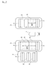
- FIG. 2 is a block diagram for explaining the function of the parking assist ECU 50.
- the parking assist ECU 50 includes a vehicle recognition unit 501, a road direction reference line setting unit 502, a reference distance calculation unit 503, a vehicle group division unit 504, a parking space estimation unit 505, a parking lot
- the possible space division unit 506, a parking route calculation unit 507, and a vehicle control unit 508 are provided.
- the vehicle recognition unit 501 recognizes the parked vehicle 2 (see FIG. 3 and the like) based on a reflection point position information group (hereinafter referred to as a point group) input from the distance sensor group 10 as a polar coordinate group.
- the vehicle recognizing unit 501 first integrates the point group input from the front distance sensor 11, the right side distance sensor 12, and the left side distance sensor 13 by converting the coordinates from polar coordinates to xy plane coordinates, and then clustering. To extract a group of adjacent points.
- FIG. 3 is a plan view for explaining the recognition process of the parked vehicle 2.
- the parked vehicle 2 existing in the parking lot is extracted as an L-shaped point group by the vehicle recognition unit 501.
- a recognition method of the parked vehicle 2 it is not restricted to the above-mentioned method, Other well-known methods can be used.
- FIG. 4 is a plan view for explaining the calculation process of the position and orientation of the parked vehicle 2.
- the vehicle recognition unit 501 calculates the position and orientation of the parked vehicle 2 based on the information of the L-shaped point group extracted by performing clustering. For example, the vehicle recognition unit 501 calculates the representative point P (see FIG. 3) of each parked vehicle 2 based on the information of the L-shaped point group, and determines the position and orientation of the calculated representative point P as the parked vehicle. 2 is output to the reference distance calculation unit 503 as the position and orientation of 2.
- one of the pair of L-shaped straight lines becomes a straight line indicating the front surface of the parked vehicle 2 parked rearward or the rear surface of the parked vehicle 2 parked forward, and the other straight line represents the parked vehicle 2. It becomes a straight line showing the side surface of.
- the parked vehicle 2 is parked in front or facing forward.
- the rear surface of the parked vehicle 2 enters a range from 45 ° on the left side to 45 ° on the right side with respect to the vector indicating the direction of the host vehicle 1.
- the vehicle recognition unit 501 makes a straight line that falls in a range from 45 ° on the left side to 45 ° on the right side with respect to the vector indicating the direction of the host vehicle 1 on the front or front side of the parked vehicle 2 parked rearward. It is extracted as a straight line indicating the rear surface of the parked parked vehicle 2. Then, the vehicle recognition unit 501 calculates the center point of the extracted straight line as the representative point P of the parked vehicle 2.
- the vehicle recognizing unit 501 calculates not only the position of the representative point P of the parked vehicle 2 but also the direction based on the direction of the straight line indicating the front or rear surface of the parked vehicle 2 and the straight line indicating the side of the parked vehicle 2. Information on the position and orientation of the representative point P of the vehicle 2 is output to the reference distance calculation unit 503.
- the representative point P of the parked vehicle 2 is not necessarily set at the center of the front or rear surface of the parked vehicle 2, and may be set at the same position for the plurality of parked vehicles 2, for example, the front of the parked vehicle 2 May be set at the left and right ends, the center (center of gravity), and the like.
- FIG. 5 is a plan view for explaining the setting process of the runway direction reference line L.
- the runway direction reference line setting unit 502 sets the runway direction of the host vehicle, sets the runway direction reference line L that is a straight line along the runway direction as the runway of the host vehicle 1, and outputs the runway direction reference line L to the reference distance calculation unit 503. To do.
- the road direction reference line L is a straight line passing through an arbitrary point of the host vehicle 1 (for example, the center of the front surface of the host vehicle 1 described above).
- the distribution of the orientations of the parked vehicles 2 recognized by the vehicle recognition unit 501 is histogrammed, and the direction at a predetermined angle with respect to the peak direction is defined as the traveling direction.
- the method of doing can be illustrated.
- This method can be applied when information on the angle between the traveling direction of the host vehicle 1 and the direction of the parking frame is acquired in advance. For example, when the information that the angle between the traveling direction of the host vehicle 1 and the direction of the parking frame is 90 ° is acquired in advance, the direction is 90 ° with respect to the direction that peaks among the directions of the parked vehicle 2. Is set to the direction of the road.
- the traveling direction of the own vehicle 1 is detected by matching the map data including the parking lot acquired by the navigation system with the position of the own vehicle 1. The method of doing can be illustrated.
- FIG. 6 is a plan view for explaining the calculation process of the reference distance X.
- the reference distance calculation unit 503 calculates a reference distance X that is a distance between the position of the representative point P of the parked vehicle 2 and the runway direction reference line L, and calculates a relative position of the parked vehicle 2 with respect to the runway direction reference line L. Then, the calculated reference distance X and relative position are output to the vehicle group dividing unit 504. When calculating the relative position of the parked vehicle 2 with respect to the runway direction reference line L, it is calculated whether the parked vehicle 2 is on the left side or the right side of the runway direction reference line L.
- FIG. 7 is a plan view for explaining the grouping process of the vehicle group 3.
- the vehicle group division unit 504 groups a plurality of parked vehicles 2 having the same reference distance X and the same relative position with respect to the runway direction reference line L of the parked vehicle 2 as one vehicle group 3.
- Information on the vehicle group 3 and the parked vehicle 2 included therein is output to the parking space estimation unit 505.
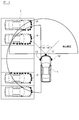
- FIG. 8 is a plan view for explaining the estimation process of the parking space 5.
- the parking space estimation unit 505 selects the vehicle group 3 closest to the host vehicle 1 from the plurality of vehicle groups 3 when there are a plurality of vehicle groups 3. When there is only one vehicle group 3, the parking space estimation unit 505 inevitably selects one vehicle group 3.
- the parking space estimation unit 505 calculates a mutual distance W1 between the adjacent parked vehicles 2 in the selected vehicle group 3.
- the parking space estimation unit 505 determines that the inter-distance W1 satisfies the relationship of the following expression (1).
- the space to be filled is estimated as the parking space 5 and the estimation result is output to the parking space division unit 506.
- the estimation method of the parking space 5 may be implemented based on the point cloud information acquired by the radar, or may be implemented based on the recognition result of the camera.
- the parking space estimation unit 505 can park the vehicle so as to include at least a region in which one of the parked vehicles 2 on both sides of the parking space 5 (for example, the longer overall length) is projected in the vehicle width direction. Space 5 is set.
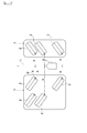
- FIG. 9 is a plan view for explaining the division processing of the parking space 5.
- the parking space division unit 506 divides the parking space 5 in the width direction (a direction parallel to the traveling direction) by the integer n expressed by the above equation (2), and information on the divided parking space 5 is obtained.
- the information is output to the parking route calculation unit 507.
- n parking spaces included in the parking space 5 are referred to as parking spaces 6.
- the parking route calculation unit 507 calculates the parking route to each parking space 6.
- the calculation method of the parking route is not particularly limited, and various known methods can be used.
- the parking route to the small parking space 6 is not calculated. Thereby, calculation load can be reduced.
- the parking route calculation unit 507 When calculating the parking route, the parking route calculation unit 507 first sets the parking target position in each of the small parking spaces 6. Examples of the method for setting the parking target position include a method in which the center point in the front-rear direction and the width direction of the selected small parking space 6 and the center point in the front-rear direction and the width direction of the host vehicle 1 coincide with each other. it can. And the parking route calculation part 507 calculates the parking route to the parking target position of each parking possible small space 6. FIG.
- the parking route calculation unit 507 selects one parking available small space 6 from the n parking available small spaces 6 included in the parking available space 5, and selects the selected parking available small space.
- the parking route to 6 may be calculated.
- a method of selecting one parking-capable small space 6 from among the n parking-capable small spaces 6 a method of selecting the closest parking-capable space 6 from the host vehicle 1 can be exemplified.
- the vehicle control unit 508 calculates a vehicle control command value for traveling along the parking route input from the parking route calculation unit 507, and outputs the vehicle control command value to the vehicle control ECU 60.
- Examples of the vehicle control command value include a target vehicle speed and a target steering angle, but other command values such as the acceleration of the host vehicle may be included.
- the vehicle control value calculation method is not particularly limited, and various known methods can be used.
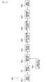
- FIG. 10 is a flowchart showing a control procedure of parking support processing executed by the parking support device 100 according to the present embodiment.
- parking assistance processing is started, and the process proceeds to step S101.
- step S101 detection information of the distance sensor group 10, the movement distance sensor 20, and the steering angle sensor 30 is input to the parking assistance ECU 50.
- step S102 the vehicle recognition unit 501 executes a process of recognizing the parked vehicle 2 based on the point cloud information input as a polar coordinate group from the distance sensor group 110 (see FIG. 3). If the parked vehicle 2 is recognized in step S102, the process proceeds to step S103. If the parked vehicle 2 is not recognized in step S102, the parking support process ends.
- step S103 the vehicle recognizing unit 501 calculates the position and orientation of the parked vehicle 2 based on the information of the L-shaped point group extracted by clustering and outputs the calculated position and orientation to the reference distance calculating unit 503 (FIG. 4). reference).
- step S104 the road direction reference line setting unit 502 sets the road direction reference line L as the road of the host vehicle 1 and outputs it to the reference distance calculation unit 503 (see FIG. 5).
- step S105 the reference distance calculation unit 503 calculates the reference distance X, calculates the relative position of the parked vehicle 2 with respect to the travel direction reference line L, and calculates the relative distance between the calculated reference distance X and the parked vehicle 2. The position is output to the vehicle group dividing unit 504 (see FIG. 6).
- step S106 and step S107 the vehicle group dividing unit 504 executes a process of grouping the vehicle group 3 (see FIG. 7).
- step S106 the vehicle group dividing unit 504 determines whether there are a plurality of parked vehicles 2 having the same reference distance X and the same relative position with respect to the runway direction reference line L of the parked vehicle 2. Determine whether. If an affirmative determination is made in step S106, the process proceeds to step S107, and if a negative determination is made in step S106, the parking support process ends.
- step S107 the vehicle group dividing unit 504 replaces the plurality of parked vehicles 2 having the same reference distance X and the same relative position with respect to the travel direction reference line L of the parked vehicle 2 into one vehicle group 3. And the information of the vehicle group 3 and the parked vehicle 2 included therein is output to the parking space estimation unit 505.
- step S108 and step S109 the parking space estimation unit 505 performs a process for estimating the parking space 5 (see FIG. 8).
- step S108 the parking space estimation unit 505 selects the vehicle group 3 that is closest to the host vehicle 1, and calculates the mutual distance W1 between the adjacent parked vehicles 2 in the selected vehicle group 3.
- step S109 the parking space estimation unit 505 determines whether the calculated mutual distance W1 and the width W0 of the host vehicle 1 satisfy the relationship of the above expression (1). If an affirmative determination is made in step S109, the process proceeds to step S110, and if a negative determination is made in step S109, the parking support process ends.
- step S110 the parking space estimation unit 505 estimates the area where the mutual distance W1 and the width W0 of the host vehicle 1 satisfy the relationship of the above expression (1) as the parking space 5, and can park the estimation result.
- the data is output to the space division unit 506.
- step S111 the parking space dividing unit 506 divides the parking space 5 in the width direction by the integer n represented by the above expression (2), and the information on the divided parking space 5 is the parking route calculation unit 507. (See FIG. 9).
- n 1, as a result, the division of the parking space 5 is not executed.
- step S112 the parking route calculation unit 507 calculates a parking route to each of the small parking spaces 6.
- step S113 the vehicle control unit 508 calculates a vehicle control command value for traveling along the parking route input from the parking route calculation unit 507, and outputs the vehicle control command value to the vehicle control ECU 60.
- the vehicle control ECU 60 executes drive control of the host vehicle 1 in accordance with the vehicle control command value input from the vehicle control unit 508. This completes the parking assistance process.
- the parking operation is executed and the parking support process is terminated.
- the sequential parking route may be corrected.
- the parking space 5 may be estimated between the parked vehicles 2 when there is a space larger than the length of the vehicle. In this case, the front-rear direction position of the host vehicle 1 parked in the parking space 5 and the front-rear direction position of other parked vehicles 2 can be matched, and the host vehicle 1 parked in the parking space 5 Can be prevented from sticking forward.
- the recognition information of the parked vehicle 2 existing in the parking lot is acquired from the distance sensor group 10, and the plurality of parked vehicles 2 arranged in parallel.
- the vehicle group 3 is extracted from the recognition information and grouped, and a parking space 5 is estimated between the parked vehicles 2 included in the vehicle group 3.
- the parking space can be estimated even when the white line indicating the parking frame cannot be recognized because the white line indicating the parking frame does not exist or is unclear.
- a plurality of parked vehicles 2 arranged in parallel along the running path of the parking lot can be grouped into one vehicle group 3.
- the distance W1 between the parked vehicles 2 included in the grouped vehicle group 3 is compared with the width W0 of one vehicle.
- the space is estimated as a parking space 5.
- at least one vehicle can be parked in the parking space 5 existing in the grouped vehicle group 3.
- the distance W1 between the parked vehicles 2 on both sides of the parking space 5 is multiplied by a predetermined width W2 of the parking frame by an integer n of 2 or more.
- the parking space 5 is divided by an integer n in the arrangement direction of the parked vehicles 2 in the vehicle group 3. As a result, at least n vehicles can be parked in the parking space 5 existing in the grouped vehicle group 3.
- a parking route to the parking space 5 is generated, and the host vehicle 1 is controlled so as to travel along the parking route.
- automatic parking can be executed without requiring the driver's operation.
- FIG. 11 is a block diagram for explaining functions of a parking assist ECU 150 according to another embodiment of the present invention.
- the parking assist ECU 150 includes a vehicle recognition unit 501, a vehicle group division unit 151, a parking space estimation unit 505, a parking space division unit 506, a parking route calculation unit 507, and vehicle control. Part 508.
- description is abbreviate
- FIG. 12 is a plan view for explaining the grouping process of the vehicle group 3.
- the vehicle group dividing unit 151 groups a plurality of parked vehicles 2 having the same direction (for example, an angle difference of ⁇ 0 to 10 °) as a single vehicle group 3, and is included in the vehicle group 3 and the vehicle group 3 Information on the parked vehicle 2 is output to the parking space estimation unit 505.
- FIG. 13 is a plan view for explaining the estimation process of the parking space 5.
- the parking space estimation unit 505 selects the vehicle group 3 closest to the host vehicle 1 from the plurality of vehicle groups 3 when there are a plurality of vehicle groups 3.
- the parking space estimation unit 505 calculates a mutual distance W1 between the adjacent parked vehicles 2 in the selected vehicle group 3.
- the inter-park distance W1 satisfies the relationship of the following equation (3).
- the area to be filled is estimated as the parking space 5 and the estimation result is output to the parking space division unit 506.
- (alpha) is an angle of the straight line orthogonal to the front-back direction of the parked vehicle 2, and the straight line parallel to a runway direction.
- the parking space estimation unit 505 estimates the parking space 5 in a situation where the mutual distance W1 and the width W0 of the host vehicle 1 satisfy the relationship of the above expression (1). Become.
- the parking space estimation unit 505 estimates the parking space 5 in a situation where the mutual distance W1 and the width W0 of the host vehicle 1 satisfy the relationship of the above expression (3). Become.
- the parking space 5 is set so as to include at least a region obtained by projecting one of the parked vehicles 2 on both sides (for example, the longer full length) in the vehicle width direction.
- FIG. 14 is a plan view for explaining the dividing process of the parking space 5.
- the parking space division unit 506 calculates whether the estimated width W1 of the parking space 5 corresponds to n times W2 / cos ⁇ (n is an integer), as represented by the following equation (4).
- n W1 / (W2 / cos ⁇ ) (4)
- (alpha) is an angle of the straight line orthogonal to the front-back direction of the parked vehicle 2, and a straight line parallel to a runway direction
- W2 is the width
- the parking space division unit 506 has an estimated width W1 of the parking space 5 that is n times the width W2 of the preset parking frame ( Whether n is an integer) is calculated.
- the parking space division unit 506 as represented by the above equation (4), the estimated width W1 of the parking space 5 corresponds to n times W2 / cos ⁇ (n is an integer). Will be calculated.
- the parking space division unit 506 calculates the parking route information of the parking space 5 obtained by dividing the parking space 5 by the integer n expressed by the above equation (4) in the width direction (direction parallel to the traveling road direction). Output to the unit 507.
- FIG. 15 is a flowchart showing a control procedure of parking support processing according to the present embodiment.
- parking assistance processing is started, and the process proceeds to step S101.
- Steps S101 and S102 are executed in the same manner as the parking support process in the above-described embodiment.
- the vehicle recognition unit 501 calculates the position and orientation of the parked vehicle 2 based on the information of the L-shaped point group extracted by clustering, and outputs the calculated position and orientation to the vehicle group division unit 151. (See FIG. 4).
- step S204 and step S205 the vehicle group dividing unit 151 executes a process of grouping the vehicle group 3 (see FIG. 13).
- step S204 there are a plurality of parked vehicles 2 in which the vehicle group dividing unit 151 has the same angle ⁇ between a straight line orthogonal to the front-rear direction of the parked vehicle 2 and a straight line parallel to the running direction. It is determined whether or not to do. If an affirmative determination is made in step S204, the process proceeds to step S205, and if a negative determination is made in step S204, the parking support process ends.
- step S205 the vehicle group dividing unit 151 groups the plurality of parked vehicles 2 having the same angle ⁇ as one vehicle group 3, and stores information on the vehicle group 3 and the parked vehicles 2 included therein. It outputs to the parking space estimation part 505.
- step S206 and step S207 the parking space estimation unit 505 performs a process for estimating the parking space 5 (see FIG. 14).
- step S206 the parking space estimation unit 505 selects the vehicle group 3 closest to the host vehicle 1, and calculates the mutual distance W1 between the adjacent parked vehicles 2 of the selected vehicle group 3.
- step S207 the parking space estimation unit 505 determines whether or not the calculated mutual distance W1 and the width W0 of the host vehicle 1 satisfy the relationship of the above expression (3). If an affirmative determination is made in step S207, the process proceeds to step S208, and if a negative determination is made in step S207, the parking assistance process ends.
- step S208 the parking space estimation unit 505 estimates the space where the mutual distance W1 and the width W0 of the host vehicle 1 satisfy the relationship of the above expression (3) as the parking space 5, and can park the estimation result.
- the data is output to the space division unit 506.
- step S209 the parking space dividing unit 506 divides the parking space 5 in the width direction by the integer n expressed by the above expression (4), and the information on the divided parking space 5 is the parking route calculation unit 507. (See FIG. 14).
- n 1, as a result, the division of the parking space 5 is not executed.
- steps S112 and S113 are executed in the same manner as the parking support process in the above-described embodiment.
- the parking assistance process in this embodiment is complete
- the parking operation is executed and the parking support process is terminated.
- the sequential parking route may be corrected.
- the direction of the parked vehicle 2 included in the recognition information of the distance sensor group 10 is detected, and based on the detected direction of the parked vehicle 2,
- the vehicle group 3 is grouped.
- a plurality of parked vehicles 2 arranged in parallel along the running path of the parking lot can be grouped into a single vehicle group 3 in the parking lots of both the parallel parking system without angles and the parallel parking system with angles. .
- FIG. 16 is a block diagram for explaining functions of a parking assist ECU 250 according to another embodiment of the present invention.
- the parking assist ECU 250 includes a vehicle recognition unit 501, a vehicle group division unit 151, a road direction reference line setting unit 502, a reference distance calculation unit 503, and a vehicle group division unit 504.
- a space estimation unit 505, a parking space division unit 506, a parking route calculation unit 507, and a vehicle control unit 508 are provided.
- description is abbreviate
- FIG. 17 is a plan view for explaining the grouping process of the vehicle group 3.
- the vehicle group dividing unit 151 groups a plurality of parked vehicles 2 having the same direction (for example, an angle difference of ⁇ 0 to 10 °) as a single vehicle group 3, 3 and the information of the parked vehicle 2 included therein are output to the parking space estimation unit 505.
- the parking space estimation unit 505. there may be a mixture of parked vehicles 2 having different reference distances X in the vehicle group 3.
- FIG. 18 is a plan view for explaining the setting process of the runway direction reference line L and the calculation process of the reference distance X.
- the travel direction reference line setting unit 502 sets the travel direction reference line L as the travel path of the host vehicle 1 and outputs it to the reference distance calculation unit 503.
- the reference distance calculation unit 503 calculates the reference distance X, calculates the relative position of the parked vehicle 2 with respect to the road direction reference line L, and sends the calculated reference distance X and relative position to the vehicle group dividing unit 504. Output.
- the relative position of the parked vehicle 2 with respect to the runway direction reference line L it is specified whether the parked vehicle 2 is on the left side or the right side of the runway direction reference line L.
- FIG. 19 is a plan view for explaining the dividing process of the vehicle group 3.
- the vehicle group dividing unit 504 further divides the vehicle group 3 in which parked vehicles 2 having different reference distances X are mixed into a plurality of vehicle groups 3A based on the reference distance X. At this time, the reference distance X for the parked vehicles 2 included in each vehicle group 3A is approximately the same. Then, the vehicle group division unit 504 outputs information on the plurality of vehicle groups 3A and the parked vehicles 2 included in each vehicle group 3A to the parking space estimation unit 505.
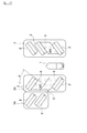
- FIG. 20 is a plan view for explaining the estimation process of the parking space 5.
- the parking space estimation unit 505 selects a vehicle group 3 closest to the host vehicle 1 from the plurality of vehicle groups 3 when there are a plurality of vehicle groups 3.
- the parking space estimation unit 505 calculates a mutual distance W1 between the adjacent parked vehicles 2 in the selected vehicle group 3.
- the parking space estimation unit 505 determines that the mutual distance W1 satisfies the relationship of the above equation (3).
- the space to be filled is estimated as the parking space 5 and the estimation result is output to the parking space division unit 506.
- FIG. 21 is a plan view for explaining the division processing of the parking space 5.
- the parking space division unit 506 calculates whether the estimated width W1 of the parking space 5 corresponds to n times W2 / cos ⁇ (n is an integer), as expressed by the above equation (4). Then, the parking space division unit 506 divides the parking space 5 in the width direction (direction parallel to the traveling road direction) by the integer n represented by the above expression (4), and information on the divided parking space 5 is obtained. The information is output to the parking route calculation unit 507.
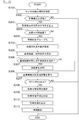
- FIG. 22 is a flowchart showing a control procedure of parking support processing according to the present embodiment.
- parking assistance processing is started, and the process proceeds to step S101.
- Steps S101, S102, S203, S204, and S205 are executed in the same manner as the parking support process in the above-described embodiment.
- step S104 similar to the parking assistance process in the above-described embodiment is executed.
- the road direction reference line setting unit 502 sets the road direction reference line L as the road of the host vehicle 1 and outputs it to the reference distance calculation unit 503 (see FIG. 18).
- the reference distance calculation unit 503 calculates the reference distance X, calculates the relative position of the parked vehicle 2 with respect to the travel direction reference line L, and uses the calculated reference distance X and relative position as the vehicle.
- the data is output to the group dividing unit 504.
- step S306 and step S307 the vehicle group dividing unit 504 executes a process of dividing the vehicle group 3 (see FIG. 19).
- step S306 the vehicle group dividing unit 504 determines whether or not there is a vehicle group 3 in which parked vehicles 2 having different reference distances X exist. If an affirmative determination is made in step S306, the process proceeds to step S307, and if a negative determination is made in step S306, the process proceeds to step S206.
- step S307 the vehicle group dividing unit 504 further divides the vehicle group 3 in which the parked vehicles 2 having different reference distances X are mixed into a plurality of vehicle groups 3A based on the reference distance X. Then, the vehicle group dividing unit 504 outputs information on the vehicle groups 3 and 3A and the parked vehicle 2 included therein to the parking space estimation unit 505.
- Steps S206 and S207, Steps S208, S209, S112, and S113 are executed.
- the parking assistance process in this embodiment is complete
- the parking operation is executed and the parking support process is terminated.
- the sequential parking route may be corrected.
- the direction of the parked vehicle 2 included in the recognition information of the distance sensor group 10 is detected, and based on the detected direction of the parked vehicle 2,
- the vehicle group 3 is grouped. Furthermore, a runway direction reference line L extending along the runway of the parking lot is set, and a reference distance X between the parked vehicle 2 and the runway direction reference line L included in the recognition information acquired from the distance sensor group 10 is calculated.
- the vehicle group 3 is divided based on the reference distance X.
- the vehicle groups 3 in which the parked vehicles 2 having different distances from the runway are mixed have the same distance from the runway.
- the vehicle group 3A can be divided into two or more groups of parked vehicles 2.
- the space when there is a space between the parked vehicles 2 included in the grouped vehicle group 3 where the interval between the parked vehicles 2 is larger than the width of one vehicle, The space was estimated as a parking space 5. However, when there is a space between the parked vehicles 2 included in the grouped vehicle group 3 and the space between the parked vehicles 2 is larger than the predetermined width of one parking frame, the space is parked. The possible space 5 may be estimated.
- the distance between the parked vehicles 2 across the parking space 5 in the grouped vehicle group 3 is compared with a value obtained by multiplying a predetermined parking frame width by an integer n of 2 or more.
- the parking space 5 is divided by n in the arrangement direction of the parked vehicles 2 in the vehicle group 3.
- the parkable space. 5 may be divided by n in the arrangement direction of the parked vehicles 2 in the vehicle group 3.
Abstract
Description
W1>W0 …(1) Here, as shown in FIG. 8, in the case of a parallel parking system without an angle, the mutual distance W1 and the width W0 of the
W1> W0 (1)
n=W1/W2 …(2) FIG. 9 is a plan view for explaining the division processing of the
n = W1 / W2 (2)
W1>W0/cosα …(3)
但し、αは、駐車車両2の前後方向に対して直交する直線と走路方向に対して平行な直線との角度である。 When the calculated inter-distance W1 and the width W0 of the
W1> W0 / cosα (3)
However, (alpha) is an angle of the straight line orthogonal to the front-back direction of the parked
n=W1/(W2/cosα) …(4)
但し、αは、駐車車両2の前後方向に対して直交する直線と走路方向に対して平行な直線との角度であり、W2は、予め設定された駐車枠の幅である。 FIG. 14 is a plan view for explaining the dividing process of the
n = W1 / (W2 / cos α) (4)
However, (alpha) is an angle of the straight line orthogonal to the front-back direction of the parked
2 駐車車両
3 車両群
5 駐車可能空間
6 駐車可能小空間
50 駐車支援ECU
60 車両制御ECU
100 駐車支援装置
L 走路方向基準線
X 基準距離 DESCRIPTION OF
60 Vehicle control ECU
100 Parking assistance device L Track direction reference line X Reference distance
Claims (8)
- 駐車場に存在する駐車車両の認識情報を取得し、
並列された複数の前記駐車車両からなる車両群を前記認識情報から抽出してグループ化し、
グループ化した前記車両群に含まれる前記駐車車両の相互間に駐車可能な空間が存在する場合に、当該空間を駐車可能空間と推定する駐車支援方法。 Get recognition information for parked vehicles in the parking lot,
A vehicle group consisting of a plurality of the parked vehicles arranged in parallel is extracted from the recognition information and grouped,
The parking assistance method of estimating the said space as parking possible space, when the space which can park between the said parked vehicles contained in the grouped said vehicle group exists. - 前記駐車場の走路に沿って延びる基準線を設定し、
前記基準線と前記認識情報に含まれる前記駐車車両との距離を算出し、
算出した前記距離に基づいて、前記車両群を前記認識情報から抽出してグループ化する請求項1に記載の駐車支援方法。 Set a reference line that extends along the runway of the parking lot,
Calculating a distance between the reference line and the parked vehicle included in the recognition information;
The parking support method according to claim 1, wherein the vehicle group is extracted from the recognition information and grouped based on the calculated distance. - 前記認識情報に含まれる前記駐車車両の向きを検出し、
検出した前記向きに基づいて、前記車両群を前記認識情報から抽出してグループ化する請求項1又は2に記載の駐車支援方法。 Detecting the direction of the parked vehicle included in the recognition information;
The parking assistance method according to claim 1 or 2, wherein the vehicle group is extracted from the recognition information and grouped based on the detected orientation. - 前記車両群に含まれる前記駐車車両の相互間に、前記駐車車両の相互間距離が1台の車両の幅又は予め定めた1つの駐車枠の幅と比較して大きい空間が存在する場合に、当該空間を駐車可能空間と推定する請求項1~3の何れか1項に記載の駐車支援方法。 When there is a space between the parked vehicles included in the vehicle group where the distance between the parked vehicles is larger than the width of one vehicle or the width of one predetermined parking frame, The parking support method according to any one of claims 1 to 3, wherein the space is estimated as a parking space.
- 前記車両群に含まれる前記駐車車両の相互間に、前記駐車車両の前後方向の長さが1台の車両の長さと比較して大きい空間が存在する場合に、当該空間を駐車可能空間と推定する請求項4に記載の駐車支援方法。 When there is a space between the parked vehicles included in the vehicle group and the length of the parked vehicle is larger than the length of one vehicle, the space is estimated as a parking space. The parking support method according to claim 4.
- 前記駐車可能空間の両側の前記駐車車両の相互間距離が、予め定めた駐車枠の幅又は車両の幅に2以上の整数nを乗じた値と比較して大きい場合に、前記駐車可能空間を、前記車両群における前記駐車車両の配列方向に前記整数nで分割する請求項4又は5に記載の駐車支援方法。 When the distance between the parked vehicles on both sides of the parking space is larger than a predetermined parking frame width or a vehicle width multiplied by an integer n of 2 or more, the parking space is The parking support method according to claim 4 or 5, wherein the parking space is divided by the integer n in the arrangement direction of the parked vehicles in the vehicle group.
- 前記駐車可能空間への駐車経路を生成し、
前記駐車経路に沿って走行するように自車両を制御する請求項1~6の何れか1項に記載の駐車支援方法。 Generate a parking route to the parking space,
The parking support method according to any one of claims 1 to 6, wherein the host vehicle is controlled to travel along the parking route. - 駐車支援機能を有する駐車支援コントローラを備え、
前記駐車支援コントローラは、
駐車場に存在する駐車車両の認識情報を取得し、
並列された複数の前記駐車車両からなる車両群を前記認識情報から抽出してグループ化し、
グループ化した前記車両群に含まれる前記駐車車両の相互間に駐車可能な空間が存在する場合に、当該空間を駐車可能空間と推定する駐車支援装置。 A parking support controller having a parking support function;
The parking assistance controller is:
Get recognition information for parked vehicles in the parking lot,
A vehicle group consisting of a plurality of the parked vehicles arranged in parallel is extracted from the recognition information and grouped,
The parking assistance apparatus which estimates the said space as parking possible space, when the space which can park between the said parked vehicles contained in the grouped said vehicle group exists.
Priority Applications (9)
| Application Number | Priority Date | Filing Date | Title |
|---|---|---|---|
| JP2018514047A JP6665929B2 (en) | 2016-04-28 | 2016-04-28 | Parking assistance method and device |
| US16/096,445 US10733889B2 (en) | 2016-04-28 | 2016-04-28 | Method and device for parking assistance |
| CA3022346A CA3022346A1 (en) | 2016-04-28 | 2016-04-28 | Method and device for parking assistance |
| KR1020187030851A KR102076439B1 (en) | 2016-04-28 | 2016-04-28 | Parking Assistance Method and Device |
| PCT/JP2016/063331 WO2017187592A1 (en) | 2016-04-28 | 2016-04-28 | Method and device for parking assistance |
| EP16900462.9A EP3451311B1 (en) | 2016-04-28 | 2016-04-28 | Method and device for parking assistance |
| BR112018072028-3A BR112018072028A2 (en) | 2016-04-28 | 2016-04-28 | parking assistance method and device |
| CN201680084963.1A CN109074743A (en) | 2016-04-28 | 2016-04-28 | Parking assistance method and device |
| RU2018139286A RU2707409C1 (en) | 2016-04-28 | 2016-04-28 | Method and device for parking assistance |
Applications Claiming Priority (1)
| Application Number | Priority Date | Filing Date | Title |
|---|---|---|---|
| PCT/JP2016/063331 WO2017187592A1 (en) | 2016-04-28 | 2016-04-28 | Method and device for parking assistance |
Publications (1)
| Publication Number | Publication Date |
|---|---|
| WO2017187592A1 true WO2017187592A1 (en) | 2017-11-02 |
Family
ID=60160341
Family Applications (1)
| Application Number | Title | Priority Date | Filing Date |
|---|---|---|---|
| PCT/JP2016/063331 WO2017187592A1 (en) | 2016-04-28 | 2016-04-28 | Method and device for parking assistance |
Country Status (9)
| Country | Link |
|---|---|
| US (1) | US10733889B2 (en) |
| EP (1) | EP3451311B1 (en) |
| JP (1) | JP6665929B2 (en) |
| KR (1) | KR102076439B1 (en) |
| CN (1) | CN109074743A (en) |
| BR (1) | BR112018072028A2 (en) |
| CA (1) | CA3022346A1 (en) |
| RU (1) | RU2707409C1 (en) |
| WO (1) | WO2017187592A1 (en) |
Cited By (2)
| Publication number | Priority date | Publication date | Assignee | Title |
|---|---|---|---|---|
| KR20160021554A (en) * | 2014-08-18 | 2016-02-26 | 현대모비스 주식회사 | Apparatus and method for guiding parking zone |
| WO2023171401A1 (en) * | 2022-03-11 | 2023-09-14 | ソニーセミコンダクタソリューションズ株式会社 | Signal processing device, signal processing method, and recording medium |
Families Citing this family (8)
| Publication number | Priority date | Publication date | Assignee | Title |
|---|---|---|---|---|
| DE102017204271A1 (en) * | 2017-03-15 | 2018-09-20 | Bayerische Motoren Werke Aktiengesellschaft | Optimal climate conditioning when parking |
| DE102017208385A1 (en) * | 2017-05-18 | 2018-11-22 | Ford Global Technologies, Llc | A method for supporting a parking operation of a motor vehicle, electronic parking assistance system and motor vehicle |
| US10967851B2 (en) * | 2018-09-24 | 2021-04-06 | Ford Global Technologies, Llc | Vehicle system and method for setting variable virtual boundary |
| JP7229804B2 (en) * | 2019-02-14 | 2023-02-28 | フォルシアクラリオン・エレクトロニクス株式会社 | Image processing device and image processing method |
| DE102019209482B3 (en) * | 2019-06-28 | 2020-08-27 | Volkswagen Aktiengesellschaft | Method for recognizing a parking space that is becoming vacant by an assistance system with a radar sensor, as well as assistance system and motor vehicle |
| CN113670305A (en) * | 2020-05-13 | 2021-11-19 | 长沙智能驾驶研究院有限公司 | Parking trajectory generation method and device, computer equipment and storage medium |
| CN112435500B (en) * | 2020-12-01 | 2022-03-08 | 深圳市顺易通信息科技有限公司 | Method and device for counting remaining parking spaces of parking lot and terminal equipment |
| US20230311854A1 (en) * | 2022-03-29 | 2023-10-05 | Continental Autonomous Mobility US, LLC | Autonomous vehicle garage parking |
Citations (3)
| Publication number | Priority date | Publication date | Assignee | Title |
|---|---|---|---|---|
| JP2009234294A (en) * | 2008-03-25 | 2009-10-15 | Panasonic Electric Works Co Ltd | Parking space monitoring device |
| JP2010012908A (en) * | 2008-07-03 | 2010-01-21 | Nikon Corp | Parking assist range finding system |
| JP2013116698A (en) * | 2011-12-05 | 2013-06-13 | Denso Corp | Control system |
Family Cites Families (16)
| Publication number | Priority date | Publication date | Assignee | Title |
|---|---|---|---|---|
| KR100894530B1 (en) | 2004-08-19 | 2009-04-24 | 아이신세이끼가부시끼가이샤 | Parking assist apparatus and parking assist method for vehicle |
| KR100908421B1 (en) | 2004-08-19 | 2009-07-21 | 아이신세이끼가부시끼가이샤 | Car parking assistance device and method |
| JP4543983B2 (en) * | 2005-03-22 | 2010-09-15 | 株式会社豊田自動織機 | Parking assistance device |
| JP4432930B2 (en) * | 2006-04-25 | 2010-03-17 | トヨタ自動車株式会社 | Parking assistance device and parking assistance method |
| JP2007315956A (en) | 2006-05-26 | 2007-12-06 | Aisin Aw Co Ltd | Map creation method, guiding method and navigation device for parking lot |
| JP2009096306A (en) * | 2007-10-16 | 2009-05-07 | Hiroshima Industrial Promotion Organization | Parking assist method |
| MY164070A (en) * | 2010-06-11 | 2017-11-15 | Nissan Motor | Parking assist apparatus and method |
| KR20140144470A (en) * | 2013-06-11 | 2014-12-19 | 주식회사 만도 | Parking control method, device and system |
| DE102014111011A1 (en) * | 2014-08-04 | 2016-02-04 | Valeo Schalter Und Sensoren Gmbh | Method for determining a parking area for parking a motor vehicle, driver assistance system and motor vehicle |
| JP6067635B2 (en) | 2014-09-12 | 2017-01-25 | アイシン精機株式会社 | Parking assistance device |
| JP6517561B2 (en) * | 2015-03-27 | 2019-05-22 | クラリオン株式会社 | Vehicle control device |
| KR101900228B1 (en) * | 2015-12-17 | 2018-09-20 | 닛산 지도우샤 가부시키가이샤 | Method and apparatus for parking assistance |
| CN108367722B (en) * | 2015-12-17 | 2020-08-18 | 日产自动车株式会社 | Parking assisting method and device |
| US20170186317A1 (en) * | 2015-12-29 | 2017-06-29 | Tannery Creek Systems Inc. | System and Method for Determining Parking Infraction |
| WO2017179206A1 (en) * | 2016-04-15 | 2017-10-19 | 三菱電機株式会社 | Display control device for parking assistance, and display control method for parking assistance |
| US10852153B2 (en) * | 2017-05-12 | 2020-12-01 | Lg Electronics Inc. | Autonomous vehicle and method of controlling the same |
-
2016
- 2016-04-28 CN CN201680084963.1A patent/CN109074743A/en active Pending
- 2016-04-28 WO PCT/JP2016/063331 patent/WO2017187592A1/en active Application Filing
- 2016-04-28 CA CA3022346A patent/CA3022346A1/en not_active Abandoned
- 2016-04-28 KR KR1020187030851A patent/KR102076439B1/en active IP Right Grant
- 2016-04-28 JP JP2018514047A patent/JP6665929B2/en active Active
- 2016-04-28 RU RU2018139286A patent/RU2707409C1/en active
- 2016-04-28 US US16/096,445 patent/US10733889B2/en active Active
- 2016-04-28 BR BR112018072028-3A patent/BR112018072028A2/en not_active Application Discontinuation
- 2016-04-28 EP EP16900462.9A patent/EP3451311B1/en active Active
Patent Citations (3)
| Publication number | Priority date | Publication date | Assignee | Title |
|---|---|---|---|---|
| JP2009234294A (en) * | 2008-03-25 | 2009-10-15 | Panasonic Electric Works Co Ltd | Parking space monitoring device |
| JP2010012908A (en) * | 2008-07-03 | 2010-01-21 | Nikon Corp | Parking assist range finding system |
| JP2013116698A (en) * | 2011-12-05 | 2013-06-13 | Denso Corp | Control system |
Non-Patent Citations (1)
| Title |
|---|
| See also references of EP3451311A4 * |
Cited By (3)
| Publication number | Priority date | Publication date | Assignee | Title |
|---|---|---|---|---|
| KR20160021554A (en) * | 2014-08-18 | 2016-02-26 | 현대모비스 주식회사 | Apparatus and method for guiding parking zone |
| KR102264395B1 (en) | 2014-08-18 | 2021-06-14 | 현대모비스 주식회사 | Apparatus and method for guiding parking zone |
| WO2023171401A1 (en) * | 2022-03-11 | 2023-09-14 | ソニーセミコンダクタソリューションズ株式会社 | Signal processing device, signal processing method, and recording medium |
Also Published As
| Publication number | Publication date |
|---|---|
| US20190130747A1 (en) | 2019-05-02 |
| CN109074743A (en) | 2018-12-21 |
| JP6665929B2 (en) | 2020-03-13 |
| CA3022346A1 (en) | 2017-11-02 |
| EP3451311A1 (en) | 2019-03-06 |
| BR112018072028A2 (en) | 2019-02-12 |
| KR102076439B1 (en) | 2020-02-11 |
| RU2707409C1 (en) | 2019-11-26 |
| EP3451311A4 (en) | 2019-05-15 |
| EP3451311B1 (en) | 2021-06-16 |
| US10733889B2 (en) | 2020-08-04 |
| KR20180128030A (en) | 2018-11-30 |
| JPWO2017187592A1 (en) | 2019-03-14 |
Similar Documents
| Publication | Publication Date | Title |
|---|---|---|
| WO2017187592A1 (en) | Method and device for parking assistance | |
| US10703360B2 (en) | Parking support method and device | |
| US10435074B2 (en) | Parking support method and device | |
| US10310508B2 (en) | Vehicle control apparatus | |
| JP6446732B2 (en) | Vehicle control device, vehicle control method, and vehicle control program | |
| US10019017B2 (en) | Autonomous driving system | |
| CN107848534B (en) | Vehicle control device, vehicle control method, and medium storing vehicle control program | |
| US9896098B2 (en) | Vehicle travel control device | |
| JP6666883B2 (en) | Driving support device | |
| WO2018047223A1 (en) | Obstacle determination method, parking support method, dispatch support method, and obstacle determination device | |
| JPWO2018066133A1 (en) | Vehicle determination method, travel route correction method, vehicle determination device, and travel route correction device | |
| JP2020087191A (en) | Lane boundary setting apparatus and lane boundary setting method | |
| JP2019067116A (en) | Solid object ground discrimination device | |
| JP4661602B2 (en) | Rear vehicle analysis device and collision prediction device | |
| US20220222946A1 (en) | Traffic environment recognition device and vehicle control device |
Legal Events
| Date | Code | Title | Description |
|---|---|---|---|
| ENP | Entry into the national phase |
Ref document number: 2018514047 Country of ref document: JP Kind code of ref document: A |
|
| ENP | Entry into the national phase |
Ref document number: 20187030851 Country of ref document: KR Kind code of ref document: A |
|
| ENP | Entry into the national phase |
Ref document number: 3022346 Country of ref document: CA |
|
| NENP | Non-entry into the national phase |
Ref country code: DE |
|
| REG | Reference to national code |
Ref country code: BR Ref legal event code: B01A Ref document number: 112018072028 Country of ref document: BR |
|
| 121 | Ep: the epo has been informed by wipo that ep was designated in this application |
Ref document number: 16900462 Country of ref document: EP Kind code of ref document: A1 |
|
| WWE | Wipo information: entry into national phase |
Ref document number: 2016900462 Country of ref document: EP |
|
| ENP | Entry into the national phase |
Ref document number: 2016900462 Country of ref document: EP Effective date: 20181128 |
|
| ENP | Entry into the national phase |
Ref document number: 112018072028 Country of ref document: BR Kind code of ref document: A2 Effective date: 20181025 |