WO2017183601A1 - Heat source unit - Google Patents
Heat source unit Download PDFInfo
- Publication number
- WO2017183601A1 WO2017183601A1 PCT/JP2017/015450 JP2017015450W WO2017183601A1 WO 2017183601 A1 WO2017183601 A1 WO 2017183601A1 JP 2017015450 W JP2017015450 W JP 2017015450W WO 2017183601 A1 WO2017183601 A1 WO 2017183601A1
- Authority
- WO
- WIPO (PCT)
- Prior art keywords
- bottom frame
- heat source
- refrigerant circuit
- refrigerant
- source unit
- Prior art date
Links
Images


Classifications
-
- F—MECHANICAL ENGINEERING; LIGHTING; HEATING; WEAPONS; BLASTING
- F24—HEATING; RANGES; VENTILATING
- F24F—AIR-CONDITIONING; AIR-HUMIDIFICATION; VENTILATION; USE OF AIR CURRENTS FOR SCREENING
- F24F1/00—Room units for air-conditioning, e.g. separate or self-contained units or units receiving primary air from a central station
- F24F1/06—Separate outdoor units, e.g. outdoor unit to be linked to a separate room comprising a compressor and a heat exchanger
- F24F1/56—Casing or covers of separate outdoor units, e.g. fan guards
-
- F—MECHANICAL ENGINEERING; LIGHTING; HEATING; WEAPONS; BLASTING
- F24—HEATING; RANGES; VENTILATING
- F24F—AIR-CONDITIONING; AIR-HUMIDIFICATION; VENTILATION; USE OF AIR CURRENTS FOR SCREENING
- F24F1/00—Room units for air-conditioning, e.g. separate or self-contained units or units receiving primary air from a central station
- F24F1/06—Separate outdoor units, e.g. outdoor unit to be linked to a separate room comprising a compressor and a heat exchanger
- F24F1/14—Heat exchangers specially adapted for separate outdoor units
- F24F1/16—Arrangement or mounting thereof
-
- F—MECHANICAL ENGINEERING; LIGHTING; HEATING; WEAPONS; BLASTING
- F24—HEATING; RANGES; VENTILATING
- F24F—AIR-CONDITIONING; AIR-HUMIDIFICATION; VENTILATION; USE OF AIR CURRENTS FOR SCREENING
- F24F13/00—Details common to, or for air-conditioning, air-humidification, ventilation or use of air currents for screening
- F24F13/20—Casings or covers
Definitions
- the present invention relates to a heat source unit, and more particularly to a heat source unit in which a refrigerant circuit component is provided in a casing.
- Patent Document 1 Japanese Patent Application Laid-Open No. 2011-158137
- refrigerant circuit components are provided in the casing.
- the bottom frame forming the bottom surface of the casing has a structure divided in the front-rear direction.
- any of the divided bottom frames is provided with the changed or added refrigerant circuit components, or No consideration is given to which size of the bottom frame is increased in order to provide the refrigerant circuit components to be changed or added. That is, the arrangement of all refrigerant circuit components, including the refrigerant circuit components to be changed or added, is examined, and the arrangement of the refrigerant circuit components and the casing size are changed based on the examination results. It has become.
- An object of the present invention is to provide a heat source unit in which a refrigerant circuit component is provided in a casing, and when the refrigerant circuit component is changed or added according to the capability or function, The purpose is to facilitate the arrangement.
- the heat source unit is a heat source unit in which a refrigerant circuit component is provided in a casing, and the refrigerant circuit component is changed or added according to capability or function.
- the bottom frame forming the bottom surface of the casing is a first bottom frame provided with a common first refrigerant circuit component, regardless of capability or function among refrigerant circuit components, and among refrigerant circuit components
- a second bottom frame provided with a second refrigerant circuit component that is changed or added according to capability or function.
- the bottom frame is divided into two, and one bottom frame (first bottom frame) is provided with a common refrigerant circuit component (first refrigerant circuit component) that does not depend on ability or function. Therefore, the arrangement of the refrigerant circuit components on the first bottom frame side and the size of the casing can be kept unchanged regardless of whether or not the refrigerant circuit components are changed or added according to the capability or function. .
- the refrigerant circuit component (second refrigerant circuit component) that is changed or added depending on the capability or function is provided on the other bottom frame (second bottom frame), the refrigerant circuit component on the second bottom frame side. It is only necessary to change the arrangement and the size of the casing.
- the casing size of the casing is changed by changing or adding the refrigerant circuit components according to the capability or function, the casing size is changed and the refrigerant circuit components are easily arranged. be able to.
- the first refrigerant circuit component temporarily stores the compressor that compresses the refrigerant and the refrigerant before being sucked into the compressor.
- An accumulator and an oil separator for separating the refrigerating machine oil from the refrigerant discharged from the compressor.
- the refrigerant pipe connected to the compressor and its peripheral equipment may be damaged by vibration during operation or transportation. Therefore, the arrangement of these devices and the arrangement and shape of the refrigerant pipes connected to these devices are appropriately set. For this reason, even when the refrigerant circuit components are changed or added according to the capability or function, the arrangement of these devices and the arrangement and shape of the refrigerant pipes connected to these devices need not be changed. Is preferred.
- the compressor and its peripheral devices are arranged together on the first bottom frame as the first refrigerant circuit component.
- the first bottom frame is thicker than the second bottom frame.
- a common refrigerant circuit component that does not depend on the capability or function includes a heavy object (such as a compressor or an accumulator), and is changed or added according to the capability or function.
- the component may include only a lightweight object.
- the first bottom frame is made thicker than the second bottom frame.
- the strength of the first bottom frame can be increased and the weight of the second bottom frame can be reduced.
- a heat source unit is the heat source unit according to any one of the first to third aspects, wherein a heat source side heat exchanger functioning as a refrigerant radiator or an evaporator is used as a second refrigerant circuit component.
- a heat source side heat exchanger is provided over both the first bottom frame and the second bottom frame.
- the size of the heat source side heat exchanger can be changed by changing the length of the side of the bottom frame.
- the heat source side heat exchanger is used as the second refrigerant circuit component, and the heat source side heat exchanger is provided over both the first bottom frame and the second bottom frame.
- the size of the heat source side heat exchanger can be easily changed without changing the size of the first bottom frame.
- the heat source unit according to the fifth aspect is the heat source unit according to any one of the first to fourth aspects, wherein the first bottom frame and the second bottom frame are formed with peaks and valleys extending in the front-rear direction of the casing. It is a corrugated member.
- first bottom frame and the second bottom frame are corrugated members, a high strength bottom frame can be obtained.
- first bottom frame and the second bottom frame are connected to the front of the casing.
- the casings can be arranged side by side to change the size of the casing.
- the size of the casing can be changed by arranging it side by side, so the size of the casing in the front-rear direction It can be done without restrictions.
- FIG. 1 It is a schematic block diagram of the air conditioning apparatus by which the heat source unit concerning one Embodiment of this invention was employ
- It is an external appearance perspective view of a heat source unit.
- It is a disassembled perspective view (only the schematic shape of an accumulator, a compressor, an oil separator, and a heat source side heat exchanger is shown in figure) of a heat source unit.
- It is a top view (only the schematic shape of an accumulator, a compressor, an oil separator, and a heat source side heat exchanger is shown) which shows a bottom frame and an installation leg.
- It is a schematic block diagram (when an injection function is added) of an air conditioning apparatus.
- FIG. 1 It is a top view (only the schematic shape of an accumulator, a compressor, an oil separator, a heat source side heat exchanger, and a receiver is shown in figure) which shows a bottom frame and an installation leg at the time of adding an injection function.
- Plan view showing bottom frame and installation legs when capacity is increased (only schematic shapes of accumulator, compressor, oil separator, heat source side heat exchanger, second compressor, second oil separator and receiver are shown) ).
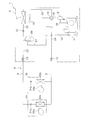
- FIG. 1 is a schematic configuration diagram of an air conditioner 1 in which a heat source unit 2 according to an embodiment of the present invention is employed.
- the air conditioner 1 is a device capable of cooling and heating a room such as a building by performing a vapor compression refrigeration cycle.
- the air conditioner 1 is mainly configured by connecting a heat source unit 2 and utilization units 3a and 3b.
- the heat source unit 2 and the utilization units 3 a and 3 b are connected via a liquid refrigerant communication tube 4 and a gas refrigerant communication tube 5.
- the vapor compression refrigerant circuit 6 of the air conditioner 1 is configured by connecting the heat source unit 2 and the utilization units 3 a and 3 b via the refrigerant communication tubes 4 and 5.
- the heat source unit 2 is installed outdoors (on the roof of a building, near the wall of the building, etc.) and constitutes a part of the refrigerant circuit 6.
- the heat source unit 2 mainly includes an accumulator 7, a compressor 8, an oil separator 9, a four-way switching valve 10, a heat source side heat exchanger 11, a heat source side expansion valve 12, a liquid side closing valve 13, The gas side closing valve 14 and the heat source side fan 15 are provided. Each device and the valve are connected by refrigerant pipes 16-24.
- the utilization units 3a and 3b are installed in a room (such as a living room or a ceiling space) and constitute a part of the refrigerant circuit 6.
- the utilization unit 3a mainly includes a utilization side expansion valve 31a, a utilization side heat exchanger 32a, and a utilization side fan 33a.
- the utilization unit 3b mainly includes a utilization side expansion valve 31b, a utilization side heat exchanger 32b, and a utilization side fan 33b.
- the refrigerant communication pipes 4 and 5 are refrigerant pipes that are constructed on site when the air conditioner 1 is installed at a place such as a building.
- One end of the liquid refrigerant communication tube 4 is connected to the liquid side closing valve 13 of the heat source unit 2, and the other end of the liquid refrigerant communication tube 4 is connected to the liquid side end of the usage side expansion valves 31a and 31b of the usage units 3a and 3b. It is connected.
- One end of the gas refrigerant communication pipe 5 is connected to the gas side shut-off valve 14 of the heat source unit 2, and the other end of the gas refrigerant communication pipe 5 is the gas side end of the usage side heat exchangers 32a and 32b of the usage units 3a and 3b. It is connected to the.
- FIG. 2 is an external perspective view of the heat source unit 2.
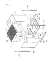
- FIG. 3 is an exploded perspective view of the heat source unit 2 (only the schematic shapes of the accumulator 7, the compressor 8, the oil separator 9, and the heat source side heat exchanger 11 are shown).
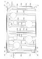
- FIG. 4 is a plan view showing only the bottom frame 51 and the installation legs 41 (only schematic shapes of the accumulator 7, the compressor 8, the oil separator 9, and the heat source side heat exchanger 11 are shown).
- FIG. 5 is a schematic configuration diagram of the air conditioner 1 (when an injection function is added).
- FIG. 6 is a plan view showing the bottom frame 51 and the installation leg 41 when the injection function is added (only the schematic shapes of the accumulator 7, the compressor 8, the oil separator 9, the heat source side heat exchanger 11 and the receiver 26 are illustrated. ).
- FIG. 7 is a plan view showing the bottom frame 51 and the installation leg 41 when the capacity is increased (accumulator 7, compressor 8, oil separator 9, heat source side heat exchanger 11, second compressor 28, second Only the schematic shapes of the oil separator 29 and the receiver 26 are shown).
- the heat source unit 2 is called an upper blow type structure that takes air into the casing 40 from below and blows air out of the casing 40 from above.
- the heat source unit 2 is mainly composed of a substantially rectangular parallelepiped box-shaped casing 40, a heat source side fan 15, devices 7, 8, 9, 11 such as a compressor and a heat source side heat exchanger, a four-way switching valve, and a heat source side expansion valve.
- refrigerant circuit components constituting a part of the refrigerant circuit 6 including the valves 10, 12 to 14 and the refrigerant pipes 16 to 24.
- “top”, “bottom”, “left”, “right”, “front”, “back”, “front”, and “back” are shown in FIG. 2 unless otherwise specified.
- the direction when the heat source unit 2 to be viewed is viewed from the front (left oblique front side of the drawing) is meant.
- the casing 40 mainly includes a bottom frame 51 spanned on a pair of installation legs 41 extending in the left-right direction, a column 61 extending vertically from a corner of the bottom frame 51, and a fan module 71 attached to the upper end of the column 61. And a front panel 81.
- the bottom frame 51 forms the bottom surface of the casing 40, and the heat source side heat exchanger 11 is provided on the bottom frame 51.
- the heat source side heat exchanger 11 is a substantially U-shaped heat exchanger in plan view facing the back surface and both left and right side surfaces of the casing 40, and substantially forms the back surface and both left and right side surfaces of the casing 40. Yes.
- a fan module 71 is provided on the upper side of the heat source side heat exchanger 11, and forms a portion above the front and rear surfaces of the casing 40, and the left and right support columns 61, and the top surface of the casing 40. Yes.
- the fan module 71 is an assembly in which the heat source side fan 15 and the bell mouth 72 are housed in a substantially rectangular parallelepiped box having an upper surface and a lower surface opened, and a blow grill 73 is provided at the upper surface opening. Yes.
- the front panel 81 is bridged between the front columns 61 and forms the front surface of the casing 40.
- refrigerant circuit components other than the heat source side fan 15 and the heat source side heat exchanger 11 are also accommodated.
- the compressor 8 is a device that compresses the refrigerant, and is provided on the bottom frame 51.
- the accumulator 7 is a refrigerant container that temporarily stores the refrigerant before being sucked into the compressor 8, and is provided on the bottom frame 51.
- the oil separator 9 is a device that separates refrigeration oil from the refrigerant discharged from the compressor 8, and is provided on the bottom frame 51.
- the bottom frame 51 is a corrugated plate-like member in which peaks and valleys extending in the front-rear direction of the casing 40 are formed, and has a first bottom frame 51a and a second bottom frame 51b that are divided into left and right.
- the first bottom frame 51a constitutes a portion on the left side of the bottom frame 51 when the casing 40 is viewed from the front side, and a peak portion 52a and a valley portion 53a extending in the front-rear direction of the casing 40 are formed. It is a corrugated member.
- the second bottom frame 51b constitutes a portion on the right side of the bottom frame 51 when the casing 40 is viewed from the front side.
- the corrugated plate is formed with peaks 52b and valleys 53b extending in the front-rear direction of the casing 40. Shaped member.
- the first bottom frame 51a and the second bottom frame 51b are arranged side by side in the left-right direction when the casing 40 is viewed from the front side.
- the first bottom frame 51 a and the second bottom frame 51 b are bridged on the installation leg 41.
- the ends of the first and second bottom frames 51a, 51b on the side where the peaks 52a, 52b and valleys 53a, 53b are visible are supported by the installation legs 41.
- the second bottom frame 51b is connected to the end of the first bottom frame 51a perpendicular to the front-rear direction end (here, the left-right direction) and closer to the second bottom frame 51b (here, the right side).
- a connecting wall portion 59a is formed in contact therewith.
- An outer wall portion 55b extending upward from the valley portion 53b is formed at the end of the second bottom frame 51b orthogonal to the front-rear direction end (here, the left-right direction) and far from the first bottom frame 51a (here, the right side).
- the end of the second bottom frame 51b is orthogonal to the front-rear direction end (here, the left-right direction) and close to the first bottom frame 51a (here, the left side).
- a connecting wall portion 59b that comes into contact is formed.
- the outer wall portions are not formed at the end portions in the front-rear direction of the first and second bottom frames 51a, 51b.
- the shapes of the first and second bottom frames 51a and 51b are simplified.
- first bottom frame 51a and the second bottom frame 51b are corrugated members, it is possible to obtain the bottom frames 51a and 51b having high strength.
- the crest portions 52a and 52b and the trough portions 53a and 53b of the corrugated first bottom frame 51a and the second bottom frame 51b are formed across the front and rear direction of the casing 40, so the first bottom frame 51a.
- the second bottom frame 51b is suitable for being arranged side by side when the casing 40 is viewed from the front side.
- the installation leg 41 is a substantially C-shaped member in side view extending in the left-right direction of the casing 40.
- the installation leg 41 mainly includes a fixed portion 42 fixed to the installation surface, a rising portion 43 extending upward from one end portion in the front-rear direction of the fixed portion 42, and a front-rear direction from the upper end portion of the rising portion 43. And a support portion 44 extending horizontally toward the other side.
- the support portion 44 supports the end portions in the front-rear direction of the first and second bottom frames 51a and 51b from below.
- the installation leg 41 has a wall portion 45 extending upward from the other end portion of the support portion 44 in the front-rear direction.
- the wall portion 45 is located outside the end portions in the front-rear direction of the first and second bottom frames 51a and 51b. That is, in the case of the installation leg 41 arranged on the front side of the casing 40, the wall 45 is located on the front side of the front and rear ends of the first and second bottom frames 51a and 51b. In the case of the installation leg 41 arranged on the back side, the wall portion 45 is located on the back side of the front and rear end portions of the first and second bottom frames 51a and 51b. And the wall part 45 of the installation leg 41 functions as an outer wall part of the edge part of the front-back direction of the 1st and 2nd bottom frames 51a and 51b.
- the wall portions 45 of the installation legs 41 allow the outer wall portions of the left and right ends of the first and second bottom frames 51a and 51b to be formed. It has the same function as 55a and 55b.
- the heat source unit 2 adopting the bottom frame 51 having such a divided structure refrigerant circuit components such as the compressor 8 are provided. At this time, the refrigerant circuit components are changed or added according to the capability or function. There is a case. In such a case, any of the divided bottom frames 51a and 51b is provided with the refrigerant circuit components to be changed or added, and the bottom to provide these changed or added refrigerant circuit components. It is desirable to make it easy to change the size of the casing 40 and arrange the refrigerant circuit components in consideration of which size of the frames 51a and 51b is increased.
- the bottom frame 51 is divided into two (first and second bottom frames 51a, 51b), and one of the bottom frames (first bottom frame 51a) has functions and functions.
- An unreliable common refrigerant circuit component (first refrigerant circuit component) is provided.
- the first refrigerant circuit components are the refrigerant circuit components 7 to 10, 12 to 24 except for the heat source side heat exchanger 11 among the refrigerant circuit components 7 to 14, 16 to 24 provided in the casing 40. 14, 16-24.
- These first refrigerant circuit components are required to be provided in the heat source unit 2 at the minimum in configuring the air conditioner 1, and are not changed even when the capability or function is changed or added. It is a refrigerant circuit component.
- the first refrigerant circuit component includes the compressor 8 that compresses the refrigerant, the accumulator 7 that temporarily stores the refrigerant before being sucked into the compressor 8, and the refrigerant that is discharged from the compressor 8.
- An oil separator 9 for separating the refrigerating machine oil is included.
- the other bottom frame (second bottom frame 51b) is provided with a refrigerant circuit component (second refrigerant circuit component) that is changed or added depending on capability or function.
- the second refrigerant circuit component is the heat source side heat exchanger 11 that functions as a refrigerant radiator or an evaporator, and includes the first bottom frame 51a and the second bottom frame 51b.
- the heat source side heat exchanger 11 is included in the second refrigerant circuit component because the size may be changed in order to change the heat exchange capacity when the capacity is changed.
- the heat source side heat exchanger 11 is set to a size suitable for the first refrigerant circuit component, and accordingly, the size of the second bottom frame 51 b is also the heat source side in the entire bottom frame 51. The size is set such that the heat exchanger 11 can be arranged.
- the arrangement of the refrigerant circuit components (that is, the first refrigerant circuit components) on the first bottom frame 51a side and the size of the casing 40 can be changed according to the capability or function. Regardless of whether the component (ie, the second refrigerant circuit component) is changed or added, it can be left unchanged.
- the arrangement of the refrigerant circuit components (that is, the second refrigerant circuit components) on the second bottom frame 51b side and the size of the casing 40 need be changed. Thereby, when the size of the casing 40 is changed by changing or adding the refrigerant circuit components according to the capability or function, it is easy to change the size of the casing 40 or arrange the refrigerant circuit components. Can be done.
- a receiver 26 is connected to the refrigerant pipe 23 in the heat source unit 2, and a gas vent pipe 27 for extracting a gas refrigerant from the upper part of the receiver 26 is connected to the compressor 8.
- a function to perform gas injection may be added. That is, the receiver 26 and the gas vent pipe 27 are added as second refrigerant circuit components.
- the receiver 26 is here connected to the second bottom frame as shown in FIG.
- the refrigerant pipe 23 (not shown in FIG. 6) is connected to the receiver 26, and the gas vent pipe 27 (not shown in FIG. 6) is connected to the receiver 26 and the compressor 8.
- the first refrigerant circuit components such as the compressor 8 provided in the first bottom frame 51a are provided.
- a gas injection function can be easily added without changing the arrangement.
- the receiver 26 as the refrigerant circuit component (second refrigerant circuit component) that is changed or added according to the capability or function is provided in the second bottom frame 51b. It is lighter than the first refrigerant circuit components including the compressor 8 and the accumulator 7 provided in the frame 51a.
- the first bottom frame 51a is made thicker than the second bottom frame 51b. Thereby, here, the strength of the first bottom frame 51a can be increased, and the weight of the second bottom frame 51b can be reduced.
- the second compressor connected in parallel to the first compressor 8 is provided together with the second oil separator to increase the operating capacity of the compressor, and the size of the heat source side heat exchanger 11 is accordingly increased.
- the ability may be changed to increase That is, while adding a 2nd compressor and a 2nd oil separator as a 2nd refrigerant circuit component, the size of the heat source side heat exchanger 11 as a 2nd refrigerant circuit component is changed.
- the second compressor 28 and the second oil separator 29 are provided on the second bottom frame 51b and connected in parallel to the first compressor 8, and the size of the heat source side heat exchanger 11 is increased.
- the size of the second bottom frame 51b is increased.
- the second compressor 28 and the second oil separator 29 are provided in the second bottom frame 51b, and the size of the second bottom frame 51b is changed in accordance with the change in the size of the heat source side heat exchanger 11. Therefore, it is possible to easily change the capacity without changing the arrangement of the first refrigerant circuit components such as the compressor 8 provided in the first bottom frame 51a.
- the heat source side heat exchanger 11 is provided along the side portion of the bottom frame 51, the length of the side portion of the second bottom frame 51b is changed to thereby serve as the second refrigerant circuit component.
- the size of the heat source side heat exchanger 11 can be easily changed.
- the refrigerant pipe connected to the compressor 8 and peripheral devices may be damaged by vibration during operation or transportation.
- the arrangement of these devices and the arrangement and shape of the refrigerant pipes connected to these devices are appropriately set so that such damage does not occur. For this reason, even when the refrigerant circuit components are changed or added according to the capability or function, the arrangement of these devices and the arrangement and shape of the refrigerant pipes connected to these devices need not be changed. Is preferred.
- the compressor 8 and its peripheral devices are attached to the first bottom frame 51a as the first refrigerant circuit components. They are arranged together.
- the refrigerant pipe connected to the compressor 8, the accumulator 7, the oil separator 9, and these apparatuses It is possible to do without changing the arrangement and shape. Further, since the size of the first bottom frame 51a and the refrigerant circuit components (that is, the first refrigerant circuit components) provided on the first bottom frame 51a are not changed, the vibration and noise performance is evaluated. Simulation prediction and the like can be easily performed.
- the crest portions 52a and 52b and the trough portions 53a and 53b of the corrugated first bottom frame 51a and the second bottom frame 51b are formed over the front-rear direction of the casing 40, so the first bottom frame 51a.
- the second bottom frame 51b can be arranged side by side to change the size of the casing 40.
- the size of the casing 40 can be changed by arranging the casing 40 side by side. This can be done without being restricted by the size of the direction.
- the first bottom frame 51a constitutes the left part of the bottom surface of the casing 40
- the second bottom frame 51b constitutes the right part of the bottom surface of the casing 40.
- the present invention is not limited to this. Instead, the left and right may be reversed.
- the present invention is widely applicable to heat source units in which refrigerant circuit components are provided in the casing.
Abstract
Description
図1は、本発明の一実施形態にかかる熱源ユニット2が採用された空気調和装置1の概略構成図である。 (1) Configuration of Air Conditioner FIG. 1 is a schematic configuration diagram of an air conditioner 1 in which a
図2は、熱源ユニット2の外観斜視図である。図3は、熱源ユニット2の分解斜視図(アキュムレータ7、圧縮機8、油分離器9及び熱源側熱交換器11の概略形状のみを図示)である。図4は、底フレーム51及び据付脚41を示す平面図(アキュムレータ7、圧縮機8、油分離器9及び熱源側熱交換器11の概略形状のみを図示)である。図5は、空気調和装置1の概略構成図(インジェクション機能を付加した場合)である。図6は、インジェクション機能を付加した場合の底フレーム51及び据付脚41を示す平面図(アキュムレータ7、圧縮機8、油分離器9、熱源側熱交換器11及びレシーバ26の概略形状のみを図示)である。図7は、能力を増大させた場合の底フレーム51及び据付脚41を示す平面図(アキュムレータ7、圧縮機8、油分離器9、熱源側熱交換器11、第2圧縮機28、第2油分離器29及びレシーバ26の概略形状のみを図示)である。 (2) Configuration of Heat Source Unit FIG. 2 is an external perspective view of the
熱源ユニット2は、下方からケーシング40内に空気を取り込んで上方からケーシング40外に空気を吹き出す上吹き型構造と呼ばれるものである。熱源ユニット2は、主として、略直方体箱状のケーシング40と、熱源側ファン15と、圧縮機や熱源側熱交換器等の機器7、8、9、11、四路切換弁や熱源側膨張弁等の弁10、12~14及び冷媒管16~24等を含み冷媒回路6の一部を構成する冷媒回路構成部品と、を有している。尚、以下の説明において、「上」、「下」、「左」、「右」、「前」、「後」、「前面」、「背面」は、特にことわりのない限り、図2に示される熱源ユニット2を前方(図面の左斜前側)から見た場合の方向を意味している。 <Overall structure>
The
底フレーム51は、ケーシング40の前後方向にわたる山部及び谷部が形成された波板状の部材であり、左右に二分割された第1底フレーム51a及び第2底フレーム51bを有している。ここで、第1底フレーム51aは、ケーシング40を前面側から見た際に、底フレーム51の左寄りの部分を構成しており、ケーシング40の前後方向にわたる山部52a及び谷部53aが形成された波板状の部材である。第2底フレーム51bは、ケーシング40を前面側から見た際に、底フレーム51の右寄りの部分を構成しており、ケーシング40の前後方向にわたる山部52b及び谷部53bが形成された波板状の部材である。第1底フレーム51a及び第2底フレーム51bは、ケーシング40を前面側から見た際に、左右方向に並んで配置されている。第1底フレーム51a及び第2底フレーム51bは、据付脚41上に架け渡されている。第1及び第2底フレーム51a、51bの山部52a、52b及び谷部53a、53bが見える側(ここでは、前後方向)の端部は、据付脚41によって支持されている。第1底フレーム51aの前後方向の端部に直交し(ここでは、左右方向)、かつ、第2底フレーム51bから遠い側(ここでは、左側)の端部には、山部52a及び谷部53aよりも上方に延びる外壁部55aが形成されている。第1底フレーム51aの前後方向の端部に直交し(ここでは、左右方向)、かつ、第2底フレーム51bに近い側(ここでは、右側)の端部には、第2底フレーム51bに接する接続壁部59aが形成されている。また、第2底フレーム51bの前後方向の端部に直交し(ここでは、左右方向)、かつ、第1底フレーム51aから遠い側(ここでは、右側)の端部には、山部52b及び谷部53bよりも上方に延びる外壁部55bが形成されている。第2底フレーム51bの前後方向の端部に直交し(ここでは、左右方向)、かつ、第1底フレーム51aに近い側(ここでは、左側)の端部には、第1底フレーム51aに接する接続壁部59bが形成されている。そして、第1及び第2底フレーム51a、51bの前後方向の端部には、第1及び第2底フレーム51a、51bの左右方向の端部とは異なり、外壁部が形成されておらず、第1及び第2底フレーム51a、51bの形状が簡略化されている。 <Detailed structure (including split structure of
The
<A>
上記実施形態では、第1底フレーム51aがケーシング40の底面の左寄りの部分を構成し、かつ、第2底フレーム51bがケーシング40の底面の右寄りの部分を構成しているが、これに限定されず、左右が逆であってもよい。 (3) Modification <A>
In the above embodiment, the first
上記実施形態では、能力又は機能に応じて冷媒回路構成部品が変更又は追加される場合として、ガスインジェクション機能の追加、及び、能力を大きくする変更する場合を挙げたが、これらに限定されるものではなく、他の機能追加や能力変更の場合に本発明を適用することも可能である。 <B>
In the above-described embodiment, the case where the refrigerant circuit components are changed or added according to the capability or function has been described as the addition of the gas injection function and the case of changing the capability to increase the capability. Instead, it is possible to apply the present invention when adding other functions or changing capabilities.
7 アキュムレータ
8 圧縮機
9 油分離器
40 ケーシング
51 底フレーム
51a 第1底フレーム
51b 第2底フレーム
52a、52b 山部
53a、53b 谷部 2
Claims (5)
- ケーシング(40)内に冷媒回路構成部品が設けられており、能力又は機能に応じて前記冷媒回路構成部品が変更又は追加されてなる熱源ユニットにおいて、
前記ケーシングの底面を形成する底フレーム(51)は、前記冷媒回路構成部品のうち能力又は機能によらず共通する第1冷媒回路構成部品が設けられる第1底フレーム(51a)と、前記冷媒回路構成部品のうち能力又は機能によって変更又は追加される第2冷媒回路構成部品が設けられる第2底フレーム(51b)と、を有している、
熱源ユニット(2)。 In the heat source unit in which the refrigerant circuit component is provided in the casing (40), and the refrigerant circuit component is changed or added according to capability or function,
The bottom frame (51) forming the bottom surface of the casing includes a first bottom frame (51a) provided with a common first refrigerant circuit component, regardless of capability or function among the refrigerant circuit components, and the refrigerant circuit. A second bottom frame (51b) provided with a second refrigerant circuit component that is changed or added depending on capability or function among the components,
Heat source unit (2). - 前記第1冷媒回路構成部品は、冷媒を圧縮する圧縮機(8)と、前記圧縮機に吸入される前の冷媒を一時的に溜めるアキュムレータ(7)と、前記圧縮機から吐出された後の冷媒から冷凍機油を分離する油分離器(9)と、を有している、
請求項1に記載の熱源ユニット。 The first refrigerant circuit component includes a compressor (8) that compresses the refrigerant, an accumulator (7) that temporarily stores the refrigerant before being sucked into the compressor, and a refrigerant that has been discharged from the compressor. An oil separator (9) for separating the refrigerating machine oil from the refrigerant,
The heat source unit according to claim 1. - 前記第1底フレームは、前記第2底フレームよりも板厚が大きい、
請求項1又は2に記載の熱源ユニット。 The first bottom frame has a larger plate thickness than the second bottom frame,
The heat source unit according to claim 1 or 2. - 前記第2冷媒回路構成部品には、冷媒の放熱器又は蒸発器として機能する熱源側熱交換器(11)が含まれており、
前記熱源側熱交換器は、前記第1底フレーム及び前記第2底フレームの両方にわたって設けられている、
請求項1~3のいずれか1項に記載の熱源ユニット。 The second refrigerant circuit component includes a heat source side heat exchanger (11) that functions as a refrigerant radiator or evaporator,
The heat source side heat exchanger is provided over both the first bottom frame and the second bottom frame,
The heat source unit according to any one of claims 1 to 3. - 前記第1底フレーム及び前記第2底フレームは、前記ケーシングの前後方向にわたる山部(52a、52b)及び谷部(53a、53b)が形成された波板状の部材である、
請求項1~4のいずれか1項に記載の熱源ユニット。 The first bottom frame and the second bottom frame are corrugated members in which crests (52a, 52b) and troughs (53a, 53b) extending in the front-rear direction of the casing are formed.
The heat source unit according to any one of claims 1 to 4.
Priority Applications (5)
| Application Number | Priority Date | Filing Date | Title |
|---|---|---|---|
| CN201780024294.3A CN109073249B (en) | 2016-04-21 | 2017-04-17 | Heat source unit |
| US16/094,840 US11022328B2 (en) | 2016-04-21 | 2017-04-17 | Heat source unit |
| ES17785939T ES2863665T3 (en) | 2016-04-21 | 2017-04-17 | Heat source unit |
| AU2017252884A AU2017252884B2 (en) | 2016-04-21 | 2017-04-17 | Heat source unit |
| EP17785939.4A EP3447396B1 (en) | 2016-04-21 | 2017-04-17 | Heat source unit |
Applications Claiming Priority (2)
| Application Number | Priority Date | Filing Date | Title |
|---|---|---|---|
| JP2016-084983 | 2016-04-21 | ||
| JP2016084983A JP6269717B2 (en) | 2016-04-21 | 2016-04-21 | Heat source unit |
Publications (1)
| Publication Number | Publication Date |
|---|---|
| WO2017183601A1 true WO2017183601A1 (en) | 2017-10-26 |
Family
ID=60116096
Family Applications (1)
| Application Number | Title | Priority Date | Filing Date |
|---|---|---|---|
| PCT/JP2017/015450 WO2017183601A1 (en) | 2016-04-21 | 2017-04-17 | Heat source unit |
Country Status (7)
| Country | Link |
|---|---|
| US (1) | US11022328B2 (en) |
| EP (1) | EP3447396B1 (en) |
| JP (1) | JP6269717B2 (en) |
| CN (1) | CN109073249B (en) |
| AU (1) | AU2017252884B2 (en) |
| ES (1) | ES2863665T3 (en) |
| WO (1) | WO2017183601A1 (en) |
Cited By (3)
| Publication number | Priority date | Publication date | Assignee | Title |
|---|---|---|---|---|
| JP2019132543A (en) * | 2018-01-31 | 2019-08-08 | ダイキン工業株式会社 | Outdoor unit of air conditioning device |
| US10753640B2 (en) | 2016-09-29 | 2020-08-25 | Daikin Industries, Ltd. | Heat source unit |
| WO2023209753A1 (en) * | 2022-04-25 | 2023-11-02 | 三菱電機株式会社 | Heat source unit |
Families Citing this family (1)
| Publication number | Priority date | Publication date | Assignee | Title |
|---|---|---|---|---|
| JP2023105765A (en) * | 2022-01-19 | 2023-07-31 | パナソニックIpマネジメント株式会社 | Outdoor unit |
Citations (6)
| Publication number | Priority date | Publication date | Assignee | Title |
|---|---|---|---|---|
| JP2004028359A (en) * | 2002-06-21 | 2004-01-29 | Mitsubishi Electric Corp | Air-conditioning and freezing device, heat source side unit, load side unit, replacing method of compressor and adding method of heat exchanger |
| JP2004156799A (en) * | 2002-11-05 | 2004-06-03 | Daikin Ind Ltd | Outdoor unit for air conditioner |
| JP2008075974A (en) * | 2006-09-21 | 2008-04-03 | Daikin Ind Ltd | Air conditioning unit, and outdoor unit for air conditioner |
| JP2011158137A (en) * | 2010-01-29 | 2011-08-18 | Sanyo Electric Co Ltd | Outdoor unit of air conditioner |
| JP2013083422A (en) * | 2011-09-30 | 2013-05-09 | Daikin Industries Ltd | Outdoor unit and refrigeration device |
| JP2016038175A (en) * | 2014-08-08 | 2016-03-22 | パナソニックIpマネジメント株式会社 | Bottom structure of outdoor unit for air conditioning device |
Family Cites Families (36)
| Publication number | Priority date | Publication date | Assignee | Title |
|---|---|---|---|---|
| JPH0468238A (en) * | 1990-07-05 | 1992-03-04 | Toshiba Corp | Outdoor unit of air conditioner |
| JP2001091023A (en) * | 1999-09-22 | 2001-04-06 | Mitsubishi Electric Corp | Air conditioner |
| US6457653B1 (en) * | 2001-02-21 | 2002-10-01 | Nordyne, Inc. | Blowerless air conditioning system |
| JP3719233B2 (en) * | 2002-07-04 | 2005-11-24 | ダイキン工業株式会社 | Air conditioner outdoor unit |
| CN100516696C (en) * | 2004-07-08 | 2009-07-22 | 乐金电子(天津)电器有限公司 | Outdoor unit of air conditioner having device for preventing drained water from freezing |
| JP2007093151A (en) | 2005-09-30 | 2007-04-12 | Hitachi Ltd | Air-conditioner |
| US20070163295A1 (en) * | 2006-01-18 | 2007-07-19 | Martin Lendell Sr | Air treatment systems |
| KR101371886B1 (en) * | 2007-10-31 | 2014-03-10 | 엘지전자 주식회사 | Air conditioner |
| US20090241577A1 (en) * | 2008-03-26 | 2009-10-01 | Sanyo Electric Co., Ltd. | Chiller unit, refrigeration system having chiller unit and air conditioner having chiller unit |
| US8627674B2 (en) * | 2008-05-15 | 2014-01-14 | Mark PLATT | Modular outboard heat exchanger air conditioning system |
| KR101575904B1 (en) * | 2009-01-09 | 2015-12-08 | 엘지전자 주식회사 | Fan motot mounting structure and outdoor unit for air conditioner comprising the same |
| JP2010216798A (en) * | 2009-02-23 | 2010-09-30 | Daikin Ind Ltd | Outdoor unit and refrigerating device |
| CN102753895B (en) * | 2010-02-15 | 2015-07-15 | 东芝开利株式会社 | Chilling unit |
| CN102562520B (en) * | 2010-12-10 | 2015-07-15 | 珠海格力电器股份有限公司 | Compressor fixing device and compressor fixing structure |
| JP5387610B2 (en) * | 2011-04-15 | 2014-01-15 | ダイキン工業株式会社 | Air conditioner outdoor unit |
| JP5218628B2 (en) * | 2011-11-30 | 2013-06-26 | ダイキン工業株式会社 | Air conditioner outdoor unit |
| JP5353998B2 (en) * | 2011-11-30 | 2013-11-27 | ダイキン工業株式会社 | Air conditioner outdoor unit |
| JP2015127593A (en) * | 2012-04-27 | 2015-07-09 | 東芝キヤリア株式会社 | Outdoor unit of air conditioner |
| JP5831431B2 (en) * | 2012-11-15 | 2015-12-09 | 三菱電機株式会社 | Air conditioner outdoor unit |
| EP2884193B1 (en) * | 2013-10-23 | 2022-08-03 | Lg Electronics Inc. | Air handling unit |
| KR20150075934A (en) * | 2013-12-26 | 2015-07-06 | 엘지전자 주식회사 | Brower apparatus and air conditioner having the same |
| US20150198353A1 (en) * | 2014-01-13 | 2015-07-16 | Multistack, LLC | Modular outboard heat exchanger air conditioning system |
| KR101633780B1 (en) * | 2014-03-18 | 2016-06-27 | 엘지전자 주식회사 | Outdoor unit of air conditioner and Manufacturing method of the same |
| KR20160031230A (en) * | 2014-09-12 | 2016-03-22 | 엘지전자 주식회사 | An outdoor unit for a an air conditioner |
| KR102337163B1 (en) * | 2014-11-12 | 2021-12-09 | 삼성전자주식회사 | Duct type air conditioning apparatus and assembling and deassembling method as the same |
| JP6335106B2 (en) * | 2014-11-21 | 2018-05-30 | ヤンマー株式会社 | heat pump |
| US20160178290A1 (en) * | 2014-12-17 | 2016-06-23 | Lg Electronics Inc. | Outdoor device for an air conditioner |
| EP3287706B1 (en) * | 2015-04-21 | 2023-03-15 | Mitsubishi Electric Corporation | Heat source unit |
| KR101872567B1 (en) * | 2015-08-25 | 2018-06-28 | 엘지전자 주식회사 | An outdoor unit for a an air conditioner |
| JP2017053577A (en) * | 2015-09-11 | 2017-03-16 | ジョンソンコントロールズ ヒタチ エア コンディショニング テクノロジー(ホンコン)リミテッド | Outdoor unit |
| JP2017110843A (en) * | 2015-12-15 | 2017-06-22 | 三菱重工業株式会社 | Outdoor equipment of multiple air conditioning system |
| US10180266B2 (en) * | 2016-02-25 | 2019-01-15 | Heatcraft Refrigeration Products Llc | Expansion rack for compressor mounting |
| WO2017199339A1 (en) * | 2016-05-17 | 2017-11-23 | 三菱電機株式会社 | Outdoor unit for air conditioning device |
| JP6281619B1 (en) * | 2016-09-29 | 2018-02-21 | ダイキン工業株式会社 | Heat source unit |
| JP6369518B2 (en) * | 2016-09-30 | 2018-08-08 | ダイキン工業株式会社 | Refrigeration equipment |
| JP2018063097A (en) * | 2016-10-14 | 2018-04-19 | 三菱重工サーマルシステムズ株式会社 | Air cooling chiller |
-
2016
- 2016-04-21 JP JP2016084983A patent/JP6269717B2/en active Active
-
2017
- 2017-04-17 CN CN201780024294.3A patent/CN109073249B/en active Active
- 2017-04-17 EP EP17785939.4A patent/EP3447396B1/en active Active
- 2017-04-17 AU AU2017252884A patent/AU2017252884B2/en active Active
- 2017-04-17 ES ES17785939T patent/ES2863665T3/en active Active
- 2017-04-17 US US16/094,840 patent/US11022328B2/en active Active
- 2017-04-17 WO PCT/JP2017/015450 patent/WO2017183601A1/en active Application Filing
Patent Citations (6)
| Publication number | Priority date | Publication date | Assignee | Title |
|---|---|---|---|---|
| JP2004028359A (en) * | 2002-06-21 | 2004-01-29 | Mitsubishi Electric Corp | Air-conditioning and freezing device, heat source side unit, load side unit, replacing method of compressor and adding method of heat exchanger |
| JP2004156799A (en) * | 2002-11-05 | 2004-06-03 | Daikin Ind Ltd | Outdoor unit for air conditioner |
| JP2008075974A (en) * | 2006-09-21 | 2008-04-03 | Daikin Ind Ltd | Air conditioning unit, and outdoor unit for air conditioner |
| JP2011158137A (en) * | 2010-01-29 | 2011-08-18 | Sanyo Electric Co Ltd | Outdoor unit of air conditioner |
| JP2013083422A (en) * | 2011-09-30 | 2013-05-09 | Daikin Industries Ltd | Outdoor unit and refrigeration device |
| JP2016038175A (en) * | 2014-08-08 | 2016-03-22 | パナソニックIpマネジメント株式会社 | Bottom structure of outdoor unit for air conditioning device |
Cited By (4)
| Publication number | Priority date | Publication date | Assignee | Title |
|---|---|---|---|---|
| US10753640B2 (en) | 2016-09-29 | 2020-08-25 | Daikin Industries, Ltd. | Heat source unit |
| JP2019132543A (en) * | 2018-01-31 | 2019-08-08 | ダイキン工業株式会社 | Outdoor unit of air conditioning device |
| US11118796B2 (en) | 2018-01-31 | 2021-09-14 | Daikin Industries, Ltd. | Outdoor unit for air conditioner |
| WO2023209753A1 (en) * | 2022-04-25 | 2023-11-02 | 三菱電機株式会社 | Heat source unit |
Also Published As
| Publication number | Publication date |
|---|---|
| JP2017194227A (en) | 2017-10-26 |
| US11022328B2 (en) | 2021-06-01 |
| EP3447396A4 (en) | 2019-04-24 |
| ES2863665T3 (en) | 2021-10-11 |
| US20190120506A1 (en) | 2019-04-25 |
| AU2017252884B2 (en) | 2018-12-20 |
| AU2017252884A1 (en) | 2018-12-06 |
| JP6269717B2 (en) | 2018-01-31 |
| CN109073249B (en) | 2019-08-23 |
| EP3447396A1 (en) | 2019-02-27 |
| CN109073249A (en) | 2018-12-21 |
| EP3447396B1 (en) | 2021-02-17 |
Similar Documents
| Publication | Publication Date | Title |
|---|---|---|
| WO2017183601A1 (en) | Heat source unit | |
| JP5447580B2 (en) | Air conditioner outdoor unit | |
| WO2017183607A1 (en) | Heat source unit | |
| JP2019120450A (en) | Heat source unit for refrigeration device | |
| WO2017175520A1 (en) | Heat source unit | |
| JP2005241236A (en) | Piping structure of outdoor unit of air-conditioner | |
| WO2018061426A1 (en) | Heat source unit | |
| JP6610691B2 (en) | Heat source unit | |
| JP6495860B2 (en) | Heat source unit | |
| JP2018087698A5 (en) | ||
| JP2017156038A (en) | Noise insulation cover and outdoor unit including the same | |
| JP2009186061A (en) | Outdoor unit and air conditioner equipped with the same | |
| JP5625889B2 (en) | Air conditioner outdoor unit | |
| JP2010151343A (en) | Refrigerating apparatus | |
| JP2014240712A (en) | Outdoor unit for air conditioner |
Legal Events
| Date | Code | Title | Description |
|---|---|---|---|
| NENP | Non-entry into the national phase |
Ref country code: DE |
|
| WWE | Wipo information: entry into national phase |
Ref document number: 2017785939 Country of ref document: EP |
|
| 121 | Ep: the epo has been informed by wipo that ep was designated in this application |
Ref document number: 17785939 Country of ref document: EP Kind code of ref document: A1 |
|
| ENP | Entry into the national phase |
Ref document number: 2017785939 Country of ref document: EP Effective date: 20181121 |
|
| ENP | Entry into the national phase |
Ref document number: 2017252884 Country of ref document: AU Date of ref document: 20170417 Kind code of ref document: A |