WO2017183528A1 - 被監視者監視装置、該方法および該システム - Google Patents
被監視者監視装置、該方法および該システム Download PDFInfo
- Publication number
- WO2017183528A1 WO2017183528A1 PCT/JP2017/014920 JP2017014920W WO2017183528A1 WO 2017183528 A1 WO2017183528 A1 WO 2017183528A1 JP 2017014920 W JP2017014920 W JP 2017014920W WO 2017183528 A1 WO2017183528 A1 WO 2017183528A1
- Authority
- WO
- WIPO (PCT)
- Prior art keywords
- sleeping posture
- monitored person
- unit
- sleeping
- information storage
- Prior art date
- Legal status (The legal status is an assumption and is not a legal conclusion. Google has not performed a legal analysis and makes no representation as to the accuracy of the status listed.)
- Ceased
Links
Images




Classifications
-
- A—HUMAN NECESSITIES
- A61—MEDICAL OR VETERINARY SCIENCE; HYGIENE
- A61B—DIAGNOSIS; SURGERY; IDENTIFICATION
- A61B5/00—Measuring for diagnostic purposes; Identification of persons
-
- A—HUMAN NECESSITIES
- A61—MEDICAL OR VETERINARY SCIENCE; HYGIENE
- A61B—DIAGNOSIS; SURGERY; IDENTIFICATION
- A61B5/00—Measuring for diagnostic purposes; Identification of persons
- A61B5/103—Measuring devices for testing the shape, pattern, colour, size or movement of the body or parts thereof, for diagnostic purposes
- A61B5/107—Measuring physical dimensions, e.g. size of the entire body or parts thereof
-
- A—HUMAN NECESSITIES
- A61—MEDICAL OR VETERINARY SCIENCE; HYGIENE
- A61G—TRANSPORT, PERSONAL CONVEYANCES, OR ACCOMMODATION SPECIALLY ADAPTED FOR PATIENTS OR DISABLED PERSONS; OPERATING TABLES OR CHAIRS; CHAIRS FOR DENTISTRY; FUNERAL DEVICES
- A61G7/00—Beds specially adapted for nursing; Devices for lifting patients or disabled persons
- A61G7/05—Parts, details or accessories of beds
-
- G—PHYSICS
- G08—SIGNALLING
- G08B—SIGNALLING SYSTEMS, e.g. PERSONAL CALLING SYSTEMS; ORDER TELEGRAPHS; ALARM SYSTEMS
- G08B21/00—Alarms responsive to a single specified undesired or abnormal condition and not otherwise provided for
- G08B21/02—Alarms for ensuring the safety of persons
- G08B21/04—Alarms for ensuring the safety of persons responsive to non-activity, e.g. of elderly persons
-
- G—PHYSICS
- G08—SIGNALLING
- G08B—SIGNALLING SYSTEMS, e.g. PERSONAL CALLING SYSTEMS; ORDER TELEGRAPHS; ALARM SYSTEMS
- G08B21/00—Alarms responsive to a single specified undesired or abnormal condition and not otherwise provided for
- G08B21/02—Alarms for ensuring the safety of persons
- G08B21/06—Alarms for ensuring the safety of persons indicating a condition of sleep, e.g. anti-dozing alarms
-
- G—PHYSICS
- G08—SIGNALLING
- G08B—SIGNALLING SYSTEMS, e.g. PERSONAL CALLING SYSTEMS; ORDER TELEGRAPHS; ALARM SYSTEMS
- G08B25/00—Alarm systems in which the location of the alarm condition is signalled to a central station, e.g. fire or police telegraphic systems
-
- G—PHYSICS
- G08—SIGNALLING
- G08B—SIGNALLING SYSTEMS, e.g. PERSONAL CALLING SYSTEMS; ORDER TELEGRAPHS; ALARM SYSTEMS
- G08B25/00—Alarm systems in which the location of the alarm condition is signalled to a central station, e.g. fire or police telegraphic systems
- G08B25/01—Alarm systems in which the location of the alarm condition is signalled to a central station, e.g. fire or police telegraphic systems characterised by the transmission medium
- G08B25/04—Alarm systems in which the location of the alarm condition is signalled to a central station, e.g. fire or police telegraphic systems characterised by the transmission medium using a single signalling line, e.g. in a closed loop
Definitions
- the present invention relates to a monitored person monitoring apparatus, a method, and a system for monitoring, for example, a person who needs nursing or a person who needs care (hereinafter referred to as a nursing person) as a monitoring target.
- a nursing person a person who needs nursing or a person who needs care
- Japan is an aging society, more specifically the ratio of population over 65 years old to the total population due to the improvement of living standards accompanying the post-war high economic growth, improvement of sanitary environment and improvement of medical standards, etc. It is a super-aging society with an aging rate exceeding 21%.
- the total population was about 126.5 million, while the elderly population over the age of 65 was about 25.56 million.
- the total population was about 124.11 million.
- the elderly population will be about 34.56 million.
- the number of nurses who need nursing or nursing care due to illness, injury, aging or the like is expected to increase more than those who need nursing in a normal society that is not an aging society.
- Such nurses are required to enter and receive nursing and nursing care at facilities such as hospitals and welfare facilities for the elderly (Japanese elderly law short-term entrance facilities, nursing homes for the elderly and special nursing homes for the elderly, etc.).
- facilities such as hospitals and welfare facilities for the elderly for example, those who need nursing care such as nurses or caregivers, etc. Nurses, etc.
- Nurses, etc. confirm their safety by periodically patrols.
- the number of nurses and the like is reduced in the quasi-night shift and night shift hours compared to the day shift hours, the work load per person increases, and therefore the work load must be reduced. For this reason, in recent years, a monitored person monitoring device that monitors (monitors) a patient who needs nursing is monitored and developed.
- Patent Document 1 discloses a bed slip notification system.
- This bed slip reporting system disclosed in Patent Document 1 includes a portable transmitter including an acceleration sensor that detects acceleration acting on a lying person lying on bedding, and a transmission unit that transmits a detection result of the acceleration sensor, A display unit; a receiving unit that receives a detection result of the acceleration sensor; a determination unit that determines whether the recumbent has turned over within a predetermined time based on the received detection result; And a monitoring device including a display control unit that controls the display unit to display a warning screen that warns of occurrence of bed slipping when it is determined that the user has not turned over within a predetermined time.
- the portable transmitter is configured to be attachable to a lying person's torso, and the determination unit identifies the lying person's posture based on the acceleration detected by the acceleration sensor, and the lying person is in the predetermined time period. It is comprised so that it may determine whether it has taken the substantially same attitude
- the present invention has been made in view of the above-described circumstances, and an object of the present invention is to be able to detect a sleeping posture without wearing a sensor, and to reduce the occurrence of a bed slip and a monitored person monitoring method. And providing a monitored person monitoring system.
- a monitored person monitoring apparatus, a monitored person monitoring method, and a monitored person monitoring system detect a sleeping posture that is a sleeping posture of a monitored subject to be monitored in a non-contact manner, and based on the detection result. When a certain sleeping posture continues for a predetermined time, a notification is made to the outside. Therefore, the monitored person monitoring apparatus, the monitored person monitoring method, and the monitored person monitoring system according to the present invention can detect the sleeping posture without wearing a sensor, and can reduce the occurrence of bed slip.
- the monitored person monitoring system in the embodiment monitors a monitored person (watched person) Ob that is a monitored object (watched object) to be monitored (watched), and communicates with the terminal device and the terminal device. And a monitored person monitoring device for monitoring the monitored person Ob.
- the monitored person monitoring apparatus is based on a sleeping posture detection unit that detects a sleeping posture that is a sleeping posture of the monitored person to be monitored, and a detection result of the sleeping posture detection unit.
- the device is provided with a sleeping posture determination notification unit that notifies the outside when a certain sleeping posture continues for a predetermined time, and can detect the sleeping posture without wearing a sensor and can reduce the occurrence of bed slip.
- Such a monitored person monitoring apparatus may be realized by being integrally configured as one device, and may be realized by a plurality of devices as a system.
- the monitored person monitoring device includes first and second devices that are communicably connected to each other, and the sleeping posture detection unit includes an imaging unit that generates an image of the monitored person; A detection unit that detects a sleeping posture of the monitored person based on the image of the monitored person generated by the imaging unit, the first device includes the imaging unit, and the second device includes: The detection unit and the sleeping posture determination notification unit.
- the monitored person monitoring device includes a sensor device SU as an example of the first device and a management server device SV as an example of the second device.
- the monitored person monitoring apparatus can be configured similarly to the following description.
- the sensor device SU may be configured to include the sleeping posture detection unit and the sleeping posture determination notification unit.
- the said terminal device may be one type of apparatus, in this embodiment, the said terminal device is two types of apparatuses, a fixed terminal device and a portable terminal device.
- the main difference between these fixed terminal devices and portable terminal devices is that the fixed terminal device is fixedly operated, while the portable terminal device is operated by being carried by a supervisor (user) such as a nurse or a caregiver.
- the fixed terminal device and the mobile terminal device are substantially the same.
- FIG. 1 is a diagram illustrating a configuration of a monitored person monitoring system according to the embodiment.
- FIG. 2 is a diagram showing the configuration of the management server device in the monitored person monitoring system.
- the monitored person monitoring system MS in the embodiment includes, for example, as shown in FIG. 1, one or a plurality of sensor devices SU (SU-1 to SU-4), a management server device SV, A fixed terminal device SP, one or a plurality of portable terminal devices TA (TA-1, TA-2), and a private branch exchange (PBX) CX, which are wired or wireless, LAN (Local) It is connected to be communicable via a network (network, communication line) NW such as Area Network.
- NW network, communication line
- the network NW may be provided with repeaters such as repeaters, bridges, and routers that relay communication signals.
- FIG. 1 one or a plurality of sensor devices SU (SU-1 to SU-4), a management server device SV, A fixed terminal device SP, one or a plurality of portable terminal devices TA (TA-1, TA-2), and a private branch exchange (PBX) CX, which are wired or wireless, LAN (Local) It is connected to be communicable via
- the plurality of sensor devices SU-1 to SU-4, the management server device SV, the fixed terminal device SP, the plurality of portable terminal devices TA-1, TA-2, and the private branch exchange CX include an L2 switch.
- a wired / wireless LAN for example, a LAN in accordance with the IEEE 802.11 standard
- NW including the LS and the access point AP.
- the plurality of sensor devices SU-1 to SU-4, the management server device SV, the fixed terminal device SP, and the private branch exchange CX are connected to the line concentrator LS, and the plurality of portable terminal devices TA-1, TA-2. Is connected to the line concentrator LS via the access point AP.
- the network NW constitutes a so-called intranet by using Internet protocol groups such as TCP (Transmission control protocol) and IP (Internet protocol).
- the monitored person monitoring system MS is arranged at an appropriate place according to the monitored person Ob.
- the monitored person (person to be watched) Ob is, for example, a person who needs nursing due to illness or injury, a person who needs care due to a decrease in physical ability, a single person living alone, or the like.
- the monitored person Ob may be a person who needs the detection when a predetermined inconvenient event such as an abnormal state occurs in the person. preferable.
- the monitored person monitoring system MS is suitably arranged in a building such as a hospital, a welfare facility for the elderly, and a dwelling unit according to the type of the monitored person Ob.
- the monitored person monitoring system MS is disposed in a building of a care facility that includes a plurality of living rooms RM in which a plurality of monitored persons Ob live and a plurality of living rooms such as a nurse station.
- the sensor device SU has, for example, a communication function that communicates with other devices SV, SP, TA via the network NW, and the management server device SV is a sleeping posture of the monitored subject Ob.
- the management server device SV is a sleeping posture of the monitored subject Ob.
- the sensor device SU communicates with the imaging unit that generates the image of the monitored person and other devices SV, SP, and TA via the network NW, for example, according to the IEEE 802.11 standard or the like.
- a communication interface unit such as a communication interface circuit (communication card), and a control unit such as a microcomputer for controlling the imaging unit and the communication interface unit according to the function.
- the imaging unit is disposed on, for example, a ceiling surface so as to be able to monitor a space (location space, in the example shown in FIG. 1, where the monitored person Ob is scheduled), and images the location space.
- An image is captured from above as an object, an image (image data) overlooking the imaged object is generated at a predetermined time interval, and each image (object image) of the imaged object is output to the control unit.
- the control unit transmits the target image input from the imaging unit to the management server device SV via the network NW by the communication interface unit.
- the imaging unit is expected to be located at the head of the monitored person Ob in the bedding on which the monitored person Ob is lying (for example, a bed). It arrange
- Such an imaging unit may be a device that generates a visible light image, but in the present embodiment, it is a device that generates an infrared image so that the monitored subject Ob can be monitored even in a relatively dark place.
- an imaging unit is an imaging optical system that forms an infrared optical image of an imaging target on a predetermined imaging surface, and the light receiving surface is aligned with the imaging surface.
- An image sensor that converts an infrared optical image in the imaging target into an electrical signal, and image data that is data representing an infrared image in the imaging target by performing image processing on the output of the image sensor.
- a digital infrared camera including an image processing unit to be generated.
- the imaging optical system of the imaging unit is preferably a wide-angle optical system (so-called wide-angle lens (including a fisheye lens)) having an angle of view that can image the entire living room RM in which the imaging unit is disposed.
- wide-angle optical system so-called wide-angle lens (including a fisheye lens)
- FIG. 1 shows four first to fourth sensor devices SU-1 to SU-4 as an example, and the first sensor device SU-1 is one of the monitored persons Ob.
- the second sensor device SU-2 is arranged in a room RM-2 (not shown) of Mr. B Ob-2 who is one of the monitored persons Ob.
- the third sensor device SU-3 is disposed in the room RM-3 (not shown) of Mr. C Ob-3, one of the monitored subjects Ob, and the fourth sensor device SU-4 It is arranged in the room RM-4 (not shown) of Mr. D Ob-4, one of the monitored persons Ob.
- the management server device SV has a communication function for communicating with other devices SU, TA, SP via the network NW.
- the management server device SV receives a target image of the monitored person Ob from the sensor device SU, the target image of the monitored person Ob
- the sleeping posture of the monitored person Ob is detected based on the detection result, and when a certain sleeping posture continues for a predetermined time based on the detection result, notification is made to the outside, in the present embodiment, to the predetermined terminal devices SP and TA.
- a device that provides the client with data corresponding to the request of the client terminal device SP, TA, etc. in the present embodiment
- manages the monitored person monitoring system MS as a whole.
- Such a management server device SV will be described in more detail later.
- the fixed terminal device SP includes a communication function for communicating with other devices SU, SV, TA via the network NW, a display function for displaying predetermined information, an input function for inputting predetermined instructions and data, and the like.
- a user interface of the monitored person monitoring system MS by inputting a predetermined instruction or data to be given to the management server device SV, the sensor device SU, or the mobile terminal device TA, or outputting a notification from the management server device SV It is a device that functions as (UI).
- Such a fixed terminal device SP can be configured by, for example, a computer with a communication function.
- the mobile terminal device TA has a communication function for communicating with other devices SV, SP, SU via the network NW, a display function for displaying predetermined information, an input function for inputting predetermined instructions and data, and a voice call.
- a portable terminal device TA can be configured by a portable communication terminal device such as a so-called tablet computer, a smartphone, or a mobile phone.
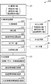
- the management server device SV includes a server-side communication interface unit (SV communication IF unit) 21, a server-side control processing unit (SV control processing unit) 22, and a server-side storage unit ( SV storage unit) 23.
- SV communication IF unit server-side communication interface unit
- SV control processing unit server-side control processing unit
- SV storage unit server-side storage unit
- the SV communication IF unit 21 is a communication circuit that is connected to the SV control processing unit 22 and performs communication according to the control of the SV control processing unit 22.
- the SV communication IF unit 21 generates a communication signal containing data to be transferred input from the SV control processing unit 22 in accordance with a communication protocol used in the network NW of the monitored person monitoring system MS, and the generated communication The signal is transmitted to other devices SV, SP, TA via the network NW.
- the SV communication IF unit 21 receives communication signals from other devices SV, SP, and TA via the network NW, extracts data from the received communication signals, and the SV control processing unit 22 can process the extracted data.
- the data is converted into data in a proper format and output to the SV control processing unit 22.
- the SV communication IF unit 21 includes, for example, a communication interface circuit that complies with the IEEE 802.11 standard or the like.
- the SV storage unit 23 is a circuit that is connected to the SV control processing unit 22 and stores various predetermined programs and various predetermined data under the control of the SV control processing unit 22.
- the various predetermined programs include, for example, an SV control program for controlling each part of the management server device SV according to the function of each part, and the target image of the monitored person Ob received from the sensor device SU.
- a detection program for detecting the sleeping posture of the monitored person Ob a sleeping posture determination notification program for notifying the outside when a predetermined sleeping posture continues for a predetermined time based on a detection result by the detection program,
- a control processing program such as a timer program that counts the time until a preset time is reached and outputs the fact (time up) at the preset time is included.
- the various types of predetermined data include a server identifier (server ID) that is an identifier for identifying and identifying the management server device SV of the own device, predetermined characteristic parameters related to occurrence of bed slip in the monitored person Ob, Data necessary for executing each program such as sleeping posture, which is a sleeping posture of a person, and inter-device information representing information between devices SU, SP, and TA such as a notification destination of the notification is included.
- the SV storage unit 23 includes, for example, a ROM (Read Only Memory) that is a nonvolatile storage element, an EEPROM (Electrically Erasable Programmable Read Only Memory) that is a rewritable nonvolatile storage element, and the like.
- the SV storage unit 23 includes a RAM (Random Access Memory) that serves as a working memory of the so-called SV control processing unit 22 that stores data generated during the execution of the predetermined program.
- the SV storage unit 23 functionally includes a feature parameter information storage unit 231, a sleeping posture information storage unit 232, and an inter-device information storage unit 233 in order to store the characteristic parameters, the sleeping posture, and the inter-device information.
- the characteristic parameter information storage unit 231 stores the characteristic parameter of the monitored person Ob in association with the monitored person Ob. Since the present embodiment aims to reduce the occurrence of bed slips in the monitored person Ob, the characteristic parameter is a predetermined parameter related to the occurrence of bed slips in the monitored person as described above.
- the characteristic parameter includes, for example, at least one of the body shape of the monitored person Ob, the presence or absence of paralysis in the monitored person Ob, and the location of paralysis in the monitored person Ob.
- the body shape is, for example, a thin shape that is thin or thick.
- the part of the paralysis is a part of a human body such as a right arm, a left arm, a right foot, a left foot, a waist, a hip, and a trunk.
- Such characteristic parameters are input to the terminal devices SP and TA by the supervisor, received from the terminal devices SP and TA by the SV communication IF unit 21 of the management server device SV via the network NW, and input to the management server device SV. Then, the SV control processing unit 22 stores the characteristic parameter information storage unit 231 in association with the monitored person Ob.
- the distinction between the thin type and the thick type is subjectively determined by the monitor by looking at the body type of the monitored person Ob and input to the terminal devices SP and TA.
- the characteristic parameter information indicating the characteristic parameter of the monitored person Ob and the monitored person Ob Name is contained.
- the SV communication IF unit 21 corresponds to an example of a feature receiving unit that receives input of feature parameters.
- the feature parameter information storage unit 231 uses the feature parameter of the monitored person Ob as the sensor device SU that monitors the monitored person Ob. Is stored in association with the sensor ID of the sensor.
- the correspondence relationship between the name of the monitored person Ob and the sensor ID of the sensor device SU that monitors the monitored person Ob is stored in advance in the SV storage unit 23.
- the correspondence relationship is stored in the terminal devices SP and TA, and a sensor of the sensor device SU that monitors the monitored person Ob instead of or in addition to the name of the monitored person Ob is included in the characteristic parameter notification communication signal.
- An ID may be accommodated.
- the sensor ID (sensor identifier) is an identifier for identifying and identifying the sensor device SU.
- the sleeping posture information storage unit 232 stores a plurality of different sleeping postures.
- the sleeping posture is, for example, a supine lying on the back, a right-side lying posture sleeping with the left arm down, a left-side lying posture sleeping with the right arm down, And prone lying down lying on its face.
- the sleeping posture may or may not be in the state of the monitored person Ob and is independent of the level of consciousness of the monitored person Ob.
- the inter-device information storage unit 233 stores a notification destination correspondence relationship, a communication address correspondence relationship, and the like as the inter-device information.
- the notification destination correspondence relationship is a correspondence relationship between a sensor ID as a transmission source and a terminal ID as a notification destination (transmission destination) indicating a notification destination (notification destination, transmission destination) of a communication signal transmitted from the sensor device SU. It is.
- the communication address correspondence relationship is a correspondence relationship between IDs (sensor IDs and terminal IDs) of the devices SU, SP, and TA and their communication addresses.
- the terminal ID terminal identifier
- the SV control processing unit 22 controls each unit of the management server device SV according to the function of each unit and receives the target image of the monitored person Ob from the sensor device SU, the SV control processing unit 22 is based on the target image of the monitored person Ob.
- the sleeping posture of the monitored person Ob is detected and a certain sleeping posture continues for a predetermined time based on the detection result, the outside is notified to the predetermined terminal devices SP and TA in the present embodiment, and the client This is a circuit for providing the client with data corresponding to a request from the terminal device SP, TA, etc. (in this embodiment) and managing the monitored person monitoring system MS as a whole.
- the SV control processing unit 22 includes, for example, a CPU (Central Processing Unit) and its peripheral circuits.
- the SV control processing unit 22 functionally includes a server-side control unit (SV control unit) 221, a detection unit 222, a sleeping posture determination notification unit 223, and a timer unit 224 by executing the control processing program.
- the SV control unit 221 controls each unit of the management server device SV according to the function of each unit, and controls the entire management server device SV.
- the detection unit 222 detects the sleeping posture of the monitored person Ob based on the target image of the monitored person Ob received from the sensor device SU. In the present embodiment, the detection unit 222 obtains the amount of movement of the monitored person Ob as the sleeping posture of the monitored person Ob based on the target image of the monitored person Ob received from the sensor device SU. More specifically, the detection unit 222 detects the difference between the target image of the monitored person Ob currently received from the sensor device SU and the target image of the monitored person Ob previously received from the sensor device SU. And the total number of pixels having different pixel values is obtained, and this total value is obtained as the amount of motion of the monitored person Ob. The detection unit 222 outputs the calculated amount of movement (the total value) of the monitored person Ob to the sleeping posture determination notification unit 223.
- the sleeping posture determination notification unit 223 notifies the outside when a certain sleeping posture continues for a predetermined time (continuation determination time) ⁇ T based on the detection result of the detection unit 222. More specifically, in the present embodiment, the amount of movement (total value) of the monitored person Ob is input from the detection unit 222 to the sleeping posture determination notification unit 223 as a detection result. Based on the amount of movement (the total value) of the monitored subject Ob obtained by the detection unit 222, it is determined whether or not a certain sleeping posture continues for the continuation determination time ⁇ T. More specifically, in the sleeping posture determination notification unit 223, the motion amount (the total value) of the monitored person Ob obtained by the detection unit 222 continues to fall below a predetermined threshold value (motion determination threshold value) Th.
- a predetermined threshold value motion determination threshold value
- the sleeping posture determination notifying unit 223 determines that the constant sleeping posture has not continued for the continuation determination time ⁇ T, and on the other hand, the movement amount (the total value) of the monitored person Ob obtained by the detection unit 222 is changed.
- the sleeping posture determination notification unit 223 determines that the constant sleeping posture continues for the continuation determination time ⁇ T. .
- the sleeping posture determination notification unit 223 transmits the transmission associated with the sensor device SU (sensor ID) that is the transmission source of the target image related to the detection result from the notification destination correspondence.
- a communication signal (sleeping posture continuation) for selecting (searching) the previous terminal device SP, TA (terminal ID) and notifying the selected terminal device SP, TA that a certain sleeping posture has continued for a predetermined time.
- Notification communication signal is transmitted by the SV communication IF unit 21.
- the sleeping posture continuation notification communication signal includes a sensor ID of the sensor device SU that is a transmission source of the target image related to the detection result, a sleeping posture continuation notification information indicating that a certain sleeping posture has continued for a predetermined time, and a posture.
- the recommended sleeping posture information indicating the sleeping posture recommended by the conversion is stored.
- the sleeping posture determination notification unit 223 includes one or more sleeping postures among the plurality of sleeping postures stored in the sleeping posture information storage unit 232. Is selected as the recommended sleeping posture in the posture change. More specifically, in this embodiment, the sleeping posture determination notification unit 223 performs SV communication from the terminal devices SP and TA through the network NW from the plurality of sleeping postures stored in the sleeping posture information storage unit 232. A sleeping posture is selected based on the feature parameter received in the IF unit 21 and stored in the feature parameter information storage unit 231 in association with the monitored person Ob (sensor ID).
- the feature parameter for selecting the sleeping posture is a feature parameter associated with the sensor ID of the sensor device SU that is the transmission source of the target image related to the detection result. Therefore, the sleeping posture determination notification unit 223 first selects (searches) the feature parameter associated with the sensor ID of the sensor device SU that is the transmission source of the target image related to the detection result, from the feature parameter information storage unit 231. Then, a sleeping posture is selected from a plurality of sleeping postures stored in the sleeping posture information storage unit 232 based on the selected characteristic parameter. For example, when the feature parameter stored in the feature parameter information storage unit 231 in association with the monitored person Ob (sensor ID) is left arm paralysis, the sleeping posture determination notification unit 223 displays the supine lying posture and the left side orientation.
- At least one of the recumbent postures is selected as a recommended sleeping posture in the posture change. Further, for example, when the feature parameter stored in the feature parameter information storage unit 231 in association with the monitored person Ob (sensor ID) has a floor slip at the waist, the sleeping posture determination notification unit 223 displays the right sideways At least one of the posture, the left sideways lying posture, and the prone lying posture is selected as the sleeping posture recommended in the posture change.
- the sleeping posture determination notification unit 223 is received by the SV communication IF unit 21 from the terminal devices SP and TA via the network NW, and is associated with the monitored person Ob (sensor ID) in the feature parameter information storage unit 231.
- the predetermined time (continuation determination time) ⁇ T is changed based on the stored characteristic parameter.
- the feature parameter for changing the continuation determination time ⁇ T is a feature parameter associated with the sensor ID of the sensor device SU that is the transmission source of the target image related to the detection result. Therefore, the sleeping posture determination notification unit 223 first selects (searches) the feature parameter associated with the sensor ID of the sensor device SU that is the transmission source of the target image related to the detection result, from the feature parameter information storage unit 231.
- the continuation determination time ⁇ T is changed based on the selected feature parameter. For example, when the feature parameter stored in the feature parameter information storage unit 231 in association with the monitored person Ob (sensor ID) is thin, the sleeping posture determination notification unit 223 sets the continuation determination time ⁇ T. The first continuation determination time ⁇ T1 for the lean type is set. Further, for example, when the feature parameter stored in the feature parameter information storage unit 231 in association with the monitored person Ob (sensor ID) is thick, the sleeping posture determination notification unit 223 displays the continuation determination time ⁇ T. Is set to the second continuation determination time ⁇ T2 for the thick type. The first continuation determination time ⁇ T1 for the lean type is shorter than the second continuation determination time ⁇ T2 for the thick type.
- the second continuation determination time ⁇ T2 for the thick type is defined to be relatively longer than the first continuation determination time ⁇ T1 for the lean type ((the first continuation determination time ⁇ for the thin type T1) ⁇ (second continuation determination time ⁇ T2 for thick type)).
- the sleeping posture determination notification unit 223 displays the continuation determination time ⁇ T. Is set to the third continuation determination time ⁇ T3 for the presence of paralysis.
- the sleeping posture determination notification unit 223 performs the continuation determination time ⁇ T. Is set to the fourth continuation determination time ⁇ T4 for the absence of paralysis.
- the third continuation determination time ⁇ T3 for the presence of paralysis is shorter than the fourth continuation determination time ⁇ T4 for the absence of paralysis.
- the sleeping posture determination notification unit 223 When the feature parameter stored in the feature parameter information storage unit 231 in association with the monitored person Ob (sensor ID) is thin and paralyzed, the sleeping posture determination notification unit 223 The continuation determination time ⁇ T is set to the A-th continuation determination time ⁇ TA for the presence of paralysis and is stored in the feature parameter information storage unit 231 in association with the monitored person Ob (sensor ID). When the characteristic parameter is lean and there is no paralysis, the sleeping posture determination notification unit 223 sets the continuation determination time ⁇ T to the B-th continuation determination time ⁇ TB for being thin and without paralysis.
- the sleeping posture determination notification unit 223 When the feature parameter set and stored in the feature parameter information storage unit 231 in association with the monitored person Ob (sensor ID) is thick and paralyzed, the sleeping posture determination notification unit 223 The continuation determination time ⁇ T is set to the C-th continuation determination time ⁇ TC for being thick and having paralysis, and stored in the feature parameter information storage unit 231 in association with the monitored person Ob (sensor ID). When the characteristic parameter is thick and there is no paralysis, the sleeping posture determination notification unit 223 sets the continuation determination time ⁇ T to the D-th continuation determination time ⁇ TD that is thick and has no paralysis. Set. Thus, the continuation determination time ⁇ T may be set from a plurality of feature parameters.
- the sleeping posture determination notification unit 223 is received by the SV communication IF unit 21 from the terminal devices SP and TA via the network NW and is stored in the feature parameter information storage unit 231 to the monitored person Ob (sensor ID).
- the predetermined threshold value (motion determination threshold value) Th is changed based on the feature parameter stored in association therewith.
- the feature parameter for changing the motion determination threshold Th is a feature parameter associated with the sensor ID of the sensor device SU that is the transmission source of the target image related to the detection result. Therefore, the sleeping posture determination notification unit 223 first selects (searches) the feature parameter associated with the sensor ID of the sensor device SU that is the transmission source of the target image related to the detection result, from the feature parameter information storage unit 231.
- the sleeping posture determination notification unit 223 When the characteristic parameter stored in the parameter information storage unit 231 in association with the monitored person Ob (sensor ID) is thick and paralyzed, the sleeping posture determination notification unit 223 The feature determination threshold Th is set to the Cth motion determination threshold ThC that is thick and has paralysis, and is stored in the feature parameter information storage unit 231 in association with the monitored person Ob (sensor ID). When the parameter is thick and there is no paralysis, the sleeping posture determination notification unit 223 sets the movement determination threshold Th to the D-th movement determination threshold ThD that is thick and has no paralysis. Thus, the motion determination threshold Th may be set from a plurality of feature parameters.
- the timer unit 224 measures time until a preset time is reached, and when the preset time is reached, the fact that the time is up (time-up) is determined. This is output to the notification unit 223.
- the timer unit 224 is prepared (generated) for each sensor ID, operates the timer for each sensor ID, and is deleted at a timing described later.
- the predetermined time is set to a value corresponding to the characteristic parameter by the sleeping posture determination notification unit 223 as described above.
- the management server device SV is further connected to the SV control processing unit 22 as necessary, as shown by a broken line in FIG. 2, for example, a server side input unit (SV input) for inputting various commands, various data, and the like. Part) 24, a server-side output part (SV output part) 25 for outputting various commands and various data inputted by the SV input part 24 and the fact that the fixed sleeping posture has continued for a predetermined time, and an external device
- SVIF unit server-side interface unit
- the SV input unit 24 may receive the input of the feature parameter, and corresponds to another example of the feature receiving unit that receives the input of the feature parameter.
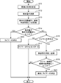
- FIG. 3 is a flowchart showing processing relating to reduction of occurrence of bed slip in the management server device.
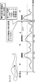
- FIG. 4 is a diagram for explaining processing related to reduction of occurrence of bed slip in the management server device for a thin monitored person.
- FIG. 5 is a diagram for explaining processing related to reduction of occurrence of bed slip in the management server device for a fat monitored person. 4 and 5, the horizontal axis is the elapsed time, and the vertical axis is the amount of movement.
- the management server apparatus SV acquires the timer of the timer unit 224 corresponding to the sensor ID accommodated in the target image notification communication signal received in the process S11 by the sleeping posture determination notification unit 223 in the process S13. It is determined whether or not the continuous determination time ⁇ T is exceeded.
- the sleeping posture determination notification unit 223 determines whether or not a time-up has been received from the timer of the timer unit 224 corresponding to the sensor ID accommodated in the target image notification communication signal received in step S11.
- the sleeping posture continuation notification communication signal is transmitted to the predetermined terminal devices SP and TA. Then, the sleeping posture determination notification unit 223 deletes the timer of the timer unit 224 corresponding to the sensor ID accommodated in the target image notification communication signal received in step S11.
- the terminal devices SP and TA which have received this sleeping posture continuation notification communication signal output to the outside that a certain sleeping posture has continued for a predetermined time.
- the output indicating that this constant sleeping posture has continued for a predetermined time may be an output of a warning sound, an output of vibration, or a display of a warning message.
- the terminal devices SP and TA output a predetermined warning sound and are monitored by a sensor device SU having a sensor ID accommodated in the received sleeping posture continuation notification communication signal.
- the name and the sleeping posture represented by the recommended sleeping posture information contained in the received sleeping posture continuation notification communication signal are displayed.
- the terminal devices SP and TA that have received this sleeping posture continuation notification communication signal output predetermined warning sounds such as pipi, pipi, pi, etc., and are accommodated in the received sleeping posture continuation notification communication signal.
- the name of the person being monitored by the sensor device SU having the sensor ID, and the sleeping posture represented by the recommended sleeping posture information contained in the received sleeping posture continuation notification communication signal for example, Please convert "message. The image after the nurse has changed the posture is acquired, and the flow shown in FIG. 3 is repeated again.
- the amount of motion becomes equal to or greater than the second thick motion determination threshold Th2, and thus the same operation as described above at time T11 is performed.
- the second motion determination threshold Th2 is larger than the first motion determination threshold Th1
- the monitored person Ob is thick
- the change in the amount of motion with respect to the elapsed time is that the monitored person Ob is thin.
- the time from time 0 to time T21 is longer than the time from time 0 to time T11.
- the change in the amount of movement with respect to the elapsed time when the monitored person Ob is thick, and the result that the change in the amount of movement with respect to the elapsed time when the monitored person Ob is thin is changing more slowly.
- the time from time T21 to time T22 is longer than the time from time T11 to time T12.
- the amount of movement falls below the first motion determination threshold value Th1 for lean type, and as a result of the absence of the timer, the operation is similar to the above-described operation at time T12.
- the time T12 is passed before the time T13.
- the operation is the same as that described above.
- the operation is similar to the above-described operation at time T11, and after time T23 and before time T24, the operation is similar to the above-described operation after time T11 and before time T12.
- the operation is similar to the above-described operation at time T12, and after time T24 and before time T25, the operation is similar to the above-described operation after time T12 and before time T13.
- the predetermined time ⁇ T is set as the monitored person. It can be optimized according to the body shape of Ob.
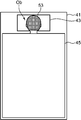
- the detection unit 222 based on the target image of the monitored person Ob received from the sensor device SU, in addition to the calculation of the amount of movement, for example, the supine recumbent posture, the right recumbent recumbent posture, The left sideways recumbent posture and the prone recumbent posture are determined and detected.
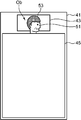
- symbol 43 is a code
- the skin color area 51 is an area of the face of the monitored person Ob.
- the color of the skin color area 51 is the skin color of the face of the monitored person Ob.
- the hair color region 53 is a region where the hair of the head of the monitored subject Ob grows.
- the color of the hair color area 53 is the color of the hair of the head of the monitored person Ob.
- the detection unit 222 stores the determination result in association with the sensor ID (monitored person Ob) and the determination time stored in the target image notification communication signal received in step S11, and stores the SV.
- the result is stored and recorded in the unit 23, and the determination result is output to the sleeping posture determination notification unit 223.
- the sleeping posture determination notification unit 223 detects from the plurality of sleeping postures stored in the sleeping posture information storage unit 232 in step S18 when notifying that the predetermined sleeping posture has continued for a predetermined time in step S20. Selecting a sleeping posture different from the determination result input from the unit 222, accommodating the selected sleeping posture as the recommended sleeping posture information in the sleeping posture continuation notification communication signal, and selecting the selected predetermined terminal device SP, The SV communication IF unit 21 transmits the sleeping posture continuation notification communication signal to the TA. For example, when the determination result input from the detection unit 222 in process S18 is a supine lying position, the sleeping position determination notifying unit 223 is at least one of a right-side lying position, a left-side lying position, and a prone lying position. Is selected as the recommended sleeping posture in the posture change.
- Such a monitored person monitoring system MS, the sensor device SU, the management server apparatus SV, and the monitored person monitoring method, when notifying a sleeping posture, are different from a certain sleeping posture that has continued for the predetermined time ⁇ T. Since the posture is selected, a monitor such as a nurse or a caregiver can change the monitored person Ob to a different sleeping position, and can change the position of the monitored person more appropriately.
- Such a monitored person monitoring system MS, the sensor device SU, the management server apparatus SV, and the monitored person monitoring method include the sleeping posture accepting unit, and therefore a preferred sleeping posture for the monitored subject Ob, for example, a nurse. Can be inputted and stored in the sleeping posture information storage unit 232, and the posture can be changed in a preferred sleeping posture for the monitored person Ob.
- SV control process part 22 is further provided with the entrance detection part 225 which detects the to-be-monitored person Ob, functionally, and SV memory
- storage part 23 stores the sleeping posture (sleeping posture after entering the floor) first detected by the detecting unit 222 after detecting the entering by the entering detecting unit 225 in association with the monitored person Ob (sensor ID).
- the sleeping posture information storage unit 234 is further provided, and the sleeping posture determination notification unit 223 is stored in the sleeping posture information storage unit 234 when notified to the outside, and is received from the sensor device SU in step S11. You may further notify the sleeping posture after entering the floor corresponding to the sensor ID accommodated in the target image notification communication signal.
- the entrance detection unit 225 detects the entrance of the monitored person Ob as follows in parallel with the operation shown in FIG. 3.
- the location area of the bedding is stored in advance in the SV storage unit 23.
- the entrance detection unit 225 extracts a moving body region from the target image of the monitored person Ob received in the target image notification communication signal received from the sensor device SU in step S11, for example, by a background difference method or a frame difference method.
- the detection unit 222 determines that there is an entry when the moving body area changes over time from outside the bedding location area to within the bedding location area, and detects entry.
- the detection unit 222 when detecting this entry, the detection unit 222, as described above, the sleeping position of the monitored subject Ob (for example, the supine lying position, the right lying position, the left lying position, and the prone position) After detecting the detection result, the detection result is associated with the sensor ID (monitored subject Ob) accommodated in the target image notification communication signal received in step S11 and the determination time. This is stored in the sleeping posture information storage unit 234.
- the said sleeping posture reception part further receives the input of the information of the element which can be used in order to correspond to monitored person Ob (sensor ID), and to prevent bedsore (decubitus), and sleeping posture
- the information storage unit 232 further stores the element information received by the sleeping posture receiving unit in association with the monitored person Ob (sensor ID), and the sleeping posture determination notification unit 223 performs notification to the outside.
- the element information corresponding to the sensor ID (monitored person Ob) stored in the sleeping posture information storage unit 232 and contained in the target image notification communication signal received in step S11 may be further notified.
- This Doppler sensor is a body motion sensor that transmits a transmission wave, receives a reflection wave of the transmission wave reflected by an object, and outputs a Doppler signal having a Doppler frequency component based on the transmission wave and the reflection wave. .
- the Doppler sensor generates a signal of the Doppler frequency component as a Doppler signal and outputs it to the processing unit of the sensor device SU.
- the transmission wave may be an ultrasonic wave, a microwave, or the like, but is a microwave in the present embodiment. Since the microwave can be transmitted through the clothing and reflected from the body surface of the monitored person Ob, the movement of the body surface can be detected even when the monitored person Ob is wearing clothes.
- the respiratory movement appears as a vertical movement of the chest, and becomes a periodic movement with a relatively small movement. In rest breathing, it is generally about 12 to 25 times / minute, and the chest moves up and down at about 0.2 Hz to 0.4 Hz.
- the Doppler signal corresponding to the movement of the breath is a relatively narrow band signal having a relatively small signal strength, and in time space, the amplitude is relatively small and the signal regularly changes with time. In the frequency space, the profile has a peak at a specific frequency component (for example, about 0.3 Hz).
- the detection unit 222 performs frequency analysis on the Doppler signal received from the sensor device SU by, for example, fast Fourier transform, and obtains the Doppler signal in the frequency space, and the Doppler signal in the obtained frequency space predominates any of the above profiles. By determining whether to show or not, it can be determined whether the body is moving or at rest (that is, during a certain posture).
- a monitored person monitoring apparatus is fixed based on a detection result of a sleeping posture detection unit that detects a sleeping posture that is a sleeping posture of a monitored subject to be monitored, and a detection result of the sleeping posture detection unit.
- a sleeping posture determination notification unit for notifying the outside when the sleeping posture is continued for a predetermined time.
- the sleeping posture detection unit detects the sleeping posture of the monitored person based on the image of the monitored person.
- Such a monitored person monitoring apparatus includes a sleeping posture detection unit that detects the sleeping posture in a non-contact manner, so that the sleeping posture can be detected without wearing a sensor, and the occurrence of bed slip can be reduced.
- the monitoring object monitoring apparatus further includes a feature receiving unit that receives an input of a predetermined characteristic parameter related to occurrence of bed slipping in the monitored person, and the sleeping posture determination notification unit includes: The predetermined time is changed based on the feature parameter received by the feature receiving unit.
- the ease (risk) of occurrence of bedsores is not uniform. Some people are prone to bedsores and others are difficult to bedsores.
- the monitored person monitoring apparatus changes the predetermined time based on the feature parameter received by the feature receiving unit, so that the predetermined time can be optimized according to the ease of occurrence of bed slip. For example, a person who is relatively prone to bed slipping is set to the predetermined time short, and a person who is relatively hard to slip the floor is set to a long time (( Corresponding predetermined time) ⁇ (predetermined time corresponding to a person who is difficult to make a bed slip))).
- the characteristic parameter includes at least one of the body shape of the monitored person, the presence or absence of paralysis in the monitored person, and the location of paralysis in the monitored person Contains one.
- the monitored person monitoring apparatus can optimize the predetermined time according to the body type of the monitored person when the characteristic parameter includes the body type of the monitored person.
- the monitored person monitoring apparatus can optimize the predetermined time according to the presence or absence of the paralysis in the monitored person when the characteristic parameter includes the presence or absence of the paralysis in the monitored person.
- the above-described monitored person monitoring device further includes a sleeping posture information storage unit that stores a plurality of different sleeping postures, and the sleeping posture determination notification unit, when notifying the outside, One or more sleeping postures are selected from the plurality of sleeping postures stored in the sleeping posture information storage unit, and the selected sleeping posture is further notified.
- the plurality of different sleeping postures include a supine lying on the back, a right-side lying posture sleeping on the left arm facing down, and a lower right arm. Left-sided lying down lying on the side and lying down lying down.
- a so-called postural change as a countermeasure against bedsores. Since the monitored person monitoring device notifies the selected one or a plurality of sleeping postures, a supervisor such as a nurse or a caregiver can change the posture of the monitored person with reference to the notification.
- the sleeping posture determination notification unit is input from the feature receiving unit from among a plurality of sleeping postures stored in the sleeping posture information storage unit. A sleeping posture is selected based on the feature parameter.
- the monitored person monitoring apparatus selects a sleeping position based on the characteristic parameter when notifying the sleeping position when the feature parameter includes a part of paralysis in the monitored person. The posture can be notified.
- the sleeping posture determination notification unit is a constant that continues for the predetermined time from the plurality of sleeping postures stored in the sleeping posture information storage unit. A sleeping posture different from the sleeping posture is selected.
- Such a monitored person monitoring device selects a sleeping position different from the certain sleeping position that has continued for the predetermined time when notifying the sleeping position.
- the monitor can be switched to a different sleeping posture, and the position of the monitored person can be changed more appropriately.
- the above-described monitored person monitoring apparatus further includes an order receiving unit that receives an input of a selection order of a sleeping posture in association with the monitored person, and the sleeping posture information storage unit includes the order receiving unit.
- the sleeping order determination notifying unit further selects a sleeping posture according to the selection order from a plurality of sleeping postures stored in the sleeping posture information storage unit.
- Such a monitored person monitoring device selects a sleeping position in accordance with the selection order when notifying the sleeping position, so that a monitor such as a nurse or a caregiver can switch the monitored person to a different sleeping position. It is possible to change the position of the monitored person more appropriately.
- the sleeping posture information storage unit associates the sleeping posture detected by the sleeping posture detection unit with the monitored person as the plurality of sleeping postures.
- Such a monitored person monitoring device stores the sleeping position detected by the sleeping position detection unit in the sleeping position information storage unit, so that the position can be changed in the sleeping position that the monitored person can actually take, Can avoid a severe sleeping posture.
- the above-described monitored person monitoring device further includes a sleeping position receiving unit that receives an input of a sleeping position in association with the monitored person, and the sleeping position information storage unit is configured to receive the sleeping position reception
- the sleeping posture received by the unit is stored in association with the monitored person as the plurality of sleeping postures.
- Such a monitored person monitoring apparatus includes a sleeping posture receiving unit, a sleeping posture that is preferable for the monitored person can be input and stored in the sleeping posture information storage unit, and a sleeping posture that is preferable for the monitored person. Can change position.
- the bed detection unit that detects the bed of the monitored person, and the bed posture detection unit after the bed detection is detected by the bed detection unit.
- a sleeping posture information storage unit that stores the sleeping posture detected first, and the sleeping posture determination notification unit stores the sleeping posture information storage unit in the sleeping posture information storage unit when notifying the outside. Further notice of the sleeping posture.
- Such a monitored person monitoring device selects the sleeping posture first detected by the sleeping posture detection unit after detecting the bed entry by the floor detection unit when notifying the outside.
- a monitor such as a caregiver or the like has a high probability of switching the monitored person to a different sleeping posture, and can change the position of the monitored person more appropriately.
- the sleeping posture receiving unit further receives an input of at least one of a right knee angle and a left knee angle in association with the monitored person.
- the sleeping posture information storage unit further stores at least one of the right knee angle and the left knee angle received by the sleeping posture reception unit in association with the monitored person, and the sleeping posture determination notification unit.
- at least one of a right knee angle and a left knee angle corresponding to the monitored person stored in the sleeping posture information storage unit is further notified.
- the monitored person monitoring apparatus further notifies at least one of a right knee angle and a left knee angle corresponding to the monitored person stored in the sleeping posture information storage unit when notifying the outside Therefore, a monitor such as a nurse or a caregiver can change the position of the monitored person at a preferable knee angle according to the condition of the monitored person.
- the sleeping posture reception unit further receives input of information on elements that can be used in association with the monitored person to prevent bedsore
- the posture information storage unit further stores information on the elements received by the sleeping posture reception unit in association with the monitored person
- the sleeping posture determination notification unit is configured to notify the sleeping posture when notifying the outside. The information of the element corresponding to the monitored person stored in the information storage unit is further notified.
- Such a monitored person monitoring device corresponds to the monitored person stored in the sleeping posture information storage unit, for example, a bedding such as a pillow or a cushion, and welfare equipment, etc. when notifying the outside
- a bedding such as a pillow or a cushion
- welfare equipment etc.
- information on the above-mentioned elements that can be used to prevent bed sores (decubitus) is notified, so that a monitor such as a nurse or a caregiver uses a suitable tool according to the condition of the monitored person. Can change position.
- a monitoring subject monitoring method is based on a sleeping posture detection step of detecting a sleeping posture that is a sleeping posture of a monitored subject to be monitored in a non-contact manner and a detection result of the sleeping posture detection step. And a sleeping posture determination notification step of notifying the outside when a certain sleeping posture continues for a predetermined time.
- Such a monitored person monitoring method includes a sleeping posture detection step for detecting the sleeping posture in a non-contact manner, so that the sleeping posture can be detected without wearing a sensor, and the occurrence of bed slip can be reduced.
- a monitored person monitoring system includes a terminal device and a monitored person monitoring device that is communicably connected to the terminal device and monitors a monitored person that is a monitoring target.
- the monitored person monitoring device is any one of the above-described monitored person monitoring devices.
- Such a monitored person monitoring system uses any of the above-described monitored person monitoring devices, and therefore can detect a sleeping posture without wearing a sensor, and can reduce the occurrence of bed slip.
- a monitored person monitoring device a monitored person monitoring method, and a monitored person monitoring system can be provided.
Landscapes
- Health & Medical Sciences (AREA)
- Life Sciences & Earth Sciences (AREA)
- Physics & Mathematics (AREA)
- General Physics & Mathematics (AREA)
- Emergency Management (AREA)
- General Health & Medical Sciences (AREA)
- Business, Economics & Management (AREA)
- Public Health (AREA)
- Veterinary Medicine (AREA)
- Animal Behavior & Ethology (AREA)
- Heart & Thoracic Surgery (AREA)
- Surgery (AREA)
- Molecular Biology (AREA)
- Medical Informatics (AREA)
- Biophysics (AREA)
- Pathology (AREA)
- Engineering & Computer Science (AREA)
- Biomedical Technology (AREA)
- Gerontology & Geriatric Medicine (AREA)
- Oral & Maxillofacial Surgery (AREA)
- Dentistry (AREA)
- Nursing (AREA)
- Alarm Systems (AREA)
- Accommodation For Nursing Or Treatment Tables (AREA)
- Emergency Alarm Devices (AREA)
- Measurement Of The Respiration, Hearing Ability, Form, And Blood Characteristics Of Living Organisms (AREA)
- Measuring And Recording Apparatus For Diagnosis (AREA)
Abstract
本発明にかかる被監視者監視装置、被監視者監視方法および被監視者監視システムは、監視対象の被監視者における寝ている姿勢である寝姿勢を非接触で検出し、その検出結果に基づいて一定の寝姿勢が所定の時間継続した場合に、外部へ通知する。したがって、本発明にかかる被監視者監視装置、被監視者監視方法および被監視者監視システムは、センサを装着することなく寝姿勢を検知でき、床ずれの発生を低減できる。
Description
本発明は、例えば、看護を必要とする者や介護を必要とする者(以下、要看護者等)を、監視対象として監視する被監視者監視装置、該方法および該システムに関する。
我が国(日本)は、戦後の高度経済成長に伴う生活水準の向上、衛生環境の改善および医療水準の向上等によって、高齢化社会、より詳しくは、総人口に対する65歳以上の人口の割合である高齢化率が21%を超える超高齢化社会になっている。また、2005年では、総人口約1億2765万人に対し65歳以上の高齢者人口は、約2556万人であったのに対し、2020年では、総人口約1億2411万人に対し高齢者人口は、約3456万人となる予測もある。このような高齢化社会では、病気や怪我や高齢等による看護や介護を必要とする要看護者等は、高齢化社会ではない通常の社会で生じる要看護者等よりもその増加が見込まれる。
このような要看護者等は、病院や、老人福祉施設(日本の法令では老人短期入所施設、養護老人ホームおよび特別養護老人ホーム等)等の施設に入所し、その看護や介護を受ける。このような病院や老人福祉施設等の施設では、要看護者等が快適で安心して過ごせるように、例えば、看護師や介護士のような要看護者等の看護や介護をする者(以下、看護師等)は、定期的に巡視することによってその安否を確認している。しかしながら、日勤の時間帯に較べ、準夜勤や夜勤の時間帯では、看護師等の人数が減るため、一人当たりの業務負荷が増大するので、業務負荷の軽減が要請される。このため、近年では、要看護者等を、被監視者として監視(モニタ)する被監視者監視装置が研究、開発されている。
病院や老人福祉施設等の施設に収容されている要看護者等の中には、ベッド上で寝返りをすることが困難な者もおり、このような要看護者等の床ずれを防止する必要がある。また、寝返りができる要看護者等であっても、特定の姿勢(例えば、仰向き)で寝ている時間が長いとき、床ずれを起こすことがある。そこで、看護師等は、このような要看護者等に対して必要に応じて、寝ている姿勢を変える作業をしている。
人が寝ている姿勢としては、仰向き、横向き、うつ伏せがある。要看護者等に対して、寝ている姿勢を変えるとき、特定の姿勢(例えば、仰向き)に集中しないように、寝ている姿勢を管理する必要がある。看護師等が、要看護者等の部屋に定期的に訪れて、寝ている姿勢を確認し、記録することは、看護師等にとって大きな負担となる。
このような床ずれに関し、例えば特許文献1に床ずれ通報システムが開示されている。この特許文献1に開示された床ずれ通報システムは、寝具に横臥する横臥者に作用する加速度を検出する加速度センサと、当該加速度センサの検出結果を送信する送信部とを備える携帯型発信機と、表示部と、前記加速度センサの検出結果を受信する受信部と、受信した検出結果に基づいて、前記横臥者が所定時間内に寝返りをしたか否かを判定する判定部と、前記横臥者が所定時間内に寝返りをしていないと判定された場合に、床ずれの発生を警告する警告画面を表示するよう前記表示部を制御する表示制御部とを備える監視装置と、を備える。前記携帯型発信機は、横臥者の胴体に装着可能に構成され、前記判定部は、前記加速度センサの検出した加速度に基づいて、前記横臥者の姿勢を特定し、前記横臥者が前記所定時間以上にわたって実質的に同一の姿勢をとっているか否かを判定するように構成されている。
ところで、前記特許文献1に開示された床ずれ通報システムでは、床ずれの発生を警告する警告画面が表示されるので、床ずれの発生を回避する点で便利である。しかしながら、前記特許文献1に開示された床ずれ通報システムでは、患者は、当該患者に作用する加速度を検出する携帯型発信機を装着する必要があるので、煩わしく、違和感を感じてしまう。
本発明は、上述の事情に鑑みて為された発明であり、その目的は、センサを装着することなく寝姿勢を検知でき、床ずれの発生を低減できる被監視者監視装置、被監視者監視方法および被監視者監視システムを提供することである。
本発明にかかる被監視者監視装置、被監視者監視方法および被監視者監視システムは、監視対象の被監視者における寝ている姿勢である寝姿勢を非接触で検出し、その検出結果に基づいて一定の寝姿勢が所定の時間継続した場合に、外部へ通知する。したがって、本発明にかかる被監視者監視装置、被監視者監視方法および被監視者監視システムは、センサを装着することなく寝姿勢を検知でき、床ずれの発生を低減できる。
上記並びにその他の本発明の目的、特徴及び利点は、以下の詳細な記載と添付図面から明らかになるであろう。
以下、本発明にかかる実施の一形態を図面に基づいて説明する。なお、各図において同一の符号を付した構成は、同一の構成であることを示し、適宜、その説明を省略する。本明細書において、総称する場合には添え字を省略した参照符号で示し、個別の構成を指す場合には添え字を付した参照符号で示す。
実施形態における被監視者監視システムは、監視すべき(見守るべき)監視対象(見守り対象)である被監視者(見守り対象者)Obを監視するものであり、端末装置と、前記端末装置と通信可能に接続され、被監視者Obを監視する被監視者監視装置とを備える。前記被監視者監視装置は、本実施形態では、監視対象の被監視者における寝ている姿勢である寝姿勢を非接触で検出する寝姿勢検出部と、前記寝姿勢検出部の検出結果に基づいて一定の寝姿勢が所定の時間継続した場合に、外部へ通知する寝姿勢判定通知部とを備え、センサを装着することなく寝姿勢を検知でき、床ずれの発生を低減できる装置である。このような被監視者監視装置は、1個の機器として、一体に構成されて実現されて良く、また、システムとして、複数の機器で実現されて良い。一例として、ここでは、前記被監視者監視装置がシステムとして複数の機器で実現されている場合について、前記被監視者監視装置の実施形態を説明する。より具体的には、前記被監視者監視装置は、互いに通信可能に接続される第1および第2装置を備え、前記寝姿勢検出部は、前記被監視者の画像を生成する撮像部と、前記撮像部で生成された前記被監視者の画像に基づいて前記被監視者の寝姿勢を検出する検出部とを備え、前記第1装置は、前記撮像部を備え、前記第2装置は、前記検出部と、前記寝姿勢判定通知部とを備える。以下では、前記被監視者監視装置は、前記第1装置の一例としてセンサ装置SUと、前記第2装置の一例として管理サーバ装置SVとを備えて構成される。なお、前記被監視者監視装置が1個の機器として一体に構成されて実現される場合についても、以下の説明と同様に、前記被監視者監視装置を構成できる。例えば、前記第1装置の一例としてセンサ装置SUが前記寝姿勢検出部と、前記寝姿勢判定通知部とを備えて構成されても良い。なお、前記端末装置は、1種類の装置であって良いが、本実施形態態では、前記端末装置は、固定端末装置と携帯端末装置との2種類の装置である。これら固定端末装置と携帯端末装置との主な相違は、固定端末装置が固定的に運用される一方、携帯端末装置が例えば看護師や介護士等の監視者(ユーザ)に携行されて運用される点であり、これら固定端末装置と携帯端末装置とは、略同様である。
図1は、実施形態における被監視者監視システムの構成を示す図である。図2は、前記被監視者監視システムにおける管理サーバ装置の構成を示す図である。
実施形態における被監視者監視システムMSは、より具体的には、例えば、図1に示すように、1または複数のセンサ装置SU(SU-1~SU-4)と、管理サーバ装置SVと、固定端末装置SPと、1または複数の携帯端末装置TA(TA-1、TA-2)と、構内交換機(PBX、Private branch exchange)CXとを備え、これらは、有線や無線で、LAN(Local Area Network)等の網(ネットワーク、通信回線)NWを介して通信可能に接続される。ネットワークNWは、通信信号を中継する例えばリピーター、ブリッジおよびルーター等の中継機が備えられても良い。図1に示す例では、これら複数のセンサ装置SU-1~SU-4、管理サーバ装置SV、固定端末装置SP、複数の携帯端末装置TA-1、TA-2および構内交換機CXは、L2スイッチの集線装置(ハブ、HUB)LSおよびアクセスポイントAPを含む有線および無線の混在したLAN(例えばIEEE802.11規格に従ったLAN等)NWによって互いに通信可能に接続されている。より詳しくは、複数のセンサ装置SU-1~SU-4、管理サーバ装置SV、固定端末装置SPおよび構内交換機CXは、集線装置LSに接続され、複数の携帯端末装置TA-1、TA-2は、アクセスポイントAPを介して集線装置LSに接続されている。そして、ネットワークNWは、TCP(Transmission control protocol)およびIP(Internet protocol)等のインターネットプロトコル群が用いられることによっていわゆるイントラネットを構成する。
被監視者監視システムMSは、被監視者Obに応じて適宜な場所に配設される。被監視者(見守り対象者)Obは、例えば、病気や怪我等によって看護を必要とする者や、身体能力の低下等によって介護を必要とする者や、一人暮らしの独居者等である。特に、早期発見と早期対処とを可能にする観点から、被監視者Obは、例えば異常状態等の所定の不都合な事象がその者に生じた場合にその発見を必要としている者であることが好ましい。このため、被監視者監視システムMSは、被監視者Obの種類に応じて、病院、老人福祉施設および住戸等の建物に好適に配設される。図1に示す例では、被監視者監視システムMSは、複数の被監視者Obが入居する複数の居室RMや、ナースステーション等の複数の居室を備える介護施設の建物に配設されている。
センサ装置SUは、例えば、ネットワークNWを介して他の装置SV、SP、TAと通信する通信機能等を備え、管理サーバ装置SVが監視対象の被監視者Obにおける寝ている姿勢である寝姿勢を非接触で検出するために、被監視者Obの画像を生成し、この生成した被監視者Obの画像を管理サーバ装置SVへ送信する装置である。より具体的には、センサ装置SUは、前記被監視者の画像を生成する撮像部と、ネットワークNWを介して他の装置SV、SP、TAと通信を行う、例えばIEEE802.11規格等に従った通信インターフェース回路(通信カード)等の通信インターフェース部と、これら撮像部および通信インターフェース部を当該機能に応じてそれぞれ制御する、例えばマイクロコンピュータ等の制御部とを備える。
前記撮像部は、被監視者Obが所在を予定している空間(所在空間、図1に示す例では配設場所の居室RM)を監視可能に例えば天井面に配置され、前記所在空間を撮像対象としてその上方から撮像し、前記撮像対象を俯瞰した画像(画像データ)を所定の時間間隔で生成し、前記撮像対象の各画像(対象画像)を前記制御部へ出力する。前記制御部は、この撮像部から前記対象画像が入力されるごとに、この撮像部から入力された前記対象画像を前記通信インターフェース部でネットワークNWを介して管理サーバ装置SVへ送信する。好ましくは、被監視者Ob全体を撮像できる蓋然性が高いことから、撮像部は、被監視者Obが横臥する寝具(例えばベッド等)における、被監視者Obの頭部が位置すると予定されている予め設定された頭部予定位置(通常、枕の配設位置)の直上から撮像対象を撮像できるように配設される。
このような撮像部は、可視光の画像を生成する装置であって良いが、比較的暗がりでも被監視者Obを監視できるように、本実施形態では、赤外線の画像を生成する装置である。このような撮像部は、例えば、本実施形態では、撮像対象における赤外の光学像を所定の結像面上に結像する結像光学系、前記結像面に受光面を一致させて配置され、前記撮像対象における赤外の光学像を電気的な信号に変換するイメージセンサ、および、イメージセンサの出力を画像処理することで前記撮像対象における赤外の画像を表すデータである画像データを生成する画像処理部等を備えるデジタル赤外線カメラである。撮像部の前記結像光学系は、本実施形態では、その配設された居室RM全体を撮像できる画角を持つ広角な光学系(いわゆる広角レンズ(魚眼レンズを含む))であることが好ましい。
図1には、一例として、4個の第1ないし第4センサ装置SU-1~SU-4が示されており、第1センサ装置SU-1は、被監視者Obの一人であるAさんOb-1の居室RM-1(不図示)に配設され、第2センサ装置SU-2は、被監視者Obの一人であるBさんOb-2の居室RM-2(不図示)に配設され、第3センサ装置SU-3は、被監視者Obの一人であるCさんOb-3の居室RM-3(不図示)に配設され、そして、第4センサ装置SU-4は、被監視者Obの一人であるDさんOb-4の居室RM-4(不図示)に配設されている。
管理サーバ装置SVは、ネットワークNWを介して他の装置SU、TA、SPと通信する通信機能を備え、センサ装置SUから被監視者Obの対象画像を受信すると、被監視者Obの前記対象画像に基づいて被監視者Obの寝姿勢を検出し、その検出結果に基づいて一定の寝姿勢が所定の時間継続した場合に、外部へ、本実施形態では所定の端末装置SP、TAへ通知し、クライアント(本実施形態では端末装置SP、TA等)の要求に応じたデータを前記クライアントに提供し、被監視者監視システムMS全体を管理する装置である。このような管理サーバ装置SVは、後述でより詳細に説明される。
固定端末装置SPは、ネットワークNWを介して他の装置SU、SV、TAと通信する通信機能、所定の情報を表示する表示機能、および、所定の指示やデータを入力する入力機能等を備え、管理サーバ装置SVやセンサ装置SUや携帯端末装置TAに与える所定の指示やデータを入力したり、管理サーバ装置SVからの通知を出力したり等することによって、被監視者監視システムMSのユーザインターフェース(UI)として機能する機器である。このような固定端末装置SPは、例えば、通信機能付きのコンピュータによって構成可能である。
携帯端末装置TAは、ネットワークNWを介して他の装置SV、SP、SUと通信する通信機能、所定の情報を表示する表示機能、所定の指示やデータを入力する入力機能、および、音声通話を行う通話機能等を備え、管理サーバ装置SVやセンサ装置SUに与える所定の指示やデータを入力したり、管理サーバ装置SVからの通知を出力したり等することによって、被監視者監視システムMSのユーザインターフェース(UI)として機能する機器である。このような携帯端末装置TAは、例えば、いわゆるタブレット型コンピュータやスマートフォンや携帯電話機等の、持ち運び可能な通信端末装置によって構成可能である。
次に、管理サーバ装置SVについて、より詳しく説明する。上述の管理サーバ装置SVは、例えば、図2に示すように、サーバ側通信インターフェース部(SV通信IF部)21と、サーバ側制御処理部(SV制御処理部)22と、サーバ側記憶部(SV記憶部)23とを備える。
SV通信IF部21は、SV制御処理部22に接続され、SV制御処理部22の制御に従って通信を行うための通信回路である。SV通信IF部21は、SV制御処理部22から入力された転送すべきデータを収容した通信信号を、この被監視者監視システムMSのネットワークNWで用いられる通信プロトコルに従って生成し、この生成した通信信号をネットワークNWを介して他の装置SV、SP、TAへ送信する。SV通信IF部21は、ネットワークNWを介して他の装置SV、SP、TAから通信信号を受信し、この受信した通信信号からデータを取り出し、この取り出したデータをSV制御処理部22が処理可能な形式のデータに変換してSV制御処理部22へ出力する。SV通信IF部21は、例えば、IEEE802.11規格等に従った通信インタフェース回路を備えて構成される。
SV記憶部23は、SV制御処理部22に接続され、SV制御処理部22の制御に従って、各種の所定のプログラムおよび各種の所定のデータを記憶する回路である。前記各種の所定のプログラムには、例えば、管理サーバ装置SVの各部を当該各部の機能に応じてそれぞれ制御するSV制御プログラムや、センサ装置SUから受信した被監視者Obの前記対象画像に基づいて被監視者Obの寝姿勢を検出する検出プログラムや、前記検出プログラムによる検出結果に基づいて一定の寝姿勢が所定の時間継続した場合に、外部へ通知する寝姿勢判定通知プログラムや、前記所定の時間の継続を計るために、予め設定した時間になるまで計時し、前記予め設定した時間になるとその旨(タイムアップ)を出力するタイマープログラム等の制御処理プログラムが含まれる。前記各種の所定のデータには、自機の、管理サーバ装置SVを特定し識別するための識別子であるサーバ識別子(サーバID)や、被監視者Obにおける床ずれの発生に関わる所定の特徴パラメータや、人の寝ている姿勢である寝姿勢や、前記通知の通知先等の装置SU、SP、TA間の情報を表す装置間情報等の各プログラムを実行する上で必要なデータ等が含まれる。SV記憶部23は、例えば不揮発性の記憶素子であるROM(Read Only Memory)や書き換え可能な不揮発性の記憶素子であるEEPROM(Electrically Erasable Programmable Read Only Memory)等を備える。そして、SV記憶部23は、前記所定のプログラムの実行中に生じるデータ等を記憶するいわゆるSV制御処理部22のワーキングメモリとなるRAM(Random Access Memory)等を含む。SV記憶部23は、前記特徴パラメータ、寝姿勢および装置間情報それぞれを記憶するために、特徴パラメータ情報記憶部231、寝姿勢情報記憶部232および装置間情報記憶部233を機能的に備える。
特徴パラメータ情報記憶部231は、被監視者Obの特徴パラメータを前記被監視者Obに対応付けて記憶するものである。本実施形態では、被監視者Obにおける床ずれの発生を低減することを目的としているので、前記特徴パラメータは、上述したように、被監視者における、床ずれの発生に関わる所定のパラメータである。前記特徴パラメータは、例えば、被監視者Obの体型、被監視者Obにおける麻痺の有無、および、被監視者Obにおける麻痺の箇所のうちの少なくとも1つを含む。前記体型は、例えば、痩せている痩せ型や太っている太型等である。前記麻痺の箇所は、例えば、右腕、左腕、右足、左足、腰部、臀部および体幹等の人体の部位である。このような特徴パラメータは、監視者によって端末装置SP、TAに入力され、端末装置SP、TAからネットワークNWを介して管理サーバ装置SVのSV通信IF部21で受け付けられて管理サーバ装置SVに入力され、SV制御処理部22によって特徴パラメータ情報記憶部231に被監視者Obに対応付けて記憶される。痩せ型および太型の区別は、監視者が被監視者Obの体型を見て主観的に判断され、端末装置SP、TAに入力される。この特徴パラメータを端末装置SP、TAから管理サーバ装置SVへ送信するための通信信号(特徴パラメータ通知通信信号)には、被監視者Obの特徴パラメータを表す特徴パラメータ情報および前記被監視者Obの氏名が収容される。したがって、SV通信IF部21は、特徴パラメータの入力を受け付ける特徴受付部の一例に相当する。また、本実施形態では、被監視者Obは、センサ装置SUによって監視されるので、特徴パラメータ情報記憶部231は、被監視者Obの特徴パラメータを、前記被監視者Obを監視するセンサ装置SUのセンサIDに対応付けて記憶する。このために、被監視者Obの氏名と前記被監視者Obを監視するセンサ装置SUのセンサIDとの対応関係がSV記憶部23に予め記憶される。なお、前記対応関係が端末装置SP、TAに記憶され、前記特徴パラメータ通知通信信号には、被監視者Obの氏名に代え、または追加して前記被監視者Obを監視するセンサ装置SUのセンサIDが収容されても良い。前記センサID(センサ識別子)は、センサ装置SUを特定し識別するための識別子である。
寝姿勢情報記憶部232は、互いに異なる複数の寝姿勢を記憶するものである。前記寝姿勢は、例えば、仰向けに寝ている仰向け横臥姿勢、左腕を下にして横を向いて寝ている右横向き横臥姿勢、右腕を下にして横を向いて寝ている左横向き横臥姿勢、および、うつ伏せで寝ているうつ伏せ横臥姿勢を含む。なお、前記寝姿勢は、被監視者Obが睡眠中であっても無くても良く、被監視者Obの意識レベルとは無関係である。
装置間情報記憶部233は、前記装置間情報として、本実施形態では、通知先対応関係および通信アドレス対応関係等を記憶するものである。前記通知先対応関係は、センサ装置SUから送信された通信信号の通知先(報知先、送信先)を示す、送信元であるセンサIDと通知先(送信先)である端末IDとの対応関係である。前記通信アドレス対応関係は、各装置SU、SP、TAのID(センサID、端末ID)とその通信アドレスとの対応関係である。端末ID(端末識別子)は、端末装置SP、TAを特定し端末装置SP、TAを識別するための識別子である。
SV制御処理部22は、管理サーバ装置SVの各部を当該各部の機能に応じてそれぞれ制御し、センサ装置SUから被監視者Obの対象画像を受信すると、被監視者Obの前記対象画像に基づいて被監視者Obの寝姿勢を検出し、その検出結果に基づいて一定の寝姿勢が所定の時間継続した場合に、外部へ、本実施形態では所定の端末装置SP、TAへ通知し、クライアント(本実施形態では端末装置SP、TA等)の要求に応じたデータを前記クライアントに提供し、被監視者監視システムMS全体を管理するための回路である。SV制御処理部22は、例えば、CPU(Central Processing Unit)およびその周辺回路を備えて構成される。SV制御処理部22は、前記制御処理プログラムが実行されることによって、サーバ側制御部(SV制御部)221、検出部222、寝姿勢判定通知部223およびタイマー部224を機能的に備える。
SV制御部221は、管理サーバ装置SVの各部を当該各部の機能に応じてそれぞれ制御し、管理サーバ装置SVの全体制御を司るものである。
検出部222は、センサ装置SUから受信した被監視者Obの前記対象画像に基づいて被監視者Obの寝姿勢を検出するものである。本実施形態では、検出部222は、センサ装置SUから受信した被監視者Obの前記対象画像に基づいて被監視者Obの動き量を被監視者Obの寝姿勢として求める。より具体的には、検出部222は、センサ装置SUから、今回、受信した被監視者Obの前記対象画像と、センサ装置SUから、前回、受信した被監視者Obの前記対象画像との差分を求め、画素値が異なっている画素の個数を合計し、この合計値を被監視者Obの動き量として求める。検出部222は、この求めた被監視者Obの動き量(前記合計値)を寝姿勢判定通知部223へ出力する。
寝姿勢判定通知部223は、検出部222の検出結果に基づいて一定の寝姿勢が所定の時間(継続判定時間)△T継続した場合に、外部へ通知するものである。より具体的には、本実施形態では、検出結果として被監視者Obの動き量(合計値)が検出部222から寝姿勢判定通知部223に入力されるので、寝姿勢判定通知部223は、検出部222で求められた被監視者Obの動き量(前記合計値)に基づいて一定の寝姿勢が継続判定時間△T継続しているか否かを判定する。より詳しくは、寝姿勢判定通知部223は、検出部222で求められた被監視者Obの動き量(前記合計値)が予め設定された所定の閾値(動き判定閾値)Thを継続して下回っている時間が継続判定時間△Tを超えているか否かを判定する。この判定の結果、検出部222で求められた被監視者Obの動き量(前記合計値)が動き判定閾値Thを継続して下回っている時間が継続判定時間△Tを超えていない場合には、寝姿勢判定通知部223は、一定の寝姿勢が継続判定時間△T継続していないと判定し、一方、検出部222で求められた被監視者Obの動き量(前記合計値)が動き判定閾値Thを継続して下回っている時間が継続判定時間△Tを超えている場合には、寝姿勢判定通知部223は、一定の寝姿勢が継続判定時間△T継続していると判定する。
前記通知では、本実施形態では、寝姿勢判定通知部223は、前記通知先対応関係から、前記検出結果に関わる前記対象画像の送信元であるセンサ装置SU(センサID)に対応付けられた送信先の端末装置SP、TA(端末ID)を選定(検索)し、この選定した端末装置SP、TAへ、一定の寝姿勢が所定の時間継続した旨を通知するための通信信号(寝姿勢継続通知通信信号)をSV通信IF部21で送信する。前記寝姿勢継続通知通信信号には、前記検出結果に関わる前記対象画像の送信元であるセンサ装置SUのセンサID、一定の寝姿勢が所定の時間継続した旨を表す寝姿勢継続通知情報、体位変換で推奨する寝姿勢を表す推奨寝姿勢情報が収容される。
前記寝姿勢継続通知通信信号に前記推奨寝姿勢情報を収容するために、寝姿勢判定通知部223は、寝姿勢情報記憶部232に記憶された複数の寝姿勢の中から1または複数の寝姿勢を、前記体位変換で推奨する寝姿勢として選択する。より具体的には、本実施形態では、寝姿勢判定通知部223は、寝姿勢情報記憶部232に記憶された複数の寝姿勢の中から、端末装置SP、TAからネットワークNWを介してSV通信IF部21で受信され特徴パラメータ情報記憶部231に被監視者Ob(センサID)に対応付けて記憶された前記特徴パラメータに基づいて寝姿勢を選択する。この寝姿勢を選択するための前記特徴パラメータは、前記検出結果に関わる前記対象画像の送信元であるセンサ装置SUのセンサIDに対応付けられた特徴パラメータである。したがって、寝姿勢判定通知部223は、まず、特徴パラメータ情報記憶部231から、前記検出結果に関わる前記対象画像の送信元であるセンサ装置SUのセンサIDに対応付けられた特徴パラメータを選定(検索)し、そして、寝姿勢情報記憶部232に記憶された複数の寝姿勢の中から、この選定した特徴パラメータに基づいて寝姿勢を選択する。例えば、特徴パラメータ情報記憶部231に被監視者Ob(センサID)に対応付けて記憶された前記特徴パラメータが左腕麻痺である場合には、寝姿勢判定通知部223は、仰向け横臥姿勢および左横向き横臥姿勢のうちの少なくとも一方を、前記体位変換で推奨する寝姿勢として選択する。また例えば、特徴パラメータ情報記憶部231に被監視者Ob(センサID)に対応付けて記憶された前記特徴パラメータが腰部に床ずれ有りである場合には、寝姿勢判定通知部223は、右横向き横臥姿勢、左横向き横臥姿勢およびうつ伏せ横臥姿勢のうちの少なくとも一方を、前記体位変換で推奨する寝姿勢として選択する。
本実施形態では、寝姿勢判定通知部223は、端末装置SP、TAからネットワークNWを介してSV通信IF部21で受信され特徴パラメータ情報記憶部231に被監視者Ob(センサID)に対応付けて記憶された前記特徴パラメータに基づいて前記所定の時間(継続判定時間)△Tを変更する。この継続判定時間△Tを変更するための前記特徴パラメータは、前記検出結果に関わる前記対象画像の送信元であるセンサ装置SUのセンサIDに対応付けられた特徴パラメータである。したがって、寝姿勢判定通知部223は、まず、特徴パラメータ情報記憶部231から、前記検出結果に関わる前記対象画像の送信元であるセンサ装置SUのセンサIDに対応付けられた特徴パラメータを選定(検索)し、そして、この選定した特徴パラメータに基づいて継続判定時間△Tを変更する。例えば、特徴パラメータ情報記憶部231に被監視者Ob(センサID)に対応付けて記憶された前記特徴パラメータが痩せ型である場合には、寝姿勢判定通知部223は、継続判定時間△Tを、痩せ型のための第1継続判定時間△T1に設定する。また例えば、特徴パラメータ情報記憶部231に被監視者Ob(センサID)に対応付けて記憶された前記特徴パラメータが太型である場合には、寝姿勢判定通知部223は、継続判定時間△Tを、太型のための第2継続判定時間△T2に設定する。痩せ型のための第1継続判定時間△T1は、太型のための第2継続判定時間△T2より短い。したがって、太型のための第2継続判定時間△T2は、相対的に、痩せ型のための第1継続判定時間△T1より長く規定される((痩せ型のための第1継続判定時間△T1)<(太型のための第2継続判定時間△T2))。また例えば、特徴パラメータ情報記憶部231に被監視者Ob(センサID)に対応付けて記憶された前記特徴パラメータが麻痺有りである場合には、寝姿勢判定通知部223は、継続判定時間△Tを、麻痺有りのための第3継続判定時間△T3に設定する。また例えば、特徴パラメータ情報記憶部231に被監視者Ob(センサID)に対応付けて記憶された前記特徴パラメータが麻痺無しである場合には、寝姿勢判定通知部223は、継続判定時間△Tを、麻痺無しのための第4継続判定時間△T4に設定する。麻痺有りのための第3継続判定時間△T3は、麻痺無しのための第4継続判定時間△T4より短い。
また例えば、特徴パラメータ情報記憶部231に被監視者Ob(センサID)に対応付けて記憶された前記特徴パラメータが痩せ型であって麻痺有りである場合には、寝姿勢判定通知部223は、継続判定時間△Tを、痩せ型であって麻痺有りのための第A継続判定時間△TAに設定し、特徴パラメータ情報記憶部231に被監視者Ob(センサID)に対応付けて記憶された前記特徴パラメータが痩せ型であって麻痺無しである場合には、寝姿勢判定通知部223は、継続判定時間△Tを、痩せ型であって麻痺無しのための第B継続判定時間△TBに設定し、特徴パラメータ情報記憶部231に被監視者Ob(センサID)に対応付けて記憶された前記特徴パラメータが太型であって麻痺有りである場合には、寝姿勢判定通知部223は、継続判定時間△Tを、太型であって麻痺有りのための第C継続判定時間△TCに設定し、特徴パラメータ情報記憶部231に被監視者Ob(センサID)に対応付けて記憶された前記特徴パラメータが太型であって麻痺無しである場合には、寝姿勢判定通知部223は、継続判定時間△Tを、太型であって麻痺無しのための第D継続判定時間△TDに設定する。このように複数の特徴パラメータから継続判定時間△Tが設定されてもよい。
このような特徴パラメータに対応する継続判定時間△Tは、例えば、特徴パラメータ情報記憶部231に前記特徴パラメータおよび被監視者Ob(センサID)に対応付けて記憶される。
さらに、本実施形態では、寝姿勢判定通知部223は、端末装置SP、TAからネットワークNWを介してSV通信IF部21で受信され特徴パラメータ情報記憶部231に被監視者Ob(センサID)に対応付けて記憶された前記特徴パラメータに基づいて前記所定の閾値(動き判定閾値)Thを変更する。この動き判定閾値Thを変更するための前記特徴パラメータは、前記検出結果に関わる前記対象画像の送信元であるセンサ装置SUのセンサIDに対応付けられた特徴パラメータである。したがって、寝姿勢判定通知部223は、まず、特徴パラメータ情報記憶部231から、前記検出結果に関わる前記対象画像の送信元であるセンサ装置SUのセンサIDに対応付けられた特徴パラメータを選定(検索)し、そして、この選定した特徴パラメータに基づいて動き判定閾値Thを変更する。例えば、特徴パラメータ情報記憶部231に被監視者Ob(センサID)に対応付けて記憶された前記特徴パラメータが痩せ型である場合には、寝姿勢判定通知部223は、動き判定閾値Thを、痩せ型のための第1動き判定閾値Th1に設定する。また例えば、特徴パラメータ情報記憶部231に被監視者Ob(センサID)に対応付けて記憶された前記特徴パラメータが太型である場合には、寝姿勢判定通知部223は、動き判定閾値Thを、太型のための第2動き判定閾値Th2に設定する。痩せ型のための第1動き判定閾値Th1は、太型のための第2動き判定閾値Th2より小さい。したがって、太型のための第2動き判定閾値Th2は、相対的に、痩せ型のための第1動き判定閾値Th1より大きな値に規定される((痩せ型のための第1動き判定閾値Th1)<(太型のための第2動き判定閾値Th2))。
また例えば、特徴パラメータ情報記憶部231に被監視者Ob(センサID)に対応付けて記憶された前記特徴パラメータが痩せ型であって麻痺有りである場合には、寝姿勢判定通知部223は、動き判定閾値Thを、痩せ型であって麻痺有りのための第A動き判定閾値ThAに設定し、特徴パラメータ情報記憶部231に被監視者Ob(センサID)に対応付けて記憶された前記特徴パラメータが痩せ型であって麻痺無しである場合には、寝姿勢判定通知部223は、動き判定閾値Thを、痩せ型であって麻痺無しのための第B動き判定閾値ThBに設定し、特徴パラメータ情報記憶部231に被監視者Ob(センサID)に対応付けて記憶された前記特徴パラメータが太型であって麻痺有りである場合には、寝姿勢判定通知部223は、動き判定閾値Thを、太型であって麻痺有りのための第C動き判定閾値ThCに設定し、特徴パラメータ情報記憶部231に被監視者Ob(センサID)に対応付けて記憶された前記特徴パラメータが太型であって麻痺無しである場合には、寝姿勢判定通知部223は、動き判定閾値Thを、太型であって麻痺無しのための第D動き判定閾値ThDに設定する。このように複数の特徴パラメータから動き判定閾値Thが設定されてもよい。
このような特徴パラメータに対応する動き判定閾値Thは、例えば、特徴パラメータ情報記憶部231に前記特徴パラメータおよび被監視者Ob(センサID)に対応付けて記憶される。
タイマー部224は、前記所定の時間(継続判定時間)△Tの継続を計るために、予め設定した時間になるまで計時し、前記予め設定した時間になるとその旨(タイムアップ)を寝姿勢判定通知部223へ出力するものである。タイマー部224は、センサIDごとに用意(生成)され、センサIDごとにそのタイマーを動作させ、後述のタイミングで消去される。前記所定の時間は、寝姿勢判定通知部223によって上述のように特徴パラメータに応じた値に設定される。
なお、管理サーバ装置SVは、図2に破線で示すように、必要に応じて、さらに、SV制御処理部22に接続され、例えば各種コマンドや各種データ等を入力するサーバ側入力部(SV入力部)24、SV入力部24で入力された各種コマンドや各種データおよび前記一定の寝姿勢が所定の時間継続した旨等を出力するサーバ側出力部(SV出力部)25、および、外部機器との間でデータの入出力を行うサーバ側インターフェース部(SVIF部)26等を備えても良い。この場合では、SV入力部24は、前記特徴パラメータの入力を受け付けて良く、特徴パラメータの入力を受け付ける特徴受付部の他の一例に相当する。
このような管理サーバ装置SVは、例えば、通信機能付きのコンピュータによって構成可能である。
次に、本実施形態の動作について説明する。図3は、前記管理サーバ装置における床ずれの発生の低減に関する処理を示すフローチャートである。図4は、痩せた被監視者に対する、前記管理サーバ装置における床ずれの発生の低減に関する処理を説明するための図である。図5は、太った被監視者に対する、前記管理サーバ装置における床ずれの発生の低減に関する処理を説明するための図である。図4および図5において、その横軸は、経過時間であり、その縦軸は、動き量である。
上記構成の被監視者監視システムMSでは、各装置SU、SV、SP、TAは、電源が投入されると、必要な各部の初期化を実行し、その稼働を始める。管理サーバ装置SVでは、その制御処理プログラムの実行によって、SV制御処理部22には、SV制御部221、検出部222、寝姿勢判定通知部223およびタイマー部224が機能的に構成される。
床ずれの発生の低減に関する処理において、まず、センサ装置SVは、前記対象画像を生成し、この生成した前記対象画像および自機のセンサIDを収容した通信信号(対象画像通知通信信号)を管理サーバ装置SVへ送信する。センサ装置SVは、この動作を所定の時間間隔で実行する。
一方、管理サーバ装置SVは、図3において、センサ装置SUから前記対象画像を取得すると、この取得した前記対象画像をSV記憶部23に記憶する(S11)。より具体的には、本実施形態では、管理サーバ装置SVは、SV通信IF部21で対象画像通知通信信号を受信すると、SV制御処理部22によって、この受信した対象画像通知通信信号に収容された前記対象画像とセンサIDとを互いに対応付け、さらにセンサIDごとのシリアル番号を対応付けてこれらをSV記憶部23に記憶する。なお、シリアル番号に代え、対象画像通知通信信号の受信時刻であっても良い。
次に、管理サーバ装置SVは、SV制御処理部22の検出部222によって、被監視者Obの寝姿勢を検出するために、動き量を求める(S12)。より具体的には、検出部222は、まず、処理S11で受信した対象画像通知通信信号に収容されたセンサIDに対応する、前回に受信した前記対象画像をSV記憶部23から取り出す。前回の判断は、センサIDごとに割り付けられたシリアル番号に基づいて実施される。すなわち、処理S11で受信した対象画像通知通信信号に収容されたセンサIDに対応するシリアル番号の中で、最大のシリアル番号に対応する前記対象画像が、前回に受信した前記対象画像としてSV記憶部23から取り出される。なお、前回の対象画像のみSV記憶部23に記憶する構成では、前記シリアル番号は、省略できる。次に、検出部222は、このSV記憶部23から取り出した前記対象画像(前回の前記対象画像)と、処理S11で受信した対象画像通知通信信号に収容された前記対象画像(今回の前記対象画像)との差分を求める。そして、検出部222は、画素値が異なっている画素の個数を合計し、この合計値を被監視者Obの動き量として求め、この求めた被監視者Obの動き量(前記合計値)を寝姿勢判定通知部223へ出力する。
次に、管理サーバ装置SVは、SV制御処理部22の寝姿勢判定通知部223によって、特徴パラメータ情報記憶部231から、処理S11で受信した対象画像通知通信信号に収容されたセンサIDに対応し、そして、このセンサIDに対応する特徴パラメータにも対応する動き判定閾値Thおよび継続判定時間△Tを取得する(S13)。
次に、管理サーバ装置SVは、寝姿勢判定通知部223によって、処理S12で検出部222によって求められた動き量が、処理S13で取得した動き判定閾値Th以上か否かを判定する。この判定の結果、前記動き量が前記動き判定閾値Th以上である場合(Yes)には、寝姿勢判定通知部223は、次の処理S15を実行した後に、本処理を終了する。一方、前記判定の結果、前記動き量が前記動き判定閾値Th以上ではない場合(前記動き量が前記動き判定閾値Th未満である場合)(No)には、寝姿勢判定通知部223は、次の処理S16を実行する。
処理S15では、管理サーバ装置SVは、寝姿勢判定通知部223によって、処理S11で受信した対象画像通知通信信号に収容されたセンサIDに対応するタイマー部224のタイマーが存在する場合にそのタイマーを消去する。したがって、処理S12で検出部222によって求められた動き量が、処理S13で取得した動き判定閾値Th以上になると、処理S11で受信した対象画像通知通信信号に収容されたセンサIDに対応するタイマー部224のタイマーが消去される。
一方、処理S16では、管理サーバ装置SVは、寝姿勢判定通知部223によって、処理S11で受信した対象画像通知通信信号に収容されたセンサIDに対応するタイマー部224のタイマーが存在するか否かを判定する。この判定の結果、前記タイマーが存在しない場合(No)には、寝姿勢判定通知部223は、次の処理S17を実行した後に、本処理を終了する。一方、前記判定の結果、前記タイマーが存在する場合(Yes)には、寝姿勢判定通知部223は、次の処理S19を実行する。
処理S17では、管理サーバ装置SVは、寝姿勢判定通知部223によって、処理S11で受信した対象画像通知通信信号に収容されたセンサIDに対応するタイマー部224のタイマーを用意(生成)し、処理S13で取得した継続判定時間△Tに設定してリセットスタートする。したがって、処理S12で検出部222によって求められた動き量が、処理S13で取得した動き判定閾値Th以上ではなくなると、処理S11で受信した対象画像通知通信信号に収容されたセンサIDに対応するタイマー部224のタイマーが用意(生成)され、リセットされ、処理S13で取得した継続判定時間△Tに設定され、その動作を開始する。
この処理S13で取得した継続判定時間△Tに設定されてリセットスタートしたタイマー部224のタイマーは、この設定された継続判定時間△Tを経過すると、その旨(タイムアップ)を寝姿勢判定通知部223へ出力する。
一方、処理S19では、管理サーバ装置SVは、寝姿勢判定通知部223によって、処理S11で受信した対象画像通知通信信号に収容されたセンサIDに対応するタイマー部224のタイマーが、処理S13で取得した継続判定時間△T以上か否かを判定する。本実施形態では、寝姿勢判定通知部223は、処理S11で受信した対象画像通知通信信号に収容されたセンサIDに対応するタイマー部224のタイマーからタイムアップを受けているか否かを判定する。この判定の結果、前記タイムアップを受けていない場合(No)には、寝姿勢判定通知部223は、本処理を終了し、一方、前記判定の結果、前記タイムアップを受けている場合(Yes)には、寝姿勢判定通知部223は、次の処理S20を実行した後に、本処理を終了する。したがって、処理S12で検出部222によって求められた動き量が、処理S13で取得した動き判定閾値Th以上ではなく、処理S11で受信した対象画像通知通信信号に収容されたセンサIDに対応するタイマー部224のタイマーが、タイムアップしていない場合には、そのタイマーの動作が継続される。
この処理S20では、管理サーバ装置SVは、寝姿勢判定通知部223によって、一定の寝姿勢が所定の時間継続した旨を通知する。より具体的には、寝姿勢判定通知部223は、前記通知先対応関係から、処理S11で受信した対象画像通知通信信号に収容されたセンサIDに対応付けられた送信先の端末装置SP、TA(端末ID)を選定(検索)し、この選定した端末装置SP、TAへ、寝姿勢継続通知通信信号をSV通信IF部21で送信する。前記寝姿勢継続通知通信信号には、処理S11で受信した対象画像通知通信信号に収容されたセンサID、寝姿勢継続通知情報、および、上述のように特徴パラメータに基づく推奨寝姿勢情報が収容される。したがって、処理S12で検出部222によって求められた動き量が、処理S13で取得した動き判定閾値Thを継続して下回っている時間が、処理S13で取得した継続判定時間△Tを超えている場合に、前記寝姿勢継続通知通信信号が所定の端末装置SP、TAへ送信される。そして、寝姿勢判定通知部223は、処理S11で受信した対象画像通知通信信号に収容されたセンサIDに対応するタイマー部224のタイマーを消去する。
一方、この寝姿勢継続通知通信信号を受信した端末装置SP、TAは、一定の寝姿勢が所定の時間継続した旨を外部へ出力する。この一定の寝姿勢が所定の時間継続した旨の前記出力は、警告音の出力であって良く、振動の出力であって良く、警告メッセージの表示であって良い。例えば、本実施形態では、端末装置SP、TAは、所定の警告音を出力し、前記受信した寝姿勢継続通知通信信号に収容されたセンサIDを持つセンサ装置SUによって監視されている被監視者名、および、前記受信した寝姿勢継続通知通信信号に収容された推奨寝姿勢情報の表す寝姿勢を表示する。
一例として、被監視者Obが痩せ型である場合について、上述の動作を説明する。なお、図4では、時刻0で、上述のように前記タイマーが用意され、その動作を開始しているものとする。時刻0から時刻T11の前まででは、前記動き量が痩せ型用の第1動き判定閾値Th1を下回り、前記タイマーがタイムアップせずに存在する結果、処理S11、処理S12、処理S13、処理S14、処理S16および処理S19の各処理が順次に繰り返され、前記タイマーが計時を継続する。時刻T11になると、前記動き量が痩せ型用の第1動き判定閾値Th1以上となる結果、処理S11、処理S12、処理S13、処理S14および処理S15の各処理が実行され、前記タイマーが消去される。時刻T11を過ぎて時刻T12の前まででは、前記動き量が痩せ型用の第1動き判定閾値Th1以上である結果、処理S11、処理S12、処理S13、処理S14および処理S15の各処理が順次に繰り返される。時刻T12になると、前記動き量が痩せ型用の第1動き判定閾値Th1を下回り、前記タイマーが存在しない結果、処理S11、処理S12、処理S13、処理S14、処理S16および処理S17の各処理が実行され、上述のように前記タイマーが用意され、その動作を開始する。時刻T12を過ぎて時刻T13の前まででは、前記動き量が痩せ型用の第1動き判定閾値Th1を下回り、前記タイマーがタイムアップせずに存在する結果、処理S11、処理S12、処理S13、処理S14、処理S16および処理S19の各処理が順次に繰り返され、前記タイマーが計時を継続する。以下、時刻T13では、時刻T11における上述の動作と同様に動作し、時刻T13を過ぎて時刻T14の前まででは、時刻T11を過ぎて時刻T12の前までにおける上述の動作と同様に動作し、時刻T14では、時刻T12における上述の動作と同様に動作し、時刻T14を過ぎて時刻T15の前まででは、時刻T12を過ぎて時刻T13の前までにおける上述の動作と同様に動作する。時刻T15では、時刻T11における上述の動作と同様に動作し、時刻T15を過ぎて時刻T16の前まででは、時刻T11を過ぎて時刻T12の前までにおける上述の動作と同様に動作し、時刻T16では、時刻T12における上述の動作と同様に動作し、時刻T16を過ぎて時刻T17の前まででは、時刻T12を過ぎて時刻T13の前までにおける上述の動作と同様に動作する。時刻T17では、時刻T11における上述の動作と同様に動作し、時刻T17を過ぎて時刻T18の前まででは、時刻T11を過ぎて時刻T12の前までにおける上述の動作と同様に動作し、時刻T18では、時刻T12における上述の動作と同様に動作し、時刻T18を過ぎて時刻T19の前まででは、時刻T12を過ぎて時刻T13の前までにおける上述の動作と同様に動作する。そして、時刻T19では、前記動き量が痩せ型用の第1動き判定閾値Th1を下回り、前記タイマーがタイムアップして存在する結果、処理S11、処理S12、処理S13、処理S14、処理S16、処理S19よび処理S20の各処理が実行され、上述のように寝姿勢継続通知通信信号が所定の端末装置SP、TAへ送信され、前記タイマーが消去される。
この寝姿勢継続通知通信信号を受信した端末装置SP、TAは、例えばピピ、ピピ、ピピ、・・・等の所定の警告音を出力し、前記受信した寝姿勢継続通知通信信号に収容されたセンサIDを持つセンサ装置SUによって監視されている被監視者名、および、前記受信した寝姿勢継続通知通信信号に収容された推奨寝姿勢情報の表す寝姿勢、例えば、「次は左横向きに体位変換してください。」のメッセージを表示する。看護師が体位変換させた後の画像が取得され、再び図3に示すフローが繰り返される。
一方、他の一例として、被監視者Obが太型である場合について、上述の動作を説明する。なお、図5では、時刻0で、上述のように前記タイマーが用意され、その動作を開始しているものとする。被監視者Obが太型である、経過時間に対する前記動き量の変化は、被監視者Obが痩せ型である、経過時間に対する前記動き量の変化に較べ、図4と図5とを比較すると分かるように、緩やかに変化している。図5において、時刻0から時刻T21の前まででは、前記動き量が太用の第2動き判定閾値Th2を下回り、前記タイマーがタイムアップせずに存在する結果、時刻T11の前までにおける上述の動作と同様に動作する。時刻T21になると、前記動き量が太型用の第2動き判定閾値Th2以上となる結果、時刻T11における上述の動作と同様に動作する。ここで、第2動き判定閾値Th2が第1動き判定閾値Th1より大きく、被監視者Obが太型である、経過時間に対する前記動き量の変化が、被監視者Obが痩せ型である、経過時間に対する前記動き量の変化に較べ、緩やかに変化している結果、時刻0から時刻T21までの時間は、時刻0から時刻T11までの時間より長くなっている。また、被監視者Obが太型である、経過時間に対する前記動き量の変化が、被監視者Obが痩せ型である、経過時間に対する前記動き量の変化に較べ、緩やかに変化している結果、時刻T21から時刻T22までの時間は、時刻T11から時刻T12までの時間より長くなっている。時刻T22になると、前記動き量が痩せ型用の第1動き判定閾値Th1を下回り、前記タイマーが存在しない結果、時刻T12における上述の動作と同様に動作する。時刻T22を過ぎて時刻T23の前まででは、前記動き量が太型用の第2動き判定閾値Th2を下回り、前記タイマーがタイムアップせずに存在する結果、時刻T12を過ぎて時刻T13の前までにおける上述の動作と同様に動作する。以下、時刻T23では、時刻T11における上述の動作と同様に動作し、時刻T23を過ぎて時刻T24の前まででは、時刻T11を過ぎて時刻T12の前までにおける上述の動作と同様に動作し、時刻T24では、時刻T12における上述の動作と同様に動作し、時刻T24を過ぎて時刻T25の前まででは、時刻T12を過ぎて時刻T13の前までにおける上述の動作と同様に動作する。そして、時刻T25では、前記動き量が太型用の第2動き判定閾値Th2を下回り、前記タイマーがタイムアップして存在する結果、処理S11、処理S12、処理S13、処理S14、処理S16、処理S19よび処理S20の各処理が実行され、上述のように寝姿勢継続通知通信信号が所定の端末装置SP、TAへ送信され、前記タイマーが消去される。この寝姿勢継続通知通信信号を受信した端末装置SP、TAは、上述と同様に動作する。
以上説明したように、本実施形態における被監視者監視システムMS、被監視者監視装置の一例であるセンサ装置SUおよび管理サーバ装置SVならびにこれらに実装された被監視者監視方法は、センサ装置SUの前記撮像部で生成された被監視者Obの前記対象画像に基づいて寝姿勢を検出するので、前記寝姿勢を非接触で検出できる。したがって、上記被監視者監視システムMS、センサ装置SUおよび管理サーバ装置SVならびに被監視者監視方法は、センサを装着することなく寝姿勢を検知でき、床ずれの発生を低減できる。
床ずれの発生のし易さ(リスク)は、一律ではなく、床ずれのでき易い人もいれば、床ずれのでき難い人もいる。上記被監視者監視システムMS、センサ装置SUおよび管理サーバ装置SVならびに被監視者監視方法は、端末装置SP、TAからネットワークNWを介してSV通信IF部21で受信した前記特徴パラメータに基づいて前記所定の時間(継続判定時間)△Tを変更するので、床ずれの発生のし易さに応じて前記所定の時間△Tを最適化できる。例えば、相対的に、床ずれのでき易い人(一例では痩せ型の人)は、前記所定の時間△Tが短く設定され、相対的に、床ずれのでき難い人(一例では太型の人)は、前記所定の時間△Tが長く設定される。
一般に、痩せている人は、相対的に、床ずれができ易く、太っている人は、相対的に、床ずれができ難い。麻痺のある人は、動き難く、相対的に、床ずれができ易い。腰部に麻痺がある人は、動き難く、相対的に、床ずれができ易い。また、腰部や臀部には、相対的に床ずれができ易い。上記被監視者監視システムMS、センサ装置SUおよび管理サーバ装置SVならびに被監視者監視方法は、前記特徴パラメータが被監視者Obの体型を含む場合には、前記所定の時間△Tを被監視者Obの体型に応じて最適化できる。上記被監視者監視システムMS、センサ装置SUおよび管理サーバ装置SVならびに被監視者監視方法は、前記特徴パラメータが被監視者Obにおける麻痺の有無を含む場合には、前記所定の時間△Tを被監視者Obにおける麻痺の有無に応じて最適化できる。
床ずれの発生対策として、いわゆる体位変換がある。上記被監視者監視システムMS、センサ装置SUおよび管理サーバ装置SVならびに被監視者監視方法は、前記選択した1または複数の寝姿勢を通知するので、看護師や介護士等の監視者は、通知を参考に、被監視者Obを体位変換できる。
被監視者Obの特徴パラメータに応じた好ましい寝姿勢がある。例えば、右腕に麻痺があれば、右腕が体幹の下にならない(右腕を体幹の上にした)寝姿勢が好ましい。また例えば、既に床ずれができていれば、床ずれ箇所が体幹の下にならない寝姿勢が好ましい。上記被監視者監視システムMS、センサ装置SUおよび管理サーバ装置SVならびに被監視者監視方法は、前記特徴パラメータが被監視者Obにおける麻痺の箇所を含む場合には、寝姿勢を通知する際に、前記特徴パラメータに基づいて寝姿勢を選択するので、より好ましい寝姿勢を通知できる。
なお、上述の実施形態では、寝姿勢判定通知部223は、寝姿勢情報記憶部232に記憶された複数の寝姿勢の中から、前記特徴パラメータに基づいて寝姿勢を選択したが、寝姿勢判定通知部223は、寝姿勢情報記憶部232に記憶された複数の寝姿勢の中から、前記所定の時間△T継続した一定の寝姿勢とは異なる寝姿勢を選択しても良い。
図6は、被監視者が仰向け横臥姿勢で寝ている状態を示す模式図である。図7は、被監視者がうつ伏せ横臥姿勢で寝ている状態を示す模式図である。図8は、被監視者が右横向き横臥姿勢で寝ている状態を示す模式図である。図9は、被監視者が左横向き横臥姿勢で寝ている状態を示す模式図である。
このような場合では、検出部222は、センサ装置SUから受信した被監視者Obの前記対象画像に基づいて、前記動き量の演算に加え、例えば、前記仰向け横臥姿勢、前記右横向き横臥姿勢、前記左横向き横臥姿勢、および、前記うつ伏せ横臥姿勢等の別を判定して検出する。
より具体的には、上述した図3に示す動作において、図3に破線で示すように、処理S16と処理S19との間に、検出部222によって寝姿勢を判定し、その判定結果をSV記憶部23に記憶する処理S18が追加される。より詳しくは、この処理S18では、検出部222は、処理S11でセンサ装置SUから受信した対象画像通知通信信号に収容された被監視者Obの前記対象画像から寝姿勢を検出し判定する。例えば、検出部222は、前記被監視者Obの前記対象画像から頭部の画像領域を抽出し、前記抽出した前記頭部の画像領域における肌色領域および髪色領域を抽出し、前記抽出した肌色領域および髪色領域に基づいて前記被監視者Obの寝姿勢を検出する。寝姿勢の検出の仕方の一例を以下に説明する。
図6ないし図9を参照して、被監視者Obは、ベッド41上で寝ており、被監視者Obの頭部以外の身体には、布団45がかけられている。符号43は、枕を指し示す符号である。肌色領域51は、被監視者Obの顔の領域である。肌色領域51の色は、被監視者Obの顔の肌の色である。髪色領域53は、被監視者Obの頭部の髪の毛が生えている領域である。髪色領域53の色は、被監視者Obの頭部の髪の毛の色である。検出部222は、まず、前記被監視者Obの前記対象画像を用いて、被監視者Obの頭部の画像領域を抽出する。例えば円形や楕円形のハフ変換によって、また例えば予め用意された頭部のモデルを用いたパターンマッチングによって、また例えば頭部検出用に学習したニューラルネットワークによって、被監視者Obの頭部領域が抽出される。次に、検出部222は、この抽出した頭部領域における肌色領域51と髪色領域53とを抽出する。これらの領域は、画素値の色により区別することができる。検出部222は、被監視者Obの頭部の画像領域において、左側の大部分に髪色領域53が存在すれば、被監視者Obの寝姿勢が、その左腕を下にして横を向いて寝ている右横向き横臥姿勢と判定する(図8参照)。検出部222は、被監視者Obの頭部の画像領域において、右側の大部分に髪色領域53が存在すれば、被監視者Obの寝姿勢が、右腕を下にして横を向いて寝ている左横向き横臥姿勢と判定する(図9参照)。検出部222は、右横向き横臥姿勢および左横向き横臥姿勢のいずれにも該当せず、頭部領域において、肌色領域51が髪色領域53より大きければ、被監視者Obの寝姿勢が、仰向けに寝ている仰向きと判定する(図6参照)。検出部222は、右横向き横臥姿勢および左横向き横臥姿勢のいずれにも該当せず、被監視者Obの頭部領域において、髪色領域53が肌色領域51より大きければ、被監視者Obの寝姿勢が、うつ伏せで寝ているうつ伏せ横臥姿勢と判定する(図7参照)。
なお、寝姿勢の検出は、特開2014-207934号公報の技術を用いてもよい。この特開2014-207934号公報に開示された生体情報取得装置は、被検者にマイクロ波を照射し前記被検者で反射されたマイクロ波を検出する検出部と、前記検出部によって検出されたマイクロ波に含まれる呼吸成分を抽出する抽出部と、 前記抽出部によって抽出された呼吸成分の信号強度に基づいて睡眠時の体位(仰向け、横向き、うつ伏せ)を判定する判定部と、を備える。
このように寝姿勢を判定すると、検出部222は、この判定結果を、処理S11で受信した対象画像通知通信信号に収容されたセンサID(被監視者Ob)および判定時刻と対応付けてSV記憶部23に記憶して記録し、この判定結果を寝姿勢判定通知部223へ出力する。
寝姿勢判定通知部223は、処理S20で一定の寝姿勢が所定の時間継続した旨を通知する際に、寝姿勢情報記憶部232に記憶された複数の寝姿勢の中から、処理S18で検出部222から入力された前記判定結果とは異なる寝姿勢を選択し、この選択した寝姿勢を前記推奨寝姿勢情報として前記寝姿勢継続通知通信信号に収容し、前記選定した所定の端末装置SP、TAへ、前記寝姿勢継続通知通信信号をSV通信IF部21で送信する。例えば処理S18で検出部222から入力された前記判定結果が仰向け横臥姿勢である場合には、寝姿勢判定通知部223は、右横向き横臥姿勢、左横向き横臥姿勢およびうつ伏せ横臥姿勢のうちの少なくとも一方を、前記体位変換で推奨する寝姿勢として選択する。
このような被監視者監視システムMS、センサ装置SUおよび管理サーバ装置SVならびに被監視者監視方法は、寝姿勢を通知する際に、前記所定の時間△T継続した一定の寝姿勢とは異なる寝姿勢を選択するので、看護師や介護士等の監視者は、被監視者Obを異なる寝姿勢に転換でき、被監視者をより適切に体位変換できる。
また、上述の実施形態において、被監視者Ob(センサID)に対応付けて寝姿勢の選択順序の入力を受け付ける順序受付部をさらに備え、寝姿勢情報記憶部232は、SV制御処理部22によって、前記順序受付部で受け付けた選択順序を被監視者Ob(センサID)に対応付けてさらに記憶し、寝姿勢判定通知部223は、寝姿勢情報記憶部232に記憶された複数の寝姿勢の中から、処理S11でセンサ装置SUから受信した対象画像通知通信信号に収容されたセンサIDに対応する前記選択順序に従って寝姿勢を選択しても良い。前記選択順序は、前記特徴パラメータと同様に、例えば、端末装置SP、TAから入力され、端末装置SP、TAからネットワークNWを介してSV通信IF部21で受信されて管理サーバ装置SVに入力される。この場合では、SV通信IF部21が前記順序受付部の一例に相当する。また例えば、管理サーバ装置SVが上述したようにSV入力部24を備える場合には、前記選択順序は、このSV入力部24から入力されても良い。この場合では、SV入力部24が前記順序受付部の他の一例に相当する。
このような被監視者監視システムMS、センサ装置SUおよび管理サーバ装置SVならびに被監視者監視方法は、寝姿勢を通知する際に、前記選択順序に従って寝姿勢を選択するので、看護師や介護士等の監視者は、被監視者Obを異なる寝姿勢に転換でき、被監視者Obをより適切に体位変換できる。
また、これら上述の実施形態において、寝姿勢情報記憶部232は、検出部222で検出された寝姿勢を被監視者Ob(センサID)に対応付けて前記複数の寝姿勢として記憶しても良い。この場合では、例えば、初期状態では、寝姿勢情報記憶部232は、寝姿勢を記憶せずに、上述の処理S18において、検出部222は、前記判定結果を、重複しないように、被監視者Ob(センサID)に対応付けて寝姿勢情報記憶部232にも記憶する。
このような被監視者監視システムMS、センサ装置SUおよび管理サーバ装置SVならびに被監視者監視方法は、検出部222で検出された寝姿勢を寝姿勢情報記憶部232に記憶するので、被監視者Obが現実に取り得る寝姿勢で体位変換でき、被監視者Obにとって厳しい寝姿勢(被監視者Obが自発的に採らない寝姿勢)を避けることができる。
また、これら上述の実施形態において、被監視者Ob(センサID)に対応付けて寝姿勢の入力を受け付ける寝姿勢受付部をさらに備え、寝姿勢情報記憶部232は、SV制御処理部22によって、前記寝姿勢受付部で受け付けた寝姿勢を被監視者Ob(センサID)に対応付けて前記複数の寝姿勢として記憶しても良い。前記寝姿勢は、前記特徴パラメータと同様に、例えば、端末装置SP、TAから入力され、端末装置SP、TAからネットワークNWを介してSV通信IF部21で受信されて管理サーバ装置SVに入力される。この場合では、SV通信IF部21が前記寝姿勢受付部の一例に相当する。また例えば、管理サーバ装置SVが上述したようにSV入力部24を備える場合には、前記寝姿勢は、このSV入力部24から入力されても良い。この場合では、SV入力部24が前記寝姿勢受付部の他の一例に相当する。
このような被監視者監視システムMS、センサ装置SUおよび管理サーバ装置SVならびに被監視者監視方法は、前記寝姿勢受付部を備えるので、被監視者Obに取って好ましい寝姿勢を、例えば看護士や介護士等の監視者の判断で入力して寝姿勢情報記憶部232に記憶でき、体位変換の際に、被監視者Obに取って好ましい寝姿勢で体位変換できる。
また、これら上述の実施形態において、図2に破線で示すように、SV制御処理部22は、被監視者Obの入床を検出する入床検出部225を機能的にさらに備え、SV記憶部23は、入床検出部225によって入床を検出した後に検出部222によって最初に検出された寝姿勢(入床後寝姿勢)を、前記被監視者Ob(センサID)と対応付けて記憶する入床後寝姿勢情報記憶部234をさらに備え、寝姿勢判定通知部223は、前記外部へ通知する際に、入床後寝姿勢情報記憶部234に記憶され、処理S11でセンサ装置SUから受信した対象画像通知通信信号に収容されたセンサIDに対応する入床後寝姿勢をさらに通知しても良い。
入床検出部225は、例えば、図3に示す動作中において、図3に示す動作と並行して次のように被監視者Obの入床を検出する。まず、SV記憶部23には、予め寝具の所在領域が記憶される。次に、入床検出部225は、処理S11でセンサ装置SUから受信した対象画像通知通信信号に収容された被監視者Obの前記対象画像から例えば背景差分法やフレーム差分法によって動体領域を抽出する。次に、検出部222は、この動体領域が、前記寝具の所在領域外から、前記寝具の所在領域内へ時間変化した場合に、入床有りと判定し、入床を検出する。そして、この入床を検出すると、検出部222は、上述のように、被監視者Obの寝姿勢(例えば、前記仰向け横臥姿勢、前記右横向き横臥姿勢、前記左横向き横臥姿勢、および、前記うつ伏せ横臥姿勢等の別)を判定して検出し、この検出結果を、処理S11で受信した対象画像通知通信信号に収容されたセンサID(被監視者Ob)および判定時刻と対応付けて入床後寝姿勢情報記憶部234に記憶する。
このような被監視者監視システムMS、センサ装置SUおよび管理サーバ装置SVならびに被監視者監視方法は、前記外部へ通知する際に、入床検出部225によって入床を検出した後に検出部222によって最初に検出された入床後寝姿勢を選択するので、看護師や介護士等の監視者は、被監視者Obを異なる寝姿勢に転換できる蓋然性が高く、被監視者Obをより適切に体位変換できる。
また、これら上述の実施形態において、前記寝姿勢受付部は、被監視者Ob(センサID)に対応付けて右膝の角度および左膝の角度のうちの少なくとも一方の入力をさらに受け付け、寝姿勢情報記憶部232は、前記寝姿勢受付部で受け付けた右膝の角度および左膝の角度のうちの少なくとも一方を被監視者Ob(センサID)に対応付けてさらに記憶し、寝姿勢判定通知部223は、前記外部へ通知する際に、寝姿勢情報記憶部232に記憶され、処理S11で受信した対象画像通知通信信号に収容されたセンサID(被監視者Ob)に対応する右膝の角度および左膝の角度のうちの少なくとも一方をさらに通知しても良い。
このような被監視者監視システムMS、センサ装置SUおよび管理サーバ装置SVならびに被監視者監視方法は、前記外部へ通知する際に、寝姿勢情報記憶部232に記憶された被監視者Ob(センサID)に対応する右膝の角度および左膝の角度のうちの少なくとも一方をさらに通知するので、看護師や介護士等の監視者は、被監視者Obの状態に応じて好ましい膝角度で被監視者を体位変換できる。
また、これら上述の実施形態において、前記寝姿勢受付部は、被監視者Ob(センサID)に対応付けて床ずれ(褥瘡)を予防するために使用できる要素の情報の入力をさらに受け付け、寝姿勢情報記憶部232は、前記寝姿勢受付部で受け付けた前記要素の情報を被監視者Ob(センサID)に対応付けてさらに記憶し、寝姿勢判定通知部223は、前記外部へ通知する際に、寝姿勢情報記憶部232に記憶され、処理S11で受信した対象画像通知通信信号に収容されたセンサID(被監視者Ob)に対応する前記要素の情報をさらに通知しても良い。
このような被監視者監視システムMS、センサ装置SUおよび管理サーバ装置SVならびに被監視者監視方法は、前記外部へ通知する際に、寝姿勢情報記憶部232に記憶された被監視者Ob(センサID)に対応する、例えば枕や座布団等の寝具、および、福祉機器類等の床ずれを予防するために使用できる前記要素の情報をさらに通知するので、看護師や介護士等の監視者は、被監視者Obの状態に応じて好ましい用具を用いて被監視者Obを体位変換できる。
また、上述の実施形態では、被監視者Obにおける一定の寝姿勢が所定の時間継続しているか否かは、前記対象画像から求められた動き量(第1動き量)によって判定されたが、ドップラセンサの出力から求められた動き量(第2動き量)によって判定されても良い。あるいは、被監視者Obにおける一定の寝姿勢が所定の時間継続しているか否かは、前記対象画像から求められた動き量(第1動き量)、および、ドップラセンサの出力から求められた動き量(第2動き量)に基づいて判定されても良い。例えば、被監視者Obにおける一定の寝姿勢が所定の時間継続しているか否かは、第1および第2動き量の平均値あるいは加重平均値によって判定される。
このような場合では、センサ装置SUは、前記撮像部に代え、あるいは、前記撮像部に加えてドップラセンサを備え、前記対象画像に代え、あるいは、前記対象画像と共に管理サーバ装置SVへ送信される。
このドップラセンサは、送信波を送信し、物体で反射した前記送信波の反射波を受信し、前記送信波と前記反射波とに基づいてドップラ周波数成分のドップラ信号を出力する体動センサである。前記物体が動いている場合、いわゆるドップラ効果により前記物体の動いている速度に比例して反射波の周波数がシフトするため、送信波の周波数と反射波の周波数とに差(ドップラ周波数成分)が生じる。前記ドップラセンサは、このドップラ周波数成分の信号をドップラ信号として生成し、センサ装置SUの前記処理部へ出力する。前記送信波は、超音波やマイクロ波等であって良いが、本実施形態では、マイクロ波である。マイクロ波は、着衣を透過して被監視者Obの体表で反射できるため、被監視者Obが衣服を着ていても体表の動きを検知でき、好ましい。
例えば、寝返り等の体動時では、ドップラセンサによって前記体動が観測される。前記体動は、ゆっくり動く胴体の動きと早く動く手足の動きが混在し、比較的大きな動作で非周期的な動きとなる。このような体の各部が様々な動きをする体動に対応するドップラ信号は、比較的大きな信号強度を持つ比較的広帯域な信号であり、時間空間では、比較的振幅が大きく時間経過に従って振幅が不規則に変化する信号となり、周波数空間では、特定の周波数成分にピークを持たない比較的フラットな(平坦な)プロファイルとなる。一方、比較的体動の少ない安静時では、ドップラセンサによって呼吸による動きが観測される。前記呼吸の動きは、胸部の上下動として現れ、比較的小さな動作で周期的な動きとなる。安静呼吸では、一般に、約12~25回/分であり、約0.2Hz~0.4Hzで胸部が上下動する。このような呼吸の動きに対応するドップラ信号は、比較的小さな信号強度を持つ比較的狭帯域な信号であり、時間空間では、比較的振幅が小さく時間経過に従って振幅が規則に変化する信号となり、周波数空間では、特定の周波数成分(例えば約0.3Hz)にピークを持つプロファイルとなる。
したがって、検出部222は、センサ装置SUから受信したドップラ信号を例えば高速フーリエ変換等によって周波数解析し、周波数空間のドップラ信号を求め、この求めた周波数空間のドップラ信号が上記いずれのプロファイルを優位に示すか判定することによって、前記体動時か前記安静時(すなわち、一定の姿勢継続中)かを判定することができる。
本明細書は、上記のように様々な態様の技術を開示しているが、そのうち主な技術を以下に纏める。
一態様にかかる被監視者監視装置は、監視対象の被監視者における寝ている姿勢である寝姿勢を非接触で検出する寝姿勢検出部と、前記寝姿勢検出部の検出結果に基づいて一定の寝姿勢が所定の時間継続した場合に、外部へ通知する寝姿勢判定通知部とを備える。好ましくは、上述の被監視者監視装置において、前記寝姿勢検出部は、前記被監視者の画像に基づいて前記被監視者の寝姿勢を検出する。好ましくは、上述の被監視者監視装置において、前記寝姿勢検出部は、前記被監視者の画像から頭部の画像領域を抽出し、前記抽出した前記頭部の画像領域における肌色領域および髪色領域を抽出し、前記抽出した肌色領域および髪色領域に基づいて前記被監視者の寝姿勢を検出する。好ましくは、上述の被監視者監視装置は、互いに通信可能に接続される第1および第2装置を備え、前記寝姿勢検出部は、前記被監視者の画像を生成する撮像部と、前記撮像部で生成された前記被監視者の画像に基づいて前記被監視者の寝姿勢を検出する検出部とを備え、前記第1装置は、前記撮像部を備え、前記第2装置は、前記検出部と、前記寝姿勢判定通知部とを備える。
このような被監視者監視装置は、寝姿勢を非接触で検出する寝姿勢検出部を備えるので、センサを装着することなく寝姿勢を検知でき、床ずれの発生を低減できる。
他の一態様では、上述の被監視者監視装置において、前記被監視者における、床ずれの発生に関わる所定の特徴パラメータの入力を受け付ける特徴受付部をさらに備え、前記寝姿勢判定通知部は、前記特徴受付部で受け付けた前記特徴パラメータに基づいて前記所定の時間を変更する。
床ずれの発生のし易さ(リスク)は、一律ではなく、床ずれのでき易い人もいれば、床ずれのでき難い人もいる。上記被監視者監視装置は、特徴受付部で受け付けた前記特徴パラメータに基づいて前記所定の時間を変更するので、床ずれの発生のし易さに応じて前記所定の時間を最適化できる。例えば、相対的に、床ずれのでき易い人は、前記所定の時間が短く設定され、相対的に、床ずれのでき難い人は、前記所定の時間が長く設定される((床ずれのでき易い人に対応する前記所定の時間)<(床ずれのでき難い人に対応する前記所定の時間))。
他の一態様では、上述の被監視者監視装置において、前記特徴パラメータは、前記被監視者の体型、前記被監視者における麻痺の有無、および、前記被監視者における麻痺の箇所のうちの少なくとも1つを含む。
一般に、痩せている人は、相対的に、床ずれができ易く、太っている人は、相対的に、床ずれができ難い。麻痺のある人は、動き難く、相対的に、床ずれができ易い。腰部に麻痺がある人は、動き難く、相対的に、床ずれができ易い。腰部や臀部には、相対的に床ずれができ易い。上記被監視者監視装置は、前記特徴パラメータが前記被監視者の体型を含む場合には、前記所定の時間を前記被監視者の体型に応じて最適化できる。上記被監視者監視装置は、前記特徴パラメータが前記被監視者における麻痺の有無を含む場合には、前記所定の時間を前記被監視者における麻痺の有無に応じて最適化できる。
他の一態様では、これら上述の被監視者監視装置において、互いに異なる複数の寝姿勢を記憶する寝姿勢情報記憶部をさらに備え、前記寝姿勢判定通知部は、前記外部へ通知する際に、前記寝姿勢情報記憶部に記憶された複数の寝姿勢の中から1または複数の寝姿勢を選択し、前記選択した寝姿勢をさらに通知する。好ましくは、上述の被監視者監視装置において、前記互いに異なる複数の寝姿勢は、仰向けに寝ている仰向け横臥姿勢、左腕を下にして横を向いて寝ている右横向き横臥姿勢、右腕を下にして横を向いて寝ている左横向き横臥姿勢、および、うつ伏せで寝ているうつ伏せ横臥姿勢を含む。
床ずれの発生対策として、いわゆる体位変換がある。上記被監視者監視装置は、前記選択した1または複数の寝姿勢を通知するので、看護師や介護士等の監視者は、通知を参考に、被監視者を体位変換できる。
他の一態様では、これら上述の被監視者監視装置において、前記寝姿勢判定通知部は、前記寝姿勢情報記憶部に記憶された複数の寝姿勢の中から、前記特徴受付部から入力された前記特徴パラメータに基づいて寝姿勢を選択する。
被監視者の特徴パラメータに応じた好ましい寝姿勢がある。例えば、右腕に麻痺があれば、右腕が体幹の下にならない(右腕を体幹の上にした)寝姿勢が好ましい。また例えば、既に床ずれができていれば、床ずれ箇所が体幹の下にならない寝姿勢が好ましい。上記被監視者監視装置は、前記特徴パラメータが前記被監視者における麻痺の箇所を含む場合には、寝姿勢を通知する際に、前記特徴パラメータに基づいて寝姿勢を選択するので、より好ましい寝姿勢を通知できる。
他の一態様では、これら上述の被監視者監視装置において、前記寝姿勢判定通知部は、前記寝姿勢情報記憶部に記憶された複数の寝姿勢の中から、前記所定の時間継続した一定の寝姿勢とは異なる寝姿勢を選択する。
このような被監視者監視装置は、寝姿勢を通知する際に、前記所定の時間継続した一定の寝姿勢とは異なる寝姿勢を選択するので、看護師や介護士等の監視者は、被監視者を異なる寝姿勢に転換でき、被監視者をより適切に体位変換できる。
他の一態様では、上述の被監視者監視装置において、前記被監視者に対応付けて寝姿勢の選択順序の入力を受け付ける順序受付部をさらに備え、前記寝姿勢情報記憶部は、前記順序受付部で受け付けた選択順序をさらに記憶し、前記寝姿勢判定通知部は、前記寝姿勢情報記憶部に記憶された複数の寝姿勢の中から、前記選択順序に従って寝姿勢を選択する。
このような被監視者監視装置は、寝姿勢を通知する際に、前記選択順序に従って寝姿勢を選択するので、看護師や介護士等の監視者は、被監視者を異なる寝姿勢に転換でき、被監視者をより適切に体位変換できる。
他の一態様では、これら上述の被監視者監視装置において、前記寝姿勢情報記憶部は、前記寝姿勢検出部で検出された寝姿勢を前記被監視者に対応付けて前記複数の寝姿勢として記憶する。
このような被監視者監視装置は、前記寝姿勢検出部で検出された寝姿勢を前記寝姿勢情報記憶部に記憶するので、被監視者が現実に取り得る寝姿勢で体位変換でき、被監視者にとって厳しい寝姿勢を避けることができる。
他の一態様では、これら上述の被監視者監視装置において、前記被監視者に対応付けて寝姿勢の入力を受け付ける寝姿勢受付部をさらに備え、前記寝姿勢情報記憶部は、前記寝姿勢受付部で受け付けた寝姿勢を前記被監視者に対応付けて前記複数の寝姿勢として記憶する。
このような被監視者監視装置は、寝姿勢受付部を備えるので、被監視者に取って好ましい寝姿勢を入力して前記寝姿勢情報記憶部に記憶でき、被監視者に取って好ましい寝姿勢で体位変換できる。
他の一態様では、これら上述の被監視者監視装置において、前記被監視者の入床を検出する入床検出部と、前記入床検出部によって入床を検出した後に前記寝姿勢検出部によって最初に検出された寝姿勢を記憶する入床後寝姿勢情報記憶部とをさらに備え、前記寝姿勢判定通知部は、前記外部へ通知する際に、前記入床後寝姿勢情報記憶部に記憶された寝姿勢をさらに通知する。
このような被監視者監視装置は、前記外部へ通知する際に、前記入床検出部によって入床を検出した後に前記寝姿勢検出部によって最初に検出された寝姿勢を選択するので、看護師や介護士等の監視者は、被監視者を異なる寝姿勢に転換できる蓋然性が高く、被監視者をより適切に体位変換できる。
他の一態様では、これら上述の被監視者監視装置において、前記寝姿勢受付部は、前記被監視者に対応付けて右膝の角度および左膝の角度のうちの少なくとも一方の入力をさらに受け付け、前記寝姿勢情報記憶部は、前記寝姿勢受付部で受け付けた右膝の角度および左膝の角度のうちの少なくとも一方を前記被監視者に対応付けてさらに記憶し、前記寝姿勢判定通知部は、前記外部へ通知する際に、前記寝姿勢情報記憶部に記憶された前記被監視者に対応する右膝の角度および左膝の角度のうちの少なくとも一方をさらに通知する。
被監視者の状態に応じて好ましい膝角度がある。上記被監視者監視装置は、前記外部へ通知する際に、前記寝姿勢情報記憶部に記憶された前記被監視者に対応する右膝の角度および左膝の角度のうちの少なくとも一方をさらに通知するので、看護師や介護士等の監視者は、被監視者の状態に応じて好ましい膝角度で被監視者を体位変換できる。
他の一態様では、これら上述の被監視者監視装置において、前記寝姿勢受付部は、前記被監視者に対応付けて床ずれを予防するために使用できる要素の情報の入力をさらに受け付け、前記寝姿勢情報記憶部は、前記寝姿勢受付部で受け付けた前記要素の情報を前記被監視者に対応付けてさらに記憶し、前記寝姿勢判定通知部は、前記外部へ通知する際に、前記寝姿勢情報記憶部に記憶された前記被監視者に対応する前記要素の情報をさらに通知する。
このような被監視者監視装置は、前記外部へ通知する際に、前記寝姿勢情報記憶部に記憶された前記被監視者に対応する、例えば枕や座布団等の寝具、および、福祉機器類等の床ずれ(褥瘡)を予防するために使用できる前記要素の情報をさらに通知するので、看護師や介護士等の監視者は、被監視者の状態に応じて好ましい用具を用いて被監視者を体位変換できる。
他の一態様にかかる被監視者監視方法は、監視対象の被監視者における寝ている姿勢である寝姿勢を非接触で検出する寝姿勢検出工程と、前記寝姿勢検出工程の検出結果に基づいて一定の寝姿勢が所定の時間継続した場合に、外部へ通知する寝姿勢判定通知工程とを備えることを特徴とする。
このような被監視者監視方法は、寝姿勢を非接触で検出する寝姿勢検出工程を備えるので、センサを装着することなく寝姿勢を検知でき、床ずれの発生を低減できる。
他の一態様にかかる被監視者監視システムは、端末装置と、前記端末装置と通信可能に接続され、監視対象である被監視者を監視する被監視者監視装置とを備える被監視者監視システムであって、前記被監視者監視装置は、これら上述のいずれかの被監視者監視装置であることを特徴とする。
このような被監視者監視システムは、これら上述のいずれかの被監視者監視装置を用いるので、センサを装着することなく寝姿勢を検知でき、床ずれの発生を低減できる。
この出願は、2016年4月19日に出願された日本国特許出願特願2016-83441を基礎とするものであり、その内容は、本願に含まれるものである。
本発明を表現するために、上述において図面を参照しながら実施形態を通して本発明を適切且つ十分に説明したが、当業者であれば上述の実施形態を変更および/または改良することは容易に為し得ることであると認識すべきである。したがって、当業者が実施する変更形態または改良形態が、請求の範囲に記載された請求項の権利範囲を離脱するレベルのものでない限り、当該変更形態または当該改良形態は、当該請求項の権利範囲に包括されると解釈される。
本発明によれば、被監視者監視装置、被監視者監視方法および被監視者監視システムが提供できる。
Claims (14)
- 監視対象の被監視者における寝ている姿勢である寝姿勢を非接触で検出する寝姿勢検出部と、
前記寝姿勢検出部の検出結果に基づいて一定の寝姿勢が所定の時間継続した場合に、外部へ通知する寝姿勢判定通知部とを備える、
被監視者監視装置。 - 前記被監視者における、床ずれの発生に関わる所定の特徴パラメータの入力を受け付ける特徴受付部をさらに備え、
前記寝姿勢判定通知部は、前記特徴受付部で受け付けた前記特徴パラメータに基づいて前記所定の時間を変更する、
請求項1に記載の被監視者監視装置。 - 前記特徴パラメータは、前記被監視者の体型、前記被監視者における麻痺の有無、および、前記被監視者における麻痺の箇所のうちの少なくとも1つを含む、
請求項2に記載の被監視者監視装置。 - 互いに異なる複数の寝姿勢を記憶する寝姿勢情報記憶部をさらに備え、
前記寝姿勢判定通知部は、前記外部へ通知する際に、前記寝姿勢情報記憶部に記憶された複数の寝姿勢の中から1または複数の寝姿勢を選択し、前記選択した寝姿勢をさらに通知する、
請求項1ないし請求項3のいずれか1項に記載の被監視者監視装置。 - 前記寝姿勢判定通知部は、前記寝姿勢情報記憶部に記憶された複数の寝姿勢の中から、前記特徴受付部から入力された前記特徴パラメータに基づいて寝姿勢を選択する、
請求項2または請求項3を引用する請求項4に記載の被監視者監視装置。 - 前記寝姿勢判定通知部は、前記寝姿勢情報記憶部に記憶された複数の寝姿勢の中から、前記所定の時間継続した一定の寝姿勢とは異なる寝姿勢を選択する、
請求項4または請求項5に記載の被監視者監視装置。 - 前記被監視者に対応付けて寝姿勢の選択順序の入力を受け付ける順序受付部をさらに備え、
前記寝姿勢情報記憶部は、前記順序受付部で受け付けた選択順序をさらに記憶し、
前記寝姿勢判定通知部は、前記寝姿勢情報記憶部に記憶された複数の寝姿勢の中から、前記選択順序に従って寝姿勢を選択する、
請求項4に記載の被監視者監視装置。 - 前記寝姿勢情報記憶部は、前記寝姿勢検出部で検出された寝姿勢を前記被監視者に対応付けて前記複数の寝姿勢として記憶する、
請求項4ないし請求項7のいずれか1項に記載の被監視者監視装置。 - 前記被監視者に対応付けて寝姿勢の入力を受け付ける寝姿勢受付部をさらに備え、
前記寝姿勢情報記憶部は、前記寝姿勢受付部で受け付けた寝姿勢を前記被監視者に対応付けて前記複数の寝姿勢として記憶する、
請求項4ないし請求項7のいずれか1項に記載の被監視者監視装置。 - 前記被監視者の入床を検出する入床検出部と、
前記入床検出部によって入床を検出した後に前記寝姿勢検出部によって最初に検出された寝姿勢を記憶する入床後寝姿勢情報記憶部とをさらに備え、
前記寝姿勢判定通知部は、前記外部へ通知する際に、前記入床後寝姿勢情報記憶部に記憶された寝姿勢をさらに通知する、
請求項1ないし請求項3のいずれか1項に記載の被監視者監視装置。 - 前記寝姿勢受付部は、前記被監視者に対応付けて右膝の角度および左膝の角度のうちの少なくとも一方の入力をさらに受け付け、
前記寝姿勢情報記憶部は、前記寝姿勢受付部で受け付けた右膝の角度および左膝の角度のうちの少なくとも一方を前記被監視者に対応付けてさらに記憶し、
前記寝姿勢判定通知部は、前記外部へ通知する際に、前記寝姿勢情報記憶部に記憶された前記被監視者に対応する右膝の角度および左膝の角度のうちの少なくとも一方をさらに通知する、
請求項1ないし請求項10のいずれか1項に記載の被監視者監視装置。 - 前記寝姿勢受付部は、前記被監視者に対応付けて床ずれを予防するために使用できる要素の情報の入力をさらに受け付け、
前記寝姿勢情報記憶部は、前記寝姿勢受付部で受け付けた前記要素の情報を前記被監視者に対応付けてさらに記憶し、
前記寝姿勢判定通知部は、前記外部へ通知する際に、前記寝姿勢情報記憶部に記憶された前記被監視者に対応する前記要素の情報をさらに通知する、
請求項1ないし請求項11のいずれか1項に記載の被監視者監視装置。 - 監視対象の被監視者における寝ている姿勢である寝姿勢を非接触で検出する寝姿勢検出工程と、
前記寝姿勢検出工程の検出結果に基づいて一定の寝姿勢が所定の時間継続した場合に、外部へ通知する寝姿勢判定通知工程とを備える、
被監視者監視方法。 - 端末装置と、前記端末装置と通信可能に接続され、監視対象である被監視者を監視する被監視者監視装置とを備える被監視者監視システムであって、
前記被監視者監視装置は、請求項1ないし請求項11のいずれか1項に記載の被監視者監視装置である、
被監視者監視システム。
Priority Applications (1)
| Application Number | Priority Date | Filing Date | Title |
|---|---|---|---|
| JP2018513126A JP6908028B2 (ja) | 2016-04-19 | 2017-04-12 | 被監視者監視装置、該方法、該システムおよびプログラム |
Applications Claiming Priority (2)
| Application Number | Priority Date | Filing Date | Title |
|---|---|---|---|
| JP2016083441 | 2016-04-19 | ||
| JP2016-083441 | 2016-04-19 |
Publications (1)
| Publication Number | Publication Date |
|---|---|
| WO2017183528A1 true WO2017183528A1 (ja) | 2017-10-26 |
Family
ID=60116292
Family Applications (1)
| Application Number | Title | Priority Date | Filing Date |
|---|---|---|---|
| PCT/JP2017/014920 Ceased WO2017183528A1 (ja) | 2016-04-19 | 2017-04-12 | 被監視者監視装置、該方法および該システム |
Country Status (2)
| Country | Link |
|---|---|
| JP (1) | JP6908028B2 (ja) |
| WO (1) | WO2017183528A1 (ja) |
Cited By (2)
| Publication number | Priority date | Publication date | Assignee | Title |
|---|---|---|---|---|
| JP2020057223A (ja) * | 2018-10-02 | 2020-04-09 | コニカミノルタ株式会社 | 状態監視装置 |
| JP2021177830A (ja) * | 2020-05-11 | 2021-11-18 | 日本無線株式会社 | 生体状態推定装置 |
Citations (7)
| Publication number | Priority date | Publication date | Assignee | Title |
|---|---|---|---|---|
| WO2001095848A2 (en) * | 2000-06-09 | 2001-12-20 | Bed-Check Corporation | Apparatus and method for reducing the risk of decubitus ulcers |
| JP2003024392A (ja) * | 2001-07-12 | 2003-01-28 | Fujikura Ltd | 床ずれ防止センサ |
| JP2012005745A (ja) * | 2010-06-28 | 2012-01-12 | Tateyama System Laboratory Ltd | 寝床看護システム |
| JP2013526900A (ja) * | 2010-04-22 | 2013-06-27 | ケンタウリ メディカル インコーポレイテッド | 圧力誘因虚血、褥瘡等の状況を防止、検知及び処置するシステム、デバイス及び方法 |
| JP2013544616A (ja) * | 2010-12-07 | 2013-12-19 | アーリーセンス リミテッド | 臨床症状のモニター、予測、および治療 |
| WO2015074007A1 (en) * | 2013-11-15 | 2015-05-21 | Leaf Healthcare, Inc. | Prevention and treatment of bed exits, falls, and other conditions |
| WO2015151963A1 (ja) * | 2014-03-31 | 2015-10-08 | 富士フイルム株式会社 | ガイダンス情報配信装置、ガイダンス情報配信装置の制御方法、ガイダンス情報配信プログラム、及びガイダンス情報配信システム |
Family Cites Families (2)
| Publication number | Priority date | Publication date | Assignee | Title |
|---|---|---|---|---|
| JP2006092257A (ja) * | 2004-09-24 | 2006-04-06 | Sekisui Chem Co Ltd | 介護支援システム及び介護支援方法 |
| JP2008212306A (ja) * | 2007-03-01 | 2008-09-18 | Paramount Bed Co Ltd | 寝台装置 |
-
2017
- 2017-04-12 JP JP2018513126A patent/JP6908028B2/ja active Active
- 2017-04-12 WO PCT/JP2017/014920 patent/WO2017183528A1/ja not_active Ceased
Patent Citations (7)
| Publication number | Priority date | Publication date | Assignee | Title |
|---|---|---|---|---|
| WO2001095848A2 (en) * | 2000-06-09 | 2001-12-20 | Bed-Check Corporation | Apparatus and method for reducing the risk of decubitus ulcers |
| JP2003024392A (ja) * | 2001-07-12 | 2003-01-28 | Fujikura Ltd | 床ずれ防止センサ |
| JP2013526900A (ja) * | 2010-04-22 | 2013-06-27 | ケンタウリ メディカル インコーポレイテッド | 圧力誘因虚血、褥瘡等の状況を防止、検知及び処置するシステム、デバイス及び方法 |
| JP2012005745A (ja) * | 2010-06-28 | 2012-01-12 | Tateyama System Laboratory Ltd | 寝床看護システム |
| JP2013544616A (ja) * | 2010-12-07 | 2013-12-19 | アーリーセンス リミテッド | 臨床症状のモニター、予測、および治療 |
| WO2015074007A1 (en) * | 2013-11-15 | 2015-05-21 | Leaf Healthcare, Inc. | Prevention and treatment of bed exits, falls, and other conditions |
| WO2015151963A1 (ja) * | 2014-03-31 | 2015-10-08 | 富士フイルム株式会社 | ガイダンス情報配信装置、ガイダンス情報配信装置の制御方法、ガイダンス情報配信プログラム、及びガイダンス情報配信システム |
Cited By (4)
| Publication number | Priority date | Publication date | Assignee | Title |
|---|---|---|---|---|
| JP2020057223A (ja) * | 2018-10-02 | 2020-04-09 | コニカミノルタ株式会社 | 状態監視装置 |
| JP7225649B2 (ja) | 2018-10-02 | 2023-02-21 | コニカミノルタ株式会社 | 状態監視装置 |
| JP2021177830A (ja) * | 2020-05-11 | 2021-11-18 | 日本無線株式会社 | 生体状態推定装置 |
| JP7451040B2 (ja) | 2020-05-11 | 2024-03-18 | 日本無線株式会社 | 生体状態推定装置 |
Also Published As
| Publication number | Publication date |
|---|---|
| JPWO2017183528A1 (ja) | 2019-02-21 |
| JP6908028B2 (ja) | 2021-07-21 |
Similar Documents
| Publication | Publication Date | Title |
|---|---|---|
| JP6852733B2 (ja) | 生体監視装置及び生体監視方法 | |
| JP6806145B2 (ja) | 被監視者監視システムおよび被監視者監視方法 | |
| JP7415434B2 (ja) | 情報共有装置、情報共有システム、および情報共有プログラム | |
| JP6711474B2 (ja) | システム、システムの制御方法、制御プログラム、およびプログラムを含む装置 | |
| WO2018003752A1 (ja) | 呼吸異常検出装置及び呼吸異常検出方法 | |
| JP2017194971A (ja) | 被監視者監視装置および該方法ならびに被監視者監視システム | |
| JP2020052808A (ja) | 見守り装置、見守りシステム、見守りプログラム、および見守り方法 | |
| WO2017183603A1 (ja) | 被監視者監視システムおよび被監視者監視方法 | |
| JP7259540B2 (ja) | 判定装置、判定装置の制御プログラム、および判定方法 | |
| JP6908028B2 (ja) | 被監視者監視装置、該方法、該システムおよびプログラム | |
| WO2020003715A1 (ja) | レポート出力プログラム、レポート出力方法およびレポート出力装置 | |
| JP2020140418A (ja) | 携帯端末の制御プログラム、携帯端末および見守りシステム | |
| WO2017195839A1 (ja) | 被監視者監視システム、端末装置及び被監視者監視方法 | |
| JP7327396B2 (ja) | 制御プログラム、レポート出力方法、およびレポート出力装置 | |
| WO2018012432A1 (ja) | 行動判定装置及び行動判定方法 | |
| JPWO2020003714A1 (ja) | レポート出力プログラム、レポート出力方法およびレポート出力装置 | |
| JP7714924B2 (ja) | 情報処理装置、情報処理システム、情報処理プログラムおよび制御方法 | |
| JP2021176036A (ja) | 情報処理装置および情報処理プログラム | |
| JP7797786B2 (ja) | 情報処理システム | |
| JP7686944B2 (ja) | 情報処理装置、情報処理システム、および情報処理プログラム | |
| JP7484393B2 (ja) | 情報処理装置および情報処理プログラム | |
| JP7622360B2 (ja) | 情報処理装置、情報処理システム、および情報処理プログラム | |
| JP6930536B2 (ja) | 生体監視システム及び生体監視システムのプログラム | |
| JP2024167937A (ja) | 情報処理装置、情報処理プログラムおよび機械学習装置 | |
| JP2024167938A (ja) | 情報処理装置、情報処理プログラムおよび機械学習装置 |
Legal Events
| Date | Code | Title | Description |
|---|---|---|---|
| WWE | Wipo information: entry into national phase |
Ref document number: 2018513126 Country of ref document: JP |
|
| NENP | Non-entry into the national phase |
Ref country code: DE |
|
| 121 | Ep: the epo has been informed by wipo that ep was designated in this application |
Ref document number: 17785867 Country of ref document: EP Kind code of ref document: A1 |
|
| 122 | Ep: pct application non-entry in european phase |
Ref document number: 17785867 Country of ref document: EP Kind code of ref document: A1 |