WO2017183286A1 - Negative electrode active substance, mixed negative electrode active substance material, and method for producing negative electrode active substance - Google Patents

Negative electrode active substance, mixed negative electrode active substance material, and method for producing negative electrode active substance Download PDF

Info

Publication number
WO2017183286A1
WO2017183286A1 PCT/JP2017/006680 JP2017006680W WO2017183286A1 WO 2017183286 A1 WO2017183286 A1 WO 2017183286A1 JP 2017006680 W JP2017006680 W JP 2017006680W WO 2017183286 A1 WO2017183286 A1 WO 2017183286A1
Authority
WO
WIPO (PCT)
Prior art keywords
negative electrode
active material
electrode active
particles
lithium
Prior art date
Application number
PCT/JP2017/006680
Other languages
French (fr)
Japanese (ja)
Inventor
博道 加茂
貴一 廣瀬
Original Assignee
信越化学工業株式会社
Priority date (The priority date is an assumption and is not a legal conclusion. Google has not performed a legal analysis and makes no representation as to the accuracy of the date listed.)
Filing date
Publication date
Application filed by 信越化学工業株式会社 filed Critical 信越化学工業株式会社
Priority to US16/092,645 priority Critical patent/US10862122B2/en
Priority to KR1020187029636A priority patent/KR20180134898A/en
Priority to CN201780024239.4A priority patent/CN109075331B/en
Priority to EP17785631.7A priority patent/EP3447829B1/en
Publication of WO2017183286A1 publication Critical patent/WO2017183286A1/en

Links

Images

Classifications

    • HELECTRICITY
    • H01ELECTRIC ELEMENTS
    • H01MPROCESSES OR MEANS, e.g. BATTERIES, FOR THE DIRECT CONVERSION OF CHEMICAL ENERGY INTO ELECTRICAL ENERGY
    • H01M4/00Electrodes
    • H01M4/02Electrodes composed of, or comprising, active material
    • H01M4/36Selection of substances as active materials, active masses, active liquids
    • H01M4/362Composites
    • H01M4/364Composites as mixtures
    • HELECTRICITY
    • H01ELECTRIC ELEMENTS
    • H01MPROCESSES OR MEANS, e.g. BATTERIES, FOR THE DIRECT CONVERSION OF CHEMICAL ENERGY INTO ELECTRICAL ENERGY
    • H01M4/00Electrodes
    • H01M4/02Electrodes composed of, or comprising, active material
    • H01M4/36Selection of substances as active materials, active masses, active liquids
    • H01M4/58Selection of substances as active materials, active masses, active liquids of inorganic compounds other than oxides or hydroxides, e.g. sulfides, selenides, tellurides, halogenides or LiCoFy; of polyanionic structures, e.g. phosphates, silicates or borates
    • H01M4/5825Oxygenated metallic salts or polyanionic structures, e.g. borates, phosphates, silicates, olivines
    • HELECTRICITY
    • H01ELECTRIC ELEMENTS
    • H01MPROCESSES OR MEANS, e.g. BATTERIES, FOR THE DIRECT CONVERSION OF CHEMICAL ENERGY INTO ELECTRICAL ENERGY
    • H01M4/00Electrodes
    • H01M4/02Electrodes composed of, or comprising, active material
    • H01M4/13Electrodes for accumulators with non-aqueous electrolyte, e.g. for lithium-accumulators; Processes of manufacture thereof
    • H01M4/131Electrodes based on mixed oxides or hydroxides, or on mixtures of oxides or hydroxides, e.g. LiCoOx
    • CCHEMISTRY; METALLURGY
    • C01INORGANIC CHEMISTRY
    • C01BNON-METALLIC ELEMENTS; COMPOUNDS THEREOF; METALLOIDS OR COMPOUNDS THEREOF NOT COVERED BY SUBCLASS C01C
    • C01B33/00Silicon; Compounds thereof
    • C01B33/113Silicon oxides; Hydrates thereof
    • CCHEMISTRY; METALLURGY
    • C01INORGANIC CHEMISTRY
    • C01BNON-METALLIC ELEMENTS; COMPOUNDS THEREOF; METALLOIDS OR COMPOUNDS THEREOF NOT COVERED BY SUBCLASS C01C
    • C01B33/00Silicon; Compounds thereof
    • C01B33/20Silicates
    • C01B33/32Alkali metal silicates
    • HELECTRICITY
    • H01ELECTRIC ELEMENTS
    • H01MPROCESSES OR MEANS, e.g. BATTERIES, FOR THE DIRECT CONVERSION OF CHEMICAL ENERGY INTO ELECTRICAL ENERGY
    • H01M10/00Secondary cells; Manufacture thereof
    • H01M10/42Methods or arrangements for servicing or maintenance of secondary cells or secondary half-cells
    • H01M10/44Methods for charging or discharging
    • H01M10/446Initial charging measures
    • HELECTRICITY
    • H01ELECTRIC ELEMENTS
    • H01MPROCESSES OR MEANS, e.g. BATTERIES, FOR THE DIRECT CONVERSION OF CHEMICAL ENERGY INTO ELECTRICAL ENERGY
    • H01M4/00Electrodes
    • H01M4/02Electrodes composed of, or comprising, active material
    • H01M4/04Processes of manufacture in general
    • H01M4/0438Processes of manufacture in general by electrochemical processing
    • H01M4/044Activating, forming or electrochemical attack of the supporting material
    • H01M4/0445Forming after manufacture of the electrode, e.g. first charge, cycling
    • H01M4/0447Forming after manufacture of the electrode, e.g. first charge, cycling of complete cells or cells stacks
    • HELECTRICITY
    • H01ELECTRIC ELEMENTS
    • H01MPROCESSES OR MEANS, e.g. BATTERIES, FOR THE DIRECT CONVERSION OF CHEMICAL ENERGY INTO ELECTRICAL ENERGY
    • H01M4/00Electrodes
    • H01M4/02Electrodes composed of, or comprising, active material
    • H01M4/04Processes of manufacture in general
    • H01M4/0438Processes of manufacture in general by electrochemical processing
    • H01M4/0459Electrochemical doping, intercalation, occlusion or alloying
    • HELECTRICITY
    • H01ELECTRIC ELEMENTS
    • H01MPROCESSES OR MEANS, e.g. BATTERIES, FOR THE DIRECT CONVERSION OF CHEMICAL ENERGY INTO ELECTRICAL ENERGY
    • H01M4/00Electrodes
    • H01M4/02Electrodes composed of, or comprising, active material
    • H01M4/13Electrodes for accumulators with non-aqueous electrolyte, e.g. for lithium-accumulators; Processes of manufacture thereof
    • H01M4/139Processes of manufacture
    • H01M4/1391Processes of manufacture of electrodes based on mixed oxides or hydroxides, or on mixtures of oxides or hydroxides, e.g. LiCoOx
    • HELECTRICITY
    • H01ELECTRIC ELEMENTS
    • H01MPROCESSES OR MEANS, e.g. BATTERIES, FOR THE DIRECT CONVERSION OF CHEMICAL ENERGY INTO ELECTRICAL ENERGY
    • H01M4/00Electrodes
    • H01M4/02Electrodes composed of, or comprising, active material
    • H01M4/13Electrodes for accumulators with non-aqueous electrolyte, e.g. for lithium-accumulators; Processes of manufacture thereof
    • H01M4/139Processes of manufacture
    • H01M4/1393Processes of manufacture of electrodes based on carbonaceous material, e.g. graphite-intercalation compounds or CFx
    • HELECTRICITY
    • H01ELECTRIC ELEMENTS
    • H01MPROCESSES OR MEANS, e.g. BATTERIES, FOR THE DIRECT CONVERSION OF CHEMICAL ENERGY INTO ELECTRICAL ENERGY
    • H01M4/00Electrodes
    • H01M4/02Electrodes composed of, or comprising, active material
    • H01M4/36Selection of substances as active materials, active masses, active liquids
    • H01M4/362Composites
    • H01M4/366Composites as layered products
    • HELECTRICITY
    • H01ELECTRIC ELEMENTS
    • H01MPROCESSES OR MEANS, e.g. BATTERIES, FOR THE DIRECT CONVERSION OF CHEMICAL ENERGY INTO ELECTRICAL ENERGY
    • H01M4/00Electrodes
    • H01M4/02Electrodes composed of, or comprising, active material
    • H01M4/36Selection of substances as active materials, active masses, active liquids
    • H01M4/48Selection of substances as active materials, active masses, active liquids of inorganic oxides or hydroxides
    • H01M4/483Selection of substances as active materials, active masses, active liquids of inorganic oxides or hydroxides for non-aqueous cells
    • HELECTRICITY
    • H01ELECTRIC ELEMENTS
    • H01MPROCESSES OR MEANS, e.g. BATTERIES, FOR THE DIRECT CONVERSION OF CHEMICAL ENERGY INTO ELECTRICAL ENERGY
    • H01M4/00Electrodes
    • H01M4/02Electrodes composed of, or comprising, active material
    • H01M4/36Selection of substances as active materials, active masses, active liquids
    • H01M4/48Selection of substances as active materials, active masses, active liquids of inorganic oxides or hydroxides
    • H01M4/485Selection of substances as active materials, active masses, active liquids of inorganic oxides or hydroxides of mixed oxides or hydroxides for inserting or intercalating light metals, e.g. LiTi2O4 or LiTi2OxFy
    • HELECTRICITY
    • H01ELECTRIC ELEMENTS
    • H01MPROCESSES OR MEANS, e.g. BATTERIES, FOR THE DIRECT CONVERSION OF CHEMICAL ENERGY INTO ELECTRICAL ENERGY
    • H01M4/00Electrodes
    • H01M4/02Electrodes composed of, or comprising, active material
    • H01M4/36Selection of substances as active materials, active masses, active liquids
    • H01M4/58Selection of substances as active materials, active masses, active liquids of inorganic compounds other than oxides or hydroxides, e.g. sulfides, selenides, tellurides, halogenides or LiCoFy; of polyanionic structures, e.g. phosphates, silicates or borates
    • H01M4/583Carbonaceous material, e.g. graphite-intercalation compounds or CFx
    • H01M4/587Carbonaceous material, e.g. graphite-intercalation compounds or CFx for inserting or intercalating light metals
    • HELECTRICITY
    • H01ELECTRIC ELEMENTS
    • H01MPROCESSES OR MEANS, e.g. BATTERIES, FOR THE DIRECT CONVERSION OF CHEMICAL ENERGY INTO ELECTRICAL ENERGY
    • H01M4/00Electrodes
    • H01M4/02Electrodes composed of, or comprising, active material
    • H01M4/36Selection of substances as active materials, active masses, active liquids
    • H01M4/60Selection of substances as active materials, active masses, active liquids of organic compounds
    • HELECTRICITY
    • H01ELECTRIC ELEMENTS
    • H01MPROCESSES OR MEANS, e.g. BATTERIES, FOR THE DIRECT CONVERSION OF CHEMICAL ENERGY INTO ELECTRICAL ENERGY
    • H01M4/00Electrodes
    • H01M4/02Electrodes composed of, or comprising, active material
    • H01M4/62Selection of inactive substances as ingredients for active masses, e.g. binders, fillers
    • H01M4/621Binders
    • H01M4/622Binders being polymers
    • HELECTRICITY
    • H01ELECTRIC ELEMENTS
    • H01MPROCESSES OR MEANS, e.g. BATTERIES, FOR THE DIRECT CONVERSION OF CHEMICAL ENERGY INTO ELECTRICAL ENERGY
    • H01M4/00Electrodes
    • H01M4/02Electrodes composed of, or comprising, active material
    • H01M4/62Selection of inactive substances as ingredients for active masses, e.g. binders, fillers
    • H01M4/624Electric conductive fillers
    • H01M4/625Carbon or graphite
    • CCHEMISTRY; METALLURGY
    • C01INORGANIC CHEMISTRY
    • C01PINDEXING SCHEME RELATING TO STRUCTURAL AND PHYSICAL ASPECTS OF SOLID INORGANIC COMPOUNDS
    • C01P2002/00Crystal-structural characteristics
    • C01P2002/60Compounds characterised by their crystallite size
    • CCHEMISTRY; METALLURGY
    • C01INORGANIC CHEMISTRY
    • C01PINDEXING SCHEME RELATING TO STRUCTURAL AND PHYSICAL ASPECTS OF SOLID INORGANIC COMPOUNDS
    • C01P2002/00Crystal-structural characteristics
    • C01P2002/70Crystal-structural characteristics defined by measured X-ray, neutron or electron diffraction data
    • C01P2002/72Crystal-structural characteristics defined by measured X-ray, neutron or electron diffraction data by d-values or two theta-values, e.g. as X-ray diagram
    • CCHEMISTRY; METALLURGY
    • C01INORGANIC CHEMISTRY
    • C01PINDEXING SCHEME RELATING TO STRUCTURAL AND PHYSICAL ASPECTS OF SOLID INORGANIC COMPOUNDS
    • C01P2002/00Crystal-structural characteristics
    • C01P2002/70Crystal-structural characteristics defined by measured X-ray, neutron or electron diffraction data
    • C01P2002/74Crystal-structural characteristics defined by measured X-ray, neutron or electron diffraction data by peak-intensities or a ratio thereof only
    • CCHEMISTRY; METALLURGY
    • C01INORGANIC CHEMISTRY
    • C01PINDEXING SCHEME RELATING TO STRUCTURAL AND PHYSICAL ASPECTS OF SOLID INORGANIC COMPOUNDS
    • C01P2002/00Crystal-structural characteristics
    • C01P2002/80Crystal-structural characteristics defined by measured data other than those specified in group C01P2002/70
    • C01P2002/86Crystal-structural characteristics defined by measured data other than those specified in group C01P2002/70 by NMR- or ESR-data
    • CCHEMISTRY; METALLURGY
    • C01INORGANIC CHEMISTRY
    • C01PINDEXING SCHEME RELATING TO STRUCTURAL AND PHYSICAL ASPECTS OF SOLID INORGANIC COMPOUNDS
    • C01P2004/00Particle morphology
    • C01P2004/60Particles characterised by their size
    • C01P2004/61Micrometer sized, i.e. from 1-100 micrometer
    • CCHEMISTRY; METALLURGY
    • C01INORGANIC CHEMISTRY
    • C01PINDEXING SCHEME RELATING TO STRUCTURAL AND PHYSICAL ASPECTS OF SOLID INORGANIC COMPOUNDS
    • C01P2006/00Physical properties of inorganic compounds
    • C01P2006/40Electric properties
    • HELECTRICITY
    • H01ELECTRIC ELEMENTS
    • H01MPROCESSES OR MEANS, e.g. BATTERIES, FOR THE DIRECT CONVERSION OF CHEMICAL ENERGY INTO ELECTRICAL ENERGY
    • H01M10/00Secondary cells; Manufacture thereof
    • H01M10/05Accumulators with non-aqueous electrolyte
    • H01M10/052Li-accumulators
    • H01M10/0525Rocking-chair batteries, i.e. batteries with lithium insertion or intercalation in both electrodes; Lithium-ion batteries
    • HELECTRICITY
    • H01ELECTRIC ELEMENTS
    • H01MPROCESSES OR MEANS, e.g. BATTERIES, FOR THE DIRECT CONVERSION OF CHEMICAL ENERGY INTO ELECTRICAL ENERGY
    • H01M4/00Electrodes
    • H01M4/02Electrodes composed of, or comprising, active material
    • H01M2004/021Physical characteristics, e.g. porosity, surface area
    • HELECTRICITY
    • H01ELECTRIC ELEMENTS
    • H01MPROCESSES OR MEANS, e.g. BATTERIES, FOR THE DIRECT CONVERSION OF CHEMICAL ENERGY INTO ELECTRICAL ENERGY
    • H01M4/00Electrodes
    • H01M4/02Electrodes composed of, or comprising, active material
    • H01M2004/026Electrodes composed of, or comprising, active material characterised by the polarity
    • H01M2004/027Negative electrodes
    • YGENERAL TAGGING OF NEW TECHNOLOGICAL DEVELOPMENTS; GENERAL TAGGING OF CROSS-SECTIONAL TECHNOLOGIES SPANNING OVER SEVERAL SECTIONS OF THE IPC; TECHNICAL SUBJECTS COVERED BY FORMER USPC CROSS-REFERENCE ART COLLECTIONS [XRACs] AND DIGESTS
    • Y02TECHNOLOGIES OR APPLICATIONS FOR MITIGATION OR ADAPTATION AGAINST CLIMATE CHANGE
    • Y02EREDUCTION OF GREENHOUSE GAS [GHG] EMISSIONS, RELATED TO ENERGY GENERATION, TRANSMISSION OR DISTRIBUTION
    • Y02E60/00Enabling technologies; Technologies with a potential or indirect contribution to GHG emissions mitigation
    • Y02E60/10Energy storage using batteries

Definitions

  • the negative electrode active material contains such materials, the negative electrode active material can be obtained with better cycle characteristics and initial charge / discharge characteristics.
  • the negative electrode active material layer 12 may include a mixed negative electrode active material containing the negative electrode active material (silicon-based negative electrode active material) of the present invention and a carbon-based active material.
  • the electrical resistance of the negative electrode active material layer is reduced, and the expansion stress associated with charging can be reduced.
  • the carbon-based active material include pyrolytic carbons, cokes, glassy carbon fibers, organic polymer compound fired bodies, carbon blacks, and the like.
  • the ratio of the mass of the negative electrode active material to the total mass of the negative electrode active material and the carbon-based active material is preferably 6% by mass or more. When the proportion of the mass of the negative electrode active material of the present invention is 6% by mass or more, the battery capacity can be reliably improved.
  • the amines contained in the solution A 2 it may be used dimethylamine, ethylamine, diethylamine, ethylenediamine, triethylenetetramine and the like.
  • ketone solvent acetone, acetophenone, or the like can be used.
  • the positive electrode active material is 95% by mass of LiNi 0.7 Co 0.25 Al 0.05 O, which is a lithium nickel cobalt composite oxide, 2.5% by mass of a positive electrode conductive additive, and a positive electrode binder (polyvinylidene fluoride). : PVDF) 2.5% by mass was mixed to obtain a positive electrode mixture.
  • the positive electrode mixture was dispersed in an organic solvent (N-methyl-2-pyrrolidone: NMP) to obtain a paste slurry.
  • the slurry was applied to both surfaces of the positive electrode current collector with a coating apparatus having a die head, and dried with a hot air drying apparatus. At this time, a positive electrode current collector having a thickness of 15 ⁇ m was used. Finally, compression molding was performed with a roll press.
  • the negative electrode active material particles prepared as described above and the carbon-based active material were blended at a mass ratio of 1: 9 to prepare a negative electrode active material.
  • a mixture of natural graphite and artificial graphite coated with a pitch layer at a mass ratio of 5: 5 was used as the carbon-based active material.
  • the median diameter of the carbon-based active material was 20 ⁇ m.

Abstract

The present invention is a negative electrode active substance that contains negative electrode active substance particles, wherein the negative electrode active substance particles contain silicon compound particles containing a silicon compound (SiOx: 0.5 ≤ x ≤ 1.6), the negative electrode active substance particles contain lithium, and the negative electrode active substance particles have a peak within the range 2θ = 31.8±0.5° in an X-Ray diffraction spectrum obtained using CuKα radiation. Due to this configuration, provided is a negative electrode active substance that can improve cycle characteristics and initial charging and discharging characteristics when used as a negative electrode active substance for a lithium ion secondary battery.

Description

負極活物質、混合負極活物質材料、負極活物質の製造方法Negative electrode active material, mixed negative electrode active material, and production method of negative electrode active material
 本発明は、負極活物質、混合負極活物質材料、負極活物質の製造方法に関する。 The present invention relates to a negative electrode active material, a mixed negative electrode active material, and a method for producing a negative electrode active material.
 近年、モバイル端末などに代表される小型の電子機器が広く普及しており、さらなる小型化、軽量化及び長寿命化が強く求められている。このような市場要求に対し、特に小型かつ軽量で高エネルギー密度を得ることが可能な二次電池の開発が進められている。この二次電池は、小型の電子機器に限らず、自動車などに代表される大型の電子機器、家屋などに代表される電力貯蔵システムへの適用も検討されている。 In recent years, small electronic devices such as mobile terminals have become widespread, and further downsizing, weight reduction, and long life have been strongly demanded. In response to such market demands, development of secondary batteries capable of obtaining a high energy density, in particular, being small and light is underway. This secondary battery is not limited to a small electronic device, but is also considered to be applied to a large-sized electronic device represented by an automobile or the like, or an electric power storage system represented by a house.
 その中でも、リチウムイオン二次電池は小型かつ高容量化が行いやすく、また、鉛電池、ニッケルカドミウム電池よりも高いエネルギー密度が得られるため、大いに期待されている。 Among them, lithium ion secondary batteries are highly expected because they are small in size and easy to increase in capacity, and can obtain higher energy density than lead batteries and nickel cadmium batteries.
 上記のリチウムイオン二次電池は、正極および負極、セパレータと共に電解液を備えており、負極は充放電反応に関わる負極活物質を含んでいる。 The above lithium ion secondary battery includes a positive electrode, a negative electrode, and a separator together with an electrolyte, and the negative electrode includes a negative electrode active material involved in a charge / discharge reaction.
 この負極活物質としては、炭素材料が広く使用されている一方で、最近の市場要求から電池容量のさらなる向上が求められている。電池容量向上のために、負極活物質材としてケイ素を用いることが検討されている。なぜならば、ケイ素の理論容量(4199mAh/g)は黒鉛の理論容量(372mAh/g)よりも10倍以上大きいため、電池容量の大幅な向上を期待できるからである。負極活物質材としてのケイ素材の開発はケイ素単体だけではなく、合金、酸化物に代表される化合物などについても検討されている。また、活物質形状は、炭素材では標準的な塗布型から、集電体に直接堆積する一体型まで検討されている。 As the negative electrode active material, a carbon material is widely used, but further improvement in battery capacity is required due to recent market demand. In order to improve battery capacity, use of silicon as a negative electrode active material has been studied. This is because the theoretical capacity of silicon (4199 mAh / g) is 10 times or more larger than the theoretical capacity of graphite (372 mAh / g), so that significant improvement in battery capacity can be expected. The development of a siliceous material as a negative electrode active material has been examined not only for silicon itself but also for compounds represented by alloys and oxides. In addition, the shape of the active material has been studied from a standard coating type for carbon materials to an integrated type directly deposited on a current collector.
 しかしながら、負極活物質としてケイ素を主原料として用いると、充放電時に負極活物質が膨張収縮するため、主に負極活物質表層近傍で割れやすくなる。また、活物質内部にイオン性物質が生成され、負極活物質が割れやすい物質となる。負極活物質表層が割れると、それによって新表面が生じ、活物質の反応面積が増加する。この時、新表面において電解液の分解反応が生じるとともに、新表面に電解液の分解物である被膜が形成されるため電解液が消費される。このためサイクル特性が低下しやすくなる。 However, when silicon is used as the negative electrode active material as the main raw material, the negative electrode active material expands and contracts during charge / discharge, and therefore, it tends to break mainly near the surface of the negative electrode active material. In addition, an ionic material is generated inside the active material, and the negative electrode active material is easily broken. When the negative electrode active material surface layer is cracked, a new surface is generated thereby increasing the reaction area of the active material. At this time, a decomposition reaction of the electrolytic solution occurs on the new surface, and a coating that is a decomposition product of the electrolytic solution is formed on the new surface, so that the electrolytic solution is consumed. For this reason, the cycle characteristics are likely to deteriorate.
 これまでに、電池初期効率やサイクル特性を向上させるために、ケイ素材を主材としたリチウムイオン二次電池用負極材料、電極構成についてさまざまな検討がなされている。 So far, in order to improve the initial efficiency and cycle characteristics of the battery, various studies have been made on the negative electrode material for lithium ion secondary batteries mainly composed of a siliceous material and the electrode configuration.
 具体的には、良好なサイクル特性や高い安全性を得る目的で、気相法を用いケイ素及びアモルファス二酸化ケイ素を同時に堆積させている(例えば特許文献1参照)。また、高い電池容量や安全性を得るために、ケイ素酸化物粒子の表層に炭素材(電子伝導材)を設けている(例えば特許文献2参照)。さらに、サイクル特性を改善するとともに高入出力特性を得るために、ケイ素及び酸素を含有する活物質を作製し、かつ、集電体近傍での酸素比率が高い活物質層を形成している(例えば特許文献3参照)。また、サイクル特性向上させるために、ケイ素活物質中に酸素を含有させ、平均酸素含有量が40at%以下であり、かつ集電体に近い場所で酸素含有量が多くなるように形成している(例えば特許文献4参照)。 Specifically, for the purpose of obtaining good cycle characteristics and high safety, silicon and amorphous silicon dioxide are simultaneously deposited using a vapor phase method (see, for example, Patent Document 1). Further, in order to obtain a high battery capacity and safety, a carbon material (electron conductive material) is provided on the surface layer of the silicon oxide particles (see, for example, Patent Document 2). Furthermore, in order to improve cycle characteristics and obtain high input / output characteristics, an active material containing silicon and oxygen is produced, and an active material layer having a high oxygen ratio in the vicinity of the current collector is formed ( For example, see Patent Document 3). Further, in order to improve cycle characteristics, oxygen is contained in the silicon active material, the average oxygen content is 40 at% or less, and the oxygen content is increased at a location close to the current collector. (For example, refer to Patent Document 4).
 また、初回充放電効率を改善するためにSi相、SiO、MO金属酸化物を含有するナノ複合体を用いている(例えば特許文献5参照)。また、サイクル特性改善のため、SiOx(0.8≦x≦1.5、粒径範囲=1μm~50μm)と炭素材を混合して高温焼成している(例えば特許文献6参照)。また、サイクル特性改善のために、負極活物質中におけるケイ素に対する酸素のモル比を0.1~1.2とし、活物質、集電体界面近傍におけるモル比の最大値、最小値との差が0.4以下となる範囲で活物質の制御を行っている(例えば特許文献7参照)。また、電池負荷特性を向上させるため、リチウムを含有した金属酸化物を用いている(例えば特許文献8参照)。また、サイクル特性を改善させるために、ケイ素材表層にシラン化合物などの疎水層を形成している(例えば特許文献9参照)。また、サイクル特性改善のため、酸化ケイ素を用い、その表層に黒鉛被膜を形成することで導電性を付与している(例えば特許文献10参照)。特許文献10において、黒鉛被膜に関するRAMANスペクトルから得られるシフト値に関して、1330cm-1及び1580cm-1にブロードなピークが現れるとともに、それらの強度比I1330/I1580が1.5<I1330/I1580<3となっている。また、高い電池容量、サイクル特性の改善のため、二酸化ケイ素中に分散されたケイ素微結晶相を有する粒子を用いている(例えば、特許文献11参照)。また、過充電、過放電特性を向上させるために、ケイ素と酸素の原子数比を1:y(0<y<2)に制御したケイ素酸化物を用いている(例えば特許文献12参照)。 Further, Si phase, (for example, see Patent Document 5) by using a nanocomposite containing SiO 2, M y O metal oxide in order to improve the initial charge and discharge efficiency. In order to improve cycle characteristics, SiOx (0.8 ≦ x ≦ 1.5, particle size range = 1 μm to 50 μm) and a carbon material are mixed and fired at a high temperature (see, for example, Patent Document 6). In order to improve cycle characteristics, the molar ratio of oxygen to silicon in the negative electrode active material is set to 0.1 to 1.2, and the difference between the maximum and minimum molar ratios in the vicinity of the active material and current collector interface The active material is controlled within a range of 0.4 or less (see, for example, Patent Document 7). Further, in order to improve battery load characteristics, a metal oxide containing lithium is used (see, for example, Patent Document 8). Further, in order to improve cycle characteristics, a hydrophobic layer such as a silane compound is formed on the surface layer of the siliceous material (see, for example, Patent Document 9). Further, in order to improve cycle characteristics, conductivity is imparted by using silicon oxide and forming a graphite film on the surface layer (see, for example, Patent Document 10). In Patent Document 10, with respect to the shift value obtained from the RAMAN spectrum for graphite coating, with broad peaks appearing at 1330 cm -1 and 1580 cm -1, their intensity ratio I 1330 / I 1580 is 1.5 <I 1330 / I 1580 has become a <3. In addition, particles having a silicon microcrystalline phase dispersed in silicon dioxide are used in order to improve high battery capacity and cycle characteristics (see, for example, Patent Document 11). Further, in order to improve overcharge and overdischarge characteristics, silicon oxide in which the atomic ratio of silicon and oxygen is controlled to 1: y (0 <y <2) is used (see, for example, Patent Document 12).
特開2001-185127号公報JP 2001-185127 A 特開2002-042806号公報JP 2002-042806 A 特開2006-164954号公報JP 2006-164955 A 特開2006-114454号公報JP 2006-114454 A 特開2009-070825号公報JP 2009-070825 A 特開2008-282819号公報JP 2008-282819 A 特開2008-251369号公報JP 2008-251369 A 特開2008-177346号公報JP 2008-177346 A 特開2007-234255号公報JP 2007-234255 A 特開2009-212074号公報JP 2009-212074 A 特開2009-205950号公報JP 2009-205950 A 特許第2997741号明細書Japanese Patent No. 2,997,741
 上述したように、近年、電子機器に代表される小型のモバイル機器は高性能化、多機能化がすすめられており、その主電源であるリチウムイオン二次電池は電池容量の増加が求められている。この問題を解決する1つの手法として、ケイ素材を主材として用いた負極からなるリチウムイオン二次電池の開発が望まれている。また、ケイ素材を用いたリチウムイオン二次電池は、炭素材を用いたリチウムイオン二次電池と同等に近い初回効率、サイクル特性が望まれている。しかしながら、炭素材を用いたリチウムイオン二次電池と同等の初回効率、サイクル安定性を示す負極活物質を提案するには至っていなかった。 As described above, in recent years, small mobile devices typified by electronic devices have been improved in performance and multifunction, and lithium ion secondary batteries, which are the main power sources, are required to have an increased battery capacity. Yes. As one method for solving this problem, development of a lithium ion secondary battery composed of a negative electrode using a siliceous material as a main material is desired. In addition, a lithium ion secondary battery using a siliceous material is desired to have initial efficiency and cycle characteristics close to those of a lithium ion secondary battery using a carbon material. However, a negative electrode active material having initial efficiency and cycle stability equivalent to those of a lithium ion secondary battery using a carbon material has not been proposed.
 本発明は、上記問題点に鑑みてなされたものであって、リチウムイオン二次電池の負極活物質として用いた際に、サイクル特性及び初期充放電特性を向上させることが可能な負極活物質を提供することを目的とする。また、本発明は、そのような負極活物質の製造方法を提供することを目的とする。また、本発明は、この負極活物質を含む混合負極活物質材料を提供することを目的とする。 The present invention has been made in view of the above problems, and a negative electrode active material capable of improving cycle characteristics and initial charge / discharge characteristics when used as a negative electrode active material of a lithium ion secondary battery. The purpose is to provide. Moreover, an object of this invention is to provide the manufacturing method of such a negative electrode active material. Moreover, an object of this invention is to provide the mixed negative electrode active material material containing this negative electrode active material.
 上記目的を達成するために、本発明は、負極活物質粒子を含む負極活物質であって、前記負極活物質粒子は、ケイ素化合物(SiO:0.5≦x≦1.6)を含むケイ素化合物粒子を含有し、前記負極活物質粒子はリチウムを含有し、前記負極活物質粒子は、CuのKα線を用いたX線回折(XRD)スペクトルにおいて、2θ=31.8±0.5°の範囲にピークを有するものであることを特徴とする負極活物質を提供する。 In order to achieve the above object, the present invention provides a negative electrode active material including negative electrode active material particles, wherein the negative electrode active material particles include a silicon compound (SiO x : 0.5 ≦ x ≦ 1.6). In the X-ray diffraction (XRD) spectrum using Cu Kα ray, the negative electrode active material particle contains lithium, and the negative electrode active material particle contains 2θ = 31.8 ± 0.5. A negative electrode active material having a peak in the range of ° is provided.
 このように、負極活物質粒子として、CuのKα線を用いたXRDスペクトルで、31.8±0.5°にピークを有するものを用いることで、水系負極スラリー(水系溶媒中に負極活物質等を分散させたスラリー)の作製時に、負極活物質粒子からのLi化合物の溶出が抑えられるため、負極活物質粒子中に含まれるLi成分が保持されるとともに、水系負極スラリーへのアルカリ溶出によるダメージを最小限にとどめることが可能である。そのため、このような負極活物質粒子を含む負極活物質をリチウムイオン二次電池の負極活物質として用いた際に、高い電池容量を有するとともに、良好なサイクル特性及び初期充放電特性が得られる。 As described above, the negative electrode active material particles having an XRD spectrum using Cu Kα rays and having a peak at 31.8 ± 0.5 ° can be used as an aqueous negative electrode slurry (negative electrode active material in an aqueous solvent). And the like, the Li component contained in the negative electrode active material particles is retained and the alkaline elution into the aqueous negative electrode slurry is performed. It is possible to minimize damage. Therefore, when a negative electrode active material containing such negative electrode active material particles is used as a negative electrode active material of a lithium ion secondary battery, it has a high battery capacity and good cycle characteristics and initial charge / discharge characteristics.
 このとき、前記負極活物質粒子は、前記X線回折スペクトルにおいて、2θ=28.2±0.5°の範囲に現れるSi(111)面に由来するピークの強度Iと、2θ=31.8±0.5°の範囲に現れるピークの強度Iとが、下記式1の関係を満たすものであることが好ましい。
式1) 1.0×10⁻³<I/I<1.0×10
At this time, in the X-ray diffraction spectrum, the negative electrode active material particles have a peak intensity I a derived from the Si (111) plane appearing in the range of 2θ = 28.2 ± 0.5 °, and 2θ = 31. 8 and the intensity I b of the peak appearing in the range of ± 0.5 ° is preferably satisfy the relation of the following formula 1.
Formula 1) 1.0 × 10 −3 <I b / I a <1.0 × 10 0
 このようなものは、水系負極スラリーへのLi化合物の溶出が抑制される。そのため、より良好なサイクル特性及び初期充放電特性が得られる。 Such a thing suppresses the elution of the Li compound into the aqueous negative electrode slurry. Therefore, better cycle characteristics and initial charge / discharge characteristics can be obtained.
 また、前記CuのKα線を用いたX線回折スペクトルにおける2θ=31.8±0.5°の範囲に現れたピークが、炭酸リチウムの結晶相であるZabuyelite(ザブヤイト)の(002)面に由来するピークであることが好ましい。 In addition, the peak appearing in the range of 2θ = 31.8 ± 0.5 ° in the X-ray diffraction spectrum using the Cu Kα ray is on the (002) plane of Zabuylite, which is a crystalline phase of lithium carbonate. It is preferably a peak derived from.
 負極活物質粒子に、上記の結晶相を有する結晶化した炭酸リチウムが存在することにより、水系負極スラリー作製時にケイ素化合物のバルクからのアルカリ溶出をより効果的に抑制することができ、より良好なサイクル特性及び初期充放電特性が得られる。 The presence of crystallized lithium carbonate having the above crystal phase in the negative electrode active material particles can more effectively suppress alkali elution from the bulk of the silicon compound during the preparation of the aqueous negative electrode slurry. Cycle characteristics and initial charge / discharge characteristics can be obtained.
 また、前記負極活物質粒子は、ポリフェニレン化合物及び多環芳香族化合物のうち1種以上を含み、前記ポリフェニレン化合物がビフェニル、ターフェニル、及びこれらの誘導体のうち1種以上であり、前記多環芳香族化合物がナフタレン、アントラセン、フェナントレン、ナフタセン、ペンタセン、ピレン、ピセン、コロネン、クリセン、及びこれらの誘導体のうち1種以上であることが好ましい。 The negative electrode active material particles include one or more of a polyphenylene compound and a polycyclic aromatic compound, and the polyphenylene compound is one or more of biphenyl, terphenyl, and derivatives thereof, and the polycyclic aromatic The group compound is preferably at least one of naphthalenes, anthracene, phenanthrene, naphthacene, pentacene, pyrene, picene, coronene, chrysene, and derivatives thereof.
 これらのようなものを負極活物質が含むことで、より良好なサイクル特性及び初期充放電特性が得られる負極活物質となる。 When the negative electrode active material contains such materials, the negative electrode active material can be obtained with better cycle characteristics and initial charge / discharge characteristics.
 また、前記ケイ素化合物粒子がLiSiO及びLiSiOのうち1種以上を含むものであることが好ましい。 Further, it is preferable that the silicon compound particles contain one or more of Li 2 SiO 3 and Li 4 SiO 4.
 これらのリチウムシリケートは、ケイ素化合物中の、電池の充放電時のリチウムの挿入、脱離時に不安定化するSiO成分部を、予めリチウムシリケートに改質させたものであるため、電池の充電時に発生する不可逆容量を低減することができる。その結果、より良好なサイクル特性及び初期充放電特性が得られる負極活物質となる。 In these lithium silicates, the SiO 2 component part, which is destabilized during the insertion and removal of lithium during charging and discharging of the battery in the silicon compound, is modified in advance to lithium silicate, so that charging of the battery The irreversible capacity that sometimes occurs can be reduced. As a result, the negative electrode active material can be obtained with better cycle characteristics and initial charge / discharge characteristics.
 また、前記ケイ素化合物粒子は、CuのKα線を用いたX線回折スペクトルにおけるSi(111)結晶面に起因するピークの半値幅(2θ)が1.2°以上であるとともに、その結晶面に対応する結晶子サイズは7.5nm以下であることが好ましい。 The silicon compound particles have a peak half-value width (2θ) due to the Si (111) crystal plane in an X-ray diffraction spectrum using Cu Kα rays of 1.2 ° or more, and The corresponding crystallite size is preferably 7.5 nm or less.
 ケイ素化合物粒子が上記のケイ素結晶性を有する負極活物質をリチウムイオン二次電池の負極活物質として用いれば、より良好なサイクル特性及び初期充放電特性が得られる。 If the negative electrode active material in which the silicon compound particles have the above-described silicon crystallinity is used as the negative electrode active material of the lithium ion secondary battery, better cycle characteristics and initial charge / discharge characteristics can be obtained.
 また、本発明の負極活物質は、前記ケイ素化合物粒子において、29Si-MAS-NMR スペクトルから得られる、ケミカルシフト値として-60~-95ppmで与えられるSi及びLiシリケート領域の最大ピーク強度値Aと、ケミカルシフト値として-96~-150ppmで与えられるSiO領域のピーク強度値Bが、A>Bという関係を満たすものであることが好ましい。 In addition, the negative electrode active material of the present invention is obtained by using the silicon compound particles obtained from a 29 Si-MAS-NMR spectrum, and having a maximum peak intensity value A in a Si and Li silicate region given as a chemical shift value of −60 to −95 ppm. The peak intensity value B in the SiO 2 region given as a chemical shift value of −96 to −150 ppm preferably satisfies the relationship A> B.
 ケイ素化合物粒子において、SiO成分を基準としてSi及びLiSiOの量がより多いものであれば、Liの挿入による電池特性の向上効果を十分に得られる負極活物質となる。 If the silicon compound particles have a larger amount of Si and Li 2 SiO 3 based on the SiO 2 component, a negative electrode active material that can sufficiently obtain an effect of improving battery characteristics by inserting Li is obtained.
 また、前記負極活物質と炭素系活物質との混合物を含む負極電極と対極リチウムとから成る試験セルを作製し、該試験セルにおいて、前記負極活物質にリチウムを挿入するよう電流を流す充電と、前記負極活物質からリチウムを脱離するよう電流を流す放電とから成る充放電を30回実施し、各充放電における放電容量Qを前記対極リチウムを基準とする前記負極電極の電位Vで微分した微分値dQ/dVと前記電位Vとの関係を示すグラフを描いた場合に、X回目以降(1≦X≦30)の放電時における、前記負極電極の電位Vが0.40V~0.55Vの範囲にピークを有するものであることが好ましい。 In addition, a test cell comprising a negative electrode containing a mixture of the negative electrode active material and the carbon-based active material and counter lithium is prepared, and in the test cell, charging is performed such that current is inserted so that lithium is inserted into the negative electrode active material. 30 times of charge / discharge consisting of discharge through which current flows so as to desorb lithium from the negative electrode active material, and the discharge capacity Q in each charge / discharge is differentiated by the potential V of the negative electrode with respect to the counter lithium. When the graph showing the relationship between the differentiated value dQ / dV and the potential V is drawn, the potential V of the negative electrode during the Xth and subsequent discharges (1 ≦ X ≦ 30) is 0.40 V to 0. It is preferable to have a peak in the range of 55V.
 V-dQ/dV曲線における上記のピークはケイ素材のピークと類似しており、より高電位側における放電カーブが鋭く立ち上がるため、電池設計を行う際、容量発現しやすくなる。また、上記ピークが30回以内の充放電で発現するものであれば、安定したバルクが形成される負極活物質となる。 The above-mentioned peak in the V-dQ / dV curve is similar to the peak of the siliceous material, and the discharge curve on the higher potential side rises sharply, so that the capacity is easily developed when designing the battery. Moreover, if the said peak expresses by charge / discharge within 30 times, it will become a negative electrode active material in which a stable bulk is formed.
 また、前記負極活物質粒子はメジアン径が1.0μm以上15μm以下であることが好ましい。 The negative electrode active material particles preferably have a median diameter of 1.0 μm to 15 μm.
 メジアン径が1.0μm以上であれば、質量当たりの表面積の増加により電池不可逆容量が増加することを抑制することができる。一方で、メジアン径を15μm以下とすることで、粒子が割れ難くなるため新表面が出難くなる。 If the median diameter is 1.0 μm or more, an increase in battery irreversible capacity due to an increase in surface area per mass can be suppressed. On the other hand, when the median diameter is set to 15 μm or less, the particles are difficult to break and a new surface is difficult to appear.
 また、前記負極活物質粒子は、表層部に炭素材を含むことが好ましい。 The negative electrode active material particles preferably include a carbon material in the surface layer portion.
 このように、負極活物質粒子がその表層部に炭素材を含むことで、導電性の向上が得られる。 Thus, when the negative electrode active material particles contain the carbon material in the surface layer portion, the conductivity can be improved.
 また、前記炭素材の平均厚さは10nm以上5000nm以下であることが好ましい。 The average thickness of the carbon material is preferably 10 nm or more and 5000 nm or less.
 炭素材の平均厚さが10nm以上であれば導電性向上が得られる。また、被覆する炭素材の平均厚さが5000nm以下であれば、このような負極活物質粒子を含む負極活物質をリチウムイオン二次電池に用いることにより、ケイ素化合物粒子を十分な量確保できるので、電池容量の低下を抑制することができる。 If the average thickness of the carbon material is 10 nm or more, conductivity can be improved. Moreover, if the average thickness of the carbon material to be coated is 5000 nm or less, a sufficient amount of silicon compound particles can be secured by using a negative electrode active material including such negative electrode active material particles in a lithium ion secondary battery. , Battery capacity reduction can be suppressed.
 上記の負極活物質と炭素系活物質とを含むことを特徴とする混合負極活物質材料を提供する。 Provided is a mixed negative electrode active material comprising the above negative electrode active material and a carbon-based active material.
 このように、負極活物質層を形成する材料として、本発明の負極活物質(ケイ素系負極活物質)とともに炭素系活物質を含むことで、負極活物質層の導電性を向上させることができるとともに、充電に伴う膨張応力を緩和することが可能となる。また、ケイ素系負極活物質を炭素系活物質に混合することで電池容量を増加させることができる。 Thus, as a material for forming the negative electrode active material layer, the conductivity of the negative electrode active material layer can be improved by including the carbon-based active material together with the negative electrode active material (silicon-based negative electrode active material) of the present invention. At the same time, the expansion stress associated with charging can be relaxed. Further, the battery capacity can be increased by mixing the silicon-based negative electrode active material with the carbon-based active material.
 また、上記目的を達成するために、本発明は、ケイ素化合物粒子を含有する負極活物質粒子を含む負極活物質を製造する方法であって、ケイ素化合物(SiO:0.5≦x≦1.6)を含むケイ素化合物粒子を作製する工程と、前記ケイ素化合物粒子にリチウムを挿入し、リチウムを含有させる工程と、により負極活物質粒子を作製し、前記作製した負極活物質粒子から、CuのKα線を用いたX線回折スペクトルにおいて、2θ=31.8±0.5°の範囲にピークを有するものを選別する工程とを含み、該選別した前記負極活物質粒子を用いて、負極活物質を製造することを特徴とする負極活物質の製造方法を提供する。 In order to achieve the above object, the present invention provides a method for producing a negative electrode active material including negative electrode active material particles containing silicon compound particles, wherein the silicon compound (SiO x : 0.5 ≦ x ≦ 1). .6), and a step of inserting lithium into the silicon compound particles to contain lithium, and producing negative electrode active material particles. From the produced negative electrode active material particles, Cu And screening the X-ray diffraction spectrum having a peak in the range of 2θ = 31.8 ± 0.5 °, using the selected negative electrode active material particles, Provided is a method for producing a negative electrode active material, characterized by producing an active material.
 ケイ素系活物質粒子をこのように選別して、負極活物質を製造することで、リチウムイオン二次電池の負極活物質として使用した際に高容量であるとともに良好なサイクル特性及び初期充放電特性を有する負極活物質を製造することができる。 By selecting the silicon-based active material particles in this way to produce the negative electrode active material, the high capacity and good cycle characteristics and initial charge / discharge characteristics when used as the negative electrode active material of a lithium ion secondary battery The negative electrode active material which has can be manufactured.
 本発明の負極活物質は、二次電池の負極活物質として用いた際に、高容量で良好なサイクル特性及び初期充放電特性が得られる。また、この負極活物質を含む混合負極活物質材料においても同様の効果が得られる。また、本発明の負極活物質の製造方法であれば、リチウムイオン二次電池の負極活物質として用いた際に、良好なサイクル特性及び初期充放電特性を有する負極活物質を製造することができる。 When the negative electrode active material of the present invention is used as a negative electrode active material for a secondary battery, a high capacity and good cycle characteristics and initial charge / discharge characteristics can be obtained. Moreover, the same effect is acquired also in the mixed negative electrode active material material containing this negative electrode active material. Moreover, the negative electrode active material production method of the present invention can produce a negative electrode active material having good cycle characteristics and initial charge / discharge characteristics when used as the negative electrode active material of a lithium ion secondary battery. .
本発明の負極活物質を含む非水電解質二次電池用負極の構成の一例を示す断面図である。It is sectional drawing which shows an example of a structure of the negative electrode for nonaqueous electrolyte secondary batteries containing the negative electrode active material of this invention. 本発明の負極活物質粒子が示すXRDスペクトルである。It is an XRD spectrum which the negative electrode active material particle of this invention shows. 本発明の負極活物質を製造する際に、電気化学的にリチウムドープするのに用いられるバルク内改質装置である。It is an in-bulk reformer used for electrochemically lithium doping when producing the negative electrode active material of the present invention. 酸化還元法により改質を行った場合にケイ素化合物粒子から測定される29Si-MAS-NMRスペクトルの一例である。It is an example of a 29 Si-MAS-NMR spectrum measured from silicon compound particles when modified by a redox method. 熱ドープ法により改質を行った場合にケイ素化合物粒子から測定される29Si-MAS-NMRスペクトルの一例である。It is an example of a 29 Si-MAS-NMR spectrum measured from silicon compound particles when modified by a thermal doping method. 本発明の負極活物質を含むリチウム二次電池の構成例(ラミネートフィルム型)を表す図である。It is a figure showing the structural example (laminate film type) of the lithium secondary battery containing the negative electrode active material of this invention.
 以下、本発明について実施の形態を説明するが、本発明はこれに限定されるものではない。 Hereinafter, embodiments of the present invention will be described, but the present invention is not limited thereto.
 前述のように、リチウムイオン二次電池の電池容量を増加させる1つの手法として、ケイ素材を主材として用いた負極をリチウムイオン二次電池の負極として用いることが検討されている。このケイ素材を用いたリチウムイオン二次電池は、炭素材を用いたリチウムイオン二次電池と同等に近い初期充放電特性及びサイクル特性が望まれているが、炭素材を用いたリチウムイオン二次電池と同等の初期充放電特性及びサイクル安定性を示す負極活物質を提案するには至っていなかった。 As described above, as one method for increasing the battery capacity of a lithium ion secondary battery, it has been studied to use a negative electrode using a siliceous material as a main material as a negative electrode of a lithium ion secondary battery. Lithium ion secondary batteries using this siliceous material are expected to have initial charge / discharge characteristics and cycle characteristics similar to those of lithium ion secondary batteries using carbon materials, but lithium ion secondary batteries using carbon materials. A negative electrode active material exhibiting initial charge / discharge characteristics and cycle stability equivalent to those of a battery has not been proposed.
 そこで、発明者らは、リチウムイオン二次電池の負極として用いた際に、良好な特性が得られる負極活物質について鋭意検討を重ねた。その結果、負極活物質に含まれる負極活物質粒子が、ケイ素化合物(SiO:0.5≦x≦1.6)を含むケイ素化合物粒子を含有し、ケイ素化合物粒子は、リチウムを含有するものであり、負極活物質粒子が、XRDスペクトルで、31.8±0.5°にピークを有する負極活物質であれば、この負極活物質をリチウムイオン二次電池の負極活物質として用いた際に、良好なサイクル特性及び初期充放電特性が得られることを見出し、本発明をなすに至った。 Therefore, the inventors have made extensive studies on a negative electrode active material that can provide good characteristics when used as a negative electrode of a lithium ion secondary battery. As a result, the negative electrode active material particles contained in the negative electrode active material contain silicon compound particles containing a silicon compound (SiO x : 0.5 ≦ x ≦ 1.6), and the silicon compound particles contain lithium. If the negative electrode active material particle is a negative electrode active material having a peak at 31.8 ± 0.5 ° in the XRD spectrum, the negative electrode active material is used as a negative electrode active material of a lithium ion secondary battery. In addition, the inventors have found that good cycle characteristics and initial charge / discharge characteristics can be obtained, and have reached the present invention.
<非水電解質二次電池用負極>
 まず、非水電解質二次電池用負極について、説明する。図1は本発明の負極活物質を含む非水電解質二次電池用負極(以下、「負極」と記述)の構成の一例を示す断面図を表している。
<Negative electrode for non-aqueous electrolyte secondary battery>
First, the negative electrode for nonaqueous electrolyte secondary batteries will be described. FIG. 1 is a cross-sectional view showing an example of the configuration of a negative electrode for a nonaqueous electrolyte secondary battery (hereinafter referred to as “negative electrode”) containing the negative electrode active material of the present invention.
 図1に示すように、負極10は、負極集電体11の上に負極活物質層12を有する構成になっている。また、負極活物質層12は負極集電体の両面、又は、片面だけに設けられていても良い。さらに、本発明の負極活物質が用いられたものであれば、負極集電体はなくてもよい。 As shown in FIG. 1, the negative electrode 10 is configured to have a negative electrode active material layer 12 on a negative electrode current collector 11. Further, the negative electrode active material layer 12 may be provided on both surfaces or only one surface of the negative electrode current collector. Furthermore, as long as the negative electrode active material of the present invention is used, the negative electrode current collector may be omitted.
[負極集電体]
 負極集電体11は、優れた導電性材料であり、かつ、機械的な強度が大きい物で構成される。導電性材料として、例えば銅(Cu)やニッケル(Ni)があげられる。また、この導電性材料は、リチウム(Li)と金属間化合物を形成しない材料であることが好ましい。
[Negative electrode current collector]
The negative electrode current collector 11 is an excellent conductive material and is made of a material having high mechanical strength. Examples of the conductive material include copper (Cu) and nickel (Ni). The conductive material is preferably a material that does not form an intermetallic compound with lithium (Li).
 負極集電体11は、主元素以外に炭素(C)や硫黄(S)を含んでいることが好ましい。なぜならば、負極集電体の物理的強度が向上するからである。特に、充電時に膨張する活物質層を負極が有する場合、集電体が上記の元素を含んでいれば、集電体を含む電極変形を抑制する効果がある。上記の含有元素の含有量は特に限定されないが、中でも100質量ppm以下であることが好ましい。なぜならば、より高い変形抑制効果が得られるからである。 The negative electrode current collector 11 preferably contains carbon (C) or sulfur (S) in addition to the main element. This is because the physical strength of the negative electrode current collector is improved. In particular, when the negative electrode has an active material layer that expands during charging, if the current collector contains the above-described element, there is an effect of suppressing electrode deformation including the current collector. Although content of said content element is not specifically limited, Especially it is preferable that it is 100 mass ppm or less. This is because a higher deformation suppressing effect can be obtained.
 また、負極集電体11の表面は粗化されていてもよいし、粗化されていなくてもよい。粗化されている負極集電体は、例えば、電解処理、エンボス処理、又は、化学エッチング処理された金属箔などである。粗化されていない負極集電体は、例えば、圧延金属箔などである。 Further, the surface of the negative electrode current collector 11 may be roughened or may not be roughened. The roughened negative electrode current collector is, for example, a metal foil subjected to electrolytic treatment, embossing treatment, or chemical etching treatment. The non-roughened negative electrode current collector is, for example, a rolled metal foil.
[負極活物質層]
 負極活物質層12は、リチウムイオンを吸蔵、放出可能な本発明の負極活物質を含んでおり、電池設計上の観点から、さらに、負極結着剤(バインダ)や導電助剤など他の材料を含んでいてもよい。負極活物質は負極活物質粒子を含み、負極活物質粒子はケイ素化合物(SiO:0.5≦x≦1.6)を含有するケイ素化合物粒子を含む。
[Negative electrode active material layer]
The negative electrode active material layer 12 contains the negative electrode active material of the present invention capable of occluding and releasing lithium ions, and from the viewpoint of battery design, further, other materials such as a negative electrode binder (binder) and a conductive aid. May be included. The negative electrode active material includes negative electrode active material particles, and the negative electrode active material particles include silicon compound particles containing a silicon compound (SiO x : 0.5 ≦ x ≦ 1.6).
 また、負極活物質層12は、本発明の負極活物質(ケイ素系負極活物質)と炭素系活物質とを含む混合負極活物質材料を含んでいても良い。これにより、負極活物質層の電気抵抗が低下するとともに、充電に伴う膨張応力を緩和することが可能となる。炭素系活物質としては、例えば、熱分解炭素類、コークス類、ガラス状炭素繊維、有機高分子化合物焼成体、カーボンブラック類などを使用できる。また、混合負極活物質材料において、負極活物質と炭素系活物質の質量の合計に対する、負極活物質の質量の割合が6質量%以上であることが好ましい。本発明の負極活物質の質量の割合が6質量%以上であれば、電池容量を確実に向上させることが可能となる。 Further, the negative electrode active material layer 12 may include a mixed negative electrode active material containing the negative electrode active material (silicon-based negative electrode active material) of the present invention and a carbon-based active material. As a result, the electrical resistance of the negative electrode active material layer is reduced, and the expansion stress associated with charging can be reduced. Examples of the carbon-based active material include pyrolytic carbons, cokes, glassy carbon fibers, organic polymer compound fired bodies, carbon blacks, and the like. In the mixed negative electrode active material, the ratio of the mass of the negative electrode active material to the total mass of the negative electrode active material and the carbon-based active material is preferably 6% by mass or more. When the proportion of the mass of the negative electrode active material of the present invention is 6% by mass or more, the battery capacity can be reliably improved.
 また、上記のように本発明の負極活物質は、ケイ素化合物粒子を含み、ケイ素化合物粒子はケイ素化合物(SiO:0.5≦x≦1.6)を含有する酸化ケイ素材であるが、その組成はxが1に近い方が好ましい。なぜならば、高いサイクル特性が得られるからである。なお、本発明におけるケイ素化合物の組成は必ずしも純度100%を意味しているわけではなく、微量の不純物元素を含んでいてもよい。 Further, as described above, the negative electrode active material of the present invention contains silicon compound particles, and the silicon compound particles are a silicon oxide material containing a silicon compound (SiO x : 0.5 ≦ x ≦ 1.6). The composition is preferably such that x is close to 1. This is because high cycle characteristics can be obtained. Note that the composition of the silicon compound in the present invention does not necessarily mean a purity of 100%, and may contain a trace amount of impurity elements.
 また、本発明の負極活物質において、ケイ素化合物粒子は、リチウムを含んでいる。ケイ素化合物粒子は特に、LiSiO及びLiSiOのうち少なくとも1種以上を含有することができる。このようなものは、ケイ素化合物中の、電池の充放電時のリチウムの挿入、脱離時に不安定化するSiO成分部を予め別のリチウムシリケートに改質させたものであるので、充電時に発生する不可逆容量を低減することができる。 Moreover, in the negative electrode active material of the present invention, the silicon compound particles contain lithium. In particular, the silicon compound particles can contain at least one of Li 2 SiO 3 and Li 4 SiO 4 . In such a case, in the silicon compound, the SiO 2 component part, which is destabilized at the time of charging / discharging of the battery and destabilized at the time of charging / discharging, is modified in advance to another lithium silicate. The generated irreversible capacity can be reduced.
 また、ケイ素化合物粒子のバルク内部にLiSiO、LiSiOは少なくとも1種以上存在することで電池特性が向上するが、上記2種類のLi化合物を共存させる場合に電池特性がより向上する。なお、これらのリチウムシリケートは、NMR(Nuclear Magnetic Resonance:核磁気共鳴)又はXPS(X-ray photoelectron spectroscopy:X線光電子分光)で定量可能である。XPSとNMRの測定は、例えば、以下の条件により行うことができる。
XPS
・装置: X線光電子分光装置、
・X線源: 単色化Al Kα線、
・X線スポット径: 100μm、
・Arイオン銃スパッタ条件: 0.5kV/2mm×2mm。
29Si MAS NMR(マジック角回転核磁気共鳴)
・装置: Bruker社製700NMR分光器、
・プローブ: 4mmHR-MASローター 50μL、
・試料回転速度: 10kHz、
・測定環境温度: 25℃。
In addition, the battery characteristics are improved when at least one of Li 4 SiO 4 and Li 2 SiO 3 is present in the bulk of the silicon compound particles, but the battery characteristics are further improved when the two types of Li compounds are present together. To do. These lithium silicates can be quantified by NMR (Nuclear Magnetic Resonance) or XPS (X-ray photoelectron spectroscopy: X-ray photoelectron spectroscopy). The XPS and NMR measurements can be performed, for example, under the following conditions.
XPS
・ Device: X-ray photoelectron spectrometer,
・ X-ray source: Monochromatic Al Kα ray,
・ X-ray spot diameter: 100 μm,
Ar ion gun sputtering conditions: 0.5 kV / 2 mm × 2 mm.
29 Si MAS NMR (magic angle rotating nuclear magnetic resonance)
Apparatus: 700 NMR spectrometer manufactured by Bruker,
・ Probe: 4mmHR-MAS rotor 50μL,
Sample rotation speed: 10 kHz,
-Measurement environment temperature: 25 ° C.
 また、本発明において負極活物質粒子は、図2に示すように、CuのKα線を用いたX線回折(XRD)スペクトルにおいて、2θ=31.8±0.5°の範囲にピークを有する。このような負極活物質粒子を含む負極活物質であれば、水系負極スラリーの作製時に、負極活物質粒子からのLi化合物の溶出が抑えられるため、バルク改質を行った際に挿入した負極活物質粒子中のLi成分が保持されるとともに、水系負極スラリーへのアルカリ溶出によるダメージを最小限にとどめることが可能である。そのため、このような負極活物質粒子を含む負極活物質をリチウムイオン二次電池の負極活物質として用いた際に、高い電池容量を有するとともに、良好なサイクル特性及び初期充放電特性が得られる。 In the present invention, the negative electrode active material particles have a peak in the range of 2θ = 31.8 ± 0.5 ° in an X-ray diffraction (XRD) spectrum using Cu Kα rays, as shown in FIG. . With such a negative electrode active material containing negative electrode active material particles, the elution of Li compounds from the negative electrode active material particles can be suppressed during the preparation of the aqueous negative electrode slurry. It is possible to retain the Li component in the material particles and to minimize damage due to alkali elution to the aqueous negative electrode slurry. Therefore, when a negative electrode active material containing such negative electrode active material particles is used as a negative electrode active material of a lithium ion secondary battery, it has a high battery capacity and good cycle characteristics and initial charge / discharge characteristics.
 また、CuのKα線を用いたXRDスペクトルにおいて、2θ=31.8±0.5°の範囲に現れたピークが、炭酸リチウムの結晶相であるZabuyeliteの(002)面に由来するピークであることが好ましい。負極活物質粒子に、上記の結晶相を有する結晶化した炭酸リチウムが存在することにより、水系負極スラリー作製時にケイ素化合物のバルクからのアルカリ溶出をより効果的に抑制することができ、より良好なサイクル特性及び初期充放電特性が得られる。 Further, in the XRD spectrum using Cu Kα ray, the peak appearing in the range of 2θ = 31.8 ± 0.5 ° is a peak derived from the (002) plane of Zabuylite which is a crystal phase of lithium carbonate. It is preferable. The presence of crystallized lithium carbonate having the above crystal phase in the negative electrode active material particles can more effectively suppress alkali elution from the bulk of the silicon compound during the preparation of the aqueous negative electrode slurry. Cycle characteristics and initial charge / discharge characteristics can be obtained.
 また、本発明において、負極活物質粒子は、X線回折スペクトルにおいて、2θ=28.2±0.5°の範囲に現れるSi(111)面に由来するピークの強度Iと、2θ=31.8±0.5°の範囲に現れるピークの強度Iとが、下記式1の関係を満たすものであることが好ましい。
式1) 1.0×10⁻³<I/I<1.0×10
In the present invention, the negative electrode active material particles have an intensity I a of a peak derived from the Si (111) plane appearing in the range of 2θ = 28.2 ± 0.5 ° in the X-ray diffraction spectrum and 2θ = 31. It is preferable that the peak intensity I b appearing in the range of ± 8 ± 0.5 ° satisfies the relationship of the following formula 1.
Formula 1) 1.0 × 10 −3 <I b / I a <1.0 × 10 0
 上記のような関係を満たすピークの強度I、Iの比を有する負極活物質粒子は、Siの結晶子サイズの成長と、Li化合物の結晶子サイズの成長とのバランスが取れているため、水系負極スラリーへのLi化合物の溶出が抑制される。そのため、このような本発明の負極活物質は、より良好なサイクル特性及び初期充放電特性が得られる。 Since the negative electrode active material particles having the ratio of the peak intensities I a and I b satisfying the above relationship are balanced between the growth of the crystallite size of Si and the growth of the crystallite size of the Li compound. The elution of the Li compound into the aqueous negative electrode slurry is suppressed. Therefore, such a negative electrode active material of the present invention provides better cycle characteristics and initial charge / discharge characteristics.
 ピークの強度I、Iは、例えば、以下のように求めることができる。例えば、ピークの強度I、Iは、図2のように、CuのKα線を用いたXRDスペクトルから算出されたベースラインからのピークの高さで表される。このベースラインは、Iの場合27.5°と29.5°の値から、Ibの場合31.0°と32.5°の値から求め、これを基に2θ=28.2±0.5°の範囲に現れるピークの強度Iと、2θ=31.8±0.5°の範囲に現れるピークの強度Ibとを決定できる。以上のようにして、ピークの強度I、Iを求めることができる。なお、2θ=28.2±0.5°の範囲に現れる強度Iを有するピークがブロード過ぎて実際にはピークが得られなくとも、2θ=28.2±0.5°の範囲に現れるピークの強度Iの計算上は27.5°~29.5°の範囲の最大値の強度をピーク強度として計算できる。また、2θ=31.8±0.5°の範囲に現れるピークがブロードな場合についても、そのピーク強度Iは31.0°~32.5°の範囲の最大値の強度をピーク強度として計算できる。また、半値幅は、強度とは別に数学的にフィッティングして求めたものとすることができる。 The peak intensities I a and I b can be obtained, for example, as follows. For example, as shown in FIG. 2, the peak intensities I a and I b are expressed as peak heights from the baseline calculated from the XRD spectrum using Cu Kα rays. This baseline is obtained from the values of 27.5 ° and 29.5 ° for I a and from the values of 31.0 ° and 32.5 ° for I b , and based on this, 2θ = 28.2 ± and intensity I a of the peak appearing in the range of 0.5 °, the intensity I b of the peak appearing in the range of 2θ = 31.8 ± 0.5 ° can be determined. As described above, the peak intensities I a and I b can be obtained. Actually, without resulting peak is too broad peak with 2θ = 28.2 ± 0.5 ° range occurrence intensity I a of, appears in the range of 2θ = 28.2 ± 0.5 ° In calculating the peak intensity Ia , the maximum intensity in the range of 27.5 ° to 29.5 ° can be calculated as the peak intensity. Also, when the peak appearing in the range of 2θ = 31.8 ± 0.5 ° is broad, the peak intensity I b is the maximum intensity in the range of 31.0 ° to 32.5 ° as the peak intensity. Can be calculated. Further, the half width can be obtained by mathematical fitting separately from the strength.
 また、本発明において負極活物質粒子は、ポリフェニレン化合物及び多環芳香族化合物のうち1種以上を含み、ポリフェニレン化合物がビフェニル、ターフェニル、及びこれらの誘導体のうち1種以上であり、多環芳香族化合物がナフタレン、アントラセン、フェナントレン、ナフタセン、ペンタセン、ピレン、ピセン、コロネン、クリセン、及びこれらの誘導体のうち1種以上であることが好ましい。これらのようなものを負極活物質が含むことで、より良好なサイクル特性及び初期充放電特性が得られる負極活物質となる。 In the present invention, the negative electrode active material particles include at least one of a polyphenylene compound and a polycyclic aromatic compound, and the polyphenylene compound is at least one of biphenyl, terphenyl, and derivatives thereof, The group compound is preferably at least one of naphthalenes, anthracene, phenanthrene, naphthacene, pentacene, pyrene, picene, coronene, chrysene, and derivatives thereof. By including such a material in the negative electrode active material, it becomes a negative electrode active material from which better cycle characteristics and initial charge / discharge characteristics can be obtained.
 本発明においてケイ素化合物粒子は、CuのKα線を用いたX線回折スペクトルにおけるSi(111)結晶面に起因する回折ピークの半値幅(2θ)が1.2°以上であるとともに、その結晶面に対応する結晶子サイズは7.5nm以下であることが好ましい。ケイ素化合物粒子におけるケイ素化合物のケイ素結晶性は低いほどよく、特に、Si結晶の存在量が少なければ、電池特性を向上でき、さらに、安定的なLi化合物が生成できる。CuのKα線を用いたX線回折スペクトルでは、2θ=28.4°付近にSi(111)結晶面に起因する回折ピークが観察される。 In the present invention, the silicon compound particles have a full width at half maximum (2θ) of a diffraction peak due to the Si (111) crystal plane in an X-ray diffraction spectrum using Cu Kα rays of 1.2 ° or more, and the crystal plane thereof. The crystallite size corresponding to is preferably 7.5 nm or less. The silicon crystallinity of the silicon compound in the silicon compound particles is preferably as low as possible. In particular, if the amount of Si crystal is small, battery characteristics can be improved, and a stable Li compound can be generated. In the X-ray diffraction spectrum using Cu Kα rays, a diffraction peak due to the Si (111) crystal plane is observed in the vicinity of 2θ = 28.4 °.
 本発明の負極活物質は、ケイ素化合物粒子において、29Si-MAS-NMRスペクトルから得られる、ケミカルシフト値として-60~-95ppmで与えられるSi及びLiシリケート領域の最大ピーク強度値Aと、ケミカルシフト値として-96~-150ppmで与えられるSiO領域のピーク強度値Bが、A>Bという関係を満たすことが好ましい。ケイ素化合物粒子において、SiO成分を基準とした場合にケイ素成分又はLiSiOの量が比較的多いものであれば、Liの挿入による電池特性の向上効果を十分に得られる。 The negative electrode active material of the present invention includes a maximum peak intensity value A in a Si and Li silicate region obtained from a 29 Si-MAS-NMR spectrum and a chemical shift value of −60 to −95 ppm, It is preferable that the peak intensity value B of the SiO 2 region given as a shift value of −96 to −150 ppm satisfies the relationship A> B. If the silicon compound particles have a relatively large amount of silicon component or Li 2 SiO 3 when the SiO 2 component is used as a reference, the effect of improving battery characteristics due to insertion of Li can be sufficiently obtained.
 本発明の負極活物質は、該負極活物質と炭素系活物質との混合物を含む負極電極と対極リチウムとから成る試験セルを作製し、該試験セルにおいて、負極活物質にリチウムを挿入するよう電流を流す充電と、負極活物質からリチウムを脱離するよう電流を流す放電とから成る充放電を30回実施し、各充放電における放電容量Qを前記対極リチウムを基準とする負極電極の電位Vで微分した微分値dQ/dVと電位Vとの関係を示すグラフを描いた場合に、X回目以降(1≦X≦30)の放電時における、負極電極の電位Vが0.40V~0.55Vの範囲にピークを有するものであることが好ましい。V-dQ/dV曲線における上記のピークはケイ素材のピークと類似しており、より高電位側における放電カーブが鋭く立ち上がるため、電池設計を行う際、容量発現しやすくなる。また、上記ピークが30回以内の充放電で発現するものであれば、安定したバルクが形成されるものであると判断できる。 The negative electrode active material of the present invention is prepared by preparing a test cell composed of a negative electrode containing a mixture of the negative electrode active material and a carbon-based active material and counter lithium, and inserting lithium into the negative electrode active material in the test cell. Charging / discharging comprising charging for flowing current and discharging for flowing current so as to desorb lithium from the negative electrode active material is performed 30 times, and the discharge capacity Q in each charge / discharge is the potential of the negative electrode with respect to the counter lithium. When a graph showing the relationship between the differential value dQ / dV differentiated by V and the potential V is drawn, the potential V of the negative electrode is 0.40 V to 0 at the Xth and subsequent discharges (1 ≦ X ≦ 30). It is preferable to have a peak in the range of .55V. The above-mentioned peak in the V-dQ / dV curve is similar to the peak of the siliceous material, and the discharge curve on the higher potential side rises sharply, so that the capacity is easily developed when designing the battery. Moreover, if the said peak expresses by charging / discharging within 30 times, it can be judged that the stable bulk is formed.
 本発明の負極活物質は、負極活物質粒子のメジアン径(D50:累積体積が50%となる時の粒子径)が1.0μm以上15μm以下であることが好ましい。メジアン径が上記の範囲であれば、充放電時においてリチウムイオンの吸蔵放出がされやすくなるとともに、粒子が割れにくくなるからである。メジアン径が1.0μm以上であれば、質量当たりの表面積を小さくでき、電池不可逆容量の増加を抑制することができる。また、メジアン径を15μm以下とすることで、粒子が割れ難くなるため新表面が出難く、充放電時に新生面によるSEI(固体電解質界面)が生成し難いため、可逆Liの損失を抑制することができる。また、ケイ素系活物質粒子のメジアン径が15μm以下であれば、充電時のケイ素化合物粒子の膨張量が大きくならないため、膨張による負極活物質層の物理的、電気的破壊を防止できる。その結果、サイクル特性を向上できる。 In the negative electrode active material of the present invention, the negative electrode active material particles preferably have a median diameter (D 50 : particle diameter at a cumulative volume of 50%) of 1.0 μm or more and 15 μm or less. This is because, if the median diameter is in the above range, lithium ions are easily occluded and released during charging and discharging, and the particles are difficult to break. When the median diameter is 1.0 μm or more, the surface area per mass can be reduced, and an increase in battery irreversible capacity can be suppressed. In addition, by making the median diameter 15 μm or less, it is difficult to break a particle, so that a new surface is difficult to be generated, and SEI (solid electrolyte interface) due to a new surface is difficult to be generated during charging / discharging, thereby suppressing loss of reversible Li. it can. Further, if the median diameter of the silicon-based active material particles is 15 μm or less, the amount of expansion of the silicon compound particles during charging does not increase, so that physical and electrical destruction of the negative electrode active material layer due to expansion can be prevented. As a result, cycle characteristics can be improved.
 本発明の負極活物質において、負極活物質粒子は、表層部に炭素材を含むことが好ましい。負極活物質粒子がその表層部に炭素材を含むことで、導電性の向上が得られるため、このような負極活物質粒子を含む負極活物質を二次電池の負極活物質として用いた際に、電池特性を向上させることができる。 In the negative electrode active material of the present invention, the negative electrode active material particles preferably include a carbon material in the surface layer portion. When the negative electrode active material particles include a carbon material in the surface layer portion, the conductivity can be improved. Therefore, when the negative electrode active material containing such negative electrode active material particles is used as the negative electrode active material of a secondary battery. Battery characteristics can be improved.
 また、負極活物質粒子の表層部の炭素材の平均厚さは、10nm以上5000nm以下であることが好ましい。炭素材の平均厚さが10nm以上であれば導電性向上が得られ、被覆する炭素材の平均厚さが5000nm以下であれば、このような負極活物質粒子を含む負極活物質をリチウムイオン二次電池の負極活物質として用いた際に、電池容量の低下を抑制することができる。 Further, the average thickness of the carbon material in the surface layer portion of the negative electrode active material particles is preferably 10 nm or more and 5000 nm or less. If the average thickness of the carbon material is 10 nm or more, conductivity can be improved, and if the average thickness of the carbon material to be coated is 5000 nm or less, the negative electrode active material containing such negative electrode active material particles is converted into lithium ion When used as a negative electrode active material for a secondary battery, a decrease in battery capacity can be suppressed.
 この被覆炭素部の平均厚さは、例えば、以下の手順により算出できる。先ず、TEM(透過型電子顕微鏡)により任意の倍率で負極活物質粒子を観察する。この倍率は、厚さを測定できるように、目視で被覆部の厚さを確認できる倍率が好ましい。続いて、任意の15点において、被覆部の厚さを測定する。この場合、できるだけ特定の場所に集中せず、広くランダムに測定位置を設定することが好ましい。最後に、上記の15点の被覆部の厚さの平均値を算出する。 The average thickness of the coated carbon part can be calculated by the following procedure, for example. First, negative electrode active material particles are observed at an arbitrary magnification using a TEM (transmission electron microscope). This magnification is preferably a magnification by which the thickness of the covering portion can be visually confirmed so that the thickness can be measured. Subsequently, the thickness of the covering portion is measured at any 15 points. In this case, it is preferable to set the measurement position widely and randomly without concentrating on a specific place as much as possible. Finally, the average value of the thicknesses of the 15 covering portions is calculated.
 炭素材の被覆率は特に限定されないが、できるだけ高い方が望ましい。被覆率が30%以上であれば、電気伝導性がより向上するため好ましい。炭素材の被覆手法は特に限定されないが、糖炭化法、炭化水素ガスの熱分解法が好ましい。なぜならば、被覆率を向上させることができるからである。 ¡The coverage of the carbon material is not particularly limited, but is preferably as high as possible. A coverage of 30% or more is preferable because electric conductivity is further improved. The method for coating the carbon material is not particularly limited, but a sugar carbonization method and a pyrolysis method of hydrocarbon gas are preferable. This is because the coverage can be improved.
 また、負極活物質層に含まれる負極結着剤としては、例えば、高分子材料、合成ゴムなどのいずれか1種類以上を用いることができる。高分子材料は、例えば、ポリフッ化ビニリデン、ポリイミド、ポリアミドイミド、アラミド、ポリアクリル酸、ポリアクリル酸リチウム、カルボキシメチルセルロースなどである。合成ゴムは、例えば、スチレンブタジエン系ゴム、フッ素系ゴム、エチレンプロピレンジエンなどである。 In addition, as the negative electrode binder contained in the negative electrode active material layer, for example, one or more of polymer materials, synthetic rubbers and the like can be used. Examples of the polymer material include polyvinylidene fluoride, polyimide, polyamideimide, aramid, polyacrylic acid, lithium polyacrylate, and carboxymethylcellulose. Examples of the synthetic rubber include styrene butadiene rubber, fluorine rubber, and ethylene propylene diene.
 負極導電助剤としては、例えば、カーボンブラック、アセチレンブラック、黒鉛、ケチェンブラック、カーボンナノチューブ、カーボンナノファイバーなどの炭素材料のいずれか1種以上を用いることができる。 As the negative electrode conductive additive, for example, one or more carbon materials such as carbon black, acetylene black, graphite, ketjen black, carbon nanotube, and carbon nanofiber can be used.
 負極活物質層は、例えば、塗布法で形成される。塗布法とは、負極活物質粒子と上記の結着剤など、また、必要に応じて導電助剤、炭素材料を混合した後に、有機溶剤や水などに分散させ塗布する方法である。 The negative electrode active material layer is formed by, for example, a coating method. The coating method is a method in which negative electrode active material particles and the above-mentioned binder, and the like, and a conductive additive and a carbon material are mixed as necessary, and then dispersed and applied in an organic solvent or water.
[負極の製造方法]
 負極は、例えば、以下の手順により製造できる。まず、負極に使用する負極活物質の製造方法を説明する。この方法では、まず、ケイ素化合物(SiO:0.5≦x≦1.6)を含むケイ素化合物粒子を作製する工程と、ケイ素化合物粒子にリチウムを挿入する工程とにより負極活物質粒子を作製する。次に、CuのKα線を用いて、負極活物質粒子のXRDスペクトルを測定し、2θ=31.8±0.5°にピークを有する負極活物質粒子を選別する。次に、選別した負極活物質粒子を用いて、負極活物質を製造する。これにより、リチウムイオン二次電池の負極活物質として使用した際に高容量であるとともに良好なサイクル特性及び初期充放電特性を有する負極活物質を製造することができる。
[Production method of negative electrode]
The negative electrode can be produced, for example, by the following procedure. First, the manufacturing method of the negative electrode active material used for a negative electrode is demonstrated. In this method, first, negative electrode active material particles are produced by a step of producing silicon compound particles containing a silicon compound (SiO x : 0.5 ≦ x ≦ 1.6) and a step of inserting lithium into the silicon compound particles. To do. Next, the XRD spectrum of the negative electrode active material particles is measured using Cu Kα rays, and the negative electrode active material particles having a peak at 2θ = 31.8 ± 0.5 ° are selected. Next, a negative electrode active material is manufactured using the selected negative electrode active material particles. Thereby, when it uses as a negative electrode active material of a lithium ion secondary battery, it can manufacture the negative electrode active material which has a favorable capacity | capacitance characteristic and initial stage charge / discharge characteristic while being high capacity | capacitance.
 また、ケイ素化合物粒子にリチウムを挿入する工程の後に、100℃~1000℃で熱処理を行っても良い。系内にSiOxとLiと炭素源がある場合には、この熱処理により、炭酸リチウムの結晶であるZabuyeliteを生成でき、より確実に2θ=31.8±0.5°にピークを有する負極活物質粒子を得ることができる。また、系内に炭酸リチウムを追加し、上記の熱処理を行うことで、Zabuyeliteをより確実に生成することもできる。 Further, after the step of inserting lithium into the silicon compound particles, heat treatment may be performed at 100 ° C. to 1000 ° C. When there is SiOx, Li and a carbon source in the system, this heat treatment can generate Zabuylite which is a crystal of lithium carbonate, and more reliably a negative electrode active material having a peak at 2θ = 31.8 ± 0.5 ° Particles can be obtained. Moreover, Zabuylite can also be more reliably produced | generated by adding lithium carbonate in a system and performing said heat processing.
 より具体的には以下のように負極活物質を製造できる。先ず、酸化珪素ガスを発生する原料を不活性ガスの存在下、減圧下で900℃~1600℃の温度範囲で加熱し、酸化珪素ガスを発生させる。金属珪素粉末の表面酸素及び反応炉中の微量酸素の存在を考慮すると、混合モル比が、0.8<金属珪素粉末/二酸化珪素粉末<1.3の範囲であることが望ましい。 More specifically, the negative electrode active material can be produced as follows. First, a raw material for generating silicon oxide gas is heated in a temperature range of 900 ° C. to 1600 ° C. under reduced pressure in the presence of an inert gas to generate silicon oxide gas. Considering the surface oxygen of the metal silicon powder and the presence of a trace amount of oxygen in the reaction furnace, the mixing molar ratio is preferably in the range of 0.8 <metal silicon powder / silicon dioxide powder <1.3.
 発生した酸化珪素ガスは吸着板上で固体化され堆積される。次に、反応炉内温度を100℃以下に下げた状態で酸化珪素の堆積物を取出し、ボールミル、ジェットミルなどを用いて粉砕、粉末化を行う。以上のようにして、ニッケルを含むケイ素化合物粒子を作製することができる。なお、ケイ素化合物粒子中のSi結晶子は、気化温度の変更、又は、生成後の熱処理で制御できる。 The generated silicon oxide gas is solidified and deposited on the adsorption plate. Next, a silicon oxide deposit is taken out in a state where the temperature in the reactor is lowered to 100 ° C. or lower, and pulverized and powdered using a ball mill, a jet mill or the like. As described above, silicon compound particles containing nickel can be produced. Note that the Si crystallites in the silicon compound particles can be controlled by changing the vaporization temperature or by heat treatment after generation.
 ここで、ケイ素化合物粒子の表層に炭素材の層を生成しても良い。炭素材の層を生成する方法としては、熱分解CVD法が望ましい。熱分解CVD法で炭素材の層を生成する方法について説明する。 Here, a carbon material layer may be formed on the surface layer of the silicon compound particles. As a method for generating the carbon material layer, a thermal decomposition CVD method is desirable. A method for generating a carbon material layer by pyrolytic CVD will be described.
 先ず、ケイ素化合物粒子を炉内にセットする。次に、炉内に炭化水素ガスを導入し、炉内温度を昇温させる。分解温度は特に限定しないが、1200℃以下が望ましく、より望ましいのは950℃以下である。分解温度を1200℃以下にすることで、活物質粒子の意図しない不均化を抑制することができる。所定の温度まで炉内温度を昇温させた後に、ケイ素化合物粒子の表面に炭素層を生成する。また、炭素材の原料となる炭化水素ガスは、特に限定しないが、C組成においてn≦3であることが望ましい。n≦3であれは、製造コストを低くでき、また、分解生成物の物性を良好にすることができる。 First, silicon compound particles are set in a furnace. Next, hydrocarbon gas is introduced into the furnace to raise the temperature in the furnace. The decomposition temperature is not particularly limited, but is preferably 1200 ° C. or lower, and more preferably 950 ° C. or lower. By setting the decomposition temperature to 1200 ° C. or lower, unintended disproportionation of the active material particles can be suppressed. After raising the furnace temperature to a predetermined temperature, a carbon layer is generated on the surface of the silicon compound particles. The hydrocarbon gas used as the raw material for the carbon material is not particularly limited, but it is desirable that n ≦ 3 in the C n H m composition. If n ≦ 3, the production cost can be reduced, and the physical properties of the decomposition product can be improved.
 次に、上記のように作製したケイ素化合物粒子に、リチウムを含有させ、負極活物質粒子を作製する。このときに、負極活物質粒子にLiSiO、LiSiOのうち少なくとも1種以上を含有させることが好ましい。Liの挿入は、電気化学的方法又は酸化還元的方法により行うことが特に好ましい。 Next, lithium is contained in the silicon compound particles produced as described above to produce negative electrode active material particles. At this time, it is preferable that the negative electrode active material particles contain at least one of Li 2 SiO 3 and Li 4 SiO 4 . The insertion of Li is particularly preferably performed by an electrochemical method or a redox method.
 電気化学的方法による改質では、特に装置構造を限定しないが、例えば、図3に示す電気化学的Liドープ改質装置20を用いて、Liを挿入することができる。電気化学的Liドープ改質装置20は、有機溶媒23で満たされた浴槽27と、浴槽27内に配置され、電源26の一方に接続された陽電極(リチウム源)21と、浴槽27内に配置され、電源26の他方に接続された粉末格納容器25と、陽電極21と粉末格納容器25との間に設けられたセパレータ24とを有している。粉末格納容器25には、ケイ素化合物粒子22が格納される。 In the reforming by the electrochemical method, the structure of the apparatus is not particularly limited. For example, Li can be inserted using the electrochemical Li doping reforming apparatus 20 shown in FIG. The electrochemical Li doping reformer 20 includes a bathtub 27 filled with an organic solvent 23, a positive electrode (lithium source) 21 disposed in the bathtub 27 and connected to one of the power sources 26, and the bathtub 27. It has a powder storage container 25 arranged and connected to the other side of the power supply 26, and a separator 24 provided between the positive electrode 21 and the powder storage container 25. Silicon compound particles 22 are stored in the powder storage container 25.
 浴槽27内の有機溶媒23として、炭酸エチレン、炭酸プロピレン、炭酸ジメチル、炭酸ジエチル、炭酸エチルメチル、炭酸フルオロメチルメチル、炭酸ジフルオロメチルメチルなどを用いることができる。また、有機溶媒23に含まれる電解質塩として、六フッ化リン酸リチウム(LiPF)、四フッ化ホウ酸リチウム(LiBF)などを用いることができる。 As the organic solvent 23 in the bathtub 27, ethylene carbonate, propylene carbonate, dimethyl carbonate, diethyl carbonate, ethyl methyl carbonate, fluoromethyl methyl carbonate, difluoromethyl methyl carbonate, or the like can be used. As the electrolyte salt contained in the organic solvent 23, lithium hexafluorophosphate (LiPF 6 ), lithium tetrafluoroborate (LiBF 4 ), or the like can be used.
 陽電極21はLi箔を用いてもよく、またLi含有化合物を用いてもよい。Li含有化合物として、炭酸リチウム、酸化リチウムなどが挙げられる。 The positive electrode 21 may use a Li foil or a Li-containing compound. Examples of the Li-containing compound include lithium carbonate and lithium oxide.
 電気化学的Liドープ改質後には、負極活物質粒子を、アルコール、アルカリ水、弱酸、又は純水などで洗浄しても良い。 After the electrochemical Li doping modification, the negative electrode active material particles may be washed with alcohol, alkaline water, weak acid, or pure water.
 酸化還元的方法を用いる場合は、例えば、リチウムを含み、溶媒がエーテル系溶媒のものである溶液Aに、ケイ素化合物粒子を接触させることにより、ケイ素化合物粒子にリチウムを挿入することができる。また、リチウムを含む溶液Aとして、リチウムを含み、かつポリフェニレン化合物及びその誘導体並びに多環芳香族化合物及びその誘導体から選ばれる1種以上を含み、溶媒がエーテル系溶媒の溶液A又はリチウム及びアミン類を含み、溶媒がエーテル系溶媒の溶液Aを用いることが好ましい。 When using the oxidation-reduction method, for example, lithium can be inserted into the silicon compound particles by bringing the silicon compound particles into contact with a solution A containing lithium and the solvent being an ether solvent. Further, the solution A containing lithium contains one or more selected from polyphenylene compounds and derivatives thereof and polycyclic aromatic compounds and derivatives thereof, and the solvent is an ether solvent solution A 1 or lithium and amine. includes a class, the solvent is preferably used a solution a 2 in ether solvents.
 溶液A、A、Aに用いるエーテル系溶媒としては、ジエチルエーテル、tert-ブチルメチルエーテル、テトラヒドロフラン、ジオキサン、1,2-ジメトキシエタン、ジエチレングリコールジメチルエーテル、トリエチレングリコールジメチルエーテル、テトラエチレングリコールジメチルエーテル、又はこれらの混合溶媒等を用いることができる。この中でも特にテトラヒドロフラン、ジオキサン、1,2-ジメトキシエタンを用いることが好ましい。これらの溶媒は、脱水されていることが好ましく、脱酸素されていることが好ましい。 Examples of ether solvents used for the solutions A, A 1 and A 2 include diethyl ether, tert-butyl methyl ether, tetrahydrofuran, dioxane, 1,2-dimethoxyethane, diethylene glycol dimethyl ether, triethylene glycol dimethyl ether, tetraethylene glycol dimethyl ether, or These mixed solvents can be used. Of these, tetrahydrofuran, dioxane, and 1,2-dimethoxyethane are particularly preferable. These solvents are preferably dehydrated and preferably deoxygenated.
 また、溶液Aに含まれるポリフェニレン化合物及びその誘導体として、ビフェニル、ターフェニル、及びこれらの誘導体から選ばれる1種以上を用いることができる。また、溶液Aに含まれる多環芳香族化合物及びその誘導体としては、ナフタレン、アントラセン、フェナントレン、ナフタセン、ペンタセン、ピレン、ピセン、トリフェニレン、コロネン、クリセン、及びこれらの誘導体から選ばれる1種以上を用いることができる。 Further, as the polyphenylene compounds and derivatives thereof contained in the solution A 1, it can be used biphenyl, terphenyl, and one or more selected from these derivatives. As the polycyclic aromatic compound and a derivative thereof contained in the solution A 1, naphthalene, anthracene, phenanthrene, naphthacene, pentacene, pyrene, picene, triphenylene, coronene, chrysene, and one or more selected from these derivatives Can be used.
 また、溶液Aに含まれるアミン類としては、ジメチルアミン、エチルアミン、ジエチルアミン、エチレンジアミン、トリエチレントリアミンなどを用いることができる。 As the amines contained in the solution A 2, it may be used dimethylamine, ethylamine, diethylamine, ethylenediamine, triethylenetetramine and the like.
 リチウムの挿入後、多環芳香族化合物やその誘導体を含む溶液Bにケイ素化合物粒子を浸漬することで、ケイ素化合物粒子から活性なリチウムを脱離できる。これにより、負極活物質を水系負極スラリーとしたときの安定性を向上できる。この溶液Bの溶媒は例えば、エーテル系溶媒、ケトン系溶媒、エステル系溶媒、アルコール系溶媒、アミン系溶媒、又はこれらの混合溶媒を使用できる。 After the insertion of lithium, active lithium can be desorbed from the silicon compound particles by immersing the silicon compound particles in a solution B containing a polycyclic aromatic compound or a derivative thereof. Thereby, stability when a negative electrode active material is made into a water-system negative electrode slurry can be improved. As the solvent of the solution B, for example, an ether solvent, a ketone solvent, an ester solvent, an alcohol solvent, an amine solvent, or a mixed solvent thereof can be used.
 溶液Bに含まれる多環芳香族化合物としては、ナフタレン、アントラセン、フェナントレン、ナフタセン、ペンタセン、ピレン、ピセン、トリフェニレン、コロネン、クリセン及びこれらの誘導体のうち1種類以上を用いることができる。 As the polycyclic aromatic compound contained in the solution B, one or more of naphthalene, anthracene, phenanthrene, naphthacene, pentacene, pyrene, picene, triphenylene, coronene, chrysene and derivatives thereof can be used.
 また、エーテル系溶媒としては、ジエチルエーテル、tert-ブチルメチルエーテル、テトラヒドロフラン、ジオキサン、1,2-ジメトキシエタン、ジエチレングリコールジメチルエーテル、トリエチレングリコールジメチルエーテル、及びテトラエチレングリコールジメチルエーテル等を用いることができる。 As the ether solvent, diethyl ether, tert-butyl methyl ether, tetrahydrofuran, dioxane, 1,2-dimethoxyethane, diethylene glycol dimethyl ether, triethylene glycol dimethyl ether, tetraethylene glycol dimethyl ether, or the like can be used.
 ケトン系溶媒としては、アセトン、アセトフェノン等を用いることができる。 As the ketone solvent, acetone, acetophenone, or the like can be used.
 エステル系溶媒としては、ギ酸メチル、酢酸メチル、酢酸エチル、酢酸プロピル、及び酢酸イソプロピル等を用いることができる。 Examples of ester solvents that can be used include methyl formate, methyl acetate, ethyl acetate, propyl acetate, and isopropyl acetate.
 アルコール系溶媒としては、メタノール、エタノール、プロパノール、及びイソプロピルアルコール等を用いることができる。 As the alcohol solvent, methanol, ethanol, propanol, isopropyl alcohol, or the like can be used.
 アミン系溶媒としては、メチルアミン、エチルアミン、及びエチレンジアミン等を用いることができる。 As the amine solvent, methylamine, ethylamine, ethylenediamine, or the like can be used.
 また、上記のエーテル系溶媒、ケトン系溶媒、エステル系溶媒、アルコール系溶媒、及びアミン系溶媒のうち、2種以上を組み合わせた混合溶媒等を用いても良い。 Further, a mixed solvent in which two or more of the above ether solvents, ketone solvents, ester solvents, alcohol solvents, and amine solvents are combined may be used.
 また、熱ドープ法によって、負極活物質粒子にLiを挿入しても良い。この場合、例えば、ケイ素化合物粒子をLiH粉やLi粉と混合し、非酸化雰囲気下で加熱をすることで改質可能である。非酸化雰囲気としては、例えば、Ar雰囲気などが使用できる。より具体的には、まず、Ar雰囲気下でLiH粉又はLi粉とケイ素化合物粒子を十分に混ぜ、封止を行い、封止した容器ごと撹拌することで均一化する。その後、700℃~850℃の範囲で加熱し改質を行う。またこの場合、活性なLiをケイ素化合物粒子から脱離するには、加熱後の粉末を十分に冷却し、その後アルコールやアルカリ水、弱酸や純水で洗浄する方法などを使用できる。これにより、負極活物質を水系負極スラリーとしたときの安定性を向上できる。 Further, Li may be inserted into the negative electrode active material particles by a thermal doping method. In this case, for example, the silicon compound particles can be modified by mixing with LiH powder or Li powder and heating in a non-oxidizing atmosphere. For example, an Ar atmosphere can be used as the non-oxidizing atmosphere. More specifically, first, LiH powder or Li powder and silicon compound particles are sufficiently mixed in an Ar atmosphere, sealed, and homogenized by stirring the sealed container. Thereafter, heating is performed in the range of 700 ° C. to 850 ° C. to perform modification. In this case, in order to desorb active Li from the silicon compound particles, a method of sufficiently cooling the heated powder and then washing with alcohol, alkaline water, weak acid or pure water can be used. Thereby, stability when a negative electrode active material is made into a water-system negative electrode slurry can be improved.
 なお、熱ドープ法によって改質を行った場合、ケイ素化合物粒子から得られる29Si-MAS-NMRスペクトルは酸化還元法を用いた場合とは異なる。図4に酸化還元法により改質を行った場合にケイ素化合物粒子から測定される29Si-MAS-NMRスペクトルの一例を示す。図4において、-75ppm近辺に与えられるピークがLiSiOに由来するピークであり、-80~-100ppmに与えられるピークがSiに由来するピークである。なお、-80~-100ppmにかけて、LiSiO、LiSiO以外のLiシリケートのピークを有する場合もある。 When the modification is performed by the thermal doping method, the 29 Si-MAS-NMR spectrum obtained from the silicon compound particles is different from the case of using the redox method. FIG. 4 shows an example of a 29 Si-MAS-NMR spectrum measured from silicon compound particles when modification is performed by the oxidation-reduction method. In FIG. 4, the peak given in the vicinity of −75 ppm is a peak derived from Li 2 SiO 3, and the peak given from −80 to −100 ppm is a peak derived from Si. In some cases, peaks of Li silicate other than Li 2 SiO 3 and Li 4 SiO 4 may be present in the range of −80 to −100 ppm.
 また、図5に熱ドープ法により改質を行った場合にケイ素化合物粒子から測定される29Si-MAS-NMRスペクトルの一例を示す。図5において、-75ppm近辺に与えられるピークがLiSiOに由来するピークであり、-80~-100ppmに与えられるピークがSiに由来するピークである。なお、-80~-100ppmにかけて、LiSiO、LiSiO以外のLiシリケートのピークを有する場合もある。なお、XPSスペクトルから、LiSiOのピークを確認できる。 FIG. 5 shows an example of a 29 Si-MAS-NMR spectrum measured from silicon compound particles when the modification is performed by the thermal doping method. In FIG. 5, the peak given in the vicinity of −75 ppm is a peak derived from Li 2 SiO 3, and the peak given from −80 to −100 ppm is a peak derived from Si. In some cases, peaks of Li silicate other than Li 2 SiO 3 and Li 4 SiO 4 may be present in the range of −80 to −100 ppm. Note that the peak of Li 4 SiO 4 can be confirmed from the XPS spectrum.
 次に、改質後の負極活物質粒子を、Ar中で100℃~1000℃の温度で加熱してもよい。この加熱によって、XRDスペクトルで、2θ=31.8±0.5°の範囲に現れるピークの強度を調整することができる。 Next, the modified negative electrode active material particles may be heated at a temperature of 100 ° C. to 1000 ° C. in Ar. By this heating, the intensity of the peak appearing in the range of 2θ = 31.8 ± 0.5 ° in the XRD spectrum can be adjusted.
 電気化学的方法を用いたドープ又は酸化還元的方法を用いたドープを行った場合は、Li挿入によって副生した有機Li塩が、改質後の加熱によって分解・結晶化し、Zabuyeliteとなり得る。なお、有機Li塩は、例えば、電気化学的方法では図2の有機溶媒23等から副生し得る。また、酸化還元的方法では、例えば、溶液Aに含まれるエーテル系溶媒等から副生し得る。 When dope using an electrochemical method or dope using an oxidation-reduction method is performed, an organic Li salt by-produced by insertion of Li can be decomposed and crystallized by heating after modification to become Zabuylite. The organic Li salt can be by-produced from the organic solvent 23 in FIG. Further, in the oxidation-reduction method, for example, it can be by-produced from an ether solvent contained in the solution A.
 また、Zabuyeliteを含む負極活物質粒子は、例えば、炭酸リチウムを含む物質とケイ素化合物を混合し、さらに負極活物質粒子を100~1000℃で加熱することによって得ることもできる。特に、熱ドープ法により改質を行う場合には、熱ドープ時にケイ素化合物粒子に炭酸リチウムを含む物質を混合して加熱すれば、Zabuyeliteを生成できる。すなわち、熱ドープにおいては、ケイ素化合物へのリチウムの挿入と、Zabuyeliteの生成を同時に行うこともできる。 The negative electrode active material particles containing Zabuylite can also be obtained, for example, by mixing a material containing lithium carbonate and a silicon compound, and further heating the negative electrode active material particles at 100 to 1000 ° C. In particular, when the modification is performed by the thermal doping method, Zabuylite can be generated by mixing and heating a substance containing lithium carbonate to the silicon compound particles during the thermal doping. That is, in thermal doping, lithium insertion into a silicon compound and generation of Zabuylite can be performed simultaneously.
 以上のようにして、ケイ素化合物粒子にリチウムを含有させて負極活物質粒子を作製した後、該負極活物質粒子から、CuのKα線を用いたX線回折スペクトルにおいて、2θ=31.8±0.5°の範囲にピークを有するものを選別する。 As described above, after negative electrode active material particles were produced by containing lithium in silicon compound particles, an X-ray diffraction spectrum using Cu Kα rays was used to obtain 2θ = 31.8 ± from the negative electrode active material particles. Those having a peak in the range of 0.5 ° are selected.
 尚、負極活物質粒子の選別は、必ずしも負極活物質の製造の都度行う必要はなく、CuのKα線を用いたX線回折スペクトルにおいて、2θ=31.8±0.5°の範囲にピークが現れる負極活物質粒子の製造条件を見出して選択すれば、その後は、その選択された条件と同じ条件で負極活物質を製造することができる。 The selection of the negative electrode active material particles does not necessarily have to be performed every time the negative electrode active material is produced. In the X-ray diffraction spectrum using Cu Kα ray, the peak is in the range of 2θ = 31.8 ± 0.5 °. If the production conditions for the negative electrode active material particles in which the above appears are found and selected, then the negative electrode active material can be produced under the same conditions as the selected conditions.
 以上のようにして作製した負極活物質を、負極結着剤、導電助剤などの他の材料と混合して、負極合剤とした後に、有機溶剤又は水などを加えてスラリーとする。次に負極集電体の表面に、上記のスラリーを塗布し、乾燥させて、負極活物質層を形成する。この時、必要に応じて加熱プレスなどを行ってもよい。以上のようにして、負極を作製できる。 The negative electrode active material produced as described above is mixed with other materials such as a negative electrode binder and a conductive aid to form a negative electrode mixture, and then an organic solvent or water is added to obtain a slurry. Next, the above slurry is applied to the surface of the negative electrode current collector and dried to form a negative electrode active material layer. At this time, you may perform a heat press etc. as needed. A negative electrode can be produced as described above.
<リチウムイオン二次電池>
 次に、本発明の負極活物質を含むリチウムイオン二次電池について説明する。本発明の負極活物質を含むリチウムイオン二次電池は、本発明の負極活物質を含む負極を用いたものである。ここでは具体例として、ラミネートフィルム型のリチウムイオン二次電池を例に挙げる。
<Lithium ion secondary battery>
Next, a lithium ion secondary battery containing the negative electrode active material of the present invention will be described. The lithium ion secondary battery containing the negative electrode active material of the present invention uses a negative electrode containing the negative electrode active material of the present invention. Here, as a specific example, a laminated film type lithium ion secondary battery is taken as an example.
[ラミネートフィルム型二次電池の構成]
 図6に示すラミネートフィルム型二次電池30は、主にシート状の外装部材35の内部に巻回電極体31が収納されたものである。この巻回体は正極、負極間にセパレータを有し、巻回されたものである。また正極、負極間にセパレータを有し積層体を収納した場合も存在する。どちらの電極体においても、正極に正極リード32が取り付けられ、負極に負極リード33が取り付けられている。電極体の最外周部は保護テープにより保護されている。
[Configuration of laminated film type secondary battery]
A laminated film type secondary battery 30 shown in FIG. 6 is one in which a wound electrode body 31 is accommodated mainly in a sheet-like exterior member 35. This wound body has a separator between a positive electrode and a negative electrode and is wound. There is also a case where a separator is provided between the positive electrode and the negative electrode and a laminate is accommodated. In both electrode bodies, the positive electrode lead 32 is attached to the positive electrode, and the negative electrode lead 33 is attached to the negative electrode. The outermost peripheral part of the electrode body is protected by a protective tape.
 正負極リードは、例えば、外装部材の内部から外部に向かって一方向で導出されている。正極リード32は、例えば、アルミニウムなどの導電性材料により形成され、負極リード33は、例えば、ニッケル、銅などの導電性材料により形成される。 For example, the positive and negative electrode leads are led out in one direction from the inside of the exterior member to the outside. The positive electrode lead 32 is formed of a conductive material such as aluminum, and the negative electrode lead 33 is formed of a conductive material such as nickel or copper.
 外装部材35は、例えば、融着層、金属層、表面保護層がこの順に積層されたラミネートフィルムであり、このラミネートフィルムは融着層が電極体と対向するように、2枚のフィルムの融着層における外周縁部同士が融着、又は、接着剤などで張り合わされている。融着部は、例えばポリエチレンやポリプロピレンなどのフィルムであり、金属部はアルミ箔などである。保護層は例えば、ナイロンなどである。 The exterior member 35 is, for example, a laminate film in which a fusing layer, a metal layer, and a surface protective layer are laminated in this order. The laminating film is formed by fusing two films so that the fusing layer faces the electrode body. The outer peripheral edge portions in the adhesion layer are bonded together with an adhesive or the like. The fused part is, for example, a film such as polyethylene or polypropylene, and the metal part is aluminum foil or the like. The protective layer is, for example, nylon.
 外装部材35と正負極リードとの間には、外気侵入防止のため密着フィルム34が挿入されている。この材料は、例えば、ポリエチレン、ポリプロピレン、ポリオレフィン樹脂である。 An adhesion film 34 is inserted between the exterior member 35 and the positive and negative electrode leads to prevent intrusion of outside air. This material is, for example, polyethylene, polypropylene, or polyolefin resin.
[正極]
 正極は、例えば、図1の負極10と同様に、正極集電体の両面または片面に正極活物質層を有している。正極集電体は、例えば、アルミニウムなどの導電性材により形成されている。正極活物質層は、リチウムイオンの吸蔵放出可能な正極材のいずれか1種または2種以上を含んでおり、設計に応じて結着剤、導電助剤、分散剤などの他の材料を含んでいてもよい。この場合、結着剤、導電助剤に関する詳細は、例えば、既に記述した負極結着剤、負極導電助剤と同様とすることができる。
[Positive electrode]
The positive electrode has, for example, a positive electrode active material layer on both surfaces or one surface of the positive electrode current collector, similarly to the negative electrode 10 of FIG. The positive electrode current collector is formed of, for example, a conductive material such as aluminum. The positive electrode active material layer includes one or more of positive electrode materials capable of occluding and releasing lithium ions, and includes other materials such as a binder, a conductive additive, and a dispersant depending on the design. You may go out. In this case, the details regarding the binder and the conductive additive can be the same as, for example, the negative electrode binder and the negative electrode conductive additive already described.
 正極材料としては、リチウム含有化合物が望ましい。このリチウム含有化合物は、例えば、リチウムと遷移金属元素からなる複合酸化物、またはリチウムと遷移金属元素を有するリン酸化合物があげられる。これらの正極材の中でも、ニッケル、鉄、マンガン、コバルトの少なくとも1種以上を有する化合物が好ましい。これらの正極材の化学式は、例えば、LiM1O、又は、LiM2POで表される。上記の化学式中、M1、M2は少なくとも1種以上の遷移金属元素を示しており、x、yの値は電池充放電状態によって異なる値を示すが、一般的に、0.05≦x≦1.10、0.05≦y≦1.10で示される。 As the positive electrode material, a lithium-containing compound is desirable. Examples of the lithium-containing compound include a composite oxide composed of lithium and a transition metal element, or a phosphate compound having lithium and a transition metal element. Among these positive electrode materials, compounds having at least one of nickel, iron, manganese, and cobalt are preferable. The chemical formulas of these positive electrode materials are represented by, for example, Li x M1O 2 or Li y M2PO 4 . In the above chemical formula, M1 and M2 represent at least one or more transition metal elements, and the values of x and y vary depending on the battery charge / discharge state, but generally 0.05 ≦ x ≦ 1 .10, 0.05 ≦ y ≦ 1.10.
 リチウムと遷移金属元素とを有する複合酸化物としては、例えば、リチウムコバルト複合酸化物(LiCoO)、リチウムニッケル複合酸化物(LiNiO)などが挙げられ、リチウムと遷移金属元素とを有するリン酸化合物としては、例えば、リチウム鉄リン酸化合物(LiFePO)、リチウム鉄マンガンリン酸化合物(LiFe1-uMnPO(0<u<1))などが挙げられる。上記の正極材を用いれば、高い電池容量が得られるともに、優れたサイクル特性を得られる。 Examples of the composite oxide having lithium and a transition metal element include lithium cobalt composite oxide (Li x CoO 2 ) and lithium nickel composite oxide (Li x NiO 2 ). Examples of the phosphoric acid compound having a lithium iron phosphate compound (LiFePO 4 ) and a lithium iron manganese phosphate compound (LiFe 1-u Mn u PO 4 (0 <u <1)). By using the above positive electrode material, high battery capacity can be obtained and excellent cycle characteristics can be obtained.
[負極]
 負極は、上記した図1の非水電解質二次電池用負極と同様の構成を有し、例えば、集電体の両面に負極活物質層を有している。この負極は、正極活物質剤から得られる電気容量(電池としての充電容量)に対して、負極充電容量が大きくなることが好ましい。これにより、負極上でのリチウム金属の析出を抑制することができる。
[Negative electrode]
The negative electrode has the same configuration as the above-described negative electrode for the non-aqueous electrolyte secondary battery in FIG. 1, and has, for example, negative electrode active material layers on both sides of the current collector. This negative electrode preferably has a negative electrode charge capacity larger than the electric capacity (charge capacity as a battery) obtained from the positive electrode active material agent. Thereby, precipitation of lithium metal on the negative electrode can be suppressed.
 正極活物質層は、正極集電体の両面の一部に設けられており、負極活物質層も負極集電体の両面の一部に設けられている。この場合、例えば、負極集電体上に設けられた負極活物質層は対向する正極活物質層が存在しない領域が設けられている。これは、安定した電池設計を行うためである。 The positive electrode active material layer is provided on a part of both surfaces of the positive electrode current collector, and the negative electrode active material layer is also provided on a part of both surfaces of the negative electrode current collector. In this case, for example, the negative electrode active material layer provided on the negative electrode current collector is provided with a region where there is no opposing positive electrode active material layer. This is to perform a stable battery design.
 上記の負極活物質層と正極活物質層とが対向しない領域では、充放電の影響をほとんど受けることが無い。そのため、負極活物質層の状態が形成直後のまま維持され、これによって負極活物質の組成など、充放電の有無に依存せずに再現性良く組成などを正確に調べることができる。 In the region where the negative electrode active material layer and the positive electrode active material layer do not face each other, there is almost no influence of charge / discharge. Therefore, the state of the negative electrode active material layer is maintained as it is, so that the composition and the like of the negative electrode active material can be accurately examined with good reproducibility without depending on the presence or absence of charge / discharge.
[セパレータ]
 セパレータは正極、負極を隔離し、両極接触に伴う電流短絡を防止しつつ、リチウムイオンを通過させるものである。このセパレータは、例えば、合成樹脂、あるいはセラミックからなる多孔質膜により形成されており、2種以上の多孔質膜が積層された積層構造を有しても良い。合成樹脂として、例えば、ポリテトラフルオロエチレン、ポリプロピレン、ポリエチレンなどが挙げられる。
[Separator]
The separator separates the positive electrode and the negative electrode, and allows lithium ions to pass through while preventing current short-circuiting due to bipolar contact. This separator is formed of, for example, a porous film made of synthetic resin or ceramic, and may have a laminated structure in which two or more kinds of porous films are laminated. Examples of the synthetic resin include polytetrafluoroethylene, polypropylene, and polyethylene.
[電解液]
 活物質層の少なくとも一部、又は、セパレータには、液状の電解質(電解液)が含浸されている。この電解液は、溶媒中に電解質塩が溶解されており、添加剤など他の材料を含んでいても良い。
[Electrolyte]
At least a part of the active material layer or the separator is impregnated with a liquid electrolyte (electrolytic solution). This electrolytic solution has an electrolyte salt dissolved in a solvent, and may contain other materials such as additives.
 溶媒は、例えば、非水溶媒を用いることができる。非水溶媒としては、例えば、炭酸エチレン、炭酸プロピレン、炭酸ブチレン、炭酸ジメチル、炭酸ジエチル、炭酸エチルメチル、炭酸メチルプロピル、1、2-ジメトキシエタン、テトラヒドロフランなどが挙げられる。この中でも、炭酸エチレン、炭酸プロピレン、炭酸ジメチル、炭酸ジエチル、炭酸エチルメチルのうちの少なくとも1種以上を用いることが望ましい。より良い特性が得られるからである。またこの場合、炭酸エチレン、炭酸プロピレンなどの高粘度溶媒と、炭酸ジメチル、炭酸エチルメチル、炭酸ジエチルなどの低粘度溶媒とを組み合わせて用いることで、電解質塩の解離性やイオン移動度を向上させることができる。 As the solvent, for example, a non-aqueous solvent can be used. Examples of the non-aqueous solvent include ethylene carbonate, propylene carbonate, butylene carbonate, dimethyl carbonate, diethyl carbonate, ethyl methyl carbonate, methyl propyl carbonate, 1,2-dimethoxyethane, tetrahydrofuran and the like. Among these, it is desirable to use at least one of ethylene carbonate, propylene carbonate, dimethyl carbonate, diethyl carbonate, and ethyl methyl carbonate. This is because better characteristics can be obtained. In this case, the dissociation property and ion mobility of the electrolyte salt are improved by using a combination of a high viscosity solvent such as ethylene carbonate and propylene carbonate and a low viscosity solvent such as dimethyl carbonate, ethyl methyl carbonate, and diethyl carbonate. be able to.
 合金系負極を用いる場合、特に溶媒として、ハロゲン化鎖状炭酸エステル、又は、ハロゲン化環状炭酸エステルのうち少なくとも1種を含んでいることが望ましい。これにより、充放電時、特に充電時において、負極活物質表面に安定な被膜が形成される。ここで、ハロゲン化鎖状炭酸エステルとは、ハロゲンを構成元素として有する(少なくとも1つの水素がハロゲンにより置換された)鎖状炭酸エステルである。また、ハロゲン化環状炭酸エステルとは、ハロゲンを構成元素として有する(すなわち、少なくとも1つの水素がハロゲンにより置換された)環状炭酸エステルである。 In the case of using an alloy-based negative electrode, it is desirable to contain at least one of a halogenated chain carbonate or a halogenated cyclic carbonate as a solvent. Thereby, a stable film is formed on the surface of the negative electrode active material during charging and discharging, particularly during charging. Here, the halogenated chain carbonate ester is a chain carbonate ester having halogen as a constituent element (at least one hydrogen is replaced by halogen). The halogenated cyclic carbonate is a cyclic carbonate having halogen as a constituent element (that is, at least one hydrogen is replaced by a halogen).
 ハロゲンの種類は特に限定されないが、フッ素が好ましい。これは、他のハロゲンよりも良質な被膜を形成するからである。また、ハロゲン数は多いほど望ましい。これは、得られる被膜がより安定的であり、電解液の分解反応が低減されるからである。 The type of halogen is not particularly limited, but fluorine is preferred. This is because a film having a better quality than other halogens is formed. Further, the larger the number of halogens, the better. This is because the resulting coating is more stable and the decomposition reaction of the electrolyte is reduced.
 ハロゲン化鎖状炭酸エステルは、例えば、炭酸フルオロメチルメチル、炭酸ジフルオロメチルメチルなどが挙げられる。ハロゲン化環状炭酸エステルとしては、4-フルオロ-1,3-ジオキソラン-2-オン、4,5-ジフルオロ-1,3-ジオキソラン-2-オンなどが挙げられる。 Examples of the halogenated chain carbonate include fluoromethyl methyl carbonate and difluoromethyl methyl carbonate. Examples of the halogenated cyclic carbonate include 4-fluoro-1,3-dioxolane-2-one, 4,5-difluoro-1,3-dioxolane-2-one, and the like.
 溶媒添加物として、不飽和炭素結合環状炭酸エステルを含んでいることが好ましい。これは、充放電時に負極表面に安定な被膜が形成され、電解液の分解反応が抑制できるからである。不飽和炭素結合環状炭酸エステルとしては、例えば炭酸ビニレン、炭酸ビニルエチレンなどが挙げられる。 It is preferable that the solvent additive contains an unsaturated carbon bond cyclic carbonate. This is because a stable film is formed on the negative electrode surface during charging and discharging, and the decomposition reaction of the electrolytic solution can be suppressed. Examples of the unsaturated carbon-bonded cyclic ester carbonate include vinylene carbonate and vinyl ethylene carbonate.
 また、溶媒添加物として、スルトン(環状スルホン酸エステル)を含んでいることも好ましい。これは、電池の化学的安定性が向上するからである。スルトンとしては、例えば、プロパンスルトン、プロペンスルトンが挙げられる。 It is also preferable that sultone (cyclic sulfonic acid ester) is included as a solvent additive. This is because the chemical stability of the battery is improved. Examples of sultone include propane sultone and propene sultone.
 さらに、溶媒は、酸無水物を含んでいることが好ましい。これは、電解液の化学的安定性が向上するからである。酸無水物としては、例えば、プロパンジスルホン酸無水物が挙げられる。 Furthermore, the solvent preferably contains an acid anhydride. This is because the chemical stability of the electrolytic solution is improved. Examples of the acid anhydride include propanedisulfonic acid anhydride.
 電解質塩は、例えば、リチウム塩などの軽金属塩のいずれか1種類以上含むことができる。リチウム塩としては、例えば、六フッ化リン酸リチウム(LiPF)、四フッ化ホウ酸リチウム(LiBF)などが挙げられる。 The electrolyte salt can contain, for example, any one or more of light metal salts such as lithium salts. Examples of the lithium salt include lithium hexafluorophosphate (LiPF 6 ) and lithium tetrafluoroborate (LiBF 4 ).
 電解質塩の含有量は、溶媒に対して0.5mol/kg以上2.5mol/kg以下であることが好ましい。これは、高いイオン伝導性が得られるからである。 The content of the electrolyte salt is preferably 0.5 mol / kg or more and 2.5 mol / kg or less with respect to the solvent. This is because high ion conductivity is obtained.
[ラミネートフィルム型二次電池の製造方法]
 最初に上記した正極材を用い正極電極を作製する。先ず、正極活物質と、必要に応じて結着剤、導電助剤などを混合し正極合剤とした後に、有機溶剤に分散させ正極合剤スラリーとする。続いて、ナイフロールまたはダイヘッドを有するダイコーターなどのコーティング装置で正極集電体に合剤スラリーを塗布し、熱風乾燥させて正極活物質層を得る。最後に、ロールプレス機などで正極活物質層を圧縮成型する。この時、加熱または圧縮成型を複数回繰り返しても良い。
[Production method of laminated film type secondary battery]
First, a positive electrode is manufactured using the positive electrode material described above. First, a positive electrode active material and, if necessary, a binder, a conductive additive and the like are mixed to form a positive electrode mixture, and then dispersed in an organic solvent to obtain a positive electrode mixture slurry. Subsequently, the mixture slurry is applied to the positive electrode current collector with a coating apparatus such as a die coater having a knife roll or a die head, and dried with hot air to obtain a positive electrode active material layer. Finally, the positive electrode active material layer is compression molded with a roll press or the like. At this time, heating or compression molding may be repeated a plurality of times.
 次に、上記した非水電解質二次電池用負極と同様の作業手順を用い、負極集電体に負極活物質層を形成し負極を作製する。 Next, a negative electrode is produced by forming a negative electrode active material layer on the negative electrode current collector using the same operating procedure as that of the negative electrode for a nonaqueous electrolyte secondary battery described above.
 正極及び負極を作製する際に、正極及び負極集電体の両面にそれぞれの活物質層を形成することができる。この時、どちらの電極においても両面部の活物質塗布長がずれていても良い(図1を参照)。 When producing the positive electrode and the negative electrode, respective active material layers can be formed on both surfaces of the positive electrode and the negative electrode current collector. At this time, the active material application length of both surface portions may be shifted in either electrode (see FIG. 1).
 続いて、電解液を調整する。続いて、超音波溶接などにより、正極集電体に正極リードを取り付けると共に、負極集電体に負極リードを取り付ける。続いて、正極と負極とをセパレータを介して積層、または巻回させて巻回電極体を作製し、その最外周部に保護テープを接着させる。次に、扁平な形状となるように巻回体を成型する。続いて、折りたたんだフィルム状の外装部材の間に巻回電極体を挟み込んだ後、熱融着法により外装部材の絶縁部同士を接着させ、一方向のみ解放状態にて、倦回電極体を封入する。正極リード、および負極リードと外装部材の間に密着フィルムを挿入する。解放部から上記調整した電解液を所定量投入し、真空含浸を行う。含浸後、解放部を真空熱融着法により接着させる。以上のようにして、ラミネートフィルム型二次電池を製造することができる。 Next, adjust the electrolyte. Subsequently, the positive electrode lead is attached to the positive electrode current collector and the negative electrode lead is attached to the negative electrode current collector by ultrasonic welding or the like. Subsequently, the positive electrode and the negative electrode are laminated or wound via a separator to produce a wound electrode body, and a protective tape is bonded to the outermost periphery. Next, the wound body is molded so as to have a flat shape. Subsequently, after sandwiching the wound electrode body between the folded film-shaped exterior members, the insulating portions of the exterior members are bonded to each other by a thermal fusion method, and the wound electrode body is opened in only one direction. Encapsulate. An adhesion film is inserted between the positive electrode lead and the negative electrode lead and the exterior member. A predetermined amount of the adjusted electrolytic solution is introduced from the release portion, and vacuum impregnation is performed. After impregnation, the release part is bonded by a vacuum heat fusion method. As described above, a laminated film type secondary battery can be manufactured.
 以下、本発明の実施例及び比較例を示して本発明をより具体的に説明するが、本発明はこれら実施例に限定されるものではない。 Hereinafter, the present invention will be described more specifically with reference to examples and comparative examples of the present invention, but the present invention is not limited to these examples.
(実施例1-1)
 以下の手順により、図6に示したラミネートフィルム型リチウム二次電池30を作製した。
Example 1-1
The laminate film type lithium secondary battery 30 shown in FIG. 6 was produced by the following procedure.
 最初に正極を作製した。正極活物質はリチウムニッケルコバルト複合酸化物であるLiNi0.7Co0.25Al0.05Oを95質量%と、正極導電助剤2.5質量%と、正極結着剤(ポリフッ化ビニリデン:PVDF)2.5質量%とを混合し、正極合剤とした。続いて正極合剤を有機溶剤(N-メチル-2-ピロリドン:NMP)に分散させてペースト状のスラリーとした。続いてダイヘッドを有するコーティング装置で正極集電体の両面にスラリーを塗布し、熱風式乾燥装置で乾燥した。この時正極集電体は厚み15μmのものを用いた。最後にロールプレスで圧縮成型を行った。 First, a positive electrode was produced. The positive electrode active material is 95% by mass of LiNi 0.7 Co 0.25 Al 0.05 O, which is a lithium nickel cobalt composite oxide, 2.5% by mass of a positive electrode conductive additive, and a positive electrode binder (polyvinylidene fluoride). : PVDF) 2.5% by mass was mixed to obtain a positive electrode mixture. Subsequently, the positive electrode mixture was dispersed in an organic solvent (N-methyl-2-pyrrolidone: NMP) to obtain a paste slurry. Subsequently, the slurry was applied to both surfaces of the positive electrode current collector with a coating apparatus having a die head, and dried with a hot air drying apparatus. At this time, a positive electrode current collector having a thickness of 15 μm was used. Finally, compression molding was performed with a roll press.
 次に負極を作製した。負極活物質は金属ケイ素と二酸化ケイ素を混合した原料を反応炉に導入し、10Paの真空度の雰囲気中で気化させたものを吸着板上に堆積させ、十分に冷却した後、堆積物を取出しボールミルで粉砕した。このようにして得たケイ素化合物粒子のSiOのxの値は0.5であった。続いて、ケイ素化合物粒子の粒径を分級により調整した。その後、熱CVDを行うことで、ケイ素化合物粒子の表面に炭素材を被覆し、これを負極活物質粒子とした。 Next, a negative electrode was produced. As the negative electrode active material, a raw material mixed with metallic silicon and silicon dioxide is introduced into a reaction furnace, vaporized in a vacuum atmosphere of 10 Pa is deposited on an adsorption plate, sufficiently cooled, and then the deposit is taken out. It grind | pulverized with the ball mill. The value x of SiO x of the silicon compound particles thus obtained was 0.5. Subsequently, the particle size of the silicon compound particles was adjusted by classification. Thereafter, the surface of the silicon compound particles was coated with a carbon material by performing thermal CVD, and this was used as negative electrode active material particles.
 続いて、炭素材が被覆されたケイ素化合物粒子に酸化還元法によりリチウムを挿入し改質した。まず、上記のケイ素化合物粒子を、リチウム片とポリフェニレン化合物であるビフェニルをテトラヒドロフラン(以下、THFとも呼称する)に溶解させた溶液(溶液A)に浸漬した。実施例1-1の溶液Aは、THF溶媒にビフェニルを1mol/Lの濃度で溶解させた後に、このTHFとビフェニルの混合液に対して10質量%の質量分のリチウム片を加えることで作製した。また、ケイ素化合物粒子を浸漬する際の溶液の温度は20℃で、浸漬時間は10時間とした。その後、ケイ素化合物粒子を濾取した。以上の処理により、ケイ素化合物粒子にリチウムを挿入した。 Subsequently, the silicon compound particles coated with the carbon material were modified by inserting lithium by an oxidation-reduction method. First, the silicon compound particles were immersed in a solution (solution A 1 ) in which lithium pieces and a polyphenylene compound biphenyl were dissolved in tetrahydrofuran (hereinafter also referred to as THF). The solution A 1 of Example 1-1 was obtained by dissolving biphenyl in a THF solvent at a concentration of 1 mol / L, and then adding a lithium piece having a mass of 10% by mass with respect to the mixed solution of THF and biphenyl. Produced. The temperature of the solution when dipping the silicon compound particles was 20 ° C., and the dipping time was 10 hours. Thereafter, silicon compound particles were collected by filtration. Through the above treatment, lithium was inserted into the silicon compound particles.
 次に、THFにナフタレンを溶解させた溶液(溶液B)に、リチウム挿入後のケイ素化合物粒子を浸漬した。実施例1-1の溶液Bは、THF溶媒にナフタレンを2mol/Lの濃度で溶解させて作製した。また、ケイ素化合物粒子を浸漬する際の溶液の温度は20℃、浸漬時間は20時間とした。その後、ケイ素化合物粒子を濾取した。この操作により、ケイ素化合物粒子の活性なリチウムを脱離した。 Next, the silicon compound particles after lithium insertion were immersed in a solution (solution B) in which naphthalene was dissolved in THF. Solution B of Example 1-1 was prepared by dissolving naphthalene in a THF solvent at a concentration of 2 mol / L. The temperature of the solution when dipping the silicon compound particles was 20 ° C., and the dipping time was 20 hours. Thereafter, silicon compound particles were collected by filtration. By this operation, active lithium of the silicon compound particles was eliminated.
 次に、改質後の負極活物質粒子20gをAr中、800℃で熱処理した。この熱処理によって、酸化還元法において副生した有機Li塩からZabuyeliteが形成された。即ち、Cu-Kαを用いたXRDスペクトルで、31.8±0.5°の範囲に、Zabuyeliteの(002)面に由来するピークを有する負極活物質粒子を製造した。 Next, 20 g of the modified negative electrode active material particles were heat-treated at 800 ° C. in Ar. By this heat treatment, Zabuylite was formed from the organic Li salt by-produced in the oxidation-reduction method. That is, negative electrode active material particles having a peak derived from the (002) plane of Zabuylite in the range of 31.8 ± 0.5 ° in the XRD spectrum using Cu—Kα were produced.
 以上のようにして作製した負極活物質粒子と、炭素系活物質を1:9の質量比で配合し、負極活物質を作製した。ここで、炭素系活物質としては、ピッチ層で被覆した天然黒鉛及び人造黒鉛を5:5の質量比で混合したものを使用した。また、炭素系活物質のメジアン径は20μmであった。 The negative electrode active material particles prepared as described above and the carbon-based active material were blended at a mass ratio of 1: 9 to prepare a negative electrode active material. Here, as the carbon-based active material, a mixture of natural graphite and artificial graphite coated with a pitch layer at a mass ratio of 5: 5 was used. The median diameter of the carbon-based active material was 20 μm.
 次に、作製した負極活物質、導電助剤1(カーボンナノチューブ、CNT)、導電助剤2(メジアン径が約50nmの炭素微粒子)、スチレンブタジエンゴム(スチレンブタジエンコポリマー、以下、SBRと称する)、カルボキシメチルセルロース(以下、CMCと称する)92.5:1:1:2.5:3の乾燥質量比で混合した後、純水で希釈し負極合剤スラリーとした。尚、上記のSBR、CMCは負極バインダー(負極結着剤)である。 Next, the produced negative electrode active material, conductive additive 1 (carbon nanotube, CNT), conductive additive 2 (carbon fine particles having a median diameter of about 50 nm), styrene butadiene rubber (styrene butadiene copolymer, hereinafter referred to as SBR), Carboxymethylcellulose (hereinafter referred to as CMC) was mixed at a dry mass ratio of 92.5: 1: 1: 2.5: 3, and then diluted with pure water to obtain a negative electrode mixture slurry. In addition, said SBR and CMC are negative electrode binders (negative electrode binder).
 また、負極集電体としては、厚さ15μmの電解銅箔を用いた。最後に、負極合剤スラリーを負極集電体に塗布し真空雰囲気中で100℃×1時間の乾燥を行った。乾燥後の、負極の片面における単位面積あたりの負極活物質層の堆積量(面積密度とも称する)は5mg/cmであった。 As the negative electrode current collector, an electrolytic copper foil having a thickness of 15 μm was used. Finally, the negative electrode mixture slurry was applied to the negative electrode current collector and dried in a vacuum atmosphere at 100 ° C. for 1 hour. The amount of deposition (also referred to as area density) of the negative electrode active material layer per unit area on one side of the negative electrode after drying was 5 mg / cm 2 .
 次に、溶媒(4-フルオロ-1,3-ジオキソラン-2-オン(FEC)、エチレンカーボネート(EC)、及びジメチルカーボネート(DMC))を混合した後、電解質塩(六フッ化リン酸リチウム:LiPF)を溶解させて電解液を調製した。この場合には、溶媒の組成を堆積比でFEC:EC:DMC=10:20:70とし、電解質塩の含有量を溶媒に対して1.2mol/kgとした。 Next, after mixing the solvent (4-fluoro-1,3-dioxolan-2-one (FEC), ethylene carbonate (EC), and dimethyl carbonate (DMC)), an electrolyte salt (lithium hexafluorophosphate: LiPF 6 ) was dissolved to prepare an electrolytic solution. In this case, the composition of the solvent was FEC: EC: DMC = 10: 20: 70 as a deposition ratio, and the content of the electrolyte salt was 1.2 mol / kg with respect to the solvent.
 次に、以下のようにして二次電池を組み立てた。最初に、正極集電体の一端にアルミリードを超音波溶接し、負極集電体の一端にはニッケルリードを溶接した。続いて、正極、セパレータ、負極、セパレータをこの順に積層し、長手方向に倦回させ倦回電極体を得た。その捲き終わり部分をPET保護テープで固定した。セパレータは多孔性ポリプロピレンを主成分とするフィルムにより多孔性ポリエチレンを主成分とするフィルムに挟まれた積層フィルム(厚さ12μm)を用いた。続いて、外装部材間に電極体を挟んだ後、一辺を除く外周縁部同士を熱融着し、内部に電極体を収納した。外装部材はナイロンフィルム、アルミ箔及び、ポリプロピレンフィルムが積層されたアルミラミネートフィルムを用いた。続いて、開口部から調整した電解液を注入し、真空雰囲気下で含浸した後、熱融着し、封止した。 Next, a secondary battery was assembled as follows. First, an aluminum lead was ultrasonically welded to one end of the positive electrode current collector, and a nickel lead was welded to one end of the negative electrode current collector. Subsequently, a positive electrode, a separator, a negative electrode, and a separator were laminated in this order, and wound in the longitudinal direction to obtain a wound electrode body. The end portion was fixed with a PET protective tape. As the separator, a laminated film (thickness: 12 μm) sandwiched between a film mainly composed of porous polyethylene and a film mainly composed of porous polypropylene was used. Subsequently, after sandwiching the electrode body between the exterior members, the outer peripheral edges excluding one side were heat-sealed, and the electrode body was housed inside. As the exterior member, a nylon film, an aluminum foil, and an aluminum laminate film in which a polypropylene film was laminated were used. Subsequently, an electrolytic solution prepared from the opening was injected, impregnated in a vacuum atmosphere, heat-sealed, and sealed.
 以上のようにして作製した二次電池のサイクル特性及び初回充放電特性を評価した。 The cycle characteristics and initial charge / discharge characteristics of the secondary battery produced as described above were evaluated.
 サイクル特性については、以下のようにして調べた。最初に、電池安定化のため25℃の雰囲気下、0.2Cで2サイクル充放電を行い、2サイクル目の放電容量を測定した。続いて、総サイクル数が499サイクルとなるまで充放電を行い、その都度放電容量を測定した。最後に、0.2C充放電で得られた500サイクル目の放電容量を2サイクル目の放電容量で割り、容量維持率(以下、単に維持率ともいう)を算出した。通常サイクル、すなわち3サイクル目から499サイクル目までは、充電0.7C、放電0.5Cで充放電を行った。 The cycle characteristics were examined as follows. First, in order to stabilize the battery, charge and discharge was performed for 2 cycles at 0.2 C in an atmosphere at 25 ° C., and the discharge capacity at the second cycle was measured. Subsequently, charge and discharge were performed until the total number of cycles reached 499 cycles, and the discharge capacity was measured each time. Finally, the discharge capacity at the 500th cycle obtained by 0.2 C charge / discharge was divided by the discharge capacity at the second cycle to calculate a capacity retention rate (hereinafter also simply referred to as a retention rate). In the normal cycle, that is, from the 3rd cycle to the 499th cycle, charging and discharging were performed with a charge of 0.7 C and a discharge of 0.5 C.
 初回充放電特性を調べる場合には、初回効率(以下では初期効率と呼ぶ場合もある)を算出した。初回効率は、初回効率(%)=(初回放電容量/初回充電容量)×100で表される式から算出した。雰囲気温度は、サイクル特性を調べた場合と同様にした。 When investigating the initial charge / discharge characteristics, the initial efficiency (hereinafter sometimes referred to as initial efficiency) was calculated. The initial efficiency was calculated from an equation represented by initial efficiency (%) = (initial discharge capacity / initial charge capacity) × 100. The ambient temperature was the same as when the cycle characteristics were examined.
(実施例1-2~実施例1-5、比較例1-1、1-2)
 ケイ素化合物のバルク内酸素量を調整したことを除き、実施例1-1と同様に、二次電池の製造を行った。この場合、ケイ素化合物の原料中の金属ケイ素と二酸化ケイ素との比率や加熱温度を変化させることで、酸素量を調整した。実施例1-1~1-5、比較例1-1、1-2における、SiOで表されるケイ素化合物のxの値を表1中に示した。
(Example 1-2 to Example 1-5, Comparative Example 1-1, 1-2)
A secondary battery was manufactured in the same manner as Example 1-1 except that the amount of oxygen in the bulk of the silicon compound was adjusted. In this case, the amount of oxygen was adjusted by changing the ratio of metal silicon and silicon dioxide in the raw material of the silicon compound and the heating temperature. Table 1 shows the value of x of the silicon compound represented by SiO x in Examples 1-1 to 1-5 and Comparative Examples 1-1 and 1-2.
 このとき、実施例1-1~1-5及び比較例1-1、1-2のケイ素系活物質粒子は以下のような性質を有していた。負極活物質粒子中のケイ素化合物粒子の内部には、LiSiO及びLiSiOが含まれていた。また、負極活物質粒子のメジアン径D50は4.0μmであった。また、ケイ素化合物は、X線回折により得られるSi(111)結晶面に起因する回折ピークの半値幅(2θ)が2.257°であり、Si(111)結晶面に起因する結晶子サイズは3.77nmであった。 At this time, the silicon-based active material particles of Examples 1-1 to 1-5 and Comparative Examples 1-1 and 1-2 had the following properties. Li 2 SiO 3 and Li 4 SiO 4 were contained inside the silicon compound particles in the negative electrode active material particles. Also, the median diameter D 50 of the negative electrode active material particle was 4.0 .mu.m. Moreover, the silicon compound has a half-value width (2θ) of a diffraction peak due to the Si (111) crystal plane obtained by X-ray diffraction of 2.257 °, and the crystallite size due to the Si (111) crystal plane is It was 3.77 nm.
 また、上記の全ての実施例及び比較例において、29Si-MAS-NMR スペクトルから得られるケミカルシフト値として-60~-95ppmで与えられるSi及びLiシリケート領域のピークが発現した。また、上記全ての実施例、比較例で、29Si-MAS-NMR スペクトルから得られるケミカルシフト値として-60~-95ppmで与えられるSi及びLiシリケート領域の最大ピーク強度値Aと、-96~-150ppmで与えられるSiO領域のピーク強度値Bとの関係がA>Bであった。 In all of the above Examples and Comparative Examples, peaks in the Si and Li silicate regions given by −60 to −95 ppm as chemical shift values obtained from 29 Si-MAS-NMR spectra were exhibited. In all of the above Examples and Comparative Examples, the maximum peak intensity value A in the Si and Li silicate regions given by −60 to −95 ppm as the chemical shift value obtained from the 29 Si-MAS-NMR spectrum, and −96 to The relationship with the peak intensity value B in the SiO 2 region given at −150 ppm was A> B.
 また、負極活物質粒子に含まれる炭素材の平均厚さは100nmであった。 Moreover, the average thickness of the carbon material contained in the negative electrode active material particles was 100 nm.
 また、負極活物質粒子1.5gを平面にならし、Cu-Kαを用いて測定したXRDスペクトルにおいて、2θ=28.2±0.5°の範囲に現れるSi(111)面に由来するピークの強度Iと、同XRDスペクトルにおいて、2θ=31.8±0.5°の範囲に現れるピークの強度Iは、I/I=4.0×10-2の関係を満たすものであった。即ち、下記式1を満たすものであった。
式1) 1.0×10⁻³<I/I<1.0×10
In addition, a peak derived from the Si (111) plane appearing in the range of 2θ = 28.2 ± 0.5 ° in the XRD spectrum measured using Cu—Kα after flattening 1.5 g of the negative electrode active material particles. Intensity I a and peak intensity I b appearing in the range of 2θ = 31.8 ± 0.5 ° in the same XRD spectrum satisfy the relationship of I b / I a = 4.0 × 10 −2 Met. That is, the following formula 1 was satisfied.
Formula 1) 1.0 × 10 −3 <I b / I a <1.0 × 10 0
 また、負極活物質粒子には、ポリフェニル化合物としてビフェニル、多環芳香族としてナフタレンが含まれていた。 Also, the negative electrode active material particles contained biphenyl as the polyphenyl compound and naphthalene as the polycyclic aromatic.
 また、上記のように作製した負極と、対極リチウムとから、2032サイズのコイン電池型の試験セルを作製し、その放電挙動を評価した。より具体的には、まず、対極Liで0Vまで定電流定電圧充電を行い、電流密度が0.05mA/cmに達した時点で充電を終止させた。その後、1.2Vまで定電流放電を行った。この時の電流密度は0.2mA/cmであった。この充放電を30回繰り返し、各充放電において得られたデータから、縦軸を容量の変化率(dQ/dV)、横軸を電圧(V)としてグラフを描き、Vが0.4~0.55(V)の範囲にピークが得られるかを確認した。その結果、SiOxのxが0.5未満である比較例1では、上記ピークが得られなかった。その他の実施例、比較例では、30回以内の充放電において上記ピークは得られ、上記ピークが初めて発現した充放電から30回目の充放電まで、全ての充放電において上記ピークが得られた。 Moreover, a 2032 size coin cell type test cell was produced from the negative electrode produced as described above and counter electrode lithium, and the discharge behavior was evaluated. More specifically, first, constant current and constant voltage charging was performed up to 0 V with the counter electrode Li, and the charging was terminated when the current density reached 0.05 mA / cm 2 . Then, constant current discharge was performed to 1.2V. The current density at this time was 0.2 mA / cm 2 . This charge / discharge was repeated 30 times, and from the data obtained in each charge / discharge, a graph was drawn with the vertical axis representing the rate of change in capacity (dQ / dV) and the horizontal axis representing the voltage (V). It was confirmed whether a peak was obtained in the range of .55 (V). As a result, the peak was not obtained in Comparative Example 1 in which x of SiOx was less than 0.5. In the other Examples and Comparative Examples, the peak was obtained in charge / discharge within 30 times, and the peak was obtained in all charge / discharge from the charge / discharge where the peak first appeared until the 30th charge / discharge.
 実施例1-1~1-5、比較例1-1、1-2の評価結果を表1に示す。 Table 1 shows the evaluation results of Examples 1-1 to 1-5 and Comparative Examples 1-1 and 1-2.
Figure JPOXMLDOC01-appb-T000001
 表1に示すように、SiOxで表わされるケイ素化合物において、xの値が、0.5≦x≦1.6の範囲外の場合、電池特性が悪化した。例えば、比較例1-1に示すように、酸素が十分にない場合(x=0.3)、初回効率は向上するが、容量維持率が著しく悪化する。一方、比較例1-2に示すように、酸素量が多い場合(x=1.8)は導電性の低下が生じ実質的にケイ素酸化物の容量が発現しないため、評価を停止した。 As shown in Table 1, in the silicon compound represented by SiOx, when the value of x was outside the range of 0.5 ≦ x ≦ 1.6, the battery characteristics deteriorated. For example, as shown in Comparative Example 1-1, when there is not enough oxygen (x = 0.3), the initial efficiency is improved, but the capacity retention rate is significantly deteriorated. On the other hand, as shown in Comparative Example 1-2, when the amount of oxygen was large (x = 1.8), the conductivity was lowered and the silicon oxide capacity was not substantially exhibited, so the evaluation was stopped.
(実施例2-1、実施例2-2)
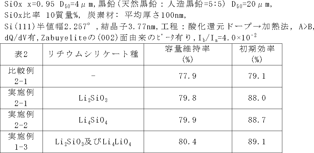
 ケイ素化合物粒子の内部に含ませるリチウムシリケートの種類を表2のように変更したこと以外、実施例1-3と同じ条件で二次電池を作製し、サイクル特性及び初期効率を評価した。リチウムシリケートの種類は、酸化還元法によるリチウム挿入工程の条件を変更することで制御した。
(Example 2-1 and Example 2-2)
A secondary battery was fabricated under the same conditions as in Example 1-3, except that the type of lithium silicate contained in the silicon compound particles was changed as shown in Table 2, and the cycle characteristics and initial efficiency were evaluated. The type of lithium silicate was controlled by changing the conditions of the lithium insertion step by the redox method.
(比較例2-1)
 負極活物質粒子にリチウムの挿入を行わなかったこと以外、実施例1-3と同じ条件で二次電池を作製し、サイクル特性及び初期効率を評価した。
(Comparative Example 2-1)
A secondary battery was fabricated under the same conditions as in Example 1-3 except that lithium was not inserted into the negative electrode active material particles, and the cycle characteristics and initial efficiency were evaluated.
 実施例2-1、実施例2-2、比較例2-1の結果を表2に示す。 Table 2 shows the results of Example 2-1, Example 2-2, and Comparative Example 2-1.
Figure JPOXMLDOC01-appb-T000002
 ケイ素化合物がLiSiO、LiSiOのような安定したリチウムシリケートを含むことで、サイクル特性、初期充放電特性が向上した。特に、LiSiOとLiSiOの両方のリチウムシリケートを含む場合に、サイクル特性、初期充放電特性がより向上した。一方で、改質を行わず、上記のリチウムシリケートを含ませなかった、即ち、ケイ素化合物にリチウムを含ませなかった比較例2-1ではサイクル特性、初期充放電特性が低下した。 When the silicon compound contains stable lithium silicate such as Li 2 SiO 3 and Li 4 SiO 4 , cycle characteristics and initial charge / discharge characteristics are improved. In particular, when both lithium silicates of Li 2 SiO 3 and Li 4 SiO 4 are included, cycle characteristics and initial charge / discharge characteristics are further improved. On the other hand, the cycle characteristics and the initial charge / discharge characteristics were lowered in Comparative Example 2-1, which was not modified and did not contain the above lithium silicate, that is, the silicon compound did not contain lithium.
(実施例3-1~3-4)
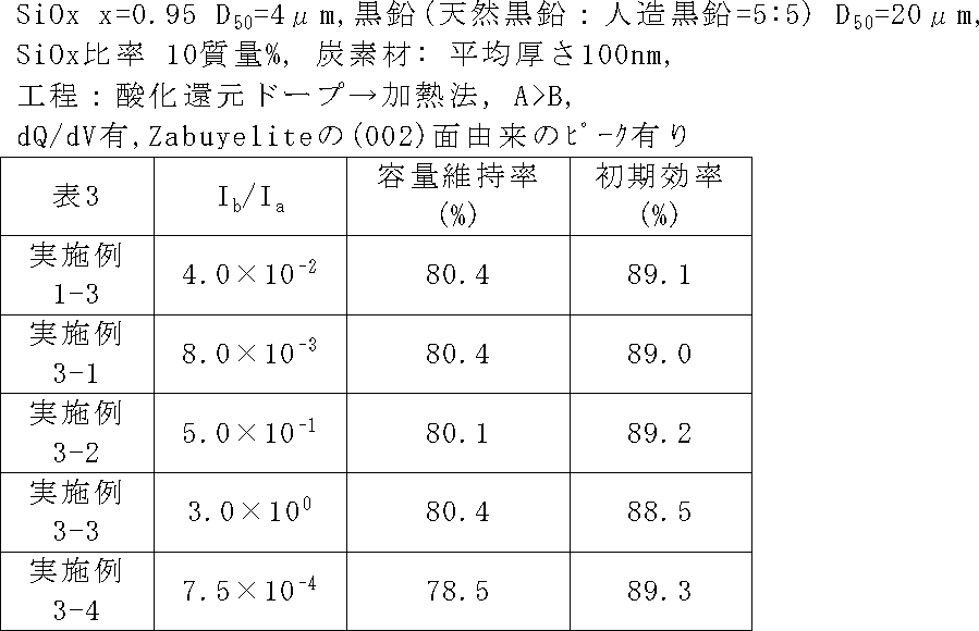
 負極活物質粒子のCu-Kαを用いたXRDスペクトルにおいて、上記したピークの強度比I/Iを表3に示すように変更したこと以外、実施例1-3と同じ条件で二次電池を作製し、サイクル特性及び初期効率を評価した。I/Iは、ケイ素化合物の不均化度と、バルク改質後の熱処理温度を変更することより調整した。
(Examples 3-1 to 3-4)
In the XRD spectrum using Cu—Kα of the negative electrode active material particles, the secondary battery was subjected to the same conditions as in Example 1-3 except that the peak intensity ratio I b / I a was changed as shown in Table 3. The cycle characteristics and initial efficiency were evaluated. I b / I a was adjusted by changing the disproportionation degree of the silicon compound and the heat treatment temperature after bulk modification.
Figure JPOXMLDOC01-appb-T000003
 表3からわかるように、I/Iが1.0×10-3<I/I<1.0×10の範囲にあることで、特に電池特性が優れていた。 As can be seen from Table 3, that is in the range of I b / I a is 1.0 × 10 -3 <I b / I a <1.0 × 10 0, was particularly excellent battery characteristics.
(実施例4-1~4-8)
 ケイ素化合物粒子のSi結晶子の結晶性を表4のように変化させたこと以外、実施例1-3と同じ条件で二次電池を作製し、サイクル特性及び初回効率を評価した。なお、ケイ素化合物粒子中のSi結晶子の結晶性は、原料の気化温度の変更、又は、ケイ素化合物粒子の生成後の熱処理で制御できる。実施例4-8では半値幅を20°以上と算出しているが、解析ソフトを用いフィッティングした結果であり、実質的にピークは得られていない。よって、実施例4-8のケイ素化合物粒子中のケイ素領域は、実質的に非晶質であると言える。
(Examples 4-1 to 4-8)
A secondary battery was fabricated under the same conditions as in Example 1-3, except that the crystallinity of the Si crystallites of the silicon compound particles was changed as shown in Table 4, and the cycle characteristics and initial efficiency were evaluated. Note that the crystallinity of the Si crystallites in the silicon compound particles can be controlled by changing the vaporization temperature of the raw material or by heat treatment after the generation of the silicon compound particles. In Example 4-8, the half-value width is calculated to be 20 ° or more, but it is a result of fitting using analysis software, and a peak is not substantially obtained. Therefore, it can be said that the silicon region in the silicon compound particles of Example 4-8 is substantially amorphous.
Figure JPOXMLDOC01-appb-T000004
 表4からわかるように、特に半値幅が1.2°以上で、尚且つSi(111)面に起因する結晶子サイズが7.5nm以下の低結晶性材料で高い容量維持率が得られた。なかでも、ケイ素化合物が非晶質である場合には、最も良い特性が得られた。 As can be seen from Table 4, a high capacity retention ratio was obtained with a low crystalline material having a half width of 1.2 ° or more and a crystallite size due to the Si (111) plane of 7.5 nm or less. . In particular, the best characteristics were obtained when the silicon compound was amorphous.
(実施例5-1)
 ケイ素化合物をSi及びLiシリケート領域の最大ピーク強度値Aと上記SiO領域に由来するピーク強度値Bとの関係がA<Bのものとしたこと以外、実施例1-3と同じ条件で二次電池を作製し、サイクル特性及び初回効率を評価した。この場合、改質時にリチウムの挿入量を減らすことで、LiSiOの量を減らし、LiSiOに由来するピークの強度Aを小さくした。
Example 5-1
The silicon compound was prepared under the same conditions as in Example 1-3 except that the relationship between the maximum peak intensity value A in the Si and Li silicate regions and the peak intensity value B derived from the SiO 2 region was A <B. A secondary battery was prepared and the cycle characteristics and initial efficiency were evaluated. In this case, by reducing the amount of insertion of lithium during reforming to reduce the amount of Li 2 SiO 3, it has a small intensity A of a peak derived from the Li 2 SiO 3.
Figure JPOXMLDOC01-appb-T000005
 表5からわかるように、ピーク強度の関係がA>Bである場合の方が、サイクル特性及び初期充放電特性が向上した。 As can be seen from Table 5, the cycle characteristics and the initial charge / discharge characteristics were improved when the peak intensity relationship was A> B.
(実施例6-1)
 上記試験セルにおける30回の充放電で得られたV-dQ/dV曲線において、いずれの充放電でもVが0.40V~0.55Vの範囲にピークが得られなかった負極活物質を用いた以外、実施例1-3と同じ条件で二次電池を作製し、サイクル特性及び初期効率を評価した。
Example 6-1
In the VdQ / dV curve obtained by charging and discharging 30 times in the test cell, a negative electrode active material in which no peak was obtained in the range of 0.40 V to 0.55 V in any charging and discharging was used. A secondary battery was manufactured under the same conditions as in Example 1-3, and the cycle characteristics and initial efficiency were evaluated.
Figure JPOXMLDOC01-appb-T000006
 放電カーブ形状がより鋭く立ち上がるためには、ケイ素化合物(SiOx)において、ケイ素(Si)と同様の放電挙動を示す必要がある。30回の充放電で上記の範囲にピークが発現しない、ケイ素化合物は比較的緩やかな放電カーブとなるため、二次電池にした際に、若干初期充放電特性が低下する結果となった。ピークが30回以内の充放電で発現するものであれば、安定したバルクが形成され、サイクル特性及び初期充放電特性が向上した。 In order for the discharge curve shape to rise sharper, the silicon compound (SiOx) needs to exhibit a discharge behavior similar to that of silicon (Si). The silicon compound, which does not exhibit a peak in the above-mentioned range after 30 charge / discharge cycles, has a relatively gentle discharge curve. Therefore, when a secondary battery is used, the initial charge / discharge characteristics are slightly lowered. If the peak appears within 30 charge / discharge cycles, a stable bulk was formed, and cycle characteristics and initial charge / discharge characteristics were improved.
(実施例7-1~7-6)
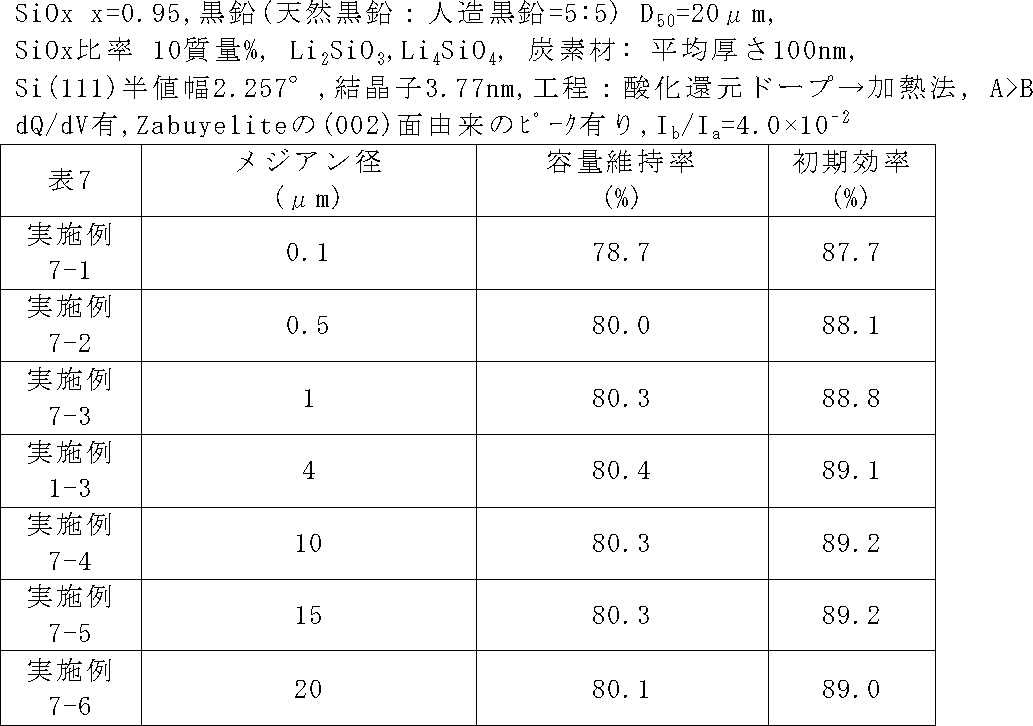
 負極活物質粒子のメジアン径を表7のように変化させたこと以外、実施例1-3と同じ条件で二次電池を作製し、サイクル特性及び初回効率を評価した。
(Examples 7-1 to 7-6)
A secondary battery was fabricated under the same conditions as in Example 1-3, except that the median diameter of the negative electrode active material particles was changed as shown in Table 7, and the cycle characteristics and initial efficiency were evaluated.
Figure JPOXMLDOC01-appb-T000007
 表7からわかるように、負極活物質粒子のメジアン径が1.0μm以上であれば、サイクル特性が向上した。これは、ケイ素化合物の質量当たりの表面積が大すぎず、副反応が起きる面積を小さくできたためと考えられる。また、メジアン径が15μm以下であれば、サイクル特性が向上した。これは、充電時に粒子が割れ難く、充放電時に新生面によるSEI(固体電解質界面)が生成し難いため、可逆Liの損失を抑制することができたためであると考えられる。さらに、ケイ素系活物質粒子のメジアン径が15μm以下であれば、充電時のケイ素化合物粒子の膨張量が大きくならないため、膨張による負極活物質層の物理的、電気的破壊を防止できたためであると考えられる。 As can be seen from Table 7, when the median diameter of the negative electrode active material particles was 1.0 μm or more, the cycle characteristics were improved. This is presumably because the surface area per mass of the silicon compound was not too large, and the area where the side reaction occurred could be reduced. Further, when the median diameter was 15 μm or less, the cycle characteristics were improved. This is considered to be because the loss of reversible Li could be suppressed because the particles are difficult to break during charging and the SEI (solid electrolyte interface) due to the new surface is difficult to generate during charging and discharging. Furthermore, if the median diameter of the silicon-based active material particles is 15 μm or less, the amount of expansion of the silicon compound particles during charging does not increase, so that physical and electrical destruction of the negative electrode active material layer due to expansion could be prevented. it is conceivable that.
(実施例8-1~8-4)
 ケイ素系活物質粒子の表面に被覆された炭素材の平均厚さを変更したこと以外、実施例1-3と同じ条件で二次電池を作製し、サイクル特性及び初回効率を評価した。炭素材の平均厚さは、CVD条件を変更することで調整できる。
(Examples 8-1 to 8-4)
A secondary battery was fabricated under the same conditions as in Example 1-3, except that the average thickness of the carbon material coated on the surface of the silicon-based active material particles was changed, and the cycle characteristics and initial efficiency were evaluated. The average thickness of the carbon material can be adjusted by changing the CVD conditions.
Figure JPOXMLDOC01-appb-T000008
 表8からわかるように、炭素層の膜厚が10nm以上で導電性が特に向上するため、サイクル特性及び初期充放電特性を向上させることができる。一方、炭素層の膜厚が5000nm以下であれば、電池設計上、ケイ素化合物粒子の量を十分に確保できるため、電池容量を十分確保することができる。 As can be seen from Table 8, since the conductivity is particularly improved when the thickness of the carbon layer is 10 nm or more, the cycle characteristics and the initial charge / discharge characteristics can be improved. On the other hand, if the film thickness of the carbon layer is 5000 nm or less, the amount of silicon compound particles can be sufficiently ensured in battery design, so that the battery capacity can be sufficiently ensured.
(実施例9-1)
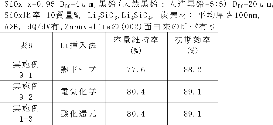
 表9に示すように改質方法を熱ドープ法に変更した以外は、実施例1-3と同じ条件で二次電池を作製し、サイクル特性及び初期効率を評価した。実施例9-1では、まず、ケイ素化合物粒子を作製し、炭素被膜形成を実施例1-3と同様に行った。その後、この炭素被覆されたケイ素化合物粒子に対して、LiH粉を使用して熱ドープ法によりリチウム挿入を行った。その後、炭酸リチウムを混合し、再度、Ar中、800℃で熱処理することで、2θ=31.8±0.5°のピークを出現させた。
Example 9-1
As shown in Table 9, a secondary battery was fabricated under the same conditions as in Example 1-3 except that the modification method was changed to the thermal doping method, and the cycle characteristics and initial efficiency were evaluated. In Example 9-1, silicon compound particles were first prepared, and a carbon film was formed in the same manner as in Example 1-3. Thereafter, lithium insertion was performed on the carbon-coated silicon compound particles using a LiH powder by a thermal doping method. Thereafter, lithium carbonate was mixed and heat-treated again at 800 ° C. in Ar, so that a peak of 2θ = 31.8 ± 0.5 ° appeared.
(実施例9-2)
 表9に示すように改質方法を電気化学的方法に変更し、バルク改質後、Ar中、800℃で熱処理することで、2θ=31.8±0.5°のピークを出現させた。
(Example 9-2)
As shown in Table 9, the reforming method was changed to an electrochemical method, and after bulk reforming, a heat treatment was performed at 800 ° C. in Ar, and a peak of 2θ = 31.8 ± 0.5 ° appeared. .
Figure JPOXMLDOC01-appb-T000009
 熱ドープ法又は酸化還元法を用いた場合であっても良好な電池特性が得られた。また、熱ドープ法を用いた場合には、加熱によりケイ素化合物粒子の結晶性も変化した。表9のいずれの改質方法であっても十分な容量維持率及び初期効率が得られた。 Good battery characteristics were obtained even when the thermal doping method or the oxidation-reduction method was used. In addition, when the thermal doping method was used, the crystallinity of the silicon compound particles was also changed by heating. A sufficient capacity retention ratio and initial efficiency were obtained by any of the reforming methods in Table 9.
(実施例10-1)
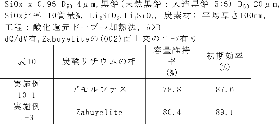
 負極活物質粒子に含まれる炭酸リチウムの相を変化させた以外、実施例1-3と同じ条件で二次電池を作製し、サイクル特性及び初回効率を評価した。炭酸リチウムの相は、負極活物質粒子(ケイ素系活物質粒子)に炭酸リチウムを混合し、その後加熱することによって調整した。なお、表10では実施例10-1に含まれる炭酸リチウムは「アモルファス」と表記している。実施例10-1でいう「アモルファス」とは、アニオンクロマトグラフィーやXPSなどによってLiCOの存在が確認でき、かつ、XRDスペクトルにおいて31.8±0.5°の範囲にピークがブロードに表れている場合(例えば、デバイシェラーの式で、結晶サイズが2nm以下の場合)のことを言う。
(Example 10-1)
A secondary battery was fabricated under the same conditions as in Example 1-3 except that the phase of lithium carbonate contained in the negative electrode active material particles was changed, and the cycle characteristics and initial efficiency were evaluated. The phase of lithium carbonate was adjusted by mixing lithium carbonate with negative electrode active material particles (silicon-based active material particles) and then heating. In Table 10, lithium carbonate contained in Example 10-1 is described as “amorphous”. The term “amorphous” as used in Example 10-1 indicates that the presence of Li 2 CO 3 can be confirmed by anion chromatography, XPS, etc., and the peak is broad in the range of 31.8 ± 0.5 ° in the XRD spectrum. If it appears (for example, when the crystal size is 2 nm or less in the Debye-Scherrer equation).
Figure JPOXMLDOC01-appb-T000010
 表10からわかるように、炭酸リチウムの相がZabuyeliteであることで、サイクル特性及び初期充放電特性を向上させることができる。 As can be seen from Table 10, the cycle characteristics and the initial charge / discharge characteristics can be improved when the lithium carbonate phase is Zabuylite.
 なお、本発明は、上記実施形態に限定されるものではない。上記実施形態は例示であり、本発明の特許請求の範囲に記載された技術的思想と実質的に同一な構成を有し、同様な作用効果を奏するものは、いかなるものであっても本発明の技術的範囲に包含される。 Note that the present invention is not limited to the above embodiment. The above-described embodiment is an exemplification, and the present invention has any configuration that has substantially the same configuration as the technical idea described in the claims of the present invention and that exhibits the same effects. Are included in the technical scope.

Claims (13)

  1.  負極活物質粒子を含む負極活物質であって、
     前記負極活物質粒子は、ケイ素化合物(SiO:0.5≦x≦1.6)を含むケイ素化合物粒子を含有し、
     前記負極活物質粒子はリチウムを含有し、
     前記負極活物質粒子は、CuのKα線を用いたX線回折スペクトルにおいて、2θ=31.8±0.5°の範囲にピークを有するものであることを特徴とする負極活物質。
    A negative electrode active material comprising negative electrode active material particles,
    The negative electrode active material particles contain silicon compound particles containing a silicon compound (SiO x : 0.5 ≦ x ≦ 1.6),
    The negative electrode active material particles contain lithium,
    The negative electrode active material, wherein the negative electrode active material particles have a peak in a range of 2θ = 31.8 ± 0.5 ° in an X-ray diffraction spectrum using Cu Kα rays.
  2.  前記負極活物質粒子は、前記CuのKα線を用いたX線回折スペクトルにおいて、2θ=28.2±0.5°の範囲に現れるSi(111)面に由来するピークの強度Iと、2θ=31.8±0.5°の範囲に現れるピークの強度Iとが、下記式1の関係を満たすものであることを特徴とする請求項1に記載の負極活物質。
    式1) 1.0×10⁻³<I/I<1.0×10
    In the X-ray diffraction spectrum using the Cu Kα ray, the negative electrode active material particles have a peak intensity I a derived from the Si (111) plane appearing in the range of 2θ = 28.2 ± 0.5 °, the negative active material of claim 1, 2 [Theta] = 31.8 and the intensity I b of the peak appearing in the range of ± 0.5 °, and wherein the satisfy the relation of the following formula 1.
    Formula 1) 1.0 × 10 −3 <I b / I a <1.0 × 10 0
  3.  前記CuのKα線を用いたX線回折スペクトルにおける2θ=31.8±0.5°の範囲に現れたピークが、炭酸リチウムの結晶相であるZabuyeliteの(002)面に由来するピークであることを特徴とする請求項1又は請求項2に記載の負極活物質。 The peak appearing in the range of 2θ = 31.8 ± 0.5 ° in the X-ray diffraction spectrum using the Cu Kα ray is a peak derived from the (002) plane of Zabuylite, which is a crystalline phase of lithium carbonate. The negative electrode active material according to claim 1, wherein the negative electrode active material is a negative electrode active material.
  4.  前記負極活物質粒子は、ポリフェニレン化合物及び多環芳香族化合物のうち1種以上を含み、
     前記ポリフェニレン化合物がビフェニル、ターフェニル、及びこれらの誘導体のうち1種以上であり、前記多環芳香族化合物がナフタレン、アントラセン、フェナントレン、ナフタセン、ペンタセン、ピレン、ピセン、コロネン、クリセン、及びこれらの誘導体のうち1種以上であることを特徴とする請求項1から請求項3のいずれか1項に記載の負極活物質。
    The negative electrode active material particles include one or more of a polyphenylene compound and a polycyclic aromatic compound,
    The polyphenylene compound is at least one of biphenyl, terphenyl, and derivatives thereof, and the polycyclic aromatic compound is naphthalene, anthracene, phenanthrene, naphthacene, pentacene, pyrene, picene, coronene, chrysene, and derivatives thereof The negative electrode active material according to any one of claims 1 to 3, wherein the negative electrode active material is one or more of the above.
  5.  前記ケイ素化合物粒子がLiSiO及びLiSiOのうち1種以上を含むものであることを特徴とする請求項1から請求項4のいずれか1項に記載の負極活物質。 5. The negative electrode active material according to claim 1, wherein the silicon compound particles include one or more of Li 2 SiO 3 and Li 4 SiO 4 .
  6.  前記ケイ素化合物粒子は、CuのKα線を用いたX線回折スペクトルにおけるSi(111)結晶面に起因するピークの半値幅(2θ)が1.2°以上であるとともに、その結晶面に対応する結晶子サイズは7.5nm以下であることを特徴とする請求項1から請求項5のいずれか1項に記載の負極活物質。 The silicon compound particles have a full width at half maximum (2θ) due to the Si (111) crystal plane in the X-ray diffraction spectrum using Cu Kα rays of 1.2 ° or more and correspond to the crystal plane. 6. The negative electrode active material according to claim 1, wherein the crystallite size is 7.5 nm or less.
  7.  前記ケイ素化合物粒子において、29Si-MAS-NMR スペクトルから得られる、ケミカルシフト値として-60~-95ppmで与えられるSi及びLiシリケート領域の最大ピーク強度値Aと、ケミカルシフト値として-96~-150ppmで与えられるSiO領域のピーク強度値Bが、A>Bという関係を満たすものであることを特徴とする請求項1から請求項6のいずれか1項に負極活物質。 In the silicon compound particles, the maximum peak intensity value A in the Si and Li silicate regions given by the chemical shift value of −60 to −95 ppm obtained from the 29 Si-MAS-NMR spectrum and the chemical shift value of −96 to − 7. The negative electrode active material according to claim 1, wherein a peak intensity value B of the SiO 2 region given at 150 ppm satisfies a relationship of A> B. 8.
  8.  前記負極活物質と炭素系活物質との混合物を含む負極電極と対極リチウムとから成る試験セルを作製し、該試験セルにおいて、前記負極活物質にリチウムを挿入するよう電流を流す充電と、前記負極活物質からリチウムを脱離するよう電流を流す放電とから成る充放電を30回実施し、各充放電における放電容量Qを前記対極リチウムを基準とする前記負極電極の電位Vで微分した微分値dQ/dVと前記電位Vとの関係を示すグラフを描いた場合に、X回目以降(1≦X≦30)の放電時における、前記負極電極の電位Vが0.40V~0.55Vの範囲にピークを有するものであることを特徴とする請求項1から請求項7のいずれか1項に記載の負極活物質。 A negative electrode containing a mixture of the negative electrode active material and the carbon-based active material, and a test cell comprising a counter lithium, and charging the current to insert lithium into the negative electrode active material in the test cell; A charge / discharge process comprising 30 discharges through which a current is passed so as to desorb lithium from the negative electrode active material, and the discharge capacity Q in each charge / discharge is differentiated by the potential V of the negative electrode with respect to the counter lithium. When a graph showing the relationship between the value dQ / dV and the potential V is drawn, the potential V of the negative electrode is 0.40 V to 0.55 V during the Xth and subsequent discharges (1 ≦ X ≦ 30). The negative electrode active material according to claim 1, wherein the negative electrode active material has a peak in the range.
  9.  前記負極活物質粒子はメジアン径が1.0μm以上15μm以下であることを特徴とする請求項1から請求項8のいずれか1項に記載の負極活物質。 The negative electrode active material according to any one of claims 1 to 8, wherein the negative electrode active material particles have a median diameter of 1.0 µm to 15 µm.
  10.  前記負極活物質粒子は、表層部に炭素材を含むことを特徴とする請求項1から請求項9のいずれか1項に記載の負極活物質。 The negative electrode active material according to claim 1, wherein the negative electrode active material particles include a carbon material in a surface layer portion.
  11.  前記炭素材の平均厚さは10nm以上5000nm以下であることを特徴とする請求項10に記載の負極活物質。 The negative electrode active material according to claim 10, wherein an average thickness of the carbon material is 10 nm or more and 5000 nm or less.
  12.  請求項1から請求項11のいずれか1項に記載の負極活物質と炭素系活物質とを含むことを特徴とする混合負極活物質材料。 A mixed negative electrode active material comprising the negative electrode active material according to any one of claims 1 to 11 and a carbon-based active material.
  13.  ケイ素化合物粒子を含有する負極活物質粒子を含む負極活物質を製造する方法であって、
     ケイ素化合物(SiO:0.5≦x≦1.6)を含むケイ素化合物粒子を作製する工程と、
     前記ケイ素化合物粒子にリチウムを挿入し、リチウムを含有させる工程と、
     により負極活物質粒子を作製し、
     前記作製した負極活物質粒子から、CuのKα線を用いたX線回折スペクトルにおいて、2θ=31.8±0.5°の範囲にピークを有するものを選別する工程とを含み、
     該選別した前記負極活物質粒子を用いて、負極活物質を製造することを特徴とする負極活物質の製造方法。
    A method for producing a negative electrode active material comprising negative electrode active material particles containing silicon compound particles,
    Producing silicon compound particles containing a silicon compound (SiO x : 0.5 ≦ x ≦ 1.6);
    Inserting lithium into the silicon compound particles to contain lithium;
    To produce negative electrode active material particles,
    Screening the produced negative electrode active material particles having a peak in the range of 2θ = 31.8 ± 0.5 ° in an X-ray diffraction spectrum using Cu Kα ray,
    A method for producing a negative electrode active material, wherein a negative electrode active material is produced using the selected negative electrode active material particles.
PCT/JP2017/006680 2016-04-18 2017-02-22 Negative electrode active substance, mixed negative electrode active substance material, and method for producing negative electrode active substance WO2017183286A1 (en)

Priority Applications (4)

Application Number Priority Date Filing Date Title
US16/092,645 US10862122B2 (en) 2016-04-18 2017-02-22 Negative electrode active material, mixed negative electrode active material, method for producing negative electrode active material
KR1020187029636A KR20180134898A (en) 2016-04-18 2017-02-22 Negative electrode active material, mixed negative electrode active material, negative electrode active material manufacturing method
CN201780024239.4A CN109075331B (en) 2016-04-18 2017-02-22 Negative electrode active material, mixed negative electrode active material, and method for producing negative electrode active material
EP17785631.7A EP3447829B1 (en) 2016-04-18 2017-02-22 Negative electrode active substance, mixed negative electrode active substance material, and method for producing negative electrode active substance

Applications Claiming Priority (2)

Application Number Priority Date Filing Date Title
JP2016082590A JP6719262B2 (en) 2016-04-18 2016-04-18 Negative electrode active material, mixed negative electrode active material, and method for producing negative electrode active material
JP2016-082590 2016-04-18

Publications (1)

Publication Number Publication Date
WO2017183286A1 true WO2017183286A1 (en) 2017-10-26

Family

ID=60116011

Family Applications (1)

Application Number Title Priority Date Filing Date
PCT/JP2017/006680 WO2017183286A1 (en) 2016-04-18 2017-02-22 Negative electrode active substance, mixed negative electrode active substance material, and method for producing negative electrode active substance

Country Status (7)

Country Link
US (1) US10862122B2 (en)
EP (1) EP3447829B1 (en)
JP (1) JP6719262B2 (en)
KR (1) KR20180134898A (en)
CN (1) CN109075331B (en)
TW (1) TWI717479B (en)
WO (1) WO2017183286A1 (en)

Cited By (3)

* Cited by examiner, † Cited by third party
Publication number Priority date Publication date Assignee Title
JPWO2019088139A1 (en) * 2017-11-02 2020-12-24 国立大学法人 東京大学 Negative electrodes for secondary batteries, secondary batteries, and their manufacturing methods
WO2022239676A1 (en) * 2021-05-13 2022-11-17 信越化学工業株式会社 Negative electrode active material and method for producing same
EP3889107A4 (en) * 2018-11-28 2022-12-21 Shin-Etsu Chemical Co., Ltd. Negative-electrode active material and method for producing same

Families Citing this family (3)

* Cited by examiner, † Cited by third party
Publication number Priority date Publication date Assignee Title
JP7214662B2 (en) * 2018-01-19 2023-01-30 三洋電機株式会社 Non-aqueous electrolyte secondary battery
JP7186156B2 (en) * 2019-10-03 2022-12-08 信越化学工業株式会社 Negative electrode active material, negative electrode, and method for producing negative electrode active material
JP7412372B2 (en) * 2021-02-15 2024-01-12 信越化学工業株式会社 Negative electrode active material for non-aqueous electrolyte secondary battery, method for producing the same, and non-aqueous electrolyte secondary battery

Citations (16)

* Cited by examiner, † Cited by third party
Publication number Priority date Publication date Assignee Title
JP2997741B2 (en) 1992-07-29 2000-01-11 セイコーインスツルメンツ株式会社 Non-aqueous electrolyte secondary battery and method of manufacturing the same
JP2001185127A (en) 1999-12-24 2001-07-06 Fdk Corp Lithium secondary battery
JP2002042806A (en) 2000-07-19 2002-02-08 Japan Storage Battery Co Ltd Non-aqueous electrolyte secondary battery
JP2006114454A (en) 2004-10-18 2006-04-27 Sony Corp Battery
JP2006164954A (en) 2004-11-11 2006-06-22 Matsushita Electric Ind Co Ltd Negative electrode for lithium ion secondary battery, its manufacturing method, and lithium ion secondary battery using it
JP2007234255A (en) 2006-02-27 2007-09-13 Sanyo Electric Co Ltd Anode for lithium secondary battery, its manufacturing method and lithium secondary battery
JP2008177346A (en) 2007-01-18 2008-07-31 Sanyo Electric Co Ltd Energy storage device
JP2008251369A (en) 2007-03-30 2008-10-16 Matsushita Electric Ind Co Ltd Negative electrode for lithium secondary battery, lithium secondary battery equipped with it, and manufacturing method of negative electrode for lithium secondary battery
JP2008282819A (en) 2008-07-10 2008-11-20 Toshiba Corp Manufacturing method of negative electrode active material for nonaqueous electrolyte secondary battery, and negative electrode active material for nonaqueous electrolyte secondary battery provided thereby
JP2009070825A (en) 2007-09-17 2009-04-02 Samsung Sdi Co Ltd Negative active material for lithium secondary battery, its manufacturing method, negative electrode for lithium secondary battery and lithium secondary battery
JP2009205950A (en) 2008-02-28 2009-09-10 Shin Etsu Chem Co Ltd Negative electrode active material for nonaqueous electrolyte secondary battery, and nonaqueous electrolyte secondary battery using the same
JP2009212074A (en) 2008-02-07 2009-09-17 Shin Etsu Chem Co Ltd Negative electrode material for nonaqueous electrolyte secondary battery, manufacturing method therefor, lithium ion secondary battery, and electrochemical capacitor
JP2013114820A (en) * 2011-11-25 2013-06-10 National Institute Of Advanced Industrial & Technology Silicon oxide powder, lithium ion secondary battery negative electrode material including the same, lithium ion secondary battery including the material, and method for producing silicon oxide powder for lithium ion secondary battery negative electrode material
JP2015149224A (en) * 2014-02-07 2015-08-20 信越化学工業株式会社 Negative electrode material for nonaqueous electrolyte secondary batteries, negative electrode for nonaqueous electrolyte secondary batteries, manufacturing method thereof, and nonaqueous electrolyte secondary battery
JP2015153520A (en) * 2014-02-12 2015-08-24 株式会社大阪チタニウムテクノロジーズ Powder for negative electrode of lithium ion secondary battery, and method of manufacturing the same
WO2016056155A1 (en) * 2014-10-08 2016-04-14 信越化学工業株式会社 Negative electrode active substance for nonaqueous electrolyte secondary cell, negative electrode for nonaqueous electrolyte secondary cell, nonaqueous electrolyte secondary cell, and method for producing negative electrode material for nonaqueous electrolyte secondary cell

Family Cites Families (10)

* Cited by examiner, † Cited by third party
Publication number Priority date Publication date Assignee Title
US20050118083A1 (en) 2003-09-05 2005-06-02 Japan Storage Battery Co., Ltd. Process for the production of lithium-containing material and non-aqueous electrolyte electrochemical cells using it
JP2005108826A (en) * 2003-09-05 2005-04-21 Japan Storage Battery Co Ltd Lithium-containing substance and method of manufacturing non-aqueous electrolyte electrochemical cell
KR101193166B1 (en) * 2010-07-15 2012-10-19 삼성에스디아이 주식회사 Positive active material, lithium battery using the same and method of preparing the same
JP5989634B2 (en) * 2011-02-28 2016-09-07 三洋電機株式会社 Non-aqueous electrolyte secondary battery
CN103918107B (en) * 2011-12-28 2016-09-07 松下知识产权经营株式会社 Anode for nonaqueous electrolyte secondary battery and use its rechargeable nonaqueous electrolytic battery
KR102227684B1 (en) 2013-10-29 2021-03-15 신에쓰 가가꾸 고교 가부시끼가이샤 Negative electrode active material, production method for negative electrode active material, and lithium ion secondary battery
JP6397262B2 (en) 2014-02-07 2018-09-26 信越化学工業株式会社 Nonaqueous electrolyte secondary battery
CN103943827B (en) * 2014-03-31 2016-08-17 华南理工大学 The high-temperature solid phase preparation method of the positive Lithium metasilicate of lithium ion battery negative material
JP6181590B2 (en) * 2014-04-02 2017-08-16 信越化学工業株式会社 Anode for non-aqueous electrolyte secondary battery and non-aqueous electrolyte secondary battery
WO2016009590A1 (en) * 2014-07-15 2016-01-21 信越化学工業株式会社 Negative electrode material for nonaqueous electrolyte secondary battery and method for producing negative electrode active material particle

Patent Citations (16)

* Cited by examiner, † Cited by third party
Publication number Priority date Publication date Assignee Title
JP2997741B2 (en) 1992-07-29 2000-01-11 セイコーインスツルメンツ株式会社 Non-aqueous electrolyte secondary battery and method of manufacturing the same
JP2001185127A (en) 1999-12-24 2001-07-06 Fdk Corp Lithium secondary battery
JP2002042806A (en) 2000-07-19 2002-02-08 Japan Storage Battery Co Ltd Non-aqueous electrolyte secondary battery
JP2006114454A (en) 2004-10-18 2006-04-27 Sony Corp Battery
JP2006164954A (en) 2004-11-11 2006-06-22 Matsushita Electric Ind Co Ltd Negative electrode for lithium ion secondary battery, its manufacturing method, and lithium ion secondary battery using it
JP2007234255A (en) 2006-02-27 2007-09-13 Sanyo Electric Co Ltd Anode for lithium secondary battery, its manufacturing method and lithium secondary battery
JP2008177346A (en) 2007-01-18 2008-07-31 Sanyo Electric Co Ltd Energy storage device
JP2008251369A (en) 2007-03-30 2008-10-16 Matsushita Electric Ind Co Ltd Negative electrode for lithium secondary battery, lithium secondary battery equipped with it, and manufacturing method of negative electrode for lithium secondary battery
JP2009070825A (en) 2007-09-17 2009-04-02 Samsung Sdi Co Ltd Negative active material for lithium secondary battery, its manufacturing method, negative electrode for lithium secondary battery and lithium secondary battery
JP2009212074A (en) 2008-02-07 2009-09-17 Shin Etsu Chem Co Ltd Negative electrode material for nonaqueous electrolyte secondary battery, manufacturing method therefor, lithium ion secondary battery, and electrochemical capacitor
JP2009205950A (en) 2008-02-28 2009-09-10 Shin Etsu Chem Co Ltd Negative electrode active material for nonaqueous electrolyte secondary battery, and nonaqueous electrolyte secondary battery using the same
JP2008282819A (en) 2008-07-10 2008-11-20 Toshiba Corp Manufacturing method of negative electrode active material for nonaqueous electrolyte secondary battery, and negative electrode active material for nonaqueous electrolyte secondary battery provided thereby
JP2013114820A (en) * 2011-11-25 2013-06-10 National Institute Of Advanced Industrial & Technology Silicon oxide powder, lithium ion secondary battery negative electrode material including the same, lithium ion secondary battery including the material, and method for producing silicon oxide powder for lithium ion secondary battery negative electrode material
JP2015149224A (en) * 2014-02-07 2015-08-20 信越化学工業株式会社 Negative electrode material for nonaqueous electrolyte secondary batteries, negative electrode for nonaqueous electrolyte secondary batteries, manufacturing method thereof, and nonaqueous electrolyte secondary battery
JP2015153520A (en) * 2014-02-12 2015-08-24 株式会社大阪チタニウムテクノロジーズ Powder for negative electrode of lithium ion secondary battery, and method of manufacturing the same
WO2016056155A1 (en) * 2014-10-08 2016-04-14 信越化学工業株式会社 Negative electrode active substance for nonaqueous electrolyte secondary cell, negative electrode for nonaqueous electrolyte secondary cell, nonaqueous electrolyte secondary cell, and method for producing negative electrode material for nonaqueous electrolyte secondary cell

Non-Patent Citations (1)

* Cited by examiner, † Cited by third party
Title
See also references of EP3447829A4

Cited By (9)

* Cited by examiner, † Cited by third party
Publication number Priority date Publication date Assignee Title
JPWO2019088139A1 (en) * 2017-11-02 2020-12-24 国立大学法人 東京大学 Negative electrodes for secondary batteries, secondary batteries, and their manufacturing methods
EP3706212A4 (en) * 2017-11-02 2021-08-11 The University of Tokyo Secondary battery negative electrode, secondary battery, and methods for manufacturing these
JP7170330B2 (en) 2017-11-02 2022-11-14 国立大学法人 東京大学 Negative electrode for secondary battery and secondary battery
US11670756B2 (en) 2017-11-02 2023-06-06 The University Of Tokyo Negative electrode for secondary battery, secondary battery, and manufacturing methods thereof
JP7421044B2 (en) 2017-11-02 2024-01-24 国立大学法人 東京大学 Method for manufacturing negative electrode for secondary battery and method for manufacturing secondary battery
EP3889107A4 (en) * 2018-11-28 2022-12-21 Shin-Etsu Chemical Co., Ltd. Negative-electrode active material and method for producing same
WO2022239676A1 (en) * 2021-05-13 2022-11-17 信越化学工業株式会社 Negative electrode active material and method for producing same
JP2022175518A (en) * 2021-05-13 2022-11-25 信越化学工業株式会社 Negative electrode active material and manufacturing method therefor
JP7457671B2 (en) 2021-05-13 2024-03-28 信越化学工業株式会社 Negative electrode active material and its manufacturing method

Also Published As

Publication number Publication date
TWI717479B (en) 2021-02-01
JP6719262B2 (en) 2020-07-08
KR20180134898A (en) 2018-12-19
EP3447829A4 (en) 2019-12-25
CN109075331A (en) 2018-12-21
EP3447829A1 (en) 2019-02-27
EP3447829B1 (en) 2021-06-16
JP2017195015A (en) 2017-10-26
US20190148728A1 (en) 2019-05-16
CN109075331B (en) 2021-12-03
TW201806859A (en) 2018-03-01
US10862122B2 (en) 2020-12-08

Similar Documents

Publication Publication Date Title
WO2018168411A1 (en) Negative electrode material, method for producing said negative electrode material, and mixed negative electrode material
CN109155408B (en) Negative electrode active material, mixed negative electrode active material, and method for producing negative electrode active material
CN109075332B (en) Negative electrode active material, mixed negative electrode active material, and method for producing negative electrode active material
TWI714753B (en) Anode active material, mixed anode active material material, and manufacturing method of anode active material (3)
JP6445956B2 (en) Negative electrode active material, mixed negative electrode active material, negative electrode for non-aqueous electrolyte secondary battery, lithium ion secondary battery
WO2017145853A1 (en) Negative electrode active material, negative electrode active material mixed material, negative electrode for nonaqueous electrolyte secondary batteries, lithium ion secondary battery, method for producing negative electrode active material, and method for manufacturing lithium ion secondary battery
WO2017085911A1 (en) Negative electrode active material, mixed negative electrode active material, negative electrode for non-aqueous electrolyte secondary battery, lithium ion secondary battery, method for producing negative electrode active material, and method for producing lithium ion secondary battery
CN108352522B (en) Negative electrode active material, lithium ion secondary battery, and method for producing same
WO2017183286A1 (en) Negative electrode active substance, mixed negative electrode active substance material, and method for producing negative electrode active substance
WO2017119031A1 (en) Negative electrode active material, mixed negative electrode active material, negative electrode for non-aqueous electrolyte secondary batteries, lithium ion secondary battery, method for producing negative electrode active material, and method for producing lithium ion secondary batteries
WO2017141661A1 (en) Anode active material, mixed anode active material ingredient, anode for nonaqueous electrolytic secondary battery, lithium ion secondary battery, and method for manufacturing anode active material
TWI716580B (en) Method for manufacturing negative electrode active material for lithium ion secondary battery, mixed negative electrode active material material for lithium ion secondary battery, and negative electrode active material for lithium ion secondary battery (2)
JP2018060771A (en) Negative electrode active material, mixing negative electrode active material, and method of manufacturing negative electrode active material
JP2018049811A (en) Negative electrode active substance, mixed negative electrode active substance material and method for producing negative electrode active substance
JP2017199657A (en) Negative electrode active material, mixed negative electrode active material, and method for manufacturing negative electrode active material
WO2017085908A1 (en) Negative electrode active material, mixed negative electrode active material, negative electrode for non-aqueous electrolyte secondary battery, lithium ion secondary battery, method for producing negative electrode active material, and method for producing lithium ion secondary battery
JP2017147058A (en) Negative electrode active material, mixed negative electrode active material material, negative electrode for nonaqueous electrolyte secondary battery, lithium ion secondary battery, and method for manufacturing negative electrode active material
WO2018051710A1 (en) Negative electrode active substance, mixed negative electrode active substance material and method for producing negative electrode active substance

Legal Events

Date Code Title Description
ENP Entry into the national phase

Ref document number: 20187029636

Country of ref document: KR

Kind code of ref document: A

NENP Non-entry into the national phase

Ref country code: DE

WWE Wipo information: entry into national phase

Ref document number: 2017785631

Country of ref document: EP

ENP Entry into the national phase

Ref document number: 2017785631

Country of ref document: EP

Effective date: 20181119

121 Ep: the epo has been informed by wipo that ep was designated in this application

Ref document number: 17785631

Country of ref document: EP

Kind code of ref document: A1