WO2017183157A1 - Optical fiber scanner, illumination device, and observation device - Google Patents
Optical fiber scanner, illumination device, and observation device Download PDFInfo
- Publication number
- WO2017183157A1 WO2017183157A1 PCT/JP2016/062650 JP2016062650W WO2017183157A1 WO 2017183157 A1 WO2017183157 A1 WO 2017183157A1 JP 2016062650 W JP2016062650 W JP 2016062650W WO 2017183157 A1 WO2017183157 A1 WO 2017183157A1
- Authority
- WO
- WIPO (PCT)
- Prior art keywords
- optical fiber
- elastic member
- fitting portion
- piezoelectric element
- piezoelectric elements
- Prior art date
Links
Images


Classifications
-
- A—HUMAN NECESSITIES
- A61—MEDICAL OR VETERINARY SCIENCE; HYGIENE
- A61B—DIAGNOSIS; SURGERY; IDENTIFICATION
- A61B1/00—Instruments for performing medical examinations of the interior of cavities or tubes of the body by visual or photographical inspection, e.g. endoscopes; Illuminating arrangements therefor
-
- G—PHYSICS
- G02—OPTICS
- G02B—OPTICAL ELEMENTS, SYSTEMS OR APPARATUS
- G02B23/00—Telescopes, e.g. binoculars; Periscopes; Instruments for viewing the inside of hollow bodies; Viewfinders; Optical aiming or sighting devices
- G02B23/24—Instruments or systems for viewing the inside of hollow bodies, e.g. fibrescopes
- G02B23/26—Instruments or systems for viewing the inside of hollow bodies, e.g. fibrescopes using light guides
-
- G—PHYSICS
- G02—OPTICS
- G02B—OPTICAL ELEMENTS, SYSTEMS OR APPARATUS
- G02B26/00—Optical devices or arrangements for the control of light using movable or deformable optical elements
- G02B26/08—Optical devices or arrangements for the control of light using movable or deformable optical elements for controlling the direction of light
- G02B26/10—Scanning systems
-
- H—ELECTRICITY
- H10—SEMICONDUCTOR DEVICES; ELECTRIC SOLID-STATE DEVICES NOT OTHERWISE PROVIDED FOR
- H10N—ELECTRIC SOLID-STATE DEVICES NOT OTHERWISE PROVIDED FOR
- H10N30/00—Piezoelectric or electrostrictive devices
- H10N30/20—Piezoelectric or electrostrictive devices with electrical input and mechanical output, e.g. functioning as actuators or vibrators
Definitions
- the present invention relates to an optical fiber scanner, an illumination device, and an observation device.
- Patent Document 1 an optical fiber is inserted in a longitudinal direction into a through hole of a cylindrical piezoelectric element.
- the present invention has been made in view of the above-described circumstances, and an object thereof is to provide an optical fiber scanner capable of easily performing an assembling operation, and an illumination device and an observation device including the same.
- an optical fiber having a longitudinal axis and emitting light from a distal end portion, and a position of the optical fiber at a position closer to the proximal end portion of the optical fiber than the distal end portion of the optical fiber.
- An elastic member that is fixed to the outer peripheral surface and covers a part of the optical fiber in the longitudinal direction; a piezoelectric element that is fixed to the outer surface of the elastic member and expands and contracts in the longitudinal direction of the optical fiber by application of voltage; and the elastic member
- An optical fiber scanner comprising: a fitting portion formed from a distal end surface to a proximal end surface, having an opening on a radially outer side of the optical fiber, and having a portion of the longitudinal direction of the optical fiber disposed therein.
- the piezoelectric element when a voltage is applied to the piezoelectric element, the piezoelectric element is deformed in the longitudinal direction of the optical fiber, and the elastic member and the optical fiber to which the piezoelectric element is fixed are bent and deformed.
- the tip of the optical fiber is displaced in the radial direction. Thereby, the light emitted from the tip of the optical fiber can be scanned.
- the fitting portion of the elastic member in which the optical fiber is disposed opens not only on the distal end side and the proximal end side of the elastic member but also on the radially outer side. Accordingly, in the assembly process of the optical fiber scanner, the optical fiber and the elastic member can be easily assembled by fitting the optical fiber into the fitting portion through the opening in the radial direction instead of the longitudinal direction. .
- the opening of the fitting portion may have a width larger than the diameter dimension of the optical fiber in a direction orthogonal to the longitudinal axis.
- a pressing member that is provided on the radially outer side of the fitting portion and covers the fitting portion in the width direction may be provided.
- a cylindrical shape is provided on the radially outer side of the optical fiber on the proximal end side than the piezoelectric element and is fixed to the elastic member, and has a larger outer diameter than the elastic member.
- a holding member is provided, the holding member communicates with the fitting portion of the elastic member in the longitudinal direction, has an opening on the same side as the fitting portion of the elastic member, and holds the optical fiber. You may provide the member side insertion part.
- the opening of the holding member side fitting portion may have a width larger than the diameter dimension of the optical fiber in a direction orthogonal to the longitudinal axis.
- the fitting portion may be a U-shaped groove having a substantially semicircular shape or a square groove having a quadrangular shape in a cross section intersecting the longitudinal direction.
- the elastic member may have a rectangular tube-like or substantially semi-cylindrical outer surface in which a part of the circumference is cut out in the longitudinal direction from the distal end to the proximal end.
- the piezoelectric element may be disposed so as to straddle the central axis of the optical fiber in the radial direction of the optical fiber.
- the three piezoelectric elements and the openings of the fitting portions are arranged at equal intervals in the circumferential direction of the optical fiber, and are opposed to the openings of the fitting portions in the radial direction.
- the thickness of the piezoelectric element arranged at the position may be larger than the thickness of the other two piezoelectric elements.
- the three piezoelectric elements and the openings of the fitting portions are arranged at equal intervals in the circumferential direction of the optical fiber, and are opposed to the openings of the fitting portions in the radial direction.
- the piezoelectric element arranged at the position may be made of a material having a large deformation amount with respect to the voltage as compared with the material forming the other two piezoelectric elements. By doing so, the optical fiber is bent and deformed in the first direction and the second direction orthogonal to each other by the single piezoelectric element facing the opening of the fitting portion and the other two piezoelectric elements. Is done.
- an illuminating apparatus including a light source that generates illumination light and an optical fiber scanner according to the first aspect in which a proximal end of the optical fiber is connected to the light source.
- the illumination device according to the second aspect, a light detection unit that detects return light that returns from the subject when the subject is irradiated with illumination light from the illumination device, and the piezoelectric device. And a voltage supply unit that supplies the voltage to the element.
- FIG. 1 is an overall configuration diagram of an observation apparatus including an optical fiber scanner and an illumination device according to an embodiment of the present invention. It is a longitudinal cross-sectional view along the longitudinal axis which shows the internal structure of the insertion part front-end
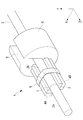
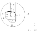
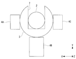
- FIG. 3 is a perspective view of the optical fiber scanner of FIG. 2. It is the front view which looked at the optical fiber scanner of Drawing 3A from the tip side in the direction of a longitudinal axis. It is the front view which looked at the modification of the optical fiber scanner of FIG. 2 from the front end side to the longitudinal axis direction. It is the front view which looked at the other modification of the optical fiber scanner of FIG. 2 from the front end side to the longitudinal axis direction.
- the observation apparatus 100 includes an endoscope 20 having an elongated insertion portion 20a, a control device main body 30 connected to the endoscope 20, and the control device main body 30. And a display 40 connected thereto.
- the observation apparatus 100 scans illumination light emitted from the distal end of the insertion portion 20a of the endoscope 20 along the spiral scanning locus B on the subject A, and acquires an image of the subject A. It is a mirror device.
- the observation device 100 includes a lighting device 10 that irradiates the subject A with illumination light, and a light detection device such as a photodiode that detects return light that returns from the subject A when the illumination light is irradiated. And a drive control device (voltage supply unit) 70 for driving and controlling the illumination device 10 and the photodetector 60.
- the photodetector 60 and the drive control device 70 are provided in the control device main body 30.
- the illuminating device 10 is provided in the control device main body 30 and generates an illuminating light.
- the illuminating device 10 is provided in the insertion portion 20a.
- the illuminating device 10 guides the illuminating light emitted from the light source 50 and emits it from the tip.
- An optical fiber scanner 1 having an optical fiber 2, a condensing lens 11 that is disposed on the tip side of the optical fiber 2 and collects illumination light emitted from the optical fiber 2, and the optical fiber scanner 1 and the condensing lens 11.
- a long and narrow cylindrical frame 12 that accommodates the light and a circumferential arrangement on the outer peripheral surface of the frame 12, and return light from the subject A (for example, reflected light or fluorescence of illumination light) is detected.
- a plurality of optical fibers for detection 13 that are guided to the device 60.
- the optical fiber scanner 1 includes an optical fiber 2, an elastic member 3 fixed to the outer peripheral surface of the optical fiber 2, and a plurality of sheets fixed to the outer surface of the elastic member 3.
- Piezoelectric elements 4A, 4B, and 4C, a holding member 5 that is provided on the optical fiber 2 on the proximal end side relative to the piezoelectric elements 4A, 4B, and 4C, and an elastic member 3 are provided.
- the holding member 6 is provided. In FIG. 2, the pressing member 6 is omitted.
- the optical fiber 2 is a multimode fiber or a single mode fiber, and is made of a cylindrical glass material having a longitudinal axis.
- a resin coating 2 b for reinforcing and protecting the optical fiber 2 is applied to the outer peripheral surface of the optical fiber 2.
- the optical fiber 2 shown in FIGS. 2 and 3A is provided with a resin coating 2b from the base end to the tip of the elastic member 3, but may be provided with a resin coating 2b from the base end to the tip.
- the optical fiber 2 is arranged along the longitudinal direction of the frame body 12 and extends from the base end of the frame body 12 to the control device main body 30.
- the distal end of the optical fiber 2 is disposed in the vicinity of the distal end portion inside the frame body 12, and the proximal end of the optical fiber 2 is connected to the light source 50 in the control device main body 30.
- the elastic member 3 is provided on the outer peripheral surface of the optical fiber 2 at a position closer to the proximal end portion of the optical fiber 2 than the distal end portion of the optical fiber 2.
- the distal end portion of the optical fiber 2 projecting from the distal end surface of the elastic member 3 to the distal end side is referred to as a protruding portion 2a.
- the elastic member 3 has a quadrangular prism shape having three flat side surfaces and one side surface on which the fitting portion 7 is formed.
- the fitting portion 7 is formed of a U-shaped groove having a substantially semicircular shape in a cross section orthogonal to the longitudinal direction of the elastic member 3, and is formed in the longitudinal direction over the entire length of the elastic member 3 from the distal end surface to the proximal end surface of the elastic member 3.
- the optical fiber 2 is disposed in the longitudinal direction in the fitting portion 7, and the inner surface of the fitting portion 7 and the outer peripheral surface of the optical fiber 2 are fixed to each other by an epoxy adhesive.
- the width dimension of the opening of the fitting portion 7 on the side surface of the elastic member 3 is equal to or larger than the diameter dimension of the optical fiber 2. Accordingly, the optical fiber 2 can be fitted into the fitting portion 7 in the radial direction.
- the depth dimension of the fitting part 7 (the dimension in the direction orthogonal to the side surface on which the fitting part 7 is formed) is larger than the radial dimension of the optical fiber 2. Therefore, the central axis of the optical fiber 2 fitted in the fitting part 7 is located in the fitting part 7.
- the elastic member 3 is made of a material having elasticity and high rigidity. Such a material is selected from, for example, metal (nickel, stainless steel, iron, aluminum alloy, titanium, etc.), synthetic resin (hard plastic), glass, and carbon. As will be described later, when the elastic member 3 is used as a common ground (GND), the elastic member 3 is made of a conductive metal material so that the elastic member 3 has conductivity at least on the surface, Alternatively, a film made of a conductive metal material is formed on the surface.
- GND common ground
- the piezoelectric elements 4A, 4B, 4C are rectangular flat plates made of a piezoelectric ceramic material such as lead zirconate titanate (PZT), for example.
- the piezoelectric elements 4A, 4B, and 4C are subjected to + electrode processing on the front surface and ⁇ electrode processing on the back surface, and are thus polarized in the thickness direction from the + pole toward the ⁇ pole.
- Arrows attached to the piezoelectric elements 4A, 4B, and 4C in the drawing indicate the polarization directions of the piezoelectric elements 4A, 4B, and 4C.
- Piezoelectric elements 4A, 4B, and 4C are fixed to each of three flat side surfaces of the four side surfaces of the elastic member 3 other than the side surface on which the fitting portion 7 is formed, with an epoxy adhesive. .
- the three piezoelectric elements 4 ⁇ / b> A, 4 ⁇ / b> B, 4 ⁇ / b> C and the openings of the fitting portions 7 are arranged at substantially equal intervals in the circumferential direction of the optical fiber 2.
- the longitudinal direction of the optical fiber 2 is defined as a Z direction
- two radial directions of the optical fiber 2 are defined as an X direction and a Y direction.
- the width direction of the fitting portion 7 is the X direction
- the depth direction of the fitting portion 7 is the Y direction.
- the three piezoelectric elements are composed of two piezoelectric elements 4A and 4C for the A phase (X direction) and one piezoelectric element 4B for the B phase (Y direction). As shown in FIG. 3B, the two A-phase piezoelectric elements 4A and 4C are arranged so that the polarization directions are parallel to the X direction and face the same side. The B-phase piezoelectric element 4B is arranged so that the polarization direction is parallel to the Y direction.
- the A-phase piezoelectric elements 4A and 4C are arranged so as to straddle the central axis of the optical fiber 2 in the Y direction, and the B-phase piezoelectric elements 4B are arranged so as to straddle the central axis of the optical fiber 2 in the X direction.
- a phase A lead wire (not shown) is connected to the two A phase piezoelectric elements 4A and 4C by a conductive adhesive, and a B phase piezoelectric element 4B is connected to the B phase lead.
- a wire (not shown) is connected by a conductive adhesive, and a GND lead wire (not shown) is connected to the holding member 5 by a conductive adhesive.
- the lead wires for A phase, B phase, and GND are connected to the drive control device 70 in the control device main body 30.
- the holding member 5 has a cylindrical shape having an outer dimension larger than that of the elastic member 3, and a fitting portion (holding member side fitting portion) 8 is formed in a part of the outer circumferential surface in the circumferential direction.
- the fitting portion 8 is formed of a U-shaped groove having a U-shaped inner surface in a cross section orthogonal to the longitudinal direction of the holding member 5, and extends in the longitudinal direction over the entire length of the holding member 5 from the distal end surface to the proximal end surface of the holding member 5. Is formed.
- the fitting part 8 is arranged in line with the fitting part 7 so as to communicate with the fitting part 7 in the longitudinal direction.
- the optical fiber 2 is disposed in the longitudinal direction in the fitting portion 8, and the inner surface of the fitting portion 8 and the outer peripheral surface of the optical fiber 2 are fixed to each other by an epoxy adhesive.
- the width dimension (dimension in the direction orthogonal to the longitudinal direction) of the opening of the fitting portion 8 on the outer peripheral surface of the holding member 5 is equal to or larger than the diameter dimension of the optical fiber 2. Accordingly, the optical fiber 2 can be fitted into the fitting portion 8 in the radial direction.
- the distal end surface of the holding member 5 is disposed in contact with the proximal end surface of the elastic member 3, and is fixed to the proximal end surface of the elastic member 3 by a conductive adhesive.
- the outer peripheral surface of the holding member 5 is fixed to the inner wall of the frame body 12.
- the optical fiber 2 may be provided with a metal coating on the outer peripheral surface instead of the resin coating. In this way, an epoxy adhesive or solder can be used for fixing the optical fiber 2 to the elastic member 3 and the holding member 5.
- the drive control device 70 applies an A-phase alternating voltage having a predetermined drive frequency to the piezoelectric elements 4A and 4C via the A-phase lead wire, and applies a predetermined voltage to the piezoelectric element 4B via the B-phase lead wire.
- a B-phase alternating voltage having a driving frequency of 2 is applied.
- the predetermined drive frequency is set to a frequency that is equal to or close to the natural frequency of the protruding portion 2a of the optical fiber 2.
- the drive control device 70 uses the A-phase alternating voltage and the B-phase alternating voltage whose phases are different from each other by ⁇ / 2 and whose amplitude changes in a sinusoidal shape over time, for the A-phase lead wire and the B-phase To each lead wire.
- the pressing member 6 is, for example, an annular member having elasticity in the circumferential direction such as an O-ring, or a heat shrinkable tube.
- the pressing member 6 is wound around the elastic member 3 and the piezoelectric elements 4A, 4B, and 4C, and is disposed so as to cover the opening of the fitting portion 7 on the side surface of the elastic member 3 in the width direction.
- the pressing member 6 is fixed to the elastic member 3 via the piezoelectric elements 4A, 4B, 4C.
- the optical fiber 2 is more stably held in the fitting portions 7 and 8 by such a pressing member 6.
- the pressing member 6 is provided so as to pass through or in the vicinity of the longitudinal center of the piezoelectric elements 4A, 4B, and 4C where the stress of the optical fiber 2 is maximized.
- the pressing member 6 is provided only on the elastic member 3, but another pressing member may also be provided on the holding member 5.
- the drive control device 70 is operated, illumination light is supplied from the light source 50 to the optical fiber 2, and the piezoelectric elements 4A, 4A, An alternating voltage having a predetermined drive frequency is applied to 4B and 4C.
- the piezoelectric elements 4A and 4C to which the A-phase alternating voltage is applied vibrate in the Z direction perpendicular to the polarization direction.
- one of the two piezoelectric elements 4A and 4C is contracted in the Z direction, and the other is expanded in the Z direction, whereby the elastic member 3 is bent in the X direction with the position of the holding member 5 as a node. Is excited.
- the protrusion 2a bends and vibrates in the X direction at a frequency equal to the drive frequency of the alternating voltage, and the tip of the optical fiber 2 vibrates in the X direction.
- the illumination light emitted from the tip is linearly scanned in the X direction.
- the piezoelectric element 4B to which the B-phase alternating voltage is applied expands and contracts in the Z direction orthogonal to the polarization direction, and the elastic member 3 is excited to bend in the Y direction with the position of the holding member 5 as a node. Then, when the bending vibration of the elastic member 3 is transmitted to the optical fiber 2, the protruding portion 2a bends and vibrates in the Y direction at a frequency equal to the drive frequency of the alternating voltage, and the illumination light emitted from the tip in the Y direction. It is scanned linearly.
- the phase of the A-phase alternating voltage and the phase of the B-phase alternating voltage are shifted from each other by ⁇ / 2, and the amplitudes of the A-phase alternating voltage and the B-phase alternating voltage change in a sine wave shape over time.
- the tip of the optical fiber 2 vibrates along a spiral trajectory, and the illumination light is scanned two-dimensionally on the subject A along the spiral trajectory.
- the drive frequency is equal to or near the natural frequency of the protrusion 2a, the protrusion 2a can be excited efficiently.
- the holding member 5 that is electrically connected to the electrodes on the elastic member 3 side of the three piezoelectric elements 4A, 4B, and 4C via the elastic member 3 functions as a common GND.
- the frame body 12 electrically connected to the holding member 5 also functions as a common GND.
- Return light from the subject A is received by a plurality of optical fibers 13, and the intensity thereof is detected by a photodetector 60.
- the drive control device 70 causes the photodetector 60 to detect return light in synchronization with the scanning period of the illumination light, and generates an image of the subject A by associating the detected intensity of the return light with the scanning position of the illumination light. .
- the generated image is output from the control device main body 30 to the display 40 and displayed on the display 40.
- an assembling method of the optical fiber scanner 1 will be described. First, an elastic member integrated by joining the base end surface of the elastic member 3 and the front end surface of the holding member 5 so that the two fitting portions 7 and 8 are arranged in a row and open on the same side. 3 and the holding member 5 are assembled. Next, an adhesive is applied to the inner surfaces of the fitting portions 7 and 8 of the unit, the optical fiber 2 is fitted in the fitting portions 7 and 8 in the radial direction, and the adhesive is cured. Thereby, the optical fiber 2, the elastic member 3, and the holding member 5 can be assembled.
- the unit including the elastic member 3 and the holding member 5 is provided with the fitting portions 7 and 8 that are opened outward in the radial direction and have a width dimension equal to or larger than the diameter of the optical fiber 2.
- the fiber 2 can be inserted into the fitting portions 7 and 8 not in the longitudinal direction but in the radial direction, and the elastic member 3 and the holding member 5 and the optical fiber 2 can be easily assembled. Thereby, it is possible to prevent the optical fiber 2 from being bent or to damage the outer peripheral surface of the optical fiber 2, particularly the front end surface, and to stably manufacture the optical fiber scanner 1 having a desired scanning performance. There are advantages.
- the opening on the radially outer side of the fitting portion 7 has a width dimension equal to or larger than the diameter dimension of the optical fiber 2, but the opening of the fitting portion 7 is elastically deformed in the vicinity of the fitting portion 7.
- the width dimension of the radially outer opening of the fitting portion 7 may be smaller than the diameter dimension of the optical fiber 2.
- at least a part of the opening may be closed in a natural state (a state where no external force is applied), and the width of the opening may be increased when the optical fiber 2 is fitted.
- the holding member 5 is formed of an elastic material in the vicinity of the fitting portion 8 and the width dimension of the opening can be temporarily enlarged by elastic deformation of the elastic material
- the width dimension of the radially outer opening may be smaller than the diameter dimension of the optical fiber 2.
- the elastic member 3 has a rectangular cylindrical outer surface in which a part of one side surface is cut out in the longitudinal direction, and the fitting portion 7 is formed of a U-shaped groove.
- the outer surface shape of 3 and the inner surface shape of the fitting portion 7 can be appropriately changed.
- 4 to 6 show modified examples of the shapes of the elastic member 3 and the fitting portion 7. 4 to 6, illustration of the holding member 5 and the pressing member 6 is omitted.
- the fitting part 7 of FIG. 4 consists of a square groove which has a rectangular cross-sectional shape.
- the elastic member 3 of FIG. 5 has a substantially semi-cylindrical outer shape, and a fitting portion 7 formed of a U-shaped groove is formed on a flat surface.
- the elastic member 3 in FIG. 6 has a partial cylindrical shape in which a part of a circular cylinder is cut out in the longitudinal direction, and is formed with a fitting portion 7 made of a square groove.
- the fitting portion 7 is opened only on one side in the Y direction, but instead, the opening is also opened on one side in the X direction as shown in FIGS. 7A to 8. You may do it.
- the elastic member 3 has a substantially L-shaped cross section.
- the outer surface of the elastic member 3 may be composed of two flat surfaces perpendicular to each other as shown in FIGS. 7A and 7B, or may be a substantially semi-cylindrical surface as shown in FIG. .
- illustration of the holding member 5 and the pressing member 6 is omitted.
- the substantially L-shaped elastic member 3 is provided with one A-phase piezoelectric element 4 ⁇ / b> A and one B-phase piezoelectric element 4 ⁇ / b> B.
- the thickness dimensions are equal to each other.
- the piezoelectric elements 4A, 4B, and 4C having the above are illustrated in FIGS. 3A to 6, instead of this, as shown in FIG. 9, the openings of the fitting portions 7 and the optical fiber 2 are opposed to each other in the radial direction.
- the arranged B-phase piezoelectric element 4B may have a thickness dimension that is twice the thickness dimension of the other two A-phase piezoelectric elements 4A and 4C.
- illustration of the holding member 5 and the pressing member 6 is omitted.
- FIG. 9 shows a partially cylindrical elastic member 3 and a fitting portion 7 made of a square groove. The elastic member 3 and the fitting portion 7 having the shapes shown in FIGS. 3B to 5 are employed. Also good.
- the protrusion 2a can be bent and vibrated more stably.
- a stable scanning locus B can be obtained. Furthermore, by making the magnitudes of the alternating voltages of the A phase and the B phase equal, the amplitude of the bending vibration of the protruding portion 2a in the X direction and the Y direction becomes equal. That is, since it is only necessary to supply an alternating voltage having the same magnitude to all the piezoelectric elements 4A, 4B, 4C, the control of the alternating voltage can be facilitated.
- the A-phase piezoelectric elements 4A and 4C and the fitting portion 7 are arranged at substantially equal intervals in the circumferential direction of the optical fiber 2, the A-phase piezoelectric elements 4A and 4C and As shown in FIG. 3A to FIG. 6, the B-phase piezoelectric element 4B has the same thickness dimension, and as the material of the B-phase piezoelectric element 4B, the A-phase piezoelectric elements 4A and 4C A material having a piezoelectric constant d31 that is twice the piezoelectric constant d31 of the material may be employed.
- the piezoelectric constant d31 is a value representing the amount of deformation in the Z direction of the piezoelectric element with respect to the alternating voltage.
- the elastic member 3 and the holding member 5 are formed of separate members, but may be formed of a single member instead. Further, the elastic member 3 may have a longer shape extending toward the proximal end side of the piezoelectric elements 4A, 4B, and 4C, and the holding member 5 may be fixed to the outer peripheral surface of the elastic member 3.
Abstract
An optical fiber scanner (1) is provided with the following: an optical fiber (2); an elastic member (3) which is fixed to the outer circumferential surface of the optical fiber (2) and which covers a longitudinal-direction portion of the optical fiber (2); piezoelectric elements (4A, 4B, 4C) which are fixed to the outer surface of the elastic member (3); and an insertion portion (7) which is formed in the elastic member (3) from the distal end surface thereof to the base end surface thereof, which has an opening on the radial outer side of the optical fiber (2), and into which a longitudinal-direction portion of the optical fiber (2) is disposed.
Description
本発明は、光ファイバスキャナ、照明装置および観察装置に関するものである。
The present invention relates to an optical fiber scanner, an illumination device, and an observation device.
従来、片持ち梁状に支持された光ファイバと、該光ファイバの外周面に固定された圧電素子とを備え、圧電素子によって光ファイバを屈曲振動させて光ファイバの先端面から射出される光を走査する光ファイバスキャナが知られている(例えば、特許文献1参照。)。特許文献1の光ファイバスキャナにおいては、筒状の圧電素子の貫通孔内に光ファイバが長手方向に挿入されている。
Conventionally, an optical fiber supported in the form of a cantilever and a piezoelectric element fixed to the outer peripheral surface of the optical fiber, and light emitted from the front end surface of the optical fiber by bending and vibrating the optical fiber by the piezoelectric element. Is known (for example, see Patent Document 1). In the optical fiber scanner of Patent Document 1, an optical fiber is inserted in a longitudinal direction into a through hole of a cylindrical piezoelectric element.
特許文献1の光ファイバスキャナを組み立てるためには、圧電素子の貫通孔内に光ファイバを長手方向に挿入する作業が必要となる。しかしながら、この挿入作業を、折れや傷等の損傷を光ファイバに生じることなく行うことは難しい。光ファイバに損傷が生じると、光ファイバスキャナの性能が低下したり性能に個体差が生じたりするという問題がある。特に光ファイバの先端面が損傷されると、先端面からの光の射出量が低下して画像の明るさが低下したり、光ビームのスポット径が大きくなって画像の分解能が低下したりするなどの性能の低下を招く。
In order to assemble the optical fiber scanner of Patent Document 1, it is necessary to insert an optical fiber in the longitudinal direction into the through hole of the piezoelectric element. However, it is difficult to perform this insertion operation without causing damage such as bending or scratches to the optical fiber. When the optical fiber is damaged, there is a problem that the performance of the optical fiber scanner deteriorates or individual differences occur in the performance. In particular, if the tip surface of the optical fiber is damaged, the amount of light emitted from the tip surface decreases and the brightness of the image decreases, or the spot diameter of the light beam increases and the resolution of the image decreases. Such as performance degradation.
本発明は、上述した事情に鑑みてなされたものであって、組立作業を容易に行うことができる光ファイバスキャナおよびこれを備える照明装置および観察装置を提供することを目的とする。
The present invention has been made in view of the above-described circumstances, and an object thereof is to provide an optical fiber scanner capable of easily performing an assembling operation, and an illumination device and an observation device including the same.
上記目的を達成するため、本発明は以下の手段を提供する。
本発明の第1の態様は、長手軸を有し、先端部から光を射出する光ファイバと、該光ファイバの前記先端部よりも前記光ファイバの基端部側の位置において前記光ファイバの外周面に固定され、該光ファイバの長手方向の一部分を覆う弾性部材と、該弾性部材の外面に固定され、電圧の印加によって前記光ファイバの長手方向に伸縮する圧電素子と、前記弾性部材に先端面から基端面まで形成され、前記光ファイバの径方向外側に開口を有し、前記光ファイバの前記長手方向の一部分が配置される嵌込部とを備える光ファイバスキャナである。 In order to achieve the above object, the present invention provides the following means.
According to a first aspect of the present invention, there is provided an optical fiber having a longitudinal axis and emitting light from a distal end portion, and a position of the optical fiber at a position closer to the proximal end portion of the optical fiber than the distal end portion of the optical fiber. An elastic member that is fixed to the outer peripheral surface and covers a part of the optical fiber in the longitudinal direction; a piezoelectric element that is fixed to the outer surface of the elastic member and expands and contracts in the longitudinal direction of the optical fiber by application of voltage; and the elastic member An optical fiber scanner comprising: a fitting portion formed from a distal end surface to a proximal end surface, having an opening on a radially outer side of the optical fiber, and having a portion of the longitudinal direction of the optical fiber disposed therein.
本発明の第1の態様によれば、圧電素子に電圧が印加されると、圧電素子が光ファイバの長手方向に変形し、圧電素子が固定されている弾性部材および光ファイバが屈曲変形し、光ファイバの先端が径方向に変位する。これにより、光ファイバの先端から射出される光を走査することができる。
According to the first aspect of the present invention, when a voltage is applied to the piezoelectric element, the piezoelectric element is deformed in the longitudinal direction of the optical fiber, and the elastic member and the optical fiber to which the piezoelectric element is fixed are bent and deformed. The tip of the optical fiber is displaced in the radial direction. Thereby, the light emitted from the tip of the optical fiber can be scanned.
この場合に、光ファイバが配置されている弾性部材の嵌込部は、弾性部材の先端側および基端側のみならず径方向外側にも開口している。したがって、光ファイバスキャナの組み立て工程において、光ファイバを、長手方向ではなく径方向に開口を介して嵌込部内に嵌め込むことによって、光ファイバと弾性部材との組み立て作業を容易に行うことができる。
In this case, the fitting portion of the elastic member in which the optical fiber is disposed opens not only on the distal end side and the proximal end side of the elastic member but also on the radially outer side. Accordingly, in the assembly process of the optical fiber scanner, the optical fiber and the elastic member can be easily assembled by fitting the optical fiber into the fitting portion through the opening in the radial direction instead of the longitudinal direction. .
上記第1の態様においては、前記嵌込部の前記開口が、前記長手軸に直交する方向に前記光ファイバの直径寸法よりも大きな幅を有していてもよい。
このようにすることで、嵌込部の開口近傍が硬質な材料から形成されている場合であっても、開口を介して嵌込部内に光ファイバを嵌め込むことができる。なお、嵌込部の開口近傍が弾性材料から形成されている場合には、開口の幅が光ファイバの直径以下であってもよい。 In the first aspect, the opening of the fitting portion may have a width larger than the diameter dimension of the optical fiber in a direction orthogonal to the longitudinal axis.
By doing in this way, even if it is a case where the opening vicinity of an insertion part is formed from a hard material, an optical fiber can be inserted in an insertion part via an opening. When the vicinity of the opening of the fitting portion is made of an elastic material, the width of the opening may be equal to or smaller than the diameter of the optical fiber.
上記第1の態様においては、前記嵌込部の径方向外側に設けられ、前記嵌込部を幅方向に覆う押さえ部材を備えていてもよい。
このようにすることで、光ファイバを嵌込部内により安定的に保持することができる。 In the first aspect, a pressing member that is provided on the radially outer side of the fitting portion and covers the fitting portion in the width direction may be provided.
By doing in this way, an optical fiber can be hold | maintained more stably in a fitting part.
上記第1の態様においては、前記圧電素子よりも基端部側において前記光ファイバの径方向外側に設けられるとともに前記弾性部材と固定され、前記弾性部材よりも大きな外径寸法を有する筒状の保持部材を備え、該保持部材は、前記弾性部材の前記嵌込部と長手方向に連通し、前記弾性部材の前記嵌込部と同一側に開口を有し、前記光ファイバが配置される保持部材側嵌込部を備えていてもよい。前記保持部材側嵌込部の前記開口が、前記長手軸に直交する方向に前記光ファイバの直径寸法よりも大きな幅を有していてもよい。
このようにすることで、光ファイバスキャナの組み立て工程において、嵌込部および保持部材側嵌込部の両方に同時に光ファイバを径方向に嵌め込むことができる。 In the first aspect, a cylindrical shape is provided on the radially outer side of the optical fiber on the proximal end side than the piezoelectric element and is fixed to the elastic member, and has a larger outer diameter than the elastic member. A holding member is provided, the holding member communicates with the fitting portion of the elastic member in the longitudinal direction, has an opening on the same side as the fitting portion of the elastic member, and holds the optical fiber. You may provide the member side insertion part. The opening of the holding member side fitting portion may have a width larger than the diameter dimension of the optical fiber in a direction orthogonal to the longitudinal axis.
By doing in this way, in the assembly process of an optical fiber scanner, an optical fiber can be simultaneously fitted to both a fitting part and a holding member side fitting part to radial direction.
上記第1の態様においては、前記嵌込部は、長手方向に交差する断面において略半円形状を有するU字溝または四角形状を有する角溝であってもよい。また、上記第1の態様においては、前記弾性部材は、周の一部分が先端から基端まで長手方向に切り欠かれた角筒状または略半円筒状の外面を有していてもよい。
このようにすることで、弾性部材の外面および嵌込部の内面形状を、特に3個の圧電素子を備える場合に好適な形状とすることができる。 In the first aspect, the fitting portion may be a U-shaped groove having a substantially semicircular shape or a square groove having a quadrangular shape in a cross section intersecting the longitudinal direction. In the first aspect, the elastic member may have a rectangular tube-like or substantially semi-cylindrical outer surface in which a part of the circumference is cut out in the longitudinal direction from the distal end to the proximal end.
By doing in this way, the outer surface of an elastic member and the inner surface shape of a fitting part can be made into a suitable shape especially when it comprises three piezoelectric elements.
上記第1の態様においては、前記圧電素子が、前記光ファイバの中心軸を該光ファイバの径方向に跨ぐように配置されていてもよい。
このようにすることで、光ファイバの中心軸に直交するベクトル成分を有する変形力を光ファイバに与えることができる。 In the first aspect, the piezoelectric element may be disposed so as to straddle the central axis of the optical fiber in the radial direction of the optical fiber.
By doing in this way, the deformation force which has a vector component orthogonal to the central axis of an optical fiber can be given to an optical fiber.
上記第1の態様においては、3つの前記圧電素子および前記嵌込部の開口が、前記光ファイバの周方向に均等に間隔をあけて配置され、前記嵌込部の開口と前記径方向に対向する位置に配置されている圧電素子の厚さが、他の2つの前記圧電素子の厚さよりも大きくてもよい。
このようにすることで、光ファイバは、嵌込部の開口と対向する単一の圧電素子と、他の2つの圧電素子とによって、互いに直交する第1の方向および第2の方向に屈曲変形される。この場合に、第1の方向における光ファイバの屈曲振動の共振周波数と第2の方向における光ファイバの屈曲振動の共振周波数とが近くなり、光ファイバの振動をより安定させることができる。 In the first aspect, the three piezoelectric elements and the openings of the fitting portions are arranged at equal intervals in the circumferential direction of the optical fiber, and are opposed to the openings of the fitting portions in the radial direction. The thickness of the piezoelectric element arranged at the position may be larger than the thickness of the other two piezoelectric elements.
By doing so, the optical fiber is bent and deformed in the first direction and the second direction orthogonal to each other by the single piezoelectric element facing the opening of the fitting portion and the other two piezoelectric elements. Is done. In this case, the resonance frequency of the bending vibration of the optical fiber in the first direction becomes close to the resonance frequency of the bending vibration of the optical fiber in the second direction, and the vibration of the optical fiber can be further stabilized.
上記第1の態様においては、3つの前記圧電素子および前記嵌込部の開口が、前記光ファイバの周方向に均等に間隔をあけて配置され、前記嵌込部の開口と前記径方向に対向する位置に配置されている圧電素子は、他の2つの前記圧電素子を形成する材料に比べて、前記電圧に対する変形量が大きい材料から形成されていてもよい。
このようにすることで、光ファイバは、嵌込部の開口と対向する単一の圧電素子と、他の2つの圧電素子とによって、互いに直交する第1の方向および第2の方向に屈曲変形される。この場合に、3つの圧電素子に等しい大きさの電圧を印加したときに、単一の圧電素子による第1の方向の光ファイバの変形量と、他の2つの圧電素子による第2の方向の光ファイバの変形量とが等しくなる。これにより、3つの圧電素子に印加する電圧の制御を容易にすることができる。 In the first aspect, the three piezoelectric elements and the openings of the fitting portions are arranged at equal intervals in the circumferential direction of the optical fiber, and are opposed to the openings of the fitting portions in the radial direction. The piezoelectric element arranged at the position may be made of a material having a large deformation amount with respect to the voltage as compared with the material forming the other two piezoelectric elements.
By doing so, the optical fiber is bent and deformed in the first direction and the second direction orthogonal to each other by the single piezoelectric element facing the opening of the fitting portion and the other two piezoelectric elements. Is done. In this case, when a voltage of equal magnitude is applied to the three piezoelectric elements, the deformation amount of the optical fiber in the first direction by the single piezoelectric element and the second direction by the other two piezoelectric elements. The amount of deformation of the optical fiber becomes equal. Thereby, control of the voltage applied to the three piezoelectric elements can be facilitated.
本発明の第2の態様は、照明光を発生する光源と、該光源に前記光ファイバの基端が接続される第1の態様に係る光ファイバスキャナとを備える照明装置である。
本発明の第3の態様は、第2の態様に係る照明装置と、該照明装置からの照明光が被写体に照射されることにより、被写体から戻る戻り光を検出する光検出部と、前記圧電素子に前記電圧を供給する電圧供給部とを備える観察装置である。 According to a second aspect of the present invention, there is provided an illuminating apparatus including a light source that generates illumination light and an optical fiber scanner according to the first aspect in which a proximal end of the optical fiber is connected to the light source.
According to a third aspect of the present invention, there is provided the illumination device according to the second aspect, a light detection unit that detects return light that returns from the subject when the subject is irradiated with illumination light from the illumination device, and the piezoelectric device. And a voltage supply unit that supplies the voltage to the element.
本発明によれば、組立作業を容易に行うことができるという効果を奏する。
According to the present invention, there is an effect that the assembling work can be easily performed.
以下に、本発明の一実施形態に係る光ファイバスキャナ1、照明装置10および観察装置100について図面を参照して説明する。
本実施形態に係る観察装置100は、図1に示されるように、細長い挿入部20aを有する内視鏡20と、該内視鏡20に接続された制御装置本体30と、該制御装置本体30に接続されたディスプレイ40とを備えている。観察装置100は、内視鏡20の挿入部20aの先端から射出される照明光を被写体A上でスパイラル状の走査軌跡Bに沿って走査し、被写体Aの画像を取得する光走査型内視鏡装置である。 Hereinafter, anoptical fiber scanner 1, an illumination device 10, and an observation device 100 according to an embodiment of the present invention will be described with reference to the drawings.
As shown in FIG. 1, theobservation apparatus 100 according to the present embodiment includes an endoscope 20 having an elongated insertion portion 20a, a control device main body 30 connected to the endoscope 20, and the control device main body 30. And a display 40 connected thereto. The observation apparatus 100 scans illumination light emitted from the distal end of the insertion portion 20a of the endoscope 20 along the spiral scanning locus B on the subject A, and acquires an image of the subject A. It is a mirror device.
本実施形態に係る観察装置100は、図1に示されるように、細長い挿入部20aを有する内視鏡20と、該内視鏡20に接続された制御装置本体30と、該制御装置本体30に接続されたディスプレイ40とを備えている。観察装置100は、内視鏡20の挿入部20aの先端から射出される照明光を被写体A上でスパイラル状の走査軌跡Bに沿って走査し、被写体Aの画像を取得する光走査型内視鏡装置である。 Hereinafter, an
As shown in FIG. 1, the
観察装置100は、図2に示されるように、被写体Aに照明光を照射する照明装置10と、照明光が照射されることによって被写体Aから戻る戻り光を検出するフォトダイオードのような光検出器(光検出部)60と、照明装置10および光検出器60を駆動制御する駆動制御装置(電圧供給部)70とをさらに備えている。光検出器60および駆動制御装置70は制御装置本体30内に設けられている。
As shown in FIG. 2, the observation device 100 includes a lighting device 10 that irradiates the subject A with illumination light, and a light detection device such as a photodiode that detects return light that returns from the subject A when the illumination light is irradiated. And a drive control device (voltage supply unit) 70 for driving and controlling the illumination device 10 and the photodetector 60. The photodetector 60 and the drive control device 70 are provided in the control device main body 30.
照明装置10は、制御装置本体30内に設けられ照明光を発生する光源50と、挿入部20a内に設けられ、光源50から発せられた照明光を導光して先端から射出する照明用の光ファイバ2を有する光ファイバスキャナ1と、光ファイバ2よりも先端側に配置され、光ファイバ2から射出された照明光を集光させる集光レンズ11と、光ファイバスキャナ1および集光レンズ11を収納する細長い筒状の枠体12と、該枠体12の外周面上に周方向に配列して設けられ、被写体Aからの戻り光(例えば、照明光の反射光または蛍光)を光検出器60に導光する複数の検出用の光ファイバ13とを備えている。
The illuminating device 10 is provided in the control device main body 30 and generates an illuminating light. The illuminating device 10 is provided in the insertion portion 20a. The illuminating device 10 guides the illuminating light emitted from the light source 50 and emits it from the tip. An optical fiber scanner 1 having an optical fiber 2, a condensing lens 11 that is disposed on the tip side of the optical fiber 2 and collects illumination light emitted from the optical fiber 2, and the optical fiber scanner 1 and the condensing lens 11. A long and narrow cylindrical frame 12 that accommodates the light and a circumferential arrangement on the outer peripheral surface of the frame 12, and return light from the subject A (for example, reflected light or fluorescence of illumination light) is detected. And a plurality of optical fibers for detection 13 that are guided to the device 60.
光ファイバスキャナ1は、図2から図3Bに示されるように、光ファイバ2と、光ファイバ2の外周面に固定された弾性部材3と、該弾性部材3の外面に固定された複数枚の圧電素子4A,4B,4Cと、該圧電素子4A,4B,4Cよりも基端側において光ファイバ2に設けられ光ファイバ2を枠体12に固定する保持部材5と、弾性部材3に設けられた押さえ部材6とを備えている。図2において、押さえ部材6は省略されている。
2 to 3B, the optical fiber scanner 1 includes an optical fiber 2, an elastic member 3 fixed to the outer peripheral surface of the optical fiber 2, and a plurality of sheets fixed to the outer surface of the elastic member 3. Piezoelectric elements 4A, 4B, and 4C, a holding member 5 that is provided on the optical fiber 2 on the proximal end side relative to the piezoelectric elements 4A, 4B, and 4C, and an elastic member 3 are provided. The holding member 6 is provided. In FIG. 2, the pressing member 6 is omitted.
光ファイバ2は、マルチモードファイバまたはシングルモードファイバであり、長手軸を有する円柱状のガラス材からなる。光ファイバ2の外周面には、該光ファイバ2を補強および保護するための樹脂コーティング2bが施されている。図2および図3Aに示される光ファイバ2は、基端から弾性部材3の先端まで樹脂コーティング2bが施されているが、基端から先端まで樹脂コーティング2bが施されていてもよい。光ファイバ2は、枠体12の長手方向に沿って配され、枠体12の基端から制御装置本体30へ延びている。光ファイバ2の先端は枠体12の内部の先端部近傍に配置され、光ファイバ2の基端は制御装置本体30内の光源50に接続されている。
The optical fiber 2 is a multimode fiber or a single mode fiber, and is made of a cylindrical glass material having a longitudinal axis. A resin coating 2 b for reinforcing and protecting the optical fiber 2 is applied to the outer peripheral surface of the optical fiber 2. The optical fiber 2 shown in FIGS. 2 and 3A is provided with a resin coating 2b from the base end to the tip of the elastic member 3, but may be provided with a resin coating 2b from the base end to the tip. The optical fiber 2 is arranged along the longitudinal direction of the frame body 12 and extends from the base end of the frame body 12 to the control device main body 30. The distal end of the optical fiber 2 is disposed in the vicinity of the distal end portion inside the frame body 12, and the proximal end of the optical fiber 2 is connected to the light source 50 in the control device main body 30.
弾性部材3は、光ファイバ2の先端部よりも該光ファイバ2の基端部側の位置において光ファイバ2の外周面に設けられている。以下、弾性部材3の先端面から先端側に突出している光ファイバ2の先端部分を突出部2aという。弾性部材3は、図3Aおよび図3Bに示されるように、3つの平坦な側面と、嵌込部7が形成された1つの側面とを有する四角柱状である。
The elastic member 3 is provided on the outer peripheral surface of the optical fiber 2 at a position closer to the proximal end portion of the optical fiber 2 than the distal end portion of the optical fiber 2. Hereinafter, the distal end portion of the optical fiber 2 projecting from the distal end surface of the elastic member 3 to the distal end side is referred to as a protruding portion 2a. As shown in FIGS. 3A and 3B, the elastic member 3 has a quadrangular prism shape having three flat side surfaces and one side surface on which the fitting portion 7 is formed.
嵌込部7は、弾性部材3の長手方向に直交する横断面において略半円形状を有するU字溝からなり、弾性部材3の先端面から基端面まで弾性部材3の全長にわたって長手方向に形成されている。光ファイバ2は嵌込部7内に長手方向に配置され、嵌込部7の内面と光ファイバ2の外周面とがエポキシ系接着剤によって互いに固定されている。
The fitting portion 7 is formed of a U-shaped groove having a substantially semicircular shape in a cross section orthogonal to the longitudinal direction of the elastic member 3, and is formed in the longitudinal direction over the entire length of the elastic member 3 from the distal end surface to the proximal end surface of the elastic member 3. Has been. The optical fiber 2 is disposed in the longitudinal direction in the fitting portion 7, and the inner surface of the fitting portion 7 and the outer peripheral surface of the optical fiber 2 are fixed to each other by an epoxy adhesive.
弾性部材3の側面における嵌込部7の開口の幅寸法(長手方向に直交する方向における寸法)は、光ファイバ2の直径寸法以上である。したがって、光ファイバ2を嵌込部7内へ径方向に嵌め込むことができるようになっている。嵌込部7の深さ寸法(嵌込部7が形成されている側面に直交する方向における寸法)は、光ファイバ2の半径寸法よりも大きくなっている。したがって、嵌込部7内に嵌め込まれた光ファイバ2の中心軸が嵌込部7内に位置するようになっている。
The width dimension of the opening of the fitting portion 7 on the side surface of the elastic member 3 (dimension in the direction orthogonal to the longitudinal direction) is equal to or larger than the diameter dimension of the optical fiber 2. Accordingly, the optical fiber 2 can be fitted into the fitting portion 7 in the radial direction. The depth dimension of the fitting part 7 (the dimension in the direction orthogonal to the side surface on which the fitting part 7 is formed) is larger than the radial dimension of the optical fiber 2. Therefore, the central axis of the optical fiber 2 fitted in the fitting part 7 is located in the fitting part 7.
弾性部材3は、弾性と高い剛性とを有する材質から構成されている。このような材質は、例えば、金属(ニッケル、ステンレス鋼、鉄、アルミニウム合金、チタン等)、合成樹脂(硬性プラスチック)、ガラスおよびカーボンから選択される。後述するように、弾性部材3を共通グランド(GND)として用いる場合には、弾性部材3が少なくとも表面において導電性を有するように、弾性部材3は、導電性の金属材料から構成されるか、または導電性の金属材料からなる被膜が表面に形成される。
The elastic member 3 is made of a material having elasticity and high rigidity. Such a material is selected from, for example, metal (nickel, stainless steel, iron, aluminum alloy, titanium, etc.), synthetic resin (hard plastic), glass, and carbon. As will be described later, when the elastic member 3 is used as a common ground (GND), the elastic member 3 is made of a conductive metal material so that the elastic member 3 has conductivity at least on the surface, Alternatively, a film made of a conductive metal material is formed on the surface.
圧電素子4A,4B,4Cは、例えば、チタン酸ジルコン酸鉛(PZT)などの圧電セラミックス材料からなる矩形の平板状である。圧電素子4A,4B,4Cは、表面に+の電極処理が施され、裏面に-の電極処理が施されており、これによって+極から-極に向かって板厚方向に分極している。図中の圧電素子4A,4B,4Cに付されている矢印は、圧電素子4A,4B,4Cの分極方向を示している。
The piezoelectric elements 4A, 4B, 4C are rectangular flat plates made of a piezoelectric ceramic material such as lead zirconate titanate (PZT), for example. The piezoelectric elements 4A, 4B, and 4C are subjected to + electrode processing on the front surface and − electrode processing on the back surface, and are thus polarized in the thickness direction from the + pole toward the − pole. Arrows attached to the piezoelectric elements 4A, 4B, and 4C in the drawing indicate the polarization directions of the piezoelectric elements 4A, 4B, and 4C.
圧電素子4A,4B,4Cは、弾性部材3の4つの側面のうち、嵌込部7が形成されている側面以外の3つの平坦な側面に1枚ずつ、エポキシ系接着剤によって固定されている。これにより。3枚の圧電素子4A,4B,4Cおよび嵌込部7の開口は、光ファイバ2の周方向に略均等に間隔をあけて配置されている。以下、光ファイバ2の長手方向をZ方向とし、光ファイバ2の互いに直交する2つの径方向をX方向およびY方向とする。特に、嵌込部7の幅方向をX方向とし、嵌込部7の深さ方向をY方向とする。
Piezoelectric elements 4A, 4B, and 4C are fixed to each of three flat side surfaces of the four side surfaces of the elastic member 3 other than the side surface on which the fitting portion 7 is formed, with an epoxy adhesive. . By this. The three piezoelectric elements 4 </ b> A, 4 </ b> B, 4 </ b> C and the openings of the fitting portions 7 are arranged at substantially equal intervals in the circumferential direction of the optical fiber 2. Hereinafter, the longitudinal direction of the optical fiber 2 is defined as a Z direction, and two radial directions of the optical fiber 2 are defined as an X direction and a Y direction. In particular, the width direction of the fitting portion 7 is the X direction, and the depth direction of the fitting portion 7 is the Y direction.
3枚の圧電素子は、A相(X方向)用の2枚の圧電素子4A,4Cと、B相(Y方向)用の1枚の圧電素子4Bとからなる。図3Bに示されるように、A相用の2枚の圧電素子4A,4Cは、分極方向がX方向に平行になりかつ互いに同一の側を向くように、配置されている。B相用の圧電素子4Bは、分極方向がY方向に平行になるように配置されている。さらに、A相用の圧電素子4A,4Cは光ファイバ2の中心軸をY方向に跨ぐように、B相用の圧電素子4Bは光ファイバ2の中心軸をX方向に跨ぐように、それぞれ配置されている。
The three piezoelectric elements are composed of two piezoelectric elements 4A and 4C for the A phase (X direction) and one piezoelectric element 4B for the B phase (Y direction). As shown in FIG. 3B, the two A-phase piezoelectric elements 4A and 4C are arranged so that the polarization directions are parallel to the X direction and face the same side. The B-phase piezoelectric element 4B is arranged so that the polarization direction is parallel to the Y direction. Furthermore, the A-phase piezoelectric elements 4A and 4C are arranged so as to straddle the central axis of the optical fiber 2 in the Y direction, and the B-phase piezoelectric elements 4B are arranged so as to straddle the central axis of the optical fiber 2 in the X direction. Has been.
A相用の2枚の圧電素子4A,4CにはA相用のリード線(図示略)が導電性接着剤によって接続され、B相用の1枚の圧電素子4BにはB相用のリード線(図示略)が導電性接着剤によって接続され、保持部材5にはGND用のリード線(図示略)が導電性接着剤によって接続されている。A相用、B相用およびGND用のリード線は、制御装置本体30内の駆動制御装置70に接続されている。
A phase A lead wire (not shown) is connected to the two A phase piezoelectric elements 4A and 4C by a conductive adhesive, and a B phase piezoelectric element 4B is connected to the B phase lead. A wire (not shown) is connected by a conductive adhesive, and a GND lead wire (not shown) is connected to the holding member 5 by a conductive adhesive. The lead wires for A phase, B phase, and GND are connected to the drive control device 70 in the control device main body 30.
保持部材5は、弾性部材3よりも大きな外形寸法を有する円柱状であり、外周面の周方向の一部分に嵌込部(保持部材側嵌込部)8が形成されている。嵌込部8は、保持部材5の長手方向に直交する横断面においてU字状の内面を有するU字溝からなり、保持部材5の先端面から基端面まで保持部材5の全長にわたって長手方向に形成されている。嵌込部8は、嵌込部7と長手方向に連通するように嵌込部7と一列に並んで配置されている。光ファイバ2は嵌込部8内に長手方向に配置され、嵌込部8の内面と光ファイバ2の外周面とがエポキシ系接着剤によって互いに固定されている。
The holding member 5 has a cylindrical shape having an outer dimension larger than that of the elastic member 3, and a fitting portion (holding member side fitting portion) 8 is formed in a part of the outer circumferential surface in the circumferential direction. The fitting portion 8 is formed of a U-shaped groove having a U-shaped inner surface in a cross section orthogonal to the longitudinal direction of the holding member 5, and extends in the longitudinal direction over the entire length of the holding member 5 from the distal end surface to the proximal end surface of the holding member 5. Is formed. The fitting part 8 is arranged in line with the fitting part 7 so as to communicate with the fitting part 7 in the longitudinal direction. The optical fiber 2 is disposed in the longitudinal direction in the fitting portion 8, and the inner surface of the fitting portion 8 and the outer peripheral surface of the optical fiber 2 are fixed to each other by an epoxy adhesive.
保持部材5の外周面における嵌込部8の開口の幅寸法(長手方向に直交する方向における寸法)は、光ファイバ2の直径寸法以上である。したがって、光ファイバ2を嵌込部8内へ径方向に嵌め込むことができるようになっている。
The width dimension (dimension in the direction orthogonal to the longitudinal direction) of the opening of the fitting portion 8 on the outer peripheral surface of the holding member 5 is equal to or larger than the diameter dimension of the optical fiber 2. Accordingly, the optical fiber 2 can be fitted into the fitting portion 8 in the radial direction.
保持部材5の先端面は、弾性部材3の基端面と接触して配置され該弾性部材3の基端面と導電性接着剤によって固定されている。保持部材5の外周面は、枠体12の内壁に固定されている。これにより、弾性部材3および光ファイバ2の突出部2aは、先端を自由端とする片持ち梁状に保持部材5によって支持されている。
The distal end surface of the holding member 5 is disposed in contact with the proximal end surface of the elastic member 3, and is fixed to the proximal end surface of the elastic member 3 by a conductive adhesive. The outer peripheral surface of the holding member 5 is fixed to the inner wall of the frame body 12. As a result, the elastic member 3 and the protruding portion 2a of the optical fiber 2 are supported by the holding member 5 in a cantilever shape with the tip as a free end.
光ファイバ2は、樹脂コーティングに代えて、金属コーティングが外周面に施されていてもよい。このようにすることで、光ファイバ2と弾性部材3および保持部材5との固定に、エポキシ系接着剤または半田を使用することができる。
The optical fiber 2 may be provided with a metal coating on the outer peripheral surface instead of the resin coating. In this way, an epoxy adhesive or solder can be used for fixing the optical fiber 2 to the elastic member 3 and the holding member 5.
駆動制御装置70は、A相用のリード線を介して圧電素子4A,4Cに所定の駆動周波数を有するA相の交番電圧を印加し、B相用のリード線を介して圧電素子4Bに所定の駆動周波数を有するB相の交番電圧を印加する。所定の駆動周波数は、光ファイバ2の突出部2aの固有振動数と等しい周波数または固有振動数の近傍の周波数に設定される。ここで、駆動制御装置70は、位相が互いにπ/2だけ異なり、かつ、振幅が正弦波状に時間変化するA相の交番電圧およびB相の交番電圧をA相用のリード線およびB相用のリード線にそれぞれ供給する。
The drive control device 70 applies an A-phase alternating voltage having a predetermined drive frequency to the piezoelectric elements 4A and 4C via the A-phase lead wire, and applies a predetermined voltage to the piezoelectric element 4B via the B-phase lead wire. A B-phase alternating voltage having a driving frequency of 2 is applied. The predetermined drive frequency is set to a frequency that is equal to or close to the natural frequency of the protruding portion 2a of the optical fiber 2. Here, the drive control device 70 uses the A-phase alternating voltage and the B-phase alternating voltage whose phases are different from each other by π / 2 and whose amplitude changes in a sinusoidal shape over time, for the A-phase lead wire and the B-phase To each lead wire.
押さえ部材6は、例えば、Oリングのような周方向に弾性を有する環状の部材か、または熱収縮チューブからなる。押さえ部材6は、弾性部材3および圧電素子4A,4B,4Cの周囲に巻かれ、弾性部材3の側面における嵌込部7の開口を幅方向に覆うように配置されている。押さえ部材6は、圧電素子4A,4B,4Cを介して弾性部材3に固定されている。このような押さえ部材6によって、光ファイバ2が嵌込部7,8内にさらに安定に保持されるようになっている。ここで、押さえ部材6は、光ファイバ2の応力が最大となる圧電素子4A,4B,4Cの長手方向の中心またはその近傍を通るように、設けられていることが好ましい。図2および図3Aにおいては弾性部材3のみに押さえ部材6が設けられているが、もう1つの押さえ部材が保持部材5にも設けられていてもよい。
The pressing member 6 is, for example, an annular member having elasticity in the circumferential direction such as an O-ring, or a heat shrinkable tube. The pressing member 6 is wound around the elastic member 3 and the piezoelectric elements 4A, 4B, and 4C, and is disposed so as to cover the opening of the fitting portion 7 on the side surface of the elastic member 3 in the width direction. The pressing member 6 is fixed to the elastic member 3 via the piezoelectric elements 4A, 4B, 4C. The optical fiber 2 is more stably held in the fitting portions 7 and 8 by such a pressing member 6. Here, it is preferable that the pressing member 6 is provided so as to pass through or in the vicinity of the longitudinal center of the piezoelectric elements 4A, 4B, and 4C where the stress of the optical fiber 2 is maximized. In FIG. 2 and FIG. 3A, the pressing member 6 is provided only on the elastic member 3, but another pressing member may also be provided on the holding member 5.
次に、このように構成された光ファイバスキャナ1、照明装置10および観察装置100の作用について説明する。
本実施形態に係る観察装置100を用いて被写体Aを観察するには、駆動制御装置70を作動させ、光源50から光ファイバ2に照明光を供給させるとともに、リード線を介して圧電素子4A,4B,4Cに所定の駆動周波数を有する交番電圧を印加させる。 Next, operations of theoptical fiber scanner 1, the illumination device 10, and the observation device 100 configured as described above will be described.
In order to observe the subject A using theobservation device 100 according to the present embodiment, the drive control device 70 is operated, illumination light is supplied from the light source 50 to the optical fiber 2, and the piezoelectric elements 4A, 4A, An alternating voltage having a predetermined drive frequency is applied to 4B and 4C.
本実施形態に係る観察装置100を用いて被写体Aを観察するには、駆動制御装置70を作動させ、光源50から光ファイバ2に照明光を供給させるとともに、リード線を介して圧電素子4A,4B,4Cに所定の駆動周波数を有する交番電圧を印加させる。 Next, operations of the
In order to observe the subject A using the
A相の交番電圧が印加された圧電素子4A,4Cは、分極方向に直交するZ方向に伸縮振動する。このときに、2枚の圧電素子4A,4Cのうち、一方がZ方向に縮み、他方がZ方向に伸びることにより、弾性部材3に、保持部材5の位置を節とするX方向の屈曲振動が励起される。そして、弾性部材3の屈曲振動が光ファイバ2に伝達されることにより、突出部2aが交番電圧の駆動周波数と等しい周波数でX方向に屈曲振動して光ファイバ2の先端がX方向に振動し、先端から射出される照明光がX方向に直線的に走査される。
The piezoelectric elements 4A and 4C to which the A-phase alternating voltage is applied vibrate in the Z direction perpendicular to the polarization direction. At this time, one of the two piezoelectric elements 4A and 4C is contracted in the Z direction, and the other is expanded in the Z direction, whereby the elastic member 3 is bent in the X direction with the position of the holding member 5 as a node. Is excited. Then, when the bending vibration of the elastic member 3 is transmitted to the optical fiber 2, the protrusion 2a bends and vibrates in the X direction at a frequency equal to the drive frequency of the alternating voltage, and the tip of the optical fiber 2 vibrates in the X direction. The illumination light emitted from the tip is linearly scanned in the X direction.
B相の交番電圧が印加された圧電素子4Bは、分極方向に直交するZ方向に伸縮振動し、弾性部材3に保持部材5の位置を節とするY方向の屈曲振動が励起される。そして、弾性部材3の屈曲振動が光ファイバ2に伝達されることにより、突出部2aが交番電圧の駆動周波数と等しい周波数でY方向に屈曲振動し、先端から射出される照明光がY方向に直線的に走査される。
The piezoelectric element 4B to which the B-phase alternating voltage is applied expands and contracts in the Z direction orthogonal to the polarization direction, and the elastic member 3 is excited to bend in the Y direction with the position of the holding member 5 as a node. Then, when the bending vibration of the elastic member 3 is transmitted to the optical fiber 2, the protruding portion 2a bends and vibrates in the Y direction at a frequency equal to the drive frequency of the alternating voltage, and the illumination light emitted from the tip in the Y direction. It is scanned linearly.
ここで、A相の交番電圧の位相とB相の交番電圧の位相とは互いにπ/2ずれており、かつ、A相の交番電圧およびB相の交番電圧の振幅が正弦波状に時間変化することによって、光ファイバ2の先端がスパイラル状の軌跡に沿って振動し、照明光が被写体A上においてスパイラル状の軌跡に沿って2次元的に走査される。また、駆動周波数は突出部2aの固有振動数と等しいまたは近傍の周波数であるので、突出部2aを効率的に励振させることができる。
Here, the phase of the A-phase alternating voltage and the phase of the B-phase alternating voltage are shifted from each other by π / 2, and the amplitudes of the A-phase alternating voltage and the B-phase alternating voltage change in a sine wave shape over time. As a result, the tip of the optical fiber 2 vibrates along a spiral trajectory, and the illumination light is scanned two-dimensionally on the subject A along the spiral trajectory. Further, since the drive frequency is equal to or near the natural frequency of the protrusion 2a, the protrusion 2a can be excited efficiently.
このときに、弾性部材3を介して3枚の圧電素子4A,4B,4Cの弾性部材3側の電極と電気的に接続されている保持部材5は、共通GNDとして機能するようになっている。さらに、保持部材5と電気的に接続されている枠体12も、共通GNDとして機能するようになっている。
At this time, the holding member 5 that is electrically connected to the electrodes on the elastic member 3 side of the three piezoelectric elements 4A, 4B, and 4C via the elastic member 3 functions as a common GND. . Furthermore, the frame body 12 electrically connected to the holding member 5 also functions as a common GND.
被写体Aからの戻り光は、複数本の光ファイバ13によって受光され、その強度が光検出器60によって検出される。駆動制御装置70は、照明光の走査周期と同期して光検出器60に戻り光を検出させ、検出された戻り光の強度を照明光の走査位置と対応付けることによって被写体Aの画像を生成する。生成された画像は、制御装置本体30からディスプレイ40に出力され該ディスプレイ40に表示される。
Return light from the subject A is received by a plurality of optical fibers 13, and the intensity thereof is detected by a photodetector 60. The drive control device 70 causes the photodetector 60 to detect return light in synchronization with the scanning period of the illumination light, and generates an image of the subject A by associating the detected intensity of the return light with the scanning position of the illumination light. . The generated image is output from the control device main body 30 to the display 40 and displayed on the display 40.
ここで、光ファイバスキャナ1の組み立て方法について説明する。
まず、2つの嵌込部7,8が一列に並び、かつ、同一側に開口するように、弾性部材3の基端面と保持部材5の先端面とを接合して、一体化された弾性部材3および保持部材5からなるユニットを組み立てる。次に、ユニットの嵌込部7,8の内面に接着剤を塗布し、嵌込部7,8内に光ファイバ2を径方向に嵌め込み、接着剤を硬化させる。これにより、光ファイバ2と弾性部材3と保持部材5とを組み立てることができる。 Here, an assembling method of theoptical fiber scanner 1 will be described.
First, an elastic member integrated by joining the base end surface of theelastic member 3 and the front end surface of the holding member 5 so that the two fitting portions 7 and 8 are arranged in a row and open on the same side. 3 and the holding member 5 are assembled. Next, an adhesive is applied to the inner surfaces of the fitting portions 7 and 8 of the unit, the optical fiber 2 is fitted in the fitting portions 7 and 8 in the radial direction, and the adhesive is cured. Thereby, the optical fiber 2, the elastic member 3, and the holding member 5 can be assembled.
まず、2つの嵌込部7,8が一列に並び、かつ、同一側に開口するように、弾性部材3の基端面と保持部材5の先端面とを接合して、一体化された弾性部材3および保持部材5からなるユニットを組み立てる。次に、ユニットの嵌込部7,8の内面に接着剤を塗布し、嵌込部7,8内に光ファイバ2を径方向に嵌め込み、接着剤を硬化させる。これにより、光ファイバ2と弾性部材3と保持部材5とを組み立てることができる。 Here, an assembling method of the
First, an elastic member integrated by joining the base end surface of the
このように、弾性部材3および保持部材5からなるユニットには、径方向外側に開口し光ファイバ2の直径以上の幅寸法を有する嵌込部7,8が全長にわたって設けられているので、光ファイバ2を長手方向ではなく径方向に嵌込部7,8内に挿入することができ、弾性部材3および保持部材5と光ファイバ2とを容易に組み立てることができる。これにより、光ファイバ2が折れたり光ファイバ2の外周面、特に先端面に傷が付いたりすることを防止し、所望の走査性能を有する光ファイバスキャナ1を安定的に製造することができるという利点がある。
As described above, the unit including the elastic member 3 and the holding member 5 is provided with the fitting portions 7 and 8 that are opened outward in the radial direction and have a width dimension equal to or larger than the diameter of the optical fiber 2. The fiber 2 can be inserted into the fitting portions 7 and 8 not in the longitudinal direction but in the radial direction, and the elastic member 3 and the holding member 5 and the optical fiber 2 can be easily assembled. Thereby, it is possible to prevent the optical fiber 2 from being bent or to damage the outer peripheral surface of the optical fiber 2, particularly the front end surface, and to stably manufacture the optical fiber scanner 1 having a desired scanning performance. There are advantages.
本実施形態においては、嵌込部7の径方向外側の開口が光ファイバ2の直径寸法以上の幅寸法を有することとしたが、嵌込部7の近傍における弾性部材3の弾性変形によって開口の幅寸法を一時的に拡大することが可能である場合には、嵌込部7の径方向外側の開口の幅寸法が光ファイバ2の直径寸法よりも小さくてもよい。例えば、自然状態(外力が作用していない状態)において開口の少なくとも一部分が閉塞しており、光ファイバ2の嵌め込み時に開口の幅を拡大してもよい。
同様に、嵌込部8の近傍において保持部材5が弾性材料から形成され、弾性材料の弾性変形によって開口の幅寸法を一時的に拡大することが可能である場合には、嵌込部8の径方向外側の開口の幅寸法が光ファイバ2の直径寸法よりも小さくてもよい。 In the present embodiment, the opening on the radially outer side of thefitting portion 7 has a width dimension equal to or larger than the diameter dimension of the optical fiber 2, but the opening of the fitting portion 7 is elastically deformed in the vicinity of the fitting portion 7. In the case where the width dimension can be temporarily enlarged, the width dimension of the radially outer opening of the fitting portion 7 may be smaller than the diameter dimension of the optical fiber 2. For example, at least a part of the opening may be closed in a natural state (a state where no external force is applied), and the width of the opening may be increased when the optical fiber 2 is fitted.
Similarly, when the holdingmember 5 is formed of an elastic material in the vicinity of the fitting portion 8 and the width dimension of the opening can be temporarily enlarged by elastic deformation of the elastic material, The width dimension of the radially outer opening may be smaller than the diameter dimension of the optical fiber 2.
同様に、嵌込部8の近傍において保持部材5が弾性材料から形成され、弾性材料の弾性変形によって開口の幅寸法を一時的に拡大することが可能である場合には、嵌込部8の径方向外側の開口の幅寸法が光ファイバ2の直径寸法よりも小さくてもよい。 In the present embodiment, the opening on the radially outer side of the
Similarly, when the holding
本実施形態においては、弾性部材3が、1つの側面の一部分が長手方向に切り欠かれた四角筒状の外面を有し、嵌込部7がU字溝からなることとしたが、弾性部材3の外面形状および嵌込部7の内面形状は適宜変更可能である。
図4から図6には、弾性部材3および嵌込部7の形状の変形例が示されている。図4から図6において、保持部材5および押さえ部材6の図示は省略している。 In this embodiment, theelastic member 3 has a rectangular cylindrical outer surface in which a part of one side surface is cut out in the longitudinal direction, and the fitting portion 7 is formed of a U-shaped groove. The outer surface shape of 3 and the inner surface shape of the fitting portion 7 can be appropriately changed.
4 to 6 show modified examples of the shapes of theelastic member 3 and the fitting portion 7. 4 to 6, illustration of the holding member 5 and the pressing member 6 is omitted.
図4から図6には、弾性部材3および嵌込部7の形状の変形例が示されている。図4から図6において、保持部材5および押さえ部材6の図示は省略している。 In this embodiment, the
4 to 6 show modified examples of the shapes of the
図4の嵌込部7は、矩形の横断面形状を有する角溝からなる。
図5の弾性部材3は、略半円筒状の外面形状を有し、U字溝からなる嵌込部7が平坦面に形成されている。
図6の弾性部材3は、円柱の一部分を長手方向に切り欠いた部分円柱状であり、角溝からなる嵌込部7が形成されている。 Thefitting part 7 of FIG. 4 consists of a square groove which has a rectangular cross-sectional shape.
Theelastic member 3 of FIG. 5 has a substantially semi-cylindrical outer shape, and a fitting portion 7 formed of a U-shaped groove is formed on a flat surface.
Theelastic member 3 in FIG. 6 has a partial cylindrical shape in which a part of a circular cylinder is cut out in the longitudinal direction, and is formed with a fitting portion 7 made of a square groove.
図5の弾性部材3は、略半円筒状の外面形状を有し、U字溝からなる嵌込部7が平坦面に形成されている。
図6の弾性部材3は、円柱の一部分を長手方向に切り欠いた部分円柱状であり、角溝からなる嵌込部7が形成されている。 The
The
The
図4および図6のように、角溝からなる嵌込部7を採用した場合には、光ファイバ2の外周面と弾性部材3とが、面接触ではなく線接触する。この場合には、圧電素子4A,4B,4Cからの駆動力が狭い接触領域のみから光ファイバ2に伝達し、不要な力が光ファイバ2に伝播されないため、光ファイバ2の走査特性をさらに安定させることができるという利点がある。
4 and 6, when the fitting portion 7 formed of a square groove is employed, the outer peripheral surface of the optical fiber 2 and the elastic member 3 are in line contact instead of surface contact. In this case, since the driving force from the piezoelectric elements 4A, 4B, and 4C is transmitted to the optical fiber 2 only from a narrow contact region and unnecessary force is not propagated to the optical fiber 2, the scanning characteristics of the optical fiber 2 are further stabilized. There is an advantage that can be made.
本実施形態においては、嵌込部7が、Y方向の一側においてのみ開口することとしたが、これに代えて、図7Aから図8に示されるように、X方向の一側においても開口していてもよい。この場合には、弾性部材3は、略L字状の横断面形状を有する。弾性部材3の外面は、図7Aおよび図7Bに示されるように、互いに垂直な2つの平坦面から構成されていてもよく、図8に示されるように、略半円筒面であってもよい。図8において、保持部材5および押さえ部材6の図示は省略している。
図7Aから図8に示されるように、略L字状の弾性部材3には、A相用の圧電素子4AおよびB相用の圧電素子4Bが1つずつ設けられる。 In the present embodiment, thefitting portion 7 is opened only on one side in the Y direction, but instead, the opening is also opened on one side in the X direction as shown in FIGS. 7A to 8. You may do it. In this case, the elastic member 3 has a substantially L-shaped cross section. The outer surface of the elastic member 3 may be composed of two flat surfaces perpendicular to each other as shown in FIGS. 7A and 7B, or may be a substantially semi-cylindrical surface as shown in FIG. . In FIG. 8, illustration of the holding member 5 and the pressing member 6 is omitted.
As shown in FIGS. 7A to 8, the substantially L-shapedelastic member 3 is provided with one A-phase piezoelectric element 4 </ b> A and one B-phase piezoelectric element 4 </ b> B.
図7Aから図8に示されるように、略L字状の弾性部材3には、A相用の圧電素子4AおよびB相用の圧電素子4Bが1つずつ設けられる。 In the present embodiment, the
As shown in FIGS. 7A to 8, the substantially L-shaped
本実施形態においては、3枚の圧電素子4A,4B,4Cおよび嵌込部7の開口が光ファイバ2の周方向に略均等に間隔をあけて配置される構成において、互いに等しい厚さ寸法を有する圧電素子4A,4B,4Cを図3Aから図6に例示したが、これに代えて、図9に示されるように、嵌込部7の開口と光ファイバ2の径方向に対向する位置に配置されているB相用の圧電素子4Bが、他の2枚のA相用の圧電素子4A,4Cの厚さ寸法の2倍の厚さ寸法を有していてもよい。図9において、保持部材5および押さえ部材6の図示は省略している。図9には、部分円筒状の弾性部材3および角溝からなる嵌込部7が示されているが、図3Bから図5に示される形状の弾性部材3および嵌込部7を採用してもよい。
In the present embodiment, in the configuration in which the openings of the three piezoelectric elements 4A, 4B, 4C and the fitting portion 7 are arranged at substantially equal intervals in the circumferential direction of the optical fiber 2, the thickness dimensions are equal to each other. Although the piezoelectric elements 4A, 4B, and 4C having the above are illustrated in FIGS. 3A to 6, instead of this, as shown in FIG. 9, the openings of the fitting portions 7 and the optical fiber 2 are opposed to each other in the radial direction. The arranged B-phase piezoelectric element 4B may have a thickness dimension that is twice the thickness dimension of the other two A-phase piezoelectric elements 4A and 4C. In FIG. 9, illustration of the holding member 5 and the pressing member 6 is omitted. FIG. 9 shows a partially cylindrical elastic member 3 and a fitting portion 7 made of a square groove. The elastic member 3 and the fitting portion 7 having the shapes shown in FIGS. 3B to 5 are employed. Also good.
このようにすることで、突出部2aのX方向における屈曲振動の共振周波数とY方向における屈曲振動の共振周波数とが等しくなるので、突出部2aをより安定的に屈曲振動させることができ、より安定した走査軌跡Bを得ることができる。さらに、A相およびB相の交番電圧の大きさを等しくすることによって、X方向およびY方向における突出部2aの屈曲振動の振幅が等しくなる。すなわち、全ての圧電素子4A,4B,4Cに等しい大きさの交番電圧を供給すればよいので、交番電圧の制御を容易にすることができる。
By doing in this way, since the resonance frequency of the bending vibration in the X direction of the protrusion 2a is equal to the resonance frequency of the bending vibration in the Y direction, the protrusion 2a can be bent and vibrated more stably. A stable scanning locus B can be obtained. Furthermore, by making the magnitudes of the alternating voltages of the A phase and the B phase equal, the amplitude of the bending vibration of the protruding portion 2a in the X direction and the Y direction becomes equal. That is, since it is only necessary to supply an alternating voltage having the same magnitude to all the piezoelectric elements 4A, 4B, 4C, the control of the alternating voltage can be facilitated.
あるいは、3枚の圧電素子4A,4B,4Cおよび嵌込部7の開口が光ファイバ2の周方向に略均等に間隔をあけて配置される構成において、A相用の圧電素子4A,4CおよびB相用の圧電素子4Bが、図3Aから図6に示されるように、互いに等しい厚さ寸法を有し、B相用の圧電素子4Bの材料として、A相用の圧電素子4A,4Cの材料の圧電定数d31の2倍の圧電定数d31を有する材料を採用してもよい。圧電定数d31は、交番電圧に対する圧電素子のZ方向の変形量を表す値であり、圧電定数d31が大きい程、同一の大きさの交番電圧に対する圧電素子のZ方向の変形量が大きいことを意味する。
このようにしても、A相およびB相の交番電圧の大きさを等しくすることができる。 Alternatively, in the configuration in which the openings of the three piezoelectric elements 4A, 4B, and 4C and the fitting portion 7 are arranged at substantially equal intervals in the circumferential direction of the optical fiber 2, the A-phase piezoelectric elements 4A and 4C and As shown in FIG. 3A to FIG. 6, the B-phase piezoelectric element 4B has the same thickness dimension, and as the material of the B-phase piezoelectric element 4B, the A-phase piezoelectric elements 4A and 4C A material having a piezoelectric constant d31 that is twice the piezoelectric constant d31 of the material may be employed. The piezoelectric constant d31 is a value representing the amount of deformation in the Z direction of the piezoelectric element with respect to the alternating voltage. The larger the piezoelectric constant d31, the larger the amount of deformation of the piezoelectric element in the Z direction with respect to the alternating voltage of the same magnitude. To do.
Even in this case, the magnitudes of the alternating voltages of the A phase and the B phase can be made equal.
このようにしても、A相およびB相の交番電圧の大きさを等しくすることができる。 Alternatively, in the configuration in which the openings of the three
Even in this case, the magnitudes of the alternating voltages of the A phase and the B phase can be made equal.
本実施形態においては、弾性部材3および保持部材5が別々の部材からなることとしたが、これに代えて、単一の部材から形成されていてもよい。また、弾性部材3が、圧電素子4A,4B,4Cの基端側へ延びるより長い形状を有し、弾性部材3の外周面に保持部材5が固定されていてもよい。
In the present embodiment, the elastic member 3 and the holding member 5 are formed of separate members, but may be formed of a single member instead. Further, the elastic member 3 may have a longer shape extending toward the proximal end side of the piezoelectric elements 4A, 4B, and 4C, and the holding member 5 may be fixed to the outer peripheral surface of the elastic member 3.
1 光ファイバスキャナ
2 光ファイバ
3 弾性部材
4A,4B,4C 圧電素子
5 保持部材
6 押さえ部材
7,8 嵌込部
10 照明装置
11 集光レンズ
12 枠体
13 光ファイバ
20 内視鏡
20a 挿入部
30 制御装置本体
40 ディスプレイ
50 光源
60 光検出器(光検出部)
70 駆動制御装置
100 観察装置
A 被写体
B 走査軌跡 DESCRIPTION OFSYMBOLS 1 Optical fiber scanner 2 Optical fiber 3 Elastic member 4A, 4B, 4C Piezoelectric element 5 Holding member 6 Holding member 7, 8 Insertion part 10 Illuminating device 11 Condensing lens 12 Frame body 13 Optical fiber 20 Endoscope 20a Insertion part 30 Control device body 40 Display 50 Light source 60 Photodetector (photodetector)
70Drive Control Device 100 Observation Device A Subject B Scanning Trajectory
2 光ファイバ
3 弾性部材
4A,4B,4C 圧電素子
5 保持部材
6 押さえ部材
7,8 嵌込部
10 照明装置
11 集光レンズ
12 枠体
13 光ファイバ
20 内視鏡
20a 挿入部
30 制御装置本体
40 ディスプレイ
50 光源
60 光検出器(光検出部)
70 駆動制御装置
100 観察装置
A 被写体
B 走査軌跡 DESCRIPTION OF
70
Claims (12)
- 長手軸を有し、先端部から光を射出する光ファイバと、
該光ファイバの前記先端部よりも前記光ファイバの基端部側の位置において前記光ファイバの外周面に固定され、該光ファイバの長手方向の一部分を覆う弾性部材と、
該弾性部材の外面に固定され、電圧の印加によって前記光ファイバの長手方向に伸縮する圧電素子と、
前記弾性部材に先端面から基端面まで形成され、前記光ファイバの径方向外側に開口を有し、前記光ファイバの前記長手方向の一部分が配置される嵌込部とを備える光ファイバスキャナ。 An optical fiber having a longitudinal axis and emitting light from the tip;
An elastic member fixed to the outer peripheral surface of the optical fiber at a position closer to the proximal end portion of the optical fiber than the distal end portion of the optical fiber, and covering a part in the longitudinal direction of the optical fiber;
A piezoelectric element that is fixed to the outer surface of the elastic member and expands and contracts in the longitudinal direction of the optical fiber by application of a voltage;
An optical fiber scanner comprising: an insertion portion formed on the elastic member from a distal end surface to a proximal end surface, having an opening on a radially outer side of the optical fiber, and in which a part of the longitudinal direction of the optical fiber is disposed. - 前記嵌込部の前記開口が、前記長手軸に直交する方向に前記光ファイバの直径寸法よりも大きな幅を有する請求項1に記載の光ファイバスキャナ。 The optical fiber scanner according to claim 1, wherein the opening of the fitting portion has a width larger than the diameter dimension of the optical fiber in a direction orthogonal to the longitudinal axis.
- 前記嵌込部の径方向外側に設けられ、前記嵌込部を幅方向に覆う押さえ部材を備える請求項1に記載の光ファイバスキャナ。 The optical fiber scanner according to claim 1, further comprising a pressing member that is provided on a radially outer side of the fitting portion and covers the fitting portion in the width direction.
- 前記圧電素子よりも基端部側において前記光ファイバの径方向外側に設けられるとともに前記弾性部材と固定され、前記弾性部材よりも大きな外径寸法を有する筒状の保持部材を備え、
該保持部材は、前記弾性部材の前記嵌込部と前記長手方向に連通し、前記弾性部材の前記嵌込部と同一側に開口を有し、前記光ファイバが配置される保持部材側嵌込部を備える請求項1から請求項3のいずれかに記載の光ファイバスキャナ。 A cylindrical holding member that is provided on the radially outer side of the optical fiber on the base end side of the piezoelectric element and fixed to the elastic member, and has a larger outer diameter than the elastic member;
The holding member communicates with the fitting portion of the elastic member in the longitudinal direction, has an opening on the same side as the fitting portion of the elastic member, and is fitted on the holding member side where the optical fiber is arranged The optical fiber scanner in any one of Claims 1-3 provided with a part. - 前記保持部材側嵌込部の前記開口が、前記長手軸に直交する方向に前記光ファイバの直径寸法よりも大きな幅を有する請求項4に記載の光ファイバスキャナ。 The optical fiber scanner according to claim 4, wherein the opening of the holding member side fitting portion has a width larger than the diameter dimension of the optical fiber in a direction orthogonal to the longitudinal axis.
- 前記嵌込部は、前記長手方向に交差する断面において略半円形状を有するU字溝または四角形状を有する角溝からなる請求項1から請求項3のいずれかに記載の光ファイバスキャナ。 The optical fiber scanner according to any one of claims 1 to 3, wherein the fitting portion is formed of a U-shaped groove having a substantially semicircular shape or a rectangular groove having a quadrangular shape in a cross section intersecting the longitudinal direction.
- 前記弾性部材は、周の一部分が先端から基端まで長手方向に切り欠かれた角筒状または略半円筒状の外面を有する請求項1から請求項3のいずれかに記載の光ファイバスキャナ。 The optical fiber scanner according to any one of claims 1 to 3, wherein the elastic member has a rectangular tube-like or substantially semi-cylindrical outer surface in which a part of a circumference is cut out in a longitudinal direction from a distal end to a proximal end.
- 前記圧電素子が、前記光ファイバの中心軸を該光ファイバの径方向に跨ぐように配置されている請求項1から請求項3のいずれかに記載の光ファイバスキャナ。 The optical fiber scanner according to any one of claims 1 to 3, wherein the piezoelectric element is disposed so as to straddle a central axis of the optical fiber in a radial direction of the optical fiber.
- 3つの前記圧電素子および前記嵌込部の開口が、前記光ファイバの周方向に均等に間隔をあけて配置され、
前記嵌込部の開口と前記径方向に対向する位置に配置されている圧電素子の厚さが、他の2つの前記圧電素子の厚さよりも大きい請求項1から請求項3のいずれかに記載の光ファイバスキャナ。 The three piezoelectric elements and the openings of the fitting portions are arranged evenly spaced in the circumferential direction of the optical fiber,
The thickness of the piezoelectric element arrange | positioned in the position facing the opening of the said fitting part in the said radial direction is larger than the thickness of the other two said piezoelectric elements. Fiber optic scanner. - 3つの前記圧電素子および前記嵌込部の開口が、前記光ファイバの周方向に均等に間隔をあけて配置され、
前記嵌込部の開口と前記径方向に対向する位置に配置されている圧電素子は、他の2つの前記圧電素子を形成する材料に比べて、前記電圧に対する変形量が大きい材料から形成されている請求項1から請求項3のいずれかに記載の光ファイバスキャナ。 The three piezoelectric elements and the openings of the fitting portions are arranged evenly spaced in the circumferential direction of the optical fiber,
The piezoelectric element arranged at a position facing the opening of the fitting portion in the radial direction is made of a material having a large deformation amount with respect to the voltage as compared with the material forming the other two piezoelectric elements. The optical fiber scanner according to any one of claims 1 to 3. - 照明光を発生する光源と、
該光源に前記光ファイバの基端が接続される請求項1から請求項3のいずれかに記載の光ファイバスキャナとを備える照明装置。 A light source that generates illumination light;
An illuminating device comprising: the optical fiber scanner according to claim 1, wherein a base end of the optical fiber is connected to the light source. - 請求項11に記載の照明装置と、
該照明装置からの照明光が被写体に照射されることにより、被写体から戻る戻り光を検出する光検出部と、
前記圧電素子に前記電圧を供給する電圧供給部とを備える観察装置。 A lighting device according to claim 11;
A light detection unit that detects return light returning from the subject by irradiating the subject with illumination light from the illumination device; and
An observation apparatus comprising: a voltage supply unit that supplies the voltage to the piezoelectric element.
Priority Applications (2)
| Application Number | Priority Date | Filing Date | Title |
|---|---|---|---|
| PCT/JP2016/062650 WO2017183157A1 (en) | 2016-04-21 | 2016-04-21 | Optical fiber scanner, illumination device, and observation device |
| JP2018512721A JP6710272B2 (en) | 2016-04-21 | 2016-04-21 | Optical fiber scanner, illumination device and observation device |
Applications Claiming Priority (1)
| Application Number | Priority Date | Filing Date | Title |
|---|---|---|---|
| PCT/JP2016/062650 WO2017183157A1 (en) | 2016-04-21 | 2016-04-21 | Optical fiber scanner, illumination device, and observation device |
Publications (1)
| Publication Number | Publication Date |
|---|---|
| WO2017183157A1 true WO2017183157A1 (en) | 2017-10-26 |
Family
ID=60116858
Family Applications (1)
| Application Number | Title | Priority Date | Filing Date |
|---|---|---|---|
| PCT/JP2016/062650 WO2017183157A1 (en) | 2016-04-21 | 2016-04-21 | Optical fiber scanner, illumination device, and observation device |
Country Status (2)
| Country | Link |
|---|---|
| JP (1) | JP6710272B2 (en) |
| WO (1) | WO2017183157A1 (en) |
Citations (4)
| Publication number | Priority date | Publication date | Assignee | Title |
|---|---|---|---|---|
| JPS61106126A (en) * | 1984-10-31 | 1986-05-24 | オリンパス光学工業株式会社 | Endoscope |
| JPH03261908A (en) * | 1990-03-13 | 1991-11-21 | Fujitsu Ltd | Optical switch |
| JP2008116922A (en) * | 2006-09-14 | 2008-05-22 | Optiscan Pty Ltd | Optical fiber scanning apparatus |
| WO2015163001A1 (en) * | 2014-04-22 | 2015-10-29 | オリンパス株式会社 | Optical scanning device and scanning-type endoscope |
-
2016
- 2016-04-21 JP JP2018512721A patent/JP6710272B2/en active Active
- 2016-04-21 WO PCT/JP2016/062650 patent/WO2017183157A1/en active Application Filing
Patent Citations (4)
| Publication number | Priority date | Publication date | Assignee | Title |
|---|---|---|---|---|
| JPS61106126A (en) * | 1984-10-31 | 1986-05-24 | オリンパス光学工業株式会社 | Endoscope |
| JPH03261908A (en) * | 1990-03-13 | 1991-11-21 | Fujitsu Ltd | Optical switch |
| JP2008116922A (en) * | 2006-09-14 | 2008-05-22 | Optiscan Pty Ltd | Optical fiber scanning apparatus |
| WO2015163001A1 (en) * | 2014-04-22 | 2015-10-29 | オリンパス株式会社 | Optical scanning device and scanning-type endoscope |
Also Published As
| Publication number | Publication date |
|---|---|
| JPWO2017183157A1 (en) | 2019-02-28 |
| JP6710272B2 (en) | 2020-06-17 |
Similar Documents
| Publication | Publication Date | Title |
|---|---|---|
| JP6274949B2 (en) | Optical fiber scanner, illumination device and observation device | |
| JP6129050B2 (en) | Optical fiber scanner, illumination device and observation device | |
| JP6498214B2 (en) | Optical fiber scanner, illumination device and observation device | |
| WO2015129391A1 (en) | Optical fiber scanner, lighting device, and observation device | |
| WO2016075758A1 (en) | Optical fiber scanner, illumination device, and observation apparatus | |
| JP6518687B2 (en) | Optical scanning actuator and optical scanning device | |
| WO2016075777A1 (en) | Optical fiber scanner, illumination device, and observation apparatus | |
| JP6253491B2 (en) | Scanner unit, optical fiber scanner, illumination device and observation device | |
| WO2018109883A1 (en) | Optical fiber scanner, illumination apparatus, and observation apparatus | |
| JP6865221B2 (en) | Fiber optic scanner, lighting and observation equipment | |
| US20180252910A1 (en) | Optical fiber scanner, illumination device, and observation device | |
| WO2017183157A1 (en) | Optical fiber scanner, illumination device, and observation device | |
| JP6553293B2 (en) | Optical fiber scanner, illumination device and observation device | |
| WO2017068924A1 (en) | Optical fiber scanner, lighting device, and observation device | |
| US20190235231A1 (en) | Optical fiber scanner, illumination device, and observation device | |
| WO2016189627A1 (en) | Optical fiber scanner, illumination device, and observation device | |
| WO2017168809A1 (en) | Optical fibre scanner, illumination device, and observation device | |
| WO2017068651A1 (en) | Optical fiber scanner, illumination device, and observation device |
Legal Events
| Date | Code | Title | Description |
|---|---|---|---|
| WWE | Wipo information: entry into national phase |
Ref document number: 2018512721 Country of ref document: JP |
|
| NENP | Non-entry into the national phase |
Ref country code: DE |
|
| 121 | Ep: the epo has been informed by wipo that ep was designated in this application |
Ref document number: 16899429 Country of ref document: EP Kind code of ref document: A1 |
|
| 122 | Ep: pct application non-entry in european phase |
Ref document number: 16899429 Country of ref document: EP Kind code of ref document: A1 |