WO2017179499A1 - Blower - Google Patents
Blower Download PDFInfo
- Publication number
- WO2017179499A1 WO2017179499A1 PCT/JP2017/014466 JP2017014466W WO2017179499A1 WO 2017179499 A1 WO2017179499 A1 WO 2017179499A1 JP 2017014466 W JP2017014466 W JP 2017014466W WO 2017179499 A1 WO2017179499 A1 WO 2017179499A1
- Authority
- WO
- WIPO (PCT)
- Prior art keywords
- stator
- boss
- weld
- weld surface
- rotating shaft
- Prior art date
Links
- 239000011347 resin Substances 0.000 claims abstract description 43
- 229920005989 resin Polymers 0.000 claims abstract description 43
- 230000002093 peripheral effect Effects 0.000 claims abstract description 23
- 238000002347 injection Methods 0.000 description 24
- 239000007924 injection Substances 0.000 description 24
- 238000001746 injection moulding Methods 0.000 description 8
- 238000005336 cracking Methods 0.000 description 4
- 238000000034 method Methods 0.000 description 3
- 230000000694 effects Effects 0.000 description 2
- 210000000078 claw Anatomy 0.000 description 1
- 238000004519 manufacturing process Methods 0.000 description 1
- 239000002184 metal Substances 0.000 description 1
- 238000000465 moulding Methods 0.000 description 1
- 238000003892 spreading Methods 0.000 description 1
Images


Classifications
-
- F—MECHANICAL ENGINEERING; LIGHTING; HEATING; WEAPONS; BLASTING
- F04—POSITIVE - DISPLACEMENT MACHINES FOR LIQUIDS; PUMPS FOR LIQUIDS OR ELASTIC FLUIDS
- F04D—NON-POSITIVE-DISPLACEMENT PUMPS
- F04D29/00—Details, component parts, or accessories
- F04D29/60—Mounting; Assembling; Disassembling
- F04D29/62—Mounting; Assembling; Disassembling of radial or helico-centrifugal pumps
- F04D29/624—Mounting; Assembling; Disassembling of radial or helico-centrifugal pumps especially adapted for elastic fluid pumps
- F04D29/626—Mounting or removal of fans
-
- B—PERFORMING OPERATIONS; TRANSPORTING
- B29—WORKING OF PLASTICS; WORKING OF SUBSTANCES IN A PLASTIC STATE IN GENERAL
- B29C—SHAPING OR JOINING OF PLASTICS; SHAPING OF MATERIAL IN A PLASTIC STATE, NOT OTHERWISE PROVIDED FOR; AFTER-TREATMENT OF THE SHAPED PRODUCTS, e.g. REPAIRING
- B29C45/00—Injection moulding, i.e. forcing the required volume of moulding material through a nozzle into a closed mould; Apparatus therefor
- B29C45/0046—Details relating to the filling pattern or flow paths or flow characteristics of moulding material in the mould cavity
-
- B—PERFORMING OPERATIONS; TRANSPORTING
- B29—WORKING OF PLASTICS; WORKING OF SUBSTANCES IN A PLASTIC STATE IN GENERAL
- B29C—SHAPING OR JOINING OF PLASTICS; SHAPING OF MATERIAL IN A PLASTIC STATE, NOT OTHERWISE PROVIDED FOR; AFTER-TREATMENT OF THE SHAPED PRODUCTS, e.g. REPAIRING
- B29C45/00—Injection moulding, i.e. forcing the required volume of moulding material through a nozzle into a closed mould; Apparatus therefor
- B29C45/17—Component parts, details or accessories; Auxiliary operations
- B29C45/26—Moulds
- B29C45/2616—Moulds having annular mould cavities
-
- B—PERFORMING OPERATIONS; TRANSPORTING
- B29—WORKING OF PLASTICS; WORKING OF SUBSTANCES IN A PLASTIC STATE IN GENERAL
- B29C—SHAPING OR JOINING OF PLASTICS; SHAPING OF MATERIAL IN A PLASTIC STATE, NOT OTHERWISE PROVIDED FOR; AFTER-TREATMENT OF THE SHAPED PRODUCTS, e.g. REPAIRING
- B29C45/00—Injection moulding, i.e. forcing the required volume of moulding material through a nozzle into a closed mould; Apparatus therefor
- B29C45/17—Component parts, details or accessories; Auxiliary operations
- B29C45/26—Moulds
- B29C45/27—Sprue channels ; Runner channels or runner nozzles
- B29C45/2701—Details not specific to hot or cold runner channels
- B29C45/2708—Gates
-
- F—MECHANICAL ENGINEERING; LIGHTING; HEATING; WEAPONS; BLASTING
- F04—POSITIVE - DISPLACEMENT MACHINES FOR LIQUIDS; PUMPS FOR LIQUIDS OR ELASTIC FLUIDS
- F04D—NON-POSITIVE-DISPLACEMENT PUMPS
- F04D29/00—Details, component parts, or accessories
- F04D29/02—Selection of particular materials
- F04D29/023—Selection of particular materials especially adapted for elastic fluid pumps
-
- F—MECHANICAL ENGINEERING; LIGHTING; HEATING; WEAPONS; BLASTING
- F04—POSITIVE - DISPLACEMENT MACHINES FOR LIQUIDS; PUMPS FOR LIQUIDS OR ELASTIC FLUIDS
- F04D—NON-POSITIVE-DISPLACEMENT PUMPS
- F04D29/00—Details, component parts, or accessories
- F04D29/26—Rotors specially for elastic fluids
- F04D29/263—Rotors specially for elastic fluids mounting fan or blower rotors on shafts
-
- B—PERFORMING OPERATIONS; TRANSPORTING
- B29—WORKING OF PLASTICS; WORKING OF SUBSTANCES IN A PLASTIC STATE IN GENERAL
- B29C—SHAPING OR JOINING OF PLASTICS; SHAPING OF MATERIAL IN A PLASTIC STATE, NOT OTHERWISE PROVIDED FOR; AFTER-TREATMENT OF THE SHAPED PRODUCTS, e.g. REPAIRING
- B29C45/00—Injection moulding, i.e. forcing the required volume of moulding material through a nozzle into a closed mould; Apparatus therefor
- B29C45/0025—Preventing defects on the moulded article, e.g. weld lines, shrinkage marks
- B29C2045/0027—Gate or gate mark locations
-
- F—MECHANICAL ENGINEERING; LIGHTING; HEATING; WEAPONS; BLASTING
- F05—INDEXING SCHEMES RELATING TO ENGINES OR PUMPS IN VARIOUS SUBCLASSES OF CLASSES F01-F04
- F05D—INDEXING SCHEME FOR ASPECTS RELATING TO NON-POSITIVE-DISPLACEMENT MACHINES OR ENGINES, GAS-TURBINES OR JET-PROPULSION PLANTS
- F05D2230/00—Manufacture
- F05D2230/20—Manufacture essentially without removing material
- F05D2230/21—Manufacture essentially without removing material by casting
-
- F—MECHANICAL ENGINEERING; LIGHTING; HEATING; WEAPONS; BLASTING
- F05—INDEXING SCHEMES RELATING TO ENGINES OR PUMPS IN VARIOUS SUBCLASSES OF CLASSES F01-F04
- F05D—INDEXING SCHEME FOR ASPECTS RELATING TO NON-POSITIVE-DISPLACEMENT MACHINES OR ENGINES, GAS-TURBINES OR JET-PROPULSION PLANTS
- F05D2300/00—Materials; Properties thereof
- F05D2300/40—Organic materials
- F05D2300/43—Synthetic polymers, e.g. plastics; Rubber
Definitions
- the present invention relates to a blower provided with multi-blade blades, and more particularly, to a blower fixing structure in which a resin centrifugal fan is attached to a rotating shaft of a motor.
- Patent Document 1 JP-A-2016-035238 (Patent Document 1), for example, is known as a blower provided with a resin-made centrifugal fan, particularly as a blower for a vehicle air conditioner.
- This type of vehicle air conditioner has an anti-rotation member (fixed) that is fitted with a resin fan body, a motor, and a boss formed at the rotation center of the fan body. Child).
- the rotation preventing member is formed by injection molding of resin, has a shaft hole, and a rotating shaft of a round bar (a cross-sectional shape is circular) is press-fitted into the shaft hole. Accordingly, the rotation preventing member can transmit the rotational force of the motor to the centrifugal fan without idling with respect to the rotation shaft.
- the rotation preventing member is provided with a concave portion on the outer periphery for fitting with the boss, and when being press-fitted into the rotating shaft, a high stress generating portion in which high stress is generated from the concave portion, A low stress generating portion in which a stress lower than that of the high stress generating portion is generated.
- the anti-rotation member has a weld surface (weld line) that is easily damaged by stress at a portion where two resin flows merge in the injection molding process.
- Patent Document 1 the position where the weld surface is formed is set as a low stress generating portion, so that the weld surface is formed even when the anti-rotation member is pressed into the rotation shaft and nonuniform stress is generated. It is said that it can prevent cracks in the parts.
- the weld surface is formed over the entire length along the longitudinal direction of the rotation preventing member. For this reason, even if a weld surface is formed in the low stress generation portion, if a crack occurs in any part of the weld surface, the crack easily extends along the longitudinal direction, and the anti-rotation member is eventually attached to the rotating shaft. It is foreseeable that it will not be possible to fix to. That is, there is a possibility that the function required for the rotation preventing member, which transmits the rotational force of the rotating shaft to the centrifugal fan without idling, may not be exhibited.
- the present invention has been made in view of the above-described circumstances, and in a blower using a rotation preventing member into which a rotating shaft having a circular cross section is press-fitted, even if a crack occurs on the weld surface of the rotation preventing member, the entire length is extended. It aims at obtaining the fixing structure of the air blower excellent in durability without this.
- the blower according to the present invention is as follows if the reference numerals used in the examples are attached. That is, the invention of claim 1 includes a scroll housing 2 through which air flows, a motor 70 fixed to the scroll housing and having a rotary shaft 71 having a circular cross section, and a resin-made press-fitted into the rotary shaft.
- a resin centrifugal fan having a stator 20, a boss 61 accommodated in the scroll housing and inserted into the stator, a cone 62 extending from the boss, and a plurality of blades 63 extending from an outer peripheral edge of the cone.
- the stator is a cylindrical member, and is a first stator end surface 21 near the tip of the rotating shaft, a second stator end surface 22 far from the tip of the rotating shaft, the first stator end surface, A stator outer peripheral surface 23 formed between the second end surfaces of the stator, a stator through hole 24 into which the rotating shaft is inserted, and a concave or convex stator engagement formed on the outer peripheral surface of the stator.
- a joint portion 25 The boss is a cylindrical member, and is formed in a boss through hole 64 into which the stator is inserted, and a boss engagement that engages with the stator engaging portion.
- the stator includes a first weld surface W1 disposed substantially perpendicular to the axial direction of the rotation shaft between the first end surface of the stator and the second end surface of the stator, and the first end surface of the stator. Between the first weld surface and the second weld surface W2 disposed along the axial direction of the rotation axis, and between the second end surface of the stator and the first weld surface.
- the blower 1 has a third weld surface W3 arranged along the axial direction of the rotating shaft and at a position different from the second weld surface in the circumferential direction.
- the invention of claim 2 is the blower according to claim 1, wherein the second weld surface and the third weld surface are arranged on substantially opposite sides in the circumferential direction.
- the invention of claim 3 is the blower according to claim 1, wherein the second weld surface and the third weld surface are disposed at a position substantially orthogonal to each other in the circumferential direction.
- the invention of claim 4 is the blower according to any one of claims 1 to 3, wherein the stator engaging portion is formed in a convex shape on the outer peripheral surface.
- the stator has the second weld surface W2 and the third weld surface W3 along the axial direction of the rotation axis.
- the weld surface W1 (the first weld surface W1 disposed between the first end surface of the stator and the second end surface of the stator and substantially perpendicular to the axial direction of the rotation shaft). That is, even if a weld surface is formed in the longitudinal direction of the stator, it remains in a part of the longitudinal direction. Further, the second weld surface W2 and the third weld surface W3 are arranged at different positions in the circumferential direction of the stator. For this reason, even if a crack occurs on the weld surface, the crack is prevented from extending over the entire length of the stator.
- the second weld surface W2 and the third weld surface W3 are disposed on substantially opposite sides in the circumferential direction. Even if a crack is generated on one of the second weld surface and the third weld surface, it is arranged on the substantially opposite side in the circumferential direction. The effect of cracking can be made difficult to propagate.
- the second weld surface W2 and the third weld surface W3 are arranged at positions substantially orthogonal to each other in the circumferential direction. Since it is arranged at a position substantially orthogonal to the circumferential direction, even if a crack occurs in one weld surface due to stress in one direction (for example, the direction spreading to the left and right), the other weld surface is easily cracked ( For example, since the direction extending in the front-rear direction is different from the one direction, it is possible to prevent two weld surfaces extending in the axial direction from cracking due to the same stress in one direction.
- the stator engaging portion is preferably formed in a convex shape on the outer peripheral surface.
- the high stress generating portion appears by forming the stator engaging portion in a concave shape on the outer peripheral surface of the stator, the appearance of the high stress generating portion can be suppressed by forming the convex shape.
- the crack may extend in the entire longitudinal direction of the stator.
- a blower fixing structure that is prevented and has excellent durability can be provided.
- FIG. 1 is a blower according to an embodiment of the present invention
- FIG. 1A is a schematic cross-sectional view showing a cross section perpendicular to the axis of a rotating shaft
- FIG. 1B is a cross-sectional view taken along line XX of FIG. It is.
- It is an external appearance perspective view which shows the component of a fan motor.
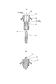
- FIG. 3A is a schematic cross-sectional view showing a state before fixing the centrifugal fan to the rotating shaft
- FIG. 3B is a schematic cross-sectional view showing the fixed state.
- FIG. 5A is a perspective view when injection of resin into an injection mold is started
- FIG. 5A is a perspective view when injection of resin into an injection mold is started
- FIG. 5B is a perspective view in the middle of injection molding, regarding the manufacturing process of the stator according to the embodiment of the present invention.
- FIG. 5C is a perspective view when the injection molding is completed.
- FIG. 5 is an external perspective view in which a weld surface is added to the stator of FIG. 4. It is an external appearance perspective view when the lower part of the stator which concerns on the other Example of this invention is seen from the top.
- or FIG. 6 has shown each component (component) of the air blower concerning 1st embodiment of this invention.
- the blower 1 according to the present embodiment includes a scroll housing 2 through which air flows, a motor 70 shown in the figure having a rotary shaft 71 having a circular cross section fixed to the scroll housing, and a resin press-fitted into the rotary shaft 71.
- a centrifugal fan 60 a centrifugal fan 60.
- the stator 20 and the centrifugal fan 60 are assembled to the motor 70 via the rotary shaft 71 to form the fan motor 10, and then attached to the scroll housing 2.
- the fan motor 10 is attached to the scroll housing 2 by fixing the disk-like flange 72 supporting the motor 70 to the scroll housing 2 by a known method (for example, screwing).
- the rotational force of the rotary shaft 71 of the motor 70 is transmitted to the stator 20, the boss 61, the cone 62, and the blade 63, and the centrifugal fan 60 rotates. Then, air can be sucked from the bell mouth 3 provided in the scroll housing 2, and the sucked air can be blown out from the outlet 4.
- the stator 20 is made of a resin having a high mechanical strength
- the boss 61 is made of a resin having a mechanical strength lower than that of the stator 20 as in the prior art (for example, Patent Document 1).
- the stator 20 and the boss 61 may be formed of a resin having the same mechanical strength.
- the stator 20 and the centrifugal fan 60 are formed by a known molding method such as injection molding.
- the stator 20 is a cylindrical member and is press-fitted into the rotary shaft 1 as described above.
- a centrifugal fan 60 is attached to the stator 10 via a boss 61, and the rotational force of the rotating shaft 71 is transmitted to the centrifugal fan 60 via the stator 20. Therefore, the stator 20 is firmly fixed to the rotating shaft 71 so as not to slip with respect to the rotating shaft 71 or move in the axial direction.
- the stator 20 includes a stator first end surface 21 near the tip of the rotating shaft 71, a stator second end surface 22 far from the tip of the rotating shaft, the stator first end surface 21, and the fixed portion.
- Stator outer peripheral surface 23 formed between the second end face 22 of the stator, stator through hole 24 into which the rotary shaft 71 is press-fitted, and concave or convex stator engagement formed in the outer peripheral surface 23 of the stator.
- Part 25 stator first engagement part 25a, stator second engagement part 25b.
- the stator first end surface 21 is located on the upper side of the drawing
- the stator second end surface 22 is located on the lower side of the drawing.
- the stator engaging portion 25 has a concave shape. Further, the first stator engaging portion 25 a and the second stator engaging portion 25 b are arranged radially and equiangularly around the virtual axis of the rotating shaft 71.
- the stator first engaging portion 25a extends from the stator first end surface 21 along the axial direction of the rotating shaft 71, and the extended end portion has a step, and further to the tip (lower side in FIG. 4). Is a stator outer peripheral surface 23. Further, the stator second engagement portion 25b extends from the stator second end surface 22 along the axial direction of the rotation shaft 71, and the extended end portion has a step, and further beyond that (upward in FIG. 4) Side) is a stator outer peripheral surface 23.
- the boss 61 is a cylindrical member, is formed of resin, and is inserted into the stator 20.
- the boss 61 of the present embodiment is formed in a boss through hole 64 into which the stator 20 is inserted, and an inner peripheral surface of the boss through hole 64, and engages with the stator first engagement portion 25a.
- a boss second engaging portion 65b that engages with the portion 65a and the stator second engaging portion 25b.
- the boss first engagement portion 65a and the boss second engagement portion 65b are convex shapes corresponding to the concave shapes of the stator first engagement portion 25a and the stator second engagement portion 25b.
- the arrangement of the boss first engagement portion 65a and the boss second engagement portion 65b is centered on the virtual axis of the rotation shaft 71 corresponding to the stator first engagement portion 25a and the stator second engagement portion 25b. And are arranged radially and equiangularly.
- the stator 20 is press-fitted into the rotating shaft 71 of the motor, and the boss 61 of the centrifugal fan 60 is inserted into the stator 20 from the front end side of the rotating shaft 71. Then, the engaging portions of the boss 61 are engaged with the engaging portions of the stator 20. For this reason, the stator 20 shown in FIG. 3B, that is, the stator 20 into which the metal rotation shaft 71 is press-fitted, is always in a state of being stressed in the direction in which the stator through hole 24 is expanded. Yes.
- the boss first engaging portion 65a of the boss 61 is used as the stator first engaging portion 25a and the boss second engaging portion 65b.
- the outer peripheral surface of the stator is compressed while compressing the second engaging portion 65b formed in a known claw shape. 23 is moved in sliding contact.
- the boss first engagement portion 65a is engaged with and engaged with the stator first engagement portion 25a, and the boss second engagement portion 65b is engaged with the stator second engagement portion 25b.
- the centrifugal fan 60 can be fixed to the rotating shaft 71 so as not to idle.
- FIG. 5 (a) is a perspective view when the injection of the resin into the injection mold is started.
- FIG. 5A shows the moment when injection is started, and no resin has entered the mold.
- the resin is formed with a one-side injection port 30 formed on a surface (upper side surface of FIG. 5A) on which the stator first end surface 21 is formed, and a stator second end surface 22 is formed. From the other side injection port 40 formed on the surface to be formed (the lower side surface of FIG. 5A), the injection is performed substantially simultaneously.
- the positions of the one-side injection port 30 and the other-side injection port 40 are not only vertically separated from the stator-like space (dotted line portion shown in FIG. 5A), but also the circumferential direction is different. Yes.
- FIG. 5A shows an example in which the stator through-hole planned portion 124 is sandwiched and provided on the substantially opposite side.
- FIG. 5 (b) is a perspective view of the mold showing the middle of injection molding.
- the resin injected from the one-side injection port 30 proceeds in the direction indicated by the resin flow 31 in the rotation axis direction and the resin flow 32 in the circumferential direction, and fills the mold space.
- the resin injected from the other injection port 40 proceeds in the direction indicated by the resin flow 41 in the rotation axis direction and the resin flow 42 in the circumferential direction, and fills the mold space.
- FIG. 5C is a perspective view when the injection molding is completed.
- the resin injected from the one-side injection port 30 spreads downward in the mold space along the resin flow 31 in the rotation axis direction, and the resin injected from the other-side injection port 40 is the resin in the rotation axis direction.
- the mold space is expanded upward along the flow 41, and the weld surface W1 is formed at the merged position.
- the first weld surface W1 is located between the stator first end surface 21 and the stator second end surface 22, and is disposed substantially perpendicular to the axial direction of the rotation shaft 71. It has become a surface.
- the weld surface (also referred to as a weld line) is a surface formed in a region where the flow of the resin merges, and the bonding force between the resin molecules is weaker than the region where the resin flows and crystallizes normally. There is a characteristic that the proof stress is small.
- the resin injected from the one-side injection port 30 spreads in the mold space in the circumferential direction along the circumferential resin flow 32 to form the second weld surface W2.
- the resin injected from the one-side injection port 30 fills the space between the stator first end surface 21 and the first weld surface W1, and is substantially opposite to the one-side injection port 30 in the circumferential direction.
- a second weld surface W2 is formed on the side.
- the resin injected from the other-side injection port 40 spreads in the mold space along the circumferential resin flow 42 in the circumferential direction to form a third weld surface W3.
- the resin injected from the other side injection port 40 fills the space between the stator second end surface 22 and the first weld surface W1, and is substantially opposite to the other side injection port 40 in the circumferential direction.
- a third weld surface W3 is formed on the side.
- stator 20 can be produced so that the second weld surface W2 does not reach the stator second end surface 22, and the third weld surface W3 does not reach the stator first end surface 21. it can.
- the rotating shaft 71 is press-fitted into the stator through-hole 24 and the stress is applied to the stator 20 in the direction of expanding the stator through-hole 24.
- the stress in the direction of expanding the stator through hole 24 is applied to the first weld surface W1 in the direction in which the surface expands. That is, the direction in which the first weld surface W1 is separated from the stator first end surface 21 side and the stator second end surface 22 side is stress applied in different directions. For this reason, even if the rotating shaft 71 is press-fitted into the stator through-hole 24, no crack is generated.
- the stress in the direction of expanding the stator through hole 24 is applied to the second weld surface W2 substantially perpendicularly to the direction of surface expansion. That is, it is a direction force applied along the direction in which the second weld surface W2 is separated in the circumferential direction. For this reason, when the rotating shaft 71 is press-fitted into the stator through hole 24, a crack may occur.
- the stress in the direction of expanding the stator through hole 24 is applied to the third weld surface W3 substantially perpendicularly to the direction of surface expansion. That is, it is a direction force applied along the direction of separating in the circumferential direction with the third weld surface W3 as a boundary. For this reason, when the rotating shaft 71 is press-fitted into the stator through hole 24, a crack may occur.
- FIG. 7 shows the stator 120 on which three weld surfaces W1, W2, and W3 are arranged.
- the difference from the stator 20 in FIG. 6 is the position in the circumferential direction of the third weld surface W3, and is a position substantially orthogonal to the second weld surface W2.
- the rotating shaft 71 is press-fitted into the stator through-hole 24 and the stress is applied to the stator 20 in the direction of expanding the stator through-hole 24.
- the stress in the direction in which the stator through hole 24 is expanded does not crack even if the rotary shaft 71 is press-fitted into the stator through hole 24 with respect to the first weld surface W1.
- a crack may occur in the second weld surface W2.
- a crack may also occur in the third weld surface W2.
- the stator engaging portion 25 may be formed in a convex shape on the outer peripheral surface.
- the high stress generating portion appears by forming the stator engaging portion in a concave shape on the outer peripheral surface of the stator, the appearance of the high stress generating portion can be suppressed by forming the convex shape.
- the difference in the circumferential direction between the second weld surface W2 and the third weld surface W3 not only the opposite side or the substantially orthogonal direction but also the shape of the stator and the stress applied to the stator It may be set appropriately from the direction or the like. It is only necessary that the second weld surface W2 and the third weld surface W3 can be prevented from cracking due to stress in one direction.
- the blower according to the present invention can be manufactured industrially, and can be suitably used particularly for a vehicle air conditioner.
Abstract
Description
すなわち、請求項1の発明は、内部を空気が通流するスクロールハウジング2と、前記スクロールハウジングに固定され、断面円形の回転軸71を有するモータ70と、前記回転軸に圧入された樹脂製の固定子20と、前記スクロールハウジングに収容され、前記固定子に挿入されたボス61、前記ボスから延びたコーン62、前記コーンの外周縁部から延びた多数のブレード63を有する樹脂製の遠心ファン60と、を備え、
前記固定子は、筒状の部材であって、前記回転軸の先端に近い固定子第1端面21と、前記回転軸の先端から遠い固定子第2端面22と、前記固定子第1端面および前記固定子第2端面の間に形成された固定子外周面23と、前記回転軸が挿入される固定子貫通孔24と、前記固定子外周面に形成された凹または凸形状の固定子係合部25と、を備え、
前記ボスは、筒状の部材であって、前記固定子が挿入されるボス貫通孔64と、前記ボス貫通孔の内周面に形成され、前記固定子係合部に係合するボス係合部65と、を備え、
前記固定子は、前記固定子第1端面と前記固定子第2端面との間に、前記回転軸の軸方向と略垂直に配置された第1のウエルド面W1と、前記固定子第1端面と前記第1のウエルド面との間に、前記回転軸の軸方向に沿って配置された第2のウエルド面W2と、前記固定子第2端面と前記第1のウエルド面との間に、前記回転軸の軸方向に沿って、かつ前記第2のウエルド面と周方向に異なる位置に配置された第3のウエルド面W3とを有することを特徴とする送風機1である。 The blower according to the present invention is as follows if the reference numerals used in the examples are attached.
That is, the invention of
The stator is a cylindrical member, and is a first
The boss is a cylindrical member, and is formed in a boss through
The stator includes a first weld surface W1 disposed substantially perpendicular to the axial direction of the rotation shaft between the first end surface of the stator and the second end surface of the stator, and the first end surface of the stator. Between the first weld surface and the second weld surface W2 disposed along the axial direction of the rotation axis, and between the second end surface of the stator and the first weld surface. The
2 スクロールハウジング
3 ベルマウス
4 吹出口
10 ファンモータ
20、120 固定子
21 固定子第1端面
22 固定子第2端面
23 固定子外周面
24 固定子貫通孔
25 固定子係合部
25a 固定子第1係合部
25b 固定子第2係合部
30 一方側射出ポート
31 回転軸方向の樹脂の流れ
32 周方向の樹脂の流れ
40 他方側射出ポート
41 回転軸方向の樹脂の流れ
42 周方向の樹脂の流れ
60 遠心ファン
61 ボス
62 コーン
63 ブレード
64 ボス貫通孔
65 ボス係合部
65a ボス第1係合部
65b ボス第2係合部
70 モータ
71 回転軸
72 フランジ
124 固定子貫通孔予定部
SW2 間隔
SW3 間隔
W1 第1のウエルド面
W2 第2のウエルド面
W3 第3のウエルド面 DESCRIPTION OF
Claims (4)
- 内部を空気が通流するスクロールハウジング2と、
前記スクロールハウジングに固定され、断面円形の回転軸71を有するモータ70と、
前記回転軸に圧入された樹脂製の固定子20と、
前記スクロールハウジングに収容され、前記固定子に挿入されたボス61、前記ボスから延びたコーン62、前記コーンの外周縁部から延びた多数のブレード63を有する樹脂製の遠心ファン60と、を備え、
前記固定子は、筒状の部材であって、
前記回転軸の先端に近い固定子第1端面21と、
前記回転軸の先端から遠い固定子第2端面22と、
前記固定子第1端面および前記固定子第2端面の間に形成された固定子外周面23と、
前記回転軸が挿入される固定子貫通孔24と、
前記固定子外周面に形成された凹または凸形状の固定子係合部25と、を備え、
前記ボスは、筒状の部材であって、
前記固定子が挿入されるボス貫通孔64と、
前記ボス貫通孔の内周面に形成され、前記固定子係合部に係合するボス係合部65と、を備え、
前記固定子は、
前記固定子第1端面と前記固定子第2端面との間に、前記回転軸の軸方向と略垂直に配置された第1のウエルド面W1と、
前記固定子第1端面と前記第1のウエルド面との間に、前記回転軸の軸方向に沿って配置された第2のウエルド面W2と、
前記固定子第2端面と前記第1のウエルド面との間に、前記回転軸の軸方向に沿って、かつ前記第2のウエルド面と周方向に異なる位置に配置された第3のウエルド面W3とを有する
ことを特徴とする送風機1。 A scroll housing 2 through which air flows;
A motor 70 fixed to the scroll housing and having a rotary shaft 71 having a circular cross section;
A resin stator 20 press-fitted into the rotating shaft;
A boss 61 housed in the scroll housing and inserted into the stator; a cone 62 extending from the boss; and a resin centrifugal fan 60 having a plurality of blades 63 extending from an outer peripheral edge of the cone. ,
The stator is a cylindrical member,
A stator first end face 21 near the tip of the rotating shaft;
A stator second end face 22 far from the tip of the rotating shaft;
A stator outer peripheral surface 23 formed between the stator first end surface and the stator second end surface;
A stator through hole 24 into which the rotating shaft is inserted;
A concave or convex stator engaging portion 25 formed on the outer peripheral surface of the stator,
The boss is a tubular member,
A boss through-hole 64 into which the stator is inserted;
A boss engaging portion 65 formed on the inner peripheral surface of the boss through-hole and engaging with the stator engaging portion,
The stator is
A first weld surface W1 disposed between the first end surface of the stator and the second end surface of the stator and substantially perpendicular to the axial direction of the rotation shaft;
A second weld surface W2 disposed along the axial direction of the rotation axis between the first end surface of the stator and the first weld surface;
A third weld surface disposed between the second end surface of the stator and the first weld surface along the axial direction of the rotation axis and at a position different from the second weld surface in the circumferential direction. The blower 1 characterized by having W3. - 前記第2のウエルド面と前記第3のウエルド面とは、周方向において略反対側に配置されたことを特徴とする請求項1に記載の送風機。 The blower according to claim 1, wherein the second weld surface and the third weld surface are disposed on substantially opposite sides in the circumferential direction.
- 前記第2のウエルド面と前記第3のウエルド面とは、周方向において略直交する位置に配置されたことを特徴とする請求項1に記載の送風機。 2. The blower according to claim 1, wherein the second weld surface and the third weld surface are arranged at positions substantially orthogonal to each other in the circumferential direction.
- 前記固定子係合部は、前記外周面に凸形状に形成されたことを特徴とする請求項1乃至請求項3のいずれかに記載の送風機。 The blower according to any one of claims 1 to 3, wherein the stator engaging portion is formed in a convex shape on the outer peripheral surface.
Priority Applications (3)
| Application Number | Priority Date | Filing Date | Title |
|---|---|---|---|
| CN201780023388.9A CN109072936B (en) | 2016-04-12 | 2017-04-07 | Air blower |
| JP2018511985A JP6771544B2 (en) | 2016-04-12 | 2017-04-07 | Blower |
| US16/092,525 US10605268B2 (en) | 2016-04-12 | 2017-04-07 | Blower |
Applications Claiming Priority (2)
| Application Number | Priority Date | Filing Date | Title |
|---|---|---|---|
| JP2016079467 | 2016-04-12 | ||
| JP2016-079467 | 2016-04-12 |
Publications (1)
| Publication Number | Publication Date |
|---|---|
| WO2017179499A1 true WO2017179499A1 (en) | 2017-10-19 |
Family
ID=60042467
Family Applications (1)
| Application Number | Title | Priority Date | Filing Date |
|---|---|---|---|
| PCT/JP2017/014466 WO2017179499A1 (en) | 2016-04-12 | 2017-04-07 | Blower |
Country Status (4)
| Country | Link |
|---|---|
| US (1) | US10605268B2 (en) |
| JP (1) | JP6771544B2 (en) |
| CN (1) | CN109072936B (en) |
| WO (1) | WO2017179499A1 (en) |
Cited By (2)
| Publication number | Priority date | Publication date | Assignee | Title |
|---|---|---|---|---|
| EP3156658B1 (en) * | 2014-08-04 | 2018-09-12 | Japan Climate Systems Corporation | Fan with fan body attachment structure |
| CN108825554A (en) * | 2018-09-11 | 2018-11-16 | 珠海格力电器股份有限公司 | Axial flow blower and air conditioner |
Citations (4)
| Publication number | Priority date | Publication date | Assignee | Title |
|---|---|---|---|---|
| JP2001021171A (en) * | 1999-07-07 | 2001-01-26 | Hitachi Ltd | Indoor unit of air conditioner |
| JP2004202811A (en) * | 2002-12-25 | 2004-07-22 | Bridgestone Flowtech Corp | Resin pipe joint and its manufacturing method |
| JP2005054722A (en) * | 2003-08-06 | 2005-03-03 | Denso Corp | Blower |
| JP2016035238A (en) * | 2014-08-04 | 2016-03-17 | 株式会社日本クライメイトシステムズ | Fan attachment structure |
Family Cites Families (9)
| Publication number | Priority date | Publication date | Assignee | Title |
|---|---|---|---|---|
| DE102006009726A1 (en) | 2005-11-04 | 2007-05-10 | Siemens Ag | Method and server for providing a mobility key |
| JP4242411B2 (en) * | 2006-11-02 | 2009-03-25 | シグマ株式会社 | Impeller |
| CN101350710B (en) | 2007-07-16 | 2011-11-16 | 华为技术有限公司 | Network system, authority issuing server, authority issuing and executing method |
| JP4969493B2 (en) * | 2008-02-28 | 2012-07-04 | 三菱重工業株式会社 | Plastic fan |
| US9185095B1 (en) | 2012-03-20 | 2015-11-10 | United Services Automobile Association (Usaa) | Behavioral profiling method and system to authenticate a user |
| CN103841557A (en) | 2012-11-20 | 2014-06-04 | 中兴通讯股份有限公司 | Ubiquitous terminal unified management and control method and platform |
| CN105264487B (en) | 2013-03-15 | 2018-09-07 | 美国邮政管理局 | Authentication system and method |
| CN105391696B (en) | 2015-10-20 | 2019-01-25 | 山东泰信电子股份有限公司 | Endpoint to register, method of calibration and endpoint to register, check system |
| CN105701372B (en) | 2015-12-18 | 2019-04-09 | 布比(北京)网络技术有限公司 | A kind of building of block chain identity and verification method |
-
2017
- 2017-04-07 JP JP2018511985A patent/JP6771544B2/en active Active
- 2017-04-07 US US16/092,525 patent/US10605268B2/en active Active
- 2017-04-07 WO PCT/JP2017/014466 patent/WO2017179499A1/en active Application Filing
- 2017-04-07 CN CN201780023388.9A patent/CN109072936B/en not_active Expired - Fee Related
Patent Citations (4)
| Publication number | Priority date | Publication date | Assignee | Title |
|---|---|---|---|---|
| JP2001021171A (en) * | 1999-07-07 | 2001-01-26 | Hitachi Ltd | Indoor unit of air conditioner |
| JP2004202811A (en) * | 2002-12-25 | 2004-07-22 | Bridgestone Flowtech Corp | Resin pipe joint and its manufacturing method |
| JP2005054722A (en) * | 2003-08-06 | 2005-03-03 | Denso Corp | Blower |
| JP2016035238A (en) * | 2014-08-04 | 2016-03-17 | 株式会社日本クライメイトシステムズ | Fan attachment structure |
Cited By (2)
| Publication number | Priority date | Publication date | Assignee | Title |
|---|---|---|---|---|
| EP3156658B1 (en) * | 2014-08-04 | 2018-09-12 | Japan Climate Systems Corporation | Fan with fan body attachment structure |
| CN108825554A (en) * | 2018-09-11 | 2018-11-16 | 珠海格力电器股份有限公司 | Axial flow blower and air conditioner |
Also Published As
| Publication number | Publication date |
|---|---|
| JPWO2017179499A1 (en) | 2019-02-21 |
| JP6771544B2 (en) | 2020-10-21 |
| US20190170160A1 (en) | 2019-06-06 |
| CN109072936A (en) | 2018-12-21 |
| CN109072936B (en) | 2020-01-14 |
| US10605268B2 (en) | 2020-03-31 |
Similar Documents
| Publication | Publication Date | Title |
|---|---|---|
| JP5457621B2 (en) | Multi-blade impeller | |
| WO2017179499A1 (en) | Blower | |
| JP6682659B2 (en) | Assembly for supporting an electric motor, especially in heating, ventilation and / or air conditioning systems of motor vehicles | |
| JP5007457B2 (en) | Turbo fan | |
| JP5706483B2 (en) | Vacuum pump | |
| JP4507553B2 (en) | Cross flow fan and cross flow fan manufacturing method | |
| US11008893B2 (en) | Sector for the assembly of a stage of a turbine and corresponding manufacturing method | |
| JP2014015851A (en) | Vibration control boss for fan, and method of manufacturing rotary fan | |
| JP2007153329A (en) | Flanged hub | |
| JP4385679B2 (en) | Blower | |
| JP5633546B2 (en) | Blower | |
| JP2015197082A (en) | Rotor blade and rotary machine | |
| WO2017154764A1 (en) | Blower | |
| JP7069357B2 (en) | Fan blade shaft and its assembly structure of fan blade, and bearing sleeve | |
| JP2007278193A (en) | Blower | |
| TW202305249A (en) | Fan blade device | |
| JP6450538B2 (en) | Fan and fan manufacturing method | |
| KR101076150B1 (en) | Spline shaft joint | |
| JPWO2003087582A1 (en) | Centrifugal fan rotor and manufacturing method thereof | |
| WO2017138493A1 (en) | Blower | |
| KR20190048771A (en) | Compressor Having Disk With Groove And Gas Turbine Having The Same | |
| JP7360264B2 (en) | turbo fan | |
| KR100535679B1 (en) | Turbo fan | |
| JP6486180B2 (en) | Propeller fan | |
| JP3873873B2 (en) | Blower |
Legal Events
| Date | Code | Title | Description |
|---|---|---|---|
| WWE | Wipo information: entry into national phase |
Ref document number: 2018511985 Country of ref document: JP |
|
| NENP | Non-entry into the national phase |
Ref country code: DE |
|
| WWE | Wipo information: entry into national phase |
Ref document number: 2017782315 Country of ref document: EP |
|
| ENP | Entry into the national phase |
Ref document number: 2017782315 Country of ref document: EP Effective date: 20181112 |
|
| 121 | Ep: the epo has been informed by wipo that ep was designated in this application |
Ref document number: 17782315 Country of ref document: EP Kind code of ref document: A1 |
|
| 122 | Ep: pct application non-entry in european phase |
Ref document number: 17782315 Country of ref document: EP Kind code of ref document: A1 |