WO2017175669A1 - 空調機 - Google Patents
空調機 Download PDFInfo
- Publication number
- WO2017175669A1 WO2017175669A1 PCT/JP2017/013504 JP2017013504W WO2017175669A1 WO 2017175669 A1 WO2017175669 A1 WO 2017175669A1 JP 2017013504 W JP2017013504 W JP 2017013504W WO 2017175669 A1 WO2017175669 A1 WO 2017175669A1
- Authority
- WO
- WIPO (PCT)
- Prior art keywords
- air
- blower
- target
- evaporator
- warm
- Prior art date
- Legal status (The legal status is an assumption and is not a legal conclusion. Google has not performed a legal analysis and makes no representation as to the accuracy of the status listed.)
- Ceased
Links
Images




Classifications
-
- F—MECHANICAL ENGINEERING; LIGHTING; HEATING; WEAPONS; BLASTING
- F24—HEATING; RANGES; VENTILATING
- F24F—AIR-CONDITIONING; AIR-HUMIDIFICATION; VENTILATION; USE OF AIR CURRENTS FOR SCREENING
- F24F11/00—Control or safety arrangements
- F24F11/70—Control systems characterised by their outputs; Constructional details thereof
- F24F11/80—Control systems characterised by their outputs; Constructional details thereof for controlling the temperature of the supplied air
- F24F11/81—Control systems characterised by their outputs; Constructional details thereof for controlling the temperature of the supplied air by controlling the air supply to heat-exchangers or bypass channels
-
- B—PERFORMING OPERATIONS; TRANSPORTING
- B60—VEHICLES IN GENERAL
- B60H—ARRANGEMENTS OF HEATING, COOLING, VENTILATING OR OTHER AIR-TREATING DEVICES SPECIALLY ADAPTED FOR PASSENGER OR GOODS SPACES OF VEHICLES
- B60H1/00—Heating, cooling or ventilating devices
- B60H1/00007—Combined heating, ventilating, or cooling devices
- B60H1/00021—Air flow details of HVAC devices
- B60H1/00064—Air flow details of HVAC devices for sending air streams of different temperatures into the passenger compartment
-
- F—MECHANICAL ENGINEERING; LIGHTING; HEATING; WEAPONS; BLASTING
- F24—HEATING; RANGES; VENTILATING
- F24F—AIR-CONDITIONING; AIR-HUMIDIFICATION; VENTILATION; USE OF AIR CURRENTS FOR SCREENING
- F24F1/00—Room units for air-conditioning, e.g. separate or self-contained units or units receiving primary air from a central station
- F24F1/02—Self-contained room units for air-conditioning, i.e. with all apparatus for treatment installed in a common casing
- F24F1/032—Self-contained room units for air-conditioning, i.e. with all apparatus for treatment installed in a common casing characterised by heat exchangers
- F24F1/0323—Self-contained room units for air-conditioning, i.e. with all apparatus for treatment installed in a common casing characterised by heat exchangers by the mounting or arrangement of the heat exchangers
-
- F—MECHANICAL ENGINEERING; LIGHTING; HEATING; WEAPONS; BLASTING
- F24—HEATING; RANGES; VENTILATING
- F24F—AIR-CONDITIONING; AIR-HUMIDIFICATION; VENTILATION; USE OF AIR CURRENTS FOR SCREENING
- F24F13/00—Details common to, or for air-conditioning, air-humidification, ventilation or use of air currents for screening
- F24F13/30—Arrangement or mounting of heat-exchangers
-
- B—PERFORMING OPERATIONS; TRANSPORTING
- B60—VEHICLES IN GENERAL
- B60H—ARRANGEMENTS OF HEATING, COOLING, VENTILATING OR OTHER AIR-TREATING DEVICES SPECIALLY ADAPTED FOR PASSENGER OR GOODS SPACES OF VEHICLES
- B60H1/00—Heating, cooling or ventilating devices
- B60H1/00271—HVAC devices specially adapted for particular vehicle parts or components and being connected to the vehicle HVAC unit
- B60H1/00285—HVAC devices specially adapted for particular vehicle parts or components and being connected to the vehicle HVAC unit for vehicle seats
-
- B—PERFORMING OPERATIONS; TRANSPORTING
- B60—VEHICLES IN GENERAL
- B60H—ARRANGEMENTS OF HEATING, COOLING, VENTILATING OR OTHER AIR-TREATING DEVICES SPECIALLY ADAPTED FOR PASSENGER OR GOODS SPACES OF VEHICLES
- B60H1/00—Heating, cooling or ventilating devices
- B60H1/00007—Combined heating, ventilating, or cooling devices
- B60H1/00021—Air flow details of HVAC devices
- B60H2001/00114—Heating or cooling details
- B60H2001/00121—More than one heat exchanger in parallel
Definitions
- This disclosure relates to an air conditioner.
- an integrated air conditioner in which a condenser, an evaporator, and a compressor are combined in one main body.
- the integrated air conditioner described in Patent Literature 1 below includes an indoor heat exchanger disposed on the indoor side and an outdoor heat exchanger disposed on the outdoor side.
- the refrigeration cycle In summer, the refrigeration cycle is operated so that the indoor heat exchanger functions as an evaporator and the outdoor heat exchanger functions as a condenser.
- the refrigeration cycle is operated so that the indoor heat exchanger functions as a condenser and the outdoor heat exchanger functions as an evaporator.
- Patent Document 1 air conditioning is realized by switching the flow of refrigerant in the refrigeration cycle by providing a switching valve in the refrigerant passage.
- the apparatus configuration is complicated and a large switching valve is required, the air conditioner cannot be reduced in size.
- This disclosure is intended to provide an air conditioner that can be reduced in size while having a refrigeration cycle integrated into one main body and exhibiting an air conditioning function.
- the present disclosure is directed to a blower (10) capable of blowing cold air and warm air at the same time, a target blower (31) for blowing air to a space to be air-conditioned, and a non-target blow to blow to a space not to be air-conditioned.
- the air duct (30) which has a part (32), and the air switch part (40) which switches the air sent into a target ventilation part and a non-target ventilation part are provided.
- the air switching unit includes a cold air supply state in which cold air is sent to the target air blowing unit, warm air is sent to the non-target air blowing unit, and warm air in which the warm air is sent to the target air blowing unit and the cold air is sent to the non-target air blowing unit. Toggles between supply status.
- the cold air supply state and the warm air supply state are switched by the air switching unit without changing the state of the cold air and the warm air blown out by the blower. Therefore, for example, it is not necessary to provide a switching valve in the refrigerant flow path to change the flow of the refrigerant, and it is possible to switch between cold air and warm air with a simple configuration.
- FIG. 1 is a perspective view showing an air conditioner according to the present embodiment.
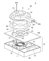
- FIG. 2 is an exploded perspective view showing the air conditioner according to the present embodiment.
- FIG. 3 is a plan view showing an internal configuration of the blower shown in FIGS. 1 and 2.
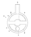
- FIG. 4 is a back view showing the air duct shown in FIGS. 1 and 2.
- FIG. 5 is an exploded perspective view showing the air conditioner according to the present embodiment.
- FIG. 6 is a rear view showing the air duct shown in FIGS. 1 and 2.
- the air conditioner 2 is disposed, for example, under the seat of an automobile, and is used for cooling and heating the vicinity of the seat in the passenger compartment.
- the air conditioner 2 includes a blower device 10 and a blower duct 30.
- the blower 10 has a main body 101 and an opening plate 102.
- the aperture plate 102 is provided between the main body 101 and the air duct 30.
- the blower duct 30 includes a target blower unit 31 that supplies air into a room to be air-conditioned and a non-target blower unit 32 that exhausts air to the outside.
- the target air blower 31 is provided with an air supply port 311.
- the non-target blower 32 is provided with an exhaust port 321.
- the main body 101 includes a centrifugal fan 11, a condenser 12, an evaporator 13, and a compressor 14.
- the condenser 12, the evaporator 13, and the compressor 14 constitute a refrigeration cycle.
- the opening plate 102 is configured to close the upper opening of the main body 101.
- the aperture plate 102 has a flat plate shape.
- the opening plate 102 is provided with warm air ports 21 and 22 and cold air ports 23 and 24.
- the warm air ports 21 and 22 and the cold air ports 23 and 24 surround the air supply port of the centrifugal fan 11 and are formed in a fan shape.
- the warm air ports 21 and 22 are arranged at positions corresponding to the capacitor 12.
- the cold air outlets 23 and 24 are arranged at positions corresponding to the evaporator 13.
- the air switching unit 40 has a disk shape.
- the air switching unit 40 is provided with a pair of open portions 41 and 42.
- the opening part 41 and the opening part 42 are provided so as to face each other across the rotation center of the air switching part 40.
- the open portions 41 and 42 are formed so as to form a sector shape.
- the part other than the opening parts 41 and 42 is formed as a closing part 43.
- the main body 101 will be described with reference to FIG.
- the main body 101 has a main body case 15.
- the main body case 15 is partitioned into three compartments: a compressor compartment 151, a capacitor compartment 152, and an evaporator compartment 153.
- a compressor 14 is disposed in the compressor section 151.
- the capacitor partition 152 and the evaporator partition 153 are disposed adjacent to each other.
- the centrifugal fan 11 is disposed so as to straddle the capacitor partitioning part 152 and the evaporator partitioning part 153.
- the center 111 of the centrifugal fan 11 is located on the boundary between the capacitor partition 152 and the evaporator partition 153.
- the capacitor 12 is disposed in the capacitor partition 152.
- the capacitor 12 has partial capacitor portions 121, 122, and 123.
- the partial capacitor units 121, 122, and 123 are each configured to function as a heat exchanger, and are connected to each other by a refrigerant pipe.
- the partial capacitor portions 121, 122, and 123 are arranged in the capacitor partition portion 152 so as to surround the half circumference portion of the centrifugal fan 11.
- the evaporator 13 is disposed in the evaporator section 153.
- the evaporator 13 has partial evaporator portions 131, 132, and 133.
- the partial evaporator units 131, 132, and 133 are configured to function as heat exchangers, and are connected to each other by a refrigerant pipe.
- the partial evaporator portions 131, 132, and 133 are disposed so as to surround the half-circumferential portion of the centrifugal fan 11 in the evaporator partition portion 153.
- the air blown out from the centrifugal fan 11 flows in the evaporator partition part 153 so as to pass through the partial evaporator parts 131, 132, 133.
- the air that has passed through each of the partial evaporator portions 131, 132, and 133 is cooled and passes through the cold air ports 171, 172, and 173.
- the cold air that has passed through the cold air ports 171, 172, and 173 travels toward the cold air ports 23 and 24 of the opening plate 102.
- the air switching unit 40 is positioned so that the opening 41 overlaps the warm air port 21 and the opening 42 overlaps the cold air port 23 with respect to the opening plate 102.
- the warm air port 22 and the cold air port 24 are closed by a closing part 43. Therefore, the warm air toward the warm air outlet 21 passes through the opening 41 and goes to the air duct 30, and the cold air toward the cold air outlet 23 passes through the opening 42 and goes to the air duct 30.
- FIG. 4 shows a state in which the air duct 30 is viewed from the air switching unit 40 side.
- An air supply passage 312 is connected to the air supply port 311.
- the supply passage 312 opens in a substantially semicircular shape on the air switching unit 40 side.
- An exhaust passage 322 is connected to the exhaust port 321.
- the exhaust passage 322 opens in a substantially semicircular shape on the air switching unit 40 side.
- the open portion 41 through which the warm air passes is positioned so as to overlap the air supply passage 312. Accordingly, warm air is blown out from the air supply port 311.
- the opening 42 through which the cold air passes is located so as to overlap the exhaust passage 322. Accordingly, cold air is blown out from the exhaust port 321.
- the air switching unit 40 is rotated 90 degrees from the state shown in FIG. 2 so that the opening 41 overlaps the cold air outlet 24 and the opening 42 overlaps the warm air outlet 22 with respect to the opening plate 102.
- the warm air port 21 and the cold air port 23 are closed by a closing part 43. Accordingly, the warm air directed toward the warm air port 22 passes through the opening portion 42 toward the air duct 30, and the cool air directed toward the cold air port 24 passes through the open portion 41 toward the air duct 30.
- FIG. 6 shows a state in which the air duct 30 is viewed from the air switching unit 40 side.
- the opening 42 through which the warm air passes is positioned so as to overlap the exhaust passage 322. Accordingly, warm air is blown out from the exhaust port 321.
- the opening portion 41 through which the cold air passes is positioned so as to overlap the air supply passage 312. Accordingly, cold air is blown out from the air supply port 311.
- the warm air supply state in which the warm air is blown from the air supply port 311 is set.
- the arrangement state of the air switching unit 40 with respect to the opening plate 102 is as shown in FIG. 5, a cold air supply state in which cold air is blown out from the air supply port 311 is entered.
- the air conditioner 2 includes the air blower 10 that can blow out the cold air and the warm air at the same time, the target air blowing unit 31 that blows air to the air conditioning target space, and the space that is not the air conditioning target.
- the air duct 30 which has the non-target ventilation part 32 which ventilates to the air, and the air switching part 40 which switches the air sent into the target ventilation part 31 and the non-target ventilation part 32 are provided.
- the air switching unit 40 has a cold air supply state in which cold air is sent to the target blower unit 31 and warm air is sent to the non-target blower unit 32, and warm air is sent to the target blower unit 31, and cold air is sent to the non-target blower unit 32. It is comprised so that it may switch with the warm air supply state sent in.
- the cold air supply state and the warm air supply state are switched by the air switching unit 40 without changing the state of the cold air and the warm air blown out by the blower 10. Therefore, for example, it is not necessary to change the flow of the refrigerant by providing a switching valve in the refrigerant flow path, and it is possible to switch between cold air and warm air.
- the air blower 10 has the evaporator 13 and the capacitor
- Cold air is supplied by air passing through an evaporator 13 that evaporates the refrigerant, and warm air is supplied by air passing through a condenser 12 that condenses the refrigerant.
- the air switching unit 40 opens the space between the evaporator 13 and the target air blowing unit 31 and closes the space between the evaporator 13 and the non-target air blowing unit 32 to send cold air to the target air blowing unit 31.
- a supply state can be formed. In this cold air supply state, the warm air is sent to the non-target air blower 32 by opening the space between the capacitor 12 and the non-target air blower 32 and closing the space between the capacitor 12 and the target air blower 31.
- the air switching unit 40 can send cold air to the non-target air blowing unit 32 by opening the space between the evaporator 13 and the non-target air blowing unit 32 and closing the space between the evaporator 13 and the target air blowing unit 31.
- the air switching unit 40 opens the space between the condenser 12 and the target air blowing unit 31 and closes the space between the capacitor 12 and the non-target air blowing unit 32 to send warm air to the target air blowing unit 31. Forming a state.
- the air switching unit 40 By operating the air switching unit 40 as described above, it is possible to switch between the cold air supply state and the warm air supply state. As described above, the air switching unit 40 can switch between the cold air and the warm air by switching between the open state and the closed state between the condenser 12 and the evaporator 13 and the target air blowing unit 31.
- the air blower 10 includes the opening plate 102 provided with the cool air ports 23 and 24 for blowing the cool air supplied from the evaporator 13 and the warm air ports 21 and 22 for blowing the warm air supplied from the capacitor 12.
- the air switching unit 40 includes opening portions 41 and 42 that open between the target blower unit 31 and the non-target blower unit 32, the evaporator 13 and the condenser 12, and the target blower unit 31 and the non-target blower unit 32 and the evaporator 13 and A closing portion 43 that closes the space between the capacitor 12 is provided.
- the opening parts 41 and 42 are arranged so as to be connected to either the target blower part 31 or the non-target blower part 32, when the cool air is supplied to the target blower part 31, warm air is sent from the non-target blower part 32. Can be discharged. On the other hand, when the warm air is supplied to the target blower 31, the cold wind can be discharged from the non-target blower 32.
- the air switching unit 40 is configured in a flat plate shape that rotates along the opening plate 102, and switches between the cold air supply state and the warm air supply state by rotating.
- the air switching unit 40 in a flat plate shape, the thickness in the direction from the blower 10 toward the blower duct 30 can be reduced.
- the air blower 10 has the centrifugal fan 11 which sends air into the evaporator 13 and the condenser 12 simultaneously. Since the centrifugal fan 11 feeds air into the evaporator 13 and the condenser 12 at the same time, there is no need to adjust the air flow between the centrifugal fan 11 and the evaporator 13 and the condenser 12, and the structure of the air conditioner 2 is simplified. be able to.
- the centrifugal fan 11 is disposed such that the evaporator 13 and the condenser 12 surround the centrifugal fan 11 when viewed from the rotation axis direction of the centrifugal fan 11.
- the thickness of the centrifugal fan 11 in the rotation axis direction can be reduced.
- the region where the evaporator 13 is disposed and the region where the capacitor 12 is disposed are divided as viewed from the direction of the rotation axis of the centrifugal fan 11. Since the evaporator 13 and the condenser 12 are arranged so as not to overlap each other when viewed from the direction of the rotation axis of the centrifugal fan 11, the thickness of the centrifugal fan 11 in the direction of the rotation axis can be reduced.
Landscapes
- Engineering & Computer Science (AREA)
- Mechanical Engineering (AREA)
- Chemical & Material Sciences (AREA)
- Combustion & Propulsion (AREA)
- General Engineering & Computer Science (AREA)
- Physics & Mathematics (AREA)
- Thermal Sciences (AREA)
- Air-Conditioning Room Units, And Self-Contained Units In General (AREA)
- Devices For Blowing Cold Air, Devices For Blowing Warm Air, And Means For Preventing Water Condensation In Air Conditioning Units (AREA)
- Air Filters, Heat-Exchange Apparatuses, And Housings Of Air-Conditioning Units (AREA)
- Air-Conditioning For Vehicles (AREA)
Abstract
冷凍サイクルがひとつの本体の内部にまとめられ冷暖房機能を発揮することができつつも、小型化することが可能な空調機を提供する。空調機(2)における空気切替部(40)は、冷風が対象送風部(31)に送り込まれ、暖風が非対象送風部(32)に送り込まれる冷風供給状態と、暖風が対象送風部(31)に送り込まれ、冷風が非対象送風部(32)に送り込まれる暖風供給状態と、を切り替える。
Description
本出願は、2016年4月5日に出願された日本国特許出願2016-075908号に基づくものであって、その優先権の利益を主張するものであり、その特許出願の全ての内容が、参照により本明細書に組み込まれる。
本開示は、空調機に関する。
空調機の一形態として、コンデンサと、エバポレータと、コンプレッサと、が1つの本体の内部にまとめられた一体式空調機がある。下記特許文献1に記載された一体式空調機は、室内側に配置された室内側熱交換器と、室外側に配置された室外側熱交換器と、を備えている。夏季においては、室内側熱交換器がエバポレータとして機能し、室外側熱交換器がコンデンサとして機能するように冷凍サイクルを運転する。一方、冬季においては、室内側熱交換器がコンデンサとして機能し、室外側熱交換器がエバポレータとして機能するように冷凍サイクルを運転する。
特許文献1では、冷媒通路に切替弁を設けることで、冷凍サイクルにおける冷媒の流れを切り替えて冷暖房を実現している。しかしながら、装置構成が複雑になり、大きな切替弁が必要になるため、空調機を小型化することができない。
本開示は、冷凍サイクルがひとつの本体の内部にまとめられ冷暖房機能を発揮することができつつも、小型化することが可能な空調機を提供することを目的とする。
本開示は、冷風と暖風とを同時に吹き出すことが可能な送風装置(10)と、空調対象となる空間に送風する対象送風部(31)及び空調対象とはならない空間に送風する非対象送風部(32)を有する送風ダクト(30)と、対象送風部と非対象送風部とに送り込む空気を切り替える空気切替部(40)と、を備える。空気切替部は、冷風が対象送風部に送り込まれ、暖風が非対象送風部に送り込まれる冷風供給状態と、暖風が対象送風部に送り込まれ、冷風が非対象送風部に送り込まれる暖風供給状態と、を切り替える。
本開示によれば、送風装置が吹き出す冷風及び暖風の状態を変えること無く、空気切替部によって冷風供給状態と暖風供給状態とを切り替えている。従って、例えば冷媒流路に切替弁を設けて冷媒の流れを変える必要がなく、簡便な構成で冷風と暖風とを切り替えて供給できる。
尚、「発明の概要」及び「請求の範囲」に記載した括弧内の符号は、後述する「発明を実施するための形態」との対応関係を示すものであって、「発明の概要」及び「請求の範囲」が、後述する「発明を実施するための形態」に限定されることを示すものではない。
以下、添付図面を参照しながら実施形態について説明する。説明の理解を容易にするため、各図面において同一の構成要素に対しては可能な限り同一の符号を付して、重複する説明は省略する。
図1を参照しながら本実施形態に係る空調機2について説明する。空調機2は、例えば、自動車のシート下に配置され、車室内のシート近傍を冷暖房するために用いられる。図1に示されるように、空調機2は、送風装置10と、送風ダクト30とを備えている。送風装置10は、本体部101と、開口板102とを有している。開口板102は、本体部101と送風ダクト30との間に設けられている。
送風ダクト30は、空調対象となる室内に給気する対象送風部31と、室外に排気する非対象送風部32と、を有している。対象送風部31には、給気口311が設けられている。非対象送風部32には、排気口321が設けられている。
図2を参照しながら説明を続ける。図2に示されるように、本体部101は、遠心ファン11と、コンデンサ12と、エバポレータ13と、コンプレッサ14と、を有している。コンデンサ12と、エバポレータ13と、コンプレッサ14とは、冷凍サイクルを構成している。遠心ファン11が回転することで、コンデンサ12及びエバポレータ13を空気が通り抜けて、暖風及び冷風が供給される。
開口板102は、本体部101の上部開口を塞ぐように構成されている。開口板102は、平板状をなしている。開口板102には、暖風口21,22及び冷風口23,24が設けられている。暖風口21,22及び冷風口23,24は、遠心ファン11の給気口を取り囲んで、それぞれが扇型を成すように形成されている。暖風口21,22は、コンデンサ12に対応する位置に配置されている。冷風口23,24は、エバポレータ13に対応する位置に配置されている。
開口板102と送風ダクト30との間には、空気切替部40が配置されている。空気切替部40は、円板状をなしている。空気切替部40には、一対の開放部41,42が設けられている。開放部41と開放部42とは、空気切替部40の回転中心を挟んで対向するように設けられている。開放部41,42は、それぞれが扇形を成すように形成されている。空気切替部40において、開放部41,42以外の部分は閉塞部43として形成されている。
本体部101について、図3を参照しながら説明を加える。本体部101は、本体ケース15を有している。本体ケース15は、コンプレッサ区画部151と、コンデンサ区画部152と、エバポレータ区画部153との3つの区画に仕切られている。コンプレッサ区画部151には、コンプレッサ14が配置されている。
コンデンサ区画部152と、エバポレータ区画部153とは、隣接するように配置されている。コンデンサ区画部152とエバポレータ区画部153とに跨るように、遠心ファン11が配置されている。遠心ファン11の中心111は、コンデンサ区画部152とエバポレータ区画部153との境界上に位置している。
コンデンサ区画部152には、コンデンサ12が配置されている。コンデンサ12は、部分コンデンサ部121,122,123を有している。部分コンデンサ部121,122,123は、それぞれが熱交換器として機能するように構成され、それぞれは互いに冷媒管によって繋がれている。部分コンデンサ部121,122,123は、コンデンサ区画部152において、遠心ファン11の半周部分を囲むように配置されている。
エバポレータ区画部153には、エバポレータ13が配置されている。エバポレータ13は、部分エバポレータ部131,132,133を有している。部分エバポレータ部131,132,133は、それぞれが熱交換器として機能するように構成され、それぞれは互いに冷媒管によって繋がれている。部分エバポレータ部131,132,133は、エバポレータ区画部153において、遠心ファン11の半周部分を囲むように配置されている。
遠心ファン11が回転すると、外周方向に空気が吹き出される。遠心ファン11から吹き出された空気は、コンデンサ区画部152においては、各部分コンデンサ部121,122,123を通過するように流れる。各部分コンデンサ部121,122,123を通過し、温められた空気は暖風となって、暖風口161,162,163を通過する。暖風口161,162,163を通過した暖風は、開口板102の暖風口21,22に向かう。
遠心ファン11から吹き出された空気は、エバポレータ区画部153においては、各部分エバポレータ部131,132,133を通過するように流れる。各部分エバポレータ部131,132,133を通過し、冷やされた空気は冷風となって、冷風口171,172,173を通過する。冷風口171,172,173を通過した冷風は、開口板102の冷風口23,24に向かう。
図2に戻って説明を続ける。図2に示される状態では、開口板102に対して空気切替部40は、開放部41が暖風口21に重なるように位置し、開放部42が冷風口23に重なるように位置している。暖風口22及び冷風口24は、閉塞部43によって閉塞されている。従って、暖風口21に向かった暖風は開放部41を通過して送風ダクト30に向かい、冷風口23に向かった冷風は開放部42を通過して送風ダクト30に向かう。
図4を参照しながら、空気切替部40と送風ダクト30との関係について説明する。図4は、空気切替部40側から送風ダクト30を見た状態を示している。給気口311には、給気通路312が繋がっている。給気通路312は、空気切替部40側において略半円形状に開口している。排気口321には、排気通路322が繋がっている。排気通路322は、空気切替部40側において略半円形状に開口している。
図2に示されるような位置関係の場合、暖風が通過する開放部41は、給気通路312に重なるように位置している。従って、給気口311からは暖風が吹き出される。一方、冷風が通過する開放部42は、排気通路322に重なるように位置している。従って、排気口321からは冷風が吹き出される。
続いて、図2に示された状態から空気切替部40が90度回転した状態について、図5を参照しながら説明する。図5に示される状態では、開口板102に対して空気切替部40は、開放部41が冷風口24に重なるように位置し、開放部42が暖風口22に重なるように位置している。暖風口21及び冷風口23は、閉塞部43によって閉塞されている。従って、暖風口22に向かった暖風は開放部42を通過して送風ダクト30に向かい、冷風口24に向かった冷風は開放部41を通過して送風ダクト30に向かう。
図6を参照しながら、空気切替部40と送風ダクト30との関係について説明する。図6は、空気切替部40側から送風ダクト30を見た状態を示している。図5に示されるような位置関係の場合、暖風が通過する開放部42は、排気通路322に重なるように位置している。従って、排気口321からは暖風が吹き出される。一方、冷風が通過する開放部41は、給気通路312に重なるように位置している。従って、給気口311からは冷風が吹き出される。
上記したように、空気切替部40の開口板102に対する配置状態が図2に示されるような場合には、給気口311から暖風が吹き出される暖風供給状態となる。空気切替部40の開口板102に対する配置状態が図5に示されるような場合には、給気口311から冷風が吹き出される冷風供給状態となる。
上記したように本実施形態に係る空調機2は、冷風と暖風とを同時に吹き出すことが可能な送風装置10と、空調対象となる空間に送風する対象送風部31及び空調対象とはならない空間に送風する非対象送風部32を有する送風ダクト30と、対象送風部31と非対象送風部32とに送り込む空気を切り替える空気切替部40と、を備えている。
空気切替部40は、冷風が対象送風部31に送り込まれ、暖風が非対象送風部32に送り込まれる冷風供給状態と、暖風が対象送風部31に送り込まれ、冷風が非対象送風部32に送り込まれる暖風供給状態と、を切り替えるように構成されている。
本実施形態では、送風装置10が吹き出す冷風及び暖風の状態を変えること無く、空気切替部40によって冷風供給状態と暖風供給状態とを切り替えている。従って、例えば冷媒流路に切替弁を設けて冷媒の流れを変える必要がなく、冷風と暖風とを切り替えて供給できる。
また本実施形態では、送風装置10は、冷凍サイクルを構成するエバポレータ13及びコンデンサ12を有している。冷風は、冷媒を蒸発させるエバポレータ13を空気が通ることによって供給され、暖風は、冷媒を凝縮するコンデンサ12を空気が通ることによって供給される。
また本実施形態では、空気切替部40は、エバポレータ13と対象送風部31との間を開放しエバポレータ13と非対象送風部32との間を閉塞することで冷風を対象送風部31に送り込む冷風供給状態を形成することができる。この冷風供給状態においては、コンデンサ12と非対象送風部32との間を開放しコンデンサ12と対象送風部31との間を閉塞することで暖風を非対象送風部32に送り込む。
空気切替部40は、エバポレータ13と非対象送風部32との間を開放しエバポレータ13と対象送風部31との間を閉塞することで冷風を非対象送風部32に送り込むことができる。この場合、空気切替部40は、コンデンサ12と対象送風部31との間を開放しコンデンサ12と非対象送風部32との間を閉塞することで暖風を対象送風部31に送り込む暖風供給状態を形成している。
上記したように空気切替部40を動作させることで、冷風供給状態と暖風供給状態とを切替て形成することができる。このように、空気切替部40によって、コンデンサ12及びエバポレータ13と対象送風部31との間の開放状態及び閉塞状態を切り替えるという簡便な態様によって、冷風と暖風とを切り替えて供給できる。
また本実施形態では、送風装置10は、エバポレータ13から供給される冷風を吹き出す冷風口23,24、及びコンデンサ12から供給される暖風を吹き出す暖風口21,22が設けられた開口板102を有している。空気切替部40には、対象送風部31及び非対象送風部32とエバポレータ13及びコンデンサ12との間を開放する開放部41,42、及び対象送風部31及び非対象送風部32とエバポレータ13及びコンデンサ12との間を閉塞する閉塞部43が設けられている。
このように構成することで、開放部41,42の一方を冷風口23,24に重なるようにすれば冷風を通過させることができ、開放部41,42の他方を暖風口21,22に重なるようにすれば暖風を通過させることができる。開放部41,42は、対象送風部31及び非対象送風部32のいずれかに繋がるように配置されるので、対象送風部31へ冷風を供給した場合には非対象送風部32から暖風を排出することができる。一方、対象送風部31へ暖風を供給した場合には、非対象送風部32から冷風を排出することができる。
また本実施形態では、空気切替部40は、開口板102に沿って回転する平板状に構成され、回転することによって冷風供給状態と暖風供給状態とを切り替えている。空気切替部40を平板状に構成することで、送風装置10から送風ダクト30に向かう方向の厚みを薄くすることができる。
また本実施形態では、送風装置10は、エバポレータ13及びコンデンサ12に同時に空気を送り込む遠心ファン11を有している。遠心ファン11は、エバポレータ13及びコンデンサ12に同時に空気を送り込むので、遠心ファン11からエバポレータ13及びコンデンサ12の間では空気の流れを調整する必要がなく、空調機2の構造を簡便なものとすることができる。
本実施形態において、遠心ファン11は、エバポレータ13及びコンデンサ12が、遠心ファン11の回転軸方向から見て遠心ファン11を囲うように配置されている。エバポレータ13及びコンデンサ12が遠心ファン11を囲うように配置することで、遠心ファン11の回転軸方向における厚みを薄くすることができる。
また本実施形態では、遠心ファン11の回転軸方向から見て、エバポレータ13が配置されている領域と、コンデンサ12が配置されている領域とが区分されている。遠心ファン11の回転軸方向から見て、エバポレータ13とコンデンサ12とが重ならないように配置されているので、遠心ファン11の回転軸方向における厚みを薄くすることができる。
以上、具体例を参照しつつ実施の形態について説明した。しかし、本開示はこれらの具体例に限定されるものではない。これら具体例に、当業者が適宜設計変更を加えたものも、本開示の特徴を備えている限り、本開示の範囲に包含される。前述した各具体例が備える各要素およびその配置、条件、形状などは、例示したものに限定されるわけではなく適宜変更することができる。前述した各具体例が備える各要素は、技術的な矛盾が生じない限り、適宜組み合わせを変えることができる。
Claims (8)
- 空調機であって、
冷風と暖風とを同時に吹き出すことが可能な送風装置(10)と、
空調対象となる空間に送風する対象送風部(31)及び空調対象とはならない空間に送風する非対象送風部(32)を有する送風ダクト(30)と、
前記対象送風部と前記非対象送風部とに送り込む空気を切り替える空気切替部(40)と、を備え、
前記空気切替部は、
前記冷風が前記対象送風部に送り込まれ、前記暖風が前記非対象送風部に送り込まれる冷風供給状態と、前記暖風が前記対象送風部に送り込まれ、前記冷風が前記非対象送風部に送り込まれる暖風供給状態と、を切り替える、空調機。 - 前記送風装置は、冷凍サイクルを構成するエバポレータ(13)及びコンデンサ(12)を有し、
前記冷風は、冷媒を蒸発させるエバポレータを空気が通ることによって供給され、
前記暖風は、前記冷媒を凝縮するコンデンサを空気が通ることによって供給される、請求項1記載の空調機。 - 前記空気切替部は、
前記エバポレータと前記対象送風部との間を開放する一方で、前記エバポレータと前記非対象送風部との間を閉塞することで前記冷風を前記対象送風部に送り込み、前記コンデンサと前記非対象送風部との間を開放する一方で、前記コンデンサと前記対象送風部との間を閉塞することで前記暖風を前記非対象送風部に送り込む前記冷風供給状態と、
前記エバポレータと前記非対象送風部との間を開放する一方で、前記エバポレータと前記対象送風部との間を閉塞することで前記冷風を前記非対象送風部に送り込み、前記コンデンサと前記対象送風部との間を開放する一方で、前記コンデンサと前記非対象送風部との間を閉塞することで前記暖風を前記対象送風部に送り込む前記暖風供給状態と、を切り替える、請求項2記載の空調機。 - 前記送風装置は、前記エバポレータから供給される前記冷風を吹き出す冷風口(23,24)、及び前記コンデンサから供給される前記暖風を吹き出す暖風口(21,22)が設けられた開口板(102)を有し、
前記空気切替部には、前記対象送風部及び前記非対象送風部と前記エバポレータ及び前記コンデンサとの間を開放する開放部(41,42)、及び前記対象送風部及び前記非対象送風部と前記エバポレータ及び前記コンデンサとの間を閉塞する閉塞部(43)が設けられている、請求項3記載の空調機。 - 前記空気切替部は、前記開口板に沿って回転する平板状に構成され、回転することによって前記冷風供給状態と前記暖風供給状態とを切り替える、請求項4記載の空調機。
- 前記送風装置は、前記エバポレータ及び前記コンデンサに同時に空気を送り込むファン11を有する、請求項2記載の空調機。
- 前記ファンは遠心ファンであって、前記エバポレータ及び前記コンデンサが、前記ファンの回転軸方向から見て前記ファンを囲うように配置されている、請求項6記載の空調機。
- 前記ファンの回転軸方向から見て、前記エバポレータが配置されている領域と、前記コンデンサが配置されている領域とが区分されている、請求項7記載の空調機。
Priority Applications (3)
| Application Number | Priority Date | Filing Date | Title |
|---|---|---|---|
| DE112017001904.4T DE112017001904T5 (de) | 2016-04-05 | 2017-03-31 | Klimaanlage |
| US16/090,837 US10967701B2 (en) | 2016-04-05 | 2017-03-31 | Air conditioner |
| CN201780021532.5A CN108885016B (zh) | 2016-04-05 | 2017-03-31 | 空调机 |
Applications Claiming Priority (2)
| Application Number | Priority Date | Filing Date | Title |
|---|---|---|---|
| JP2016075908A JP6515856B2 (ja) | 2016-04-05 | 2016-04-05 | 空調機 |
| JP2016-075908 | 2016-04-05 |
Publications (1)
| Publication Number | Publication Date |
|---|---|
| WO2017175669A1 true WO2017175669A1 (ja) | 2017-10-12 |
Family
ID=60000424
Family Applications (1)
| Application Number | Title | Priority Date | Filing Date |
|---|---|---|---|
| PCT/JP2017/013504 Ceased WO2017175669A1 (ja) | 2016-04-05 | 2017-03-31 | 空調機 |
Country Status (5)
| Country | Link |
|---|---|
| US (1) | US10967701B2 (ja) |
| JP (1) | JP6515856B2 (ja) |
| CN (1) | CN108885016B (ja) |
| DE (1) | DE112017001904T5 (ja) |
| WO (1) | WO2017175669A1 (ja) |
Families Citing this family (4)
| Publication number | Priority date | Publication date | Assignee | Title |
|---|---|---|---|---|
| JP7196658B2 (ja) * | 2018-04-03 | 2022-12-27 | 株式会社デンソー | 空調装置 |
| WO2019244253A1 (ja) * | 2018-06-19 | 2019-12-26 | 三菱電機株式会社 | 冷凍サイクル装置 |
| CN114110810A (zh) * | 2020-08-27 | 2022-03-01 | 广东美的制冷设备有限公司 | 空调器 |
| CN113452456B (zh) * | 2021-06-10 | 2022-08-05 | 成都华芯天微科技有限公司 | 一种便携式平面近场测试系统、方法及终端 |
Citations (7)
| Publication number | Priority date | Publication date | Assignee | Title |
|---|---|---|---|---|
| JPS4416911Y1 (ja) * | 1966-01-25 | 1969-07-22 | ||
| JPS5642034A (en) * | 1979-09-14 | 1981-04-20 | Mitsubishi Electric Corp | Air-conditioner |
| JPS579023U (ja) * | 1980-06-02 | 1982-01-18 | ||
| JPS57137930U (ja) * | 1981-02-23 | 1982-08-28 | ||
| JPS63176938A (ja) * | 1987-01-19 | 1988-07-21 | Matsushita Electric Ind Co Ltd | 一体型空気調和機 |
| JP2005241171A (ja) * | 2004-02-27 | 2005-09-08 | Mitsubishi Heavy Ind Ltd | 空調機 |
| JP2015193381A (ja) * | 2011-02-24 | 2015-11-05 | パナソニックIpマネジメント株式会社 | 車両用空調装置 |
Family Cites Families (11)
| Publication number | Priority date | Publication date | Assignee | Title |
|---|---|---|---|---|
| JPH05256472A (ja) | 1992-03-13 | 1993-10-05 | Sharp Corp | 簡易一体型空気調和機 |
| JPH0659564A (ja) | 1992-06-25 | 1994-03-04 | Xerox Corp | 金属酸化物を含むトナープロセス |
| JPH0650564A (ja) | 1992-07-29 | 1994-02-22 | Sharp Corp | 冷暖房兼用一体型空気調和機 |
| JP4337200B2 (ja) * | 1999-12-20 | 2009-09-30 | 株式会社デンソー | 車両用シート空調システム |
| JP4505510B2 (ja) * | 2007-02-20 | 2010-07-21 | カルソニックカンセイ株式会社 | 車両用空調システム |
| JP2011178372A (ja) * | 2010-03-04 | 2011-09-15 | Calsonic Kansei Corp | 車両用空気調和装置及びその運転切替方法 |
| JP5381834B2 (ja) * | 2010-03-17 | 2014-01-08 | 株式会社デンソー | 車両用シート空調装置 |
| JP6052099B2 (ja) * | 2013-08-22 | 2016-12-27 | 株式会社デンソー | 車両用シート空調装置 |
| JP6015607B2 (ja) * | 2013-09-18 | 2016-10-26 | 株式会社デンソー | 車両用空調ユニット |
| DE102014114478B3 (de) | 2014-10-06 | 2016-02-25 | Leica Microsystems (Schweiz) Ag | Digitales Mikroskop mit federgelagerter schwenkbarer Einheit |
| CN104807155A (zh) * | 2015-04-28 | 2015-07-29 | 苏州市时代工程咨询设计管理有限公司 | 空调系统 |
-
2016
- 2016-04-05 JP JP2016075908A patent/JP6515856B2/ja not_active Expired - Fee Related
-
2017
- 2017-03-31 US US16/090,837 patent/US10967701B2/en not_active Expired - Fee Related
- 2017-03-31 CN CN201780021532.5A patent/CN108885016B/zh not_active Expired - Fee Related
- 2017-03-31 DE DE112017001904.4T patent/DE112017001904T5/de not_active Withdrawn
- 2017-03-31 WO PCT/JP2017/013504 patent/WO2017175669A1/ja not_active Ceased
Patent Citations (7)
| Publication number | Priority date | Publication date | Assignee | Title |
|---|---|---|---|---|
| JPS4416911Y1 (ja) * | 1966-01-25 | 1969-07-22 | ||
| JPS5642034A (en) * | 1979-09-14 | 1981-04-20 | Mitsubishi Electric Corp | Air-conditioner |
| JPS579023U (ja) * | 1980-06-02 | 1982-01-18 | ||
| JPS57137930U (ja) * | 1981-02-23 | 1982-08-28 | ||
| JPS63176938A (ja) * | 1987-01-19 | 1988-07-21 | Matsushita Electric Ind Co Ltd | 一体型空気調和機 |
| JP2005241171A (ja) * | 2004-02-27 | 2005-09-08 | Mitsubishi Heavy Ind Ltd | 空調機 |
| JP2015193381A (ja) * | 2011-02-24 | 2015-11-05 | パナソニックIpマネジメント株式会社 | 車両用空調装置 |
Also Published As
| Publication number | Publication date |
|---|---|
| US20200324612A1 (en) | 2020-10-15 |
| JP6515856B2 (ja) | 2019-05-22 |
| CN108885016A (zh) | 2018-11-23 |
| CN108885016B (zh) | 2020-04-17 |
| JP2017187218A (ja) | 2017-10-12 |
| US10967701B2 (en) | 2021-04-06 |
| DE112017001904T5 (de) | 2018-12-13 |
Similar Documents
| Publication | Publication Date | Title |
|---|---|---|
| US10611207B2 (en) | Air conditioning system for vehicle | |
| US10675938B2 (en) | Air conditioner for vehicle and controlling method thereof | |
| US20180080676A1 (en) | Air conditioner | |
| KR101628530B1 (ko) | 차량용 공조 장치 | |
| CN109804202B (zh) | 空调 | |
| WO2017175669A1 (ja) | 空調機 | |
| WO2015087606A1 (ja) | 室内機及び空気調和装置 | |
| KR20190068356A (ko) | 차량용 공조시스템 | |
| US10718533B2 (en) | Fan assembly and air conditioner having the same | |
| KR102182342B1 (ko) | 차량용 히트 펌프 시스템 | |
| KR102158496B1 (ko) | 차량용 히트 펌프 시스템 | |
| JP2017187218A5 (ja) | ||
| CN107110564A (zh) | 制冷循环装置 | |
| KR102613353B1 (ko) | 차량용 공조장치 | |
| CN112303722A (zh) | 空调柜机及控制方法 | |
| KR20180008977A (ko) | 차량용 공조 시스템 | |
| JPH09150620A (ja) | 車両用空調装置の吹出口切り換え装置 | |
| JP2015160581A (ja) | 圧縮機および車両用空調装置 | |
| JP2015128938A (ja) | 車両用送風機および車両用空調装置 | |
| JP2009018644A (ja) | 車両用空調装置 | |
| JP2017154717A (ja) | 車両用空調装置 | |
| KR20160047024A (ko) | 차량용 히트 펌프 시스템 | |
| KR102945914B1 (ko) | 공기조화기 | |
| JP2010194403A (ja) | 除湿機 | |
| JP2017074833A (ja) | 車両用空調装置 |
Legal Events
| Date | Code | Title | Description |
|---|---|---|---|
| 121 | Ep: the epo has been informed by wipo that ep was designated in this application |
Ref document number: 17779048 Country of ref document: EP Kind code of ref document: A1 |
|
| 122 | Ep: pct application non-entry in european phase |
Ref document number: 17779048 Country of ref document: EP Kind code of ref document: A1 |