WO2017175374A1 - Image acquisition device - Google Patents
Image acquisition device Download PDFInfo
- Publication number
- WO2017175374A1 WO2017175374A1 PCT/JP2016/061531 JP2016061531W WO2017175374A1 WO 2017175374 A1 WO2017175374 A1 WO 2017175374A1 JP 2016061531 W JP2016061531 W JP 2016061531W WO 2017175374 A1 WO2017175374 A1 WO 2017175374A1
- Authority
- WO
- WIPO (PCT)
- Prior art keywords
- light
- signal
- illumination light
- intensity
- illumination
- Prior art date
Links
Images


Classifications
-
- G—PHYSICS
- G01—MEASURING; TESTING
- G01N—INVESTIGATING OR ANALYSING MATERIALS BY DETERMINING THEIR CHEMICAL OR PHYSICAL PROPERTIES
- G01N21/00—Investigating or analysing materials by the use of optical means, i.e. using sub-millimetre waves, infrared, visible or ultraviolet light
- G01N21/62—Systems in which the material investigated is excited whereby it emits light or causes a change in wavelength of the incident light
- G01N21/63—Systems in which the material investigated is excited whereby it emits light or causes a change in wavelength of the incident light optically excited
- G01N21/64—Fluorescence; Phosphorescence
-
- G—PHYSICS
- G02—OPTICS
- G02B—OPTICAL ELEMENTS, SYSTEMS OR APPARATUS
- G02B21/00—Microscopes
-
- G—PHYSICS
- G02—OPTICS
- G02B—OPTICAL ELEMENTS, SYSTEMS OR APPARATUS
- G02B21/00—Microscopes
- G02B21/06—Means for illuminating specimens
Definitions
- the present invention relates to an image acquisition device.
- the present invention has been made in view of the above-described circumstances, and an operator can accurately acquire a signal light image regardless of environmental changes without adjusting the intensity ratio of illumination light for each observation.
- An object of the present invention is to provide an image acquisition device capable of performing the above.
- a modulation unit that generates illumination light in which two different states are periodically switched by modulating light from a light source, and illumination that detects the illumination light generated by the modulation unit
- a light detection unit an illumination optical system that irradiates the sample with the illumination light generated by the modulation unit; and the signal light generated at the illumination light irradiation position on the sample by the illumination optical system is collected and detected.
- illumination light in which two different states are switched periodically is generated, and the generated illumination light is irradiated onto the sample by the illumination optical system. Is done.
- the signal light generated at the irradiation position of the illumination light on the sample is detected by the signal light detector.
- the intensity signal of the detected signal light is demodulated by the demodulator, and a signal light image is generated by the image generator based on the demodulated signal light intensity signal.
- the illumination light generated by the modulation unit is detected by the illumination light detection unit, and the intensity signal of the detected illumination light is demodulated by the demodulation unit.
- the intensity signal in each state of illumination light having two states can be compared by the modulation unit, and the intensity signal of the illumination light in two states can be obtained even when the modulation ratio by the modulation unit varies due to environmental changes. Correction can be performed in the modulation section so that the ratio is constant.
- the signal light image can be accurately acquired regardless of the environmental change without the operator adjusting the intensity ratio of the illumination light for each observation.
- the two states are states in which time integrated intensity is equal
- the demodulator outputs a difference in time integrated intensity of the illumination light demodulated for each state
- the modulator is The modulation intensity may be corrected so that the difference becomes zero.
- the modulation intensity is corrected by the modulation unit until the difference in time integration intensity of the illumination light output from the demodulation unit becomes zero, thereby making the time integration intensity of the illumination light in the two states equal. Can be maintained.
- the state where the time integrated intensities of the two states are equal includes not only the case where the intensity of the illumination light is equal but also the case where the intensities are different.
- the state which irradiates the said illumination light to the different position of a sample may be sufficient as said two states.
- it is applied to a scanning confocal microscope, and the illumination light in one state is condensed at a position optically conjugate with the pinhole in front of the detector, and the illumination light in the other state is condensed.
- the light is condensed at a position optically unconjugated with the pinhole.
- the focus signal light from the condensing position and the out-of-focus signal light from other than the condensing position pass through the pinhole, and in the other state, only the out-of-focus signal light passes through the pinhole.
- the out-of-focus fluorescence can be accurately removed by correcting the intensity of the illumination light applied to the sample in the two states in the modulation unit so as to match with high accuracy.
- the two states may be a state where the signal light generated in the sample is saturated and a state where the signal light is not saturated.
- SAX saturated Excitation
- the time integrated intensity of the illumination light is the same in the two states, but the signal light generated in the sample is saturated with the illumination light with the higher intensity.
- high-precision observation can be performed by accurately matching the time integrated intensities of the illumination light in the two states.
- the optical system includes a branching unit that branches the light from the light source into two optical paths, and the modulation unit modulates the light of each optical path branched by the branching unit with a different frequency, respectively.
- the modulation intensity of the illumination light may be corrected so that the intensity ratio of the two illumination lights demodulated by the demodulator has a preset value.
- the obtained signal light intensity is proportional to the square of the instantaneous intensity of the illumination light. Even if the intensities are matched, there is a difference in the intensity of the detected signal light. According to this aspect, it is possible to acquire a signal light image without color unevenness by correcting the modulation intensity of the illumination light so as to obtain a preset intensity ratio in consideration of the irradiation pattern.
- FIG. 1 is an overall configuration diagram illustrating an image acquisition device according to a first embodiment of the present invention. It is a figure which shows an example of the illumination light modulated by the modulation part of the image acquisition apparatus of FIG. It is a figure which shows an example of the illumination light used for the modification of the image acquisition apparatus of FIG. It is a whole block diagram which shows the image acquisition apparatus which concerns on the 2nd Embodiment of this invention. It is a figure which shows an example of the illumination light modulated by the 1st modulator of the image acquisition apparatus of FIG. It is a figure which shows an example of the laser beam inject
- the image acquisition apparatus 1 includes a laser light source (light source) 2 that emits laser light having a constant intensity, and a modulation unit that modulates laser light from the laser light source 2.
- a laser light source (light source) 2 that emits laser light having a constant intensity
- a modulation unit that modulates laser light from the laser light source 2.
- a microscope optical system for condensing fluorescence (signal light) generated in the sample X while irradiating the illumination light modulated in the modulation unit 3 to the sample X (not shown), and the microscope
- a photodetector (signal light detection unit) 5 for detecting fluorescence that has passed through the pinhole 16 of the optical system 4
- a detector (illumination light detection unit) 6 for detecting the illumination lights L1 and L2 modulated by the modulation unit 3; Based on the fluorescence intensity signal detected by the photodetector 5 and the intensity signal of the illumination lights L1 and L2 detected by the detector 6, the demodulator 7 and the fluorescence intensity signal demodulated by the demodulator 7 To generate fluorescent images And an image generation unit 8 that.
- the modulation unit 3 is arranged on each optical path and a first beam splitter (branching unit) 9 that branches the laser light from the laser light source 2 into two optical paths, and turns on and off the laser light that passes through each optical path at alternate timings.
- Modulators 10a and 10b such as an acousto-optic modulator (AOM) that modulates in this way, a modulation control unit 11 that controls these modulators 10a and 10b, and illumination light L1 output from the modulators 10a and 10b
- AOM acousto-optic modulator
- the second beam splitter 12 is arranged at an angle slightly different from 45 ° with respect to the optical axis of one optical path, and the two illumination lights L1 and L2 after being combined are emitted at different angles. It is like that.
- the microscope optical system 4 is an optical system of a laser scanning fluorescence microscope, and includes a scanner 13 that scans two illumination lights L1 and L2 emitted from the modulation unit 3, and an illumination light L1 that is scanned by the scanner 13. , L2 on the sample X, a dichroic mirror 15 for branching the fluorescence condensed by the objective lens 14 from the optical path of the illumination light L1, L2, and a pinhole 16.
- reference numeral 17 denotes an optical path forming mirror.
- the two illumination lights L1 and L2 having different emission angles by the second beam splitter 12 of the modulation unit 3 are incident on the pupil of the objective lens 14 from different angles, thereby being condensed at different positions in the sample X.
- the fluorescent material existing in the sample X is excited to generate fluorescence. That is, the illumination light L1 that has passed through one optical path is condensed at a position optically conjugate with the pinhole 16 disposed in the front stage of the photodetector 5, while the illumination light L2 that has passed through the other optical path. Is condensed at a position optically unconjugated with the pinhole 16.
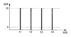
- the illumination light L1 and L2 passing through the two optical paths are alternately emitted by the operation of the modulation control unit 11, as shown in FIG. 2, the illumination light L1 that is condensed at the conjugate position and the non-conjugated light Illumination light is generated in which the illumination light L1, L2 in two states of the illumination light L2 condensed at the position is switched periodically.
- the modulation control unit 11 outputs a modulation signal to the demodulation unit 7.
- the photodetector 5 is, for example, a photomultiplier tube, and detects the intensity of the fluorescence condensed by the objective lens 14.
- the demodulating unit 7 modulates the intensity signals of the fluorescence generated by the illumination lights L1 and L2 in the two states detected by the photodetector 5 by the modulators 10a and 10b sent from the modulation control unit 11, respectively.
- the signal is demodulated in synchronization with the timing, and the difference between the fluorescence intensity signals is output.
- the image generator 8 generates a fluorescent image by arranging the difference value of the fluorescence intensity signal output from the demodulator 7 in association with the information of the scanning position by the scanner 13.
- the fluorescence detected by the photodetector 5 includes the focus fluorescence generated at the focus position and the path to the focus in the sample X. Part of the generated out-of-focus fluorescence is included.
- the fluorescence detected by the photodetector 5 when the illumination light L2 is condensed at a position unconjugated with the pinhole 16 includes the focus fluorescence generated at the focal position because it cannot pass through the pinhole 16. Only the out-of-focus fluorescence is included. Therefore, the difference between these fluorescence intensity signals output from the demodulator 7 includes only the focus fluorescence from which the out-of-focus fluorescence is removed, and a clear fluorescence image with less noise is generated. Will be able to.
- the detector 6 is disposed, for example, at the subsequent stage of the modulation unit 3, and includes a beam sampler 18 including a low-reflectance half mirror that separates part of the illumination lights L 1 and L 2 output from the modulation unit 3, and the beam sampler 18. And a single point detector 19 disposed at a position where the illumination lights L1 and L2 in the two states separated by (2) can be detected.
- the single point detector 19 may be arranged at a position conjugate with the pupil plane of the objective lens 14 by a relay lens (not shown), may be arranged at the focal position of a condenser lens (not shown), or two illuminations You may employ
- the output of the single point detector 19 is input to the demodulator 7, and the output from the demodulator 7 is input to the modulation controller 11.
- the modulation control unit 11 corrects the modulation intensity of the illumination lights L1 and L2 modulated by one of the modulators 10a and 10b in accordance with the difference value input from the demodulation unit 7. That is, based on the intensity of the illumination lights L1 and L2 in two states separated by the beam sampler 18, the modulation control unit 11 sets the intensity of any illumination light so that the output from the demodulation unit 7 becomes zero. Therefore, the intensities of the illumination lights L1 and L2 in the two states are adjusted with high accuracy.
- the laser light emitted from the laser light source 2 is branched into two optical paths by the first beam splitter 9 in the modulation unit 3 and passes through the optical paths. During this time, the light is modulated by the modulators 10a and 10b arranged in the respective optical paths, combined by the second beam splitter 12, and emitted at different angles.
- Illumination lights L1 and L2 output from the modulation unit 3 and that change in two states in terms of time are made incident on the microscope optical system 4, and a part of the illumination lights L1 and L2 are separated by the beam sampler 18 and single point detector 19 is used. Is detected.
- the illumination lights L1 and L2 in two states scanned by the scanner 13 in the microscope optical system 4 and condensed by the objective lens 14 are condensed at two different positions in the sample X, and fluorescent at each condensing position. Is generated.
- Fluorescence generated in the sample X by irradiation with the illumination lights L1 and L2 in two states is detected by the photodetector 5 and input to the demodulator 7.
- the difference between the fluorescence intensity signals generated by the illumination lights L 1 and L 2 in each state is output from the demodulator 7.
- the difference in the intensity signal of the fluorescence output from the demodulator 7 is an intensity signal of only the fluorescence from the focal position of the illumination light from which the out-of-focus fluorescence is removed.
- the intensities of the illumination lights L1 and L2 in the two states are required to be the same.
- the modulation control unit 11 is set so that the intensity of the illumination lights L1 and L2 in the two states output from the modulation unit 3 are the same, but the use environment such as temperature fluctuates, There may be a difference in the intensity of the illumination lights L1 and L2 output from the modulators 10a and 10b.
- part of the illumination lights L1 and L2 output from the modulation unit 3 are separated by the beam sampler 18, detected by the single point detector 19, and detected illumination light L1.
- L2 intensity signals are demodulated by the demodulator 7 so that the difference between the signal intensities of the two illumination lights L1 and L2 is output from the demodulator 7.
- the difference output from the demodulator 7 is input to the modulation control unit 11, so that the modulation intensity of the illumination lights L1 and L2 modulated by the modulators 10a and 10b according to the difference is modulated by the modulation control unit 11. It is corrected.
- the demodulator 7 that outputs the difference between the fluorescence intensity signals is used to obtain the difference between the intensity signals of the illumination lights L1 and L2, so that the beam sampler 18 and the single point detector 19
- a demodulator for illumination light may be prepared separately from the demodulator 7 for fluorescence.
- the image acquisition device 1 that uses modulation / demodulation to remove out-of-focus fluorescence has been described as an example, but instead, this is applied to a SAX microscope as shown in FIG. You may decide. That is, as shown in FIG. 3, the modulation unit 3 generates illumination lights L1 and L2 having two different peak values and equal time integration intensities, unlike the above embodiment. Yes.
- the modulators 10a and 10b may employ electro-optic modulators instead of the acousto-optic modulators.
- the illumination light L1 having a higher peak intensity saturates the fluorescence generated in the sample X and the illumination light L2 having a lower peak intensity does not saturate the fluorescence, even if the usage environment changes, two In this state, the time integrated intensities of the illumination lights L1 and L2 can be maintained in a highly accurate state, and high-precision observation can be performed.
- an image acquisition apparatus 20 according to a second embodiment of the present invention will be described below with reference to the drawings.
- the same reference numerals are given to portions having the same configuration as that of the image acquisition device 1 according to the first embodiment described above, and description thereof is omitted.
- the image acquisition device 20 is applied to a two-photon excitation microscope, and divides illumination light composed of ultrashort pulse laser light into two optical paths, The light is modulated at different frequencies by the arranged modulators 10a and 10b, condensed at two different points of the sample X, and the fluorescence emitted from each focal point is detected and demodulated to detect the fluorescence from the two points.
- the light is modulated at different frequencies by the arranged modulators 10a and 10b, condensed at two different points of the sample X, and the fluorescence emitted from each focal point is detected and demodulated to detect the fluorescence from the two points.
- the first modulator 10a in one optical path cuts every other pulse of the ultrashort pulse laser light from the laser light source 2 to become 50% duty. So that it can be modulated.
- the other second modulator 10b reduces the peak intensity of all pulses of the ultrashort pulse laser beam from the laser light source 2 shown in FIG. 5B to 70% as shown in FIG. 5C. Yes.
- the first modulator 10a modulates the ultrashort pulse laser light from the laser light source 2 to generate the 40 MHz illumination light L2. Yes.
- the illumination light L2 has an alternating current pattern whose intensity changes at 40 MHz.
- the second modulator 10b modulates the peak intensity of the ultrashort pulse laser light from the laser light source 2 to 70% to generate 80 MHz illumination light L1.
- the signals are subtracted and a fluorescent signal corresponding to L2 is output.
- the fluorescence intensity signals output from the two demodulation units 21a and 21b are substantially equal, and the occurrence of uneven brightness in the fluorescence image generated using these fluorescence intensities can be prevented.
- the intensity signals of the illumination lights L1 and L2 in the two states detected by the single point detector 19 and demodulated by the demodulation units 21a and 21b are output as a difference, unlike the first embodiment. And output as separate intensity signals.
- the modulation intensity in each of the modulators 10a and 10b controls so that correction is not performed. That is, the modulation control unit 11 multiplies the intensity signal of the illumination light L1 output from the first demodulation unit 21a by a preset ratio, 10/7 in the above example, and the second value.
- the two modulators 10a and 10b are controlled so that the difference from the intensity signal of the illumination light L2 output from the demodulator 21b becomes zero.
- the image acquisition device 20 even if the usage environment changes, two-point simultaneous detection is performed without the operator adjusting the intensity ratio of the illumination lights L1 and L2 for each observation. There is an advantage that a fluorescent image with little luminance unevenness can be acquired while improving the frame rate by the above.
- the present invention is applied to a light sheet microscope for photographing fluorescence generated by sheet-like illumination light incident on different positions along the optical axis of the objective lens 14 with a camera. May be.
- the sampling ratio by the beam sampler 18 may be different for each of the illumination lights L1 and L2. Can do. In such a case, even if the two illumination lights L1 and L2 have the same intensity, they are detected as having different intensities in the single point detector 19, so that the single point detector is detected by the correction coefficient obtained in advance.
- a signal correction unit (not shown) that corrects the intensity signals of the illumination lights L1 and L2 detected by the projector 19 may be provided.
- the modulation control unit 11 corrects the modulation intensity by the two modulators 10a and 10b, the modulation intensity may be corrected by only one modulator 10a.
- the timing of correcting the modulation intensity of the illumination lights L1 and L2 is not particularly limited. For example, it is automatically performed before the fluorescence observation of the sample X is performed. do it.
- the intensity correction of the illumination lights L1 and L2 can be performed without using the sample X, and can be performed without damaging the sample X.
Abstract
With the objective of accurately acquiring a signal light image regardless of environmental variation without an operator adjusting the intensity ratio of illumination light at every observation, an image acquisition device (1) according to the present invention is provided with: a modulation unit (3) for modulating light from a light source (2), thereby generating an illumination light which switches between two differing states over a time cycle; an illumination light detection unit (6) for detecting the generated illumination light (L1, L2); an illumination optical system (4) for irradiating a sample (X) with the generated illumination light (L1, L2); a signal light detection unit (5) for focusing and detecting the signal light using the illumination light (L1, L2) generated at the illumination position of the sample (X); a demodulation unit (7) for demodulating the modulation of the detected intensity signal of the signal light and the detected intensity signal of the illumination light; and an image generation unit (8) for generating a signal light image on the basis of the demodulated intensity signal of the signal light, the modulation unit (3) correcting the modulation intensity of the illumination light on the basis of the intensity signal of the illumination light demodulated by the demodulation unit (8).
Description
本発明は、画像取得装置に関するものである。
The present invention relates to an image acquisition device.
レーザ走査顕微鏡等の画像取得装置において、変調することにより生成された2つの状態の励起光を試料に照射し、試料において発生した蛍光を検出した後に復調することにより、各状態の励起光に対応する蛍光を取得して画像を生成する技術が知られている(例えば、特許文献1参照。)。
Corresponding to excitation light in each state by irradiating the sample with excitation light in two states generated by modulation and demodulating after detecting fluorescence generated in the sample in an image acquisition device such as a laser scanning microscope A technique for generating an image by acquiring fluorescence is known (for example, see Patent Document 1).
特許文献1の顕微鏡では、2つの状態の励起光の強度が理想的には同一であることが必要であるが、光学部品の特性が温度等の環境変化によって変化するため、強度比率を一定に保持することは困難である。このため、作業者が観察に先立って励起光の強度比率を一定となるように調節する必要があり、手間がかかって煩わしいという不都合がある。
In the microscope of Patent Document 1, it is necessary that the intensity of the excitation light in the two states is ideally the same. However, since the characteristics of the optical components change due to environmental changes such as temperature, the intensity ratio is kept constant. It is difficult to hold. For this reason, it is necessary for the operator to adjust the intensity ratio of the excitation light to be constant before observation, which is troublesome and troublesome.
本発明は上述した事情に鑑みてなされたものであって、作業者が観察毎に照明光の強度比率の調整を行うことなく、環境変化に関わらず、信号光画像を精度よく取得することができる画像取得装置を提供することを目的としている。
The present invention has been made in view of the above-described circumstances, and an operator can accurately acquire a signal light image regardless of environmental changes without adjusting the intensity ratio of illumination light for each observation. An object of the present invention is to provide an image acquisition device capable of performing the above.
本発明の一態様は、光源からの光を変調することにより、異なる2つの状態が時間周期的に切り替わる照明光を生成する変調部と、該変調部により生成された前記照明光を検出する照明光検出部と、前記変調部により生成された前記照明光を試料に照射する照明光学系と、該照明光学系による前記照明光の試料における照射位置において発生した信号光を集光して検出する信号光検出部と、該信号光検出部により検出された前記信号光の強度信号および前記照明光検出部により検出された前記照明光の強度信号に対し前記変調に対する復調を行う復調部と、該復調部により復調された前記信号光の強度信号に基づいて信号光画像を生成する画像生成部とを備え、前記変調部が、前記復調部により復調された前記照明光の強度信号に基づいて前記照明光の変調強度を補正する画像取得装置である。
According to one embodiment of the present invention, a modulation unit that generates illumination light in which two different states are periodically switched by modulating light from a light source, and illumination that detects the illumination light generated by the modulation unit A light detection unit; an illumination optical system that irradiates the sample with the illumination light generated by the modulation unit; and the signal light generated at the illumination light irradiation position on the sample by the illumination optical system is collected and detected. A signal light detector; a demodulator that demodulates the modulation of the intensity signal of the signal light detected by the signal light detector and the intensity signal of the illumination light detected by the illumination light detector; and An image generation unit that generates a signal light image based on the intensity signal of the signal light demodulated by the demodulation unit, and the modulation unit is based on the intensity signal of the illumination light demodulated by the demodulation unit Serial is an image acquisition device that corrects the modulated intensity of the illumination light.
本態様によれば、光源から発せられた光が変調部に入射されると、異なる2つの状態が時間周期的に切り替わる照明光が生成され、生成された照明光が照明光学系によって試料に照射される。試料における照明光の照射位置において発生した信号光は信号光検出部により検出される。検出された信号光の強度信号が復調部において復調され、復調された信号光の強度信号に基づいて画像生成部により信号光画像が生成される。
According to this aspect, when the light emitted from the light source is incident on the modulation unit, illumination light in which two different states are switched periodically is generated, and the generated illumination light is irradiated onto the sample by the illumination optical system. Is done. The signal light generated at the irradiation position of the illumination light on the sample is detected by the signal light detector. The intensity signal of the detected signal light is demodulated by the demodulator, and a signal light image is generated by the image generator based on the demodulated signal light intensity signal.
その一方で、変調部により生成された照明光は照明光検出部により検出され、検出された照明光の強度信号が復調部において復調される。変調部により2つの状態を有する照明光の各状態における強度信号を比較することが可能となり、環境変化によって変調部による変調比率が変動した場合であっても2つの状態の照明光の強度信号が一定の比率となるように変調部において補正することができる。これにより、作業者が観察毎に照明光の強度比率の調整を行うことなく、環境変化に関わらず、信号光画像を精度よく取得することができる。
On the other hand, the illumination light generated by the modulation unit is detected by the illumination light detection unit, and the intensity signal of the detected illumination light is demodulated by the demodulation unit. The intensity signal in each state of illumination light having two states can be compared by the modulation unit, and the intensity signal of the illumination light in two states can be obtained even when the modulation ratio by the modulation unit varies due to environmental changes. Correction can be performed in the modulation section so that the ratio is constant. Thus, the signal light image can be accurately acquired regardless of the environmental change without the operator adjusting the intensity ratio of the illumination light for each observation.
上記態様においては、前記2つの状態は、時間積分強度が等しくなる状態であり、前記復調部が、状態毎に復調された前記照明光の時間積分強度の差分を出力し、前記変調部は、前記差分がゼロとなるように前記変調強度を補正してもよい。
このようにすることで、復調部から出力される照明光の時間積分強度の差分がゼロとなるまで変調部により変調強度が補正されることによって、2つの状態における照明光の時間積分強度を等しく維持することができる。2つの状態の時間積分強度が等しくなる状態には、照明光の強度が等しい場合の他、強度が異なる場合も含まれる。 In the above aspect, the two states are states in which time integrated intensity is equal, the demodulator outputs a difference in time integrated intensity of the illumination light demodulated for each state, and the modulator is The modulation intensity may be corrected so that the difference becomes zero.
In this way, the modulation intensity is corrected by the modulation unit until the difference in time integration intensity of the illumination light output from the demodulation unit becomes zero, thereby making the time integration intensity of the illumination light in the two states equal. Can be maintained. The state where the time integrated intensities of the two states are equal includes not only the case where the intensity of the illumination light is equal but also the case where the intensities are different.
また、上記態様においては、前記2つの状態が、前記照明光を試料の異なる位置に照射する状態であってもよい。
このようにすることで、例えば、走査型共焦点顕微鏡に適用し、一方の状態の照明光を検出器前のピンホールと光学的に共役な位置に集光させ、他方の状態の照明光をピンホールと光学的に非共役な位置に集光させる。 Moreover, in the said aspect, the state which irradiates the said illumination light to the different position of a sample may be sufficient as said two states.
By doing so, for example, it is applied to a scanning confocal microscope, and the illumination light in one state is condensed at a position optically conjugate with the pinhole in front of the detector, and the illumination light in the other state is condensed. The light is condensed at a position optically unconjugated with the pinhole.
一方の状態では集光位置からの焦点信号光および集光位置以外からの焦点外信号光がピンホールを通過し、他方の状態では焦点外信号光のみがピンホールを通過するので、その差分を取得することによって、焦点外信号光を除去することができる。
この場合において、2つの状態において試料に照射する照明光の強度を変調部において補正して精度よく一致させることにより、焦点外蛍光を精度よく除去することができる。 In one state, the focus signal light from the condensing position and the out-of-focus signal light from other than the condensing position pass through the pinhole, and in the other state, only the out-of-focus signal light passes through the pinhole. By acquiring, out-of-focus signal light can be removed.
In this case, the out-of-focus fluorescence can be accurately removed by correcting the intensity of the illumination light applied to the sample in the two states in the modulation unit so as to match with high accuracy.
また、上記態様においては、前記2つの状態が、試料において発生する前記信号光が飽和する状態と飽和しない状態であってもよい。
このようにすることで、例えば、SAX(Saturated excitation)顕微鏡に適用し、2つの状態で照明光の時間積分強度は等しいが、強度が高い方の照明光では試料において発生する信号光が飽和し、強度の低い方の照明光では信号光が飽和しない状態とする場合に、2つの状態での照明光の時間積分強度を精度よく一致させることにより、高精度の観察を行うことができる。 Further, in the above aspect, the two states may be a state where the signal light generated in the sample is saturated and a state where the signal light is not saturated.
In this way, for example, when applied to a SAX (Saturated Excitation) microscope, the time integrated intensity of the illumination light is the same in the two states, but the signal light generated in the sample is saturated with the illumination light with the higher intensity. When the signal light is not saturated with the illumination light having the lower intensity, high-precision observation can be performed by accurately matching the time integrated intensities of the illumination light in the two states.
また、上記態様においては、前記光源からの光を2つの光路に分岐する分岐部を備え、前記変調部が、前記分岐部により分岐された各前記光路の光をそれぞれ異なる周波数で変調するとともに、前記復調部により復調された2つの前記照明光の強度比が予め設定された値となるように前記照明光の変調強度を補正してもよい。
このようにすることで、分岐部により2つの光路に分岐された光源からの光が異なる周波数で変調されて試料の2箇所に照射され、検出された信号光の強度信号を復調部により復調することによって、試料の2点を同時観察することができる。 Further, in the above aspect, the optical system includes a branching unit that branches the light from the light source into two optical paths, and the modulation unit modulates the light of each optical path branched by the branching unit with a different frequency, respectively. The modulation intensity of the illumination light may be corrected so that the intensity ratio of the two illumination lights demodulated by the demodulator has a preset value.
By doing in this way, the light from the light source branched into the two optical paths by the branching unit is modulated at different frequencies and irradiated to two locations of the sample, and the intensity signal of the detected signal light is demodulated by the demodulation unit Thus, two points of the sample can be observed simultaneously.
2光子励起顕微鏡に代表される非線形顕微鏡に適用する場合には、得られる信号光強度は照明光の瞬間強度の2乗に比例するので、照明光の照射パターンが異なる場合には、照明光の強度を一致させても検出される信号光の強度に差がでる。本態様によれば、照射パターンを考慮して予め設定された強度比となるように照明光の変調強度を補正することにより、色ムラのない信号光画像を取得することができる。
When applied to a nonlinear microscope typified by a two-photon excitation microscope, the obtained signal light intensity is proportional to the square of the instantaneous intensity of the illumination light. Even if the intensities are matched, there is a difference in the intensity of the detected signal light. According to this aspect, it is possible to acquire a signal light image without color unevenness by correcting the modulation intensity of the illumination light so as to obtain a preset intensity ratio in consideration of the irradiation pattern.
また、上記態様においては、前記照明光検出部により検出された前記照明光の強度信号を予め設定された補正係数により補正する信号補正部を備えていてもよい。
このようにすることで、照明光検出部が照明光の偏光状態や周波数によって異なる特性を有する場合に、信号補正部において予め設定された補正係数によってその特性差による検出誤差をなくすことができる。 Moreover, in the said aspect, you may provide the signal correction | amendment part which correct | amends the intensity signal of the said illumination light detected by the said illumination light detection part with the preset correction coefficient.
In this way, when the illumination light detection unit has different characteristics depending on the polarization state and frequency of the illumination light, it is possible to eliminate a detection error due to the characteristic difference by the correction coefficient set in advance in the signal correction unit.
本発明によれば、作業者が観察毎に照明光の強度比率の調整を行うことなく、環境変化に関わらず、信号光画像を精度よく取得することができるという効果を奏する。
According to the present invention, there is an effect that a signal light image can be obtained with high accuracy regardless of environmental changes without an operator adjusting the intensity ratio of illumination light for each observation.
以下、本発明の第1の実施形態に係る画像取得装置1について、図面を参照して以下に説明する。
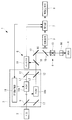
本実施形態に係る画像取得装置1は、図1に示されるように、一定の強度を有するレーザ光を射出するレーザ光源(光源)2と、該レーザ光源2からのレーザ光を変調する変調部3と、該変調部3において変調された照明光を図示しない試料Xに照射する一方、試料Xにおいて発生した蛍光(信号光)を集光する顕微鏡光学系(照明光学系)4と、該顕微鏡光学系4のピンホール16を通過した蛍光を検出する光検出器(信号光検出部)5と、変調部3により変調された照明光L1,L2を検出するディテクタ(照明光検出部)6と、光検出器5により検出された蛍光の強度信号およびディテクタ6により検出された照明光L1,L2の強度信号を復調する復調部7と、該復調部7により復調された蛍光の強度信号に基づいて蛍光画像を生成する画像生成部8とを備えている。 Hereinafter, animage acquisition device 1 according to a first embodiment of the present invention will be described with reference to the drawings.
As shown in FIG. 1, theimage acquisition apparatus 1 according to the present embodiment includes a laser light source (light source) 2 that emits laser light having a constant intensity, and a modulation unit that modulates laser light from the laser light source 2. 3 and a microscope optical system (illumination optical system) 4 for condensing fluorescence (signal light) generated in the sample X while irradiating the illumination light modulated in the modulation unit 3 to the sample X (not shown), and the microscope A photodetector (signal light detection unit) 5 for detecting fluorescence that has passed through the pinhole 16 of the optical system 4; a detector (illumination light detection unit) 6 for detecting the illumination lights L1 and L2 modulated by the modulation unit 3; Based on the fluorescence intensity signal detected by the photodetector 5 and the intensity signal of the illumination lights L1 and L2 detected by the detector 6, the demodulator 7 and the fluorescence intensity signal demodulated by the demodulator 7 To generate fluorescent images And an image generation unit 8 that.
本実施形態に係る画像取得装置1は、図1に示されるように、一定の強度を有するレーザ光を射出するレーザ光源(光源)2と、該レーザ光源2からのレーザ光を変調する変調部3と、該変調部3において変調された照明光を図示しない試料Xに照射する一方、試料Xにおいて発生した蛍光(信号光)を集光する顕微鏡光学系(照明光学系)4と、該顕微鏡光学系4のピンホール16を通過した蛍光を検出する光検出器(信号光検出部)5と、変調部3により変調された照明光L1,L2を検出するディテクタ(照明光検出部)6と、光検出器5により検出された蛍光の強度信号およびディテクタ6により検出された照明光L1,L2の強度信号を復調する復調部7と、該復調部7により復調された蛍光の強度信号に基づいて蛍光画像を生成する画像生成部8とを備えている。 Hereinafter, an
As shown in FIG. 1, the
変調部3は、レーザ光源2からのレーザ光を2つの光路に分岐する第1ビームスプリッタ(分岐部)9と、各光路に配置され、各光路を通過するレーザ光を交互のタイミングでオンオフするように変調する音響光学変調器(AOM)のような変調器10a,10bと、これらの変調器10a,10bを制御する変調制御部11と、変調器10a,10bから出力された照明光L1,L2を合波する第2ビームスプリッタ12とを備えている。第2ビームスプリッタ12は、一方の光路の光軸に対して45°とは微小に異なる角度をなして配置されており、合波後の2つの照明光L1,L2が異なる角度で射出されるようになっている。
The modulation unit 3 is arranged on each optical path and a first beam splitter (branching unit) 9 that branches the laser light from the laser light source 2 into two optical paths, and turns on and off the laser light that passes through each optical path at alternate timings. Modulators 10a and 10b such as an acousto-optic modulator (AOM) that modulates in this way, a modulation control unit 11 that controls these modulators 10a and 10b, and illumination light L1 output from the modulators 10a and 10b And a second beam splitter 12 for multiplexing L2. The second beam splitter 12 is arranged at an angle slightly different from 45 ° with respect to the optical axis of one optical path, and the two illumination lights L1 and L2 after being combined are emitted at different angles. It is like that.
顕微鏡光学系4は、レーザ走査型蛍光顕微鏡の光学系であって、変調部3から射出されてきた2つの照明光L1,L2を走査するスキャナ13と、該スキャナ13により走査された照明光L1,L2を試料Xに集光する対物レンズ14と、対物レンズ14により集光された蛍光を照明光L1,L2の光路から分岐するダイクロイックミラー15と、ピンホール16とを備えている。
図中、符号17は光路形成用のミラーである。 The microscopeoptical system 4 is an optical system of a laser scanning fluorescence microscope, and includes a scanner 13 that scans two illumination lights L1 and L2 emitted from the modulation unit 3, and an illumination light L1 that is scanned by the scanner 13. , L2 on the sample X, a dichroic mirror 15 for branching the fluorescence condensed by the objective lens 14 from the optical path of the illumination light L1, L2, and a pinhole 16.
In the figure,reference numeral 17 denotes an optical path forming mirror.
図中、符号17は光路形成用のミラーである。 The microscope
In the figure,
変調部3の第2ビームスプリッタ12により射出角度が異ならされた2つの照明光L1,L2は、対物レンズ14の瞳に異なる角度から入射させられることにより、試料X内の異なる位置に集光させられ、試料X内に存在する蛍光物質を励起して蛍光を発生させるようになっている。
すなわち、一方の光路を通過した照明光L1は、光検出器5の前段に配置されているピンホール16と光学的に共役な位置に集光させられる一方、他方の光路を通過した照明光L2は、ピンホール16とは光学的に非共役な位置に集光させられるようになっている。 The two illumination lights L1 and L2 having different emission angles by thesecond beam splitter 12 of the modulation unit 3 are incident on the pupil of the objective lens 14 from different angles, thereby being condensed at different positions in the sample X. The fluorescent material existing in the sample X is excited to generate fluorescence.
That is, the illumination light L1 that has passed through one optical path is condensed at a position optically conjugate with thepinhole 16 disposed in the front stage of the photodetector 5, while the illumination light L2 that has passed through the other optical path. Is condensed at a position optically unconjugated with the pinhole 16.
すなわち、一方の光路を通過した照明光L1は、光検出器5の前段に配置されているピンホール16と光学的に共役な位置に集光させられる一方、他方の光路を通過した照明光L2は、ピンホール16とは光学的に非共役な位置に集光させられるようになっている。 The two illumination lights L1 and L2 having different emission angles by the
That is, the illumination light L1 that has passed through one optical path is condensed at a position optically conjugate with the
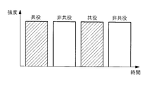
変調制御部11の作動により、2つの光路を通過する照明光L1,L2が交互に射出させられるので、図2に示されるように、共役な位置に集光させられる照明光L1および非共役な位置に集光させられる照明光L2の2つの状態の照明光L1,L2が時間周期的に切り替わる照明光が生成されるようになっている。変調制御部11は、復調部7に対し、変調信号を出力するようになっている。
Since the illumination light L1 and L2 passing through the two optical paths are alternately emitted by the operation of the modulation control unit 11, as shown in FIG. 2, the illumination light L1 that is condensed at the conjugate position and the non-conjugated light Illumination light is generated in which the illumination light L1, L2 in two states of the illumination light L2 condensed at the position is switched periodically. The modulation control unit 11 outputs a modulation signal to the demodulation unit 7.
光検出器5は、例えば、光電子増倍管であり、対物レンズ14により集光された蛍光の強度を検出するようになっている。
復調部7は、光検出器5により検出された、2つの状態の照明光L1,L2によりそれぞれ発生した蛍光の強度信号を、変調制御部11から送られてくる変調器10a,10bの変調のタイミングに同期して復調し、それらの蛍光の強度信号の差分を出力するようになっている。 Thephotodetector 5 is, for example, a photomultiplier tube, and detects the intensity of the fluorescence condensed by the objective lens 14.
Thedemodulating unit 7 modulates the intensity signals of the fluorescence generated by the illumination lights L1 and L2 in the two states detected by the photodetector 5 by the modulators 10a and 10b sent from the modulation control unit 11, respectively. The signal is demodulated in synchronization with the timing, and the difference between the fluorescence intensity signals is output.
復調部7は、光検出器5により検出された、2つの状態の照明光L1,L2によりそれぞれ発生した蛍光の強度信号を、変調制御部11から送られてくる変調器10a,10bの変調のタイミングに同期して復調し、それらの蛍光の強度信号の差分を出力するようになっている。 The
The
画像生成部8は、復調部7から出力された蛍光の強度信号の差分の値を、スキャナ13による走査位置の情報と対応づけて配列することにより、蛍光画像を生成するようになっている。ピンホール16と共役な位置に照明光L1が集光されたときに、光検出器5により検出される蛍光には、焦点位置において発生した焦点蛍光の他、試料X内の焦点までの経路で発生した焦点外蛍光が一部含まれている。
The image generator 8 generates a fluorescent image by arranging the difference value of the fluorescence intensity signal output from the demodulator 7 in association with the information of the scanning position by the scanner 13. When the illumination light L1 is condensed at a position conjugate with the pinhole 16, the fluorescence detected by the photodetector 5 includes the focus fluorescence generated at the focus position and the path to the focus in the sample X. Part of the generated out-of-focus fluorescence is included.
一方、ピンホール16と非共役な位置に照明光L2が集光されたときに光検出器5により検出される蛍光には、焦点位置において発生した焦点蛍光はピンホール16を通過できないので含まれておらず、焦点外蛍光のみが含まれている。したがって、復調部7から出力される、これらの蛍光の強度信号の差分には焦点外蛍光が除去された焦点蛍光のみが含まれていることになり、ノイズが少ない鮮明な蛍光画像を生成することができるようになる。
On the other hand, the fluorescence detected by the photodetector 5 when the illumination light L2 is condensed at a position unconjugated with the pinhole 16 includes the focus fluorescence generated at the focal position because it cannot pass through the pinhole 16. Only the out-of-focus fluorescence is included. Therefore, the difference between these fluorescence intensity signals output from the demodulator 7 includes only the focus fluorescence from which the out-of-focus fluorescence is removed, and a clear fluorescence image with less noise is generated. Will be able to.
ディテクタ6は、例えば、変調部3の後段に配置され、変調部3から出力された照明光L1,L2の一部を分離する反射率の低いハーフミラーからなるビームサンプラ18と、該ビームサンプラ18により分離された2つの状態の照明光L1,L2を検出可能な位置に配置されたシングルポイントディテクタ19とを備えている。
The detector 6 is disposed, for example, at the subsequent stage of the modulation unit 3, and includes a beam sampler 18 including a low-reflectance half mirror that separates part of the illumination lights L 1 and L 2 output from the modulation unit 3, and the beam sampler 18. And a single point detector 19 disposed at a position where the illumination lights L1 and L2 in the two states separated by (2) can be detected.
シングルポイントディテクタ19は、図示しないリレーレンズによって対物レンズ14の瞳面と共役な位置に配置されていてもよいし、図示しない集光レンズの焦点位置に配置されていてもよいし、2つの照明光L1,L2を広い範囲で検出可能な大口径のものを採用してもよい。
本実施形態においては、シングルポイントディテクタ19の出力は、復調部7に入力され、復調部7からの出力は変調制御部11に入力されるようになっている。 Thesingle point detector 19 may be arranged at a position conjugate with the pupil plane of the objective lens 14 by a relay lens (not shown), may be arranged at the focal position of a condenser lens (not shown), or two illuminations You may employ | adopt the thing of the large diameter which can detect light L1, L2 in a wide range.
In the present embodiment, the output of thesingle point detector 19 is input to the demodulator 7, and the output from the demodulator 7 is input to the modulation controller 11.
本実施形態においては、シングルポイントディテクタ19の出力は、復調部7に入力され、復調部7からの出力は変調制御部11に入力されるようになっている。 The
In the present embodiment, the output of the
変調制御部11は、復調部7から入力される差分の値に応じて、いずれかの変調器10a,10bにより変調される照明光L1,L2の変調強度を補正するようになっている。すなわち、ビームサンプラ18により分離された2つの状態の照明光L1,L2の強度に基づいて、変調制御部11が、復調部7からの出力がゼロとなるようにいずれかの照明光の強度を変化させるので、2つの状態の照明光L1,L2の強度が精度よく一致するように調節されるようになっている。
The modulation control unit 11 corrects the modulation intensity of the illumination lights L1 and L2 modulated by one of the modulators 10a and 10b in accordance with the difference value input from the demodulation unit 7. That is, based on the intensity of the illumination lights L1 and L2 in two states separated by the beam sampler 18, the modulation control unit 11 sets the intensity of any illumination light so that the output from the demodulation unit 7 becomes zero. Therefore, the intensities of the illumination lights L1 and L2 in the two states are adjusted with high accuracy.
このように構成された本実施形態に係る画像取得装置1によれば、レーザ光源2から射出されたレーザ光は変調部3において、第1ビームスプリッタ9により2つの光路に分岐され各光路を通過させられる間に、各々の光路に配置された変調器10a,10bによって変調され、第2ビームスプリッタ12によって合波されて異なる角度で射出される。
According to the image acquisition apparatus 1 according to the present embodiment configured as described above, the laser light emitted from the laser light source 2 is branched into two optical paths by the first beam splitter 9 in the modulation unit 3 and passes through the optical paths. During this time, the light is modulated by the modulators 10a and 10b arranged in the respective optical paths, combined by the second beam splitter 12, and emitted at different angles.
変調部3から出力された、時間周期的に2つの状態が変化する照明光L1,L2は、顕微鏡光学系4に入射されるとともに、その一部がビームサンプラ18によって分離されてシングルポイントディテクタ19により検出される。顕微鏡光学系4内のスキャナ13によって走査され対物レンズ14によって集光された2つの状態の照明光L1,L2は試料X内の2つの異なる位置に集光させられて、各集光位置において蛍光を発生させる。
Illumination lights L1 and L2 output from the modulation unit 3 and that change in two states in terms of time are made incident on the microscope optical system 4, and a part of the illumination lights L1 and L2 are separated by the beam sampler 18 and single point detector 19 is used. Is detected. The illumination lights L1 and L2 in two states scanned by the scanner 13 in the microscope optical system 4 and condensed by the objective lens 14 are condensed at two different positions in the sample X, and fluorescent at each condensing position. Is generated.
2つの状態の照明光L1,L2が照射されることにより試料Xにおいて発生した蛍光は光検出器5によって検出され、復調部7に入力される。復調部7においては、変調部3における変調に同期した復調を受けることにより、各状態の照明光L1,L2の照射により発生した蛍光の強度信号の差分が復調部7から出力される。
上述したように、復調部7から出力される蛍光の強度信号の差分は、焦点外蛍光が除去された照明光の焦点位置からの蛍光のみの強度信号となっているので、この差分の値とスキャナ13による走査位置とを、画像生成部8において対応づけて配列することにより、ノイズのない鮮明な蛍光画像を取得することができる。 Fluorescence generated in the sample X by irradiation with the illumination lights L1 and L2 in two states is detected by thephotodetector 5 and input to the demodulator 7. In the demodulator 7, by receiving demodulation synchronized with the modulation in the modulator 3, the difference between the fluorescence intensity signals generated by the illumination lights L 1 and L 2 in each state is output from the demodulator 7.
As described above, the difference in the intensity signal of the fluorescence output from thedemodulator 7 is an intensity signal of only the fluorescence from the focal position of the illumination light from which the out-of-focus fluorescence is removed. By arranging the scanning positions by the scanner 13 in association with each other in the image generation unit 8, a clear fluorescent image without noise can be acquired.
上述したように、復調部7から出力される蛍光の強度信号の差分は、焦点外蛍光が除去された照明光の焦点位置からの蛍光のみの強度信号となっているので、この差分の値とスキャナ13による走査位置とを、画像生成部8において対応づけて配列することにより、ノイズのない鮮明な蛍光画像を取得することができる。 Fluorescence generated in the sample X by irradiation with the illumination lights L1 and L2 in two states is detected by the
As described above, the difference in the intensity signal of the fluorescence output from the
この場合において、復調部7において焦点外蛍光を精度よく除去するためには、2つの状態の照明光L1,L2の強度が同一であることが必要である。観察に先立って、変調部3から出力される2つの状態の照明光L1,L2の強度が同一となるように変調制御部11が設定されるが、温度等の使用環境が変動することにより、各変調器10a,10bから出力される照明光L1,L2の強度に差が発生する場合がある。
In this case, in order to accurately remove the out-of-focus fluorescence in the demodulator 7, the intensities of the illumination lights L1 and L2 in the two states are required to be the same. Prior to observation, the modulation control unit 11 is set so that the intensity of the illumination lights L1 and L2 in the two states output from the modulation unit 3 are the same, but the use environment such as temperature fluctuates, There may be a difference in the intensity of the illumination lights L1 and L2 output from the modulators 10a and 10b.
本実施形態に係る画像取得装置1によれば、変調部3から出力される照明光L1,L2の一部がビームサンプラ18によって分離され、シングルポイントディテクタ19により検出され、検出された照明光L1,L2の強度信号が復調部7によって復調されることにより、2つの状態の照明光L1,L2の信号強度の差分が復調部7から出力される。そして、復調部7から出力された差分が変調制御部11に入力されることにより、変調制御部11が差分に応じて各変調器10a,10bにより変調される照明光L1,L2の変調強度が補正される。
According to the image acquisition device 1 according to the present embodiment, part of the illumination lights L1 and L2 output from the modulation unit 3 are separated by the beam sampler 18, detected by the single point detector 19, and detected illumination light L1. , L2 intensity signals are demodulated by the demodulator 7 so that the difference between the signal intensities of the two illumination lights L1 and L2 is output from the demodulator 7. Then, the difference output from the demodulator 7 is input to the modulation control unit 11, so that the modulation intensity of the illumination lights L1 and L2 modulated by the modulators 10a and 10b according to the difference is modulated by the modulation control unit 11. It is corrected.
すなわち、2つの状態の照明光L1,L2の強度信号の差分がゼロであれば変調強度の補正は行われないので、2つの状態の照明光L1,L2の強度が精度よく一致させられる。これにより、復調部7において焦点外蛍光を精度よく除去することができ、使用環境が変動しても、作業者が観察毎に照明光L1,L2の強度比率の調整を行うことなく、ノイズのない鮮明な蛍光画像を取得することができるという利点がある。
That is, if the difference between the intensity signals of the illumination lights L1 and L2 in the two states is zero, the modulation intensity is not corrected, so that the intensities of the illumination lights L1 and L2 in the two states are matched with high accuracy. As a result, out-of-focus fluorescence can be accurately removed in the demodulator 7, and even if the usage environment fluctuates, the operator does not adjust the intensity ratio of the illumination lights L1 and L2 for each observation. There is an advantage that a clear fluorescent image can be obtained.
特に、本実施形態においては、蛍光の強度信号の差分を出力する復調部7を照明光L1,L2の強度信号の差分を求めるために利用しているので、ビームサンプラ18とシングルポイントディテクタ19とを新たに設置するだけで足り、簡易な構成で低コストに実現できるという利点がある。
なお、蛍光用の復調部7とは別に照明光用の復調部を用意してもよい。 In particular, in the present embodiment, thedemodulator 7 that outputs the difference between the fluorescence intensity signals is used to obtain the difference between the intensity signals of the illumination lights L1 and L2, so that the beam sampler 18 and the single point detector 19 There is an advantage that it is only necessary to newly install and can be realized at a low cost with a simple configuration.
A demodulator for illumination light may be prepared separately from thedemodulator 7 for fluorescence.
なお、蛍光用の復調部7とは別に照明光用の復調部を用意してもよい。 In particular, in the present embodiment, the
A demodulator for illumination light may be prepared separately from the
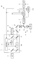
また、本実施形態においては、焦点外蛍光を除去するために変復調を利用する画像取得装置1を例示して説明したが、これに代えて、図3に示されるように、SAX顕微鏡に適用することにしてもよい。
すなわち、変調部3が、図3に示されるように、異なるピーク値を有し、かつ、時間積分強度が等しい2つの状態の照明光L1,L2を生成する点で上記実施形態と相違している。
また、変調器10a,10bは、音響光学変調器に代えて、電気光学変調器を採用してもよい。 Further, in the present embodiment, theimage acquisition device 1 that uses modulation / demodulation to remove out-of-focus fluorescence has been described as an example, but instead, this is applied to a SAX microscope as shown in FIG. You may decide.
That is, as shown in FIG. 3, themodulation unit 3 generates illumination lights L1 and L2 having two different peak values and equal time integration intensities, unlike the above embodiment. Yes.
The modulators 10a and 10b may employ electro-optic modulators instead of the acousto-optic modulators.
すなわち、変調部3が、図3に示されるように、異なるピーク値を有し、かつ、時間積分強度が等しい2つの状態の照明光L1,L2を生成する点で上記実施形態と相違している。
また、変調器10a,10bは、音響光学変調器に代えて、電気光学変調器を採用してもよい。 Further, in the present embodiment, the
That is, as shown in FIG. 3, the
The
ピーク強度が高い方の照明光L1では試料Xにおいて発生する蛍光が飽和し、ピーク強度の低い方の照明光L2では蛍光が飽和しない状態とする場合に、使用環境が変動しても、2つの状態での照明光L1,L2の時間積分強度を精度よく一致させた状態に維持することができ、高精度の観察を行うことができる。
When the illumination light L1 having a higher peak intensity saturates the fluorescence generated in the sample X and the illumination light L2 having a lower peak intensity does not saturate the fluorescence, even if the usage environment changes, two In this state, the time integrated intensities of the illumination lights L1 and L2 can be maintained in a highly accurate state, and high-precision observation can be performed.
次に本発明の第2の実施形態に係る画像取得装置20について、図面を参照して以下に説明する。
本実施形態の説明において、上述した第1の実施形態に係る画像取得装置1と構成を共通とする箇所には同一符号を付して説明を省略する。 Next, animage acquisition apparatus 20 according to a second embodiment of the present invention will be described below with reference to the drawings.
In the description of the present embodiment, the same reference numerals are given to portions having the same configuration as that of theimage acquisition device 1 according to the first embodiment described above, and description thereof is omitted.
本実施形態の説明において、上述した第1の実施形態に係る画像取得装置1と構成を共通とする箇所には同一符号を付して説明を省略する。 Next, an
In the description of the present embodiment, the same reference numerals are given to portions having the same configuration as that of the
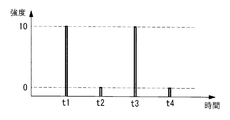
本実施形態に係る画像取得装置20は、図4に示されるように、2光子励起顕微鏡に適用したものであり、極短パルスレーザ光からなる照明光を2つの光路に分岐し、各光路に配置された変調器10a,10bにより異なる周波数で変調して、試料Xの異なる2点に集光し、各集光点から発せられた蛍光を検出して復調することにより、2点からの蛍光を別々に取得するようになっている。
As shown in FIG. 4, the image acquisition device 20 according to the present embodiment is applied to a two-photon excitation microscope, and divides illumination light composed of ultrashort pulse laser light into two optical paths, The light is modulated at different frequencies by the arranged modulators 10a and 10b, condensed at two different points of the sample X, and the fluorescence emitted from each focal point is detected and demodulated to detect the fluorescence from the two points. Are supposed to be acquired separately.
具体的には、一方の光路の第1変調器10aは、図5Aに示されるように、レーザ光源2からの極短パルスレーザ光のパルスを1つ置きに遮断して、50%デューティとなるように変調させるようになっている。
他方の第2変調器10bは、図5Bに示されるレーザ光源2からの極短パルスレーザ光の全てのパルスのピーク強度を、図5Cに示されるように、70%に低下させるようになっている。 Specifically, as shown in FIG. 5A, thefirst modulator 10a in one optical path cuts every other pulse of the ultrashort pulse laser light from the laser light source 2 to become 50% duty. So that it can be modulated.
The othersecond modulator 10b reduces the peak intensity of all pulses of the ultrashort pulse laser beam from the laser light source 2 shown in FIG. 5B to 70% as shown in FIG. 5C. Yes.
他方の第2変調器10bは、図5Bに示されるレーザ光源2からの極短パルスレーザ光の全てのパルスのピーク強度を、図5Cに示されるように、70%に低下させるようになっている。 Specifically, as shown in FIG. 5A, the
The other
例えば、レーザ光源2から射出される光が80MHzである場合に、第1変調器10aは、レーザ光源2からの極短パルスレーザ光を変調して40MHzの照明光L2を生成するようになっている。これにより、照明光L2は、40MHzで強度が変化する交流パターンを有している。第2変調器10bは、レーザ光源2からの極短パルスレーザ光のピーク強度を70%に変調して80MHzの照明光L1を生成している。
For example, when the light emitted from the laser light source 2 is 80 MHz, the first modulator 10a modulates the ultrashort pulse laser light from the laser light source 2 to generate the 40 MHz illumination light L2. Yes. Thereby, the illumination light L2 has an alternating current pattern whose intensity changes at 40 MHz. The second modulator 10b modulates the peak intensity of the ultrashort pulse laser light from the laser light source 2 to 70% to generate 80 MHz illumination light L1.
そして、光検出器5により検出された試料Xからの蛍光の強度信号を2つの復調部21a,21bに入力する。入力される信号は二つの焦点から来る蛍光信号の合計であり、蛍光信号は照明光L1のピーク強度の2乗に比例するので、到着パルスごとに時間関数で表現すると、Fall(t)=[102+72,72,102+72,72]と表現される。
Then, the fluorescence intensity signal from the sample X detected by the photodetector 5 is input to the two demodulation units 21a and 21b. Since the input signal is the sum of the fluorescence signals coming from the two focal points, and the fluorescence signal is proportional to the square of the peak intensity of the illumination light L1, it can be expressed as a time function for each arrival pulse, F all (t) = [10 2 +7 2 , 7 2 , 10 2 +7 2 , 7 2 ].
一方の第1復調部21aでは、第1変調器10aの変調信号に同期する復調信号として、code1(t)=(1,-1,1,-1)が乗算されて積分された蛍光信号が出力される。
具体的には、L1に対応するF1=Fall(t)・code1(t)=102+72-72+102+72-72=200が出力される。 On the other hand, in thefirst demodulator 21a, as a demodulated signal synchronized with the modulated signal of the first modulator 10a, the fluorescence signal integrated by multiplying code1 (t) = (1, -1,1, -1) is integrated. Is output.
Specifically, F1 = F all (t) · code1 (t) = 10 2 +7 2 −7 2 +10 2 +7 2 −7 2 = 200 corresponding to L1 is output.
具体的には、L1に対応するF1=Fall(t)・code1(t)=102+72-72+102+72-72=200が出力される。 On the other hand, in the
Specifically, F1 = F all (t) · code1 (t) = 10 2 +7 2 −7 2 +10 2 +7 2 −7 2 = 200 corresponding to L1 is output.
また、他方の第2復調部21bでは、第2変調器10bの変調信号に同期する復調信号としてcode1=(1,1,1,1)が乗算されて積分された後、L1に対応する蛍光信号が差分されL2に対応する蛍光信号が出力される。具体的には、蛍光信号は照明光L1のピーク強度の2乗に比例するので、F2=Fall(t)・code2(t)-F1=102+72+72+102+72+72-200≒200が出力される。
The other second demodulator 21b multiplies and integrates code1 = (1,1,1,1) as a demodulated signal synchronized with the modulated signal of the second modulator 10b, and then fluorescence corresponding to L1. The signals are subtracted and a fluorescent signal corresponding to L2 is output. Specifically, since the fluorescence signal is proportional to the square of the peak intensity of the illumination light L1, F2 = F all (t) · code 2 (t) −F1 = 10 2 +7 2 +7 2 +10 2 +7 2 +7 2 − 200≈200 is output.
これにより、2つの復調部21a,21bから出力される蛍光の強度信号は略同等となり、これらの蛍光強度を用いて生成される蛍光画像の輝度ムラの発生を防止することができる。
この場合において、シングルポイントディテクタ19により検出され復調部21a,21bにより復調された2つの状態の照明光L1,L2の強度信号は、第1の実施形態とは異なって、差分として出力されることなく、別々の強度信号として出力される。 As a result, the fluorescence intensity signals output from the two demodulation units 21a and 21b are substantially equal, and the occurrence of uneven brightness in the fluorescence image generated using these fluorescence intensities can be prevented.
In this case, the intensity signals of the illumination lights L1 and L2 in the two states detected by thesingle point detector 19 and demodulated by the demodulation units 21a and 21b are output as a difference, unlike the first embodiment. And output as separate intensity signals.
この場合において、シングルポイントディテクタ19により検出され復調部21a,21bにより復調された2つの状態の照明光L1,L2の強度信号は、第1の実施形態とは異なって、差分として出力されることなく、別々の強度信号として出力される。 As a result, the fluorescence intensity signals output from the two
In this case, the intensity signals of the illumination lights L1 and L2 in the two states detected by the
したがって、各復調部21a,21bから出力された各状態の照明光L1,L2の強度信号が、上記の例ではL1:L2=7:10の場合に、各変調器10a,10bにおける変調強度の補正が行われなくなるように、変調制御部11が制御するようになっている。すなわち、変調制御部11は、第1復調部21aから出力されてきた照明光L1の強度信号に、予め設定された比率、上記の例では10/7を乗算して得られた値と第2復調部21bから出力されてきた照明光L2の強度信号との差分がゼロとなるように、2つの変調器10a,10bを制御する。
Therefore, when the intensity signals of the illumination lights L1 and L2 in the respective states output from the demodulating units 21a and 21b are L1: L2 = 7: 10 in the above example, the modulation intensity in each of the modulators 10a and 10b. The modulation control unit 11 controls so that correction is not performed. That is, the modulation control unit 11 multiplies the intensity signal of the illumination light L1 output from the first demodulation unit 21a by a preset ratio, 10/7 in the above example, and the second value. The two modulators 10a and 10b are controlled so that the difference from the intensity signal of the illumination light L2 output from the demodulator 21b becomes zero.
このように、本実施形態に係る画像取得装置20によれば、使用環境が変動しても、作業者が観察毎に照明光L1,L2の強度比率の調整を行うことなく、2点同時検出によるフレームレートの向上を図りながら、輝度ムラの少ない蛍光画像を取得することができるという利点がある。
As described above, according to the image acquisition device 20 according to the present embodiment, even if the usage environment changes, two-point simultaneous detection is performed without the operator adjusting the intensity ratio of the illumination lights L1 and L2 for each observation. There is an advantage that a fluorescent image with little luminance unevenness can be acquired while improving the frame rate by the above.
なお、本実施形態においては、照明光L1,L2を試料Xに同時に2点で集光させて蛍光を検出する場合について説明したが、3点以上を同時に集光することにしてもよい。また、スキャナ13によるポイントスキャン方式のものを例示したが、対物レンズ14の光軸に沿う方向に異なる位置に入射されるシート状の照明光により発生する蛍光をカメラによって撮影するライトシート顕微鏡に適用してもよい。
In the present embodiment, the case where the illumination lights L1 and L2 are condensed on the sample X at two points at the same time to detect fluorescence is described, but three or more points may be condensed at the same time. Further, although the point scan method using the scanner 13 has been exemplified, the present invention is applied to a light sheet microscope for photographing fluorescence generated by sheet-like illumination light incident on different positions along the optical axis of the objective lens 14 with a camera. May be.
また、2つの変調器10a,10bによって別々に変調される結果、2つの照明光L1,L2の偏光状態が異なる場合に、ビームサンプラ18によるサンプリング比率が照明光L1,L2毎に異なる場合が発生し得る。このような場合には、2つの照明光L1,L2が同じ強度を有していてもシングルポイントディテクタ19において異なる強度を有するものとして検出されてしまうので、事前に求めた補正係数によってシングルポイントディテクタ19により検出された照明光L1,L2の強度信号を補正する信号補正部(図示略)を設けてもよい。
また、変調制御部11において2つの変調器10a,10bによる変調強度を補正することとしたが、一方の変調器10aのみにおいて変調強度を補正することにしてもよい。 Further, as a result of being separately modulated by the two modulators 10a and 10b, when the polarization states of the two illumination lights L1 and L2 are different, the sampling ratio by the beam sampler 18 may be different for each of the illumination lights L1 and L2. Can do. In such a case, even if the two illumination lights L1 and L2 have the same intensity, they are detected as having different intensities in the single point detector 19, so that the single point detector is detected by the correction coefficient obtained in advance. A signal correction unit (not shown) that corrects the intensity signals of the illumination lights L1 and L2 detected by the projector 19 may be provided.
Further, although themodulation control unit 11 corrects the modulation intensity by the two modulators 10a and 10b, the modulation intensity may be corrected by only one modulator 10a.
また、変調制御部11において2つの変調器10a,10bによる変調強度を補正することとしたが、一方の変調器10aのみにおいて変調強度を補正することにしてもよい。 Further, as a result of being separately modulated by the two
Further, although the
また、上記各実施形態においては、照明光L1,L2の変調強度の補正のタイミングは、特に限定されるものではないが、例えば、試料Xの蛍光観察を行う前に自動的に実施することにすればよい。照明光L1,L2の強度補正は試料Xを用いることなく実施でき、試料Xにダメージを与えずに行うことができる。
In each of the above embodiments, the timing of correcting the modulation intensity of the illumination lights L1 and L2 is not particularly limited. For example, it is automatically performed before the fluorescence observation of the sample X is performed. do it. The intensity correction of the illumination lights L1 and L2 can be performed without using the sample X, and can be performed without damaging the sample X.
1,20 画像取得装置
2 レーザ光源(光源)
3 変調部
4 顕微鏡光学系(照明光学系)
5 光検出器(信号光検出部)
6 ディテクタ(照明光検出部)
7,21a,21b 復調部
8 画像生成部
9 第1ビームスプリッタ(分岐部)
L1,L2 照明光
X 試料 1,20Image acquisition device 2 Laser light source (light source)
3Modulator 4 Microscope optical system (illumination optical system)
5 Light detector (Signal light detector)
6 Detector (illumination light detector)
7, 21a,21b Demodulator 8 Image generator 9 First beam splitter (branch unit)
L1, L2 Illumination light X Sample
2 レーザ光源(光源)
3 変調部
4 顕微鏡光学系(照明光学系)
5 光検出器(信号光検出部)
6 ディテクタ(照明光検出部)
7,21a,21b 復調部
8 画像生成部
9 第1ビームスプリッタ(分岐部)
L1,L2 照明光
X 試料 1,20
3
5 Light detector (Signal light detector)
6 Detector (illumination light detector)
7, 21a,
L1, L2 Illumination light X Sample
Claims (6)
- 光源からの光を変調することにより、異なる2つの状態が時間周期的に切り替わる照明光を生成する変調部と、
該変調部により生成された前記照明光を検出する照明光検出部と、
前記変調部により生成された前記照明光を試料に照射する照明光学系と、
該照明光学系による前記照明光の試料における照射位置において発生した信号光を集光して検出する信号光検出部と、
該信号光検出部により検出された前記信号光の強度信号および前記照明光検出部により検出された前記照明光の強度信号に対し前記変調に対する復調を行う復調部と、
該復調部により復調された前記信号光の強度信号に基づいて信号光画像を生成する画像生成部とを備え、
前記変調部が、前記復調部により復調された前記照明光の強度信号に基づいて前記照明光の変調強度を補正する画像取得装置。 A modulator that generates illumination light in which two different states are periodically switched by modulating light from the light source;
An illumination light detector that detects the illumination light generated by the modulator;
An illumination optical system for irradiating a sample with the illumination light generated by the modulation unit;
A signal light detection unit that collects and detects signal light generated at an irradiation position of the illumination light in the sample by the illumination optical system;
A demodulator that demodulates the modulation of the intensity signal of the signal light detected by the signal light detector and the intensity signal of the illumination light detected by the illumination light detector;
An image generation unit that generates a signal light image based on an intensity signal of the signal light demodulated by the demodulation unit;
The image acquisition device in which the modulation unit corrects the modulation intensity of the illumination light based on the intensity signal of the illumination light demodulated by the demodulation unit. - 前記2つの状態は、時間積分強度が等しくなる状態であり、
前記復調部が、状態毎に復調された前記照明光の時間積分強度の差分を出力し、
前記変調部は、前記差分がゼロとなるように前記変調強度を補正する請求項1に記載の画像取得装置。 The two states are states in which time integrated intensity is equal,
The demodulator outputs a difference in time integrated intensity of the illumination light demodulated for each state,
The image acquisition apparatus according to claim 1, wherein the modulation unit corrects the modulation intensity so that the difference becomes zero. - 前記2つの状態が、前記照明光を試料の異なる位置に照射する状態である請求項1または請求項2に記載の画像取得装置。 The image acquisition device according to claim 1 or 2, wherein the two states are states in which the illumination light is irradiated to different positions of the sample.
- 前記2つの状態が、試料において発生する前記信号光が飽和する状態と飽和しない状態である請求項1または請求項2に記載の画像取得装置。 3. The image acquisition apparatus according to claim 1, wherein the two states are a state where the signal light generated in the sample is saturated and a state where the signal light is not saturated.
- 前記光源からの光を2つの光路に分岐する分岐部を備え、
前記変調部が、前記分岐部により分岐された各前記光路の光をそれぞれ異なる周波数で変調するとともに、前記復調部により復調された2つの前記照明光の強度比が予め設定された値となるように前記照明光の変調強度を補正する請求項1に記載の画像取得装置。 A branching portion for branching light from the light source into two optical paths;
The modulation unit modulates the light of each of the optical paths branched by the branching unit with different frequencies, and the intensity ratio of the two illumination lights demodulated by the demodulation unit becomes a preset value. The image acquisition apparatus according to claim 1, wherein the modulation intensity of the illumination light is corrected. - 前記照明光検出部により検出された前記照明光の強度信号を予め設定された補正係数により補正する信号補正部を備える請求項1から請求項5のいずれかに記載の画像取得装置。 6. The image acquisition apparatus according to claim 1, further comprising a signal correction unit that corrects an intensity signal of the illumination light detected by the illumination light detection unit using a preset correction coefficient.
Priority Applications (1)
| Application Number | Priority Date | Filing Date | Title |
|---|---|---|---|
| PCT/JP2016/061531 WO2017175374A1 (en) | 2016-04-08 | 2016-04-08 | Image acquisition device |
Applications Claiming Priority (1)
| Application Number | Priority Date | Filing Date | Title |
|---|---|---|---|
| PCT/JP2016/061531 WO2017175374A1 (en) | 2016-04-08 | 2016-04-08 | Image acquisition device |
Publications (1)
| Publication Number | Publication Date |
|---|---|
| WO2017175374A1 true WO2017175374A1 (en) | 2017-10-12 |
Family
ID=60000918
Family Applications (1)
| Application Number | Title | Priority Date | Filing Date |
|---|---|---|---|
| PCT/JP2016/061531 WO2017175374A1 (en) | 2016-04-08 | 2016-04-08 | Image acquisition device |
Country Status (1)
| Country | Link |
|---|---|
| WO (1) | WO2017175374A1 (en) |
Citations (4)
| Publication number | Priority date | Publication date | Assignee | Title |
|---|---|---|---|---|
| JP2008012852A (en) * | 2006-07-07 | 2008-01-24 | Konica Minolta Business Technologies Inc | Image forming device |
| JP2011141427A (en) * | 2010-01-07 | 2011-07-21 | Seiko Epson Corp | Projector |
| JP2015168184A (en) * | 2014-03-07 | 2015-09-28 | 株式会社リコー | Optical writing device, image formation device and optical writing method |
| WO2015163261A1 (en) * | 2014-04-24 | 2015-10-29 | オリンパス株式会社 | Microscope and microscopic observation method |
-
2016
- 2016-04-08 WO PCT/JP2016/061531 patent/WO2017175374A1/en active Application Filing
Patent Citations (4)
| Publication number | Priority date | Publication date | Assignee | Title |
|---|---|---|---|---|
| JP2008012852A (en) * | 2006-07-07 | 2008-01-24 | Konica Minolta Business Technologies Inc | Image forming device |
| JP2011141427A (en) * | 2010-01-07 | 2011-07-21 | Seiko Epson Corp | Projector |
| JP2015168184A (en) * | 2014-03-07 | 2015-09-28 | 株式会社リコー | Optical writing device, image formation device and optical writing method |
| WO2015163261A1 (en) * | 2014-04-24 | 2015-10-29 | オリンパス株式会社 | Microscope and microscopic observation method |
Similar Documents
| Publication | Publication Date | Title |
|---|---|---|
| US9158100B2 (en) | Laser microscope using phase-modulation type spatial light modulator | |
| US9606341B2 (en) | Optical apparatus | |
| US7915575B2 (en) | Laser scanning microscope having an IR partial transmission filter for realizing oblique illumination | |
| US11131630B2 (en) | Method of aligning a laser-scanning fluorescence microscope and laser-scanning fluorescence microscope having an automatic aligning system | |
| US9356413B2 (en) | Laser source apparatus and laser microscope | |
| US20210116691A1 (en) | Method for scanning microscopy and scanning microscope | |
| WO2019069509A1 (en) | Fluorescence microscope device and fluorescence microscope system | |
| JP2015517681A (en) | A microscope for imaging the tissue of interest in a sample with high spatial resolution | |
| JP5307418B2 (en) | Scanning laser microscope | |
| JP5058624B2 (en) | Laser microscope | |
| JP2009145826A (en) | Scanning type microscope | |
| WO2017094184A1 (en) | Scanning microscope and microscope image acquisition method | |
| WO2016208322A1 (en) | Image acquisition device and method for acquiring image | |
| WO2017175374A1 (en) | Image acquisition device | |
| US10942345B2 (en) | Image acquisition method and image acquisition device | |
| JP5191352B2 (en) | Laser scanning microscope | |
| US9588328B2 (en) | Wide-field microscope and method for wide-field microscopy | |
| US10261299B2 (en) | Image-acquisition apparatus and image-acquisition method | |
| KR102599457B1 (en) | Microscopy apparatus for generating structured illumination and operating method thereof | |
| JPH11237554A (en) | Scanning type optical microscope | |
| JP2012150331A (en) | Confocal microscope | |
| WO2018084268A1 (en) | Fluorescence observation device | |
| JP2010117657A (en) | Microscope, and method of adjusting optical axis of laser beam | |
| JP2006189468A (en) | One-photon excitation fluorescence observation device and method | |
| JP2004133011A (en) | Automatic focusing device |
Legal Events
| Date | Code | Title | Description |
|---|---|---|---|
| NENP | Non-entry into the national phase |
Ref country code: DE |
|
| 121 | Ep: the epo has been informed by wipo that ep was designated in this application |
Ref document number: 16897930 Country of ref document: EP Kind code of ref document: A1 |
|
| 122 | Ep: pct application non-entry in european phase |
Ref document number: 16897930 Country of ref document: EP Kind code of ref document: A1 |
|
| NENP | Non-entry into the national phase |
Ref country code: JP |