WO2017174766A1 - A heat pump laundry washing and/or drying machine - Google Patents
A heat pump laundry washing and/or drying machine Download PDFInfo
- Publication number
- WO2017174766A1 WO2017174766A1 PCT/EP2017/058353 EP2017058353W WO2017174766A1 WO 2017174766 A1 WO2017174766 A1 WO 2017174766A1 EP 2017058353 W EP2017058353 W EP 2017058353W WO 2017174766 A1 WO2017174766 A1 WO 2017174766A1
- Authority
- WO
- WIPO (PCT)
- Prior art keywords
- evaporator
- housing
- condenser
- drying machine
- heat pump
- Prior art date
- Legal status (The legal status is an assumption and is not a legal conclusion. Google has not performed a legal analysis and makes no representation as to the accuracy of the status listed.)
- Ceased
Links
Images


Classifications
-
- D—TEXTILES; PAPER
- D06—TREATMENT OF TEXTILES OR THE LIKE; LAUNDERING; FLEXIBLE MATERIALS NOT OTHERWISE PROVIDED FOR
- D06F—LAUNDERING, DRYING, IRONING, PRESSING OR FOLDING TEXTILE ARTICLES
- D06F25/00—Washing machines with receptacles, e.g. perforated, having a rotary movement, e.g. oscillatory movement, the receptacle serving both for washing and for centrifugally separating water from the laundry and having further drying means, e.g. using hot air
-
- D—TEXTILES; PAPER
- D06—TREATMENT OF TEXTILES OR THE LIKE; LAUNDERING; FLEXIBLE MATERIALS NOT OTHERWISE PROVIDED FOR
- D06F—LAUNDERING, DRYING, IRONING, PRESSING OR FOLDING TEXTILE ARTICLES
- D06F58/00—Domestic laundry dryers
- D06F58/20—General details of domestic laundry dryers
- D06F58/206—Heat pump arrangements
-
- D—TEXTILES; PAPER
- D06—TREATMENT OF TEXTILES OR THE LIKE; LAUNDERING; FLEXIBLE MATERIALS NOT OTHERWISE PROVIDED FOR
- D06F—LAUNDERING, DRYING, IRONING, PRESSING OR FOLDING TEXTILE ARTICLES
- D06F58/00—Domestic laundry dryers
- D06F58/20—General details of domestic laundry dryers
- D06F58/24—Condensing arrangements
Definitions
- the present invention relates to a heat pump laundry washing and/or drying machine.
- the heat pump used for drying the laundry is composed of heat exchangers named as evaporator and condenser.
- the laundry-drying process is performed by passing hot and dry air over the laundry. Humid air leaving the laundry leaves its moisture while passing over the evaporator that works as the condenser and warms while passing over the condenser that works as the heater. The air that leaves its moisture and warms up is sent onto the laundry throughout the drying cycle. After leaving its moisture on the condenser , the process air is heated by the condenser and is delivered into the drum with high temperature and low relative humidity rate and is involved in the drying cycle again.
- the humid air condensing on the fins of the evaporator causes accumulation of water droplets on the fins and the heat pump. With the contact of the air passed through the heat up with the water droplets, the air gathers moisture again, therefore, the drying performance of the laundry washing and/or drying machine decreases.
- a dryer having a flow channel and a guiding member that enables the processing air to be directed on the flow channel.
- the aim of the present invention is the realization of a laundry washing and/or drying machine, the drying effectiveness of which is increased.
- the laundry washing and/or drying machine realized in order to attain the aim of the present invention, explicated in the first claim and the respective claims thereof, comprises a body, a drum wherein the laundry to be dried is placed, a tub wherein the drum moves, and an air circulation duct with one end connected to the drum and the other end to a fan providing the circulation of the process air passed over the laundry in the drum.
- the laundry washing and/or drying machine of the present invention comprises a heat pump that is disposed on the body so that one end thereof is connected to the fan and the other to an air inlet hole arranged on the body and extending into the drum and that comprises an evaporator that provides the condensation of the process air passing thereover, a condenser that provides the heating of the process air and a housing that is disposed between the evaporator and the condenser and wherein the water droplets forming on the evaporator surface are collected.
- the condenser located in the heat pump functions as a heater and the evaporator as a condenser.
- the humid process air taken from the end of the heat pump opening into the air circulation duct is heated in the condenser and delivered to the drum through the air inlet hole.
- the water droplets accumulated on the fins of the evaporator during the condensation process in the evaporator contact the process air before the process air enters the condenser and causes the process air to gather moisture.
- the process air leaving the evaporator is delivered to the condenser without contacting the water droplets.
- the heating performance of the condenser is improved and the drying effectiveness of the laundry washing and/or drying machine is increased.
- the heat pump comprises a cover that is disposed on the housing and that has more than one opening providing the intake of the water droplets leaving the evaporator into the housing.
- the water droplets accumulated on the fins of the evaporator as the humid process air received from the heat pump condenses on the fins of the evaporator are delivered downwards from the evaporator during the movement of the process air and accumulated in the housing by passing through the openings arranged on the cover mounted onto the housing.
- the cover comprises more than one baffle plate that is disposed in the flow direction of the process air in an inclined manner.
- the process air leaving the evaporator and hitting the baffle plates is enabled to be guided to the condenser without entering the housing.
- the water droplets formed on the baffle plates as a result of the contact of the process air with the baffle plates flow into the housing over the baffle plates by means of the inclined position of the baffle plates.
- the evaporator is positioned in an inclined manner so as to at least partially cover the housing.
- the upper end of the evaporator extends over the housing and thus, by means of the inclined position of the evaporator, the water droplets formed on the fins of the evaporator are enabled to slide over the fins and flow into the housing with the effect of the gravity.
- the heat pump comprises an evaporator housing wherein the evaporator is disposed.
- the width and length of the evaporator housing are equal to that of the evaporator.
- the condenser is positioned in an inclined manner so that the upper end thereof extends to the upper end of the evaporator.
- the condenser is positioned so as to be inclined in a direction opposite to the evaporator.
- the heat pump comprises a condenser housing wherein the condenser is disposed.
- the condenser housing By means of the condenser housing, the condenser is positioned at the proper angle with respect to the evaporator. The width and length of the condenser housing are equal to that of the condenser. Thus, the condenser is tightly disposed into the condenser housing and the condenser is prevented from being displaced.
- the heat pump comprises a discharge hole arranged at the base of the housing.
- the water droplets collected in the housing are discharged from the housing by means of the discharge hole.
- the water discharged from the discharge hole is delivered to the drum or the discharge pump preferably by means of a hose.
- the laundry washing and/or drying machine comprises the heat pump that is detachably mounted to the rear wall of the body.
- the heat pump can be accessed by removing the rear cover of the body of the laundry washing and/or drying machine.
- the access to the heat pump is facilitated.
- ease of assembly is provided.
- the water condensing on the evaporator is prevented from contacting the process air in the heat pump, thus preventing the process air dehumidified by the heat pump from gathering moisture.
- the drying performance of the laundry washing and/or drying machine is improved.
- Figure 1 – is the schematic view of a laundry washing and/or drying machine.
- Figure 2 - is the perspective view of the laundry washing and/or drying machine in an embodiment of the present invention.
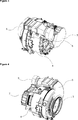
- Figure – 3 is the perspective view of the tub, the air circulation duct and the heat pump in an embodiment of the present invention.
- Figure – 4 is the perspective view of the tub, the air circulation duct and the heat pump in an embodiment of the present invention.
- the laundry washing and/or drying machine (1) comprises a body (2), a drum (3) wherein the laundry to be dried is placed, a tub (4) wherein the drum (3) moves, and an air circulation duct (5) with one end connected to the drum (3) and the other end to a fan (6) providing the circulation of the process air (PA) passed over the laundry in the drum (3) ( Figure 1 and Figure 2).
- PA process air
- the laundry washing and/or drying machine (1) of the present invention comprises a heat pump (7)
- the process air (PA) passed over the laundry passes through the air circulation duct (5) so as to be delivered to the heat pump (7).
- the processing air (PA) leaves its humidity while passing over the evaporator (9), heats up while passing over the condenser (10) and delivered onto the laundry in a heated state.
- the water droplets formed on the fins of the evaporator (9) as a result of the condensation on the fins of the evaporator (9) are accumulated on the fins or in the heat pump (7).
- the moisture of the process air (PA) increases as a result of the contact of the process air (PA) with the water droplets accumulated on the fins of the evaporator (9) and the heat pump (7), thus the condensation efficiency of the evaporator (9) decreases.
- the humid process air (PA) is delivered from the evaporator (9) to the condenser (10)
- the amount of energy required by the condenser (10) for heating the process air (PA) at the desired temperature increases. Therefore, the drying efficiency of the laundry washing and/or drying machine (1) decreases.
- the heat pump (7) comprises a cover (12) that is disposed on the housing (11) and that has more than one opening providing the intake of the water droplets leaving the evaporator (9) into the housing (11).
- the humid air condensing on the evaporator (9) fins trickles down as water droplets due to the effect of the gravity and these droplets are accumulated in the housing (11) after passing through the openings arranged on the cover (12) covering the housing (11) ( Figure 2).
- the cover (12) comprises more than one baffle plate (13) that is disposed in the flow direction of the process air (PA) in an inclined manner.
- the process air (PA) leaving the evaporator (9) and hitting the baffle plates (13) is enabled to be guided to the condenser (10) ( Figure 2).
- the evaporator (9) is positioned in an inclined manner so as to at least partially cover the housing (11).
- one end of the evaporator (9) extends over the housing (11).
- the water droplets formed on the fins of the evaporator (9) are enabled to slide over the fins and flow into the housing (11) ( Figure 1).
- the heat pump (7) comprises an evaporator housing (15) wherein the evaporator (9) is disposed.
- the evaporator (9) is enabled to be properly mounted to the heat pump (7).
- the condenser (10) is positioned in an inclined manner so that the upper end thereof extends to the upper end of the evaporator (9).
- the lower end of the condenser (10) moves away from the housing (11).
- the water accumulated in the housing (11) during the movement of the process air (PA) in the heat pump (7) is prevented from being delivered to the condenser (10).
- the heat pump (7) comprises a condenser housing (16) wherein the condenser (10) is disposed.
- the condenser (10) is enabled to be properly mounted to the heat pump (7) ( Figure 1).
- the heat pump (7) comprises a discharge hole (14) arranged at the base of the housing (11).
- the water droplets flowing from the evaporator (9) so as to be collected in the housing (11) are discharged from the housing (11) by means of the discharge hole (14).
- the water accumulated in the housing (11) is prevented from overflowing from the housing (11) and spreading in the heat pump (7) and being delivered to the condenser (10).
- the laundry washing and/or drying machine (1) comprises the heat pump (7) that is detachably mounted to the rear wall of the body (2).
- the heat pump (7) can be detached from the body (2) and serviced.
- ease of service and assembly is provided.
- the water droplets formed as the moisture removed from the laundry after entering the heat pump (7) condenses on the evaporator (9) are prevented from being delivered to the condenser (10), thus providing the efficient heating of the process air (PA) at the condenser (10).
- PA process air
Landscapes
- Engineering & Computer Science (AREA)
- Textile Engineering (AREA)
- Detail Structures Of Washing Machines And Dryers (AREA)
Abstract
The present invention relates to a laundry washing and/or drying machine (1) comprising a body (2), a drum (3) wherein the laundry to be dried is placed, a tub (4) wherein the drum (3) moves, and an air circulation duct (5) with one end connected to the drum (3) and the other end to a fan (6) providing the circulation of the process air (PA) passed over the laundry in the drum (3).
Description
The present invention relates to a heat pump laundry washing and/or drying machine.
In heat pump laundry washing and/or drying machines wherein closed cycle drying process is applied, the heat pump used for drying the laundry is composed of heat exchangers named as evaporator and condenser. The laundry-drying process is performed by passing hot and dry air over the laundry. Humid air leaving the laundry leaves its moisture while passing over the evaporator that works as the condenser and warms while passing over the condenser that works as the heater. The air that leaves its moisture and warms up is sent onto the laundry throughout the drying cycle. After leaving its moisture on the condenser, the process air is heated by the condenser and is delivered into the drum with high temperature and low relative humidity rate and is involved in the drying cycle again. The humid air condensing on the fins of the evaporator causes accumulation of water droplets on the fins and the heat pump. With the contact of the air passed through the heat up with the water droplets, the air gathers moisture again, therefore, the drying performance of the laundry washing and/or drying machine decreases.
In the Patent Application No. WO2012146534, a dryer is explained having an air guide that enables the processing air to be directed on the lower water chamber.
In the Patent Application No. WO2012146533, a dryer is explained having a flow channel and a guiding member that enables the processing air to be directed on the flow channel.
The aim of the present invention is the realization of a laundry washing and/or drying machine, the drying effectiveness of which is increased.
The laundry washing and/or drying machine realized in order to attain the aim of the present invention, explicated in the first claim and the respective claims thereof, comprises a body, a drum wherein the laundry to be dried is placed, a tub wherein the drum moves, and an air circulation duct with one end connected to the drum and the other end to a fan providing the circulation of the process air passed over the laundry in the drum.
The laundry washing and/or drying machine of the present invention comprises a heat pump that is disposed on the body so that one end thereof is connected to the fan and the other to an air inlet hole arranged on the body and extending into the drum and that comprises an evaporator that provides the condensation of the process air passing thereover, a condenser that provides the heating of the process air and a housing that is disposed between the evaporator and the condenser and wherein the water droplets forming on the evaporator surface are collected. The condenser located in the heat pump functions as a heater and the evaporator as a condenser. After being passed through the evaporator to be condensed, the humid process air taken from the end of the heat pump opening into the air circulation duct is heated in the condenser and delivered to the drum through the air inlet hole. During this operation carried out throughout the drying process, the water droplets accumulated on the fins of the evaporator during the condensation process in the evaporator contact the process air before the process air enters the condenser and causes the process air to gather moisture. By collecting the water droplets formed on the evaporator in the housing, the process air leaving the evaporator is delivered to the condenser without contacting the water droplets. Thus, the heating performance of the condenser is improved and the drying effectiveness of the laundry washing and/or drying machine is increased.
In an embodiment of the present invention, the heat pump comprises a cover that is disposed on the housing and that has more than one opening providing the intake of the water droplets leaving the evaporator into the housing. The water droplets accumulated on the fins of the evaporator as the humid process air received from the heat pump condenses on the fins of the evaporator are delivered downwards from the evaporator during the movement of the process air and accumulated in the housing by passing through the openings arranged on the cover mounted onto the housing.
In another embodiment of the present invention, the cover comprises more than one baffle plate that is disposed in the flow direction of the process air in an inclined manner. By means of the inclined position of the baffle plates, the process air leaving the evaporator and hitting the baffle plates is enabled to be guided to the condenser without entering the housing. Moreover, the water droplets formed on the baffle plates as a result of the contact of the process air with the baffle plates flow into the housing over the baffle plates by means of the inclined position of the baffle plates.
In another embodiment of the present invention, the evaporator is positioned in an inclined manner so as to at least partially cover the housing. In this embodiment, the upper end of the evaporator extends over the housing and thus, by means of the inclined position of the evaporator, the water droplets formed on the fins of the evaporator are enabled to slide over the fins and flow into the housing with the effect of the gravity.
In another embodiment of the present invention, the heat pump comprises an evaporator housing wherein the evaporator is disposed. The width and length of the evaporator housing are equal to that of the evaporator. Thus, the evaporator is tightly disposed into the evaporator housing and the evaporator is prevented from moving as the process air hits the fins of the evaporator during its movement in the heat pump.
In another embodiment of the present invention, the condenser is positioned in an inclined manner so that the upper end thereof extends to the upper end of the evaporator. In this embodiment, the condenser is positioned so as to be inclined in a direction opposite to the evaporator. Thus, while the upper end of the condenser extends towards the evaporator, the lower end of the condenser moves away from the housing. Thereby, the water droplets leaving the evaporator are delivered to the housing with the effect of the gravity and the water droplets are prevented from being carried from the housing to the condenser.
In another embodiment, the heat pump comprises a condenser housing wherein the condenser is disposed. By means of the condenser housing, the condenser is positioned at the proper angle with respect to the evaporator. The width and length of the condenser housing are equal to that of the condenser. Thus, the condenser is tightly disposed into the condenser housing and the condenser is prevented from being displaced.
In another embodiment, the heat pump comprises a discharge hole arranged at the base of the housing. The water droplets collected in the housing are discharged from the housing by means of the discharge hole. In this embodiment, the water discharged from the discharge hole is delivered to the drum or the discharge pump preferably by means of a hose.
In another embodiment of the present invention, the laundry washing and/or drying machine comprises the heat pump that is detachably mounted to the rear wall of the body. The heat pump can be accessed by removing the rear cover of the body of the laundry washing and/or drying machine. Thus, in case of an evaporator or condenser malfunction, the access to the heat pump is facilitated. Moreover, by disposing the heat pump in a detachable manner, ease of assembly is provided.
By means of the present invention, the water condensing on the evaporator is prevented from contacting the process air in the heat pump, thus preventing the process air dehumidified by the heat pump from gathering moisture. Thus, the drying performance of the laundry washing and/or drying machine is improved.
The laundry washing and/or drying machine realized in order to attain the aim of the present invention is illustrated in the attached figures, where:
Figure 1 – is the schematic view of a laundry washing and/or drying machine.
Figure 2 - is the perspective view of the laundry washing and/or drying machine in an embodiment of the present invention.
Figure – 3 is the perspective view of the tub, the air circulation duct and the heat pump in an embodiment of the present invention.
Figure – 4 is the perspective view of the tub, the air circulation duct and the heat pump in an embodiment of the present invention.
The elements in the figures are numbered as follows:
- Laundry washing and/or drying machine
- Body
- Drum
- Tub
- Air circulation duct
- Fan
- Heat pump
- Air inlet hole
- Evaporator
- Condenser
- Housing
- Cover
- Baffle plate
- Discharge hole
- Evaporator housing
- Condenser housing
The laundry washing and/or drying machine (1) comprises a body (2), a drum (3) wherein the laundry to be dried is placed, a tub (4) wherein the drum (3) moves, and an air circulation duct (5) with one end connected to the drum (3) and the other end to a fan (6) providing the circulation of the process air (PA) passed over the laundry in the drum (3) (Figure 1 and Figure 2).
The laundry washing and/or drying machine (1) of the present invention comprises a heat pump (7)
- that is disposed on the body (2) so that one end thereof is connected to the fan (6) and the other to an air inlet hole (8) arranged on the body (2) and extending into the drum (3) and
- that comprises an evaporator (9) that provides the condensation of the process air (PA) passing thereover, a condenser (10) that provides the heating of the process air (PA) and a housing (11) that is disposed between the evaporator (9) and the condenser (10) and wherein the water droplets forming on the evaporator (9) surface are collected
(Figure 1 and Figure 2).
In the drying process, the process air (PA) passed over the laundry passes through the air circulation duct (5) so as to be delivered to the heat pump (7). After dehumidifying the laundry, the processing air (PA) leaves its humidity while passing over the evaporator (9), heats up while passing over the condenser (10) and delivered onto the laundry in a heated state. The water droplets formed on the fins of the evaporator (9) as a result of the condensation on the fins of the evaporator (9) are accumulated on the fins or in the heat pump (7). During the circulation of the process air (PA) between the drum (3) and the heat pump (7) throughout the drying process, the moisture of the process air (PA) increases as a result of the contact of the process air (PA) with the water droplets accumulated on the fins of the evaporator (9) and the heat pump (7), thus the condensation efficiency of the evaporator (9) decreases. Moreover, in case the humid process air (PA) is delivered from the evaporator (9) to the condenser (10), the amount of energy required by the condenser (10) for heating the process air (PA) at the desired temperature increases. Therefore, the drying efficiency of the laundry washing and/or drying machine (1) decreases.
In an embodiment of the present invention, the heat pump (7) comprises a cover (12) that is disposed on the housing (11) and that has more than one opening providing the intake of the water droplets leaving the evaporator (9) into the housing (11). The humid air condensing on the evaporator (9) fins trickles down as water droplets due to the effect of the gravity and these droplets are accumulated in the housing (11) after passing through the openings arranged on the cover (12) covering the housing (11) (Figure 2).
In another embodiment of the present invention, the cover (12) comprises more than one baffle plate (13) that is disposed in the flow direction of the process air (PA) in an inclined manner. By means of the inclined position of the baffle plates (13), the process air (PA) leaving the evaporator (9) and hitting the baffle plates (13) is enabled to be guided to the condenser (10) (Figure 2).
In another embodiment of the present invention, the evaporator (9) is positioned in an inclined manner so as to at least partially cover the housing (11). In this embodiment, one end of the evaporator (9) extends over the housing (11). By means of the inclined position of the evaporator (9), the water droplets formed on the fins of the evaporator (9) are enabled to slide over the fins and flow into the housing (11) (Figure 1).
In another embodiment, the heat pump (7) comprises an evaporator housing (15) wherein the evaporator (9) is disposed. Thus, during the assembly process, the evaporator (9) is enabled to be properly mounted to the heat pump (7).
In another embodiment of the present invention, the condenser (10) is positioned in an inclined manner so that the upper end thereof extends to the upper end of the evaporator (9). In this embodiment, while the upper end of the condenser (10) extends towards the evaporator (9), the lower end of the condenser (10) moves away from the housing (11). Thus, the water accumulated in the housing (11) during the movement of the process air (PA) in the heat pump (7) is prevented from being delivered to the condenser (10).
In another embodiment, the heat pump (7) comprises a condenser housing (16) wherein the condenser (10) is disposed. Thus, during the assembly process, the condenser (10) is enabled to be properly mounted to the heat pump (7) (Figure 1).
In another embodiment of the present invention, the heat pump (7) comprises a discharge hole (14) arranged at the base of the housing (11). The water droplets flowing from the evaporator (9) so as to be collected in the housing (11) are discharged from the housing (11) by means of the discharge hole (14). Thus, the water accumulated in the housing (11) is prevented from overflowing from the housing (11) and spreading in the heat pump (7) and being delivered to the condenser (10).
In another embodiment of the present invention, the laundry washing and/or drying machine (1) comprises the heat pump (7) that is detachably mounted to the rear wall of the body (2). Thus, if case of a malfunction, the heat pump (7) can be detached from the body (2) and serviced. Thus, ease of service and assembly is provided.
In the laundry washing and/or drying machine (1) of the present invention, the water droplets formed as the moisture removed from the laundry after entering the heat pump (7) condenses on the evaporator (9) are prevented from being delivered to the condenser (10), thus providing the efficient heating of the process air (PA) at the condenser (10). Thus, the drying efficiency of the laundry washing and/or drying machine (1) is increased.
Claims (9)
- A laundry washing and/or drying machine (1) comprising a body (2), a drum (3) wherein the laundry to be dried is placed, a tub (4) wherein the drum (3) moves, and an air circulation duct (5) with one end connected to the drum (3) and the other end to a fan (6) providing the circulation of the process air (PA) passed over the laundry in the drum (3), characterized by a heat pump (7)- that is disposed on the body (2) so that one end thereof is connected to the fan (6) and the other to an air inlet hole (8) arranged on the body (2) and extending into the drum (3) and- that comprises an evaporator (9) that provides the condensation of the process air (PA) passing thereover, a condenser (10) that provides the heating of the process air (PA) and a housing (11) that is disposed between the evaporator (9) and the condenser (10) and wherein the water droplets forming on the evaporator (9) surface are collected.
- A laundry washing and/or drying machine (1) as in Claim 1, characterized by a cover (12) that is disposed on the housing (11) and that has more than one opening providing the intake of the water droplets leaving the evaporator (9) into the housing (11).
- A laundry washing and/or drying machine (1) as in Claim 2, characterized by the cover (12) comprising more than one baffle plate (13) that is disposed in the flow direction of the process air (PA) in an inclined manner.
- A laundry washing and/or drying machine (1) as in any one of claims 1 to 3, characterized by the evaporator (9) that is positioned in an inclined manner so as to at least partially cover the housing (11).
- A laundry washing and/or drying machine (1) as in any one of the above claims, characterized by an evaporator housing (15) that is arranged in the heat pump (7) and wherein the evaporator (9) is disposed.
- A laundry washing and/or drying machine (1) as in Claim 4 or 5, characterized by the condenser (10) of which the upper end is positioned in an inclined manner so as to extend towards the upper end of the evaporator (9).
- A laundry washing and/or drying machine (1) as in any one of the above claims, characterized by a condenser housing (16) that is arranged in the heat pump (7) and wherein the condenser (10) is disposed.
- A laundry washing and/or drying machine (1) as in any one of the above claims, characterized by a discharge hole (14) that is arranged at the base of the housing (11).
- A laundry washing and/or drying machine (1) as in any one of the above claims, characterized by the heat pump (7) that is detachably mounted to the rear wall of the body (2).
Applications Claiming Priority (2)
| Application Number | Priority Date | Filing Date | Title |
|---|---|---|---|
| TR201604581 | 2016-04-08 | ||
| TRA2016/04581 | 2016-04-08 |
Publications (1)
| Publication Number | Publication Date |
|---|---|
| WO2017174766A1 true WO2017174766A1 (en) | 2017-10-12 |
Family
ID=58632358
Family Applications (1)
| Application Number | Title | Priority Date | Filing Date |
|---|---|---|---|
| PCT/EP2017/058353 Ceased WO2017174766A1 (en) | 2016-04-08 | 2017-04-07 | A heat pump laundry washing and/or drying machine |
Country Status (1)
| Country | Link |
|---|---|
| WO (1) | WO2017174766A1 (en) |
Cited By (4)
| Publication number | Priority date | Publication date | Assignee | Title |
|---|---|---|---|---|
| WO2019214805A1 (en) * | 2018-05-08 | 2019-11-14 | V-Zug Ag | Laundry dryer |
| EP3981907A1 (en) * | 2020-10-06 | 2022-04-13 | Miele & Cie. KG | Heat exchange device for a laundry treatment machine and floor module for a laundry treatment machine |
| EP4130374A1 (en) * | 2021-08-03 | 2023-02-08 | Miele & Cie. KG | Heat exchanger device for a heat pump module for a heat pump dryer, heat pump module, heat pump dryer, method of manufacturing and method of operating a heat exchanger device |
| EP4421232A1 (en) * | 2023-02-22 | 2024-08-28 | BSH Hausgeräte GmbH | Laundry treatment apparatus |
Citations (6)
| Publication number | Priority date | Publication date | Assignee | Title |
|---|---|---|---|---|
| EP1550829A1 (en) * | 2002-09-26 | 2005-07-06 | Matsushita Electric Industrial Co., Ltd. | Drying apparatus |
| WO2012146533A2 (en) | 2011-04-26 | 2012-11-01 | Arcelik Anonim Sirketi | Heat pump laundry dryer |
| WO2012146534A2 (en) | 2011-04-26 | 2012-11-01 | Arcelik Anonim Sirketi | Heat pump laundry dryer |
| EP2925924A2 (en) * | 2012-11-27 | 2015-10-07 | Meccanica Generale S.R.L. | Front load laundry washing machine with incorporated drying system |
| CN105133269A (en) * | 2014-05-30 | 2015-12-09 | 杭州三花研究院有限公司 | Clothing drying device and drying system |
| EP3026168A1 (en) * | 2014-11-25 | 2016-06-01 | Hangzhou Sanhua Research Institute Co., Ltd. | Clothes drying device |
-
2017
- 2017-04-07 WO PCT/EP2017/058353 patent/WO2017174766A1/en not_active Ceased
Patent Citations (6)
| Publication number | Priority date | Publication date | Assignee | Title |
|---|---|---|---|---|
| EP1550829A1 (en) * | 2002-09-26 | 2005-07-06 | Matsushita Electric Industrial Co., Ltd. | Drying apparatus |
| WO2012146533A2 (en) | 2011-04-26 | 2012-11-01 | Arcelik Anonim Sirketi | Heat pump laundry dryer |
| WO2012146534A2 (en) | 2011-04-26 | 2012-11-01 | Arcelik Anonim Sirketi | Heat pump laundry dryer |
| EP2925924A2 (en) * | 2012-11-27 | 2015-10-07 | Meccanica Generale S.R.L. | Front load laundry washing machine with incorporated drying system |
| CN105133269A (en) * | 2014-05-30 | 2015-12-09 | 杭州三花研究院有限公司 | Clothing drying device and drying system |
| EP3026168A1 (en) * | 2014-11-25 | 2016-06-01 | Hangzhou Sanhua Research Institute Co., Ltd. | Clothes drying device |
Cited By (5)
| Publication number | Priority date | Publication date | Assignee | Title |
|---|---|---|---|---|
| WO2019214805A1 (en) * | 2018-05-08 | 2019-11-14 | V-Zug Ag | Laundry dryer |
| EP3981907A1 (en) * | 2020-10-06 | 2022-04-13 | Miele & Cie. KG | Heat exchange device for a laundry treatment machine and floor module for a laundry treatment machine |
| US11932985B2 (en) | 2020-10-06 | 2024-03-19 | Miele & Cie. Kg | Heat exchanger device and floor module for a laundry treatment machine |
| EP4130374A1 (en) * | 2021-08-03 | 2023-02-08 | Miele & Cie. KG | Heat exchanger device for a heat pump module for a heat pump dryer, heat pump module, heat pump dryer, method of manufacturing and method of operating a heat exchanger device |
| EP4421232A1 (en) * | 2023-02-22 | 2024-08-28 | BSH Hausgeräte GmbH | Laundry treatment apparatus |
Similar Documents
| Publication | Publication Date | Title |
|---|---|---|
| EP2702199B1 (en) | Heat pump laundry dryer | |
| EP2702198B1 (en) | Heat pump laundry dryer | |
| EP3309291B1 (en) | Clothes dryer | |
| US8495822B2 (en) | Heat pump module and drying apparatus using the same | |
| EP2723928B1 (en) | Laundry washing and drying machine with air-cooled condenser | |
| EP2576888B1 (en) | A thermoelectric heat pump laundry dryer | |
| EP2883487B1 (en) | Drying machine | |
| EP3887592B1 (en) | A laundry dryer with a water-cooled condenser | |
| WO2017174766A1 (en) | A heat pump laundry washing and/or drying machine | |
| KR20090028028A (en) | Ductless dryer | |
| EP2449164B1 (en) | A laundry dryer the drying effectiveness of which is increased | |
| EP3135805A1 (en) | Laundry dryer | |
| WO2014017004A1 (en) | Clothes dryer | |
| KR20190010178A (en) | Drum type washing and drying machine improved drying efficiency | |
| EP3282049B1 (en) | Maintenance free dryer having multiple self-cleaning lint filters | |
| EP3077586B1 (en) | A heat pump dryer | |
| JP5990772B2 (en) | Clothes dryer | |
| WO2015065299A1 (en) | A heat pump laundry dryer | |
| WO2016107699A1 (en) | A laundry washing and/or drying machine comprising an air-cooled condenser | |
| EP3071744B1 (en) | A laundry dryer | |
| EP2123823B1 (en) | Home laundry drier | |
| WO2013000955A2 (en) | A laundry dryer comprising a thermoelectric heat pump | |
| CN114250611B (en) | Heat exchange element for dehumidification device, dehumidification device, and clothes dryer | |
| WO2013050541A1 (en) | A dishwasher comprising a dehumidifying unit | |
| WO2017194531A1 (en) | A laundry washing-drying machine comprising a water-cooled condenser |
Legal Events
| Date | Code | Title | Description |
|---|---|---|---|
| NENP | Non-entry into the national phase |
Ref country code: DE |
|
| 121 | Ep: the epo has been informed by wipo that ep was designated in this application |
Ref document number: 17719190 Country of ref document: EP Kind code of ref document: A1 |
|
| 122 | Ep: pct application non-entry in european phase |
Ref document number: 17719190 Country of ref document: EP Kind code of ref document: A1 |