WO2017171307A1 - Method for reporting channel state by using aperiodic channel state information-reference signal, and device therefor - Google Patents
Method for reporting channel state by using aperiodic channel state information-reference signal, and device therefor Download PDFInfo
- Publication number
- WO2017171307A1 WO2017171307A1 PCT/KR2017/003144 KR2017003144W WO2017171307A1 WO 2017171307 A1 WO2017171307 A1 WO 2017171307A1 KR 2017003144 W KR2017003144 W KR 2017003144W WO 2017171307 A1 WO2017171307 A1 WO 2017171307A1
- Authority
- WO
- WIPO (PCT)
- Prior art keywords
- csi
- aperiodic csi
- resource
- aperiodic
- transmitted
- Prior art date
Links
Images


Classifications
-
- H—ELECTRICITY
- H04—ELECTRIC COMMUNICATION TECHNIQUE
- H04B—TRANSMISSION
- H04B7/00—Radio transmission systems, i.e. using radiation field
- H04B7/02—Diversity systems; Multi-antenna system, i.e. transmission or reception using multiple antennas
- H04B7/04—Diversity systems; Multi-antenna system, i.e. transmission or reception using multiple antennas using two or more spaced independent antennas
- H04B7/06—Diversity systems; Multi-antenna system, i.e. transmission or reception using multiple antennas using two or more spaced independent antennas at the transmitting station
- H04B7/0613—Diversity systems; Multi-antenna system, i.e. transmission or reception using multiple antennas using two or more spaced independent antennas at the transmitting station using simultaneous transmission
- H04B7/0615—Diversity systems; Multi-antenna system, i.e. transmission or reception using multiple antennas using two or more spaced independent antennas at the transmitting station using simultaneous transmission of weighted versions of same signal
- H04B7/0619—Diversity systems; Multi-antenna system, i.e. transmission or reception using multiple antennas using two or more spaced independent antennas at the transmitting station using simultaneous transmission of weighted versions of same signal using feedback from receiving side
- H04B7/0636—Feedback format
- H04B7/0645—Variable feedback
- H04B7/0647—Variable feedback rate
-
- H—ELECTRICITY
- H04—ELECTRIC COMMUNICATION TECHNIQUE
- H04B—TRANSMISSION
- H04B7/00—Radio transmission systems, i.e. using radiation field
- H04B7/02—Diversity systems; Multi-antenna system, i.e. transmission or reception using multiple antennas
- H04B7/04—Diversity systems; Multi-antenna system, i.e. transmission or reception using multiple antennas using two or more spaced independent antennas
- H04B7/06—Diversity systems; Multi-antenna system, i.e. transmission or reception using multiple antennas using two or more spaced independent antennas at the transmitting station
- H04B7/0613—Diversity systems; Multi-antenna system, i.e. transmission or reception using multiple antennas using two or more spaced independent antennas at the transmitting station using simultaneous transmission
- H04B7/0615—Diversity systems; Multi-antenna system, i.e. transmission or reception using multiple antennas using two or more spaced independent antennas at the transmitting station using simultaneous transmission of weighted versions of same signal
- H04B7/0619—Diversity systems; Multi-antenna system, i.e. transmission or reception using multiple antennas using two or more spaced independent antennas at the transmitting station using simultaneous transmission of weighted versions of same signal using feedback from receiving side
- H04B7/0621—Feedback content
- H04B7/0626—Channel coefficients, e.g. channel state information [CSI]
-
- H—ELECTRICITY
- H04—ELECTRIC COMMUNICATION TECHNIQUE
- H04B—TRANSMISSION
- H04B7/00—Radio transmission systems, i.e. using radiation field
- H04B7/02—Diversity systems; Multi-antenna system, i.e. transmission or reception using multiple antennas
- H04B7/04—Diversity systems; Multi-antenna system, i.e. transmission or reception using multiple antennas using two or more spaced independent antennas
- H04B7/0413—MIMO systems
- H04B7/0456—Selection of precoding matrices or codebooks, e.g. using matrices antenna weighting
- H04B7/0478—Special codebook structures directed to feedback optimisation
-
- H—ELECTRICITY
- H04—ELECTRIC COMMUNICATION TECHNIQUE
- H04L—TRANSMISSION OF DIGITAL INFORMATION, e.g. TELEGRAPHIC COMMUNICATION
- H04L1/00—Arrangements for detecting or preventing errors in the information received
- H04L1/0001—Systems modifying transmission characteristics according to link quality, e.g. power backoff
- H04L1/0009—Systems modifying transmission characteristics according to link quality, e.g. power backoff by adapting the channel coding
- H04L1/0013—Rate matching, e.g. puncturing or repetition of code symbols
-
- H—ELECTRICITY
- H04—ELECTRIC COMMUNICATION TECHNIQUE
- H04L—TRANSMISSION OF DIGITAL INFORMATION, e.g. TELEGRAPHIC COMMUNICATION
- H04L1/00—Arrangements for detecting or preventing errors in the information received
- H04L1/0001—Systems modifying transmission characteristics according to link quality, e.g. power backoff
- H04L1/0023—Systems modifying transmission characteristics according to link quality, e.g. power backoff characterised by the signalling
- H04L1/0026—Transmission of channel quality indication
-
- H—ELECTRICITY
- H04—ELECTRIC COMMUNICATION TECHNIQUE
- H04L—TRANSMISSION OF DIGITAL INFORMATION, e.g. TELEGRAPHIC COMMUNICATION
- H04L1/00—Arrangements for detecting or preventing errors in the information received
- H04L1/0001—Systems modifying transmission characteristics according to link quality, e.g. power backoff
- H04L1/0023—Systems modifying transmission characteristics according to link quality, e.g. power backoff characterised by the signalling
- H04L1/0027—Scheduling of signalling, e.g. occurrence thereof
-
- H—ELECTRICITY
- H04—ELECTRIC COMMUNICATION TECHNIQUE
- H04L—TRANSMISSION OF DIGITAL INFORMATION, e.g. TELEGRAPHIC COMMUNICATION
- H04L1/00—Arrangements for detecting or preventing errors in the information received
- H04L1/004—Arrangements for detecting or preventing errors in the information received by using forward error control
- H04L1/0056—Systems characterized by the type of code used
- H04L1/0067—Rate matching
- H04L1/0068—Rate matching by puncturing
- H04L1/0069—Puncturing patterns
-
- H—ELECTRICITY
- H04—ELECTRIC COMMUNICATION TECHNIQUE
- H04L—TRANSMISSION OF DIGITAL INFORMATION, e.g. TELEGRAPHIC COMMUNICATION
- H04L5/00—Arrangements affording multiple use of the transmission path
- H04L5/003—Arrangements for allocating sub-channels of the transmission path
- H04L5/0032—Distributed allocation, i.e. involving a plurality of allocating devices, each making partial allocation
- H04L5/0035—Resource allocation in a cooperative multipoint environment
-
- H—ELECTRICITY
- H04—ELECTRIC COMMUNICATION TECHNIQUE
- H04L—TRANSMISSION OF DIGITAL INFORMATION, e.g. TELEGRAPHIC COMMUNICATION
- H04L5/00—Arrangements affording multiple use of the transmission path
- H04L5/003—Arrangements for allocating sub-channels of the transmission path
- H04L5/0048—Allocation of pilot signals, i.e. of signals known to the receiver
- H04L5/0051—Allocation of pilot signals, i.e. of signals known to the receiver of dedicated pilots, i.e. pilots destined for a single user or terminal
-
- H—ELECTRICITY
- H04—ELECTRIC COMMUNICATION TECHNIQUE
- H04L—TRANSMISSION OF DIGITAL INFORMATION, e.g. TELEGRAPHIC COMMUNICATION
- H04L5/00—Arrangements affording multiple use of the transmission path
- H04L5/003—Arrangements for allocating sub-channels of the transmission path
- H04L5/0053—Allocation of signaling, i.e. of overhead other than pilot signals
-
- H—ELECTRICITY
- H04—ELECTRIC COMMUNICATION TECHNIQUE
- H04L—TRANSMISSION OF DIGITAL INFORMATION, e.g. TELEGRAPHIC COMMUNICATION
- H04L5/00—Arrangements affording multiple use of the transmission path
- H04L5/003—Arrangements for allocating sub-channels of the transmission path
- H04L5/0058—Allocation criteria
- H04L5/0073—Allocation arrangements that take into account other cell interferences
-
- H—ELECTRICITY
- H04—ELECTRIC COMMUNICATION TECHNIQUE
- H04L—TRANSMISSION OF DIGITAL INFORMATION, e.g. TELEGRAPHIC COMMUNICATION
- H04L5/00—Arrangements affording multiple use of the transmission path
- H04L5/003—Arrangements for allocating sub-channels of the transmission path
- H04L5/0078—Timing of allocation
-
- H—ELECTRICITY
- H04—ELECTRIC COMMUNICATION TECHNIQUE
- H04L—TRANSMISSION OF DIGITAL INFORMATION, e.g. TELEGRAPHIC COMMUNICATION
- H04L5/00—Arrangements affording multiple use of the transmission path
- H04L5/0091—Signaling for the administration of the divided path
- H04L5/0094—Indication of how sub-channels of the path are allocated
-
- H—ELECTRICITY
- H04—ELECTRIC COMMUNICATION TECHNIQUE
- H04W—WIRELESS COMMUNICATION NETWORKS
- H04W72/00—Local resource management
- H04W72/20—Control channels or signalling for resource management
- H04W72/23—Control channels or signalling for resource management in the downlink direction of a wireless link, i.e. towards a terminal
-
- H—ELECTRICITY
- H04—ELECTRIC COMMUNICATION TECHNIQUE
- H04B—TRANSMISSION
- H04B7/00—Radio transmission systems, i.e. using radiation field
- H04B7/02—Diversity systems; Multi-antenna system, i.e. transmission or reception using multiple antennas
- H04B7/022—Site diversity; Macro-diversity
- H04B7/024—Co-operative use of antennas of several sites, e.g. in co-ordinated multipoint or co-operative multiple-input multiple-output [MIMO] systems
-
- H—ELECTRICITY
- H04—ELECTRIC COMMUNICATION TECHNIQUE
- H04L—TRANSMISSION OF DIGITAL INFORMATION, e.g. TELEGRAPHIC COMMUNICATION
- H04L27/00—Modulated-carrier systems
- H04L27/26—Systems using multi-frequency codes
- H04L27/2601—Multicarrier modulation systems
- H04L27/2602—Signal structure
-
- H—ELECTRICITY
- H04—ELECTRIC COMMUNICATION TECHNIQUE
- H04L—TRANSMISSION OF DIGITAL INFORMATION, e.g. TELEGRAPHIC COMMUNICATION
- H04L5/00—Arrangements affording multiple use of the transmission path
- H04L5/0001—Arrangements for dividing the transmission path
- H04L5/0003—Two-dimensional division
- H04L5/0005—Time-frequency
- H04L5/0007—Time-frequency the frequencies being orthogonal, e.g. OFDM(A), DMT
- H04L5/0012—Hopping in multicarrier systems
-
- H—ELECTRICITY
- H04—ELECTRIC COMMUNICATION TECHNIQUE
- H04L—TRANSMISSION OF DIGITAL INFORMATION, e.g. TELEGRAPHIC COMMUNICATION
- H04L5/00—Arrangements affording multiple use of the transmission path
- H04L5/0001—Arrangements for dividing the transmission path
- H04L5/0014—Three-dimensional division
- H04L5/0023—Time-frequency-space
Definitions
- the present invention relates to a wireless communication system, and more particularly, to a method and apparatus for reporting channel state using aperiodic channel state information-reference signal.
- MID full dimension
- FD-MIMO the number of antenna ports is also greatly increased as compared with the related art, so that the overhead of the reference signal for channel estimation also increases.
- an aperiodic channel state information-reference signal has been proposed, and the present invention intends to address the related issues.
- the present invention proposes a method for channel state reporting based on aperiodic channel state information-reference signal.
- the method is performed by a terminal, the aperiodic channel state information-reference signal (CSI-RS) Receiving control information indicating an aperiodic CSI-RS resource masked with an associated identifier; If the control information does not indicate an aperiodic CSI-RS resource for each terminal in a cell, the resource element for a downlink data channel or an enhanced downlink control channel is used for the aperiodic CSI-RS resource indicated by the control information. an element (RE) puncturing pattern; And decoding the downlink data channel or the enhanced downlink control channel using the RE puncturing pattern.
- CSI-RS channel state information-reference signal
- the method indicates separate control information for information indicating an aperiodic CSI-RS resource for the terminal.
- Receiving through may further include.
- the method may further comprise measuring the aperiodic CSI-RS in an aperiodic CSI-RS resource for the terminal if the control information indicates an aperiodic CSI-RS resource for each terminal in a cell. It may further include.
- the control information indicates an aperiodic CSI-RS resource for each terminal in a cell
- the aperiodic CSI-RS resource for another terminal other than the terminal is allocated to the downlink data channel or the enhanced downlink. Can be used for rate matching for decoding of the control channel.
- control information may be received in a terminal-specific search space.
- control information may be received at a control information candidate of a predetermined minimum aggregation level.
- control information may be received in downlink control information of a predetermined specific format.
- control information may be received in a downlink control channel except the enhanced downlink control channel.
- control information may be received in an enhanced downlink control channel.
- the method may further comprise receiving information indicating when aperiodic CSI according to the control information is transmitted, if the control information is received in an enhanced downlink control channel.
- the time point at which the aperiodic CSI is transmitted is the time point at which the aperiodic CSI is transmitted when the control information is received in a downlink control channel (subframe # n + q ),
- p may be a positive integer greater than q.
- the time point at which the aperiodic CSI is transmitted may be different from the time point at which uplink data indicated by the control information is transmitted.
- the uplink resource on which the aperiodic CSI is transmitted may be predefined.
- a terminal configured to receive a downlink signal in a wireless communication system according to another embodiment of the present invention, the terminal comprising: a transmitter and a receiver; And a processor controlling the transmitter and the receiver, wherein the processor indicates an aperiodic CSI-RS resource masked with an aperiodic channel state information-reference signal (CSI-RS) related identifier.
- Receive control information If the control information does not indicate an aperiodic CSI-RS resource for each terminal in a cell, the resource element for a downlink data channel or an enhanced downlink control channel is used for the aperiodic CSI-RS resource indicated by the control information.
- element (RE) puncturing pattern And decode the downlink data channel or the enhanced downlink control channel using the RE puncturing pattern.
- FIG. 1 illustrates an example of a radio frame structure used in a wireless communication system.
- FIG. 2 illustrates an example of a downlink / uplink (DL / UL) slot structure in a wireless communication system.
- FIG 3 illustrates a downlink (DL) subframe structure used in a 3GPP LTE / LTE-A system.
- FIG. 4 illustrates an example of an uplink (UL) subframe structure used in a 3GPP LTE / LTE-A system.
- FIG. 5 illustrates a plurality of CSI-RS configuration and default feedback methods in a single CSI process.
- FIG. 6 illustrates a plurality of CSI-RS settings and their states in a single CSI process, and a default feedback method.
- FIG. 7 illustrates a structure of a new DCI format according to an embodiment of the present invention.
- FIG. 8 illustrates an aperiodic CSI request and a target CSI-RS resource thereof according to an embodiment of the present invention.
- FIG. 9 illustrates an aperiodic CSI request and a target CSI-RS resource thereof according to an embodiment of the present invention.
- FIG. 10 illustrates an aperiodic CSI request and a target CSI-RS resource thereof according to an embodiment of the present invention.
- FIG 11 illustrates transmission using a vertical beam according to an embodiment of the present invention.
- FIG. 12 illustrates transmission using a vertical beam according to an embodiment of the present invention.
- FIG. 13 illustrates a CSI-RS to which different beams are applied according to an embodiment of the present invention.
- 15 shows a block diagram of an apparatus for implementing an embodiment (s) of the present invention.
- a user equipment may be fixed or mobile, and various devices which transmit and receive user data and / or various control information by communicating with a base station (BS) belong to this.
- the UE may be a terminal equipment (MS), a mobile station (MS), a mobile terminal (MT), a user terminal (UT), a subscriber station (SS), a wireless device, a personal digital assistant (PDA), or a wireless modem. It may be called a modem, a handheld device, or the like.
- a BS generally refers to a fixed station communicating with the UE and / or another BS, and communicates with the UE and another BS to exchange various data and control information.
- BS includes Advanced Base Station (ABS), Node-B (NB), evolved-NodeB (eNB), Base Transceiver System (BTS), Access Point, Processing Server (PS), Transmission Point (TP) May be called in other terms.
- ABS Advanced Base Station
- NB Node-B
- eNB evolved-NodeB
- BTS Base Transceiver System
- PS Processing Server
- TP Transmission Point
- BS is collectively referred to as eNB.
- a node refers to a fixed point capable of transmitting / receiving a radio signal by communicating with a user equipment.
- Various forms of eNBs may be used as nodes regardless of their name.
- the node may be a BS, an NB, an eNB, a pico-cell eNB (PeNB), a home eNB (HeNB), a relay, a repeater, and the like.
- the node may not be an eNB.
- it may be a radio remote head (RRH), a radio remote unit (RRU).
- RRHs, RRUs, etc. generally have a power level lower than the power level of the eNB.
- RRH or RRU, RRH / RRU is generally connected to an eNB by a dedicated line such as an optical cable
- RRH / RRU and eNB are generally compared to cooperative communication by eNBs connected by a wireless line.
- cooperative communication can be performed smoothly.
- At least one antenna is installed at one node.
- the antenna may mean a physical antenna or may mean an antenna port, a virtual antenna, or an antenna group.
- Nodes are also called points. Unlike conventional centralized antenna systems (ie, single node systems) where antennas are centrally located at base stations and controlled by one eNB controller, in a multi-node system A plurality of nodes are typically located farther apart than a predetermined interval.
- the plurality of nodes may be managed by one or more eNBs or eNB controllers that control the operation of each node or schedule data to be transmitted / received through each node.
- Each node may be connected to the eNB or eNB controller that manages the node through a cable or dedicated line.
- the same cell identifier (ID) may be used or different cell IDs may be used for signal transmission / reception to / from a plurality of nodes.
- ID cell identifier
- each of the plurality of nodes behaves like some antenna group of one cell.
- a multi-node system may be regarded as a multi-cell (eg, macro-cell / femto-cell / pico-cell) system.
- the network formed by the multiple cells is particularly called a multi-tier network.
- the cell ID of the RRH / RRU and the cell ID of the eNB may be the same or may be different.
- both the RRH / RRU and the eNB operate as independent base stations.
- one or more eNB or eNB controllers connected with a plurality of nodes may control the plurality of nodes to simultaneously transmit or receive signals to the UE via some or all of the plurality of nodes.
- multi-node systems depending on the identity of each node, the implementation of each node, etc., these multi-nodes in that multiple nodes together participate in providing communication services to the UE on a given time-frequency resource.
- the systems are different from single node systems (eg CAS, conventional MIMO system, conventional relay system, conventional repeater system, etc.).
- embodiments of the present invention regarding a method for performing data cooperative transmission using some or all of a plurality of nodes may be applied to various kinds of multi-node systems.
- a node generally refers to an antenna group spaced apart from another node by a predetermined distance or more
- embodiments of the present invention described later may be applied even when the node means any antenna group regardless of the interval.
- the eNB may control the node configured as the H-pol antenna and the node configured as the V-pol antenna, and thus embodiments of the present invention may be applied. .
- a communication scheme that enables different nodes to receive the uplink signal is called multi-eNB MIMO or CoMP (Coordinated Multi-Point TX / RX).
- Cooperative transmission schemes among such cooperative communication between nodes can be largely classified into joint processing (JP) and scheduling coordination.
- the former may be divided into joint transmission (JT) / joint reception (JR) and dynamic point selection (DPS), and the latter may be divided into coordinated scheduling (CS) and coordinated beamforming (CB).
- DPS is also called dynamic cell selection (DCS).
- JP Joint Processing Protocol
- JR refers to a communication scheme in which a plurality of nodes receive the same stream from the UE.
- the UE / eNB combines the signals received from the plurality of nodes to recover the stream.
- the reliability of signal transmission may be improved by transmit diversity.
- DPS in JP refers to a communication technique in which a signal is transmitted / received through one node selected according to a specific rule among a plurality of nodes.
- DPS since a node having a good channel condition between the UE and the node will be selected as a communication node, the reliability of signal transmission can be improved.
- a cell refers to a certain geographic area in which one or more nodes provide a communication service. Therefore, in the present invention, communication with a specific cell may mean communication with an eNB or a node that provides a communication service to the specific cell.
- the downlink / uplink signal of a specific cell means a downlink / uplink signal from / to an eNB or a node that provides a communication service to the specific cell.
- the cell providing uplink / downlink communication service to the UE is particularly called a serving cell.
- the channel state / quality of a specific cell means a channel state / quality of a channel or communication link formed between an eNB or a node providing a communication service to the specific cell and a UE.
- a UE transmits a downlink channel state from a specific node on a channel CSI-RS (Channel State Information Reference Signal) resource to which the antenna port (s) of the specific node is assigned to the specific node. Can be measured using CSI-RS (s).
- CSI-RS Channel State Information Reference Signal
- adjacent nodes transmit corresponding CSI-RS resources on CSI-RS resources orthogonal to each other.
- Orthogonality of CSI-RS resources means that the CSI-RS is allocated by CSI-RS resource configuration, subframe offset, and transmission period that specify symbols and subcarriers carrying the CSI-RS. This means that at least one of a subframe configuration and a CSI-RS sequence for specifying the specified subframes are different from each other.
- Physical Downlink Control CHannel / Physical Control Format Indicator CHannel (PCFICH) / PHICH (Physical Hybrid automatic retransmit request Indicator CHannel) / PDSCH (Physical Downlink Shared CHannel) are respectively DCI (Downlink Control Information) / CFI ( Control Format Indicator) / Downlink ACK / NACK (ACKnowlegement / Negative ACK) / Downlink Means a set of time-frequency resources or a set of resource elements, and also a PUCCH (Physical Uplink Control CHannel) / PUSCH (Physical) Uplink Shared CHannel / PACH (Physical Random Access CHannel) means a set of time-frequency resources or a set of resource elements that carry uplink control information (UCI) / uplink data / random access signals, respectively.
- UCI Uplink Control Information
- PACH Physical Random Access CHannel
- the PDCCH / PCFICH / PHICH / PDSCH / PUCCH / PUSCH / PRACH resource is referred to below ..
- the user equipment transmits the PUCCH / PUSCH / PRACH, respectively.
- PDCCH / PCFICH / PHICH / PDSCH is used for downlink data / control information on or through PDCCH / PCFICH / PHICH / PDSCH, respectively. It is used in the same sense as sending it.
- Figure 1 illustrates an example of a radio frame structure used in a wireless communication system.
- Figure 1 (a) shows a frame structure for frequency division duplex (FDD) used in the 3GPP LTE / LTE-A system
- Figure 1 (b) is used in the 3GPP LTE / LTE-A system
- the frame structure for time division duplex (TDD) is shown.
- a radio frame used in a 3GPP LTE / LTE-A system has a length of 10 ms (307200 Ts), and is composed of 10 equally sized subframes (SF). Numbers may be assigned to 10 subframes in one radio frame.
- Each subframe has a length of 1 ms and consists of two slots. 20 slots in one radio frame may be sequentially numbered from 0 to 19. Each slot is 0.5ms long.
- the time for transmitting one subframe is defined as a transmission time interval (TTI).
- the time resource may be classified by a radio frame number (also called a radio frame index), a subframe number (also called a subframe number), a slot number (or slot index), and the like.
- the radio frame may be configured differently according to the duplex mode. For example, in the FDD mode, since downlink transmission and uplink transmission are divided by frequency, a radio frame includes only one of a downlink subframe or an uplink subframe for a specific frequency band. In the TDD mode, since downlink transmission and uplink transmission are separated by time, a radio frame includes both a downlink subframe and an uplink subframe for a specific frequency band.
- Table 1 illustrates a DL-UL configuration of subframes in a radio frame in the TDD mode.
- D represents a downlink subframe
- U represents an uplink subframe
- S represents a special subframe.
- the singular subframe includes three fields of Downlink Pilot TimeSlot (DwPTS), Guard Period (GP), and Uplink Pilot TimeSlot (UpPTS).
- DwPTS is a time interval reserved for downlink transmission
- UpPTS is a time interval reserved for uplink transmission.
- Table 2 illustrates the configuration of a singular frame.
- FIG. 2 illustrates an example of a downlink / uplink (DL / UL) slot structure in a wireless communication system.
- FIG. 2 shows a structure of a resource grid of a 3GPP LTE / LTE-A system. There is one resource grid per antenna port.
- a slot includes a plurality of Orthogonal Frequency Division Multiplexing (OFDM) symbols in the time domain and a plurality of resource blocks (RBs) in the frequency domain.
- OFDM symbol may mean a symbol period.
- the signal transmitted in each slot is * Subcarriers and It may be represented by a resource grid composed of OFDM symbols.
- Represents the number of resource blocks (RBs) in the downlink slot Represents the number of RBs in the UL slot.
- Wow Depends on the DL transmission bandwidth and the UL transmission bandwidth, respectively.
- Denotes the number of OFDM symbols in the downlink slot Denotes the number of OFDM symbols in the UL slot.
- the OFDM symbol may be called an OFDM symbol, a Single Carrier Frequency Division Multiplexing (SC-FDM) symbol, or the like according to a multiple access scheme.
- the number of OFDM symbols included in one slot may vary depending on the channel bandwidth and the length of the cyclic prefix (CP). For example, in case of a normal CP, one slot includes 7 OFDM symbols, whereas in case of an extended CP, one slot includes 6 OFDM symbols.
- FIG. 2 illustrates a subframe in which one slot includes 7 OFDM symbols for convenience of description, embodiments of the present invention can be applied to subframes having other numbers of OFDM symbols in the same manner. 2, each OFDM symbol, in the frequency domain, * Subcarriers are included.
- the types of subcarriers may be divided into data subcarriers for data transmission, reference signal subcarriers for transmission of reference signals, null subcarriers for guard band, and direct current (DC) components.
- the null subcarrier for the DC component is a subcarrier left unused and is mapped to a carrier frequency f0 during an OFDM signal generation process or a frequency upconversion process.
- the carrier frequency is also called the center frequency.
- 1 RB in the time domain It is defined as (eg, seven) consecutive OFDM symbols, and is defined by c (for example 12) consecutive subcarriers in the frequency domain.
- a resource composed of one OFDM symbol and one subcarrier is called a resource element (RE) or tone. Therefore, one RB is * It consists of three resource elements.
- Each resource element in the resource grid may be uniquely defined by an index pair (k, 1) in one slot. k is from 0 in the frequency domain * Index given up to -1, where l is from 0 in the time domain Index given up to -1.
- Two RBs one in each of two slots of the subframe, occupying the same consecutive subcarriers, are called a physical resource block (PRB) pair.
- PRB physical resource block
- Two RBs constituting a PRB pair have the same PRB number (or also referred to as a PRB index).
- VRB is a kind of logical resource allocation unit introduced for resource allocation.
- VRB has the same size as PRB.
- FIG 3 illustrates a downlink (DL) subframe structure used in a 3GPP LTE / LTE-A system.
- a DL subframe is divided into a control region and a data region in the time domain.
- up to three (or four) OFDM symbols located in the first slot of a subframe correspond to a control region to which a control channel is allocated.
- a resource region available for PDCCH transmission in a DL subframe is called a PDCCH region.
- the remaining OFDM symbols other than the OFDM symbol (s) used as the control region correspond to a data region to which a Physical Downlink Shared CHannel (PDSCH) is allocated.
- PDSCH Physical Downlink Shared CHannel
- a resource region available for PDSCH transmission in a DL subframe is called a PDSCH region.
- Examples of DL control channels used in 3GPP LTE include a physical control format indicator channel (PCFICH), a physical downlink control channel (PDCCH), a physical hybrid ARQ indicator channel (PHICH), and the like.
- the PCFICH is transmitted in the first OFDM symbol of a subframe and carries information about the number of OFDM symbols used for transmission of a control channel within the subframe.
- the PHICH carries a Hybrid Automatic Repeat Request (HARQ) ACK / NACK (acknowledgment / negative-acknowledgment) signal in response to the UL transmission.
- HARQ Hybrid Automatic Repeat Request
- DCI downlink control information
- DL-SCH downlink shared channel
- UL-SCH uplink shared channel
- paging channel a downlink shared channel
- the transmission format and resource allocation information of a downlink shared channel may also be called DL scheduling information or a DL grant, and may be referred to as an uplink shared channel (UL-SCH).
- the transmission format and resource allocation information is also called UL scheduling information or UL grant.
- the DCI carried by one PDCCH has a different size and use depending on the DCI format, and its size may vary depending on a coding rate.
- various formats such as formats 0 and 4 for uplink and formats 1, 1A, 1B, 1C, 1D, 2, 2A, 2B, 2C, 3, and 3A are defined for uplink.
- Hopping flag RB allocation, modulation coding scheme (MCS), redundancy version (RV), new data indicator (NDI), transmit power control (TPC), and cyclic shift DMRS Control information such as shift demodulation reference signal (UL), UL index, CQI request, DL assignment index, HARQ process number, transmitted precoding matrix indicator (TPMI), and precoding matrix indicator (PMI) information
- MCS modulation coding scheme
- RV redundancy version
- NDI new data indicator
- TPC transmit power control
- cyclic shift DMRS Control information such as shift demodulation reference signal (UL), UL index, CQI request, DL assignment index, HARQ process number, transmitted precoding matrix indicator (TPMI), and precoding matrix indicator (PMI) information
- UL shift demodulation reference signal
- CQI request UL assignment index
- HARQ process number transmitted precoding matrix indicator
- PMI precoding matrix indicator
- the DCI format that can be transmitted to the UE depends on the transmission mode (TM) configured in the UE.
- TM transmission mode
- not all DCI formats may be used for a UE configured in a specific transmission mode, but only certain DCI format (s) corresponding to the specific transmission mode may be used.
- the PDCCH is transmitted on an aggregation of one or a plurality of consecutive control channel elements (CCEs).
- CCE is a logical allocation unit used to provide a PDCCH with a coding rate based on radio channel conditions.
- the CCE corresponds to a plurality of resource element groups (REGs). For example, one CCE corresponds to nine REGs and one REG corresponds to four REs.
- REGs resource element groups
- a CCE set in which a PDCCH can be located is defined for each UE.
- the set of CCEs in which a UE can discover its PDCCH is referred to as a PDCCH search space, simply a search space (SS).
- SS search space
- An individual resource to which a PDCCH can be transmitted in a search space is called a PDCCH candidate.
- the collection of PDCCH candidates that the UE will monitor is defined as a search space.
- a search space for each DCI format may have a different size, and a dedicated search space and a common search space are defined.
- the dedicated search space is a UE-specific search space and is configured for each individual UE.
- the common search space is configured for a plurality of UEs.
- An aggregation level defining the search space is as follows.
- One PDCCH candidate corresponds to 1, 2, 4 or 8 CCEs depending on the CCE aggregation level.
- the eNB sends the actual PDCCH (DCI) on any PDCCH candidate in the search space, and the UE monitors the search space to find the PDCCH (DCI).
- monitoring means attempting decoding of each PDCCH in a corresponding search space according to all monitored DCI formats.
- the UE may detect its own PDCCH by monitoring the plurality of PDCCHs. Basically, since the UE does not know where its PDCCH is transmitted, every Pframe attempts to decode the PDCCH until every PDCCH of the corresponding DCI format has detected a PDCCH having its own identifier. It is called blind detection (blind decoding).
- the eNB may transmit data for the UE or the UE group through the data area.
- Data transmitted through the data area is also called user data.
- a physical downlink shared channel (PDSCH) may be allocated to the data area.
- Paging channel (PCH) and downlink-shared channel (DL-SCH) are transmitted through PDSCH.
- the UE may read data transmitted through the PDSCH by decoding control information transmitted through the PDCCH.
- Information indicating to which UE or UE group data of the PDSCH is transmitted, how the UE or UE group should receive and decode PDSCH data, and the like are included in the PDCCH and transmitted.
- a specific PDCCH is masked with a cyclic redundancy check (CRC) with a Radio Network Temporary Identity (RNTI) of "A", a radio resource (eg, a frequency location) of "B” and a transmission of "C".
- CRC cyclic redundancy check
- RNTI Radio Network Temporary Identity
- format information eg, transport block size, modulation scheme, coding information, etc.
- a reference signal reference signal (RS) to be compared with the data signal.
- the reference signal refers to a signal of a predetermined special waveform that the eNB and the UE know each other, which the eNB transmits to the UE or the eNB, and is also called a pilot.
- Reference signals are divided into a cell-specific RS shared by all UEs in a cell and a demodulation RS (DM RS) dedicated to a specific UE.
- DM RS demodulation RS
- the DM RS transmitted by the eNB for demodulation of downlink data for a specific UE may be specifically referred to as a UE-specific RS.
- the DM RS and the CRS may be transmitted together, but only one of the two may be transmitted.
- the DM RS transmitted by applying the same precoder as the data may be used only for demodulation purposes, and thus RS for channel measurement should be separately provided.
- an additional measurement RS, CSI-RS is transmitted to the UE.
- the CSI-RS is transmitted every predetermined transmission period consisting of a plurality of subframes, unlike the CRS transmitted every subframe, based on the fact that the channel state is relatively not changed over time.
- FIG. 4 illustrates an example of an uplink (UL) subframe structure used in a 3GPP LTE / LTE-A system.
- the UL subframe may be divided into a control region and a data region in the frequency domain.
- One or several physical uplink control channels may be allocated to the control region to carry uplink control information (UCI).
- One or several physical uplink shared channels may be allocated to a data region of a UL subframe to carry user data.
- subcarriers having a long distance based on a direct current (DC) subcarrier are used as a control region.
- subcarriers located at both ends of the UL transmission bandwidth are allocated for transmission of uplink control information.
- the DC subcarrier is a component that is not used for signal transmission and is mapped to a carrier frequency f0 during frequency upconversion.
- the PUCCH for one UE is allocated to an RB pair belonging to resources operating at one carrier frequency in one subframe, and the RBs belonging to the RB pair occupy different subcarriers in two slots.
- the PUCCH allocated in this way is expressed as that the RB pair allocated to the PUCCH is frequency hopped at the slot boundary. However, if frequency hopping is not applied, RB pairs occupy the same subcarrier.
- PUCCH may be used to transmit the following control information.
- SR Service Request: Information used for requesting an uplink UL-SCH resource. It is transmitted using OOK (On-Off Keying) method.
- HARQ-ACK A response to a PDCCH and / or a response to a downlink data packet (eg, codeword) on a PDSCH. This indicates whether the PDCCH or PDSCH is successfully received.
- One bit of HARQ-ACK is transmitted in response to a single downlink codeword, and two bits of HARQ-ACK are transmitted in response to two downlink codewords.
- HARQ-ACK response includes a positive ACK (simple, ACK), negative ACK (hereinafter, NACK), DTX (Discontinuous Transmission) or NACK / DTX.
- the term HARQ-ACK is mixed with HARQ ACK / NACK, ACK / NACK.
- CSI Channel State Information
- MIMO Multiple Input Multiple Output
- RI rank indicator
- PMI precoding matrix indicator
- the amount of uplink control information (UCI) that a UE can transmit in a subframe depends on the number of SC-FDMA available for control information transmission.
- SC-FDMA available for UCI means the remaining SC-FDMA symbol except for the SC-FDMA symbol for transmitting the reference signal in the subframe, and in the case of a subframe including a Sounding Reference Signal (SRS), the last SC of the subframe
- SRS Sounding Reference Signal
- the -FDMA symbol is also excluded.
- the reference signal is used for coherent detection of the PUCCH.
- PUCCH supports various formats according to the transmitted information.
- Table 4 shows a mapping relationship between PUCCH format and UCI in LTE / LTE-A system.
- the PUCCH format 1 series is mainly used to transmit ACK / NACK information
- the PUCCH format 2 series is mainly used to carry channel state information (CSI) such as CQI / PMI / RI
- the PUCCH format 3 series is mainly used to transmit ACK / NACK information.
- the transmitted packet is transmitted through a wireless channel
- signal distortion may occur during the transmission process.
- the distortion In order to correctly receive the distorted signal at the receiving end, the distortion must be corrected in the received signal using the channel information.
- a method of transmitting the signal known to both the transmitting side and the receiving side and finding the channel information with the distortion degree when the signal is received through the channel is mainly used.
- the signal is called a pilot signal or a reference signal.
- the reference signal may be divided into an uplink reference signal and a downlink reference signal.
- an uplink reference signal as an uplink reference signal,
- DM-RS Demodulation-Reference Signal
- SRS sounding reference signal
- DM-RS Demodulation-Reference Signal
- CSI-RS Channel State Information Reference Signal
- MBSFN Multimedia Broadcast Single Frequency Network
- Reference signals can be classified into two types according to their purpose. There is a reference signal for obtaining channel information and a reference signal used for data demodulation. In the former, since the UE can acquire channel information on the downlink, it should be transmitted over a wide band, and even if the UE does not receive downlink data in a specific subframe, it should receive the reference signal. It is also used in situations such as handover.
- the latter is a reference signal transmitted together with a corresponding resource when the base station transmits a downlink, and the terminal can demodulate data by performing channel measurement by receiving the reference signal. This reference signal should be transmitted in the area where data is transmitted.
- a user equipment In the 3GPP LTE (-A) system, a user equipment (UE) is defined to report channel state information (CSI) to a base station (BS), and channel state information (CSI) is a radio formed between a UE and an antenna port.
- CSI channel state information
- RI represents rank information of a channel, which means the number of streams that a UE receives through the same time-frequency resource. Since this value is determined dependent on the long term fading of the channel, it is fed back from the UE to the BS with a period that is usually longer than PMI, CQI.
- PMI is a value reflecting channel spatial characteristics and indicates a precoding index preferred by the UE based on a metric such as SINR.
- CQI is a value indicating the strength of a channel and generally refers to a reception SINR obtained when a BS uses PMI.
- the UE Based on the measurement of the radio channel, the UE calculates a preferred PMI and RI that can derive an optimal or highest transmission rate if used by the BS under current channel conditions, and feeds back the calculated PMI and RI to the BS. do.
- CQI refers to a modulation and coding scheme that provides an acceptable packet error probability for the fed back PMI / RI.
- the current CSI feedback is defined in LTE and thus does not fully support those newly introduced operations.
- PMI becomes long term / wideband PMI (W 1 ) and short term ( It has been agreed to consist of two terms: short term) and subband PMI (W 2 ).
- W 1 * W 2 W 1 * W 2
- W W 2 * W 1 .
- the CSI will consist of RI, W 1 , W 2 and CQI.
- the uplink channel used for CSI transmission in the 3GPP LTE (-A) system is shown in Table 5 below.
- the CSI may be transmitted using a physical uplink control channel (PUCCH) at a period determined by a higher layer, and a physical uplink shared channel (Physical Uplink) is aperiodically required by a scheduler. It may be transmitted using a shared channel (PUSCH).
- the CSI is transmitted in the PUSCH only in case of frequency selective scheduling and aperiodic CSI transmission.
- a CSI transmission method according to a scheduling method and a periodicity will be described.
- a control signal for requesting transmission of CSI may be included in a PUSCH scheduling control signal (UL Grant) transmitted through a PDCCH signal.
- UL Grant PUSCH scheduling control signal
- the following table shows a mode of a UE when transmitting CQI, PMI, RI through PUSCH.
- the transmission mode of Table 6 is selected in the upper layer, and all CQI / PMI / RI are transmitted in the same PUSCH subframe.
- Table 6 an uplink transmission method of a UE according to each mode will be described.
- Mode 1-2 represents a case in which a precoding matrix is selected on the assumption that data is transmitted only through subbands for each subband.
- the UE generates a CQI assuming the selected precoding matrix for the entire band (set S) designated by the system band or the upper layer.
- the UE may transmit the CQI and the PMI value of each subband.
- the size of each subband may vary depending on the size of the system band.
- the UE in mode 2-0 may select the preferred M subbands for the designated band set S designated by the system band or the upper layer.
- the UE may generate one CQI value on the assumption that data is transmitted for the selected M subbands.
- the UE further preferably reports one wideband CQI (CQI) value for the system band or set S.
- CQI wideband CQI
- the UE defines a CQI value for each codeword in a differential format.
- the differential CQI value is determined as a difference value between an index corresponding to the CQI values for the selected M subbands and a wideband CQI (WB-CQI) index.
- the UE in mode 2-0 transmits information on the location of the selected M subbands, one CQI value for the selected M subbands, and a CQI value generated for all bands or a set band (set S) to the BS.
- the size of the subband and the M value may vary depending on the size of the system band.
- a UE in mode 2-2 transmits data on M preferred subbands, it simultaneously selects the locations of the M preferred subbands and a single precoding matrix for the M preferred subbands. Can be.
- CQI values for M preferred subbands are defined for each codeword.
- the UE further generates a wideband CQI (wideband CQI) value for the system band or the designated band (set S).
- the UE in mode 2-2 is configured with information on the location of the M preferred subbands, one CQI value for the selected M subbands, a single PMI for the M preferred subbands, a wideband PMI, and a wideband CQI value. Can transmit to BS.
- the size of the subband and the M value may vary depending on the size of the system band.
- the UE in mode 3-0 generates a wideband CQI value.
- the UE generates a CQI value for each subband assuming that data is transmitted on each subband. At this time, even if RI> 1, the CQI value represents only the CQI value for the first codeword.
- the UE in mode 3-1 generates a single precoding matrix for the system band or the set band (set S).
- the UE assumes the previously generated single precoding matrix for each subband and generates subband CQI for each codeword.
- the UE may assume a single precoding matrix and generate a wideband CQI.
- the CQI value of each subband may be expressed in a difference form.
- the subband CQI value is calculated as a difference between the subband CQI index and the wideband CQI index.
- the size of the subband may vary depending on the size of the system band.
- a UE in mode 3-2 generates a precoding matrix for each subband, instead of a single precoding matrix for the entire band, compared to mode 3-1.
- the UE may periodically transmit CSI (e.g. CQI / PMI / PTI (precoding type indicator) and / or RI information) to the BS through the PUCCH. If the UE receives a control signal for transmitting user data, the UE may transmit the CQI through the PUCCH. Even if the control signal is transmitted through the PUSCH, the CQI / PMI / PTI / RI may be transmitted by one of the modes defined in the following table.
- CSI e.g. CQI / PMI / PTI (precoding type indicator) and / or RI information
- the UE may have a transmission mode as shown in Table 7.
- the bandwidth part (BP) is a set of subbands continuously located in the frequency domain. It can cover both the system band or the set band (set S).
- the size of each subband, the size of the BP, and the number of BPs may vary depending on the size of the system band.
- the UE transmits the CQI in ascending order in the frequency domain for each BP so as to cover the system band or the set band (set S).
- the UE may have the following PUCCH transmission type.
- Type 1 transmits subband CQI (SB-CQI) of mode 2-0, mode 2-1.
- Type 1a transmit subband CQI and second PMI
- Type 2b transmit wideband CQI and PMI (WB-CQI / PMI).
- Type 2a transmit wideband PMI.
- Type 3 transmit RI.
- Type 4 Send wideband CQI.
- Type 5 transmit RI and wideband PMI.
- Type 6 Send RI and PTI.
- Type 7 Transmit CSI-RS resource indicator (CRI) and RI.
- Type 8 transmit CRI, RI and wideband PMI.
- Type 9 send CRI, RI and precode type indication (PTI).
- Type 10 Send CRI.
- the CQI / PMI is transmitted in subframes having different periods and offsets.
- CQI / PMI is not transmitted.
- the present invention proposes a method of setting two or more CSI-RSs in one CSI process when performing channel measurement by setting the CSI-RS to the UE in a full dimension (MID) environment.
- the present invention proposes a resource configuration method and a transmission method for configuring an aperiodic CSI-RS, signaling of an indication method for the transmission, and an operation related thereto.
- a situation in which a beamformed CSI-RS is allocated to a terminal and used in different vertical directions is considered.
- a situation in which a plurality of CSI-RSs having different “characteristics” are set in one CSI process is discussed in the CSI process.
- the “characteristic” can be
- each CSI-RS may be used according to different uses (CSI, RSRP, etc.) according to the characteristics of each CSI-RS. That is, by setting the CSI-RS in one CSI process, the CSI feedback chain may be maintained, but the CSI-RS may be fed back with different CSI-RSs.
- the terminal is a CSI process specified in the aperiodic CSI request
- Aperiodic CSI reporting is performed for all CSIs configured to transmit aperiodic CSI among CSI-RSs set in the CSI-RS.
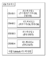
- Different feedback types may be set for each CSI-RS configured in the CSI process. For example, when four CSI-RSs are designated, the feedback method may be set as shown in FIG. 5.
- periodic and aperiodic CSI reporting is performed using CSI-RS 1 and aperiodic CSI reporting is performed using CSI-RS 2.
- RSRP RSRP for each of CSI-RSs 1 to 4 may be measured / transmitted.
- the feedback type setting may be set to RRC.
- the CSI-IM defined in the CSI process may be used for interference measurement in this case by pairing with the CSI-RS (CSI-RS 1 and 2 in the above example) that provides CSI feedback.
- parameters eg, feedback mode, period, offset, etc.
- the method may be used or it may be set independently for the CSI-RS.
- Second proposal define 'status' related to channel measurement / feedback and set 'status' for each CSI-RS
- the feedback method for each CSI-RS can be designated.
- the active state is the CSI-RS that is the object of CSI measurement and feedback according to the method set in the CSI process, and the long-term CSI measurement for vertical beam selection.
- the inactive state is a CSI-RS that is not involved in the CSI feedback set in the CSI process, but is a long-term CSI measurement target for vertical beam selection and the like.
- the off state is a CSI-RS resource that is previously assigned to the terminal in order to be set to an active state / inactive state later without being involved in measurement / feedback such as feedback or RSRP.
- FIG. 6 illustrates a 'state' setting for each CSI-RS belonging to one CSI process according to an embodiment of the present invention.
- the CSI-IM defined in the CSI process can be used in this case in conjunction with the active CSI-RS (in the example above, CSI-RS 1) to measure interference.
- the number of CSI-RSs that can be assigned to each state may be limited.
- the number of CSI-RSs set to an active state may be limited to one, and the number of CSI-RSs set to an inactive state may be limited to three. There may be no CSI-RS set to the off state.
- the second proposal has a default feedback method, in which case the CSI-RSs included in the corresponding CSI process should be defined in a setting (eg, setting in the same codebook) to which the corresponding feedback method is applicable.
- the state of the CSI-RS may be designated as RRC, MAC or DCI.
- DCI it may be possible to designate a CSI-RS that becomes active within the CSI-RS designated as inactive and to assume an unselected CSI-RS as inactive.
- transmission resources may overlap between the CSI-RSs.
- periodic / aperiodic CSI if the CSI-RS corresponding to the periodic CSI report and the aperiodic CSI report are different, it may be necessary to transmit the aperiodic CSI-RS for the aperiodic CSI request.
- the aperiodic CSI-RS resource overlaps with the periodic CSI-RS resource, it is preferable to transmit the CSI-RS for the aperiodic CSI request and drop the CSI-RS for the periodic CSI report.
- some CSI-RSs are CSI-RSs for long-term CSI for vertical CSI-RS selection, and others are CSI-RSs for short-term CSI for horizontal CSI measurement / transmission for selected vertical beams.
- RS may be.
- the transmission resource of the CSI-RS for the long-term CSI overlaps with the CSI-RS resource for the short-term CSI (eg, time, frequency, beam, etc.)
- the CSI-RS for the long-term CSI is selected. Transmit and drop the CSI-RS for the short-term CSI. That is, the following CSI-RS hierarchical structure is possible.
- the higher level CSI-RS may be transmitted and the lower level CSI-RS may be dropped.
- a plurality of CSI-RS resources When a plurality of CSI-RS resources are included in one CSI process as described above, one of them may be an aperiodic CSI-RS, or only a single aperiodic CSI-RS resource or configuration may be included in the CSI process.
- a case in which a plurality of CSI-RS resources are included in one CSI process as in the former is basically considered. However, the following detailed techniques may be applied to the latter case.
- Settings other than the time of the aperiodic CSI-RS (relocation (mapping) in RB, transmission subband, scrambling ID, etc.) may be set in advance through higher-layer signaling or the like.
- the aperiodic CSI-RS may be measured / transmitted as an aperiodic CSI or may be regarded as an aperiodic CSI-RS for another UE and may be ignored depending on whether or not the aperiodic CSI request is received.
- Aperiodic CSI-RS can be divided depending on how resources are set up and used.
- Aperiodic CSI-RS transmission may be performed within a predetermined CSI-RS resource pool.
- aperiodic CSI-RS may be transmitted using resources that are already allocated for periodic CSI-RS transmission. In this case, if there is no transmission of the aperiodic CSI-RS, the corresponding resource is used for the existing periodic CSI-RS transmission.
- additional techniques will be described based on this "case of transmitting aperiodic CSI-RS using resources already allocated for periodic CSI-RS transmission". However, the details proposed below can also be applied to the case of considering an independent aperiodic CSI-RS transmission resource separated from the periodic CSI-RS transmission resource. In this case, the following specific indicator or terminal operations are applied only with respect to the corresponding aperiodic CSI-RS transmission and may be operated independently of other periodic CSI-RS settings.
- the base station transmits the aperiodic CSI-RS indication to the terminal and may inform the terminal of the transmission of the aperiodic CSI-RS.
- the "aperiodic CSI-RS indication" may be an explicit signaling message separate from the "aperiodic CSI request", in which case the "aperiodic CSI-RS indication” means the actual transmission opportunity of the aperiodic CSI-RS. Can be interpreted as Alternatively, the "aperiodic CSI-RS indication" itself may be applied in the form of being implicitly signaled in conjunction with the "aperiodic CSI request" without being provided separately.
- the aperiodic CSI-RS indication means that the aperiodic CSI-RS having a different configuration from that of the existing CSI-RS is transmitted instead of the conventional CSI-RS transmitted periodically. Therefore, the UE should not use the CSI-RS transmitted in the corresponding subframe for periodic CSI reporting. Instead, the aperiodic CSI-RS transmitted in the corresponding subframe may be used for the aperiodic CSI request according to the aperiodic CSI request.
- a UE receives both an aperiodic CSI-RS indication and an aperiodic CSI request, it is assumed that the CSI-RS is transmitted to the aperiodic CSI-RS resource, and the aperiodic CSI using the aperiodic CSI-RS is measured. Or send.
- the terminal receiving only the aperiodic CSI-RS indication interprets the aperiodic CSI-RS indication as a dynamic zero-power (ZP) CSI-RS indication, the corresponding aperiodic CSI-RS in the corresponding subframe
- ZP dynamic zero-power
- Aperiodic CSI-RS indication may be sent using DCI.
- the transmission time of the aperiodic CSI-RS may be as follows.
- the transmission time of aperiodic CSI-RS may be interpreted as subframe n + p.
- p is an aperiodic CSI-RS transmission delay and may inform the UE that p is explicitly transmitted in the aperiodic CSI-RS indication field of DCI.
- aperiodic CSI-RS is transmitted in subframe n + p using a predefined constant p.
- the aperiodic CSI-RS may be transmitted in the same subframe as the transmission timing of the aperiodic CSI-RS indication.
- the structure of the corresponding signal may be as follows.
- the delay may refer to the aperiodic CSI-RS transmitted before the aperiodic CSI-RS indication reception time.
- the transmission time of the aperiodic CSI-RS is interpreted as the subframe n-p time, and the table shown in Table 10 may be used as it is.
- the meaning of the table may be changed to aperiodic CSI-RS opportunity indication instead of aperiodic CSI-RS transmission delay.
- the aperiodic CSI-RS opportunity indicator may inform the aperiodic CSI-RS resource unit as shown in Table 11. That is, the UE may report aperiodic CSI using the first aperiodic CSI-RS or the second aperiodic CSI-RS based on the aperiodic CSI-RS indication reception time according to the corresponding field value.
- the base station may transmit only the on / off indication of the aperiodic CSI-RS as ⁇ 0, 1 ⁇ as the aperiodic CSI-RS indication.
- An example is as follows.
- the DCI may be transmitted in a cell-common DCI using SI-RNTI.
- the aperiodic CSI-RS indication may use a cell ID of a corresponding cell through DCI 1A, 1C, etc. to receive and use the corresponding DCI.
- the base station may transmit the aperiodic CSI-RS indication to the terminal in the space added to the existing DCI. The size of this space is determined according to the indication method at the time of the aperiodic CSI-RS transmission described above.
- the aperiodic CSI-RS indication may be transmitted using some of the space reserved when using the SI-RNTI for DCI 1A.
- SI-RNTI when SI-RNTI is used as shown in FIG. 8, a space corresponding to a HARQ process number (defined as 3 bits for FDD and 4 bits for TDD) and a downlink allocation index (defined as 2 bits for TDD only) This is reserved.
- the aperiodic CSI-RS indication may be broadcast using a DCI such as DCI format 3 / 3A.
- DCI may be transmitted using a broadcast RNTI such as SI-RNTI or a separate RNTI such as aperiodic-CSI-RS-RNTI for information only.
- a broadcast RNTI such as SI-RNTI
- a separate RNTI such as aperiodic-CSI-RS-RNTI for information only.
- the DCI format X shown in FIG. 7 masked with a separate RNTI such as aperiodic-CSI-RS-RNTI and the like may be cell-specifically transmitted, which may be transmitted through a common search space (CSS).
- the base station transmits, to each terminal, bit-to-terminal (UE) allocation information on which bit (s) of the bitmap in the DCI format X is aperiodic CSI-RS indication corresponding to the terminal. It may be informed by higher layer signaling such as RRC signaling.
- RRC signaling such as RRC signaling.
- the UE detects the DCI format X it can know whether it should measure the corresponding aperiodic CSI-RS through information on its bit position, and / or through the remaining bit (s) position.
- aperiodic CSI-RS transmission is transmitted for another UE.
- the UE can apply the rate to the PDSCH RE mapping operation.
- DCI format X may be transmitted for a specific (cell-specific) common zero power (ZP) CSI-RS indication purpose, and RRC for the bit-to-terminal allocation information mentioned above.
- ZP common zero power
- the corresponding DCI format X may be defined or configured to be available only for PDSCH / EPDCCH rate matching signaling. That is, in this case, the aperiodic CSI-RS indication for the aperiodic CSI-RS measurement may be provided through a separate DCI.
- the length of the DCI format X is set to the same length as a specific DCI format (eg, DCI formats 3, 3A, 1A and / or 1C) that can be transmitted in the existing common search space to reduce blind decoding overhead of the UE.
- a specific DCI format eg, DCI formats 3, 3A, 1A and / or 1C
- a restriction in which zero padding is applied to the remaining space by (the corresponding DCI format length-actual DCI format X length) is applied. Can be.
- the information present in DCI is aperiodic ZP CSI-RS used for rate matching of PDSCH or EPDCCH.
- the base station configures N aperiodic ZP CSI-RSs to the UE through RRC signaling, and then rate matching using any aperiodic ZP CSI-RS among N aperiodic ZP CSI-RSs through DCI format X. Can tell you if
- the UE may fail to decode the data / control signal by attempting an incorrect rate matching.
- the UE and the base station may promise that the information informs the RE puncturing pattern of the PDSCH / EPDCCH, not for rate matching.
- the information indicated by DCI format X is a RE puncturing pattern of PDSCH / EPDCCH, and the base station performs PDSCH / EPDCCH RE mapping in a RE puncturing manner rather than rate matching.
- the base station maps the RE of PDSCH / EPDCCH
- the RE (s) to which the aperiodic CSI-RS is mapped also transmits the PDSCH / EPDCCH, and then maps the RE to the corresponding RE at the last transmission time point.
- the aperiodic CSI-RS is transmitted in the corresponding RE without actually transmitting the PDSCH / EPDCCH.
- the UE may assume such a transmission operation and perform decoding on PDSCH / EPDCCH.
- the UE assumes that the PDSCH / EPDCCH muting RE corresponding to the RE puncturing pattern has a noise and dummy signal instead of the PDSCH / EPDCCH.
- the LLR log-like ratio
- the operations of the base station and the terminal are as follows.
- the base station maps the PDSCH / EPDCCH RE
- it is assumed that the PDSCH / EPDCCH is not transmitted to the aperiodic CSI-RS RE from the outset, and then performs the RE mapping, and then transmits the PDSCH / EPDCCH.
- the base station also transmits the aperiodic CSI-RS in the aperiodic CSI-RS RE.
- the UE assumes such a transmission operation and performs decoding on the PDSCH / EPDCCH.
- the UE assumes that the PDSCH / EPDCCH is not mapped from the beginning in the PDSCH / EPDCCH muting RE and performs decoding.
- the aggregation level of DCI format X may be increased to increase reliability.
- the base station and the terminal may limit the minimum aggregation level for DCI format X.
- DCI format X may be promised to be sent at two or more aggregation levels.
- the operation of the base station-terminal will vary depending on which search space DCI format X is transmitted.
- DCI format X contains information as a common DCI, it may be preferable to be transmitted in a common search space.
- a part of the terminal-specific search space USS
- 'common terminal-specific search space common-USS
- the DCI format X may be transmitted to the common UE-specific discovery space, but the corresponding USS may be set to be used by all UEs.
- the aperiodic CSI-RS-RNTI may be set as another C-RNTI.
- the C-RNTI is defined as the C-RNIT for the 'terminal 6' as aperiodic CSI-RS-RNTI, and all terminals are corresponding ratios.
- Enable periodic CSI-RS-RNTI to be shared. Accordingly, in case of DCI format X, the base station transmits to the USS linked to the 'common UE-specific search space', that is, the aperiodic CSI-RS-RNTI using aperiodic CSI-RS-RNTI, and the terminal transmits CSS, itself.
- blind decoding may be performed on a total of three search spaces of USS and common-USS.
- blind decoding may be performed on CSS, USS for UE 1, and USS for UE 6 (ie, common-USS) to receive DCI transmitted from the base station.
- blind decoding overhead of the terminal may increase.
- the above scheme has increased the number of candidates in the USS, and therefore, blind decoding should be performed for many aggregation levels (ie, 1, 2, 4, 8) with all DCIs transmitted to the USS. Therefore, in order to reduce the blind decoding overhead of the UE, the blind decoding candidate may be limited in the case of the common-USS linked to the aperiodic CSI-RS-RNTI.
- the DCI transmitted in the common-USS interworking with the aperiodic CSI-RS RNTI may be blindly decoded to the DCI format X.
- the minimum aggregation level may be limited.
- the minimum aggregation level may be limited to 4 such as CSS.
- the aperiodic CSI-RS-RNTI may be transmitted by the base station to each terminal through RRC signaling. If necessary, a common-USS setting corresponding to an aperiodic CSI-RS-RNTI, for example, a minimum aggregation level and a blind decoding candidate DCI format may also be transmitted to each UE.
- the DCI may be transmitted to the UE-specific DCI using C-RNTI.
- the base station may transmit the aperiodic CSI-RS indication to the terminal in the space added to the existing DCI.
- using uplink DCI (DCI format 0, 4), can be transmitted with aperiodic CSI request.
- the size of this space is determined according to the indication method at the time of the aperiodic CSI-RS transmission described above.
- the UE receives both the aperiodic CSI-RS indication and the aperiodic CSI request, it is assumed that the CSI-RS is transmitted to the aperiodic CSI-RS resource at the time, and the aperiodic CSI using the aperiodic CSI-RS Measure / send In particular, the UE that has been performing the CSI averaging does not use the subframe in the periodic CSI average in this case, and the UE that performs the RRM measurement using the aperiodic CSI-RS is the aperiodic CSI.
- -CSI-RS transmitted from RS resource is not used for RRM measurement.
- a UE that receives only an aperiodic CSI-RS indication and does not receive an aperiodic CSI request may interpret the aperiodic CSI-RS indication as a dynamic ZP CSI-RS indication. That is, the terminal assumes that the aperiodic CSI-RS resource is rate matched in the corresponding subframe and operates as if the CSI-RS is not transmitted. As described above, the UE performing the CSI averaging does not use the corresponding subframe in the CSI averaging, and the UE performing the RRM measurement using the corresponding periodic CSI-RS. The CSI-RS transmitted in the periodic CSI-RS resource is not used for RRM measurement.
- the UE Upon receiving the aperiodic CSI request, the UE reports or transmits the aperiodic CSI for the aperiodic CSI-RS when there is an aperiodic CSI-RS that satisfies the following conditions.
- the UE receives the aperiodic CSI request after the aperiodic CSI-RS transmission. 9 illustrates the above conditions.
- -Aperiodic CSI-RS is sent that was not previously used for aperiodic CSI reporting.
- the base station transmits the aperiodic CSI request to the UE after the aperiodic CSI-RS indication and before the transmission of the next aperiodic CSI-RS indication, so that the aperiodic CSI can refer to the correct aperiodic CSI-RS. have.
- the aperiodic CSI for the aperiodic CSI-RS may be transmitted.
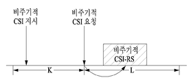
- the UE receives the aperiodic CSI request after the aperiodic CSI-RS transmission. 9 illustrates the above conditions.
- Aperiodic CSI-RS indication was received within K subframes before the aperiodic CSI request was received.
- Aperiodic CSI-RS which is scheduled to be transmitted within the L subframe after the aperiodic CSI request reception time, is transmitted.
- the K and L values refer to aperiodic CSI-RS valid period, which may be predefined or transmitted to the UE through higher layer signaling. If there is no aperiodic CSI-RS corresponding to the above, the UE is a CSI-RS set as a target of the aperiodic CSI among other CSI-RS included in the CSI process specified in the aperiodic CSI request, for example, the existing periodic CSI-RS Aperiodic CSI for may be transmitted.
- the aperiodic CSI request may be configured to perform the function of the aperiodic CSI-RS indication.
- a reception time of an aperiodic CSI request is referred to as a subframe n
- a subframe n-k which is a time point in which the aperiodic CSI-RS is transmitted from the subframe n
- the aperiodic CSI-RS indication may be separately transmitted, but in this case, the aperiodic CSI-RS indication that is separately transmitted is the dynamic ZP-CSI-RS indication. Used only as.
- a separate aperiodic CSI-RS resource for aperiodic CSI-RS can be set.
- the CSI-RS resource may be configured to the UE through higher layer signaling such as RRC. This may be divided according to the operation when aperiodic CSI-RS is not transmitted to the corresponding aperiodic CSI-RS resource as follows.
- the resource may be used for other purposes such as data transmission.
- the aperiodic CSI-RS indication of the resource may be interpreted and operated like the ZP-CSI-RS. That is, when the aperiodic CSI-RS is transmitted, when the UE that does not use the aperiodic CSI-RS receives the aperiodic CSI-RS indication, the corresponding resource may be regarded as rate matched.
- the resource is reserved. That is, the resource is not used for any other purpose than aperiodic CSI-RS.
- the operation using the aperiodic CSI-RS of the second eye can also use the method of the first eye as it is. That is, if the terminal receives both the aperiodic CSI-RS indication and the aperiodic CSI request, the aperiodic CSI is assumed to be transmitted to the aperiodic CSI-RS resource as in the operation of the first proposal. Measure / report aperiodic CSI using RS. In addition, the terminal receiving only the aperiodic CSI-RS indication, interprets the aperiodic CSI-RS indication as a dynamic ZP CSI-RS indication, as if the rate-matching the aperiodic CSI-RS resources in the corresponding subframe It can behave as if no data has been sent.
- the following method may be considered as a configuration form of the aperiodic CSI-RS resource.
- the transmission position of the aperiodic CSI-RS may be informed by a predetermined aperiodic CSI-RS resource unit.
- Aperiodic CSI-RS transmission subframes may be directly set in a bitmap (eg, subframe by subframe).
- a periodic CSI-RS transmission location may be set, but subframes not transmitted may be defined in advance or set as bitmaps.
- the aperiodic CSI-RS transmission timing is not defined in advance, and an instance in which the aperiodic CSI-RS is actually transmitted to a predetermined aperiodic CSI-RS resource is directly generated by an aperiodic CSI-RS indication. I can tell you. This indication is made through the aperiodic CSI-RS indication described below.
- the aperiodic CSI-RS configuration as described above may be defined in advance or may be configured to the UE through higher layer signaling such as RRC.
- the aperiodic CSI-RS indication may be transmitted using a DCI, as in the first proposal described above, and when the UE receives the aperiodic CSI-RS indication signal in subframe n, the transmission time of the aperiodic CSI-RS is It can be
- the transmission time of aperiodic CSI-RS may be interpreted as subframe n + p.
- p is an aperiodic CSI-RS transmission delay and may inform the UE that p is explicitly transmitted in the aperiodic CSI-RS indication field of DCI.
- aperiodic CSI-RS is transmitted in subframe n + p using a predefined constant p.
- the aperiodic CSI-RS may be transmitted in the same subframe as the transmission timing of the aperiodic CSI-RS indication.
- the structure of the corresponding signal may be as follows.
- the delay may refer to the aperiodic CSI-RS transmitted before the aperiodic CSI-RS indication reception time.
- the transmission time of the aperiodic CSI-RS is interpreted as the subframe n-p time, and the table shown in Table 10 may be used as it is.
- the meaning of the table may be changed to aperiodic CSI-RS opportunity indication instead of aperiodic CSI-RS transmission delay.
- the aperiodic CSI-RS opportunity indicator may inform the aperiodic CSI-RS resource unit as shown in Table 11. That is, the UE may report aperiodic CSI using the first aperiodic CSI-RS or the second aperiodic CSI-RS based on the aperiodic CSI-RS indication reception time according to the corresponding field value.
- the base station may transmit only the on / off indication of the aperiodic CSI-RS as ⁇ 0, 1 ⁇ as the aperiodic CSI-RS indication.
- An example is as follows.
- the DCI may be transmitted in a cell-common DCI using SI-RNTI.
- the aperiodic CSI-RS indication may be received and used by the terminal using the cell ID of the cell through the DCI 1A, 1C and the like.
- the base station may transmit the aperiodic CSI-RS indication to the terminal in the space added to the existing DCI. The size of this space is determined according to the indication method at the time of the aperiodic CSI-RS transmission described above.
- the aperiodic CSI-RS indication may be transmitted using some of the space reserved when using the SI-RNTI for DCI 1A.
- space corresponding to a HARQ process number (defined as 3 bits for FDD and 4 bits for TDD) and a downlink allocation index (defined as 2 bits for TDD only) is reserved.
- the aperiodic CSI-RS indication may be broadcast using a DCI such as DCI format 3 / 3A.
- DCI may be transmitted using a broadcast RNTI such as SI-RNTI or a separate RNTI such as aperiodic-CSI-RS-RNTI for information only.
- a broadcast RNTI such as SI-RNTI
- a separate RNTI such as aperiodic-CSI-RS-RNTI for information only.
- the DCI may be transmitted to the UE-specific DCI using C-RNTI.
- the base station may transmit the aperiodic CSI-RS indication to the terminal in the space added to the existing DCI.
- using uplink DCI (DCI format 0, 4), can be transmitted with aperiodic CSI request.
- the size of this space is determined according to the indication method at the time of the aperiodic CSI-RS transmission described above.
- the UE receives both the aperiodic CSI-RS indication and the aperiodic CSI request, it is assumed that the CSI-RS is transmitted to the aperiodic CSI-RS resource at the time, and the aperiodic CSI using the aperiodic CSI-RS Measure / send In particular, the UE that has been performing the CSI averaging does not use the subframe in the periodic CSI average in this case, and the UE that performs the RRM measurement using the aperiodic CSI-RS is the aperiodic CSI.
- -CSI-RS transmitted from RS resource is not used for RRM measurement.
- a UE that receives only an aperiodic CSI-RS indication and does not receive an aperiodic CSI request may interpret the aperiodic CSI-RS indication as a dynamic ZP CSI-RS indication. That is, the terminal assumes that the aperiodic CSI-RS resource is rate matched in the corresponding subframe and operates as if the CSI-RS is not transmitted. As described above, the UE performing the CSI averaging does not use the corresponding subframe in the CSI averaging, and the UE performing the RRM measurement using the corresponding periodic CSI-RS. The CSI-RS transmitted in the periodic CSI-RS resource is not used for RRM measurement.
- the aperiodic CSI request may use the same method as the first proposal described above. That is, when there is an aperiodic CSI-RS that satisfies the following conditions, the UE reports or transmits the aperiodic CSI for the aperiodic CSI-RS. In this case, consider a situation in which the terminal receives the aperiodic CSI request after the aperiodic CSI-RS transmission of the base station.
- -Aperiodic CSI-RS is sent that was not previously used for aperiodic CSI reporting.
- the base station transmits the aperiodic CSI request to the UE after the aperiodic CSI-RS indication and before the transmission of the next aperiodic CSI-RS indication, so that the aperiodic CSI can refer to the correct aperiodic CSI-RS. have.
- the aperiodic CSI for the aperiodic CSI-RS may be transmitted.
- the UE receives the aperiodic CSI request after the aperiodic CSI-RS transmission. 9 illustrates the above conditions.
- Aperiodic CSI-RS indication was received within K subframes before the aperiodic CSI request was received.
- Aperiodic CSI-RS which is scheduled to be transmitted within the L subframe after the aperiodic CSI request reception time point, is transmitted.
- the K and L values refer to aperiodic CSI-RS valid period, which may be predefined or transmitted to the UE through higher layer signaling. If there is no aperiodic CSI-RS corresponding to the above, the UE is a CSI-RS set as a target of the aperiodic CSI among other CSI-RS included in the CSI process specified in the aperiodic CSI request, for example, the existing periodic CSI-RS Aperiodic CSI for may be transmitted.
- the aperiodic CSI request may be configured to perform the function of the aperiodic CSI-RS indication.
- a reception time of an aperiodic CSI request is referred to as a subframe n
- a subframe n-k which is a time point in which the aperiodic CSI-RS is transmitted from the subframe n
- the aperiodic CSI-RS indication may be transmitted separately, but in this case, the aperiodic CSI-RS indication is used only as a dynamic ZP-CSI-RS indication. .
- the aperiodic CSI-RS indication is transmitted in the same subframe as the aperiodic CSI request (eg, the aperiodic CSI-RS indication is joint encoded with the aperiodic CSI request, included as a separate field of the same DCI, or the same subframe CSI-RS indication is transmitted in DL DCI) and when aperiodic CSI-RS is transmitted in the corresponding subframe, the corresponding CSI-RS indication or / and aperiodic CSI request is not transmitted in Enhanced PDCCH (EPDCCH). It can be limited.
- EPDCCH Enhanced PDCCH
- EPDCCH means a control channel allocated to a data region (hereinafter, referred to as a PDSCH region) instead of an existing control region (hereinafter, referred to as a PDCCH region).
- PDSCH region a data region
- PDCCH region an existing control region
- the aperiodic CSI-RS indication may be limited to being included in the DCI transmitted on the PDCCH. This is because, when the aperiodic CSI-RS indication is transmitted on the EPDCCH, since the UE needs all one subframe to decode the EPDCCH, a time budget for CSI processing may be insufficient. If limited to the aperiodic CSI-RS indication indicated by (UL) DCI transmitted on the PDCCH, the UE needs less time (eg, 2 to 4 symbols) to decode the PDCCH, thus performing CSI processing. More time budget will be available. Of course, the same method can be applied when the aperiodic CSI-RS indication comes at a different timing from the aperiodic CSI request.
- the timing for CSI processing can be relaxed. This is not a method of limiting the transmission of the aperiodic CSI-RS indication to the PDCCH, but rather a method for the UE to relax the time for CSI processing.
- UL data allocation at this time can be made while maintaining the existing timing. That is, when UL data allocation is transmitted with aperiodic CSI request in UL DCI, resource allocation for UL data is applied (and data scheduling) to the existing subframe # n + 4, and using aperiodic CSI-RS Aperiodic CSI may be transmitted in subframe # n + p. Resource allocation information for the aperiodic CSI at this time may be defined in advance.
- the UL data is to be transmitted in the resource region indicated in the resource allocation field of the indicated DCI.
- the aperiodic CSI reporting timing may be indicated as described above.
- aperiodic CSI reporting time is subframe #n and the actual transmission time of aperiodic CSI-RS is subframe #nj
- the UE may inform the base station through higher layer signaling such as RRC signaling whether the existing feedback timing can be maintained. . If the base station receives the feedback timing even when the terminal uses the EPDCCH, the base station transmits an aperiodic CSI request (or / and aperiodic CSI-RS indication) for the terminal to the EPDCCH transmitted to the terminal. In addition, it is possible to expect the same feedback timing as when transmitting aperiodic CSI request through the existing PDCCH and allocate resources for CSI feedback.
- higher layer signaling such as RRC signaling
- the terminal may transmit or report an aperiodic CSI on a resource allocated by the base station.
- the base station transmits only the DCI not including the aperiodic CSI request to the terminal through the EPDCCH.
- the UE also expects that the aperiodic CSI request is not transmitted through the EPDCCH, and the DCI including the aperiodic CSI request on the EPDCCH is not regarded as a blind decoding target.
- the terminal may inform the base station of the timing p when the aperiodic CSI request (or / and the aperiodic CSI-RS indication) is transmitted on the EPDCCH through higher layer signaling.
- the base station if the non-periodic CSI request (or / and the non-periodic CSI-RS indication) signaling to the UE through the EPDCCH, the corresponding aperiodic CSI is transmitted in subframe #n + p (The aperiodic CSI request is sent in subframe #n). That is, resource allocation included in the corresponding EPDCCH is applied to subframe # n + p.
- the UE can also transmit the aperiodic CSI in subframe # n + p.
- the base station transmits an aperiodic CSI request (or / and aperiodic CSI-RS indication) to the terminal through the PDCCH, the base station and the terminal to the existing aperiodic CSI report timing (eg, subframe #n + 4)
- the operation for reporting the aperiodic CSI may be performed.
- a range of p values when the aperiodic CSI request is transmitted on the EPDCCH may be separately designated. This can be defined in the following way.
- the terminal may inform the base station of the range of p value when the aperiodic CSI request is transmitted on the EPDCCH.
- the UE may inform the base station of a parameter capable of determining a range of p values when the aperiodic CSI request is transmitted on the EPDCCH, for example, a minimum value of the range of p values.
- the base station may inform the terminal of the range of p values that can be actually used.
- the UE may inform the base station of a parameter capable of determining a range of p values when the aperiodic CSI request is transmitted on the EPDCCH, for example, a minimum value of the range of p values.
- the range of p values may be defined in a predefined manner, such as the range determination parameter of the p value, the size of the DCI field (e.g., 2 bits) required to transmit the p value, and the index to p value matching method. Is determined through.
- the range of p value is to transmit a predetermined range determination parameter of p value, p value
- the size of the required DCI field (eg, 2 bits) and the index to p value matching method are determined through a predefined method.
- the above method is applicable to both periodic CSI-RS and aperiodic CSI-RS, but it is possible that the calculation of aperiodic CSI takes longer than the calculation of periodic CSI-RS (e.g., in case of periodic CSI-RS Since there may be already performed before the aperiodic CSI trigger), the above method can be applied only when the subject of the aperiodic CSI request is an aperiodic CSI-RS rather than a periodic CSI-RS.
- the aperiodic CSI-RS When the aperiodic CSI-RS is transmitted for two or more terminals and when the aperiodic CSI-RS transmission time points for each terminal are adjacent, there may be a plurality of aperiodic CSI-RSs that satisfy the above conditions from the viewpoint of the terminal. have.
- the same resource is used for the aperiodic CSI-RS
- the UE transmits the aperiodic CSI for any aperiodic CSI-RS among the plurality of transmitted aperiodic CSI-RSs. You need to decide if you have to.
- the base station can directly designate the aperiodic CSI-RS to which the UE refers for aperiodic CSI reporting.
- a field such as an aperiodic CSI-RS transmission opportunity indication in the aperiodic CSI-RS indication may be added to the DCI including the aperiodic CSI request.
- the structure of the aperiodic CSI-RS transmission opportunity indication may be as follows.
- the aperiodic CSI-RS transmission opportunity indication may indicate an aperiodic CSI-RS transmitted prior to the reception time of the aperiodic CSI-RS indication.
- the transmission time of the aperiodic CSI-RS may be interpreted as a subframe np and may be defined as shown in the following table.
- Aperiodic CSI requests may include aperiodic CSI-RS indications. For example, when the reception time of the aperiodic CSI request is the subframe n and the reception time of the aperiodic CSI-RS is the subframe nk, the setting for the state of the aperiodic CSI request may be set to RRC or the like as follows. .
- the base station transmits the index "11" in a non-periodic CSI request, and based on the aperiodic CSI-RS transmitted in subframe n-4 Periodic CSI may be reported.
- the plurality of aperiodic CSI-RS resources may be mapped to different RE locations, or may be set to be mapped to different RE locations but transmitted at different timings by varying transmission periods and offsets. For example, if two aperiodic CSI-RS resources are set to share the same RE location, each aperiodic CSI-RS resource is set up alternately on the time axis.
- the UE basically transmits the aperiodic CSI for the aperiodic CSI-RS resource set to the UE, but the UE transmits two or more aperiodic CSI-RS resources (especially within one CSI process). ), Then the aperiodic CSI request may inform which of the aperiodic CSI-RS resources should be reported for the aperiodic CSI.
- the following table shows an example of indicating a specific aperiodic CSI-RS resource in an aperiodic CSI request.
- an aperiodic CSI-RS indication independent of the aperiodic CSI request may be transmitted.
- operation on two or more aperiodic CSI-RS resources means that two or more specific settings (eg, RE / Timing pattern, antenna port number, antenna port subset, etc.) may be applied to the operation of dynamically indicating the DCI in a state in which candidate sets are set to a higher layer signal.
- the timing pattern indicates a transmission time of the aperiodic CSI-RS as described above, and may particularly include a plurality of time points instead of one.
- a total of (n ap +1) aperiodic CSI-RS including the time when the terminal receives the aperiodic CSI-RS indication Can be interpreted as being transmitted.
- one aperiodic CSI-RS (or resource) includes multiple settings (e.g., RE / timing pattern, antenna port number, antenna port subset, etc.) ) And select one of them by signaling such as DCI to inform the UE of the configuration used for the actual aperiodic CSI-RS transmission.
- each configuration may be independently given to each resource, and in particular, each configuration may include a candidate set (eg, RE / timing pattern, number of antenna ports).
- a specific configuration used for actual aperiodic CSI-RS transmission in a base station can be designated in the same way as DCI.
- the UE applies a set corresponding to the '10' state among two or more configuration candidate sets independently configured for each aperiodic CSI-RS resource. To measure the aperiodic CSI-RS.
- aperiodic CSI resource configuration common to all (or some) established aperiodic CSI-RS resources in the CSI process eg, RE / timing pattern, antenna port) Number, antenna port subset, etc.
- its setting is set to a plurality of candidate sets (e.g., RE / timing pattern, number of antenna ports, antenna port subset, etc.), so that the base station is not responsible for actual aperiodic CSI-RS transmission.
- Specific settings used can be indicated in the same way as aperiodic DCI.
- some characteristics are RRC signaling, in which a setting (e.g., the number of antenna ports) for a particular parameter is semi-statically defined for each aperiodic CSI-RS resource in the CSI process, and for other parameters the CSI process.
- a base station is defined by defining a plurality of aperiodic CSI-RS resource configuration candidate sets (e.g., RE / timing pattern, antenna port number, antenna port subset, etc.) that are common among all (or some) configured aperiodic CSI-RS resources.
- a specific configuration used for the actual aperiodic CSI-RS transmission can be specified in the same way as aperiodic DCI.
- the UE when the '10' state is dynamically indicated by the DCI, the UE applies a set corresponding to the '10' state among the commonly set candidate sets, and is independent of each of the aperiodic CSI-RS resources.
- the aperiodic CSI-RS is measured (in a CSI process) by applying a set corresponding to a '10' state among two or more of the configuration candidate sets that have been set to.
- aperiodic CSI-RSs that are subject to aperiodic CSI feedback
- only the most recently transmitted aperiodic CSI-RS may be used for the measurement of CSI.
- aperiodic CSI request is transmitted in subframe n
- the UE For periodic CSI an aperiodic CSI-RS transmitted in subframe n-2 may be used. This may be implemented by first storing aperiodic CSI-RS transmitted in subframe n-4 in a buffer of the UE and replacing the aperiodic CSI-RS transmitted in subframe n-2.
- the UE may calculate aperiodic CSI using all of the aperiodic CSI-RS existing in the above-specified interval.
- two aperiodic CSI-RSs may be defined / configured to have the same antenna port configuration (eg, antenna port number, antenna port subset).
- the UE may calculate and report a channel measurement result that aggregates measurement results for each antenna port. For example, in order to measure CSI for a total of 12 antenna ports, 4 port-aperiodic CSI-RS and 8 port-aperiodic CSI-RS are transmitted, and the UE transmits the measurement results of these two aperiodic CSI-RSs. In conjunction with the CSI for a total of 12 antenna ports can be reported to the base station.
- the UE independently calculates the CSI for the previous 4 port-aperiodic CSI-RS and the CSI for the 8 port-aperiodic CSI-RS, and reports both CSIs to one aperiodic CSI.
- the best of the two CSIs can be selected to report the setting and the CSI (ie, the best CSI) for the setting.
- the aperiodic CSI-RS transmitted to the UE may be transmitted only on some antenna ports (for the number of antenna ports set to RRC), and for this purpose,
- the aperiodic CSI-RS indication for the aperiodic CSI-RS may inform the antenna port subset transmitted to the aperiodic CSI-RS.
- the antenna port subset can be set as follows.
- A It is possible to define a subset of antenna ports that are commonly defined for all aperiodic CSI-RS resources. For example, the "number of antenna ports" may be set semi-statically for each aperiodic CSI-RS resource as RRC signaling. The table below illustrates a state in which "number of antenna ports" is set to eight among corresponding aperiodic CSI-RS resources in common.
- aperiodic CSI-RS e.g., number of antenna ports
- a set of configuration candidates according to the parameters is defined in common among aperiodic CSI-RSs (in a CSI process). And may be indicated by DCI.
- independent antenna port subset configuration can be given for each aperiodic CSI-RS resource. This means that when a configuration table such as Tables 16 and 17 above is dynamically indicated by a specific DCI, a corresponding state may be dynamically indicated for each resource-specific configuration.
- the subset index may be used to indicate a corresponding antenna port subset in the DCI.
- Option 1 Number of antenna ports and partial RE pattern in legacy RE pattern configured for aperiodic CSI-RS
- Option 1 measures only the (partial) RE pattern corresponding to the antenna port subset indicated to the UE without changing the number of antenna ports set in the corresponding resource. For example, if the corresponding resource is set to 8 ports and the antenna port subset is dynamically indicated as ⁇ 15, 16, 19, 20 ⁇ , the terminal is a given antenna port of the (legacy) CSI-RS RE pattern defined as 8 ports.
- the CSI-RS may be measured using only four REs corresponding to the subset. At this time, an RE not used for CSI-RS transmission may be used for other purposes (eg, data transmission).
- Option 2 determines the number of CSI-RS REs transmitted according to the number of antenna ports included in the antenna port subset, and at the same time the RE pattern position to which the CSI-RS REs are transmitted is fixed (legacy, or predefined). In the pre-configured state, the antenna port numbering applied to the corresponding RE pattern is as indicated by the antenna port (subset) setting. For example, even if the base station implements 8-port transmission, this fact may or may not be set to the terminal.
- the UE recognizes that the aperiodic CSI-RS is 4-port transmission and measures the aperiodic CSI-RS for the 4-port RE pattern (legacy or predefined / preset). At this time, if a specific "antenna port subset (hopping / cycling pattern)" is also indicated together with this, the UE may connect antenna port numbering with respect to other CSI-RS ports received at different time points. Can be defined / configured to perform customized CSI derivation and reporting.
- the base station may configure aperiodic CSI-RS having a different configuration (eg, antenna port subset) in the at least two (adjacent) subframes to the terminal.
- aperiodic CSI-RS having a different configuration (eg, antenna port subset) in the at least two (adjacent) subframes to the terminal.
- the union of the subset of the antenna port may be the entire antenna port
- the terminal may be able to calculate and report the channel information for the entire antenna port by aggregating the channel information measured in each subframe.
- a specific restriction may be given in a form in which aperiodic CSI-RSs using different antenna port subsets may be transmitted in adjacent subframes.
- the 'timing pattern' information may be implicitly transmitted from subframe n, for example, in which aperiodic CSI-RS is transmitted.
- Some of the ⁇ may be defined / set in the form of “multi-shot triggering”.
- the base station may indicate a plurality of aperiodic CSI-RS in one DCI.
- each aperiodic CSI-RS must include information on a location where the aperiodic CSI-RSs are transmitted, and the above-described method can be used.
- the RE pattern may be common among a plurality of aperiodic CSI-RSs or may be defined / set in advance (for each resource), or the RE pattern itself may also be included in the dynamic indication attribute by "multi-shot triggering" above. have.
- a plurality of antenna port subsets (in the form of a kind of "antenna port subset” hopping / cycling pattern) at each aperiodic CSI-RS transmission time point within a specific interval (e.g., can be defined by the K and L values). It can be interlocked. For example, to send an aperiodic CSI-RS for a real 4 port (for this, the number of antenna ports can be set to 8 ports (> 4) as above on RRC configuration), the first aperiodic within a particular interval.
- Aperiodic CSI-RS may be set to be transmitted.
- the antenna port subset (or hopping / cycling pattern information itself) according to time is transmitted to the UE through higher layer signaling such as RRC or MAC signaling.
- the configuration for the aperiodic CSI-RS may be previously defined or set to higher signaling such as RRC and inform the UE in the same manner as DCI. That is, when 4-bit DCI signaling is used, 16 configurations may be preset or defined in advance in RRC and one of them may be indicated by the DCI signaling.
- the setting for the aperiodic CSI-RS may include, for example, the following information in the aperiodic CSI-RS related information, and some of the above-described operations with respect to at least one of the following information may be the same. It is obvious that it can be applied.
- the following attributes may be included and used in the configuration of the periodic CSI-RS, rather than the aperiodic CSI-RS mainly discussed in the present invention.
- Configuration ID for aperiodic CSI-RS
- the following attributes may not be set in the aperiodic CSI-RS resource, but may be separated on the configuration so that they can be dynamically indicated separately
- Subframe-setting (e.g., multiple subframe-settings are targeted for the dynamic indication, and if a particular subframe-setting is indicated, it is periodically cycled to the corresponding period / offset until another subframe-setting is indicated later). May be sent, or may be indicated by a separate indicator for deactivation)
- Scrambling ID eg, virtual cell identifier
- QCL-related information eg CRS information that is QCL related to the aperiodic CSI-RS
- At least one of the above attributes may be indicated by one DCI in the form of "multi-shot triggering" in a state previously set / defined in the form of the above-mentioned hopping / cycling pattern.
- the aperiodic CSI request field may be used for the aperiodic CSI-RS indication. For example, using an additional 2 bits and using it as an aperiodic CSI-RS indication, if the bit is transmitted with a specific state (eg, '00'), then the 2 bits of the aperiodic CSI request field is an existing aperiodic CSI request.
- the aperiodic CSI-RS indication field is a value other than '00'
- the aperiodic CSI request field together with the aperiodic CSI-RS indication field, contains a specific X number of payloads (four bits) in total.
- a field for UL data in the UL DCI (eg, resource allocation) for more free aperiodic CSI-RS configuration signaling when transmitting an aperiodic CSI-RS indication through the UL DCI.
- resource allocation RA
- Specific states (eg, '1111') of the above indication field values are defined in the form of 'extended aperiodic CSI-RS indication', and when the corresponding state is signaled to the UE, a specific resource that is not used, such as a UL resource allocation field
- a more detailed configuration can be transmitted to the terminal.
- some of the UL DCI fields other than the CQI request field and the SRS request field may be used as the available field.
- the CSI is piggybacked on the PUSCH and transmitted.
- the UE maps from the lowest CSI-RS resource index when mapping the CSI for each CSI-RS resource to the PUSCH resource. . Therefore, the following procedure is performed.
- the CSI-RS resource index is an index for a CSI-RS resource set in a CSI process, which is CSI-RS 1 and CSI-RS 2 in FIG. 5 or FIG. 6.
- the terminal has a 2-bit non-period.
- the periodic CSI request may be used to inform information on which aperiodic CSI-RS is transmitted using the aperiodic CSI-RS. This does not require additional DCI signaling, but the CSI process may be insufficient because the maximum number of CSI processes for configuring the UE is limited (eg, up to 5 CSI processes).
- the CSI process 1 is an aperiodic CSI-RS resource 1
- the CSI process 2 is a situation in which the non-periodic CSI-RS resource 2 is allocated as an example. Therefore, if 10 is transmitted to the UE as an aperiodic CSI request, the UE may measure / report an aperiodic CSI for the nearest resource among the aperiodic CSI-RS resource 1.
- CSI-IM For the interference measurement in the CoMP environment, CSI-IM was set up to make the environment easy to measure interference in the cooperative operation of neighboring base stations.
- resources for the CSI-RS may be insufficient. For example, if five CSI processes are configured and four CSI-RSs are set for each CSI process, a total of 20 CSI-RS resources are used.
- the resource of the CSI-RS is 8 ports, there are up to 10 available CSI-RS resources. Therefore, in order to configure a CSI-IM that shares CSI-RS resources as currently, CSI-RS resources may be insufficient.
- a method of limiting some of the characteristics of the CSI-RS to a signal transmitted to a corresponding resource for CSI-IM may be considered.
- a method of setting the ZP-CSI-RS only for the UE using a specific vertical beam may be considered.
- the current CSI-IM does not know whether the interference is completely avoided in the corresponding resource, or whether only part of the interference is suppressed by a method such as vertical beam avoidance. That is, the current method cannot accurately identify the interference effect when a particular 'characteristic' is used for data transmission in the interfering cell.
- the base station may configure the CSI-part-IM (CSI-PIM) instead of setting the CSI-IM to the terminal.
- the terminal aims to measure the interference suppression level when the neighboring base station restricts certain characteristics to data transmission.
- the terminal measures the interference result in the corresponding CSI-PIM resource and feeds it back to the base station, and the base station is expected to be able to use the more efficient vertical beam scheduling by sharing the information between the base stations. For example, if there is a large number of UEs in cell A having a large interference with a specific vertical beam of cell B, the base station of cell B may limit the use of the corresponding vertical beam for cell A for a specific time.
- the existing CSI-IM can measure the interference in the corresponding resource and use it for the purpose of interference in the CQI calculation.
- the resource does not specify what operation (eg, no transmission or routine data transmission) to perform in the neighboring base station. That is, the corresponding resource may or may not transmit data at the interfering base station.
- the terminal may measure interference to measure interference close to an incoming interference when actual data is transmitted.
- the ZP-CSI-RS may be applied to a terminal on which data transmission to which a specific 'characteristic' is applied is performed in the corresponding resource.
- ZP-CSI-RS may be applied only to resources for terminals using vertical beams 0 and 1.
- FIG. have. Therefore, in the CSI-PIM resource, data may be transmitted or not transmitted in an interfering cell, but data transmitted using a specific 'characteristic' does not exist, and thus, the UE may only measure interference when transmitting using a specific 'characteristic'. It becomes possible.
- the terminal may directly report the measured interference amount to the base station.
- the base station may inform the base station whether the interference measured in the CSI-PIM is bearable. For example, if there is an interference threshold that the terminal can tolerate, and if the interference measured in the corresponding CSI-PIM is greater than the interference threshold, the terminal gives feedback indicating 'unbearable interference', and if it is smaller than that. The terminal may give feedback meaning 'tolerable interference'.
- feedback may be defined by defining '0' as 'tolerable interference' and '1' as 'unbearable interference' through 1-bit signaling, or vice versa. have.
- the absolute amount of the measured interference may be directly raised, and the base station may determine whether the interference can be tolerated in consideration of the terminal interference threshold value, etc. previously transmitted to the base station, and share it among the base stations.
- the interference threshold is a capability of the terminal, which may be retained by the terminal or transmitted by the terminal to the base station as necessary, or may be set by a higher layer signaling from the base station.
- the long-term characteristic of the interference can be measured by measuring the CSI-PIM for a certain period.
- the CSI-PIM configuration may include a start subframe / end subframe (or interval) portion of the resource in addition to the resource characteristics of the CSI-RS.
- the CSI-PIM configures the corresponding CSI-PIM from the start subframe to the end subframe (or during the interval), and the UE measures the amount of interference in the CSI-PIM resource configured during the interval.
- the method can accurately measure the interference to the terminal when the interference base station uses a specific beam. Also, if the transmission delay between base stations is small, this information can be quickly used for cooperative communication between CoMP base stations. However, if the transmission delay between base stations is large, a large delay gain cannot be seen compared to the following RRM measurement method.
- the feedback on whether or not tolerable interference may be made through higher layer signaling. Alternatively, it can be used with aperiodic CSI requests.
- the aperiodic CSI request requests feedback from a corresponding CSI-PIM configured aperiodically, the UE measures / determines whether the interference strength measured in the corresponding CSI-PIM or the interference can be tolerated and then through an uplink resource. You can feedback.
- the operation can be replaced by RRM measurement.
- the UE compares each measurement result value and the interference threshold value with respect to the measured RRM-RS, and feeds back the tolerable interference for each RRM-RS, or transmits the interference threshold value of the terminal to the base station,
- the base station may determine whether it can withstand the corresponding CSI-RS based on the RRM report value received from the terminal. Alternatively, the received RRM report value may be simply shared between the base stations. In this case, since there is no need for additional CSI-RS allocation, there is an advantage in that the physical layer overhead is less than that of the conventional method, but since the time required for RRM measurement and communication using a higher layer is longer, CSI-PIM is used. It may have a longer delay compared to the method.
- the LTE Rel-13 FD-MIMO supports beamformed CSI-RS based operations, and the beamformed CSI-RS is divided into two main features, and the number of NZP CSI-RS resources set in the Class B CSI process.
- (K) the number of NZP CSI-RS resources set in the Class B CSI process.
- Class B with K> 1 CRI report with existing RI / PMI / CQI report
- Class B with K 1: Relies on existing RI / PMI / CQI reporting, legacy codebooks, or PMI-settings to instruct to use new codebooks defined in Rel-13.
- Class B with K> 1 is generally considered to be based on cell-specific beamformed CSI-RSs transmitted in a cell with different beamforming coefficients applied per CSI-RS, so that the UE is configured with K
- the best CSI-RS index may be selected and reported from among the CSI-RSs.
- the set K CSI-RSs are transmitted towards different beam directions, which may include different vertical beam directions, as shown in FIG.
- certain beams may cause strong interference to neighboring cells.
- a beam for terminal 2 may directly interfere with terminal 3 of a neighboring cell, and this beam direction may be oriented in the horizontal direction causing severe inter-cell interference.
- the beam towards terminal 2 may be strictly prohibited.
- a terminal in a high-rise building does not have an interfering terminal, or if some scheduling coordination is possible between neighboring cells, depending on the network implementation, it is still limited to the beam for data transmission, thus simply limiting the beams in any case. It is not desirable to do so.
- K beamformed CSI-RSs with all beam directions may be set for subframe set 1, whereas only a subset of K CSI-RSs will be limited to valid for subframe set 2.
- the UE can measure and report the CSI including the CRI for each subframe set, and thus the base station can flexibly use the CRI considering the inter-cell interference situation and possible coordination between cells.
- CSI-RS overhead reduction techniques need to be investigated according to their purposes.
- One approach to overhead reduction should relate to dealing with the activation / deactivation of beamformed CSI-RS in each cell, depending on the terminal distribution in the cell. More specifically, it may be necessary for the base station to be able to turn on or off some CSI-RSs in specific directions depending on whether there is a terminal to serve in specific beam directions. As shown in FIG. 12, there may be specific CSI-RSs in which a terminal is not selected during a time interval of CRI reporting, such as CSI-RSs toward zones C and D.
- CSI-RSs may be deactivated via appropriate L2 signaling, somewhat similar to activating / deactivating SCells in a carrier aggregation (CA) system, and may be more appropriate than relying on RRC reconfiguration in terms of fast and efficient resource utilization. .
- CA carrier aggregation
- the above scheme is a technique for saving resources for transmitting the CSI-RS by activating / deactivating some beams of the CSI-RS in the FD-MIMO scheme for transmitting a plurality of CSI-RSs for CRI measurement and reporting.
- a class A terminal that does not perform CRI reporting or a terminal that does not use FD-MIMO supports ZP CSI-RS configuration for the resource in a form of informing the terminal. It is becoming.
- the ZP CSI-RS corresponding to the corresponding resource can be set to the terminals so that the corresponding resource no longer rate matching.
- signaling with low delay such as DCI or MAC is used.
- the configuration may be cell-specifically transmitted, and when using DCI for this, a format such as DCI 3 / 3A may be used.
- the ZP CSI-RS deactivation (or activation) signal may be configured as follows.
- the starting time point may use an offset value based on an absolute time value or a time point at which the corresponding signaling is received.
- the duration or end point may be given to a higher layer signaling such as RRC signaling or may be a fixed value.
- the activation time point may signal an offset value based on an absolute time value or a time point at which the corresponding signaling is received.
- ZP CSI-RS can be activated selectively in activation signaling.
- the target resource may be transmitted in a bitmap format.
- the resource transmitted in the bitmap may be an existing 4-port ZP CSI-RS resource indication, and separate K ports (K may be a number other than 4) configured with RRC signaling. It may be a resource indicator for.
- the ZP CSI-RS deactivation (and / or activation) signal may be interpreted as a ZP CSI-RS update signal. That is, the ZP CSI-RS may be deactivated (or activated) with respect to a designated ZP CSI-RS resource without distinguishing the above deactivation / activation signal. In other words, when four resources are deactivated by the ZP CSI-RS bitmap '1111', '1101' included in the next ZP CSI-RS update signal may be interpreted to mean that the third ZP CSI-RS resource is activated. .
- the above option may not include the starting point.
- only the target ZP CSI-RS designation signal may be included.
- NZP CSI-RS deactivation signaling may be interpreted as ZP CSI-RS deactivation signaling.
- some fields of the NZP CSI-RS deactivation signaling eg, the target NZP CSI-RS resource indication field
- ZP CSI-RS deactivation signaling eg, the target ZP CSI-RS resource indication field.
- the NZP CSI-RS should be signaling that is cell-specifically transmitted.
- the above-described ZP CSI-RS activation / deactivation may be used in a similar structure for the signal of NZP CSI-RS activation / deactivation.
- the NZP CSI-RS deactivation (and / or activation) signal may be configured as follows.
- the target NZP CSI-RS may be transmitted in a bitmap format.
- the resource set and transmitted in the bitmap is an NZP CSI-RS set by RRC signaling, etc., and the NZP CSI-RS corresponding to each bit in the bitmap may be mapped in the order of receiving resource settings in the same CSI process. .
- a measuring restriction (MR) specified in LTE Rel-13 may be used as aperiodic CSI-RS transmission within preset possible CSI-RS transmission opportunities.
- the UE can measure the CSI-RS only when the aperiodic CSI request is received.
- different beams of indexes B1 and B2 may be applied to the same CSI-RS, which may be referred to as “CSI-RS resource pooling”.
- the base station can freely select and transmit beamformed CSI-RSs to which different beam directions are applied within preset possible transmission opportunities.
- the dynamic indication of aperiodic CSI-RS can be considered.
- the aperiodic CSI-RS indication message which may be associated with the aperiodic CSI request, is transmitted to terminals for which the corresponding aperiodic CSI-RS is used for CSI measurement.
- resources are utilized for aperiodic CSI-RS, and alternatively, these aperiodic resources can be used for other purposes, such as data transmission, and can lead to significant CSI-RS overhead reduction.
- aperiodic CSI-RS indication message may be interpreted as a dynamic ZP-CSI-RS indication for terminals for performing PDSCH rate matching around the indicated resources. .
- This mechanism does not require a specific pre-configured time grid, such as a 5 ms grid, at possible CSI-RS transmission opportunities, which gives flexibility in resource utilization for base station implementation.
- the UE may perform rate matching by selecting a separate ZP-CSI-RS configuration (assuming aperiodic CSI-RS transmission) set in the UE.
- this operation may be limited only for a specific TM.
- a new indicator such as the 1-bit indicator can be set only for TM9.
- ZP-CSI-RS can be used through PQI after ZP-CSI-RS is set to RRC assuming that aperiodic CSI-RS is transmitted without setting ZP-CSI-RS. .
- the aperiodic CSI-RS indicator may be used as a resource selector.
- the aperiodic CSI-RS indicator is a CSI-RS included in the corresponding CSI process (e.g., a specific CSI process dynamically indicated through the aperiodic CSI request field coming down together at the same time point (e.g. SF)).
- the CSI for the resource or the resource set designated as the indicator among the resources may be reported to the base station, through which the UE reports the CSI for the best 1 CSI-RS including the CRI (in this case, It can be viewed as an extension / restriction of CSI-RS resources subject to CRI measurement / reporting.) Instead of selecting and reporting the best 1 CRI, all CSIs for the CSI-RS designated as resource indicators can be reported.
- the RS resource set may be set to higher layer signaling such as RRC signaling.
- the 14 is a method for receiving downlink signals in a wireless communication system. The method may be performed by a terminal.
- the terminal 101 may receive control information indicating an aperiodic CSI-RS resource, which is masked with an aperiodic channel state information-reference signal (CSI-RS) related identifier, from the base station 102. It may be (S1410). If the control information does not indicate an aperiodic CSI-RS resource for each terminal in the cell, the terminal uses the aperiodic CSI-RS resource indicated by the control information as a resource for a downlink data channel or an enhanced downlink control channel. It may be determined as an element puncturing pattern (S1420).
- CSI-RS channel state information-reference signal
- the terminal may decode the downlink data channel or the enhanced downlink control channel using the RE puncturing pattern (S1430).
- the terminal may receive information indicating aperiodic CSI-RS resources for the terminal through separate control information.
- the terminal may measure the aperiodic CSI-RS in the aperiodic CSI-RS resource for the terminal.
- the control information indicates aperiodic CSI-RS resources for each terminal in the cell
- the aperiodic CSI-RS resources for other terminals other than the terminal are decoded in the downlink data channel or the enhanced downlink control channel. Can be used for rate matching for
- control information may be received in a terminal-specific search space, and / or the control information may be received in a control information candidate of a predetermined minimum aggregation level.
- control information may be received in downlink control information of a predetermined specific format.
- the control information may be received in a downlink control channel except the enhanced downlink control channel.
- the control information may be received in an enhanced downlink control channel.
- the terminal may receive information indicating a time point when the aperiodic CSI according to the control information is transmitted.
- the time point at which the aperiodic CSI is transmitted (subframe # n + p) is different from the time point at which the aperiodic CSI is transmitted (subframe # n + q) when the control information is received in a downlink control channel, and p May be a positive integer greater than q.
- the time point at which the aperiodic CSI is transmitted may be different from the time point at which uplink data indicated by the control information is transmitted.
- the uplink resource through which the aperiodic CSI is transmitted may be predefined.
- FIG. 14 may alternatively or additionally include at least some of the above-described embodiment (s).
- FIG. 15 is a block diagram illustrating components of a transmitter 10 and a receiver 20 that perform embodiments of the present invention.
- the transmitter 10 and the receiver 20 are associated with transmitters / receivers 13 and 23 capable of transmitting or receiving radio signals carrying information and / or data, signals, messages, etc.
- Memory 12, 22 for storing a variety of information, the transmitter / receiver 13, 23 and the memory 12, 22 and the like is operatively connected to control the components to control the components described above
- the memories 12 and 22 may store a program for processing and controlling the processors 11 and 21, and may temporarily store input / output information.
- the memories 12 and 22 may be utilized as buffers.
- the processors 11 and 21 typically control the overall operation of the various modules in the transmitter or receiver. In particular, the processors 11 and 21 may perform various control functions for carrying out the present invention.
- the processors 11 and 21 may also be called controllers, microcontrollers, microprocessors, microcomputers, or the like.
- the processors 11 and 21 may be implemented by hardware or firmware, software, or a combination thereof.
- firmware or software When implementing the present invention using hardware, application specific integrated circuits (ASICs) or digital signal processors (DSPs), digital signal processing devices (DSPDs), programmable logic devices (PLDs), FPGAs ( field programmable gate arrays) may be provided in the processors 11 and 21.
- ASICs application specific integrated circuits
- DSPs digital signal processors
- DSPDs digital signal processing devices
- PLDs programmable logic devices
- FPGAs field programmable gate arrays
- firmware or software may be configured to include a module, a procedure, or a function for performing the functions or operations of the present invention, and configured to perform the present invention.
- the firmware or software may be provided in the processors 11 and 21 or stored in the memory 12 and 22 to be driven by the processors 11 and 21.
- the processor 11 of the transmission apparatus 10 is predetermined from the processor 11 or a scheduler connected to the processor 11 and has a predetermined encoding and modulation on a signal and / or data to be transmitted to the outside. After performing the transmission to the transmitter / receiver (13). For example, the processor 11 converts the data sequence to be transmitted into K layers through demultiplexing, channel encoding, scrambling, and modulation.
- the coded data string is also called a codeword and is equivalent to a transport block, which is a data block provided by the MAC layer.
- One transport block (TB) is encoded into one codeword, and each codeword is transmitted to a receiving device in the form of one or more layers.
- the transmitter / receiver 13 may include an oscillator for frequency upconversion.
- the transmitter / receiver 13 may include Nt transmit antennas, where Nt is a positive integer greater than or equal to one.
- the signal processing of the receiver 20 is the reverse of the signal processing of the transmitter 10.
- the transmitter / receiver 23 of the receiver 20 receives a radio signal transmitted by the transmitter 10.
- the transmitter / receiver 23 may include Nr receive antennas, and the transmitter / receiver 23 frequency down-converts each of the signals received through the receive antennas to restore baseband signals. do.
- Transmitter / receiver 23 may include an oscillator for frequency downconversion.
- the processor 21 may decode and demodulate a radio signal received through a reception antenna to restore data originally transmitted by the transmission apparatus 10.
- the transmitter / receiver 13, 23 is equipped with one or more antennas.
- the antenna transmits a signal processed by the transmitter / receiver 13, 23 to the outside or receives a radio signal from the outside under the control of the processors 11 and 21, thereby transmitting / receiving the transmitter / receiver. It performs the function of forwarding to (13, 23).
- Antennas are also called antenna ports.
- Each antenna may correspond to one physical antenna or may be configured by a combination of more than one physical antenna elements.
- the signal transmitted from each antenna can no longer be decomposed by the receiver 20.
- a reference signal (RS) transmitted in correspondence with the corresponding antenna defines the antenna as viewed from the perspective of the receiver 20, and whether the channel is a single radio channel from one physical antenna or includes the antenna.
- RS reference signal
- the receiver 20 enables channel estimation for the antenna. That is, the antenna is defined such that a channel carrying a symbol on the antenna can be derived from the channel through which another symbol on the same antenna is delivered.
- MIMO multi-input multi-output
- the terminal or the UE operates as the transmitter 10 in the uplink and the receiver 20 in the downlink.
- the base station or eNB operates as the receiving device 20 in the uplink, and operates as the transmitting device 10 in the downlink.
- the transmitter and / or the receiver may perform at least one or a combination of two or more of the embodiments of the present invention described above.
- the present invention can be used in a wireless communication device such as a terminal, a relay, a base station, and the like.
Abstract
The present invention relates to a method for receiving a downlink signal in a wireless communication system. The method, according to one embodiment of the present invention, is performed by a terminal and may comprise the steps of: receiving control information indicating an aperiodic channel state information-reference signal (CSI-RS) resource masked with an identifier associated with an aperiodic CSI-RS; if the control information does not indicate an aperiodic CSI-RS resource for each terminal in a cell, determining that the aperiodic CSI-RS resource indicated by the control information is a resource element (RE) puncturing pattern for a downlink data channel or an improved downlink control channel; and decoding the downlink data channel or the improved downlink control channel by using the RE puncturing pattern.
Description
본 발명은 무선 통신 시스템에 관한 것으로서, 구체적으로 비주기적 채널 상태 정보-참조 신호를 이용한 채널 상태 보고를 위한 방법 및 이를 위한 장치에 관한 것이다.BACKGROUND OF THE INVENTION 1. Field of the Invention The present invention relates to a wireless communication system, and more particularly, to a method and apparatus for reporting channel state using aperiodic channel state information-reference signal.
안테나 어레이를 2차원으로 구축하는 안테나 시스템이 도입되었다. 이러한 2차원 안테나 시스템을 통핸 다중-입력 다중 출력 방식을 FD(full dimension)-MIMO라고 지칭한다. FD-MIMO는 안테나 포트의 수 역시 종래에 비해 크게 늘어나므로, 채널 추정을 위한 참조 신호의 오버헤드 역시 증가하는 문제가 있다. 이를 위해, 비주기적 채널 상태 정보-참조 신호가 제안되었으며, 본 발명은 이와 관련한 이슈를 다루고자 한다. An antenna system for constructing an antenna array in two dimensions has been introduced. The multiple-input multiple output scheme through this two-dimensional antenna system is referred to as full dimension (MID). In FD-MIMO, the number of antenna ports is also greatly increased as compared with the related art, so that the overhead of the reference signal for channel estimation also increases. For this purpose, an aperiodic channel state information-reference signal has been proposed, and the present invention intends to address the related issues.
본 발명은 비주기적 채널 상태 정보-참조 신호 기반의 채널 상태 보고를 위한 방법을 제안하고자 한다. The present invention proposes a method for channel state reporting based on aperiodic channel state information-reference signal.
본 발명에서 이루고자 하는 기술적 과제들은 상기 기술적 과제로 제한되지 않으며, 언급하지 않은 또 다른 기술적 과제들은 아래의 기재로부터 본 발명이 속하는 기술분야에서 통상의 지식을 가진 자에게 명확하게 이해될 수 있을 것이다.Technical problems to be achieved in the present invention are not limited to the above technical problems, and other technical problems that are not mentioned will be clearly understood by those skilled in the art from the following description.
본 발명의 일 실시예에 따른 무선 통신 시스템에서 하향링크 신호 수신을 위한 방법에 있어서, 상기 방법은 단말에 의해 수행되며, 비주기적 채널 상태 정보-참조 신호(channel state information-reference signal; CSI-RS) 관련 식별자로 마스킹된, 비주기적 CSI-RS 자원을 지시하는 제어 정보를 수신하는 단계; 상기 제어 정보가 셀 내의 각 단말을 위한 비주기적 CSI-RS 자원을 지시하지 않으면, 상기 제어 정보가 지시하는 비주기적 CSI-RS 자원을 하향링크 데이터 채널 또는 향상된 하향링크 제어 채널을 위한 자원 요소(resource element; RE) 펑쳐링 패턴으로 판단하는 단계; 및 상기 RE 펑쳐링 패턴을 사용하여 상기 하향링크 데이터 채널 또는 상기 향상된 하향링크 제어 채널을 디코딩하는 단계를 포함할 수 있다.In the method for receiving a downlink signal in a wireless communication system according to an embodiment of the present invention, the method is performed by a terminal, the aperiodic channel state information-reference signal (CSI-RS) Receiving control information indicating an aperiodic CSI-RS resource masked with an associated identifier; If the control information does not indicate an aperiodic CSI-RS resource for each terminal in a cell, the resource element for a downlink data channel or an enhanced downlink control channel is used for the aperiodic CSI-RS resource indicated by the control information. an element (RE) puncturing pattern; And decoding the downlink data channel or the enhanced downlink control channel using the RE puncturing pattern.
추가로 또는 대안으로, 상기 방법은 상기 제어 정보가 셀 내의 각 단말을 위한 비주기적 CSI-RS 자원을 지시하지 않으면, 상기 단말을 위한 비주기적 CSI-RS 자원을 지시하는 정보를 별도의 제어 정보를 통해 수신하는 단계를 더 포함할 수 있다. Additionally or alternatively, if the control information does not indicate an aperiodic CSI-RS resource for each terminal in a cell, the method indicates separate control information for information indicating an aperiodic CSI-RS resource for the terminal. Receiving through may further include.
추가로 또는 대안으로, 상기 방법은 상기 제어 정보가 셀 내의 각 단말을 위한 비주기적 CSI-RS 자원을 지시하면, 상기 단말을 위한 비주기적 CSI-RS 자원에서 상기 비주기적 CSI-RS를 측정하는 단계를 더 포함할 수 있다.Additionally or alternatively, the method may further comprise measuring the aperiodic CSI-RS in an aperiodic CSI-RS resource for the terminal if the control information indicates an aperiodic CSI-RS resource for each terminal in a cell. It may further include.
추가로 또는 대안으로, 상기 제어 정보가 셀 내의 각 단말을 위한 비주기적 CSI-RS 자원을 지시하면, 상기 단말 외의 다른 단말을 위한 비주기적 CSI-RS 자원은 상기 하향링크 데이터 채널 또는 상기 향상된 하향링크 제어 채널의 디코딩을 위한 레이트 매칭을 위해 사용될 수 있다. Additionally or alternatively, if the control information indicates an aperiodic CSI-RS resource for each terminal in a cell, the aperiodic CSI-RS resource for another terminal other than the terminal is allocated to the downlink data channel or the enhanced downlink. Can be used for rate matching for decoding of the control channel.
추가로 또는 대안으로, 상기 제어 정보는 단말-특정 탐색 공간에서 수신될 수 있다. Additionally or alternatively, the control information may be received in a terminal-specific search space.
추가로 또는 대안으로, 상기 제어 정보는 미리 결정된 최소 집성 레벨의 제어 정보 후보에서 수신될 수 있다. Additionally or alternatively, the control information may be received at a control information candidate of a predetermined minimum aggregation level.
추가로 또는 대안으로, 상기 제어 정보는 미리 결정된 특정 포맷의 하향링크 제어 정보에서 수신될 수 있다. Additionally or alternatively, the control information may be received in downlink control information of a predetermined specific format.
추가로 또는 대안으로, 상기 제어 정보는 향상된 하향링크 제어 채널을 제외한 하향링크 제어 채널에서 수신될 수 있다. Additionally or alternatively, the control information may be received in a downlink control channel except the enhanced downlink control channel.
추가로 또는 대안으로, 상기 제어 정보는 향상된 하향링크 제어 채널에서 수신될 수 있다. Additionally or alternatively, the control information may be received in an enhanced downlink control channel.
추가로 또는 대안으로, 상기 방법은 상기 제어 정보가 향상된 하향링크 제어 채널에서 수신되면, 상기 제어 정보에 따른 비주기적 CSI가 전송되는 시점을 지시하는 정보를 수신하는 단계를 더 포함할 수 있다. Additionally or alternatively, the method may further comprise receiving information indicating when aperiodic CSI according to the control information is transmitted, if the control information is received in an enhanced downlink control channel.
추가로 또는 대안으로, 상기 비주기적 CSI가 전송되는 시점(서브프레임 #n+p)은 상기 제어 정보가 하향링크 제어 채널에서 수신되는 경우의 비주기적 CSI가 전송되는 시점(서브프레임 #n+q)과 상이하고, p는 q보다 큰 양의 정수일 수 있다. Additionally or alternatively, the time point at which the aperiodic CSI is transmitted (subframe # n + p) is the time point at which the aperiodic CSI is transmitted when the control information is received in a downlink control channel (subframe # n + q ), And p may be a positive integer greater than q.
추가로 또는 대안으로, 상기 비주기적 CSI가 전송되는 시점은 상기 제어 정보가 지시하는 상향링크 데이터가 전송되는 시점과 상이할 수 있다. Additionally or alternatively, the time point at which the aperiodic CSI is transmitted may be different from the time point at which uplink data indicated by the control information is transmitted.
추가로 또는 대안으로, 상기 비주기적 CSI가 전송되는 상향링크 자원은 미리 정의될 수 있다. Additionally or alternatively, the uplink resource on which the aperiodic CSI is transmitted may be predefined.
본 발명의 또다른 일 실시예에 따른 무선 통신 시스템에서 하향링크 신호를 수신하도록 구성된 단말에 있어서, 상기 단말은 송신기 및 수신기; 및 상기 송신기 및 수신기를 제어하는 프로세서를 포함하고, 상기 프로세서는 비주기적 채널 상태 정보-참조 신호(channel state information-reference signal; CSI-RS) 관련 식별자로 마스킹된, 비주기적 CSI-RS 자원을 지시하는 제어 정보를 수신하고; 상기 제어 정보가 셀 내의 각 단말을 위한 비주기적 CSI-RS 자원을 지시하지 않으면, 상기 제어 정보가 지시하는 비주기적 CSI-RS 자원을 하향링크 데이터 채널 또는 향상된 하향링크 제어 채널을 위한 자원 요소(resource element; RE) 펑쳐링 패턴으로 판단하고; 그리고 상기 RE 펑쳐링 패턴을 사용하여 상기 하향링크 데이터 채널 또는 상기 향상된 하향링크 제어 채널을 디코딩하도록 구성될 수 있다. A terminal configured to receive a downlink signal in a wireless communication system according to another embodiment of the present invention, the terminal comprising: a transmitter and a receiver; And a processor controlling the transmitter and the receiver, wherein the processor indicates an aperiodic CSI-RS resource masked with an aperiodic channel state information-reference signal (CSI-RS) related identifier. Receive control information; If the control information does not indicate an aperiodic CSI-RS resource for each terminal in a cell, the resource element for a downlink data channel or an enhanced downlink control channel is used for the aperiodic CSI-RS resource indicated by the control information. element (RE) puncturing pattern; And decode the downlink data channel or the enhanced downlink control channel using the RE puncturing pattern.
상기 과제 해결방법들은 본 발명의 실시예들 중 일부에 불과하며, 본원 발명의 기술적 특징들이 반영된 다양한 실시예들이 당해 기술분야의 통상적인 지식을 가진 자에 의해 이하 상술할 본 발명의 상세한 설명을 기반으로 도출되고 이해될 수 있다.The problem solving methods are only a part of embodiments of the present invention, and various embodiments reflecting the technical features of the present invention are based on the detailed description of the present invention described below by those skilled in the art. Can be derived and understood.
본 발명의 실시예들에 따르면 확장되는 안테나 포트 수에 따른 주기적 채널 상태 보고-참조 신호에 따른 채널 상태 보고를 효율적으로 처리할 수 있다. According to embodiments of the present invention, it is possible to efficiently process the channel state report according to the periodic channel state report-reference signal according to the extended number of antenna ports.
본 발명에서 얻은 수 있는 효과는 이상에서 언급한 효과들로 제한되지 않으며, 언급하지 않은 또 다른 효과들은 아래의 기재로부터 본 발명이 속하는 기술분야에서 통상의 지식을 가진 자에게 명확하게 이해될 수 있을 것이다.Effects obtained in the present invention are not limited to the above-mentioned effects, and other effects not mentioned above may be clearly understood by those skilled in the art from the following description. will be.
본 발명에 관한 이해를 돕기 위해 상세한 설명의 일부로 포함되는, 첨부 도면은 본 발명에 대한 실시예를 제공하고, 상세한 설명과 함께 본 발명의 기술적 사상을 설명한다.BRIEF DESCRIPTION OF THE DRAWINGS The accompanying drawings, which are included as part of the detailed description in order to provide a thorough understanding of the present invention, provide an embodiment of the present invention and together with the description, illustrate the technical idea of the present invention.
도 1 무선 통신 시스템에서 사용되는 무선 프레임 구조의 일 예를 나타낸 것이다. 1 illustrates an example of a radio frame structure used in a wireless communication system.
도 2는 무선 통신 시스템에서 하향링크/상향링크(DL/UL) 슬롯 구조의 일례를 나타낸 것이다. 2 illustrates an example of a downlink / uplink (DL / UL) slot structure in a wireless communication system.
도 3은 3GPP LTE/LTE-A 시스템에서 사용되는 하향링크(downlink, DL) 서브프레임 구조를 예시한 것이다.3 illustrates a downlink (DL) subframe structure used in a 3GPP LTE / LTE-A system.
도 4 는 3GPP LTE/LTE-A 시스템에서 사용되는 상향링크(uplink, UL) 서브프레임 구조의 일례를 나타낸 것이다.4 illustrates an example of an uplink (UL) subframe structure used in a 3GPP LTE / LTE-A system.
도 5는 단일 CSI 프로세스 내 복수의 CSI-RS 설정 및 디폴트(default) 피드백 방법을 예시한다. 5 illustrates a plurality of CSI-RS configuration and default feedback methods in a single CSI process.
도 6은 단일 CSI 프로세스 내 복수의 CSI-RS 설정 및 그의 상태(state), 그리고 디폴트 피드백 방법을 예시한다. 6 illustrates a plurality of CSI-RS settings and their states in a single CSI process, and a default feedback method.
도 7은 본 발명의 일 실시예에 따른 새로운 DCI 포맷의 구조를 도시한다.7 illustrates a structure of a new DCI format according to an embodiment of the present invention.
도 8은 본 발명의 일 실시예에 따른 비주기적 CSI 요청과 그 대상 CSI-RS 자원을 도시한다. 8 illustrates an aperiodic CSI request and a target CSI-RS resource thereof according to an embodiment of the present invention.
도 9는 본 발명의 일 실시예에 따른 비주기적 CSI 요청과 그 대상 CSI-RS 자원을 도시한다. 9 illustrates an aperiodic CSI request and a target CSI-RS resource thereof according to an embodiment of the present invention.
도 10은 본 발명의 일 실시예에 따른 비주기적 CSI 요청과 그 대상 CSI-RS 자원을 도시한다. 10 illustrates an aperiodic CSI request and a target CSI-RS resource thereof according to an embodiment of the present invention.
도 11은 본 발명의 일 실시예에 따른 수직 빔을 이용한 전송을 도시한다. 11 illustrates transmission using a vertical beam according to an embodiment of the present invention.
도 12는 본 발명의 일 실시예에 따른 수직 빔을 이용한 전송을 도시한다. 12 illustrates transmission using a vertical beam according to an embodiment of the present invention.
도 13은 본 발명의 일 실시예에 따른 서로 다른 빔이 적용된 CSI-RS를 도시한다. 13 illustrates a CSI-RS to which different beams are applied according to an embodiment of the present invention.
도 14는 본 발명의 일 실시예에 따른 동작을 도시한다. 14 illustrates operation according to an embodiment of the present invention.
도 15는 본 발명의 실시예(들)을 구현하기 위한 장치의 블록도를 도시한다. 15 shows a block diagram of an apparatus for implementing an embodiment (s) of the present invention.
이하, 본 발명에 따른 바람직한 실시 형태를 첨부된 도면을 참조하여 상세하게 설명한다. 첨부된 도면과 함께 이하에 개시될 상세한 설명은 본 발명의 예시적인 실시형태를 설명하고자 하는 것이며, 본 발명이 실시될 수 있는 유일한 실시형태를 나타내고자 하는 것이 아니다. 이하의 상세한 설명은 본 발명의 완전한 이해를 제공하기 위해서 구체적 세부사항을 포함한다. 그러나, 당업자는 본 발명이 이러한 구체적 세부사항 없이도 실시될 수 있음을 안다.Hereinafter, exemplary embodiments of the present invention will be described in detail with reference to the accompanying drawings. The detailed description, which will be given below with reference to the accompanying drawings, is intended to explain exemplary embodiments of the present invention and is not intended to represent the only embodiments in which the present invention may be practiced. The following detailed description includes specific details in order to provide a thorough understanding of the present invention. However, one of ordinary skill in the art appreciates that the present invention may be practiced without these specific details.
몇몇 경우, 본 발명의 개념이 모호해지는 것을 피하기 위하여 공지의 구조 및 장치는 생략되거나, 각 구조 및 장치의 핵심기능을 중심으로 한 블록도 형식으로 도시될 수 있다. 또한, 본 명세서 전체에서 동일한 구성요소에 대해서는 동일한 도면 부호를 사용하여 설명한다.In some instances, well-known structures and devices may be omitted or shown in block diagram form centering on the core functions of the structures and devices in order to avoid obscuring the concepts of the present invention. In addition, the same components will be described with the same reference numerals throughout the present specification.
본 발명에 있어서, 사용자기기(user equipment, UE)는 고정되거나 이동성을 가질 수 있으며, 기지국(base station, BS)와 통신하여 사용자데이터 및/또는 각종 제어정보를 송수신하는 각종 기기들이 이에 속한다. UE는 단말(Terminal Equipment), MS(Mobile Station), MT(Mobile Terminal), UT(User Terminal), SS(Subscribe Station), 무선기기(wireless device), PDA(Personal Digital Assistant), 무선 모뎀(wireless modem), 휴대기기(handheld device) 등으로 불릴 수 있다. 또한, 본 발명에 있어서, BS는 일반적으로 UE 및/또는 다른 BS와 통신하는 고정국(fixed station)을 말하며, UE 및 타 BS와 통신하여 각종 데이터 및 제어정보를 교환한다. BS는 ABS(Advanced Base Station), NB(Node-B), eNB(evolved-NodeB), BTS(Base Transceiver System), 엑세스 포인트(Access Point), PS(Processing Server), 전송 포인트(transmission point; TP)등 다른 용어로 불릴 수 있다. 이하의 본 발명에 관한 설명에서는, BS를 eNB로 통칭한다.In the present invention, a user equipment (UE) may be fixed or mobile, and various devices which transmit and receive user data and / or various control information by communicating with a base station (BS) belong to this. The UE may be a terminal equipment (MS), a mobile station (MS), a mobile terminal (MT), a user terminal (UT), a subscriber station (SS), a wireless device, a personal digital assistant (PDA), or a wireless modem. It may be called a modem, a handheld device, or the like. In addition, in the present invention, a BS generally refers to a fixed station communicating with the UE and / or another BS, and communicates with the UE and another BS to exchange various data and control information. BS includes Advanced Base Station (ABS), Node-B (NB), evolved-NodeB (eNB), Base Transceiver System (BTS), Access Point, Processing Server (PS), Transmission Point (TP) May be called in other terms. In the following description of the present invention, BS is collectively referred to as eNB.
본 발명에서 노드(node)라 함은 사용자기기와 통신하여 무선 신호를 전송/수신할 수 있는 고정된 지점(point)을 말한다. 다양한 형태의 eNB들이 그 명칭에 관계없이 노드로서 이용될 수 있다. 예를 들어, BS, NB, eNB, 피코-셀 eNB(PeNB), 홈 eNB(HeNB), 릴레이, 리피터 등이 노드가 될 수 있다. 또한, 노드는 eNB가 아니어도 될 수 있다. 예를 들어, 무선 리모트 헤드(radio remote head, RRH), 무선 리모트 유닛(radio remote unit, RRU)가 될 수 있다. RRH, RRU 등은 일반적으로 eNB의 전력 레벨(power level) 보다 낮은 전력 레벨을 갖는다. RRH 혹은 RRU이하, RRH/RRU)는 일반적으로 광 케이블 등의 전용 회선(dedicated line)으로 eNB에 연결되어 있기 때문에, 일반적으로 무선 회선으로 연결된 eNB들에 의한 협력 통신에 비해, RRH/RRU와 eNB에 의한 협력 통신이 원활하게 수행될 수 있다. 일 노드에는 최소 하나의 안테나가 설치된다. 상기 안테나는 물리 안테나를 의미할 수도 있으며, 안테나 포트, 가상 안테나, 또는 안테나 그룹을 의미할 수도 있다. 노드는 포인트(point)라고 불리기도 한다. 안테나들이 기지국에 집중되어 위치하여 하나의 eNB 컨트롤러(controller)에 의해 제어되는 기존의(conventional) 중앙 집중형 안테나 시스템(centralized antenna system, CAS)(즉, 단일 노드 시스템)과 달리, 다중 노드 시스템에서 복수의 노드는 통상 일정 간격 이상으로 떨어져 위치한다. 상기 복수의 노드는 각 노드의 동작을 제어하거나, 각 노드를 통해 송/수신될 데이터를 스케줄링(scheduling)하는 하나 이상의 eNB 혹은 eNB 컨트롤러에 의해 관리될 수 있다. 각 노드는 해당 노드를 관리하는 eNB 혹은 eNB 컨트롤러와 케이블(cable) 혹은 전용 회선(dedicated line)을 통해 연결될 수 있다. 다중 노드 시스템에서, 복수의 노드들로의/로부터의 통한 신호 전송/수신에는 동일한 셀 식별자(identity, ID)가 이용될 수도 있고 서로 다른 셀 ID가 이용될 수도 있다. 복수의 노드들이 동일한 셀 ID를 갖는 경우, 상기 복수의 노드 각각은 하나의 셀의 일부 안테나 집단처럼 동작한다. 다중 노드 시스템에서 노드들이 서로 다른 셀 ID를 갖는다면, 이러한 다중 노드 시스템은 다중 셀(예를 들어, 매크로-셀/펨토-셀/피코-셀) 시스템이라고 볼 수 있다. 복수의 노드들 각각이 형성한 다중 셀들이 커버리지에 따라 오버레이되는 형태로 구성되면, 상기 다중 셀들이 형성한 네트워크를 특히 다중-계층(multi-tier) 네트워크라 부른다. RRH/RRU의 셀 ID와 eNB의 셀 ID는 동일할 수도 있고 다를 수도 있다. RRH/RRU가 eNB가 서로 다른 셀 ID를 사용하는 경우, RRH/RRU와 eNB는 모두 독립적인 기지국으로서 동작하게 된다. In the present invention, a node refers to a fixed point capable of transmitting / receiving a radio signal by communicating with a user equipment. Various forms of eNBs may be used as nodes regardless of their name. For example, the node may be a BS, an NB, an eNB, a pico-cell eNB (PeNB), a home eNB (HeNB), a relay, a repeater, and the like. Also, the node may not be an eNB. For example, it may be a radio remote head (RRH), a radio remote unit (RRU). RRHs, RRUs, etc. generally have a power level lower than the power level of the eNB. Since RRH or RRU, RRH / RRU) is generally connected to an eNB by a dedicated line such as an optical cable, RRH / RRU and eNB are generally compared to cooperative communication by eNBs connected by a wireless line. By cooperative communication can be performed smoothly. At least one antenna is installed at one node. The antenna may mean a physical antenna or may mean an antenna port, a virtual antenna, or an antenna group. Nodes are also called points. Unlike conventional centralized antenna systems (ie, single node systems) where antennas are centrally located at base stations and controlled by one eNB controller, in a multi-node system A plurality of nodes are typically located farther apart than a predetermined interval. The plurality of nodes may be managed by one or more eNBs or eNB controllers that control the operation of each node or schedule data to be transmitted / received through each node. Each node may be connected to the eNB or eNB controller that manages the node through a cable or dedicated line. In a multi-node system, the same cell identifier (ID) may be used or different cell IDs may be used for signal transmission / reception to / from a plurality of nodes. When a plurality of nodes have the same cell ID, each of the plurality of nodes behaves like some antenna group of one cell. If the nodes have different cell IDs in the multi-node system, such a multi-node system may be regarded as a multi-cell (eg, macro-cell / femto-cell / pico-cell) system. When the multiple cells formed by each of the plurality of nodes are configured to be overlaid according to coverage, the network formed by the multiple cells is particularly called a multi-tier network. The cell ID of the RRH / RRU and the cell ID of the eNB may be the same or may be different. When the RRH / RRU uses eNBs with different cell IDs, both the RRH / RRU and the eNB operate as independent base stations.
이하에서 설명될 본 발명의 다중 노드 시스템에서, 복수의 노드와 연결된 하나 이상의 eNB 혹은 eNB 컨트롤러가 상기 복수의 노드 중 일부 또는 전부를 통해 UE에 동시에 신호를 전송 혹은 수신하도록 상기 복수의 노드를 제어할 수 있다. 각 노드의 실체, 각 노드의 구현 형태 등에 따라 다중 노드 시스템들 사이에는 차이점이 존재하지만, 복수의 노드가 함께 소정 시간-주파수 자원 상에서 UE에 통신 서비스를 제공하는 데 참여한다는 점에서, 이들 다중 노드 시스템들은 단일 노드 시스템(예를 들어, CAS, 종래의 MIMO 시스템, 종래의 중계 시스템, 종래의 리피터 시스템 등)과 다르다. 따라서, 복수의 노드들 중 일부 또는 전부를 사용하여 데이터 협력 전송을 수행하는 방법에 관한 본 발명의 실시예들은 다양한 종류의 다중 노드 시스템에 적용될 수 있다. 예를 들어, 노드는 통상 타 노드와 일정 간격 이상으로 떨어져 위치한 안테나 그룹을 일컫지만, 후술하는 본 발명의 실시예들은 노드가 간격에 상관없이 임의의 안테나 그룹을 의미하는 경우에도 적용될 수 있다. 예를 들어, X-pol(Cross polarized) 안테나를 구비한 eNB의 경우, 상기 eNB가 H-pol 안테나로 구성된 노드와 V-pol 안테나로 구성된 노드를 제어한다고 보고 본 발명의 실시예들이 적용될 수 있다.In the multi-node system of the present invention to be described below, one or more eNB or eNB controllers connected with a plurality of nodes may control the plurality of nodes to simultaneously transmit or receive signals to the UE via some or all of the plurality of nodes. Can be. Although there are differences between multi-node systems depending on the identity of each node, the implementation of each node, etc., these multi-nodes in that multiple nodes together participate in providing communication services to the UE on a given time-frequency resource. The systems are different from single node systems (eg CAS, conventional MIMO system, conventional relay system, conventional repeater system, etc.). Accordingly, embodiments of the present invention regarding a method for performing data cooperative transmission using some or all of a plurality of nodes may be applied to various kinds of multi-node systems. For example, although a node generally refers to an antenna group spaced apart from another node by a predetermined distance or more, embodiments of the present invention described later may be applied even when the node means any antenna group regardless of the interval. For example, in case of an eNB equipped with a cross polarized (X-pol) antenna, the eNB may control the node configured as the H-pol antenna and the node configured as the V-pol antenna, and thus embodiments of the present invention may be applied. .
복수의 전송(Tx)/수신(Rx) 노드를 통해 신호를 전송/수신하거나, 복수의 전송/수신 노드들 중에서 선택된 적어도 하나의 노드를 통해 신호를 전송/수신하거나, 하향링크 신호를 전송하는 노드와 상향링크 신호를 수신하는 노드를 다르게 할 수 있는 통신 기법을 다중-eNB MIMO 또는 CoMP(Coordinated Multi-Point TX/RX)라 한다. 이러한 노드 간 협력 통신 중 협력 전송 기법은 크게 JP(joint processing)과 스케줄링 협력(scheduling coordination)으로 구분될 수 있다. 전자는 JT(joint transmission)/JR(joint reception)과 DPS(dynamic point selection)으로 나뉘고 후자는 CS(coordinated scheduling)과 CB(coordinated beamforming)으로 나뉠 수 있다. DPS는 DCS(dynamic cell selection)으로 불리기도 한다. 다른 협력 통신 기법에 비해, 노드 간 협력 통신 기법들 중 JP가 수행될 때, 보다 더 다양한 통신환경이 형성될 수 있다. JP 중 JT는 복수의 노드들이 동일한 스트림을 UE로 전송하는 통신 기법을 말하며, JR은 복수의 노드들이 동일한 스트림을 UE로부터 수신하는 통신 기법을 말한다. 상기 UE/eNB는 상기 복수의 노드들로부터 수신한 신호들을 합성하여 상기 스트림을 복원한다. JT/JR의 경우, 동일한 스트림이 복수의 노드들로부터/에게 전송되므로 전송 다이버시티(diversity)에 의해 신호 전송의 신뢰도가 향상될 수 있다. JP 중 DPS는 복수의 노드들 중 특정 규칙에 따라 선택된 일 노드를 통해 신호가 전송/수신되는 통신 기법을 말한다. DPS의 경우, 통상적으로 UE와 노드 사이의 채널 상태가 좋은 노드가 통신 노드로서 선택되게 될 것이므로, 신호 전송의 신뢰도가 향상될 수 있다.Nodes that transmit / receive signals through a plurality of Tx / Rx nodes, transmit / receive signals through at least one node selected from a plurality of Tx / Rx nodes, or transmit downlink signals A communication scheme that enables different nodes to receive the uplink signal is called multi-eNB MIMO or CoMP (Coordinated Multi-Point TX / RX). Cooperative transmission schemes among such cooperative communication between nodes can be largely classified into joint processing (JP) and scheduling coordination. The former may be divided into joint transmission (JT) / joint reception (JR) and dynamic point selection (DPS), and the latter may be divided into coordinated scheduling (CS) and coordinated beamforming (CB). DPS is also called dynamic cell selection (DCS). Compared to other cooperative communication techniques, more diverse communication environments may be formed when JP is performed among cooperative communication techniques among nodes. JT in JP refers to a communication scheme in which a plurality of nodes transmit the same stream to the UE, and JR refers to a communication scheme in which a plurality of nodes receive the same stream from the UE. The UE / eNB combines the signals received from the plurality of nodes to recover the stream. In the case of JT / JR, since the same stream is transmitted to / from a plurality of nodes, the reliability of signal transmission may be improved by transmit diversity. DPS in JP refers to a communication technique in which a signal is transmitted / received through one node selected according to a specific rule among a plurality of nodes. In the case of DPS, since a node having a good channel condition between the UE and the node will be selected as a communication node, the reliability of signal transmission can be improved.
한편, 본 발명에서 셀(cell)이라 함은 하나 이상의 노드가 통신 서비스를 제공하는 일정 지리적 영역을 말한다. 따라서, 본 발명에서 특정 셀과 통신한다고 함은 상기 특정 셀에 통신 서비스를 제공하는 eNB 혹은 노드와 통신하는 것을 의미할 수 있다. 또한, 특정 셀의 하향링크/상향링크 신호는 상기 특정 셀에 통신 서비스를 제공하는 eNB 혹은 노드로부터의/로의 하향링크/상향링크 신호를 의미한다. UE에게 상/하향링크 통신 서비스를 제공하는 셀을 특히 서빙 셀(serving cell)이라고 한다. 또한, 특정 셀의 채널 상태/품질은 상기 특정 셀에 통신 서비스를 제공하는 eNB 혹은 노드와 UE 사이에 형성된 채널 혹은 통신 링크의 채널 상태/품질을 의미한다. 3GPP LTE-A 기반의 시스템에서, UE는 특정 노드로부터의 하향링크 채널 상태를 상기 특정 노드의 안테나 포트(들)이 상기 특정 노드에 할당된 채널 CSI-RS(Channel State Information Reference Signal) 자원 상에서 전송하는 CSI-RS(들)을 이용하여 측정할 수 있다. 일반적으로 인접한 노드들은 서로 직교하는 CSI-RS 자원들 상에서 해당 CSI-RS 자원들을 전송한다. CSI-RS 자원들이 직교한다고 함은 CSI-RS를 나르는 심볼 및 부반송파를 특정하는 CSI-RS 자원 구성(resource configuration), 서브프레임 오프셋(offset) 및 전송 주기(transmission period) 등에 의해 CSI-RS가 할당된 서브프레임들을 특정하는 서브프레임 구성(subframe configuration), CSI-RS 시퀀스 중 최소 한가지가 서로 다름을 의미한다.Meanwhile, in the present invention, a cell refers to a certain geographic area in which one or more nodes provide a communication service. Therefore, in the present invention, communication with a specific cell may mean communication with an eNB or a node that provides a communication service to the specific cell. In addition, the downlink / uplink signal of a specific cell means a downlink / uplink signal from / to an eNB or a node that provides a communication service to the specific cell. The cell providing uplink / downlink communication service to the UE is particularly called a serving cell. In addition, the channel state / quality of a specific cell means a channel state / quality of a channel or communication link formed between an eNB or a node providing a communication service to the specific cell and a UE. In a 3GPP LTE-A based system, a UE transmits a downlink channel state from a specific node on a channel CSI-RS (Channel State Information Reference Signal) resource to which the antenna port (s) of the specific node is assigned to the specific node. Can be measured using CSI-RS (s). In general, adjacent nodes transmit corresponding CSI-RS resources on CSI-RS resources orthogonal to each other. Orthogonality of CSI-RS resources means that the CSI-RS is allocated by CSI-RS resource configuration, subframe offset, and transmission period that specify symbols and subcarriers carrying the CSI-RS. This means that at least one of a subframe configuration and a CSI-RS sequence for specifying the specified subframes are different from each other.
본 발명에서 PDCCH(Physical Downlink Control CHannel)/PCFICH(Physical Control Format Indicator CHannel)/PHICH((Physical Hybrid automatic retransmit request Indicator CHannel)/PDSCH(Physical Downlink Shared CHannel)은 각각 DCI(Downlink Control Information)/CFI(Control Format Indicator)/하향링크 ACK/NACK(ACKnowlegement/Negative ACK)/하향링크 데이터를 나르는 시간-주파수 자원의 집합 혹은 자원요소의 집합을 의미한다. 또한, PUCCH(Physical Uplink Control CHannel)/PUSCH(Physical Uplink Shared CHannel)/PRACH(Physical Random Access CHannel)는 각각 UCI(Uplink Control Information)/상향링크 데이터/랜덤 엑세스 신호를 나르는 시간-주파수 자원의 집합 혹은 자원요소의 집합을 의미한다. 본 발명에서는, 특히, PDCCH/PCFICH/PHICH/PDSCH/PUCCH/PUSCH/PRACH에 할당되거나 이에 속한 시간-주파수 자원 혹은 자원요소(Resource Element, RE)를 각각 PDCCH/PCFICH/PHICH/PDSCH/PUCCH/PUSCH/PRACH RE 또는 PDCCH/PCFICH/PHICH/PDSCH/PUCCH/PUSCH/PRACH 자원이라고 칭한다. 이하에서 사용자기기가 PUCCH/PUSCH/PRACH를 전송한다는 표현은, 각각, PUSCH/PUCCH/PRACH 상에서 혹은 통해서 상향링크 제어정보/상향링크 데이터/랜덤 엑세스 신호를 전송한다는 것과 동일한 의미로 사용된다. 또한, eNB가 PDCCH/PCFICH/PHICH/PDSCH를 전송한다는 표현은, 각각, PDCCH/PCFICH/PHICH/PDSCH 상에서 혹은 통해서 하향링크 데이터/제어정보를 전송한다는 것과 동일한 의미로 사용된다. In the present invention, Physical Downlink Control CHannel (PDCCH) / Physical Control Format Indicator CHannel (PCFICH) / PHICH (Physical Hybrid automatic retransmit request Indicator CHannel) / PDSCH (Physical Downlink Shared CHannel) are respectively DCI (Downlink Control Information) / CFI ( Control Format Indicator) / Downlink ACK / NACK (ACKnowlegement / Negative ACK) / Downlink Means a set of time-frequency resources or a set of resource elements, and also a PUCCH (Physical Uplink Control CHannel) / PUSCH (Physical) Uplink Shared CHannel / PACH (Physical Random Access CHannel) means a set of time-frequency resources or a set of resource elements that carry uplink control information (UCI) / uplink data / random access signals, respectively. PDCCH / PCFICH / PHICH / PDSCH / PUCCH / PUSCH / PRACH RE or the time-frequency resource or resource element (RE) assigned to or belonging to PDCCH / PCFICH / PHICH / PDSCH / PUCCH / PUSCH / PRACH, respectively. The PDCCH / PCFICH / PHICH / PDSCH / PUCCH / PUSCH / PRACH resource is referred to below .. In the following description, the user equipment transmits the PUCCH / PUSCH / PRACH, respectively. It is used in the same sense as transmitting a data / random access signal, and the expression that the eNB transmits PDCCH / PCFICH / PHICH / PDSCH is used for downlink data / control information on or through PDCCH / PCFICH / PHICH / PDSCH, respectively. It is used in the same sense as sending it.
도 1은 무선 통신 시스템에서 사용되는 무선 프레임 구조의 일 예를 나타낸 것이다. 특히, 도 1(a)는 3GPP LTE/LTE-A 시스템에서 사용되는 주파수분할듀플렉스(frequency division duplex, FDD)용 프레임 구조를 나타낸 것이고, 도 1(b)는 3GPP LTE/LTE-A 시스템에서 사용되는 시분할듀플렉스(time division duplex, TDD)용 프레임 구조를 나타낸 것이다. 1 illustrates an example of a radio frame structure used in a wireless communication system. In particular, Figure 1 (a) shows a frame structure for frequency division duplex (FDD) used in the 3GPP LTE / LTE-A system, Figure 1 (b) is used in the 3GPP LTE / LTE-A system The frame structure for time division duplex (TDD) is shown.
도 1을 참조하면, 3GPP LTE/LTE-A 시스템에서 사용되는 무선프레임은 10ms(307200Ts)의 길이를 가지며, 10개의 균등한 크기의 서브프레임(subframe, SF)으로 구성된다. 일 무선프레임 내 10개의 서브프레임에는 각각 번호가 부여될 수 있다. 여기에서, Ts는 샘플링 시간을 나타내고, Ts=1/(2048*15kHz)로 표시된다. 각각의 서브프레임은 1ms의 길이를 가지며 2개의 슬롯으로 구성된다. 일 무선프레임 내에서 20개의 슬롯들은 0부터 19까지 순차적으로 넘버링될 수 있다. 각각의 슬롯은 0.5ms의 길이를 가진다. 일 서브프레임을 전송하기 위한 시간은 전송시간간격(transmission time interval, TTI)로 정의된다. 시간 자원은 무선프레임 번호(혹은 무선 프레임 인덱스라고도 함)와 서브프레임 번호(혹은 서브프레임 번호라고도 함), 슬롯 번호(혹은 슬롯 인덱스) 등에 의해 구분될 수 있다. Referring to FIG. 1, a radio frame used in a 3GPP LTE / LTE-A system has a length of 10 ms (307200 Ts), and is composed of 10 equally sized subframes (SF). Numbers may be assigned to 10 subframes in one radio frame. Here, Ts represents a sampling time and is represented by Ts = 1 / (2048 * 15 kHz). Each subframe has a length of 1 ms and consists of two slots. 20 slots in one radio frame may be sequentially numbered from 0 to 19. Each slot is 0.5ms long. The time for transmitting one subframe is defined as a transmission time interval (TTI). The time resource may be classified by a radio frame number (also called a radio frame index), a subframe number (also called a subframe number), a slot number (or slot index), and the like.
무선 프레임은 듀플레스(duplex) 모드에 따라 다르게 구성(configure)될 수 있다. 예를 들어, FDD 모드에서, 하향링크 전송 및 상향링크 전송은 주파수에 의해 구분되므로, 무선 프레임은 특정 주파수 대역에 대해 하향링크 서브프레임 또는 상향링크 서브프레임 중 하나만을 포함한다. TDD 모드에서 하향링크 전송 및 상향링크 전송은 시간에 의해 구분되므로, 특정 주파수 대역에 대해 무선 프레임은 하향링크 서브프레임과 상향링크 서브프레임을 모두 포함한다. The radio frame may be configured differently according to the duplex mode. For example, in the FDD mode, since downlink transmission and uplink transmission are divided by frequency, a radio frame includes only one of a downlink subframe or an uplink subframe for a specific frequency band. In the TDD mode, since downlink transmission and uplink transmission are separated by time, a radio frame includes both a downlink subframe and an uplink subframe for a specific frequency band.
표 1은 TDD 모드에서, 무선 프레임 내 서브프레임들의 DL-UL 구성(configuration)을 예시한 것이다.Table 1 illustrates a DL-UL configuration of subframes in a radio frame in the TDD mode.
표 1
Table 1
| DL-UL configuration | Downlink-to-Uplink Switch-point periodicity | Subframe number | |||||||||
| 0 | 1 | 2 | 3 | 4 | 5 | 6 | 7 | 8 | 9 | ||
| 0 | 5ms | D | S | U | U | U | D | S | U | U | U |
| 1 | 5ms | D | S | U | U | D | D | S | U | U | D |
| 2 | 5ms | D | S | U | D | D | D | S | U | D | D |
| 3 | 10ms | D | S | U | U | U | D | D | D | D | D |
| 4 | 10ms | D | S | U | U | D | D | D | D | D | D |
| 5 | 10ms | D | S | U | D | D | D | D | D | D | D |
| 6 | 5ms | D | S | U | U | U | D | S | U | U | D |
| DL-UL configuration | Downlink-to-Uplink Switch-point | Subframe number | |||||||||||||||||||
| 0 | One | 2 | 3 | 4 | 5 | 6 | 7 | 8 | 9 | ||||||||||||
| 0 | 5 ms | D | S | U | U | U | D | S | U | U | U | ||||||||||
| One | 5 ms | D | S | U | U | D | D | S | | U | D | ||||||||||
| 2 | 5 ms | D | S | U | D | D | D | S | | D | D | ||||||||||
| 3 | 10 ms | D | S | U | U | U | D | D | | D | D | ||||||||||
| 4 | 10 ms | D | S | U | U | D | D | D | D | D | D | ||||||||||
| 5 | 10 ms | D | S | U | D | D | D | D | D | D | D | ||||||||||
| 6 | 5 ms | D | S | U | U | U | D | S | U | U | D | ||||||||||
표 1에서, D는 하향링크 서브프레임을, U는 상향링크 서브프레임을, S는 특이(special) 서브프레임을 나타낸다. 특이 서브프레임은 DwPTS(Downlink Pilot TimeSlot), GP(Guard Period), UpPTS(Uplink Pilot TimeSlot)의 3개 필드를 포함한다. DwPTS는 하향링크 전송용으로 유보되는 시간 구간이며, UpPTS는 상향링크 전송용으로 유보되는 시간 구간이다. 표 2는 특이 프레임의 구성(configuration)을 예시한 것이다.In Table 1, D represents a downlink subframe, U represents an uplink subframe, and S represents a special subframe. The singular subframe includes three fields of Downlink Pilot TimeSlot (DwPTS), Guard Period (GP), and Uplink Pilot TimeSlot (UpPTS). DwPTS is a time interval reserved for downlink transmission, and UpPTS is a time interval reserved for uplink transmission. Table 2 illustrates the configuration of a singular frame.
표 2
TABLE 2
| Special subframe configuration | Normal cyclic prefix in downlink | Extended cyclic prefix in downlink | ||||
| DwPTS | UpPTS | DwPTS | UpPTS | |||
| Normal cyclic prefix in uplink | Extended cyclic prefix in uplink | Normal cyclic prefix in uplink | Extended cyclic prefix in uplink | |||
| 0 | 6592·Ts | 2192·Ts | 2560·Ts | 7680·Ts | 2192·Ts | 2560·Ts |
| 1 | 19760·Ts | 20480·Ts | ||||
| 2 | 21952·Ts | 23040·Ts | ||||
| 3 | 24144·Ts | 25600·Ts | ||||
| 4 | 26336·Ts | 7680·Ts | 4384·Ts | *5120·Ts | ||
| 5 | 6592·Ts | 4384·Ts | *5120·Ts | 20480·Ts | ||
| 6 | 19760·Ts | 23040·Ts | ||||
| 7 | 21952·Ts | 12800·Ts | ||||
| 8 | 24144·Ts | - | - | - | ||
| 9 | 13168·Ts | - | - | - | ||
| Special subframe configuration | Normal cyclic prefix in downlink | Extended cyclic prefix in downlink | ||||
| DwPTS | UpPTS | DwPTS | UpPTS | |||
| Normal cyclic prefix in uplink | Extended cyclic prefix in uplink | Normal cyclic prefix in uplink | Extended cyclic prefix in | |||
| 0 | 6592T s | 2192T s | 2560T s | 7680T s | 2192T s | 2560T s |
| One | 19760T s | 20480T s | ||||
| 2 | 21952T s | 23040T s | ||||
| 3 | 24144T s | 25600T s | ||||
| 4 | 26336T s | 7680T s | 4384T s | * 5120T s | ||
| 5 | 6592T s | 4384T s | * 5120T s | 20480T s | ||
| 6 | 19760T s | 23040T s | ||||
| 7 | 21952T s | 12800 · T s | ||||
| 8 | 24144T s | - | - | - | ||
| 9 | 13168T s | - | - | - | ||
도 2는 무선 통신 시스템에서 하향링크/상향링크(DL/UL) 슬롯 구조의 일례를 나타낸 것이다. 특히, 도 2는 3GPP LTE/LTE-A 시스템의 자원격자(resource grid)의 구조를 나타낸다. 안테나 포트당 1개의 자원격자가 있다.2 illustrates an example of a downlink / uplink (DL / UL) slot structure in a wireless communication system. In particular, FIG. 2 shows a structure of a resource grid of a 3GPP LTE / LTE-A system. There is one resource grid per antenna port.
도 2를 참조하면, 슬롯은 시간 도메인에서 복수의 OFDM(Orthogonal Frequency Division Multiplexing) 심볼을 포함하고, 주파수 도메인에서 다수의 자원블록(resource block, RB)을 포함한다. OFDM 심볼은 일 심볼 구간을 의미하기도 한다. 도 2를 참조하면, 각 슬롯에서 전송되는 신호는  *
* 개의 부반송파(subcarrier)와
  개의 OFDM 심볼로 구성되는 자원격자(resource grid)로 표현될 수 있다. 여기서,
  은 하향링크 슬롯에서의 자원블록(resource block, RB)의 개수를 나타내고,
  은 UL 슬롯에서의 RB의 개수를 나타낸다.
  와
와  은 DL 전송 대역폭과 UL 전송 대역폭에 각각 의존한다.
  은 하향링크 슬롯 내 OFDM 심볼의 개수를 나타내며,
  은 UL 슬롯 내 OFDM 심볼의 개수를 나타낸다.
  는 하나의 RB를 구성하는 부반송파의 개수를 나타낸다. Referring to FIG. 2, a slot includes a plurality of Orthogonal Frequency Division Multiplexing (OFDM) symbols in the time domain and a plurality of resource blocks (RBs) in the frequency domain. An OFDM symbol may mean a symbol period. 2, the signal transmitted in each slot is * Subcarriers and It may be represented by a resource grid composed of OFDM symbols. here, Represents the number of resource blocks (RBs) in the downlink slot, Represents the number of RBs in the UL slot. Wow Depends on the DL transmission bandwidth and the UL transmission bandwidth, respectively. Denotes the number of OFDM symbols in the downlink slot, Denotes the number of OFDM symbols in the UL slot. Denotes the number of subcarriers constituting one RB.
OFDM 심볼은 다중 접속 방식에 따라 OFDM 심볼, SC-FDM(Single Carrier Frequency Division Multiplexing) 심볼 등으로 불릴 수 있다. 하나의 슬롯에 포함되는 OFDM 심볼의 수는 채널 대역폭, CP(cyclic prefix)의 길이에 따라 다양하게 변경될 수 있다. 예를 들어, 정규(normal) CP의 경우에는 하나의 슬롯이 7개의 OFDM 심볼을 포함하나, 확장(extended) CP의 경우에는 하나의 슬롯이 6개의 OFDM 심볼을 포함한다. 도 2에서는 설명의 편의를 위하여 하나의 슬롯이 7 OFDM 심볼로 구성되는 서브프레임을 예시하였으나, 본 발명의 실시예들은 다른 개수의 OFDM 심볼을 갖는 서브프레임들에도 마찬가지의 방식으로 적용될 수 있다. 도 2를 참조하면, 각 OFDM 심볼은, 주파수 도메인에서, *
* 개의 부반송파를 포함한다. 부반송파의 유형은 데이터 전송을 위한 데이터 부반송파, 참조신호(reference signal)의 전송 위한 참조신호 부반송파, 가드 밴드(guard band) 및 직류(Direct Current, DC) 성분을 위한 널(null) 부반송파로 나뉠 수 있다. DC 성분을 위한 널 부반송파는 미사용인 채 남겨지는 부반송파로서, OFDM 신호 생성 과정 혹은 주파수 상향변환 과정에서 반송파 주파수(carrier frequency, f0)로 맵핑(mapping)된다. 반송파 주파수는 중심 주파수(center frequency)라고도 한다. The OFDM symbol may be called an OFDM symbol, a Single Carrier Frequency Division Multiplexing (SC-FDM) symbol, or the like according to a multiple access scheme. The number of OFDM symbols included in one slot may vary depending on the channel bandwidth and the length of the cyclic prefix (CP). For example, in case of a normal CP, one slot includes 7 OFDM symbols, whereas in case of an extended CP, one slot includes 6 OFDM symbols. Although FIG. 2 illustrates a subframe in which one slot includes 7 OFDM symbols for convenience of description, embodiments of the present invention can be applied to subframes having other numbers of OFDM symbols in the same manner. 2, each OFDM symbol, in the frequency domain, * Subcarriers are included. The types of subcarriers may be divided into data subcarriers for data transmission, reference signal subcarriers for transmission of reference signals, null subcarriers for guard band, and direct current (DC) components. . The null subcarrier for the DC component is a subcarrier left unused and is mapped to a carrier frequency f0 during an OFDM signal generation process or a frequency upconversion process. The carrier frequency is also called the center frequency.
일 RB는 시간 도메인에서  개(예를 들어, 7개)의 연속하는 OFDM 심볼로서 정의되며, 주파수 도메인에서 c개(예를 들어, 12개)의 연속하는 부반송파에 의해 정의된다. 참고로, 하나의 OFDM 심볼과 하나의 부반송파로 구성된 자원을 자원요소(resource element, RE) 혹은 톤(tone)이라고 한다. 따라서, 하나의 RB는
  *
* 개의 자원요소로 구성된다. 자원격자 내 각 자원요소는 일 슬롯 내 인덱스 쌍 (k, 1)에 의해 고유하게 정의될 수 있다. k는 주파수 도메인에서 0부터
  *
* -1까지 부여되는 인덱스이며, l은 시간 도메인에서 0부터
  -1까지 부여되는 인덱스이다. 1 RB in the time domain It is defined as (eg, seven) consecutive OFDM symbols, and is defined by c (for example 12) consecutive subcarriers in the frequency domain. For reference, a resource composed of one OFDM symbol and one subcarrier is called a resource element (RE) or tone. Therefore, one RB is * It consists of three resource elements. Each resource element in the resource grid may be uniquely defined by an index pair (k, 1) in one slot. k is from 0 in the frequency domain * Index given up to -1, where l is from 0 in the time domain Index given up to -1.
일 서브프레임에서  개의 연속하는 동일한 부반송파를 점유하면서, 상기 서브프레임의 2개의 슬롯 각각에 1개씩 위치하는 2개의 RB를 물리자원블록(physical resource block, PRB) 쌍(pair)이라고 한다. PRB 쌍을 구성하는 2개의 RB는 동일한 PRB 번호(혹은, PRB 인덱스(index)라고도 함)를 갖는다. VRB는 자원할당을 위해 도입된 일종의 논리적 자원할당 단위이다. VRB는 PRB와 동일한 크기를 갖는다. VRB를 PRB로 맵핑하는 방식에 따라, VRB는 로컬라이즈(localized) 타입의 VRB와 분산(distributed) 타입의 VRB로 구분된다. 로컬라이즈 타입의 VRB들은 PRB들에 바로 맵핑되어, VRB 번호(VRB 인덱스라고도 함)가 PRB 번호에 바로 대응된다. 즉, nPRB=nVRB가 된다. 로컬라이즈 타입의 VRB들에는 0부터
  -1순으로 번호가 부여되며,
  =
=  이다. 따라서, 로컬라이즈 맵핑 방식에 의하면, 동일한 VRB 번호를 갖는 VRB가 첫 번째 슬롯과 두 번째 슬롯에서, 동일 PRB 번호의 PRB에 맵핑된다. 반면, 분산 타입의 VRB는 인터리빙을 거쳐 PRB에 맵핑된다. 따라서, 동일한 VRB 번호를 갖는 분산 타입의 VRB는 첫 번째 슬롯과 두 번째 슬롯에서 서로 다른 번호의 PRB에 맵핑될 수 있다. 서브프레임의 두 슬롯에 1개씩 위치하며 동일한 VRB 번호를 갖는 2개의 PRB를 VRB 쌍이라 칭한다. In one subframe Two RBs, one in each of two slots of the subframe, occupying the same consecutive subcarriers, are called a physical resource block (PRB) pair. Two RBs constituting a PRB pair have the same PRB number (or also referred to as a PRB index). VRB is a kind of logical resource allocation unit introduced for resource allocation. VRB has the same size as PRB. According to the mapping method of the VRB to the PRB, the VRB is divided into a localized type VRB and a distributed type VRB. Localized type VRBs are mapped directly to PRBs, so that a VRB number (also called a VRB index) corresponds directly to a PRB number. That is, n PRB = n VRB . Localized type VRBs start at 0 Numbered in -1 order, = to be. Therefore, according to the localization mapping scheme, VRBs having the same VRB number are mapped to PRBs having the same PRB number in the first slot and the second slot. On the other hand, the distributed type VRB is mapped to the PRB through interleaving. Therefore, a distributed type VRB having the same VRB number may be mapped to different numbers of PRBs in the first slot and the second slot. Two PRBs, one located in two slots of a subframe and having the same VRB number, are called VRB pairs.
도 3은 3GPP LTE/LTE-A 시스템에서 사용되는 하향링크(downlink, DL) 서브프레임 구조를 예시한 것이다.3 illustrates a downlink (DL) subframe structure used in a 3GPP LTE / LTE-A system.
도 3을 참조하면, DL 서브프레임은 시간 도메인에서 제어영역(control region)과 데이터영역(data region)으로 구분된다. 도 3을 참조하면, 서브프레임의 첫 번째 슬롯에서 앞부분에 위치한 최대 3(혹은 4)개의 OFDM 심볼은 제어 채널이 할당되는 제어영역(control region)에 대응한다. 이하, DL 서브프레임에서 PDCCH 전송에 이용가능한 자원 영역(resource region)을 PDCCH 영역이라 칭한다. 제어영역으로 사용되는 OFDM 심볼(들)이 아닌 남은 OFDM 심볼들은 PDSCH(Physical Downlink Shared CHannel)가 할당되는 데이터영역(data region)에 해당한다. 이하, DL 서브프레임에서 PDSCH 전송에 이용가능한 자원 영역을 PDSCH 영역이라 칭한다. 3GPP LTE에서 사용되는 DL 제어 채널의 예는 PCFICH(Physical Control Format Indicator Channel), PDCCH(Physical Downlink Control Channel), PHICH(Physical hybrid ARQ indicator Channel) 등을 포함한다. PCFICH는 서브프레임의 첫 번째 OFDM 심볼에서 전송되고 서브프레임 내에서 제어 채널의 전송에 사용되는 OFDM 심볼의 개수에 관한 정보를 나른다. PHICH는 UL 전송에 대한 응답으로 HARQ(Hybrid Automatic Repeat Request) ACK/NACK(acknowledgment/negative-acknowledgment) 신호를 나른다.Referring to FIG. 3, a DL subframe is divided into a control region and a data region in the time domain. Referring to FIG. 3, up to three (or four) OFDM symbols located in the first slot of a subframe correspond to a control region to which a control channel is allocated. Hereinafter, a resource region available for PDCCH transmission in a DL subframe is called a PDCCH region. The remaining OFDM symbols other than the OFDM symbol (s) used as the control region correspond to a data region to which a Physical Downlink Shared CHannel (PDSCH) is allocated. Hereinafter, a resource region available for PDSCH transmission in a DL subframe is called a PDSCH region. Examples of DL control channels used in 3GPP LTE include a physical control format indicator channel (PCFICH), a physical downlink control channel (PDCCH), a physical hybrid ARQ indicator channel (PHICH), and the like. The PCFICH is transmitted in the first OFDM symbol of a subframe and carries information about the number of OFDM symbols used for transmission of a control channel within the subframe. The PHICH carries a Hybrid Automatic Repeat Request (HARQ) ACK / NACK (acknowledgment / negative-acknowledgment) signal in response to the UL transmission.
PDCCH를 통해 전송되는 제어 정보를 상향링크 제어 정보(downlink control information, DCI)라고 지칭한다. DCI는 UE 또는 UE 그룹을 위한 자원 할당 정보 및 다른 제어 정보를 포함한다. 예를 들어, DCI는 DL 공유 채널(downlink shared channel, DL-SCH)의 전송 포맷 및 자원 할당 정보, UL 공유 채널(uplink shared channel, UL-SCH)의 전송 포맷 및 자원 할당 정보, 페이징 채널(paging channel, PCH) 상의 페이징 정보, DL-SCH 상의 시스템 정보, PDSCH 상에서 전송되는 임의 접속 응답과 같은 상위 계층(upper layer) 제어 메시지의 자원 할당 정보, UE 그룹 내의 개별 UE들에 대한 전송 전력 제어 명령(Transmit Control Command Set), 전송 전력 제어(Transmit Power Control) 명령, VoIP(Voice over IP)의 활성화(activation) 지시 정보, DAI(Downlink Assignment Index) 등을 포함한다. DL 공유 채널(downlink shared channel, DL-SCH)의 전송 포맷(Transmit Format) 및 자원 할당 정보는 DL 스케줄링 정보 혹은 DL 그랜트(DL grant)라고도 불리며, UL 공유 채널(uplink shared channel, UL-SCH)의 전송 포맷 및 자원 할당 정보는 UL 스케줄링 정보 혹은 UL 그랜트(UL grant)라고도 불린다. 일 PDCCH가 나르는 DCI는 DCI 포맷에 따라서 그 크기와 용도가 다르며, 부호화율에 따라 그 크기가 달라질 수 있다. 현재 3GPP LTE 시스템에서는 상향링크용으로 포맷 0 및 4, 하향링크용으로 포맷 1, 1A, 1B, 1C, 1D, 2, 2A, 2B, 2C, 3, 3A 등의 다양한 포맷이 정의되어 있다. DCI 포맷 각각의 용도에 맞게, 호핑 플래그, RB 할당(RB allocation), MCS(modulation coding scheme), RV(redundancy version), NDI(new data indicator), TPC(transmit power control), 순환 천이 DMRS(cyclic shift demodulation reference signal), UL 인덱스, CQI(channel quality information) 요청, DL 할당 인덱스(DL assignment index), HARQ 프로세스 넘버, TPMI(transmitted precoding matrix indicator), PMI(precoding matrix indicator) 정보 등의 제어정보가 취사 선택된 조합이 하향링크 제어정보로서 UE에게 전송된다. Control information transmitted through the PDCCH is referred to as downlink control information (DCI). DCI includes resource allocation information and other control information for the UE or UE group. For example, the DCI includes a transmission format and resource allocation information of a downlink shared channel (DL-SCH), a transmission format and resource allocation information of an uplink shared channel (UL-SCH), and a paging channel. channel, PCH) paging information, system information on the DL-SCH, resource allocation information of an upper layer control message such as a random access response transmitted on the PDSCH, transmission power control command for individual UEs in the UE group ( It includes a Transmit Control Command Set, a Transmit Power Control command, activation indication information of Voice over IP (VoIP), a Downlink Assignment Index (DAI), and the like. The transmission format and resource allocation information of a downlink shared channel (DL-SCH) may also be called DL scheduling information or a DL grant, and may be referred to as an uplink shared channel (UL-SCH). The transmission format and resource allocation information is also called UL scheduling information or UL grant. The DCI carried by one PDCCH has a different size and use depending on the DCI format, and its size may vary depending on a coding rate. In the current 3GPP LTE system, various formats such as formats 0 and 4 for uplink and formats 1, 1A, 1B, 1C, 1D, 2, 2A, 2B, 2C, 3, and 3A are defined for uplink. Hopping flag, RB allocation, modulation coding scheme (MCS), redundancy version (RV), new data indicator (NDI), transmit power control (TPC), and cyclic shift DMRS Control information such as shift demodulation reference signal (UL), UL index, CQI request, DL assignment index, HARQ process number, transmitted precoding matrix indicator (TPMI), and precoding matrix indicator (PMI) information The selected combination is transmitted to the UE as downlink control information.
일반적으로, UE에 구성된 전송 모드(transmission mode, TM)에 따라 상기 UE에게 전송될 수 있는 DCI 포맷이 달라진다. 다시 말해, 특정 전송 모드로 구성된 UE를 위해서는 모든 DCI 포맷이 사용될 수 있는 것이 아니라, 상기 특정 전송 모드에 대응하는 일정 DCI 포맷(들)만이 사용될 수 있다.In general, the DCI format that can be transmitted to the UE depends on the transmission mode (TM) configured in the UE. In other words, not all DCI formats may be used for a UE configured in a specific transmission mode, but only certain DCI format (s) corresponding to the specific transmission mode may be used.
PDCCH는 하나 또는 복수의 연속된 제어 채널 요소(control channel element, CCE)들의 집성(aggregation) 상에서 전송된다. CCE는 PDCCH에 무선 채널 상태에 기초한 부호화율(coding rate)를 제공하기 위해 사용되는 논리적 할당 유닛(unit)이다. CCE는 복수의 자원 요소 그룹(resource element group, REG)에 대응한다. 예를 들어, 하나의 CCE는 9개의 REG에 대응되고 하나의 REG는 4개의 RE에 대응한다. 3GPP LTE 시스템의 경우, 각각의 UE을 위해 PDCCH가 위치할 수 있는 CCE 세트를 정의하였다. UE가 자신의 PDCCH를 발견할 수 있는 CCE 세트를 PDCCH 탐색 공간, 간단히 탐색 공간(Search Space, SS)라고 지칭한다. 탐색 공간 내에서 PDCCH가 전송될 수 있는 개별 자원을 PDCCH 후보(candidate)라고 지칭한다. UE가 모니터링(monitoring)할 PDCCH 후보들의 모음은 탐색 공간으로 정의된다. 3GPP LTE/LTE-A 시스템에서 각각의 DCI 포맷을 위한 탐색 공간은 다른 크기를 가질 수 있으며, 전용(dedicated) 탐색 공간과 공통(common) 탐색 공간이 정의되어 있다. 전용 탐색 공간은 UE-특정(specific) 탐색 공간이며, 각각의 개별 UE를 위해 구성(configuration)된다. 공통 탐색 공간은 복수의 UE들을 위해 구성된다. 상기 탐색 공간을 정의하는 집성 레벨(aggregation level)은 다음과 같다.The PDCCH is transmitted on an aggregation of one or a plurality of consecutive control channel elements (CCEs). CCE is a logical allocation unit used to provide a PDCCH with a coding rate based on radio channel conditions. The CCE corresponds to a plurality of resource element groups (REGs). For example, one CCE corresponds to nine REGs and one REG corresponds to four REs. In the 3GPP LTE system, a CCE set in which a PDCCH can be located is defined for each UE. The set of CCEs in which a UE can discover its PDCCH is referred to as a PDCCH search space, simply a search space (SS). An individual resource to which a PDCCH can be transmitted in a search space is called a PDCCH candidate. The collection of PDCCH candidates that the UE will monitor is defined as a search space. In the 3GPP LTE / LTE-A system, a search space for each DCI format may have a different size, and a dedicated search space and a common search space are defined. The dedicated search space is a UE-specific search space and is configured for each individual UE. The common search space is configured for a plurality of UEs. An aggregation level defining the search space is as follows.
표 3
TABLE 3
| Search Space SK (L) | Number of PDCCH candidates M(L) | ||
| Type | Aggregation Level L | Size[in CCEs] | |
| UE-specific | 1 | 6 | 6 |
| 2 | 12 | 6 | |
| 4 | 8 | 2 | |
| 8 | 16 | 2 | |
| Common | 4 | 16 | 4 |
| 8 | 16 | 2 | |
| Search Space S K (L) | Number of PDCCH candidates M (L) | ||
| Type | Aggregation Level L | Size [in CCEs] | |
| UE-specific | One | 6 | 6 |
| 2 | 12 | 6 | |
| 4 | 8 | 2 | |
| 8 | 16 | 2 | |
| | 4 | 16 | 4 |
| 8 | 16 | 2 | |
하나의 PDCCH 후보는 CCE 집성 레벨에 따라 1, 2, 4 또는 8개의 CCE에 대응한다. eNB는 탐색 공간 내의 임의의 PDCCH 후보 상에서 실제 PDCCH (DCI)를 전송하고, UE는 PDCCH (DCI)를 찾기 위해 탐색 공간을 모니터링한다. 여기서, 모니터링이라 함은 모든 모니터링되는 DCI 포맷들에 따라 해당 탐색 공간 내의 각 PDCCH의 복호(decoding)를 시도(attempt)하는 것을 의미한다. UE는 상기 복수의 PDCCH를 모니터링하여, 자신의 PDCCH를 검출할 수 있다. 기본적으로 UE는 자신의 PDCCH가 전송되는 위치를 모르기 때문에, 매 서브프레임마다 해당 DCI 포맷의 모든 PDCCH를 자신의 식별자를 가진 PDCCH를 검출할 때까지 PDCCH의 복호를 시도하는데, 이러한 과정을 블라인드 검출(blind detection)(블라인드 복호(blind decoding, BD))이라고 한다.One PDCCH candidate corresponds to 1, 2, 4 or 8 CCEs depending on the CCE aggregation level. The eNB sends the actual PDCCH (DCI) on any PDCCH candidate in the search space, and the UE monitors the search space to find the PDCCH (DCI). Here, monitoring means attempting decoding of each PDCCH in a corresponding search space according to all monitored DCI formats. The UE may detect its own PDCCH by monitoring the plurality of PDCCHs. Basically, since the UE does not know where its PDCCH is transmitted, every Pframe attempts to decode the PDCCH until every PDCCH of the corresponding DCI format has detected a PDCCH having its own identifier. It is called blind detection (blind decoding).
eNB는 데이터영역을 통해 UE 혹은 UE 그룹을 위한 데이터를 전송할 수 있다. 상기 데이터영역을 통해 전송되는 데이터를 사용자데이터라 칭하기도 한다. 사용자데이터의 전송을 위해, 데이터영역에는 PDSCH(Physical Downlink Shared CHannel)가 할당될 수 있다. PCH(Paging channel) 및 DL-SCH(Downlink-shared channel)는 PDSCH를 통해 전송된다. UE는 PDCCH를 통해 전송되는 제어정보를 복호하여 PDSCH를 통해 전송되는 데이터를 읽을 수 있다. PDSCH의 데이터가 어떤 UE 혹은 UE 그룹에게 전송되는지, 상기 UE 혹은 UE 그룹이 어떻게 PDSCH 데이터를 수신하고 복호해야 하는지 등을 나타내는 정보가 PDCCH에 포함되어 전송된다. 예를 들어, 특정 PDCCH가 "A"라는 RNTI(Radio Network Temporary Identity)로 CRC(cyclic redundancy check) 마스킹(masking)되어 있고, "B"라는 무선자원(예, 주파수 위치) 및 "C"라는 전송형식정보(예, 전송 블록 사이즈, 변조 방식, 코딩 정보 등)를 이용해 전송되는 데이터에 관한 정보가 특정 DL 서브프레임을 통해 전송된다고 가정한다. UE는 자신이 가지고 있는 RNTI 정보를 이용하여 PDCCH를 모니터링하고, "A"라는 RNTI를 가지고 있는 UE는 PDCCH를 검출하고, 수신한 PDCCH의 정보를 통해 "B"와 "C"에 의해 지시되는 PDSCH를 수신한다. The eNB may transmit data for the UE or the UE group through the data area. Data transmitted through the data area is also called user data. For transmission of user data, a physical downlink shared channel (PDSCH) may be allocated to the data area. Paging channel (PCH) and downlink-shared channel (DL-SCH) are transmitted through PDSCH. The UE may read data transmitted through the PDSCH by decoding control information transmitted through the PDCCH. Information indicating to which UE or UE group data of the PDSCH is transmitted, how the UE or UE group should receive and decode PDSCH data, and the like are included in the PDCCH and transmitted. For example, a specific PDCCH is masked with a cyclic redundancy check (CRC) with a Radio Network Temporary Identity (RNTI) of "A", a radio resource (eg, a frequency location) of "B" and a transmission of "C". It is assumed that information about data transmitted using format information (eg, transport block size, modulation scheme, coding information, etc.) is transmitted through a specific DL subframe. The UE monitors the PDCCH using its own RNTI information, and the UE having the RNTI "A" detects the PDCCH, and the PDSCH indicated by "B" and "C" through the received PDCCH information. Receive
UE가 eNB로부터 수신한 신호의 복조를 위해서는 데이터 신호와 비교될 참조신호 참조신호(reference signal, RS)가 필요하다. 참조신호라 함은 eNB가 UE로 혹은 UE가 eNB로 전송하는, eNB와 UE가 서로 알고 있는, 기정의된 특별한 파형의 신호를 의미하며, 파일럿(pilot)이라고도 불린다. 참조신호들은 셀 내 모든 UE들에 의해 공용되는 셀-특정(cell-specific) RS와 특정 UE에게 전용되는 복조(demodulation) RS(DM RS)로 구분된다. eNB가 특정 UE를 위한 하향링크 데이터의 복조를 위해 전송하는 DM RS를 UE-특정적(UE-specific) RS라 특별히 칭하기도 한다. 하향링크에서 DM RS와 CRS는 함께 전송될 수도 있으나 둘 중 한 가지만 전송될 수도 있다. 다만, 하향링크에서 CRS없이 DM RS만 전송되는 경우, 데이터와 동일한 프리코더를 적용하여 전송되는 DM RS는 복조 목적으로만 사용될 수 있으므로, 채널측정용 RS가 별도로 제공되어야 한다. 예를 들어, 3GPP LTE(-A)에서는 UE가 채널 상태 정보를 측정할 수 있도록 하기 위하여, 추가적인 측정용 RS인 CSI-RS가 상기 UE에게 전송된다. CSI-RS는 채널상태가 상대적으로 시간에 따른 변화도가 크지 않다는 사실에 기반하여, 매 서브프레임마다 전송되는 CRS와 달리, 다수의 서브프레임으로 구성되는 소정 전송 주기마다 전송된다.In order to demodulate the signal received by the UE from the eNB, a reference signal reference signal (RS) to be compared with the data signal is required. The reference signal refers to a signal of a predetermined special waveform that the eNB and the UE know each other, which the eNB transmits to the UE or the eNB, and is also called a pilot. Reference signals are divided into a cell-specific RS shared by all UEs in a cell and a demodulation RS (DM RS) dedicated to a specific UE. The DM RS transmitted by the eNB for demodulation of downlink data for a specific UE may be specifically referred to as a UE-specific RS. In the downlink, the DM RS and the CRS may be transmitted together, but only one of the two may be transmitted. However, when only the DM RS is transmitted without the CRS in the downlink, the DM RS transmitted by applying the same precoder as the data may be used only for demodulation purposes, and thus RS for channel measurement should be separately provided. For example, in 3GPP LTE (-A), in order to enable the UE to measure channel state information, an additional measurement RS, CSI-RS, is transmitted to the UE. The CSI-RS is transmitted every predetermined transmission period consisting of a plurality of subframes, unlike the CRS transmitted every subframe, based on the fact that the channel state is relatively not changed over time.
도 4는 3GPP LTE/LTE-A 시스템에서 사용되는 상향링크(uplink, UL) 서브프레임 구조의 일례를 나타낸 것이다.4 illustrates an example of an uplink (UL) subframe structure used in a 3GPP LTE / LTE-A system.
도 4를 참조하면, UL 서브프레임은 주파수 도메인에서 제어영역과 데이터영역으로 구분될 수 있다. 하나 또는 여러 PUCCH(physical uplink control channel)가 상향링크 제어 정보(uplink control information, UCI)를 나르기 위해, 상기 제어영역에 할당될 수 있다. 하나 또는 여러 PUSCH(physical uplink shared channel)가 사용자 데이터를 나르기 위해, UL 서브프레임의 데이터영역에 할당될 수 있다. Referring to FIG. 4, the UL subframe may be divided into a control region and a data region in the frequency domain. One or several physical uplink control channels (PUCCHs) may be allocated to the control region to carry uplink control information (UCI). One or several physical uplink shared channels (PUSCHs) may be allocated to a data region of a UL subframe to carry user data.
UL 서브프레임에서는 DC(Direct Current) 부반송파를 기준으로 거리가 먼 부반송파들이 제어영역으로 활용된다. 다시 말해, UL 전송 대역폭의 양쪽 끝부분에 위치하는 부반송파들이 상향링크 제어정보의 전송에 할당된다. DC 부반송파는 신호 전송에 사용되지 않고 남겨지는 성분으로서, 주파수 상향변환 과정에서 반송파 주파수 f0로 맵핑된다. 일 UE에 대한 PUCCH는 일 서브프레임에서, 일 반송파 주파수에서 동작하는 자원들에 속한 RB 쌍에 할당되며, 상기 RB 쌍에 속한 RB들은 두 개의 슬롯에서 각각 다른 부반송파를 점유한다. 이와 같이 할당되는 PUCCH를, PUCCH에 할당된 RB 쌍이 슬롯 경계에서 주파수 호핑된다고 표현한다. 다만, 주파수 호핑이 적용되지 않는 경우에는, RB 쌍이 동일한 부반송파를 점유한다. In the UL subframe, subcarriers having a long distance based on a direct current (DC) subcarrier are used as a control region. In other words, subcarriers located at both ends of the UL transmission bandwidth are allocated for transmission of uplink control information. The DC subcarrier is a component that is not used for signal transmission and is mapped to a carrier frequency f0 during frequency upconversion. The PUCCH for one UE is allocated to an RB pair belonging to resources operating at one carrier frequency in one subframe, and the RBs belonging to the RB pair occupy different subcarriers in two slots. The PUCCH allocated in this way is expressed as that the RB pair allocated to the PUCCH is frequency hopped at the slot boundary. However, if frequency hopping is not applied, RB pairs occupy the same subcarrier.
PUCCH는 다음의 제어 정보를 전송하는데 사용될 수 있다.PUCCH may be used to transmit the following control information.
- SR(Scheduling Request): 상향링크 UL-SCH 자원을 요청하는데 사용되는 정보이다. OOK(On-Off Keying) 방식을 이용하여 전송된다.SR (Scheduling Request): Information used for requesting an uplink UL-SCH resource. It is transmitted using OOK (On-Off Keying) method.
- HARQ-ACK: PDCCH에 대한 응답 및/또는 PDSCH 상의 하향링크 데이터 패킷(예, 코드워드)에 대한 응답이다. PDCCH 혹은 PDSCH가 성공적으로 수신되었는지 여부를 나타낸다. 단일 하향링크 코드워드에 대한 응답으로 HARQ-ACK 1비트가 전송되고, 두 개의 하향링크 코드워드에 대한 응답으로 HARQ-ACK 2비트가 전송된다. HARQ-ACK 응답은 포지티브 ACK(간단히, ACK), 네거티브 ACK(이하, NACK), DTX(Discontinuous Transmission) 또는 NACK/DTX를 포함한다. 여기서, HARQ-ACK이라는 용어는 HARQ ACK/NACK, ACK/NACK과 혼용된다.HARQ-ACK: A response to a PDCCH and / or a response to a downlink data packet (eg, codeword) on a PDSCH. This indicates whether the PDCCH or PDSCH is successfully received. One bit of HARQ-ACK is transmitted in response to a single downlink codeword, and two bits of HARQ-ACK are transmitted in response to two downlink codewords. HARQ-ACK response includes a positive ACK (simple, ACK), negative ACK (hereinafter, NACK), DTX (Discontinuous Transmission) or NACK / DTX. Here, the term HARQ-ACK is mixed with HARQ ACK / NACK, ACK / NACK.
- CSI(Channel State Information): 하향링크 채널에 대한 피드백 정보(feedback information)이다. MIMO(Multiple Input Multiple Output)-관련 피드백 정보는 RI(Rank Indicator) 및 PMI(Precoding Matrix Indicator)를 포함한다. Channel State Information (CSI): Feedback information for the downlink channel. Multiple Input Multiple Output (MIMO) -related feedback information includes a rank indicator (RI) and a precoding matrix indicator (PMI).
UE가 서브프레임에서 전송할 수 있는 상향링크 제어정보(UCI)의 양은 제어 정보 전송에 가용한 SC-FDMA의 개수에 의존한다. UCI에 가용한 SC-FDMA는 서브프레임에서 참조 신호 전송을 위한 SC-FDMA 심볼을 제외하고 남은 SC-FDMA 심볼을 의미하고, SRS(Sounding Reference Signal)가 구성된 서브프레임의 경우에는 서브프레임의 마지막 SC-FDMA 심볼도 제외된다. 참조 신호는 PUCCH의 코히런트(coherent) 검출에 사용된다. PUCCH는 전송되는 정보에 따라 다양한 포맷을 지원한다.The amount of uplink control information (UCI) that a UE can transmit in a subframe depends on the number of SC-FDMA available for control information transmission. SC-FDMA available for UCI means the remaining SC-FDMA symbol except for the SC-FDMA symbol for transmitting the reference signal in the subframe, and in the case of a subframe including a Sounding Reference Signal (SRS), the last SC of the subframe The -FDMA symbol is also excluded. The reference signal is used for coherent detection of the PUCCH. PUCCH supports various formats according to the transmitted information.
표 4는 LTE/LTE-A 시스템에서 PUCCH 포맷과 UCI의 맵핑 관계를 나타낸다.Table 4 shows a mapping relationship between PUCCH format and UCI in LTE / LTE-A system.
표 4
Table 4
| PUCCH format | Modulation scheme | Number of bits per subframe | Usage | Etc. |
| 1 | N/A | N/A (exist or absent) | SR (Scheduling Request) | |
| 1a | BPSK | 1 | ACK/NACK orSR + ACK/NACK | One codeword |
| 1b | QPSK | 2 | ACK/NACK orSR + ACK/NACK | Two codeword |
| 2 | QPSK | 20 | CQI/PMI/RI | Joint coding ACK/NACK (extended CP) |
| 2a | QPSK+BPSK | 21 | CQI/PMI/RI + ACK/NACK | Normal CP only |
| 2b | QPSK+QPSK | 22 | CQI/PMI/RI + ACK/NACK | Normal CP only |
| 3 | QPSK | 48 | ACK/NACK orSR + ACK/NACK orCQI/PMI/RI + ACK/NACK |
| PUCCH format | Modulation scheme | Number of bits per subframe | Usage | Etc. |
| One | N / A | N / A (exist or absent) | SR (Scheduling Request) | |
| 1a | BPSK | One | ACK / NACK orSR + ACK / NACK | One |
| 1b | QPSK | |||
| 2 | ACK / NACK orSR + ACK / | Two codeword | ||
| 2 | | 20 | CQI / PMI / RI | Joint coding ACK / NACK (extended CP) |
| 2a | QPSK + | 21 | CQI / PMI / RI + ACK / NACK | Normal CP only |
| 2b | QPSK + QPSK | 22 | CQI / PMI / RI + ACK / NACK | Normal CP only |
| 3 | QPSK | 48 | ACK / NACK orSR + ACK / NACK orCQI / PMI / RI + ACK / NACK |
표 4를 참조하면, PUCCH 포맷 1 계열은 주로 ACK/NACK 정보를 전송하는 데 사용되며, PUCCH 포맷 2 계열은 주로 CQI/PMI/RI 등의 채널상태정보(channel state information, CSI)를 나르는 데 사용되고, PUCCH 포맷 3 계열은 주로 ACK/NACK 정보를 전송하는 데 사용된다.Referring to Table 4, the PUCCH format 1 series is mainly used to transmit ACK / NACK information, and the PUCCH format 2 series is mainly used to carry channel state information (CSI) such as CQI / PMI / RI. In particular, the PUCCH format 3 series is mainly used to transmit ACK / NACK information.
참조 신호 (Reference Signal; RS)Reference Signal (RS)
무선 통신 시스템에서 패킷을 전송할 때, 전송되는 패킷은 무선 채널을 통해서 전송되기 때문에 전송과정에서 신호의 왜곡이 발생할 수 있다. 왜곡된 신호를 수신측에서 올바로 수신하기 위해서는 채널 정보를 이용하여 수신 신호에서 왜곡을 보정하여야 한다. 채널 정보를 알아내기 위해서, 송신측과 수신측에서 모두 알고 있는 신호를 전송하여, 상기 신호가 채널을 통해 수신될 때의 왜곡 정도를 가지고 채널 정보를 알아내는 방법을 주로 사용한다. 상기 신호를 파일럿 신호(Pilot Signal) 또는 참조신호(Reference Signal)라고 한다.When transmitting a packet in a wireless communication system, since the transmitted packet is transmitted through a wireless channel, signal distortion may occur during the transmission process. In order to correctly receive the distorted signal at the receiving end, the distortion must be corrected in the received signal using the channel information. In order to find out the channel information, a method of transmitting the signal known to both the transmitting side and the receiving side and finding the channel information with the distortion degree when the signal is received through the channel is mainly used. The signal is called a pilot signal or a reference signal.
다중안테나를 사용하여 데이터를 송수신하는 경우에는 각 송신 안테나와 수신 안테나 사이의 채널 상황을 알아야 올바른 신호를 수신할 수 있다. 따라서, 각 송신 안테나 별로, 좀더 자세하게는 안테나 포트(안테나 포트)별로 별도의 참조신호가 존재하여야 한다.When transmitting and receiving data using multiple antennas, it is necessary to know the channel condition between each transmitting antenna and the receiving antenna to receive the correct signal. Therefore, a separate reference signal should exist for each transmit antenna and more specifically for each antenna port (antenna port).
참조신호는 상향링크 참조신호와 하향링크 참조신호로 구분될 수 있다. 현재 LTE 시스템에는 상향링크 참조신호로써,The reference signal may be divided into an uplink reference signal and a downlink reference signal. In the current LTE system, as an uplink reference signal,
i) PUSCH 및 PUCCH를 통해 전송된 정보의 코히런트(coherent)한 복조를 위한 채널 추정을 위한 복조 참조신호(DeModulation-Reference Signal, DM-RS)i) Demodulation-Reference Signal (DM-RS) for Channel Estimation for Coherent Demodulation of Information Transmitted over PUSCH and PUCCH
ii) 기지국이, 네트워크가 다른 주파수에서의 상향링크 채널 품질을 측정하기 위한 사운딩 참조신호(Sounding Reference Signal, SRS)가 있다. ii) There is a sounding reference signal (SRS) for the base station to measure uplink channel quality at different frequencies.
한편, 하향링크 참조신호에는,Meanwhile, in the downlink reference signal,
i) 셀 내의 모든 단말이 공유하는 셀-특정 참조신호(Cell-specific Reference Signal, CRS)i) Cell-specific reference signal (CRS) shared by all terminals in the cell
ii) 특정 단말만을 위한 단말-특정 참조신호(UE-specific Reference Signal)ii) UE-specific reference signal for specific UE only
iii) PDSCH가 전송되는 경우 코히런트한 복조를 위해 전송되는 (DeModulation-Reference Signal, DM-RS)iii) when PDSCH is transmitted, it is transmitted for coherent demodulation (DeModulation-Reference Signal, DM-RS)
iv) 하향링크 DMRS가 전송되는 경우 채널 상태 정보(Channel State Information; CSI)를 전달하기 위한 채널상태정보 참조신호(Channel State Information- Reference Signal, CSI-RS)iv) Channel State Information Reference Signal (CSI-RS) for transmitting Channel State Information (CSI) when downlink DMRS is transmitted;
v) MBSFN(Multimedia Broadcast Single Frequency Network) 모드로 전송되는 신호에 대한 코히런트한 복조를 위해 전송되는 MBSFN 참조신호(MBSFN Reference Signal)v) MBSFN Reference Signal, which is transmitted for coherent demodulation of the signal transmitted in Multimedia Broadcast Single Frequency Network (MBSFN) mode.
vi) 단말의 지리적 위치 정보를 추정하는데 사용되는 위치 참조신호(Positioning Reference Signal)가 있다.vi) There is a Positioning Reference Signal used to estimate the geographical location information of the terminal.
참조신호는 그 목적에 따라 크게 두 가지로 구분될 수 있다. 채널 정보 획득을 위한 목적의 참조신호와 데이터 복조를 위해 사용되는 참조신호가 있다. 전자는 UE가 하향 링크로의 채널 정보를 획득할 수 있는데 그 목적이 있으므로, 광대역으로 전송되어야 하고, 특정 서브 프레임에서 하향 링크 데이터를 수신하지 않는 단말이라도 그 참조신호를 수신하여야 한다. 또한 이는 핸드 오버 등의 상황에서도 사용된다. 후자는 기지국이 하향링크를 보낼 때 해당 자원에 함께 보내는 참조신호로서, 단말은 해당 참조신호를 수신함으로써 채널 측정을 하여 데이터를 복조할 수 있게 된다. 이 참조신호는 데이터가 전송되는 영역에 전송되어야 한다.Reference signals can be classified into two types according to their purpose. There is a reference signal for obtaining channel information and a reference signal used for data demodulation. In the former, since the UE can acquire channel information on the downlink, it should be transmitted over a wide band, and even if the UE does not receive downlink data in a specific subframe, it should receive the reference signal. It is also used in situations such as handover. The latter is a reference signal transmitted together with a corresponding resource when the base station transmits a downlink, and the terminal can demodulate data by performing channel measurement by receiving the reference signal. This reference signal should be transmitted in the area where data is transmitted.
CSI 보고CSI Report
3GPP LTE(-A) 시스템에서는, 사용자 기기(UE)가 채널상태정보(CSI)를 기지국(BS)으로 보고하도록 정의되었으며, 채널상태정보(CSI)라 함은 UE와 안테나 포트 사이에 형성되는 무선 채널(혹은 링크라고도 함)의 품질을 나타낼 수 있는 정보를 통칭한다. 예를 들어, 랭크 지시자(rank indicator, RI), 프리코딩행렬 지시자(precoding matrix indicator, PMI), 채널품질지시자(channel quality indicator, CQI) 등이 이에 해당한다. 여기서, RI는 채널의 랭크(rank) 정보를 나타내며, 이는 UE가 동일 시간-주파수 자원을 통해 수신하는 스트림의 개수를 의미한다. 이 값은 채널의 롱 텀 페이딩(fading)에 의해 종속되어 결정되므로, PMI, CQI보다 보통 더 긴 주기를 가지고 UE에서 BS로 피드백된다. PMI는 채널 공간 특성을 반영한 값으로 SINR 등의 메트릭(metric)을 기준으로 UE가 선호하는 프리코딩 인덱스를 나타낸다. CQI는 채널의 세기를 나타내는 값으로 일반적으로 BS가 PMI를 이용했을 때 얻을 수 있는 수신 SINR을 의미한다. In the 3GPP LTE (-A) system, a user equipment (UE) is defined to report channel state information (CSI) to a base station (BS), and channel state information (CSI) is a radio formed between a UE and an antenna port. A generic term for information that may indicate the quality of a channel (also called a link). For example, a rank indicator (RI), a precoding matrix indicator (PMI), a channel quality indicator (CQI), and the like. Here, RI represents rank information of a channel, which means the number of streams that a UE receives through the same time-frequency resource. Since this value is determined dependent on the long term fading of the channel, it is fed back from the UE to the BS with a period that is usually longer than PMI, CQI. PMI is a value reflecting channel spatial characteristics and indicates a precoding index preferred by the UE based on a metric such as SINR. CQI is a value indicating the strength of a channel and generally refers to a reception SINR obtained when a BS uses PMI.
상기 무선 채널의 측정에 기반하여, UE는 현재 채널 상태 하에서 상기 BS에 의해 사용된다면 최적 또는 최고의 전송 레이트를 도출할 수 있는 선호되는 PMI 및 RI를 계산하고, 계산된 PMI 및 RI를 상기 BS로 피드백한다. 여기서, CQI는 상기 피드백된 PMI/RI에 대한 수용가능한 패킷 에러율(packet error probability)을 제공하는 변조 및 코딩 방식(modulation and coding scheme)을 지칭한다. Based on the measurement of the radio channel, the UE calculates a preferred PMI and RI that can derive an optimal or highest transmission rate if used by the BS under current channel conditions, and feeds back the calculated PMI and RI to the BS. do. Here, CQI refers to a modulation and coding scheme that provides an acceptable packet error probability for the fed back PMI / RI.
한편, 더 정밀한 MU-MIMO와 명시적인 CoMP 동작들을 포함하도록 기대되는LTE-A 시스템에서, 현재의 CSI 피드백은 LTE에서 정의되었으며 따라서 저러한 새롭게 도입될 동작들을 충분하게 지원하지 못한다. CSI 피드백 정확도에 대한 요구사항이 충분한 MU-MIMO 또는 CoMP 스루풋(throughput) 이득을 얻기 위해 점점 까다로워짐에 따라, PMI가 롱 텀(long term)/광대역(wideband) PMI (W1) 그리고 숏 텀(short term)/서브밴드(subband) PMI (W2), 두 가지로 구성되도록 합의되었다. 다시 말해서, 최종 PMI는 W1과 W2의 함수로서 표현된다. 예컨대, 최종 PMI W는 다음과 같이 정의될 수 있다: W=W1*W2 or W=W2*W1. 따라서, LTE-A에서 CSI는 RI, W1, W2 및 CQI로 구성될 것이다. On the other hand, in the LTE-A system, which is expected to include more precise MU-MIMO and explicit CoMP operations, the current CSI feedback is defined in LTE and thus does not fully support those newly introduced operations. As the requirement for CSI feedback accuracy becomes more and more demanding to obtain sufficient MU-MIMO or CoMP throughput gain, PMI becomes long term / wideband PMI (W 1 ) and short term ( It has been agreed to consist of two terms: short term) and subband PMI (W 2 ). In other words, the final PMI is expressed as a function of W 1 and W 2 . For example, the final PMI W can be defined as follows: W = W 1 * W 2 or W = W 2 * W 1 . Thus, in LTE-A, the CSI will consist of RI, W 1 , W 2 and CQI.
3GPP LTE(-A)시스템에서 CSI 전송을 위해 사용되는 상향링크 채널은 다음 표 5와 같다.The uplink channel used for CSI transmission in the 3GPP LTE (-A) system is shown in Table 5 below.
표 5
Table 5
| 스케줄링 방식 | 주기적 CSI 전송 | 비주기적 CSI 전송 |
| 주파수 비선택적 | PUCCH | - |
| 주파수 선택적 | PUCCH | PUSCH |
| Scheduling Method | Periodic CSI Transmission | Aperiodic CSI Transmission |
| Frequency non-selective | PUCCH | - |
| Frequency selective | PUCCH | PUSCH |
표 5를 참조하면, CSI는 상위 계층에서 정한 주기로 물리상향링크 제어채널(Physical Uplink Control Channel, PUCCH)을 이용하여 전송될 수 있고, 스케줄러의 필요에 따라 비주기적으로 물리상향링크 공유채널(Physical Uplink Shared Channel, PUSCH)을 이용하여 전송될 수 있다. CSI가 PUSCH로 전송되는 경우는 주파수 선택적인 스케줄링 방식 및 비주기적 CSI 전송인 경우에만 가능하다. 이하에서는 스케줄링 방식 및 주기성에 따른 CSI 전송 방식에 대해서 설명한다.Referring to Table 5, the CSI may be transmitted using a physical uplink control channel (PUCCH) at a period determined by a higher layer, and a physical uplink shared channel (Physical Uplink) is aperiodically required by a scheduler. It may be transmitted using a shared channel (PUSCH). The CSI is transmitted in the PUSCH only in case of frequency selective scheduling and aperiodic CSI transmission. Hereinafter, a CSI transmission method according to a scheduling method and a periodicity will be described.
1) CSI 전송 요청 제어 신호(CSI request) 수신 후 PUSCH를 통한 CQI/PMI/RI 전송1) CQI / PMI / RI transmission through PUSCH after receiving CSI request control signal
PDCCH 신호로 전송되는 PUSCH 스케줄링 제어신호(UL Grant)에 CSI를 전송하도록 요청하는 제어 신호가 포함될 수 있다. 다음 표는 PUSCH를 통해 CQI, PMI, RI를 전송할 때의 UE의 모드를 나타낸다.A control signal for requesting transmission of CSI may be included in a PUSCH scheduling control signal (UL Grant) transmitted through a PDCCH signal. The following table shows a mode of a UE when transmitting CQI, PMI, RI through PUSCH.
표 6
Table 6
| PMI Feedback Type | ||||
| No PMI | Single PMI | Multiple PMIs | ||
| PUSCH CQI Feedback Type | Wideband(Wideband CQI) | Mode 1-2 RI 1st wideband CQI(4bit) 2nd wideband CQI(4bit) if RI>1 N*Subband PMI(4bit) (N is the total # of subbands)(if 8Tx Ant, N*subband W2 + wideband W1) | ||
| UE selected(Subband CQI) | Mode 2-0 RI (only for Open-loop SM) 1st wideband CQI(4bit) + Best-M CQI(2bit) (Best-M CQI: 총 N개의 SB중 선택된 M개의 SB에 대한 평균 CQI) Best-M index (L bit) | Mode 2-2 RI 1st wideband CQI(4bit) + Best-M CQI(2bit) 2nd wideband CQI(4bit) + Best-M CQI(2bit) if RI>1* Best-M index (L bit) Wideband PMI(4bit)+ Best-M PMI(4bit) (if 8Tx Ant, wideband W2 + Best-M W2 + wideband W1) | ||
| Higher Layer-configured(Subband CQI) | Mode 3-0 RI (only for Open-loop SM) 1st wideband CQI(4bit)+N*subbandCQI(2bit) | Mode 3-1 RI 1st wideband CQI(4bit)+ N*subbandCQI(2bit) 2nd wideband CQI(4bit)+ N*subbandCQI(2bit) if RI>1 Wideband PMI(4bit) (if 8Tx Ant, wideband W2 + wideband W1) | Mode 3-2 RI 1st wideband CQI(4bit)+ N*subbandCQI(2bit) 2nd wideband CQI(4bit)+ N*subbandCQI(2bit) if RI>1N*Subband PMI(4bit) (N is the total # of subbands)(if 8Tx Ant, N*subband W2 + wideband W1) | |
| PMI Feedback Type | ||||
| No PMI | Single PMI | Multiple PMIs | ||
| PUSCH CQI Feedback Type | Wideband (Wideband CQI) | Mode 1-2 RI 1st wideband CQI (4bit) 2nd wideband CQI (4bit) if RI> 1 N * Subband PMI (4bit) (N is the total # of subbands) (if 8Tx Ant, N * subband W2 + wideband W1) | ||
| UE selected (Subband CQI) | Mode 2-0 RI (only for Open-loop SM) 1st wideband CQI (4bit) + Best-M CQI (2bit) (Best-M CQI: Average CQI for selected M SBs out of total N SBs) Best-M index (L bit) | Mode 2-2 RI 1st wideband CQI (4bit) + Best-M CQI (2bit) 2nd wideband CQI (4bit) + Best-M CQI (2bit) if RI> 1 * Best-M index (L bit) Wideband PMI (4bit ) + Best-M PMI (4bit) (if 8Tx Ant, wideband W2 + Best-M W2 + wideband W1) | ||
| Higher Layer-configured (Subband CQI) | Mode 3-0 RI (only for Open-loop SM) 1st wideband CQI (4bit) + N * subbandCQI (2bit) | Mode 3-1 RI 1st wideband CQI (4bit) + N * subbandCQI (2bit) 2nd wideband CQI (4bit) + N * subbandCQI (2bit) if RI> 1 Wideband PMI (4bit) (if 8Tx Ant, wideband W2 + wideband W1 ) | Mode 3-2 RI 1st wideband CQI (4bit) + N * subbandCQI (2bit) 2nd wideband CQI (4bit) + N * subbandCQI (2bit) if RI> 1N * Subband PMI (4bit) (N is the total # of subbands) (if 8Tx Ant, N * subband W2 + wideband W1) | |
표 6의 전송 모드는 상위 레이어에서 선택되며, CQI/PMI/RI는 모두 같은 PUSCH 서브프레임에서 전송된다. 이하에서는, 각 모드에 따른 UE의 상향링크 전송 방법에 대해서 설명한다.The transmission mode of Table 6 is selected in the upper layer, and all CQI / PMI / RI are transmitted in the same PUSCH subframe. Hereinafter, an uplink transmission method of a UE according to each mode will be described.
모드 1-2(Mode 1-2)는 각각의 서브밴드에 대해서 데이터가 서브밴드만을 통해서 전송된다는 가정하에 프리코딩 행렬을 선택하는 경우를 나타낸다. UE는 시스템 대역 또는 상위 레이어에서 지정한 대역(set S) 전체에 대해서 선택한 프리코딩 행렬을 가정하여 CQI를 생성한다. 모드 1-2에서 UE는 CQI와 각 서브밴드의 PMI 값을 전송할 수 있다. 이때, 각 서브밴드의 크기는 시스템 대역의 크기에 따라 달라질 수 있다.Mode 1-2 represents a case in which a precoding matrix is selected on the assumption that data is transmitted only through subbands for each subband. The UE generates a CQI assuming the selected precoding matrix for the entire band (set S) designated by the system band or the upper layer. In mode 1-2, the UE may transmit the CQI and the PMI value of each subband. In this case, the size of each subband may vary depending on the size of the system band.
모드 2-0(Mode 2-0)인 UE는 시스템 대역 또는 상위 레이어에서 지정한 지정 대역(set S)에 대해서 선호하는 M개의 서브밴드를 선택할 수 있다. UE는 선택한 M개의 서브밴드에 대해서 데이터를 전송한다는 가정하에 하나의 CQI 값을 생성할 수 있다. UE는 추가로 시스템 대역 또는 set S에 대해서 하나의 CQI (wideband CQI) 값을 보고하는 것이 바람직하다. UE는 선택한 M개의 서브밴드들에 대해서 다수 개의 코드워드가 있을 경우, 각 코드워드에 대한 CQI 값을 차분 형식으로 정의한다.The UE in mode 2-0 may select the preferred M subbands for the designated band set S designated by the system band or the upper layer. The UE may generate one CQI value on the assumption that data is transmitted for the selected M subbands. The UE further preferably reports one wideband CQI (CQI) value for the system band or set S. When there are a plurality of codewords for the selected M subbands, the UE defines a CQI value for each codeword in a differential format.
이때, 차분 CQI 값은 선택한 M개의 서브밴드에 대한 CQI 값에 해당하는 인덱스와 광대역 CQI(WB-CQI: Wideband CQI) 인덱스의 차이값으로 결정된다. In this case, the differential CQI value is determined as a difference value between an index corresponding to the CQI values for the selected M subbands and a wideband CQI (WB-CQI) index.
모드 2-0인 UE는 선택한 M개의 서브밴드의 위치에 대한 정보, 선택한 M개의 서브밴드들에 대한 하나의 CQI 값 및 전 대역 또는 지정 대역(set S)에 대해서 생성한 CQI 값을 BS로 전송할 수 있다. 이때, 서브밴드의 크기 및 M값은 시스템 대역의 크기에 따라 달라질 수 있다.The UE in mode 2-0 transmits information on the location of the selected M subbands, one CQI value for the selected M subbands, and a CQI value generated for all bands or a set band (set S) to the BS. Can be. In this case, the size of the subband and the M value may vary depending on the size of the system band.
모드 2-2(Mode 2-2)인 UE는 M개의 선호하는 서브밴드를 통하여 데이터를 전송한다는 가정하에, M개의 선호 서브밴드의 위치와 M개의 선호 서브밴드에 대한 단일 프리코딩 행렬을 동시에 선택할 수 있다. 이때, M개의 선호 서브밴드에 대한CQI 값은 코드워드마다 정의된다. 또한, UE는 추가로 시스템 대역 또는 지정 대역(set S)에 대해서 광대역 CQI(wideband CQI) 값을 생성한다.Assuming that a UE in mode 2-2 transmits data on M preferred subbands, it simultaneously selects the locations of the M preferred subbands and a single precoding matrix for the M preferred subbands. Can be. In this case, CQI values for M preferred subbands are defined for each codeword. In addition, the UE further generates a wideband CQI (wideband CQI) value for the system band or the designated band (set S).
모드 2-2인 UE는 M개의 선호하는 서브밴드의 위치에 대한 정보, 선택된 M개의 서브밴드들에 대한 하나의 CQI 값, M개의 선호하는 서브밴드에 대한 단일 PMI, 광대역 PMI, 광대역 CQI 값을 BS로 전송할 수 있다. 이때, 서브밴드의 크기 및 M 값은 시스템 대역의 크기에 따라 달라질 수 있다.The UE in mode 2-2 is configured with information on the location of the M preferred subbands, one CQI value for the selected M subbands, a single PMI for the M preferred subbands, a wideband PMI, and a wideband CQI value. Can transmit to BS. In this case, the size of the subband and the M value may vary depending on the size of the system band.
모드 3-0(Mode 3-0)인 UE는 광대역 CQI 값을 생성한다. UE는 각 서브밴드를 통해서 데이터를 전송한다는 가정하에 각 서브밴드에 대한 CQI 값을 생성한다. 이때, RI > 1이더라도 CQI 값은 첫 번째 코드워드에 대한 CQI 값만을 나타낸다.The UE in mode 3-0 generates a wideband CQI value. The UE generates a CQI value for each subband assuming that data is transmitted on each subband. At this time, even if RI> 1, the CQI value represents only the CQI value for the first codeword.
모드 3-1(Mode 3-1)인 UE는 시스템 대역 또는 지정대역(set S)에 대해서 단일 프리코딩 행렬(precoding matrix)을 생성한다. UE는 각 서브밴드에 대해서 앞서 생성한 단일 프리코딩 행렬을 가정하고, 코드워드 별로 서브밴드 CQI를 생성한다. 또한, UE는 단일 프리코딩 행렬을 가정하고 광대역 CQI를 생성할 수 있다. 각 서브밴드의 CQI 값은 차분 형식으로 표현될 수 있다. 서브밴드 CQI 값은 서브밴드 CQI 인덱스와 광대역 CQI 인덱스의 차이값으로 계산된다. 이때, 서브밴드의 크기는 시스템 대역의 크기에 따라 달라질 수 있다.The UE in mode 3-1 generates a single precoding matrix for the system band or the set band (set S). The UE assumes the previously generated single precoding matrix for each subband and generates subband CQI for each codeword. In addition, the UE may assume a single precoding matrix and generate a wideband CQI. The CQI value of each subband may be expressed in a difference form. The subband CQI value is calculated as a difference between the subband CQI index and the wideband CQI index. In this case, the size of the subband may vary depending on the size of the system band.
모드 3-2(Mode 3-2)인 UE는 모드 3-1와 비교하여, 전체 대역에 대한 단일 프리코딩 행렬 대신, 각 서브밴드에 대한 프리코딩 행렬을 생성한다. A UE in mode 3-2 generates a precoding matrix for each subband, instead of a single precoding matrix for the entire band, compared to mode 3-1.
2) PUCCH를 통한 주기적인 CQI/PMI/RI 전송2) Periodic CQI / PMI / RI Transmission over PUCCH
UE는 CSI(e.g. CQI/PMI/PTI(precoding type indicator) 및/또는 RI 정보)를 PUCCH를 통해 BS에 주기적으로 전송할 수 있다. 만약, UE가 사용자 데이터를 전송하라는 제어신호를 수신하였을 경우에는, UE는 PUCCH를 통하여 CQI를 전송할 수 있다. 제어신호가 PUSCH를 통하여 전송되더라도 CQI/PMI/PTI/RI는 다음 표에서 정의된 모드들 중 하나의 방식에 의해 전송될 수 있다.The UE may periodically transmit CSI (e.g. CQI / PMI / PTI (precoding type indicator) and / or RI information) to the BS through the PUCCH. If the UE receives a control signal for transmitting user data, the UE may transmit the CQI through the PUCCH. Even if the control signal is transmitted through the PUSCH, the CQI / PMI / PTI / RI may be transmitted by one of the modes defined in the following table.
표 7
TABLE 7
| PMI 피드백 타입 | |||
| No PMI | 단일 PMI | ||
| PUCCH CQI 피드백 타입 | 광대역(광대역 CQI) | Mode 1-0 | Mode 1-1 |
| UE 선택(서브밴드 CQI) | Mode 2-0 | Mode 2-1 | |
| PMI feedback type | |||
| No PMI | Single PMI | ||
| PUCCH CQI Feedback Type | Wideband (Wideband CQI) | Mode 1-0 | Mode 1-1 |
| UE selection (subband CQI) | Mode 2-0 | Mode 2-1 | |
UE는 표 7과 같은 전송 모드를 가질 수 있다. 표 9를 참조하면, 모드 2-0(Mode 2-0) 및 모드 2-1(Mode 2-1)의 경우, 대역폭 파트(BP: Bandwidth Part)는 주파수 영역에서 연속적으로 위치한 서브밴드들의 집합이며 시스템 대역 또는 지정대역(set S)를 모두 커버할 수 있다. 표 7에서 각 서브밴드의 크기, BP의 크기 및 BP의 개수는 시스템 대역의 크기에 따라 달라질 수 있다. 또한, UE는 시스템 대역 또는 지정대역(set S)을 커버할 수 있도록 BP 별로 CQI를 주파수 영역에서 오름차순으로 전송한다.The UE may have a transmission mode as shown in Table 7. Referring to Table 9, for Mode 2-0 and Mode 2-1, the bandwidth part (BP) is a set of subbands continuously located in the frequency domain. It can cover both the system band or the set band (set S). In Table 7, the size of each subband, the size of the BP, and the number of BPs may vary depending on the size of the system band. In addition, the UE transmits the CQI in ascending order in the frequency domain for each BP so as to cover the system band or the set band (set S).
CQI/PMI/PTI/RI의 전송 조합에 따라, UE는 다음과 같은 PUCCH 전송 타입을 가질 수 있다.According to the transmission combination of CQI / PMI / PTI / RI, the UE may have the following PUCCH transmission type.
i) 타입1 (Type 1): 모드 2-0(Mode 2-0), 모드 2-1(Mode 2-1)의 서브밴드 CQI(SB-CQI)를 전송한다.i) Type 1: transmits subband CQI (SB-CQI) of mode 2-0, mode 2-1.
ii) 타입1a: 서브밴드 CQI 및 제2 PMI를 전송한다ii) Type 1a: transmit subband CQI and second PMI
iii) 타입2, 타입 2b, 타입 2c: 광대역 CQI 및 PMI(WB-CQI/PMI)를 전송한다.iii) Type 2, Type 2b, Type 2c: transmit wideband CQI and PMI (WB-CQI / PMI).
iv) 타입2a: 광대역 PMI를 전송한다.iv) Type 2a: transmit wideband PMI.
v) 타입3: RI를 전송한다.v) Type 3: transmit RI.
vi) 타입 4: 광대역 CQI를 전송한다.vi) Type 4: Send wideband CQI.
vii) 타입 5: RI 및 광대역 PMI를 전송한다.vii) Type 5: transmit RI and wideband PMI.
viii) 타입 6: RI 및 PTI를 전송한다.viii) Type 6: Send RI and PTI.
ix) 타입 7: CRI(CSI-RS resource indicator) 및 RI를 전송한다.ix) Type 7: Transmit CSI-RS resource indicator (CRI) and RI.
x) 타입 8: CRI, RI 및 광대역 PMI를 전송한다. x) Type 8: transmit CRI, RI and wideband PMI.
xi) 타입 9: CRI, RI 및 PTI(precode type indication)를 전송한다. xi) Type 9: send CRI, RI and precode type indication (PTI).
xii) 타입 10: CRI를 전송한다. xii) Type 10: Send CRI.
UE가 RI와 광대역 CQI/PMI를 전송하는 경우, CQI/PMI는 서로 다른 주기와 오프셋을 가지는 서브프레임에 전송된다. 또한, RI와 광대역 CQI/PMI가 같은 서브프레임에 전송되어야 하는 경우에는 CQI/PMI는 전송되지 않는다.When the UE transmits the RI and the wideband CQI / PMI, the CQI / PMI is transmitted in subframes having different periods and offsets. In addition, when RI and wideband CQI / PMI are to be transmitted in the same subframe, CQI / PMI is not transmitted.
본 발명에서는 FD(full dimension)-MIMO 환경에서 단말에게 CSI-RS를 설정하여 채널 측정을 하고자 할 때, 하나의 CSI 프로세스에 둘 이상의 CSI-RS를 설정하여 활용하는 방법에 대해 제안한다. 또한, 비주기적 CSI-RS를 설정해 주기 위한 자원 설정 방식 및 전송 방식, 그 전송에 대한 지시 방식에 대한 시그널링 및 그와 관련된 동작에 대해 제안한다.The present invention proposes a method of setting two or more CSI-RSs in one CSI process when performing channel measurement by setting the CSI-RS to the UE in a full dimension (MID) environment. In addition, the present invention proposes a resource configuration method and a transmission method for configuring an aperiodic CSI-RS, signaling of an indication method for the transmission, and an operation related thereto.
복수의 CSI-RS 자원을 포함한 CSI 프로세스CSI process with multiple CSI-RS resources
빔포밍된(beamformed) CSI-RS의 경우, 서로 다른 수직(vertical) 방향으로 빔포밍된 CSI-RS를 단말에게 할당하여 사용하는 상황이 고려되고 있다. 이를 위해, CSI 프로세스에는 서로 다른 “특성”을 갖는 CSI-RS가 하나의 CSI 프로세스에 대해 복수 개 설정되는 상황이 논의되고 있다. 해당 “특성”은 아래와 같을 수 있다.In the case of a beamformed CSI-RS, a situation in which a beamformed CSI-RS is allocated to a terminal and used in different vertical directions is considered. For this purpose, a situation in which a plurality of CSI-RSs having different “characteristics” are set in one CSI process is discussed in the CSI process. The “characteristic” can be
- RB들 내 RE 위치(맵핑)RE location in the RBs (mapping)
- 전송 주기/오프셋Transmission cycle / offset
- 전송 서브밴드-Transmission subband
- 안테나 포트 수-Number of antenna ports
- 수직 빔-Vertical beam
- 스크램블링 ID-Scrambling ID
- 주기적/비주기적 여부Periodic / non-periodic
상기 특성 중 하나 이상이 다른 복수 개의 CSI-RS를 하나의 CSI 프로세스에 설정하여, 각 CSI-RS의 특성에 따라 각 CSI-RS를 다른 용도(CSI, RSRP, etc)에 따라 사용할 수 있다. 즉, 하나의 CSI 프로세스에 CSI-RS를 설정하여, CSI 피드백 체인(chain)은 그대로 유지하되, 서로 다른 CSI-RS에 대한 CSI를 피드백하는 동작이 가능할 수 있을 것이다. 이 때, 만약 단말로 비주기적 CSI-RS 요칭이 전송되었고, 해당 CSI 프로세스에 비주기적 CSI의 대상이 될 수 있는 CSI-RS가 둘 이상 존재한다면, 단말은 비주기적 CSI 요청에 지정되어 있는 CSI 프로세스 내에 설정되어 있는 CSI-RS 중, 비주기적 CSI를 전송하도록 설정되어 있는 CSI 전부에 대한 비주기적 CSI 보고를 수행한다.By setting a plurality of CSI-RSs different from one or more of the above characteristics in one CSI process, each CSI-RS may be used according to different uses (CSI, RSRP, etc.) according to the characteristics of each CSI-RS. That is, by setting the CSI-RS in one CSI process, the CSI feedback chain may be maintained, but the CSI-RS may be fed back with different CSI-RSs. At this time, if the aperiodic CSI-RS is transmitted to the terminal, and there is more than one CSI-RS that can be the target of the aperiodic CSI in the CSI process, the terminal is a CSI process specified in the aperiodic CSI request Aperiodic CSI reporting is performed for all CSIs configured to transmit aperiodic CSI among CSI-RSs set in the CSI-RS.
CSI-RS를 위한 피드백 방법 설정Set feedback method for CSI-RS
제 1안: 채널 측정/각 CSI-RS를 위한 피드백 설정1st proposal: Channel measurement / feedback setting for each CSI-RS
CSI 프로세스에 설정된 CSI-RS마다 서로 다른 피드백 타입이 설정될 수 있다. 예를 들어, 4개의 CSI-RS가 지정되어 있을 때 그 피드백 방법은 도 5와 같이 설정될 수 있다.Different feedback types may be set for each CSI-RS configured in the CSI process. For example, when four CSI-RSs are designated, the feedback method may be set as shown in FIG. 5.
이 경우, CSI-RS 1을 사용하여 주기적 및 비주기적 CSI 보고를, CSI-RS 2를 사용하여 비주기적 CSI 보고를 수행하게 된다. RSRP의 경우는 CSI-RS 1 내지 4 각각에 대한 RSRP를 측정/전송할 수 있다. 해당 피드백 타입 설정은 RRC로 설정될 수 있다. CSI 프로세스에 정의된 CSI-IM은 이 경우 CSI 피드백을 하는 CSI-RS(위 예시에서, CSI-RS 1, 2)과 쌍을 이루어(pairing) 간섭 측정에 이용될 수 있다. In this case, periodic and aperiodic CSI reporting is performed using CSI-RS 1 and aperiodic CSI reporting is performed using CSI-RS 2. In case of RSRP, RSRP for each of CSI-RSs 1 to 4 may be measured / transmitted. The feedback type setting may be set to RRC. The CSI-IM defined in the CSI process may be used for interference measurement in this case by pairing with the CSI-RS (CSI- RS 1 and 2 in the above example) that provides CSI feedback.
주기적, 비주기적 피드백의 대상으로 설정된 CSI-RS의 경우 해당 피드백 방법에 대한 파라미터들(예컨대, 피드백 모드, 주기, 오프셋 등)이 설정되어야 하는데, 이는 도 5와 같이 해당 CSI 프로세스의 디폴트(default) 방법을 사용할 수 있고, 그렇지 않다면 CSI-RS에 대해 독립적으로 설정될 수 있다.In the case of CSI-RS set as a target for periodic and aperiodic feedback, parameters (eg, feedback mode, period, offset, etc.) for a corresponding feedback method should be set, which is the default of the corresponding CSI process as shown in FIG. 5. The method may be used or it may be set independently for the CSI-RS.
제 2안: 채널 측정/피드백 관련된 '상태'를 정의하고 각 CSI-RS에 '상태'를 설정Second proposal: define 'status' related to channel measurement / feedback and set 'status' for each CSI-RS
아래와 같은 상태를 설정하여 각 CSI-RS에 지정하는 것으로, 각 CSI-RS에 대한 피드백 방법을 지정해 줄 수 있다.By setting the following states and assigning them to each CSI-RS, the feedback method for each CSI-RS can be designated.
1. 활성(Active): 활성 상태는 CSI 프로세스에 설정된 방법에 따른 CSI 측정 및 피드백의 대상, 그리고 수직 빔 선택 등을 위한 롱-텀 CSI 측정의 대상이 되는 CSI-RS이다. 1. Active: The active state is the CSI-RS that is the object of CSI measurement and feedback according to the method set in the CSI process, and the long-term CSI measurement for vertical beam selection.
2. 비활성(Non-active): 비활성 상태는 CSI 프로세스에 설정된 CSI 피드백에는 관여하지 않고, 단지 수직 빔 선택 등을 위한 롱-텀 CSI 측정 대상이 되는 CSI-RS이다.2. Non-active: The inactive state is a CSI-RS that is not involved in the CSI feedback set in the CSI process, but is a long-term CSI measurement target for vertical beam selection and the like.
3. 오프(Off): 오프 상태는 피드백 혹은 RSRP 등의 측정/피드백에 관여하지 않고, 차후 활성 상태/비활성 상태로 설정되기 위해 사전에 단말에게 지정된 CSI-RS 자원이다.3. Off: The off state is a CSI-RS resource that is previously assigned to the terminal in order to be set to an active state / inactive state later without being involved in measurement / feedback such as feedback or RSRP.
도 6은 본 발명의 일 실시예에 따른 하나의 CSI 프로세스에 속한 각 CSI-RS에 대한 '상태' 설정을 도시한다. FIG. 6 illustrates a 'state' setting for each CSI-RS belonging to one CSI process according to an embodiment of the present invention.
CSI 프로세스에 정의된 CSI-IM은 이 경우 활성 상태인 CSI-RS(위 예시에서, CSI-RS 1)과 연결되어 간섭을 측정하는데 사용될 수 있다.The CSI-IM defined in the CSI process can be used in this case in conjunction with the active CSI-RS (in the example above, CSI-RS 1) to measure interference.
이 경우 각 상태에 지정될 수 있는 CSI-RS의 개수가 한정될 수 있다. 예를 들어, 활성 상태로 설정되는 CSI-RS의 개수는 1개로, 비활성 상태로 설정되는 CSI-RS의 개수는 3개로 한정될 수 있다. 오프 상태로 설정되는 CSI-RS는 없을 수 있다. In this case, the number of CSI-RSs that can be assigned to each state may be limited. For example, the number of CSI-RSs set to an active state may be limited to one, and the number of CSI-RSs set to an inactive state may be limited to three. There may be no CSI-RS set to the off state.
제 2안은 디폴트 피드백 방법을 가지게 되는데, 이 경우 해당 CSI 프로세스에 포함된 CSI-RS들은 해당 피드백 방법을 적용할 수 있는 설정(예컨대, 동일한 코드북 내 설정) 내에서 정의되어야 할 것이다. The second proposal has a default feedback method, in which case the CSI-RSs included in the corresponding CSI process should be defined in a setting (eg, setting in the same codebook) to which the corresponding feedback method is applicable.
해당 CSI-RS의 상태는 RRC, MAC 혹은 DCI로 지정될 수 있다. 특히, DCI의 경우, 비활성 상태로 지정된 CSI-RS 내에서 활성 상태가 되는 CSI-RS를 지정하고, 선택되지 않은 CSI-RS를 비활성화 상태로 가정하는 동작이 가능할 것이다. The state of the CSI-RS may be designated as RRC, MAC or DCI. In particular, in the case of DCI, it may be possible to designate a CSI-RS that becomes active within the CSI-RS designated as inactive and to assume an unselected CSI-RS as inactive.
CSI-RS들 간의 계층적 구조(hierarchy)Hierarchy between CSI-RSs
복수 개의 CSI 프로세스가 설정된 경우 혹은 하나의 CSI 프로세스에서 두 개 이상의 CSI-RS가 설정된 경우, CSI-RS간에 전송 자원이 겹칠 수 있다. 특히, 주기적/비주기적 CSI의 경우, 주기적 CSI 보고와 비주기적 CSI 보고에 해당하는 CSI-RS가 다르다면, 비주기적 CSI 요청을 위한 비주기적 CSI-RS를 전송할 필요가 있을 수 있다. 이 경우, 상기 비주기적 CSI-RS 자원이 주기적 CSI-RS 자원과 겹칠 경우, 비주기적 CSI 요청에 대한 CSI-RS를 전송하고 주기적 CSI 보고에 대한 CSI-RS를 드롭(drop)하는 것이 바람직하다. When a plurality of CSI processes are configured or when two or more CSI-RSs are configured in one CSI process, transmission resources may overlap between the CSI-RSs. In particular, in case of periodic / aperiodic CSI, if the CSI-RS corresponding to the periodic CSI report and the aperiodic CSI report are different, it may be necessary to transmit the aperiodic CSI-RS for the aperiodic CSI request. In this case, when the aperiodic CSI-RS resource overlaps with the periodic CSI-RS resource, it is preferable to transmit the CSI-RS for the aperiodic CSI request and drop the CSI-RS for the periodic CSI report.
혹은, 어떤 CSI-RS는 수직 CSI-RS 선택을 위한 롱-텀 CSI를 위한 CSI-RS이고, 다른 CSI-RS는 선택된 수직 빔에 대한 수평 CSI 측정/전송을 위한 숏-텀 CSI를 위한 CSI-RS일 수 있다. 이 경우, 만약 롱-텀 CSI를 위한 CSI-RS의 전송 자원이 숏-텀 CSI를 위한 CSI-RS 자원과 겹칠 경우(예컨대, 시간, 주파수, 빔 등) 롱-텀 CSI를 위핸 CSI-RS를 전송하고 숏-텀 CSI를 위한 CSI-RS를 드롭할 수 있다. 즉, 아래와 같은 CSI-RS 계층적 구조가 가능하다.Alternatively, some CSI-RSs are CSI-RSs for long-term CSI for vertical CSI-RS selection, and others are CSI-RSs for short-term CSI for horizontal CSI measurement / transmission for selected vertical beams. RS may be. In this case, if the transmission resource of the CSI-RS for the long-term CSI overlaps with the CSI-RS resource for the short-term CSI (eg, time, frequency, beam, etc.), the CSI-RS for the long-term CSI is selected. Transmit and drop the CSI-RS for the short-term CSI. That is, the following CSI-RS hierarchical structure is possible.
- Level 3 : 비주기적 CSI-RSLevel 3: Aperiodic CSI-RS
- Level 2 : 롱-텀 CSI-RSLevel 2: Long-term CSI-RS
- Level 1 : 숏-텀 CSI-RSLevel 1: Short-term CSI-RS
상위 레벨의 CSI-RS와 하위 레벨의 CSI-RS의 전송 자원이 겹칠 경우, 상위 레벨의 CSI-RS를 전송하고 하위 레벨의 CSI-RS를 드롭할 수 있다.When the transmission resources of the higher level CSI-RS and the lower level CSI-RS overlap, the higher level CSI-RS may be transmitted and the lower level CSI-RS may be dropped.
비주기적 CSI-RSAperiodic CSI-RS
위와 같이 하나의 CSI 프로세스에 다수 개의 CSI-RS 자원을 포함하는 경우 그 중 하나가 비주기적 CSI-RS일 수 있으며, 혹은 단일 비주기적 CSI-RS 자원 또는 설정만이 CSI 프로세스에 포함될 수 있다. 본 발명의 이하에서는 전자와 같이 하나의 CSI 프로세스에 다수 개의 CSI-RS 자원이 포함된 경우를 기본적으로 고려하나, 후자와 같은 경우에도 하기 세부 기술들이 적용될 수 있음은 자명하다. 비주기적 CSI-RS의 시간을 제외한 나머지 특성(RB내 RE 위치(맵핑), 전송 서브밴드, 스크램블링 ID 등)에 대한 설정이 상위-계층 시그널링 등을 통해 사전에 설정될 수 있다. 해당 비주기적 CSI-RS는 비주기적 CSI 요청의 수신 여부에 따라, 비주기적 CSI로서 측정/전송되거나, 다른 단말을 위한 비주기적 CSI-RS로 간주되어 무시될 수도 있다. When a plurality of CSI-RS resources are included in one CSI process as described above, one of them may be an aperiodic CSI-RS, or only a single aperiodic CSI-RS resource or configuration may be included in the CSI process. In the following description of the present invention, a case in which a plurality of CSI-RS resources are included in one CSI process as in the former is basically considered. However, the following detailed techniques may be applied to the latter case. Settings other than the time of the aperiodic CSI-RS (relocation (mapping) in RB, transmission subband, scrambling ID, etc.) may be set in advance through higher-layer signaling or the like. The aperiodic CSI-RS may be measured / transmitted as an aperiodic CSI or may be regarded as an aperiodic CSI-RS for another UE and may be ignored depending on whether or not the aperiodic CSI request is received.
비주기적 CSI-RS는 자원의 설정 및 사용 방법에 따라 나뉠 수 있다. Aperiodic CSI-RS can be divided depending on how resources are set up and used.
제 1안: 비주기적 CSI-RS의 전송은 미리 정해져 있는 CSI-RS 자원 풀(pool) 내에서 이루어질 수 있다. 특히, 추가적인 CSI-RS 자원의 사용을 피하기 위해, 이미 주기적 CSI-RS 전송을 위해 할당되어 있는 자원을 사용하여 비주기적 CSI-RS를 전송할 수 있다. 이 경우, 비주기적 CSI-RS의 전송이 없을 경우 해당 자원은 기존의 주기적 CSI-RS 전송에 사용된다. 본 발명의 이하에서는, 이와 같이 "이미 주기적 CSI-RS 전송을 위해 할당되어 있는 자원을 사용하여 비주기적 CSI-RS를 전송하는 경우"를 기반으로 하여 추가 기술들을 설명한다. 그러나, 하기에 제안하는 세부 내용들은 주기적 CSI-RS 전송 자원과 분리된 독립적인 비주기적 CSI-RS 전송 자원을 고려하는 경우에 대해서도 적용될 수 있다. 이 경우, 하기 특정 지시자 혹은 단말 동작들은 오직 해당 비주기적 CSI-RS 전송과 관련하여 적용되며 다른 주기적 CSI-RS 설정들과는 무관하게 동작될 수 있다.First proposal: Aperiodic CSI-RS transmission may be performed within a predetermined CSI-RS resource pool. In particular, in order to avoid the use of additional CSI-RS resources, aperiodic CSI-RS may be transmitted using resources that are already allocated for periodic CSI-RS transmission. In this case, if there is no transmission of the aperiodic CSI-RS, the corresponding resource is used for the existing periodic CSI-RS transmission. In the following description of the present invention, additional techniques will be described based on this "case of transmitting aperiodic CSI-RS using resources already allocated for periodic CSI-RS transmission". However, the details proposed below can also be applied to the case of considering an independent aperiodic CSI-RS transmission resource separated from the periodic CSI-RS transmission resource. In this case, the following specific indicator or terminal operations are applied only with respect to the corresponding aperiodic CSI-RS transmission and may be operated independently of other periodic CSI-RS settings.
기지국은 비주기적 CSI-RS 지시를 단말에게 전송해 주는 것으로 해당 비주기적 CSI-RS의 전송을 단말에게 알릴 수 있다. 상기 "비주기적 CSI-RS 지시"는 "비주기적 CSI 요청"과 분리된 명시적 시그널링 메시지 일 수 있으며, 이 경우 "비주기적 CSI-RS 지시"는 해당 비주기적 CSI-RS의 실제 전송 기회(instance)를 지시해주는 것으로 해석될 수 있다. 또는, "비주기적 CSI-RS 지시" 자체는 별도로 제공되지 않고 "비주기적 CSI 요청"과 연동되어 암시적으로 시그널링되는 형태로 적용될 수도 있다. 상기 비주기적 CSI-RS 지시는 주기적으로 전송되던 기존의 CSI-RS 대신, 기존의 CSI-RS와 다른 설정을 가진 비주기적 CSI-RS가 전송되었다는 것을 의미한다. 따라서, 단말은 해당 서브프레임에서 전송된 CSI-RS를 주기적 CSI 보고에 사용하지 않아야 한다. 대신 해당 서브프레임에서 전송된 비주기적 CSI-RS는 비주기적 CSI 요청에 따라 비주기적 CSI 요청에 사용할 수 있다. 즉, 비주기적 CSI-RS 지시와 비주기적 CSI 요청을 둘 다 수신한 단말이라면, 비주기적 CSI-RS 자원에 CSI-RS가 전송된다고 가정하여, 해당 비주기적 CSI-RS를 사용한 비주기적 CSI를 측정 또는 전송할 수 있다. 또한, 비주기적 CSI-RS 지시만을 수신한 단말은, 해당 비주기적 CSI-RS 지시를 동적인 제로파워(zero-power; ZP) CSI-RS 지시로 해석하여, 해당 서브프레임에서 해당 비주기적 CSI-RS 자원을 레이트 매칭(rate matching)된 것과 같이 데이터가 전송되지 않은 것으로 인식하고 그에 따라 동작할 수 있다. The base station transmits the aperiodic CSI-RS indication to the terminal and may inform the terminal of the transmission of the aperiodic CSI-RS. The "aperiodic CSI-RS indication" may be an explicit signaling message separate from the "aperiodic CSI request", in which case the "aperiodic CSI-RS indication" means the actual transmission opportunity of the aperiodic CSI-RS. Can be interpreted as Alternatively, the "aperiodic CSI-RS indication" itself may be applied in the form of being implicitly signaled in conjunction with the "aperiodic CSI request" without being provided separately. The aperiodic CSI-RS indication means that the aperiodic CSI-RS having a different configuration from that of the existing CSI-RS is transmitted instead of the conventional CSI-RS transmitted periodically. Therefore, the UE should not use the CSI-RS transmitted in the corresponding subframe for periodic CSI reporting. Instead, the aperiodic CSI-RS transmitted in the corresponding subframe may be used for the aperiodic CSI request according to the aperiodic CSI request. That is, if a UE receives both an aperiodic CSI-RS indication and an aperiodic CSI request, it is assumed that the CSI-RS is transmitted to the aperiodic CSI-RS resource, and the aperiodic CSI using the aperiodic CSI-RS is measured. Or send. In addition, the terminal receiving only the aperiodic CSI-RS indication, interprets the aperiodic CSI-RS indication as a dynamic zero-power (ZP) CSI-RS indication, the corresponding aperiodic CSI-RS in the corresponding subframe The RS resource may be recognized as no data is transmitted, such as rate matched, and operate accordingly.
비주기적 CSI-RS 지시는 DCI를 사용해 전송될 수 있다. 비주기적 CSI-RS 지시 신호를 서브프레임 n에서 단말이 수신했을 때, 비주기적 CSI-RS의 전송 시점은 아래와 같을 수 있다. Aperiodic CSI-RS indication may be sent using DCI. When the UE receives the aperiodic CSI-RS indication signal in subframe n, the transmission time of the aperiodic CSI-RS may be as follows.
1. 비주기적 CSI-RS의 전송 시점은 서브프레임 n+p라고 해석될 수 있다. 이 때, p는 비주기적 CSI-RS 전송 지연으로, DCI의 비주기적 CSI-RS 지시 필드에 p를 명시적으로 전송하는 것으로 단말에게 알려줄 수 있다. 1. The transmission time of aperiodic CSI-RS may be interpreted as subframe n + p. In this case, p is an aperiodic CSI-RS transmission delay and may inform the UE that p is explicitly transmitted in the aperiodic CSI-RS indication field of DCI.
2. 별도의 시그널링 없이, 사전에 정의되는 상수 p를 이용하여, 서브프레임 n+p에서 비주기적 CSI-RS가 전송된다고 해석될 수 있다. 2. Without separate signaling, it can be interpreted that aperiodic CSI-RS is transmitted in subframe n + p using a predefined constant p.
A. 특히, p=0인 경우 비주기적 CSI-RS 지시의 전송 타이밍과 같은 서브프레임에 비주기적 CSI-RS가 전송될 수 있다.A. In particular, when p = 0, the aperiodic CSI-RS may be transmitted in the same subframe as the transmission timing of the aperiodic CSI-RS indication.
상기 각각의 비주기적 CSI-RS 전송 시점 지시 방법에 따라, 해당 신호의 구조는 아래와 같을 수 있다.According to the aperiodic CSI-RS transmission time indication method, the structure of the corresponding signal may be as follows.
1. [0, P] 사이의 정수, 혹은 "no aperiodic CSI-RS state"를 의미하는 정수를 p로서 전송한다. P는 최대 비주기적 CSI-RS 전송 지연으로, "no aperiodic CSI-RS state"를 포함하여 P+2개 상태, 즉 총  비트가 필요하다. 아래 표는 P=6인 경우의 예시를 정리하였다.1. An integer between [0, P], or an integer meaning "no aperiodic CSI-RS state" is transmitted as p. P is the maximum aperiodic CSI-RS transmission delay, with P + 2 states, including the "no aperiodic CSI-RS state" I need a bit. The table below summarizes the case where P = 6.
표 8
Table 8
| 인덱스 | 설명 |
| 0 | no aperiodic CSI-RS 전송 |
| 1 | p=0 |
| 2 | 지연 1, 서브프레임 p=1 |
| 3 | 지연 2, 서브프레임 p=2 |
| 4 | 지연 3, 서브프레임 p=3 |
| 5 | 지연 4, 서브프레임 p=4 |
| 6 | 지연 5, 서브프레임 p=5 |
| 7 | 지연 6, 서브프레임 p=6 |
| | Explanation | |
| 0 | no aperiodic CSI-RS transmission | |
| One | p = 0 | |
| 2 | | |
| 3 | | |
| 4 | | |
| 5 | | |
| 6 | Delay 5, subframe p = 5 | |
| 7 | Delay 6, subframe p = 6 |
혹은 지연 대신, 비주기적 CSI-RS 지시 수신 시점 대비 이전에 전송된 비주기적 CSI-RS를 지칭할 수 있다. 이 경우, 비주기적 CSI-RS의 전송 시점은 서브프레임 n-p시점으로 해석되고, 위의 표 10과 같은 표를 그대로 사용할 수 있다. 대신, 상기 표의 의미는 비주기적 CSI-RS 전송 지연 대신 비주기적 CSI-RS 기회 지시로서 바뀔 수 있다.Alternatively, instead of the delay, it may refer to the aperiodic CSI-RS transmitted before the aperiodic CSI-RS indication reception time. In this case, the transmission time of the aperiodic CSI-RS is interpreted as the subframe n-p time, and the table shown in Table 10 may be used as it is. Instead, the meaning of the table may be changed to aperiodic CSI-RS opportunity indication instead of aperiodic CSI-RS transmission delay.
상기 비주기적 CSI-RS 기회 지시자는 표 11과 같이 비주기적 CSI-RS 자원 단위로 알려줄 수 있다. 즉, 해당 필드 값에 따라 단말은 비주기적 CSI-RS 지시 수신 시점 기준 첫 번째 비주기적 CSI-RS, 혹은 두 번째 비주기적 CSI-RS를 사용한 비주기적 CSI를 보고할 수 있다. The aperiodic CSI-RS opportunity indicator may inform the aperiodic CSI-RS resource unit as shown in Table 11. That is, the UE may report aperiodic CSI using the first aperiodic CSI-RS or the second aperiodic CSI-RS based on the aperiodic CSI-RS indication reception time according to the corresponding field value.
표 9
Table 9
| 인덱스 | 설명 |
| 0 | CSI-RS 자원 X의 가장 최근 기회(instance) |
| 1 | CSI-RS 자원 X의 두번째 최근 기회 |
| | Explanation | |
| 0 | Most recent instance of CSI-RS Resource X | |
| One | Second Recent Opportunity for CSI-RS Resource X |
2. 또는, 기지국은 비주기적 CSI-RS 지시로서 {0, 1}로 비주기적 CSI-RS의 온/오프 지시만을 전송할 수 있다. 그 예는 다음과 같다. 2. Alternatively, the base station may transmit only the on / off indication of the aperiodic CSI-RS as {0, 1} as the aperiodic CSI-RS indication. An example is as follows.
표 10
Table 10
| 인덱스 | 설명 |
| 0 | 비주기적 CSI-RS 없음 |
| 1 | 비주기적 CSI-RS 전송 |
| | Explanation | |
| 0 | No aperiodic CSI-RS | |
| One | Aperiodic CSI-RS Transmission |
상기 DCI는 SI-RNTI를 사용한 셀-공통 DCI로 전송될 수 있다. 이 경우 상기 비주기적 CSI-RS 지시는 DCI 1A, 1C 등을 통해 해당 셀의 셀 ID를 사용하는 단말은 해당 DCI를 수신하여 사용할 수 있다. 이 경우, 기지국은 기존 DCI에 추가된 공간에 해당 비주기적 CSI-RS 지시를 단말에게 전송할 수 있다. 이 공간의 크기는 상술한 비주기적 CSI-RS 전송 시점의 지시 방법에 따라 결정된다. The DCI may be transmitted in a cell-common DCI using SI-RNTI. In this case, the aperiodic CSI-RS indication may use a cell ID of a corresponding cell through DCI 1A, 1C, etc. to receive and use the corresponding DCI. In this case, the base station may transmit the aperiodic CSI-RS indication to the terminal in the space added to the existing DCI. The size of this space is determined according to the indication method at the time of the aperiodic CSI-RS transmission described above.
혹은, 해당 비주기적 CSI-RS 지시는 DCI 1A에 SI-RNTI를 사용할 때 예비(reserve)되는 공간 중 일부 공간을 사용하여 전송될 수 있다. 예를 들어, 도 8과 같이 SI-RNTI가 사용될 경우 HARQ 프로세스 번호(FDD를 위해 3비트, TDD를 위해 4비트로 정의됨), 하향링크 할당 인덱스(TDD만을 위해 2비트로 정의됨)에 해당하는 공간이 예비된다. 비주기적 CSI-RS (자원)가 K개 정의된다면, 해당 예비된 공간 중 K개의 비트를 사용하여 비트맵 형식으로 각각의 온/오프를 셀 내 단말에 알려줄 수 있을 것이다. 여기서, K는 이용가능한 공간보다 작거나 같아야 한다. 만약 FDD이고 HARQ 프로세스 번호에 대응하는 공간을 사용한다면, K<=3일 수 있다. Alternatively, the aperiodic CSI-RS indication may be transmitted using some of the space reserved when using the SI-RNTI for DCI 1A. For example, when SI-RNTI is used as shown in FIG. 8, a space corresponding to a HARQ process number (defined as 3 bits for FDD and 4 bits for TDD) and a downlink allocation index (defined as 2 bits for TDD only) This is reserved. If aperiodic CSI-RS (resource) is defined, K bits of the reserved space may be used to inform each terminal of each cell on / off in a bitmap format. Where K must be less than or equal to the available space. If it is FDD and uses a space corresponding to the HARQ process number, K <= 3.
또는, 상기 비주기적 CSI-RS 지시는 DCI 포맷 3/3A와 같은 DCI를 사용하여 브로드캐스트될 수 있다. Alternatively, the aperiodic CSI-RS indication may be broadcast using a DCI such as DCI format 3 / 3A.
이 경우, SI-RNTI와 같은 브로드캐스트용 RNTI, 혹은 해당 정보만을 위한 비주기적-CSI-RS-RNTI와 같은 별도의 RNTI를 사용하여 DCI를 전송할 수 있다. In this case, DCI may be transmitted using a broadcast RNTI such as SI-RNTI or a separate RNTI such as aperiodic-CSI-RS-RNTI for information only.
새로운 DCI 포맷 XNew DCI Format X
이와 같이 비주기적-CSI-RS-RNTI 등과 같은 별도의 RNTI로 마스킹된 도 7과 같은 DCI 포맷 X가 셀-특정하게 전송될 수 있으며, 이는 공통 탐색 공간(CSS)을 통해 전송될 수 있다. 이 때, 기지국은 각 단말에게, 사전에 상기 DCI 포맷 X 내 비트맵 중 어떤 비트(들)가 해당 단말에게 해당하는 비주기적 CSI-RS 지시인지에 대한 비트-대-단말(UE) 할당 정보를 RRC 시그널링과 같은 상위 계층 시그널링으로 알려줄 수 있다. 이 경우, 단말은 상기 DCI 포맷 X를 검출 시 자신의 비트 위치에 대한 정보를 통해 자신이 해당 비주기적 CSI-RS를 측정해야 하는지 여부를 알 수 있으며, 그리고/또는 나머지 비트(들) 위치를 통해 다른 단말을 위해 전송되는 비주기적 CSI-RS 전송 여부를 파악할 수 있다. 또한, 단말이 다른 단말을 위해 전송되는 비주기적 CSI-RS 전송 여부를 파악하지 못하더라도, 다른 단말을 위한 비주기적 CSI-RS 전송 등으로 해당 RE 위치들이 데이터 전송에 사용되지 않는다는 사실을 인지함으로써, 해당 단말이 이 서브프레임에서 DL 승인을 수신하였을 경우 PDSCH RE 맵핑 동작에 레이트 매칭(rate matching) 용도로 적용할 수 있도록 한다. The DCI format X shown in FIG. 7 masked with a separate RNTI such as aperiodic-CSI-RS-RNTI and the like may be cell-specifically transmitted, which may be transmitted through a common search space (CSS). In this case, the base station transmits, to each terminal, bit-to-terminal (UE) allocation information on which bit (s) of the bitmap in the DCI format X is aperiodic CSI-RS indication corresponding to the terminal. It may be informed by higher layer signaling such as RRC signaling. In this case, when the UE detects the DCI format X, it can know whether it should measure the corresponding aperiodic CSI-RS through information on its bit position, and / or through the remaining bit (s) position. It is possible to determine whether aperiodic CSI-RS transmission is transmitted for another UE. In addition, even if the UE does not know whether to transmit aperiodic CSI-RS transmitted for another UE, by recognizing the fact that the corresponding RE locations are not used for data transmission by aperiodic CSI-RS transmission for other UEs, When the UE receives the DL grant in this subframe, the UE can apply the rate to the PDSCH RE mapping operation.
결국, 도 7과 같이, DCI 포맷 X는 특정 (셀-특정) 공통 제로 파워(zero power; ZP) CSI-RS 지시 용도로 전송될 수 있고, 위에서 언급한 비트-대-단말 할당 정보에 대한 RRC 시그널링이 설정되지 않는다면, 해당 DCI 포맷 X는 PDSCH/EPDCCH 레이트 매칭 시그널링 용도로만 사용할 수 있는 것으로 정의 또는 설정될 수 있다. 즉, 이 경우는 비주기적 CSI-RS 측정을 위한 비주기적 CSI-RS 지시는 별도의 DCI를 통해 제공될 수 있다. As a result, as shown in FIG. 7, DCI format X may be transmitted for a specific (cell-specific) common zero power (ZP) CSI-RS indication purpose, and RRC for the bit-to-terminal allocation information mentioned above. If signaling is not configured, the corresponding DCI format X may be defined or configured to be available only for PDSCH / EPDCCH rate matching signaling. That is, in this case, the aperiodic CSI-RS indication for the aperiodic CSI-RS measurement may be provided through a separate DCI.
상기 DCI 포맷 X의 길이는 단말의 블라인드 디코딩 오버헤드를 줄이기 위해, 기존의 공통 탐색 공간에서 전송될 수 있는 특정 DCI 포맷(예컨대, DCI 포맷 3, 3A, 1A 및/또는 1C)과 같은 길이로 설정될 수 있다. 이 때, DCI 포맷 X의 총 페이로드 길이를 해당 특정 DCI의 길이와 같게 하기 위해, (해당 DCI 포맷 길이 - 실제 DCI 포맷 X 길이)만큼 남는 공간에 제로 패딩(zero padding)이 적용되는 제한이 적용될 수 있다. The length of the DCI format X is set to the same length as a specific DCI format (eg, DCI formats 3, 3A, 1A and / or 1C) that can be transmitted in the existing common search space to reduce blind decoding overhead of the UE. Can be. In this case, in order to make the total payload length of DCI format X equal to the length of the specific DCI, a restriction in which zero padding is applied to the remaining space by (the corresponding DCI format length-actual DCI format X length) is applied. Can be.
DCI 포맷 X는 위에서 설명한 레이트 매칭 시그널링 용도로 사용되는 경우, DCI 내에 존재하는 정보는 PDSCH 또는 EPDCCH의 레이트 매칭에 사용되는 비주기적 ZP CSI-RS이다. 구체적으로, 기지국은 RRC 시그널링을 통해 단말에게 N개의 비주기적 ZP CSI-RS를 설정해주고, 이후 DCI 포맷 X를 통해 N개의 비주기적 ZP CSI-RS 중에 어떤 비주기적 ZP CSI-RS를 사용해서 레이트 매칭을 수행하는지 알려줄 수 있다. When DCI format X is used for the rate matching signaling purpose described above, the information present in DCI is aperiodic ZP CSI-RS used for rate matching of PDSCH or EPDCCH. Specifically, the base station configures N aperiodic ZP CSI-RSs to the UE through RRC signaling, and then rate matching using any aperiodic ZP CSI-RS among N aperiodic ZP CSI-RSs through DCI format X. Can tell you if
만약 단말이 PDSCH 또는 EPDCCH를 수신했지만, DCI 포맷 X의 블라인드 디코딩에 실패했을 경우 올바르지 못한 레이트 매칭을 시도함으로써 데이터/제어 신호 디코딩에 실패할 수 있다. 1)따라서, 이를 해결하기 위해 단말과 기지국은 해당 정보가 레이트 매칭을 위한 것이 아니라 PDSCH/EPDCCH의 RE 펑쳐링(puncturing) 패턴을 알려주는 것으로 약속할 수 있다. 다시 말하면, DCI 포맷 X가 지시하는 정보는 PDSCH/EPDCCH의 RE 펑쳐링(puncturing) 패턴이고, 기지국은 레이트 매칭이 아닌 RE 펑쳐링 방식으로 PDSCH/EPDCCH RE 맵핑을 수행한다.If the UE receives the PDSCH or the EPDCCH, but fails to blindly decode the DCI format X, it may fail to decode the data / control signal by attempting an incorrect rate matching. 1) Accordingly, in order to solve this problem, the UE and the base station may promise that the information informs the RE puncturing pattern of the PDSCH / EPDCCH, not for rate matching. In other words, the information indicated by DCI format X is a RE puncturing pattern of PDSCH / EPDCCH, and the base station performs PDSCH / EPDCCH RE mapping in a RE puncturing manner rather than rate matching.
즉, 기지국이 PDSCH/EPDCCH의 RE를 맵핑할 때, 비주기적 CSI-RS가 맵핑되는 RE(들)도 PDSCH/EPDCCH를 전송한다고 가정하고 RE를 맵핑한 뒤, 최종 전송 시점에서 해당 RE에 맵핑된 PDSCH/EPDCCH를 실제로 전송하지 않고 해당 RE에서 비주기적 CSI-RS를 전송한다. 그리고, 단말은 이러한 전송 동작을 가정하고 PDSCH/EPDCCH에 대한 디코딩을 수행할 수 있다. 결과적으로, 단말은 상기 RE 펑쳐링 패턴에 대응하는 PDSCH/EPDCCH 뮤팅 RE에서는 PDSCH/EPDCCH가 아니라 잡음, 더미 신호가 있다고 가정하며 결과적으로 PDSCH/EPDCCH 뮤팅 RE에서는 채널 디코딩시 LLR(log-like ratio) 계산을 수행하지 않는다. That is, when the base station maps the RE of PDSCH / EPDCCH, it is assumed that the RE (s) to which the aperiodic CSI-RS is mapped also transmits the PDSCH / EPDCCH, and then maps the RE to the corresponding RE at the last transmission time point. The aperiodic CSI-RS is transmitted in the corresponding RE without actually transmitting the PDSCH / EPDCCH. In addition, the UE may assume such a transmission operation and perform decoding on PDSCH / EPDCCH. As a result, the UE assumes that the PDSCH / EPDCCH muting RE corresponding to the RE puncturing pattern has a noise and dummy signal instead of the PDSCH / EPDCCH. As a result, in the PDSCH / EPDCCH muting RE, the LLR (log-like ratio) during channel decoding Do not perform calculations.
참고로, PDSCH/EPDCCH가 비주기적 CSI-RS RE에서 레이트 매칭되는 경우, 기지국과 단말의 동작은 다음과 같다. 기지국이 PDSCH/EPDCCH RE를 맵핑할 때, 비주기적 CSI-RS RE에는 애초부터 PDSCH/EPDCCH를 전송하지 않는다고 가정하고 RE 맵핑을 한 뒤, PDSCH/EPDCCH를 전송한다. 기지국은 또한 비주기적 CSI-RS RE에서는 비주기적 CSI-RS를 전송한다. 그리고, 단말은 이러한 전송 동작을 가정하고 PDSCH/EPDCCH에 대한 디코딩을 수행한다. 결과적으로, 단말은 PDSCH/EPDCCH 뮤팅 RE에서는 PDSCH/EPDCCH가 처음부터 맵핑되지 않았다고 가정하고 디코딩을 수행한다. For reference, when the PDSCH / EPDCCH is rate matched in the aperiodic CSI-RS RE, the operations of the base station and the terminal are as follows. When the base station maps the PDSCH / EPDCCH RE, it is assumed that the PDSCH / EPDCCH is not transmitted to the aperiodic CSI-RS RE from the outset, and then performs the RE mapping, and then transmits the PDSCH / EPDCCH. The base station also transmits the aperiodic CSI-RS in the aperiodic CSI-RS RE. The UE assumes such a transmission operation and performs decoding on the PDSCH / EPDCCH. As a result, the UE assumes that the PDSCH / EPDCCH is not mapped from the beginning in the PDSCH / EPDCCH muting RE and performs decoding.
이와 같이 레이트 매칭 정보보다 RE 펑쳐링 패턴으로 약속되고 실제로 사용되는 것은 좀더 양호한 수신 성능을 보장하기 위함이다. 즉, 상기 RE 펑쳐링 패턴 검출에 에러가 어느 정도 섞여 있더라도, 레이트 매칭 정보의 검출 에러로 인한 것보다는 좀더 양호한 데이터 디코딩 결과를 얻을 수 있을 것이다.As such, what is promised and actually used in the RE puncturing pattern rather than the rate matching information is to ensure better reception performance. That is, even if an error is mixed in the RE puncturing pattern detection, a better data decoding result may be obtained than due to a detection error of rate matching information.
2) 또 다른 해결책으로, DCI 포맷 X의 집성 레벨을 높여 신뢰도를 높여서 전송할 수도 있다. 이를 위해 기지국과 단말은 DCI 포맷 X를 위한 최소 집성 레벨에 제한을 둘 수 있다. 예를 들어, DCI 포맷 X는 2 이상의 집성 레벨로 전송된다고 약속될 수 있다.2) Alternatively, the aggregation level of DCI format X may be increased to increase reliability. To this end, the base station and the terminal may limit the minimum aggregation level for DCI format X. For example, DCI format X may be promised to be sent at two or more aggregation levels.
DCI 포맷 X를 어떤 탐색 공간에서 전송하는지 여부에 따라 기지국-단말의 동작이 달라질 것이다. 위와 같이, DCI 포맷 X가 공통 DCI로서의 정보를 담고 있기 때문에, 기본적으로 공통 탐색 공간에서 전송되는 것이 바람직할 수 있다. 하지만, 공통 탐색 공간의 공간이 부족할 경우, DCI 포맷 X를 공통 탐색 공간을 통해 전송하는 것이 어려울 수 있으므로, 단말-특정 탐색 공간(USS)의 일부를 일종의 '공통 단말-특정 탐색 공간(공통-USS)'으로 정의하여, 공통 단말-특정 탐색 공간에 해당 DCI 포맷 X를 전송하되 해당 USS를 모든 단말이 사용할 수 있도록 설정할 수 있다. The operation of the base station-terminal will vary depending on which search space DCI format X is transmitted. As described above, since DCI format X contains information as a common DCI, it may be preferable to be transmitted in a common search space. However, when the space of the common search space is insufficient, it may be difficult to transmit DCI format X through the common search space, so that a part of the terminal-specific search space (USS) is a kind of 'common terminal-specific search space (common-USS). '), The DCI format X may be transmitted to the common UE-specific discovery space, but the corresponding USS may be set to be used by all UEs.
이를 위해, 비주기적 CSI-RS-RNTI를 일종의 또다른 C-RNTI로 설정할 수 있다. 예를 들어, 셀 내에 단말 1 내지 5, 총 5개의 단말이 존재할 때, 상기 C-RNTI를 '단말 6'에 대한 C-RNIT를 비주기적 CSI-RS-RNTI로 정의하며, 모든 단말이 해당 비주기적 CSI-RS-RNTI를 공유할 수 있도록 한다. 따라서, 기지국은 DCI 포맷 X의 경우 비주기적 CSI-RS-RNTI를 사용하여 '공통 단말-특정 탐색 공간', 즉 비주기적 CSI-RS-RNTI에 연동되는 USS에 전송하고, 단말은 CSS, 자신을 위한 USS, 공통-USS의 총 3개의 탐색 공간에 대해 블라인드 디코딩을 수행할 수 있다. 예를 들어, 단말 1의 경우, CSS, 단말 1을 위한 USS, 단말 6을 위한 USS(즉, 공통-USS)에 대해 블라인드 디코딩을 수행하여 기지국으로부터 전송되는 DCI를 수신할 수 있다. To this end, the aperiodic CSI-RS-RNTI may be set as another C-RNTI. For example, when the terminal 1 to 5, a total of five terminals are present in the cell, the C-RNTI is defined as the C-RNIT for the 'terminal 6' as aperiodic CSI-RS-RNTI, and all terminals are corresponding ratios. Enable periodic CSI-RS-RNTI to be shared. Accordingly, in case of DCI format X, the base station transmits to the USS linked to the 'common UE-specific search space', that is, the aperiodic CSI-RS-RNTI using aperiodic CSI-RS-RNTI, and the terminal transmits CSS, itself. It is possible to perform blind decoding on a total of three search spaces of USS and common-USS. For example, in case of UE 1, blind decoding may be performed on CSS, USS for UE 1, and USS for UE 6 (ie, common-USS) to receive DCI transmitted from the base station.
이 경우, 단말의 블라인드 디코딩 오버헤드가 증가할 수 있다. 특히, 위 방안은 USS의 후보가 증가했으므로, USS로 전송되는 모든 DCI와 더불어 많은 집성 레벨(즉, 1, 2, 4, 8)에 대한 블라인드 디코딩을 수행해야 한다. 따라서, 단말의 블라인드 디코딩 오버헤드를 줄이기 위해, 비주기적 CSI-RS-RNTI에 연동되는 공통-USS의 경우, 블라인드 디코딩 후보를 제한할 수 있다. 다시 말해, 비주기적 CSI-RS RNTI에 연동되는 공통-USS에서 전송되는 DCI는 상기 DCI 포맷 X로 한정하여 블라인드 디코딩을 수행할 수 있다. 추가로 또는 대안으로, 비주기적 CSI-RS-RNTI에 연동된 공통-USS의 경우, 최소 집성 레벨을 제한할 수 있다. 예를 들어, 비주기적 CSI-RS-RNTI에 연동된 공통-USS의 경우 최소 집성 레벨을 CSS와 같은 4로 제한할 수 있다. In this case, blind decoding overhead of the terminal may increase. In particular, the above scheme has increased the number of candidates in the USS, and therefore, blind decoding should be performed for many aggregation levels (ie, 1, 2, 4, 8) with all DCIs transmitted to the USS. Therefore, in order to reduce the blind decoding overhead of the UE, the blind decoding candidate may be limited in the case of the common-USS linked to the aperiodic CSI-RS-RNTI. In other words, the DCI transmitted in the common-USS interworking with the aperiodic CSI-RS RNTI may be blindly decoded to the DCI format X. Additionally or alternatively, for common-USS linked to aperiodic CSI-RS-RNTI, the minimum aggregation level may be limited. For example, in the case of the common-USS linked to the aperiodic CSI-RS-RNTI, the minimum aggregation level may be limited to 4 such as CSS.
상기 비주기적 CSI-RS-RNTI는 각 단말에게 기지국이 RRC 시그널링으로 전송해줄 수 있다. 그리고 필요하다면, 비주기적 CSI-RS-RNTI에 해당하는 공통-USS의 설정, 예컨대 최소 집성 레벨, 블라인드 디코딩 후보 DCI 포맷 등도 각 단말에게 전송될 수 있다. The aperiodic CSI-RS-RNTI may be transmitted by the base station to each terminal through RRC signaling. If necessary, a common-USS setting corresponding to an aperiodic CSI-RS-RNTI, for example, a minimum aggregation level and a blind decoding candidate DCI format may also be transmitted to each UE.
혹은 상기 DCI는 C-RNTI를 사용하여 UE-특정 DCI로 전송될 수 있다. 이 경우 기지국은 기존 DCI에 추가된 공간에 해당 비주기적 CSI-RS 지시를 단말에게 전송할 수 있다. 특히, 상향링크 DCI(DCI 포맷 0, 4)를 사용하여, 비주기적 CSI 요청과 함께 전송될 수 있다. 이 공간의 크기는 상술한 비주기적 CSI-RS 전송 시점의 지시 방법에 따라 결정된다.Alternatively, the DCI may be transmitted to the UE-specific DCI using C-RNTI. In this case, the base station may transmit the aperiodic CSI-RS indication to the terminal in the space added to the existing DCI. In particular, using uplink DCI (DCI format 0, 4), can be transmitted with aperiodic CSI request. The size of this space is determined according to the indication method at the time of the aperiodic CSI-RS transmission described above.
만약 비주기적 CSI-RS 지시와 비주기적 CSI 요청을 둘 다 수신한 단말이라면, 해당 시점의 비주기적 CSI-RS 자원에 CSI-RS가 전송된다고 가정하여, 해당 비주기적 CSI-RS를 사용한 비주기적 CSI를 측정/전송한다. 특히, CSI 평균(average)을 수행하고 있던 단말은, 이 경우에는 해당 서브프레임을 주기적 CSI 평균에 사용하지 않고, 또한 해당 비주기적 CSI-RS를 사용하여 RRM 측정을 수행하는 단말은 해당 비주기적 CSI-RS 자원에서 전송되는 CSI-RS를 RRM 측정에 사용하지 않는다. If the UE receives both the aperiodic CSI-RS indication and the aperiodic CSI request, it is assumed that the CSI-RS is transmitted to the aperiodic CSI-RS resource at the time, and the aperiodic CSI using the aperiodic CSI-RS Measure / send In particular, the UE that has been performing the CSI averaging does not use the subframe in the periodic CSI average in this case, and the UE that performs the RRM measurement using the aperiodic CSI-RS is the aperiodic CSI. -CSI-RS transmitted from RS resource is not used for RRM measurement.
특정 서브프레임에서, 비주기적 CSI-RS 지시만을 수신하고 비주기적 CSI 요청을 수신하지 못한 단말은, 해당 비주기적 CSI-RS 지시를 동적 ZP CSI-RS 지시로 해석할 수 있다. 즉, 단말은 해당 서브프레임에서 해당 비주기적 CSI-RS 자원을 레이트 매칭된 것으로 가정하고, CSI-RS가 전송되지 않은 것과 같이 동작할 수 있다. 위 경우와 같이 CSI 평균을 수행하고 있던 단말은, 이 경우에 해당 서브프레임을 CSI 평균에 사용하지 않고, 또한 해당 주기적 CSI-RS를 사용하여 RRM(radio resource management) 측정을 수행하는 단말은 해당 비주기적 CSI-RS 자원에서 전송되는 CSI-RS를 RRM 측정에 사용하지 않는다. In a specific subframe, a UE that receives only an aperiodic CSI-RS indication and does not receive an aperiodic CSI request may interpret the aperiodic CSI-RS indication as a dynamic ZP CSI-RS indication. That is, the terminal assumes that the aperiodic CSI-RS resource is rate matched in the corresponding subframe and operates as if the CSI-RS is not transmitted. As described above, the UE performing the CSI averaging does not use the corresponding subframe in the CSI averaging, and the UE performing the RRM measurement using the corresponding periodic CSI-RS. The CSI-RS transmitted in the periodic CSI-RS resource is not used for RRM measurement.
비주기적 CSI 요청을 수신한 단말은 아래와 같은 조건을 만족하는 비주기적 CSI-RS가 존재할 때, 해당 비주기적 CSI-RS에 대한 비주기적 CSI를 보고 또는 전송한다. 이 때, 단말이 비주기적 CSI-RS 전송 이후 비주기적 CSI 요청을 수신한 상황을 고려한다. 도 9는 상기 조건을 예시한다. Upon receiving the aperiodic CSI request, the UE reports or transmits the aperiodic CSI for the aperiodic CSI-RS when there is an aperiodic CSI-RS that satisfies the following conditions. In this case, consider a situation in which the UE receives the aperiodic CSI request after the aperiodic CSI-RS transmission. 9 illustrates the above conditions.
- 비주기적 CSI 요청 수신 시점 이전 K 서브프레임 이내에 전송되었고,-Transmitted within K subframes before the reception of an aperiodic CSI request,
- 이전에 비주기적 CSI 보고에 사용되지 않은 비주기적 CSI-RS가 전송됨.-Aperiodic CSI-RS is sent that was not previously used for aperiodic CSI reporting.
이 경우 기지국은 비주기적 CSI-RS 지시 이후 다음 비주기적 CSI-RS 지시의 전송 이전에 해당 단말에게 비주기적 CSI 요청을 전송하여, 비주기적 CSI가 올바른 비주기적 CSI-RS를 참조할 수 있도록 할 수 있다.In this case, the base station transmits the aperiodic CSI request to the UE after the aperiodic CSI-RS indication and before the transmission of the next aperiodic CSI-RS indication, so that the aperiodic CSI can refer to the correct aperiodic CSI-RS. have.
혹은 아래와 같은 조건을 만족하는 비주기적 CSI-RS가 존재할 때, 해당 비주기적 CSI-RS에 대한 비주기적 CSI를 전송할 수 있다. 이 때, 단말이 비주기적 CSI-RS 전송 이후 비주기적 CSI 요청을 수신한 상황을 고려한다. 도 9는 상기 조건을 예시한다. Alternatively, when there is an aperiodic CSI-RS satisfying the following conditions, the aperiodic CSI for the aperiodic CSI-RS may be transmitted. In this case, consider a situation in which the UE receives the aperiodic CSI request after the aperiodic CSI-RS transmission. 9 illustrates the above conditions.
- 비주기적 CSI 요청 수신 시점 이전 K 서브프레임 이내에 비주기적 CSI-RS 지시를 수신하였고,Aperiodic CSI-RS indication was received within K subframes before the aperiodic CSI request was received.
- 비주기적 CSI 요청 수신 시점 이후 L 서브프레임 이내에 전송될 예정인 비주기적 CSI-RS가 전송됨.Aperiodic CSI-RS, which is scheduled to be transmitted within the L subframe after the aperiodic CSI request reception time, is transmitted.
상기 K 및 L 값은 비주기적 CSI-RS 유효 구간(valid period)을 의미하고, 사전에 정의되거나 상위 계층 시그널링을 통해 단말에게 전송될 수 있다. 위에 해당하는 비주기적 CSI-RS가 없을 경우, 단말은 비주기적 CSI 요청에 지정된 CSI 프로세스에 포함된 다른 CSI-RS 중 비주기적 CSI의 대상으로서 설정된 CSI-RS, 예를 들어 기존의 주기적 CSI-RS에 대한 비주기적 CSI를 전송할 수 있다. The K and L values refer to aperiodic CSI-RS valid period, which may be predefined or transmitted to the UE through higher layer signaling. If there is no aperiodic CSI-RS corresponding to the above, the UE is a CSI-RS set as a target of the aperiodic CSI among other CSI-RS included in the CSI process specified in the aperiodic CSI request, for example, the existing periodic CSI-RS Aperiodic CSI for may be transmitted.
특히, 비주기적 CSI 요청이 비주기적 CSI-RS 지시의 기능을 수행하도록 설정될 수도 있다. 이 경우, 비주기적 CSI 요청의 수신 시점을 서브프레임 n이라 했을 때, 서브프레임 n으로부터 비주기적 CSI-RS가 전송되는 시점인 서브프레임 n-k가 정의되어야 한다. 이는 아래의 표와 같이 비주기적 CSI 요청에서 지정될 수 있거나, 혹은 사전에 정의(예컨대, k=0으로서 비주기적 CSI 요청 전송/수신되는 서브프레임에서 비주기적 CSI-RS가 수신됨)될 수 있다.In particular, the aperiodic CSI request may be configured to perform the function of the aperiodic CSI-RS indication. In this case, when a reception time of an aperiodic CSI request is referred to as a subframe n, a subframe n-k, which is a time point in which the aperiodic CSI-RS is transmitted from the subframe n, should be defined. This may be specified in an aperiodic CSI request as shown in the table below, or may be defined in advance (eg, aperiodic CSI-RS is received in a subframe in which the aperiodic CSI request is transmitted / received as k = 0). .
표 11
Table 11
| 인덱스 | 비주기적 CSI 요청 |
| 00 | 비주기적 CSI 요청 없음 |
| 01 | CSI 프로세스 0을 위한 비주기적 CSI 요청 |
| 10 | 비주기적 CSI 요청, k=0 |
| 11 | 비주기적 CSI 요청, k=4 |
| index | Aperiodic CSI Request |
| 00 | No aperiodic CSI request |
| 01 | Aperiodic CSI Request for |
| 10 | Aperiodic CSI request, k = 0 |
| 11 | Aperiodic CSI Request, k = 4 |
비주기적 CSI 요청에 비주기적 CSI-RS 지시가 포함되는 경우에도 비주기적 CSI-RS 지시를 별도로 전송할 수 있으나, 이 경우에는 별도로 전송되는 비주기적 CSI-RS 지시는 상기 동적인 ZP-CSI-RS 지시로만 사용된다.Even when the aperiodic CSI request includes the aperiodic CSI-RS indication, the aperiodic CSI-RS indication may be separately transmitted, but in this case, the aperiodic CSI-RS indication that is separately transmitted is the dynamic ZP-CSI-RS indication. Used only as.
제 2안: 비주기적 CSI-RS를 위한 별도의 자원 풀(pool)을 설정하는 등의 방법으로, 비주기적 CSI-RS를 위한 별도의 비주기적 CSI-RS 자원을 설정해 줄 수 있다. 해당 CSI-RS 자원은 단말에게 RRC와 같은 상위 계층 시그널링 등으로 설정될 수 있다. 이는 해당 비주기적 CSI-RS 자원에 비주기적 CSI-RS가 전송되지 않을 때의 동작에 따라 아래와 같이 나뉠 수 있다.Second proposal: By setting a separate resource pool for aperiodic CSI-RS, etc., a separate aperiodic CSI-RS resource for aperiodic CSI-RS can be set. The CSI-RS resource may be configured to the UE through higher layer signaling such as RRC. This may be divided according to the operation when aperiodic CSI-RS is not transmitted to the corresponding aperiodic CSI-RS resource as follows.
2-1. 비주기적 CSI-RS가 전송되지 않을 때는, 해당 자원은 데이터 전송 등 다른 용도에 사용될 수 있다.2-1. When the aperiodic CSI-RS is not transmitted, the resource may be used for other purposes such as data transmission.
반대로, 해당 자원에 비주기적 CSI-RS가 전송될 때는 해당 자원의 비주기적 CSI-RS 지시를 ZP-CSI-RS처럼 해석하여 동작할 수 있다. 즉, 비주기적 CSI-RS가 전송될 때에, 해당 비주기적 CSI-RS를 사용하지 않는 단말이 비주기적 CSI-RS 지시를 수신한 경우 해당 자원이 레이트 매칭된 것으로 간주할 수 있다. On the contrary, when the aperiodic CSI-RS is transmitted to the resource, the aperiodic CSI-RS indication of the resource may be interpreted and operated like the ZP-CSI-RS. That is, when the aperiodic CSI-RS is transmitted, when the UE that does not use the aperiodic CSI-RS receives the aperiodic CSI-RS indication, the corresponding resource may be regarded as rate matched.
2-2. 비주기적 CSI-RS가 전송되지 않을 때, 해당 자원은 예비된다. 즉, 해당 자원은 비주기적 CSI-RS 외 다른 용도로 사용되지 않는다.2-2. When the aperiodic CSI-RS is not transmitted, the resource is reserved. That is, the resource is not used for any other purpose than aperiodic CSI-RS.
위 제 2안의 비주기적 CSI-RS를 이용한 동작도, 제 1안의 방법을 그대로 사용할 수 있다. 즉, 비주기적 CSI-RS 지시와 비주기적 CSI 요청을 둘 다 수신한 단말이라면, 위 제 1안의 동작과 같이 비주기적 CSI-RS 자원에 비주기적 CSI-RS가 전송된다고 가정하여, 해당 비주기적 CSI-RS를 사용한 비주기적 CSI를 측정/보고한다. 또한, 비주기적 CSI-RS 지시만을 수신한 단말은, 해당 비주기적 CSI-RS 지시를 동적인 ZP CSI-RS 지시로 해석하여, 해당 서브프레임에 해당 비주기적 CSI-RS 자원을 레이트 매칭된 것과 같이 데이터가 전송되지 않은 것처럼 동작할 수 있다.The operation using the aperiodic CSI-RS of the second eye can also use the method of the first eye as it is. That is, if the terminal receives both the aperiodic CSI-RS indication and the aperiodic CSI request, the aperiodic CSI is assumed to be transmitted to the aperiodic CSI-RS resource as in the operation of the first proposal. Measure / report aperiodic CSI using RS. In addition, the terminal receiving only the aperiodic CSI-RS indication, interprets the aperiodic CSI-RS indication as a dynamic ZP CSI-RS indication, as if the rate-matching the aperiodic CSI-RS resources in the corresponding subframe It can behave as if no data has been sent.
상기 비주기적 CSI-RS 자원의 설정 형태로 다음과 같은 방법을 고려할 수 있다. The following method may be considered as a configuration form of the aperiodic CSI-RS resource.
● 비주기적 CSI-RS 전송을 위해 주기적 자원을 설정● Set up periodic resources for aperiodic CSI-RS transmission
- 이 경우, 비주기적 CSI-RS의 전송 위치는 사전에 설정된 비주기적 CSI-RS 자원 단위로 알려줄 수 있다. In this case, the transmission position of the aperiodic CSI-RS may be informed by a predetermined aperiodic CSI-RS resource unit.
● 비주기적 CSI-RS 전송을 위한 비주기적 자원을 설정● Setting aperiodic resource for aperiodic CSI-RS transmission
- 비주기적 CSI-RS 전송 서브프레임을 비트맵(예컨대, 서브프레임 by 서브프레임으로) 직접 설정할 수 있다.Aperiodic CSI-RS transmission subframes may be directly set in a bitmap (eg, subframe by subframe).
- 주기적 CSI-RS 전송 위치를 설정하되, 전송하지 않는 서브프레임을 사전에 정의하거나, 비트맵으로 설정해 줄 수 있다.A periodic CSI-RS transmission location may be set, but subframes not transmitted may be defined in advance or set as bitmaps.
●비주기적 CSI-RS 전송 타이밍을 직접 지시Direct indication of aperiodic CSI-RS transmission timing
- 비주기적 CSI-RS 전송 타이밍은 사전에 정의되지 않고, 사전에 설정된 비주기적 CSI-RS 자원에 실제로 비주기적 CSI-RS의 전송이 이루어지는 기회(instance)를 직접적으로 비주기적 CSI-RS 지시 등으로 알려줄 수 있다. 이러한 지시는 아래에 설명할 비주기적 CSI-RS 지시를 통해 이루어진다.The aperiodic CSI-RS transmission timing is not defined in advance, and an instance in which the aperiodic CSI-RS is actually transmitted to a predetermined aperiodic CSI-RS resource is directly generated by an aperiodic CSI-RS indication. I can tell you. This indication is made through the aperiodic CSI-RS indication described below.
위와 같은 형태의 비주기적 CSI-RS 설정은 사전에 정의되거나, RRC 등의 상위 계층 시그널링으로 단말에게 설정될 수 있다. The aperiodic CSI-RS configuration as described above may be defined in advance or may be configured to the UE through higher layer signaling such as RRC.
비주기적 CSI-RS 지시는, 앞서 설명한 제 1안처럼, DCI를 사용해 전송될 수 있고, 비주기적 CSI-RS 지시 신호를 서브프레임 n에서 단말이 수신했을 때, 비주기적 CSI-RS의 전송 시점은 아래와 같을 수 있다. The aperiodic CSI-RS indication may be transmitted using a DCI, as in the first proposal described above, and when the UE receives the aperiodic CSI-RS indication signal in subframe n, the transmission time of the aperiodic CSI-RS is It can be
1. 비주기적 CSI-RS의 전송 시점은 서브프레임 n+p라고 해석될 수 있다. 이 때, p는 비주기적 CSI-RS 전송 지연으로, DCI의 비주기적 CSI-RS 지시 필드에 p를 명시적으로 전송하는 것으로 단말에게 알려줄 수 있다. 1. The transmission time of aperiodic CSI-RS may be interpreted as subframe n + p. In this case, p is an aperiodic CSI-RS transmission delay and may inform the UE that p is explicitly transmitted in the aperiodic CSI-RS indication field of DCI.
2. 별도의 시그널링 없이, 사전에 정의되는 상수 p를 이용하여, 서브프레임 n+p에서 비주기적 CSI-RS가 전송된다고 해석될 수 있다. 2. Without separate signaling, it can be interpreted that aperiodic CSI-RS is transmitted in subframe n + p using a predefined constant p.
A. 특히, p=0인 경우 비주기적 CSI-RS 지시의 전송 타이밍과 같은 서브프레임에 비주기적 CSI-RS가 전송될 수 있다.A. In particular, when p = 0, the aperiodic CSI-RS may be transmitted in the same subframe as the transmission timing of the aperiodic CSI-RS indication.
상기 각각의 비주기적 CSI-RS 전송 시점 지시 방법에 따라, 해당 신호의 구조는 아래와 같을 수 있다.According to the aperiodic CSI-RS transmission time indication method, the structure of the corresponding signal may be as follows.
1. [0, P] 사이의 정수, 혹은 "no aperiodic CSI-RS state"를 의미하는 정수를 p로서 전송한다. P는 최대 비주기적 CSI-RS 전송 지연으로, "no aperiodic CSI-RS state"를 포함하여 P+2개 상태, 즉 총  비트가 필요하다. 표 10을 참조할 수 있다.1. An integer between [0, P], or an integer meaning "no aperiodic CSI-RS state" is transmitted as p. P is the maximum aperiodic CSI-RS transmission delay, with P + 2 states, including the "no aperiodic CSI-RS state" I need a bit. See Table 10.
혹은 지연 대신, 비주기적 CSI-RS 지시 수신 시점 대비 이전에 전송된 비주기적 CSI-RS를 지칭할 수 있다. 이 경우, 비주기적 CSI-RS의 전송 시점은 서브프레임 n-p시점으로 해석되고, 위의 표 10과 같은 표를 그대로 사용할 수 있다. 대신, 상기 표의 의미는 비주기적 CSI-RS 전송 지연 대신 비주기적 CSI-RS 기회 지시로서 바뀔 수 있다.Alternatively, instead of the delay, it may refer to the aperiodic CSI-RS transmitted before the aperiodic CSI-RS indication reception time. In this case, the transmission time of the aperiodic CSI-RS is interpreted as the subframe n-p time, and the table shown in Table 10 may be used as it is. Instead, the meaning of the table may be changed to aperiodic CSI-RS opportunity indication instead of aperiodic CSI-RS transmission delay.
상기 비주기적 CSI-RS 기회 지시자는 표 11과 같이 비주기적 CSI-RS 자원 단위로 알려줄 수 있다. 즉, 해당 필드 값에 따라 단말은 비주기적 CSI-RS 지시 수신 시점 기준 첫 번째 비주기적 CSI-RS, 혹은 두 번째 비주기적 CSI-RS를 사용한 비주기적 CSI를 보고할 수 있다. The aperiodic CSI-RS opportunity indicator may inform the aperiodic CSI-RS resource unit as shown in Table 11. That is, the UE may report aperiodic CSI using the first aperiodic CSI-RS or the second aperiodic CSI-RS based on the aperiodic CSI-RS indication reception time according to the corresponding field value.
2. 또는, 기지국은 비주기적 CSI-RS 지시로서 {0, 1}로 비주기적 CSI-RS의 온/오프 지시만을 전송할 수 있다. 그 예는 다음과 같다. 2. Alternatively, the base station may transmit only the on / off indication of the aperiodic CSI-RS as {0, 1} as the aperiodic CSI-RS indication. An example is as follows.
상기 DCI는 SI-RNTI를 사용한 셀-공통 DCI로 전송될 수 있다. 이 경우 상기 비주기적 CSI-RS 지시는 DCI 1A, 1C 등을 통해 해당 셀의 셀 ID를 사용하는 단말은 해당 DCI를 수신하여 사용할 수 있다. 이 경우, 기지국은 기존 DCI에 추가된 공간에 해당 비주기적 CSI-RS 지시를 단말에게 전송할 수 있다. 이 공간의 크기는 상술한 비주기적 CSI-RS 전송 시점의 지시 방법에 따라 결정된다. The DCI may be transmitted in a cell-common DCI using SI-RNTI. In this case, the aperiodic CSI-RS indication may be received and used by the terminal using the cell ID of the cell through the DCI 1A, 1C and the like. In this case, the base station may transmit the aperiodic CSI-RS indication to the terminal in the space added to the existing DCI. The size of this space is determined according to the indication method at the time of the aperiodic CSI-RS transmission described above.
혹은, 해당 비주기적 CSI-RS 지시는 DCI 1A에 SI-RNTI를 사용할 때 예비(reserve)되는 공간 중 일부 공간을 사용하여 전송될 수 있다. 예를 들어, SI-RNTI가 사용될 경우 HARQ 프로세스 번호(FDD를 위해 3비트, TDD를 위해 4비트로 정의됨), 하향링크 할당 인덱스(TDD만을 위해 2비트로 정의됨)에 해당하는 공간이 예비된다. 비주기적 CSI-RS (자원)가 K개 정의된다면, 해당 예비된 공간 중 K개의 비트를 사용하여 비트맵 형식으로 각각의 온/오프를 셀 내 단말에 알려줄 수 있을 것이다. 여기서, K는 이용가능한 공간보다 작거나 같아야 한다. 만약 FDD이고 HARQ 프로세스 번호에 대응하는 공간을 사용한다면, K<=3일 수 있다. Alternatively, the aperiodic CSI-RS indication may be transmitted using some of the space reserved when using the SI-RNTI for DCI 1A. For example, when SI-RNTI is used, space corresponding to a HARQ process number (defined as 3 bits for FDD and 4 bits for TDD) and a downlink allocation index (defined as 2 bits for TDD only) is reserved. If aperiodic CSI-RS (resource) is defined, K bits of the reserved space may be used to inform each terminal of each cell on / off in a bitmap format. Where K must be less than or equal to the available space. If it is FDD and uses a space corresponding to the HARQ process number, K <= 3.
또는, 상기 비주기적 CSI-RS 지시는 DCI 포맷 3/3A와 같은 DCI를 사용하여 브로드캐스트될 수 있다. Alternatively, the aperiodic CSI-RS indication may be broadcast using a DCI such as DCI format 3 / 3A.
이 경우, SI-RNTI와 같은 브로드캐스트용 RNTI, 혹은 해당 정보만을 위한 비주기적-CSI-RS-RNTI와 같은 별도의 RNTI를 사용하여 DCI를 전송할 수 있다. In this case, DCI may be transmitted using a broadcast RNTI such as SI-RNTI or a separate RNTI such as aperiodic-CSI-RS-RNTI for information only.
혹은 상기 DCI는 C-RNTI를 사용하여 UE-특정 DCI로 전송될 수 있다. 이 경우 기지국은 기존 DCI에 추가된 공간에 해당 비주기적 CSI-RS 지시를 단말에게 전송할 수 있다. 특히, 상향링크 DCI(DCI 포맷 0, 4)를 사용하여, 비주기적 CSI 요청과 함께 전송될 수 있다. 이 공간의 크기는 상술한 비주기적 CSI-RS 전송 시점의 지시 방법에 따라 결정된다.Alternatively, the DCI may be transmitted to the UE-specific DCI using C-RNTI. In this case, the base station may transmit the aperiodic CSI-RS indication to the terminal in the space added to the existing DCI. In particular, using uplink DCI (DCI format 0, 4), can be transmitted with aperiodic CSI request. The size of this space is determined according to the indication method at the time of the aperiodic CSI-RS transmission described above.
만약 비주기적 CSI-RS 지시와 비주기적 CSI 요청을 둘 다 수신한 단말이라면, 해당 시점의 비주기적 CSI-RS 자원에 CSI-RS가 전송된다고 가정하여, 해당 비주기적 CSI-RS를 사용한 비주기적 CSI를 측정/전송한다. 특히, CSI 평균(average)을 수행하고 있던 단말은, 이 경우에는 해당 서브프레임을 주기적 CSI 평균에 사용하지 않고, 또한 해당 비주기적 CSI-RS를 사용하여 RRM 측정을 수행하는 단말은 해당 비주기적 CSI-RS 자원에서 전송되는 CSI-RS를 RRM 측정에 사용하지 않는다. If the UE receives both the aperiodic CSI-RS indication and the aperiodic CSI request, it is assumed that the CSI-RS is transmitted to the aperiodic CSI-RS resource at the time, and the aperiodic CSI using the aperiodic CSI-RS Measure / send In particular, the UE that has been performing the CSI averaging does not use the subframe in the periodic CSI average in this case, and the UE that performs the RRM measurement using the aperiodic CSI-RS is the aperiodic CSI. -CSI-RS transmitted from RS resource is not used for RRM measurement.
특정 서브프레임에서, 비주기적 CSI-RS 지시만을 수신하고 비주기적 CSI 요청을 수신하지 못한 단말은, 해당 비주기적 CSI-RS 지시를 동적 ZP CSI-RS 지시로 해석할 수 있다. 즉, 단말은 해당 서브프레임에서 해당 비주기적 CSI-RS 자원을 레이트 매칭된 것으로 가정하고, CSI-RS가 전송되지 않은 것과 같이 동작할 수 있다. 위 경우와 같이 CSI 평균을 수행하고 있던 단말은, 이 경우에 해당 서브프레임을 CSI 평균에 사용하지 않고, 또한 해당 주기적 CSI-RS를 사용하여 RRM(radio resource management) 측정을 수행하는 단말은 해당 비주기적 CSI-RS 자원에서 전송되는 CSI-RS를 RRM 측정에 사용하지 않는다. In a specific subframe, a UE that receives only an aperiodic CSI-RS indication and does not receive an aperiodic CSI request may interpret the aperiodic CSI-RS indication as a dynamic ZP CSI-RS indication. That is, the terminal assumes that the aperiodic CSI-RS resource is rate matched in the corresponding subframe and operates as if the CSI-RS is not transmitted. As described above, the UE performing the CSI averaging does not use the corresponding subframe in the CSI averaging, and the UE performing the RRM measurement using the corresponding periodic CSI-RS. The CSI-RS transmitted in the periodic CSI-RS resource is not used for RRM measurement.
비주기적 CSI 요청도 위에서 설명한 제 1안과 같은 방식을 사용할 수 있다. 즉, 아래와 같은 조건을 만족하는 비주기적 CSI-RS가 존재할 때, 단말은 해당 비주기적 CSI-RS에 대한 비주기적 CSI를 보고 또는 전송한다. 이 때, 단말이 기지국의 비주기적 CSI-RS 전송 이후 비주기적 CSI 요청을 수신한 상황을 고려한다. The aperiodic CSI request may use the same method as the first proposal described above. That is, when there is an aperiodic CSI-RS that satisfies the following conditions, the UE reports or transmits the aperiodic CSI for the aperiodic CSI-RS. In this case, consider a situation in which the terminal receives the aperiodic CSI request after the aperiodic CSI-RS transmission of the base station.
- 비주기적 CSI 요청 수신 시점 이전 K 서브프레임 이내에 전송되었고,-Transmitted within K subframes before the reception of an aperiodic CSI request,
- 이전에 비주기적 CSI 보고에 사용되지 않은 비주기적 CSI-RS가 전송됨.-Aperiodic CSI-RS is sent that was not previously used for aperiodic CSI reporting.
도 9는 위 예시를 도시한다. 이 경우 기지국은 비주기적 CSI-RS 지시 이후 다음 비주기적 CSI-RS 지시의 전송 이전에 해당 단말에게 비주기적 CSI 요청을 전송하여, 비주기적 CSI가 올바른 비주기적 CSI-RS를 참조할 수 있도록 할 수 있다.9 shows the above example. In this case, the base station transmits the aperiodic CSI request to the UE after the aperiodic CSI-RS indication and before the transmission of the next aperiodic CSI-RS indication, so that the aperiodic CSI can refer to the correct aperiodic CSI-RS. have.
혹은 아래와 같은 조건을 만족하는 비주기적 CSI-RS가 존재할 때, 해당 비주기적 CSI-RS에 대한 비주기적 CSI를 전송할 수 있다. 이 때, 단말이 비주기적 CSI-RS 전송 이후 비주기적 CSI 요청을 수신한 상황을 고려한다. 도 9는 상기 조건을 예시한다. Alternatively, when there is an aperiodic CSI-RS satisfying the following conditions, the aperiodic CSI for the aperiodic CSI-RS may be transmitted. In this case, consider a situation in which the UE receives the aperiodic CSI request after the aperiodic CSI-RS transmission. 9 illustrates the above conditions.
- 비주기적 CSI 요청 수신 시점 이전 K 서브프레임 이내에 비주기적 CSI-RS 지시를 수신하였고,Aperiodic CSI-RS indication was received within K subframes before the aperiodic CSI request was received.
- 비주기적 CSI 요청 수신 시점 이후 L 서브프레임 이내에 전송될 예정인 비주기적 CSI-RS가 전송됨.Aperiodic CSI-RS, which is scheduled to be transmitted within the L subframe after the aperiodic CSI request reception time point, is transmitted.
도 10은 위 예시를 도시한다. 상기 K 및 L 값은 비주기적 CSI-RS 유효 구간(valid period)을 의미하고, 사전에 정의되거나 상위 계층 시그널링을 통해 단말에게 전송될 수 있다. 위에 해당하는 비주기적 CSI-RS가 없을 경우, 단말은 비주기적 CSI 요청에 지정된 CSI 프로세스에 포함된 다른 CSI-RS 중 비주기적 CSI의 대상으로서 설정된 CSI-RS, 예를 들어 기존의 주기적 CSI-RS에 대한 비주기적 CSI를 전송할 수 있다. 10 shows the above example. The K and L values refer to aperiodic CSI-RS valid period, which may be predefined or transmitted to the UE through higher layer signaling. If there is no aperiodic CSI-RS corresponding to the above, the UE is a CSI-RS set as a target of the aperiodic CSI among other CSI-RS included in the CSI process specified in the aperiodic CSI request, for example, the existing periodic CSI-RS Aperiodic CSI for may be transmitted.
특히, 비주기적 CSI 요청이 비주기적 CSI-RS 지시의 기능을 수행하도록 설정될 수도 있다. 이 경우, 비주기적 CSI 요청의 수신 시점을 서브프레임 n이라 했을 때, 서브프레임 n으로부터 비주기적 CSI-RS가 전송되는 시점인 서브프레임 n-k가 정의되어야 한다. 이는 표 13과 같이 비주기적 CSI 요청에서 지정될 수 있거나, 혹은 사전에 정의(예컨대, k=0으로서 비주기적 CSI 요청 전송/수신되는 서브프레임에서 비주기적 CSI-RS가 수신됨)될 수 있다.In particular, the aperiodic CSI request may be configured to perform the function of the aperiodic CSI-RS indication. In this case, when a reception time of an aperiodic CSI request is referred to as a subframe n, a subframe n-k, which is a time point in which the aperiodic CSI-RS is transmitted from the subframe n, should be defined. This may be specified in an aperiodic CSI request as shown in Table 13, or may be defined in advance (eg, an aperiodic CSI-RS is received in a subframe in which the aperiodic CSI request is transmitted / received as k = 0).
비주기적 CSI 요청에 비주기적 CSI-RS 지시가 포함되는 경우에도 비주기적 CSI-RS 지시가 별도로 전송될 수 있으나, 이 경우에되 비주기적 CSI-RS 지시는 동적 ZP-CSI-RS 지시로만 사용된다. Even if the aperiodic CSI request includes the aperiodic CSI-RS indication, the aperiodic CSI-RS indication may be transmitted separately, but in this case, the aperiodic CSI-RS indication is used only as a dynamic ZP-CSI-RS indication. .
비주기적 CSI-RS 지시의 전송 매체와 그에 따른 추가 고려 사항Transmission medium for aperiodic CSI-RS indication and additional considerations
상기 비주기적 CSI-RS 지시가 비주기적 CSI 요청과 같은 서브프레임에 전송(예컨대, 비주기적 CSI-RS 지시가 비주기적 CSI 요청과 조인트 인코딩되거나, 동일한 DCI의 별도 필드로 포함되거나, 또는 동일한 서브프레임에 DL DCI로 CSI-RS 지시가 전송)되고, 비주기적 CSI-RS가 해당 서브프레임에 전송될 때, 해당 CSI-RS 지시 또는/및 비주기적 CSI 요청은 EPDCCH(Enhanced PDCCH)로 전송되지 않는 것으로 한정할 수 있다. 여기서, EPDCCH라 함은, 기존의 제어 영역(이하, PDCCH 영역)이 아닌 데이터 영역(이하 PDSCH 영역으로 기술)에 할당하는 제어 채널을 의미한다. 이러한 EPDCCH를 통해 각 단말 별로 노드에 대한 제어 정보를 전송이 가능해져 기존의 PDCCH 영역이 부족할 수 있는 문제를 해결할 수 있다. The aperiodic CSI-RS indication is transmitted in the same subframe as the aperiodic CSI request (eg, the aperiodic CSI-RS indication is joint encoded with the aperiodic CSI request, included as a separate field of the same DCI, or the same subframe CSI-RS indication is transmitted in DL DCI) and when aperiodic CSI-RS is transmitted in the corresponding subframe, the corresponding CSI-RS indication or / and aperiodic CSI request is not transmitted in Enhanced PDCCH (EPDCCH). It can be limited. Here, EPDCCH means a control channel allocated to a data region (hereinafter, referred to as a PDSCH region) instead of an existing control region (hereinafter, referred to as a PDCCH region). Through such EPDCCH, it is possible to transmit control information for each terminal for each terminal, thereby solving the problem of insufficient existing PDCCH region.
다시 말해, 비주기적 CSI-RS 지시는 PDCCH에서 전송되는 DCI에 포함되는 것으로 한정할 수 있다. 이는 EPDCCH로 비주기적 CSI-RS 지시가 전송될 경우, 단말은 EPDCCH를 디코딩하는데 한 서브프레임이 모두 필요하기 때문에, CSI 프로세싱을 위한 시간 예산(budget)이 부족할 수 있기 때문이다. 만약 PDCCH로 전송되는 (UL) DCI로 지시되는 비주기적 CSI-RS 지시로 한정될 경우, 단말은 PDCCH를 디코딩하는데 더 적은 시간(예컨대, 2 내지 4개 심볼)이 필요하게 되고, 따라서 CSI 프로세싱을 위한 시간 예산을 좀더 확보할 수 있게 된다. 물론 비주기적 CSI-RS 지시가 비주기적 CSI 요청과 별도의 타이밍에 올 경우에도, 같은 방법을 적용할 수 있다. In other words, the aperiodic CSI-RS indication may be limited to being included in the DCI transmitted on the PDCCH. This is because, when the aperiodic CSI-RS indication is transmitted on the EPDCCH, since the UE needs all one subframe to decode the EPDCCH, a time budget for CSI processing may be insufficient. If limited to the aperiodic CSI-RS indication indicated by (UL) DCI transmitted on the PDCCH, the UE needs less time (eg, 2 to 4 symbols) to decode the PDCCH, thus performing CSI processing. More time budget will be available. Of course, the same method can be applied when the aperiodic CSI-RS indication comes at a different timing from the aperiodic CSI request.
반대로 CSI 프로세싱을 위한 타이밍을 완화(relax)할 수 있다. 이는 비주기적 CSI-RS 지시의 전송을 PDCCH로 한정하지 않는 대신, 단말이 CSI 프로세싱을 위한 시간을 완화해주는 방법이다. 이를 위해, 기지국은 단말에게 비주기적 CSI-RS를 이용한 비주기적 CSI를 전송해주는 타이밍을 알려줄 수 있고, 이는 위의 비주기적 CSI-RS 전송 타이밍의 지시와 유사하게 전송될 수 있다. 예를 들어, 비주기적 CSI-RS 지시 및 비주기적 CSI 요청이 전송된 서브프레임을 서브프레임 #n이라고 했을 때, 서브프레임 #n+p에 단말이 비주기적 CSI-RS를 이용한 비주기적 CSI를 전송하도록 지시할 수 있고, 이 때 p(p>=4)를 단말에게 비주기적 CSI-RS 지시와 함께 시그널링 해줄 수 있다. Conversely, the timing for CSI processing can be relaxed. This is not a method of limiting the transmission of the aperiodic CSI-RS indication to the PDCCH, but rather a method for the UE to relax the time for CSI processing. To this end, the base station can inform the terminal of the timing for transmitting the aperiodic CSI using the aperiodic CSI-RS, which can be transmitted similar to the indication of the aperiodic CSI-RS transmission timing. For example, when a subframe in which an aperiodic CSI-RS indication and an aperiodic CSI request is transmitted is called subframe #n, the UE transmits aperiodic CSI using aperiodic CSI-RS in subframe # n + p. In this case, p (p> = 4) may be signaled to the UE together with the aperiodic CSI-RS indication.
이 때의 UL 데이터 할당은 기존의 타이밍을 유지한 채 이루어질 수 있다. 즉, UL DCI에 비주기적 CSI 요청과 함께 UL 데이터 할당이 전송될 경우, UL 데이터에 대한 자원 할당은 기존의 서브프레임 #n+4에 적용(및 데이터 스케줄링)되고, 비주기적 CSI-RS를 이용한 비주기적 CSI는 서브프레임 #n+p에 전송될 수 있다. 이 때의 비주기적 CSI를 위한 자원 할당 정보는 사전에 정의될 수 있다. UL 데이터는 지시된 DCI의 자원 할당 필드에서 지시된 자원 영역에서 전송되도록 한다. UL data allocation at this time can be made while maintaining the existing timing. That is, when UL data allocation is transmitted with aperiodic CSI request in UL DCI, resource allocation for UL data is applied (and data scheduling) to the existing subframe # n + 4, and using aperiodic CSI-RS Aperiodic CSI may be transmitted in subframe # n + p. Resource allocation information for the aperiodic CSI at this time may be defined in advance. The UL data is to be transmitted in the resource region indicated in the resource allocation field of the indicated DCI.
비주기적 CSI-RS 지시가 비주기적 CSI 요청과 별도의 타이밍에 전송될 경우에도, 별도의 비주기적 CSI 보고 타이밍을 위와 같이 지시해줄 수 있다. 이 경우, 비주기적 CSI 보고 시점을 서브프레임 #n, 비주기적 CSI-RS의 실제 전송 시점을 서브프레임 #n-j라고 했을 때, j>=jprocess (예컨대, jprocess=4)를 만족해야 한다. 만약 비주기적 CSI-RS 지시가 EPDCCH를 통해 전송될 수 있다면, jprocess=5로 정해지거나, 혹은 EPDCCH로 전송될 때로 안해 별도의 jprocess를 적용할 수 있다. Even when the aperiodic CSI-RS indication is transmitted at a separate timing from the aperiodic CSI request, the aperiodic CSI reporting timing may be indicated as described above. In this case, when aperiodic CSI reporting time is subframe #n and the actual transmission time of aperiodic CSI-RS is subframe #nj, j> = j process (eg, j process = 4) must be satisfied. If the aperiodic CSI-RS indication can be transmitted through the EPDCCH, j process = 5 may be determined, or a separate j process may be applied without being transmitted through the EPDCCH.
혹은 단말은 EPDCCH를 통한 비주기적 CSI 요청(또는/및 비주기적 CSI-RS 지시)을 수신했을 때, 기존의 피드백 타이밍을 유지할 수 있는지 여부를 기지국으로 RRC 시그널링과 같은 상위 계층 시그널링을 통해 알려줄 수 있다. 이를 수신한 기지국은, 만약 단말이 EPDCCH를 사용할 때에도 기존의 피드백 타이밍을 유지할 수 있다면, 해당 단말에게 전송되는 EPDCCH에 해당 단말에 대한 비주기적 CSI 요청(또는/및 비주기적 CSI-RS 지시)을 전송할 수 있고, 기존 PDCCH을 통해 비주기적 CSI 요청을 전송했을 때와 같은 피드백 타이밍을 기대하고 CSI 피드백을 위한 자원을 할당할 수 있다. 단말은 기지국에 의해 할당된 자원에서 비주기적 CSI를 전송 또는 보고할 수 있다. 반대로, 만약 단말이 EPDCCH를 사용할 때에도 기존 피드백 타이밍을 유지할 수 없다는 시그널링을 수신할 경우, 기지국은 비주기적 CSI 요청이 포함되지 않은 DCI만을 EPDCCH를 통해 단말에게 전송한다. 또한, 단말 역시 비주기적 CSI 요청은 EPDCCH를 통해 전송되지 않는다고 기대하며, EPDCCH 상의 비주기적 CSI 요청이 포함된 DCI는 블라인드 디코딩 대상으로 보지 않는다. Alternatively, when the UE receives the aperiodic CSI request (or / and the aperiodic CSI-RS indication) through the EPDCCH, the UE may inform the base station through higher layer signaling such as RRC signaling whether the existing feedback timing can be maintained. . If the base station receives the feedback timing even when the terminal uses the EPDCCH, the base station transmits an aperiodic CSI request (or / and aperiodic CSI-RS indication) for the terminal to the EPDCCH transmitted to the terminal. In addition, it is possible to expect the same feedback timing as when transmitting aperiodic CSI request through the existing PDCCH and allocate resources for CSI feedback. The terminal may transmit or report an aperiodic CSI on a resource allocated by the base station. On the contrary, if the terminal receives signaling that the existing feedback timing cannot be maintained even when using the EPDCCH, the base station transmits only the DCI not including the aperiodic CSI request to the terminal through the EPDCCH. In addition, the UE also expects that the aperiodic CSI request is not transmitted through the EPDCCH, and the DCI including the aperiodic CSI request on the EPDCCH is not regarded as a blind decoding target.
또는, 단말은 비주기적 CSI 요청(또는/및 비주기적 CSI-RS 지시)이 EPDCCH로 전송될 때의 타이밍 p를 상위 계층 시그널링으로 기지국에게 알려줄 수 있다. 이를 수신한 기지국은, 만약 비주기적 CSI 요청(또는/및 비주기적 CSI-RS 지시)을 EPDCCH를 통해 단말에게 시그널링해 줄 경우, 이에 해당하는 비주기적 CSI는 서브프레임 #n+p에 전송되는 것으로 간주할 수 있다(서브프레임 #n에서 상기 비주기적 CSI 요청이 전송됨). 즉, 해당 EPDCCH에 포함된 자원 할당은 서브프레임 #n+p에 적용된다. 동시에, 단말도 해당 비주기적 CSI를 서브프레임 #n+p에서 전송할 수 있다. 반대로, 만약 비주기적 CSI 요청(또는/및 비주기적 CSI-RS 지시)을 PDCCH를 통해 기지국이 단말에게 전송할 경우, 기지국과 단말은 기존 비주기적 CSI 보고 타이밍(예컨대, 서브프레임 #n+4)에 해당 비주기적 CSI를 보고하는 동작을 수행할 수 있다. Alternatively, the terminal may inform the base station of the timing p when the aperiodic CSI request (or / and the aperiodic CSI-RS indication) is transmitted on the EPDCCH through higher layer signaling. When receiving the base station, if the non-periodic CSI request (or / and the non-periodic CSI-RS indication) signaling to the UE through the EPDCCH, the corresponding aperiodic CSI is transmitted in subframe #n + p (The aperiodic CSI request is sent in subframe #n). That is, resource allocation included in the corresponding EPDCCH is applied to subframe # n + p. At the same time, the UE can also transmit the aperiodic CSI in subframe # n + p. On the contrary, if the base station transmits an aperiodic CSI request (or / and aperiodic CSI-RS indication) to the terminal through the PDCCH, the base station and the terminal to the existing aperiodic CSI report timing (eg, subframe #n + 4) The operation for reporting the aperiodic CSI may be performed.
혹은, 비주기적 CSI 요청이 EPDCCH로 전송될 때의 p 값의 범위가 별도로 지정될 수 있다. 이는 아래와 같은 방법으로 정의될 수 있다.Alternatively, a range of p values when the aperiodic CSI request is transmitted on the EPDCCH may be separately designated. This can be defined in the following way.
1. 단말이 비주기적 CSI 요청이 EPDCCH로 전송될 때의 p 값의 범위를 기지국에 알려줄 수 있다.1. The terminal may inform the base station of the range of p value when the aperiodic CSI request is transmitted on the EPDCCH.
2. 단말이 비주기적 CSI 요청이 EPDCCH로 전송될 때의 p 값의 범위를 결정할 수 있는 파라미터, 예를 들어, p 값의 범위의 최소값을 기지국에 알려줄 수 있다. 이 경우, 기지국은 실제 사용할 수 있는 p 값의 범위를 단말에게 알려줄 수 있다. 2. The UE may inform the base station of a parameter capable of determining a range of p values when the aperiodic CSI request is transmitted on the EPDCCH, for example, a minimum value of the range of p values. In this case, the base station may inform the terminal of the range of p values that can be actually used.
3. 단말이 비주기적 CSI 요청이 EPDCCH로 전송될 때의 p 값의 범위를 결정할 수 있는 파라미터, 예를 들어, p 값의 범위의 최소값을 기지국에 알려줄 수 있다. 이 경우, p 값의 범위는 상기 p 값의 범위 결정 파라미터, p 값을 전송하는데 필요한 DCI 필드의 크기(예컨대, 2비트) 및 인덱스 대 p 값 매칭(matching) 방법과 같이 사전에 정의된 방법을 통해 정해진다. 3. The UE may inform the base station of a parameter capable of determining a range of p values when the aperiodic CSI request is transmitted on the EPDCCH, for example, a minimum value of the range of p values. In this case, the range of p values may be defined in a predefined manner, such as the range determination parameter of the p value, the size of the DCI field (e.g., 2 bits) required to transmit the p value, and the index to p value matching method. Is determined through.
4. 단말이 비주기적 CSI 요청이 EPDCCH로 전송될 때 기존의 피드백 타이밍을 사용할 수 있는지 여부를 기지국에게 알려주는 경우, p 값의 범위는 사전에 결정된 p 값의 범위 결정 파라미터, p 값을 전송하는데 필요한 DCI 필드의 크기(예컨대, 2비트) 및 인덱스 대 p 값 매칭(matching) 방법과 같이 사전에 정의된 방법을 통해 정해진다. 4. When the terminal informs the base station whether or not the existing feedback timing can be used when the aperiodic CSI request is transmitted to the EPDCCH, the range of p value is to transmit a predetermined range determination parameter of p value, p value The size of the required DCI field (eg, 2 bits) and the index to p value matching method are determined through a predefined method.
상기 방식은 주기적 CSI-RS와 비주기적 CSI-RS 양측에 모두 적용가능하나, 비주기적 CSI의 계산이 주기적 CSI-RS의 계산보다 필요한 시간이 더 길 가능성(예컨대, 주기적 CSI-RS의 경우 측정이 비주기적 CSI 트리거 이전에 이미 수행되었을 수 있음)이 존재하므로, 상기 방식은 비주기적 CSI 요청의 대상이 주기적 CSI-RS가 아닌 비주기적 CSI-RS일 경우로 한정하여 적용할 수 있다. The above method is applicable to both periodic CSI-RS and aperiodic CSI-RS, but it is possible that the calculation of aperiodic CSI takes longer than the calculation of periodic CSI-RS (e.g., in case of periodic CSI-RS Since there may be already performed before the aperiodic CSI trigger), the above method can be applied only when the subject of the aperiodic CSI request is an aperiodic CSI-RS rather than a periodic CSI-RS.
복수의 비주기적 CSI-RS 전송의 처리Processing of Multiple Aperiodic CSI-RS Transmissions
비주기적 CSI-RS가 둘 이상의 단말을 위해서 전송되고, 각 단말에 대한 비주기적 CSI-RS 전송 시점이 인접해 있을 경우, 단말의 입장에서 상기 조건을 만족하는 비주기적 CSI-RS가 복수 개 존재할 수 있다. 특히 같은 자원을 비주기적 CSI-RS를 위해서 사용할 경우, 이와 같이 단말에게 비주기적 CSI를 전송해준다면 단말은 전송된 복수의 비주기적 CSI-RS 중 어떤 비주기적 CSI-RS에 대한 비주기적 CSI를 전송해야 하는지 판단할 필요가 있다. When the aperiodic CSI-RS is transmitted for two or more terminals and when the aperiodic CSI-RS transmission time points for each terminal are adjacent, there may be a plurality of aperiodic CSI-RSs that satisfy the above conditions from the viewpoint of the terminal. have. In particular, when the same resource is used for the aperiodic CSI-RS, if the aperiodic CSI is transmitted to the UE in this way, the UE transmits the aperiodic CSI for any aperiodic CSI-RS among the plurality of transmitted aperiodic CSI-RSs. You need to decide if you have to.
이를 위해 다음과 같은 방법을 사용할 수 있다.To do this, you can use the following method.
1. 기지국이 비주기적 CSI 요청에서 해당 단말이 비주기적 CSI 보고를 위해 참조할 비주기적 CSI-RS를 직접 지정해 줄 수 있다. 이를 위해 비주기적 CSI 요청이 포함된 DCI에 상기 비주기적 CSI-RS 지시에서의 비주기적 CSI-RS 전송 기회 지시와 같은 필드가 추가될 수 있다.1. In the aperiodic CSI request, the base station can directly designate the aperiodic CSI-RS to which the UE refers for aperiodic CSI reporting. To this end, a field such as an aperiodic CSI-RS transmission opportunity indication in the aperiodic CSI-RS indication may be added to the DCI including the aperiodic CSI request.
예를 들어, 비주기적 CSI-RS 전송 기회 지시의 구조는 아래와 같을 수 있다. 비주기적 CSI-RS 전송 기회 지시는 비주기적 CSI-RS 지시 수신 시점 대비 이전에 전송된 비주기적 CSI-RS를 지시할 수 있다. 이 경우, 비주기적 CSI-RS의 전송 시점은 서브프레임 n-p으로 해석되고, 아래 표와 같이 정의될 수 있다. p는 최대 비주기적 CSI-RS 전송 지연으로,  비트가 필요하다. 아래 표는 p=7인 경우의 예시를 정리하였다.For example, the structure of the aperiodic CSI-RS transmission opportunity indication may be as follows. The aperiodic CSI-RS transmission opportunity indication may indicate an aperiodic CSI-RS transmitted prior to the reception time of the aperiodic CSI-RS indication. In this case, the transmission time of the aperiodic CSI-RS may be interpreted as a subframe np and may be defined as shown in the following table. p is the maximum aperiodic CSI-RS transmission delay, I need a bit. The table below summarizes the case where p = 7.
표 12
Table 12
| 인덱스 | 설명 |
| 0 | p=0 (동일 서브프레임) |
| 1 | p=1 (1개 서브프레임 이전) |
| 2 | p=2 (2개 서브프레임 이전) |
| 3 | p=3 (3개 서브프레임 이전) |
| 4 | p=4 (4개 서브프레임 이전) |
| 5 | p=5 (5개 서브프레임 이전) |
| 6 | p=6 (6개 서브프레임 이전) |
| 7 | p=7 (7개 서브프레임 이전) |
| index | Explanation |
| 0 | p = 0 (same subframe) |
| One | p = 1 (one subframe ago) |
| 2 | p = 2 (before two subframes) |
| 3 | p = 3 (before 3 subframes) |
| 4 | p = 4 (4 subframes before) |
| 5 | p = 5 (before 5 subframes) |
| 6 | p = 6 (before 6 subframes) |
| 7 | p = 7 (before 7 subframes) |
2. 비주기적 CSI 요청에 비주기적 CSI-RS 지시를 포함시킬 수 있다. 예를 들어, 비주기적 CSI 요청의 수신 시점이 서브프레임 n이고, 비주기적 CSI-RS의 수신 시점이 서브프레임 n-k일 때, 비주기적 CSI 요청의 상태에 대한 설정을 아래와 같이 RRC 등으로 설정할 수 있다.2. Aperiodic CSI requests may include aperiodic CSI-RS indications. For example, when the reception time of the aperiodic CSI request is the subframe n and the reception time of the aperiodic CSI-RS is the subframe nk, the setting for the state of the aperiodic CSI request may be set to RRC or the like as follows. .
표 13
Table 13
| 인덱스 | 설명 |
| 00 | 비주기적 CSI 요청 없음 |
| 01 | CSI 프로세스 0에 대한 비주기적 CSI 요청 |
| 10 | k=0, CSI 프로세스 1에 대한 비주기적 CSI 요청 |
| 11 | k=4, CSI 프로세스 1에 대한 비주기적 CSI 요청 |
| index | Explanation |
| 00 | No aperiodic CSI request |
| 01 | Aperiodic CSI Request for |
| 10 | k = 0, aperiodic CSI request for |
| 11 | k = 4, aperiodic CSI request for |
위 예시에서 CSI 프로세스 1에 비주기적 CSI-RS가 포함되어 있을 경우, 기지국은 비주기적 CSI 요청으로 인덱스 "11"을 전송하여, 서브프레임 n-4에서 전송된 비주기적 CSI-RS를 기준으로 비주기적 CSI를 보고받을 수 있다.In the above example, if the CSI process 1 includes the aperiodic CSI-RS, the base station transmits the index "11" in a non-periodic CSI request, and based on the aperiodic CSI-RS transmitted in subframe n-4 Periodic CSI may be reported.
3. 상기 비주기적 CSI-RS 지시를 통해 측정 대상 CSI-RS를 선택하는 대신, 비주기적 CSI-RS 자원을 복수 개 설정하는 것으로 비주기적 CSI-RS의 애매함(ambiguity)을 줄일 수 있다. 이러한 복수의 비주기적 CSI-RS 자원은 서로 다른 RE 위치에 맵핑될 수도 있고, 혹은 같은 RE 위치에 맵핑되되 전송 주기와 오프셋 등을 달리 하여 서로 다른 타이밍에 전송되는 것으로 설정할 수 있다. 예를 들어, 만약 두 개의 비주기적 CSI-RS 자원이 같은 RE 위치를 공유하도록 설정되었다면, 각 비주기적 CSI-RS 자원은 시간 축에서 서로 번갈아가면서 설정된다.3. Instead of selecting the measurement target CSI-RS through the aperiodic CSI-RS indication, it is possible to reduce the ambiguity of the aperiodic CSI-RS by setting a plurality of aperiodic CSI-RS resources. The plurality of aperiodic CSI-RS resources may be mapped to different RE locations, or may be set to be mapped to different RE locations but transmitted at different timings by varying transmission periods and offsets. For example, if two aperiodic CSI-RS resources are set to share the same RE location, each aperiodic CSI-RS resource is set up alternately on the time axis.
위의 "3"의 방식에서, 기본적으로 단말은 자신에게 설정된 비주기적 CSI-RS 자원에 대한 비주기적 CSI를 전송하나, 단말에게 둘 이상의 비주기적 CSI-RS 자원(특히, 하나의 CSI 프로세스 내에서)이 설정되었다면, 이후 비주기적 CSI 요청에서는 비주기적 CSI-RS 자원 중 어떤 자원에 대한 비주기적 CSI를 보고해야 하는지 알려줄 수 있다. 다음의 표는, 비주기적 CSI 요청에서 특정 비주기적 CSI-RS 자원을 지시해주는 예를 나타낸다. In the method of "3" above, the UE basically transmits the aperiodic CSI for the aperiodic CSI-RS resource set to the UE, but the UE transmits two or more aperiodic CSI-RS resources (especially within one CSI process). ), Then the aperiodic CSI request may inform which of the aperiodic CSI-RS resources should be reported for the aperiodic CSI. The following table shows an example of indicating a specific aperiodic CSI-RS resource in an aperiodic CSI request.
표 14
Table 14
| 인덱스 | 설명 |
| 00 | 비주기적 CSI 요청 없음 |
| 01 | CSI 프로세스 0에 대한 비주기적 CSI 요청 |
| 10 | 비주기적 CSI-RS 자원 1에 대한 비주기적 CSI 요청 |
| 11 | 비주기적 CSI-RS 자원 2에 대한 비주기적 CSI 요청 |
| index | Explanation |
| 00 | No aperiodic CSI request |
| 01 | Aperiodic CSI Request for |
| 10 | Aperiodic CSI Request for Aperiodic CSI- |
| 11 | Aperiodic CSI Request for Aperiodic CSI- |
혹은 비주기적 CSI 요청과는 독립적인 비주기적 CSI-RS 지시가 전송될 수 있다.Alternatively, an aperiodic CSI-RS indication independent of the aperiodic CSI request may be transmitted.
위에서, "둘 이상의 비주기적 CSI-RS 자원에 관한 동작"은, 동일한 동작을 표현하는 또 다른 방법으로 "하나의 비주기적 CSI-RS 자원에 대하여 이것이 가질 수 있는 둘 이상의 특정 설정(예컨대, RE/타이밍 패턴, 안테나 포트 수, 안테나 포트 서브셋 등) 후보 집합들을 상위 계층 신호로 설정한 상태에서 DCI로 이를 동적으로 지시하는 동작"으로도 적용될 수 있음은 자명하다. 특히, 타이밍 패턴은 상술한 바와 같이 비주기적 CSI-RS의 전송 시점을 알려주고, 특히 하나가 아닌 복수개의 시점을 포함할 수 있다. 이 때, 상기 타이밍 패턴으로 nap개의 비주기적 CSI-RS의 전송 시점을 알려줄 때, 비주기적 CSI-RS 지시를 단말이 수신한 시점을 포함하여 총 (nap+1)개의 비주기적 CSI-RS가 전송된다고 해석할 수 있다. Above, "operation on two or more aperiodic CSI-RS resources" means that two or more specific settings (eg, RE / Timing pattern, antenna port number, antenna port subset, etc.) may be applied to the operation of dynamically indicating the DCI in a state in which candidate sets are set to a higher layer signal. In particular, the timing pattern indicates a transmission time of the aperiodic CSI-RS as described above, and may particularly include a plurality of time points instead of one. At this time, when notifying the transmission time of the n ap aperiodic CSI-RS in the timing pattern, a total of (n ap +1) aperiodic CSI-RS including the time when the terminal receives the aperiodic CSI-RS indication Can be interpreted as being transmitted.
예를 들어, 비주기적 CSI-RS의 유연성(flexibility)을 위해, 하나의 비주기적 CSI-RS(또는 자원)에 복수 개의 설정(예컨대, RE/타이밍 패턴, 안테나 포트 수, 안테나 포트 서브셋 등을 포함)을 설정하고, DCI와 같은 시그널링으로 그 중 하나를 선택하여, 실제 비주기적 CSI-RS 전송에 사용된 설정을 단말에게 알려줄 수 있다. 또한, 하나의 CSI 프로세스 내에 둘 이상의 비주기적 CSI-RS 자원이 존재할 경우, 각 자원에 대해 각각의 설정을 독립적으로 줄 수 있고, 특히 각 설정은 후보 집합(예컨대, RE/타이밍 패턴, 안테나 포트 수, 안테나 포트 서브셋 등)으로 정의되어, 기지국에서 실제 비주기적 CSI-RS 전송에 사용된 특정 설정을 DCI와 같은 방법으로 지정해 줄 수 있다. 또한, 예를 들어, DCI로 '10' 상태가 동적으로 지시되면, 단말은 상기 각 비주기적 CSI-RS 자원 별로 독립적으로 설정되었던 둘 이상의 설정 후보 집합들 중에서 '10' 상태에 해당하는 집합을 적용하여 해당 비주기적 CSI-RS를 측정하도록 한다. For example, for the flexibility of aperiodic CSI-RS, one aperiodic CSI-RS (or resource) includes multiple settings (e.g., RE / timing pattern, antenna port number, antenna port subset, etc.) ) And select one of them by signaling such as DCI to inform the UE of the configuration used for the actual aperiodic CSI-RS transmission. In addition, when two or more aperiodic CSI-RS resources exist in one CSI process, each configuration may be independently given to each resource, and in particular, each configuration may include a candidate set (eg, RE / timing pattern, number of antenna ports). , An antenna port subset, etc.), so that a specific configuration used for actual aperiodic CSI-RS transmission in a base station can be designated in the same way as DCI. In addition, for example, when the '10' state is dynamically indicated by the DCI, the UE applies a set corresponding to the '10' state among two or more configuration candidate sets independently configured for each aperiodic CSI-RS resource. To measure the aperiodic CSI-RS.
혹은 CSI 프로세스 내에 둘 이상의 비주기적 CSI-RS 자원이 존재할 경우, CSI 프로세스 내 모든 (또는 일부) 설정된 비주기적 CSI-RS 자원들 간에 공통인 비주기적 CSI 자원 설정(예컨대,R E/타이밍 패턴, 안테나 포트 수, 안테나 포트 서브셋 등)이 존재하고, 해당 설정은 복수 개의 후보 집합들(예컨대, RE/타이밍 패턴, 안테나 포트 수, 안테나 포트 서브셋 등)로 설정되어, 기지국에서 실제 비주기적 CSI-RS 전송에 사용된 특정 설정을 비주기적 DCI와 같은 방법으로 지시해줄 수 있다. Or when there are two or more aperiodic CSI-RS resources in the CSI process, aperiodic CSI resource configuration common to all (or some) established aperiodic CSI-RS resources in the CSI process (eg, RE / timing pattern, antenna port) Number, antenna port subset, etc.), and its setting is set to a plurality of candidate sets (e.g., RE / timing pattern, number of antenna ports, antenna port subset, etc.), so that the base station is not responsible for actual aperiodic CSI-RS transmission. Specific settings used can be indicated in the same way as aperiodic DCI.
위 방법에 이어, 일부 특성은 RRC 시그널링으로서 CSI 프로세스내 각 비주기적 CSI-RS 자원에 대해 특정 파라미터에 대한 설정(예컨대, 안테나 포트 수)이 반-정적으로 정의되고, 그 외의 파라미터에 대해서는 CSI 프로세스 내 모든(또는 일부) 설정된 비주기적 CSI-RS 자원들 간에 공통인 복수 개의 비주기적 CSI-RS 자원 설정 후보 집합(예컨대, RE/타이밍 패턴, 안테나 포트 수, 안테나 포트 서브셋 등)을 정의하여, 기지국에서 실제 비주기적 CSI-RS 전송에 사용된 특정 설정을 비주기적 DCI와 같은 방법으로 지정해줄 수 있다. 또한, 예를 들어, DCI로 '10' 상태가 동적으로 지시되면, 단말은 상기 공통으로 설정된 후보 집합들 중에서 '10' 상태에 해당하는 집합을 적용하고, 상기 각 비주기적 CSI-RS 자원 별로 독립적으로 설정되었던 둘 이상의 상기 설정 후보 집합들 중에서 '10' 상태에 해당하는 집합을 적용하여 (CSI 프로세스 내) 비주기적 CSI-RS를 측정하도록 한다. Following the above method, some characteristics are RRC signaling, in which a setting (e.g., the number of antenna ports) for a particular parameter is semi-statically defined for each aperiodic CSI-RS resource in the CSI process, and for other parameters the CSI process. A base station is defined by defining a plurality of aperiodic CSI-RS resource configuration candidate sets (e.g., RE / timing pattern, antenna port number, antenna port subset, etc.) that are common among all (or some) configured aperiodic CSI-RS resources. In A specific configuration used for the actual aperiodic CSI-RS transmission can be specified in the same way as aperiodic DCI. In addition, for example, when the '10' state is dynamically indicated by the DCI, the UE applies a set corresponding to the '10' state among the commonly set candidate sets, and is independent of each of the aperiodic CSI-RS resources. The aperiodic CSI-RS is measured (in a CSI process) by applying a set corresponding to a '10' state among two or more of the configuration candidate sets that have been set to.
또한, 비주기적 CSI 피드백의 대상이 되는 비주기적 CSI-RS가 둘 이상 존재할 경우, 가장 최근에 전송된 비주기적 CSI-RS만을 CSI의 측정에 사용할 수 있다. 예를 들어, 비주기적 CSI 요청이 서브프레임 n에서 전송되었을 때, 비주기적 CSI가 서브프레임 n-4와 서브프레임 n-2에서 전송되었을 경우(K>=4, L=0), 단말은 비주기적 CSI를 위해 서브프레임 n-2에서 전송된 비주기적 CSI-RS를 사용할 수 있다. 이는 단말이 가진 버퍼에 우선 서브프레임 n-4에서 전송된 비주기적 CSI-RS를 저장하였다가, 서브프레임 n-2에서 전송된 비주기적 CSI-RS로 대체하는 방식으로 구현될 수 있다. In addition, when two or more aperiodic CSI-RSs that are subject to aperiodic CSI feedback exist, only the most recently transmitted aperiodic CSI-RS may be used for the measurement of CSI. For example, when aperiodic CSI request is transmitted in subframe n, when aperiodic CSI is transmitted in subframe n-4 and subframe n-2 (K> = 4, L = 0), the UE For periodic CSI, an aperiodic CSI-RS transmitted in subframe n-2 may be used. This may be implemented by first storing aperiodic CSI-RS transmitted in subframe n-4 in a buffer of the UE and replacing the aperiodic CSI-RS transmitted in subframe n-2.
혹은 좀 더 나은 채널 측정 성능을 위하여, 단말은 위에서 지정된 구간 내에 존재하는 비주기적 CSI-RS를 전부 사용하여 비주기적 CSI를 계산할 수 있다. 이를 위해, 두 비주기적 CSI-RS는 동일한 안테나 포트 설정(예컨대, 안테나 포트 수, 안테나 포트 서브셋)을 가지도록 정의/설정해 줄 수 있다. Alternatively, for better channel measurement performance, the UE may calculate aperiodic CSI using all of the aperiodic CSI-RS existing in the above-specified interval. To this end, two aperiodic CSI-RSs may be defined / configured to have the same antenna port configuration (eg, antenna port number, antenna port subset).
특히 둘 이상의 서로 다른 안테나 포트 설정을 가진 비주기적 CSI-RS일 경우, 각 안테나 포트에 대한 측정 결과를 집성(aggregate)한 채널 측정 결과를 단말이 계산 및 보고할 수 있다. 예를 들어, 총 12개 안테나 포트에 대한 CSI를 측정하기 위해, 4 포트-비주기적 CSI-RS와 8 포트-비주기적 CSI-RS를 전송하고 단말은 이 두 비주기적 CSI-RS의 측정 결과를 연접하여 총 12개 안테나 포트에 대한 CSI를 기지국에 보고할 수 있다.In particular, in the case of an aperiodic CSI-RS having two or more different antenna port settings, the UE may calculate and report a channel measurement result that aggregates measurement results for each antenna port. For example, in order to measure CSI for a total of 12 antenna ports, 4 port-aperiodic CSI-RS and 8 port-aperiodic CSI-RS are transmitted, and the UE transmits the measurement results of these two aperiodic CSI-RSs. In conjunction with the CSI for a total of 12 antenna ports can be reported to the base station.
또한, 위 예에서 단말은 앞 4 포트-비주기적 CSI-RS에 대한 CSI와 8 포트-비주기적 CSI-RS에 대한 CSI를 각각 독립적으로 계산한 후, 하나의 비주기적 CSI에 두 CSI를 모두 보고하거나, 두 CSI 중 베스트(best)를 골라서 해당 설정 및 해당 설정에 대한 CSI(즉, 베스트 CSI)를 보고할 수 있다.Also, in the above example, the UE independently calculates the CSI for the previous 4 port-aperiodic CSI-RS and the CSI for the 8 port-aperiodic CSI-RS, and reports both CSIs to one aperiodic CSI. Alternatively, the best of the two CSIs can be selected to report the setting and the CSI (ie, the best CSI) for the setting.
특히, 비주기적 CSI-RS로 인한 오버헤드 감소를 위해, 단말에게 전송되는 비주기적 CSI-RS는 (RRC로 설정된 안테나 포트의 수에 대해) 일부 안테나 포트에서만 전송될 수 있고, 이를 위해 단말에게 해당 비주기적 CSI-RS에 관한 비주기적 CSI-RS 지시에서 해당 비주기적 CSI-RS에 전송되는 안테나 포트 서브셋을 알려줄 수 있다.In particular, in order to reduce overhead due to aperiodic CSI-RS, the aperiodic CSI-RS transmitted to the UE may be transmitted only on some antenna ports (for the number of antenna ports set to RRC), and for this purpose, The aperiodic CSI-RS indication for the aperiodic CSI-RS may inform the antenna port subset transmitted to the aperiodic CSI-RS.
이를 위해 사전에 정의 혹은 RRC 시그널링 등 상위 계층 시그널링으로 정의된 안테나 포트 서브셋이 단말에게 주어진다. 예를 들어, 2비트의 지시를 사용할 때, 안테나 포트 서브셋은 아래와 같이 설정해 줄 수 있다.For this purpose, a subset of antenna ports defined in advance or defined by higher layer signaling such as RRC signaling is given to the UE. For example, when using a 2-bit indication, the antenna port subset can be set as follows.
제 1안. 비주기적 CSI-RS; 자원-공통 설정: First proposal. Aperiodic CSI-RS; Resource-Common Settings:
A. 비주기적 CSI-RS 자원 전체에 공통으로 정의되는 안테나 포트 서브셋을 정의할 수 있다. 예컨대, "안테나 포트의 수"는 RRC 시그널링으로서 각 비주기적 CSI-RS 자원 별로 반-정적으로 설정될 수 있다. 아래의 표는 "안테나 포트의 수"가 8개로 공통적으로 해당 비주기적 CSI-RS 자원들 간에 설정된 상태를 예시한다. A. It is possible to define a subset of antenna ports that are commonly defined for all aperiodic CSI-RS resources. For example, the "number of antenna ports" may be set semi-statically for each aperiodic CSI-RS resource as RRC signaling. The table below illustrates a state in which "number of antenna ports" is set to eight among corresponding aperiodic CSI-RS resources in common.
표 15
Table 15
| 서브셋 인덱스 | 안테나 포트 서브셋 |
| 00 | 4포트 서브셋 1(예컨대, 안테나 포트 15, 16, 17, 18) |
| 01 | 4포트 서브셋 2(예컨대, 안테나 포트 15, 16, 19, 20) |
| 10 | 8포트 서브셋(예컨대, 안테나 포트 15, 16, 17, 18, 19, 20, 21, 22) |
| 11 | 4포트 서브셋 3(예컨대, 안테나 포트 17, 18, 21, 22) |
| Subset index | Antenna port subset |
| 00 | 4-port subset 1 (e.g., antenna ports 15, 16, 17, 18) |
| 01 | 4-port subset 2 (e.g., |
| 10 | 8-port subset (e.g., |
| 11 | 4-port subset 3 (e.g., |
B. 비주기적 CSI-RS의 특성 중 일부 파라미터(예컨대, 안테나 포트 수)가 자원-특정하게 정의되고, 해당 파라미터에 따른 설정 후보 집합이 (CSI 프로세스 내) 비주기적 CSI-RS들 간 공통으로 정의되어, DCI로 지시될 수 있다.B. Some of the characteristics of aperiodic CSI-RS (e.g., number of antenna ports) are defined resource-specifically, and a set of configuration candidates according to the parameters is defined in common among aperiodic CSI-RSs (in a CSI process). And may be indicated by DCI.
표 16
Table 16
| 서브셋 인덱스 | 안테나 포트 서브셋 |
| 00 | 4-포트로 설정된 CSI-RS 자원에 대해 2포트 서브셋 1(예컨대, 안테나 포트 15, 17), 또는8-포트로 설정된 CSI-RS 자원에 대해 4포트 서브셋 1(예컨대, 안테나 포트 15, 16, 17, 18) |
| 01 | 4-포트로 설정된 CSI-RS 자원에 대해 2포트 서브셋 2(예컨대, 안테나 포트 15, 18), 또는8-포트로 설정된 CSI-RS 자원에 대해 4포트 서브셋 2(예컨대, 안테나 포트 15, 17, 19, 21) |
| 10 | 4-포트로 설정된 CSI-RS 자원에 대해 2포트 서브셋 3(예컨대, 안테나 포트 16, 17), 또는8-포트로 설정된 CSI-RS 자원에 대해 8포트 서브셋(예컨대, 안테나 포트 15, 16, 17, 18, 19, 20, 21, 22) |
| 11 | 4-포트로 설정된 CSI-RS 자원에 대해 4포트 서브셋 1(예컨대, 안테나 포트 15, 16, 17, 18)), 또는4-포트로 설정된 CSI-RS 자원에 대해 4포트 서브셋 3(예컨대, 안테나 포트 15, 16, 19, 21) |
| Subset index | Antenna port subset |
| 00 | 2-port subset 1 (e.g., antenna ports 15, 17) for 4-port CSI-RS resources, or 4-port subset 1 (e.g., antenna ports 15, 16, 8) for CSI-RS resources set to 8-port 17, 18) |
| 01 | 2-port subset 2 (e.g., antenna ports 15, 18) for CSI-RS resources set to 4-port, or 4-port subset 2 (e.g., antenna ports 15, 17, 8) for CSI-RS resources set to 8- |
| 10 | 2-port subset 3 (eg antenna ports 16, 17) for 4-port CSI-RS resources, or 8-port subset (eg antenna ports 15, 16, 17) for CSI-RS resources set to 8-port , 18, 19, 20, 21, 22) |
| 11 | 4-port subset 1 (e.g., antenna ports 15, 16, 17, 18) for CSI-RS resources set to 4-port, or 4-port subset 3 (e.g., antennas for CSI-RS resources set to 4-port) |
제 2안. 비주기적 CSI-RS; 자원-특정 설정 (안테나 포트 서브셋에 따라)Second proposal. Aperiodic CSI-RS; Resource-specific settings (depending on the antenna port subset)
A. 비주기적 CSI-RS 자원 마다 독립적인 안테나 포트 서브셋 설정을 줄 수 있다. 이는 위의 표 16 및 17과 같은 설정 표가 특정 DCI에 의해 동적으로 지시될 때, 해당 상태가 상기 자원-특정 설정 별로 개별적으로 동적 지시될 수 있음을 의미한다. A. Independent antenna port subset configuration can be given for each aperiodic CSI-RS resource. This means that when a configuration table such as Tables 16 and 17 above is dynamically indicated by a specific DCI, a corresponding state may be dynamically indicated for each resource-specific configuration.
위 예시에서 서브셋 인덱스는 DCI에서 해당 안테나 포트 서브셋을 지시하는데 사용할 수 있다. In the above example, the subset index may be used to indicate a corresponding antenna port subset in the DCI.
또다른 기술 제안으로서, 상기 안테나 포트 서브셋에 연동된 비주기적 CSI-RS의 실제 전송되는 RE 패턴에 관해 다음과 같은 옵션이 있을 수 있다.As another technology proposal, there may be the following options with respect to the actual transmitted RE pattern of the aperiodic CSI-RS associated with the antenna port subset.
옵션 1. 비주기적 CSI-RS를 위해 설정된 안테나 포트 수와 레가시 RE 패턴 내 부분 RE 패턴Option 1.Number of antenna ports and partial RE pattern in legacy RE pattern configured for aperiodic CSI-RS
A. 옵션 1은 해당 자원에 설정된 안테나 포트 수는 변하지 않고, 단말에게 지시되는 안테나 포트 서브셋에 해당하는 (부분) RE 패턴에 대해서만 측정하도록 한다. 예를 들어, 해당 자원은 8 포트로 설정되고, 안테나 포트 서브셋이 {15, 16, 19, 20}으로 동적 지시되었다면, 단말은 8 포트로 정의된 (레가시) CSI-RS RE 패턴 중 주어진 안테나 포트 서브셋에 해당되는 4개 RE만을 사용하여 CSI-RS를 측정할 수 있다. 이 때, CSI-RS 전송에 사용되지 않는 RE는 다른 용도(예컨대, 데이터 전송)로 사용할 수 있다. A. Option 1 measures only the (partial) RE pattern corresponding to the antenna port subset indicated to the UE without changing the number of antenna ports set in the corresponding resource. For example, if the corresponding resource is set to 8 ports and the antenna port subset is dynamically indicated as {15, 16, 19, 20}, the terminal is a given antenna port of the (legacy) CSI-RS RE pattern defined as 8 ports. The CSI-RS may be measured using only four REs corresponding to the subset. At this time, an RE not used for CSI-RS transmission may be used for other purposes (eg, data transmission).
옵션 2. 안테나 포트 (서브셋) 설정에 의한 지시된 안테나 포트 수에 따른 (레가시, 또는 미리 정의/미리 설정된) RE 패턴 Option 2. RE pattern (legacy, or predefined / preset) according to the indicated number of antenna ports by antenna port (subset) setting
A. 옵션 2는 안테나 포트 서브셋에 포함된 안테나 포트의 숫자에 따라 전송되는 CSI-RS RE의 수가 결정됨과 동시에 해당 CSI-RS RE들이 전송될 RE 패턴 위치가 위와 같이 고정된(레가시, 또는 미리 정의/미리 설정된) 상태에서, 해당 RE 패턴에 대해 적용하는 안테나 포트 넘버링(numbering)이 상기 안테나 포트(서브셋) 설정에 의해 지시되는 바를 따르도록 한다. 예를 들어, 기지국이 8포트 전송을 구현하고 있다 하더라도 이 사실은 단말에게 설정될 수도 설정되지 않을 수도 있으며, 상기 일례로 안테나 포트 서브셋이 안테나 포트 {15, 16, 19, 20}으로 지시되었다면, 해당 비주기적 CSI-RS는 4포트 전송임을 단말이 인식하고 상기 (레가시, 또는 미리 정의/미리 설정된) 4포트 RE 패턴에 대해 비주기적 CSI-RS를 측정하도록 한다. 이 때, 이와 함께 하기 특정 "안테나 포트 서브셋(호핑/사이클링)(hopping/cycling) 패턴"이 함께 지시된다면, 단말은 다른 시점에 수신되는 다른 CSI-RS 포트들에 대하여 안테나 포트 넘버링을 연접시켜 지벙된 CSI 도출 및 보고를 수행하도록 정의/설정될 수 있다. A. Option 2 determines the number of CSI-RS REs transmitted according to the number of antenna ports included in the antenna port subset, and at the same time the RE pattern position to which the CSI-RS REs are transmitted is fixed (legacy, or predefined). In the pre-configured state, the antenna port numbering applied to the corresponding RE pattern is as indicated by the antenna port (subset) setting. For example, even if the base station implements 8-port transmission, this fact may or may not be set to the terminal. For example, if the antenna port subset is indicated as the antenna port {15, 16, 19, 20}, The UE recognizes that the aperiodic CSI-RS is 4-port transmission and measures the aperiodic CSI-RS for the 4-port RE pattern (legacy or predefined / preset). At this time, if a specific "antenna port subset (hopping / cycling pattern)" is also indicated together with this, the UE may connect antenna port numbering with respect to other CSI-RS ports received at different time points. Can be defined / configured to perform customized CSI derivation and reporting.
전체 안테나 포트에 대한 채널을 측정하기 위해, 기지국은 둘 이상의 (인접한) 서브프레임에서 서로 다른 설정(예컨대, 안테나 포트 서브셋)을 가지는 비주기적 CSI-RS를 단말에게 설정해 줄 수 있다. 이 때, 해당 안테나 포트 서브셋의 합집합은 전체 안테나 포트가 될 수 있고, 단말은 각 서브프레임에서 측정된 채널 정보를 집성하여 전체 안테나 포트에 대한 채널 정보를 계산 및 보고할 수 있도록 할 수 있다. In order to measure the channel for the entire antenna port, the base station may configure aperiodic CSI-RS having a different configuration (eg, antenna port subset) in the at least two (adjacent) subframes to the terminal. At this time, the union of the subset of the antenna port may be the entire antenna port, the terminal may be able to calculate and report the channel information for the entire antenna port by aggregating the channel information measured in each subframe.
특히, 측정된 채널 정보의 에이징(aging)을 방지하기 위해, 서로 인접한 서브프레임 내에서 서로 다른 안테나 포트 서브셋을 이용한 비주기적 CSI-RS를 전송할 수 있는 형태로 특정 제한이 부여될 수 있다. 예컨대, 상기 '타이밍 패턴' 정보는 암시적으로 해당 DCI 트리거링 시점 서브프레임 n으로부터 예를 들어 비주기적 CSI-RS가 전송되는 {…, 서브프레임 n-2, 서브프레임 n-1, 서브프레임 n, 서브프레임 n+1, …}들 중 일부를 "다중-샷 트리거링"형태로 정의/설정될 수 있다. 이를 위해, 기지국은 복수의 비주기적 CSI-RS를 하나의 DCI에서 지시할 수 있다. 하나의 DCI에서 복수의 비주기적 CSI-RS를 지시해 줄 경우에는, 각 비주기적 CSI-RS가 전송되는 위치에 대한 정보를 포함해야 하고 그 내용은 위에 서술한 방법을 사용할 수 있다. 예컨대, RE 패턴은 복수의 비주기적 CSI-RS간에 공통되거나 사전에 (각 자원 별로) 정의/설정될 수 있거나, 또는 RE 패턴 자체도 위 "다중-샷 트리거링"에 의한 동적 지시 속성에 포함시킬 수도 있다. In particular, in order to prevent aging of the measured channel information, a specific restriction may be given in a form in which aperiodic CSI-RSs using different antenna port subsets may be transmitted in adjacent subframes. For example, the 'timing pattern' information may be implicitly transmitted from subframe n, for example, in which aperiodic CSI-RS is transmitted. , Subframe n-2, subframe n-1, subframe n, subframe n + 1,... Some of the} may be defined / set in the form of “multi-shot triggering”. To this end, the base station may indicate a plurality of aperiodic CSI-RS in one DCI. When a plurality of aperiodic CSI-RSs are indicated in one DCI, each aperiodic CSI-RS must include information on a location where the aperiodic CSI-RSs are transmitted, and the above-described method can be used. For example, the RE pattern may be common among a plurality of aperiodic CSI-RSs or may be defined / set in advance (for each resource), or the RE pattern itself may also be included in the dynamic indication attribute by "multi-shot triggering" above. have.
이 경우, 복수의 안테나 포트 서브셋이 특정 구간 내(예컨대, 상기 K, L 값으로 정의될 수 있음)의 각 비주기적 CSI-RS 전송 시점에 (일종의 "안테나 포트 서브셋" 호핑/사이클링 패턴 형태로) 연동될 수 있다. 예를 들어, 실제 4 포트에 대한 비주기적 CSI-RS를 보내기 위해, (이를 위해 RRC 설정상에서는 안테나 포트 수가 상기와 같이 8 포트(>4)로 설정될 수 있음), 특정 구간 내 첫 번째 비주기적 CSI-RS 전송 시점의 경우 첫 번째 안테나 포트 서브셋 {15, 16, 19, 20}에 대한, 두 번째 비주기적 CSI-RS 전송 시점에는 두 번째 안테나 포트 서브셋 {17, 18, 21, 22}에 대한 비주기적 CSI-RS가 전송되는 것으로 설정될 수 있다. 이와 같은 시간에 따른 안테나 포트 서브셋(또는 호핑/사이클링 패턴 정보 자체)은 RRC 혹은 MAC 시그널링과 같은 상위 계층 시그널링으로 단말에게 전송된다.In this case, a plurality of antenna port subsets (in the form of a kind of "antenna port subset" hopping / cycling pattern) at each aperiodic CSI-RS transmission time point within a specific interval (e.g., can be defined by the K and L values). It can be interlocked. For example, to send an aperiodic CSI-RS for a real 4 port (for this, the number of antenna ports can be set to 8 ports (> 4) as above on RRC configuration), the first aperiodic within a particular interval. For the CSI-RS transmission time point, for the first antenna port subset {15, 16, 19, 20}, for the second aperiodic CSI-RS transmission time point for the second antenna port subset {17, 18, 21, 22}. Aperiodic CSI-RS may be set to be transmitted. The antenna port subset (or hopping / cycling pattern information itself) according to time is transmitted to the UE through higher layer signaling such as RRC or MAC signaling.
상기 비주기적 CSI-RS를 위한 설정이 사전에 정의 혹은 RRC 등 상위 시그널링으로 설정되어, DCI와 같은 방법으로 단말에게 알려줄 수 있다. 즉,4비트의 DCI 시그널링을 사용할 경우, 16개의 설정을 RRC로 미리 설정,혹은 미리 정의하고 상기 DCI 시그널링으로 그 중 하나를 지시할 수 있다. 해당 비주기적 CSI-RS를 위한 설정은, 상기 비주기적 CSI-RS 관련 정보에 예를 들어 다음과 같은 정보를 포함할 수 있으며, 하기 정보들 중 적어도 하나에 관하여 위에서 제안한 동작들 중 일부가 동일하게 적용될 수 있음은 자명하다. 또한, 하기 속성들은 본 발명에서 주로 논의하는 비주기적 CSI-RS가 아닌, 주기적 CSI-RS의 설정 내에 포함되어 사용될 수 있다. The configuration for the aperiodic CSI-RS may be previously defined or set to higher signaling such as RRC and inform the UE in the same manner as DCI. That is, when 4-bit DCI signaling is used, 16 configurations may be preset or defined in advance in RRC and one of them may be indicated by the DCI signaling. The setting for the aperiodic CSI-RS may include, for example, the following information in the aperiodic CSI-RS related information, and some of the above-described operations with respect to at least one of the following information may be the same. It is obvious that it can be applied. In addition, the following attributes may be included and used in the configuration of the periodic CSI-RS, rather than the aperiodic CSI-RS mainly discussed in the present invention.
● (비주기적 CSI-RS를 위한) 설정 ID (예를 들어, 하기 속성들이 비주기적 CSI-RS 자원 내에 설정되지 않고, 별도로 동적 지시될 수 있도록 설정 상에서 분리될 수 있음.)Configuration ID (for aperiodic CSI-RS) (for example, the following attributes may not be set in the aperiodic CSI-RS resource, but may be separated on the configuration so that they can be dynamically indicated separately)
● 자원 (RE/타이밍) 패턴● Resource (RE / Timing) Pattern
● 안테나 포트 서브셋● Antenna port subset
● 안테나 포트 수● Number of antenna ports
● 서브프레임-설정 (예컨대, 다수의 서브프레임-설정을 상기 동적 지시의 대상으로 두고, 특정 서브프레임-설정이 지시되면, 추후 다른 서브프레임-설정이 지시되기 전까지는 해당 주기/오프셋으로 주기적인 전송을 할 수 있음. 또는, 비활성화를 위한 별도의 지시자에 의한 지시도 가능할 수 있음)Subframe-setting (e.g., multiple subframe-settings are targeted for the dynamic indication, and if a particular subframe-setting is indicated, it is periodically cycled to the corresponding period / offset until another subframe-setting is indicated later). May be sent, or may be indicated by a separate indicator for deactivation)
● 스크램블링 ID(예컨대, 가상 셀 식별자)Scrambling ID (eg, virtual cell identifier)
● QCL관련 정보 (예컨대, 해당 비주기적 CSI-RS와 QCL 관계인 CRS 정보)● QCL-related information (eg CRS information that is QCL related to the aperiodic CSI-RS)
즉, 위와 같은 속성들 중 적어도 하나는 상기 언급한 호핑/사이클링 패턴 형태로 사전에 설정/정의된 상태에서 "다중-샷 트리거링" 형태로 하나의 DCI에 의해 지시될 수 있다.That is, at least one of the above attributes may be indicated by one DCI in the form of "multi-shot triggering" in a state previously set / defined in the form of the above-mentioned hopping / cycling pattern.
비주기적 CSI-RS 지시와 비주기적 CSI 요청의 전송 DCI를 분리할 경우, 비주기적 CSI 요청 필드를 비주기적 CSI-RS 지시에 활용할 수 있다. 예를 들어, 추가 2비트를 사용하여, 비주기적 CSI-RS 지시로 사용할 경우, 해당 비트가 특정 상태(예컨대, '00')이 전송된다면 비주기적 CSI 요청 필드 2비트는 기존의 비주기적 CSI 요청과 동일하게 해석되고, 비주기적 CSI-RS 지시 필드가 '00' 이외의 값이 될 경우, 비주기적 CSI 요청 필드는 비주기적 CSI-RS 지시 필드와 함께 총 4비트의 페이로드 중 특정 X개(예컨대, X=12) 상태(총 16개 상태 중 '00xx' 4개를 제외한 나머지 상태)로 해석되어 해당 비주기적 CSI-RS 지시 정보가 단말에게 전송될 수 있다. When separating the aperiodic CSI-RS indication and the transmission DCI of the aperiodic CSI request, the aperiodic CSI request field may be used for the aperiodic CSI-RS indication. For example, using an additional 2 bits and using it as an aperiodic CSI-RS indication, if the bit is transmitted with a specific state (eg, '00'), then the 2 bits of the aperiodic CSI request field is an existing aperiodic CSI request. If the aperiodic CSI-RS indication field is a value other than '00', then the aperiodic CSI request field, together with the aperiodic CSI-RS indication field, contains a specific X number of payloads (four bits) in total. For example, the aperiodic CSI-RS indication information may be transmitted to the UE after being interpreted as an X = 12) state (a state other than 4 '00xx' among 16 states).
단말에게 UL 데이터 할당이 필요없을 경우, UL DCI를 통한 비주기적 CSI-RS 지시를 전송할 때 좀 더 자유로운 비주기적 CSI-RS 설정 시그널링을 위해, UL DCI 내 UL 데이터를 위한 필드(예컨대, 자원 할당(resource allocation; RA))를 사용할 수 있다. 위 지시 필드 값 중 특정 상태들(예컨대, '1111')를 '확장된 비주기적 CSI-RS 지시'와 같은 형태로 정의하고, 해당 상태가 단말에게 시그널링되었을 경우 UL 자원 할당 필드 등 사용되지 않는 특정 필드들을 추가적인 비주기적 CSI-RS 지시 필드로 활용하여 좀 더 상세한 설정을 단말에게 전송해 줄 수 있다. 이 경우 사용할 수 있는 필드는 CQI 요청 필드, SRS 요청 필드를 제외한 나머지 UL DCI 필드 중에서 일부가 사용될 수 있다.When UL data allocation is not required for the UE, a field for UL data in the UL DCI (eg, resource allocation) for more free aperiodic CSI-RS configuration signaling when transmitting an aperiodic CSI-RS indication through the UL DCI. resource allocation (RA)). Specific states (eg, '1111') of the above indication field values are defined in the form of 'extended aperiodic CSI-RS indication', and when the corresponding state is signaled to the UE, a specific resource that is not used, such as a UL resource allocation field By using the fields as an additional aperiodic CSI-RS indication field, a more detailed configuration can be transmitted to the terminal. In this case, some of the UL DCI fields other than the CQI request field and the SRS request field may be used as the available field.
위와 같이 비주기적 CSI 보고를 보고해야 하는 경우, 해당 CSI는 PUSCH에 피기백(piggyback)되어 전송된다. 특히, 하나의 CSI 프로세스 내의 둘 이상의 CSI-RS 자원에 대한 CSI를 측정/보고하는 경우 단말은 각 CSI-RS 자원에 대한 CSI를 PUSCH 자원에 맵핑할 때, 가장 낮은 CSI-RS 자원 인덱스부터 맵핑한다. 따라서, 다음과 같은 순서를 거쳐게 된다.If it is necessary to report the aperiodic CSI report as described above, the CSI is piggybacked on the PUSCH and transmitted. In particular, when measuring / reporting CSI of two or more CSI-RS resources in one CSI process, the UE maps from the lowest CSI-RS resource index when mapping the CSI for each CSI-RS resource to the PUSCH resource. . Therefore, the following procedure is performed.
1. 가장 낮은 CSI 프로세스 인덱스 우선1. Lowest CSI Process Index First
2. CSI 프로세스 인덱스가 같다면, 가장 낮은 CSI-RS 자원 인덱스 우선2. If the CSI process indexes are the same, the lowest CSI-RS resource index has priority
상기 CSI-RS 자원 인덱스는 CSI 프로세스 내에 설정된 CSI-RS 자원에 대한 인덱스로, 도 5이나 도 6에서 CSI-RS 1, CSI-RS 2가 그것이다.The CSI-RS resource index is an index for a CSI-RS resource set in a CSI process, which is CSI-RS 1 and CSI-RS 2 in FIG. 5 or FIG. 6.
만약 CSI 프로세스를 사용하여 상기 동작을 지원하기 위해서는, 상기 두 비주기적 CSI-RS 자원은 서로 다른 CSI 프로세스에 할당하고, 각 CSI 프로세스를 비주기적 CSI 요청의 상태에 할당한다면, 단말에게 2비트의 비주기적 CSI 요청을 사용하여 어떤 비주기적 CSI-RS를 사용한 비주기적 CSI-RS를 전송하는지에 대한 정보를 알려줄 수 있다. 이는 추가적인 DCI 시그널링을 필요로 하지 않지만, 단말에게 설정해 주기 위한 CSI 프로세스의 최대 숫자가 제한되어 있기 때문에(예컨대, 최대 5개 CSI 프로세스) CSI 프로세스가 부족해질 수 있다.If the CSI process is used to support the operation, if the two aperiodic CSI-RS resources are allocated to different CSI processes and each CSI process is allocated to the state of the aperiodic CSI request, the terminal has a 2-bit non-period. The periodic CSI request may be used to inform information on which aperiodic CSI-RS is transmitted using the aperiodic CSI-RS. This does not require additional DCI signaling, but the CSI process may be insufficient because the maximum number of CSI processes for configuring the UE is limited (eg, up to 5 CSI processes).
표 17
Table 17
| 인덱스 | 비주기적 CSI 요청 |
| 00 | 비주기적 CSI 요청 없음 |
| 01 | CSI 프로세스0을 위한 비주기적 CSI 요청 |
| 10 | CSI 프로세스1를 위한 비주기적 CSI 요청 |
| 11 | CSI 프로세스2를 위한 비주기적 CSI 요청 |
| index | Aperiodic CSI Request |
| 00 | No aperiodic CSI request |
| 01 | Aperiodic CSI Request for |
| 10 | Aperiodic CSI Request for |
| 11 | Aperiodic CSI Request for CSI Process2 |
위 표에서, CSI 프로세스 1에는 비주기적 CSI-RS 자원 1이, CSI 프로세스 2에는 비주기적 CSI-RS 자원 2가 할당되어 있는 상황을 예시로 들고 있다. 따라서, 단말에게 비주기적 CSI 요청으로 10이 전송되었다면, 단말은 비주기적 CSI-RS 자원 1 중에서 가장 가까운 자원에 대한 비주기적 CSI를 측정/보고할 수 있다.In the above table, the CSI process 1 is an aperiodic CSI-RS resource 1, the CSI process 2 is a situation in which the non-periodic CSI-RS resource 2 is allocated as an example. Therefore, if 10 is transmitted to the UE as an aperiodic CSI request, the UE may measure / report an aperiodic CSI for the nearest resource among the aperiodic CSI-RS resource 1.
빔 제한된 ZP CSI-RSBeam limited ZP CSI-RS
CoMP 환경에서의 간섭 측정을 위해, CSI-IM을 설정하여 인접 기지국의 협력이 동작하고 있는 상태에서 간섭 측정이 용이한 환경을 만들어 주었다. 하지만 위와 같이 복수 개의 CSI-RS가 하나의 CSI 프로세스에 설정될 수 있을 때 CoMP와 같은 상황에서 간섭 등의 측정을 위한 CSI 프로세스를 설정한다면 CSI-RS를 위한 자원이 부족할 수 있다. 예를 들어, CSI 프로세스가 5개 설정되고 각 CSI 프로세스에 CSI-RS가 4개씩 설정된다면, 총 20개의 CSI-RS 자원이 사용된다. 현재의 LTE 표준과 같은 상황에서, CSI-RS의 자원은 8 포트일 때 최대 10개의 이용가능한 CSI-RS 자원이 존재한다. 따라서, 현재와 같이 CSI-RS 자원을 공유하는 CSI-IM을 설정하기 위해서는, CSI-RS 자원이 부족할 수 있다. For the interference measurement in the CoMP environment, CSI-IM was set up to make the environment easy to measure interference in the cooperative operation of neighboring base stations. However, when a plurality of CSI-RSs can be configured in one CSI process as described above, if a CSI process for measuring interference is set in a situation such as CoMP, resources for the CSI-RS may be insufficient. For example, if five CSI processes are configured and four CSI-RSs are set for each CSI process, a total of 20 CSI-RS resources are used. In the same situation as the current LTE standard, when the resource of the CSI-RS is 8 ports, there are up to 10 available CSI-RS resources. Therefore, in order to configure a CSI-IM that shares CSI-RS resources as currently, CSI-RS resources may be insufficient.
따라서, CSI-IM을 위해서 해당 자원에 전송되는 신호에는 상기 CSI-RS의 특성 중 일부를 제한하는 방법을 고려할 수 있을 것이다. 예를 들어, 특정 수직 빔을 사용하는 단말에게만 ZP-CSI-RS를 설정하는 등의 방법이 고려될 수 있다. 하지만, 수직 빔을 사용할 경우, 해당 빔의 특성에 따라 특정 단말에게 미치는 간섭 영향이 완전히 제거되는 것은 힘들고, 따라서 단말에게 주어지는 간섭 영향을 완전히 제거하는 것이 어렵다. 또한, 현재의 CSI-IM은 해당 자원에 간섭이 완전히 회피되었는지, 혹은 수직 빔 회피 등의 방법으로 간섭의 일부만 억제되었는지를 알 수 없다. 즉, 현재의 방법으로는 간섭 셀에서 데이터 전송에 특정 '특성'을 사용했을 때의 간섭 효과를 정확하게 확인할 수 없다. Therefore, a method of limiting some of the characteristics of the CSI-RS to a signal transmitted to a corresponding resource for CSI-IM may be considered. For example, a method of setting the ZP-CSI-RS only for the UE using a specific vertical beam may be considered. However, when using a vertical beam, it is difficult to completely eliminate the interference effect on a specific terminal according to the characteristics of the beam, and thus it is difficult to completely remove the interference effect given to the terminal. In addition, the current CSI-IM does not know whether the interference is completely avoided in the corresponding resource, or whether only part of the interference is suppressed by a method such as vertical beam avoidance. That is, the current method cannot accurately identify the interference effect when a particular 'characteristic' is used for data transmission in the interfering cell.
따라서, 기지국은 단말에게 CSI-IM을 설정하는 대신, CSI-부분-IM(CSI-PIM) 을 설정해 줄 수 있다. 해당 자원에서 단말은 인접 기지국이 데이터 전송에 특정 특성을 제한했을 때의 간섭 억제 수준을 측정할 수 있는 것을 목표로 한다. 단말은 해당 CSI-PIM 자원에서의 간섭 결과를 측정하여 기지국에 피드백하고, 기지국은 해당 정보를 기지국간에 공유해 좀 더 효율적인 수직 빔 스케줄링에 사용할 수 있을 것으로 기대된다. 예를 들어, 셀 B의 특정 수직 빔에 대한 간섭이 큰 단말이 셀 A에 많을 경우, 셀 B의 기지국에서는 셀 A를 위해 해당 수직 빔의 사용을 특정한 시간 동안 제한하는 동작이 가능할 것이다. 기존의 CSI-IM은 해당 자원에서 간섭을 측정하여 CQI 계산에 간섭의 목적 등으로 사용할 수 있다. 이 경우 해당 자원에서는 인접 기지국에서 어떤 동작을 수행할 지(예컨대, 전송을 하지 않거나, 일상적인 데이터 전송을 하는 등)가 명시되어 있지 않다. 즉, 해당 자원에서는 간섭 기지국에서 데이터를 전송할 수도 있고, 혹은 전송하지 않을 수도 있다. 단말은 이와 같은 상황에서 간섭을 측정하여, 실제 데이터를 전송할 때 들어올 간섭에 가까운 간섭을 측정할 수 있다.Accordingly, the base station may configure the CSI-part-IM (CSI-PIM) instead of setting the CSI-IM to the terminal. In the corresponding resource, the terminal aims to measure the interference suppression level when the neighboring base station restricts certain characteristics to data transmission. The terminal measures the interference result in the corresponding CSI-PIM resource and feeds it back to the base station, and the base station is expected to be able to use the more efficient vertical beam scheduling by sharing the information between the base stations. For example, if there is a large number of UEs in cell A having a large interference with a specific vertical beam of cell B, the base station of cell B may limit the use of the corresponding vertical beam for cell A for a specific time. The existing CSI-IM can measure the interference in the corresponding resource and use it for the purpose of interference in the CQI calculation. In this case, the resource does not specify what operation (eg, no transmission or routine data transmission) to perform in the neighboring base station. That is, the corresponding resource may or may not transmit data at the interfering base station. In this situation, the terminal may measure interference to measure interference close to an incoming interference when actual data is transmitted.
CSI-PIM의 경우는, 해당 자원에서는 특정 '특성'이 적용된 데이터 전송이 이루어지는 단말에게 ZP-CSI-RS가 적용될 수 있다. 예를 들어, 간섭 기지국에서 수직 빔 0 내지 3까지 총 4개의 수직 빔을 사용하여 데이터 전송을 수행할 때, 수직 빔 0, 1을 사용하는 단말에 대한 자원에만 ZP-CSI-RS를 적용할 수 있다. 따라서 CSI-PIM 자원에서는 간섭 셀에서 데이터를 전송할 수도 전송하지 않을 수도 있지만, 특정 '특성'을 사용해 전송되는 데이터는 존재하지 않게 되고, 따라서 단말은 특정 '특성'을 사용해 전송할 때의 간섭만을 측정할 수 있게 된다. In the case of the CSI-PIM, the ZP-CSI-RS may be applied to a terminal on which data transmission to which a specific 'characteristic' is applied is performed in the corresponding resource. For example, when performing data transmission using a total of four vertical beams up to vertical beams 0 to 3 at an interfering base station, ZP-CSI-RS may be applied only to resources for terminals using vertical beams 0 and 1. FIG. have. Therefore, in the CSI-PIM resource, data may be transmitted or not transmitted in an interfering cell, but data transmitted using a specific 'characteristic' does not exist, and thus, the UE may only measure interference when transmitting using a specific 'characteristic'. It becomes possible.
이 경우 단말은 해당 CSI-PIM에서 측정된 간섭을 CQI에 포함하여 전송하는 대신, 측정된 간섭량을 직접 기지국에 보고하는 동작이 가능하다. 혹은 CSI-PIM에서 측정된 간섭이 견딜수 있는지(bearable)에 대한 여부를 기지국에 알려줄 수 있다. 예를 들어, 단말이 견딜 수 있는 간섭 임계치가 존재하고, 해당 CSI-PIM에서 측정된 간섭이 해당 간섭 임계치 보다 더 클 경우, 단말은 '견딜 수 없는 간섭'을 의미하는 피드백을 하고, 그보다 작을 경우 단말은 '견딜 수 있는 간섭'을 의미하는 피드백을 할 수 있다. 이 경우, 예를 들어, 1비트 시그널링을 통해서 '0'을 '견딜 수 있는 간섭'으로, '1'을 '견딜 수 없는 간섭'으로 정의하여 피드백할 수 있거나, 그 역으로 설정/동작할 수 있다. 혹은, 측정된 간섭의 절대량을 직접 올리되, 단말이 사전에 기지국에게 전달한 단말 간섭 임계치 등을 고려하여 기지국이 '견딜 수 있는 간섭' 여부를 판단하여 기지국 간에 공유할 수 있다. 상기 간섭 임계치는 단말의 능력(capability)으로서 단말이 보유하거나 필요에 따라 단말이 기지국에 전송해 줄 수 있고, 혹은 기지국으로부터 상위 계층 시그널링 등으로 설정받을 수 있다.In this case, instead of transmitting the interference measured in the corresponding CSI-PIM in the CQI, the terminal may directly report the measured interference amount to the base station. Alternatively, the base station may inform the base station whether the interference measured in the CSI-PIM is bearable. For example, if there is an interference threshold that the terminal can tolerate, and if the interference measured in the corresponding CSI-PIM is greater than the interference threshold, the terminal gives feedback indicating 'unbearable interference', and if it is smaller than that. The terminal may give feedback meaning 'tolerable interference'. In this case, for example, feedback may be defined by defining '0' as 'tolerable interference' and '1' as 'unbearable interference' through 1-bit signaling, or vice versa. have. Alternatively, the absolute amount of the measured interference may be directly raised, and the base station may determine whether the interference can be tolerated in consideration of the terminal interference threshold value, etc. previously transmitted to the base station, and share it among the base stations. The interference threshold is a capability of the terminal, which may be retained by the terminal or transmitted by the terminal to the base station as necessary, or may be set by a higher layer signaling from the base station.
기지국간의 지연을 고려했을 때, 간섭의 빠른 페이딩(fast fading) 특성은 측정의 의미가 적으므로, CSI-PIM를 일정 구간 동안 측정하여 간섭의 롱-텀 특성을 측정할 수 있다. 이와 같은 경우에 CSI-PIM 설정에는 상기 CSI-RS의 자원 특성 이외에도 자원의 시작 서브프레임/끝 서브프레임(혹은, 구간) 부분을 포함할 수 있다. CSI-PIM은 상기 시작 서브프레임부터 끝 서브프레임까지(혹은, 구간 동안) 해당 CSI-PIM을 설정하고, 단말은 해당 구간 동안 설정받은 CSI-PIM 자원에서 간섭량을 측정한다.In consideration of the delay between the base stations, since the fast fading characteristic of the interference has little meaning, the long-term characteristic of the interference can be measured by measuring the CSI-PIM for a certain period. In such a case, the CSI-PIM configuration may include a start subframe / end subframe (or interval) portion of the resource in addition to the resource characteristics of the CSI-RS. The CSI-PIM configures the corresponding CSI-PIM from the start subframe to the end subframe (or during the interval), and the UE measures the amount of interference in the CSI-PIM resource configured during the interval.
해당 방법은 간섭 기지국이 특정 빔을 사용할 때 해당 단말에게 끼치는 간섭을 정확히 측정할 수 있다. 또한, 만약 기지국간의 전송 지연이 작다면, 이 정보는 CoMP 기지국 간의 협력 통신에 빠르게 이용될 수 있다. 하지만 기지국간의 전송 지연이 크다면, 하기 RRM 측정 방법에 비해 큰 지연 이득을 볼 수 없게 된다.The method can accurately measure the interference to the terminal when the interference base station uses a specific beam. Also, if the transmission delay between base stations is small, this information can be quickly used for cooperative communication between CoMP base stations. However, if the transmission delay between base stations is large, a large delay gain cannot be seen compared to the following RRM measurement method.
상기 견딜 수 있는 간섭 여부에 대한 피드백은 상위 계층 시그널링을 통해 이루어질 수 있다. 혹은, 비주기적 CSI 요청과 함께 사용될 수 있다. 비주기적 CSI 요청이 비주기적으로 설정된 해당 CSI-PIM에서의 피드백을 요청할 경우, 단말은 해당 CSI-PIM에서 측정된 간섭 세기, 혹은 상기 간섭이 견딜 수 있는지 여부를 측정/판단하여 상향링크 자원을 통해 피드백할 수 있다. The feedback on whether or not tolerable interference may be made through higher layer signaling. Alternatively, it can be used with aperiodic CSI requests. When the aperiodic CSI request requests feedback from a corresponding CSI-PIM configured aperiodically, the UE measures / determines whether the interference strength measured in the corresponding CSI-PIM or the interference can be tolerated and then through an uplink resource. You can feedback.
상기 동작은 RRM 측정으로 대체될 수 있다. 단말은 측정하는 RRM-RS에 대해, 각 측정 결과 값과 간섭 임계치 값을 비교하여, 각 RRM-RS에 대한 견딜 수 있는 간섭 여부를 각각 피드백하거나, 단말의 간섭 임계치 값을 기지국에 전송해 주어, 기지국이 단말로부터 전송받은 RRM 보고 값을 토대로 해당 CSI-RS에 대한 견딜 수 있는지 여부를 판단할 수 있다. 혹은 단순히 전송받은 RRM 보고 값을 기지국간에 공유할 수 있다. 이 경우 추가적인 CSI-RS 할당이 필요없기 때문에 기존의 방법에 비해 물리 계층의 오버헤드를 적게 가져갈 수 있는 장점이 있으나, RRM 측정 및 상위 계층을 사용한 통신에 필요한 시간이 길기 때문에, CSI-PIM을 사용한 방법에 비해 더 긴 지연을 가질 수 있다.The operation can be replaced by RRM measurement. The UE compares each measurement result value and the interference threshold value with respect to the measured RRM-RS, and feeds back the tolerable interference for each RRM-RS, or transmits the interference threshold value of the terminal to the base station, The base station may determine whether it can withstand the corresponding CSI-RS based on the RRM report value received from the terminal. Alternatively, the received RRM report value may be simply shared between the base stations. In this case, since there is no need for additional CSI-RS allocation, there is an advantage in that the physical layer overhead is less than that of the conventional method, but since the time required for RRM measurement and communication using a higher layer is longer, CSI-PIM is used. It may have a longer delay compared to the method.
LTE Rel-13 FD-MIMO는 빔포밍된 CSI-RS 기반 동작들을 지원하며, 빔포밍된 CSI-RS는 크게 2개의 특징들로 구분되며, 클래스 B의 CSI 프로세스 내 설정된 NZP CSI-RS 자원의 수(K)에 관해서, The LTE Rel-13 FD-MIMO supports beamformed CSI-RS based operations, and the beamformed CSI-RS is divided into two main features, and the number of NZP CSI-RS resources set in the Class B CSI process. As for (K),
K>1인 클래스 B: 존재하는 RI/PMI/CQI 보고를 포함하는 CRI 보고Class B with K> 1: CRI report with existing RI / PMI / CQI report
K=1인 클래스 B: 존재하는 RI/PMI/CQI 보고, 레가시 코드북 또는 Rel-13에서 정의된 새로운 코드북을 사용하도록 지시하는 PMI-설정에 의존함.Class B with K = 1: Relies on existing RI / PMI / CQI reporting, legacy codebooks, or PMI-settings to instruct to use new codebooks defined in Rel-13.
K>1인 클래스 B는 일반적으로 CSI-RS 별로 적용된 상이한 빔포밍 계수들을 갖는 셀에서 전송되는 셀-특정 빔포밍된 CSI-RS들에 기반하는 것으로 여겨지며, 따라서 단말은 CRI 보고에 의해 설정된 K개의 CSI-RS들 중에서 최상(best)의 CSI-RS 인덱스를 선택하여 보고할 수 있다. 그러나, 항상 셀-특정 빔포밍된 CSI-RS를 포함할 필요는 없고, 기지국 구현에 따라, CSI-RS 자원 레벨에서 단말에 의한 빔 선택을 위한 단말-특정(또는 단말 그룹-특정) 빔포밍된 CSI-RS 자원들을 가질 수도 있다. Class B with K> 1 is generally considered to be based on cell-specific beamformed CSI-RSs transmitted in a cell with different beamforming coefficients applied per CSI-RS, so that the UE is configured with K The best CSI-RS index may be selected and reported from among the CSI-RSs. However, it is not always necessary to include cell-specific beamformed CSI-RS, and, depending on the base station implementation, UE-specific (or UE group-specific) beamformed for beam selection by the UE at the CSI-RS resource level. It may have CSI-RS resources.
K=1인 클래스 B는 일반적으로 단말을 위해 전송된 단말-특정 빔포밍된 CSI-RS에 기반할 수 있고, 따라서 단말은 설정된 "단말-전용" 빔포밍된 CSI-RS 자원에 기반하여 CSI 보고를 수행할 수 있다. 기지국 구현에 따라, 이 케이스는 또한 특히, 공통 빔 방향이 셀에서 복수의 단말들을 위해 공통적인 K=1 빔포밍된 CSI-RS 자원에 적용될 수 있을 때, CSI-RS 오버헤드를 줄이기 위해 단말 그룹-특정 빔포밍된 CSI-RS에 기반하여 활용될 수 있다. Class B with K = 1 can generally be based on a UE-specific beamformed CSI-RS transmitted for the UE, so that the UE reports CSI based on the configured " terminal-only " beamformed CSI-RS resource. Can be performed. Depending on the base station implementation, this case may also be a group of terminals to reduce CSI-RS overhead, especially when the common beam direction can be applied to a K = 1 beamformed CSI-RS resource that is common for multiple terminals in the cell. Can be utilized based on a specific beamformed CSI-RS.
클래스 B를 위해 위에서 이미 지원한 특징들 중에서, 빔포밍된 CSI-RS 기반 동작들과 관련된 잠재적인 개선 주제들에 대해 후술한다. Among the features already supported above for Class B, potential improvement topics related to beamformed CSI-RS based operations are described below.
셀-간 간섭 완화를 위한 CRI 서브셋 제한Limiting CRI Subsets for Inter-cell Interference Mitigation
K>1인 클래스 B의 경우에 대해, 설정된 K개의 CSI-RS들은 상이한 빔 방향들을 향해 전송되며, 이는 도 11에 도시된 것처럼, 상이한 수직 빔 방향들을 포함할 수 있다. 그러나, 빔의 방향이 다른 셀들의 단말에게 도달가능하다면, 특정 빔들은 이웃 셀들에게 강한 간섭을 유발할 수 있다. 예를 들어, 단말 2를 위한 빔은 이웃 셀의 단말 3에게 직접 간섭을 줄 수 있고, 이러한 빔 방향은 심각한 셀-간 간섭을 유발하는 수평 방향을 향할 수 있다. For the case of class B where K> 1, the set K CSI-RSs are transmitted towards different beam directions, which may include different vertical beam directions, as shown in FIG. However, if the direction of the beam is reachable to the terminal of other cells, certain beams may cause strong interference to neighboring cells. For example, a beam for terminal 2 may directly interfere with terminal 3 of a neighboring cell, and this beam direction may be oriented in the horizontal direction causing severe inter-cell interference.
이러한 간섭 문제를 회피하기 위해, 일종의 엄격한 빔 제한들이 수직 빔 조절(steering)에 관하여 고려될 수 있다. 예를 들어, 단말 2를 향한 빔은 엄격하게 금지될 수 있다. 그러나, 고층 건물에 있는 단말이 간섭받는 단말이 없을 경우, 또는 네트워크 구현에 따라 인접 셀들 간에 몇몇 스케줄링 조정이 가능하면, 데이터 전송을 위한 빔으로 여전히 서비스받을 수 있기 때문에, 어떤 경우에도 단순히 빔들을 제한하는 것은 바람직하지 않다. In order to avoid this interference problem, some sort of strict beam limitations can be considered with regard to vertical beam steering. For example, the beam towards terminal 2 may be strictly prohibited. However, if a terminal in a high-rise building does not have an interfering terminal, or if some scheduling coordination is possible between neighboring cells, depending on the network implementation, it is still limited to the beam for data transmission, thus simply limiting the beams in any case. It is not desirable to do so.
LTE Rel-13에서 현재 CRI 보고 및 관련된 CSI 피드백 행동들을 고려하는 것은 이미 두 개의 서브프레임 집합에 대해 지원되며, 서브프레임 집합 별 CRI 서브셋 제한들이 문제를 완화하고 CRI를 도출하기 위한 단말의 가정을 제어하기 위한 네트워크의 유연성을 제공하기 위해 고려될 수 있다. 예를 들어, 모든 빔 방향을 갖는 K개의 빔포밍된 CSI-RS들이 서브프레임 집합 1에 대해 설정될 수 있고, 반면에 오직 K개의 CSI-RS의 서브셋이 서브프레임 집합 2에 대해서 유효한 것으로 제한될 수 있다. 그리고나서, 단말은 각 서브프레임 집합에 대해 CRI를 포함한 CSI를 측정 및 보고할 수 있고, 따라서 기지국은 셀들 간에 셀-간 간섭 상황 및 가능한 조정을 고려한 CRI를 유연하게 사용할 수 있다. Considering the current CRI reporting and related CSI feedback behaviors in LTE Rel-13 is already supported for two subframe sets, and the CRI subset restrictions per subframe set control the assumption of the terminal to mitigate the problem and derive the CRI. May be considered to provide the flexibility of the network to do so. For example, K beamformed CSI-RSs with all beam directions may be set for subframe set 1, whereas only a subset of K CSI-RSs will be limited to valid for subframe set 2. Can be. Then, the UE can measure and report the CSI including the CRI for each subframe set, and thus the base station can flexibly use the CRI considering the inter-cell interference situation and possible coordination between cells.
▲서브프레임 집합을 갖는 CRI 서브셋 제한이 셀-간 간섭을 완화하기 위해 고려됨CRI subset limits with subframe sets are considered to mitigate inter-cell interference
CSI-RS 활성화/비활성화를 포함한 오버헤드 감소Reduced overhead, including enabling / disabling CSI-RS
CSI-RS 오버헤드 감소 기술들은 그 목적들을 따라 조사될 필요가 있다. 오버헤드 감소의 한가지 방안은 셀에서 단말 분포에 의존하여, 셀 각각에서 빔포밍된 CSI-RS의 활성화/비활성화을 다루는 것에 관련되어야 한다. 더욱 상세하게, 기지국이 특정 빔 방향들로 서빙할 단말이 존재하는지에 따라 특정 방향을 향하는 몇몇 CSI-RS를 켜거나 끌 수 있는 것이 지원될 필요가 있다. 도 12에 도시된 것처럼, 존 C 및 D를 향하는 CSI-RS들 처럼, CRI 보고의 시간 구간 동안 단말이 선택되지 않는 특정 CSI-RS들이 있을 수 있다. 이러한 CSI-RS들은 캐리어 집성(CA) 시스템에서 SCell을 활성화/비활성화하는 것과 다소 유사하게 적절한 L2 시그널링을 통해 비활성화될 수 있고, 빠르고 효율적인 자원 활용의 관점에서 RRC 재구성에 의존하는 것보다 더 적절할 수 있다. CSI-RS overhead reduction techniques need to be investigated according to their purposes. One approach to overhead reduction should relate to dealing with the activation / deactivation of beamformed CSI-RS in each cell, depending on the terminal distribution in the cell. More specifically, it may be necessary for the base station to be able to turn on or off some CSI-RSs in specific directions depending on whether there is a terminal to serve in specific beam directions. As shown in FIG. 12, there may be specific CSI-RSs in which a terminal is not selected during a time interval of CRI reporting, such as CSI-RSs toward zones C and D. These CSI-RSs may be deactivated via appropriate L2 signaling, somewhat similar to activating / deactivating SCells in a carrier aggregation (CA) system, and may be more appropriate than relying on RRC reconfiguration in terms of fast and efficient resource utilization. .
비활성화된 CSI-RS들을 위한 자원들은 데이터 전송을 위해 활용될 수 있고, 따라서 CSI-RS 오버헤드 감소 메카니즘은 자원 활용 효율성을 증가시킬 이득을 가져온다. 결국, 몇몇 활성/비활성된 CSI-RS RE들을 업데이트하는 것을 고려하는 ZP CSI-RS 재설정을 위한 유사한 L1/L2-레벨 시그널링이 또한 클래스 B, K>1로 설정되지 않은 다른 단말들을 위해 지원될 필요가 있다. Resources for deactivated CSI-RSs can be utilized for data transmission, so the CSI-RS overhead reduction mechanism has the benefit of increasing resource utilization efficiency. As a result, similar L1 / L2-level signaling for ZP CSI-RS resetting, which considers updating some active / inactive CSI-RS REs, also needs to be supported for other terminals not set to class B, K> 1. There is.
▲CSI-RS 활성화/비활성화에 기반한 오버헤드 감소 메카니즘이 조사(investigate)되어야 함Overhead reduction mechanism based on CSI-RS activation / deactivation should be investigated
위 방식은 CRI 측정 및 보고를 위해 복수개의 CSI-RS를 전송하는 FD-MIMO 방식에서, 해당 CSI-RS 중 일부 빔을 활성화/비활성화하여 해당 CSI-RS를 전송하는 자원을 절약하기 위한 기술이다. 이를 위해, 비활성되는 CSI-RS 자원에 대한 ZP CSI-RS의 비활성화 설정이 필요하다. 기존에는, CRI 보고를 하지 않는 클래스 A 단말 혹은 FD-MIMO를 사용하지 않는 단말들이 해당 자원을 레이트 매칭과 같은 방법으로 피하기 위해, 해당 자원에 대한 ZP CSI-RS 설정을 단말에게 알려주는 형태로 지원되고 있다.The above scheme is a technique for saving resources for transmitting the CSI-RS by activating / deactivating some beams of the CSI-RS in the FD-MIMO scheme for transmitting a plurality of CSI-RSs for CRI measurement and reporting. To this end, it is necessary to set the deactivation of the ZP CSI-RS for the CSI-RS resources to be deactivated. Conventionally, in order to avoid a corresponding resource in a manner such as rate matching, a class A terminal that does not perform CRI reporting or a terminal that does not use FD-MIMO supports ZP CSI-RS configuration for the resource in a form of informing the terminal. It is becoming.
만약 위와 같이 특정 자원에 대한 CSI-RS를 활성/비활성할 수 있다면, 해당 자원에 해당하는 ZP CSI-RS를 비활성화하여 해당 자원을 더 이상 레이트 매칭하지 않게 단말들에게 설정할 수 있다. 이를 위해, DCI나 MAC과 같이 적은 지연을 갖는 시그널링을 사용한다. 특히, 해당 설정은 셀-특정적으로 전송될 수 있고, 이를 위해 DCI를 사용할 경우 DCI 3/3A와 같은 형식을 사용할 수 있다. If it is possible to activate / deactivate the CSI-RS for a specific resource as described above, it is possible to deactivate the ZP CSI-RS corresponding to the corresponding resource can be set to the terminals so that the corresponding resource no longer rate matching. For this purpose, signaling with low delay such as DCI or MAC is used. In particular, the configuration may be cell-specifically transmitted, and when using DCI for this, a format such as DCI 3 / 3A may be used.
위 ZP CSI-RS 비활성화(또는 활성화) 신호는 아래와 같이 구성될 수 있다.The ZP CSI-RS deactivation (or activation) signal may be configured as follows.
옵션 1. 시작 시점 + 대상 ZP CSI-RS 자원 Option 1. Start Point + Target ZP CSI-RS Resource
■ 시작 시점은 절대 시간값, 혹은 해당 시그널링을 수신한 시점을 기준으로 오프셋 값을 사용할 수 있다.■ The starting time point may use an offset value based on an absolute time value or a time point at which the corresponding signaling is received.
■ 구간(duration) 혹은 종료 시점은 RRC 시그널링과 같은 상위 계층 시그널링으로 주거나, 혹은 고정된 값일 수 있다.The duration or end point may be given to a higher layer signaling such as RRC signaling or may be a fixed value.
옵션 2. 시작 시점 + 구간 + 대상 ZP CSI-RS 자원 Option 2. Start Point + Segment + Target ZP CSI-RS Resource
옵션 3. 시작 시점 + 종료 시점 + 대상 ZP CSI-RS 자원 Option 3. Start Point + End Point + Target ZP CSI-RS Resources
옵션 4. 시작 시점 + 대상 ZP CSI-RS 자원 및 별도의 ZP CSI-RS 활성화 신호 Option 4. Start Point + Target ZP CSI-RS Resource and Separate ZP CSI-RS Activation Signal
■ 별도의 활성화 시그널링을 전송해준다. 따라서 ZP CSI-RS의 비활성화 시간은 활성화되기 전 까지가 된다.■ Sends separate activation signaling. Therefore, the deactivation time of ZP CSI-RS is until it is activated.
■ 활성화 시점은 절대 시간값, 혹은 해당 시그널링을 수신한 시점을 기준으로 오프셋 값을 시그널링해 줄 수 있다.■ The activation time point may signal an offset value based on an absolute time value or a time point at which the corresponding signaling is received.
옵션 5. 시작 시점 + 대상 ZP CSI-RS 자원, 및 별도의 ZP CSI-RS 활성화 신호 + 대상 ZP CSI-RS 자원Option 5. Start Point + Target ZP CSI-RS Resource, and Separate ZP CSI-RS Activation Signal + Target ZP CSI-RS Resource
■위 방식에서, 활성화 시그널링에서 선택적으로 ZP CSI-RS를 활성화할 수 있다.In the above manner, ZP CSI-RS can be activated selectively in activation signaling.
대상 자원은 비트맵 형식으로 전송될 수 있다. 이 때, 비트맵으로 전송되는 자원은 기존의 4 포트 ZP CSI-RS 자원 지시일 수 있고, RRC 시그널링으로 설정된 별도의 K개 포트(K는 4 이외의 숫자가 될 수 있음) ZP CSI-RS 자원에 대한 자원 지시자일 수 있다.The target resource may be transmitted in a bitmap format. In this case, the resource transmitted in the bitmap may be an existing 4-port ZP CSI-RS resource indication, and separate K ports (K may be a number other than 4) configured with RRC signaling. It may be a resource indicator for.
위 ZP CSI-RS 비활성화(및/또는 활성화) 신호는 ZP CSI-RS 갱신 신호로 해석될 수 있다. 즉, 상술한 비활성화/활성화 신호의 구분 없이, 지정된 ZP CSI-RS 자원에 대해 해당 ZP CSI-RS를 비활성화(혹은 활성화)할 수 있다. 다시 말해, ZP CSI-RS 비트맵 '1111'로 4개의 자원을 비활성화시켰을 경우, 다음 ZP CSI-RS 갱신 신호에 포함된 '1101'은 세번째 ZP CSI-RS 자원을 활성화시키는 의미로 해석될 수 있다.The ZP CSI-RS deactivation (and / or activation) signal may be interpreted as a ZP CSI-RS update signal. That is, the ZP CSI-RS may be deactivated (or activated) with respect to a designated ZP CSI-RS resource without distinguishing the above deactivation / activation signal. In other words, when four resources are deactivated by the ZP CSI-RS bitmap '1111', '1101' included in the next ZP CSI-RS update signal may be interpreted to mean that the third ZP CSI-RS resource is activated. .
위 옵션에서, 시작 시점은 RRC 등 상위 계층 시그널링으로 주거나, 혹은 고정된 값(예컨대, 지시를 수신한 서브프레임 + k개 서브프레임, k=0, 1, 또는 8, ...)일 수 있다. 이 경우 위 옵션에서 시작 시점을 포함하지 않을 수 있다. 예를 들어, 옵션 1의 경우 대상 ZP CSI-RS 지정 신호만을 포함할 수 있다.In the above option, the start time may be given by higher layer signaling such as RRC or may be a fixed value (eg, a subframe in which the indication has been received + k subframes, k = 0, 1, or 8, ...). . In this case, the above option may not include the starting point. For example, in case of option 1, only the target ZP CSI-RS designation signal may be included.
별도의 시그널링 없이, NZP CSI-RS 비활성화 시그널링이 ZP CSI-RS 비활성화 시그널링으로 해석될 수 있다. 혹은, NZP CSI-RS 비활성화 시그널링의 일부 필드(예컨대, 대상 NZP CSI-RS 자원 지시 필드)가 ZP CSI-RS 비활성화 시그널링에 포함된 시그널링(예컨대, 대상 ZP CSI-RS 자원 지시 필드)으로 해석될 수 있다. 이 경우 NZP CSI-RS는 셀-특정하게 전송되는 시그널링이어야 한다.Without separate signaling, NZP CSI-RS deactivation signaling may be interpreted as ZP CSI-RS deactivation signaling. Alternatively, some fields of the NZP CSI-RS deactivation signaling (eg, the target NZP CSI-RS resource indication field) may be interpreted as signaling included in ZP CSI-RS deactivation signaling (eg, the target ZP CSI-RS resource indication field). have. In this case, the NZP CSI-RS should be signaling that is cell-specifically transmitted.
상술한 ZP CSI-RS 활성화/비활성화가 NZP CSI-RS 활성화/비활성화의 신호에도 유사한 구조로 사용될 수 있다. 위 NZP CSI-RS 비활성화(및/또는 활성화) 신호는 아래와 같이 구성될 수 있다.The above-described ZP CSI-RS activation / deactivation may be used in a similar structure for the signal of NZP CSI-RS activation / deactivation. The NZP CSI-RS deactivation (and / or activation) signal may be configured as follows.
옵션 1. 시작 시점 + 대상 NZP CSI-RSOption 1.Start Point + Target NZP CSI-RS
옵션 2. 시작 시점 + 구간 + 대상 NZP CSI-RS Option 2. Start Point + Segment + Target NZP CSI-RS
옵션 3. 시작 시점 + 종료 시점 + 대상 NZP CSI-RS Option 3. Start Point + End Point + Target NZP CSI-RS
옵션 4. 시작 시점 + 대상 NZP CSI-RS, 및 별도의 NZP CSI-RS 활성화 신호 Option 4. Start Point + Target NZP CSI-RS, and Separate NZP CSI-RS Activation Signal
옵션 5. 시작 시점 + 대상 NZP CSI-RS, 및 별도의 NZP CSI-RS 활성화Option 5. Start Point + Target NZP CSI-RS, and Separate NZP CSI-RS Activation
이 때, 대상 NZP CSI-RS는 비트맵 형식으로 전송될 수 있다. 이 때, 비트맵으로 설정 및 전송되는 자원은 RRC 시그널링 등으로 설정된 NZP CSI-RS이고, 비트맵에서 각 비트가 대응되는 NZP CSI-RS는 같은 CSI 프로세스 내 자원 설정을 받은 순서로 맵핑될 수 있다.At this time, the target NZP CSI-RS may be transmitted in a bitmap format. At this time, the resource set and transmitted in the bitmap is an NZP CSI-RS set by RRC signaling, etc., and the NZP CSI-RS corresponding to each bit in the bitmap may be mapped in the order of receiving resource settings in the same CSI process. .
비주기적 CSI-RS의 오버헤드 감소Reduced overhead of aperiodic CSI-RS
CSI-RS 오버헤드 감소를 위해, LTE Rel-13에서 특정된 측정 제한(measuring restriction; MR)이 미리 설정된 가능한 CSI-RS 전송 기회들 내에서 비주기적 CSI-RS 전송으로서 이용될 수 있다. 'MR-ON'으로 설정된 CSI-RS를 위해, 단말은 오직 비주기적 CSI 요청이 수신된 경우 CSI-RS를 측정할 수 있다. 도 13에 도시된 것처럼, 예를 들어, 인덱스 B1 및 B2의 상이한 빔들이 동일한 CSI-RS에 적용될 수 있고, 이는 "CSI-RS 자원 풀링(pooling)"이라고 지칭될 수 있다. 다시 말하면, 기지국은 미리 설정된 가능한 전송 기회들 내에서 상이한 빔 방향들이 적용된 빔포밍된 CSI-RS들을 자유롭게 선택하고 전송할 수 있다. 그러나, 이러한 현존하는 메카니즘은 예비된 자원, 예컨대, 5ms 그리드를 필요로 하므로, CSI-RS 전송의 자원 활용 효율성을 개선하는데 중요한 제한을 갖는다. 이는 실제 CSI-RS 전송들과 관계없는 점유된 자원들이 데이터 전송과 같은 다른 목적을 위해 사용될 수 없기 때문이다. 만약 가능한 CSI-RS 전송들의 예비된 전송 기회들이 종종 실제로 사용되지 못하면, 이러한 비효율적인 자원 활용의 문제는 더욱 심각해진다. For CSI-RS overhead reduction, a measuring restriction (MR) specified in LTE Rel-13 may be used as aperiodic CSI-RS transmission within preset possible CSI-RS transmission opportunities. For the CSI-RS set to 'MR-ON', the UE can measure the CSI-RS only when the aperiodic CSI request is received. As shown in FIG. 13, for example, different beams of indexes B1 and B2 may be applied to the same CSI-RS, which may be referred to as “CSI-RS resource pooling”. In other words, the base station can freely select and transmit beamformed CSI-RSs to which different beam directions are applied within preset possible transmission opportunities. However, these existing mechanisms require reserved resources, such as a 5ms grid, and therefore have significant limitations in improving the resource utilization efficiency of CSI-RS transmission. This is because occupied resources irrelevant to actual CSI-RS transmissions cannot be used for other purposes such as data transmission. If the reserved transmission opportunities of possible CSI-RS transmissions are often not actually used, then this problem of inefficient resource utilization becomes more serious.
결국, 더욱 더 유연한 자원 사용을 위해, 비주기적 CSI-RS의 의 동적인 지시가 고려될 수 있다. 비주기적 CSI 요청과 연계될 수도 있는 비주기적 CSI-RS 지시 메시지는 해당 비주기적으로 전송된 CSI-RS가 CSI 측정을 위해 사용될 단말들에게 전송된다. 다른 말로, 자원들이 비주기적 CSI-RS를 위해 활용되며, 대안으로, 이러한 비주기적 지시 없는 자원들이 데이터 전송과 같은 다른 목적을 위해 사용될 수 있고, 상당한 CSI-RS 오버헤드 감소로 이어질 수 있다. 비주기적 CSI를 보고하도록 지시되지 않은 단말들을 위해, 이러한 비주기적 CSI-RS 지시 메시지는 지시된 자원들 주변을 PDSCH 레이트 매칭을 수행하기 위한 단말들을 위한 동적 ZP-CSI-RS 지시로서 해석될 수 있다. 이 메카니즘은 가능한 CSI-RS 전송 기회들에서 특정 미리-설정된 시간 그리드, 예컨대 5ms 그리드를 필요로하지 않고, 이는 기지국 구현을 위한 자원 활용에 유연성을 준다. Finally, for more flexible resource usage, the dynamic indication of aperiodic CSI-RS can be considered. The aperiodic CSI-RS indication message, which may be associated with the aperiodic CSI request, is transmitted to terminals for which the corresponding aperiodic CSI-RS is used for CSI measurement. In other words, resources are utilized for aperiodic CSI-RS, and alternatively, these aperiodic resources can be used for other purposes, such as data transmission, and can lead to significant CSI-RS overhead reduction. For terminals not instructed to report aperiodic CSI, such aperiodic CSI-RS indication message may be interpreted as a dynamic ZP-CSI-RS indication for terminals for performing PDSCH rate matching around the indicated resources. . This mechanism does not require a specific pre-configured time grid, such as a 5 ms grid, at possible CSI-RS transmission opportunities, which gives flexibility in resource utilization for base station implementation.
▲비주기적 CSI-RS 전송의 동적 지시가 효율적인 자원 활용을 위해 지원되어야 함Dynamic indication of aperiodic CSI-RS transmission should be supported for efficient resource utilization
위 케이스에서, 비주기적 CSI-RS를 측정할 필요가 없는 단말을 위해 DCI를 통한(예컨대, 1-비트 ZP-CSI-RS 지시자) 시그널링을 통해 비주기적 CSI-RS의 전송을 알리고, 동시에 RRC 등으로 단말에게 설정된 별도의 ZP-CSI-RS 설정(비주기적 CSI-RS 전송을 가정한)을 선택하여 단말이 레이트 매칭을 수행하도록 할 수 있다. 특히, 이러한 동작은 특정 TM에 대해서만 한정적으로 적용될 수 있다. 예컨대, TM9에 대해서만 상기 1-비트 지시자와 같은 새로운 지시자가 설정될 수 있다. TM10일 경우에는 별도의 ZP-CSI-RS 설정 없이, 비주기적 CSI-RS가 전송될 때를 가정한 ZP-CSI-RS를 RRC로 설정한 후 PQI를 통해 해당 ZP-CSI-RS를 사용할 수 있다.In the above case, for the UE that does not need to measure the aperiodic CSI-RS, to inform the transmission of the aperiodic CSI-RS through signaling through DCI (eg, 1-bit ZP-CSI-RS indicator), and at the same time RRC, etc. In this case, the UE may perform rate matching by selecting a separate ZP-CSI-RS configuration (assuming aperiodic CSI-RS transmission) set in the UE. In particular, this operation may be limited only for a specific TM. For example, a new indicator such as the 1-bit indicator can be set only for TM9. In case of TM10, ZP-CSI-RS can be used through PQI after ZP-CSI-RS is set to RRC assuming that aperiodic CSI-RS is transmitted without setting ZP-CSI-RS. .
또한, 상기 비주기적 CSI-RS 지시자는 자원 선택자(selector)로서 사용될 수 있다. 이 경우, 상기 비주기적 CSI-RS 지시자는 해당 CSI 프로세스(예컨대, (같은 시점(예컨대, SF)에 함께 내려오는 비주기적 CSI 요청 필드를 통해 동적으로 지시되는 특정 CSI 프로세스)에 포함된 CSI-RS 자원 중 상기 지시자로 지정된 자원 혹은 자원 집합에 대한 CSI를 기지국에 보고할 수 있다. 해당 CSI를 통해 단말은 CRI를 포함하여 최상의(best) 1 CSI-RS에 대한 CSI를 보고하거나(이 경우, 일종의 CRI 측정/보고의 대상이 되는 CSI-RS 자원의 확장/제한으로 볼 수 있다.), 최상의 1 CRI를 선택 및 보고하는 대신 자원 지시자로 지정된 CSI-RS에 대한 CSI를 전부 보고할 수 있다. CSI-RS 자원 집합은 RRC 시그널링과 같은 상위 계층 시그널링으로 설정될 수 있다.In addition, the aperiodic CSI-RS indicator may be used as a resource selector. In this case, the aperiodic CSI-RS indicator is a CSI-RS included in the corresponding CSI process (e.g., a specific CSI process dynamically indicated through the aperiodic CSI request field coming down together at the same time point (e.g. SF)). The CSI for the resource or the resource set designated as the indicator among the resources may be reported to the base station, through which the UE reports the CSI for the best 1 CSI-RS including the CRI (in this case, It can be viewed as an extension / restriction of CSI-RS resources subject to CRI measurement / reporting.) Instead of selecting and reporting the best 1 CRI, all CSIs for the CSI-RS designated as resource indicators can be reported. The RS resource set may be set to higher layer signaling such as RRC signaling.
도 14는 본 발명의 일 실시예예 따른 동작을 도시한다. 14 illustrates operation according to an embodiment of the present invention.
도 14는 무선 통신 시스템에서 하향링크 신호 수신을 위한 방법에 관한 것이다. 상기 방법은 단말에 의해 수행될 수 있다. 14 is a method for receiving downlink signals in a wireless communication system. The method may be performed by a terminal.
단말(101)은 기지국(102)으로부터 비주기적 채널 상태 정보-참조 신호(channel state information-reference signal; CSI-RS) 관련 식별자로 마스킹된, 비주기적 CSI-RS 자원을 지시하는 제어 정보를 수신할 수 있다(S1410). 상기 제어 정보가 셀 내의 각 단말을 위한 비주기적 CSI-RS 자원을 지시하지 않으면, 상기 단말은 상기 제어 정보가 지시하는 비주기적 CSI-RS 자원을 하향링크 데이터 채널 또는 향상된 하향링크 제어 채널을 위한 자원 요소(resource element; RE) 펑쳐링 패턴으로 판단할 수 있다(S1420).The terminal 101 may receive control information indicating an aperiodic CSI-RS resource, which is masked with an aperiodic channel state information-reference signal (CSI-RS) related identifier, from the base station 102. It may be (S1410). If the control information does not indicate an aperiodic CSI-RS resource for each terminal in the cell, the terminal uses the aperiodic CSI-RS resource indicated by the control information as a resource for a downlink data channel or an enhanced downlink control channel. It may be determined as an element puncturing pattern (S1420).
상기 단말은 상기 RE 펑쳐링 패턴을 사용하여 상기 하향링크 데이터 채널 또는 상기 향상된 하향링크 제어 채널을 디코딩할 수 있다(S1430). The terminal may decode the downlink data channel or the enhanced downlink control channel using the RE puncturing pattern (S1430).
상기 제어 정보가 셀 내의 각 단말을 위한 비주기적 CSI-RS 자원을 지시하지 않으면, 상기 단말은 상기 단말을 위한 비주기적 CSI-RS 자원을 지시하는 정보를 별도의 제어 정보를 통해 수신할 수 있다. If the control information does not indicate aperiodic CSI-RS resources for each terminal in the cell, the terminal may receive information indicating aperiodic CSI-RS resources for the terminal through separate control information.
상기 제어 정보가 셀 내의 각 단말을 위한 비주기적 CSI-RS 자원을 지시하면, 상기 단말은 상기 단말을 위한 비주기적 CSI-RS 자원에서 상기 비주기적 CSI-RS를 측정할 수 있다. If the control information indicates an aperiodic CSI-RS resource for each terminal in a cell, the terminal may measure the aperiodic CSI-RS in the aperiodic CSI-RS resource for the terminal.
또한, 상기 제어 정보가 셀 내의 각 단말을 위한 비주기적 CSI-RS 자원을 지시하면, 상기 단말 외의 다른 단말을 위한 비주기적 CSI-RS 자원은 상기 하향링크 데이터 채널 또는 상기 향상된 하향링크 제어 채널의 디코딩을 위한 레이트 매칭을 위해 사용될 수 있다. In addition, if the control information indicates aperiodic CSI-RS resources for each terminal in the cell, the aperiodic CSI-RS resources for other terminals other than the terminal are decoded in the downlink data channel or the enhanced downlink control channel. Can be used for rate matching for
또한, 상기 제어 정보는 단말-특정 탐색 공간에서 수신될 수 있고, 또는/그리고 상기 제어 정보는 미리 결정된 최소 집성 레벨의 제어 정보 후보에서 수신될 수 있다. In addition, the control information may be received in a terminal-specific search space, and / or the control information may be received in a control information candidate of a predetermined minimum aggregation level.
또한, 상기 제어 정보는 미리 결정된 특정 포맷의 하향링크 제어 정보에서 수신될 수 있다. In addition, the control information may be received in downlink control information of a predetermined specific format.
상기 제어 정보는 향상된 하향링크 제어 채널을 제외한 하향링크 제어 채널에서 수신될 수 있다. The control information may be received in a downlink control channel except the enhanced downlink control channel.
상기 제어 정보는 향상된 하향링크 제어 채널에서 수신될 수 있다. The control information may be received in an enhanced downlink control channel.
상기 제어 정보가 향상된 하향링크 제어 채널에서 수신되면, 상기 단말은 상기 제어 정보에 따른 비주기적 CSI가 전송되는 시점을 지시하는 정보를 수신할 수 있다. When the control information is received in the enhanced downlink control channel, the terminal may receive information indicating a time point when the aperiodic CSI according to the control information is transmitted.
상기 비주기적 CSI가 전송되는 시점(서브프레임 #n+p)은 상기 제어 정보가 하향링크 제어 채널에서 수신되는 경우의 비주기적 CSI가 전송되는 시점(서브프레임 #n+q)과 상이하고, p는 q보다 큰 양의 정수일 수 있다. 또한, 상기 비주기적 CSI가 전송되는 시점은 상기 제어 정보가 지시하는 상향링크 데이터가 전송되는 시점과 상이할 수 있다. The time point at which the aperiodic CSI is transmitted (subframe # n + p) is different from the time point at which the aperiodic CSI is transmitted (subframe # n + q) when the control information is received in a downlink control channel, and p May be a positive integer greater than q. In addition, the time point at which the aperiodic CSI is transmitted may be different from the time point at which uplink data indicated by the control information is transmitted.
상기 비주기적 CSI가 전송되는 상향링크 자원은 미리 정의될 수 있다. The uplink resource through which the aperiodic CSI is transmitted may be predefined.
이상으로 도 14를 참조하여 본 발명에 따른 실시예들을 간략히 설명하였으나, 도 14와 관련된 실시예는 앞서 설명한 실시예(들) 중 적어도 일부를 대안적으로 또는 추가적으로 포함할 수 있을 것이다.Although the embodiments of the present invention have been briefly described with reference to FIG. 14, the embodiment related to FIG. 14 may alternatively or additionally include at least some of the above-described embodiment (s).
도 15는 본 발명의 실시예들을 수행하는 전송장치(10) 및 수신장치(20)의 구성요소를 나타내는 블록도이다. 전송장치(10) 및 수신장치(20)는 정보 및/또는 데이터, 신호, 메시지 등을 나르는 무선 신호를 전송 또는 수신할 수 있는 송신기/수신기(13, 23)와, 무선통신 시스템 내 통신과 관련된 각종 정보를 저장하는 메모리(12, 22), 상기 송신기/수신기(13, 23) 및 메모리(12, 22)등의 구성요소와 동작적으로 연결되어, 상기 구성요소를 제어하여 해당 장치가 전술한 본 발명의 실시예들 중 적어도 하나를 수행하도록 메모리(12, 22) 및/또는 송신기/수신기(13,23)을 제어하도록 구성된 프로세서(11, 21)를 각각 포함한다. FIG. 15 is a block diagram illustrating components of a transmitter 10 and a receiver 20 that perform embodiments of the present invention. The transmitter 10 and the receiver 20 are associated with transmitters / receivers 13 and 23 capable of transmitting or receiving radio signals carrying information and / or data, signals, messages, etc. Memory 12, 22 for storing a variety of information, the transmitter / receiver 13, 23 and the memory 12, 22 and the like is operatively connected to control the components to control the components described above And a processor 11, 21, respectively, configured to control the memory 12, 22 and / or the transmitter / receiver 13, 23 to perform at least one of the embodiments of the present invention.
메모리(12, 22)는 프로세서(11, 21)의 처리 및 제어를 위한 프로그램을 저장할 수 있고, 입/출력되는 정보를 임시 저장할 수 있다. 메모리(12, 22)가 버퍼로서 활용될 수 있다. 프로세서(11, 21)는 통상적으로 전송장치 또는 수신장치 내 각종 모듈의 전반적인 동작을 제어한다. 특히, 프로세서(11, 21)는 본 발명을 수행하기 위한 각종 제어 기능을 수행할 수 있다. 프로세서(11, 21)는 컨트롤러(controller), 마이크로 컨트롤러(microcontroller), 마이크로 프로세서(microprocessor), 마이크로 컴퓨터(microcomputer) 등으로도 불릴 수 있다. 프로세서(11, 21)는 하드웨어(hardware) 또는 펌웨어(firmware), 소프트웨어, 또는 이들의 결합에 의해 구현될 수 있다. 하드웨어를 이용하여 본 발명을 구현하는 경우에는, 본 발명을 수행하도록 구성된 ASICs(application specific integrated circuits) 또는 DSPs(digital signal processors), DSPDs(digital signal processing devices), PLDs(programmable logic devices), FPGAs(field programmable gate arrays) 등이 프로세서(11, 21)에 구비될 수 있다. 한편, 펌웨어나 소프트웨어를 이용하여 본 발명을 구현하는 경우에는 본 발명의 기능 또는 동작들을 수행하는 모듈, 절차 또는 함수 등을 포함하도록 펌웨어나 소프트웨어가 구성될 수 있으며, 본 발명을 수행할 수 있도록 구성된 펌웨어 또는 소프트웨어는 프로세서(11, 21) 내에 구비되거나 메모리(12, 22)에 저장되어 프로세서(11, 21)에 의해 구동될 수 있다. The memories 12 and 22 may store a program for processing and controlling the processors 11 and 21, and may temporarily store input / output information. The memories 12 and 22 may be utilized as buffers. The processors 11 and 21 typically control the overall operation of the various modules in the transmitter or receiver. In particular, the processors 11 and 21 may perform various control functions for carrying out the present invention. The processors 11 and 21 may also be called controllers, microcontrollers, microprocessors, microcomputers, or the like. The processors 11 and 21 may be implemented by hardware or firmware, software, or a combination thereof. When implementing the present invention using hardware, application specific integrated circuits (ASICs) or digital signal processors (DSPs), digital signal processing devices (DSPDs), programmable logic devices (PLDs), FPGAs ( field programmable gate arrays) may be provided in the processors 11 and 21. Meanwhile, when implementing the present invention using firmware or software, the firmware or software may be configured to include a module, a procedure, or a function for performing the functions or operations of the present invention, and configured to perform the present invention. The firmware or software may be provided in the processors 11 and 21 or stored in the memory 12 and 22 to be driven by the processors 11 and 21.
전송장치(10)의 프로세서(11)는 상기 프로세서(11) 또는 상기 프로세서(11)와 연결된 스케줄러로부터 스케줄링되어 외부로 전송될 신호 및/또는 데이터에 대하여 소정의 부호화(coding) 및 변조(modulation)를 수행한 후 송신기/수신기(13)에 전송한다. 예를 들어, 프로세서(11)는 전송하고자 하는 데이터 열을 역다중화 및 채널 부호화, 스크램블링, 변조과정 등을 거쳐 K개의 레이어로 변환한다. 부호화된 데이터 열은 코드워드로 지칭되기도 하며, MAC 계층이 제공하는 데이터 블록인 전송 블록과 등가이다. 일 전송블록(transport block, TB)은 일 코드워드로 부호화되며, 각 코드워드는 하나 이상의 레이어의 형태로 수신장치에 전송되게 된다. 주파수 상향 변환을 위해 송신기/수신기(13)는 오실레이터(oscillator)를 포함할 수 있다. 송신기/수신기(13)는 Nt개(Nt는 1보다 이상의 양의 정수)의 전송 안테나를 포함할 수 있다. The processor 11 of the transmission apparatus 10 is predetermined from the processor 11 or a scheduler connected to the processor 11 and has a predetermined encoding and modulation on a signal and / or data to be transmitted to the outside. After performing the transmission to the transmitter / receiver (13). For example, the processor 11 converts the data sequence to be transmitted into K layers through demultiplexing, channel encoding, scrambling, and modulation. The coded data string is also called a codeword and is equivalent to a transport block, which is a data block provided by the MAC layer. One transport block (TB) is encoded into one codeword, and each codeword is transmitted to a receiving device in the form of one or more layers. The transmitter / receiver 13 may include an oscillator for frequency upconversion. The transmitter / receiver 13 may include Nt transmit antennas, where Nt is a positive integer greater than or equal to one.
수신장치(20)의 신호 처리 과정은 전송장치(10)의 신호 처리 과정의 역으로 구성된다. 프로세서(21)의 제어 하에, 수신장치(20)의 송신기/수신기(23)는 전송장치(10)에 의해 전송된 무선 신호를 수신한다. 상기 송신기/수신기(23)는 Nr개의 수신 안테나를 포함할 수 있으며, 상기 송신기/수신기(23)는 수신 안테나를 통해 수신된 신호 각각을 주파수 하향 변환하여(frequency down-convert) 기저대역 신호로 복원한다. 송신기/수신기(23)는 주파수 하향 변환을 위해 오실레이터를 포함할 수 있다. 상기 프로세서(21)는 수신 안테나를 통하여 수신된 무선 신호에 대한 복호(decoding) 및 복조(demodulation)를 수행하여, 전송장치(10)가 본래 전송하고자 했던 데이터를 복원할 수 있다. The signal processing of the receiver 20 is the reverse of the signal processing of the transmitter 10. Under the control of the processor 21, the transmitter / receiver 23 of the receiver 20 receives a radio signal transmitted by the transmitter 10. The transmitter / receiver 23 may include Nr receive antennas, and the transmitter / receiver 23 frequency down-converts each of the signals received through the receive antennas to restore baseband signals. do. Transmitter / receiver 23 may include an oscillator for frequency downconversion. The processor 21 may decode and demodulate a radio signal received through a reception antenna to restore data originally transmitted by the transmission apparatus 10.
송신기/수신기(13, 23)는 하나 이상의 안테나를 구비한다. 안테나는, 프로세서(11, 21)의 제어 하에 본 발명의 일 실시예에 따라, 송신기/수신기(13, 23)에 의해 처리된 신호를 외부로 전송하거나, 외부로부터 무선 신호를 수신하여 송신기/수신기(13, 23)로 전달하는 기능을 수행한다. 안테나는 안테나 포트로 불리기도 한다. 각 안테나는 하나의 물리 안테나에 해당하거나 하나보다 많은 물리 안테나 요소(element)의 조합에 의해 구성될 수 있다. 각 안테나로부터 전송된 신호는 수신장치(20)에 의해 더 이상 분해될 수 없다. 해당 안테나에 대응하여 전송된 참조신호(reference signal, RS)는 수신장치(20)의 관점에서 본 안테나를 정의하며, 채널이 일 물리 안테나로부터의 단일(single) 무선 채널인지 혹은 상기 안테나를 포함하는 복수의 물리 안테나 요소(element)들로부터의 합성(composite) 채널인지에 관계없이, 상기 수신장치(20)로 하여금 상기 안테나에 대한 채널 추정을 가능하게 한다. 즉, 안테나는 상기 안테나 상의 심볼을 전달하는 채널이 상기 동일 안테나 상의 다른 심볼이 전달되는 상기 채널로부터 도출될 수 있도록 정의된다. 복수의 안테나를 이용하여 데이터를 송수신하는 다중 입출력(Multi-Input Multi-Output, MIMO) 기능을 지원하는 송신기/수신기의 경우에는 2개 이상의 안테나와 연결될 수 있다.The transmitter / receiver 13, 23 is equipped with one or more antennas. The antenna transmits a signal processed by the transmitter / receiver 13, 23 to the outside or receives a radio signal from the outside under the control of the processors 11 and 21, thereby transmitting / receiving the transmitter / receiver. It performs the function of forwarding to (13, 23). Antennas are also called antenna ports. Each antenna may correspond to one physical antenna or may be configured by a combination of more than one physical antenna elements. The signal transmitted from each antenna can no longer be decomposed by the receiver 20. A reference signal (RS) transmitted in correspondence with the corresponding antenna defines the antenna as viewed from the perspective of the receiver 20, and whether the channel is a single radio channel from one physical antenna or includes the antenna. Regardless of whether it is a composite channel from a plurality of physical antenna elements, the receiver 20 enables channel estimation for the antenna. That is, the antenna is defined such that a channel carrying a symbol on the antenna can be derived from the channel through which another symbol on the same antenna is delivered. In the case of a transmitter / receiver that supports a multi-input multi-output (MIMO) function for transmitting and receiving data using a plurality of antennas, two or more antennas may be connected.
본 발명의 실시예들에 있어서, 단말 또는 UE는 상향링크에서는 전송장치(10)로 동작하고, 하향링크에서는 수신장치(20)로 동작한다. 본 발명의 실시예들에 있어서, 기지국 또는 eNB는 상향링크에서는 수신장치(20)로 동작하고, 하향링크에서는 전송장치(10)로 동작한다.In the embodiments of the present invention, the terminal or the UE operates as the transmitter 10 in the uplink and the receiver 20 in the downlink. In the embodiments of the present invention, the base station or eNB operates as the receiving device 20 in the uplink, and operates as the transmitting device 10 in the downlink.
상기 전송장치 및/또는 상기 수신장치는 앞서 설명한 본 발명의 실시예들 중 적어도 하나 또는 둘 이상의 실시예들의 조합을 수행할 수 있다. The transmitter and / or the receiver may perform at least one or a combination of two or more of the embodiments of the present invention described above.
상술한 바와 같이 개시된 본 발명의 바람직한 실시예들에 대한 상세한 설명은 당업자가 본 발명을 구현하고 실시할 수 있도록 제공되었다. 상기에서는 본 발명의 바람직한 실시예들을 참조하여 설명하였지만, 해당 기술 분야의 숙련된 당업자는 하기의 특허 청구의 범위에 기재된 본 발명을 다양하게 수정 및 변경시킬 수 있음을 이해할 수 있을 것이다. 따라서, 본 발명은 여기에 나타난 실시형태들에 제한되려는 것이 아니라, 여기서 개시된 원리들 및 신규한 특징들과 일치하는 최광의 범위를 부여하려는 것이다.The detailed description of the preferred embodiments of the invention disclosed as described above is provided to enable those skilled in the art to implement and practice the invention. While the above has been described with reference to preferred embodiments of the present invention, those skilled in the art will understand that various modifications and changes can be made to the present invention as set forth in the claims below. Thus, the present invention is not intended to be limited to the embodiments shown herein but is to be accorded the widest scope consistent with the principles and novel features disclosed herein.
본 발명은 단말, 릴레이, 기지국 등과 같은 무선 통신 장치에 사용될 수 있다.The present invention can be used in a wireless communication device such as a terminal, a relay, a base station, and the like.
Claims (14)
- 무선 통신 시스템에서 하향링크 신호 수신을 위한 방법에 있어서, 상기 방법은 단말에 의해 수행되며,In the method for receiving a downlink signal in a wireless communication system, the method is performed by a terminal,비주기적 채널 상태 정보-참조 신호(channel state information-reference signal; CSI-RS) 관련 식별자로 마스킹된, 비주기적 CSI-RS 자원을 지시하는 제어 정보를 수신하는 단계;Receiving control information indicating an aperiodic CSI-RS resource masked with an aperiodic channel state information-reference signal (CSI-RS) related identifier;상기 제어 정보가 셀 내의 각 단말을 위한 비주기적 CSI-RS 자원을 지시하지 않으면, 상기 제어 정보가 지시하는 비주기적 CSI-RS 자원을 하향링크 데이터 채널 또는 향상된 하향링크 제어 채널을 위한 자원 요소(resource element; RE) 펑쳐링 패턴으로 판단하는 단계; 및If the control information does not indicate an aperiodic CSI-RS resource for each terminal in a cell, the resource element for a downlink data channel or an enhanced downlink control channel is used for the aperiodic CSI-RS resource indicated by the control information. an element (RE) puncturing pattern; And상기 RE 펑쳐링 패턴을 사용하여 상기 하향링크 데이터 채널 또는 상기 향상된 하향링크 제어 채널을 디코딩하는 단계를 포함하는 것을 특징으로 하는, 하향링크 신호 수신 방법.And decoding the downlink data channel or the enhanced downlink control channel using the RE puncturing pattern.
- 제1항에 있어서, The method of claim 1,상기 제어 정보가 셀 내의 각 단말을 위한 비주기적 CSI-RS 자원을 지시하지 않으면, 상기 단말을 위한 비주기적 CSI-RS 자원을 지시하는 정보를 별도의 제어 정보를 통해 수신하는 단계를 더 포함하는 것을 특징으로 하는, 하향링크 신호 수신 방법.If the control information does not indicate an aperiodic CSI-RS resource for each terminal in the cell, further comprising receiving information indicating the aperiodic CSI-RS resource for the terminal through separate control information; Characterized in that the downlink signal receiving method.
- 제1항에 있어서, The method of claim 1,상기 제어 정보가 셀 내의 각 단말을 위한 비주기적 CSI-RS 자원을 지시하면, 상기 단말을 위한 비주기적 CSI-RS 자원에서 상기 비주기적 CSI-RS를 측정하는 단계를 더 포함하는 것을 특징으로 하는, 하향링크 신호 수신 방법.If the control information indicates an aperiodic CSI-RS resource for each terminal in a cell, measuring the aperiodic CSI-RS in the aperiodic CSI-RS resource for the terminal, further comprising: Downlink signal receiving method.
- 제1항에 있어서, The method of claim 1,상기 제어 정보가 셀 내의 각 단말을 위한 비주기적 CSI-RS 자원을 지시하면, 상기 단말 외의 다른 단말을 위한 비주기적 CSI-RS 자원은 상기 하향링크 데이터 채널 또는 상기 향상된 하향링크 제어 채널의 디코딩을 위한 레이트 매칭을 위해 사용되는 것을 특징으로 하는, 하향링크 신호 수신 방법.If the control information indicates an aperiodic CSI-RS resource for each terminal in a cell, the aperiodic CSI-RS resource for another terminal other than the terminal is used for decoding the downlink data channel or the enhanced downlink control channel. A downlink signal receiving method, characterized in that used for rate matching.
- 제1항에 있어서, The method of claim 1,상기 제어 정보는 단말-특정 탐색 공간에서 수신되는 것을 특징으로 하는, 하향링크 신호 수신 방법.And the control information is received in a terminal-specific search space.
- 제1항에 있어서, The method of claim 1,상기 제어 정보는 미리 결정된 최소 집성 레벨의 제어 정보 후보에서 수신되는 것을 특징으로 하는, 하향링크 신호 수신 방법.And the control information is received in a control information candidate of a predetermined minimum aggregation level.
- 제1항에 있어서, The method of claim 1,상기 제어 정보는 미리 결정된 특정 포맷의 하향링크 제어 정보에서 수신되는 것을 특징으로 하는, 하향링크 신호 수신 방법.And the control information is received from downlink control information of a predetermined specific format.
- 제1항에 있어서, The method of claim 1,상기 제어 정보는 향상된 하향링크 제어 채널을 제외한 하향링크 제어 채널에서 수신되는 것을 특징으로 하는, 하향링크 신호 수신 방법.And the control information is received in a downlink control channel except for an enhanced downlink control channel.
- 제1항에 있어서, The method of claim 1,상기 제어 정보는 향상된 하향링크 제어 채널에서 수신되는 것을 특징으로 하는, 하향링크 신호 수신 방법.And the control information is received in an enhanced downlink control channel.
- 제9항에 있어서, 상기 제어 정보가 향상된 하향링크 제어 채널에서 수신되면, 상기 제어 정보에 따른 비주기적 CSI가 전송되는 시점을 지시하는 정보를 수신하는 단계를 더 포함하는 것을 특징으로 하는, 하향링크 신호 수신 방법.10. The method of claim 9, further comprising receiving information indicating when aperiodic CSI is transmitted according to the control information when the control information is received in an enhanced downlink control channel. How to receive the signal.
- 제10항에 있어서, 상기 비주기적 CSI가 전송되는 시점(서브프레임 #n+p)은 상기 제어 정보가 하향링크 제어 채널에서 수신되는 경우의 비주기적 CSI가 전송되는 시점(서브프레임 #n+q)과 상이하고, p는 q보다 큰 양의 정수인 것을 특징으로 하는, 하향링크 신호 수신 방법.The method of claim 10, wherein the time point at which the aperiodic CSI is transmitted (subframe # n + p) is a time point at which the aperiodic CSI is transmitted when the control information is received in a downlink control channel (subframe # n + q). And p is a positive integer greater than q, downlink signal receiving method.
- 제10항에 있어서, 상기 비주기적 CSI가 전송되는 시점은 상기 제어 정보가 지시하는 상향링크 데이터가 전송되는 시점과 상이한 것을 특징으로 하는, 하향링크 신호 수신 방법.The method of claim 10, wherein the time point at which the aperiodic CSI is transmitted is different from the time point at which uplink data indicated by the control information is transmitted.
- 제10항에 있어서, 상기 비주기적 CSI가 전송되는 상향링크 자원은 미리 정의되는 것을 특징으로 하는, 하향링크 신호 수신 방법.The method of claim 10, wherein the uplink resource to which the aperiodic CSI is transmitted is predefined.
- 무선 통신 시스템에서 하향링크 신호를 수신하도록 구성된 단말에 있어서, 상기 단말은:A terminal configured to receive a downlink signal in a wireless communication system, the terminal comprising:송신기 및 수신기; 및Transmitter and receiver; And상기 송신기 및 수신기를 제어하는 프로세서를 포함하고,A processor controlling the transmitter and the receiver;상기 프로세서는:The processor is:비주기적 채널 상태 정보-참조 신호(channel state information-reference signal; CSI-RS) 관련 식별자로 마스킹된, 비주기적 CSI-RS 자원을 지시하는 제어 정보를 수신하고;Receive control information indicating an aperiodic CSI-RS resource masked with an aperiodic channel state information-reference signal (CSI-RS) related identifier;상기 제어 정보가 셀 내의 각 단말을 위한 비주기적 CSI-RS 자원을 지시하지 않으면, 상기 제어 정보가 지시하는 비주기적 CSI-RS 자원을 하향링크 데이터 채널 또는 향상된 하향링크 제어 채널을 위한 자원 요소(resource element; RE) 펑쳐링 패턴으로 판단하고; 그리고If the control information does not indicate an aperiodic CSI-RS resource for each terminal in a cell, the resource element for a downlink data channel or an enhanced downlink control channel is used for the aperiodic CSI-RS resource indicated by the control information. element (RE) puncturing pattern; And상기 RE 펑쳐링 패턴을 사용하여 상기 하향링크 데이터 채널 또는 상기 향상된 하향링크 제어 채널을 디코딩하도록 구성되는 것을 특징으로 하는, 단말.And decode the downlink data channel or the enhanced downlink control channel using the RE puncturing pattern.
Priority Applications (1)
| Application Number | Priority Date | Filing Date | Title |
|---|---|---|---|
| US16/089,884 US11075678B2 (en) | 2016-03-31 | 2017-03-23 | Method for reporting channel state by using aperiodic channel state information-reference signal, and device therefor |
Applications Claiming Priority (10)
| Application Number | Priority Date | Filing Date | Title |
|---|---|---|---|
| US201662316553P | 2016-03-31 | 2016-03-31 | |
| US62/316,553 | 2016-03-31 | ||
| US201662326825P | 2016-04-24 | 2016-04-24 | |
| US62/326,825 | 2016-04-24 | ||
| US201662339941P | 2016-05-22 | 2016-05-22 | |
| US62/339,941 | 2016-05-22 | ||
| US201662376897P | 2016-08-18 | 2016-08-18 | |
| US62/376,897 | 2016-08-18 | ||
| US201662379220P | 2016-08-24 | 2016-08-24 | |
| US62/379,220 | 2016-08-24 |
Publications (1)
| Publication Number | Publication Date |
|---|---|
| WO2017171307A1 true WO2017171307A1 (en) | 2017-10-05 |
Family
ID=59966035
Family Applications (1)
| Application Number | Title | Priority Date | Filing Date |
|---|---|---|---|
| PCT/KR2017/003144 WO2017171307A1 (en) | 2016-03-31 | 2017-03-23 | Method for reporting channel state by using aperiodic channel state information-reference signal, and device therefor |
Country Status (2)
| Country | Link |
|---|---|
| US (1) | US11075678B2 (en) |
| WO (1) | WO2017171307A1 (en) |
Cited By (5)
| Publication number | Priority date | Publication date | Assignee | Title |
|---|---|---|---|---|
| CN111264083A (en) * | 2018-02-14 | 2020-06-09 | Lg 电子株式会社 | Method and apparatus for determining slot format in wireless communication system |
| CN111295859A (en) * | 2017-11-03 | 2020-06-16 | 高通股份有限公司 | Method and apparatus for bandwidth partial enhancement |
| CN112470517A (en) * | 2018-07-20 | 2021-03-09 | 夏普株式会社 | User equipment, base station and method for CSI reporting |
| CN112586071A (en) * | 2018-08-10 | 2021-03-30 | 华为技术有限公司 | Communication method and device |
| CN114257359A (en) * | 2020-09-24 | 2022-03-29 | 大唐移动通信设备有限公司 | CSI-RS measuring method and device |
Families Citing this family (11)
| Publication number | Priority date | Publication date | Assignee | Title |
|---|---|---|---|---|
| US11178666B2 (en) * | 2017-04-28 | 2021-11-16 | Ntt Docomo, Inc. | User terminal and radio communication method |
| CN109151847B (en) * | 2017-06-16 | 2020-08-04 | 维沃移动通信有限公司 | Channel measurement processing method and device |
| US10721723B2 (en) * | 2017-06-23 | 2020-07-21 | Qualcomm Incorporated | Dynamic padding field to match downlink and uplink downlink control information length |
| KR102405391B1 (en) * | 2017-08-10 | 2022-06-03 | 파나소닉 인텔렉츄얼 프로퍼티 코포레이션 오브 아메리카 | Communication device, communication method, base station and integrated circuit |
| WO2019092835A1 (en) * | 2017-11-09 | 2019-05-16 | 株式会社Nttドコモ | User terminal and wireless communication method |
| CN108112034B (en) * | 2017-11-29 | 2023-05-02 | 中兴通讯股份有限公司 | Triggering method and device for measurement report |
| CN111937336B (en) * | 2018-04-06 | 2023-06-20 | 高通股份有限公司 | Aperiodic channel state information triggering and reporting in wireless communications |
| US11658855B2 (en) * | 2019-11-16 | 2023-05-23 | Qualcomm Incorporated | Positioning reference signal muting patterns |
| US11956044B2 (en) * | 2020-05-13 | 2024-04-09 | Qualcomm Incorporated | Dynamic adaptation of semi-persistent CSI report setting |
| US20220272543A1 (en) * | 2021-02-25 | 2022-08-25 | Qualcomm Incorporated | Techniques for full-duplex listen-before-talk operations in an unlicensed radio frequency spectrum |
| WO2023140581A1 (en) * | 2022-01-19 | 2023-07-27 | 엘지전자 주식회사 | Method and device for transmitting/receiving channel state information in wireless communication system |
Citations (3)
| Publication number | Priority date | Publication date | Assignee | Title |
|---|---|---|---|---|
| WO2014157786A1 (en) * | 2013-03-27 | 2014-10-02 | 엘지전자 주식회사 | Method for canceling interference in wireless communication system and apparatus therefor |
| US20150244444A1 (en) * | 2012-11-12 | 2015-08-27 | Huawei Technologies Co., Ltd. | Method for reporting channel state information, user equipment, and base station |
| WO2016036097A1 (en) * | 2014-09-01 | 2016-03-10 | 엘지전자 주식회사 | Method for measuring and reporting channel state in wireless access system supporting unlicensed band |
Family Cites Families (2)
| Publication number | Priority date | Publication date | Assignee | Title |
|---|---|---|---|---|
| US9166718B2 (en) * | 2012-05-11 | 2015-10-20 | Intel Corporation | Downlink control indication for a stand-alone new carrier type (NCT) |
| US10084577B2 (en) * | 2015-01-30 | 2018-09-25 | Motorola Mobility Llc | Method and apparatus for signaling aperiodic channel state indication reference signals for LTE operation |
-
2017
- 2017-03-23 US US16/089,884 patent/US11075678B2/en active Active
- 2017-03-23 WO PCT/KR2017/003144 patent/WO2017171307A1/en active Application Filing
Patent Citations (3)
| Publication number | Priority date | Publication date | Assignee | Title |
|---|---|---|---|---|
| US20150244444A1 (en) * | 2012-11-12 | 2015-08-27 | Huawei Technologies Co., Ltd. | Method for reporting channel state information, user equipment, and base station |
| WO2014157786A1 (en) * | 2013-03-27 | 2014-10-02 | 엘지전자 주식회사 | Method for canceling interference in wireless communication system and apparatus therefor |
| WO2016036097A1 (en) * | 2014-09-01 | 2016-03-10 | 엘지전자 주식회사 | Method for measuring and reporting channel state in wireless access system supporting unlicensed band |
Non-Patent Citations (2)
| Title |
|---|
| "Beamformed CSI-RS Design for CSI Reporting Class B", 3GPP TSG-RAN WG1 #82BIS, 5 October 2015 (2015-10-05), Maimo , Sweden * |
| LG ELECTRONICS: "Beamformed CSI-RS Related Enhancements Based on the Identified Approaches", 3GPP TSG RAN WG1 #82, 24 August 2015 (2015-08-24), Beijing, China * |
Cited By (9)
| Publication number | Priority date | Publication date | Assignee | Title |
|---|---|---|---|---|
| CN111295859A (en) * | 2017-11-03 | 2020-06-16 | 高通股份有限公司 | Method and apparatus for bandwidth partial enhancement |
| US11678333B2 (en) | 2017-11-03 | 2023-06-13 | Qualcomm Incorporated | Methods and apparatus for bandwidth part enhancement |
| CN111264083A (en) * | 2018-02-14 | 2020-06-09 | Lg 电子株式会社 | Method and apparatus for determining slot format in wireless communication system |
| CN111264083B (en) * | 2018-02-14 | 2023-08-25 | Lg 电子株式会社 | Method for determining slot format in wireless communication system and apparatus therefor |
| CN112470517A (en) * | 2018-07-20 | 2021-03-09 | 夏普株式会社 | User equipment, base station and method for CSI reporting |
| CN112586071A (en) * | 2018-08-10 | 2021-03-30 | 华为技术有限公司 | Communication method and device |
| US11962522B2 (en) | 2018-08-10 | 2024-04-16 | Huawei Technologies Co., Ltd. | Communication method and communications apparatus |
| CN114257359A (en) * | 2020-09-24 | 2022-03-29 | 大唐移动通信设备有限公司 | CSI-RS measuring method and device |
| CN114257359B (en) * | 2020-09-24 | 2023-06-16 | 大唐移动通信设备有限公司 | CSI-RS measurement method and device |
Also Published As
| Publication number | Publication date |
|---|---|
| US20200304192A1 (en) | 2020-09-24 |
| US11075678B2 (en) | 2021-07-27 |
Similar Documents
| Publication | Publication Date | Title |
|---|---|---|
| WO2016204546A1 (en) | Method for channel state report using aperiodic channel state information-reference signal and apparatus therefor | |
| WO2017171307A1 (en) | Method for reporting channel state by using aperiodic channel state information-reference signal, and device therefor | |
| WO2018030804A1 (en) | Channel state reporting method in wireless communication system and device therefor | |
| WO2017222329A1 (en) | Method for reporting channel state in wireless communication system and device therefor | |
| WO2018026230A1 (en) | Method for reporting channel state in wireless communication system, and device therefor | |
| WO2018226039A2 (en) | Method and apparatus for receiving or transmitting downlink signal in wireless communication system | |
| WO2018056784A1 (en) | Method for interference measurement in wireless communication system and apparatus for same | |
| WO2019160361A1 (en) | Method and apparatus for transmitting or receiving signal in wireless communication system | |
| WO2016093600A1 (en) | Method for transmitting uplink control information and device therefor | |
| WO2018236180A1 (en) | Method and device for reporting channel state in wireless communication system | |
| WO2019139369A1 (en) | Method and apparatus for csi reporting in wireless communication system | |
| WO2016163819A1 (en) | Method for reporting channel state and apparatus therefor | |
| WO2018128376A1 (en) | Method for transmitting/receiving uplink channel in wireless communication system, and device therefor | |
| WO2016072712A2 (en) | Method for channel-related feedback and apparatus for same | |
| WO2016126063A1 (en) | Method for reporting channel state in wireless communication system, and apparatus therefor | |
| WO2018203728A1 (en) | Method for transmitting and receiving uplink in wireless communication system and apparatus therefor | |
| WO2018056789A1 (en) | Uplink transmission/reception method in wireless communication system and device therefor | |
| WO2019017753A1 (en) | Method for reporting channel state in wireless communication system, and apparatus therefor | |
| WO2016117929A1 (en) | Method for transmitting uplink control information and apparatus therefor | |
| WO2017052193A1 (en) | Method for transceiving data in unlicensed band and apparatus for same | |
| WO2018128504A1 (en) | Uplink transmission/reception method in wireless communication system, and device therefor | |
| WO2018231001A1 (en) | Method for performing coordinated transmission in wireless communication system and apparatus therefor | |
| WO2016010354A1 (en) | Method for transmitting/receiving channel state information in wireless communication system and device therefor | |
| WO2017047973A1 (en) | Method and device for performing lbt process on multiple carriers in wireless access system supporting unlicensed band | |
| WO2016064169A2 (en) | Method for transmitting and receiving wireless signal in wireless communication system and apparatus therefor |
Legal Events
| Date | Code | Title | Description |
|---|---|---|---|
| NENP | Non-entry into the national phase |
Ref country code: DE |
|
| 121 | Ep: the epo has been informed by wipo that ep was designated in this application |
Ref document number: 17775732 Country of ref document: EP Kind code of ref document: A1 |
|
| 122 | Ep: pct application non-entry in european phase |
Ref document number: 17775732 Country of ref document: EP Kind code of ref document: A1 |