WO2017170708A1 - Device for controlling multi-cylinder engine - Google Patents
Device for controlling multi-cylinder engine Download PDFInfo
- Publication number
- WO2017170708A1 WO2017170708A1 PCT/JP2017/012930 JP2017012930W WO2017170708A1 WO 2017170708 A1 WO2017170708 A1 WO 2017170708A1 JP 2017012930 W JP2017012930 W JP 2017012930W WO 2017170708 A1 WO2017170708 A1 WO 2017170708A1
- Authority
- WO
- WIPO (PCT)
- Prior art keywords
- cylinder
- exhaust
- intake
- engine
- valve
- Prior art date
Links
Images


Classifications
-
- F—MECHANICAL ENGINEERING; LIGHTING; HEATING; WEAPONS; BLASTING
- F02—COMBUSTION ENGINES; HOT-GAS OR COMBUSTION-PRODUCT ENGINE PLANTS
- F02D—CONTROLLING COMBUSTION ENGINES
- F02D13/00—Controlling the engine output power by varying inlet or exhaust valve operating characteristics, e.g. timing
- F02D13/02—Controlling the engine output power by varying inlet or exhaust valve operating characteristics, e.g. timing during engine operation
- F02D13/0203—Variable control of intake and exhaust valves
- F02D13/0207—Variable control of intake and exhaust valves changing valve lift or valve lift and timing
-
- F—MECHANICAL ENGINEERING; LIGHTING; HEATING; WEAPONS; BLASTING
- F01—MACHINES OR ENGINES IN GENERAL; ENGINE PLANTS IN GENERAL; STEAM ENGINES
- F01L—CYCLICALLY OPERATING VALVES FOR MACHINES OR ENGINES
- F01L1/00—Valve-gear or valve arrangements, e.g. lift-valve gear
- F01L1/34—Valve-gear or valve arrangements, e.g. lift-valve gear characterised by the provision of means for changing the timing of the valves without changing the duration of opening and without affecting the magnitude of the valve lift
- F01L1/344—Valve-gear or valve arrangements, e.g. lift-valve gear characterised by the provision of means for changing the timing of the valves without changing the duration of opening and without affecting the magnitude of the valve lift changing the angular relationship between crankshaft and camshaft, e.g. using helicoidal gear
- F01L1/3442—Valve-gear or valve arrangements, e.g. lift-valve gear characterised by the provision of means for changing the timing of the valves without changing the duration of opening and without affecting the magnitude of the valve lift changing the angular relationship between crankshaft and camshaft, e.g. using helicoidal gear using hydraulic chambers with variable volume to transmit the rotating force
-
- F—MECHANICAL ENGINEERING; LIGHTING; HEATING; WEAPONS; BLASTING
- F01—MACHINES OR ENGINES IN GENERAL; ENGINE PLANTS IN GENERAL; STEAM ENGINES
- F01L—CYCLICALLY OPERATING VALVES FOR MACHINES OR ENGINES
- F01L9/00—Valve-gear or valve arrangements actuated non-mechanically
- F01L9/10—Valve-gear or valve arrangements actuated non-mechanically by fluid means, e.g. hydraulic
- F01L9/11—Valve-gear or valve arrangements actuated non-mechanically by fluid means, e.g. hydraulic in which the action of a cam is being transmitted to a valve by a liquid column
- F01L9/12—Valve-gear or valve arrangements actuated non-mechanically by fluid means, e.g. hydraulic in which the action of a cam is being transmitted to a valve by a liquid column with a liquid chamber between a piston actuated by a cam and a piston acting on a valve stem
- F01L9/14—Valve-gear or valve arrangements actuated non-mechanically by fluid means, e.g. hydraulic in which the action of a cam is being transmitted to a valve by a liquid column with a liquid chamber between a piston actuated by a cam and a piston acting on a valve stem the volume of the chamber being variable, e.g. for varying the lift or the timing of a valve
-
- F—MECHANICAL ENGINEERING; LIGHTING; HEATING; WEAPONS; BLASTING
- F02—COMBUSTION ENGINES; HOT-GAS OR COMBUSTION-PRODUCT ENGINE PLANTS
- F02D—CONTROLLING COMBUSTION ENGINES
- F02D13/00—Controlling the engine output power by varying inlet or exhaust valve operating characteristics, e.g. timing
- F02D13/02—Controlling the engine output power by varying inlet or exhaust valve operating characteristics, e.g. timing during engine operation
- F02D13/0257—Independent control of two or more intake or exhaust valves respectively, i.e. one of two intake valves remains closed or is opened partially while the other is fully opened
-
- F—MECHANICAL ENGINEERING; LIGHTING; HEATING; WEAPONS; BLASTING
- F02—COMBUSTION ENGINES; HOT-GAS OR COMBUSTION-PRODUCT ENGINE PLANTS
- F02D—CONTROLLING COMBUSTION ENGINES
- F02D13/00—Controlling the engine output power by varying inlet or exhaust valve operating characteristics, e.g. timing
- F02D13/02—Controlling the engine output power by varying inlet or exhaust valve operating characteristics, e.g. timing during engine operation
- F02D13/06—Cutting-out cylinders
-
- F—MECHANICAL ENGINEERING; LIGHTING; HEATING; WEAPONS; BLASTING
- F02—COMBUSTION ENGINES; HOT-GAS OR COMBUSTION-PRODUCT ENGINE PLANTS
- F02D—CONTROLLING COMBUSTION ENGINES
- F02D41/00—Electrical control of supply of combustible mixture or its constituents
- F02D41/0002—Controlling intake air
-
- F—MECHANICAL ENGINEERING; LIGHTING; HEATING; WEAPONS; BLASTING
- F02—COMBUSTION ENGINES; HOT-GAS OR COMBUSTION-PRODUCT ENGINE PLANTS
- F02D—CONTROLLING COMBUSTION ENGINES
- F02D41/00—Electrical control of supply of combustible mixture or its constituents
- F02D41/008—Controlling each cylinder individually
- F02D41/0087—Selective cylinder activation, i.e. partial cylinder operation
-
- F—MECHANICAL ENGINEERING; LIGHTING; HEATING; WEAPONS; BLASTING
- F01—MACHINES OR ENGINES IN GENERAL; ENGINE PLANTS IN GENERAL; STEAM ENGINES
- F01L—CYCLICALLY OPERATING VALVES FOR MACHINES OR ENGINES
- F01L1/00—Valve-gear or valve arrangements, e.g. lift-valve gear
- F01L1/34—Valve-gear or valve arrangements, e.g. lift-valve gear characterised by the provision of means for changing the timing of the valves without changing the duration of opening and without affecting the magnitude of the valve lift
- F01L1/344—Valve-gear or valve arrangements, e.g. lift-valve gear characterised by the provision of means for changing the timing of the valves without changing the duration of opening and without affecting the magnitude of the valve lift changing the angular relationship between crankshaft and camshaft, e.g. using helicoidal gear
- F01L1/3442—Valve-gear or valve arrangements, e.g. lift-valve gear characterised by the provision of means for changing the timing of the valves without changing the duration of opening and without affecting the magnitude of the valve lift changing the angular relationship between crankshaft and camshaft, e.g. using helicoidal gear using hydraulic chambers with variable volume to transmit the rotating force
- F01L2001/34423—Details relating to the hydraulic feeding circuit
- F01L2001/34446—Fluid accumulators for the feeding circuit
-
- F—MECHANICAL ENGINEERING; LIGHTING; HEATING; WEAPONS; BLASTING
- F02—COMBUSTION ENGINES; HOT-GAS OR COMBUSTION-PRODUCT ENGINE PLANTS
- F02D—CONTROLLING COMBUSTION ENGINES
- F02D41/00—Electrical control of supply of combustible mixture or its constituents
- F02D41/0002—Controlling intake air
- F02D2041/001—Controlling intake air for engines with variable valve actuation
- F02D2041/0012—Controlling intake air for engines with variable valve actuation with selective deactivation of cylinders
-
- F—MECHANICAL ENGINEERING; LIGHTING; HEATING; WEAPONS; BLASTING
- F02—COMBUSTION ENGINES; HOT-GAS OR COMBUSTION-PRODUCT ENGINE PLANTS
- F02D—CONTROLLING COMBUSTION ENGINES
- F02D2200/00—Input parameters for engine control
- F02D2200/02—Input parameters for engine control the parameters being related to the engine
- F02D2200/10—Parameters related to the engine output, e.g. engine torque or engine speed
- F02D2200/101—Engine speed
-
- Y—GENERAL TAGGING OF NEW TECHNOLOGICAL DEVELOPMENTS; GENERAL TAGGING OF CROSS-SECTIONAL TECHNOLOGIES SPANNING OVER SEVERAL SECTIONS OF THE IPC; TECHNICAL SUBJECTS COVERED BY FORMER USPC CROSS-REFERENCE ART COLLECTIONS [XRACs] AND DIGESTS
- Y02—TECHNOLOGIES OR APPLICATIONS FOR MITIGATION OR ADAPTATION AGAINST CLIMATE CHANGE
- Y02T—CLIMATE CHANGE MITIGATION TECHNOLOGIES RELATED TO TRANSPORTATION
- Y02T10/00—Road transport of goods or passengers
- Y02T10/10—Internal combustion engine [ICE] based vehicles
- Y02T10/12—Improving ICE efficiencies
Definitions
- the present invention relates to an engine control device, and more particularly to an engine control device that controls opening and closing of an intake valve by a hydraulic variable valve mechanism.
- the variable valve mechanism described in Patent Document 1 includes a cam that rotates in synchronization with the rotation of the crankshaft, a pressure chamber in which engine oil is filled and the oil pressure of the engine oil changes according to the operation of the cam, And a hydraulic valve that is connected to the chamber and controls the hydraulic pressure applied to the valve by opening and closing. According to such a variable valve mechanism, the lift start timing and lift amount of the valve can be controlled by the hydraulic valve without completely depending on the shape of the cam.
- an intake valve and an exhaust valve are provided in each of a plurality of intake ports and a plurality of exhaust ports connected to each combustion chamber of the multi-cylinder engine. And each exhaust valve can be controlled independently.
- a variable valve mechanism is applied to two exhaust valves provided in the intake port and one exhaust valve provided in the exhaust port, and the remaining provided in the exhaust port.
- the following control is performed when cylinder stop control is performed when an exhaust valve mechanism with a fixed valve timing and lift amount is applied.
- the piston and the exhaust valve mechanism are operating in the same manner as during normal cylinder operation except that fuel injection is not performed for the cylinder and the variable valve mechanism is not operated. Since the exhaust valve mechanism has a fixed lift timing, it opens only when the piston is raised, and closes when the piston is lowered.
- variable valve mechanism since the variable valve mechanism is stopped when the cylinder is stopped, the intake valve and the exhaust valve to which the variable valve mechanism is applied are closed when the piston is raised and lowered. . Therefore, when the cylinder is stopped, all the intake valves and exhaust valves are closed when the piston is lowered. Therefore, when the combustion chamber expands due to the piston lowering, the pressure in the combustion chamber rapidly decreases, and the piston descends. Resistance occurs. This resistance becomes a resistance against other operating cylinders, and there is a problem that a pumping loss occurs with respect to the engine.
- variable valve mechanism As described in Patent Document 1 described above, this problem is controlled by using hydraulic pressure such as a VVL (VariableariValve Lift) mechanism or a VVT (Variable Valve Timing) mechanism. The same can occur in the variable valve mechanism.
- VVL VehicleariValve Lift
- VVT Variable Valve Timing
- an object of the present invention is to provide an engine control device that can suppress a pumping loss when a cylinder is stopped for a specific engine.
- the present invention provides a control device for a multi-cylinder engine, which includes a plurality of intake ports, a plurality of intake valves provided corresponding to the plurality of intake ports, and a plurality of exhaust ports.
- An exhaust side valve mechanism that drives another exhaust valve of the plurality of provided exhaust valves at a fixed timing, and when performing cylinder stop in a specific cylinder in a predetermined operation region, The cylinder fuel injection is stopped, the intake valve lift of the specific cylinder is prohibited by the intake side variable valve mechanism, and the exhaust valve is opened by the exhaust side variable valve mechanism when the piston in the specific cylinder is lowered.
- At least one exhaust valve can be opened using the exhaust side variable valve mechanism when the piston is lowered while the cylinder is stopped in a predetermined operation region.
- at least one exhaust valve is opened so that the combustion chamber and the exhaust port on the downstream side of the engine Can be communicated.
- the combustion chamber communicates with the exhaust port when the piston is lowered, the pressure drop in the combustion chamber can be suppressed when the piston is lowered. Thereby, the pumping loss at the time of a cylinder stop can be suppressed.
- the closed state of the exhaust valve is maintained when the piston in the specific cylinder is lowered.
- the exhaust valve is maintained in the closed state, and the warm air in the combustion chamber is not discharged from the combustion chamber, and the combustion chamber is not discharged. stop. Thereby, the temperature in the combustion chamber can be maintained in a state where the pumping loss is small.
- the lift amount of the exhaust valve when the cylinder is stopped increases as the engine speed increases. In the present invention, it is preferable that the lift amount of the exhaust valve when the cylinder is stopped decreases as the engine speed decreases.
- the pumping loss increases as the engine speed increases, but according to the present invention configured in this way, by increasing the lift amount of the exhaust valve as the engine speed increases, A large amount of gas can be taken into the combustion chamber from the opened exhaust valve. Thereby, an increase in pumping loss can be suppressed even when the engine speed increases.
- the multi-cylinder engine is a multi-cylinder engine in which cylinders are arranged in series, and cylinder stop is performed for a cylinder closer to the center among a plurality of cylinders arranged in series.
- 1 is a schematic configuration diagram of an engine according to an embodiment of the present invention.
- 1 is a schematic configuration diagram of an engine according to an embodiment of the present invention. It is a control block diagram of the engine by the embodiment of the present invention. It is a graph which shows the relationship between the pumping loss at the time of a cylinder stop, and a cooling loss. It is a graph which shows operation
- FIGS. 1 and 2 are schematic configuration diagrams of an engine according to an embodiment of the present invention
- FIG. 2 is a schematic configuration diagram particularly showing the periphery of an intake port and an exhaust port of the engine.
- the engine 1 is a gasoline engine mounted on a vehicle and supplied with fuel containing at least gasoline.
- the engine 1 includes a cylinder block 11 provided with a plurality of cylinders 18 (only one cylinder is shown in FIG.
- the cylinder head 12 is provided, and the oil pan 13 is disposed below the cylinder block 11 and stores engine oil.
- a piston 14 connected to the crankshaft 15 via a connecting rod 142 is fitted in each cylinder 18 so as to be able to reciprocate.
- the top surface of the piston 14 is provided with a cavity 141 that forms a reentrant combustion chamber that is applied to the combustion chamber of a diesel engine.
- the cavity 141 is opposed to the injector 67 when the piston 14 is positioned near the compression top dead center.
- the cylinder head 12, the cylinder 18, and the piston 14 having the cavity 141 define a combustion chamber 19.
- the shape of the combustion chamber 19 is not limited to the shape illustrated.
- the shape of the cavity 141, the top surface shape of the piston 14, the shape of the ceiling portion of the combustion chamber 19, and the like can be changed as appropriate.
- This engine 1 is set to a relatively high geometric compression ratio of 15 or more for the purpose of improving theoretical thermal efficiency, stabilizing compression ignition combustion, which will be described later, and the like. In addition, what is necessary is just to set a geometric compression ratio suitably in the range of about 15-20.
- an intake port 16 and an exhaust port 17 communicating with the combustion chamber 19 are formed for each cylinder 18, and an opening on the combustion chamber 19 side is opened and closed in the intake port 16 and the exhaust port 17.
- An intake valve 21 and an exhaust valve 22 are disposed respectively.
- the cylinder head 12 is provided with an injector 67 for each cylinder 18 for directly injecting fuel into the cylinder 18 (direct injection).
- the injector 67 is disposed so that its nozzle hole faces the inside of the combustion chamber 19 from the central portion of the ceiling surface of the combustion chamber 19.
- the injector 67 directly injects an amount of fuel into the combustion chamber 19 at an injection timing set according to the operating state of the engine 1 and according to the operating state of the engine 1.
- the injector 67 is a multi-hole injector having a plurality of nozzle holes, although detailed illustration is omitted. Thereby, the injector 67 injects the fuel so that the fuel spray spreads radially from the center position of the combustion chamber 19.
- the fuel spray injected radially from the central portion of the combustion chamber 19 flows along the wall surface of the cavity 141 formed on the top surface of the piston.
- the cavity 141 is formed so that the fuel spray injected at the timing when the piston 14 is positioned near the compression top dead center is contained therein.
- This combination of the multi-hole injector 67 and the cavity 141 is an advantageous configuration for shortening the mixture formation period and the combustion period after fuel injection.
- the injector 67 is not limited to a multi-hole injector, and may be an open valve type injector.
- the fuel tank (not shown) and the injector 67 are connected to each other by a fuel supply path.
- a fuel supply system 62 including a fuel pump 63 and a common rail 64 and capable of supplying fuel to the injector 67 at a relatively high fuel pressure is interposed on the fuel supply path.
- the fuel pump 63 pumps fuel from the fuel tank to the common rail 64, and the common rail 64 can store the pumped fuel at a relatively high fuel pressure.
- the fuel pump 63 is a plunger type pump and is driven by the engine 1.
- the fuel supply system 62 configured to include this engine-driven pump enables the fuel with a high fuel pressure of 30 MPa or more to be supplied to the injector 67.
- the fuel pressure may be set to about 120 MPa at the maximum.
- the pressure of the fuel supplied to the injector 67 is changed according to the operating state of the engine 1.
- the fuel supply system 62 is not limited to this configuration.
- the cylinder head 12 is also provided with an ignition plug 25 for forcibly igniting the air-fuel mixture in the combustion chamber 19 (specifically, spark ignition).
- the spark plug 25 is disposed through the cylinder head 12 so as to extend obliquely downward from the exhaust side of the engine 1.
- the tip of the spark plug 25 is disposed facing the cavity 141 of the piston 14 located at the compression top dead center.
- An intake passage 30 is connected to one side of the engine 1 so as to communicate with the intake port 16 of each cylinder 18.
- an exhaust passage 40 for discharging burned gas (exhaust gas) from the combustion chamber 19 of each cylinder 18 is connected to the other side of the engine 1.
- An air cleaner 31 that filters intake air is disposed at the upstream end of the intake passage 30, and a throttle valve 36 that adjusts the amount of intake air to each cylinder 18 is disposed downstream thereof.
- a surge tank 33 is disposed near the downstream end of the intake passage 30.
- the intake passage 30 on the downstream side of the surge tank 33 is an independent passage branched for each cylinder 18, and the downstream end of each independent passage is connected to the intake port 16 of each cylinder 18.
- the upstream portion of the exhaust passage 40 is constituted by an exhaust manifold having an independent passage branched for each cylinder 18 and connected to the outer end of the exhaust port 17 and a collecting portion where the independent passages gather.
- a direct catalyst 41 and an underfoot catalyst 42 are connected downstream of the exhaust manifold in the exhaust passage 40 as exhaust purification devices for purifying harmful components in the exhaust gas.
- Each of the direct catalyst 41 and the underfoot catalyst 42 includes a cylindrical case and, for example, a three-way catalyst disposed in a flow path in the case.
- a portion between the surge tank 33 and the throttle valve 36 in the intake passage 30 and a portion upstream of the direct catalyst 41 in the exhaust passage 40 are used for returning a part of the exhaust gas to the intake passage 30. They are connected via a passage 50.
- the EGR passage 50 includes a main passage 51 in which an EGR cooler 52 for cooling the exhaust gas with engine coolant is disposed.
- the main passage 51 is provided with an EGR valve 511 for adjusting the recirculation amount of the exhaust gas to the intake passage 30.
- the engine 1 is controlled by a powertrain control module (hereinafter referred to as “PCM”) 10 as a control means.
- the PCM 10 is constituted by a microprocessor having a CPU, a memory, a counter timer group, an interface, and a path connecting these units, and this PCM 10 constitutes a controller.
- each cylinder 18 of the engine is connected to an intake port 16 and an exhaust port 17, respectively.
- the intake port 16 communicates with the combustion chamber 19 through two intake ports 23a and 23b
- the exhaust port 17 communicates with the combustion chamber 19 through two exhaust ports 24a and 24b.
- the intake ports 23a and 23b are opened and closed by intake valves 21a and 21b controlled independently of each other
- the exhaust ports 24a and 24b are opened and closed by intake valves 22a and 22b controlled independently of each other.
- the intake valves 21a and 21b are both configured to be controlled by VVT, VVL, or a variable valve mechanism as described in Patent Document 1. Further, one of the intake valves 22a and 22b, for example, the intake valve 22a is also controlled by VVT, VVL, or a variable valve mechanism as described in Patent Document 1, and the other intake valve 22b opens and closes according to the cam profile.
- the lift amount and the lift timing are controlled by an exhaust valve mechanism that is fixed.
- one of the two exhaust valves 22a and 22b is controlled by the variable valve mechanism, and the other exhaust valve 22b is controlled by the exhaust valve mechanism, for example, at the start of the engine.
- the exhaust valve 22b can be driven to reduce pumping loss during cranking.
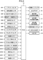
- FIG. 3 is a control block diagram of the engine according to the embodiment of the present invention.
- detection signals from various sensors SW1, SW2, SW4 to SW18 are input to the PCM 10.
- the PCM 10 includes a detection signal of an air flow sensor SW 1 that detects a flow rate of fresh air, a detection signal of an intake air temperature sensor SW 2 that detects the temperature of fresh air, and an EGR passage 50.
- the detection signal of the EGR gas temperature sensor SW4 that is disposed in the vicinity of the connection portion with the intake passage 30 and detects the temperature of the external EGR gas, and the intake air that is attached to the intake port 16 and immediately before flowing into the cylinder 18
- the detection signals of the exhaust temperature sensor SW7 and the exhaust pressure sensor SW8 that detect the exhaust temperature and the exhaust pressure, respectively.
- a detection signal of a lambda O 2 sensor SW10 that detects the oxygen concentration of the engine, a detection signal of a water temperature sensor SW11 that detects the temperature of engine cooling water, a detection signal of a crank angle sensor SW12 that detects the rotation angle of the crankshaft 15, A detection signal of an accelerator opening sensor SW13 that detects an accelerator opening corresponding to an operation amount of an accelerator pedal (not shown) of the vehicle, detection signals of intake side and exhaust side cam angle sensors SW14 and SW15, and a fuel supply system A fuel pressure sensor S that is attached to the common rail 64 of 62 and detects the fuel pressure supplied to the injector 67. 16 a detection signal of a detection signal of the hydraulic sensor SW17 for detecting the oil pressure of the engine 1, and the detection signal of the oil temperature sensor SW18 for detecting the oil temperature of the
- the PCM 10 determines the state of the engine 1 and the vehicle by performing various calculations based on these detection signals, and controls the (direct injection) injector 67, the spark plug 25, and the intake valves 21a and 21b accordingly.
- a control signal is output to the actuator of (throttle valve 36, EGR valve 511).
- the PCM 10 operates the engine 1.
- the PCM 10 controls the direct injection injector 67, the spark plug 25, and the like so that the engine output requested by the driver can be achieved based on the detection values from various sensors.
- each cylinder 18 of the engine is operated under the same conditions so as to obtain the same output.
- a predetermined operating region that is, when the engine load is low and the engine speed is low, for example, two of the four cylinders of the engine are stopped, and the remaining two cylinders are stopped. Increase output. As a result, the total pumping loss of the engine as a whole is reduced and fuel efficiency is improved.
- FIG. 4 is a graph showing the relationship between the pumping loss and the cooling loss when the exhaust valve 22a is opened by the exhaust side variable valve mechanism 72 when the piston of the engine descends while the cylinder is stopped.
- the pumping loss and the cooling loss are in an inversely proportional relationship. Accordingly, when the piston is lowered, if the lift amount of the exhaust valve 22a is increased to reduce the pumping loss, a large amount of gas flows from the exhaust port 17 into the combustion chamber 19, so that the cooling loss increases. . On the other hand, if the lift amount of the exhaust valve 22a is reduced to reduce the cooling loss, the resistance when the combustion chamber 19 is expanded increases and the pumping loss increases.
- the pumping loss is preferentially reduced in a region where the pumping loss is relatively large and the engine speed is high, and the cooling loss is reduced in a region where the pumping loss is relatively small and the engine speed is low.
- FIG. 5 is a graph showing the operation of the exhaust valve when the cylinder stop control is performed with the engine speed being low.
- the vertical movement of the piston 14 is shown for convenience of explanation.
- the lift amount of the exhaust valve is shown on the Y axis
- the passage of time is shown on the X axis.
- 5 shows the vertical movement of the piston 14.
- the bottom dead center of the piston is shown in the positive direction of the Y axis
- the top dead center of the piston is shown in the negative direction of the Y axis. ing.
- the broken line L1 indicates the operation of the piston 14, and the solid line L2 indicates the operation of the exhaust valve 22b controlled by the exhaust side valve mechanism 73.
- the exhaust valve 22b controlled by the exhaust side valve mechanism 73 when the piston moves up from the bottom dead center to the top dead center. Opens.
- the exhaust valve 22a controlled by the exhaust-side variable valve mechanism 72 is operated while the piston 14 is raised from the bottom dead center toward the top dead center and while the piston 14 is lowered from the top dead center toward the bottom dead center. The valve is kept closed. Thereby, the high-temperature burned gas in the combustion chamber 19 is not discharged to the exhaust port 17 but remains in the combustion chamber 19.
- the temperature in the combustion chamber 19 can be kept high. In this state, even if the driver depresses the accelerator and the engine load increases and the cylinder stop control is terminated, the combustion chamber 19 of the cylinder that was performing the cylinder stop control is kept at a high temperature. It is possible to achieve the torque required by
- FIG. 6 is a graph showing the operation of the exhaust valve when the cylinder stop control is performed with the engine speed being high.
- the broken line L1 indicates the operation of the piston 14 as in FIG. 5
- the solid line L2 indicates the exhaust valve 22b controlled by the exhaust side valve mechanism 73
- the solid line L3 indicates the exhaust side variable motion.
- the operation of the exhaust valve 22a controlled by the valve mechanism 72 is shown.
- the exhaust valve 22a controlled by the exhaust side variable valve mechanism 72 is closed while the piston 14 rises from the bottom dead center toward the top dead center, but the piston 14 is lowered from the top dead center. The valve opens while descending towards the dead center.
- the exhaust valve 22 a is opened when the piston 14 is lowered, so that the gas in the exhaust port 17 is introduced into the combustion chamber 19.
- the intake side variable valve mechanism 71 is stopped, and the intake ports 23a and 23b are sealed by the intake valves 21a and 21b.
- the exhaust valve 22b controlled by the exhaust side valve mechanism 73 is also closed. Therefore, by opening the exhaust valve 22a by the exhaust side variable valve mechanism 72 at this timing, the combustion chamber 19 that expands the gas in the exhaust port 17 when the piston 14 descends, that is, when the combustion chamber 19 expands. Can be taken in.
- the resistance at the time of expansion of the combustion chamber 19 can be reduced compared with the case where both the exhaust valves 22a and 22b are closed.
- the gas taken into the combustion chamber 19 when the piston 14 is lowered while the exhaust valve 22a is opened contains burned gas during normal operation, and its temperature is higher than that of the outside air. is there. Therefore, when the piston 14 is lowered, the exhaust valve 22a is opened, and the gas in the exhaust port 17 is reintroduced into the combustion chamber 19, whereby the temperature drop in the combustion chamber 19 can be suppressed. And by maintaining the temperature in the combustion chamber 19, the combustion efficiency in a cylinder can be raised when it restarts from a stop state.
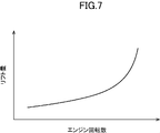
- FIG. 7 is a graph showing the relationship between the lift amount of the exhaust valve and the engine speed.
- the lift amount of the exhaust valve 22a when the cylinder is stopped is preferably determined according to the engine speed. More specifically, the lift amount of the exhaust valve 22a when the cylinder is stopped increases as the engine speed increases. If the exhaust valve 22a is opened when the cylinder is stopped, the cooling loss in which the temperature in the combustion chamber 19 decreases as the lift amount increases, but the pumping loss is reduced by introducing gas into the combustion chamber 19. Therefore, when the engine speed is not high, it is preferable to limit the lift amount of the exhaust valve 22a to some extent to reduce the pumping loss and reduce the cooling loss.
- the pumping loss increases rapidly as the engine speed increases, in this embodiment, the lift amount of the exhaust valve 22a is increased as the engine speed increases. As a result, the pumping loss of the engine can be reliably reduced even when the engine is rotating at high speed.
- the exhaust valve 22a is opened using the exhaust side variable valve mechanism 72 when the piston 14 is lowered while the cylinder is stopped in the low load / low rotation operation region. be able to.
- the exhaust valve 22a is opened and the combustion chamber 19 and the exhaust port 17 are opened. Can be communicated.
- the pressure drop in the combustion chamber 19 can be suppressed when the piston 14 is lowered.
- the pumping loss at the time of a cylinder stop can be suppressed.
Abstract
A device for controlling a multi-cylinder engine provided with a combustion chamber 19 to which an intake port 16 and an intake port 17 are connected, wherein: the device for controlling a multi-cylinder engine is provided with an intake-side variable valve mechanism 71 for controlling the lift timing of intake valves 21a, 21b of the intake port 16, an exhaust-side variable valve mechanism 72 for controlling the lift timing of an exhaust valve 22a, and an exhaust-side valve train mechanism 73 for driving an exhaust valve 22b at a fixed timing. When cylinder deactivation is performed in a low load/low rotation operation region, the exhaust valve 22a is opened by the exhaust-side variable valve mechanism 72 while a piston 14 in a cylinder 18 subjected to cylinder deactivation is descending.
Description
本発明は、エンジンの制御装置に関し、特に、油圧式可変動弁機構によって吸気弁の開閉を制御するエンジンの制御装置に関する。
The present invention relates to an engine control device, and more particularly to an engine control device that controls opening and closing of an intake valve by a hydraulic variable valve mechanism.
従来から、エンジンの制御装置においては、エンジンの吸気弁及び排気弁の開弁及び閉弁の時期を適切に制御することにより、特に圧縮自己燃焼運転領域におけるエンジンの運転効率を高める技術が知られている。そして、エンジンの吸気弁及び排気弁の開弁及び閉弁を制御するための手段としては、弁の開閉を、カムの表面に設けられたカム山の形状に応じて一定の間隔で、且つ一定のリフト量で開閉弁させる、いわゆるメカニカル可変動弁機構や、カム山の形状に完全には依存せず、リフト開始のタイミングやリフト量を油圧で制御する油圧式可変動弁機構が知られている(例えば、特許文献1)。
2. Description of the Related Art Conventionally, in an engine control device, a technique for improving the engine operating efficiency particularly in a compression self-combustion operation region by appropriately controlling the timing of opening and closing of an intake valve and an exhaust valve of an engine is known. ing. As a means for controlling the opening and closing of the intake valve and exhaust valve of the engine, the opening and closing of the valve is performed at regular intervals according to the shape of the cam crest provided on the surface of the cam. There is known a so-called mechanical variable valve mechanism that opens and closes with a lift amount of a certain amount, and a hydraulic variable valve mechanism that controls the lift start timing and lift amount with hydraulic pressure without completely depending on the shape of the cam crest. (For example, Patent Document 1).
特許文献1に記載された可変動弁機構は、クランクシャフトの回転に同期して回転するカムと、内部にエンジンオイルが充填され、カムの動作によってエンジンオイルの油圧が変化する圧力室と、圧力室に接続されており、開閉することにより弁に作用させる油圧を制御する油圧バルブと、を備えている。そして、このような可変動弁機構によれば、カムの形状に完全に依存することなく、油圧バルブによって弁の開閉のリフト開始タイミング及びリフト量を制御することができる。そしてこのような可変動弁機構を多気筒エンジンに適用することにより、多気筒エンジンの各燃焼室に繋がる複数の吸気ポート及び複数の排気ポートのそれぞれに吸気弁及び排気弁を設け、各吸気弁及び各排気弁を独立して制御することが可能となる。
The variable valve mechanism described in Patent Document 1 includes a cam that rotates in synchronization with the rotation of the crankshaft, a pressure chamber in which engine oil is filled and the oil pressure of the engine oil changes according to the operation of the cam, And a hydraulic valve that is connected to the chamber and controls the hydraulic pressure applied to the valve by opening and closing. According to such a variable valve mechanism, the lift start timing and lift amount of the valve can be controlled by the hydraulic valve without completely depending on the shape of the cam. By applying such a variable valve mechanism to a multi-cylinder engine, an intake valve and an exhaust valve are provided in each of a plurality of intake ports and a plurality of exhaust ports connected to each combustion chamber of the multi-cylinder engine. And each exhaust valve can be controlled independently.
一方で、油圧式の可変動弁機構を用いた場合、エンジン始動直後に可変動弁機構内で油圧を十分に上昇させることができないという課題も存在する。即ち、エンジン始動直後のクランキング時には、スタータの動力によってエンジンのピストンを受動的に動かすこととなるが、このとき、少なくともピストンの降下時に燃焼室が拡張する際に排気弁を開弁しなければ、燃焼室内の圧力低下によりピストンの降下の抵抗が発生してしまう。従って、排気弁及び吸気弁について油圧式の可変動弁機構を適用する場合、少なくとも1つの排気弁についてはバルブタイミング及びリフト量が固定された排気動弁機構を適用することが行われている。
On the other hand, when a hydraulic variable valve mechanism is used, there is a problem that the hydraulic pressure cannot be sufficiently increased in the variable valve mechanism immediately after the engine is started. In other words, during cranking immediately after engine startup, the piston of the engine is passively moved by the power of the starter. At this time, at least when the combustion chamber expands when the piston is lowered, the exhaust valve must be opened. In addition, the pressure drop in the combustion chamber causes a resistance to lowering the piston. Therefore, when a hydraulic variable valve mechanism is applied to the exhaust valve and the intake valve, an exhaust valve mechanism having a fixed valve timing and lift amount is applied to at least one exhaust valve.
ところで、近年では、エンジンのポンピングロスの低減、燃費向上、及び排気ガスの排出量の低減を目的として、所定の運転領域において、多気筒エンジンの複数の気筒のうちの幾つかの気筒を停止させる、いわゆる気筒停止が行われている。
By the way, in recent years, several cylinders of a plurality of cylinders of a multi-cylinder engine are stopped in a predetermined operation region for the purpose of reducing pumping loss of the engine, improving fuel consumption, and reducing exhaust gas emissions. A so-called cylinder stop is performed.
例えば、吸気ポート及び排気ポートを有するエンジンについて、吸気ポートに設けられた2つの排気弁及び排気ポートに設けられた1つの排気弁については可変動弁機構を適用し、排気ポートに設けられた残りの1つの排気弁については、バルブタイミング及びリフト量が固定された排気動弁機構を適用する場合において、気筒停止制御を行うときは、次のような制御が行われている。気筒停止時には、該当気筒について燃料噴射を行わない点、及び可変動弁機構を作動させない点以外については、通常の気筒稼働時と同様にピストン及び排気動弁機構が作動している。そして、排気動弁機構は、リフトタイミングが固定されたものであるため、ピストンの上昇時にのみ開弁し、ピストンの降下時には閉弁している。そして、上述したように、可変動弁機構は、気筒停止時には停止しているため、ピストンの上昇時及び降下時には、可変動弁機構が適用されている吸気弁及び排気弁は閉弁している。従って、気筒停止時には、ピストン降下時には、全ての吸気弁及び排気弁が閉弁しているため、ピストン降下によって燃焼室が拡張する際に、燃焼室内の圧力が急激に低下し、ピストンの降下動作に抵抗が発生する。そして、この抵抗が他の稼働中の気筒に対して抵抗となり、エンジンに対してポンピングロスが発生してしまう、という問題があった。この問題は、上述した特許文献1に記載されているような可変動弁機構に加え、例えばVVL(Variable Valve Lift)機構やVVT(Variable Valve Timing)機構等の油圧を用いて弁の制御を行う可変動弁機構においても同様に生じ得る。
For example, for an engine having an intake port and an exhaust port, a variable valve mechanism is applied to two exhaust valves provided in the intake port and one exhaust valve provided in the exhaust port, and the remaining provided in the exhaust port. For the one exhaust valve, the following control is performed when cylinder stop control is performed when an exhaust valve mechanism with a fixed valve timing and lift amount is applied. When the cylinder is stopped, the piston and the exhaust valve mechanism are operating in the same manner as during normal cylinder operation except that fuel injection is not performed for the cylinder and the variable valve mechanism is not operated. Since the exhaust valve mechanism has a fixed lift timing, it opens only when the piston is raised, and closes when the piston is lowered. As described above, since the variable valve mechanism is stopped when the cylinder is stopped, the intake valve and the exhaust valve to which the variable valve mechanism is applied are closed when the piston is raised and lowered. . Therefore, when the cylinder is stopped, all the intake valves and exhaust valves are closed when the piston is lowered. Therefore, when the combustion chamber expands due to the piston lowering, the pressure in the combustion chamber rapidly decreases, and the piston descends. Resistance occurs. This resistance becomes a resistance against other operating cylinders, and there is a problem that a pumping loss occurs with respect to the engine. In addition to the variable valve mechanism as described in Patent Document 1 described above, this problem is controlled by using hydraulic pressure such as a VVL (VariableariValve Lift) mechanism or a VVT (Variable Valve Timing) mechanism. The same can occur in the variable valve mechanism.
そこで本発明は、上述した課題を解決するためになされたものであり、特定のエンジンについて、気筒停止時にポンピングロスを抑制することができるエンジンの制御装置を提供することを目的とする。
Therefore, the present invention has been made to solve the above-described problems, and an object of the present invention is to provide an engine control device that can suppress a pumping loss when a cylinder is stopped for a specific engine.
上述した課題を解決するために、本発明は、多気筒エンジンの制御装置であって、複数の吸気ポート、及び該複数の吸気ポートに対応して設けられた複数の吸気弁と、複数の排気ポート、及び該複数の排気ポートに対応して設けられた複数の排気弁と、複数の吸気ポート及び複数の排気ポートが接続された燃焼室と、吸気ポートの吸気弁のリフトタイミングを制御するための吸気側可変動弁機構と、複数の排気ポートに設けられた複数の排気弁のうちの少なくとも一つの排気弁のリフトタイミングを制御するための排気側可変動弁機構と、複数の排気ポートに設けられた複数の排気弁のうちの他の排気弁を固定されたタイミングで駆動させる排気側動弁機構と、を備え、所定の運転領域に特定の気筒において気筒停止を行う場合、該特定の気筒の燃料噴射を停止して、吸気側可変動弁機構により特定の気筒の吸気弁のリフトを禁止するとともに、該特定の気筒内のピストンの降下時に排気側可変動弁機構により排気弁を開弁させる。
In order to solve the above-described problems, the present invention provides a control device for a multi-cylinder engine, which includes a plurality of intake ports, a plurality of intake valves provided corresponding to the plurality of intake ports, and a plurality of exhaust ports. A port, a plurality of exhaust valves provided corresponding to the plurality of exhaust ports, a combustion chamber to which a plurality of intake ports and a plurality of exhaust ports are connected, and lift timing of the intake valves of the intake ports An intake side variable valve mechanism, an exhaust side variable valve mechanism for controlling the lift timing of at least one exhaust valve among a plurality of exhaust valves provided in the plurality of exhaust ports, and a plurality of exhaust ports An exhaust side valve mechanism that drives another exhaust valve of the plurality of provided exhaust valves at a fixed timing, and when performing cylinder stop in a specific cylinder in a predetermined operation region, The cylinder fuel injection is stopped, the intake valve lift of the specific cylinder is prohibited by the intake side variable valve mechanism, and the exhaust valve is opened by the exhaust side variable valve mechanism when the piston in the specific cylinder is lowered. Let me speak.
このように構成された本発明によれば、所定の運転領域における気筒停止を行っている間、ピストンの降下時に排気側可変動弁機構を用いて少なくとも1つの排気弁を開弁させることができる。これにより、ピストンの降下時に全ての吸気弁及び排気側動弁機構によって制御されている排気弁が閉じている場合でも、少なくとも1つの排気弁を開弁させて燃焼室とエンジン下流側の排気ポートを連通させることができる。そして、ピストン降下時に燃焼室と排気ポートを連通させることにより、ピストン降下時に燃焼室内の圧力低下を抑制することができる。これにより、気筒停止時のポンピングロスを抑制することができる。
According to the present invention configured as described above, at least one exhaust valve can be opened using the exhaust side variable valve mechanism when the piston is lowered while the cylinder is stopped in a predetermined operation region. . Thus, even when all the intake valves and the exhaust valves controlled by the exhaust side valve operating mechanism are closed when the piston is lowered, at least one exhaust valve is opened so that the combustion chamber and the exhaust port on the downstream side of the engine Can be communicated. And by making the combustion chamber communicate with the exhaust port when the piston is lowered, the pressure drop in the combustion chamber can be suppressed when the piston is lowered. Thereby, the pumping loss at the time of a cylinder stop can be suppressed.
また、本発明において、好ましくは、所定の低回転領域では、特定の気筒における気筒停止中において、該特定の気筒内のピストン降下時に排気弁の閉弁状態を維持する。
このように構成された本発明によれば、ポンピングロスが少なくなる、エンジン回転数が低い領域では排気弁の閉弁状態を維持して燃焼室内の暖気を燃焼室内から排出せず、燃焼室内に留める。これにより、ポンピングロスが少ない状態では燃焼室内の温度を保つことができる。 In the present invention, preferably, in a predetermined low rotation region, when the cylinder in the specific cylinder is stopped, the closed state of the exhaust valve is maintained when the piston in the specific cylinder is lowered.
According to the present invention configured as described above, in a region where the pumping loss is reduced and the engine speed is low, the exhaust valve is maintained in the closed state, and the warm air in the combustion chamber is not discharged from the combustion chamber, and the combustion chamber is not discharged. stop. Thereby, the temperature in the combustion chamber can be maintained in a state where the pumping loss is small.
また、本発明において、好ましくは、気筒停止時の排気弁のリフト量は、エンジン回転数の増加に伴い、増加する。また、本発明において、好ましくは、気筒停止時の排気弁のリフト量は、エンジン回転数の減少に伴い、減少する。
In the present invention, preferably, the lift amount of the exhaust valve when the cylinder is stopped increases as the engine speed increases. In the present invention, it is preferable that the lift amount of the exhaust valve when the cylinder is stopped decreases as the engine speed decreases.
一般的に、エンジン回転数の増加に伴ってポンピングロスは増加するが、このように構成された本発明によれば、エンジン回転数の増加に伴って排気弁のリフト量を増加させることにより、開弁した排気弁より大量の気体を燃焼室内に取り込むことができる。これにより、エンジン回転数が増加した場合においてもポンピングロスの増加を抑制することができる。
Generally, the pumping loss increases as the engine speed increases, but according to the present invention configured in this way, by increasing the lift amount of the exhaust valve as the engine speed increases, A large amount of gas can be taken into the combustion chamber from the opened exhaust valve. Thereby, an increase in pumping loss can be suppressed even when the engine speed increases.
また、本発明において、好ましくは、多気筒エンジンは、気筒を直列に配置した多気筒エンジンであり、直列に配列された複数の気筒のうち中央寄りの気筒について気筒停止を行う。
In the present invention, preferably, the multi-cylinder engine is a multi-cylinder engine in which cylinders are arranged in series, and cylinder stop is performed for a cylinder closer to the center among a plurality of cylinders arranged in series.
以上のように、本発明によれば、特定のエンジンについて、気筒停止時にポンピングロスを抑制することができる。
As described above, according to the present invention, it is possible to suppress a pumping loss when a cylinder is stopped for a specific engine.
以下、添付図面を参照して、本発明の実施形態によるエンジンについて説明する。
Hereinafter, an engine according to an embodiment of the present invention will be described with reference to the accompanying drawings.
まず、図1及び2を参照して、本発明の実施形態によるエンジンの構成について説明する。図1及び2は、本発明の実施形態によるエンジンの概略構成図であり、図2は、特に、エンジンの吸気ポート及び排気ポート周辺を示す概略構成図である。
First, the configuration of an engine according to an embodiment of the present invention will be described with reference to FIGS. FIGS. 1 and 2 are schematic configuration diagrams of an engine according to an embodiment of the present invention, and FIG. 2 is a schematic configuration diagram particularly showing the periphery of an intake port and an exhaust port of the engine.
図1に示すように、エンジン1は、車両に搭載される、少なくともガソリンを含有する燃料が供給されるガソリンエンジンである。エンジン1は、複数の気筒18が設けられたシリンダブロック11(なお、図1では、1つの気筒のみを図示するが、例えば4つの気筒が直列に設けられる)と、このシリンダブロック11上に配設されたシリンダヘッド12と、シリンダブロック11の下側に配設され、エンジンオイルが貯留されたオイルパン13とを有している。各気筒18内には、コンロッド142を介してクランクシャフト15と連結されているピストン14が往復動可能に嵌挿されている。ピストン14の頂面には、ディーゼルエンジンの燃焼室に適用されるリエントラント型燃焼室を形成するようなキャビティ141が設けられている。キャビティ141は、ピストン14が圧縮上死点付近に位置するときには、インジェクタ67に相対する。シリンダヘッド12と、気筒18と、キャビティ141を有するピストン14とは、燃焼室19を画定する。なお、燃焼室19の形状は、図示する形状に限定されるものではない。例えばキャビティ141の形状、ピストン14の頂面形状、及び、燃焼室19の天井部の形状等は、適宜変更することが可能である。
As shown in FIG. 1, the engine 1 is a gasoline engine mounted on a vehicle and supplied with fuel containing at least gasoline. The engine 1 includes a cylinder block 11 provided with a plurality of cylinders 18 (only one cylinder is shown in FIG. The cylinder head 12 is provided, and the oil pan 13 is disposed below the cylinder block 11 and stores engine oil. A piston 14 connected to the crankshaft 15 via a connecting rod 142 is fitted in each cylinder 18 so as to be able to reciprocate. The top surface of the piston 14 is provided with a cavity 141 that forms a reentrant combustion chamber that is applied to the combustion chamber of a diesel engine. The cavity 141 is opposed to the injector 67 when the piston 14 is positioned near the compression top dead center. The cylinder head 12, the cylinder 18, and the piston 14 having the cavity 141 define a combustion chamber 19. The shape of the combustion chamber 19 is not limited to the shape illustrated. For example, the shape of the cavity 141, the top surface shape of the piston 14, the shape of the ceiling portion of the combustion chamber 19, and the like can be changed as appropriate.
このエンジン1は、理論熱効率の向上や、後述する圧縮着火燃焼の安定化等を目的として、15以上の比較的高い幾何学的圧縮比に設定されている。なお、幾何学的圧縮比は15以上20以下程度の範囲で、適宜設定すればよい。
This engine 1 is set to a relatively high geometric compression ratio of 15 or more for the purpose of improving theoretical thermal efficiency, stabilizing compression ignition combustion, which will be described later, and the like. In addition, what is necessary is just to set a geometric compression ratio suitably in the range of about 15-20.
シリンダヘッド12には、気筒18毎に、燃焼室19に連通する吸気ポート16及び排気ポート17が形成されていると共に、これら吸気ポート16及び排気ポート17には、燃焼室19側の開口を開閉する吸気弁21及び排気弁22がそれぞれ配設されている。
In the cylinder head 12, an intake port 16 and an exhaust port 17 communicating with the combustion chamber 19 are formed for each cylinder 18, and an opening on the combustion chamber 19 side is opened and closed in the intake port 16 and the exhaust port 17. An intake valve 21 and an exhaust valve 22 are disposed respectively.
シリンダヘッド12には、気筒18毎に、気筒18内に燃料を直接噴射する(直噴)インジェクタ67が取り付けられている。インジェクタ67は、その噴口が燃焼室19の天井面の中央部分から、その燃焼室19内に臨むように配設されている。インジェクタ67は、エンジン1の運転状態に応じて設定された噴射タイミングでかつ、エンジン1の運転状態に応じた量の燃料を、燃焼室19内に直接噴射する。この例において、インジェクタ67は、詳細な図示は省略するが、複数の噴口を有する多噴口型のインジェクタである。これによって、インジェクタ67は、燃料噴霧が、燃焼室19の中心位置から放射状に広がるように、燃料を噴射する。ピストン14が圧縮上死点付近に位置するタイミングで、燃焼室19の中央部分から放射状に広がるように噴射された燃料噴霧は、ピストン頂面に形成されたキャビティ141の壁面に沿って流動する。換言すれば、キャビティ141は、ピストン14が圧縮上死点付近に位置するタイミングで噴射された燃料噴霧を、その内部に収めるように形成されている。この多噴口型のインジェクタ67とキャビティ141との組み合わせは、燃料の噴射後、混合気形成期間を短くすると共に、燃焼期間を短くする上で有利な構成である。なお、インジェクタ67は、多噴口型のインジェクタに限定されず、外開弁タイプのインジェクタを採用してもよい。
The cylinder head 12 is provided with an injector 67 for each cylinder 18 for directly injecting fuel into the cylinder 18 (direct injection). The injector 67 is disposed so that its nozzle hole faces the inside of the combustion chamber 19 from the central portion of the ceiling surface of the combustion chamber 19. The injector 67 directly injects an amount of fuel into the combustion chamber 19 at an injection timing set according to the operating state of the engine 1 and according to the operating state of the engine 1. In this example, the injector 67 is a multi-hole injector having a plurality of nozzle holes, although detailed illustration is omitted. Thereby, the injector 67 injects the fuel so that the fuel spray spreads radially from the center position of the combustion chamber 19. At the timing when the piston 14 is positioned near the compression top dead center, the fuel spray injected radially from the central portion of the combustion chamber 19 flows along the wall surface of the cavity 141 formed on the top surface of the piston. In other words, the cavity 141 is formed so that the fuel spray injected at the timing when the piston 14 is positioned near the compression top dead center is contained therein. This combination of the multi-hole injector 67 and the cavity 141 is an advantageous configuration for shortening the mixture formation period and the combustion period after fuel injection. In addition, the injector 67 is not limited to a multi-hole injector, and may be an open valve type injector.
図外の燃料タンクとインジェクタ67との間は、燃料供給経路によって互いに連結されている。この燃料供給経路上には、燃料ポンプ63とコモンレール64とを含み、かつ、インジェクタ67に、比較的高い燃料圧力で燃料を供給することが可能な燃料供給システム62が介設されている。燃料ポンプ63は、燃料タンクからコモンレール64に燃料を圧送し、コモンレール64は圧送された燃料を、比較的高い燃料圧力で蓄えることが可能である。インジェクタ67が開弁することによって、コモンレール64に蓄えられている燃料がインジェクタ67の噴口から噴射される。ここで、燃料ポンプ63は、図示は省略するが、プランジャー式のポンプであり、エンジン1によって駆動される。このエンジン駆動のポンプを含む構成の燃料供給システム62は、30MPa以上の高い燃料圧力の燃料を、インジェクタ67に供給することを可能にする。燃料圧力は、最高で120MPa程度に設定してもよい。インジェクタ67に供給される燃料の圧力は、エンジン1の運転状態に応じて変更される。なお、燃料供給システム62は、この構成に限定されるものではない。
The fuel tank (not shown) and the injector 67 are connected to each other by a fuel supply path. A fuel supply system 62 including a fuel pump 63 and a common rail 64 and capable of supplying fuel to the injector 67 at a relatively high fuel pressure is interposed on the fuel supply path. The fuel pump 63 pumps fuel from the fuel tank to the common rail 64, and the common rail 64 can store the pumped fuel at a relatively high fuel pressure. When the injector 67 is opened, the fuel stored in the common rail 64 is injected from the injection port of the injector 67. Here, although not shown, the fuel pump 63 is a plunger type pump and is driven by the engine 1. The fuel supply system 62 configured to include this engine-driven pump enables the fuel with a high fuel pressure of 30 MPa or more to be supplied to the injector 67. The fuel pressure may be set to about 120 MPa at the maximum. The pressure of the fuel supplied to the injector 67 is changed according to the operating state of the engine 1. The fuel supply system 62 is not limited to this configuration.
シリンダヘッド12にはまた、燃焼室19内の混合気に強制点火(具体的には火花点火)する点火プラグ25が取り付けられている。点火プラグ25は、この例では、エンジン1の排気側から斜め下向きに延びるように、シリンダヘッド12内を貫通して配置されている。点火プラグ25の先端は、圧縮上死点に位置するピストン14のキャビティ141内に臨んで配置される。
The cylinder head 12 is also provided with an ignition plug 25 for forcibly igniting the air-fuel mixture in the combustion chamber 19 (specifically, spark ignition). In this example, the spark plug 25 is disposed through the cylinder head 12 so as to extend obliquely downward from the exhaust side of the engine 1. The tip of the spark plug 25 is disposed facing the cavity 141 of the piston 14 located at the compression top dead center.
エンジン1の一側面には、各気筒18の吸気ポート16に連通するように吸気通路30が接続されている。一方、エンジン1の他側面には、各気筒18の燃焼室19からの既燃ガス(排気ガス)を排出する排気通路40が接続されている。
An intake passage 30 is connected to one side of the engine 1 so as to communicate with the intake port 16 of each cylinder 18. On the other hand, an exhaust passage 40 for discharging burned gas (exhaust gas) from the combustion chamber 19 of each cylinder 18 is connected to the other side of the engine 1.
吸気通路30の上流端部には、吸入空気を濾過するエアクリーナ31が配設され、その下流側には、各気筒18への吸入空気量を調節するスロットル弁36が配設されている。また、吸気通路30における下流端近傍には、サージタンク33が配設されている。このサージタンク33よりも下流側の吸気通路30は、気筒18毎に分岐する独立通路とされ、これら各独立通路の下流端が各気筒18の吸気ポート16にそれぞれ接続されている。
An air cleaner 31 that filters intake air is disposed at the upstream end of the intake passage 30, and a throttle valve 36 that adjusts the amount of intake air to each cylinder 18 is disposed downstream thereof. A surge tank 33 is disposed near the downstream end of the intake passage 30. The intake passage 30 on the downstream side of the surge tank 33 is an independent passage branched for each cylinder 18, and the downstream end of each independent passage is connected to the intake port 16 of each cylinder 18.
排気通路40の上流側の部分は、気筒18毎に分岐して排気ポート17の外側端に接続された独立通路と該各独立通路が集合する集合部とを有する排気マニホールドによって構成されている。この排気通路40における排気マニホールドよりも下流側には、排気ガス中の有害成分を浄化する排気浄化装置として、直キャタリスト41とアンダーフットキャタリスト42とがそれぞれ接続されている。直キャタリスト41及びアンダーフットキャタリスト42はそれぞれ、筒状ケースと、そのケース内の流路に配置した、例えば三元触媒とを備えて構成されている。
The upstream portion of the exhaust passage 40 is constituted by an exhaust manifold having an independent passage branched for each cylinder 18 and connected to the outer end of the exhaust port 17 and a collecting portion where the independent passages gather. A direct catalyst 41 and an underfoot catalyst 42 are connected downstream of the exhaust manifold in the exhaust passage 40 as exhaust purification devices for purifying harmful components in the exhaust gas. Each of the direct catalyst 41 and the underfoot catalyst 42 includes a cylindrical case and, for example, a three-way catalyst disposed in a flow path in the case.
吸気通路30におけるサージタンク33とスロットル弁36との間の部分と、排気通路40における直キャタリスト41よりも上流側の部分とは、排気ガスの一部を吸気通路30に還流するためのEGR通路50を介して接続されている。このEGR通路50は、排気ガスをエンジン冷却水によって冷却するためのEGRクーラ52が配設された主通路51を含んで構成されている。主通路51には、排気ガスの吸気通路30への還流量を調整するためのEGR弁511が配設されている。
A portion between the surge tank 33 and the throttle valve 36 in the intake passage 30 and a portion upstream of the direct catalyst 41 in the exhaust passage 40 are used for returning a part of the exhaust gas to the intake passage 30. They are connected via a passage 50. The EGR passage 50 includes a main passage 51 in which an EGR cooler 52 for cooling the exhaust gas with engine coolant is disposed. The main passage 51 is provided with an EGR valve 511 for adjusting the recirculation amount of the exhaust gas to the intake passage 30.
また、エンジン1は、制御手段としてのパワートレイン・コントロール・モジュール(以下では「PCM」と呼ぶ。)10によって制御される。PCM10は、CPU、メモリ、カウンタタイマ群、インターフェース及びこれらのユニットを接続するパスを有するマイクロプロセッサで構成されており、このPCM10が制御器を構成する。
The engine 1 is controlled by a powertrain control module (hereinafter referred to as “PCM”) 10 as a control means. The PCM 10 is constituted by a microprocessor having a CPU, a memory, a counter timer group, an interface, and a path connecting these units, and this PCM 10 constitutes a controller.
また、図2に示すように、エンジンの各気筒18は、それぞれ、吸気ポート16及び排気ポート17と接続されている。そして、吸気ポート16は、2つの吸気口23a,23bを介して燃焼室19と連通しており、さらに排気ポート17も、2つの排気口24a,24bを介して燃焼室19と連通している。そして、吸気口23a,23bは、互いに独立して制御される吸気弁21a,21bによって開閉され、排気口24a,24bは、互いに独立して制御される吸気弁22a,22bによって開閉される。
Further, as shown in FIG. 2, each cylinder 18 of the engine is connected to an intake port 16 and an exhaust port 17, respectively. The intake port 16 communicates with the combustion chamber 19 through two intake ports 23a and 23b, and the exhaust port 17 communicates with the combustion chamber 19 through two exhaust ports 24a and 24b. . The intake ports 23a and 23b are opened and closed by intake valves 21a and 21b controlled independently of each other, and the exhaust ports 24a and 24b are opened and closed by intake valves 22a and 22b controlled independently of each other.
本実施形態では、吸気弁21a,21bは、共に、VVT、VVL、又は特許文献1に記載されたような可変動弁機構によって制御されるように構成されている。さらに、吸気弁22a,22bのうちの一方、例えば吸気弁22aもVVT、VVL、又は特許文献1に記載されたような可変動弁機構によって制御され、他方の吸気弁22bは、カムプロフィールに従って開閉し、そのリフト量及びリフトタイミングが固定されている排気側動弁機構によって制御されるように構成されている。
In this embodiment, the intake valves 21a and 21b are both configured to be controlled by VVT, VVL, or a variable valve mechanism as described in Patent Document 1. Further, one of the intake valves 22a and 22b, for example, the intake valve 22a is also controlled by VVT, VVL, or a variable valve mechanism as described in Patent Document 1, and the other intake valve 22b opens and closes according to the cam profile. The lift amount and the lift timing are controlled by an exhaust valve mechanism that is fixed.
このように、2つの排気弁22a,22bのうちの一方の排気弁22aを可変動弁機構によって制御し、他方の排気弁22bを排気側動弁機構によって制御することにより、例えばエンジンの始動時にクランキングを行う際に、エンジンオイルの圧力の上昇に関わらず、少なくとも排気弁22bのみを駆動させ、クランキング時のポンピングロスを低減することができる。
In this way, one of the two exhaust valves 22a and 22b is controlled by the variable valve mechanism, and the other exhaust valve 22b is controlled by the exhaust valve mechanism, for example, at the start of the engine. When cranking, regardless of the increase in engine oil pressure, at least only the exhaust valve 22b can be driven to reduce pumping loss during cranking.
図3は、本発明の実施形態によるエンジンの制御ブロック図である。図3に示すように、PCM10には、各種のセンサSW1、SW2、SW4~SW18の検出信号が入力される。具体的には、PCM10には、エアクリーナ31の下流側で、新気の流量を検出するエアフローセンサSW1の検出信号と、新気の温度を検出する吸気温度センサSW2の検出信号と、EGR通路50における吸気通路30との接続部近傍に配置されかつ、外部EGRガスの温度を検出するEGRガス温センサSW4の検出信号と、吸気ポート16に取り付けられかつ、気筒18内に流入する直前の吸気の温度を検出する吸気ポート温度センサSW5の検出信号と、シリンダヘッド12に取り付けられかつ、気筒18内の圧力を検出する筒内圧センサSW6の検出信号と、排気通路40におけるEGR通路50の接続部近傍に配置されかつ、それぞれ排気温度及び排気圧力を検出する排気温センサSW7及び排気圧センサSW8の検出信号と、直キャタリスト41の上流側に配置されかつ、排気中の酸素濃度を検出するリニアO2センサSW9の検出信号と、直キャタリスト41とアンダーフットキャタリスト42との間に配置されかつ、排気中の酸素濃度を検出するラムダO2センサSW10の検出信号と、エンジン冷却水の温度を検出する水温センサSW11の検出信号と、クランクシャフト15の回転角を検出するクランク角センサSW12の検出信号と、車両のアクセルペダル(図示省略)の操作量に対応したアクセル開度を検出するアクセル開度センサSW13の検出信号と、吸気側及び排気側のカム角センサSW14、SW15の検出信号と、燃料供給システム62のコモンレール64に取り付けられかつ、インジェクタ67に供給する燃料圧力を検出する燃圧センサSW16の検出信号と、エンジン1の油圧を検出する油圧センサSW17の検出信号と、エンジンオイルの油温を検出する油温センサSW18の検出信号と、が入力される。
FIG. 3 is a control block diagram of the engine according to the embodiment of the present invention. As shown in FIG. 3, detection signals from various sensors SW1, SW2, SW4 to SW18 are input to the PCM 10. Specifically, on the downstream side of the air cleaner 31, the PCM 10 includes a detection signal of an air flow sensor SW 1 that detects a flow rate of fresh air, a detection signal of an intake air temperature sensor SW 2 that detects the temperature of fresh air, and an EGR passage 50. The detection signal of the EGR gas temperature sensor SW4 that is disposed in the vicinity of the connection portion with the intake passage 30 and detects the temperature of the external EGR gas, and the intake air that is attached to the intake port 16 and immediately before flowing into the cylinder 18 The detection signal of the intake port temperature sensor SW5 for detecting the temperature, the detection signal of the in-cylinder pressure sensor SW6 attached to the cylinder head 12 and detecting the pressure in the cylinder 18, and the vicinity of the connection portion of the EGR passage 50 in the exhaust passage 40 And the detection signals of the exhaust temperature sensor SW7 and the exhaust pressure sensor SW8 that detect the exhaust temperature and the exhaust pressure, respectively. And it is disposed on the upstream side of the direct catalyst 41, disposed between the detection signal of the linear O 2 sensor SW9 for detecting the oxygen concentration in the exhaust gas, the direct catalyst 41 and underfoot catalyst 42 and the exhaust A detection signal of a lambda O 2 sensor SW10 that detects the oxygen concentration of the engine, a detection signal of a water temperature sensor SW11 that detects the temperature of engine cooling water, a detection signal of a crank angle sensor SW12 that detects the rotation angle of the crankshaft 15, A detection signal of an accelerator opening sensor SW13 that detects an accelerator opening corresponding to an operation amount of an accelerator pedal (not shown) of the vehicle, detection signals of intake side and exhaust side cam angle sensors SW14 and SW15, and a fuel supply system A fuel pressure sensor S that is attached to the common rail 64 of 62 and detects the fuel pressure supplied to the injector 67. 16 a detection signal of a detection signal of the hydraulic sensor SW17 for detecting the oil pressure of the engine 1, and the detection signal of the oil temperature sensor SW18 for detecting the oil temperature of the engine oil, is input.
PCM10は、これらの検出信号に基づいて種々の演算を行うことによってエンジン1や車両の状態を判定し、これに応じて、(直噴)インジェクタ67、点火プラグ25、吸気弁21a,21bを制御する吸気側可変動弁機構71、一方の排気弁22aを制御する排気側可変動弁機構72、他方の排気弁22bを制御する排気側動弁機構73、燃料供給システム62、及び、各種の弁(スロットル弁36、EGR弁511)のアクチュエータに対して制御信号を出力する。こうしてPCM10は、エンジン1を運転する。
The PCM 10 determines the state of the engine 1 and the vehicle by performing various calculations based on these detection signals, and controls the (direct injection) injector 67, the spark plug 25, and the intake valves 21a and 21b accordingly. Intake side variable valve mechanism 71, exhaust side variable valve mechanism 72 for controlling one exhaust valve 22a, exhaust side valve mechanism 73 for controlling the other exhaust valve 22b, fuel supply system 62, and various valves A control signal is output to the actuator of (throttle valve 36, EGR valve 511). Thus, the PCM 10 operates the engine 1.
次に、本実施形態の作用について詳述する。
Next, the operation of this embodiment will be described in detail.
エンジンの通常の運転時には、PCM10は、各種センサからの検出値に基づいて、ドライバから要求されたエンジン出力を達成できるよう、直噴インジェクタ67、点火プラグ25等の制御を行う。そして、通常運転時には、エンジンの各気筒18は、同一の出力を得られるように同一の条件で運転されている。一方で、所定の運転領域、即ちエンジンの負荷が低く、かつエンジンの回転数が低いような場合には、エンジンの4つの気筒のうち、例えば2つの気筒を停止し、残りの2つの気筒の出力を増加させる。これにより、エンジン全体としての総ポンピングロスを低減し、燃費の向上を実現する。そして、例えば直列4気筒エンジンの場合には、停止している気筒内温度の低下を防ぐため、直列に配列されている4気筒のうち中央寄りにある2気筒を停止させる。気筒停止制御がなされている気筒では、当該気筒内の直噴インジェクタ67からの燃料噴射が停止され、かつ吸気側可変動弁機構71による当該気筒の吸気口23a,23bの吸気弁21a,21bの駆動が停止される。これにより、吸気口23a,23bは、吸気弁21a,21bによって密閉される。一方で、気筒停止制御がなされている場合でも、気筒停止がなされていない気筒と連動しているピストン14や、点火プラグ25は、通常の運転状態と同様に作動している。
During normal operation of the engine, the PCM 10 controls the direct injection injector 67, the spark plug 25, and the like so that the engine output requested by the driver can be achieved based on the detection values from various sensors. During normal operation, each cylinder 18 of the engine is operated under the same conditions so as to obtain the same output. On the other hand, in a predetermined operating region, that is, when the engine load is low and the engine speed is low, for example, two of the four cylinders of the engine are stopped, and the remaining two cylinders are stopped. Increase output. As a result, the total pumping loss of the engine as a whole is reduced and fuel efficiency is improved. For example, in the case of an in-line four-cylinder engine, two cylinders closer to the center among the four cylinders arranged in series are stopped in order to prevent a decrease in the in-cylinder temperature. In a cylinder for which cylinder stop control is performed, fuel injection from the direct injection injector 67 in the cylinder is stopped, and the intake valves 21a and 21b of the intake ports 23a and 23b of the cylinder by the intake side variable valve mechanism 71 are stopped. Driving is stopped. Thereby, the intake ports 23a and 23b are sealed by the intake valves 21a and 21b. On the other hand, even when the cylinder stop control is performed, the piston 14 and the spark plug 25 that are linked to the cylinders that are not stopped are operating in the same manner as in the normal operation state.
図4は、気筒停止状態でエンジンのピストンが降下する際に、排気側可変動弁機構72によって排気弁22aを開弁した場合におけるポンピングロスと冷却損失との関係を示すグラフである。図4に示すように、ポンピングロスと冷却損失は反比例する関係にある。従って、ピストンが降下する際に、排気弁22aのリフト量を多くしてポンピングロスを減少させようとすると、大量のガスが排気ポート17から燃焼室19内に流入するため、冷却損失が増加する。一方で、排気弁22aのリフト量を少なくして冷却損失を減少させようとるすと、燃焼室19の拡張時の抵抗が大きくなり、ポンピングロスが増加する。
FIG. 4 is a graph showing the relationship between the pumping loss and the cooling loss when the exhaust valve 22a is opened by the exhaust side variable valve mechanism 72 when the piston of the engine descends while the cylinder is stopped. As shown in FIG. 4, the pumping loss and the cooling loss are in an inversely proportional relationship. Accordingly, when the piston is lowered, if the lift amount of the exhaust valve 22a is increased to reduce the pumping loss, a large amount of gas flows from the exhaust port 17 into the combustion chamber 19, so that the cooling loss increases. . On the other hand, if the lift amount of the exhaust valve 22a is reduced to reduce the cooling loss, the resistance when the combustion chamber 19 is expanded increases and the pumping loss increases.
そこで本実施形態では、ポンピングロスが比較的大きくなる、エンジン回転数が高い領域ではポンピングロスを優先的に軽減させ、ポンピングロスが比較的小さくなる、エンジン回転数が低い領域では、冷却損失を軽減させる。
Therefore, in this embodiment, the pumping loss is preferentially reduced in a region where the pumping loss is relatively large and the engine speed is high, and the cooling loss is reduced in a region where the pumping loss is relatively small and the engine speed is low. Let
図5は、エンジン回転数が低い状態で気筒停止制御を行っている場合における、排気弁の動作を示すグラフである。なお同図には、説明の便宜上、ピストン14の上下動を記載されている。図5に示すグラフでは、Y軸に排気弁のリフト量を示し、X軸に時間経過を示す。また、図5には、ピストン14の上下動を示しているが、この図5では、ピストンの下死点をY軸の正方向に示し、ピストンの上死点をY軸の負方向に示している。
FIG. 5 is a graph showing the operation of the exhaust valve when the cylinder stop control is performed with the engine speed being low. In the figure, the vertical movement of the piston 14 is shown for convenience of explanation. In the graph shown in FIG. 5, the lift amount of the exhaust valve is shown on the Y axis, and the passage of time is shown on the X axis. 5 shows the vertical movement of the piston 14. In FIG. 5, the bottom dead center of the piston is shown in the positive direction of the Y axis, and the top dead center of the piston is shown in the negative direction of the Y axis. ing.
図5中、破線L1は、ピストン14の動作を示しており、実線L2は、排気側動弁機構73によって制御される排気弁22bの動作を示している。図5に示すように、エンジン回転数が低い状態で気筒停止制御を行っている場合、ピストンが下死点から上死点に移動する上昇時に排気側動弁機構73によって制御される排気弁22bが開弁する。一方で、排気側可変動弁機構72によって制御される排気弁22aは、ピストン14が下死点から上死点に向けて上昇する間、及び上死点から下死点に向けて降下する間、閉弁状態を維持している。これにより、燃焼室19内の高温の既燃ガスは排気ポート17に排出されず、燃焼室19内に留まる。従って、燃焼室19内の温度を高温に保つことができる。そして、この状態でドライバがアクセルを踏み込み、エンジンの負荷が上昇して気筒停止制御が終了したとしても、気筒停止制御を行っていた気筒の燃焼室19は高温を保っているため、迅速にドライバの要求するトルクを実現することが可能となる。
5, the broken line L1 indicates the operation of the piston 14, and the solid line L2 indicates the operation of the exhaust valve 22b controlled by the exhaust side valve mechanism 73. As shown in FIG. 5, when the cylinder stop control is performed with the engine speed being low, the exhaust valve 22b controlled by the exhaust side valve mechanism 73 when the piston moves up from the bottom dead center to the top dead center. Opens. On the other hand, the exhaust valve 22a controlled by the exhaust-side variable valve mechanism 72 is operated while the piston 14 is raised from the bottom dead center toward the top dead center and while the piston 14 is lowered from the top dead center toward the bottom dead center. The valve is kept closed. Thereby, the high-temperature burned gas in the combustion chamber 19 is not discharged to the exhaust port 17 but remains in the combustion chamber 19. Therefore, the temperature in the combustion chamber 19 can be kept high. In this state, even if the driver depresses the accelerator and the engine load increases and the cylinder stop control is terminated, the combustion chamber 19 of the cylinder that was performing the cylinder stop control is kept at a high temperature. It is possible to achieve the torque required by
また、図6は、エンジン回転数が高い状態で気筒停止制御を行っている場合における、排気弁の動作を示すグラフである。
FIG. 6 is a graph showing the operation of the exhaust valve when the cylinder stop control is performed with the engine speed being high.
図6中、破線L1は、図5と同様にピストン14の動作を示しており、実線L2は、排気側動弁機構73によって制御される排気弁22bを示し、実線L3は、排気側可変動弁機構72によって制御される排気弁22aの動作を示している。図6に示すように、エンジン回転数が高い状態で気筒停止制御を行っている場合、ピストン14が下死点から上死点に移動する上昇時に排気側動弁機構73によって制御される排気弁22bが開弁する。そして、排気側可変動弁機構72によって制御される排気弁22aは、ピストン14が下死点から上死点に向けて上昇する間は閉弁しているが、ピストン14が上死点から下死点に向けて降下する間は開弁する。これにより、ピストン14の降下時に排気弁22aが開弁するため、排気ポート17中のガスが燃焼室19内に導入される。気筒停止中は、上述したように、吸気側可変動弁機構71は停止しており、吸気口23a,23bは、吸気弁21a,21bによって密閉されている。そして、気筒停止制御中においてピストン14が降下する際には、排気側動弁機構73によって制御される排気弁22bも閉じている。従って、このタイミングで排気側可変動弁機構72によって排気弁22aを開弁させることにより、ピストン14の降下時、即ち燃焼室19が拡張する際に排気ポート17中の気体を拡張する燃焼室19内に取り込むことができる。これにより、燃焼室19が拡張する際の抵抗を、両排気弁22a,22bを閉弁した場合と比較して減少させることができる。また、排気弁22aを開弁した状態でピストン14の降下時に燃焼室19内に取り込まれる気体は、通常運転時の既燃ガスを含有しており、その温度は、外気と比べて高い状態にある。従って、ピストン14の降下時に排気弁22aを開弁して排気ポート17中の気体を燃焼室19内に再導入させることにより燃焼室19内の温度の低下を抑制することができる。そして、燃焼室19内の温度を保つことにより、停止状態から再稼働する際に気筒内での燃焼効率を高めることができる。また、エンジン回転数が高い領域において気筒停止中の気筒についてポンピングロスを減少させることを優先したとしても、エンジン回転数の上昇に伴って直列に配列されている4気筒のうちの両端にある2気筒の温度が上昇するため、中央寄りにある停止している2気筒の温度低下を抑制することができる。
In FIG. 6, the broken line L1 indicates the operation of the piston 14 as in FIG. 5, the solid line L2 indicates the exhaust valve 22b controlled by the exhaust side valve mechanism 73, and the solid line L3 indicates the exhaust side variable motion. The operation of the exhaust valve 22a controlled by the valve mechanism 72 is shown. As shown in FIG. 6, when the cylinder stop control is performed with the engine speed being high, the exhaust valve that is controlled by the exhaust side valve mechanism 73 when the piston 14 moves up from the bottom dead center to the top dead center. 22b opens. The exhaust valve 22a controlled by the exhaust side variable valve mechanism 72 is closed while the piston 14 rises from the bottom dead center toward the top dead center, but the piston 14 is lowered from the top dead center. The valve opens while descending towards the dead center. As a result, the exhaust valve 22 a is opened when the piston 14 is lowered, so that the gas in the exhaust port 17 is introduced into the combustion chamber 19. While the cylinder is stopped, as described above, the intake side variable valve mechanism 71 is stopped, and the intake ports 23a and 23b are sealed by the intake valves 21a and 21b. When the piston 14 is lowered during the cylinder stop control, the exhaust valve 22b controlled by the exhaust side valve mechanism 73 is also closed. Therefore, by opening the exhaust valve 22a by the exhaust side variable valve mechanism 72 at this timing, the combustion chamber 19 that expands the gas in the exhaust port 17 when the piston 14 descends, that is, when the combustion chamber 19 expands. Can be taken in. Thereby, the resistance at the time of expansion of the combustion chamber 19 can be reduced compared with the case where both the exhaust valves 22a and 22b are closed. Further, the gas taken into the combustion chamber 19 when the piston 14 is lowered while the exhaust valve 22a is opened contains burned gas during normal operation, and its temperature is higher than that of the outside air. is there. Therefore, when the piston 14 is lowered, the exhaust valve 22a is opened, and the gas in the exhaust port 17 is reintroduced into the combustion chamber 19, whereby the temperature drop in the combustion chamber 19 can be suppressed. And by maintaining the temperature in the combustion chamber 19, the combustion efficiency in a cylinder can be raised when it restarts from a stop state. Further, even if priority is given to reducing the pumping loss for the cylinders that are stopped in a region where the engine speed is high, two cylinders located at both ends of the four cylinders arranged in series as the engine speed increases. Since the temperature of the cylinder rises, it is possible to suppress the temperature drop of the stopped two cylinders near the center.
図7は、排気弁のリフト量と、エンジン回転数との関係を示すグラフである。同図に示すように、気筒停止時における排気弁22aのリフト量は、エンジン回転数に応じて決定されていることが好ましい。より具体的には、気筒停止時における排気弁22aのリフト量は、エンジン回転数の増加に伴って増加するようになっている。気筒停止時に排気弁22aを開弁すると、リフト量の増加に伴い燃焼室19内の温度が低下する冷損が増加する反面、燃焼室19内に気体を導入することによりポンピングロスは低減する。従って、エンジン回転数が高くない状態では、排気弁22aのリフト量をある程度制限し、ポンピングロスを低減しつつ、冷損も低減することが好ましい。一方で、エンジン回転数が高くなるとポンピングロスが急激に増加するため、本実施形態では、エンジン回転数が増加するに従って排気弁22aのリフト量を増加させるようになっている。これにより、エンジンの高回転時にも、エンジンのポンピングロスを確実に低減させることができる。
FIG. 7 is a graph showing the relationship between the lift amount of the exhaust valve and the engine speed. As shown in the figure, the lift amount of the exhaust valve 22a when the cylinder is stopped is preferably determined according to the engine speed. More specifically, the lift amount of the exhaust valve 22a when the cylinder is stopped increases as the engine speed increases. If the exhaust valve 22a is opened when the cylinder is stopped, the cooling loss in which the temperature in the combustion chamber 19 decreases as the lift amount increases, but the pumping loss is reduced by introducing gas into the combustion chamber 19. Therefore, when the engine speed is not high, it is preferable to limit the lift amount of the exhaust valve 22a to some extent to reduce the pumping loss and reduce the cooling loss. On the other hand, since the pumping loss increases rapidly as the engine speed increases, in this embodiment, the lift amount of the exhaust valve 22a is increased as the engine speed increases. As a result, the pumping loss of the engine can be reliably reduced even when the engine is rotating at high speed.
以上のように、本実施形態によれば、低負荷・低回転運転領域における気筒停止を行っている間、ピストン14の降下時に排気側可変動弁機構72を用いて排気弁22aを開弁させることができる。これにより、ピストン14の降下時に吸気弁21a,21b及び排気側動弁機構73によって制御されている排気弁22bが閉じている場合でも、排気弁22aを開弁させて燃焼室19と排気ポート17を連通させることができる。そして、ピストン14降下時に燃焼室19と排気ポート17を連通させることにより、ピストン14降下時に燃焼室19内の圧力低下を抑制することができる。これにより、気筒停止時のポンピングロスを抑制することができる。
As described above, according to the present embodiment, the exhaust valve 22a is opened using the exhaust side variable valve mechanism 72 when the piston 14 is lowered while the cylinder is stopped in the low load / low rotation operation region. be able to. Thereby, even when the exhaust valve 22b controlled by the intake valves 21a and 21b and the exhaust side valve operating mechanism 73 is closed when the piston 14 is lowered, the exhaust valve 22a is opened and the combustion chamber 19 and the exhaust port 17 are opened. Can be communicated. And by making the combustion chamber 19 and the exhaust port 17 communicate with each other when the piston 14 is lowered, the pressure drop in the combustion chamber 19 can be suppressed when the piston 14 is lowered. Thereby, the pumping loss at the time of a cylinder stop can be suppressed.
1 エンジン
10 PCM
18 気筒
21 吸気弁
22 排気弁
71 吸気側可変動弁機構
72 排気側可変動弁機構
73 排気側動弁機構 1engine 10 PCM
18cylinder 21 intake valve 22 exhaust valve 71 intake side variable valve mechanism 72 exhaust side variable valve mechanism 73 exhaust side valve mechanism
10 PCM
18 気筒
21 吸気弁
22 排気弁
71 吸気側可変動弁機構
72 排気側可変動弁機構
73 排気側動弁機構 1
18
Claims (7)
- 多気筒エンジンの制御装置であって、
吸気ポート、及び該吸気ポートに対応して設けられた吸気弁と、
排気ポート、及び該複数の排気ポートに対応して設けられた排気弁と、
前記吸気ポート及び前記排気ポートが接続された燃焼室と、を備え、
特定の気筒において燃料噴射を停止する気筒停止を実行可能に構成され、
前記気筒停止を実行しているときには、吸気行程において前記特定の気筒の吸気弁のリフトを抑制するとともに、前記排気弁を開弁させる、多気筒エンジンの制御装置。 A control device for a multi-cylinder engine,
An intake port, and an intake valve provided corresponding to the intake port;
An exhaust port and an exhaust valve provided corresponding to the plurality of exhaust ports;
A combustion chamber to which the intake port and the exhaust port are connected,
Cylinder stop that stops fuel injection in a specific cylinder is configured to be executable,
A control device for a multi-cylinder engine that suppresses lift of an intake valve of the specific cylinder and opens the exhaust valve during an intake stroke when the cylinder stop is being executed. - 多気筒エンジンの制御装置であって、
複数の吸気ポート、及び該複数の吸気ポートに対応して設けられた複数の吸気弁と、
複数の排気ポート、及び該複数の排気ポートに対応して設けられた複数の排気弁と、
前記複数の吸気ポート及び前記複数の排気ポートが接続された燃焼室と、
前記吸気ポートの吸気弁のリフトタイミングを制御するための吸気側可変動弁機構と、
前記複数の排気ポートに設けられた複数の排気弁のうちの少なくとも一つの排気弁のリフトタイミングを制御するための排気側可変動弁機構と、
前記複数の排気ポートに設けられた複数の排気弁のうちの他の排気弁を固定されたタイミングで駆動させる排気側動弁機構と、を備え、
所定の運転領域に特定の気筒において気筒停止を行う場合、該特定の気筒の燃料噴射を停止して、前記吸気側可変動弁機構により前記特定の気筒の吸気弁のリフトを禁止するとともに、該特定の気筒内のピストンの降下時に前記排気側可変動弁機構により前記排気弁を開弁させる、多気筒エンジンの制御装置。 A control device for a multi-cylinder engine,
A plurality of intake ports, and a plurality of intake valves provided corresponding to the plurality of intake ports;
A plurality of exhaust ports, and a plurality of exhaust valves provided corresponding to the plurality of exhaust ports;
A combustion chamber to which the plurality of intake ports and the plurality of exhaust ports are connected;
An intake side variable valve mechanism for controlling the lift timing of the intake valve of the intake port;
An exhaust-side variable valve mechanism for controlling the lift timing of at least one of the plurality of exhaust valves provided in the plurality of exhaust ports;
An exhaust side valve mechanism that drives another exhaust valve among the plurality of exhaust valves provided in the plurality of exhaust ports at a fixed timing; and
When stopping a cylinder in a specific cylinder in a predetermined operating region, the fuel injection of the specific cylinder is stopped, the intake side variable valve mechanism prohibits lift of the intake valve of the specific cylinder, and A control apparatus for a multi-cylinder engine, wherein the exhaust valve is opened by the exhaust-side variable valve mechanism when the piston in a specific cylinder is lowered. - 所定の低回転領域では、前記特定の気筒における気筒停止中において、該特定の気筒内のピストン降下時に前記排気弁の閉弁状態を維持する、請求項1又は2に記載の多気筒エンジンの制御装置。 3. The control of a multi-cylinder engine according to claim 1, wherein in a predetermined low speed region, the closed state of the exhaust valve is maintained when the piston in the specific cylinder is lowered while the cylinder is stopped in the specific cylinder. apparatus.
- 気筒停止時の前記排気弁のリフト量は、エンジン回転数の増加に伴い、増加する、請求項1乃至3のいずれか一項に記載の多気筒エンジンの制御装置。 The control device for a multi-cylinder engine according to any one of claims 1 to 3, wherein the lift amount of the exhaust valve when the cylinder is stopped increases as the engine speed increases.
- 気筒停止時の前記排気弁のリフト量は、エンジン回転数の減少に伴い、減少する、請求項1乃至4のいずれか一項に記載の多気筒エンジンの制御装置。 The multi-cylinder engine control apparatus according to any one of claims 1 to 4, wherein the lift amount of the exhaust valve when the cylinder is stopped decreases as the engine speed decreases.
- 前記多気筒エンジンは、気筒を直列に配置した多気筒エンジンであり、直列に配列された複数の気筒のうち中央寄りの気筒について気筒停止を行う、請求項1乃至5のいずれか一項に記載の多気筒エンジンの制御装置。 The said multi-cylinder engine is a multi-cylinder engine which arrange | positioned the cylinder in series, A cylinder stop is carried out about the cylinder near the center among several cylinders arranged in series. Multi-cylinder engine control device.
- 前記気筒停止を実行しているときの、吸気行程中での前記排気弁の開弁時期は、吸気行程の前半に設定される、請求項1乃至6のいずれか一項に記載の多気筒エンジンの制御装置。 The multi-cylinder engine according to any one of claims 1 to 6, wherein the opening timing of the exhaust valve during the intake stroke when the cylinder stop is executed is set in the first half of the intake stroke. Control device.
Priority Applications (3)
| Application Number | Priority Date | Filing Date | Title |
|---|---|---|---|
| US16/086,520 US10612474B2 (en) | 2016-03-31 | 2017-03-29 | Controller for multi-cylinder engine |
| EP17775242.5A EP3418536B1 (en) | 2016-03-31 | 2017-03-29 | Device for controlling a multi-cylinder engine |
| CN201780017501.2A CN108779719B (en) | 2016-03-31 | 2017-03-29 | Control device for multi-cylinder engine |
Applications Claiming Priority (4)
| Application Number | Priority Date | Filing Date | Title |
|---|---|---|---|
| JP2016-070643 | 2016-03-31 | ||
| JP2016070643A JP6323799B2 (en) | 2016-03-31 | 2016-03-31 | Multi-cylinder engine controller |
| JP2016070644A JP6278342B2 (en) | 2016-03-31 | 2016-03-31 | Multi-cylinder engine controller |
| JP2016-070644 | 2016-03-31 |
Publications (1)
| Publication Number | Publication Date |
|---|---|
| WO2017170708A1 true WO2017170708A1 (en) | 2017-10-05 |
Family
ID=59965782
Family Applications (1)
| Application Number | Title | Priority Date | Filing Date |
|---|---|---|---|
| PCT/JP2017/012930 WO2017170708A1 (en) | 2016-03-31 | 2017-03-29 | Device for controlling multi-cylinder engine |
Country Status (4)
| Country | Link |
|---|---|
| US (1) | US10612474B2 (en) |
| EP (1) | EP3418536B1 (en) |
| CN (1) | CN108779719B (en) |
| WO (1) | WO2017170708A1 (en) |
Cited By (1)
| Publication number | Priority date | Publication date | Assignee | Title |
|---|---|---|---|---|
| JP2019137662A (en) * | 2018-02-15 | 2019-08-22 | Jxtgエネルギー株式会社 | Method for producing alkene |
Citations (4)
| Publication number | Priority date | Publication date | Assignee | Title |
|---|---|---|---|---|
| JPH02135603U (en) * | 1989-04-18 | 1990-11-13 | ||
| JP2006144634A (en) * | 2004-11-18 | 2006-06-08 | Toyota Motor Corp | Control device of variable cylinder internal combustion engine |
| JP2006336579A (en) * | 2005-06-03 | 2006-12-14 | Toyota Motor Corp | Controller for internal combustion engine |
| JP2015169190A (en) * | 2014-03-11 | 2015-09-28 | 本田技研工業株式会社 | Exhaust emission control device for internal combustion engine |
Family Cites Families (9)
| Publication number | Priority date | Publication date | Assignee | Title |
|---|---|---|---|---|
| US4499870A (en) * | 1983-04-26 | 1985-02-19 | Nissan Motor Company, Limited | Multi-cylinder internal combustion engine |
| JP2001132484A (en) * | 1999-11-05 | 2001-05-15 | Denso Corp | Variable cylinder control device for internal combustion engine |
| JP4059131B2 (en) * | 2003-04-17 | 2008-03-12 | トヨタ自動車株式会社 | Variable valve mechanism drive device for internal combustion engine |
| JP4486910B2 (en) * | 2005-05-25 | 2010-06-23 | 本田技研工業株式会社 | Control device |
| DE102007054376A1 (en) | 2007-11-14 | 2009-05-20 | Schaeffler Kg | Hydraulic unit for a cylinder head of an internal combustion engine with hydraulically variable valve train |
| JP6007504B2 (en) * | 2012-02-13 | 2016-10-12 | いすゞ自動車株式会社 | diesel engine |
| CN104411554B (en) * | 2012-06-27 | 2017-02-22 | 丰田自动车株式会社 | Vehicle control device |
| EP2960470B1 (en) * | 2014-06-27 | 2020-03-11 | Volvo Car Corporation | Method and arrangement for cylinder deactivation |
| EP3191700B1 (en) | 2014-09-12 | 2019-03-13 | PSA Automobiles SA | Motor vehicle combustion engine with improved cylinder deactivation |
-
2017
- 2017-03-29 WO PCT/JP2017/012930 patent/WO2017170708A1/en active Application Filing
- 2017-03-29 EP EP17775242.5A patent/EP3418536B1/en active Active
- 2017-03-29 US US16/086,520 patent/US10612474B2/en active Active
- 2017-03-29 CN CN201780017501.2A patent/CN108779719B/en not_active Expired - Fee Related
Patent Citations (4)
| Publication number | Priority date | Publication date | Assignee | Title |
|---|---|---|---|---|
| JPH02135603U (en) * | 1989-04-18 | 1990-11-13 | ||
| JP2006144634A (en) * | 2004-11-18 | 2006-06-08 | Toyota Motor Corp | Control device of variable cylinder internal combustion engine |
| JP2006336579A (en) * | 2005-06-03 | 2006-12-14 | Toyota Motor Corp | Controller for internal combustion engine |
| JP2015169190A (en) * | 2014-03-11 | 2015-09-28 | 本田技研工業株式会社 | Exhaust emission control device for internal combustion engine |
Non-Patent Citations (1)
| Title |
|---|
| See also references of EP3418536A4 * |
Cited By (1)
| Publication number | Priority date | Publication date | Assignee | Title |
|---|---|---|---|---|
| JP2019137662A (en) * | 2018-02-15 | 2019-08-22 | Jxtgエネルギー株式会社 | Method for producing alkene |
Also Published As
| Publication number | Publication date |
|---|---|
| EP3418536A1 (en) | 2018-12-26 |
| EP3418536A4 (en) | 2019-03-27 |
| CN108779719A (en) | 2018-11-09 |
| CN108779719B (en) | 2021-10-29 |
| US20190101064A1 (en) | 2019-04-04 |
| EP3418536B1 (en) | 2021-05-05 |
| US10612474B2 (en) | 2020-04-07 |
Similar Documents
| Publication | Publication Date | Title |
|---|---|---|
| JP5994700B2 (en) | Control device for spark ignition engine | |
| JP2014051936A (en) | Spark ignition type direct-injection engine | |
| JP2014051935A (en) | Spark ignition type direct-injection engine | |
| JP6019936B2 (en) | Spark ignition direct injection engine | |
| JP5928251B2 (en) | Spark ignition direct injection engine | |
| JP6241678B2 (en) | Engine control device | |
| JP6213410B2 (en) | Control device for compression ignition engine | |
| WO2017170708A1 (en) | Device for controlling multi-cylinder engine | |
| JP6323799B2 (en) | Multi-cylinder engine controller | |
| JP6191836B2 (en) | Engine control device | |
| JP6278342B2 (en) | Multi-cylinder engine controller | |
| JP6460412B2 (en) | Engine control device | |
| JP6296428B2 (en) | Multi-cylinder engine controller | |
| JP6079973B2 (en) | Engine control device | |
| JP6252995B2 (en) | Engine control device | |
| JP6395117B2 (en) | Engine control device | |
| JP6245454B2 (en) | Engine control device | |
| JP6296429B2 (en) | Engine control device | |
| JP5910423B2 (en) | Spark ignition engine | |
| JP6288610B2 (en) | Engine control device | |
| JP6131873B2 (en) | Engine blow-by gas recirculation control device | |
| JP6241679B2 (en) | Engine control device | |
| JP6350973B2 (en) | Engine control device | |
| JP5998752B2 (en) | Spark ignition direct injection engine | |
| JP6131839B2 (en) | Control device for compression ignition engine |
Legal Events
| Date | Code | Title | Description |
|---|---|---|---|
| WWE | Wipo information: entry into national phase |
Ref document number: 2017775242 Country of ref document: EP |
|
| ENP | Entry into the national phase |
Ref document number: 2017775242 Country of ref document: EP Effective date: 20180918 |
|
| NENP | Non-entry into the national phase |
Ref country code: DE |
|
| 121 | Ep: the epo has been informed by wipo that ep was designated in this application |
Ref document number: 17775242 Country of ref document: EP Kind code of ref document: A1 |