WO2017170467A1 - 可変容量圧縮機 - Google Patents
可変容量圧縮機 Download PDFInfo
- Publication number
- WO2017170467A1 WO2017170467A1 PCT/JP2017/012508 JP2017012508W WO2017170467A1 WO 2017170467 A1 WO2017170467 A1 WO 2017170467A1 JP 2017012508 W JP2017012508 W JP 2017012508W WO 2017170467 A1 WO2017170467 A1 WO 2017170467A1
- Authority
- WO
- WIPO (PCT)
- Prior art keywords
- pressure
- suction
- opening
- valve body
- working fluid
- Prior art date
- Legal status (The legal status is an assumption and is not a legal conclusion. Google has not performed a legal analysis and makes no representation as to the accuracy of the status listed.)
- Ceased
Links
Images




Classifications
-
- F—MECHANICAL ENGINEERING; LIGHTING; HEATING; WEAPONS; BLASTING
- F04—POSITIVE - DISPLACEMENT MACHINES FOR LIQUIDS; PUMPS FOR LIQUIDS OR ELASTIC FLUIDS
- F04B—POSITIVE-DISPLACEMENT MACHINES FOR LIQUIDS; PUMPS
- F04B27/00—Multi-cylinder pumps specially adapted for elastic fluids and characterised by number or arrangement of cylinders
- F04B27/08—Multi-cylinder pumps specially adapted for elastic fluids and characterised by number or arrangement of cylinders having cylinders coaxial with, or parallel or inclined to, main shaft axis
- F04B27/10—Multi-cylinder pumps specially adapted for elastic fluids and characterised by number or arrangement of cylinders having cylinders coaxial with, or parallel or inclined to, main shaft axis having stationary cylinders
- F04B27/12—Multi-cylinder pumps specially adapted for elastic fluids and characterised by number or arrangement of cylinders having cylinders coaxial with, or parallel or inclined to, main shaft axis having stationary cylinders having plural sets of cylinders or pistons
-
- F—MECHANICAL ENGINEERING; LIGHTING; HEATING; WEAPONS; BLASTING
- F04—POSITIVE - DISPLACEMENT MACHINES FOR LIQUIDS; PUMPS FOR LIQUIDS OR ELASTIC FLUIDS
- F04B—POSITIVE-DISPLACEMENT MACHINES FOR LIQUIDS; PUMPS
- F04B27/00—Multi-cylinder pumps specially adapted for elastic fluids and characterised by number or arrangement of cylinders
- F04B27/08—Multi-cylinder pumps specially adapted for elastic fluids and characterised by number or arrangement of cylinders having cylinders coaxial with, or parallel or inclined to, main shaft axis
- F04B27/14—Control
- F04B27/16—Control of pumps with stationary cylinders
- F04B27/18—Control of pumps with stationary cylinders by varying the relative positions of a swash plate and a cylinder block
Definitions
- the present invention relates to a variable capacity compressor capable of changing the discharge capacity based on the pressure in the crank chamber, and more particularly, to a variable capacity compressor that improves the reliability of the compressor at a high load and a large capacity.
- the inclination of the swash plate that is slidably connected to the piston is changed by changing the pressure in the crank chamber with the pressure control valve, thereby changing the piston stroke to control the discharge capacity.
- the arrangement is well known.
- Patent Document 1 Japanese Patent Laid-Open No. 9-280171
- a capacity control valve pressure control valve for adjusting the opening degree is provided in the middle of an air supply passage communicating the discharge chamber and the crank chamber.
- a swash plate type variable displacement compressor is disclosed in which the crank chamber pressure is controlled by adjusting the opening of the displacement control valve (Patent Document 1).
- the capacity control valve used here includes a valve body that opens and closes an air supply passage, a pressure sensing chamber that communicates with a suction pressure region, and a sensor that is accommodated in the pressure sensing chamber and transmits fluctuations in suction pressure to the valve body.
- a pressure mechanism, and a solenoid that changes a set suction pressure by changing a load applied to the valve body in accordance with an input current.
- variable capacity compressor equipped with this type of capacity control valve (pressure control valve)
- the compressor discharge capacity is autonomously controlled so that the suction pressure maintains the set suction pressure. Even if the rotational speed of the compressor connected via the pulley increases due to the increase in the discharge pressure, the discharge capacity is reduced so as to keep the suction pressure at the set suction pressure.
- the inclination angle of the swash plate is 80% of the full stroke when converted to the piston stroke (80% stroke), and the compressor is operated at a speed of 2000 r / min. Assuming that the compressor rotational speed is accelerated to 8000 r / min, the swash plate tilt angle is about 20% stroke because the suction pressure is autonomously controlled to be kept constant.
- the load received by the side surface of the piston is reduced by reducing the stroke amount, but the load received by the shoe that is provided between the piston and the swash plate and slides at high speed with respect to the swash plate is the upper surface of the piston.
- the pressure acting on the load does not decrease so much, the peripheral speed is quadrupled, so the PV value between the shoe and the swash plate becomes very high, and seizure and abnormal wear occur.
- the piston stroke increases, which causes a disadvantage that the vibration of the compressor increases.
- the present invention has been made in view of such circumstances, and ensures the reliability of the sliding portion by limiting the discharge amount of the compressor only at the time of high load and high rotation even without a special sensor.
- the main object is to provide a variable capacity compressor capable of reducing the vibration of the compressor at the time of high load and high rotation.
- a variable capacity compressor is used in a refrigeration cycle of an air conditioner, and includes a suction chamber that stores a working fluid sucked from the refrigeration cycle, and a suction chamber that is sucked from the suction chamber.
- a compression chamber for compressing the working fluid; a discharge chamber for storing the working fluid discharged from the compression chamber; a crank chamber for storing a swash plate that penetrates the shaft and rotates as the shaft rotates;
- An air supply passage communicating the discharge chamber and the crank chamber; an air extraction passage communicating the crank chamber and the suction chamber; and an opening degree of the air supply passage and / or the air extraction passage is adjusted to adjust the crank chamber.
- a pressure control valve that adjusts the pressure of the crank chamber, and the pressure regulating valve adjusts the pressure of the crank chamber so that the pressure of the suction chamber becomes a set suction pressure.
- a suction throttle valve capable of restricting the opening of the suction passage is provided on a suction passage connecting the refrigeration cycle and the suction chamber.
- the suction throttle valve has a predetermined flow rate of the working fluid passing through the suction throttle valve. In the following cases, the opening degree of the apparatus is fully opened, and the opening degree of the working fluid is reduced when the flow rate of the working fluid passing through the inside exceeds the predetermined value.
- the flow rate is a mass flow rate, which is the mass (kg / h) of the working fluid that passes through the suction throttle valve per unit time.
- a suction throttle valve capable of reducing the opening of the suction passage is provided on the suction passage communicating with the refrigeration cycle and the suction chamber, and when the flow rate of the working fluid passing through the inside is less than a predetermined value, If the opening is fully open and the opening of the intake passage is maximized, and the flow rate of the working fluid passing through the interior exceeds a predetermined value, the opening of the intake throttle valve is reduced and the opening of the intake passage is reduced.
- the suction passage is not throttled and is controlled in the same manner as a conventional variable capacity compressor.
- the suction passage starts to be throttled in a large flow rate operation region where the reliability of the compressor may be impaired or vibration may increase, and the increase in the discharge amount (increase in the flow rate) is limited. For this reason, the flow rate of the compressor does not greatly exceed a predetermined value even at high load and high rotation, and the reliability of the compressor is ensured.
- the suction throttle valve includes a casing for flowing the working fluid therein, and a valve that is movably accommodated in the casing and is urged in the forward direction of the flow of the working fluid by the fluid force of the working fluid that passes through the inside of the casing. And a valve seat part provided integrally or separately with the casing on the inlet side of the working fluid of the casing, and the valve body is seated from the downstream side, and the valve body is directed to the valve seat part An opening that opens at a downstream side of the valve body, and the valve seat is seated by the biasing force of the spring member.
- valve body When the flow path for allowing the working fluid to flow is formed and the flow rate of the working fluid is equal to or less than a predetermined value, the valve body is maintained in the seated state on the valve seat portion. Open the opening fully Deliberately, when the flow rate of the working fluid exceeds a predetermined value, the valve body may be narrow the opening of the opening away from the valve seat.
- the flow rate of the working fluid is predetermined. For example, during normal operation when the working fluid (refrigerant) has a low to medium flow rate, the working fluid is downstream of the valve body even though the seated state of the valve body is maintained. Since the opening on the downstream side of the valve body is fully open, the suction passage is maintained at its maximum opening without being throttled by the suction throttle valve.
- the valve body is separated from the valve seat, and the valve body throttles the opening of the casing.
- the flow of the working fluid is restricted by the suction throttle valve. For this reason, the operation of the compressor exceeding the predetermined discharge amount is restricted, and the reliability of the compressor can be ensured.
- the opening degree of the opening portion decreases with an increase in the displacement amount of the valve body from the valve seat portion, and has an opening characteristic that protrudes upward with respect to the displacement amount of the valve body. It is preferable to have.
- the pressure control valve includes a valve body capable of opening and closing the opening of the air supply passage, a pressure sensing mechanism that guides the pressure of the suction chamber and transmits the fluctuation of the pressure of the suction chamber to the valve body, A valve that can open and close the opening of the bleed passage when the valve body starts to open the opening of the air supply passage when the pressure in the suction chamber falls below a predetermined set value.
- a body, and a pressure sensing mechanism that guides the pressure of the suction chamber and transmits the fluctuation of the pressure of the suction chamber to the valve body, and when the pressure of the suction chamber falls below a predetermined set value, The valve body may start to close the opening of the extraction passage.
- the discharge capacity is adjusted so that the suction chamber pressure, which has been reduced by the throttling function of the suction throttle valve, does not fall below the set suction pressure. Even at times, the flow rate is restricted from exceeding a predetermined value.
- the suction of the working fluid when the flow rate of the working fluid passing through the inside of the suction passage connecting the refrigeration cycle and the suction chamber exceeds the predetermined value, the suction of reducing the opening degree of the working fluid. Since the throttle valve is provided, during normal operation when the working fluid (refrigerant) has a low to medium flow rate, the working fluid can flow without restricting the suction passage, and when the working fluid has a high flow rate or high flow rate. During the rotation, the discharge amount of the compressor does not exceed a predetermined value.
- FIG. 1 is a diagram showing a configuration example of a refrigeration cycle in which a variable capacity compressor according to the present invention is used.
- FIG. 2 is a sectional view showing a variable capacity compressor according to the present invention.
- FIG. 3 is a cross-sectional view showing an example of a pressure control valve.
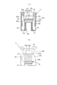
- 4A and 4B are views showing the suction throttle valve, where FIG. 4A is a sectional view thereof, and FIG. 4B is a side view thereof.
- FIG. 5A is a characteristic diagram showing a change in the opening area of the opening with respect to the displacement of the valve body of the suction throttle valve, and FIG. 5B shows a change in the flow resistance with respect to the flow rate flowing through the suction throttle valve.
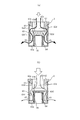
- FIG. 6 is a cross-sectional view showing the operating state of the suction throttle valve, (a) is a diagram showing a state at low to medium flow rate, and (b) is a diagram showing a state at high flow rate. .
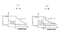
- FIG. 7 is a characteristic line showing changes in piston stroke and compressor suction side pressure: Ps (pressure in the low-pressure line downstream of the evaporator and pressure Psc in the suction chamber) with respect to the compressor speed (Comp speed).
- FIG. 7A is a diagram showing the operating characteristics of a conventional compressor
- FIG. 7B is a diagram showing the operating characteristics of the present invention.
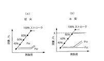
- FIG. 8 is a characteristic diagram showing changes in the flow rate of the refrigeration cycle and the pressure on the suction side of the compressor: Ps (pressure Pss in the low pressure line downstream of the evaporator and pressure Psc in the suction chamber) with respect to the heat load of the evaporator.
- FIG. 8 (a) is a diagram showing the operating characteristics of a conventional compressor
- FIG. 8 (b) is a diagram showing the operating characteristics of the present invention.
- FIG. 9 is a cross-sectional view showing another configuration example of the suction throttle valve, (a) is a view showing a state at a low to medium flow rate, and (b) is a view showing a state at a high flow rate. It is.
- FIG. 1 shows a configuration example of a refrigeration cycle 1 mounted on a vehicle.
- the refrigeration cycle 1 includes a variable capacity compressor (hereinafter referred to as a compressor) provided with a pressure control valve 2 for changing the discharge capacity and a suction throttle valve 3 for changing the passage area of the suction passage for introducing the refrigerant into the interior. 4.
- a condenser 5 that cools the refrigerant, an expansion device 6 that decompresses the refrigerant, and an evaporator 8 that is disposed in the air conditioning passage 7 and evaporates and evaporates the working fluid.
- the discharge side of the compressor 4 is connected to the expansion device 6 via the condenser 5, and a high-pressure line is configured by a path from the discharge side of the compressor 4 to the inflow side of the expansion device 6. .
- the outflow side of the expansion device 6 is connected to the evaporator 8, and the outflow side of the evaporator 8 is connected to the suction side of the compressor 4, so that the outflow side of the expansion device 6 is connected to the suction side of the compressor 4.
- the low pressure line is constituted by the route to reach.
- the refrigerant compressed by the compressor 4 enters the condenser 5 as a high-temperature and high-pressure refrigerant, and is cooled and sent to the expansion device 6. Then, the pressure is reduced in the expansion device 6 to become low-temperature and low-pressure wet steam, and heat is exchanged with the air passing therethrough in the evaporator 8 to form a gas, which is then returned to the compressor 4.
- FIG. 2 shows a specific configuration example of the compressor 4 described above.
- the compressor includes a cylinder block 11, a rear housing 13 assembled to the rear side of the cylinder block 11 via a valve plate 12, and a front side of the cylinder block 11, together with the cylinder block 11 and a crank chamber 14. And a front housing 15 that defines The front housing 15, the cylinder block 11, the valve plate 12, and the rear housing 13 are fastened in the axial direction by fastening bolts 16 to constitute the housing of the compressor 4.
- a shaft 17 whose one end protrudes from the front housing 15 is accommodated in the crank chamber 14 defined by the front housing 15 and the cylinder block 11.
- a clutch plate 19 is fixed to a portion of the shaft 17 protruding from the front housing 15 via a relay member 18 attached in the axial direction.
- a drive pulley 20 that is rotatably fitted around the boss portion 15 a of the front housing 15 is provided opposite to the clutch plate 19, and the clutch plate 19 is energized by the energizing electromagnetic coil 21 embedded in the drive pulley 20. The rotational power that is attracted to the drive pulley 20 and applied to the drive pulley 20 is transmitted to the shaft 17.
- one end of the shaft 17 is hermetically sealed with the front housing 15 through a seal member 22 provided between the shaft 17 and is supported rotatably by a radial bearing 23.
- the other end of the shaft 17 is rotatably supported by a thrust bearing 25 housed in a housing hole 24 formed substantially at the center of the cylinder block 11 and a radial bearing 26 provided on the rear side adjacent thereto. Has been.
- the cylinder block 11 is formed with the accommodation hole 24 and a plurality of cylinder bores 27 arranged at equal intervals on the circumference centered on the accommodation hole 24.
- Each cylinder bore 27 has a single-head piston. 30 is inserted so that reciprocation is possible.
- a thrust flange 31 that rotates integrally with the shaft 17 is fixed to the shaft 17 in the crank chamber 14.
- the thrust flange 31 is rotatably supported via a thrust bearing 32 on an inner wall surface of the front housing 15 formed substantially perpendicular to the shaft 17.
- a swash plate 34 is connected to the thrust flange 31 via a link member 33.
- the swash plate 34 is held so as to be tiltable via a hinge ball 35 provided on the shaft 17, and rotates integrally with the rotation of the thrust flange 31.
- the thrust flange 31 and the swash plate 34 constitute a power transmission mechanism that rotates in synchronization with the rotation of the shaft 17.
- the mooring part 30a of the single-headed piston 30 is moored by the peripheral part of the swash plate 34 via a pair of shoes 36 provided in the front and back.
- the valve plate 12 is formed with suction holes 38 and discharge holes 39 corresponding to the respective cylinder bores 27, and the rear housing 13 has a suction chamber 41 for containing the working fluid supplied to the compression chamber 37, A discharge chamber 42 for accommodating the working fluid discharged from the compression chamber 37 is provided.
- the suction chamber 41 communicates with a suction port 43 communicating with the outlet side of the evaporator 8 via a suction passage 44 and can communicate with a compression chamber 37 via a suction hole 38 of the valve plate 12.
- the discharge chamber 42 communicates with a discharge port (not shown) that communicates with the inlet side of the condenser 5 and can communicate with the compression chamber 37 through the discharge hole 39 of the valve plate 12.
- the suction hole 38 is opened and closed by a suction valve 45 provided on the front side end face of the valve plate 12, and the discharge hole 39 is opened and closed by a discharge valve 46 provided on the rear side end face of the valve plate 12. It has become.
- the discharge capacity of the compressor 4 is determined by the stroke of the piston 30, which is the pressure applied to the front surface of the piston 30, that is, the pressure in the compression chamber 37 (pressure in the cylinder bore) and the pressure applied to the back surface of the piston 30. That is, it is determined by the differential pressure from the pressure in the crank chamber 14 (crank chamber pressure Pc). Specifically, if the pressure in the crank chamber 14 is increased, the differential pressure between the compression chamber 37 and the crank chamber 14 is reduced, so that the inclination angle (swing angle) of the swash plate 34 is reduced. If the stroke of the piston 30 is reduced and the discharge capacity is reduced. Conversely, if the pressure in the crank chamber 14 is reduced, the differential pressure between the compression chamber 37 and the crank chamber 14 is increased. Oscillating angle) increases, and the stroke of the piston 30 increases and the discharge capacity increases.
- the passage 47 a formed in the cylinder block 11, the through hole 47 b formed in the valve plate 12, and the passage 47 c formed over the rear housing 13 are connected to the discharge chamber 42 and the crank.
- An air supply passage 47 that communicates with the chamber 14 is formed. Further, the clearance of the radial bearing 26 accommodated in the accommodation hole 24 formed in the cylinder block 11, the communication hole 48a of the cylinder block 11 formed following the accommodation hole 24, and the valve plate 12 communicated with the communication hole 48a.
- a bleed passage 48 that connects the crank chamber 14 and the suction chamber 41 is formed through an orifice hole 48b formed in the first and second openings.
- the pressure of the crank chamber 14 (crank chamber pressure Pc) is controlled by adjusting the opening of the supply passage 47 by the pressure control valve 2 provided on the supply passage 47.
- the pressure control valve 2 is mounted in a control valve mounting hole 28 formed in the rear housing 13.
- the pressure control valve 2 has a valve hole 53 that communicates a discharge pressure introduction port 51 that communicates with the discharge chamber 42 and a pressure supply port 52 that communicates with the crank chamber 14.
- a valve body 54 that adjusts the opening of the valve hole 53, a suction pressure introduction port 55 that communicates with the suction chamber 41, a pressure sensing chamber 56 that communicates with the suction pressure introduction port 55, and the pressure of the fluid guided to the pressure sensing chamber 56 And a pressure-sensitive mechanism 57 made of a bellows or the like that urges the valve body 54 in a direction to increase the opening of the valve hole 53 when the pressure decreases.
- a solenoid portion 59 is further provided for adjusting the urging force for changing the opening of the valve hole 53 by the excitation of the solenoid 58.
- the opening of the air supply passage increases as the pressure in the suction chamber 41 decreases, and the air supply passage is opened so that the pressure in the suction chamber 41 becomes the set suction pressure.
- the degree is controlled autonomously. That is, when the pressure in the suction chamber falls below the set suction pressure, the pressure sensing mechanism extends and the valve element moves in the direction to open the valve hole, so that the opening of the air supply passage increases and the discharge chamber moves to the crank chamber. A high-pressure working fluid is supplied.
- the suction port 43 for sucking the refrigerant from the external cycle, the suction passage 44 for guiding the refrigerant sucked from the suction port 43 to the suction chamber 41, A discharge port (not shown) for discharging the refrigerant to the external cycle and a discharge passage (not shown) for guiding the refrigerant discharged to the discharge chamber to the discharge port are formed.
- a suction throttle valve 3 as shown in FIG. 4 is arranged on the suction passage 44 connecting the suction port 43 and the suction chamber 41.
- This suction throttle valve 3 is fixed to the inner wall of the suction passage 44 and is formed separately from the casing 61 through which the working fluid flows, and is fitted to the upstream end (entrance end) of the casing 61. And a valve member 63 accommodated in the casing 61 so as to be seated on the valve seat 62, and a spring member 64 that urges the valve member 63 toward the valve seat 62. Configured.
- the casing 61 is formed in a bottomed cylindrical shape, and is fixed to the inner wall of the suction passage 44 with the open end facing the upstream side, but the vicinity of the bottom of the peripheral wall faces the suction chamber 41 so as to face the suction chamber 41. It is separated from the inner wall of the housing 13. In the vicinity of the bottom of the peripheral wall 61a of the casing 61, three or four openings 65 are formed in the circumferential direction to communicate the inside and outside of the casing.
- the shape of the opening 65 is not particularly specified, but is preferably a shape that narrows toward the bottom of the casing 61.
- the opening 65 has a trapezoidal shape in which the upper side is longer than the lower side. Is formed.
- a columnar portion 66 is provided that protrudes inward toward the opening end.
- the columnar portion 66 serves as a portion that supports a spring member 64 described later, and functions as a stopper that regulates the maximum lift amount of the valve body 63.
- the valve seat 62 extends in the axial direction with a predetermined interval from the inner wall inside the casing 61 following the fitting portion 62a and an annular fitting portion 62a that is fitted to the upstream end portion of the casing 61.
- a cylindrical valve seat wall 62b is formed, and a valve seat hole 62c penetrating in the axial direction is formed at the center.
- valve seat wall 62b On the valve seat wall 62b, notches 62d cut in the axial direction from the downstream end are formed around the valve seat wall 62b at substantially equal intervals in three to four locations in the circumferential direction, and a valve body 63 described later is provided downstream of the valve seat portion 62. Even in a state of being seated on the end (valve seat wall 62b), the working fluid flows from the upstream side to the downstream side of the valve seat portion 62 through the valve seat hole 62c and the notch 62d of the valve seat portion 62. .
- the valve body 63 has a bottomed cylindrical shape that is open on the downstream side, and connects a flat top portion 63a, a cylindrical portion 63b that slides in contact with the inner peripheral surface of the casing 61, and a top portion 63a and the cylindrical portion 63b. And a tapered portion 63c.
- the top portion 63 a is formed smaller than the outer diameter of the cylindrical portion 63 b and larger than the outer diameter of the columnar portion 66 of the casing 61. Further, the top portion 63a is formed larger than the inner shape of the downstream end of the valve seat wall 62b of the valve seat portion 62, and the valve body 63 is sized so as to contact (seat) only at the downstream end of the valve seat wall 62b. Is formed.
- the valve body 63 is movable in the axial direction of the casing 61 from the position where the outer surface of the top portion 63a contacts the valve seat portion 62 to the position where the inner surface of the top portion 63a contacts the columnar portion 66, and the outer surface of the top portion 63a is the valve.
- the cylinder 63 b of the valve body 63 does not overlap the opening 65 of the casing 61 (the opening 65 of the casing 61 is throttled by the cylinder 63 b of the valve 63.
- the cylindrical portion 63b of the valve body 63 largely overlaps the opening portion 65 of the casing 61 (the opening portion 65 of the casing 61 is the valve body). 63).
- the opening area of the opening portion of the casing 61 rapidly decreases as the valve body 63 moves away from the state where the valve body 63 is seated on the valve seat portion 62. ing.
- a plurality of through holes 63d are formed in the taper portion 63c of the valve body 63 in the circumferential direction to communicate the upstream side and the downstream side of the valve body 63.
- the spring member 64 is configured by a coiled compression spring that is elastically mounted between the bottom 61 a of the casing 61 and the top 63 a of the valve body 63 around the columnar portion 66 of the casing 61.
- the inner diameter of the spring member 64 is larger than the outer diameter of the columnar portion 66 and smaller than the diameter of the top portion 63a of the valve body 63. Therefore, the top portion 63a of the valve body 63 is inside the valve body 63.
- a bottom portion 61 a of the casing 61 are elastically mounted while a radial shift is restricted by a columnar portion 66.
- the spring member sets the spring constant as low as possible and is sufficient for the valve body without moving when the valve body is below a predetermined flow rate (mass of working fluid passing through the suction throttle valve per unit time, for example, 190 kg / h). 5 (b), the displacement of the valve body can be suppressed until the flow rate reaches the predetermined value X, and the flow rate is set to the predetermined value X.
- the valve body When the pressure exceeds the value, the valve body is greatly displaced, and the opening can be sufficiently narrowed. That is, the valve body has a characteristic that the opening is fully opened without displacement until the fluid exceeds a predetermined value, and the flow resistance is rapidly increased by reducing the opening of the opening at once when the flow rate exceeds the predetermined value. I have.
- the suction throttle valve 3 is connected to the inside of the casing 61 from the upstream side to the downstream side through the valve seat hole 62c and the notch 62d of the valve seat portion 62, the through hole 63d of the valve body 63, and the opening portion 65 of the casing 61.
- a refrigerant flow path is formed through which the working fluid flows.
- the refrigerant flow path is throttled by the restriction of the opening 65 by the valve body 63, and when the valve body 63 is seated on the valve seat 62, the refrigerant flow
- the passage is not throttled (the opening degree of the suction throttle valve 3 is fully opened), and the opening degree of the suction passage 44 is maximized.
- the opening 65 is throttled by the cylindrical portion 63b of the valve body 63 (since the refrigerant flow path inside the casing is throttled), the opening degree of the suction passage 44 is throttled. It is supposed to be.
- the working fluid sucked from the suction passage 44 passes through the valve seat portion 62 as shown in FIG.
- the valve body 63 is pressed against the valve seat 62 by the spring member 64, and the working fluid that has passed through the valve seat hole 62c collides with the valve body 63. Thereafter, the direction is changed to the outside in the radial direction, and flows into the casing 61 from the valve seat portion 62 through the notch 62d.
- the working fluid has a fluid force that tries to bring the valve body 63 close to the columnar portion 66 against the spring force of the spring member 64 by colliding with the valve body 63, but the flow rate is a predetermined value or less.
- the urging force by the spring member 64 is larger, so that the valve body 63 does not move and maintains the seated state on the valve seat portion 62.
- the valve body 63 does not restrict the opening 65 of the casing 61, and the working fluid that has flowed into the casing flows from the upstream side to the downstream side of the valve body 63 via the through hole 63d of the valve body 63. Thereafter, the gas flows out from the opening 65 of the casing 61 to the downstream side of the suction throttle valve 3 and is supplied to the suction chamber 41.
- the spring member 64 Since the spring member 64 has a characteristic of greatly displacing the valve body 63 when the working fluid exceeds a predetermined flow rate, the opening 65 of the casing 61 is opened when the working fluid exceeds a predetermined flow rate. As a result, the pressure in the suction chamber 41 is greatly reduced.
- the pressure Psc in the suction chamber 41 is lower than the pressure Pss in the low-pressure line on the downstream side of the evaporator because of a slight amount that occurs when the working fluid passes through the suction passage.
- the pressure loss is exaggerated for clarity.
- the suction passage 44 is throttled all at once by the suction throttle valve 3, and the low-pressure line on the downstream side of the evaporator Regardless of the pressure Pss, only the pressure Psc in the suction chamber decreases and reaches the set suction pressure. Therefore, the air supply passage 47 is opened, the crank chamber 14 is raised, the piston stroke is reduced, and the increase in the discharge amount is suppressed.
- the rotation speed of the compressor at which the piston stroke starts to decrease is Rx lower than the rotation speed R when there is no suction throttle valve.
- the suction throttle valve 3 when the compressor 4 is operating at a high speed, as shown in the diagram of FIG.
- the piston stroke increases and the refrigerant flow rate increases in order to obtain the amount of refrigerant commensurate with the heat load (the refrigerant pressure at the evaporator outlet increases, so the suction chamber pressure Ps is set).
- the piston stroke increases and the refrigerant flow rate increases.
- the suction passage 44 is throttled by the suction throttle valve 3.
- the pressure in the suction chamber continues to be lower than the set suction pressure, and the control valve 2 maintains the open state of the air supply passage.
- the refrigerant flow is much higher It made it will not. Since the refrigerant flow rate reaches a peak before reaching the amount of 100% stroke (for example, 80%), a flow rate suitable for the heat load cannot be obtained, and the pressure Pss in the low-pressure line on the downstream side of the evaporator gradually increases. Since the suction passage 44 is throttled by the suction throttle valve, the pressure Psc of the suction chamber 41 is kept substantially constant in a low state.
- the suction throttle valve is provided on the suction passage to throttle its opening when the flow rate of the working fluid passing through the interior exceeds a predetermined value, the working fluid (refrigerant) is low to medium. During normal operation at a flow rate, the working fluid can flow without constricting the suction passage. On the other hand, when the working fluid is at a high flow rate or at a high speed, the compressor discharge amount is a predetermined value. Will not be greatly exceeded.
- valve seat portion 62 is provided separately on the inlet side of the working fluid flow in the casing 61.
- the valve seat portion 62 is integrally provided on the inlet side of the working fluid flow in the casing 61. May be.
- the example which opens and closes the opening part of the casing 61 directly with the valve body 63 was shown in the above-mentioned example, you may make it open and close an opening part in conjunction with the motion of the valve body 63.
- FIG. 9 An example of such a suction throttle valve 3 is shown in FIG. 9, and the suction throttle valve 3 will be described below.
- a valve seat portion 62 formed by a cylindrical valve seat wall 61b protruding inward at the upstream end portion in the axial direction of the casing 61 is integrally formed, and a valve seat hole 62c penetrating in the axial direction in the center. Is formed.
- the valve seat wall 61b is formed with notches 62d cut in the axial direction from the downstream end around the valve seat wall 61b at substantially equal intervals in 3 to 4 locations in the circumferential direction.
- an opening 65 is formed at the substantially center of the downstream end portion in the axial direction, which is the bottom 61a of the casing 61, and a spring receiver 68 is formed by projecting the periphery of the opening 65 inward.
- a coil-shaped spring member 64 is engaged and held by the spring receiver 68, and a valve body 63 that can be displaced in the axial direction of the casing 61 is attached to the other end of the spring member 64.
- the upstream side and the downstream side of the suction throttle valve 3 can communicate with each other via the valve seat hole 62 c and the notch 62 d formed in the valve seat portion 62 and the clearance between the coils of the spring member 64.
- the opening 65 of the casing 61 is closed.
- the setting force of the spring member 64 can suppress the displacement of the valve body 63 until the flow rate reaches a predetermined value, and the flow rate exceeds the predetermined value. In this case, the valve body 63 is greatly displaced, and the opening 65 can be sufficiently narrowed.
- the spring member 64 has a preload that allows the valve body 63 to be seated on the valve seat portion 62 until the flow rate reaches a predetermined value, and as the valve body 63 moves away from the valve seat portion 62, The opening is narrowed by reducing the gap between the coils. Even in such a configuration, it is possible to achieve the same operational effects as the above-described embodiment.
- valve seat 63 is formed with the notch (flow path) 62d allowing the flow of the working fluid in the state where the valve body 63 is seated by the biasing force of the spring member 64.
- a flow path that penetrates the top portion 63 a of the valve body 63 may be formed so that the working fluid flows into the casing 61.
- the pressure control valve is provided in the air supply passage, and when the pressure in the suction chamber falls below the set suction pressure, the valve body starts opening the opening of the air supply passage.
- the valve body Comprises at least a valve body capable of opening and closing the opening of the bleed passage, and a pressure-sensitive mechanism for guiding the pressure of the suction chamber and transmitting the pressure variation of the suction chamber to the valve body. If the pressure falls below the set suction pressure, the same effect can be obtained even if the valve body starts closing the opening of the extraction passage.
Landscapes
- Engineering & Computer Science (AREA)
- Mechanical Engineering (AREA)
- General Engineering & Computer Science (AREA)
- Compressors, Vaccum Pumps And Other Relevant Systems (AREA)
Abstract
【課題】格別なセンサが無くても高負荷・高回転時に限って圧縮器の吐出量を制限することで、摺動箇所の信頼性を確保することができ、高負荷・高回転時での圧縮機の振動を低減することが可能な可変容量圧縮機を提供する。【要約】給気通路(47)及び/又は抽気通路(48)の開度を調節してクランク室(14)の圧力を調整する圧力制御弁(2)を備え、この圧力調節弁(2)により吸入室(41)の圧力を設定吸入圧にするようクランク室(14)の圧力を調節して吐出容量を可変させる可変容量圧縮機(4)において、冷凍サイクルと吸入室(41)とを接続する吸入通路(44)上に、この吸入通路の開度を絞ることが可能な吸入絞り弁(3)を設ける。吸入絞り弁(3)は、内部を通過する作動流体の流量が所定値以下である場合に自身の開度を全開とし、内部を通過する作動流体の流量が所定値を超えると、自身の開度を絞る。
Description
本発明は、クランク室の圧力に基づいて吐出容量を変更可能な可変容量圧縮機に関し、特に、高負荷大容量時の圧縮機の信頼性を高めた可変容量圧縮機に関する。
可変容量圧縮機として、圧力制御弁によりクランク室の圧力を変更することでピストンに摺動可能に連結した斜板の傾斜角を変更し、これによりピストンストロークを変更させて吐出容量を制御するようにした構成は周知である。
例えば、特許文献1(特開平9-280171)には、吐出室とクランク室とを連通する給気通路の途中に、その開度を調節するための容量制御弁(圧力制御弁)を設け、この容量制御弁の開度を調節することでクランク室圧を制御するようにした斜板式可変容量圧縮機が開示されている(特許文献1)。
ここで用いられる容量制御弁は、給気通路を開閉する弁体と、吸入圧領域に連通された感圧室と、その感圧室に収容されて吸入圧の変動を弁体に伝達する感圧機構と、入力電流に応じて前記弁体への付与荷重を変化させて設定吸入圧を変更するソレノイドとを備えている。圧縮機の駆動シャフトの回転数の上昇に伴って圧縮機が吐出する冷媒ガスの流量が増大すると、冷凍サイクルを循環する冷媒の流量が増加して吸入圧領域の圧力が低下し、感圧機構によって弁体が給気通路を開放する方向へ移動され、これにより、吐出室からクランク室への冷媒ガスの供給量が増大し、斜板の傾角が減少されてピストンストロークが減少することで吸入圧の低下が阻止される。
つまり、この種の容量制御弁(圧力制御弁)を備えた可変容量圧縮機においては、吸入圧力が設定吸入圧を維持するように圧縮機の吐出容量が自律的に制御されるので、エンジン回転の上昇によりプーリを介して連結した圧縮機の回転数が上昇したとしても、吸入圧を設定吸入圧に保つように吐出容量が低減されることとなる。
例えば、斜板の傾斜角がピストンストロークに換算してフルストロークの80%となる傾斜角(80%ストローク)であり、圧縮機回転数が2000r/minで運転している状態から、急加速により圧縮機回転数が8000r/minまで加速したとすると、吸入圧力が一定に保たれるように自律制御されるため、斜板の傾斜角は約20%ストロークとなる。
この場合、ピストンの側面が受ける負荷は、ストローク量が減ったことにより軽減されるが、ピストンと斜板の間に設けられ、斜板に対して高速で摺動するシューが受ける負荷は、ピストンの上面に作用する圧力(圧縮反力に基づく荷重)がさほど低下しないにも拘らず周速が4倍になるので、シューと斜板との間のPV値は非常に高くなり、焼き付きや異常摩耗を誘発する限界PV値に近づき、斜板とシューとの摺動面の信頼性を損なう恐れがある。特に冷凍サイクルの熱負荷が高い時にはピストンストロークが大きくなるので、圧縮機の振動が大きくなるという不都合も生じる。
このような懸念に対して、前述した先行技術文献においては、圧縮機の駆動シャフトの回転数が所定値以上になった場合に、容量制御弁のソレノイドの入力電流を変更して設定吸入圧を上昇させ、吐出容量を減少させることが提案されている。
このような制御方法によれば、圧縮機の回転数が所定値以上になると、吐出容量が減らされるので、ピストンの上面に作用する圧力が低くなり、高速運転時の斜板とシューとの摺動面の信頼性を確保することが可能となる。
しかしながら、特許文献1の制御方法においては、圧縮機の回転数が所定値以上になったときにソレノイドの入力電流を変更するものであるため、回転数を検出するためのセンサや、ソレノイドへの入力電流を変更するための制御回路が必要となり、圧縮機単体では対応できないという不都合がある。またソレノイドを有さないいわゆる内部制御弁には適用することができない。
また、圧縮機の回転数のみによって吐出容量の低減を判断しているため、圧縮機の回転数が高い状態であるが冷凍サイクルの熱負荷が低い場合など、摺動箇所の信頼性を損ねる懸念が低い場合であっても吐出容量を低減させてしまう不都合がある。
本発明は係る事情に鑑みてなされたものであり、格別なセンサが無くても高負荷・高回転時に限って圧縮器の吐出量を制限することで、摺動箇所の信頼性を確保することができると共に、高負荷・高回転時での圧縮機の振動を低減することが可能な可変容量圧縮機を提供することを主たる課題としている。
上記課題を達成するために、本発明に係る可変容量圧縮機は、空調装置の冷凍サイクルに用いられ、この冷凍サイクルから吸入された作動流体を収容する吸入室と、この吸入室から吸入された作動流体を圧縮する圧縮室と、この圧縮室から吐出された作動流体を収容する吐出室と、シャフトが貫通されると共にこのシャフトの回転に伴って回転する斜板を収容するクランク室と、前記吐出室と前記クランク室とを連通する給気通路と、前記クランク室と前記吸入室とを連通する抽気通路と、前記給気通路及び/又は前記抽気通路の開度を調節して前記クランク室の圧力を調整する圧力制御弁とを備え、この圧力調節弁により前記吸入室の圧力を設定吸入圧にするよう前記クランク室の圧力を調節して吐出容量を可変させる構成において、前記冷凍サイクルと前記吸入室とを接続する吸入通路上に、この吸入通路の開度を絞ることが可能な吸入絞り弁を設け、前記吸入絞り弁は、内部を通過する作動流体の流量が所定値以下である場合に自身の開度を全開とし、内部を通過する作動流体の流量が前記所定値を超えると、自身の開度を絞るものであることを特徴としている。
尚、ここで、流量とは、質量流量であり、単位時間あたりに吸入絞り弁を通過する作動流体の質量(kg/h)のことである。
尚、ここで、流量とは、質量流量であり、単位時間あたりに吸入絞り弁を通過する作動流体の質量(kg/h)のことである。
したがって、冷凍サイクルと吸入室を連通する吸入通路上に吸入通路の開度を絞ることが可能な吸入絞り弁を設け、内部を通過する作動流体の流量が所定値以下の時は吸入絞り弁の開度が全開となって吸入通路の開度を最大とし、内部を通過する作動流体の流量が所定値を超えると、吸入絞り弁の開度が絞られて吸入通路の開度が絞れられるので、圧縮機の信頼性が損なわれたり、振動が大きくなったりする恐れがない低~中流量運転時は、吸入通路が絞られることなく従来の可変容量圧縮機と同様に制御される。一方、圧縮機の信頼性が損なわれたり、振動が大きくなったりする恐れがある大流量運転領域には、吸入通路が絞られ始め、吐出量の増加(流量の増加)が制限される。このため、高負荷、高回転時においても圧縮機の流量は所定値を大きく上回ることがなくなり、圧縮機の信頼性が確保される。
上記吸入絞り弁としては、内部に作動流体を流すケーシングと、このケーシング内に移動可能に収容され、ケーシング内部を通過する作動流体の流体力により作動流体の流れの順方向に付勢される弁体と、前記ケーシングの作動流体の流入口側において、このケーシングと一体又は別体に設けられ、前記弁体が下流側から着座する弁座部と、前記弁体を前記弁座部に向けて付勢するバネ部材と、を少なくとも備え、前記ケーシングには、前記弁体の下流側において開口する開口部が形成され、前記弁座部は、前記弁体が前記バネ部材の付勢力により着座している状態において、作動流体の流れを許容する流路が形成されており、作動流体の流量が所定値以下である場合に、前記弁体は前記弁座部への着座状態が維持されて前記開口部を全開状態とし、作動流体の流量が所定値を超えると、前記弁体は前記弁座から離れて前記開口部の開度を絞るようにしてもよい。
このような構成においては、弁座部に、弁体がバネ部材の付勢力により着座している状態においても作動流体の流れを許容する流路が形成されているので、作動流体の流量が所定値以下の時、例えば作動流体(冷媒)が低~中流量である通常運転時においては、弁体の弁座部への着座状態が維持されているにも拘らず作動流体は弁体の下流側へ流れ、また弁体の下流側の開口部は全開状態となっているので、吸入通路は、吸入絞り弁によって絞られることなく開度が最大に維持される。
これに対して、作動流体の流量が所定の値を超えると、弁体が弁座から離れ、弁体がケーシングの開口部を絞るので、例えば作動流体(冷媒)が大流量となる高負荷高回転運転時には、吸入絞り弁により作動流体の流れが制限される。このため、所定の吐出量を超えて圧縮機が運転されることが制限され、圧縮機の信頼性を確保することが可能となる。
ここで、開口部の開度は、前記弁体の前記弁座部からの変位量の増加に伴って小さくなり、且つ、前記弁体の変位量に対して上に凸となる開度特性を有していることが好ましい。
このような構成においては、弁体の弁座部からの変位量が大きくなると、開口部の開度が急速に小さくなるので、作動流体の流量が多くなるほど、僅かな弁体の変位に対して、開口部の開度が大きく変化することとなり、所定の流量を超えた後の流量制限機能が鋭敏となる。
なお、圧力制御弁は、前記給気通路の開度を開閉可能な弁体と、前記吸入室の圧力が導かれ、前記吸入室の圧力の変動を前記弁体に伝達する感圧機構と、を少なくとも備え、前記吸入室の圧力が所定の設定値を下回ると、前記弁体が前記給気通路の開度を開き始めるようにしても、また、前記抽気通路の開度を開閉可能な弁体と、前記吸入室の圧力が導かれ、前記吸入室の圧力の変動を前記弁体に伝達する感圧機構と、を少なくとも備え、前記吸入室の圧力が所定の設定値を下回ると、前記弁体が前記抽気通路の開度を閉じ始めるようにしてもよい。
大流量時に吸入絞り弁によってこの吸入通路の開度が絞られると、吸入絞り弁の前後で圧力差が生じ、吸入室の圧力は、冷凍サイクルの低圧ラインの圧力よりもさらに低下することとなる。一方、圧力制御弁は、吸入室の圧力に感応する感圧機構により弁体の開度を調整するものであるため、冷凍サイクルの低圧ラインの圧力の大きさに拘わらず、吸入室の圧力が設定吸入圧になるようクランク室の圧力を上昇させ、これにより吐出容量を減少させる。このため、作動流体の流量が多くなって所定値に達すると、吸入絞り弁の絞り機能により低下した吸入室の圧力が設定吸入圧を下回らないよう吐出容量が調整され、これにより高負荷高回転時であっても流量が所定値を超えることが制限される。
以上述べたように、本発明によれば、冷凍サイクルと前記吸入室とを接続する吸入通路上に、内部を通過する作動流体の流量が前記所定値を超えると、自身の開度を絞る吸入絞り弁を設けたので、作動流体(冷媒)が低~中流量である通常運転時は、吸入通路を絞ることなく作動流体を流すことができ、作動流体が大流量となる高負荷時や高回転時においては圧縮機の吐出量が所定値より大きく上回ることがなくなる。
このため、格別なセンサを設けなくても、高負荷・高回転時に圧縮器の吐出量を制限して、摺動箇所の信頼性を確保することが可能になると共に、高負荷・高回転時での圧縮機の振動を低減することが可能となる。したがって、ソレノイドを有しない圧力制御弁を用いる場合であっても圧縮機の運転状況に応じた吐出量の制限を行うことが可能となる。
以下、本発明に係る実施形態を添付図面を参照しながら説明する。
図1において、車両に搭載される冷凍サイクル1の構成例が示されている。この冷凍サイクル1は、吐出容量を可変するための圧力制御弁2及び冷媒を内部に導く吸入通路の通路面積を可変させる吸入絞り弁3を備えた可変容量型圧縮機(以下、圧縮機という)4、冷媒を冷却する凝縮器5、冷媒を減圧する膨張装置6、空調通路7に配置されて作動流体を蒸発気化する蒸発器8を有して構成されている。この冷凍サイクル1では、圧縮機4の吐出側を凝縮器5を介して膨張装置6に接続し、圧縮機4の吐出側から膨張装置6の流入側に至る経路によって高圧ラインが構成されている。また、膨張装置6の流出側は蒸発器8に接続され、この蒸発器8の流出側は圧縮機4の吸入側に接続されており、膨張装置6の流出側から圧縮機4の吸入側に至る経路によって低圧ラインが構成されている。
したがって、この冷凍サイクル1においては、圧縮機4で圧縮された冷媒は、高温高圧の冷媒として凝縮器5に入り、ここで冷却されて膨張装置6へ送られる。そして、この膨張装置6において減圧されて低温低圧の湿り蒸気となり、蒸発器8においてここを通過する空気と熱交換してガス状となり、しかる後に圧縮機4へ戻される。
図2において、上述した圧縮機4の具体的構成例が示されている。この圧縮機は、シリンダブロック11と、このシリンダブロック11のリア側にバルブプレート12を介して組み付けられたリアハウジング13と、シリンダブロック11のフロント側に組付けられ、シリンダブロック11と共にクランク室14を画成するフロントハウジング15とを有して構成されている。これらフロントハウジング15、シリンダブロック11、バルブプレート12、及び、リアハウジング13は、締結ボルト16により軸方向に締結されて圧縮機4のハウジングを構成している。
フロントハウジング15とシリンダブロック11とによって画成されるクランク室14には、一端がフロントハウジング15から突出するシャフト17が収容されている。このシャフト17のフロントハウジング15から突出した部分には、軸方向に取り付けられた中継部材18を介してクラッチ板19が固定されている。フロントハウジング15のボス部15aには回転自在に外嵌された駆動プーリ20がクラッチ板19に対峙して設けられ、クラッチ板19は、駆動プーリ20に埋設された励磁電磁コイル21への通電により駆動プーリ20に吸着され、駆動プーリ20に与えられる回転動力がシャフト17に伝達されるようになっている。
また、このシャフト17の一端側は、フロントハウジング15との間に設けられたシール部材22を介してフロントハウジング15との間が気密よく封じられると共にラジアル軸受23にて回転自在に支持されており、シャフト17の他端側は、シリンダブロック11の略中央に形成された収容孔24に収容されるスラスト軸受25及びこれに隣接してリア側に設けられたラジアル軸受26にて回転自在に支持されている。
シリンダブロック11には、前記収容孔24と、この収容孔24を中心とする円周上に等間隔に配された複数のシリンダボア27とが形成されており、それぞれのシリンダボア27には、片頭ピストン30が往復摺動可能に挿入されている。
前記シャフト17には、クランク室14内において、該シャフト17と一体に回転するスラストフランジ31が固定されている。このスラストフランジ31は、シャフト17に対して略垂直に形成されたフロントハウジング15の内壁面にスラスト軸受32を介して回転自在に支持されている。そして、このスラストフランジ31には、リンク部材33を介して斜板34が連結されている。
斜板34は、シャフト17上に設けられたヒンジボール35を介して傾動可能に保持されているもので、スラストフランジ31の回転に同期して一体に回転するようになっている。これらスラストフランジ31と斜板34とによってシャフト17の回転に同期して回転する動力伝達機構が構成されている。そして、斜板34の周縁部分には、前後に設けられた一対のシュー36を介して片頭ピストン30の係留部30aが係留されている。
したがって、シャフト17が回転すると、これに伴って斜板34が回転し、この斜板34の回転運動がシュー36を介して片頭ピストン30の往復直線運動に変換され、シリンダボア27内においてピストン30とバルブプレート12とにより画成された圧縮室37の容積が変更されるようになっている。
バルブプレート12には、それぞれのシリンダボア27に対応して吸入孔38と吐出孔39とが形成され、また、リアハウジング13には、圧縮室37に供給する作動流体を収容する吸入室41と、圧縮室37から吐出した作動流体を収容する吐出室42とが画設されている。吸入室41は、蒸発器8の出口側に通じる吸入口43に吸入通路44を介して連通すると共にバルブプレート12の吸入孔38を介して圧縮室37に連通可能となっている。また、吐出室42は、凝縮器5の入口側に通じる図示しない吐出口に連通すると共にバルブプレート12の吐出孔39を介して圧縮室37に連通可能となっている。ここで、吸入孔38は、バルブプレート12のフロント側端面に設けられた吸入弁45によって開閉され、吐出孔39は、バルブプレート12のリア側端面に設けられた吐出弁46によって開閉されるようになっている。
この圧縮機4の吐出容量は、ピストン30のストロークによって決定され、このストロークは、ピストン30の前面にかかる圧力、即ち圧縮室37の圧力(シリンダボア内の圧力)と、ピストン30の背面にかかる圧力、即ちクランク室14内の圧力(クランク室圧Pc)との差圧によって決定される。具体的には、クランク室14内の圧力を高くすれば、圧縮室37とクランク室14との差圧が小さくなるので、斜板34の傾斜角度(揺動角度)が小さくなり、このため、ピストン30のストロークが小さくなって吐出容量が小さくなり、逆に、クランク室14の圧力を低くすれば、圧縮室37とクランク室14との差圧が大きくなるので、斜板34の傾斜角度(揺動角度)が大きくなり、このため、ピストン30のストロークが大きくなって吐出容量が大きくなる。
クランク室14の圧力を調節するために、シリンダブロック11に形成された通路47a、バルブプレート12に形成された通孔47b、及びリアハウジング13に亘って形成された通路47cによって吐出室42とクランク室14とを連通する給気通路47が形成されている。また、シリンダブロック11に形成された収容孔24に収容されるラジアル軸受26の隙間や収容孔24に続いて形成されたシリンダブロック11の連通孔48a、この連通孔48aに連通されるバルブプレート12に形成されたオリフィス孔48bを介してクランク室14と吸入室41とを連通する抽気通路48が形成されている。
そして、この例では、給気通路47上に設けられた圧力制御弁2により、給気通路47の開度を調節することで、クランク室14の圧力(クランク室圧Pc)を制御するようにしている。
ここで、圧力制御弁2は、リアハウジング13に形成された制御弁装着孔28に装着されているもので、例えば、特開2006-152803号公報などに示されるような圧力制御弁を用いるとよい。図3において、その概略構成が示され、圧力制御弁2は、吐出室42に通じる吐出圧力導入ポート51と、クランク室14に通じる圧力供給ポート52とを連通する弁孔53を有し、この弁孔53の開度を調節する弁体54と、吸入室41に通じる吸入圧力導入ポート55とこの吸入圧力導入ポート55に通じる感圧室56と、感圧室56に導かれた流体の圧力に応動し、圧力が減少すると弁孔53の開度を増加させる方向へ弁体54を付勢するベローズ等からなる感圧機構57と、を備えている。また、この例では、ソレノイド58の励磁により、弁孔53の開度を変更させる付勢力を調節するソレノイド部59がさらに設けられている。
ここで、圧力制御弁2は、リアハウジング13に形成された制御弁装着孔28に装着されているもので、例えば、特開2006-152803号公報などに示されるような圧力制御弁を用いるとよい。図3において、その概略構成が示され、圧力制御弁2は、吐出室42に通じる吐出圧力導入ポート51と、クランク室14に通じる圧力供給ポート52とを連通する弁孔53を有し、この弁孔53の開度を調節する弁体54と、吸入室41に通じる吸入圧力導入ポート55とこの吸入圧力導入ポート55に通じる感圧室56と、感圧室56に導かれた流体の圧力に応動し、圧力が減少すると弁孔53の開度を増加させる方向へ弁体54を付勢するベローズ等からなる感圧機構57と、を備えている。また、この例では、ソレノイド58の励磁により、弁孔53の開度を変更させる付勢力を調節するソレノイド部59がさらに設けられている。
したがって、このような圧力制御弁2を用いることで、吸入室41の圧力が低くなるほど給気通路の開度が大きくなり、吸入室41の圧力が設定吸入圧になるように給気通路の開度が自律的に制御されるようになっている。
すなわち、吸入室の圧力が設定吸入圧を下回ると、感圧機構が伸長して弁体が弁孔を開く方向に移動するので、給気通路の開度が大きくなり、吐出室からクランク室へ高圧の作動流体が供給される。このため、斜板の揺動角(シャフトの軸心に対して垂直となる垂直面に対する斜板の傾斜角)が小さくなるので、吸引量は小さくなって吸入圧の更なる低下が阻止され、吸入圧を設定吸入圧に維持するように自律的に制御する。逆に、吸入室の圧力が設定吸入圧以上になると、感圧機構が縮小して弁体が弁孔の開度(即ち、給気通路の開度)を小さくし、吐出室からクランク室への高圧の作動流体の供給が制限され、斜板の揺動角を大きくして吸入量を大きくし、吸入圧の増加を阻止して吸入圧を設定吸入圧に維持するように自律的に制御する。
すなわち、吸入室の圧力が設定吸入圧を下回ると、感圧機構が伸長して弁体が弁孔を開く方向に移動するので、給気通路の開度が大きくなり、吐出室からクランク室へ高圧の作動流体が供給される。このため、斜板の揺動角(シャフトの軸心に対して垂直となる垂直面に対する斜板の傾斜角)が小さくなるので、吸引量は小さくなって吸入圧の更なる低下が阻止され、吸入圧を設定吸入圧に維持するように自律的に制御する。逆に、吸入室の圧力が設定吸入圧以上になると、感圧機構が縮小して弁体が弁孔の開度(即ち、給気通路の開度)を小さくし、吐出室からクランク室への高圧の作動流体の供給が制限され、斜板の揺動角を大きくして吸入量を大きくし、吸入圧の増加を阻止して吸入圧を設定吸入圧に維持するように自律的に制御する。
このような圧縮機において、リアハウジング13には、前述した如く、外部サイクルから冷媒を吸入するための吸入口43と、吸入口43から吸入された冷媒を吸入室41に導く吸入通路44と、冷媒を外部サイクルへ吐出するための吐出口(図示せず)と、吐出室に吐出された冷媒を吐出口に導く吐出通路(図示せず)とが形成されている。
そして、吸入口43と吸入室41を接続する吸入通路44上には、図4にも示されるような吸入絞り弁3が配置されている。
そして、吸入口43と吸入室41を接続する吸入通路44上には、図4にも示されるような吸入絞り弁3が配置されている。
この吸入絞り弁3は、吸入通路44の内壁に固定されて内部に作動流体を流すケーシング61と、このケーシング61とは別体に形成され、ケーシング61の上流端部(入り口端部)に嵌合される弁座部62と、ケーシング61内において前記弁座部62に着座可能に収容された弁体63と、弁体63を弁座部62に向けて付勢するバネ部材64とを有して構成されている。
ケーシング61は、有底円筒状に形成されているもので、開放端を上流側に向けて吸入通路44の内壁に固定されているが、周壁の底部近傍は、吸入室41に臨むようにリアハウジング13の内壁から離れている。そして、このケーシング61の周壁61aの底部近傍には、ケーシングの内外を連通させる開口部65が周方向に3,4箇所形成されている。
開口部65の形状は特に特定されるものではないが、ケーシング61の底部に向かって狭まる形状であることが好ましく、この例では、開口部65の上辺が下辺よりも長く形成された台形状に形成されている。
ケーシング61の底部には、開口端に向かって内側に突出した柱状部66が立設されている。この柱状部66は、後述するバネ部材64を支持する部位になると共に、弁体63の最大リフト量を規制するストッパとして機能する。
弁座部62は、ケーシング61の上流端部に嵌合する環状の嵌合部62aとこの嵌合部62aに続いてケーシング61の内側において内壁と所定の間隔を開けて軸方向に延設された円筒状の弁座壁62bとから構成され、中央に軸方向に貫通する弁座孔62cが形成されている。
弁座壁62bには、その周囲に下流端から軸方向に切削された切り欠き62dが周方向の3~4箇所に略等間隔に形成され、後述する弁体63が弁座部62の下流端(弁座壁62b)に着座した状態においても、弁座部62の弁座孔62cおよび切り欠き62dを介して作動流体が弁座部62の上流側から下流側へ流れるようになっている。
弁体63は、下流側が開放された有底円筒状のもので、平坦に形成された頂部63aと、ケーシング61の内周面を摺接する筒部63bと、頂部63aと筒部63bとを連接するテーパ部63cとを有して構成されている。頂部63aは、筒部63bの外径よりも小さく、且つ、ケーシング61の柱状部66の外径よりも大きく形成されている。また、この頂部63aは、弁座部62の弁座壁62bの下流端の内形よりも大きく形成され、弁体63は弁座壁62bの下流端でのみ当接(着座)できる大きさに形成されている。
弁体63は、頂部63aの外面が前記弁座部62に当接する位置から頂部63aの内面が柱状部66に当接する位置にかけてケーシング61の軸方向に移動可能であり、頂部63aの外面が弁座部62に当接した状態においては、弁体63の筒部63bがケーシング61の開口部65にオーバラップすることはなく(ケーシング61の開口部65が弁体63の筒部63bで絞られることはなく)、頂部63aの内面が柱状部66に当接した状態においては、弁体63の筒部63bがケーシング61の開口部65に大きくオーバラップする(ケーシング61の開口部65が弁体63の筒部63bで絞られる)ようになっている。
したがって、ケーシング61の開口部の開口面積は、図5(a)に示されるように、弁体63が弁座部62に着座している状態から離れるにつれて、急速に開口面積が小さくなるようなっている。
また、弁体63のテーパ部63cには、弁体63の上流側と下流側とを連通させる通孔63dが周方向に複数形成されている。
バネ部材64は、ケーシング61の柱状部66の周囲においてケーシング61の底部61aと弁体63の頂部63aとの間に弾装されたコイル状の圧縮バネによって構成されている。このバネ部材64の内径は、前記柱状部66の外径よりも大きく、且つ、前記弁体63の頂部63aの径よりも小さく形成され、したがって、弁体63の内側において弁体63の頂部63aとケーシング61の底部61aとの間に柱状部66によって径方向のずれが規制されつつ弾装されている。
このバネ部材は、バネ定数を極力低く設定すると共に、弁体が所定の流量(単位時間あたりに吸入絞り弁を通過する作動流体の質量、例えば190kg/h)以下では動かずに弁体に十分な予荷重を与えることができるように設定されており、図5(b)に示されるように、流量が所定値Xに達するまでは弁体の変位を抑えることができ、流量が所定値Xを超えた場合に弁体を大きく変位させ、開口部を十分に絞らせることができるようになっている。
すなわち、弁体は、流体が所定値を超えるまでは変位せずに開口部を全開状態とし、流量が所定値を超えた時点で開口部の開度を一気に絞って流れ抵抗を急増させる特性を備えている。
すなわち、弁体は、流体が所定値を超えるまでは変位せずに開口部を全開状態とし、流量が所定値を超えた時点で開口部の開度を一気に絞って流れ抵抗を急増させる特性を備えている。
したがって、吸入絞り弁3は、弁座部62の弁座孔62cおよび切り欠き62d、弁体63の通孔63d、及びケーシング61の開口部65を介してケーシング61の内部に上流側から下流側へ作動流体を流す冷媒流路が形成され、この冷媒流路は、弁体63による開口部65の絞りにより絞られ、弁体63が弁座部62に着座している場合には、冷媒流路は絞られず(吸入絞り弁3の開度は全開となり)、吸入通路44の開度は最大となる。また、弁体63が弁座部62から離れるにつれて、開口部65が弁体63の筒部63bによって絞られるので(ケーシング内部の冷媒流路は絞られるので)、吸入通路44の開度が絞られるようになっている。
すなわち、吸入絞り弁3を通る作動流体の流量が所定値以下である場合には、図6(a)に示されるように、吸入通路44から吸入された作動流体は、弁座部62を介してケーシング61内に流入するが、弁座部62には、弁体63がバネ部材64によって押し付けられて着座しているため、弁座孔62cを通過した作動流体は、弁体63に衝突した後、径方向外側へ向きを変えて切り欠き62dを介して弁座部62からケーシング61の内部に流入する。
この際、作動流体は、弁体63に衝突することにより弁体63をバネ部材64のバネ力に抗して柱状部66に近接させようとする流体力を有するが、流量が所定値以下のときは、バネ部材64による付勢力の方が大きいため、弁体63は動くことなく、弁座部62に着座した状態を維持する。
このため、弁体63はケーシング61の開口部65を絞ることはなく、ケーシング内に流入した作動流体は、弁体63の通孔63dを介して弁体63の上流側から下流側へ流れ、しかる後に、ケーシング61の開口部65から吸入絞り弁3の下流側へ流出し、吸入室41に供給される。
これに対して、吸入絞り弁3を通る作動流体の流量が所定値を超えると、弁体63に作用する流体力がバネ部材64の付勢力を上回る。このため、弁体63は、図6(b)に示されるように、バネ部材64の付勢力に抗してケーシング61の内面に沿って底部61aに向かって変位し、この弁体63の変位によって、弁体の筒部63bがケーシング61の開口部65を絞り始める。
バネ部材64は、作動流体が所定の流量を超えた場合に弁体63を大きく変位させる特性を有しているので、作動流体が所定の流量を超えた場合に、ケーシング61の開口部65は一気に絞られ、吸入室41の圧力が大きく低下することになる。
以上の構成において、蒸発器8の周囲の温度が高い場合(熱負荷が高い場合)に圧縮機4を稼働させた場合についてみると、吸入絞り弁3がない従来の構成においては、図7(a)の線図に示されるように、圧縮機4の回転数が小さいうちは、熱負荷に見合う冷媒量を確保できていないため、蒸発器下流側の低圧ラインの圧力Pssは高く、これに伴い吸入室41の圧力Pscも高い状態にある。このため、給気通路47は閉じてクランク室圧は低くなっているので、ピストンストロークは最大(100%)となっている。なお、図7(a)において、蒸発器下流側の低圧ラインの圧力Pssに対して、吸入室41の圧力Pscが低くなっているのは、作動流体が吸入通路を通過する際に生じる僅かな圧力損失を、明瞭化のため誇張して示したものである。
圧縮機4の回転数が大きくなると、冷媒量も多くなってくるので、蒸発器下流側の低圧ラインの圧力Pssは徐々に低くなり、これに伴って吸入室41の圧力Pscも徐々に低くなってくるが、熱負荷に見合う冷媒量が得られていないうちは、ピストンストロークは、依然として最大(100%)の状態である。
圧縮機4の回転数がさらに高くなり、吸入室の圧力Pscが設定吸入圧力に到達すると、圧力制御弁2により給気通路47が開かれ、クランク室14の圧力が上昇しピストンストロークが減少しはじめる。このため、圧縮機の回転数が高くなっても、それに合わせてピストンストロークが小さくなるので、吸入室の圧力Pscは設定吸入圧を維持するように一定となる。
上述の説明において、吸入室の圧力吸入圧力Pscが設定吸入圧力に到達してピストンストロークが減少し始める回転数をRとすると、熱負荷が高い時は、同じ冷媒流量でもバランスする低圧圧力が高くなるので、より高いRに達するまでは、ピストンストロークが減少しないこととなる。よって、吸入絞り弁を有しない従来の構成においては、高負荷時において圧縮機を高回転領域まで稼働しなければ、ピストンストロークを小さくすることができず(吸入圧を設定吸入圧まで低下させることができず)、吐出量が圧縮機が信頼性を維持することが可能な値を上回ったり、圧縮機の振動が大きくなったりするものであった。
これに対して吸入絞り弁3を設けた場合には、図7(b)の線図に示されるように、圧縮機の回転数が小さいうちは、従来と同様に、熱負荷に見合う冷媒量を確保できていないため、蒸発器下流側の低圧ラインの圧力Pssは高く、これに伴い吸入室の圧力Pscも高い状態であり、給気通路は閉じてクランク室圧は低くなっているので、ピストンストロークは最大(100%)となる。しかしながら、コンプレサの回転数が増加し、吐出量が吸入絞り弁3の弁体63が変位する流量Xに達すると、吸入絞り弁3により吸入通路44が一気に絞られ、蒸発器下流側の低圧ラインの圧力Pssに拘わらず、吸入室の圧力Pscのみが低下し設定吸入圧に到達する。このため、給気通路47は開状態となり、クランク室14が高められてピストンストロークは小さくなり、吐出量の増大が抑えられる。ピストンストロークが減少し始める圧縮機の回転数は、吸入絞り弁がない場合の回転数Rより低いRxとなる。
この状態においては、熱負荷に見合う冷媒量が確保されているわけではなく、流量が大きくなったときに吸入絞り弁3が動作することによって圧力制御弁2が動作する環境を疑似的に形成することで、快適な空調状態の形成に優先して圧縮機の吐出容量が所定値より大きく上回ることを回避し、圧縮機の振動を抑えるようにしたものである。
また同様に、圧縮機が高回転で稼働している状態において吸入絞り弁の有無について比較してみると、吸入絞り弁がない従来の構成においては、図8(a)の線図に示されるように、蒸発器の周囲の温度(熱負荷)が低いうちは、ピストンストロークを減少させても十分に吸入圧力を設定圧力に維持できているが、熱負荷の増大に伴いピストンストロークが大きくなり、ついには高回転で運転しているにも関わらず、ピストンストロークが100%に達する。その後さらに熱負荷が上昇すると、熱負荷に見合う冷媒量が得られないため、蒸発器下流側の低圧ラインの圧力Pssは徐々に高くなり、これに伴って吸入室41の圧力Pscも徐々に高くなってくる。
これに対して、吸入絞り弁3を設けた場合には、圧縮機4が高回転で稼働している状態においては、図8(b)の線図に示されるように、蒸発器の周囲の温度(熱負荷)が大きくなるほど、熱負荷に見合う冷媒量を得るためにピストンストロークは大きくなって冷媒流量が多くなるが(蒸発器出口の冷媒圧力が高くなるので、吸入室の圧力Psを設定吸入圧に保つためにはピストンストロークが大きくなって冷媒流量を多くするが)、流量が吸入絞り弁3の弁体を変位させる量Xに達すると、吸入絞り弁3により吸入通路44が絞られるので、蒸発器下流側の低圧ラインの圧力Pssの上昇に拘わらず、吸入室の圧力は設定吸入圧を下回った状態が継続されることとなり、制御弁2が給気通路の開状態を維持させ、冷媒流量は、それ以上に多くなることはなくなる。冷媒流量は100%ストロークの量に達する前に(例えば80%)頭打ちになってしまうので、熱負荷に見合う流量が得られなくなり、蒸発器下流側の低圧ラインの圧力Pssは徐々に高くなるが、吸入通路44は、吸入絞り弁により絞られているので、吸入室41の圧力Pscは低い状態でほぼ一定に保たれる。
この状態においては、熱負荷に見合う冷媒量が確保されているわけではないが、冷媒流量を抑えることで(ピストンストロークが最大になることを抑えることで)、快適な空調状態の形成に優先して圧縮機の吐出容量が所定値より大きく上回ることをなくし、圧縮機の振動を抑えるようにしている。
したがって、上述の構成においては、吸入通路上に、内部を通過する作動流体の流量が所定値を超えると自身の開度を絞る吸入絞り弁を設けたので、作動流体(冷媒)が低~中流量である通常運転時においては、吸入通路を絞ることなく作動流体を流すことができる一方、作動流体が大流量となる高負荷時や高回転時においては、圧縮機の吐出量が所定の値を大きく上回ることがなくなる。
このため、格別なセンサを設ける必要がなく、高負荷・高回転時に圧縮器の吐出量を制限して、摺動箇所の信頼性を確保することが可能になり、また、高負荷・高回転時での圧縮機の振動を低減することが可能となる。したがって、上述の例では、ソレノイド58を有する圧力制御弁2の例を挙げたが、ソレノイドを有しない圧力制御弁を用いる場合であっても圧縮機の運転状況に応じた吐出容量の制限を行うことが可能となる。
以上の例では、弁座部62がケーシング61の作動流体の流れの入り口側に別体に設けられている例を示したが、ケーシング61の作動流体の流れの入り口側に一体に設けるようにしてもよい。
また、上述の例では、弁体63によってケーシング61の開口部を直接開閉する例を示したが、弁体63の動きに連動して開口部を間接的に開閉させるようにしてもよい。
また、上述の例では、弁体63によってケーシング61の開口部を直接開閉する例を示したが、弁体63の動きに連動して開口部を間接的に開閉させるようにしてもよい。
このような吸入絞り弁3の例が図9に示されており、以下、この吸入絞り弁3について説明する。
この例では、ケーシング61の軸方向の上流端部に内側に突出する円筒状の弁座壁61bによって形成された弁座部62が一体に形成され、中央に軸方向に貫通する弁座孔62cが形成されている。この例においても、弁座壁61bには、その周囲に下流端から軸方向に切削された切り欠き62dが周方向の3~4箇所に略等間隔に形成され、弁体63が弁座部62の下流端(弁座壁61b)に着座した状態においても、弁座部62の弁座孔62cおよび切り欠き62dを介して作動流体が弁座部62の上流側から下流側へ流れるようになっている。
この例では、ケーシング61の軸方向の上流端部に内側に突出する円筒状の弁座壁61bによって形成された弁座部62が一体に形成され、中央に軸方向に貫通する弁座孔62cが形成されている。この例においても、弁座壁61bには、その周囲に下流端から軸方向に切削された切り欠き62dが周方向の3~4箇所に略等間隔に形成され、弁体63が弁座部62の下流端(弁座壁61b)に着座した状態においても、弁座部62の弁座孔62cおよび切り欠き62dを介して作動流体が弁座部62の上流側から下流側へ流れるようになっている。
また、ケーシング61の底部61aである軸方向の下流端部には、その略中央に開口部65が形成され、この開口部65の周縁を内側に突出させてバネ受け68が形成されている。そして、このバネ受け68にコイル状のバネ部材64の一端が係合保持され、このバネ部材64の他端にケーシング61の軸方向に変位可能な弁体63が取り付けられている。
したがって、吸入絞り弁3の上流側と下流側とは、弁座部62に形成された弁座孔62cおよび切り欠き62dと、バネ部材64のコイルの線間隙間を介して連通可能となっており、バネ部材64が収縮してコイルの線間隙間が無くなると、ケーシング61の開口部65は閉鎖された状態となる。
この例においても、バネ部材64のセット力は、図5(b)に示されるように、流量が所定値に達するまでは弁体63の変位を抑えることができ、流量が所定値を超えた場合に弁体63を大きく変位させ、開口部65を十分に絞らせることができるようになっている。すなわち、バネ部材64は、流量が所定値に達するまでは弁体63を弁座部62に着座させることができる予荷重を有し、また、弁体63が弁座部62から離反するほど、コイルの線間隙間を小さくすることで開口部を絞るようにしている。
このような構成においても、前記実施例と同様の作用効果を奏することが可能である。
この例においても、バネ部材64のセット力は、図5(b)に示されるように、流量が所定値に達するまでは弁体63の変位を抑えることができ、流量が所定値を超えた場合に弁体63を大きく変位させ、開口部65を十分に絞らせることができるようになっている。すなわち、バネ部材64は、流量が所定値に達するまでは弁体63を弁座部62に着座させることができる予荷重を有し、また、弁体63が弁座部62から離反するほど、コイルの線間隙間を小さくすることで開口部を絞るようにしている。
このような構成においても、前記実施例と同様の作用効果を奏することが可能である。
また、上述の例では、弁体63がバネ部材64の付勢力によって着座している状態において、作動流体の流れを許容する切り欠き(流路)62dを弁座部62に形成したが、弁座部62の流路に替えて、又は加えて、弁体63の頂部63aを貫通する流路を形成して作動流体をケーシング61の内部に流入させるようにしてもよい。
なお、上述の例では、給気通路に圧力制御弁を設け、吸入室の圧力が設定吸入圧を下回ると、弁体が給気通路の開度を開き始める例について説明したが、圧力制御弁は、抽気通路の開度を開閉可能な弁体と、吸入室の圧力が導かれ、吸入室の圧力の変動を前記弁体に伝達する感圧機構と、を少なくとも備えものとし、吸入室の圧力が設定吸入圧を下回ると、弁体が抽気通路の開度を閉じ始めるものであっても同様の作用効果を得ることが可能である。
1 冷凍サイクル
2 圧力制御弁
3 吸入絞り弁
4 圧縮機
14 クランク室
17 シャフト
34 斜板
37 圧縮室
41 吸入室
42 吐出室
47 給気通路
48 抽気通路
54 弁体
57 感圧機構
61 ケーシング
62 弁座部
62d 切り欠き
63 弁体
64 バネ部材
65 開口部
2 圧力制御弁
3 吸入絞り弁
4 圧縮機
14 クランク室
17 シャフト
34 斜板
37 圧縮室
41 吸入室
42 吐出室
47 給気通路
48 抽気通路
54 弁体
57 感圧機構
61 ケーシング
62 弁座部
62d 切り欠き
63 弁体
64 バネ部材
65 開口部
Claims (5)
- 空調装置の冷凍サイクルに用いられ、この冷凍サイクルから吸入された作動流体を収容する吸入室と、この吸入室から吸入された作動流体を圧縮する圧縮室と、この圧縮室から吐出された作動流体を収容する吐出室と、シャフトが貫通されると共にこのシャフトの回転に伴って回転する斜板を収容するクランク室と、前記吐出室と前記クランク室とを連通する給気通路と、前記クランク室と前記吸入室とを連通する抽気通路と、前記給気通路及び/又は前記抽気通路の開度を調節して前記クランク室の圧力を調整する圧力制御弁とを備え、この圧力調節弁により前記吸入室の圧力を設定吸入圧にするよう前記クランク室の圧力を調節して吐出容量を可変させる可変容量圧縮機において、
前記冷凍サイクルと前記吸入室とを接続する吸入通路上に、この吸入通路の開度を絞ることが可能な吸入絞り弁を設け、
前記吸入絞り弁は、内部を通過する作動流体の流量が所定値以下である場合に自身の開度を全開とし、内部を通過する作動流体の流量が前記所定値を超えると、自身の開度を絞るものであることを特徴とする可変容量圧縮機。 - 前記吸入絞り弁は、内部に作動流体を流すケーシングと、このケーシング内に移動可能に収容され、ケーシング内部を通過する作動流体の流体力により作動流体の流れの順方向に付勢される弁体と、前記ケーシングの作動流体の流入口側において、このケーシングと一体又は別体に設けられ、前記弁体が下流側から着座する弁座部と、前記弁体を前記弁座部に向けて付勢するバネ部材と、を少なくとも備え、
前記ケーシングには、前記弁体の下流側において開口する開口部が形成され、
前記弁座部は、前記弁体が前記バネ部材の付勢力により着座している状態において、作動流体の流れを許容する流路が形成されており、
作動流体の流量が所定値以下である場合に、前記弁体は前記弁座部への着座状態が維持されて前記開口部を全開状態とし、
作動流体の流量が所定値を超えると、前記弁体は前記弁座から離れて前記開口部の開度を絞るものであることを特徴とする請求項1に記載の可変容量圧縮機。 - 前記開口部の開度は、前記弁体の前記弁座部からの変位量の増加に伴って小さくなり、且つ、前記弁体の変位量に対して上に凸となる開度特性を有していることを特徴とする請求項2に記載の可変容量圧縮機。
- 前記圧力制御弁は、前記給気通路の開度を開閉可能な弁体と、前記吸入室の圧力が導かれ、前記吸入室の圧力の変動を前記弁体に伝達する感圧機構と、を少なくとも備え、前記吸入室の圧力が設定吸入圧を下回ると、前記弁体が前記給気通路の開度を開き始めることを特徴とする請求項1~3記載のいずれかに記載の可変容量圧縮機。
- 前記圧力制御弁は、前記抽気通路の開度を開閉可能な弁体と、前記吸入室の圧力が導かれ、前記吸入室の圧力の変動を前記弁体に伝達する感圧機構と、を少なくとも備え、前記吸入室の圧力が設定吸入圧を下回ると、前記弁体が前記抽気通路の開度を閉じ始めることを特徴とする請求項1~3記載のいずれかに記載の可変容量圧縮機。
Priority Applications (1)
| Application Number | Priority Date | Filing Date | Title |
|---|---|---|---|
| JP2018508024A JPWO2017170467A1 (ja) | 2016-03-31 | 2017-03-28 | 可変容量圧縮機 |
Applications Claiming Priority (2)
| Application Number | Priority Date | Filing Date | Title |
|---|---|---|---|
| JP2016071198 | 2016-03-31 | ||
| JP2016-071198 | 2016-03-31 |
Publications (1)
| Publication Number | Publication Date |
|---|---|
| WO2017170467A1 true WO2017170467A1 (ja) | 2017-10-05 |
Family
ID=59965725
Family Applications (1)
| Application Number | Title | Priority Date | Filing Date |
|---|---|---|---|
| PCT/JP2017/012508 Ceased WO2017170467A1 (ja) | 2016-03-31 | 2017-03-28 | 可変容量圧縮機 |
Country Status (2)
| Country | Link |
|---|---|
| JP (1) | JPWO2017170467A1 (ja) |
| WO (1) | WO2017170467A1 (ja) |
Cited By (1)
| Publication number | Priority date | Publication date | Assignee | Title |
|---|---|---|---|---|
| JP2023094376A (ja) * | 2021-12-23 | 2023-07-05 | 株式会社前川製作所 | 粘度計測器、及び圧縮機 |
Citations (3)
| Publication number | Priority date | Publication date | Assignee | Title |
|---|---|---|---|---|
| JPS60164684A (ja) * | 1984-02-08 | 1985-08-27 | Hitachi Ltd | 自動車用空気調和装置の圧縮機 |
| JP2009079530A (ja) * | 2007-09-26 | 2009-04-16 | Sanden Corp | 容量制御弁及びこれを用いた可変容量圧縮機 |
| JP2013100824A (ja) * | 2013-01-30 | 2013-05-23 | Sanden Corp | 往復動圧縮機 |
-
2017
- 2017-03-28 JP JP2018508024A patent/JPWO2017170467A1/ja active Pending
- 2017-03-28 WO PCT/JP2017/012508 patent/WO2017170467A1/ja not_active Ceased
Patent Citations (3)
| Publication number | Priority date | Publication date | Assignee | Title |
|---|---|---|---|---|
| JPS60164684A (ja) * | 1984-02-08 | 1985-08-27 | Hitachi Ltd | 自動車用空気調和装置の圧縮機 |
| JP2009079530A (ja) * | 2007-09-26 | 2009-04-16 | Sanden Corp | 容量制御弁及びこれを用いた可変容量圧縮機 |
| JP2013100824A (ja) * | 2013-01-30 | 2013-05-23 | Sanden Corp | 往復動圧縮機 |
Cited By (2)
| Publication number | Priority date | Publication date | Assignee | Title |
|---|---|---|---|---|
| JP2023094376A (ja) * | 2021-12-23 | 2023-07-05 | 株式会社前川製作所 | 粘度計測器、及び圧縮機 |
| JP7820142B2 (ja) | 2021-12-23 | 2026-02-25 | 株式会社前川製作所 | 粘度計測器、及び圧縮機 |
Also Published As
| Publication number | Publication date |
|---|---|
| JPWO2017170467A1 (ja) | 2019-02-07 |
Similar Documents
| Publication | Publication Date | Title |
|---|---|---|
| JP4431462B2 (ja) | 斜板式容量可変型圧縮機および電磁制御弁 | |
| US6361283B1 (en) | Displacement control valve | |
| JP4700048B2 (ja) | 容量制御弁 | |
| KR102034904B1 (ko) | 제어 밸브 | |
| JP3942851B2 (ja) | 容量制御弁 | |
| EP2913527B1 (en) | Control valve for variable displacement compressor | |
| WO2019117225A1 (ja) | 容量制御弁及び容量制御弁の制御方法 | |
| US8529219B2 (en) | Variable displacement compressor | |
| WO2015093502A1 (ja) | 圧力制御弁およびこれを用いた可変容量圧縮機 | |
| US20010016168A1 (en) | Swashplate type variable-displacement compressor | |
| JP2002285956A (ja) | 容量可変型圧縮機の制御弁 | |
| US6074173A (en) | Variable displacement compressor in which a liquid refrigerant can be prevented from flowing into a crank chamber | |
| JP2003239857A (ja) | 容量可変型圧縮機の制御装置 | |
| KR100726752B1 (ko) | 무클러치 가변 용량형 압축기용 용량 제어 밸브 | |
| US6783332B2 (en) | Control valve of variable displacement compressor with pressure sensing member | |
| EP1026398A2 (en) | Control valve for variable displacement compressors | |
| WO2017170467A1 (ja) | 可変容量圧縮機 | |
| JP4082802B2 (ja) | 可変容量型圧縮機用制御弁 | |
| JP5519199B2 (ja) | 可変容量斜板式圧縮機及びこれを用いた空調装置システム | |
| EP1637736A2 (en) | Control valve for variable displacement compressor | |
| KR100235510B1 (ko) | 클러치 없는 가변용량 압축기 | |
| JPWO2004061304A1 (ja) | 可変容量型圧縮機の制御装置 | |
| JP7062698B2 (ja) | 可変容量型圧縮機 | |
| KR20140044750A (ko) | 가변 용량 압축기용 제어 밸브 | |
| JP4728848B2 (ja) | 制御弁および容量可変型圧縮機および冷凍サイクル装置 |
Legal Events
| Date | Code | Title | Description |
|---|---|---|---|
| WWE | Wipo information: entry into national phase |
Ref document number: 2018508024 Country of ref document: JP |
|
| NENP | Non-entry into the national phase |
Ref country code: DE |
|
| 121 | Ep: the epo has been informed by wipo that ep was designated in this application |
Ref document number: 17775004 Country of ref document: EP Kind code of ref document: A1 |
|
| 122 | Ep: pct application non-entry in european phase |
Ref document number: 17775004 Country of ref document: EP Kind code of ref document: A1 |