WO2017169348A1 - Device and method - Google Patents
Device and method Download PDFInfo
- Publication number
- WO2017169348A1 WO2017169348A1 PCT/JP2017/006738 JP2017006738W WO2017169348A1 WO 2017169348 A1 WO2017169348 A1 WO 2017169348A1 JP 2017006738 W JP2017006738 W JP 2017006738W WO 2017169348 A1 WO2017169348 A1 WO 2017169348A1
- Authority
- WO
- WIPO (PCT)
- Prior art keywords
- sensing
- lbt
- resource
- processing unit
- enb
- Prior art date
Links
- 238000000034 method Methods 0.000 title claims description 124
- 238000004891 communication Methods 0.000 claims abstract description 218
- 238000012545 processing Methods 0.000 claims abstract description 65
- 238000013507 mapping Methods 0.000 claims abstract description 32
- 230000005540 biological transmission Effects 0.000 claims description 111
- 101001093748 Homo sapiens Phosphatidylinositol N-acetylglucosaminyltransferase subunit P Proteins 0.000 claims 1
- 238000010586 diagram Methods 0.000 description 43
- 230000006870 function Effects 0.000 description 27
- 238000005516 engineering process Methods 0.000 description 11
- 238000013468 resource allocation Methods 0.000 description 10
- 101000741965 Homo sapiens Inactive tyrosine-protein kinase PRAG1 Proteins 0.000 description 8
- 102100038659 Inactive tyrosine-protein kinase PRAG1 Human genes 0.000 description 8
- 230000010267 cellular communication Effects 0.000 description 6
- 230000000694 effects Effects 0.000 description 6
- 230000008859 change Effects 0.000 description 5
- 230000000737 periodic effect Effects 0.000 description 5
- 238000012546 transfer Methods 0.000 description 3
- 230000008901 benefit Effects 0.000 description 2
- 238000011161 development Methods 0.000 description 2
- 230000002708 enhancing effect Effects 0.000 description 2
- 230000006872 improvement Effects 0.000 description 2
- 238000007726 management method Methods 0.000 description 2
- 230000001151 other effect Effects 0.000 description 2
- 230000008569 process Effects 0.000 description 2
- 230000004044 response Effects 0.000 description 2
- 239000004065 semiconductor Substances 0.000 description 2
- 230000005236 sound signal Effects 0.000 description 2
- 230000001133 acceleration Effects 0.000 description 1
- 230000003044 adaptive effect Effects 0.000 description 1
- 230000000295 complement effect Effects 0.000 description 1
- 238000001514 detection method Methods 0.000 description 1
- 238000009434 installation Methods 0.000 description 1
- 239000004973 liquid crystal related substance Substances 0.000 description 1
- 230000007774 longterm Effects 0.000 description 1
- 238000005259 measurement Methods 0.000 description 1
- 229910044991 metal oxide Inorganic materials 0.000 description 1
- 150000004706 metal oxides Chemical class 0.000 description 1
- 238000012986 modification Methods 0.000 description 1
- 230000004048 modification Effects 0.000 description 1
- 239000013307 optical fiber Substances 0.000 description 1
- 238000005457 optimization Methods 0.000 description 1
- 238000010187 selection method Methods 0.000 description 1
- 230000011664 signaling Effects 0.000 description 1
- 230000001960 triggered effect Effects 0.000 description 1
Images


Classifications
-
- H—ELECTRICITY
- H04—ELECTRIC COMMUNICATION TECHNIQUE
- H04W—WIRELESS COMMUNICATION NETWORKS
- H04W74/00—Wireless channel access
- H04W74/08—Non-scheduled access, e.g. ALOHA
- H04W74/0808—Non-scheduled access, e.g. ALOHA using carrier sensing, e.g. carrier sense multiple access [CSMA]
-
- H—ELECTRICITY
- H04—ELECTRIC COMMUNICATION TECHNIQUE
- H04W—WIRELESS COMMUNICATION NETWORKS
- H04W4/00—Services specially adapted for wireless communication networks; Facilities therefor
- H04W4/30—Services specially adapted for particular environments, situations or purposes
- H04W4/40—Services specially adapted for particular environments, situations or purposes for vehicles, e.g. vehicle-to-pedestrians [V2P]
- H04W4/46—Services specially adapted for particular environments, situations or purposes for vehicles, e.g. vehicle-to-pedestrians [V2P] for vehicle-to-vehicle communication [V2V]
-
- H—ELECTRICITY
- H04—ELECTRIC COMMUNICATION TECHNIQUE
- H04W—WIRELESS COMMUNICATION NETWORKS
- H04W72/00—Local resource management
- H04W72/50—Allocation or scheduling criteria for wireless resources
- H04W72/54—Allocation or scheduling criteria for wireless resources based on quality criteria
-
- H—ELECTRICITY
- H04—ELECTRIC COMMUNICATION TECHNIQUE
- H04W—WIRELESS COMMUNICATION NETWORKS
- H04W4/00—Services specially adapted for wireless communication networks; Facilities therefor
- H04W4/30—Services specially adapted for particular environments, situations or purposes
- H04W4/38—Services specially adapted for particular environments, situations or purposes for collecting sensor information
Definitions
- the present disclosure relates to an apparatus and a method.
- Patent Document 1 A technology for allocating resources in D2D (Device to Device) communication between terminal devices is disclosed (for example, Patent Document 1).
- V2X communication is an abbreviation for Vehicle to X communication, and is a system in which “something” communicates with a vehicle. Examples of “something” include a vehicle, a facility (Infrastructure / Network), a pedestrian, and the like (V2V, V2I / N, V2P).
- V2V, V2I / N, V2P As for wireless communication for vehicles, the development of 802.11p-based DSRC (Dedicated Short Range Communication) has been promoted so far, but in recent years, LTE-based in-vehicle communication "LTE-based V2X "Standardization discussion" has started.
- This disclosure proposes a new and improved apparatus and method capable of efficient resource sensing in V2X communication.
- a first sensing that senses a resource for a predetermined period and selects a communication resource based on the sensing result, and a communication based on a decoding result of control information transmitted by another user
- An apparatus includes a processing unit that performs sensing by either the first sensing or the second sensing with reference to a mapping table during the second sensing for selecting the resource.
- the first sensing that senses the resource for a predetermined period and selects the communication resource based on the sensing result, and the communication based on the decoding result of the control information transmitted by another user
- a second sensing for selecting a resource for use a method is provided that includes performing a sensing with either the first sensing or the second sensing with reference to a mapping table.
- V2X operation scenario It is explanatory drawing explaining a V2X operation scenario. It is explanatory drawing explaining a V2X operation scenario. It is explanatory drawing explaining a V2X operation scenario. It is explanatory drawing explaining a V2X operation scenario. It is explanatory drawing explaining a V2X operation scenario. It is explanatory drawing explaining IBE. It is explanatory drawing explaining TDM allocation and FDM allocation. It is explanatory drawing explaining the outline
- 6 is a flowchart illustrating a method for performing sensing centralization. 6 is a flowchart illustrating a method for performing sensing centralization. It is a flowchart which shows the switching method of a LBT system. It is a flowchart which shows the flow of the two-step sensing in a terminal. It is a flowchart which shows the operation example of backoff. It is a flowchart which shows the setting method of a sensing area. It is a flowchart which shows the method in the case of judging whether transmission right can be acquired only by SA. It is a flowchart which shows the operation example in the case of acquiring SA and the transmission right of data.
- FIG. 6 is an explanatory diagram illustrating an example of resource allocation in mode 1.
- FIG. 6 is an explanatory diagram illustrating an example of resource allocation in mode 2.
- FIG. It is explanatory drawing which shows the example in which the time interval of sensing in TDM is restrict
- FIG. 38 is a block diagram illustrating an example of a schematic configuration of a car navigation device 920 to which the technology according to the present disclosure can be applied.
- V2X communication is an abbreviation for Vehicle to X communication, and is a system in which “something” communicates with a vehicle. Examples of “something” include a vehicle, a facility (Infrastructure / Network), a pedestrian, and the like (V2V, V2I / N, V2P).
- V2V, V2I / N, V2P the standardization discussion of “LTE-based V2X”, which is LTE-based in-vehicle communication, has started. is doing.
- V2X communication An example of a use case for V2X communication is shown below.
- communications such as event trigger messages that are mainly targeted for safety applications and that periodically send messages to vehicles and provide necessary information according to events (3GPP TR 22.885).
- V2X use case 1.Forward Collision Warning 2.Control Loss Warning 3.V2V Use case for emergency vehicle warning 4.V2V Emergency Stop Use case 5.Cooperative Adaptive Cruise Control 6.V2I Emergency Stop Use Case 7.Queue Warning 8.Road safety services 9.Automated Parking System 10.Wrong way driving warning 11.V2V message transfer under operator control 12.Pre-crash Sensing Warning 13.V2X in areas outside network coverage 14.V2X Road safety service via infrastructure 15.V2I / V2N Traffic Flow Optimization 16.Curve speed Warning 17.Warning to Pedestrian against pedestrian Collision 18.Vulnerable Road User (VRU) Safety 19.V2X by UE type RSU 20.V2X Minimum QoS 21.Use case for V2X access when roaming 22.Pedestrian Road Safety via V2P awareness messages 23.Mixed Use Traffic Management 24.Enhancing Positional Precision for traffic participants
- V2I / N and V2P are standardization of the physical layer of V2X communication.
- V2V communication is vehicle-to-vehicle communication.
- D2D communication As a base technology of V2X communication, D2D (Device to device) communication standardized in the past by 3GPP can be mentioned. Since D2D communication is communication between terminals not via a base station, it can be considered to be enhanced and adapted to V2V communication or V2P communication (partly applicable to V2I communication). Such an interface between terminals is called a PC5 interface.
- the main enhancement points are, for example, improvement of resource allocation, Doppler frequency countermeasure, establishment of synchronization method, realization of low power consumption communication, realization of low delay communication, and the like.
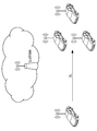
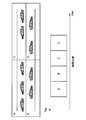
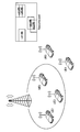
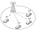
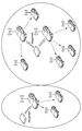
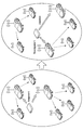
- V2X operation scenario A V2X operation scenario will be described. It is based on V2V communication. In the following description, when one vehicle becomes a pedestrian, it becomes V2P communication, and when it terminates in a facility or network, it becomes V2I / N communication.
- FIG. 1 shows a scenario in which vehicles communicate directly with each other without going through a base station (E-UTRAN).
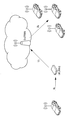
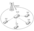
- FIG. 2 shows a scenario in which vehicles communicate with each other via a base station.
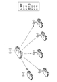
- 3 and 4 show a scenario in which vehicles communicate with each other via a terminal (UE, here, a roadside wireless device (RSU)) and a base station.
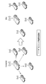
- FIG. 5 shows a scenario in which vehicles communicate with each other via a terminal (UE, here, a roadside radio device (RSU)).
- UE terminal
- RSU roadside radio device
- V2X communication is different from D2D communication in terms of requirements and communication environment, existing D2D communication cannot be used as it is. Therefore, it is necessary to enhance to a form adapted to V2X communication. Differences in features between D2D communication and V2X communication are shown below.
- V2X communication is highly reliable and requires low-delay communication.
- V2X-specific traffic There is V2X-specific traffic.
- V2X has various links.
- Capacity is a bigger issue than D2D.
- Position information can always be obtained.
- V2X communication has many safety applications, and reliability is a very important index. Further, since the moving speed of the car is faster than that of the D2D walking use case, it is necessary to realize low-delay communication.
- Periodic traffic is communication that periodically notifies the surrounding vehicle of data, which is also a characteristic point of V2X.
- V vehicle
- I facility
- N network
- P pedestrian
- the IBE problem (4) and the HD problem (5) are related to the topology of the terminal and the RF performance.
- IBE will be described with reference to FIG.
- the positional relationship between the transmitting and receiving terminals always changes. If there is a receiving terminal in the vicinity of the transmitting terminal, the Emission from the transmitting side may affect the neighboring receiving terminal. Although orthogonality is maintained on the frequency axis, the influence of IBE becomes remarkable from the closeness of the distance between the transmitting and receiving terminals.
- FIG. 6 shows a state in which the transmitting terminal A gives IBE to the receiving terminal D.
- HD problem refers to a problem that the terminal cannot receive when it is transmitting. For this reason, it is necessary to take measures such as preparing an opportunity to receive a plurality of times, or not assigning transmissions of other users in a frame for transmitting data.
- the HD problem is not a problem specific to V2X, but is a major limitation in V2X communication that requires many transmissions.
- V2X communication has an extremely large number of accommodated terminals compared to D2D communication. Furthermore, since the automobile runs on the road, the terminal density inevitably increases locally. Therefore, in V2X communication, improvement of capacity is indispensable. It is necessary to eliminate unnecessary overhead as much as possible to realize efficient communication.
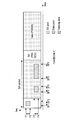
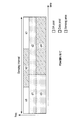
- the PC5 interface through which D2D communication and V2X communication are performed mainly includes a control channel section (PSCCH: Physical Sidelink Channel) and a data channel section (PSSCH: Physical Sideline Shared Channel).
- PSCCH Physical Sidelink Channel
- PSSCH Physical Sideline Shared Channel
- the TDM scheme Since a PSCH resource instruction or the like is notified in the PSCCH, the TDM scheme has a problem that a delay from generation of a packet to transmission becomes large. On the other hand, there is an advantage that the complexity (complexity) of the terminal is good. In D2D, a TDM allocation method is adopted. On the other hand, in the FDM system, since the PSCCH is mapped in the frequency direction, the delay is improved. In addition, it is expected that problems of IBE and HD can be improved by transmitting SA (Scheduling Assignment) and Data in the same SF (subframe). Therefore, in V2X communication, establishment of a communication method using the FDM method is required.
- SA Service Assignment
- SPS Semi-Persistent Scheduling
- Mode 1 Centralized resource allocation
- Mode 2 Autonomous resource selection.
- the base station performs all resource allocation for the PC5 interface.
- the terminal side it is only necessary to perform transmission using resources instructed to the base station.
- the communication characteristics are good because resources are allocated orthogonally.
- the terminal autonomously selects a resource to be used for transmission from the resource pool notified from the base station.
- Mode 2 has an advantage that it can be operated not only in In-coverage in the network of the base station but also in Out-of-overage.
- the Solution can be roughly divided into two.
- One is energy sensing.
- energy sensing a resource is sensed for a certain period, and a communication resource is selected from relatively unused resources based on the sensing result. While simple, the power level is not so accurate. However, it is possible to sense a system other than LTE.
- Another method is SA decoding. This is a method of recognizing the location of a resource being used by decoding SA (control information) transmitted by another user. While the used resources can be discovered with high accuracy, there are disadvantages such that the SA resource itself cannot be sensed, and if the SA decoding fails, the used resource cannot be detected.
- Table 2 shows a list of explanations of enhancements so far. This is an example and describes typical enhancements, and various other methods are being considered.
- Sensing mode switching When there are one or more sensing modes, the UE does not know which sensing mode should be used in a given situation. As for energy sensing, blind sensing is used for the SA pool and the data pool, which is a sensing mode that uses power very much for a UE carried by a pedestrian.
- the UE sets the sensing mode by two methods.
- the first method is to determine which sensing mode the eNB should use.
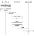
- FIG. 11 is a flowchart illustrating a sensing mode determination method by the eNB, the transmission side UE, and the reception side UE.
- ENB determines the sensing mode and sensing parameters. Subsequently, the eNB generates a mapping table in which the relationship between the sensing mode, the sensing parameter, and the state is defined. Subsequently, the eNB determines a sensing mode and a sensing parameter, and notifies the UE on the transmission side of the sensing mode and the sensing parameter.
- the UE on the transmission side sets the sensing mode and sensing parameter notified from the eNB, performs sensing according to the sensing mode and sensing parameter, and transmits the packet.
- the receiving side UE receives the packet transmitted from the transmitting side UE.
- the second method is a method for determining which sensing mode the UE should use.
- FIG. 12 is a flowchart illustrating a sensing mode determination method by the eNB, the transmission side UE, and the reception side UE.
- ENB determines the sensing mode and sensing parameters. Subsequently, the eNB generates a mapping table in which the relationship between the sensing mode, the sensing parameter, and the state is defined. Subsequently, the eNB notifies the UE on the receiving side of the mapping table.
- the mapping table may be pre-configured in advance in the terminal.
- the UE on the receiving side determines the sensing mode and sensing parameter, performs sensing according to the sensing mode and sensing parameter, and transmits a packet.
- the receiving side UE receives the packet transmitted from the transmitting side UE.
- the mapping table is a table in which which sensing mode is used and which sensing parameter is used depending on the situation.
- Table 3 shows an example of the mapping table.
- “Sensing mode” is used for energy sensing, SA decoding, or a combination thereof. In addition to this, “Sensing mode” may be used in combination with data decoding, assistant sensing from the eNB, or the like. Data decoding is a method of decoding data of other terminals and confirming the resource usage status, and assistant sensing from the eNB is a method of sensing by receiving information on radio environment information from the eNB.
- “Condition” sends a periodic or event triggered message, for example, the UE has a low power requirement, has a safety requirement, has a low latency requirement, Have high or low priority, categories, types of sensing channels such as PSCCH, PSSCH, types of presence of other RATs (Radio Access Technologies), data traffic congestion, resource usage, terminal There can be a location.
- the UE has a low power requirement, has a safety requirement, has a low latency requirement, Have high or low priority, categories, types of sensing channels such as PSCCH, PSSCH, types of presence of other RATs (Radio Access Technologies), data traffic congestion, resource usage, terminal There can be a location.
- RATs Radio Access Technologies
- Sensing parameter may include, for example, parameters such as sensing interval, sensing start time, weight information, information on a limited sensing area for saving battery, and the like.
- the limited sensing area information may include sensing time interval and frequency band information, for example, information such as a sensing frequency region, such as bandwidth, resource pool, and subcarrier.
- the restricted sensing area information may also include, for example, sensing area definition, eg, block ID information.
- the block ID is an ID assigned to each partitioned pool.
- the information on the restricted sensing area may include information on a location where sensing is performed. The terminal performs the specified sensing at the specified position.
- the mapping table can be updated.
- the sensing mode can be changed depending on the given situation, and the sensing parameter can be changed depending on the given situation. Also, the sensing parameter can be changed according to a given sensing mode.
- ENB evaluates whether the current mapping is not the best choice. Also, the UE reports to the eNB that the current mapping is not the best choice. Thereby, the mapping table can be updated.
- the eNB notifies the UE of the mapping table or the sensing mode and sensing parameters, and for this notification, for example, SIB or DCI may be used. For example, the eNB broadcasts this information. For example, in a coexisting DSRC scenario, the eNB requests all UEs to select energy sensing. Further, for example, the eNB notifies the multicast information to a group of UEs and some UEs. Also, for example, the eNB notifies information to a unique UE by unicast.
- the mapping table can be transmitted at the timing of RRC connection setup or re-establishment, for example. Further, the mapping table can be transmitted, for example, at an initially set timing. Also, the mapping table can be transmitted at an updated timing, for example. Further, the mapping table can be transmitted, for example, at a timing when the UE transmits a request for the mapping table. Further, the mapping table can be transmitted periodically, for example, at a period defined by the UE.
- centralized sensing is executed by two methods.
- the first method is a method in which the eNB or RSU determines one or more representatives that perform sensing.
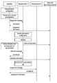
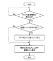
- FIG. 13 is a flowchart illustrating an operation example of an eNB or RSU, a node that is representatively sensing, and other UEs when performing sensing centralization.
- the eNB or RSU defines conditions representative of sensing, determines a node to be represented as a representative, and transmits a message indicating that it has been assigned as a representative to the determined node.
- the representative transmits an ACK or NACK to the message indicating that the representative has been assigned to the eNB or RSU.
- the eNB or the RSU itself can be a representative.
- the eNB or RSU may be set as a representative, or may be set as a representative from the Core Network side.
- the setting can be performed from the eNB side.
- the eNB or RSU When the eNB or RSU receives a reply from the representative, the eNB or RSU transmits information indicating that the representative UE has been assigned to the other UEs.
- the representative performs sensing by setting sensing.
- the representative transmits a sensing result to the UE that is not represented.
- ENB or RSU determines whether to release the representative and reassign the representative.
- the eNB or RSU sends a release message to the current representative.
- the representative transmits ACK or NACK for the release message to the eNB or RSU.
- the eNB or RSU transmits information indicating that the representative has been released to other UEs, and transmits a message indicating that the representative has been assigned to another node.
- the representative transmits an ACK or NACK to the message indicating that it has been assigned as a representative to the eNB or RSU.
- the eNB or RSU receives a reply from the representative, the eNB or RSU transmits information indicating that the representative is assigned to the other UEs.
- the second method is a method in which the UE determines one or more representative UEs that perform sensing.
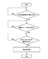
- FIG. 14 is a flowchart showing an operation example of an eNB or RSU, a node that is representatively sensing, and other UEs when performing sensing centralization.
- ENB or RSU defines conditions representative of sensing, and transmits representative setting information to the UE.
- the UE that has received the representative setting information from the eNB or the RSU determines a representative based on the information, and transmits a message indicating that the representative has been assigned to the node determined as the representative.
- the representative who has received the message indicating the assignment as the representative transmits ACK or NACK.
- the representative performs sensing by setting sensing.
- the representative transmits a sensing result to the UE that is not represented.
- the UE can also determine whether to release the representative and reassign the representative. When releasing the representative, the UE sends a release message to the current representative. The representative transmits an ACK or NACK for the release message to the UE.
- the UE transmits information indicating that the representative has been released to other UEs, and transmits a message indicating that the representative has been assigned to another node.
- the representative transmits an ACK or NACK to the message indicating that the representative has been assigned to the UE.
- the UE Upon receiving a reply from the representative, the UE transmits information indicating that the representative UE has been assigned to the other UEs.
- eNB may be a representative of sensing
- RSU may be a representative of sensing
- UE may be a representative of sensing.
- the eNB, RSU, or UE to determine the representative UE may be determined randomly from UEs in a predetermined area in a predetermined period, or may be determined based on a predetermined rule.
- the UE that is transmitting the synchronization signal may be the representative UE, and the UE ID, UE location, UE category, UE battery status, UE speed, UE mobility, UE The representative UE may be determined based on the status of the buffer.
- the representative setting information may include information such as a method for determining the representative, a start time and a period of the representative, and a sensing parameter.
- the sensing parameters may include parameters such as a sensing mode, a sensing start time, a sensing period, and a sensing target, for example.
- the sensing target can be LTE-V2X, DSRC, or the like. If the target is LTE-V2X, UE, a list of UEs to be sensed may be provided.
- the release of the representative may be performed, for example, when the current representative cannot sense.
- the UE in the eNB or RSU, when the sensing function is stopped, the UE is in an idle state, requested to suppress power consumption, and out of the current eNB coverage, from the responsibility of the current RSU This is the case when it comes off.
- Reassignment of the representative may be performed immediately after the representative is released, or may be performed when the timer value reaches the next allocation timing.
- the representative For ACK or NACK, the representative returns ACK when an allocation or release request is sent to the representative. If a NACK is returned or there is no response until the response deadline, a new representative can be assigned.
- the eNB monitors resource usage and sensing of all UEs in coverage. In this case, the eNB collects radio condition measurement reports from UEs in coverage.
- the RSU monitors resource usage and sensing of nearby UEs.
- the eNB determines a UE to be sensed representatively at random or in a predetermined method.
- the predetermined method may be, for example, a method of selecting a terminal having a high SA reception capability (such as a terminal equipped with an advanced receiver), and selecting a UE that does not mind power consumption even when energy sensing is used. The method is fine.
- the RSU may determine a UE to be sensed representatively at random or by a predetermined method.
- the UE determines a UE that is transmitting a synchronization signal randomly or based on the ID of the UE.
- the representative UE can be released. For example, when the UE becomes incapable of sensing, for example, when the UE status changes from Connected to idle, when the UE wants to reduce power consumption, when the UE is out of the current eNB coverage, the UE is responsible for the current RSU. If you are out of the range, there may be.
- the representative UE can also be released when the sensing period timer is set and the sensing period ends. At the end of the sensing period, the eNB or RSU may decide to release, and the UE may sense one after another.
- a new UE may be selected at random, or may be selected by a predetermined method. Further, the reallocation may be performed immediately after the release or may be performed after a predetermined time has elapsed.
- Sensing + LBT Listen Before Talk
- Sensing + LBT Listen Before Talk
- LBT is a method adopted in the WiFi system, but it is difficult to handle specific traffic, and it is difficult to apply it as it is in V2X communication that can receive support from a base station. Therefore, LBT enhancement is required for LTE V2X communication.
- the sensing method here is not limited to energy sensing, and SA decoding, data decoding method, or the like may be used.
- V2X communication there are a periodical traffic where the latency requirement is not so severe and an event trigger traffic where the latency requirement is severe.
- the latency of the LBT back-off time becomes latency, and the communication request may not be satisfied in some cases.
- the sensing threshold may be set separately for Type 1 and Type 2.
- the threshold may be set separately for each channel such as PSCCH and PSSCH.
- a switching method of the LBT method is proposed according to the traffic type to be transmitted.
- FIG. 15 is a flowchart showing a switching method of the LBT method. This indicates that if the traffic to be transmitted is traffic with a severe latency requirement, for example, if the event trigger traffic is sent, it is sent with Type 2, and if not, it is sent with Type 1.
- the LBT method may be switched according to the resource usage status (traffic congestion status). If the available resources are tight after sensing, the probability of selecting the same resource as the neighboring terminal is increased. In order to avoid this, the terminal switches the LBT method according to the degree of resource congestion. For example, when sensing is performed and a resource amount that can be selected is equal to or less than a certain threshold, the terminal determines that a resource selection cover occurs with another terminal and operates to avoid the cover by selecting the LBT method. be able to.
- a terminal category As information used for switching the LBT, a terminal category, a terminal ID, traffic priority information, a terminal speed, and the like may be used in addition to the traffic type and the resource usage status. May be switched.
- the LBT type switching method notifies an arbitrary LBT method from the base station. This may be notified for each UE or for each cell.
- the base station may provide an LBT method and a mapping table of information used for switching to the terminal, and the terminal may select the LBT type according to the information used for switching.
- An LBT type switching method may be preset in the terminal.
- V2X communication Introduction of two-step sensing, a case where operation is performed while performing co-existence with a DSRC system (802.11p communication) is assumed. In this case, the LTE V2X communication needs to detect the DSRC system and perform an operation so as not to cause interference. At the same time, it is necessary to avoid packet collision with other users even in LTE V2X communication.
- DSRC_LBT for DSRC system detection is introduced.
- DSRC_LBT may be Type 1 or Type 2, but Type 1 is preferable.
- LTE_V2X_LBT for avoiding Mode2 communication packet collision in the LTE V2X system is introduced.
- LTE_V2X_LBT may be Type 1 or Type 2, but Type 2 is preferable.
- LTE_V2X_LBT In addition to LTE_V2X_LBT, other sensing methods such as SA decoding may be used.
- FIG. 16 is a flowchart showing the flow of two-step sensing at the terminal.
- the terminal performs DSRC_LBT and performs LTE_V2X_LBT after determining that the channel state is IDLE.
- LTE_V2X_LBT When the channel state is determined to be IDLE in LTE_V2X_LBT, a signal is transmitted.
- the terminal may change the area for sensing with DSRC_LBT and LTE_V2X_LBT. Also, the terminal may change the region in the frequency direction, may change the region in the time direction, or may change the region in both the frequency direction and the time direction.
- the sensing area may be notified in advance from the base station, or may be set in advance in the terminal.
- a back-off timer is set from the base station to the terminal.
- the notification method from the base station to the terminal may be notified by RRC, may be notified by DCI, may be notified by SIB, may be notified by signaling, or may be notified by other methods. Also good.
- the value of the backoff timer may be a backoff timer in the time direction, a backoff timer in the frequency direction, or a backoff timer in both the time direction and the frequency direction.
- the band may be divided into a plurality of subcarriers, may be divided by the number of subcarriers used for its own transmission, or may be uniquely divided by the system.
- the value of the back-off timer may be the sum of the back-off timers for both time and frequency. Further, a valid period of the back-off timer may be set from the base station to the terminal. Further, the back-off timer may be set across a plurality of scheduling periods.
- the back-off timer table When the back-off timer table is provided from the base station to the terminal, information such as the back-off timer value, the time-direction back-off timer, the frequency-direction back-off timer, and the time-frequency back-off timer are added. May be.
- FIG. 17 is a flowchart showing an example of backoff operation.
- the backoff may be set in the time direction or may be set in the frequency direction. Moreover, you may set to both time and a frequency.
- the terminal senses the specified time and frequency domain, and if Occupation is detected, it determines whether there is still a sensing area in the frequency direction, and if there is none, it slides in the frequency direction, otherwise it slides in the time direction. The frequency direction is reset. If the terminal does not detect Occupation, the terminal performs back-off subtraction described later.
- the back-off may be configured by any of Subframe, Subcarrier, and SA period units, or may be configured by a combination thereof.
- the terminal When the terminal is notified of a specific back-off timer, the terminal sets the back-off timer. When the back-off timer is set with a width, the terminal randomly selects from the width.
- the terminal selects the back-off timer according to the associated parameter.
- the back-off timer is set with a width, a random selection is made from the width.
- the terminal performs back-off value subtraction according to the sensing result.
- the terminal can subtract in the time direction and the frequency direction, respectively.
- backoff is set for each of time and frequency
- the terminal performs subtraction for each. If it is a common back-off, the terminal subtracts one when detecting one non-occupation regardless of time and frequency.
- FIG. 18 is a flowchart showing a sensing area setting method.
- Examples of the time and frequency sliding method include a method of sliding first in the time direction and then sliding in the frequency direction.
- Sensing + LBT transmission is performed after acquisition of the transmission right.
- SA pool and data pool are separated in terms of time, so it is necessary to newly set conditions for acquiring transmission rights. For example, even if the SA resource transmission right is acquired, transmission is not possible unless resources in the data area are secured. The reverse is also true. In this way, it is necessary to newly define the conditions for acquiring the transmission right.
- three methods are shown.
- a method for acquiring SA and data transmission rights when SA transmission resources can be secured.
- a transmission terminal senses only the SA area and obtains SA transmission rights, the SA and data transmission rights are obtained. It is a method to acquire. Since sensing of the data part is not performed, collision of the data part may occur. Since at least SA is sensing, it is better than doing nothing.
- the transmission right acquisition condition is when SA_LBT is OK. If the remaining SA resource is equal to or greater than a certain value, the SA resource is randomly selected from the remaining SA pool, and the data resource is randomly selected from the data pool, and then transmitted.
- the transmission is postponed until the next SA period. Randomly select the SA resource from the SA resource pool based on the SA_LBT result randomly or based on the SA_LBT result, and then send the data resource selected at random from the data pool.
- FIG. 19 is a flowchart showing a method for determining whether or not the transmission right can be obtained only by the SA.
- N is a counter, and N is decremented by 1 when the SA channel is idle.
- SA_LBT 0.
- the terminal determines whether the corresponding SA period has sufficient SA resources by comparing with a usable subframe SF available which is a parameter set in advance by the base station.
- the terminal randomly selects an SA resource from the SA resource pool. If there are enough SA resources, the terminal postpones transmission until the next SA period. Randomly select the SA resource from the SA resource pool based on the SA_LBT result randomly or based on the SA_LBT result, and then send the data resource selected at random from the data pool.
- the terminal may subtract a certain amount of the back-off value in order to increase the priority for acquiring the transmission opportunity when transmitting in the following SA period.
- the transmission right acquisition condition is when Data_LBT is OK. If the remaining data resources in the corresponding SA period exceed a certain value, the data resources are reserved from the remaining.
- the terminal randomly selects an SA resource from the SA resource pool for the next SA period, selects a reserved data resource from the data pool, and transmits it.
- the SA resource is randomly selected from the SA resource pool as the next SA period, and is transmitted when the data resource is selected randomly from the data pool or based on the result of DATA_LBT.
- FIG. 20 is a flowchart showing an operation example when the SA and the data transmission right are acquired when the data transmission resource can be secured.
- DATA_LBT N and sensing is started.
- N is a counter, and N is decremented by 1 when the SA channel is idle.
- the terminal determines whether or not there is sufficient data resource in the corresponding SA period by comparing it with an available subframe SF available which is a parameter preset by the base station.
- the terminal randomly selects an SA resource from the SA resource pool for the next SA period, selects a reserved data resource from the data pool, and transmits it.
- the SA resource is randomly selected from the SA resource pool as the next SA period, and is transmitted when the data resource is selected randomly from the data pool or based on the result of DATA_LBT.
- a method of acquiring SA and data transmission rights when both SA and data transmission resources can be secured.
- the transmitting terminal performs sensing of both the SA area and the data area. Only SA applies LBT, and data introduces a new reservation. Since both SA and data are sensed, the probability of collision is low compared to the above two methods.
- the transmission right acquisition condition is when SA_LBT is OK and the resource in the Data area is “Reserved”. If the remaining SA resources are below a certain value, the transmission is postponed until the next SA period.
- FIG. 21 is a flowchart showing an operation example in the case where both the SA and data transmission resources are secured and the SA and data transmission rights are acquired.
- the data pool performs sensing without LBT and reserves resources to be used. It is determined whether or not to use the reserved data resource according to the SA_LBT result.
- the securing of the data resource reserves the resource to be used using sensing without LBT.
- the terminal When the terminal performs SA_LBT and acquires the transmission right, the terminal refers to the reserved data resource of the previous SA period and selects the resource of the current SA period. If the remaining SA resources are below a certain value, the terminal postpones transmission until the next SA period.
- Mode 1 and Mode 2 sensing The UE should be in eNB coverage.
- the eNB sets up a resource pool and indicates resource allocation for all UEs.
- FIG. 24 is an explanatory diagram showing an example of mode 1 resource allocation.
- Mode 2 The UE may be present or out of coverage of the eNB. If out of coverage, the resource pool should be pre-configured. The UE randomly selects a resource from the resource pool.
- FIG. 25 is an explanatory diagram showing an example of resource allocation in mode 2.
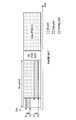
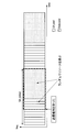
- the UE may have a limited time interval for sensing.
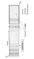
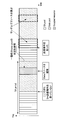
- FIG. 26 is an explanatory diagram illustrating an example in which the sensing time interval is limited in TDM.
- the UE is informed of the time interval for sensing as ⁇ (SF1, SF2), (SF3, SF4), (SF4, SF5) ⁇ in FIG.
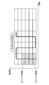
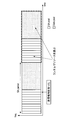
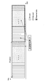
- FIG. 27 is an explanatory diagram illustrating an example in which the sensing frequency band is limited in TDM.
- the UE is informed of a frequency band for sensing, for example, SA ⁇ (F1, F2) ⁇ , data ⁇ (F3, F4) ⁇ in FIG.
- FIG. 28 is an explanatory diagram illustrating an example in which both the sensing time interval and the frequency band are limited in TDM.
- the UE performs sensing of ⁇ SF1, SF2), (SF3, SF4), (SF4, SF5) ⁇ , SA ⁇ (F1, F2) ⁇ , data ⁇ (F3, F4) ⁇ in FIG. Be informed of the time interval and frequency band for.
- FIG. 29 is an explanatory diagram illustrating an example in which a sensing block is limited in TDM. The UE is informed of a block ID for sensing in block units, for example, ⁇ s4, d2, d5 ⁇ in FIG.
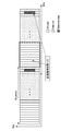
- FIG. 30 is an explanatory diagram illustrating an example in which the sensing time interval is limited in the FDM.
- the UE is informed of the time interval for sensing as ⁇ (SF1, SF2), (SF3, SF4), (SF4, SF5) ⁇ in FIG.
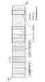
- FIG. 31 is an explanatory diagram illustrating an example in which the sensing frequency band is limited in the FDM.
- the UE is informed of the frequency band for sensing, for example, ⁇ (F1, F2) ⁇ , ⁇ (F3, F4) ⁇ in FIG.
- FIG. 32 is an explanatory diagram showing an example in which both the sensing time interval and the frequency band are limited in FDM.
- the UE is, for example, SA ⁇ (SF1, SF2) ⁇ , ⁇ (SF3, SF4) ⁇ , data ⁇ (SF4, SF5) ⁇ , ⁇ (F1, F2), (F3, F4) ⁇ in FIG. You are informed of the time interval and frequency band for sensing.
- FIG. 33 is an explanatory diagram showing an example in which the sensing block is limited in the FDM.
- the UE is informed of a block ID for sensing in block units, for example, ⁇ s4, d4 ⁇ in FIG.
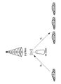
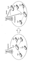
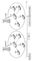
- FIG. 34 is an explanatory diagram showing how the eNB performs sensing.
- FIG. 35 is an explanatory diagram showing how the RSU performs sensing.
- FIG. 36 is an explanatory diagram showing a state where a typical UE performs sensing.
- FIG. 36 illustrates an example in which the eNB assigns one or more UEs as UEs that perform sensing.
- FIG. 37 is an explanatory diagram showing how a typical UE performs sensing.
- FIG. 37 shows an example when the RSU assigns one or more UEs as UEs that perform sensing.
- FIG. 38 is an explanatory diagram showing how a typical UE performs sensing.
- FIG. 38 shows an example in which the UE determines a representative UE by itself using, for example, UEid.
- FIG. 39 is an explanatory diagram illustrating a state where a representative UE is released when the UE state changes from connected to idle.
- a representative UE may be released when away from the current eNB or RSU.
- FIG. 40 is an explanatory diagram illustrating an example in which a typical UE is released when the user moves away from the current eNB.
- FIG. 41 is an explanatory diagram showing an example in which a typical UE is released when the user moves away from the current RSU.
- FIG. 42 is an explanatory diagram illustrating an example of a new typical UE assignment using a timer.
- FIG. 43 is an explanatory diagram illustrating an example in which a typical UE performs sensing in order using a predetermined timer.
- the transmission terminal sets the counter N to 5.
- the terminal starts sensing from the next subframe SF1.
- the terminal selects a resource and transmits a packet in the next subframe SF8.
- the transmission terminal sets the counter N to 5. After waiting for 5 subframes, the terminal selects a resource in the next subframe and transmits a packet.
- FIG. 44 is an explanatory diagram showing an enhanced LBT.
- the UE randomly selects an SA resource from the remaining SA pool and data pool in the current SA period.
- FIG. 45 is an explanatory diagram showing an enhanced LBT.
- the UE randomly selects SA resources and data resources from the SA pool and data pool in the next SA period.
- FIG. 46 is an explanatory diagram showing the enhanced LBT.
- the UE selects an SA resource based on the SA_LBT result from among the SA pool and data pool in the next SA period, and also randomly selects a data resource.
- the subframe offset is set to 2.
- the counter N is 0 and a transmission right is obtained and the number of remaining subframes is 3, which is larger than the subframe offset, is shown.
- FIG. 47 is an explanatory diagram showing the enhanced LBT. In this case, the UE randomly selects an SA resource from the SA pool in the next SA period, and selects a data resource from the reserved data pool.
- FIG. 48 is an explanatory diagram showing the enhanced LBT.
- the UE randomly selects an SA resource and a data resource from the SA pool and data pool in the next SA period.
- FIG. 49 is an explanatory diagram showing the enhanced LBT.
- the UE selects an SA resource from the SA pool in the next SA period, and selects an SA resource from the DATA_LBT result in the data pool.
- FIG. 50 is an explanatory diagram showing the enhanced LBT. As a first example, a case is shown in which the SA transmission right is taken, but data resources are not secured. In this case, the UE reserves the data resource with the current SA period, and randomly selects the data resource from the SA pool and the data pool in the next SA period.
- FIG. 51 is an explanatory diagram showing the enhanced LBT.
- a case is shown in which data resources are secured but no SA transmission right is taken.
- the UE refers to the status of the previous SA period, and randomly selects an SA resource from the current SA pool and the reserved data pool.
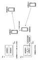
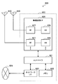
- FIG. 52 is a block diagram illustrating an exemplary configuration of the base station 100 according to the embodiment of the present disclosure.
- the base station 100 includes an antenna unit 110, a wireless communication unit 120, a network communication unit 130, a storage unit 140, and a processing unit 150.
- Antenna unit 110 The antenna unit 110 radiates a signal output from the wireless communication unit 120 to the space as a radio wave. Further, the antenna unit 110 converts radio waves in space into a signal and outputs the signal to the wireless communication unit 120.
- the wireless communication unit 120 transmits and receives signals.
- the radio communication unit 120 transmits a downlink signal to the terminal device and receives an uplink signal from the terminal device.
- the network communication unit 130 transmits and receives information.
- the network communication unit 130 transmits information to other nodes and receives information from other nodes.
- the other nodes include other base stations and core network nodes.
- Storage unit 140 The storage unit 140 temporarily or permanently stores a program for operating the base station 100 and various data.
- Processing unit 150 provides various functions of the base station 100.
- the processing unit 150 includes a transmission processing unit 151 and a notification unit 153.
- the processing unit 150 may further include other components other than these components. That is, the processing unit 150 can perform operations other than the operations of these components.
- the transmission processing unit 151 executes processing related to data transmission to the terminal device 200.
- the transmission processing unit 151 performs the overall processing of the base station (eNB) described above.
- the notification unit 153 executes processing related to notification of information to the terminal device 200.
- the notification unit 153 performs overall notification processing for the terminal device by the base station (eNB) described above.
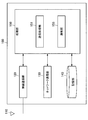
- FIG. 53 is a block diagram illustrating an exemplary configuration of the terminal device 200 according to an embodiment of the present disclosure.
- the terminal device 200 includes an antenna unit 210, a wireless communication unit 220, a storage unit 230, and a processing unit 240.
- Antenna unit 210 The antenna unit 210 radiates the signal output from the wireless communication unit 220 to the space as a radio wave. Further, the antenna unit 210 converts a radio wave in the space into a signal and outputs the signal to the wireless communication unit 220.
- the wireless communication unit 220 transmits and receives signals.
- the radio communication unit 220 receives a downlink signal from the base station and transmits an uplink signal to the base station.
- Storage unit 230 The storage unit 230 temporarily or permanently stores a program for operating the terminal device 200 and various data.
- the processing unit 240 provides various functions of the terminal device 200.
- the processing unit 240 includes an acquisition unit 241 and a reception processing unit 243.
- the processing unit 240 may further include other components other than these components. That is, the processing unit 240 can perform operations other than the operations of these components.
- the acquisition unit 241 executes processing related to acquisition of data transmitted from the base station 100.
- the reception processing unit 243 executes processing related to reception of data acquired by the acquisition unit 241.
- the reception processing unit 243 executes the overall processing of the terminal device described above.
- the base station 100 may be realized as any type of eNB (evolved Node B) such as a macro eNB or a small eNB.
- the small eNB may be an eNB that covers a cell smaller than a macro cell, such as a pico eNB, a micro eNB, or a home (femto) eNB.
- the base station 100 may be realized as another type of base station such as a NodeB or a BTS (Base Transceiver Station).
- Base station 100 may include a main body (also referred to as a base station apparatus) that controls radio communication, and one or more RRHs (Remote Radio Heads) that are arranged at locations different from the main body. Further, various types of terminals described later may operate as the base station 100 by temporarily or semi-permanently executing the base station function.
- a main body also referred to as a base station apparatus
- RRHs Remote Radio Heads
- the terminal device 200 is a smartphone, a tablet PC (Personal Computer), a notebook PC, a portable game terminal, a mobile terminal such as a portable / dongle type mobile router or a digital camera, or an in-vehicle terminal such as a car navigation device. It may be realized as.
- the terminal device 200 may be realized as a terminal (also referred to as an MTC (Machine Type Communication) terminal) that performs M2M (Machine To Machine) communication.
- the terminal device 200 may be a wireless communication module (for example, an integrated circuit module configured by one die) mounted on these terminals.
- FIG. 54 is a block diagram illustrating a first example of a schematic configuration of an eNB to which the technology according to the present disclosure may be applied.
- the eNB 800 includes one or more antennas 810 and a base station device 820. Each antenna 810 and the base station apparatus 820 can be connected to each other via an RF cable.
- Each of the antennas 810 has a single or a plurality of antenna elements (for example, a plurality of antenna elements constituting a MIMO antenna), and is used for transmission and reception of radio signals by the base station apparatus 820.
- the eNB 800 includes a plurality of antennas 810 as illustrated in FIG. 54, and the plurality of antennas 810 may respectively correspond to a plurality of frequency bands used by the eNB 800, for example.
- 54 illustrates an example in which the eNB 800 includes a plurality of antennas 810, but the eNB 800 may include a single antenna 810.
- the base station apparatus 820 includes a controller 821, a memory 822, a network interface 823, and a wireless communication interface 825.
- the controller 821 may be a CPU or a DSP, for example, and operates various functions of the upper layer of the base station apparatus 820. For example, the controller 821 generates a data packet from the data in the signal processed by the wireless communication interface 825, and transfers the generated packet via the network interface 823. The controller 821 may generate a bundled packet by bundling data from a plurality of baseband processors, and may transfer the generated bundled packet. In addition, the controller 821 is a logic that executes control such as radio resource control, radio bearer control, mobility management, inflow control, or scheduling. May have a typical function. Moreover, the said control may be performed in cooperation with a surrounding eNB or a core network node.
- the memory 822 includes RAM and ROM, and stores programs executed by the controller 821 and various control data (for example, terminal list, transmission power data, scheduling data, and the like).
- the network interface 823 is a communication interface for connecting the base station device 820 to the core network 824.
- the controller 821 may communicate with the core network node or other eNB via the network interface 823.
- the eNB 800 and the core network node or another eNB may be connected to each other by a logical interface (for example, an S1 interface or an X2 interface).
- the network interface 823 may be a wired communication interface or a wireless communication interface for wireless backhaul.
- the network interface 823 may use a frequency band higher than the frequency band used by the wireless communication interface 825 for wireless communication.
- the wireless communication interface 825 supports any cellular communication scheme such as LTE (Long Term Evolution) or LTE-Advanced, and provides a wireless connection to terminals located in the cell of the eNB 800 via the antenna 810.
- the wireless communication interface 825 may typically include a baseband (BB) processor 826, an RF circuit 827, and the like.
- the BB processor 826 may perform, for example, encoding / decoding, modulation / demodulation, and multiplexing / demultiplexing, and each layer (for example, L1, MAC (Medium Access Control), RLC (Radio Link Control), and PDCP).
- Various signal processing of Packet Data Convergence Protocol
- Packet Data Convergence Protocol is executed.
- the BB processor 826 may have some or all of the logical functions described above instead of the controller 821.
- the BB processor 826 may be a module that includes a memory that stores a communication control program, a processor that executes the program, and related circuits. The function of the BB processor 826 may be changed by updating the program. Good.
- the module may be a card or a blade inserted into a slot of the base station apparatus 820, or a chip mounted on the card or the blade.
- the RF circuit 827 may include a mixer, a filter, an amplifier, and the like, and transmits and receives a radio signal via the antenna 810.
- the wireless communication interface 825 includes a plurality of BB processors 826 as shown in FIG. 54, and the plurality of BB processors 826 may respectively correspond to a plurality of frequency bands used by the eNB 800, for example. Further, the wireless communication interface 825 includes a plurality of RF circuits 827 as shown in FIG. 54, and the plurality of RF circuits 827 may respectively correspond to a plurality of antenna elements, for example. 54 illustrates an example in which the wireless communication interface 825 includes a plurality of BB processors 826 and a plurality of RF circuits 827, the wireless communication interface 825 includes a single BB processor 826 or a single RF circuit 827. But you can.
- the eNB 800 includes a module including a part (for example, the BB processor 826) or all of the wireless communication interface 825 and / or the controller 821, and the one or more components are mounted in the module. Good.
- the module stores a program for causing the processor to function as the one or more components (in other words, a program for causing the processor to execute the operation of the one or more components). The program may be executed.
- a program for causing a processor to function as the one or more components is installed in the eNB 800, and the radio communication interface 825 (eg, the BB processor 826) and / or the controller 821 executes the program.
- the eNB 800, the base station apparatus 820, or the module may be provided as an apparatus including the one or more components, and a program for causing a processor to function as the one or more components is provided. May be.
- a readable recording medium in which the program is recorded may be provided.
- the radio communication unit 120 described with reference to FIG. 52 in the eNB 800 illustrated in FIG. 54 may be implemented in the radio communication interface 825 (for example, the RF circuit 827). Further, the antenna unit 110 may be mounted on the antenna 810.
- the network communication unit 130 may be implemented in the controller 821 and / or the network interface 823.
- the storage unit 140 may be implemented in the memory 822.
- FIG. 55 is a block diagram illustrating a second example of a schematic configuration of an eNB to which the technology according to the present disclosure may be applied.
- the eNB 830 includes one or more antennas 840, a base station apparatus 850, and an RRH 860. Each antenna 840 and RRH 860 may be connected to each other via an RF cable. Base station apparatus 850 and RRH 860 can be connected to each other via a high-speed line such as an optical fiber cable.
- Each of the antennas 840 has a single or a plurality of antenna elements (for example, a plurality of antenna elements constituting a MIMO antenna), and is used for transmission / reception of radio signals by the RRH 860.
- the eNB 830 includes a plurality of antennas 840 as illustrated in FIG. 55, and the plurality of antennas 840 may respectively correspond to a plurality of frequency bands used by the eNB 830, for example. 55 shows an example in which the eNB 830 has a plurality of antennas 840, but the eNB 830 may have a single antenna 840.
- the base station device 850 includes a controller 851, a memory 852, a network interface 853, a wireless communication interface 855, and a connection interface 857.
- the controller 851, the memory 852, and the network interface 853 are the same as the controller 821, the memory 822, and the network interface 823 described with reference to FIG.
- the wireless communication interface 855 supports a cellular communication method such as LTE or LTE-Advanced, and provides a wireless connection to a terminal located in a sector corresponding to the RRH 860 via the RRH 860 and the antenna 840.
- the wireless communication interface 855 may typically include a BB processor 856 and the like.
- the BB processor 856 is the same as the BB processor 826 described with reference to FIG. 54 except that the BB processor 856 is connected to the RF circuit 864 of the RRH 860 via the connection interface 857.
- the wireless communication interface 855 includes a plurality of BB processors 856 as illustrated in FIG.
- FIG. 55 shows an example in which the wireless communication interface 855 includes a plurality of BB processors 856, but the wireless communication interface 855 may include a single BB processor 856.
- connection interface 857 is an interface for connecting the base station device 850 (wireless communication interface 855) to the RRH 860.
- the connection interface 857 may be a communication module for communication on the high-speed line that connects the base station apparatus 850 (wireless communication interface 855) and the RRH 860.
- the RRH 860 includes a connection interface 861 and a wireless communication interface 863.
- connection interface 861 is an interface for connecting the RRH 860 (wireless communication interface 863) to the base station device 850.
- the connection interface 861 may be a communication module for communication on the high-speed line.
- the wireless communication interface 863 transmits and receives wireless signals via the antenna 840.
- the wireless communication interface 863 may typically include an RF circuit 864 and the like.
- the RF circuit 864 may include a mixer, a filter, an amplifier, and the like, and transmits and receives wireless signals via the antenna 840.
- the wireless communication interface 863 includes a plurality of RF circuits 864 as shown in FIG. 55, and the plurality of RF circuits 864 may correspond to, for example, a plurality of antenna elements, respectively.
- FIG. 55 shows an example in which the wireless communication interface 863 includes a plurality of RF circuits 864, but the wireless communication interface 863 may include a single RF circuit 864.
- one or more components included in the processing unit 150 described with reference to FIG. 52 include the wireless communication interface 855 and / or the wireless The communication interface 863 may be implemented. Alternatively, at least some of these components may be implemented in the controller 851.
- the eNB 830 includes a module including a part (for example, the BB processor 856) or the whole of the wireless communication interface 855 and / or the controller 851, and the one or more components are mounted in the module. Good.
- the module stores a program for causing the processor to function as the one or more components (in other words, a program for causing the processor to execute the operation of the one or more components).
- the program may be executed.
- a program for causing a processor to function as the one or more components is installed in the eNB 830, and the wireless communication interface 855 (eg, the BB processor 856) and / or the controller 851 executes the program.
- the eNB 830, the base station apparatus 850, or the module may be provided as an apparatus including the one or more components, and a program for causing a processor to function as the one or more components is provided. May be.
- a readable recording medium in which the program is recorded may be provided.
- the radio communication unit 120 described with reference to FIG. 52 may be implemented in the radio communication interface 863 (for example, the RF circuit 864).
- the antenna unit 110 may be mounted on the antenna 840.
- the network communication unit 130 may be implemented in the controller 851 and / or the network interface 853.
- the storage unit 140 may be mounted in the memory 852.
- FIG. 56 is a block diagram illustrating an example of a schematic configuration of a smartphone 900 to which the technology according to the present disclosure may be applied.
- the smartphone 900 includes a processor 901, a memory 902, a storage 903, an external connection interface 904, a camera 906, a sensor 907, a microphone 908, an input device 909, a display device 910, a speaker 911, a wireless communication interface 912, one or more antenna switches 915.
- One or more antennas 916, a bus 917, a battery 918 and an auxiliary controller 919 are provided.
- the processor 901 may be, for example, a CPU or a SoC (System on Chip), and controls the functions of the application layer and other layers of the smartphone 900.
- the memory 902 includes a RAM and a ROM, and stores programs executed by the processor 901 and data.
- the storage 903 can include a storage medium such as a semiconductor memory or a hard disk.
- the external connection interface 904 is an interface for connecting an external device such as a memory card or a USB (Universal Serial Bus) device to the smartphone 900.
- the camera 906 includes, for example, an image sensor such as a CCD (Charge Coupled Device) or a CMOS (Complementary Metal Oxide Semiconductor), and generates a captured image.
- the sensor 907 may include a sensor group such as a positioning sensor, a gyro sensor, a geomagnetic sensor, and an acceleration sensor.
- the microphone 908 converts sound input to the smartphone 900 into an audio signal.
- the input device 909 includes, for example, a touch sensor that detects a touch on the screen of the display device 910, a keypad, a keyboard, a button, or a switch, and receives an operation or information input from a user.
- the display device 910 has a screen such as a liquid crystal display (LCD) or an organic light emitting diode (OLED) display, and displays an output image of the smartphone 900.
- the speaker 911 converts an audio signal output from the smartphone 900 into audio.
- the wireless communication interface 912 supports any cellular communication method such as LTE or LTE-Advanced, and performs wireless communication.
- the wireless communication interface 912 may typically include a BB processor 913, an RF circuit 914, and the like.
- the BB processor 913 may perform, for example, encoding / decoding, modulation / demodulation, and multiplexing / demultiplexing, and performs various signal processing for wireless communication.
- the RF circuit 914 may include a mixer, a filter, an amplifier, and the like, and transmits and receives radio signals via the antenna 916.
- the wireless communication interface 912 may be a one-chip module in which the BB processor 913 and the RF circuit 914 are integrated.
- the wireless communication interface 912 may include a plurality of BB processors 913 and a plurality of RF circuits 914 as shown in FIG. 56 shows an example in which the wireless communication interface 912 includes a plurality of BB processors 913 and a plurality of RF circuits 914, the wireless communication interface 912 includes a single BB processor 913 or a single RF circuit 914. But you can.
- the wireless communication interface 912 may support other types of wireless communication methods such as a short-range wireless communication method, a proximity wireless communication method, or a wireless LAN (Local Area Network) method in addition to the cellular communication method.
- a BB processor 913 and an RF circuit 914 for each wireless communication method may be included.
- Each of the antenna switches 915 switches the connection destination of the antenna 916 among a plurality of circuits (for example, circuits for different wireless communication systems) included in the wireless communication interface 912.
- Each of the antennas 916 includes a single or a plurality of antenna elements (for example, a plurality of antenna elements constituting a MIMO antenna), and is used for transmission / reception of a radio signal by the radio communication interface 912.
- the smartphone 900 may include a plurality of antennas 916 as illustrated in FIG. Note that FIG. 56 illustrates an example in which the smartphone 900 includes a plurality of antennas 916, but the smartphone 900 may include a single antenna 916.
- the smartphone 900 may include an antenna 916 for each wireless communication method.
- the antenna switch 915 may be omitted from the configuration of the smartphone 900.
- the bus 917 connects the processor 901, the memory 902, the storage 903, the external connection interface 904, the camera 906, the sensor 907, the microphone 908, the input device 909, the display device 910, the speaker 911, the wireless communication interface 912, and the auxiliary controller 919 to each other.
- the battery 918 supplies power to each block of the smartphone 900 shown in FIG. 56 via a power supply line partially shown by a broken line in the drawing.
- the auxiliary controller 919 operates the minimum necessary functions of the smartphone 900 in the sleep mode.
- the smartphone 900 includes a module including a part (for example, the BB processor 913) or the whole of the wireless communication interface 912, the processor 901, and / or the auxiliary controller 919, and the one or more components in the module. May be implemented.
- the module stores a program for causing the processor to function as the one or more components (in other words, a program for causing the processor to execute the operation of the one or more components). The program may be executed.
- a program for causing a processor to function as the one or more components is installed in the smartphone 900, and the wireless communication interface 912 (eg, the BB processor 913), the processor 901, and / or the auxiliary controller 919 is The program may be executed.
- the smartphone 900 or the module may be provided as a device including the one or more components, and a program for causing a processor to function as the one or more components may be provided.
- a readable recording medium in which the program is recorded may be provided.
- the wireless communication unit 220 described with reference to FIG. 53 may be implemented in the wireless communication interface 912 (for example, the RF circuit 914).
- the antenna unit 210 may be mounted on the antenna 916.
- the storage unit 230 may be mounted in the memory 902.
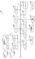
- FIG. 57 is a block diagram illustrating an example of a schematic configuration of a car navigation device 920 to which the technology according to the present disclosure can be applied.
- the car navigation device 920 includes a processor 921, a memory 922, a GPS (Global Positioning System) module 924, a sensor 925, a data interface 926, a content player 927, a storage medium interface 928, an input device 929, a display device 930, a speaker 931, and wireless communication.
- the interface 933 includes one or more antenna switches 936, one or more antennas 937, and a battery 938.
- the processor 921 may be a CPU or SoC, for example, and controls the navigation function and other functions of the car navigation device 920.
- the memory 922 includes RAM and ROM, and stores programs and data executed by the processor 921.
- the GPS module 924 measures the position (for example, latitude, longitude, and altitude) of the car navigation device 920 using GPS signals received from GPS satellites.
- the sensor 925 may include a sensor group such as a gyro sensor, a geomagnetic sensor, and an atmospheric pressure sensor.
- the data interface 926 is connected to the in-vehicle network 941 through a terminal (not shown), for example, and acquires data generated on the vehicle side such as vehicle speed data.
- the content player 927 reproduces content stored in a storage medium (for example, CD or DVD) inserted into the storage medium interface 928.
- the input device 929 includes, for example, a touch sensor, a button, or a switch that detects a touch on the screen of the display device 930, and receives an operation or information input from the user.
- the display device 930 has a screen such as an LCD or an OLED display, and displays a navigation function or an image of content to be reproduced.
- the speaker 931 outputs the navigation function or the audio of the content to be played back.
- the wireless communication interface 933 supports any cellular communication method such as LTE or LTE-Advanced, and performs wireless communication.
- the wireless communication interface 933 may typically include a BB processor 934, an RF circuit 935, and the like.
- the BB processor 934 may perform, for example, encoding / decoding, modulation / demodulation, and multiplexing / demultiplexing, and performs various signal processing for wireless communication.
- the RF circuit 935 may include a mixer, a filter, an amplifier, and the like, and transmits and receives a radio signal via the antenna 937.
- the wireless communication interface 933 may be a one-chip module in which the BB processor 934 and the RF circuit 935 are integrated.
- the wireless communication interface 933 may include a plurality of BB processors 934 and a plurality of RF circuits 935 as shown in FIG.
- FIG. 57 shows an example in which the wireless communication interface 933 includes a plurality of BB processors 934 and a plurality of RF circuits 935.
- the wireless communication interface 933 includes a single BB processor 934 or a single RF circuit 935. But you can.
- the wireless communication interface 933 may support other types of wireless communication methods such as a short-range wireless communication method, a proximity wireless communication method, or a wireless LAN method in addition to the cellular communication method.
- a BB processor 934 and an RF circuit 935 may be included for each communication method.
- Each of the antenna switches 936 switches the connection destination of the antenna 937 among a plurality of circuits included in the wireless communication interface 933 (for example, circuits for different wireless communication systems).
- Each of the antennas 937 has a single or a plurality of antenna elements (for example, a plurality of antenna elements constituting a MIMO antenna), and is used for transmission / reception of a radio signal by the radio communication interface 933.
- the car navigation device 920 may include a plurality of antennas 937 as shown in FIG. FIG. 57 shows an example in which the car navigation apparatus 920 includes a plurality of antennas 937. However, the car navigation apparatus 920 may include a single antenna 937.
- the car navigation device 920 may include an antenna 937 for each wireless communication method.
- the antenna switch 936 may be omitted from the configuration of the car navigation device 920.
- the battery 938 supplies electric power to each block of the car navigation device 920 shown in FIG. 57 via a power supply line partially shown by broken lines in the drawing. Further, the battery 938 stores electric power supplied from the vehicle side.
- the car navigation apparatus 920 includes a module including a part (for example, the BB processor 934) or the whole of the wireless communication interface 933 and / or the processor 921, and the one or more components are mounted in the module. May be.
- the module stores a program for causing the processor to function as the one or more components (in other words, a program for causing the processor to execute the operation of the one or more components). The program may be executed.
- a program for causing a processor to function as the one or more components is installed in the car navigation device 920, and the wireless communication interface 933 (eg, the BB processor 934) and / or the processor 921 executes the program.
- the car navigation apparatus 920 or the module may be provided as an apparatus including the one or more components, and a program for causing a processor to function as the one or more components may be provided. Good.
- a readable recording medium in which the program is recorded may be provided.
- the wireless communication unit 220 described with reference to FIG. 53 may be implemented in the wireless communication interface 933 (for example, the RF circuit 935).
- the antenna unit 210 may be mounted on the antenna 937.
- the storage unit 230 may be implemented in the memory 922.
- the technology according to the present disclosure may be realized as an in-vehicle system (or vehicle) 940 including one or more blocks of the car navigation device 920 described above, an in-vehicle network 941, and a vehicle side module 942. That is, the in-vehicle system (or vehicle) 940 may be provided as a device including the acquisition unit 241 and / or the reception processing unit 243.
- the vehicle-side module 942 generates vehicle-side data such as vehicle speed, engine speed, or failure information, and outputs the generated data to the in-vehicle network 941.
- a first sensing that senses a resource for a predetermined period and selects a communication resource based on the sensing result, and a communication based on a decoding result of control information transmitted by another user
- An apparatus includes a processing unit that performs sensing by either the first sensing or the second sensing with reference to a mapping table during the second sensing for selecting the resource.
- the first sensing that senses the resource for a predetermined period and selects the communication resource based on the sensing result, and the communication based on the decoding result of the control information transmitted by another user
- a second sensing for selecting a resource for use a method is provided that includes performing a sensing with either the first sensing or the second sensing with reference to a mapping table.
- a first centralized sensing method and a second centralized sensing method are provided to improve sensing efficiency.
- the eNB or the RSU determines one or more representatives that perform sensing, assigns resources to one or more representatives that perform the sensing, and performs the sensing.
- the first centralized sensing method is provided, wherein one includes releasing one or more representatives.
- the eNB or RSU notifies the UE, including a method for determining one or more representatives for performing sensing and a method for releasing the one or more representatives for performing the sensing. Using the information notified by the UE to determine one or more representatives to perform sensing, and to release one or more representatives to perform the sensing. Two centralized sensing methods provide.
- the first sensing method of Energy sensing + LBT with Backoff due to the severeness of latency requirement is provided.
- the second sensing method of energy sensing + LBT without backoff depending on the severity of the latency request is provided.
- a method includes switching between LBT with Backoff and LBT without Backoff and LBT type notification.
- the DSRC system since it is assumed that the operation is performed while performing co-existence with the DSRC system (802.11p communication), the DSRC system is detected, and even within LTE V2X communication, To avoid packet collision, a two-step sensing method is provided.
- a first Enhanced Energy sensing + LBT sensing method that selects SA resources and data data and transmits a packet when SA transmission resources can be secured.
- a second Enhanced Energy Sensing plus LBT sensing method that selects an SA resource and data data and transmits a packet when a data transmission resource can be secured.
- the third Enhanced Energy Sensing + LBT sensing method is provided in which the SA resource and the data data are selected and the packet is transmitted.
- the following configurations also belong to the technical scope of the present disclosure.
- First sensing a resource for a predetermined period, selecting a communication resource based on the sensing result, and selecting a communication resource based on a decoding result of control information transmitted by another user An apparatus comprising a processing unit that performs sensing by either the first sensing or the second sensing with reference to a mapping table in the second sensing.
- the mapping table is a table in which which sensing mode is used and which sensing parameter is used according to a situation.
- the mapping table includes a parameter that limits an area where sensing is performed.
- the processing unit when only the SA (Scheduling Assignment) transmission resource is secured in the LBT, the processing unit causes the transmission terminal to acquire the right to transmit SA and data.
- the processing unit when only the data transmission resource is secured in the LBT, the processing unit causes the transmission terminal to acquire SA (Scheduling Assignment) and a data transmission right.
Landscapes
- Engineering & Computer Science (AREA)
- Computer Networks & Wireless Communication (AREA)
- Signal Processing (AREA)
- Quality & Reliability (AREA)
- Mobile Radio Communication Systems (AREA)
Abstract
[Problem] To provide a device capable of performing efficient resource sensing in V2X communication.
[Solution] Provided is a device equipped with a processing unit which, when the processing unit performs first sensing in which a resource is sensed for a prescribed period of time and a communication resource is selected on the basis of the sensing result, and second sensing in which the communication resource is selected on the basis of the result of decoding control information transmitted by another user, performs sensing using either the first sensing or the second sensing with reference to a mapping table.
Description
本開示は、装置及び方法に関する。
The present disclosure relates to an apparatus and a method.
端末装置間のD2D(Device to Device)通信においてリソースを割り当てるための技術が開示されている(例えば特許文献1)。
A technology for allocating resources in D2D (Device to Device) communication between terminal devices is disclosed (for example, Patent Document 1).
その一方で、将来の自動運転の実現のため、近年、車載通信(V2X通信)への期待が高まってきている。V2X通信とは、Vehicle to X通信の略であり、車と“何か”が通信を行うシステムである。ここでの“何か”の例として、車両(Vehicle)、施設(Infrastructure/Network)、歩行者(Pedestrian)等が挙げられる(V2V,V2I/N,V2P)。車用の無線通信としては、これまで主に、802.11pベースのDSRC(Dedicated Short Range Communication)の開発が進められてきたが、近年になり、LTEベースの車載通信である“LTE-based V2X”の標準化議論がスタートしている。
On the other hand, in order to realize future automatic driving, expectations for in-vehicle communication (V2X communication) have increased in recent years. V2X communication is an abbreviation for Vehicle to X communication, and is a system in which “something” communicates with a vehicle. Examples of “something” include a vehicle, a facility (Infrastructure / Network), a pedestrian, and the like (V2V, V2I / N, V2P). As for wireless communication for vehicles, the development of 802.11p-based DSRC (Dedicated Short Range Communication) has been promoted so far, but in recent years, LTE-based in-vehicle communication "LTE-based V2X "Standardization discussion" has started.
本開示では、V2X通信において効率的なリソースのセンシングが可能な、新規かつ改良された装置及び方法を提案する。
This disclosure proposes a new and improved apparatus and method capable of efficient resource sensing in V2X communication.
本開示によれば、所定期間リソースをセンシングし、該センシングの結果に基づいて通信用のリソースを選択する第1のセンシングと、他ユーザが送信している制御情報のデコード結果に基づいて通信用のリソースを選択する第2のセンシングと、の際に、マッピングテーブルを参照し、前記第1のセンシングまたは前記第2のセンシングのいずれかでセンシングを行う処理部を備える、装置が提供される。
According to the present disclosure, a first sensing that senses a resource for a predetermined period and selects a communication resource based on the sensing result, and a communication based on a decoding result of control information transmitted by another user An apparatus is provided that includes a processing unit that performs sensing by either the first sensing or the second sensing with reference to a mapping table during the second sensing for selecting the resource.
また本開示によれば、所定期間リソースをセンシングし、該センシングの結果に基づいて通信用のリソースを選択する第1のセンシングと、他ユーザが送信している制御情報のデコード結果に基づいて通信用のリソースを選択する第2のセンシングと、の際に、マッピングテーブルを参照し、前記第1のセンシングまたは前記第2のセンシングのいずれかでセンシングを行うことを含む、方法が提供される。
Further, according to the present disclosure, the first sensing that senses the resource for a predetermined period and selects the communication resource based on the sensing result, and the communication based on the decoding result of the control information transmitted by another user And a second sensing for selecting a resource for use, a method is provided that includes performing a sensing with either the first sensing or the second sensing with reference to a mapping table.
以上説明したように本開示によれば、V2X通信において効率的なリソースのセンシングが可能な、新規かつ改良された装置及び方法を提供することが出来る。
As described above, according to the present disclosure, it is possible to provide a new and improved apparatus and method capable of efficiently sensing resources in V2X communication.
なお、上記の効果は必ずしも限定的なものではなく、上記の効果とともに、または上記の効果に代えて、本明細書に示されたいずれかの効果、または本明細書から把握され得る他の効果が奏されてもよい。
Note that the above effects are not necessarily limited, and any of the effects shown in the present specification, or other effects that can be grasped from the present specification, together with or in place of the above effects. May be played.
以下に添付図面を参照しながら、本開示の好適な実施の形態について詳細に説明する。なお、本明細書及び図面において、実質的に同一の機能構成を有する構成要素については、同一の符号を付することにより重複説明を省略する。
Hereinafter, preferred embodiments of the present disclosure will be described in detail with reference to the accompanying drawings. In addition, in this specification and drawing, about the component which has the substantially same function structure, duplication description is abbreviate | omitted by attaching | subjecting the same code | symbol.
なお、説明は以下の順序で行うものとする。
1.本開示の実施の形態
1.1.概要
1.2.実施例
1.3.構成例
2.応用例 The description will be made in the following order.
1. Embodiment of the present disclosure 1.1. Outline 1.2. Example 1.3. Configuration example 2. Application examples
1.本開示の実施の形態
1.1.概要
1.2.実施例
1.3.構成例
2.応用例 The description will be made in the following order.
1. Embodiment of the present disclosure 1.1. Outline 1.2. Example 1.3. Configuration example 2. Application examples
<1.本開示の実施の形態>
[1.1.概要]
まず、本開示の実施の形態の概要を説明する。 <1. Embodiment of the present disclosure>
[1.1. Overview]
First, an outline of an embodiment of the present disclosure will be described.
[1.1.概要]
まず、本開示の実施の形態の概要を説明する。 <1. Embodiment of the present disclosure>
[1.1. Overview]
First, an outline of an embodiment of the present disclosure will be described.
上述したように、将来の自動運転の実現のため、近年、車載通信(V2X通信)への期待が高まってきている。V2X通信とは、Vehicle to X通信の略であり、車と“何か”が通信を行うシステムである。ここでの“何か”の例として、車両(Vehicle)、施設(Infrastructure/Network)、歩行者(Pedestrian)等が挙げられる(V2V,V2I/N,V2P)。車用の無線通信としては、これまで主に、802.11pベースのDSRCの開発が進められてきたが、近年になり、LTEベースの車載通信である“LTE-based V2X”の標準化議論がスタートしている。
As described above, in recent years, expectations for in-vehicle communication (V2X communication) have increased in order to realize future automatic driving. V2X communication is an abbreviation for Vehicle to X communication, and is a system in which “something” communicates with a vehicle. Examples of “something” include a vehicle, a facility (Infrastructure / Network), a pedestrian, and the like (V2V, V2I / N, V2P). Until now, the development of 802.11p-based DSRC has mainly been promoted as wireless communication for vehicles, but in recent years, the standardization discussion of “LTE-based V2X”, which is LTE-based in-vehicle communication, has started. is doing.
V2X通信のユースケースの一例を下記に示す。主に安全用途をターゲットとし、定期的に車両にメッセージを送るような周期的なメッセージの送信や、イベントに応じて必要な情報を提供するイベントトリガメッセージのような通信が求められている(3GPP TR 22.885)。
An example of a use case for V2X communication is shown below. There is a need for communications such as event trigger messages that are mainly targeted for safety applications and that periodically send messages to vehicles and provide necessary information according to events (3GPP TR 22.885).
(V2Xユースケース例)
1.Forward
Collision Warning
2.Control
Loss Warning
3.V2V
Use case for emergency vehicle warning
4.V2V
Emergency Stop Use case
5.Cooperative
Adaptive Cruise Control
6.V2I
Emergency Stop Use Case
7.Queue
Warning
8.Road
safety services
9.Automated
Parking System
10.Wrong
way driving warning
11.V2V
message transfer under operator control
12.Pre-crash
Sensing Warning
13.V2X
in areas outside network coverage
14.V2X
Road safety service via infrastructure
15.V2I/V2N
Traffic Flow Optimization
16.Curve
speed Warning
17.Warning
to Pedestrian against pedestrian Collision
18.Vulnerable
Road User (VRU) Safety
19.V2X
by UE type RSU
20.V2X
Minimum QoS
21.Use
case for V2X access when roaming
22.Pedestrian
Road Safety via V2P awareness messages
23.Mixed
Use Traffic Management
24.Enhancing
Positional Precision for traffic participants (Example of V2X use case)
1.Forward
Collision Warning
2.Control
Loss Warning
3.V2V
Use case for emergency vehicle warning
4.V2V
Emergency Stop Use case
5.Cooperative
Adaptive Cruise Control
6.V2I
Emergency Stop Use Case
7.Queue
Warning
8.Road
safety services
9.Automated
Parking System
10.Wrong
way driving warning
11.V2V
message transfer under operator control
12.Pre-crash
Sensing Warning
13.V2X
in areas outside network coverage
14.V2X
Road safety service via infrastructure
15.V2I / V2N
Traffic Flow Optimization
16.Curve
speed Warning
17.Warning
to Pedestrian against pedestrian Collision
18.Vulnerable
Road User (VRU) Safety
19.V2X
by UE type RSU
20.V2X
Minimum QoS
21.Use
case for V2X access when roaming
22.Pedestrian
Road Safety via V2P awareness messages
23.Mixed
Use Traffic Management
24.Enhancing
Positional Precision for traffic participants
1.Forward
Collision Warning
2.Control
Loss Warning
3.V2V
Use case for emergency vehicle warning
4.V2V
Emergency Stop Use case
5.Cooperative
Adaptive Cruise Control
6.V2I
Emergency Stop Use Case
7.Queue
Warning
8.Road
safety services
9.Automated
Parking System
10.Wrong
way driving warning
11.V2V
message transfer under operator control
12.Pre-crash
Sensing Warning
13.V2X
in areas outside network coverage
14.V2X
Road safety service via infrastructure
15.V2I/V2N
Traffic Flow Optimization
16.Curve
speed Warning
17.Warning
to Pedestrian against pedestrian Collision
18.Vulnerable
Road User (VRU) Safety
19.V2X
by UE type RSU
20.V2X
Minimum QoS
21.Use
case for V2X access when roaming
22.Pedestrian
Road Safety via V2P awareness messages
23.Mixed
Use Traffic Management
24.Enhancing
Positional Precision for traffic participants (Example of V2X use case)
1.Forward
Collision Warning
2.Control
Loss Warning
3.V2V
Use case for emergency vehicle warning
4.V2V
Emergency Stop Use case
5.Cooperative
Adaptive Cruise Control
6.V2I
Emergency Stop Use Case
7.Queue
Warning
8.Road
safety services
9.Automated
Parking System
10.Wrong
way driving warning
11.V2V
message transfer under operator control
12.Pre-crash
Sensing Warning
13.V2X
in areas outside network coverage
14.V2X
Road safety service via infrastructure
15.V2I / V2N
Traffic Flow Optimization
16.Curve
speed Warning
17.Warning
to Pedestrian against pedestrian Collision
18.Vulnerable
Road User (VRU) Safety
19.V2X
by UE type RSU
20.V2X
Minimum QoS
21.Use
case for V2X access when roaming
22.Pedestrian
Road Safety via V2P awareness messages
23.Mixed
Use Traffic Management
24.Enhancing
Positional Precision for traffic participants
これらのユースケースをベースとした要求事項の一例を下記に示す。
An example of requirements based on these use cases is shown below.

上記の要求事項を達成するために、V2X通信の物理レイヤの標準化が3GPPにおいては既にスタートしている。車車間通信であるV2V通信の規格化を中心に、V2I/N、V2Pの規格化が行われている。
In order to achieve the above requirements, standardization of the physical layer of V2X communication has already started in 3GPP. The standardization of V2I / N and V2P is performed mainly on the standardization of V2V communication which is vehicle-to-vehicle communication.
V2X通信のベース技術としては、3GPPで過去に規格化されたD2D(Device to device)通信があげられる。D2D通信は基地局を介さない端末間通信のため、V2V通信やV2P通信にエンハンスして適応されることが考えられる(一部V2I通信にも適応可能)。このような端末間のインタフェースをPC5インタフェースと呼ぶ。
As a base technology of V2X communication, D2D (Device to device) communication standardized in the past by 3GPP can be mentioned. Since D2D communication is communication between terminals not via a base station, it can be considered to be enhanced and adapted to V2V communication or V2P communication (partly applicable to V2I communication). Such an interface between terminals is called a PC5 interface.
また、V2I通信やV2N通信においては、既存の基地局と端末間の通信をエンハンスして適応することが考えられる。このような基地局、端末間のインタフェースをUuインタフェースと呼ぶ。
Also, in V2I communication and V2N communication, it is conceivable to enhance and adapt communication between existing base stations and terminals. Such an interface between the base station and the terminal is called a Uu interface.
このようにV2X通信実現のためには、PC5インタフェースやUuインタフェースを、要求事項を満たすようにエンハンスしていくことが必要である。
Thus, in order to realize V2X communication, it is necessary to enhance the PC5 interface and Uu interface to meet the requirements.
主なエンハンスメントのポイントは、例えば、リソース割り当ての改善、ドップラー周波数対策、同期手法の確立、低消費電力通信の実現、低遅延通信の実現などである。
The main enhancement points are, for example, improvement of resource allocation, Doppler frequency countermeasure, establishment of synchronization method, realization of low power consumption communication, realization of low delay communication, and the like.
(V2Xオペレーションシナリオ)
V2Xオペレーションシナリオを説明する。V2V通信をベースに構成される。なお、以下の説明で片方の自動車が歩行者になるとV2P通信となり、施設やネットワークで終端するとV2I/N通信となる。 (V2X operation scenario)
A V2X operation scenario will be described. It is based on V2V communication. In the following description, when one vehicle becomes a pedestrian, it becomes V2P communication, and when it terminates in a facility or network, it becomes V2I / N communication.
図1~図5は、V2Xオペレーションシナリオを説明する説明図である。図1は、車両同士が基地局(E-UTRAN)を介さずに直接通信するシナリオを示している。図2は、車両同士が基地局を介して通信するシナリオを示している。図3及び図4は、車両同士が端末(UE、ここでは路側無線装置(RSU))及び基地局を介して通信するシナリオを示している。図5は、車両同士が端末(UE、ここでは路側無線装置(RSU))を介して通信するシナリオを示している。
1 to 5 are explanatory diagrams for explaining a V2X operation scenario. FIG. 1 shows a scenario in which vehicles communicate directly with each other without going through a base station (E-UTRAN). FIG. 2 shows a scenario in which vehicles communicate with each other via a base station. 3 and 4 show a scenario in which vehicles communicate with each other via a terminal (UE, here, a roadside wireless device (RSU)) and a base station. FIG. 5 shows a scenario in which vehicles communicate with each other via a terminal (UE, here, a roadside radio device (RSU)).
V2X通信は、要求事項や通信環境などがD2D通信とは異なるため、既存のD2D通信をそのまま用いることはできない。そのため、V2X通信に適応する形にエンハンスする必要がある。D2D通信とV2X通信の特徴の違いを下記に示す。
Since V2X communication is different from D2D communication in terms of requirements and communication environment, existing D2D communication cannot be used as it is. Therefore, it is necessary to enhance to a form adapted to V2X communication. Differences in features between D2D communication and V2X communication are shown below.
(1)V2X通信は信頼性が高く、低遅延通信が必要。
(2)V2X特有のトラフィックが存在する。
(3)V2Xは様々なリンクを持つ。
(4)IBE(In-Band Emission)問題。
(5)HD(Half Duplex)問題。
(6)D2DよりCapacityが大きな課題になる。
(7)位置情報が常に得られる。 (1) V2X communication is highly reliable and requires low-delay communication.
(2) There is V2X-specific traffic.
(3) V2X has various links.
(4) IBE (In-Band Emission) problem.
(5) HD (Half Duplex) problem.
(6) Capacity is a bigger issue than D2D.
(7) Position information can always be obtained.
まず、(1)はV2X通信のユースケースから明白である。V2X通信は安全用途が多く、信頼性が非常に重要な指標となる。また、車の移動速度がD2Dの歩行ユースケースと比較して早いことから、低遅延通信の実現が必要となる。
First, (1) is clear from the use case of V2X communication. V2X communication has many safety applications, and reliability is a very important index. Further, since the moving speed of the car is faster than that of the D2D walking use case, it is necessary to realize low-delay communication.
(2)のV2X特有のトラフィックについては、V2X通信では、主にPeriodic trafficとEvent trigger trafficの二つが想定されている。Periodic trafficは定期的にデータを周辺車両に通知するような通信であり、これもV2Xの特徴的な点である。
(2) For V2X-specific traffic, two main types of traffic are assumed: Periodic traffic and Event trigger traffic. Periodic traffic is communication that periodically notifies the surrounding vehicle of data, which is also a characteristic point of V2X.
(3)の様々なリンクについては、V2X通信では車の通信対象(X)として、V(車両)/I(施設)/N(ネットワーク)/P(歩行者)を想定している。このような多様なリンクを持つ点もV2X通信特有である。
For the various links in (3), V (vehicle) / I (facility) / N (network) / P (pedestrian) is assumed as the vehicle communication target (X) in V2X communication. The point having such various links is also unique to V2X communication.
(4)のIBE問題、(5)のHD問題については、端末のトポロジーとRF性能が関係してくる。まず、IBEについて図6を用いて説明する。V2V通信では、基地局-端末間の通信とは異なり、送受信の端末の位置関係が常に変化する。もし送信端末の近隣に受信端末がいた場合、送信側からのEmissionが近隣の受信端末に影響する場合がある。周波数軸上で直交性を保っているが、送受信端末の距離の近さからIBEの影響が顕著になる。図6では、送信端末Aが受信端末DへIBEを与えている様子を示している。このように送受信端末間の距離が近いような場合は、周波数上で隣接するリソースに対して干渉が起こってしまう可能性がある。この問題はD2Dでも起こりえる。しかしながら、D2Dより多くの端末が通信するようなV2X通信においては、IBE問題はより顕著になる。
(4) The IBE problem (4) and the HD problem (5) are related to the topology of the terminal and the RF performance. First, IBE will be described with reference to FIG. In the V2V communication, unlike the communication between the base station and the terminal, the positional relationship between the transmitting and receiving terminals always changes. If there is a receiving terminal in the vicinity of the transmitting terminal, the Emission from the transmitting side may affect the neighboring receiving terminal. Although orthogonality is maintained on the frequency axis, the influence of IBE becomes remarkable from the closeness of the distance between the transmitting and receiving terminals. FIG. 6 shows a state in which the transmitting terminal A gives IBE to the receiving terminal D. In this way, when the distance between the transmitting and receiving terminals is short, there is a possibility that interference will occur with respect to adjacent resources on the frequency. This problem can also occur with D2D. However, in V2X communication in which more terminals than D2D communicate, the IBE problem becomes more prominent.
(5)のHD問題は、端末が送信しているときに受信できない問題を指す。そのため、複数回受信の機会を用意したり、データを送信するフレームで他のユーザの送信を割り当てないようにしたりする、などの対応が必要になってくる。HD問題もV2X特有の問題ではないが、多くの送受信を行う必要があるV2X通信では大きな制約となる。
(5) HD problem refers to a problem that the terminal cannot receive when it is transmitting. For this reason, it is necessary to take measures such as preparing an opportunity to receive a plurality of times, or not assigning transmissions of other users in a frame for transmitting data. The HD problem is not a problem specific to V2X, but is a major limitation in V2X communication that requires many transmissions.
次に(6)のCapacityについて説明する。先述したとおり、D2D通信と比較してV2X通信は収容端末数が非常に多くなる。さらに、自動車は道路の上を走行するため、必然的に端末密度は局所的に増加してしまう。そのため、V2X通信においては、Capacityの改善が必要不可欠になる。不要なオーバーヘッドなどは最大限削除し、効率的な通信を実現する必要がある。
Next, (6) Capacity will be described. As described above, V2X communication has an extremely large number of accommodated terminals compared to D2D communication. Furthermore, since the automobile runs on the road, the terminal density inevitably increases locally. Therefore, in V2X communication, improvement of capacity is indispensable. It is necessary to eliminate unnecessary overhead as much as possible to realize efficient communication.
最後の(7)の位置情報が常に得られることは、近年の自動車のナビゲーションシステムの搭載率を見てもわかるとおり、自動車は自身の位置情報を常に知っていると想定される。このような位置情報は、V2X通信をエンハンスする上で非常に重要な特徴になる。
It is assumed that the last (7) location information is always obtained, as can be seen from the recent automobile navigation system installation rate, the vehicle always knows its own location information. Such position information is a very important feature in enhancing V2X communication.
これらの問題を解決する為、3GPPではFDM(Frequency Division Multiplexing ;周波数分割多重化)を用いたリソース割り当て方法が現在検討されている。TDM(Time Division Multiplexing;時分割多重化)割り当てとFDM割り当てについて、図7を用いて説明を行う。D2D通信やV2X通信が行われるPC5インタフェースは、主に制御チャネル部(PSCCH:Physical Sidelink Control CHannel)とデータチャネル部(PSSCH:Physical Sidelink Shared CHannel)から構成されている。
In order to solve these problems, 3GPP is currently examining a resource allocation method using FDM (Frequency Division Multiplexing). TDM (Time Division Multiplexing) allocation and FDM allocation will be described with reference to FIG. The PC5 interface through which D2D communication and V2X communication are performed mainly includes a control channel section (PSCCH: Physical Sidelink Channel) and a data channel section (PSSCH: Physical Sideline Shared Channel).
PSCCHにおいてPSSCHのリソース指示などを通知するため、TDM方式では、パケットの発生から送信までの遅延が大きくなるといった問題がある。一方で、端末の複雑度(Complexity)が良いというメリットがある。なお、D2DではTDM割り当て方式が採用されている。これに対しては、FDM方式では、周波数方向にPSCCHがマッピングされているため、遅延が改善される。また、SA(Scheduling Assignment)とDataを同じSF(サブフレーム)で送信することで、IBEやHDの問題も改善することが期待できる。そのため、V2X通信では、FDM方式を用いた通信方法の確立が求められている。
Since a PSCH resource instruction or the like is notified in the PSCCH, the TDM scheme has a problem that a delay from generation of a packet to transmission becomes large. On the other hand, there is an advantage that the complexity (complexity) of the terminal is good. In D2D, a TDM allocation method is adopted. On the other hand, in the FDM system, since the PSCCH is mapped in the frequency direction, the delay is improved. In addition, it is expected that problems of IBE and HD can be improved by transmitting SA (Scheduling Assignment) and Data in the same SF (subframe). Therefore, in V2X communication, establishment of a communication method using the FDM method is required.
FDM方式に加えてさらなるエンハンスメントの追加も検討されている。前述した(6)のキャパシティの問題を解決する為に、現在SPS(Semi-Persistent Scheduling)の導入も検討されている。これは、V2X通信で特徴のあるトラフィックタイプの特性をうまく利用している。SPSの概要を図8に示す。SPSでは一つのSAで複数のデータをスケジューリングする。そのため、データ送信の度にSAを送信する必要がなく、オーバーヘッドの削減が可能になる。特にV2XのPeriodical trafficのような周期的な通信においては、このようなスケジューリングが大きな効果を生むことが確認されている。そのため、V2X通信では、SPSの導入も求められている。
In addition to the FDM method, the addition of further enhancement is also being studied. In order to solve the capacity problem of (6) described above, the introduction of SPS (Semi-Persistent Scheduling) is currently being studied. This makes good use of the characteristics of the traffic type that is characteristic of V2X communication. An outline of the SPS is shown in FIG. In SPS, a plurality of data is scheduled with one SA. Therefore, it is not necessary to transmit SA every time data is transmitted, and overhead can be reduced. In particular, in periodic communication such as V2X Periodic traffic, it has been confirmed that such scheduling has a great effect. Therefore, introduction of SPS is also required in V2X communication.
次に、図9、図10を用いて位置情報を用いたエンハンスメントについて説明する。(6)で述べたとおり、V2Xではキャパシティが大きな問題となる。そこで、周波数リソースの空間再利用が検討されている。空間再利用を行うに当たり、(7)で説明した、自動車の位置情報を活用する。この位置情報を用いたエンハンスメントも現在3GPPで議論されている。
Next, enhancement using position information will be described with reference to FIGS. As described in (6), capacity becomes a big problem in V2X. Thus, spatial reuse of frequency resources is being studied. In reusing the space, the position information of the car described in (7) is utilized. Enhancement using this location information is also currently being discussed in 3GPP.
これまでが、PC5インタフェースのエンハンスメントの概要である。V2X通信では、リソース割り当ての方法として、Mode1のCentralized resource allocationとMode2のAutonomous resource selectionの2種類がある。Mode1の場合は、PC5インタフェースのリソース割り当てを基地局がすべて行う。端末側では基地局に指示されたリソースで送信を行うだけでよい。基地局端末間のオーバーヘッドが懸念されるが、リソースが直交して割り当てられるため通信特性はよい。一方で、Mode2では、端末は基地局から通知されたリソースプールの中から、自律的に送信に使用するリソースを選択する。Mode1のオーバーヘッドの懸念がないが、他端末と同じリソースを選択してしまう可能性もあるため、Collisionの課題が出てくる。Mode2は基地局のNetwork内であるIn-coverageのみならず、Out-of-overageでオペレーションできるというメリットもある。
So far, this is an overview of PC5 interface enhancements. In V2X communication, there are two types of resource allocation methods: Mode 1 Centralized resource allocation and Mode 2 Autonomous resource selection. In the case of Mode 1, the base station performs all resource allocation for the PC5 interface. On the terminal side, it is only necessary to perform transmission using resources instructed to the base station. Although there is concern about the overhead between base station terminals, the communication characteristics are good because resources are allocated orthogonally. On the other hand, in Mode 2, the terminal autonomously selects a resource to be used for transmission from the resource pool notified from the base station. Although there is no concern about the overhead of Mode 1, there is a possibility that the same resource as that of other terminals may be selected. Mode 2 has an advantage that it can be operated not only in In-coverage in the network of the base station but also in Out-of-overage.
このMode2のCollision問題についても、現在いくつかの提案が行われている。Solutionは大きく2つに分けられる。一つはEnergy sensingである。Energy sensingでは、ある一定期間リソースをセンシングし、そのセンシング結果に基づいて、比較的使用されていないリソースから通信用のリソースを選択する方法である。簡単である一方、電力レベルなので精度はそこまで高くない。ただし、LTE以外のシステムをセンシングすることが可能である。もう一つの方法は、SA decodingである。これは、他ユーザが送信しているSA(制御情報)をデコードし、使用されているリソースの場所を認識する方法である。使用されているリソースが精度よく発見することができる反面、SAリソース自体のセンシングが行えない、SAのデコードを失敗すると使用されているリソースが検出できないなどのデメリットがある。
Some proposals have been made for the Collation problem of Mode2. The Solution can be roughly divided into two. One is energy sensing. In energy sensing, a resource is sensed for a certain period, and a communication resource is selected from relatively unused resources based on the sensing result. While simple, the power level is not so accurate. However, it is possible to sense a system other than LTE. Another method is SA decoding. This is a method of recognizing the location of a resource being used by decoding SA (control information) transmitted by another user. While the used resources can be discovered with high accuracy, there are disadvantages such that the SA resource itself cannot be sensed, and if the SA decoding fails, the used resource cannot be detected.
最後に、これまでのエンハンスメントの説明一覧を表2に示す。これは一例であり、代表的なエンハンスメントを記載しており、その他にもさまざまな方法が検討されている。
Finally, Table 2 shows a list of explanations of enhancements so far. This is an example and describes typical enhancements, and various other methods are being considered.
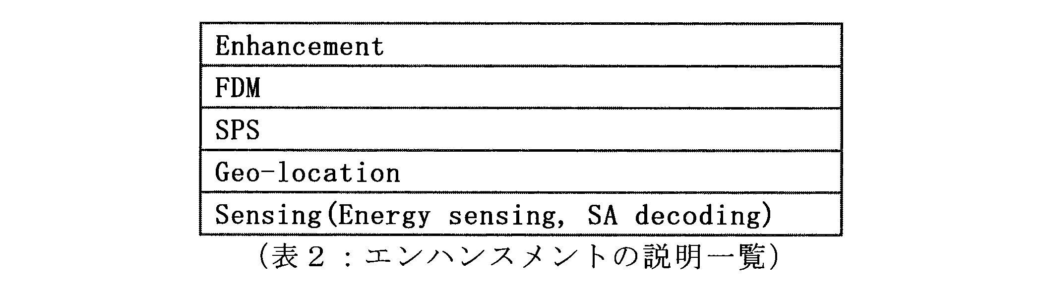
[1.2.解決すべき内容]
(1)センシングモード切り替え
1つ以上のセンシングモードが存在する場合に、UEは、決められた状況においてどのセンシングモードを使用すべきであるか分からない。また、エネルギーセンシングについて、SAプール及びデータプールに対してブラインドセンシングが用いられるが、これは歩行者が携帯するUEにとっては非常に電力を使用するセンシングモードである。 [1.2. Contents to be solved]
(1) Sensing mode switching When there are one or more sensing modes, the UE does not know which sensing mode should be used in a given situation. As for energy sensing, blind sensing is used for the SA pool and the data pool, which is a sensing mode that uses power very much for a UE carried by a pedestrian.
ここで本開示の実施の形態では、2つの方法によりUEにセンシングモードを設定させる。
Here, in the embodiment of the present disclosure, the UE sets the sensing mode by two methods.
1つ目の方法は、eNBがどのセンシングモードを使用すべきか決定する方法である。図11は、eNB、送信側のUE、受信側のUEによるセンシングモードの決定方法を示す流れ図である。
The first method is to determine which sensing mode the eNB should use. FIG. 11 is a flowchart illustrating a sensing mode determination method by the eNB, the transmission side UE, and the reception side UE.
eNBは、センシングモード及びセンシングパラメータを決定する。続いて、eNBは、センシングモード及びセンシングパラメータと、状態との関係が規定されたマッピングテーブルを生成する。続いてeNBは、センシングモード及びセンシングパラメータを決定し、センシングモード及びセンシングパラメータを送信側のUEに通知する。
ENB determines the sensing mode and sensing parameters. Subsequently, the eNB generates a mapping table in which the relationship between the sensing mode, the sensing parameter, and the state is defined. Subsequently, the eNB determines a sensing mode and a sensing parameter, and notifies the UE on the transmission side of the sensing mode and the sensing parameter.
送信側のUEは、eNBから通知されたセンシングモード及びセンシングパラメータを設定して、そのセンシングモード及びセンシングパラメータによってセンシングを実行し、パケットを送信する。受信側のUEは、送信側のUEから送信されたパケットを受信する。
The UE on the transmission side sets the sensing mode and sensing parameter notified from the eNB, performs sensing according to the sensing mode and sensing parameter, and transmits the packet. The receiving side UE receives the packet transmitted from the transmitting side UE.
2つ目の方法は、UEがどのセンシングモードを使用すべきか決定する方法である。図12は、eNB、送信側のUE、受信側のUEによるセンシングモードの決定方法を示す流れ図である。
The second method is a method for determining which sensing mode the UE should use. FIG. 12 is a flowchart illustrating a sensing mode determination method by the eNB, the transmission side UE, and the reception side UE.
eNBは、センシングモード及びセンシングパラメータを決定する。続いて、eNBは、センシングモード及びセンシングパラメータと、状態との関係が規定されたマッピングテーブルを生成する。続いてeNBは、受信側のUEにマッピングテーブルを通知する。マッピングテーブルは端末に事前にPre-configureされていてもよい。
ENB determines the sensing mode and sensing parameters. Subsequently, the eNB generates a mapping table in which the relationship between the sensing mode, the sensing parameter, and the state is defined. Subsequently, the eNB notifies the UE on the receiving side of the mapping table. The mapping table may be pre-configured in advance in the terminal.
マッピングテーブルの通知を受けた受信側のUEは、センシングモード及びセンシングパラメータを決定し、そのセンシングモード及びセンシングパラメータによってセンシングを実行し、パケットを送信する。受信側のUEは、送信側のUEから送信されたパケットを受信する。
Upon receiving the notification of the mapping table, the UE on the receiving side determines the sensing mode and sensing parameter, performs sensing according to the sensing mode and sensing parameter, and transmits a packet. The receiving side UE receives the packet transmitted from the transmitting side UE.
マッピングテーブルは、状況に応じて、どのセンシングモードを使用し、どのセンシングパラメータを使用するかが規定されたテーブルである。表3にマッピングテーブルの例を示す。
The mapping table is a table in which which sensing mode is used and which sensing parameter is used depending on the situation. Table 3 shows an example of the mapping table.
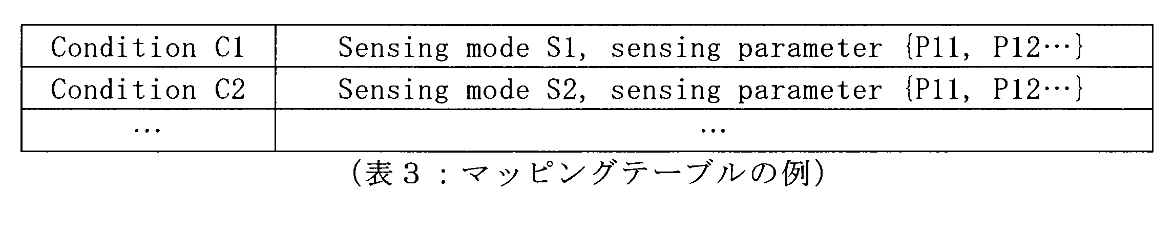
「Sensing mode」はエネルギーセンシング、SAデコーディングまたはそれらの組み合わせ等に用いられる。「Sensing mode」は、この他にも、データデコーディングやeNBからのアシスタントセンシングなどを組み合わせて用いてもよい。なお、データデコーディングは、他端末のデータをデコードし、リソースの使用状況を確認する方式であり、eNBからのアシスタントセンシングは、eNBから無線環境情報の情報をもらってセンシングを行う方式である。
“Sensing mode” is used for energy sensing, SA decoding, or a combination thereof. In addition to this, “Sensing mode” may be used in combination with data decoding, assistant sensing from the eNB, or the like. Data decoding is a method of decoding data of other terminals and confirming the resource usage status, and assistant sensing from the eNB is a method of sensing by receiving information on radio environment information from the eNB.
「Condition」は、例えば、UEが低消費電力の要求を有している、安全性の要求を有している、低レイテンシの要求を有している、周期的またはイベントトリガメッセージを送信している、高いまたは低い優先度を有している、カテゴリ、PSCCH、PSSCHなどのセンシングチャネルのタイプ、他のRATs(Radio Access Technologies)の存在のタイプ、データトラフィックの混雑度、リソースの使用率、端末位置などがありうる。
“Condition” sends a periodic or event triggered message, for example, the UE has a low power requirement, has a safety requirement, has a low latency requirement, Have high or low priority, categories, types of sensing channels such as PSCCH, PSSCH, types of presence of other RATs (Radio Access Technologies), data traffic congestion, resource usage, terminal There can be a location.
「sensing parameter」は、例えば、センシング間隔、センシング開始時間、重み情報などのパラメータや、バッテリーを節約するための制限されたセンシングエリアの情報などが含まれうる。制限されたセンシングエリアの情報には、センシングの時間間隔や周波数帯の情報、例えば、センシングする周波数領域、例えばバンド幅、リソースプール、サブキャリアなどの情報が含まれうる。制限されたセンシングエリアの情報には、また例えば、センシング領域の定義、例えばブロックIDの情報が含まれうる。ブロックIDは、区画された各プールに付されるIDである。また、制限されたセンシングエリアの情報には、センシングを行う場所の情報が含まれていてもよい。端末は指定された位置で指定されたセンシングを実施する。
“Sensing parameter” may include, for example, parameters such as sensing interval, sensing start time, weight information, information on a limited sensing area for saving battery, and the like. The limited sensing area information may include sensing time interval and frequency band information, for example, information such as a sensing frequency region, such as bandwidth, resource pool, and subcarrier. The restricted sensing area information may also include, for example, sensing area definition, eg, block ID information. The block ID is an ID assigned to each partitioned pool. Further, the information on the restricted sensing area may include information on a location where sensing is performed. The terminal performs the specified sensing at the specified position.
マッピングテーブルは更新可能である。与えられた状況によって、センシングモードは変更可能であり、また、与えられた状況によって、センシングパラメータは変更可能である。また、与えられたセンシングモードによって、センシングパラメータは変更可能である。
The mapping table can be updated. The sensing mode can be changed depending on the given situation, and the sensing parameter can be changed depending on the given situation. Also, the sensing parameter can be changed according to a given sensing mode.
eNBは、現在のマッピングが最も良い選択で無いかどうかを評価する。また、UEは、現在のマッピングが最も良い選択で無いことをeNBに報告する。これによりマッピングテーブルが更新されうる。
ENB evaluates whether the current mapping is not the best choice. Also, the UE reports to the eNB that the current mapping is not the best choice. Thereby, the mapping table can be updated.
eNBは、マッピングテーブルまたは、センシングモード及びセンシングパラメータをUEに通知するが、その通知には、例えばSIBやDCIが使われうる。例えば、eNBは、これらの情報をブロードキャストする。例えば、共存されているDSRCのシナリオでは、eNBは、全てのUEに、エネルギーセンシングの選択を要求する。また例えば、eNBは、UEのグループや、いくつかのUEに対してマルチキャストで情報を通知する。また例えば、eNBは、あるユニークなUEに対してユニキャストで情報を通知する。
The eNB notifies the UE of the mapping table or the sensing mode and sensing parameters, and for this notification, for example, SIB or DCI may be used. For example, the eNB broadcasts this information. For example, in a coexisting DSRC scenario, the eNB requests all UEs to select energy sensing. Further, for example, the eNB notifies the multicast information to a group of UEs and some UEs. Also, for example, the eNB notifies information to a unique UE by unicast.
マッピングテーブルは、例えば、RRCコネクションのセットアップや再確立のタイミングで送信されうる。またマッピングテーブルは、例えば、初期設定されたタイミングで送信されうる。またマッピングテーブルは、例えば、更新されたタイミングで送信されうる。またマッピングテーブルは、例えば、UEがマッピングテーブルのリクエストを送信したタイミングで送信されうる。またマッピングテーブルは、例えば、UEによって規定された周期によって周期的に送信されうる。
The mapping table can be transmitted at the timing of RRC connection setup or re-establishment, for example. Further, the mapping table can be transmitted, for example, at an initially set timing. Also, the mapping table can be transmitted at an updated timing, for example. Further, the mapping table can be transmitted, for example, at a timing when the UE transmits a request for the mapping table. Further, the mapping table can be transmitted periodically, for example, at a period defined by the UE.
(2)集中化されたセンシング
全てのUEがセンシングを行うのは非効率で有り、不必要である。特に、センシング結果が殆ど同じ場合に、センシング結果はシェアされることが望ましい。 (2) Centralized sensing It is inefficient and unnecessary for all UEs to perform sensing. In particular, when the sensing results are almost the same, it is desirable to share the sensing results.
全てのUEがセンシングを行うのは非効率で有り、不必要である。特に、センシング結果が殆ど同じ場合に、センシング結果はシェアされることが望ましい。 (2) Centralized sensing It is inefficient and unnecessary for all UEs to perform sensing. In particular, when the sensing results are almost the same, it is desirable to share the sensing results.
ここで本開示の実施の形態では、2つの方法により集中化されたセンシングを実行させる。
Here, in the embodiment of the present disclosure, centralized sensing is executed by two methods.
第1の方法は、eNBまたはRSUが、センシングを実行する1または複数の代表を決定する方法である。図13は、センシングの集中化を実行する際の、eNBまたはRSU、代表してセンシングするノード、その他のUEの動作例を示す流れ図である。
The first method is a method in which the eNB or RSU determines one or more representatives that perform sensing. FIG. 13 is a flowchart illustrating an operation example of an eNB or RSU, a node that is representatively sensing, and other UEs when performing sensing centralization.
eNBまたはRSUは、センシングを代表する条件を規定し、代表してセンシングするノードを決定して、決定したノードに対して代表として割り当てた旨のメッセージを送信する。代表は、eNBまたはRSUに対して、代表として割り当てた旨のメッセージに対するACKまたはNACKを送信する。なお、eNBまたはRSU自身が代表者になることも可能である。この場合、eNBまたはRSUが自ら代表として設定するか、もしくはCore Network側から代表として設定されてもよい。特に、eNB配下に存在するノード(Small Cell、UE Type RSUなど)の場合、eNB側から設定を行うことが可能である。
The eNB or RSU defines conditions representative of sensing, determines a node to be represented as a representative, and transmits a message indicating that it has been assigned as a representative to the determined node. The representative transmits an ACK or NACK to the message indicating that the representative has been assigned to the eNB or RSU. Note that the eNB or the RSU itself can be a representative. In this case, the eNB or RSU may be set as a representative, or may be set as a representative from the Core Network side. In particular, in the case of a node (Small Cell, UE Type RSU, etc.) existing under the eNB, the setting can be performed from the eNB side.
eNBまたはRSUは、代表からの返信を受信すると、その他のUEに対して、代表UEが割り当てられた旨の情報を送信する。
When the eNB or RSU receives a reply from the representative, the eNB or RSU transmits information indicating that the representative UE has been assigned to the other UEs.
代表は、センシングの設定を行って、センシングを実行する。そして代表は、代表されていないUEに対してセンシング結果を送信する。
The representative performs sensing by setting sensing. The representative transmits a sensing result to the UE that is not represented.
eNBまたはRSUは、代表の解放、及び代表の再割り当てを行うかどうかを判断する。代表UEを解放する場合、eNBまたはRSUは、現在の代表に対して解放メッセージを送信する。代表は、eNBまたはRSUに対して、解放メッセージに対するACKまたはNACKを送信する。
ENB or RSU determines whether to release the representative and reassign the representative. When releasing the representative UE, the eNB or RSU sends a release message to the current representative. The representative transmits ACK or NACK for the release message to the eNB or RSU.
そしてeNBまたはRSUは、その他のUEに対して代表を解放した旨の情報を送信し、別のノードに対して、代表として割り当てた旨のメッセージを送信する。代表は、eNBまたはRSUに対して、代表として割り当てた旨のメッセージに対するACKまたはNACKを送信する。eNBまたはRSUは、代表からの返信を受信すると、その他のUEに対して、代表が割り当てられた旨の情報を送信する。
Then, the eNB or RSU transmits information indicating that the representative has been released to other UEs, and transmits a message indicating that the representative has been assigned to another node. The representative transmits an ACK or NACK to the message indicating that it has been assigned as a representative to the eNB or RSU. When the eNB or RSU receives a reply from the representative, the eNB or RSU transmits information indicating that the representative is assigned to the other UEs.
第2の方法は、UEが、センシングを実行する1または複数の代表的なUEを決定する方法である。図14は、センシングの集中化を実行する際の、eNBまたはRSU、代表してセンシングするノード、その他のUEの動作例を示す流れ図である。
The second method is a method in which the UE determines one or more representative UEs that perform sensing. FIG. 14 is a flowchart showing an operation example of an eNB or RSU, a node that is representatively sensing, and other UEs when performing sensing centralization.
eNBまたはRSUは、センシングを代表する条件を規定し、UEに対して代表の設定の情報を送信する。
ENB or RSU defines conditions representative of sensing, and transmits representative setting information to the UE.
eNBまたはRSUから、代表の設定の情報を受信したUEは、情報に基づいて代表を決定し、代表として決定したノードに対して代表として割り当てた旨のメッセージを送信する。代表として割り当てた旨のメッセージを受信した代表は、ACKまたはNACKを送信する。
The UE that has received the representative setting information from the eNB or the RSU determines a representative based on the information, and transmits a message indicating that the representative has been assigned to the node determined as the representative. The representative who has received the message indicating the assignment as the representative transmits ACK or NACK.
代表は、センシングの設定を行って、センシングを実行する。そして代表は、代表されていないUEに対してセンシング結果を送信する。
The representative performs sensing by setting sensing. The representative transmits a sensing result to the UE that is not represented.
UEは、代表の解放、及び代表の再割り当てを行うかどうかを判断することも可能である。代表を解放する場合、UEは、現在の代表に対して解放メッセージを送信する。代表は、UEに対して、解放メッセージに対するACKまたはNACKを送信する。
The UE can also determine whether to release the representative and reassign the representative. When releasing the representative, the UE sends a release message to the current representative. The representative transmits an ACK or NACK for the release message to the UE.
そしてUEは、その他のUEに対して代表を解放した旨の情報を送信し、別のノードに対して、代表として割り当てた旨のメッセージを送信する。代表は、UEに対して、代表として割り当てた旨のメッセージに対するACKまたはNACKを送信する。UEは、代表からの返信を受信すると、その他のUEに対して、代表UEが割り当てられた旨の情報を送信する。
Then, the UE transmits information indicating that the representative has been released to other UEs, and transmits a message indicating that the representative has been assigned to another node. The representative transmits an ACK or NACK to the message indicating that the representative has been assigned to the UE. Upon receiving a reply from the representative, the UE transmits information indicating that the representative UE has been assigned to the other UEs.
eNBまたはRSUによって実行される、代表する条件の設定としては、例えば、代表の立候補がある。eNBがセンシングの代表となっても良く、RSUがセンシングの代表となってもよく、UEがセンシングの代表となっても良い。
As a representative condition setting executed by the eNB or RSU, for example, there is a representative candidate. eNB may be a representative of sensing, RSU may be a representative of sensing, and UE may be a representative of sensing.
eNB、RSU、またはUEが代表UEを決定する方法として、例えば、所定の期間において所定のエリアにいるUEの中からランダムに決定してもよく、所定のルールに基づいて決定しても良い。所定のルールとしては、例えば、同期信号を送信しているUEを代表UEにしてもよく、UEのID、UEの位置、UEのカテゴリ、UEのバッテリ状態、UEのスピード、UEのモビリティ、UEのバッファのステータスなどに基づいて代表UEが決定されても良い。
As a method for the eNB, RSU, or UE to determine the representative UE, for example, it may be determined randomly from UEs in a predetermined area in a predetermined period, or may be determined based on a predetermined rule. As the predetermined rule, for example, the UE that is transmitting the synchronization signal may be the representative UE, and the UE ID, UE location, UE category, UE battery status, UE speed, UE mobility, UE The representative UE may be determined based on the status of the buffer.
代表の設定の情報としては、例えばUEが代表を決定する場合は、代表を決定する方法、代表となる開始時間及び期間、センシングパラメータ等の情報が含まれうる。センシングパラメータには、例えば、センシングモード、センシングの開始時間、センシング期間、センシングターゲット等のパラメータが含まれうる。センシングターゲットには、LTE-V2X、DSRCなどがありうる。仮に、ターゲットがLTE-V2X、UEの場合、センシングすべきUEのリストが提供されうる。
For example, when the UE determines a representative, the representative setting information may include information such as a method for determining the representative, a start time and a period of the representative, and a sensing parameter. The sensing parameters may include parameters such as a sensing mode, a sensing start time, a sensing period, and a sensing target, for example. The sensing target can be LTE-V2X, DSRC, or the like. If the target is LTE-V2X, UE, a list of UEs to be sensed may be provided.
代表の解放は、例えば、現在の代表がセンシング出来なくなった場合に行われても良い。例えば、eNBやRSUでは、センシング機能が停止された場合であり、UEでは、アイドル状態になった、電力消費を抑えることを要求した、現在のeNBのカバレッジから外れた、現在のRSUの担当から外れた、などの場合である。
The release of the representative may be performed, for example, when the current representative cannot sense. For example, in the eNB or RSU, when the sensing function is stopped, the UE is in an idle state, requested to suppress power consumption, and out of the current eNB coverage, from the responsibility of the current RSU This is the case when it comes off.
代表の再割り当ては、代表の解放の後に速やかに行われても良く、タイマの値が次の割り当てタイミングになった所で行われてもよい。
Reassignment of the representative may be performed immediately after the representative is released, or may be performed when the timer value reaches the next allocation timing.
ACKまたはNACKについては、割り当てまたは解放のリクエストが代表へ送信された際に、代表はACKを返す。NACKが返されたり、返答期限まで何の返答も無かったりすれば、新たな代表がアサインされうる。
For ACK or NACK, the representative returns ACK when an allocation or release request is sent to the representative. If a NACK is returned or there is no response until the response deadline, a new representative can be assigned.
代表の割り当てメッセージの後にACKが受信されると、他のUEは、少なくとも代表のIDが通知される。代表の解放のメッセージの後にACKが受信されると、他のUEにも現在の代表が解放された旨が通知される。
When ACK is received after the representative assignment message, other UEs are notified of at least the representative ID. When an ACK is received after the representative release message, other UEs are notified that the current representative has been released.
他のノードが、UEに変わってセンシングを助けても良い。eNBは、カバレッジにいる全てのUEの、リソース使用状況及びセンシングをモニタする。このケースでは、eNBは、カバレッジにいるUEから、無線状況の測定レポートを収集する。
Other nodes may help sensing instead of UEs. The eNB monitors resource usage and sensing of all UEs in coverage. In this case, the eNB collects radio condition measurement reports from UEs in coverage.
また、RSUは、近隣にいるUEの、リソース使用状況及びセンシングをモニタする。
Also, the RSU monitors resource usage and sensing of nearby UEs.
1または複数の代表UEが、全ての他の近隣UEのためにセンシングを実行する。eNBは、ランダムに、または予め定められた方法で、代表してセンシングするUEを決定する。予め定められた方法は、例えば、SAの受信能力が高い端末を選択する方法(Advanced receiverを搭載している端末など)でも良く、エネルギーセンシングが使われても電力消費を気にしないUEを選ぶ方法でも良い。
One or more representative UEs perform sensing for all other neighboring UEs. The eNB determines a UE to be sensed representatively at random or in a predetermined method. The predetermined method may be, for example, a method of selecting a terminal having a high SA reception capability (such as a terminal equipped with an advanced receiver), and selecting a UE that does not mind power consumption even when energy sensing is used. The method is fine.
また、RSUは、ランダムに、または予め定められた方法で、代表してセンシングするUEを決定してもよい。
Also, the RSU may determine a UE to be sensed representatively at random or by a predetermined method.
また、UEは、ランダムに、または同期信号を送信しているUEを、またはUEのIDに基づいて、代表を決定する。
Also, the UE determines a UE that is transmitting a synchronization signal randomly or based on the ID of the UE.
現在の代表UEがセンシング出来なくなった場合に、代表UEは解放されうる。センシング出来なくなった場合とは、例えば、UEのステータスがConnectedからアイドルに変わった場合、UEは電力消費を抑えたい場合、UEが現在のeNBのカバレッジから外れた場合、UEが現在のRSUの担当から外れた場合、などがありうる。また、センシング期間のタイマがセットされ、そのセンシング期間が終了した場合にも、代表UEは解放されうる。センシング期間の終了時に、eNBまたはRSUが解放を決定しても良く、UEが次々にセンシングしてもよい。
When the current representative UE cannot be sensed, the representative UE can be released. For example, when the UE becomes incapable of sensing, for example, when the UE status changes from Connected to idle, when the UE wants to reduce power consumption, when the UE is out of the current eNB coverage, the UE is responsible for the current RSU. If you are out of the range, there may be. The representative UE can also be released when the sensing period timer is set and the sensing period ends. At the end of the sensing period, the eNB or RSU may decide to release, and the UE may sense one after another.
再割り当て時には、例えば、新たなUEがランダムに選択されても良く、予め定められた方法で選択されてもよい。また、再割り当ては、解放の後すぐに行われても良く、所定の時間が経ってから行われても良い。
At the time of reassignment, for example, a new UE may be selected at random, or may be selected by a predetermined method. Further, the reallocation may be performed immediately after the release or may be performed after a predetermined time has elapsed.
(3)Sensing+LBT
Sensing+LBT(Listen before Talk)を導入することで、ユーザ間でフェアネスを保ちながら、コリジョンを少なく送信を行うことが可能となる。一方で、LBTはWiFiのシステムで採用されている方式であるが、特有なトラフィックを扱うことが難しく、また、基地局のサポートが受けられるV2X通信においてはそのまま適用することは難しい。そのため、LTE V2X通信に向けてLBTのエンハンスメントが必要となる。なお、ここでのSensing方式は、Energy sensingに限定されず、SA decodingやData decoding方式などを用いても構わない。 (3) Sensing + LBT
By introducing Sensing + LBT (Listen Before Talk), it is possible to perform transmission with less collision while maintaining fairness among users. On the other hand, LBT is a method adopted in the WiFi system, but it is difficult to handle specific traffic, and it is difficult to apply it as it is in V2X communication that can receive support from a base station. Therefore, LBT enhancement is required for LTE V2X communication. Note that the sensing method here is not limited to energy sensing, and SA decoding, data decoding method, or the like may be used.
トラフィックタイプに応じたLBT方式の選択方法を説明する。V2X通信ではレイテンシ要求があまり厳しくないPeriodical trafficと、レイテンシ要求が厳しいEvent trigger trafficが存在する。
The LBT method selection method according to the traffic type will be described. In V2X communication, there are a periodical traffic where the latency requirement is not so severe and an event trigger traffic where the latency requirement is severe.
特にレイテンシ要求の厳しいEvent trigger trafficの場合、LBTのバックオフ時間の待ち時間がレイテンシとなり、通信要求を満たせない場合が出てくる場合がある。
In particular, in the case of event trigger traffic with severe latency requirements, the latency of the LBT back-off time becomes latency, and the communication request may not be satisfied in some cases.
そこで、本実施形態では、2つのLBT方式を示す。
Therefore, in this embodiment, two LBT methods are shown.
(Type 1:LBT with Backoff process)
これは、バックオフタイマーありのLBTである。送信端末の送信条件は以下の通りである。
・After
deciding to use sensing plus LBT, a positive counter N=Ninit is generated.
・Start
sensing, if the resource of the sensed subframe is not occupied, decrease the
value of N; else, N keeps invariant.
・When
N become 0, select resources and send packets. (Type 1: LBT with Backoff process)
This is an LBT with a back-off timer. The transmission conditions of the transmission terminal are as follows.
・ After
deciding to use sensing plus LBT, a positive counter N = Ninit is generated.
・ Start
sensing, if the resource of the sensed subframe is not occupied, decrease the
value of N; else, N keeps invariant.
・ When
N become 0, select resources and send packets.
(Type 2: LBT without backoff process)
これは、バックオフタイマーなしのLBTである。送信端末の送信条件は以下の通りである。
・After
deciding to use sensing plus LBT, a positive counter N=Ninit is generated.
・UEs
select resources and send packets in N subframes. (Type 2: LBT without backoff process)
This is an LBT without a backoff timer. The transmission conditions of the transmission terminal are as follows.
・ After
deciding to use sensing plus LBT, a positive counter N = Ninit is generated.
・ UEs
select resources and send packets in N subframes.
センシングの閾値はType 1とType 2で別々に設定されてもよい。また、閾値は、PSCCH,PSSCHなど、チャネルごとに別々に設定されてもよい。送信するトラフィックタイプに応じて、LBT方式の切り替え方法を提案する。図15は、LBT方式の切り替え方法を示す流れ図である。送信するトラフィックがレイテンシ要求の厳しいトラフィック、例えばEvent trigger trafficであればType 2で送信し、そうでなければType 1で送信することを示している。また、LBT方式は、リソースの使用状況(トラフィックの混雑状況)に応じて切り替えてもよい。センシング後、使用可能なリソースが逼迫している場合に、近隣端末と同じリソースを選択してしまう確率が高くなってしまう。これを回避するため、端末はリソースの混雑度に応じてLBT方式の切り替えを行う。例えば、センシングを行って、選択可能なリソース量がある閾値以下である場合、端末は他端末とリソース選択の被りが発生すると判断し、LBT方式を選択することで被りを回避するように動作することができる。
The sensing threshold may be set separately for Type 1 and Type 2. The threshold may be set separately for each channel such as PSCCH and PSSCH. A switching method of the LBT method is proposed according to the traffic type to be transmitted. FIG. 15 is a flowchart showing a switching method of the LBT method. This indicates that if the traffic to be transmitted is traffic with a severe latency requirement, for example, if the event trigger traffic is sent, it is sent with Type 2, and if not, it is sent with Type 1. Also, the LBT method may be switched according to the resource usage status (traffic congestion status). If the available resources are tight after sensing, the probability of selecting the same resource as the neighboring terminal is increased. In order to avoid this, the terminal switches the LBT method according to the degree of resource congestion. For example, when sensing is performed and a resource amount that can be selected is equal to or less than a certain threshold, the terminal determines that a resource selection cover occurs with another terminal and operates to avoid the cover by selecting the LBT method. be able to.
LBTの切り替えに使用する情報として、トラフィックタイプ、リソース使用状況以外にも、端末カテゴリや、端末ID、トラフィックの優先度情報、端末の速度などを用いても良く、これらの情報に応じてLBT方式の切り替えを行ってもよい。
As information used for switching the LBT, a terminal category, a terminal ID, traffic priority information, a terminal speed, and the like may be used in addition to the traffic type and the resource usage status. May be switched.
LBTタイプの切り替え方法は、基地局から任意のLBT方式を通知する。これはUEごとに通知してもよく、セルごとに通知してもよい。基地局から、LBT方式と、切り替えに使用する情報のマッピングテーブルを端末へと提供し、端末側で、切り替えに使用する情報に応じてLBTタイプを選択してもよい。LBTタイプの切り替え方法が端末に予め設定されていてもよい。
The LBT type switching method notifies an arbitrary LBT method from the base station. This may be notified for each UE or for each cell. The base station may provide an LBT method and a mapping table of information used for switching to the terminal, and the terminal may select the LBT type according to the information used for switching. An LBT type switching method may be preset in the terminal.
(2段階センシングの導入)
V2X通信では、DSRCシステム(802.11p通信)とのCo-existenceを行いながらオペレーションするケースが想定される。この場合、LTE V2X通信は、DSRCシステムを検知し、干渉を与えないようにオペレーションを行う必要がある。同時に、LTE V2X通信内でも、他ユーザとのパケット衝突回避を行う必要がある。 (Introduction of two-step sensing)
In V2X communication, a case where operation is performed while performing co-existence with a DSRC system (802.11p communication) is assumed. In this case, the LTE V2X communication needs to detect the DSRC system and perform an operation so as not to cause interference. At the same time, it is necessary to avoid packet collision with other users even in LTE V2X communication.
そこで、本実施形態では、DSRCシステム検出用のDSRC_LBTを導入する。DSRC_LBTはType 1でもよくType 2でもよいが、Type1の方が望ましい。
Therefore, in this embodiment, DSRC_LBT for DSRC system detection is introduced. DSRC_LBT may be Type 1 or Type 2, but Type 1 is preferable.
また本実施形態では、LTE V2Xシステム内のMode2通信パケット衝突回避用のLTE_V2X_LBTを導入する。LTE_V2X_LBTはType 1でもよくType 2でもよいが、Type 2の方が望ましい。
In this embodiment, LTE_V2X_LBT for avoiding Mode2 communication packet collision in the LTE V2X system is introduced. LTE_V2X_LBT may be Type 1 or Type 2, but Type 2 is preferable.
なお、LTE_V2X_LBTの他に、SA decodingなど他のセンシング方法を用いてもよい。
In addition to LTE_V2X_LBT, other sensing methods such as SA decoding may be used.
図16は、端末での2段階センシングの流れを示す流れ図である。端末は、DSRC_LBTを実施し、チャネル状態がIDLEと判断された後、LTE_V2X_LBTを実施する。そしてLTE_V2X_LBTにてチャネル状態がIDLEと判断された場合、信号を送信する。
FIG. 16 is a flowchart showing the flow of two-step sensing at the terminal. The terminal performs DSRC_LBT and performs LTE_V2X_LBT after determining that the channel state is IDLE. When the channel state is determined to be IDLE in LTE_V2X_LBT, a signal is transmitted.
端末は、DSRC_LBTとLTE_V2X_LBTでセンシングを行う領域を変更してもよい。また、端末は、周波数方向で領域を変更してもよく、時間方向で領域を変更してもよく、周波数方向と時間方向との両方で領域を変更しても良い。センシング領域は基地局から事前に通知されてもよく、端末に予め設定されていてもよい。
The terminal may change the area for sensing with DSRC_LBT and LTE_V2X_LBT. Also, the terminal may change the region in the frequency direction, may change the region in the time direction, or may change the region in both the frequency direction and the time direction. The sensing area may be notified in advance from the base station, or may be set in advance in the terminal.
(LBTバックオフの設定方法)
V2X通信では、WiFiシステムとは異なり、基地局のような中央制御局が存在する。そこで、LBTのバックオフタイマーを設定する方法が必要となる。 (Setting method of LBT back-off)
In V2X communication, unlike the WiFi system, there is a central control station such as a base station. Therefore, a method for setting an LBT back-off timer is required.
V2X通信では、WiFiシステムとは異なり、基地局のような中央制御局が存在する。そこで、LBTのバックオフタイマーを設定する方法が必要となる。 (Setting method of LBT back-off)
In V2X communication, unlike the WiFi system, there is a central control station such as a base station. Therefore, a method for setting an LBT back-off timer is required.
本実施形態では、基地局から端末へバックオフタイマーを設定する。基地局から端末への通知方法としては、RRCで通知してもよく、DCIで通知してもよく、SIBで通知してもよく、シグナリングで通知しても良く、その他の方法で通知しても良い。
In this embodiment, a back-off timer is set from the base station to the terminal. The notification method from the base station to the terminal may be notified by RRC, may be notified by DCI, may be notified by SIB, may be notified by signaling, or may be notified by other methods. Also good.
バックオフタイマーの値は、時間方向のバックオフタイマーでもよく、周波数方向のバックオフタイマーでもよく、時間方向及び周波数方向両方のバックオフタイマーでもよい。周波数方向のバックオフタイマーの場合は、帯域を複数サブキャリアに分割してもよく、自身の送信に使用するサブキャリア数で分割してもよく、システムで一意に分割してもよい。またバックオフタイマーの値は、時間周波数両方のバックオフタイマーを足したものでもよい。また、基地局から端末へバックオフタイマーの有効期間を設定しても良い。また、バックオフタイマーは複数のスケジューリング期間をまたいで設定されてもよい。
The value of the backoff timer may be a backoff timer in the time direction, a backoff timer in the frequency direction, or a backoff timer in both the time direction and the frequency direction. In the case of the frequency direction back-off timer, the band may be divided into a plurality of subcarriers, may be divided by the number of subcarriers used for its own transmission, or may be uniquely divided by the system. The value of the back-off timer may be the sum of the back-off timers for both time and frequency. Further, a valid period of the back-off timer may be set from the base station to the terminal. Further, the back-off timer may be set across a plurality of scheduling periods.
基地局から端末へバックオフタイマーテーブルを提供する場合、バックオフタイマーの値、時間方向のバックオフタイマー、周波数方向のバックオフタイマー、時間周波数両方のバックオフタイマーを足したものといった情報が提供されても良い。
When the back-off timer table is provided from the base station to the terminal, information such as the back-off timer value, the time-direction back-off timer, the frequency-direction back-off timer, and the time-frequency back-off timer are added. May be.
図17は、バックオフの動作例を示す流れ図である。バックオフは時間方向に設定されてもよく、周波数方向に設定されてもよい。また、時間と周波数の両方に設定されてもよい。
FIG. 17 is a flowchart showing an example of backoff operation. The backoff may be set in the time direction or may be set in the frequency direction. Moreover, you may set to both time and a frequency.
端末は、指定された時間や周波数領域に対してセンシングし、Occupationを検出すれば、周波数方向にセンシング領域がまだあるか判断し、あれば周波数方向にスライドし、無ければ時間方向にスライドして周波数方向はリセットする。端末は、Occupationを検出しなければ、後述のバックオフ減算を行う。バックオフはSubrame、Subcarrier、SA period単位のいずれかで構成されてもよく、これらの組み合わせで構成されてもよい。
The terminal senses the specified time and frequency domain, and if Occupation is detected, it determines whether there is still a sensing area in the frequency direction, and if there is none, it slides in the frequency direction, otherwise it slides in the time direction. The frequency direction is reset. If the terminal does not detect Occupation, the terminal performs back-off subtraction described later. The back-off may be configured by any of Subframe, Subcarrier, and SA period units, or may be configured by a combination thereof.
端末は、特定のバックオフタイマーを通知された場合は、バックオフタイマーをセットする。バックオフタイマーが幅を持って設定された場合は、端末は、その幅の中からランダムに選択する。
When the terminal is notified of a specific back-off timer, the terminal sets the back-off timer. When the back-off timer is set with a width, the terminal randomly selects from the width.
また端末は、テーブルを提供された場合は、端末は、紐付されたパラメータに応じて、端末自身がバックオフタイマーを選択する。バックオフタイマーが幅を持って設定された場合は、幅の中からランダムに選択する。
In addition, when the terminal is provided with the table, the terminal selects the back-off timer according to the associated parameter. When the back-off timer is set with a width, a random selection is made from the width.
端末はセンシングした結果によってバックオフ値の減算を行う。端末は、時間方向と周波数方向でそれぞれ減算可能である。時間と周波数とでそれぞれバックオフが設定されている場合は、端末は、それぞれで減算を行う。共通バックオフであれば、端末は、時間、周波数に関係無く、Non-occupationを1つ検出したら1つ減算する。
The terminal performs back-off value subtraction according to the sensing result. The terminal can subtract in the time direction and the frequency direction, respectively. When backoff is set for each of time and frequency, the terminal performs subtraction for each. If it is a common back-off, the terminal subtracts one when detecting one non-occupation regardless of time and frequency.
図18は、センシング領域の設定方法を示す流れ図である。時間と周波数のスライド方法は例えば、時間方向にまずスライドし、その後、周波数方向にスライドする方法などの方法がある。
FIG. 18 is a flowchart showing a sensing area setting method. Examples of the time and frequency sliding method include a method of sliding first in the time direction and then sliding in the frequency direction.
Sensing+LBTでは、送信権利の獲得後にお送信を行う。TDMの場合に、SA poolとdata poolは時間軸的に分かれているため、送信権利獲得の条件を新たに設定する必要がある。例えば、SAリソースの送信権利を獲得しても、データ領域のリソースが確保できていなければ送信はできない。逆も同様である。このように送信権利獲得の条件を新たに規定する必要がある。ここでは3つの方法を示す。
In Sensing + LBT, transmission is performed after acquisition of the transmission right. In the case of TDM, SA pool and data pool are separated in terms of time, so it is necessary to newly set conditions for acquiring transmission rights. For example, even if the SA resource transmission right is acquired, transmission is not possible unless resources in the data area are secured. The reverse is also true. In this way, it is necessary to newly define the conditions for acquiring the transmission right. Here, three methods are shown.
(1)SAの送信リソースを確保できた場合に、SAとデータの送信権利を獲得する方法
送信端末はSA領域のみセンシングを行い、SAの送信権利を得た段階で、SAとデータの送信権利獲得とする方法である。データ部のセンシングは行わないため、データ部のコリジョンは発生する可能性がある。少なくともSAはセンシングを行っているため、何もしないよりは良い。 (1) A method for acquiring SA and data transmission rights when SA transmission resources can be secured. When a transmission terminal senses only the SA area and obtains SA transmission rights, the SA and data transmission rights are obtained. It is a method to acquire. Since sensing of the data part is not performed, collision of the data part may occur. Since at least SA is sensing, it is better than doing nothing.
送信端末はSA領域のみセンシングを行い、SAの送信権利を得た段階で、SAとデータの送信権利獲得とする方法である。データ部のセンシングは行わないため、データ部のコリジョンは発生する可能性がある。少なくともSAはセンシングを行っているため、何もしないよりは良い。 (1) A method for acquiring SA and data transmission rights when SA transmission resources can be secured. When a transmission terminal senses only the SA area and obtains SA transmission rights, the SA and data transmission rights are obtained. It is a method to acquire. Since sensing of the data part is not performed, collision of the data part may occur. Since at least SA is sensing, it is better than doing nothing.
送信権利獲得条件は、SA_LBTがOKになった時とする。もしSAリソースの残りが一定値以上であれば、残りのSAプールからSAリソースをランダムに選んで、データプールからデータリソースをランダムに選んだら、送信する。
The transmission right acquisition condition is when SA_LBT is OK. If the remaining SA resource is equal to or greater than a certain value, the SA resource is randomly selected from the remaining SA pool, and the data resource is randomly selected from the data pool, and then transmitted.
もしSAリソースの残りが一定値以下であれば、次のSA periodまで送信を延期する。次のSA periodにランダムにあるいはSA_LBTの結果に基づき、SAリソースプールからSAリソースを選んで、データプールからデータリソースをランダムに選んだら、送信する。
If the remaining SA resources are below a certain value, the transmission is postponed until the next SA period. Randomly select the SA resource from the SA resource pool based on the SA_LBT result randomly or based on the SA_LBT result, and then send the data resource selected at random from the data pool.
図19は、SAのみで、送信権利を取れるかどうかを判断する場合の方法を示す流れ図である。
FIG. 19 is a flowchart showing a method for determining whether or not the transmission right can be obtained only by the SA.
送信側の端末がパケットの送信を希望すると、SA_LBT=Nにしてセンシングを開始する。Nはカウンタで有り、SAチャネルがアイドルであるとNが1減算される。
When the transmitting terminal wishes to transmit a packet, SA_LBT = N and sensing is started. N is a counter, and N is decremented by 1 when the SA channel is idle.
サブフレームSFSA_LBTendにおいてNが0になると、SA_LBT=0となる。端末は、該当のSA periodに、十分なSAリソースが有るかどうかを、基地局により予め設定されたパラメータである利用可能サブフレームSFavailableと比較することで判断する。
When N becomes 0 in the subframe SF SA_LBTend , SA_LBT = 0. The terminal determines whether the corresponding SA period has sufficient SA resources by comparing with a usable subframe SF available which is a parameter set in advance by the base station.
SAリソースが十分にあれば、端末は、SAリソースプールからSAリソースをランダムに選択する。SAリソースが無ければ、端末は、次のSA periodまで送信を延期する。次のSA periodにランダムにあるいはSA_LBTの結果に基づき、SAリソースプールからSAリソースを選んで、データプールからデータリソースをランダムに選んだら、送信する。ここで端末は、次以降のSA periodで送信する場合、送信機会獲得の優先度を上げるため、バックオフの値を一定量減算してもよい。
If there are enough SA resources, the terminal randomly selects an SA resource from the SA resource pool. If there is no SA resource, the terminal postpones transmission until the next SA period. Randomly select the SA resource from the SA resource pool based on the SA_LBT result randomly or based on the SA_LBT result, and then send the data resource selected at random from the data pool. Here, the terminal may subtract a certain amount of the back-off value in order to increase the priority for acquiring the transmission opportunity when transmitting in the following SA period.
(2)データの送信リソースを確保できた場合に、SAとデータの送信権利を獲得する方法
送信端末はデータ領域のみセンシングを行い、データの送信権利を得た段階で、SAとデータの送信権利獲得とする方法である。SA部のセンシングは行わないため、SA部のコリジョンは発生する可能性がある。少なくともデータ部はセンシングを行っているため、何もしないよりは良い。 (2) Method of acquiring SA and data transmission right when data transmission resource can be secured When the transmitting terminal senses only the data area and obtains the data transmission right, SA and data transmission right It is a method to acquire. Since sensing of the SA unit is not performed, collision of the SA unit may occur. Since at least the data part is sensing, it is better than doing nothing.
送信端末はデータ領域のみセンシングを行い、データの送信権利を得た段階で、SAとデータの送信権利獲得とする方法である。SA部のセンシングは行わないため、SA部のコリジョンは発生する可能性がある。少なくともデータ部はセンシングを行っているため、何もしないよりは良い。 (2) Method of acquiring SA and data transmission right when data transmission resource can be secured When the transmitting terminal senses only the data area and obtains the data transmission right, SA and data transmission right It is a method to acquire. Since sensing of the SA unit is not performed, collision of the SA unit may occur. Since at least the data part is sensing, it is better than doing nothing.
送信権利獲得条件は、Data_LBTがOKになった時とする。もし該当のSA periodにおいてデータリソースの残りが一定値以上であれば、残りの中からデータリソースをリザーブする。端末は、次のSA PeriodにSAリソースプールからランダムにSAリソースを選んで、リザーブしたデータリソースをデータプールから選んで、送信する。
The transmission right acquisition condition is when Data_LBT is OK. If the remaining data resources in the corresponding SA period exceed a certain value, the data resources are reserved from the remaining. The terminal randomly selects an SA resource from the SA resource pool for the next SA period, selects a reserved data resource from the data pool, and transmits it.
もしデータリソースの残りが一定値以下であれば、次のSA periodまで送信を延期する。次のSA PeriodにSAリソースプールからランダムにSAリソースを選んで、データプールからランダムにあるいはDATA_LBTの結果を基づき、データリソースを選んだら、送信する。
If the remaining data resources are below a certain value, the transmission is postponed until the next SA period. The SA resource is randomly selected from the SA resource pool as the next SA period, and is transmitted when the data resource is selected randomly from the data pool or based on the result of DATA_LBT.
図20は、データの送信リソースを確保できた場合に、SAとデータの送信権利を獲得する場合の動作例を示す流れ図である。送信側の端末がパケットの送信を希望すると、DATA_LBT=Nにしてセンシングを開始する。Nはカウンタで有り、SAチャネルがアイドルであるとNが1減算される。
FIG. 20 is a flowchart showing an operation example when the SA and the data transmission right are acquired when the data transmission resource can be secured. When the transmission side terminal wishes to transmit a packet, DATA_LBT = N and sensing is started. N is a counter, and N is decremented by 1 when the SA channel is idle.
Nが0になると、端末は、該当のSA periodに十分なデータリソースが有るかどうかを、基地局により予め設定されたパラメータである利用可能サブフレームSFavailableと比較することで判断する。
When N becomes 0, the terminal determines whether or not there is sufficient data resource in the corresponding SA period by comparing it with an available subframe SF available which is a parameter preset by the base station.
データリソースがあれば、残りの中からデータリソースをリザーブする。端末は、次のSA PeriodにSAリソースプールからランダムにSAリソースを選んで、リザーブしたデータリソースをデータプールから選んで、送信する。
If there is a data resource, reserve the data resource from the rest. The terminal randomly selects an SA resource from the SA resource pool for the next SA period, selects a reserved data resource from the data pool, and transmits it.
データリソースが無ければ、次のSA periodまで送信を延期する。次のSA PeriodにSAリソースプールからランダムにSAリソースを選んで、データプールからランダムにあるいはDATA_LBTの結果を基づき、データリソースを選んだら、送信する。
If there is no data resource, the transmission is postponed until the next SA period. The SA resource is randomly selected from the SA resource pool as the next SA period, and is transmitted when the data resource is selected randomly from the data pool or based on the result of DATA_LBT.
(3)SAとデータの送信リソースを両方確保できた場合に、SAとデータの送信権利を獲得する方法
送信端末は、SA領域とデータ領域の両方のセンシングを行う。SAのみLBTを適用し、データはリザベーションを新たに導入する。SAとデータ両方のセンシングを行うため、コリジョンの確率は上述の2つの方法と比較して低くなる。 (3) A method of acquiring SA and data transmission rights when both SA and data transmission resources can be secured. The transmitting terminal performs sensing of both the SA area and the data area. Only SA applies LBT, and data introduces a new reservation. Since both SA and data are sensed, the probability of collision is low compared to the above two methods.
送信端末は、SA領域とデータ領域の両方のセンシングを行う。SAのみLBTを適用し、データはリザベーションを新たに導入する。SAとデータ両方のセンシングを行うため、コリジョンの確率は上述の2つの方法と比較して低くなる。 (3) A method of acquiring SA and data transmission rights when both SA and data transmission resources can be secured. The transmitting terminal performs sensing of both the SA area and the data area. Only SA applies LBT, and data introduces a new reservation. Since both SA and data are sensed, the probability of collision is low compared to the above two methods.
送信権利獲得条件は、SA_LBTがOKになり、かつData領域のリソースが“Reserved”である時とする。もしSAリソースの残りが一定値以下であれば、次のSA periodまで送信を延期する。
The transmission right acquisition condition is when SA_LBT is OK and the resource in the Data area is “Reserved”. If the remaining SA resources are below a certain value, the transmission is postponed until the next SA period.
図21は、SAとデータの送信リソースを両方確保できた場合に、SAとデータの送信権利を獲得する場合の動作例を示す流れ図である。
FIG. 21 is a flowchart showing an operation example in the case where both the SA and data transmission resources are secured and the SA and data transmission rights are acquired.
SAの送信権利が取れたが、データリソースを確保していない場合(図22)、SAの送信権利が取れるかどうかは、上述の(1)のSAの送信リソースを確保できた場合に、SAとデータの送信権利を獲得する方法を実行する。
When the SA transmission right is obtained but the data resource is not secured (FIG. 22), whether the SA transmission right can be obtained is determined by whether the SA transmission resource of (1) described above can be secured. And execute the method of acquiring data transmission right.
データプールは、LBTなしのセンシングを行い、使用するリソースをリザーブする。SA_LBTの結果に応じて、リザーブされたデータリソースを使用するかしないかを判断する。
The data pool performs sensing without LBT and reserves resources to be used. It is determined whether or not to use the reserved data resource according to the SA_LBT result.
データリソースを確保しているが、SAの送信権利が取れていない場合(図23)、データリソースの確保は、LBTなしのセンシングを用いて使用するリソースをリザーブする。
If the data resource is secured but the SA transmission right is not obtained (FIG. 23), the securing of the data resource reserves the resource to be used using sensing without LBT.
端末は、SA_LBTを行い、送信権利を獲得したら、1つ前のSA Periodのリザーブされたデータリソースを参照して、現SA Periodのリソースを選択する。もしSAリソースの残りが一定値以下であれば、端末は、次のSA periodまで送信を延期する。
When the terminal performs SA_LBT and acquires the transmission right, the terminal refers to the reserved data resource of the previous SA period and selects the resource of the current SA period. If the remaining SA resources are below a certain value, the terminal postpones transmission until the next SA period.
続いて実施例を詳細に説明する。
Subsequently, the embodiment will be described in detail.
1.モード1およびモード2センシング
(モード1)
UEはeNBのカバレッジに存在すべきである。eNBはリソースプールを設定し、全てのUEのためのリソース割当てを示す。図24はモード1のリソース割当ての例を示す説明図である。 1.Mode 1 and Mode 2 sensing (Mode 1)
The UE should be in eNB coverage. The eNB sets up a resource pool and indicates resource allocation for all UEs. FIG. 24 is an explanatory diagram showing an example ofmode 1 resource allocation.
(モード1)
UEはeNBのカバレッジに存在すべきである。eNBはリソースプールを設定し、全てのUEのためのリソース割当てを示す。図24はモード1のリソース割当ての例を示す説明図である。 1.
The UE should be in eNB coverage. The eNB sets up a resource pool and indicates resource allocation for all UEs. FIG. 24 is an explanatory diagram showing an example of
(モード2)
UEは、eNBのカバレッジまたはカバレッジ外に存在してもよい。カバレッジ外の場合、リソースプールは事前設定されるべきである。UEは、そのリソースプールからランダムにリソースを選択する。図25はモード2のリソース割当ての例を示す説明図である。 (Mode 2)
The UE may be present or out of coverage of the eNB. If out of coverage, the resource pool should be pre-configured. The UE randomly selects a resource from the resource pool. FIG. 25 is an explanatory diagram showing an example of resource allocation inmode 2.
UEは、eNBのカバレッジまたはカバレッジ外に存在してもよい。カバレッジ外の場合、リソースプールは事前設定されるべきである。UEは、そのリソースプールからランダムにリソースを選択する。図25はモード2のリソース割当ての例を示す説明図である。 (Mode 2)
The UE may be present or out of coverage of the eNB. If out of coverage, the resource pool should be pre-configured. The UE randomly selects a resource from the resource pool. FIG. 25 is an explanatory diagram showing an example of resource allocation in
2.センシングエリアの制限
(TDMの場合)
UEは、センシングの時間間隔が制限されうる。図26は、TDMにおける、センシングの時間間隔が制限される例を示す説明図である。UEは、例えば図26における{(SF1,SF2),(SF3,SF4),(SF4,SF5)}のように、センシングのための時間間隔を知らされる。 2. Limitation of sensing area (TDM)
The UE may have a limited time interval for sensing. FIG. 26 is an explanatory diagram illustrating an example in which the sensing time interval is limited in TDM. For example, the UE is informed of the time interval for sensing as {(SF1, SF2), (SF3, SF4), (SF4, SF5)} in FIG.
UEは、またセンシングの周波数帯が制限されうる。図27は、TDMにおける、センシングの周波数帯が制限される例を示す説明図である。UEは、例えば図27におけるSA{(F1,F2)},data{(F3,F4)}のように、センシングのための周波数帯を知らされる。
UE may also be restricted in sensing frequency band. FIG. 27 is an explanatory diagram illustrating an example in which the sensing frequency band is limited in TDM. The UE is informed of a frequency band for sensing, for example, SA {(F1, F2)}, data {(F3, F4)} in FIG.
UEは、またセンシングの時間間隔および周波数帯の双方が制限されうる。図28は、TDMにおける、センシングの時間間隔および周波数帯の双方が制限される例を示す説明図である。UEは、例えば図28における{(SF1,SF2),(SF3,SF4),(SF4,SF5)},SA{(F1,F2)},data{(F3,F4)}のように、センシングのための時間間隔および周波数帯を知らされる。
UE can also be limited in both sensing time interval and frequency band. FIG. 28 is an explanatory diagram illustrating an example in which both the sensing time interval and the frequency band are limited in TDM. For example, the UE performs sensing of {{SF1, SF2), (SF3, SF4), (SF4, SF5)}, SA {(F1, F2)}, data {(F3, F4)} in FIG. Be informed of the time interval and frequency band for.
UEは、またセンシングのブロックが制限されうる。プールは区画され、各プールにはブロックIDが付される。図29は、TDMにおける、センシングのブロックが制限される例を示す説明図である。UEは、例えば図29における{s4,d2,d5}のように、ブロック単位でのセンシングのためのブロックIDを知らされる。
UE can also be restricted in sensing blocks. Pools are partitioned and each pool is given a block ID. FIG. 29 is an explanatory diagram illustrating an example in which a sensing block is limited in TDM. The UE is informed of a block ID for sensing in block units, for example, {s4, d2, d5} in FIG.
(FDMの場合)
UEは、センシングの時間間隔が制限されうる。図30は、FDMにおける、センシングの時間間隔が制限される例を示す説明図である。UEは、例えば図30における{(SF1,SF2),(SF3,SF4),(SF4,SF5)}のように、センシングのための時間間隔を知らされる。 (In case of FDM)
The UE may have a limited time interval for sensing. FIG. 30 is an explanatory diagram illustrating an example in which the sensing time interval is limited in the FDM. For example, the UE is informed of the time interval for sensing as {(SF1, SF2), (SF3, SF4), (SF4, SF5)} in FIG.
UEは、またセンシングの周波数帯が制限されうる。図31は、FDMにおける、センシングの周波数帯が制限される例を示す説明図である。UEは、例えば図31における{(F1,F2)},{(F3,F4)}のように、センシングのための周波数帯を知らされる。
UE may also be restricted in sensing frequency band. FIG. 31 is an explanatory diagram illustrating an example in which the sensing frequency band is limited in the FDM. The UE is informed of the frequency band for sensing, for example, {(F1, F2)}, {(F3, F4)} in FIG.
UEは、またセンシングの時間間隔および周波数帯の双方が制限されうる。図32は、FDMにおける、センシングの時間間隔および周波数帯の双方が制限される例を示す説明図である。UEは、例えば図32におけるSA{(SF1,SF2)},{(SF3,SF4)},data{(SF4,SF5)},{(F1,F2),(F3,F4)}のように、センシングのための時間間隔および周波数帯を知らされる。
UE can also be limited in both sensing time interval and frequency band. FIG. 32 is an explanatory diagram showing an example in which both the sensing time interval and the frequency band are limited in FDM. The UE is, for example, SA {(SF1, SF2)}, {(SF3, SF4)}, data {(SF4, SF5)}, {(F1, F2), (F3, F4)} in FIG. You are informed of the time interval and frequency band for sensing.
UEは、またセンシングのブロックが制限されうる。プールは区画され、各プールにはブロックIDが付される。図33は、FDMにおける、センシングのブロックが制限される例を示す説明図である。UEは、例えば図33における{s4,d4}のように、ブロック単位でのセンシングのためのブロックIDを知らされる。
UE can also be restricted in sensing blocks. Pools are partitioned and each pool is given a block ID. FIG. 33 is an explanatory diagram showing an example in which the sensing block is limited in the FDM. The UE is informed of a block ID for sensing in block units, for example, {s4, d4} in FIG.
3.センシングの典型例
3. Typical example of sensing
(eNBがセンシングを行う)
図34は、eNBがセンシングを行う様子を示す説明図である。 (ENB performs sensing)
FIG. 34 is an explanatory diagram showing how the eNB performs sensing.
図34は、eNBがセンシングを行う様子を示す説明図である。 (ENB performs sensing)
FIG. 34 is an explanatory diagram showing how the eNB performs sensing.
(RSUがセンシングを行う)
図35は、RSUがセンシングを行う様子を示す説明図である。 (RSU performs sensing)
FIG. 35 is an explanatory diagram showing how the RSU performs sensing.
図35は、RSUがセンシングを行う様子を示す説明図である。 (RSU performs sensing)
FIG. 35 is an explanatory diagram showing how the RSU performs sensing.
(代表的なUEがセンシングを行う)
図36は、代表的なUEがセンシングを行う様子を示す説明図である。図36に示したのは、eNBが、1または複数のUEを、センシングを行うUEとして割り当てる場合の例である。 (A typical UE performs sensing)
FIG. 36 is an explanatory diagram showing a state where a typical UE performs sensing. FIG. 36 illustrates an example in which the eNB assigns one or more UEs as UEs that perform sensing.
図37は、代表的なUEがセンシングを行う様子を示す説明図である。図37に示したのは、RSUが、1または複数のUEを、センシングを行うUEとして割り当てる場合の例である。
FIG. 37 is an explanatory diagram showing how a typical UE performs sensing. FIG. 37 shows an example when the RSU assigns one or more UEs as UEs that perform sensing.
図38は、代表的なUEがセンシングを行う様子を示す説明図である。図38に示したのは、UEが、例えばUEidを用いて、自身で代表的なUEを決定する場合の例である。図38では、Id=3のUEが代表的なUEとして決定される例を示している。
FIG. 38 is an explanatory diagram showing how a typical UE performs sensing. FIG. 38 shows an example in which the UE determines a representative UE by itself using, for example, UEid. FIG. 38 illustrates an example in which a UE with Id = 3 is determined as a representative UE.
(代表的なUEの解放及び再割り当て)
例えば、UEの状態が接続(connected)からアイドルに変化した場合に代表的なUEが解放されても良い。図39は、UEの状態が接続(connected)からアイドルに変化した場合に代表的なUEが解放される様子を示す説明図である。 (Release and reassignment of typical UEs)
For example, a representative UE may be released when the UE state changes from connected to idle. FIG. 39 is an explanatory diagram illustrating a state where a representative UE is released when the UE state changes from connected to idle.
また例えば、現在のeNBまたはRSUから離れた場合に代表的なUEが解放されても良い。図40は、現在のeNBから離れた場合に代表的なUEが解放される例を示す説明図である。また図41は、現在のRSUから離れた場合に代表的なUEが解放される例を示す説明図である。
Also, for example, a representative UE may be released when away from the current eNB or RSU. FIG. 40 is an explanatory diagram illustrating an example in which a typical UE is released when the user moves away from the current eNB. FIG. 41 is an explanatory diagram showing an example in which a typical UE is released when the user moves away from the current RSU.
代表的なUEの新たな割り当ては、例えば所定のタイマを用いて行われうる。図42は、タイマを用いた代表的なUEの新たな割り当ての例を示す説明図である。
A new assignment of a typical UE can be performed using a predetermined timer, for example. FIG. 42 is an explanatory diagram illustrating an example of a new typical UE assignment using a timer.
代表的なUEの新たな割り当ては、また例えば、代表的なUEが、所定のタイマを用いて順番にセンシングを行うことで行われうる。図43は、代表的なUEが、所定のタイマを用いて順番にセンシングを行う例を示す説明図である。
The new assignment of a representative UE can also be performed, for example, by sensing the UE in order using a predetermined timer. FIG. 43 is an explanatory diagram illustrating an example in which a typical UE performs sensing in order using a predetermined timer.
4.センシング+LBT
(バックオフを用いたLBT)
サブフレームSF0において、送信端末はカウンタNが5に設定される。端末は、次のサブフレームSF1からセンシングを開始する。センシングの結果、サブフレームSF1~SF3ではリソースに余裕が有り、サブフレームSF4~SF5ではリソースに余裕が無く、サブフレームSF6~SF7ではリソースに余裕があると判定されたとする。 4). Sensing + LBT
(LBT with backoff)
In the subframe SF0, the transmission terminal sets the counter N to 5. The terminal starts sensing from the next subframe SF1. As a result of the sensing, it is determined that there is a margin in resources in the subframes SF1 to SF3, a margin in resources in the subframes SF4 to SF5, and a margin in resources in the subframes SF6 to SF7.
サブフレームSF1~SF3では、リソースに余裕があるサブフレームが3つ続いたので、カウンタNが5から2に減算される。
In subframes SF1 to SF3, since three subframes with sufficient resources continue, counter N is subtracted from 5 to 2.
サブフレームSF4~SF5では、リソースに余裕が無いので、カウンタNの値は変化しない。
In the subframes SF4 to SF5, since there is no room for resources, the value of the counter N does not change.
サブフレームSF6~SF7では、リソースに余裕があるサブフレームが3つ続いたので、カウンタNが2から0に減算される。従って、端末は、次のサブフレームSF8においてリソースを選択してパケットを送信する。
In subframes SF6 to SF7, since three subframes with sufficient resources continue, the counter N is subtracted from 2 to 0. Therefore, the terminal selects a resource and transmits a packet in the next subframe SF8.
(バックオフを用いないLBT)
サブフレームSF0において、送信端末はカウンタNが5に設定される。端末は、5サブフレーム待機した後に、次のサブフレームにおいてリソースを選択してパケットを送信する。 (LBT without backoff)
In the subframe SF0, the transmission terminal sets the counter N to 5. After waiting for 5 subframes, the terminal selects a resource in the next subframe and transmits a packet.
サブフレームSF0において、送信端末はカウンタNが5に設定される。端末は、5サブフレーム待機した後に、次のサブフレームにおいてリソースを選択してパケットを送信する。 (LBT without backoff)
In the subframe SF0, the transmission terminal sets the counter N to 5. After waiting for 5 subframes, the terminal selects a resource in the next subframe and transmits a packet.
(TDMの場合におけるエンハンスされたLBT)
(1)SAの送信権利のみを判断する
条件として、サブフレームオフセットを2とする。第1の例として、カウンタNが0となって送信権利を取り、残りのサブフレームの数が、サブフレームオフセットより多い、4である場合を示す。図44は、エンハンスされたLBTについて示す説明図である。この場合、UEは、現在のSA periodにおける残りのSAプール及びデータプールからランダムでSAリソースを選ぶ。 (Enhanced LBT in case of TDM)
(1) Only the SA transmission right is determined As a condition, the subframe offset is set to 2. As a first example, a case where the counter N is 0 and a transmission right is obtained, and the number of remaining subframes is 4, which is larger than the subframe offset, is shown. FIG. 44 is an explanatory diagram showing an enhanced LBT. In this case, the UE randomly selects an SA resource from the remaining SA pool and data pool in the current SA period.
第2の例として、カウンタNが0となって送信権利を取り、残りのサブフレームの数が、サブフレームオフセットより少ない、1である場合を示す。図45は、エンハンスされたLBTについて示す説明図である。この場合、UEは、次のSA periodにおけるSAプール及びデータプールからランダムでSAリソース及びデータリソースを選ぶ。
As a second example, a case where the counter N is 0 and a transmission right is obtained and the number of remaining subframes is 1, which is smaller than the subframe offset, is shown. FIG. 45 is an explanatory diagram showing an enhanced LBT. In this case, the UE randomly selects SA resources and data resources from the SA pool and data pool in the next SA period.
第3の例として、カウンタNが0となって送信権利を取り、残りのサブフレームの数が、サブフレームオフセットより少ない、1である場合を示す。図46は、エンハンスされたLBTについて示す説明図である。この場合、UEは、次のSA periodにおけるSAプール及びデータプールのうち、SA_LBTの結果に基づいてSAリソースを選び、また、ランダムでデータリソースを選ぶ。
As a third example, a case where the counter N is 0 and a transmission right is obtained and the number of remaining subframes is 1, which is smaller than the subframe offset, is shown. FIG. 46 is an explanatory diagram showing the enhanced LBT. In this case, the UE selects an SA resource based on the SA_LBT result from among the SA pool and data pool in the next SA period, and also randomly selects a data resource.
(2)データの送信権利のみを判断する
条件として、サブフレームオフセットを2とする。第1の例として、カウンタNが0となって送信権利を取り、残りのサブフレームの数が、サブフレームオフセットより多い、3である場合を示す。図47は、エンハンスされたLBTについて示す説明図である。この場合、UEは、次のSA periodにおけるSAプールからランダムでSAリソースを選び、及び、リザーブされたデータプールからデータリソースを選ぶ。 (2) Only the data transmission right is determined. As a condition, the subframe offset is set to 2. As a first example, a case where the counter N is 0 and a transmission right is obtained and the number of remaining subframes is 3, which is larger than the subframe offset, is shown. FIG. 47 is an explanatory diagram showing the enhanced LBT. In this case, the UE randomly selects an SA resource from the SA pool in the next SA period, and selects a data resource from the reserved data pool.
条件として、サブフレームオフセットを2とする。第1の例として、カウンタNが0となって送信権利を取り、残りのサブフレームの数が、サブフレームオフセットより多い、3である場合を示す。図47は、エンハンスされたLBTについて示す説明図である。この場合、UEは、次のSA periodにおけるSAプールからランダムでSAリソースを選び、及び、リザーブされたデータプールからデータリソースを選ぶ。 (2) Only the data transmission right is determined. As a condition, the subframe offset is set to 2. As a first example, a case where the counter N is 0 and a transmission right is obtained and the number of remaining subframes is 3, which is larger than the subframe offset, is shown. FIG. 47 is an explanatory diagram showing the enhanced LBT. In this case, the UE randomly selects an SA resource from the SA pool in the next SA period, and selects a data resource from the reserved data pool.
第2の例として、カウンタNが0となって送信権利を取り、残りのサブフレームの数が、サブフレームオフセットより少ない、1である場合を示す。図48は、エンハンスされたLBTについて示す説明図である。この場合、UEは、次のSA periodにおけるSAプール及びデータプールからランダムでSAリソースとデータリソースを選ぶ。
As a second example, a case where the counter N is 0 and a transmission right is obtained and the number of remaining subframes is 1, which is smaller than the subframe offset, is shown. FIG. 48 is an explanatory diagram showing the enhanced LBT. In this case, the UE randomly selects an SA resource and a data resource from the SA pool and data pool in the next SA period.
第3の例として、カウンタNが0となって送信権利を取り、残りのサブフレームの数が、サブフレームオフセットより少ない、1である場合を示す。図49は、エンハンスされたLBTについて示す説明図である。この場合、UEは、次のSA periodにおけるSAプールからSAリソースを選び、及び、データプールのうち、DATA_LBTの結果からSAリソースを選ぶ。
As a third example, a case where the counter N is 0 and a transmission right is obtained and the number of remaining subframes is 1, which is smaller than the subframe offset, is shown. FIG. 49 is an explanatory diagram showing the enhanced LBT. In this case, the UE selects an SA resource from the SA pool in the next SA period, and selects an SA resource from the DATA_LBT result in the data pool.
(3)SAの送信権利とデータの送信権利の両方を判断する
条件として、サブフレームオフセットを2とする。図50は、エンハンスされたLBTについて示す説明図である。第1の例として、SAの送信権利を取ったが、データリソースを確保していない場合を示す。この場合、UEは、現在のSA periodでデータリソースをリザーブし、次のSA periodにおけるSAプール及びデータプールからランダムでデータリソースを選ぶ。 (3) The subframe offset is set to 2 as a condition for determining both the SA transmission right and the data transmission right. FIG. 50 is an explanatory diagram showing the enhanced LBT. As a first example, a case is shown in which the SA transmission right is taken, but data resources are not secured. In this case, the UE reserves the data resource with the current SA period, and randomly selects the data resource from the SA pool and the data pool in the next SA period.
条件として、サブフレームオフセットを2とする。図50は、エンハンスされたLBTについて示す説明図である。第1の例として、SAの送信権利を取ったが、データリソースを確保していない場合を示す。この場合、UEは、現在のSA periodでデータリソースをリザーブし、次のSA periodにおけるSAプール及びデータプールからランダムでデータリソースを選ぶ。 (3) The subframe offset is set to 2 as a condition for determining both the SA transmission right and the data transmission right. FIG. 50 is an explanatory diagram showing the enhanced LBT. As a first example, a case is shown in which the SA transmission right is taken, but data resources are not secured. In this case, the UE reserves the data resource with the current SA period, and randomly selects the data resource from the SA pool and the data pool in the next SA period.
図51は、エンハンスされたLBTについて示す説明図である。第2の例として、データリソースは確保したが、SAの送信権利を撮っていない場合を示す。この場合、UEは、送信権利を取った時点で、1つ前のSA periodの状況を参照し、現在のSAプール及びリザーブされたデータプールからランダムでSAリソースを選ぶ。
FIG. 51 is an explanatory diagram showing the enhanced LBT. As a second example, a case is shown in which data resources are secured but no SA transmission right is taken. In this case, when the UE acquires the transmission right, the UE refers to the status of the previous SA period, and randomly selects an SA resource from the current SA pool and the reserved data pool.
[1.3.構成例]
次に、図52を参照して、本開示の実施形態に係る基地局(eNB)100の構成の一例を説明する。図52は、本開示の実施形態に係る基地局100の構成の一例を示すブロック図である。図52を参照すると、基地局100は、アンテナ部110、無線通信部120、ネットワーク通信部130、記憶部140及び処理部150を備える。 [1.3. Configuration example]
Next, an example of a configuration of the base station (eNB) 100 according to the embodiment of the present disclosure will be described with reference to FIG. FIG. 52 is a block diagram illustrating an exemplary configuration of thebase station 100 according to the embodiment of the present disclosure. Referring to FIG. 52, the base station 100 includes an antenna unit 110, a wireless communication unit 120, a network communication unit 130, a storage unit 140, and a processing unit 150.
次に、図52を参照して、本開示の実施形態に係る基地局(eNB)100の構成の一例を説明する。図52は、本開示の実施形態に係る基地局100の構成の一例を示すブロック図である。図52を参照すると、基地局100は、アンテナ部110、無線通信部120、ネットワーク通信部130、記憶部140及び処理部150を備える。 [1.3. Configuration example]
Next, an example of a configuration of the base station (eNB) 100 according to the embodiment of the present disclosure will be described with reference to FIG. FIG. 52 is a block diagram illustrating an exemplary configuration of the
(1)アンテナ部110
アンテナ部110は、無線通信部120により出力される信号を電波として空間に放射する。また、アンテナ部110は、空間の電波を信号に変換し、当該信号を無線通信部120へ出力する。 (1)Antenna unit 110
Theantenna unit 110 radiates a signal output from the wireless communication unit 120 to the space as a radio wave. Further, the antenna unit 110 converts radio waves in space into a signal and outputs the signal to the wireless communication unit 120.
アンテナ部110は、無線通信部120により出力される信号を電波として空間に放射する。また、アンテナ部110は、空間の電波を信号に変換し、当該信号を無線通信部120へ出力する。 (1)
The
(2)無線通信部120
無線通信部120は、信号を送受信する。例えば、無線通信部120は、端末装置へのダウンリンク信号を送信し、端末装置からのアップリンク信号を受信する。 (2)Wireless communication unit 120
Thewireless communication unit 120 transmits and receives signals. For example, the radio communication unit 120 transmits a downlink signal to the terminal device and receives an uplink signal from the terminal device.
無線通信部120は、信号を送受信する。例えば、無線通信部120は、端末装置へのダウンリンク信号を送信し、端末装置からのアップリンク信号を受信する。 (2)
The
(3)ネットワーク通信部130
ネットワーク通信部130は、情報を送受信する。例えば、ネットワーク通信部130は、他のノードへの情報を送信し、他のノードからの情報を受信する。例えば、上記他のノードは、他の基地局及びコアネットワークノードを含む。 (3)Network communication unit 130
Thenetwork communication unit 130 transmits and receives information. For example, the network communication unit 130 transmits information to other nodes and receives information from other nodes. For example, the other nodes include other base stations and core network nodes.
ネットワーク通信部130は、情報を送受信する。例えば、ネットワーク通信部130は、他のノードへの情報を送信し、他のノードからの情報を受信する。例えば、上記他のノードは、他の基地局及びコアネットワークノードを含む。 (3)
The
(4)記憶部140
記憶部140は、基地局100の動作のためのプログラム及び様々なデータを一時的に又は恒久的に記憶する。 (4)Storage unit 140
Thestorage unit 140 temporarily or permanently stores a program for operating the base station 100 and various data.
記憶部140は、基地局100の動作のためのプログラム及び様々なデータを一時的に又は恒久的に記憶する。 (4)
The
(5)処理部150
処理部150は、基地局100の様々な機能を提供する。処理部150は、送信処理部151及び通知部153を含む。なお、処理部150は、これらの構成要素以外の他の構成要素をさらに含み得る。即ち、処理部150は、これらの構成要素の動作以外の動作も行い得る。 (5)Processing unit 150
Theprocessing unit 150 provides various functions of the base station 100. The processing unit 150 includes a transmission processing unit 151 and a notification unit 153. The processing unit 150 may further include other components other than these components. That is, the processing unit 150 can perform operations other than the operations of these components.
処理部150は、基地局100の様々な機能を提供する。処理部150は、送信処理部151及び通知部153を含む。なお、処理部150は、これらの構成要素以外の他の構成要素をさらに含み得る。即ち、処理部150は、これらの構成要素の動作以外の動作も行い得る。 (5)
The
送信処理部151は、端末装置200へ向けたデータの送信に関する処理を実行する。送信処理部151は、上述した基地局(eNB)の処理全般を実行する。また通知部153は、端末装置200に対する情報の通知に関する処理を実行する。通知部153は、上述した基地局(eNB)の、端末装置に対する通知処理全般を実行する。
The transmission processing unit 151 executes processing related to data transmission to the terminal device 200. The transmission processing unit 151 performs the overall processing of the base station (eNB) described above. Further, the notification unit 153 executes processing related to notification of information to the terminal device 200. The notification unit 153 performs overall notification processing for the terminal device by the base station (eNB) described above.
次に、図53を参照して、本開示の実施形態に係る端末装置200の構成の一例を説明する。図53は、本開示の実施形態に係る端末装置200の構成の一例を示すブロック図である。図53を参照すると、端末装置200は、アンテナ部210、無線通信部220、記憶部230及び処理部240を備える。
Next, an example of the configuration of the terminal device 200 according to the embodiment of the present disclosure will be described with reference to FIG. FIG. 53 is a block diagram illustrating an exemplary configuration of the terminal device 200 according to an embodiment of the present disclosure. Referring to FIG. 53, the terminal device 200 includes an antenna unit 210, a wireless communication unit 220, a storage unit 230, and a processing unit 240.
(1)アンテナ部210
アンテナ部210は、無線通信部220により出力される信号を電波として空間に放射する。また、アンテナ部210は、空間の電波を信号に変換し、当該信号を無線通信部220へ出力する。 (1)Antenna unit 210
Theantenna unit 210 radiates the signal output from the wireless communication unit 220 to the space as a radio wave. Further, the antenna unit 210 converts a radio wave in the space into a signal and outputs the signal to the wireless communication unit 220.
アンテナ部210は、無線通信部220により出力される信号を電波として空間に放射する。また、アンテナ部210は、空間の電波を信号に変換し、当該信号を無線通信部220へ出力する。 (1)
The
(2)無線通信部220
無線通信部220は、信号を送受信する。例えば、無線通信部220は、基地局からのダウンリンク信号を受信し、基地局へのアップリンク信号を送信する。 (2)Wireless communication unit 220
Thewireless communication unit 220 transmits and receives signals. For example, the radio communication unit 220 receives a downlink signal from the base station and transmits an uplink signal to the base station.
無線通信部220は、信号を送受信する。例えば、無線通信部220は、基地局からのダウンリンク信号を受信し、基地局へのアップリンク信号を送信する。 (2)
The
(3)記憶部230
記憶部230は、端末装置200の動作のためのプログラム及び様々なデータを一時的に又は恒久的に記憶する。 (3)Storage unit 230
Thestorage unit 230 temporarily or permanently stores a program for operating the terminal device 200 and various data.
記憶部230は、端末装置200の動作のためのプログラム及び様々なデータを一時的に又は恒久的に記憶する。 (3)
The
(4)処理部240
処理部240は、端末装置200の様々な機能を提供する。処理部240は、取得部241及び受信処理部243を含む。なお、処理部240は、これらの構成要素以外の他の構成要素をさらに含み得る。即ち、処理部240は、これらの構成要素の動作以外の動作も行い得る。 (4)Processing unit 240
Theprocessing unit 240 provides various functions of the terminal device 200. The processing unit 240 includes an acquisition unit 241 and a reception processing unit 243. Note that the processing unit 240 may further include other components other than these components. That is, the processing unit 240 can perform operations other than the operations of these components.
処理部240は、端末装置200の様々な機能を提供する。処理部240は、取得部241及び受信処理部243を含む。なお、処理部240は、これらの構成要素以外の他の構成要素をさらに含み得る。即ち、処理部240は、これらの構成要素の動作以外の動作も行い得る。 (4)
The
取得部241は、基地局100から送信されたデータの取得に関する処理を実行する。受信処理部243は、取得部241が取得したデータの受信に関する処理を実行する。受信処理部243は、上述した端末装置の処理全般を実行する。
The acquisition unit 241 executes processing related to acquisition of data transmitted from the base station 100. The reception processing unit 243 executes processing related to reception of data acquired by the acquisition unit 241. The reception processing unit 243 executes the overall processing of the terminal device described above.
<2.応用例>
本開示に係る技術は、様々な製品へ応用可能である。例えば、基地局100は、マクロeNB又はスモールeNBなどのいずれかの種類のeNB(evolved Node B)として実現されてもよい。スモールeNBは、ピコeNB、マイクロeNB又はホーム(フェムト)eNBなどの、マクロセルよりも小さいセルをカバーするeNBであってよい。その代わりに、基地局100は、NodeB又はBTS(Base Transceiver Station)などの他の種類の基地局として実現されてもよい。基地局100は、無線通信を制御する本体(基地局装置ともいう)と、本体とは別の場所に配置される1つ以上のRRH(Remote Radio Head)とを含んでもよい。また、後述する様々な種類の端末が一時的に又は半永続的に基地局機能を実行することにより、基地局100として動作してもよい。 <2. Application example>
The technology according to the present disclosure can be applied to various products. For example, thebase station 100 may be realized as any type of eNB (evolved Node B) such as a macro eNB or a small eNB. The small eNB may be an eNB that covers a cell smaller than a macro cell, such as a pico eNB, a micro eNB, or a home (femto) eNB. Instead, the base station 100 may be realized as another type of base station such as a NodeB or a BTS (Base Transceiver Station). Base station 100 may include a main body (also referred to as a base station apparatus) that controls radio communication, and one or more RRHs (Remote Radio Heads) that are arranged at locations different from the main body. Further, various types of terminals described later may operate as the base station 100 by temporarily or semi-permanently executing the base station function.
本開示に係る技術は、様々な製品へ応用可能である。例えば、基地局100は、マクロeNB又はスモールeNBなどのいずれかの種類のeNB(evolved Node B)として実現されてもよい。スモールeNBは、ピコeNB、マイクロeNB又はホーム(フェムト)eNBなどの、マクロセルよりも小さいセルをカバーするeNBであってよい。その代わりに、基地局100は、NodeB又はBTS(Base Transceiver Station)などの他の種類の基地局として実現されてもよい。基地局100は、無線通信を制御する本体(基地局装置ともいう)と、本体とは別の場所に配置される1つ以上のRRH(Remote Radio Head)とを含んでもよい。また、後述する様々な種類の端末が一時的に又は半永続的に基地局機能を実行することにより、基地局100として動作してもよい。 <2. Application example>
The technology according to the present disclosure can be applied to various products. For example, the
また、例えば、端末装置200は、スマートフォン、タブレットPC(Personal Computer)、ノートPC、携帯型ゲーム端末、携帯型/ドングル型のモバイルルータ若しくはデジタルカメラなどのモバイル端末、又はカーナビゲーション装置などの車載端末として実現されてもよい。また、端末装置200は、M2M(Machine To Machine)通信を行う端末(MTC(Machine Type Communication)端末ともいう)として実現されてもよい。さらに、端末装置200は、これら端末に搭載される無線通信モジュール(例えば、1つのダイで構成される集積回路モジュール)であってもよい。
Further, for example, the terminal device 200 is a smartphone, a tablet PC (Personal Computer), a notebook PC, a portable game terminal, a mobile terminal such as a portable / dongle type mobile router or a digital camera, or an in-vehicle terminal such as a car navigation device. It may be realized as. The terminal device 200 may be realized as a terminal (also referred to as an MTC (Machine Type Communication) terminal) that performs M2M (Machine To Machine) communication. Further, the terminal device 200 may be a wireless communication module (for example, an integrated circuit module configured by one die) mounted on these terminals.
<2.1.基地局に関する応用例>
(第1の応用例)
図54は、本開示に係る技術が適用され得るeNBの概略的な構成の第1の例を示すブロック図である。eNB800は、1つ以上のアンテナ810、及び基地局装置820を有する。各アンテナ810及び基地局装置820は、RFケーブルを介して互いに接続され得る。 <2.1. Application examples for base stations>
(First application example)
FIG. 54 is a block diagram illustrating a first example of a schematic configuration of an eNB to which the technology according to the present disclosure may be applied. TheeNB 800 includes one or more antennas 810 and a base station device 820. Each antenna 810 and the base station apparatus 820 can be connected to each other via an RF cable.
(第1の応用例)
図54は、本開示に係る技術が適用され得るeNBの概略的な構成の第1の例を示すブロック図である。eNB800は、1つ以上のアンテナ810、及び基地局装置820を有する。各アンテナ810及び基地局装置820は、RFケーブルを介して互いに接続され得る。 <2.1. Application examples for base stations>
(First application example)
FIG. 54 is a block diagram illustrating a first example of a schematic configuration of an eNB to which the technology according to the present disclosure may be applied. The
アンテナ810の各々は、単一の又は複数のアンテナ素子(例えば、MIMOアンテナを構成する複数のアンテナ素子)を有し、基地局装置820による無線信号の送受信のために使用される。eNB800は、図54に示したように複数のアンテナ810を有し、複数のアンテナ810は、例えばeNB800が使用する複数の周波数帯域にそれぞれ対応してもよい。なお、図54にはeNB800が複数のアンテナ810を有する例を示したが、eNB800は単一のアンテナ810を有してもよい。
Each of the antennas 810 has a single or a plurality of antenna elements (for example, a plurality of antenna elements constituting a MIMO antenna), and is used for transmission and reception of radio signals by the base station apparatus 820. The eNB 800 includes a plurality of antennas 810 as illustrated in FIG. 54, and the plurality of antennas 810 may respectively correspond to a plurality of frequency bands used by the eNB 800, for example. 54 illustrates an example in which the eNB 800 includes a plurality of antennas 810, but the eNB 800 may include a single antenna 810.
基地局装置820は、コントローラ821、メモリ822、ネットワークインタフェース823及び無線通信インタフェース825を備える。
The base station apparatus 820 includes a controller 821, a memory 822, a network interface 823, and a wireless communication interface 825.
コントローラ821は、例えばCPU又はDSPであってよく、基地局装置820の上位レイヤの様々な機能を動作させる。例えば、コントローラ821は、無線通信インタフェース825により処理された信号内のデータからデータパケットを生成し、生成したパケットをネットワークインタフェース823を介して転送する。コントローラ821は、複数のベースバンドプロセッサからのデータをバンドリングすることによりバンドルドパケットを生成し、生成したバンドルドパケットを転送してもよい。また、コントローラ821は、無線リソース管理(Radio Resource Control)、無線ベアラ制御(Radio Bearer Control)、移動性管理(Mobility Management)、流入制御(Admission Control)又はスケジューリング(Scheduling)などの制御を実行する論理的な機能を有してもよい。また、当該制御は、周辺のeNB又はコアネットワークノードと連携して実行されてもよい。メモリ822は、RAM及びROMを含み、コントローラ821により実行されるプログラム、及び様々な制御データ(例えば、端末リスト、送信電力データ及びスケジューリングデータなど)を記憶する。
The controller 821 may be a CPU or a DSP, for example, and operates various functions of the upper layer of the base station apparatus 820. For example, the controller 821 generates a data packet from the data in the signal processed by the wireless communication interface 825, and transfers the generated packet via the network interface 823. The controller 821 may generate a bundled packet by bundling data from a plurality of baseband processors, and may transfer the generated bundled packet. In addition, the controller 821 is a logic that executes control such as radio resource control, radio bearer control, mobility management, inflow control, or scheduling. May have a typical function. Moreover, the said control may be performed in cooperation with a surrounding eNB or a core network node. The memory 822 includes RAM and ROM, and stores programs executed by the controller 821 and various control data (for example, terminal list, transmission power data, scheduling data, and the like).
ネットワークインタフェース823は、基地局装置820をコアネットワーク824に接続するための通信インタフェースである。コントローラ821は、ネットワークインタフェース823を介して、コアネットワークノード又は他のeNBと通信してもよい。その場合に、eNB800と、コアネットワークノード又は他のeNBとは、論理的なインタフェース(例えば、S1インタフェース又はX2インタフェース)により互いに接続されてもよい。ネットワークインタフェース823は、有線通信インタフェースであってもよく、又は無線バックホールのための無線通信インタフェースであってもよい。ネットワークインタフェース823が無線通信インタフェースである場合、ネットワークインタフェース823は、無線通信インタフェース825により使用される周波数帯域よりもより高い周波数帯域を無線通信に使用してもよい。
The network interface 823 is a communication interface for connecting the base station device 820 to the core network 824. The controller 821 may communicate with the core network node or other eNB via the network interface 823. In that case, the eNB 800 and the core network node or another eNB may be connected to each other by a logical interface (for example, an S1 interface or an X2 interface). The network interface 823 may be a wired communication interface or a wireless communication interface for wireless backhaul. When the network interface 823 is a wireless communication interface, the network interface 823 may use a frequency band higher than the frequency band used by the wireless communication interface 825 for wireless communication.
無線通信インタフェース825は、LTE(Long Term Evolution)又はLTE-Advancedなどのいずれかのセルラー通信方式をサポートし、アンテナ810を介して、eNB800のセル内に位置する端末に無線接続を提供する。無線通信インタフェース825は、典型的には、ベースバンド(BB)プロセッサ826及びRF回路827などを含み得る。BBプロセッサ826は、例えば、符号化/復号、変調/復調及び多重化/逆多重化などを行なってよく、各レイヤ(例えば、L1、MAC(Medium Access Control)、RLC(Radio Link Control)及びPDCP(Packet Data Convergence Protocol))の様々な信号処理を実行する。BBプロセッサ826は、コントローラ821の代わりに、上述した論理的な機能の一部又は全部を有してもよい。BBプロセッサ826は、通信制御プログラムを記憶するメモリ、当該プログラムを実行するプロセッサ及び関連する回路を含むモジュールであってもよく、BBプロセッサ826の機能は、上記プログラムのアップデートにより変更可能であってもよい。また、上記モジュールは、基地局装置820のスロットに挿入されるカード若しくはブレードであってもよく、又は上記カード若しくは上記ブレードに搭載されるチップであってもよい。一方、RF回路827は、ミキサ、フィルタ及びアンプなどを含んでもよく、アンテナ810を介して無線信号を送受信する。
The wireless communication interface 825 supports any cellular communication scheme such as LTE (Long Term Evolution) or LTE-Advanced, and provides a wireless connection to terminals located in the cell of the eNB 800 via the antenna 810. The wireless communication interface 825 may typically include a baseband (BB) processor 826, an RF circuit 827, and the like. The BB processor 826 may perform, for example, encoding / decoding, modulation / demodulation, and multiplexing / demultiplexing, and each layer (for example, L1, MAC (Medium Access Control), RLC (Radio Link Control), and PDCP). Various signal processing of (Packet Data Convergence Protocol) is executed. The BB processor 826 may have some or all of the logical functions described above instead of the controller 821. The BB processor 826 may be a module that includes a memory that stores a communication control program, a processor that executes the program, and related circuits. The function of the BB processor 826 may be changed by updating the program. Good. Further, the module may be a card or a blade inserted into a slot of the base station apparatus 820, or a chip mounted on the card or the blade. On the other hand, the RF circuit 827 may include a mixer, a filter, an amplifier, and the like, and transmits and receives a radio signal via the antenna 810.
無線通信インタフェース825は、図54に示したように複数のBBプロセッサ826を含み、複数のBBプロセッサ826は、例えばeNB800が使用する複数の周波数帯域にそれぞれ対応してもよい。また、無線通信インタフェース825は、図54に示したように複数のRF回路827を含み、複数のRF回路827は、例えば複数のアンテナ素子にそれぞれ対応してもよい。なお、図54には無線通信インタフェース825が複数のBBプロセッサ826及び複数のRF回路827を含む例を示したが、無線通信インタフェース825は単一のBBプロセッサ826又は単一のRF回路827を含んでもよい。
The wireless communication interface 825 includes a plurality of BB processors 826 as shown in FIG. 54, and the plurality of BB processors 826 may respectively correspond to a plurality of frequency bands used by the eNB 800, for example. Further, the wireless communication interface 825 includes a plurality of RF circuits 827 as shown in FIG. 54, and the plurality of RF circuits 827 may respectively correspond to a plurality of antenna elements, for example. 54 illustrates an example in which the wireless communication interface 825 includes a plurality of BB processors 826 and a plurality of RF circuits 827, the wireless communication interface 825 includes a single BB processor 826 or a single RF circuit 827. But you can.
図54に示したeNB800において、図52を参照して説明した処理部150に含まれる1つ以上の構成要素(送信処理部151及び/又は通知部153)は、無線通信インタフェース825において実装されてもよい。あるいは、これらの構成要素の少なくとも一部は、コントローラ821において実装されてもよい。一例として、eNB800は、無線通信インタフェース825の一部(例えば、BBプロセッサ826)若しくは全部、及び/又はコントローラ821を含むモジュールを搭載し、当該モジュールにおいて上記1つ以上の構成要素が実装されてもよい。この場合に、上記モジュールは、プロセッサを上記1つ以上の構成要素として機能させるためのプログラム(換言すると、プロセッサに上記1つ以上の構成要素の動作を実行させるためのプログラム)を記憶し、当該プログラムを実行してもよい。別の例として、プロセッサを上記1つ以上の構成要素として機能させるためのプログラムがeNB800にインストールされ、無線通信インタフェース825(例えば、BBプロセッサ826)及び/又はコントローラ821が当該プログラムを実行してもよい。以上のように、上記1つ以上の構成要素を備える装置としてeNB800、基地局装置820又は上記モジュールが提供されてもよく、プロセッサを上記1つ以上の構成要素として機能させるためのプログラムが提供されてもよい。また、上記プログラムを記録した読み取り可能な記録媒体が提供されてもよい。
54, one or more components (transmission processing unit 151 and / or notification unit 153) included in the processing unit 150 described with reference to FIG. 52 are implemented in the wireless communication interface 825. Also good. Alternatively, at least some of these components may be implemented in the controller 821. As an example, the eNB 800 includes a module including a part (for example, the BB processor 826) or all of the wireless communication interface 825 and / or the controller 821, and the one or more components are mounted in the module. Good. In this case, the module stores a program for causing the processor to function as the one or more components (in other words, a program for causing the processor to execute the operation of the one or more components). The program may be executed. As another example, a program for causing a processor to function as the one or more components is installed in the eNB 800, and the radio communication interface 825 (eg, the BB processor 826) and / or the controller 821 executes the program. Good. As described above, the eNB 800, the base station apparatus 820, or the module may be provided as an apparatus including the one or more components, and a program for causing a processor to function as the one or more components is provided. May be. In addition, a readable recording medium in which the program is recorded may be provided.
また、図54に示したeNB800において、図52を参照して説明した無線通信部120は、無線通信インタフェース825(例えば、RF回路827)において実装されてもよい。また、アンテナ部110は、アンテナ810において実装されてもよい。また、ネットワーク通信部130は、コントローラ821及び/又はネットワークインタフェース823において実装されてもよい。また、記憶部140は、メモリ822において実装されてもよい。
54, the radio communication unit 120 described with reference to FIG. 52 in the eNB 800 illustrated in FIG. 54 may be implemented in the radio communication interface 825 (for example, the RF circuit 827). Further, the antenna unit 110 may be mounted on the antenna 810. The network communication unit 130 may be implemented in the controller 821 and / or the network interface 823. In addition, the storage unit 140 may be implemented in the memory 822.
(第2の応用例)
図55は、本開示に係る技術が適用され得るeNBの概略的な構成の第2の例を示すブロック図である。eNB830は、1つ以上のアンテナ840、基地局装置850、及びRRH860を有する。各アンテナ840及びRRH860は、RFケーブルを介して互いに接続され得る。また、基地局装置850及びRRH860は、光ファイバケーブルなどの高速回線で互いに接続され得る。 (Second application example)
FIG. 55 is a block diagram illustrating a second example of a schematic configuration of an eNB to which the technology according to the present disclosure may be applied. TheeNB 830 includes one or more antennas 840, a base station apparatus 850, and an RRH 860. Each antenna 840 and RRH 860 may be connected to each other via an RF cable. Base station apparatus 850 and RRH 860 can be connected to each other via a high-speed line such as an optical fiber cable.
図55は、本開示に係る技術が適用され得るeNBの概略的な構成の第2の例を示すブロック図である。eNB830は、1つ以上のアンテナ840、基地局装置850、及びRRH860を有する。各アンテナ840及びRRH860は、RFケーブルを介して互いに接続され得る。また、基地局装置850及びRRH860は、光ファイバケーブルなどの高速回線で互いに接続され得る。 (Second application example)
FIG. 55 is a block diagram illustrating a second example of a schematic configuration of an eNB to which the technology according to the present disclosure may be applied. The
アンテナ840の各々は、単一の又は複数のアンテナ素子(例えば、MIMOアンテナを構成する複数のアンテナ素子)を有し、RRH860による無線信号の送受信のために使用される。eNB830は、図55に示したように複数のアンテナ840を有し、複数のアンテナ840は、例えばeNB830が使用する複数の周波数帯域にそれぞれ対応してもよい。なお、図55にはeNB830が複数のアンテナ840を有する例を示したが、eNB830は単一のアンテナ840を有してもよい。
Each of the antennas 840 has a single or a plurality of antenna elements (for example, a plurality of antenna elements constituting a MIMO antenna), and is used for transmission / reception of radio signals by the RRH 860. The eNB 830 includes a plurality of antennas 840 as illustrated in FIG. 55, and the plurality of antennas 840 may respectively correspond to a plurality of frequency bands used by the eNB 830, for example. 55 shows an example in which the eNB 830 has a plurality of antennas 840, but the eNB 830 may have a single antenna 840.
基地局装置850は、コントローラ851、メモリ852、ネットワークインタフェース853、無線通信インタフェース855及び接続インタフェース857を備える。コントローラ851、メモリ852及びネットワークインタフェース853は、図54を参照して説明したコントローラ821、メモリ822及びネットワークインタフェース823と同様のものである。
The base station device 850 includes a controller 851, a memory 852, a network interface 853, a wireless communication interface 855, and a connection interface 857. The controller 851, the memory 852, and the network interface 853 are the same as the controller 821, the memory 822, and the network interface 823 described with reference to FIG.
無線通信インタフェース855は、LTE又はLTE-Advancedなどのいずれかのセルラー通信方式をサポートし、RRH860及びアンテナ840を介して、RRH860に対応するセクタ内に位置する端末に無線接続を提供する。無線通信インタフェース855は、典型的には、BBプロセッサ856などを含み得る。BBプロセッサ856は、接続インタフェース857を介してRRH860のRF回路864と接続されることを除き、図54を参照して説明したBBプロセッサ826と同様のものである。無線通信インタフェース855は、図55に示したように複数のBBプロセッサ856を含み、複数のBBプロセッサ856は、例えばeNB830が使用する複数の周波数帯域にそれぞれ対応してもよい。なお、図55には無線通信インタフェース855が複数のBBプロセッサ856を含む例を示したが、無線通信インタフェース855は単一のBBプロセッサ856を含んでもよい。
The wireless communication interface 855 supports a cellular communication method such as LTE or LTE-Advanced, and provides a wireless connection to a terminal located in a sector corresponding to the RRH 860 via the RRH 860 and the antenna 840. The wireless communication interface 855 may typically include a BB processor 856 and the like. The BB processor 856 is the same as the BB processor 826 described with reference to FIG. 54 except that the BB processor 856 is connected to the RF circuit 864 of the RRH 860 via the connection interface 857. The wireless communication interface 855 includes a plurality of BB processors 856 as illustrated in FIG. 55, and the plurality of BB processors 856 may respectively correspond to a plurality of frequency bands used by the eNB 830, for example. FIG. 55 shows an example in which the wireless communication interface 855 includes a plurality of BB processors 856, but the wireless communication interface 855 may include a single BB processor 856.
接続インタフェース857は、基地局装置850(無線通信インタフェース855)をRRH860と接続するためのインタフェースである。接続インタフェース857は、基地局装置850(無線通信インタフェース855)とRRH860とを接続する上記高速回線での通信のための通信モジュールであってもよい。
The connection interface 857 is an interface for connecting the base station device 850 (wireless communication interface 855) to the RRH 860. The connection interface 857 may be a communication module for communication on the high-speed line that connects the base station apparatus 850 (wireless communication interface 855) and the RRH 860.
また、RRH860は、接続インタフェース861及び無線通信インタフェース863を備える。
In addition, the RRH 860 includes a connection interface 861 and a wireless communication interface 863.
接続インタフェース861は、RRH860(無線通信インタフェース863)を基地局装置850と接続するためのインタフェースである。接続インタフェース861は、上記高速回線での通信のための通信モジュールであってもよい。
The connection interface 861 is an interface for connecting the RRH 860 (wireless communication interface 863) to the base station device 850. The connection interface 861 may be a communication module for communication on the high-speed line.
無線通信インタフェース863は、アンテナ840を介して無線信号を送受信する。無線通信インタフェース863は、典型的には、RF回路864などを含み得る。RF回路864は、ミキサ、フィルタ及びアンプなどを含んでもよく、アンテナ840を介して無線信号を送受信する。無線通信インタフェース863は、図55に示したように複数のRF回路864を含み、複数のRF回路864は、例えば複数のアンテナ素子にそれぞれ対応してもよい。なお、図55には無線通信インタフェース863が複数のRF回路864を含む例を示したが、無線通信インタフェース863は単一のRF回路864を含んでもよい。
The wireless communication interface 863 transmits and receives wireless signals via the antenna 840. The wireless communication interface 863 may typically include an RF circuit 864 and the like. The RF circuit 864 may include a mixer, a filter, an amplifier, and the like, and transmits and receives wireless signals via the antenna 840. The wireless communication interface 863 includes a plurality of RF circuits 864 as shown in FIG. 55, and the plurality of RF circuits 864 may correspond to, for example, a plurality of antenna elements, respectively. FIG. 55 shows an example in which the wireless communication interface 863 includes a plurality of RF circuits 864, but the wireless communication interface 863 may include a single RF circuit 864.
図55に示したeNB830において、図52を参照して説明した処理部150に含まれる1つ以上の構成要素(送信処理部151及び/又は通知部153)は、無線通信インタフェース855及び/又は無線通信インタフェース863において実装されてもよい。あるいは、これらの構成要素の少なくとも一部は、コントローラ851において実装されてもよい。一例として、eNB830は、無線通信インタフェース855の一部(例えば、BBプロセッサ856)若しくは全部、及び/又はコントローラ851を含むモジュールを搭載し、当該モジュールにおいて上記1つ以上の構成要素が実装されてもよい。この場合に、上記モジュールは、プロセッサを上記1つ以上の構成要素として機能させるためのプログラム(換言すると、プロセッサに上記1つ以上の構成要素の動作を実行させるためのプログラム)を記憶し、当該プログラムを実行してもよい。別の例として、プロセッサを上記1つ以上の構成要素として機能させるためのプログラムがeNB830にインストールされ、無線通信インタフェース855(例えば、BBプロセッサ856)及び/又はコントローラ851が当該プログラムを実行してもよい。以上のように、上記1つ以上の構成要素を備える装置としてeNB830、基地局装置850又は上記モジュールが提供されてもよく、プロセッサを上記1つ以上の構成要素として機能させるためのプログラムが提供されてもよい。また、上記プログラムを記録した読み取り可能な記録媒体が提供されてもよい。
In the eNB 830 illustrated in FIG. 55, one or more components (the transmission processing unit 151 and / or the notification unit 153) included in the processing unit 150 described with reference to FIG. 52 include the wireless communication interface 855 and / or the wireless The communication interface 863 may be implemented. Alternatively, at least some of these components may be implemented in the controller 851. As an example, the eNB 830 includes a module including a part (for example, the BB processor 856) or the whole of the wireless communication interface 855 and / or the controller 851, and the one or more components are mounted in the module. Good. In this case, the module stores a program for causing the processor to function as the one or more components (in other words, a program for causing the processor to execute the operation of the one or more components). The program may be executed. As another example, a program for causing a processor to function as the one or more components is installed in the eNB 830, and the wireless communication interface 855 (eg, the BB processor 856) and / or the controller 851 executes the program. Good. As described above, the eNB 830, the base station apparatus 850, or the module may be provided as an apparatus including the one or more components, and a program for causing a processor to function as the one or more components is provided. May be. In addition, a readable recording medium in which the program is recorded may be provided.
また、図55に示したeNB830において、例えば、図52を参照して説明した無線通信部120は、無線通信インタフェース863(例えば、RF回路864)において実装されてもよい。また、アンテナ部110は、アンテナ840において実装されてもよい。また、ネットワーク通信部130は、コントローラ851及び/又はネットワークインタフェース853において実装されてもよい。また、記憶部140は、メモリ852において実装されてもよい。
55, for example, the radio communication unit 120 described with reference to FIG. 52 may be implemented in the radio communication interface 863 (for example, the RF circuit 864). The antenna unit 110 may be mounted on the antenna 840. The network communication unit 130 may be implemented in the controller 851 and / or the network interface 853. The storage unit 140 may be mounted in the memory 852.
<2-2.端末装置に関する応用例>
(第1の応用例)
図56は、本開示に係る技術が適用され得るスマートフォン900の概略的な構成の一例を示すブロック図である。スマートフォン900は、プロセッサ901、メモリ902、ストレージ903、外部接続インタフェース904、カメラ906、センサ907、マイクロフォン908、入力デバイス909、表示デバイス910、スピーカ911、無線通信インタフェース912、1つ以上のアンテナスイッチ915、1つ以上のアンテナ916、バス917、バッテリー918及び補助コントローラ919を備える。 <2-2. Application examples related to terminal devices>
(First application example)
FIG. 56 is a block diagram illustrating an example of a schematic configuration of asmartphone 900 to which the technology according to the present disclosure may be applied. The smartphone 900 includes a processor 901, a memory 902, a storage 903, an external connection interface 904, a camera 906, a sensor 907, a microphone 908, an input device 909, a display device 910, a speaker 911, a wireless communication interface 912, one or more antenna switches 915. One or more antennas 916, a bus 917, a battery 918 and an auxiliary controller 919 are provided.
(第1の応用例)
図56は、本開示に係る技術が適用され得るスマートフォン900の概略的な構成の一例を示すブロック図である。スマートフォン900は、プロセッサ901、メモリ902、ストレージ903、外部接続インタフェース904、カメラ906、センサ907、マイクロフォン908、入力デバイス909、表示デバイス910、スピーカ911、無線通信インタフェース912、1つ以上のアンテナスイッチ915、1つ以上のアンテナ916、バス917、バッテリー918及び補助コントローラ919を備える。 <2-2. Application examples related to terminal devices>
(First application example)
FIG. 56 is a block diagram illustrating an example of a schematic configuration of a
プロセッサ901は、例えばCPU又はSoC(System on Chip)であってよく、スマートフォン900のアプリケーションレイヤ及びその他のレイヤの機能を制御する。メモリ902は、RAM及びROMを含み、プロセッサ901により実行されるプログラム及びデータを記憶する。ストレージ903は、半導体メモリ又はハードディスクなどの記憶媒体を含み得る。外部接続インタフェース904は、メモリーカード又はUSB(Universal Serial Bus)デバイスなどの外付けデバイスをスマートフォン900へ接続するためのインタフェースである。
The processor 901 may be, for example, a CPU or a SoC (System on Chip), and controls the functions of the application layer and other layers of the smartphone 900. The memory 902 includes a RAM and a ROM, and stores programs executed by the processor 901 and data. The storage 903 can include a storage medium such as a semiconductor memory or a hard disk. The external connection interface 904 is an interface for connecting an external device such as a memory card or a USB (Universal Serial Bus) device to the smartphone 900.
カメラ906は、例えば、CCD(Charge Coupled Device)又はCMOS(Complementary Metal Oxide Semiconductor)などの撮像素子を有し、撮像画像を生成する。センサ907は、例えば、測位センサ、ジャイロセンサ、地磁気センサ及び加速度センサなどのセンサ群を含み得る。マイクロフォン908は、スマートフォン900へ入力される音声を音声信号へ変換する。入力デバイス909は、例えば、表示デバイス910の画面上へのタッチを検出するタッチセンサ、キーパッド、キーボード、ボタン又はスイッチなどを含み、ユーザからの操作又は情報入力を受け付ける。表示デバイス910は、液晶ディスプレイ(LCD)又は有機発光ダイオード(OLED)ディスプレイなどの画面を有し、スマートフォン900の出力画像を表示する。スピーカ911は、スマートフォン900から出力される音声信号を音声に変換する。
The camera 906 includes, for example, an image sensor such as a CCD (Charge Coupled Device) or a CMOS (Complementary Metal Oxide Semiconductor), and generates a captured image. The sensor 907 may include a sensor group such as a positioning sensor, a gyro sensor, a geomagnetic sensor, and an acceleration sensor. The microphone 908 converts sound input to the smartphone 900 into an audio signal. The input device 909 includes, for example, a touch sensor that detects a touch on the screen of the display device 910, a keypad, a keyboard, a button, or a switch, and receives an operation or information input from a user. The display device 910 has a screen such as a liquid crystal display (LCD) or an organic light emitting diode (OLED) display, and displays an output image of the smartphone 900. The speaker 911 converts an audio signal output from the smartphone 900 into audio.
無線通信インタフェース912は、LTE又はLTE-Advancedなどのいずれかのセルラー通信方式をサポートし、無線通信を実行する。無線通信インタフェース912は、典型的には、BBプロセッサ913及びRF回路914などを含み得る。BBプロセッサ913は、例えば、符号化/復号、変調/復調及び多重化/逆多重化などを行なってよく、無線通信のための様々な信号処理を実行する。一方、RF回路914は、ミキサ、フィルタ及びアンプなどを含んでもよく、アンテナ916を介して無線信号を送受信する。無線通信インタフェース912は、BBプロセッサ913及びRF回路914を集積したワンチップのモジュールであってもよい。無線通信インタフェース912は、図56に示したように複数のBBプロセッサ913及び複数のRF回路914を含んでもよい。なお、図56には無線通信インタフェース912が複数のBBプロセッサ913及び複数のRF回路914を含む例を示したが、無線通信インタフェース912は単一のBBプロセッサ913又は単一のRF回路914を含んでもよい。
The wireless communication interface 912 supports any cellular communication method such as LTE or LTE-Advanced, and performs wireless communication. The wireless communication interface 912 may typically include a BB processor 913, an RF circuit 914, and the like. The BB processor 913 may perform, for example, encoding / decoding, modulation / demodulation, and multiplexing / demultiplexing, and performs various signal processing for wireless communication. On the other hand, the RF circuit 914 may include a mixer, a filter, an amplifier, and the like, and transmits and receives radio signals via the antenna 916. The wireless communication interface 912 may be a one-chip module in which the BB processor 913 and the RF circuit 914 are integrated. The wireless communication interface 912 may include a plurality of BB processors 913 and a plurality of RF circuits 914 as shown in FIG. 56 shows an example in which the wireless communication interface 912 includes a plurality of BB processors 913 and a plurality of RF circuits 914, the wireless communication interface 912 includes a single BB processor 913 or a single RF circuit 914. But you can.
さらに、無線通信インタフェース912は、セルラー通信方式に加えて、近距離無線通信方式、近接無線通信方式又は無線LAN(Local Area Network)方式などの他の種類の無線通信方式をサポートしてもよく、その場合に、無線通信方式ごとのBBプロセッサ913及びRF回路914を含んでもよい。
Furthermore, the wireless communication interface 912 may support other types of wireless communication methods such as a short-range wireless communication method, a proximity wireless communication method, or a wireless LAN (Local Area Network) method in addition to the cellular communication method. In that case, a BB processor 913 and an RF circuit 914 for each wireless communication method may be included.
アンテナスイッチ915の各々は、無線通信インタフェース912に含まれる複数の回路(例えば、異なる無線通信方式のための回路)の間でアンテナ916の接続先を切り替える。
Each of the antenna switches 915 switches the connection destination of the antenna 916 among a plurality of circuits (for example, circuits for different wireless communication systems) included in the wireless communication interface 912.
アンテナ916の各々は、単一の又は複数のアンテナ素子(例えば、MIMOアンテナを構成する複数のアンテナ素子)を有し、無線通信インタフェース912による無線信号の送受信のために使用される。スマートフォン900は、図56に示したように複数のアンテナ916を有してもよい。なお、図56にはスマートフォン900が複数のアンテナ916を有する例を示したが、スマートフォン900は単一のアンテナ916を有してもよい。
Each of the antennas 916 includes a single or a plurality of antenna elements (for example, a plurality of antenna elements constituting a MIMO antenna), and is used for transmission / reception of a radio signal by the radio communication interface 912. The smartphone 900 may include a plurality of antennas 916 as illustrated in FIG. Note that FIG. 56 illustrates an example in which the smartphone 900 includes a plurality of antennas 916, but the smartphone 900 may include a single antenna 916.
さらに、スマートフォン900は、無線通信方式ごとにアンテナ916を備えてもよい。その場合に、アンテナスイッチ915は、スマートフォン900の構成から省略されてもよい。
Furthermore, the smartphone 900 may include an antenna 916 for each wireless communication method. In that case, the antenna switch 915 may be omitted from the configuration of the smartphone 900.
バス917は、プロセッサ901、メモリ902、ストレージ903、外部接続インタフェース904、カメラ906、センサ907、マイクロフォン908、入力デバイス909、表示デバイス910、スピーカ911、無線通信インタフェース912及び補助コントローラ919を互いに接続する。バッテリー918は、図中に破線で部分的に示した給電ラインを介して、図56に示したスマートフォン900の各ブロックへ電力を供給する。補助コントローラ919は、例えば、スリープモードにおいて、スマートフォン900の必要最低限の機能を動作させる。
The bus 917 connects the processor 901, the memory 902, the storage 903, the external connection interface 904, the camera 906, the sensor 907, the microphone 908, the input device 909, the display device 910, the speaker 911, the wireless communication interface 912, and the auxiliary controller 919 to each other. . The battery 918 supplies power to each block of the smartphone 900 shown in FIG. 56 via a power supply line partially shown by a broken line in the drawing. For example, the auxiliary controller 919 operates the minimum necessary functions of the smartphone 900 in the sleep mode.
図56に示したスマートフォン900において、図53を参照して説明した処理部240に含まれる1つ以上の構成要素(取得部241及び/又は受信処理部243)は、無線通信インタフェース912において実装されてもよい。あるいは、これらの構成要素の少なくとも一部は、プロセッサ901又は補助コントローラ919において実装されてもよい。一例として、スマートフォン900は、無線通信インタフェース912の一部(例えば、BBプロセッサ913)若しくは全部、プロセッサ901、及び/又は補助コントローラ919を含むモジュールを搭載し、当該モジュールにおいて上記1つ以上の構成要素が実装されてもよい。この場合に、上記モジュールは、プロセッサを上記1つ以上の構成要素として機能させるためのプログラム(換言すると、プロセッサに上記1つ以上の構成要素の動作を実行させるためのプログラム)を記憶し、当該プログラムを実行してもよい。別の例として、プロセッサを上記1つ以上の構成要素として機能させるためのプログラムがスマートフォン900にインストールされ、無線通信インタフェース912(例えば、BBプロセッサ913)、プロセッサ901、及び/又は補助コントローラ919が当該プログラムを実行してもよい。以上のように、上記1つ以上の構成要素を備える装置としてスマートフォン900又は上記モジュールが提供されてもよく、プロセッサを上記1つ以上の構成要素として機能させるためのプログラムが提供されてもよい。また、上記プログラムを記録した読み取り可能な記録媒体が提供されてもよい。
56, one or more components (acquisition unit 241 and / or reception processing unit 243) included in the processing unit 240 described with reference to FIG. 53 are implemented in the wireless communication interface 912. May be. Alternatively, at least some of these components may be implemented in the processor 901 or the auxiliary controller 919. As an example, the smartphone 900 includes a module including a part (for example, the BB processor 913) or the whole of the wireless communication interface 912, the processor 901, and / or the auxiliary controller 919, and the one or more components in the module. May be implemented. In this case, the module stores a program for causing the processor to function as the one or more components (in other words, a program for causing the processor to execute the operation of the one or more components). The program may be executed. As another example, a program for causing a processor to function as the one or more components is installed in the smartphone 900, and the wireless communication interface 912 (eg, the BB processor 913), the processor 901, and / or the auxiliary controller 919 is The program may be executed. As described above, the smartphone 900 or the module may be provided as a device including the one or more components, and a program for causing a processor to function as the one or more components may be provided. In addition, a readable recording medium in which the program is recorded may be provided.
また、図56に示したスマートフォン900において、例えば、図53を参照して説明した無線通信部220は、無線通信インタフェース912(例えば、RF回路914)において実装されてもよい。また、アンテナ部210は、アンテナ916において実装されてもよい。また、記憶部230は、メモリ902において実装されてもよい。
56, for example, the wireless communication unit 220 described with reference to FIG. 53 may be implemented in the wireless communication interface 912 (for example, the RF circuit 914). The antenna unit 210 may be mounted on the antenna 916. The storage unit 230 may be mounted in the memory 902.
(第2の応用例)
図57は、本開示に係る技術が適用され得るカーナビゲーション装置920の概略的な構成の一例を示すブロック図である。カーナビゲーション装置920は、プロセッサ921、メモリ922、GPS(Global Positioning System)モジュール924、センサ925、データインタフェース926、コンテンツプレーヤ927、記憶媒体インタフェース928、入力デバイス929、表示デバイス930、スピーカ931、無線通信インタフェース933、1つ以上のアンテナスイッチ936、1つ以上のアンテナ937及びバッテリー938を備える。 (Second application example)
FIG. 57 is a block diagram illustrating an example of a schematic configuration of acar navigation device 920 to which the technology according to the present disclosure can be applied. The car navigation device 920 includes a processor 921, a memory 922, a GPS (Global Positioning System) module 924, a sensor 925, a data interface 926, a content player 927, a storage medium interface 928, an input device 929, a display device 930, a speaker 931, and wireless communication. The interface 933 includes one or more antenna switches 936, one or more antennas 937, and a battery 938.
図57は、本開示に係る技術が適用され得るカーナビゲーション装置920の概略的な構成の一例を示すブロック図である。カーナビゲーション装置920は、プロセッサ921、メモリ922、GPS(Global Positioning System)モジュール924、センサ925、データインタフェース926、コンテンツプレーヤ927、記憶媒体インタフェース928、入力デバイス929、表示デバイス930、スピーカ931、無線通信インタフェース933、1つ以上のアンテナスイッチ936、1つ以上のアンテナ937及びバッテリー938を備える。 (Second application example)
FIG. 57 is a block diagram illustrating an example of a schematic configuration of a
プロセッサ921は、例えばCPU又はSoCであってよく、カーナビゲーション装置920のナビゲーション機能及びその他の機能を制御する。メモリ922は、RAM及びROMを含み、プロセッサ921により実行されるプログラム及びデータを記憶する。
The processor 921 may be a CPU or SoC, for example, and controls the navigation function and other functions of the car navigation device 920. The memory 922 includes RAM and ROM, and stores programs and data executed by the processor 921.
GPSモジュール924は、GPS衛星から受信されるGPS信号を用いて、カーナビゲーション装置920の位置(例えば、緯度、経度及び高度)を測定する。センサ925は、例えば、ジャイロセンサ、地磁気センサ及び気圧センサなどのセンサ群を含み得る。データインタフェース926は、例えば、図示しない端子を介して車載ネットワーク941に接続され、車速データなどの車両側で生成されるデータを取得する。
The GPS module 924 measures the position (for example, latitude, longitude, and altitude) of the car navigation device 920 using GPS signals received from GPS satellites. The sensor 925 may include a sensor group such as a gyro sensor, a geomagnetic sensor, and an atmospheric pressure sensor. The data interface 926 is connected to the in-vehicle network 941 through a terminal (not shown), for example, and acquires data generated on the vehicle side such as vehicle speed data.
コンテンツプレーヤ927は、記憶媒体インタフェース928に挿入される記憶媒体(例えば、CD又はDVD)に記憶されているコンテンツを再生する。入力デバイス929は、例えば、表示デバイス930の画面上へのタッチを検出するタッチセンサ、ボタン又はスイッチなどを含み、ユーザからの操作又は情報入力を受け付ける。表示デバイス930は、LCD又はOLEDディスプレイなどの画面を有し、ナビゲーション機能又は再生されるコンテンツの画像を表示する。スピーカ931は、ナビゲーション機能又は再生されるコンテンツの音声を出力する。
The content player 927 reproduces content stored in a storage medium (for example, CD or DVD) inserted into the storage medium interface 928. The input device 929 includes, for example, a touch sensor, a button, or a switch that detects a touch on the screen of the display device 930, and receives an operation or information input from the user. The display device 930 has a screen such as an LCD or an OLED display, and displays a navigation function or an image of content to be reproduced. The speaker 931 outputs the navigation function or the audio of the content to be played back.
無線通信インタフェース933は、LTE又はLTE-Advancedなどのいずれかのセルラー通信方式をサポートし、無線通信を実行する。無線通信インタフェース933は、典型的には、BBプロセッサ934及びRF回路935などを含み得る。BBプロセッサ934は、例えば、符号化/復号、変調/復調及び多重化/逆多重化などを行なってよく、無線通信のための様々な信号処理を実行する。一方、RF回路935は、ミキサ、フィルタ及びアンプなどを含んでもよく、アンテナ937を介して無線信号を送受信する。無線通信インタフェース933は、BBプロセッサ934及びRF回路935を集積したワンチップのモジュールであってもよい。無線通信インタフェース933は、図57に示したように複数のBBプロセッサ934及び複数のRF回路935を含んでもよい。なお、図57には無線通信インタフェース933が複数のBBプロセッサ934及び複数のRF回路935を含む例を示したが、無線通信インタフェース933は単一のBBプロセッサ934又は単一のRF回路935を含んでもよい。
The wireless communication interface 933 supports any cellular communication method such as LTE or LTE-Advanced, and performs wireless communication. The wireless communication interface 933 may typically include a BB processor 934, an RF circuit 935, and the like. The BB processor 934 may perform, for example, encoding / decoding, modulation / demodulation, and multiplexing / demultiplexing, and performs various signal processing for wireless communication. On the other hand, the RF circuit 935 may include a mixer, a filter, an amplifier, and the like, and transmits and receives a radio signal via the antenna 937. The wireless communication interface 933 may be a one-chip module in which the BB processor 934 and the RF circuit 935 are integrated. The wireless communication interface 933 may include a plurality of BB processors 934 and a plurality of RF circuits 935 as shown in FIG. FIG. 57 shows an example in which the wireless communication interface 933 includes a plurality of BB processors 934 and a plurality of RF circuits 935. However, the wireless communication interface 933 includes a single BB processor 934 or a single RF circuit 935. But you can.
さらに、無線通信インタフェース933は、セルラー通信方式に加えて、近距離無線通信方式、近接無線通信方式又は無線LAN方式などの他の種類の無線通信方式をサポートしてもよく、その場合に、無線通信方式ごとのBBプロセッサ934及びRF回路935を含んでもよい。
Further, the wireless communication interface 933 may support other types of wireless communication methods such as a short-range wireless communication method, a proximity wireless communication method, or a wireless LAN method in addition to the cellular communication method. A BB processor 934 and an RF circuit 935 may be included for each communication method.
アンテナスイッチ936の各々は、無線通信インタフェース933に含まれる複数の回路(例えば、異なる無線通信方式のための回路)の間でアンテナ937の接続先を切り替える。
Each of the antenna switches 936 switches the connection destination of the antenna 937 among a plurality of circuits included in the wireless communication interface 933 (for example, circuits for different wireless communication systems).
アンテナ937の各々は、単一の又は複数のアンテナ素子(例えば、MIMOアンテナを構成する複数のアンテナ素子)を有し、無線通信インタフェース933による無線信号の送受信のために使用される。カーナビゲーション装置920は、図57に示したように複数のアンテナ937を有してもよい。なお、図57にはカーナビゲーション装置920が複数のアンテナ937を有する例を示したが、カーナビゲーション装置920は単一のアンテナ937を有してもよい。
Each of the antennas 937 has a single or a plurality of antenna elements (for example, a plurality of antenna elements constituting a MIMO antenna), and is used for transmission / reception of a radio signal by the radio communication interface 933. The car navigation device 920 may include a plurality of antennas 937 as shown in FIG. FIG. 57 shows an example in which the car navigation apparatus 920 includes a plurality of antennas 937. However, the car navigation apparatus 920 may include a single antenna 937.
さらに、カーナビゲーション装置920は、無線通信方式ごとにアンテナ937を備えてもよい。その場合に、アンテナスイッチ936は、カーナビゲーション装置920の構成から省略されてもよい。
Furthermore, the car navigation device 920 may include an antenna 937 for each wireless communication method. In that case, the antenna switch 936 may be omitted from the configuration of the car navigation device 920.
バッテリー938は、図中に破線で部分的に示した給電ラインを介して、図57に示したカーナビゲーション装置920の各ブロックへ電力を供給する。また、バッテリー938は、車両側から給電される電力を蓄積する。
The battery 938 supplies electric power to each block of the car navigation device 920 shown in FIG. 57 via a power supply line partially shown by broken lines in the drawing. Further, the battery 938 stores electric power supplied from the vehicle side.
図57に示したカーナビゲーション装置920において、図53を参照して説明した処理部240に含まれる1つ以上の構成要素(取得部241及び/又は受信処理部243)は、無線通信インタフェース933において実装されてもよい。あるいは、これらの構成要素の少なくとも一部は、プロセッサ921において実装されてもよい。一例として、カーナビゲーション装置920は、無線通信インタフェース933の一部(例えば、BBプロセッサ934)若しくは全部及び/又はプロセッサ921を含むモジュールを搭載し、当該モジュールにおいて上記1つ以上の構成要素が実装されてもよい。この場合に、上記モジュールは、プロセッサを上記1つ以上の構成要素として機能させるためのプログラム(換言すると、プロセッサに上記1つ以上の構成要素の動作を実行させるためのプログラム)を記憶し、当該プログラムを実行してもよい。別の例として、プロセッサを上記1つ以上の構成要素として機能させるためのプログラムがカーナビゲーション装置920にインストールされ、無線通信インタフェース933(例えば、BBプロセッサ934)及び/又はプロセッサ921が当該プログラムを実行してもよい。以上のように、上記1つ以上の構成要素を備える装置としてカーナビゲーション装置920又は上記モジュールが提供されてもよく、プロセッサを上記1つ以上の構成要素として機能させるためのプログラムが提供されてもよい。また、上記プログラムを記録した読み取り可能な記録媒体が提供されてもよい。
In the car navigation device 920 shown in FIG. 57, one or more components (acquisition unit 241 and / or reception processing unit 243) included in the processing unit 240 described with reference to FIG. May be implemented. Alternatively, at least some of these components may be implemented in the processor 921. As an example, the car navigation apparatus 920 includes a module including a part (for example, the BB processor 934) or the whole of the wireless communication interface 933 and / or the processor 921, and the one or more components are mounted in the module. May be. In this case, the module stores a program for causing the processor to function as the one or more components (in other words, a program for causing the processor to execute the operation of the one or more components). The program may be executed. As another example, a program for causing a processor to function as the one or more components is installed in the car navigation device 920, and the wireless communication interface 933 (eg, the BB processor 934) and / or the processor 921 executes the program. May be. As described above, the car navigation apparatus 920 or the module may be provided as an apparatus including the one or more components, and a program for causing a processor to function as the one or more components may be provided. Good. In addition, a readable recording medium in which the program is recorded may be provided.
また、図57に示したカーナビゲーション装置920において、例えば、図53を参照して説明した無線通信部220は、無線通信インタフェース933(例えば、RF回路935)において実装されてもよい。また、アンテナ部210は、アンテナ937において実装されてもよい。また、記憶部230は、メモリ922において実装されてもよい。
In the car navigation device 920 shown in FIG. 57, for example, the wireless communication unit 220 described with reference to FIG. 53 may be implemented in the wireless communication interface 933 (for example, the RF circuit 935). The antenna unit 210 may be mounted on the antenna 937. Further, the storage unit 230 may be implemented in the memory 922.
また、本開示に係る技術は、上述したカーナビゲーション装置920の1つ以上のブロックと、車載ネットワーク941と、車両側モジュール942とを含む車載システム(又は車両)940として実現されてもよい。即ち、取得部241及び/又は受信処理部243を備える装置として車載システム(又は車両)940が提供されてもよい。車両側モジュール942は、車速、エンジン回転数又は故障情報などの車両側データを生成し、生成したデータを車載ネットワーク941へ出力する。
Also, the technology according to the present disclosure may be realized as an in-vehicle system (or vehicle) 940 including one or more blocks of the car navigation device 920 described above, an in-vehicle network 941, and a vehicle side module 942. That is, the in-vehicle system (or vehicle) 940 may be provided as a device including the acquisition unit 241 and / or the reception processing unit 243. The vehicle-side module 942 generates vehicle-side data such as vehicle speed, engine speed, or failure information, and outputs the generated data to the in-vehicle network 941.
本開示によれば、所定期間リソースをセンシングし、該センシングの結果に基づいて通信用のリソースを選択する第1のセンシングと、他ユーザが送信している制御情報のデコード結果に基づいて通信用のリソースを選択する第2のセンシングと、の際に、マッピングテーブルを参照し、前記第1のセンシングまたは前記第2のセンシングのいずれかでセンシングを行う処理部を備える、装置が提供される。
According to the present disclosure, a first sensing that senses a resource for a predetermined period and selects a communication resource based on the sensing result, and a communication based on a decoding result of control information transmitted by another user An apparatus is provided that includes a processing unit that performs sensing by either the first sensing or the second sensing with reference to a mapping table during the second sensing for selecting the resource.
また本開示によれば、所定期間リソースをセンシングし、該センシングの結果に基づいて通信用のリソースを選択する第1のセンシングと、他ユーザが送信している制御情報のデコード結果に基づいて通信用のリソースを選択する第2のセンシングと、の際に、マッピングテーブルを参照し、前記第1のセンシングまたは前記第2のセンシングのいずれかでセンシングを行うことを含む、方法が提供される。
Further, according to the present disclosure, the first sensing that senses the resource for a predetermined period and selects the communication resource based on the sensing result, and the communication based on the decoding result of the control information transmitted by another user And a second sensing for selecting a resource for use, a method is provided that includes performing a sensing with either the first sensing or the second sensing with reference to a mapping table.
また本開示によれば、センシングの効率を向上するため、第1の集中化されたセンシング方法及び第2の集中化されたセンシング方法が提供される。
Also, according to the present disclosure, a first centralized sensing method and a second centralized sensing method are provided to improve sensing efficiency.
また本開示によれば、eNBまたはRSUが、センシングを実行する1または複数の代表を決定することと、前記のセンシングを実行する1または複数の代表にリソースの割り当てと、前記のセンシングを実行する1はまたは複数の代表を解放することを含む、前記の第一の集中化されたセンシング方法が提供される。
According to the present disclosure, the eNB or the RSU determines one or more representatives that perform sensing, assigns resources to one or more representatives that perform the sensing, and performs the sensing. The first centralized sensing method is provided, wherein one includes releasing one or more representatives.
また本開示によれば、eNBまたはRSUが、センシングを実行する1または複数の代表を決定する方法と、前記のセンシングを実行する1または複数の代表を解放する方法を含む、UEに通知することと、前記のUEが通知された情報を用いて、センシングを実行する1または複数の代表を決定することと、前記のセンシングを実行する1または複数の代表を解放することを含む、前記の第二の集中化されたセンシング方法が提供する。
Also according to the present disclosure, the eNB or RSU notifies the UE, including a method for determining one or more representatives for performing sensing and a method for releasing the one or more representatives for performing the sensing. Using the information notified by the UE to determine one or more representatives to perform sensing, and to release one or more representatives to perform the sensing. Two centralized sensing methods provide.
また本開示によれば、ユーザ間のフェアネスを保ちながら、コリジョンを少なく送信を行うことが実現できるため、2つのEnergy sensing+LBTのセンシング方法が提供される。
Further, according to the present disclosure, since it is possible to perform transmission with less collision while maintaining fairness between users, two energy sensing + LBT sensing methods are provided.
また本開示によれば、V2X通信ではレイテンシ要求の厳しさによる、Energy sensing+LBT with Backoffの第1のセンシング方法が提供される。
Also, according to the present disclosure, in the V2X communication, the first sensing method of Energy sensing + LBT with Backoff due to the severeness of latency requirement is provided.
また本開示によれば、V2X通信ではレイテンシ要求の厳しさによる、Energy sensing+LBT without Backoffの第2のセンシング方法が提供される。
Also, according to the present disclosure, in the V2X communication, the second sensing method of energy sensing + LBT without backoff depending on the severity of the latency request is provided.
また本開示によれば、LBT with BackoffとLBT without Backoff間の切り替えを決定することと、LBTタイプの通知と、を含む、方法が提供される。
Also, according to the present disclosure, a method is provided that includes switching between LBT with Backoff and LBT without Backoff and LBT type notification.
また本開示によれば、DSRCシステム(802.11p通信)とのCo-existenceを行いながらオペレーションするケースが想定されるため、DSRCシステムを検知し、及びLTE V2X通信内でも、他のユーザとのパケット衝突を回避するため、2段階のセンシング方法が提供される。
In addition, according to the present disclosure, since it is assumed that the operation is performed while performing co-existence with the DSRC system (802.11p communication), the DSRC system is detected, and even within LTE V2X communication, To avoid packet collision, a two-step sensing method is provided.
また本開示によれば、Energy sensing+LBTでは、TDMの場合に、SA poolとdata poolは時間軸的に分かれていて、SAリソースの送信権利、かつデータ領域のリソースが確保できていなければ送信はできないため、3つのEnhanced Energy sensing+LBTのセンシング方法が提供される。
Further, according to the present disclosure, in energy sensing + LBT, in the case of TDM, SA pool and data pool are separated in time axis, and transmission is not possible unless SA resource transmission rights and data area resources are secured. Therefore, three enhanced energy sensing + LBT sensing methods are provided.
また本開示によれば、SAの送信リソースを確保できた場合に、SAリソースとデータデータを選択し、パケットを送信する第1のEnhanced Energy sensing+LBTのセンシング方法が提供される。
Also, according to the present disclosure, there is provided a first Enhanced Energy sensing + LBT sensing method that selects SA resources and data data and transmits a packet when SA transmission resources can be secured.
また本開示によれば、データの送信リソースを確保できた場合に、SAリソースとデータデータを選択し、パケットを送信する第2のEnhanced Energy sensingプラスLBTのセンシング方法が提供される。
Also, according to the present disclosure, there is provided a second Enhanced Energy Sensing plus LBT sensing method that selects an SA resource and data data and transmits a packet when a data transmission resource can be secured.
また本開示によれば、SAの送信リソース、及びデータの送信リソースを両方確保できた場合に、SAリソースとデータデータを選択し、パケットを送信する第3のEnhanced Energy sensing+LBTのセンシング方法が提供される。
Further, according to the present disclosure, when both the SA transmission resource and the data transmission resource can be secured, the third Enhanced Energy Sensing + LBT sensing method is provided in which the SA resource and the data data are selected and the packet is transmitted. The
以上、添付図面を参照しながら本開示の好適な実施形態について詳細に説明したが、本開示の技術的範囲はかかる例に限定されない。本開示の技術分野における通常の知識を有する者であれば、特許請求の範囲に記載された技術的思想の範疇内において、各種の変更例または修正例に想到し得ることは明らかであり、これらについても、当然に本開示の技術的範囲に属するものと了解される。
The preferred embodiments of the present disclosure have been described in detail above with reference to the accompanying drawings, but the technical scope of the present disclosure is not limited to such examples. It is obvious that a person having ordinary knowledge in the technical field of the present disclosure can come up with various changes or modifications within the scope of the technical idea described in the claims. Of course, it is understood that it belongs to the technical scope of the present disclosure.
また、本明細書に記載された効果は、あくまで説明的または例示的なものであって限定的ではない。つまり、本開示に係る技術は、上記の効果とともに、または上記の効果に代えて、本明細書の記載から当業者には明らかな他の効果を奏しうる。
In addition, the effects described in this specification are merely illustrative or illustrative, and are not limited. That is, the technology according to the present disclosure can exhibit other effects that are apparent to those skilled in the art from the description of the present specification in addition to or instead of the above effects.
なお、以下のような構成も本開示の技術的範囲に属する。
(1)
所定期間リソースをセンシングし、該センシングの結果に基づいて通信用のリソースを選択する第1のセンシングと、他ユーザが送信している制御情報のデコード結果に基づいて通信用のリソースを選択する第2のセンシングと、の際に、マッピングテーブルを参照し、前記第1のセンシングまたは前記第2のセンシングのいずれかでセンシングを行う処理部を備える、装置。
(2)
前記マッピングテーブルは、状況に応じて、どのセンシングモードを使用し、どのセンシングパラメータを使用するかが規定されたテーブルである、前記(1)に記載の装置。
(3)
前記マッピングテーブルは、センシングを行う区域を制限するパラメータを有する前記(1)または(2)に記載の装置。
(4)
前記処理部は、所定の条件に基づいて前記第1のセンシングと前記第2のセンシングとを切り替える、前記(1)~(3)のいずれかに記載の装置。
(5)
前記処理部は、前記第1のセンシングまたは前記第2のセンシングのいずれかのセンシングを他の装置で集中して実行させる、前記(1)~(4)のいずれかに記載の装置。
(6)
前記処理部は、前記第1のセンシングまたは前記第2のセンシングのいずれかのセンシングを実行させる他の装置を解放させる、前記(1)~(5)に記載の装置。
(7)
前記処理部は、前記第1のセンシングにおいてLBT(Listen before Talk)方式によるセンシングを行う、前記(1)~(6)のいずれかに記載の装置。
(8)
前記処理部は、送信するトラフィックタイプに応じて前記LBT方式の選択を行う、前記(7)に記載の装置。
(9)
前記処理部は、送信するトラフィックタイプに応じてバックオフタイマ有りのLBT方式を選択する、前記(8)に記載の装置。
(10)
前記処理部は、リソースの使用状況に応じてバックオフタイマ有りのLBT方式を選択する、前記(8)に記載の装置。
(11)
前記バックオフタイマは、時間軸の方向で設定される時間方向バックオフタイマを用いて減算を行う、前記(9)に記載の装置。
(12)
前記バックオフタイマは、周波数軸の方向で設定される周波数方向バックオフタイマを用いて減算を行う、前記(9)に記載の装置。
(13)
前記バックオフタイマは、時間軸と周波数軸の両方向で設定される時間方向及び周波数方向のバックオフタイマのいずれかのバックオフタイマを用いて減算を行う、前記(9)に記載の装置。
(14)
前記処理部は、前記LBTにおいて、SA(Scheduling Assignment)の送信リソースのみを確保すると、SA及びデータの送信権利を送信端末に獲得させる、前記(7)に記載の装置。
(15)
前記処理部は、前記LBTにおいて、データの送信リソースのみを確保すると、SA(Scheduling Assignment)及びデータの送信権利を送信端末に獲得させる、前記(7)に記載の装置。
(16)
前記処理部は、前記LBTにおいて、SA(Scheduling Assignment)の送信リソース及びデータの送信リソース両方を確保すると、SA及びデータの送信権利を送信端末に獲得させる、前記(7)に記載の装置。
(17)
前記処理部は、DSRCシステムのセンシング及びV2Xシステムのセンシングによる2段階センシングを行う、前記(1)~(16)のいずれかに記載の装置。
(18)
所定期間リソースをセンシングし、該センシングの結果に基づいて通信用のリソースを選択する第1のセンシングと、他ユーザが送信している制御情報のデコード結果に基づいて通信用のリソースを選択する第2のセンシングと、の際に、マッピングテーブルを参照し、前記第1のセンシングまたは前記第2のセンシングのいずれかでセンシングを行うことを含む、方法。 The following configurations also belong to the technical scope of the present disclosure.
(1)
First sensing a resource for a predetermined period, selecting a communication resource based on the sensing result, and selecting a communication resource based on a decoding result of control information transmitted by another user An apparatus comprising a processing unit that performs sensing by either the first sensing or the second sensing with reference to a mapping table in the second sensing.
(2)
The device according to (1), wherein the mapping table is a table in which which sensing mode is used and which sensing parameter is used according to a situation.
(3)
The apparatus according to (1) or (2), wherein the mapping table includes a parameter that limits an area where sensing is performed.
(4)
The apparatus according to any one of (1) to (3), wherein the processing unit switches between the first sensing and the second sensing based on a predetermined condition.
(5)
The apparatus according to any one of (1) to (4), wherein the processing unit causes one of the first sensing and the second sensing to be centrally performed by another apparatus.
(6)
The device according to any one of (1) to (5), wherein the processing unit releases another device that performs sensing of either the first sensing or the second sensing.
(7)
The apparatus according to any one of (1) to (6), wherein the processing unit performs sensing by an LBT (Listen Before Talk) method in the first sensing.
(8)
The apparatus according to (7), wherein the processing unit selects the LBT method according to a traffic type to be transmitted.
(9)
The apparatus according to (8), wherein the processing unit selects an LBT method with a back-off timer according to a traffic type to be transmitted.
(10)
The apparatus according to (8), wherein the processing unit selects an LBT method with a back-off timer according to a resource usage state.
(11)
The apparatus according to (9), wherein the back-off timer performs subtraction using a time-direction back-off timer set in a time axis direction.
(12)
The apparatus according to (9), wherein the back-off timer performs subtraction using a frequency direction back-off timer set in a direction of a frequency axis.
(13)
The apparatus according to (9), wherein the back-off timer performs subtraction using a back-off timer of either a time direction or a frequency direction back-off timer set in both the time axis and the frequency axis.
(14)
The apparatus according to (7), wherein when only the SA (Scheduling Assignment) transmission resource is secured in the LBT, the processing unit causes the transmission terminal to acquire the right to transmit SA and data.
(15)
The apparatus according to (7), wherein when only the data transmission resource is secured in the LBT, the processing unit causes the transmission terminal to acquire SA (Scheduling Assignment) and a data transmission right.
(16)
The apparatus according to (7), wherein the processing unit, when securing both SA (Scheduling Assignment) transmission resources and data transmission resources in the LBT, causes the transmission terminal to acquire SA and data transmission rights.
(17)
The apparatus according to any one of (1) to (16), wherein the processing unit performs two-step sensing based on sensing of a DSRC system and sensing of a V2X system.
(18)
First sensing a resource for a predetermined period, selecting a communication resource based on the sensing result, and selecting a communication resource based on a decoding result of control information transmitted by another user A method of performing sensing with either the first sensing or the second sensing with reference to a mapping table.
(1)
所定期間リソースをセンシングし、該センシングの結果に基づいて通信用のリソースを選択する第1のセンシングと、他ユーザが送信している制御情報のデコード結果に基づいて通信用のリソースを選択する第2のセンシングと、の際に、マッピングテーブルを参照し、前記第1のセンシングまたは前記第2のセンシングのいずれかでセンシングを行う処理部を備える、装置。
(2)
前記マッピングテーブルは、状況に応じて、どのセンシングモードを使用し、どのセンシングパラメータを使用するかが規定されたテーブルである、前記(1)に記載の装置。
(3)
前記マッピングテーブルは、センシングを行う区域を制限するパラメータを有する前記(1)または(2)に記載の装置。
(4)
前記処理部は、所定の条件に基づいて前記第1のセンシングと前記第2のセンシングとを切り替える、前記(1)~(3)のいずれかに記載の装置。
(5)
前記処理部は、前記第1のセンシングまたは前記第2のセンシングのいずれかのセンシングを他の装置で集中して実行させる、前記(1)~(4)のいずれかに記載の装置。
(6)
前記処理部は、前記第1のセンシングまたは前記第2のセンシングのいずれかのセンシングを実行させる他の装置を解放させる、前記(1)~(5)に記載の装置。
(7)
前記処理部は、前記第1のセンシングにおいてLBT(Listen before Talk)方式によるセンシングを行う、前記(1)~(6)のいずれかに記載の装置。
(8)
前記処理部は、送信するトラフィックタイプに応じて前記LBT方式の選択を行う、前記(7)に記載の装置。
(9)
前記処理部は、送信するトラフィックタイプに応じてバックオフタイマ有りのLBT方式を選択する、前記(8)に記載の装置。
(10)
前記処理部は、リソースの使用状況に応じてバックオフタイマ有りのLBT方式を選択する、前記(8)に記載の装置。
(11)
前記バックオフタイマは、時間軸の方向で設定される時間方向バックオフタイマを用いて減算を行う、前記(9)に記載の装置。
(12)
前記バックオフタイマは、周波数軸の方向で設定される周波数方向バックオフタイマを用いて減算を行う、前記(9)に記載の装置。
(13)
前記バックオフタイマは、時間軸と周波数軸の両方向で設定される時間方向及び周波数方向のバックオフタイマのいずれかのバックオフタイマを用いて減算を行う、前記(9)に記載の装置。
(14)
前記処理部は、前記LBTにおいて、SA(Scheduling Assignment)の送信リソースのみを確保すると、SA及びデータの送信権利を送信端末に獲得させる、前記(7)に記載の装置。
(15)
前記処理部は、前記LBTにおいて、データの送信リソースのみを確保すると、SA(Scheduling Assignment)及びデータの送信権利を送信端末に獲得させる、前記(7)に記載の装置。
(16)
前記処理部は、前記LBTにおいて、SA(Scheduling Assignment)の送信リソース及びデータの送信リソース両方を確保すると、SA及びデータの送信権利を送信端末に獲得させる、前記(7)に記載の装置。
(17)
前記処理部は、DSRCシステムのセンシング及びV2Xシステムのセンシングによる2段階センシングを行う、前記(1)~(16)のいずれかに記載の装置。
(18)
所定期間リソースをセンシングし、該センシングの結果に基づいて通信用のリソースを選択する第1のセンシングと、他ユーザが送信している制御情報のデコード結果に基づいて通信用のリソースを選択する第2のセンシングと、の際に、マッピングテーブルを参照し、前記第1のセンシングまたは前記第2のセンシングのいずれかでセンシングを行うことを含む、方法。 The following configurations also belong to the technical scope of the present disclosure.
(1)
First sensing a resource for a predetermined period, selecting a communication resource based on the sensing result, and selecting a communication resource based on a decoding result of control information transmitted by another user An apparatus comprising a processing unit that performs sensing by either the first sensing or the second sensing with reference to a mapping table in the second sensing.
(2)
The device according to (1), wherein the mapping table is a table in which which sensing mode is used and which sensing parameter is used according to a situation.
(3)
The apparatus according to (1) or (2), wherein the mapping table includes a parameter that limits an area where sensing is performed.
(4)
The apparatus according to any one of (1) to (3), wherein the processing unit switches between the first sensing and the second sensing based on a predetermined condition.
(5)
The apparatus according to any one of (1) to (4), wherein the processing unit causes one of the first sensing and the second sensing to be centrally performed by another apparatus.
(6)
The device according to any one of (1) to (5), wherein the processing unit releases another device that performs sensing of either the first sensing or the second sensing.
(7)
The apparatus according to any one of (1) to (6), wherein the processing unit performs sensing by an LBT (Listen Before Talk) method in the first sensing.
(8)
The apparatus according to (7), wherein the processing unit selects the LBT method according to a traffic type to be transmitted.
(9)
The apparatus according to (8), wherein the processing unit selects an LBT method with a back-off timer according to a traffic type to be transmitted.
(10)
The apparatus according to (8), wherein the processing unit selects an LBT method with a back-off timer according to a resource usage state.
(11)
The apparatus according to (9), wherein the back-off timer performs subtraction using a time-direction back-off timer set in a time axis direction.
(12)
The apparatus according to (9), wherein the back-off timer performs subtraction using a frequency direction back-off timer set in a direction of a frequency axis.
(13)
The apparatus according to (9), wherein the back-off timer performs subtraction using a back-off timer of either a time direction or a frequency direction back-off timer set in both the time axis and the frequency axis.
(14)
The apparatus according to (7), wherein when only the SA (Scheduling Assignment) transmission resource is secured in the LBT, the processing unit causes the transmission terminal to acquire the right to transmit SA and data.
(15)
The apparatus according to (7), wherein when only the data transmission resource is secured in the LBT, the processing unit causes the transmission terminal to acquire SA (Scheduling Assignment) and a data transmission right.
(16)
The apparatus according to (7), wherein the processing unit, when securing both SA (Scheduling Assignment) transmission resources and data transmission resources in the LBT, causes the transmission terminal to acquire SA and data transmission rights.
(17)
The apparatus according to any one of (1) to (16), wherein the processing unit performs two-step sensing based on sensing of a DSRC system and sensing of a V2X system.
(18)
First sensing a resource for a predetermined period, selecting a communication resource based on the sensing result, and selecting a communication resource based on a decoding result of control information transmitted by another user A method of performing sensing with either the first sensing or the second sensing with reference to a mapping table.
100 基地局
200 端末装置 100base station 200 terminal device
200 端末装置 100
Claims (18)
- 所定期間リソースをセンシングし、該センシングの結果に基づいて通信用のリソースを選択する第1のセンシングと、他ユーザが送信している制御情報のデコード結果に基づいて通信用のリソースを選択する第2のセンシングと、の際に、マッピングテーブルを参照し、前記第1のセンシングまたは前記第2のセンシングのいずれかでセンシングを行う処理部を備える、装置。 First sensing a resource for a predetermined period, selecting a communication resource based on the sensing result, and selecting a communication resource based on a decoding result of control information transmitted by another user An apparatus comprising a processing unit that performs sensing by either the first sensing or the second sensing with reference to a mapping table in the second sensing.
- 前記マッピングテーブルは、状況に応じて、どのセンシングモードを使用し、どのセンシングパラメータを使用するかが規定されたテーブルである、請求項1に記載の装置。 The apparatus according to claim 1, wherein the mapping table is a table in which which sensing mode is used and which sensing parameter is used according to a situation.
- 前記マッピングテーブルは、センシングを行う区域を制限するパラメータを有する、請求項1に記載の装置。 The apparatus according to claim 1, wherein the mapping table includes a parameter for limiting an area where sensing is performed.
- 前記処理部は、所定の条件に基づいて前記第1のセンシングと前記第2のセンシングとを切り替える、請求項1に記載の装置。 The apparatus according to claim 1, wherein the processing unit switches between the first sensing and the second sensing based on a predetermined condition.
- 前記処理部は、前記第1のセンシングまたは前記第2のセンシングのいずれかのセンシングを他の装置で集中して実行させる、請求項1に記載の装置。 The apparatus according to claim 1, wherein the processing unit causes one of the first sensing and the second sensing to be centrally performed by another apparatus.
- 前記処理部は、前記第1のセンシングまたは前記第2のセンシングのいずれかのセンシングを実行させる他の装置を解放させる、請求項1に記載の装置。 The apparatus according to claim 1, wherein the processing unit releases another apparatus that performs sensing of either the first sensing or the second sensing.
- 前記処理部は、前記第1のセンシングにおいてLBT(Listen before Talk)方式によるセンシングを行う、請求項1に記載の装置。 The apparatus according to claim 1, wherein the processing unit performs sensing by an LBT (Listen Before Talk) method in the first sensing.
- 前記処理部は、送信するトラフィックタイプに応じて前記LBT方式の選択を行う、請求項7に記載の装置。 The apparatus according to claim 7, wherein the processing unit selects the LBT method according to a traffic type to be transmitted.
- 前記処理部は、送信するトラフィックタイプに応じてバックオフタイマ有りのLBT方式を選択する、請求項8に記載の装置。 The apparatus according to claim 8, wherein the processing unit selects an LBT method with a back-off timer according to a traffic type to be transmitted.
- 前記処理部は、リソースの使用状況に応じてバックオフタイマ有りのLBT方式を選択する、請求項8に記載の装置。 The apparatus according to claim 8, wherein the processing unit selects an LBT method with a back-off timer according to a resource usage state.
- 前記バックオフタイマは、時間軸の方向で設定される時間方向バックオフタイマを用いて減算を行う、請求項9に記載の装置。 10. The apparatus according to claim 9, wherein the back-off timer performs subtraction using a time-direction back-off timer set in a time axis direction.
- 前記バックオフタイマは、周波数軸の方向で設定される周波数方向バックオフタイマを用いて減算を行う、請求項9に記載の装置。 10. The apparatus according to claim 9, wherein the back-off timer performs subtraction using a frequency direction back-off timer set in the direction of the frequency axis.
- 前記バックオフタイマは、時間軸と周波数軸の両方向で設定される時間方向及び周波数方向のバックオフタイマのいずれかのバックオフタイマを用いて減算を行う、請求項9に記載の装置。 The apparatus according to claim 9, wherein the back-off timer performs subtraction using a back-off timer of either a time direction or a frequency direction back-off timer set in both the time axis and the frequency axis.
- 前記処理部は、前記LBTにおいて、SA(Scheduling Assignment)の送信リソースのみを確保すると、SA及びデータの送信権利を送信端末に獲得させる、請求項7に記載の装置。 The apparatus according to claim 7, wherein the processing unit, when securing only SA (Scheduling Assignment) transmission resources in the LBT, causes the transmission terminal to acquire SA and data transmission rights.
- 前記処理部は、前記LBTにおいて、データの送信リソースのみを確保すると、SA(Scheduling Assignment)及びデータの送信権利を送信端末に獲得させる、請求項7に記載の装置。 The apparatus according to claim 7, wherein when only the data transmission resource is secured in the LBT, the processing unit causes the transmission terminal to acquire SA (Scheduling Assignment) and a data transmission right.
- 前記処理部は、前記LBTにおいて、SA(Scheduling Assignment)の送信リソース及びデータの送信リソース両方を確保すると、SA及びデータの送信権利を送信端末に獲得させる、請求項7に記載の装置。 8. The apparatus according to claim 7, wherein the processing unit, when securing both SA (Scheduling Assignment) transmission resources and data transmission resources in the LBT, causes the transmission terminal to acquire SA and data transmission rights.
- 前記処理部は、DSRCシステムのセンシング及びV2Xシステムのセンシングによる2段階センシングを行う、請求項1に記載の装置。 The apparatus according to claim 1, wherein the processing unit performs two-step sensing by sensing of a DSRC system and sensing of a V2X system.
- 所定期間リソースをセンシングし、該センシングの結果に基づいて通信用のリソースを選択する第1のセンシングと、他ユーザが送信している制御情報のデコード結果に基づいて通信用のリソースを選択する第2のセンシングと、の際に、マッピングテーブルを参照し、前記第1のセンシングまたは前記第2のセンシングのいずれかでセンシングを行うことを含む、方法。 First sensing a resource for a predetermined period, selecting a communication resource based on the sensing result, and selecting a communication resource based on a decoding result of control information transmitted by another user A method of performing sensing with either the first sensing or the second sensing with reference to a mapping table.
Priority Applications (2)
| Application Number | Priority Date | Filing Date | Title |
|---|---|---|---|
| EP17773893.7A EP3439403A4 (en) | 2016-03-31 | 2017-02-23 | Device and method |
| US16/078,374 US10798738B2 (en) | 2016-03-31 | 2017-02-23 | Device and method |
Applications Claiming Priority (2)
| Application Number | Priority Date | Filing Date | Title |
|---|---|---|---|
| JP2016-073260 | 2016-03-31 | ||
| JP2016073260 | 2016-03-31 |
Publications (1)
| Publication Number | Publication Date |
|---|---|
| WO2017169348A1 true WO2017169348A1 (en) | 2017-10-05 |
Family
ID=59964203
Family Applications (1)
| Application Number | Title | Priority Date | Filing Date |
|---|---|---|---|
| PCT/JP2017/006738 WO2017169348A1 (en) | 2016-03-31 | 2017-02-23 | Device and method |
Country Status (3)
| Country | Link |
|---|---|
| US (1) | US10798738B2 (en) |
| EP (1) | EP3439403A4 (en) |
| WO (1) | WO2017169348A1 (en) |
Cited By (1)
| Publication number | Priority date | Publication date | Assignee | Title |
|---|---|---|---|---|
| TWI787441B (en) * | 2018-03-09 | 2022-12-21 | 美商高通公司 | Ev2x mode 3 operation based on enb tunneling |
Families Citing this family (12)
| Publication number | Priority date | Publication date | Assignee | Title |
|---|---|---|---|---|
| EP4236600A3 (en) | 2016-05-12 | 2023-09-13 | Sony Group Corporation | Communication device, communication method and computer program |
| JP6669041B2 (en) * | 2016-05-12 | 2020-03-18 | ソニー株式会社 | Communication device, communication method, and computer program |
| US10952031B2 (en) * | 2016-05-20 | 2021-03-16 | Huawei Technologies Co., Ltd. | Licensed-assisted user equipment cooperation in unlicensed sidelink |
| BR112019002439A2 (en) | 2016-08-09 | 2019-06-04 | Panasonic Ip Corp America | transmitting device, and method for a transmitting device |
| US10694497B2 (en) * | 2016-09-30 | 2020-06-23 | Telefonaktiebolaget L M Ericsson (Publ) | Method and apparatus for sensing |
| EP3718286B1 (en) * | 2017-11-30 | 2023-10-18 | Intel Corporation | Multi-access edge computing (mec) translation of radio access technology messages |
| WO2020032679A1 (en) * | 2018-08-09 | 2020-02-13 | 엘지전자 주식회사 | Communication method and device considering flexible slot format in nr v2x |
| US10632908B2 (en) * | 2018-09-19 | 2020-04-28 | Ria Dubey | Method and apparatus for vehicular communication |
| US11166310B2 (en) * | 2018-11-02 | 2021-11-02 | Qualcomm Incorporated | Channel access mechanism for wireless communications |
| US11080993B1 (en) | 2020-03-26 | 2021-08-03 | Qualcomm Incorporated | Vehicle to everything communication management according to a vulnerable roadside user device configuration |
| WO2022172247A1 (en) * | 2021-02-15 | 2022-08-18 | Cognitive Systems Corp. | Systems and methods for wi-fi sensing |
| EP4454379A1 (en) * | 2021-12-23 | 2024-10-30 | Huawei Technologies Co., Ltd. | Triggering sensing in a wireless communication system |
Family Cites Families (3)
| Publication number | Priority date | Publication date | Assignee | Title |
|---|---|---|---|---|
| US9185690B2 (en) | 2012-02-29 | 2015-11-10 | Sharp Kabushiki Kaisha | Allocating and determining resources for a device-to-device link |
| US9847848B2 (en) * | 2014-05-09 | 2017-12-19 | Samsung Electronics Co., Ltd. | Method and apparatus for performing communication by D2D communication terminal |
| US10383147B2 (en) * | 2015-12-28 | 2019-08-13 | Samsung Electronics Co., Ltd. | Methods and apparatus for resource collision avoidance in vehicle to vehicle communication |
-
2017
- 2017-02-23 US US16/078,374 patent/US10798738B2/en active Active
- 2017-02-23 EP EP17773893.7A patent/EP3439403A4/en active Pending
- 2017-02-23 WO PCT/JP2017/006738 patent/WO2017169348A1/en active Application Filing
Non-Patent Citations (4)
| Title |
|---|
| KOJI OSHIMA ET AL.: "A study on controlling QoS-aware channel access of DSA system in 2.4 GHz ISM band (SR2011-117)", IEICE TECHNICAL REPORT SR, vol. 111, no. 452, 29 February 2012 (2012-02-29), pages 93 - 100, XP009512552 * |
| LG ELECTRONICS: "Summary of V2V offline summary", 3GPP TSG-RAN WG1#84 RL-161405, 24 February 2016 (2016-02-24), XP051079327, Retrieved from the Internet <URL:http://www.3gpp.org/ ftp/tsg_ran/WG1_RL1/TSGR1_84/Docs/R1-161405. zip> [retrieved on 20170509] * |
| See also references of EP3439403A4 * |
| TAKUYA ENDO ET AL.: "A Study on Station Clustering Strategy for Centralized OFDMA W LAN Systems", PROCEEDINGS OF THE 2013 IEICE GENERAL CONFERENCE TSUSHIN 1, 5 March 2013 (2013-03-05), pages 610, XP032587491 * |
Cited By (1)
| Publication number | Priority date | Publication date | Assignee | Title |
|---|---|---|---|---|
| TWI787441B (en) * | 2018-03-09 | 2022-12-21 | 美商高通公司 | Ev2x mode 3 operation based on enb tunneling |
Also Published As
| Publication number | Publication date |
|---|---|
| EP3439403A4 (en) | 2019-10-23 |
| US10798738B2 (en) | 2020-10-06 |
| US20190059091A1 (en) | 2019-02-21 |
| EP3439403A1 (en) | 2019-02-06 |
Similar Documents
| Publication | Publication Date | Title |
|---|---|---|
| US11457447B2 (en) | Communication device, communication method, and computer program for sensing of resources used in inter-device communications | |
| WO2017169348A1 (en) | Device and method | |
| US12022456B2 (en) | Methods, base station, infrastructure node and communications terminal | |
| JP6958594B2 (en) | Base stations, terminal devices, and communication methods | |
| US12022494B2 (en) | Communication device, communication method, and computer program for sensing of resources used in inter-device communications | |
| WO2018142785A1 (en) | Terminal device, base station, method, and recording medium | |
| CN107852649B (en) | Method, base station, infrastructure node and terminal for measuring and delay-sensitive vehicle-related communication | |
| WO2020090387A1 (en) | Communication device and control device | |
| WO2019187562A1 (en) | Communication device | |
| JP7355018B2 (en) | Communication device | |
| US20210314930A1 (en) | Communication device | |
| CN118647030A (en) | Sidestream communication method and device | |
| WO2020066583A1 (en) | Communication device, control device, and communication system | |
| CN117158085A (en) | Method, device, equipment and storage medium for requesting transmission resources | |
| JP2021106302A (en) | Communication device |
Legal Events
| Date | Code | Title | Description |
|---|---|---|---|
| NENP | Non-entry into the national phase |
Ref country code: DE |
|
| 121 | Ep: the epo has been informed by wipo that ep was designated in this application |
Ref document number: 17773893 Country of ref document: EP Kind code of ref document: A1 |
|
| WWE | Wipo information: entry into national phase |
Ref document number: 2017773893 Country of ref document: EP |
|
| ENP | Entry into the national phase |
Ref document number: 2017773893 Country of ref document: EP Effective date: 20181031 |
|
| NENP | Non-entry into the national phase |
Ref country code: JP |