WO2017169227A1 - Hygienic cleaning device - Google Patents
Hygienic cleaning device Download PDFInfo
- Publication number
- WO2017169227A1 WO2017169227A1 PCT/JP2017/005491 JP2017005491W WO2017169227A1 WO 2017169227 A1 WO2017169227 A1 WO 2017169227A1 JP 2017005491 W JP2017005491 W JP 2017005491W WO 2017169227 A1 WO2017169227 A1 WO 2017169227A1
- Authority
- WO
- WIPO (PCT)
- Prior art keywords
- water
- toilet
- foam
- spray nozzle
- cleaning
- Prior art date
Links
Images


Classifications
-
- E—FIXED CONSTRUCTIONS
- E03—WATER SUPPLY; SEWERAGE
- E03D—WATER-CLOSETS OR URINALS WITH FLUSHING DEVICES; FLUSHING VALVES THEREFOR
- E03D9/00—Sanitary or other accessories for lavatories ; Devices for cleaning or disinfecting the toilet room or the toilet bowl; Devices for eliminating smells
-
- E—FIXED CONSTRUCTIONS
- E03—WATER SUPPLY; SEWERAGE
- E03D—WATER-CLOSETS OR URINALS WITH FLUSHING DEVICES; FLUSHING VALVES THEREFOR
- E03D11/00—Other component parts of water-closets, e.g. noise-reducing means in the flushing system, flushing pipes mounted in the bowl, seals for the bowl outlet, devices preventing overflow of the bowl contents; devices forming a water seal in the bowl after flushing, devices eliminating obstructions in the bowl outlet or preventing backflow of water and excrements from the waterpipe
- E03D11/02—Water-closet bowls ; Bowls with a double odour seal optionally with provisions for a good siphonic action; siphons as part of the bowl
-
- E—FIXED CONSTRUCTIONS
- E03—WATER SUPPLY; SEWERAGE
- E03D—WATER-CLOSETS OR URINALS WITH FLUSHING DEVICES; FLUSHING VALVES THEREFOR
- E03D9/00—Sanitary or other accessories for lavatories ; Devices for cleaning or disinfecting the toilet room or the toilet bowl; Devices for eliminating smells
- E03D9/08—Devices in the bowl producing upwardly-directed sprays; Modifications of the bowl for use with such devices ; Bidets; Combinations of bowls with urinals or bidets; Hot-air or other devices mounted in or on the bowl, urinal or bidet for cleaning or disinfecting
Definitions
- This disclosure relates to a sanitary washing device for washing a local part of a human body.
- the washing nozzle is protruded from the storage position to the buttocks washing position or the bidet washing position, and the washing water is discharged from the washing nozzle discharge port to wash the local part of the human body.
- a sanitary cleaning device In addition to the cleaning nozzle for cleaning the local part of the human body, a sanitary cleaning device has been proposed that includes a spray nozzle that injects foam onto the inner surface of the toilet before defecation and forms a foam film on the inner surface of the toilet (for example, a patent) Reference 1).
- such a conventional sanitary washing device automatically injects foam from the spray nozzle by detection at the detection unit that detects the seating of the user, and forms a foam film on the inner surface of the toilet before defecation. This is to prevent dirt on the inner surface of the toilet.
- the present disclosure provides a sanitary washing device that forms a foam film on the inner surface from the front to the back of the toilet to suppress adhesion of dirt.
- a spray nozzle, a spray nozzle drive unit that rotationally drives the direction of the discharge port of the spray nozzle, and a control unit that controls at least the operation of the spray nozzle drive unit are provided.
- the sanitary washing device instructs the control unit to have an operation unit arranged at the upper part of the sleeve part case, a detergent tank having a detergent inlet and arranged in front of the operation part of the sleeve case. It has.
- washing foam when spraying foam (hereinafter referred to as washing foam) from the spray nozzle to the toilet bowl, the direction of the discharge nozzle discharge port is driven to rotate while the cleaning foam is widely spread in the toilet bowl. It is sprayed to reach it.
- the operation unit is arranged at the upper part of the sleeve case on the side of the main body, and the detergent tank having the detergent inlet is arranged in front of the operation unit in the sleeve unit case. It will be close to the front of the toilet. Therefore, it is easy to replenish detergent in the detergent tank. Further, since the detergent tank is disposed in front of the operation unit, it is possible to prevent the detergent from spilling into the operation unit when the detergent is replenished.
- the sanitary washing device of the present disclosure can suppress the adhesion of dirt by forming a foam film from the front of the toilet bowl to the inner surface of the back.
- the detergent tank can be easily replenished with detergent.
- FIG. 1 is a perspective view of the appearance of the sanitary washing device according to the first embodiment of the present disclosure in a state where it is installed in a toilet bowl.
- FIG. 2 is a perspective view of the sanitary washing device according to the first embodiment of the present disclosure with the front main body case removed.
- FIG. 3 is a perspective view of the sanitary washing device according to the first embodiment of the present disclosure with the front body case and the control unit removed from the body.
- FIG. 4 is a perspective view of the upper surface of the operation unit of the sanitary washing device according to the first embodiment of the present disclosure.
- FIG. 5 is a perspective view of the appearance of the remote controller 400 according to the first embodiment of the present disclosure.
- FIG. 6 is a schematic diagram illustrating a water circuit configuration of the sanitary washing device according to the first embodiment of the present disclosure.
- FIG. 7 is a perspective view illustrating an exploded state of the water circuit of the sanitary washing device according to the first embodiment of the present disclosure.
- FIG. 8 is a perspective view illustrating an assembled state of the water circuit of the sanitary washing device according to the first embodiment of the present disclosure.
- FIG. 9 is a perspective view illustrating an appearance of a sub tank according to the first embodiment of the present disclosure.
- FIG. 10 is a cross-sectional view of the sub tank as viewed from the lateral direction according to the first embodiment of the present disclosure.
- FIG. 11 is a cross-sectional view of the sub tank cut in the front-rear direction in the first embodiment of the present disclosure.
- FIG. 12 is a perspective view illustrating an appearance of the heat exchanger in the first embodiment of the present disclosure.
- FIG. 13 is a cross-sectional view of the heat exchanger according to the first embodiment of the present disclosure.
- FIG. 14 is a perspective view illustrating an appearance of a water pump that is a water discharge amount variable unit according to the first embodiment of the present disclosure.
- FIG. 15 is a cross-sectional view of a water pump that is a water discharge amount variable unit according to the first embodiment of the present disclosure.
- FIG. 16 is a perspective view illustrating an external appearance of the nozzle device in the housed state according to the first embodiment of the present disclosure.
- 17 is a cross-sectional view taken along line 17-17 in FIG. FIG.
- FIG. 18 is a longitudinal cross-sectional view illustrating a storage state of the nozzle device according to the first embodiment of the present disclosure.
- FIG. 19 is a detailed cross-sectional view of a portion B shown in FIG. 20 is a cross-sectional view taken along the line 20-20 in FIG.
- FIG. 21 is a cross-sectional view of the nozzle device in the housed state in the first embodiment of the present disclosure.
- FIG. 22 is a detailed cross-sectional view of a portion C shown in FIG.
- FIG. 23 is a vertical cross-sectional view illustrating a state of cleaning the bottom of the nozzle device according to the first embodiment of the present disclosure.
- FIG. 24 is a detailed cross-sectional view of a D portion illustrated in FIG. 23 in the first embodiment of the present disclosure.
- FIG. 25 is a vertical cross-sectional view showing a bidet cleaning state of the nozzle device according to the first embodiment of the present disclosure.
- FIG. 26 is a detailed cross-sectional view of a portion E shown in FIG.
- FIG. 27 is a cross-sectional view of the nozzle portion showing the bidet cleaning state of the nozzle device according to the first embodiment of the present disclosure.
- FIG. 28 is a detailed cross-sectional view of a portion G shown in FIG.
- FIG. 29 is a time chart of the cleaning unit during the initial use of the sanitary cleaning device according to the first embodiment of the present disclosure.
- FIG. 30 is a time chart of the cleaning unit during normal use of the sanitary cleaning device according to the first embodiment of the present disclosure.
- FIG. 26 is a detailed cross-sectional view of a portion E shown in FIG.
- FIG. 27 is a cross-sectional view of the nozzle portion showing the bidet cleaning state of the nozzle device according to the first embodiment of the present disclosure.
- FIG. 31 is a perspective view illustrating an appearance of a spray nozzle according to the first embodiment of the present disclosure.
- FIG. 32 is a vertical cross-sectional view of the spray nozzle in the first embodiment of the present disclosure.
- FIG. 33 is a longitudinal cross-sectional view illustrating an installation state of the spray nozzles in the sanitary washing device according to the first embodiment of the present disclosure.
- FIG. 34 is a front view illustrating an installation state of the spray nozzles in the sanitary washing device according to the first embodiment of the present disclosure.
- FIG. 35 is a plan view illustrating the installation position of the spray nozzle and the rotation angle of the discharge port of the spray nozzle in the sanitary washing device according to the first embodiment of the present disclosure.
- FIG. 36 is a chart showing the pump output at the rotation angle of the discharge port of the spray nozzle in the first embodiment of the present disclosure.
- FIG. 37 is an explanatory diagram illustrating a discharge operation to the inner surface of the toilet bowl by the spray nozzle according to the first embodiment of the present disclosure.
- FIG. 38 is a perspective view illustrating the inside of the sleeve case according to the sanitary washing device according to the first embodiment of the present disclosure.
- FIG. 39 is a perspective view of the sleeve case of the sanitary washing device according to the first embodiment of the present disclosure with the sleeve cover removed.
- FIG. 37 is an explanatory diagram illustrating a discharge operation to the inner surface of the toilet bowl by the spray nozzle according to the first embodiment of the present disclosure.
- FIG. 38 is a perspective view illustrating the inside of the sleeve case according to the sanitary washing device according to the first embodiment of the present disclosure.
- FIG. 39 is a perspective view of the sleeve case of the
- FIG. 40 is a cross-sectional view of the center portion of the spray nozzle installed in the rear main body case in the sanitary washing device according to the first embodiment of the present disclosure, cut in the front-rear direction.
- FIG. 41 is a front view of the main body of the sanitary washing device according to the first embodiment of the present disclosure.
- FIG. 42 is a side view of the main body of the sanitary washing device according to the first embodiment of the present disclosure.
- FIG. 43 is a perspective view of the main body fixing plate and the rear main body case of the main body in the sanitary washing device according to the first embodiment of the present disclosure.
- FIG. 44 is a partial cross-sectional view illustrating a state in which the main body is fixed to the main body fixing plate in the sanitary washing device according to the first embodiment of the present disclosure.
- FIG. 45 is a time chart at the time of rotating foam spraying of the sanitary washing device according to the first embodiment of the present disclosure.
- FIG. 46 is a time chart during the rinsing operation in the sanitary washing device according to the first embodiment of the present disclosure.
- FIG. 47 is a time chart when the stationary foam spraying is performed in the sanitary washing device according to the first embodiment of the present disclosure.
- FIG. 48 is a diagram for describing automatic operation selection setting for foam spraying in the sanitary washing device according to the first embodiment of the present disclosure.
- FIG. 49 is a diagram for describing the effect of suppressing the spread of foam in the sanitary washing device according to the first embodiment of the present disclosure.
- FIG. 50 is a partial cross-sectional view of the foam tank in the sanitary washing device according to the first embodiment of the present disclosure.
- FIG. 51 is a perspective view of a sanitary washing device according to the second embodiment of the present disclosure.
- a sanitary washing device includes a main body installed in a toilet bowl, a sleeve case disposed on a side of the main body, a foam generating section that generates cleaning foam, an inner surface of the toilet bowl, Or the spray nozzle which discharges a cleaning bubble, the spray nozzle drive part which rotationally drives the direction of the discharge port of a spray nozzle, and the control part which controls the operation
- movement of a spray nozzle drive part at least are provided.
- an operation unit that is instructed to the control unit and disposed at the upper portion of the sleeve case and a detergent tank that has a detergent inlet and is disposed in front of the operation unit of the sleeve case are provided.
- cleaning foam when spraying foam from the spray nozzle (hereinafter referred to as “cleaning foam”) to the toilet bowl, the direction of the outlet of the spray nozzle is driven to rotate so that the cleaning foam can reach the toilet bowl widely.
- the foam film is spread from the front of the toilet to the inner surface of the rear, and the adhesion of dirt can be suppressed.
- the operation unit is arranged at the upper part of the sleeve case on the side of the main body, and the detergent tank having the detergent inlet is arranged in front of the operation unit in the sleeve unit case. It will be close to the front of the toilet. Therefore, it is easy to replenish detergent in the detergent tank. Further, since the detergent tank is disposed in front of the operation unit, it is possible to prevent the detergent from spilling into the operation unit when the detergent is replenished.
- the spray nozzle may be installed in the main body so that the rotation axis of the discharge port of the spray nozzle driven to rotate is inclined in the front-rear direction and the left-right direction.
- the tilt in the front-rear direction may be configured such that the lower side of the rotation axis is tilted toward the front of the toilet, and the tilt in the left-right direction is tilted toward the washing nozzle that cleans the human body.
- the distance from the spray nozzle discharge port to the spray position is long, and when the discharge port faces the front of the toilet, When the direction of the discharge port becomes high, the distance from the discharge port of the spray nozzle to the spray position becomes short, or when the discharge port faces the rear of the toilet, the direction of the discharge port becomes low.
- the washing foam can be sprayed while the height of the outlet of the spray nozzle changes, forming a foam film from the front of the toilet bowl to the rear inner surface, Dirt adhesion can be suppressed.
- the third mode is the first mode or the second mode, wherein when the control unit sprays the rotating foam from the spray nozzle to the toilet bowl, the control unit rotates the spray nozzle driving unit in the normal direction, and the direction of the discharge port of the spray nozzle. However, from the rear of the toilet to the rear of the toilet through the front of the toilet, the spray nozzle drive unit is reversed, and the direction of the discharge port of the spray nozzle returns from the rear of the toilet through the front of the toilet and back to the toilet. You may be comprised so that rotation foam may be spread
- the control section causes the spray nozzle drive section to rotate forward so that the direction of the spray nozzle discharge port passes from the rear of the toilet bowl to the front of the toilet bowl.
- the spray nozzle drive part is reversed and the direction of the discharge port of the spray nozzle returns from the rear of the toilet to the front of the toilet and back to the rear of the toilet.
- the output of the water discharge amount variable unit is controlled so as to reach the vicinity. Therefore, the cleaning foam can be dispersed almost all around the inner surface of the toilet bowl, and a foam film can be formed from the front side of the toilet bowl to the rear inner face to suppress the adhesion of dirt.
- the fourth aspect may further include a human body detection sensor for detecting entry / exit of the user into / from the toilet room in any one of the first aspect to the third aspect.
- a control part may be comprised so that a rotation bubble may be spread on a toilet bowl, when a human body detection sensor detects a user's entrance into a toilet room.
- the human body detection sensor detects the user entering the toilet room
- the direction of the discharge port of the spray nozzle is driven to rotate at least one reciprocating rotation, while the cleaning foam is sprayed on the inner surface of the toilet. It can be sprayed, and before use, a foam film is surely formed on the inner surface of the toilet, and the adhesion of dirt can be suppressed.
- the fifth aspect may further include a discharge amount variable part and an on-off valve controlled by the control part in any one of the first aspect to the fourth aspect.
- the foam generating unit opens the on-off valve by the control unit, so that the washing water is supplied by the water discharge amount variable unit, the detergent tank, and the detergent pump that supplies the detergent in the detergent tank to the foam tank. And an air pump for supplying air to the foam tank. And it is good also as a structure by which the washing water or washing foam of a foam tank is discharged from a spray nozzle.
- control unit is configured to stop the detergent pump of the foam generation unit in the rinse issuing mode in which the cleaning water is discharged from the spray nozzle through the foam generation unit, It is good also as a structure which opens an on-off valve, a washing water is sent to a foam tank by a water discharge amount variable part, and a washing water is discharged from a spray nozzle.
- the detergent liquid level confirmation for confirming the detergent liquid level of the detergent tank on the front surface of the sleeve case.
- a window may be further provided.
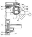
- FIG. 1 is a perspective view of an external appearance of the sanitary washing device 100 according to the first embodiment of the present disclosure in a state where the sanitary washing device 100 is installed on a toilet 110
- FIG. FIG. 3 is a perspective view of the sanitary washing device 100 with the front main body case and the control unit 130 removed.
- FIG. 4 is a perspective view of the upper surface of the operation unit 210 of the sanitary washing device 100 according to the first embodiment of the present disclosure.
- FIG. 5 is an external view of the remote controller 400 according to the first embodiment of the present disclosure.
- FIG. 1 is a perspective view of an external appearance of the sanitary washing device 100 according to the first embodiment of the present disclosure in a state where the sanitary washing device 100 is installed on a toilet 110
- FIG. FIG. 3 is a perspective view of the sanitary washing device 100 with the front main body case and the control unit 130 removed.
- FIG. 4 is a perspective view of the upper surface of the operation unit 210 of the sanitary washing device 100 according to the first embodiment of the present
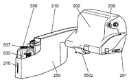
- the sanitary washing device 100 includes a main body 200, a toilet seat 300, a toilet lid 320, a remote controller 400, and a human body detection sensor 450 as main components. Yes.
- the main body 200, the toilet seat 300, and the toilet lid 320 are integrally configured and installed on the upper surface of the toilet 110.
- the installation side of the main body 200 is the rear side
- the installation side of the toilet seat 300 is the front side
- the rear side is frontward
- the right side is right side
- the rear side is front side.
- the arrangement of each component will be described with the left side as the left side.
- a protruding operation unit 210 is integrally provided on a side portion of the main body 200, and a toilet seat 300 and a toilet lid 320 are provided on a front portion of the main body 200 via a toilet seat toilet lid rotation mechanism 360 (see FIG. 2). It can be opened and closed freely.
- the toilet seat toilet lid rotation mechanism 360 includes a DC motor and a plurality of gears, and can open and close the toilet seat 300 and the toilet lid 320 individually or simultaneously.
- the toilet lid 320 stands up so as to be positioned at the rearmost part of the sanitary washing device 100.
- the toilet lid 320 is closed, the upper surface of the toilet seat 300 is concealed.
- the toilet seat 300 includes a toilet seat heater (not shown) that heats the seating surface, and is heated so that the seating surface of the toilet seat has a comfortable temperature.
- a seating sensor 330 that is a seating detection unit that detects a human body seated on the toilet seat 300 is installed in a bearing portion in the main body 200 that supports the rotation shaft of the toilet seat 300.
- the seating sensor 330 is a weight-type seating sensor, and whether or not the user is seated on the seating surface of the toilet seat 300 by opening and closing a switch due to a weight change caused by the seating of the user on the toilet seat 300. Is detected.
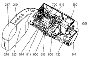
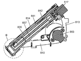
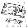
- the main body 200 includes a sub tank 600, a heat exchanger 700, a nozzle device 800, and the like (see FIG. 3).
- the main body 200 includes a buttocks cleaning nozzle 831 that is a cleaning nozzle for cleaning a local part of the human body, a spray nozzle 550 that sprays cleaning water or cleaning foam on the inner surface of the toilet, and a deodorizing device 120 that deodorizes odor during defecation. (See FIG. 2), a control unit 130 (see FIG. 2) for controlling each function of the sanitary washing device 100, and the like.
- a nozzle device 800 which is a main component of the cleaning unit 500, is installed at the center inside the main body 200, and is placed on the toilet 110 on the right side of the nozzle device 800.
- the spray nozzle 550 is installed at the front position of the main body 200 fixedly installed, and the deodorizing device 120 is installed on the left side of the nozzle device 800.
- a toilet seat toilet lid rotation mechanism 360 that opens and closes the toilet seat 300 and the toilet lid 320 is installed on the left side of the main body 200.
- a water stop electromagnetic valve 514 of the cleaning unit 500, a sub tank 600, and the like are installed on the right side of the nozzle device 800, and a heat exchanger 700 is installed on the rear side.
- a water pump 516 which is a water discharge amount variable part is installed in the rear of the heat exchanger 700.
- a control unit 130 is installed above the cleaning unit 500.
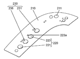
- a sleeve part case 250 is integrally provided on the right side of the main body 200 so as to protrude forward, and an operation part 210 is disposed on the upper part of the sleeve part case 250.
- the operation unit 210 is provided with a plurality of switches and indicator lights (lamps) for operating and setting each function of the sanitary washing device 100.
- an operation board (not shown) is installed.
- a plurality of tact switches and a plurality of LEDs are installed on the operation board, and the tact switch can be pressed and the LEDs can be visually recognized via a switch nameplate attached to the upper surface of the operation unit 210. ing.
- an infrared receiving unit 211 that receives an infrared signal transmitted from the remote controller 400 including the human body detection sensor 450 is disposed behind the upper surface of the operation unit 210 (FIG. 4).
- the switches installed in the operation unit 210 include a plurality of operation switches 220 for operating the cleaning operation and a plurality of setting switches 230 for setting various functions.
- a plurality of LEDs that display the setting state are installed as indicator lamps.
- the operation switch 220 includes a butt washing switch 221 that is used as an auxiliary when the battery of the remote controller 400 is dead, a failure, and the like, and a spray nozzle from a foam tank 532 (see FIG. 6), which will be described later.
- a rinse switch 223 and the like are provided for rinsing the path leading to the discharge port 550u of 550 (see FIG. 31) with cleaning water.
- a hot water temperature switch 231 for setting the temperature of the washing water
- a toilet seat temperature switch for setting the temperature of the toilet seat
- an 8-hour switch for stopping the warming of the toilet seat 300 for 8 hours after being set.
- a power saving switch that automatically learns a time zone when the sanitary washing device 100 is not used and saves power by lowering the temperature of the toilet seat 300 during a time period when it is not used.
- a toilet lid automatic opening / closing switch for setting an automatic opening / closing operation of the toilet seat 300 and the toilet lid 320 is provided.
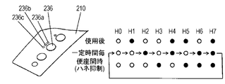
- an automatic selection setting switch 236 for selecting a foam coating operation, a splash suppression operation, or a foam regular operation, which will be described later, is also provided.
- the foam coating operation is an operation for preventing the toilet dirt from being adhered by spraying rotating foam over a wide area of the toilet inner periphery while automatically rotating the spray nozzle 550.
- the splash suppression operation when the user operates the manual splash suppression switch 434 of the remote controller 400, the direction of the discharge port 550u of the spray nozzle 550 is rotationally driven to the rear of the toilet, and then a large amount of foam is quickly sprayed in the direction where the fixation is stopped.
- the regular foam operation is an operation for automatically and periodically spraying foam on the toilet even during periods when it is not being used to keep the foam on the upper surface of the water in the toilet, thereby suppressing water line contamination.
- a foam tank 532 As shown in FIG. 38, inside the sleeve case 250 having the operation unit 210 at the top, there are a foam tank 532, a detergent tank 533, a detergent pump 534 of a foam generating unit 560 (FIG. 6) that generates cleaning foam, An air pump 535 is installed.
- the detergent tank 533 having the detergent inlet 537 provided with a filter is disposed in the forefront portion, which is in front of the operation portion 210 of the sleeve case 250.
- a detergent liquid level confirmation window 216 for visually confirming the detergent liquid level position of the detergent tank 533 is provided on the front surface of the sleeve case 250.
- FIG. 39 is a perspective view showing a state in which the sleeve lid 217 that is opened and closed when the detergent is injected into the detergent tank 533 shown in FIG. 38 and when the detergent tank 533 is attached and detached is removed.
- a remote controller 400 configured separately from the main body 200.
- the remote controller 400 is attached to a wall surface of a toilet room so that a user sitting on the toilet seat 300 can easily operate.
- the overall shape of the remote controller 400 is formed in a thin rectangular parallelepiped, and a plurality of switches and indicator lights are formed on the upper surface and the front surface of the box-shaped remote control main body 401 formed of a resin material. is set up.
- a transmission unit 402 that transmits an operation signal of the remote controller 400 to the main body 200 by infrared rays is disposed at the upper corner of the remote control main body 401.
- a control board constituting a control function of the remote controller 400 and a battery (not shown) as a power source of the remote controller 400 are incorporated.
- a human body detection sensor 450 is configured at the upper center of the front surface of the remote control body 401. Below the human body detection sensor 450, a toilet lid switch 418 that electrically opens and closes the toilet lid 320 and a toilet seat switch 419 that electrically opens and closes the toilet seat 300 are installed. The toilet seat 300 and the toilet lid 320 can be arbitrarily opened and closed.
- the toilet seat 300 is in an open state when the toilet seat 300 is erected substantially vertically like a male urine, and the toilet seat 300 is in a closed state when the toilet seat 300 is attached to the toilet 110. It is the state that is almost parallel to the upper surface. Whether the toilet seat 300 is in an open state or a closed state can be detected by a signal from a toilet seat opening / closing sensor 331 (FIG. 1) which is a toilet seat opening / closing detection unit.
- a butt cleaning switch 410 for starting butt cleaning and a cleaning position are periodically moved back and forth during butt cleaning and bidet cleaning to perform a wide range of cleaning.
- a move cleaning switch 413 is provided, and a rhythm cleaning switch 414 that periodically changes the cleaning strength during buttocks cleaning is provided.
- a cleaning strength switch 415 for adjusting the cleaning strength at the butt cleaning and bidet cleaning with two switches, and at the butt cleaning and bidet cleaning.
- a cleaning position switch 416 that adjusts the cleaning position with two switches, a buttocks drying switch 431, and a power deodorization switch 432 are arranged.
- a bidet washing switch 411 for starting bidet washing for washing a woman's local washing, a stop switch 412 for stopping buttocks washing and bidet washing, and a spray nozzle 550 are rotated.
- a manual foam coat switch 433 for spraying rotating foam over a wide region of the toilet inner periphery and a manual splash suppression switch 434 for spraying foam while fixing the spray nozzle 550 are disposed.
- a hot water temperature switch 435 for setting the temperature of the washing water
- An eight-hour cut-off switch 437 for stopping the heat retention of 300 is arranged. Furthermore, a power saving switch 438 that automatically learns a time period when the sanitary washing device 100 is not used and saves heat by lowering the temperature of the toilet seat 300 during a time period when it is not used, and automatically opens and closes the toilet seat 300 and the toilet lid 320.
- a toilet lid automatic opening / closing switch 439 for setting the operation, a nozzle cleaning switch 430 for cleaning the buttocks cleaning nozzle 831 and the bidet cleaning nozzle 832 which are cleaning nozzles, and the like are also arranged.
- an LED strength indicator 421 that displays the cleaning strength in five levels is provided, and between two cleaning position switches 416, there are five levels of cleaning positions.
- the position indicator lamps 422 to be displayed are respectively arranged.
- the open state of the toilet seat 300 is a state in which the toilet seat 300 is erected almost vertically like a male urine, and the closed state of the toilet seat 300 is the upper surface of the toilet 110. In other words, it is in a state of being approximately parallel. Whether the toilet seat is open or closed can be detected by a signal from the toilet seat opening / closing sensor 331 (FIG. 1), which is a toilet seat opening / closing detection unit.
- FIG. 6 is a schematic diagram illustrating a water circuit configuration of the sanitary cleaning device 100 in the first embodiment of the present disclosure.
- the main body 200 includes a cleaning unit 500 that cleans the user's local area.
- the cleaning unit 500 includes a nozzle device 800 that ejects cleaning water and a series of cleaning water supply channels 690 that supply the cleaning water to the nozzle device 800 from the water supply connection port 510.
- the cleaning water supply channel 690 includes a water supply connection port 510, a strainer 511, a check valve 512, a constant flow valve 513, a water stop electromagnetic valve 514, a relief valve 515, A sub tank 600, a heat exchanger 700, a buffer tank 750, a water pump 516 that is a water discharge amount variable unit, and a flow control valve 517 are sequentially installed and connected to the nozzle device 800.
- a water supply connection port 510 to which a water pipe is connected is arranged at the lower right side of the main body 200. Inside the water supply connection port 510, a strainer 511 for preventing inflow of waste contained in tap water and a sub tank 600 are provided. A check valve 512 for preventing the water stored therein from flowing back to the water pipe is incorporated.
- a constant flow valve 513 Downstream of the check valve 512, a constant flow valve 513 that keeps the amount of washing water flowing in the flow path constant, a water stop electromagnetic valve 514 that electrically opens and closes the flow path, and a relief valve 515 are integrally configured. ing.
- a sub tank 600 having an air release port Downstream of the water stop solenoid valve 514, a sub tank 600 having an air release port, a heat exchanger 700 that instantaneously heats wash water, and a buffer tank that makes the temperature of the hot water heated by the heat exchanger 700 uniform. 750 is connected.
- a water pump 516 that is a water discharge amount variable section is connected downstream of the buffer tank 750.
- a nozzle device 800 is connected to the downstream of the water pump 516 that is a water discharge amount variable section via a flow control valve 517, and each port of the flow control valve 517 has a butt cleaning nozzle 831 of the nozzle device 800, A bidet cleaning nozzle 832 and a nozzle cleaning unit 833 are connected.
- the branch flow path 530 branched between the water pump 516 and the flow regulating valve 517 of the wash water supply flow path 690 serving as the water discharge amount variable portion supplies the wash water to the foam tank 532 via the check valve 531.
- a spray nozzle 550 that is rotationally driven by a spray nozzle driving unit 550 a is connected downstream of the foam tank 532.
- a detergent tank 533 and a detergent pump 534 for supplying detergent are connected to the foam tank 532, and an air pump 535 for sending air to the foam tank 532 and creating washing foam is provided.
- the foam generation unit 560 includes an air pump 535, a detergent pump 534, a detergent tank 533, a foam tank 532, and a check valve 531.
- FIG. 6 only one check valve 531 is drawn in the branch flow path 530 branched between the water pump 516 and the flow control valve 517, which are the water discharge amount variable part.
- another rubber check valve 531b (see FIG. 50) is added to the foam tank water inlet 532a (see FIG. 50) where the wash water enters the foam tank 532 from the branch channel 530.
- Duckville is established.
- the configuration in which a plurality of check valves are provided on the upstream side of the water entering the foam tank 532 prevents the liquid and cleaning foam in the foam tank 532 containing the detergent from flowing back to the tap water side. It is possible to realize a configuration that can prevent the backflow safely and safely.
- the heat exchanger 700, the buffer tank 750, and the water pump 516 that is a water discharge amount variable unit are integrally configured by being incorporated in a chassis 501 molded from a resin material. 2).
- the strainer 511 and the check valve 512 are integrated into the water supply connection port 510, and the constant flow valve 513 and the relief valve 515 are integrated into the water stop electromagnetic valve 514. ing. Further, the buffer tank 750 is configured integrally with the heat exchanger 700.
- the water supply connection port 510 and the water stop electromagnetic valve 514, the water stop electromagnetic valve 514 and the sub tank 600, and the sub tank 600 and the heat exchanger 700 are packing each other without using a connection tube or the like. It is configured to be directly connected via an O-ring. Further, the members constituting these water circuits are installed and fixed at predetermined positions of the chassis 501.
- the water pump 516 which is a water discharge amount variable part is a piston pump which is a positive displacement pump. As shown in FIGS. 14 and 15, the outer shape is substantially L-shaped when viewed from the front, and is substantially cylindrical.
- the motor unit 516a has a shape (including a cylindrical shape), a link mechanism unit 516b that converts the rotary motion of the motor into a reciprocating motion, and a piston unit 516c that is driven by the reciprocating motion of the link mechanism unit 516b.
- a water suction port 516d and a discharge port 516e are provided as connection ports on the outer surface of the piston portion 516c.
- the piston unit 516c By driving the motor unit 516a, the piston unit 516c starts reciprocating motion, the cleaning water is sucked from the water suction port 516d, and the cleaning water is discharged from the discharge port 516e.
- the discharged cleaning water becomes a water flow with an appropriate pulsation as the piston portion 516c reciprocates.
- the outer periphery of the substantially cylindrical motor portion 516a of the water pump 516 which is the water discharge amount variable portion, is surrounded by a foamed resin cushioning member (not shown) having elasticity.
- the motor part 516a is inserted in the substantially cylindrical water pump installation part 501a (FIG. 7) provided in the rear part of the chassis 501. Accordingly, the water pump 516 is supported, and the link mechanism portion 516b and the piston portion 516c are suspended so as to hang downward.
- the water pump installation part 501a shown in FIG. 7 is formed with a thin wall thickness, and is formed on the upper part of the rib-like leg part 501b standing from the bottom surface of the chassis 501. Since the water pump installation part 501a is formed with a thin wall thickness, it is possible to obtain an effect of absorbing the vibration of the water pump 516 which is the water discharge amount variable part by the elasticity of the resin.
- FIG. 12 and FIG. 13 there are a hot water outlet 712 that is a connection port of the heat exchanger 700 in which the buffer tank 750 is integrally formed, and a connection port of a water pump 516 that is a water discharge amount variable part.
- the water inlet 516d (FIG. 14) is connected by a connection tube made of a soft resin.
- the motor unit 516a with less vibration is installed in the water pump installation unit 501a formed with a thin thickness of the chassis 501 via the buffer member, and the link mechanism unit 516b and the piston that generate a lot of vibrations.
- the part 516c is suspended in a free state.
- the buffer tank 750 and the water pump 516 are connected by a connection tube 502 (see FIG. 8) made of a soft resin.
- the water pump 516 which is a water discharge amount variable part is supported via two different materials, a foamed resin buffer member and an elastic resin forming the water pump installation part 501a.
- the vibration of the frequency of a wide range is absorbed and the transmission of the vibration to a main body can be suppressed effectively.
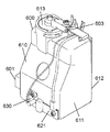
- FIG. 9 is a perspective view illustrating an appearance of the subtank 600 according to the first embodiment of the present disclosure
- FIG. 10 is a cross-sectional view of the subtank 600 viewed from the lateral direction
- FIG. 11 is a cross-sectional view of the sub tank 600 cut in the front-rear direction.
- the sub-tank 600 includes a tank body 610 molded from a resin material, a water level detection sensor 620 (FIG. 6) that detects the level of the cleaning water stored in the tank body 610, and the tank body 610. It is comprised with the incoming water temperature sensor 630 which consists of a thermistor which is a water temperature detection part which detects the temperature of the wash water supplied in the inside.
- the tank body 610 includes a front tank 611 that constitutes a front wall, both side walls, a bottom surface, and a top surface of the tank, a rear tank 612 that constitutes a rear wall of the tank, and an atmosphere disposed on the top surface of the tank body 610. It is comprised by three members of the opening part 613.
- the overall shape of the tank body 610 is formed by a plurality of planes including a front wall, a rear wall, both side walls, a bottom surface, and a top surface, and the shape in plan view is a substantially square shape.
- the front wall has an inclined part that retreats from the lower part toward the upper part, and the side view shape is formed in a substantially trapezoidal shape with the upper part being thinner than the lower part. It is smaller than the area.
- a water inlet 601 is provided at the lower portion of one side wall of the tank main body 610, and a water outlet 602 is provided at the lower rear wall of the tank main body 610, and the atmosphere opening portion 613 disposed on the top surface of the tank main body 610
- An air opening 603 that communicates the inside and the outside of the tank body 610 is provided.
- the flow path from the downstream of the sub tank 600 to the water inlet 516d of the water pump 516, which is a water discharge amount variable unit, is also maintained at atmospheric pressure.
- the water pump 516 which is a water discharge amount variable part can supply water without being influenced by fluctuations in water pressure. Therefore, a stable pump function can be exhibited.
- a buffer section 613a (FIG. 10) having a large cross-sectional area of the flow path is formed in the flow path communicating with the open air opening 603 of the open air section 613, and washing water suddenly occurs from the open air opening 603 along with bubbles. If the washing water is temporarily stored in the buffer unit 613a, the outflow from the atmosphere opening port 603 is suppressed.
- a partition wall 614 is provided inside the tank body 610, and the interior of the tank body 610 is divided into two tanks, a water tank 615 and a storage tank 616, by the partition wall 614.
- a water inlet 601 is provided near the bottom of the side surface of the water tank 615, and a water outlet 602 is provided near the bottom of the rear wall of the storage tank 616.
- the partition wall 614 By providing the partition wall 614 and forming the water tank 615 and the storage tank 616, when air is contained in the washing water flowing from the water inlet 601, the air is opened to the atmosphere opening from the upper part of the water inlet 615. It passes through 603 and is discharged to the outside. For this reason, only the wash water which does not contain air can be made to flow into the storage tank 616.
- a barrier 617 is provided between the upper surface opening 615a of the water tank 615 and the air opening 613, and protrudes from the side wall of the tank body 610 in a substantially horizontal direction (including the horizontal direction). (FIG. 10).
- the barrier 617 has a size that covers the entire upper surface opening of the water tank 615.
- a plurality of rectifying ribs 618 protruding alternately in a substantially horizontal direction are formed on the surfaces of the tank body 610 and the partition wall 614 facing each other inside the water tank 615.
- the washing water that has flowed in from the water inlet 601 first flows into the lower portion of the water tank 615 and rises in the water tank 615 while the flow direction is changed by the rectifying rib 618. At this time, when the pressure of the cleaning water flowing in from the water inlet 601 is high, or when the cleaning water contains a large amount of air and the flow is significantly disturbed, the flow is appropriately rectified by the rectifying rib 618. In addition, air contained in the cleaning water is separated by the vortex generated on the downstream side of the rectifying rib 618.
- the washing water that has risen in the water tank 615 and separated from the air passes over the upper end of the partition wall 614 and flows into the storage tank 616 to be stored.
- the wash water flowing in from the water inlet 601 is separated from the air contained in the wash water while rising in the water tank 615, and the separated air passes from the atmosphere opening 603 to the outside of the tank body 610. To be released. Therefore, cleaning water that does not contain air is stored in the storage tank 616 and supplied to the heat exchanger 700 from the water outlet 602.
- the cleaning water supplied from the sub tank 600 to the heat exchanger 700 is mixed with air, bubbles are generated inside the heat exchanger 700, the temperature inside the heat exchanger 700 rises abnormally, and heat is generated.
- the exchanger 700 may be damaged.
- an effect of preventing damage to the heat exchanger 700 can be obtained by providing the partition wall 614 to prevent air from entering.
- the water level detection sensor 620 includes a common electrode 621 serving as a common electrode and a plurality of water level electrodes 622 installed for each water level.
- the water level detection sensor 620 includes one common electrode 621 and two water level electrodes 622.
- the common electrode 621 is disposed on the inner surface of the lower front wall of the tank body 610, and the water level electrode 622 is disposed on the inner surface of the rear wall of the tank body 610.
- the water level electrode 622 includes an upper limit electrode 623 provided at the upper portion and a lower limit electrode 624 provided at the lower portion.
- the common electrode 621 is installed at a position lower than the lower limit electrode 624, and the common electrode 621 is always in a flooded state in a normal use state.
- the detection of the water level is performed by applying a DC voltage between the common electrode 621 and the water level electrode 622 and changing the voltage depending on whether or not the water level electrode 622 is submerged. That is, when washing water flows into the storage tank 616, the water level rises, and the lower limit electrode 624 and the upper limit electrode 623 (or only the lower limit electrode 624) are submerged, the common electrode 621, the lower limit electrode 624, and the upper limit electrode 623
- the control part 130 detects a water level by the voltage in between decreasing.
- the upper limit electrode 623 is used for detecting the upper limit water level
- the lower limit electrode 624 is used for detecting the lower limit water level.
- the upper limit electrode 623 is installed at a position lower than the atmosphere opening port 603, thereby preventing washing water from flowing out from the atmosphere opening port 603.
- the lower limit electrode 624 is installed above the water outlet 602, thereby preventing air from flowing into the heat exchanger 700.
- FIG. 12 is a perspective view illustrating an appearance of the heat exchanger 700 according to the first embodiment of the present disclosure
- FIG. 13 is a cross-sectional view of the heat exchanger 700. .
- a buffer tank 750 is integrally formed, and the buffer tank 750 is installed on the top of the heat exchanger 700.
- the heat exchanger 700 has a substantially rectangular flat plate shape when viewed from the front, and a casing 701 formed of a reinforced ABS resin in which glass fibers are compounded with an ABS resin, and a ceramic flat plate shape.
- a heater 702 (FIG. 13) and a hot water outlet member 703 are main constituent members.
- the casing 701 is composed of a front member 710 that constitutes the front portion and a back member 720 that constitutes the back portion, and a flat heater 702 is formed in a space formed between the front member 710 and the back member 720. Is installed. Washing water that flows through the heating channel 715 is defined as a heating channel 715 that includes a gap formed in the facing part between the front member 710 and the flat heater 702 and the opposing part between the back member 720 and the flat heater 702. However, the temperature is instantaneously raised by the flat heater 702.
- the heat exchanger 700 has a water inlet 711 that is a connection port on the right side of the front lower end of the front member 710, and is a connection port to the hot water outlet member 703 installed at the upper right side of the front member 710.
- a hot water outlet 712 is provided.
- a water inlet channel 713 connected to the water inlet 711 is provided over substantially the entire width of the lower end portion of the casing 701.
- a plurality of slits 714 are provided across the entire width of the upper surface of the water inlet channel 713, and the wash water that has flowed into the water inlet channel 713 passes through the slit 714 and flows into the heating channel 715. It has become.
- the slits 714 allow the cleaning water to flow evenly over the entire width of the heating channel 715.
- a partition rib 716 is provided at the upper end of the heating channel 715, and a buffer tank 750 is located above the partition rib 716.
- the partition rib 716 is provided with a plurality of water passage holes 717 over substantially the entire width, and the wash water heated by the heating flow path 715 flows into the buffer tank 750 through the water passage holes 717. It is the composition to do.
- protrusions 718 having a substantially semicircular cross section (including a semicircular shape) are provided with an interval across the entire width.
- the washing water flowing in the buffer tank 750 toward the hot water outlet 712 is disturbed by the protrusions 718, so that the washing water is mixed and temperature unevenness (unevenness) of the washing water is eliminated, and the uniform temperature is obtained.
- the wash water is discharged from the hot water outlet 712.
- Two thermistors are installed in the hot water member 703, one is a hot water temperature sensor 730 that detects the hot water temperature of the wash water, and the other is an excessive temperature that detects the excessive temperature of the heat exchanger 700. This is a temperature sensor 731.
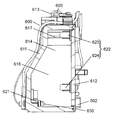
- FIG. 16 is a perspective view showing a storage state of the nozzle device 800 in the first embodiment of the present disclosure
- FIG. 17 is a cross-sectional view taken along line 17-17 in FIG.
- FIG. 18 is a longitudinal sectional view showing a storage state of the nozzle device 800
- FIG. 19 is a detailed sectional view of a portion B shown in FIG. 20 is a cross-sectional view taken along 20-20 in FIG. 19
- FIG. 21 is a horizontal cross-sectional view of the nozzle device 800 in the storage state according to the first embodiment of the present disclosure
- FIG. FIG. 23 is a detailed cross-sectional view of a portion C shown in FIG. 21, and FIG. 23 is a vertical cross-sectional view showing a butt cleaning state of the nozzle device 800.
- FIG. 24 is a detailed cross-sectional view of a portion D shown in FIG. 23 according to the first embodiment of the present disclosure.
- FIG. 25 is a nozzle device 800 according to the first embodiment of the present disclosure.
- FIG. 26 is a detailed cross-sectional view of a portion E shown in FIG. 25, and
- FIG. 27 is a cross-sectional view of the nozzle portion 820 showing the bidet cleaning state of the nozzle device 800.
- FIG. 28 is a detailed cross-sectional view of a portion G shown in FIG.
- the nozzle device 800 includes a substantially triangular frame-shaped support portion 810 molded from a resin material, a nozzle portion 820 that moves forward and backward along the support portion 810, and a forward and backward movement of the nozzle portion 820. And a flow control valve 517 for switching the supply of cleaning water to the nozzle unit 820.
- the storage direction of the nozzle portion 820 is the rear
- the advance direction of the nozzle portion 820 is the front
- the right side is the right side
- the left side is the left side from the rear to the front. Will be explained.
- the support portion 810 is formed in a substantially triangular frame shape in a side view, and an inclined portion 812 that descends from the rear portion toward the front portion with respect to the substantially horizontal bottom portion 811, and the bottom portion 811 is inclined.
- a vertical side portion 813 (FIG. 18) that joins the rear end of the portion 812 is formed.
- a guide rail 814 that guides the forward and backward movement of the nozzle portion 820 and a rack guide 815 (FIG. 17) that guides the flexible rack 861 (FIG. 23) of the cleaning nozzle drive portion 860 extend over substantially the entire length. Is formed.
- the guide rail 814 for guiding the nozzle portion 820 has a substantially T-shaped cross section.
- the rack guide 815 for guiding the flexible rack 861 has a substantially U-shaped cross section with one side open, and the upper and lower surfaces of the flexible rack 861 are restricted. It is configured to guide.
- the rack guide 815 is also formed continuously on the vertical side portion 813 and the bottom side portion 811 of the rear portion of the support portion 810 following the inclined portion 812.
- the corners of the inclined portion 812 and the vertical side portion 813 and the corners of the vertical side portion 813 and the bottom side portion 811 are connected in an arc shape.
- the cross-sectional shape of the rack guide 815 formed on each of the vertical side portion 813 and the bottom side portion 811 is also substantially U-shaped, but the open side surface is the left side in the inclined portion 812, whereas the vertical side The part 813 and the bottom part 811 are on the opposite right side.
- the open surfaces of the rack guides 815 of the vertical side portion 813 and the bottom side portion 811 are closed by a support member lid which is a separate member.
- the cleaning nozzle drive unit 860 that moves the nozzle unit 820 forward and backward along the guide rail 814 includes a flexible rack 861 coupled to the nozzle unit 820, a pinion gear 862 (FIG. 17) that meshes with the flexible rack 861, and a pinion It is comprised with the drive motor 863 (FIG. 16) which rotationally drives the gear 862.
- FIG. 17 The cleaning nozzle drive unit 860 that moves the nozzle unit 820 forward and backward along the guide rail 814 includes a flexible rack 861 coupled to the nozzle unit 820, a pinion gear 862 (FIG. 17) that meshes with the flexible rack 861, and a pinion It is comprised with the drive motor 863 (FIG. 16) which rotationally drives the gear 862.
- the drive motor 863 is a stepping motor, and the rotation angle is controlled by a pulse signal. As the drive motor 863 rotates, the flexible rack 861 is driven via the pinion gear 862.
- a gap is provided between the inner peripheral surface of the holding portion 816 of the support portion 810 and the outer peripheral surface of the nozzle portion 820, and the cleaning water ejected from the nozzle portion 820 is the inner peripheral surface of the holding portion 816.
- the nozzle portion 820 flows into a gap formed between the outer peripheral surface of the nozzle portion 820 and the outer peripheral surface of the nozzle portion 820 is cleaned.
- a nozzle lid 801 that opens and closes by the forward and backward movement of the nozzle portion 820 is provided in front of the holding portion 816 so that the nozzle lid 801 is closed when the nozzle portion 820 is housed.
- the nozzle portion 820 can be prevented from being contaminated with feces or the like.
- a water supply tube (not shown) connected to the cleaning water supply unit and a connection tube 802 for supplying cleaning water from the support unit 810 to the flow control valve 517 are connected to the bottom portion 811 of the support unit 810.
- a water supply joint 817 is formed.
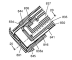
- the nozzle portion 820 includes a rod-shaped nozzle body 830 molded from a resin material, a cylindrical nozzle cover 840 that covers substantially the entire nozzle body 830, and a connecting portion 850 that pulls the nozzle cover 840 with the nozzle body 830. (FIG. 21).
- the nozzle body 830 includes a butt cleaning nozzle 831 for cleaning a local part, a bidet cleaning nozzle 832 for cleaning a female local part, and a nozzle cleaning part 833 for cleaning the nozzle part 820.
- the butt cleaning nozzle 831 includes an butt cleaning jet 834 that opens upward at the tip of the nozzle body 830 and an butt cleaning channel 835 that communicates with the butt cleaning jet 834 from the rear end of the nozzle body 830. It is configured.
- the buttocks washing flow path 835 is installed in the lower part of the nozzle body 830 and is bent upward and below the buttocks washing ejection port 834, and the bent portion rectifies the flow of washing water. 835a is installed (FIG. 24).
- the washing water ejected from the buttocks washing ejection port 834 passes through the ejection opening 844 of the nozzle cover 840 and is ejected upward.
- the bidet cleaning nozzle 832 includes a bidet cleaning nozzle 836 disposed behind the butt cleaning nozzle 834, and a bidet cleaning channel 837 that communicates with the bidet cleaning nozzle 836 from the rear end of the nozzle body 830. .
- the washing water ejected from the bidet washing outlet 836 passes through the ejection opening 844 of the nozzle cover 840 and is ejected upward (FIG. 26).
- the nozzle cleaning unit 833 includes a nozzle cleaning ejection port 838 disposed on the side surface of the nozzle body 830, and a nozzle cleaning channel 839 communicating with the nozzle cleaning ejection port 838 from the rear end of the nozzle body 830 (see FIG. 21).
- the cleaning water ejected from the nozzle cleaning ejection port 838 is ejected into the nozzle cover 840 and discharged from the drain port 845 of the nozzle cover 840 to the outside of the nozzle cover 840.
- the washing water ejected from the nozzle cleaning ejection port 838 is used for cleaning the nozzle portion 820 and its surroundings.
- the nozzle part 820 is supported in a state where the front part is inserted into the holding part 816 of the support part 810, and is slidably installed in a state where the rear part is suspended from the guide rail 814.
- the nozzle portion 820 includes a storage position where the nozzle portion 820 is stored behind the holding portion 816 as shown in FIG. 16, and the nozzle portion 820 protrudes from the holding portion 816 as shown in FIG. It is possible to advance and retract between the buttocks cleaning position and the bidet cleaning position as shown in FIG.
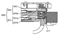
- the nozzle cover 840 includes a nozzle cover main body 841 and a connecting member 842 (FIG. 21).
- the nozzle cover main body 841 is formed by forming a thin stainless steel plate into a cylindrical shape, the front end surface is a closed surface, and the rear end surface is an open surface.
- the connecting member 842 has a substantially cylindrical shape (including a cylindrical shape) molded from a resin material, and connecting pieces 843 that engage with the nozzle body 830 are formed on both sides (FIG. 22).
- a nozzle cover stopper that regulates the sliding range of the nozzle cover 840 is integrally formed on the right side of the rear end of the connecting member 842.
- the front stopper receiving portion and the rear stopper receiving portion formed on the support portion 810 are integrally formed. By the contact, the sliding range is regulated.
- a part of the connecting member 842 is fixed and integrated in a state of being inserted into the nozzle cover main body 841 through the opening at the rear end of the nozzle cover main body 841.
- On the front upper surface of the nozzle cover main body 841 there is provided one jet opening 844 that can be opposed to the bottom cleaning jet 834 and the bidet cleaning jet 836 of the nozzle main body 830.
- a drain outlet 845 for discharging the cleaning water that has flowed into the nozzle cover main body 841 to the outside is provided on the front lower surface of the nozzle cover main body 841.
- the inner diameter of the nozzle cover 840 is slightly larger than the outer diameter of the nozzle body 830, and the nozzle body 830 and the nozzle cover 840 slide smoothly with each other with the nozzle body 830 inserted into the nozzle cover 840. It has a possible dimensional relationship.
- a flow control valve 517 is installed on the rear end surface of the nozzle body 830.
- the flow control valve 517 includes a disc-type valve body and a stepping motor that drives a switching operation.
- the flow control valve 517 selectively supplies cleaning water to the buttocks cleaning channel 835, the bidet cleaning channel 837, and the nozzle cleaning channel 839.
- a water supply port for supplying cleaning water to the flow control valve 517 is provided on the outer surface of the valve body of the flow control valve 517, and the connection tube 802 communicating with the water supply joint 817 of the support portion 810 is installed in the water supply port. Are joined (FIG. 16).
- connection part 850 configured by the connection member 842 of the nozzle cover 840 and the connection receiving part 851 of the nozzle body 830 will be described.
- connection receiving portion 851 is formed on the right side of the outer periphery of the rear end portion of the nozzle body 830. As shown in FIG. Two substantially V-shaped grooves are formed in the connection receiving portion 851, and two front concave portions 851a and two rear concave portions 851b are arranged at intervals in the front-rear direction. . The distance between the front recessed part 851a and the rear recessed part 851b is the same as the distance between the buttocks cleaning jet 834 and the bidet cleaning jet 836.
- the connecting member 842 of the nozzle cover 840 is molded from a substantially cylindrical resin material, and a connecting piece 843 protruding rearward is formed on both sides of the rear part, and a rear end part of the connecting piece 843 is A substantially V-shaped connecting protrusion 843a protruding inward is formed.
- connection protrusion 843a is always pressed against the connection receiving portion 851 of the nozzle body 830 due to the elasticity of the connection member 842 of the nozzle cover 840.
- connection protrusion 843a is engaged with the front recess 851a or the rear recess 851b, the nozzle body 830 and the nozzle cover 840 are connected, and the nozzle cover 840 is pulled by the nozzle body 830. It becomes possible to move.
- the bidet cleaning outlet 836 of the nozzle body 830 and the outlet opening 844 of the nozzle cover 840 are formed as shown in FIG. 26. It will be in the opposite state.
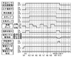
- FIG. 29 is a time chart of the cleaning unit 500 at the time of initial use in the first embodiment of the present disclosure
- FIG. 30 is a normal use in the same embodiment. It is a time chart of the washing
- the basic operation of the cleaning unit 500 is that tap water flowing through the water pipe is supplied to the water supply connection port 510 as cleaning water and the water stop solenoid valve 514 is opened, so that the cleaning water is sent to the sub tank 600. Be paid.
- the flow rate of the cleaning water flowing in the flow path is kept constant by the constant flow valve 513.
- the drive of the water stop solenoid valve 514 is controlled by the control unit 130 based on the operation of at least one of the remote controller 400 and the operation unit 210.
- the washing water supplied to the sub tank 600 is stored in the sub tank 600 and also supplied to the heat exchanger 700 and the water pump 516 which is a water discharge amount variable section.
- the water pump 516 By driving the water pump 516 that is the water discharge amount variable section, the wash water is supplied to the nozzle device 800 via the flow control valve 517.
- the driving of the water pump 516 which is a water discharge amount variable unit is controlled by the control unit 130 based on the operation of at least one of the remote controller 400 and the operation unit 210.
- the control unit 130 drives the water pump 516 that is a water discharge amount variable unit, starts energization of the flat plate heater 702 of the heat exchanger 700, and starts heating the cleaning water.
- the control unit 130 controls the energization to the flat heater 702 based on the detection information of the incoming water temperature sensor 630 and the hot water temperature sensor 730, and maintains the cleaning water at the temperature set by the hot water temperature switch 231 of the operation unit 210. .
- the control unit 130 controls the flow control valve 517 based on operation information of at least one of the operation unit 210 and the remote controller 400 to control the bottom cleaning nozzle 831, the bidet cleaning nozzle 832, and the nozzle cleaning unit of the nozzle device 800. Wash water is supplied to any of 833. Accordingly, the cleaning water is ejected from any one of the buttocks cleaning ejection port 834, the bidet cleaning ejection port 836, and the nozzle cleaning ejection port 838.
- FIG. 29 shows the cleaning unit when it is used for the first time after installation of the sanitary washing device 100 according to the first embodiment of the present disclosure, or when it is reused after the draining operation is performed to prevent freezing.
- cleaning part 500 at the time of the initial use where the washing water is not stored is shown.
- the control unit 130 starts energizing the water stop electromagnetic valve 514 and supplies the cleaning water.
- the control unit 130 starts driving the water level detection sensor 620. The driving of the water level detection sensor 620 is continued until the buttocks cleaning stop P14.
- the control unit 130 starts time measurement, stops energization of the water stop solenoid valve 514 at a time P3 when a predetermined time has elapsed, and Stop supplying.
- the energization is stopped 2 seconds after the upper limit water level is detected.
- the sub-tank 600 and the heat exchanger 700 are basically full of water, but by continuing the supply for an extra 2 seconds, the heat exchanger 700 and the amount of water discharged
- the water pump 516 which is a variable part can be more reliably filled with the washing water.
- the heat exchanger 700 air can be excluded and the washing water can be surely filled with water, so that the heat exchanger 700 can be prevented from being blown away with safety and durability. Can be improved.
- the water supply function of the water pump 516 which is a water discharge amount variable part can be reliably started by surely supplying wash water to the water pump 516 which is a water discharge amount variable part to be in a full water state.
- the control unit 130 starts driving the water pump 516 that is the water discharge amount variable unit at the time point P3 when the energization to the water stop solenoid valve 514 is stopped, and operates the flow control valve 517 so that the nozzle unit 820 operates. Supply of cleaning water to the bottom cleaning channel 835 is started.
- the control unit 130 controls the heat exchanger 700. Start driving. By detecting a decrease in the water level, it is possible to confirm that the water pump 516, which is the water discharge amount variable section, is operating normally, and to prevent an abnormal temperature rise of the heat exchanger 700 or the like.
- the washing water supplied to the buttocks washing channel 835 is ejected from the buttocks washing outlet 834.
- the jetted washing water passes through the jetting opening 844 and is reflected on the inner surface of the holding portion 816 provided at the tip of the support portion 810 to clean the outer surface of the nozzle cover 840.
- This cleaning operation is called pre-cleaning.
- the pre-cleaning is continued until time point P5, which is 2 seconds after the tapping temperature of the heat exchanger 700 reaches 25 ° C.
- the control unit 130 starts driving the cleaning nozzle driving unit 860 of the nozzle device 800, and advances the nozzle unit 820 from the storage position to the buttocks cleaning position.
- the flow control valve 517 is switched to supply cleaning water to the nozzle cleaning flow path 839.
- the cleaning water supplied to the nozzle cleaning flow path 839 is jetted into the nozzle cover 840 from the nozzle cleaning jet port 838.
- the jetted cleaning water cleans the inner surface of the nozzle cover 840 and then the nozzle cover from the drain port 845.
- 840 flows out of 840.
- the nozzle part 820 is warmed by the washing water, it is possible to suppress the feeling of discomfort due to the cold water being ejected at the time of the hip cleaning performed later.
- the control unit 130 switches the flow control valve 517 and starts supplying cleaning water to the buttocks cleaning channel 835.
- the washing water supplied to the buttocks washing flow path 835 is ejected from the buttocks washing ejection port 834 and passes through the ejection opening 844 to wash the user's local area.
- the buttocks cleaning operation is continued until the time point P11 at which the cleaning stop operation is performed.
- control unit 130 controls the wash water to a set temperature based on the detection data of the incoming water temperature sensor 630 and the outgoing hot water temperature sensor 730.
- the control unit 130 controls the water stop solenoid valve 514.
- the energization is started, and energization is continued until time point P8 when the water level detection sensor 620 detects the upper limit water level.
- the control unit 130 stops energization of the water stop solenoid valve 514 and starts time measurement, and then the process until time point P9 when the water level detection sensor 620 detects the lower limit water level. Measure time.
- the control unit 130 calculates the flow rate by calculating using the measured elapsed time and the amount of water (65 cc) from the upper limit water level to the lower limit water level. If there is a difference between the flow rate set for each cleaning strength and the calculated flow rate at the calculation end point P10, the control unit 130 adjusts the output of the water pump 516 that is the water discharge amount variable unit. Correct the flow rate of cleaning water.
- the driving of the cleaning nozzle driving unit 860 of the nozzle device 800 is stopped, and the water pump 516 and the heat exchanger 700 which are the water discharge amount variable unit are driven again.
- cleaning is started, and at a time P13 when a predetermined time has elapsed, the drive of the water pump 516 and the heat exchanger 700, which are the water discharge amount variable unit, is stopped, and the post-cleaning ends.
- the water stop solenoid valve 514 is energized again, the wash water is supplied to the sub tank 600, and at the time P14 when the upper limit water level is detected, the water stop solenoid valve 514 is energized. A series of control of the buttocks cleaning is terminated, and the cleaning section is in a standby state with the sub tank 600 at the upper limit water level.
- FIG. 30 shows a time chart during normal use in the first embodiment of the present disclosure when the initial use has been performed before and the sanitary cleaning device 100 in the standby state performs the cleaning operation. It is.
- the difference from the case of the initial use shown in FIG. 29 is that the sub tank 600 is already full at the time point P20 when the cleaning operation is performed, and that the control unit 130 has performed the initial use. Is a point.
- the control unit 130 starts energization of the water pump 516, starts supplying cleaning water, and simultaneously starts energization of the heat exchanger 700 based on the stored data that has already been controlled for the initial operation. Further, the pre-cleaning operation of the nozzle device 800 is started simultaneously. Moreover, the drive of the water level detection sensor 620 is started simultaneously.
- the control from the time point when the cleaning operation is performed to the time point when the heat exchanger 700 starts energization is different from the case of the initial use described above. It is the same.
- the sanitary washing device 100 has a change in the water level by the water level detection sensor provided in the sub-tank 600 without separately providing a dedicated flow rate sensor for detecting the flow rate in the configuration of the cleaning unit 500.
- the flow rate is detected by calculation.
- the configuration of the cleaning unit 500 can be simplified and the cost can be reduced.
- the accuracy of the water level detection and the flow rate detection can be improved, and water having different conductivity in a wide range can be obtained. It can be used as cleaning water for sanitary cleaning equipment. Thereby, the use range and usability of the sanitary washing device 100 can be improved.
- the water level detection sensor cancels the detection of the upper limit water level, and heat exchange is performed.
- Starting energization of the heat exchanger 700 can prevent the heat exchanger 700 from being blown. Thereby, safety and reliability can be ensured at a low cost with a simpler structure than means for preventing air blowing using a flow rate sensor that is generally performed.
- FIG. 31 is a perspective view showing the appearance of the spraying nozzle 550 in the first embodiment of the present disclosure
- FIG. 32 shows the spraying nozzle 550.
- 33 is a longitudinal sectional view showing the installation state of the spray nozzle 550
- FIG. 34 is a front view showing the installation state of the spray nozzle 550
- FIG. 35 is the spray nozzle. It is a top view which shows the installation position of 550, and the rotation angle of the discharge outlet of the spraying nozzle 550.
- FIG. FIG. 36 is a chart showing the pump output at the rotation angle of the discharge port 550u of the spray nozzle 550 according to the first embodiment of the present disclosure.
- the spray nozzle 550 includes an O-ring 550e and an O-ring that can be freely rotated by a spray nozzle driving unit 550a, which is a motor, in a body 550c having an inlet channel 550b.
- the shaft is sealed by 550f.
- an X ring instead of the O-ring 550f, the torque required for rotational driving can be reduced, and sticking can be easily prevented. Can be a thing.
- the shaft 550n of the spray nozzle driving unit 550a is fitted to the rotary nozzle 550d.
- the cleaning water or the cleaning foam supplied from the inlet channel 550b of the body 550c is discharged from the discharge port 550u through a plurality of inlet holes 550h opened around the rotary nozzle 550d.
- the spray nozzle 550 is installed on the right side of the center of the main body 200. This is because priority is given to placing the buttocks washing nozzle 831 or the like, which is a washing nozzle for washing the human body part, in the center, so that the spray nozzle 550 is arranged not on the center but on the left or right side thereof. Because.
- the control unit 130 of the sanitary washing device 100 detects the person entering the room with the human body detection sensor 450 and rotates the direction of the discharge port 550u of the spray nozzle 550 while rotating the washing bubbles.
- the rotating foam spraying instruction (foam coat) mode for spraying in the toilet 110 is entered, the operation shifts to the operation of spraying the rotating foam on the toilet 110, the operation of the water pump 516 as the water discharge amount variable unit is started, and the on-off valve 530a. open.
- the flow control valve 517 that switches the flow path to the buttocks cleaning nozzle 831, the bidet cleaning nozzle 832, the nozzle cleaning unit 833, and the like is in a closed state, so that the cleaning water from the heat exchanger 700 is supplied to the branch flow path.
- check valve 531 and foam tank 532 are discharged from spray nozzle 550 to the inner surface of toilet 110.
- control unit 130 drives the spray nozzle driving unit 550a of the spray nozzle 550 to rotationally drive the direction of the discharge port 550u of the spray nozzle 550, and the cleaning water or the cleaning foam discharged from the discharge port 550u.
- a water film or a foam film is formed around the entire inner surface of the toilet 110.
- the control unit 130 performs control so as to change the output of the water pump 516, which is a water discharge amount variable unit, according to the rotation angle of the discharge port 550u of the spray nozzle 550.
- the distance to the toilet inner surface is the longest, and when the direction of the discharge port 550u is 340 °, The distance to the toilet bowl is the shortest.
- the control unit 130 controls the pump (water pump 516, which is a water discharge amount variable unit) according to the rotation angle of the discharge port 550u of the spray nozzle 550.
- the output is changed as shown in the chart of FIG.
- a so-called toilet bowl that sprays washing bubbles on the toilet 110 when the human body detection sensor 450 detects that the user has entered the toilet or when the operation unit 210 or the spray switch 417 of the remote controller 400 is operated. Bubbles can be sprayed.
- the controller 130 rotates the spray nozzle driving unit 550a in the normal direction while changing the output of the water discharge amount variable unit 516, when the toilet foam is sprayed by the toilet foam spraying signal described above.
- the spray nozzle 550u is driven so that the direction of the discharge port 550u extends from the rear of the toilet bowl to the front of the toilet bowl.
- the control unit 130 reverses the spray nozzle driving unit 550a, and executes a step of spraying bubbles by at least one reciprocating rotation operation in which the direction of the discharge port 550u of the spray nozzle returns from the rear of the toilet bowl to the rear of the toilet bowl. .
- the output of the water discharge amount variable unit is controlled so that the cleaning foam reaches the vicinity of the rim of the toilet 110, and the cleaning foam can be dispersed almost all around the inner surface of the toilet bowl. It is possible to suppress the adhesion of dirt.
- control unit 130 causes the output of the water discharge amount variable unit during the normal rotation of the spray nozzle driving unit 550a to be lower than that during the reverse rotation of the spray nozzle driving unit 550a. It is good also as a structure which controls to and discharges a cleaning foam.
- the momentum at which the cleaning bubbles are discharged is strengthened, and the force disperses from the spray nozzle 550 to a location far away, and if the output of the water discharge amount variable part is lowered, the momentum at which the cleaning bubbles are discharged. Is weakened and sprayed to a location near the spray nozzle 550.
- the draft surface at the top of the outlet of the toilet 110 can be covered with the cleaning foam, and the cleaning foam can be sprayed almost all around the inner surface of the toilet close to the rim.
- the foam film can be formed up to the inner surface to suppress the adhesion of dirt.
- the installation position of the spray nozzle 550 is located in front of the main body 200 installed on the toilet 110 as shown in FIG. 2, FIG. 33, FIG. 34, FIG. Further, since the spray nozzle 550 is installed further forward than the front tip position of the cleaning nozzle 831 in the state accommodated in the nozzle device 800, the direction of the discharge nozzle 550u of the spray nozzle is driven to rotate. Thus, foam can be sprayed to the rear of the toilet, and a foam film can be formed from the front of the toilet to the inner surface of the rear to suppress adhesion of dirt.
- the forward rotation is a clockwise rotation when viewed from above in FIG. 35, and the reverse rotation is shown as a counterclockwise rotation.
- the forward rotation is a counterclockwise rotation and the reverse rotation is clockwise. It may be a rotation.
- the direction in which the discharge port 550u of the spray nozzle starts to rotate during spraying is referred to as normal rotation, and the return direction is referred to as reverse rotation.
- the output of the water pump 516 which is a water discharge amount variable unit
- the present disclosure is based on this. It is not limited. Even if the output of the water pump 516, which is the water discharge amount variable part, is not changed when rotating the foam, a foam film is formed from the front of the toilet to the rear inner surface by configuring the spray nozzle 550 as described below. Thus, the adhesion of dirt can be suppressed.
- the spray nozzle 550 is installed in the main body 200 such that the rotation axis Ax of the discharge port 550u of the spray nozzle 550 that is driven to rotate is inclined in the front-rear direction and the left-right direction. Yes.
- the lower side of the rotation axis Ax is inclined toward the front side of the toilet 110, and in the left-right direction, the lower side of the rotation axis Ax is inclined toward the washing nozzle 831.
- the direction of the discharge port 550u is slightly higher and close to the rim on the left side of the toilet 110.
- the discharge port 550u is directed to the right side of the toilet 110, the direction of the discharge port 550u is slightly lowered.
- the direction of the discharge port 550u of the spray nozzle 550 is rotationally driven around the rotation axis Ax by the spray nozzle driving unit 550a.
- the distance from the discharge port 550u of the spray nozzle 550 to the inner surface of the toilet bowl changes, but with the rotation, the washing bubbles are sprayed while the height of the discharge port 550u of the spray nozzle 550 changes. Therefore, it is possible to form a foam film from the front of the toilet bowl to the inner surface near the rear rim, with a scattering locus as depicted by the counterclockwise broken arrow in FIG. Can be suppressed.
- the rotation axis Ax of the discharge port 550u of the spray nozzle 550 has an inclination angle ⁇ (angle with respect to the vertical direction) of 20 degrees, as shown in FIG.
- the horizontal inclination angle ⁇ (angle with respect to the vertical direction) is 10 degrees.
- the height position of the discharge port 550u of the spray nozzle 550 is set to be lower than the upper end surface of the toilet 110 at any rotational position.
- the distance to the front, side, and rear of the toilet is different. Even if the cleaning water or the cleaning foam can reach the wide area of the inner surface of the toilet, the water film or the foam film can be formed on the wide area of the inner surface of the toilet to suppress the adhesion of dirt. .
- a level change switch that can adjust the pump output level (average level) to be higher or lower may be provided in at least one of the operation unit 210 and the remote controller 400.
- the cleaning water or the cleaning foam can be discharged so as to reach the entire inner surface of the toilet, and the water film or the foam film is formed to the inner surface in front of the toilet. Adhesion can be suppressed.
- the control unit 130 sets the rotation angle of the discharge port 550u of the spray nozzle 550 to the rotation angle. Accordingly, the speed of the spray nozzle driving unit 550a may be changed.
- the output of the pump water pump 516, which is a water discharge amount variable part
- the momentum of the discharge can be changed to reach the inner surface of a distant toilet, and the scattering on the inner surface of a close toilet can be suppressed.
- the speed of the spray nozzle driver 550a in accordance with the rotation angle of the discharge port 550u the spray density can be made more uniform.
- the spray density is coarse at a location far from the toilet inner surface and the spray density at a location far from the toilet inner surface. Then, the spraying density becomes dense.
- the washing water or the washing bubbles sprayed forward of the toilet 110 is dispersed when the rotation angle that is the farthest from the discharge port 550u of the spray nozzle 550 is around 160 °. Then, when the spraying density is discharged to the front of the toilet bowl, the spraying nozzle 550 has the slowest rotation speed, thereby increasing the spraying density. On the other hand, when discharging to the rear of the toilet whose rotation angle is the closest distance from the discharge port 550u of the spray nozzle 550, the spray nozzle 550 has the fastest rotation speed, thereby reducing the spray density. Can be made. In this way, the distribution of the cleaning water or the cleaning foam sprayed on the inner surface of the toilet bowl can be made more uniform, and dirt adhesion can be suppressed.
- control unit 130 changes the speed of the spray nozzle driving unit 550a according to the rotation angle of the discharge port 550u of the spray nozzle 550, so that the direction of the discharge port 550u of the spray nozzle 550 is the distance to the inner surface of the toilet bowl.
- the speed of the spray nozzle driving section 550a is made small, and when the rotation angle is short at the rear of the toilet bowl and the rotation angle is behind the toilet bowl, the speed of the spray nozzle driving section 550a is made large. Can do.
- washing water or washing bubbles can be discharged evenly to the inner surface of the toilet, and more uniformly, to the inner surface in front of the toilet
- a dirt film can be suppressed by forming a water film or a foam film.
- the controller 130 sprays the cleaning foam from the spray nozzle 550 to the inner surface of the toilet after the human body detection sensor 450 detects the person entering the room. While rotating at least one reciprocating rotation, bubbles are sprayed and automatically stopped.
- the configuration is not limited to the above-described one-time reciprocating rotation drive, and is not limited to the above-described one-way reciprocating rotational drive, as long as it is applied to the inner surface of the toilet from the rotating discharge port 550u.
- the number of times can be selected and set by the user using at least one of the operation unit 210 and the remote controller 400.
- the spray nozzle 550 is configured to reciprocally rotate the rotating nozzle 550d of the spray nozzle 550 as shown in FIG. 36 when spraying cleaning water or cleaning foam on the inner surface of the toilet.
- the spraying direction of the cleaning water or the cleaning foam is not always the same as in the configuration in which the rotating nozzle 550d of the spraying nozzle 550 is rotated all around in the right direction or the left direction.
- the rotation nozzle 550d of the spray nozzle 550 is provided with a rotation restricting portion (not shown) whose rotation range is restricted from a rotation angle of 0 ° to a rotation angle of 340 ° by a mechanical stopper.
- the rotation restricting portion (not shown) is a spray nozzle driving portion 550a when a protrusion formed on a part of the outer periphery of the rotating nozzle 550d rotates together with the rotating nozzle 550d and contacts the rotation restricting wall of the body 550c. Even if the motor attempts to rotate the rotating nozzle 550d, it is in mechanical contact with the motor, so that the motor slips and idles, and the rotating nozzle 550d cannot rotate.
- the spray nozzle driving unit 550a is configured by a motor and the spray nozzle driving unit 550a can recognize the origin of the rotation position at the position where the rotation restricting unit is in contact, the accuracy of the rotation angle position and the rotation speed is possible. High spraying and extremely low dispersion.
- the branch flow path 530 branched between the water pump 516 and the flow control valve 517 in the wash water supply flow path 690 that is the water discharge amount variable portion is opened and closed.
- the foam tank 532 Via a valve 530 a and a check valve 531, the foam tank 532 is connected so that washing water is supplied, and a spray nozzle 550 is connected downstream of the foam tank 532.
- a detergent tank 533 for supplying detergent and a detergent pump 534 are connected to the foam tank 532, and an air pump 535 for sending air to the foam tank 532 and creating washing foam is provided.
- the cleaning water from the heat exchanger 700 is fed by the water pump 516 that is the water discharge amount variable unit, and the cleaning water or the cleaning bubbles are discharged from the spray nozzle 550.
- the discharge amount of the cleaning water or the cleaning foam discharged from the spray nozzle 550 and the momentum of discharge are increased or decreased.
- the configuration in which the on-off valve 530a is provided in the branch channel 530 may be a configuration in which a channel switching valve is provided in a branch portion between the branch channel 530 and the washing water supply channel 690.
- the user can select whether to spray the cleaning water from the spray nozzle 550 or spray the cleaning foam by at least one of the operation unit 210 of the main body 200 and the remote controller 400.
- a foam tank 532 that supplies detergent and generates cleaning foam, and the cleaning foam is discharged from the outlet 550u of the spray nozzle 550 to the inner surface of the toilet.
- the foam film made of cleaning foam containing detergent can suppress unpleasant odor and improve the comfort of a visually clean image.
- the washing water or the washing foam is sprayed from the spray nozzle 550 to the inner surface of the toilet bowl separately from the case where the human body detection sensor 450 detects the person entering the room.
- the spraying can also be performed by operating the spraying switch 417 of 210 or the remote controller 400.
- control unit 130 has a rinsing instruction mode that can be selected and instructed by at least one of the operation unit 210 and the switch button of the remote controller 400.
- the control unit 130 opens the on-off valve 530a with the detergent pump 534 supplying the detergent in the detergent tank 533 of the foam generating unit 560 to the foam tank 532 stopped, and the water discharge amount varying unit 516 The cleaning water may be supplied to the foam tank 532 and discharged from the spray nozzle 550.
- the path from the foam tank 532 to the spray nozzle 550 is rinsed with washing water, and the clogging due to the sticking of the detergent on the path and the spray nozzle 550 and the rotation failure due to the sticking of the detergent on the spray nozzle 550 are prevented. be able to.
- the inner surface of the toilet bowl can be rinsed.
- the detergent pump 534 is in a stopped state, so that the detergent is not supplied to the foam tank 532 and cleaning water is sent. For this reason, the path from the foam tank 532 to the spray nozzle 550 can be rinsed with the washing water, and the inner surface of the toilet can be rinsed with the washing water.
- rinsing can be performed even with washing water whose temperature is not controlled.
- a more excellent rinsing effect can be obtained. it can.
- the user can perform rinsing at any time by operating the rinsing switch 223 of the operation unit 210 to set the rinsing instruction mode.
- a rinsing lamp 223a (FIG. 4) such as an LED is provided in the vicinity of the rinsing switch 223 of the operation unit 210 to set the above-described rinsing instruction mode. For example, when a predetermined time such as 20 days elapses, it is possible to prevent forgetting to rinse by making the rinse lamp 223a automatically blink.
- the control unit 130 When the cleaning foam is sprayed from the spray nozzle 550 to the inner surface of the toilet bowl, the control unit 130, according to the rotation angle of the discharge port 550u of the spray nozzle 550, similar to the case shown in the pump output of FIG.
- the output of the air pump 535 may be changed. As a result, even if the distance to the front, side, and rear of the toilet is different, the cleaning foam can be discharged so as to reach the entire inner surface of the toilet. Dirt adhesion can be suppressed.
- the air pressure by the air pump 535 is increased by increasing the output of the air pump 535. It becomes high and the momentum which blows a washing bubble far from the discharge outlet 550u can be strengthened.
- the air pressure by the air pump 535 is reduced by reducing the output of the air pump 535, and cleaning is performed. The momentum to blow bubbles can be weakened. In this way, the cleaning foam can be discharged uniformly on the inner surface of the toilet.
- the image sensor or the like further includes a dirt detection unit (not shown) that detects the dirt of the toilet 110, and the control unit 130 reciprocates the part where the dirt remains and sprays it intensively.
- the dirt suppressing effect can be further improved.
- the rotation speed when the discharge port 550u of the spray nozzle 550 passes through may be set to a low speed rotation or the pump output may be increased.
- the signal of the toilet seat opening / closing detection unit 331 is in the toilet seat open state, and the signal of the seating detection unit 330 is in the non-sitting state.
- the control unit 130 positions the discharge port 550u of the spray nozzle 550 toward the toilet outlet 115 (this embodiment). Then, as shown in the chart of FIG. 37, the spray nozzle driving unit 550a is rotationally driven and stopped until the rotation angle of the discharge port 550u is about 20 °. Thereafter, the water discharge amount variable unit 516 is controlled with a medium output, and the cleaning foam is discharged to the toilet outlet 115 for a predetermined time (in this embodiment, 8 seconds) as shown by the arrow in FIG. The discharged cleaning foam is in a state of covering the water surface above the outlet 115 of the toilet 110, that is, the upper part of the so-called draft surface in the toilet 110 with foam.
- the rotating foam spraying the cleaning foam into the toilet while rotating the direction of the discharge port 550u of the spraying nozzle 550.
- the cleaning foam is sprayed into the toilet 110 while the direction of the discharge port 550u of the spray nozzle 550 is fixed by the fixed foam spraying instruction (splash suppression) mode of the control unit 130. Fixed foam spraying is performed.
- the operation unit 210 or the spray switch of the remote controller 400 is used. Assume that a certain manual splash suppression switch 434 is operated.
- the control unit 130 controls the position where the direction of the discharge port 550u of the spray nozzle 550 is toward the rear of the toilet bowl (in this embodiment, as shown in the chart of FIG.
- the spray nozzle drive unit 550a is rotationally driven until the rotation angle of the outlet 550u is around 20 °) and stopped.
- the water discharge amount variable unit 516 is controlled at a high output, and the washing foam is discharged to the rear of the toilet for a predetermined time (8 seconds in the present embodiment) as indicated by an arrow in FIG.
- the discharge port 550u of the spray nozzle 550 opens rearward with respect to the rotation axis: Ax of the spray nozzle 550 in the direction of an angle ⁇ .
- the cleaning bubbles are discharged.
- the water discharge amount variable unit 516 is controlled at a high output, so that the washing bubbles are placed at the upper part of the discharge port 115 in the toilet bowl.
- the upper surface of the water surface and the waterline in the toilet bowl can be quickly covered with foam. Therefore, it is possible to suppress the odor and the adhesion of dirt near the draft surface of the toilet bowl by the cleaning foam.
- the urine falls to the vicinity of the water surface in the toilet bowl, bounce back to the surroundings can be suppressed by the cushion effect of the foam covering the water surface. That is, it is possible to prevent the urine from splashing and scattering by quickly spraying a large amount of foam in the direction in which the spray nozzle 550 is fixed and forming bubbles on the upper surface of the water in the toilet 110.
- the control unit 130 enters the fixed bubble spraying instruction (splash suppression) mode, and the discharge port of the spray nozzle 550
- the spray nozzle driving unit 550a is rotationally driven to a position where the direction of 550u is directed to the toilet outlet 115 and stops.
- the water discharge amount variable unit 516 is controlled at a high output, and the cleaning foam is discharged toward the back of the toilet.
- the position where the cleaning foam is fixedly sprayed is the toilet near the outlet 115. Any of the front side, the center, and the rear side may be used.
- the upper surface of the draft surface and the toilet bowl water line is quickly covered with the foam, so that the urine can be prevented from splashing and scattering, and the draft line in the toilet bowl 110 can be suppressed.
- the adhesion of dirt in the vicinity and the upper part thereof can be suppressed.
- the output of the water pump 516 that is the water discharge amount variable unit is a constant output that does not change, that is, the water pump that is the water discharge amount variable unit during the fixed foam spraying.
- the output of 516 may be the same as that at the time of rotating foam spraying.
- the sanitary washing device cleans the main body 200 installed in the toilet 110, the washing nozzle 831 for washing the human body, the foam generating unit 560 that produces washing bubbles, and the toilet inner surface.
- a spray nozzle 550 that discharges water or washing bubbles, a water discharge amount variable unit (water pump 516) that varies the flow rate of cleaning water to be sent to the spray nozzle, and a spray nozzle drive that rotationally drives the direction of the spray nozzle outlet 550u Part 550a.
- an opening / closing valve 530a for opening and closing a water channel to the spray nozzle 550, a control unit 130 for controlling these operations, and an operation unit 210 (or a remote controller 400) for setting instructions to the control unit 130 are provided.
- control unit 130 rotates the direction of the discharge port 550u of the spray nozzle 550 while rotating the foam in the toilet 110 while rotating the direction of the discharge port 550u, and the discharge port 550u of the spray nozzle 550. It has a fixed foam spraying instruction (splash suppression) mode in which the cleaning foam is sprayed into the toilet bowl while the direction is fixed.
- the direction of the discharge port 550u of the spray nozzle 550 is rotationally driven and the wash foam is sprayed so as to be widely distributed in the toilet bowl.
- a foam film is formed from the front of the toilet bowl to the rear inner face, and the adhesion of dirt on the toilet inner face and in the vicinity of the water line can be suppressed.
- the cleaning foam is quickly formed on the upper surface of the water in the toilet bowl 110.
- the water surface above the discharge port 115 can be covered with cleaning bubbles. Thereby, the unpleasant smell at the time of piss and the scattering by the splash at the time of male piss are suppressed by the washing foam.
- the foam thickness is about 5 mm, which has the effect of being improved compared to no foam, It can be confirmed that the suppression effect becomes significant when the thickness of the foam is about 10 mm. That is, it is preferable that the lower limit of the thickness of the foam on the water surface in the toilet 110 by foam dispersion is 5 mm or more and the upper limit is 50 mm or less. In addition, 50 mm or less is an upper limit for making the foam
- sanitary washing device 100 is installed in main body 200 with spray nozzle 550 inclining rotation axis Ax of discharge port 550u of spray nozzle 550 that is rotationally driven in the front-rear direction and the left-right direction.
- the inclination in the front-rear direction is configured such that the lower side of the rotation axis Ax is inclined toward the front side of the toilet 110
- the inclination in the left-right direction is configured such that the lower side of the rotation axis Ax is inclined toward the cleaning nozzle 831.
- the discharge port 550u when the toilet nozzle is sprayed from the spray nozzle 550 to the toilet bowl 110, when the discharge port 550u faces the front of the toilet where the distance from the discharge port 550u of the spray nozzle 550 to the spray position is long, the discharge port When the direction of 550u becomes high and the discharge port 550u is directed to the rear of the toilet where the distance from the discharge port 550u of the spray nozzle to the spray position is short, the direction of the discharge port 550u is low.
- the cleaning foam can be sprayed while changing the height of the discharge port 550u of the spray nozzle. Even if the output of the water pump 516 is not changed, a foam film can be formed from the front of the toilet to the rear inner surface to suppress the adhesion of dirt.
- the control unit 130 rotates the spray nozzle driving unit 550a in the normal direction so that the discharge port 550u of the spray nozzle 550 is discharged.
- the direction is led from the rear of the toilet to the rear of the toilet through the front of the toilet.
- the control unit 130 reverses the spray nozzle driving unit 550a so that the direction of the discharge port 550u of the spray nozzle returns from the rear of the toilet to the front of the toilet and to the rear of the toilet by at least one reciprocating rotation operation. Execute the process of spraying.
- the control nozzle 130 causes the spray nozzle drive unit 550a to rotate forward so that the direction of the discharge port 550u of the spray nozzle 550 is from the rear of the toilet bowl. It goes to the rear of the toilet through the front of the toilet. Thereafter, the control unit 130 reversely rotates the spray nozzle driving unit 550a so that the direction of the discharge port 550u of the spray nozzle returns from the rear of the toilet to the front of the toilet and back to the rear of the toilet. Then, the output of the water discharge amount variable unit is controlled so that the cleaning foam reaches the vicinity of the rim of the toilet 110. Thereby, washing
- sanitary washing device 100 further includes human body detection sensor 450 that detects entry / exit of a user into / from a toilet room, and controller 130 includes a human body detection sensor 450 that enters the user's room into the toilet room. Is detected, at least by the one reciprocating rotation operation described above, the rotating foam is sprayed on the toilet 110.
- the cleaning foam is sprayed on the inner surface of the toilet 110 while the direction of the discharge port 550u of the spray nozzle is driven to rotate at least once. Rotating foam can be sprayed, and before use, a foam film is reliably formed on the inner surface of the toilet bowl, and adhesion of dirt can be suppressed.
- the control unit 130 opens the on-off valve 530a, so that the washing water is fed by the water discharge amount varying unit 516, and the detergent in the detergent tank 533 is removed from the foam tank.
- a detergent pump 534 for supplying to 532 and an air pump 535 for supplying air to the foam tank are provided. Then, the cleaning water or the cleaning foam in the foam tank 532 is discharged from the spray nozzle 550.
- the control unit 130 has a rinsing instruction mode, and in the rinsing instruction mode, a detergent pump that supplies the detergent in the detergent tank 533 of the foam generation unit 560 to the foam tank 532.
- the on-off valve 530 a is opened, and the wash water is supplied to the foam tank 532 by the water discharge amount variable unit 516 and discharged from the spray nozzle 550.
- the path from the foam tank 532 to the spray nozzle 550 is rinsed by the washing water, and the clogging due to the fixing of the detergent on the path and the spray nozzle 550 and the rotation failure due to the fixing of the detergent on the spray nozzle 550 are prevented. can do. Moreover, the inner surface of the toilet bowl can be rinsed.
- a motor is used as the spray nozzle driving unit 550a.
- the spray nozzle 550 is rotated by an action when another cleaning source, for example, the discharge bubbles 550u of the spray nozzle 550 is discharged. You may comprise so that it may move.
- a spray nozzle 550 for spraying the cleaning foam near the rim of the toilet 110 and a spray nozzle 550 for spraying the cleaning foam near the outlet 115 of the toilet 110 may be provided.
- the plurality of spray nozzles 550 may be rotated independently, or may be rotated in conjunction with each other.
- the spray nozzle 550 may be provided with a discharge port 550u for spraying cleaning foam near the rim of the toilet 110 and a discharge port 550u for spraying cleaning foam near the discharge port 115 of the toilet 110.
- the spray nozzle 550 is configured to spray in the vicinity of the rim of the toilet 110 and in the vicinity of the outlet 115 of the toilet 110, but in the vicinity of the rim of the toilet 110 and the outlet of the toilet 110. In addition to the vicinity of 115, it may be configured to be dispersed at other positions.
- sanitary washing device 100 of the present embodiment is integrally provided with a sleeve case 250 so as to protrude forward from the side of main body 200.
- a sleeve lid 217 provided in front of the operation unit 210 disposed at the upper part of the sleeve case 250, and a foam generating unit 560 at the forefront of the sleeve case 250 inside the sleeve lid 217.
- a detergent tank 533 that is a transparent or translucent container is built in, and a detergent liquid level confirmation window 216 that can visually confirm the detergent liquid surface position of the detergent tank 533 is provided on the front surface of the sleeve case 250.
- the detergent tank 533 having the detergent inlet 537 provided with the detergent tank lid 536 is installed at the frontmost part in front of the operation part 210 of the sleeve case 250 and is located closest to the front of the toilet bowl. Therefore, it is possible to make it easy to replenish the detergent.
- the detergent tank 533 having the detergent inlet 537 is installed at the forefront part in front of the operation part 210 of the sleeve case 250, the sleeve cover 217 in front of the operation part 210 is opened, and the detergent When the detergent is replenished from the inlet 537 to the detergent tank 533, the detergent can be prevented from falling into the operation unit 210.
- the height of the detergent inlet 537 is configured to be lower than that of the operation unit 210. Therefore, when the detergent tank 533 is replenished with detergent, more detergent is added. It is possible to prevent the operation unit 210 from falling down.
- the detergent pump hose 561 shown in FIGS. 6 and 38 guides the detergent from the outlet side of the detergent pump 534 to the inlet side of the foam tank 532 and has a hollow inside. It is a cylindrical tube, and is formed of a so-called double hose in which the tube is further coated on the outside of the tube.
- the inner diameter of the detergent pump hose 561 is smaller than the inner diameter of the foam tank hose 562 that guides the cleaning foam from the foam tank 532 to the spray nozzle 550.
- the detergent pump hose 561 can be prevented from greatly expanding and bursting, and the washing bubbles can be stably removed from the spray nozzle 550. Can be sprayed.
- the detergent pump hose 561 having a double hose structure is composed of a double hose whose outer side of the elastomer resin tube is covered with a heat shrinkable tube. Not limited to. Even if it is another material, by using a double hose, swelling and bursting can be prevented, and the cleaning foam can be stably sprayed from the spray nozzle 550.
- the sanitary washing device 100 includes a main body 200 that includes a control unit 130, a spray nozzle 550, a nozzle device 800, and the like.
- the front surface of the main body case 201 is covered with the main body case 202.
- the spray nozzle 550 is installed in the front part of the rear main body case 201, the front and upper part of the spray nozzle 550 are covered with the main body case 202, and the discharge outlet 516e of the lower part of the spray nozzle 550 is open
- FIG. 40 is a cross-sectional view of the center portion of the spray nozzle 550 installed in the rear main body case 201 cut in the front-rear direction in the first embodiment of the present disclosure.
- the cleaning foam discharged from the discharge port 516e of the spray nozzle 550 is normally discharged to the inner surface of the toilet as shown by the dotted line T in FIG.
- the two-dot chain line S in FIG. As indicated by, the jets may diffuse and scatter, and may splash outside the toilet and wet the floor.
- the body case 202 blocks the upward jet flow from the discharge port 516 e of the spray nozzle 550 with a wall, Scatter guard portions 550z are formed to be dropped into 110.
- the splash guard 550z can prevent the cleaning bubbles and the cleaning water discharged from the spray nozzle 550 from being ejected outside the toilet 110, and can be sprayed into the toilet 110.
- a part of the main body case 202 of the main body 200 that covers the front and top of the spray nozzle 550 has a splash guard portion 550z that blocks the upward jet flow from the discharge port 550u of the spray nozzle 550 and drops it into the toilet bowl.
- a splash guard portion 550z that blocks the upward jet flow from the discharge port 550u of the spray nozzle 550 and drops it into the toilet bowl.
- the sanitary washing device 100 has a configuration in which the main body 200 can be attached to and detached from the toilet 110 via the main body fixing plate 240 (FIG. 43). It was removed when the contractor or the user initially installed the toilet 110, and when the user wanted to remove the main body 200 from the toilet 110 and clean the dirt near the bottom of the main body 200.
- the main body 200 of the sanitary washing device 100 may be temporarily placed on a table or a floor.
- the discharge port 516e of the spray nozzle 550 positioned below the mounting surface of the main body 200 is scattered.
- the guard portion 550z protects the base and the floor from being touched, and damage to the spray nozzle 550 can be prevented.
- 41 which is a front view of the main body 200
- a two-dot chain line in FIG. 42 which is a side view of the main body 200, indicate the surface of the table when the main body 200 is placed.
- the discharge port 516e of the spray nozzle 550 does not come into contact with the surface of the table by the scattering guard portion 550z.
- the splash guard part 550z is formed on the main body case 202, but the splash guard part 550z may be formed on the body 550c of the spray nozzle 550 and the like.
- FIG. 43 is a perspective view of the main body fixing plate 240 and the rear main body case 201 of the main body 200 according to the first embodiment of the present disclosure.
- the perspective view of the rear main body case 201 is a diagram in which the control unit 130, the spray nozzle 550, the nozzle device 800, and the like installed therein are omitted for convenience of explanation.
- the main body fixing plate 240 is fixed to the toilet 110 through an attachment bolt (not shown) in the position adjusting long hole 241. Then, the main body fixing plate 240 and the center of the main body 200 are aligned, the rear portion of the main body fixing plate 240 is slightly lifted, and the main body 200 is slid from the toilet surface until it clicks into place. 200 is fixed to the toilet bowl 110.
- the main body 200 when removing the main body 200 from the toilet 110, the main body 200 can be removed by pulling the main body 200 forward while pushing the main body attachment / detachment button 242 next to the main body 200 to the back.
- a magnet 243 is embedded in the resin main body fixing plate 240, and the main body 200 is attached to the toilet bowl 110 in the rear main body case 201 or the main body 200 is attached to the toilet bowl.
- a detachable sensor 244 that can detect whether the detachable sensor 110 is detached from the camera 110 is attached.
- the attachment / detachment sensor 244 is composed of a reed switch. As shown in the partial cross-sectional view of FIG. 44, the state in which the main body 200 is attached to the toilet 110 includes the magnet 243 of the main body fixing plate 240 and the rear main body case. It can be detected by the positional relationship facing the attachment / detachment sensor 244 of 201. Further, when the main body 200 is detached from the toilet bowl 110, the detachment state is detected by the attachment / detachment sensor 244 due to the separation of the magnet 243 and the attachment / detachment sensor 244.
- the control unit 130 is configured not to execute the discharge operation from the spray nozzle 550 when the attachment / detachment sensor 244 detects that the main body 200 is detached from the toilet bowl 110. Thereby, when the main body 200 is removed from the toilet 110, for example, the manual foam coat switch 433 of the remote control main body 401 or the manual splash control switch 434 or the like is pressed. Even if this is done, the discharge operation from the spray nozzle 550 is not executed. For this reason, it is possible to prevent a problem that the washing bubbles are ejected carelessly on the floor and the person.
- control unit 130 is configured not to prohibit the discharge operation from the buttocks cleaning nozzle 831 and the bidet cleaning nozzle 832 even when the attachment / detachment sensor 244 recognizes that the main body 200 is removed from the toilet 110. Yes. Accordingly, even if a failure occurs in the attachment / detachment sensor 244 and a situation in which the main body 200 is mistakenly recognized as being removed from the toilet bowl 110 is a basic function of the sanitary washing device 100, for the user Important buttocks and bidet cleaning can be made feasible.
- FIG. 45 is a time chart when rotating foam spraying is performed in the sanitary washing device 100 according to the first embodiment of the present disclosure.
- the detergent pump 534 reverses for 2 seconds at the time N2 shown in FIG. 45, and then starts normal rotation at the time N3 and the water pump 516 and
- the air pump 535 is operated and detergent, water, and air are supplied to the foam tank 532 to produce cleaning foam.
- the generated cleaning foam is sprayed on the inner surface of the toilet 110 from the discharge port 550u of the spray nozzle 550. By spraying the rotating foam on the inner surface of the toilet, the inner surface of the toilet is less likely to get dirty, and the dirt can be easily removed.
- the discharge port 550u of the spray nozzle 550 is rotationally driven by a spray nozzle driving unit 550a which is a stepping motor.
- the discharge port 550u of the spray nozzle 550 sprays bubbles while rotating forward from the stop position at the time point N3 to the extreme end position at the time point N6, and then from the extreme end position at the time point N6, Bubbles are sprinkled and returned to the stop position at the time of N9. Then, at the time of N11, the operation of the water pump 516 and the air pump 535 is automatically stopped, and the rotating foam spraying is automatically ended.
- control part 130 is operating the water pump 516 and the air pump 535 continuously between N3 to N11 sprayed with rotating foam.
- the detergent pump 534 is intermittently operated such that it rotates normally from N3 to N4, stops, rotates normally from N6 to N7, and stops rotating normally from N9 to N10.
- the detergent pump 534 is operated for 2 seconds in a 6-second cycle in intermittent operation.
- the chart of the heat exchanger 700 is drawn with a broken line.
- the water supplied to the tank 532 is at a temperature lower than 20 ° C.
- the water is heated by the heat exchanger 700 so that the water temperature is about 20 ° C. and supplied to the foam tank 532. is there.
- the foaming property is deteriorated.
- by supplying the heat exchanger 700 so that the water temperature is about 20 ° C. it is possible to generate preferable washing bubbles in the foam tank 532.
- the detergent pump 534 is inverted from N2 to N3 immediately before the time point N3 when the rotating foam spraying is started. This is because a tube pump is used as the detergent pump 534, and the detergent solution on the outlet side of the tube flows backward to the tube portion that has been crushed by the roller, and the crushed portion becomes cylindrical. This is because a stable amount of detergent can be delivered by normal rotation after recovery.
- the spray nozzle driving unit 550a is in contact with the origin position from the stop position. After being driven, the rotation detection microswitch is pressed, and after the origin position of the spray nozzle driving unit 550a, which is a stepping motor, is recognized, the driving is controlled by the control unit 130 so as to return to the stop position.
- the origin reset operation of the spray nozzle drive unit 550a causes the stepping motor of the spray nozzle drive unit 550a to cause a slip phenomenon due to an increase in some rotational load, and the rotation amount cannot be driven according to the number of drive steps. Even if a misalignment occurs, it is possible to correct and reset the stop position, which is the starting position of the rotating bubble spraying, to start driving. That is, it is possible to spray the rotating foam at a stable position at all times.
- the rotation detection microswitch that is pressed by the origin reset operation of the spray nozzle driving unit 550a rotates until the rotation detection microswitch is pressed because, for some reason, detergent adheres around the discharge port 550u of the spray nozzle 550. It is possible to detect a case in which driving cannot be performed. That is, when a signal for pressing the rotation detection microswitch cannot be obtained when spraying the rotating bubbles, the rinsing lamp 223a is turned on to notify the user to perform the rinsing operation by the rinsing switch 223 described above. be able to.
- the time from the N3 time point when the rotating foam spraying starts to the N12 time point when the rotating foam spraying ends is set to about 15 seconds. This about 15 seconds can be set and changed from the amount of foam accumulated to about 10 seconds, about 25 seconds, etc. according to the size of the toilet 110.
- the rinsing lamp 223a When the time until the rotation detection micro switch is pressed is delayed by about 10% or more with respect to the set rotating bubble spraying time, the rinsing lamp 223a is lit to repeat blinking once with “Chika” and “Chika”. The user is prompted to press the rinse switch 223 to instruct the rinse operation.
- washing In the rinsing operation, washing is performed for about 3 minutes while flowing washing water heated to about 40 ° C. in the heat exchanger 700.
- the foam generating unit 560 and the spray nozzle 550 are rinsed with washing water, and the sticking of the detergent to the foam generating unit 560 and the spray nozzle 550 and clogging are prevented, and stable foam spraying is performed. be able to.
- the rinse lamp 223a is set to “Chika, “Chica”, “Chica, Chica” are lit and displayed so as to blink twice, and the rinse switch 223 is pressed to promote the vicinity of the discharge port 550u of the spray nozzle 550 with a toothbrush or the like while performing the rinse operation. It is.
- the flow path switching chart is the time from N2 to N3 from the water discharge amount variable unit 516 that is a water pump in the water circuit of FIG.
- the operation of switching the supply destination of the cleaning water from the nozzle device 800 side to the bubble generating unit 560 side and switching from the bubble generating unit 560 side to the nozzle device 800 side at the time of N11 to N13 is shown.
- the control unit 130 closes the flow control valve 517 and opens the on-off valve 530a, and at the time of N11 to N13, closes the on-off valve 530a and opens the flow control valve 517.
- a flow path switching valve may be provided at a branch point where the branch flow path 530 branches from the cleaning water supply flow path 690, and the flow path switching valve may be used to switch the flow path. Good.
- FIG. 46 is a time chart during the rinsing operation in the sanitary washing device 100 according to the first embodiment of the present disclosure.
- the supply destination of the cleaning water is switched from the nozzle device 800 side to the bubble generation unit 560 side at the time of N2 to N3.
- the washing water heated to about 40 ° C. by the heat exchanger 700 is kept in the foam tank by the water discharge amount variable unit 516 that is a water pump while the detergent pump 534 is stopped for about 2 minutes from the time N3 to N8. Water is fed to 532 and discharged from the spray nozzle 550.
- the air pump 535 that sends air to the foam tank 532 is rinsed and washed.
- FIG. 47 is a time chart when fixed foam spraying is performed in the sanitary washing device 100 according to the first embodiment of the present disclosure.
- the detergent pump 534 When the manual splash suppression switch 434 of the remote control main body 401 is pressed, the detergent pump 534 reverses for 2 seconds at the time N2 shown in FIG. 47 and then starts normal rotation at the time N3.
- the air pump 535 is operated and the foam tank 532 is supplied with detergent, water, and air to produce cleaning foam.
- the generated cleaning foam is sprayed on the inner surface of the toilet 110 from the discharge port 550u of the spray nozzle 550.
- the time chart of FIG. 47 is the same as the time chart of FIG. 45 except for the above, and the description overlapping with FIG. 45 is omitted.
- the origin position is 0 degree (directly behind) and the stop position is 20 degrees (clockwise). Further, the extreme end position is shown as a position of 340 degrees (clockwise). However, the present disclosure is not limited to this.
- the origin position is a position of 5 degrees (clockwise from right behind)
- the stop position is a position of 60 degrees (clockwise from right behind)
- the extreme end position is The position may be 300 degrees (clockwise).
- the spray nozzle driving unit 550a keeps the direction of the discharge port 550u stopped at a stop position of about 60 degrees clockwise from behind. Immediately sprayed with fixed foam. In this way, if the spray nozzle driving unit 550a is driven and the direction of the discharge port 550u is set to a standby state in advance at a position of about 60 degrees which is the stop position, immediately after the fixed bubble spraying is instructed, The spray nozzle 550 immediately discharges the cleaning foam on the inner surface of the toilet without moving, and quickly forms the necessary foam height on the water surface in the toilet before the male use is started. be able to.
- the direction of the discharge port 550u at the stop position hits the slope of the inner surface of the toilet bowl, and the cleaning foam hitting the slope flows to the position of 50 to 70 (about 60) degrees so as to flow down the water surface so as to rotate on the slope inside the toilet bowl. By doing so, it is possible to quickly form cleaning bubbles on the entire water surface.
- the sanitary washing device 100 of the present embodiment applies the rotating foam spraying described in FIG. 45 not only when the manual foam coat switch 433 of the remote control body 401 is pressed, but also after toilet use, that is, toilet use. Later, it can be set to automatically spray the rotating foam. Furthermore, it can be set so that the rotating bubbles are automatically sprayed at regular intervals. By automatically rotating and lathering after use of the toilet or at regular intervals, the inner surface of the toilet is less likely to get dirty, and the dirt can be more easily removed.
- the seating sensor 330 detects it, and after about 60 seconds, Rotating foam is applied for about 15 seconds.
- Rotating foam is applied for about 15 seconds.
- male toilet is not seated on the toilet seat
- the toilet seat 300 is closed, it is detected by the toilet seat opening / closing sensor 331, and after about 60 seconds, rotating foam is sprayed for about 15 seconds.
- the sanitary washing device 100 applies the fixed foam spraying described in FIG. 47 not only when the manual splash suppression switch 434 of the remote control main body 401 is pressed but also when the toilet seat 300 is opened. It can be set to automatically spray fixed bubbles. When the toilet seat 300 is opened at the time of male use, it is possible to suppress splashing at the time of male use by adopting a configuration in which fixed bubbles are automatically sprayed.
- the toilet seat 300 when the toilet seat 300 is opened and the automatic operation setting for spraying fixed bubbles is performed, the toilet seat 300 is opened immediately after the toilet seat 300 is opened. A fixed foam spray is applied for 15 seconds.
- FIG. 48 is a diagram illustrating a configuration for selecting and setting automatic operation of fixed foam spraying and rotating foam spraying according to the first embodiment of the present disclosure.
- the automatic selection setting switch 236 of the operation unit 210 Every time the automatic selection setting switch 236 of the operation unit 210 is pressed, a desired setting can be selected. Next to the automatic selection setting switch 236, an automatic rotating spray lamp 236a after use, an automatic rotating spray lamp 236b after every fixed time, and an automatic fixed foam spraying display lamp 236c when the toilet seat is opened are arranged. Each time the setting switch 236 is pressed, the settings for the three types of automatic operation can be changed in the directions indicated by the arrows in FIG.
- the rotating foam spraying shown in the time chart of FIG. It is executed every hour and can suppress dirt around the water line in the toilet 110, in particular, ringing.
- the above-mentioned about 3 hours can be set and changed every 6 hours, every 12 hours, every 24 hours, etc. with the switch of the remote control body 401. It can be adjusted according to the convenience of the user, such as reducing the number of times.
- FIG. 51 is a perspective view of a sanitary washing device 1000 according to the second embodiment of the present disclosure.
- the sanitary washing apparatus 1000 according to the second embodiment is a so-called toilet bowl-integrated sanitary washing apparatus in which the toilet bowl 110 and the main body 200 are integrally formed.
- the sanitary washing device 100 is a so-called retrofit type sanitary washing device in which the main body 200 is installed on the toilet 110 later, separately from the toilet 110.
- the sanitary washing apparatus 1000 according to the second embodiment also has a configuration for performing a foam spraying operation, like the sanitary washing apparatus 100 according to the first embodiment.
- the sanitary washing device 1000 of the second embodiment is different from the sanitary washing device 100 of the first embodiment in that after use of the toilet, the post-piss flush switch 910 of the remote controller 400 as the operation unit or A flush valve (not shown) that can flush the toilet after the urine or flush the toilet after the urine by the flush switch 920 after the stool is provided.
- the signal for washing the toilet bowl 110 does not enter the control unit 130, is it flushed after the urine,
- the control unit 130 cannot obtain signal information indicating whether or not washing is performed. For this reason, the amount of automatic foam spraying after use of the toilet could not be changed according to the size of the toilet.
- the sanitary washing apparatus 1000 has a configuration in which a remote controller 400 that is an operation unit is provided with a post-pouch flush switch 910 and a post-pouch flush switch 920, and the control unit 130 can change the amount of automatic foam spraying after using the toilet.
- the control unit 130 is configured to increase the amount of foam sprayed on the inner surface of the toilet when the post-stool flush switch is operated than when the post-piss flush switch is operated. As a result, it is possible to make it more difficult for the toilet bowl soiled after the stool to easily get dirty. Accordingly, it is possible to realize a sanitary washing apparatus 1000 that can disperse bubbles more appropriately according to the usage scene without waste of detergent, and is less likely to get dirt on the inner surface of the toilet 110.
- a sanitary washing device that can form a foam film on the inner surface from the front to the back of the toilet bowl to suppress adhesion of dirt and easily replenish the detergent into the detergent tank. Can do. Therefore, this indication can be applied also to uses, such as a sanitary washing device which wash
Abstract
Provided is a hygienic cleaning device comprising: a body (200) mounted on a toilet bowl; a side case (250) disposed at a side of the body (200); a foam generation unit for generating cleaning foam; a spray nozzle for discharging cleaning water or cleaning foam onto the inner surface of the toilet bowl; a spray nozzle drive unit for rotationally driving the direction of the discharge opening of the spray nozzle; and a control unit for controlling the operation of at least the spray nozzle drive unit. The hygienic cleaning device further comprises an operation unit (210) disposed on the upper part of the side case (250) and instructing the control unit; and a detergent tank (533) having a detergent pouring opening (537) and disposed in front of the operation unit (210) of the side case (250).
Description
本開示は、人体の局部を洗浄する衛生洗浄装置に関する。
This disclosure relates to a sanitary washing device for washing a local part of a human body.
従来、この種の衛生洗浄装置は、洗浄ノズルを、収納位置から、お尻洗浄位置またはビデ洗浄位置まで突出させて、洗浄ノズルの吐出口から洗浄水を吐出させ、人体の局部を洗浄する。
Conventionally, in this type of sanitary washing apparatus, the washing nozzle is protruded from the storage position to the buttocks washing position or the bidet washing position, and the washing water is discharged from the washing nozzle discharge port to wash the local part of the human body.
この人体の局部を洗浄する洗浄ノズルとは別に、排便前に便器内面に泡を噴射して、便器内面に泡膜を形成する散布ノズルを備えた衛生洗浄装置が提案されている(例えば、特許文献1参照)。
In addition to the cleaning nozzle for cleaning the local part of the human body, a sanitary cleaning device has been proposed that includes a spray nozzle that injects foam onto the inner surface of the toilet before defecation and forms a foam film on the inner surface of the toilet (for example, a patent) Reference 1).
しかしながら、このような従来の衛生洗浄装置は、使用者の着座を検知する検知部での検知により、自動的に散布ノズルから泡を噴射させ、排便前に、便器内面に泡膜を形成して、便器内面の汚れ付着を予防するものである。
However, such a conventional sanitary washing device automatically injects foam from the spray nozzle by detection at the detection unit that detects the seating of the user, and forms a foam film on the inner surface of the toilet before defecation. This is to prevent dirt on the inner surface of the toilet.
しかしながら、便器内面に対して泡散布が十分に行き届かない部分がある等、汚れ対策として十分な効果が期待できないという課題がある。
However, there is a problem that a sufficient effect cannot be expected as a countermeasure against dirt, for example, there is a part where the foam is not sufficiently spread on the inner surface of the toilet.
本開示は、便器前方から後方までの内面に、泡膜を形成して汚れ付着を抑制する衛生洗浄装置を提供するものである。
The present disclosure provides a sanitary washing device that forms a foam film on the inner surface from the front to the back of the toilet to suppress adhesion of dirt.
衛生洗浄装置であって、便器に設置される本体と、本体の側方に配置された袖部ケースと、洗浄泡を生成する泡発生部と、便器内面に、洗浄水または洗浄泡を吐出する散布ノズルと、散布ノズルの吐出口の方向を回転駆動する散布ノズル駆動部と、少なくとも散布ノズル駆動部の動作を制御する制御部とを備えている。また、衛生洗浄装置は、制御部に指示する、袖部ケースの上部に配置された操作部と、洗剤注入口を有し、袖部ケースの、操作部よりも前方に配置された洗剤タンクとを備えている。
This is a sanitary washing device, which discharges washing water or washing foam to the main body installed in the toilet bowl, the sleeve case arranged on the side of the main body, the foam generating section for generating cleaning foam, and the inner surface of the toilet bowl A spray nozzle, a spray nozzle drive unit that rotationally drives the direction of the discharge port of the spray nozzle, and a control unit that controls at least the operation of the spray nozzle drive unit are provided. Further, the sanitary washing device instructs the control unit to have an operation unit arranged at the upper part of the sleeve part case, a detergent tank having a detergent inlet and arranged in front of the operation part of the sleeve case. It has.
このような構成により、散布ノズルから、泡(以下は洗浄泡と記す)を便器に散布する便器泡散布時に、散布ノズルの吐出口の方向が回転駆動されながら、洗浄泡が、便器内に広く行き届くように散布される。また、操作部を、本体の側方の袖部ケースの上部に配置するとともに、洗剤注入口を有する洗剤タンクを、袖部ケースにおける、操作部よりも前方に配置したことにより、洗剤タンクが、便器前面から近い位置にあることになる。よって、洗剤タンクへの洗剤の補充がしやすい。また、洗剤タンクが操作部より前方に配置されているので、洗剤を補充する際に、洗剤が操作部に零れ落ちることを防止できる。
With such a configuration, when spraying foam (hereinafter referred to as washing foam) from the spray nozzle to the toilet bowl, the direction of the discharge nozzle discharge port is driven to rotate while the cleaning foam is widely spread in the toilet bowl. It is sprayed to reach it. In addition, the operation unit is arranged at the upper part of the sleeve case on the side of the main body, and the detergent tank having the detergent inlet is arranged in front of the operation unit in the sleeve unit case. It will be close to the front of the toilet. Therefore, it is easy to replenish detergent in the detergent tank. Further, since the detergent tank is disposed in front of the operation unit, it is possible to prevent the detergent from spilling into the operation unit when the detergent is replenished.
本開示の衛生洗浄装置は、便器前方から後方の内面まで泡膜を形成して汚れ付着を抑制することができる。また、洗剤タンクへの洗剤の補充がしやすい。
The sanitary washing device of the present disclosure can suppress the adhesion of dirt by forming a foam film from the front of the toilet bowl to the inner surface of the back. In addition, the detergent tank can be easily replenished with detergent.
本開示の第1の態様の衛生洗浄装置は、便器に設置される本体と、本体の側方に配置された袖部ケースと、洗浄泡を生成する泡発生部と、便器内面に、洗浄水または洗浄泡を吐出する散布ノズルと、散布ノズルの吐出口の方向を回転駆動する散布ノズル駆動部と、少なくとも散布ノズル駆動部の動作を制御する制御部と、を備えている。また、制御部に指示する、袖部ケースの上部に配置された操作部と、洗剤注入口を有し、袖部ケースの、操作部よりも前方に配置された洗剤タンクとを備えている。
A sanitary washing device according to a first aspect of the present disclosure includes a main body installed in a toilet bowl, a sleeve case disposed on a side of the main body, a foam generating section that generates cleaning foam, an inner surface of the toilet bowl, Or the spray nozzle which discharges a cleaning bubble, the spray nozzle drive part which rotationally drives the direction of the discharge port of a spray nozzle, and the control part which controls the operation | movement of a spray nozzle drive part at least are provided. In addition, an operation unit that is instructed to the control unit and disposed at the upper portion of the sleeve case and a detergent tank that has a detergent inlet and is disposed in front of the operation unit of the sleeve case are provided.
このような構成により、散布ノズルから泡(以下は洗浄泡と記す)を便器に散布する便器泡散布時に、散布ノズルの吐出口の方向が回転駆動されながら、洗浄泡が便器内に広く行き届くように散布され、便器前方から後方の内面まで泡膜を形成し、汚れ付着を抑制することができる。また、操作部を、本体の側方の袖部ケースの上部に配置するとともに、洗剤注入口を有する洗剤タンクを、袖部ケースにおける、操作部よりも前方に配置したことにより、洗剤タンクが、便器前面から近い位置にあることになる。よって、洗剤タンクへの洗剤の補充がしやすい。また、洗剤タンクが操作部より前方に配置されているので、洗剤を補充する際に、洗剤が操作部に零れ落ちることを防止できる。
With such a configuration, when spraying foam from the spray nozzle (hereinafter referred to as “cleaning foam”) to the toilet bowl, the direction of the outlet of the spray nozzle is driven to rotate so that the cleaning foam can reach the toilet bowl widely. The foam film is spread from the front of the toilet to the inner surface of the rear, and the adhesion of dirt can be suppressed. In addition, the operation unit is arranged at the upper part of the sleeve case on the side of the main body, and the detergent tank having the detergent inlet is arranged in front of the operation unit in the sleeve unit case. It will be close to the front of the toilet. Therefore, it is easy to replenish detergent in the detergent tank. Further, since the detergent tank is disposed in front of the operation unit, it is possible to prevent the detergent from spilling into the operation unit when the detergent is replenished.
第2の態様は、第1の態様において、散布ノズルは、回転駆動される散布ノズルの吐出口の回転軸が、前後方向および左右方向に傾斜するように本体に設置されていてもよい。そして、前後方向の傾斜は、回転軸下側が便器前方側に傾斜し、左右方向の傾斜は、回転軸下側が人体を洗浄する洗浄ノズル側に傾斜するように構成されていてもよい。
In a second aspect, in the first aspect, the spray nozzle may be installed in the main body so that the rotation axis of the discharge port of the spray nozzle driven to rotate is inclined in the front-rear direction and the left-right direction. The tilt in the front-rear direction may be configured such that the lower side of the rotation axis is tilted toward the front of the toilet, and the tilt in the left-right direction is tilted toward the washing nozzle that cleans the human body.
このような構成によれば、さらに、散布ノズルから洗浄泡を便器に散布する便器泡散布時に、散布ノズルの吐出口から散布位置までの距離が遠くなる、便器前方に吐出口が向くときは、吐出口の向きが高くなり、散布ノズルの吐出口から散布位置までの距離が近くなる、便器後方に吐出口が向くときは、吐出口の向きが低くなる。このように、散布ノズルの吐出口から便器内面までの距離にともなって、散布ノズルの吐出口の高さが変わりながら洗浄泡を散布でき、便器前方から後方の内面まで泡膜を形成して、汚れ付着を抑制することができる。
According to such a configuration, when the toilet foam is sprayed from the spray nozzle to the toilet bowl, the distance from the spray nozzle discharge port to the spray position is long, and when the discharge port faces the front of the toilet, When the direction of the discharge port becomes high, the distance from the discharge port of the spray nozzle to the spray position becomes short, or when the discharge port faces the rear of the toilet, the direction of the discharge port becomes low. In this way, along with the distance from the outlet of the spray nozzle to the inner surface of the toilet bowl, the washing foam can be sprayed while the height of the outlet of the spray nozzle changes, forming a foam film from the front of the toilet bowl to the rear inner surface, Dirt adhesion can be suppressed.
第3の態様は、第1の態様または第2の態様において、制御部は、散布ノズルから便器に回転泡を散布する際、散布ノズル駆動部を正転させて、散布ノズルの吐出口の方向が、便器後方から便器前方を経て便器後方に至り、散布ノズル駆動部を逆転させて、散布ノズルの吐出口の方向が、便器後方から便器前方を経て便器後方に戻る、少なくとも一往復回転動作により回転泡を散布するように構成されていてもよい。
The third mode is the first mode or the second mode, wherein when the control unit sprays the rotating foam from the spray nozzle to the toilet bowl, the control unit rotates the spray nozzle driving unit in the normal direction, and the direction of the discharge port of the spray nozzle. However, from the rear of the toilet to the rear of the toilet through the front of the toilet, the spray nozzle drive unit is reversed, and the direction of the discharge port of the spray nozzle returns from the rear of the toilet through the front of the toilet and back to the toilet. You may be comprised so that rotation foam may be spread | dispersed.
このような構成により、散布ノズルから便器に洗浄泡を散布する回転泡散布時には、制御部によって、散布ノズル駆動部を正転させて散布ノズルの吐出口の方向が便器後方から便器前方を経て便器後方に至った後、散布ノズル駆動部を逆転させて、散布ノズルの吐出口の方向が便器後方から便器前方を経て便器後方に戻る、少なくとも一往復回転駆動がなされながら、洗浄泡が便器のリム付近まで届くように吐水量可変部の出力が制御される。よって、洗浄泡が、便器内面のほぼ全周に散布でき、便器前方から後方の内面まで泡膜を形成して、汚れ付着を抑制することができる。
With such a configuration, when rotating foam is sprayed from the spray nozzle to the toilet bowl, the control section causes the spray nozzle drive section to rotate forward so that the direction of the spray nozzle discharge port passes from the rear of the toilet bowl to the front of the toilet bowl. After reaching the rear, the spray nozzle drive part is reversed and the direction of the discharge port of the spray nozzle returns from the rear of the toilet to the front of the toilet and back to the rear of the toilet. The output of the water discharge amount variable unit is controlled so as to reach the vicinity. Therefore, the cleaning foam can be dispersed almost all around the inner surface of the toilet bowl, and a foam film can be formed from the front side of the toilet bowl to the rear inner face to suppress the adhesion of dirt.
第4の態様は、第1の態様から第3の態様までのうち、いずれか1つの態様において、トイレ室内への、使用者の入出を検知する人体検知センサをさらに備えていてもよい。そして、制御部は、人体検知センサがトイレ室内への使用者の入室を検知したときに、便器に回転泡を散布するように構成されていてもよい。
The fourth aspect may further include a human body detection sensor for detecting entry / exit of the user into / from the toilet room in any one of the first aspect to the third aspect. And a control part may be comprised so that a rotation bubble may be spread on a toilet bowl, when a human body detection sensor detects a user's entrance into a toilet room.
これにより、人体検知センサがトイレ室内への使用者の入室を検知したとき、散布ノズルの吐出口の方向が、少なくとも一往復回転駆動されながら、便器の内面へ洗浄泡が散布される回転泡の散布ができ、使用前に、確実に便器内面に泡膜が形成され、汚れの付着を抑制することができる。
Thereby, when the human body detection sensor detects the user entering the toilet room, the direction of the discharge port of the spray nozzle is driven to rotate at least one reciprocating rotation, while the cleaning foam is sprayed on the inner surface of the toilet. It can be sprayed, and before use, a foam film is surely formed on the inner surface of the toilet, and the adhesion of dirt can be suppressed.
第5の態様は、第1の態様から第4の態様までのいずれか1つの態様において、制御部によって制御される、吐出量可変部および開閉弁をさらに備えてもよい。そして、泡発生部は、制御部が開閉弁を開くことによって、洗浄水が吐水量可変部によって送水される泡タンクと、洗剤タンクと、洗剤タンクの洗剤を泡タンクへ供給する洗剤ポンプと、空気を泡タンクへ供給する空気ポンプと、を有してもよい。そして、泡タンクの、洗浄水または洗浄泡が、散布ノズルから吐出される構成としてもよい。
The fifth aspect may further include a discharge amount variable part and an on-off valve controlled by the control part in any one of the first aspect to the fourth aspect. The foam generating unit opens the on-off valve by the control unit, so that the washing water is supplied by the water discharge amount variable unit, the detergent tank, and the detergent pump that supplies the detergent in the detergent tank to the foam tank. And an air pump for supplying air to the foam tank. And it is good also as a structure by which the washing water or washing foam of a foam tank is discharged from a spray nozzle.
これにより、洗浄ノズルの表面または便器内面に、水または温水のみが吐出されるのではなく、洗剤を含む洗浄泡が吐出されることにより、洗浄効果および汚れ付着を抑制する効果を高めることができる。また、洗剤を含む洗浄泡によって、いやな臭いを抑制できるとともに、視覚的に、清潔な快適感を向上させることができる。
Thereby, not only water or warm water is discharged to the surface of the cleaning nozzle or the inner surface of the toilet bowl, but the cleaning foam containing the detergent is discharged, thereby enhancing the cleaning effect and the effect of suppressing the adhesion of dirt. . In addition, an unpleasant odor can be suppressed by the cleaning foam containing the detergent, and a visually comfortable feeling can be improved.
第6の態様は、第5の態様において、制御部は、洗浄水が泡発生部を経て、散布ノズルから吐出される、すすぎ発令モード時に、泡発生部の洗剤ポンプを停止させた状態で、開閉弁を開き、吐水量可変部によって、洗浄水が泡タンクに送水され、散布ノズルから洗浄水が吐出される構成としてもよい。
In a fifth aspect, in the fifth aspect, the control unit is configured to stop the detergent pump of the foam generation unit in the rinse issuing mode in which the cleaning water is discharged from the spray nozzle through the foam generation unit, It is good also as a structure which opens an on-off valve, a washing water is sent to a foam tank by a water discharge amount variable part, and a washing water is discharged from a spray nozzle.
これにより、泡タンクから散布ノズルに至る経路が洗浄水によって濯がれ、経路および散布ノズルの洗剤の固着による詰まり、ならびに、散布ノズルの洗剤の固着による回転不具合を防止することができる。また、便器内面の濯ぎを行うことができる。
This allows the path from the foam tank to the spray nozzle to be rinsed with washing water, preventing clogging due to the sticking of the detergent on the path and the spray nozzle, and the rotation failure due to the sticking of the detergent on the spray nozzle. Moreover, the inner surface of the toilet bowl can be rinsed.
また、本開示の第7の態様は、第1の態様から第6の態様までのいずれかの態様において、袖部ケースの前面に、洗剤タンクの洗剤液位を確認するための洗剤液位確認窓をさらに備えていてもよい。
Further, according to a seventh aspect of the present disclosure, in any aspect from the first aspect to the sixth aspect, the detergent liquid level confirmation for confirming the detergent liquid level of the detergent tank on the front surface of the sleeve case. A window may be further provided.
これにより、使用者が衛生洗浄装置の前に行った場合に、容易に洗剤残量を目視確認できるので、洗剤切れになる前に洗剤を補充することができる。
This makes it possible to easily visually check the remaining amount of detergent when the user goes in front of the sanitary washing apparatus, so that the detergent can be replenished before the detergent runs out.
以下、本開示の実施の形態について、図面を参照しながら説明する。なお、これらの実施の形態によって、本開示が限定されるものではない。
Hereinafter, embodiments of the present disclosure will be described with reference to the drawings. Note that the present disclosure is not limited by these embodiments.
(第1の実施の形態)
図1は、本開示の第1の実施の形態における衛生洗浄装置100を便器110上に設置した状態の外観の斜視図であり、図2は、同衛生洗浄装置100の本体200の前本体ケースを取り外した状態の斜視図であり、図3は、同衛生洗浄装置100の本体200の前本体ケースと制御部130とを取り外した状態の斜視図である。また、図4は、本開示の第1の実施の形態における衛生洗浄装置100の操作部210上面の斜視図であり、図5は、本開示の第1の実施の形態におけるリモートコントローラ400の外観の斜視図である。 (First embodiment)
FIG. 1 is a perspective view of an external appearance of thesanitary washing device 100 according to the first embodiment of the present disclosure in a state where the sanitary washing device 100 is installed on a toilet 110, and FIG. FIG. 3 is a perspective view of the sanitary washing device 100 with the front main body case and the control unit 130 removed. FIG. 4 is a perspective view of the upper surface of the operation unit 210 of the sanitary washing device 100 according to the first embodiment of the present disclosure. FIG. 5 is an external view of the remote controller 400 according to the first embodiment of the present disclosure. FIG.
図1は、本開示の第1の実施の形態における衛生洗浄装置100を便器110上に設置した状態の外観の斜視図であり、図2は、同衛生洗浄装置100の本体200の前本体ケースを取り外した状態の斜視図であり、図3は、同衛生洗浄装置100の本体200の前本体ケースと制御部130とを取り外した状態の斜視図である。また、図4は、本開示の第1の実施の形態における衛生洗浄装置100の操作部210上面の斜視図であり、図5は、本開示の第1の実施の形態におけるリモートコントローラ400の外観の斜視図である。 (First embodiment)
FIG. 1 is a perspective view of an external appearance of the
<1>衛生洗浄装置の全体構成
図1に示されるように、衛生洗浄装置100は、本体200、便座300、便蓋320、リモートコントローラ400、および人体検知センサ450を主構成部材として構成されている。本体200と便座300と便蓋320とは、一体に構成されて、便器110の上面に設置される。 <1> Overall Configuration of Sanitary Washing Device As shown in FIG. 1, thesanitary washing device 100 includes a main body 200, a toilet seat 300, a toilet lid 320, a remote controller 400, and a human body detection sensor 450 as main components. Yes. The main body 200, the toilet seat 300, and the toilet lid 320 are integrally configured and installed on the upper surface of the toilet 110.
図1に示されるように、衛生洗浄装置100は、本体200、便座300、便蓋320、リモートコントローラ400、および人体検知センサ450を主構成部材として構成されている。本体200と便座300と便蓋320とは、一体に構成されて、便器110の上面に設置される。 <1> Overall Configuration of Sanitary Washing Device As shown in FIG. 1, the
なお、本実施の形態においては、衛生洗浄装置100において、本体200の設置側を後方とし、便座300の設置側を前方とし、後方から前方に向かって右側を右方、後方から前方に向かって左側を左方として各構成要素の配置を説明する。
In the present embodiment, in the sanitary washing device 100, the installation side of the main body 200 is the rear side, the installation side of the toilet seat 300 is the front side, the rear side is frontward, the right side is right side, and the rear side is front side. The arrangement of each component will be described with the left side as the left side.
本体200の側部には、突出した操作部210が一体に設けられ、本体200の前部には、便座300および便蓋320が、便座便蓋回動機構360(図2を参照)を介して、開閉自在に取り付けられている。便座便蓋回動機構360は、直流モータと複数のギアとで構成されており、便座300と便蓋320とを、個別、または、同時に開閉することができる。
A protruding operation unit 210 is integrally provided on a side portion of the main body 200, and a toilet seat 300 and a toilet lid 320 are provided on a front portion of the main body 200 via a toilet seat toilet lid rotation mechanism 360 (see FIG. 2). It can be opened and closed freely. The toilet seat toilet lid rotation mechanism 360 includes a DC motor and a plurality of gears, and can open and close the toilet seat 300 and the toilet lid 320 individually or simultaneously.
図1に示されるように、便蓋320が開放された状態においては、便蓋320は、衛生洗浄装置100の最後部に位置するように起立する。また、便蓋320が閉成されると、便座300の上面が隠蔽される。
As shown in FIG. 1, in the state where the toilet lid 320 is opened, the toilet lid 320 stands up so as to be positioned at the rearmost part of the sanitary washing device 100. When the toilet lid 320 is closed, the upper surface of the toilet seat 300 is concealed.
便座300は、着座面を加熱する便座ヒータ(図示せず)を備えており、便座の着座面が快適な温度になるように加熱される。
The toilet seat 300 includes a toilet seat heater (not shown) that heats the seating surface, and is heated so that the seating surface of the toilet seat has a comfortable temperature.
また、便座300の回動軸を支持する本体200内の軸受け部分には、便座300に着座した人体を検知する着座検知部である、着座センサ330が設置されている。この着座センサ330は、重量式の着座センサであり、便座300に使用者が着座することによる重量変化によってスイッチを開閉させることにより、便座300の着座面に、使用者が着座しているか否かを検知するものである。
In addition, a seating sensor 330 that is a seating detection unit that detects a human body seated on the toilet seat 300 is installed in a bearing portion in the main body 200 that supports the rotation shaft of the toilet seat 300. The seating sensor 330 is a weight-type seating sensor, and whether or not the user is seated on the seating surface of the toilet seat 300 by opening and closing a switch due to a weight change caused by the seating of the user on the toilet seat 300. Is detected.
本体200には、サブタンク600、熱交換器700、およびノズル装置800等が構成され(図3参照)ている。本体200には、人体の局部を洗浄する洗浄ノズルである、お尻洗浄ノズル831と、便器内面に、洗浄水または洗浄泡を散布する散布ノズル550と、排便時の臭気を脱臭する脱臭装置120(図2参照)と、衛生洗浄装置100の各機能を制御する制御部130(図2参照)等とが備えられている。
The main body 200 includes a sub tank 600, a heat exchanger 700, a nozzle device 800, and the like (see FIG. 3). The main body 200 includes a buttocks cleaning nozzle 831 that is a cleaning nozzle for cleaning a local part of the human body, a spray nozzle 550 that sprays cleaning water or cleaning foam on the inner surface of the toilet, and a deodorizing device 120 that deodorizes odor during defecation. (See FIG. 2), a control unit 130 (see FIG. 2) for controlling each function of the sanitary washing device 100, and the like.
図2に示されるように、本体200の内部の中央部には、洗浄部500の主構成部材であるノズル装置800が設置されており、ノズル装置800の右側で、かつ便器110上に載置されて固定設置される本体200の前方位置に、散布ノズル550が設置され、ノズル装置800の左側には、脱臭装置120が設置されている。また本体200の左側部には、便座300と便蓋320を開閉駆動する便座便蓋回動機構360が設置されている。
As shown in FIG. 2, a nozzle device 800, which is a main component of the cleaning unit 500, is installed at the center inside the main body 200, and is placed on the toilet 110 on the right side of the nozzle device 800. The spray nozzle 550 is installed at the front position of the main body 200 fixedly installed, and the deodorizing device 120 is installed on the left side of the nozzle device 800. Further, a toilet seat toilet lid rotation mechanism 360 that opens and closes the toilet seat 300 and the toilet lid 320 is installed on the left side of the main body 200.
図3に示されるように、ノズル装置800の右側には、前方に洗浄部500の止水電磁弁514、およびサブタンク600等が設置されており、その後方には熱交換器700が設置されており、熱交換器700の後方には、吐水量可変部である水ポンプ516が設置されている。また、図2に示されるように、洗浄部500の上方には制御部130が設置されている。
As shown in FIG. 3, a water stop electromagnetic valve 514 of the cleaning unit 500, a sub tank 600, and the like are installed on the right side of the nozzle device 800, and a heat exchanger 700 is installed on the rear side. In the rear of the heat exchanger 700, a water pump 516 which is a water discharge amount variable part is installed. Further, as shown in FIG. 2, a control unit 130 is installed above the cleaning unit 500.
本体200の右側部には、前方に突出するように袖部ケース250が一体に設けられており、その袖部ケース250の上部には、操作部210が配置されている。図4に示されるように、操作部210には、衛生洗浄装置100の各機能を、操作および設定する複数のスイッチおよび表示灯(ランプ)が設置されている。
A sleeve part case 250 is integrally provided on the right side of the main body 200 so as to protrude forward, and an operation part 210 is disposed on the upper part of the sleeve part case 250. As shown in FIG. 4, the operation unit 210 is provided with a plurality of switches and indicator lights (lamps) for operating and setting each function of the sanitary washing device 100.
操作部210の内部には、操作基板(図示せず)が設置されている。操作基板には、複数のタクトスイッチと複数のLEDとが設置されており、操作部210の上面に貼付されたスイッチ銘板を介して、タクトスイッチの押圧操作、および、LEDの視認が可能となっている。
In the operation unit 210, an operation board (not shown) is installed. A plurality of tact switches and a plurality of LEDs are installed on the operation board, and the tact switch can be pressed and the LEDs can be visually recognized via a switch nameplate attached to the upper surface of the operation unit 210. ing.
また、操作部210の上面後方には、人体検知センサ450を備えたリモートコントローラ400から送信される赤外線信号を受信する、赤外線受信部211が配置されている(図4)。
Further, an infrared receiving unit 211 that receives an infrared signal transmitted from the remote controller 400 including the human body detection sensor 450 is disposed behind the upper surface of the operation unit 210 (FIG. 4).
操作部210に設置されたスイッチには、洗浄動作を操作する複数の操作スイッチ220と、各種機能を設定する複数の設定スイッチ230とが含まれている。また、表示灯(ランプ)として、設定状態を表示する複数のLEDが設置されている。
The switches installed in the operation unit 210 include a plurality of operation switches 220 for operating the cleaning operation and a plurality of setting switches 230 for setting various functions. In addition, a plurality of LEDs that display the setting state are installed as indicator lamps.
操作スイッチ220としては、リモートコントローラ400の電池切れ、および、故障等の場合に補助的に使用される、お尻洗浄スイッチ221と、後で説明する、泡タンク532(図6参照)から散布ノズル550の吐出口550u(図31参照)に至る経路を、洗浄水によって濯ぐための、すすぎスイッチ223等が設けられている。
The operation switch 220 includes a butt washing switch 221 that is used as an auxiliary when the battery of the remote controller 400 is dead, a failure, and the like, and a spray nozzle from a foam tank 532 (see FIG. 6), which will be described later. A rinse switch 223 and the like are provided for rinsing the path leading to the discharge port 550u of 550 (see FIG. 31) with cleaning water.
設定スイッチ230としては、洗浄水の温度を設定する温水温度スイッチ231と、便座の温度を設定する便座温度スイッチと、設定されてから8時間に亘り、便座300の保温を停止する8時間切りスイッチと、衛生洗浄装置100が使用されない時間帯を自動的に学習して、使用されない時間帯に便座300の保温温度を下げることにより節電を行う節電スイッチとを備えている。さらに、設定スイッチ230として、便座300および便蓋320の自動開閉動作を設定する便蓋自動開閉スイッチを備えている。
As the setting switch 230, a hot water temperature switch 231 for setting the temperature of the washing water, a toilet seat temperature switch for setting the temperature of the toilet seat, and an 8-hour switch for stopping the warming of the toilet seat 300 for 8 hours after being set. And a power saving switch that automatically learns a time zone when the sanitary washing device 100 is not used and saves power by lowering the temperature of the toilet seat 300 during a time period when it is not used. Further, as the setting switch 230, a toilet lid automatic opening / closing switch for setting an automatic opening / closing operation of the toilet seat 300 and the toilet lid 320 is provided.
また、後で説明する、泡コート運転、ハネ抑制運転、または泡定期運転を選択するための自動選択設定スイッチ236も設けられている。泡コート運転は、人体検知センサ450が人を検知すると、自動的に散布ノズル550を回転させながら、便器内周の広い領域に回転泡を散布して便器汚れ付着防止をする運転である。ハネ抑制運転は、使用者がリモートコントローラ400の手動ハネ抑制スイッチ434を操作すると、散布ノズル550の吐出口550uの方向を便器後方に回転駆動後、固定停止した方向に、早く多く泡散布をして、便器内の水面上部に泡を形成し、尿の飛び跳ね飛散防止をする運転である。そして、泡定期運転は、使用されていない期間にも自動定期的に便器に泡散布して便器内の水面上部に泡を保ち、喫水線汚れを抑制する運転である。
Further, an automatic selection setting switch 236 for selecting a foam coating operation, a splash suppression operation, or a foam regular operation, which will be described later, is also provided. When the human body detection sensor 450 detects a person, the foam coating operation is an operation for preventing the toilet dirt from being adhered by spraying rotating foam over a wide area of the toilet inner periphery while automatically rotating the spray nozzle 550. In the splash suppression operation, when the user operates the manual splash suppression switch 434 of the remote controller 400, the direction of the discharge port 550u of the spray nozzle 550 is rotationally driven to the rear of the toilet, and then a large amount of foam is quickly sprayed in the direction where the fixation is stopped. In this operation, foam is formed on the upper surface of the water in the toilet to prevent the urine from splashing and splashing. The regular foam operation is an operation for automatically and periodically spraying foam on the toilet even during periods when it is not being used to keep the foam on the upper surface of the water in the toilet, thereby suppressing water line contamination.
図38に示されるように、上部に操作部210を有する袖部ケース250の内部には、洗浄泡を生成する泡発生部560(図6)の泡タンク532、洗剤タンク533、洗剤ポンプ534、および、空気ポンプ535が設置されている。
As shown in FIG. 38, inside the sleeve case 250 having the operation unit 210 at the top, there are a foam tank 532, a detergent tank 533, a detergent pump 534 of a foam generating unit 560 (FIG. 6) that generates cleaning foam, An air pump 535 is installed.
上方に、フィルタが設けられた洗剤注入口537を有する洗剤タンク533は、袖部ケース250の操作部210よりも前方である、最前部に配置されている。袖部ケース250の前面には、洗剤タンク533の洗剤液面位置を目視確認できる洗剤液位確認窓216が設けられている。
Above, the detergent tank 533 having the detergent inlet 537 provided with a filter is disposed in the forefront portion, which is in front of the operation portion 210 of the sleeve case 250. A detergent liquid level confirmation window 216 for visually confirming the detergent liquid level position of the detergent tank 533 is provided on the front surface of the sleeve case 250.
図39は、図38に示された洗剤タンク533に洗剤が注入されるとき、および、洗剤タンク533が着脱されるときに開閉される袖部フタ217を取り外した状態を示す斜視図である。
FIG. 39 is a perspective view showing a state in which the sleeve lid 217 that is opened and closed when the detergent is injected into the detergent tank 533 shown in FIG. 38 and when the detergent tank 533 is attached and detached is removed.
衛生洗浄装置100の多くの操作は、本体200とは別体に構成されたリモートコントローラ400で行われる。リモートコントローラ400は、便座300に着座した使用者が操作をしやすいように、トイレルームの壁面等に取り付けられる。
Many operations of the sanitary washing apparatus 100 are performed by a remote controller 400 configured separately from the main body 200. The remote controller 400 is attached to a wall surface of a toilet room so that a user sitting on the toilet seat 300 can easily operate.
図5に示されるように、リモートコントローラ400の全体形状は、薄い直方体に形成されており、樹脂材料で成形された、箱状のリモコン本体401の上面および前面に、複数のスイッチおよび表示灯が設置されている。また、リモコン本体401の上部角には、リモートコントローラ400の操作信号を、本体200に赤外線で送信する送信部402が配置されている。
As shown in FIG. 5, the overall shape of the remote controller 400 is formed in a thin rectangular parallelepiped, and a plurality of switches and indicator lights are formed on the upper surface and the front surface of the box-shaped remote control main body 401 formed of a resin material. is set up. In addition, a transmission unit 402 that transmits an operation signal of the remote controller 400 to the main body 200 by infrared rays is disposed at the upper corner of the remote control main body 401.
リモコン本体401の内部には、リモートコントローラ400の制御機能を構成する制御基板(図示せず)と、リモートコントローラ400の電源である電池(図示せず)とが内蔵されている。
Inside the remote control main body 401, a control board (not shown) constituting a control function of the remote controller 400 and a battery (not shown) as a power source of the remote controller 400 are incorporated.
リモコン本体401の前面中央の上部には、人体検知センサ450が構成されている。その人体検知センサ450の下側には、便蓋320を電動で開閉する便蓋スイッチ418と、便座300を電動で開閉する便座スイッチ419とが設置されており、スイッチ操作により、使用者が、任意に便座300と便蓋320とを開閉できる構成となっている。
A human body detection sensor 450 is configured at the upper center of the front surface of the remote control body 401. Below the human body detection sensor 450, a toilet lid switch 418 that electrically opens and closes the toilet lid 320 and a toilet seat switch 419 that electrically opens and closes the toilet seat 300 are installed. The toilet seat 300 and the toilet lid 320 can be arbitrarily opened and closed.
なお、便座300の開状態というのは、男性小便時のように、便座300が、およそ垂直に立てられた状態のことであり、便座300の閉状態というのは、便座300が、便器110の上淵面に、およそ平行になった状態のことである。なお、便座300が開状態になっているか閉状態になっているかは、便座開閉検知部である便座開閉センサ331(図1)からの信号によって検出できる。
Note that the toilet seat 300 is in an open state when the toilet seat 300 is erected substantially vertically like a male urine, and the toilet seat 300 is in a closed state when the toilet seat 300 is attached to the toilet 110. It is the state that is almost parallel to the upper surface. Whether the toilet seat 300 is in an open state or a closed state can be detected by a signal from a toilet seat opening / closing sensor 331 (FIG. 1) which is a toilet seat opening / closing detection unit.
リモコン本体401の前面の、向かって右側には、お尻洗浄を開始するお尻洗浄スイッチ410と、お尻洗浄およびビデ洗浄時に洗浄位置を前後に周期的に移動させて、広い範囲の洗浄を可能とするムーブ洗浄スイッチ413と、お尻洗浄時に、洗浄強さを周期的に変化させるリズム洗浄スイッチ414とが設けられている。また、リモコン本体401の前面の、向かって右側には、お尻洗浄およびビデ洗浄時の洗浄強さを、二個のスイッチで調節する洗浄強さスイッチ415と、お尻洗浄およびビデ洗浄時の洗浄位置を、二個のスイッチで調整する洗浄位置スイッチ416と、お尻乾燥スイッチ431と、パワー脱臭スイッチ432とが配置されている。
On the right side of the front surface of the remote control main body 401, a butt cleaning switch 410 for starting butt cleaning and a cleaning position are periodically moved back and forth during butt cleaning and bidet cleaning to perform a wide range of cleaning. A move cleaning switch 413 is provided, and a rhythm cleaning switch 414 that periodically changes the cleaning strength during buttocks cleaning is provided. Further, on the right side of the front surface of the remote control main body 401, a cleaning strength switch 415 for adjusting the cleaning strength at the butt cleaning and bidet cleaning with two switches, and at the butt cleaning and bidet cleaning. A cleaning position switch 416 that adjusts the cleaning position with two switches, a buttocks drying switch 431, and a power deodorization switch 432 are arranged.
リモコン本体401の前面の、向かって左側には、女性の局部洗浄を洗浄するビデ洗浄を開始するビデ洗浄スイッチ411と、お尻洗浄およびビデ洗浄を停止する停止スイッチ412と、散布ノズル550を回転させながら、便器内周の広い領域に回転泡を散布する、手動泡コートスイッチ433と、散布ノズル550を固定して泡散布する、手動ハネ抑制スイッチ434とが配置されている。また、リモコン本体401の前面の、向かって左側には、洗浄水の温度を設定する温水温度スイッチ435と、便座の温度を設定する便座温度スイッチ436と、設定されてから八時間に亘って便座300の保温を停止する、八時間切りスイッチ437とが配置されている。さらに、衛生洗浄装置100が使用されない時間帯を自動的に学習して、使用されない時間帯に便座300の保温温度を下げることにより節電を行う節電スイッチ438と、便座300および便蓋320の自動開閉動作を設定する便蓋自動開閉スイッチ439と、洗浄ノズルである、お尻洗浄ノズル831およびビデ洗浄ノズル832を洗浄するノズル掃除スイッチ430等も配置されている。
On the left side of the front surface of the remote control main body 401, a bidet washing switch 411 for starting bidet washing for washing a woman's local washing, a stop switch 412 for stopping buttocks washing and bidet washing, and a spray nozzle 550 are rotated. In addition, a manual foam coat switch 433 for spraying rotating foam over a wide region of the toilet inner periphery and a manual splash suppression switch 434 for spraying foam while fixing the spray nozzle 550 are disposed. Further, on the left side of the front surface of the remote control main body 401, a hot water temperature switch 435 for setting the temperature of the washing water, a toilet seat temperature switch 436 for setting the temperature of the toilet seat, and a toilet seat for eight hours after being set. An eight-hour cut-off switch 437 for stopping the heat retention of 300 is arranged. Furthermore, a power saving switch 438 that automatically learns a time period when the sanitary washing device 100 is not used and saves heat by lowering the temperature of the toilet seat 300 during a time period when it is not used, and automatically opens and closes the toilet seat 300 and the toilet lid 320. A toilet lid automatic opening / closing switch 439 for setting the operation, a nozzle cleaning switch 430 for cleaning the buttocks cleaning nozzle 831 and the bidet cleaning nozzle 832 which are cleaning nozzles, and the like are also arranged.
また、二個の洗浄強さスイッチ415の間には、洗浄強さを五段階で表示するLEDの強さ表示灯421が、二個の洗浄位置スイッチ416の間には、洗浄位置を五段階で表示する位置表示灯422が、それぞれ配置されている。
Further, between two cleaning strength switches 415, an LED strength indicator 421 that displays the cleaning strength in five levels is provided, and between two cleaning position switches 416, there are five levels of cleaning positions. The position indicator lamps 422 to be displayed are respectively arranged.
ちなみに、便座300の開状態というのは、男性小便時のように便座300がおよそ垂直に立てられた状態のことであり、便座300の閉状態というのは、便座300が便器110の上淵面に、およそ平行になった状態のことである。なお、便座が、開状態になっているか閉状態になっているかは、便座開閉検知部である便座開閉センサ331(図1)からの信号によって検出できる。
Incidentally, the open state of the toilet seat 300 is a state in which the toilet seat 300 is erected almost vertically like a male urine, and the closed state of the toilet seat 300 is the upper surface of the toilet 110. In other words, it is in a state of being approximately parallel. Whether the toilet seat is open or closed can be detected by a signal from the toilet seat opening / closing sensor 331 (FIG. 1), which is a toilet seat opening / closing detection unit.
<2>衛生洗浄装置の水回路構成
図6は、本開示の第1の実施の形態における、衛生洗浄装置100の水回路構成を示す模式図である。 <2> Water Circuit Configuration of Sanitary Cleaning Device FIG. 6 is a schematic diagram illustrating a water circuit configuration of thesanitary cleaning device 100 in the first embodiment of the present disclosure.
図6は、本開示の第1の実施の形態における、衛生洗浄装置100の水回路構成を示す模式図である。 <2> Water Circuit Configuration of Sanitary Cleaning Device FIG. 6 is a schematic diagram illustrating a water circuit configuration of the
本体200の内部には、使用者の局部を洗浄する洗浄部500を有する。洗浄部500は、洗浄水を噴出するノズル装置800と、給水接続口510からノズル装置800に洗浄水を供給する、一連の洗浄水供給流路690とで形成されている。
The main body 200 includes a cleaning unit 500 that cleans the user's local area. The cleaning unit 500 includes a nozzle device 800 that ejects cleaning water and a series of cleaning water supply channels 690 that supply the cleaning water to the nozzle device 800 from the water supply connection port 510.
図6に示されるように、洗浄水供給流路690は、給水接続口510と、ストレーナ511と、逆止弁512と、定流量弁513と、止水電磁弁514と、リリーフ弁515と、サブタンク600と、熱交換器700と、バッファタンク750と、吐水量可変部である水ポンプ516と、流調弁517と、が順次設置され、ノズル装置800に接続されている。
As shown in FIG. 6, the cleaning water supply channel 690 includes a water supply connection port 510, a strainer 511, a check valve 512, a constant flow valve 513, a water stop electromagnetic valve 514, a relief valve 515, A sub tank 600, a heat exchanger 700, a buffer tank 750, a water pump 516 that is a water discharge amount variable unit, and a flow control valve 517 are sequentially installed and connected to the nozzle device 800.
本体200の右側下方には、水道管が接続される給水接続口510が配置されており、給水接続口510の内部には、水道水に含まれるごみの流入を防止するストレーナ511と、サブタンク600内に貯溜された水が水道配管に逆流することを防止する逆止弁512とが組み込まれている。
A water supply connection port 510 to which a water pipe is connected is arranged at the lower right side of the main body 200. Inside the water supply connection port 510, a strainer 511 for preventing inflow of waste contained in tap water and a sub tank 600 are provided. A check valve 512 for preventing the water stored therein from flowing back to the water pipe is incorporated.
逆止弁512の下流には、流路に流れる洗浄水の量を一定に保つ定流量弁513と、流路を電動で開閉する止水電磁弁514と、リリーフ弁515とが一体に構成されている。
Downstream of the check valve 512, a constant flow valve 513 that keeps the amount of washing water flowing in the flow path constant, a water stop electromagnetic valve 514 that electrically opens and closes the flow path, and a relief valve 515 are integrally configured. ing.
止水電磁弁514の下流には、大気解放口を備えたサブタンク600と、洗浄水を瞬時に加熱する熱交換器700と、熱交換器700で加熱された温水の温度を均一にするバッファタンク750とが接続されている。
Downstream of the water stop solenoid valve 514, a sub tank 600 having an air release port, a heat exchanger 700 that instantaneously heats wash water, and a buffer tank that makes the temperature of the hot water heated by the heat exchanger 700 uniform. 750 is connected.
バッファタンク750の下流には、吐水量可変部である水ポンプ516が接続されている。吐水量可変部である水ポンプ516の下流には、流調弁517を介してノズル装置800が接続されており、流調弁517のそれぞれのポートにはノズル装置800のお尻洗浄ノズル831、ビデ洗浄ノズル832、ノズルクリーニング部833が接続されている。
A water pump 516 that is a water discharge amount variable section is connected downstream of the buffer tank 750. A nozzle device 800 is connected to the downstream of the water pump 516 that is a water discharge amount variable section via a flow control valve 517, and each port of the flow control valve 517 has a butt cleaning nozzle 831 of the nozzle device 800, A bidet cleaning nozzle 832 and a nozzle cleaning unit 833 are connected.
洗浄水供給流路690の、吐水量可変部である水ポンプ516と流調弁517との間で分岐された分岐流路530は、逆止弁531を介して泡タンク532に洗浄水が供給されるように接続されている。泡タンク532の下流には、散布ノズル駆動部550aにより回転駆動される散布ノズル550が接続されている。そして、泡タンク532には、洗剤を供給する、洗剤タンク533および洗剤ポンプ534が接続されるとともに、泡タンク532に空気を送り込み、洗浄泡を作る空気ポンプ535が備わっている。
The branch flow path 530 branched between the water pump 516 and the flow regulating valve 517 of the wash water supply flow path 690 serving as the water discharge amount variable portion supplies the wash water to the foam tank 532 via the check valve 531. Connected to be. A spray nozzle 550 that is rotationally driven by a spray nozzle driving unit 550 a is connected downstream of the foam tank 532. A detergent tank 533 and a detergent pump 534 for supplying detergent are connected to the foam tank 532, and an air pump 535 for sending air to the foam tank 532 and creating washing foam is provided.
泡発生部560は、空気ポンプ535、洗剤ポンプ534、洗剤タンク533、泡タンク532、および逆止弁531を含んでいる。
The foam generation unit 560 includes an air pump 535, a detergent pump 534, a detergent tank 533, a foam tank 532, and a check valve 531.
なお、図6において、吐水量可変部である水ポンプ516と流調弁517との間で分岐された分岐流路530には、逆止弁531は一個だけしか描かれていないが、実際には、洗浄水が分岐流路530から泡タンク532に入る泡タンク入水部532a(図50を参照)に、図6の逆止弁531とは別に、もう一つのゴム製の逆止弁531b(ダックビル)が設けられている。このように、泡タンク532への入水上流側に、複数の逆止弁が設けられた構成によって、洗剤が含まれる泡タンク532の、液体および洗浄泡が水道水側に逆流しないように、二重に安全に逆流を防止できる構成が実現できる。
In FIG. 6, only one check valve 531 is drawn in the branch flow path 530 branched between the water pump 516 and the flow control valve 517, which are the water discharge amount variable part. In addition to the check valve 531 of FIG. 6, another rubber check valve 531b (see FIG. 50) is added to the foam tank water inlet 532a (see FIG. 50) where the wash water enters the foam tank 532 from the branch channel 530. Duckville) is established. As described above, the configuration in which a plurality of check valves are provided on the upstream side of the water entering the foam tank 532 prevents the liquid and cleaning foam in the foam tank 532 containing the detergent from flowing back to the tap water side. It is possible to realize a configuration that can prevent the backflow safely and safely.
なお、図6の破線は、制御部130との電気的な接続を示すものである。
Note that the broken lines in FIG. 6 indicate electrical connection with the control unit 130.
図7および図8に示すように、洗浄部500を構成する部材のうち、給水接続口510、ストレーナ511、逆止弁512、定流量弁513、止水電磁弁514、リリーフ弁515、サブタンク600、熱交換器700、バッファタンク750、および、吐水量可変部である水ポンプ516は、樹脂材料で成型されたシャーシ501に組み込まれて一体的に構成され、本体200の後本体ケース201(図2)に組み付けられている。
As shown in FIGS. 7 and 8, among the members constituting the cleaning unit 500, the water supply connection port 510, the strainer 511, the check valve 512, the constant flow valve 513, the water stop electromagnetic valve 514, the relief valve 515, and the sub tank 600 The heat exchanger 700, the buffer tank 750, and the water pump 516 that is a water discharge amount variable unit are integrally configured by being incorporated in a chassis 501 molded from a resin material. 2).
図7に示されるように、ストレーナ511および逆止弁512は、給水接続口510に一体に組み込まれており、定流量弁513とリリーフ弁515とは、止水電磁弁514に一体に組み込まれている。また、バッファタンク750は、熱交換器700と一体に構成されている。
As shown in FIG. 7, the strainer 511 and the check valve 512 are integrated into the water supply connection port 510, and the constant flow valve 513 and the relief valve 515 are integrated into the water stop electromagnetic valve 514. ing. Further, the buffer tank 750 is configured integrally with the heat exchanger 700.
給水接続口510と止水電磁弁514、止水電磁弁514とサブタンク600、サブタンク600と熱交換器700、とは、それぞれ、接続チューブ等を介さずに、相互の接続口が、パッキンであるOリングを介して、直接接続される構成となっている。また、これらの水回路を構成する部材は、シャーシ501の所定の位置に設置固定されている。
The water supply connection port 510 and the water stop electromagnetic valve 514, the water stop electromagnetic valve 514 and the sub tank 600, and the sub tank 600 and the heat exchanger 700 are packing each other without using a connection tube or the like. It is configured to be directly connected via an O-ring. Further, the members constituting these water circuits are installed and fixed at predetermined positions of the chassis 501.
このような構成を採用することにより、構造の水密性を向上することが可能になるとともに、相互の部材の配置精度を向上させることができる。特に、サブタンク600と熱交換器700との配置精度が向上することにより、洗浄水の流量の制御精度を向上させることが可能となり、洗浄部500の性能の向上、および、制御精度の向上をさせることができる。
By adopting such a configuration, it becomes possible to improve the watertightness of the structure and improve the arrangement accuracy of the members. In particular, by improving the arrangement accuracy of the sub tank 600 and the heat exchanger 700, it becomes possible to improve the control accuracy of the flow rate of the cleaning water, and improve the performance of the cleaning unit 500 and the control accuracy. be able to.
吐水量可変部である水ポンプ516は、容積形ポンプであるピストンポンプであり、図14、および図15に示されるように、外形は正面から見て略L字状をなしており、略円筒形(円筒形を含む)のモータ部516aと、モータの回転運動を往復運動に変換するリンク機構部516bと、リンク機構部516bの往復運動で駆動されるピストン部516cとで構成されている。ピストン部516cの外面には、接続口として、吸水口516dと吐出口516eとが設けられている。
The water pump 516 which is a water discharge amount variable part is a piston pump which is a positive displacement pump. As shown in FIGS. 14 and 15, the outer shape is substantially L-shaped when viewed from the front, and is substantially cylindrical. The motor unit 516a has a shape (including a cylindrical shape), a link mechanism unit 516b that converts the rotary motion of the motor into a reciprocating motion, and a piston unit 516c that is driven by the reciprocating motion of the link mechanism unit 516b. A water suction port 516d and a discharge port 516e are provided as connection ports on the outer surface of the piston portion 516c.
上記構成において、吐水量可変部である水ポンプ516を駆動させた場合、往復運動を伴う、リンク機構部516bとピストン部516cに比べて、回転運動のみが行われるモータ部516aにおいては、発生する振動が少ない構成となっている。
In the above configuration, when the water pump 516 that is the water discharge amount variable unit is driven, it is generated in the motor unit 516a that performs reciprocating motion and performs only rotational motion as compared to the link mechanism portion 516b and the piston portion 516c. It has a configuration with less vibration.
モータ部516aを駆動させることにより、ピストン部516cが往復運動を開始し、吸水口516dから洗浄水が吸引されて、吐出口516eから洗浄水が吐出される。吐出される洗浄水は、ピストン部516cの往復運動に伴い、適度な脈動を伴った水流となる。
By driving the motor unit 516a, the piston unit 516c starts reciprocating motion, the cleaning water is sucked from the water suction port 516d, and the cleaning water is discharged from the discharge port 516e. The discharged cleaning water becomes a water flow with an appropriate pulsation as the piston portion 516c reciprocates.
上記構成において、吐水量可変部である水ポンプ516の略円柱形のモータ部516aの外周を、弾性を備えた発泡樹脂製の緩衝部材(図示せず)で包囲する。そして、モータ部516aを、シャーシ501の後部に設けられた、略円筒形の水ポンプ設置部501a(図7)に挿入する。これにより、水ポンプ516が支持され、リンク機構部516bとピストン部516cとは、下方に垂れ下がるように懸架される。
In the above configuration, the outer periphery of the substantially cylindrical motor portion 516a of the water pump 516, which is the water discharge amount variable portion, is surrounded by a foamed resin cushioning member (not shown) having elasticity. And the motor part 516a is inserted in the substantially cylindrical water pump installation part 501a (FIG. 7) provided in the rear part of the chassis 501. Accordingly, the water pump 516 is supported, and the link mechanism portion 516b and the piston portion 516c are suspended so as to hang downward.
図7に示された水ポンプ設置部501aは、薄い肉厚で形成されており、シャーシ501の底面から起立したリブ状の脚部501bの上部に形成されている。水ポンプ設置部501aが薄い肉厚で形成されたことにより、樹脂の弾性により、吐水量可変部である水ポンプ516の振動を吸収する効果を得ることができる。
The water pump installation part 501a shown in FIG. 7 is formed with a thin wall thickness, and is formed on the upper part of the rib-like leg part 501b standing from the bottom surface of the chassis 501. Since the water pump installation part 501a is formed with a thin wall thickness, it is possible to obtain an effect of absorbing the vibration of the water pump 516 which is the water discharge amount variable part by the elasticity of the resin.
また、図12および図13に示されるように、バッファタンク750が一体に形成された熱交換器700の接続口である出湯口712と、吐水量可変部である水ポンプ516の接続口である吸水口516d(図14)とは、軟質樹脂製の接続チューブで接続される。
Moreover, as shown in FIG. 12 and FIG. 13, there are a hot water outlet 712 that is a connection port of the heat exchanger 700 in which the buffer tank 750 is integrally formed, and a connection port of a water pump 516 that is a water discharge amount variable part. The water inlet 516d (FIG. 14) is connected by a connection tube made of a soft resin.
上記したように、振動の少ないモータ部516aは、緩衝部材を介して、シャーシ501の、薄い肉厚で形成された水ポンプ設置部501aに設置され、振動が多く発生するリンク機構部516bおよびピストン部516cは、フリーな状態で懸架される。そして、バッファタンク750と水ポンプ516とは軟質樹脂製の接続チューブ502(図8参照)で接続される。この構成により、吐水量可変部である水ポンプ516の駆動時に発生する振動が、シャーシ501、他の部材、および、本体200に伝わることを抑制することが可能となり、衛生洗浄装置100の快適性および耐久性を向上させる効果を得ることができる。
As described above, the motor unit 516a with less vibration is installed in the water pump installation unit 501a formed with a thin thickness of the chassis 501 via the buffer member, and the link mechanism unit 516b and the piston that generate a lot of vibrations. The part 516c is suspended in a free state. The buffer tank 750 and the water pump 516 are connected by a connection tube 502 (see FIG. 8) made of a soft resin. With this configuration, vibration generated when the water pump 516 that is the water discharge amount variable unit is driven can be prevented from being transmitted to the chassis 501, other members, and the main body 200, and the comfort of the sanitary washing device 100 can be reduced. In addition, an effect of improving durability can be obtained.
特に、吐水量可変部である水ポンプ516は、発泡樹脂製の緩衝部材、および、水ポンプ設置部501aを形成する弾性を備えた樹脂の二つの異なる材質を介して支持される。これにより、広い範囲の周波数の振動が吸収され、本体への振動の伝達を効果的に抑制することができる。
In particular, the water pump 516 which is a water discharge amount variable part is supported via two different materials, a foamed resin buffer member and an elastic resin forming the water pump installation part 501a. Thereby, the vibration of the frequency of a wide range is absorbed and the transmission of the vibration to a main body can be suppressed effectively.
<3>サブタンクの構成
図9は、本開示の第1の実施の形態における、サブタンク600の外観を示す斜視図であり、図10は、同サブタンク600の横方向から見た断面図であり、図11は、同サブタンク600の前後方向に切断した断面図である。 <3> Configuration of Subtank FIG. 9 is a perspective view illustrating an appearance of thesubtank 600 according to the first embodiment of the present disclosure, and FIG. 10 is a cross-sectional view of the subtank 600 viewed from the lateral direction. FIG. 11 is a cross-sectional view of the sub tank 600 cut in the front-rear direction.
図9は、本開示の第1の実施の形態における、サブタンク600の外観を示す斜視図であり、図10は、同サブタンク600の横方向から見た断面図であり、図11は、同サブタンク600の前後方向に切断した断面図である。 <3> Configuration of Subtank FIG. 9 is a perspective view illustrating an appearance of the
図9に示されるように、サブタンク600は、樹脂材料により成型されたタンク本体610と、タンク本体610に貯溜された洗浄水の水位を検知する水位検知センサ620(図6)と、タンク本体610内に供給される洗浄水の温度を検知する水温検知部であるサーミスタからなる入水温度センサ630とで構成されている。
As shown in FIG. 9, the sub-tank 600 includes a tank body 610 molded from a resin material, a water level detection sensor 620 (FIG. 6) that detects the level of the cleaning water stored in the tank body 610, and the tank body 610. It is comprised with the incoming water temperature sensor 630 which consists of a thermistor which is a water temperature detection part which detects the temperature of the wash water supplied in the inside.
タンク本体610は、タンクの前壁、両側壁、底面、および天面を構成する前部タンク611と、タンクの後壁を構成する後部タンク612と、タンク本体610の天面に配置された大気開放部613と、の三個の部材で構成されている。タンク本体610の全体的な形状は、前壁、後壁、両側壁、底面、および天面からなる複数の平面で形成されており、平面視形状は略四角形である。前壁は下部から上部に向かって途中から後退する傾斜部を備え、側面視形状は下部より上部が細くなった略台形形状に形成されており、タンク本体610の上部の断面積は下部の断面積よりも小さくなっている。
The tank body 610 includes a front tank 611 that constitutes a front wall, both side walls, a bottom surface, and a top surface of the tank, a rear tank 612 that constitutes a rear wall of the tank, and an atmosphere disposed on the top surface of the tank body 610. It is comprised by three members of the opening part 613. The overall shape of the tank body 610 is formed by a plurality of planes including a front wall, a rear wall, both side walls, a bottom surface, and a top surface, and the shape in plan view is a substantially square shape. The front wall has an inclined part that retreats from the lower part toward the upper part, and the side view shape is formed in a substantially trapezoidal shape with the upper part being thinner than the lower part. It is smaller than the area.
タンク本体610の一方の側壁下部には入水口601が、タンク本体610後壁下部には出水口602が、それぞれ設けられており、タンク本体610の天面に配置された大気開放部613には、タンク本体610の内部と外部を連通する大気開放口603が設けられている。大気開放口603が設けられることにより、タンク本体610内に溜まった空気を外部に放出するとともに、タンク本体610の内部圧力を、常時大気圧に維持することができる。
A water inlet 601 is provided at the lower portion of one side wall of the tank main body 610, and a water outlet 602 is provided at the lower rear wall of the tank main body 610, and the atmosphere opening portion 613 disposed on the top surface of the tank main body 610 An air opening 603 that communicates the inside and the outside of the tank body 610 is provided. By providing the air release port 603, the air accumulated in the tank body 610 can be released to the outside, and the internal pressure of the tank body 610 can be constantly maintained at atmospheric pressure.
サブタンク600の内部が、常時、大気圧に維持されることにより、サブタンク600の下流から、吐水量可変部である水ポンプ516の吸水口516dまでの流路も大気圧に維持される。このため、吐水量可変部である水ポンプ516は、水圧変動の影響を受けずに給水することができる。よって、安定したポンプ機能を発揮することができる。
When the interior of the sub tank 600 is always maintained at atmospheric pressure, the flow path from the downstream of the sub tank 600 to the water inlet 516d of the water pump 516, which is a water discharge amount variable unit, is also maintained at atmospheric pressure. For this reason, the water pump 516 which is a water discharge amount variable part can supply water without being influenced by fluctuations in water pressure. Therefore, a stable pump function can be exhibited.
大気開放部613の大気開放口603に連通する流路には、流路の断面積が大きいバッファ部613a(図10)が形成されており、大気開放口603から気泡に伴って洗浄水が突発的に流出しようとした場合等に、洗浄水が、一旦、バッファ部613aに貯溜されることにより、大気開放口603からの流出が抑制される機能を備えている。
A buffer section 613a (FIG. 10) having a large cross-sectional area of the flow path is formed in the flow path communicating with the open air opening 603 of the open air section 613, and washing water suddenly occurs from the open air opening 603 along with bubbles. If the washing water is temporarily stored in the buffer unit 613a, the outflow from the atmosphere opening port 603 is suppressed.
タンク本体610の内部には、仕切壁614が設けられており、仕切壁614により、タンク本体610の内部は、入水槽615および貯溜槽616の二つの槽に分割されている。入水槽615の側面の底面近傍には、入水口601が、貯溜槽616の後壁の底面近傍には、出水口602が、それぞれ設けられている。
A partition wall 614 is provided inside the tank body 610, and the interior of the tank body 610 is divided into two tanks, a water tank 615 and a storage tank 616, by the partition wall 614. A water inlet 601 is provided near the bottom of the side surface of the water tank 615, and a water outlet 602 is provided near the bottom of the rear wall of the storage tank 616.
仕切壁614を設けて、入水槽615および貯溜槽616を形成することにより、入水口601から流入した洗浄水に空気が含まれている場合、空気は、入水槽615の上部より、大気開放口603を通過して外部に放出される。このため、貯溜槽616には、空気を含まない洗浄水のみを流入させることができる。
By providing the partition wall 614 and forming the water tank 615 and the storage tank 616, when air is contained in the washing water flowing from the water inlet 601, the air is opened to the atmosphere opening from the upper part of the water inlet 615. It passes through 603 and is discharged to the outside. For this reason, only the wash water which does not contain air can be made to flow into the storage tank 616.
入水槽615の上方には、入水槽615の上面開口部615aと大気開放部613との間に介在し、タンク本体610の側壁から略水平方向(水平方向を含む)に突出した障壁617が設けられている(図10)。障壁617は、入水槽615の上面開口部の全面を覆う大きさを有している。
Above the water tank 615, a barrier 617 is provided between the upper surface opening 615a of the water tank 615 and the air opening 613, and protrudes from the side wall of the tank body 610 in a substantially horizontal direction (including the horizontal direction). (FIG. 10). The barrier 617 has a size that covers the entire upper surface opening of the water tank 615.
また、入水槽615の内部において、タンク本体610の側壁および仕切壁614の互いに対向する面には、略水平方向(水平方向を含む)に交互に突出した、複数の整流リブ618が形成されている。
In addition, a plurality of rectifying ribs 618 protruding alternately in a substantially horizontal direction (including the horizontal direction) are formed on the surfaces of the tank body 610 and the partition wall 614 facing each other inside the water tank 615. Yes.
入水口601から流入した洗浄水は、まず入水槽615の下部に流入し、整流リブ618で、流れの方向を変化させられながら入水槽615内を上昇する。このとき、入水口601から流入する洗浄水の圧力が高い場合、または、洗浄水が大量の空気を含んで、著しく流れが乱れている場合には、整流リブ618により、流れが適度に整流化されるとともに、整流リブ618の下流側で発生する渦により、洗浄水内に含まれる空気が分離される。
The washing water that has flowed in from the water inlet 601 first flows into the lower portion of the water tank 615 and rises in the water tank 615 while the flow direction is changed by the rectifying rib 618. At this time, when the pressure of the cleaning water flowing in from the water inlet 601 is high, or when the cleaning water contains a large amount of air and the flow is significantly disturbed, the flow is appropriately rectified by the rectifying rib 618. In addition, air contained in the cleaning water is separated by the vortex generated on the downstream side of the rectifying rib 618.
入水槽615内を上昇した、空気が分離された洗浄水は、仕切壁614の上端を乗り越えて、貯溜槽616に流入して貯溜される。
The washing water that has risen in the water tank 615 and separated from the air passes over the upper end of the partition wall 614 and flows into the storage tank 616 to be stored.
このとき、入水口601から流入する洗浄水の圧力が高い場合、または、洗浄水が大量の空気を含んで著しく流れが乱れている場合でも、洗浄水は、障壁617によって、上方への流れが抑制され、洗浄水が大気開放部613に直接当たるので、大気開放口603からサブタンク600の外部に流出することが防止される。
At this time, even when the pressure of the cleaning water flowing in from the water inlet 601 is high, or even when the cleaning water contains a large amount of air and the flow is significantly disturbed, the cleaning water flows upward due to the barrier 617. In other words, since the cleaning water directly hits the atmosphere opening portion 613, it is prevented from flowing out of the sub tank 600 through the atmosphere opening port 603.
上述したように、入水口601から流入した洗浄水は、入水槽615内を上昇する間に、洗浄水に含まれる空気が分離され、分離された空気は、大気開放口603からタンク本体610外に放出される。よって、貯溜槽616には空気を含まない洗浄水が貯溜されて、出水口602から熱交換器700に供給される。
As described above, the wash water flowing in from the water inlet 601 is separated from the air contained in the wash water while rising in the water tank 615, and the separated air passes from the atmosphere opening 603 to the outside of the tank body 610. To be released. Therefore, cleaning water that does not contain air is stored in the storage tank 616 and supplied to the heat exchanger 700 from the water outlet 602.
サブタンク600から熱交換器700に供給される洗浄水に、空気が混入している場合、熱交換器700の内部に気泡が発生して、熱交換器700の内部の温度が異常上昇し、熱交換器700が損傷することがある。本実施の形態においては、仕切壁614を設けて、空気の混入が防止されていることにより、熱交換器700の損傷を防止する効果を得ることができる。
When the cleaning water supplied from the sub tank 600 to the heat exchanger 700 is mixed with air, bubbles are generated inside the heat exchanger 700, the temperature inside the heat exchanger 700 rises abnormally, and heat is generated. The exchanger 700 may be damaged. In the present embodiment, an effect of preventing damage to the heat exchanger 700 can be obtained by providing the partition wall 614 to prevent air from entering.
図11に示されるように、水位検知センサ620は、共通の電極となるコモン電極621と、水位毎に設置された複数の水位電極622とで構成されている。本実施の形態において、水位検知センサ620は、一個のコモン電極621と、二個の水位電極622とで構成されている。
As shown in FIG. 11, the water level detection sensor 620 includes a common electrode 621 serving as a common electrode and a plurality of water level electrodes 622 installed for each water level. In the present embodiment, the water level detection sensor 620 includes one common electrode 621 and two water level electrodes 622.
タンク本体610の前壁下部の内面には、コモン電極621が配置されており、タンク本体610の後壁の内面には、水位電極622が配置されている。水位電極622は、上部に設けられた上限電極623と、下部に設けられた下限電極624とで構成されている。コモン電極621は、下限電極624より低い位置に設置されており、コモン電極621は、通常の使用状態では、常に浸水状態となっている。
The common electrode 621 is disposed on the inner surface of the lower front wall of the tank body 610, and the water level electrode 622 is disposed on the inner surface of the rear wall of the tank body 610. The water level electrode 622 includes an upper limit electrode 623 provided at the upper portion and a lower limit electrode 624 provided at the lower portion. The common electrode 621 is installed at a position lower than the lower limit electrode 624, and the common electrode 621 is always in a flooded state in a normal use state.
コモン電極621と、水位電極622である、上限電極623および下限電極624とを異なる面に設置したことにより、タンク本体610の内面に付着した残水を、貯溜水として誤検知することを抑制する効果を得ることができる。
By installing the common electrode 621 and the upper limit electrode 623 and the lower limit electrode 624 which are the water level electrodes 622 on different surfaces, it is possible to suppress erroneous detection of residual water adhering to the inner surface of the tank body 610 as stored water. An effect can be obtained.
水位の検知は、コモン電極621と水位電極622との間に直流電圧を印加し、水位電極622が浸水しているか否かによって電圧が変化することを利用して行われる。すなわち、貯溜槽616に洗浄水が流入して、水位が上昇し、下限電極624および上限電極623(または下限電極624のみ)が浸水すると、コモン電極621と、下限電極624および上限電極623との間の電圧が低下することにより、制御部130は水位を検知する。
The detection of the water level is performed by applying a DC voltage between the common electrode 621 and the water level electrode 622 and changing the voltage depending on whether or not the water level electrode 622 is submerged. That is, when washing water flows into the storage tank 616, the water level rises, and the lower limit electrode 624 and the upper limit electrode 623 (or only the lower limit electrode 624) are submerged, the common electrode 621, the lower limit electrode 624, and the upper limit electrode 623 The control part 130 detects a water level by the voltage in between decreasing.
上限電極623は上限水位の検知に使用され、下限電極624は下限水位の検知に使用される。上限電極623は、大気開放口603よりも低い位置に設置されており、これにより、大気開放口603から洗浄水が流出することを防止することができる。また、下限電極624は、出水口602より上方に設置されており、これにより、熱交換器700に空気が流入することを防止することができる。
The upper limit electrode 623 is used for detecting the upper limit water level, and the lower limit electrode 624 is used for detecting the lower limit water level. The upper limit electrode 623 is installed at a position lower than the atmosphere opening port 603, thereby preventing washing water from flowing out from the atmosphere opening port 603. In addition, the lower limit electrode 624 is installed above the water outlet 602, thereby preventing air from flowing into the heat exchanger 700.
<4>熱交換器の構成
図12は、本開示の第1の実施の形態における、熱交換器700の外観を示す斜視図であり、図13は、同熱交換器700の断面図である。 <4> Configuration of Heat Exchanger FIG. 12 is a perspective view illustrating an appearance of theheat exchanger 700 according to the first embodiment of the present disclosure, and FIG. 13 is a cross-sectional view of the heat exchanger 700. .
図12は、本開示の第1の実施の形態における、熱交換器700の外観を示す斜視図であり、図13は、同熱交換器700の断面図である。 <4> Configuration of Heat Exchanger FIG. 12 is a perspective view illustrating an appearance of the
本実施の形態における熱交換器700は、バッファタンク750が一体に形成されており、熱交換器700の上部に、バッファタンク750が設置されている。
In the heat exchanger 700 in the present embodiment, a buffer tank 750 is integrally formed, and the buffer tank 750 is installed on the top of the heat exchanger 700.
図12に示されるように、熱交換器700は、正面視で略長方形の平板状をなし、ABS樹脂にガラス繊維がコンパウンドされた強化ABS樹脂で成型されたケーシング701と、セラミック製の平板状ヒータ702(図13)と、出湯部材703とを主構成部材としている。
As shown in FIG. 12, the heat exchanger 700 has a substantially rectangular flat plate shape when viewed from the front, and a casing 701 formed of a reinforced ABS resin in which glass fibers are compounded with an ABS resin, and a ceramic flat plate shape. A heater 702 (FIG. 13) and a hot water outlet member 703 are main constituent members.
ケーシング701は、前面部を構成する前面部材710と、背面部を構成する背面部材720とで構成されており、前面部材710と背面部材720との間に形成される空間に、平板状ヒータ702が設置されている。前面部材710と平板状ヒータ702との対向部、および、背面部材720と平板状ヒータ702との対向部、それぞれに形成された隙間を、加熱流路715とし、加熱流路715を流れる洗浄水が、平板状ヒータ702で瞬時に昇温される。
The casing 701 is composed of a front member 710 that constitutes the front portion and a back member 720 that constitutes the back portion, and a flat heater 702 is formed in a space formed between the front member 710 and the back member 720. Is installed. Washing water that flows through the heating channel 715 is defined as a heating channel 715 that includes a gap formed in the facing part between the front member 710 and the flat heater 702 and the opposing part between the back member 720 and the flat heater 702. However, the temperature is instantaneously raised by the flat heater 702.
熱交換器700は、前面部材710の前面下端の右側に、接続口である入水口711を有しており、前面部材710の右側面上端に設置された出湯部材703には、接続口である出湯口712が設けられている。
The heat exchanger 700 has a water inlet 711 that is a connection port on the right side of the front lower end of the front member 710, and is a connection port to the hot water outlet member 703 installed at the upper right side of the front member 710. A hot water outlet 712 is provided.
図13に示されるように、入水口711に連なる入水流路713が、ケーシング701の下端部の略全幅に亘って設けられている。入水流路713の上面には、全幅に亘って、複数のスリット714が設けられており、入水流路713に流入した洗浄水は、スリット714を通過して加熱流路715へ流入する構成となっている。スリット714は、洗浄水を、加熱流路715の全幅に亘って均等に流入させる。
As shown in FIG. 13, a water inlet channel 713 connected to the water inlet 711 is provided over substantially the entire width of the lower end portion of the casing 701. A plurality of slits 714 are provided across the entire width of the upper surface of the water inlet channel 713, and the wash water that has flowed into the water inlet channel 713 passes through the slit 714 and flows into the heating channel 715. It has become. The slits 714 allow the cleaning water to flow evenly over the entire width of the heating channel 715.
加熱流路715の上端部には、仕切リブ716が設けられており、仕切リブ716より上方がバッファタンク750となっている。仕切リブ716には、略全幅に亘り、複数の通水孔717が設けられており、加熱流路715で加熱された洗浄水は、通水孔717を通過して、バッファタンク750内に流入する構成となっている。
A partition rib 716 is provided at the upper end of the heating channel 715, and a buffer tank 750 is located above the partition rib 716. The partition rib 716 is provided with a plurality of water passage holes 717 over substantially the entire width, and the wash water heated by the heating flow path 715 flows into the buffer tank 750 through the water passage holes 717. It is the composition to do.
バッファタンク750内には、断面形状が略半円形(半円形を含む)の突起718が、略全幅に亘って、間隔をあけて設けられている。バッファタンク750内を、出湯口712に向かって流れる洗浄水は、突起718によって流れが乱されることにより、洗浄水が混ざり合って、洗浄水の温度斑(むら)が解消され、均一な温度の洗浄水が、出湯口712より出湯される。
In the buffer tank 750, protrusions 718 having a substantially semicircular cross section (including a semicircular shape) are provided with an interval across the entire width. The washing water flowing in the buffer tank 750 toward the hot water outlet 712 is disturbed by the protrusions 718, so that the washing water is mixed and temperature unevenness (unevenness) of the washing water is eliminated, and the uniform temperature is obtained. The wash water is discharged from the hot water outlet 712.
出湯部材703には、二個のサーミスタが設置されており、一方は、洗浄水の出湯温度を検知する出湯温度センサ730であり、他方は、熱交換器700の過昇温度を検知する過昇温度センサ731である。
Two thermistors are installed in the hot water member 703, one is a hot water temperature sensor 730 that detects the hot water temperature of the wash water, and the other is an excessive temperature that detects the excessive temperature of the heat exchanger 700. This is a temperature sensor 731.
<5>ノズル装置の構成
図16は、本開示の第1の実施の形態における、ノズル装置800の収納状態を示す斜視図であり、図17は、図16における17-17断面図であり、図18は、同ノズル装置800の収納状態を示す縦断面図であり、図19は、図18に示されたB部の詳細断面図である。また、図20は、図19における、20-20断面図であり、図21は、本開示の第1の実施の形態における、ノズル装置800の収納状態の横断面図であり、図22は、図21に示されるC部の詳細断面図であり、図23は、同ノズル装置800のお尻洗浄状態を示す縦断面図である。 <5> Configuration of Nozzle Device FIG. 16 is a perspective view showing a storage state of thenozzle device 800 in the first embodiment of the present disclosure, and FIG. 17 is a cross-sectional view taken along line 17-17 in FIG. FIG. 18 is a longitudinal sectional view showing a storage state of the nozzle device 800, and FIG. 19 is a detailed sectional view of a portion B shown in FIG. 20 is a cross-sectional view taken along 20-20 in FIG. 19, FIG. 21 is a horizontal cross-sectional view of the nozzle device 800 in the storage state according to the first embodiment of the present disclosure, and FIG. FIG. 23 is a detailed cross-sectional view of a portion C shown in FIG. 21, and FIG. 23 is a vertical cross-sectional view showing a butt cleaning state of the nozzle device 800.
図16は、本開示の第1の実施の形態における、ノズル装置800の収納状態を示す斜視図であり、図17は、図16における17-17断面図であり、図18は、同ノズル装置800の収納状態を示す縦断面図であり、図19は、図18に示されたB部の詳細断面図である。また、図20は、図19における、20-20断面図であり、図21は、本開示の第1の実施の形態における、ノズル装置800の収納状態の横断面図であり、図22は、図21に示されるC部の詳細断面図であり、図23は、同ノズル装置800のお尻洗浄状態を示す縦断面図である。 <5> Configuration of Nozzle Device FIG. 16 is a perspective view showing a storage state of the
また、図24は、本開示の第1の実施の形態における、図23に示されたD部の詳細断面図であり、図25は、本開示の第1の実施の形態における、ノズル装置800のビデ洗浄状態を示す縦断面図であり、図26は、図25に示されたE部の詳細断面図であり、図27は、同ノズル装置800のビデ洗浄状態を示すノズル部820の横断面図であり、図28は、図27に示されたG部の詳細断面図である。
FIG. 24 is a detailed cross-sectional view of a portion D shown in FIG. 23 according to the first embodiment of the present disclosure. FIG. 25 is a nozzle device 800 according to the first embodiment of the present disclosure. FIG. 26 is a detailed cross-sectional view of a portion E shown in FIG. 25, and FIG. 27 is a cross-sectional view of the nozzle portion 820 showing the bidet cleaning state of the nozzle device 800. FIG. 28 is a detailed cross-sectional view of a portion G shown in FIG.
ノズル装置800は、図16に示されるように、樹脂材料で成型された略三角形の枠状の支持部810と、支持部810に沿って進退移動するノズル部820と、ノズル部820の進退移動を駆動する洗浄ノズル駆動部860と、ノズル部820への洗浄水の供給を切り替える流調弁517とで構成されている。
As shown in FIG. 16, the nozzle device 800 includes a substantially triangular frame-shaped support portion 810 molded from a resin material, a nozzle portion 820 that moves forward and backward along the support portion 810, and a forward and backward movement of the nozzle portion 820. And a flow control valve 517 for switching the supply of cleaning water to the nozzle unit 820.
なお、以下の説明においては、ノズル部820の収納方向を後方とし、ノズル部820の進出方向を前方とし、後方より前方に向かって右側を右方、左側を左方として、各構成要素の配置を説明する。
In the following description, the storage direction of the nozzle portion 820 is the rear, the advance direction of the nozzle portion 820 is the front, the right side is the right side and the left side is the left side from the rear to the front. Will be explained.
支持部810には、側面視において、略三角形の枠状に形成されており、略水平な底辺部811に対して、後部より前部に向かって降下した傾斜部812と、底辺部811と傾斜部812の後端を接合する縦辺部813(図18)とが形成されている。
The support portion 810 is formed in a substantially triangular frame shape in a side view, and an inclined portion 812 that descends from the rear portion toward the front portion with respect to the substantially horizontal bottom portion 811, and the bottom portion 811 is inclined. A vertical side portion 813 (FIG. 18) that joins the rear end of the portion 812 is formed.
傾斜部812には、ノズル部820の進退移動を案内するガイドレール814と、洗浄ノズル駆動部860の可撓ラック861(図23)を案内するラックガイド815(図17)が、略全長に亘って形成されている。また傾斜部812の前端下方には、ノズル部820を包囲するように支持する、略円筒形の抱持部816が一体に形成されている。
In the inclined portion 812, a guide rail 814 that guides the forward and backward movement of the nozzle portion 820 and a rack guide 815 (FIG. 17) that guides the flexible rack 861 (FIG. 23) of the cleaning nozzle drive portion 860 extend over substantially the entire length. Is formed. A substantially cylindrical holding portion 816 that supports the nozzle portion 820 so as to surround the nozzle portion 820 is integrally formed below the front end of the inclined portion 812.
図16および図17に示されるように、ノズル部820を案内するガイドレール814は、断面が略T字状に形成されている。また、可撓ラック861を案内するラックガイド815は、断面が、一方の側面が開放された略コの字状を成しており、可撓ラック861を、その上下面と一方の側面を規制して案内する構成となっている。
16 and FIG. 17, the guide rail 814 for guiding the nozzle portion 820 has a substantially T-shaped cross section. The rack guide 815 for guiding the flexible rack 861 has a substantially U-shaped cross section with one side open, and the upper and lower surfaces of the flexible rack 861 are restricted. It is configured to guide.
ラックガイド815は、傾斜部812に続いて、支持部810の後部の縦辺部813、および底辺部811にも連続して形成されている。傾斜部812と縦辺部813とのコーナ、および、縦辺部813と底辺部811とのコーナは、それぞれ、円弧形状で接続されている。縦辺部813および底辺部811それぞれに形成されたラックガイド815の断面形状も、略コの字状であるが、開放された側面は、傾斜部812においては左側であるのに対し、縦辺部813および底辺部811では反対の右側面となっている。縦辺部813および底辺部811のラックガイド815の開放面は、別部材の支持部蓋により閉塞されている。
The rack guide 815 is also formed continuously on the vertical side portion 813 and the bottom side portion 811 of the rear portion of the support portion 810 following the inclined portion 812. The corners of the inclined portion 812 and the vertical side portion 813 and the corners of the vertical side portion 813 and the bottom side portion 811 are connected in an arc shape. The cross-sectional shape of the rack guide 815 formed on each of the vertical side portion 813 and the bottom side portion 811 is also substantially U-shaped, but the open side surface is the left side in the inclined portion 812, whereas the vertical side The part 813 and the bottom part 811 are on the opposite right side. The open surfaces of the rack guides 815 of the vertical side portion 813 and the bottom side portion 811 are closed by a support member lid which is a separate member.
ノズル部820をガイドレール814に沿って進退移動させる洗浄ノズル駆動部860は、ノズル部820に結合された可撓ラック861と、可撓ラック861と噛合するピニオンギア862(図17)と、ピニオンギア862を回転駆動する駆動モータ863(図16)とで構成されている。
The cleaning nozzle drive unit 860 that moves the nozzle unit 820 forward and backward along the guide rail 814 includes a flexible rack 861 coupled to the nozzle unit 820, a pinion gear 862 (FIG. 17) that meshes with the flexible rack 861, and a pinion It is comprised with the drive motor 863 (FIG. 16) which rotationally drives the gear 862. FIG.
駆動モータ863は、ステッピングモータであり、パルス信号により回転角度が制御される。駆動モータ863が回転することにより、ピニオンギア862を介して可撓ラック861が駆動される。
The drive motor 863 is a stepping motor, and the rotation angle is controlled by a pulse signal. As the drive motor 863 rotates, the flexible rack 861 is driven via the pinion gear 862.
支持部810の抱持部816の内周面と、ノズル部820の外周面との間には間隙が設けられており、ノズル部820から噴出した洗浄水が、抱持部816の内周面とノズル部820の外周面との間に形成される間隙に流入して、ノズル部820外周面を洗浄する構成となっている。
A gap is provided between the inner peripheral surface of the holding portion 816 of the support portion 810 and the outer peripheral surface of the nozzle portion 820, and the cleaning water ejected from the nozzle portion 820 is the inner peripheral surface of the holding portion 816. The nozzle portion 820 flows into a gap formed between the outer peripheral surface of the nozzle portion 820 and the outer peripheral surface of the nozzle portion 820 is cleaned.
また、抱持部816の前方には、ノズル部820の進退により開閉するノズル蓋801が開閉自在に設けられており、ノズル部820が収納されている状態では、ノズル蓋801が閉塞することにより、ノズル部820が便等で汚染されることを防止できる。
In addition, a nozzle lid 801 that opens and closes by the forward and backward movement of the nozzle portion 820 is provided in front of the holding portion 816 so that the nozzle lid 801 is closed when the nozzle portion 820 is housed. The nozzle portion 820 can be prevented from being contaminated with feces or the like.
支持部810の底辺部811には、洗浄水供給部に接続される給水チューブ(図示せず)と、支持部810から流調弁517に洗浄水を供給する接続チューブ802とを相互に接続する給水継手817が形成されている。
A water supply tube (not shown) connected to the cleaning water supply unit and a connection tube 802 for supplying cleaning water from the support unit 810 to the flow control valve 517 are connected to the bottom portion 811 of the support unit 810. A water supply joint 817 is formed.
ノズル部820は、樹脂材料で成型された棒状のノズル本体830と、ノズル本体830の略全体を覆う筒状のノズルカバー840と、ノズル本体830でノズルカバー840を牽引する連結部850とで構成されている(図21)。
The nozzle portion 820 includes a rod-shaped nozzle body 830 molded from a resin material, a cylindrical nozzle cover 840 that covers substantially the entire nozzle body 830, and a connecting portion 850 that pulls the nozzle cover 840 with the nozzle body 830. (FIG. 21).
ノズル本体830は、局部を洗浄するお尻洗浄ノズル831と、女性の局部を洗浄するビデ洗浄ノズル832と、ノズル部820をクリーニングするノズルクリーニング部833を備えている。
The nozzle body 830 includes a butt cleaning nozzle 831 for cleaning a local part, a bidet cleaning nozzle 832 for cleaning a female local part, and a nozzle cleaning part 833 for cleaning the nozzle part 820.
お尻洗浄ノズル831は、ノズル本体830の先端部に上方に開口したお尻洗浄噴出口834と、ノズル本体830の後端よりお尻洗浄噴出口834に連通するお尻洗浄流路835とで構成されている。お尻洗浄流路835は、ノズル本体830の下部に設置されており、お尻洗浄噴出口834の下方で上方に向かって屈曲しており、屈曲部には洗浄水の流れを整流する整流板835aが設置されている(図24)。お尻洗浄噴出口834から噴出した洗浄水は、ノズルカバー840の噴出開口844を通過して上方に向かって噴出される。
The butt cleaning nozzle 831 includes an butt cleaning jet 834 that opens upward at the tip of the nozzle body 830 and an butt cleaning channel 835 that communicates with the butt cleaning jet 834 from the rear end of the nozzle body 830. It is configured. The buttocks washing flow path 835 is installed in the lower part of the nozzle body 830 and is bent upward and below the buttocks washing ejection port 834, and the bent portion rectifies the flow of washing water. 835a is installed (FIG. 24). The washing water ejected from the buttocks washing ejection port 834 passes through the ejection opening 844 of the nozzle cover 840 and is ejected upward.
ビデ洗浄ノズル832は、お尻洗浄噴出口834の後方に配置されたビデ洗浄噴出口836と、ノズル本体830の後端よりビデ洗浄噴出口836に連通するビデ洗浄流路837で構成されている。ビデ洗浄噴出口836から噴出した洗浄水は、ノズルカバー840の噴出開口844を通過して、上方に向かって噴出される(図26)。
The bidet cleaning nozzle 832 includes a bidet cleaning nozzle 836 disposed behind the butt cleaning nozzle 834, and a bidet cleaning channel 837 that communicates with the bidet cleaning nozzle 836 from the rear end of the nozzle body 830. . The washing water ejected from the bidet washing outlet 836 passes through the ejection opening 844 of the nozzle cover 840 and is ejected upward (FIG. 26).
ノズルクリーニング部833は、ノズル本体830の側面に配置されたノズルクリーニング噴出口838と、ノズル本体830の後端よりノズルクリーニング噴出口838に連通するノズルクリーニング流路839とで構成されている(図21)。ノズルクリーニング噴出口838から噴出した洗浄水は、ノズルカバー840の内部に噴出され、ノズルカバー840の排水口845からノズルカバー840の外部に放出される。ノズルクリーニング噴出口838から噴出した洗浄水は、ノズル部820とその周辺の清掃に使用される。
The nozzle cleaning unit 833 includes a nozzle cleaning ejection port 838 disposed on the side surface of the nozzle body 830, and a nozzle cleaning channel 839 communicating with the nozzle cleaning ejection port 838 from the rear end of the nozzle body 830 (see FIG. 21). The cleaning water ejected from the nozzle cleaning ejection port 838 is ejected into the nozzle cover 840 and discharged from the drain port 845 of the nozzle cover 840 to the outside of the nozzle cover 840. The washing water ejected from the nozzle cleaning ejection port 838 is used for cleaning the nozzle portion 820 and its surroundings.
ノズル部820は、前方が支持部810の抱持部816に挿入された状態で支持され、後部がガイドレール814に懸架された状態で摺動自在に設置されている。
The nozzle part 820 is supported in a state where the front part is inserted into the holding part 816 of the support part 810, and is slidably installed in a state where the rear part is suspended from the guide rail 814.
ノズル部820は、図16に示されるような、ノズル部820が抱持部816よりも後方に収容された収納位置と、図23に示されるような、ノズル部820が抱持部816より突出したお尻洗浄位置と、図25に示されるような、ビデ洗浄位置との間を進退可能となっている。
The nozzle portion 820 includes a storage position where the nozzle portion 820 is stored behind the holding portion 816 as shown in FIG. 16, and the nozzle portion 820 protrudes from the holding portion 816 as shown in FIG. It is possible to advance and retract between the buttocks cleaning position and the bidet cleaning position as shown in FIG.
ノズルカバー840は、ノズルカバー本体841と連結部材842とで構成されている(図21)。ノズルカバー本体841は、ステンレスの薄板を円筒状に形成したものであり、先端面は閉塞面をなし、後端面は開放面となっている。連結部材842は、樹脂材料で成型された略円筒状(円筒状を含む)であり、両側部には、ノズル本体830と係合する連結片843が形成されている(図22)。
The nozzle cover 840 includes a nozzle cover main body 841 and a connecting member 842 (FIG. 21). The nozzle cover main body 841 is formed by forming a thin stainless steel plate into a cylindrical shape, the front end surface is a closed surface, and the rear end surface is an open surface. The connecting member 842 has a substantially cylindrical shape (including a cylindrical shape) molded from a resin material, and connecting pieces 843 that engage with the nozzle body 830 are formed on both sides (FIG. 22).
また、連結部材842の後端右側には、ノズルカバー840の摺動範囲を規制するノズルカバーストッパが一体に形成されており、支持部810に形成された前ストッパ受部および後ストッパ受部に当接することにより、摺動範囲が規制される構成となっている。
In addition, a nozzle cover stopper that regulates the sliding range of the nozzle cover 840 is integrally formed on the right side of the rear end of the connecting member 842. The front stopper receiving portion and the rear stopper receiving portion formed on the support portion 810 are integrally formed. By the contact, the sliding range is regulated.
連結部材842の一部は、ノズルカバー本体841の後端の開口よりノズルカバー本体841内に挿入された状態で固定され、一体化された構成となっている。ノズルカバー本体841の前方上面には、ノズル本体830のお尻洗浄噴出口834およびビデ洗浄噴出口836が対向可能な噴出開口844が一個設けられている。また、ノズルカバー本体841の前方下面には、ノズルカバー本体841内に流出した洗浄水を外部に排出する排水口845が設けられている。
A part of the connecting member 842 is fixed and integrated in a state of being inserted into the nozzle cover main body 841 through the opening at the rear end of the nozzle cover main body 841. On the front upper surface of the nozzle cover main body 841, there is provided one jet opening 844 that can be opposed to the bottom cleaning jet 834 and the bidet cleaning jet 836 of the nozzle main body 830. In addition, a drain outlet 845 for discharging the cleaning water that has flowed into the nozzle cover main body 841 to the outside is provided on the front lower surface of the nozzle cover main body 841.
ノズルカバー840の内径は、ノズル本体830の外径よりに僅かに大きい寸法であり、ノズルカバー840にノズル本体830が挿入された状態で、ノズル本体830とノズルカバー840とが互いにスムーズに摺動可能な寸法関係となっている。
The inner diameter of the nozzle cover 840 is slightly larger than the outer diameter of the nozzle body 830, and the nozzle body 830 and the nozzle cover 840 slide smoothly with each other with the nozzle body 830 inserted into the nozzle cover 840. It has a possible dimensional relationship.
ノズル本体830の後端面には、流調弁517が設置されている。流調弁517は、ディスクタイプの弁本体と切り替え動作を駆動するステッピングモータとで構成されている。流調弁517は、お尻洗浄流路835と、ビデ洗浄流路837と、ノズルクリーニング流路839とに、選択的に洗浄水を供給するものである。
A flow control valve 517 is installed on the rear end surface of the nozzle body 830. The flow control valve 517 includes a disc-type valve body and a stepping motor that drives a switching operation. The flow control valve 517 selectively supplies cleaning water to the buttocks cleaning channel 835, the bidet cleaning channel 837, and the nozzle cleaning channel 839.
また、流調弁517の弁本体の外面には、流調弁517に洗浄水を供給する給水口が設置されており、給水口には、支持部810の給水継手817と連通する接続チューブ802が接合されている(図16)。
Further, a water supply port for supplying cleaning water to the flow control valve 517 is provided on the outer surface of the valve body of the flow control valve 517, and the connection tube 802 communicating with the water supply joint 817 of the support portion 810 is installed in the water supply port. Are joined (FIG. 16).
次に、ノズルカバー840の連結部材842とノズル本体830の連結受部851とで構成される連結部850について説明する。
Next, the connection part 850 configured by the connection member 842 of the nozzle cover 840 and the connection receiving part 851 of the nozzle body 830 will be described.
図22、および図28に示されるように、ノズル本体830の後端部の外周右側には、連結受部851が形成されている。連結受部851には、二本の略V字型の溝が形成されており、前方の前凹陥部851aと後方の後凹陥部851bとが、前後に間隔をあけて二本配置されている。前凹陥部851aと後凹陥部851bとの間隔は、お尻洗浄噴出口834とビデ洗浄噴出口836との間隔と等しい寸法となっている。
22 and 28, a connection receiving portion 851 is formed on the right side of the outer periphery of the rear end portion of the nozzle body 830. As shown in FIG. Two substantially V-shaped grooves are formed in the connection receiving portion 851, and two front concave portions 851a and two rear concave portions 851b are arranged at intervals in the front-rear direction. . The distance between the front recessed part 851a and the rear recessed part 851b is the same as the distance between the buttocks cleaning jet 834 and the bidet cleaning jet 836.
一方、ノズルカバー840の連結部材842は、略円筒状の樹脂材料で成型され、後部両側部には、後方に突出した連結片843が形成されており、連結片843の後端部には、内方に突出した略V字形状の連結突起843aが形成されている。
On the other hand, the connecting member 842 of the nozzle cover 840 is molded from a substantially cylindrical resin material, and a connecting piece 843 protruding rearward is formed on both sides of the rear part, and a rear end part of the connecting piece 843 is A substantially V-shaped connecting protrusion 843a protruding inward is formed.
ノズル本体830がノズルカバー840に挿入された状態においては、ノズルカバー840の連結部材842の弾性により、連結突起843aがノズル本体830の連結受部851に常時押し当てられた状態となる。
In a state where the nozzle body 830 is inserted into the nozzle cover 840, the connection protrusion 843a is always pressed against the connection receiving portion 851 of the nozzle body 830 due to the elasticity of the connection member 842 of the nozzle cover 840.
また、連結突起843aが前凹陥部851a内または後凹陥部851bに係合した状態では、ノズル本体830とノズルカバー840とが連結された状態となり、ノズルカバー840は、ノズル本体830に牽引されて移動することが可能となる。
Further, in a state where the connection protrusion 843a is engaged with the front recess 851a or the rear recess 851b, the nozzle body 830 and the nozzle cover 840 are connected, and the nozzle cover 840 is pulled by the nozzle body 830. It becomes possible to move.
図22に示されるように、連結突起843aが前凹陥部851aに入り込んでいる状態では、図26に示されるように、ノズル本体830のビデ洗浄噴出口836とノズルカバー840の噴出開口844とが対向した状態となる。
As shown in FIG. 22, in a state where the connecting protrusion 843 a enters the front recess 851 a, the bidet cleaning outlet 836 of the nozzle body 830 and the outlet opening 844 of the nozzle cover 840 are formed as shown in FIG. 26. It will be in the opposite state.
図28に示されるように、連結突起843aが後凹陥部851bに入り込んでいる状態では、図19、および図24に示されるように、お尻洗浄噴出口834と噴出開口844とが対向した状態となる。
As shown in FIG. 28, in a state where the connecting projection 843a is inserted into the rear recessed portion 851b, as shown in FIGS. 19 and 24, the buttocks cleaning jet outlet 834 and the jet opening 844 are opposed to each other. It becomes.
<6>洗浄部の制御と作用動作
図29は、本開示の第1の実施の形態における、初期使用時における洗浄部500のタイムチャートであり、図30は、同実施の形態における、通常使用時における洗浄部500のタイムチャートである。 <6> Control and Operation of Cleaning Unit FIG. 29 is a time chart of thecleaning unit 500 at the time of initial use in the first embodiment of the present disclosure, and FIG. 30 is a normal use in the same embodiment. It is a time chart of the washing | cleaning part 500 at the time.
図29は、本開示の第1の実施の形態における、初期使用時における洗浄部500のタイムチャートであり、図30は、同実施の形態における、通常使用時における洗浄部500のタイムチャートである。 <6> Control and Operation of Cleaning Unit FIG. 29 is a time chart of the
洗浄部500の基本的な作用動作としては、水道配管を流れる水道水が、洗浄水として給水接続口510に供給され、止水電磁弁514が開放されることにより、サブタンク600へ洗浄水が送給される。流路内を流れる洗浄水の流量は、定流量弁513により一定に維持される。止水電磁弁514の駆動は、リモートコントローラ400および操作部210の少なくともいずれかの操作に基づき、制御部130により制御される。
The basic operation of the cleaning unit 500 is that tap water flowing through the water pipe is supplied to the water supply connection port 510 as cleaning water and the water stop solenoid valve 514 is opened, so that the cleaning water is sent to the sub tank 600. Be paid. The flow rate of the cleaning water flowing in the flow path is kept constant by the constant flow valve 513. The drive of the water stop solenoid valve 514 is controlled by the control unit 130 based on the operation of at least one of the remote controller 400 and the operation unit 210.
サブタンク600に送給された洗浄水は、サブタンク600内に貯溜されるとともに、熱交換器700、および、吐水量可変部である水ポンプ516に送給される。吐水量可変部である水ポンプ516が駆動されることにより、洗浄水は、流調弁517を介して、ノズル装置800に送給される。
The washing water supplied to the sub tank 600 is stored in the sub tank 600 and also supplied to the heat exchanger 700 and the water pump 516 which is a water discharge amount variable section. By driving the water pump 516 that is the water discharge amount variable section, the wash water is supplied to the nozzle device 800 via the flow control valve 517.
吐水量可変部である水ポンプ516の駆動は、リモートコントローラ400および操作部210の少なくともいずれかの操作に基づき、制御部130により制御される。制御部130は、吐水量可変部である水ポンプ516を駆動するとともに、熱交換器700の平板状ヒータ702への通電を開始し、洗浄水の加熱を開始する。
The driving of the water pump 516 which is a water discharge amount variable unit is controlled by the control unit 130 based on the operation of at least one of the remote controller 400 and the operation unit 210. The control unit 130 drives the water pump 516 that is a water discharge amount variable unit, starts energization of the flat plate heater 702 of the heat exchanger 700, and starts heating the cleaning water.
制御部130は、入水温度センサ630および出湯温度センサ730の検知情報により、平板状ヒータ702への通電を制御し、洗浄水を、操作部210の温水温度スイッチ231で設定された温度に維持する。
The control unit 130 controls the energization to the flat heater 702 based on the detection information of the incoming water temperature sensor 630 and the hot water temperature sensor 730, and maintains the cleaning water at the temperature set by the hot water temperature switch 231 of the operation unit 210. .
制御部130は、操作部210およびリモートコントローラ400の少なくともいずれかの操作情報に基づき、流調弁517を制御して、ノズル装置800のお尻洗浄ノズル831、ビデ洗浄ノズル832、およびノズルクリーニング部833のうちのいずれかに洗浄水を供給する。これにより、お尻洗浄噴出口834、ビデ洗浄噴出口836、および、ノズルクリーニング噴出口838のうち、いずれかの噴出口から洗浄水が噴出する。
The control unit 130 controls the flow control valve 517 based on operation information of at least one of the operation unit 210 and the remote controller 400 to control the bottom cleaning nozzle 831, the bidet cleaning nozzle 832, and the nozzle cleaning unit of the nozzle device 800. Wash water is supplied to any of 833. Accordingly, the cleaning water is ejected from any one of the buttocks cleaning ejection port 834, the bidet cleaning ejection port 836, and the nozzle cleaning ejection port 838.
次に、本実施の形態の特徴的な構成の一つである、サブタンク600に関わる制御、特に水位検知および流量検知について、詳細を説明する。
Next, details of control related to the sub tank 600, particularly water level detection and flow rate detection, which is one of the characteristic configurations of the present embodiment, will be described.
図29は、本開示の第1の実施の形態における衛生洗浄装置100の設置後に初めて使用する場合、または、凍結防止のため、水抜き操作を実施した後の再使用の場合等、洗浄部に洗浄水が貯溜されていない初期使用時における、洗浄部500の各機能のタイムチャートを示している。
FIG. 29 shows the cleaning unit when it is used for the first time after installation of the sanitary washing device 100 according to the first embodiment of the present disclosure, or when it is reused after the draining operation is performed to prevent freezing. The time chart of each function of the washing | cleaning part 500 at the time of the initial use where the washing water is not stored is shown.
操作部210またはリモートコントローラ400の洗浄スイッチ(例えば、お尻洗浄スイッチ221,410)が操作された時点P1で、制御部130は、止水電磁弁514に通電を開始して、洗浄水の供給を開始する、これと同時に、制御部130は、水位検知センサ620の駆動を開始する。水位検知センサ620の駆動は、お尻洗浄の停止P14まで継続される。
At the time P1 when the operation unit 210 or the cleaning switch (for example, the buttocks cleaning switch 221 or 410) of the remote controller 400 is operated, the control unit 130 starts energizing the water stop electromagnetic valve 514 and supplies the cleaning water. At the same time, the control unit 130 starts driving the water level detection sensor 620. The driving of the water level detection sensor 620 is continued until the buttocks cleaning stop P14.
水位検知センサ620が、上限水位であることをP2において検知すると、制御部130は、時間計測を開始し、所定時間経過した時点P3において、止水電磁弁514の通電を停止して、洗浄水の供給を停止する。本実施の形態においては、上限水位検知の2秒後に通電が停止される。
When the water level detection sensor 620 detects that it is the upper limit water level in P2, the control unit 130 starts time measurement, stops energization of the water stop solenoid valve 514 at a time P3 when a predetermined time has elapsed, and Stop supplying. In the present embodiment, the energization is stopped 2 seconds after the upper limit water level is detected.
上限水位を検知した時点P2で、基本的にはサブタンク600および熱交換器700は満水状態になっているが、2秒間余分に送給を継続することにより、熱交換器700、および、吐水量可変部である水ポンプ516に、より確実に洗浄水を充満させることができる。
At the time point P2 when the upper limit water level is detected, the sub-tank 600 and the heat exchanger 700 are basically full of water, but by continuing the supply for an extra 2 seconds, the heat exchanger 700 and the amount of water discharged The water pump 516 which is a variable part can be more reliably filled with the washing water.
これにより、熱交換器700内において、空気の排除、および、洗浄水を確実に満水状態とすることができるので、熱交換器700の空焚きを確実に防止することができ、安全性および耐久性を向上させることができる。また、吐水量可変部である水ポンプ516へ、洗浄水を確実に送給して満水状態とすることにより、吐水量可変部である水ポンプ516の送水機能を確実に起動させることができる。
Thereby, in the heat exchanger 700, air can be excluded and the washing water can be surely filled with water, so that the heat exchanger 700 can be prevented from being blown away with safety and durability. Can be improved. Moreover, the water supply function of the water pump 516 which is a water discharge amount variable part can be reliably started by surely supplying wash water to the water pump 516 which is a water discharge amount variable part to be in a full water state.
制御部130は、止水電磁弁514への通電を停止した時点P3で、吐水量可変部である水ポンプ516の駆動を開始するとともに、流調弁517を作動させて、ノズル部820のお尻洗浄流路835に洗浄水の供給を開始する。
The control unit 130 starts driving the water pump 516 that is the water discharge amount variable unit at the time point P3 when the energization to the water stop solenoid valve 514 is stopped, and operates the flow control valve 517 so that the nozzle unit 820 operates. Supply of cleaning water to the bottom cleaning channel 835 is started.
吐水量可変部である水ポンプ516を駆動することにより、サブタンク600の水位は低下し、水位検知センサ620による、上限水位の検知が解消した時点P4で、制御部130は、熱交換器700の駆動を開始する。水位の低下を検知することにより、吐水量可変部である水ポンプ516が正常に作動していることを確認して、熱交換器700の異常温度上昇等を防止することができる。
By driving the water pump 516 that is the water discharge amount variable unit, the water level of the sub tank 600 is lowered, and at the time P4 when the detection of the upper limit water level by the water level detection sensor 620 is canceled, the control unit 130 controls the heat exchanger 700. Start driving. By detecting a decrease in the water level, it is possible to confirm that the water pump 516, which is the water discharge amount variable section, is operating normally, and to prevent an abnormal temperature rise of the heat exchanger 700 or the like.
お尻洗浄流路835に供給された洗浄水は、お尻洗浄噴出口834より噴出する。噴出した洗浄水は、噴出開口844を通過して支持部810の先端に設けられた抱持部816の内面にあたって反射し、ノズルカバー840の外面をクリーニングする。このクリーニング動作を前洗浄と称する。前洗浄は、熱交換器700の出湯温度が25℃に到達してから2秒後の時点P5まで継続される。
The washing water supplied to the buttocks washing channel 835 is ejected from the buttocks washing outlet 834. The jetted washing water passes through the jetting opening 844 and is reflected on the inner surface of the holding portion 816 provided at the tip of the support portion 810 to clean the outer surface of the nozzle cover 840. This cleaning operation is called pre-cleaning. The pre-cleaning is continued until time point P5, which is 2 seconds after the tapping temperature of the heat exchanger 700 reaches 25 ° C.
時点P5で前洗浄が終了すると、制御部130は、ノズル装置800の洗浄ノズル駆動部860の駆動を開始し、ノズル部820を収納位置からお尻洗浄位置へと進出させる。収納位置からお尻洗浄位置への移動の間は、流調弁517を切替えて、ノズルクリーニング流路839に洗浄水を供給する。ノズルクリーニング流路839に供給された洗浄水は、ノズルクリーニング噴出口838よりノズルカバー840の内部に噴出され、噴出した洗浄水は、ノズルカバー840の内面を洗浄した後に、排水口845よりノズルカバー840の外部に流出する。その間、ノズル部820は洗浄水により温められるので、後に実施されるお尻洗浄時に冷水が噴出して、不快を感じさせることを抑制することができる。
When the pre-cleaning is completed at time P5, the control unit 130 starts driving the cleaning nozzle driving unit 860 of the nozzle device 800, and advances the nozzle unit 820 from the storage position to the buttocks cleaning position. During the movement from the storage position to the buttocks cleaning position, the flow control valve 517 is switched to supply cleaning water to the nozzle cleaning flow path 839. The cleaning water supplied to the nozzle cleaning flow path 839 is jetted into the nozzle cover 840 from the nozzle cleaning jet port 838. The jetted cleaning water cleans the inner surface of the nozzle cover 840 and then the nozzle cover from the drain port 845. 840 flows out of 840. In the meantime, since the nozzle part 820 is warmed by the washing water, it is possible to suppress the feeling of discomfort due to the cold water being ejected at the time of the hip cleaning performed later.
ノズル部820がお尻洗浄位置に到達した時点P6で、制御部130は流調弁517を切替えて、お尻洗浄流路835に洗浄水の供給を開始する。お尻洗浄流路835に供給された洗浄水は、お尻洗浄噴出口834より噴出し、噴出開口844を通過して使用者の局部を洗浄する。お尻洗浄の動作は、洗浄停止の操作が行われる時点P11まで継続される。
At time P6 when the nozzle unit 820 reaches the buttocks cleaning position, the control unit 130 switches the flow control valve 517 and starts supplying cleaning water to the buttocks cleaning channel 835. The washing water supplied to the buttocks washing flow path 835 is ejected from the buttocks washing ejection port 834 and passes through the ejection opening 844 to wash the user's local area. The buttocks cleaning operation is continued until the time point P11 at which the cleaning stop operation is performed.
熱交換器700の駆動中、制御部130は、入水温度センサ630および出湯温度センサ730の検知データにより、洗浄水を、設定された温度に制御する。
During the driving of the heat exchanger 700, the control unit 130 controls the wash water to a set temperature based on the detection data of the incoming water temperature sensor 630 and the outgoing hot water temperature sensor 730.
吐水量可変部である水ポンプ516の駆動が継続されることにより、サブタンク600の水位は低下し、水位検知センサ620が下限水位を検知した時点P7で、制御部130は、止水電磁弁514に通電を開始し、水位検知センサ620が上限水位を検知する時点P8まで通電を継続する。
By continuing to drive the water pump 516 that is the water discharge amount variable unit, the water level of the sub tank 600 decreases, and at the time P7 when the water level detection sensor 620 detects the lower limit water level, the control unit 130 controls the water stop solenoid valve 514. The energization is started, and energization is continued until time point P8 when the water level detection sensor 620 detects the upper limit water level.
上限水位が検知された時点P8で、制御部130は、止水電磁弁514の通電を停止するとともに、時間計測を開始し、次に水位検知センサ620が下限水位を検知する時点P9までの経過時間を計測する。下限水位が検知された時点P9で、制御部130は、計測した経過時間と、上限水位から下限水位までの水量(65cc)とを用いて演算することにより、流量が算出される。演算終了時点P10で、洗浄強さ毎に設定された流量と、演算された流量との間に差がある場合は、制御部130は、吐水量可変部である水ポンプ516の出力を調整し、洗浄水の流量を補正する。
At the time point P8 when the upper limit water level is detected, the control unit 130 stops energization of the water stop solenoid valve 514 and starts time measurement, and then the process until time point P9 when the water level detection sensor 620 detects the lower limit water level. Measure time. At the time point P9 when the lower limit water level is detected, the control unit 130 calculates the flow rate by calculating using the measured elapsed time and the amount of water (65 cc) from the upper limit water level to the lower limit water level. If there is a difference between the flow rate set for each cleaning strength and the calculated flow rate at the calculation end point P10, the control unit 130 adjusts the output of the water pump 516 that is the water discharge amount variable unit. Correct the flow rate of cleaning water.
操作部210またはリモートコントローラ400の洗浄停止の操作が行われた時点P11で、吐水量可変部である水ポンプ516、および、熱交換器700への通電は停止されるとともに、ノズル装置800において洗浄ノズル駆動部860の駆動が開始され、ノズル部820がお尻洗浄位置から収納位置へと後退する。
At the time point P11 when the operation unit 210 or the remote controller 400 is operated to stop cleaning, energization of the water pump 516 and the heat exchanger 700 as the water discharge amount variable unit is stopped and the nozzle device 800 performs cleaning. The drive of the nozzle drive unit 860 is started, and the nozzle unit 820 moves backward from the buttocks cleaning position to the storage position.
ノズル部820が収納位置に後退した時点P12で、ノズル装置800の洗浄ノズル駆動部860の駆動が停止するとともに、吐水量可変部である水ポンプ516および熱交換器700が再度駆動され、ノズル部820をクリーニングする後洗浄が開始され、所定時間経過した時点P13で、吐水量可変部である水ポンプ516および熱交換器700の駆動が停止され、後洗浄が終了する。
At the time point P12 when the nozzle unit 820 is moved back to the storage position, the driving of the cleaning nozzle driving unit 860 of the nozzle device 800 is stopped, and the water pump 516 and the heat exchanger 700 which are the water discharge amount variable unit are driven again. After cleaning 820, cleaning is started, and at a time P13 when a predetermined time has elapsed, the drive of the water pump 516 and the heat exchanger 700, which are the water discharge amount variable unit, is stopped, and the post-cleaning ends.
ノズル部820の後洗浄が終了した時点P13で、止水電磁弁514が再度通電され、サブタンク600に洗浄水が供給され、上限水位が検知された時点P14で、止水電磁弁514の通電が停止され、お尻洗浄の一連の制御が終了し、サブタンク600が上限水位の状態で洗浄部は待機状態となる。
At the time P13 when the post-cleaning of the nozzle unit 820 is completed, the water stop solenoid valve 514 is energized again, the wash water is supplied to the sub tank 600, and at the time P14 when the upper limit water level is detected, the water stop solenoid valve 514 is energized. A series of control of the buttocks cleaning is terminated, and the cleaning section is in a standby state with the sub tank 600 at the upper limit water level.
図30は、本開示の第1の実施の形態において、初期使用を以前に実施して、待機状態にある衛生洗浄装置100において、洗浄動作を実施した場合の通常使用時のタイムチャートを示すものである。
FIG. 30 shows a time chart during normal use in the first embodiment of the present disclosure when the initial use has been performed before and the sanitary cleaning device 100 in the standby state performs the cleaning operation. It is.
図29に示される初期使用の場合と大きく異なるのは、洗浄操作がなされた時点P20において、サブタンク600が既に満水状態である点と、制御部130が初期使用を実施したことを記憶している点である。
The difference from the case of the initial use shown in FIG. 29 is that the sub tank 600 is already full at the time point P20 when the cleaning operation is performed, and that the control unit 130 has performed the initial use. Is a point.
図30に示されるように、サブタンク600が満水状態の待機状態で、操作部210またはリモートコントローラ400の洗浄スイッチ(例えば、お尻洗浄スイッチ221,410)が操作された時点P20において、制御部130は、水ポンプ516の通電を開始して、洗浄水の供給を開始するとともに、初期操作の制御を既に実施した記憶データに基づき、熱交換器700の通電を同時に開始する。また、ノズル装置800の前洗浄動作を同時に開始する。また、水位検知センサ620の駆動を同時に開始する。
As shown in FIG. 30, at the time point P20 when the operation unit 210 or the cleaning switch (for example, the buttocks cleaning switch 221, 410) of the remote controller 400 is operated in the standby state where the sub tank 600 is full, the control unit 130. Starts energization of the water pump 516, starts supplying cleaning water, and simultaneously starts energization of the heat exchanger 700 based on the stored data that has already been controlled for the initial operation. Further, the pre-cleaning operation of the nozzle device 800 is started simultaneously. Moreover, the drive of the water level detection sensor 620 is started simultaneously.
前述した初期使用の場合とは、洗浄操作をした時点から熱交換器700の通電開始の時点までの制御が異なっており、ノズル装置800の駆動が開始される時点P5以降の制御および作用動作は同様である。
The control from the time point when the cleaning operation is performed to the time point when the heat exchanger 700 starts energization is different from the case of the initial use described above. It is the same.
上述したように、本実施の形態における衛生洗浄装置100は、洗浄部500の構成において、流量を検知する専用の流量センサを別途設けることなく、サブタンク600に設けられた水位検知センサにより水位の変化を検知し、流量を演算により検出する構成としている。これにより、洗浄部500の構成を簡素化することができるとともに、コスト削減を図ることができる。
As described above, the sanitary washing device 100 according to the present embodiment has a change in the water level by the water level detection sensor provided in the sub-tank 600 without separately providing a dedicated flow rate sensor for detecting the flow rate in the configuration of the cleaning unit 500. The flow rate is detected by calculation. As a result, the configuration of the cleaning unit 500 can be simplified and the cost can be reduced.
また、水位検知における、電極間の出力電圧変化を判定する閾値を、温度によって補正することにより、水位検知および流量検知の精度を向上することができるとともに、広い範囲で導電率の異なる水を、衛生洗浄装置の洗浄水として使用することが可能となる。これにより、衛生洗浄装置100の使用範囲および使い勝手を向上させることができる。
In addition, by correcting the threshold for determining the output voltage change between the electrodes in the water level detection by the temperature, the accuracy of the water level detection and the flow rate detection can be improved, and water having different conductivity in a wide range can be obtained. It can be used as cleaning water for sanitary cleaning equipment. Thereby, the use range and usability of the sanitary washing device 100 can be improved.
また、衛生洗浄装置100の初期使用時において、サブタンク600の満水状態検知後に、所定時間通水を継続するとともに、水ポンプ駆動後に、水位検知センサが上限水位の検知が解消された後に、熱交換器700の通電を開始することにより、熱交換器700の空焚きを防止することができる。これにより、一般的に実施されている、流量センサを使用した空焚きを防止の手段よりも、シンプルな構成で、低コストに、安全性および信頼性を確保することができる。
In addition, during the initial use of the sanitary washing device 100, after the sub-tank 600 is detected to be full, water continues to flow for a predetermined time, and after the water pump is driven, the water level detection sensor cancels the detection of the upper limit water level, and heat exchange is performed. Starting energization of the heat exchanger 700 can prevent the heat exchanger 700 from being blown. Thereby, safety and reliability can be ensured at a low cost with a simpler structure than means for preventing air blowing using a flow rate sensor that is generally performed.
<7>散布ノズルによる便器内面への吐出の制御および作用動作
図31は、本開示の第1の実施の形態における散布ノズル550の外観を示す斜視図であり、図32は、同散布ノズル550の断面図であり、図33は、同散布ノズル550の設置状態を示す縦断面図であり、図34は、同散布ノズル550の設置状態を示す正面図であり、図35は、同散布ノズル550の設置位置および同散布ノズル550の吐出口の回転角度を示す平面図である。また、図36は、本開示の第1の実施の形態における散布ノズル550の吐出口550uの回転角度におけるポンプ出力を示すチャートである。 <7> Control and Operation of Discharge to Toilet Inner Surface by Spraying Nozzle FIG. 31 is a perspective view showing the appearance of the sprayingnozzle 550 in the first embodiment of the present disclosure, and FIG. 32 shows the spraying nozzle 550. 33 is a longitudinal sectional view showing the installation state of the spray nozzle 550, FIG. 34 is a front view showing the installation state of the spray nozzle 550, and FIG. 35 is the spray nozzle. It is a top view which shows the installation position of 550, and the rotation angle of the discharge outlet of the spraying nozzle 550. FIG. FIG. 36 is a chart showing the pump output at the rotation angle of the discharge port 550u of the spray nozzle 550 according to the first embodiment of the present disclosure.
図31は、本開示の第1の実施の形態における散布ノズル550の外観を示す斜視図であり、図32は、同散布ノズル550の断面図であり、図33は、同散布ノズル550の設置状態を示す縦断面図であり、図34は、同散布ノズル550の設置状態を示す正面図であり、図35は、同散布ノズル550の設置位置および同散布ノズル550の吐出口の回転角度を示す平面図である。また、図36は、本開示の第1の実施の形態における散布ノズル550の吐出口550uの回転角度におけるポンプ出力を示すチャートである。 <7> Control and Operation of Discharge to Toilet Inner Surface by Spraying Nozzle FIG. 31 is a perspective view showing the appearance of the spraying
散布ノズル550は、図32に示されるように、回転ノズル550dが、入り口流路550bを備えたボディ550cの中に、モータである散布ノズル駆動部550aによって回転自在に、Oリング550e,Oリング550fによって軸シールされた構成である。なお、Oリング550fの代わりに、Xリングを用いることにより、回転駆動に必要なトルクを小さくすることができ、かつ、固着も防止しやすく、モータである散布ノズル駆動部550aを小型低トルクのものにできる。散布ノズル駆動部550aのシャフト550nは、回転ノズル550dに嵌合されている。
As shown in FIG. 32, the spray nozzle 550 includes an O-ring 550e and an O-ring that can be freely rotated by a spray nozzle driving unit 550a, which is a motor, in a body 550c having an inlet channel 550b. The shaft is sealed by 550f. In addition, by using an X ring instead of the O-ring 550f, the torque required for rotational driving can be reduced, and sticking can be easily prevented. Can be a thing. The shaft 550n of the spray nozzle driving unit 550a is fitted to the rotary nozzle 550d.
ボディ550cの入り口流路550bから供給された、洗浄水または洗浄泡は、回転ノズル550dの周囲に開けられた複数の入り口孔550hを経て、吐出口550uから吐出される。
The cleaning water or the cleaning foam supplied from the inlet channel 550b of the body 550c is discharged from the discharge port 550u through a plurality of inlet holes 550h opened around the rotary nozzle 550d.
図34および図35に示されるように、散布ノズル550は、本体200の中央よりも右側に設置されている。これは、人体局部を洗浄する洗浄ノズルであるお尻洗浄ノズル831等を中央に配置することを優先するために、散布ノズル550は、中央ではなく、その左右どちらかに配置されることになるためである。
34 and 35, the spray nozzle 550 is installed on the right side of the center of the main body 200. This is because priority is given to placing the buttocks washing nozzle 831 or the like, which is a washing nozzle for washing the human body part, in the center, so that the spray nozzle 550 is arranged not on the center but on the left or right side thereof. Because.
衛生洗浄装置100の制御部130は、使用者がトイレに入室すると、人体検知センサ450によって、人の入室を検知するとともに、散布ノズル550の吐出口550uの方向を回転駆動しながら、洗浄泡を便器110内に散布する回転泡散布発令(泡コート)モードになり、便器110に回転泡を散布する動作に移行し、吐水量可変部である水ポンプ516の運転を開始するとともに、開閉弁530aを開く。
When the user enters the toilet, the control unit 130 of the sanitary washing device 100 detects the person entering the room with the human body detection sensor 450 and rotates the direction of the discharge port 550u of the spray nozzle 550 while rotating the washing bubbles. The rotating foam spraying instruction (foam coat) mode for spraying in the toilet 110 is entered, the operation shifts to the operation of spraying the rotating foam on the toilet 110, the operation of the water pump 516 as the water discharge amount variable unit is started, and the on-off valve 530a. open.
このとき、お尻洗浄ノズル831、ビデ洗浄ノズル832、およびノズルクリーニング部833等への流路切り替えを行う流調弁517は、閉止状態なので、熱交換器700からの洗浄水は、分岐流路530、逆止弁531、および泡タンク532を経て、散布ノズル550から便器110内面に吐出される。
At this time, the flow control valve 517 that switches the flow path to the buttocks cleaning nozzle 831, the bidet cleaning nozzle 832, the nozzle cleaning unit 833, and the like is in a closed state, so that the cleaning water from the heat exchanger 700 is supplied to the branch flow path. 530, check valve 531 and foam tank 532 are discharged from spray nozzle 550 to the inner surface of toilet 110.
その際、制御部130は、散布ノズル550の散布ノズル駆動部550aを駆動して、散布ノズル550の吐出口550uの方向を回転駆動し、吐出口550uから吐出された、洗浄水または洗浄泡によって、便器110の内面全周に、水膜または泡膜が形成される。
At that time, the control unit 130 drives the spray nozzle driving unit 550a of the spray nozzle 550 to rotationally drive the direction of the discharge port 550u of the spray nozzle 550, and the cleaning water or the cleaning foam discharged from the discharge port 550u. A water film or a foam film is formed around the entire inner surface of the toilet 110.
図35のように、散布ノズル550の吐出口550uの回転角度方向によって、散布ノズル550から便器110内面までの距離が異なる。制御部130は、図36に示されるように、散布ノズル550の吐出口550uの回転角度に応じて、吐水量可変部である水ポンプ516の出力を変化させるように制御する。
As shown in FIG. 35, the distance from the spray nozzle 550 to the inner surface of the toilet 110 varies depending on the rotation angle direction of the discharge port 550u of the spray nozzle 550. As shown in FIG. 36, the control unit 130 performs control so as to change the output of the water pump 516, which is a water discharge amount variable unit, according to the rotation angle of the discharge port 550u of the spray nozzle 550.
本実施の形態の衛生洗浄装置100は、散布ノズル550の吐出口550uの方向が、回転角度が160°のとき、便器内面までの距離が最も長く、吐出口550uの方向が340°のとき、便器内面までの距離が最も短くなる。
In the sanitary washing device 100 of the present embodiment, when the direction of the discharge port 550u of the spray nozzle 550 is 160 °, the distance to the toilet inner surface is the longest, and when the direction of the discharge port 550u is 340 °, The distance to the toilet bowl is the shortest.
使用者のトイレへの入室が人体検知センサ450によって検知されると、制御部130は、散布ノズル550の吐出口550uの回転角度に応じて、ポンプ(吐水量可変部である水ポンプ516)の出力を、図36に示されたチャートのように変化させる。
When the user's entry into the toilet is detected by the human body detection sensor 450, the control unit 130 controls the pump (water pump 516, which is a water discharge amount variable unit) according to the rotation angle of the discharge port 550u of the spray nozzle 550. The output is changed as shown in the chart of FIG.
すなわち、散布ノズル550の吐出口550uから便器内面までの距離が最も遠く(長く)なる、回転角度が160°付近のとき、ポンプの出力が大になり、吐出口550uから便器内面までの距離が最も近く(短く)なる、回転角度が340°付近のとき、ポンプの出力が小になるように、吐出口550uからの噴出量(および噴出速度)が制御される。
That is, when the distance from the discharge port 550u of the spray nozzle 550 to the inner surface of the toilet is the longest (longer), and the rotation angle is near 160 °, the output of the pump becomes large, and the distance from the discharge port 550u to the inner surface of the toilet is When the rotation angle that is closest (shorter) is around 340 °, the ejection amount (and ejection speed) from the discharge port 550u is controlled so that the output of the pump becomes small.
したがって、散布ノズル550の吐出口550uから最も遠い距離になる便器前方へ吐出されるとき、洗浄水は、最も強い勢いで吐出されて、便器前方の内面まで洗浄水が行き届く。また、散布ノズル550の吐出口550uから最も近い距離になる便器110の後方へ吐出されるとき、洗浄水は、最も弱い勢いで吐出されるので、便器後方へは飛び散り等の不具合もなく、洗浄水または洗浄泡が便器内面の全般に行き届くように吐出することができ、便器前方の内面まで水膜または泡膜を形成し、汚れ付着を抑制することできる。
Therefore, when water is discharged to the front of the toilet, which is the farthest distance from the discharge port 550u of the spray nozzle 550, the cleaning water is discharged with the strongest force and reaches the inner surface of the front of the toilet. In addition, when water is discharged to the rear of the toilet 110, which is the closest distance from the discharge port 550u of the spray nozzle 550, the washing water is discharged with the weakest momentum. Water or washing bubbles can be discharged so as to reach the entire inner surface of the toilet, and a water film or a foam film can be formed up to the inner surface of the front of the toilet, thereby suppressing adhesion of dirt.
人体検知センサ450によって、使用者のトイレへの入室が検知されたとき、または、操作部210またはリモートコントローラ400の散布スイッチ417が操作されることによって、便器110に洗浄泡を散布する、いわゆる便器泡散布をすることができる。
A so-called toilet bowl that sprays washing bubbles on the toilet 110 when the human body detection sensor 450 detects that the user has entered the toilet or when the operation unit 210 or the spray switch 417 of the remote controller 400 is operated. Bubbles can be sprayed.
制御部130は、上述の便器泡散布の信号によって便器泡散布する際、図36に示されたように、吐水量可変部516の出力を変化させながら、散布ノズル駆動部550aを正転させ、散布ノズルの吐出口550uの方向が便器後方から便器前方を経て便器後方に至るように駆動する。その後、制御部130は、散布ノズル駆動部550aを逆転させ、散布ノズルの吐出口550uの方向が便器後方から便器前方を経て便器後方に戻る、少なくとも一往復回転動作により泡散布する工程を実行する。
As shown in FIG. 36, the controller 130 rotates the spray nozzle driving unit 550a in the normal direction while changing the output of the water discharge amount variable unit 516, when the toilet foam is sprayed by the toilet foam spraying signal described above. The spray nozzle 550u is driven so that the direction of the discharge port 550u extends from the rear of the toilet bowl to the front of the toilet bowl. Thereafter, the control unit 130 reverses the spray nozzle driving unit 550a, and executes a step of spraying bubbles by at least one reciprocating rotation operation in which the direction of the discharge port 550u of the spray nozzle returns from the rear of the toilet bowl to the rear of the toilet bowl. .
これにより、洗浄泡が、便器110のリム付近まで届くように、吐水量可変部の出力が制御され、洗浄泡が便器内面のほぼ全周に散布でき、便器前方から後方の内面まで、泡膜を形成して汚れ付着を抑制することができる。
As a result, the output of the water discharge amount variable unit is controlled so that the cleaning foam reaches the vicinity of the rim of the toilet 110, and the cleaning foam can be dispersed almost all around the inner surface of the toilet bowl. It is possible to suppress the adhesion of dirt.
この場合、制御部130は、図36に示されたように、散布ノズル駆動部550aの正転時における吐水量可変部の出力が、散布ノズル駆動部550aの逆転時よりも低い出力になるように制御して、洗浄泡を吐出する構成としてもよい。
In this case, as illustrated in FIG. 36, the control unit 130 causes the output of the water discharge amount variable unit during the normal rotation of the spray nozzle driving unit 550a to be lower than that during the reverse rotation of the spray nozzle driving unit 550a. It is good also as a structure which controls to and discharges a cleaning foam.
ちなみに、吐水量可変部の出力を高めれば、洗浄泡が吐出される勢いが強まり、散布ノズル550から遠い箇所まで散布され、吐水量可変部の出力を低くすれば、洗浄泡が吐出される勢いが弱まり、散布ノズル550から近い箇所に散布される。
By the way, if the output of the water discharge amount variable part is increased, the momentum at which the cleaning bubbles are discharged is strengthened, and the force disperses from the spray nozzle 550 to a location far away, and if the output of the water discharge amount variable part is lowered, the momentum at which the cleaning bubbles are discharged. Is weakened and sprayed to a location near the spray nozzle 550.
これにより、図35に点線で示された散布移動軌跡のように、散布ノズルの吐出口550uの方向が一往復回転駆動される正転時に、便器110のリムより内側の喫水面に近い側に洗浄泡が散布される。そして、図35に破線で示された散布移動軌跡のように、散布ノズルの吐出口550uの方向が一往復回転駆動される逆転時に、便器110のリムに近い側に洗浄泡が散布される。
As a result, as shown in the scatter movement trajectory indicated by the dotted line in FIG. 35, when the direction of the discharge port 550u of the spray nozzle is rotated forward and backward, it is closer to the draft surface inside the rim of the toilet 110. Cleaning foam is sprayed. Then, as shown in the spray movement trajectory indicated by the broken line in FIG. 35, the washing bubbles are sprayed on the side close to the rim of the toilet 110 at the time of reverse rotation in which the direction of the discharge port 550u of the spray nozzle is driven to reciprocate once.
これによって、散布初期に、早めに便器110の排出口上部の喫水面を洗浄泡で覆うことができるとともに、リムに近い便器内面のほぼ全周に、洗浄泡を散布でき、便器前方から後方の内面まで、泡膜を形成して汚れ付着を抑制することができる。
As a result, at the initial stage of spraying, the draft surface at the top of the outlet of the toilet 110 can be covered with the cleaning foam, and the cleaning foam can be sprayed almost all around the inner surface of the toilet close to the rim. The foam film can be formed up to the inner surface to suppress the adhesion of dirt.
なお、散布ノズル550の設置位置が、図2、図33、図34、および図35等に示されているように、便器110上に設置された本体200の前方に位置している。また、洗浄ノズル831の、ノズル装置800に収納された状態での前方先端位置よりも、より前方側に、散布ノズル550が設置されているので、散布ノズルの吐出口550uの方向を回転駆動して、便器後方まで泡散布することができ、便器前方から後方の内面まで、泡膜を形成して、汚れ付着を抑制することができる。
In addition, the installation position of the spray nozzle 550 is located in front of the main body 200 installed on the toilet 110 as shown in FIG. 2, FIG. 33, FIG. 34, FIG. Further, since the spray nozzle 550 is installed further forward than the front tip position of the cleaning nozzle 831 in the state accommodated in the nozzle device 800, the direction of the discharge nozzle 550u of the spray nozzle is driven to rotate. Thus, foam can be sprayed to the rear of the toilet, and a foam film can be formed from the front of the toilet to the inner surface of the rear to suppress adhesion of dirt.
なお、上述の説明において、正転は、図35では上方から見ると右回り回転であり、逆転は、左回り回転で示されているが、正転が左回り回転であり、逆転が右回り回転であってもよい。要するに、散布ノズルの吐出口550uが、散布時に回転し始める方向が正転で、戻る方向を逆転と称している。
In the above description, the forward rotation is a clockwise rotation when viewed from above in FIG. 35, and the reverse rotation is shown as a counterclockwise rotation. However, the forward rotation is a counterclockwise rotation and the reverse rotation is clockwise. It may be a rotation. In short, the direction in which the discharge port 550u of the spray nozzle starts to rotate during spraying is referred to as normal rotation, and the return direction is referred to as reverse rotation.
なお、上述の説明においては、洗浄泡を便器110内に散布する回転泡散布時に、吐水量可変部である水ポンプ516の出力を変化させるように制御する構成としたが、本開示はこれに限定されない。回転泡散布時に、吐水量可変部である水ポンプ516の出力を変化させなくても、散布ノズル550を、次に説明する構成にすることよって、便器前方から後方の内面まで泡膜を形成して、汚れ付着を抑制することができる。
In the above description, when rotating foam is sprayed in the toilet 110, the output of the water pump 516, which is a water discharge amount variable unit, is controlled to change, but the present disclosure is based on this. It is not limited. Even if the output of the water pump 516, which is the water discharge amount variable part, is not changed when rotating the foam, a foam film is formed from the front of the toilet to the rear inner surface by configuring the spray nozzle 550 as described below. Thus, the adhesion of dirt can be suppressed.
図33および図34に示されているように、散布ノズル550は、回転駆動される散布ノズル550の吐出口550uの回転軸Axが、前後方向および左右方向に傾斜して本体200に設置されている。前後方向の傾斜は、回転軸Ax下側が便器110前方側に向いて傾斜し、左右方向の傾斜は、回転軸Ax下側が洗浄ノズル831側に傾斜している。このような構成により、散布ノズル550の吐出口550uから散布位置までの距離が遠くなる、便器110前方に吐出口550uが向くときは、吐出口550uの向きが高くなり、便器110前方のリム近くまで洗浄泡を散布できる。一方、散布ノズル550の吐出口550uから散布位置までの距離が近くなる、便器110後方に前記吐出口550uが向くときは、吐出口550uの向きが低くなる。
As shown in FIGS. 33 and 34, the spray nozzle 550 is installed in the main body 200 such that the rotation axis Ax of the discharge port 550u of the spray nozzle 550 that is driven to rotate is inclined in the front-rear direction and the left-right direction. Yes. In the front-rear direction, the lower side of the rotation axis Ax is inclined toward the front side of the toilet 110, and in the left-right direction, the lower side of the rotation axis Ax is inclined toward the washing nozzle 831. With such a configuration, when the distance from the discharge port 550u of the spray nozzle 550 to the spray position is increased, or when the discharge port 550u faces the front of the toilet 110, the direction of the discharge port 550u becomes higher, and the vicinity of the rim in front of the toilet 110 Can wash up to foam. On the other hand, when the distance from the discharge port 550u of the spray nozzle 550 to the spray position becomes short, and the discharge port 550u is directed behind the toilet 110, the direction of the discharge port 550u is lowered.
また、散布ノズル550の吐出口550uから散布位置までの距離がやや遠くなる、便器110左側に吐出口550uが向くときは、吐出口550uの向きが、やや高くなり、便器110左側のリム近くまで洗浄泡を散布でき、散布ノズル550の吐出口550uから散布位置までの距離がやや近くなる、便器110右側に吐出口550uが向くときは、吐出口550uの向きがやや低くなる。
In addition, when the distance from the discharge port 550u of the spray nozzle 550 to the spray position is slightly longer, or when the discharge port 550u is directed to the left side of the toilet 110, the direction of the discharge port 550u is slightly higher and close to the rim on the left side of the toilet 110. When the cleaning foam can be sprayed and the distance from the discharge port 550u of the spray nozzle 550 to the spray position is slightly closer, the discharge port 550u is directed to the right side of the toilet 110, the direction of the discharge port 550u is slightly lowered.
このように、散布ノズル550から、洗浄泡を便器110に散布する回転泡散布時に、散布ノズル駆動部550aによって、散布ノズル550の吐出口550uの方向が、回転軸Axを中心に回転駆動される。この散布ノズル550の回転にともなって、散布ノズル550の吐出口550uから便器内面までの距離が変わるが、回転にともなって、散布ノズル550の吐出口550uの高さが変わりながら洗浄泡が散布されるため、図35に左回りの破線矢印で描かれたような散布軌跡で、便器前方から後方のリムに近い内面まで泡膜を形成することができ、便器前方から後方の内面まで、汚れ付着を抑制することができる。
As described above, when rotating foam is sprayed from the spray nozzle 550 to the toilet 110, the direction of the discharge port 550u of the spray nozzle 550 is rotationally driven around the rotation axis Ax by the spray nozzle driving unit 550a. . With the rotation of the spray nozzle 550, the distance from the discharge port 550u of the spray nozzle 550 to the inner surface of the toilet bowl changes, but with the rotation, the washing bubbles are sprayed while the height of the discharge port 550u of the spray nozzle 550 changes. Therefore, it is possible to form a foam film from the front of the toilet bowl to the inner surface near the rear rim, with a scattering locus as depicted by the counterclockwise broken arrow in FIG. Can be suppressed.
なお、回転泡散布は、吐水量可変部である水ポンプ516の出力を変化させない一定出力で行われるため、右回りの回転泡散布時は、図35に左回りの破線矢印と同じ軌跡を逆方向に辿るように散布される。
In addition, since the rotating foam spraying is performed with a constant output that does not change the output of the water pump 516 that is the water discharge amount variable section, the same locus as the counterclockwise broken arrow in FIG. Scattered to follow the direction.
ちなみに、本実施の形態において、散布ノズル550の吐出口550uの回転軸Axは、図33に示されるように、前後方向の傾斜角度β(鉛直方向に対する角度)が20度で、図34に示される左右方向の傾斜角度γ(垂直方向に対する角度)が10度である。また、散布ノズル550の吐出口550uの高さ位置は、いずれの回転位置においても、便器110の上端面よりも下側位置になるように設置されている。
Incidentally, in this embodiment, as shown in FIG. 33, the rotation axis Ax of the discharge port 550u of the spray nozzle 550 has an inclination angle β (angle with respect to the vertical direction) of 20 degrees, as shown in FIG. The horizontal inclination angle γ (angle with respect to the vertical direction) is 10 degrees. Further, the height position of the discharge port 550u of the spray nozzle 550 is set to be lower than the upper end surface of the toilet 110 at any rotational position.
以上述べたように、制御部130が、散布ノズル550の吐出口550uの回転角度に応じて、ポンプの出力を変化させる構成によれば、便器の前方,側方,および後方への距離が異なっていても、洗浄水または洗浄泡が、便器内面の広い範囲に行き届くように吐出することができ、便器内面の広い範囲に、水膜または泡膜を形成して、汚れ付着を抑制することできる。
As described above, according to the configuration in which the control unit 130 changes the output of the pump according to the rotation angle of the discharge port 550u of the spray nozzle 550, the distance to the front, side, and rear of the toilet is different. Even if the cleaning water or the cleaning foam can reach the wide area of the inner surface of the toilet, the water film or the foam film can be formed on the wide area of the inner surface of the toilet to suppress the adhesion of dirt. .
なお、上述したポンプ出力のレベル(平均レベル)を高くしたり低くしたりと調整できるレベル切り替えスイッチを、操作部210およびリモートコントローラ400の少なくともいずれかに設けてもよい。これにより、便器110の大きさ等が異なっても、洗浄水または洗浄泡を、便器内面全般に行き届くように吐出させることができ、便器前方の内面まで、水膜または泡膜を形成して汚れ付着を抑制することできる。
Note that a level change switch that can adjust the pump output level (average level) to be higher or lower may be provided in at least one of the operation unit 210 and the remote controller 400. Thereby, even if the size of the toilet 110 is different, the cleaning water or the cleaning foam can be discharged so as to reach the entire inner surface of the toilet, and the water film or the foam film is formed to the inner surface in front of the toilet. Adhesion can be suppressed.
上述のように、制御部130が、散布ノズル550の吐出口550uの回転角度に応じてポンプの出力を変化させることに加えて、制御部130は、散布ノズル550の吐出口550uの回転角度に応じて、散布ノズル駆動部550aの速度を変化させるようにしてもよい。ポンプ(吐水量可変部である水ポンプ516)の出力を変化させることによって、吐出の勢いが変化して、遠い便器内面まで届くようにでき、近い便器内面での飛び散りを抑制でき、それに加えて、吐出口550uの回転角度に応じて、散布ノズル駆動部550aの速度を変化させることによって、さらに散布密度を、より均等にすることができる。
As described above, in addition to the controller 130 changing the output of the pump in accordance with the rotation angle of the discharge port 550u of the spray nozzle 550, the control unit 130 sets the rotation angle of the discharge port 550u of the spray nozzle 550 to the rotation angle. Accordingly, the speed of the spray nozzle driving unit 550a may be changed. By changing the output of the pump (water pump 516, which is a water discharge amount variable part), the momentum of the discharge can be changed to reach the inner surface of a distant toilet, and the scattering on the inner surface of a close toilet can be suppressed. By changing the speed of the spray nozzle driver 550a in accordance with the rotation angle of the discharge port 550u, the spray density can be made more uniform.
すなわち、散布ノズル550の吐出口550uを一定の回転速度で回転させた場合には、便器内面までの距離が遠い箇所では、散布密度が粗になり、便器内面までの距離が遠い箇所における散布密度では、散布密度が密になる。
That is, when the discharge port 550u of the spray nozzle 550 is rotated at a constant rotational speed, the spray density is coarse at a location far from the toilet inner surface and the spray density at a location far from the toilet inner surface. Then, the spraying density becomes dense.
ポンプ(吐水量可変部である水ポンプ516)の出力を変化させることで、散布分布を均等にする作用もあるが、回転角度に応じて散布ノズル駆動部550aの速度を変化させることで、より均等に、言い換えると、便器内面に、より万遍なく吐出することができる。
By changing the output of the pump (water pump 516 which is a water discharge amount variable part), there is also an effect of making the distribution distribution uniform, but by changing the speed of the spray nozzle drive part 550a according to the rotation angle, it is more In other words, it can be discharged more evenly on the inner surface of the toilet.
たとえば、図35に示された回転角度で説明すると、散布ノズル550の吐出口550uから最も遠い距離になる回転角度が160°付近で、便器110の前方へ散布される洗浄水または洗浄泡が分散して、散布密度が疎になる便器前方へ吐出されるとき、散布ノズル550が最も遅い回転速度となることにより、散布密度が高められる。一方で、散布ノズル550の吐出口550uから最も近い距離になる回転角度が340°付近の、便器の後方へ吐出されるとき、散布ノズル550が最も速い回転速度となることにより、散布密度が薄められるようにすることができる。このように、便器内面に散布される、洗浄水または洗浄泡の分布を、より均等化でき、汚れ付着を抑制することできる。
For example, in the case of the rotation angle shown in FIG. 35, the washing water or the washing bubbles sprayed forward of the toilet 110 is dispersed when the rotation angle that is the farthest from the discharge port 550u of the spray nozzle 550 is around 160 °. Then, when the spraying density is discharged to the front of the toilet bowl, the spraying nozzle 550 has the slowest rotation speed, thereby increasing the spraying density. On the other hand, when discharging to the rear of the toilet whose rotation angle is the closest distance from the discharge port 550u of the spray nozzle 550, the spray nozzle 550 has the fastest rotation speed, thereby reducing the spray density. Can be made. In this way, the distribution of the cleaning water or the cleaning foam sprayed on the inner surface of the toilet bowl can be made more uniform, and dirt adhesion can be suppressed.
つまり、制御部130は、散布ノズル550の吐出口550uの回転角度に応じて、散布ノズル駆動部550aの速度を変化させることにより、散布ノズル550の吐出口550uの方向が、便器内面までの距離の長い、便器前方の回転角度のとき、散布ノズル駆動部550aの速度を小とし、便器内面までの距離の短い、便器後方の回転角度のとき、散布ノズル駆動部550aの速度を大とすることができる。これにより、便器の前方,側方,および後方への距離が異なっていても、洗浄水または洗浄泡を、便器内面に万遍なく吐出することができ、より万遍なく、便器前方の内面まで、水膜または泡膜を形成して汚れ付着を抑制することできる。
That is, the control unit 130 changes the speed of the spray nozzle driving unit 550a according to the rotation angle of the discharge port 550u of the spray nozzle 550, so that the direction of the discharge port 550u of the spray nozzle 550 is the distance to the inner surface of the toilet bowl. When the rotation angle of the front of the toilet bowl is long, the speed of the spray nozzle driving section 550a is made small, and when the rotation angle is short at the rear of the toilet bowl and the rotation angle is behind the toilet bowl, the speed of the spray nozzle driving section 550a is made large. Can do. As a result, even if the distance to the front, side, and rear of the toilet is different, washing water or washing bubbles can be discharged evenly to the inner surface of the toilet, and more uniformly, to the inner surface in front of the toilet A dirt film can be suppressed by forming a water film or a foam film.
制御部130は、人体検知センサ450によって人の入室が検知された後、散布ノズル550から便器内面に洗浄泡を散布する、いわゆる便器泡散布の際、散布ノズル駆動部550aによって、回転ノズル550dを少なくとも一往復回転駆動させながら、泡散布して自動停止する。
The controller 130 sprays the cleaning foam from the spray nozzle 550 to the inner surface of the toilet after the human body detection sensor 450 detects the person entering the room. While rotating at least one reciprocating rotation, bubbles are sprayed and automatically stopped.
このような動作により、トイレ室内へ使用者が入室したとき、使用前に、便器内面に泡膜を形成することができ、汚れの付着を抑制することができる。なお、回転する吐出口550uから、便器内面に、散布が行き亘る回数だけ散布して停止させる構成であればよく、上述の一往復回転駆動に限定されるものではなく、便器泡散布時の往復回数を、使用者が、操作部210およびリモートコントローラ400の少なくとも一方により選択設定することができる。
By such an operation, when the user enters the toilet room, a foam film can be formed on the inner surface of the toilet before use, and the adhesion of dirt can be suppressed. It should be noted that the configuration is not limited to the above-described one-time reciprocating rotation drive, and is not limited to the above-described one-way reciprocating rotational drive, as long as it is applied to the inner surface of the toilet from the rotating discharge port 550u. The number of times can be selected and set by the user using at least one of the operation unit 210 and the remote controller 400.
また、散布ノズル550は、便器内面に、洗浄水または洗浄泡を散布する際、図36で示されているように、散布ノズル550の回転ノズル550dを往復回転させる構成となっている。これにより、散布ノズル550の回転ノズル550dを、右方向または左方向のうち、いずれか一方向に全周回転させる構成のように、洗浄水または洗浄泡の散布方向が常に同じ方向にならず、往復回転させることによって、往復による逆方向からの散布がなされ、この正逆回転による二方向からの散布により、いわゆる散布抜け部を、より少なくでき、より行き亘りやすい散布ができる。よって、少ない散布回数(時間)で、汚れ付着を抑制することできる。
Further, the spray nozzle 550 is configured to reciprocally rotate the rotating nozzle 550d of the spray nozzle 550 as shown in FIG. 36 when spraying cleaning water or cleaning foam on the inner surface of the toilet. Thereby, the spraying direction of the cleaning water or the cleaning foam is not always the same as in the configuration in which the rotating nozzle 550d of the spraying nozzle 550 is rotated all around in the right direction or the left direction. By reciprocating rotation, spraying from the opposite direction by reciprocation is performed, and by spraying from two directions by this forward / reverse rotation, so-called scattering omission portions can be reduced, and spraying that is more easily spread can be performed. Therefore, it is possible to suppress the adhesion of dirt with a small number of spraying times (time).
図36のチャートでは、便器の後部側に相当する回転角度0°から回転角度340°まで正回転して一旦停止し、その後、回転角度340°から回転角度0°まで逆回転する往復回転後に、停止する動作が示されている。
In the chart of FIG. 36, after a reciprocating rotation in which the rotation angle 0 ° corresponding to the rear side of the toilet is normally rotated from the rotation angle 0 ° to the rotation angle 340 ° and temporarily stopped, and then the rotation angle 340 ° is rotated backward to the rotation angle 0 ° The action to stop is shown.
散布ノズル550の回転ノズル550dには、回転可能範囲が、回転角度0°から回転角度340°に、機械的ストッパによって規制される回転規制部(図示せず)が設けられている。
The rotation nozzle 550d of the spray nozzle 550 is provided with a rotation restricting portion (not shown) whose rotation range is restricted from a rotation angle of 0 ° to a rotation angle of 340 ° by a mechanical stopper.
回転規制部(図示せず)は、回転ノズル550dの外周の一部に形成された突起が、回転ノズル550dとともに回転し、ボディ550cの回転規制壁に当接すると、散布ノズル駆動部550aであるモータが、回転ノズル550dを回転させようとしても、機械的に当接しているので、モータがスリップして空転し、回転ノズル550dは回転できないように構成されている。
The rotation restricting portion (not shown) is a spray nozzle driving portion 550a when a protrusion formed on a part of the outer periphery of the rotating nozzle 550d rotates together with the rotating nozzle 550d and contacts the rotation restricting wall of the body 550c. Even if the motor attempts to rotate the rotating nozzle 550d, it is in mechanical contact with the motor, so that the motor slips and idles, and the rotating nozzle 550d cannot rotate.
このように、回転範囲を規制する回転規制部を設けて、回転規制部で規制されていない回転範囲で散布ノズル550を往復回転させる構成とすることにより、往復による逆方向からの散布がされ、この正逆回転による二方向からの散布により、いわゆる散布抜け部を、より少なくでき、より行き亘りやすい散布ができるので、少ない散布回数(時間)で汚れ付着を抑制することできる。
Thus, by providing a rotation restricting portion that restricts the rotation range and rotating the spray nozzle 550 in a reciprocating range that is not restricted by the rotation restricting portion, spraying from the reverse direction by reciprocation is performed, By spraying from two directions by this forward / reverse rotation, so-called spraying-out portions can be reduced, and spraying can be performed more easily, so that the adhesion of dirt can be suppressed with a small number of spraying times (time).
また、散布ノズル駆動部550aをモータで構成し、回転規制部が当接した位置で、散布ノズル駆動部550aに、回転位置の原点認識をさせることができるので、回転角度位置および回転速度の精度が高く、極めてばらつきの少ない散布ができる。
Further, since the spray nozzle driving unit 550a is configured by a motor and the spray nozzle driving unit 550a can recognize the origin of the rotation position at the position where the rotation restricting unit is in contact, the accuracy of the rotation angle position and the rotation speed is possible. High spraying and extremely low dispersion.
なお、図6による水回路構成で説明したように、洗浄水供給流路690における、吐水量可変部である水ポンプ516と流調弁517との間で分岐された分岐流路530は、開閉弁530aおよび逆止弁531を介して、泡タンク532に洗浄水が供給されるように接続され、泡タンク532の下流に散布ノズル550が接続されている。そして、泡タンク532には、洗剤を供給する洗剤タンク533および洗剤ポンプ534が接続されるとともに、泡タンク532に空気を送り込み、洗浄泡を作る空気ポンプ535が備わっている。
As described in the water circuit configuration according to FIG. 6, the branch flow path 530 branched between the water pump 516 and the flow control valve 517 in the wash water supply flow path 690 that is the water discharge amount variable portion is opened and closed. Via a valve 530 a and a check valve 531, the foam tank 532 is connected so that washing water is supplied, and a spray nozzle 550 is connected downstream of the foam tank 532. A detergent tank 533 for supplying detergent and a detergent pump 534 are connected to the foam tank 532, and an air pump 535 for sending air to the foam tank 532 and creating washing foam is provided.
制御部130が開閉弁530aを開くことによって、熱交換器700からの洗浄水が、吐水量可変部である水ポンプ516によって送水され、散布ノズル550から、洗浄水または洗浄泡が吐出される。その際、吐水量可変部である水ポンプ(ポンプ)516および空気ポンプ535の出力の増減に応じて、散布ノズル550から吐出される、洗浄水または洗浄泡の吐出量、ならびに、吐出の勢い(吐出速度および吐出圧)が増減される。
When the control unit 130 opens the on-off valve 530a, the cleaning water from the heat exchanger 700 is fed by the water pump 516 that is the water discharge amount variable unit, and the cleaning water or the cleaning bubbles are discharged from the spray nozzle 550. At that time, the discharge amount of the cleaning water or the cleaning foam discharged from the spray nozzle 550 and the momentum of discharge (in accordance with the increase or decrease of the output of the water pump (pump) 516 and the air pump 535 which are the water discharge amount variable section ( (Discharge speed and discharge pressure) are increased or decreased.
なお、分岐流路530に開閉弁530aが設けられた構成は、分岐流路530と洗浄水供給流路690の分岐部に、流路切換弁が設けられた構成としてもよい。
Note that the configuration in which the on-off valve 530a is provided in the branch channel 530 may be a configuration in which a channel switching valve is provided in a branch portion between the branch channel 530 and the washing water supply channel 690.
散布ノズル550から洗浄水を散布するか、または洗浄泡を散布するかを、使用者は、本体200の操作部210およびリモートコントローラ400の少なくともいずれかによって選択指示できる構成となっている。
The user can select whether to spray the cleaning water from the spray nozzle 550 or spray the cleaning foam by at least one of the operation unit 210 of the main body 200 and the remote controller 400.
開閉弁530aと散布ノズル550の間には、洗剤が供給されて洗浄泡を生成する泡タンク532が設けられ、散布ノズル550の吐出口550uから便器内面に洗浄泡が吐出される構成である。これにより、便器内面に、水または温水の散布による単なる水膜が形成されるのではなく、洗剤を含む洗浄泡による泡膜が形成されることにより、汚れ付着を抑制する効果をさらに高めることができる。
Between the on-off valve 530a and the spray nozzle 550, there is provided a foam tank 532 that supplies detergent and generates cleaning foam, and the cleaning foam is discharged from the outlet 550u of the spray nozzle 550 to the inner surface of the toilet. As a result, not only a simple water film is formed on the inner surface of the toilet bowl by spraying water or hot water, but a foam film is formed by washing bubbles containing detergent, thereby further enhancing the effect of suppressing the adhesion of dirt. it can.
また、洗剤を含む洗浄泡による泡膜によって、いやな臭いの抑制、および、視覚的に清潔なイメージの快適感を向上させることができる。
Also, the foam film made of cleaning foam containing detergent can suppress unpleasant odor and improve the comfort of a visually clean image.
本実施の形態の衛生洗浄装置100において、散布ノズル550から便器内面に、洗浄水または洗浄泡が散布されるのは、人体検知センサ450によって人の入室が検知された場合とは別に、操作部210またはリモートコントローラ400の散布スイッチ417が操作されることによっても散布することができる。
In the sanitary washing device 100 of the present embodiment, the washing water or the washing foam is sprayed from the spray nozzle 550 to the inner surface of the toilet bowl separately from the case where the human body detection sensor 450 detects the person entering the room. The spraying can also be performed by operating the spraying switch 417 of 210 or the remote controller 400.
よって、汚れが気になる場合、いつでも洗剤を含む洗浄泡による泡膜を形成して便器110を清潔にすることができる。
Therefore, when the dirt is worrisome, it is possible to clean the toilet 110 by forming a foam film with a cleaning foam containing a detergent at any time.
なお、散布ノズル550から便器内面に、洗浄水および洗浄泡のどちらを散布するかについては、あらかじめ、操作部210およびリモートコントローラ400の少なくともいずれかの散布選択スイッチ(図示せず)により、使用者が任意に選択することができる。
Note that whether to spray the cleaning water or the cleaning foam from the spray nozzle 550 to the inner surface of the toilet bowl is previously determined by a user using at least one spraying selection switch (not shown) of the operation unit 210 or the remote controller 400. Can be arbitrarily selected.
また、制御部130は、操作部210およびリモートコントローラ400のスイッチボタンの少なくともいずれかによって選択指示できる、すすぎ発令モードを有している。すすぎ発令モード時は、制御部130は、泡発生部560の洗剤タンク533の洗剤を泡タンク532へ供給する洗剤ポンプ534を停止させた状態で、開閉弁530aを開き、吐水量可変部516によって、洗浄水が泡タンク532に送水され、散布ノズル550から吐出されるように構成されていてもよい。
In addition, the control unit 130 has a rinsing instruction mode that can be selected and instructed by at least one of the operation unit 210 and the switch button of the remote controller 400. In the rinsing command mode, the control unit 130 opens the on-off valve 530a with the detergent pump 534 supplying the detergent in the detergent tank 533 of the foam generating unit 560 to the foam tank 532 stopped, and the water discharge amount varying unit 516 The cleaning water may be supplied to the foam tank 532 and discharged from the spray nozzle 550.
これにより、泡タンク532から散布ノズル550に至る経路が、洗浄水によって濯がれ、経路および散布ノズル550の洗剤の固着による詰まり、ならびに、散布ノズル550の洗剤の固着による回転不具合等を防止することができる。また、便器内面の濯ぎを行うことができる。
As a result, the path from the foam tank 532 to the spray nozzle 550 is rinsed with washing water, and the clogging due to the sticking of the detergent on the path and the spray nozzle 550 and the rotation failure due to the sticking of the detergent on the spray nozzle 550 are prevented. be able to. Moreover, the inner surface of the toilet bowl can be rinsed.
すなわち、この濯ぎ動作時には、洗剤ポンプ534が停止した状態なので、泡タンク532には洗剤は供給されることなく、洗浄水が送られる。このため、泡タンク532から散布ノズル550に至る経路を、洗浄水によって濯ぐことができるとともに、便器内面も洗浄水によって濯ぐことができる。
That is, at the time of this rinsing operation, the detergent pump 534 is in a stopped state, so that the detergent is not supplied to the foam tank 532 and cleaning water is sent. For this reason, the path from the foam tank 532 to the spray nozzle 550 can be rinsed with the washing water, and the inner surface of the toilet can be rinsed with the washing water.
また、この濯ぎ動作のとき、温度制御しない洗浄水でも濯ぎができるが、熱交換器700から送られる洗浄水の温度を、約40℃に制御することよって、より優れた濯ぎ効果を得ることができる。
Further, in this rinsing operation, rinsing can be performed even with washing water whose temperature is not controlled. However, by controlling the temperature of the washing water sent from the heat exchanger 700 to about 40 ° C., a more excellent rinsing effect can be obtained. it can.
使用者が、すすぎ発令モードにするために、操作部210のすすぎスイッチ223を操作することによって、任意のときに、濯ぎをすることができる。
The user can perform rinsing at any time by operating the rinsing switch 223 of the operation unit 210 to set the rinsing instruction mode.
なお、上述のすすぎ発令モードにするための、操作部210のすすぎスイッチ223の近傍に、LED等のすすぎランプ223a(図4)を設けて、制御部130は、前回、濯ぎをしてから、例えば20日といった所定の時間が経過すると、すすぎランプ223aを自動的に点滅させる構成にすることによって、濯ぎ忘れを防止できる。
In addition, a rinsing lamp 223a (FIG. 4) such as an LED is provided in the vicinity of the rinsing switch 223 of the operation unit 210 to set the above-described rinsing instruction mode. For example, when a predetermined time such as 20 days elapses, it is possible to prevent forgetting to rinse by making the rinse lamp 223a automatically blink.
散布ノズル550から、便器内面に洗浄泡が散布される際、制御部130は、散布ノズル550の吐出口550uの回転角度に応じて、前述した図36のポンプ出力で示した場合と同様に、空気ポンプ535の出力を変化させるようにしてもよい。このことによって、便器の前方,側方,および後方への距離が異なっていても、洗浄泡が便器内面全般に行き届くように吐出することができ、便器前方の内面まで、泡膜を形成して汚れ付着を抑制することができる。
When the cleaning foam is sprayed from the spray nozzle 550 to the inner surface of the toilet bowl, the control unit 130, according to the rotation angle of the discharge port 550u of the spray nozzle 550, similar to the case shown in the pump output of FIG. The output of the air pump 535 may be changed. As a result, even if the distance to the front, side, and rear of the toilet is different, the cleaning foam can be discharged so as to reach the entire inner surface of the toilet. Dirt adhesion can be suppressed.
すなわち、散布ノズル550の吐出口550uから便器内面までの距離が最も遠く(長く)なる、回転角度が160°付近のとき、空気ポンプ535の出力を大とすることによって、空気ポンプ535による空気圧が高くなり、吐出口550uから洗浄泡を遠くまで飛ばす勢いを強くすることができる。一方、吐出口550uから便器内面までの距離が最も近く(短く)なる、回転角度が340°付近のとき、空気ポンプ535の出力を小とすることによって、空気ポンプ535による空気圧が低くなり、洗浄泡を飛ばす勢いを弱くすることができる。このように、洗浄泡を、便器内面に万遍なく吐出させることができる。
That is, when the distance from the discharge port 550u of the spray nozzle 550 to the inner surface of the toilet is the longest (longest) and the rotation angle is near 160 °, the air pressure by the air pump 535 is increased by increasing the output of the air pump 535. It becomes high and the momentum which blows a washing bubble far from the discharge outlet 550u can be strengthened. On the other hand, when the distance from the discharge port 550u to the inner surface of the toilet bowl is the shortest (short) and the rotation angle is around 340 °, the air pressure by the air pump 535 is reduced by reducing the output of the air pump 535, and cleaning is performed. The momentum to blow bubbles can be weakened. In this way, the cleaning foam can be discharged uniformly on the inner surface of the toilet.
また、画像素子等により、便器110の汚れを検知する汚れ検知部(図示せず)をさらに備え、制御部130は、汚れが残っている部分を往復させて、集中的に散布することにより、より汚れ抑制効果を向上することができる。汚れ部分を部分往復させる方法以外に、汚れ部分においては、散布ノズル550の吐出口550uが回転通過する際の回転速度を低速回転とするか、ポンプ出力を増大させてもよい。
In addition, the image sensor or the like further includes a dirt detection unit (not shown) that detects the dirt of the toilet 110, and the control unit 130 reciprocates the part where the dirt remains and sprays it intensively. The dirt suppressing effect can be further improved. In addition to the method of partially reciprocating the dirt portion, in the dirt portion, the rotation speed when the discharge port 550u of the spray nozzle 550 passes through may be set to a low speed rotation or the pump output may be increased.
<8>便座開・非着座状態における、散布ノズルによる吐出の制御および作用動作
次に、男性小便時のように、使用者が便座300に着座していない状態で、かつ、便座300が、ほぼ垂直に開いた状態において、操作部210またはリモートコントローラ400の散布スイッチが操作された場合について、説明する。 <8> Discharge control and action operation by spray nozzle in toilet seat open / non-sitting state Next, when the user is not seated on thetoilet seat 300 as in the case of male urine, the toilet seat 300 is almost A case where the operation unit 210 or the spraying switch of the remote controller 400 is operated in the vertically opened state will be described.
次に、男性小便時のように、使用者が便座300に着座していない状態で、かつ、便座300が、ほぼ垂直に開いた状態において、操作部210またはリモートコントローラ400の散布スイッチが操作された場合について、説明する。 <8> Discharge control and action operation by spray nozzle in toilet seat open / non-sitting state Next, when the user is not seated on the
この場合、使用者は立位姿勢で、便座300が開いた状態なので、便座開閉検知部331の信号は便座開状態であり、着座検知部330の信号は非着座状態である。
In this case, since the user is in a standing posture and the toilet seat 300 is open, the signal of the toilet seat opening / closing detection unit 331 is in the toilet seat open state, and the signal of the seating detection unit 330 is in the non-sitting state.
使用者によって、散布スイッチ417が押されると、図37に示されたように、制御部130は、散布ノズル550の吐出口550uの方向が、便器の排出口115に向く位置(本実施の形態では、図37のチャートに示したように吐出口550uの回転角度20°付近)まで、散布ノズル駆動部550aを回転駆動して停止させる。その後、吐水量可変部516を中程度の出力で制御して、図37の矢印のように、洗浄泡を便器の排出口115に所定時間(本実施の形態では8秒間)吐出する。吐出された洗浄泡は、便器110の排出口115の上部の水面、いわゆる便器110内の喫水面の上部を泡で覆う状態になる。
When the spray switch 417 is pressed by the user, as shown in FIG. 37, the control unit 130 positions the discharge port 550u of the spray nozzle 550 toward the toilet outlet 115 (this embodiment). Then, as shown in the chart of FIG. 37, the spray nozzle driving unit 550a is rotationally driven and stopped until the rotation angle of the discharge port 550u is about 20 °. Thereafter, the water discharge amount variable unit 516 is controlled with a medium output, and the cleaning foam is discharged to the toilet outlet 115 for a predetermined time (in this embodiment, 8 seconds) as shown by the arrow in FIG. The discharged cleaning foam is in a state of covering the water surface above the outlet 115 of the toilet 110, that is, the upper part of the so-called draft surface in the toilet 110 with foam.
上述した<7>項で説明した、制御部130の回転泡散布発令(泡コート)モードにおいて、散布ノズル550の吐出口550uの方向を回転駆動させながら、洗浄泡を便器内に散布する回転泡散布に対して、本<8>項では、制御部130の固定泡散布発令(ハネ抑制)モードによって、散布ノズル550の吐出口550uの方向を固定させたまま、洗浄泡を便器110内に散布する固定泡散布が行われる。
In the rotating bubble spraying issuing (foam coating) mode of the control unit 130 described in the section <7> above, the rotating foam spraying the cleaning foam into the toilet while rotating the direction of the discharge port 550u of the spraying nozzle 550. For spraying, in this section <8>, the cleaning foam is sprayed into the toilet 110 while the direction of the discharge port 550u of the spray nozzle 550 is fixed by the fixed foam spraying instruction (splash suppression) mode of the control unit 130. Fixed foam spraying is performed.
上述のように、男性小便時のように、使用者が、便座300に着座していない状態で、かつ、便座300がほぼ垂直に開いた状態において、操作部210またはリモートコントローラ400の散布スイッチである手動ハネ抑制スイッチ434を操作された場合を想定する。この場合、図37に示されたように、制御部130は、散布ノズル550の吐出口550uの方向が便器後方に向く位置(本実施の形態では、図37のチャートに示されたように吐出口550uの回転角度20°付近)まで散布ノズル駆動部550aを回転駆動させて停止される。その後、吐水量可変部516が高い出力で制御されて、図37の矢印のように、洗浄泡が便器後方に所定時間(本実施の形態では8秒間)吐出される。
As described above, in the state where the user is not seated on the toilet seat 300 and the toilet seat 300 is opened almost vertically as in the case of male urination, the operation unit 210 or the spray switch of the remote controller 400 is used. Assume that a certain manual splash suppression switch 434 is operated. In this case, as shown in FIG. 37, the control unit 130 controls the position where the direction of the discharge port 550u of the spray nozzle 550 is toward the rear of the toilet bowl (in this embodiment, as shown in the chart of FIG. The spray nozzle drive unit 550a is rotationally driven until the rotation angle of the outlet 550u is around 20 °) and stopped. Thereafter, the water discharge amount variable unit 516 is controlled at a high output, and the washing foam is discharged to the rear of the toilet for a predetermined time (8 seconds in the present embodiment) as indicated by an arrow in FIG.
この場合、散布ノズル550の吐出口550uは、図33の断面図に示されるように、散布ノズル550の回転軸:Axに対して、後方に、角度α度の向きに開口しているので、図33の吐出口方向:Ac(b)の方向に停止固定された状態で、洗浄泡が吐出される。
In this case, as shown in the cross-sectional view of FIG. 33, the discharge port 550u of the spray nozzle 550 opens rearward with respect to the rotation axis: Ax of the spray nozzle 550 in the direction of an angle α. In the state of being stopped and fixed in the direction of the discharge port: Ac (b) in FIG. 33, the cleaning bubbles are discharged.
このように、散布ノズル550の吐出口550uの方向を、便器後方に回転駆動させた後、吐水量可変部516が高出力で制御されるので、洗浄泡は、便器内の排出口115上部の水面および便器内の喫水線の上部を、すばやく泡で覆う状態にすることができる。よって、洗浄泡により、臭いおよび便器の喫水面付近の汚れ付着を抑制することができる。また、小便が便器内の水面付近に落下したとき、水面を覆った泡のクッション効果によって、周囲への跳ね返りを抑制することができる。すなわち、散布ノズル550が固定された方向に、早く多く泡散布をして、便器110内の水面上部に泡を形成することにより、尿の飛び跳ね飛散防止をすることができる。
In this way, after the direction of the discharge port 550u of the spray nozzle 550 is driven to rotate backward in the toilet bowl, the water discharge amount variable unit 516 is controlled at a high output, so that the washing bubbles are placed at the upper part of the discharge port 115 in the toilet bowl. The upper surface of the water surface and the waterline in the toilet bowl can be quickly covered with foam. Therefore, it is possible to suppress the odor and the adhesion of dirt near the draft surface of the toilet bowl by the cleaning foam. Moreover, when the urine falls to the vicinity of the water surface in the toilet bowl, bounce back to the surroundings can be suppressed by the cushion effect of the foam covering the water surface. That is, it is possible to prevent the urine from splashing and scattering by quickly spraying a large amount of foam in the direction in which the spray nozzle 550 is fixed and forming bubbles on the upper surface of the water in the toilet 110.
なお、本実施の形態においては、男性小便時に、使用者がリモートコントローラ400の手動ハネ抑制スイッチ434を操作すると、制御部130は固定泡散布発令(ハネ抑制)モードとなり、散布ノズル550の吐出口550uの方向が、便器の排出口115に向く位置まで散布ノズル駆動部550aが回転駆動されて、停止する。そして、その後、吐水量可変部516が高い出力で制御されて、洗浄泡が便器の後方に向けて吐出される構成としたが、洗浄泡が固定散布される位置は、排出口115付近の便器前方側、中心、および後方側のうち、いずれであってもよい。
In the present embodiment, when the user operates the manual splash suppression switch 434 of the remote controller 400 during male urination, the control unit 130 enters the fixed bubble spraying instruction (splash suppression) mode, and the discharge port of the spray nozzle 550 The spray nozzle driving unit 550a is rotationally driven to a position where the direction of 550u is directed to the toilet outlet 115 and stops. After that, the water discharge amount variable unit 516 is controlled at a high output, and the cleaning foam is discharged toward the back of the toilet. The position where the cleaning foam is fixedly sprayed is the toilet near the outlet 115. Any of the front side, the center, and the rear side may be used.
すなわち、洗浄泡が吐出され始めて数秒の短い時間に、喫水面および便器喫水線の上部を、すばやく泡で覆う状態にすることで、尿の飛び跳ね飛散を抑制することができるとともに、便器110内の喫水線付近およびその上部の汚れ付着を抑制することができる。
That is, in a short time of a few seconds after the cleaning foam starts to be discharged, the upper surface of the draft surface and the toilet bowl water line is quickly covered with the foam, so that the urine can be prevented from splashing and scattering, and the draft line in the toilet bowl 110 can be suppressed. The adhesion of dirt in the vicinity and the upper part thereof can be suppressed.
また、固定泡散布発令(ハネ抑制)モードによって、散布ノズル550の吐出口550uの方向を固定したまま、洗浄泡を便器110内に散布する固定泡散布において、図37では、吐水量可変部516を高い出力で制御して、洗浄泡が便器110の排出口115に向けて吐出される構成とした。しかしながら、上記<7>項で説明された回転泡散布と同様に、吐水量可変部である水ポンプ516の出力は変化させない一定出力、すなわち、固定泡散布時の吐水量可変部である水ポンプ516の出力を、回転泡散布時と同じ出力のままとしてもよい。
Also, in the fixed foam spraying in which the cleaning foam is sprayed into the toilet bowl 110 while the direction of the discharge port 550u of the spray nozzle 550 is fixed by the fixed foam spraying instruction (strain suppression) mode, in FIG. Is controlled at a high output, and the cleaning foam is discharged toward the outlet 115 of the toilet 110. However, similarly to the rotating foam spraying described in the section <7> above, the output of the water pump 516 that is the water discharge amount variable unit is a constant output that does not change, that is, the water pump that is the water discharge amount variable unit during the fixed foam spraying. The output of 516 may be the same as that at the time of rotating foam spraying.
以上のように、本実施の形態の衛生洗浄装置は、便器110に設置された本体200と、人体を洗浄する洗浄ノズル831と、洗浄泡を生成する泡発生部560と、便器内面に、洗浄水または洗浄泡を吐出する散布ノズル550と、散布ノズルへ送出する洗浄水の流量を可変する吐水量可変部(水ポンプ516)と、散布ノズルの吐出口550uの方向を回転駆動する散布ノズル駆動部550aとを備えている。また、散布ノズル550への水路を開閉する開閉弁530aと、これらの動作を制御する制御部130と、制御部130に指示設定する操作部210(またはリモートコントローラ400)と、を備えている。
As described above, the sanitary washing device according to the present embodiment cleans the main body 200 installed in the toilet 110, the washing nozzle 831 for washing the human body, the foam generating unit 560 that produces washing bubbles, and the toilet inner surface. A spray nozzle 550 that discharges water or washing bubbles, a water discharge amount variable unit (water pump 516) that varies the flow rate of cleaning water to be sent to the spray nozzle, and a spray nozzle drive that rotationally drives the direction of the spray nozzle outlet 550u Part 550a. Further, an opening / closing valve 530a for opening and closing a water channel to the spray nozzle 550, a control unit 130 for controlling these operations, and an operation unit 210 (or a remote controller 400) for setting instructions to the control unit 130 are provided.
そして、制御部130は、散布ノズル550の吐出口550uの方向を回転駆動させながら、洗浄泡を便器110内に散布する回転泡散布発令(泡コート)モードと、散布ノズル550の吐出口550uの方向を固定したまま、洗浄泡を便器内に散布する固定泡散布発令(ハネ抑制)モードを有している。
Then, the control unit 130 rotates the direction of the discharge port 550u of the spray nozzle 550 while rotating the foam in the toilet 110 while rotating the direction of the discharge port 550u, and the discharge port 550u of the spray nozzle 550. It has a fixed foam spraying instruction (splash suppression) mode in which the cleaning foam is sprayed into the toilet bowl while the direction is fixed.
このような構成により、散布ノズル550から洗浄泡を便器110に散布する便器泡散布時に、散布ノズル550の吐出口550uの方向が回転駆動されながら、洗浄泡が便器内に広く行き届くように散布されて、便器前方から後方の内面まで、泡膜が形成されて、便器内面および喫水線付近の汚れ付着を抑制することができる。また、散布ノズル550の吐出口550uの方向を固定したまま、洗浄泡を便器内に散布する固定泡散布発令モードによって、便器110内の水面上部に、早く洗浄泡が形成され、便器110内の排出口115上部の水面を、洗浄泡で覆うことができる。これにより、小便時のいやな臭い、および、男性小便時のハネによる飛び散りが、洗浄泡によって抑制される。
With such a configuration, when the toilet foam is sprayed from the spray nozzle 550 to the toilet bowl 110, the direction of the discharge port 550u of the spray nozzle 550 is rotationally driven and the wash foam is sprayed so as to be widely distributed in the toilet bowl. Thus, a foam film is formed from the front of the toilet bowl to the rear inner face, and the adhesion of dirt on the toilet inner face and in the vicinity of the water line can be suppressed. In addition, with the fixed foam spraying instruction mode in which the cleaning foam is sprayed into the toilet bowl while the direction of the discharge port 550u of the spray nozzle 550 is fixed, the cleaning foam is quickly formed on the upper surface of the water in the toilet bowl 110. The water surface above the discharge port 115 can be covered with cleaning bubbles. Thereby, the unpleasant smell at the time of piss and the scattering by the splash at the time of male piss are suppressed by the washing foam.
なお、男性小便時のハネによる飛び散り抑制効果について検証実験した結果、図49に示されるように、泡高さである泡の厚みが5mm程度から、泡なしに比べて改善される効果があり、泡の厚みが10mm程度になると、抑制効果が顕著となることを確認することができる。つまり、泡散布による便器110内の水面上の泡の厚みは、下限が5mm以上で、上限が50mm以下であることが好ましい。なお、50mm以下は、使用者が便座に着座したとき、溜まった泡が、お尻に付かない泡高さにするための上限である。
In addition, as a result of the verification experiment about the scattering suppression effect due to honey at the time of male urination, as shown in FIG. 49, the foam thickness is about 5 mm, which has the effect of being improved compared to no foam, It can be confirmed that the suppression effect becomes significant when the thickness of the foam is about 10 mm. That is, it is preferable that the lower limit of the thickness of the foam on the water surface in the toilet 110 by foam dispersion is 5 mm or more and the upper limit is 50 mm or less. In addition, 50 mm or less is an upper limit for making the foam | bubble which accumulated when the user sat down on the toilet seat the foam height which does not stick to a buttocks.
また、本実施の形態の衛生洗浄装置100は、散布ノズル550が、回転駆動される散布ノズル550の吐出口550uの回転軸Axを、前後方向および左右方向に傾斜させて、本体200に設置されている。そして、前後方向の傾斜は、回転軸Ax下側が便器110前方側に傾斜し、左右方向の傾斜は、回転軸Ax下側が洗浄ノズル831側に傾斜した構成である。
In addition, sanitary washing device 100 according to the present embodiment is installed in main body 200 with spray nozzle 550 inclining rotation axis Ax of discharge port 550u of spray nozzle 550 that is rotationally driven in the front-rear direction and the left-right direction. ing. Further, the inclination in the front-rear direction is configured such that the lower side of the rotation axis Ax is inclined toward the front side of the toilet 110, and the inclination in the left-right direction is configured such that the lower side of the rotation axis Ax is inclined toward the cleaning nozzle 831.
これにより、散布ノズル550から、洗浄泡を便器110に散布する便器泡散布時に、散布ノズル550の吐出口550uから散布位置までの距離が遠くなる便器前方に吐出口550uが向くときは、吐出口550uの向きが高くなり、散布ノズルの吐出口550uから散布位置までの距離が近くなる便器後方に吐出口550uが向くときは、吐出口550uの向きが低くなる。
Thus, when the toilet nozzle is sprayed from the spray nozzle 550 to the toilet bowl 110, when the discharge port 550u faces the front of the toilet where the distance from the discharge port 550u of the spray nozzle 550 to the spray position is long, the discharge port When the direction of 550u becomes high and the discharge port 550u is directed to the rear of the toilet where the distance from the discharge port 550u of the spray nozzle to the spray position is short, the direction of the discharge port 550u is low.
このように、散布ノズルの吐出口550uから便器110内面までの距離にともなって、散布ノズルの吐出口550uの高さを変えながら洗浄泡を散布でき、回転泡散布時に、吐水量可変部である水ポンプ516の出力を変化させなくても、便器前方から後方の内面まで、泡膜を形成して、汚れ付着を抑制することができる。
As described above, along with the distance from the discharge port 550u of the spray nozzle to the inner surface of the toilet 110, the cleaning foam can be sprayed while changing the height of the discharge port 550u of the spray nozzle. Even if the output of the water pump 516 is not changed, a foam film can be formed from the front of the toilet to the rear inner surface to suppress the adhesion of dirt.
また、本実施の形態の衛生洗浄装置100は、散布ノズル550から便器110に回転泡散布する際、制御部130は、散布ノズル駆動部550aを正転させて、散布ノズル550の吐出口550uの方向を、便器後方から便器前方を経て便器後方に至らせる。次に、制御部130は、散布ノズル駆動部550aを逆転させて、散布ノズルの吐出口550uの方向を、便器後方から便器前方を経て便器後方に戻らせる、少なくとも一往復回転動作により、回転泡散布する工程を実行する。
In addition, in the sanitary washing device 100 of the present embodiment, when the rotating foam is sprayed from the spray nozzle 550 to the toilet 110, the control unit 130 rotates the spray nozzle driving unit 550a in the normal direction so that the discharge port 550u of the spray nozzle 550 is discharged. The direction is led from the rear of the toilet to the rear of the toilet through the front of the toilet. Next, the control unit 130 reverses the spray nozzle driving unit 550a so that the direction of the discharge port 550u of the spray nozzle returns from the rear of the toilet to the front of the toilet and to the rear of the toilet by at least one reciprocating rotation operation. Execute the process of spraying.
これにより、散布ノズル550から便器110に洗浄泡を散布する回転泡散布時には、制御部130によって、散布ノズル駆動部550aが正転して、散布ノズル550の吐出口550uの方向が、便器後方から便器前方を経て便器後方に至る。その後、制御部130は、散布ノズル駆動部550aを逆転させて、散布ノズルの吐出口550uの方向が、便器後方から便器前方を経て便器後方に戻る、少なくとも一往復回転駆動がなされる。そして、洗浄泡が、便器110のリム付近まで届くように、吐水量可変部の出力が制御される。これにより、洗浄泡を、便器内面のほぼ全周に散布でき、便器前方から後方の内面まで泡膜を形成して、汚れ付着を抑制することができる。
Thereby, at the time of rotating foam spraying spraying the cleaning foam from the spray nozzle 550 to the toilet 110, the control nozzle 130 causes the spray nozzle drive unit 550a to rotate forward so that the direction of the discharge port 550u of the spray nozzle 550 is from the rear of the toilet bowl. It goes to the rear of the toilet through the front of the toilet. Thereafter, the control unit 130 reversely rotates the spray nozzle driving unit 550a so that the direction of the discharge port 550u of the spray nozzle returns from the rear of the toilet to the front of the toilet and back to the rear of the toilet. Then, the output of the water discharge amount variable unit is controlled so that the cleaning foam reaches the vicinity of the rim of the toilet 110. Thereby, washing | cleaning foam can be spread | dispersed to the perimeter of the toilet bowl inner surface, a foam film | membrane can be formed from the toilet bowl front to the back inner surface, and dirt adhesion can be suppressed.
また、本実施の形態の衛生洗浄装置100は、トイレ室内への使用者の入出を検知する人体検知センサ450をさらに備え、制御部130は、人体検知センサ450がトイレ室内への使用者の入室を検知したとき、少なくとも前述の一往復回転動作により、便器110に回転泡を散布するように構成されている。
In addition, sanitary washing device 100 according to the present embodiment further includes human body detection sensor 450 that detects entry / exit of a user into / from a toilet room, and controller 130 includes a human body detection sensor 450 that enters the user's room into the toilet room. Is detected, at least by the one reciprocating rotation operation described above, the rotating foam is sprayed on the toilet 110.
これにより、人体検知センサ450がトイレ室内への使用者の入室を検知したとき、散布ノズルの吐出口550uの方向が、少なくとも一往復回転駆動されながら、便器110の内面へ洗浄泡が散布される回転泡散布ができ、使用前に、確実に便器内面に泡膜が形成され、汚れの付着を抑制することができる。
Accordingly, when the human body detection sensor 450 detects the user entering the toilet room, the cleaning foam is sprayed on the inner surface of the toilet 110 while the direction of the discharge port 550u of the spray nozzle is driven to rotate at least once. Rotating foam can be sprayed, and before use, a foam film is reliably formed on the inner surface of the toilet bowl, and adhesion of dirt can be suppressed.
また、本実施の形態の衛生洗浄装置100は、制御部130が開閉弁530aを開くことによって、洗浄水が吐水量可変部516によって送水される泡タンク532と、洗剤タンク533の洗剤を泡タンク532へ供給する洗剤ポンプ534と、空気を泡タンクへ供給する空気ポンプ535と、を備えている。そして、泡タンク532の、洗浄水または洗浄泡が、散布ノズル550から吐出される構成である。
Further, in the sanitary washing device 100 of the present embodiment, the control unit 130 opens the on-off valve 530a, so that the washing water is fed by the water discharge amount varying unit 516, and the detergent in the detergent tank 533 is removed from the foam tank. A detergent pump 534 for supplying to 532 and an air pump 535 for supplying air to the foam tank are provided. Then, the cleaning water or the cleaning foam in the foam tank 532 is discharged from the spray nozzle 550.
このような構成により、洗浄ノズル831の表面または便器内面に、水または温水のみが吐出されるのではなく、洗剤を含む洗浄泡が吐出される。これにより、洗浄効果、および、汚れ付着を抑制する効果を高めることができる。また、洗剤を含む洗浄泡によって、いやな臭いを抑制できるとともに、視覚的に清潔な快適感を向上させることができる。
With such a configuration, not only water or hot water is discharged to the surface of the cleaning nozzle 831 or the inner surface of the toilet bowl, but cleaning bubbles including a detergent are discharged. Thereby, the cleaning effect and the effect which suppresses dirt adhesion can be heightened. In addition, an unpleasant odor can be suppressed and a visually clean and comfortable feeling can be improved by the cleaning foam containing the detergent.
また、本実施の形態の衛生洗浄装置100において、制御部130は、すすぎ発令モードを有し、すすぎ発令モード時は、泡発生部560の洗剤タンク533の洗剤を泡タンク532へ供給する洗剤ポンプ534を停止させた状態で、開閉弁530aを開き、吐水量可変部516によって、洗浄水が、泡タンク532に送水され、散布ノズル550から吐出される構成である。
Moreover, in the sanitary washing device 100 of the present embodiment, the control unit 130 has a rinsing instruction mode, and in the rinsing instruction mode, a detergent pump that supplies the detergent in the detergent tank 533 of the foam generation unit 560 to the foam tank 532. In a state where 534 is stopped, the on-off valve 530 a is opened, and the wash water is supplied to the foam tank 532 by the water discharge amount variable unit 516 and discharged from the spray nozzle 550.
このような構成によって、泡タンク532から散布ノズル550に至る経路が洗浄水によって濯がれ、経路および散布ノズル550における洗剤の固着による詰まり、ならびに、散布ノズル550の洗剤の固着による回転不具合を防止することができる。また、便器内面の濯ぎを行うことができる。
With such a configuration, the path from the foam tank 532 to the spray nozzle 550 is rinsed by the washing water, and the clogging due to the fixing of the detergent on the path and the spray nozzle 550 and the rotation failure due to the fixing of the detergent on the spray nozzle 550 are prevented. can do. Moreover, the inner surface of the toilet bowl can be rinsed.
なお、本実施の形態では、散布ノズル駆動部550aとしてモータを用いたが、他の駆動源、例えば、散布ノズル550の吐出口550uから洗浄泡を吐出する際の作用により、散布ノズル550が回動するように構成してもよい。
In the present embodiment, a motor is used as the spray nozzle driving unit 550a. However, the spray nozzle 550 is rotated by an action when another cleaning source, for example, the discharge bubbles 550u of the spray nozzle 550 is discharged. You may comprise so that it may move.
また、便器110のリム付近に洗浄泡を散布する散布ノズル550と、便器110の排出口115付近に洗浄泡を散布する散布ノズル550とを設けてもよい。これら複数の散布ノズル550は、独立して回動させてもよく、連動させて回動させることも可能である。
Further, a spray nozzle 550 for spraying the cleaning foam near the rim of the toilet 110 and a spray nozzle 550 for spraying the cleaning foam near the outlet 115 of the toilet 110 may be provided. The plurality of spray nozzles 550 may be rotated independently, or may be rotated in conjunction with each other.
さらに、散布ノズル550に、便器110のリム付近に洗浄泡を散布する吐出口550uと、便器110の排出口115付近に洗浄泡を散布する吐出口550uとを設けてもよい。
Further, the spray nozzle 550 may be provided with a discharge port 550u for spraying cleaning foam near the rim of the toilet 110 and a discharge port 550u for spraying cleaning foam near the discharge port 115 of the toilet 110.
本実施の形態において、散布ノズル550は、便器110のリム付近と、便器110の排出口115付近の二箇所に散布するよう構成されているが、便器110のリム付近と、便器110の排出口115付近以外に加えて、さらに他の位置に散布するように構成してもよい。
In the present embodiment, the spray nozzle 550 is configured to spray in the vicinity of the rim of the toilet 110 and in the vicinity of the outlet 115 of the toilet 110, but in the vicinity of the rim of the toilet 110 and the outlet of the toilet 110. In addition to the vicinity of 115, it may be configured to be dispersed at other positions.
また、図34、図38、および図39に示すように、本実施の形態の衛生洗浄装置100は、本体200の側部前方に突出するように、袖部ケース250が一体に設けられている。また、袖部ケース250の上部に配置された操作部210より前方に設けられた袖部フタ217と、その袖部フタ217の内側で、袖部ケース250の最前部に、泡発生部560の、透明または半透明容器である洗剤タンク533が内蔵され、袖部ケース250の前面に、洗剤タンク533の洗剤液面位置を目視確認できる洗剤液位確認窓216が設けられている構成である。
Also, as shown in FIGS. 34, 38, and 39, sanitary washing device 100 of the present embodiment is integrally provided with a sleeve case 250 so as to protrude forward from the side of main body 200. . In addition, a sleeve lid 217 provided in front of the operation unit 210 disposed at the upper part of the sleeve case 250, and a foam generating unit 560 at the forefront of the sleeve case 250 inside the sleeve lid 217. A detergent tank 533 that is a transparent or translucent container is built in, and a detergent liquid level confirmation window 216 that can visually confirm the detergent liquid surface position of the detergent tank 533 is provided on the front surface of the sleeve case 250.
このような構成により、使用者が衛生洗浄装置100の前に行った際に、容易に洗剤残量を目視確認できるため、洗剤切れになる前に洗剤を補充することができる。
With such a configuration, when the user goes in front of the sanitary washing device 100, the remaining amount of the detergent can be easily visually confirmed, so that the detergent can be replenished before the detergent runs out.
このように、上方に洗剤タンクフタ536が設けられた洗剤注入口537を有する洗剤タンク533が、袖部ケース250の操作部210よりも前方の最前部に設置されており、便器前面から最も近い位置にあることから、洗剤の補充をしやすい構成とすることができる。また、洗剤注入口537を有する洗剤タンク533が、袖部ケース250の操作部210よりも前方の最前部に設置されていることにより、操作部210より前方の袖部フタ217を開けて、洗剤注入口537から洗剤タンク533に洗剤を補充する際に、洗剤が操作部210に零れ落ちることを防止できる。
As described above, the detergent tank 533 having the detergent inlet 537 provided with the detergent tank lid 536 is installed at the frontmost part in front of the operation part 210 of the sleeve case 250 and is located closest to the front of the toilet bowl. Therefore, it is possible to make it easy to replenish the detergent. In addition, since the detergent tank 533 having the detergent inlet 537 is installed at the forefront part in front of the operation part 210 of the sleeve case 250, the sleeve cover 217 in front of the operation part 210 is opened, and the detergent When the detergent is replenished from the inlet 537 to the detergent tank 533, the detergent can be prevented from falling into the operation unit 210.
また、図38、および図39のように、洗剤注入口537の高さ位置が、操作部210よりも低い位置になる構成であるため、洗剤タンク533に洗剤を補充する際に、より洗剤が操作部210に零れ落ちることを防止することができる。
Further, as shown in FIGS. 38 and 39, the height of the detergent inlet 537 is configured to be lower than that of the operation unit 210. Therefore, when the detergent tank 533 is replenished with detergent, more detergent is added. It is possible to prevent the operation unit 210 from falling down.
また、本実施の形態の衛生洗浄装置100において、図6および図38に示される洗剤ポンプホース561は、洗剤ポンプ534の出口側から泡タンク532の入口側に洗剤を導き通す、内部が空洞の円筒管であり、チューブの外側に、さらにチューブが被覆された、いわゆる二重ホースで形成されている。また、洗剤ポンプホース561の内径は、泡タンク532から散布ノズル550に洗浄泡を導き通す泡タンクホース562の内径よりも細い。
In the sanitary washing device 100 of the present embodiment, the detergent pump hose 561 shown in FIGS. 6 and 38 guides the detergent from the outlet side of the detergent pump 534 to the inlet side of the foam tank 532 and has a hollow inside. It is a cylindrical tube, and is formed of a so-called double hose in which the tube is further coated on the outside of the tube. The inner diameter of the detergent pump hose 561 is smaller than the inner diameter of the foam tank hose 562 that guides the cleaning foam from the foam tank 532 to the spray nozzle 550.
このような構成によって、洗剤ポンプ534からの高い圧力が作用しても、洗剤ポンプホース561が大きく膨らむこと、および、破裂することを防止することができ、安定して散布ノズル550から洗浄泡を散布できる。
With such a configuration, even if a high pressure from the detergent pump 534 is applied, the detergent pump hose 561 can be prevented from greatly expanding and bursting, and the washing bubbles can be stably removed from the spray nozzle 550. Can be sprayed.
なお、本実施の形態の衛生洗浄装置100においては、二重ホース構造である洗剤ポンプホース561は、エラストマー樹脂チューブの外側が熱収縮チューブで覆われた二重ホースで構成したが、材質はこれらに限らない。他の材質であっても、二重ホースにすることによって、膨らみ、および、破裂を防止することができ、安定して散布ノズル550から洗浄泡を散布できる。
In the sanitary washing device 100 of the present embodiment, the detergent pump hose 561 having a double hose structure is composed of a double hose whose outer side of the elastomer resin tube is covered with a heat shrinkable tube. Not limited to. Even if it is another material, by using a double hose, swelling and bursting can be prevented, and the cleaning foam can be stably sprayed from the spray nozzle 550.
また、図2、図39および図40からわかるように、本実施の形態の衛生洗浄装置100は、内部に、制御部130、散布ノズル550、およびノズル装置800等を備えた本体200は、後本体ケース201の前面が本体ケース202で覆われた構成である。
As can be seen from FIGS. 2, 39, and 40, the sanitary washing device 100 according to the present embodiment includes a main body 200 that includes a control unit 130, a spray nozzle 550, a nozzle device 800, and the like. The front surface of the main body case 201 is covered with the main body case 202.
そして、散布ノズル550は、後本体ケース201の前方部に設置され、散布ノズル550の前方および上部は、本体ケース202で覆われ、散布ノズル550の下部の吐出口516eは、便器内面に開放された形態で設置されている(図40)。
And the spray nozzle 550 is installed in the front part of the rear main body case 201, the front and upper part of the spray nozzle 550 are covered with the main body case 202, and the discharge outlet 516e of the lower part of the spray nozzle 550 is open | released by the toilet bowl inner surface. (FIG. 40).
なお、図40は、本開示の第1の実施の形態において、後本体ケース201に設置された散布ノズル550の中心部を、前後方向に切断して示した断面図である。
Note that FIG. 40 is a cross-sectional view of the center portion of the spray nozzle 550 installed in the rear main body case 201 cut in the front-rear direction in the first embodiment of the present disclosure.
散布ノズル550の吐出口516eから吐出される洗浄泡は、通常は、図40の点線Tで示したように便器内面に吐出される。しかしながら、前述したすすぎ発令モードによって濯ぎを行う際のように、洗剤を含まず、泡のない洗浄水が散布ノズル550のから吐出口516eから吐出される場合には、図40の二点鎖線Sで示したように、噴流が拡散して飛び散り、便器の外に飛び散って床を濡らす可能性がある。
The cleaning foam discharged from the discharge port 516e of the spray nozzle 550 is normally discharged to the inner surface of the toilet as shown by the dotted line T in FIG. However, as in the case of rinsing in the above-described rinsing instruction mode, when cleaning water that does not include detergent and is free of bubbles is discharged from the discharge nozzle 550 through the discharge port 516e, the two-dot chain line S in FIG. As indicated by, the jets may diffuse and scatter, and may splash outside the toilet and wet the floor.
これに対して、本実施の形態の衛生洗浄装置100では、図40に示されるように、本体ケース202には、散布ノズル550の吐出口516eからの上限を超える上向き噴流を壁で遮り、便器110内に落とす、飛び散りガード部550zが形成されている。この飛び散りガード部550zによって、散布ノズル550から吐出される洗浄泡および洗浄水が、便器110外に噴出することを防止でき、便器110内に散布することができる。
On the other hand, in the sanitary washing device 100 of the present embodiment, as shown in FIG. 40, the body case 202 blocks the upward jet flow from the discharge port 516 e of the spray nozzle 550 with a wall, Scatter guard portions 550z are formed to be dropped into 110. The splash guard 550z can prevent the cleaning bubbles and the cleaning water discharged from the spray nozzle 550 from being ejected outside the toilet 110, and can be sprayed into the toilet 110.
すなわち、散布ノズル550の前方および上部を覆う本体200の本体ケース202の一部に、散布ノズル550の吐出口550uからの上限を超える上向き噴流を遮り、便器内に落とす飛び散りガード部550zを有することにより、散布ノズル550から吐出される洗浄泡および洗浄水が、便器110外に噴出することを防止できる。
That is, a part of the main body case 202 of the main body 200 that covers the front and top of the spray nozzle 550 has a splash guard portion 550z that blocks the upward jet flow from the discharge port 550u of the spray nozzle 550 and drops it into the toilet bowl. Thus, it is possible to prevent the cleaning bubbles and the cleaning water discharged from the spray nozzle 550 from being ejected outside the toilet 110.
また、本体ケース202に形成された飛び散りガード部550zは、散布ノズル550から吐出される、洗浄泡および洗浄水が便器110外に噴出することを防止するだけではない。衛生洗浄装置100は、本体200を、本体固定板240を介して便器110に着脱できる構成である(図43)。施工業者または使用者が、当初、便器110に設置工事する際、および、使用者が、本体200を便器110から取り外して、本体200奥の下部付近の汚れを清掃したい際等に、取り外された衛生洗浄装置100の本体200が、台の上、または、床等に仮置きされる場合がある。
Also, the splash guard part 550z formed in the main body case 202 not only prevents the washing bubbles and washing water discharged from the spray nozzle 550 from being ejected outside the toilet 110. The sanitary washing device 100 has a configuration in which the main body 200 can be attached to and detached from the toilet 110 via the main body fixing plate 240 (FIG. 43). It was removed when the contractor or the user initially installed the toilet 110, and when the user wanted to remove the main body 200 from the toilet 110 and clean the dirt near the bottom of the main body 200. The main body 200 of the sanitary washing device 100 may be temporarily placed on a table or a floor.
このように、衛生洗浄装置の本体200を、台の上または床に、無造作に仮置きされた場合にも、本体200の取り付け面より下側に位置する散布ノズル550の吐出口516eが、飛び散りガード部550zによって台や床に接触しないように保護されて、散布ノズル550の損傷を防止することができる。本体200の正面図である図41、本体200の側面図である図42の二点鎖線は、本体200が置かれた場合の、台の面を示している。図41および図42に示されたように、飛び散りガード部550zによって、散布ノズル550の吐出口516eは、台の面に接触することはない。
As described above, even when the main body 200 of the sanitary washing apparatus is temporarily placed on the base or the floor, the discharge port 516e of the spray nozzle 550 positioned below the mounting surface of the main body 200 is scattered. The guard portion 550z protects the base and the floor from being touched, and damage to the spray nozzle 550 can be prevented. 41, which is a front view of the main body 200, and a two-dot chain line in FIG. 42, which is a side view of the main body 200, indicate the surface of the table when the main body 200 is placed. As shown in FIG. 41 and FIG. 42, the discharge port 516e of the spray nozzle 550 does not come into contact with the surface of the table by the scattering guard portion 550z.
なお、本実施の形態の衛生洗浄装置100では、飛び散りガード部550zが本体ケース202に形成される構成としたが、飛び散りガード部550zを、散布ノズル550のボディ550c等に形成してもよい。
In the sanitary washing device 100 of the present embodiment, the splash guard part 550z is formed on the main body case 202, but the splash guard part 550z may be formed on the body 550c of the spray nozzle 550 and the like.
図43は、本開示の第1の実施の形態における、本体固定板240と、本体200の後本体ケース201との斜視図である。
FIG. 43 is a perspective view of the main body fixing plate 240 and the rear main body case 201 of the main body 200 according to the first embodiment of the present disclosure.
なお、後本体ケース201の斜視図は、説明の便宜上、内部に設置される制御部130、散布ノズル550、およびノズル装置800等を省いた図としている。
In addition, the perspective view of the rear main body case 201 is a diagram in which the control unit 130, the spray nozzle 550, the nozzle device 800, and the like installed therein are omitted for convenience of explanation.
本体固定板240は、位置調節用長穴241に、図示しない取り付けボルトを通して、便器110に固定されている。そして、本体固定板240と本体200の中心とを合わせ、本体固定板240の後部を少し浮かし、便器面から本体200をすべらせて「カチッ」と音がするまで押し込むと、ラッチェット機構により、本体200が便器110に固定される。
The main body fixing plate 240 is fixed to the toilet 110 through an attachment bolt (not shown) in the position adjusting long hole 241. Then, the main body fixing plate 240 and the center of the main body 200 are aligned, the rear portion of the main body fixing plate 240 is slightly lifted, and the main body 200 is slid from the toilet surface until it clicks into place. 200 is fixed to the toilet bowl 110.
また、本体200を便器110から取り外す際は、本体200の横にある本体脱着ボタン242を、指で奥まで押し込みながら、本体200を前方に引き出せば取り外せる。
Also, when removing the main body 200 from the toilet 110, the main body 200 can be removed by pulling the main body 200 forward while pushing the main body attachment / detachment button 242 next to the main body 200 to the back.
また、図43に示されるように、樹脂製の本体固定板240には磁石243が埋め込まれており、後本体ケース201には、本体200が便器110に取り付けられているのか、本体200が便器110から取り外されているのかを検知できる着脱センサ244が装着されている。
As shown in FIG. 43, a magnet 243 is embedded in the resin main body fixing plate 240, and the main body 200 is attached to the toilet bowl 110 in the rear main body case 201 or the main body 200 is attached to the toilet bowl. A detachable sensor 244 that can detect whether the detachable sensor 110 is detached from the camera 110 is attached.
着脱センサ244は、リードスイッチで構成されており、図44に示された部分断面図のように、本体200が便器110に取り付けられた状態は、本体固定板240の磁石243と、後本体ケース201の着脱センサ244とが対向する位置関係となることで検出できる。また、本体200が便器110から取り外されているときは、磁石243と着脱センサ244とが離れることにより、着脱センサ244によって取り外し状態が検出される。
The attachment / detachment sensor 244 is composed of a reed switch. As shown in the partial cross-sectional view of FIG. 44, the state in which the main body 200 is attached to the toilet 110 includes the magnet 243 of the main body fixing plate 240 and the rear main body case. It can be detected by the positional relationship facing the attachment / detachment sensor 244 of 201. Further, when the main body 200 is detached from the toilet bowl 110, the detachment state is detected by the attachment / detachment sensor 244 due to the separation of the magnet 243 and the attachment / detachment sensor 244.
制御部130は、着脱センサ244によって、本体200が便器110から取り外されていると検出されている場合には、散布ノズル550からの吐出運転を実行しないように構成されている。これにより、本体200が便器110から取り外されているときに、たとえば、リモコン本体401の手動泡コートスイッチ433、または、手動ハネ抑制スイッチ434等、散布ノズル550からの吐出運転を指示するボタンが押されても、散布ノズル550からの吐出運転は実行されない。このため、不用意に、床および人に洗浄泡が噴出されるような不具合を防止することができる。
The control unit 130 is configured not to execute the discharge operation from the spray nozzle 550 when the attachment / detachment sensor 244 detects that the main body 200 is detached from the toilet bowl 110. Thereby, when the main body 200 is removed from the toilet 110, for example, the manual foam coat switch 433 of the remote control main body 401 or the manual splash control switch 434 or the like is pressed. Even if this is done, the discharge operation from the spray nozzle 550 is not executed. For this reason, it is possible to prevent a problem that the washing bubbles are ejected carelessly on the floor and the person.
また制御部130は、着脱センサ244によって本体200が便器110から取り外されていると認識している場合でも、お尻洗浄ノズル831およびビデ洗浄ノズル832からの吐出運転は禁止しないように構成されている。これにより、万が一、着脱センサ244に故障が発生して、本体200が便器110から取り外されていると誤認識される事態が生じた場合でも、衛生洗浄装置100の基本機能であり、使用者にとって重要である、お尻洗浄およびビデ洗浄を実行可能にすることができる。
Further, the control unit 130 is configured not to prohibit the discharge operation from the buttocks cleaning nozzle 831 and the bidet cleaning nozzle 832 even when the attachment / detachment sensor 244 recognizes that the main body 200 is removed from the toilet 110. Yes. Accordingly, even if a failure occurs in the attachment / detachment sensor 244 and a situation in which the main body 200 is mistakenly recognized as being removed from the toilet bowl 110 is a basic function of the sanitary washing device 100, for the user Important buttocks and bidet cleaning can be made feasible.
図45は、本開示の第1の実施の形態の衛生洗浄装置100において、回転泡散布を行う際のタイムチャートである。
FIG. 45 is a time chart when rotating foam spraying is performed in the sanitary washing device 100 according to the first embodiment of the present disclosure.
リモコン本体401の手動泡コートスイッチ433が押されると、図45に示されるN2の時点で、洗剤ポンプ534が2秒間反転した後、N3の時点で、正転を開始するとともに、水ポンプ516および空気ポンプ535が運転されて、泡タンク532に洗剤、水、および空気が供給されて、洗浄泡が生成される。この生成された洗浄泡が、散布ノズル550の吐出口550uから、便器110の内面に散布される。便器内面への回転泡散布によって、便器内面に汚れが付きにくく、また汚れを落としやすくすることができる。
When the manual foam coat switch 433 of the remote control main body 401 is pressed, the detergent pump 534 reverses for 2 seconds at the time N2 shown in FIG. 45, and then starts normal rotation at the time N3 and the water pump 516 and The air pump 535 is operated and detergent, water, and air are supplied to the foam tank 532 to produce cleaning foam. The generated cleaning foam is sprayed on the inner surface of the toilet 110 from the discharge port 550u of the spray nozzle 550. By spraying the rotating foam on the inner surface of the toilet, the inner surface of the toilet is less likely to get dirty, and the dirt can be easily removed.
この際、散布ノズル550の吐出口550uは、ステッピングモータである散布ノズル駆動部550aによって回転駆動される。散布ノズル550の吐出口550uは、図45のタイムチャートにおいて、N3の時点の停止位置から、N6の時点の最端位置まで正転しながら泡散布した後、N6の時点の最端位置から、N9の時点の停止位置まで反転しながら泡散布して戻る。そして、N11の時点で、水ポンプ516および空気ポンプ535の運転が自動停止して、回転泡散布が自動終了する。
At this time, the discharge port 550u of the spray nozzle 550 is rotationally driven by a spray nozzle driving unit 550a which is a stepping motor. In the time chart of FIG. 45, the discharge port 550u of the spray nozzle 550 sprays bubbles while rotating forward from the stop position at the time point N3 to the extreme end position at the time point N6, and then from the extreme end position at the time point N6, Bubbles are sprinkled and returned to the stop position at the time of N9. Then, at the time of N11, the operation of the water pump 516 and the air pump 535 is automatically stopped, and the rotating foam spraying is automatically ended.
なお、回転泡散布されるN3からN11の間において、制御部130は、水ポンプ516および空気ポンプ535を連続運転している。これに対し、洗剤ポンプ534は、N3からN4まで正転して停止、N6からN7まで正転して停止、N9からN10まで正転して停止するといったように間欠運転している。
In addition, the control part 130 is operating the water pump 516 and the air pump 535 continuously between N3 to N11 sprayed with rotating foam. On the other hand, the detergent pump 534 is intermittently operated such that it rotates normally from N3 to N4, stops, rotates normally from N6 to N7, and stops rotating normally from N9 to N10.
実験により、回転泡散布中に洗剤ポンプ534を連続運転させるよりも、間欠運転するほうが、洗剤、水、および空気の混合が、より好ましく、より安定した洗浄泡を生成することができる。このように、回転泡散布中に洗剤ポンプ534を間欠運転させることにより、安定した洗浄泡を生成することができる。また、洗剤のムダな使用を防止することでき、洗剤補給の手間を少なくすることができる。
Through experiments, it is more preferable to mix the detergent, water, and air in the intermittent operation than in the continuous operation of the detergent pump 534 during spraying of the rotating foam, and it is possible to generate more stable cleaning bubbles. As described above, stable washing foam can be generated by intermittently operating the detergent pump 534 during spraying of the rotating foam. In addition, wasteful use of the detergent can be prevented, and the trouble of supplying the detergent can be reduced.
なお、本実施の形態の衛生洗浄装置100では、洗剤ポンプ534を、間欠運転では、6秒周期中に2秒間運転するようにしている。
In the sanitary washing device 100 of the present embodiment, the detergent pump 534 is operated for 2 seconds in a 6-second cycle in intermittent operation.
また、図45に示された回転泡散布を行う際のタイムチャートにおいて、熱交換器700のチャートは破線で描かれているが、これは、回転泡散布を行うときに、水ポンプ516から泡タンク532に供給される水が、20℃より低い温度である場合には、水温が約20℃になるように、熱交換器700で加熱して泡タンク532に供給されることを示すものである。水温が低いと、泡立ち性が低下するが、熱交換器700で、水温が約20℃になるようにして供給することで、泡タンク532で好ましい洗浄泡を生成することができる。
In addition, in the time chart when the rotating foam spraying shown in FIG. 45, the chart of the heat exchanger 700 is drawn with a broken line. When the water supplied to the tank 532 is at a temperature lower than 20 ° C., the water is heated by the heat exchanger 700 so that the water temperature is about 20 ° C. and supplied to the foam tank 532. is there. When the water temperature is low, the foaming property is deteriorated. However, by supplying the heat exchanger 700 so that the water temperature is about 20 ° C., it is possible to generate preferable washing bubbles in the foam tank 532.
また、図45に示された回転泡散布を行う際のタイムチャートで、回転泡散布が開始される時点N3の直前のN2からN3において、洗剤ポンプ534を反転させている。これは、洗剤ポンプ534にチューブポンプが採用されており、ローラによって押しつぶされていたチューブの箇所に、直前の反転によってチューブの出口側の洗剤液が逆流して、つぶれていた箇所が円筒状に回復されてから正転することによって、安定した量の洗剤を送出することができるためである。
Also, in the time chart when rotating foam spraying shown in FIG. 45, the detergent pump 534 is inverted from N2 to N3 immediately before the time point N3 when the rotating foam spraying is started. This is because a tube pump is used as the detergent pump 534, and the detergent solution on the outlet side of the tube flows backward to the tube portion that has been crushed by the roller, and the crushed portion becomes cylindrical. This is because a stable amount of detergent can be delivered by normal rotation after recovery.
また、図45に示された回転泡散布を行う際のタイムチャートで、回転泡散布が終了する時点のN11から時点N14において、散布ノズル駆動部550aは、停止位置から、原点位置に当接するまで駆動されて、回転検知マイクロスイッチを押し、ステッピングモータである散布ノズル駆動部550aの原点位置が認識された後、停止位置に戻るように、制御部130によって駆動制御される。
Also, in the time chart when performing the rotating bubble spraying shown in FIG. 45, from N11 to the time N14 when the rotating foam spraying ends, the spray nozzle driving unit 550a is in contact with the origin position from the stop position. After being driven, the rotation detection microswitch is pressed, and after the origin position of the spray nozzle driving unit 550a, which is a stepping motor, is recognized, the driving is controlled by the control unit 130 so as to return to the stop position.
このように、散布ノズル駆動部550aの原点リセット動作により、散布ノズル駆動部550aのステッピングモータが、何らかの回転負荷の増大等によってスリップ現象を生じ、駆動ステップ数どおりの回転駆動ができずに回転量にズレを発生したとしても、回転泡散布の開始位置である停止位置を正しく修正リセットして駆動開始することができる。すなわち、いつも安定した位置に、回転泡散布をすることができる。
As described above, the origin reset operation of the spray nozzle drive unit 550a causes the stepping motor of the spray nozzle drive unit 550a to cause a slip phenomenon due to an increase in some rotational load, and the rotation amount cannot be driven according to the number of drive steps. Even if a misalignment occurs, it is possible to correct and reset the stop position, which is the starting position of the rotating bubble spraying, to start driving. That is, it is possible to spray the rotating foam at a stable position at all times.
また、この散布ノズル駆動部550aの原点リセット動作によって押される回転検知マイクロスイッチによって、何らかの理由で散布ノズル550の吐出口550uまわりに洗剤が固着する等して、回転検知マイクロスイッチが押されるまで回転駆動ができなくなった場合を検出することができる。すなわち、回転泡散布をしたとき、回転検知マイクロスイッチが押される信号が得られない際には、上述した、すすぎスイッチ223によってすすぎ動作を行うように促すべく、すすぎランプ223aを点灯させて、知らせることができる。
In addition, the rotation detection microswitch that is pressed by the origin reset operation of the spray nozzle driving unit 550a rotates until the rotation detection microswitch is pressed because, for some reason, detergent adheres around the discharge port 550u of the spray nozzle 550. It is possible to detect a case in which driving cannot be performed. That is, when a signal for pressing the rotation detection microswitch cannot be obtained when spraying the rotating bubbles, the rinsing lamp 223a is turned on to notify the user to perform the rinsing operation by the rinsing switch 223 described above. be able to.
本実施の形態の衛生洗浄装置100は、回転泡散布が開始されるN3時点から回転泡散布が終了されるN12時点までの時間が約15秒に設定されている。この約15秒は、便器110の大きさに合わせて、溜める泡の量から、約10秒、約25秒等に設定変更することができる。
In the sanitary washing device 100 of the present embodiment, the time from the N3 time point when the rotating foam spraying starts to the N12 time point when the rotating foam spraying ends is set to about 15 seconds. This about 15 seconds can be set and changed from the amount of foam accumulated to about 10 seconds, about 25 seconds, etc. according to the size of the toilet 110.
この設定された回転泡散布時間に対して、回転検知マイクロスイッチが押されるまでの時間が約10パーセント以上遅れると、すすぎランプ223aを「チカ」、「チカ」と1回点滅を繰り返すように点灯表示させ、すすぎスイッチ223を押して、すすぎ運転を指示することが促される。すすぎ運転は、熱交換器700で約40℃に加熱された洗浄水を流しながら、約3分間洗浄される。このすすぎ運転によって、泡発生部560および散布ノズル550等が、洗浄水で濯がれ、泡発生部560および散布ノズル550等への洗剤の固着および目詰まりが防止され、安定した泡散布をすることができる。
When the time until the rotation detection micro switch is pressed is delayed by about 10% or more with respect to the set rotating bubble spraying time, the rinsing lamp 223a is lit to repeat blinking once with “Chika” and “Chika”. The user is prompted to press the rinse switch 223 to instruct the rinse operation. In the rinsing operation, washing is performed for about 3 minutes while flowing washing water heated to about 40 ° C. in the heat exchanger 700. By this rinsing operation, the foam generating unit 560 and the spray nozzle 550 are rinsed with washing water, and the sticking of the detergent to the foam generating unit 560 and the spray nozzle 550 and clogging are prevented, and stable foam spraying is performed. be able to.
散布ノズル550に洗剤等が固まって動きが悪くなり、設定された回転泡散布時間に対して、回転検知マイクロスイッチが押されるまでの時間が約20パーセント以上遅れると、すすぎランプ223aを「チカ、チカ」、「チカ、チカ」と2回点滅を繰り返すように点灯表示させ、すすぎスイッチ223を押して、すすぎ運転をしながら、散布ノズル550の吐出口550u付近を、歯ブラシ等で洗浄することが促される。
If the detergent or the like becomes hard on the spray nozzle 550 and the movement becomes worse, and the time until the rotation detection micro switch is pressed is delayed by about 20% or more with respect to the set rotation foam spray time, the rinse lamp 223a is set to “Chika, “Chica”, “Chica, Chica” are lit and displayed so as to blink twice, and the rinse switch 223 is pressed to promote the vicinity of the discharge port 550u of the spray nozzle 550 with a toothbrush or the like while performing the rinse operation. It is.
また、図45に示された回転泡散布を行う際のタイムチャートにおいて、流路切替えのチャートは、N2~N3の時点で、図6の水回路で水ポンプである吐水量可変部516からの洗浄水の供給先が、ノズル装置800側から泡発生部560側へ切替えられ、N11~N13の時点で、泡発生部560側からノズル装置800側へ切替えられる動作を示す。
In addition, in the time chart when the rotating foam spraying shown in FIG. 45 is performed, the flow path switching chart is the time from N2 to N3 from the water discharge amount variable unit 516 that is a water pump in the water circuit of FIG. The operation of switching the supply destination of the cleaning water from the nozzle device 800 side to the bubble generating unit 560 side and switching from the bubble generating unit 560 side to the nozzle device 800 side at the time of N11 to N13 is shown.
すなわち、N2~N3の時点では、制御部130は、流調弁517を閉じて開閉弁530aを開き、N11~N13の時点では、開閉弁530aを閉じて流調弁517を開く。なお、開閉弁530aの代わりに、洗浄水供給流路690から分岐流路530が分岐される分岐箇所に流路切替弁を配設し、その流路切替弁で流路切替えをする構成としてもよい。
That is, at the time of N2 to N3, the control unit 130 closes the flow control valve 517 and opens the on-off valve 530a, and at the time of N11 to N13, closes the on-off valve 530a and opens the flow control valve 517. Instead of the on-off valve 530a, a flow path switching valve may be provided at a branch point where the branch flow path 530 branches from the cleaning water supply flow path 690, and the flow path switching valve may be used to switch the flow path. Good.
また、図46は、本開示の第1の実施の形態の衛生洗浄装置100における、すすぎ運転時のタイムチャートである。
FIG. 46 is a time chart during the rinsing operation in the sanitary washing device 100 according to the first embodiment of the present disclosure.
操作部210のすすぎスイッチ223が押され、制御部130がすすぎ発令モードになると、N2~N3の時点で、洗浄水の供給先がノズル装置800側から泡発生部560側へ切替えられる。そして、N3~N8時点の約2分間、洗剤ポンプ534は停止状態のまま、熱交換器700によって約40℃に加温された洗浄水が、水ポンプである吐水量可変部516によって、泡タンク532に送水され、散布ノズル550から吐出される。
When the rinsing switch 223 of the operation unit 210 is pressed and the control unit 130 enters the rinsing instruction mode, the supply destination of the cleaning water is switched from the nozzle device 800 side to the bubble generation unit 560 side at the time of N2 to N3. The washing water heated to about 40 ° C. by the heat exchanger 700 is kept in the foam tank by the water discharge amount variable unit 516 that is a water pump while the detergent pump 534 is stopped for about 2 minutes from the time N3 to N8. Water is fed to 532 and discharged from the spray nozzle 550.
さらに、N8~N10時点の約1分間、約40℃に加温された洗浄水に加えて、泡タンク532に空気を送る空気ポンプ535が作動されながら濯ぎ洗浄される。
Further, in addition to the wash water heated to about 40 ° C. for about 1 minute at the time of N8 to N10, the air pump 535 that sends air to the foam tank 532 is rinsed and washed.
このように、濯ぎ洗浄する、すすぎ運転時に、まず洗浄水だけを送水して、その途中から空気ポンプ535を作動させて、空気を加えながら濯ぐ。これによって、まず、泡タンク532および流路に残っている洗剤成分の大半が、洗浄水によって、早く効率よく散布ノズル550から吐出されて、その後、空気ポンプ535による気泡の勢いも加わって、洗剤成分の僅かな残留分まで濯がれるように作用するので、短時間に効果的な濯ぎを行うことができる。
In this way, at the time of the rinsing operation for rinsing and washing, first, only the washing water is supplied, and the air pump 535 is operated from the middle to rinse while adding air. As a result, first, most of the detergent components remaining in the foam tank 532 and the flow path are quickly and efficiently discharged from the spray nozzle 550 by the wash water, and then the momentum of the bubbles by the air pump 535 is also added. Since it acts to rinse even a slight residue of the components, it is possible to perform an effective rinse in a short time.
N3~N10時点までの約3分間の濯ぎ洗浄が終了すると、N10~N14において、洗剤ポンプ534を反転正転させて、回転泡散布および固定泡散布が正常にできるように、スタンバイ動作がなされて、すすぎ運転が自動終了される。
When rinsing for about 3 minutes from time N3 to N10 is completed, in N10 to N14, the standby operation is performed so that the detergent pump 534 is rotated in the reverse direction so that the rotating foam spraying and the fixed foam spraying can be normally performed. The rinsing operation is automatically terminated.
図47は、本開示の第1の実施の形態の衛生洗浄装置100において、固定泡散布が行われる際のタイムチャートである。
FIG. 47 is a time chart when fixed foam spraying is performed in the sanitary washing device 100 according to the first embodiment of the present disclosure.
リモコン本体401の手動ハネ抑制スイッチ434が押されると、図47に示されたN2の時点で、洗剤ポンプ534が2秒間反転した後、N3の時点で正転を開始するとともに、水ポンプ516および空気ポンプ535が運転されて、泡タンク532に、洗剤、水、および空気が供給されて、洗浄泡が生成される。
When the manual splash suppression switch 434 of the remote control main body 401 is pressed, the detergent pump 534 reverses for 2 seconds at the time N2 shown in FIG. 47 and then starts normal rotation at the time N3. The air pump 535 is operated and the foam tank 532 is supplied with detergent, water, and air to produce cleaning foam.
この生成された洗浄泡が、散布ノズル550の吐出口550uから便器110の内面に散布される。便器内面への固定泡散布によって、便器110の水面に泡を溜めることで、男性小用時の飛びはねを抑制することができる。
The generated cleaning foam is sprayed on the inner surface of the toilet 110 from the discharge port 550u of the spray nozzle 550. By collecting bubbles on the water surface of the toilet 110 by spraying fixed bubbles on the inner surface of the toilet, it is possible to suppress flying splashes when men are small.
図47に示された固定泡散布を行う際のタイムチャートと、先に図45で説明された回転泡散布を行う際のタイムチャートとの相違点は、回転泡散布を行う際には、散布ノズル駆動部550aによって吐出口550uの方向が回転駆動されているのに対し、固定泡散布を行う際には、散布ノズル駆動部550aは吐出口550uの方向を回転駆動させないで、固定されたまま固定泡散布される点である。図47のタイムチャートは、それ以外は、図45のタイムチャートと同じであり、図45と重複する説明は省略する。
The difference between the time chart when performing the fixed bubble spraying shown in FIG. 47 and the time chart when performing the rotating foam spraying previously described in FIG. While the direction of the discharge port 550u is rotationally driven by the nozzle drive unit 550a, the spray nozzle drive unit 550a does not rotate the direction of the discharge port 550u and remains fixed when performing fixed bubble spraying. This is the point where fixed bubbles are sprayed. The time chart of FIG. 47 is the same as the time chart of FIG. 45 except for the above, and the description overlapping with FIG. 45 is omitted.
なお、図45~図47の原点位置、停止位置、および最端位置について、例えば、図37においては、原点位置は0度(真後ろ)の位置で、停止位置が20度(時計回り)の位置、さらに最端位置は340度(時計回り)の位置として示されている。しかしながら、本開示は、これに限定されず、例えば、原点位置は5度(真後ろから時計回りに)の位置で、停止位置が60度(真後ろから時計回りに)の位置、さらに最端位置は300度(時計回り)の位置としてもよい。
45 to 47, for example, in FIG. 37, the origin position is 0 degree (directly behind) and the stop position is 20 degrees (clockwise). Further, the extreme end position is shown as a position of 340 degrees (clockwise). However, the present disclosure is not limited to this. For example, the origin position is a position of 5 degrees (clockwise from right behind), the stop position is a position of 60 degrees (clockwise from right behind), and the extreme end position is The position may be 300 degrees (clockwise).
図47の固定泡散布の際、固定泡散布の指示が発令されると、散布ノズル駆動部550aは、吐出口550uの方向を、真後ろから時計回りに約60度の停止位置に停止させたまま、すぐに固定泡散布される。このように、散布ノズル駆動部550aを駆動させて、吐出口550uの方向を、停止位置である約60度の位置であらかじめ待機させた状態としておけば、固定泡散布が指示された直後に、散布ノズル550は移動動作をすることなく、すぐ便器内面に洗浄泡を吐出して、男性小用が開始されるまでに、素早く、便器内の水面にハネ抑制に必要な泡高さを形成することができる。
47, when an instruction to spray fixed bubbles is issued, the spray nozzle driving unit 550a keeps the direction of the discharge port 550u stopped at a stop position of about 60 degrees clockwise from behind. Immediately sprayed with fixed foam. In this way, if the spray nozzle driving unit 550a is driven and the direction of the discharge port 550u is set to a standby state in advance at a position of about 60 degrees which is the stop position, immediately after the fixed bubble spraying is instructed, The spray nozzle 550 immediately discharges the cleaning foam on the inner surface of the toilet without moving, and quickly forms the necessary foam height on the water surface in the toilet before the male use is started. be able to.
特に、停止位置における吐出口550uの方向を、便器内面の斜面に当たり、かつ、斜面に当たった洗浄泡が、便器内斜面を回転するように水面に流れ落ちる50~70(約60)度の位置にすることによって、水面全体に、いち早く、洗浄泡を形成することができる。
In particular, the direction of the discharge port 550u at the stop position hits the slope of the inner surface of the toilet bowl, and the cleaning foam hitting the slope flows to the position of 50 to 70 (about 60) degrees so as to flow down the water surface so as to rotate on the slope inside the toilet bowl. By doing so, it is possible to quickly form cleaning bubbles on the entire water surface.
また、本実施の形態の衛生洗浄装置100は、図45で説明された回転泡散布を、リモコン本体401の手動泡コートスイッチ433が押されたときだけではなく、用便後、すなわち、トイレ使用後に、自動的に回転泡散布されるように設定することができる。さらに、一定時間毎に、自動的に回転泡散布されるように設定することもできる。トイレ使用後、または、一定時間毎に自動で回転泡散させることで、より便器内面の汚れが付きにくく、より汚れを落としやすくすることができる。
In addition, the sanitary washing device 100 of the present embodiment applies the rotating foam spraying described in FIG. 45 not only when the manual foam coat switch 433 of the remote control body 401 is pressed, but also after toilet use, that is, toilet use. Later, it can be set to automatically spray the rotating foam. Furthermore, it can be set so that the rotating bubbles are automatically sprayed at regular intervals. By automatically rotating and lathering after use of the toilet or at regular intervals, the inner surface of the toilet is less likely to get dirty, and the dirt can be more easily removed.
また、一定時間毎に、自動で回転泡散布させることで、便器110内の喫水線付近の汚れ、特に輪じみを抑制することができる。
In addition, by automatically spraying the rotating foam at regular intervals, it is possible to suppress dirt around the water line in the toilet 110, in particular, ringing.
本実施の形態の衛生洗浄装置100は、トイレ使用後に回転泡散布をする自動運転設定がされている場合、使用者が便座300から立ち上がると、着座センサ330で検知されて、約60秒後に、約15秒間、回転泡散布がなされる。便座に着座されない男性小用時は、便座300を閉じられると、便座開閉センサ331で検知されて、約60秒後に、約15秒間、回転泡散布がなされる。
In the sanitary washing device 100 according to the present embodiment, when the automatic operation setting for spraying the rotating foam after use of the toilet is set, when the user stands up from the toilet seat 300, the seating sensor 330 detects it, and after about 60 seconds, Rotating foam is applied for about 15 seconds. When male toilet is not seated on the toilet seat, when the toilet seat 300 is closed, it is detected by the toilet seat opening / closing sensor 331, and after about 60 seconds, rotating foam is sprayed for about 15 seconds.
なお、上述した、約60秒は、リモコン本体401のスイッチにより、約10秒後、または25秒後等に設定変更することができる構成である。これにより、使用者が、便座から立ち上がってから回転泡散布が開始されるまでの時間を、使用者の使われ方に合う時間に加減することができる。
In addition, about 60 seconds mentioned above is a structure which can be set and changed about 10 seconds after 25 seconds etc. with the switch of the remote control main body 401. FIG. Thus, the time from when the user stands up from the toilet seat until the start of rotating foam spraying can be adjusted to a time that suits the user's usage.
また、回転泡散布時間の約15秒は、リモコン本体401のスイッチにより、10秒、または25秒等に設定変更することができる構成である。これにより、便器110の大きさに合わせて、溜める泡の量を加減することができる。
Moreover, about 15 seconds of the rotating bubble spraying time can be changed to 10 seconds, 25 seconds, or the like by a switch of the remote control body 401. Thereby, according to the magnitude | size of the toilet bowl 110, the quantity of the foam to accumulate can be adjusted.
また、本実施の形態の衛生洗浄装置100は、図47で説明された固定泡散布を、リモコン本体401の手動ハネ抑制スイッチ434が押されたときだけではなく、便座300が開かれた時に、自動的に固定泡散布されるように設定することができる。男性小用時に便座300が開かれると、自動で固定泡散布される構成とすることで、男性小用時の飛びはねを抑制することができる。
In addition, the sanitary washing device 100 according to the present embodiment applies the fixed foam spraying described in FIG. 47 not only when the manual splash suppression switch 434 of the remote control main body 401 is pressed but also when the toilet seat 300 is opened. It can be set to automatically spray fixed bubbles. When the toilet seat 300 is opened at the time of male use, it is possible to suppress splashing at the time of male use by adopting a configuration in which fixed bubbles are automatically sprayed.
本実施の形態の衛生洗浄装置100は、便座300が開かれた時に、固定泡散布をする自動運転設定がされている場合、便座300が開かれると、便座300が開かれた直後に、約15秒間固定泡散布がなされる。
In the sanitary washing device 100 according to the present embodiment, when the toilet seat 300 is opened and the automatic operation setting for spraying fixed bubbles is performed, the toilet seat 300 is opened immediately after the toilet seat 300 is opened. A fixed foam spray is applied for 15 seconds.
なお、上述の固定泡散布時間の約15秒は、リモコン本体401のスイッチにより、10秒、または25秒等に設定変更することができる構成である。これにより、便器110の大きさに合わせて、溜める泡の量を加減することができる。
In addition, about 15 seconds of the above-described fixed bubble spraying time can be changed to 10 seconds, 25 seconds, or the like by a switch on the remote control main body 401. Thereby, according to the magnitude | size of the toilet bowl 110, the quantity of the foam to accumulate can be adjusted.
図48は、本開示の第1の実施の形態における、固定泡散布および回転泡散布の自動運転を選択設定する構成について示す図である。
FIG. 48 is a diagram illustrating a configuration for selecting and setting automatic operation of fixed foam spraying and rotating foam spraying according to the first embodiment of the present disclosure.
操作部210の自動選択設定スイッチ236が押される毎に、好みの設定が選択できる。自動選択設定スイッチ236の傍に、使用後自動回転散布ランプ236a、一定時間毎自動回転散布ランプ236b、および、便座開時自動固定泡散布表示ランプ236cが配置されており、操作部210の自動選択設定スイッチ236が押される毎に、図48の矢印で示される方向に、三種類の自動運転について、設定を変更することができる。
Every time the automatic selection setting switch 236 of the operation unit 210 is pressed, a desired setting can be selected. Next to the automatic selection setting switch 236, an automatic rotating spray lamp 236a after use, an automatic rotating spray lamp 236b after every fixed time, and an automatic fixed foam spraying display lamp 236c when the toilet seat is opened are arranged. Each time the setting switch 236 is pressed, the settings for the three types of automatic operation can be changed in the directions indicated by the arrows in FIG.
使用後自動回転散布ランプ236a、一定時間毎自動回転散布ランプ236b、および、便座開時自動固定泡散布表示ランプ236cの全てが消灯状態のH0は、3種類の自動運転のいずれもが全て「切」の状態であることを示す。この状態から、自動選択設定スイッチ236を一回押すと、使用後自動回転散布ランプ236aだけが点灯したH1の状態となる。
H0 when the automatic rotation spray lamp 236a after use, the automatic rotation spray lamp 236b at regular intervals, and the automatic fixed foam spray display lamp 236c when the toilet seat is opened are all turned off. "Is shown. From this state, when the automatic selection setting switch 236 is pressed once, only the automatic rotation spray lamp 236a after use is turned on.
このように、自動選択設定スイッチ236を一回押す毎に、H2、H3・・・H6と設定が移行でき、H7では、三種類の自動運転のいずれも全てが「入」の状態にできる構成である。なお、図48のランプ表示においては、○印がランプ消灯で設定「切」の状態を示し、●印がランプ点灯で設定「入」の状態を示す。
Thus, every time the automatic selection setting switch 236 is pressed, the setting can be shifted to H2, H3... H6, and in H7, all of the three types of automatic driving can be in the “ON” state. It is. In the lamp display of FIG. 48, a circle indicates that the lamp is turned off and indicates a setting “off” state, and a circle indicates that the lamp is turned on and indicates a setting “on” state.
たとえば、図48で、一定時間毎の回転泡散布の自動運転を行う設定であるH2、H4、H6、およびH7の場合、図45のタイムチャートで示された回転泡散布が、自動で約3時間毎に実行され、便器110内の喫水線付近の汚れ、特に輪じみを抑制することができる。
For example, in FIG. 48, in the case of H2, H4, H6, and H7 which are settings for performing automatic operation of rotating foam spraying at regular intervals, the rotating foam spraying shown in the time chart of FIG. It is executed every hour and can suppress dirt around the water line in the toilet 110, in particular, ringing.
なお、上記の約3時間は、リモコン本体401のスイッチにより、約6時間毎、約12時間毎、または約24時間毎等に設定変更することができる構成であり、長期間不在時の自動運転回数を減らしたい等、使用者の都合に応じて加減することができる。
The above-mentioned about 3 hours can be set and changed every 6 hours, every 12 hours, every 24 hours, etc. with the switch of the remote control body 401. It can be adjusted according to the convenience of the user, such as reducing the number of times.
(第2の実施の形態)
図51は、本開示の第2の実施の形態における衛生洗浄装置1000の斜視図である。 (Second Embodiment)
FIG. 51 is a perspective view of asanitary washing device 1000 according to the second embodiment of the present disclosure.
図51は、本開示の第2の実施の形態における衛生洗浄装置1000の斜視図である。 (Second Embodiment)
FIG. 51 is a perspective view of a
第2の実施の形態の衛生洗浄装置1000は、便器110と本体200とが一体に構成された、いわゆる便器一体型の衛生洗浄装置である。
The sanitary washing apparatus 1000 according to the second embodiment is a so-called toilet bowl-integrated sanitary washing apparatus in which the toilet bowl 110 and the main body 200 are integrally formed.
第1の実施の形態の衛生洗浄装置100は、便器110とは別個に本体200を後から便器110上に設置する、いわゆる後付けタイプの衛生洗浄装置である。
The sanitary washing device 100 according to the first embodiment is a so-called retrofit type sanitary washing device in which the main body 200 is installed on the toilet 110 later, separately from the toilet 110.
第2の実施の形態の衛生洗浄装置1000においても、第1の実施の形態の衛生洗浄装置100と同様に、泡散布運転を行う構成を備えている。
The sanitary washing apparatus 1000 according to the second embodiment also has a configuration for performing a foam spraying operation, like the sanitary washing apparatus 100 according to the first embodiment.
第2の実施の形態の衛生洗浄装置1000が、第1の実施の形態の衛生洗浄装置100と相違する点は、トイレ使用後に、操作部であるリモートコントローラ400の、小便後フラッシュスイッチ910または、大便後フラッシュスイッチ920によって、小便後の便器洗い流し、または、小便後の便器洗い流しができるフラッシュバルブ(図示せず)を備えている点である。
The sanitary washing device 1000 of the second embodiment is different from the sanitary washing device 100 of the first embodiment in that after use of the toilet, the post-piss flush switch 910 of the remote controller 400 as the operation unit or A flush valve (not shown) that can flush the toilet after the urine or flush the toilet after the urine by the flush switch 920 after the stool is provided.
図48に示されたH1、H4、H5、H7のように、使用後の所定時間後に、図45で示された泡散布の自動運転が設定されている場合、小便後フラッシュスイッチ910操作時の泡散布量よりも、大便後フラッシュスイッチ920操作時の、便器内面への泡散布量を、より多くする構成にすることよって、汚れやすい大便後の便器汚れを、より付きにくくすることができる。
When the automatic operation of foaming shown in FIG. 45 is set after a predetermined time after use, such as H1, H4, H5, and H7 shown in FIG. By setting the amount of foam sprayed on the inner surface of the toilet bowl greater when the post-stool flush switch 920 is operated than the amount of foam sprayed, it is possible to make it more difficult to get stool stains after stool that tends to get dirty.
第1の実施の形態のように、便器110に、本体200を後付けする衛生洗浄装置100の場合は、便器110を洗い流す信号が制御部130に入らず、小便後の洗い流しなのか、大便後の洗い流しなのかの信号情報を、制御部130は得ることができない。このため、用便の大小の違いに応じて、トイレ使用後の自動泡散布量を変えることができなかった。
In the case of the sanitary washing device 100 that retrofits the main body 200 to the toilet bowl 110 as in the first embodiment, the signal for washing the toilet bowl 110 does not enter the control unit 130, is it flushed after the urine, The control unit 130 cannot obtain signal information indicating whether or not washing is performed. For this reason, the amount of automatic foam spraying after use of the toilet could not be changed according to the size of the toilet.
第2の実施の形態の衛生洗浄装置1000は、操作部であるリモートコントローラ400に、小便後フラッシュスイッチ910、および、大便後フラッシュスイッチ920が備えられた構成により、その信号に基づいて、制御部130が、トイレ使用後の自動泡散布量を変えることができる。そして、制御部130は、小便後フラッシュスイッチ操作時よりも、大便後フラッシュスイッチ操作時のほうの、便器内面への泡散布量を、より多くするように構成されている。これにより、汚れやすい大便後の便器汚れを、より付きにくくすることができる。このことにより、洗剤をムダにすることなく、使用場面に応じて、より適確に泡散布でき、便器110内面の汚れの付きにくい衛生洗浄装置1000を実現することができる。
The sanitary washing apparatus 1000 according to the second embodiment has a configuration in which a remote controller 400 that is an operation unit is provided with a post-pouch flush switch 910 and a post-pouch flush switch 920, and the control unit 130 can change the amount of automatic foam spraying after using the toilet. The control unit 130 is configured to increase the amount of foam sprayed on the inner surface of the toilet when the post-stool flush switch is operated than when the post-piss flush switch is operated. As a result, it is possible to make it more difficult for the toilet bowl soiled after the stool to easily get dirty. Accordingly, it is possible to realize a sanitary washing apparatus 1000 that can disperse bubbles more appropriately according to the usage scene without waste of detergent, and is less likely to get dirt on the inner surface of the toilet 110.
以上述べたように、本開示によれば、便器前方から後方までの内面に、泡膜を形成して汚れ付着を抑制でき、洗剤タンクへの洗剤の補充のしやすい衛生洗浄装置を提供することができる。よって、本開示は、人体の局部を洗浄する衛生洗浄装置、および、他の散布ノズルを備えた機器等の用途にも適用でき、有用である。
As described above, according to the present disclosure, it is possible to provide a sanitary washing device that can form a foam film on the inner surface from the front to the back of the toilet bowl to suppress adhesion of dirt and easily replenish the detergent into the detergent tank. Can do. Therefore, this indication can be applied also to uses, such as a sanitary washing device which wash | cleans the local part of a human body, and the apparatus provided with another spray nozzle, and is useful.
100,1000 衛生洗浄装置
110 便器
115 排出口
120 脱臭装置
130 制御部
200 本体
201 後本体ケース
202 本体ケース
210 操作部
211 赤外線受信部
216 洗剤液位確認窓
217 袖部フタ
220 操作スイッチ
221 お尻洗浄スイッチ
223 すすぎスイッチ
223a すすぎランプ
230 設定スイッチ
231 温水温度スイッチ
236 自動選択設定スイッチ
236a 使用後自動回転散布ランプ
236b 一定時間毎自動回転散布ランプ
236c 便座開時自動固定泡散布表示ランプ
240 本体固定板
241 位置調節用長穴
242 本体脱着ボタン
243 磁石
244 着脱センサ
250 袖部ケース
300 便座
320 便蓋
330 着座センサ(着座検知部)
331 便座開閉センサ(便座開閉検知部)
360 便座便蓋回動機構
400 リモートコントローラ
401 リモコン本体
402 送信部
410 お尻洗浄スイッチ
411 ビデ洗浄スイッチ
412 停止スイッチ
413 ムーブ洗浄スイッチ
414 リズム洗浄スイッチ
415 洗浄強さスイッチ
416 洗浄位置スイッチ
417 散布スイッチ
418 便蓋スイッチ
419 便座スイッチ
421 表示灯
422 位置表示灯
430 ノズル掃除スイッチ
431 お尻乾燥スイッチ
432 パワー脱臭スイッチ
433 手動泡コートスイッチ
434 手動ハネ抑制スイッチ
435 温水温度スイッチ
436 便座温度スイッチ
437 八時間切りスイッチ
438 節電スイッチ
439 便蓋自動開閉スイッチ
450 人体検知センサ
500 洗浄部
501 シャーシ
501a 水ポンプ設置部
501b 脚部
502 接続チューブ
510 給水接続口
511 ストレーナ
512 逆止弁
513 定流量弁
514 止水電磁弁
515 リリーフ弁
516 水ポンプ(吐水量可変部)
516a モータ部
516b リンク機構部
516c ピストン部
516d 吸水口
516e 吐出口
517 流調弁
530 分岐流路
530a 開閉弁
531 逆止弁
531b 逆止弁
532 泡タンク
532a 泡タンク入水部
533 洗剤タンク
534 洗剤ポンプ
535 空気ポンプ
536 洗剤タンクフタ
537 洗剤注入口
550 散布ノズル
550a 散布ノズル駆動部
550b 入り口流路
550c ボディ
550d 回転ノズル
550e Oリング
550f Oリング
550h 入り口孔
550n シャフト
550u 吐出口
550z 飛び散りガード部
560 泡発生部
561 洗剤ポンプホース
562 泡タンクホース
600 サブタンク
601 入水口
602 出水口
603 大気開放口
610 タンク本体
611 前部タンク
612 後部タンク
613 大気開放部
613a バッファ部
614 仕切壁
615 入水槽
615a 上面開口部
616 貯溜槽
617 障壁
618 整流リブ
620 水位検知センサ
621 コモン電極
622 水位電極
623 上限電極
624 下限電極
630 入水温度センサ
690 洗浄水供給流路
700 熱交換器
701 ケーシング
702 平板状ヒータ
703 出湯部材
710 前面部材
711 入水口
712 出湯口
713 入水流路
714 スリット
715 加熱流路
716 仕切リブ
717 通水孔
718 突起
720 背面部材
730 出湯温度センサ
731 過昇温度センサ
750 バッファタンク
800 ノズル装置
801 ノズル蓋
802 接続チューブ
810 支持部
811 底辺部
812 傾斜部
813 縦辺部
814 ガイドレール
815 ラックガイド
816 抱持部
817 給水継手
820 ノズル部
830 ノズル本体
831 お尻洗浄ノズル(洗浄ノズル)
832 ビデ洗浄ノズル
833 ノズルクリーニング部
834 お尻洗浄噴出口
835 お尻洗浄流路
835a 整流板
836 ビデ洗浄噴出口
837 ビデ洗浄流路
838 ノズルクリーニング噴出口
839 ノズルクリーニング流路
840 ノズルカバー
841 ノズルカバー本体
842 連結部材
843 連結片
843a 連結突起
844 噴出開口
845 排水口
850 連結部
851 連結受部
851a 前凹陥部
851b 後凹陥部
860 洗浄ノズル駆動部
861 可撓ラック
862 ピニオンギア
863 駆動モータ
910 小便後フラッシュスイッチ
920 大便後フラッシュスイッチ DESCRIPTION OF SYMBOLS 100,1000 Sanitary washing apparatus 110 Toilet bowl 115 Outlet 120 Deodorizing apparatus 130 Control part 200 Main body 201 Rear main body case 202 Main body case 210 Operation part 211 Infrared receiving part 216 Detergent liquid level confirmation window 217 Sleeve part cover 220 Operation switch 221 Ass washing Switch 223 Rinse switch 223a Rinse lamp 230 Setting switch 231 Hot water temperature switch 236 Automatic selection setting switch 236a Automatic rotation spray lamp after use 236b Automatic rotation spray lamp at regular intervals 236c Toilet seat automatic fixed foam spray display lamp 240 Body fixing plate 241 Position Long hole for adjustment 242 Body attachment / detachment button 243 Magnet 244 Detachment sensor 250 Sleeve case 300 Toilet seat 320 Toilet lid 330 Seating sensor (seat detection unit)
331 Toilet seat opening / closing sensor (toilet seat opening / closing detection unit)
360 toilet seat toiletlid rotation mechanism 400 remote controller 401 remote control body 402 transmission unit 410 butt washing switch 411 bidet washing switch 412 stop switch 413 move washing switch 414 rhythm washing switch 415 washing strength switch 416 washing position switch 417 spraying switch 418 stool Lid switch 419 Toilet seat switch 421 Indicator light 422 Position indicator light 430 Nozzle cleaning switch 431 Butt dry switch 432 Power deodorization switch 433 Manual foam coat switch 434 Manual splash control switch 435 Hot water temperature switch 436 Toilet seat temperature switch 437 Eight hour switch 438 Power saving Switch 439 Toilet lid automatic open / close switch 450 Human body detection sensor 500 Cleaning unit 501 Chassis 501a Water port Flop installation portion 501b legs 502 connecting tube 510 water supply connection port 511 a strainer 512 check valve 513 constant flow valve 514 electromagnetic shutoff valve 515 relief valve 516 water pump (water discharge amount variable unit)
516a Motor part 516b Link mechanism part 516c Piston part 516d Water intake port 516e Discharge port 517 Flow control valve 530 Branch flow path 530a Open / close valve 531 Check valve 531b Check valve 532 Foam tank 532a Foam tank water inlet part 533 Detergent pump 535 Detergent pump 535 Air pump 536 Detergent tank cover 537 Detergent injection port 550 Spray nozzle 550a Spray nozzle drive unit 550b Inlet flow path 550c Body 550d Rotating nozzle 550e O-ring 550f O-ring 550h Entrance hole 550n Shaft 550u Discharge port 550z Spattering guard unit 560 Pump hose 562 Foam tank hose 600 Sub tank 601 Water inlet 602 Water outlet 603 Air release port 610 Tank body 611 Front tank 612 Rear tank 613 Atmospheric release part 613a Buffer part 614 Partition wall 615 Water tank 615a Upper surface opening part 616 Reservoir tank 617 Barrier 618 Rectification rib 620 Water level detection sensor 621 Common electrode 622 Water level electrode 623 Upper limit electrode 624 Lower limit electrode 630 Sensor 690 Washing water supply channel 700 Heat exchanger 701 Casing 702 Flat heater 703 Hot water outlet member 710 Front surface member 711 Water inlet 712 Hot water outlet 713 Water inlet channel 714 Slit 715 Heating channel 716 Partition rib 717 Water hole 718 Projection 720 Back surface Member 730 Hot water temperature sensor 731 Overheating temperature sensor 750 Buffer tank 800 Nozzle device 801 Nozzle cover 802 Connection tube 810 Support portion 811 Bottom side portion 812 Inclined Slant part 813 Vertical side part 814 Guide rail 815 Rack guide 816 Holding part 817 Water supply joint 820 Nozzle part 830 Nozzle body 831 Butt washing nozzle (washing nozzle)
832Bidet cleaning nozzle 833 Nozzle cleaning part 834 Butt cleaning ejection port 835 Butt cleaning channel 835a Rectifying plate 836 Bidet cleaning ejection port 837 Bidet cleaning channel 838 Nozzle cleaning ejection port 839 Nozzle cleaning channel 840 Nozzle cover 841 Nozzle cover body 842 Connection member 843 Connection piece 843a Connection protrusion 844 Ejection opening 845 Drainage port 850 Connection part 851 Connection receiving part 851a Front recessed part 851b Rear recessed part 860 Cleaning nozzle drive part 861 Flexible rack 862 Pinion gear 863 Drive motor 910 Rear flush switch 920 Flush switch after stool
110 便器
115 排出口
120 脱臭装置
130 制御部
200 本体
201 後本体ケース
202 本体ケース
210 操作部
211 赤外線受信部
216 洗剤液位確認窓
217 袖部フタ
220 操作スイッチ
221 お尻洗浄スイッチ
223 すすぎスイッチ
223a すすぎランプ
230 設定スイッチ
231 温水温度スイッチ
236 自動選択設定スイッチ
236a 使用後自動回転散布ランプ
236b 一定時間毎自動回転散布ランプ
236c 便座開時自動固定泡散布表示ランプ
240 本体固定板
241 位置調節用長穴
242 本体脱着ボタン
243 磁石
244 着脱センサ
250 袖部ケース
300 便座
320 便蓋
330 着座センサ(着座検知部)
331 便座開閉センサ(便座開閉検知部)
360 便座便蓋回動機構
400 リモートコントローラ
401 リモコン本体
402 送信部
410 お尻洗浄スイッチ
411 ビデ洗浄スイッチ
412 停止スイッチ
413 ムーブ洗浄スイッチ
414 リズム洗浄スイッチ
415 洗浄強さスイッチ
416 洗浄位置スイッチ
417 散布スイッチ
418 便蓋スイッチ
419 便座スイッチ
421 表示灯
422 位置表示灯
430 ノズル掃除スイッチ
431 お尻乾燥スイッチ
432 パワー脱臭スイッチ
433 手動泡コートスイッチ
434 手動ハネ抑制スイッチ
435 温水温度スイッチ
436 便座温度スイッチ
437 八時間切りスイッチ
438 節電スイッチ
439 便蓋自動開閉スイッチ
450 人体検知センサ
500 洗浄部
501 シャーシ
501a 水ポンプ設置部
501b 脚部
502 接続チューブ
510 給水接続口
511 ストレーナ
512 逆止弁
513 定流量弁
514 止水電磁弁
515 リリーフ弁
516 水ポンプ(吐水量可変部)
516a モータ部
516b リンク機構部
516c ピストン部
516d 吸水口
516e 吐出口
517 流調弁
530 分岐流路
530a 開閉弁
531 逆止弁
531b 逆止弁
532 泡タンク
532a 泡タンク入水部
533 洗剤タンク
534 洗剤ポンプ
535 空気ポンプ
536 洗剤タンクフタ
537 洗剤注入口
550 散布ノズル
550a 散布ノズル駆動部
550b 入り口流路
550c ボディ
550d 回転ノズル
550e Oリング
550f Oリング
550h 入り口孔
550n シャフト
550u 吐出口
550z 飛び散りガード部
560 泡発生部
561 洗剤ポンプホース
562 泡タンクホース
600 サブタンク
601 入水口
602 出水口
603 大気開放口
610 タンク本体
611 前部タンク
612 後部タンク
613 大気開放部
613a バッファ部
614 仕切壁
615 入水槽
615a 上面開口部
616 貯溜槽
617 障壁
618 整流リブ
620 水位検知センサ
621 コモン電極
622 水位電極
623 上限電極
624 下限電極
630 入水温度センサ
690 洗浄水供給流路
700 熱交換器
701 ケーシング
702 平板状ヒータ
703 出湯部材
710 前面部材
711 入水口
712 出湯口
713 入水流路
714 スリット
715 加熱流路
716 仕切リブ
717 通水孔
718 突起
720 背面部材
730 出湯温度センサ
731 過昇温度センサ
750 バッファタンク
800 ノズル装置
801 ノズル蓋
802 接続チューブ
810 支持部
811 底辺部
812 傾斜部
813 縦辺部
814 ガイドレール
815 ラックガイド
816 抱持部
817 給水継手
820 ノズル部
830 ノズル本体
831 お尻洗浄ノズル(洗浄ノズル)
832 ビデ洗浄ノズル
833 ノズルクリーニング部
834 お尻洗浄噴出口
835 お尻洗浄流路
835a 整流板
836 ビデ洗浄噴出口
837 ビデ洗浄流路
838 ノズルクリーニング噴出口
839 ノズルクリーニング流路
840 ノズルカバー
841 ノズルカバー本体
842 連結部材
843 連結片
843a 連結突起
844 噴出開口
845 排水口
850 連結部
851 連結受部
851a 前凹陥部
851b 後凹陥部
860 洗浄ノズル駆動部
861 可撓ラック
862 ピニオンギア
863 駆動モータ
910 小便後フラッシュスイッチ
920 大便後フラッシュスイッチ DESCRIPTION OF
331 Toilet seat opening / closing sensor (toilet seat opening / closing detection unit)
360 toilet seat toilet
516a Motor part 516b Link mechanism part 516c Piston part 516d Water intake port 516e Discharge port 517 Flow control valve 530 Branch flow path 530a Open / close valve 531 Check valve 531b Check valve 532 Foam tank 532a Foam tank water inlet part 533 Detergent pump 535 Detergent pump 535 Air pump 536 Detergent tank cover 537 Detergent injection port 550 Spray nozzle 550a Spray nozzle drive unit 550b Inlet flow path 550c Body 550d Rotating nozzle 550e O-ring 550f O-ring 550h Entrance hole 550n Shaft 550u Discharge port 550z Spattering guard unit 560 Pump hose 562 Foam tank hose 600 Sub tank 601 Water inlet 602 Water outlet 603 Air release port 610 Tank body 611 Front tank 612 Rear tank 613 Atmospheric release part 613a Buffer part 614 Partition wall 615 Water tank 615a Upper surface opening part 616 Reservoir tank 617 Barrier 618 Rectification rib 620 Water level detection sensor 621 Common electrode 622 Water level electrode 623 Upper limit electrode 624 Lower limit electrode 630 Sensor 690 Washing water supply channel 700 Heat exchanger 701 Casing 702 Flat heater 703 Hot water outlet member 710 Front surface member 711 Water inlet 712 Hot water outlet 713 Water inlet channel 714 Slit 715 Heating channel 716 Partition rib 717 Water hole 718 Projection 720 Back surface Member 730 Hot water temperature sensor 731 Overheating temperature sensor 750 Buffer tank 800 Nozzle device 801 Nozzle cover 802 Connection tube 810 Support portion 811 Bottom side portion 812 Inclined Slant part 813 Vertical side part 814 Guide rail 815 Rack guide 816 Holding part 817 Water supply joint 820 Nozzle part 830 Nozzle body 831 Butt washing nozzle (washing nozzle)
832
Claims (7)
- 便器に設置される本体と、
前記本体の側方に配置された袖部ケースと、
洗浄泡を生成する泡発生部と、
前記便器内面に、洗浄水または洗浄泡を吐出する散布ノズルと、
前記散布ノズルの吐出口の方向を回転駆動する散布ノズル駆動部と、
少なくとも前記散布ノズル駆動部の動作を制御する制御部と、
前記制御部に指示する、前記袖部ケースの上部に配置された操作部と、
洗剤注入口を有し、前記袖部ケースの、前記操作部よりも前方に配置された洗剤タンクとを備えた
衛生洗浄装置。 A body installed in the toilet,
A sleeve case disposed on the side of the main body;
A foam generating section for generating cleaning foam;
A spray nozzle for discharging cleaning water or cleaning foam on the inner surface of the toilet,
A spray nozzle drive unit that rotationally drives the direction of the discharge port of the spray nozzle;
A control unit that controls at least the operation of the spray nozzle driving unit;
Instructing the control unit, an operation unit arranged on the upper part of the sleeve case,
A sanitary washing apparatus having a detergent inlet and having a detergent tank disposed in front of the operation part of the sleeve case. - 前記散布ノズルは、回転駆動される前記散布ノズルの前記吐出口の回転軸が、前後方向および左右方向に傾斜するように前記本体に設置され、
前記前後方向の傾斜は、前記回転軸下側が便器前方側に傾斜し、前記左右方向の傾斜は、前記回転軸下側が人体を洗浄する洗浄ノズル側に傾斜するように構成された
請求項1に記載の衛生洗浄装置。 The spray nozzle is installed in the main body so that a rotation axis of the discharge port of the spray nozzle that is rotationally driven is inclined in the front-rear direction and the left-right direction,
2. The front-rear direction tilt is configured such that the lower side of the rotation axis is inclined toward the front of the toilet, and the left-right direction tilt is configured such that the lower side of the rotation axis is inclined toward a washing nozzle for washing a human body. The sanitary washing device described. - 前記制御部は、前記散布ノズルから前記便器に前記回転泡を散布するとき、前記散布ノズル駆動部を正転させて、前記散布ノズルの前記吐出口の方向が、前記便器後方から前記便器前方を経て前記便器後方に至り、前記散布ノズル駆動部を逆転させて、前記散布ノズルの前記吐出口の方向が、前記便器後方から前記便器前方を経て前記便器後方に戻る、少なくとも一往復回転動作により前記回転泡を散布するように構成された
請求項1または請求項2に記載の衛生洗浄装置。 The controller, when spraying the rotating foam from the spray nozzle to the toilet, rotates the spray nozzle drive unit so that the direction of the discharge port of the spray nozzle is from the rear of the toilet to the front of the toilet. Through the toilet back, reverse the spray nozzle drive unit, and the direction of the discharge port of the spray nozzle returns from the toilet back to the toilet back through the toilet forward by at least one reciprocating rotation operation The sanitary washing device according to claim 1 or 2, wherein the sanitary washing device is configured to spray rotating foam. - トイレ室内への、使用者の入出を検知する人体検知センサをさらに備え、
前記制御部は、前記人体検知センサが前記トイレ室内への前記使用者の入室を検知したときに、前記便器に前記回転泡を散布するように構成された
請求項1から請求項3までのいずれか1項に記載の衛生洗浄装置。 It is further equipped with a human body detection sensor that detects the user entering and exiting the toilet room,
4. The control unit according to claim 1, wherein the control unit is configured to spray the rotating foam on the toilet when the human body detection sensor detects the user entering the toilet room. The sanitary washing device according to claim 1. - 前記制御部によって制御される、吐水量可変部および開閉弁をさらに備え、
前記泡発生部は、前記制御部が前記開閉弁を開くことによって、前記洗浄水が前記吐水量可変部によって送水される泡タンクと、
前記洗剤タンクと、
前記洗剤タンクの洗剤を前記泡タンクへ供給する洗剤ポンプと、
空気を前記泡タンクへ供給する空気ポンプと、を有し、
前記泡タンクの、前記洗浄水または前記洗浄泡が、前記散布ノズルから吐出される
請求項1から請求項4までのいずれか1項に記載の衛生洗浄装置。 Further comprising a water discharge amount variable section and an on-off valve controlled by the control section;
The foam generation unit, the control unit to open the on-off valve, the foam tank to which the wash water is fed by the water discharge amount variable unit,
The detergent tank;
A detergent pump for supplying detergent from the detergent tank to the foam tank;
An air pump for supplying air to the foam tank,
The sanitary washing apparatus according to any one of claims 1 to 4, wherein the washing water or the washing foam of the foam tank is discharged from the spray nozzle. - 前記制御部は、
前記洗浄水が前記泡発生部を経て、前記散布ノズルから吐出される、すすぎ発令モード時に、前記泡発生部の前記洗剤ポンプを停止させた状態で、前記開閉弁を開き、前記吐水量可変部によって、前記洗浄水が前記泡タンクに送水され、前記散布ノズルから前記洗浄水が吐出されるように構成された
請求項5に記載の衛生洗浄装置。 The controller is
The washing water is discharged from the spray nozzle through the foam generation unit, and in the rinse instruction mode, the detergent pump of the foam generation unit is stopped, the on-off valve is opened, and the water discharge amount variable unit The sanitary washing device according to claim 5, wherein the washing water is sent to the foam tank and the washing water is discharged from the spray nozzle. - 前記袖部ケースの前面に、前記洗剤タンクの洗剤液位を確認するための洗剤液位確認窓をさらに備えた
請求項1から請求項6までのいずれか1項に記載の衛生洗浄装置。 The sanitary washing device according to any one of claims 1 to 6, further comprising a detergent liquid level confirmation window for confirming a detergent liquid level of the detergent tank on a front surface of the sleeve case.
Priority Applications (1)
| Application Number | Priority Date | Filing Date | Title |
|---|---|---|---|
| CN201780012390.6A CN108699830A (en) | 2016-03-29 | 2017-02-15 | Sanitary washing equipment |
Applications Claiming Priority (2)
| Application Number | Priority Date | Filing Date | Title |
|---|---|---|---|
| JP2016-065333 | 2016-03-29 | ||
| JP2016065333A JP6754940B2 (en) | 2016-03-29 | 2016-03-29 | Sanitary cleaning equipment |
Publications (1)
| Publication Number | Publication Date |
|---|---|
| WO2017169227A1 true WO2017169227A1 (en) | 2017-10-05 |
Family
ID=59963881
Family Applications (1)
| Application Number | Title | Priority Date | Filing Date |
|---|---|---|---|
| PCT/JP2017/005491 WO2017169227A1 (en) | 2016-03-29 | 2017-02-15 | Hygienic cleaning device |
Country Status (4)
| Country | Link |
|---|---|
| JP (1) | JP6754940B2 (en) |
| CN (1) | CN108699830A (en) |
| TW (1) | TWI720131B (en) |
| WO (1) | WO2017169227A1 (en) |
Cited By (5)
| Publication number | Priority date | Publication date | Assignee | Title |
|---|---|---|---|---|
| CN108240026A (en) * | 2018-03-14 | 2018-07-03 | 诺仪器(中国)有限公司 | A kind of Intelligent toilet cover with foam-making apparatus |
| US10370837B2 (en) | 2017-05-16 | 2019-08-06 | Homemation Llc | Self-contained toilet bowl dispenser and light |
| US10378194B2 (en) | 2017-02-08 | 2019-08-13 | Homemation Llc | Self-contained toilet bowl dispenser and light |
| USD991427S1 (en) | 2021-08-05 | 2023-07-04 | Homemation, Inc. | Fragrance dispenser |
| USD1008036S1 (en) | 2021-08-05 | 2023-12-19 | Homemation, Inc. | Fragrance container |
Families Citing this family (1)
| Publication number | Priority date | Publication date | Assignee | Title |
|---|---|---|---|---|
| JP7004249B2 (en) * | 2018-03-27 | 2022-02-10 | Toto株式会社 | Toilet device |
Citations (6)
| Publication number | Priority date | Publication date | Assignee | Title |
|---|---|---|---|---|
| JP2001146783A (en) * | 1999-11-22 | 2001-05-29 | Seiko Precision Inc | Toilet with automatic washing function |
| JP2003064759A (en) * | 2001-08-28 | 2003-03-05 | Matsushita Electric Works Ltd | Bubble producing device for toilet stool |
| JP2003247259A (en) * | 2002-02-25 | 2003-09-05 | Matsushita Electric Works Ltd | Private part washing device |
| JP2003342993A (en) * | 2002-05-28 | 2003-12-03 | Matsushita Electric Works Ltd | Private parts washing device |
| JP2005201017A (en) * | 2004-01-19 | 2005-07-28 | Matsushita Electric Works Ltd | Private part washing device |
| JP2008138422A (en) * | 2006-11-30 | 2008-06-19 | Matsushita Electric Works Ltd | Cleaning water ejector and water closet equipped with the same |
Family Cites Families (5)
| Publication number | Priority date | Publication date | Assignee | Title |
|---|---|---|---|---|
| JP2004293115A (en) * | 2003-03-26 | 2004-10-21 | Matsushita Electric Works Ltd | Toilet seat device |
| TWM301901U (en) * | 2006-04-22 | 2006-12-01 | Wen-Shian Gau | Hygiene bubble equipment |
| JP2008061928A (en) * | 2006-09-11 | 2008-03-21 | Matsushita Electric Works Ltd | Western style toilet |
| JP5919466B2 (en) * | 2012-05-11 | 2016-05-18 | パナソニックIpマネジメント株式会社 | Sanitary washing device |
| CN204728432U (en) * | 2015-06-08 | 2015-10-28 | 松下家电研究开发(杭州)有限公司 | A kind of seat device |
-
2016
- 2016-03-29 JP JP2016065333A patent/JP6754940B2/en active Active
-
2017
- 2017-02-15 WO PCT/JP2017/005491 patent/WO2017169227A1/en active Application Filing
- 2017-02-15 CN CN201780012390.6A patent/CN108699830A/en active Pending
- 2017-02-18 TW TW106105432A patent/TWI720131B/en active
Patent Citations (6)
| Publication number | Priority date | Publication date | Assignee | Title |
|---|---|---|---|---|
| JP2001146783A (en) * | 1999-11-22 | 2001-05-29 | Seiko Precision Inc | Toilet with automatic washing function |
| JP2003064759A (en) * | 2001-08-28 | 2003-03-05 | Matsushita Electric Works Ltd | Bubble producing device for toilet stool |
| JP2003247259A (en) * | 2002-02-25 | 2003-09-05 | Matsushita Electric Works Ltd | Private part washing device |
| JP2003342993A (en) * | 2002-05-28 | 2003-12-03 | Matsushita Electric Works Ltd | Private parts washing device |
| JP2005201017A (en) * | 2004-01-19 | 2005-07-28 | Matsushita Electric Works Ltd | Private part washing device |
| JP2008138422A (en) * | 2006-11-30 | 2008-06-19 | Matsushita Electric Works Ltd | Cleaning water ejector and water closet equipped with the same |
Cited By (9)
| Publication number | Priority date | Publication date | Assignee | Title |
|---|---|---|---|---|
| US10378194B2 (en) | 2017-02-08 | 2019-08-13 | Homemation Llc | Self-contained toilet bowl dispenser and light |
| US10626588B2 (en) | 2017-02-08 | 2020-04-21 | Homemation Llc | Self-contained toilet bowl dispenser and light |
| US10633847B2 (en) | 2017-02-08 | 2020-04-28 | Homemation Llc | Self-contained toilet bowl dispenser and light |
| US10633846B2 (en) | 2017-02-08 | 2020-04-28 | Homemation Llc | Self-contained toilet bowl dispenser and light |
| US10370837B2 (en) | 2017-05-16 | 2019-08-06 | Homemation Llc | Self-contained toilet bowl dispenser and light |
| CN108240026A (en) * | 2018-03-14 | 2018-07-03 | 诺仪器(中国)有限公司 | A kind of Intelligent toilet cover with foam-making apparatus |
| CN108240026B (en) * | 2018-03-14 | 2024-04-16 | 一诺仪器(中国)有限公司 | Intelligent toilet lid with foam generating device |
| USD991427S1 (en) | 2021-08-05 | 2023-07-04 | Homemation, Inc. | Fragrance dispenser |
| USD1008036S1 (en) | 2021-08-05 | 2023-12-19 | Homemation, Inc. | Fragrance container |
Also Published As
| Publication number | Publication date |
|---|---|
| CN108699830A (en) | 2018-10-23 |
| JP6754940B2 (en) | 2020-09-16 |
| TW201736685A (en) | 2017-10-16 |
| JP2017179775A (en) | 2017-10-05 |
| TWI720131B (en) | 2021-03-01 |
Similar Documents
| Publication | Publication Date | Title |
|---|---|---|
| WO2017169221A1 (en) | Sanitary washing device | |
| JP6650569B2 (en) | Sanitary washing equipment | |
| WO2017169227A1 (en) | Hygienic cleaning device | |
| WO2017169224A1 (en) | Hygienic cleaning device | |
| WO2017169222A1 (en) | Hygienic cleaning device | |
| WO2017169223A1 (en) | Sanitary washing device | |
| JP7022903B2 (en) | Sanitary cleaning equipment | |
| JP6934591B2 (en) | Sanitary cleaning equipment | |
| JP6655775B2 (en) | Sanitary washing equipment | |
| JP6603869B2 (en) | Sanitary washing device | |
| JP6704117B2 (en) | Sanitary washing equipment | |
| JP6467633B2 (en) | Sanitary washing device | |
| JP6937461B2 (en) | Sanitary cleaning equipment | |
| JP6765034B2 (en) | Sanitary cleaning equipment | |
| JP2016104949A (en) | Sanitary washing device |
Legal Events
| Date | Code | Title | Description |
|---|---|---|---|
| NENP | Non-entry into the national phase |
Ref country code: DE |
|
| 121 | Ep: the epo has been informed by wipo that ep was designated in this application |
Ref document number: 17773775 Country of ref document: EP Kind code of ref document: A1 |
|
| 122 | Ep: pct application non-entry in european phase |
Ref document number: 17773775 Country of ref document: EP Kind code of ref document: A1 |