WO2017168647A1 - 固定翼式ターボチャージャ - Google Patents
固定翼式ターボチャージャ Download PDFInfo
- Publication number
- WO2017168647A1 WO2017168647A1 PCT/JP2016/060467 JP2016060467W WO2017168647A1 WO 2017168647 A1 WO2017168647 A1 WO 2017168647A1 JP 2016060467 W JP2016060467 W JP 2016060467W WO 2017168647 A1 WO2017168647 A1 WO 2017168647A1
- Authority
- WO
- WIPO (PCT)
- Prior art keywords
- fixed wing
- impeller
- vane
- fixed
- turbocharger
- Prior art date
Links
Images


Classifications
-
- F—MECHANICAL ENGINEERING; LIGHTING; HEATING; WEAPONS; BLASTING
- F01—MACHINES OR ENGINES IN GENERAL; ENGINE PLANTS IN GENERAL; STEAM ENGINES
- F01D—NON-POSITIVE DISPLACEMENT MACHINES OR ENGINES, e.g. STEAM TURBINES
- F01D9/00—Stators
- F01D9/02—Nozzles; Nozzle boxes; Stator blades; Guide conduits, e.g. individual nozzles
- F01D9/04—Nozzles; Nozzle boxes; Stator blades; Guide conduits, e.g. individual nozzles forming ring or sector
- F01D9/045—Nozzles; Nozzle boxes; Stator blades; Guide conduits, e.g. individual nozzles forming ring or sector for radial flow machines or engines
-
- F—MECHANICAL ENGINEERING; LIGHTING; HEATING; WEAPONS; BLASTING
- F01—MACHINES OR ENGINES IN GENERAL; ENGINE PLANTS IN GENERAL; STEAM ENGINES
- F01D—NON-POSITIVE DISPLACEMENT MACHINES OR ENGINES, e.g. STEAM TURBINES
- F01D9/00—Stators
- F01D9/02—Nozzles; Nozzle boxes; Stator blades; Guide conduits, e.g. individual nozzles
- F01D9/04—Nozzles; Nozzle boxes; Stator blades; Guide conduits, e.g. individual nozzles forming ring or sector
-
- F—MECHANICAL ENGINEERING; LIGHTING; HEATING; WEAPONS; BLASTING
- F02—COMBUSTION ENGINES; HOT-GAS OR COMBUSTION-PRODUCT ENGINE PLANTS
- F02B—INTERNAL-COMBUSTION PISTON ENGINES; COMBUSTION ENGINES IN GENERAL
- F02B37/00—Engines characterised by provision of pumps driven at least for part of the time by exhaust
- F02B37/12—Control of the pumps
- F02B37/22—Control of the pumps by varying cross-section of exhaust passages or air passages, e.g. by throttling turbine inlets or outlets or by varying effective number of guide conduits
-
- F—MECHANICAL ENGINEERING; LIGHTING; HEATING; WEAPONS; BLASTING
- F02—COMBUSTION ENGINES; HOT-GAS OR COMBUSTION-PRODUCT ENGINE PLANTS
- F02B—INTERNAL-COMBUSTION PISTON ENGINES; COMBUSTION ENGINES IN GENERAL
- F02B39/00—Component parts, details, or accessories relating to, driven charging or scavenging pumps, not provided for in groups F02B33/00 - F02B37/00
-
- F—MECHANICAL ENGINEERING; LIGHTING; HEATING; WEAPONS; BLASTING
- F01—MACHINES OR ENGINES IN GENERAL; ENGINE PLANTS IN GENERAL; STEAM ENGINES
- F01D—NON-POSITIVE DISPLACEMENT MACHINES OR ENGINES, e.g. STEAM TURBINES
- F01D9/00—Stators
- F01D9/02—Nozzles; Nozzle boxes; Stator blades; Guide conduits, e.g. individual nozzles
- F01D9/04—Nozzles; Nozzle boxes; Stator blades; Guide conduits, e.g. individual nozzles forming ring or sector
- F01D9/048—Nozzles; Nozzle boxes; Stator blades; Guide conduits, e.g. individual nozzles forming ring or sector for radial admission
-
- F—MECHANICAL ENGINEERING; LIGHTING; HEATING; WEAPONS; BLASTING
- F05—INDEXING SCHEMES RELATING TO ENGINES OR PUMPS IN VARIOUS SUBCLASSES OF CLASSES F01-F04
- F05D—INDEXING SCHEME FOR ASPECTS RELATING TO NON-POSITIVE-DISPLACEMENT MACHINES OR ENGINES, GAS-TURBINES OR JET-PROPULSION PLANTS
- F05D2220/00—Application
- F05D2220/40—Application in turbochargers
-
- F—MECHANICAL ENGINEERING; LIGHTING; HEATING; WEAPONS; BLASTING
- F05—INDEXING SCHEMES RELATING TO ENGINES OR PUMPS IN VARIOUS SUBCLASSES OF CLASSES F01-F04
- F05D—INDEXING SCHEME FOR ASPECTS RELATING TO NON-POSITIVE-DISPLACEMENT MACHINES OR ENGINES, GAS-TURBINES OR JET-PROPULSION PLANTS
- F05D2230/00—Manufacture
- F05D2230/50—Building or constructing in particular ways
- F05D2230/54—Building or constructing in particular ways by sheet metal manufacturing
-
- F—MECHANICAL ENGINEERING; LIGHTING; HEATING; WEAPONS; BLASTING
- F05—INDEXING SCHEMES RELATING TO ENGINES OR PUMPS IN VARIOUS SUBCLASSES OF CLASSES F01-F04
- F05D—INDEXING SCHEME FOR ASPECTS RELATING TO NON-POSITIVE-DISPLACEMENT MACHINES OR ENGINES, GAS-TURBINES OR JET-PROPULSION PLANTS
- F05D2250/00—Geometry
- F05D2250/10—Two-dimensional
- F05D2250/18—Two-dimensional patterned
- F05D2250/182—Two-dimensional patterned crenellated, notched
-
- F—MECHANICAL ENGINEERING; LIGHTING; HEATING; WEAPONS; BLASTING
- F05—INDEXING SCHEMES RELATING TO ENGINES OR PUMPS IN VARIOUS SUBCLASSES OF CLASSES F01-F04
- F05D—INDEXING SCHEME FOR ASPECTS RELATING TO NON-POSITIVE-DISPLACEMENT MACHINES OR ENGINES, GAS-TURBINES OR JET-PROPULSION PLANTS
- F05D2250/00—Geometry
- F05D2250/10—Two-dimensional
- F05D2250/18—Two-dimensional patterned
- F05D2250/183—Two-dimensional patterned zigzag
-
- F—MECHANICAL ENGINEERING; LIGHTING; HEATING; WEAPONS; BLASTING
- F05—INDEXING SCHEMES RELATING TO ENGINES OR PUMPS IN VARIOUS SUBCLASSES OF CLASSES F01-F04
- F05D—INDEXING SCHEME FOR ASPECTS RELATING TO NON-POSITIVE-DISPLACEMENT MACHINES OR ENGINES, GAS-TURBINES OR JET-PROPULSION PLANTS
- F05D2250/00—Geometry
- F05D2250/10—Two-dimensional
- F05D2250/18—Two-dimensional patterned
- F05D2250/184—Two-dimensional patterned sinusoidal
-
- Y—GENERAL TAGGING OF NEW TECHNOLOGICAL DEVELOPMENTS; GENERAL TAGGING OF CROSS-SECTIONAL TECHNOLOGIES SPANNING OVER SEVERAL SECTIONS OF THE IPC; TECHNICAL SUBJECTS COVERED BY FORMER USPC CROSS-REFERENCE ART COLLECTIONS [XRACs] AND DIGESTS
- Y02—TECHNOLOGIES OR APPLICATIONS FOR MITIGATION OR ADAPTATION AGAINST CLIMATE CHANGE
- Y02T—CLIMATE CHANGE MITIGATION TECHNOLOGIES RELATED TO TRANSPORTATION
- Y02T10/00—Road transport of goods or passengers
- Y02T10/10—Internal combustion engine [ICE] based vehicles
- Y02T10/12—Improving ICE efficiencies
Definitions
- the present disclosure relates to a fixed-wing turbocharger.
- the flow path between the scroll flow path and the turbine impeller is Fixed wings may be provided that do not move.
- Patent Document 1 describes, in a fixed blade turbocharger, a fixed blade formed by joining a plurality of plate members so as to cross each other.
- Patent Document 1 since the fixed wing described in Patent Document 1 is formed by joining a plurality of plate members so as to cross each other, the configuration is complicated.
- the present invention has been made in view of the conventional problems as described above, and an object of the present invention is to provide a fixed-wing turbocharger capable of realizing high efficiency with a simple configuration.
- a fixed-blade turbocharger comprises an impeller, an impeller housing space for housing the impeller, a scroll flow passage formed on the outer peripheral side of the impeller, and the impeller housing space
- a housing having a communication flow passage communicating the scroll flow passage with the scroll flow passage, and the communication flow passage provided in the housing and fixed at a portion of the housing inside the scroll flow passage in the radial direction of the impeller
- At least one fixed wing unit, each fixed wing unit having at least two vane sections and a connecting section connecting the two vane sections; It is formed of a sheet metal member.
- each of the fixed wing units is formed of one sheet metal member, it is possible to use a fixed wing unit rather than forming each of the fixed wing units by casting.
- the surface roughness can be improved and the cost can be reduced. Therefore, the rectification effect of the fixed wing unit can be enhanced to realize high efficiency of the turbocharger with a simple configuration.
- the section coefficient of the fixed wing unit can be increased, and deformation or falling due to fluid force can be suppressed.
- the at least one fixed blade unit may be the one sheet metal member over the entire circumference of the impeller in the circumferential direction. It is formed by
- the rigidity of the entire fixed blade unit can be enhanced.
- the inward fluid force in the radial direction is offset, it is possible to reduce the fixing force required to fix the fixed wing unit to the housing (for example, the fastening force in the case of fixing by bolt fastening).
- the at least one fixed wing unit includes a plurality of fixed wing units spaced apart in the circumferential direction. .
- the fixed wing unit is divided into a plurality of fixed wing units in comparison with the case where the fixed wing unit is formed of a single sheet metal member over the entire circumference.
- the fixed wing unit can be miniaturized while securing the structural strength.
- the installation angle of the fixed wing unit can be adjusted, and a flow rate characteristic according to the installation angle of the fixed wing unit can be obtained.
- the fixed wing unit is installed so that the angle between the cord direction of the vane portion and the circumferential direction is small, and to cope with a large flow rate, the fixed wing unit is It may be installed so that the angle between the cord direction and the circumferential direction is large.
- desired flow characteristics can be obtained with a simple configuration and at low cost. .
- the at least one fixed wing unit is stacked in the axial direction of the impeller. Including multiple fixed wing units.
- At least the trailing edge side portion of the vane portion is convex on the pressure surface side. It is curved to become.
- the flow strain in the vicinity of the trailing edge side portion is suppressed, the efficiency is improved, and the reliability of the moving blade of the turbine impeller is improved (the exciting force for exciting the moving blade) Can be reduced).
- the metal to the circumferential tangent of the impeller at the leading edge of the vane portion The angle is larger than the metal angle with respect to the circumferential tangent at the trailing edge of the vane portion.
- the leading edge side portion of the vane portion has a tip end that is the leading edge of the vane portion It is rounded to be located further downstream.
- the trailing edge of the vane portion is circumferential relative to the axial direction of the impeller. It extends in a direction inclined to the direction.
- the exhaust gas having passed through the vane portion is out of phase to excite the moving blade of the turbine impeller, so the vibration stress of the moving blade is suppressed. be able to.
- the fixed wing unit expands due to the heat of the exhaust gas, the displacement can be absorbed by the bending of the vane portion, and the occurrence of buckling in the vane portion can be suppressed.
- a fixed wing turbocharger capable of achieving high efficiency with a simple configuration.
- FIG. 1 It is a schematic sectional drawing in alignment with the rotation axis of fixed wing type turbocharger 100 concerning one embodiment of the present invention.
- FIG. 1 It is a schematic perspective view which shows typically a part of fixed wing
- FIG. 1 It is a figure which shows typically an example of the shape of the trailing edge 26 of the vane part 14 in the fixed wing
- FIG. 6B It is a schematic perspective view which shows typically a part of fixed wing
- FIG. 5 is a schematic cross-sectional view schematically showing an example of the AA cross section (see FIG. 1) of the fixed wing unit 6 (6A, 6B), that is, a cross section orthogonal to the axial direction. It is a figure which shows typically an example of the AA cross section of fixed wing
- FIG. 7 is a schematic cross-sectional view schematically showing an example of the AA cross section (see FIG. 1) of the fixed wing unit 6 (6C), that is, a cross section orthogonal to the axial direction. It is a figure for demonstrating the installation angle of fixed wing unit 6 (6C) corresponding to a small flow. It is a figure for demonstrating the installation angle of fixed wing unit 6 (6C) corresponding to a large flow.
- FIG. 6 is a view showing an example of a combination of two fixed wing units 6;
- FIG. 6 is a view showing an example of a combination of two fixed wing units 6;
- FIG. 7 is a schematic cross-sectional view schematically showing an example of the AA cross section (see FIG. 1) of the fixed wing unit 6 (6C), that is, a cross section orthogonal to the axial direction. It is a figure for demonstrating the installation angle of fixed wing unit 6 (6C) corresponding to a small flow. It is a figure for demonstrating the installation angle of
- FIG. 6 is a view showing an example of a combination of two fixed wing units 6;
- FIG. 6 is a view showing an example of a combination of two fixed wing units 6;
- FIG. 6 is a view showing an example of a combination of two fixed wing units 6;
- expressions that indicate that things such as “identical”, “equal” and “homogeneous” are equal states not only represent strictly equal states, but also have tolerances or differences with which the same function can be obtained. It also represents the existing state.
- expressions representing shapes such as quadrilateral shapes and cylindrical shapes not only represent shapes such as rectangular shapes and cylindrical shapes in a geometrically strict sense, but also uneven portions and chamfers within the range where the same effect can be obtained. The shape including a part etc. shall also be expressed.
- the expressions “comprising”, “having”, “having”, “including” or “having” one component are not exclusive expressions excluding the presence of other components.
- FIG. 1 is a schematic cross-sectional view along a rotational axis of a fixed-blade turbocharger 100 according to an embodiment of the present invention.
- the fixed wing turbocharger 100 includes a turbine impeller 2 provided coaxially with a compressor (not shown), a housing 4 and at least one fixed wing unit 6.
- the axial direction of the turbine impeller 2 is simply referred to as “axial direction”
- the radial direction of the turbine impeller 2 is simply referred to as “radial direction”
- the circumferential direction of the turbine impeller 2 is simply referred to as “circumferential direction”.
- the housing 4 has an impeller accommodating space 8 for accommodating the turbine impeller 2, a scroll passage 10 formed on the outer peripheral side of the turbine impeller 2, and a communication passage 12 communicating the impeller accommodating space 8 with the scroll passage 10. Internally.
- the fixed wing unit 6 is provided in the communication flow path 12 and is fixed to a portion 4 a of the housing 4 inside the scroll flow path 10 in the radial direction by an arbitrary means such as a bolt.
- the fixed wing unit 6 is provided in the communication passage 12 so as not to extend to the scroll passage 10.
- the exhaust gas flowing from the engine (not shown) into the scroll flow passage 10 flows from the scroll flow passage 10 to the communication flow passage 12 and rectified by the fixed wing unit 6 provided in the communication flow passage 12 , And is supplied to the moving blades 2 a of the turbine impeller 2.
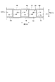
- FIG. 2 is a schematic perspective view schematically showing a part of the fixed wing unit 6 (6A) according to one embodiment.
- FIG. 3 is a view schematically showing an example of the shape of the trailing edge 26 of the vane portion 14 in the fixed wing unit 6 (6A).
- FIG. 4 is a schematic perspective view schematically showing a part of the fixed wing unit 6 (6B) according to an embodiment.
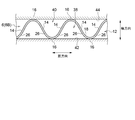
- FIG. 5 is a view schematically showing an example of the shape of the trailing edge 26 of the vane portion 14 in the fixed wing unit 6 (6B).
- FIG. 6 is a view schematically showing an example of the shape of the trailing edge 26 of the vane portion 14 in the fixed wing unit 6 (6B).
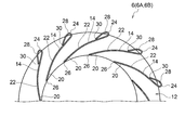
- FIG. 7 is a schematic cross-sectional view schematically showing an example of the AA cross section (see FIG. 1) of the fixed wing unit 6 (6A), that is, a cross section orthogonal to the axial direction.
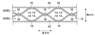
- FIG. 8 is a view schematically showing an example of the AA cross section of the fixed wing unit 6 (6A, 6B).
- FIG. 9 is a view schematically showing an example of the AA cross section of the fixed wing unit 6 (6A, 6B).
- each of the fixed wing units 6 (6A, 6B) includes at least two vane portions 14 and a connection portion 16 connecting the two vane portions 14 And is formed of one sheet metal member 18.
- the fixed wing unit 6 includes a large number (three or more) of vane portions 14 and a large number (three or more) of coupling portions 16, and the vane portions 14 and the coupling portions 16 are circumferentially Are alternately arranged.
- the fixed wing unit 6 (6A) shown in FIG. 2 has a shape in which a sheet metal member 18 is periodically bent in a square wave (see FIG. 3), and the fixed wing unit 6 shown in FIG. (6B) has a shape formed by periodically bending one sheet metal member 18 in a triangular wave shape (see FIG. 5) or a sine wave (see FIG. 6).
- the fixed wing unit 6 (6A, 6B) includes the communication channel 12 and the hub-side channel 38 and the shroud-side channel 40.
- the hub side flow paths 38 is defined by two vane portions 14, a connecting portion 16 connecting the two vane portions 14, and a hub side wall 42 of the communication flow path 12.
- Each of the shroud side flow passages 40 is defined by two vane portions 14, a connection portion 16 connecting the two vane portions 14, and a shroud side wall 44 of the communication flow passage 12.
- each of the fixed wing units 6 is formed by the sheet metal member 18 of one sheet, improvement of the surface roughness of the fixed wing units 6 is better than forming each of the fixed wing units 6 by casting. Cost reduction can be realized. Therefore, the rectification effect of fixed wing unit 6 can be enhanced to realize high efficiency of turbocharger 100 with a simple configuration. Further, since at least two vane portions 14 are connected by the connecting portion 16, it is possible to increase the cross section coefficient of the fixed wing unit 6 and to suppress deformation or falling due to fluid force.
- the fixed wing unit 6 (6A, 6B) is formed of a single sheet metal member 18 over the entire circumference in the circumferential direction.
- the rigidity of the entire fixed wing unit 6 (6A, 6B) can be enhanced. Further, since the fluid force inward in the radial direction is offset, the fixing force (for example, the fastening force in the case of fixing by bolt fastening) necessary to fix the fixed wing unit 6 to the housing 4 can be reduced. .
- the trailing edge 26 of the vane portion 14 extends axially parallel, for example as shown in FIG. In some embodiments, as shown, for example, in FIGS. 5 and 6, it extends in a circumferentially inclined direction relative to the axial direction.
- the exhaust gas having passed through the vane portion 14 is made to extend by the trailing edge 26 of the vane portion 14 extending in the circumferentially inclined direction with respect to the axial direction. Since the phase which excites the moving blade 2a shifts, the vibrational stress of the moving blade 2a can be suppressed. In addition, when the fixed wing unit 6 expands due to the heat of the exhaust gas, the displacement can be absorbed by the bending of the vane portion 14, and the occurrence of buckling in the vane portion 14 can be suppressed.
- the vane portion 14 extends linearly in a cross section orthogonal to the axial direction. According to this configuration, the configuration of the fixed wing unit 6 can be simplified.
- At least the trailing edge portion 20 of the vane portion 14 is curved to be convex toward the pressure surface 22 side.
- the metal angle ⁇ 1 with respect to the tangent L1 in the circumferential direction at the front edge 24 of the vane portion 14 is the metal with respect to the tangent L2 in the circumferential direction at the trailing edge 26 of the vane portion 14 It is larger than the angle ⁇ 2.
- leading edge portion 28 of the vane portion 14 is rounded so that the tip 30 is located downstream of the leading edge 24 of the vane portion 14.
- FIG. 10 is a schematic perspective view schematically showing a part of a fixed wing unit 6 (6C) according to an embodiment.
- FIG. 11 schematically shows an example of the shape of the trailing edge 26 of the vane portion 14 in the fixed wing unit 6 (6C).
- FIG. 12 is a schematic cross-sectional view schematically showing an example of the AA cross section (see FIG. 1) of the fixed wing unit 6 (6C), that is, a cross section orthogonal to the axial direction.
- fixed wing turbocharger 100 includes a plurality of fixed wing units 6 (6C) circumferentially spaced apart.
- each of the fixed wing units 6 (6C) has a shape formed by bending one sheet metal member 18 into a square wave (see FIG. 3), and two vane portions 14 and 2; And one connecting portion 16 which connects the two vane portions 14.
- each of the two vanes 14 is provided with a leg 36.
- the leg portion 36 protrudes from the one end portion 14a of the vane portion 14 in the axial direction (the end portion of the vane portion 14 on the side of the hub side wall 34 of the communication passage 12 in the illustrated embodiment) to the opposite side to the connecting portion 16 in the circumferential direction It is provided to do.
- the leg portion 36 is provided along the flow passage wall of the communication flow passage 12 (the hub side wall 34 in the illustrated embodiment) from the front edge 24 to the rear edge 26 of the vane portion 14.
- the hub side flow path 38 and the shroud side flow path 40 are alternately positioned in the circumferential direction. It is configured to partition into Each of the hub side flow paths 38 is defined by two vane portions 14, a connecting portion 16 connecting the two vane portions 14, and a hub side wall 42 of the communication flow path 12.
- Each of the shroud side flow passages 40 is defined by two vane portions 14, two leg portions 36, a shroud side wall 44 of the communication flow passage 12, and a hub side wall 42 of the communication flow passage 12.
- each of the fixed wing units 6 (6C) is formed of one sheet metal member 18, the surface roughness of the fixed wing units 6 is better than that of forming each of the fixed wing units 6 by casting. It is possible to realize improvement and cost reduction. Therefore, the rectification effect of fixed wing unit 6 can be enhanced to realize high efficiency of turbocharger 100 with a simple configuration. Further, since at least two vane portions 14 are connected by the connecting portion 16, it is possible to increase the cross section coefficient of the fixed wing unit 6 and to suppress deformation or falling due to fluid force.
- the fixed wing unit 6 compared with the fixed wing unit 6 (6A, 6) formed of one sheet metal member 18 over the entire circumference in the circumferential direction, the plurality of fixed wing units 6 (6C) Because of the division, the fixed wing unit 6 can be miniaturized while securing the structural strength.
- the installation angle of the fixed wing unit 6 can be adjusted, and a flow rate characteristic according to the installation angle of the fixed wing unit 6 (6C) can be obtained.
- the fixed wing unit 6 (6C) is installed so that the angle ⁇ 3 between the cord direction of the vane portion 14 and the circumferential direction is small.
- the fixed wing unit 6 may be installed so that the angle ⁇ 3 between the cord direction of the vane portion 14 and the circumferential direction is large. Further, by cutting unnecessary portions (broken line parts in FIGS. 13 and 14) of the fixed wing unit 6 made of a common type and made of sheet metal, desired flow characteristics are obtained by adjusting the installation angle of the fixed wing unit 6 Can be obtained with a simple configuration and at low cost.
- the present invention is not limited to the above-described embodiments, and includes the embodiments in which the above-described embodiments are modified or the embodiments in which these embodiments are appropriately combined.
- each of the fixed wing units 6 (6C) has two vane portions 14 and one connecting portion 16 connecting the two vane portions 14
- the fixed wing unit which has three or more vane parts and two or more connection parts may be provided at intervals in the circumferential direction.
- the shape of the vane portion 14 described with reference to FIGS. 7 to 9 is applicable to the vane portion 14 of the fixed wing unit 6 (6C) shown in FIGS.
- fixed wing turbocharger 100 may include a plurality of (multi-stage) fixed wing units 6 axially stacked. .
- the fixed wing turbocharger 100 may include two fixed wing units 6 (6A) axially stacked.
- the two fixed wing units 6 (6A) are axially stacked such that the respective connecting portions 16 abut.
- the fixed blade turbocharger 100 may include two fixed wing units 6 (6 B) stacked in the axial direction.
- the two fixed wing units 6 (6A) are axially stacked such that the respective connecting portions 16 abut.
- the fixed wing turbocharger 100 may be provided with a fixed wing unit 6 (6A) and a fixed wing unit 6 (6B) stacked in the axial direction.
- the fixed wing unit 6 (6A) and the fixed wing unit 6 (6B) are axially stacked such that the respective connecting portions 16 abut.
- the present invention is also applicable to a diffuser vane of a compressor provided in a turbocharger.
- the fixed blade type turbocharger communicates the compressor impeller, the impeller housing space for housing the compressor impeller, the scroll channel formed on the outer peripheral side of the compressor impeller, and the impeller housing space and the scroll channel.
- a housing having a flow path (a diffuser flow path) inside, and at least one fixed wing unit (a diffuser provided in a communication flow path and fixed to a portion of the housing inside the scroll flow path in the radial direction of the compressor impeller) And a wing unit).
- each of the fixed wing units has at least two vane portions and a connecting portion connecting the two vane portions, and is formed of one sheet metal member.
- each of the fixed wing units is formed of a single sheet metal member, so improvement in surface roughness and cost reduction of the fixed wing units can be achieved rather than forming each of the fixed wing units by casting. It can be realized. Therefore, the rectification effect of the fixed wing unit can be enhanced to realize high efficiency of the turbocharger with a simple configuration.
- connection part since at least two vane parts are connected by the connection part, the section coefficient of the fixed wing unit can be increased, and deformation or falling due to fluid force can be suppressed.
Landscapes
- Engineering & Computer Science (AREA)
- Mechanical Engineering (AREA)
- General Engineering & Computer Science (AREA)
- Chemical & Material Sciences (AREA)
- Combustion & Propulsion (AREA)
- Supercharger (AREA)
Abstract
Description
例えば、「ある方向に」、「ある方向に沿って」、「平行」、「直交」、「中心」、「同心」或いは「同軸」等の相対的或いは絶対的な配置を表す表現は、厳密にそのような配置を表すのみならず、公差、若しくは、同じ機能が得られる程度の角度や距離をもって相対的に変位している状態も表すものとする。
例えば、「同一」、「等しい」及び「均質」等の物事が等しい状態であることを表す表現は、厳密に等しい状態を表すのみならず、公差、若しくは、同じ機能が得られる程度の差が存在している状態も表すものとする。
例えば、四角形状や円筒形状等の形状を表す表現は、幾何学的に厳密な意味での四角形状や円筒形状等の形状を表すのみならず、同じ効果が得られる範囲で、凹凸部や面取り部等を含む形状も表すものとする。
一方、一の構成要素を「備える」、「具える」、「具備する」、「含む」、又は、「有する」という表現は、他の構成要素の存在を除外する排他的な表現ではない。
2a 動翼
4 ハウジング
4a 部位
6 固定翼ユニット
8 インペラ収容空間
10 スクロール流路
12 連通流路
14 ベーン部
14a 一端部
14b 他端部
16 連結部
18 板金部材
20 後縁側部分
22 圧力面
24 前縁
26 縁
28 前縁側部分
30 先端
32 シュラウド壁
34 ハブ壁
36 縁部
38 ハブ側流路
40 シュラウド側流路
42 ハブ側壁
44 シュラウド側壁
100 固定翼式ターボチャージャ
L1,L2 接線
Claims (8)
- インペラと、
前記インペラを収容するインペラ収容空間と、前記インペラの外周側に形成されるスクロール流路と、前記インペラ収容空間と前記スクロール流路とを連通する連通流路とを内部に有するハウジングと、
前記連通流路に設けられ、前記ハウジングのうち前記インペラの径方向における前記スクロール流路より内側の部位に固定された少なくとも一つの固定翼ユニットと、を備える固定翼式ターボチャージャであって、
前記固定翼ユニットの各々は、少なくとも2つのベーン部と、前記2つのベーン部を連結する連結部とを有し、1枚の板金部材で形成された、固定翼式ターボチャージャ。 - 前記少なくとも一つの固定翼ユニットは、前記インペラの周方向における全周に亘って前記1枚の板金部材で形成される、請求項1に記載の固定翼式ターボチャージャ。
- 前記少なくとも一つの固定翼ユニットは、周方向に間隔を開けて設けられた複数の固定翼ユニットを含む、請求項1に記載の固定翼式ターボチャージャ。
- 前記少なくとも一つの固定翼ユニットは、前記インペラの軸方向に重ねられた複数の固定翼ユニットを含む、請求項1乃至3の何れか1項に記載の固定翼式ターボチャージャ。
- 前記ベーン部のうち少なくとも後縁側部分は、圧力面側に凸となるように湾曲している、請求項1乃至4の何れか1項に記載の固定翼式ターボチャージャ。
- 前記ベーン部の前縁における前記インペラの周方向への接線に対するメタル角は、当該ベーン部の後縁における前記周方向への接線に対するメタル角よりも大きい、請求項1乃至5の何れか1項に記載の固定翼式ターボチャージャ。
- 前記ベーン部の前縁側部分は、先端が前記ベーン部の前縁より下流側に位置するように丸められている、請求項1乃至6の何れか1項に記載の固定翼式ターボチャージャ。
- 前記ベーン部の後縁は、前記インペラの軸方向に対して周方向に傾斜した方向に延在している、請求項1乃至7の何れか1項に記載の固定翼式ターボチャージャ。
Priority Applications (5)
| Application Number | Priority Date | Filing Date | Title |
|---|---|---|---|
| CN201680083694.7A CN109154232B (zh) | 2016-03-30 | 2016-03-30 | 固定翼式涡轮增压器 |
| US16/088,189 US11230938B2 (en) | 2016-03-30 | 2016-03-30 | Fixed vane turbocharger |
| JP2018507950A JP6640987B2 (ja) | 2016-03-30 | 2016-03-30 | 固定翼式ターボチャージャ |
| PCT/JP2016/060467 WO2017168647A1 (ja) | 2016-03-30 | 2016-03-30 | 固定翼式ターボチャージャ |
| EP16896866.7A EP3418531B1 (en) | 2016-03-30 | 2016-03-30 | Fixed vane turbo charger |
Applications Claiming Priority (1)
| Application Number | Priority Date | Filing Date | Title |
|---|---|---|---|
| PCT/JP2016/060467 WO2017168647A1 (ja) | 2016-03-30 | 2016-03-30 | 固定翼式ターボチャージャ |
Publications (1)
| Publication Number | Publication Date |
|---|---|
| WO2017168647A1 true WO2017168647A1 (ja) | 2017-10-05 |
Family
ID=59962767
Family Applications (1)
| Application Number | Title | Priority Date | Filing Date |
|---|---|---|---|
| PCT/JP2016/060467 WO2017168647A1 (ja) | 2016-03-30 | 2016-03-30 | 固定翼式ターボチャージャ |
Country Status (5)
| Country | Link |
|---|---|
| US (1) | US11230938B2 (ja) |
| EP (1) | EP3418531B1 (ja) |
| JP (1) | JP6640987B2 (ja) |
| CN (1) | CN109154232B (ja) |
| WO (1) | WO2017168647A1 (ja) |
Citations (4)
| Publication number | Priority date | Publication date | Assignee | Title |
|---|---|---|---|---|
| US3292364A (en) * | 1963-09-06 | 1966-12-20 | Garrett Corp | Gas turbine with pulsating gas flows |
| JPS6319002U (ja) * | 1986-07-24 | 1988-02-08 | ||
| JP2008196453A (ja) * | 2007-02-15 | 2008-08-28 | Toyota Industries Corp | 可変容量型ターボチャージャ |
| JP2008196452A (ja) * | 2007-02-15 | 2008-08-28 | Toyota Industries Corp | 可変容量型ターボチャージャ |
Family Cites Families (6)
| Publication number | Priority date | Publication date | Assignee | Title |
|---|---|---|---|---|
| IN2012DN02819A (ja) | 2009-10-06 | 2015-07-24 | Cummins Ltd | |
| US9234456B2 (en) * | 2009-10-06 | 2016-01-12 | Cummins Ltd. | Turbomachine |
| US8920114B2 (en) * | 2009-11-27 | 2014-12-30 | Borgwarner Inc. | Turbocharger with variable turbine geometry |
| US8616836B2 (en) * | 2010-07-19 | 2013-12-31 | Cameron International Corporation | Diffuser using detachable vanes |
| US20120023936A1 (en) | 2010-07-30 | 2012-02-02 | Caterpillar Inc. | Nozzled turbocharger turbine |
| JP6514644B2 (ja) * | 2013-01-23 | 2019-05-15 | コンセプツ エヌアールイーシー,エルエルシー | ターボ機械の隣接する翼要素の流れの場を強制的に結合する構造体および方法、ならびにそれを組み込むターボ機械 |
-
2016
- 2016-03-30 WO PCT/JP2016/060467 patent/WO2017168647A1/ja active Application Filing
- 2016-03-30 JP JP2018507950A patent/JP6640987B2/ja active Active
- 2016-03-30 EP EP16896866.7A patent/EP3418531B1/en active Active
- 2016-03-30 CN CN201680083694.7A patent/CN109154232B/zh active Active
- 2016-03-30 US US16/088,189 patent/US11230938B2/en active Active
Patent Citations (4)
| Publication number | Priority date | Publication date | Assignee | Title |
|---|---|---|---|---|
| US3292364A (en) * | 1963-09-06 | 1966-12-20 | Garrett Corp | Gas turbine with pulsating gas flows |
| JPS6319002U (ja) * | 1986-07-24 | 1988-02-08 | ||
| JP2008196453A (ja) * | 2007-02-15 | 2008-08-28 | Toyota Industries Corp | 可変容量型ターボチャージャ |
| JP2008196452A (ja) * | 2007-02-15 | 2008-08-28 | Toyota Industries Corp | 可変容量型ターボチャージャ |
Non-Patent Citations (1)
| Title |
|---|
| See also references of EP3418531A4 * |
Also Published As
| Publication number | Publication date |
|---|---|
| EP3418531A4 (en) | 2019-03-20 |
| US11230938B2 (en) | 2022-01-25 |
| EP3418531B1 (en) | 2022-09-28 |
| JPWO2017168647A1 (ja) | 2018-12-13 |
| EP3418531A1 (en) | 2018-12-26 |
| US20200116036A1 (en) | 2020-04-16 |
| CN109154232A (zh) | 2019-01-04 |
| JP6640987B2 (ja) | 2020-02-05 |
| CN109154232B (zh) | 2021-02-26 |
Similar Documents
| Publication | Publication Date | Title |
|---|---|---|
| JP5199849B2 (ja) | 車両用熱交換モジュールおよびこれを備えた車両 | |
| US9777578B2 (en) | Radial turbine blade | |
| EP2096319B1 (en) | Centrifugal compressor | |
| JP5124276B2 (ja) | ガスタービン中間構造および該中間構造を含むガスタービンエンジン | |
| EP2096321B1 (en) | Compressor | |
| RU2702579C1 (ru) | Рабочее колесо с высокой жёсткостью для турбомашины, турбомашина, содержащая указанное рабочее колесо, и способ изготовления | |
| US20060051199A1 (en) | Turbomachine with fluid removal | |
| WO2016071959A1 (ja) | タービンハウジングおよびタービンハウジングの製造方法 | |
| EP2662531A1 (en) | Steam turbine stator blade and steam turbine | |
| JP6801009B2 (ja) | タービンホイール、タービン及びターボチャージャ | |
| CN109695480B (zh) | 包含矫直组件的涡轮发动机 | |
| JP6606613B2 (ja) | ターボチャージャ及びターボチャージャのノズルベーン並びにタービン | |
| EP3705699A1 (en) | Turbine and turbocharger comprising same | |
| US20200355198A1 (en) | Impeller for centrifugal compressor, centrifugal compressor, and turbocharger | |
| JP6651404B2 (ja) | ターボ機械 | |
| WO2017168647A1 (ja) | 固定翼式ターボチャージャ | |
| JP5933749B2 (ja) | ガスタービンエンジン構成要素 | |
| US11280204B2 (en) | Air flow straightening assembly and turbomachine including such an assembly | |
| JP2021156266A (ja) | タービンおよび過給機 | |
| JP2019100286A (ja) | 遠心圧縮機及びターボチャージャ | |
| US20230258197A1 (en) | Impeller of centrifugal compressor and centrifugal compressor | |
| WO2023187913A1 (ja) | 斜流タービン及びターボチャージャ | |
| US11835057B2 (en) | Impeller of centrifugal compressor, centrifugal compressor, and turbocharger |
Legal Events
| Date | Code | Title | Description |
|---|---|---|---|
| WWE | Wipo information: entry into national phase |
Ref document number: 2018507950 Country of ref document: JP |
|
| WWE | Wipo information: entry into national phase |
Ref document number: 2016896866 Country of ref document: EP |
|
| ENP | Entry into the national phase |
Ref document number: 2016896866 Country of ref document: EP Effective date: 20180921 |
|
| NENP | Non-entry into the national phase |
Ref country code: DE |
|
| 121 | Ep: the epo has been informed by wipo that ep was designated in this application |
Ref document number: 16896866 Country of ref document: EP Kind code of ref document: A1 |