WO2017168539A1 - Wireless communication system - Google Patents
Wireless communication system Download PDFInfo
- Publication number
- WO2017168539A1 WO2017168539A1 PCT/JP2016/060012 JP2016060012W WO2017168539A1 WO 2017168539 A1 WO2017168539 A1 WO 2017168539A1 JP 2016060012 W JP2016060012 W JP 2016060012W WO 2017168539 A1 WO2017168539 A1 WO 2017168539A1
- Authority
- WO
- WIPO (PCT)
- Prior art keywords
- time slot
- data
- master station
- station
- vehicle
- Prior art date
Links
Images


Classifications
-
- H—ELECTRICITY
- H04—ELECTRIC COMMUNICATION TECHNIQUE
- H04W—WIRELESS COMMUNICATION NETWORKS
- H04W72/00—Local resource management
- H04W72/04—Wireless resource allocation
-
- H—ELECTRICITY
- H04—ELECTRIC COMMUNICATION TECHNIQUE
- H04W—WIRELESS COMMUNICATION NETWORKS
- H04W74/00—Wireless channel access, e.g. scheduled or random access
- H04W74/08—Non-scheduled or contention based access, e.g. random access, ALOHA, CSMA [Carrier Sense Multiple Access]
Definitions
- the present disclosure relates to a wireless communication system, and is applicable to, for example, a wireless communication system in which a plurality of independent subsystems that complete communication between a master station and a slave station are collected.
- beacons necessary for maintaining the wireless communication system are transmitted at regular intervals.
- a beacon or the like may interfere between adjacent subsystems.
- An object of the present disclosure is to provide a wireless communication system that reduces interference between adjacent subsystems.
- the wireless communication system includes a plurality of subsystems each including a master station and a plurality of slave stations.
- the master station and the slave station perform data transmission / reception in a superframe composed of a plurality of subframes.
- Each of the plurality of subframes includes a first time slot in which the master station transmits a beacon to the slave station, and a second time in which the master station detects a carrier of another subsystem immediately before the first time slot.
- Configuration diagram of wireless communication system according to embodiment Configuration diagram of subframe and superframe according to the embodiment
- Configuration diagram of subframe according to another embodiment Illustration for explaining the shooting training system The figure which looked at the vehicle of FIG.
- FIG. 16A Diagram for explaining link-up restart when beacon and status data interfere
- FIG. 17A Enlarged view of FIG. 17A
- Enlarged view of FIG. 18A Enlarged view of FIG. 18A
- Enlarged view of FIG. 20A Enlarged view of FIG. 20A
- Diagram for explaining synchronization protection after linkup The figure for demonstrating the case where the vehicle of the same timing joins
- the figure for demonstrating the case where the vehicle of the same timing joins Configuration diagram of subframe according to modification
- Enlarged view of FIG. 24A The figure for demonstrating the link-up process by the sub-frame which concerns on an Example.
- FIG. 1 is a configuration diagram of a wireless communication system according to an embodiment.
- the wireless communication system 1 of the present embodiment includes one master station (coordinator) 10 and a plurality of slave stations (end devices) 20, and each slave station 20 and the master station 10 are wirelessly connected and communicate directly. Configured to do. That is, it is a star type configuration centering on the master station 10.
- the master station in the present embodiment is a radio station having a function of instructing the timing of radio transmission to other stations serving as slave stations by wirelessly transmitting a synchronization signal (beacon described later in this embodiment). Means.
- the wireless communication system 1 is composed of one master station (CD) 10 and n (n: an integer of 2 or more) slave stations 20.
- n an integer of 2 or more slave stations 20.
- a configuration in which the number of slave stations 20 is 1 is also possible.
- the first slave station 20 (1),..., The nth slave station 20 (n) is described as a representative, it is referred to as a slave station 20.
- the first slave station 20 (1) may be referred to as a first end device (ED1),...
- nth slave station 20 (n) may be referred to as an nth end device (EDn).
- TDMA wireless communication is performed in accordance with the standard IEEE 802.15.4. That is, time division wireless communication is performed between the master station 10 and the slave station 20 according to the superframe.
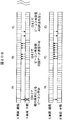
- FIG. 2 is a configuration diagram of a subframe and a superframe according to the embodiment.
- the subframe (Sub Frame) defines a period (time slot) in which the master station 10 and each slave station 20 can transmit frames.
- 3 includes a beacon transmission (TSb) 31, a first coordinator data transmission (TSc1) 32 (1),..., An m-th coordinator data transmission (TScm) 32 (m ), First end device (end device) data transmission (TS1) 33 (1),..., Nth end device data transmission (TSn) 33 (n), carrier sense (TScs) 34 time slots (Time Slot: TS).
- the number of time slots is determined by the amount of data transmitted between the master station 10 and the slave station 20 and the number of slave stations 20.
- Data transmission / reception between the master station 10 and the slave station 20 is performed by periodically repeating a super frame (Supper Frame) 300 including a plurality (k) of subframes 30.
- Carrier frequency (f1) of the first subframe (SBF1) 30 (1), carrier frequency (f2) of the second subframe (SBF2) 30 (2),..., Carrier frequency of the kth subframe (SBFk) (Fk) may be different from each other, or k may be divided into several groups so that carrier frequencies in the groups are different, thereby reducing interference with adjacent wireless communication systems.
- One frame can be transmitted in one time slot.
- the length of each time slot is determined as the time required for wireless transmission of this data based on the maximum data length of one frame.
- the length of each time slot may not be uniform.
- a guard time (not shown) is provided between a certain time slot and the next time slot. The guard time is provided to prevent interference between signals in different time slots, and transmission / reception is switched during the guard time.
- One frame includes one or a plurality of packets.
- the frame includes a header, transmission data, and a footer, and the header can accommodate the transmission source address and the transmission destination address of the frame.
- the footer includes communication error detection data.
- the beacon transmission (TSb) 31 is a time slot in which the master station (coordinator) 10 outputs a frame including a beacon (synchronization reference signal).
- Each of the master station 10 and the slave station 20 is synchronized based on the synchronization reference signal output by the beacon transmission 31 and calculates a time slot in which the local station can transmit or receive data.
- the first coordinator data transmission 32 (1),..., The m-th coordinator data transmission 32 (m) is described as a representative, it is referred to as a coordinator data transmission 32.
- one coordinator data transmission 32 for example, the first coordinator data transmission 32 (1)
- data to a plurality of slave stations 20 can be multiplexed in one frame.
- the first end device data transmission 33 (1),..., The nth end device data transmission 33 (n) are respectively transmitted from the slave stations (end devices) 20 (1) to 20 (n) to the master station 10 (coordinator). It is a time slot that can transmit data to.
- the end device data transmission 33 (1) is the slave station 20 (1), that is, the time slot TS1 in which data can be transmitted from the end device 1 to the coordinator 10
- the end device data transmission 33 (n) is the slave station 20 ( n), that is, a time slot TSn in which data can be transmitted from the end device n to the coordinator 10.
- the number of end devices n 1
- the number of end device data transmissions 33 can be 1.
- the first end device data transmission 33 (1),..., The nth end device data 33 (n) is described as a representative, it is referred to as an end device data transmission 33.
- Carrier sense (TScs) 34 is a time slot for detecting beacon transmission or data transmission of an adjacent wireless communication system. The function of the carrier sense 34 will be described below.
- FIG. 3 is a diagram illustrating a state in which different wireless communication subsystems are adjacent to each other in the wireless communication system according to the embodiment.
- FIG. 4 is a timing diagram showing a case where a beacon of an adjacent wireless communication subsystem is sensed.
- FIG. 5 is a timing chart showing a case where data of an adjacent wireless communication subsystem is sensed.
- the master station 10A, the first slave station 20A (1),..., The nth slave station 20A (n) constitutes a wireless communication subsystem (hereinafter simply referred to as “subsystem”) 1A.
- the station 10B, the first slave station 20B (1),..., The nth slave station 20B (n) constitute the subsystem 1B.
- the subsystems 1A and 1B have the same configuration as that of the wireless communication system 1 in FIG.
- the number of slave stations of the subsystem 1B may be different from that of the subsystem 1A.
- the master station 10B, the first slave station 20B (1), the seventh slave station 20B (7), and the nth slave station 20B ( n) may be in a position where radio waves from the master station 10A of the subsystem 1A can be received.
- the beacon timing of the subsystem 1A and the beacon timing of the subsystem 1B overlap for example, a beacon collision occurs at the position of the first slave station 20B (1).
- FIG. 5 if the beacon timing of the subsystem 1A and the data transmission timing of the subsystem 1B overlap, data interference occurs at the position of the first slave station 20B (1), for example.
- the parent station in the beacon transmission 31 next to the detected carrier sense 34 10A does not perform beacon transmission but performs beacon transmission with a predetermined number of subframes shifted to avoid a beacon collision with the parent station 10B or interference between the beacon transmission of the parent station 10A and the data transmission of the subsystem 1B.
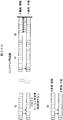
- FIG. 6 is a configuration diagram of a subframe according to another embodiment. 6 includes a beacon transmission (TSb) 31, a first coordinator data transmission (TSc1) 32 (1),..., An m-th coordinator data transmission (TScm) 32 (m), and a first end device. Data transmission (TS1) 33 (1),..., First end device data transmission (TSn) 33 (n), and carrier sense (TScs) 34 are configured to include each time slot. Beacon transmission (TSb) 31, first coordinator data transmission (TSc1) 32 (1), ...
- TScm m-th coordinator data transmission
- TS1 first end device data transmission
- TScs Carrier sense
- TSn n-th end device data transmission
- the wireless communication system according to the embodiment is not limited to the shooting training system, but can be applied to a system including a plurality of adjacent wireless communication subsystems.
- FIG. 7 is a diagram for explaining the shooting training system.
- FIG. 8 is a top view of the vehicle shown in FIG.
- the shooting training system includes a vehicle 110 including a light receiver (slave station) 111 (1) to 111 (8) and a presenter (master station) 112, and a laser transmitter 120.
- the light receivers 111 (1) to 111 (8) are described as a representative, they are referred to as the light receiver 111.
- the number of light receivers 111 is eight in the example of FIG. 8, but is not limited to eight.
- the light receiver 111 and the indicator 112 can be installed in helicopters, ships, personnel, buildings, and the like.
- a laser beam 121 emitted from the laser transmitter 120 is used as a simulated bullet without using an actual bullet.
- the laser beam 121 includes information such as an identifier (ID) of the laser transmitter 120 that has emitted the laser beam 121, a firearm type, and a bullet type as the emission information.
- ID an identifier
- the light receiver 111 attached to the vehicle 110 detects the laser beam 121 to detect the impact that the light receiver 111 has received. That is, when detecting the laser beam 121, the light receiver 111 reads the emission information included in the laser beam 121 and wirelessly transmits it to the display unit 112 together with the bullet information.
- the bulleted information is information such as a wear category indicating the degree of wear due to the bullet, and a worn part (shot position).
- the presenter 112 When receiving the bullet information from the light receiver 111, the presenter 112 displays the bulleted situation, that is, outputs the bulleted situation, using one or more of light emission, sound generation, and smoke according to the contents.
- the wireless communication method of the standard IEEE 802.15.4 is used for data transmission between the light receiver (slave station) and the presenter (master station).
- specifications of a communication method (access method, data transmission sequence, etc.) based on TDMA are established for a data link layer (MAC layer) of a wireless network.
- time slots in which the master station and the slave station can transmit frames are set in advance in one superframe.
- the master station and the slave station perform transmission in the set time slots.
- the super frame indicates a structure on the time axis that defines time slots in which the master station and the slave stations can transmit frames.
- FIG. 9 is a configuration diagram of the presenting device and the light receiving device according to the embodiment.
- the presenter (coordinator) 112 includes a wireless module 11, a display unit 15, and a battery 16.
- the wireless module 11 includes a control unit 12, a transmission / reception unit 13, and a storage unit 14.
- the transceiver 13 includes an antenna 13 a for transmitting and receiving radio waves to and from the light receiver 111.
- the battery 16 supplies power to each component of the indicator 112.
- the control unit 12 controls the operation of each component of the display unit 112 and the entire display unit 112.
- the control unit 12 transmits data such as status data, operation setting data, and ACK data based on the timing of the superframe time slot stored in the storage unit 14. Determine the timing.
- the control unit 12 causes the light receiver 111 to transmit a beacon for detecting a time slot for transmitting data and ACK data from the transmission / reception unit 13. That is, the control unit 12 notifies the light receiver 111 of the timing at which the light receiver 111 transmits data and ACK data.
- the ACK data is an acknowledgment (also referred to as a positive response) data, that is, an affirmative sent from the receiving side to the transmitting side in order to indicate that the data transmitted from the transmitting side has been normally received at the receiving side. It is a response data.
- the transmission / reception unit 13 transmits or receives data or ACK data wirelessly with the light receiver 111 according to the control from the control unit 12.
- the storage unit 14 stores the timing of the superframe time slot. Further, the storage unit 14 holds data received from the light receiver 111 and holds data to be transmitted to the light receiver 111 according to control from the control unit 12. Data to be transmitted to the light receiver 111 is input from the control unit 12, for example.
- the display unit 15 is an output unit that outputs various types of information, and displays information received from the light receiver 111.
- the display unit 15 includes a sound generation unit 151 that emits sound, a light emission unit 152 that emits light, and a smoke generation unit 153 that emits smoke, and outputs sounds such as sound generation, light emission, and smoke generation according to information received from the light receiver 111. Do. Information input to the display unit 15 is held in the storage unit 14.
- the light receiver (end device) 111 includes a wireless module 21, a light receiving unit 25, and a battery 26.
- the wireless module 21 includes a control unit 22, a transmission / reception unit 23, and a storage unit 24.
- the transmission / reception unit 23 includes an antenna 23a for transmitting / receiving radio waves to / from the display unit 112.
- the battery 26 supplies power to each component of the light receiver 111.
- the control unit 22 controls the operation of each component of the light receiver 111 and the entire light receiver 111. Further, the control unit 22 performs control so that the information input from the light receiving unit 25 is wirelessly transmitted to the indicator 112. In addition, when performing wireless transmission to the indicator 112, the control unit 22 determines the timing for transmitting data and ACK data based on the timing of the superframe time slot stored in the storage unit 24.
- the transmission / reception unit 23 transmits or receives data or ACK wirelessly with the display unit 112 according to the control from the control unit 22.
- the storage unit 24 stores the timing of the superframe time slot based on the beacon received from the display unit 112.
- the storage unit 24 holds data received from the display unit 112 and holds data to be transmitted to the display unit 112 in accordance with control from the control unit 22.
- Data to be transmitted to the indicator 112 is input from the light receiving unit 25, for example.
- the light receiving unit 25 is an input unit that receives input of various types of information. For example, the light receiving unit 25 receives a laser beam and outputs information included in the received laser beam to the control unit 22. Information input to the light receiving unit 25 is held in the storage unit 24.
- Each of the control unit 12 and the control unit 22 includes a CPU (Central Processing Unit) and a memory for storing an operation program of each control unit as a hardware configuration.
- the CPU operates according to the operation program.
- the storage unit 14 and the storage unit 24 are each composed of a semiconductor memory (flash memory, RAM (Random Access Memory), ROM (read only memory), etc.), a magnetic disk, or the like.
- a semiconductor memory flash memory, RAM (Random Access Memory), ROM (read only memory), etc.
- ROM read only memory
- magnetic disk or the like.
- the slave station 20 is a light receiver that receives a laser beam, acquires information included in the received laser beam, and wirelessly transmits the acquired information to the display device.
- the master station 10 is a display device that is directly connected to a plurality of light receivers, receives information wirelessly transmitted from the plurality of light receivers, and performs output based on the received information. .
- FIG. 10 is a configuration diagram of a subframe according to the embodiment.
- 10 includes a beacon transmission (TSb) 31, a first coordinator data transmission (TSc1) 32 (1), a second coordinator transmission (TSc2) 32 (2), and a first end.
- FIG. 11 is a diagram illustrating a subframe period at the time of link-up.
- the indicator 112 transmits a beacon to the light receiver 111 when no carrier is detected.
- the light receiver 111 receives the beacon of its own master station and completes the synchronization.
- the light receiver 111 transmits status data to the indicator 112.
- the indicator 112 receives the status data.
- the state data is represented by solid arrows.
- the indicator 112 transmits ACK data to the light receiver 111.
- the light receiver 111 receives ACK data.
- ACK data is indicated by a broken-line arrow.
- the display unit 112 transmits operation setting data to the light receiver 111.
- the light receiver 111 receives the operation setting data and transmits ACK data to the display device 112. Complete the link up.
- the operation setting data is represented by solid arrows.
- the subsystems that perform independent communication are one master station and eight slave stations, and there are about nine subsystems in the radio notification area in one subsystem.
- the number of channels is 4 to 8, and it is assumed that interference will surely occur during operation. Therefore, the operation is divided into two patterns of link-up (when connection is established) and operation (normal operation), and a method for avoiding interference in each of them will be described.
- a frequency hopping of 4 channels a super frame is composed of sub-frames of 4 types of frequencies.
- FIG. 12 is a diagram for explaining a case where a carrier of state data of an adjacent subsystem is detected.
- FIG. 13 is a diagram for explaining a case where a beacon carrier of an adjacent subsystem is detected.
- the frequency of the subframe changes in the order of fA, fB, fC, fD, fA, fB, fC, fD,...,
- the frequency of the subframe changes in the order of fC, fA, fD, fB, fC, fA, fD, fB,.
- the sub-frame with the frequency of vehicle A fA and the sub-frame with the frequency of vehicle B fA partially overlap.
- the parent station of the vehicle A detects the carrier of the state data transmitted from the child station of the vehicle B to the parent station by carrier sense before the timing of beacon transmission to the child station. Therefore, the parent station of vehicle A delays the beacon transmission timing by 8 subframes to avoid interference.
- the child station of vehicle A continues to wait for a beacon on the reference channel when no beacon is received.
- the frequency of the subframe changes in the order of fA, fB, fC, fD, fA, fB, fC, fD,.
- the sub-frame with the frequency of vehicle A fA and the sub-frame with the frequency of vehicle B fA partially overlap.
- the parent station of vehicle A detects the carrier of the beacon transmitted from the parent station of vehicle B to the child station by carrier sense before the timing of beacon transmission to the child station. Therefore, the master station of the A vehicle delays the beacon transmission timing (superframe start) by 8 subframes to avoid interference.
- the child station of vehicle A continues to wait for a beacon on the reference channel when no beacon is received.
- FIG. 14A is a timing chart when interference occurs in ARQ retransmission but link-up is completed.
- FIG. 14B is an enlarged view of FIG. 14A.
- FIG. 15A is a timing diagram when link up is completed without interference in ARQ retransmission.
- FIG. 15B is an enlarged view of FIG. 15A.
- the subframe frequency changes in the order of fA, fB, fC, fD, fA, fB, fC, fD,..., And in the B subsystem (B vehicle).
- the frequency of the subframe changes in the order of fD, fC, fB, fA, fD, fC, fB, fA,.
- the subframe with the frequency of vehicle A being fB, the subframe with the frequency of vehicle B being fB, the subframe with the frequency of vehicle A being fD, and the subframe having a frequency of vehicle B being fD partially overlap, and the broken line portion Cause interference.
- transmission of status data from the slave station of the A vehicle to the master station, transmission of ACK data from the master station of the B vehicle to the slave station, and status data transmission from the slave station to the master station are performed. have a finger in the pie.
- the first, sixth to eighth slave stations (ED1, 6 to 8) of the vehicle A perform ARQ retransmission, but the ACK data (CD1, 2) from the master station to the slave stations also interfere and cause a retry over.
- the link up is completed by receiving operational data.
- the slave stations 5 to 7 of the B vehicle perform ARQ retransmission, but ACK data (CD1, 2) from the master station to the slave station also interferes and a retry over occurs.
- link-up is completed by receiving operational data.
- the frequency of subframes changes in the order of fA, fB, fC, fD, fA, fB, fC, fD,...,
- the frequency of the subframe changes in the order of fD, fC, fB, fA, fD, fC, fB, fA,.
- the subframe with the frequency of the vehicle A of fB and the subframe of the vehicle B with the frequency fB partially overlap, and interference occurs at the broken line portion.
- transmission of status data from the slave station of the A vehicle to the master station interferes with transmission of ACK data from the master station of the B vehicle to the slave station.
- the seventh and eighth slave stations (ED7 and 8) of the A vehicle are ARQ retransmitted, and the status data is transmitted to complete the link up.
- the first to fourth slave stations of the B vehicle are ARQ retransmitted, and the status data is transmitted to complete the link up.
- FIG. 16A is a timing diagram in which linkup is completed by APL retransmission.
- FIG. 16B is an enlarged view of FIG. 16A.
- the frequency of subframes changes in the order of fA, fB, fC, fD, fA, fB, fC, fD,...,
- the frequency of the subframe changes in the order of fB, fD, fA, fC, fB, fD, fA, fC,.
- the subframe with the frequency of vehicle A being fB, the subframe with the frequency of vehicle B being fB, the subframe with the frequency of vehicle A being fD, and the subframe having a frequency of vehicle B being fD partially overlap, and the broken line portion Cause interference.
- transmission of status data from the slave station of the A vehicle to the master station interferes with transmission of operation setting data from the master station of the B vehicle to the slave station.
- the 4th to 7th slave stations (ED4 to 7) of the A vehicle are ARQ retransmitted, but the ACK data (CD1, 2) from the master station to the slave station also interferes and a retry over occurs.
- the link up is completed by receiving operational data.
- the operation setting data from the master station to the slave station of the B vehicle is ARQ retransmission, but the ACK data (ED4 to ED7) from the slave station to the master station also interferes and causes a retry over.
- retransmission processing by the application layer is performed.
- the retransmission timing is determined by a delay time using random numbers. This is to prevent re-interference due to retransmission at the same timing in vehicles having the same frequency hopping (FH).
- the delay time is determined by referring to the delay time table from the PAN-ID assigned with a unique number for each vehicle.
- the setting value of the delay time table is configured to be as inconsistent as possible with the FH pattern determined by the PAN-ID.
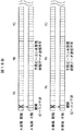
- FIG. 17A is a timing diagram when only one of the interfered subsystems completes link-up by restarting. 17B and 17C are enlarged views of FIG. 17A. 17C is connected next to FIG. 17B, and the right side part of FIG. 17B and the left side part of FIG. 17C overlap.
- FIG. 18A is a timing diagram when both interfering subsystems complete the link-up by restarting. 18B and 18C are enlarged views of FIG. 18A. 18C is connected next to FIG. 18B.
- the frequency of subframes changes in the order of fA, fB, fC, fD, fA, fB, fC, fD,...,
- the frequency of the subframe changes in the order of fC, fA, fD, fB, fC, fA, fD, fB,.
- the subframe with the frequency of vehicle A is fA and the subframe with the frequency of vehicle B are fA partially overlap, and interference occurs at the broken line portion.
- This restart process is implemented by transmitting an operation stop request from the control unit 12 to the transmission / reception unit 13 and then transmitting an operation start request after a delay time based on a random value.
- the slave station continues to wait for a beacon on the reference channel when no beacon is received.
- the subframe frequency changes in the order of fA, fB, fC, fD, fA, fB, fC, fD,..., And in the B subsystem (B vehicle).
- the subframe frequency changes in the order of fA, fB, fC, fD, fA, fB, fC, fD,.
- the sub-frames of all the frequencies of the A vehicle and the sub-frames of all the frequencies of the B vehicle overlap, and interference occurs at the broken line portion.
- the beacon transmission timings of the parent station of the A vehicle and the parent station of the B vehicle can be shifted.
- the slave station continues to wait for a beacon on the reference channel when no beacon is received.
- FIG. 19 is a diagram illustrating a positional relationship of vehicles in which a hidden terminal problem occurs during beacon transmission.
- FIG. 20A is a timing diagram for explaining the hidden terminal problem during beacon transmission.
- 20B and 20C are enlarged views of FIG. 20A. After FIG. 20B, FIG. 20C is connected.
- the carrier of the B vehicle does not reach the master station 112A of the A vehicle 110A, but the fourth vehicle station 111A (4) and the fifth slave station 111A (5) of the A vehicle 110A May arrive.
- the master station does not recognize the interference with the adjacent subsystem and the slave station interferes with the adjacent subsystem, it is called a hidden terminal problem.
- the frequency of subframes changes in the order of fA, fB, fC, fD, fA, fB, fC, fD,...,
- the frequency of the subframe changes in the order of fA, fC, fD, fB, fA, fC, fD, fB,.
- the sub-frame with the frequency of vehicle A fA and the sub-frame with the frequency of vehicle B fA overlap, and interference occurs at the broken line portion.
- beacon reception from the fourth and fifth child stations of the A vehicle interferes with transmission of a beacon from the parent station of the B vehicle to the child station.
- beacon reception from the fourth and fifth child stations of the A vehicle may interfere with transmission of operation data and the like of the B vehicle (not shown).
- the fourth child station and the fifth child station of the A vehicle cannot receive the beacon and cannot transmit the status data. Further, the 4th slave station and the 5th slave station do not receive the beacon and ARQ retransmission is not performed. Therefore, when the master station of the vehicle A detects incomplete operation data transmission even after a predetermined time (for example, 3 seconds) has passed since the beacon transmission, the master station restarts the link-up process using this as a trigger.
- a predetermined time for example, 3 seconds
- This restart process is implemented by transmitting an operation stop request from the control unit 12 to the transmission / reception unit 13 and then transmitting an operation start request after a delay time based on a random value.
- the interference generating slave station continues to wait for a beacon on the reference channel when no beacon is received.
- the slave station detects that no operational data has been received even after a predetermined time (for example, 3 seconds) has elapsed since the start of synchronization, the slave station shifts to a beacon wait on the reference channel using this as a trigger.
- FIG. 21 is a timing chart when a beacon is not transmitted by carrier sense.
- 22A and 22B are timing diagrams when vehicles having the same timing merge.
- FIG. 22B is connected after FIG. 22A.
- the master station of vehicle A when the master station of vehicle A cannot detect the carrier of another subsystem in the sense slot and transmit a beacon, it transmits the beacon with a shift of 8 subframes.
- the slave station of vehicle A receives the next beacon if synchronized. If the slave station cannot receive a beacon, it continues to transmit beacons at intervals of 8 subframes.
- the slave station shifts to beacon waiting on the reference channel as out-of-synchronization when no new beacon reception occurs in the period of 2 superframes from the previous beacon reception.
- the beacon of the A vehicle and the beacon of the B vehicle continue to collide, and the beacon not received by the slave station continues.
- slave station asynchrony occurs and the process shifts to beacon waiting.
- the master station transmits Keep-Alive data to the slave station, but there is no response if all the slave stations are asynchronous at this time.
- the wireless module is restarted when no response is received from the slave station for Keep-Alive data transmitted from the master station every 10 minutes. This is the same processing as link-up restart.
- carrier sense is performed before beacon transmission, and if detected, the specified frame is shifted to avoid collision with other subsystems. Also, by providing a link-up time and resetting (restarting) if the connection is not established within a predetermined time, the beacon transmission timing of the subsystem can be shifted by performing the link-up again. Can avoid a state in which communication cannot be performed at all due to overlapping transmission timings. Also, the hidden terminal problem can be solved.
- FIG. 23 is a configuration diagram of a subframe according to a modification.
- the subframe 30A shown in FIG. 23 corresponds to FIG. 6, and includes a beacon transmission (TSb) 31, a first coordinator data transmission (TSc1) 32 (1), a second coordinator transmission (TSc2) 32 (2), 1 end device data transmission (TS1) 33 (1),..., Eighth end device data transmission (TS8) 33 (8), and carrier sense (TScs) 34.
- FIG. 24A is a timing diagram of link-up processing using subframes according to a modification.
- FIG. 24B is an enlarged view of FIG. 24A.
- FIG. 25A is a timing diagram of link-up processing using subframes according to the embodiment.
- FIG. 25B is an enlarged view of FIG. 25A.
- the frequency of subframes changes in the order of fA, fB, fC, fD, fA, fB, fC, fD,...,
- the frequency of the subframe changes in the order of fD, fC, fB, fA, fD, fC, fB, fA,.
- the subframe with the frequency of the vehicle A of fB and the subframe of the vehicle B with the frequency fB partially overlap, and interference occurs at the broken line portion.
- transmission data including a beacon
- TScs carrier sense
- the frequency of subframes changes in the order of fA, fB, fC, fD, fA, fB, fC, fD,.
- the frequency of the subframe changes in the order of fD, fC, fB, fA, fD, fC, fB, fA,.
- the subframe with the frequency of vehicle A being fB, the subframe with the frequency of vehicle B being fB, the subframe with the frequency of vehicle A being fD, and the subframe having a frequency of vehicle B being fD partially overlap, and the broken line portion Cause interference.
- transmission of status data from the slave station of the A vehicle to the master station, transmission of ACK data from the master station of the B vehicle to the slave station, and status data transmission from the slave station to the master station are performed. have a finger in the pie.
- the first, sixth to eighth slave stations (ED1, 6 to 8) of the A vehicle are ARQ retransmitted, but ACK data (CD1, 2) from the master station to the slave stations also interfere and retry over. However, the link up is completed when the operation setting data is received.
- the fifth to seventh slave stations of vehicle B perform ARQ retransmission, but ACK data (CD1, 2) from the master station to the slave stations also interfere and retry over. However, the link up is completed when the operation setting data is received.
- ARQ retransmission can be avoided, but in the embodiment, AR retransmission and ARQ retry over occur.
- vehicle B the link-up is completed one subframe earlier in the modified example than in the example.
- the super frame is shorter than the modified example, the real-time property at the time of continuous shooting is superior to the modified example.
- the power saving is superior to the modified example.
- the slave station performs carrier sense, and if a carrier is detected at the time of transmission of the slave station, the real-time property is slightly delayed by waiting until the next beacon transmission timing. Since the collision is eliminated, the lost data is reduced, and as a result, the data arrival rate can be increased.
Abstract
This wireless communication is provided with a plurality of subsystems configured from a master station and a plurality of slave stations. In each of the plurality of subsystems, the master station and the slave stations transmit/receive data using a superframe configured from a plurality of subframes. Each of the plurality of subframes is provided with a first time slot in which the master station transmits a beacon to the slave stations, a second time slot in which the master station detects carriers of other subsystems immediately before the first time slot, a third time slot in which the master station transmits data to the slave stations, and a fourth time slot in which the stave stations transmit data to the master station.
Description
本開示は無線通信システムに関し、例えば親局と子局間で通信が完了する独立したサブシステムが複数集合する無線通信システムに適用可能である。
The present disclosure relates to a wireless communication system, and is applicable to, for example, a wireless communication system in which a plurality of independent subsystems that complete communication between a master station and a slave station are collected.
複数の無線通信装置によって無線通信システムを構成するような場合、無線通信システム維持に必要なビーコンが一定間隔で送信される。
When a wireless communication system is configured by a plurality of wireless communication devices, beacons necessary for maintaining the wireless communication system are transmitted at regular intervals.
無線通信システムが複数の無線通信サブシステム(サブシステム)が隣接する場合、ビーコン等が隣接するサブシステム間で干渉することがある。
本開示の課題は隣接するサブシステム間の干渉を低減する無線通信システムを提供することにある。
その他の課題と新規な特徴は、本明細書の記述および添付図面から明らかになるであろう。 When a wireless communication system includes a plurality of adjacent wireless communication subsystems (subsystems), a beacon or the like may interfere between adjacent subsystems.
An object of the present disclosure is to provide a wireless communication system that reduces interference between adjacent subsystems.
Other problems and novel features will become apparent from the description of the specification and the accompanying drawings.
本開示のうち、代表的なものの概要を簡単に説明すれば、下記のとおりである。
すなわち、無線通信システムは、親局と複数の子局で構成されるサブシステムを複数備える。前記複数のサブシステムのそれぞれにおいて、前記親局と前記子局とは複数のサブフレームで構成されるスーパーフレームでデータの送受信を行う。前記複数のサブフレームのそれぞれは、前記親局が前記子局にビーコンを送信する第1タイムスロットと、前記親局が前記第1タイムスロットの直前に他サブシステムのキャリアを検知する第2タイムスロットと、前記親局が前記子局にデータを送信する第3タイムスロットと、前記子局が前記親局にデータを送信する第4タイムスロットと、を備える。 The outline of a representative one of the present disclosure will be briefly described as follows.
That is, the wireless communication system includes a plurality of subsystems each including a master station and a plurality of slave stations. In each of the plurality of subsystems, the master station and the slave station perform data transmission / reception in a superframe composed of a plurality of subframes. Each of the plurality of subframes includes a first time slot in which the master station transmits a beacon to the slave station, and a second time in which the master station detects a carrier of another subsystem immediately before the first time slot. A slot, a third time slot in which the master station transmits data to the slave station, and a fourth time slot in which the slave station transmits data to the master station.
上記無線通信システムによれば、サブシステム間の干渉を低減することができる。
According to the above wireless communication system, interference between subsystems can be reduced.
以下、実施形態、実施例および変形例について、図面を用いて説明する。ただし、以下の説明において、同一構成要素には同一符号を付し繰り返しの説明を省略することがある。
Hereinafter, embodiments, examples, and modifications will be described with reference to the drawings. However, in the following description, the same components may be denoted by the same reference numerals and repeated description may be omitted.
図1は実施形態に係る無線通信システムの構成図である。本実施形態の無線通信システム1は、1つの親局(コーディネータ)10と複数の子局(エンドデバイス)20とを含み、各子局20と親局10とが、それぞれ無線接続され、直接通信を行うように構成される。つまり、親局10を中心とするスター型の構成である。なお、本実施形態でいう親局とは、同期信号(本実施形態では、後述するビーコン)を無線送信することにより、子局となる他局に無線送信のタイミングを指示する機能を有する無線局を意味する。
FIG. 1 is a configuration diagram of a wireless communication system according to an embodiment. The wireless communication system 1 of the present embodiment includes one master station (coordinator) 10 and a plurality of slave stations (end devices) 20, and each slave station 20 and the master station 10 are wirelessly connected and communicate directly. Configured to do. That is, it is a star type configuration centering on the master station 10. The master station in the present embodiment is a radio station having a function of instructing the timing of radio transmission to other stations serving as slave stations by wirelessly transmitting a synchronization signal (beacon described later in this embodiment). Means.
図1の例では、1つの親局(CD)10とn(n:2以上の整数)個の子局20とから、無線通信システム1が構成される。なお、子局20の数を1とする構成も可能である。第1子局20(1)、・・・、第n子局20(n)を代表して説明するときは、子局20と称する。以降の説明で、第1子局20(1)を第1エンドデバイス(ED1)、・・・、第n子局20(n)を第nエンドデバイス(EDn)と称することもある。
In the example of FIG. 1, the wireless communication system 1 is composed of one master station (CD) 10 and n (n: an integer of 2 or more) slave stations 20. A configuration in which the number of slave stations 20 is 1 is also possible. When the first slave station 20 (1),..., The nth slave station 20 (n) is described as a representative, it is referred to as a slave station 20. In the following description, the first slave station 20 (1) may be referred to as a first end device (ED1),..., And the nth slave station 20 (n) may be referred to as an nth end device (EDn).
本実施形態に係る無線通信システムでは、標準規格IEEE802.15.4に従い、TDMA方式の無線通信を行う。すなわち、親局10と子局20との間で、スーパーフレームに従って、時分割方式の無線通信を行う。
In the wireless communication system according to the present embodiment, TDMA wireless communication is performed in accordance with the standard IEEE 802.15.4. That is, time division wireless communication is performed between the master station 10 and the slave station 20 according to the superframe.
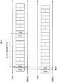
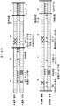
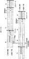
図2は実施形態に係るサブフレームおよびスーパーフレームの構成図である。サブフレーム(Sub Frame)は、親局10と各子局20が、それぞれフレームを送信することができる期間(タイムスロット)を定めるものである。図3に示すサブフレーム30は、ビーコン(beacon)送信(TSb)31、第1コーディネータ(coordinator)データ送信(TSc1)32(1)、・・・、第mコーディネータデータ送信(TScm)32(m)、第1エンドデバイス(end device)データ送信(TS1)33(1)、・・・、第nエンドデバイスデータ送信(TSn)33(n)、キャリアセンス(TScs)34の各タイムスロット(Time Slot:TS)を含むように構成される。これらのタイムスロット数は、親局10と子局20の間で送信されるデータ量や子局20の数により決定される。親局10と子局20との間のデータ送受信は、複数(k個)のサブフレーム30で構成されるスーパーフレーム(Supper Frame)300を、周期的に繰り返して行われる。第1サブフレーム(SBF1)30(1)のキャリア周波数(f1)、第2サブフレーム(SBF2)30(2)のキャリア周波数(f2)、・・・、第kサブフレーム(SBFk)のキャリア周波数(fk)はそれぞれ異なるようにしたり、k個をいくつかのグループに分けてグループ内はキャリア周波数が異なるようにしたりして、隣接する無線通信システムとの干渉を低減する。
FIG. 2 is a configuration diagram of a subframe and a superframe according to the embodiment. The subframe (Sub Frame) defines a period (time slot) in which the master station 10 and each slave station 20 can transmit frames. 3 includes a beacon transmission (TSb) 31, a first coordinator data transmission (TSc1) 32 (1),..., An m-th coordinator data transmission (TScm) 32 (m ), First end device (end device) data transmission (TS1) 33 (1),..., Nth end device data transmission (TSn) 33 (n), carrier sense (TScs) 34 time slots (Time Slot: TS). The number of time slots is determined by the amount of data transmitted between the master station 10 and the slave station 20 and the number of slave stations 20. Data transmission / reception between the master station 10 and the slave station 20 is performed by periodically repeating a super frame (Supper Frame) 300 including a plurality (k) of subframes 30. Carrier frequency (f1) of the first subframe (SBF1) 30 (1), carrier frequency (f2) of the second subframe (SBF2) 30 (2),..., Carrier frequency of the kth subframe (SBFk) (Fk) may be different from each other, or k may be divided into several groups so that carrier frequencies in the groups are different, thereby reducing interference with adjacent wireless communication systems.
1タイムスロットにおいて、1フレームの送信が可能である。各タイムスロットの長さは、1フレームの最大データ長に基づき、このデータの無線送信に必要となる時間として決定される。各タイムスロットの長さは、一律でなくてもよい。なお、あるタイムスロットと次のタイムスロットとの間には、ガードタイム(不図示)が設けられる。ガードタイムは、異なるタイムスロットの信号間の干渉防止のために設けられ、ガードタイム中に送受信の切替が行われる。1フレームには、1又は複数のパケットが含まれる。フレームとは、ヘッダと送信データとフッタとを含むもので、ヘッダには、当該フレームの送信元アドレスと送信先アドレスとを収容可能である。また、フッタには、通信誤り検出用のデータが含まれる。
∙ One frame can be transmitted in one time slot. The length of each time slot is determined as the time required for wireless transmission of this data based on the maximum data length of one frame. The length of each time slot may not be uniform. A guard time (not shown) is provided between a certain time slot and the next time slot. The guard time is provided to prevent interference between signals in different time slots, and transmission / reception is switched during the guard time. One frame includes one or a plurality of packets. The frame includes a header, transmission data, and a footer, and the header can accommodate the transmission source address and the transmission destination address of the frame. The footer includes communication error detection data.
ビーコン送信(TSb)31は、親局(コーディネータ)10がビーコン(同期基準信号)を含むフレームを出力するタイムスロットである。親局10と子局20は、それぞれ、ビーコン送信31で出力される同期基準信号を基準に同期をとり、自局がデータ送信又は受信できるタイムスロットを算出する。
The beacon transmission (TSb) 31 is a time slot in which the master station (coordinator) 10 outputs a frame including a beacon (synchronization reference signal). Each of the master station 10 and the slave station 20 is synchronized based on the synchronization reference signal output by the beacon transmission 31 and calculates a time slot in which the local station can transmit or receive data.
第1コーディネータデータ送信(TSc1)32(1)、・・・、第mコーディネータデータ送信(TScm)32(m)は、それぞれ、親局(コーディネータ)10から子局(エンドデバイス)20へデータ送信できるタイムスロットである。mは、親局10から子局20へ送信するデータ量に応じて決定される。親局10から送信するデータ量が少ない無線通信システムでは、m=1とすることも可能である。第1コーディネータデータ送信32(1)、・・・、第mコーディネータデータ送信32(m)を代表して説明するときは、コーディネータデータ送信32と称する。本実施形態では、1つのコーディネータデータ送信32(例えば、第1コーディネータデータ送信32(1))において、複数の子局20へのデータを、1フレーム内に多重することができる。
The first coordinator data transmission (TSc1) 32 (1),..., The m-th coordinator data transmission (TScm) 32 (m) is transmitted from the master station (coordinator) 10 to the slave station (end device) 20, respectively. It is a possible time slot. m is determined according to the amount of data transmitted from the master station 10 to the slave station 20. In a wireless communication system with a small amount of data transmitted from the master station 10, it is possible to set m = 1. When the first coordinator data transmission 32 (1),..., The m-th coordinator data transmission 32 (m) is described as a representative, it is referred to as a coordinator data transmission 32. In the present embodiment, in one coordinator data transmission 32 (for example, the first coordinator data transmission 32 (1)), data to a plurality of slave stations 20 can be multiplexed in one frame.
第1エンドデバイスデータ送信33(1)、・・・、第nエンドデバイスデータ送信33(n)は、それぞれ、子局(エンドデバイス)20(1)~20(n)から親局10(コーディネータ)へデータ送信できるタイムスロットである。例えば、エンドデバイスデータ送信33(1)は、子局20(1)、つまりエンドデバイス1からコーディネータ10へデータ送信できるタイムスロットTS1であり、エンドデバイスデータ送信33(n)は、子局20(n)、つまりエンドデバイスnからコーディネータ10へデータ送信できるタイムスロットTSnである。なお、エンドデバイスの数n=1の場合は、エンドデバイスデータ送信33の数を1とすることができる。第1エンドデバイスデータ送信33(1)、・・・、第nエンドデバイスデータ33(n)を代表して説明するときは、エンドデバイスデータ送信33と称する。
The first end device data transmission 33 (1),..., The nth end device data transmission 33 (n) are respectively transmitted from the slave stations (end devices) 20 (1) to 20 (n) to the master station 10 (coordinator). It is a time slot that can transmit data to. For example, the end device data transmission 33 (1) is the slave station 20 (1), that is, the time slot TS1 in which data can be transmitted from the end device 1 to the coordinator 10, and the end device data transmission 33 (n) is the slave station 20 ( n), that is, a time slot TSn in which data can be transmitted from the end device n to the coordinator 10. When the number of end devices n = 1, the number of end device data transmissions 33 can be 1. When the first end device data transmission 33 (1),..., The nth end device data 33 (n) is described as a representative, it is referred to as an end device data transmission 33.
キャリアセンス(TScs)34は、隣接する無線通信システムのビーコン送信またはデータ送信を検出するタイムスロットである。キャリアセンス34の機能について以下説明する。
Carrier sense (TScs) 34 is a time slot for detecting beacon transmission or data transmission of an adjacent wireless communication system. The function of the carrier sense 34 will be described below.
図3は実施形態に係る無線通信システムにおいて異なる無線通信サブシステムが隣接している様子を示す図である。図4は隣接する無線通信サブシステムのビーコンをセンスした場合を示すタイミング図である。図5は隣接する無線通信サブシステムのデータをセンスした場合を示すタイミング図である。ここでは、親局10A、第1子局20A(1)、・・・、第n子局20A(n)が無線通信サブシステム(以下、単に「サブシステム」という。)1Aを構成し、親局10B、第1子局20B(1)、・・・、第n子局20B(n)がサブシステム1Bを構成している。サブシステム1A、1Bは図1の無線通信システム1と同様な構成である。サブシステム1Bの子局の数はサブシステム1Aと異なってもよい。
FIG. 3 is a diagram illustrating a state in which different wireless communication subsystems are adjacent to each other in the wireless communication system according to the embodiment. FIG. 4 is a timing diagram showing a case where a beacon of an adjacent wireless communication subsystem is sensed. FIG. 5 is a timing chart showing a case where data of an adjacent wireless communication subsystem is sensed. Here, the master station 10A, the first slave station 20A (1),..., The nth slave station 20A (n) constitutes a wireless communication subsystem (hereinafter simply referred to as “subsystem”) 1A. The station 10B, the first slave station 20B (1),..., The nth slave station 20B (n) constitute the subsystem 1B. The subsystems 1A and 1B have the same configuration as that of the wireless communication system 1 in FIG. The number of slave stations of the subsystem 1B may be different from that of the subsystem 1A.
サブシステム1Aおよびサブシステム1Bの少なくとも一方が移動することにより、サブシステム1Bを構成する親局10B、第1子局20B(1)、第7子局20B(7)、第n子局20B(n)はサブシステム1Aの親局10Aからの電波が受信できる位置にいることがある。このとき、図4に示すように、サブシステム1Aのビーコンタイミングとサブシステム1Bのビーコンタイミングとが重なっていると、例えば第1子局20B(1)の位置においてビーコンの衝突が生じる。また、図5に示すように、サブシステム1Aのビーコンタイミングとサブシステム1Bのデータ送信のタイミングとが重なっていると、例えば第1子局20B(1)の位置においてデータの干渉が生じる。
When at least one of the subsystem 1A and the subsystem 1B moves, the master station 10B, the first slave station 20B (1), the seventh slave station 20B (7), and the nth slave station 20B ( n) may be in a position where radio waves from the master station 10A of the subsystem 1A can be received. At this time, as shown in FIG. 4, when the beacon timing of the subsystem 1A and the beacon timing of the subsystem 1B overlap, for example, a beacon collision occurs at the position of the first slave station 20B (1). Also, as shown in FIG. 5, if the beacon timing of the subsystem 1A and the data transmission timing of the subsystem 1B overlap, data interference occurs at the position of the first slave station 20B (1), for example.
そこで、サブシステム1Aがキャリアセンス34においてサブシステム1Bのビーコン送信またはデータ送信(コーディネータデータ送信またはエンドデバイスデータ送信)を検出した場合は、検出したキャリアセンス34の次のビーコン送信31において、親局10Aはビーコン送信を行なわず、所定サブフレーム数ずらしビーコン送信を行い、親局10Bとのビーコンの衝突または親局10Aのビーコン送信とサブシステム1Bのデータ送信との干渉を回避する。
Therefore, when the subsystem 1A detects the beacon transmission or data transmission (coordinator data transmission or end device data transmission) of the subsystem 1B in the carrier sense 34, the parent station in the beacon transmission 31 next to the detected carrier sense 34 10A does not perform beacon transmission but performs beacon transmission with a predetermined number of subframes shifted to avoid a beacon collision with the parent station 10B or interference between the beacon transmission of the parent station 10A and the data transmission of the subsystem 1B.
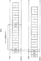
図6は別の実施形態に係るサブフレームの構成図である。図6に示すサブフレーム30は、ビーコン送信(TSb)31、第1コーディネータデータ送信(TSc1)32(1)、・・・、第mコーディネータデータ送信(TScm)32(m)、第1エンドデバイスデータ送信(TS1)33(1)、・・・、第1エンドデバイスデータ送信(TSn)33(n)、キャリアセンス(TScs)34の各タイムスロットを含むように構成される。ビーコン送信(TSb)31、第1コーディネータデータ送信(TSc1)32(1)、・・・、第mコーディネータデータ送信(TScm)32(m)、第1エンドデバイスデータ送信(TS1)33(1)、・・・、第nエンドデバイスデータ送信(TSn)33(n)のそれぞれ直前のタイムスロットにキャリアセンス(TScs)34が配置される。
FIG. 6 is a configuration diagram of a subframe according to another embodiment. 6 includes a beacon transmission (TSb) 31, a first coordinator data transmission (TSc1) 32 (1),..., An m-th coordinator data transmission (TScm) 32 (m), and a first end device. Data transmission (TS1) 33 (1),..., First end device data transmission (TSn) 33 (n), and carrier sense (TScs) 34 are configured to include each time slot. Beacon transmission (TSb) 31, first coordinator data transmission (TSc1) 32 (1), ... m-th coordinator data transmission (TScm) 32 (m), first end device data transmission (TS1) 33 (1) ,..., Carrier sense (TScs) 34 is arranged in the time slot immediately before the n-th end device data transmission (TSn) 33 (n).
実施形態に係る無線通信システムを射撃訓練システムに適用した例を以下に説明する。実施形態に係る無線通信システムは射撃訓練システムに限定されるものではなく、無線通信システムが隣接する複数の無線通信サブシステムで構成されるシステムに適用可能である。
An example in which the wireless communication system according to the embodiment is applied to a shooting training system will be described below. The wireless communication system according to the embodiment is not limited to the shooting training system, but can be applied to a system including a plurality of adjacent wireless communication subsystems.
図7は射撃訓練システムを説明するための図である。図8は図7の車両を上から見た図である。射撃訓練システムは、受光器(子局)111(1)~111(8)と現示器(親局)112とを備える車両110と、レーザ送信器120と、を備える。受光器111(1)~111(8)を代表して説明するときは受光器111と称す。なお、受光器111は、図8の例では8個であるが、8個に限られるものではない。また、受光器111と現示器112は、車両の他にも、ヘリコプター、船舶、人員、建屋などに設置することが可能である。
FIG. 7 is a diagram for explaining the shooting training system. FIG. 8 is a top view of the vehicle shown in FIG. The shooting training system includes a vehicle 110 including a light receiver (slave station) 111 (1) to 111 (8) and a presenter (master station) 112, and a laser transmitter 120. When the light receivers 111 (1) to 111 (8) are described as a representative, they are referred to as the light receiver 111. The number of light receivers 111 is eight in the example of FIG. 8, but is not limited to eight. In addition to the vehicle, the light receiver 111 and the indicator 112 can be installed in helicopters, ships, personnel, buildings, and the like.
射撃訓練においては、実弾を使用せずに模擬弾として、レーザ送信器120から発射されるレーザ光線121を使用する。レーザ光線121には、発射情報として、当該レーザ光線121を発射したレーザ送信器120の識別子(ID)、火器の種別、弾種などの情報が含まれる。
In the shooting training, a laser beam 121 emitted from the laser transmitter 120 is used as a simulated bullet without using an actual bullet. The laser beam 121 includes information such as an identifier (ID) of the laser transmitter 120 that has emitted the laser beam 121, a firearm type, and a bullet type as the emission information.
車両110に取り付けられた受光器111は、レーザ光線121を検出することにより、当該受光器111が被弾したとみなす被弾検出を行う。すなわち、受光器111は、レーザ光線121を検出すると、レーザ光線121に含まれる発射情報を読み取り、被弾情報とともに現示器112へ無線送信する。被弾情報とは、被弾による損耗の程度を示す損耗区分や、損耗部位(被弾位置)などの情報である。
The light receiver 111 attached to the vehicle 110 detects the laser beam 121 to detect the impact that the light receiver 111 has received. That is, when detecting the laser beam 121, the light receiver 111 reads the emission information included in the laser beam 121 and wirelessly transmits it to the display unit 112 together with the bullet information. The bulleted information is information such as a wear category indicating the degree of wear due to the bullet, and a worn part (shot position).
現示器112は受光器111から被弾情報を受信すると、その内容に応じて、発光、発音、発煙のうち1つ以上を用いて、被弾状況の現示、つまり被弾状況の出力を行う。
When receiving the bullet information from the light receiver 111, the presenter 112 displays the bulleted situation, that is, outputs the bulleted situation, using one or more of light emission, sound generation, and smoke according to the contents.
この射撃訓練システムにおいては、複数の受光器111にて被弾検出を行った後、被弾情報を現示器112へ無線送信し、現示器112で現示するまでの時間は、概ね100ms以下とする必要がある。また、無線送信時のデータ誤りなどによる被弾情報の紛失は、正常な訓練に影響を及ぼすので、その場合は、確実にデータ再送されることが必要である。
In this shooting training system, after bullet detection is performed by a plurality of light receivers 111, bullet information is wirelessly transmitted to the indicator 112, and the time until the indicator 112 is displayed is approximately 100 ms or less. There is a need to. Also, loss of bullet information due to data errors during wireless transmission affects normal training. In that case, it is necessary to reliably retransmit data.
そこで、この射撃訓練システムにおいて、受光器(子局)と現示器(親局)間のデータ伝送に、標準規格IEEE802.15.4の無線通信方式を用いる。標準規格IEEE802.15.4には、無線ネットワークのデータリンク層(MAC層)に関し、TDMAをベースとした通信方式(アクセス方式やデータ伝送シーケンス等)の仕様が制定されている。
Therefore, in this shooting training system, the wireless communication method of the standard IEEE 802.15.4 is used for data transmission between the light receiver (slave station) and the presenter (master station). In the standard IEEE 802.15.4, specifications of a communication method (access method, data transmission sequence, etc.) based on TDMA are established for a data link layer (MAC layer) of a wireless network.
上記規格に従いTDMA方式の無線通信を行う場合、例えば、親局と子局の間でデータ送信を行う場合、親局と子局がそれぞれフレーム送信できるタイムスロットは、1スーパーフレーム内にそれぞれ予め設定されており、親局と子局は、それぞれ設定されたタイムスロットにおいて送信を行う。スーパーフレームは、親局と子局がそれぞれフレーム送信することができるタイムスロットを定める時間軸上の構造を示すものである。
When TDMA wireless communication is performed in accordance with the above standard, for example, when data transmission is performed between a master station and a slave station, time slots in which the master station and the slave station can transmit frames are set in advance in one superframe. The master station and the slave station perform transmission in the set time slots. The super frame indicates a structure on the time axis that defines time slots in which the master station and the slave stations can transmit frames.
図9は実施例に係る現示器および受光器の構成図である。図9に示すように、現示器(コーディネータ)112は、無線モジュール11と表示部15と電池16とを備える。無線モジュール11は制御部12と送受信部13と記憶部14とを備える。送受信部13は、受光器111との間で電波を送受信するためのアンテナ13aを含む。電池16は、現示器112の各構成部へ電源供給する。
FIG. 9 is a configuration diagram of the presenting device and the light receiving device according to the embodiment. As shown in FIG. 9, the presenter (coordinator) 112 includes a wireless module 11, a display unit 15, and a battery 16. The wireless module 11 includes a control unit 12, a transmission / reception unit 13, and a storage unit 14. The transceiver 13 includes an antenna 13 a for transmitting and receiving radio waves to and from the light receiver 111. The battery 16 supplies power to each component of the indicator 112.
制御部12は、現示器112の各構成部や現示器112全体の動作を制御する。また、制御部12は、受光器111に対して無線送信を行うときに、記憶部14に記憶したスーパーフレームのタイムスロットのタイミングに基づき、状態データ、運用設定データ等のデータやACKデータを送信するタイミングを決定する。また、制御部12は、受光器111に対し、データやACKデータを送信するタイムスロットを検出するためのビーコンを、送受信部13から送信させる。つまり、制御部12は、受光器111がデータやACKデータを送信するタイミングを、受光器111へ通知する。なお、ACKデータとは、確認応答(肯定応答ともいう)データ、つまり、送信側から送信されたデータを受信側で正常に受信したことを示すために、受信側から送信側へ送られる肯定的な応答のデータのことである。
The control unit 12 controls the operation of each component of the display unit 112 and the entire display unit 112. In addition, when wirelessly transmitting to the optical receiver 111, the control unit 12 transmits data such as status data, operation setting data, and ACK data based on the timing of the superframe time slot stored in the storage unit 14. Determine the timing. In addition, the control unit 12 causes the light receiver 111 to transmit a beacon for detecting a time slot for transmitting data and ACK data from the transmission / reception unit 13. That is, the control unit 12 notifies the light receiver 111 of the timing at which the light receiver 111 transmits data and ACK data. The ACK data is an acknowledgment (also referred to as a positive response) data, that is, an affirmative sent from the receiving side to the transmitting side in order to indicate that the data transmitted from the transmitting side has been normally received at the receiving side. It is a response data.
送受信部13は、制御部12からの制御に従い、受光器111との間でデータやACKデータを、無線により送信又は受信する。
The transmission / reception unit 13 transmits or receives data or ACK data wirelessly with the light receiver 111 according to the control from the control unit 12.
記憶部14は、スーパーフレームのタイムスロットのタイミングを記憶する。また、記憶部14は、制御部12からの制御に従い、受光器111から受信したデータの保持や、受光器111へ送信するデータの保持を行う。受光器111へ送信するデータは、例えば、制御部12から入力される。
The storage unit 14 stores the timing of the superframe time slot. Further, the storage unit 14 holds data received from the light receiver 111 and holds data to be transmitted to the light receiver 111 according to control from the control unit 12. Data to be transmitted to the light receiver 111 is input from the control unit 12, for example.
表示部15は、各種情報を出力する出力部で、受光器111から受信した情報を表示する。例えば、表示部15は音を発する発音部151と光を発する発光部152と煙を発する発煙部153とを備え、受光器111から受信した情報に応じて、発音、発光、発煙等の出力を行う。表示部15に入力される情報は、記憶部14に保持される。
The display unit 15 is an output unit that outputs various types of information, and displays information received from the light receiver 111. For example, the display unit 15 includes a sound generation unit 151 that emits sound, a light emission unit 152 that emits light, and a smoke generation unit 153 that emits smoke, and outputs sounds such as sound generation, light emission, and smoke generation according to information received from the light receiver 111. Do. Information input to the display unit 15 is held in the storage unit 14.
受光器(エンドデバイス)111は、無線モジュール21と、受光部25と、電池26と、を備える。無線モジュール21は制御部22と送受信部23と記憶部24とを備える。送受信部23は、現示器112との間で電波を送受信するためのアンテナ23aを含む。電池26は、受光器111の各構成部へ電源供給する。
The light receiver (end device) 111 includes a wireless module 21, a light receiving unit 25, and a battery 26. The wireless module 21 includes a control unit 22, a transmission / reception unit 23, and a storage unit 24. The transmission / reception unit 23 includes an antenna 23a for transmitting / receiving radio waves to / from the display unit 112. The battery 26 supplies power to each component of the light receiver 111.
制御部22は、受光器111の各構成部や受光器111全体の動作を制御する。また、制御部22は、受光部25から入力された情報を、現示器112へ無線送信するよう制御する。また、制御部22は、現示器112に対して無線送信を行うときに、記憶部24に記憶したスーパーフレームのタイムスロットのタイミングに基づき、データやACKデータを送信するタイミングを決定する。
The control unit 22 controls the operation of each component of the light receiver 111 and the entire light receiver 111. Further, the control unit 22 performs control so that the information input from the light receiving unit 25 is wirelessly transmitted to the indicator 112. In addition, when performing wireless transmission to the indicator 112, the control unit 22 determines the timing for transmitting data and ACK data based on the timing of the superframe time slot stored in the storage unit 24.
送受信部23は、制御部22からの制御に従い、現示器112との間でデータやACKを、無線により送信又は受信する。
The transmission / reception unit 23 transmits or receives data or ACK wirelessly with the display unit 112 according to the control from the control unit 22.
記憶部24は、現示器112から受信したビーコンに基づき、スーパーフレームのタイムスロットのタイミングを記憶する。また、記憶部24は、制御部22からの制御に従い、現示器112から受信したデータの保持や、現示器112へ送信するデータの保持を行う。現示器112へ送信するデータは、例えば、受光部25から入力される。
The storage unit 24 stores the timing of the superframe time slot based on the beacon received from the display unit 112. The storage unit 24 holds data received from the display unit 112 and holds data to be transmitted to the display unit 112 in accordance with control from the control unit 22. Data to be transmitted to the indicator 112 is input from the light receiving unit 25, for example.
受光部25は、各種情報の入力を受け付ける入力部である。例えば、受光部25は、レーザ光線を受光して、該受光したレーザ光線に含まれる情報を、制御部22へ出力する。受光部25に入力された情報は、記憶部24に保持される。
The light receiving unit 25 is an input unit that receives input of various types of information. For example, the light receiving unit 25 receives a laser beam and outputs information included in the received laser beam to the control unit 22. Information input to the light receiving unit 25 is held in the storage unit 24.
制御部12、制御部22は、それぞれ、ハードウエア構成としては、CPU(Central Processing Unit)と各制御部の動作プログラム等を格納するメモリとを備えている。CPUは、上記動作プログラムに従って動作する。
Each of the control unit 12 and the control unit 22 includes a CPU (Central Processing Unit) and a memory for storing an operation program of each control unit as a hardware configuration. The CPU operates according to the operation program.
記憶部14、記憶部24は、それぞれ、半導体メモリ(フラッシュメモリ、RAM(Random Access Memory)、ROM(read only memory)等)や磁気ディスク等により構成される。
The storage unit 14 and the storage unit 24 are each composed of a semiconductor memory (flash memory, RAM (Random Access Memory), ROM (read only memory), etc.), a magnetic disk, or the like.
例えば、射撃訓練システムの例では、子局20は、レーザ光線を受光し、該受光したレーザ光線に含まれる情報を取得して、該取得した情報を現示器へ無線送信する受光器である。また、親局10は、複数の受光器とそれぞれ直接的に通信接続され、複数の受光器からそれぞれ無線送信された情報を受信して、該受信した情報に基づく出力を行う現示器である。
For example, in the example of the shooting training system, the slave station 20 is a light receiver that receives a laser beam, acquires information included in the received laser beam, and wirelessly transmits the acquired information to the display device. . The master station 10 is a display device that is directly connected to a plurality of light receivers, receives information wirelessly transmitted from the plurality of light receivers, and performs output based on the received information. .
図10は実施例に係るサブフレームの構成図である。図10に示すサブフレーム30は、ビーコン(beacon)送信(TSb)31、第1コーディネータ(coordinator)データ送信(TSc1)32(1)、第2コーディネータ送信(TSc2)32(2)、第1エンドデバイス(end device)データ送信(TS1)33(1)、・・・、第8エンドデバイスデータ送信(TS8)33(8)、キャリアセンス(TScs)34の各タイムスロット(Time Slot:TS)を含むように構成される。よって、実施例のサブフレームは実施形態のサブフレームにおいて、m=2、n=8の場合である。
FIG. 10 is a configuration diagram of a subframe according to the embodiment. 10 includes a beacon transmission (TSb) 31, a first coordinator data transmission (TSc1) 32 (1), a second coordinator transmission (TSc2) 32 (2), and a first end. Device (end device) data transmission (TS1) 33 (1),..., Eighth end device data transmission (TS8) 33 (8), carrier sense (TScs) 34 time slots (Time Slot: TS) Configured to include. Therefore, the subframe of the example is a case where m = 2 and n = 8 in the subframe of the embodiment.
各タイムスロットの時間は、例えば、
tTScs=0.9ms
tTSb =0.9ms
tTSc1=tTSc2=2.8ms
tTS1=tTS2=・・・=tTS8=1.27ms
tGT=0.2ms
tSD=19.96ms
である。 The time of each time slot is, for example,
tTScs = 0.9ms
tTSb = 0.9ms
tTSc1 = tTSc2 = 2.8 ms
tTS1 = tTS2 = ... = tTS8 = 1.27 ms
tGT = 0.2ms
tSD = 19.96ms
It is.
tTScs=0.9ms
tTSb =0.9ms
tTSc1=tTSc2=2.8ms
tTS1=tTS2=・・・=tTS8=1.27ms
tGT=0.2ms
tSD=19.96ms
である。 The time of each time slot is, for example,
tTScs = 0.9ms
tTSb = 0.9ms
tTSc1 = tTSc2 = 2.8 ms
tTS1 = tTS2 = ... = tTS8 = 1.27 ms
tGT = 0.2ms
tSD = 19.96ms
It is.
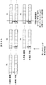
受光器111と現示器112とのリンクアップ(通信接続確立時)について図11を用いて説明する。図11はリンクアップ時のサブフレーム周期を示す図である。
The link up (at the time of communication connection establishment) with the light receiver 111 and the indicator 112 is demonstrated using FIG. FIG. 11 is a diagram illustrating a subframe period at the time of link-up.
サブフレーム#1において、現示器112は、キャリアを検出しない場合、ビーコンを受光器111に送信する。受光器111は自己の親局のビーコンを受信し、同期を完了する。
In subframe # 1, the indicator 112 transmits a beacon to the light receiver 111 when no carrier is detected. The light receiver 111 receives the beacon of its own master station and completes the synchronization.
サブフレーム#2において、受光器111は現示器112に状態データを送信する。現示器112は状態データを受信する。なお、図11以降の図面では状態データは実線矢印で表している。
In subframe # 2, the light receiver 111 transmits status data to the indicator 112. The indicator 112 receives the status data. In FIG. 11 and subsequent drawings, the state data is represented by solid arrows.
サブフレーム#3において、現示器112は受光器111にACKデータを送信する。受光器111はACKデータを受信する。なお、図11以降の図面ではACKデータは破線矢印で表している。
In subframe # 3, the indicator 112 transmits ACK data to the light receiver 111. The light receiver 111 receives ACK data. In FIG. 11 and subsequent drawings, ACK data is indicated by a broken-line arrow.
サブフレーム#nにおいて、現示器112は受光器111に運用設定データを送信する。受光器111は運用設定データを受信し、現示器112にACKデータを送信する。リンクアップを完了する。なお、図11以降の図面では運用設定データは実線矢印で表している。
In subframe #n, the display unit 112 transmits operation setting data to the light receiver 111. The light receiver 111 receives the operation setting data and transmits ACK data to the display device 112. Complete the link up. In FIG. 11 and subsequent drawings, the operation setting data is represented by solid arrows.
上記射撃訓練システムでは、独立した通信を行うサブシステムは親局1台と子局8台であり、1サブシステムにおける無線通達エリアには約9台のサブシステムが存在する。チャネル数は4~8で、確実に運用中に干渉が発生することが想定される。そこで運用を、リンクアップ(接続確立時)と運用(通常運用)の2パターンに分け、それぞれにおいて干渉を避けるための方式を説明する。なお、以下の説明では、4チャネルの周波数ホッピングとして、スーパーフレームは4種類の周波数のサブフレームで構成されている。
In the above-mentioned shooting training system, the subsystems that perform independent communication are one master station and eight slave stations, and there are about nine subsystems in the radio notification area in one subsystem. The number of channels is 4 to 8, and it is assumed that interference will surely occur during operation. Therefore, the operation is divided into two patterns of link-up (when connection is established) and operation (normal operation), and a method for avoiding interference in each of them will be described. In the following description, as a frequency hopping of 4 channels, a super frame is composed of sub-frames of 4 types of frequencies.
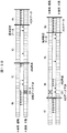
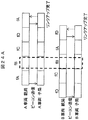
キャリアを検出する場合のビーコンの送信タイミングについて図12、13を用いて説明する。図12は隣接するサブシステムの状態データのキャリアを検出する場合を説明するための図である。図13は隣接するサブシステムのビーコンのキャリアを検出する場合を説明するための図である。
The beacon transmission timing when a carrier is detected will be described with reference to FIGS. FIG. 12 is a diagram for explaining a case where a carrier of state data of an adjacent subsystem is detected. FIG. 13 is a diagram for explaining a case where a beacon carrier of an adjacent subsystem is detected.
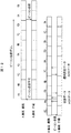
図12に示すAサブシステム(A車両)ではサブフレームの周波数がfA、fB、fC、fD、fA、fB、fC、fD、・・・という順序で変化し、Bサブシステム(B車両)ではサブフレームの周波数がfC、fA、fD、fB、fC、fA、fD、fB、・・・という順序で変化する。A車両の周波数がfAのサブフレームとB車両の周波数がfAのサブフレームとは一部重なっている。図12に示すように、A車両の親局は子局にビーコン送信するタイミングの前のキャリアセンスでB車両の子局が親局に送信する状態データのキャリアを検出する。そこで、A車両の親局はビーコン送信のタイミングを8サブフレーム遅らせて、干渉を回避する。A車両の子局はビーコン未受信につき基準チャネルでビーコン待ちを継続する。
In the A subsystem (A vehicle) shown in FIG. 12, the frequency of the subframe changes in the order of fA, fB, fC, fD, fA, fB, fC, fD,..., And in the B subsystem (B vehicle) The frequency of the subframe changes in the order of fC, fA, fD, fB, fC, fA, fD, fB,. The sub-frame with the frequency of vehicle A fA and the sub-frame with the frequency of vehicle B fA partially overlap. As shown in FIG. 12, the parent station of the vehicle A detects the carrier of the state data transmitted from the child station of the vehicle B to the parent station by carrier sense before the timing of beacon transmission to the child station. Therefore, the parent station of vehicle A delays the beacon transmission timing by 8 subframes to avoid interference. The child station of vehicle A continues to wait for a beacon on the reference channel when no beacon is received.
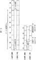
図13に示すAサブシステム(A車両)およびBサブシステム(B車両)ではサブフレームの周波数がfA、fB、fC、fD、fA、fB、fC、fD、・・・という順序で変化する。A車両の周波数がfAのサブフレームとB車両の周波数がfAのサブフレームとは一部重なっている。図13に示すように、A車両の親局は子局にビーコン送信するタイミングの前のキャリアセンスでB車両の親局が子局に送信するビーコンのキャリアを検出する。そこで、A車両の親局はビーコン送信のタイミング(スーパフレームの開始)を8サブフレーム遅らせて、干渉を回避する。A車両の子局はビーコン未受信につき基準チャネルでビーコン待ちを継続する。
In the A subsystem (A vehicle) and B subsystem (B vehicle) shown in FIG. 13, the frequency of the subframe changes in the order of fA, fB, fC, fD, fA, fB, fC, fD,. The sub-frame with the frequency of vehicle A fA and the sub-frame with the frequency of vehicle B fA partially overlap. As shown in FIG. 13, the parent station of vehicle A detects the carrier of the beacon transmitted from the parent station of vehicle B to the child station by carrier sense before the timing of beacon transmission to the child station. Therefore, the master station of the A vehicle delays the beacon transmission timing (superframe start) by 8 subframes to avoid interference. The child station of vehicle A continues to wait for a beacon on the reference channel when no beacon is received.
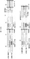
隣接するサブシステム間でデータ干渉が発生する場合のARQ(Automatic Repeat reQuest)再送について図14A、14B、15A、15Bを用いて説明する。図14AはARQ再送で干渉が発生するがリンクアップが完了する場合のタイミング図である。図14Bは図14Aの拡大図である。図15AはARQ再送では干渉が発生せずリンクアップが完了する場合のタイミング図である。図15Bは図15Aの拡大図である。
ARQ (Automatic Repeat request) retransmission when data interference occurs between adjacent subsystems will be described with reference to FIGS. 14A, 14B, 15A, and 15B. FIG. 14A is a timing chart when interference occurs in ARQ retransmission but link-up is completed. FIG. 14B is an enlarged view of FIG. 14A. FIG. 15A is a timing diagram when link up is completed without interference in ARQ retransmission. FIG. 15B is an enlarged view of FIG. 15A.
図14Aに示すAサブシステム(A車両)ではサブフレームの周波数がfA、fB、fC、fD、fA、fB、fC、fD、・・・という順序で変化し、Bサブシステム(B車両)ではサブフレームの周波数がfD、fC、fB、fA、fD、fC、fB、fA、・・・という順序で変化する。A車両の周波数がfBのサブフレームとB車両の周波数がfBのサブフレーム、およびA車両の周波数がfDのサブフレームとB車両の周波数がfDのサブフレームとは一部重なっており、破線部分で干渉が発生する。
In the A subsystem (A vehicle) shown in FIG. 14A, the subframe frequency changes in the order of fA, fB, fC, fD, fA, fB, fC, fD,..., And in the B subsystem (B vehicle). The frequency of the subframe changes in the order of fD, fC, fB, fA, fD, fC, fB, fA,. The subframe with the frequency of vehicle A being fB, the subframe with the frequency of vehicle B being fB, the subframe with the frequency of vehicle A being fD, and the subframe having a frequency of vehicle B being fD partially overlap, and the broken line portion Cause interference.
図14Bに示すように、A車両の子局から親局への状態データの送信と、B車両の親局はから子局へのACKデータの送信および子局から親局への状態データ送信が干渉する。車両Aの第1、6~8子局(ED1,6~8)がARQ再送になるが、親局から子局へのACKデータ(CD1,2)も干渉してリトライオーバとなる。しかし、運用データを受信することでリンクアップ完了とする。B車両の子局5~7がARQ再送になるが、親局から子局へのACKデータ(CD1,2)も干渉してリトライオーバとなる。しかし、運用データを受信することでリンクアップを完了する。
As shown in FIG. 14B, transmission of status data from the slave station of the A vehicle to the master station, transmission of ACK data from the master station of the B vehicle to the slave station, and status data transmission from the slave station to the master station are performed. have a finger in the pie. The first, sixth to eighth slave stations (ED1, 6 to 8) of the vehicle A perform ARQ retransmission, but the ACK data (CD1, 2) from the master station to the slave stations also interfere and cause a retry over. However, the link up is completed by receiving operational data. The slave stations 5 to 7 of the B vehicle perform ARQ retransmission, but ACK data (CD1, 2) from the master station to the slave station also interferes and a retry over occurs. However, link-up is completed by receiving operational data.
図15Aに示すAサブシステム(A車両)ではサブフレームの周波数がfA、fB、fC、fD、fA、fB、fC、fD、・・・という順序で変化し、Bサブシステム(B車両)ではサブフレームの周波数がfD、fC、fB、fA、fD、fC、fB、fA、・・・という順序で変化する。A車両の周波数がfBのサブフレームとB車両の周波数がfBのサブフレームとは一部重なっており、破線部分で干渉が発生する。
In the A subsystem (A vehicle) shown in FIG. 15A, the frequency of subframes changes in the order of fA, fB, fC, fD, fA, fB, fC, fD,..., And in the B subsystem (B vehicle) The frequency of the subframe changes in the order of fD, fC, fB, fA, fD, fC, fB, fA,. The subframe with the frequency of the vehicle A of fB and the subframe of the vehicle B with the frequency fB partially overlap, and interference occurs at the broken line portion.
図15Bに示すように、A車両の子局から親局への状態データの送信と、B車両の親局はから子局へのACKデータの送信が干渉する。A車両の第7,8子局(ED7、8)がARQ再送になり、状態データが送信されてリンクアップ完了とする。B車両の第1~4子局がARQ再送になり、状態データが送信されてリンクアップを完了とする。
As shown in FIG. 15B, transmission of status data from the slave station of the A vehicle to the master station interferes with transmission of ACK data from the master station of the B vehicle to the slave station. The seventh and eighth slave stations (ED7 and 8) of the A vehicle are ARQ retransmitted, and the status data is transmitted to complete the link up. The first to fourth slave stations of the B vehicle are ARQ retransmitted, and the status data is transmitted to complete the link up.
データ干渉発生時にアプリケーション層からの再送指示(APL再送)によりリンクアップ完了が可能なタイミングについて図16A、16Bを用いて説明する。図16AはAPL再送によりリンクアップが完了するタイミング図である。図16Bは図16Aの拡大図である。
The timing at which link-up can be completed by a retransmission instruction (APL retransmission) from the application layer when data interference occurs will be described with reference to FIGS. 16A and 16B. FIG. 16A is a timing diagram in which linkup is completed by APL retransmission. FIG. 16B is an enlarged view of FIG. 16A.
図16Aに示すAサブシステム(A車両)ではサブフレームの周波数がfA、fB、fC、fD、fA、fB、fC、fD、・・・という順序で変化し、Bサブシステム(B車両)ではサブフレームの周波数がfB、fD、fA、fC、fB、fD、fA、fC、・・・という順序で変化する。A車両の周波数がfBのサブフレームとB車両の周波数がfBのサブフレーム、およびA車両の周波数がfDのサブフレームとB車両の周波数がfDのサブフレームとは一部重なっており、破線部分で干渉が発生する。
In the A subsystem (A vehicle) shown in FIG. 16A, the frequency of subframes changes in the order of fA, fB, fC, fD, fA, fB, fC, fD,..., And in the B subsystem (B vehicle) The frequency of the subframe changes in the order of fB, fD, fA, fC, fB, fD, fA, fC,. The subframe with the frequency of vehicle A being fB, the subframe with the frequency of vehicle B being fB, the subframe with the frequency of vehicle A being fD, and the subframe having a frequency of vehicle B being fD partially overlap, and the broken line portion Cause interference.
図16Bに示すように、A車両の子局から親局への状態データの送信と、B車両の親局から子局への運用設定データの送信が干渉する。A車両の第4~7子局(ED4~7)がARQ再送になるが、親局から子局へのACKデータ(CD1,2)も干渉してリトライオーバとなる。しかし、運用データを受信することでリンクアップ完了とする。B車両の親局から子局への運用設定データがARQ再送になるが、子局から親局へのACKデータ(ED4~7)も干渉してリトライオーバとなる。しかし、親局にて運用設定データのARQリトライオーバ時はアプリケーション層による再送処理を実施する。再送タイミングは乱数による遅延時間により決定する。これは、同一の周波数ホッピング(FH)の車両で同タイミング再送での再干渉を防ぐ為である。
As shown in FIG. 16B, transmission of status data from the slave station of the A vehicle to the master station interferes with transmission of operation setting data from the master station of the B vehicle to the slave station. The 4th to 7th slave stations (ED4 to 7) of the A vehicle are ARQ retransmitted, but the ACK data (CD1, 2) from the master station to the slave station also interferes and a retry over occurs. However, the link up is completed by receiving operational data. The operation setting data from the master station to the slave station of the B vehicle is ARQ retransmission, but the ACK data (ED4 to ED7) from the slave station to the master station also interferes and causes a retry over. However, at the time of ARQ retry over of the operation setting data at the master station, retransmission processing by the application layer is performed. The retransmission timing is determined by a delay time using random numbers. This is to prevent re-interference due to retransmission at the same timing in vehicles having the same frequency hopping (FH).
なお、子局でのAPL再送において、各子局にて乱数取得を実施した場合、子局再送タイミングに違いが生じ、それぞれの再送データと親局からのACKデータで多くのサブフレームを使用することとなり、結果として再干渉が発生する割合が高くなる。この対策として、子局からの再送データは1サブフレームまたは連続した2サブフレームとなるように調整する必要がある。車両毎にユニークな番号割付となっているPAN-IDより遅延時間テーブルを参照して遅延時間を決定する。遅延時間テーブルの設定値は、PAN-IDにより決定するFHパターンとなるべく一致しない構成とする。
When random numbers are acquired at each slave station in APL retransmission at the slave station, a difference occurs in the slave station retransmission timing, and a lot of subframes are used for each retransmission data and ACK data from the master station. As a result, the rate of occurrence of re-interference increases. As a countermeasure, it is necessary to adjust the retransmission data from the slave station to be one subframe or two consecutive subframes. The delay time is determined by referring to the delay time table from the PAN-ID assigned with a unique number for each vehicle. The setting value of the delay time table is configured to be as inconsistent as possible with the FH pattern determined by the PAN-ID.
ビーコン干渉時に無線モジュール再起動によりリンクアップ完了を可能とするタイミングについて図17A、17B、17C、図18A、18B、18Cを用いて説明する。図17Aは干渉したサブシステムの一方のみが再起動によりリンクアップを完了する場合のタイミング図である。図17B、17Cは図17Aの拡大図である。図17Bの次に図17Cが繋がり、図17Bの右側部分と図17Cの左側部分は重複している。図18Aは干渉したサブシステムの両方が再起動によりリンクアップを完了する場合のタイミング図である。図18B、18Cは図18Aの拡大図である。図18Bの次に図18Cが繋がる。
The timing at which link-up can be completed by restarting the wireless module at the time of beacon interference will be described with reference to FIGS. 17A, 17B, 17C, 18A, 18B, and 18C. FIG. 17A is a timing diagram when only one of the interfered subsystems completes link-up by restarting. 17B and 17C are enlarged views of FIG. 17A. 17C is connected next to FIG. 17B, and the right side part of FIG. 17B and the left side part of FIG. 17C overlap. FIG. 18A is a timing diagram when both interfering subsystems complete the link-up by restarting. 18B and 18C are enlarged views of FIG. 18A. 18C is connected next to FIG. 18B.
図17Aに示すAサブシステム(A車両)ではサブフレームの周波数がfA、fB、fC、fD、fA、fB、fC、fD、・・・という順序で変化し、Bサブシステム(B車両)ではサブフレームの周波数がfC、fA、fD、fB、fC、fA、fD、fB、・・・という順序で変化する。A車両の周波数がfAのサブフレームとB車両の周波数がfAのサブフレームとは一部重なっており、破線部分で干渉が発生する。
In the A subsystem (A vehicle) shown in FIG. 17A, the frequency of subframes changes in the order of fA, fB, fC, fD, fA, fB, fC, fD,..., And in the B subsystem (B vehicle) The frequency of the subframe changes in the order of fC, fA, fD, fB, fC, fA, fD, fB,. The subframe with the frequency of vehicle A is fA and the subframe with the frequency of vehicle B are fA partially overlap, and interference occurs at the broken line portion.
図17Bに示すように、A車両の親局から子局へのビーコンの送信と、B車両の子局から親局への状態データの送信が干渉する。A車両の子局はビーコンを受信できず、状態データ送信が不可となる。一方、B車両の第1子局(ED1)がARQ再送になり、状態データが送信されてリンクアップ完了とする。そこで、図17Cに示すように、A車両の親局は、ビーコン送信後、所定時間(例えば3秒)経過しても運用データの送信未完了を検出すると、これをトリガにリンクアップ処理を再起動する。この再起動処理は制御部12から送受信部13に動作停止要求を送信後、乱数値による遅延時間後に動作開始要求を送信することで実施する。子局はビーコン未受信につき基準チャネルでビーコン待ちを継続する。
As shown in FIG. 17B, transmission of a beacon from the parent station of the A vehicle to the child station interferes with transmission of status data from the child station of the B vehicle to the parent station. The child station of the vehicle A cannot receive the beacon and cannot transmit the status data. On the other hand, the first slave station (ED1) of vehicle B performs ARQ retransmission, and status data is transmitted to complete link up. Therefore, as shown in FIG. 17C, when the master station of the vehicle A detects the incomplete operation data transmission even after a predetermined time (for example, 3 seconds) has passed since the beacon transmission, the link up process is restarted by using this as a trigger. to start. This restart process is implemented by transmitting an operation stop request from the control unit 12 to the transmission / reception unit 13 and then transmitting an operation start request after a delay time based on a random value. The slave station continues to wait for a beacon on the reference channel when no beacon is received.
図18Aに示すAサブシステム(A車両)ではサブフレームの周波数がfA、fB、fC、fD、fA、fB、fC、fD、・・・という順序で変化し、Bサブシステム(B車両)ではサブフレームの周波数がfA、fB、fC、fD、fA、fB、fC、fD、・・・という順序で変化する。A車両のすべての周波数のサブフレームとB車両のすべての周波数のサブフレームとが重なっており、破線部分で干渉が発生する。
In the A subsystem (A vehicle) shown in FIG. 18A, the subframe frequency changes in the order of fA, fB, fC, fD, fA, fB, fC, fD,..., And in the B subsystem (B vehicle). The subframe frequency changes in the order of fA, fB, fC, fD, fA, fB, fC, fD,. The sub-frames of all the frequencies of the A vehicle and the sub-frames of all the frequencies of the B vehicle overlap, and interference occurs at the broken line portion.
図18Bに示すように、A車両の親局から子局へのビーコンの送信と、B車両の親局から子局へのビーコンの送信が干渉する。A車両の子局およびB車両の子局はビーコンを受信できず、状態データ送信が不可となる。そこで、図18Cに示すように、A車両の親局およびB車両の親局は、ビーコン送信後、所定時間(例えば3秒)経過しても運用データの送信未完了を検出すると、これをトリガにリンクアップ処理を再起動する。この再起動処理は制御部12から送受信部13に動作停止要求を送信後、乱数値による遅延時間後に動作開始要求を送信することで実施する。乱数値による遅延時間後に動作開始要求を送信することで、図18Cに示すように、A車両の親局とB車両の親局のビーコン送信のタイミングはずらすことができる。子局はビーコン未受信につき基準チャネルでビーコン待ちを継続する。
As shown in FIG. 18B, transmission of a beacon from the parent station of the A vehicle to the child station interferes with transmission of a beacon from the parent station of the B vehicle to the child station. The slave station of the A vehicle and the slave station of the B vehicle cannot receive the beacon and cannot transmit the status data. Therefore, as shown in FIG. 18C, when the master station of the A vehicle and the master station of the B vehicle detect the incomplete transmission of the operation data even after a predetermined time (for example, 3 seconds) has passed since the beacon transmission, this is triggered. Restart the link up process. This restart process is implemented by transmitting an operation stop request from the control unit 12 to the transmission / reception unit 13 and then transmitting an operation start request after a delay time based on a random value. By transmitting the operation start request after the delay time based on the random number value, as shown in FIG. 18C, the beacon transmission timings of the parent station of the A vehicle and the parent station of the B vehicle can be shifted. The slave station continues to wait for a beacon on the reference channel when no beacon is received.
ビーコン送信時の隠れ端末問題について図19、図20A、20B、20Cを用いて説明する。図19はビーコン送信時の隠れ端末問題が発生する車両の位置関係を示す図である。図20Aはビーコン送信時の隠れ端末問題を説明するためのタイミング図である。図20B、20Cは図20Aの拡大図である。図20Bの次に図20Cが繋がる。
The hidden terminal problem during beacon transmission will be described with reference to FIGS. 19, 20A, 20B, and 20C. FIG. 19 is a diagram illustrating a positional relationship of vehicles in which a hidden terminal problem occurs during beacon transmission. FIG. 20A is a timing diagram for explaining the hidden terminal problem during beacon transmission. 20B and 20C are enlarged views of FIG. 20A. After FIG. 20B, FIG. 20C is connected.
図19に示すように、A車両110Aの親局112AにはB車両のキャリアが届かないが、A車両110Aの第4子局111A(4)、第5子局111A(5)にはB車両のキャリアが届くことがある。親局が隣接サブシステムとの干渉を認知しないでその子局が隣接サブシステムと干渉することを隠れ端末問題という。
As shown in FIG. 19, the carrier of the B vehicle does not reach the master station 112A of the A vehicle 110A, but the fourth vehicle station 111A (4) and the fifth slave station 111A (5) of the A vehicle 110A May arrive. When the master station does not recognize the interference with the adjacent subsystem and the slave station interferes with the adjacent subsystem, it is called a hidden terminal problem.
図20Aに示すAサブシステム(A車両)ではサブフレームの周波数がfA、fB、fC、fD、fA、fB、fC、fD、・・・という順序で変化し、Bサブシステム(B車両)ではサブフレームの周波数がfA、fC、fD、fB、fA、fC、fD、fB、・・・という順序で変化する。A車両の周波数がfAのサブフレームとB車両の周波数がfAのサブフレームとは重なっており、破線部分で干渉が発生する。
In the A subsystem (A vehicle) shown in FIG. 20A, the frequency of subframes changes in the order of fA, fB, fC, fD, fA, fB, fC, fD,..., And in the B subsystem (B vehicle) The frequency of the subframe changes in the order of fA, fC, fD, fB, fA, fC, fD, fB,. The sub-frame with the frequency of vehicle A fA and the sub-frame with the frequency of vehicle B fA overlap, and interference occurs at the broken line portion.
図20Bに示すように、A車両の第4子局、第5子局の親局からのビーコン受信と、B車両の親局から子局へのビーコンの送信が干渉する。B車両のタイミングによっては、A車両の第4子局、第5子局の親局からのビーコン受信と、B車両の運用データ等の送信が干渉する場合(不図示)もある。A車両の第4子局、第5子局はビーコンを受信できず、状態データ送信が不可となる。また、第4子局、第5子局ではビーコン未受信でARQ再送も行われない。そこで、A車両の親局はビーコン送信後、所定時間(例えば3秒)経過しても運用データ送信の未完了を検出すると、これをトリガにリンクアップ処理を再起動する。この再起動処理は制御部12から送受信部13に動作停止要求を送信後、乱数値による遅延時間後に動作開始要求を送信することで実施する。干渉発生子局はビーコン未受信につき基準チャネルでビーコン待ちを継続する。その他子局は同期開始後、所定時間(例えば3秒)経過しても運用データの未受信を検出すると、これをトリガに基準チャネルでビーコン待ちに移行する。
As shown in FIG. 20B, beacon reception from the fourth and fifth child stations of the A vehicle interferes with transmission of a beacon from the parent station of the B vehicle to the child station. Depending on the timing of the B vehicle, beacon reception from the fourth and fifth child stations of the A vehicle may interfere with transmission of operation data and the like of the B vehicle (not shown). The fourth child station and the fifth child station of the A vehicle cannot receive the beacon and cannot transmit the status data. Further, the 4th slave station and the 5th slave station do not receive the beacon and ARQ retransmission is not performed. Therefore, when the master station of the vehicle A detects incomplete operation data transmission even after a predetermined time (for example, 3 seconds) has passed since the beacon transmission, the master station restarts the link-up process using this as a trigger. This restart process is implemented by transmitting an operation stop request from the control unit 12 to the transmission / reception unit 13 and then transmitting an operation start request after a delay time based on a random value. The interference generating slave station continues to wait for a beacon on the reference channel when no beacon is received. When the other slave station detects that no operational data has been received even after a predetermined time (for example, 3 seconds) has elapsed since the start of synchronization, the slave station shifts to a beacon wait on the reference channel using this as a trigger.
リンクアップ後の同期保護について図21、22A、22Bを用いて説明する。図21はキャリアセンスによってビーコンが送信されなかった場合のタイミング図である。図22A、22Bは同一タイミングの車両が合流した場合のタイミング図である。図22Aの次に図22Bが繋がる。
Synchronization protection after link-up will be described with reference to FIGS. 21, 22A and 22B. FIG. 21 is a timing chart when a beacon is not transmitted by carrier sense. 22A and 22B are timing diagrams when vehicles having the same timing merge. FIG. 22B is connected after FIG. 22A.
図21に示すように、A車両の親局はセンススロットで他サブシステムのキャリアを検出してビーコンを送信できない場合、8サブフレームずらしてビーコンを送信する。A車両の子局は同期中なら次回ビーコンを受信する。子局がビーコンを受信できなければ8サブフレーム間隔でビーコンを送信し続ける。子局は前回ビーコン受信から2スーパーフレームの期間で新規ビーコン受信が発生しなかった場合に同期はずれとして基準チャネルでのビーコン待ちに移行する。
As shown in FIG. 21, when the master station of vehicle A cannot detect the carrier of another subsystem in the sense slot and transmit a beacon, it transmits the beacon with a shift of 8 subframes. The slave station of vehicle A receives the next beacon if synchronized. If the slave station cannot receive a beacon, it continues to transmit beacons at intervals of 8 subframes. The slave station shifts to beacon waiting on the reference channel as out-of-synchronization when no new beacon reception occurs in the period of 2 superframes from the previous beacon reception.
図22Aに示すように、A車両に同一タイミングのB車両が合流する場合、A車両のビーコンとB車両のビーコンは衝突し続け、子局のビーコン未受信が続く。これにより、子局非同期が発生し、ビーコン待ちへ移行する。親局はKeep-Aliveデータを子局に送信するが、このとき全子局は非同期になっていると応答はない。10分毎に親局より送信するKeep-Aliveデータに対する子局からの応答未受信により無線モジュールを再起動する。これは、リンクアップ再起動と同様の処理である。
As shown in FIG. 22A, when the B vehicle of the same timing joins the A vehicle, the beacon of the A vehicle and the beacon of the B vehicle continue to collide, and the beacon not received by the slave station continues. As a result, slave station asynchrony occurs and the process shifts to beacon waiting. The master station transmits Keep-Alive data to the slave station, but there is no response if all the slave stations are asynchronous at this time. The wireless module is restarted when no response is received from the slave station for Keep-Alive data transmitted from the master station every 10 minutes. This is the same processing as link-up restart.
実施例では、ビーコン送信前にキャリアセンスを行い、検出した場合は規定したフレームをずらすことで、他のサブシステムとの衝突を避けることができる。また、リンクアップ時を設け、所定時間内に接続が成立しなかったらリセット(再起動)することにより、再度リンクアップを行うことでサブシステムのビーコン送信タイミングをずらすことができ、それにより場合によっては常に送信タイミングが重なることによって全く通信ができない状態を避けることができる。また、隠れ端末問題を解消することができる。
In this embodiment, carrier sense is performed before beacon transmission, and if detected, the specified frame is shifted to avoid collision with other subsystems. Also, by providing a link-up time and resetting (restarting) if the connection is not established within a predetermined time, the beacon transmission timing of the subsystem can be shifted by performing the link-up again. Can avoid a state in which communication cannot be performed at all due to overlapping transmission timings. Also, the hidden terminal problem can be solved.
<変形例>
図23は変形例に係るサブフレームの構成図である。図23に示すサブフレーム30Aは、図6に対応するもので、ビーコン送信(TSb)31、第1コーディネータデータ送信(TSc1)32(1)、第2コーディネータ送信(TSc2)32(2)、第1エンドデバイスデータ送信(TS1)33(1)、・・・、第8エンドデバイスデータ送信(TS8)33(8)、キャリアセンス(TScs)34の各タイムスロットを含むように構成される。TScsはTSbおよび各TSc1、TSc2、TS1、・・・、TS8の前に配置される。よって、変形例のサブフレームは実施形態のサブフレームにおいて、m=2、n=8の場合である。 <Modification>
FIG. 23 is a configuration diagram of a subframe according to a modification. The subframe 30A shown in FIG. 23 corresponds to FIG. 6, and includes a beacon transmission (TSb) 31, a first coordinator data transmission (TSc1) 32 (1), a second coordinator transmission (TSc2) 32 (2), 1 end device data transmission (TS1) 33 (1),..., Eighth end device data transmission (TS8) 33 (8), and carrier sense (TScs) 34. TScs is arranged in front of TSb and each TSc1, TSc2, TS1,..., TS8. Therefore, the subframe of the modified example is a case where m = 2 and n = 8 in the subframe of the embodiment.
タイムスロットの時間は、例えば、
tTScs=0.2ms
tTSb =0.9ms
tTSc1=tTSc2=2.8ms
tTS1=tTS2=・・・=tTS8=1.27ms
tGT=0.2ms
tSD=23.26ms
である。 The time slot time is, for example,
tTScs = 0.2ms
tTSb = 0.9ms
tTSc1 = tTSc2 = 2.8ms
tTS1 = tTS2 = ... = tTS8 = 1.27 ms
tGT = 0.2ms
tSD = 23.26ms
It is.
tTScs=0.2ms
tTSb =0.9ms
tTSc1=tTSc2=2.8ms
tTS1=tTS2=・・・=tTS8=1.27ms
tGT=0.2ms
tSD=23.26ms
である。 The time slot time is, for example,
tTScs = 0.2ms
tTSb = 0.9ms
tTSc1 = tTSc2 = 2.8ms
tTS1 = tTS2 = ... = tTS8 = 1.27 ms
tGT = 0.2ms
tSD = 23.26ms
It is.
変形例の効果について図24A、24B、25A、25Bを用いて説明する。図24Aは変形例に係るサブフレームによるリンクアップ処理のタイミング図である。図24Bは図24Aの拡大図である。図25Aは実施例に係るサブフレームによるリンクアップ処理のタイミング図である。図25Bは図25Aの拡大図である。
The effect of the modification will be described with reference to FIGS. 24A, 24B, 25A, and 25B. FIG. 24A is a timing diagram of link-up processing using subframes according to a modification. FIG. 24B is an enlarged view of FIG. 24A. FIG. 25A is a timing diagram of link-up processing using subframes according to the embodiment. FIG. 25B is an enlarged view of FIG. 25A.
図24Aに示すAサブシステム(A車両)ではサブフレームの周波数がfA、fB、fC、fD、fA、fB、fC、fD、・・・という順序で変化し、Bサブシステム(B車両)ではサブフレームの周波数がfD、fC、fB、fA、fD、fC、fB、fA、・・・という順序で変化する。A車両の周波数がfBのサブフレームとB車両の周波数がfBのサブフレームとは一部重なっており、破線部分で干渉が発生する。
In the A subsystem (A vehicle) shown in FIG. 24A, the frequency of subframes changes in the order of fA, fB, fC, fD, fA, fB, fC, fD,..., And in the B subsystem (B vehicle) The frequency of the subframe changes in the order of fD, fC, fB, fA, fD, fC, fB, fA,. The subframe with the frequency of the vehicle A of fB and the subframe of the vehicle B with the frequency fB partially overlap, and interference occurs at the broken line portion.
図24Bに示すように、A車両の第1子局から親局への状態データ(ED1)の送信と、B車両の親局はから子局へのACKデータ(CD2)の送信が干渉する。親局、子局とも送信データ(ビーコン含む)が発生している場合、該当タイムスロットの直前のキャリアセンス(TScs)で他局のキャリアを検出したならば送信を次サブフレームに延期(以下、Ts_Kickという。)する。
As shown in FIG. 24B, transmission of status data (ED1) from the first slave station of the A vehicle to the master station and transmission of ACK data (CD2) from the master station of the B vehicle to the slave station interfere. When transmission data (including a beacon) is generated in both the master station and the slave station, if a carrier of another station is detected by carrier sense (TScs) immediately before the corresponding time slot, transmission is postponed to the next subframe (hereinafter, Ts_Kick.)
図25Aに示すAサブシステム(A車両)では図24Aと同様にサブフレームの周波数がfA、fB、fC、fD、fA、fB、fC、fD、・・・という順序で変化し、Bサブシステム(B車両)では図24Aと同様にサブフレームの周波数がfD、fC、fB、fA、fD、fC、fB、fA、・・・という順序で変化する。A車両の周波数がfBのサブフレームとB車両の周波数がfBのサブフレーム、およびA車両の周波数がfDのサブフレームとB車両の周波数がfDのサブフレームとは一部重なっており、破線部分で干渉が発生する。
In the A subsystem (A vehicle) shown in FIG. 25A, the frequency of subframes changes in the order of fA, fB, fC, fD, fA, fB, fC, fD,. In (B vehicle), the frequency of the subframe changes in the order of fD, fC, fB, fA, fD, fC, fB, fA,. The subframe with the frequency of vehicle A being fB, the subframe with the frequency of vehicle B being fB, the subframe with the frequency of vehicle A being fD, and the subframe having a frequency of vehicle B being fD partially overlap, and the broken line portion Cause interference.
図25Bに示すように、A車両の子局から親局への状態データの送信と、B車両の親局はから子局へのACKデータの送信および子局から親局への状態データ送信が干渉する。A車両の第1、6~8子局(ED1,6~8)がARQ再送になるが、親局から子局へのACKデータ(CD1,2)も干渉してリトライオーバとなる。しかし、運用設定データを受信することでリンクアップ完了とする。B車両の第5~7子局がARQ再送になるが、親局から子局へのACKデータ(CD1,2)も干渉してリトライオーバとなる。しかし、運用設定データを受信することでリンクアップ完了とする。
As shown in FIG. 25B, transmission of status data from the slave station of the A vehicle to the master station, transmission of ACK data from the master station of the B vehicle to the slave station, and status data transmission from the slave station to the master station are performed. have a finger in the pie. The first, sixth to eighth slave stations (ED1, 6 to 8) of the A vehicle are ARQ retransmitted, but ACK data (CD1, 2) from the master station to the slave stations also interfere and retry over. However, the link up is completed when the operation setting data is received. The fifth to seventh slave stations of vehicle B perform ARQ retransmission, but ACK data (CD1, 2) from the master station to the slave stations also interfere and retry over. However, the link up is completed when the operation setting data is received.
変形例ではARQ再送が回避できるが、実施例ではAR再送やARQリトライオーバが発生する。これにより、B車両では、変形例の方が実施例よりも1サブフレーム早くリンクアップが完了する。一方、実施例では、スーパーフレームが変形例よりも短くなる分、連射時のリアルタイム性については変形例よりも優れている。また、実施例では、子局においてもデータ送信前にキャリアセンスを行わないので、省電力化については変形例よりも優れている。
In the modification, ARQ retransmission can be avoided, but in the embodiment, AR retransmission and ARQ retry over occur. Thereby, in vehicle B, the link-up is completed one subframe earlier in the modified example than in the example. On the other hand, in the embodiment, since the super frame is shorter than the modified example, the real-time property at the time of continuous shooting is superior to the modified example. In the embodiment, since the carrier sense is not performed before data transmission even in the slave station, the power saving is superior to the modified example.
変形例によれば、親局だけでなく子局もキャリアセンスすることにより、子局の送信時にキャリアを検出した場合は次のビーコン送信タイミングまで待つことで、リアルタイム性は少し遅れるが、データの衝突がなくなるので、データのロストが減少し、結果としてはデータの到達率を上げることができる。
According to the modified example, not only the master station but also the slave station performs carrier sense, and if a carrier is detected at the time of transmission of the slave station, the real-time property is slightly delayed by waiting until the next beacon transmission timing. Since the collision is eliminated, the lost data is reduced, and as a result, the data arrival rate can be increased.
以上、本発明者によってなされた発明を実施形態および実施例に基づき具体的に説明したが、本発明は、上記実施形態および実施例に限定されるものではなく、種々変更可能であることはいうまでもない。
Although the invention made by the present inventor has been specifically described based on the embodiments and examples, the present invention is not limited to the above-described embodiments and examples, and various modifications can be made. Not too long.
1・・・無線通信システム
1A・・・無線通信サブシステム
1B・・・無線通信サブシステム
110・・・車両
10、10A、10B・・・親局
112・・・現示器(親局)
11・・・無線モジュール
12・・・制御部
13・・・送受信部
13a・・・アンテナ
14・・・記憶部
15・・・表示部
151・・・発音部
152・・・発光部
153・・・発煙部
16・・・電池
20、20A、20B・・・子局
111・・・受光器(子局)
21・・・無線モジュール
22・・・制御部
23・・・送受信部
23a・・・アンテナ
24・・・記憶部
25・・・受光部
26・・・電池
30・・・サブフレーム
31・・・ビーコン送信
32・・・コーディネータデータ送信
33・・・エンドデバイスデータ送信
34・・・キャリアセンス
300・・・スーパーフレーム DESCRIPTION OFSYMBOLS 1 ... Wireless communication system 1A ... Wireless communication subsystem 1B ... Wireless communication subsystem 110 ... Vehicle 10, 10A, 10B ... Master station 112 ... Indicator (master station)
DESCRIPTION OFSYMBOLS 11 ... Wireless module 12 ... Control part 13 ... Transmission / reception part 13a ... Antenna 14 ... Memory | storage part 15 ... Display part 151 ... Sound-producing part 152 ... Light emission part 153 ...・ Smoke generating part 16 ... battery 20, 20A, 20B ... slave station 111 ... receiver (slave station)
21 ...Wireless module 22 ... Control unit 23 ... Transmission / reception unit 23a ... Antenna 24 ... Storage unit 25 ... Light receiving unit 26 ... Battery 30 ... Subframe 31 ... Beacon transmission 32 ... Coordinator data transmission 33 ... End device data transmission 34 ... Carrier sense 300 ... Superframe
1A・・・無線通信サブシステム
1B・・・無線通信サブシステム
110・・・車両
10、10A、10B・・・親局
112・・・現示器(親局)
11・・・無線モジュール
12・・・制御部
13・・・送受信部
13a・・・アンテナ
14・・・記憶部
15・・・表示部
151・・・発音部
152・・・発光部
153・・・発煙部
16・・・電池
20、20A、20B・・・子局
111・・・受光器(子局)
21・・・無線モジュール
22・・・制御部
23・・・送受信部
23a・・・アンテナ
24・・・記憶部
25・・・受光部
26・・・電池
30・・・サブフレーム
31・・・ビーコン送信
32・・・コーディネータデータ送信
33・・・エンドデバイスデータ送信
34・・・キャリアセンス
300・・・スーパーフレーム DESCRIPTION OF
DESCRIPTION OF
21 ...
Claims (7)
- 親局と複数の子局で構成されるサブシステムを複数備え
前記複数のサブシステムのそれぞれにおいて、前記親局と前記子局とは複数のサブフレームで構成されるスーパーフレームでデータの送受信を行い、
前記複数のサブフレームのそれぞれは、
前記親局が前記子局にビーコンを送信する第1タイムスロットと、
前記親局が前記第1タイムスロットの直前に他サブシステムのキャリアを検知する第2タイムスロットと、
前記親局が前記子局にデータを送信する第3タイムスロットと、
前記子局が前記親局にデータを送信する第4タイムスロットと、
を備える無線通信システム。 Provided with a plurality of subsystems composed of a master station and a plurality of slave stations. In each of the plurality of subsystems, the master station and the slave stations perform data transmission / reception in a superframe composed of a plurality of subframes. ,
Each of the plurality of subframes is
A first time slot in which the master station transmits a beacon to the slave station;
A second time slot in which the master station detects a carrier of another subsystem immediately before the first time slot;
A third time slot in which the master station transmits data to the slave station;
A fourth time slot in which the slave station transmits data to the master station;
A wireless communication system comprising: - 請求項1において、
前記親局が前記第2タイムスロットで他サブシステムのキャリアを検知した場合、当該サブフレームでのビーコンの送信を取止め、所定数のサブフレーム後のサブフレームの前記第2タイムスロットで他サブシステムのキャリアの有無を調べ、他サブシステムのキャリアが未検出になるまで繰り返し、未検出になったらビーコンの送信を行う無線通信システム。 In claim 1,
When the master station detects a carrier of another subsystem in the second time slot, the beacon transmission is stopped in the subframe, and the other subsystem is used in the second time slot of the subframe after a predetermined number of subframes. A wireless communication system that checks for the presence or absence of a carrier, repeats until a carrier of another subsystem is not detected, and transmits a beacon when the carrier is not detected. - 請求項2において、
前記親局と前記子局との通信接続確立処理において、前記親局はビーコン送信後、前記所定時間内に運用データの送信未完了を検出すると、前記通信確立処理を再起動する無線通信システム。 In claim 2,
In the communication connection establishment process between the master station and the slave station, a wireless communication system that restarts the communication establishment process when the master station detects incomplete transmission of operational data within the predetermined time after transmitting a beacon. - 請求項1において、
前記第4タイムスロットは、前記子局の状態データを前記親局に送信するタイムスロットであり、
前記第3タイムスロットは、前記親局が前記状態データを受信したことを示すACKデータを前記子局に送信するタイムスロットである無線通信システム。 In claim 1,
The fourth time slot is a time slot for transmitting the status data of the slave station to the master station,
The wireless communication system, wherein the third time slot is a time slot for transmitting ACK data indicating that the master station has received the status data to the slave station. - 請求項1において、
前記第3タイムスロットは、前記親局が運用設定データを前記子局に送信するタイムスロットであり、
前記第4タイムスロットは、前記子局が前記運用設定データを受信したことを示すACKデータを前記親局に送信するタイムスロットである無線通信システム。 In claim 1,
The third time slot is a time slot in which the master station transmits operation setting data to the slave station,
The fourth time slot is a wireless communication system, which is a time slot for transmitting ACK data indicating that the slave station has received the operation setting data to the master station. - 請求項1において、
前記スーパーフレーム内の前記複数のサブフレームのキャリア周波数は異なる無線通信システム。 In claim 1,
A wireless communication system in which carrier frequencies of the plurality of subframes in the superframe are different. - 請求項1において、
前記複数のサブフレームのそれぞれは、さらに、
前記第3タイムスロットの直前に他サブシステムのキャリアを検知する第5タイムスロットと、
前記第4タイムスロットの直前に他サブシステムのキャリアを検知する第6タイムスロットと、
を備える無線通信システム。 In claim 1,
Each of the plurality of subframes further includes
A fifth time slot for detecting a carrier of another subsystem immediately before the third time slot;
A sixth time slot for detecting a carrier of another subsystem immediately before the fourth time slot;
A wireless communication system comprising:
Priority Applications (2)
| Application Number | Priority Date | Filing Date | Title |
|---|---|---|---|
| JP2018507861A JP6630816B2 (en) | 2016-03-29 | 2016-03-29 | Wireless communication system |
| PCT/JP2016/060012 WO2017168539A1 (en) | 2016-03-29 | 2016-03-29 | Wireless communication system |
Applications Claiming Priority (1)
| Application Number | Priority Date | Filing Date | Title |
|---|---|---|---|
| PCT/JP2016/060012 WO2017168539A1 (en) | 2016-03-29 | 2016-03-29 | Wireless communication system |
Publications (1)
| Publication Number | Publication Date |
|---|---|
| WO2017168539A1 true WO2017168539A1 (en) | 2017-10-05 |
Family
ID=59963694
Family Applications (1)
| Application Number | Title | Priority Date | Filing Date |
|---|---|---|---|
| PCT/JP2016/060012 WO2017168539A1 (en) | 2016-03-29 | 2016-03-29 | Wireless communication system |
Country Status (2)
| Country | Link |
|---|---|
| JP (1) | JP6630816B2 (en) |
| WO (1) | WO2017168539A1 (en) |
Citations (3)
| Publication number | Priority date | Publication date | Assignee | Title |
|---|---|---|---|---|
| JPH08102977A (en) * | 1994-09-23 | 1996-04-16 | Motorola Inc | Method and equipment to provide synchronous communication environment |
| JPH10313483A (en) * | 1997-05-13 | 1998-11-24 | Mitsubishi Electric Corp | Radio base station |
| WO2009116682A1 (en) * | 2008-03-18 | 2009-09-24 | Mitsubishi Electric Corporation | Method for communicating in a wireless network including a plurality of nodes |
-
2016
- 2016-03-29 WO PCT/JP2016/060012 patent/WO2017168539A1/en active Application Filing
- 2016-03-29 JP JP2018507861A patent/JP6630816B2/en active Active
Patent Citations (3)
| Publication number | Priority date | Publication date | Assignee | Title |
|---|---|---|---|---|
| JPH08102977A (en) * | 1994-09-23 | 1996-04-16 | Motorola Inc | Method and equipment to provide synchronous communication environment |
| JPH10313483A (en) * | 1997-05-13 | 1998-11-24 | Mitsubishi Electric Corp | Radio base station |
| WO2009116682A1 (en) * | 2008-03-18 | 2009-09-24 | Mitsubishi Electric Corporation | Method for communicating in a wireless network including a plurality of nodes |
Also Published As
| Publication number | Publication date |
|---|---|
| JPWO2017168539A1 (en) | 2019-01-10 |
| JP6630816B2 (en) | 2020-01-15 |
Similar Documents
| Publication | Publication Date | Title |
|---|---|---|
| US6763241B2 (en) | Data communications synchronization using GPS receiver | |
| US7620409B2 (en) | Wireless communication system with channel hopping and redundant connectivity | |
| JP4396584B2 (en) | Fire alarm system | |
| JP2009229393A (en) | Radio determination system and radio determination method | |
| US10609535B2 (en) | Blue-tooth communication system and broadcasting method thereof | |
| KR100769673B1 (en) | Position recognition method and position recognition system | |
| US8155107B2 (en) | Current position transmission in a shared robust scheme | |
| US10056931B2 (en) | Digital remote antennas operation | |
| JP6074852B2 (en) | Wireless communication system | |
| WO2017168539A1 (en) | Wireless communication system | |
| JP5016264B2 (en) | Wireless fire alarm system | |
| JP4501787B2 (en) | Fire alarm system | |
| JP2017011350A (en) | System, method and device for radio relay | |
| US11284453B2 (en) | Slave device with fast Bluetooth connection and responding method thereof | |
| CN105099513A (en) | Bluetooth communication system and broadcasting method thereof | |
| JP6434153B2 (en) | Shooting training system, wireless communication system, master station, and slave station | |
| JP4965918B2 (en) | Fire alarm system | |
| KR101243322B1 (en) | Ack/nak transmission method in wireless communication system | |
| US20190081736A1 (en) | Communication system | |
| JP7034345B1 (en) | Gateway, synchronization system, synchronization method, and synchronization program | |
| KR101243321B1 (en) | Ack/nak transmission method in wireless communication system | |
| JP2009260566A (en) | Communication control method | |
| JP2005159599A (en) | Timing system | |
| JP2012100143A (en) | Two channel network system | |
| JP2020096256A (en) | Communication device, communication method, and program |
Legal Events
| Date | Code | Title | Description |
|---|---|---|---|
| WWE | Wipo information: entry into national phase |
Ref document number: 2018507861 Country of ref document: JP |
|
| NENP | Non-entry into the national phase |
Ref country code: DE |
|
| 121 | Ep: the epo has been informed by wipo that ep was designated in this application |
Ref document number: 16896759 Country of ref document: EP Kind code of ref document: A1 |
|
| 122 | Ep: pct application non-entry in european phase |
Ref document number: 16896759 Country of ref document: EP Kind code of ref document: A1 |