WO2017166287A1 - Ue-rs-based open-loop and semi-open-loop mimo - Google Patents
Ue-rs-based open-loop and semi-open-loop mimo Download PDFInfo
- Publication number
- WO2017166287A1 WO2017166287A1 PCT/CN2016/078312 CN2016078312W WO2017166287A1 WO 2017166287 A1 WO2017166287 A1 WO 2017166287A1 CN 2016078312 W CN2016078312 W CN 2016078312W WO 2017166287 A1 WO2017166287 A1 WO 2017166287A1
- Authority
- WO
- WIPO (PCT)
- Prior art keywords
- data
- matrix
- block
- transmission
- cqi
- Prior art date
- Legal status (The legal status is an assumption and is not a legal conclusion. Google has not performed a legal analysis and makes no representation as to the accuracy of the status listed.)
- Ceased
Links
Images


Classifications
-
- H—ELECTRICITY
- H04—ELECTRIC COMMUNICATION TECHNIQUE
- H04B—TRANSMISSION
- H04B7/00—Radio transmission systems, i.e. using radiation field
- H04B7/02—Diversity systems; Multi-antenna system, i.e. transmission or reception using multiple antennas
- H04B7/04—Diversity systems; Multi-antenna system, i.e. transmission or reception using multiple antennas using two or more spaced independent antennas
- H04B7/0413—MIMO systems
- H04B7/0456—Selection of precoding matrices or codebooks, e.g. using matrices antenna weighting
- H04B7/0486—Selection of precoding matrices or codebooks, e.g. using matrices antenna weighting taking channel rank into account
-
- H—ELECTRICITY
- H04—ELECTRIC COMMUNICATION TECHNIQUE
- H04B—TRANSMISSION
- H04B7/00—Radio transmission systems, i.e. using radiation field
- H04B7/02—Diversity systems; Multi-antenna system, i.e. transmission or reception using multiple antennas
- H04B7/04—Diversity systems; Multi-antenna system, i.e. transmission or reception using multiple antennas using two or more spaced independent antennas
- H04B7/06—Diversity systems; Multi-antenna system, i.e. transmission or reception using multiple antennas using two or more spaced independent antennas at the transmitting station
- H04B7/0613—Diversity systems; Multi-antenna system, i.e. transmission or reception using multiple antennas using two or more spaced independent antennas at the transmitting station using simultaneous transmission
- H04B7/0615—Diversity systems; Multi-antenna system, i.e. transmission or reception using multiple antennas using two or more spaced independent antennas at the transmitting station using simultaneous transmission of weighted versions of same signal
- H04B7/0617—Diversity systems; Multi-antenna system, i.e. transmission or reception using multiple antennas using two or more spaced independent antennas at the transmitting station using simultaneous transmission of weighted versions of same signal for beam forming
-
- H—ELECTRICITY
- H04—ELECTRIC COMMUNICATION TECHNIQUE
- H04B—TRANSMISSION
- H04B7/00—Radio transmission systems, i.e. using radiation field
- H04B7/02—Diversity systems; Multi-antenna system, i.e. transmission or reception using multiple antennas
- H04B7/04—Diversity systems; Multi-antenna system, i.e. transmission or reception using multiple antennas using two or more spaced independent antennas
- H04B7/06—Diversity systems; Multi-antenna system, i.e. transmission or reception using multiple antennas using two or more spaced independent antennas at the transmitting station
- H04B7/0613—Diversity systems; Multi-antenna system, i.e. transmission or reception using multiple antennas using two or more spaced independent antennas at the transmitting station using simultaneous transmission
- H04B7/0615—Diversity systems; Multi-antenna system, i.e. transmission or reception using multiple antennas using two or more spaced independent antennas at the transmitting station using simultaneous transmission of weighted versions of same signal
- H04B7/0619—Diversity systems; Multi-antenna system, i.e. transmission or reception using multiple antennas using two or more spaced independent antennas at the transmitting station using simultaneous transmission of weighted versions of same signal using feedback from receiving side
- H04B7/0621—Feedback content
- H04B7/0632—Channel quality parameters, e.g. channel quality indicator [CQI]
-
- H—ELECTRICITY
- H04—ELECTRIC COMMUNICATION TECHNIQUE
- H04B—TRANSMISSION
- H04B7/00—Radio transmission systems, i.e. using radiation field
- H04B7/02—Diversity systems; Multi-antenna system, i.e. transmission or reception using multiple antennas
- H04B7/04—Diversity systems; Multi-antenna system, i.e. transmission or reception using multiple antennas using two or more spaced independent antennas
- H04B7/06—Diversity systems; Multi-antenna system, i.e. transmission or reception using multiple antennas using two or more spaced independent antennas at the transmitting station
- H04B7/0613—Diversity systems; Multi-antenna system, i.e. transmission or reception using multiple antennas using two or more spaced independent antennas at the transmitting station using simultaneous transmission
- H04B7/0667—Diversity systems; Multi-antenna system, i.e. transmission or reception using multiple antennas using two or more spaced independent antennas at the transmitting station using simultaneous transmission of delayed versions of same signal
- H04B7/0671—Diversity systems; Multi-antenna system, i.e. transmission or reception using multiple antennas using two or more spaced independent antennas at the transmitting station using simultaneous transmission of delayed versions of same signal using different delays between antennas
-
- H—ELECTRICITY
- H04—ELECTRIC COMMUNICATION TECHNIQUE
- H04L—TRANSMISSION OF DIGITAL INFORMATION, e.g. TELEGRAPHIC COMMUNICATION
- H04L27/00—Modulated-carrier systems
- H04L27/26—Systems using multi-frequency codes
-
- H—ELECTRICITY
- H04—ELECTRIC COMMUNICATION TECHNIQUE
- H04L—TRANSMISSION OF DIGITAL INFORMATION, e.g. TELEGRAPHIC COMMUNICATION
- H04L27/00—Modulated-carrier systems
- H04L27/26—Systems using multi-frequency codes
- H04L27/2601—Multicarrier modulation systems
- H04L27/2602—Signal structure
- H04L27/2605—Symbol extensions, e.g. Zero Tail, Unique Word [UW]
- H04L27/2607—Cyclic extensions
-
- H—ELECTRICITY
- H04—ELECTRIC COMMUNICATION TECHNIQUE
- H04L—TRANSMISSION OF DIGITAL INFORMATION, e.g. TELEGRAPHIC COMMUNICATION
- H04L27/00—Modulated-carrier systems
- H04L27/26—Systems using multi-frequency codes
- H04L27/2601—Multicarrier modulation systems
- H04L27/2626—Arrangements specific to the transmitter only
- H04L27/2627—Modulators
- H04L27/2634—Inverse fast Fourier transform [IFFT] or inverse discrete Fourier transform [IDFT] modulators in combination with other circuits for modulation
- H04L27/2636—Inverse fast Fourier transform [IFFT] or inverse discrete Fourier transform [IDFT] modulators in combination with other circuits for modulation with FFT or DFT modulators, e.g. standard single-carrier frequency-division multiple access [SC-FDMA] transmitter or DFT spread orthogonal frequency division multiplexing [DFT-SOFDM]
-
- H—ELECTRICITY
- H04—ELECTRIC COMMUNICATION TECHNIQUE
- H04L—TRANSMISSION OF DIGITAL INFORMATION, e.g. TELEGRAPHIC COMMUNICATION
- H04L5/00—Arrangements affording multiple use of the transmission path
- H04L5/0001—Arrangements for dividing the transmission path
- H04L5/0014—Three-dimensional division
- H04L5/0023—Time-frequency-space
-
- H—ELECTRICITY
- H04—ELECTRIC COMMUNICATION TECHNIQUE
- H04L—TRANSMISSION OF DIGITAL INFORMATION, e.g. TELEGRAPHIC COMMUNICATION
- H04L5/00—Arrangements affording multiple use of the transmission path
- H04L5/003—Arrangements for allocating sub-channels of the transmission path
- H04L5/0037—Inter-user or inter-terminal allocation
- H04L5/0039—Frequency-contiguous, i.e. with no allocation of frequencies for one user or terminal between the frequencies allocated to another
-
- H—ELECTRICITY
- H04—ELECTRIC COMMUNICATION TECHNIQUE
- H04L—TRANSMISSION OF DIGITAL INFORMATION, e.g. TELEGRAPHIC COMMUNICATION
- H04L5/00—Arrangements affording multiple use of the transmission path
- H04L5/003—Arrangements for allocating sub-channels of the transmission path
- H04L5/0048—Allocation of pilot signals, i.e. of signals known to the receiver
- H04L5/0051—Allocation of pilot signals, i.e. of signals known to the receiver of dedicated pilots, i.e. pilots destined for a single user or terminal
-
- H—ELECTRICITY
- H04—ELECTRIC COMMUNICATION TECHNIQUE
- H04L—TRANSMISSION OF DIGITAL INFORMATION, e.g. TELEGRAPHIC COMMUNICATION
- H04L5/00—Arrangements affording multiple use of the transmission path
- H04L5/003—Arrangements for allocating sub-channels of the transmission path
- H04L5/0053—Allocation of signalling, i.e. of overhead other than pilot signals
- H04L5/0057—Physical resource allocation for CQI
Definitions
- aspects of the present disclosure relate generally to wireless communication systems, and more particularly, to user equipment (UE) reference signal (UE-RS) -based open-loop and semi-open-loop multiple input, multiple output (MIMO) .
- UE user equipment
- UE-RS user equipment reference signal
- MIMO multiple input, multiple output
- Wireless communication networks are widely deployed to provide various communication services such as voice, video, packet data, messaging, broadcast, and the like. These wireless networks may be multiple-access networks capable of supporting multiple users by sharing the available network resources. Such networks, which are usually multiple access networks, support communications for multiple users by sharing the available network resources.
- UTRAN Universal Terrestrial Radio Access Network
- the UTRAN is the radio access network (RAN) defined as a part of the Universal Mobile Telecommunications System (UMTS) , a third generation (3G) mobile phone technology supported by the 3rd Generation Partnership Project (3GPP) .
- UMTS Universal Mobile Telecommunications System
- 3GPP 3rd Generation Partnership Project
- multiple-access network formats include Code Division Multiple Access (CDMA) networks, Time Division Multiple Access (TDMA) networks, Frequency Division Multiple Access (FDMA) networks, Orthogonal FDMA (OFDMA) networks, and Single-Carrier FDMA (SC-FDMA) networks.
- CDMA Code Division Multiple Access
- TDMA Time Division Multiple Access
- FDMA Frequency Division Multiple Access
- OFDMA Orthogonal FDMA
- SC-FDMA Single-Carrier FDMA
- a wireless communication network may include a number of base stations or node Bs that can support communication for a number of user equipments (UEs) .
- a UE may communicate with a base station via downlink and uplink.
- the downlink (or forward link) refers to the communication link from the base station to the UE
- the uplink (or reverse link) refers to the communication link from the UE to the base station.
- a base station may transmit data and control information on the downlink to a UE and/or may receive data and control information on the uplink from the UE.
- a transmission from the base station may encounter interference due to transmissions from neighbor base stations or from other wireless radio frequency (RF) transmitters.
- RF radio frequency
- a transmission from the UE may encounter interference from uplink transmissions of other UEs communicating with the neighbor base stations or from other wireless RF transmitters. This interference may degrade performance on both the downlink and uplink.
- a method of wireless communication includes randomly selecting a first precoder associated with a first transmission block, wherein the first transmission block includes one of: a first resource block, a first set of bundled resource blocks, or a first sub-resource block selected as a group of contiguous resource elements within a resource block, transmitting user equipment (UE) -specific reference signals (UE-RS) and data within the first transmission block, wherein the UE-RS and data are precoded using the first precoder, selecting a next precoder associated with a next transmission block, wherein the next transmission block includes one of: a next resource block, a next set of bundled resource blocks, or a next sub-resource block selected as a next group of contiguous resource elements within the resource block, and transmitting the UE-RS and data in the next transmission block, wherein the UE-RS and data are precoded with a next precoder.
- UE user equipment
- UE-RS user equipment
- UE-RS user equipment
- UE-RS user equipment
- a method of wireless communication includes obtaining a first port virtualization matrix for mapping a predetermined number of antennas into a subset of virtualized antenna ports, transmitting in a first transmission block a UE-RS precoded with the first port virtualization matrix, wherein the first transmission block is one of: a first resource block or a first set of bundled resource blocks, precoding data using a random beamformer, wherein the random beamformer includes the first port virtualization matrix and a second precoding matrix selected from a set of precoding matrices associated with the subset of virtualized antenna ports, and transmitting the precoded data in the first transmission block.
- a method of wireless communication includes measuring a reference signal received from a base station, determining a set of wideband and subband precoders associated with a configured antenna array, transmitting a rank indicator, wherein the rank indicator corresponds to a number of useful layers in a transmission channel, transmitting a precoding matrix indicator (PMI) , wherein the PMI is associated with a wideband precoding matrix selected from a set of predetermined wideband precoders, and transmitting a channel quality indicator (CQI) generated based on the measured reference signal, wherein the channel quality indicator is generated according to an assumption that precoder elements are cycled from a set of predetermined subband precoders.
- PMI precoding matrix indicator
- CQI channel quality indicator
- an apparatus configured for wireless communication includes means for randomly selecting a first precoder associated with a first transmission block, wherein the first transmission block includes one of: a first resource block, a first set of bundled resource blocks, or a first sub-resource block selected as a group of contiguous resource elements within a resource block, means for transmitting UE-RS and data within the first transmission block, wherein the UE-RS and data are precoded using the first precoder, means for selecting a next precoder associated with a next transmission block, wherein the next transmission block includes one of: a next resource block, a next set of bundled resource blocks, or a next sub-resource block selected as a next group of contiguous resource elements within the resource block, and means for transmitting the UE-RS and data in the next transmission block, wherein the UE-RS and data are precoded with a next precoder.
- an apparatus configured for wireless communication includes means for obtaining a first port virtualization matrix for mapping a predetermined number of antennas into a subset of virtualized antenna ports, means for transmitting in a first transmission block a UE-RS precoded with the first port virtualization matrix, wherein the first transmission block is one of: a first resource block or a first set of bundled resource blocks, means for precoding data using a random beamformer, wherein the random beamformer includes the first port virtualization matrix and a second precoding matrix selected from a set of precoding matrices associated with the subset of virtualized antenna ports, and means for transmitting the precoded data in the first transmission block.
- an apparatus configured for wireless communication includes means for measuring a reference signal received from a base station, means for determining a set of wideband and subband precoders associated with a configured antenna array, means for transmitting a rank indicator, wherein the rank indicator corresponds to a number of useful layers in a transmission channel, means for transmitting a PMI, wherein the PMI is associated with a wideband precoding matrix selected from a set of predetermined wideband precoders, and means for transmitting a CQI generated based on the measured reference signal, wherein the channel quality indicator is generated according to an assumption that precoder elements are cycled from a set of predetermined subband precoders.
- a non-transitory computer-readable medium having program code recorded thereon.
- the program code further includes code to randomly select a first precoder associated with a first transmission block, wherein the first transmission block includes one of: a first resource block, a first set of bundled resource blocks, or a first sub-resource block selected as a group of contiguous resource elements within a resource block, code to transmit UE-RS and data within the first transmission block, wherein the UE-RS and data are precoded using the first precoder, code to select a next precoder associated with a next transmission block, wherein the next transmission block includes one of: a next resource block, a next set of bundled resource blocks, or a next sub-resource block selected as a next group of contiguous resource elements within the resource block, and code to transmit the UE-RS and data in the next transmission block, wherein the UE-RS and data are precoded with a next precoder.
- a non-transitory computer-readable medium having program code recorded thereon.
- the program code further includes code to obtain a first port virtualization matrix for mapping a predetermined number of antennas into a subset of virtualized antenna ports, code to transmit in a first transmission block a UE-RS precoded with the first port virtualization matrix, wherein the first transmission block is one of: a first resource block or a first set of bundled resource blocks, code to precode data using a random beamformer, wherein the random beamformer includes the first port virtualization matrix and a second precoding matrix selected from a set of precoding matrices associated with the subset of virtualized antenna ports, and code to transmit the precoded data in the first transmission block.
- a non-transitory computer-readable medium having program code recorded thereon.
- the program code further includes code to measure a reference signal received from a base station, code to determine a set of wideband and subband precoders associated with a configured antenna array, code to transmit a rank indicator, wherein the rank indicator corresponds to a number of useful layers in a transmission channel, code to transmit a PMI, wherein the PMI is associated with a wideband precoding matrix selected from a set of predetermined wideband precoders, and code to transmit a CQI generated based on the measured reference signal, wherein the channel quality indicator is generated according to an assumption that precoder elements are cycled from a set of predetermined subband precoders.
- an apparatus configured for wireless communication.
- the apparatus includes at least one processor, and a memory coupled to the processor.
- the processor is configured to randomly select a first precoder associated with a first transmission block, wherein the first transmission block includes one of: a first resource block, a first set of bundled resource blocks, or a first sub-resource block selected as a group of contiguous resource elements within a resource block, to transmit UE-RS and data within the first transmission block, wherein the UE-RS and data are precoded using the first precoder, to select a next precoder associated with a next transmission block, wherein the next transmission block includes one of: a next resource block, a next set of bundled resource blocks, or a next sub-resource block selected as a next group of contiguous resource elements within the resource block, and to transmit the UE-RS and data in the next transmission block, wherein the UE-RS and data are precoded with a next precoder.
- an apparatus configured for wireless communication.
- the apparatus includes at least one processor, and a memory coupled to the processor.
- the processor is configured to obtain a first port virtualization matrix for mapping a predetermined number of antennas into a subset of virtualized antenna ports, to transmit in a first transmission block a UE-RS precoded with the first port virtualization matrix, wherein the first transmission block is one of: a first resource block or a first set of bundled resource blocks, to precode data using a random beamformer, wherein the random beamformer includes the first port virtualization matrix and a second precoding matrix selected from a set of precoding matrices associated with the subset of virtualized antenna ports, and to transmit the precoded data in the first transmission block.
- an apparatus configured for wireless communication.
- the apparatus includes at least one processor, and a memory coupled to the processor.
- the processor is configured to measure a reference signal received from a base station, to determine a set of wideband and subband precoders associated with a configured antenna array, to transmit a rank indicator, wherein the rank indicator corresponds to a number of useful layers in a transmission channel, to transmit a PMI, wherein the PMI is associated with a wideband precoding matrix selected from a set of predetermined wideband precoders, and to transmit a CQI generated based on the measured reference signal, wherein the channel quality indicator is generated according to an assumption that precoder elements are cycled from a set of predetermined subband precoders.
- FIG. 1 is a block diagram illustrating details of a wireless communication system.
- FIG. 2 is a block diagram conceptually illustrating a design of a base station/eNB and a UE configured according to one aspect of the present disclosure.
- FIG. 3 is a block diagram illustrating a typical 2D active antenna array.
- FIG. 4 is a block diagram illustrating example blocks executed to implement one aspect of the present disclosure.
- FIGs. 5A and 5B are block diagrams illustrating resource blocks having sub-RB-based transmission blocks according to aspects of the present disclosure.
- FIGs. 6A and 6B are block diagrams illustrating transmission streams of an eNB configured according to aspects of the present disclosure.
- FIG. 7 is a block diagram illustrating example blocks executed to implement one aspect of the present disclosure.
- FIG. 8 is a block diagram illustrating a resource block considered for UE-RS based open-loop or semi-open-loop MIMO with SFBC block coding.
- FIG. 9 is a block diagram illustrating an eNB configured according to one aspect of the present disclosure for mapping an SFBC block across two RBs in the same bundling RB set.
- FIG. 10 is a block diagram illustrating example blocks executed to implement one aspect of the present disclosure for semi-open-loop MIMO.
- FIG. 11A is a block diagram illustrating a UE and eNB configured according to one aspect of the present disclosure.
- FIGs. 11B and 11C are block diagrams illustrating CSI reporting between UE and eNB configured according to aspects of the present disclosure.
- FIG. 12 is a block diagram illustrating an eNB configured according to one aspect of the present disclosure.
- FIG. 13 is a block diagram illustrating a UE configured according to one aspect of the present disclosure.
- This disclosure relates generally to providing or participating in authorized shared access between two or more wireless communications systems, also referred to as wireless communications networks.
- the techniques and apparatus may be used for wireless communication networks such as code division multiple access (CDMA) networks, time division multiple access (TDMA) networks, frequency division multiple access (FDMA) networks, orthogonal FDMA (OFDMA) networks, single-carrier FDMA (SC-FDMA) networks, LTE networks, GSM networks, as well as other communications networks.
- CDMA code division multiple access
- TDMA time division multiple access
- FDMA frequency division multiple access
- OFDMA orthogonal FDMA
- SC-FDMA single-carrier FDMA
- a CDMA network may implement a radio technology such as universal terrestrial radio access (UTRA) , cdma2000, and the like.
- UTRA includes wideband-CDMA (W-CDMA) and low chip rate (LCR) .
- CDMA2000 covers IS-2000, IS-95, and IS-856 standards.
- a TDMA network may implement a radio technology such as Global System for Mobile Communications (GSM) .
- GSM Global System for Mobile Communications
- 3GPP defines standards for the GSM EDGE (enhanced data rates for GSM evolution) radio access network (RAN) , also denoted as GERAN.
- GERAN is the radio component of GSM/EDGE, together with the network that joins the base stations (for example, the Ater and Abis interfaces) and the base station controllers (A interfaces, etc. ) .
- the radio access network represents a component of a GSM network, through which phone calls and packet data are routed from and to the public switched telephone network (PSTN) and Internet to and from subscriber handsets, also known as user terminals or user equipments (UEs) .
- PSTN public switched telephone network
- UEs subscriber handsets
- a mobile phone operator's network may comprise one or more GERANs, which may be coupled with UTRANs in the case of a UMTS/GSM network.
- An operator network may also include one or more LTE networks, and/or one or more other networks.
- the various different network types may use different radio access technologies (RATs) and radio access networks (RANs) .
- RATs radio access technologies
- RANs radio access networks
- An OFDMA network may implement a radio technology such as evolved UTRA (E-UTRA) , IEEE 802.11, IEEE 802.16, IEEE 802.20, flash-OFDM and the like.
- E-UTRA evolved UTRA
- GSM Global System for Mobile communications
- LTE long term evolution
- UTRA, E-UTRA, GSM, UMTS and LTE are described in documents provided from an organization named “3rd Generation Partnership Project” (3GPP)
- cdma2000 is described in documents from an organization named “3rd Generation Partnership Project 2” (3GPP2) .
- 3GPP 3rd Generation Partnership Project
- 3GPP long term evolution LTE
- UMTS universal mobile telecommunications system
- the 3GPP may define specifications for the next generation of mobile networks, mobile systems, and mobile devices.
- LTE terminology may be used as illustrative examples in portions of the description below; however, the description is not intended to be limited to LTE applications.
- the present disclosure is concerned with shared access to wireless spectrum between networks using different radio access technologies or radio air interfaces.
- LTE/LTE-A when operating in unlicensed spectrum, may leverage LTE concepts and may introduce some modifications to physical layer (PHY) and media access control (MAC) aspects of the network or network devices to provide efficient operation in the unlicensed spectrum and meet regulatory requirements.
- the unlicensed spectrum used may range from as low as several hundred Megahertz (MHz) to as high as tens of Gigahertz (GHz) , for example.
- LTE/LTE-A networks may operate with any combination of licensed or unlicensed spectrum depending on loading and availability. Accordingly, it may be apparent to one of skill in the art that the systems, apparatus and methods described herein may be applied to other communications systems and applications.
- System designs may support various time-frequency reference signals for the downlink and uplink to facilitate beamforming and other functions.
- a reference signal is a signal generated based on known data and may also be referred to as a pilot, preamble, training signal, sounding signal, and the like.
- a reference signal may be used by a receiver for various purposes such as channel estimation, coherent demodulation, channel quality measurement, signal strength measurement, and the like.
- MIMO systems using multiple antennas generally provide for coordination of sending of reference signals between antennas; however, LTE systems do not in general provide for coordination of sending of reference signals from multiple base stations or eNBs.
- a system may utilize time division duplexing (TDD) .
- TDD time division duplexing
- the downlink and uplink share the same frequency spectrum or channel, and downlink and uplink transmissions are sent on the same frequency spectrum.
- the downlink channel response may thus be correlated with the uplink channel response.
- Reciprocity may allow a downlink channel to be estimated based on transmissions sent via the uplink.
- These uplink transmissions may be reference signals or uplink control channels (which may be used as reference symbols after demodulation) .
- the uplink transmissions may allow for estimation of a space-selective channel via multiple antennas.
- orthogonal frequency division multiplexing is used for the downlink –that is, from a base station, access point or eNodeB (eNB) to a user terminal or UE.
- OFDM orthogonal frequency division multiplexing
- eNB access point
- UE user terminal
- OFDM is used in standards such as IEEE 802.11a/g, 802.16, High Performance Radio LAN-2 (HIPERLAN-2, wherein LAN stands for Local Area Network) standardized by the European Telecommunications Standards Institute (ETSI) , Digital Video Broadcasting (DVB) published by the Joint Technical Committee of ETSI, and other standards.
- IEEE 802.11a/g 802.16, High Performance Radio LAN-2 (HIPERLAN-2, wherein LAN stands for Local Area Network) standardized by the European Telecommunications Standards Institute (ETSI) , Digital Video Broadcasting (DVB) published by the Joint Technical Committee of ETSI, and other standards.
- ETSI European Telecommunications Standards Institute
- DVD Digital Video Broadcasting
- Time frequency physical resource blocks may be defined in OFDM systems as groups of transport carriers (e.g. sub-carriers) or intervals that are assigned to transport data.
- the RBs are defined over a time and frequency period.
- Resource blocks are comprised of time-frequency resource elements (also denoted here in as resource elements or “REs” for brevity) , which may be defined by indices of time and frequency in a slot. Additional details of LTE RBs and REs are described in the 3GPP specifications, such as, for example, 3GPP TS 36.211.
- UMTS LTE supports scalable carrier bandwidths from 20 MHz down to 1.4 MHZ.
- an RB is defined as 12 sub-carriers when the subcarrier bandwidth is 15 kHz, or 24 sub-carriers when the sub-carrier bandwidth is 7.5 kHz.
- in the time domain there is a defined radio frame that is 10 ms long and consists of 10 subframes of 1 millisecond (ms) each. Every subframe consists of 2 slots, where each slot is 0.5 ms.
- the subcarrier spacing in the frequency domain in this case is 15 kHz. Twelve of these subcarriers together (per slot) constitute an RB, so in this implementation one resource block is 180 kHz.
- Six Resource blocks fit in a carrier of 1.4 MHz and 100 resource blocks fit in a carrier of 20 MHz.
- an aspect disclosed herein may be implemented independently of any other aspects and that two or more of these aspects may be combined in various ways.
- an apparatus may be implemented or a method may be practiced using any number of the aspects set forth herein.
- such an apparatus may be implemented or such a method may be practiced using other structure, functionality, or structure and functionality in addition to or other than one or more of the aspects set forth herein.
- a method may be implemented as part of a system, device, apparatus, and/or as instructions stored on a computer readable medium for execution on a processor or computer.
- an aspect may comprise at least one element of a claim.
- FIG. 1 shows a wireless network 100 for communication, which may be an LTE-A network.
- the wireless network 100 includes a number of evolved node Bs (eNBs) 105 and other network entities.
- An eNB may be a station that communicates with the UEs and may also be referred to as a base station, a node B, an access point, and the like.
- Each eNB 105 may provide communication coverage for a particular geographic area.
- the term “cell” can refer to this particular geographic coverage area of an eNB and/or an eNB subsystem serving the coverage area, depending on the context in which the term is used.
- An eNB may provide communication coverage for a macro cell or a small cell, such as a pico cell or a femto cell, and/or other types of cell.
- a macro cell generally covers a relatively large geographic area (e.g., several kilometers in radius) and may allow unrestricted access by UEs with service subscriptions with the network provider.
- a small cell, such as a pico cell would generally cover a relatively smaller geographic area and may allow unrestricted access by UEs with service subscriptions with the network provider.
- a small cell such as a femto cell, would also generally cover a relatively small geographic area (e.g., a home) and, in addition to unrestricted access, may also provide restricted access by UEs having an association with the femto cell (e.g., UEs in a closed subscriber group (CSG) , UEs for users in the home, and the like) .
- An eNB for a macro cell may be referred to as a macro eNB.
- An eNB for a small cell may be referred to as a small cell eNB, a pico eNB, a femto eNB or a home eNB.
- the eNBs 105a, 105b and 105c are macro eNBs for the macro cells 110a, 110b and 110c, respectively.
- the eNBs 105x, 105y, and 105z are small cell eNBs, which may include pico or femto eNBs that provide service to small cells 110x, 110y, and 110z, respectively.
- An eNB may support one or multiple (e.g., two, three, four, and the like) cells.
- the wireless network 100 may support synchronous or asynchronous operation.
- the eNBs may have similar frame timing, and transmissions from different eNBs may be approximately aligned in time.
- the eNBs may have different frame timing, and transmissions from different eNBs may not be aligned in time.
- the UEs 115 are dispersed throughout the wireless network 100, and each UE may be stationary or mobile.
- a UE may also be referred to as a terminal, a mobile station, a subscriber unit, a station, or the like.
- a UE may be a cellular phone, a personal digital assistant (PDA) , a wireless modem, a wireless communication device, a handheld device, a tablet computer, a laptop computer, a cordless phone, a wireless local loop (WLL) station, or the like.
- PDA personal digital assistant
- a UE may be able to communicate with macro eNBs, pico eNBs, femto eNBs, relays, and the like.
- a lightning bolt (e.g., communication links 125) indicates wireless transmissions between a UE and a serving eNB, which is an eNB designated to serve the UE on the downlink and/or uplink, or desired transmission between eNBs.
- Wired backhaul communication 134 indicate wired backhaul communications that may occur between eNBs.
- LTE/-A utilizes orthogonal frequency division multiplexing (OFDM) on the downlink and single-carrier frequency division multiplexing (SC-FDM) on the uplink.
- OFDM and SC- FDM partition the system bandwidth into multiple (X) orthogonal subcarriers, which are also commonly referred to as tones, bins, or the like.
- Each subcarrier may be modulated with data.
- modulation symbols are sent in the frequency domain with OFDM and in the time domain with SC-FDM.
- the spacing between adjacent subcarriers may be fixed, and the total number of subcarriers (X) may be dependent on the system bandwidth.
- X may be equal to 72, 180, 300, 600, 900, and 1200 for a corresponding system bandwidth of 1.4, 3, 5, 10, 15, or 20 megahertz (MHz) , respectively.
- the system bandwidth may also be partitioned into sub-bands.
- a sub-band may cover 1.08 MHz, and there may be 1, 2, 4, 8 or 16 sub-bands for a corresponding system bandwidth of 1.4, 3, 5, 10, 15, or 20MHz, respectively.
- FIG. 2 shows a block diagram of a design of a base station/eNB 105 and a UE 115, which may be one of the base stations/eNBs and one of the UEs in FIG. 1.
- the eNB 105 may be the small cell eNB 105z in FIG. 1
- the UE 115 may be the UE 115z, which in order to access small cell eNB 105z, would be included in a list of accessible UEs for small cell eNB 105z.
- the eNB 105 may also be a base station of some other type.
- the eNB 105 may be equipped with antennas 234a through 234t, and the UE 115 may be equipped with antennas 252a through 252r.
- a transmit processor 220 may receive data from a data source 212 and control information from a controller/processor 240.
- the control information may be for the PBCH, PCFICH, PHICH, PDCCH, etc.
- the data may be for the PDSCH, etc.
- the transmit processor 220 may process (e.g., encode and symbol map) the data and control information to obtain data symbols and control symbols, respectively.
- the transmit processor 220 may also generate reference symbols, e.g., for the PSS, SSS, and cell-specific reference signal.
- a transmit (TX) multiple-input multiple-output (MIMO) processor 230 may perform spatial processing (e.g., precoding) on the data symbols, the control symbols, and/or the reference symbols, if applicable, and may provide output symbol streams to the modulators (MODs) 232a through 232t.
- Each modulator 232 may process a respective output symbol stream (e.g., for OFDM, etc. ) to obtain an output sample stream.
- Each modulator 232 may further process (e.g., convert to analog, amplify, filter, and upconvert) the output sample stream to obtain a downlink signal.
- Downlink signals from modulators 232a through 232t may be transmitted via the antennas 234a through 234t, respectively.
- the antennas 252a through 252r may receive the downlink signals from the eNB 105 and may provide received signals to the demodulators (DEMODs) 254a through 254r, respectively.
- Each demodulator 254 may condition (e.g., filter, amplify, downconvert, and digitize) a respective received signal to obtain input samples.
- Each demodulator 254 may further process the input samples (e.g., for OFDM, etc. ) to obtain received symbols.
- a MIMO detector 256 may obtain received symbols from all the demodulators 254a through 254r, perform MIMO detection on the received symbols if applicable, and provide detected symbols.
- a receive processor 258 may process (e.g., demodulate, deinterleave, and decode) the detected symbols, provide decoded data for the UE 115 to a data sink 260, and provide decoded control information to a controller/processor 280.
- a transmit processor 264 may receive and process data (e.g., for the PUSCH) from a data source 262 and control information (e.g., for the PUCCH) from the controller/processor 280.
- the transmit processor 264 may also generate reference symbols for a reference signal.
- the symbols from the transmit processor 264 may be precoded by a TX MIMO processor 266 if applicable, further processed by the modulators 254a through 254r (e.g., for SC-FDM, etc. ) , and transmitted to the eNB 105.
- the uplink signals from the UE 115 may be received by the antennas 234, processed by the demodulators 232, detected by a MIMO detector 236 if applicable, and further processed by a receive processor 238 to obtain decoded data and control information sent by the UE 115.
- the processor 238 may provide the decoded data to a data sink 239 and the decoded control information to the controller/processor 240.
- the controllers/processors 240 and 280 may direct the operation at the eNB 105 and the UE 115, respectively.
- the controller/processor 240 and/or other processors and modules at the eNB 105 may perform or direct the execution of various processes for the techniques described herein.
- the controllers/processor 280 and/or other processors and modules at the UE 115 may also perform or direct the execution of the functional blocks illustrated in FIGs. 4, 7, and 10, and/or other processes for the techniques described herein.
- the memories 242 and 282 may store data and program codes for the eNB 105 and the UE 115, respectively.
- a scheduler 244 may schedule UEs for data transmission on the downlink and/or uplink.
- MIMO Multiple-input multiple-output
- An eNB may broadcast cell-specific CSI reference signals (CSI-RS) for which the UE measures CSI based on configurations signaled by eNB via RRC, such as CSI-RS resource configuration and transmission mode.
- the CSI-RS are periodically transmitted at periodicities of 5, 10, 20, 40, 80 ms, or the like.
- a UE may report CSI at CSI reporting instances also configured by the eNB.
- the UE As a part of CSI reporting the UE generates and reports channel quality indicator (CQI) , precoding matrix indicator (PMI) , and rank indicator (RI) .
- CQI channel quality indicator
- PMI precoding matrix indicator
- RI rank indicator
- the CSI can be reported either via PUCCH or via PUSCH and may be reported either periodically or aperiodically, with potentially different granularity.
- the payload size for CSI may be limited.
- FD-MIMO full-dimensional
- an eNB uses a two-dimensional (2D) active antenna array with a large number of antennas with antenna ports having both horizontal and vertical axes, and has a larger number of transceiver units.
- 2D two-dimensional
- beamforming has typically implemented using only azimuth dimension, although of a 3D multi-path propagation.
- each transceiver unit has its own independent amplitude and phase control.
- Such capability together with the 2D active antenna array allows the transmitted signal to be steered not only in the horizontal direction, as in conventional multi-antenna systems, but also simultaneously in both the horizontal and the vertical direction, which provides more flexibility in shaping beam directions from an eNB to a UE.
- Providing dynamic beam steering in the vertical direction has been shown to result in significant gain in interference avoidance.
- FD-MIMO technologies may take advantage of both azimuth and elevation beamforming, which would greatly improve MIMO system capacity and signal quality.
- FIG. 3 is a block diagram illustrating a typical 2D active antenna array 30.
- the CSI in terms of PMI, RI, and CQI, can be fed back to the base station by a mobile station based on downlink channel estimation and predefined PMI codebook (s) .
- PMI codebook predefined PMI codebook
- different multi-antenna transmission modes may be employed for downlink data transmission in order to increase diversity, data rate, or both.
- transmit diversity provides for communication using signals originating from two or more independent sources modulated with the same information-bearing signals and that may vary in their transmission characteristics at any given instant.
- spatial multiplexing is a transmission mode in MIMO wireless communications that transmits independent and separately-encoded data signals or streams from each of the multiple transmit antennas.
- Spatial multiplexing may be closed-loop, in which the transmitter has knowledge of the channel conditions through feedback from the receiver, or open-loop, in which the transmitter and receiver do not exchange feedback information and the transmitter figures out the channel conditions on its own.
- Open-loop spatial multiplexing mode may be more beneficial for medium to high mobility UEs when the reliable PMI feedback is not available at the transmitter due to fast time update of the spatial channel.
- open-loop spatial multiplexing is supported for common reference signal (CRS) -based transmission schemes.
- CRS common reference signal
- Two open-loop transmission schemes e.g. transmit diversity of space-frequency block code (SFBC) , or spatial multiplexing using a large delay CDD precoding are supported.
- SFBC space-frequency block code
- UE-specific reference signal (UE-RS) -based open-loop (without PMI) or semi-open-loop (with reduced PMI) transmission are not yet supported in currently specified systems, but may be provided for in the future. It is expected that UE-RS based open-loop transmission may result in gains over CRS based transmit diversity and spatial multiplexing.
- UE-RS UE-specific reference signal
- open-loop beamforming may outperform large delay CDD due to rank limitation.
- the gain may be further increased when more antenna ports are configured, such as in FD-MIMO.
- MBSFN multicast-broadcast single frequency network
- using CRS based transmit diversity schemes may be likely to perform poorly due to the absence of CRS in the PDSCH region and, hence, such a UE-RS based open loop scheme may benefit in supporting efficient data transmission to high speed UEs on MBSFN subframes.
- the precoding for CRS based large delay CDD spatial multiplexing may be defined as follows:
- y (p) (i) is the precoded transmitted signal
- p is the antenna port index for P antennas
- W (i) a random beamformer
- D (i) is the CDD matrix
- U is a discrete Fourier transform (DFT) rotational matrix
- x (i) is the data for transmission.
- the precoding matrix concatenates three matrices.
- the random beamformer, W (i) may be selected from a 2 transmit antenna (Tx) /4Tx codebook.
- the random beamformer, W (i) may change every v subcarriers and, for every v contiguous subcarriers, v beams may be formed when the channel rank v is greater than one.
- the CDD matrix, D (i) is a v ⁇ v diagonal matrix that assigns a different delay to the v beams
- the DFT rotational matrix, U is a v ⁇ v matrix that maps the v beams to v data symbols.
- the matrix, U may also implement averaging of channel quality indicator (CQI) measurements across all the layers and, thus, the difference in the CQI between two codewords may be unnecessary, leaving just one CQI to be reported by a UE for ranks greater than 1.
- CQI channel quality indicator
- Scheme 1 both UE-RS and data (PDSCH) are precoded using the same random beamformer, which may stay constant for each RB or multiple bundled RBs when precoding bundling is configured. That is:
- a similar precoding structure to closed-loop single user (SU) -MIMO may be used for open-loop SU-MIMO, except that an eNB may cyclically assign different precoding elements from the codebook set to different RBs for PDSCH transmission instead of using the PMI feedback from a UE.
- SU closed-loop single user
- W 1 can be fed back by a UE for semi-open-loop MIMO operation or may be randomly selected from the predetermined codebook set when open-loop MIMO is configured without PMI feedback.
- a modified large delay CDD precoding may be implemented by using a different beamformer for UE-RS and data transmissions. That is, for UE-RS, a per RB or per RB bundling-based random beamforming W (i RB ) may be applied. For the data symbols in PDSCH, the W (i RB ) , D (i) , and U matrices may be used for precoding.
- the CDD matrix D (i) may change from data resource element (RE) subcarrier to subcarrier, similar to the operational characteristics of transmission mode 3 (TM3) .
- Scheme 2 may be described according to the following:
- W 1 may be fed back by the UE for semi-open-loop MIMO operation or randomly selected from the predetermined wideband codebook set when open-loop MIMO is configured without PMI feedback.
- e j ⁇ 1 or j
- u 1 and u 2 are DFT precoding vectors selected from the W 1 codebook set.
- the combined precoder for data symbols may be represented as:
- the eNB For each v continuous subcarriers, the eNB cyclically assigns the v data symbols to the v beams formed by the combined precoding matrix W.
- the benefit of the CDD precoding may be reduced, however, by correlation of the two DFT vectors u 1 and u 2 , and the data transmission from one polarization instead of two polarizations may not fully utilize the spatial diversity of the channel.
- FIG. 4 is a block diagram illustrating example blocks executed to implement one aspect of the present disclosure.
- the example blocks of FIG. 4 define an improvement to Scheme 1 of the UE-RS based open-loop and semi-open-loop spatial multiplexing.
- the example blocks will also be described with respect to eNB 60 as illustrated in FIG. 12.
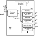
- FIG. 12 is a block diagram illustrating eNB 60 configured according to one aspect of the present disclosure.
- eNB 60 includes the structure, hardware, and components as illustrated for UE 105 of FIG. 2.
- eNB 60 includes controller/processor 240, which operates to execute logic or computer instructions stored in memory 242, as well as controlling the components of eNB 60 that provide the features and functionality of eNB 60.
- Wireless radios 1201a-t includes various components and hardware, as illustrated in FIG. 2 for eNB 105, including modulator/demodulators 232a-t, MIMO detector 236, receive processor 238, transmit processor 220, and TX MIMO processor 230.
- an eNB randomly selects a first precoder associated with a first transmission block.
- eNB 60 under control of controller/processor 240, executes UE-RS MIMO scheme 1202 stored in memory 242.
- the execution environment of executing UE-RS MIMO scheme 1202 determines whether the improved aspects of Scheme 1 or Scheme 2 are implemented by eNB 60.
- controller/processor 240 of transmission block 1204 eNB 60 may define a transmission block as a RB or a set of bundled RBs, or, in additional aspects of the present disclosure, a transmission block may also be a sub-RB.
- a sub-RB is a selection of contiguous REs within a RB.
- Each RB may include multiple sub-RB groups selected with different contiguous REs across subcarriers, OFDM symbols, or a combination of both.
- the sub-RB based transmission block operation may be used for a small size resource allocation (e.g., one or a limited #of RBs) .
- the threshold for selecting such a sub-RB scheme may be hard-coded, RRC configured, or even indicated in DCI.
- the eNB transmits UE-RS and data within the first transmission block, wherein the UE-RS and data are precoded using a first precoder.
- the UE-RS and data are precoded through execution of precoder 1203, stored in memory 242, into the selected group of contiguous REs of the RB.
- precoder 1203 stored in memory 242
- eNB 60 knows whether to precode both UE-RS and data using the same precoders, or to use different precoding for UE-RS and data.
- the eNB selects a next precoder associated with a next transmission block.
- the execution environment of UE-RS MIMO scheme 1202 and precoder 1203 direct eNB 60 to select the appropriate beamformer.
- the precoder, W (i sub_RB ) may change in each sub-RB group. Multiple different precoders may be used in transmission of UE-RS and data within the same RB, thus, improving diversity even in small or medium bandwidth allocations of Scheme 1.
- the eNB transmits UE-RS and data in the next transmission block, wherein the UE-RS and data are precoded using the next precoder.
- the UE-RS and data are transmitted via wireless radios 1201a-t and antennas 234a-t.
- W 1 can be fed back by a UE when configured for semi-open-loop MIMO operation or may be randomly selected from the predetermined codebook set when open-loop MIMO is configured without PMI feedback.
- FIGs. 5A and 5B are block diagrams illustrating resource blocks 500 and 501 having sub-RB-based transmission blocks according to aspects of the present disclosure.
- the performance of Scheme 1 with small/medium BW allocation can be improved by using a sub-RB level precoding bundling according to the various aspects of the present disclosure.
- resource block 500 in the FIG. 5A the 12 UE-RS tones per RB are divided into three frequency division multiplex (FDM) groups, each associated with one sub-RB transmission block, Sub-RB#0, Sub-RB#1, and Sub-RB#2.
- the random precoding is applied within each sub-RB transmission block and the precoder may change across the sub-RBs. That is:
- the partition of one RB into multiple sub-RBs may include other options, such as illustrated by resource block 501 in FIG. 5B, in which case the sub-RB transmission blocks have staggered grouping.
- resource block 501 is divided into six sub-RB-based transmission blocks, Sub-RB#0-Sub-RB#5.
- downlink resource allocation may also be changed from a per-RB to a per-sub-RB basis.
- the eNB may transmit UE-RS and data within the first transmission block via wireless radios 1201a-t and antennas 234a-t, wherein the UE-RS is precoded by executing precoder 1203 using the first precoder and the data is precoded by executing precoder 1203 using the first precoder and a layer permutation matrix stored at layer shifting matrix 1205, at alternative block 401b.
- alternative block 401b allows additional precoding of the data with the layer permutation matrix at layer shifting matrix 1205, which, when executed under control of controller/processor 240 that causes the data to be shifted by layers within the transmission channel via wireless radios 1201a-t and antennas 234a-t.
- Scheme 1 may be modified as follows:
- the matrix U (i) is an RE-level layer permutation matrix stored at layer shifting matrix 1205 in memory 242 that cyclically assigns the v beams formed by the matrix W (i RB ) to different layers within v continuous subcarriers.
- the eNB After selecting the next precoder associated with the next transmission block at block 402, the eNB, in the additional example illustrated in FIG. 4, would transmit the UE-RS and data within the next transmission block, wherein the UE-RS is precoded with the next precoder, while the data is again precoded not only with the next precoder but also using the layer permutation matrix, U (i) .
- FIGs. 6A and 6B are block diagrams illustrating transmission streams 600 and 601 of eNB 60 configured according to aspects of the present disclosure.
- eNB 60 transmits data without RE-level layer shifting
- eNB 60 uses random precoding with RE-level layer shift for data transmission.
- P7, P8, P9 and P10 are precoders for UE-RS port 7, 8, 9 and 10, while X0, X1, X2 and X3 are data symbols of the layers 0, 1, 2 and 3.
- eNB 60 uses the same precoder for the data symbols in four continuous subcarriers in which the diversity is obtained through the beamformer changing across RBs.
- eNB 60 With RE-level layer shift, as illustrated in transmission stream 601, eNB 60 cyclically assigns the four precoders to four layers for every four continuous subcarriers and RE-level frequency selectivity is achieved. With the layer shift, two codewords experience the same effective channel SINR for rank > 1 and CQI averaging may be achieved across all layers.
- FIG. 7 is a block diagram illustrating example blocks executed to implement one aspect of the present disclosure.
- an eNB obtains a first port virtualization matrix for mapping a predetermined number of antennas into a subset of virtualized antenna ports.
- the eNB transmits in a first transmission block a UE-RS precoded by executing precoder 1203 with the port virtualization matrix 1206 stored in memory 242.
- a modified Scheme 2 uses RE-level random precoding from precoder 1203 for increased frequency selectivity according to the following:
- W 1 (i RB ) is a port virtualization matrix 1206 with an orthogonal column vector which maps P antennas into 2 or 4 virtualized ports.
- W 1 (i RB ) may be used to precode UE-RS and may change on per RB or per RB bundling.
- W 1 (i RB ) can be constructed from a set of orthogonal DFT basis vector, e.g., for 2 –ports and for 4-ports, where u 1 and u 2 are the DFT vectors from the W 1 codebook set.
- the eNB precode data by executing precoder 1203, under control of controller/processor 240, using a random beamformer, where the random beamformer includes the first port virtualization matrix and a second precoding matrix selected from a set of precoding matrices associated with the subset of virtualized antenna ports, from UE-RS MIMO scheme 1202 and precoder 1203, and, at block 703, the eNB transmits the precoded data in the first transmission block via wireless radios 1201a-t and antennas 234a-t.
- the modified Scheme 2 uses RE-level random precoding for increased frequency selectivity further according to the following:
- the random beamformer W (i) W 1 (i RB ) W 2 (i) , where W 2 (i) is selected from the 2Tx/4Tx codebook of size 2 ⁇ v or 4 ⁇ v.
- rank 1 transmissions with transmit diversity of two layers may be extended to UE-RS-based operations using space frequency block coding (SFBC) .
- SFBC space frequency block coding
- W (i RB ) W 1 W 2 (i RB ) (Scheme 1) , or W 1 (i RB ) (Scheme 2) may be applied.
- Rank 1 transmissions with a single UE-RS port can be based on Scheme 1 with a sub-RB level bundling operation, e.g., same beamformer changed across sub-RB transmission blocks for UE-RS and data:
- FIG. 8 is a block diagram illustrating a resource block 80 considered for UE-RS based open-loop or semi-open-loop MIMO with SFBC block coding.
- an SFBC block e.g. two REs may not span across different OFDM symbols, or across more than three subcarriers in the frequency domain, or across two RBs. If there is an odd number of available PDSCH REs in a PRB, as in resource block 80, the symbol of the entire RB is skipped.
- the symbols 5, 6, 12 and 13 are unusable for PDSCH transmission which may greatly reduce the peak throughput.
- FIG. 9 is a block diagram illustrating eNB 60 configured according to one aspect of the present disclosure for mapping an SFBC block across two RBs 900 and 901 in the same bundling RB set 90.
- RB bundling may be applied for UE-RS
- the above SFBC block mapping restrictions can be relaxed so that an SFBC block can be mapped across two RBs 900 and 901 in the same bundling set 90 if there is an even number of resource elements for the OFDM symbol containing UE-RS in two continuous resource blocks assigned for transmission.
- OFDM symbols 902 and 903 there are an even number of resource elements in the two continuous resource blocks 900 and 901 assigned for transmission.
- sub-RB bundling operation for improvements to Scheme 1 is used for a small size resource allocation (e.g., one or a limited number of RBs) .
- the threshold for choosing such a sub-RB scheme may be hard-coded in a UE, RRC configured, or even indicated in downlink control information (DCI) .
- DCI downlink control information
- FIG. 10 is a block diagram illustrating example blocks executed to implement one aspect of the present disclosure for semi-open-loop MIMO. The example blocks of FIG. 10 will also be described with respect to UE 1100 as illustrated in FIG. 13.
- FIG. 13 is a block diagram illustrating UE 1100 configured according to one aspect of the present disclosure.
- UE 1100 includes the structure, hardware, and components as illustrated for UE 115 of FIG. 2.
- controller/processor 280 which operates to execute logic or computer instructions stored in memory 282, as well as controlling the components of UE 1100 that provide the features and functionality of UE 1100.
- UE 1100 under control of controller/processor 280, transmits and receives signals via wireless radios 1301a-r and antennas 252a-r.
- Wireless radios 1301a-r includes various components and hardware as illustrated in FIG. 2 for UE 115, including demodulator/modulators 254a-r, MIMO detector 256, receive processor 258, transmit processor 264, and TX MIMO processor 266.
- a UE measures a reference signal received from a base station.
- UE 1100 executes measurement logic 1302, stored in memory 282, under control of controller/processor 280.
- the UE determines a set of wideband and subband precoders associated with a configured antenna array.
- UE 1100 under control of controller/processor 280, determines the set of wideband and subband precoders within the execution environment of measurement logic 1302 and by accessing precoders 1305, stored in memory 282, for the configured antenna array of antennas 252a-r.
- the UE transmits a rank indicator via the wireless radios 1301a-r and antennas 252a-r, wherein the rank indicator corresponds to a number of useful layers in a transmission channel.
- UE 1100 measures the received signals by executing measurement logic 1302 and using the resulting measurements to generate the particular CSI report, through the execution environment of CSI Report Generator 1303.
- the UE transmits a PMI via wireless radios 1301a-r, and antennas 252a-r, wherein the PMI is associated with a wideband precoding matrix selected from a set of predetermined wideband precoders associated with a configured antenna array.
- the reported PMI which may be constrained by the reported RI, indicates the first PMI of the dual codebook.
- the UE transmits a CQI generated based on the measured reference signal, wherein the CQI is generated according to an assumption that precoder elements are cycled from a set of predetermined subband precoders.
- the predetermined subband precoders includes the W 2 codebook associated with the first PMI.
- the CQI can be either wideband or subband based on the configuration.
- one CQI is reported for two codewords.
- rank 1
- the UE may report a CQI for single port transmission and a delta CQI identifying the CQI difference between single port and transmit diversity. Otherwise, one CQI may be reported.
- the existing CSI reporting without PMI feedback may be reused except that CQI and RI are determined under assumption of the precoder cycling in both the first and second precoding matrix.
- the UE may skip reporting the PMI. Additionally, when the rank indicator is >4, the UE may skip reporting the PMI, and the CQI may be generated according to an assumption that precoder elements are cycled from a set of predetermined wideband precoders.
- FIG. 11A is a block diagram illustrating a UE 1100 and eNB 60 configured according to one aspect of the present disclosure.
- UE 1100 is configured to transmit CSI reporting 1101 for PUCCH Mode 1-1.
- UE 1100 send eNB 60 the first CSI report via wireless radios 1301a-r and antennas 252a-r, including RI, the second report including the first PMI, and the third report including a wideband CQI.
- the period of the third wideband CQI report may be N pd subframes, while the period of the first and second reports may be M RI N pd and H’ N pd subframes.
- M RI , N pd and H’ may be configured by the higher-layer signaling from eNB 60 and stored at periodicities 1304 in memory 282.
- the second and third reports are configured with the same reporting subframe offset which can be different from that of the first report.
- UE 1100 under control of controller/processor 280, will access the periodicities and offsets stored in periodicities 1304 when executing the CSI report generator 1303 to generate and send out the CSI reports.
- FIGs. 11B and 11C are block diagrams illustrating CSI reporting 1102 and 1103 between UE 1100 and eNB 60 configured according to aspects of the present disclosure.
- the period of the third report may be N pd subframes.
- the period of the first report may be M RI ⁇ H ⁇ N pd subframes.
- the open loop transmission schemes and associated UE-RS ports and layers are indicated by layer 1 (L1) signaling, as shown in Table 1 below, assuming total single user/multiple user layers no larger than four.
- L1 layer 1
- the first four code points with the value 0-3 are used to indicate the rank 1 transmission with single antenna port mapping. It can be used for both single user/multiple user transmission.
- different UEs can be distinguished by different UE-RS ports or by a scrambling identity of 0 and 1.
- the value of 6 of one codeword case it may be used for retransmission when the associated transport block is mapped to 2 layers in the initial transmission.
- the first code points with a value of 0 and 1 are used for rank 2 spatial multiplexing transmission with UE-RS ports 7-8.
- rank 3 transmission there may be two configurations, one for UE-RS ports 7-9 and the other for UE-RS ports 7-10. The first may be associated with Scheme 1 and the second may be associated with Scheme 2, where four virtualized ports may be used.
- UE-RS ports 7-10 may be used. It should be noted that the definition of UE-RS ports 7, 8, 9 and 10 may be same as that used for close-loop beamforming, e.g., based on an orthogonal cover code of length 2.
- the associated downlink control signaling design may be easily extended by using a 4-bit table corresponding to maximum of 16 code points instead of 8 code points.
- aspects of the present disclosure may include different implementations, such as through non-transitory computer-readable media, which, when code stored thereon is executed by one or more computers or processors performs the features and functionality of the aspects, and such as through apparatuses that have one or more processors and memory coupled to the processors, such that when instructions are executed, the apparatus may be configured to perform the features and functionality of the aspects.
- the following aspects represent statements that reflect the various aspects of the present disclosure in different formats from the claims filed herewith.
- the present disclosure comprises a first aspect, such as a non-transitory computer-readable medium having program code recorded thereon, the program code including:
- program code for causing a computer to randomly select a first precoder associated with a first transmission block, wherein the first transmission block includes one of: a first resource block, a first set of bundled resource blocks, or a first sub-resource block selected as a group of contiguous resource elements within a resource block;
- program code for causing the computer to transmit user equipment (UE) -specific reference signals (UE-RS) and data within the first transmission block, wherein the UE-RS and data are precoded using the first precoder;
- UE user equipment
- UE-RS user equipment -specific reference signals
- program code for causing the computer to select a next precoder associated with a next transmission block, wherein the next transmission block includes one of: a next resource block, a next set of bundled resource blocks, or a next sub-resource block selected as a next group of contiguous resource elements within the resource block; and
- program code for causing the computer to transmit the UE-RS and data in the next transmission block, wherein the UE-RS and data are precoded with a next precoder.
- the non-transitory computer-readable medium of a second aspect wherein the first precoder and the next precoder are based on a product of a wideband precoding matrix and a subband precoding matrix, wherein the subband precoding matrix is cyclically selected from a set of predetermined precoding matrices.
- the non-transitory computer-readable medium of a third aspect wherein the wideband precoding matrix is one of:
- the non-transitory computer-readable medium of a fourth aspect wherein the program code for causing the computer to transmit the UE-RS and data are executed at rank > 1, wherein the data is further precoded with a layer permutation matrix along with the first precoder and the next precoder; wherein the layer permutation matrix cyclically assigns each resulting transmission beam to a different layer within a predetermined number of continuous subcarriers.
- the non-transitory computer-readable medium of a fifth aspect wherein the program code for causing the computer to transmit the UE-RS and data are executed at rank 1 and configured with transmit diversity, wherein the data is further precoded with a space frequency block coding matrix.
- non-transitory computer-readable medium of a sixth aspect further includes:
- program code for causing the computer to determine the first transmission block is the first set of bundled resource blocks
- program code for causing the computer to determine presence of an even number of resource elements for the data in two continuous resource blocks of the first set of bundled resource blocks;
- program code for causing the computer to map the data precoded with the space frequency block coding matrix across two continuous resource blocks of the first set of bundled resource blocks.
- non-transitory computer-readable medium of a seventh aspect further includes:
- program code for causing the computer to transmit an indication of transmission scheme, wherein the indication of transmission scheme is associated with at least one or more UE-RS ports, the number of useful layers, a mode of transmit diversity or spatial multiplexing for data transmission.
- non-transitory computer-readable medium of an eighth aspect further includes:
- program code for causing the computer to determine the first transmission block and the next transmission block based on at least a total number of scheduled resource blocks, wherein a sub-resource block is selected only for a small size resource allocation.
- the present disclosure comprises a ninth aspect which further comprises the non-transitory computer-readable medium of any combination the first through eighth aspects.
- the present disclosure comprises a tenth aspect, such as a non-transitory computer-readable medium having program code recorded thereon, the program includes:
- program code for causing a computer to obtain a first port virtualization matrix for mapping a predetermined number of antennas into a subset of virtualized antenna ports;
- program code for causing the computer to transmit in a first transmission block a user equipment (UE) -specific reference signal (UE-RS) precoded with the first port virtualization matrix, wherein the first transmission block is one of: a first resource block or a first set of bundled resource blocks;
- UE user equipment
- UE-RS user specific reference signal
- program code for causing the computer to precode data using a random beamformer, wherein the random beamformer includes the first port virtualization matrix and a second precoding matrix selected from a set of precoding matrices associated with the subset of virtualized antenna ports; and
- program code for causing the computer to transmit the precoded data in the first transmission block.
- the non-transitory computer-readable medium of an eleventh aspect wherein the program code for causing the computer to obtain the port virtualization matrix includes one of:
- program code for causing the computer to receive the port virtualization matrix from a UE;
- program code for causing the computer to randomly select a set of orthogonal DFT basis vectors from a predetermined wideband codebook for the port virtualization matrix.
- the non-transitory computer-readable medium of an twelfth aspect wherein the program code for causing the computer to transmit the UE-RS and data are executed at rank > 1, wherein the data is further precoded with a cyclic delay diversity matrix and a discrete Fourier transform (DFT) rotational matrix along with the random beamformer; wherein the cyclic delay diversity matrix and the DFT rotation matrix cyclically assign each resulting transmission beam to a different layer within a predetermined number of continuous subcarriers.
- DFT discrete Fourier transform
- the non-transitory computer-readable medium of a thirteenth aspect wherein the program code for causing the computer to transmit the UE-RS and data are executed at rank 1 and configured with transmit diversity, wherein the data is further precoded with a space frequency block coding matrix.
- the non-transitory computer-readable medium of a fourteenth aspect further includes:
- program code for causing the computer to determine the first transmission block is the first set of bundled resource blocks
- program code for causing the computer to determine presence of an even number of resource elements for the data in two continuous resource blocks of the first set of bundled resource blocks;
- program code for causing the computer to map the data precoded with the space frequency block coding matrix across two resource blocks of the first set of bundled resource blocks.
- the non-transitory computer-readable medium of a fifteenth aspect further includes:
- program code for causing the computer to transmit an indication of transmission scheme, wherein the indication of transmission scheme is associated with at least one or more UE-RS ports, the number of useful layers, a mode of transmit diversity or spatial multiplexing for data transmission.
- the present disclosure comprises a sixteenth aspect which further comprises the non-transitory computer-readable medium of any combination the tenth through fifteenth aspects.
- the present disclosure comprises a seventeenth aspect, such as a non-transitory computer-readable medium having program code recorded thereon, the program code comprising:
- program code for causing a computer to measure a reference signal received from a base station
- program code for causing the computer to determine a set of wideband and subband precoders associated with a configured antenna array
- program code for causing the computer to transmit a rank indicator, wherein the rank indicator corresponds to a number of useful layers in a transmission channel;
- program code for causing the computer to transmit a precoding matrix indicator (PMI) , wherein the PMI is associated with a wideband precoding matrix selected from a set of predetermined wideband precoders; and
- PMI precoding matrix indicator
- program code for causing the computer to transmit a channel quality indicator (CQI) generated based on the measured reference signal, wherein the channel quality indicator is generated according to an assumption that precoder elements are cycled from a set of predetermined subband precoders.
- CQI channel quality indicator
- the CQI includes a single CQI when the rank indicator is > 1, and
- the CQI includes a first CQI for single port transmissions and a second CQI when transmit diversity is supported, wherein the second CQI includes a difference between the first CQI and a diversity CQI for the transmit diversity.
- the non-transitory computer-readable medium of a nineteenth aspect wherein the PMI is not reported when the rank indicator is > 4, wherein the CQI is generated according to an assumption that precoder elements are cycled from a set of predetermined wideband precoders.
- non-transitory computer-readable medium of a twentieth aspect further includes:
- program code for causing the computer to receive from the base station configuration of a first, second, and third reporting parameters, wherein the rank indicator is transmitted according to a first periodicity, the PMI is transmitted according to a second periodicity, and the CQI is transmitted according to a third periodicity, wherein the first, second, and third periodicities are based on one or more of the first, second, and third reporting parameters.
- the present disclosure comprises a twenty-first aspect which further comprises the non-transitory computer-readable medium of any combination the seventeenth through twentieth aspects.
- the present disclosure comprises a twenty-second aspect, such as an apparatus configured for wireless communication, the apparatus comprising:
- the at least one processor is configured:
- the first transmission block includes one of: a first resource block, a first set of bundled resource blocks, or a first sub-resource block selected as a group of contiguous resource elements within a resource block;
- UE user equipment
- UE-RS user equipment -specific reference signals
- next transmission block includes one of: a next resource block, a next set of bundled resource blocks, or a next sub-resource block selected as a next group of contiguous resource elements within the resource block;
- the UE-RS and data are precoded with a next precoder.
- the non-transitory computer-readable medium of a twenty-third aspect wherein the first precoder and the next precoder are based on a product of a wideband precoding matrix and a subband precoding matrix, wherein the subband precoding matrix is cyclically selected from a set of predetermined precoding matrices.
- the non-transitory computer-readable medium of a twenty-fourth aspect wherein the wideband precoding matrix is one of:
- the non-transitory computer-readable medium of a twenty-fifth aspect wherein the configuration of the at least one processor to transmit the UE-RS and data are performed at rank > 1, wherein the data is further precoded with a layer permutation matrix along with the first precoder and the next precoder; wherein the layer permutation matrix cyclically assigns each resulting transmission beam to a different layer within a predetermined number of continuous subcarriers.
- the non-transitory computer-readable medium of a twenty-sixth aspect wherein the configuration of the at least one processor to transmit the UE-RS and data are performed at rank 1 and configured with transmit diversity, wherein the data is further precoded with a space frequency block coding matrix.
- the non-transitory computer-readable medium of a twenty-seventh aspect further including configuration of the at least one processor:
- the first transmission block is the first set of bundled resource blocks
- the non-transitory computer-readable medium of a twenty-eighth aspect further including configuration of the at least one processor to transmit an indication of transmission scheme, wherein the indication of transmission scheme is associated with at least one or more UE-RS ports, the number of useful layers, a mode of transmit diversity or spatial multiplexing for data transmission.
- the non-transitory computer-readable medium of a twenty-ninth aspect further including configuration of the at least one processor to determine the first transmission block and the next transmission block based on at least a total number of scheduled resource blocks, wherein a sub-resource block is selected only for a small size resource allocation.
- the present disclosure comprises a thirtieth aspect which further comprises the non-transitory computer-readable medium of any combination the twenty-second through twenty-ninth aspects.
- the present disclosure comprises a thirty-first aspect, such as an apparatus configured for wireless communication, the apparatus comprising:
- the at least one processor is configured:
- UE user equipment
- UE-RS user equipment -specific reference signal
- the random beamformer includes the first port virtualization matrix and a second precoding matrix selected from a set of precoding matrices associated with the subset of virtualized antenna ports;
- the non-transitory computer-readable medium of a thirty-second aspect wherein the configuration of the at least one processor to obtain the port virtualization matrix includes configuration of the at least one processor to one of:
- the non-transitory computer-readable medium of a thirty-third aspect wherein the configuration of the at least one processor to transmit the UE-RS and data are performed at rank > 1, wherein the data is further precoded with a cyclic delay diversity matrix and a discrete Fourier transform (DFT) rotational matrix along with the random beamformer; wherein the cyclic delay diversity matrix and the DFT rotation matrix cyclically assign each resulting transmission beam to a different layer within a predetermined number of continuous subcarriers.
- DFT discrete Fourier transform
- the non-transitory computer-readable medium of a thirty-fourth aspect wherein the configuration of the at least one processor to transmit the UE-RS and data are performed at rank 1 and configured with transmit diversity, wherein the data is further precoded with a space frequency block coding matrix.
- non-transitory computer-readable medium of a thirty-fifth aspect further including configuration of the at least one processor:
- the first transmission block is the first set of bundled resource blocks
- the non-transitory computer-readable medium of a thirty-sixth aspect further including configuration of the at least one processor to transmit an indication of transmission scheme, wherein the indication of transmission scheme is associated with at least one or more UE-RS ports, the number of useful layers, a mode of transmit diversity or spatial multiplexing for data transmission.
- the present disclosure comprises a thirty-seventh aspect which further comprises the non-transitory computer-readable medium of any combination the thirty-first through thirty-sixth aspects.
- the present disclosure comprises a thirty-eighth aspect, such as an apparatus configured for wireless communication, the apparatus comprising:
- the at least one processor is configured:
- the rank indicator corresponds to a number of useful layers in a transmission channel
- PMI precoding matrix indicator
- CQI channel quality indicator
- the non-transitory computer-readable medium of a thirty-ninth aspect Based on the thirty-eighth aspect, the non-transitory computer-readable medium of a thirty-ninth aspect,
- the CQI includes a single CQI when the rank indicator is > 1, and
- the CQI includes a first CQI for single port transmissions and a second CQI when transmit diversity is supported, wherein the second CQI includes a difference between the first CQI and a diversity CQI for the transmit diversity.
- the non-transitory computer-readable medium of a fortieth aspect wherein the PMI is not reported when the rank indicator is > 4, wherein the CQI is generated according to an assumption that precoder elements are cycled from a set of predetermined wideband precoders.
- the non-transitory computer-readable medium of a forty-first aspect further including configuration of the at least one processor to receive from the base station configuration of a first, second, and third reporting parameters, wherein the rank indicator is transmitted according to a first periodicity, the PMI is transmitted according to a second periodicity, and the CQI is transmitted according to a third periodicity, wherein the first, second, and third periodicities are based on one or more of the first, second, and third reporting parameters.
- the present disclosure comprises a forty-second aspect which further comprises the non-transitory computer-readable medium of any combination the thirty-eighth through forty-first aspects.
- the functional blocks and modules described herein may comprise processors, electronics devices, hardware devices, electronics components, logical circuits, memories, software codes, firmware codes, etc., or any combination thereof.
- DSP digital signal processor
- ASIC application specific integrated circuit
- FPGA field programmable gate array
- a general-purpose processor may be a microprocessor, but in the alternative, the processor may be any conventional processor, controller, microcontroller, or state machine.
- a processor may also be implemented as a combination of computing devices, e.g., a combination of a DSP and a microprocessor, a plurality of microprocessors, one or more microprocessors in conjunction with a DSP core, or any other such configuration.
- a software module may reside in RAM memory, flash memory, ROM memory, EPROM memory, EEPROM memory, registers, hard disk, a removable disk, a CD-ROM, or any other form of storage medium known in the art.
- An exemplary storage medium is coupled to the processor such that the processor can read information from, and write information to, the storage medium.
- the storage medium may be integral to the processor.
- the processor and the storage medium may reside in an ASIC.
- the ASIC may reside in a user terminal.
- the processor and the storage medium may reside as discrete components in a user terminal.
- the functions described may be implemented thorugh computer-executable instructions in hardware, software, firmware, or any combination thereof. If implemented in software, the functions may be stored on or transmitted over as one or more instructions or code on a computer-readable medium.
- Computer-readable media includes both computer storage media and communication media including any medium that facilitates transfer of a computer program from one place to another. Computer-readable storage media may be any available media that can be accessed by a general purpose or special purpose computer.
- such computer-readable media can comprise RAM, ROM, EEPROM, CD-ROM or other optical disk storage, magnetic disk storage or other magnetic storage devices, or any other medium that can be used to carry or store desired program code means in the form of instructions or data structures and that can be accessed by a general-purpose or special-purpose computer, or a general-purpose or special-purpose processor.
- a connection may be properly termed a computer-readable medium.
- the software is transmitted from a website, server, or other remote source using a coaxial cable, fiber optic cable, twisted pair, or digital subscriber line (DSL) , then the coaxial cable, fiber optic cable, twisted pair, or DSL, are included in the definition of medium.
- DSL digital subscriber line
- Disk and disc includes compact disc (CD) , laser disc, optical disc, digital versatile disc (DVD) , floppy disk and blu-ray disc where disks usually reproduce data magnetically, while discs reproduce data optically with lasers. Combinations of the above should also be included within the scope of computer-readable media.
- the term “and/or, ” when used in a list of two or more items means that any one of the listed items can be employed by itself, or any combination of two or more of the listed items can be employed.
- the composition can contain A alone; B alone; C alone; A and B in combination; A and C in combination; B and C in combination; or A, B, and C in combination.
Landscapes
- Engineering & Computer Science (AREA)
- Signal Processing (AREA)
- Computer Networks & Wireless Communication (AREA)
- Physics & Mathematics (AREA)
- Discrete Mathematics (AREA)
- General Physics & Mathematics (AREA)
- Mathematical Physics (AREA)
- Mobile Radio Communication Systems (AREA)
- Radio Transmission System (AREA)
Priority Applications (8)
| Application Number | Priority Date | Filing Date | Title |
|---|---|---|---|
| PCT/CN2016/078312 WO2017166287A1 (en) | 2016-04-01 | 2016-04-01 | Ue-rs-based open-loop and semi-open-loop mimo |
| CN201780020753.0A CN108886434B (zh) | 2016-04-01 | 2017-03-22 | 基于ue-rs的开环以及半开环mimo |
| US16/078,526 US10868594B2 (en) | 2016-04-01 | 2017-03-22 | UE-RS-based open-loop and semi-open-loop MIMO |
| BR112018069805-9A BR112018069805B1 (pt) | 2016-04-01 | 2017-03-22 | Método de comunicação sem fio, aparelho configurado para comunicação sem fio, e, memória legível por computador |
| PCT/CN2017/077674 WO2017167092A1 (en) | 2016-04-01 | 2017-03-22 | Ue-rs-based open-loop and semi-open-loop mimo |
| EP17773122.1A EP3437225A4 (en) | 2016-04-01 | 2017-03-22 | OPEN LOOP AND SEMI-OPEN LOOP MIMO BASED ON EU RS |
| JP2018550411A JP7126948B2 (ja) | 2016-04-01 | 2017-03-22 | Ue-rsベースの開ループおよび半開ループmimo |
| US17/092,764 US11336344B2 (en) | 2016-04-01 | 2020-11-09 | UE-RS-based open-loop and semi-open-loop MIMO |
Applications Claiming Priority (1)
| Application Number | Priority Date | Filing Date | Title |
|---|---|---|---|
| PCT/CN2016/078312 WO2017166287A1 (en) | 2016-04-01 | 2016-04-01 | Ue-rs-based open-loop and semi-open-loop mimo |
Publications (1)
| Publication Number | Publication Date |
|---|---|
| WO2017166287A1 true WO2017166287A1 (en) | 2017-10-05 |
Family
ID=59962506
Family Applications (2)
| Application Number | Title | Priority Date | Filing Date |
|---|---|---|---|
| PCT/CN2016/078312 Ceased WO2017166287A1 (en) | 2016-04-01 | 2016-04-01 | Ue-rs-based open-loop and semi-open-loop mimo |
| PCT/CN2017/077674 Ceased WO2017167092A1 (en) | 2016-04-01 | 2017-03-22 | Ue-rs-based open-loop and semi-open-loop mimo |
Family Applications After (1)
| Application Number | Title | Priority Date | Filing Date |
|---|---|---|---|
| PCT/CN2017/077674 Ceased WO2017167092A1 (en) | 2016-04-01 | 2017-03-22 | Ue-rs-based open-loop and semi-open-loop mimo |
Country Status (5)
| Country | Link |
|---|---|
| US (2) | US10868594B2 (enExample) |
| EP (1) | EP3437225A4 (enExample) |
| JP (1) | JP7126948B2 (enExample) |
| CN (1) | CN108886434B (enExample) |
| WO (2) | WO2017166287A1 (enExample) |
Cited By (1)
| Publication number | Priority date | Publication date | Assignee | Title |
|---|---|---|---|---|
| WO2023002236A1 (en) * | 2021-07-22 | 2023-01-26 | Telefonaktiebolaget Lm Ericsson (Publ) | Diversity-aware truncated layer selection for low complexity beamforming |
Families Citing this family (11)
| Publication number | Priority date | Publication date | Assignee | Title |
|---|---|---|---|---|
| WO2017166287A1 (en) | 2016-04-01 | 2017-10-05 | Qualcomm Incorporated | Ue-rs-based open-loop and semi-open-loop mimo |
| US10673500B2 (en) * | 2018-06-25 | 2020-06-02 | Qualcomm Incorporated | Hybrid closed-loop multiple-input multiple-output and transparent diversity schemes |
| US11569886B2 (en) * | 2019-04-01 | 2023-01-31 | Qualcomm Incorporated | Network-sensitive transmit diversity scheme |
| CN114946148B (zh) * | 2020-01-31 | 2024-07-12 | 高通股份有限公司 | 下行链路控制信息中的预编码器指示 |
| CN113497645B (zh) * | 2020-04-03 | 2022-11-08 | 大唐移动通信设备有限公司 | 一种预编码矩阵指示、确定方法、设备及介质 |
| EP4193473A4 (en) * | 2020-08-07 | 2024-05-08 | Apple Inc. | HIERARCHICAL CHANNEL STATUS INFORMATION (CSI) FEEDBACK WITH PARTIAL RECIPROCITY IN A NETWORK |
| CN116134740B (zh) | 2020-08-07 | 2025-08-26 | 苹果公司 | 具有与用户装备(ue)的部分互易性的分级信道状态信息(csi)反馈 |
| US12063082B2 (en) * | 2022-05-23 | 2024-08-13 | Qualcomm Incorporated | Pseudo singular value decomposition (SVD) precoder |
| US12088372B2 (en) * | 2022-09-09 | 2024-09-10 | Qualcomm Incorporated | Demodulation and CSF for 8Rx antennas |
| GB2627237A (en) * | 2023-02-16 | 2024-08-21 | Nokia Technologies Oy | Devices, methods and apparatuses for spatial adaptation |
| WO2025063615A1 (ko) * | 2023-09-18 | 2025-03-27 | 엘지전자 주식회사 | 상향링크 채널의 송수신을 위한 방법 및 장치 |
Citations (3)
| Publication number | Priority date | Publication date | Assignee | Title |
|---|---|---|---|---|
| CN102916766A (zh) * | 2011-08-05 | 2013-02-06 | 华为技术有限公司 | 反馈、获取信道状态信息的方法和装置 |
| US20130163530A1 (en) * | 2011-12-22 | 2013-06-27 | Qualcomm Incorporated | Reference signals design for time tracking in lte-a |
| US20150117249A1 (en) * | 2012-07-10 | 2015-04-30 | Huawei Technologies Co., Ltd. | Method for acquiring channel quality indicator, user equipment, evolved node b and system |
Family Cites Families (13)
| Publication number | Priority date | Publication date | Assignee | Title |
|---|---|---|---|---|
| KR100754795B1 (ko) * | 2004-06-18 | 2007-09-03 | 삼성전자주식회사 | 직교주파수분할다중 시스템에서 주파수 공간 블록 부호의부호화/복호화 장치 및 방법 |
| US8923143B2 (en) | 2009-06-29 | 2014-12-30 | Qualcomm Incorporated | Open loop channel reporting in a wireless communication system |
| US8917677B2 (en) * | 2010-04-14 | 2014-12-23 | Samsung Electronics Co., Ltd. | Systems and methods for bundling resource blocks in a wireless communication system |
| CN102244559A (zh) | 2010-05-12 | 2011-11-16 | 华为技术有限公司 | 一种预编码信息的发送和接收方法及装置 |
| JP2012100254A (ja) | 2010-10-06 | 2012-05-24 | Marvell World Trade Ltd | Pucchフィードバックのためのコードブックサブサンプリング |
| EP2673892A4 (en) | 2011-02-07 | 2016-09-14 | Intel Corp | COPHASING EMISSIONS FROM MULTIPLE INFRASTRUCTURE N UDS |
| US8842628B2 (en) * | 2011-09-12 | 2014-09-23 | Blackberry Limited | Enhanced PDCCH with transmit diversity in LTE systems |
| US9247537B2 (en) * | 2011-11-16 | 2016-01-26 | Samsung Electronics Co., Ltd. | Method and apparatus for transmitting control information in wireless communication systems |
| CN107317614B (zh) | 2013-12-31 | 2020-09-04 | 上海华为技术有限公司 | 一种信道状态信息测量、参考信号的发送方法和装置 |
| KR102319700B1 (ko) | 2014-05-02 | 2021-11-01 | 삼성전자 주식회사 | 무선 통신 시스템에서 선택적 채널 피드백 방법 및 장치 |
| US9680535B2 (en) * | 2015-01-16 | 2017-06-13 | Samsung Electronics Co., Ltd. | Method and apparatus for reduced feedback FD-MIMO |
| CN108292942B (zh) * | 2015-10-04 | 2021-07-13 | Lg 电子株式会社 | 在无线通信系统中发送和接收信道状态信息的方法及其设备 |
| WO2017166287A1 (en) | 2016-04-01 | 2017-10-05 | Qualcomm Incorporated | Ue-rs-based open-loop and semi-open-loop mimo |
-
2016
- 2016-04-01 WO PCT/CN2016/078312 patent/WO2017166287A1/en not_active Ceased
-
2017
- 2017-03-22 EP EP17773122.1A patent/EP3437225A4/en active Pending
- 2017-03-22 CN CN201780020753.0A patent/CN108886434B/zh active Active
- 2017-03-22 JP JP2018550411A patent/JP7126948B2/ja active Active
- 2017-03-22 US US16/078,526 patent/US10868594B2/en active Active
- 2017-03-22 WO PCT/CN2017/077674 patent/WO2017167092A1/en not_active Ceased
-
2020
- 2020-11-09 US US17/092,764 patent/US11336344B2/en active Active
Patent Citations (3)
| Publication number | Priority date | Publication date | Assignee | Title |
|---|---|---|---|---|
| CN102916766A (zh) * | 2011-08-05 | 2013-02-06 | 华为技术有限公司 | 反馈、获取信道状态信息的方法和装置 |
| US20130163530A1 (en) * | 2011-12-22 | 2013-06-27 | Qualcomm Incorporated | Reference signals design for time tracking in lte-a |
| US20150117249A1 (en) * | 2012-07-10 | 2015-04-30 | Huawei Technologies Co., Ltd. | Method for acquiring channel quality indicator, user equipment, evolved node b and system |
Cited By (1)
| Publication number | Priority date | Publication date | Assignee | Title |
|---|---|---|---|---|
| WO2023002236A1 (en) * | 2021-07-22 | 2023-01-26 | Telefonaktiebolaget Lm Ericsson (Publ) | Diversity-aware truncated layer selection for low complexity beamforming |
Also Published As
| Publication number | Publication date |
|---|---|
| WO2017167092A1 (en) | 2017-10-05 |
| JP7126948B2 (ja) | 2022-08-29 |
| JP2019518346A (ja) | 2019-06-27 |
| US20210058120A1 (en) | 2021-02-25 |
| EP3437225A4 (en) | 2020-02-19 |
| US11336344B2 (en) | 2022-05-17 |
| BR112018069805A2 (pt) | 2019-01-29 |
| US10868594B2 (en) | 2020-12-15 |
| EP3437225A1 (en) | 2019-02-06 |
| CN108886434A (zh) | 2018-11-23 |
| CN108886434B (zh) | 2022-03-25 |
| US20190089429A1 (en) | 2019-03-21 |
Similar Documents
| Publication | Publication Date | Title |
|---|---|---|
| US11581933B2 (en) | Energy efficient CSI measurement for FD-MIMO | |
| US11336344B2 (en) | UE-RS-based open-loop and semi-open-loop MIMO | |
| US20220150017A1 (en) | Csi feedback processing and reporting for eb/fd-mimo | |
| US12166547B2 (en) | Enhanced hybrid CSI-RS for FD-MIMO | |
| US12113733B2 (en) | Processing relaxation for aperiodic CSI-RS | |
| US11177862B2 (en) | Hybrid class B FD-MIMO | |
| WO2017190356A1 (en) | Enhancement of linear combination codebooks in fd-mimo | |
| CA3016260A1 (en) | Channel covariance feedback for enhanced fd-mimo | |
| AU2017310826A1 (en) | Signaling for interlaced FDM uplink DMRS | |
| WO2017049599A1 (en) | Csi reporting for beamformed csi-rs based fd-mimo | |
| WO2017166288A1 (en) | Csi-rs design for larger number of antenna ports for efd-mimo | |
| BR112018069805B1 (pt) | Método de comunicação sem fio, aparelho configurado para comunicação sem fio, e, memória legível por computador |
Legal Events
| Date | Code | Title | Description |
|---|---|---|---|
| NENP | Non-entry into the national phase |
Ref country code: DE |
|
| 121 | Ep: the epo has been informed by wipo that ep was designated in this application |
Ref document number: 16896066 Country of ref document: EP Kind code of ref document: A1 |
|
| 122 | Ep: pct application non-entry in european phase |
Ref document number: 16896066 Country of ref document: EP Kind code of ref document: A1 |