WO2017166201A1 - Signal transmitting method for terminal apparatus, and terminal apparatus - Google Patents

Signal transmitting method for terminal apparatus, and terminal apparatus Download PDF

Info

Publication number
WO2017166201A1
WO2017166201A1 PCT/CN2016/078110 CN2016078110W WO2017166201A1 WO 2017166201 A1 WO2017166201 A1 WO 2017166201A1 CN 2016078110 W CN2016078110 W CN 2016078110W WO 2017166201 A1 WO2017166201 A1 WO 2017166201A1
Authority
WO
WIPO (PCT)
Prior art keywords
terminal device
antenna
antennas
signal
downlink
Prior art date
Application number
PCT/CN2016/078110
Other languages
French (fr)
Chinese (zh)
Inventor
陈小红
Original Assignee
华为技术有限公司
Priority date (The priority date is an assumption and is not a legal conclusion. Google has not performed a legal analysis and makes no representation as to the accuracy of the date listed.)
Filing date
Publication date
Application filed by 华为技术有限公司 filed Critical 华为技术有限公司
Priority to US16/085,586 priority Critical patent/US11115135B2/en
Priority to EP16895981.5A priority patent/EP3410768B1/en
Priority to CN201680080577.5A priority patent/CN108702639B/en
Priority to KR1020187027168A priority patent/KR102138112B1/en
Priority to JP2018551201A priority patent/JP6732228B2/en
Priority to PCT/CN2016/078110 priority patent/WO2017166201A1/en
Publication of WO2017166201A1 publication Critical patent/WO2017166201A1/en

Links

Images

Classifications

    • HELECTRICITY
    • H04ELECTRIC COMMUNICATION TECHNIQUE
    • H04BTRANSMISSION
    • H04B17/00Monitoring; Testing
    • H04B17/0082Monitoring; Testing using service channels; using auxiliary channels
    • HELECTRICITY
    • H04ELECTRIC COMMUNICATION TECHNIQUE
    • H04BTRANSMISSION
    • H04B17/00Monitoring; Testing
    • H04B17/30Monitoring; Testing of propagation channels
    • H04B17/391Modelling the propagation channel
    • H04B17/3912Simulation models, e.g. distribution of spectral power density or received signal strength indicator [RSSI] for a given geographic region
    • HELECTRICITY
    • H04ELECTRIC COMMUNICATION TECHNIQUE
    • H04BTRANSMISSION
    • H04B17/00Monitoring; Testing
    • H04B17/0082Monitoring; Testing using service channels; using auxiliary channels
    • H04B17/0085Monitoring; Testing using service channels; using auxiliary channels using test signal generators
    • HELECTRICITY
    • H04ELECTRIC COMMUNICATION TECHNIQUE
    • H04BTRANSMISSION
    • H04B17/00Monitoring; Testing
    • H04B17/10Monitoring; Testing of transmitters
    • H04B17/101Monitoring; Testing of transmitters for measurement of specific parameters of the transmitter or components thereof
    • H04B17/102Power radiated at antenna
    • HELECTRICITY
    • H04ELECTRIC COMMUNICATION TECHNIQUE
    • H04BTRANSMISSION
    • H04B17/00Monitoring; Testing
    • H04B17/10Monitoring; Testing of transmitters
    • H04B17/11Monitoring; Testing of transmitters for calibration
    • H04B17/12Monitoring; Testing of transmitters for calibration of transmit antennas, e.g. of the amplitude or phase
    • HELECTRICITY
    • H04ELECTRIC COMMUNICATION TECHNIQUE
    • H04BTRANSMISSION
    • H04B17/00Monitoring; Testing
    • H04B17/10Monitoring; Testing of transmitters
    • H04B17/15Performance testing
    • H04B17/19Self-testing arrangements
    • HELECTRICITY
    • H04ELECTRIC COMMUNICATION TECHNIQUE
    • H04BTRANSMISSION
    • H04B17/00Monitoring; Testing
    • H04B17/30Monitoring; Testing of propagation channels
    • H04B17/391Modelling the propagation channel
    • H04B17/3911Fading models or fading generators
    • HELECTRICITY
    • H04ELECTRIC COMMUNICATION TECHNIQUE
    • H04BTRANSMISSION
    • H04B7/00Radio transmission systems, i.e. using radiation field
    • H04B7/02Diversity systems; Multi-antenna system, i.e. transmission or reception using multiple antennas
    • H04B7/04Diversity systems; Multi-antenna system, i.e. transmission or reception using multiple antennas using two or more spaced independent antennas
    • H04B7/0413MIMO systems
    • HELECTRICITY
    • H04ELECTRIC COMMUNICATION TECHNIQUE
    • H04WWIRELESS COMMUNICATION NETWORKS
    • H04W24/00Supervisory, monitoring or testing arrangements
    • H04W24/06Testing, supervising or monitoring using simulated traffic

Definitions

  • the present application relates to the field of communications technologies, and in particular, to a signal transmitting method and a terminal device of a terminal device.
  • MIMO Multiple Input Multiple Output
  • LTE Long Term Evolution
  • LTE-Advanced Enhanced LTE
  • WiMAX Worldwide Interoperability for Microwave Access
  • OTA MIMO Over The Air
  • test methods for MIMO OTA testing of terminal equipment include: multi-probe darkroom test method, radiation two-stage test method, reverberation room test method (or reverberation chamber + channel simulator test method).
  • the embodiment of the invention provides a method for transmitting a signal of a terminal device and a terminal device, which are used to solve the problem that the terminal device that can measure the complex pattern does not exist in the prior art.
  • an embodiment of the present invention provides a signal sending method of a terminal device.
  • the method includes: the terminal device can generate a tone signal of a set frequency point, and after generating the tone signal, Transmitting the tone signal through a set antenna in the terminal device, wherein the set antenna is a receive antenna or a transmit antenna in the terminal device.
  • the setting antenna may be any one of a plurality of receiving antennas and a plurality of transmitting antennas in the terminal device, and the set frequency point may be preset by the terminal device or set by a user.
  • the antenna complex pattern measurement system of the terminal device can transmit the setting through each of the receiving antennas or the transmitting antenna through the terminal device.
  • the frequency of the tone signal accurately measures the complex pattern of each antenna in the terminal device, and when the MIMO OTA performance test is performed on the terminal device according to the complex pattern of each antenna in the terminal device, Get accurate measurement results.
  • the tone signal is a monotone continuous wave signal of constant amplitude.
  • the tone signal of the set frequency point sent by the terminal device is a monotone continuous wave signal with a constant amplitude, so that the accuracy of the complex pattern of each antenna measured subsequently can be ensured.
  • the method before the terminal device sends the tone signal through the setting antenna, the method further includes:
  • the terminal device opens an antenna selection switch of the set antenna, and turns off an antenna selection switch of a receiving antenna and a transmitting antenna other than the set antenna.
  • the antenna complex pattern measurement system of the terminal device measures the complex pattern of each antenna of the terminal device
  • the complex pattern of the multiple antennas cannot be simultaneously measured, and only the plurality of antennas of the terminal device can be measured in sequence.
  • Direction map. Therefore, the terminal device can sequentially adjust the set antenna in the above manner, so that the antenna complex pattern measurement system of the terminal device can measure the complex pattern of each antenna of the terminal device.
  • an embodiment of the present invention further provides an antenna complex pattern measurement system for a terminal device, where the system includes a terminal device and a first signal analyzer, where
  • a terminal device configured to sequentially transmit a tone signal through each of the plurality of receiving antennas in the terminal device according to a setting sequence
  • the first signal analyzer is configured to: when the terminal device transmits the tone signal through any one of the receiving antennas, perform the following operations on the receiving antenna:
  • the complex pattern of the receiving antenna is obtained based on the amplitude and phase in each of the three-dimensional radiation spheres on the I and Q paths measured for the receiving antenna.
  • the first signal analyzer can directly and accurately determine the complex pattern of each receiving antenna in the black box mode of the terminal device.
  • the channel emulator can simulate the signal transmission scenario of the terminal device in different orientations according to the complex pattern of each receiving antenna, thereby ensuring the
  • the base station simulator can finally get the throughput when the terminal devices of the downlink are in different orientations.
  • the first signal analyzer can directly and accurately determine the complex pattern of each receiving antenna in the black box mode of the terminal device.
  • the channel emulator can simulate the signal transmission scenario of the terminal device in different orientations according to the complex pattern of each receiving antenna, thereby ensuring the The base station simulator can finally get the throughput when the terminal devices of the downlink are in different orientations.
  • the first signal analyzer is further configured to:
  • the first signal analyzer can also accurately determine the antenna envelope correlation coefficient of any two receiving antennas of the terminal device in the black box mode.
  • an embodiment of the present invention further provides an antenna complex pattern measurement system for a terminal device, where the system includes a terminal device and a third signal analyzer, where
  • a terminal device configured to sequentially transmit a tone signal through each of the plurality of transmit antennas in the terminal device according to a set sequence
  • a third signal analyzer configured to: when the terminal device transmits the tone signal through any one of the transmitting antennas, perform the following operations on the transmitting antenna:
  • the complex pattern of the transmitting antenna is obtained based on the amplitude and phase in each of the three-dimensional radiation spheres on the I and Q paths measured for the transmitting antenna.
  • the third signal analyzer can directly and accurately determine the complex pattern of each transmitting antenna in the black box mode of the terminal device.
  • the channel emulator can simulate the signal transmission scenario of the terminal device in different orientations according to the complex pattern of each transmit antenna, thereby ensuring the The base station simulator can ultimately obtain the throughput of the terminal devices in the uplink when they are in different orientations.
  • the third signal analyzer is also used to:
  • the antenna envelope correlation coefficients of the two transmitting antennas are determined according to a complex pattern of any two of the plurality of transmitting antennas.
  • the third signal analyzer can also accurately determine the antenna envelope correlation coefficient of any two transmit antennas of the terminal device in the black box mode.
  • the embodiment of the present invention further provides a MIMO OTA performance testing system, where the system includes: a base station simulator, a channel emulator, and a terminal device, where
  • a base station simulator configured to send a multi-stream downlink test signal to the channel emulator by using multiple downlink ports
  • the channel emulator is configured to: according to the complex pattern of each of the plurality of receiving antennas in the terminal device, the inverse radiation channel inverse matrix, and the set downlink channel fading model, the received multi-stream downlink
  • the test signal is subjected to channel simulation processing, and the multi-stream processed downlink test signal is sent to the terminal device in the darkroom through a plurality of downlink antennas in the darkroom;
  • the terminal device is configured to receive, by using the multiple receiving antennas, the multi-stream processed downlink test signal sent by the channel emulator, and to the base station emulator for the received downlink test signal after each stream processing a feedback confirmation message, wherein the acknowledgement message for the first-level processed downlink test signal feedback is used to notify the base station simulator whether the terminal device correctly demodulates the processed downlink test signal;
  • the base station simulator is further configured to determine, according to the number of streams of the downlink test signal that is sent, and the number of acknowledgment information indicating that the terminal device correctly demodulates in the received acknowledgment message, determine the throughput of the terminal device in the downlink. the amount.
  • the base station simulator can send a multi-stream downlink test signal, and the terminal device can receive, by using multiple receiving antennas, the channel emulator to send the multi-stream processed downlink test signal through multiple downlink antennas, without limiting the downlink test.
  • the number of streams of the signal, the number of downlink antennas, and the number of receiving antennas in the terminal device can support the downlink a ⁇ b MIMO test, and both a and b are positive integers greater than or equal to 2. Obviously, through the above system, the throughput of the terminal device of the multiple receiving channel can be tested, and the applicability is high.
  • system further includes:
  • a first signal analyzer for determining a complex pattern of each of the receiving antennas
  • the channel emulator is further configured to acquire a complex pattern of each of the receiving antennas in the first signal analyzer.
  • the first signal analyzer in the system can directly determine the complex pattern of each receiving antenna of the terminal device in the current system, and avoid the inaccuracy of the complex pattern of each receiving antenna determined by other methods, resulting in inaccurate measurement results.
  • the problem can directly determine the complex pattern of each receiving antenna of the terminal device in the current system, and avoid the inaccuracy of the complex pattern of each receiving antenna determined by other methods, resulting in inaccurate measurement results.
  • the terminal device is further configured to sequentially transmit a tone signal through each of the plurality of receiving antennas according to a setting sequence
  • the first signal analyzer is specifically configured to perform the following operations for each receiving antenna:
  • the complex pattern of the receiving antenna is obtained based on the amplitude and phase in each of the three-dimensional radiation spheres on the I and Q paths measured for the receiving antenna.
  • the complex pattern of each receiving antenna in the black box mode of the terminal device can be directly and accurately determined.
  • the channel emulator can simulate the signal transmission scenario of the terminal device in different orientations according to the complex pattern of each receiving antenna, thereby ensuring The base station simulator can ultimately obtain throughput when the terminal devices of the downlink are in different orientations.
  • system further includes:
  • a second signal analyzer configured to determine a downlink radiation channel matrix of the terminal device
  • a first processing device configured to acquire the downlink radiation channel matrix in the second signal analyzer, and calculate an inverse matrix of the downlink radiation channel matrix to obtain a downlink radiation channel inverse matrix;
  • the channel emulator is further configured to obtain the inverse radiation channel inverse matrix in the first processing device.
  • the terminal device is further configured to determine a minimum value n of the number of receiving antennas of the terminal device and a number of downlink ports of the base station simulator, and in the multiple Selecting n receiving antennas in the receiving antenna; and sequentially transmitting a tone signal through each of the n receiving antennas in a set order;
  • the second signal analyzer is specifically configured to:
  • the terminal device When the terminal device transmits the tone signal through each receiving antenna, respectively, it is connected to n downlink antennas in the darkroom, and measures signals received by each of the n downlink antennas;
  • the downlink radiation channel matrix is generated according to the generated signal vector for each of the n receiving antennas.
  • the second signal analyzer can directly and accurately determine the downlink radiation channel matrix of the terminal device, thereby obtaining an accurate inverse matrix of the downlink radiation channel.
  • the channel emulator can perform channel emulation processing on the downlink test signal according to the accurate inverse matrix of the downlink radiating channel, thereby obtaining accurate measurement results.
  • the first signal analyzer is further configured to:
  • the antenna envelope correlation coefficient of any two receiving antennas of the terminal device in the black box mode can also be accurately determined in the system.
  • the embodiment of the present invention further provides a MIMO OTA performance testing system, where the system includes a terminal device, a channel emulator, and a base station emulator, where
  • a terminal device in a dark room configured to transmit a multi-stream uplink test signal by using multiple transmit antennas in the terminal device, and transmit the multi-stream uplink test signal to a channel emulator by using multiple uplink antennas in the dark room ;
  • the channel emulator is configured to: according to a complex pattern of each of the plurality of transmit antennas in the terminal device, the uplink radiation channel inverse matrix, and a set uplink channel fading model, Flowing the uplink test signal to perform channel simulation processing, and transmitting the multi-stream processed uplink test signal to the base station simulator;
  • the base station simulator is configured to receive, by using a plurality of uplink ports, a multi-stream processed uplink test signal sent by the channel emulator, and according to the flow number of the uplink test signal sent by the terminal device, and the base station The simulator receives the number of streams of the processed uplink test signal, and determines the throughput of the terminal device in the uplink.
  • the throughput of the terminal device in the uplink can be accurately measured, thereby accurately obtaining the working performance of the terminal device in the uplink.
  • system further includes:
  • a third signal analyzer for determining a complex pattern of each of the transmitting antennas
  • the channel emulator is further configured to acquire a complex pattern of each of the transmit antennas in the third signal analyzer.
  • the third signal analyzer in the system can directly determine the complex pattern of each transmitting antenna of the terminal device in the current system, and avoid the inaccuracy of the complex pattern of each transmitting antenna determined by other methods, resulting in inaccurate measurement results.
  • the problem can directly determine the complex pattern of each transmitting antenna of the terminal device in the current system, and avoid the inaccuracy of the complex pattern of each transmitting antenna determined by other methods, resulting in inaccurate measurement results.
  • the terminal device is further configured to sequentially transmit a tone signal through each of the plurality of transmit antennas according to a set sequence;
  • the third signal analyzer is specifically configured to perform the following operations for each transmit antenna:
  • the complex pattern of the transmitting antenna is obtained based on the amplitude and phase in each of the measurement directions in the three-dimensional radiation spheres on the I and Q paths measured for the receiving antenna.
  • the third signal analyzer in the above system can directly and accurately determine the complex pattern of each of the transmitting antennas in the black box mode of the terminal device.
  • the channel emulator can simulate the signal transmission scenario of the terminal device in different orientations according to the complex pattern of each transmit antenna, thereby ensuring the The base station simulator can ultimately obtain the throughput of the terminal devices in the uplink when they are in different orientations.
  • system further includes:
  • a fourth signal analyzer configured to determine an uplink radiation channel matrix of the terminal device
  • a second processing device configured to acquire the uplink radiation channel matrix in the fourth signal analyzer, and calculate an inverse matrix of the uplink radiation channel matrix to obtain an uplink radiation channel inverse matrix;
  • the channel emulator is further configured to obtain the inverse radiation channel inverse matrix in the second processing device.
  • the terminal device is further configured to determine a minimum value m of the number of transmit antennas of the terminal device and the number of uplink ports of the base station simulator, and in the multiple Selecting m transmit antennas from among the transmit antennas; and sequentially transmitting a tone signal through each of the m transmit antennas in a set order;
  • the fourth signal analyzer is specifically configured to:
  • the terminal device transmits the tone signal through each transmitting antenna, respectively, connecting to m uplink antennas in the darkroom, and measuring signals received by each of the m uplink antennas;
  • the upstream radiating channel matrix is generated based on the generated signal vector for each of the m transmit antennas.
  • the fourth signal analyzer in the above system can directly and accurately determine the uplink radiation channel matrix of the terminal device, thereby obtaining an accurate inverse matrix of the uplink radiation channel.
  • the channel emulator can perform channel emulation processing on the uplink test signal according to the accurate inverse matrix of the uplink radiating channel, thereby obtaining an accurate measurement result.
  • the third signal analyzer is also used to:
  • the antenna envelope correlation coefficient of any two transmit antennas of the terminal device in the black box mode can also be accurately determined in the system.
  • an embodiment of the present invention further provides a terminal device, where the terminal device has a function of implementing behavior of a terminal device in an example of a cedar method.
  • the functions may be implemented by hardware or by corresponding software implemented by hardware.
  • the hardware or software includes one or more modules corresponding to the functions described above.
  • the structure of the terminal device includes a generating unit and a transmitting unit, and the units may perform the corresponding functions in the foregoing method examples.
  • the units may perform the corresponding functions in the foregoing method examples.
  • the detailed description in the method example which is not described herein.
  • the structure of the terminal device includes a signal generator, a processor, a bus, a memory, and a plurality of antennas (a plurality of receiving antennas and a plurality of transmitting antennas), wherein the signal generator is configured to generate A tone signal of a fixed frequency point, the plurality of antennas for transmitting the tone signal, the processor being configured to support a terminal device to perform a corresponding function in the above method.
  • the memory is coupled to the processor, which stores program instructions and data necessary for the terminal device.
  • the embodiment of the present invention further provides a method for measuring an antenna complex pattern of a terminal device, where the method is used to measure a complex pattern of each receiving antenna of the terminal device, and the device involved in the method may be the foregoing measurement terminal.
  • the method is used to measure a complex pattern of each receiving antenna of the terminal device, and the device involved in the method may be the foregoing measurement terminal.
  • the embodiment of the present invention further provides a method for measuring an antenna complex pattern of a terminal device, where the method is used to measure a complex pattern of each transmitting antenna of the terminal device, and the device involved in the method may be the foregoing measurement terminal.
  • the method is used to measure a complex pattern of each transmitting antenna of the terminal device, and the device involved in the method may be the foregoing measurement terminal.
  • the embodiment of the present invention further provides a MIMO OTA performance testing method, which is used to test the throughput of a terminal device in the downlink, and the method involved in the method may be that the measurement terminal device is in the downlink.
  • a MIMO OTA performance testing method which is used to test the throughput of a terminal device in the downlink
  • the method involved in the method may be that the measurement terminal device is in the downlink.
  • the embodiment of the present invention further provides a MIMO OTA performance testing method, which is used to test the throughput of a terminal device in an uplink, and the method involved in the method may be that the measurement terminal device is uplinked.
  • a MIMO OTA performance testing method which is used to test the throughput of a terminal device in an uplink
  • the method involved in the method may be that the measurement terminal device is uplinked.
  • the antenna complex pattern measurement system of the terminal device can pass each of the receiving antennas through the terminal device.
  • the transmitting antenna transmits the tone signal of the set frequency point, accurately measures the complex pattern of each antenna in the terminal device, and further performs MIMO on the terminal device according to the complex pattern of each antenna in the terminal device. Accurate measurement results can be obtained during OTA performance testing.
  • FIG. 1 is a flowchart of a method for transmitting a signal of a terminal device according to an embodiment of the present invention
  • FIG. 2 is a structural diagram of an antenna complex pattern measurement system of a terminal device according to an embodiment of the present invention
  • FIG. 3 is a structural diagram of an antenna complex pattern measurement system of another terminal device according to an embodiment of the present invention.
  • FIG. 4 is a structural diagram of a MIMO OTA performance test system according to an embodiment of the present invention.
  • FIG. 5 is a structural diagram of another MIMO OTA performance test system according to an embodiment of the present invention.
  • FIG. 6 is a structural diagram of still another MIMO OTA performance testing system according to an embodiment of the present invention.
  • FIG. 7 is a schematic structural diagram of a terminal device according to an embodiment of the present disclosure.
  • FIG. 8 is a schematic structural diagram of still another terminal device according to an embodiment of the present disclosure.
  • FIG. 9 is a flowchart of a method for measuring an antenna complex pattern of a terminal device according to an embodiment of the present disclosure.
  • FIG. 10 is a flowchart of another method for measuring an antenna complex pattern of a terminal device according to an embodiment of the present invention.
  • FIG. 11 is a flowchart of a MIMO OTA performance testing method according to an embodiment of the present invention.
  • FIG. 12 is a flowchart of another MIMO OTA performance testing method according to an embodiment of the present invention.
  • the embodiment of the invention provides a method for transmitting a signal of a terminal device and a terminal device, which are used to solve the problem that the terminal device that can measure the complex pattern does not exist in the prior art.
  • the method and the device are based on the same inventive concept. Since the principles of the method and the device for solving the problem are similar, the implementation of the device and the method can be referred to each other, and the repeated description is not repeated.
  • the terminal device can generate a tone signal of a set frequency point, and can transmit the tone signal through a set receiving antenna or a transmitting antenna in the terminal device. Since the terminal device has a function of transmitting a tone signal of a specified frequency point through any one of the set antennas, the antenna complex pattern measurement system of the terminal device can transmit the setting through each of the receiving antennas or the transmitting antenna through the terminal device.
  • the frequency of the tone signal accurately measures the complex pattern of each antenna in the terminal device, and when the MIMO OTA performance test is performed on the terminal device according to the complex pattern of each antenna in the terminal device, Get accurate measurement results.
  • An embodiment of the present invention provides a method for transmitting a signal of a terminal device, where the terminal device can measure a complex pattern of each antenna. Referring to FIG. 1, the flow of the method is:
  • Step 101 The terminal device generates a tone signal of a set frequency point.
  • the set frequency point may be preset by the terminal device or set by a user, which is not limited by the present invention.
  • the tone signal is a tone continuous wave signal of constant amplitude.
  • the tone signal of the set frequency point sent by the terminal device is a monotone continuous wave signal with a constant amplitude, which can ensure the accuracy of the complex pattern of each antenna measured subsequently.
  • Step 102 The terminal device transmits the tone signal by using a set antenna in the terminal device, where the set antenna is a receiving antenna or a transmitting antenna in the terminal device.
  • the set antenna may be any one of multiple receive antennas and multiple transmit antennas in the terminal device.
  • the terminal device can control the setting antenna to transmit the tone signal, so as to ensure that the antenna complex pattern measurement system of the terminal device can measure the complex pattern of the set antenna.
  • the antenna complex pattern measurement system of the terminal device cannot simultaneously measure the complex pattern of multiple antennas, and can only measure the complex direction of each antenna of the terminal device in sequence. Figure. Therefore, the terminal device can sequentially adjust the set antenna, so that the antenna complex pattern measurement system of the terminal device can measure the complex pattern of each antenna of the terminal device.
  • the terminal device may control the set antenna (receiving antenna or transmitting antenna) in the terminal device, and connect the antenna to a transmitting channel to transmit a tone signal of the set frequency point.
  • the terminal device may control, by using an antenna selection switch of each antenna, whether the receiving antenna transmits a tone signal of a specified frequency point, that is, the terminal device sends the signal through the setting antenna.
  • the terminal device opens an antenna selection switch of the set antenna, and turns off an antenna selection switch of a receiving antenna and a transmitting antenna other than the set antenna.
  • the terminal device may generate a tone signal of a set frequency point, and may transmit the tone signal by using a set receiving antenna or a transmitting antenna in the terminal device. . Since the terminal device has a function of transmitting a tone signal of a specified frequency point through any one of the set antennas, the antenna complex pattern measurement system of the terminal device can transmit the setting through each of the receiving antennas or the transmitting antenna through the terminal device. The frequency of the tone signal accurately measures the complex pattern of each antenna in the terminal device, and when the MIMO OTA performance test is performed on the terminal device according to the complex pattern of each antenna in the terminal device, Get accurate measurement results.
  • the complex pattern of each receiving antenna of the terminal device cannot be obtained directly by measurement, and in the two-stage radiation testing method, the terminal device can only be tested by the data reported by the terminal device.
  • the complex pattern of each receiving antenna Therefore, in the above test method, the MIMO OTA test cannot be performed according to the complex pattern of each antenna of the terminal device, which further leads to a large error in the obtained measurement result.
  • the embodiment of the present invention provides an antenna complex pattern measurement system for a terminal device, which is used for measuring a complex pattern of each receiving antenna of the terminal device.
  • the system architecture of the system includes: The terminal device 201 and the first signal analyzer 202, the terminal device 201 has a function of implementing a signal transmission method of the terminal device as shown in FIG. 1, and the dark room in which the terminal device 201 is located may be a universal single input list.
  • a single input single output (SISO) OTA darkroom, or a large circular cut darkroom, or a conical cut darkroom, the darkroom used in the embodiment of the present invention is a general-purpose SISO OTA darkroom, the first signal analyzer 202
  • a network analyzer that can be multi-input. among them,
  • the terminal device 201 is configured to sequentially transmit a tone signal through each of the plurality of receiving antennas in the terminal device 201 according to a setting sequence;
  • the first signal analyzer 202 is configured to perform the following operations for each receiving antenna:
  • the complex pattern of the receiving antenna is obtained based on the amplitude and phase in each of the three-dimensional radiation spheres on the I and Q paths measured for the receiving antenna.
  • the terminal device 201 when the first signal analyzer 202 determines the complex pattern of each of the receiving antennas, the terminal device 201 needs to lock a set frequency point, that is, the terminal device 201 transmits through each receiving antenna.
  • the frequency of the tone signal is the same. Since the terminal device 201 has a function of transmitting a tone signal of a set frequency point, the terminal device 201 can control any one of the receiving antennas, and connect the receiving antenna to the transmitting channel to transmit the specified frequency point.
  • a tone signal optionally, the terminal device 201 can control whether the receiving antenna transmits a tone signal of a specified frequency point through an antenna selection switch of the receiving antenna, wherein the tone signal is a tone with a constant amplitude Continuous wave signal.
  • the direction of the terminal device 201 is controlled by a rotating disk in a dark room, since the first signal analyzer 202 is measured by a dual-polarized antenna in a dark room, The amplitude and phase of the single tone signal transmitted by the receiving antenna on the Q channel in a measurement direction, the dual-polarized antenna position is fixed, and therefore, the terminal device 201 rotates on the rotating disk to adjust the measurement direction.
  • the amplitude and phase in each measurement direction in the three-dimensional radiation sphere can be represented by a representative amplitude and phase in a plurality of measurement directions.
  • the measuring direction may be represented by a first angle ⁇ and a second angle ⁇ , wherein the first angle is a vertical angle between a vector in the measuring direction and a horizontal plane, and the first angle is The value ranges from [-90°, 90°], and the second angle is an angle between the projected vector and the reference direction when the vector is projected onto the horizontal plane, and the second angle is The value range is [0°, 360°).
  • the first signal analyzer 202 measures, for the first receiving antenna, the respective measurements of the single tone signal emitted by the first receiving antenna in the three-dimensional radiation sphere on the I channel and the Q channel.
  • Amplitude and phase in direction including:
  • determining that the current measuring direction is the initial measuring direction is ( ⁇ 0 , ⁇ 0 ), where ⁇ 0 is the first angle, ⁇ 0 is the second angle, and the first signal analyzer 202 Measuring the amplitude and phase of the single tone signal emitted by the first receiving antenna on the I path in the measurement direction ( ⁇ 0 , ⁇ 0 ) by a dual-polarized antenna, and obtaining a complex test result E 1I ( ⁇ 0 , ⁇ 0 ), and measuring the amplitude and phase of the single tone signal emitted by the receiving antenna on the Q path in the measurement direction ( ⁇ 0 , ⁇ 0 ), and obtaining a complex test result E 1Q ( ⁇ 0 , ⁇ 0 );
  • the first signal analyzer 202 measures the single tone signal emitted by the first receiving antenna on the I path in the adjusted measurement direction through the dual polarized antenna. Amplitude and phase, obtaining a complex test result, and measuring amplitude and phase of the single tone signal emitted by the first receiving antenna on the Q path in the adjusted measurement direction, to obtain a plurality of test results;
  • the first signal analyzer 202 measures the adjusted measurement of the tone signal transmitted by the first receiving antenna on the I channel and the Q channel
  • the first signal analyzer 202 measures the amplitude and phase of the single tone signal emitted by the first receiving antenna in each measurement direction in the three-dimensional radiation sphere by using the measurement result as the first receiving antenna.
  • the first signal analyzer 202 can determine the complex pattern P 2 ( ⁇ , ⁇ ) of the second receiving antenna, and the complex pattern of each subsequent receiving antenna.
  • the complex pattern of each receiving antenna of the terminal device cannot be obtained directly by measurement, and in the two-stage radiation testing method, the terminal device can only be tested by the data reported by the terminal device.
  • the first signal analyzer 202 can directly and accurately determine the plural number of each receiving antenna in the black box mode.
  • Direction map In this way, when the MIMO OTA performance test is performed on the terminal device 201, the channel emulator can simulate the signal transmission scenario of the terminal device in different orientations according to the complex pattern of each receiving antenna, thereby ensuring the base station simulation. The device can finally get the throughput of the terminal device in different orientations.
  • the first signal analyzer 202 is further configured to:
  • the first signal analyzer 202 may determine an antenna envelope correlation coefficient of the first receiving antenna and the second receiving antenna by using the following formula: among them,
  • ⁇ 1 ⁇ XPR ⁇ E 1I ( ⁇ , ⁇ ) ⁇ E' 2I ( ⁇ , ⁇ ) ⁇ P I ( ⁇ , ⁇ )+E 1Q ( ⁇ , ⁇ ) ⁇ E′ 2Q ( ⁇ , ⁇ ) ⁇ P Q ( ⁇ , ⁇ ) ⁇ d ⁇ ,
  • ⁇ 2 ⁇ XPR ⁇ E 1I ( ⁇ , ⁇ ) ⁇ E' 1I ( ⁇ , ⁇ ) ⁇ P I ( ⁇ , ⁇ )+E 1Q ( ⁇ , ⁇ ) ⁇ E′ 1Q ( ⁇ , ⁇ ) ⁇ P Q ( ⁇ , ⁇ ) ⁇ d ⁇ ,
  • ⁇ 3 ⁇ XPR ⁇ E 2I ( ⁇ , ⁇ ) ⁇ E' 2I ( ⁇ , ⁇ ) ⁇ P I ( ⁇ , ⁇ )+E 2Q ( ⁇ , ⁇ ) ⁇ E′ 2Q ( ⁇ , ⁇ ) ⁇ P Q ( ⁇ , ⁇ ) ⁇ d ⁇ .
  • E 1I ( ⁇ , ⁇ ) is a complex test result in the respective measurement directions of the first receiving antenna on the I path;
  • E′ 2I ( ⁇ , ⁇ ) is E 2I ( ⁇ , ⁇ ) a conjugate complex number, E 2I ( ⁇ , ⁇ ) is a complex test result in the respective measurement directions of the second receiving antenna on the I path;
  • E 1Q ( ⁇ , ⁇ ) is the number on the Q path a plurality of individual test results in a measurement direction of the receiving antenna;
  • Q in said first path E '2Q ( ⁇ , ⁇ ) is the E 2Q ( ⁇ , ⁇ ) the complex conjugate, E 2Q ( ⁇ , ⁇ ) of The complex test results of the two receiving antennas in each measurement direction;
  • P I ( ⁇ , ⁇ ) are the complex test results of the two receiving antennas in the respective measurement directions on the I path;
  • P Q ( ⁇ , ⁇ ) is on the Q path.
  • E' 1I ( ⁇ , ⁇ ) is the conjugate of E 1I ( ⁇ , ⁇ ) Complex number
  • E' 1Q ( ⁇ , ⁇ ) is a conjugate complex number of E 1Q ( ⁇ , ⁇ ).
  • the first signal analyzer 104 can still determine the antenna envelope correlation coefficients of the first receiving antenna and the second receiving antenna by the following formula: But among them,
  • the first signal analyzer 202 can determine the complex pattern of each of the plurality of receiving antennas in the terminal device 201, according to the foregoing method, A complex pattern of any two of the plurality of receiving antennas, and determining an antenna envelope correlation coefficient of the two receiving antennas.
  • the first signal analyzer can directly and accurately determine the complex pattern of each receiving antenna in the black box mode of the terminal device. .
  • the downlink MIMO OTA is performed on the terminal device.
  • the channel emulator can simulate the signal transmission scenario of the terminal device in different orientations according to the complex pattern of each receiving antenna, thereby ensuring that the base station simulator can finally obtain the terminal in the downlink.
  • the throughput of the device in different orientations.
  • the antenna envelope correlation coefficient of any two receiving antennas of the terminal device in the black box mode can also be accurately determined in the system.
  • An embodiment of the present invention provides an antenna complex pattern measurement system for another terminal device, where the system is used to measure a complex pattern of each transmit antenna of the terminal device, as shown in FIG. 3, including in the system architecture of the system.
  • a terminal device 301 and a third signal analyzer 302 having a function of implementing a signal transmission method of the terminal device as shown in FIG. 1, and the dark room in which the terminal device 301 is located may be a SISO OTA darkroom.
  • the darkroom of the large circular cutting method or the darkroom of the conical cutting method, the darkroom used in the embodiment of the present invention is a general-purpose SISO OTA darkroom, and the third signal analyzer 302 can also be a multi-input network analyzer. among them,
  • the terminal device 301 is configured to sequentially transmit a tone signal through each of the plurality of transmit antennas in the terminal device according to a set sequence;
  • the third signal analyzer 302 is configured to perform the following operations for each transmit antenna:
  • the complex pattern of the transmitting antenna is obtained based on the amplitude and phase in each of the three-dimensional radiation spheres on the I and Q paths measured for the transmitting antenna.
  • the terminal device 301 can control the transmitting antenna through the antenna selection switch, so that the transmitting antenna can also transmit a tone signal with a constant frequency and a constant amplitude, and the tone signal is a single tone continuous wave signal.
  • the third signal analyzer 302 when measuring the complex pattern of each of the transmit antennas, has the same function as the first signal analyzer 202 in measuring the complex pattern of each receive antenna, and the test steps, and The way to adjust the measurement direction is the same and will not be described here.
  • the third signal analyzer 302 is further configured to:
  • the antenna envelope correlation coefficients of the two transmitting antennas are determined according to a complex pattern of any two of the plurality of transmitting antennas.
  • the method used by the third signal analyzer 302 when determining the antenna envelope correlation coefficient of any two transmit antennas and the first signal analyzer 202 in determining the antenna envelope correlation coefficients of any two transmit antennas The formula is the same and will not be described here.
  • the third signal analyzer can directly and accurately determine the complex pattern of each of the transmitting antennas in the black box mode of the terminal device. .
  • the channel emulator can simulate the signal transmission scenario of the terminal device in different orientations according to the complex pattern of each transmit antenna, thereby ensuring the The base station simulator can ultimately obtain the throughput of the terminal devices in the uplink when they are in different orientations.
  • the antenna envelope correlation coefficient of any two transmit antennas of the terminal device in the black box mode can also be accurately determined in the system.
  • the existing test method for performing MIMO OTA test on a terminal device only supports downlink 2 ⁇ 2 MIMO test, and cannot test the downlink throughput of terminal devices exceeding 2 receiving channels. Therefore, existing The test method cannot test the throughput of the terminal devices of multiple receiving channels, and the applicability is low.
  • the embodiment of the present invention further provides a MIMO OTA performance test system.
  • the system architecture of the system includes a base station simulator 401, a channel emulator 402, and a terminal device 403 in a dark room.
  • the darkroom in which the terminal device 403 is located may be a general single input single output (SISO) OTA darkroom, or a large circular cut darkroom, or a conical cut darkroom, in the embodiment of the present invention.
  • the darkroom used is a general-purpose SISO OTA darkroom, which requires only an appropriate amount of test antenna (downlink antenna) to be added, thus reducing costs.
  • the base station simulator 401 is configured to send to the channel emulator 402 through multiple downlink ports. Multi-stream downlink test signal;
  • the channel emulator 402 is configured to receive, according to the complex pattern of each of the plurality of receiving antennas in the terminal device 403, the inverse radiation channel inverse matrix, and the set downlink channel fading model, Flow downlink test signal for channel emulation processing, the multi-stream processed downlink test signal is sent to the terminal device 403 in the darkroom through a plurality of downlink antennas in the darkroom;
  • the terminal device 403 is configured to receive, by using the multiple receiving antennas, the multi-stream processed downlink test signal sent by the channel emulator, and simulate the downlink test signal received by each stream to the base station.
  • the device 401 feeds back an acknowledgement message, wherein the acknowledgement message for the downlink test signal feedback after the first-class processing is used to notify the base station simulator 401, whether the terminal device 403 correctly demodulates the processed downlink test signal;
  • the base station simulator 401 is further configured to determine, according to the number of streams of the downlink test signal that is sent, and the number of acknowledgment information indicating that the terminal device 403 is correctly demodulated in the received acknowledgment message, that the terminal device 403 is in the downlink. The throughput of the road.
  • the downlink channel fading model set in the channel emulator 402 may be an Extended Spatial Channel Model (SCME) Umi, or an SCME Uma, or other channel fading model.
  • SCME Extended Spatial Channel Model
  • the base station emulator 401 determines the throughput of the terminal device 403 in the downlink according to the number of streams of the downlink test signal transmitted and the number of acknowledgment information indicating that the terminal device 403 correctly demodulates according to the received acknowledgment message.
  • Quantity including:
  • the base station simulator 401 sets the throughput of the terminal device 403 in the downlink as the quotient of the number of correctly demodulated acknowledgment information and the number of streams of the downlink test signal transmitted, as the terminal device 403 is in the downlink. Throughput.
  • the acknowledgment message for the feedback of the downlink test signal after the first-class processing is usually an ACKnowledge (ACK) or a Negative ACKnowledge (NACK), where the acknowledgment message is an ACK, and is used to notify the The base station simulator 401, the terminal device 403 correctly demodulates the processed downlink test signal; and when the acknowledgement message is NACK, it is used to notify the base station simulator 401 that the terminal device 403 is not correctly demodulated. After the treatment Line test signal.
  • ACK ACKnowledge
  • NACK Negative ACKnowledge
  • system further includes:
  • a first signal analyzer 404 configured to determine a complex pattern of each of the receiving antennas
  • the channel emulator 402 is further configured to acquire a complex pattern of each of the receiving antennas in the first signal analyzer 404.
  • the first signal analyzer 404 determines the complex pattern of each of the receiving antennas:
  • the terminal device 403 is further configured to sequentially transmit a tone signal through each of the plurality of receiving antennas according to a setting sequence
  • the first signal analyzer 404 is specifically configured to perform the following operations for each receiving antenna:
  • the complex pattern of the receiving antenna is obtained based on the amplitude and phase in each of the three-dimensional radiation spheres on the I and Q paths measured for the receiving antenna.
  • the terminal device 403 has the function of implementing the signal transmitting method of the terminal device as shown in FIG. A function of transmitting a tone signal of a specified frequency point through any one of the set antennas.
  • the first signal analyzer 404 measures the complex pattern of each of the receiving antennas
  • the first signal analyzer 202 in the antenna complex pattern measuring system of the terminal device shown in FIG. 2 is measuring each
  • the functions of the complex antennas of the receiving antennas are the same, and the test steps and the manner of adjusting the measurement direction are the same, and are not described here.
  • the first signal analyzer can directly and accurately determine the complex pattern of each receiving antenna in the black box mode of the terminal device.
  • the channel emulator can simulate the signal transmission scenario of the terminal device in different orientations according to the complex pattern of each receiving antenna, thereby ensuring the The base station simulator can finally obtain the throughput of the terminal device in the downlink in different orientations. the amount.
  • system further includes:
  • a second signal analyzer 405, configured to determine a downlink radiation channel matrix of the terminal device
  • the first processing device 406 is configured to obtain the downlink radiation channel matrix in the second signal analyzer 405, and calculate an inverse matrix of the downlink radiation channel matrix to obtain a downlink radiation channel inverse matrix;
  • the channel emulator 402 is further configured to acquire the inverse radiation channel inverse matrix in the first processing device 406.
  • the terminal device 403 is further configured to determine the number of receiving antennas of the terminal device and the downlink port of the base station simulator. a minimum value n of the number, and selecting n receiving antennas among the plurality of receiving antennas; and sequentially transmitting a tone signal through each of the n receiving antennas in a set order;
  • the second signal analyzer 405 is specifically configured to:
  • the terminal device When the terminal device transmits the tone signal through each receiving antenna, respectively, it is connected to n downlink antennas in the darkroom, and measures signals received by each of the n downlink antennas;
  • the downlink radiation channel matrix is generated according to the generated signal vector for each of the n receiving antennas.
  • the terminal device 403 has the function of implementing the signal transmission method of the terminal device as shown in FIG. The function of transmitting a tone signal of a specified frequency point through any one of the set antennas.
  • the second signal analyzer 405 is first connected to the n downlink antennas. a first downlink antenna, measuring a signal of the first downlink antenna to obtain h 11 , and then the second signal analyzer 405 is connected to a second one of the n downlink antennas, and measuring the The signals of the two downlink antennas are obtained by h 12 , and are repeated until the signal of the nth downlink antenna of the n downlink antennas is measured to obtain h 1n , which is measured when the first receiving antenna transmits a tone signal.
  • a signal vector (h 11 h 12 ... h 1n ) for the first receiving antenna is generated.
  • the second signal analyzer 405 continues to adopt the above method to obtain, for each of the n receiving antennas The signal vector of the receiving antenna.
  • the second signal analyzer 405 generates the downlink radiation channel matrix and the downlink channel matrix according to the generated signal vector for each of the n receiving antennas.
  • the second signal analyzer 405 sends the downlink radiation channel matrix to the first processing device 406; the first processing device 406 acquires the downlink radiation channel matrix in the second signal analyzer 405 And calculating an inverse matrix of the downlink radiation channel matrix, obtaining an inverse radiation channel inverse matrix, and transmitting the downlink radiation channel inverse matrix to the channel emulator 402.
  • the inverse radiation channel inverse matrix determined by the above radiation test can be determined by the following formula, which can be used as the downlink channel inverse matrix of the conduction test, that is, the downlink radiation channel inverse matrix can be used by the channel emulator 102 to channel the downlink test signal.
  • a signal of the n receiving antennas of the terminal device when testing for radiation It is the inverse matrix of the downlink radiating channel.
  • the first signal analyzer 404 is further configured to:
  • the first signal analyzer 404 determines the antenna envelope correlation coefficient of any two receiving antennas with the first signal analyzer 202 in the antenna complex pattern measurement system of the terminal device shown in FIG.
  • the antenna envelope correlation coefficient of any two receiving antennas is the same, the method and formula are the same, and will not be described here.
  • the complex pattern of any two receiving antennas cannot be directly measured.
  • the first signal analyzer 404 can determine the complex pattern of each of the plurality of receiving antennas in the terminal device 403, according to the foregoing method, A complex pattern of any two of the plurality of receiving antennas, and determining an antenna envelope correlation coefficient of the two receiving antennas.
  • the base station simulator may send a multi-stream downlink test signal, and the terminal device may receive the channel emulator through multiple receiving antennas through multiple downlink antennas.
  • the MIMO OTA performance test system provided by the embodiment of the present invention can be used to transmit the downlink test signal after the multi-stream processing, without limiting the number of streams of the downlink test signal, the number of downlink antennas, and the number of receiving antennas in the terminal device. Supporting the MIMO test of the downlink a ⁇ b, both a and b are positive integers greater than or equal to 2.
  • the MIMO OTA performance test system of the embodiment of the present invention can test the throughput of the terminal device of the multiple receiving channel, and is applicable. Higher sex.
  • the embodiment of the present invention further provides another MIMO OTA performance testing system.
  • the system architecture of the system includes: a base station simulator 501, Channel emulator 502, and terminal device 503 in a darkroom.
  • the darkroom in which the terminal device 503 is located may be a general SISO OTA darkroom, or a large circular cut darkroom, or a conical cut darkroom.
  • the darkroom used in the embodiment of the present invention is a general-purpose SISO OTA darkroom, only It is necessary to increase the amount of test antenna (uplink antenna), thus reducing the cost.
  • the terminal device 503 is configured to send a multi-stream uplink test signal by using multiple transmit antennas in the terminal device 503, and Transmitting the multi-stream uplink test signal to the channel emulator 502 through a plurality of uplink antennas in the darkroom;
  • the channel emulator 502 is configured to: according to a complex pattern of each of the plurality of transmit antennas in the terminal device 503, the inverse radiation channel inverse matrix, and a set uplink channel fading model, The multi-stream uplink test signal is subjected to channel emulation processing, and the multi-stream processed uplink test signal is sent to the base station simulator 501;
  • the base station simulator 501 is configured to receive, by using multiple uplink ports, the multi-stream processed uplink test signal sent by the channel emulator 502, and according to the number of uplink test signals sent by the terminal device 503, and The base station simulator 501 receives the number of streams of the processed uplink test signal, and determines the throughput of the terminal device 503 in the uplink.
  • the uplink channel fading model set in the channel emulator 502 may be SCME Umi, or SCME Uma, or other channel fading model.
  • the base station simulator 501 determines that the terminal device 503 is in the uplink according to the number of streams of the uplink test signal sent by the terminal device 503 and the number of streams of the processed uplink test signal received by the base station simulator 501.
  • Throughput including:
  • the base station simulator 501 uses the quotient of the number of streams of the processed uplink test signal and the number of streams of the uplink test signal transmitted by the terminal device 503 as the throughput of the terminal device 503 in the uplink.
  • system further includes:
  • a third signal analyzer 504 configured to determine a complex pattern of each of the transmitting antennas
  • the channel emulator 502 is further configured to acquire a complex pattern of each of the transmit antennas in the third signal analyzer.
  • the third signal analyzer 504 determines the complex pattern of each of the transmitting antennas:
  • the terminal device 503 is further configured to sequentially transmit a tone signal through each of the plurality of transmit antennas according to a set sequence;
  • the third signal analyzer 504 is specifically configured to perform the following operations for each transmit antenna:
  • the complex pattern of the transmitting antenna is obtained based on the amplitude and phase in each of the measurement directions in the three-dimensional radiation spheres on the I and Q paths measured for the receiving antenna.
  • the terminal device 503 has the function of implementing the signal transmitting method of the terminal device as shown in FIG. 1, ie A function of transmitting a tone signal of a specified frequency point through any one of the set antennas.
  • the third signal analyzer 504 measures the complex pattern of each of the transmitting antennas
  • the third signal analyzer 302 in the antenna complex pattern measuring system of the terminal device shown in FIG. 3 is measuring each
  • the functions of the complex antennas of the receiving antennas are the same, and the test steps and the manner of adjusting the measurement direction are the same, and are not described here.
  • the first signal analyzer can directly and accurately determine the complex pattern of each transmitting antenna in the black box mode of the terminal device.
  • the channel emulator can simulate the signal transmission scenario of the terminal device in different orientations according to the complex pattern of each transmit antenna, thereby ensuring the The base station simulator can ultimately obtain the throughput of the terminal devices in the uplink when they are in different orientations.
  • system further includes:
  • a fourth signal analyzer 505, configured to determine an uplink radiation channel matrix of the terminal device
  • a second processing device 506 configured to acquire the uplink radiation channel matrix in the fourth signal analyzer 505, and calculate an inverse matrix of the uplink radiation channel matrix to obtain an uplink radiation channel inverse matrix;
  • the channel emulator 502 is further configured to obtain the inverse radiation channel inverse matrix in the second processing device.
  • the terminal device 503 is further configured to determine the number of transmit antennas of the terminal device and an uplink port of the base station simulator, when the fourth signal analyzer 505 determines the uplink radiating channel matrix of the terminal device. a minimum value m of the number, and selecting m transmit antennas among the plurality of transmit antennas; and sequentially transmitting a tone signal through each of the m transmit antennas in a set order;
  • the fourth signal analyzer 505 is specifically configured to:
  • the terminal device transmits the tone signal through each transmitting antenna, respectively, connecting to m uplink antennas in the darkroom, and measuring signals received by each of the m uplink antennas;
  • the upstream radiating channel matrix is generated based on the generated signal vector for each of the m transmit antennas.
  • the terminal device 503 has the function of implementing the signal transmitting method of the terminal device as shown in FIG. The function of transmitting a tone signal of a specified frequency point through any one of the set antennas.
  • the fourth signal analyzer 505 determines the uplink radiation channel matrix of the terminal device 503, and the MIMO OTA test system shown in FIG. 4, the second signal analysis
  • the step 405 of determining the downlink radiation channel matrix of the terminal device 403 is the same, and details are not described herein again.
  • the third signal analyzer 504 is further configured to:
  • the third signal analyzer 504 determines the antenna envelope correlation coefficient of any two transmit antennas with the third signal analyzer 302 in the antenna complex pattern measurement system of the terminal device shown in FIG.
  • the correlation coefficient of the antenna envelope of any two transmitting antennas is the same, the method and formula are the same, and will not be described here.
  • the MIMO OTA performance test system provided by the embodiment of the present invention can accurately measure the throughput of the terminal device in the uplink, thereby accurately obtaining the working performance of the terminal device in the uplink.
  • the embodiment of the present invention provides a MIMO OTA performance testing system, which can measure the throughput of the terminal device in the uplink, and can also measure the throughput of the terminal device in the downlink, as shown in FIG. 6 .
  • the system architecture of the system includes a base station simulator 601, a channel emulator 602, and a terminal device 603 in a dark room.
  • the system may further include a first signal analyzer 604 for determining a complex pattern of each of the receiving antennas.
  • the system may further include a second signal analyzer 605 for determining a downlink radiation channel matrix of the terminal device 603.
  • the first processing device 606 is further configured to obtain the downlink radiation channel matrix in the second signal analyzer 605, and calculate an inverse matrix of the downlink radiation channel matrix to obtain a downlink radiation channel inverse matrix.
  • the system may further include a third signal analyzer 607 for determining a complex pattern of each of the transmitting antennas.
  • the system may further include a fourth signal analyzer 608 for determining an uplink radiating channel matrix of the terminal device 603.
  • the second processing device 609 is further configured to acquire the fourth signal analyzer 608.
  • the uplink radiation channel matrix and calculating an inverse matrix of the uplink radiation channel matrix, to obtain an uplink radiation channel inverse matrix.
  • the functions of the related devices are referred to the functions of the corresponding devices in the embodiment shown in FIG. 4; the system is measuring the terminal device 603 on the uplink.
  • the function of the related devices refer to the functions of the corresponding devices in the embodiment shown in FIG. 5, and details are not described herein again.
  • the first signal analyzer 604 and the third signal analyzer 607 respectively test the complex pattern of each transmitting antenna and the complex pattern in each transmitting antenna, and therefore,
  • the first signal analyzer 604 and the third signal analyzer 607 can be the same signal analyzer.
  • the second signal analyzer 605 and the fourth signal analyzer 608 can also be the same signal.
  • the analyzer, optionally, the first signal analyzer 604, the second signal analyzer 605, the third signal analyzer 607, and the fourth signal analyzer 608 may also be the same signal analyzer.
  • the embodiment of the present invention is not limited thereto, and each of the signal analyzers involved in the present invention may also be a multi-input network analyzer.
  • the first processing device 606 and the second processing device 609 may also be the same processing device. This embodiment of the present invention does not limit this.
  • the MIMO OTA performance testing system provided by the embodiment of the present invention can not only measure the throughput of the terminal device of the multiple receiving channel, but also test the throughput of the terminal device of the multiple transmitting channel, which is compared with the prior art.
  • the probe darkroom test method does not require two channel simulators for each antenna of the terminal device.
  • the present invention can reduce the test cost.
  • the system provided by the embodiment of the present invention can directly measure the complex direction pattern of each receiving antenna of the terminal, the complex direction diagram of each transmitting antenna, and directly obtain the downlink radiating channel matrix and the uplink radiating channel.
  • the matrix obtains the inverse matrix of the downlink radiating channel and the inverse matrix of the downlink radiating channel, and the obtained parameters are more accurate, and finally the accuracy of the MMO OTA performance test result is improved.
  • an embodiment of the present invention further provides a terminal device, where the terminal device uses The signal transmission method shown in FIG. 1 is implemented.
  • the terminal device 700 includes a generating unit 701 and a transmitting unit 702, where
  • a generating unit 701 configured to generate a tone signal of a set frequency point
  • the transmitting unit 702 is configured to transmit the tone signal by using a set antenna in the terminal device 700, where the set antenna is a receiving antenna or a transmitting antenna in the terminal device.
  • the tone signal is a tone continuous wave signal of constant amplitude.
  • the transmitting unit 702 is further configured to:
  • the terminal device may generate a tone signal of a set frequency point, and may transmit the tone signal by using a set receiving antenna or a transmitting antenna in the terminal device. Since the terminal device has a function of transmitting a tone signal of a specified frequency point through any one of the set antennas, the antenna complex pattern measurement system of the terminal device can transmit the setting through each of the receiving antennas or the transmitting antenna through the terminal device. The frequency of the tone signal accurately measures the complex pattern of each antenna in the terminal device, and when the MIMO OTA performance test is performed on the terminal device according to the complex pattern of each antenna in the terminal device, Get accurate measurement results.
  • the embodiment of the present invention further provides a terminal device, which is used to implement the signal sending method shown in FIG. 1.
  • the terminal device 800 includes a signal generation. 801, a processor 802, a bus 803, a memory 804, and a plurality of antennas, including a plurality of receiving antennas 805 and a plurality of transmitting antennas 806, each antenna having an antenna selection switch, wherein
  • the signal generator 801, the processor 802, the memory 804, and the plurality of antennas are connected to each other through a bus 803;
  • the bus 803 may be a peripheral component interconnect (PCI) bus or an extended industry standard (extended industry standard) Architecture, referred to as EISA) bus.
  • PCI peripheral component interconnect
  • EISA extended industry standard
  • the bus can be divided into an address bus, a data bus, Control bus, etc. For ease of representation, only one thick line is shown in Figure 8, but it does not mean that there is only one bus or one type of bus.
  • the signal generator 801 is configured to generate a tone signal of a set frequency point
  • the plurality of antennas are configured to transmit the tone signal; wherein the receiving antenna 805 is further configured to receive a downlink signal, and the transmitting antenna 806 is further configured to transmit an uplink signal.
  • the processor 802 is configured to implement a signaling method as shown in FIG. 1, and includes:
  • the tone signal is transmitted by a setting antenna in the terminal device, and the setting antenna is a receiving antenna 805 or a transmitting antenna 806 in the terminal device.
  • the tone signal is a tone continuous wave signal of constant amplitude.
  • processor 802 is further configured to:
  • the antenna selection switch of the set antenna Before transmitting the tone signal through the set antenna, the antenna selection switch of the set antenna is turned on, and the antenna selection switches of the receiving antenna 805 and the transmitting antenna 806 except the set antenna are turned off.
  • the terminal device may generate a tone signal of a set frequency point, and may transmit the tone signal by using a set receiving antenna or a transmitting antenna in the terminal device. Since the terminal device has a function of transmitting a tone signal of a specified frequency point through any one of the set antennas, the antenna complex pattern measurement system of the terminal device can transmit the setting through each of the receiving antennas or the transmitting antenna through the terminal device. The frequency of the tone signal accurately measures the complex pattern of each antenna in the terminal device, and when the MIMO OTA performance test is performed on the terminal device according to the complex pattern of each antenna in the terminal device, Get accurate measurement results.
  • the embodiment of the present invention further provides a method for measuring an antenna complex pattern of a terminal device, where the method is applicable to an antenna complex pattern measurement system of the terminal device as shown in FIG. 2, and the device involved in the method
  • the process of the method includes:
  • Step 901 The terminal device sequentially transmits a tone signal through each of the plurality of receiving antennas in the terminal device according to the setting sequence.
  • Step 902 The first signal analyzer performs the following operations for each receiving antenna:
  • the complex pattern of the receiving antenna is obtained based on the amplitude and phase in each of the three-dimensional radiation spheres on the I and Q paths measured for the receiving antenna.
  • the method further includes:
  • the first signal analyzer can directly and accurately determine the complex pattern of each receiving antenna in the black box mode of the terminal device.
  • the channel emulator can simulate the signal transmission scenario of the terminal device in different orientations according to the complex pattern of each receiving antenna, thereby ensuring the
  • the base station simulator can finally get the throughput when the terminal devices of the downlink are in different orientations.
  • the antenna envelope correlation coefficient of any two receiving antennas of the terminal device in the black box mode can also be accurately determined in the system.
  • the embodiment of the present invention further provides a method for measuring an antenna complex pattern of a terminal device, where the method is applicable to an antenna complex pattern measurement system of the terminal device as shown in FIG. 3, and the device involved in the method
  • the process of the method includes:
  • Step 1001 The terminal device sequentially transmits a tone signal through each of the plurality of transmit antennas in the terminal device according to a set sequence.
  • Step 1002 The third signal analyzer performs the following operations for each transmit antenna:
  • the complex pattern of the transmitting antenna is obtained based on the amplitude and phase in each of the three-dimensional radiation spheres on the I and Q paths measured for the transmitting antenna.
  • the method further includes:
  • the third signal analyzer can directly and accurately determine the complex pattern of each of the transmitting antennas in the black box mode of the terminal device.
  • the channel emulator can simulate the signal transmission scenario of the terminal device in different orientations according to the complex pattern of each transmit antenna, thereby ensuring the
  • the base station simulator can finally obtain the throughput of the terminal devices in the upper phase link when they are in different orientations.
  • the antenna envelope correlation coefficient of any two transmit antennas of the terminal device in the black box mode can also be accurately determined in the system.
  • the embodiment of the present invention further provides a MIMO OTA performance testing method, which is applicable to the MIMO OTA performance testing system shown in FIG. 4, and the device involved in the method may be the system shown in FIG.
  • the corresponding device, as shown in Figure 11, the process of the method includes:
  • Step 1101 The base station simulator sends a multi-stream downlink test signal to the channel emulator by using multiple downlink ports.
  • Step 1102 The channel emulator is configured to receive the multi-stream downlink according to a complex pattern of each of the plurality of receiving antennas in the terminal device, a downlink radiation channel inverse matrix, and a set downlink channel fading model.
  • the test signal is subjected to channel simulation processing, and the multi-stream processed downlink test signal is sent to the terminal device in the darkroom through a plurality of downlink antennas in the darkroom;
  • Step 1103 The terminal device receives, by using the multiple receiving antennas, the multi-stream processed downlink test signal sent by the channel emulator, and sends the processed downlink test signal to each base station to the base station simulator. Feedback confirmation message, in which the downlink test signal after the first-class processing is reversed And the acknowledgment message is sent to notify the base station simulator whether the terminal device correctly demodulates the processed downlink test signal;
  • Step 1104 The base station simulator determines the throughput of the terminal device in the downlink according to the number of streams of the downlink test signal sent and the number of acknowledgment information indicating that the terminal device correctly demodulates in the received acknowledgment message. .
  • the method before the channel emulator performs channel emulation processing on the received multi-stream downlink test signal, the method further includes:
  • a first signal analyzer determines a complex pattern of each of the receiving antennas
  • the channel emulator obtains a complex pattern of each of the receiving antennas in the first signal analyzer.
  • the method further includes:
  • the first signal analyzer determines a plurality of patterns of each of the receiving antennas, including:
  • the first signal analyzer performs the following operations for each receiving antenna:
  • the complex pattern of the receiving antenna is obtained based on the amplitude and phase in each of the three-dimensional radiation spheres on the I and Q paths measured for the receiving antenna.
  • the method before the channel emulator performs channel emulation processing on the received multi-stream downlink test signal, the method further includes:
  • the first processing device acquires the downlink radiation channel matrix in the second signal analyzer, and calculates an inverse matrix of the downlink radiation channel matrix to obtain an inverse radiation channel inverse matrix;
  • the channel emulator obtains the inverse radiation channel inverse matrix in the first processing device.
  • the method further includes:
  • the second signal analyzer determines a downlink radiation channel matrix of the terminal device, including:
  • the terminal device When the terminal device transmits the tone signal through each receiving antenna, respectively, it is connected to n downlink antennas in the darkroom, and measures signals received by each of the n downlink antennas;
  • the downlink radiation channel matrix is generated according to the generated signal vector for each of the n receiving antennas.
  • the method further includes:
  • the base station simulator can send a multi-stream downlink test signal, and the terminal device can receive the channel emulator through multiple receiving antennas and send through multiple downlink antennas.
  • the MIMO OTA performance test system provided by the embodiment of the present invention can support the downlink test signal after the multi-stream processing, without limiting the number of streams of the downlink test signal, the number of downlink antennas, and the number of receiving antennas in the terminal device.
  • a and b are positive integers greater than or equal to 2.
  • the MIMO OTA performance test system of the embodiment of the present invention can test the throughput of the terminal device of the multiple receiving channel, and the applicability. Higher.
  • Another MIMO OTA performance testing method is provided in the embodiment of the present invention.
  • the method is applicable to the MIMO OTA performance testing system shown in FIG. 5, and the device involved in the method may be as shown in FIG.
  • the process of the method includes:
  • Step 1201 The terminal device in the darkroom passes through multiple transmit antennas in the terminal device Transmitting a multi-stream uplink test signal, and transmitting the multi-stream uplink test signal to a channel emulator through a plurality of uplink antennas in the darkroom;
  • Step 1202 The channel emulator is configured according to a complex pattern of each of the plurality of transmit antennas in the terminal device, an inverse matrix of the uplink radiating channel, and a set uplink channel fading model. Flowing the uplink test signal to perform channel simulation processing, and transmitting the multi-stream processed uplink test signal to the base station simulator;
  • Step 1203 The base station simulator receives, by using multiple uplink ports, the multi-stream processed uplink test signal sent by the channel emulator, and according to the flow number of the uplink test signal sent by the terminal device, and the base station.
  • the simulator receives the number of streams of the processed uplink test signal, and determines the throughput of the terminal device in the uplink.
  • the method further includes:
  • a third signal analyzer determines a complex pattern of each of the transmitting antennas
  • the channel emulator obtains a complex pattern of each of the transmit antennas in the third signal analyzer.
  • the method further includes:
  • the third signal analyzer determines a complex pattern of each of the transmit antennas, including:
  • the third signal analyzer performs the following operations for each transmit antenna:
  • the complex pattern of the transmitting antenna is obtained based on the amplitude and phase in each of the measurement directions in the three-dimensional radiation spheres on the I and Q paths measured for the receiving antenna.
  • the method further includes:
  • the fourth signal analyzer determines an uplink radiation channel matrix of the terminal device
  • the second processing device acquires the uplink radiation channel matrix in the fourth signal analyzer, and calculates an inverse matrix of the uplink radiation channel matrix to obtain an uplink radiation channel inverse matrix;
  • the channel emulator obtains the inverse radiation channel inverse matrix in the second processing device.
  • the method further includes:
  • the fourth signal analyzer determines an uplink radiation channel matrix of the terminal device, including:
  • the terminal device transmits the tone signal through each transmitting antenna, respectively, connecting to m uplink antennas in the darkroom, and measuring signals received by each of the m uplink antennas;
  • the upstream radiating channel matrix is generated based on the generated signal vector for each of the m transmit antennas.
  • the method further includes:
  • the MIMO OTA performance test system provided by the embodiment of the present invention can accurately measure the throughput of the terminal device in the uplink, thereby accurately obtaining the working performance of the terminal device in the uplink.
  • the terminal device may generate a tone signal of a set frequency point, and may pass the setting in the terminal device.
  • a receiving antenna or a transmitting antenna is transmitted to transmit the tone signal. Since the terminal device has a function of transmitting a tone signal of a specified frequency point through any one of the set antennas, the antenna complex pattern measurement system of the terminal device can pass each of the receiving antennas or the transmission through the terminal device.
  • the transmitting antenna transmits the tone signal of the set frequency point, accurately measures the complex pattern of each antenna in the terminal device, and further performs MIMO OTA on the terminal device according to the complex pattern of each antenna in the terminal device. Accurate measurement results can be obtained during performance testing.

Abstract

A signal transmitting method for a terminal apparatus and a terminal apparatus, used to address the problem in the prior art in which a terminal apparatus is unable to measure a complex radiation pattern. The terminal apparatus in the present invention can generate a single-tone signal at a preset frequency, and emits the single-tone signal by means of a preset receiving antenna or emitting antenna of the terminal apparatus. The terminal apparatus can emit a single-tone signal at a preset frequency by means of any preset antenna, and therefore, an antenna complex radiation pattern measurement system of the terminal apparatus can use each receiving antenna and emitting antenna to emit a single-tone signal at a preset frequency, so as to accurately measure a complex radiation pattern of each antenna of the terminal apparatus. Furthermore, the present invention enables acquisition of an accurate measurement result when MIMO OTA performance testing of a terminal apparatus is performed according to a complex radiation pattern of each antenna of the terminal apparatus.

Description

一种终端设备的信号发送方法及终端设备Signal transmitting method and terminal device of terminal device 技术领域Technical field
本申请涉及通信技术领域,尤其涉及一种终端设备的信号发送方法及终端设备。The present application relates to the field of communications technologies, and in particular, to a signal transmitting method and a terminal device of a terminal device.
背景技术Background technique
随着通信技术的发展,为了提高信道的容量和可靠性,从而改善通信质量,新的无线技术都在移动终端采用了多天线技术,即多输入多输出(Multiple Input Multiple Output,MIMO)技术,如在长期演进(Long Term Evolution,LTE)、增强型LTE(LTE-Advanced)以及全球微波互联接入(Worldwide Interoperability for Microwave Access,WiMAX)系统中,均可以采用MIMO技术。如果要了解具有MIMO功能的终端设备的端到端的工作性能,就需要进行MIMO空中接口(Over the Air,OTA)测试。With the development of communication technology, in order to improve the capacity and reliability of the channel and improve the communication quality, the new wireless technology adopts multi-antenna technology, that is, Multiple Input Multiple Output (MIMO) technology in the mobile terminal. For example, in Long Term Evolution (LTE), Enhanced LTE (LTE-Advanced), and Worldwide Interoperability for Microwave Access (WiMAX) systems, MIMO technology can be adopted. To understand the end-to-end performance of MIMO-enabled end devices, MIMO Over The Air (OTA) testing is required.
目前,对终端设备进行MIMO OTA测试的测试方法包括:多探头暗室测试方法、辐射两阶段测试方法、混响室测试方法(或混响室+信道仿真仪测试方法)等。At present, the test methods for MIMO OTA testing of terminal equipment include: multi-probe darkroom test method, radiation two-stage test method, reverberation room test method (or reverberation chamber + channel simulator test method).
在对终端设备进行MIMO OTA测试时,需要确定终端设备中各天线的复数方向图。现有的终端设备中,不存在可以测量出复数方向图的终端设备,导致在现有测试方法中,不能根据准确的终端设备的各天线的复数方向图进行MIMO OTA测试,进一步导致获得的测量结果误差较大。When performing MIMO OTA testing on the terminal device, it is necessary to determine the complex pattern of each antenna in the terminal device. In the existing terminal equipment, there is no terminal device that can measure the complex pattern, and in the existing test method, the MIMO OTA test cannot be performed according to the complex pattern of each antenna of the accurate terminal device, which further leads to the obtained measurement. The result is large.
发明内容Summary of the invention
本发明实施例提供了一种终端设备的信号发送方法及终端设备,用以解决现有技术中不存在可以测量出复数方向图的终端设备的问题。The embodiment of the invention provides a method for transmitting a signal of a terminal device and a terminal device, which are used to solve the problem that the terminal device that can measure the complex pattern does not exist in the prior art.
一方面,本发明实施例提供了一种终端设备的信号发送方法。该方法包括:终端设备可以生成设定频点的单音信号,并在生成所述单音信号后,通 过所述终端设备中的设定天线发射所述单音信号,其中,所述设定天线为所述终端设备中的接收天线或发射天线。所述设定天线可以为所述终端设备中多个接收天线和多个发射天线中的任意一个天线,所述设定频点可以是所述终端设备预设的,或者用户设定的。In one aspect, an embodiment of the present invention provides a signal sending method of a terminal device. The method includes: the terminal device can generate a tone signal of a set frequency point, and after generating the tone signal, Transmitting the tone signal through a set antenna in the terminal device, wherein the set antenna is a receive antenna or a transmit antenna in the terminal device. The setting antenna may be any one of a plurality of receiving antennas and a plurality of transmitting antennas in the terminal device, and the set frequency point may be preset by the terminal device or set by a user.
由于终端设备具有通过任意一个设定的天线发射指定频点的单音信号的功能,因此,终端设备的天线复数方向图测量系统可以通过所述终端设备通过每个接收天线或发射天线发射设定频点的单音信号,准确的测量出所述终端设备中各天线的复数方向图,进而在根据所述终端设备中各天线的复数方向图对所述终端设备进行MIMO OTA性能测试时,可以获得准确的测量结果。Since the terminal device has a function of transmitting a tone signal of a specified frequency point through any one of the set antennas, the antenna complex pattern measurement system of the terminal device can transmit the setting through each of the receiving antennas or the transmitting antenna through the terminal device. The frequency of the tone signal accurately measures the complex pattern of each antenna in the terminal device, and when the MIMO OTA performance test is performed on the terminal device according to the complex pattern of each antenna in the terminal device, Get accurate measurement results.
在一个可能的设计中,所述单音信号为幅度恒定的单音连续波信号。In one possible design, the tone signal is a monotone continuous wave signal of constant amplitude.
所述终端设备发送的设定频点的单音信号是幅度恒定的单音连续波信号,这样,可以保证后续测量到的各天线的复数方向图的准确性。The tone signal of the set frequency point sent by the terminal device is a monotone continuous wave signal with a constant amplitude, so that the accuracy of the complex pattern of each antenna measured subsequently can be ensured.
在一个可能的设计中,在所述终端设备通过所述设定天线发送所述单音信号之前,还包括:In a possible design, before the terminal device sends the tone signal through the setting antenna, the method further includes:
所述终端设备打开所述设定天线的天线选择开关,以及关闭除所述设定天线以外的其他接收天线和发射天线的天线选择开关。The terminal device opens an antenna selection switch of the set antenna, and turns off an antenna selection switch of a receiving antenna and a transmitting antenna other than the set antenna.
由于所述终端设备的天线复数方向图测量系统在测量所述终端设备各天线的复数方向图时,不能同时测量多个天线的复数方向图,只能依次测量所述终端设备每个天线的复数方向图。因此,所述终端设备可以通过上述方式依次调整所述设定天线,使所述终端设备的天线复数方向图测量系统可以测量到所述终端设备各天线的复数方向图。When the antenna complex pattern measurement system of the terminal device measures the complex pattern of each antenna of the terminal device, the complex pattern of the multiple antennas cannot be simultaneously measured, and only the plurality of antennas of the terminal device can be measured in sequence. Direction map. Therefore, the terminal device can sequentially adjust the set antenna in the above manner, so that the antenna complex pattern measurement system of the terminal device can measure the complex pattern of each antenna of the terminal device.
另一方面,本发明实施例还提供了一种终端设备的天线复数方向图测量系统,该系统包括终端设备和第一信号分析仪,其中,On the other hand, an embodiment of the present invention further provides an antenna complex pattern measurement system for a terminal device, where the system includes a terminal device and a first signal analyzer, where
终端设备,用于按照设定顺序,依次通过所述终端设备中的多个接收天线中每个接收天线发射单音信号;a terminal device, configured to sequentially transmit a tone signal through each of the plurality of receiving antennas in the terminal device according to a setting sequence;
第一信号分析仪,用于在所述终端设备通过任意一个接收天线发射所述单音信号时,针对该接收天线,执行以下操作: The first signal analyzer is configured to: when the terminal device transmits the tone signal through any one of the receiving antennas, perform the following operations on the receiving antenna:
分别测量在同相I路和异相Q路上的,该接收天线发射的所述单音信号在三维辐射球面中的各个测量方向上的幅度和相位;以及Measure the amplitude and phase of the single tone signal emitted by the receiving antenna in each measurement direction in the three-dimensional radiation sphere on the in-phase I and out-of-phase Q paths, respectively;
根据针对该接收天线测量得到的在I路和Q路上的三维辐射球面中的各个测量方向上的幅度和相位,得到该接收天线的复数方向图。The complex pattern of the receiving antenna is obtained based on the amplitude and phase in each of the three-dimensional radiation spheres on the I and Q paths measured for the receiving antenna.
所述第一信号分析仪可以直接准确地确定所述终端设备在黑盒模式下,每个接收天线的复数方向图。这样,在对所述终端设备进行下行链路的MIMO OTA性能测试时,信道仿真仪可以根据每个接收天线的复数方向图来模拟所述终端设备在不同朝向时的信号传输场景,进而保证所述基站模拟器可以最终得到在下行链路的所述终端设备在不同朝向时的吞吐量。The first signal analyzer can directly and accurately determine the complex pattern of each receiving antenna in the black box mode of the terminal device. In this way, when the terminal device performs the downlink MIMO OTA performance test, the channel emulator can simulate the signal transmission scenario of the terminal device in different orientations according to the complex pattern of each receiving antenna, thereby ensuring the The base station simulator can finally get the throughput when the terminal devices of the downlink are in different orientations.
通过上述系统,所述第一信号分析仪可以直接准确地确定所述终端设备在黑盒模式下,每个接收天线的复数方向图。这样,在对所述终端设备进行下行链路的MIMO OTA性能测试时,信道仿真仪可以根据每个接收天线的复数方向图来模拟所述终端设备在不同朝向时的信号传输场景,进而保证所述基站模拟器可以最终得到在下行链路的所述终端设备在不同朝向时的吞吐量。Through the above system, the first signal analyzer can directly and accurately determine the complex pattern of each receiving antenna in the black box mode of the terminal device. In this way, when the terminal device performs the downlink MIMO OTA performance test, the channel emulator can simulate the signal transmission scenario of the terminal device in different orientations according to the complex pattern of each receiving antenna, thereby ensuring the The base station simulator can finally get the throughput when the terminal devices of the downlink are in different orientations.
在一个可能的设计中,所述第一信号分析仪,还用于:In one possible design, the first signal analyzer is further configured to:
在得到每个接收天线的复数放线图后,根据所述多个接收天线中任意两个接收天线的复数方向图,确定所述两个接收天线的天线包络相关系数。After obtaining the complex line-of-line diagram of each of the receiving antennas, determining antenna envelope correlation coefficients of the two receiving antennas according to a complex pattern of any two of the plurality of receiving antennas.
这样,在该系统中所述第一信号分析仪还可准确地确定所述终端设备在黑盒模式下任意两个接收天线的天线包络相关系数。Thus, in the system, the first signal analyzer can also accurately determine the antenna envelope correlation coefficient of any two receiving antennas of the terminal device in the black box mode.
又一方面,本发明实施例还提供了一种终端设备的天线复数方向图测量系统,该系统包括终端设备和第三信号分析仪,其中,In another aspect, an embodiment of the present invention further provides an antenna complex pattern measurement system for a terminal device, where the system includes a terminal device and a third signal analyzer, where
终端设备,用于按照设定顺序,依次通过所述终端设备中的多个发射天线中每个发射天线发射单音信号;a terminal device, configured to sequentially transmit a tone signal through each of the plurality of transmit antennas in the terminal device according to a set sequence;
第三信号分析仪,用于在所述终端设备通过任意一个发射天线发射所述单音信号时,针对该发射天线,执行以下操作:And a third signal analyzer, configured to: when the terminal device transmits the tone signal through any one of the transmitting antennas, perform the following operations on the transmitting antenna:
分别测量在同相I路和异相Q路上的,该发射天线发射的所述单音信号 在三维辐射球面中的各个测量方向上的幅度和相位;以及Measuring the single tone signal transmitted by the transmitting antenna on the in-phase I channel and the out-of-phase Q path, respectively Amplitude and phase in each measurement direction in a three-dimensional radiation sphere;
根据针对该发射天线测量得到的在I路和Q路上的三维辐射球面中的各个测量方向上的幅度和相位,得到该发射天线的复数方向图。The complex pattern of the transmitting antenna is obtained based on the amplitude and phase in each of the three-dimensional radiation spheres on the I and Q paths measured for the transmitting antenna.
通过上述系统,所述第三信号分析仪可以直接准确地确定所述终端设备在黑盒模式下,每个发射天线的复数方向图。这样,在对所述终端设备进行上行链路的MIMO OTA性能测试时,信道仿真仪可以根据每个发射天线的复数方向图来模拟所述终端设备在不同朝向时的信号传输场景,进而保证所述基站模拟器可以最终得到在上行链路的所述终端设备在不同朝向时的吞吐量。Through the above system, the third signal analyzer can directly and accurately determine the complex pattern of each transmitting antenna in the black box mode of the terminal device. In this way, when performing the uplink MIMO OTA performance test on the terminal device, the channel emulator can simulate the signal transmission scenario of the terminal device in different orientations according to the complex pattern of each transmit antenna, thereby ensuring the The base station simulator can ultimately obtain the throughput of the terminal devices in the uplink when they are in different orientations.
在一个可能的设计中,所述第三信号分析仪,还用于:In one possible design, the third signal analyzer is also used to:
在得到每个发射天线的复数放线图后,根据所述多个发射天线中任意两个发射天线的复数方向图,确定所述两个发射天线的天线包络相关系数。After obtaining the complex line-of-line diagram of each of the transmitting antennas, the antenna envelope correlation coefficients of the two transmitting antennas are determined according to a complex pattern of any two of the plurality of transmitting antennas.
这样,在该系统中所述第三信号分析仪还可准确地确定所述终端设备在黑盒模式下任意两个发射天线的天线包络相关系数。Thus, in the system, the third signal analyzer can also accurately determine the antenna envelope correlation coefficient of any two transmit antennas of the terminal device in the black box mode.
又一方面,本发明实施例还提供了一种MIMO OTA性能测试系统,该系统包括:基站模拟器、信道仿真仪,以及终端设备,其中,In another aspect, the embodiment of the present invention further provides a MIMO OTA performance testing system, where the system includes: a base station simulator, a channel emulator, and a terminal device, where
基站模拟器,用于通过多个下行端口,向信道仿真仪发送多流下行测试信号;a base station simulator, configured to send a multi-stream downlink test signal to the channel emulator by using multiple downlink ports;
所述信道仿真仪,用于根据终端设备中的多个接收天线中每个接收天线的复数方向图、下行辐射信道逆矩阵,以及设定的下行信道衰落模型,对接收的所述多流下行测试信号进行信道仿真处理,将多流处理后的下行测试信号通过暗室中的多个下行天线发送至处于暗室中的终端设备;The channel emulator is configured to: according to the complex pattern of each of the plurality of receiving antennas in the terminal device, the inverse radiation channel inverse matrix, and the set downlink channel fading model, the received multi-stream downlink The test signal is subjected to channel simulation processing, and the multi-stream processed downlink test signal is sent to the terminal device in the darkroom through a plurality of downlink antennas in the darkroom;
所述终端设备,用于通过所述多个接收天线接收所述信道仿真仪发送的多流处理后的下行测试信号,并针对接收的每流处理后的下行测试信号,向所述基站模拟器反馈确认消息,其中,针对一流处理后的下行测试信号反馈的确认消息,用于通知所述基站模拟器,所述终端设备是否正确解调所述处理后的下行测试信号; The terminal device is configured to receive, by using the multiple receiving antennas, the multi-stream processed downlink test signal sent by the channel emulator, and to the base station emulator for the received downlink test signal after each stream processing a feedback confirmation message, wherein the acknowledgement message for the first-level processed downlink test signal feedback is used to notify the base station simulator whether the terminal device correctly demodulates the processed downlink test signal;
所述基站模拟器,还用于根据发送的下行测试信号的流数,以及接收的确认消息中指示所述终端设备正确解调的确认信息的数目,确定所述终端设备在下行链路的吞吐量。The base station simulator is further configured to determine, according to the number of streams of the downlink test signal that is sent, and the number of acknowledgment information indicating that the terminal device correctly demodulates in the received acknowledgment message, determine the throughput of the terminal device in the downlink. the amount.
由于所述基站模拟器可以发送多流下行测试信号,且所述终端设备可以通过多个接收天线接收所述信道仿真仪通过多个下行天线发送多流处理后的下行测试信号,不用限定下行测试信号的流数、下行天线的个数以及所述终端设备中接收天线的个数,因此,上述系统可以支持下行链路a×b的MIMO测试,a和b均为大于等于2的正整数,显然,通过上述系统,可以测试多接收通道的终端设备的吞吐量,适用性较高。The base station simulator can send a multi-stream downlink test signal, and the terminal device can receive, by using multiple receiving antennas, the channel emulator to send the multi-stream processed downlink test signal through multiple downlink antennas, without limiting the downlink test. The number of streams of the signal, the number of downlink antennas, and the number of receiving antennas in the terminal device. Therefore, the above system can support the downlink a×b MIMO test, and both a and b are positive integers greater than or equal to 2. Obviously, through the above system, the throughput of the terminal device of the multiple receiving channel can be tested, and the applicability is high.
在一个可能的设计中,所述系统还包括:In one possible design, the system further includes:
第一信号分析仪,用于确定所述每个接收天线的复数方向图;a first signal analyzer for determining a complex pattern of each of the receiving antennas;
所述信道仿真仪,还用于获取所述第一信号分析仪中的所述每个接收天线的复数方向图。The channel emulator is further configured to acquire a complex pattern of each of the receiving antennas in the first signal analyzer.
这样,系统中的第一信号分析仪可以直接确定当前系统中的终端设备的每个接收天线的复数方向图,避免通过其他方式确定的每个接收天线的复数方向图不准确导致测量结果不准确的问题。In this way, the first signal analyzer in the system can directly determine the complex pattern of each receiving antenna of the terminal device in the current system, and avoid the inaccuracy of the complex pattern of each receiving antenna determined by other methods, resulting in inaccurate measurement results. The problem.
在一个可能的设计中,所述终端设备,还用于按照设定顺序,依次通过所述多个接收天线中的每个接收天线发射单音信号;In a possible design, the terminal device is further configured to sequentially transmit a tone signal through each of the plurality of receiving antennas according to a setting sequence;
所述第一信号分析仪,具体用于针对每个接收天线,执行以下操作:The first signal analyzer is specifically configured to perform the following operations for each receiving antenna:
分别测量在同相I路和异相Q路上的,该接收天线发射的所述单音信号在三维辐射球面中的各个测量方向上的幅度和相位;以及Measure the amplitude and phase of the single tone signal emitted by the receiving antenna in each measurement direction in the three-dimensional radiation sphere on the in-phase I and out-of-phase Q paths, respectively;
根据针对该接收天线测量得到的在I路和Q路上的三维辐射球面中的各个测量方向上的幅度和相位,得到该接收天线的复数方向图。The complex pattern of the receiving antenna is obtained based on the amplitude and phase in each of the three-dimensional radiation spheres on the I and Q paths measured for the receiving antenna.
通过上述系统中的所述第一信号分析仪,可以直接准确地确定所述终端设备在黑盒模式下,每个接收天线的复数方向图。这样,在对所述终端设备进行下行链路的MIMO OTA性能测试时,信道仿真仪可以根据每个接收天线的复数方向图来模拟所述终端设备在不同朝向时的信号传输场景,进而保证 所述基站模拟器可以最终得到在下行链路的所述终端设备在不同朝向时的吞吐量。Through the first signal analyzer in the above system, the complex pattern of each receiving antenna in the black box mode of the terminal device can be directly and accurately determined. In this way, when performing downlink MIMO OTA performance testing on the terminal device, the channel emulator can simulate the signal transmission scenario of the terminal device in different orientations according to the complex pattern of each receiving antenna, thereby ensuring The base station simulator can ultimately obtain throughput when the terminal devices of the downlink are in different orientations.
在一个可能的设计中,所述系统还包括:In one possible design, the system further includes:
第二信号分析仪,用于确定所述终端设备的下行辐射信道矩阵;a second signal analyzer, configured to determine a downlink radiation channel matrix of the terminal device;
第一处理设备,用于获取所述第二信号分析仪中的所述下行辐射信道矩阵,并计算所述下行辐射信道矩阵的逆矩阵,获得下行辐射信道逆矩阵;a first processing device, configured to acquire the downlink radiation channel matrix in the second signal analyzer, and calculate an inverse matrix of the downlink radiation channel matrix to obtain a downlink radiation channel inverse matrix;
所述信道仿真仪,还用于获取所述第一处理设备中的所述下行辐射信道逆矩阵。The channel emulator is further configured to obtain the inverse radiation channel inverse matrix in the first processing device.
在一个可能的设计中,所述终端设备,还用于确定所述终端设备的接收天线的个数和所述基站模拟器的下行端口的个数中的最小值n,并在所述多个接收天线中选择n个接收天线;以及按照设定顺序,依次通过所述n个接收天线中的每个接收天线发射单音信号;In a possible design, the terminal device is further configured to determine a minimum value n of the number of receiving antennas of the terminal device and a number of downlink ports of the base station simulator, and in the multiple Selecting n receiving antennas in the receiving antenna; and sequentially transmitting a tone signal through each of the n receiving antennas in a set order;
所述第二信号分析仪,具体用于:The second signal analyzer is specifically configured to:
在所述终端设备通过每个接收天线发射所述单音信号时,分别与所述暗室中n个下行天线相连,测量所述n个下行天线中每个下行天线接收的信号;When the terminal device transmits the tone signal through each receiving antenna, respectively, it is connected to n downlink antennas in the darkroom, and measures signals received by each of the n downlink antennas;
根据在所述n个下行天线中测量到的信号,生成针对每个接收天线的信号向量;Generating a signal vector for each receive antenna based on the signals measured in the n downlink antennas;
根据生成的针对n个接收天线中每个接收天线的信号向量,生成所述下行辐射信道矩阵。The downlink radiation channel matrix is generated according to the generated signal vector for each of the n receiving antennas.
通过上述方式,所述第二信号分析仪可以直接准确地确定所述终端设备下行辐射信道矩阵,进而获得准确的所述下行辐射信道逆矩阵。这样,在对所述终端设备进行下行链路的MIMO OTA性能测试时,信道仿真仪可以根据准确的所述下行辐射信道逆矩阵对下行测试信号进行信道仿真处理,进而可以得到准确的测量结果。In the above manner, the second signal analyzer can directly and accurately determine the downlink radiation channel matrix of the terminal device, thereby obtaining an accurate inverse matrix of the downlink radiation channel. In this way, when performing downlink MIMO OTA performance testing on the terminal device, the channel emulator can perform channel emulation processing on the downlink test signal according to the accurate inverse matrix of the downlink radiating channel, thereby obtaining accurate measurement results.
在一个可能的设计中,所述第一信号分析仪,还用于:In one possible design, the first signal analyzer is further configured to:
在确定所述终端设备中的多个接收天线中每个接收天线的复数方向图后,根据所述多个接收天线中任意两个接收天线的复数方向图,确定所述两 个接收天线的天线包络相关系数。After determining a complex pattern of each of the plurality of receiving antennas in the terminal device, determining the two according to a plurality of patterns of any two of the plurality of receiving antennas The antenna envelope correlation coefficient of the receiving antennas.
这样,在该系统中还可准确地确定所述终端设备在黑盒模式下任意两个接收天线的天线包络相关系数。In this way, the antenna envelope correlation coefficient of any two receiving antennas of the terminal device in the black box mode can also be accurately determined in the system.
又一方面,本发明实施例还提供了一种MIMO OTA性能测试系统,该系统包括终端设备、信道仿真仪以及基站模拟器,其中,In another aspect, the embodiment of the present invention further provides a MIMO OTA performance testing system, where the system includes a terminal device, a channel emulator, and a base station emulator, where
处于暗室中的终端设备,用于通过所述终端设备中的多个发射天线发射多流上行测试信号,并通过所述暗室中多个上行天线将所述多流上行测试信号传输至信道仿真仪;a terminal device in a dark room, configured to transmit a multi-stream uplink test signal by using multiple transmit antennas in the terminal device, and transmit the multi-stream uplink test signal to a channel emulator by using multiple uplink antennas in the dark room ;
所述信道仿真仪,用于根据所述终端设备中的多个发射天线中每个发射天线的复数方向图、所述上行辐射信道逆矩阵,以及设定的上行信道衰落模型,对所述多流上行测试信号进行信道仿真处理,将多流处理后的上行测试信号发送至基站模拟器;The channel emulator is configured to: according to a complex pattern of each of the plurality of transmit antennas in the terminal device, the uplink radiation channel inverse matrix, and a set uplink channel fading model, Flowing the uplink test signal to perform channel simulation processing, and transmitting the multi-stream processed uplink test signal to the base station simulator;
所述基站模拟器,用于通过多个上行端口,接收所述信道仿真仪发送的多流处理后的上行测试信号,并根据所述终端设备发送的上行测试信号的流数,以及所述基站模拟器接收到处理后的上行测试信号的流数,确定所述终端设备在上行链路的吞吐量。The base station simulator is configured to receive, by using a plurality of uplink ports, a multi-stream processed uplink test signal sent by the channel emulator, and according to the flow number of the uplink test signal sent by the terminal device, and the base station The simulator receives the number of streams of the processed uplink test signal, and determines the throughput of the terminal device in the uplink.
通过上述系统,可以准确地测量终端设备在上行链路的吞吐量,从而准确地得到终端设备在上行链路的工作性能。Through the above system, the throughput of the terminal device in the uplink can be accurately measured, thereby accurately obtaining the working performance of the terminal device in the uplink.
在一个可能的设计中,所述系统还包括:In one possible design, the system further includes:
第三信号分析仪,用于确定所述每个发射天线的复数方向图;a third signal analyzer for determining a complex pattern of each of the transmitting antennas;
所述信道仿真仪,还用于获取所述第三信号分析仪中的所述每个发射天线的复数方向图。The channel emulator is further configured to acquire a complex pattern of each of the transmit antennas in the third signal analyzer.
这样,系统中的第三信号分析仪可以直接确定当前系统中的终端设备的每个发射天线的复数方向图,避免通过其他方式确定的每个发射天线的复数方向图不准确导致测量结果不准确的问题。In this way, the third signal analyzer in the system can directly determine the complex pattern of each transmitting antenna of the terminal device in the current system, and avoid the inaccuracy of the complex pattern of each transmitting antenna determined by other methods, resulting in inaccurate measurement results. The problem.
在一个可能的设计中,所述终端设备,还用于按照设定顺序,依次通过所述多个发射天线中的每个发射天线发射单音信号; In a possible design, the terminal device is further configured to sequentially transmit a tone signal through each of the plurality of transmit antennas according to a set sequence;
所述第三信号分析仪,具体用于针对每个发射天线,执行以下操作:The third signal analyzer is specifically configured to perform the following operations for each transmit antenna:
分别测量在同相I路和异相Q路上的,该发射天线发射的所述单音信号在三维辐射球面中的各个测量方向上的幅度和相位;以及Measure the amplitude and phase of the single tone signal emitted by the transmitting antenna in each measurement direction in the three-dimensional radiation sphere on the in-phase I and out-of-phase Q paths, respectively;
根据针对该接收天线测量得到的在I路和Q路上的三维辐射球面中的各个测量方向上的幅度和相位,得到该发射天线的复数方向图。The complex pattern of the transmitting antenna is obtained based on the amplitude and phase in each of the measurement directions in the three-dimensional radiation spheres on the I and Q paths measured for the receiving antenna.
上述系统中的所述第三信号分析仪可以直接准确地确定所述终端设备在黑盒模式下,每个发射天线的复数方向图。这样,在对所述终端设备进行上行链路的MIMO OTA性能测试时,信道仿真仪可以根据每个发射天线的复数方向图来模拟所述终端设备在不同朝向时的信号传输场景,进而保证所述基站模拟器可以最终得到在上行链路的所述终端设备在不同朝向时的吞吐量。The third signal analyzer in the above system can directly and accurately determine the complex pattern of each of the transmitting antennas in the black box mode of the terminal device. In this way, when performing the uplink MIMO OTA performance test on the terminal device, the channel emulator can simulate the signal transmission scenario of the terminal device in different orientations according to the complex pattern of each transmit antenna, thereby ensuring the The base station simulator can ultimately obtain the throughput of the terminal devices in the uplink when they are in different orientations.
在一个可能的设计中,所述系统还包括:In one possible design, the system further includes:
第四信号分析仪,用于确定所述终端设备的上行辐射信道矩阵;a fourth signal analyzer, configured to determine an uplink radiation channel matrix of the terminal device;
第二处理设备,用于获取所述第四信号分析仪中的所述上行辐射信道矩阵,并计算所述上行辐射信道矩阵的逆矩阵,获得上行辐射信道逆矩阵;a second processing device, configured to acquire the uplink radiation channel matrix in the fourth signal analyzer, and calculate an inverse matrix of the uplink radiation channel matrix to obtain an uplink radiation channel inverse matrix;
所述信道仿真仪,还用于获取所述第二处理设备中的所述上行辐射信道逆矩阵。The channel emulator is further configured to obtain the inverse radiation channel inverse matrix in the second processing device.
在一个可能的设计中,所述终端设备,还用于确定所述终端设备的发射天线的个数和所述基站模拟器的上行端口的个数中的最小值m,并在所述多个发射天线中选择m个发射天线;以及按照设定顺序,依次通过所述m个发射天线中的每个发射天线发射单音信号;In a possible design, the terminal device is further configured to determine a minimum value m of the number of transmit antennas of the terminal device and the number of uplink ports of the base station simulator, and in the multiple Selecting m transmit antennas from among the transmit antennas; and sequentially transmitting a tone signal through each of the m transmit antennas in a set order;
所述第四信号分析仪,具体用于:The fourth signal analyzer is specifically configured to:
在所述终端设备通过每个发射天线发射所述单音信号时,分别与所述暗室中m个上行天线相连,测量所述m个上行天线中每个上行天线接收的信号;When the terminal device transmits the tone signal through each transmitting antenna, respectively, connecting to m uplink antennas in the darkroom, and measuring signals received by each of the m uplink antennas;
根据在所述m个上行天线中测量到的信号,生成针对每个发射天线的信号向量;Generating a signal vector for each transmit antenna based on the signals measured in the m uplink antennas;
根据生成的针对m个发射天线中的每个发射天线的信号向量,生成所述上行辐射信道矩阵。 The upstream radiating channel matrix is generated based on the generated signal vector for each of the m transmit antennas.
通过上述系统中的所述第四信号分析仪可以直接准确地确定所述终端设备上行辐射信道矩阵,进而获得准确的所述上行辐射信道逆矩阵。这样,在对所述终端设备进行上行链路的MIMO OTA性能测试时,信道仿真仪可以根据准确的所述上行辐射信道逆矩阵对上行测试信号进行信道仿真处理,进而可以得到准确的测量结果。The fourth signal analyzer in the above system can directly and accurately determine the uplink radiation channel matrix of the terminal device, thereby obtaining an accurate inverse matrix of the uplink radiation channel. In this way, when the terminal device performs the uplink MIMO OTA performance test, the channel emulator can perform channel emulation processing on the uplink test signal according to the accurate inverse matrix of the uplink radiating channel, thereby obtaining an accurate measurement result.
在一个可能的设计中,所述第三信号分析仪,还用于:In one possible design, the third signal analyzer is also used to:
在确定所述终端设备中的多个发射天线中每个发射天线的复数方向图后,根据所述多个发射天线中任意两个发射天线的复数方向图,确定所述两个发射天线的天线包络相关系数。After determining a complex pattern of each of the plurality of transmit antennas in the terminal device, determining antennas of the two transmit antennas according to a complex pattern of any two of the plurality of transmit antennas Envelope correlation coefficient.
这样,在该系统中还可准确地确定所述终端设备在黑盒模式下任意两个发射天线的天线包络相关系数。In this way, the antenna envelope correlation coefficient of any two transmit antennas of the terminal device in the black box mode can also be accurately determined in the system.
又一方面,本发明实施例还提供了一种终端设备,该终端设备具有实现杉树方法实例中终端设备行为的功能。所述功能可以通过硬件实现,也可以通过硬件执行相应的软件实现。所述硬件或软件包括一个或多个与上述功能相对应的模块。In another aspect, an embodiment of the present invention further provides a terminal device, where the terminal device has a function of implementing behavior of a terminal device in an example of a cedar method. The functions may be implemented by hardware or by corresponding software implemented by hardware. The hardware or software includes one or more modules corresponding to the functions described above.
在一种可能的设计中,所述终端设备的结构中包括生成单元、发射单元,这些单元可以执行上述方法示例中的相应功能,具体参见方法示例中的详细描述,此处不做赘述。In a possible design, the structure of the terminal device includes a generating unit and a transmitting unit, and the units may perform the corresponding functions in the foregoing method examples. For details, refer to the detailed description in the method example, which is not described herein.
在一种可能的设计中,所述终端设备的结构中包括信号发生器、处理器、总线、存储器以及多个天线(多个接收天线和多个发射天线),所述信号发生器用于生成设定频点的单音信号,所述多个天线用于发射所述单音信号,所述处理器被配置为支持终端设备执行上述方法中相应的功能。所述存储器与所述处理器耦合,其保存所述终端设备必要的程序指令和数据。In a possible design, the structure of the terminal device includes a signal generator, a processor, a bus, a memory, and a plurality of antennas (a plurality of receiving antennas and a plurality of transmitting antennas), wherein the signal generator is configured to generate A tone signal of a fixed frequency point, the plurality of antennas for transmitting the tone signal, the processor being configured to support a terminal device to perform a corresponding function in the above method. The memory is coupled to the processor, which stores program instructions and data necessary for the terminal device.
又一方面,本发明实施例还提供了一种终端设备的天线复数方向图测量方法,该方法用于测量终端设备的每个接收天线的复数方向图,该方法涉及的设备可以为上述测量终端设备的每个接收天线的复数方向图的系统示例中相应的设备,具体流程参见上述系统中的详细描述,此处不做赘述。 In another aspect, the embodiment of the present invention further provides a method for measuring an antenna complex pattern of a terminal device, where the method is used to measure a complex pattern of each receiving antenna of the terminal device, and the device involved in the method may be the foregoing measurement terminal. For the corresponding device in the system example of the complex pattern of each receiving antenna of the device, refer to the detailed description in the above system, and no further details are provided here.
又一方面,本发明实施例还提供了一种终端设备的天线复数方向图测量方法,该方法用于测量终端设备的每个发射天线的复数方向图,该方法涉及的设备可以为上述测量终端设备的每个发射天线的复数方向图的系统示例中相应的设备,具体流程参见上述系统中的详细描述,此处不做赘述。In another aspect, the embodiment of the present invention further provides a method for measuring an antenna complex pattern of a terminal device, where the method is used to measure a complex pattern of each transmitting antenna of the terminal device, and the device involved in the method may be the foregoing measurement terminal. For the corresponding device in the system example of the complex pattern of each transmitting antenna of the device, refer to the detailed description in the above system, and details are not described herein.
又一方面,本发明实施例还提供了一种MIMO OTA性能测试方法,该方法用于测试终端设备在下行链路的吞吐量,该方法涉及的设备可以为上述测量终端设备在下行链路的吞吐量的系统示例中相应的设备,具体流程参见上述系统中的详细描述,此处不做赘述。In another aspect, the embodiment of the present invention further provides a MIMO OTA performance testing method, which is used to test the throughput of a terminal device in the downlink, and the method involved in the method may be that the measurement terminal device is in the downlink. For the corresponding device in the system example of throughput, refer to the detailed description in the above system for specific process, and no further details are provided here.
又一方面,本发明实施例还提供了一种MIMO OTA性能测试方法,该方法用于测试终端设备在上行链路的吞吐量,该方法涉及的设备可以为上述测量终端设备在上行链路的吞吐量的系统示例中相应的设备,具体流程参见上述系统中的详细描述,此处不做赘述。In another aspect, the embodiment of the present invention further provides a MIMO OTA performance testing method, which is used to test the throughput of a terminal device in an uplink, and the method involved in the method may be that the measurement terminal device is uplinked. For the corresponding device in the system example of throughput, refer to the detailed description in the above system for specific process, and no further details are provided here.
本发明实施例中,由于终端设备具有通过任意一个设定的天线发射指定频点的单音信号的功能,因此,终端设备的天线复数方向图测量系统可以通过所述终端设备通过每个接收天线或发射天线发射设定频点的单音信号,准确的测量出所述终端设备中各天线的复数方向图,进而在根据所述终端设备中各天线的复数方向图对所述终端设备进行MIMO OTA性能测试时,可以获得准确的测量结果。In the embodiment of the present invention, since the terminal device has a function of transmitting a tone signal of a specified frequency point through any one of the set antennas, the antenna complex pattern measurement system of the terminal device can pass each of the receiving antennas through the terminal device. Or the transmitting antenna transmits the tone signal of the set frequency point, accurately measures the complex pattern of each antenna in the terminal device, and further performs MIMO on the terminal device according to the complex pattern of each antenna in the terminal device. Accurate measurement results can be obtained during OTA performance testing.
附图说明DRAWINGS
图1为本发明实施例提供的一种终端设备的信号发送方法流程图;FIG. 1 is a flowchart of a method for transmitting a signal of a terminal device according to an embodiment of the present invention;
图2为本发明实施例提供的一种终端设备的天线复数方向图测量系统架构图;2 is a structural diagram of an antenna complex pattern measurement system of a terminal device according to an embodiment of the present invention;
图3为本发明实施例提供的另一种终端设备的天线复数方向图测量系统架构图;3 is a structural diagram of an antenna complex pattern measurement system of another terminal device according to an embodiment of the present invention;
图4为本发明实施例提供的一种MIMO OTA性能测试系统架构图;4 is a structural diagram of a MIMO OTA performance test system according to an embodiment of the present invention;
图5为本发明实施例提供的另一种MIMO OTA性能测试系统架构图; FIG. 5 is a structural diagram of another MIMO OTA performance test system according to an embodiment of the present invention;
图6为本发明实施例提供的又一种MIMO OTA性能测试系统架构图;FIG. 6 is a structural diagram of still another MIMO OTA performance testing system according to an embodiment of the present invention;
图7为本发明实施例提供的一种终端设备的结构示意图;FIG. 7 is a schematic structural diagram of a terminal device according to an embodiment of the present disclosure;
图8为本发明实施例提供的又一种终端设备的结构示意图;FIG. 8 is a schematic structural diagram of still another terminal device according to an embodiment of the present disclosure;
图9为本发明实施例提供的一种终端设备的天线复数方向图测量方法的流程图;FIG. 9 is a flowchart of a method for measuring an antenna complex pattern of a terminal device according to an embodiment of the present disclosure;
图10为本发明实施例提供的另一种终端设备的天线复数方向图测量方法的流程图;FIG. 10 is a flowchart of another method for measuring an antenna complex pattern of a terminal device according to an embodiment of the present invention;
图11为本发明实施例提供的一种MIMO OTA性能测试方法的流程图;FIG. 11 is a flowchart of a MIMO OTA performance testing method according to an embodiment of the present invention;
图12为本发明实施例提供的另一种MIMO OTA性能测试方法的流程图。FIG. 12 is a flowchart of another MIMO OTA performance testing method according to an embodiment of the present invention.
具体实施方式detailed description
为了使本发明的目的、技术方案和优点更加清楚,下面将结合附图对本发明作进一步地详细描述,显然,所描述的实施例仅仅是本发明一部分实施例,而不是全部的实施例。基于本发明中的实施例,本领域普通技术人员在没有做出创造性劳动前提下所获得的所有其它实施例,都属于本发明保护的范围。The present invention will be further described in detail with reference to the accompanying drawings, in which FIG. All other embodiments obtained by a person of ordinary skill in the art based on the embodiments of the present invention without creative efforts are within the scope of the present invention.
本发明实施例提供一种终端设备的信号发送方法及终端设备,用以解决现有技术中不存在可以测量出复数方向图的终端设备的问题。其中,方法和装置是基于同一发明构思的,由于方法及装置解决问题的原理相似,因此装置与方法的实施可以相互参见,重复之处不再赘述。The embodiment of the invention provides a method for transmitting a signal of a terminal device and a terminal device, which are used to solve the problem that the terminal device that can measure the complex pattern does not exist in the prior art. The method and the device are based on the same inventive concept. Since the principles of the method and the device for solving the problem are similar, the implementation of the device and the method can be referred to each other, and the repeated description is not repeated.
采用本发明技术方案,终端设备可以生成设定频点的单音信号,并可以通过所述终端设备中的设定接收天线或发射天线,发射所述单音信号。由于终端设备具有通过任意一个设定的天线发射指定频点的单音信号的功能,因此,终端设备的天线复数方向图测量系统可以通过所述终端设备通过每个接收天线或发射天线发射设定频点的单音信号,准确的测量出所述终端设备中各天线的复数方向图,进而在根据所述终端设备中各天线的复数方向图对所述终端设备进行MIMO OTA性能测试时,可以获得准确的测量结果。 With the technical solution of the present invention, the terminal device can generate a tone signal of a set frequency point, and can transmit the tone signal through a set receiving antenna or a transmitting antenna in the terminal device. Since the terminal device has a function of transmitting a tone signal of a specified frequency point through any one of the set antennas, the antenna complex pattern measurement system of the terminal device can transmit the setting through each of the receiving antennas or the transmitting antenna through the terminal device. The frequency of the tone signal accurately measures the complex pattern of each antenna in the terminal device, and when the MIMO OTA performance test is performed on the terminal device according to the complex pattern of each antenna in the terminal device, Get accurate measurement results.
为了使本发明的目的、技术方案和优点更加清楚,下面将结合附图对本发明实施例的技术方案进行描述。The technical solutions of the embodiments of the present invention will be described below in conjunction with the accompanying drawings.
本发明实施例提供了一种终端设备的信号发送方法,其中,所述终端设备可以被测量到各天线的复数方向图,参阅图1所示,该方法的流程为:An embodiment of the present invention provides a method for transmitting a signal of a terminal device, where the terminal device can measure a complex pattern of each antenna. Referring to FIG. 1, the flow of the method is:
步骤101:终端设备生成设定频点的单音信号。Step 101: The terminal device generates a tone signal of a set frequency point.
所述设定频点可以是所述终端设备预设的,或者用户设定的,本发明对此不做限定。The set frequency point may be preset by the terminal device or set by a user, which is not limited by the present invention.
可选的,所述单音信号为幅度恒定的单音连续波信号。Optionally, the tone signal is a tone continuous wave signal of constant amplitude.
所述终端设备发送的设定频点的单音信号是幅度恒定的单音连续波信号,可以保证后续测量到的各天线的复数方向图的准确性。The tone signal of the set frequency point sent by the terminal device is a monotone continuous wave signal with a constant amplitude, which can ensure the accuracy of the complex pattern of each antenna measured subsequently.
步骤102:所述终端设备通过所述终端设备中的设定天线发射所述单音信号,所述设定天线为所述终端设备中的接收天线或发射天线。Step 102: The terminal device transmits the tone signal by using a set antenna in the terminal device, where the set antenna is a receiving antenna or a transmitting antenna in the terminal device.
其中,所述设定天线可以为所述终端设备中多个接收天线和多个发射天线中的任意一个天线。The set antenna may be any one of multiple receive antennas and multiple transmit antennas in the terminal device.
所述终端设备可以控制设定天线发射所述单音信号,这样,才能保证所述终端设备的天线复数方向图测量系统能够测量到该设定天线的复数方向图。The terminal device can control the setting antenna to transmit the tone signal, so as to ensure that the antenna complex pattern measurement system of the terminal device can measure the complex pattern of the set antenna.
所述终端设备的天线复数方向图测量系统在测量所述终端设备各天线的复数方向图时,不能同时测量多个天线的复数方向图,只能依次测量所述终端设备每个天线的复数方向图。因此,所述终端设备可以依次调整所述设定天线,使所述终端设备的天线复数方向图测量系统可以测量到所述终端设备各天线的复数方向图。When measuring the complex pattern of each antenna of the terminal device, the antenna complex pattern measurement system of the terminal device cannot simultaneously measure the complex pattern of multiple antennas, and can only measure the complex direction of each antenna of the terminal device in sequence. Figure. Therefore, the terminal device can sequentially adjust the set antenna, so that the antenna complex pattern measurement system of the terminal device can measure the complex pattern of each antenna of the terminal device.
可选的,所述终端设备可以控制所述终端设备中的所述设定天线(接收天线或发射天线),使该天线连接到发射通道上,发射所述设定频点的单音信号。Optionally, the terminal device may control the set antenna (receiving antenna or transmitting antenna) in the terminal device, and connect the antenna to a transmitting channel to transmit a tone signal of the set frequency point.
可选的,所述终端设备可以通过各天线的天线选择开关,控制该接收天线是否发射指定频点的单音信号,即在所述终端设备通过所述设定天线发送 所述单音信号之前,所述终端设备打开所述设定天线的天线选择开关,以及关闭除所述设定天线以外的其他接收天线和发射天线的天线选择开关。Optionally, the terminal device may control, by using an antenna selection switch of each antenna, whether the receiving antenna transmits a tone signal of a specified frequency point, that is, the terminal device sends the signal through the setting antenna. Before the tone signal, the terminal device opens an antenna selection switch of the set antenna, and turns off an antenna selection switch of a receiving antenna and a transmitting antenna other than the set antenna.
采用本发明实施例提供的终端设备的信号发送方法,终端设备可以生成设定频点的单音信号,并可以通过所述终端设备中的设定接收天线或发射天线,发射所述单音信号。由于终端设备具有通过任意一个设定的天线发射指定频点的单音信号的功能,因此,终端设备的天线复数方向图测量系统可以通过所述终端设备通过每个接收天线或发射天线发射设定频点的单音信号,准确的测量出所述终端设备中各天线的复数方向图,进而在根据所述终端设备中各天线的复数方向图对所述终端设备进行MIMO OTA性能测试时,可以获得准确的测量结果。According to the signal sending method of the terminal device provided by the embodiment of the present invention, the terminal device may generate a tone signal of a set frequency point, and may transmit the tone signal by using a set receiving antenna or a transmitting antenna in the terminal device. . Since the terminal device has a function of transmitting a tone signal of a specified frequency point through any one of the set antennas, the antenna complex pattern measurement system of the terminal device can transmit the setting through each of the receiving antennas or the transmitting antenna through the terminal device. The frequency of the tone signal accurately measures the complex pattern of each antenna in the terminal device, and when the MIMO OTA performance test is performed on the terminal device according to the complex pattern of each antenna in the terminal device, Get accurate measurement results.
在现有的多探头暗室测试方法中,无法通过测量直接获得终端设备每个接收天线的复数方向图,而在辐射两阶段测试方法中,只能通过终端设备上报的数据才能测试所述终端设备每个接收天线的复数方向图,因此,在上述测试方法中,不能根据准确的终端设备的各天线的复数方向图进行MIMO OTA测试,进一步导致获得的测量结果误差较大。In the existing multi-probe darkroom test method, the complex pattern of each receiving antenna of the terminal device cannot be obtained directly by measurement, and in the two-stage radiation testing method, the terminal device can only be tested by the data reported by the terminal device. The complex pattern of each receiving antenna. Therefore, in the above test method, the MIMO OTA test cannot be performed according to the complex pattern of each antenna of the terminal device, which further leads to a large error in the obtained measurement result.
本发明实施例提供了一种终端设备的天线复数方向图测量系统,该系统用于测量终端设备的每个接收天线的复数方向图,参阅图2所示,在该系统的系统架构中包括:终端设备201以及第一信号分析仪202,所述终端设备201具有实现如图1所示的终端设备的信号发送方法的功能,且所述终端设备201所处的暗室可以为通用的单输入单输出(Single Input Single Output,SISO)OTA暗室,或大圆切法的暗室,或圆锥切法的暗室,在本发明实施例中采用的暗室为通用的SISO OTA暗室,所述第一信号分析仪202可以为多路输入的网络分析仪。其中,The embodiment of the present invention provides an antenna complex pattern measurement system for a terminal device, which is used for measuring a complex pattern of each receiving antenna of the terminal device. Referring to FIG. 2, the system architecture of the system includes: The terminal device 201 and the first signal analyzer 202, the terminal device 201 has a function of implementing a signal transmission method of the terminal device as shown in FIG. 1, and the dark room in which the terminal device 201 is located may be a universal single input list. A single input single output (SISO) OTA darkroom, or a large circular cut darkroom, or a conical cut darkroom, the darkroom used in the embodiment of the present invention is a general-purpose SISO OTA darkroom, the first signal analyzer 202 A network analyzer that can be multi-input. among them,
终端设备201,用于按照设定顺序,依次通过所述终端设备201中的多个接收天线中每个接收天线发射单音信号;The terminal device 201 is configured to sequentially transmit a tone signal through each of the plurality of receiving antennas in the terminal device 201 according to a setting sequence;
第一信号分析仪202,用于针对每个接收天线,执行以下操作:The first signal analyzer 202 is configured to perform the following operations for each receiving antenna:
分别测量在同相(In-phase,I)路和异相(Quadrature,Q)路上的,该 接收天线发射的所述单音信号在三维辐射球面中的各个测量方向上的幅度和相位;以及Measured on the in-phase (I) and out-of-phase (Quadrature, Q) roads, respectively Amplitude and phase of the single tone signal emitted by the receiving antenna in respective measurement directions in the three-dimensional radiation sphere;
根据针对该接收天线测量得到的在I路和Q路上的三维辐射球面中的各个测量方向上的幅度和相位,得到该接收天线的复数方向图。The complex pattern of the receiving antenna is obtained based on the amplitude and phase in each of the three-dimensional radiation spheres on the I and Q paths measured for the receiving antenna.
其中,在所述第一信号分析仪202在确定所述每个接收天线的复数方向图时,所述终端设备201需要锁定一个设定频点,即所述终端设备201通过每个接收天线发射的单音信号的频点相同。由于所述终端设备201具备发射设定频点的单音信号的功能,同时,所述终端设备201可以控制任意一个接收天线,使该接收天线连接到发射通道上,发射所述指定频点的单音信号,可选的,所述终端设备201可以通过该接收天线的天线选择开关,控制该接收天线是否发射指定频点的单音信号,其中,所述单音信号为幅度恒定的单音连续波信号。Wherein, when the first signal analyzer 202 determines the complex pattern of each of the receiving antennas, the terminal device 201 needs to lock a set frequency point, that is, the terminal device 201 transmits through each receiving antenna. The frequency of the tone signal is the same. Since the terminal device 201 has a function of transmitting a tone signal of a set frequency point, the terminal device 201 can control any one of the receiving antennas, and connect the receiving antenna to the transmitting channel to transmit the specified frequency point. a tone signal, optionally, the terminal device 201 can control whether the receiving antenna transmits a tone signal of a specified frequency point through an antenna selection switch of the receiving antenna, wherein the tone signal is a tone with a constant amplitude Continuous wave signal.
在本发明实施例提供的系统中,通过暗室中的旋转盘,控制所述终端设备201的方向,由于所述第一信号分析仪202是通过暗室中的双极化天线,测量在I路和Q路上的该接收天线发射的所述单音信号在一个测量方向上的幅度和相位的,所述双极化天线位置固定,因此,所述终端设备201在旋转盘上旋转,即可调整测量方向。In the system provided by the embodiment of the present invention, the direction of the terminal device 201 is controlled by a rotating disk in a dark room, since the first signal analyzer 202 is measured by a dual-polarized antenna in a dark room, The amplitude and phase of the single tone signal transmitted by the receiving antenna on the Q channel in a measurement direction, the dual-polarized antenna position is fixed, and therefore, the terminal device 201 rotates on the rotating disk to adjust the measurement direction.
可选的,三维辐射球面中各个测量方向上的幅度和相位,可以通过具有代表性的多个测量方向上的幅度和相位来表示。其中,所述测量方向可以通过第一夹角θ和第二夹角φ表示,所述第一夹角为在所述测量方向的一矢量与水平面的垂直夹角,所述第一夹角的取值范围为[-90°,90°],所述第二夹角为将所述矢量投影到水平面上时,投影后的所述矢量与基准方向的夹角,所述第二夹角的取值范围为[0°,360°)。Alternatively, the amplitude and phase in each measurement direction in the three-dimensional radiation sphere can be represented by a representative amplitude and phase in a plurality of measurement directions. Wherein, the measuring direction may be represented by a first angle θ and a second angle φ, wherein the first angle is a vertical angle between a vector in the measuring direction and a horizontal plane, and the first angle is The value ranges from [-90°, 90°], and the second angle is an angle between the projected vector and the reference direction when the vector is projected onto the horizontal plane, and the second angle is The value range is [0°, 360°).
具体的,所述第一信号分析仪202在针对第一个接收天线,分别测量在I路和Q路上的,该第一个接收天线发射的所述单音信号在三维辐射球面中的各个测量方向上的幅度和相位,包括: Specifically, the first signal analyzer 202 measures, for the first receiving antenna, the respective measurements of the single tone signal emitted by the first receiving antenna in the three-dimensional radiation sphere on the I channel and the Q channel. Amplitude and phase in direction, including:
不调整所述旋转盘,确定当前的测量方向为初始测量方向为(θ00),其中θ0为第一夹角,φ0为第二夹角,所述第一信号分析仪202通过双极化天线,测量在I路上的所述第一个接收天线发射的所述单音信号在测量方向(θ00)上的幅度和相位,得到复数测试结果E1I00),以及测量在Q路上的所述接收天线发射的所述单音信号在测量方向(θ00)上的幅度和相位,得到复数测试结果E1Q00);Without adjusting the rotating disk, determining that the current measuring direction is the initial measuring direction is (θ 0 , φ 0 ), where θ 0 is the first angle, φ 0 is the second angle, and the first signal analyzer 202 Measuring the amplitude and phase of the single tone signal emitted by the first receiving antenna on the I path in the measurement direction (θ 0 , φ 0 ) by a dual-polarized antenna, and obtaining a complex test result E 1I0 , φ 0 ), and measuring the amplitude and phase of the single tone signal emitted by the receiving antenna on the Q path in the measurement direction (θ 0 , φ 0 ), and obtaining a complex test result E 1Q0 , φ 0 );
通过调整所述旋转盘,控制所述终端设备201的方向,使测量方向中θ固定,并按照设定的第二步长Δφ调整φ,直至调整φ的取值遍历完φ的取值范围,所述φ取值范围为[φmodmod+Δφ,φmod+2Δφ,…,φmod+pΔφ],其中,
Figure PCTCN2016078110-appb-000001
每调整一次测量方向后,所述第一信号分析仪202通过所述双极化天线,测量在I路上的所述第一个接收天线发射的所述单音信号在调整后的测量方向上的幅度和相位,得到复数测试结果,以及测量在Q路上的所述第一个接收天线发射的所述单音信号在调整后的测量方向上的幅度和相位,得到复数测试结果;
By adjusting the rotating disk, controlling the direction of the terminal device 201, fixing θ in the measurement direction, and adjusting φ according to the set second step size Δφ until the value of the adjustment φ traverses the value range of φ, The value of φ is in the range of [φ mod , φ mod + Δφ, φ mod + 2 Δφ, ..., φ mod + p Δφ], wherein
Figure PCTCN2016078110-appb-000001
After adjusting the measurement direction, the first signal analyzer 202 measures the single tone signal emitted by the first receiving antenna on the I path in the adjusted measurement direction through the dual polarized antenna. Amplitude and phase, obtaining a complex test result, and measuring amplitude and phase of the single tone signal emitted by the first receiving antenna on the Q path in the adjusted measurement direction, to obtain a plurality of test results;
通过调整所述旋转盘,使上次测量方向中的φ=φ0+nΔφ固定不变,并按照设定的第一步长Δθ,调整一次θ,使θ=θ0+Δθ,所述第一信号分析仪202通过所述双极化天线,测量在I路和Q路上的所述第一个接收天线发射的所述单音信号在测量方向上(θ0+Δθ,φ0+pΔφ)的幅度和相位,得到复数测试结果;继续通过调整所述旋转盘,使测量方向中θ=θ0+Δθ固定,并按照设定的第二步长Δφ调整φ,直至调整φ的取值遍历完φ的取值范围,所述φ取值范围为[φmodmod+Δφ,φmod+2Δφ,…,φmod+pΔφ],其中,φmod=φ0%(Δφ),
Figure PCTCN2016078110-appb-000002
每调整一次测量方向后,所述第一信号分析仪202通过所述双极化天线,测量在I路和Q路上的所述第一个接收天线发射的所述单音信号在调整后的测量方向上的幅度和相位,得到复数测试结果;
By adjusting the rotating disk, φ=φ 0 +nΔφ in the last measurement direction is fixed, and θ is adjusted once according to the set first step length Δθ, so that θ=θ 0 +Δθ, the first A signal analyzer 202 measures the single tone signal transmitted by the first receiving antenna on the I path and the Q path in the measurement direction through the dual polarized antenna (θ 0 + Δθ, φ 0 + p Δφ) The amplitude and phase of the test result are obtained; continue to adjust the rotating disk to fix θ = θ 0 + Δθ in the measurement direction, and adjust φ according to the set second step size Δφ until the value φ is traversed The range of values of φ is φ mod , φ mod + Δφ, φ mod + 2 Δφ, ..., φ mod + p Δφ, where φ mod = φ 0 % (Δφ),
Figure PCTCN2016078110-appb-000002
After adjusting the measurement direction, the first signal analyzer 202 measures the adjusted measurement of the tone signal transmitted by the first receiving antenna on the I channel and the Q channel through the dual polarization antenna. The amplitude and phase in the direction, the complex test results are obtained;
如此重复,直至调整θ的取值遍历完θ的取值范围,所述θ的取值范围为 [θmodmod+Δθ,θmod+2Δθ,…,θmod+qΔθ],其中,θmod=θ0%(Δθ),
Figure PCTCN2016078110-appb-000003
This is repeated until the value of the adjustment θ traverses the value range of θ, which ranges from [θ mod , θ mod + Δθ, θ mod + 2 Δθ, ..., θ mod + q Δθ], where θ Mod = θ 0 %(Δθ),
Figure PCTCN2016078110-appb-000003
所述第一信号分析仪202通过以上方式测量该第一个接收天线发射的所述单音信号在三维辐射球面中的各个测量方向上的幅度和相位,将测量结果作为第一个接收天线的复数方向图P1(θ,φ)。The first signal analyzer 202 measures the amplitude and phase of the single tone signal emitted by the first receiving antenna in each measurement direction in the three-dimensional radiation sphere by using the measurement result as the first receiving antenna. Complex pattern P 1 (θ, φ).
继续通过上述方法,所述第一信号分析仪202可以确定第二个接收天线的复数方向图P2(θ,φ),以及后续每个接收天线的复数方向图。Continuing with the above method, the first signal analyzer 202 can determine the complex pattern P 2 (θ, φ) of the second receiving antenna, and the complex pattern of each subsequent receiving antenna.
在现有的多探头暗室测试方法中,无法通过测量直接获得终端设备每个接收天线的复数方向图,而在辐射两阶段测试方法中,只能通过终端设备上报的数据才能测试所述终端设备每个接收天线的复数方向图,在本发明实施例提供的系统中,所述第一信号分析仪202,可以直接准确地确定所述终端设备201在黑盒模式下,每个接收天线的复数方向图。这样,在对所述终端设备201进行MIMO OTA性能测试时,信道仿真仪可以根据每个接收天线的复数方向图来模拟所述终端设备在不同朝向时的信号传输场景,进而保证所述基站模拟器可以最终得到所述终端设备在不同朝向时的吞吐量。In the existing multi-probe darkroom test method, the complex pattern of each receiving antenna of the terminal device cannot be obtained directly by measurement, and in the two-stage radiation testing method, the terminal device can only be tested by the data reported by the terminal device. In the system of the embodiment of the present invention, the first signal analyzer 202 can directly and accurately determine the plural number of each receiving antenna in the black box mode. Direction map. In this way, when the MIMO OTA performance test is performed on the terminal device 201, the channel emulator can simulate the signal transmission scenario of the terminal device in different orientations according to the complex pattern of each receiving antenna, thereby ensuring the base station simulation. The device can finally get the throughput of the terminal device in different orientations.
可选的,所述第一信号分析仪202,还用于:Optionally, the first signal analyzer 202 is further configured to:
在得到每个接收天线的复数放线图后,根据所述多个接收天线中任意两个接收天线的复数方向图,确定所述两个接收天线的天线包络相关系数。After obtaining the complex line-of-line diagram of each of the receiving antennas, determining antenna envelope correlation coefficients of the two receiving antennas according to a complex pattern of any two of the plurality of receiving antennas.
可选的,所述第一信号分析仪202可以通过下述公式,确定第一个接收天线和第二个接收天线的天线包络相关系数:
Figure PCTCN2016078110-appb-000004
其中,
Optionally, the first signal analyzer 202 may determine an antenna envelope correlation coefficient of the first receiving antenna and the second receiving antenna by using the following formula:
Figure PCTCN2016078110-appb-000004
among them,
ω1=∮{XPR·E1I(θ,φ)·E′2I(θ,φ)·PI(θ,φ)+E1Q(θ,φ)·E′2Q(θ,φ)·PQ(θ,φ)}dΩ,ω 1 =∮{XPR·E 1I (θ,φ)·E' 2I (θ,φ)·P I (θ,φ)+E 1Q (θ,φ)·E′ 2Q (θ,φ)·P Q (θ, φ)}dΩ,
ω2=∮{XPR·E1I(θ,φ)·E′1I(θ,φ)·PI(θ,φ)+E1Q(θ,φ)·E′1Q(θ,φ)·PQ(θ,φ)}dΩ,ω 2 =∮{XPR·E 1I (θ,φ)·E' 1I (θ,φ)·P I (θ,φ)+E 1Q (θ,φ)·E′ 1Q (θ,φ)·P Q (θ, φ)}dΩ,
ω3=∮{XPR·E2I(θ,φ)·E′2I(θ,φ)·PI(θ,φ)+E2Q(θ,φ)·E′2Q(θ,φ)·PQ(θ,φ)}dΩ。ω 3 =∮{XPR·E 2I (θ,φ)·E' 2I (θ,φ)·P I (θ,φ)+E 2Q (θ,φ)·E′ 2Q (θ,φ)·P Q (θ, φ)}dΩ.
其中,上述公式中,E1I(θ,φ)为在I路上的所述第一个接收天线的在各个测量方向的复数测试结果;E′2I(θ,φ)为E2I(θ,φ)的共轭复数,E2I(θ,φ)为在I 路上的所述第二个接收天线的在各个测量方向的复数测试结果;E1Q(θ,φ)为在Q路上的所述第一个接收天线的在各个测量方向的复数测试结果;E′2Q(θ,φ)为E2Q(θ,φ)的共轭复数,E2Q(θ,φ)为在Q路上的所述第二个接收天线的在各个测量方向的复数测试结果;PI(θ,φ)在I路上两个接收天线的在各个测量方向的复数测试结果;PQ(θ,φ)在Q路上两个接收天线的在各个测量方向的复数测试结果;XPR为预设的接收天线的I路和Q路的交叉极化比;E′1I(θ,φ)为E1I(θ,φ)的共轭复数;E′1Q(θ,φ)为E1Q(θ,φ)的共轭复数。Wherein, in the above formula, E 1I (θ, φ) is a complex test result in the respective measurement directions of the first receiving antenna on the I path; E′ 2I (θ, φ) is E 2I (θ, φ) a conjugate complex number, E 2I (θ, φ) is a complex test result in the respective measurement directions of the second receiving antenna on the I path; E 1Q (θ, φ) is the number on the Q path a plurality of individual test results in a measurement direction of the receiving antenna; Q in said first path E '2Q (θ, φ) is the E 2Q (θ, φ) the complex conjugate, E 2Q (θ, φ) of The complex test results of the two receiving antennas in each measurement direction; P I (θ, φ) are the complex test results of the two receiving antennas in the respective measurement directions on the I path; P Q (θ, φ) is on the Q path. The complex test results of the receiving antenna in each measurement direction; XPR is the cross-polarization ratio of the I and Q paths of the preset receiving antenna; E' 1I (θ, φ) is the conjugate of E 1I (θ, φ) Complex number; E' 1Q (θ, φ) is a conjugate complex number of E 1Q (θ, φ).
在所述第一信号分析仪202在确定所述每个接收天线的复数方向图时,是通过第一步长Δθ调整θ,以及通过第二步长Δφ调整φ,最终调整测量方向时,所述第一信号分析仪104仍可以通过下述公式,确定第一个接收天线和第二个接收天线的天线包络相关系数:
Figure PCTCN2016078110-appb-000005
但是,其中,
When the first signal analyzer 202 determines the complex pattern of each of the receiving antennas, the θ is adjusted by the first step Δθ, and the φ is adjusted by the second step Δφ, and finally the measurement direction is adjusted. The first signal analyzer 104 can still determine the antenna envelope correlation coefficients of the first receiving antenna and the second receiving antenna by the following formula:
Figure PCTCN2016078110-appb-000005
But among them,
Figure PCTCN2016078110-appb-000006
Figure PCTCN2016078110-appb-000007
Figure PCTCN2016078110-appb-000008
本组公式中每个参数与上组公式中相应的参数意义相同,可以相互参见,此处不再赘述,其中,
Figure PCTCN2016078110-appb-000009
Each parameter in the formula of this group has the same meaning as the corresponding parameter in the formula of the above group, and can be referred to each other, and is not described here again.
Figure PCTCN2016078110-appb-000009
在本发明实施例提供的系统中,通过上述方法,所述第一信号分析仪202可以确定所述终端设备201中的多个接收天线中每个接收天线的复数方向图后,可以根据所述多个接收天线中任意两个接收天线的复数方向图,确定所述两个接收天线的天线包络相关系数。In the system provided by the embodiment of the present invention, after the first signal analyzer 202 can determine the complex pattern of each of the plurality of receiving antennas in the terminal device 201, according to the foregoing method, A complex pattern of any two of the plurality of receiving antennas, and determining an antenna envelope correlation coefficient of the two receiving antennas.
在本发明实施例提供的一种终端设备的天线复数方向图测量系统中,所述第一信号分析仪可以直接准确地确定所述终端设备在黑盒模式下,每个接收天线的复数方向图。这样,在对所述终端设备进行下行链路的MIMO OTA 性能测试时,信道仿真仪可以根据每个接收天线的复数方向图来模拟所述终端设备在不同朝向时的信号传输场景,进而保证所述基站模拟器可以最终得到在下行链路的所述终端设备在不同朝向时的吞吐量。进一步的,在该系统中还可准确地确定所述终端设备在黑盒模式下任意两个接收天线的天线包络相关系数。In the antenna complex pattern measurement system of the terminal device provided by the embodiment of the present invention, the first signal analyzer can directly and accurately determine the complex pattern of each receiving antenna in the black box mode of the terminal device. . In this way, the downlink MIMO OTA is performed on the terminal device. During the performance test, the channel emulator can simulate the signal transmission scenario of the terminal device in different orientations according to the complex pattern of each receiving antenna, thereby ensuring that the base station simulator can finally obtain the terminal in the downlink. The throughput of the device in different orientations. Further, the antenna envelope correlation coefficient of any two receiving antennas of the terminal device in the black box mode can also be accurately determined in the system.
在现有的各种MIMO OTA测试方法中,均不能测量终端设备的每个发射天线的复数方向图。本发明实施例提供了另一种终端设备的天线复数方向图测量系统,该系统用于测量终端设备的每个发射天线的复数方向图,参阅图3所示,在该系统的系统架构中包括:终端设备301以及第三信号分析仪302,所述终端设备301具有实现如图1所示的终端设备的信号发送方法的功能,且所述终端设备301所处的暗室可以为SISO OTA暗室,或大圆切法的暗室,或圆锥切法的暗室,在本发明实施例中采用的暗室为通用的SISO OTA暗室,所述第三信号分析仪302还可以为多路输入的网络分析仪。其中,In the various existing MIMO OTA test methods, the complex pattern of each transmit antenna of the terminal device cannot be measured. An embodiment of the present invention provides an antenna complex pattern measurement system for another terminal device, where the system is used to measure a complex pattern of each transmit antenna of the terminal device, as shown in FIG. 3, including in the system architecture of the system. a terminal device 301 and a third signal analyzer 302 having a function of implementing a signal transmission method of the terminal device as shown in FIG. 1, and the dark room in which the terminal device 301 is located may be a SISO OTA darkroom. The darkroom of the large circular cutting method or the darkroom of the conical cutting method, the darkroom used in the embodiment of the present invention is a general-purpose SISO OTA darkroom, and the third signal analyzer 302 can also be a multi-input network analyzer. among them,
终端设备301,用于按照设定顺序,依次通过所述终端设备中的多个发射天线中每个发射天线发射单音信号;The terminal device 301 is configured to sequentially transmit a tone signal through each of the plurality of transmit antennas in the terminal device according to a set sequence;
第三信号分析仪302,用于针对每个发射天线,执行以下操作:The third signal analyzer 302 is configured to perform the following operations for each transmit antenna:
分别测量在I路和Q路上的,该发射天线发射的所述单音信号在三维辐射球面中的各个测量方向上的幅度和相位;以及Measure the amplitude and phase of the single tone signal emitted by the transmitting antenna in each measurement direction in the three-dimensional radiation sphere on the I road and the Q road, respectively;
根据针对该发射天线测量得到的在I路和Q路上的三维辐射球面中的各个测量方向上的幅度和相位,得到该发射天线的复数方向图。The complex pattern of the transmitting antenna is obtained based on the amplitude and phase in each of the three-dimensional radiation spheres on the I and Q paths measured for the transmitting antenna.
显然,所述终端设备301可以通过天线选择开关,控制发射天线,使发射天线也可以发射指定频点、幅度恒定的单音信号,所述单音信号为单音连续波信号。Obviously, the terminal device 301 can control the transmitting antenna through the antenna selection switch, so that the transmitting antenna can also transmit a tone signal with a constant frequency and a constant amplitude, and the tone signal is a single tone continuous wave signal.
所述第三信号分析仪302在测量所述每个发射天线的复数方向图时,与所述第一信号分析仪202在测量每个接收天线的复数方向图的功能相同,且测试步骤,以及调整测量方向的方式相同,此处不再赘述。The third signal analyzer 302, when measuring the complex pattern of each of the transmit antennas, has the same function as the first signal analyzer 202 in measuring the complex pattern of each receive antenna, and the test steps, and The way to adjust the measurement direction is the same and will not be described here.
可选的,所述第三信号分析仪302,还用于: Optionally, the third signal analyzer 302 is further configured to:
在得到每个发射天线的复数放线图后,根据所述多个发射天线中任意两个发射天线的复数方向图,确定所述两个发射天线的天线包络相关系数。After obtaining the complex line-of-line diagram of each of the transmitting antennas, the antenna envelope correlation coefficients of the two transmitting antennas are determined according to a complex pattern of any two of the plurality of transmitting antennas.
所述第三信号分析仪302在确定任意两个发射天线的天线包络相关系数时,与所述第一信号分析仪202在确定任意两个发射天线的天线包络相关系数时,使用的方法和公式相同,此处不再赘述。The method used by the third signal analyzer 302 when determining the antenna envelope correlation coefficient of any two transmit antennas and the first signal analyzer 202 in determining the antenna envelope correlation coefficients of any two transmit antennas The formula is the same and will not be described here.
在本发明实施例提供的一种终端设备的天线复数方向图测量系统中,所述第三信号分析仪可以直接准确地确定所述终端设备在黑盒模式下,每个发射天线的复数方向图。这样,在对所述终端设备进行上行链路的MIMO OTA性能测试时,信道仿真仪可以根据每个发射天线的复数方向图来模拟所述终端设备在不同朝向时的信号传输场景,进而保证所述基站模拟器可以最终得到在上行链路的所述终端设备在不同朝向时的吞吐量。进一步的,在该系统中还可准确地确定所述终端设备在黑盒模式下任意两个发射天线的天线包络相关系数。In the antenna complex pattern measurement system of the terminal device provided by the embodiment of the present invention, the third signal analyzer can directly and accurately determine the complex pattern of each of the transmitting antennas in the black box mode of the terminal device. . In this way, when performing the uplink MIMO OTA performance test on the terminal device, the channel emulator can simulate the signal transmission scenario of the terminal device in different orientations according to the complex pattern of each transmit antenna, thereby ensuring the The base station simulator can ultimately obtain the throughput of the terminal devices in the uplink when they are in different orientations. Further, the antenna envelope correlation coefficient of any two transmit antennas of the terminal device in the black box mode can also be accurately determined in the system.
目前,现有的对终端设备进行MIMO OTA测试的测试方法,仅支持下行链路2×2的MIMO测试,不能测试超过2个接收通道的终端设备的下行链路的吞吐量,因此,现有的测试方法不能测试多接收通道的终端设备的吞吐量,适用性较低。At present, the existing test method for performing MIMO OTA test on a terminal device only supports downlink 2×2 MIMO test, and cannot test the downlink throughput of terminal devices exceeding 2 receiving channels. Therefore, existing The test method cannot test the throughput of the terminal devices of multiple receiving channels, and the applicability is low.
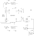
为了解决上述现有的对终端设备进行MIMO OTA测试的测试方法,不能测试多接收通道的终端设备的吞吐量,适用性较低的问题,本发明实施例还提供了一种MIMO OTA性能测试系统,参阅图4所示,在该系统的系统架构中包括:基站模拟器401、信道仿真仪402,以及处于暗室中的终端设备403。其中,所述终端设备403所处的暗室可以为通用的单输入单输出(Single Input Single Output,SISO)OTA暗室,或大圆切法的暗室,或圆锥切法的暗室,在本发明实施例中采用的暗室为通用的SISO OTA暗室,只需要增加适量的测试天线(下行天线),因此降低了成本。In order to solve the above-mentioned existing test method for performing MIMO OTA test on a terminal device, the throughput of the terminal device of the multiple receiving channel cannot be tested, and the applicability is low. The embodiment of the present invention further provides a MIMO OTA performance test system. Referring to FIG. 4, the system architecture of the system includes a base station simulator 401, a channel emulator 402, and a terminal device 403 in a dark room. The darkroom in which the terminal device 403 is located may be a general single input single output (SISO) OTA darkroom, or a large circular cut darkroom, or a conical cut darkroom, in the embodiment of the present invention. The darkroom used is a general-purpose SISO OTA darkroom, which requires only an appropriate amount of test antenna (downlink antenna) to be added, thus reducing costs.
在采用该系统架构,对所述终端设备进行下行链路的MIMO OTA性能测试时,所述基站模拟器401,用于通过多个下行端口,向信道仿真仪402发送 多流下行测试信号;When the MIMO OTA performance test of the downlink device is performed on the terminal device by using the system architecture, the base station simulator 401 is configured to send to the channel emulator 402 through multiple downlink ports. Multi-stream downlink test signal;
所述信道仿真仪402,用于根据终端设备403中的多个接收天线中每个接收天线的复数方向图、下行辐射信道逆矩阵,以及设定的下行信道衰落模型,对接收的所述多流下行测试信号进行信道仿真处理,将多流处理后的下行测试信号通过暗室中的多个下行天线发送至处于暗室中的终端设备403;The channel emulator 402 is configured to receive, according to the complex pattern of each of the plurality of receiving antennas in the terminal device 403, the inverse radiation channel inverse matrix, and the set downlink channel fading model, Flow downlink test signal for channel emulation processing, the multi-stream processed downlink test signal is sent to the terminal device 403 in the darkroom through a plurality of downlink antennas in the darkroom;
所述终端设备403,用于通过所述多个接收天线接收所述信道仿真仪发送的多流处理后的下行测试信号,并针对接收的每流处理后的下行测试信号,向所述基站模拟器401反馈确认消息,其中,针对一流处理后的下行测试信号反馈的确认消息,用于通知所述基站模拟器401,所述终端设备403是否正确解调所述处理后的下行测试信号;The terminal device 403 is configured to receive, by using the multiple receiving antennas, the multi-stream processed downlink test signal sent by the channel emulator, and simulate the downlink test signal received by each stream to the base station. The device 401 feeds back an acknowledgement message, wherein the acknowledgement message for the downlink test signal feedback after the first-class processing is used to notify the base station simulator 401, whether the terminal device 403 correctly demodulates the processed downlink test signal;
所述基站模拟器401,还用于根据发送的下行测试信号的流数,以及接收的确认消息中指示所述终端设备403正确解调的确认信息的数目,确定所述终端设备403在下行链路的吞吐量。The base station simulator 401 is further configured to determine, according to the number of streams of the downlink test signal that is sent, and the number of acknowledgment information indicating that the terminal device 403 is correctly demodulated in the received acknowledgment message, that the terminal device 403 is in the downlink. The throughput of the road.
其中,所述信道仿真仪402中设定的下行信道衰落模型,可以为扩展的空间信道模型(Spatial Channel Model Extended,SCME)Umi,或者SCME Uma,或者其他信道衰落模型。The downlink channel fading model set in the channel emulator 402 may be an Extended Spatial Channel Model (SCME) Umi, or an SCME Uma, or other channel fading model.
所述基站模拟器401在根据发送的下行测试信号的流数,以及接收的确认消息中指示所述终端设备403正确解调的确认信息的数目,确定所述终端设备403在下行链路的吞吐量,包括:The base station emulator 401 determines the throughput of the terminal device 403 in the downlink according to the number of streams of the downlink test signal transmitted and the number of acknowledgment information indicating that the terminal device 403 correctly demodulates according to the received acknowledgment message. Quantity, including:
所述基站模拟器401将所述终端设备403在下行链路的吞吐量为正确解调的确认信息的数目与发送的下行测试信号的流数的商,作为所述终端设备403在下行链路的吞吐量。The base station simulator 401 sets the throughput of the terminal device 403 in the downlink as the quotient of the number of correctly demodulated acknowledgment information and the number of streams of the downlink test signal transmitted, as the terminal device 403 is in the downlink. Throughput.
其中,所述针对一流处理后的下行测试信号反馈的确认消息,通常为正确应答消息(ACKnowledge,ACK)或错误应答消息(Negative ACKnowledge,NACK),其中,确认消息为ACK时,用于通知所述基站模拟器401,所述终端设备403正确解调所述处理后的下行测试信号;而确认消息为NACK时,用于通知所述基站模拟器401,所述终端设备403未正确解调所述处理后的下 行测试信号。The acknowledgment message for the feedback of the downlink test signal after the first-class processing is usually an ACKnowledge (ACK) or a Negative ACKnowledge (NACK), where the acknowledgment message is an ACK, and is used to notify the The base station simulator 401, the terminal device 403 correctly demodulates the processed downlink test signal; and when the acknowledgement message is NACK, it is used to notify the base station simulator 401 that the terminal device 403 is not correctly demodulated. After the treatment Line test signal.
可选的,所述系统还包括:Optionally, the system further includes:
第一信号分析仪404,用于确定所述每个接收天线的复数方向图;a first signal analyzer 404, configured to determine a complex pattern of each of the receiving antennas;
所述信道仿真仪402,还用于获取所述第一信号分析仪404中的所述每个接收天线的复数方向图。The channel emulator 402 is further configured to acquire a complex pattern of each of the receiving antennas in the first signal analyzer 404.
其中,所述第一信号分析仪404在确定所述每个接收天线的复数方向图时:Wherein the first signal analyzer 404 determines the complex pattern of each of the receiving antennas:
所述终端设备403,还用于按照设定顺序,依次通过所述多个接收天线中的每个接收天线发射单音信号;The terminal device 403 is further configured to sequentially transmit a tone signal through each of the plurality of receiving antennas according to a setting sequence;
所述第一信号分析仪404,具体用于针对每个接收天线,执行以下操作:The first signal analyzer 404 is specifically configured to perform the following operations for each receiving antenna:
分别测量在I路和Q路上的,该接收天线发射的所述单音信号在三维辐射球面中的各个测量方向上的幅度和相位;以及Measure the amplitude and phase of the single tone signal emitted by the receiving antenna in each measurement direction in the three-dimensional radiation sphere on the I and Q paths, respectively;
根据针对该接收天线测量得到的在I路和Q路上的三维辐射球面中的各个测量方向上的幅度和相位,得到该接收天线的复数方向图。The complex pattern of the receiving antenna is obtained based on the amplitude and phase in each of the three-dimensional radiation spheres on the I and Q paths measured for the receiving antenna.
显然,当该系统中的第一信号分析仪404可以确定所述每个接收天线的复数方向图时,所述终端设备403具有实现如图1所示的终端设备的信号发送方法的功能,即具有通过任意一个设定的天线发射指定频点的单音信号的功能。Obviously, when the first signal analyzer 404 in the system can determine the complex pattern of each of the receiving antennas, the terminal device 403 has the function of implementing the signal transmitting method of the terminal device as shown in FIG. A function of transmitting a tone signal of a specified frequency point through any one of the set antennas.
所述第一信号分析仪404在测量所述每个接收天线的复数方向图时,与图2所示的终端设备的天线复数方向图测量系统中的所述第一信号分析仪202在测量每个接收天线的复数方向图的功能相同,且测试步骤,以及调整测量方向的方式相同,此处不再赘述。When the first signal analyzer 404 measures the complex pattern of each of the receiving antennas, the first signal analyzer 202 in the antenna complex pattern measuring system of the terminal device shown in FIG. 2 is measuring each The functions of the complex antennas of the receiving antennas are the same, and the test steps and the manner of adjusting the measurement direction are the same, and are not described here.
通过上述方式,所述第一信号分析仪可以直接准确地确定所述终端设备在黑盒模式下,每个接收天线的复数方向图。这样,在对所述终端设备进行下行链路的MIMO OTA性能测试时,信道仿真仪可以根据每个接收天线的复数方向图来模拟所述终端设备在不同朝向时的信号传输场景,进而保证所述基站模拟器可以最终得到在下行链路的所述终端设备在不同朝向时的吞吐 量。In the above manner, the first signal analyzer can directly and accurately determine the complex pattern of each receiving antenna in the black box mode of the terminal device. In this way, when the terminal device performs the downlink MIMO OTA performance test, the channel emulator can simulate the signal transmission scenario of the terminal device in different orientations according to the complex pattern of each receiving antenna, thereby ensuring the The base station simulator can finally obtain the throughput of the terminal device in the downlink in different orientations. the amount.
可选的,所述系统还包括:Optionally, the system further includes:
第二信号分析仪405,用于确定所述终端设备的下行辐射信道矩阵;a second signal analyzer 405, configured to determine a downlink radiation channel matrix of the terminal device;
第一处理设备406,用于获取所述第二信号分析仪405中的所述下行辐射信道矩阵,并计算所述下行辐射信道矩阵的逆矩阵,获得下行辐射信道逆矩阵;The first processing device 406 is configured to obtain the downlink radiation channel matrix in the second signal analyzer 405, and calculate an inverse matrix of the downlink radiation channel matrix to obtain a downlink radiation channel inverse matrix;
所述信道仿真仪402,还用于获取所述第一处理设备406中的所述下行辐射信道逆矩阵。The channel emulator 402 is further configured to acquire the inverse radiation channel inverse matrix in the first processing device 406.
所述第二信号分析仪405在确定所述终端设备的下行辐射信道矩阵时,所述终端设备403,还用于确定所述终端设备的接收天线的个数和所述基站模拟器的下行端口的个数中的最小值n,并在所述多个接收天线中选择n个接收天线;以及按照设定顺序,依次通过所述n个接收天线中的每个接收天线发射单音信号;When the second signal analyzer 405 determines the downlink radiation channel matrix of the terminal device, the terminal device 403 is further configured to determine the number of receiving antennas of the terminal device and the downlink port of the base station simulator. a minimum value n of the number, and selecting n receiving antennas among the plurality of receiving antennas; and sequentially transmitting a tone signal through each of the n receiving antennas in a set order;
所述第二信号分析仪405,具体用于:The second signal analyzer 405 is specifically configured to:
在所述终端设备通过每个接收天线发射所述单音信号时,分别与所述暗室中n个下行天线相连,测量所述n个下行天线中每个下行天线接收的信号;When the terminal device transmits the tone signal through each receiving antenna, respectively, it is connected to n downlink antennas in the darkroom, and measures signals received by each of the n downlink antennas;
根据在所述n个下行天线中测量到的信号,生成针对每个接收天线的信号向量;Generating a signal vector for each receive antenna based on the signals measured in the n downlink antennas;
根据生成的针对n个接收天线中每个接收天线的信号向量,生成所述下行辐射信道矩阵。The downlink radiation channel matrix is generated according to the generated signal vector for each of the n receiving antennas.
显然,当该系统中的第二信号分析仪405可以确定所述终端设备的下行辐射信道矩阵时,所述终端设备403具有实现如图1所示的终端设备的信号发送方法的功能,即具有通过任意一个设定的天线发射指定频点的单音信号的功能。Obviously, when the second signal analyzer 405 in the system can determine the downlink radiation channel matrix of the terminal device, the terminal device 403 has the function of implementing the signal transmission method of the terminal device as shown in FIG. The function of transmitting a tone signal of a specified frequency point through any one of the set antennas.
如图所示,在所述终端设备403通过所述n个接收天线中的第一个接收天线发射单音信号时,所述第二信号分析仪405首先连接至所述n个下行天 线中的第一个下行天线,测量所述第一个下行天线的信号,得到h11,然后所述第二信号分析仪405连接至所述n个下行天线中的第二个下行天线,测量所述第二个下行天线的信号,得到h12,如此重复,直至测量所述n个下行天线中的第n个下行天线的信号,得到h1n,在第一个接收天线发射单音信号时,测量的所述n个下行天线的信号的结果,生成针对第一个接收天线的信号向量(h11h12…h1n)。As shown, when the terminal device 403 transmits a tone signal through a first one of the n receiving antennas, the second signal analyzer 405 is first connected to the n downlink antennas. a first downlink antenna, measuring a signal of the first downlink antenna to obtain h 11 , and then the second signal analyzer 405 is connected to a second one of the n downlink antennas, and measuring the The signals of the two downlink antennas are obtained by h 12 , and are repeated until the signal of the nth downlink antenna of the n downlink antennas is measured to obtain h 1n , which is measured when the first receiving antenna transmits a tone signal. As a result of the signals of the n downlink antennas, a signal vector (h 11 h 12 ... h 1n ) for the first receiving antenna is generated.
在所述终端设备403通过所述n个接收天线中的其他任意一个接收天线发射单音信号时,所述第二信号分析仪405继续采用上述方法,获得针对所述n个接收天线中,每个接收天线的信号向量。When the terminal device 403 transmits a tone signal through any one of the n receiving antennas, the second signal analyzer 405 continues to adopt the above method to obtain, for each of the n receiving antennas The signal vector of the receiving antenna.
所述第二信号分析仪405根据生成的针对n个接收天线中每个接收天线的信号向量,生成所述下行辐射信道矩阵,下行信道矩阵The second signal analyzer 405 generates the downlink radiation channel matrix and the downlink channel matrix according to the generated signal vector for each of the n receiving antennas.
Figure PCTCN2016078110-appb-000010
所述第二信号分析仪405在确定下行辐射信道矩阵后,发送给所述第一处理设备406;所述第一处理设备406获取所述第二信号分析仪405中的所述下行辐射信道矩阵,并计算所述下行辐射信道矩阵的逆矩阵,获得下行辐射信道逆矩阵,并将所述下行辐射信道逆矩阵发送给所述信道仿真仪402。The second signal analyzer 405 sends the downlink radiation channel matrix to the first processing device 406; the first processing device 406 acquires the downlink radiation channel matrix in the second signal analyzer 405 And calculating an inverse matrix of the downlink radiation channel matrix, obtaining an inverse radiation channel inverse matrix, and transmitting the downlink radiation channel inverse matrix to the channel emulator 402.
通过下述公式,可以确定通过上述辐射测试确定的下行辐射信道逆矩阵,可以作为传导测试的下行信道逆矩阵,即所述下行辐射信道逆矩阵可以用于信道仿真仪102对下行测试信号进行信道仿真处理:The inverse radiation channel inverse matrix determined by the above radiation test can be determined by the following formula, which can be used as the downlink channel inverse matrix of the conduction test, that is, the downlink radiation channel inverse matrix can be used by the channel emulator 102 to channel the downlink test signal. Simulation processing:
Figure PCTCN2016078110-appb-000011
其中,
Figure PCTCN2016078110-appb-000012
为传导测试时所述终端设备的所述n个接收天线的信号,
Figure PCTCN2016078110-appb-000013
为辐射测试时所述终端设备的所述n个接收天线的信号,
Figure PCTCN2016078110-appb-000014
为下行辐射信道逆矩阵。
among them,
Figure PCTCN2016078110-appb-000012
To conduct the signals of the n receiving antennas of the terminal device during the test,
Figure PCTCN2016078110-appb-000013
a signal of the n receiving antennas of the terminal device when testing for radiation,
Figure PCTCN2016078110-appb-000014
It is the inverse matrix of the downlink radiating channel.
可选的,所述第一信号分析仪404,还用于:Optionally, the first signal analyzer 404 is further configured to:
在确定所述终端设备中的多个接收天线中每个接收天线的复数方向图后,根据所述多个接收天线中任意两个接收天线的复数方向图,确定所述两个接收天线的天线包络相关系数。After determining a complex pattern of each of the plurality of receiving antennas in the terminal device, determining antennas of the two receiving antennas according to a complex pattern of any two of the plurality of receiving antennas Envelope correlation coefficient.
所述第一信号分析仪404在确定任意两个接收天线的天线包络相关系数时,与图2所示的终端设备的天线复数方向图测量系统中的所述第一信号分析仪202在确定任意两个接收天线的天线包络相关系数时,使用的方法和公式相同,此处不再赘述。The first signal analyzer 404 determines the antenna envelope correlation coefficient of any two receiving antennas with the first signal analyzer 202 in the antenna complex pattern measurement system of the terminal device shown in FIG. When the antenna envelope correlation coefficient of any two receiving antennas is the same, the method and formula are the same, and will not be described here.
在现有的MIMO OTA测试方法中,无法直接测量任意两个接收天线的复数方向图。在本发明实施例提供的系统中,通过上述方法,所述第一信号分析仪404可以确定所述终端设备403中的多个接收天线中每个接收天线的复数方向图后,可以根据所述多个接收天线中任意两个接收天线的复数方向图,确定所述两个接收天线的天线包络相关系数。In the existing MIMO OTA test method, the complex pattern of any two receiving antennas cannot be directly measured. In the system provided by the embodiment of the present invention, after the first signal analyzer 404 can determine the complex pattern of each of the plurality of receiving antennas in the terminal device 403, according to the foregoing method, A complex pattern of any two of the plurality of receiving antennas, and determining an antenna envelope correlation coefficient of the two receiving antennas.
在本发明实施例提供的MIMO OTA性能测试系统中,由于所述基站模拟器可以发送多流下行测试信号,且所述终端设备可以通过多个接收天线接收所述信道仿真仪通过多个下行天线发送多流处理后的下行测试信号,不用限定下行测试信号的流数、下行天线的个数以及所述终端设备中接收天线的个数,因此,本发明实施例提供的MIMO OTA性能测试系统可以支持下行链路a×b的MIMO测试,a和b均为大于等于2的正整数,显然,采用本发明实施例的MIMO OTA性能测试系统,可以测试多接收通道的终端设备的吞吐量,适用性较高。In the MIMO OTA performance test system provided by the embodiment of the present invention, the base station simulator may send a multi-stream downlink test signal, and the terminal device may receive the channel emulator through multiple receiving antennas through multiple downlink antennas. The MIMO OTA performance test system provided by the embodiment of the present invention can be used to transmit the downlink test signal after the multi-stream processing, without limiting the number of streams of the downlink test signal, the number of downlink antennas, and the number of receiving antennas in the terminal device. Supporting the MIMO test of the downlink a×b, both a and b are positive integers greater than or equal to 2. Obviously, the MIMO OTA performance test system of the embodiment of the present invention can test the throughput of the terminal device of the multiple receiving channel, and is applicable. Higher sex.
在现有的MIMO OTA性能测试方法中,仅可以测试终端设备在下行链路的吞吐量,而无法测试终端设备在上行链路的吞吐量,导致无法准确地得到 终端设备在上行链路的工作性能。In the existing MIMO OTA performance test method, only the throughput of the terminal device in the downlink can be tested, and the throughput of the terminal device in the uplink cannot be tested, resulting in failure to accurately obtain The performance of the terminal equipment on the uplink.
为了准确地测量终端设备在上行链路的吞吐量,本发明实施例还提供了另一种MIMO OTA性能测试系统,参阅图5所示,在该系统的系统架构中包括:基站模拟器501、信道仿真仪502,以及处于暗室中的终端设备503。其中,所述终端设备503所处的暗室可以为通用的SISO OTA暗室,或大圆切法的暗室,或圆锥切法的暗室,在本发明实施例中采用的暗室为通用的SISO OTA暗室,只需要增加适量的测试天线(上行天线),因此降低了成本。In order to accurately measure the throughput of the terminal device in the uplink, the embodiment of the present invention further provides another MIMO OTA performance testing system. Referring to FIG. 5, the system architecture of the system includes: a base station simulator 501, Channel emulator 502, and terminal device 503 in a darkroom. The darkroom in which the terminal device 503 is located may be a general SISO OTA darkroom, or a large circular cut darkroom, or a conical cut darkroom. The darkroom used in the embodiment of the present invention is a general-purpose SISO OTA darkroom, only It is necessary to increase the amount of test antenna (uplink antenna), thus reducing the cost.
在采用该系统架构,对所述终端设备进行上行链路的MIMO OTA性能测试时,所述终端设备503,用于通过所述终端设备503中的多个发射天线发射多流上行测试信号,并通过所述暗室中多个上行天线将所述多流上行测试信号传输至信道仿真仪502;When the MIMO OTA performance test of the uplink is performed on the terminal device by using the system architecture, the terminal device 503 is configured to send a multi-stream uplink test signal by using multiple transmit antennas in the terminal device 503, and Transmitting the multi-stream uplink test signal to the channel emulator 502 through a plurality of uplink antennas in the darkroom;
所述信道仿真仪502,用于根据所述终端设备503中的多个发射天线中每个发射天线的复数方向图、所述上行辐射信道逆矩阵,以及设定的上行信道衰落模型,对所述多流上行测试信号进行信道仿真处理,将多流处理后的上行测试信号发送至基站模拟器501;The channel emulator 502 is configured to: according to a complex pattern of each of the plurality of transmit antennas in the terminal device 503, the inverse radiation channel inverse matrix, and a set uplink channel fading model, The multi-stream uplink test signal is subjected to channel emulation processing, and the multi-stream processed uplink test signal is sent to the base station simulator 501;
所述基站模拟器501,用于通过多个上行端口,接收所述信道仿真仪502发送的多流处理后的上行测试信号,并根据所述终端设备503发送的上行测试信号的流数,以及所述基站模拟器501接收到处理后的上行测试信号的流数,确定所述终端设备503在上行链路的吞吐量。The base station simulator 501 is configured to receive, by using multiple uplink ports, the multi-stream processed uplink test signal sent by the channel emulator 502, and according to the number of uplink test signals sent by the terminal device 503, and The base station simulator 501 receives the number of streams of the processed uplink test signal, and determines the throughput of the terminal device 503 in the uplink.
其中,所述信道仿真仪502中设定的上行信道衰落模型,可以为SCME Umi,或者SCME Uma,或者其他信道衰落模型。The uplink channel fading model set in the channel emulator 502 may be SCME Umi, or SCME Uma, or other channel fading model.
所述基站模拟器501根据所述终端设备503发送的上行测试信号的流数,以及所述基站模拟器501接收到处理后的上行测试信号的流数,确定所述终端设备503在上行链路的吞吐量,包括:The base station simulator 501 determines that the terminal device 503 is in the uplink according to the number of streams of the uplink test signal sent by the terminal device 503 and the number of streams of the processed uplink test signal received by the base station simulator 501. Throughput, including:
所述基站模拟器501将接收到处理后的上行测试信号的流数与所述终端设备503发送的上行测试信号的流数的商,作为所述终端设备503在上行链路的吞吐量。 The base station simulator 501 uses the quotient of the number of streams of the processed uplink test signal and the number of streams of the uplink test signal transmitted by the terminal device 503 as the throughput of the terminal device 503 in the uplink.
可选的,所述系统还包括:Optionally, the system further includes:
第三信号分析仪504,用于确定所述每个发射天线的复数方向图;a third signal analyzer 504, configured to determine a complex pattern of each of the transmitting antennas;
所述信道仿真仪502,还用于获取所述第三信号分析仪中的所述每个发射天线的复数方向图。The channel emulator 502 is further configured to acquire a complex pattern of each of the transmit antennas in the third signal analyzer.
其中,所述第三信号分析仪504在确定所述每个发射天线的复数方向图时:Wherein, the third signal analyzer 504 determines the complex pattern of each of the transmitting antennas:
所述终端设备503,还用于按照设定顺序,依次通过所述多个发射天线中的每个发射天线发射单音信号;The terminal device 503 is further configured to sequentially transmit a tone signal through each of the plurality of transmit antennas according to a set sequence;
所述第三信号分析仪504,具体用于针对每个发射天线,执行以下操作:The third signal analyzer 504 is specifically configured to perform the following operations for each transmit antenna:
分别测量在I路和Q路上的,该发射天线发射的所述单音信号在三维辐射球面中的各个测量方向上的幅度和相位;以及Measure the amplitude and phase of the single tone signal emitted by the transmitting antenna in each measurement direction in the three-dimensional radiation sphere on the I road and the Q road, respectively;
根据针对该接收天线测量得到的在I路和Q路上的三维辐射球面中的各个测量方向上的幅度和相位,得到该发射天线的复数方向图。The complex pattern of the transmitting antenna is obtained based on the amplitude and phase in each of the measurement directions in the three-dimensional radiation spheres on the I and Q paths measured for the receiving antenna.
显然,当该系统中的第三信号分析仪504可以确定所述每个发射天线的复数方向图时,所述终端设备503具有实现如图1所示的终端设备的信号发送方法的功能,即具有通过任意一个设定的天线发射指定频点的单音信号的功能。Obviously, when the third signal analyzer 504 in the system can determine the complex pattern of each of the transmitting antennas, the terminal device 503 has the function of implementing the signal transmitting method of the terminal device as shown in FIG. 1, ie A function of transmitting a tone signal of a specified frequency point through any one of the set antennas.
所述第三信号分析仪504在测量所述每个发射天线的复数方向图时,与图3所示的终端设备的天线复数方向图测量系统中的所述第三信号分析仪302在测量每个接收天线的复数方向图的功能相同,且测试步骤,以及调整测量方向的方式相同,此处不再赘述。When the third signal analyzer 504 measures the complex pattern of each of the transmitting antennas, the third signal analyzer 302 in the antenna complex pattern measuring system of the terminal device shown in FIG. 3 is measuring each The functions of the complex antennas of the receiving antennas are the same, and the test steps and the manner of adjusting the measurement direction are the same, and are not described here.
通过上述方式,所述第一信号分析仪可以直接准确地确定所述终端设备在黑盒模式下,每个发射天线的复数方向图。这样,在对所述终端设备进行上行链路的MIMO OTA性能测试时,信道仿真仪可以根据每个发射天线的复数方向图来模拟所述终端设备在不同朝向时的信号传输场景,进而保证所述基站模拟器可以最终得到在上行链路的所述终端设备在不同朝向时的吞吐量。 In the above manner, the first signal analyzer can directly and accurately determine the complex pattern of each transmitting antenna in the black box mode of the terminal device. In this way, when performing the uplink MIMO OTA performance test on the terminal device, the channel emulator can simulate the signal transmission scenario of the terminal device in different orientations according to the complex pattern of each transmit antenna, thereby ensuring the The base station simulator can ultimately obtain the throughput of the terminal devices in the uplink when they are in different orientations.
可选的,所述系统还包括:Optionally, the system further includes:
第四信号分析仪505,用于确定所述终端设备的上行辐射信道矩阵;a fourth signal analyzer 505, configured to determine an uplink radiation channel matrix of the terminal device;
第二处理设备506,用于获取所述第四信号分析仪505中的所述上行辐射信道矩阵,并计算所述上行辐射信道矩阵的逆矩阵,获得上行辐射信道逆矩阵;a second processing device 506, configured to acquire the uplink radiation channel matrix in the fourth signal analyzer 505, and calculate an inverse matrix of the uplink radiation channel matrix to obtain an uplink radiation channel inverse matrix;
所述信道仿真仪502,还用于获取所述第二处理设备中的所述上行辐射信道逆矩阵。The channel emulator 502 is further configured to obtain the inverse radiation channel inverse matrix in the second processing device.
所述第四信号分析仪505在确定所述终端设备的上行辐射信道矩阵时,所述终端设备503,还用于确定所述终端设备的发射天线的个数和所述基站模拟器的上行端口的个数中的最小值m,并在所述多个发射天线中选择m个发射天线;以及按照设定顺序,依次通过所述m个发射天线中的每个发射天线发射单音信号;The terminal device 503 is further configured to determine the number of transmit antennas of the terminal device and an uplink port of the base station simulator, when the fourth signal analyzer 505 determines the uplink radiating channel matrix of the terminal device. a minimum value m of the number, and selecting m transmit antennas among the plurality of transmit antennas; and sequentially transmitting a tone signal through each of the m transmit antennas in a set order;
所述第四信号分析仪505,具体用于:The fourth signal analyzer 505 is specifically configured to:
在所述终端设备通过每个发射天线发射所述单音信号时,分别与所述暗室中m个上行天线相连,测量所述m个上行天线中每个上行天线接收的信号;When the terminal device transmits the tone signal through each transmitting antenna, respectively, connecting to m uplink antennas in the darkroom, and measuring signals received by each of the m uplink antennas;
根据在所述m个上行天线中测量到的信号,生成针对每个发射天线的信号向量;Generating a signal vector for each transmit antenna based on the signals measured in the m uplink antennas;
根据生成的针对m个发射天线中的每个发射天线的信号向量,生成所述上行辐射信道矩阵。The upstream radiating channel matrix is generated based on the generated signal vector for each of the m transmit antennas.
显然,当该系统中的第四信号分析仪505可以确定所述终端设备的上行辐射信道矩阵时,所述终端设备503具有实现如图1所示的终端设备的信号发送方法的功能,即具有通过任意一个设定的天线发射指定频点的单音信号的功能。Obviously, when the fourth signal analyzer 505 in the system can determine the uplink radiating channel matrix of the terminal device, the terminal device 503 has the function of implementing the signal transmitting method of the terminal device as shown in FIG. The function of transmitting a tone signal of a specified frequency point through any one of the set antennas.
在本发明实施例提供系统中,所述第四信号分析仪505在确定所述终端设备503的上行辐射信道矩阵时,与如图4所示的MIMO OTA测试系统中,所述第二信号分析仪405在确定所述终端设备403的下行辐射信道矩阵的步骤相同,此处也不再赘述。 In the system provided by the embodiment of the present invention, when the fourth signal analyzer 505 determines the uplink radiation channel matrix of the terminal device 503, and the MIMO OTA test system shown in FIG. 4, the second signal analysis The step 405 of determining the downlink radiation channel matrix of the terminal device 403 is the same, and details are not described herein again.
可选的,所述第三信号分析仪504,还用于:Optionally, the third signal analyzer 504 is further configured to:
在确定所述终端设备中的多个发射天线中每个发射天线的复数方向图后,根据所述多个发射天线中任意两个发射天线的复数方向图,确定所述两个发射天线的天线包络相关系数。After determining a complex pattern of each of the plurality of transmit antennas in the terminal device, determining antennas of the two transmit antennas according to a complex pattern of any two of the plurality of transmit antennas Envelope correlation coefficient.
所述第三信号分析仪504在确定任意两个发射天线的天线包络相关系数时,与图3所示的终端设备的天线复数方向图测量系统中的所述第三信号分析仪302在确定任意两个发射天线的天线包络相关系数时,使用的方法和公式相同,此处不再赘述。The third signal analyzer 504 determines the antenna envelope correlation coefficient of any two transmit antennas with the third signal analyzer 302 in the antenna complex pattern measurement system of the terminal device shown in FIG. When the correlation coefficient of the antenna envelope of any two transmitting antennas is the same, the method and formula are the same, and will not be described here.
采用本发明实施例提供的MIMO OTA性能测试系统,可以准确地测量终端设备在上行链路的吞吐量,从而准确地得到终端设备在上行链路的工作性能。The MIMO OTA performance test system provided by the embodiment of the present invention can accurately measure the throughput of the terminal device in the uplink, thereby accurately obtaining the working performance of the terminal device in the uplink.
基于以上实施例,本发明实施例提供了还一种MIMO OTA性能测试系统,该系统可以测量终端设备在上行链路的吞吐量,还可以测量终端设备在下行链路的吞吐量,如图6所示,在该系统的系统架构中包括:基站模拟器601、信道仿真仪602,以及处于暗室中的终端设备603。Based on the above embodiments, the embodiment of the present invention provides a MIMO OTA performance testing system, which can measure the throughput of the terminal device in the uplink, and can also measure the throughput of the terminal device in the downlink, as shown in FIG. 6 . As shown, the system architecture of the system includes a base station simulator 601, a channel emulator 602, and a terminal device 603 in a dark room.
可选的,该系统中还可以包括第一信号分析仪604,用于确定所述每个接收天线的复数方向图。Optionally, the system may further include a first signal analyzer 604 for determining a complex pattern of each of the receiving antennas.
可选的,该系统中还可以包括第二信号分析仪605,用于确定所述终端设备603的下行辐射信道矩阵。Optionally, the system may further include a second signal analyzer 605 for determining a downlink radiation channel matrix of the terminal device 603.
相应的,还包括第一处理设备606,用于获取所述第二信号分析仪605中的所述下行辐射信道矩阵,并计算所述下行辐射信道矩阵的逆矩阵,获得下行辐射信道逆矩阵。Correspondingly, the first processing device 606 is further configured to obtain the downlink radiation channel matrix in the second signal analyzer 605, and calculate an inverse matrix of the downlink radiation channel matrix to obtain a downlink radiation channel inverse matrix.
可选的,该系统中还可以包括第三信号分析仪607,用于确定所述每个发射天线的复数方向图。Optionally, the system may further include a third signal analyzer 607 for determining a complex pattern of each of the transmitting antennas.
可选的,该系统中还可以包括第四信号分析仪608,用于确定所述终端设备603的上行辐射信道矩阵。Optionally, the system may further include a fourth signal analyzer 608 for determining an uplink radiating channel matrix of the terminal device 603.
相应的,还包括第二处理设备609,用于获取所述第四信号分析仪608中 的所述上行辐射信道矩阵,并计算所述上行辐射信道矩阵的逆矩阵,获得上行辐射信道逆矩阵。Correspondingly, the second processing device 609 is further configured to acquire the fourth signal analyzer 608. The uplink radiation channel matrix, and calculating an inverse matrix of the uplink radiation channel matrix, to obtain an uplink radiation channel inverse matrix.
所述系统在测量终端设备603在下行链路的吞吐量时,相关的各个设备的功能参见图4所示的实施例中相应设备的功能;所述系统在测量终端设备603在上行链路的吞吐量时,相关的各个设备的功能参见图5所示的实施例中相应设备的功能,此处不再赘述。When the system measures the throughput of the terminal device 603 in the downlink, the functions of the related devices are referred to the functions of the corresponding devices in the embodiment shown in FIG. 4; the system is measuring the terminal device 603 on the uplink. For the function of the related devices, refer to the functions of the corresponding devices in the embodiment shown in FIG. 5, and details are not described herein again.
在本发明实施例提供的MIMO OTA性能测试系统中,第一信号分析仪604和第三信号分析仪607分别测试每个发射天线的复数方向图和每个发射天线中的复数方向图,因此,所述第一信号分析仪604和所述第三信号分析仪607可以同一个信号分析仪,同理,所述第二信号分析仪605和所述第四信号分析仪608也可以是同一个信号分析仪,可选的,所述第一信号分析仪604、所述第二信号分析仪605、所述第三信号分析仪607、所述第四信号分析仪608也可以是同一个信号分析仪,本发明实施例对此不做限定,其中,本发明涉及的各个信号分析仪还可以为多路输入的网络分析仪。In the MIMO OTA performance testing system provided by the embodiment of the present invention, the first signal analyzer 604 and the third signal analyzer 607 respectively test the complex pattern of each transmitting antenna and the complex pattern in each transmitting antenna, and therefore, The first signal analyzer 604 and the third signal analyzer 607 can be the same signal analyzer. Similarly, the second signal analyzer 605 and the fourth signal analyzer 608 can also be the same signal. The analyzer, optionally, the first signal analyzer 604, the second signal analyzer 605, the third signal analyzer 607, and the fourth signal analyzer 608 may also be the same signal analyzer. The embodiment of the present invention is not limited thereto, and each of the signal analyzers involved in the present invention may also be a multi-input network analyzer.
在本发明实施例提供的MIMO OTA性能测试系统中,所述第一处理设备606和所述第二处理设备609也可以相同的处理设备。本发明实施例对此不做限定。In the MIMO OTA performance testing system provided by the embodiment of the present invention, the first processing device 606 and the second processing device 609 may also be the same processing device. This embodiment of the present invention does not limit this.
综上所述,本发明实施例提供的MIMO OTA性能测试系统不仅可以测量多接收通道的终端设备的吞吐量,还可以测试多发射通道的终端设备的吞吐量,相对于现有技术中的多探头暗室测试方法,无需针对所述终端设备的每个天线,都配置两个信道模拟器,显然,本发明可以降低测试成本。同时,采用本发明实施例提供的系统,还可以直接测量获得所述终端每个接收天线的复数方向图、每个发射天线的复数方向图,还可以直接测量获得下行辐射信道矩阵、上行辐射信道矩阵,进而获得下行辐射信道逆矩阵、下行辐射信道逆矩阵,且获得的各个参数更准确,最终提高了MMO OTA性能测试结果的准确度。In summary, the MIMO OTA performance testing system provided by the embodiment of the present invention can not only measure the throughput of the terminal device of the multiple receiving channel, but also test the throughput of the terminal device of the multiple transmitting channel, which is compared with the prior art. The probe darkroom test method does not require two channel simulators for each antenna of the terminal device. Obviously, the present invention can reduce the test cost. At the same time, the system provided by the embodiment of the present invention can directly measure the complex direction pattern of each receiving antenna of the terminal, the complex direction diagram of each transmitting antenna, and directly obtain the downlink radiating channel matrix and the uplink radiating channel. The matrix, in turn, obtains the inverse matrix of the downlink radiating channel and the inverse matrix of the downlink radiating channel, and the obtained parameters are more accurate, and finally the accuracy of the MMO OTA performance test result is improved.
基于以上实施例,本发明实施例还提供了一种终端设备,该终端设备用 于实现如图1所示的信号发送方法,参阅图7所示,该终端设备700中包括生成单元701和发射单元702,其中,Based on the above embodiment, an embodiment of the present invention further provides a terminal device, where the terminal device uses The signal transmission method shown in FIG. 1 is implemented. Referring to FIG. 7, the terminal device 700 includes a generating unit 701 and a transmitting unit 702, where
生成单元701,用于生成设定频点的单音信号;a generating unit 701, configured to generate a tone signal of a set frequency point;
发射单元702,用于通过所述终端设备700中的设定天线发射所述单音信号,所述设定天线为所述终端设备中的接收天线或发射天线。The transmitting unit 702 is configured to transmit the tone signal by using a set antenna in the terminal device 700, where the set antenna is a receiving antenna or a transmitting antenna in the terminal device.
可选的,所述单音信号为幅度恒定的单音连续波信号。Optionally, the tone signal is a tone continuous wave signal of constant amplitude.
可选的,所述发射单元702,还用于:Optionally, the transmitting unit 702 is further configured to:
在通过所述设定天线发送所述单音信号之前,打开所述设定天线的天线选择开关,以及关闭除所述设定天线以外的其他接收天线和发射天线的天线选择开关。Before transmitting the tone signal through the set antenna, turning on an antenna selection switch of the set antenna, and turning off an antenna selection switch of a receiving antenna and a transmitting antenna other than the set antenna.
采用本发明实施例提供的终端设备,所述终端设备可以生成设定频点的单音信号,并可以通过所述终端设备中的设定接收天线或发射天线,发射所述单音信号。由于终端设备具有通过任意一个设定的天线发射指定频点的单音信号的功能,因此,终端设备的天线复数方向图测量系统可以通过所述终端设备通过每个接收天线或发射天线发射设定频点的单音信号,准确的测量出所述终端设备中各天线的复数方向图,进而在根据所述终端设备中各天线的复数方向图对所述终端设备进行MIMO OTA性能测试时,可以获得准确的测量结果。According to the terminal device provided by the embodiment of the present invention, the terminal device may generate a tone signal of a set frequency point, and may transmit the tone signal by using a set receiving antenna or a transmitting antenna in the terminal device. Since the terminal device has a function of transmitting a tone signal of a specified frequency point through any one of the set antennas, the antenna complex pattern measurement system of the terminal device can transmit the setting through each of the receiving antennas or the transmitting antenna through the terminal device. The frequency of the tone signal accurately measures the complex pattern of each antenna in the terminal device, and when the MIMO OTA performance test is performed on the terminal device according to the complex pattern of each antenna in the terminal device, Get accurate measurement results.
基于以上实施例,本发明实施例还提供了一种终端设备,该终端设备用于实现如图1所示的所示的信号发送方法,参阅图8所示,该终端设备800中包括信号发生器801、处理器802、总线803、存储器804,以及多个天线,包括多个接收天线805以及多个发射天线806,每个天线具有一个天线选择开关,其中,Based on the above embodiment, the embodiment of the present invention further provides a terminal device, which is used to implement the signal sending method shown in FIG. 1. Referring to FIG. 8, the terminal device 800 includes a signal generation. 801, a processor 802, a bus 803, a memory 804, and a plurality of antennas, including a plurality of receiving antennas 805 and a plurality of transmitting antennas 806, each antenna having an antenna selection switch, wherein
信号发生器801、处理器802、存储器804,以及多个天线通过总线803相互连接;总线803可以是外设部件互连标准(peripheral component interconnect,简称PCI)总线或扩展工业标准结构(extended industry standard architecture,简称EISA)总线等。所述总线可以分为地址总线、数据总线、 控制总线等。为便于表示,图8中仅用一条粗线表示,但并不表示仅有一根总线或一种类型的总线。The signal generator 801, the processor 802, the memory 804, and the plurality of antennas are connected to each other through a bus 803; the bus 803 may be a peripheral component interconnect (PCI) bus or an extended industry standard (extended industry standard) Architecture, referred to as EISA) bus. The bus can be divided into an address bus, a data bus, Control bus, etc. For ease of representation, only one thick line is shown in Figure 8, but it does not mean that there is only one bus or one type of bus.
所述信号发生器801用于生成设定频点的单音信号;The signal generator 801 is configured to generate a tone signal of a set frequency point;
所述多个天线,用于发射所述单音信号;其中,所述接收天线805还用于接收下行信号,所述发射天线806还用于发射上行信号。The plurality of antennas are configured to transmit the tone signal; wherein the receiving antenna 805 is further configured to receive a downlink signal, and the transmitting antenna 806 is further configured to transmit an uplink signal.
所述处理器802,用于实现如图1所示的信号发送方法,包括:The processor 802 is configured to implement a signaling method as shown in FIG. 1, and includes:
控制所述信号发生器801,使所述信号发生器801生成所述设定频点的单音信号;Controlling the signal generator 801 to cause the signal generator 801 to generate a tone signal of the set frequency point;
通过所述终端设备中的设定天线发射所述单音信号,所述设定天线为所述终端设备中的接收天线805或发射天线806。The tone signal is transmitted by a setting antenna in the terminal device, and the setting antenna is a receiving antenna 805 or a transmitting antenna 806 in the terminal device.
可选的,所述单音信号为幅度恒定的单音连续波信号。Optionally, the tone signal is a tone continuous wave signal of constant amplitude.
可选的,所述处理器802,还用于:Optionally, the processor 802 is further configured to:
在通过所述设定天线发送所述单音信号之前,打开所述设定天线的天线选择开关,以及关闭除所述设定天线以外的其他接收天线805和发射天线806的天线选择开关。Before transmitting the tone signal through the set antenna, the antenna selection switch of the set antenna is turned on, and the antenna selection switches of the receiving antenna 805 and the transmitting antenna 806 except the set antenna are turned off.
采用本发明实施例提供的终端设备,所述终端设备可以生成设定频点的单音信号,并可以通过所述终端设备中的设定接收天线或发射天线,发射所述单音信号。由于终端设备具有通过任意一个设定的天线发射指定频点的单音信号的功能,因此,终端设备的天线复数方向图测量系统可以通过所述终端设备通过每个接收天线或发射天线发射设定频点的单音信号,准确的测量出所述终端设备中各天线的复数方向图,进而在根据所述终端设备中各天线的复数方向图对所述终端设备进行MIMO OTA性能测试时,可以获得准确的测量结果。According to the terminal device provided by the embodiment of the present invention, the terminal device may generate a tone signal of a set frequency point, and may transmit the tone signal by using a set receiving antenna or a transmitting antenna in the terminal device. Since the terminal device has a function of transmitting a tone signal of a specified frequency point through any one of the set antennas, the antenna complex pattern measurement system of the terminal device can transmit the setting through each of the receiving antennas or the transmitting antenna through the terminal device. The frequency of the tone signal accurately measures the complex pattern of each antenna in the terminal device, and when the MIMO OTA performance test is performed on the terminal device according to the complex pattern of each antenna in the terminal device, Get accurate measurement results.
基于以上实施例,本发明实施例还提供了一种终端设备的天线复数方向图测量方法,该方法适用于如图2所示的终端设备的天线复数方向图测量系统,该方法中涉及的设备可以为图2所示的系统中相应的设备,参阅图9所示,该方法的流程包括: Based on the above embodiment, the embodiment of the present invention further provides a method for measuring an antenna complex pattern of a terminal device, where the method is applicable to an antenna complex pattern measurement system of the terminal device as shown in FIG. 2, and the device involved in the method For the corresponding device in the system shown in FIG. 2, refer to FIG. 9, the process of the method includes:
步骤901:终端设备按照设定顺序,依次通过所述终端设备中的多个接收天线中每个接收天线发射单音信号;Step 901: The terminal device sequentially transmits a tone signal through each of the plurality of receiving antennas in the terminal device according to the setting sequence.
步骤902:第一信号分析仪针对每个接收天线,执行以下操作:Step 902: The first signal analyzer performs the following operations for each receiving antenna:
分别测量在I路和Q路上的,该接收天线发射的所述单音信号在三维辐射球面中的各个测量方向上的幅度和相位;以及Measure the amplitude and phase of the single tone signal emitted by the receiving antenna in each measurement direction in the three-dimensional radiation sphere on the I and Q paths, respectively;
根据针对该接收天线测量得到的在I路和Q路上的三维辐射球面中的各个测量方向上的幅度和相位,得到该接收天线的复数方向图。The complex pattern of the receiving antenna is obtained based on the amplitude and phase in each of the three-dimensional radiation spheres on the I and Q paths measured for the receiving antenna.
可选的,在所述第一信号分析仪得到每个接收天线的复数放线图后,还包括:Optionally, after the first signal analyzer obtains the multiple line diagrams of each receiving antenna, the method further includes:
根据所述多个接收天线中任意两个接收天线的复数方向图,确定所述两个接收天线的天线包络相关系数。Determining an antenna envelope correlation coefficient of the two receiving antennas according to a complex pattern of any two of the plurality of receiving antennas.
采用本发明实施例提供的一种终端设备的天线复数方向图测量方法,所述第一信号分析仪可以直接准确地确定所述终端设备在黑盒模式下,每个接收天线的复数方向图。这样,在对所述终端设备进行下行链路的MIMO OTA性能测试时,信道仿真仪可以根据每个接收天线的复数方向图来模拟所述终端设备在不同朝向时的信号传输场景,进而保证所述基站模拟器可以最终得到在下行链路的所述终端设备在不同朝向时的吞吐量。进一步的,在该系统中还可准确地确定所述终端设备在黑盒模式下任意两个接收天线的天线包络相关系数。The method for measuring the antenna complex pattern of the terminal device provided by the embodiment of the present invention, the first signal analyzer can directly and accurately determine the complex pattern of each receiving antenna in the black box mode of the terminal device. In this way, when the terminal device performs the downlink MIMO OTA performance test, the channel emulator can simulate the signal transmission scenario of the terminal device in different orientations according to the complex pattern of each receiving antenna, thereby ensuring the The base station simulator can finally get the throughput when the terminal devices of the downlink are in different orientations. Further, the antenna envelope correlation coefficient of any two receiving antennas of the terminal device in the black box mode can also be accurately determined in the system.
基于以上实施例,本发明实施例还提供了一种终端设备的天线复数方向图测量方法,该方法适用于如图3所示的终端设备的天线复数方向图测量系统,该方法中涉及的设备可以为图3所示的系统中相应的设备,参阅图10所示,该方法的流程包括:Based on the above embodiment, the embodiment of the present invention further provides a method for measuring an antenna complex pattern of a terminal device, where the method is applicable to an antenna complex pattern measurement system of the terminal device as shown in FIG. 3, and the device involved in the method For the corresponding device in the system shown in FIG. 3, refer to FIG. 10, the process of the method includes:
步骤1001:终端设备按照设定顺序,依次通过所述终端设备中的多个发射天线中每个发射天线发射单音信号;Step 1001: The terminal device sequentially transmits a tone signal through each of the plurality of transmit antennas in the terminal device according to a set sequence.
步骤1002:第三信号分析仪针对每个发射天线,执行以下操作:Step 1002: The third signal analyzer performs the following operations for each transmit antenna:
分别测量在I路和Q路上的,该发射天线发射的所述单音信号在三维辐 射球面中的各个测量方向上的幅度和相位;以及Measuring the monophonic signals emitted by the transmitting antenna on the I-channel and the Q-channel, respectively, in three-dimensional radiation The amplitude and phase in each measurement direction in the spherical surface;
根据针对该发射天线测量得到的在I路和Q路上的三维辐射球面中的各个测量方向上的幅度和相位,得到该发射天线的复数方向图。The complex pattern of the transmitting antenna is obtained based on the amplitude and phase in each of the three-dimensional radiation spheres on the I and Q paths measured for the transmitting antenna.
可选的,在所述第三信号分析仪得到每个发射天线的复数放线图后,还包括:Optionally, after the third signal analyzer obtains the multiple line diagrams of each of the transmitting antennas, the method further includes:
根据所述多个发射天线中任意两个发射天线的复数方向图,确定所述两个发射天线的天线包络相关系数。Determining an antenna envelope correlation coefficient of the two transmit antennas according to a complex pattern of any two of the plurality of transmit antennas.
采用本发明实施例提供的一种终端设备的天线复数方向图测量方法,所述第三信号分析仪可以直接准确地确定所述终端设备在黑盒模式下,每个发射天线的复数方向图。这样,在对所述终端设备进行上行链路的MIMO OTA性能测试时,信道仿真仪可以根据每个发射天线的复数方向图来模拟所述终端设备在不同朝向时的信号传输场景,进而保证所述基站模拟器可以最终得到在上相链路的所述终端设备在不同朝向时的吞吐量。进一步的,在该系统中还可准确地确定所述终端设备在黑盒模式下任意两个发射天线的天线包络相关系数。The method for measuring the antenna complex pattern of the terminal device provided by the embodiment of the present invention, the third signal analyzer can directly and accurately determine the complex pattern of each of the transmitting antennas in the black box mode of the terminal device. In this way, when performing the uplink MIMO OTA performance test on the terminal device, the channel emulator can simulate the signal transmission scenario of the terminal device in different orientations according to the complex pattern of each transmit antenna, thereby ensuring the The base station simulator can finally obtain the throughput of the terminal devices in the upper phase link when they are in different orientations. Further, the antenna envelope correlation coefficient of any two transmit antennas of the terminal device in the black box mode can also be accurately determined in the system.
基于以上实施例,本发明实施例还提供的一种MIMO OTA性能测试方法,该方法适用于如图4所示的MIMO OTA性能测试系统,该方法中涉及的设备可以为图4所示的系统中相应的设备,参阅图11所示,该方法的流程包括:Based on the above embodiment, the embodiment of the present invention further provides a MIMO OTA performance testing method, which is applicable to the MIMO OTA performance testing system shown in FIG. 4, and the device involved in the method may be the system shown in FIG. The corresponding device, as shown in Figure 11, the process of the method includes:
步骤1101:基站模拟器通过多个下行端口,向信道仿真仪发送多流下行测试信号;Step 1101: The base station simulator sends a multi-stream downlink test signal to the channel emulator by using multiple downlink ports.
步骤1102:所述信道仿真仪根据终端设备中的多个接收天线中每个接收天线的复数方向图、下行辐射信道逆矩阵,以及设定的下行信道衰落模型,对接收的所述多流下行测试信号进行信道仿真处理,将多流处理后的下行测试信号通过暗室中的多个下行天线发送至处于暗室中的终端设备;Step 1102: The channel emulator is configured to receive the multi-stream downlink according to a complex pattern of each of the plurality of receiving antennas in the terminal device, a downlink radiation channel inverse matrix, and a set downlink channel fading model. The test signal is subjected to channel simulation processing, and the multi-stream processed downlink test signal is sent to the terminal device in the darkroom through a plurality of downlink antennas in the darkroom;
步骤1103:所述终端设备通过所述多个接收天线接收所述信道仿真仪发送的多流处理后的下行测试信号,并针对接收的每流处理后的下行测试信号,向所述基站模拟器反馈确认消息,其中,针对一流处理后的下行测试信号反 馈的确认消息,用于通知所述基站模拟器,所述终端设备是否正确解调所述处理后的下行测试信号;Step 1103: The terminal device receives, by using the multiple receiving antennas, the multi-stream processed downlink test signal sent by the channel emulator, and sends the processed downlink test signal to each base station to the base station simulator. Feedback confirmation message, in which the downlink test signal after the first-class processing is reversed And the acknowledgment message is sent to notify the base station simulator whether the terminal device correctly demodulates the processed downlink test signal;
步骤1104:所述基站模拟器根据发送的下行测试信号的流数,以及接收的确认消息中指示所述终端设备正确解调的确认信息的数目,确定所述终端设备在下行链路的吞吐量。Step 1104: The base station simulator determines the throughput of the terminal device in the downlink according to the number of streams of the downlink test signal sent and the number of acknowledgment information indicating that the terminal device correctly demodulates in the received acknowledgment message. .
可选的,在所述信道仿真仪对接收的所述多流下行测试信号进行信道仿真处理之前,所述方法还包括:Optionally, before the channel emulator performs channel emulation processing on the received multi-stream downlink test signal, the method further includes:
第一信号分析仪确定所述每个接收天线的复数方向图;A first signal analyzer determines a complex pattern of each of the receiving antennas;
所述信道仿真仪获取所述第一信号分析仪中的所述每个接收天线的复数方向图。The channel emulator obtains a complex pattern of each of the receiving antennas in the first signal analyzer.
可选的,所述方法还包括:Optionally, the method further includes:
所述终端设备按照设定顺序,依次通过所述多个接收天线中的每个接收天线发射单音信号;Transmitting, by the terminal device, a tone signal through each of the plurality of receiving antennas in sequence according to a setting sequence;
所述第一信号分析仪确定所述每个接收天线的复数方向图,包括:The first signal analyzer determines a plurality of patterns of each of the receiving antennas, including:
所述第一信号分析仪针对每个接收天线,执行以下操作:The first signal analyzer performs the following operations for each receiving antenna:
分别测量在I路和Q路上的,该接收天线发射的所述单音信号在三维辐射球面中的各个测量方向上的幅度和相位;以及Measure the amplitude and phase of the single tone signal emitted by the receiving antenna in each measurement direction in the three-dimensional radiation sphere on the I and Q paths, respectively;
根据针对该接收天线测量得到的在I路和Q路上的三维辐射球面中的各个测量方向上的幅度和相位,得到该接收天线的复数方向图。The complex pattern of the receiving antenna is obtained based on the amplitude and phase in each of the three-dimensional radiation spheres on the I and Q paths measured for the receiving antenna.
可选的,在所述信道仿真仪在对接收的所述多流下行测试信号进行信道仿真处理之前,所述方法还包括:Optionally, before the channel emulator performs channel emulation processing on the received multi-stream downlink test signal, the method further includes:
第二信号分析仪确定所述终端设备的下行辐射信道矩阵;Determining, by the second signal analyzer, a downlink radiation channel matrix of the terminal device;
第一处理设备获取所述第二信号分析仪中的所述下行辐射信道矩阵,并计算所述下行辐射信道矩阵的逆矩阵,获得下行辐射信道逆矩阵;The first processing device acquires the downlink radiation channel matrix in the second signal analyzer, and calculates an inverse matrix of the downlink radiation channel matrix to obtain an inverse radiation channel inverse matrix;
所述信道仿真仪获取所述第一处理设备中的所述下行辐射信道逆矩阵。The channel emulator obtains the inverse radiation channel inverse matrix in the first processing device.
可选的,所述方法还包括:Optionally, the method further includes:
所述终端设备确定所述终端设备的接收天线的个数和所述基站模拟器的 下行端口的个数中的最小值n,并在所述多个接收天线中选择n个接收天线;以及按照设定顺序,依次通过所述n个接收天线中的每个接收天线发射单音信号;Determining, by the terminal device, the number of receiving antennas of the terminal device and the base station simulator a minimum value n of the number of downlink ports, and selecting n receiving antennas among the plurality of receiving antennas; and sequentially transmitting a tone signal through each of the n receiving antennas in a set order ;
所述第二信号分析仪确定所述终端设备的下行辐射信道矩阵,包括:The second signal analyzer determines a downlink radiation channel matrix of the terminal device, including:
在所述终端设备通过每个接收天线发射所述单音信号时,分别与所述暗室中n个下行天线相连,测量所述n个下行天线中每个下行天线接收的信号;When the terminal device transmits the tone signal through each receiving antenna, respectively, it is connected to n downlink antennas in the darkroom, and measures signals received by each of the n downlink antennas;
根据在所述n个下行天线中测量到的信号,生成针对每个接收天线的信号向量;Generating a signal vector for each receive antenna based on the signals measured in the n downlink antennas;
根据生成的针对n个接收天线中每个接收天线的信号向量,生成所述下行辐射信道矩阵。The downlink radiation channel matrix is generated according to the generated signal vector for each of the n receiving antennas.
可选的,在所述第一信号分析仪确定每个接收天线的复数方向图后,所述方法还包括:Optionally, after the first signal analyzer determines the complex pattern of each receiving antenna, the method further includes:
根据所述多个接收天线中任意两个接收天线的复数方向图,确定所述两个接收天线的天线包络相关系数。Determining an antenna envelope correlation coefficient of the two receiving antennas according to a complex pattern of any two of the plurality of receiving antennas.
采用本发明实施例提供的MIMO OTA性能测试方法,由于所述基站模拟器可以发送多流下行测试信号,且所述终端设备可以通过多个接收天线接收所述信道仿真仪通过多个下行天线发送多流处理后的下行测试信号,不用限定下行测试信号的流数、下行天线的个数以及所述终端设备中接收天线的个数,因此,本发明实施例提供的MIMO OTA性能测试系统可以支持下行链路a×b的MIMO测试,a和b均为大于等于2的正整数,显然,采用本发明实施例的MIMO OTA性能测试系统,可以测试多接收通道的终端设备的吞吐量,适用性较高。According to the MIMO OTA performance test method provided by the embodiment of the present invention, the base station simulator can send a multi-stream downlink test signal, and the terminal device can receive the channel emulator through multiple receiving antennas and send through multiple downlink antennas. The MIMO OTA performance test system provided by the embodiment of the present invention can support the downlink test signal after the multi-stream processing, without limiting the number of streams of the downlink test signal, the number of downlink antennas, and the number of receiving antennas in the terminal device. For the MIMO test of the downlink a×b, both a and b are positive integers greater than or equal to 2. Obviously, the MIMO OTA performance test system of the embodiment of the present invention can test the throughput of the terminal device of the multiple receiving channel, and the applicability. Higher.
基于以上实施例,本发明实施例还提供的另一种MIMO OTA性能测试方法,该方法适用于如图5所示的MIMO OTA性能测试系统,该方法中涉及的设备可以为图5所示的系统中相应的设备,参阅图12所示,该方法的流程包括:Based on the foregoing embodiment, another MIMO OTA performance testing method is provided in the embodiment of the present invention. The method is applicable to the MIMO OTA performance testing system shown in FIG. 5, and the device involved in the method may be as shown in FIG. For the corresponding device in the system, as shown in Figure 12, the process of the method includes:
步骤1201:处于暗室中的终端设备通过所述终端设备中的多个发射天线 发射多流上行测试信号,并通过所述暗室中多个上行天线将所述多流上行测试信号传输至信道仿真仪;Step 1201: The terminal device in the darkroom passes through multiple transmit antennas in the terminal device Transmitting a multi-stream uplink test signal, and transmitting the multi-stream uplink test signal to a channel emulator through a plurality of uplink antennas in the darkroom;
步骤1202:所述信道仿真仪根据所述终端设备中的多个发射天线中每个发射天线的复数方向图、所述上行辐射信道逆矩阵,以及设定的上行信道衰落模型,对所述多流上行测试信号进行信道仿真处理,将多流处理后的上行测试信号发送至基站模拟器;Step 1202: The channel emulator is configured according to a complex pattern of each of the plurality of transmit antennas in the terminal device, an inverse matrix of the uplink radiating channel, and a set uplink channel fading model. Flowing the uplink test signal to perform channel simulation processing, and transmitting the multi-stream processed uplink test signal to the base station simulator;
步骤1203:所述基站模拟器通过多个上行端口,接收所述信道仿真仪发送的多流处理后的上行测试信号,并根据所述终端设备发送的上行测试信号的流数,以及所述基站模拟器接收到处理后的上行测试信号的流数,确定所述终端设备在上行链路的吞吐量。Step 1203: The base station simulator receives, by using multiple uplink ports, the multi-stream processed uplink test signal sent by the channel emulator, and according to the flow number of the uplink test signal sent by the terminal device, and the base station. The simulator receives the number of streams of the processed uplink test signal, and determines the throughput of the terminal device in the uplink.
可选的,在所述信道仿真仪对所述多流上行测试信号进行信道仿真处理之前,所述方法还包括:Optionally, before the channel emulation device performs channel emulation processing on the multi-stream uplink test signal, the method further includes:
第三信号分析仪确定所述每个发射天线的复数方向图;A third signal analyzer determines a complex pattern of each of the transmitting antennas;
所述信道仿真仪获取所述第三信号分析仪中的所述每个发射天线的复数方向图。The channel emulator obtains a complex pattern of each of the transmit antennas in the third signal analyzer.
可选的,所述方法还包括:Optionally, the method further includes:
所述终端设备按照设定顺序,依次通过所述多个发射天线中的每个发射天线发射单音信号;Transmitting, by the terminal device, a tone signal through each of the plurality of transmit antennas in sequence according to a set sequence;
所述第三信号分析仪确定所述每个发射天线的复数方向图,包括:The third signal analyzer determines a complex pattern of each of the transmit antennas, including:
所述第三信号分析仪针对每个发射天线,执行以下操作:The third signal analyzer performs the following operations for each transmit antenna:
分别测量在I路和Q路上的,该发射天线发射的所述单音信号在三维辐射球面中的各个测量方向上的幅度和相位;以及Measure the amplitude and phase of the single tone signal emitted by the transmitting antenna in each measurement direction in the three-dimensional radiation sphere on the I road and the Q road, respectively;
根据针对该接收天线测量得到的在I路和Q路上的三维辐射球面中的各个测量方向上的幅度和相位,得到该发射天线的复数方向图。The complex pattern of the transmitting antenna is obtained based on the amplitude and phase in each of the measurement directions in the three-dimensional radiation spheres on the I and Q paths measured for the receiving antenna.
可选的,在所述信道仿真仪对所述多流上行测试信号进行信道仿真处理之前,所述方法还包括:Optionally, before the channel emulation device performs channel emulation processing on the multi-stream uplink test signal, the method further includes:
第四信号分析仪确定所述终端设备的上行辐射信道矩阵; The fourth signal analyzer determines an uplink radiation channel matrix of the terminal device;
第二处理设备获取所述第四信号分析仪中的所述上行辐射信道矩阵,并计算所述上行辐射信道矩阵的逆矩阵,获得上行辐射信道逆矩阵;The second processing device acquires the uplink radiation channel matrix in the fourth signal analyzer, and calculates an inverse matrix of the uplink radiation channel matrix to obtain an uplink radiation channel inverse matrix;
所述信道仿真仪获取所述第二处理设备中的所述上行辐射信道逆矩阵。The channel emulator obtains the inverse radiation channel inverse matrix in the second processing device.
可选的,所述方法还包括:Optionally, the method further includes:
所述终端设备确定所述终端设备的发射天线的个数和所述基站模拟器的上行端口的个数中的最小值m,并在所述多个发射天线中选择m个发射天线;以及按照设定顺序,依次通过所述m个发射天线中的每个发射天线发射单音信号;Determining, by the terminal device, a minimum value m of the number of transmit antennas of the terminal device and the number of uplink ports of the base station simulator, and selecting m transmit antennas among the multiple transmit antennas; Setting a sequence, sequentially transmitting a tone signal through each of the m transmit antennas;
所述第四信号分析仪确定所述终端设备的上行辐射信道矩阵,包括:The fourth signal analyzer determines an uplink radiation channel matrix of the terminal device, including:
在所述终端设备通过每个发射天线发射所述单音信号时,分别与所述暗室中m个上行天线相连,测量所述m个上行天线中每个上行天线接收的信号;When the terminal device transmits the tone signal through each transmitting antenna, respectively, connecting to m uplink antennas in the darkroom, and measuring signals received by each of the m uplink antennas;
根据在所述m个上行天线中测量到的信号,生成针对每个发射天线的信号向量;Generating a signal vector for each transmit antenna based on the signals measured in the m uplink antennas;
根据生成的针对m个发射天线中的每个发射天线的信号向量,生成所述上行辐射信道矩阵。The upstream radiating channel matrix is generated based on the generated signal vector for each of the m transmit antennas.
可选的,在所述第三信号分析仪确定每个发射天线的复数方向图后,所述方法还包括:Optionally, after the third signal analyzer determines the complex pattern of each transmit antenna, the method further includes:
根据所述多个发射天线中任意两个发射天线的复数方向图,确定所述两个发射天线的天线包络相关系数。Determining an antenna envelope correlation coefficient of the two transmit antennas according to a complex pattern of any two of the plurality of transmit antennas.
采用本发明实施例提供的MIMO OTA性能测试系统,可以准确地测量终端设备在上行链路的吞吐量,从而准确地得到终端设备在上行链路的工作性能。The MIMO OTA performance test system provided by the embodiment of the present invention can accurately measure the throughput of the terminal device in the uplink, thereby accurately obtaining the working performance of the terminal device in the uplink.
综上所述,通过本发明实施例中提供的一种终端设备的信号发送方法及终端设备,所述终端设备可以生成设定频点的单音信号,并可以通过所述终端设备中的设定接收天线或发射天线,发射所述单音信号。由于终端设备具有通过任意一个设定的天线发射指定频点的单音信号的功能,因此,终端设备的天线复数方向图测量系统可以通过所述终端设备通过每个接收天线或发 射天线发射设定频点的单音信号,准确的测量出所述终端设备中各天线的复数方向图,进而在根据所述终端设备中各天线的复数方向图对所述终端设备进行MIMO OTA性能测试时,可以获得准确的测量结果。In summary, the method for transmitting a terminal device and the terminal device provided by the embodiment of the present invention, the terminal device may generate a tone signal of a set frequency point, and may pass the setting in the terminal device. A receiving antenna or a transmitting antenna is transmitted to transmit the tone signal. Since the terminal device has a function of transmitting a tone signal of a specified frequency point through any one of the set antennas, the antenna complex pattern measurement system of the terminal device can pass each of the receiving antennas or the transmission through the terminal device. The transmitting antenna transmits the tone signal of the set frequency point, accurately measures the complex pattern of each antenna in the terminal device, and further performs MIMO OTA on the terminal device according to the complex pattern of each antenna in the terminal device. Accurate measurement results can be obtained during performance testing.
尽管已描述了本发明的优选实施例,但本领域内的技术人员一旦得知了基本创造性概念,则可对这些实施例做出另外的变更和修改。所以,所附权利要求意欲解释为包括优选实施例以及落入本发明范围的所有变更和修改。Although the preferred embodiment of the invention has been described, it will be apparent to those skilled in the < Therefore, the appended claims are intended to be interpreted as including the preferred embodiments and the modifications and
显然,本领域的技术人员可以对本发明实施例进行各种改动和变型而不脱离本发明实施例的精神和范围。这样,倘若本发明实施例的这些修改和变型属于本发明权利要求及其等同技术的范围之内,则本发明也意图包含这些改动和变型在内。 It is apparent that those skilled in the art can make various modifications and variations to the embodiments of the invention without departing from the spirit and scope of the embodiments of the invention. Thus, it is intended that the present invention cover the modifications and modifications of the embodiments of the invention.

Claims (41)

  1. 一种终端设备的信号发送方法,其特征在于,包括:A method for transmitting a signal of a terminal device, comprising:
    终端设备生成设定频点的单音信号;The terminal device generates a tone signal of a set frequency point;
    所述终端设备通过所述终端设备中的设定天线发射所述单音信号,所述设定天线为所述终端设备中的接收天线或发射天线。The terminal device transmits the tone signal by using a set antenna in the terminal device, where the set antenna is a receiving antenna or a transmitting antenna in the terminal device.
  2. 如权利要求1所述的方法,其特征在于,所述单音信号为幅度恒定的单音连续波信号。The method of claim 1 wherein said tone signal is a monotone continuous wave signal of constant amplitude.
  3. 如权利要求1或2所述的方法,其特征在于,在所述终端设备通过所述设定天线发送所述单音信号之前,还包括:The method according to claim 1 or 2, further comprising: before the transmitting, by the terminal device, the tone signal by using the set antenna,
    所述终端设备打开所述设定天线的天线选择开关,以及关闭除所述设定天线以外的其他接收天线和发射天线的天线选择开关。The terminal device opens an antenna selection switch of the set antenna, and turns off an antenna selection switch of a receiving antenna and a transmitting antenna other than the set antenna.
  4. 一种终端设备的天线复数方向图测量系统,其特征在于,包括:An antenna complex pattern measurement system for a terminal device, comprising:
    终端设备,用于按照设定顺序,依次通过所述终端设备中的多个接收天线中每个接收天线发射单音信号;a terminal device, configured to sequentially transmit a tone signal through each of the plurality of receiving antennas in the terminal device according to a setting sequence;
    第一信号分析仪,用于针对每个接收天线,执行以下操作:The first signal analyzer is used to perform the following operations for each receiving antenna:
    分别测量在同相I路和异相Q路上的,该接收天线发射的所述单音信号在三维辐射球面中的各个测量方向上的幅度和相位;以及Measure the amplitude and phase of the single tone signal emitted by the receiving antenna in each measurement direction in the three-dimensional radiation sphere on the in-phase I and out-of-phase Q paths, respectively;
    根据针对该接收天线测量得到的在I路和Q路上的三维辐射球面中的各个测量方向上的幅度和相位,得到该接收天线的复数方向图。The complex pattern of the receiving antenna is obtained based on the amplitude and phase in each of the three-dimensional radiation spheres on the I and Q paths measured for the receiving antenna.
  5. 如权利要求4所述的系统,其特征在于,所述第一信号分析仪,还用于:The system of claim 4 wherein said first signal analyzer is further configured to:
    在得到每个接收天线的复数放线图后,根据所述多个接收天线中任意两个接收天线的复数方向图,确定所述两个接收天线的天线包络相关系数。After obtaining the complex line-of-line diagram of each of the receiving antennas, determining antenna envelope correlation coefficients of the two receiving antennas according to a complex pattern of any two of the plurality of receiving antennas.
  6. 一种终端设备的天线复数方向图测量系统,其特征在于,包括:An antenna complex pattern measurement system for a terminal device, comprising:
    终端设备,用于按照设定顺序,依次通过所述终端设备中的多个发射天线中每个发射天线发射单音信号; a terminal device, configured to sequentially transmit a tone signal through each of the plurality of transmit antennas in the terminal device according to a set sequence;
    第三信号分析仪,用于针对每个发射天线,执行以下操作:A third signal analyzer is used to perform the following operations for each transmit antenna:
    分别测量在同相I路和异相Q路上的,该发射天线发射的所述单音信号在三维辐射球面中的各个测量方向上的幅度和相位;以及Measure the amplitude and phase of the single tone signal emitted by the transmitting antenna in each measurement direction in the three-dimensional radiation sphere on the in-phase I and out-of-phase Q paths, respectively;
    根据针对该发射天线测量得到的在I路和Q路上的三维辐射球面中的各个测量方向上的幅度和相位,得到该发射天线的复数方向图。The complex pattern of the transmitting antenna is obtained based on the amplitude and phase in each of the three-dimensional radiation spheres on the I and Q paths measured for the transmitting antenna.
  7. 如权利要求6所述的系统,其特征在于,所述第三信号分析仪,还用于:The system of claim 6 wherein said third signal analyzer is further configured to:
    在得到每个发射天线的复数放线图后,根据所述多个发射天线中任意两个发射天线的复数方向图,确定所述两个发射天线的天线包络相关系数。After obtaining the complex line-of-line diagram of each of the transmitting antennas, the antenna envelope correlation coefficients of the two transmitting antennas are determined according to a complex pattern of any two of the plurality of transmitting antennas.
  8. 一种MIMO OTA性能测试系统,其特征在于,包括:A MIMO OTA performance testing system, comprising:
    基站模拟器,用于通过多个下行端口,向信道仿真仪发送多流下行测试信号;a base station simulator, configured to send a multi-stream downlink test signal to the channel emulator by using multiple downlink ports;
    所述信道仿真仪,用于根据终端设备中的多个接收天线中每个接收天线的复数方向图、下行辐射信道逆矩阵,以及设定的下行信道衰落模型,对接收的所述多流下行测试信号进行信道仿真处理,将多流处理后的下行测试信号通过暗室中的多个下行天线发送至处于暗室中的终端设备;The channel emulator is configured to: according to the complex pattern of each of the plurality of receiving antennas in the terminal device, the inverse radiation channel inverse matrix, and the set downlink channel fading model, the received multi-stream downlink The test signal is subjected to channel simulation processing, and the multi-stream processed downlink test signal is sent to the terminal device in the darkroom through a plurality of downlink antennas in the darkroom;
    所述终端设备,用于通过所述多个接收天线接收所述信道仿真仪发送的多流处理后的下行测试信号,并针对接收的每流处理后的下行测试信号,向所述基站模拟器反馈确认消息,其中,针对一流处理后的下行测试信号反馈的确认消息,用于通知所述基站模拟器,所述终端设备是否正确解调所述处理后的下行测试信号;The terminal device is configured to receive, by using the multiple receiving antennas, the multi-stream processed downlink test signal sent by the channel emulator, and to the base station emulator for the received downlink test signal after each stream processing a feedback confirmation message, wherein the acknowledgement message for the first-level processed downlink test signal feedback is used to notify the base station simulator whether the terminal device correctly demodulates the processed downlink test signal;
    所述基站模拟器,还用于根据发送的下行测试信号的流数,以及接收的确认消息中指示所述终端设备正确解调的确认信息的数目,确定所述终端设备在下行链路的吞吐量。The base station simulator is further configured to determine, according to the number of streams of the downlink test signal that is sent, and the number of acknowledgment information indicating that the terminal device correctly demodulates in the received acknowledgment message, determine the throughput of the terminal device in the downlink. the amount.
  9. 如权利要求8所述的系统,其特征在于,所述系统还包括:The system of claim 8 wherein said system further comprises:
    第一信号分析仪,用于确定所述每个接收天线的复数方向图;a first signal analyzer for determining a complex pattern of each of the receiving antennas;
    所述信道仿真仪,还用于获取所述第一信号分析仪中的所述每个接收天 线的复数方向图。The channel emulator is further configured to acquire each of the receiving days in the first signal analyzer The complex pattern of the line.
  10. 如权利要求9所述的系统,其特征在于,The system of claim 9 wherein:
    所述终端设备,还用于按照设定顺序,依次通过所述多个接收天线中的每个接收天线发射单音信号;The terminal device is further configured to sequentially transmit a tone signal through each of the plurality of receiving antennas according to a setting sequence;
    所述第一信号分析仪,具体用于针对每个接收天线,执行以下操作:The first signal analyzer is specifically configured to perform the following operations for each receiving antenna:
    分别测量在同相I路和异相Q路上的,该接收天线发射的所述单音信号在三维辐射球面中的各个测量方向上的幅度和相位;以及Measure the amplitude and phase of the single tone signal emitted by the receiving antenna in each measurement direction in the three-dimensional radiation sphere on the in-phase I and out-of-phase Q paths, respectively;
    根据针对该接收天线测量得到的在I路和Q路上的三维辐射球面中的各个测量方向上的幅度和相位,得到该接收天线的复数方向图。The complex pattern of the receiving antenna is obtained based on the amplitude and phase in each of the three-dimensional radiation spheres on the I and Q paths measured for the receiving antenna.
  11. 如权利要求8-10任一项所述的系统,其特征在于,所述系统还包括:The system of any of claims 8-10, wherein the system further comprises:
    第二信号分析仪,用于确定所述终端设备的下行辐射信道矩阵;a second signal analyzer, configured to determine a downlink radiation channel matrix of the terminal device;
    第一处理设备,用于获取所述第二信号分析仪中的所述下行辐射信道矩阵,并计算所述下行辐射信道矩阵的逆矩阵,获得下行辐射信道逆矩阵;a first processing device, configured to acquire the downlink radiation channel matrix in the second signal analyzer, and calculate an inverse matrix of the downlink radiation channel matrix to obtain a downlink radiation channel inverse matrix;
    所述信道仿真仪,还用于获取所述第一处理设备中的所述下行辐射信道逆矩阵。The channel emulator is further configured to obtain the inverse radiation channel inverse matrix in the first processing device.
  12. 如权利要求11所述的系统,其特征在于,The system of claim 11 wherein:
    所述终端设备,还用于确定所述终端设备的接收天线的个数和所述基站模拟器的下行端口的个数中的最小值n,并在所述多个接收天线中选择n个接收天线;以及按照设定顺序,依次通过所述n个接收天线中的每个接收天线发射单音信号;The terminal device is further configured to determine a minimum value n of the number of receiving antennas of the terminal device and a number of downlink ports of the base station simulator, and select n receiving among the multiple receiving antennas. An antenna; and sequentially transmitting a tone signal through each of the n receiving antennas in a set order;
    所述第二信号分析仪,具体用于:The second signal analyzer is specifically configured to:
    在所述终端设备通过每个接收天线发射所述单音信号时,分别与所述暗室中n个下行天线相连,测量所述n个下行天线中每个下行天线接收的信号;When the terminal device transmits the tone signal through each receiving antenna, respectively, it is connected to n downlink antennas in the darkroom, and measures signals received by each of the n downlink antennas;
    根据在所述n个下行天线中测量到的信号,生成针对每个接收天线的信号向量;Generating a signal vector for each receive antenna based on the signals measured in the n downlink antennas;
    根据生成的针对n个接收天线中每个接收天线的信号向量,生成所述下行辐射信道矩阵。 The downlink radiation channel matrix is generated according to the generated signal vector for each of the n receiving antennas.
  13. 如权利要求9或10所述的系统,其特征在于,所述第一信号分析仪,还用于:The system of claim 9 or 10, wherein the first signal analyzer is further configured to:
    在确定所述终端设备中的多个接收天线中每个接收天线的复数方向图后,根据所述多个接收天线中任意两个接收天线的复数方向图,确定所述两个接收天线的天线包络相关系数。After determining a complex pattern of each of the plurality of receiving antennas in the terminal device, determining antennas of the two receiving antennas according to a complex pattern of any two of the plurality of receiving antennas Envelope correlation coefficient.
  14. 一种MIMO OTA性能测试系统,其特征在于,包括:A MIMO OTA performance testing system, comprising:
    处于暗室中的终端设备,用于通过所述终端设备中的多个发射天线发射多流上行测试信号,并通过所述暗室中多个上行天线将所述多流上行测试信号传输至信道仿真仪;a terminal device in a dark room, configured to transmit a multi-stream uplink test signal by using multiple transmit antennas in the terminal device, and transmit the multi-stream uplink test signal to a channel emulator by using multiple uplink antennas in the dark room ;
    所述信道仿真仪,用于根据所述终端设备中的多个发射天线中每个发射天线的复数方向图、所述上行辐射信道逆矩阵,以及设定的上行信道衰落模型,对所述多流上行测试信号进行信道仿真处理,将多流处理后的上行测试信号发送至基站模拟器;The channel emulator is configured to: according to a complex pattern of each of the plurality of transmit antennas in the terminal device, the uplink radiation channel inverse matrix, and a set uplink channel fading model, Flowing the uplink test signal to perform channel simulation processing, and transmitting the multi-stream processed uplink test signal to the base station simulator;
    所述基站模拟器,用于通过多个上行端口,接收所述信道仿真仪发送的多流处理后的上行测试信号,并根据所述终端设备发送的上行测试信号的流数,以及所述基站模拟器接收到处理后的上行测试信号的流数,确定所述终端设备在上行链路的吞吐量。The base station simulator is configured to receive, by using a plurality of uplink ports, a multi-stream processed uplink test signal sent by the channel emulator, and according to the flow number of the uplink test signal sent by the terminal device, and the base station The simulator receives the number of streams of the processed uplink test signal, and determines the throughput of the terminal device in the uplink.
  15. 如权利要求14所述的系统,其特征在于,所述系统还包括:The system of claim 14 wherein said system further comprises:
    第三信号分析仪,用于确定所述每个发射天线的复数方向图;a third signal analyzer for determining a complex pattern of each of the transmitting antennas;
    所述信道仿真仪,还用于获取所述第三信号分析仪中的所述每个发射天线的复数方向图。The channel emulator is further configured to acquire a complex pattern of each of the transmit antennas in the third signal analyzer.
  16. 如权利要求15所述的系统,其特征在于,The system of claim 15 wherein:
    所述终端设备,还用于按照设定顺序,依次通过所述多个发射天线中的每个发射天线发射单音信号;The terminal device is further configured to sequentially transmit a tone signal through each of the plurality of transmit antennas according to a set sequence;
    所述第三信号分析仪,具体用于针对每个发射天线,执行以下操作:The third signal analyzer is specifically configured to perform the following operations for each transmit antenna:
    分别测量在同相I路和异相Q路上的,该发射天线发射的所述单音信号在三维辐射球面中的各个测量方向上的幅度和相位;以及 Measure the amplitude and phase of the single tone signal emitted by the transmitting antenna in each measurement direction in the three-dimensional radiation sphere on the in-phase I and out-of-phase Q paths, respectively;
    根据针对该接收天线测量得到的在I路和Q路上的三维辐射球面中的各个测量方向上的幅度和相位,得到该发射天线的复数方向图。The complex pattern of the transmitting antenna is obtained based on the amplitude and phase in each of the measurement directions in the three-dimensional radiation spheres on the I and Q paths measured for the receiving antenna.
  17. 如权利要求14-16任一项所述的系统,其特征在于,所述系统还包括:The system of any of claims 14-16, wherein the system further comprises:
    第四信号分析仪,用于确定所述终端设备的上行辐射信道矩阵;a fourth signal analyzer, configured to determine an uplink radiation channel matrix of the terminal device;
    第二处理设备,用于获取所述第四信号分析仪中的所述上行辐射信道矩阵,并计算所述上行辐射信道矩阵的逆矩阵,获得上行辐射信道逆矩阵;a second processing device, configured to acquire the uplink radiation channel matrix in the fourth signal analyzer, and calculate an inverse matrix of the uplink radiation channel matrix to obtain an uplink radiation channel inverse matrix;
    所述信道仿真仪,还用于获取所述第二处理设备中的所述上行辐射信道逆矩阵。The channel emulator is further configured to obtain the inverse radiation channel inverse matrix in the second processing device.
  18. 如权利要求17所述的系统,其特征在于,The system of claim 17 wherein:
    所述终端设备,还用于确定所述终端设备的发射天线的个数和所述基站模拟器的上行端口的个数中的最小值m,并在所述多个发射天线中选择m个发射天线;以及按照设定顺序,依次通过所述m个发射天线中的每个发射天线发射单音信号;The terminal device is further configured to determine a minimum value m of the number of transmit antennas of the terminal device and the number of uplink ports of the base station simulator, and select m transmit among the multiple transmit antennas An antenna; and sequentially transmitting a tone signal through each of the m transmit antennas in a set order;
    所述第四信号分析仪,具体用于:The fourth signal analyzer is specifically configured to:
    在所述终端设备通过每个发射天线发射所述单音信号时,分别与所述暗室中m个上行天线相连,测量所述m个上行天线中每个上行天线接收的信号;When the terminal device transmits the tone signal through each transmitting antenna, respectively, connecting to m uplink antennas in the darkroom, and measuring signals received by each of the m uplink antennas;
    根据在所述m个上行天线中测量到的信号,生成针对每个发射天线的信号向量;Generating a signal vector for each transmit antenna based on the signals measured in the m uplink antennas;
    根据生成的针对m个发射天线中的每个发射天线的信号向量,生成所述上行辐射信道矩阵。The upstream radiating channel matrix is generated based on the generated signal vector for each of the m transmit antennas.
  19. 如权利要求15或16所述的系统,其特征在于,所述第三信号分析仪,还用于:The system of claim 15 or 16, wherein the third signal analyzer is further configured to:
    在确定所述终端设备中的多个发射天线中每个发射天线的复数方向图后,根据所述多个发射天线中任意两个发射天线的复数方向图,确定所述两个发射天线的天线包络相关系数。After determining a complex pattern of each of the plurality of transmit antennas in the terminal device, determining antennas of the two transmit antennas according to a complex pattern of any two of the plurality of transmit antennas Envelope correlation coefficient.
  20. 一种终端设备,其特征在于,包括:A terminal device, comprising:
    生成单元,用于生成设定频点的单音信号; a generating unit, configured to generate a tone signal of a set frequency point;
    发射单元,用于通过所述终端设备中的设定天线发射所述单音信号,所述设定天线为所述终端设备中的接收天线或发射天线。a transmitting unit, configured to transmit the tone signal by using a set antenna in the terminal device, where the set antenna is a receiving antenna or a transmitting antenna in the terminal device.
  21. 如权利要求20所述的终端设备,其特征在于,所述单音信号为幅度恒定的单音连续波信号。The terminal device according to claim 20, wherein said tone signal is a tone continuous wave signal of constant amplitude.
  22. 如权利要求20或21所述的终端设备,其特征在于,所述发射单元,还用于:The terminal device according to claim 20 or 21, wherein the transmitting unit is further configured to:
    在通过所述设定天线发送所述单音信号之前,打开所述设定天线的天线选择开关,以及关闭除所述设定天线以外的其他接收天线和发射天线的天线选择开关。Before transmitting the tone signal through the set antenna, turning on an antenna selection switch of the set antenna, and turning off an antenna selection switch of a receiving antenna and a transmitting antenna other than the set antenna.
  23. 一种终端设备,其特征在于,包括:A terminal device, comprising:
    信号发生器,用于生成设定频点的单音信号;a signal generator for generating a tone signal of a set frequency point;
    处理器,用于通过所述终端设备中的设定天线发射所述单音信号,所述设定天线为所述终端设备中的接收天线或发射天线。And a processor, configured to transmit, by using a set antenna in the terminal device, the set antenna is a receiving antenna or a transmitting antenna in the terminal device.
  24. 如权利要求23所述的终端设备,其特征在于,所述单音信号为幅度恒定的单音连续波信号。The terminal device according to claim 23, wherein said tone signal is a tone continuous wave signal of constant amplitude.
  25. 如权利要求23或24所述的终端设备,其特征在于,所述处理器,还用于:The terminal device according to claim 23 or 24, wherein the processor is further configured to:
    在通过所述设定天线发送所述单音信号之前,打开所述设定天线的天线选择开关,以及关闭除所述设定天线以外的其他接收天线和发射天线的天线选择开关。Before transmitting the tone signal through the set antenna, turning on an antenna selection switch of the set antenna, and turning off an antenna selection switch of a receiving antenna and a transmitting antenna other than the set antenna.
  26. 一种终端设备的天线复数方向图测量方法,其特征在于,包括:A method for measuring an antenna complex pattern of a terminal device, comprising:
    终端设备按照设定顺序,依次通过所述终端设备中的多个接收天线中每个接收天线发射单音信号;The terminal device sequentially transmits a tone signal through each of the plurality of receiving antennas in the terminal device according to the setting sequence;
    第一信号分析仪针对每个接收天线,执行以下操作:The first signal analyzer performs the following operations for each receive antenna:
    分别测量在同相I路和异相Q路上的,该接收天线发射的所述单音信号在三维辐射球面中的各个测量方向上的幅度和相位;以及Measure the amplitude and phase of the single tone signal emitted by the receiving antenna in each measurement direction in the three-dimensional radiation sphere on the in-phase I and out-of-phase Q paths, respectively;
    根据针对该接收天线测量得到的在I路和Q路上的三维辐射球面中的各 个测量方向上的幅度和相位,得到该接收天线的复数方向图。Each of the three-dimensional radiation spheres on the I and Q paths measured according to the receiving antenna The amplitude and phase in the measurement direction are obtained as a complex pattern of the receiving antenna.
  27. 如权利要求26所述的方法,其特征在于,在所述第一信号分析仪得到每个接收天线的复数放线图后,还包括:The method of claim 26, wherein after the first signal analyzer obtains a plurality of line diagrams for each of the receiving antennas, the method further comprises:
    根据所述多个接收天线中任意两个接收天线的复数方向图,确定所述两个接收天线的天线包络相关系数。Determining an antenna envelope correlation coefficient of the two receiving antennas according to a complex pattern of any two of the plurality of receiving antennas.
  28. 一种终端设备的天线复数方向图测量方法,其特征在于,包括:A method for measuring an antenna complex pattern of a terminal device, comprising:
    终端设备,按照设定顺序,依次通过所述终端设备中的多个发射天线中每个发射天线发射单音信号;The terminal device sequentially transmits a tone signal through each of the plurality of transmit antennas in the terminal device according to a set sequence;
    第三信号分析仪针对每个发射天线,执行以下操作:The third signal analyzer performs the following operations for each transmit antenna:
    分别测量在同相I路和异相Q路上的,该发射天线发射的所述单音信号在三维辐射球面中的各个测量方向上的幅度和相位;以及Measure the amplitude and phase of the single tone signal emitted by the transmitting antenna in each measurement direction in the three-dimensional radiation sphere on the in-phase I and out-of-phase Q paths, respectively;
    根据针对该发射天线测量得到的在I路和Q路上的三维辐射球面中的各个测量方向上的幅度和相位,得到该发射天线的复数方向图。The complex pattern of the transmitting antenna is obtained based on the amplitude and phase in each of the three-dimensional radiation spheres on the I and Q paths measured for the transmitting antenna.
  29. 如权利要求28所述的方法,其特征在于,在所述第三信号分析仪得到每个发射天线的复数放线图后,还包括:The method of claim 28, wherein after the third signal analyzer obtains a plurality of line diagrams of each of the transmitting antennas, the method further comprises:
    根据所述多个发射天线中任意两个发射天线的复数方向图,确定所述两个发射天线的天线包络相关系数。Determining an antenna envelope correlation coefficient of the two transmit antennas according to a complex pattern of any two of the plurality of transmit antennas.
  30. 一种MIMO OTA性能测试方法,其特征在于,包括:A MIMO OTA performance testing method, comprising:
    基站模拟器通过多个下行端口,向信道仿真仪发送多流下行测试信号;The base station simulator sends a multi-stream downlink test signal to the channel emulator through multiple downlink ports;
    所述信道仿真仪根据终端设备中的多个接收天线中每个接收天线的复数方向图、下行辐射信道逆矩阵,以及设定的下行信道衰落模型,对接收的所述多流下行测试信号进行信道仿真处理,将多流处理后的下行测试信号通过暗室中的多个下行天线发送至处于暗室中的终端设备;The channel emulator performs the multi-stream downlink test signal according to the complex pattern of each of the plurality of receiving antennas in the terminal device, the inverse radiation channel inverse matrix, and the set downlink channel fading model. Channel simulation processing, transmitting the multi-stream processed downlink test signal to the terminal device in the darkroom through a plurality of downlink antennas in the darkroom;
    所述终端设备通过所述多个接收天线接收所述信道仿真仪发送的多流处理后的下行测试信号,并针对接收的每流处理后的下行测试信号,向所述基站模拟器反馈确认消息,其中,针对一流处理后的下行测试信号反馈的确认消息,用于通知所述基站模拟器,所述终端设备是否正确解调所述处理后的 下行测试信号;The terminal device receives the multi-stream processed downlink test signal sent by the channel emulator by using the plurality of receiving antennas, and feeds back an acknowledgement message to the base station simulator for the received downlink test signal after each stream processing. The acknowledgment message for the feedback of the downlink test signal after the first-class processing is used to notify the base station simulator whether the terminal device correctly demodulates the processed Downstream test signal;
    所述基站模拟器根据发送的下行测试信号的流数,以及接收的确认消息中指示所述终端设备正确解调的确认信息的数目,确定所述终端设备在下行链路的吞吐量。The base station simulator determines the throughput of the terminal device in the downlink according to the number of streams of the downlink test signal sent and the number of acknowledgment information indicating that the terminal device correctly demodulates in the received acknowledgment message.
  31. 如权利要求30所述的方法,其特征在于,在所述信道仿真仪对接收的所述多流下行测试信号进行信道仿真处理之前,所述方法还包括:The method of claim 30, wherein before the channel emulator performs channel emulation processing on the received multi-stream downlink test signal, the method further includes:
    第一信号分析仪确定所述每个接收天线的复数方向图;A first signal analyzer determines a complex pattern of each of the receiving antennas;
    所述信道仿真仪获取所述第一信号分析仪中的所述每个接收天线的复数方向图。The channel emulator obtains a complex pattern of each of the receiving antennas in the first signal analyzer.
  32. 如权利要求31所述的方法,其特征在于,所述方法还包括:The method of claim 31, wherein the method further comprises:
    所述终端设备按照设定顺序,依次通过所述多个接收天线中的每个接收天线发射单音信号;Transmitting, by the terminal device, a tone signal through each of the plurality of receiving antennas in sequence according to a setting sequence;
    所述第一信号分析仪确定所述每个接收天线的复数方向图,包括:The first signal analyzer determines a plurality of patterns of each of the receiving antennas, including:
    所述第一信号分析仪针对每个接收天线,执行以下操作:The first signal analyzer performs the following operations for each receiving antenna:
    分别测量在同相I路和异相Q路上的,该接收天线发射的所述单音信号在三维辐射球面中的各个测量方向上的幅度和相位;以及Measure the amplitude and phase of the single tone signal emitted by the receiving antenna in each measurement direction in the three-dimensional radiation sphere on the in-phase I and out-of-phase Q paths, respectively;
    根据针对该接收天线测量得到的在I路和Q路上的三维辐射球面中的各个测量方向上的幅度和相位,得到该接收天线的复数方向图。The complex pattern of the receiving antenna is obtained based on the amplitude and phase in each of the three-dimensional radiation spheres on the I and Q paths measured for the receiving antenna.
  33. 如权利要求30-32任一项所述的方法,其特征在于,在所述信道仿真仪在对接收的所述多流下行测试信号进行信道仿真处理之前,所述方法还包括:The method according to any one of claims 30 to 32, wherein before the channel emulator performs channel emulation processing on the received multi-stream downlink test signal, the method further includes:
    第二信号分析仪确定所述终端设备的下行辐射信道矩阵;Determining, by the second signal analyzer, a downlink radiation channel matrix of the terminal device;
    第一处理设备获取所述第二信号分析仪中的所述下行辐射信道矩阵,并计算所述下行辐射信道矩阵的逆矩阵,获得下行辐射信道逆矩阵;The first processing device acquires the downlink radiation channel matrix in the second signal analyzer, and calculates an inverse matrix of the downlink radiation channel matrix to obtain an inverse radiation channel inverse matrix;
    所述信道仿真仪获取所述第一处理设备中的所述下行辐射信道逆矩阵。The channel emulator obtains the inverse radiation channel inverse matrix in the first processing device.
  34. 如权利要求33所述的方法,其特征在于,所述方法还包括:The method of claim 33, wherein the method further comprises:
    所述终端设备确定所述终端设备的接收天线的个数和所述基站模拟器的 下行端口的个数中的最小值n,并在所述多个接收天线中选择n个接收天线;以及按照设定顺序,依次通过所述n个接收天线中的每个接收天线发射单音信号;Determining, by the terminal device, the number of receiving antennas of the terminal device and the base station simulator a minimum value n of the number of downlink ports, and selecting n receiving antennas among the plurality of receiving antennas; and sequentially transmitting a tone signal through each of the n receiving antennas in a set order ;
    所述第二信号分析仪确定所述终端设备的下行辐射信道矩阵,包括:The second signal analyzer determines a downlink radiation channel matrix of the terminal device, including:
    在所述终端设备通过每个接收天线发射所述单音信号时,分别与所述暗室中n个下行天线相连,测量所述n个下行天线中每个下行天线接收的信号;When the terminal device transmits the tone signal through each receiving antenna, respectively, it is connected to n downlink antennas in the darkroom, and measures signals received by each of the n downlink antennas;
    根据在所述n个下行天线中测量到的信号,生成针对每个接收天线的信号向量;Generating a signal vector for each receive antenna based on the signals measured in the n downlink antennas;
    根据生成的针对n个接收天线中每个接收天线的信号向量,生成所述下行辐射信道矩阵。The downlink radiation channel matrix is generated according to the generated signal vector for each of the n receiving antennas.
  35. 如权利要求31或32所述的方法,其特征在于,在所述第一信号分析仪确定每个接收天线的复数方向图后,所述方法还包括:The method of claim 31 or 32, wherein after the first signal analyzer determines the complex pattern of each of the receiving antennas, the method further comprises:
    根据所述多个接收天线中任意两个接收天线的复数方向图,确定所述两个接收天线的天线包络相关系数。Determining an antenna envelope correlation coefficient of the two receiving antennas according to a complex pattern of any two of the plurality of receiving antennas.
  36. 一种MIMO OTA性能测试方法,其特征在于,包括:A MIMO OTA performance testing method, comprising:
    处于暗室中的终端设备通过所述终端设备中的多个发射天线发射多流上行测试信号,并通过所述暗室中多个上行天线将所述多流上行测试信号传输至信道仿真仪;The terminal device in the darkroom transmits a multi-stream uplink test signal through multiple transmit antennas in the terminal device, and transmits the multi-stream uplink test signal to the channel emulator through multiple uplink antennas in the darkroom;
    所述信道仿真仪根据所述终端设备中的多个发射天线中每个发射天线的复数方向图、所述上行辐射信道逆矩阵,以及设定的上行信道衰落模型,对所述多流上行测试信号进行信道仿真处理,将多流处理后的上行测试信号发送至基站模拟器;The channel emulator tests the multi-stream uplink according to a complex pattern of each of the plurality of transmit antennas in the terminal device, the uplink radiation channel inverse matrix, and a set uplink channel fading model. The signal is subjected to channel emulation processing, and the multi-stream processed uplink test signal is sent to the base station simulator;
    所述基站模拟器通过多个上行端口,接收所述信道仿真仪发送的多流处理后的上行测试信号,并根据所述终端设备发送的上行测试信号的流数,以及所述基站模拟器接收到处理后的上行测试信号的流数,确定所述终端设备在上行链路的吞吐量。Receiving, by the plurality of uplink ports, the multi-stream processed uplink test signal sent by the channel emulator, and receiving, according to the flow number of the uplink test signal sent by the terminal device, and the base station simulator receiving To the number of streams of the processed uplink test signal, determine the throughput of the terminal device in the uplink.
  37. 如权利要求36所述的方法,其特征在于,在所述信道仿真仪对所述 多流上行测试信号进行信道仿真处理之前,所述方法还包括:The method of claim 36 wherein said channel emulator is said Before the multi-stream uplink test signal is subjected to channel simulation processing, the method further includes:
    第三信号分析仪确定所述每个发射天线的复数方向图;A third signal analyzer determines a complex pattern of each of the transmitting antennas;
    所述信道仿真仪获取所述第三信号分析仪中的所述每个发射天线的复数方向图。The channel emulator obtains a complex pattern of each of the transmit antennas in the third signal analyzer.
  38. 如权利要求37所述的方法,其特征在于,所述方法还包括:The method of claim 37, wherein the method further comprises:
    所述终端设备按照设定顺序,依次通过所述多个发射天线中的每个发射天线发射单音信号;Transmitting, by the terminal device, a tone signal through each of the plurality of transmit antennas in sequence according to a set sequence;
    所述第三信号分析仪确定所述每个发射天线的复数方向图,包括:The third signal analyzer determines a complex pattern of each of the transmit antennas, including:
    所述第三信号分析仪针对每个发射天线,执行以下操作:The third signal analyzer performs the following operations for each transmit antenna:
    分别测量在同相I路和异相Q路上的,该发射天线发射的所述单音信号在三维辐射球面中的各个测量方向上的幅度和相位;以及Measure the amplitude and phase of the single tone signal emitted by the transmitting antenna in each measurement direction in the three-dimensional radiation sphere on the in-phase I and out-of-phase Q paths, respectively;
    根据针对该接收天线测量得到的在I路和Q路上的三维辐射球面中的各个测量方向上的幅度和相位,得到该发射天线的复数方向图。The complex pattern of the transmitting antenna is obtained based on the amplitude and phase in each of the measurement directions in the three-dimensional radiation spheres on the I and Q paths measured for the receiving antenna.
  39. 如权利要求36-38任一项所述的方法,其特征在于,在所述信道仿真仪对所述多流上行测试信号进行信道仿真处理之前,所述方法还包括:The method according to any one of claims 36 to 38, wherein before the channel emulator performs channel emulation processing on the multi-stream uplink test signal, the method further includes:
    第四信号分析仪确定所述终端设备的上行辐射信道矩阵;The fourth signal analyzer determines an uplink radiation channel matrix of the terminal device;
    第二处理设备获取所述第四信号分析仪中的所述上行辐射信道矩阵,并计算所述上行辐射信道矩阵的逆矩阵,获得上行辐射信道逆矩阵;The second processing device acquires the uplink radiation channel matrix in the fourth signal analyzer, and calculates an inverse matrix of the uplink radiation channel matrix to obtain an uplink radiation channel inverse matrix;
    所述信道仿真仪获取所述第二处理设备中的所述上行辐射信道逆矩阵。The channel emulator obtains the inverse radiation channel inverse matrix in the second processing device.
  40. 如权利要求39所述的方法,其特征在于,所述方法还包括:The method of claim 39, wherein the method further comprises:
    所述终端设备确定所述终端设备的发射天线的个数和所述基站模拟器的上行端口的个数中的最小值m,并在所述多个发射天线中选择m个发射天线;以及按照设定顺序,依次通过所述m个发射天线中的每个发射天线发射单音信号;Determining, by the terminal device, a minimum value m of the number of transmit antennas of the terminal device and the number of uplink ports of the base station simulator, and selecting m transmit antennas among the multiple transmit antennas; Setting a sequence, sequentially transmitting a tone signal through each of the m transmit antennas;
    所述第四信号分析仪确定所述终端设备的上行辐射信道矩阵,包括:The fourth signal analyzer determines an uplink radiation channel matrix of the terminal device, including:
    在所述终端设备通过每个发射天线发射所述单音信号时,分别与所述暗室中m个上行天线相连,测量所述m个上行天线中每个上行天线接收的信号; When the terminal device transmits the tone signal through each transmitting antenna, respectively, connecting to m uplink antennas in the darkroom, and measuring signals received by each of the m uplink antennas;
    根据在所述m个上行天线中测量到的信号,生成针对每个发射天线的信号向量;Generating a signal vector for each transmit antenna based on the signals measured in the m uplink antennas;
    根据生成的针对m个发射天线中的每个发射天线的信号向量,生成所述上行辐射信道矩阵。The upstream radiating channel matrix is generated based on the generated signal vector for each of the m transmit antennas.
  41. 如权利要求37或38所述的方法,其特征在于,在所述第三信号分析仪确定每个发射天线的复数方向图后,所述方法还包括:The method of claim 37 or 38, wherein after the third signal analyzer determines the complex pattern of each of the transmit antennas, the method further comprises:
    根据所述多个发射天线中任意两个发射天线的复数方向图,确定所述两个发射天线的天线包络相关系数。 Determining an antenna envelope correlation coefficient of the two transmit antennas according to a complex pattern of any two of the plurality of transmit antennas.
PCT/CN2016/078110 2016-03-31 2016-03-31 Signal transmitting method for terminal apparatus, and terminal apparatus WO2017166201A1 (en)

Priority Applications (6)

Application Number Priority Date Filing Date Title
US16/085,586 US11115135B2 (en) 2016-03-31 2016-03-31 Signal sending method for terminal device and terminal device
EP16895981.5A EP3410768B1 (en) 2016-03-31 2016-03-31 Signal transmitting method for terminal apparatus, and terminal apparatus
CN201680080577.5A CN108702639B (en) 2016-03-31 2016-03-31 Signal sending method of terminal equipment and terminal equipment
KR1020187027168A KR102138112B1 (en) 2016-03-31 2016-03-31 Signal transmission method for terminal device and terminal device
JP2018551201A JP6732228B2 (en) 2016-03-31 2016-03-31 Signal transmission method for terminal device and terminal device
PCT/CN2016/078110 WO2017166201A1 (en) 2016-03-31 2016-03-31 Signal transmitting method for terminal apparatus, and terminal apparatus

Applications Claiming Priority (1)

Application Number Priority Date Filing Date Title
PCT/CN2016/078110 WO2017166201A1 (en) 2016-03-31 2016-03-31 Signal transmitting method for terminal apparatus, and terminal apparatus

Publications (1)

Publication Number Publication Date
WO2017166201A1 true WO2017166201A1 (en) 2017-10-05

Family

ID=59962489

Family Applications (1)

Application Number Title Priority Date Filing Date
PCT/CN2016/078110 WO2017166201A1 (en) 2016-03-31 2016-03-31 Signal transmitting method for terminal apparatus, and terminal apparatus

Country Status (6)

Country Link
US (1) US11115135B2 (en)
EP (1) EP3410768B1 (en)
JP (1) JP6732228B2 (en)
KR (1) KR102138112B1 (en)
CN (1) CN108702639B (en)
WO (1) WO2017166201A1 (en)

Cited By (3)

* Cited by examiner, † Cited by third party
Publication number Priority date Publication date Assignee Title
WO2020116947A1 (en) * 2018-12-06 2020-06-11 삼성전자 주식회사 Method for generating beam book and electronic device therefor
JP2022509828A (en) * 2018-11-26 2022-01-24 ジェネラル テスト システムズ インコーポレイテッド Wireless performance test methods and systems for wireless terminals
US11962357B2 (en) 2018-11-26 2024-04-16 General Test Systems Inc. Method and system for testing wireless performance of wireless terminal

Families Citing this family (9)

* Cited by examiner, † Cited by third party
Publication number Priority date Publication date Assignee Title
CN107543978B (en) * 2016-06-23 2021-08-24 是德科技股份有限公司 System and method for calibrating radiation channel matrix in MIMO via OTA radiation test system
CN111385036B (en) * 2018-12-28 2021-08-24 深圳市通用测试系统有限公司 Radio frequency performance test method and device of wireless equipment and tester
EP3699612A1 (en) * 2019-02-19 2020-08-26 Rohde & Schwarz GmbH & Co. KG Method for performing a radiated two-stage method measurement as well as measurement setup
CN111865448B (en) * 2019-04-29 2023-05-30 深圳市通用测试系统有限公司 Phased array antenna testing method and computer readable storage medium
CN110971314B (en) * 2019-12-06 2021-03-30 武汉大学 Wireless channel monitoring and simulating device with multipath input and multipath output
CN111610377A (en) * 2020-04-27 2020-09-01 宁波锐眼电子科技有限公司 Antenna test system, method, millimeter wave radar, and computer-readable storage medium
CN112512074B (en) * 2020-11-19 2021-12-17 北京邮电大学 Equipment performance testing method and device
US20230029694A1 (en) * 2021-07-27 2023-02-02 Cisco Technology, Inc. Adaptive client steering in an access point using a monitoring radio
CN115290991B (en) * 2022-10-09 2022-12-30 荣耀终端有限公司 Antenna testing method, device and system, channel simulator and readable storage medium

Citations (4)

* Cited by examiner, † Cited by third party
Publication number Priority date Publication date Assignee Title
US20120128088A1 (en) * 2009-05-22 2012-05-24 Hyun Soo Ko Adaptive multiple antenna transmission method and apparatus in accordance with antenna transmission power in a wireless communication system
CN102624472A (en) * 2012-03-13 2012-08-01 中兴通讯股份有限公司 Method and device for multi-channel link calibration of active antenna
CN103384835A (en) * 2012-12-31 2013-11-06 华为技术有限公司 Active antenna pattern testing system and method
CN104902504A (en) * 2015-06-08 2015-09-09 北京邮电大学 Test system and test method for throughput capacity of multi-antenna mobile terminal

Family Cites Families (34)

* Cited by examiner, † Cited by third party
Publication number Priority date Publication date Assignee Title
US8983467B2 (en) 2003-12-09 2015-03-17 Lsi Corporation Method and apparatus for access point selection using channel correlation in a wireless communication system
KR100886258B1 (en) 2004-06-18 2009-02-27 노키아 코포레이션 Method and device for selecting between internal and external antennas
TWI443988B (en) 2005-04-07 2014-07-01 Interdigital Tech Corp Method and apparatus for antenna mapping selection in mimo-ofdm wireless networks
US7925253B2 (en) 2006-09-08 2011-04-12 Qualcomm Incorporated Radiated performance of a wireless device
US9015019B1 (en) * 2006-11-08 2015-04-21 Nextel Communications Inc. Radio access network simulator
US7809404B2 (en) * 2006-11-08 2010-10-05 Intel Corporation MIMO passive channel emulator
KR20080048351A (en) 2006-11-28 2008-06-02 엘지전자 주식회사 Apparatus for measuring multiple antenna performance and method for measuring multiple antenna performance
JP4468422B2 (en) * 2007-08-09 2010-05-26 株式会社東芝 Wireless transmitter using Cartesian loop
CN101188463B (en) * 2007-12-20 2011-11-09 北京北方烽火科技有限公司 A power calibration and real time correction device for CDMA receiver and its implementation method
CN101997618A (en) * 2009-08-21 2011-03-30 中兴通讯股份有限公司 Related device and method in test of MIMO wireless terminal
CN102136873B (en) * 2010-01-25 2015-06-03 中兴通讯股份有限公司 Antenna testing system and antenna testing method
CN102148648B (en) * 2010-02-05 2015-04-01 中兴通讯股份有限公司 Space radio-frequency performance test method and system in multi-antenna system
KR101661165B1 (en) 2010-04-06 2016-10-04 삼성전자주식회사 Method and apparatus for detection of mimo antenna characteristics and performance
EP2577892B1 (en) 2010-05-24 2014-11-26 Elektrobit System Test OY Over-the-air test
EP2442456B1 (en) 2010-10-14 2013-05-15 Nxp B.V. Antenna diversity for magnetic induction radio
US8912963B2 (en) * 2010-10-20 2014-12-16 Apple Inc. System for testing multi-antenna devices using bidirectional faded channels
EP2523494B1 (en) * 2011-05-11 2014-01-29 Prisma Engineering S.r.l. Mobile terminal simulator for a wireless telecommunications network and method to simulate a mobile terminal
JP5886947B2 (en) * 2011-06-15 2016-03-16 ブリュテスト アクチエボラグBluetest AB Improved method and apparatus for measuring the performance of antennas, cell phones and other wireless terminals
WO2013004887A1 (en) 2011-07-06 2013-01-10 Elektrobit System Test Oy Over-the-air test
KR20130062764A (en) 2011-12-05 2013-06-13 엘지전자 주식회사 System and method for testing mimo ota performance of mobile terminal
US9698920B2 (en) * 2012-02-13 2017-07-04 Keysight Technologies Singapore (Holdings) Pte. Ltd. Radio channel data and the use thereof
US20130303089A1 (en) * 2012-05-11 2013-11-14 Apple Inc. Uplink and/or Downlink Testing of Wireless Devices in a Reverberation Chamber
CN103856272B (en) 2012-12-03 2017-09-05 深圳市通用测试系统有限公司 The wireless performance method of testing of MIMO wireless terminals
US20140160955A1 (en) * 2012-12-12 2014-06-12 Apple Inc. Method for Validating Radio-Frequency Self-Interference of Wireless Electronic Devices
JP2016510519A (en) 2012-12-27 2016-04-07 ゼットティーイー (ユーエスエー) インコーポレイテッド Method and system for measurement of UE supporting MIMOOTA
FR3000856B1 (en) * 2013-01-04 2015-02-06 Ercom Engineering Reseaux Comm METHOD AND SYSTEM FOR TESTING BASE STATIONS IN A MOBILE TELECOMMUNICATIONS NETWORK
CN105191178B (en) * 2013-05-01 2019-06-28 三星电子株式会社 Method and apparatus for device-to-device communication system
US10003389B2 (en) * 2014-06-04 2018-06-19 Sony Corporation MIMO communication method, and base station apparatus and terminal
US10454594B2 (en) * 2016-02-18 2019-10-22 RF DSP Inc. Massive MIMO channel emulator
CN108966264B (en) * 2017-05-22 2023-05-02 是德科技股份有限公司 System and method for performing over-the-air testing for large-scale multiple-input multiple-output wireless systems
US10313034B2 (en) * 2017-10-12 2019-06-04 Spirent Communications, Inc. Massive MIMO array testing using a programmable phase matrix and channel emulator
CN109787664A (en) * 2017-11-15 2019-05-21 索尼公司 For the electronic equipment of wireless communication system, method, apparatus and storage medium
US10756828B2 (en) * 2017-12-11 2020-08-25 RF DSP Inc. Millimeter wave RF channel emulator
US10778291B1 (en) * 2019-03-19 2020-09-15 Intelligent Fusion Technology, Inc. MIMO bolt-on device, MIMO channel emulator, and MIMO channel emulation method

Patent Citations (4)

* Cited by examiner, † Cited by third party
Publication number Priority date Publication date Assignee Title
US20120128088A1 (en) * 2009-05-22 2012-05-24 Hyun Soo Ko Adaptive multiple antenna transmission method and apparatus in accordance with antenna transmission power in a wireless communication system
CN102624472A (en) * 2012-03-13 2012-08-01 中兴通讯股份有限公司 Method and device for multi-channel link calibration of active antenna
CN103384835A (en) * 2012-12-31 2013-11-06 华为技术有限公司 Active antenna pattern testing system and method
CN104902504A (en) * 2015-06-08 2015-09-09 北京邮电大学 Test system and test method for throughput capacity of multi-antenna mobile terminal

Non-Patent Citations (1)

* Cited by examiner, † Cited by third party
Title
See also references of EP3410768A4 *

Cited By (5)

* Cited by examiner, † Cited by third party
Publication number Priority date Publication date Assignee Title
JP2022509828A (en) * 2018-11-26 2022-01-24 ジェネラル テスト システムズ インコーポレイテッド Wireless performance test methods and systems for wireless terminals
EP3890199A4 (en) * 2018-11-26 2022-08-24 General Test Systems Inc. Method and system for testing wireless performance of wireless terminal
US11962357B2 (en) 2018-11-26 2024-04-16 General Test Systems Inc. Method and system for testing wireless performance of wireless terminal
JP7470686B2 (en) 2018-11-26 2024-04-18 ジェネラル テスト システムズ インコーポレイテッド Method and system for testing wireless performance of wireless terminal
WO2020116947A1 (en) * 2018-12-06 2020-06-11 삼성전자 주식회사 Method for generating beam book and electronic device therefor

Also Published As

Publication number Publication date
EP3410768B1 (en) 2022-07-27
CN108702639A (en) 2018-10-23
KR20180114181A (en) 2018-10-17
JP2019516288A (en) 2019-06-13
EP3410768A4 (en) 2019-04-10
US20190103926A1 (en) 2019-04-04
US11115135B2 (en) 2021-09-07
KR102138112B1 (en) 2020-07-27
EP3410768A1 (en) 2018-12-05
CN108702639B (en) 2021-05-04
JP6732228B2 (en) 2020-07-29

Similar Documents

Publication Publication Date Title
WO2017166201A1 (en) Signal transmitting method for terminal apparatus, and terminal apparatus
US8995511B2 (en) Emulation and controlled testing of MIMO OTA channels
CN109889239B (en) Double-darkroom structure for MIMO OTA test and test method
WO2011094989A1 (en) Method and system for testing over the air performances in multi-antenna system
CN104917577B (en) The darkroom Multi probe test system of MIMO wireless terminal performances
EP2512173A1 (en) Method and apparatus for testing total isotropic sensitivity in multi-antenna mimo system
US10684318B1 (en) System and method for testing analog beamforming device
KR102423671B1 (en) Method for over-the air calibration and testing of beamforming-based multi-antenna devices in anechoic and non-anechoic environments
US20100171650A1 (en) Multi-antenna measurement method and multi-antenna measurement system
CN109936398A (en) System and method for testing the wireless device with beamforming circuitry
CN108736985A (en) A kind of test system, the method and device of wireless aps antenna directivity performance
WO2011097882A1 (en) Method and system for implementing an over-the-air radio frequency performance test for multiple antenna devices
CN114024641B (en) Terahertz MIMO channel modeling method and system based on measured data
EP4140052A1 (en) Over-the-air beamforming calibration
CN112039608B (en) Method, device and equipment for evaluating multi-antenna terminal and computer storage medium
Li et al. On probe weighting for massive MIMO OTA testing based on angular spectrum similarity
JP2010117275A (en) Multi-antenna measuring system
WO2011020268A1 (en) Test method and test system for spatial radio frequency performance of a multi-antenna system
KR102436859B1 (en) Method and system for testing wireless performance of wireless terminals
Rumney et al. Advances in antenna pattern-based MIMO OTA test methods
CN111417141B (en) Terminal test method, base station simulator and terminal test system
Feng et al. Metrics and methods for evaluation of over-the-air performance of MIMO user equipment
CN112865840B (en) Method, device and system for testing MIMO wireless terminal
WO2011020272A1 (en) Method and system of total radiated sensitivity testing for multi-antenna system
Buris MIMO Antenna System Throughput Simulation

Legal Events

Date Code Title Description
WWE Wipo information: entry into national phase

Ref document number: 2016895981

Country of ref document: EP

ENP Entry into the national phase

Ref document number: 2016895981

Country of ref document: EP

Effective date: 20180830

WWE Wipo information: entry into national phase

Ref document number: 1020187027168

Country of ref document: KR

ENP Entry into the national phase

Ref document number: 2018551201

Country of ref document: JP

Kind code of ref document: A

NENP Non-entry into the national phase

Ref country code: DE

121 Ep: the epo has been informed by wipo that ep was designated in this application

Ref document number: 16895981

Country of ref document: EP

Kind code of ref document: A1