WO2017164307A1 - Mounting structure - Google Patents
Mounting structure Download PDFInfo
- Publication number
- WO2017164307A1 WO2017164307A1 PCT/JP2017/011726 JP2017011726W WO2017164307A1 WO 2017164307 A1 WO2017164307 A1 WO 2017164307A1 JP 2017011726 W JP2017011726 W JP 2017011726W WO 2017164307 A1 WO2017164307 A1 WO 2017164307A1
- Authority
- WO
- WIPO (PCT)
- Prior art keywords
- insertion hole
- mounting structure
- positioning
- claw
- region
- Prior art date
Links
- 238000003780 insertion Methods 0.000 claims abstract description 104
- 230000037431 insertion Effects 0.000 claims abstract description 104
- 210000000078 claw Anatomy 0.000 claims description 99
- 230000002093 peripheral effect Effects 0.000 claims description 19
- 230000004048 modification Effects 0.000 description 24
- 238000012986 modification Methods 0.000 description 24
- 238000010586 diagram Methods 0.000 description 19
- 239000000203 mixture Substances 0.000 description 19
- 239000000463 material Substances 0.000 description 8
- 230000003014 reinforcing effect Effects 0.000 description 8
- 238000006243 chemical reaction Methods 0.000 description 7
- 238000005452 bending Methods 0.000 description 5
- 230000008878 coupling Effects 0.000 description 4
- 238000010168 coupling process Methods 0.000 description 4
- 238000005859 coupling reaction Methods 0.000 description 4
- 230000001105 regulatory effect Effects 0.000 description 4
- 230000000694 effects Effects 0.000 description 3
- 238000000034 method Methods 0.000 description 3
- 230000004044 response Effects 0.000 description 3
- 230000009471 action Effects 0.000 description 2
- 230000001276 controlling effect Effects 0.000 description 2
- 230000000994 depressogenic effect Effects 0.000 description 2
- 230000002787 reinforcement Effects 0.000 description 2
- 230000001154 acute effect Effects 0.000 description 1
- 238000001514 detection method Methods 0.000 description 1
- 230000012447 hatching Effects 0.000 description 1
- 238000001746 injection moulding Methods 0.000 description 1
- 238000002955 isolation Methods 0.000 description 1
- 239000002184 metal Substances 0.000 description 1
- 239000004745 nonwoven fabric Substances 0.000 description 1
- 230000008569 process Effects 0.000 description 1
- 238000000926 separation method Methods 0.000 description 1
Images


Classifications
-
- G—PHYSICS
- G10—MUSICAL INSTRUMENTS; ACOUSTICS
- G10H—ELECTROPHONIC MUSICAL INSTRUMENTS; INSTRUMENTS IN WHICH THE TONES ARE GENERATED BY ELECTROMECHANICAL MEANS OR ELECTRONIC GENERATORS, OR IN WHICH THE TONES ARE SYNTHESISED FROM A DATA STORE
- G10H1/00—Details of electrophonic musical instruments
- G10H1/32—Constructional details
- G10H1/34—Switch arrangements, e.g. keyboards or mechanical switches specially adapted for electrophonic musical instruments
- G10H1/344—Structural association with individual keys
- G10H1/346—Keys with an arrangement for simulating the feeling of a piano key, e.g. using counterweights, springs, cams
-
- F—MECHANICAL ENGINEERING; LIGHTING; HEATING; WEAPONS; BLASTING
- F16—ENGINEERING ELEMENTS AND UNITS; GENERAL MEASURES FOR PRODUCING AND MAINTAINING EFFECTIVE FUNCTIONING OF MACHINES OR INSTALLATIONS; THERMAL INSULATION IN GENERAL
- F16B—DEVICES FOR FASTENING OR SECURING CONSTRUCTIONAL ELEMENTS OR MACHINE PARTS TOGETHER, e.g. NAILS, BOLTS, CIRCLIPS, CLAMPS, CLIPS OR WEDGES; JOINTS OR JOINTING
- F16B5/00—Joining sheets or plates, e.g. panels, to one another or to strips or bars parallel to them
- F16B5/07—Joining sheets or plates, e.g. panels, to one another or to strips or bars parallel to them by means of multiple interengaging protrusions on the surfaces, e.g. hooks, coils
-
- F—MECHANICAL ENGINEERING; LIGHTING; HEATING; WEAPONS; BLASTING
- F16—ENGINEERING ELEMENTS AND UNITS; GENERAL MEASURES FOR PRODUCING AND MAINTAINING EFFECTIVE FUNCTIONING OF MACHINES OR INSTALLATIONS; THERMAL INSULATION IN GENERAL
- F16B—DEVICES FOR FASTENING OR SECURING CONSTRUCTIONAL ELEMENTS OR MACHINE PARTS TOGETHER, e.g. NAILS, BOLTS, CIRCLIPS, CLAMPS, CLIPS OR WEDGES; JOINTS OR JOINTING
- F16B5/00—Joining sheets or plates, e.g. panels, to one another or to strips or bars parallel to them
- F16B5/10—Joining sheets or plates, e.g. panels, to one another or to strips or bars parallel to them by means of bayonet connections
-
- G—PHYSICS
- G10—MUSICAL INSTRUMENTS; ACOUSTICS
- G10B—ORGANS, HARMONIUMS OR SIMILAR WIND MUSICAL INSTRUMENTS WITH ASSOCIATED BLOWING APPARATUS
- G10B3/00—Details or accessories
- G10B3/12—Keys or keyboards; Manuals
-
- G—PHYSICS
- G10—MUSICAL INSTRUMENTS; ACOUSTICS
- G10H—ELECTROPHONIC MUSICAL INSTRUMENTS; INSTRUMENTS IN WHICH THE TONES ARE GENERATED BY ELECTROMECHANICAL MEANS OR ELECTRONIC GENERATORS, OR IN WHICH THE TONES ARE SYNTHESISED FROM A DATA STORE
- G10H1/00—Details of electrophonic musical instruments
- G10H1/32—Constructional details
- G10H1/34—Switch arrangements, e.g. keyboards or mechanical switches specially adapted for electrophonic musical instruments
Definitions
- the present invention relates to a mounting structure that couples parts using the elasticity of a material.
- the present invention relates to a key mounting structure of a keyboard device.
- Patent Document 1 proposes an attachment structure for a printed wiring board.
- Patent Document 1 since the mounting structure proposed in Patent Document 1 does not take into account variations in component dimensions, components may unintentionally be separated due to variations in component dimensions, or components may be mounted together. May become difficult. In Patent Document 1, an attempt is made to improve the mounting accuracy by using a positioning pin. However, the above-described variation in component dimensions causes a decrease in positioning accuracy.
- An object according to one aspect of the present invention is to provide a mounting structure with improved positioning accuracy during mounting.
- An attachment structure includes a first member including a flexible part, an attachment part having a claw part provided at one end of the flexible part, and a positioning part connected to the flexible part, A first insertion hole into which the attachment portion is inserted, and a second member including a second insertion hole into which the positioning portion is inserted, wherein the first insertion hole is formed with respect to the second member.
- the mounting portion penetrates in the direction in which the first member is attached, and the attachment portion projects the claw portion from the first insertion hole in a state where the first member is attached to the second member, and the first insertion hole
- the claw portion can be hooked on the peripheral edge of the opening, and when the first member is mounted on the second member, the positioning portion is tightened against the second insertion hole. It is fitted by fitting.
- the flexible part has a shape extending in one direction
- the positioning part has a shape extending in the same direction as the flexible part.
- a direction in which the flexible portion and the positioning portion are connected coincides with a direction in which the claw portion overlaps the second member.
- the positioning portion is configured to function so as to restrict movement of the mounting portion in a direction perpendicular to a direction in which the first member is mounted with respect to the second member. May be.
- the positioning portion is configured to mount the first member on the second member in a state where the first member is mounted on the second member. It may be configured to work so as to restrict movement.
- the positioning portion includes, in order from the rear end side in the insertion direction with respect to the second insertion hole, a first portion, a second portion that is narrower than the first portion, and the second portion.
- a third portion having a width smaller than that of the portion, and the second insertion hole has, in order from the rear end side in the insertion direction, a first region in which the second portion can be inserted, and a width larger than that of the first region.
- the upper end surface of the second portion of the positioning portion is the first region and the second region in the second insertion hole.
- You may be comprised so that the level
- the third portion of the positioning portion may have a cross shape in a cross section perpendicular to the insertion direction, and the second region of the second insertion hole has a cross section perpendicular to the insertion direction. May be circular, and in a state in which the first member is attached to the second member, each cross-shaped end portion of the third portion is configured to contact an inner wall surface of the second region. Good.
- the surface of the claw portion that contacts the opening peripheral portion of the second insertion hole slides relative to the opening peripheral portion in a direction in which the claw portion overlaps the second member.
- You may be comprised so that it may incline.
- the second member may have a notch that exposes a part of the second insertion hole.
- the second member has, for example, two protrusions at the end of the notch, and the two protrusions are sandwiched by a part of the first member, thereby expanding the notch. It may be configured to be regulated.
- the first member includes a plate-like member connected to the positioning portion, and in the state where the first member is attached to the second member, the plate-like member is You may be comprised so that it may arrange
- the keyboard device includes a frame, a plurality of keys extending in a longitudinal direction, and a plurality of connecting members that rotatably connect the keys to the frame.
- the connecting portion of the member and each key, and the connecting portion of each connecting member and the frame are configured by the mounting structure according to any one of the above forms.
- positioning accuracy at the time of mounting can be improved.
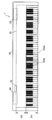
- FIG. 1 is a diagram illustrating a configuration of a keyboard device according to an embodiment.
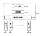
- FIG. 2 is a block diagram illustrating a configuration of the sound source device according to the embodiment.
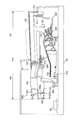
- Drawing 3 is a figure showing an example at the time of seeing the composition inside the case of an embodiment from the side.
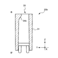
- Drawing 4 is a figure showing an example at the time of seeing the composition of the structure containing the rod-shaped flexible part of an embodiment from the side.
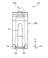
- Drawing 5 is a figure showing an example at the time of seeing the composition of the attachment structure of an embodiment from the slanting upper part.
- Drawing 6 is a figure showing an example at the time of seeing composition of the 1st member of an embodiment from the slanting upper part.
- Drawing 7 is a figure showing an example at the time of seeing the composition of the 1st member of an embodiment from the side.
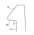
- Drawing 8A is a figure showing an example at the time of seeing the composition of the claw part of an embodiment from the side.
- Drawing 8B is a figure for explaining operation of a claw part of an embodiment.
- Drawing 9 is a figure showing an example at the time of seeing composition of the 2nd member of an embodiment from the slanting upper part.
- Drawing 10 is a figure showing an example at the time of seeing composition of the 2nd member of an embodiment from the upper part.
- 11 is a diagram illustrating an example of a cross section taken along line A-A ′ illustrated in FIG. 10 of the second member of the embodiment.
- FIG. 12 is a diagram illustrating an example of a cross section taken along line B-B ′ illustrated in FIG. 10 of the second member of the embodiment.
- Drawing 13 is a figure showing an example at the time of seeing the composition of the 2nd member of an embodiment from the back.
- Drawing 14 is a figure showing an example at the time of seeing composition of an attachment structure of an embodiment from back.
- Drawing 15 is a figure showing an example at the time of seeing composition of an attachment structure of an embodiment from the upper part.
- FIG. 16 is a diagram illustrating an example of a cross section taken along line A-A ′ illustrated in FIG. 10 of the mounting structure of the embodiment.
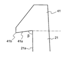
- FIG. 17A is a diagram illustrating an example of a claw portion according to a modification.
- FIG. 17B is a diagram illustrating an example of a main body according to a modification.
- FIG. 18 is a diagram illustrating an example when the configuration of the first member according to the modification is viewed obliquely from above.
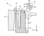
- FIG. 19 is a diagram illustrating an example of the structure of the mounting structure according to the modification as viewed from the rear and obliquely above.
- FIG. 20 is a view showing an example of a cross section corresponding to the line A-A ′ shown in FIG. 10 of the mounting structure according to the modification.
- FIG. 1 is a diagram illustrating a configuration of a keyboard device according to an embodiment.
- the keyboard device 1 is an electronic keyboard instrument that emits sound in response to a user (player) key depression such as an electronic piano.
- the keyboard device 1 may be a keyboard-type controller that outputs control data (for example, MIDI) for controlling an external sound source device in response to a key depression.
- control data for example, MIDI
- the keyboard device 1 may not have a sound source device.
- the keyboard device 1 includes a keyboard assembly 10.
- the keyboard assembly 10 includes a plurality of keys 100 extending in the longitudinal direction.
- the plurality of keys 100 include a plurality of white keys 100w and a plurality of black keys 100b.
- the plurality of white keys 100w and the plurality of black keys 100b are arranged side by side. This arranged direction is called a scale direction.
- the number of keys 100 is 88.
- the number of keys 100 is not limited to such an example, and may be appropriately determined according to the embodiment.
- the white key 100w and the black key 100b are described without particular distinction, they may be simply referred to as “key 100”.
- “w” is added at the end of the reference sign, it means that the structure corresponds to the white key.
- “b” is appended to the end of the code, it means that the configuration corresponds to the black key.
- a part of the keyboard assembly 10 exists inside the housing 90.
- a portion of the keyboard assembly 10 covered by the casing 90 is referred to as a non-appearance portion NV, and a portion exposed from the casing 90 and visible to the user is referred to as an appearance portion PV.
- the appearance part PV is a part of the key 100 and indicates an area where the user can perform a performance operation.
- a portion of the key 100 that is exposed by the appearance portion PV may be referred to as a key body portion.
- a sound source device 70 and a speaker 80 are arranged inside the housing 90.
- the tone generator 70 generates a sound waveform signal when the key 100 is pressed.
- the speaker 80 outputs the sound waveform signal generated in the sound source device 70 to an external space.
- the keyboard device 1 may be provided with a slider for controlling the volume, a switch for switching timbres, a display for displaying various information, and the like.
- directions such as up, down, left, right, front, and back indicate directions when the keyboard device 1 is viewed from the performer when performing. Therefore, for example, the non-appearance part NV can be expressed as being located on the back side with respect to the appearance part PV. Further, the direction may be indicated with the key 100 as a reference, such as the key front end side and the key rear end side. In this case, the key front end side indicates the front side as viewed from the performer with respect to the key 100. The rear end side of the key indicates the back side viewed from the performer with respect to the key 100.
- the black key 100b can be expressed as a portion protruding upward from the white key 100w from the front end to the rear end of the key body of the black key 100b.
- FIG. 2 is a block diagram illustrating a configuration of the sound source device according to the embodiment.
- the sound source device 70 includes a signal conversion unit 710, a sound source unit 730, and an output unit 750.
- the sensor 300 is provided corresponding to each key 100, detects a key operation, and outputs a signal corresponding to the detected content. In this example, the sensor 300 outputs a signal according to the key depression amount in three stages. The key pressing speed can be detected according to the interval of this signal.
- the signal conversion unit 710 acquires the output signal of the sensor 300 (sensors 300-1, 300-2,..., 300-88 corresponding to the 88 key 100), and operates according to the operation state of each key 100. Generate and output a signal.
- the operation signal is a MIDI signal. Therefore, the signal conversion unit 710 outputs note-on according to the key pressing operation. At this time, the key number indicating which of the 88 keys 100 has been operated and the velocity corresponding to the key pressing speed are also output in association with the note-on.
- the signal conversion unit 710 outputs the key number and note-off in association with each other.
- a signal corresponding to another operation such as a pedal may be input to the signal conversion unit 710 and reflected in the operation signal.
- the sound source unit 730 generates a sound waveform signal based on the operation signal output from the signal conversion unit 710.
- the output unit 750 outputs the sound waveform signal generated by the sound source unit 730. This sound waveform signal is output to, for example, the speaker 80 or the sound waveform signal output terminal.
- Drawing 3 is an explanatory view at the time of seeing the composition inside the case in an embodiment from the side.
- the keyboard assembly 10 and the speaker 80 are disposed inside the housing 90.
- the speaker 80 is disposed on the back side of the keyboard assembly 10.
- the speaker 80 is arranged to output a sound corresponding to the depressed key 100 toward the upper and lower sides of the housing 90.
- the sound output downward advances from the lower surface side of the housing 90 to the outside.
- the sound output upward passes through the space inside the keyboard assembly 10 from the inside of the housing 90, and is externally transmitted from the gap between the adjacent keys 100 in the exterior portion PV or the gap between the key 100 and the housing 90. Proceed to
- the keyboard assembly 10 includes a plurality of connecting portions 180, a hammer assembly 200, and a frame 500 in addition to the key 100 described above.
- the keyboard assembly 10 is a resin-made structure whose most configuration is manufactured by injection molding or the like.
- the frame 500 is fixed to the housing 90.
- each connection portion 180 includes a plate-like flexible portion 181 and a key-side support portion 183 that constitute the rear end portion of each key 100, and a rod-like flexible portion 185a.
- the plate-like flexible part 181 extends from the rear end of the key 100.
- the key side support portion 183 extends from the rear end of the plate-like flexible portion 181.
- the rod-like flexible portion 185 a connects the key side support portion 183 and the frame side support portion 585 of the frame 500.
- the rod-shaped flexible part 185 a is disposed between the key 100 and the frame 500.
- the key 100 can be rotated with respect to the frame 500 by bending the rod-shaped flexible portion 185a. That is, the rod-like flexible portion 185a corresponds to the “connecting member” of the present invention, and each key 100 is pivotally connected to the frame 500 by the rod-like flexible portion 185a of each connecting portion 180.
- the attachment portion described later is attached to both the joint portion between the rod-like flexible portion 185a and the key-side support portion 183 of the key 100 and the joint portion between the rod-like flexible portion 185a and the frame-side support portion 585 of the frame 500.
- a structure 20 (so-called snap fit) is provided.
- the mounting structure is designed so that the direction in which the snap-fit claw portion (claw portion 22 described later) is hooked and the longitudinal direction of the key 100 coincide. Since the snap-fit claw portion has a circumstance that it is desired to bend as much as possible, the longitudinal direction is more advantageous from the viewpoint of securing space than the scale direction in which the keys 100 are arranged with high density.
- FIG. 4 is a diagram illustrating a configuration of the structure body 185 including the rod-shaped flexible portion 185a according to the embodiment as viewed from the side surface.
- the structure 185 has a structure in which first members 20a described later are attached to both ends of a rod-like flexible portion 185a.
- a pair of first members 20 a are provided at both ends of the rod-like flexible portion 185 a so as to be opposite to each other. Therefore, by attaching one first member 20a to the key-side support portion 183 and attaching the other first member 20a to the frame-side support portion 585, the key-side support portion 183 and the frame-side support portion 585 can be connected to a bar.
- the flexible portion 185a can be coupled. Details of the mounting structure including the first member 20a will be described later.
- the key 100 includes a front end key guide 151 and a side key guide 153.
- the front end key guide 151 is slidably in contact with the front end frame guide 511 of the frame 500.
- the front end key guide 151 is in contact with the front end frame guide 511 on both sides of the upper and lower scale directions.
- the side key guide 153 is slidably in contact with the side frame guide 513 on both sides in the scale direction.
- the side key guide 153 is arranged in a region corresponding to the non-appearance portion NV on the side surface of the key 100 and exists on the key front end side with respect to the connection portion 180 (plate-like flexible portion 181). You may arrange
- the hammer assembly 200 is attached to the frame 500 so as to be rotatable. At this time, the shaft support part 220 of the hammer assembly 200 and the rotation shaft 520 of the frame 500 are slidably contacted at least at three points.
- the front end portion 210 of the hammer assembly 200 contacts the inner space of the hammer support portion 120 so as to be slidable in the front-rear direction.
- the sliding portion that is, the portion where the front end portion 210 and the hammer support portion 120 are in contact is located below the key 100 in the appearance portion PV (frontward from the rear end of the key body portion).
- a metal weight 230 is disposed on the back side of the rotation shaft.
- the weight portion 230 In a normal state (when the key is not pressed), the weight portion 230 is placed on the lower stopper 410, and the front end portion 210 of the hammer assembly 200 pushes the key 100 back.
- the weight portion 230 moves upward and collides with the upper stopper 430.
- the hammer assembly 200 applies weight to the key depression by the weight portion 230.
- the lower stopper 410 and the upper stopper 430 are formed of a buffer material or the like (nonwoven fabric, elastic body, etc.).
- the sensor 300 is attached to the frame 500 below the hammer support portion 120 and the front end portion 210. When the sensor 300 is crushed on the lower surface side of the front end portion 210 by the key depression, the sensor 300 outputs a detection signal. As described above, the sensor 300 is provided corresponding to each key 100.
- the attachment structure 20 of this embodiment is what is called a snap fit, and couples parts using the elasticity of material.
- a schematic configuration of the mounting structure 20 of the present embodiment will be described with reference to FIG.
- FIG. 5 is a diagram showing a case where the configuration of the mounting structure 20 of the embodiment is viewed from an oblique direction. Specifically, FIG. 5 shows a state in which the first member 20a and the second member 20b constituting the attachment structure 20 are coupled. In FIG. 5, the description will be focused on only the portion of the attachment structure 20, but as described above, the first member 20 a is a member provided at both ends of the rod-shaped flexible portion 185 a as shown in FIG. 4.
- the second member 20b is a member constituting the mounting structure 20 in a pair with the first member 20a, and is a member provided on the key side support portion 183 and the frame side support portion 585 shown in FIG.
- the mounting structure 20 in this embodiment uses a combination of the first member 20a and the second member 20b.
- the first member 20 a includes a flexible portion 21 extending in the vertical direction, a mounting portion 23 having a claw portion 22 provided at the tip of the flexible portion 21, and a positioning portion 25 coupled to the flexible portion 21.
- the 2nd member 20b is provided with the 1st insertion hole 33 in which the attachment part 23 is inserted from the downward side, and the 2nd insertion hole 35 in which the positioning part 25 is inserted from the downward side.
- the mounting structure 20 is configured so that the first member 20a can be mounted from below the second member 20b. That is, in the present embodiment, the direction in which the first member 20a is attached to the second member 20b (hereinafter also referred to as “attachment direction”) is the vertical direction.
- attachment direction the direction in which the first member 20a is attached to the second member 20b
- the state where the first member 20a is mounted to the second member 20b is the first member as shown in FIG. A state in which 20a and the second member 20b are coupled to each other.
- the front-rear direction of the mounting structure 20 coincides with the longitudinal direction of the key 100 shown in FIGS. Since the key 100 is arranged at a high density in the scale direction (direction orthogonal to the longitudinal direction), there is little room to secure a space for greatly bending the first member 20a. Therefore, by making the front-rear direction of the mounting structure 20 coincide with the longitudinal direction of the key 100, the amount of bending of the first member 20a can be increased as much as possible, and space saving can be achieved.
- Drawing 6 is a figure showing an example at the time of seeing composition of the 1st member 20a in mounting structure 20 of an embodiment from the slanting upper part.
- Drawing 7 is a figure showing an example at the time of seeing the composition of the 1st member 20a in mounting structure 20 of an embodiment from the side.
- the first member 20a shown in FIGS. 6 and 7 corresponds to the claw side member in the mounting structure 20 of the present embodiment.
- the first member 20a has a substantially square columnar flexible portion 21 and a claw portion 22 provided at one end of the flexible portion 21, and has a mounting portion 23 and a flexible portion 21 extending in the mounting direction (that is, the vertical direction).
- the positioning part 25 has a shape that extends in the same direction as the flexible part 21, that is, in the vertical direction.
- the flexible portion 21 is made of a flexible material.
- the flexible material is not particularly limited and may be appropriately selected depending on the embodiment.
- a plastic material can be used as the flexible material.
- the flexible portion 21 of the present embodiment is configured such that the length (thickness) in the direction along the X axis is shorter than the length (width) in the direction along the Y axis. Therefore, the flexibility of the flexible portion 21 is greatly deflected in the direction along the X axis (that is, the front-rear direction), and the direction along the Y axis (that is, the left-right direction) is larger than the direction along the X axis. It is designed to bend slightly. That is, the flexible portion 21 has a shape that is less flexible in the direction along the Y axis than the flexibility in the direction along the X axis.
- the flexible portion 21 is configured such that the claw portion 22 overlaps the second member 20b more deeply (that is, the amount of engagement increases) by increasing the flexibility in the direction along the X axis. ing.
- claw part 22 is a site
- claw part 22 which concerns on this embodiment is provided in the front-end
- the direction in which the claw portion 22 protrudes may not be limited to the front, and may be appropriately determined according to, for example, the configuration of the second member 20b (particularly, the position of the surface on which the claw portion 22 is hooked).
- the lower part of the attachment part 23 from the alternate long and short dash line 24 shown in FIG. 7 is called the flexible part 21, and the upper part is called the claw part 22.
- the flexible portion 21 and the claw portion 22 may be integrally formed, or may be configured by different members.
- the 2nd member 20b is contacted and caught. It is a part that functions as a part.
- the lower surface 22a of the claw portion 22 receives the force in the Z-axis direction applied to the flexible portion 21, so that the first member 20a can be prevented from falling off from the second member 20b.
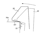
- FIG. 8A is a diagram illustrating an example when the configuration of the claw portion 22 in the mounting structure 20 of the embodiment is viewed from the side.
- Drawing 8B is a figure for explaining operation of claw part 22 in attachment structure 20 of an embodiment.
- the lower surface 22a of the claw portion 22 and the surface 21a of the flexible portion 21 are an obtuse angle.
- the lower surface 22a of the claw portion 22 can correspond to a surface inclined in the positive direction of the Z axis (the direction of the arrow) with respect to the X axis shown in FIG.
- the lower surface 22 a of the claw portion 22 can correspond to a surface inclined upward with respect to the flexible direction of the flexible portion 21.
- the claw portion 22 has the lower surface 22a in contact with the upper surface (upper surface 31a described later) of the second member 20b. Superimpose on.
- FIG. 8B shows a state where the claw portion 22 is coming off from the opening peripheral edge portion 331 of the first insertion hole 33 on the upper surface 31a of the second member 20b.
- a force is applied to the claw portion 22 in the direction of the arrow by the elastic force of the flexible portion 21. Therefore, the claw portion 22 slides in the direction of the arrow in a state where the lower surface 22a is in contact with the corner of the upper surface 31a (specifically, the edge of the first insertion hole 33 described later), and the position indicated by the solid line Move to.
- the angle ⁇ formed by the lower surface 22a of the claw portion 22 and the surface 21a of the flexible portion 21 is an obtuse angle, so that the claw portion is in contact with the opening peripheral edge portion 331 of the first insertion hole 33.
- the surface (lower surface 22a) of 22 is configured to be slidably inclined with respect to the opening peripheral edge portion 331 in a direction in which the claw portion 22 overlaps the second member 20b.
- the elastic force that tends to move forward of the flexible portion 21 is moved upward by the lower surface 22a of the claw portion 22. It is converted into the power of.
- the lower surface 22a of the claw portion 22 works in a direction to increase the amount of engagement of the claw portion 22 with the second member 20b (the length with which the claw portion 22 is superimposed on the second member 20b).
- the amount of self-recovering action (nail) Part pulling action) can be added.
- the positioning part 25 extends in the same direction as the attachment part 23, and is a part for determining the relative position of the attachment part 23 (particularly the claw part 22) with respect to the second member 20b.
- the positioning portion 25 and the flexible portion 21 of the attachment portion 23 are connected to each other on the rear end side in the mounting direction by a flat plate-like connecting portion 27. That is, the lower end portion of the positioning portion 25 and the lower end portion of the flexible portion 21 of the attachment portion 23 are connected by the connecting portion 27.
- the direction which connects the flexible part 21 and the positioning part 25 corresponds with the direction where the nail
- the direction in which the flexible portion 21 and the positioning portion 25 are connected and the direction in which the claw portion 22 is superimposed on the second member 20b coincide with the front-rear direction.
- the positioning part 25 can receive the force by the bending in the front-back direction of the flexible part 21 reliably, and can support the flexible part 21.
- the positioning portion 25 is composed of three parts, a first part 25a, a second part 25b, and a third part 25c, in order from the rear end side (that is, the lower end side) in the insertion direction of the second member 20b with respect to the second insertion hole 35. It is configured.
- the widths of the first portion 25a, the second portion 25b, and the third portion 25c in the direction perpendicular to the insertion direction (the direction along the X axis in FIG. 7) are in the ranges of X1, X2, and X3, respectively. These widths are in a relationship of X1> X2> X3. That is, each width such as X1, X2, and X3 does not mean an absolute value, but indicates a relative relationship between the widths of the first portion 25a, the second portion 25b, and the third portion 25c.
- the first portion 25a and the second portion 25b have a rectangular cross section (XY plane) in a direction perpendicular to the insertion direction with respect to the second insertion hole 35, and the third portion 25c extends in the insertion direction.
- the cross section (XY plane) in the vertical direction has a cross shape.
- the shape of each of the portions 25a to 25c is not limited to such an example, and may be appropriately determined according to the embodiment.
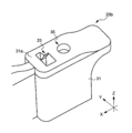
- Drawing 9 is a figure showing an example at the time of seeing composition of the 2nd member 20b in attachment structure 20 of an embodiment from the slanting upper part.
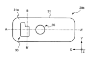
- Drawing 10 is a figure showing an example at the time of seeing composition of the 2nd member 20b in mounting structure 20 of an embodiment from the upper part.
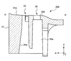
- FIG. 11 is a diagram illustrating an example of a cross section taken along line A-A ′ illustrated in FIG. 10 of the second member 20 b in the mounting structure 20 of the embodiment.
- FIG. 12 is a diagram illustrating an example of a cross section taken along line B-B ′ illustrated in FIG. 10 of the second member 20 b in the mounting structure 20 of the embodiment.
- Drawing 13 is a figure showing an example at the time of seeing composition of the 2nd member 20b in attachment structure 20 of an embodiment from back (back side).
- the second member 20b shown in FIGS. 9 to 13 corresponds to a member on the receiving side with respect to the first member 20a in the mounting structure 20 of the present embodiment.
- the second member 20 b includes a main body 31, and a first insertion hole 33, a second insertion hole 35, a notch 37, and a protrusion 39 provided in the main body 31.
- the main body portion 31 of the present embodiment is a main body portion of the second member 20b and corresponds to the key side support portion 183 and the frame side support portion 585 shown in FIG.
- the first insertion hole 33 extends in the mounting direction of the first member 20a with respect to the second member 20b (that is, the vertical direction) and is provided so as to penetrate the main body 31.
- the attachment portion 23 of the first member 20a is inserted into the first insertion hole 33 from below the main body portion 31.
- the length of the mounting portion 23 in the mounting direction (Z-axis direction) of the flexible portion 21 corresponds to the length of the first insertion hole 33, thereby causing the claw portion 22 to protrude from the first insertion hole 33,
- the claw portion 22 can be hooked on the opening peripheral edge on the upper side of the first insertion hole 33.
- the claw portion 22 of the first member 20 a overlaps the upper surface 31 a of the main body portion 31, whereby the first member 20 a and the second member 20 b are coupled.
- the first insertion hole 33 can correspond to the internal space of the main body portion 31 formed for inserting the attachment portion 23 (the flexible portion 21 and the claw portion 22) of the first member 20a.
- the second member 20b of the present embodiment has two inclined surfaces as the inner wall surface of the first insertion hole 33, that is, a first inclined surface 34a and a second inclined surface 34b.
- the first inclined surface 34 a is an inclined surface that constitutes a part of the front wall surface when the cross section including the X axis is viewed from the left side
- the second inclined surface 34 b is As shown in FIG. 12, when the cross section containing a Y-axis is seen from the front side, it is an inclined surface which comprises a part of wall surface of the right side (the direction of the arrow of a Y-axis). Any inclined surface is provided so that the width of the first insertion hole 33 becomes narrower as it goes upward when the cross section of the first insertion hole 33 is viewed from the side.
- the first inclined surface 34 a and the second inclined surface 34 b are disposed at a position where the claw portion 22 corresponding to the distal end portion of the attachment portion 23 contacts when the attachment portion 23 is inserted into the first insertion hole 33. Therefore, when the attachment portion 23 is inserted into the first insertion hole 33, the claw portion 22 slides on the respective inclined surfaces, so that the position of the claw portion 22 (position with respect to the positioning portion 25) is front and back. Move in the left or right direction.
- the upper surface of the claw portion 22 is in contact with each inclined surface.
- the “upper surface of the claw portion” refers to the entire surface visually recognized when the claw portion 22 is viewed from above. That is, when the claw portion 22 is a quadrangular pyramid as in the present embodiment, vertices and ridge lines included in the range viewed from above are also included in the upper surface.
- the second insertion hole 35 extends in the mounting direction of the first member 20 a with respect to the second member 20 b (that is, the vertical direction) and is provided so as to penetrate the main body portion 31. .
- the 2nd insertion hole 35 has the 1st field 35a and the 2nd field 35b in order from the back end side (namely, lower end side) of the insertion direction of positioning part 25 to the 2nd above-mentioned insertion hole 35. ing.
- the first region 35a is a portion into which the first portion 25a and the second portion 25b shown in FIG. 7 are inserted, and the second region 35b is a portion into which the third portion 25c is inserted.
- the first region 35a has a rectangular cross section (XY plane) perpendicular to the insertion direction of the positioning portion 25 with respect to the second insertion hole 35, and the second region 35b A cross section (XY plane) in a direction perpendicular to the direction is circular.
- region (35a, 35b) may not be limited to such an example, and may be suitably determined according to embodiment.
- the maximum width among the widths along the X axis of the first region 35a is narrower than the width X1 of the first portion 25a, and is the same as or slightly wider than the width X2 of the second portion 25b. .
- the maximum width of the second region 35b along the X axis is narrower than the first region 35a, narrower than the width X2 of the second portion 25b, and is equal to or more than the width X3 of the third portion 25c. Slightly wider.
- the 1st field 35a is constituted so that the 2nd portion 25b can be inserted.
- the second region 35b is configured such that the second portion 25b cannot be inserted and the third portion 25c can be inserted. The relative relationship between these widths will be described later.
- the positioning portion 25 of the first member 20a is inserted into the second insertion hole 35 from below the main body portion 31.
- the width X1 of the first portion 25a of the positioning portion 25 is wider than the maximum width of the first region 35a, the first portion 25a is fixed to the first region 35a by an interference fit. .
- the positioning portion 25 is fixed inside the second insertion hole 35 by an interference fit, whereby the relative positional relationship of the mounting portion 23 with respect to the second member 20b is determined. Therefore, the second insertion hole 35 can correspond to the internal space of the main body portion 31 formed to insert the positioning portion 25 of the first member 20a.
- the notch 13 is a slit-like portion provided on the back surface 31b of the main body 31, and exposes a part of the second insertion hole 35.
- the notch portion 37 is provided to enable placement of a plate-like member (such as a reinforcing portion 45 described later) connected to the positioning portion 25.
- the plate-like member is provided, for example, when reinforcing the strength of the entire mounting structure, or when extending the length of the key side support portion 183 and / or the frame side support portion 585.
- the protrusions 39 are provided at the pair of ends of the notch 37. Each protrusion 39 is provided for the purpose of regulating the spread of the notch 37. Specifically, in a state where the first member 20a is attached to the second member 20b, the two protrusions 39 are sandwiched by a part of the first member 20a, so that the spread of the notch 37 is restricted.
- Drawing 14 is a figure showing an example at the time of seeing composition of attachment structure 20 of an embodiment from back.
- the first member 20a of the present embodiment has a concave portion 29 having a shape that can hold the protrusion 39 when the rear end of the connecting portion 27 is viewed from the back side.
- the connecting portion 27 is indicated by hatching.
- Drawing 15 is a figure showing an example at the time of seeing composition of attachment structure 20 of an embodiment from the upper part.
- FIG. 16 is a diagram illustrating an example of a cross section taken along line AA ′ illustrated in FIG. 10 of the mounting structure 20 according to the embodiment.
- the third portion of the positioning portion 25 of the first member 20a is located inside the second insertion hole 35 of the second member 20b.
- a portion 25c is visible.
- the third portion 25 c of the positioning portion 25 is inserted into the second region 35 b of the second insertion hole 35.
- the maximum width of the width X3 of the third portion 25c matches the maximum width of the second region 35b. Therefore, at least a part of the third portion 25 c of the positioning portion 25 is in contact with the inner wall surface of the second region 35 b of the second insertion hole 35.
- the third portion 25c of the positioning portion 25 is formed in a cross-shaped cross section, and the second region 35b of the second insertion hole 35 is formed in a circular cross section. Therefore, as shown in FIG. 15, in the state in which the first member 20a is attached to the second member 20b, the cross-shaped end portions of the third portion 25c are second in a total of four locations in the front-rear and left-right directions. It is comprised so that the inner wall face of the area
- the positioning unit 25 is restricted from moving in the direction (XY plane direction) perpendicular to the mounting direction of the first member 20a with respect to the second member 20b, and as a result, the mounting unit 23 moves in the XY plane direction. Is regulated. That is, the positioning part 25 is configured to restrict the movement of the attachment part 23 in the direction perpendicular to the mounting direction.
- the third portion 25c is formed in a tapered shape whose width becomes narrower from the rear end side to the front end side in the insertion direction, that is, from the lower end side to the upper end side. Therefore, when the positioning portion 25 is inserted into the second insertion hole 35, the third portion 25c can function as a guide, and accurate positioning can be realized.
- the length of the first portion 25a and the second portion 25b of the positioning portion 25 in the insertion direction corresponds to the length of the first region 35a of the second insertion hole 35. Therefore, as shown in FIG. 16, in the state where the first member 20a is attached to the second member 20b, the upper end surface 25b-1 of the second portion 25b is connected to the first region 35a and the second region in the second insertion hole 35. It is comprised so that the level
- the cross section cut along the X axis is seen, but the cross section along any axis in the XY plane including the Y axis has the same configuration.
- the positioning unit 25 is restricted from further movement in the mounting direction (Z-axis direction) of the first member 20a with respect to the second member 20b.
- the positioning portion 25 is configured to restrict the movement of the mounting portion 23 in the mounting direction of the first member 20a with respect to the second member 20b in a state where the first member 20a is mounted on the second member 20b. ing.
- the mounting structure 20 of the present embodiment is inserted into the second insertion hole 35 so that the first member 20a
- the relative positional relationship with the second member 20b can be fixed.
- the positioning portion 25 can be fixed to the second member 20b by an interference fit while restricting the movement of the mounting portion 23 in the XY plane direction by the positioning portion 25.
- the mounting structure 20 of the present embodiment can prevent the mounting portion 23 from being inserted in the mounting direction more than necessary by the positioning portion 25. That is, the positioning portion 25 is fixed to the second insertion hole 35 by an interference fit, and at the same time, the claw portion 22 of the attachment portion 23 protrudes from the first insertion hole 33, and the claw portion 22 is formed on the opening peripheral edge of the first insertion hole 33. Can be caught. Thereby, the play of the nail
- the shape of the flexible portion 21 of the mounting portion 23 may not be limited to a quadrangular prism shape, and any shape can be used as long as it extends in the direction in which the first member 20a is attached to the second member 20b. May be formed.
- the shape of the positioning portion 25 may not be limited to a quadrangular prism shape, and may be any shape as long as it extends in the direction in which the first member 20a is attached to the second member 20b. Also good.
- the shape of other components may be changed as appropriate.
- the flexible portion 21 may be formed in a columnar shape other than a square columnar shape, a plate shape, or the like.
- the positioning part 25 may be formed in shapes, such as columnar shape other than a square columnar shape, cross-sectional cross shape, a cylinder shape, and cross-sectional cross-beam shape.
- the breadth of the notch part 37 is suppressed using a pair of projection part 39 provided in the 2nd member 20b.
- the configuration for suppressing the spread of the notch 37 may not be limited to such an example. If the cutout portion 37 is sandwiched by a part of the first member 20a from the left-right direction, the spread of the cutout portion 37 can be restricted even if each projection 39 is omitted. Note that the notch 37 may be omitted.
- the 3rd part 25c of the positioning part 25 is formed in cross-sectional shape
- region 35b of the 2nd insertion hole 35 is formed in cross-sectional circle shape
- each cross-shaped of the 3rd part 25c is formed.
- the positioning part 25 is configured to restrict the movement of the attachment part 23 in the direction perpendicular to the mounting direction by making the end part contact the inner wall surface of the second region 35b.
- the configuration for restricting the movement of the attachment portion 23 in the direction perpendicular to the mounting direction may not be limited to such an example.
- the positioning portion 25 moves the mounting portion 23 in the direction perpendicular to the mounting direction. You may make it regulate.
- the third portion 25c of the positioning portion 25 may be formed in a cylindrical shape or a cross-sectional shape such as a shape having a portion extending in at least three directions.
- the second region 35b of the second insertion hole 35 may be formed in a cross-sectional shape such as a circular shape, an elliptical shape, or a polygonal shape.
- the positioning part 25 has the upper end surface of the 2nd part 25b of the positioning part 25 in contact with the level
- the configuration for restricting further movement of the mounting portion 23 in the mounting direction at the time of mounting may not be limited to such an example.
- the upper end of the positioning portion 25 is in contact with the bottom of the second insertion hole 35.
- further movement of the mounting portion 23 in the mounting direction at the time of mounting may be restricted.
- claw part 22 and the surface 21a of the flexible part 21 make is an obtuse angle.
- claw part 22 is caught is flat.
- claw part 22 which contacts the opening peripheral part 331 of the 1st insertion hole 33 slides with respect to the said opening peripheral part 331 in the direction which the claw part 22 overlaps with the 2nd member 20b. It is configured to tilt as possible.
- claw part 22 and the opening peripheral part 331 may not be limited to such an example.
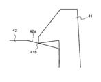
- FIG. 17A illustrates the configuration of the claw portion 41 according to this modification.
- the claw portion 41 when viewed from the side, the claw portion 41 has a lower surface 41a of the claw portion 41 and a surface 21a of the flexible portion 21 (specifically, of the entire surface of the flexible portion 21,
- the angle ⁇ formed with the surface on the side where the lower surface 22a exists is an acute angle.
- the lower surface 22a of the claw portion 22 when viewed from the side, is a surface inclined in the negative direction of the Z axis (the direction opposite to the direction of the arrow) with respect to the X axis shown in FIG.
- the lower surface 22a of the claw portion 22 can correspond to a surface inclined downward with respect to the flexible direction of the flexible portion 21 described above.
- the claw portion 41 having the configuration shown in FIG. 17A When the claw portion 41 having the configuration shown in FIG. 17A is used, the claw portion 41 is not easily deformed even if a strong downward force is applied to the flexible portion 21 and the claw portion 41. That is, according to the present modification, it is possible to realize a mounting structure that has high strength against the force of pulling downward.
- FIG. 17B illustrates a modification of the opening peripheral edge portion of the first insertion hole 33 in the second member 20b.
- the main body portion 42 of the second member may be configured to have an inclined surface 42 a at the opening peripheral edge portion of the first insertion hole 33. That is, in this modification, an example in which the inclined surface (lower surface 22a) is not provided on the claw side as shown in FIG. 8A but on the main body 42 side is shown.
- the front end portion 41b of the claw portion 41 and the inclined surface 42a are in contact with each other, and the forward force due to the bending of the flexible portion 21 is achieved.
- the tip 41b slides on the slope of the inclined surface 42b.
- a force for moving the claw portion 41 to the front side by the inclined surface 42a works while realizing a mounting structure having high strength with respect to the pulling force, so that the amount of engagement of the claw portion 41 with the second member Can be increased. Therefore, according to this modification, the first member and the second member can be stably coupled.
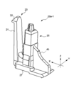
- FIGS. 18 and 19 a plate-like member may be connected to the positioning portion 25 of the first member 20a.
- FIG. 18 is a diagram illustrating an example of the first member 20a-1 according to the present modification as viewed obliquely from above.
- FIG. 19 is a diagram illustrating an example of the structure of the mounting structure 20-1 according to the present modification as viewed from the rear and obliquely above.
- a reinforcing portion 45 made of a plate-like member is provided behind the positioning portion 25.
- the first member 20a-1 is the same as the first member 20a.
- the reinforcing portion 45 is connected so as to straddle the second portion 25b to the first portion 25a of the positioning portion 25, and is connected to the connecting portion 27 on the lower end side.
- the range to which the reinforcement part 45 is connected may not be limited to such an example, and may be appropriately determined according to the embodiment.
- the reinforcing portion 45 is integrally formed with the positioning portion 25 and the connecting portion 27. Therefore, the connection between the positioning portion 25 and the connecting portion 27 becomes very strong, and as a result, the relative positional relationship between the positioning portion 25 and the mounting portion 23 can be stably maintained.
- the reinforcement part 45 may not be limited to such an example and may be comprised by a member different from at least any one of the positioning part 25 and the connection part 27. FIG.
- the reinforcing portion 45 connected to the positioning portion 25 is disposed in the gap of the notch portion 37 provided in the second member 20b.
- the cutout portion 37 is provided in the second member 20b, and the plate member (reinforcing portion 45) that can be arranged in the cutout portion 37 is connected to the positioning portion 25, whereby the first member 20a-1 is connected.
- the strength of the positioning part 25 to be configured can be increased.
- the 2nd insertion hole 35 has penetrated the main-body part 31 in the up-down direction in the 2nd member 20b.
- the second insertion hole 35 may not penetrate the main body portion 31.
- FIG. 20 illustrates a cross section corresponding to the line A-A ′ shown in FIG. 10 of the mounting structure 20-2 according to this modification.
- the positioning portion 25 has three parts, that is, the first part 25a, the second part 25b, and the third part 25c, and the second insertion hole 35 has the first area 35a and the second area 35b. It has two areas.
- the positioning portion 25 and the second insertion hole 35 are not limited to such an example, and the portions 25a to 25c and the regions (35a, 35b) may be omitted as appropriate.
- the third portion 25 c of the positioning portion 25 is omitted, and the second region 35 b of the second insertion hole 35 is omitted.
- the movement of the positioning portion 25 in the XY plane direction is restricted by an interference fit, and the movement in the Z-axis direction (upward) is such that the upper end surface of the second portion 25b is the upper end surface of the first region 35a. It is regulated by hitting.
- region 35b you may comprise so that the 2nd insertion hole 35 may not penetrate the main-body part 31.
- the said embodiment attaches to both the coupling
- a structure 20 is provided. However, for any one of the coupling portions, a different attachment method may be adopted instead of the attachment structure 20. Moreover, in the said embodiment, the example which uses the attachment structure 20 in the keyboard apparatus 1 is shown. However, the mounting structure 20 can be used for devices other than the keyboard device 1. For example, the attachment structure 20 may be used to attach a printed wiring board to an equipment device or the like.
Landscapes
- Engineering & Computer Science (AREA)
- General Engineering & Computer Science (AREA)
- Physics & Mathematics (AREA)
- Acoustics & Sound (AREA)
- Multimedia (AREA)
- Mechanical Engineering (AREA)
- Electrophonic Musical Instruments (AREA)
- Connection Of Plates (AREA)
- Snaps, Bayonet Connections, Set Pins, And Snap Rings (AREA)
Abstract
This mounting structure is provided with: a first member that includes a mounting part having a flexible part and a hook part disposed on one end of the flexible part, and a positioning part connected to the flexible part; and a second member that includes a first insertion hole into which the mounting part is inserted, and a second insertion hole into which the positioning part is inserted. The positioning part is fitted into the second insertion hole via interference fitting in a state in which the first member is fitted to the second member.
Description
本発明は、材料の弾性を利用して部品同士を結合する取付け構造に関する。特に、鍵盤装置の鍵の取付け構造に関する。
The present invention relates to a mounting structure that couples parts using the elasticity of a material. In particular, the present invention relates to a key mounting structure of a keyboard device.
従来、部品同士を結合する方式として、スナップフィットと呼ばれる、材料の弾性を利用した簡易な取付け構造が知られている。この取付け構造は、例えば、プラスチック等の成形部品を組み合わせて結合する際に利用される。
Conventionally, a simple attachment structure using the elasticity of a material, called snap fit, is known as a method for joining parts together. This attachment structure is used, for example, when a combination of molded parts such as plastic is combined.
上述の取付け構造は、部品同士の結合の容易性が要求されるともに、いったん結合した後は、簡単に外れないように固定されるという性能が要求される。このような性能を考慮した取付け構造として、例えば、特許文献1では、プリント配線板の取付け構造が提案されている。
The above-described mounting structure is required to be easy to join parts together and to be fixed so that it cannot be easily detached after being joined once. As an attachment structure considering such performance, for example, Patent Document 1 proposes an attachment structure for a printed wiring board.
しかしながら、特許文献1で提案されている取付け構造は、部品寸法のばらつきを考慮していないため、部品寸法のばらつきに起因して、部品同士が意図せず分離してしまったり、部品同士の取付けが困難になってしまったりする可能性がある。また、特許文献1には、位置決めピンを用いて取付け精度を向上させる試みがなされているが、前述の部品寸法のばらつきが位置決め精度を落とす要因となる。
However, since the mounting structure proposed in Patent Document 1 does not take into account variations in component dimensions, components may unintentionally be separated due to variations in component dimensions, or components may be mounted together. May become difficult. In Patent Document 1, an attempt is made to improve the mounting accuracy by using a positioning pin. However, the above-described variation in component dimensions causes a decrease in positioning accuracy.
本発明の一側面に係る目的は、取付け時の位置決め精度を向上させた取付け構造を提供することである。
An object according to one aspect of the present invention is to provide a mounting structure with improved positioning accuracy during mounting.
本発明の一側面に係る取付け構造は、可撓部及び前記可撓部の一端に設けられた爪部を有する取付け部、並びに前記可撓部と連結された位置決め部を含む第1部材と、前記取付け部が挿入される第1挿入孔、及び前記位置決め部が挿入される第2挿入孔を含む第2部材と、を備え、前記第1挿入孔は、前記第2部材に対して前記第1部材を装着する方向に貫通し、前記取付け部は、前記第2部材に対して前記第1部材を装着した状態において、前記第1挿入孔から前記爪部を突出させ、前記第1挿入孔の開口周縁部に前記爪部を引掛けることができるように構成されており、前記第2部材に対し前記第1部材を装着した状態において、前記位置決め部は、前記第2挿入孔に対し締まり嵌めにより嵌め込まれる。なお、例えば、可撓部は、一方向に延びる形状を有しており、位置決め部は、可撓部と同じ方向に延びる形状を有している。
An attachment structure according to one aspect of the present invention includes a first member including a flexible part, an attachment part having a claw part provided at one end of the flexible part, and a positioning part connected to the flexible part, A first insertion hole into which the attachment portion is inserted, and a second member including a second insertion hole into which the positioning portion is inserted, wherein the first insertion hole is formed with respect to the second member. The mounting portion penetrates in the direction in which the first member is attached, and the attachment portion projects the claw portion from the first insertion hole in a state where the first member is attached to the second member, and the first insertion hole The claw portion can be hooked on the peripheral edge of the opening, and when the first member is mounted on the second member, the positioning portion is tightened against the second insertion hole. It is fitted by fitting. For example, the flexible part has a shape extending in one direction, and the positioning part has a shape extending in the same direction as the flexible part.
上記一側面に係る取付け構造において、前記可撓部と前記位置決め部とを連結する方向は、前記爪部が前記第2部材に重畳する方向と一致することが好ましい。
In the mounting structure according to the one aspect, it is preferable that a direction in which the flexible portion and the positioning portion are connected coincides with a direction in which the claw portion overlaps the second member.
上記一側面に係る取付け構造において、前記位置決め部は、前記第2部材に対して前記第1部材を装着する方向に垂直な方向への前記取付け部の移動を規制するように働くように構成されてもよい。
In the mounting structure according to the one aspect, the positioning portion is configured to function so as to restrict movement of the mounting portion in a direction perpendicular to a direction in which the first member is mounted with respect to the second member. May be.
上記一側面に係る取付け構造において、前記位置決め部は、前記第2部材に対し前記第1部材を装着した状態において、前記第2部材に対して前記第1部材を装着する方向への前記取付け部の移動を規制するように働くように構成されてもよい。
In the mounting structure according to the one aspect, the positioning portion is configured to mount the first member on the second member in a state where the first member is mounted on the second member. It may be configured to work so as to restrict movement.
上記一側面に係る取付け構造において、前記位置決め部は、前記第2挿入孔に対する挿入方向の後端側から順に、第1部分、前記第1部分よりも幅が狭い第2部分、及び前記第2部分よりも幅が狭い第3部分を有し、前記第2挿入孔は、前記挿入方向の後端側から順に、前記第2部分が挿入可能な第1領域、及び前記第1領域より幅が狭く、前記第2部分が挿入不能であって前記第3部分が挿入可能な第2領域を有し、前記第2部材に対し前記第1部材を装着した状態において、前記第3部分の少なくとも一部が前記第2領域の内壁面に接するように構成されていてもよい。また、このとき、前記第2部材に対し前記第1部材を装着した状態において、前記位置決め部の前記第2部分の上端面は、前記第2挿入孔における前記第1領域及び前記第2領域の境界の段差面に接するように構成されてもよい。また、前記位置決め部の前記第3部分は、前記挿入方向に垂直な方向の断面が十字形状であってよく、前記第2挿入孔の前記第2領域は、前記挿入方向に垂直な方向の断面が円形状であってよく、前記第2部材に対し前記第1部材を装着した状態において、前記第3部分の十字形状の各端部が前記第2領域の内壁面に接するように構成されてよい。
In the mounting structure according to the one aspect, the positioning portion includes, in order from the rear end side in the insertion direction with respect to the second insertion hole, a first portion, a second portion that is narrower than the first portion, and the second portion. A third portion having a width smaller than that of the portion, and the second insertion hole has, in order from the rear end side in the insertion direction, a first region in which the second portion can be inserted, and a width larger than that of the first region. In a state where the second portion is narrow and the second portion is not insertable and the third portion is insertable, and the first member is attached to the second member, at least one of the third portions. The portion may be configured to contact the inner wall surface of the second region. Further, at this time, in a state where the first member is attached to the second member, the upper end surface of the second portion of the positioning portion is the first region and the second region in the second insertion hole. You may be comprised so that the level | step difference surface of a boundary may be touched. Further, the third portion of the positioning portion may have a cross shape in a cross section perpendicular to the insertion direction, and the second region of the second insertion hole has a cross section perpendicular to the insertion direction. May be circular, and in a state in which the first member is attached to the second member, each cross-shaped end portion of the third portion is configured to contact an inner wall surface of the second region. Good.
上記一側面に係る取付け構造において、前記第2挿入孔の開口周縁部に接触する前記爪部の面は、前記爪部が前記第2部材に重畳する方向に当該開口周縁部に対して摺動可能に傾斜するように構成されていてもよい。
In the mounting structure according to the one aspect, the surface of the claw portion that contacts the opening peripheral portion of the second insertion hole slides relative to the opening peripheral portion in a direction in which the claw portion overlaps the second member. You may be comprised so that it may incline.
上記一側面に係る取付け構造において、前記第2部材は、前記第2挿入孔の一部を露出させる切欠き部を有していてもよい。この第2部材は、例えば、前記切欠き部の端部に二つの突起部を有し、前記二つの突起部が前記第1部材の一部で挟み込まれることにより、前記切欠き部の広がりが規制されるように構成されていてもよい。
In the mounting structure according to the one aspect, the second member may have a notch that exposes a part of the second insertion hole. The second member has, for example, two protrusions at the end of the notch, and the two protrusions are sandwiched by a part of the first member, thereby expanding the notch. It may be configured to be regulated.
上記一側面に係る取付け構造において、前記第1部材は、前記位置決め部に連結された板状部材を含み、前記第2部材に対し前記第1部材を装着した状態において、前記板状部材は、前記切欠き部の間隙に配置されるように構成されていてもよい。
In the mounting structure according to the one aspect, the first member includes a plate-like member connected to the positioning portion, and in the state where the first member is attached to the second member, the plate-like member is You may be comprised so that it may arrange | position in the gap | interval of the said notch part.
また、本発明の一側面に係る鍵盤装置は、フレームと、長手方向に延びる複数の鍵と、前記各鍵を前記フレームに回動可能に連結する複数の連結部材と、を備え、前記各連結部材及び前記各鍵の結合部分、並びに前記各連結部材及び前記フレームの結合部分は上記いずれかの形態に係る取付け構造で構成される。
The keyboard device according to an aspect of the present invention includes a frame, a plurality of keys extending in a longitudinal direction, and a plurality of connecting members that rotatably connect the keys to the frame. The connecting portion of the member and each key, and the connecting portion of each connecting member and the frame are configured by the mounting structure according to any one of the above forms.
本発明によれば、取付け時の位置決め精度を向上させることができる。
According to the present invention, positioning accuracy at the time of mounting can be improved.
以下、本発明の実施形態について、図面を参照しながら詳細に説明する。以下に示す実施形態は本発明の実施形態の一例であって、本発明はこれらの実施形態に限定して解釈されるものではない。なお、本実施形態で参照する図面において、同一部分または同様な機能を有する部分には同一の符号または類似の符号(数字の後にA、B等を付しただけの符号)を付し、その繰り返しの説明は省略する場合がある。また、図面の寸法比率(各構成間の比率、縦横高さ方向の比率等)は説明の都合上実際の比率とは異なったり、構成の一部が図面から省略されたりする場合がある。
Hereinafter, embodiments of the present invention will be described in detail with reference to the drawings. The following embodiments are examples of embodiments of the present invention, and the present invention should not be construed as being limited to these embodiments. Note that in the drawings referred to in the present embodiment, the same portion or a portion having a similar function is denoted by the same reference symbol or a similar reference symbol (a reference symbol simply including A, B, etc. after a number) and repeated. The description of may be omitted. In addition, the dimensional ratios of the drawings (the ratios between the components, the ratios in the vertical and horizontal height directions, etc.) may be different from the actual ratios for convenience of explanation, or some of the configurations may be omitted from the drawings.
[鍵盤装置の構成]
図1は、実施形態における鍵盤装置の構成を示す図である。鍵盤装置1は、この例では、電子ピアノなどユーザ(演奏者)の押鍵に応じて発音する電子鍵盤楽器である。なお、鍵盤装置1は、外部の音源装置を制御するための制御データ(例えば、MIDI)を、押鍵に応じて出力する鍵盤型のコントローラであってもよい。この場合には、鍵盤装置1は、音源装置を有していなくてもよい。 [Configuration of keyboard device]
FIG. 1 is a diagram illustrating a configuration of a keyboard device according to an embodiment. In this example, thekeyboard device 1 is an electronic keyboard instrument that emits sound in response to a user (player) key depression such as an electronic piano. Note that the keyboard device 1 may be a keyboard-type controller that outputs control data (for example, MIDI) for controlling an external sound source device in response to a key depression. In this case, the keyboard device 1 may not have a sound source device.
図1は、実施形態における鍵盤装置の構成を示す図である。鍵盤装置1は、この例では、電子ピアノなどユーザ(演奏者)の押鍵に応じて発音する電子鍵盤楽器である。なお、鍵盤装置1は、外部の音源装置を制御するための制御データ(例えば、MIDI)を、押鍵に応じて出力する鍵盤型のコントローラであってもよい。この場合には、鍵盤装置1は、音源装置を有していなくてもよい。 [Configuration of keyboard device]
FIG. 1 is a diagram illustrating a configuration of a keyboard device according to an embodiment. In this example, the
鍵盤装置1は、鍵盤アセンブリ10を備える。鍵盤アセンブリ10は、長手方向に延びる複数の鍵100を備えている。当該複数の鍵100は、複数の白鍵100w及び複数の黒鍵100bを含んでいる。複数の白鍵100w及び複数の黒鍵100bは並んで配列されている。この配列された方向をスケール方向という。図1の例では、鍵100の数は、88個である。ただし、鍵100の数は、このような例に限定されなくてよく、実施の形態に応じて適宜決定されてよい。なお、以下では、白鍵100wおよび黒鍵100bを特に区別せずに説明する場合には、単に「鍵100」と記載する場合がある。また、以下の説明において、符号の最後に「w」を付した場合には、白鍵に対応する構成であることを意味している。符号の最後に「b」を付した場合には、黒鍵に対応する構成であることを意味している。
The keyboard device 1 includes a keyboard assembly 10. The keyboard assembly 10 includes a plurality of keys 100 extending in the longitudinal direction. The plurality of keys 100 include a plurality of white keys 100w and a plurality of black keys 100b. The plurality of white keys 100w and the plurality of black keys 100b are arranged side by side. This arranged direction is called a scale direction. In the example of FIG. 1, the number of keys 100 is 88. However, the number of keys 100 is not limited to such an example, and may be appropriately determined according to the embodiment. In the following description, when the white key 100w and the black key 100b are described without particular distinction, they may be simply referred to as “key 100”. In the following description, when “w” is added at the end of the reference sign, it means that the structure corresponds to the white key. When “b” is appended to the end of the code, it means that the configuration corresponds to the black key.
鍵盤アセンブリ10の一部は、筐体90の内部に存在している。鍵盤装置1を上方から見た場合において、鍵盤アセンブリ10のうち筐体90に覆われている部分を非外観部NVといい、筐体90から露出してユーザから視認できる部分を外観部PVという。すなわち、外観部PVは、鍵100の一部であって、ユーザによって演奏操作が可能な領域を示す。以下、鍵100のうち外観部PVによって露出されている部分を鍵本体部という場合がある。
A part of the keyboard assembly 10 exists inside the housing 90. When the keyboard device 1 is viewed from above, a portion of the keyboard assembly 10 covered by the casing 90 is referred to as a non-appearance portion NV, and a portion exposed from the casing 90 and visible to the user is referred to as an appearance portion PV. . That is, the appearance part PV is a part of the key 100 and indicates an area where the user can perform a performance operation. Hereinafter, a portion of the key 100 that is exposed by the appearance portion PV may be referred to as a key body portion.
筐体90内部には、音源装置70及びスピーカ80が配置されている。音源装置70は、鍵100の押下に伴って音波形信号を生成する。スピーカ80は、音源装置70において生成された音波形信号を外部の空間に出力する。なお、鍵盤装置1は、音量をコントロールするためのスライダ、音色を切り替えるためのスイッチ、様々な情報を表示するディスプレイなどが備えられていてもよい。
Inside the housing 90, a sound source device 70 and a speaker 80 are arranged. The tone generator 70 generates a sound waveform signal when the key 100 is pressed. The speaker 80 outputs the sound waveform signal generated in the sound source device 70 to an external space. The keyboard device 1 may be provided with a slider for controlling the volume, a switch for switching timbres, a display for displaying various information, and the like.
なお、図1~図3の説明において、上、下、左、右、手前及び奥などの方向は、演奏するときの演奏者から鍵盤装置1を見た場合の方向を示している。そのため、例えば、非外観部NVは、外観部PVよりも奥側に位置している、と表現することができる。また、鍵前端側、鍵後端側のように、鍵100を基準として方向を示す場合もある。この場合、鍵前端側は鍵100に対して演奏者から見た手前側を示す。鍵後端側は鍵100に対して演奏者から見た奥側を示す。この定義によれば、黒鍵100bのうち、黒鍵100bの鍵本体部の前端から後端までが、白鍵100wよりも上方に突出した部分である、と表現することができる。
In the description of FIGS. 1 to 3, directions such as up, down, left, right, front, and back indicate directions when the keyboard device 1 is viewed from the performer when performing. Therefore, for example, the non-appearance part NV can be expressed as being located on the back side with respect to the appearance part PV. Further, the direction may be indicated with the key 100 as a reference, such as the key front end side and the key rear end side. In this case, the key front end side indicates the front side as viewed from the performer with respect to the key 100. The rear end side of the key indicates the back side viewed from the performer with respect to the key 100. According to this definition, the black key 100b can be expressed as a portion protruding upward from the white key 100w from the front end to the rear end of the key body of the black key 100b.
図2は、実施形態における音源装置の構成を示すブロック図である。音源装置70は、信号変換部710、音源部730及び出力部750を備える。センサ300は、各鍵100に対応して設けられ、鍵の操作を検出し、検出した内容に応じた信号を出力する。この例では、センサ300は、3段階の押鍵量に応じて信号を出力する。この信号の間隔に応じて押鍵速度が検出可能である。
FIG. 2 is a block diagram illustrating a configuration of the sound source device according to the embodiment. The sound source device 70 includes a signal conversion unit 710, a sound source unit 730, and an output unit 750. The sensor 300 is provided corresponding to each key 100, detects a key operation, and outputs a signal corresponding to the detected content. In this example, the sensor 300 outputs a signal according to the key depression amount in three stages. The key pressing speed can be detected according to the interval of this signal.
信号変換部710は、センサ300(88の鍵100に対応したセンサ300-1、300-2、・・・、300-88)の出力信号を取得し、各鍵100における操作状態に応じた操作信号を生成して出力する。この例では、操作信号はMIDI形式の信号である。そのため、押鍵操作に応じて、信号変換部710はノートオンを出力する。このとき、88個の鍵100のいずれが操作されたかを示すキーナンバ、および押鍵速度に対応するベロシティについてもノートオンに対応付けて出力される。一方、離鍵操作に応じて、信号変換部710はキーナンバとノートオフとを対応付けて出力する。信号変換部710には、ペダル等の他の操作に応じた信号が入力され、操作信号に反映されてもよい。
The signal conversion unit 710 acquires the output signal of the sensor 300 (sensors 300-1, 300-2,..., 300-88 corresponding to the 88 key 100), and operates according to the operation state of each key 100. Generate and output a signal. In this example, the operation signal is a MIDI signal. Therefore, the signal conversion unit 710 outputs note-on according to the key pressing operation. At this time, the key number indicating which of the 88 keys 100 has been operated and the velocity corresponding to the key pressing speed are also output in association with the note-on. On the other hand, in response to the key release operation, the signal conversion unit 710 outputs the key number and note-off in association with each other. A signal corresponding to another operation such as a pedal may be input to the signal conversion unit 710 and reflected in the operation signal.
音源部730は、信号変換部710から出力された操作信号に基づいて、音波形信号を生成する。出力部750は、音源部730によって生成された音波形信号を出力する。この音波形信号は、例えば、スピーカ80または音波形信号出力端子などに出力される。
The sound source unit 730 generates a sound waveform signal based on the operation signal output from the signal conversion unit 710. The output unit 750 outputs the sound waveform signal generated by the sound source unit 730. This sound waveform signal is output to, for example, the speaker 80 or the sound waveform signal output terminal.
[鍵盤アセンブリの構成]
図3は、実施形態における筐体内部の構成を側面から見た場合の説明図である。図3に示すように、筐体90の内部には、鍵盤アセンブリ10及びスピーカ80が配置されている。スピーカ80は、鍵盤アセンブリ10の奥側に配置されている。このスピーカ80は、押鍵された鍵100に応じた音を筐体90の上方および下方に向けて出力するように配置されている。下方に出力される音は、筐体90の下面側から外部に進む。一方、上方に出力される音は筐体90の内部から鍵盤アセンブリ10の内部の空間を通過して、外観部PVにおける鍵100の隣接間の隙間または鍵100と筐体90との隙間から外部に進む。 [Configuration of keyboard assembly]
Drawing 3 is an explanatory view at the time of seeing the composition inside the case in an embodiment from the side. As shown in FIG. 3, thekeyboard assembly 10 and the speaker 80 are disposed inside the housing 90. The speaker 80 is disposed on the back side of the keyboard assembly 10. The speaker 80 is arranged to output a sound corresponding to the depressed key 100 toward the upper and lower sides of the housing 90. The sound output downward advances from the lower surface side of the housing 90 to the outside. On the other hand, the sound output upward passes through the space inside the keyboard assembly 10 from the inside of the housing 90, and is externally transmitted from the gap between the adjacent keys 100 in the exterior portion PV or the gap between the key 100 and the housing 90. Proceed to
図3は、実施形態における筐体内部の構成を側面から見た場合の説明図である。図3に示すように、筐体90の内部には、鍵盤アセンブリ10及びスピーカ80が配置されている。スピーカ80は、鍵盤アセンブリ10の奥側に配置されている。このスピーカ80は、押鍵された鍵100に応じた音を筐体90の上方および下方に向けて出力するように配置されている。下方に出力される音は、筐体90の下面側から外部に進む。一方、上方に出力される音は筐体90の内部から鍵盤アセンブリ10の内部の空間を通過して、外観部PVにおける鍵100の隣接間の隙間または鍵100と筐体90との隙間から外部に進む。 [Configuration of keyboard assembly]
Drawing 3 is an explanatory view at the time of seeing the composition inside the case in an embodiment from the side. As shown in FIG. 3, the
鍵盤アセンブリ10は、上述した鍵100の他にも、複数の接続部180、ハンマアセンブリ200及びフレーム500を備えている。鍵盤アセンブリ10は、ほとんどの構成が射出成形などによって製造された樹脂製の構造体である。フレーム500は、筐体90に固定されている。
The keyboard assembly 10 includes a plurality of connecting portions 180, a hammer assembly 200, and a frame 500 in addition to the key 100 described above. The keyboard assembly 10 is a resin-made structure whose most configuration is manufactured by injection molding or the like. The frame 500 is fixed to the housing 90.
各鍵100は、各接続部180を介して、フレーム500に対して回動可能に接続される。具体的には、各接続部180は、各鍵100の後端部を構成する板状可撓部181及び鍵側支持部183、並びに棒状可撓部185aを備えている。板状可撓部181は、鍵100の後端から延在している。鍵側支持部183は、板状可撓部181の後端から延在している。棒状可撓部185aは、鍵側支持部183及びフレーム500のフレーム側支持部585を連結している。これにより、棒状可撓部185aは、鍵100とフレーム500との間に配置される。この棒状可撓部185aが曲がることによって、鍵100はフレーム500に対して回動することができる。すなわち、この棒状可撓部185aは、本発明の「連結部材」に相当し、各鍵100は、各接続部180の棒状可撓部185aによって、フレーム500に回動可能に連結される。
Each key 100 is pivotally connected to the frame 500 via each connecting portion 180. Specifically, each connection portion 180 includes a plate-like flexible portion 181 and a key-side support portion 183 that constitute the rear end portion of each key 100, and a rod-like flexible portion 185a. The plate-like flexible part 181 extends from the rear end of the key 100. The key side support portion 183 extends from the rear end of the plate-like flexible portion 181. The rod-like flexible portion 185 a connects the key side support portion 183 and the frame side support portion 585 of the frame 500. Thereby, the rod-shaped flexible part 185 a is disposed between the key 100 and the frame 500. The key 100 can be rotated with respect to the frame 500 by bending the rod-shaped flexible portion 185a. That is, the rod-like flexible portion 185a corresponds to the “connecting member” of the present invention, and each key 100 is pivotally connected to the frame 500 by the rod-like flexible portion 185a of each connecting portion 180.
本実施形態では、棒状可撓部185aと鍵100の鍵側支持部183との結合部分、及び棒状可撓部185aとフレーム500のフレーム側支持部585との結合部分の両方に、後述する取付け構造20(いわゆるスナップフィット)が設けられている。なお、本実施形態では、スナップフィットの爪部分(後述する爪部22)が引っ掛かる方向と鍵100の長手方向とが一致するように取付け構造を設計している。スナップフィットの爪部分は、なるべく大きく撓ませたいという事情があるため、鍵100が高密度に配置されるスケール方向に比べて長手方向の方がスペース確保の観点から有利である。
In the present embodiment, the attachment portion described later is attached to both the joint portion between the rod-like flexible portion 185a and the key-side support portion 183 of the key 100 and the joint portion between the rod-like flexible portion 185a and the frame-side support portion 585 of the frame 500. A structure 20 (so-called snap fit) is provided. In the present embodiment, the mounting structure is designed so that the direction in which the snap-fit claw portion (claw portion 22 described later) is hooked and the longitudinal direction of the key 100 coincide. Since the snap-fit claw portion has a circumstance that it is desired to bend as much as possible, the longitudinal direction is more advantageous from the viewpoint of securing space than the scale direction in which the keys 100 are arranged with high density.
図4は、実施形態の棒状可撓部185aを含む構造体185の構成を側面から見た場合を示す図である。図4に示すように、構造体185は、棒状可撓部185aの両端に後述する第1部材20aを取り付けた構造となっている。図4の例では、棒状可撓部185aの両端に、互いに逆さ向きとなるように一対の第1部材20aが設けられている。そのため、一方の第1部材20aを鍵側支持部183に装着し、他方の第1部材20aをフレーム側支持部585に装着することにより、鍵側支持部183及びフレーム側支持部585と棒状可撓部185aとを結合することができる。なお、第1部材20aを含む取付け構造の詳細については後述する。
FIG. 4 is a diagram illustrating a configuration of the structure body 185 including the rod-shaped flexible portion 185a according to the embodiment as viewed from the side surface. As shown in FIG. 4, the structure 185 has a structure in which first members 20a described later are attached to both ends of a rod-like flexible portion 185a. In the example of FIG. 4, a pair of first members 20 a are provided at both ends of the rod-like flexible portion 185 a so as to be opposite to each other. Therefore, by attaching one first member 20a to the key-side support portion 183 and attaching the other first member 20a to the frame-side support portion 585, the key-side support portion 183 and the frame-side support portion 585 can be connected to a bar. The flexible portion 185a can be coupled. Details of the mounting structure including the first member 20a will be described later.
鍵100は、前端鍵ガイド151及び側面鍵ガイド153を備えている。前端鍵ガイド151は、フレーム500の前端フレームガイド511を覆った状態で摺動可能に接触している。前端鍵ガイド151は、その上部と下部のスケール方向の両側において、前端フレームガイド511と接触している。側面鍵ガイド153は、スケール方向の両側において側面フレームガイド513と摺動可能に接触している。この例では、側面鍵ガイド153は、鍵100の側面のうち非外観部NVに対応する領域に配置され、接続部180(板状可撓部181)よりも鍵前端側に存在するが、外観部PVに対応する領域に配置されてもよい。
The key 100 includes a front end key guide 151 and a side key guide 153. The front end key guide 151 is slidably in contact with the front end frame guide 511 of the frame 500. The front end key guide 151 is in contact with the front end frame guide 511 on both sides of the upper and lower scale directions. The side key guide 153 is slidably in contact with the side frame guide 513 on both sides in the scale direction. In this example, the side key guide 153 is arranged in a region corresponding to the non-appearance portion NV on the side surface of the key 100 and exists on the key front end side with respect to the connection portion 180 (plate-like flexible portion 181). You may arrange | position in the area | region corresponding to the part PV.
ハンマアセンブリ200は、フレーム500に対して回動可能に取り付けられている。このときハンマアセンブリ200の軸支持部220とフレーム500の回動軸520とは少なくとも3点で摺動可能に接触する。ハンマアセンブリ200の前端部210は、ハンマ支持部120の内部空間において概ね前後方向に摺動可能に接触する。この摺動部分、すなわち前端部210とハンマ支持部120とが接触する部分は、外観部PV(鍵本体部の後端よりも前方)における鍵100の下方に位置する。
The hammer assembly 200 is attached to the frame 500 so as to be rotatable. At this time, the shaft support part 220 of the hammer assembly 200 and the rotation shaft 520 of the frame 500 are slidably contacted at least at three points. The front end portion 210 of the hammer assembly 200 contacts the inner space of the hammer support portion 120 so as to be slidable in the front-rear direction. The sliding portion, that is, the portion where the front end portion 210 and the hammer support portion 120 are in contact is located below the key 100 in the appearance portion PV (frontward from the rear end of the key body portion).
ハンマアセンブリ200は、回動軸よりも奥側において、金属製の錘部230が配置されている。通常時(押鍵していないとき)には、錘部230が下側ストッパ410に載置された状態であり、ハンマアセンブリ200の前端部210が、鍵100を押し戻している。押鍵されると、錘部230が上方に移動し、上側ストッパ430に衝突する。ハンマアセンブリ200は、この錘部230によって、押鍵に対して加重を与える。下側ストッパ410および上側ストッパ430は、緩衝材等(不織布、弾性体等)で形成されている。
In the hammer assembly 200, a metal weight 230 is disposed on the back side of the rotation shaft. In a normal state (when the key is not pressed), the weight portion 230 is placed on the lower stopper 410, and the front end portion 210 of the hammer assembly 200 pushes the key 100 back. When the key is depressed, the weight portion 230 moves upward and collides with the upper stopper 430. The hammer assembly 200 applies weight to the key depression by the weight portion 230. The lower stopper 410 and the upper stopper 430 are formed of a buffer material or the like (nonwoven fabric, elastic body, etc.).
ハンマ支持部120および前端部210の下方には、フレーム500にセンサ300が取り付けられている。押鍵により前端部210の下面側でセンサ300が押しつぶされると、センサ300は検出信号を出力する。センサ300は、上述したように、各鍵100に対応して設けられている。
The sensor 300 is attached to the frame 500 below the hammer support portion 120 and the front end portion 210. When the sensor 300 is crushed on the lower surface side of the front end portion 210 by the key depression, the sensor 300 outputs a detection signal. As described above, the sensor 300 is provided corresponding to each key 100.
[取付け構造の構成]
次に、本実施形態における取付け構造20について説明する。本実施形態の取付け構造20は、いわゆるスナップフィットであり、材料の弾性を利用して部品同士を結合する。本実施形態の取付け構造20の概略構成について図5を用いて説明する。 [Configuration of mounting structure]
Next, the mountingstructure 20 in this embodiment will be described. The attachment structure 20 of this embodiment is what is called a snap fit, and couples parts using the elasticity of material. A schematic configuration of the mounting structure 20 of the present embodiment will be described with reference to FIG.
次に、本実施形態における取付け構造20について説明する。本実施形態の取付け構造20は、いわゆるスナップフィットであり、材料の弾性を利用して部品同士を結合する。本実施形態の取付け構造20の概略構成について図5を用いて説明する。 [Configuration of mounting structure]
Next, the mounting
図5は、実施形態の取付け構造20の構成を斜めから見た場合を示す図である。具体的には、図5は、取付け構造20を構成する第1部材20aと第2部材20bとを結合した状態を示している。なお、図5では、取付け構造20の部分のみに着目して説明するが、前述のとおり第1部材20aは、図4に示したように棒状可撓部185aの両端に設けられる部材である。また、第2部材20bは、第1部材20aと対になって取付け構造20を構成する部材であり、図3に示す鍵側支持部183及びフレーム側支持部585に設けられる部材である。
FIG. 5 is a diagram showing a case where the configuration of the mounting structure 20 of the embodiment is viewed from an oblique direction. Specifically, FIG. 5 shows a state in which the first member 20a and the second member 20b constituting the attachment structure 20 are coupled. In FIG. 5, the description will be focused on only the portion of the attachment structure 20, but as described above, the first member 20 a is a member provided at both ends of the rod-shaped flexible portion 185 a as shown in FIG. 4. The second member 20b is a member constituting the mounting structure 20 in a pair with the first member 20a, and is a member provided on the key side support portion 183 and the frame side support portion 585 shown in FIG.
なお、以下の取付け構造20に関する説明においては、説明の便宜上、図5に示したX軸、Y軸及びZ軸を基準として第1部材20a及び第2部材20bを構成する各部位の相対的な位置関係を説明する。具体的には、X軸の矢印の向かう方向を「前方」、その逆の方向を「後方」とし、Y軸の矢印の向かう方向を「右方」、その逆の方向を「左方」とし、Z軸の矢印の向かう方向を「上方」、その逆の方向を「下方」とする。
In the following description of the mounting structure 20, for convenience of explanation, relative positions of the respective parts constituting the first member 20a and the second member 20b with reference to the X axis, the Y axis, and the Z axis shown in FIG. The positional relationship will be described. Specifically, the direction of the X-axis arrow is “front”, the opposite direction is “rear”, the direction of the Y-axis arrow is “right”, and the opposite direction is “left”. The direction of the Z-axis arrow is “upward” and the opposite direction is “downward”.
図5に示すように、本実施形態における取付け構造20は、第1部材20aと第2部材20bとを組み合わせて用いる。第1部材20aは、上下方向に延びる可撓部21及び可撓部21の先端に設けられた爪部22を有する取付け部23と、可撓部21に連結された位置決め部25と、を備えている。一方、第2部材20bは、下方側から取付け部23が挿入される第1挿入孔33と、下方側から位置決め部25が挿入される第2挿入孔35と、を備えている。
As shown in FIG. 5, the mounting structure 20 in this embodiment uses a combination of the first member 20a and the second member 20b. The first member 20 a includes a flexible portion 21 extending in the vertical direction, a mounting portion 23 having a claw portion 22 provided at the tip of the flexible portion 21, and a positioning portion 25 coupled to the flexible portion 21. ing. On the other hand, the 2nd member 20b is provided with the 1st insertion hole 33 in which the attachment part 23 is inserted from the downward side, and the 2nd insertion hole 35 in which the positioning part 25 is inserted from the downward side.
これにより、本実施形態に係る取付け構造20は、第2部材20bの下方から第1部材20aを装着可能に構成されている。すなわち、本実施形態では、第2部材20bに対して第1部材20aを装着する方向(以下、「装着方向」とも記載する)は上下方向である。ここでは、第1部材20aを装着側、第2部材20bを受け側として説明するため、第2部材20bに対し第1部材20aを装着した状態とは、図5に示すように、第1部材20aと第2部材20bとを結合した状態をいう。
Thereby, the mounting structure 20 according to the present embodiment is configured so that the first member 20a can be mounted from below the second member 20b. That is, in the present embodiment, the direction in which the first member 20a is attached to the second member 20b (hereinafter also referred to as “attachment direction”) is the vertical direction. Here, in order to describe the first member 20a as the mounting side and the second member 20b as the receiving side, the state where the first member 20a is mounted to the second member 20b is the first member as shown in FIG. A state in which 20a and the second member 20b are coupled to each other.
なお、本実施形態では、取付け構造20の前後方向(X軸に沿った方向)が図1及び図3に示した鍵100の長手方向と一致している。鍵100は、スケール方向(長手方向と直交する方向)に高い密度で配置されるため、第1部材20aを大きく撓ませるだけの空間を確保する余裕が少ない。そのため、取付け構造20の前後方向を鍵100の長手方向に一致させることにより、第1部材20aの撓み量を出来るだけ大きくしつつ、省スペース化を図ることができる。
In the present embodiment, the front-rear direction of the mounting structure 20 (the direction along the X axis) coincides with the longitudinal direction of the key 100 shown in FIGS. Since the key 100 is arranged at a high density in the scale direction (direction orthogonal to the longitudinal direction), there is little room to secure a space for greatly bending the first member 20a. Therefore, by making the front-rear direction of the mounting structure 20 coincide with the longitudinal direction of the key 100, the amount of bending of the first member 20a can be increased as much as possible, and space saving can be achieved.
次に、第1部材20a及び第2部材20bについて、個別に説明する。
Next, the first member 20a and the second member 20b will be described individually.
まず、第1部材20aについて図6及び図7を用いて説明する。図6は、実施形態の取付け構造20における第1部材20aの構成を斜め上方から見た場合の一例を示す図である。図7は、実施形態の取付け構造20における第1部材20aの構成を側方から見た場合の一例を示す図である。
First, the first member 20a will be described with reference to FIGS. Drawing 6 is a figure showing an example at the time of seeing composition of the 1st member 20a in mounting structure 20 of an embodiment from the slanting upper part. Drawing 7 is a figure showing an example at the time of seeing the composition of the 1st member 20a in mounting structure 20 of an embodiment from the side.
図6及び図7に示す第1部材20aは、本実施形態の取付け構造20における爪側の部材に対応する。第1部材20aは、略四角柱状の可撓部21及び可撓部21の一端に設けられた爪部22を有し、装着方向(すなわち、上下方向)に延びる取付け部23、可撓部21と連結された略四角柱状の位置決め部25、並びに可撓部21と位置決め部25とを連結する連結部27を含む。位置決め部25は、可撓部21と同一方向、すなわち、上下方向に延びる形状を有している。
The first member 20a shown in FIGS. 6 and 7 corresponds to the claw side member in the mounting structure 20 of the present embodiment. The first member 20a has a substantially square columnar flexible portion 21 and a claw portion 22 provided at one end of the flexible portion 21, and has a mounting portion 23 and a flexible portion 21 extending in the mounting direction (that is, the vertical direction). And a connecting portion 27 for connecting the flexible portion 21 and the positioning portion 25 to each other. The positioning part 25 has a shape that extends in the same direction as the flexible part 21, that is, in the vertical direction.
可撓部21は、可撓性材料で構成される。可撓性材料は、特に限定されなくてもよく、実施の形態に応じて適宜選択されてよい。例えば、プラスチック材料を可撓性材料として用いることができる。本実施形態の可撓部21は、X軸に沿った方向の長さ(厚み)が、Y軸に沿った方向の長さ(幅)よりも短くなるように構成されている。そのため、可撓部21の可撓性は、X軸に沿った方向(すなわち、前後方向)が大きく撓み、Y軸に沿った方向(すなわち、左右方向)は、X軸に沿った方向よりも小さく撓むようになっている。すなわち、可撓部21は、X軸に沿った方向の可撓性に比べて、Y軸に沿った方向の可撓性が低い形状となっている。
The flexible portion 21 is made of a flexible material. The flexible material is not particularly limited and may be appropriately selected depending on the embodiment. For example, a plastic material can be used as the flexible material. The flexible portion 21 of the present embodiment is configured such that the length (thickness) in the direction along the X axis is shorter than the length (width) in the direction along the Y axis. Therefore, the flexibility of the flexible portion 21 is greatly deflected in the direction along the X axis (that is, the front-rear direction), and the direction along the Y axis (that is, the left-right direction) is larger than the direction along the X axis. It is designed to bend slightly. That is, the flexible portion 21 has a shape that is less flexible in the direction along the Y axis than the flexibility in the direction along the X axis.
図5に示したように、第2部材20bに対して第1部材20aを装着した場合、第1部材20aの爪部22が、第2部材20bの一部(具体的には、第1挿入孔33の開口周縁部)に引っ掛かることにより、爪部22の脱落が防止され、両者は結合されることとなる。そこで、可撓部21は、X軸に沿った方向の可撓性を大きくすることにより、爪部22が第2部材20bへより深く重畳する(すなわち、掛かり量が大きくなる)ように構成されている。これにより、第2部材20bに第1部材20aを装着させたときの両者の結合を強くすることができる。
As shown in FIG. 5, when the first member 20a is attached to the second member 20b, the claw portion 22 of the first member 20a is part of the second member 20b (specifically, the first insertion By catching on the opening peripheral edge of the hole 33, the claw portion 22 is prevented from falling off, and both are coupled. Therefore, the flexible portion 21 is configured such that the claw portion 22 overlaps the second member 20b more deeply (that is, the amount of engagement increases) by increasing the flexibility in the direction along the X axis. ing. Thereby, when the 1st member 20a is made to mount on the 2nd member 20b, both coupling | bonding can be strengthened.
爪部22は、取付け構造20において第2部材20bに対して引っ掛かる部分として機能する部位である。本実施形態に係る爪部22は、可撓部21の先端部、換言すると、可撓部21の装着方向側の端部に設けられ、可撓部21の先端部から前方に向かって突出した形状を有している。ただし、爪部22の突出する方向は、前方に限定されなくてもよく、例えば、第2部材20bの構成(特に、爪部22が引っ掛かる面の位置)に応じて、適宜決定されてよい。
The nail | claw part 22 is a site | part which functions as a part hooked with respect to the 2nd member 20b in the attachment structure 20. The nail | claw part 22 which concerns on this embodiment is provided in the front-end | tip part of the flexible part 21, in other words, the edge part of the mounting direction side of the flexible part 21, and protruded toward the front from the front-end | tip part of the flexible part 21. It has a shape. However, the direction in which the claw portion 22 protrudes may not be limited to the front, and may be appropriately determined according to, for example, the configuration of the second member 20b (particularly, the position of the surface on which the claw portion 22 is hooked).
なお、本実施形態では、取付け部23について、説明の便宜上、図7に示した一点鎖線24から下の部分を可撓部21と称し、そこから上の部分を爪部22と称する。これら可撓部21及び爪部22は、一体形成されてもよいし、それぞれ別の部材で構成されてもよい。
In the present embodiment, for the convenience of explanation, the lower part of the attachment part 23 from the alternate long and short dash line 24 shown in FIG. 7 is called the flexible part 21, and the upper part is called the claw part 22. The flexible portion 21 and the claw portion 22 may be integrally formed, or may be configured by different members.
本実施形態の爪部22において、突出部分の下面(下方側に位置する面)22aは、第2部材20bに対して第1部材20aを装着した際に、第2部材20bに接触して引っ掛かる部分として機能する部位である。本実施形態では、爪部22の下面22aが可撓部21に加わるZ軸方向の力を受けることにより、第1部材20aが第2部材20bから脱落しないようにすることができる。
In the nail | claw part 22 of this embodiment, when the 1st member 20a is mounted | worn with the lower surface (surface located in the downward side) 22a of a protrusion part, the 2nd member 20b is contacted and caught. It is a part that functions as a part. In the present embodiment, the lower surface 22a of the claw portion 22 receives the force in the Z-axis direction applied to the flexible portion 21, so that the first member 20a can be prevented from falling off from the second member 20b.
ここで、図8Aは、実施形態の取付け構造20における爪部22の構成を側方から見た場合の一例を示す図である。図8Bは、実施形態の取付け構造20における爪部22の作用について説明するための図である。
Here, FIG. 8A is a diagram illustrating an example when the configuration of the claw portion 22 in the mounting structure 20 of the embodiment is viewed from the side. Drawing 8B is a figure for explaining operation of claw part 22 in attachment structure 20 of an embodiment.
図8Aに示すように、本実施形態では、爪部22を側方から見た場合に、爪部22の下面22aと可撓部21の表面21a(具体的には、可撓部21の表面全体のうち、下面22aが存在する側に面した表面)とのなす角αが鈍角となっている。換言すれば、側方から見た場合に、爪部22の下面22aは、図7に示したX軸に対し、Z軸の正方向(矢印の向かう方向)に傾斜する面に相当し得る。ここで、図7に示したX軸は、爪部22を第2部材20bに重畳させる際に可撓部21が撓む方向(可撓方向)と概ね一致する。そのため、爪部22の下面22aは、可撓部21の可撓方向に対し、上方側に傾斜する面に相当し得る。これにより、第2部材20bに対して第1部材20aを装着したとき、爪部22は、その下面22aが第2部材20bの上面(後述する上面31a)に接した状態で、第2部材20bに重畳する。
As shown in FIG. 8A, in this embodiment, when the claw portion 22 is viewed from the side, the lower surface 22a of the claw portion 22 and the surface 21a of the flexible portion 21 (specifically, the surface of the flexible portion 21). Of the whole, the angle α formed with the surface facing the side where the lower surface 22a exists is an obtuse angle. In other words, when viewed from the side, the lower surface 22a of the claw portion 22 can correspond to a surface inclined in the positive direction of the Z axis (the direction of the arrow) with respect to the X axis shown in FIG. Here, the X axis shown in FIG. 7 substantially coincides with the direction (flexible direction) in which the flexible portion 21 bends when the claw portion 22 is superimposed on the second member 20b. Therefore, the lower surface 22 a of the claw portion 22 can correspond to a surface inclined upward with respect to the flexible direction of the flexible portion 21. Thus, when the first member 20a is attached to the second member 20b, the claw portion 22 has the lower surface 22a in contact with the upper surface (upper surface 31a described later) of the second member 20b. Superimpose on.
図8Bは、第2部材20bの上面31aにおける、第1挿入孔33の開口周縁部331から爪部22が外れかかっている状態を点線で示している。この状態において、爪部22に対しては、可撓部21の弾性力によって矢印の方向に向かって力が加わっている。そのため、爪部22が、上面31aの隅部(具体的には、後述する第1挿入孔33の縁)に下面22aを接触させた状態で矢印の方向に摺動し、実線で示した位置に移動する。つまり、本実施形態では、爪部22の下面22aと可撓部21の表面21aとのなす角αが鈍角となっていることで、第1挿入孔33の開口周縁部331に接触する爪部22の面(下面22a)が、爪部22が第2部材20bに重畳する方向に当該開口周縁部331に対して摺動可能に傾斜するように構成されている。
FIG. 8B shows a state where the claw portion 22 is coming off from the opening peripheral edge portion 331 of the first insertion hole 33 on the upper surface 31a of the second member 20b. In this state, a force is applied to the claw portion 22 in the direction of the arrow by the elastic force of the flexible portion 21. Therefore, the claw portion 22 slides in the direction of the arrow in a state where the lower surface 22a is in contact with the corner of the upper surface 31a (specifically, the edge of the first insertion hole 33 described later), and the position indicated by the solid line Move to. That is, in the present embodiment, the angle α formed by the lower surface 22a of the claw portion 22 and the surface 21a of the flexible portion 21 is an obtuse angle, so that the claw portion is in contact with the opening peripheral edge portion 331 of the first insertion hole 33. The surface (lower surface 22a) of 22 is configured to be slidably inclined with respect to the opening peripheral edge portion 331 in a direction in which the claw portion 22 overlaps the second member 20b.
これにより、例えば爪部22の変形等により第2部材20bから爪部22が外れかかったとしても、可撓部21の前方に向かおうとする弾性力が、爪部22の下面22aによって上方への力に変換される。その結果、爪部22の下面22aが、爪部22の第2部材20bへの掛かり量(爪部22が第2部材20bに重畳している長さ)を増加させる方向に働く。つまり、爪部22の下面22aとその爪部22の下面22aに連続する可撓部21の表面21aとのなす角αを鈍角とすることにより、取付け部23に掛かり量の自己回復作用(爪部の引き込み作用)を加えることができる。
As a result, even if the claw portion 22 is about to be detached from the second member 20b due to deformation of the claw portion 22 or the like, the elastic force that tends to move forward of the flexible portion 21 is moved upward by the lower surface 22a of the claw portion 22. It is converted into the power of. As a result, the lower surface 22a of the claw portion 22 works in a direction to increase the amount of engagement of the claw portion 22 with the second member 20b (the length with which the claw portion 22 is superimposed on the second member 20b). That is, by making the angle α formed by the lower surface 22a of the claw portion 22 and the surface 21a of the flexible portion 21 continuous with the lower surface 22a of the claw portion 22 into an obtuse angle, the amount of self-recovering action (nail) Part pulling action) can be added.
また、爪部22の位置が多少変動しても、常に下面22aが第2部材20bに接するため、上下方向へのガタつきを防止することができる。
Further, even if the position of the claw portion 22 slightly fluctuates, since the lower surface 22a always contacts the second member 20b, it is possible to prevent backlash in the vertical direction.
位置決め部25は、取付け部23と同じ方向に延びており、取付け部23(特に、爪部22)の第2部材20bに対する相対的な位置を決めるための部位である。位置決め部25と取付け部23の可撓部21とは、平板状の連結部27によって装着方向の後端側で連結されている。すなわち、位置決め部25の下端部と取付け部23の可撓部21の下端部とが、連結部27によって連結されている。このとき、可撓部21と位置決め部25とを連結する方向は、爪部22が第2部材20bに重畳する方向と一致することが好ましい。本実施形態では、可撓部21及び位置決め部25を連結する方向と爪部22が第2部材20bに重畳する方向と前後方向で一致している。これにより、位置決め部25は、可撓部21の前後方向への撓みによる力を確実に受け、可撓部21を支えることができる。
The positioning part 25 extends in the same direction as the attachment part 23, and is a part for determining the relative position of the attachment part 23 (particularly the claw part 22) with respect to the second member 20b. The positioning portion 25 and the flexible portion 21 of the attachment portion 23 are connected to each other on the rear end side in the mounting direction by a flat plate-like connecting portion 27. That is, the lower end portion of the positioning portion 25 and the lower end portion of the flexible portion 21 of the attachment portion 23 are connected by the connecting portion 27. At this time, it is preferable that the direction which connects the flexible part 21 and the positioning part 25 corresponds with the direction where the nail | claw part 22 overlaps with the 2nd member 20b. In the present embodiment, the direction in which the flexible portion 21 and the positioning portion 25 are connected and the direction in which the claw portion 22 is superimposed on the second member 20b coincide with the front-rear direction. Thereby, the positioning part 25 can receive the force by the bending in the front-back direction of the flexible part 21 reliably, and can support the flexible part 21. FIG.
位置決め部25は、第2部材20bの第2挿入孔35に対する挿入方向の後端側(すなわち、下端側)から順に、第1部分25a、第2部分25b及び第3部分25cの3つの部分で構成されている。第1部分25a、第2部分25b及び第3部分25cの上記挿入方向に垂直な方向(図7では、X軸に沿った方向)の幅は、それぞれX1、X2及びX3の範囲にある。そして、これらの幅は、X1>X2>X3の関係にある。つまり、X1、X2、X3といった各幅は、絶対値を意味するものではなく、第1部分25a、第2部分25b及び第3部分25cそれぞれの幅の相対的な関係を示すものである。
The positioning portion 25 is composed of three parts, a first part 25a, a second part 25b, and a third part 25c, in order from the rear end side (that is, the lower end side) in the insertion direction of the second member 20b with respect to the second insertion hole 35. It is configured. The widths of the first portion 25a, the second portion 25b, and the third portion 25c in the direction perpendicular to the insertion direction (the direction along the X axis in FIG. 7) are in the ranges of X1, X2, and X3, respectively. These widths are in a relationship of X1> X2> X3. That is, each width such as X1, X2, and X3 does not mean an absolute value, but indicates a relative relationship between the widths of the first portion 25a, the second portion 25b, and the third portion 25c.
本実施形態では、第1部分25a及び第2部分25bは、第2挿入孔35に対する挿入方向に垂直な方向の断面(XY平面)が矩形状であり、第3部分25cは、当該挿入方向に垂直な方向の断面(XY平面)が十字形状になっている。ただし、各部分25a~25cの形状は、このような例に限定されなくてもよく、実施の形態に応じて適宜決定されてよい。
In the present embodiment, the first portion 25a and the second portion 25b have a rectangular cross section (XY plane) in a direction perpendicular to the insertion direction with respect to the second insertion hole 35, and the third portion 25c extends in the insertion direction. The cross section (XY plane) in the vertical direction has a cross shape. However, the shape of each of the portions 25a to 25c is not limited to such an example, and may be appropriately determined according to the embodiment.
次に、図9~図13を用いて、第2部材20bについて説明する。図9は、実施形態の取付け構造20における第2部材20bの構成を斜め上方から見た場合の一例を示す図である。図10は、実施形態の取付け構造20における第2部材20bの構成を上方から見た場合の一例を示す図である。図11は、実施形態の取付け構造20における第2部材20bの図10に示すA-A’線の断面の一例を示す図である。図12は、実施形態の取付け構造20における第2部材20bの図10に示すB-B’線の断面の一例を示す図である。図13は、実施形態の取付け構造20における第2部材20bの構成を後方(背面側)から見た場合の一例を示す図である。
Next, the second member 20b will be described with reference to FIGS. Drawing 9 is a figure showing an example at the time of seeing composition of the 2nd member 20b in attachment structure 20 of an embodiment from the slanting upper part. Drawing 10 is a figure showing an example at the time of seeing composition of the 2nd member 20b in mounting structure 20 of an embodiment from the upper part. FIG. 11 is a diagram illustrating an example of a cross section taken along line A-A ′ illustrated in FIG. 10 of the second member 20 b in the mounting structure 20 of the embodiment. FIG. 12 is a diagram illustrating an example of a cross section taken along line B-B ′ illustrated in FIG. 10 of the second member 20 b in the mounting structure 20 of the embodiment. Drawing 13 is a figure showing an example at the time of seeing composition of the 2nd member 20b in attachment structure 20 of an embodiment from back (back side).
図9~図13に示す第2部材20bは、本実施形態の取付け構造20において第1部材20aに対する受け側の部材に対応する。第2部材20bは、本体部31、並びに本体部31に設けられた第1挿入孔33、第2挿入孔35、切欠き部37、及び突起部39を含む。前述のとおり、本実施形態の本体部31は、第2部材20bの本体部分であり、図3に示した鍵側支持部183及びフレーム側支持部585に対応する。
The second member 20b shown in FIGS. 9 to 13 corresponds to a member on the receiving side with respect to the first member 20a in the mounting structure 20 of the present embodiment. The second member 20 b includes a main body 31, and a first insertion hole 33, a second insertion hole 35, a notch 37, and a protrusion 39 provided in the main body 31. As described above, the main body portion 31 of the present embodiment is a main body portion of the second member 20b and corresponds to the key side support portion 183 and the frame side support portion 585 shown in FIG.
第1挿入孔33は、第2部材20bに対する第1部材20aの装着方向(すなわち、上下方向)に延びて、本体部31を貫通するように設けられている。第2部材20bに対して第1部材20aを装着する際、第1部材20aの取付け部23が、第1挿入孔33に対し本体部31の下方から挿入される。取付け部23の可撓部21の装着方向(Z軸方向)の長さは第1挿入孔33の長さに対応しており、これにより、第1挿入孔33から爪部22を突出させ、第1挿入孔33の上方側の開口周縁部に爪部22を引掛けることができる。つまり、第1挿入孔33を抜けた後、第1部材20aの爪部22が、本体部31の上面31aに重畳することにより、第1部材20aと第2部材20bとが結合される。このように、第1挿入孔33は、第1部材20aの取付け部23(可撓部21及び爪部22)を挿入するために形成された本体部31の内部空間に相当し得る。
The first insertion hole 33 extends in the mounting direction of the first member 20a with respect to the second member 20b (that is, the vertical direction) and is provided so as to penetrate the main body 31. When the first member 20a is attached to the second member 20b, the attachment portion 23 of the first member 20a is inserted into the first insertion hole 33 from below the main body portion 31. The length of the mounting portion 23 in the mounting direction (Z-axis direction) of the flexible portion 21 corresponds to the length of the first insertion hole 33, thereby causing the claw portion 22 to protrude from the first insertion hole 33, The claw portion 22 can be hooked on the opening peripheral edge on the upper side of the first insertion hole 33. That is, after passing through the first insertion hole 33, the claw portion 22 of the first member 20 a overlaps the upper surface 31 a of the main body portion 31, whereby the first member 20 a and the second member 20 b are coupled. Thus, the first insertion hole 33 can correspond to the internal space of the main body portion 31 formed for inserting the attachment portion 23 (the flexible portion 21 and the claw portion 22) of the first member 20a.
本実施形態の第2部材20bは、図11及び図12に示すように、第1挿入孔33の内壁面として二つの傾斜した面、すなわち第1傾斜面34a及び第2傾斜面34bを有している。第1傾斜面34aは、図11に示すように、X軸を含む断面を左方側から見た場合に前方側の壁面の一部を構成する傾斜面であり、第2傾斜面34bは、図12に示すように、Y軸を含む断面を前方側から見た場合に右方側(Y軸の矢印の方向)の壁面の一部を構成する傾斜面である。いずれの傾斜面も、側方から第1挿入孔33の断面を見た場合に、上方に向かうにしたがって第1挿入孔33の幅が狭くなるように設けられている。
As shown in FIGS. 11 and 12, the second member 20b of the present embodiment has two inclined surfaces as the inner wall surface of the first insertion hole 33, that is, a first inclined surface 34a and a second inclined surface 34b. ing. As shown in FIG. 11, the first inclined surface 34 a is an inclined surface that constitutes a part of the front wall surface when the cross section including the X axis is viewed from the left side, and the second inclined surface 34 b is As shown in FIG. 12, when the cross section containing a Y-axis is seen from the front side, it is an inclined surface which comprises a part of wall surface of the right side (the direction of the arrow of a Y-axis). Any inclined surface is provided so that the width of the first insertion hole 33 becomes narrower as it goes upward when the cross section of the first insertion hole 33 is viewed from the side.
これら第1傾斜面34a及び第2傾斜面34bは、取付け部23を第1挿入孔33に挿入する際に、取付け部23の先端部に対応する爪部22が接する位置に配置される。そのため、取付け部23を第1挿入孔33に挿入する際、爪部22がそれぞれの傾斜面を摺動することにより、爪部22の位置(位置決め部25を基準とした場合における位置)が前後方向または左右方向に移動する。なお、爪部22が第1傾斜面34a及び第2傾斜面34bを摺動する際、厳密には、爪部22の上面が各傾斜面に接する。ここで「爪部の上面」とは、爪部22を上方から見た場合に視認される面全体を指す。つまり、本実施形態のように、爪部22が四角錐台の場合、上方から見た範囲に含まれる頂点や稜線も上面に含まれる。
The first inclined surface 34 a and the second inclined surface 34 b are disposed at a position where the claw portion 22 corresponding to the distal end portion of the attachment portion 23 contacts when the attachment portion 23 is inserted into the first insertion hole 33. Therefore, when the attachment portion 23 is inserted into the first insertion hole 33, the claw portion 22 slides on the respective inclined surfaces, so that the position of the claw portion 22 (position with respect to the positioning portion 25) is front and back. Move in the left or right direction. In addition, when the claw portion 22 slides on the first inclined surface 34a and the second inclined surface 34b, strictly speaking, the upper surface of the claw portion 22 is in contact with each inclined surface. Here, the “upper surface of the claw portion” refers to the entire surface visually recognized when the claw portion 22 is viewed from above. That is, when the claw portion 22 is a quadrangular pyramid as in the present embodiment, vertices and ridge lines included in the range viewed from above are also included in the upper surface.
第2挿入孔35は、第1挿入孔33と同様に、第2部材20bに対する第1部材20aの装着方向(すなわち、上下方向)に延びて、本体部31を貫通するように設けられている。本実施形態において、第2挿入孔35は、上記第2挿入孔35に対する位置決め部25の挿入方向の後端側(すなわち、下端側)から順に、第1領域35a及び第2領域35bを有している。第1領域35aは、図7に示した第1部分25a及び第2部分25bが挿入される部分であり、第2領域35bは、第3部分25cが挿入される部分である。本実施形態では、第1領域35aは、上記第2挿入孔35に対する位置決め部25の挿入方向に垂直な方向の断面(XY平面)が矩形状になっており、第2領域35bは、当該挿入方向に垂直な方向の断面(XY平面)が円形状になっている。ただし、各領域(35a、35b)の形状は、このような例に限定されなくてもよく、実施の形態に応じて適宜決定されてよい。
Similar to the first insertion hole 33, the second insertion hole 35 extends in the mounting direction of the first member 20 a with respect to the second member 20 b (that is, the vertical direction) and is provided so as to penetrate the main body portion 31. . In this embodiment, the 2nd insertion hole 35 has the 1st field 35a and the 2nd field 35b in order from the back end side (namely, lower end side) of the insertion direction of positioning part 25 to the 2nd above-mentioned insertion hole 35. ing. The first region 35a is a portion into which the first portion 25a and the second portion 25b shown in FIG. 7 are inserted, and the second region 35b is a portion into which the third portion 25c is inserted. In the present embodiment, the first region 35a has a rectangular cross section (XY plane) perpendicular to the insertion direction of the positioning portion 25 with respect to the second insertion hole 35, and the second region 35b A cross section (XY plane) in a direction perpendicular to the direction is circular. However, the shape of each area | region (35a, 35b) may not be limited to such an example, and may be suitably determined according to embodiment.
ここで、第1領域35aのX軸に沿った幅のうち最大幅は、第1部分25aの幅X1よりも狭く、第2部分25bの幅X2と同じかまたはそれよりもやや広くなっている。また、第2領域35bのX軸に沿った幅のうち最大幅は、第1領域35aより狭く、第2部分25bの幅X2よりも狭く、第3部分25cの幅X3と同じかまたはそれよりもやや広くなっている。これにより、第1領域35aは、第2部分25bが挿入可能に構成されている。また、第2領域35bは、第2部分25bが挿入不能であって、第3部分25cが挿入可能に構成されている。これらの幅の相対的関係については後述する。
Here, the maximum width among the widths along the X axis of the first region 35a is narrower than the width X1 of the first portion 25a, and is the same as or slightly wider than the width X2 of the second portion 25b. . The maximum width of the second region 35b along the X axis is narrower than the first region 35a, narrower than the width X2 of the second portion 25b, and is equal to or more than the width X3 of the third portion 25c. Slightly wider. Thereby, the 1st field 35a is constituted so that the 2nd portion 25b can be inserted. The second region 35b is configured such that the second portion 25b cannot be inserted and the third portion 25c can be inserted. The relative relationship between these widths will be described later.
第2部材20bに対し第1部材20aを装着する際、第1部材20aの位置決め部25が、第2挿入孔35に対し本体部31の下方から挿入される。このとき、前述のとおり、第1領域35aの最大幅よりも位置決め部25の第1部分25aの幅X1の方が広いため、第1部分25aは第1領域35aに対し締まり嵌めにより固定される。
When the first member 20a is attached to the second member 20b, the positioning portion 25 of the first member 20a is inserted into the second insertion hole 35 from below the main body portion 31. At this time, as described above, since the width X1 of the first portion 25a of the positioning portion 25 is wider than the maximum width of the first region 35a, the first portion 25a is fixed to the first region 35a by an interference fit. .
このように、本実施形態では、位置決め部25が、第2挿入孔35の内部に締まり嵌めにより固定されることにより、第2部材20bに対する取付け部23の相対的な位置関係が決まる。そのため、第2挿入孔35は、第1部材20aの位置決め部25を挿入するために形成された本体部31の内部空間に相当し得る。
Thus, in the present embodiment, the positioning portion 25 is fixed inside the second insertion hole 35 by an interference fit, whereby the relative positional relationship of the mounting portion 23 with respect to the second member 20b is determined. Therefore, the second insertion hole 35 can correspond to the internal space of the main body portion 31 formed to insert the positioning portion 25 of the first member 20a.
図13に示す切欠き部37は、本体部31の背面31bに設けられたスリット状の部位であり、第2挿入孔35の一部を露出させる。切欠き部37は、位置決め部25に連結する板状部材(後述する補強部45等)を配置可能にするために設けられている。なお、板状部材は、例えば、取付け構造全体の強度を補強する場合、上記鍵側支持部183及び/又はフレーム側支持部585の長さを延長する場合等に設けられる。
13 is a slit-like portion provided on the back surface 31b of the main body 31, and exposes a part of the second insertion hole 35. The notch 37 shown in FIG. The notch portion 37 is provided to enable placement of a plate-like member (such as a reinforcing portion 45 described later) connected to the positioning portion 25. The plate-like member is provided, for example, when reinforcing the strength of the entire mounting structure, or when extending the length of the key side support portion 183 and / or the frame side support portion 585.
切欠き部37の一対の端部にはそれぞれ突起部39が設けられている。各突起部39は、切欠き部37の広がりを規制する目的で設けられている。具体的には、第2部材20bに対し第1部材20aを装着した状態において、これら二つの突起部39が第1部材20aの一部で挟み込まれることにより、切欠き部37の広がりが規制される。
The protrusions 39 are provided at the pair of ends of the notch 37. Each protrusion 39 is provided for the purpose of regulating the spread of the notch 37. Specifically, in a state where the first member 20a is attached to the second member 20b, the two protrusions 39 are sandwiched by a part of the first member 20a, so that the spread of the notch 37 is restricted. The
ここで、二つの突起部39が第1部材20aの一部で挟み込まれる様子について図14を用いて説明する。図14は、実施形態の取付け構造20の構成を後方から見た場合の一例を示す図である。
Here, how the two protrusions 39 are sandwiched between a part of the first member 20a will be described with reference to FIG. Drawing 14 is a figure showing an example at the time of seeing composition of attachment structure 20 of an embodiment from back.
本実施形態の第1部材20aは、連結部27の後端を背面側から見た場合に、突起部39を挟持可能な形状の凹部29を有している。図14においては、説明の便宜上、連結部27を斜線で示している。第2部材20bに対して第1部材20aを装着した際、第2部材20bの突起部39は、第1部材20aの連結部27が有する凹部29の内側に差し込まれる。その結果、突起部39のY軸に沿った方向の移動が凹部29によって規制され、切欠き部37の広がりが規制される。
The first member 20a of the present embodiment has a concave portion 29 having a shape that can hold the protrusion 39 when the rear end of the connecting portion 27 is viewed from the back side. In FIG. 14, for convenience of explanation, the connecting portion 27 is indicated by hatching. When the first member 20a is attached to the second member 20b, the protrusion 39 of the second member 20b is inserted inside the recess 29 of the connecting portion 27 of the first member 20a. As a result, the movement of the protrusion 39 in the direction along the Y axis is restricted by the recess 29, and the spread of the notch 37 is restricted.
[特徴]
次に、第1部材20aにおける位置決め部25と第2部材20bにおける第2挿入孔35の形状に基づく効果について説明する。図15は、実施形態の取付け構造20の構成を上方から見た場合の一例を示す図である。図16は、実施形態の取付け構造20の図10に示すA-A’線の断面の一例を示す図である。 [Characteristic]
Next, the effect based on the shape of thepositioning part 25 in the 1st member 20a and the 2nd insertion hole 35 in the 2nd member 20b is demonstrated. Drawing 15 is a figure showing an example at the time of seeing composition of attachment structure 20 of an embodiment from the upper part. FIG. 16 is a diagram illustrating an example of a cross section taken along line AA ′ illustrated in FIG. 10 of the mounting structure 20 according to the embodiment.
次に、第1部材20aにおける位置決め部25と第2部材20bにおける第2挿入孔35の形状に基づく効果について説明する。図15は、実施形態の取付け構造20の構成を上方から見た場合の一例を示す図である。図16は、実施形態の取付け構造20の図10に示すA-A’線の断面の一例を示す図である。 [Characteristic]
Next, the effect based on the shape of the
図15に示すように、第2部材20bに対して第1部材20aを装着した状態において、第2部材20bの第2挿入孔35の内側には、第1部材20aにおける位置決め部25の第3部分25cが見えている。具体的には、第2挿入孔35の第2領域35bに、位置決め部25の第3部分25cが挿入されている状態となっている。この状態において、第3部分25cの幅X3のうち最大幅は、第2領域35bの最大幅と一致する。そのため、位置決め部25の第3部分25cの少なくとも一部が第2挿入孔35の第2領域35bの内壁面に接する。本実施形態では、位置決め部25の第3部分25cは断面十字形状に形成されており、第2挿入孔35の第2領域35bは断面円形状に形成されている。そのため、図15に示すように、第2部材20bに対して第1部材20aを装着した状態において、第3部分25cの十字形状の各端部が、前後左右方向の計4か所で第2領域35bの内壁面に接するように構成されている。
As shown in FIG. 15, in the state where the first member 20a is attached to the second member 20b, the third portion of the positioning portion 25 of the first member 20a is located inside the second insertion hole 35 of the second member 20b. A portion 25c is visible. Specifically, the third portion 25 c of the positioning portion 25 is inserted into the second region 35 b of the second insertion hole 35. In this state, the maximum width of the width X3 of the third portion 25c matches the maximum width of the second region 35b. Therefore, at least a part of the third portion 25 c of the positioning portion 25 is in contact with the inner wall surface of the second region 35 b of the second insertion hole 35. In the present embodiment, the third portion 25c of the positioning portion 25 is formed in a cross-shaped cross section, and the second region 35b of the second insertion hole 35 is formed in a circular cross section. Therefore, as shown in FIG. 15, in the state in which the first member 20a is attached to the second member 20b, the cross-shaped end portions of the third portion 25c are second in a total of four locations in the front-rear and left-right directions. It is comprised so that the inner wall face of the area | region 35b may be contact | connected.
この様子を断面で見ると、図16に示すように、第3部分25cの一部(具体的には、最大幅となる側端部)が第2領域35bの内壁面に接した状態となっている。なお、図16においてはX軸に沿って切断した断面を見ているが、Y軸に沿った断面においても同様の構成となっている。これにより、位置決め部25は、第2部材20bに対する第1部材20aの装着方向に垂直な方向(XY平面方向)への移動が規制され、結果的に、取付け部23のXY平面方向への移動が規制される。つまり、位置決め部25は、上記装着方向に垂直な方向への取付け部23の移動を規制するように構成されている。
When this state is viewed in cross section, as shown in FIG. 16, a part of the third portion 25c (specifically, the side end portion having the maximum width) is in contact with the inner wall surface of the second region 35b. ing. In FIG. 16, the cross section cut along the X axis is seen, but the cross section along the Y axis has the same configuration. Accordingly, the positioning unit 25 is restricted from moving in the direction (XY plane direction) perpendicular to the mounting direction of the first member 20a with respect to the second member 20b, and as a result, the mounting unit 23 moves in the XY plane direction. Is regulated. That is, the positioning part 25 is configured to restrict the movement of the attachment part 23 in the direction perpendicular to the mounting direction.
また、本実施形態では、図16に示すとおり、第3部分25cは、挿入方向の後端側から先端側、すなわち、下端側から上端側にかけて幅が狭くなるテーパー状に形成されている。そのため、第2挿入孔35に対して位置決め部25を挿入する際に、第3部分25cはガイドとして機能することができ、正確な位置決めを実現することができる。
Further, in the present embodiment, as shown in FIG. 16, the third portion 25c is formed in a tapered shape whose width becomes narrower from the rear end side to the front end side in the insertion direction, that is, from the lower end side to the upper end side. Therefore, when the positioning portion 25 is inserted into the second insertion hole 35, the third portion 25c can function as a guide, and accurate positioning can be realized.
更に、本実施形態では、位置決め部25の第1部分25a及び第2部分25bの挿入方向の長さと第2挿入孔35の第1領域35aの長さとが対応している。そのため、図16に示すように、第2部材20bに対して第1部材20aを装着した状態において、第2部分25bの上端面25b-1は、第2挿入孔35における第1領域35a及び第2領域35bの境界の段差面351に接するように構成される。なお、図16においてはX軸に沿って切断した断面を見ているが、Y軸を含むXY平面内のあらゆる軸に沿った断面においても同様の構成となっている。これにより、位置決め部25は、第2部材20bに対して第1部材20aを装着した状態において、第2部材20bに対する第1部材20aの装着方向(Z軸方向)への更なる移動が規制され、結果的に、取付け部23のZ軸方向への更なる移動が規制される。つまり、位置決め部25は、第2部材20bに対して第1部材20aを装着した状態において、第2部材20bに対する第1部材20aの装着方向への取付け部23の移動を規制するように構成されている。
Furthermore, in this embodiment, the length of the first portion 25a and the second portion 25b of the positioning portion 25 in the insertion direction corresponds to the length of the first region 35a of the second insertion hole 35. Therefore, as shown in FIG. 16, in the state where the first member 20a is attached to the second member 20b, the upper end surface 25b-1 of the second portion 25b is connected to the first region 35a and the second region in the second insertion hole 35. It is comprised so that the level | step difference surface 351 of the boundary of 2 area | region 35b may be contact | connected. In FIG. 16, the cross section cut along the X axis is seen, but the cross section along any axis in the XY plane including the Y axis has the same configuration. Thereby, in the state in which the first member 20a is mounted on the second member 20b, the positioning unit 25 is restricted from further movement in the mounting direction (Z-axis direction) of the first member 20a with respect to the second member 20b. As a result, further movement of the mounting portion 23 in the Z-axis direction is restricted. That is, the positioning portion 25 is configured to restrict the movement of the mounting portion 23 in the mounting direction of the first member 20a with respect to the second member 20b in a state where the first member 20a is mounted on the second member 20b. ing.
以上により、本実施形態の取付け構造20は、第2部材20bに対して第1部材20aを装着する際に、位置決め部25が第2挿入孔35に挿入されることで、第1部材20aと第2部材20bとの相対的な位置関係を固定することができる。その結果、第2部材20bに対する爪部22の相対的な位置が一定となるため、第1挿入孔33の開口周縁部に対する当該爪部22の掛かり量を安定的に確保することができる。また、この際、位置決め部25により取付け部23のXY平面方向への移動を規制しながら、位置決め部25が第2部材20bに対して締まり嵌めにより固定されるようにすることができる。これによって、第2部材20bに対して第1部材20aを装着する精度を大幅に向上させることができる。
As described above, when the first member 20a is attached to the second member 20b, the mounting structure 20 of the present embodiment is inserted into the second insertion hole 35 so that the first member 20a The relative positional relationship with the second member 20b can be fixed. As a result, since the relative position of the claw portion 22 with respect to the second member 20b is constant, the amount of engagement of the claw portion 22 with respect to the opening peripheral edge portion of the first insertion hole 33 can be stably secured. At this time, the positioning portion 25 can be fixed to the second member 20b by an interference fit while restricting the movement of the mounting portion 23 in the XY plane direction by the positioning portion 25. Thereby, the precision which mounts | wears with the 1st member 20a with respect to the 2nd member 20b can be improved significantly.
更に、本実施形態の取付け構造20は、位置決め部25によって取付け部23が必要以上に装着方向に挿入されないようにすることができる。つまり、位置決め部25が締まり嵌めにより第2挿入孔35に固定されると同時に、取付け部23の爪部22が第1挿入孔33から突出し、第1挿入孔33の開口周縁部に爪部22が引っ掛かるようにすることができる。これにより、装着方向(上下方向)における爪部22のガタつきを抑え、部品同士の意図しない分離を防止することができる。
Furthermore, the mounting structure 20 of the present embodiment can prevent the mounting portion 23 from being inserted in the mounting direction more than necessary by the positioning portion 25. That is, the positioning portion 25 is fixed to the second insertion hole 35 by an interference fit, and at the same time, the claw portion 22 of the attachment portion 23 protrudes from the first insertion hole 33, and the claw portion 22 is formed on the opening peripheral edge of the first insertion hole 33. Can be caught. Thereby, the play of the nail | claw part 22 in a mounting direction (up-down direction) can be suppressed, and the unintentional isolation | separation of components can be prevented.
[変形例]
以上、本発明の実施の形態を詳細に説明してきたが、前述までの説明はあらゆる点において本発明の例示に過ぎない。本発明の範囲を逸脱することなく種々の改良や変形を行うことができることは言うまでもない。例えば、以下のような変更が可能である。なお、以下では、上記実施形態と同様の構成要素に関しては同様の符号を用い、上記実施形態と同様の点については、適宜説明を省略した。以下の変形例は適宜組み合わせ可能である。 [Modification]
As mentioned above, although embodiment of this invention has been described in detail, the above description is only illustration of this invention in all the points. It goes without saying that various improvements and modifications can be made without departing from the scope of the present invention. For example, the following changes are possible. In the following, the same reference numerals are used for the same components as in the above embodiment, and the description of the same points as in the above embodiment is omitted as appropriate. The following modifications can be combined as appropriate.
<1>
例えば、取付け部23の可撓部21の形状は、四角柱状に限定されなくてもよく、第2部材20bに対して第1部材20aを装着する方向に延びる形状であれば、どのような形状に形成されてもよい。同様に、位置決め部25の形状は、四角柱状に限定されなくてもよく、第2部材20bに対して第1部材20aを装着する方向に延びる形状であれば、どのような形状に形成されてもよい。その他の構成要素の形状についても適宜変更されてよい。例えば、可撓部21は、四角柱状以外の柱状、板状等の形状に形成されてもよい。また、位置決め部25は、四角柱状以外の柱状、断面十字状、筒状、断面井桁状等の形状に形成されてもよい。 <1>
For example, the shape of theflexible portion 21 of the mounting portion 23 may not be limited to a quadrangular prism shape, and any shape can be used as long as it extends in the direction in which the first member 20a is attached to the second member 20b. May be formed. Similarly, the shape of the positioning portion 25 may not be limited to a quadrangular prism shape, and may be any shape as long as it extends in the direction in which the first member 20a is attached to the second member 20b. Also good. The shape of other components may be changed as appropriate. For example, the flexible portion 21 may be formed in a columnar shape other than a square columnar shape, a plate shape, or the like. Moreover, the positioning part 25 may be formed in shapes, such as columnar shape other than a square columnar shape, cross-sectional cross shape, a cylinder shape, and cross-sectional cross-beam shape.
例えば、取付け部23の可撓部21の形状は、四角柱状に限定されなくてもよく、第2部材20bに対して第1部材20aを装着する方向に延びる形状であれば、どのような形状に形成されてもよい。同様に、位置決め部25の形状は、四角柱状に限定されなくてもよく、第2部材20bに対して第1部材20aを装着する方向に延びる形状であれば、どのような形状に形成されてもよい。その他の構成要素の形状についても適宜変更されてよい。例えば、可撓部21は、四角柱状以外の柱状、板状等の形状に形成されてもよい。また、位置決め部25は、四角柱状以外の柱状、断面十字状、筒状、断面井桁状等の形状に形成されてもよい。 <1>
For example, the shape of the
<2>
また、上記実施形態では、第2部材20bに設けられた一対の突起部39を用いて切欠き部37の広がりを抑えている。しかしながら、切欠き部37の広がりを抑えるための構成は、このような例に限定されなくてもよい。切欠き部37を左右方向から第1部材20aの一部によって挟み込む構造となっていれば、各突起部39が省略されても、切欠き部37の広がりを規制することは可能である。なお、切欠き部37は省略されてもよい。 <2>
Moreover, in the said embodiment, the breadth of thenotch part 37 is suppressed using a pair of projection part 39 provided in the 2nd member 20b. However, the configuration for suppressing the spread of the notch 37 may not be limited to such an example. If the cutout portion 37 is sandwiched by a part of the first member 20a from the left-right direction, the spread of the cutout portion 37 can be restricted even if each projection 39 is omitted. Note that the notch 37 may be omitted.
また、上記実施形態では、第2部材20bに設けられた一対の突起部39を用いて切欠き部37の広がりを抑えている。しかしながら、切欠き部37の広がりを抑えるための構成は、このような例に限定されなくてもよい。切欠き部37を左右方向から第1部材20aの一部によって挟み込む構造となっていれば、各突起部39が省略されても、切欠き部37の広がりを規制することは可能である。なお、切欠き部37は省略されてもよい。 <2>
Moreover, in the said embodiment, the breadth of the
<3>
また、上記実施形態では、位置決め部25の第3部分25cを断面十字形状に形成し、第2挿入孔35の第2領域35bを断面円形状に形成し、第3部分25cの十字形状の各端部が第2領域35bの内壁面に接するようにすることで、位置決め部25は、装着方向に垂直な方向への取付け部23の移動を規制するように構成されている。しかしながら、装着方向に垂直な方向への取付け部23の移動を規制するための構成は、このような例に限定されなくてもよい。例えば、位置決め部25の第3部分25cと第2挿入孔35の第2領域35bをほぼ同じ形状に形成することで、位置決め部25が、装着方向に垂直な方向への取付け部23の移動を規制するようにしてもよい。また、例えば、位置決め部25の第3部分25cは、筒状、少なくとも3方向以上に延びる部分を有する形状等の断面形状に形成されてよい。これに応じて、第2挿入孔35の第2領域35bは、円形状、楕円形状、多角形状等の断面形状に形成されてよい。 <3>
Moreover, in the said embodiment, the3rd part 25c of the positioning part 25 is formed in cross-sectional shape, the 2nd area | region 35b of the 2nd insertion hole 35 is formed in cross-sectional circle shape, and each cross-shaped of the 3rd part 25c is formed. The positioning part 25 is configured to restrict the movement of the attachment part 23 in the direction perpendicular to the mounting direction by making the end part contact the inner wall surface of the second region 35b. However, the configuration for restricting the movement of the attachment portion 23 in the direction perpendicular to the mounting direction may not be limited to such an example. For example, by forming the third portion 25c of the positioning portion 25 and the second region 35b of the second insertion hole 35 in substantially the same shape, the positioning portion 25 moves the mounting portion 23 in the direction perpendicular to the mounting direction. You may make it regulate. Further, for example, the third portion 25c of the positioning portion 25 may be formed in a cylindrical shape or a cross-sectional shape such as a shape having a portion extending in at least three directions. Accordingly, the second region 35b of the second insertion hole 35 may be formed in a cross-sectional shape such as a circular shape, an elliptical shape, or a polygonal shape.
また、上記実施形態では、位置決め部25の第3部分25cを断面十字形状に形成し、第2挿入孔35の第2領域35bを断面円形状に形成し、第3部分25cの十字形状の各端部が第2領域35bの内壁面に接するようにすることで、位置決め部25は、装着方向に垂直な方向への取付け部23の移動を規制するように構成されている。しかしながら、装着方向に垂直な方向への取付け部23の移動を規制するための構成は、このような例に限定されなくてもよい。例えば、位置決め部25の第3部分25cと第2挿入孔35の第2領域35bをほぼ同じ形状に形成することで、位置決め部25が、装着方向に垂直な方向への取付け部23の移動を規制するようにしてもよい。また、例えば、位置決め部25の第3部分25cは、筒状、少なくとも3方向以上に延びる部分を有する形状等の断面形状に形成されてよい。これに応じて、第2挿入孔35の第2領域35bは、円形状、楕円形状、多角形状等の断面形状に形成されてよい。 <3>
Moreover, in the said embodiment, the
<4>
また、上記実施形態では、位置決め部25の第2部分25bの上端面が第2挿入孔35における第1領域35a及び第2領域35bの境界の段差面351に接することで、位置決め部25は、第2部材20bに対して第1部材20aを装着した状態において、第2部材20bに対する第1部材20aの装着方向への取付け部23の更なる移動を規制するように構成されている。しかしながら、装着時における取付け部23の装着方向への更なる移動を規制する構成は、このような例に限定されなくてもよい。例えば、第2挿入孔35の上端が閉じており、第2部材20bに対して第1部材20aを装着した状態において、位置決め部25の上端が第2挿入孔35の底に接するようにすることで、装着時における取付け部23の装着方向への更なる移動が規制されてもよい。 <4>
Moreover, in the said embodiment, thepositioning part 25 has the upper end surface of the 2nd part 25b of the positioning part 25 in contact with the level | step difference surface 351 of the boundary of the 1st area | region 35a and the 2nd area | region 35b in the 2nd insertion hole 35, In the state where the first member 20a is mounted on the second member 20b, the further movement of the mounting portion 23 in the mounting direction of the first member 20a with respect to the second member 20b is restricted. However, the configuration for restricting further movement of the mounting portion 23 in the mounting direction at the time of mounting may not be limited to such an example. For example, when the upper end of the second insertion hole 35 is closed and the first member 20a is attached to the second member 20b, the upper end of the positioning portion 25 is in contact with the bottom of the second insertion hole 35. Thus, further movement of the mounting portion 23 in the mounting direction at the time of mounting may be restricted.
また、上記実施形態では、位置決め部25の第2部分25bの上端面が第2挿入孔35における第1領域35a及び第2領域35bの境界の段差面351に接することで、位置決め部25は、第2部材20bに対して第1部材20aを装着した状態において、第2部材20bに対する第1部材20aの装着方向への取付け部23の更なる移動を規制するように構成されている。しかしながら、装着時における取付け部23の装着方向への更なる移動を規制する構成は、このような例に限定されなくてもよい。例えば、第2挿入孔35の上端が閉じており、第2部材20bに対して第1部材20aを装着した状態において、位置決め部25の上端が第2挿入孔35の底に接するようにすることで、装着時における取付け部23の装着方向への更なる移動が規制されてもよい。 <4>
Moreover, in the said embodiment, the
<5>
また、上記実施形態では、爪部22の下面22aと可撓部21の表面21aとのなす角αが鈍角となっている。そして、爪部22の引っ掛かる開口周縁部331は平らになっている。これにより、第1挿入孔33の開口周縁部331に接触する爪部22の面(下面22a)は、爪部22が第2部材20bに重畳する方向に当該開口周縁部331に対して摺動可能に傾斜するように構成されている。しかしながら、爪部22及び開口周縁部331の形状は、このような例に限定されなくてもよい。 <5>
Moreover, in the said embodiment, the angle (alpha) which thelower surface 22a of the nail | claw part 22 and the surface 21a of the flexible part 21 make is an obtuse angle. And the opening peripheral part 331 where the nail | claw part 22 is caught is flat. Thereby, the surface (lower surface 22a) of the nail | claw part 22 which contacts the opening peripheral part 331 of the 1st insertion hole 33 slides with respect to the said opening peripheral part 331 in the direction which the claw part 22 overlaps with the 2nd member 20b. It is configured to tilt as possible. However, the shape of the nail | claw part 22 and the opening peripheral part 331 may not be limited to such an example.
また、上記実施形態では、爪部22の下面22aと可撓部21の表面21aとのなす角αが鈍角となっている。そして、爪部22の引っ掛かる開口周縁部331は平らになっている。これにより、第1挿入孔33の開口周縁部331に接触する爪部22の面(下面22a)は、爪部22が第2部材20bに重畳する方向に当該開口周縁部331に対して摺動可能に傾斜するように構成されている。しかしながら、爪部22及び開口周縁部331の形状は、このような例に限定されなくてもよい。 <5>
Moreover, in the said embodiment, the angle (alpha) which the
図17Aは、本変形例に係る爪部41の構成を例示する。図17Aに示すように、爪部41は、側方から見た場合に、爪部41の下面41aと可撓部21の表面21a(具体的には、可撓部21の表面全体のうち、下面22aが存在する側に面した表面)とのなす角βが鋭角となっている。換言すれば、側方から見た場合に、爪部22の下面22aは、図7に示したX軸に対し、Z軸の負方向(矢印の向かう方向とは逆の方向)に傾斜する面に相当し得る。つまり、爪部22の下面22aは、前述した可撓部21の可撓方向に対し、下方側に傾斜する面に相当し得る。これにより、本変形例に係る第1部材を第2部材20bに対して装着したとき、爪部22は、その先端部41bが第2部材20bの上面に接した状態で、第2部材20bに重畳する。
FIG. 17A illustrates the configuration of the claw portion 41 according to this modification. As shown in FIG. 17A, when viewed from the side, the claw portion 41 has a lower surface 41a of the claw portion 41 and a surface 21a of the flexible portion 21 (specifically, of the entire surface of the flexible portion 21, The angle β formed with the surface on the side where the lower surface 22a exists is an acute angle. In other words, when viewed from the side, the lower surface 22a of the claw portion 22 is a surface inclined in the negative direction of the Z axis (the direction opposite to the direction of the arrow) with respect to the X axis shown in FIG. Can correspond to That is, the lower surface 22a of the claw portion 22 can correspond to a surface inclined downward with respect to the flexible direction of the flexible portion 21 described above. Thereby, when the 1st member concerning this modification is attached to the 2nd member 20b, claw part 22 is in the state where the tip part 41b touched the upper surface of the 2nd member 20b. Superimpose.
図17Aに示す構成の爪部41を用いた場合、可撓部21及び爪部41に対して下方への強い力が加わっても、爪部41は容易に変形することがない。すなわち、本変形例によれば、下方へ引っ張る力に対して強度の高い取付け構造を実現することができる。
When the claw portion 41 having the configuration shown in FIG. 17A is used, the claw portion 41 is not easily deformed even if a strong downward force is applied to the flexible portion 21 and the claw portion 41. That is, according to the present modification, it is possible to realize a mounting structure that has high strength against the force of pulling downward.
図17Bは、第2部材20bにおける第1挿入孔33の開口周縁部の変形例を例示する。図17Bに示すように、第2部材の本体部42は、第1挿入孔33の開口周縁部に傾斜面42aを有するように構成してもよい。つまり、本変形例では、図8Aに示したように爪部側に傾斜面(下面22a)を設けるのではなく、本体部42側に設ける例を示している。
FIG. 17B illustrates a modification of the opening peripheral edge portion of the first insertion hole 33 in the second member 20b. As shown in FIG. 17B, the main body portion 42 of the second member may be configured to have an inclined surface 42 a at the opening peripheral edge portion of the first insertion hole 33. That is, in this modification, an example in which the inclined surface (lower surface 22a) is not provided on the claw side as shown in FIG. 8A but on the main body 42 side is shown.
本変形例に係る第2部材と上記爪部41を有する第1部材とを利用した場合、爪部41の先端部41bと傾斜面42aとが接し、可撓部21の撓みによる前方への力により、傾斜面42bの斜面上を先端部41bが摺動する。これにより、下方へ引っ張る力に対して強度の高い取付け構造を実現しつつ、さらに傾斜面42aにより爪部41を前方側に移動させる力が働くため、爪部41の第2部材への掛かり量を増加させることができる。そのため、本変形例によれば、第1部材と第2部材とを安定的に結合することができる。
When the second member according to this modification and the first member having the claw portion 41 are used, the front end portion 41b of the claw portion 41 and the inclined surface 42a are in contact with each other, and the forward force due to the bending of the flexible portion 21 is achieved. As a result, the tip 41b slides on the slope of the inclined surface 42b. As a result, a force for moving the claw portion 41 to the front side by the inclined surface 42a works while realizing a mounting structure having high strength with respect to the pulling force, so that the amount of engagement of the claw portion 41 with the second member Can be increased. Therefore, according to this modification, the first member and the second member can be stably coupled.
なお、本変形例では、上記爪部41を有する第1部材と本体部42を有する第2部材とを組み合わせる例を示したが、第1部材と第2部材との組み合わせはこのような例に限定されなくてもよい。爪部の先端部が傾斜面42a上を摺動可能であれば、本変形例に係る第2部材に対して、どのような形状の爪部を有する第1部材を組み合わせてもよい。
In addition, in this modification, although the example which combined the 1st member which has the said nail | claw part 41, and the 2nd member which has the main-body part 42 was shown, the combination of a 1st member and a 2nd member is in such an example. It does not need to be limited. As long as the tip of the claw can slide on the inclined surface 42a, the first member having any shape of claw may be combined with the second member according to this modification.
<6>
また、図18及び図19に例示するとおり、第1部材20aの位置決め部25には板状部材が連結していてもよい。図18は、本変形例に係る第1部材20a-1を後方斜め上方から見た場合の一例を示す図である。図19は、本変形例に係る取付け構造20-1の構成を後方斜め上方から見た場合の一例を示す図である。 <6>
Moreover, as illustrated in FIGS. 18 and 19, a plate-like member may be connected to thepositioning portion 25 of the first member 20a. FIG. 18 is a diagram illustrating an example of the first member 20a-1 according to the present modification as viewed obliquely from above. FIG. 19 is a diagram illustrating an example of the structure of the mounting structure 20-1 according to the present modification as viewed from the rear and obliquely above.
また、図18及び図19に例示するとおり、第1部材20aの位置決め部25には板状部材が連結していてもよい。図18は、本変形例に係る第1部材20a-1を後方斜め上方から見た場合の一例を示す図である。図19は、本変形例に係る取付け構造20-1の構成を後方斜め上方から見た場合の一例を示す図である。 <6>
Moreover, as illustrated in FIGS. 18 and 19, a plate-like member may be connected to the
図18に示すとおり、本変形例に係る第1部材20a-1では、位置決め部25の後方に板状部材で構成された補強部45が設けられている。その他の構成については、第1部材20a-1は、上記第1部材20aと同様である。補強部45は、位置決め部25の第2部分25bから第1部分25aに跨るように連結しており、下端側では連結部27に連結している。ただし、補強部45の連結する範囲は、このような例に限定されなくてもよく、実施の形態に応じて適宜決定されてよい。
As shown in FIG. 18, in the first member 20a-1 according to this modification, a reinforcing portion 45 made of a plate-like member is provided behind the positioning portion 25. Regarding other configurations, the first member 20a-1 is the same as the first member 20a. The reinforcing portion 45 is connected so as to straddle the second portion 25b to the first portion 25a of the positioning portion 25, and is connected to the connecting portion 27 on the lower end side. However, the range to which the reinforcement part 45 is connected may not be limited to such an example, and may be appropriately determined according to the embodiment.
また、本変形例では、補強部45は、位置決め部25及び連結部27と一体形成されている。そのため、位置決め部25と連結部27との連結が非常に強固なものとなり、結果的には、位置決め部25と取付け部23との相対的な位置関係を安定して保持することが可能となる。ただし、補強部45は、このような例に限定されなくてもよく、位置決め部25及び連結部27の少なくともいずれか一方と別部材で構成されてもよい。
In the present modification, the reinforcing portion 45 is integrally formed with the positioning portion 25 and the connecting portion 27. Therefore, the connection between the positioning portion 25 and the connecting portion 27 becomes very strong, and as a result, the relative positional relationship between the positioning portion 25 and the mounting portion 23 can be stably maintained. . However, the reinforcement part 45 may not be limited to such an example and may be comprised by a member different from at least any one of the positioning part 25 and the connection part 27. FIG.
図18に示される第1部材20a-1を第2部材20bに装着すると、図19に示すような取付け構造20-1となる。本変形例では、位置決め部25に連結された補強部45は、第2部材20bに設けられた切欠き部37の間隙に配置される。このように、第2部材20bに切欠き部37を設け、この切欠き部37に配置可能な板状部材(補強部45)を位置決め部25に連結することで、第1部材20a-1を構成する位置決め部25の強度を高めることができる。
When the first member 20a-1 shown in FIG. 18 is attached to the second member 20b, an attachment structure 20-1 as shown in FIG. 19 is obtained. In this modification, the reinforcing portion 45 connected to the positioning portion 25 is disposed in the gap of the notch portion 37 provided in the second member 20b. As described above, the cutout portion 37 is provided in the second member 20b, and the plate member (reinforcing portion 45) that can be arranged in the cutout portion 37 is connected to the positioning portion 25, whereby the first member 20a-1 is connected. The strength of the positioning part 25 to be configured can be increased.
<7>
また、上記実施形態では、第2部材20bにおいて、第2挿入孔35は上下方向に本体部31を貫通している。しかしながら、第2挿入孔35は、本体部31を貫通していなくてもよい。 <7>
Moreover, in the said embodiment, the2nd insertion hole 35 has penetrated the main-body part 31 in the up-down direction in the 2nd member 20b. However, the second insertion hole 35 may not penetrate the main body portion 31.
また、上記実施形態では、第2部材20bにおいて、第2挿入孔35は上下方向に本体部31を貫通している。しかしながら、第2挿入孔35は、本体部31を貫通していなくてもよい。 <7>
Moreover, in the said embodiment, the
図20は、本変形例に係る取付け構造20-2の図10に示すA-A’線に対応する断面を例示する。上記実施形態では、位置決め部25は、第1部分25a、第2部分25b及び第3部分25cの三つの部分を有しており、第2挿入孔35は、第1領域35a及び第2領域35bの二つの領域を有している。しかしながら、位置決め部25及び第2挿入孔35は、このような例に限定されなくてもよく、各部分25a~25c及び各領域(35a、35b)は適宜省略されてよい。図20の例では、位置決め部25の第3部分25cが省略されており、第2挿入孔35の第2領域35bが省略されている。
FIG. 20 illustrates a cross section corresponding to the line A-A ′ shown in FIG. 10 of the mounting structure 20-2 according to this modification. In the above embodiment, the positioning portion 25 has three parts, that is, the first part 25a, the second part 25b, and the third part 25c, and the second insertion hole 35 has the first area 35a and the second area 35b. It has two areas. However, the positioning portion 25 and the second insertion hole 35 are not limited to such an example, and the portions 25a to 25c and the regions (35a, 35b) may be omitted as appropriate. In the example of FIG. 20, the third portion 25 c of the positioning portion 25 is omitted, and the second region 35 b of the second insertion hole 35 is omitted.
本変形例の場合、位置決め部25のXY平面方向の移動は、締まり嵌めにより規制され、Z軸方向(上方向)への移動は、第2部分25bの上端面が第1領域35aの上端面に当たることにより規制される。なお、第2領域35bを設けた上で、第2挿入孔35が、本体部31を貫通しないように構成してもよい。
In the case of this modification, the movement of the positioning portion 25 in the XY plane direction is restricted by an interference fit, and the movement in the Z-axis direction (upward) is such that the upper end surface of the second portion 25b is the upper end surface of the first region 35a. It is regulated by hitting. In addition, after providing the 2nd area | region 35b, you may comprise so that the 2nd insertion hole 35 may not penetrate the main-body part 31. FIG.
<8>
また、上記実施形態では、棒状可撓部185aと鍵100の鍵側支持部183との結合部分、及び棒状可撓部185aとフレーム500のフレーム側支持部585との結合部分の両方に、取付け構造20が設けられている。しかしながら、いずれか一方の結合部分については、取付け構造20ではなく、異なる取付方法を採用してもよい。また、上記実施形態では、鍵盤装置1において取付け構造20を利用する例を示している。しかしながら、上記取付け構造20は、鍵盤装置1以外の装置に利用可能である。例えば、機器装置等にプリント配線基板を取り付けるのに上記取付け構造20が利用されてもよい。 <8>
Moreover, in the said embodiment, it attaches to both the coupling | bond part of the rod-shapedflexible part 185a and the key side support part 183 of the key 100, and the coupling | bond part of the rod-shaped flexible part 185a and the frame side support part 585 of the flame | frame 500. A structure 20 is provided. However, for any one of the coupling portions, a different attachment method may be adopted instead of the attachment structure 20. Moreover, in the said embodiment, the example which uses the attachment structure 20 in the keyboard apparatus 1 is shown. However, the mounting structure 20 can be used for devices other than the keyboard device 1. For example, the attachment structure 20 may be used to attach a printed wiring board to an equipment device or the like.
また、上記実施形態では、棒状可撓部185aと鍵100の鍵側支持部183との結合部分、及び棒状可撓部185aとフレーム500のフレーム側支持部585との結合部分の両方に、取付け構造20が設けられている。しかしながら、いずれか一方の結合部分については、取付け構造20ではなく、異なる取付方法を採用してもよい。また、上記実施形態では、鍵盤装置1において取付け構造20を利用する例を示している。しかしながら、上記取付け構造20は、鍵盤装置1以外の装置に利用可能である。例えば、機器装置等にプリント配線基板を取り付けるのに上記取付け構造20が利用されてもよい。 <8>
Moreover, in the said embodiment, it attaches to both the coupling | bond part of the rod-shaped
以上、本発明の実施形態として説明した構成を基にして、当業者が適宜構成要素の追加、削除もしくは設計変更を行ったもの、又は、工程の追加、省略もしくは条件変更を行ったものも、本発明の要旨を備えている限り、本発明の範囲に含まれる。
As described above, on the basis of the configuration described as the embodiment of the present invention, a person skilled in the art appropriately added, deleted, or changed a design, or a process added, omitted, or changed conditions, As long as the gist of the present invention is provided, it is included in the scope of the present invention.
また、上述した実施形態の態様によりもたらされる作用効果とは異なる他の作用効果であっても、本明細書の記載から明らかなもの、又は、当業者において容易に予測し得るものについては、当然に本発明によりもたらされると解される。
Of course, other operational effects that are different from the operational effects brought about by the above-described embodiment are obvious from the description of the present specification or can be easily predicted by those skilled in the art. It is understood that this is brought about by the present invention.
1…鍵盤装置、10…鍵盤アセンブリ、70…音源装置、
80…スピーカ、90…筐体、100…鍵、100w…白鍵、
100b…黒鍵、120…ハンマ支持部、151…前端鍵ガイド、
153…側面鍵ガイド、180…接続部、181…板状可撓部、
183…鍵側支持部、185…棒状可撓部を含む構造体、
185a…棒状可撓部、200…ハンマアセンブリ、
210…前端部、220…軸支持部、230…錘部、
410…下側ストッパ、430…上側ストッパ、500…フレーム、
511…前端フレームガイド、513…側面フレームガイド、
520…回動軸、585…フレーム側支持部、710…信号変換部、
730…音源部、750…出力部、185a…棒状可撓部、
20…取付け構造、20a…第1部材、20b…第2部材、
21…可撓部、22…爪部、22a…下面、23…取付け部、
25…位置決め部、25a…第1部分、25b…第2部分、
25c…第3部分、27…連結部、29…凹部、31…本体部、
31a…上面、33…第1挿入孔、35…第2挿入孔、
35a…第1領域、35b…第2領域、37…切欠き部、
39…突起部、41…爪部、41a…下面、41b…先端部、
45…補強部 1 ... Keyboard device, 10 ... Keyboard assembly, 70 ... Sound source device,
80 ... speaker, 90 ... housing, 100 ... key, 100w ... white key,
100b ... Black key, 120 ... Hammer support, 151 ... Front end key guide,
153 ... Side key guide, 180 ... Connection part, 181 ... Plate-like flexible part,
183 ... Key side support part, 185 ... Structure including a rod-like flexible part,
185a ... Rod-shaped flexible part, 200 ... Hammer assembly,
210 ... front end part, 220 ... shaft support part, 230 ... weight part,
410 ... lower stopper, 430 ... upper stopper, 500 ... frame,
511 ... Front end frame guide, 513 ... Side frame guide,
520 ... Rotating shaft, 585 ... Frame side support part, 710 ... Signal conversion part,
730 ... Sound source part, 750 ... Output part, 185a ... Rod-shaped flexible part,
20 ... Mounting structure, 20a ... First member, 20b ... Second member,
21 ... Flexible part, 22 ... Claw part, 22a ... Lower surface, 23 ... Mounting part,
25 ... positioning part, 25a ... 1st part, 25b ... 2nd part,
25c ... 3rd part, 27 ... connection part, 29 ... recessed part, 31 ... main-body part,
31a ... upper surface, 33 ... first insertion hole, 35 ... second insertion hole,
35a ... 1st area | region, 35b ... 2nd area | region, 37 ... Notch part,
39 ... Projection part, 41 ... Claw part, 41a ... Lower surface, 41b ... Tip part,
45. Reinforcing part
Claims (12)
- 可撓部及び前記可撓部の一端に設けられた爪部を有する取付け部、並びに前記可撓部と連結された位置決め部を含む第1部材と、
前記取付け部が挿入される第1挿入孔、及び前記位置決め部が挿入される第2挿入孔を含む第2部材と、
を備え、
前記第1挿入孔は、前記第2部材に対して前記第1部材を装着する方向に貫通し、
前記取付け部は、前記第2部材に対して前記第1部材を装着した状態において、前記第1挿入孔から前記爪部を突出させ、前記第1挿入孔の開口周縁部に前記爪部を引掛けることができるように構成されており、
前記第2部材に対して前記第1部材を装着した状態において、前記位置決め部は、前記第2挿入孔に対し締まり嵌めにより嵌め込まれる、
取付け構造。 A first member including a flexible part and a mounting part having a claw part provided at one end of the flexible part, and a positioning part connected to the flexible part;
A second member including a first insertion hole into which the attachment portion is inserted, and a second insertion hole into which the positioning portion is inserted;
With
The first insertion hole penetrates the second member in the direction of mounting the first member,
In the state where the first member is mounted on the second member, the attachment portion projects the claw portion from the first insertion hole and pulls the claw portion to the opening peripheral edge portion of the first insertion hole. It is configured to be able to hang,
In a state where the first member is mounted on the second member, the positioning portion is fitted into the second insertion hole by an interference fit.
Mounting structure. - 前記可撓部と前記位置決め部とを連結する方向は、前記爪部が前記第2部材に重畳する方向と一致する、
請求項1に記載の取付け構造。 The direction connecting the flexible portion and the positioning portion coincides with the direction in which the claw portion overlaps the second member.
The mounting structure according to claim 1. - 前記位置決め部は、前記第2部材に対して前記第1部材を装着する方向に垂直な方向への前記取付け部の移動を規制するように構成される、
請求項1又は2に記載の取付け構造。 The positioning portion is configured to restrict movement of the attachment portion in a direction perpendicular to a direction in which the first member is attached to the second member.
The mounting structure according to claim 1 or 2. - 前記位置決め部は、前記第2部材に対し前記第1部材を装着した状態において、前記第2部材に対して前記第1部材を装着する方向への前記取付け部の更なる移動を規制するように構成される、
請求項1から3のいずれか1項に記載の取付け構造。 The positioning portion restricts further movement of the attachment portion in a direction in which the first member is attached to the second member in a state where the first member is attached to the second member. Composed,
The mounting structure according to any one of claims 1 to 3. - 前記位置決め部は、前記第2挿入孔に対する挿入方向の後端側から順に、第1部分、前記第1部分よりも幅が狭い第2部分、及び前記第2部分よりも幅が狭い第3部分を有し、
前記第2挿入孔は、前記挿入方向の後端側から順に、前記第2部分が挿入可能な第1領域、及び前記第1領域より幅が狭く、前記第2部分が挿入不能であって前記第3部分が挿入可能な第2領域を有し、
前記第2部材に対し前記第1部材を装着した状態において、前記第3部分の少なくとも一部が前記第2領域の内壁面に接する、
請求項1から4のいずれか1項に記載の取付け構造。 The positioning portion includes, in order from the rear end side in the insertion direction with respect to the second insertion hole, a first portion, a second portion that is narrower than the first portion, and a third portion that is narrower than the second portion. Have
The second insertion hole is, in order from the rear end side in the insertion direction, a first region in which the second portion can be inserted, and a width narrower than the first region, and the second portion cannot be inserted. The third part has a second region into which it can be inserted;
In a state where the first member is attached to the second member, at least a part of the third portion is in contact with the inner wall surface of the second region.
The mounting structure according to any one of claims 1 to 4. - 前記第2部材に対し前記第1部材を装着した状態において、前記位置決め部の前記第2部分の上端面は、前記第2挿入孔における前記第1領域及び前記第2領域の境界の段差面に接する、
請求項5に記載の取付け構造。 In a state where the first member is attached to the second member, an upper end surface of the second portion of the positioning portion is a step surface at a boundary between the first region and the second region in the second insertion hole. Touching,
The mounting structure according to claim 5. - 前記位置決め部の前記第3部分は、前記挿入方向に垂直な方向の断面が十字形状であり、
前記第2挿入孔の前記第2領域は、前記挿入方向に垂直な方向の断面が円形状であり、
前記第2部材に対し前記第1部材を装着した状態において、前記第3部分の十字形状の各端部が前記第2領域の内壁面に接するように構成される、
請求項5又は6に記載の取付け構造。 The third portion of the positioning portion has a cross-shaped cross section in a direction perpendicular to the insertion direction,
The second region of the second insertion hole has a circular cross section in a direction perpendicular to the insertion direction,
In a state where the first member is attached to the second member, each cross-shaped end portion of the third portion is configured to contact an inner wall surface of the second region.
The mounting structure according to claim 5 or 6. - 前記第2挿入孔の開口周縁部に接触する前記爪部の面は、前記爪部が前記第2部材に重畳する方向に当該開口周縁部に対して摺動可能に傾斜するように構成されている、
請求項1から7のいずれか1項に記載の取付け構造。 The surface of the claw portion that contacts the opening peripheral portion of the second insertion hole is configured to be slidable with respect to the opening peripheral portion in a direction in which the claw portion overlaps the second member. Yes,
The mounting structure according to any one of claims 1 to 7. - 前記第2部材は、前記第2挿入孔の一部を露出させる切欠き部を有する、
請求項1から8のいずれか1項に記載の取付け構造。 The second member has a notch that exposes a part of the second insertion hole.
The mounting structure according to any one of claims 1 to 8. - 前記切欠き部は、前記第1部材の一部で挟み込まれることにより広がりが規制されるように構成される、
請求項9に記載の取付け構造。 The notch is configured to be restricted from spreading by being sandwiched by a part of the first member.
The mounting structure according to claim 9. - 前記第1部材は、前記位置決め部に連結された板状部材を含み、
前記第2部材に対し前記第1部材を装着した状態において、前記板状部材は、前記切欠き部の間隙に配置される、
請求項9又は10に記載の取付け構造。 The first member includes a plate-like member connected to the positioning portion,
In a state where the first member is attached to the second member, the plate-like member is disposed in a gap between the notches.
The mounting structure according to claim 9 or 10. - フレームと、
長手方向に延びる複数の鍵と、
前記各鍵を前記フレームに回動可能に連結する複数の連結部材と、
前記各連結部材及び前記各鍵の結合部分、並びに前記各連結部材及び前記フレームの結合部分の少なくともいずれか一方に設けられる、請求項1から11のいずれか1項に記載の取付け構造と、
を備える、
鍵盤装置。 Frame,
A plurality of longitudinally extending keys;
A plurality of connecting members for rotatably connecting the keys to the frame;
The mounting structure according to any one of claims 1 to 11, wherein the mounting structure is provided on at least one of the connecting portions of the connecting members and the keys, and the connecting portions of the connecting members and the frame.
Comprising
Keyboard device.
Applications Claiming Priority (2)
| Application Number | Priority Date | Filing Date | Title |
|---|---|---|---|
| JP2016-061706 | 2016-03-25 | ||
| JP2016061706A JP2017173701A (en) | 2016-03-25 | 2016-03-25 | Mounting structure |
Publications (1)
| Publication Number | Publication Date |
|---|---|
| WO2017164307A1 true WO2017164307A1 (en) | 2017-09-28 |
Family
ID=59899513
Family Applications (1)
| Application Number | Title | Priority Date | Filing Date |
|---|---|---|---|
| PCT/JP2017/011726 WO2017164307A1 (en) | 2016-03-25 | 2017-03-23 | Mounting structure |
Country Status (2)
| Country | Link |
|---|---|
| JP (1) | JP2017173701A (en) |
| WO (1) | WO2017164307A1 (en) |
Cited By (2)
| Publication number | Priority date | Publication date | Assignee | Title |
|---|---|---|---|---|
| CN110513374A (en) * | 2018-05-22 | 2019-11-29 | 法雷奥照明湖北技术中心有限公司 | Connection component |
| CN111716085A (en) * | 2019-03-22 | 2020-09-29 | 发那科株式会社 | Component assembling structure and automatic assembling system |
Citations (5)
| Publication number | Priority date | Publication date | Assignee | Title |
|---|---|---|---|---|
| JPS59185139U (en) * | 1983-05-27 | 1984-12-08 | マツダ株式会社 | car instrument panel |
| JPS614482U (en) * | 1984-06-14 | 1986-01-11 | リズム時計工業株式会社 | Circuit board bonding structure |
| JPH03108295U (en) * | 1990-02-23 | 1991-11-07 | ||
| JP2001124023A (en) * | 1999-10-25 | 2001-05-08 | Sony Corp | Mounting device |
| JP2015183841A (en) * | 2014-03-26 | 2015-10-22 | 株式会社デンソー | component fixing structure |
-
2016
- 2016-03-25 JP JP2016061706A patent/JP2017173701A/en active Pending
-
2017
- 2017-03-23 WO PCT/JP2017/011726 patent/WO2017164307A1/en active Application Filing
Patent Citations (5)
| Publication number | Priority date | Publication date | Assignee | Title |
|---|---|---|---|---|
| JPS59185139U (en) * | 1983-05-27 | 1984-12-08 | マツダ株式会社 | car instrument panel |
| JPS614482U (en) * | 1984-06-14 | 1986-01-11 | リズム時計工業株式会社 | Circuit board bonding structure |
| JPH03108295U (en) * | 1990-02-23 | 1991-11-07 | ||
| JP2001124023A (en) * | 1999-10-25 | 2001-05-08 | Sony Corp | Mounting device |
| JP2015183841A (en) * | 2014-03-26 | 2015-10-22 | 株式会社デンソー | component fixing structure |
Cited By (2)
| Publication number | Priority date | Publication date | Assignee | Title |
|---|---|---|---|---|
| CN110513374A (en) * | 2018-05-22 | 2019-11-29 | 法雷奥照明湖北技术中心有限公司 | Connection component |
| CN111716085A (en) * | 2019-03-22 | 2020-09-29 | 发那科株式会社 | Component assembling structure and automatic assembling system |
Also Published As
| Publication number | Publication date |
|---|---|
| JP2017173701A (en) | 2017-09-28 |
Similar Documents
| Publication | Publication Date | Title |
|---|---|---|
| US10339909B2 (en) | Electronic musical instrument, keyboard apparatus and frame | |
| US10529311B2 (en) | Keyboard apparatus and frame | |
| US10885884B2 (en) | Pivot member and keyboard apparatus | |
| JP6747240B2 (en) | Keyboard device | |
| WO2017164307A1 (en) | Mounting structure | |
| WO2017164308A1 (en) | Mounting structure | |
| WO2017164310A1 (en) | Mounting structure | |
| WO2018169080A1 (en) | Keyboard device | |
| US10636394B2 (en) | Hammer assembly, keyboard instrument, and hammer | |
| WO2017164128A1 (en) | Mounting structure | |
| WO2017163947A1 (en) | Mounting structure | |
| WO2018131599A1 (en) | Keyboard device | |
| US10825427B2 (en) | Hammer assembly and keyboard instrument | |
| JP2010262018A (en) | Electronic keyboard musical instrument | |
| WO2018047579A1 (en) | Attachment structure | |
| US10692478B2 (en) | Keyboard apparatus | |
| WO2018021334A1 (en) | Attachment structure | |
| WO2018173926A1 (en) | Rotating member and keyboard device | |
| JP2018180070A (en) | Electronic instrument | |
| JP2018180069A (en) | Electronic musical instrument | |
| WO2019207808A1 (en) | Keyboard device | |
| WO2018131598A1 (en) | Keyboard device | |
| JP2009042381A (en) | Keyboard apparatus for electronic musical instrument | |
| JP5829874B2 (en) | Electronic keyboard instrument control panel support structure | |
| JP2018163191A (en) | Hammer assembly and keyboard device |
Legal Events
| Date | Code | Title | Description |
|---|---|---|---|
| NENP | Non-entry into the national phase |
Ref country code: DE |
|
| 121 | Ep: the epo has been informed by wipo that ep was designated in this application |
Ref document number: 17770347 Country of ref document: EP Kind code of ref document: A1 |
|
| 122 | Ep: pct application non-entry in european phase |
Ref document number: 17770347 Country of ref document: EP Kind code of ref document: A1 |