WO2017164107A1 - パラメータを設定するための装置及び方法 - Google Patents
パラメータを設定するための装置及び方法 Download PDFInfo
- Publication number
- WO2017164107A1 WO2017164107A1 PCT/JP2017/010880 JP2017010880W WO2017164107A1 WO 2017164107 A1 WO2017164107 A1 WO 2017164107A1 JP 2017010880 W JP2017010880 W JP 2017010880W WO 2017164107 A1 WO2017164107 A1 WO 2017164107A1
- Authority
- WO
- WIPO (PCT)
- Prior art keywords
- user
- format
- changing
- display
- parameter
- Prior art date
- Legal status (The legal status is an assumption and is not a legal conclusion. Google has not performed a legal analysis and makes no representation as to the accuracy of the status listed.)
- Ceased
Links
Images






Classifications
-
- G—PHYSICS
- G06—COMPUTING OR CALCULATING; COUNTING
- G06F—ELECTRIC DIGITAL DATA PROCESSING
- G06F3/00—Input arrangements for transferring data to be processed into a form capable of being handled by the computer; Output arrangements for transferring data from processing unit to output unit, e.g. interface arrangements
- G06F3/01—Input arrangements or combined input and output arrangements for interaction between user and computer
- G06F3/048—Interaction techniques based on graphical user interfaces [GUI]
- G06F3/0481—Interaction techniques based on graphical user interfaces [GUI] based on specific properties of the displayed interaction object or a metaphor-based environment, e.g. interaction with desktop elements like windows or icons, or assisted by a cursor's changing behaviour or appearance
-
- G—PHYSICS
- G06—COMPUTING OR CALCULATING; COUNTING
- G06F—ELECTRIC DIGITAL DATA PROCESSING
- G06F3/00—Input arrangements for transferring data to be processed into a form capable of being handled by the computer; Output arrangements for transferring data from processing unit to output unit, e.g. interface arrangements
- G06F3/01—Input arrangements or combined input and output arrangements for interaction between user and computer
- G06F3/048—Interaction techniques based on graphical user interfaces [GUI]
- G06F3/0484—Interaction techniques based on graphical user interfaces [GUI] for the control of specific functions or operations, e.g. selecting or manipulating an object, an image or a displayed text element, setting a parameter value or selecting a range
-
- H—ELECTRICITY
- H04—ELECTRIC COMMUNICATION TECHNIQUE
- H04R—LOUDSPEAKERS, MICROPHONES, GRAMOPHONE PICK-UPS OR LIKE ACOUSTIC ELECTROMECHANICAL TRANSDUCERS; ELECTRIC HEARING AIDS; PUBLIC ADDRESS SYSTEMS
- H04R3/00—Circuits for transducers
Definitions
- the present invention relates to an apparatus and method for setting parameters using virtual operation objects displayed on a display device attached to the electronic device in various electronic devices such as an audio mixer.
- an audio mixer console has a plurality of channel strips, and each channel strip has a number of controls including a fader control for volume control and a knob control for gain adjustment.
- a conventional mixer basically, one type of parameter is assigned as a control target for each operator. Therefore, the operation interface has a complicated configuration in which a large number of knobs, faders, and the like are arranged, and it is difficult for a user unfamiliar with the operation of the mixer to determine which parameter is assigned to which of the large number of operators.
- Patent Document 1 describes that a parameter value is adjusted using a virtual operator image displayed on a touch panel as an example of an operation interface of a mixer.
- the virtual operator image displayed on the touch panel is used as an operation interface
- the virtual operator image has a problem that it is difficult to perform a sensory operation as compared to the physical operator.
- erroneous operations such as these are likely to occur.
- the operation interface that uses the virtual operator image displayed on the touch panel is configured to adjust the parameter value by touching the surface of a flat touch panel (touch operation). It is easy to cause erroneous operations such as changing.
- Patent Document 1 in order to prevent erroneous operation and improve operability, the virtual operator image is selected by the first touch operation on the virtual operator image, and the first touch operation is continued. It describes that it is possible to adjust the value of the parameter corresponding to the selected virtual operator image by performing another second touch operation in this state.
- the digital mixer disclosed in Patent Document 1 or the like parameters assigned to a physical operation element or a virtual operation element image can be changed. Therefore, the number of physical operation elements or virtual operation element images can be reduced, and the configuration of the operation interface can be simplified. It is desirable that the operation for changing the parameter assigned to the physical operation image or the virtual operation image is intuitive and easy to understand even for a user who is unfamiliar with the operation of the mixer, for example.
- the present invention has been made in view of the above-described points, and an object thereof is to improve the user's operational feeling with respect to the displayed virtual operator object. It is another object of the present invention to control parameter values using virtual operation objects in an easy-to-understand manner.
- the method according to the present invention includes displaying a virtual operation object on a display, detecting a user operation related to the object, and displaying the object according to the first operation of the user.
- To the first format to change the display format of the object to the second format in response to the second operation of the user after the change to the first format, and to the second format According to the third operation of the user after the change, the parameter value corresponding to the object is changed.
- the display format of the object is changed to the first format according to the first operation of the user related to the virtual operation object, and then the display format of the object is changed to the first format.
- the display format is changed from the first format to the second format in response to the second operation of the user after, and in response to the third operation of the user after the change to the second format,
- the value of the parameter corresponding to the object is changed.
- the mode of the third operation is determined according to the third operation of the user after the change to the second format, and the determined third operation Assigning a parameter type corresponding to the form of the object to the object, and changing the value of the parameter corresponding to the object comprises changing the value of the parameter of the type assigned to the object. It may be.
- the virtual operation object can be compared with the configuration in which the virtual operation object is displayed individually for each parameter type.
- the configuration of the used operation interface can be simplified.
- the method according to the present invention displays a virtual operation object, detects a user operation related to the object, and determines the operation according to the user operation on the object.
- the operation mode is determined, and parameter types corresponding to the determined operation mode are assigned to the object.
- an operation using a virtual operation object is compared to a configuration in which a virtual operation object object is displayed for each parameter type.
- the configuration of the interface can be simplified, and the parameter type assigned to the virtual operation object can be changed by a simple and easy-to-understand method that uses different operation modes.
- the present invention can be implemented and configured not only as a method invention but also as a setting device invention including components configured to realize the function of each step constituting the method. Furthermore, the present invention can also be implemented as a non-transitory computer readable storage medium storing instructions executable by one or more processors to perform the above method.
- the “reaction” of the virtual operation object corresponding to the difference between the first operation and the second operation of the user is visually changed by changing the display format from the first format to the second format. Therefore, it is possible to give the user a feeling as if he / she is operating a physical object that shows a response according to the operation. Therefore, in the operation of the parameter value using the virtual operation object, it is possible to improve the user's operational feeling for the object.
- the parameter value can be adjusted according to the third operation after the change to the second format, the user can be cautioned and confirmed as to which virtual operation object is being operated, Incorrect operation can be prevented.
- FIG. 8A to 8F are diagrams for explaining a change in display format of a virtual operation object according to another example.
- FIGS. 8A to 8F are diagrams for explaining a change in display format of a virtual operation object according to another example.
- FIGS. The flowchart which shows another example of the display control process of a virtual operation object.
- FIG. 1 The block diagram explaining the conceptual structural example of the setting apparatus according to the 2nd viewpoint of this invention.
- (A)-(d) is a figure explaining the example of the form of operation of the virtual operation object in the setting apparatus according to this 2nd viewpoint.
- the flowchart which shows the display control processing example of the virtual operation object in the setting apparatus according to this 2nd viewpoint.
- the flowchart which shows another example of the display control process of the virtual operation object in the setting apparatus according to this 2nd viewpoint.
- (A)-(d) is a figure explaining the example of another form of operation of the virtual operation object in the setting apparatus according to this 2nd viewpoint.
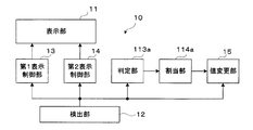
- FIG. 1 is a block diagram for explaining an overall configuration example of a setting device according to an embodiment of the present invention according to the first aspect.
- the setting device 10 includes a display unit (display) 11 that displays a virtual operation object, a detection unit 12 that detects a user operation related to the virtual operation object, and detection of the user based on the detection by the detection unit 12.
- the first display control unit 13 that performs control to change the display format of the object to the first format in response to the first operation, and the detection result after the change to the first format based on the detection by the detection unit 12.
- the second display control unit 14 that performs control to change the display format of the object to the second format in accordance with the second operation of the user, and after the change to the second display format based on the detection by the detection unit 12 In accordance with the third operation of the user, a value changing unit 15 that changes the value of the parameter corresponding to the object is provided.
- the setting device 10 is incorporated and mounted in an acoustic signal processing device 100 as shown in FIG.
- the setting device 10 may be incorporated and mounted in, for example, a general-purpose personal computer or a tablet-type terminal device.
- the processor device provided in the device (electronic device) incorporating the function of the setting device 10 may be configured to execute a program for realizing the function as the setting device 10.
- the setting device 10 may be composed of a dedicated hardware device (such as an integrated circuit) configured to be able to execute the function or operation thereof, and is configured of such a dedicated hardware device (such as an integrated circuit).
- the setting device 10 may be incorporated in a device (electronic device) such as the acoustic signal processing device 100.
- FIG. 2 is a block diagram illustrating an example of an electrical hardware configuration of the acoustic signal processing device 100 in which the setting device 10 illustrated in FIG. 1 is incorporated.
- the acoustic signal processing apparatus 100 is, for example, a mixing apparatus that performs mixing of acoustic signals of a plurality of channels, volume level adjustment, effect addition, and the like.
- the acoustic signal processing device 100 may be configured by a dedicated hardware device, or may be configured by a computer device that can execute an acoustic signal processing program, such as a general-purpose personal computer or a tablet terminal device. .
- the acoustic signal processing device 100 includes a CPU (central processing unit) 1, a memory 2, a touch panel display 3, an audio interface (I / F) 4, and a signal processing device 5, and these units are connected via a communication bus 6. Connected.
- the CPU 1 executes various programs stored in the memory 2 to control the operation of the acoustic signal processing apparatus 100.
- the memory 2 includes a ROM (Read Only Memory), a RAM (Random Access Memory), a hard disk (HDD), a solid state drive (SDD) and the like.
- the memory 2 stores the various programs and various data including various parameter values used for signal processing of the DSP 5.
- a touch panel type display (display) 3 (hereinafter simply referred to as “touch panel”) includes a display mechanism that performs various displays based on the control of the CPU 1 and a detector or detection mechanism that detects a touch operation that touches the screen (that is, a display). Upper touch detection surface).
- the display mechanism is a liquid crystal panel or the like, and includes an LCD, an organic EL, or the like.
- the detector or the detection mechanism (touch detection surface on the display) is configured to be able to individually detect and recognize two or more touches (multi-touch) on the screen. Therefore, the touch panel 3 is configured to realize the functions of both the display unit (display) 11 and the detection unit 12 illustrated in FIG.
- the audio I / F 4 includes an AD converter, a DA converter, an audio input interface, and an audio output interface.
- the acoustic signal processing apparatus 100 inputs an acoustic signal from an input device (not shown) via the audio I / F 4 and outputs the processed acoustic signal to an output device (not shown).
- the signal processing device 5 is composed of, for example, a DSP (Digital Signal Processor) or a signal processing device virtually realized by software stored in the CPU 1 and the memory 2.
- the signal processing device 5 performs signal processing on the input acoustic signal by executing a signal processing program.
- the signal processing includes, for example, mixing processing, volume level adjustment processing, equalizing processing, and the like. This signal processing is controlled based on the values of various parameters stored in the memory 2.
- the acoustic signal processing apparatus 100 may include other components not shown, such as a network interface for connecting to a computer network.
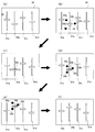
- FIGS. 3A to 3F show an example of a virtual operation object displayed on the touch panel 3, and how the display format of the virtual operation object is changed over time by the processing of FIG. 4 described later.
- FIG. 3 (a) to 3 (f) the screen 30 of the touch panel 3 displays manipulator images (“fader images”) 31a, 31b, 31c, and 31d that simulate fader manipulators as a plurality of virtual operation objects.
- Each virtual operation object 31 is configured to be able to move an image 32 representing a knob portion along a predetermined slide direction (vertical direction in FIG. 3).
- a plurality of components such as a virtual operation object are not distinguished from each other, only numbers (such as “31”) without alphabetic suffixes are used as reference symbols.
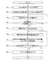
- FIG. 4 is a flowchart illustrating a processing example executed by the CPU 1 when an operation for selecting the virtual operation object 31 is performed.
- the CPU 1 detects one or more finger contact points by the detection mechanism of the touch panel 3 (step S1), and selects one virtual operation object 31 based on the detected one or more contact points (step S2). ). It is determined by the processes in steps S1 and S2 that a touch operation (first operation) for selecting one desired object 31 has been performed.
- reference numerals 33a, 33b, and 33c indicate contact points of three fingers with respect to the touch panel 3.
- the touch operation (first operation) for selecting the virtual operation object 31 is performed by holding the specific one knob portion 32 with one or more fingers in order to perform an operation of grasping the specific one knob portion 32. It consists of performing a touch operation for selection.
- the gripping operation refers to touching the vicinity of the display portion of the knob portion 32 with one or more fingers in order to select the desired knob portion 32 of one object 31 displayed on the touch panel 3, and then the selected object It consists of the operation
- FIG. 3B shows how the object 31b is selected.
- the CPU 1 detects the contact points 33a, 33b, 33c existing within a predetermined distance from a certain knob part 32b as an operation to try to grip the knob part 32b, and the contact points 33a, 33b. , 33c is specified to identify one knob 31b closest to the center position 34 (step S2).
- the CPU 1 detects a plurality of contact points that are close to each other as an operation to grip one knob portion 32 and selects the knob portion 32b that is closest to the center position 34 of the contact points. It may be configured to. A plurality of contact points may not be detected at the same time.
- steps S1 and S2 if a plurality of contact points are detected within a predetermined time and the plurality of contact points exist within a predetermined distance from a certain knob portion 32, the knob portion 32 is grasped. It may be determined that the operation to be performed (selection operation, that is, the first operation) has been performed. As another example, if only one contact point is detected within a predetermined time in step S1 and the one contact point exists within a predetermined distance from a certain knob portion 32, the knob portion 32 is grasped. It may be determined that the operation to be performed (selection operation, that is, the first operation) has been performed.
- step S3 the CPU 1 changes the display format of the selected virtual operation object 31b to the first format.
- the CPU 1 changes the display format of the knob portion 32b of the virtual operation object 31b from the still image (still ⁇ ⁇ image) before the selection operation to the moving image that appears to vibrate the knob portion 32b.
- a known technique may be applied to the method for displaying such a moving image. Note that the change to a moving image is not limited to changing (replacing) a still image to a special moving image, and the moving image is displayed by moving or displacing the same image used for the still image. May be.
- 3C shows a state where the display format of the knob portion 32 is changed to the first format in step S3.
- the contact points 33a, 33b, and 33c are not shown.
- the image of the knob portion 32b vibrates vertically and / or horizontally with a constant or random width and speed.
- the width, speed, and direction of the vibration may be appropriately set as long as the user can visually recognize the vibration.
- the reaction of the object 31b in response to an operation for gripping the knob portion 32b can be visually expressed.
- the object 31b has not yet received an operation for moving the knob portion 32b in the vertical direction, that is, an operation for adjusting the parameter value.
- the processing of the CPU 1 and step S3 realizes the function as the first display control unit 13 in FIG.
- the detected contact points 33a, 33b, 33c are mutually connected.
- the interval is gradually narrowed by the user performing an operation of narrowing a plurality of fingers in order to grasp the knob portion 32.
- the CPU 1 determines whether the user has performed a predetermined second operation on the object.
- the second operation includes narrowing the interval between the plurality of fingers touching the touch detection surface so that the selected object is grasped by the plurality of fingers of the user.
- step S4 the CPU 1 detects a change in the position of the contact points 33a, 33b, and 33c, and the distance between the contact points 33a, 33b, and 33c (in other words, the distance between a plurality of fingers) is greater than a predetermined distance. It is determined whether or not it has become smaller, and thereby, it is determined whether or not an operation (second operation) has been performed so that the user's fingers can grasp that the knob portion 32 has been grasped.
- the predetermined interval may be set to a width corresponding to the image width of the knob portion 32.
- the CPU 1 can determine the time point when the user firmly grasps the knob part 32, that is, the time point when the user touches the edge of the image of the knob part 32 by the step S4. While the finger interval is larger than the predetermined interval (No in step S4), the CPU 1 repeats step S4. Accordingly, during that time, the knob portion 32b continues to vibrate.
- the CPU 1 changes the display format of the knob portion 32b to the second format (step S4). S5).
- the display in the second format performed by the CPU 1 in step S5 is to stop the vibration of the knob portion 32b, that is, return the knob portion 32b to the still image again and change the display color of the knob portion 32b. Consists of.
- the still image of the knob portion 32b may be the same before and after the display format is changed, or may be different before and after the display format is changed.
- the display color is, for example, a color different from the display color before selection and the display color changed in step S1 (display color at the time of selection).
- FIG. 3D shows a state in which the mutual distance between the contact points 33a, 33b, and 33c is smaller than a predetermined distance.
- the selected virtual operation object 31b is in a state where the position of the knob portion 32b can be changed according to the operation, that is, the parameter value can be adjusted.
- the CPU 1 and the process of step S5 constitute the second display control unit 14 in FIG.
- step S6 the CPU 1 determines whether or not the user has performed a predetermined third operation on the object.
- the third operation includes moving the operation position of the knob portion 32b by moving the user's finger holding the knob portion 32b in a predetermined direction. For example, each finger (contact point 33a, 33b, 33c) on which the user performs an operation of grasping the knob portion 32b is moved upward or downward along the slide direction (hereinafter referred to as “movement of touch operation”).
- the CPU 1 detects the movement of the contact points 33a, 33b, 33c.
- the step S6 detects the movement of the center position 34 of the plurality of contact points 33a, 33b, 33c.
- the movement of the touch operation may be an operation of moving all the contact points 33a, 33b, and 33c, or an operation of moving any one or more of the contact points 33a, 33b, and 33c.
- the CPU 1 detects only the component in the vertical direction included in the “movement of the touch operation”.
- step S7 the CPU 1 updates the value of the corresponding parameter in the memory 2 according to the detected movement amount and direction of the touch operation, and displays the display position of the knob portion 32b.
- the parameter is, for example, the volume level of the acoustic signal.
- the knob portion 32b moves upward as shown in FIG.
- the DSP 5 performs a volume level adjustment process based on the updated volume level value.
- the CPU 1 and the process of step S7 constitute the value changing unit 15 in FIG.
- the CPU 1 loops through steps S5 to S7 until all fingers (that is, contact points 33a, 33b, and 33c) that are performing an operation of grasping the knob portion 32b are separated from the touch panel 3 (No in step S8). That is, according to the movement of the touch operation, the knob part 32b is moved and the corresponding parameter value is adjusted. The user can change the parameter value by moving the finger if only at least one of the fingers performing an operation of grasping the knob portion 32b is in contact with the touch panel 3.
- the CPU 1 ends the process of editing the parameter value of the virtual operator object 31b (step S9).
- the CPU 1 returns the display color of the knob portion 32b from the display color in the second format to the display color in the non-selected state as shown in FIG.
- the object is first changed to the first form (vibration) and then changed to the second form (vibration stop). It is possible to visually represent 31 reactions, specifically vibration and subsequent vibration stop. As a result, the user will feel as if he / she refused to grasp the virtual operation object 31 for the grasping operation first, and then refused to accept the operation after being firmly grasped. . For this reason, in the operation of the virtual operation object 31 displayed on the touch panel 3, it is possible to give the user a feeling as if a physical object showing a response to its own operation is being operated. Therefore, the operational feeling of the virtual operation object 31 can be improved.
- knob portion 32 first vibrates according to the gripping operation at the time of selection, and the parameter value can be adjusted after the vibration is stopped according to the subsequent gripping operation. It is possible to prompt attention and confirmation as to whether or not the user is operating, and prevent erroneous operation.
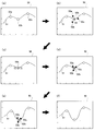
- FIGS. 5A to 5F show display examples of virtual operation objects according to another embodiment.
- the screen 50 of the touch panel 3 is a parametric equalizer operation screen
- the virtual operation object is an object of the characteristic curve 51 for adjusting the frequency characteristic of the acoustic signal and the characteristic. It consists of a combination of objects of a plurality of control points 52a, 52b, 52c on the curve.
- the virtual operation objects that are directly operated by the user are the objects of the control points 52a, 52b, and 52c
- the object of the characteristic curve 51 is indirectly linked to the operation of the control points 52a, 52b, and 52c. Will be manipulated.
- the horizontal axis indicates the frequency band
- the vertical axis indicates the gain value of the volume level.
- the center frequency is set for any three frequency bands according to the left and right positions (positions in the horizontal axis direction) of the individual control points 52a, 52b, and 52c on the characteristic curve 51.
- the gain values of the corresponding frequency bands are set according to the vertical positions (positions in the vertical axis direction) of the control points 52a, 52b, and 52c.
- FIG. 6 is a flowchart illustrating an example of a display change process executed by the CPU 1 in response to an operation for selecting a control point.
- steps S10 to S14 are substantially the same as steps S1 to S5 of FIG. That is, the CPU 1 detects one or more contact points 53a, 53b, 53c related to the operation to be grasped (first operation) (step S10), and for example, as shown in FIG.
- control point 52b closest to the center position 54 of 53a, 53b, 53c is selected (step S11), and the display format of the selected control point 52b is the first format, that is, as shown in FIG.
- the moving image is changed to a vibrating image and the display color is changed (step S12).
- step S13 the CPU 1 determines whether or not the user has performed a predetermined second operation on the object, for example, whether or not the intervals between the contact points 53a, 53b, and 53c are smaller than the predetermined interval. To do.
- the CPU 1 shows the display format of the control point 52b in the second format, that is, FIG.
- the control point 52b is changed to a moving image that vibrates, and the display color is changed (step S14).
- the control point 52 (object) can freely move in the vertical direction (vertical direction) and the horizontal direction (horizontal direction) according to the user's touch operation after the second operation (that is, the third operation).
- the CPU 1 determines the parameter type to be adjusted according to the initial movement direction of the movement of the touch operation by the processing of steps S15 to S17, and adjusts the value of the parameter of the determined type.
- the initial movement is the first movement of the user touch operation on the control point 52 (object) after the step S14 (after changing to the second form). Until the first movement is detected, the CPU 1 repeats steps S14 and S15 through the NO route of step S15.
- the detected initial movement direction (for example, the initial movement direction of the center position 54 of the contact points 53a, 53b, and 53c) is determined.
- the initial movement direction is, for example, the vertical direction or the horizontal direction.
- the CPU 1 regards the movement of the touch operation as corresponding to either the vertical or horizontal direction.
- the operation amount detected according to the movement (initial movement) of the touch operation is, for example, a movement direction and a movement amount (movement distance).
- step S17 the CPU 1 fixes the moving direction of the control point 52b in the determined initial movement direction, and determines the parameter type to be controlled according to the initial movement direction.
- the left and right positions of the control point 52 are associated with the center frequency, and the up and down position is associated with the gain value. Therefore, when the initial movement direction is the left and right direction, the parameter type to be controlled is determined as the center frequency.
- the parameter type to be controlled is determined as a gain value.
- step S17 the CPU 1 updates the value of the determined parameter in the memory 2 according to the movement amount of the touch operation, and updates the display for moving the position of the control point 52b.
- the shape of the characteristic curve is changed by moving the control point. For example, when the initial movement of the control point 52b is in the vertical direction, the user moves the control point 52b in the vertical direction (downward in the figure) and corresponds to the control point 52b as shown in FIG.
- the gain value of the frequency band can be adjusted.
- the display update and the parameter value are updated only in accordance with the movement of the vertical component that is the initial movement direction. That is, the parameter type to be adjusted can be fixed depending on the initial movement direction.
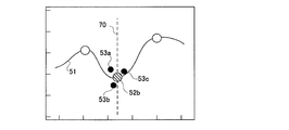
- the CPU 1 may perform a guide display 70 indicating the moving direction on the touch panel 3 as shown in FIG. 7, for example, in response to fixing the moving direction of the control point 52 in step S17.
- the fixed moving direction can be clearly shown to the user.
- the user can grasp which type of parameter is to be controlled and which direction the knob can be moved by displaying the moving direction.
- the CPU 1 loops through steps S17 and S18 until all fingers (contact points 53a, 53b, and 53c) that are performing an operation of grasping the control point 52b are separated from the touch panel 3 (No in step S18).
- the adjustment operation of the parameter value corresponding to the control point 52b is accepted.
- the CPU 1 edits the parameter value of the virtual operation object 31b.
- the process ends (step S19). In accordance with the end of the editing process, the CPU 1 may return the display color of the control point 52b to the display color before selection as shown in FIG.
- step S17 executes a function corresponding to the value changing unit 15 in FIG. 1, and in relation to this, in steps S15 to S17, the second operation is performed.
- a subsequent user touch operation that is, a third operation mode is determined, and a parameter type to be controlled is assigned to the object in accordance with the determined operation mode. That is, the function performed by the processing shown in the flowchart of FIG. 6 is represented by a functional block diagram similar to FIG. 1 as shown in FIG.
- a determination unit 113a and an allocation unit 114a are added to the configuration of FIG.
- the determination unit 113a performs an operation performed on the object by the user after the second display control unit 14 changes the display format of the object to the second format. It is detected as an operation, and it is determined which of the plurality of forms predetermined as the third operation form is the third operation performed this time.
- the function of the determination unit 113a corresponds to the processing of steps S15 and S16 in FIG.
- the plurality of forms determined in advance as the third operation form are, for example, forms in which the initial movement direction of the touch operation is either up or down or left and right.
- the assigning unit 114a assigns a parameter type corresponding to the determined third operation mode to the object.
- the value changing unit 15 changes the value of the type of parameter assigned to the object by the assigning unit 114a according to the operation amount of the third operation.
- the functions of the assigning unit 114a and the value changing unit 15 correspond to the processing in step S17 in FIG.
- the virtual operation objects 31 and 51 may have any shape.
- the “first operation” and the “second operation” may be detected based on contact of one finger.
- the knob portion 32 of the virtual operation object 31 or the control point 52 of the virtual operation object 51 close to one detected contact point is selected.
- the operation of touching the virtual operation object 31 with one finger corresponds to the “first operation”.
- the “second operation” determined in steps S4 and S13 is, for example, that the contact area (or pressure) of the finger changes by a predetermined threshold or more than the contact area (or pressure) of the first operation. It may be.
- the determination performed in step S4 or S13 may be determination of whether the area of one finger touching the virtual operation object 31 is smaller than a predetermined area.
- the finger contact area may be measured by the pressure of the finger in contact with the touch panel 3.
- the “second operation” determined in steps S4 and S13 may include, for example, moving one finger touching the virtual operation object 31. In that case, for example, steps S4 and S13 may be configured to branch to Yes when the finger moves in a direction approaching the virtual operation object 31.
- the operation to be selected is not limited to an operation for selecting one of the plurality of virtual operation objects 31 and 51.
- the operation to be selected is not limited to an operation for selecting one of the plurality of virtual operation objects 31 and 51.
- the operation to be selected is not limited to an operation for selecting one of the plurality of virtual operation objects 31 and 51.
- the operation to be selected is not limited to an operation for selecting one of the plurality of virtual operation objects 31 and 51.
- the operation to be selected is not limited to an operation for selecting one of the plurality of virtual operation objects 31 and 51. For example, when only one virtual operation object 31, 51 is displayed on the touch panel 3, starting the touch operation on the virtual operation object 31, 51 is also included in the selection operation.
- the display format of the virtual operation objects 31 and 51 in the steps S3 and S12 is changed to the first format in accordance with the operation to be selected (operation to be grasped). Not limited to this, it may be performed when a predetermined user operation (first operation) related to the virtual operation objects 31 and 51 is detected.
- changing the display format of the virtual operation objects 31 and 51 in the steps S3 and S12 to the first format includes, for example, rotating the image, moving the image randomly, May be changed to other types of moving images, such as moving so as to avoid a touch operation (contact point) or blinking an image.
- changing to the first format in steps S3 and S12 includes, for example, changing the display color of the image of the knob portion 32, the control point 52, etc., changing the display size, It may include changing the image shape of the manual operation objects 31 and 51, or changing to another display format. Moreover, you may combine suitably the deformation
- changing the display format of the virtual operation objects 31 and 51 in the steps S5 and S14 to the second format is, for example, “stopping vibration” in the embodiment.
- the change of one type is not limited to returning to the state before the change.
- Changing to the second form of steps S5 and S14 may include changing the speed and width of vibration, for example.
- changing to the second format in steps S5 and S14 may include, for example, changing to a moving image of a format different from the first format (for example, changing vibration to blinking).
- changing to the second format in steps S5 and S14 includes, for example, changing the display color, changing the display size, changing the image shape of the virtual operation objects 31, 51, and blinking display. Or changing to another display format.
- the steps S5 and S14 are configured to gradually change from the first form to the second form in response to detection of the second operation after the change to the first form. May be.
- the vibration is gradually delayed according to the narrowing of the interval between fingers, and finally the vibration can be stopped.
- the steps S4 and S13 are not limited to the configuration for determining whether the interval between the fingers is smaller than a predetermined interval, but the virtual operation object after being changed to the first format.
- the process branches to Yes (the process of changing to the second format in steps S5 and S14 is executed). It's okay.
- the user's predetermined arbitrary operation (second operation) related to the virtual operation objects 31 and 51 after the change to the first format is, for example, the rotation of one or more fingers touching the touch detection surface And an operation of increasing the interval between a plurality of fingers touching the touch detection surface.
- the steps S4 and S13 are performed when the touch operation detected in the steps S1 and S10 continues for a predetermined time or longer after the virtual operation objects 31 and 51 are changed to the first format. (The process which changes to the 2nd format of said step S5 and S14 may be performed) may be comprised.
- the steps S4 and S13 detect the pressure of the touch operation and branch to Yes according to the pressure (execute processing for changing to the second form of the steps S5 and S14).
- Configuration or detection of the movement speed of the touch operation and branching to Yes according to the movement speed (execution of the process of changing to the second format in steps S5 and S14), or other touch operation related The structure may branch to Yes according to a physical quantity or an arbitrary combination of these various physical quantities.
- the steps S8 and S18 branch to Yes when one of the plurality of fingers performing the grasping operation leaves the touch panel 3 (the editing end of the steps S9 and S19 is terminated). Execute). In another embodiment, the steps S8 and S18 branch to Yes when another finger touches the touch panel 3 in addition to the plurality of fingers performing the grasping operation (in the steps S9 and S19). (End editing). In another embodiment, when the steps S8 and S18 detect a predetermined operation such as an operation of rotating a finger performing the grasping operation (an operation of moving a contact point in an arbitrary rotation direction), for example. May be configured to branch to Yes (execution end of steps S9 and S19 is executed).
- a predetermined operation such as an operation of rotating a finger performing the grasping operation (an operation of moving a contact point in an arbitrary rotation direction), for example. May be configured to branch to Yes (execution end of steps S9 and S19 is executed).
- the device for inputting an operation related to the virtual operation objects 31 and 51 may be a motion capture device configured to detect the movement of the user's hand.
- Specific methods for detecting hand movement include detecting movement by irradiating the hand with infrared rays, etc., and detecting movement by attaching a device that can detect acceleration to the body including the hand. Can be considered.
- the virtual operation objects 31 and 51 may be displayed on a head mounted display, for example.
- the present invention uses, for example, a motion capture device and a head-mounted display in that it can effectively give the user a feeling as if a physical object responding to the operation is being operated. Suitable for use in value changing operations in an augmented reality environment.
- the setting device 10 is not limited to adjusting a parameter value related to acoustic signal processing, and adjusts a value by operating a virtual operation object, for example, brightness adjustment of illumination. Any value may be used for adjusting the value.
- the apparatus or method according to the present invention displays a virtual operation object, detects a user operation related to the virtual operation object, and detects the operation, The method comprises determining the detected operation form and assigning a parameter type corresponding to the determined operation form to the virtual operation object.
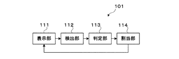
- FIG. 9 is a block diagram illustrating an example of the overall configuration of the setting apparatus 101 according to the second aspect.
- the setting apparatus 101 includes a display unit 111 that displays a virtual operation object, a detection unit 112 that detects an operation related to the virtual operation object, and determines the detected operation form according to the detection of the operation. And a determination unit 113 that assigns a parameter type according to the determined operation mode to the virtual operation object.
- the setting device 101 is incorporated into the acoustic signal processing device 100 having a hardware configuration as shown in FIG.
- the function of the determination unit 113 is that the CPU 1 of the acoustic signal processing device 100 detects the operation detected by the detection unit 112 and the volatile memory or HDD included in the memory 2 of the acoustic signal processing device 100. It can be realized by comparing operations stored in a storage medium such as SSD.
- the present invention is not limited to this, and a processor that performs a collation operation as the determination unit 113 may be separately prepared.
- the function of the allocation part 114 may be implement
- the present invention is not limited to this, and a processor that performs an allocation operation as the allocation unit 114 may be separately prepared. Note that the determination unit 113 and the allocation unit 114 execute substantially the same or similar functions as the determination unit 113a and the allocation unit 114a of FIG.
- the touch panel 3 (FIG. 2) has the display unit (display) 111 and the detection shown in FIG.
- the unit 112 is configured to realize both functions.
- the setting device 101 may be incorporated in, for example, a general-purpose personal computer or a tablet-type terminal device.
- a processor device provided in a device (electronic device) incorporating the function of the setting device 101 may be configured to execute a program for realizing the function as the setting device 101. .
- the setting device 101 may be configured by a dedicated hardware device (such as an integrated circuit) configured to be able to execute the function or operation thereof, and is configured by such a dedicated hardware device (such as an integrated circuit).
- the setting device 101 may be incorporated in a device (electronic device) such as the acoustic signal processing device 100.
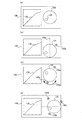
- FIGS. 10A to 10D show an example of the virtual operation object displayed on the touch panel 3 (FIG. 2), and the parameters assigned to the virtual operation object are changed by the processing of FIG. 10 described later.
- FIG. 9A to 9D on the screen 130 of the touch panel 3, an operator image for controlling the compressor as a virtual operation object 131 is displayed.
- the compressor is a kind of effect imparting processing module, and has an effect of compressing the volume difference of the acoustic signal.
- the effect of the compressor is determined, for example, by a combination of three types of parameters: ratio, threshold level, and attack time.
- the virtual operation object 131 is composed of one image representing the knob part.
- the virtual operation object 131 is associated with three types of parameters, ratio, threshold, and attack, and any one of the three types of parameters is converted into the virtual operation object 131 by the process of FIG. assign. Further, a graph 132 indicating the characteristics of the compressor is displayed on the left side of the virtual operation object 131. The horizontal axis of the graph 132 indicates the ratio, and the vertical axis indicates the threshold level.
- FIG. 11 is a flowchart showing an example of processing executed by the CPU 1 (FIG. 2) when a touch operation is performed on the virtual operation object 131.
- the touch operation is an operation in which the user's finger is brought into contact with the display location of the virtual operation object 131 (the image of the knob portion) on the touch panel 3 (FIG. 2). Moreover, moving the touched finger on the touch panel 3 (moving the contact point) is referred to as “movement of touch operation”.
- reference numerals 133a, 133b, and 133c indicate contact points of the touch operation.
- the CPU 1 (FIG. 2)
- the CPU 1 may detect a contact point existing within a predetermined distance from the virtual operation object 131 as a touch operation related to the virtual operation object 131.
- step S22 the CPU 1 (FIG. 2) determines whether or not the detected contact points 133a, 133b, and 133c have been initially moved.
- the initial movement is the movement of the first touch operation after detection of the contact points 133a, 133b, and 133c. That is, the CPU 1 detects the movement of the touch operation in the step S22.
- the physical quantity detected according to the movement of the touch operation is, for example, a moving direction and a moving amount (moving distance). Until there is an initial movement (No in step S22), the CPU 1 loops step S22. If there is an initial movement (Yes in step S22), the CPU 1 determines the operation mode in step S23.
- the form of operation is the direction of initial movement of the touch operation.
- the direction is, for example, any of the three types of rotation, up and down, and left and right.
- the CPU 1 determines which of the three types corresponds to the direction.
- the process of step S22 by the CPU 1 corresponds to the operation of the determination unit 113.
- a plurality of types of operation modes (three types of initial movement directions) are stored in a storage medium such as a volatile memory, HDD, or SSD included in the memory 2 (FIG. 2).
- step S24 to S26 the CPU 1 (FIG. 2) changes the parameter type assigned to the virtual operation object 131 according to the determined operation form, that is, the initial direction of the touch operation.
- the CPU 1 (FIG. 2) assigns a ratio to the virtual operation object 131 when the initial direction of the touch operation is rotation (step S24), and when the initial direction of the touch operation is the vertical direction, the virtual operation is performed.
- a threshold is assigned to the object 131 (step S25), and when the initial motion direction of the touch operation is the left-right direction, an attack time is assigned to the virtual operation object 131 (step S26).
- the CPU 1 may perform a display indicating the direction of initial movement in each of steps S24 to S26.
- the processing of steps S24 to S26 by the CPU 1 corresponds to the operation of the assigning unit 114.
- the association between the operation mode (three kinds of initial movement directions) and the parameter type is stored in a storage medium such as a volatile memory, HDD, or SSD included in the memory 2 (FIG. 2). Further, the user may be able to manually set the association between the operation mode (three types of initial movement directions) and the parameter type.
- a guide 134a indicating the rotation direction is displayed as shown in FIG.
- the CPU 1 sets the ratio value according to the rotational movement amount of the touch operation.
- the display position of the virtual operation object 131 is updated (step S27).
- the rotation of the touch operation may be centered on the approximate center position of the contact points 133a, 133b, and 133c, or may be centered on any one of the contact points 133a, 133b, and 133c. . For example, when the user rotates the touch operation in the right direction, as shown in FIG.
- the virtual operation object 131 (circular knob portion image) rotates in the right direction, and the ratio value increases.
- the rotation position of the virtual operation object 131 is indicated by a mark 135.
- the CPU 1 updates the display of the graph 132 indicating the characteristics of the compressor according to the changed ratio value.
- the guide 134b indicating the vertical direction is displayed.
- the CPU 1 changes the threshold value according to the movement amount of the touch operation.
- the display position of the virtual operation object 131 is updated (step S27). For example, when the user moves the touch operation downward, as shown in FIG. 10C, the virtual operation object 131 is moved downward and the threshold value becomes small.
- the CPU 1 updates the display of the graph 132 indicating the characteristics of the compressor according to the changed threshold value.
- a guide 134c indicating the left-right direction is displayed as shown in FIG.
- the CPU 1 performs an attack time according to the movement amount of the touch operation.
- the display position of the virtual operation object 131 is updated (step S27). For example, when the user moves the touch operation to the right, as shown in FIG. 10D, the virtual operation object 131 moves to the right, and the attack time value increases. Further, the CPU 1 updates the display of the graph 132 indicating the characteristics of the compressor according to the changed attack time.
- the CPU 1 loops Steps S27 and S28, and each time the movement of the touch operation is detected, the amount of movement is increased.
- the value of the parameter assigned to the virtual operation object 131 in step S24, S25, or S26 is changed (step S27).
- the CPU 1 detects only the movement amount of the component in the corresponding direction. For example, when the threshold value is adjusted by moving the touch operation in the upper right direction, the threshold value is changed only in accordance with the amount of movement of the upward component.
- Steps S27 and S28 are looped until all the contact points 133a, 133b, and 133c are separated from the touch panel 3, so that the user touches at least one of the fingers performing the touch operation on the touch panel 3 (FIG. 2). Then, the parameter value can be changed by moving the finger.
- Step S28 the CPU 1 ends the process of editing the parameter value of the virtual operation object 131b (Step S29). After step S21, the CPU 1 may end the process of FIG. 11 when all the fingers performing the touch operation are separated from the touch panel 3 at any timing.
- one virtual operation object 131 can be associated with three types of parameters: ratio, threshold, and attack time (that is, three types of parameters can be adjusted with one virtual operation object 131).
- the screen display can be simplified as compared with the configuration in which the virtual operation object is displayed for each parameter type. Therefore, an operation interface that is easy for the user to handle can be provided. Further, only by properly using the touch operation on the virtual operation object 131, that is, the touch operation form (initial movement direction) for changing the parameter value, the parameter type assigned to the virtual operation object 131 is changed or determined. be able to. Since there is no need to perform an operation for changing the parameter type separately from the parameter value changing operation, the parameter type can be easily changed or determined.
- the parameter type assigned to the virtual operation object 131 is fixed according to the initial movement direction (the loop of steps S27 and S28), so that the user may erroneously operate other types of parameters. There is no.
- FIG. 12 is a flowchart illustrating a processing example according to a touch operation according to another embodiment.
- the CPU 1 detects a contact point of one or more fingers performing a touch operation using the detection mechanism of the touch panel 3 (step S30).
- step S31 the CPU 1 determines “operation form” based on the detected number of contact points (finger). As an example, the CPU 1 determines whether the number of fingers performing a touch operation is one, two, or three. As an example, when the number of contact points is three or more, the CPU 1 may regard the number of fingers performing a touch operation as three.
- the CPU 1 changes the parameter type assigned to the virtual operation object 131 according to the determined operation mode and the number of fingers (contact points) performing the touch operation.
- the CPU 1 assigns a threshold to the virtual operation object 131 when the number of contact points is one (step S32), and assigns a ratio to the virtual operation object 131 when the number of contact points is two (step S33). ) If there are three contact points, an attack time is assigned to the virtual operation object 131 (step S34).
- the moving direction of the touch operation may be determined for each parameter type assigned to the virtual operation object 131.
- the CPU 1 may display a guide indicating the moving direction of the touch operation according to the parameter type.
- FIGS. 13A to 13D are display examples in the case where the parameter assigned to the virtual operation object 131 is changed according to the number of contact points, and FIG. 13A shows that no touch operation is performed. Indicates the state.
- symbol as FIG. 10 is provided to the component which is common in FIG.
- a guide 134b indicating the vertical direction is displayed.
- the CPU 1 changes the threshold value according to the amount of movement of the touch operation, and virtually The display position of the operation object 131 is updated (step S35). For example, when the user moves the touch operation downward, as shown in FIG. 13B, the virtual operation object 131 moves downward and the threshold value decreases.
- the CPU 1 updates the display of the graph 132 indicating the characteristics of the compressor according to the changed threshold value.
- a guide 134a indicating the rotation direction is displayed as shown in FIG.
- the CPU 1 changes the ratio value according to the rotation amount of the touch operation and performs virtual operation.
- the display position of the object 131 is updated (step S35). For example, when the user rotates the touch operation to the right, as shown in FIG. 13C, the virtual operation object 131 rotates to the right and the ratio value increases.
- the CPU 1 updates the display of the graph 132 indicating the characteristics of the compressor according to the changed threshold value.
- a guide 134c indicating the left-right direction is displayed as shown in FIG.
- the CPU 1 determines the attack time according to the movement amount of the touch operation.
- the value is changed and the display position of the virtual operation object 131 is updated (step S35). For example, when the user moves the touch operation to the right, as shown in FIG. 13D, the virtual operation object 131 moves to the right, and the attack time value increases. Further, the CPU 1 updates the display of the graph 132 indicating the characteristics of the compressor according to the changed attack time.
- step S37 the screen display can be simplified and the operation interface easy to handle for the user can be provided compared to the configuration in which the virtual operation object is displayed for each parameter type. it can. Further, the change / determination of the parameter type assigned to the virtual operation object 131 can be easily performed only by properly using the touch operation mode (number of fingers). Therefore, the parameter value control using the virtual operation object can be easily and easily performed.
- FIG. 14 shows an example of an equalizer operation screen displayed on the screen 70 of the touch panel 3 as an example of a virtual operation object according to another embodiment, which is substantially the same as FIG. Similar to FIG. 7, the virtual operation object includes a characteristic curve 71 for adjusting the frequency characteristic of the acoustic signal and a plurality of control points 72a, 72b, 72c.
- the CPU 1 determines the type of touch operation in steps S21 to S26 or steps S30 to S34, and according to the type of operation. Any one of three types of parameters, center frequency, gain, and Q is assigned to the virtual operation object 71.
- the CPU 1 changes the parameter type assigned to the virtual operation object 71 according to the number of fingers of the touch operation. For example, the CPU 1 assigns “center frequency” to the virtual operation object 71 when the number of fingers performing the touch operation is one, “Q” when there are two fingers, and “gain” when there are three fingers.
- FIG. 14 shows an example in which the control point 72b is operated with three fingers. Further, the CPU 1 may display a guide 74 indicating the moving direction (vertical direction) of the touch operation for operating the gain value.
- the virtual operation object 131 may have any shape.
- the operation amount detected according to the movement of the touch operation is not limited to the movement direction and the movement distance, but any physical amount such as the movement speed, acceleration, time, or pressure of the touch operation, or Any combination of these various physical quantities may be used.
- the steps S28 and S36 further determine the presence or absence of a predetermined operation such as, for example, slightly vibrating the touch operation (shaking the contact point slightly), and the predetermined operation was performed.
- a predetermined operation such as, for example, slightly vibrating the touch operation (shaking the contact point slightly)
- the process may return to step S23 or S31.
- the user can re-change (re-determine) the parameters assigned to the virtual operation object 131 without releasing all touch points from the touch panel 3 and performing a new touch operation. For example, the user can change the value of the ratio by rotating the touch operation in the initial movement, then perform the predetermined operation, and then change the threshold value by moving the touch operation up and down.
- the steps S28 and S36 are further configured to determine whether the touch operation mode has been changed and to return to step S23 or S31 when the operation mode has been changed. May be. Also in this case, the user can re-change (re-determine) the parameters assigned to the virtual operation object 131 without releasing all touch points from the touch panel 3 and performing a new touch operation. For example, the user can change the threshold value by moving the touch operation in the vertical direction after changing the ratio value by rotating the touch operation in the initial movement.
- the steps S28 and S36 branch to Yes when any one contact point leaves the touch panel 3, and the parameter editing process is terminated (the steps S28 and S37). It may be configured.
- the parameter value changed in steps S27 and S35 is a parameter assigned to the virtual operation object 131 according to the movement amount, regardless of the movement direction of the touch operation.
- the value of may be changed.
- the ratio value is changed only in accordance with the amount of movement in the rotational direction.
- the ratio value is changed according to the amount of movement in any direction.
- a plurality of virtual operation objects 131 may be displayed on the touch panel 3.
- one virtual operation object 131 is selected by the touch operation detected in steps S21 and S30.
- the CPU 1 selects the virtual operation object 131 that is closest to the center position of one or more contact points.
- the mode of operation for selecting the virtual operation object 131 is determined (steps S23 and S31).
- the steps S23 and S31 are configured to determine the movement of the center of gravity of a plurality of contact points and change the parameter type assigned to the virtual operation object 131 according to the movement of the center of gravity. It's okay.
- the movement of the center of gravity is, for example, to move only a part of a plurality of contact points.
- a ratio is assigned to the virtual operation object 131, and when the movement of the center of gravity is moved upward and downward by a predetermined distance from the initial position, A threshold is assigned to the operation object 131, and an attack time is assigned to the virtual operation object 131 when the movement of the center of gravity moves to the left or right by a predetermined distance or more from the initial position.
- the device that inputs an operation related to the virtual operation object 131 is a movement of the user's hand. It may be configured by a motion capture device configured to detect. In this case, the determination of the operation form in steps S23 and S31 determines the movement of the user's hand detected by the motion capture device.
- the virtual operation object 131 may be displayed by, for example, a head mounted display. In the present invention, it is possible to easily and easily control the value of a parameter using a virtual operation object. For example, use of a value change operation in an augmented reality environment using a motion capture device and a head-mounted display. It is suitable for.
- the setting device 101 is not limited to one that adjusts parameter values related to acoustic signal processing. Instead, any type of value adjustment may be used as long as the value is adjusted by operating a virtual operation object, such as adjusting the brightness of illumination.
- the function executed by the determination unit 113a and the assignment unit 114a in FIG. 8 showing a modification of the setting device 10 according to the first aspect is illustrated in FIG. 9 may be modified so as to be replaced by functions executed by the determination unit 113 and the allocation unit 114 in FIG.
- the processes of steps S15, S16, and S17 in FIG. 6 may be replaced with the same processes as steps S31, S32, S33, and S34 shown in FIG.
Landscapes
- Engineering & Computer Science (AREA)
- General Engineering & Computer Science (AREA)
- Theoretical Computer Science (AREA)
- Physics & Mathematics (AREA)
- Human Computer Interaction (AREA)
- General Physics & Mathematics (AREA)
- Acoustics & Sound (AREA)
- Signal Processing (AREA)
- User Interface Of Digital Computer (AREA)
Abstract
設定装置10は、仮想的操作オブジェクトを表示するディスプレイ11と、仮想的操作オブジェクトに関連するユーザの操作を検出する検出部12と、前記ユーザの第1の操作に応じて、前記オブジェクトの表示形式を第1形式に変化する第1表示制御部13と、前記第1形式に変化した後の前記ユーザの第2の操作に応じて、前記オブジェクトの表示形式を第2形式に変化する第2表示制御部14と、前記第2表示形式に変化後の前記ユーザの第3の操作に応じて、前記仮想的操作オブジェクトに対応するパラメータの値を変更する値変更部15を備える。
Description
この発明は、例えばオーディオミキサなど様々な電子機器において、該電子機器に付属するディスプレイ装置に表示された仮想的操作オブジェクトを用いてパラメータを設定するための装置及び方法に関する。
周知の通り、オーディオミキサの操作卓には、複数のチャンネルストリップが備わり、個々のチャンネルストリップに音量制御用のフェーダ操作子や、ゲイン調整用のノブ操作子を含む多数の操作子が備わる。従来のミキサにおいては、基本的には、個々の操作子毎に1種類のパラメータが制御対象として割り当てられている。そのため、操作インタフェースは、多数のノブやフェーダ等が配置された煩雑な構成になり、ミキサの操作が不慣れなユーザにとって、多数の操作子の何れにどのパラメータが割り当てられているのか、わかりにくい。これに対して、特許文献1は、ミキサの操作インタフェースの一例として、タッチパネルに表示された仮想的操作子画像を使用して、パラメータの値を調整することが記載されている。
しかし、操作インタフェースとしてタッチパネルに表示された仮想的操作子画像を使用する場合、物理的操作子に比べて操作感に乏しいという問題がある。そのため、仮想的操作子画像は、物理的操作子と比べて、感覚的な操作を行い難いという問題がある。また、仮想的操作子の画像は、物理的操作子と比べて、何れの操作子画像を操作しているのかを直感的に把握し難く、例えば意図とは異なる操作子画像を操作してしまう等の誤操作を起こし易いという問題がある。特に、タッチパネルに表示された仮想的操作子画像を使用する操作インタフェースは、平らなタッチパネルの表面への接触(タッチ操作)によりパラメータ値を調整する構成であるため、意図していないパラメータの値を変更してしまう等の誤操作を起こし易い。
この点、前記特許文献1は、誤操作を防ぎ、操作性を向上するために、仮想的操作子画像に対する第1タッチ操作により、該仮想的操作子画像を選択し、該第1タッチ操作が継続した状態で別の第2タッチ操作を行うことにより、該選択された仮想的操作子画像に対応するパラメータの値を調整できるように構成することを記載している。特許文献1等のデジタルミキサにおいては、物理的操作子又は仮想的操作子画像に割り当てるパラメータを変更可能である。そのため、物理的操作子又は仮想的操作子画像の点数を減らし、操作インタフェースの構成を簡略化し得る。物理的操作子又は仮想的操作子画像に割り当てるパラメータを変更する操作は、例えばミキサの操作が不慣れなユーザ等にとっても、直感的でわかりやすいものであることが望まれる。
この発明は、上述の点に鑑みてなされたもので、表示された仮想的操作子のオブジェクトに対するユーザの操作感を向上することを目的とする。また、仮想的操作オブジェクトを使用したパラメータの値の制御を、分かりやすく簡単に行えるようにすることを目的とする。
この発明に係る方法は、仮想的操作オブジェクトをディスプレイ上に表示することと、前記オブジェクトに関連するユーザの操作を検出することと、前記ユーザの第1の操作に応じて、前記オブジェクトの表示形式を第1形式に変化することと、前記第1形式に変化した後の前記ユーザの第2の操作に応じて、前記オブジェクトの表示形式を第2形式に変化することと、前記第2形式に変化した後の前記ユーザの第3の操作に応じて、前記オブジェクトに対応するパラメータの値を変更することからなる。
この発明によれば、まず、仮想的操作オブジェクトに関連するユーザの第1の操作に応じて該オブジェクトの表示形式を第1形式に変化し、次いで該オブジェクトの表示形式が第1形式に変更された後の前記ユーザの第2の操作に応じて、該表示形式を第1形式から第2形式に変化し、そして、第2形式に変化した後の前記ユーザの第3の操作に応じて、前記オブジェクトに対応するパラメータの値を変更する。この構成により、ユーザの操作の違い(つまり、第1の操作と第2の操作の違い)に応じた仮想的操作子のオブジェクトの「反応」を、その表示形式を第1形式から第2形式に変化させることにより、視覚的に表現することができる。これにより、あたかも操作の違いに応じた反応を示す物理的な物体を操作しているかのような感覚をユーザに与えることができる。
この発明の別の観点によると、前記第2形式に変化した後の前記ユーザの第3の操作に応じて、該第3の操作の形態を判定することと、前記判定された第3の操作の形態に応じたパラメータ種類を、前記オブジェクトに割り当てること、を更に備え、前記オブジェクトに対応するパラメータの値を変更することは、前記オブジェクトに割り当てられた種類のパラメータの値を変更することからなっていてよい。これによれば、1つの仮想的操作オブジェクトを複数種類のパラメータに対応付けることができるので、パラメータ種類毎に個別に仮想的操作子のオブジェクトを表示する構成に比べて、仮想的操作子のオブジェクトを使用した操作インタフェースの構成を簡略化できる。また、操作の形態を使い分けるだけの簡単でわかりやすい方法で、仮想的操作子のオブジェクトに割り当てるパラメータ種類を変更できる。
さらに別の観点によると、この発明に係る方法は、仮想的操作オブジェクトを表示することと、前記オブジェクトに関連するユーザの操作を検出することと、前記オブジェクトに対する前記ユーザの操作に応じて、該操作の形態を判定することと、前記判定された操作の形態に応じたパラメータ種類を前記オブジェクトに割り当てることからなる。この場合も、1つの仮想的操作オブジェクトを複数種類のパラメータに対応付けることができるので、パラメータ種類毎に個別に仮想的操作子のオブジェクトを表示する構成に比べて、仮想的操作オブジェクトを使用した操作インタフェースの構成を簡略化でき、また、操作の形態を使い分けるだけの簡単でわかりやすい方法で、仮想的操作オブジェクトに割り当てるパラメータ種類を変更できる。
この発明は、方法の発明として実施しうるのみならず、前記方法を構成する各ステップの機能を実現するように構成された構成要素を備える設定装置の発明として実施及び構成されてよい。さらに、本発明は、上記方法を実行するために、1以上のプロセッサにより実行可能な命令群を記憶した、非一過性のコンピュータ読み取り可能な記憶媒体として実装することもできる。
この発明によれば、ユーザの第1及び第2の操作の違いに応じた仮想的操作オブジェクトの「反応」を、その表示形式を第1形式から第2形式に変化させることにより、視覚的に表現することができ、もって、あたかも操作に応じた反応を示す物理的な物体を操作しているかのような感覚をユーザに与えることができる。従って、仮想的操作オブジェクトを用いたパラメータの値の操作において、該オブジェクトに対するユーザの操作感を向上させることができる。また、第2形式に変更した後の第3の操作に応じてパラメータ値調整可能となるので、ユーザに対して何れの仮想的操作オブジェクトを操作しているかの注意・確認を促すことができ、誤操作を防止できる。
以下、添付図面を参照して、いくつかの観点に従うこの発明の実施形態について詳細に説明する。
図1は、第1の観点に従うこの発明の一実施形態に係る設定装置の全体構成例を説明するブロック図である。設定装置10は、仮想的操作オブジェクトを表示する表示部(ディスプレイ)11と、仮想的操作オブジェクトに関連するユーザの操作を検出する検出部12と、前記検出部12による検出に基づき、前記ユーザの第1の操作に応じて、前記オブジェクトの表示形式を第1形式に変化させる制御を行う第1表示制御部13と、前記検出部12による検出に基づき、前記第1形式に変化した後の前記ユーザの第2の操作に応じて、前記オブジェクトの表示形式を第2形式に変化させる制御を行う第2表示制御部14と、前記検出部12による検出に基づき、前記第2表示形式に変化後の前記ユーザの第3の操作に応じて、前記オブジェクトに対応するパラメータの値を変更する値変更部15を備える。
設定装置10は、例えば、図2に示すような音響信号処理装置100に組み込まれて実装される。別の例において、設定装置10は、例えば汎用のパーソナルコンピュータやタブレット型の端末装置などに組み込まれて実装されてもよい。いずれの場合も、該設定装置10の機能を組み込んだ装置(電子機器)に備えられたプロセッサ装置が、該設定装置10としての機能を実現するためのプログラムを実行可能なように構成されてよい。あるいは、設定装置10は、その機能若しくは動作を実行可能なように構成された専用ハードウェア装置(集積回路等)からなっていてもよく、そのような専用ハードウェア装置(集積回路等)からなる設定装置10が音響信号処理装置100等の装置(電子機器)に組み込まれるようになっていてよい。
図2は、図1に示す設定装置10を組み込んだ音響信号処理装置100の電気的ハードウェア構成例を示すブロック図である。音響信号処理装置100は、例えば、複数チャンネルの音響信号の混合、音量レベル調整、効果付与等を行うミキシング装置である。音響信号処理装置100は、専用のハードウェア装置により構成されてもよいし、或いは、例えば汎用のパーソナルコンピュータやタブレット端末装置など、音響信号処理のプログラムを実行可能なコンピュータ装置により構成されてもよい。
音響信号処理装置100は、CPU(中央処理ユニット)1、メモリ2、タッチパネル式表示器3、オーディオインタフェース(I/F)4、及び、信号処理装置5を含み、これら各部が通信バス6を介して接続される。
CPU1は、メモリ2に記憶された各種プログラムを実行して音響信号処理装置100の動作を制御する。メモリ2は、ROM(リードオンリメモリ)、RAM(ランダムアクセスメモリ)、ハードディスク(HDD)、ソリッドステートドライブ(SDD)等を含む。メモリ2には、前記各種プログラムが記憶されるとともに、DSP5の信号処理に使用する各種パラメータの値を含む各種データが記憶される。
タッチパネル式表示器(ディスプレイ)3(以下、単に「タッチパネル」という)は、CPU1の制御に基づき各種表示を行う表示機構と、画面を接触するタッチ操作を検出する検出器若しくは検出機構(すなわち、ディスプレイ上のタッチ検出面)とを含む。表示機構は、具体的には、液晶パネルなどであり、LCDや有機ELなどを含む。前記検出器若しくは検出機構(ディスプレイ上のタッチ検出面)は、画面に対する2点以上の接触(マルチタッチ)を個別に検出及び認識できるよう構成される。したがって、タッチパネル3は、図1に示された表示部(ディスプレイ)11及び検出部12の双方の機能を実現するように構成されている。
オーディオI/F4は、AD変喚器、DA変喚器、オーディオ入力インタフェース、及び、オーディオ出力インタフェースを含む。音響信号処理装置100は、オーディオI/F4を介して、図示しない入力機器から音響信号を入力し、また、信号処理済みの音響信号を図示しない出力機器へ出力する。
信号処理装置5は、例えばDSP(Digital Signal Processor)や、CPU1およびメモリ2に記憶されたソフトウェアにより仮想的に実現された信号処理装置で構成される。信号処理装置5は、信号処理用のプログラムを実行することにより、入力された音響信号に対して信号処理を施す。信号処理は、例えば、ミキシング処理、音量レベル調整処理、イコライジング処理等を含む。この信号処理は、メモリ2に記憶された各種パラメータの値に基づいて制御される。
なお、音響信号処理装置100は、例えばコンピュータネットワークに接続するためのネットワークインタフェースなど、図示外のその他の構成部品を備えてもよい。
図3(a)~(f)は、タッチパネル3に表示された仮想的操作オブジェクトの一例を示しており、後述図4の処理により、該仮想的操作オブジェクトの表示形式が変更する様子を経時的に説明する図である。図3(a)~(f)において、タッチパネル3の画面30は、複数の仮想的操作オブジェクトとして、フェーダ操作子を模擬した操作子画像(「フェーダ画像」)31a、31b、31c及び31dが表示されている。各仮想的操作オブジェクト31は、つまみ部を表す画像32を所定のスライド方向(図3において上下方向)に沿って移動可能に構成される。なお、以下において、仮想的操作オブジェクト等、複数個の構成要素について、その個々を区別しない場合、アルファベット添え字を省いた数字のみ(「31」等)を、参照符号として用いる。
ユーザは、まず、複数の仮想的操作オブジェクト31のうち何れか1つを選択する。図4は、仮想的操作オブジェクト31を選択する操作が行われたときに、CPU1が実行する処理例を示すフローチャートである。CPU1は、タッチパネル3の検出機構により、1以上の指の接触点を検出し(ステップS1)、該検出された1以上の接触点に基づき、1つの仮想的操作オブジェクト31を選択する(ステップS2)。ステップS1及びS2の処理により、所望の1つのオブジェクト31を選択するためのタッチ操作(第1の操作)がなされたことを判定する。
図3(b)において、符号33a、33b、33cは、タッチパネル3に対する3本の指の接触点を示す。一例として、仮想的操作オブジェクト31を選択するタッチ操作(第1の操作)は、特定の1つのつまみ部32を掴む操作を行うために、1以上の指で該特定の1つのつまみ部32を選択するためのタッチ操作を行うことからなる。掴む操作とは、タッチパネル3に表示された所望の1つのオブジェクト31のつまみ部32を選択するために、1以上の指で該つまみ部32の表示個所付近を接触し、次いで、該選択したオブジェクト31のつまみ部32を複数の指で掴むようにそれらの接触点を互いに近づける(タッチした複数の指の間隔を狭める)動作(ジェスチャ)からなる。図3(b)は、オブジェクト31bを選択する様子を示す。
一例において、CPU1は、或るつまみ部32bから所定の距離以内に存在する接触点33a、33b、33cを、該つまみ部32bを掴もうとする操作として検出し、そして、該接触点33a、33b、33cの中心位置34に最も近いつまみ部32bを特定することにより、1つのオブジェクト31bを選択する(前記ステップS2)。別の例において、CPU1は、互いに近接している複数の接触点を、1つのつまみ部32を掴もうとする操作として検出して、それら接触点の中心位置34に最も近いつまみ部32bを選択するように構成されてもよい。なお、複数の接触点は同時に検出されなくてもよい。例えば、前記ステップS1及びS2は、所定の時間内に複数の接触点が検出され、それら複数の接触点が或るつまみ部32から所定の距離以内に存在するならば、該つまみ部32を掴もうとする操作(選択操作すなわち第1の操作)がなされたと判定してよい。別の例として、ステップS1において所定の時間内に1つの接触点しか検出されず、該1つの接触点が或るつまみ部32から所定の距離以内に存在するならば、該つまみ部32を掴もうとする操作(選択操作すなわち第1の操作)がなされたと判定してよい。
ステップS3において、CPU1は、選択された仮想的操作オブジェクト31bの表示形式を第1形式に変更する。一例として、前記ステップS3において、CPU1は、仮想的操作オブジェクト31bのつまみ部32bの表示形式を、選択操作以前の静止画像(still image)から、該つまみ部32bが振動しているように見える動画像(moving image)に変更し、且つ、その表示色を変更する。かかる動画像を表示する方法は周知技術を適用してよい。なお、動画像への変更は、静止画像を特別の動画像に変更(差し替え)することに限らず、静止画像に使用するのと同じ画像を振動又は変位させる表示処理によって動画像に見せるようにしてもよい。図3(c)は、前記ステップS3によりつまみ部32の表示形式を第1形式に変更した状態を示す。便宜上、接触点33a、33b、33cの図示は省略した。つまみ部32bの画像は、一定の又はランダムな幅及び速さで上下及び/又は左右方向に振動する。振動の幅、速度、及び、方向は、ユーザが振動を視認できさえすれば、適宜に設定されてよい。つまみ部32bを振動させることにより、該つまみ部32bを掴もうとする操作に応じたオブジェクト31bの反応を、視覚的に表現することができる。この段階では、オブジェクト31bは、つまみ部32bの上下方向の移動操作、すなわち、パラメータの値を調整する操作を、まだ受け付けない。CPU1とステップS3の処理が、図1の第1表示制御部13としての機能を実現する。
前記接触点33a、33b、33cの検出(第1の操作)に応じて仮想的操作オブジェクト31bの表示形式が第1形式に変更された後、前記検出された接触点33a、33b、33cの相互間隔は、ユーザがつまみ部32を掴むために複数の指を狭める操作を行うことによって次第に狭まる。CPU1は、ステップS4において、オブジェクトに対してユーザが所定の第2の操作を行ったかどうかを判定する。一例として、該第2の操作は、該ユーザの複数の指で前記選択したオブジェクトを掴むように、タッチ検出面にタッチした該複数の指の間隔を狭めることからなる。すなわち、CPU1は、ステップS4において、接触点33a、33b、33cの位置変化を検出し、接触点33a、33b、33cの相互の間隔(言い換えれば、複数の指の間隔)が所定の間隔よりも小さくなったかどうか判定し、これにより、ユーザの複数の指がつまみ部32を掴んだと見做せる操作(第2の操作)がなされたかどうかを判定する。前記所定の間隔は、例えば、つまみ部32の画像幅に対応する幅に設定されてよい。その場合、CPU1は、ユーザがつまみ部32をしっかりと掴んだ時点、すなわち、つまみ部32の画像の縁に接触した時点を、前記ステップS4により判定できる。指の間隔が所定の間隔よりも広いうちは(ステップS4のNo)、CPU1は、ステップS4を繰り返す。したがって、その間、つまみ部32bは振動し続ける。
前記指の間隔が所定の間隔よりも小さくなった、つまり第2の操作が行われたならば(ステップS4のYes)、CPU1は、つまみ部32bの表示形式を第2形式に変更する(ステップS5)。一例として、該ステップS5においてCPU1が行う第2形式の表示とは、つまみ部32bの振動を止める、すなわち、つまみ部32bを再び静止画像に戻し、且つ、つまみ部32bの表示色を変更することからなる。この場合、つまみ部32bの静止画像は、表示形式の変更前後で同じものでも良いし、あるいは、表示形式の変更前後で異なるものであってもよい。表示色は、例えば、選択前の表示色とも前記ステップS1で変更された表示色(選択時の表示色)とも異なる色である。図3(d)は、接触点33a、33b、33cの相互間隔が所定の間隔よりも小さくなった状態を示す。この状態で、当該選択された仮想的操作オブジェクト31bは、操作に応じたつまみ部32bの位置の変更可能、すなわち、パラメータの値の調整可能な状態となる。CPU1とステップS5の処理が、図1の第2表示制御部14を構成する。
次に、CPU1は、ステップS6において、オブジェクトに対してユーザが所定の第3の操作を行ったかどうかを判定する。一例として、該第3の操作は、つまみ部32bを掴んだユーザの指を所定方向に動かすことにより、つまみ部32bの操作位置を移動することからなる。例えば、ユーザが、つまみ部32bを掴む操作を行っている各指(接触点33a、33b、33c)を、スライド方向に沿って上又は下方向に移動(以下、「タッチ操作の移動」という)すると、CPU1は、ステップS6において、該接触点33a、33b、33cの移動を検出する。一例として、前記ステップS6は、複数の接触点33a、33b、33cの中心位置34の移動を検出する。この場合、タッチ操作の移動は、全ての接触点33a、33b、33cを移動する操作でもよいし、接触点33a、33b、33cのうちいずれか1つ以上を移動する操作でもよい。なお、「タッチ操作の移動」が上下方向以外の成分を含む場合、CPU1は、当該「タッチ操作の移動」に含まれる上下方向の成分のみを検出する。
ステップS7において、CPU1は、該検出されたタッチ操作の移動の量及び方向に応じて、メモリ2内の対応するパラメータの値を更新し、且つ、つまみ部32bの表示位置を移動するように表示更新を行う。パラメータは、例えば音響信号の音量レベルである。例えば、上方向へのタッチ操作の移動に応じて、つまみ部32bは、図3(e)に示すように、上方に移動する。これにより、対応付けられた音量レベルの値は、例えば大きくなる。DSP5は、更新された音量レベルの値に基づいて音量レベル調整処理等を行なう。CPU1とステップS7の処理が、図1の値変更部15を構成する。
一例として、つまみ部32bを掴む操作を行っている全ての指(すなわち、接触点33a、33b、33c)がタッチパネル3から離れるまで(ステップS8のNo)、CPU1は、ステップS5~S7をループする、すなわち、タッチ操作の移動に応じて、つまみ部32bの移動及び対応するパラメータの値の調整を行う。ユーザは、つまみ部32bを掴む操作を行っている指の少なくとも1つのみをタッチパネル3に接触させておけば、その指の移動により、パラメータ値を変更できる。
つまみ部32bを掴む操作を行っている全ての指がタッチパネル3から離れたら(ステップS8のYes)、CPU1は、仮想的操作子のオブジェクト31bのパラメータ値を編集する処理を終了する(ステップS9)。一例として、パラメータ編集処理の終了に応じて、CPU1は、つまみ部32bの表示色を、図3(f)に示すように、前記第2形式の表示色から非選択状態の表示色に戻す。
以上の通り、仮想的操作オブジェクト31を掴む操作に応じて、まず第1形式(振動)に変化させ、次いで第2形式(振動停止)に変化させる構成により、ユーザの掴む操作に応じた該オブジェクト31の反応、具体的には、振動及び、その後の振動停止を視覚的に表現することができる。これにより、ユーザは、あたかも、掴む動作に対して、仮想的操作オブジェクト31がまず掴まれることを拒み、しっかりと掴まれた後は拒むことを諦めて操作を受け入れたかのような感覚を得るだろう。このため、タッチパネル3上に表示された仮想的操作オブジェクト31の操作において、自身の操作に対して応答を示す物理的な物体を操作しているかのような感覚を、ユーザに与えることができる。したがって、仮想的操作オブジェクト31の操作感を向上することができる。また、選択時の掴む操作に応じてまずつまみ部32が振動し、その後の掴む操作に応じて振動を止めた後にパラメータ値調整可能となる構成により、ユーザに対して何れの仮想的操作オブジェクト31を操作しているかの注意・確認を促すことができ、誤操作を防止できる。
図5(a)~(f)は、別の実施形態に係る仮想的操作オブジェクトの表示例を示す。図5(a)~(f)において、タッチパネル3の画面50は、パラメトリックイコライザの操作画面であり、仮想的操作オブジェクトは、音響信号の周波数特性を調整するための特性カーブ51のオブジェクトと該特性カーブ上の複数の制御点52a,52b,52cのオブジェクトの組合せからなる。この場合、ユーザによって直接的に操作される仮想的操作オブジェクトは制御点52a,52b,52cのオブジェクトであり、特性カーブ51のオブジェクトは制御点52a,52b,52cの操作に連動して間接的に操作されることになる。図5(a)において、横軸は周波数帯域、縦軸は音量レベルのゲイン値を示す。音響信号の周波数特性においては、特性カーブ51上の個々の制御点52a,52b,52cの左右位置(横軸方向の位置)により任意の3つの周波数帯域について中心となる周波数を設定し、個々の制御点52a,52b,52cの上下位置(縦軸方向の位置)によりそれぞれ対応する周波数帯域のゲイン値を設定する。
ユーザは、1以上の指(例えば3本の指)により、いずれか1つの制御点(例えば制御点52b)を掴もうとする操作(第1の操作)を行うことにより、該いずれか1つの制御点(例えば制御点52b)を選択する。図6は、制御点を選択する操作に応じてCPU1が実行する表示変更処理例を示すフローチャートである。図6においてステップS10~S14は,前記図4のステップS1~S5と概ね同様である。すなわち、CPU1は、前記掴もうとする操作(第1の操作)に係る1以上の接触点53a,53b,53cを検出し(ステップS10)、例えば図5(b)に示すように該接触点53a,53b,53cの中心位置54に最も近い制御点52bを選択し(ステップS11)、そして、選択された制御点52bの表示形式を第1形式、すなわち、図5(c)に示すような振動する動画像に変更し、且つ、表示色を変更する(ステップS12)。
そして、CPU1は、ステップS13において、オブジェクトに対してユーザが所定の第2の操作を行ったかどうか、例えば、接触点53a、53b、及び53cの間隔が所定の間隔よりも小さくなったかどうかを判定する。接触点53a、53b、及び53cの間隔が所定の間隔よりも小さくなったとき(ステップS13のYes)、CPU1は、制御点52bの表示形式を第2形式、すなわち、図5(d)に示すような、制御点52bを振動する動画像に変更し、且つ、表示色を変更する(ステップS14)。
制御点52(オブジェクト)は、前記第2の操作後のユーザのタッチ操作(つまり第3の操作)に応じて上下方向(たて方向)及び左右方向(横方向)に自由に移動し得る。一例として、CPU1は、ステップS15~S17の処理により、タッチ操作の移動の初動方向に応じて調整対象のパラメータ種類を決定し、該決定された種類のパラメータの値を調整する。初動とは、前記ステップS14後(前記第2形式に変化した後)に該制御点52(オブジェクト)に対するユーザタッチ操作の最初の移動である。初動を検出するまでは、ステップS15のNOのルートを通って、CPU1はステップS14及びS15を繰り返す。前記第2形式に変更された後に、初動を検出したとき(ステップS15のYes)、該検出された初動の方向(例えば、接触点53a、53b、及び53cの中心位置54の初動方向)を判定する(ステップS16)。前記初動方向は、例えば、上下又は左右方向である。上下又は左右方向以外(例えば斜め方向など)にタッチ操作が移動された場合、CPU1は、該タッチ操作の移動を、上下又は左右方向の何れかに該当するものとみなす。また、タッチ操作の移動(初動)に応じて検出される操作量は、例えば、移動方向及び移動量(移動距離)である。そして、CPU1は、ステップS17において、該判定された初動方向に制御点52bの移動方向を固定するとともに、該初動方向に応じて制御対象のパラメータ種類を決定する。前述の通り、制御点52の左右位置が中心周波数に、また、上下位置がゲイン値に対応付けられているので、初動方向が左右方向の場合、制御対象のパラメータ種類は中心周波数に決定され、初動方向が上下方向の場合、制御対象のパラメータ種類はゲイン値に決定される。
CPU1は、該ステップS17において、タッチ操作の移動量に応じて、メモリ2内の前記決定されたパラメータの値を更新し、且つ、制御点52bの位置を移動する表示更新する。制御点の移動により、特性カーブの形状が変更される。例えば、制御点52bの初動が上下方向であった場合、ユーザは、図5(e)に示す通り、制御点52bを上下方向(図では下方)に移動して、該制御点52bに対応する周波数帯域のゲイン値を調整できる。ユーザが実際に行なったタッチ操作の移動が左右方向への移動を含んでいる場合も、初動方向である上下方向の成分の移動のみに応じて表示更新及びパラメータ値の更新を行なう。すなわち、初動方向により調整対象のパラメータ種類を固定することができる。
一例として、CPU1は、前記ステップS17において、制御点52の移動方向を固定することに応じて、例えば図7に示すように、タッチパネル3上に移動方向を示すガイド表示70を行ってよい。これにより、固定された移動方向をユーザに明示できる。ユーザは、移動方向の表示により、何れの種類のパラメータが制御対象になっているか、及び、つまみ部を何れの方向に移動できるかを把握できる。
CPU1は、制御点52bを掴む操作を行っている全ての指(接触点53a,53b,53c)がタッチパネル3から離れるまでは(ステップS18のNo)、ステップS17,S18をループして、該選択された制御点52bに対応するパラメータ値の調整操作を受け付ける。制御点52bを掴む操作を行っている全ての指(接触点53a,53b,53c)がタッチパネル3から離れたとき(ステップS18のYes)、CPU1は、仮想的操作オブジェクト31bのパラメータ値を編集する処理を終了する(ステップS19)。編集処理の終了に応じて、CPU1は、図5(f)に示すように、制御点52bの表示色を選択前の表示色に戻してよい。
このように、タッチパネル3に表示されたパラメトリックイコライザの特性カーブにおいても、操作に対して応答を示す物理的な物体を操作しているかのような感覚を、ユーザに与えることができる。従って、したがって、仮想的操作オブジェクト51、52の操作感を向上することができる。また、ユーザに対して何れの仮想的操作オブジェクト51、52を操作しているかの注意・確認を促すことができ、誤操作を防止できる。
なお、前記図6の実施例においては、ステップS17における処理が図1の値変更部15に対応する機能を実行しており、これに関連して、ステップS15~S17では、前記第2の操作後のユーザのタッチ操作つまり第3の操作の形態を判定することと、判定した操作形態に応じて、制御対象となるパラメータの種類をオブジェクトに割り当てることを行っている。すなわち、図6のフローチャートに示された処理によって行われる機能を、図1と同様の機能ブロック図で表すと、図8のようになる。
図8においては、図1の構成に対して判定部113aと割当部114aが追加されている。要約して説明すると、判定部113aは、前記第2表示制御部14によって前記オブジェクトの表示形式が前記第2形式に変化した後に、前記ユーザによって該オブジェクトに対してなされた操作を、第3の操作として検出し、該第3の操作の形態として予め決められている複数の形態のうち、今回なされた第3の操作がどの形態であるかを判定する。この判定部113aの機能は、図6における前記ステップS15,S16の処理に対応する。この場合、該第3の操作の形態として予め決められている複数の形態とは、例えば、タッチ操作の初動の方向が上下又は左右の何れかであるような形態である。割当部114aは、前記判定された第3の操作の形態に応じたパラメータ種類を、前記オブジェクトに割り当てる。そして、値変更部15は、前記割当部114aによって前記オブジェクトに割り当てられた種類のパラメータの値を、前記第3の操作の操作量に応じて変更する。この割当部114a及び値変更部15の機能は、図6における前記ステップS17の処理に対応する。
以上、第1の観点に従うこの発明の一実施形態を説明したが、この発明は上記実施形態に限定されるものではなく、特許請求の範囲、及び明細書と図面に記載された技術的思想の範囲内において種々の変形が可能である。例えば、仮想的操作オブジェクト31,51は、どのような形状であってもよい。
また、別の実施形態において、1つの指の接触に基づき前記「第1の操作」及び「第2の操作」を検出するように構成されてもよい。その場合、前記ステップS2及びS11において、検出された1つの接触点に近い仮想的操作オブジェクト31のつまみ部32又は仮想的操作オブジェクト51の制御点52が選択される。この場合、1本の指で仮想的操作オブジェクト31に触れる操作が、「第1の操作」に相当する。また、前記ステップS4及びS13で判定する「第2の操作」は、例えば、指の接触面積(又は圧力)が前記第1の操作による接触面積(又は圧力)よりも所定閾値以上変化することからなっていてよい。例えば、前記ステップS4又はS13で行う判定は、仮想的操作オブジェクト31に触れている1本の指の面積が所定の面積よりも小さくなったかどうかを判定することであってよい。指の接触面積は、例えば、タッチパネル3に接触する指の圧力によって計測して良い。別の例として、前記ステップS4及びS13で判定する「第2の操作」は、例えば、仮想的操作オブジェクト31に触れている1本の指を移動することからなっていてもよい。その場合、例えば、ステップS4及びS13は、前記指が仮想的操作オブジェクト31に近接する方向に移動したときにYesに分岐するように構成されてよい。
また、前記選択する操作は、複数の仮想的操作オブジェクト31、51の中から1つを選択する操作に限らない。例えば、タッチパネル3に1つの仮想的操作オブジェクト31、51しか表示されていない場合に、その仮想的操作オブジェクト31、51に対するタッチ操作を開始することも、前記選択する操作に含まれる。
また、別の実施形態において、前記ステップS3及びS12の仮想的操作オブジェクト31,51の表示形式を第1形式に変更することは、前記選択する操作(掴もうとする操作)に応じて行なわれることに限らず、仮想的操作オブジェクト31、51に関連するユーザの所定の操作(第1の操作)を検出したときに行われてよい。
また、別の実施形態において、前記ステップS3及びS12の仮想的操作オブジェクト31,51の表示形式を第1形式に変更することは、例えば、画像を回転させること、画像をランダムに動かすこと、画像がタッチ操作(接触点)を避けるように動くこと、画像を点滅表示させることなど、その他の形式の動画像に変更することであってよい。また、別の例として、前記ステップS3及びS12の第1形式に変更することは、例えば、つまみ部32、制御点52等の画像の表示色を変更すること、表示サイズを変更すること、仮想的操作オブジェクト31,51の画像形状を変更すること、あるいは、その他の表示形式に変更することを含んでよい。また、複数種類の表示形式の変形を適宜に組み合わせてよい。
また、別の実施形態において、前記ステップS5及びS14の仮想的操作オブジェクト31,51の表示形式を第2形式に変更することは、例えば前記実施形態における「振動を止めること」のように、第1形式の変更を該変更以前の状態に戻すことに限らない。前記ステップS5及びS14の第2形式に変更することは、例えば、振動の速さ、幅を変更することを含んでよい。また、前記ステップS5及びS14の第2形式に変更することは、例えば、第1形式とは別の形式の動画像に変更すること(例えば振動を点滅に変更するなど)を含んでよい。また、前記ステップS5及びS14の第2形式に変更することは、例えば表示色を変更すること、表示サイズを変更すること、仮想的操作オブジェクト31,51の画像形状を変更すること、点滅表示すること、あるいは、その他の表示形式に変更することを含んでよい。また、複数種類の表示形式の変形を適宜に組み合わせてよい。
また、別の実施形態において、前記ステップS5及びS14は、前記第1形式に変化した後の第2の操作の検出に応じて、前記第1形式から第2形式へ漸次変化させるように構成されてもよい。その場合、例えば、仮想的操作オブジェクト31,51を振動させた後、指の間隔が狭まることに応じて次第に前記振動が遅くなり、最終的に振動が止まるようにすることができる。
また、別の実施形態において、前記ステップS4及びS13は、各指の間隔が所定間隔より小さくなったか否かを判定する構成に限らず、前記第1形式に変更された後の仮想的操作オブジェクト31,51に関連するユーザの所定の任意の操作(第2の操作)を検出したときにYesに分岐する(前記ステップS5及びS14の第2形式に変更する処理を実行する)ように構成されてよい。前記第1形式に変更された後の仮想的操作オブジェクト31,51に関連するユーザの所定の任意の操作(第2の操作)とは、例えば、タッチ検出面にタッチした1以上の指を回転させる操作や、或いは、タッチ検出面にタッチした複数の指の間隔を広げる操作などを含む。
また、別の実施形態において、前記ステップS4及びS13は、仮想的操作オブジェクト31,51を第1形式に変更した後、前記ステップS1及びS10で検出されたタッチ操作が所定時間以上継続したときYesに分岐する(前記ステップS5及びS14の第2形式に変更する処理を実行する)ように構成されてもよい。
また、別の実施形態において、前記ステップS4及びS13は、タッチ操作の圧力を検出し、前記圧力に応じてYesに分岐する(前記ステップS5及びS14の第2形式に変更する処理を実行する)構成、あるいは、タッチ操作の移動速度を検出し、該移動速度に応じてYesに分岐する(前記ステップS5及びS14の第2形式に変更する処理を実行する)構成、あるいは、タッチ操作に関するその他の物理量、若しくは、それら各種物理量の任意の組み合わせに応じてYesに分岐する構成であってよい。
また、別の実施形態において、前記ステップS8及びS18は、前記掴む操作を行っている複数の指のうち1つがタッチパネル3から離れたときにYesに分岐する(前記ステップS9及びS19の編集終了を実行する)ように構成されてよい。また、別の実施形態において、前記ステップS8及びS18は、前記掴む操作を行っている複数の指に加えて別の指がタッチパネル3に接触したときにYesに分岐する(前記ステップS9及びS19の編集終了を実行する)ように構成されてよい。また、別の実施形態において、前記ステップS8及びS18は、例えば前記掴む操作を行っている指を回転する操作(接触点を任意の回転方向に移動する操作)など、所定の操作を検出したときにYesに分岐する(前記ステップS9及びS19の編集終了を実行する)ように構成されてよい。
また、別の実施形態において、仮想的操作オブジェクト31,51に関連する操作を入力する装置は、ユーザの手の動きを検出するように構成されたモーションキャプチャ装置により構成されてよい。手の動きを検出する具体的な方法としては、赤外線等を手に照射することにより動きを検出することや、手を初めとする身体に加速度を検出できる装置を取り付けることにより動きを検出することが考えられる。また、仮想的操作オブジェクト31,51は、例えばヘッドマウントディスプレイにより表示されてもよい。この発明は、操作に対して反応を示す物理的な物体を操作しているかのような感覚を、効果的にユーザに与えることができるという点で、例えばモーションキャプチャ装置とヘッドマウントディスプレイを使用した拡張現実環境での値変更操作の使用に好適である。
また、別の実施形態において、設定装置10は、音響信号処理に関連するパラメータの値を調整するものに限らず、例えば照明の明るさ調整など、仮想的操作オブジェクトの操作により値を調整するものであれば、どのような種類の値の調整に使用されてもよい。
次に、この発明の第2の観点に従う実施例について図9~図14を参照して説明する。この第2の観点に従う本発明に係る装置又は方法は、仮想的操作オブジェクトを表示することと、前記仮想的操作オブジェクトに関連するユーザの操作を検出することと、前記操作の検出に応じて、該検出された操作の形態を判定することと、前記判定された操作の形態に応じたパラメータ種類を、前記仮想的操作オブジェクトに割り当てることからなる。
図9は、該第2の観点に従う設定装置101の全体構成例を説明するブロック図である。設定装置101は、仮想的操作オブジェクトを表示する表示部111と、仮想的操作オブジェクトに関連する操作を検出する検出部112と、前記操作の検出に応じて、該検出された操作の形態を判定する判定部113と、前記判定された操作の形態に応じたパラメータ種類を、前記仮想的操作オブジェクトに割り当てる割当部114を備える。設定装置101は、例えば、前述の図2に示すようなハードウェア構成からなる音響信号処理装置100に組み込まれる。その場合、判定部113の機能は、後述するように、音響信号処理装置100のCPU1が、検出部112により検出された操作と、音響信号処理装置100のメモリ2に含まれる揮発性メモリやHDD、SSD等の記憶媒体に記憶された操作とを照らし合わせることにより実現され得る。しかし、これに限らず、判定部113としての照合動作を行うプロセッサを別途用意しても良い。また、割当部114の機能は、音響信号処理装置100のCPU1が上記割り当てを行うことにより実現され得る。しかし、これに限らず、割当部114としての割り当て動作を行うプロセッサを別途用意しても良い。なお、判定部113及び割当部114は、前記図8の判定部113a及び割当部114aと略同様若しくは類似の機能を実行する。
前述と同様に、設定装置101が図2に示す音響信号処理装置100内に組み込まれて実装される場合、タッチパネル3(図2)は、図9に示された表示部(ディスプレイ)111及び検出部112の双方の機能を実現するように構成される。別の例において、設定装置101は、例えば汎用のパーソナルコンピュータやタブレット型の端末装置などに組み込まれていてもよい。いずれの場合も、該設定装置101の機能を組み込んだ装置(電子機器)に備えられたプロセッサ装置が、該設定装置101としての機能を実現するためのプログラムを実行可能なように構成されてよい。また、設定装置101は、その機能若しくは動作を実行可能なように構成された専用ハードウェア装置(集積回路等)により構成されてもよく、そのような専用ハードウェア装置(集積回路等)からなる設定装置101が音響信号処理装置100等の装置(電子機器)に組み込まれるようになっていてよい。
図10(a)~(d)は、タッチパネル3(図2)に表示された仮想的操作オブジェクトの一例を示しており、後述図10の処理により、該仮想的操作オブジェクトに割り当てるパラメータが変更される様子を説明する図である。図9(a)~(d)において、タッチパネル3の画面130には、仮想的操作オブジェクト131として、コンプレッサを制御対象とする操作子画像が表示される。コンプレッサは、効果付与処理モジュールの1種であり、音響信号の音量差を圧縮する効果を持つものである。コンプレッサの効果は、例えば、レシオ、スレッショルドレベル、及び、アタックタイムの3種類のパラメータの組み合わせにより決定される。仮想的操作オブジェクト131は、つまみ部を表す1つの画像からなる。仮想的操作オブジェクト131は、レシオ、スレショルド及びアタックの3種類のパラメータに対応付けられており、後述の図11の処理により、前記3種類のパラメータのうち何れか1つを仮想的操作オブジェクト131に割り当てる。また、仮想的操作オブジェクト131の左側には、コンプレッサの特性を示すグラフ132が表示されている。グラフ132の横軸はレシオを示し、縦軸はスレッショルドレベルを示す。
図11は、仮想的操作オブジェクト131に対するタッチ操作が行われたときに、CPU1(図2)が実行する処理例を示すフローチャートである。タッチ操作は、タッチパネル3(図2)上の、仮想的操作オブジェクト131(つまみ部の画像)の表示個所にユーザの指を接触させる操作である。また、該接触させた指をタッチパネル3上で動かす(接触点を移動させる)ことを、「タッチ操作の移動」という。図10(a)において、符号133a、133b、133cは、タッチ操作の接触点を示す。CPU1(図2)は、タッチパネル3(図2)の検出機構により、タッチ操作を行っている1以上の指の接触点133a、133b、133cを検出する(ステップS21)。一例として、CPU1(図2)は、仮想的操作オブジェクト131から所定の距離以内に存在する接触点を、仮想的操作オブジェクト131に関連するタッチ操作として検出してよい。
ステップS22において、CPU1(図2)は、前記検出された接触点133a、133b、133cの初動があったかどうか判定する。初動は、接触点133a、133b、133cの検出後の最初のタッチ操作の移動である。すなわち、CPU1は、前記ステップS22において、タッチ操作の移動を検出する。タッチ操作の移動に応じて検出される物理量は、例えば、移動方向及び移動量(移動距離)である。初動があるまで(ステップS22のNo)、CPU1は、ステップS22をループする。初動があった場合(ステップS22のYes)、CPU1は、ステップS23において、操作の形態を判定する。一例において、操作の形態は、タッチ操作の初動の方向である。方向は、例えば、回転、上下、又は、左右の3種類の何れかである。例えば、CPU1は、前記初動の方向が厳密に前記3種類に該当していない場合であっても、概ね前記3種類の何れの方向に該当するかを判定する。CPU1によるステップS22の処理が、判定部113の動作に相当する。複数の操作の形態(3種類の初動の方向)の種類は、メモリ2(図2)に含まれる揮発性メモリやHDD、SSD等の記憶媒体に記憶されている。
CPU1(図2)は、ステップS24~S26において、前記判定した操作の形態、すなわちタッチ操作の初動の方向に応じて、仮想的操作オブジェクト131に割り当てるパラメータ種類を変更する。一例として、CPU1(図2)は、タッチ操作の初動の方向が回転の場合、仮想的操作オブジェクト131にレシオを割り当て(ステップS24)、タッチ操作の初動の方向が上下方向の場合、仮想的操作オブジェクト131にスレッショルドを割り当て(ステップS25)、タッチ操作の初動の方向が左右方向の場合、仮想的操作オブジェクト131にアタックタイムを割り当てる(ステップS26)。一例として、CPU1は、前記ステップS24~S26において、それぞれ、初動の方向を示す表示を行ってよい。CPU1によるステップS24~S26の処理が、割当部114の動作に相当する。なお、操作の形態(3種類の初動の方向)とパラメータ種類の対応付けは、メモリ2(図2)に含まれる揮発性メモリやHDD、SSD等の記憶媒体に記憶されている。また、操作の形態(3種類の初動の方向)とパラメータ種類の対応付けをユーザが手動設定できてもよい。
タッチ操作の初動の方向が回転の場合、図10(b)に示す通り、回転方向を示すガイド134aが表示される。ユーザが接触点133a、133b、133cを前記回転方向に沿って移動させる動作(タッチ操作の回転)を行うと、CPU1(図2)は、該タッチ操作の回転移動量に応じて、レシオ値を変更し、且つ、仮想的操作オブジェクト131の表示位置を更新する(ステップS27)。タッチ操作の回転は、接触点133a、133b及び133cの略中心位置を中心にしたものでもよいし、或いは、接触点133a、133b及び133cの何れか1つを中心にしたものであってもよい。例えば、ユーザがタッチ操作を右方向に回転した場合、図10(b)に示す通り、仮想的操作オブジェクト131(円形のつまみ部画像)は右方向に回転し、レシオ値は大きくなる。仮想的操作オブジェクト131の回転位置は、目印135によりを示される。また、CPU1は、該変更されたレシオ値に応じて、コンプレッサの特性を示すグラフ132の表示を更新する。
また、タッチ操作の初動の方向が上下方向の場合、図10(c)に示す通り、上下方向を示すガイド134bが表示される。ユーザが接触点133a、133b、133cを前記上下方向に沿って移動する動作(タッチ操作の上下方向への移動)を行うと、CPU1は、該タッチ操作の移動量に応じて、スレッショルド値を変更し、且つ、仮想的操作オブジェクト131の表示位置を更新する(ステップS27)。例えば、ユーザがタッチ操作を下方向に移動した場合、図10(c)に示す通り、仮想的操作オブジェクト131は下方向に移動され、スレッショルド値は小さくなる。また、CPU1は、該変更されたスレッショルド値に応じて、コンプレッサの特性を示すグラフ132の表示を更新する。
また、タッチ操作の初動の方向が左右方向の場合、図10(d)に示す通り、左右方向を示すガイド134cが表示される。ユーザが接触点133a、133b、133cを前記左右方向に沿って移動するような動作(タッチ操作の左右方向への移動)を行うと、CPU1は、該タッチ操作の移動量に応じて、アタックタイムの値を変更し、且つ、仮想的操作オブジェクト131の表示位置を更新する(ステップS27)。例えば、ユーザがタッチ操作を右方向に移動した場合、図10(d)に示す通り、仮想的操作オブジェクト131は右に移動し、アタックタイムの値は大きくなる。また、CPU1は、該変更されアタックタイムに応じて、コンプレッサの特性を示すグラフ132の表示を更新する。
一例として、全ての接触点133a、133b、133cがタッチパネル3から離れるまで(ステップS28のNo)、CPU1は、ステップS27及びS28をループし、タッチ操作の移動を検出する度に、その移動量に応じて、前記ステップS24、S25、又は、S26により仮想的操作オブジェクト131に割り当てられたパラメータの値を変更する(前記ステップS27)。一例として、前記検出されたタッチ操作の移動の方向が、割り当てられたパラメータ種類に対応付けられた方向以外の成分を含む場合、CPU1は、該当する方向の成分の移動量のみを検出する。例えば、スレッショルド値の調整に、右上方向へのタッチ操作の移動が行なわれた場合、上方向の成分の移動量のみに応じてスレッショルド値を変更する。全ての接触点133a、133b、133cがタッチパネル3から離れるまで、ステップS27及びS28をループするので、ユーザは、タッチ操作を行っている指の少なくとも1つのみをタッチパネル3(図2)に接触させておけば、その指の移動により、パラメータ値を変更できる。
全ての接触点133a、133b、133cがタッチパネル3から離れたら(ステップS28のYes)、CPU1は、仮想的操作オブジェクト131bのパラメータ値を編集する処理を終了する(ステップS29)。なお、前記ステップS21以後、何れのタイミングにおいても、タッチ操作を行っている全ての指がタッチパネル3から離れたときには、CPU1は、図11の処理を終了してよい。
このように、1つの仮想的操作オブジェクト131をレシオ、スレッショルド及びアタックタイムの3種類のパラメータに対応付けることができる(つまり、1つの仮想的操作オブジェクト131で3種類のパラメータを調整可能となる)ので、パラメータ種類毎に仮想的操作オブジェクトを表示する構成に比べて、画面の表示を簡略化できる。したがって、ユーザにとって扱い易い操作インタフェースを提供できる。また、仮想的操作オブジェクト131に対するタッチ操作、すなわち、パラメータの値を変更するためのタッチ操作の形態(初動方向)を使い分けるだけで、その仮想的操作オブジェクト131に割り当てるパラメータ種類の変更・決定を行うことができる。パラメータ値変更操作とは別にパラメータ種類の変更用の操作を行う必要が無いので、パラメータ種類の変更・決定を簡単に行うことができる。また、パラメータ種類の変更は、パラメータ値変更操作の形態の変更により行うので、パラメータ種類の変更の操作に注意をそらすことなく、パラメータ値変更操作に集中できる。従って、仮想的操作オブジェクトを使用したパラメータの値の制御を、分かりやすく簡単に行えるようになる。また、前記図11の処理例は、初動方向に応じて仮想的操作オブジェクト131に割り当てるパラメータ種類が固定される(前記ステップS27及びS28のループ)ので、ユーザが他の種類のパラメータを誤操作する恐れがない。
次に、前記ステップS23の別の実施形態として、タッチ操作を行っている指の数に応じて「操作の形態」を判定する例を説明する。図12は、別の実施形態に係る、タッチ操作に応じた処理例を示すフローチャートである。CPU1は、前記ステップS21と同様に、タッチパネル3の検出機構により、タッチ操作を行っている1以上の指の接触点を検出する(ステップS30)。
CPU1は、ステップS31において、前記検出された接触点(指)の数に基づき「操作の形態」を判定する。一例として、CPU1は、タッチ操作を行っている指の数が1本、2本、又は、3本の何れかを判定する。一例として、CPU1は、接触点の数が3つ以上の場合、タッチ操作を行っている指の数を3本とみなしてもよい。
CPU1は、ステップS32~S34において、前記判定した操作の形態、タッチ操作を行っている指(接触点)の数に応じて、仮想的操作オブジェクト131に割り当てるパラメータ種類を変更する。一例として、CPU1は、接触点の数が1つの場合、仮想的操作オブジェクト131にスレッショルドを割り当て(ステップS32)、接触点の数が2つの場合、仮想的操作オブジェクト131にレシオを割り当て(ステップS33)、接触点の数が3つの場合、仮想的操作オブジェクト131にアタックタイムを割り当てる(ステップS34)。
一例として、仮想的操作オブジェクト131に割り当てられたパラメータ種類毎に、タッチ操作の移動方向が決められていて良い。一例として、CPU1は、前記ステップS32~S34において、それぞれ、パラメータ種類に応じたタッチ操作の移動方向を示すガイドを表示してよい。
図13(a)~(d)は、接触点の数に応じて、仮想的操作オブジェクト131に割り当てるパラメータを変更する場合の表示例であり、図13(a)はタッチ操作が行われていない状態を示す。なお、図10と共通する構成要素には図10と同じ符号が付与されている。接触点の数が1つの場合、図13(b)に示すように、上下方向を示すガイド134bが表示される。ユーザが、接触点133aを上下方向に移動する動作(タッチ操作の上下方向への移動)を行うと、CPU1は、該タッチ操作の移動量に応じて、スレッショルド値を変更し、且つ、仮想的操作オブジェクト131の表示位置を更新する(ステップS35)。例えば、ユーザがタッチ操作を下方に移動した場合、図13(b)に示すように、仮想的操作オブジェクト131は下方に移動し、スレッショルド値は小さくなる。また、CPU1は、該変更されたスレッショルド値に応じて、コンプレッサの特性を示すグラフ132の表示を更新する。
また、接触点の数が2つの場合、図13(c)に示す通り、回転方向を示すガイド134aが表示される。ユーザが接触点133a、133bを前記回転方向に沿って移動する動作(タッチ操作の回転)を行うと、CPU1は、該タッチ操作の回転量に応じてレシオ値を変更し、且つ、仮想的操作オブジェクト131の表示位置を更新する(ステップS35)。例えば、ユーザがタッチ操作を右方向に回転した場合、図13(c)に示す通り、仮想的操作オブジェクト131は右方向に回転し、レシオ値は大きくなる。また、CPU1は、該変更されたスレッショルド値に応じて、コンプレッサの特性を示すグラフ132の表示を更新する。
また、接触点の数が3つの場合、図13(d)に示す通り、左右方向を示すガイド134cが表示される。ユーザが接触点133a、133b、133cを前記左右方向に沿って移動するような動作(タッチ操作の左右方向への移動)を行うと、CPU1は、該タッチ操作の移動量に応じてアタックタイムの値を変更し、且つ、仮想的操作オブジェクト131の表示位置を更新する(ステップS35)。例えば、ユーザがタッチ操作を右方向に移動した場合、図13(d)に示すように、仮想的操作オブジェクト131は右方向に移動し、アタックタイムの値は大きくなる。また、CPU1は、該変更されアタックタイムに応じて、コンプレッサの特性を示すグラフ132の表示を更新する。
そして、前記図11のステップS28及びS29と同様に、全ての接触点がタッチパネル3から離れるまで(ステップS36のNo)、CPU1は、ステップS35、S36をループし、全ての接触点がタッチパネル3から離れたら(ステップS36のYes)、パラメータ値を編集する処理を終了する(ステップS37)。図12及び図13を参照して説明した別の実施形態においても、パラメータ種類毎に仮想的操作オブジェクトを表示する構成に比べて、画面の表示を簡略化でき、ユーザにとって扱い易い操作インタフェースを提供できる。また、仮想的操作オブジェクト131に割り当てるパラメータ種類の変更・決定は、タッチ操作の形態(指の数)を使い分けるだけで、簡単に行なうことができる。従って、仮想的操作オブジェクトを使用したパラメータの値の制御を、分かりやすく簡単に行えるようになる。
図14は、別の実施形態に係る仮想的操作オブジェクトの一例として、タッチパネル3の画面70に表示されたイコライザの操作画面例を示し、前記図7と略同様の図である。図7と同様に、仮想的操作オブジェクトは、音響信号の周波数特性を調整するための特性カーブ71と複数の制御点72a,72b,72cからなる。
ユーザが仮想的操作オブジェクト71に対するタッチ操作を行ったとき、CPU1(図2)は、前記ステップS21~S26又は前記ステップS30~S34により、タッチ操作の形態を判定し、該操作の形態に応じて、中心周波数、ゲイン、及び、Qの3種類のパラメータのうち何れかを仮想的操作オブジェクト71に割り当てる。例えば、CPU1は、タッチ操作の指の本数に応じて仮想的操作オブジェクト71に割り当てるパラメータ種類を変更する。例えば、CPU1は、タッチ操作を行う指の本数が1本のとき「中心周波数」を、また、2本のとき「Q」を、3本のとき「ゲイン」を、仮想的操作オブジェクト71に割り当てる。図14は、制御点72bを3本の指で操作する例を示している。また、CPU1は、ゲイン値を操作するためのタッチ操作の移動方向(上下方向)を示すガイド74を表示してよい。
以上、第2の観点に係るこの発明の一実施形態を説明したが、この発明は上記実施形態に限定されるものではなく、特許請求の範囲、及び明細書と図面に記載された技術的思想の範囲内において種々の変形が可能である。例えば、仮想的操作オブジェクト131は、どのような形状であってもよい。また、例えば、タッチ操作の移動に応じて検出される操作量は、移動方向及び移動距離に限らず、移動の速度、加速度、時間、あるいは、タッチ操作の圧力など、どのような物理量、あるいは、それら様々な物理量の任意の組み合わせであってよい。
また、別の実施形態において、前記ステップS28及びS36は、更に、例えばタッチ操作を微振動させる(接触点を小幅に揺らす)等の所定の動作の有無を判定し、該所定の動作があったときに、ステップS23又はS31に処理が戻るように構成されてもよい。この場合、ユーザは、全ての接触点がタッチパネル3を離して、新たにタッチ操作を行うことなく、仮想的操作オブジェクト131に割り当てるパラメータを再変更(再決定)できる。例えば、ユーザは、初動にてタッチ操作を回転させることによりレシオの値を変更した後、前記所定の動作を行い、それから、タッチ操作を上下方向に移動することによりスレッショルド値を変更できる。
また、別の実施形態において、前記ステップS28及びS36は、更に、タッチ操作の形態の変更を判定し、操作の形態の変更があったときに、ステップS23又はS31に処理が戻るように構成されてもよい。この場合も、ユーザは、全ての接触点がタッチパネル3を離して、新たにタッチ操作を行うことなく、仮想的操作オブジェクト131に割り当てるパラメータを再変更(再決定)できる。例えば、ユーザは、初動にてタッチ操作を回転させることによりレシオの値を変更した後、タッチ操作を上下方向に移動することによりスレッショルド値を変更できる。
また、別の実施形態において、前記ステップS28及びS36は、いずれか1つの接触点がタッチパネル3を離れたときにYesに分岐して、パラメータ編集処理を終了する(前記ステップS28及びS37)ように構成されてもよい。
また、別の実施形態において、前記ステップS27及びS35のパラメータの値の変更は、何れの方向にタッチ操作の移動であっても、その移動量に応じて仮想的操作オブジェクト131に割り当てられたパラメータの値が変更されてもよい。例えば、レシオの場合、前述の実施形態では、レシオの値は、回転方向の移動量に応じてのみ変更される構成としたが、当該別の実施形態は、上下、左右、あるいは、斜め方向、何れの方向での、その移動量に応じてレシオの値を変更する。
また、別の実施形態において、タッチパネル3には複数の仮想的操作オブジェクト131が表示されていてもよい。その場合、前記ステップS21及びS30で検出されたタッチ操作により、1つの仮想的操作オブジェクト131を選択する。例えば、CPU1は、1以上の接触点の中心位置に最も近い仮想的操作オブジェクト131を選択する。この場合、仮想的操作オブジェクト131を選択する操作の形態を判定する(前記ステップS23及びS31)。
また、別の実施形態において、前記ステップS23及びS31は、複数の接触点の重心の移動を判定し、該重心の移動に応じて仮想的操作オブジェクト131に割り当てるパラメータ種類を変更するように構成されてよい。重心の移動は、具体的には、例えば複数の接触点のうち一部のみを移動することである。例えば、重心の移動が初期位置から所定距離以内に収まっている場合、仮想的操作オブジェクト131にレシオを割り当て、また、重心の移動が初期位置から所定距離以上上下方向に移動にした場合、仮想的操作オブジェクト131にスレッショルドを割り当て、また、重心の移動が初期位置から所定距離以上左右方向に移動にした場合、仮想的操作オブジェクト131にアタックタイムを割り当てる。
また、前記第1の観点に従う設定装置10の場合と同様に、前記第2の観点に従う設定装置101においても、仮想的操作オブジェクト131に関連する操作を入力する装置は、ユーザの手の動きを検出するように構成されたモーションキャプチャ装置により構成されてよい。この場合、ステップS23,S31の操作の形態の判定は、モーションキャプチャ装置により検出されたユーザの手の動きを判定する。また、仮想的操作オブジェクト131は、例えばヘッドマウントディスプレイにより表示されてもよい。この発明は、仮想的操作オブジェクトを使用したパラメータの値の制御を分かりやすく簡単に行うことができるという点で、例えばモーションキャプチャ装置とヘッドマウントディスプレイを使用した拡張現実環境での値変更操作の使用に好適である。
また、前記第1の観点に従う設定装置10の場合と同様に、前記第2の観点に従う設定装置101においても、該設定装置101は、音響信号処理に関連するパラメータの値を調整するものに限らず、例えば照明の明るさ調整など、仮想的操作オブジェクトの操作により値を調整するものであれば、どのような種類の値の調整に使用されてもよい。
なお、前記第1の観点に従う設定装置10の更なる変形例として、該第1の観点に従う設定装置10の変形例を示す前記図8において判定部113a及び割当部114aが実行する機能を、図9における判定部113及び割当部114が実行する機能によって置き換えるように変形してもよい。換言すれば、図6の変形例として、該図6におけるステップS15,S16,S17の処理を、図11に示されたステップS31,S32,S33,S34と同様の処理によって置き換えるようにしてよい。
Claims (19)
- 仮想的操作オブジェクトをディスプレイ上に表示することと、
前記オブジェクトに関連するユーザの操作を検出することと、
前記ユーザの第1の操作に応じて、前記オブジェクトの表示形式を第1形式に変化することと、
前記第1形式に変化した後の前記ユーザの第2の操作に応じて、前記オブジェクトの表示形式を第2形式に変化することと、
前記第2形式に変化した後の前記ユーザの第3の操作に応じて、前記オブジェクトに対応するパラメータの値を変更すること
からなる方法。 - 前記オブジェクトに対するユーザの操作を検出することは、前記ディスプレイ上のタッチ検出面に対する前記ユーザのタッチ操作を検出することからなり、
前記ユーザの第1の操作は、前記オブジェクトを選択するために、前記ユーザの1以上の指を前記タッチ検出面にタッチすることからなり、
前記ユーザの第2の操作は、前記ユーザの複数の指で前記選択したオブジェクトを掴むように、前記タッチ検出面にタッチした該複数の指の間隔を狭めることからなる、請求項1に記載の方法。 - 前記選択したオブジェクトを掴むように間隔を狭めた前記ユーザの複数指の間隔が所定間隔よりも狭くなることに応じて、前記第2の操作がなされたと判定される、請求項2に記載の方法。
- 前記オブジェクトの表示形式を第1形式に変化させることは、前記オブジェクトの静止画像を、動画像に変更することからなり、
前記第2形式に変化させることは、前記動画像を静止画像に戻すことからなる
ことを特徴とする請求項1乃至3のいずれかに記載の方法。 - 前記オブジェクトの表示形式を第1形式に変化させることは、前記オブジェクトが振動しているように見える動画像に変更することからなり、
前記第2形式に変化させることは、前記振動を止めることからなる
ことを特徴とする請求項4に記載の方法。 - 前記仮想的操作オブジェクトをディスプレイ上に表示することは、前記ディスプレイ上に複数の仮想的操作オブジェクトを表示することからなり、
前記ユーザの第1の操作は、前記複数の仮想的操作オブジェクトの何れか1つを選択することを含むことを特徴とする請求項1乃至5の何れかに記載の方法。 - 前記パラメータは、オーディオ信号のレベルを調整するためのゲインパラメータであることを特徴とする請求項1乃至6の何れかに記載の方法。
- 前記パラメータは、レベル調整対象となる周波数帯域を調整するためのバンドパラメータであることを特徴とする請求項1乃至6の何れかに記載の方法。
- 前記第2形式に変化した後の前記ユーザの第3の操作に応じて、該第3の操作の形態を判定することと、
前記判定された第3の操作の形態に応じたパラメータ種類を、前記オブジェクトに割り当てること、
を更に備え、
前記オブジェクトに対応するパラメータの値を変更することは、前記オブジェクトに割り当てられた種類のパラメータの値を変更することからなる、請求項1乃至8の何れかに記載の方法。 - 前記オブジェクトは、複数の異なる操作形態の何れかからなるユーザの操作を受け付けるように構成されており、
前記検出された第3の操作の形態を判定することは、前記検出された第3の操作の形態が前記複数の異なる操作形態の何れであるかを判定することを含む、請求項9に記載の方法。 - 前記検出された第3の操作の形態を判定することは、前記オブジェクトに関連するユーザの操作の初動方向を判定することを含み、
前記パラメータ種類を前記オブジェクトに割り当てることは、前記判定された初動方向に応じて前記複数種のパラメータのうちいずれか1つを選択することを含む、請求項9又は10に記載の方法。 - 前記検出された第3の操作の形態を判定することは、前記仮想的操作オブジェクトに関連する操作を行う指の本数を判定することを含み、
前記パラメータ種類を前記オブジェクトに割り当てることは、前記判定された指の本数に応じて、前記複数種のパラメータのうちいずれか1つを選択することを含む、請求項9又は10に記載の方法。 - 前記検出された第3の操作の形態を判定することは、前記オブジェクトに対する操作を行う前記ユーザの複数の指の重心の移動方向を判定することを含み、
前記パラメータ種類を前記オブジェクトに割り当てることは、前記判定された移動方向に応じて、前記複数種のパラメータのうちいずれか1つを選択することを含む、請求項9又は10に記載の方法。 - 前記検出された第3の操作の形態を判定することは、前記ディスプレイ上に表示された複数の仮想的操作オブジェクトのいずれか1つに対するユーザ操作に応じて、該操作された1つのオブジェクトに対する前記ユーザの前記第3の操作の形態を判定することを含む、請求項9乃至13の何れかに記載の方法。
- 前記オブジェクトは、複数種のパラメータの組み合わせにより決定される制御対象に対応付けられており、
前記パラメータ種類を前記オブジェクトに割り当てることは、前記判定された第3の操作の形態に応じて、前記複数種のパラメータのうち何れか1つを前記オブジェクトに割り当てることを含む、請求項9乃至14の何れかに記載の方法。 - 仮想的操作オブジェクトを表示するディスプレイと、
前記オブジェクトに関連するユーザの操作を検出する検出部と、
前記ユーザの第1の操作に応じて、前記オブジェクトの表示形式を第1形式に変化する第1表示制御部と、
前記第1形式に変化した後の前記ユーザの第2の操作に応じて、前記オブジェクトの表示形式を第2形式に変化する第2表示制御部と、
前記第2形式に変化した後の前記ユーザの第3の操作に応じて、前記オブジェクトに対応するパラメータの値を変更する値変更部
を備える設定装置。 - 前記第2形式に変化した後の前記ユーザの前記第3の操作に応じて、該第3の操作の形態を判定する判定部と、
前記判定された第3の操作の形態に応じたパラメータ種類を、前記オブジェクトに割り当てる割当部と
を更に備え、
前記値変更部は、前記オブジェクトに割り当てられた種類のパラメータの値を変更する、請求項16に記載の設定装置。 - 非一過性のコンピュータ読取可能な記憶媒体であって、
仮想的操作オブジェクトをディスプレイ上に表示することと、
前記オブジェクトに関連するユーザの操作を検出することと、
前記ユーザの第1の操作に応じて、前記オブジェクトの表示形式を第1形式に変化することと、
前記第1形式に変化した後の前記ユーザの第2の操作に応じて、前記オブジェクトの表示形式を第2形式に変化することと、
前記第2形式に変化した後の前記ユーザの第3の操作に応じて、前記オブジェクトに対応するパラメータの値を変更すること、
からなる方法を実行するためにプロセッサにより実行可能な命令群を記憶している、記憶媒体。 - 前記第2形式に変化した後の前記ユーザの第3の操作に応じて、該第3の操作の形態を判定することと、
前記判定された第3の操作の形態に応じたパラメータ種類を、前記オブジェクトに割り当てること、
を更に備え、
前記オブジェクトに対応するパラメータの値を変更することは、前記オブジェクトに割り当てられた種類のパラメータの値を変更することからなる、請求項18に記載の記憶媒体。
Applications Claiming Priority (4)
| Application Number | Priority Date | Filing Date | Title |
|---|---|---|---|
| JP2016062827A JP2017174362A (ja) | 2016-03-25 | 2016-03-25 | 設定装置及び方法 |
| JP2016-062826 | 2016-03-25 | ||
| JP2016062826A JP2017174361A (ja) | 2016-03-25 | 2016-03-25 | 設定装置及び方法 |
| JP2016-062827 | 2016-03-25 |
Publications (1)
| Publication Number | Publication Date |
|---|---|
| WO2017164107A1 true WO2017164107A1 (ja) | 2017-09-28 |
Family
ID=59900366
Family Applications (1)
| Application Number | Title | Priority Date | Filing Date |
|---|---|---|---|
| PCT/JP2017/010880 Ceased WO2017164107A1 (ja) | 2016-03-25 | 2017-03-17 | パラメータを設定するための装置及び方法 |
Country Status (1)
| Country | Link |
|---|---|
| WO (1) | WO2017164107A1 (ja) |
Cited By (2)
| Publication number | Priority date | Publication date | Assignee | Title |
|---|---|---|---|---|
| WO2020003645A1 (ja) * | 2018-06-26 | 2020-01-02 | 株式会社日立製作所 | シミュレーションシステム及びその制御方法 |
| JP2023180860A (ja) * | 2022-06-10 | 2023-12-21 | ローランド株式会社 | ミキシング装置およびミキシング方法 |
Citations (4)
| Publication number | Priority date | Publication date | Assignee | Title |
|---|---|---|---|---|
| JP2004070492A (ja) * | 2002-08-02 | 2004-03-04 | Hitachi Ltd | タッチパネルを備えた表示装置及び情報処理方法 |
| JP2005108211A (ja) * | 2003-09-16 | 2005-04-21 | Smart Technol Inc | ジェスチャ認識方法及びそれを組み込んだタッチシステム |
| JP2007267135A (ja) * | 2006-03-29 | 2007-10-11 | Yamaha Corp | パラメータ編集装置及び信号処理装置 |
| JP2013011983A (ja) * | 2011-06-28 | 2013-01-17 | Kyocera Corp | 電子機器、制御方法および制御プログラム |
-
2017
- 2017-03-17 WO PCT/JP2017/010880 patent/WO2017164107A1/ja not_active Ceased
Patent Citations (4)
| Publication number | Priority date | Publication date | Assignee | Title |
|---|---|---|---|---|
| JP2004070492A (ja) * | 2002-08-02 | 2004-03-04 | Hitachi Ltd | タッチパネルを備えた表示装置及び情報処理方法 |
| JP2005108211A (ja) * | 2003-09-16 | 2005-04-21 | Smart Technol Inc | ジェスチャ認識方法及びそれを組み込んだタッチシステム |
| JP2007267135A (ja) * | 2006-03-29 | 2007-10-11 | Yamaha Corp | パラメータ編集装置及び信号処理装置 |
| JP2013011983A (ja) * | 2011-06-28 | 2013-01-17 | Kyocera Corp | 電子機器、制御方法および制御プログラム |
Cited By (3)
| Publication number | Priority date | Publication date | Assignee | Title |
|---|---|---|---|---|
| WO2020003645A1 (ja) * | 2018-06-26 | 2020-01-02 | 株式会社日立製作所 | シミュレーションシステム及びその制御方法 |
| JP2020003565A (ja) * | 2018-06-26 | 2020-01-09 | 株式会社日立製作所 | シミュレーションシステム及びその制御方法 |
| JP2023180860A (ja) * | 2022-06-10 | 2023-12-21 | ローランド株式会社 | ミキシング装置およびミキシング方法 |
Similar Documents
| Publication | Publication Date | Title |
|---|---|---|
| EP2682853B1 (en) | Mobile device and operation method control available for using touch and drag | |
| EP2557492B1 (en) | Input and output method in a touch screen terminal and apparatus therefor | |
| JP5771936B2 (ja) | パラメータ調整装置及び音響調整卓 | |
| EP1944683A1 (en) | Gesture-based user interface method and apparatus | |
| KR101930225B1 (ko) | 터치스크린 동작모드의 제어방법 및 제어장치 | |
| US9857948B2 (en) | Method, apparatus and computer-readable storage means for adjusting at least one parameter | |
| EP2180400A2 (en) | Image processing apparatus, image processing method, and program | |
| JP6278262B2 (ja) | 表示制御装置 | |
| JP2015002840A (ja) | 電子ゲーム機、電子ゲーム処理方法及び電子ゲームプログラム | |
| WO2017164107A1 (ja) | パラメータを設定するための装置及び方法 | |
| JP2017174362A (ja) | 設定装置及び方法 | |
| JP5682285B2 (ja) | パラメータ設定プログラム及び電子音楽装置 | |
| US20150143295A1 (en) | Method, apparatus, and computer-readable recording medium for displaying and executing functions of portable device | |
| JP2017174363A (ja) | 設定装置及び方法 | |
| WO2014034549A1 (ja) | 情報処理装置、情報処理方法、プログラム及び情報記憶媒体 | |
| JP2017174361A (ja) | 設定装置及び方法 | |
| JP5246974B2 (ja) | 電子機器の入力装置及び入力操作処理方法、並びに入力制御プログラム | |
| JP7689584B2 (ja) | 状態ベースのアクティベーションの方法及びユーザデバイス | |
| JP7606623B2 (ja) | コンピュータ、ソフトウェアモジュールアレンジメント、回路アレンジメント、ユーザ装置、および、複数のアプリケーションを同時に制御する改良されたユーザインターフェースのための方法 | |
| CN110462575A (zh) | 触摸输入判定装置、触摸面板输入装置、触摸输入判定方法和触摸输入判定程序 | |
| CN103809968B (zh) | 操作装置 | |
| JP2007188289A (ja) | マルチタスク処理端末装置 | |
| JP2011107911A (ja) | プログラム、情報処理装置、及び情報処理システム | |
| JP2015002980A (ja) | 電子ゲーム機、電子ゲーム処理方法及び電子ゲームプログラム | |
| KR20150049661A (ko) | 터치패드 입력 정보 처리 장치 및 방법 |
Legal Events
| Date | Code | Title | Description |
|---|---|---|---|
| NENP | Non-entry into the national phase |
Ref country code: DE |
|
| 121 | Ep: the epo has been informed by wipo that ep was designated in this application |
Ref document number: 17770149 Country of ref document: EP Kind code of ref document: A1 |
|
| 122 | Ep: pct application non-entry in european phase |
Ref document number: 17770149 Country of ref document: EP Kind code of ref document: A1 |