WO2017164101A1 - 光照射システム、制御装置、光照射制御方法、及び手術用顕微鏡装置 - Google Patents
光照射システム、制御装置、光照射制御方法、及び手術用顕微鏡装置 Download PDFInfo
- Publication number
- WO2017164101A1 WO2017164101A1 PCT/JP2017/010846 JP2017010846W WO2017164101A1 WO 2017164101 A1 WO2017164101 A1 WO 2017164101A1 JP 2017010846 W JP2017010846 W JP 2017010846W WO 2017164101 A1 WO2017164101 A1 WO 2017164101A1
- Authority
- WO
- WIPO (PCT)
- Prior art keywords
- light
- visual field
- timing
- control
- irradiation
- Prior art date
- Legal status (The legal status is an assumption and is not a legal conclusion. Google has not performed a legal analysis and makes no representation as to the accuracy of the status listed.)
- Ceased
Links
Images







Classifications
-
- A—HUMAN NECESSITIES
- A61—MEDICAL OR VETERINARY SCIENCE; HYGIENE
- A61B—DIAGNOSIS; SURGERY; IDENTIFICATION
- A61B10/00—Instruments for taking body samples for diagnostic purposes; Other methods or instruments for diagnosis, e.g. for vaccination diagnosis, sex determination or ovulation-period determination; Throat striking implements
- A61B10/0041—Detection of breast cancer
-
- A—HUMAN NECESSITIES
- A61—MEDICAL OR VETERINARY SCIENCE; HYGIENE
- A61B—DIAGNOSIS; SURGERY; IDENTIFICATION
- A61B5/00—Measuring for diagnostic purposes; Identification of persons
- A61B5/0059—Measuring for diagnostic purposes; Identification of persons using light, e.g. diagnosis by transillumination, diascopy, fluorescence
- A61B5/0071—Measuring for diagnostic purposes; Identification of persons using light, e.g. diagnosis by transillumination, diascopy, fluorescence by measuring fluorescence emission
-
- A—HUMAN NECESSITIES
- A61—MEDICAL OR VETERINARY SCIENCE; HYGIENE
- A61B—DIAGNOSIS; SURGERY; IDENTIFICATION
- A61B90/00—Instruments, implements or accessories specially adapted for surgery or diagnosis and not covered by any of the groups A61B1/00 - A61B50/00, e.g. for luxation treatment or for protecting wound edges
- A61B90/30—Devices for illuminating a surgical field, the devices having an interrelation with other surgical devices or with a surgical procedure
-
- G—PHYSICS
- G02—OPTICS
- G02B—OPTICAL ELEMENTS, SYSTEMS OR APPARATUS
- G02B21/00—Microscopes
- G02B21/0004—Microscopes specially adapted for specific applications
- G02B21/0012—Surgical microscopes
-
- G—PHYSICS
- G02—OPTICS
- G02B—OPTICAL ELEMENTS, SYSTEMS OR APPARATUS
- G02B21/00—Microscopes
- G02B21/06—Means for illuminating specimens
-
- G—PHYSICS
- G02—OPTICS
- G02B—OPTICAL ELEMENTS, SYSTEMS OR APPARATUS
- G02B21/00—Microscopes
- G02B21/16—Microscopes adapted for ultraviolet illumination ; Fluorescence microscopes
-
- G—PHYSICS
- G02—OPTICS
- G02B—OPTICAL ELEMENTS, SYSTEMS OR APPARATUS
- G02B21/00—Microscopes
- G02B21/18—Arrangements with more than one light path, e.g. for comparing two specimens
- G02B21/20—Binocular arrangements
- G02B21/22—Stereoscopic arrangements
-
- G—PHYSICS
- G02—OPTICS
- G02F—OPTICAL DEVICES OR ARRANGEMENTS FOR THE CONTROL OF LIGHT BY MODIFICATION OF THE OPTICAL PROPERTIES OF THE MEDIA OF THE ELEMENTS INVOLVED THEREIN; NON-LINEAR OPTICS; FREQUENCY-CHANGING OF LIGHT; OPTICAL LOGIC ELEMENTS; OPTICAL ANALOGUE/DIGITAL CONVERTERS
- G02F1/00—Devices or arrangements for the control of the intensity, colour, phase, polarisation or direction of light arriving from an independent light source, e.g. switching, gating or modulating; Non-linear optics
- G02F1/01—Devices or arrangements for the control of the intensity, colour, phase, polarisation or direction of light arriving from an independent light source, e.g. switching, gating or modulating; Non-linear optics for the control of the intensity, phase, polarisation or colour
- G02F1/13—Devices or arrangements for the control of the intensity, colour, phase, polarisation or direction of light arriving from an independent light source, e.g. switching, gating or modulating; Non-linear optics for the control of the intensity, phase, polarisation or colour based on liquid crystals, e.g. single liquid crystal display cells
- G02F1/133—Constructional arrangements; Operation of liquid crystal cells; Circuit arrangements
- G02F1/13306—Circuit arrangements or driving methods for the control of single liquid crystal cells
-
- G—PHYSICS
- G02—OPTICS
- G02F—OPTICAL DEVICES OR ARRANGEMENTS FOR THE CONTROL OF LIGHT BY MODIFICATION OF THE OPTICAL PROPERTIES OF THE MEDIA OF THE ELEMENTS INVOLVED THEREIN; NON-LINEAR OPTICS; FREQUENCY-CHANGING OF LIGHT; OPTICAL LOGIC ELEMENTS; OPTICAL ANALOGUE/DIGITAL CONVERTERS
- G02F1/00—Devices or arrangements for the control of the intensity, colour, phase, polarisation or direction of light arriving from an independent light source, e.g. switching, gating or modulating; Non-linear optics
- G02F1/01—Devices or arrangements for the control of the intensity, colour, phase, polarisation or direction of light arriving from an independent light source, e.g. switching, gating or modulating; Non-linear optics for the control of the intensity, phase, polarisation or colour
- G02F1/13—Devices or arrangements for the control of the intensity, colour, phase, polarisation or direction of light arriving from an independent light source, e.g. switching, gating or modulating; Non-linear optics for the control of the intensity, phase, polarisation or colour based on liquid crystals, e.g. single liquid crystal display cells
- G02F1/137—Devices or arrangements for the control of the intensity, colour, phase, polarisation or direction of light arriving from an independent light source, e.g. switching, gating or modulating; Non-linear optics for the control of the intensity, phase, polarisation or colour based on liquid crystals, e.g. single liquid crystal display cells characterised by the electro-optical or magneto-optical effect, e.g. field-induced phase transition, orientation effect, guest-host interaction or dynamic scattering
-
- H—ELECTRICITY
- H05—ELECTRIC TECHNIQUES NOT OTHERWISE PROVIDED FOR
- H05B—ELECTRIC HEATING; ELECTRIC LIGHT SOURCES NOT OTHERWISE PROVIDED FOR; CIRCUIT ARRANGEMENTS FOR ELECTRIC LIGHT SOURCES, IN GENERAL
- H05B45/00—Circuit arrangements for operating light-emitting diodes [LED]
- H05B45/10—Controlling the intensity of the light
-
- H—ELECTRICITY
- H05—ELECTRIC TECHNIQUES NOT OTHERWISE PROVIDED FOR
- H05B—ELECTRIC HEATING; ELECTRIC LIGHT SOURCES NOT OTHERWISE PROVIDED FOR; CIRCUIT ARRANGEMENTS FOR ELECTRIC LIGHT SOURCES, IN GENERAL
- H05B47/00—Circuit arrangements for operating light sources in general, i.e. where the type of light source is not relevant
- H05B47/10—Controlling the light source
- H05B47/16—Controlling the light source by timing means
-
- H—ELECTRICITY
- H05—ELECTRIC TECHNIQUES NOT OTHERWISE PROVIDED FOR
- H05B—ELECTRIC HEATING; ELECTRIC LIGHT SOURCES NOT OTHERWISE PROVIDED FOR; CIRCUIT ARRANGEMENTS FOR ELECTRIC LIGHT SOURCES, IN GENERAL
- H05B47/00—Circuit arrangements for operating light sources in general, i.e. where the type of light source is not relevant
- H05B47/10—Controlling the light source
- H05B47/175—Controlling the light source by remote control
- H05B47/19—Controlling the light source by remote control via wireless transmission
-
- A—HUMAN NECESSITIES
- A61—MEDICAL OR VETERINARY SCIENCE; HYGIENE
- A61B—DIAGNOSIS; SURGERY; IDENTIFICATION
- A61B90/00—Instruments, implements or accessories specially adapted for surgery or diagnosis and not covered by any of the groups A61B1/00 - A61B50/00, e.g. for luxation treatment or for protecting wound edges
- A61B90/30—Devices for illuminating a surgical field, the devices having an interrelation with other surgical devices or with a surgical procedure
- A61B2090/304—Devices for illuminating a surgical field, the devices having an interrelation with other surgical devices or with a surgical procedure using chemi-luminescent materials
-
- A—HUMAN NECESSITIES
- A61—MEDICAL OR VETERINARY SCIENCE; HYGIENE
- A61B—DIAGNOSIS; SURGERY; IDENTIFICATION
- A61B90/00—Instruments, implements or accessories specially adapted for surgery or diagnosis and not covered by any of the groups A61B1/00 - A61B50/00, e.g. for luxation treatment or for protecting wound edges
- A61B90/30—Devices for illuminating a surgical field, the devices having an interrelation with other surgical devices or with a surgical procedure
- A61B2090/309—Devices for illuminating a surgical field, the devices having an interrelation with other surgical devices or with a surgical procedure using white LEDs
-
- Y—GENERAL TAGGING OF NEW TECHNOLOGICAL DEVELOPMENTS; GENERAL TAGGING OF CROSS-SECTIONAL TECHNOLOGIES SPANNING OVER SEVERAL SECTIONS OF THE IPC; TECHNICAL SUBJECTS COVERED BY FORMER USPC CROSS-REFERENCE ART COLLECTIONS [XRACs] AND DIGESTS
- Y02—TECHNOLOGIES OR APPLICATIONS FOR MITIGATION OR ADAPTATION AGAINST CLIMATE CHANGE
- Y02B—CLIMATE CHANGE MITIGATION TECHNOLOGIES RELATED TO BUILDINGS, e.g. HOUSING, HOUSE APPLIANCES OR RELATED END-USER APPLICATIONS
- Y02B20/00—Energy efficient lighting technologies, e.g. halogen lamps or gas discharge lamps
- Y02B20/40—Control techniques providing energy savings, e.g. smart controller or presence detection
Definitions
- the present invention relates to a light irradiation system, a control device, a light irradiation control method, and a surgical microscope apparatus.
- Non-Patent Document 1 discloses that when 5-ALA, which is a fluorescent agent, is administered to an affected area of a mouse afflicted with cancer and then irradiated with excitation light, fluorescence is observed from the affected area. If this fluorescence action is used, there is a possibility that surgery can be performed while a doctor or the like sees the fluorescence from the tumor part of the patient.
- 5-ALA which is a fluorescent agent
- the above-mentioned fluorescence is much weaker than surgical light illumination. Therefore, when applying the above-described fluorescence action to a patient's surgery, the surgical light illumination is turned off to darken the periphery in order to observe the fluorescence. It is necessary to perform an operation with the operation light turned off. In such a case, the fluorescent site can be confirmed during the operation, but other anatomical structures cannot be confirmed. For this reason, for example, a doctor cannot perform an operation while directly confirming a tumor part (fluorescent site) and other anatomical structures in the operating room. It is desirable for a surgeon or the like to be able to directly confirm a tumor part (fluorescent site) and other anatomical structures in a bright operating room.
- the visual field restriction includes a light source part that emits first light and second light for illuminating a biological tissue, and a first visual field restriction part and a second visual field restriction part for controlling the visual field of the wearing target.
- a control device that controls the operation of the light source unit and the operation of the field-of-view restriction device. The control device predetermines a first field of view of the first field-of-view restriction unit and a second field of view of the second field-of-view restriction unit.
- Open / close control is performed at each time interval, and the opening / closing timing of either the first visual field or the second visual field coincides with the light intensity control timing of the first light to be irradiated, and the light intensity control timing of the first light coincides
- a light irradiation system for controlling the light irradiation operation by the light source unit so that the timing of opening / closing a visual field other than the visual field matched with the timing of controlling the amount of light of the second light irradiated.
- the operation of the light source unit that illuminates the biological tissue with the first light and the second light, and the visual field restriction having the first visual field restriction unit and the second visual field restriction unit for controlling the visual field of the mounting target A control device that controls the operation of the device, a memory that stores a program for controlling the operation of the light source unit and the operation of the visual field limiting device, a control unit that reads the program from the memory and executes the program, The control unit controls opening and closing of the first field of view of the first field of view restriction unit and the second field of view of the second field of view restriction unit at predetermined time intervals, and opens and closes one of the first field of view and the second field of view.
- the timing of the light intensity control of the first light to be irradiated coincides with the timing of the opening and closing of the visual field other than the visual field in which the timing of the light intensity control of the first light is matched, and the light intensity control of the second light to be irradiated.
- the timing matches To, to control the irradiation operation of the light source unit, the control device is provided.
- the light source unit that illuminates the biological tissue with the first light and the second light
- the visual field restriction device having the first visual field restriction unit and the second visual field restriction unit for controlling the visual field of the wearing target.
- a control device that controls the operation of the light source unit, and the visual field restriction device controls opening and closing of the first visual field of the first visual field restriction unit and the second visual field of the second visual field restriction unit at predetermined time intervals
- the control device communicates with the field-of-view restriction device to acquire information on the opening / closing timing of the first field of view and the second field of view, and the first light irradiated with the timing of opening / closing one of the first field of view and the second field of view So that the timing of opening and closing of the field of view other than the field of view that matches the timing of controlling the amount of light of the first light matches the timing of controlling the amount of light of the second light to be irradiated.
- the light irradiation system that controls the light irradiation operation by the It is subjected
- a control device that controls the operation of a light source unit that illuminates a biological tissue with first light and second light
- the memory storing a program for controlling the operation of the light source unit
- the control unit includes a first field-of-view device having a first field-of-view restriction unit and a second field-of-view restriction unit for controlling the field of view of the wearing target.
- the timing of the light intensity control of the first light is matched, and the timing of opening and closing the visual field other than the visual field in which the light intensity control timing of the first light is matched is coincident with the timing of the light intensity control of the second light to be irradiated.
- the control device is provided.
- the operation of the light source unit that emits the first light and the second light and the operation of the visual field restriction device having the first visual field restriction unit and the second visual field restriction unit for controlling the visual field of the mounting target.
- a light irradiation control method in which the control device controls the opening and closing of the first visual field of the first visual field limiting unit and the second visual field of the second visual field limiting unit at predetermined time intervals.
- a light irradiation control method including controlling the light irradiation operation by the light source unit so that the timing of opening / closing the visual field other than the above and the timing of controlling the amount of light of the second light to be irradiated coincide with each other.
- the light irradiation control method controls the operation of the light source unit that emits the first light and the second light by the control device, and the control device controls the field of view of the mounting target.
- the timing information for controlling the opening and closing of the first visual field and the second visual field coincide with the timing for controlling the amount of light emitted from the first visual field and the second visual field.
- the light irradiation control method includes It is subjected.
- a light introduction mechanism that guides the first light and the second light emitted from the light source part to the biological tissue, an eyepiece part, and a normal optical path that guides the light from the biological tissue to the eyepiece part.
- a light splitting unit that is normally provided in the optical path and splits the light from the biological tissue into two lights, and is provided between the light splitting unit and the eyepiece, and one of the two lights passes therethrough.
- a control unit that controls the operation of the light source unit and the operation of the visual field restriction unit, and the control unit sets the first visual field in the first visual field restriction unit and the second visual field in the second visual field restriction unit at predetermined time intervals.
- a surgical microscope apparatus is provided that matches the timing of opening and closing the visual field other than the visual field that matches the timing of the light intensity control of the first light with the timing of the light intensity control of the introduced second light. Is done.
- a control device that controls the operation of the light source unit and a field-of-view restriction device for controlling a field of view through which two lights having different wavelengths are transmitted.
- An illumination control system is provided that adjusts the amount of transmitted two light.
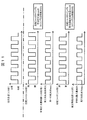
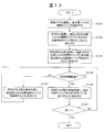
- FIG. 6 is a timing chart showing the switching timing of opening and closing of the liquid crystal shutter of the liquid crystal glasses 40 according to the first and second embodiments, the lighting timing of the surgical lamp 20, and the lighting timing of the fluorescence excitation light source 30. It is a flowchart for demonstrating the processing content (contents of the illumination control program 1061) of the control apparatus 10 in 1st Embodiment. It is a flowchart for demonstrating the processing content (contents of the illumination control program 1061) of the control apparatus 10 in 2nd Embodiment.
- this embodiment may be implemented by software that runs on a general-purpose computer, or may be implemented by dedicated hardware or a combination of software and hardware.
- FIG. 1 is a diagram illustrating a configuration of a surgical operation support system (also referred to as a medical support system or a light irradiation system) according to the present embodiment.
- a surgical operation support system also referred to as a medical support system or a light irradiation system
- the “surgical” application is used for convenience of explanation.
- the present system is not limited to the “surgical” application, and can be widely applied as, for example, a “medical” application.
- the surgery support system 1 can be used for, for example, a surgical laparotomy.
- the surgery support system 1 in the present embodiment is a surgery support illumination control system.
- the surgical operation support system 1 is, for example, a living organism (for example, an animal) administered with a fluorescent agent that reacts with excitation light (for example, 5-aminolevulinic acid (5-ALA)) (for example, oral administration or local administration by injection).
- excitation light for example, 5-aminolevulinic acid (5-ALA)
- Etc. obtained by continuously or intermittently irradiating excitation light to a tissue (observation target, irradiated body) BT (for example, an organ: FIG. 1 shows an organ as an example of the tissue BT). This is to allow a doctor, an operator, or the like (also simply referred to as “user”) to check the fluorescence from the affected area under a very bright surgical light.
- the surgery support system 1 includes, as an example, a control device 10 that controls the entire system, a surgical lamp 20, a fluorescence excitation light source 30, and liquid crystal glasses 40.
- the control device 10 is configured by a general computer, for example, a processor (CPU, MPU, etc.), reads a control program from the memory 106 and executes it, for example, a changeover switch, a mouse, a keyboard, a touch panel type pointing device (stylus). Operation with a pen or finger), a microphone, and the like, and an input unit 102 used for inputting setting information, instructions, and data, and a display device, a printer, a speaker, and the like, for outputting data and information
- An output unit 103 used for the storage, a storage unit 104 used for storing processing results and setting contents by the control unit, a communication unit 105 communicating with an external device or a network, and various programs and data in advance.
- a memory 106 for storing.
- the memory 106 holds, for example, an illumination control program 1061 for controlling operations of the surgical lamp 20, the fluorescence excitation light source 30, and the liquid crystal glasses 40.
- the operation light 20 is white LED illumination having sufficient brightness for performing surgery, and in this embodiment, for example, an illuminance of 160000 lux, but may be an illumination having an illuminance of at least 500 to 1000 lux, for example.
- the operation lamp 20 is connected to the control device 10, and the lighting timing (lighting time and light-off time) is controlled by the control device 10.
- the operation lamp 20 includes a drive unit and a control unit (not shown), and operates to repeatedly turn on and off by turning on / off the LED power source according to the lighting timing instructed by the control device 10. To do.
- the fluorescence excitation light source 30 is a light source that emits light having a wavelength in a predetermined band.
- the fluorescent excitation light source 30 is a narrow-band light source that emits light (ultraviolet light) with a wavelength of 385 to 425 nm (for example, the wavelength of emitted light is several nm to For example, the wavelength of the excitation light may be changed during irradiation with light.
- the fluorescence excitation light source 30 is connected to the control device 10 similarly to the operation lamp 20, and the lighting timing (lighting time and light-off time) is controlled by the control device 10.
- the fluorescence excitation light source 30 includes a drive unit and a control unit (not shown), and is repeatedly turned on and off by turning on and off the light source according to the lighting timing instructed by the control device 10. Operate. As will be described later, the lighting timing of the surgical lamp 20 and the lighting timing of the fluorescence excitation light source 30 are controlled so as to alternate or partially overlap every predetermined time (for example, 1/60 seconds).
- the liquid crystal glasses 40 are mounted on a mounting target (eg, a wearer, a mounting object, etc.) such as a doctor or an operator during surgery (medical practice), for example, and the visual field (eg, first visual field, second visual field) of the mounting target.
- a mounting target eg, a wearer, a mounting object, etc.
- the visual field eg, first visual field, second visual field
- the liquid crystal glasses 40 may have a glasses shape (see FIGS. 1 and 2), or may have a shape like ski goggles (not shown).
- a left eye field restriction unit first field restriction
- one field of view eg, left eye field of a wearing target (eg, wearer).
- the liquid crystal glasses 40 control the left field of view (for example, the field of view corresponding to the left eye of the wearer) and / or limit the field of view for the left eye.
- Right eye field restriction region for controlling and / or restricting a restriction region (first visual field restriction unit) (not shown) and the other visual field to be worn (for example, a field of view corresponding to the right eye of the wearer) (Second visual field limiting unit) (not shown).
- the liquid crystal glasses 40 when the liquid crystal glasses 40 are worn on a wearing subject such as a doctor, the liquid crystal glasses 40 are configured to be able to perform wireless communication via the control device 10 and the communication unit 105, and the control device 10 performs a predetermined time (for example, The timing for restricting the left eye field and the right eye field of the wearer is controlled in units of 1/60 seconds.
- the liquid crystal glasses 40 are configured so that a liquid crystal corresponding to the left eye and a liquid crystal corresponding to the right eye are alternately switched between a light shielding state and a light transmitting state in units of a predetermined period.
- the liquid crystal glasses 40 have one field of view (for example, left eye) of the wearer by shielding the first field of view (for example, the field corresponding to the left eye to be worn) of the first field restriction unit 402.
- Light in the second field of view (eg, field of view corresponding to the right eye to be worn) of the second field restriction unit 401 while blocking the field of view) darkly for example, the liquid crystal glasses 40 adjust the amount of light in the first field of view).
- the other visual field of the wearer for example, the visual field of the right eye
- the liquid crystal glasses 40 adjust the light amount in the second visual field to a light amount different from that in the first visual field).
- the liquid crystal glasses 40 in the second state make the second field of view restriction unit 401 while making one field of view of the wearer bright by the light transmission of the first field of view of the first field of view restriction unit 402.
- the other visual field of the wearer is darkly blocked by blocking the second visual field.
- the liquid crystal glasses 40 according to this embodiment include a liquid crystal region (first visual field restriction unit) corresponding to one field of view of the wearer (eg, left eye field) and the other field of view of the wearer (eg, right eye field).
- the liquid crystal glasses 40 are used, but the first visual field (for example, the visual field corresponding to the left eye) and the second visual field (for example, the visual field corresponding to the right eye) are shielded and light transmissive (for example, each Any principle other than liquid crystal may be used as long as it can be switched alternately (including the amount of light in the field of view).
- a glasses-type device that alternately switches between the light shielding and light transmission states of the first visual field and the second visual field by DMD (Digital Micromirror Device) may be used.
- liquid crystal glasses 40 and DMD glasses-type devices can be collectively referred to as, for example, a visual field limiting device.
- a visual field limiting device for example, a head-mounted visual field limiting device may be used.
- description can be made using the left eye field and the right eye field to be mounted.
- the control device 10 communicates with the operation lamp 20, the fluorescence excitation light source 30, and the liquid crystal glasses 40, and the lighting timing and the liquid crystal shutters of the liquid crystal glasses 40 are transmitted to the respective drive units (not shown) and control units (not shown).
- An opening / closing timing is instructed (hereinafter also simply referred to as “shutter”). For example, when the visual field of the left eye in the liquid crystal glasses 40 is in a light-shielded state (left-eye shutter closed) and the right eye is in a light-transmitting state (right-eye shutter opened), the control device 10 turns off the operation lamp 20 and turns on the fluorescence excitation light source. Each operation is controlled so that 30 lights up.
- the control device 10 when the visual field of the left eye is in a light-transmitting state (left-eye shutter is open) and the right eye is in a light-shielding state (right-eye shutter is closed), the control device 10 is turned on and the fluorescence excitation light source 30 is turned off.
- Each operation is controlled as follows.
- the control device 10, the surgical lamp 20, and the fluorescence excitation light source 30 are connected by wire.
- the control device 10 performs control by wirelessly communicating with the surgical lamp 20 and the fluorescence excitation light source 30. May be.
- the liquid crystal glasses 40 that has received the control signal related to the operation of the opening / closing timing of the shutter from the control device 10, based on the received control signal of the opening / closing timing, first of the first visual field limiting unit 402 corresponding to the visual field of the left eye.
- the light transmission and / or light shielding of the visual field and the light transmission and / or light shielding of the second visual field of the second visual field restriction unit 401 corresponding to the visual field of the right eye are controlled.
- the liquid crystal glasses 40 include two liquid crystal shutters (a left eye shutter and a right eye shutter) as a field restriction unit (first field restriction unit, second field restriction unit), and the first field restriction is performed by opening and closing each shutter.
- the light transmission and / or light shielding of the unit 402 and the light transmission and / or light shielding of the second visual field limiting unit 401 are controlled.
- the surgical light 20 and the fluorescence excitation light source 30 as light sources are provided as independent light sources.
- a single light source is used for surgical illumination light (for example, 500 to 1000 lux). It is necessary to be able to control so that the irradiation of light alternates or a part of the irradiation timing of light overlaps (for example, light having a wavelength of 385 to 425 nm) and excitation light (for example, light having a wavelength of 385 to 425 nm). It may be configured as follows.
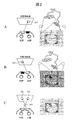
- FIG. 2 is a diagram for explaining the outline of the light irradiation timing control.
- FIG. 2A shows a left-eye image (odd number) viewed through a left-eye shutter (left visual field) in which a doctor or the like who is wearing liquid crystal glasses 40 is in a light-transmitting state for 1/60 seconds of turning on the operation lamp 20. Field) 201.
- FIG. 2A shows a left-eye image (odd number) viewed through a left-eye shutter (left visual field) in which a doctor or the like who is wearing liquid crystal glasses 40 is in a light-transmitting state for 1/60 seconds of turning on the operation lamp 20. Field
- FIG. 2B shows a case where a doctor or the like who puts on the liquid crystal glasses 40 is transmissive for 1/60 seconds of irradiating the tissue BT with excitation light from the fluorescence excitation light source 30 through a right eye shutter (right field of view). A right eye video (even field) 202 to be viewed is shown.
- FIG. 2C shows an image 203 synthesized in the brain of a doctor or the like wearing the liquid crystal glasses 40.
- the liquid crystal shutter of the liquid crystal glasses 40 has a left eye shutter (left eye field of view (also referred to as a first field of view)) and a right eye shutter (right eye shutter) in units of 1/60 seconds, for example. It is controlled by the control device 10 so as to be alternately switched between open and closed (see FIGS. 2A and 2B).
- the left eye shutter is open, the operation lamp 20 is turned on, and illumination light (for example, white LED light) is controlled to be illuminated on the tissue BT.
- illumination light for example, white LED light
- an image captured with the left eye constitutes an odd field image 201
- an image captured with the right eye constitutes an even field image 202.
- An image synthesized in the brain of a doctor or the like is a 1/30 unit frame image (reproduced image) 203.
- FIG. 3 is a timing chart showing the switching timing of opening and closing of the liquid crystal shutter of the liquid crystal glasses 40, the lighting timing of the surgical lamp 20, and the lighting timing of the fluorescence excitation light source 30.
- FIG. 3 as an example, the case where the irradiation of light by the surgical lamp 20 and the irradiation of excitation light by the fluorescence excitation light source 30 are alternated is shown.
- the irradiation timing of excitation light may partially overlap.
- the control device 10 wirelessly communicates with the liquid crystal glasses 40 and controls the opening and closing of the liquid crystal shutter according to the timing chart.
- the left-eye shutter repeats opening and closing every 1/60 seconds.
- the right eye shutter repeats opening and closing every 1/60 seconds, but the opening and closing timing is reverse to that of the left eye shutter.
- the operation lamp 20 is turned on (bright) while the left eye shutter is open, and the operation lamp 20 is turned off (dark) while the left eye shutter is closed.
- the fluorescence excitation light source is turned on (bright) while the right eye shutter is open, and the fluorescence excitation light source 30 is turned off (dark) while the right eye shutter is closed.
- the opening / closing timing of the left-eye shutter (first visual field, left-eye visual field) and the ON / OFF timing of the operation lamp 20 are the same, and the opening / closing timing of the right-eye shutter (second visual field, right-eye visual field)
- the fluorescent excitation light source 30 is controlled so as to have the same ON / OFF timing.
- the operation lamp 20 is turned on (the fluorescence excitation light source 30 is turned off) and the left eye shutter is opened and in a light transmitting state, the light (illumination light) of the operation lamp 20 that illuminates the tissue BT is transmitted through the left eye shutter. Accordingly, a doctor or the like (operator) wearing the liquid crystal glasses 40 can observe the tissue BT brightly in the left eye.
- the fluorescence excitation light source 30 when the fluorescence excitation light source 30 is turned on (the operation lamp 20 is turned off) and the right eye shutter is opened and is in a light transmitting state, the fluorescence generated from the tissue BT through the irradiation of the excitation light to the tissue BT passes through the right eye shutter. .
- a doctor or the like (operator) wearing the liquid crystal glasses 40 can observe a tumor part (affected part) that emits fluorescence in a dark visual field in the right eye.
- these states are switched and controlled at regular time intervals (for example, every 1/60 seconds)
- the image of the right eye and the image of the left eye appear to be synthesized in the brain of a doctor or the like (operator).
- the fluorescence from the tumor part (affected part) of the tissue BT appears to be emphasized (the fluorescence from the tissue BT becomes clearly visible without being canceled out by the operation lamp 20).
- the control device 10 communicates with the surgical lamp 20, the fluorescence excitation light source 30, and the liquid crystal glasses 40, and opens / closes timing of the left eye shutter (first visual field, left eye visual field) and ON / OFF of the fluorescence excitation light source 30.
- the timing may be matched so that the opening / closing timing of the right-eye shutter (second visual field, right-eye visual field) and the ON / OFF timing of the operation lamp 20 may be matched.
- the roles of the left eye shutter and the right eye shutter may be switched at a predetermined timing.
- the control device 10 communicates with the liquid crystal glasses 40 and the operation lamp 20, matches the opening / closing timing of the left eye shutter with the ON / OFF timing of the fluorescence excitation light source 30 in a certain time, and sets the opening / closing timing of the right eye shutter. You may control so that the timing of ON / OFF of the operation light 20 may correspond. Then, for example, after a predetermined time has elapsed, the control device 10 matches the opening / closing timing of the left eye shutter with the ON / OFF timing of the operation lamp 20, and the opening / closing timing of the right eye shutter and the ON / OFF of the fluorescence excitation light source 30. Control may be performed so as to match the OFF timing.
- the control apparatus 10 repeats this and switches roles. With this configuration, for example, it is possible to avoid the problem of loss of perspective because the tissue BT is viewed with only one eye on the wearing target.
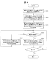
- FIG. 4 is a flowchart for explaining the processing contents of the control device 10 (contents of the illumination control program 1061) in the first embodiment.
- the control unit 101 of the control device 10 reads, for example, a lighting control program 1061 from a memory (for example, ROM (Read Only Memory)) into an internal memory (not shown) provided in the control unit 101, and the lighting control program 1061. Execute. For example, the following steps are executed by the control unit 101 according to the illumination control program 1061.
- Step 401 For example, when the power of the liquid crystal glasses 40 worn by a doctor or the like (operator) who is going to perform surgery is turned on, the power of the control device 10 is turned on, and the mode is set to the operation mode, the control device 10 The control unit 101 starts communication with the liquid crystal glasses 40 and sends a control signal to the liquid crystal glasses 40 to instruct the opening / closing timing of the left eye shutter and the right eye shutter of the liquid crystal glasses to be the timing shown in FIG. .
- the liquid crystal glasses 40 sequentially open and close the left eye shutter and the right eye shutter according to the opening and closing timing of the shutter received from the control device 10.
- the opening / closing of the left and right eye shutters of the liquid crystal glasses 40 is executed alternately every 1/60 seconds, for example (see FIG. 3).
- Step 402 The control unit 101 communicates with the surgical lamp 20 and sends a control signal to the liquid crystal glasses 40 to instruct the timing of turning on and off the surgical lamp 20 to the opening / closing timing of the left eye shutter of the liquid crystal glasses 40.
- the operation lamp 20 operates a drive unit or a control unit (not shown) according to the lighting and extinguishing timing notified from the control device 10, and turns on and off the white LED in accordance with the opening / closing timing of the left eye shutter of the liquid crystal glasses 40.
- the timing for turning on and off the white LED is, for example, every 1/60 seconds as in the case of the left eye shutter of the liquid crystal glasses 40.
- Step 403 The control unit 101 communicates with the fluorescence excitation light source 30 and sends a control signal to the liquid crystal glasses 40 to instruct the timing of turning on and off the fluorescence excitation light source 30 to the opening / closing timing of the right eye shutter of the liquid crystal glasses 40.
- the fluorescence excitation light source 30 operates a drive unit or a control unit (not shown) according to the lighting and extinguishing timings notified from the control device 10 and turns on / off excitation light irradiation in accordance with the opening / closing timing of the right eye shutter of the liquid crystal glasses 40.
- the excitation light irradiation ON / OFF timing is, for example, every 1/60 seconds as in the right eye shutter of the liquid crystal glasses 40.
- Step 404 The control unit 101 may set a predetermined time (for example, 1 minute) after starting the timing synchronization processing of the surgical lamp 20, the fluorescence excitation light source 30, and the liquid crystal glasses 40. The set time can be changed by the user. Judgment is made or not.
- the predetermined time has elapsed (Yes in Step 404)
- the process of the control unit 101 proceeds to Step 406. If the predetermined time has not elapsed (No in step 404), the process of the control unit 101 proceeds to step 405.
- Step 405 The control unit 101 instructs the operation lamp 20 and the fluorescence excitation light source 30 to continue the operation at the lighting and extinguishing timings currently being executed.
- the surgical lamp 20 and the fluorescence excitation light source 30 receive the operation continuation instruction at the lighting and extinguishing timing currently being executed from the control device 10 and continue the operation according to the instruction.
- Step 406 The control unit 101 instructs the surgical lamp 20 and the fluorescence excitation light source 30 by sending a control signal so that the lighting and extinguishing timings until now are opposite to the timings until now. Since the opening / closing timing of the shutter of the liquid crystal glasses 40 is the same as before, no special instruction is given.
- the lighting timing and extinguishing timing of the operation lamp 20 coincide with the opening / closing timing of the left eye shutter of the liquid crystal glasses 40
- the lighting timing and extinguishing timing of the fluorescence excitation light source 30 correspond to the opening timing of the right eye shutter of the liquid crystal glasses 40. If they match, the lighting timing and extinguishing timing of the surgical lamp 20 match the opening / closing timing of the right eye shutter, and the lighting timing and extinguishing timing of the fluorescence excitation light source 30 match the opening / closing timing of the left eye shutter.
- the control unit 101 sends a control signal to the operation lamp 20 and the fluorescence excitation light source 30 to instruct it.
- the surgical lamp 20 and the fluorescence excitation light source 30 each receive a timing change instruction (control signal) from the control device 10 and change the lighting and extinguishing timing according to the instructions.
- Step 407 The control unit 101 determines whether or not a processing end instruction (end signal) is input from the input unit 102 by a user (such as a doctor who is an operator). If an instruction to end the process is not input (No in step 407), the process proceeds to step 404 and the process is continued. When a process end instruction is input (Yes in step 407), the light irradiation control process by the illumination control program 1061 ends.
- steps 401 to 403 is expressed to be executed sequentially, but the processing of these steps may be executed almost simultaneously. Further, the processing of steps 404 to 405 is not essential, and step 406 may be executed after step 403. When the processing is not terminated, the same operation is continued in the surgical lamp 20, the fluorescence excitation light source 30, and the liquid crystal glasses 40.
- the control device 10 alternately opens and closes the left eye field and the right eye field to be mounted on the liquid crystal glasses (field-of-view restriction device) 40 at predetermined time intervals. These operations are controlled so that irradiation of light (first light) and irradiation of excitation light (second light) by the lamp 20 and the fluorescence excitation light source 30) are alternated.
- the control device 10 opens and closes one of the first field of view (e.g., corresponding to the left eye field) of the first field restriction unit and the second field of view (e.g., corresponding to the right eye field) of the second field restriction unit.
- the timing of ON / OFF of the surgical lamp 20 coincide with each other, and the visual field (for example, the second visual field) other than the visual field (for example, the first visual field, the left-eye visual field) matches the ON / OFF timing of the surgical lamp 20.
- the lighting of the light is controlled so that the opening / closing timing of the visual field of the right eye matches the ON / OFF timing of the fluorescence excitation light source 30.
- the visual field in which the ON / OFF timing of the operation lamp 20 is matched is the right-eye visual field
- the visual field other than the visual field is the left-eye visual field.
- the control device 10 alternately controls opening and closing of the first visual field and the second visual field of the liquid crystal glasses (visual field limiting device) 40 at predetermined time intervals, and irradiates light (first light) with the surgical lamp 20 and fluoresces. It can also be expressed that these operations are controlled so that excitation light (second light) irradiation by the excitation light source 30 alternates.
- the control device 10 matches the opening / closing timing of the first visual field with the ON / OFF timing of the operation lamp 20, and the opening / closing timing of the second visual field and the ON / OFF timing of the fluorescence excitation light source 30 are the same. Control lighting to match.
- a light source that emits visible light for example, an LED light source that emits white light
- an excitation light source that emits excitation light of a predetermined wavelength can be used as the fluorescence excitation light source 30.
- the light emission timings of the visible light (first light) from the surgical light and the excitation light (second light) from the excitation light source may be a period of alternately emitting light or a period of opposite phases. There may be a period in which some overlap.
- a user does not need to observe fluorescence emitted from a biological tissue in a darkened environment, and directly confirms a characteristic part (eg, a tumor part) in a bright operating room.
- Surgery can be performed.
- each light source in the present embodiment (as described above that irradiation may be performed while switching between visible light and excitation light with a single light source) is performed on the biological tissue to which the fluorescent agent is administered. Irradiate light.
- fluorescence is emitted from the tumor portion of the biological tissue by irradiation of excitation light, and the user can observe the affected area (characteristic portion, generated fluorescence) in a bright room. .
- the excitation light emitted from the fluorescence excitation light source 30 for example, ultraviolet light having a wavelength of 385 to 425 nm can be used. Since the ultraviolet light is invisible, it is possible to prevent the excitation light from illuminating not only the affected area but also the entire biological tissue (for example, the organ) in a colored manner and hindering medical practice.
- liquid crystal glasses 40 capable of alternately switching between left and right visual fields can be used.
- the liquid crystal glasses 40 may have a shape like ski goggles.
- doctors and operators can easily wear the field-of-view restriction device, and wearing the device does not interfere with medical practice.
- the field-of-view restriction device (or field-of-view restriction unit) according to the present embodiment has a function of controlling the user's field of view by controlling (or restricting) the light that is transmitted, for example.
- Optics such as wavelength filters to select (eg, visible filters, bandpass filters, dichroic mirrors) and filters that adjust the amount of transmitted light (eg, dimming transmitted light) (eg, ND filters, polarizing filters)
- filters to select eg, visible filters, bandpass filters, dichroic mirrors
- filters that adjust the amount of transmitted light eg, dimming transmitted light
- ND filters eg, ND filters, polarizing filters
- the control device 10 wirelessly communicates with, for example, a field-of-view restriction device (for example, liquid crystal glasses 40), and controls opening and closing of the left eye field and the right eye field.
- the opening / closing timings of the left eye field and the right eye field in the field limiting device may be controlled to alternate, for example, or may partially overlap.
- the liquid crystal glasses 40 include at least a communication unit for communicating with the control device 10, a processor for executing commands from the control device 10, and a power supply unit for driving them. Since the control device 10 and the field-of-view restriction device (liquid crystal glasses 40) can communicate with each other wirelessly, doctors and operators who wear the field-of-view restriction device can operate smoothly. It will not be disturbed.
- the control device 10 instructs the operation lamp 20, the fluorescence excitation light source 30, and the liquid crystal glasses 40 to operate each, but the second embodiment
- the liquid crystal glasses 40 in FIG. 5 autonomously open and close the left eye shutter and the right eye shutter at a predetermined timing, for example.
- the control device 10 communicates with the liquid crystal glasses 40 to detect the open / close timing of the left and right eye shutters of the liquid crystal glasses 40 (acquires information about the open / close timing).
- the configuration of the surgery support system 1 see FIG. 1) and the timing chart (FIG. 3) are the same as those in the first embodiment.
- FIG. 5 is a flowchart for explaining the processing contents (contents of the lighting control program 1061) of the control device 10 in the second embodiment.
- FIG. 5 differs from FIG. 4 only in step 501, and the other processes are the same as those in FIG. 4.
- Step 501 For example, when the power of the liquid crystal glasses 40 worn by a doctor or the like (surgeon) who intends to perform surgery is turned on, the power of the control device 10 is turned on, and the mode is set to the operation mode, the liquid crystal glasses 40 are The opening / closing operation of the left and right eye shutters is started at a preset timing (for example, every 1/60 seconds).
- the control unit 101 of the control device 10 communicates with the liquid crystal glasses 40 and detects opening / closing timings of the left eye shutter and the right eye shutter of the liquid crystal glasses 40.
- left and right liquid crystal shutter opening / closing timing information is held in a memory (not shown), and a control unit (processor) (not shown) acquires the liquid crystal shutter opening / closing timing information from the memory and actually The liquid crystal shutter is opened and closed. Therefore, the control device 10 communicates with the control unit of the liquid crystal glasses 40 using the communication unit 105, and acquires information on the opening / closing timing of the currently operating liquid crystal shutter.
- the opening and closing timings of the left and right eye shutters acquired in this way are as shown in FIG. 3 (for example, they are alternately opened and closed every 1/60 seconds).
- Steps 402 to 407 The processing contents of steps 402 to 407 are the same as those in FIG. In the first embodiment, the processing in steps 401 to 403 may be executed at the same time. However, in the second embodiment, the processing in step 501 is executed first to open / close timing of the left and right eye shutters of the liquid crystal glasses 40. It is necessary to obtain information. And the lighting timing of the operation lamp 20 and the fluorescence excitation light source 30 is controlled according to it. However, the processing of steps 402 and 403 may be executed simultaneously.
- the visual field limiting device controls opening / closing of the visual field of the left eye and the visual field of the right eye of a person (for example, a doctor or an operator) who wears the visual field restriction device at predetermined time intervals.
- the field-of-view restriction device (for example, the liquid crystal glasses 40) may alternately open and close the left-eye field and the right-eye field.
- the opening / closing control may be performed so that a part of the opening / closing timing with the visual field overlaps. For example, when the timing overlaps, for example, when both the right eye field and the left field are open and closed, or when both fields are closed or open. Cases can be mentioned.
- the left eye field can be referred to as the first field
- the right eye field can be referred to as the second field
- the right eye field can be referred to as the first field
- the left eye field can be referred to as the second field.
- the opening / closing control is controlled by the control device 10
- the visual field limiting device performs the opening / closing control by itself.
- the timing of irradiation of the first light and the timing of irradiation of the second light by the light source unit are controlled by the control device 10.
- the control device 10 communicates (for example, wirelessly communicates) with the field-of-view restriction device (for example, liquid crystal glasses 40), and the first field of view and the second field of view restriction device (the liquid crystal glasses 40). Acquires information about the opening and closing timing of the visual field. Thereby, the control apparatus 10 can acquire the information of the opening / closing timing of each visual field of the visual field restriction device (liquid crystal glasses 40).
- the control device 10 alternates the irradiation of the first light and the irradiation of the second light, the opening / closing timing of the first visual field coincides with the ON / OFF timing of the first light irradiation,
- the lighting of the light source unit (the operation lamp 20 and the fluorescence excitation light source 30) is controlled so that the opening / closing timing matches the ON / OFF timing of the second light irradiation.
- the visual field limiting device liquid crystal glasses 40
- the third embodiment relates to a surgical microscope to which the principle of the first and second embodiments is applied.
- a fluorescent agent for example, 5-aminolevulinic acid (5-ALA)
- the administration method for example, oral administration or local administration by injection can be considered.
- the surgical microscope is used after a predetermined fluorescent agent is administered.
- FIG. 6 is a schematic diagram showing an example of the appearance of a surgical microscope system 60 according to the third embodiment.
- the surgical microscope system 60 includes a surgical microscope 70, a support arm unit 62 that supports the surgical microscope 70, a tip member 63, a link mechanism 64 that connects the support arm unit 62 and the tip member 63, and a tip.
- the connection arm 61 connects a stand device (not shown) and the tip member 63 so as to be rotatable in the direction of arrow A.
- height adjustment may be performed by a stand device (not shown).
- the link mechanism 64 is, for example, a mechanism that allows the support arm portion 62 and the tip member 63 to rotate in the direction of arrow B.
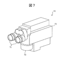
- FIG. 7 is a schematic view showing an example of the appearance of the surgical microscope 70 according to the third embodiment.
- the surgical microscope 70 includes an eyepiece unit 71, a light flux receiving unit 72, and a housing 73 that houses optical components that constitute various optical paths and a control device that controls various operations.
- the eyepiece unit 71 includes two eyepiece regions (eg, first eyepiece and second eyepiece) having eyepieces. For example, a user of a doctor or the like (operator) observes the tissue BT (eg, surgical technique).
- the light beam inlet 72 is an irradiation port for irradiating the tissue BT with observation light from the surgical microscope light source 80 and excitation light from the fluorescence excitation light source 30, and light for taking in reflected light from the tissue BT. It is the structure used as an intake.
- the light beam inlet 72 is a light inlet (incident part) into which reflected light through the tissue BT and light (for example, fluorescence) generated from the tissue BT enter.
- FIG. 8 is a diagram illustrating an internal configuration example of the surgical microscope 70 according to the third embodiment.
- the surgical microscope 70 uses the eyepiece 71, the light beam input unit 72, the surgical microscope light source 80, the fluorescence excitation light source 30, and the illumination light from the surgical microscope light source 80, and the light beam input unit 72.
- the illumination light path L that guides to the tissue BT (including the affected part (for example, a tumor part)) and the excitation light from the fluorescence excitation light source 30 includes the tissue BT (for example, the affected part (for example, the tumor part)) via the mirror 32.
- the observation light path A for guiding the reflected light from the tissue BT and the fluorescence from the affected part (for example, a tumor part) to the eyepiece part 71 via the light beam intake part 72, and the observation light path A.
- a control device 10 that controls the operation timing of the operation microscope light source 80, the fluorescence excitation light source 30, and the liquid crystal shutter 86.
- the control device 10 is accommodated in the housing 73, but may be configured to be externally connected, for example.
- the surgical microscope light source 80 can be a white LED light source having a brightness sufficient for surgery, for example, an illuminance of 60000 lux, but an illuminance of at least 500 to 1000 lux, for example.
- the lighting may be.
- the surgical microscope light source 80 is connected to the control device 10, and the lighting timing (lighting time and light-off time) is controlled by the control device 10.
- the surgical microscope light source 80 includes a drive unit (not shown), and operates to repeatedly turn on and off by turning on and off the LED power source according to the lighting timing instructed by the control device 10.
- the fluorescence excitation light source 30 is a light source that emits light having a wavelength in a predetermined band, for example, as in the first embodiment.
- a narrow band light source that emits light (ultraviolet light) with a wavelength of 385 to 425 nm, for example, can be used as the fluorescence excitation light source 30.
- the fluorescence excitation light source 30 is connected to the control device 10 similarly to the surgical microscope light source 80, and the lighting timing (lighting time and light-off time) is controlled by the control device 10.
- the fluorescence excitation light source 30 includes a drive unit and a control unit (not shown), and is repeatedly turned on and off by turning on and off the light source according to the lighting timing instructed by the control device 10. Operate.
- the lighting timing of the operation lamp 20 and the lighting timing of the fluorescence excitation light source 30 are alternately or partially overlap every predetermined time (for example, 1/60 seconds) (for example, the operation lamp 20 and the fluorescence excitation light source 30 There is a time during which both are turned on or off partially).
- the illumination optical path L is, for example, an illumination optical system 21 composed of a plurality of lenses and a rear stage of the illumination optical system 21, and changes the optical path of the illumination light that has passed through the illumination optical system 21 to illuminate the tissue BT. And a mirror 22 for appropriately irradiating 23.
- the excitation optical path E is arranged at the subsequent stage of the excitation optical system 31 composed of a plurality of lenses and the excitation optical system 31, and changes the optical path of the excitation light that has passed through the excitation optical system 31 to the tissue BT. And a mirror 32 for appropriately irradiating 33.
- the observation optical path A includes an objective optical system 81 arranged at the rear stage of the light beam receiving unit 72, a first prism 82 that changes the optical path by reflecting light that has passed through the objective optical system 81, and a zoom optical system 83.
- the second prism 84 that changes the optical path by reflecting the light that has passed through the zoom optical system 83
- the third prism 85 that changes the optical path by reflecting the light
- the excitation light for example, ultraviolet light included in the light from the tissue BT
- a notch filter F that cuts light.
- the right eye image and the left eye image), and the two divided lights (first split light and second split light) travel along the first optical path and the second optical path of the observation optical path A, respectively, and the eyepiece It will reach 71.
- the first optical path and the second optical path of the observation optical path A are provided between the objective optical system 81 and the eyepiece 71, and are optical paths through which two lights divided by the objective optical system 81 pass.
- one of the two lights divided by the objective optical system 81 passes through the first optical path of the observation optical path A
- the other light (second divided light) passes through the observation optical path A. It passes through the second optical path.
- the notch filter F is disposed, for example, to cut the excitation light 33 that is unnecessary for fluorescence observation.
- the excitation light 33 is, for example, ultraviolet light
- it is invisible to the eyes of a doctor or the like (operator), but it is dangerous if the eye is exposed to ultraviolet light for a long time, so a filter for removing such excitation light is disposed. It is desirable to do.
- the prisms 82 to 85 are used to change the optical path of the light (reflected light) from the tissue BT.
- a simple mirror may be used.
- the liquid crystal shutter 86 is disposed after the first prism 82 in the observation optical path A and before the eyepiece 71.
- the liquid crystal shutter 86 serving as the visual field limiting unit includes, for example, a first visual field limiting unit provided in the first optical path of the observation optical path A and a second visual field limiting unit provided in the second optical path of the observation optical path A.
- the liquid crystal shutter 86 is connected to, for example, the control device 10 and corresponds to the first field of view in the first field restriction unit (for example, the field of view of the user's left eye) in units of a predetermined time (for example, 1/60 seconds).
- the second visual field in the second visual field restriction unit (for example, the visual field corresponding to the visual field of the right eye of the user) are controlled.
- the liquid crystal eg, liquid crystal corresponding to the left eye
- the liquid crystal eg, right eye
- the liquid crystal corresponding to (1) is alternately switched between a light shielding state and a light transmitting state in units of a predetermined period.
- the control device 10 sends a control signal to the operation microscope light source 80, the fluorescence excitation light source 30, and the drive unit (not shown) or the control unit (not shown) of the liquid crystal shutter 86, and turns on these light sources.
- the timing and turn-off timing and the opening / closing timing of the liquid crystal shutter 86 are instructed.
- the control device 10 turns off the surgical microscope light source 80. Each operation is controlled so that the fluorescence excitation light source 30 is turned on.
- the control device 10 turns on the surgical microscope light source 80 and excites fluorescence. Each operation is controlled so that the light source 30 is turned off.
- FIG. 9 is a diagram illustrating a configuration example of an optical system of the surgical microscope 70 according to the third embodiment.
- FIG. 9 shows only the optical system configuration, and the control device 10 and the eyepiece 71 are omitted.
- the turning on and off of the illumination light from the surgical microscope light source 80 and the excitation light from the fluorescence excitation light source 30 and the opening and closing of the left and right eye shutters of the liquid crystal shutter 86 are controlled at the timing shown in FIG.
- the surgical microscope light source 80 is turned on for a predetermined time (for example, 1/60 seconds), and the illumination light emitted from the surgical microscope light source 80 is irradiated to the tissue BT via the illumination optical system 21 and the mirror 22.
- the reflected light from the tissue BT becomes, for example, two lights corresponding to the left and right eyes observed in the eyepiece 71, and the objective optical system 81, the first prism 82, the zoom optical system 83, the second prism 84, and The light is guided to the liquid crystal shutter 86 through the third prism 85.
- the liquid crystal shutter 86 has, for example, a first visual field (eg, a visual field in the left eye shutter) in a light-transmitting state and a second visual field (eg, a visual field in the right eye shutter) in a light-shielded state.
- the reflected light from the tissue BT passes only through the first visual field restriction unit (left eye shutter), and, for example, one eyepiece region of the eyepiece unit 71 (for example, via the notch filter F) Only the first eyepiece with the left eyepiece is reached.
- the operation microscope light source 80 When the operation microscope light source 80 is turned on for a predetermined time (for example, 1/60 seconds described above), the operation microscope light source 80 is turned off and the fluorescence excitation light source 30 is controlled to be turned on for a predetermined time (for example, 1/60 seconds). Is done. Further, the first visual field restriction unit (left eye shutter) of the liquid crystal shutter 86 is controlled to be in a light shielding state, and the second visual field restriction unit (right eye shutter) is controlled to be in a light transmission state. During this time, the excitation light from the fluorescence excitation light source 30 is irradiated to the tissue BT via the excitation optical system 31 and the mirror 32, for example.
- a predetermined time for example, 1/60 seconds described above
- the operation microscope light source 80 is turned off and the fluorescence excitation light source 30 is controlled to be turned on for a predetermined time (for example, 1/60 seconds). Is done. Further, the first visual field restriction unit (left eye shutter) of the
- the excitation light 33 When the excitation light 33 is irradiated to the tissue BT, fluorescence is emitted from the affected part (for example, a tumor part) of the tissue BT.
- the fluorescence from the affected part becomes, for example, two lights corresponding to the left and right eyes observed in the eyepiece 71, and the objective optical system 81, the first prism 82, the zoom optical system 83, the second prism 84, and the second
- the light is guided to the liquid crystal shutter 86 through the three prisms 85.
- the liquid crystal shutter 86 When the fluorescence excitation light source 30 is lit, the liquid crystal shutter 86 is in a state where the first visual field restriction unit (left eye shutter) is shielded and the second visual field restriction unit (right eye shutter) is in a light transmission state as described above.
- the fluorescence passes only through the second visual field restriction unit (right eye shutter). Further, since the reflected light of the excitation light via the tissue BT is removed by, for example, the notch filter F, only the fluorescence reaches the other eyepiece region of the eyepiece 71 (eg, the second eyepiece having the right eyepiece lens). To do.
- the above processing is switched and repeated every predetermined time (for example, 1/60 seconds).
- the surgical microscope light source 80 is turned on (the fluorescence excitation light source 30 is turned off) and the left-eye shutter is in a light-transmitting state (the right-eye shutter is in a light-shielding state), a doctor or the like (operator) looking into the eyepiece 71 is left
- the tissue BT can be observed brightly in the eyes.
- the fluorescence excitation light source 30 is turned on (the operation lamp 20 is turned off) and the right eye shutter is in a light transmitting state (the left eye shutter is in a light shielding state), a doctor or the like looking at the eyepiece 71 (operator)
- a tumor part (affected part) that emits fluorescence in a dark visual field in the eye can be observed. If this state is switched and controlled at regular time intervals (for example, every 1/60 seconds), the image of the right eye and the image of the left eye appear to be synthesized in the brain of a doctor or the like (operator).
- the fluorescence from the tumor part (affected part) of the tissue BT appears to be emphasized (the fluorescence from the tissue BT becomes clearly visible without being canceled out by the surgical microscope light source 80).
- the surgical microscope light source 80 and the left eye shutter of the liquid crystal shutter 86 are synchronized, and the fluorescence excitation light source 30 and the right eye shutter of the liquid crystal shutter 86 are synchronized. May be reversed.
- the surgical microscope light source 80 in the present embodiment uses a light source capable of coaxial illumination with respect to the tissue BT, but may use a light source capable of ring illumination with respect to the tissue BT.
- the surgical microscope light source 80 in the present embodiment can illuminate the tissue BT uniformly from all directions.
- the control of the lighting and extinguishing timing of the surgical microscope light source 80 and the fluorescence excitation light source 30, and the opening / closing timing of the liquid crystal shutter is, for example, as shown in the timing chart of FIG. Detailed description here is omitted.
- “surgical lamp” can be read as “surgical microscope light source”
- “liquid crystal glasses” can be read as “liquid crystal shutter”.
- the content of control processing by the control device 10 is as shown in the flowchart of FIG. 4 and the description thereof, for example, and detailed description thereof is omitted here.
- “surgical lamp” can be read as “surgical microscope light source”
- “liquid crystal glasses” can be read as “liquid crystal shutter”.
- the control device 10 and the liquid crystal glasses 40 have been described so as to perform wireless communication.
- the control device 10 and the liquid crystal shutter 86 can be connected by wire to perform communication. (However, this does not deny the possibility of wireless communication.)
- the surgical microscope 70 includes a light introduction mechanism (for example, an illumination light path L and an excitation light path) that guides first light and second light emitted from a light source unit (for example, the surgical microscope light source 80 and the fluorescence excitation light source 30) to a biological tissue. E), an eyepiece unit 71, a normal optical path (observation optical path A) for guiding light from the biological tissue to the eyepiece unit 71, and the normal optical path.
- a light introduction mechanism for example, an illumination light path L and an excitation light path
- a light source unit for example, the surgical microscope light source 80 and the fluorescence excitation light source 30
- E an eyepiece unit 71
- a normal optical path observation optical path A
- a light dividing unit that divides the light into a light field part, a visual field restricting part (for example, a liquid crystal shutter 86) provided between the light dividing part and the eyepiece part, an operation of the light source part, and a visual field restricting part
- a control device 10 for controlling the operation.
- the control device 10 controls the first visual field and the second visual field of the visual field restriction unit (the left visual field is the first visual field, the right eye visual field is the second visual field, or vice versa.
- the first field of view can be set as the second field of view), and the first light irradiation and the second light irradiation are alternately switched.
- the light introduction / non-introduction timing is made coincident, and the opening / closing timing of the second visual field is made coincident with the second light introduction / non-introduction timing.
- an operation can be performed while brightly illuminating a biological tissue and directly confirming a tumor part (affected part).
- the second light may be not only fluorescence but also phosphorescence, and the second light may be light emitted from the tissue BT by irradiation of light to the tissue BT.
- the operation microscope light source 80 and the fluorescence excitation light source 30 are turned on and off (first light irradiation timing and second light irradiation timing) as shown in FIG. You may overlap.
- the control device 10 communicates with the visual field restriction unit (for example, the liquid crystal shutter 86), and controls opening and closing of the visual field of the left eye and the visual field of the right eye.
- the opening / closing timing of the left eye field and the right eye field in the field restriction unit may be controlled to alternate, for example, as described above, or may be partially overlapped as another form. good. For example, when the timing overlaps, for example, when both the right eye field and the left field are open and closed, or when both fields are closed or open. Cases can be mentioned.
- the surgery support system according to the fourth embodiment corresponds to a modification of the surgery support system according to the first embodiment.
- the operation lamp 20 and the fluorescence excitation light source 30 are controlled to be turned on and off at predetermined time intervals (for example, every 1/60 seconds) at different timings.
- the light amount (or illuminance) of the surgical lamp 20 and the light amount (or illuminance) of the fluorescence excitation light source 30 are changed and controlled at predetermined time intervals (for example, every 1/60 seconds) at different timings. To do.
- the configuration of the surgery support system, the processing other than the control of the light amount (or illuminance) of the surgical lamp 20 and the control of the light amount (or illuminance) of the fluorescence excitation light source 30 are the same as those in the first embodiment. It is. Hereinafter, a fourth embodiment will be described.
- the hardware configuration of the surgery support system according to the fourth embodiment can adopt the same configuration as that of the surgery support system 1 according to the first embodiment.
- the software configuration is different in the points described below.
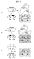
- FIG. 10 is a diagram for explaining the outline of the light irradiation timing control.
- a predetermined light amount may be a predetermined illuminance.
- it may be a maximum light amount (or maximum illuminance) that the surgical lamp 20 can output).
- a left-eye image (odd field) 1001 viewed through a left-eye shutter (left visual field) in which a doctor or the like wearing liquid crystal glasses 40 is in a light-transmitting state for a second is shown.
- the light amount of the excitation light from the fluorescence excitation light source 30 is, for example, a predetermined light amount smaller than the maximum light amount that can be output by the fluorescence excitation light source 30 (for example, 5%, 10%, or 30% of the maximum light amount, surgical light It is also possible to set the amount of light relatively lower than that of the light source 30. Further, for example, the fluorescence excitation light source 30 may be turned off.
- FIG. 10B shows a 1/60 second period in which the operation light 20 is turned on by reducing the light amount of the operation light 20 from the predetermined light amount (or by reducing the illuminance), for example, from the fluorescence excitation light source 30.
- a right-eye image (even field) 1002 viewed through a right-eye shutter (right visual field) in which a doctor or the like who is applying 40 is in a transmissive state is shown.
- FIG. 10C shows an image 1003 synthesized in the brain of a doctor or the like wearing the liquid crystal glasses 40.
- the surgical lamp 20 and the excitation light source 30 can be configured by, for example, each color LED (various wavelength LED).
- the amount of light of the surgical lamp 20 and the amount of excitation light of the excitation light source 30 can be controlled by controlling the current value flowing through the surgical lamp 20 and the excitation light source 30 (for example, changing the resistance value with a variable resistor). it can.
- the light amount of the surgical lamp 20 and the light amount of the excitation light from the excitation light source 30 can be controlled by adjusting the duty ratio of the PWM signal indicating the lighting time corresponding to the light amount. In the former case, when the light amount is decreased, the color of the LED light changes, but in the latter case, there is an advantage that only the light amount is reduced and the color of the LED light becomes constant.
- the liquid crystal shutter of the liquid crystal glasses 40 has a left eye shutter (left eye field of view (also referred to as a first field of view)) and a right eye shutter (right eye shutter) in units of 1/60 seconds, for example. It is controlled by the control device 10 so as to be alternately switched between open and closed (see also FIGS. 10A and 10B).
- the operation lamp 20 is controlled to be lit with a maximum light amount (or maximum illuminance), for example, so that illumination light (eg, white LED light) is illuminated on the tissue BT.
- 30 is controlled so as to output the excitation light with a light amount of a predetermined ratio of the maximum light amount (which may be turned off), for example.
- an image captured with the left eye constitutes an odd field image 1001
- an image captured with the right eye constitutes an even field image 1002.
- the fluorescence from the tissue BT appears to be emphasized (see FIG. 10C).
- An image (synthesized image) synthesized in the brain of a doctor or the like becomes a frame image (reproduced image) 1003 of 1/30 unit.
- FIG. 11 is a timing chart showing the switching timing of the liquid crystal shutter of the liquid crystal glasses 40, the light amount control timing of the surgical lamp 20, and the light amount control timing of the fluorescence excitation light source 30.
- FIG. 11 as an example, a case where the light amount control timing of the surgical lamp 20 and the light amount control timing of the fluorescence excitation light source 30 are alternated is shown, but the light amount control timing of the operation lamp 20 and the light amount of the fluorescence excitation light source 30 are illustrated. The control timing may partially overlap.
- the control device 10 wirelessly communicates with the liquid crystal glasses 40 and controls opening and closing of the liquid crystal shutter according to the timing chart.
- the left-eye shutter repeats opening and closing every 1/60 seconds.
- the right eye shutter repeats opening and closing every 1/60 seconds, but the opening and closing timing is reverse to that of the left eye shutter.
- the operation lamp 20 is lit (bright) with, for example, a first light amount (for example, a maximum light amount (or maximum illuminance)), and the left eye shutter is closed.
- the light amount of the surgical lamp 20 is reduced to a second light amount that is less than the first light amount.
- the amount of light that is reduced for the surgical lamp 20 may be appropriately set or adjusted by a doctor or the like (surgeon).
- the fluorescence excitation light source 30 is turned on (bright) with, for example, a third light amount (for example, maximum light amount (or maximum illuminance)), and the right eye shutter is turned on.
- the light amount of the fluorescence excitation light source 30 is reduced (darkened) to a fourth light amount (for example, it may be turned off) that is smaller than the third light amount. How much the light amount of the fluorescence excitation light source 30 is reduced may be appropriately set or adjusted by a doctor or the like (operator).
- the opening / closing timing of the left-eye shutter (first visual field, left-eye visual field) and the timing of light amount control of the surgical lamp 20 are the same, and the opening / closing timing of the right-eye shutter (second visual field, right-eye visual field) and fluorescence. Control is performed so that the timing of controlling the amount of excitation light of the excitation light source 30 is the same.
- the surgical lamp 20 is turned on with a first light amount (for example, maximum light amount (or maximum illuminance))
- the fluorescence excitation light source 30 is turned on with, for example, a fourth light amount (reduced light amount) (for example, may be turned off).
- the left-eye shutter When the left-eye shutter is open and in a light transmitting state, the light of the surgical lamp 20 that illuminates the tissue BT (maximum amount of illumination light) is transmitted through the left-eye shutter. Accordingly, a doctor or the like (operator) wearing the liquid crystal glasses 40 can observe the tissue BT brightly in the left eye.
- the fluorescence excitation light source 30 is turned on with, for example, a third light amount (the light amount of the surgical lamp 20 is reduced) and the right eye shutter is opened and is in a light-transmitting state, the surgical light 20 with the reduced light amount becomes the tissue BT.
- the fluorescence generated from the tissue BT and the light of the surgical lamp 20 that illuminates the tissue BT are transmitted through the right eye shutter.
- a doctor or the like (operator) wearing the liquid crystal glasses 40 can observe a tumor part (affected part) that emits fluorescence in a visual field having a light / dark difference (light / dark difference between the operation lamp 20 and fluorescence) in the right eye. .
- the image of the right eye and the image of the left eye appear to be synthesized in the brain of a doctor or the like (operator).
- the fluorescence from the tumor part (affected part) of the tissue BT appears to be emphasized (the fluorescence from the tissue BT becomes clearly visible without being canceled out by the operation lamp 20).
- the light quantity of the surgical lamp 20 and the light quantity of the fluorescence excitation light source 30 are controlled (adjusted), so that the surgical lamp 20 and the fluorescence light are emitted more than when the surgical lamp 20 and the fluorescence excitation light source 30 are turned off.
- the light amount is controlled so that the light amount of the operation lamp 20 and the light amount of the fluorescence excitation light source 30 are uniformly reduced by a certain ratio.
- the ratio of light quantity adjustment may be changed every 60 seconds).
- a doctor or the like may use the input unit 102 to appropriately set the light amount adjustment ratio. As a result, it is possible to realize the optimum contrast difference for the operator.
- the control device 10 communicates with the surgical lamp 20, the fluorescence excitation light source 30, and the liquid crystal glasses 40, and sets the opening / closing timing of the left eye shutter (first visual field, left eye visual field) and the light amount control timing of the fluorescence excitation light source 30. Control may be performed so that the opening / closing timing of the right-eye shutter (second visual field, right-eye visual field) and the light amount control timing of the operation lamp 20 are matched.
- the roles of the left eye shutter and right eye shutter may be switched at a predetermined timing.
- the control device 10 communicates with the liquid crystal glasses 40, the operation lamp 20, and the fluorescence excitation light source 30, and matches the opening / closing timing of the left eye shutter and the light amount control timing of the fluorescence excitation light source 30 in a certain time. You may control so that the opening-and-closing timing of a shutter and the timing of the light quantity control of the operation lamp 20 may correspond.
- the control device 10 matches the opening / closing timing of the left eye shutter with the timing of the light amount control of the operation lamp 20 after a certain time has elapsed, and controls the opening / closing timing of the right eye shutter and the light amount control of the fluorescence excitation light source 30. You may control to make it correspond with timing.
- the control apparatus 10 repeats this and switches roles. With this configuration, for example, it is possible to avoid the problem of loss of perspective because the tissue BT is viewed with only one eye on the wearing target.
- FIG. 12 is a flowchart for explaining the processing contents (contents of the illumination control program 1061) of the control device 10 in the fourth embodiment.
- the control unit 101 of the control device 10 reads, for example, a lighting control program 1061 from a memory (for example, ROM (Read Only Memory)) into an internal memory (not shown) provided in the control unit 101, and the lighting control program 1061. Execute. For example, the following steps are executed by the control unit 101 according to the illumination control program 1061.
- Step 1201 For example, when the power of the liquid crystal glasses 40 worn by a doctor or the like (operator) who is going to perform surgery is turned on, the power of the control device 10 is turned on, and the mode is set to the operation mode, the control device 10 The control unit 101 starts communication with the liquid crystal glasses 40 and sends a control signal to the liquid crystal glasses 40 to instruct the opening / closing timing of the left eye shutter and the right eye shutter of the liquid crystal glasses to be the timing shown in FIG. .
- the liquid crystal glasses 40 sequentially open and close the left eye shutter and the right eye shutter according to the opening and closing timing of the shutter received from the control device 10.
- the opening / closing of the left and right eye shutters of the liquid crystal glasses 40 is executed alternately every 1/60 seconds, for example (see FIG. 11).
- Step 1202 The control unit 101 communicates with the surgical lamp 20 and sends a control signal to the liquid crystal glasses 40 so that the timing of the light quantity control (light quantity adjustment) of the surgical lamp 20 matches the opening / closing timing of the left eye shutter of the liquid crystal glasses 40. To do.
- the operating lamp 20 operates a drive unit or a control unit (not shown) according to the timing of light amount control (light amount adjustment) notified from the control device 10, and adjusts the light amount of the white LED (in accordance with the opening / closing timing of the left-eye shutter of the liquid crystal glasses 40. Or the illuminance) is controlled.
- the timing of the light amount control (light amount adjustment) of the white LED is, for example, every 1/60 seconds like the left eye shutter of the liquid crystal glasses 40.
- the tissue BT is illuminated with a period during which the tissue BT is illuminated with the first light amount (for example, the maximum light amount (or maximum illuminance)) and the light amount is decreased to the second light amount (or the illuminance is reduced).
- the period to perform is alternately switched every 1/60 seconds, for example.
- the maximum light quantity and the reduced light quantity are taken as an example, but it can be set to an arbitrary light quantity instead of the maximum light quantity, and the light quantity control further reduces the light quantity from the arbitrary light quantity. May be used.
- the light quantity controlled in each of the light quantity control periods (for example, 1/60 seconds) can be arbitrarily set.
- the surgical light 20 is lit with the maximum light amount in the first period (for example, 1/60 seconds), is lit with the light amount of 40% of the maximum light amount in the next period, and is 90% of the maximum light amount in the next period.
- an operator for example, a doctor or the like
- the control unit 101 may control the light amount of the surgical lamp 20. By doing in this way, it becomes possible to provide a surgical environment suitable for each operator's sense.
- Step 1203 The control unit 101 communicates with the fluorescence excitation light source 30 and sends a control signal to the liquid crystal glasses 40 so that the timing of light amount control (light amount adjustment) of the fluorescence excitation light source 30 matches the opening / closing timing of the right eye shutter of the liquid crystal glasses 40. Instruct.
- the fluorescence excitation light source 30 operates a drive unit or a control unit (not shown) according to the timing of light amount control (light amount adjustment) notified from the control device 10, and adjusts the wavelength of the predetermined wavelength LED in accordance with the opening / closing timing of the right eye shutter of the liquid crystal glasses 40. Control the amount of light (or illuminance).
- the timing of the light amount control (light amount adjustment) of the predetermined wavelength LED is, for example, every 1/60 seconds as in the right eye shutter of the liquid crystal glasses 40.
- the tissue BT is reduced by reducing the light amount to the fourth light amount (or reducing the illuminance) while illuminating the tissue BT with the third light amount (for example, the maximum light amount (or maximum illuminance)).
- the illumination period is alternately switched every 1/60 seconds, for example.
- the maximum light amount and the reduced light amount are taken as an example, but it can be set to an arbitrary light amount instead of the maximum light amount, and the light amount control further reduces the light amount from the arbitrary light amount. May be used.
- the light quantity controlled in each of the light quantity control periods (for example, 1/60 seconds) can be arbitrarily set.
- the fluorescence excitation light source 30 is lit with the maximum light amount in the first period (for example, 1/60 seconds), is lit with the light amount of 40% of the maximum light amount in the next period, and is 90% of the maximum light amount in the next period.
- the light quantity of the fluorescence excitation light source 30 may be sequentially changed in each period so as to be controlled such that the light quantity is turned on at a% light quantity and is turned off in the next period.
- an operator for example, a doctor or the like inputs an instruction for changing the amount of light in each period (for example, each of a period of 1/60 seconds) using the input unit 102 during the operation, and in response thereto
- the control unit 101 may control the light amount of the fluorescence excitation light source 30.
- Step 1204 The control unit 101 may set a predetermined time (for example, 1 minute) after starting the timing synchronization processing of the surgical lamp 20, the fluorescence excitation light source 30, and the liquid crystal glasses 40.
- the set time can be changed by the user. Judgment is made or not.
- the processing of the control unit 101 proceeds to step 1206. If the predetermined time has not elapsed (No in step 1204), the process of the control unit 101 proceeds to step 1205.
- Step 1205 The control unit 101 instructs the operation lamp 20 and the fluorescence excitation light source 30 to continue the operation at the currently executed light amount control timing.
- the operation lamp 20 receives an instruction to continue the operation at the light intensity control timing currently being executed from the control device 10, and continues the operation according to the instruction.
- the fluorescence excitation light source 30 also receives an instruction to continue the operation at the currently executed light amount control timing from the control device 10 and continues the operation according to the instruction.
- Step 1206 the control unit 101 instructs the surgical lamp 20 and the fluorescence excitation light source 30 by sending control signals so that the light amount control timing so far is opposite to the timing so far. Since the opening / closing timing of the shutter of the liquid crystal glasses 40 is the same as before, no special instruction is given.
- the control unit 101 controls the operation lamp 20 so that the light amount control timing of the surgical lamp 20 matches the opening / closing timing of the right eye shutter, and the light amount control timing of the fluorescence excitation light source 30 matches the opening / closing timing of the left eye shutter. And sends a control signal to the fluorescence excitation light source 30 to instruct it.
- the operation lamp 20 receives a timing change instruction (control signal) from the control device 10 and changes the light amount control timing in accordance with the instruction.
- the fluorescence excitation light source 30 receives a timing change instruction (control signal) from the control device 10 and changes the light amount control timing in accordance with the instruction.
- Step 1207 the control unit 101 determines whether or not a processing end instruction (end signal) is input from the input unit 102 by a user (such as a doctor who is an operator). For example, if an instruction to end the process has not been input (No in step 1207), the process proceeds to step 1204, and the process is continued. For example, when an instruction to end the process is input (Yes in step 1207), the light irradiation control process by the illumination control program 1061 ends.
- a processing end instruction end signal
- steps 1201 to 1203 is expressed to be executed sequentially, but for example, the processing of these steps may be executed almost simultaneously.
- the processing of step 1204 and step 1205 is not essential, and step 1206 may be executed after step 1203.
- the process is not terminated, for example, the same operation is continued in the operation lamp 20, the fluorescence excitation light source 30, and the liquid crystal glasses 40.
- the control device 10 alternately opens and closes the left eye field and the right eye field to be mounted on the liquid crystal glasses (field-of-view restriction device) 40 at predetermined time intervals. These operations are controlled so that the light amount control timing of the light (first light) by the lamp 20 and the fluorescence excitation light source 30) is different from the light amount control timing of the excitation light (second light).
- the light amount control timing of the first light and the light amount control timing of the second light may be alternated or may partially overlap.
- the excitation light is irradiated with a third light amount
- the first light is irradiated with a second light amount smaller than the first light amount.
- the first light is irradiated with the first light amount.
- the control device 10 opens and closes one of the first field of view (e.g., corresponding to the left eye field) of the first field restriction unit and the second field of view (e.g., corresponding to the right eye field) of the second field restriction unit.
- the switching control timing of the irradiation with the first light amount and the irradiation with the second light amount of the surgical lamp 20 coincide with each other, and the visual field (for example, the first visual field)
- the light irradiation operation is controlled so that the opening / closing timing of the visual field (for example, the second visual field, the visual field of the right eye) other than the left-eye visual field coincides with the timing of the light intensity control of the fluorescence excitation light source 30.
- the visual field in which the switching control timing of the irradiation light amount of the operation lamp 20 is matched is the right-eye visual field
- the visual field other than the visual field is the left-eye visual field.
- control device 10 controls the opening and closing of the first field of view and the second field of view of the liquid crystal glasses (view limit device) 40 alternately at predetermined time intervals, and the first light amount of the light (first light) from the operation lamp 20.
- Irradiation with the third light amount of the excitation light (second light) from the fluorescence excitation light source 30 alternates (irradiation of the excitation light with the third light amount and irradiation of the first light with the second light amount are It is also possible to express that these operations are controlled so as to be at the same time.
- the control device 10 matches the timing for opening / closing the first visual field with the timing for controlling the irradiation light amount of the surgical lamp 20, and matches the timing for opening / closing the second visual field with the timing for controlling the light amount of the fluorescence excitation light source 30.
- the light irradiation operation is controlled as follows.
- a light source that emits visible light for example, an LED light source that emits white light
- an excitation light source that emits excitation light of a predetermined wavelength for example, emits excitation light of a predetermined wavelength
- LED can be used).
- the emission timings of the first light amount of visible light (first light) from the operating light and the third light amount of excitation light (second light) from the excitation light source are different, for example, alternately.
- the light emission period may be the same, the periods may be opposite to each other, or the periods may partially overlap.
- the light emission timings of the second light amount of visible light (first light) from the surgical light and the fourth light amount of excitation light (second light) from the excitation light source are also different, for example, a cycle of alternately emitting light may be used.
- the periods may be opposite in phase to each other, or may be periods in which a part of them overlap.
- a user does not need to observe fluorescence emitted from a biological tissue in a darkened environment, and can perform an operation while directly confirming a tumor portion in a bright operating room. It becomes like this.
- the second amount of visible light is irradiated onto the biological tissue while the excitation light is emitted, both the operative field and the fluorescence are reduced by reducing the contrast between the surgical light and the fluorescence. It becomes possible to make it easy to see.
- each light source in the present embodiment (as described above that irradiation may be performed while switching between visible light and excitation light with a single light source) is performed on the biological tissue to which the fluorescent agent is administered. Irradiate light.
- the fluorescence is emitted from the tumor part of the biological tissue by irradiation of the excitation light, and the user can observe the affected part (generated fluorescence) in a bright room.
- the excitation light emitted from the fluorescence excitation light source 30 for example, ultraviolet light having a wavelength of 385 to 425 nm can be used. Since the ultraviolet light is invisible, it is possible to prevent the excitation light from illuminating not only the affected area but also the entire biological tissue (for example, the organ) in a colored manner and hindering medical practice.
- liquid crystal glasses 40 capable of alternately switching between left and right visual fields can be used.
- the liquid crystal glasses 40 may have a shape like ski goggles.
- doctors and operators can easily wear the field-of-view restriction device, and wearing the device does not interfere with medical practice.
- the field-of-view restriction device (or field-of-view restriction unit) according to the present embodiment has a function of controlling the user's field of view by controlling (or restricting) the light that is transmitted, for example.
- Optics such as wavelength filters to select (eg, visible filters, bandpass filters, dichroic mirrors) and filters that adjust the amount of transmitted light (eg, dimming transmitted light) (eg, ND filters, polarizing filters)
- filters to select eg, visible filters, bandpass filters, dichroic mirrors
- filters that adjust the amount of transmitted light eg, dimming transmitted light
- ND filters eg, ND filters, polarizing filters
- the control device 10 wirelessly communicates with a visual field restriction device (for example, the liquid crystal glasses 40), and controls opening and closing of the left eye field and the right eye field.
- the opening / closing timings of the left eye field and the right eye field in the field limiting device may be controlled to alternate, for example, or may partially overlap. For example, when the timing overlaps, for example, when both the right eye field and the left field are open and closed, or when both fields are closed or open. Cases can be mentioned.
- the liquid crystal glasses 40 include at least a communication unit for communicating with the control device 10, a processor for executing instructions from the control device 10, and a power supply unit for driving them. Yes. Since the control device 10 and the field-of-view restriction device (liquid crystal glasses 40) can communicate with each other wirelessly, doctors and operators who wear the field-of-view restriction device can operate smoothly. It will not be disturbed.
- the control device 10 instructs each operation timing to the surgical lamp 20, the fluorescence excitation light source 30, and the liquid crystal glasses 40.
- the liquid crystal glasses 40 in the embodiment autonomously open and close the left eye shutter and the right eye shutter at a predetermined timing.
- the control device 10 communicates with the liquid crystal glasses 40 to detect the open / close timing of the left and right eye shutters of the liquid crystal glasses 40 (acquires information about the open / close timing).
- the structure (refer FIG. 1) of the surgery assistance system 1 and a timing chart (FIG. 11) are the same as that of 4th Embodiment.
- FIG. 13 is a flowchart for explaining the processing contents (contents of the lighting control program 1061) of the control device 10 in the fifth embodiment.
- FIG. 13 differs from FIG. 12 only in step 1301, and the other processes are the same as those in FIG.
- Step 1301 For example, when the power of the liquid crystal glasses 40 worn by a doctor or the like (surgeon) who intends to perform surgery is turned on, the power of the control device 10 is turned on, and the mode is set to the operation mode, the liquid crystal glasses 40 are The opening / closing operation of the left and right eye shutters is started at a preset timing (for example, every 1/60 seconds).
- the control unit 101 of the control device 10 communicates with the liquid crystal glasses 40 and detects opening / closing timings of the left eye shutter and the right eye shutter of the liquid crystal glasses 40.
- left and right liquid crystal shutter opening / closing timing information is held in a memory (not shown), and a control unit (processor) (not shown) acquires the liquid crystal shutter opening / closing timing information from the memory and actually The liquid crystal shutter is opened and closed. Therefore, the control device 10 communicates with the control unit of the liquid crystal glasses 40 using the communication unit 105, and acquires information on the opening / closing timing of the currently operating liquid crystal shutter.
- the opening and closing timings of the left and right eye shutters acquired in this way are as shown in FIG. 11 (for example, they are alternately opened and closed every 1/60 seconds). In FIG.
- Steps 1202 to 1207 The processing contents of steps 1202 to 1207 are the same as those in FIG.
- the processing of steps 1201 to 1203 may be executed simultaneously, but in the fifth embodiment, the processing of step 1301 is executed first to open / close timing of the left and right eye shutters of the liquid crystal glasses 40. It is necessary to obtain information. And the light quantity control timing of the operation lamp 20 and the fluorescence excitation light source 30 is controlled according to it.
- the processing in steps 1202 and 1203 may be executed simultaneously.
- the field-of-view restriction device for example, the liquid crystal glasses 40
- the field-of-view restriction device for example, alternately alternates the left-eye field and the right-eye field of the person wearing this (for example, a doctor or operator) at predetermined time intervals.
- Open / close control The left eye field can be referred to as the first field, the right eye field can be referred to as the second field, or the right eye field can be referred to as the first field, and the left eye field can be referred to as the second field.
- the opening / closing control is controlled by the control device 10, but in the fifth embodiment, the visual field limiting device executes the opening / closing control itself.
- the timing of irradiation with the first and second light amounts of the first light and the timing of irradiation with the third and fourth light amounts of the second light by the light source unit (the surgical lamp 20 and the fluorescence excitation light source 30). It is controlled by the control device 10.
- the light amount control timing of the first light and the light amount control timing of the second light are different from each other.
- the timing of the light amount control of the first light and the timing of the light amount control of the second light may be alternated, or may be partially overlapped.
- the control device 10 communicates (for example, wirelessly communicates) with the visual field limiting device (for example, the liquid crystal glasses 40), and the first visual field and the second visual field of the visual field limiting device (the liquid crystal glasses 40). Acquires information about the opening and closing timing of the visual field. Thereby, the control apparatus 10 can acquire the information of the opening / closing timing of each visual field of the visual field restriction device (liquid crystal glasses 40).
- the control device 10 has different timings (for example, alternate timings) between irradiation with the first light amount of the first light and irradiation with the third light amount of the second light (for example, with the first light amount of the first light).
- the irradiation timing of the first light with the second light amount and the irradiation timing of the second light with the third light amount are the same.
- the light source unit so that the opening / closing timing of the first field of view coincides with the timing of controlling the amount of irradiation of the first light, and the timing of opening / closing of the second field of view coincides with the timing of controlling the amount of irradiation of the second light.
- the view restriction device (liquid crystal glasses 40) does not need to control the operation in accordance with the control signal from the control device 10. For this reason, it is possible to further simplify the internal configuration of the visual field limiting device (liquid crystal glasses 40).
- the visible light with the first light amount is living. While the tissue is irradiated and the excitation light is irradiated with the third light amount, the visible light of the second light amount (the light amount is less than the first light amount) is irradiated to the biological tissue. It is possible to reduce the difference in brightness and make it easier to see both the operative field and fluorescence.
- the field-of-view restriction device may alternately open and close the left-eye field and the right-eye field.
- the opening / closing control may be performed so that a part of the opening / closing timing with the visual field overlaps. For example, when the timing overlaps, for example, when both the right eye field and the left field are open and closed, or when both fields are closed or open. Cases can be mentioned.
- the sixth embodiment relates to a surgical microscope to which the principles of the fourth and fifth embodiments are applied, for example.
- a fluorescent agent for example, 5-aminolevulinic acid (5-ALA)
- the administration method for example, oral administration or local administration by injection can be considered.
- the surgical microscope is used after a predetermined fluorescent agent is administered.
- the surgical microscope light source 80 can be a white LED light source having a brightness sufficient for surgery, for example, an illuminance of 60000 lux, but an illuminance of at least 500 to 1000 lux, for example.
- the lighting may be.
- the surgical microscope light source 80 is connected to the control device 10, and the control device 10 controls the light amount control (light amount adjustment) (as compared to the first illumination time and the first illumination time with the first light amount having a large amount of light).
- the second illumination time with the second light amount with a small amount of light is controlled.
- the surgical microscope light source 80 includes a drive unit (not shown), and controls the current value flowing through the LEDs in accordance with the light amount control timing instructed by the control device 10 to thereby increase or decrease the light amount. It operates to repeat every time (for example, 1/60 seconds).
- the fluorescence excitation light source 30 is a light source that emits light having a wavelength in a predetermined band, for example, as in the fourth embodiment.
- a narrow band light source that emits light (ultraviolet light) with a wavelength of 385 to 425 nm, for example, can be used as the fluorescence excitation light source 30.
- the fluorescence excitation light source 30 is connected to the control device 10, and the control device 10 controls the light amount control (light amount adjustment) timing (the third illumination time with the third light amount with a large amount of light).
- the fourth illumination time with a fourth light amount that is less than the third illumination time is controlled.
- the fluorescence excitation light source 30 includes a drive unit and a control unit (not shown), and controls the current value flowing through the fluorescence excitation light source (for example, LED) in accordance with the light amount control timing instructed by the control device 10. It operates so as to repeat the increase and decrease in the amount of light every predetermined time (for example, 1/60 seconds).
- the lighting timing of the surgical lamp 20 with the first light amount and the lighting timing of the fluorescence excitation light source 30 with the third light amount are alternately controlled every predetermined time (for example, 1/60 seconds).
- the lighting timing of the operation light 20 with the second light amount and the lighting timing of the fluorescence excitation light source 30 with the fourth light amount are alternately controlled every predetermined time (for example, 1/60 seconds).
- control device 10 sends a control signal to the operation microscope light source 80, the fluorescence excitation light source 30, and the drive unit (not shown) or the control unit (not shown) of the liquid crystal shutter 86, and the light quantity of these light sources.
- the control timing and the opening / closing timing of the liquid crystal shutter 86 are instructed.
- the control device 10 Each operation is controlled so that the light is turned on with a light amount (the light amount is smaller than the first light amount) and the fluorescence excitation light source 30 is turned on with a third light amount (the light amount is larger than the fourth light amount).
- the control device 10 when the first visual field is in a light-transmitting state (left-eye shutter is open) and the second visual field is in a light-shielding state (right-eye shutter is closed), the control device 10 is configured to Each operation is controlled so that the fluorescent excitation light source 30 is lit with the fourth light amount (the light amount is less than the third light amount).
- ⁇ Optical system configuration> As the configuration of the optical system of the surgical microscope according to the sixth embodiment, the configuration example (see FIG. 9) of the optical system of the surgical microscope 70 according to the third embodiment can be adopted.
- the light amount control of the illumination light from the surgical microscope light source 80, the light amount control of the excitation light from the fluorescence excitation light source 30, and the opening and closing of the left and right eye shutters of the liquid crystal shutter 86 are controlled at the timing shown in FIG.
- FIG. 11 as an example, the case where the light amount control timing of the surgical microscope light source 80 and the light amount control timing of the fluorescence excitation light source 30 are alternated is shown, but the light amount control timing of the surgical lamp 20 and the fluorescence excitation light source 30 are illustrated.
- the light amount control timing may partially overlap.
- the surgical microscope light source 80 is turned on with a first light amount (for example, maximum light amount) for a predetermined time (for example, 1/60 seconds) (at this time, the fluorescence excitation light source is turned on with a fourth light amount (dark)).
- a first light amount (bright) illumination light emitted from the microscope light source 80 is irradiated to the tissue BT via the illumination optical system 21 and the mirror 22.
- the reflected light from the tissue BT becomes, for example, two lights corresponding to the left and right eyes observed in the eyepiece 71, and the objective optical system 81, the first prism 82, the zoom optical system 83, the second prism 84, and the second
- the light is guided to the liquid crystal shutter 86 through the three prisms 85.
- the liquid crystal shutter 86 has, for example, a first visual field (eg, a visual field in the left eye shutter) in a light-transmitting state and a second visual field (eg, in the right eye shutter). (Field of view) is controlled so as to be in a light-shielding state, so that the reflected light from the tissue BT passes only through the first field-of-view restricting portion (left eye shutter) and, for example, one of the eyepiece portions 71 via the notch filter F. Reach only the eyepiece region (eg, the first eyepiece with the left eyepiece).
- a first visual field eg, a visual field in the left eye shutter
- a second visual field eg, in the right eye shutter
- the operation microscope light source 80 When the operation microscope light source 80 is turned on with the first light amount for a predetermined time (for example, 1/60 seconds described above), the operation microscope light source 80 is turned on with a second light amount smaller than the first light amount, and the fluorescence excitation light source 30 is turned on. Is controlled so as to be lit at a third light amount (bright) for a predetermined time (for example, 1/60 seconds). Further, the first visual field restriction unit (left eye shutter) of the liquid crystal shutter 86 is controlled to be in a light shielding state, and the second visual field restriction unit (right eye shutter) is controlled to be in a light transmission state.
- a predetermined time for example, 1/60 seconds described above
- the operation microscope light source 80 When the operation microscope light source 80 is turned on with a second light amount smaller than the first light amount, and the fluorescence excitation light source 30 is turned on. Is controlled so as to be lit at a third light amount (bright) for a predetermined time (for example, 1/60
- the third light amount (bright) excitation light from the fluorescence excitation light source 30 is irradiated to the tissue BT via the excitation optical system 31 and the mirror 32, for example.
- Illumination light (second light amount) from the surgical microscope light source 80 is also applied to the tissue BT via the illumination optical system 21 and the mirror 22.
- fluorescence is emitted from the affected part (for example, a tumor part) of the tissue BT.
- the fluorescence from the affected area becomes, for example, two lights corresponding to the left and right eyes observed in the eyepiece 71, and the objective optical system 81, the first prism 82, the zoom optical system 83, the second prism 84, and the third light.
- the light is guided to the liquid crystal shutter 86 through the prism 85.
- the light (reflected light) reflected by the tissue BT of the illumination light from the surgical microscope light source 80 also becomes two lights corresponding to the left and right eyes observed in the eyepiece 71, and the objective optical system 81 and the first prism 82 are reflected. Then, the light is guided to the liquid crystal shutter 86 through the zoom optical system 83, the second prism 84, and the third prism 85.
- the liquid crystal shutter 86 When the fluorescence excitation light source 30 is lit with the third light quantity (bright), the liquid crystal shutter 86 has the first visual field restriction unit (left eye shutter) in the light-shielded state and the second visual field restriction unit (right eye) as described above. Since the shutter is controlled so as to be in a light transmission state, the fluorescence and the reflected light pass only through the second visual field limiting unit (right eye shutter). Further, since the reflected light of the excitation light through the tissue BT is removed by, for example, the notch filter F, only the reflected light of the illumination light (second light amount) reflected by the tissue and the tissue BT is the other eyepiece of the eyepiece 71. A region (eg, a second eyepiece with a right eyepiece) is reached.
- the above processing is switched and repeated every predetermined time (for example, 1/60 seconds).
- the surgical microscope light source 80 is turned on with the first light quantity (the fluorescence excitation light source 30 is turned on with the fourth light quantity (dark)), and the left eye shutter is in the light transmission state (the right eye shutter is in the light shielding state), the eyepiece 71 is A doctor or the like (operator) peeping can observe the tissue BT brightly in the left eye.
- the fluorescence excitation light source 30 is turned on with the third light amount (bright) (the operation lamp 20 is turned on with the second light amount) and the right eye shutter is in the light transmission state (the left eye shutter is in the light shielding state)
- the eyepiece 71 is moved.
- a doctor or the like (operator) peeping can observe a tumor part (affected part) that emits fluorescence in a relatively dark visual field in the right eye. If this state is switched and controlled at regular time intervals (for example, every 1/60 seconds), the image of the right eye and the image of the left eye appear to be synthesized in the brain of a doctor or the like (operator). As a result, the fluorescence from the tumor part (affected part) of the tissue BT appears to be emphasized (the fluorescence from the tissue BT becomes clearly visible without being canceled out by the surgical microscope light source 80).
- the fluorescence excitation light source 30 When the fluorescence excitation light source 30 is turned on with the third light quantity (bright), the light quantity is reduced without turning off the surgical microscope light source 80, so the difference in brightness between the surgical microscope illumination and the fluorescence is reduced. It becomes possible to make it easy to see both the surgical field and the fluorescence.
- the surgical microscope light source 80 and the left eye shutter of the liquid crystal shutter 86 are synchronized, and the fluorescence excitation light source 30 and the right eye shutter of the liquid crystal shutter 86 are synchronized. May be reversed.
- the surgical microscope light source 80 in the present embodiment uses a light source capable of coaxial illumination with respect to the tissue BT, but may use a light source capable of ring illumination with respect to the tissue BT.
- the surgical microscope light source 80 in the present embodiment can illuminate the tissue BT uniformly from all directions.
- the control of the light amount control timing of the surgical microscope light source 80, the light amount control timing of the fluorescence excitation light source 30, and the opening / closing timing of the liquid crystal shutter are, for example, as shown in the timing chart of FIG. Therefore, detailed description here is omitted.
- “surgical lamp” can be read as “surgical microscope light source”
- “liquid crystal glasses” can be read as “liquid crystal shutter”.
- the content of control processing by the control device 10 is as shown in the flowchart of FIG. 12 and the description thereof, for example, and detailed description thereof is omitted here.
- “surgical lamp” can be read as “surgical microscope light source”
- “liquid crystal glasses” can be read as “liquid crystal shutter”.
- the control device 10 and the liquid crystal glasses 40 are described so as to perform wireless communication.
- the control device 10 and the liquid crystal shutter 86 can be connected by wire to perform communication. (However, this does not deny the possibility of wireless communication.)
- the surgical microscope 70 includes a light introduction mechanism (for example, an illumination light path L and an excitation light path) that guides first light and second light emitted from a light source unit (for example, the surgical microscope light source 80 and the fluorescence excitation light source 30) to a biological tissue. E), an eyepiece unit 71, a normal optical path (observation optical path A) for guiding light from the biological tissue to the eyepiece unit 71, and the normal optical path.
- a light introduction mechanism for example, an illumination light path L and an excitation light path
- a light source unit for example, the surgical microscope light source 80 and the fluorescence excitation light source 30
- E an eyepiece unit 71
- a normal optical path observation optical path A
- a light dividing unit (objective optical system 81) that divides the light into a light field part, a visual field restricting part (for example, a liquid crystal shutter 86) provided between the light dividing part and the eyepiece part, the operation of the light source part, and And a control device 10 for controlling the operation.
- the control device 10 controls the first visual field and the second visual field of the visual field restriction unit (the left visual field is the first visual field, the right eye visual field is the second visual field, or vice versa.
- the field of view can be set as the second field of view) alternately at predetermined time intervals, and the timing of introduction (irradiation) of the first light with the first light quantity and the introduction of the second light with the third light quantity
- the timing of (irradiation) can be made different (for example, alternate timing can be used.
- the introduction of the first light with the second light quantity and the introduction of the second light with the third light quantity are performed simultaneously.
- the introduction of the first light with one light quantity and the introduction of the second light with the fourth light quantity are simultaneous), the opening and closing timing of the first visual field, the introduction of the first light with the first light quantity, and the second light quantity with The timing of opening and closing of the second field of view is matched with the timing of introduction, the timing of introduction of the second light with the third light quantity, and introduction with the fourth light quantity.
- an operation can be performed while brightly illuminating a biological tissue and directly confirming a tumor part (affected part).
- the visible light with the second light amount is irradiated onto the biological tissue, and the visible light is irradiated with the first light amount.
- the tissue is irradiated with the excitation light with the fourth amount of light
- the biological tissue is irradiated, so it is possible to reduce the difference in brightness between the surgical light and the fluorescence, making it easier to see both the surgical field and the fluorescence.
- the timing of the light intensity control of the first light to be introduced and the timing of the light intensity control of the second light to be introduced are “alternate”, but they need to be “alternate”. No, as long as they are different.
- the phases of the two may be opposite to each other, or some of the timings of the two may overlap.
- the control device 10 communicates with a visual field restriction unit (for example, a liquid crystal shutter 86), and controls opening and closing of the visual field of the left eye and the visual field of the right eye.
- a visual field restriction unit for example, a liquid crystal shutter 86
- the opening / closing timings of the left eye field and the right eye field in the field restriction unit may be controlled to be alternately, for example, or may be partially overlapped. For example, when the timing overlaps, for example, when both the right eye field and the left field are open and closed, or when both fields are closed or open. Cases can be mentioned.
- the second light may be not only fluorescence but also phosphorescence, and the second light is light emitted from the tissue BT when irradiated with light to the tissue BT. Also good.
- the user can operate a fluorescent part in a tissue of an organism (for example, an animal) while turning on a surgical lamp or a surgical microscope illumination, and the organism other than the fluorescent part. Can be confirmed.
- the functions of the embodiments can also be realized by software program codes.
- a storage medium in which the program code is recorded is provided to the system or apparatus, and the computer (or CPU or MPU) of the system or apparatus reads the program code stored in the storage medium.
- the program code itself read from the storage medium realizes the functions of the above-described embodiment, and the program code itself and the storage medium storing it are included in this embodiment.
- a storage medium for supplying such program code for example, a flexible disk, CD-ROM, DVD-ROM, hard disk, optical disk, magneto-optical disk, CD-R, magnetic tape, nonvolatile memory card, ROM Etc. are used.
- an OS operating system
- the computer CPU or the like performs part or all of the actual processing based on the instruction of the program code.
- the program code of the software that realizes the functions of the embodiment is stored in a storage means such as a hard disk or memory of a system or apparatus or a storage medium such as a CD-RW or CD-R.
- the program code stored in the storage means or the storage medium may be read out and executed by the computer (or CPU or MPU) of the system or apparatus during storage.
- Control apparatus Surge light (light source for surgery) 30 fluorescence excitation light source 40 liquid crystal glasses 101 control unit 102 input unit 103 output unit 104 storage unit 106 memory 1061 illumination control program 60 surgical microscope system 61 connection arm 62 support arm unit 63 tip member 64 link mechanism 70 surgical microscope 71 eyepiece Unit 72 luminous flux input unit 73 housing 80 surgical microscope light source 81 objective optical system 86 liquid crystal shutter
Landscapes
- Physics & Mathematics (AREA)
- Health & Medical Sciences (AREA)
- Life Sciences & Earth Sciences (AREA)
- Chemical & Material Sciences (AREA)
- General Physics & Mathematics (AREA)
- Optics & Photonics (AREA)
- Surgery (AREA)
- Engineering & Computer Science (AREA)
- General Health & Medical Sciences (AREA)
- Analytical Chemistry (AREA)
- Veterinary Medicine (AREA)
- Pathology (AREA)
- Public Health (AREA)
- Biomedical Technology (AREA)
- Heart & Thoracic Surgery (AREA)
- Medical Informatics (AREA)
- Molecular Biology (AREA)
- Animal Behavior & Ethology (AREA)
- Nonlinear Science (AREA)
- Nuclear Medicine, Radiotherapy & Molecular Imaging (AREA)
- Crystallography & Structural Chemistry (AREA)
- Oral & Maxillofacial Surgery (AREA)
- Computer Networks & Wireless Communication (AREA)
- Oncology (AREA)
- Mathematical Physics (AREA)
- Biophysics (AREA)
- Non-Portable Lighting Devices Or Systems Thereof (AREA)
- Microscoopes, Condenser (AREA)
- Endoscopes (AREA)
Abstract
蛍光を利用したイメージングにおいては、例えば明るい手術室内で腫瘍部分を直接確認しながら手術を行うことは難しい。実施形態による光照射システムは、第一視野制限部の第一視野と第二視野制限部の第二視野とを所定時間間隔毎に開閉制御し、第一視野の開閉のタイミングと手術灯の光量制御のタイミングとが一致し、第二視野の開閉のタイミングと蛍光励起光源の光量制御のタイミングとが一致するように光の点灯を制御する(図1参照)。
Description
本発明は、光照射システム、制御装置、光照射制御方法、及び手術用顕微鏡装置に関する。
近年、蛍光を利用したイメージングを手術中の腫瘍識別に用いる試みが多くなされている。例えば、非特許文献1には、癌に罹患したマウスの患部に蛍光剤である5-ALAを投与した後、励起光を照射すると当該患部から蛍光が認められることが開示されている。この蛍光作用を用いれば、患者の腫瘍部分からの蛍光を医師等が見ながら手術することができる可能性がある。
「5-アミノレブリン酸(5-ALA)を用いた消化器癌転移リンパ節の診断」原田義規著,京府医大誌,122(4),181-188,2013年
しかしながら、一般に上記蛍光は手術灯照明に比べて非常に微弱であるため、上述の蛍光作用を患者の手術に適用する場合、蛍光を観察するために手術灯照明を消して周辺を暗くした状態にし、手術灯照明を消したまま手術を行う必要がある。このような場合、手術中、蛍光箇所は確認できるが、他の解剖学的構造は確認することができない。このため、例えば医師は手術室内で腫瘍部分(蛍光箇所)とその他の解剖学的構造を直接確認しながら手術を行うことができない。手術をする医師等にとっては、明るい手術室内で腫瘍部分(蛍光箇所)とその他の解剖学的構造を直接確認できることが望ましい。
本実施形態によれば、生物組織を照らすための第一光及び第二光を発する光源部と、装着対象の視野を制御するための第一視野制限部及び第二視野制限部を有する視野制限装置と、光源部の動作と視野制限装置の動作とを制御する制御装置と、を備え、制御装置は、第一視野制限部の第一視野と第二視野制限部の第二視野とを所定時間間隔毎に開閉制御し、第一視野及び第二視野の何れか一方の開閉のタイミングと照射される第一光の光量制御のタイミングとが一致し、第一光の光量制御のタイミングを一致させた視野以外の視野の開閉のタイミングと照射される第二光の光量制御のタイミングとが一致するように、光源部による光の照射動作を制御する、光照射システムが提供される。
別の実施形態によれば、生物組織を第一光及び第二光で照らす光源部の動作、及び装着対象の視野を制御するための第一視野制限部及び第二視野制限部を有する視野制限装置の動作を制御する制御装置であって、光源部の動作と視野制限装置の動作とを制御するためのプログラムを格納するメモリと、メモリからプログラムを読み込んで当該プログラムを実行する制御部と、を備え、制御部は、第一視野制限部の第一視野と第二視野制限部の第二視野とを所定時間間隔毎に開閉制御し、第一視野及び第二視野の何れか一方の開閉のタイミングと照射される第一光の光量制御のタイミングとが一致し、第一光の光量制御のタイミングを一致させた視野以外の視野の開閉のタイミングと照射される第二光の光量制御のタイミングとが一致するように、光源部の光の照射動作を制御する、制御装置が提供される。
別の実施形態によれば、生物組織を第一光及び第二光で照らす光源部と、装着対象の視野を制御するための第一視野制限部及び第二視野制限部を有する視野制限装置と、光源部の動作を制御する制御装置と、を備え、視野制限装置は、第一視野制限部の第一視野と第二視野制限部の第二視野とを所定時間間隔毎に開閉制御し、制御装置は、視野制限装置と通信して第一視野と第二視野との開閉タイミングの情報を取得し、第一視野及び第二視野の何れか一方の開閉のタイミングと照射される第一光の光量制御のタイミングとが一致し、第一光の光量制御のタイミングを一致させた視野以外の視野の開閉のタイミングと照射される第二光の光量制御のタイミングとが一致するように、光源部による光の照射動作を制御する、光照射システムが提供される。
別の実施形態によれば、生物組織を第一光及び第二光で照らす光源部の動作を制御する制御装置であって、光源部の動作を制御するためのプログラムを格納するメモリと、メモリからプログラムを読み込んで当該プログラムを実行する制御部と、を備え、制御部は、装着対象の視野を制御するための第一視野制限部及び第二視野制限部を有する視野制限装置から第一視野制限部の第一視野と第二視野制限部の第二視野とを所定時間間隔毎に開閉制御するタイミングの情報を取得し、第一視野及び第二視野の何れか一方の開閉のタイミングと照射される第一光の光量制御のタイミングとが一致し、第一光の光量制御のタイミングを一致させた視野以外の視野の開閉のタイミングと照射される第二光の光量制御のタイミングとが一致するように、光源部による光の照射動作を制御する、制御装置が提供される。
別の実施形態によれば、第一光及び第二光を発する光源部の動作、及び装着対象の視野を制御するための第一視野制限部及び第二視野制限部を有する視野制限装置の動作を、制御装置によって制御する光照射制御方法であって、制御装置が、第一視野制限部の第一視野と第二視野制限部の第二視野とを所定時間間隔毎に開閉制御することと、制御装置が、第一視野及び第二視野の何れか一方の開閉のタイミングと照射される第一光の光量制御のタイミングとが一致し、第一光の光量制御のタイミングを一致させた視野以外の視野の開閉のタイミングと照射される第二光の光量制御のタイミングとが一致するように、光源部による光の照射動作を制御することと、を含む、光照射制御方法が提供される。
別の実施形態によれば、第一光及び第二光を発する光源部の動作を、制御装置によって制御する光照射制御方法であって、制御装置が、装着対象の視野を制御するための第一視野制限部及び第二視野制限部を有する視野制限装置と通信して、当該視野制限装置から第一視野制限部の第一視野と第二視野制限部の第二視野とを所定時間間隔毎に開閉制御するタイミングの情報を取得することと、制御装置が、第一視野及び第二視野の何れか一方の開閉のタイミングと照射される第一光の光量制御のタイミングとが一致し、第一光の光量制御のタイミングを一致させた視野以外の視野の開閉のタイミングと照射される第二光の光量制御のタイミングとが一致するように、光源部による光の照射動作を制御することと、を含む、光照射制御方法が提供される。
別の実施形態によれば、光源部から発せられた第一光及び第二光を生物組織に導く光導入機構と、接眼部と、生物組織からの光を接眼部に導く通常光路と、通常光路に設けられ、生物組織からの光を2つの光に分割する光分割部と、光分割部と接眼部との間に設けられ、2つの光のうち一方の光が通過する第一光路及び2つの光のうち他方の光が通過する第二光路と、第一光路に設けられた第一視野制限部及び第二光路に設けられた第二視野制限部を有する視野制限部と、光源部の動作及び視野制限部の動作を制御する制御部と、を備え、制御部は、第一視野制限部における第一視野と第二視野制限部における第二視野とを所定時間間隔毎に開閉制御し、第一視野及び第二視野の何れか一方の開閉のタイミングと導入される第一光の光量制御のタイミングとを一致させ、第一光の光量制御のタイミングを一致させた視野以外の視野の開閉のタイミングと導入される第二光の光量制御のタイミングとを一致させる、手術用顕微鏡装置が提供される。
さらに別の実施形態によれば、光源部の動作を制御する制御装置と、波長の異なる2つの光が透過する視野を制御するための視野制限装置と、を備え、視野制限装置が、視野を透過する2つの光の光量を調整する、照明制御システムが提供される。
以下、添付図面を参照して本実施形態について説明する。添付図面では、機能的に同じ要素は同じ番号で表示される場合もある。なお、添付図面は本発明の原理に則った実施形態と実装例を示しているが、これらは本発明の理解のためのものであり、決して本発明を限定的に解釈するために用いられるものではない。本明細書の記述は典型的な例示に過ぎず、本発明の特許請求の範囲又は適用例を如何なる意味においても限定するものではない。
本実施形態では、当業者が本発明を実施するのに十分詳細にその説明がなされているが、他の実装・形態も可能で、本発明の技術的思想の範囲と精神を逸脱することなく構成・構造の変更や多様な要素の置き換えが可能であることを理解する必要がある。従って、以降の記述をこれに限定して解釈してはならない。
更に、本実施形態は、後述されるように、汎用コンピュータ上で稼動するソフトウェアで実装しても良いし専用ハードウェア又はソフトウェアとハードウェアの組み合わせで実装しても良い。
(1)第1の実施形態
<手術支援システムの構成>
図1は、本実施形態による手術支援システム(医療支援システム、或いは光照射システムと称することも可能である。)の構成を示す図である。本実施形態では説明の便宜上「手術」用途としているが、本システムは「手術」用に限られず、例えば広く「医療」用途として適用することができる。
<手術支援システムの構成>
図1は、本実施形態による手術支援システム(医療支援システム、或いは光照射システムと称することも可能である。)の構成を示す図である。本実施形態では説明の便宜上「手術」用途としているが、本システムは「手術」用に限られず、例えば広く「医療」用途として適用することができる。
手術支援システム1は、例えば外科的手術の開腹手術にも利用することができる。例えば、本実施形態における手術支援システム1は、手術支援用照明制御システムである。手術支援システム1は、例えば、励起光に反応する蛍光剤(一例として、5-アミノレブリン酸(5-ALA))を投与した(例えば、経口的投与や注射による局所的投与)生物(例えば、動物など)の組織(観察対象、被照射体)BT(例えば、臓器:図1には組織BTの例として臓器が示されている)に励起光を連続的に又は断続的に照射して得られる患部からの蛍光を非常に明るい手術灯下で医師やオペレータ等(単に「ユーザ」と称することも可能である)が確認できるようにするためのものである。
手術支援システム1は、一例として、システム全体を制御する制御装置10と、手術灯20と、蛍光励起光源30と、液晶メガネ40と、を備えている。
制御装置10は、一般的なコンピュータ、例えばプロセッサ(CPUやMPU等)で構成され、メモリ106から各種プログラムを読み込んで実行する制御部と、例えば切替スイッチ、マウス、キーボート、タッチパネル式ポインティングデバイス(スタイラスペンや指で操作)やマイク等で構成され、設定情報、指示やデータを入力するために用いられる入力部102と、例えば表示装置、プリンタやスピーカ等で構成され、データや情報を出力するために用いられる出力部103と、例えば制御部による処理結果や設定内容等を格納するために用いられる記憶部104と、例えば外部機器やネットワークと通信をする通信部105と、各種プログラムやデータを予め格納するメモリ106と、を備えている。メモリ106は、例えば、手術灯20、蛍光励起光源30、及び液晶メガネ40の動作を制御するための照明制御プログラム1061を保持している。
手術灯20は、手術をするのに十分な明るさ、本実施形態では例えば160000ルクスの照度を有する白色LED照明であるが、少なくとも例えば500~1000ルクスの照度の照明であればよい。手術灯20は、制御装置10と接続されており、制御装置10によって点灯タイミング(点灯時間と消灯時間)が制御されるようになっている。例えば、手術灯20は、図示はしないが駆動部や制御部を備えており、制御装置10によって指示された点灯タイミングに従ってLED電源をON/OFFすることにより、点灯と消灯とを繰り返すように動作する。
蛍光励起光源30は、所定の帯域の波長を有する光を発する光源である。例えば、蛍光剤に上述の5-ALAを用いる場合には、蛍光励起光源30として、385~425nmの波長の光(紫外光)を発する狭帯域光源(例えば、発する光の波長には数nm~数十nmの幅を持たせても良い。また、例えば、光を照射している間に励起光の波長を変化させても良い。)を用いることができる。蛍光励起光源30は、手術灯20と同様に、制御装置10と接続されており、制御装置10によって点灯タイミング(点灯時間と消灯時間)が制御されるようになっている。例えば、蛍光励起光源30は、図示はしないが駆動部や制御部を備えており、制御装置10によって指示された点灯タイミングに従って光源の電源をON/OFFすることにより、点灯と消灯を繰り返すように動作する。後述するが、手術灯20の点灯タイミングと蛍光励起光源30の点灯タイミングは、所定時間(例えば1/60秒)毎に交互に、或いは一部が重なり合うように制御される。
液晶メガネ40は、例えば手術(医療行為)中に医師やオペレータ等の装着対象(例、装着者、装着物など)に装着され、該装着対象の視野(例、第一視野、第二視野)を制限することが可能である。液晶メガネ40は、メガネ形状をなしても良いし(図1及び図2等参照)、スキーゴーグルのような形状(図示せず)をなしていても良い。液晶メガネ40は、例えばメガネ形状をなす場合、装着対象(例、装着者)の一方の視野(例、左眼の視野)を制御及び/又は制限する左眼用視野制限部(第一視野制限部)402と、装着対象(例、装着者)の他方の視野(例、右眼の視野)を制御及び/又は制限する右眼用視野制限部(第二視野制限部)401と、を備えている。例えば、スキーゴーグルのような形状をなす場合でも、液晶メガネ40は、装着対象の一方の視野(例、装着者の左眼に対応する領域の視野)を制御及び/又は制限する左眼用視野制限領域(第一視野制限部)(図示せず)と、装着対象の他方の視野(例、装着者の右眼に対応する領域の視野)を制御及び/又は制限する右眼用視野制限領域(第二視野制限部)(図示せず)と、を備えている。
例えば、液晶メガネ40が医師等の装着対象に装着される場合、液晶メガネ40は、制御装置10と通信部105とを介して無線通信できるように構成され、制御装置10によって所定時間(例えば、1/60秒)単位で装着者の左眼の視野と右眼の視野とを制限するタイミングが制御されるようになっている。例えば、液晶メガネ40は、左眼に対応する液晶と右眼に対応する液晶とが所定期間単位で遮光状態と光透過状態との間で交互に切り替えられるようになっている。例えば、液晶メガネ40は、第一状態において、第一視野制限部402の第一視野(例、装着対象の左眼に対応する視野)の遮光によって装着者の一方の視野(例、左眼の視野)を暗く遮るようにしつつ(例、液晶メガネ40は第一視野における光量を調整する)、第二視野制限部401の第二視野(例、装着対象の右眼に対応する視野)の光透過によって装着者の他方の視野(例、右眼の視野)を明るく見えるようにする(例、液晶メガネ40は第二視野における光量を第一視野の光量と異なる光量に調整する)。また、所定時間経過後、液晶メガネ40は、第二状態において、第一視野制限部402の第一視野の光透過によって装着者の一方の視野を明るく見えるようにしつつ、第二視野制限部401の第二視野の遮光によって装着者の他方の視野を暗く遮るようにする。本実施形態における液晶メガネ40は、装着者の一方の視野(例、左眼の視野)に対応する液晶領域(第一視野制限部)と装着者の他方の視野(例、右眼の視野)に対応する液晶領域(第二視野制限部)との光透過を制御することによって、所定時間単位で上記第一状態と第二状態とを交互に切り替えることが可能である。本実施形態では液晶メガネ40を用いているが、第一視野(例、左眼に対応する視野)と第二視野(例、右眼に対応する視野)の遮光及び光透過状態(例、各視野における光量を含む)を交互に切り替えることができれば液晶以外の原理を用いても良い。液晶以外の原理を用いたもののデバイスとして、例えばDMD(Digital Micromirror Device)によって第一視野と第二視野の遮光及び光透過状態を交互に切り替えるメガネ型デバイスを用いても良い。本実施形態において、このような液晶メガネ40やDMDメガネ型デバイスを総称して例えば視野制限装置と言うことも可能である。メガネ型デバイス以外にも、例えば、ヘッドマウント型の視野制限装置であっても良い。本実施形態においては、一例として、装着対象の左眼の視野および右眼の視野を用いて説明することも可能である。
制御装置10は、手術灯20、蛍光励起光源30、及び液晶メガネ40とそれぞれ通信し、それぞれの駆動部(図示せず)や制御部(図示せず)に点灯タイミングや液晶メガネ40の液晶シャッタ(以下、単に「シャッタ」と称する場合もある)の開閉タイミングを指示する。制御装置10は、例えば、液晶メガネ40において左眼の視野が遮光状態(左眼シャッタ閉)、右眼が光透過状態(右眼シャッタ開)のとき、手術灯20が消灯し、蛍光励起光源30が点灯するようにそれぞれの動作を制御する。また、制御装置10は、例えば左眼の視野が光透過状態(左眼シャッタ開)、右眼が遮光状態(右眼シャッタ閉)のとき、手術灯20が点灯し、蛍光励起光源30が消灯するようにそれぞれの動作を制御する。図1では、制御装置10と手術灯20及び蛍光励起光源30とは有線で接続されているが、例えば、制御装置10が手術灯20及び蛍光励起光源30と無線通信することによって制御するようにしても良い。制御装置10から上記のシャッタの開閉タイミングの動作に関する制御信号を受信した液晶メガネ40は、受信した開閉タイミングの制御信号に基づいて、左眼の視野に対応する第一視野制限部402の第一視野の光透過及び/又は遮光と右眼の視野に対応する第二視野制限部401の第二視野の光透過及び/又は遮光とを制御する。例えば、液晶メガネ40は、視野制限部(第一視野制限部、第二視野制限部)として2つの液晶シャッタ(左眼シャッタと右眼シャッタ)を備え、各シャッタの開閉動作によって第一視野制限部402の光透過及び/又は遮光と第二視野制限部401の光透過及び/又は遮光とを制御する。
本実施形態では、光源としての手術灯20及び蛍光励起光源30はそれぞれ独立の光源として設けられた例が示されているが、例えば1つの光源で手術用の照明光(例えば500~1000ルクスの照度以上の光)と励起光(例えば385~425nmの波長の光)を発する(例えば、光の照射が交互に、或いは光の照射タイミングの一部が重なり合うように制御可能であることが必要となる)ように構成しても良い。
<処理概要>
図2は、光照射タイミング制御の概要を説明するための図である。ここでは手術灯20による光の照射と蛍光励起光源30による励起光の照射が交互となる場合を例としている。図2(A)は、手術灯20を点灯する1/60秒間に液晶メガネ40を掛けている医師等が光透過状態となっている左眼シャッタ(左視野)を通して見る左眼用映像(奇数フィールド)201を示している。図2(B)は、蛍光励起光源30からの励起光を組織BTに照射する1/60秒間に液晶メガネ40を掛けている医師等が透過状態となっている右眼シャッタ(右視野)を通して見る右眼用映像(偶数フィールド)202を示している。図2(C)は、液晶メガネ40を掛けている医師等の脳内で合成される像203を示している。
図2は、光照射タイミング制御の概要を説明するための図である。ここでは手術灯20による光の照射と蛍光励起光源30による励起光の照射が交互となる場合を例としている。図2(A)は、手術灯20を点灯する1/60秒間に液晶メガネ40を掛けている医師等が光透過状態となっている左眼シャッタ(左視野)を通して見る左眼用映像(奇数フィールド)201を示している。図2(B)は、蛍光励起光源30からの励起光を組織BTに照射する1/60秒間に液晶メガネ40を掛けている医師等が透過状態となっている右眼シャッタ(右視野)を通して見る右眼用映像(偶数フィールド)202を示している。図2(C)は、液晶メガネ40を掛けている医師等の脳内で合成される像203を示している。
図2に示されるように、液晶メガネ40の液晶シャッタは、例えば1/60秒単位で左眼シャッタ(左眼の視野(第一視野と言うことも可能))と右眼シャッタ(右眼の視野(第二視野と言うことも可能))との開閉が交互に切り替えられるように制御装置10によって制御される(図2(A)及び(B)参照)。一例として、左眼シャッタが開いているときには手術灯20が点灯して照明光(例、白色LED光)が組織BT上に照らされるように制御される。例えば、左眼で捉えた画像は奇数フィールドの画像201を構成し、右眼で捉えた画像は偶数フィールドの画像202を構成する。例えば、疑似的に右眼の像と左眼の像とが合成されて見えることにより組織BTからの蛍光が強調されて見えるようになる(図2(C)参照)。医師等の脳内で合成された像(合成像)は、1/30単位のフレーム画像(再生された像)203となる。
図3は、液晶メガネ40の液晶シャッタの開閉の切り替えタイミングと、手術灯20の点灯タイミングと、蛍光励起光源30の点灯タイミングとを示すタイミングチャートである。図3では、一例として、手術灯20による光の照射と蛍光励起光源30による励起光の照射が交互となる場合が示されているが、手術灯20による光の照射タイミングと蛍光励起光源30による励起光の照射タイミングとが一部重なり合っていても良い。
図3において、例えば、制御装置10は、液晶メガネ40と無線通信し、当該タイミングチャートに従って、液晶シャッタの開閉を制御する。図3に示されるように、左眼シャッタは、1/60秒毎に開閉を繰り返す。一方、右眼シャッタも1/60秒毎に開閉を繰り返すが、開閉のタイミングが左眼シャッタと逆である。例えば、左眼シャッタが開いている間に手術灯20がON(明)され、左眼シャッタが閉じている間に手術灯20がOFF(暗)される。右眼シャッタが開いている間に蛍光励起光源がON(明)され、右眼シャッタが閉じている間に蛍光励起光源30がOFF(暗)される。例えば、左眼シャッタ(第一視野、左眼の視野)の開閉タイミングと手術灯20のON/OFFのタイミングとが同一に、右眼シャッタ(第二視野、右眼の視野)の開閉タイミングと蛍光励起光源30のON/OFFのタイミングとが同一になるように制御される。手術灯20が点灯し(蛍光励起光源30は消灯)左眼シャッタが開いて光透過状態の場合、組織BTを照明した手術灯20の光(照明光)が左眼シャッタを透過する。これによって、液晶メガネ40を装着している医師等(術者)は左眼において明るく組織BTを観察できる。一方、蛍光励起光源30が点灯し(手術灯20は消灯)右眼シャッタが開いて光透過状態の場合、組織BTへの励起光の照射によって組織BTから生じた蛍光が右眼シャッタを透過する。これによって、液晶メガネ40を装着している医師等(術者)は右眼において暗い視野中に蛍光を発する腫瘍部分(患部)を観察できる。これらの状態を一定時間毎(例えば、1/60秒毎)に切り替え制御すると、疑似的に右眼の像と左眼の像とが医師等(術者)の脳内で合成されて見えるようになり、結果として組織BTの腫瘍部分(患部)からの蛍光が強調されて見えるようになる(組織BTからの蛍光が手術灯20によって打ち消されずにはっきりと見えるようになる)。
なお、制御装置10は、手術灯20、蛍光励起光源30、及び液晶メガネ40と通信し、左眼シャッタ(第一視野、左眼の視野)の開閉タイミングと蛍光励起光源30のON/OFFのタイミングとを一致させ、右眼シャッタ(第二視野、右眼の視野)の開閉タイミングと手術灯20のON/OFFのタイミングとを一致させるように制御しても良い。
また、左眼シャッタと右眼シャッタとの役割は所定のタイミングで交替してもよい。例えば、制御装置10は、液晶メガネ40及び手術灯20と通信し、一定時間において左眼シャッタの開閉タイミングと蛍光励起光源30のON/OFFのタイミングとを一致させ、右眼シャッタの開閉タイミングと手術灯20のON/OFFのタイミングとを一致させるように制御しても良い。そして、制御装置10は、例えば、一定時間経過後において、左眼シャッタの開閉タイミングと手術灯20のON/OFFのタイミングとを一致させ、右眼シャッタの開閉タイミングと蛍光励起光源30のON/OFFのタイミングとを一致させるように制御しても良い。制御装置10は、これを繰り返して役割を切り替える。このように構成すると、例えば、装着対象において片眼だけで組織BTを見るために遠近感が失われるという問題を回避することができる。
<制御装置による処理内容:照明制御プログラムによる光照射制御処理の内容>
図4は、第1の実施形態における制御装置10の処理内容(照明制御プログラム1061の内容)を説明するためのフローチャートである。制御装置10の制御部101は、例えば、メモリ(例えばROM(Read Only Memory))から照明制御プログラム1061を制御部101内に設けられている内部メモリ(図示せず)に読み込み、照明制御プログラム1061を実行する。例えば、当該照明制御プログラム1061に従って、次のような各ステップが制御部101によって実行される。
図4は、第1の実施形態における制御装置10の処理内容(照明制御プログラム1061の内容)を説明するためのフローチャートである。制御装置10の制御部101は、例えば、メモリ(例えばROM(Read Only Memory))から照明制御プログラム1061を制御部101内に設けられている内部メモリ(図示せず)に読み込み、照明制御プログラム1061を実行する。例えば、当該照明制御プログラム1061に従って、次のような各ステップが制御部101によって実行される。
(i)ステップ401
例えば、手術をしようとする医師等(術者)の装着対象が装着した液晶メガネ40の電源をONし、制御装置10の電源をONにするとともにモードを手術モードに設定すると、制御装置10の制御部101は、液晶メガネ40と通信を開始し、液晶メガネの左眼シャッタと右眼シャッタとの開閉タイミングを図3に示されるタイミングになるように液晶メガネ40へ制御信号を送って指示する。
例えば、手術をしようとする医師等(術者)の装着対象が装着した液晶メガネ40の電源をONし、制御装置10の電源をONにするとともにモードを手術モードに設定すると、制御装置10の制御部101は、液晶メガネ40と通信を開始し、液晶メガネの左眼シャッタと右眼シャッタとの開閉タイミングを図3に示されるタイミングになるように液晶メガネ40へ制御信号を送って指示する。
液晶メガネ40は、制御装置10から受信したシャッタの開閉タイミングに従って、左眼シャッタと右眼シャッタとを順次開閉させる。液晶メガネ40の左右眼シャッタの開閉は、例えば1/60秒毎に交互に実行される(図3参照)。
(ii)ステップ402
制御部101は、手術灯20と通信し、液晶メガネ40の左眼シャッタの開閉タイミングに手術灯20の点灯及び消灯のタイミングが合致するように液晶メガネ40へ制御信号を送って指示する。
制御部101は、手術灯20と通信し、液晶メガネ40の左眼シャッタの開閉タイミングに手術灯20の点灯及び消灯のタイミングが合致するように液晶メガネ40へ制御信号を送って指示する。
手術灯20は、制御装置10から通知される点灯及び消灯のタイミングに従って図示しない駆動部或いは制御部を動作させ、液晶メガネ40の左眼シャッタの開閉タイミングに合わせて白色LEDを点灯及び消灯させる。白色LEDの点灯及び消灯のタイミングは液晶メガネ40の左眼シャッタと同様に、例えば1/60秒毎となる。
(iii)ステップ403
制御部101は、蛍光励起光源30と通信し、液晶メガネ40の右眼シャッタの開閉タイミングに蛍光励起光源30の点灯及び消灯のタイミングが合致するように液晶メガネ40へ制御信号を送って指示する。
制御部101は、蛍光励起光源30と通信し、液晶メガネ40の右眼シャッタの開閉タイミングに蛍光励起光源30の点灯及び消灯のタイミングが合致するように液晶メガネ40へ制御信号を送って指示する。
蛍光励起光源30は、制御装置10から通知される点灯及び消灯のタイミングに従って図示しない駆動部或いは制御部を動作させ、液晶メガネ40の右眼シャッタの開閉タイミングに合わせて励起光照射をON/OFFさせる。励起光照射のON/OFFのタイミングは液晶メガネ40の右眼シャッタと同様に、例えば1/60秒毎となる。
(iv)ステップ404
制御部101は、手術灯20、蛍光励起光源30、及び液晶メガネ40のタイミング同期の処理を開始してから所定時間(例えば、1分と設定しても良い。設定時間はユーザによって変更可能である)経過したか否か判断する。所定時間経過している場合(ステップ404でYesの場合)、制御部101の処理はステップ406に移行する。所定時間経過していない場合(ステップ404でNoの場合)、制御部101の処理はステップ405に移行する。
制御部101は、手術灯20、蛍光励起光源30、及び液晶メガネ40のタイミング同期の処理を開始してから所定時間(例えば、1分と設定しても良い。設定時間はユーザによって変更可能である)経過したか否か判断する。所定時間経過している場合(ステップ404でYesの場合)、制御部101の処理はステップ406に移行する。所定時間経過していない場合(ステップ404でNoの場合)、制御部101の処理はステップ405に移行する。
(v)ステップ405
制御部101は、手術灯20及び蛍光励起光源30に対して、現在実行中の点灯及び消灯タイミングで動作を継続するように指示する。
制御部101は、手術灯20及び蛍光励起光源30に対して、現在実行中の点灯及び消灯タイミングで動作を継続するように指示する。
手術灯20及び蛍光励起光源30は、制御装置10から当該現在実行中の点灯及び消灯タイミングでの動作継続の指示を受信し、指示に従って動作を継続させる。
(vi)ステップ406
制御部101は、手術灯20及び蛍光励起光源30に対して、今までの点灯及び消灯タイミングを今までのタイミングとは逆のタイミングとなるように制御信号を送って指示する。液晶メガネ40のシャッタの開閉タイミングは今までと同じなので特段指示はなされない。
制御部101は、手術灯20及び蛍光励起光源30に対して、今までの点灯及び消灯タイミングを今までのタイミングとは逆のタイミングとなるように制御信号を送って指示する。液晶メガネ40のシャッタの開閉タイミングは今までと同じなので特段指示はなされない。
例えば、今まで手術灯20の点灯タイミング及び消灯タイミングが液晶メガネ40の左眼シャッタの開閉タイミングに合致し、蛍光励起光源30の点灯タイミング及び消灯タイミングが液晶メガネ40の右眼シャッタの開閉タイミングに合致していた場合には、手術灯20の点灯タイミング及び消灯タイミングが右眼シャッタの開閉タイミングに合致し、蛍光励起光源30の点灯タイミング及び消灯タイミングが左眼シャッタの開閉タイミングに合致するように、制御部101は手術灯20及び蛍光励起光源30に制御信号を送って指示する。
手術灯20及び蛍光励起光源30はそれぞれ制御装置10からタイミング変更の指示(制御信号)を受信し、指示に従って点灯及び消灯のタイミングを変更する。
手術灯20及び蛍光励起光源30はそれぞれ制御装置10からタイミング変更の指示(制御信号)を受信し、指示に従って点灯及び消灯のタイミングを変更する。
(vii)ステップ407
制御部101は、ユーザ(術者である医師等)によって入力部102から処理終了の指示(終了信号)が入力されたか否か判断する。処理終了の指示が入力されていない場合(ステップ407でNoの場合)、処理はステップ404に移行し、処理が継続される。処理終了の指示が入力された場合(ステップ407でYesの場合)、当該照明制御プログラム1061による光照射制御処理が終了する。
制御部101は、ユーザ(術者である医師等)によって入力部102から処理終了の指示(終了信号)が入力されたか否か判断する。処理終了の指示が入力されていない場合(ステップ407でNoの場合)、処理はステップ404に移行し、処理が継続される。処理終了の指示が入力された場合(ステップ407でYesの場合)、当該照明制御プログラム1061による光照射制御処理が終了する。
なお、図4では、ステップ401乃至403の処理は順次実行されるように表現されているが、これらのステップの処理はほぼ同時に実行されるようにしても良い。また、ステップ404乃至405の処理は必須のものではなく、ステップ403の後にステップ406を実行するようにしても良い。処理を終了させない場合には、手術灯20、蛍光励起光源30、及び液晶メガネ40においては同様の動作が継続される。
第1の実施形態では、制御装置10は、液晶メガネ(視野制限装置)40の装着対象の左眼の視野と右眼の視野とを交互に所定時間間隔毎に開閉制御し、光源部(手術灯20及び蛍光励起光源30)による光(第一光)の照射と励起光(第二光)の照射とが交互になるようにこれらの動作を制御する。制御装置10は、第一視野制限部の第一視野(例、左眼の視野に相当)及び第二視野制限部の第二視野(例、右眼の視野に相当)の何れか一方の開閉のタイミングと手術灯20のON/OFFのタイミングとが一致し、手術灯20のON/OFFのタイミングを一致させた視野(例えば第一視野、左眼の視野)以外の視野(例えば第二視野、右眼の視野)の開閉のタイミングと蛍光励起光源30のON/OFFのタイミングとが一致するように光の点灯を制御する。手術灯20のON/OFFのタイミングを一致させた視野が右眼の視野の場合には、上記視野以外の視野は左眼の視野となる。例えば、制御装置10は、液晶メガネ(視野制限装置)40の第一視野と第二視野とを交互に所定時間間隔毎に開閉制御し、手術灯20による光(第一光)の照射と蛍光励起光源30による励起光(第二光)の照射とが交互になるようにこれらの動作を制御すると表現することも可能である。この場合、制御装置10は、第一視野の開閉のタイミングと手術灯20のON/OFFのタイミングとが一致し、第二視野の開閉のタイミングと蛍光励起光源30のON/OFFのタイミングとが一致するように光の点灯を制御する。例えば、手術灯20として可視光を発する光源(例えば白色光を発するLED光源)を用いることができ、蛍光励起光源30として所定波長の励起光を発する励起光源を用いることができる。また、各実施形態において、手術灯による可視光(第一光)と励起光源による励起光(第二光)との発光タイミングは、互いに交互に発光する周期でも良いし、互いに逆位相の周期であっても良いし、一部が重なり合う周期であっても良い。本実施形態によれば、ユーザ(医師等)は、周囲を暗くした状態で生物組織から発せられる蛍光を観察する必要がなくなり、明るい手術室内で特徴部分(例、腫瘍部分)を直接確認しながら手術を行うことができるようになる。なお、本実施形態における各光源(1つの光源で可視光と励起光とを切り替えながら照射しても良いことは上述の通りである)は、蛍光剤が投与された生物組織に励起光及び可視光を照射する。本実施形態における光照射システムは、励起光の照射によって生物組織の腫瘍部分から蛍光が発せられ、ユーザは明るい部屋の中で患部(特徴部分、生じた蛍光)を観察することができるようになる。
蛍光励起光源30が発する励起光として、例えば波長が385~425nmの紫外光を用いることができる。紫外光は目に見えないため、励起光が患部だけでなく生物組織(例えば臓器)全体を有色に照らして医療行為の妨げになるようなことを防ぐことができる。
視野制限装置として、本実施形態でも挙げたように、例えば、左右の視野を交互に透過・遮光を切り替えることが可能な液晶メガネ40を用いることができる。その他、液晶メガネ40はスキーゴーグルのような形状をしていても良い。メガネ形状やスキーゴーグル形状の装置を用いる場合、医師やオペレータは視野制限装置を装着しやすく、当該装置を装着することによって医療行為の邪魔になることもない。また、本実施形態における視野制限装置(又は視野制限部)は、例えば、透過する光を制御する(或いは制限する)ことによってユーザの視野を制御可能な機能を有し、透過する光の波長を選択する波長フィルタ(例、可視フィルタ、バンドパスフィルタ、ダイクロイックミラー)、や透過する光の光量を調整する(例、透過光を減光する)フィルタ(例、NDフィルタ、偏光フィルタ)などの光学部材を備える構成であっても良い。
制御装置10は、視野制限装置(例えば液晶メガネ40)と例えば無線通信し、左眼の視野と右眼の視野とを開閉制御する。当該視野制限装置における左眼の視野と右眼の視野との開閉のタイミングは、例えば、交互になるように制御しても良いし、一部が重なり合っていても良い。タイミングが一部重なり合うとは、例えば、右眼の視野及び左の視野の両方が開状態及び閉状態の時間帯があること、又は、それら両方の視野が閉状態或いは開状態の時間帯があることを意味する。液晶メガネ40は、図示していないが、制御装置10と通信するための通信部と、制御装置10から命令を実行するプロセッサと、これらを駆動させるための電源部と、を少なくとも備えている。制御装置10と視野制限装置(液晶メガネ40)とは互いに無線通信することができるため、視野制限装置を装着する医師やオペレータはスムーズに動作することができ、配線等により手術等の医療行為が妨げられることがなくなる。
(2)第2の実施形態
第1の実施形態では制御装置10が手術灯20、蛍光励起光源30、及び液晶メガネ40に対してそれぞれの動作タイミングを指示しているが、第2の実施形態における液晶メガネ40は、スイッチをONにすると、例えば、自律的に左眼シャッタと右眼シャッタとを所定のタイミングで開閉させる。そして、制御装置10が液晶メガネ40と通信することにより液晶メガネ40の左右眼シャッタの開閉タイミングを検知する(開閉タイミングの情報を取得する)ようになっている。第2の実施形態において、手術支援システム1の構成(図1参照)、及びタイミングチャート(図3)は第1の実施形態と同様である。
第1の実施形態では制御装置10が手術灯20、蛍光励起光源30、及び液晶メガネ40に対してそれぞれの動作タイミングを指示しているが、第2の実施形態における液晶メガネ40は、スイッチをONにすると、例えば、自律的に左眼シャッタと右眼シャッタとを所定のタイミングで開閉させる。そして、制御装置10が液晶メガネ40と通信することにより液晶メガネ40の左右眼シャッタの開閉タイミングを検知する(開閉タイミングの情報を取得する)ようになっている。第2の実施形態において、手術支援システム1の構成(図1参照)、及びタイミングチャート(図3)は第1の実施形態と同様である。
図5は、第2の実施形態における制御装置10の処理内容(照明制御プログラム1061の内容)を説明するためのフローチャートである。図5が図4と異なる点はステップ501のみであり、その他の処理は図4と同様である。
(i)ステップ501
例えば、手術をしようとする医師等(術者)の装着対象が装着した液晶メガネ40の電源をONし、制御装置10の電源をONにするとともにモードを手術モードに設定すると、液晶メガネ40は、予め設定されたタイミング(例えば、1/60秒毎)で左右眼シャッタの開閉動作を開始する。制御装置10の制御部101は、液晶メガネ40と通信し、液晶メガネ40の左眼シャッタと右眼シャッタとの開閉タイミングを検知する。例えば、液晶メガネ40では図示しないメモリに左右眼の液晶シャッタの開閉タイミングの情報が保持され、図示しない制御部(プロセッサ)が当該メモリから液晶シャッタの開閉タイミングの情報を取得して実際に左右眼の液晶シャッタを開閉させている。そこで、制御装置10は、通信部105を用いて液晶メガネ40の制御部と通信し、現に動作している液晶シャッタの開閉タイミングの情報を取得する。このように取得された左右眼のシャッタの開閉タイミングは、図3に示される通りである(例えば1/60秒毎に交互に開閉される)。
例えば、手術をしようとする医師等(術者)の装着対象が装着した液晶メガネ40の電源をONし、制御装置10の電源をONにするとともにモードを手術モードに設定すると、液晶メガネ40は、予め設定されたタイミング(例えば、1/60秒毎)で左右眼シャッタの開閉動作を開始する。制御装置10の制御部101は、液晶メガネ40と通信し、液晶メガネ40の左眼シャッタと右眼シャッタとの開閉タイミングを検知する。例えば、液晶メガネ40では図示しないメモリに左右眼の液晶シャッタの開閉タイミングの情報が保持され、図示しない制御部(プロセッサ)が当該メモリから液晶シャッタの開閉タイミングの情報を取得して実際に左右眼の液晶シャッタを開閉させている。そこで、制御装置10は、通信部105を用いて液晶メガネ40の制御部と通信し、現に動作している液晶シャッタの開閉タイミングの情報を取得する。このように取得された左右眼のシャッタの開閉タイミングは、図3に示される通りである(例えば1/60秒毎に交互に開閉される)。
(ii)ステップ402乃至407
ステップ402乃至407の処理内容は図4と同様なので省略する。なお、第1の実施形態では、ステップ401乃至403の処理は同時に実行しても良いが、第2の実施形態では、まずステップ501の処理を実行して液晶メガネ40の左右眼シャッタの開閉タイミングの情報を取得する必要がある。そして、それに合わせて手術灯20及び蛍光励起光源30の点灯タイミングが制御される。ただし、ステップ402と403の処理は同時に実行しても良い。
ステップ402乃至407の処理内容は図4と同様なので省略する。なお、第1の実施形態では、ステップ401乃至403の処理は同時に実行しても良いが、第2の実施形態では、まずステップ501の処理を実行して液晶メガネ40の左右眼シャッタの開閉タイミングの情報を取得する必要がある。そして、それに合わせて手術灯20及び蛍光励起光源30の点灯タイミングが制御される。ただし、ステップ402と403の処理は同時に実行しても良い。
第2の実施形態では、視野制限装置(例えば液晶メガネ40)は、これを装着する者(例えば医師やオペレータ)の左眼の視野と右眼の視野とを所定時間間隔毎に開閉制御する。視野制限装置(例えば液晶メガネ40)は、上述のように、左眼の視野と右眼の視野とを交互に開閉制御しても良いが、当該視野制限装置における左眼の視野と右眼の視野との開閉のタイミングの一部が重なり合うように開閉制御しても良い。タイミングが一部重なり合う場合として、例えば、右眼の視野及び左の視野の両方が開状態及び閉状態の時間帯がある場合、又は、それら両方の視野が閉状態或いは開状態の時間帯がある場合を挙げることが可能である。左眼の視野を第一視野、右眼の視野を第二視野、或いは逆に右眼の視野を第一視野、左眼の視野を第二視野と言うことも可能である。例えば、第1の実施形態では、当該開閉制御は制御装置10によって制御されるが、第2の実施形態では、視野制限装置が自ら当該開閉制御を実行する。一方、光源部(手術灯20及び蛍光励起光源30)による第一光の照射のタイミングと第二光の照射のタイミングとは制御装置10によって制御される。このような第2の実施形態の場合、制御装置10は、視野制限装置(例えば液晶メガネ40)と通信(例えば、無線通信)して視野制限装置(液晶メガネ40)の第一視野と第二視野との開閉タイミングの情報を取得する。これにより、制御装置10は、視野制限装置(液晶メガネ40)の各視野の開閉タイミングの情報を取得することができる。制御装置10は、第一光の照射と第二光の照射とが交互になり、第一視野の開閉のタイミングと第一光の照射のON/OFFのタイミングとが一致し、第二視野の開閉のタイミングと第二光の照射のON/OFFのタイミングとが一致するように、光源部(手術灯20及び蛍光励起光源30)による光の点灯を制御する。第2の実施形態によれば、視野制限装置(液晶メガネ40)は、制御装置10からの制御信号に合わせて動作を制御する必要がなくなる。このため、視野制限装置(液晶メガネ40)の装置内部構成をより単純化することが可能となる。
(3)第3の実施形態
第3の実施形態は、第1及び第2の実施形態の原理を適用した手術用顕微鏡に関するものである。当該手術用顕微鏡を用いて患者(例えば人間や動物)を手術する場合、例えば、手術の所定時間前に励起光に反応する蛍光剤(一例として、5-アミノレブルリン酸(5-ALA))が患者に投与される。投与方法は、例えば、経口的投与や注射による局所的投与が考えられる。このように、例えば所定の蛍光剤を投与した上で当該手術用顕微鏡は用いられる。
第3の実施形態は、第1及び第2の実施形態の原理を適用した手術用顕微鏡に関するものである。当該手術用顕微鏡を用いて患者(例えば人間や動物)を手術する場合、例えば、手術の所定時間前に励起光に反応する蛍光剤(一例として、5-アミノレブルリン酸(5-ALA))が患者に投与される。投与方法は、例えば、経口的投与や注射による局所的投与が考えられる。このように、例えば所定の蛍光剤を投与した上で当該手術用顕微鏡は用いられる。
<外観構成>
図6は、第3の実施形態による手術用顕微鏡システム60の外観例を示す概略図である。手術用顕微鏡システム60は、手術用顕微鏡70と、当該手術用顕微鏡70を支持する支持アーム部62と、先端部材63と、支持アーム部62と先端部材63とを接続するリンク機構64と、先端部材63を図示しないスタンド装置に接続するための接続アーム61と、を備えている。接続アーム61は、例えば、矢印Aの方向に回転可能なように図示しないスタンド装置と先端部材63を接続する。また、例えば、高さ調整は図示しないスタンド装置によって行えるようにしても良い。リンク機構64は、例えば、支持アーム部62と先端部材63が矢印Bの方向に回転可能なようにする機構である。
図6は、第3の実施形態による手術用顕微鏡システム60の外観例を示す概略図である。手術用顕微鏡システム60は、手術用顕微鏡70と、当該手術用顕微鏡70を支持する支持アーム部62と、先端部材63と、支持アーム部62と先端部材63とを接続するリンク機構64と、先端部材63を図示しないスタンド装置に接続するための接続アーム61と、を備えている。接続アーム61は、例えば、矢印Aの方向に回転可能なように図示しないスタンド装置と先端部材63を接続する。また、例えば、高さ調整は図示しないスタンド装置によって行えるようにしても良い。リンク機構64は、例えば、支持アーム部62と先端部材63が矢印Bの方向に回転可能なようにする機構である。
図7は、第3の実施形態による手術用顕微鏡70の外観例を示す概略図である。手術用顕微鏡70は、接眼部71と、光束取入部72と、各種光路を構成する光学部品や各種動作を制御する制御装置を収容する筐体73と、を備えている。接眼部71は、接眼レンズを有する2つの接眼領域(例、第一接眼、第二接眼)を備え、例えば医師等(術者)のユーザが組織BTを観察するためにユーザ(例、術者)の目で覗く部材である。光束取入部72は、手術用顕微鏡光源80からの観察光と蛍光励起光源30からの励起光とを組織BTに照射するための照射口であると共に、組織BTからの反射光を取り入れるための光取入口となる構成である。例えば、光束取入部72は、組織BTを介した反射光及び組織BTから生じた光(例、蛍光)が入射する光取入口(入射部)である。
<手術用顕微鏡の内部構成>
図8は、第3の実施形態による手術用顕微鏡70の内部構成例を示す図である。手術用顕微鏡70は、一例として、接眼部71と、光束取入部72と、手術用顕微鏡光源80と、蛍光励起光源30と、手術用顕微鏡光源80からの照明光を、光束取入部72を介して組織BT(患部(一例として腫瘍部分)を含む)まで誘導する照明光路Lと、蛍光励起光源30からの励起光を、ミラー32を介して組織BT(患部(一例として腫瘍部分)を含む)まで誘導する励起光路Eと、組織BTからの反射光及び患部(一例として腫瘍部分)からの蛍光を、光束取入部72を介して接眼部71まで誘導する観察光路Aと、観察光路Aに設けられた液晶シャッタ86と、手術用顕微鏡光源80、蛍光励起光源30、及び液晶シャッタ86の動作タイミングを制御する制御装置10と、を備えている。図8において、制御装置10は筐体73内に収容されているが、例えば外部接続できるような構成としても良い。
図8は、第3の実施形態による手術用顕微鏡70の内部構成例を示す図である。手術用顕微鏡70は、一例として、接眼部71と、光束取入部72と、手術用顕微鏡光源80と、蛍光励起光源30と、手術用顕微鏡光源80からの照明光を、光束取入部72を介して組織BT(患部(一例として腫瘍部分)を含む)まで誘導する照明光路Lと、蛍光励起光源30からの励起光を、ミラー32を介して組織BT(患部(一例として腫瘍部分)を含む)まで誘導する励起光路Eと、組織BTからの反射光及び患部(一例として腫瘍部分)からの蛍光を、光束取入部72を介して接眼部71まで誘導する観察光路Aと、観察光路Aに設けられた液晶シャッタ86と、手術用顕微鏡光源80、蛍光励起光源30、及び液晶シャッタ86の動作タイミングを制御する制御装置10と、を備えている。図8において、制御装置10は筐体73内に収容されているが、例えば外部接続できるような構成としても良い。
手術用顕微鏡光源80は、第1の実施形態と同様、手術をするのに十分な明るさ、例えば60000ルクスの照度を有する白色LED光源を用いることができるが、少なくとも例えば500~1000ルクスの照度の照明であっても良い。手術用顕微鏡光源80は、制御装置10と接続されており、制御装置10によって点灯タイミング(点灯時間と消灯時間)が制御されるようになっている。例えば、手術用顕微鏡光源80は、図示はしないが駆動部を備えており、制御装置10によって指示された点灯タイミングに従ってLED電源をON/OFFすることにより、点灯と消灯を繰り返すように動作する。
蛍光励起光源30は、第1の実施形態と同様、例えば、所定帯域の波長を有する光を発する光源である。例えば、蛍光剤に5-ALAを用いる場合には、蛍光励起光源30として、例えば385~425nmの波長の光(紫外光)を発する狭帯域光源を用いることができる。蛍光励起光源30は、手術用顕微鏡光源80と同様に、制御装置10と接続されており、制御装置10によって点灯タイミング(点灯時間と消灯時間)が制御されるようになっている。例えば、蛍光励起光源30は、図示はしないが駆動部や制御部を備えており、制御装置10によって指示された点灯タイミングに従って光源の電源をON/OFFすることにより、点灯と消灯を繰り返すように動作する。手術灯20の点灯タイミングと蛍光励起光源30の点灯タイミングとは、例えば、所定時間(例えば1/60秒)毎に交互に、或いは一部が重なり合う(例えば、手術灯20と蛍光励起光源30の両方が点灯或いは消灯している時間が部分的にある)ように制御される。
照明光路Lは、一例として、複数のレンズから構成される照明光学系21と、照明光学系21の後段に配置され、照明光学系21を通過した照明光の光路を変えて組織BTに照明光23を適切に照射するためのミラー22と、を備える。
励起光路Eは、一例として、複数のレンズから構成される励起光学系31と、励起光学系31の後段に配置され、励起光学系31を通過した励起光の光路を変えて組織BTに励起光33を適切に照射するためのミラー32と、を備える。
観察光路Aは、一例として、光束取入部72の後段に配置された対物光学系81と、対物光学系81を通過した光を反射させて光路を変える第1プリズム82と、ズーム光学系83と、ズーム光学系83を通過した光を反射させて光路を変える第2プリズム84と、光を反射させて光路を変える第3プリズム85と、組織BTからの光に含まれる励起光(一例として紫外光)をカットするノッチフィルターFと、を備えている。後述するように、組織BTからの光(反射光)は、対物光学系(光分割部)81を通過すると、2つの光(例、接眼部71における2つの接眼領域に対応する2つの光、右眼画像と左眼画像)に分割され、分割された2つの光(第一分割光、第二分割光)がそれぞれ観察光路Aの第一光路及び第二光路を進行し、接眼部71まで到達することとなる。観察光路Aの第一光路及び第二光路は、対物光学系81と接眼部71との間に設けられ、対物光学系81において分割された2つの光が通過する光路である。例えば、対物光学系81で分割された2つの光のうち一方の光(第一分割光)は観察光路Aの第一光路を通過し、他方の光(第二分割光)は観察光路Aの第二光路を通過する。ノッチフィルターFは、例えば蛍光観察に不要な励起光33をカットするために配置される。励起光33が例えば紫外光である場合、医師等(術者)の眼には見えないが、眼が紫外光を長時間浴びると危険であるため、このような励起光を除去するフィルタを配置することが望ましい。図8では、組織BTからの光(反射光)の光路を変えるためにプリズム82乃至85を用いているが、例えば単にミラーであっても良い。
液晶シャッタ86は、一例として、観察光路Aの第1プリズム82の後段であって接眼部71の前段に配置される。視野制限部としての液晶シャッタ86は、例えば、観察光路Aの第一光路に設けられた第一視野制限部と観察光路Aの第二光路に設けられた第二視野制限部とを備える。液晶シャッタ86は、例えば、制御装置10と接続され、制御装置10によって所定時間(例えば、1/60秒)単位で第一視野制限部における第一視野(例、ユーザの左眼の視野に対応する視野)と第二視野制限部における第二視野(例、ユーザの右眼の視野に対応する視野)とを制限するタイミングが制御されるようになっている。例えば、液晶シャッタ86の第一視野制限部(例、左眼シャッタ)における液晶(例、左眼に対応する液晶)と第二視野制限部(例、右眼シャッタ)における液晶(例、右眼に対応する液晶)とが所定期間単位で遮光状態と光透過状態との間で交互に切り替えられるようになっている。
制御装置10は、一例として、手術用顕微鏡光源80、蛍光励起光源30、及び液晶シャッタ86の駆動部(図示せず)や制御部(図示せず)に制御信号を送って、これら光源の点灯タイミング及び消灯タイミングや液晶シャッタ86の開閉タイミングを指示する。制御装置10は、例えば、液晶シャッタ86において上記の第一視野が遮光状態(左眼シャッタ閉)、第二視野が光透過状態(右眼シャッタ開)のとき、手術用顕微鏡光源80が消灯し、蛍光励起光源30が点灯するようにそれぞれの動作を制御する。また、制御装置10は、例えば上記の第一視野が光透過状態(左眼シャッタ開)、第二視野が遮光状態(右眼シャッタ閉)のとき、手術用顕微鏡光源80が点灯し、蛍光励起光源30が消灯するようにそれぞれの動作を制御する。
<光学系構成>
図9は、第3の実施形態による手術用顕微鏡70の光学系の構成例を示す図である。図9には光学系構成のみを示し、制御装置10及び接眼部71は省略されている。
図9は、第3の実施形態による手術用顕微鏡70の光学系の構成例を示す図である。図9には光学系構成のみを示し、制御装置10及び接眼部71は省略されている。
手術用顕微鏡光源80からの照明光及び蛍光励起光源30からの励起光の点灯及び消灯、及び液晶シャッタ86の左右眼シャッタの開閉は、図3に示されるタイミングで制御される。例えば、手術用顕微鏡光源80が所定時間(例えば1/60秒)点灯され、手術用顕微鏡光源80から照射された照明光が照明光学系21及びミラー22を介して組織BTに照射される。組織BTからの反射光は、例えば、接眼部71において観察される左右の眼に対応する2つの光となり、対物光学系81、第1プリズム82、ズーム光学系83、第2プリズム84、及び第3プリズム85を介して液晶シャッタ86まで導かれる。手術用顕微鏡光源80が点灯している場合、液晶シャッタ86は、例えば第一視野(例、左眼シャッタにおける視野)が光透過状態、第二視野(例、右眼シャッタにおける視野)が遮光状態になるように制御されるため、組織BTからの反射光は第一視野制限部(左眼シャッタ)のみを通過し、例えばノッチフィルターFを介して接眼部71の一方の接眼領域(例、左眼接眼レンズを有する第一接眼)にのみ到達する。
手術用顕微鏡光源80の点灯が所定時間(例えば上述の1/60秒)経過すると、手術用顕微鏡光源80が消灯して蛍光励起光源30が所定時間(例えば1/60秒)点灯するように制御される。また、液晶シャッタ86の第一視野制限部(左眼シャッタ)は遮光状態となり、第二視野制限部(右眼シャッタ)は光透過状態となるように制御される。この間、蛍光励起光源30からの励起光は、例えば、励起光学系31及びミラー32を介して組織BTに照射される。励起光33が組織BTに照射されると、組織BTの患部(例えば腫瘍部分)から蛍光が発せられる。患部からの当該蛍光は、例えば、接眼部71において観察される左右の眼に対応する2つの光となり、対物光学系81、第1プリズム82、ズーム光学系83、第2プリズム84、及び第3プリズム85を介して液晶シャッタ86まで導かれる。蛍光励起光源30が点灯している場合、液晶シャッタ86は、上述のように、第一視野制限部(左眼シャッタ)が遮光状態、第二視野制限部(右眼シャッタ)が光透過状態になるように制御されるため、蛍光は第二視野制限部(右眼シャッタ)のみを通過する。また、組織BTを介した励起光の反射光は例えばノッチフィルターFで除去されるため、蛍光のみが接眼部71の他方の接眼領域(例、右眼接眼レンズを有する第二接眼)に到達する。
以上のような処理が所定時間(例えば1/60秒)毎に切り替えられ繰り返される。手術用顕微鏡光源80が点灯し(蛍光励起光源30は消灯)左眼シャッタが光透過状態(右眼シャッタが遮光状態)の場合、接眼部71を覗いている医師等(術者)は左眼において明るく組織BTを観察できる。一方、蛍光励起光源30が点灯し(手術灯20は消灯)右眼シャッタが光透過状態(左眼シャッタが遮光状態)の場合、接眼部71を覗いている医師等(術者)は右眼において暗い視野中に蛍光を発する腫瘍部分(患部)を観察できる。この状態を一定時間毎(例えば、1/60秒毎)に切り替え制御すると、疑似的に右眼の像と左眼の像とが医師等(術者)の脳内で合成されて見えるようになり、結果として組織BTの腫瘍部分(患部)からの蛍光が強調されて見えるようになる(組織BTからの蛍光が手術用顕微鏡光源80によって打ち消されずにはっきりと見えるようになる)。
なお、本実施形態では、手術用顕微鏡光源80と液晶シャッタ86の左眼シャッタとを同期させ、蛍光励起光源30と液晶シャッタ86の右眼シャッタとを同期させるようにしているが、同期させるタイミングは逆であっても良い。また、例えば、本実施形態における手術用顕微鏡光源80は、組織BTに対して同軸照明が可能な光源を用いているが、組織BTに対してリング照明が可能な光源を用いても良い。例えば、リング照明を用いる場合、本実施形態における手術用顕微鏡光源80は、組織BTを全方向からムラなく照明することが可能である。
<同期タイミング制御及び処理内容の詳細>
第3の実施形態において、手術用顕微鏡光源80及び蛍光励起光源30の点灯及び消灯タイミング、及び液晶シャッタの開閉タイミングの制御は、例えば、図3のタイミングチャート及びその説明に示される通りであり、ここでの詳細な説明は省略する。ただし、図3及びその説明において「手術灯」は「手術用顕微鏡光源」、「液晶メガネ」は「液晶シャッタ」と読み替えることが可能である。
第3の実施形態において、手術用顕微鏡光源80及び蛍光励起光源30の点灯及び消灯タイミング、及び液晶シャッタの開閉タイミングの制御は、例えば、図3のタイミングチャート及びその説明に示される通りであり、ここでの詳細な説明は省略する。ただし、図3及びその説明において「手術灯」は「手術用顕微鏡光源」、「液晶メガネ」は「液晶シャッタ」と読み替えることが可能である。
第3の実施形態において、制御装置10による制御処理内容については、例えば、図4のフローチャート及びその説明に示される通りであり、ここでの詳細な説明は省略する。ただし、図4及びその説明において「手術灯」は「手術用顕微鏡光源」、「液晶メガネ」は「液晶シャッタ」と読み替えることが可能である。また、第1の実施形態では、制御装置10と液晶メガネ40は無線通信するように説明したが、第3の実施形態では、例えば、制御装置10と液晶シャッタ86とは有線でつながれ通信できるように構成されている(ただし、無線通信する可能性を否定するものではない)。
第3の実施形態は、第1の実施形態による原理を手術用顕微鏡に応用したものである。本実施形態では、「手術用顕微鏡」と称しているが、手術用途に限定される物ではなく、広く医療行為全般に適用することができるものである。手術用顕微鏡70は、光源部(例えば、手術用顕微鏡光源80及び蛍光励起光源30)から発せられた第一光及び第二光を生物組織に導く光導入機構(例えば、照明光路L及び励起光路E)と、接眼部71と、生物組織からの光を接眼部71に導く通常光路(観察光路A)と、通常光路に設けられ、生物組織からの光をユーザの左右の視野の光に分割する光分割部(対物光学系81)と、光分割部と接眼部との間に設けられた視野制限部(例えば、液晶シャッタ86)と、光源部の動作、及び視野制限部の動作を制御する制御装置10と、を備えている。制御装置10は、視野制限部の第一視野と第二視野(左眼の視野を第一視野、右眼の視野を第二視野、或いは逆に右眼の視野を第一視野、左眼の視野を第二視野とすることができる)とを交互に所定時間間隔毎に開閉制御し、第一光の照射と第二光の照射とを交互とし、第一視野の開閉のタイミングと第一光の導入/非導入のタイミングとを一致させ、第二視野の開閉のタイミングと第二光の導入/非導入のタイミングとを一致させる。本実施形態による顕微鏡70によれば、生物組織を明るく照らし、腫瘍部分(患部)を直接確認しながら手術を行うことができるようになる。なお、各実施形態において、例えば、第二光は蛍光だけでなくりん光であっても良く、第二光は組織BTに対する光の照射によって組織BTから発光する光であっても良い。
手術用顕微鏡光源80及び蛍光励起光源30の点灯及び消灯タイミング(第一光の照射タイミングと第二光の照射タイミング)は、図3に示されるように交互であっても良いし、一部が重なり合っていても良い。
手術用顕微鏡光源80及び蛍光励起光源30の点灯及び消灯タイミング(第一光の照射タイミングと第二光の照射タイミング)は、図3に示されるように交互であっても良いし、一部が重なり合っていても良い。
制御装置10は、上述のように、視野制限部(例えば液晶シャッタ86)と通信し、左眼の視野と右眼の視野とを開閉制御する。当該視野制限部における左眼の視野と右眼の視野との開閉のタイミングは、例えば、上述のように交互になるように制御しても良いし、別の形態として一部が重なり合っていても良い。タイミングが一部重なり合う場合として、例えば、右眼の視野及び左の視野の両方が開状態及び閉状態の時間帯がある場合、又は、それら両方の視野が閉状態或いは開状態の時間帯がある場合を挙げることが可能である。
(4)第4の実施形態
第4の実施形態による手術支援システムは、第1の実施形態による手術支援システムの変形例に相当する。例えば、第1の実施形態では、手術灯20及び蛍光励起光源30を、タイミングをずらしてそれぞれ所定時間間隔毎(例えば、1/60秒毎)に点灯及び消灯するように制御しているが、第4の実施形態では、手術灯20の光量(或いは照度)及び蛍光励起光源30の光量(或いは照度)を、タイミングをずらしてそれぞれ所定時間間隔毎(例えば、1/60秒毎)に変更制御する。第4の実施形態において、手術支援システムの構成や、手術灯20の光量(或いは照度)の制御及び蛍光励起光源30の光量(或いは照度)の制御以外の処理については第1の実施形態と同様である。以下、第4の実施形態について説明する。
第4の実施形態による手術支援システムは、第1の実施形態による手術支援システムの変形例に相当する。例えば、第1の実施形態では、手術灯20及び蛍光励起光源30を、タイミングをずらしてそれぞれ所定時間間隔毎(例えば、1/60秒毎)に点灯及び消灯するように制御しているが、第4の実施形態では、手術灯20の光量(或いは照度)及び蛍光励起光源30の光量(或いは照度)を、タイミングをずらしてそれぞれ所定時間間隔毎(例えば、1/60秒毎)に変更制御する。第4の実施形態において、手術支援システムの構成や、手術灯20の光量(或いは照度)の制御及び蛍光励起光源30の光量(或いは照度)の制御以外の処理については第1の実施形態と同様である。以下、第4の実施形態について説明する。
<手術支援システムの構成>
第4の実施形態による手術支援システムのハードウェア構成は、第1の実施形態による手術支援システム1と同様の構成を採ることができる。一方、ソフトウェア構成については、以下説明する点において異なっている。
第4の実施形態による手術支援システムのハードウェア構成は、第1の実施形態による手術支援システム1と同様の構成を採ることができる。一方、ソフトウェア構成については、以下説明する点において異なっている。
<処理概要>
図10は、光照射タイミング制御の概要を説明するための図である。ここでは手術灯20による光の照射と蛍光励起光源30による励起光の照射が交互となる場合を例としている。図10(A)は、手術灯20を所定の光量(所定の照度であっても良い。例えば手術灯20が出力できる最大光量(或いは最大照度)であっても良い)で点灯する1/60秒間において液晶メガネ40を掛けている医師等が光透過状態となっている左眼シャッタ(左視野)を通して見る左眼用映像(奇数フィールド)1001を示している。このとき蛍光励起光源30からの励起光の光量は例えば蛍光励起光源30が出力できる最大光量と比較して少ない所定の光量(例えば、最大光量の5%、10%や30%の光量、手術灯と比較して相対的に低い光量などとすることも可能。また、例えば、蛍光励起光源30を消灯していても良い)に制御される。
図10は、光照射タイミング制御の概要を説明するための図である。ここでは手術灯20による光の照射と蛍光励起光源30による励起光の照射が交互となる場合を例としている。図10(A)は、手術灯20を所定の光量(所定の照度であっても良い。例えば手術灯20が出力できる最大光量(或いは最大照度)であっても良い)で点灯する1/60秒間において液晶メガネ40を掛けている医師等が光透過状態となっている左眼シャッタ(左視野)を通して見る左眼用映像(奇数フィールド)1001を示している。このとき蛍光励起光源30からの励起光の光量は例えば蛍光励起光源30が出力できる最大光量と比較して少ない所定の光量(例えば、最大光量の5%、10%や30%の光量、手術灯と比較して相対的に低い光量などとすることも可能。また、例えば、蛍光励起光源30を消灯していても良い)に制御される。
図10(B)は、手術灯20の光量を例えば上記所定の光量より減少させて(或いは照度を弱くして)手術灯20を点灯する1/60秒間であって、蛍光励起光源30からの励起光の光量を直前の1/60秒間のときよりも増加(増加させた所定の光量(例えば、最大光量とすることも可能))させて組織BTに照射する1/60秒間に、液晶メガネ40を掛けている医師等が透過状態となっている右眼シャッタ(右視野)を通して見る右眼用映像(偶数フィールド)1002を示している。図10(C)は、液晶メガネ40を掛けている医師等の脳内で合成される像1003を示している。
手術灯20及び励起光源30は、例えば各色LED(各種波長LED)で構成することができる。この場合、手術灯20の光量や励起光源30の励起光の光量は、手術灯20や励起光源30に流れる電流値を制御する(例えば、可変抵抗で抵抗値を変える)ことにより制御することができる。或いは、手術灯20の光量や励起光源30の励起光の光量は、点灯時間を示すPWM信号のディーティ比を光量に対応させて調整することにより制御することができる。前者では光量を減少させるとLED光の色が変化するが、後者では光量だけが減少しLED光の色は一定となるという利点がある。
図10に示されるように、液晶メガネ40の液晶シャッタは、例えば1/60秒単位で左眼シャッタ(左眼の視野(第一視野と言うことも可能))と右眼シャッタ(右眼の視野(第二視野と言うことも可能))との開閉が交互に切り替えられるように制御装置10によって制御される(図10(A)及び(B)参照)。一例として、左眼シャッタが開いているときには手術灯20が例えば最大光量(或いは最大照度)で点灯して照明光(例、白色LED光)が組織BT上に照らされるように制御され、励起光源30が例えば最大光量の所定の割合の光量(消灯していても良い)で励起光を出力するように制御される。例えば、左眼で捉えた画像は奇数フィールドの画像1001を構成し、右眼で捉えた画像は偶数フィールドの画像1002を構成する。例えば、疑似的に右眼の像と左眼の像とが合成されて見えることにより組織BTからの蛍光が強調されて見えるようになる(図10(C)参照)。医師等の脳内で合成された像(合成像)は、1/30単位のフレーム画像(再生された像)1003となる。
図11は、液晶メガネ40の液晶シャッタの開閉の切り替えタイミングと、手術灯20の光量制御タイミングと、蛍光励起光源30の光量制御タイミングとを示すタイミングチャートである。図11では、一例として、手術灯20の光量制御タイミングと蛍光励起光源30の光量制御タイミングとが交互となる場合が示されているが、手術灯20の光量制御タイミングと蛍光励起光源30の光量制御タイミングとが一部重なり合っていても良い。
図11において、例えば、制御装置10は、液晶メガネ40と無線通信し、当該タイミングチャートに従って、液晶シャッタの開閉を制御する。図11に示されるように、左眼シャッタは、1/60秒毎に開閉を繰り返す。一方、右眼シャッタも1/60秒毎に開閉を繰り返すが、開閉のタイミングが左眼シャッタと逆である。左眼シャッタが開いている間(右眼シャッタが閉じている間)に手術灯20は例えば第一光量(例えば最大光量(或いは最大照度))で点灯(明)され、左眼シャッタが閉じている間(右眼シャッタが開いている間)に手術灯20の光量が第一光量よりも少ない第二光量に減じられる。手術灯20についてどの程度光量を減少させるかは医師等(術者)によって適宜設定或いは調整できるようにしても良い。右眼シャッタが開いている間(左眼シャッタが閉じている間)に蛍光励起光源30は例えば第三光量(例えば、最大光量(或いは最大照度))で点灯(明)され、右眼シャッタが閉じている間(左眼シャッタが開いている間)に例えば蛍光励起光源30の光量は第三光量よりも少ない第四光量(例えば、OFFとしても良い)に減じ(暗)られる。蛍光励起光源30についてどの程度光量を減少させるかは医師等(術者)によって適宜設定或いは調整できるようにしても良い。
例えば、左眼シャッタ(第一視野、左眼の視野)の開閉タイミングと手術灯20の光量制御のタイミングとが同一に、右眼シャッタ(第二視野、右眼の視野)の開閉タイミングと蛍光励起光源30の励起光の光量制御のタイミングとが同一になるように制御される。一例として、手術灯20が第一光量(例えば最大光量(或いは最大照度))で点灯して(蛍光励起光源30は例えば第四光量(減じされた光量)で点灯(例えば、消灯としても良い))左眼シャッタが開いて光透過状態の場合、組織BTを照明した手術灯20の光(最大光量の照明光)が左眼シャッタを透過する。これによって、液晶メガネ40を装着している医師等(術者)は左眼において明るく組織BTを観察できる。一方、蛍光励起光源30が例えば第三光量で点灯して(手術灯20の光量は減じられている)右眼シャッタが開いて光透過状態の場合、光量が減じられた手術灯20が組織BTに照射される状態で組織BTに励起光を照射することによって組織BTから生じた蛍光と組織BTを照明した手術灯20の光(光量が減じられた照明光)が右眼シャッタを透過する。これによって、液晶メガネ40を装着している医師等(術者)は右眼において明暗差(手術灯20と蛍光との明暗差)のある視野中に蛍光を発する腫瘍部分(患部)を観察できる。これらの状態を一定時間毎(例えば、1/60秒毎)に切り替え制御すると、疑似的に右眼の像と左眼の像とが医師等(術者)の脳内で合成されて見えるようになり、結果として組織BTの腫瘍部分(患部)からの蛍光が強調されて見えるようになる(組織BTからの蛍光が手術灯20によって打ち消されずにはっきりと見えるようになる)。本実施形態では、一例として手術灯20の光量と蛍光励起光源30の光量とを制御(調整)するようにしたので、手術灯20及び蛍光励起光源30を消灯する場合よりも手術灯20と蛍光との明暗差を軽減して術野と蛍光との両方を術者にとって見易くすることができるようになる。図3のタイミングチャートでは手術灯20の光量と蛍光励起光源30の光量とを一律に一定割合減少させるように光量制御されているが、これに限らず、例えば、所定時間間隔毎(例えば、1/60秒毎)に光量調整の割合を変更するようにしても良い。さらに例えば、医師等(術者)が入力部102を用いて光量調整割合を適宜設定できるようにしても良い。これによって、当該術者にとって最適な明暗差を実現することができるようになる。
制御装置10は、手術灯20、蛍光励起光源30、及び液晶メガネ40と通信し、左眼シャッタ(第一視野、左眼の視野)の開閉タイミングと蛍光励起光源30の光量制御のタイミングとを一致させ、右眼シャッタ(第二視野、右眼の視野)の開閉タイミングと手術灯20の光量制御のタイミングとを一致させるように制御しても良い。
左眼シャッタと右眼シャッタとの役割は所定のタイミングで交替してもよい。例えば、制御装置10は、液晶メガネ40、手術灯20、及び蛍光励起光源30と通信し、一定時間において左眼シャッタの開閉タイミングと蛍光励起光源30の光量制御のタイミングとを一致させ、右眼シャッタの開閉タイミングと手術灯20の光量制御のタイミングとを一致させるように制御しても良い。そして、制御装置10は、例えば、一定時間経過後において、左眼シャッタの開閉タイミングと手術灯20の光量制御のタイミングとを一致させ、右眼シャッタの開閉タイミングと蛍光励起光源30の光量制御のタイミングとを一致させるように制御しても良い。例えば、制御装置10は、これを繰り返して役割を切り替える。このように構成すると、例えば、装着対象において片眼だけで組織BTを見るために遠近感が失われるという問題を回避することができる。
<制御装置による処理内容:照明制御プログラムによる光照射制御処理の内容>
図12は、第4の実施形態における制御装置10の処理内容(照明制御プログラム1061の内容)を説明するためのフローチャートである。制御装置10の制御部101は、例えば、メモリ(例えばROM(Read Only Memory))から照明制御プログラム1061を制御部101内に設けられている内部メモリ(図示せず)に読み込み、照明制御プログラム1061を実行する。例えば、当該照明制御プログラム1061に従って、次のような各ステップが制御部101によって実行される。
図12は、第4の実施形態における制御装置10の処理内容(照明制御プログラム1061の内容)を説明するためのフローチャートである。制御装置10の制御部101は、例えば、メモリ(例えばROM(Read Only Memory))から照明制御プログラム1061を制御部101内に設けられている内部メモリ(図示せず)に読み込み、照明制御プログラム1061を実行する。例えば、当該照明制御プログラム1061に従って、次のような各ステップが制御部101によって実行される。
(i)ステップ1201
例えば、手術をしようとする医師等(術者)の装着対象が装着した液晶メガネ40の電源をONし、制御装置10の電源をONにするとともにモードを手術モードに設定すると、制御装置10の制御部101は、液晶メガネ40と通信を開始し、液晶メガネの左眼シャッタと右眼シャッタとの開閉タイミングを図11に示されるタイミングになるように液晶メガネ40へ制御信号を送って指示する。
例えば、手術をしようとする医師等(術者)の装着対象が装着した液晶メガネ40の電源をONし、制御装置10の電源をONにするとともにモードを手術モードに設定すると、制御装置10の制御部101は、液晶メガネ40と通信を開始し、液晶メガネの左眼シャッタと右眼シャッタとの開閉タイミングを図11に示されるタイミングになるように液晶メガネ40へ制御信号を送って指示する。
液晶メガネ40は、制御装置10から受信したシャッタの開閉タイミングに従って、左眼シャッタと右眼シャッタとを順次開閉させる。液晶メガネ40の左右眼シャッタの開閉は、例えば1/60秒毎に交互に実行される(図11参照)。
(ii)ステップ1202
制御部101は、手術灯20と通信し、液晶メガネ40の左眼シャッタの開閉タイミングに手術灯20の光量制御(光量調整)のタイミングが合致するように液晶メガネ40へ制御信号を送って指示する。
制御部101は、手術灯20と通信し、液晶メガネ40の左眼シャッタの開閉タイミングに手術灯20の光量制御(光量調整)のタイミングが合致するように液晶メガネ40へ制御信号を送って指示する。
手術灯20は、制御装置10から通知される光量制御(光量調整)のタイミングに従って図示しない駆動部或いは制御部を動作させ、液晶メガネ40の左眼シャッタの開閉タイミングに合わせて白色LEDの光量(或いは照度)を制御する。白色LEDの光量制御(光量調整)のタイミングは、液晶メガネ40の左眼シャッタと同様に、例えば1/60秒毎となる。例えば、手術灯20については、第一光量(例えば最大光量(或いは最大照度))で組織BTを照明する期間と第二光量に光量を減少させて(或いは照度を弱くして)組織BTを照明する期間とが例えば1/60秒毎に交互に切り替えられる。第一光量及び第二光量については最大光量と減少させた光量とを例としたが、最大光量ではなく任意の光量に設定することができ、光量制御はその任意の光量からさらに光量を減少させて用いても良い。また、例えば、上記光量制御期間(例えば、1/60秒)のそれぞれにおいて制御される光量は任意に設定することができる。例えば、手術灯20を、最初の期間(例えば、1/60秒)では最大光量で点灯し、次の期間では最大光量の40%の光量で点灯し、さらに次の期間では最大光量の90%の光量で点灯し、さらに次の期間では消灯する・・・といったように手術灯20の光量を各期間で順次変化させて制御するようにしても良い。さらに、例えば、手術中に術者(例えば、医師等)が入力部102を用いて各期間(例えば、1/60秒の期間のそれぞれ)における光量の変更の指示を入力し、それに応答して制御部101が手術灯20の光量を制御するようにしても良い。このようにすることにより、術者それぞれの感覚に適した術環境を提供することができるようになる。
(iii)ステップ1203
制御部101は、蛍光励起光源30と通信し、液晶メガネ40の右眼シャッタの開閉タイミングに蛍光励起光源30の光量制御(光量調整)のタイミングが合致するように液晶メガネ40へ制御信号を送って指示する。
制御部101は、蛍光励起光源30と通信し、液晶メガネ40の右眼シャッタの開閉タイミングに蛍光励起光源30の光量制御(光量調整)のタイミングが合致するように液晶メガネ40へ制御信号を送って指示する。
蛍光励起光源30は、制御装置10から通知される光量制御(光量調整)のタイミングに従って図示しない駆動部或いは制御部を動作させ、液晶メガネ40の右眼シャッタの開閉タイミングに合わせて所定波長LEDの光量(或いは照度)を制御する。所定波長LEDの光量制御(光量調整)のタイミングは、例えば、液晶メガネ40の右眼シャッタと同様に、例えば1/60秒毎となる。例えば、蛍光励起光源30については、第三光量(例えば最大光量(或いは最大照度))で組織BTを照明する期間と第四光量に光量を減少させて(或いは照度を弱くして)組織BTを照明する期間とが例えば1/60秒毎に交互に切り替えられる。第三光量及び第四光量については最大光量と減少させた光量とを例としたが、最大光量ではなく任意の光量に設定することができ、光量制御はその任意の光量からさらに光量を減少させて用いても良い。また、例えば、上記光量制御期間(例えば、1/60秒)のそれぞれにおいて制御される光量は任意に設定することができる。例えば、蛍光励起光源30を、最初の期間(例えば、1/60秒)では最大光量で点灯し、次の期間では最大光量の40%の光量で点灯し、さらに次の期間では最大光量の90%の光量で点灯し、さらに次の期間では消灯する・・・といったように蛍光励起光源30の光量を各期間で順次変化させて制御するようにしても良い。さらに、例えば、手術中に術者(例えば、医師等)が入力部102を用いて各期間(例えば、1/60秒の期間のそれぞれ)における光量の変更の指示を入力し、それに応答して制御部101が蛍光励起光源30の光量を制御するようにしても良い。このようにすることにより、術者それぞれの感覚に適した術環境を提供することができるようになる。
(iv)ステップ1204
制御部101は、手術灯20、蛍光励起光源30、及び液晶メガネ40のタイミング同期の処理を開始してから所定時間(例えば、1分と設定しても良い。設定時間はユーザによって変更可能である)経過したか否か判断する。所定時間経過している場合(ステップ1204でYesの場合)、制御部101の処理はステップ1206に移行する。所定時間経過していない場合(ステップ1204でNoの場合)、制御部101の処理はステップ1205に移行する。
制御部101は、手術灯20、蛍光励起光源30、及び液晶メガネ40のタイミング同期の処理を開始してから所定時間(例えば、1分と設定しても良い。設定時間はユーザによって変更可能である)経過したか否か判断する。所定時間経過している場合(ステップ1204でYesの場合)、制御部101の処理はステップ1206に移行する。所定時間経過していない場合(ステップ1204でNoの場合)、制御部101の処理はステップ1205に移行する。
(v)ステップ1205
制御部101は、手術灯20と蛍光励起光源30とに対して、それぞれ現在実行中の光量制御タイミングで動作を継続するように指示する。
制御部101は、手術灯20と蛍光励起光源30とに対して、それぞれ現在実行中の光量制御タイミングで動作を継続するように指示する。
例えば、手術灯20は、制御装置10から当該現在実行中の光量制御タイミングでの動作継続の指示を受信し、指示に従って動作を継続させる。例えば、蛍光励起光源30も、制御装置10から当該現在実行中の光量制御タイミングでの動作継続の指示を受信し、指示に従って動作を継続させる。
(vi)ステップ1206
例えば、制御部101は、手術灯20と蛍光励起光源30とに対して、今までの光量制御タイミングを今までのタイミングとは逆のタイミングとなるように、それぞれ制御信号を送って指示する。液晶メガネ40のシャッタの開閉タイミングは今までと同じなので特段指示はなされない。
例えば、制御部101は、手術灯20と蛍光励起光源30とに対して、今までの光量制御タイミングを今までのタイミングとは逆のタイミングとなるように、それぞれ制御信号を送って指示する。液晶メガネ40のシャッタの開閉タイミングは今までと同じなので特段指示はなされない。
例えば、今まで手術灯20の光量制御タイミングが液晶メガネ40の左眼シャッタの開閉タイミングに合致し、蛍光励起光源30の光量制御タイミングが液晶メガネ40の右眼シャッタの開閉タイミングに合致していた場合には、手術灯20の光量制御タイミングが右眼シャッタの開閉タイミングに合致し、蛍光励起光源30の光量制御タイミングが左眼シャッタの開閉タイミングに合致するように、制御部101は手術灯20及び蛍光励起光源30に制御信号を送って指示する。
例えば、手術灯20は、制御装置10からタイミング変更の指示(制御信号)を受信し、指示に従って、光量制御タイミングを変更する。例えば、蛍光励起光源30は、制御装置10からタイミング変更の指示(制御信号)を受信し、指示に従って、光量制御タイミングを変更する。
(vii)ステップ1207
制御部101は、例えば、ユーザ(術者である医師等)によって入力部102から処理終了の指示(終了信号)が入力されたか否か判断する。例えば、処理終了の指示が入力されていない場合(ステップ1207でNoの場合)、処理はステップ1204に移行し、処理が継続される。例えば、処理終了の指示が入力された場合(ステップ1207でYesの場合)、当該照明制御プログラム1061による光照射制御処理が終了する。
制御部101は、例えば、ユーザ(術者である医師等)によって入力部102から処理終了の指示(終了信号)が入力されたか否か判断する。例えば、処理終了の指示が入力されていない場合(ステップ1207でNoの場合)、処理はステップ1204に移行し、処理が継続される。例えば、処理終了の指示が入力された場合(ステップ1207でYesの場合)、当該照明制御プログラム1061による光照射制御処理が終了する。
なお、図12では、一例として、ステップ1201乃至1203の処理は順次実行されるように表現されているが、例えば、これらのステップの処理はほぼ同時に実行されるようにしても良い。例えば、ステップ1204及びステップ1205の処理は必須のものではなく、ステップ1203の後にステップ1206を実行するようにしても良い。処理を終了させない場合には、例えば、手術灯20、蛍光励起光源30、及び液晶メガネ40においては同様の動作が継続される。
第4の実施形態では、制御装置10は、液晶メガネ(視野制限装置)40の装着対象の左眼の視野と右眼の視野とを交互に所定時間間隔毎に開閉制御し、光源部(手術灯20及び蛍光励起光源30)による光(第一光)の光量制御のタイミングと励起光(第二光)の光量制御のタイミングとが異なるようにこれらの動作を制御する。例えば、第一光の光量制御タイミングと第二光の光量制御のタイミングとは、交互としても良いし、また、一部が重なり合っていても良い。例えば、励起光が第三光量で照射されているときに、第一光は第一光量よりも少ない第二光量で照射される。励起光が第三光量よりも光量が少ない第四光量で照射されているときに、第一光は第一光量で照射される。制御装置10は、第一視野制限部の第一視野(例、左眼の視野に相当)及び第二視野制限部の第二視野(例、右眼の視野に相当)の何れか一方の開閉のタイミングと手術灯20の第一光量での照射と第二光量での照射との切替制御タイミングとが一致し、手術灯20の照射光量の切替制御タイミングを一致させた視野(例えば第一視野、左眼の視野)以外の視野(例えば第二視野、右眼の視野)の開閉のタイミングと蛍光励起光源30の光量制御のタイミングとが一致するように光照射動作を制御する。手術灯20の照射光量の切替制御タイミングを一致させた視野が右眼の視野の場合には、上記視野以外の視野は左眼の視野となる。例えば、制御装置10は、液晶メガネ(視野制限装置)40の第一視野と第二視野とを交互に所定時間間隔毎に開閉制御し、手術灯20による光(第一光)の第一光量での照射と蛍光励起光源30による励起光(第二光)の第三光量での照射とが交互になる(励起光の第三光量での照射と第二光量での第一光の照射は同時になる)ようにこれらの動作を制御すると表現することも可能である。この場合、制御装置10は、第一視野の開閉のタイミングと手術灯20の照射光量制御のタイミングとが一致し、第二視野の開閉のタイミングと蛍光励起光源30の光量制御のタイミングとが一致するように光の照射動作を制御する。例えば、手術灯20として可視光を発する光源(例えば白色光を発するLED光源)を用いることができ、蛍光励起光源30として所定波長の励起光を発する励起光源(例えば、所定波長の励起光を発するLEDを用いることができる)を用いることができる。また、本実施形態において、手術灯による第一光量の可視光(第一光)と励起光源による第三光量の励起光(第二光)との発光タイミングは異なるものであり、例えば、互いに交互に発光する周期でも良いし、互いに逆位相の周期であっても良いし、一部が重なり合う周期であっても良い。手術灯による第二光量の可視光(第一光)と励起光源による第四光量の励起光(第二光)との発光タイミングも異なるものであり、例えば、互いに交互に発光する周期でも良いし、互いに逆位相の周期であっても良いし、一部が重なり合う周期であっても良い。本実施形態によれば、ユーザ(医師等)は、周囲を暗くした状態で生物組織から発せられる蛍光を観察する必要がなくなり、明るい手術室内で腫瘍部分を直接確認しながら手術を行うことができるようになる。本実施形態によれば、励起光を発している間には第二光量の可視光が生物組織に照射されるので、手術灯と蛍光との明暗差を軽減して術野と蛍光との両方を見やすくすることが可能となる。なお、本実施形態における各光源(1つの光源で可視光と励起光とを切り替えながら照射しても良いことは上述の通りである)は、蛍光剤が投与された生物組織に励起光及び可視光を照射する。本実施形態によれば、励起光の照射によって生物組織の腫瘍部分から蛍光が発せられ、ユーザは明るい部屋の中で患部(生じた蛍光)を観察することができるようになる。
蛍光励起光源30が発する励起光として、例えば波長が385~425nmの紫外光を用いることができる。紫外光は目に見えないため、励起光が患部だけでなく生物組織(例えば臓器)全体を有色に照らして医療行為の妨げになるようなことを防ぐことができる。
視野制限装置として、本実施形態でも挙げたように、例えば、左右の視野を交互に透過・遮光を切り替えることが可能な液晶メガネ40を用いることができる。その他、液晶メガネ40はスキーゴーグルのような形状をしていても良い。メガネ形状やスキーゴーグル形状の装置を用いる場合、医師やオペレータは視野制限装置を装着しやすく、当該装置を装着することによって医療行為の邪魔になることもない。また、本実施形態における視野制限装置(又は視野制限部)は、例えば、透過する光を制御する(或いは制限する)ことによってユーザの視野を制御可能な機能を有し、透過する光の波長を選択する波長フィルタ(例、可視フィルタ、バンドパスフィルタ、ダイクロイックミラー)、や透過する光の光量を調整する(例、透過光を減光する)フィルタ(例、NDフィルタ、偏光フィルタ)などの光学部材を備える構成であっても良い。
制御装置10は、視野制限装置(例えば液晶メガネ40)と無線通信し、左眼の視野と右眼の視野とを開閉制御する。当該視野制限装置における左眼の視野と右眼の視野との開閉のタイミングは、例えば、交互になるように制御しても良いし、一部が重なり合っていても良い。タイミングが一部重なり合う場合として、例えば、右眼の視野及び左の視野の両方が開状態及び閉状態の時間帯がある場合、又は、それら両方の視野が閉状態或いは開状態の時間帯がある場合を挙げることが可能である。例えば、液晶メガネ40は、図示していないが、制御装置10と通信するための通信部と、制御装置10から命令を実行するプロセッサと、これらを駆動させるための電源部と、を少なくとも備えている。制御装置10と視野制限装置(液晶メガネ40)とは互いに無線通信することができるため、視野制限装置を装着する医師やオペレータはスムーズに動作することができ、配線等により手術等の医療行為が妨げられることがなくなる。
(5)第5の実施形態
例えば、第4の実施形態では制御装置10が手術灯20、蛍光励起光源30、及び液晶メガネ40に対してそれぞれの動作タイミングを指示しているが、第5の実施形態における液晶メガネ40は、スイッチをONにすると、自律的に左眼シャッタと右眼シャッタとを所定のタイミングで開閉させる。そして、制御装置10が液晶メガネ40と通信することにより液晶メガネ40の左右眼シャッタの開閉タイミングを検知する(開閉タイミングの情報を取得する)ようになっている。第5の実施形態において、手術支援システム1の構成(図1参照)、及びタイミングチャート(図11)は第4の実施形態と同様である。
例えば、第4の実施形態では制御装置10が手術灯20、蛍光励起光源30、及び液晶メガネ40に対してそれぞれの動作タイミングを指示しているが、第5の実施形態における液晶メガネ40は、スイッチをONにすると、自律的に左眼シャッタと右眼シャッタとを所定のタイミングで開閉させる。そして、制御装置10が液晶メガネ40と通信することにより液晶メガネ40の左右眼シャッタの開閉タイミングを検知する(開閉タイミングの情報を取得する)ようになっている。第5の実施形態において、手術支援システム1の構成(図1参照)、及びタイミングチャート(図11)は第4の実施形態と同様である。
図13は、第5の実施形態における制御装置10の処理内容(照明制御プログラム1061の内容)を説明するためのフローチャートである。図13が図12と異なる点はステップ1301のみであり、その他の処理は図12と同様である。
(i)ステップ1301
例えば、手術をしようとする医師等(術者)の装着対象が装着した液晶メガネ40の電源をONし、制御装置10の電源をONにするとともにモードを手術モードに設定すると、液晶メガネ40は、予め設定されたタイミング(例えば、1/60秒毎)で左右眼シャッタの開閉動作を開始する。制御装置10の制御部101は、液晶メガネ40と通信し、液晶メガネ40の左眼シャッタと右眼シャッタとの開閉タイミングを検知する。例えば、液晶メガネ40では図示しないメモリに左右眼の液晶シャッタの開閉タイミングの情報が保持され、図示しない制御部(プロセッサ)が当該メモリから液晶シャッタの開閉タイミングの情報を取得して実際に左右眼の液晶シャッタを開閉させている。そこで、制御装置10は、通信部105を用いて液晶メガネ40の制御部と通信し、現に動作している液晶シャッタの開閉タイミングの情報を取得する。このように取得された左右眼のシャッタの開閉タイミングは、図11に示される通りである(例えば1/60秒毎に交互に開閉される)。図11では、一例として、手術灯20の光量制御タイミングと蛍光励起光源30の光量制御タイミングとが交互となる場合が示されているが、手術灯20の光量制御タイミングと蛍光励起光源30の光量制御タイミングとが一部重なり合っていても良い。
例えば、手術をしようとする医師等(術者)の装着対象が装着した液晶メガネ40の電源をONし、制御装置10の電源をONにするとともにモードを手術モードに設定すると、液晶メガネ40は、予め設定されたタイミング(例えば、1/60秒毎)で左右眼シャッタの開閉動作を開始する。制御装置10の制御部101は、液晶メガネ40と通信し、液晶メガネ40の左眼シャッタと右眼シャッタとの開閉タイミングを検知する。例えば、液晶メガネ40では図示しないメモリに左右眼の液晶シャッタの開閉タイミングの情報が保持され、図示しない制御部(プロセッサ)が当該メモリから液晶シャッタの開閉タイミングの情報を取得して実際に左右眼の液晶シャッタを開閉させている。そこで、制御装置10は、通信部105を用いて液晶メガネ40の制御部と通信し、現に動作している液晶シャッタの開閉タイミングの情報を取得する。このように取得された左右眼のシャッタの開閉タイミングは、図11に示される通りである(例えば1/60秒毎に交互に開閉される)。図11では、一例として、手術灯20の光量制御タイミングと蛍光励起光源30の光量制御タイミングとが交互となる場合が示されているが、手術灯20の光量制御タイミングと蛍光励起光源30の光量制御タイミングとが一部重なり合っていても良い。
(ii)ステップ1202乃至1207
ステップ1202乃至1207の処理内容は図12と同様なので省略する。なお、第4の実施形態では、ステップ1201乃至1203の処理は同時に実行しても良いが、第5の実施形態では、まずステップ1301の処理を実行して液晶メガネ40の左右眼シャッタの開閉タイミングの情報を取得する必要がある。そして、それに合わせて手術灯20及び蛍光励起光源30の光量制御タイミングが制御される。ただし、ステップ1202と1203との処理は同時に実行しても良い。
ステップ1202乃至1207の処理内容は図12と同様なので省略する。なお、第4の実施形態では、ステップ1201乃至1203の処理は同時に実行しても良いが、第5の実施形態では、まずステップ1301の処理を実行して液晶メガネ40の左右眼シャッタの開閉タイミングの情報を取得する必要がある。そして、それに合わせて手術灯20及び蛍光励起光源30の光量制御タイミングが制御される。ただし、ステップ1202と1203との処理は同時に実行しても良い。
第5の実施形態では、視野制限装置(例えば液晶メガネ40)は、例えば、これを装着する者(例えば医師やオペレータ)の左眼の視野と右眼の視野とを交互に所定時間間隔毎に開閉制御する。左眼の視野を第一視野、右眼の視野を第二視野、或いは逆に右眼の視野を第一視野、左眼の視野を第二視野と言うことも可能である。第4の実施形態では、当該開閉制御は制御装置10によって制御されるが、第5の実施形態では、視野制限装置が自ら当該開閉制御を実行する。一方、光源部(手術灯20及び蛍光励起光源30)による第一光の第一光量及び第二光量での照射のタイミングと第二光の第三光量及び第四光量での照射のタイミングとは制御装置10によって制御される。例えば、第一光の光量制御のタイミングと第二光の光量制御のタイミングとは互いに異なるものである。例えば、第一光の光量制御のタイミングと第二光の光量制御のタイミングとは、交互となるようにしても良く、また、一部が重なり合うようにしても良い。このような第5の実施形態の場合、制御装置10は、視野制限装置(例えば液晶メガネ40)と通信(例えば、無線通信)して視野制限装置(液晶メガネ40)の第一視野と第二視野との開閉タイミングの情報を取得する。これにより、制御装置10は、視野制限装置(液晶メガネ40)の各視野の開閉タイミングの情報を取得することができる。制御装置10は、第一光の第一光量での照射と第二光の第三光量での照射とが異なるタイミング(例えば、交互のタイミング)になり(例えば、第一光の第一光量での照射と第二光の第三光量での照射とが交互のタイミングで行われる場合、第一光の第二光量での照射タイミングと第二光の第三光量での照射タイミングは同じとなる)、第一視野の開閉のタイミングと第一光の照射光量制御のタイミングとが一致し、第二視野の開閉のタイミングと第二光の照射光量制御のタイミングとが一致するように、光源部(手術灯20及び蛍光励起光源30)による光の照射光量を制御する。第5の実施形態によれば、視野制限装置(液晶メガネ40)は、制御装置10からの制御信号に合わせて動作を制御する必要がなくなる。このため、視野制限装置(液晶メガネ40)の装置内部構成をより単純化することが可能となる。第5の実施形態によれば、第4の実施形態と同様に、第四光量(第三光量よりも光量が少ない)で励起光を照射している間には第一光量の可視光が生物組織に照射され、第三光量で励起光を照射している間には第二光量(第一光量よりも光量が少ない)の可視光が生物組織に照射されるので、手術灯と蛍光との明暗差を軽減して術野と蛍光との両方を見やすくすることが可能となる。
視野制限装置(例えば液晶メガネ40)は、上述のように、左眼の視野と右眼の視野とを交互に開閉制御しても良いが、当該視野制限装置における左眼の視野と右眼の視野との開閉のタイミングの一部が重なり合うように開閉制御しても良い。タイミングが一部重なり合う場合として、例えば、右眼の視野及び左の視野の両方が開状態及び閉状態の時間帯がある場合、又は、それら両方の視野が閉状態或いは開状態の時間帯がある場合を挙げることが可能である。
(6)第6の実施形態
第6の実施形態は、例えば、第4及び第5の実施形態の原理を適用した手術用顕微鏡に関するものである。当該手術用顕微鏡を用いて患者(例えば人間や動物)を手術する場合、例えば、手術の所定時間前に励起光に反応する蛍光剤(一例として、5-アミノレブルリン酸(5-ALA))が患者に投与される。投与方法は、例えば、経口的投与や注射による局所的投与が考えられる。このように、例えば所定の蛍光剤を投与した上で当該手術用顕微鏡は用いられる。
第6の実施形態は、例えば、第4及び第5の実施形態の原理を適用した手術用顕微鏡に関するものである。当該手術用顕微鏡を用いて患者(例えば人間や動物)を手術する場合、例えば、手術の所定時間前に励起光に反応する蛍光剤(一例として、5-アミノレブルリン酸(5-ALA))が患者に投与される。投与方法は、例えば、経口的投与や注射による局所的投与が考えられる。このように、例えば所定の蛍光剤を投与した上で当該手術用顕微鏡は用いられる。
<外観構成>
第6の実施形態による手術用顕微鏡システムの外観例、及び手術用顕微鏡の外観例は、第3の実施形態による、それぞれ図7及び8に示されているものと同一である。このため、以下に示す手術用顕微鏡光源80及び蛍光励起光源30の説明以外については省略する。
第6の実施形態による手術用顕微鏡システムの外観例、及び手術用顕微鏡の外観例は、第3の実施形態による、それぞれ図7及び8に示されているものと同一である。このため、以下に示す手術用顕微鏡光源80及び蛍光励起光源30の説明以外については省略する。
手術用顕微鏡光源80は、第4の実施形態と同様、手術をするのに十分な明るさ、例えば60000ルクスの照度を有する白色LED光源を用いることができるが、少なくとも例えば500~1000ルクスの照度の照明であっても良い。手術用顕微鏡光源80は、制御装置10と接続されており、制御装置10によって光量制御(光量調整)のタイミング(光量が多い第一光量での第一照明時間と第一照明時間のときよりも光量が少ない第二光量での第二照明時間)が制御されるようになっている。例えば、手術用顕微鏡光源80は、図示はしないが駆動部を備えており、制御装置10によって指示された光量制御タイミングに従ってLEDに流れる電流値を制御することにより、光量の増加と減少とを所定時間(例えば1/60秒)毎に繰り返すように動作する。
蛍光励起光源30は、第4の実施形態と同様、例えば、所定帯域の波長を有する光を発する光源である。例えば、蛍光剤に5-ALAを用いる場合には、蛍光励起光源30として、例えば385~425nmの波長の光(紫外光)を発する狭帯域光源を用いることができる。蛍光励起光源30は、手術用顕微鏡光源80と同様に、制御装置10と接続されており、制御装置10によって光量制御(光量調整)のタイミング(光量が多い第三光量での第三照明時間と第三照明時間のときよりも光量が少ない第四光量での第四照明時間)が制御されるようになっている。例えば、蛍光励起光源30は、図示はしないが駆動部や制御部を備えており、制御装置10によって指示された光量制御タイミングに従って蛍光励起光源(例えばLED)に流れる電流値を制御することにより、光量の増加と減少とを所定時間(例えば1/60秒)毎に繰り返すように動作する。例えば、手術灯20の第一光量での点灯タイミングと蛍光励起光源30の第三光量での点灯タイミングとは、所定時間(例えば1/60秒)毎に交互に制御される。手術灯20の第ニ光量での点灯タイミングと蛍光励起光源30の第四光量での点灯タイミングとは、所定時間(例えば1/60秒)毎に交互に制御される。
制御装置10は、一例として、手術用顕微鏡光源80、蛍光励起光源30、及び液晶シャッタ86の駆動部(図示せず)や制御部(図示せず)に制御信号を送って、これら光源の光量制御タイミングや液晶シャッタ86の開閉タイミングを指示する。制御装置10は、例えば、液晶シャッタ86において上記の第一視野が遮光状態(左眼シャッタ閉)、第二視野が光透過状態(右眼シャッタ開)のとき、手術用顕微鏡光源80が第二光量(第一光量よりも光量が少ない)で点灯し、蛍光励起光源30が第三光量(第四光量よりも光量が多い)で点灯するようにそれぞれの動作を制御する。また、制御装置10は、例えば上記の第一視野が光透過状態(左眼シャッタ開)、第二視野が遮光状態(右眼シャッタ閉)のとき、手術用顕微鏡光源80が第一光量(第二光量よりも光量が多い)で点灯し、蛍光励起光源30が第四光量(第三光量よりも光量が少ない)で点灯するようにそれぞれの動作を制御する。
<光学系構成>
第6の実施形態による手術用顕微鏡の光学系の構成については、第3の実施形態による手術用顕微鏡70の光学系の構成例(図9参照)を採用することができる。
第6の実施形態による手術用顕微鏡の光学系の構成については、第3の実施形態による手術用顕微鏡70の光学系の構成例(図9参照)を採用することができる。
手術用顕微鏡光源80からの照明光の光量制御、蛍光励起光源30からの励起光の光量制御、及び液晶シャッタ86の左右眼シャッタの開閉は、図11に示されるタイミングで制御される。図11では、一例として、手術用顕微鏡光源80の光量制御タイミングと蛍光励起光源30の光量制御タイミングとが交互となる場合が示されているが、手術灯20の光量制御タイミングと蛍光励起光源30の光量制御タイミングとが一部重なり合っていても良い。
例えば、手術用顕微鏡光源80が所定時間(例えば1/60秒)第一光量(例えば、最大光量)で点灯され(このとき蛍光励起光源は第四光量(暗)で点灯される)、手術用顕微鏡光源80から発せられた第一光量(明)の照明光が照明光学系21及びミラー22を介して組織BTに照射される。組織BTからの反射光は、例えば接眼部71において観察される左右の眼に対応する2つの光となり、対物光学系81、第1プリズム82、ズーム光学系83、第2プリズム84、及び第3プリズム85を介して液晶シャッタ86まで導かれる。手術用顕微鏡光源80が当該第一光量で点灯している場合、液晶シャッタ86は、例えば第一視野(例、左眼シャッタにおける視野)が光透過状態、第二視野(例、右眼シャッタにおける視野)が遮光状態になるように制御されるため、組織BTからの反射光は第一視野制限部(左眼シャッタ)のみを通過し、例えばノッチフィルターFを介して接眼部71の一方の接眼領域(例、左眼接眼レンズを有する第一接眼)にのみ到達する。
手術用顕微鏡光源80の第一光量での点灯が所定時間(例えば上述の1/60秒)経過すると、手術用顕微鏡光源80が第一光量よりも少ない第二光量で点灯し、蛍光励起光源30が所定時間(例えば1/60秒)第三光量(明)で点灯するように制御される。また、液晶シャッタ86の第一視野制限部(左眼シャッタ)は遮光状態となり、第二視野制限部(右眼シャッタ)は光透過状態となるように制御される。この間、蛍光励起光源30からの第三光量(明)の励起光は、例えば励起光学系31及びミラー32を介して組織BTに照射される。手術用顕微鏡光源80からの照明光(第二光量)も照明光学系21及びミラー22を介して組織BTに照射される。第三光量(明)の励起光33が組織BTに照射されると、組織BTの患部(例えば腫瘍部分)から蛍光が発せられる。患部からの当該蛍光は、例えば接眼部71において観察される左右の眼に対応する2つの光となり、対物光学系81、第1プリズム82、ズーム光学系83、第2プリズム84、及び第3プリズム85を介して液晶シャッタ86まで導かれる。手術用顕微鏡光源80からの照明光が組織BTで反射した光(反射光)も、接眼部71において観察される左右の眼に対応する2つの光となり、対物光学系81、第1プリズム82、ズーム光学系83、第2プリズム84、及び第3プリズム85を介して液晶シャッタ86まで導かれる。
蛍光励起光源30が第三光量(明)で点灯している場合、液晶シャッタ86は、上述のように、第一視野制限部(左眼シャッタ)が遮光状態、第二視野制限部(右眼シャッタ)が光透過状態になるように制御されるため、蛍光と反射光とは第二視野制限部(右眼シャッタ)のみを通過する。また、組織BTを介した励起光の反射光は例えばノッチフィルターFで除去されるため、蛍光と組織BTで反射した照明光(第二光量)の反射光のみが接眼部71の他方の接眼領域(例、右眼接眼レンズを有する第二接眼)に到達する。
以上のような処理が所定時間(例えば1/60秒)毎に切り替えられ繰り返される。手術用顕微鏡光源80が第一光量で点灯し(蛍光励起光源30は第四光量(暗)で点灯)左眼シャッタが光透過状態(右眼シャッタが遮光状態)の場合、接眼部71を覗いている医師等(術者)は左眼において明るく組織BTを観察できる。一方、蛍光励起光源30が第三光量(明)で点灯し(手術灯20が第二光量で点灯)右眼シャッタが光透過状態(左眼シャッタが遮光状態)の場合、接眼部71を覗いている医師等(術者)は右眼において相対的に暗い視野中に蛍光を発する腫瘍部分(患部)を観察できる。この状態を一定時間毎(例えば、1/60秒毎)に切り替え制御すると、疑似的に右眼の像と左眼の像とが医師等(術者)の脳内で合成されて見えるようになり、結果として組織BTの腫瘍部分(患部)からの蛍光が強調されて見えるようになる(組織BTからの蛍光が手術用顕微鏡光源80によって打ち消されずにはっきりと見えるようになる)。蛍光励起光源30を第三光量(明)で点灯している際に手術用顕微鏡光源80を消灯せずに光量を落としているだけなので、手術用顕微鏡照明と蛍光との明暗差を軽減して術野と蛍光との両方を見やすくすることが可能となる。
なお、本実施形態では、手術用顕微鏡光源80と液晶シャッタ86の左眼シャッタとを同期させ、蛍光励起光源30と液晶シャッタ86の右眼シャッタとを同期させるようにしているが、同期させるタイミングは逆であっても良い。また、例えば、本実施形態における手術用顕微鏡光源80は、組織BTに対して同軸照明が可能な光源を用いているが、組織BTに対してリング照明が可能な光源を用いても良い。例えば、リング照明を用いる場合、本実施形態における手術用顕微鏡光源80は、組織BTを全方向からムラなく照明することが可能である。
<同期タイミング制御及び処理内容の詳細>
第6の実施形態において、手術用顕微鏡光源80の光量制御タイミング、蛍光励起光源30の光量制御タイミング、及び液晶シャッタの開閉タイミングの制御は、例えば、図11のタイミングチャート及びその説明に示される通りであり、ここでの詳細な説明は省略する。ただし、図11及びその説明において「手術灯」は「手術用顕微鏡光源」、「液晶メガネ」は「液晶シャッタ」と読み替えることが可能である。
第6の実施形態において、手術用顕微鏡光源80の光量制御タイミング、蛍光励起光源30の光量制御タイミング、及び液晶シャッタの開閉タイミングの制御は、例えば、図11のタイミングチャート及びその説明に示される通りであり、ここでの詳細な説明は省略する。ただし、図11及びその説明において「手術灯」は「手術用顕微鏡光源」、「液晶メガネ」は「液晶シャッタ」と読み替えることが可能である。
第6の実施形態において、制御装置10による制御処理内容については、例えば、図12のフローチャート及びその説明に示される通りであり、ここでの詳細な説明は省略する。ただし、図12及びその説明において「手術灯」は「手術用顕微鏡光源」、「液晶メガネ」は「液晶シャッタ」と読み替えることが可能である。また、第4の実施形態では、制御装置10と液晶メガネ40は無線通信するように説明したが、第6の実施形態では、例えば、制御装置10と液晶シャッタ86とは有線でつながれ通信できるように構成されるようにしても良い(ただし、無線通信する可能性を否定するものではない)。
第6の実施形態は、第4の実施形態による原理を手術用顕微鏡に応用したものである。本実施形態では、「手術用顕微鏡」と称しているが、手術用途に限定される物ではなく、広く医療行為全般に適用することができるものである。手術用顕微鏡70は、光源部(例えば、手術用顕微鏡光源80及び蛍光励起光源30)から発せられた第一光及び第二光を生物組織に導く光導入機構(例えば、照明光路L及び励起光路E)と、接眼部71と、生物組織からの光を接眼部71に導く通常光路(観察光路A)と、通常光路に設けられ、生物組織からの光をユーザの左右の視野の光に分割する光分割部(対物光学系81)と、光分割部と接眼部との間に設けられた視野制限部(例えば、液晶シャッタ86)と、光源部の動作、及び視野制限部の動作を制御する制御装置10と、を備えている。制御装置10は、視野制限部の第一視野と第二視野(左眼の視野を第一視野、右眼の視野を第二視野、或いは逆に右眼の視野を第一視野、左眼の視野を第二視野とすることができる)とを交互に所定時間間隔毎に開閉制御し、第一光量での第一光の導入(照射)のタイミングと第三光量での第二光の導入(照射)のタイミングとを異なるようにし(例えば、交互のタイミングとすることができる。このとき、第二光量での第一光の導入と第三光量での第二光の導入は同時、第一光量での第一光の導入と第四光量での第二光の導入は同時となる)、第一視野の開閉のタイミングと第一光の第一光量での導入及び第二光量での導入のタイミングとを一致させ、第二視野の開閉のタイミングと第二光の第三光量での導入及び第四光量での導入のタイミングとを一致させる。本実施形態による顕微鏡70によれば、生物組織を明るく照らし、腫瘍部分(患部)を直接確認しながら手術を行うことができるようになる。本実施形態によれば、第4の実施形態と同様に、第三光量で励起光を発している間には第二光量の可視光が生物組織に照射され、第一光量で可視光を生物組織に照射している間には第四光量で励起光が生物組織に照射されるので、手術灯と蛍光との明暗差を軽減して術野と蛍光との両方を見やすくすることが可能となる。なお、本実施形態では、導入される第一光の光量制御のタイミングと導入される第二光の光量制御のタイミングとが「交互」になる例を挙げたが、必ずしも「交互」である必要はなく、両者が異なっていれば良い。例えば、両者の位相が互いに逆位相の周期となっていても良いし、両者のタイミングの一部が重なり合うようになっていても良い。
制御装置10は、視野制限部(例えば液晶シャッタ86)と通信し、左眼の視野と右眼の視野とを開閉制御する。当該視野制限部における左眼の視野と右眼の視野との開閉のタイミングは、例えば、交互になるように制御しても良いし、一部が重なり合っていても良い。タイミングが一部重なり合う場合として、例えば、右眼の視野及び左の視野の両方が開状態及び閉状態の時間帯がある場合、又は、それら両方の視野が閉状態或いは開状態の時間帯がある場合を挙げることが可能である。
(7)その他の実施形態
各実施形態において、例えば、第二光は蛍光だけでなくりん光であっても良く、第二光は組織BTに対する光の照射によって組織BTから発光する光であっても良い。
上述した各実施形態において、例えば、ユーザは、手術灯や手術用顕微鏡照明を点灯しながら生物(例えば、動物など)の組織における蛍光箇所の手術を可能とすると共に、当該蛍光箇所以外の当該生物の解剖学的構造を確認できる。
各実施形態の機能は、ソフトウェアのプログラムコードによっても実現することができる。この場合、プログラムコードを記録した記憶媒体をシステム或は装置に提供し、そのシステム或は装置のコンピュータ(又はCPUやMPU)が記憶媒体に格納されたプログラムコードを読み出す。この場合、記憶媒体から読み出されたプログラムコード自体が前述した実施形態の機能を実現することになり、そのプログラムコード自体、及びそれを記憶した記憶媒体は本実施形態に含まれる。このようなプログラムコードを供給するための記憶媒体としては、例えば、フレキシブルディスク、CD-ROM、DVD-ROM、ハードディスク、光ディスク、光磁気ディスク、CD-R、磁気テープ、不揮発性のメモリカード、ROMなどが用いられる。
各実施形態において、例えば、第二光は蛍光だけでなくりん光であっても良く、第二光は組織BTに対する光の照射によって組織BTから発光する光であっても良い。
上述した各実施形態において、例えば、ユーザは、手術灯や手術用顕微鏡照明を点灯しながら生物(例えば、動物など)の組織における蛍光箇所の手術を可能とすると共に、当該蛍光箇所以外の当該生物の解剖学的構造を確認できる。
各実施形態の機能は、ソフトウェアのプログラムコードによっても実現することができる。この場合、プログラムコードを記録した記憶媒体をシステム或は装置に提供し、そのシステム或は装置のコンピュータ(又はCPUやMPU)が記憶媒体に格納されたプログラムコードを読み出す。この場合、記憶媒体から読み出されたプログラムコード自体が前述した実施形態の機能を実現することになり、そのプログラムコード自体、及びそれを記憶した記憶媒体は本実施形態に含まれる。このようなプログラムコードを供給するための記憶媒体としては、例えば、フレキシブルディスク、CD-ROM、DVD-ROM、ハードディスク、光ディスク、光磁気ディスク、CD-R、磁気テープ、不揮発性のメモリカード、ROMなどが用いられる。
また、プログラムコードの指示に基づき、コンピュータ上で稼動しているOS(オペレーティングシステム)などが実際の処理の一部又は全部を行い、その処理によって前述した実施の形態の機能が実現されるようにしてもよい。さらに、記憶媒体から読み出されたプログラムコードが、コンピュータ上のメモリに書きこまれた後、そのプログラムコードの指示に基づき、コンピュータのCPUなどが実際の処理の一部又は全部を行い、その処理によって前述した実施形態の機能が実現されるようにしてもよい。
さらに、実施形態の機能を実現するソフトウェアのプログラムコードを、ネットワークを介して配信することにより、それをシステム又は装置のハードディスクやメモリ等の記憶手段又はCD-RW、CD-R等の記憶媒体に格納し、使用時にそのシステム又は装置のコンピュータ(又はCPUやMPU)が当該記憶手段や当該記憶媒体に格納されたプログラムコードを読み出して実行するようにしても良い。
ここで述べたプロセス及び技術は本質的に如何なる特定の装置に関連することはなく、コンポーネントの如何なる相応しい組み合わせによってでも実装できる。更に、汎用目的の多様なタイプのデバイスがここで記述した方法に従って使用可能である。ここで述べた方法のステップを実行するのに、専用の装置を構築するのが有益である場合もある。また、実施形態に開示されている複数の構成要素の適宜な組み合わせにより、種々の発明を形成できる。例えば、実施形態に示される全構成要素から幾つかの構成要素を削除してもよい。さらに、異なる実施形態にわたる構成要素を適宜組み合わせてもよい。
本技術分野の通常の知識を有する者には、本発明のその他の実装がここに開示された本発明の明細書及び実施形態の考察から明らかになる。記述された実施形態の多様な態様及び/又はコンポーネントは、単独又は如何なる組み合わせでも使用することが出来る。
1 手術支援システム
10 制御装置
20 手術灯(手術用光源)
30 蛍光励起光源
40 液晶メガネ
101 制御部
102 入力部
103 出力部
104 記憶部
106 メモリ
1061 照明制御プログラム
60 手術用顕微鏡システム
61 接続アーム
62 支持アーム部
63 先端部材
64 リンク機構
70 手術用顕微鏡
71 接眼部
72 光束取入部
73 筐体
80 手術用顕微鏡光源
81 対物光学系
86 液晶シャッタ
10 制御装置
20 手術灯(手術用光源)
30 蛍光励起光源
40 液晶メガネ
101 制御部
102 入力部
103 出力部
104 記憶部
106 メモリ
1061 照明制御プログラム
60 手術用顕微鏡システム
61 接続アーム
62 支持アーム部
63 先端部材
64 リンク機構
70 手術用顕微鏡
71 接眼部
72 光束取入部
73 筐体
80 手術用顕微鏡光源
81 対物光学系
86 液晶シャッタ
Claims (41)
- 生物組織を照らすための第一光及び第二光を発する光源部と、
装着対象の視野を制御するための第一視野制限部及び第二視野制限部を有する視野制限装置と、
前記光源部の動作と、前記視野制限装置の動作とを制御する制御装置と、を備え、
前記制御装置は、前記第一視野制限部の第一視野と前記第二視野制限部の第二視野とを所定時間間隔毎に開閉制御し、前記第一視野及び前記第二視野の何れか一方の開閉のタイミングと照射される前記第一光の光量制御のタイミングとが一致し、前記第一光の光量制御のタイミングを一致させた視野以外の視野の開閉のタイミングと照射される前記第二光の光量制御のタイミングとが一致するように、前記光源部による光の照射動作を制御する、光照射システム。 - 請求項1において、
前記光源部は、前記第一光として白色光を発するLED光源と、前記第二光として所定波長の励起光を発する励起光源と、を含む、光照射システム。 - 請求項1において、
前記第一光は可視光であり、前記第二光は励起光である、光照射システム。 - 請求項2において、
前記光源部は、蛍光剤が投与された前記生物組織に前記励起光を照射する、光照射システム。 - 請求項2乃至4の何れか1項において、
前記励起光の波長は385~425nmである、光照射システム。 - 請求項1乃至5の何れか1項において、
前記視野制限装置は、前記第一視野及び前記第二視野における光透過と遮光とを切り替えることが可能な液晶メガネである、光照射システム。 - 請求項1乃至6の何れか1項において、
前記制御装置は、前記視野制限装置と無線通信し、前記第一視野と前記第二視野とを交互に開閉制御する、光照射システム。 - 請求項1乃至7の何れか1項において、
前記第一光の光量制御は、前記第一光の照射のON/OFF制御であり、
前記第二光の光量制御は、前記第二光の照射のON/OFF制御であり、
前記制御装置は、前記第一視野制限部の第一視野と前記第二視野制限部の第二視野とを所定時間間隔毎に開閉制御し、前記第一視野及び前記第二視野の何れか一方の開閉のタイミングと前記第一光の照射のON/OFFのタイミングとが一致し、前記第一光の照射のON/OFFのタイミングを一致させた視野以外の視野の開閉のタイミングと前記第二光の照射のON/OFFのタイミングとが一致するように、前記光源部による光の点灯及び光の消灯を制御する、光照射システム。 - 請求項1乃至7の何れか1項において、
前記制御装置は、前記第一視野制限部の第一視野と前記第二視野制限部の第二視野とを所定時間間隔毎に開閉制御し、前記第一視野及び前記第二視野の何れか一方の開閉のタイミングと前記第一光の第一光量での照射と当該第一光量よりも少ない第二光量での照射との切替制御タイミングとが一致し、前記第一光の切替制御タイミングを一致させた視野以外の視野の開閉のタイミングと前記第二光の第三光量での照射と当該第三光量よりも少ない第四光量での照射との切替制御タイミングとが一致するように、前記光源部による第一光の光量と第二光の光量とを制御する、光照射システム。 - 生物組織を第一光及び第二光で照らす光源部の動作、及び装着対象の視野を制御するための第一視野制限部及び第二視野制限部を有する視野制限装置の動作を制御する制御装置であって、
前記光源部の動作と前記視野制限装置の動作とを制御するためのプログラムを格納するメモリと、
前記メモリから前記プログラムを読み込んで当該プログラムを実行する制御部と、を備え、
前記制御部は、前記第一視野制限部の第一視野と前記第二視野制限部の第二視野とを所定時間間隔毎に開閉制御し、前記第一視野及び前記第二視野の何れか一方の開閉のタイミングと照射される前記第一光の光量制御のタイミングとが一致し、前記第一光の前記光量制御のタイミングを一致させた視野以外の視野の開閉のタイミングと照射される前記第二光の光量制御のタイミングとが一致するように、前記光源部の光の照射動作を制御する、制御装置。 - 請求項10において、
前記視野制限装置と無線通信するための通信部を備え、
前記制御部は、前記通信部を介して前記視野制限装置と無線通信し、前記第一視野と前記第二視野とを開閉制御する、制御装置。 - 請求項10又は11において、
前記第一光の光量制御は、前記第一光の照射のON/OFF制御であり、
前記第二光の光量制御は、前記第二光の照射のON/OFF制御であり、
前記制御部は、前記第一視野制限部の第一視野と前記第二視野制限部の第二視野とを所定時間間隔毎に開閉制御し、前記第一視野及び前記第二視野の何れか一方の開閉のタイミングと前記第一光の照射のON/OFFのタイミングとが一致し、前記第一光の照射のON/OFFのタイミングを一致させた視野以外の視野の開閉のタイミングと前記第二光の照射のON/OFFのタイミングとが一致するように、前記光源部による光の点灯及び光の消灯を制御する、制御装置。 - 請求項10又は11において、
前記制御部は、前記第一視野制限部の第一視野と前記第二視野制限部の第二視野とを所定時間間隔毎に開閉制御し、前記第一視野及び前記第二視野の何れか一方の開閉のタイミングと前記第一光の第一光量での照射と当該第一光量よりも少ない第二光量での照射との切替制御タイミングとが一致し、前記第一光の切替制御タイミングを一致させた視野以外の視野の開閉のタイミングと前記第二光の第三光量での照射と当該第三光量よりも少ない第四光量での照射との切替制御タイミングとが一致するように、前記光源部による第一光の光量と第二光の光量とを制御する、制御装置。 - 生物組織を第一光及び第二光で照らす光源部と、
装着対象の視野を制御するための第一視野制限部及び第二視野制限部を有する視野制限装置と、
前記光源部の動作を制御する制御装置と、を備え、
前記視野制限装置は、前記第一視野制限部の第一視野と前記第二視野制限部の第二視野とを所定時間間隔毎に開閉制御し、
前記制御装置は、前記視野制限装置と通信して前記第一視野と前記第二視野との開閉タイミングの情報を取得し、前記第一視野及び前記第二視野の何れか一方の開閉のタイミングと照射される前記第一光の光量制御のタイミングとが一致し、前記第一光の光量制御のタイミングを一致させた視野以外の視野の開閉のタイミングと照射される前記第二光の光量制御のタイミングとが一致するように、前記光源部による光の照射動作を制御する、光照射システム。 - 請求項14において、
前記制御装置は、前記第一視野又は前記第二視野の開閉制御のタイミングの情報に基づいて、前記光源部による光の照射動作を制御する、光照射システム。 - 請求項14又は15において、
前記制御装置は、前記視野制限装置と無線通信することにより前記第一視野及び前記第二視野の開閉制御のタイミングの情報を取得する、光照射システム。 - 請求項14乃至16の何れか1項において、
前記第一光の光量制御は、前記第一光の照射のON/OFF制御であり、
前記第二光の光量制御は、前記第二光の照射のON/OFF制御であり、
前記制御部は、前記第一視野制限部の第一視野と前記第二視野制限部の第二視野とを所定時間間隔毎に開閉制御し、前記第一視野及び前記第二視野の何れか一方の開閉のタイミングと前記第一光の照射のON/OFFのタイミングとが一致し、前記第一光の照射のON/OFFのタイミングを一致させた視野以外の視野の開閉のタイミングと前記第二光の照射のON/OFFのタイミングとが一致するように、前記光源部による光の点灯及び光の消灯を制御する、光照射システム。 - 請求項14乃至16の何れか1項において、
前記制御部は、前記第一視野制限部の第一視野と前記第二視野制限部の第二視野とを所定時間間隔毎に開閉制御し、前記第一視野及び前記第二視野の何れか一方の開閉のタイミングと前記第一光の第一光量での照射と当該第一光量よりも少ない第二光量での照射との切替制御タイミングとが一致し、前記第一光の切替制御タイミングを一致させた視野以外の視野の開閉のタイミングと前記第二光の第三光量での照射と当該第三光量よりも少ない第四光量での照射との切替制御タイミングとが一致するように、前記光源部による第一光の光量と第二光の光量とを制御する、光照射システム。 - 生物組織を第一光及び第二光で照らす光源部の動作を制御する制御装置であって、
前記光源部の動作を制御するためのプログラムを格納するメモリと、
前記メモリから前記プログラムを読み込んで当該プログラムを実行する制御部と、を備え、
前記制御部は、装着対象の視野を制御するための第一視野制限部及び第二視野制限部を有する視野制限装置から前記第一視野制限部の第一視野と前記第二視野制限部の第二視野とを所定時間間隔毎に開閉制御するタイミングの情報を取得し、前記第一視野及び前記第二視野の何れか一方の開閉のタイミングと照射される前記第一光の光量制御のタイミングとが一致し、前記第一光の光量制御のタイミングを一致させた視野以外の視野の開閉のタイミングと照射される前記第二光の光量制御のタイミングとが一致するように、前記光源部による光の照射動作を制御する、制御装置。 - 請求項19において、
前記視野制限装置と無線通信するための通信部を備え、
前記制御部は、前記通信部を介して前記視野制限装置と無線通信し、前記第一視野及び前記第二視野を開閉制御するタイミングの情報を取得する、制御装置。 - 請求項19又は20において、
前記第一光の光量制御は、前記第一光の照射のON/OFF制御であり、
前記第二光の光量制御は、前記第二光の照射のON/OFF制御であり、
前記制御部は、前記第一視野制限部の第一視野と前記第二視野制限部の第二視野とを所定時間間隔毎に開閉制御し、前記第一視野及び前記第二視野の何れか一方の開閉のタイミングと前記第一光の照射のON/OFFのタイミングとが一致し、前記第一光の照射のON/OFFのタイミングを一致させた視野以外の視野の開閉のタイミングと前記第二光の照射のON/OFFのタイミングとが一致するように、前記光源部による光の点灯及び光の消灯を制御する、制御装置。 - 請求項19又は20において、
前記制御部は、前記第一視野制限部の第一視野と前記第二視野制限部の第二視野とを所定時間間隔毎に開閉制御し、前記第一視野及び前記第二視野の何れか一方の開閉のタイミングと前記第一光の第一光量での照射と当該第一光量よりも少ない第二光量での照射との切替制御タイミングとが一致し、前記第一光の切替制御タイミングを一致させた視野以外の視野の開閉のタイミングと前記第二光の第三光量での照射と当該第三光量よりも少ない第四光量での照射との切替制御タイミングとが一致するように、前記光源部による第一光の光量と第二光の光量とを制御する、制御装置。 - 第一光及び第二光を発する光源部の動作、及び装着対象の視野を制御するための第一視野制限部及び第二視野制限部を有する視野制限装置の動作を、制御装置によって制御する光照射制御方法であって、
前記制御装置が、前記第一視野制限部の第一視野と前記第二視野制限部の第二視野とを所定時間間隔毎に開閉制御することと、
前記制御装置が、前記第一視野及び前記第二視野の何れか一方の開閉のタイミングと照射される前記第一光の光量制御のタイミングとが一致し、前記第一光の光量制御のタイミングを一致させた視野以外の視野の開閉のタイミングと照射される前記第二光の光量制御のタイミングとが一致するように、前記光源部による光の照射動作を制御することと、
を含む、光照射制御方法。 - 請求項23において、
前記第一光の光量制御は、前記第一光の照射のON/OFF制御であり、
前記第二光の光量制御は、前記第二光の照射のON/OFF制御であり、
前記光源部による光の照射動作を制御することにおいて、前記制御装置は、前記第一視野制限部の第一視野と前記第二視野制限部の第二視野とを所定時間間隔毎に開閉制御し、前記第一視野及び前記第二視野の何れか一方の開閉のタイミングと前記第一光の照射のON/OFFのタイミングとが一致し、前記第一光の照射のON/OFFのタイミングを一致させた視野以外の視野の開閉のタイミングと前記第二光の照射のON/OFFのタイミングとが一致するように、前記光源部による光の点灯及び光の消灯を制御する、光照射制御方法。 - 請求項23において、
前記光源部による光の照射動作を制御することにおいて、前記制御装置は、前記第一視野制限部の第一視野と前記第二視野制限部の第二視野とを所定時間間隔毎に開閉制御し、前記第一視野及び前記第二視野の何れか一方の開閉のタイミングと前記第一光の第一光量での照射と当該第一光量よりも少ない第二光量での照射との切替制御タイミングとが一致し、前記第一光の切替制御タイミングを一致させた視野以外の視野の開閉のタイミングと前記第二光の第三光量での照射と当該第三光量よりも少ない第四光量での照射との切替制御タイミングとが一致するように、前記光源部による第一光の光量と第二光の光量とを制御する、光照射制御方法。 - 第一光及び第二光を発する光源部の動作を、制御装置によって制御する光照射制御方法であって、
前記制御装置が、装着対象の視野を制御する第一視野制限部及び第二視野制限部を有する視野制限装置と通信して、当該視野制限装置から前記第一視野制限部の第一視野と前記第二視野制限部の第二視野とを所定時間間隔毎に開閉制御するタイミングの情報を取得することと、
前記制御装置が、前記第一視野及び前記第二視野の何れか一方の開閉のタイミングと照射される前記第一光の光量制御のタイミングとが一致し、前記第一光の光量制御のタイミングを一致させた視野以外の視野の開閉のタイミングと照射される前記第二光の光量制御のタイミングとが一致するように、前記光源部による光の照射動作を制御することと、
を含む、光照射制御方法。 - 請求項26において、
前記第一光の光量制御は、前記第一光の照射のON/OFF制御であり、
前記第二光の光量制御は、前記第二光の照射のON/OFF制御であり、
前記光源部による光の照射動作を制御することにおいて、前記制御装置は、前記第一視野制限部の第一視野と前記第二視野制限部の第二視野とを所定時間間隔毎に開閉制御し、前記第一視野及び前記第二視野の何れか一方の開閉のタイミングと前記第一光の照射のON/OFFのタイミングとが一致し、前記第一光の照射のON/OFFのタイミングを一致させた視野以外の視野の開閉のタイミングと前記第二光の照射のON/OFFのタイミングとが一致するように、前記光源部による光の点灯及び光の消灯を制御する、光照射制御方法。 - 請求項26において、
前記光源部による光の照射動作を制御することにおいて、前記制御装置は、前記第一視野制限部の第一視野と前記第二視野制限部の第二視野とを所定時間間隔毎に開閉制御し、前記第一視野及び前記第二視野の何れか一方の開閉のタイミングと前記第一光の第一光量での照射と当該第一光量よりも少ない第二光量での照射との切替制御タイミングとが一致し、前記第一光の切替制御タイミングを一致させた視野以外の視野の開閉のタイミングと前記第二光の第三光量での照射と当該第三光量よりも少ない第四光量での照射との切替制御タイミングとが一致するように、前記光源部による第一光の光量と第二光の光量とを制御する、光照射制御方法。 - 光源部から発せられた第一光及び第二光を生物組織に導く光導入機構と、
接眼部と、
前記生物組織からの光を前記接眼部に導く通常光路と、
前記通常光路に設けられ、前記生物組織からの光を2つの光に分割する光分割部と、
前記光分割部と前記接眼部との間に設けられ、前記2つの光のうち一方の光が通過する第一光路及び前記2つの光のうち他方の光が通過する第二光路と、
前記第一光路に設けられた第一視野制限部及び前記第二光路に設けられた第二視野制限部を有する視野制限部と、
前記光源部の動作、及び前記視野制限部の動作を制御する制御部と、を備え、
前記制御部は、前記第一視野制限部の第一視野と前記第二視野制限部の第二視野とを所定時間間隔毎に開閉制御し、前記第一視野及び前記第二視野の何れか一方の開閉のタイミングと導入される前記第一光の光量制御のタイミングとを一致させ、前記第一光の光量制御のタイミングを一致させた視野以外の視野の開閉のタイミングと導入される前記第二光の光量制御のタイミングとを一致させる、手術用顕微鏡装置。 - 請求項29において、
前記第一光の光量制御は、前記第一光の導入のON/OFF制御であり、
前記第二光の光量制御は、前記第二光の導入のON/OFF制御であり、
前記制御部は、前記第一光の照射と前記第二光の照射とが交互になり、前記第一視野及び前記第二視野の何れか一方の開閉のタイミングと前記第一光の導入のON/OFFのタイミングとが一致し、前記第一光の導入のON/OFFのタイミングを一致させた視野以外の視野の開閉のタイミングと前記第二光の導入のON/OFFのタイミングとが一致するように、前記光源部による光の導入及び光の非導入を制御する、手術用顕微鏡装置。 - 請求項29において、
前記制御部は、前記第一視野制限部の第一視野と前記第二視野制限部の第二視野とを所定時間間隔毎に開閉制御し、前記第一視野及び前記第二視野の何れか一方の開閉のタイミングと前記第一光の第一光量での導入と当該第一光量よりも少ない第二光量での導入との切替制御タイミングとを一致させ、前記第一光の切替制御タイミングを一致させた視野以外の視野の開閉のタイミングと前記第二光の第三光量での導入と当該第三光量よりも少ない第四光量での導入との切替制御タイミングとを一致させる、手術用顕微鏡装置。 - 請求項29乃至31の何れか1項において、
前記光源部は、前記第一光として白色光を発するLED光源と、前記第二光として所定波長の励起光を発する励起光源と、を含む、手術用顕微鏡装置。 - 請求項29乃至32の何れか1項において、
前記第一光は可視光であり、前記第二光は励起光である、手術用顕微鏡装置。 - 請求項32において、
前記光源部は、蛍光剤が投与された前記生物組織に前記励起光を照射する、手術用顕微鏡装置。 - 請求項32乃至34の何れか1項において、
前記励起光の波長は385~425nmである、手術用顕微鏡装置。 - 請求項29乃至35の何れか1項において、
前記視野制限部は、前記第一視野及び前記第二視野における光透過と遮光とを切り替えることが可能な液晶シャッタである、手術用顕微鏡装置。 - 請求項29乃至36の何れか1項において、
前記光導入機構は、前記第一光を前記生物組織に照射するための第一光導入光路と、前記第二光を前記生物組織に照射するための第二光導入光路と、を備える、手術用顕微鏡装置。 - 光源部の動作を制御する制御装置と、
波長の異なる2つの光が透過する視野を制御するための視野制限装置と、を備え、
前記視野制限装置は、前記視野を透過する前記2つの光の光量を調整する、
照明制御システム。 - 請求項38において、
前記制御装置は、観察対象に対する前記光源部による光照射タイミングを制御し、
前記視野制限装置は、前記光照射タイミングに同期して、前記視野を透過する前記2つの光の光量を調整する、照明制御システム。 - 請求項38又は39において、
前記制御装置は、前記視野制限装置による前記2つの光の光量調整のタイミングに基づいて、観察対象に対する前記光源部による光照射タイミングを制御する、照明制御システム。 - 請求項38乃至40の何れか1項において、
前記視野制限装置は、前記2つの光のうち第1視野を透過する光の光量を調整する第1視野制限部と、前記2つの光のうち第2視野を透過する光の光量を調整する第2視野制限部とを備える、照明制御システム。
Priority Applications (2)
| Application Number | Priority Date | Filing Date | Title |
|---|---|---|---|
| JP2018507300A JP6544757B2 (ja) | 2016-03-22 | 2017-03-17 | 光照射システム、制御装置、光照射制御方法、及び手術用顕微鏡装置 |
| US16/138,547 US20190029090A1 (en) | 2016-03-22 | 2018-09-21 | Light irradiation system, control apparatus, light irradiation control method, and operating microscope apparatus |
Applications Claiming Priority (2)
| Application Number | Priority Date | Filing Date | Title |
|---|---|---|---|
| JP2016057444 | 2016-03-22 | ||
| JP2016-057444 | 2016-03-22 |
Related Child Applications (1)
| Application Number | Title | Priority Date | Filing Date |
|---|---|---|---|
| US16/138,547 Continuation US20190029090A1 (en) | 2016-03-22 | 2018-09-21 | Light irradiation system, control apparatus, light irradiation control method, and operating microscope apparatus |
Publications (1)
| Publication Number | Publication Date |
|---|---|
| WO2017164101A1 true WO2017164101A1 (ja) | 2017-09-28 |
Family
ID=59900358
Family Applications (1)
| Application Number | Title | Priority Date | Filing Date |
|---|---|---|---|
| PCT/JP2017/010846 Ceased WO2017164101A1 (ja) | 2016-03-22 | 2017-03-17 | 光照射システム、制御装置、光照射制御方法、及び手術用顕微鏡装置 |
Country Status (3)
| Country | Link |
|---|---|
| US (1) | US20190029090A1 (ja) |
| JP (1) | JP6544757B2 (ja) |
| WO (1) | WO2017164101A1 (ja) |
Cited By (5)
| Publication number | Priority date | Publication date | Assignee | Title |
|---|---|---|---|---|
| JP2019013802A (ja) * | 2013-05-30 | 2019-01-31 | 国立研究開発法人産業技術総合研究所 | 撮像システム及び手術支援システム |
| WO2019215796A1 (ja) * | 2018-05-07 | 2019-11-14 | 株式会社島津製作所 | 治療支援装置 |
| WO2019215906A1 (ja) * | 2018-05-11 | 2019-11-14 | 株式会社島津製作所 | 医用画像撮像装置 |
| CN113271841A (zh) * | 2018-11-30 | 2021-08-17 | 直观外科手术操作公司 | 促进使用不同荧光成像剂的医学成像系统和方法 |
| KR102928612B1 (ko) * | 2022-10-12 | 2026-02-24 | 주식회사 덴티스 | 수술등에 대한 무영 방법 및 그에 따른 수술등 장치 |
Families Citing this family (4)
| Publication number | Priority date | Publication date | Assignee | Title |
|---|---|---|---|---|
| US11951313B2 (en) | 2018-11-17 | 2024-04-09 | Medtronic, Inc. | VFA delivery systems and methods |
| EP4059462A1 (en) * | 2021-03-17 | 2022-09-21 | TRUMPF Medizin Systeme GmbH + Co. KG | Medical light system |
| US12615427B2 (en) | 2022-12-09 | 2026-04-28 | Stryker Corporation | Visible fluorescent viewing system |
| US20250213101A1 (en) * | 2023-12-28 | 2025-07-03 | Stryker Corporation | Systems and methods for providing medical fluorescence imaging using a rolling shutter imager and a liquid crystal light shutter |
Citations (3)
| Publication number | Priority date | Publication date | Assignee | Title |
|---|---|---|---|---|
| JP2004089533A (ja) * | 2002-09-02 | 2004-03-25 | Toshiba Corp | 蛍光物質集積性腫瘍の境界識別装置 |
| JP2006180926A (ja) * | 2004-12-24 | 2006-07-13 | Mitaka Koki Co Ltd | 医療用表示装置 |
| WO2015186225A1 (ja) * | 2014-06-05 | 2015-12-10 | 株式会社ニコン | 走査型投影装置、投影方法、及び手術支援システム |
Family Cites Families (3)
| Publication number | Priority date | Publication date | Assignee | Title |
|---|---|---|---|---|
| JP3568280B2 (ja) * | 1995-07-12 | 2004-09-22 | 富士写真フイルム株式会社 | 外科手術支援システム |
| WO2015001806A1 (ja) * | 2013-07-05 | 2015-01-08 | パナソニック株式会社 | 投影システム |
| WO2015072047A1 (ja) * | 2013-11-14 | 2015-05-21 | パナソニックIpマネジメント株式会社 | 投影システム |
-
2017
- 2017-03-17 WO PCT/JP2017/010846 patent/WO2017164101A1/ja not_active Ceased
- 2017-03-17 JP JP2018507300A patent/JP6544757B2/ja not_active Expired - Fee Related
-
2018
- 2018-09-21 US US16/138,547 patent/US20190029090A1/en not_active Abandoned
Patent Citations (3)
| Publication number | Priority date | Publication date | Assignee | Title |
|---|---|---|---|---|
| JP2004089533A (ja) * | 2002-09-02 | 2004-03-25 | Toshiba Corp | 蛍光物質集積性腫瘍の境界識別装置 |
| JP2006180926A (ja) * | 2004-12-24 | 2006-07-13 | Mitaka Koki Co Ltd | 医療用表示装置 |
| WO2015186225A1 (ja) * | 2014-06-05 | 2015-12-10 | 株式会社ニコン | 走査型投影装置、投影方法、及び手術支援システム |
Cited By (10)
| Publication number | Priority date | Publication date | Assignee | Title |
|---|---|---|---|---|
| JP2019013802A (ja) * | 2013-05-30 | 2019-01-31 | 国立研究開発法人産業技術総合研究所 | 撮像システム及び手術支援システム |
| WO2019215796A1 (ja) * | 2018-05-07 | 2019-11-14 | 株式会社島津製作所 | 治療支援装置 |
| JPWO2019215796A1 (ja) * | 2018-05-07 | 2021-05-13 | 株式会社島津製作所 | 治療支援装置 |
| WO2019215906A1 (ja) * | 2018-05-11 | 2019-11-14 | 株式会社島津製作所 | 医用画像撮像装置 |
| JPWO2019215906A1 (ja) * | 2018-05-11 | 2021-05-20 | 株式会社島津製作所 | 医用画像撮像装置 |
| JP7160093B2 (ja) | 2018-05-11 | 2022-10-25 | 株式会社島津製作所 | 医用画像撮像装置 |
| CN113271841A (zh) * | 2018-11-30 | 2021-08-17 | 直观外科手术操作公司 | 促进使用不同荧光成像剂的医学成像系统和方法 |
| CN113271841B (zh) * | 2018-11-30 | 2025-02-18 | 直观外科手术操作公司 | 促进使用不同荧光成像剂的医学成像系统和方法 |
| US12268469B2 (en) | 2018-11-30 | 2025-04-08 | Intuitive Surgical Operations, Inc. | Medical imaging systems and methods that facilitate use of different fluorescence imaging agents |
| KR102928612B1 (ko) * | 2022-10-12 | 2026-02-24 | 주식회사 덴티스 | 수술등에 대한 무영 방법 및 그에 따른 수술등 장치 |
Also Published As
| Publication number | Publication date |
|---|---|
| JPWO2017164101A1 (ja) | 2019-01-24 |
| JP6544757B2 (ja) | 2019-07-17 |
| US20190029090A1 (en) | 2019-01-24 |
Similar Documents
| Publication | Publication Date | Title |
|---|---|---|
| JP6544757B2 (ja) | 光照射システム、制御装置、光照射制御方法、及び手術用顕微鏡装置 | |
| US10485703B2 (en) | Laser treatment apparatus | |
| US10652973B2 (en) | Control apparatus, control system, and control method | |
| JP5227811B2 (ja) | 眼科機器 | |
| JP5945104B2 (ja) | 蛍光手術用実体顕微鏡 | |
| WO2011007435A1 (ja) | 開口絞り | |
| EP3070932A1 (en) | Projection system | |
| US20180288404A1 (en) | Image processing system, image processing apparatus, projecting apparatus, and projection method | |
| CN104780825B (zh) | 内窥镜系统 | |
| CN107529978A (zh) | 光源装置、光源驱动方法与观察装置 | |
| JP7107308B2 (ja) | 観察システム、および光源制御装置 | |
| US20180042475A1 (en) | Ophthalmoscope | |
| JP2014109783A (ja) | 手術用顕微鏡のための照明装置 | |
| JP2007143624A (ja) | 蛍光観察装置 | |
| JP2007034301A (ja) | レーザ光源を有する手術用スリットランプを有する顕微鏡 | |
| US12615427B2 (en) | Visible fluorescent viewing system | |
| US20250024156A1 (en) | Observation system and light emitting method | |
| KR20160069181A (ko) | 정맥 조사 장치 | |
| JP7441822B2 (ja) | 医療用制御装置及び医療用観察装置 | |
| JP2006301523A (ja) | 医療用顕微鏡 | |
| JP4426667B2 (ja) | 実体顕微鏡 | |
| KR20150061793A (ko) | 피부 혈관 식별 제어 시스템 | |
| JP2020146407A (ja) | 光源装置、医療用観察システム、照明方法およびプログラム | |
| JPWO2018122905A1 (ja) | 照明装置 | |
| JPWO2020003601A1 (ja) | 光源装置、光源の制御方法および内視鏡システム |
Legal Events
| Date | Code | Title | Description |
|---|---|---|---|
| WWE | Wipo information: entry into national phase |
Ref document number: 2018507300 Country of ref document: JP |
|
| NENP | Non-entry into the national phase |
Ref country code: DE |
|
| 121 | Ep: the epo has been informed by wipo that ep was designated in this application |
Ref document number: 17770143 Country of ref document: EP Kind code of ref document: A1 |
|
| 122 | Ep: pct application non-entry in european phase |
Ref document number: 17770143 Country of ref document: EP Kind code of ref document: A1 |