WO2017163545A1 - Device and method for controlling device-to-device communication - Google Patents
Device and method for controlling device-to-device communication Download PDFInfo
- Publication number
- WO2017163545A1 WO2017163545A1 PCT/JP2017/000759 JP2017000759W WO2017163545A1 WO 2017163545 A1 WO2017163545 A1 WO 2017163545A1 JP 2017000759 W JP2017000759 W JP 2017000759W WO 2017163545 A1 WO2017163545 A1 WO 2017163545A1
- Authority
- WO
- WIPO (PCT)
- Prior art keywords
- uplink
- relay
- base station
- estimated
- side link
- Prior art date
Links
Images


Classifications
-
- H—ELECTRICITY
- H04—ELECTRIC COMMUNICATION TECHNIQUE
- H04W—WIRELESS COMMUNICATION NETWORKS
- H04W16/00—Network planning, e.g. coverage or traffic planning tools; Network deployment, e.g. resource partitioning or cells structures
- H04W16/24—Cell structures
- H04W16/26—Cell enhancers or enhancement, e.g. for tunnels, building shadow
-
- H—ELECTRICITY
- H04—ELECTRIC COMMUNICATION TECHNIQUE
- H04W—WIRELESS COMMUNICATION NETWORKS
- H04W72/00—Local resource management
- H04W72/50—Allocation or scheduling criteria for wireless resources
- H04W72/54—Allocation or scheduling criteria for wireless resources based on quality criteria
-
- H—ELECTRICITY
- H04—ELECTRIC COMMUNICATION TECHNIQUE
- H04W—WIRELESS COMMUNICATION NETWORKS
- H04W72/00—Local resource management
- H04W72/20—Control channels or signalling for resource management
- H04W72/21—Control channels or signalling for resource management in the uplink direction of a wireless link, i.e. towards the network
-
- H—ELECTRICITY
- H04—ELECTRIC COMMUNICATION TECHNIQUE
- H04W—WIRELESS COMMUNICATION NETWORKS
- H04W72/00—Local resource management
- H04W72/50—Allocation or scheduling criteria for wireless resources
- H04W72/54—Allocation or scheduling criteria for wireless resources based on quality criteria
- H04W72/542—Allocation or scheduling criteria for wireless resources based on quality criteria using measured or perceived quality
-
- H—ELECTRICITY
- H04—ELECTRIC COMMUNICATION TECHNIQUE
- H04W—WIRELESS COMMUNICATION NETWORKS
- H04W72/00—Local resource management
- H04W72/12—Wireless traffic scheduling
- H04W72/1263—Mapping of traffic onto schedule, e.g. scheduled allocation or multiplexing of flows
- H04W72/1268—Mapping of traffic onto schedule, e.g. scheduled allocation or multiplexing of flows of uplink data flows
-
- H—ELECTRICITY
- H04—ELECTRIC COMMUNICATION TECHNIQUE
- H04W—WIRELESS COMMUNICATION NETWORKS
- H04W88/00—Devices specially adapted for wireless communication networks, e.g. terminals, base stations or access point devices
- H04W88/02—Terminal devices
- H04W88/04—Terminal devices adapted for relaying to or from another terminal or user
-
- H—ELECTRICITY
- H04—ELECTRIC COMMUNICATION TECHNIQUE
- H04W—WIRELESS COMMUNICATION NETWORKS
- H04W92/00—Interfaces specially adapted for wireless communication networks
- H04W92/16—Interfaces between hierarchically similar devices
- H04W92/18—Interfaces between hierarchically similar devices between terminal devices
Landscapes
- Engineering & Computer Science (AREA)
- Computer Networks & Wireless Communication (AREA)
- Signal Processing (AREA)
- Quality & Reliability (AREA)
- Mobile Radio Communication Systems (AREA)
Abstract
This device (1 or 3) takes into account a quality metric of an uplink from a first relay terminal (2) to a base station (3) and determines the device-to-device (D2D) radio resources to allocate to one or more D2D transmissions from at least one remote terminal (1) to the first relay terminal (2). Thus, it is possible for example to contribute to avoiding inconsistency of performance between sidelink transmissions from a remote terminal to a relay terminal and uplink transmissions from the relay terminal to the base station.
Description
本開示は、端末間直接通信(device-to-device(D2D)通信)に関し、特にD2D通信のための無線リソースの割り当てに関する。
This disclosure relates to direct communication between devices (device-to-device (D2D) communication), and particularly relates to allocation of radio resources for D2D communication.
無線端末が基地局等のインフラストラクチャ・ネットワークを介さずに他の無線端末と直接的に通信する形態は、device-to-device(D2D)通信と呼ばれる。D2D通信は、直接通信(Direct Communication)および直接ディスカバリ(Direct Discovery)の少なくとも一方を含む。幾つかの実装において、D2D通信をサポートする複数の無線端末は、自律的に又はネットワークの指示に従ってD2D通信グループを形成し、当該D2D通信グループ内の他の無線端末と通信を行う。
A form in which a wireless terminal communicates directly with another wireless terminal without going through an infrastructure network such as a base station is called device-to-device (D2D) communication. The D2D communication includes at least one of direct communication (Direct Communication) and direct discovery (Direct Discovery). In some implementations, a plurality of wireless terminals that support D2D communication form a D2D communication group autonomously or according to a network instruction, and communicate with other wireless terminals in the D2D communication group.
3GPP Release 12に規定されたProximity-based services(ProSe)は、D2D通信の一例である(例えば、非特許文献1を参照)。ProSe直接ディスカバリは、ProSeを実行可能な無線端末(ProSe-enabled User Equipment(UE))が他のProSe-enabled UEを、これら2つのUEが有する無線通信技術(例えば、Evolved Universal Terrestrial Radio Access (E-UTRA) technology)の能力だけを用いてディスカバリする手順により行われる。ProSe直接ディスカバリは、3つ以上のProSe-enabled UEsにより行われてもよい。
Proximity-based services (ProSe) defined in 3GPP Release 12 is an example of D2D communication (see, for example, Non-Patent Document 1). ProSe direct discovery is a wireless terminal that can execute ProSe (ProSe-enabled User Equipment (UE)) and other ProSe-enabled UEs, and these two UEs have wireless communication technology (for example, Evolved Universal Universal Terrestrial Radio Access -UTRA) It is performed by the discovery procedure using only the technology (technology). ProSe direct discovery may be performed by three or more ProSe-enabled UEs.
ProSe直接通信は、ProSe直接ディスカバリの手順の後に、直接通信レンジ内に存在する2以上のProSe-enabled UEsの間の通信パスの確立を可能にする。言い換えると、ProSe直接通信は、ProSe-enabled UEが、基地局(eNodeB(eNB))を含む公衆地上移動通信ネットワーク(Public Land Mobile Network (PLMN))を経由せずに、他のProSe-enabled UEと直接的に通信することを可能にする。ProSe直接通信は、基地局(eNB)にアクセスする場合と同様の無線通信技術(E-UTRA technology)を用いて行われてもよいし、Wireless Local Area Network (WLAN)の無線技術(つまり、IEEE 802.11 radio technology)を用いて行われてもよい。
ProSe direct communication enables the establishment of a communication path between two or more ProSe-enabled UEs existing in the direct communication range after the ProSe direct discovery procedure. In other words, ProSe direct communication allows ProSe-enabled UEs to communicate with other ProSe-enabled UEs without going through a public land mobile communication network (Public Land Mobile Mobile Network (PLMN)) that includes a base station (eNodeB (eNB)). Allows to communicate directly with. ProSe direct communication may be performed using the same wireless communication technology (E-UTRA technology) as that used to access the base station (eNB), or wireless technology of Wireless Local Area Network (WLAN) (ie IEEE 802.11 (radio technology) may be used.
3GPP Release 12では、直接通信または直接ディスカバリに用いられる無線端末間の無線リンクは、サイドリンク(Sidelink)と呼ばれる(例えば、非特許文献2のセクション14を参照)。サイドリンク送信は、アップリンク及びダウンリンクのために定義されたLong Term Evolution(LTE)フレーム構造と同じフレーム構造を使用し、周波数および時間ドメインにおいてアップリンク・リソースのサブセットを使用する。無線端末(UE)は、アップリンクと同様のシングルキャリア周波数分割多重(Single Carrier FDMA(Frequency Division Multiple Access)、SC-FDMA)を使用してサイドリンク送信を行う。
In 3GPP Release 12, a wireless link between wireless terminals used for direct communication or direct discovery is referred to as a side link (see, for example, Section 14 of Non-Patent Document 2). Sidelink transmission uses the same frame structure as the Long Term Evolution (LTE) frame structure defined for uplink and downlink, and uses a subset of uplink resources in frequency and time domain. The radio terminal (UE) performs side link transmission using single carrier frequency division multiplexing (Single-Carrier-FDMA (Frequency-Division-Multiple Access), SC-FDMA) similar to the uplink.
3GPP Release 12 ProSeでは、サイドリンク送信のための無線リソースのUEへの割り当ては、無線アクセスネットワーク(e.g., Evolved Universal Terrestrial Radio Access Network(E-UTRAN))によって行われる。ProSe functionによってサイドリンク通信を許可されたUEは、無線アクセスネットワークノード(e.g., eNB(eNB))によって割り当てられた無線リソースを使用してProSe直接ディスカバリ又はProSe直接通信を行う。
In 3GPP Release 12 ProSe, radio resources for side link transmission are allocated to UEs by a radio access network (e.g., Evolved Universal Terrestrial Radio Access Network (E-UTRAN)). The UE that has been permitted side link communication by ProSe function performs ProSe direct discovery or ProSe direct communication using radio resources allocated by the radio access network node (e.g., eNB (eNB)).
ProSe直接通信に関しては、2つのリソース割り当てモード、つまりscheduled resource allocation 及び autonomous resource selectionが規定されているscheduled resource allocation 及び autonomous resource selection は、それぞれ“sidelink transmission mode 1”及び“sidelink transmission mode 2”と呼ばれる(非特許文献2のセクション14を参照)。
For ProSe direct communication, two resource allocation modes, namely scheduled resource resource allocation and scheduled resource resource allocation and automatic resource resource selection are called "sidelink transmission mode 1" and "sidelink transmission mode 2", respectively. (See Section 14 of Non-Patent Document 2).
ProSe直接通信のscheduled resource allocationでは、UEがサイドリンク送信を希望する場合、当該UEがサイドリンク送信のための無線リソース割り当てをeNBに要求し、eNBがサイドリンク・コントロール及びデータのためのリソースを当該UEに割り当てる。具体的には、UEは、アップリンク(UL)データ送信リソース(Uplink Shared Channel(UL-SCH)リソース)を要求するためにスケジューリング・リクエストをeNB に送信し、アップリンクグラント(UL grant)で割り当てられたULデータ送信リソースにおいてSidelink Buffer Status Report(Sidelink BSR)をeNBに送信する。eNBは、Sidelink BSRに基づいてUEに割り当てるサイドリンク送信リソースを決定し、サイドリンク・グラント(SL grant)をUEに送信する。
In scheduled resource allocation of ProSe direct communication, when a UE desires side link transmission, the UE requests radio resource allocation for side link transmission from the eNB, and the eNB assigns resources for side link control and data. Assign to the UE. Specifically, the UE sends a scheduling request to the eNB to request an uplink (UL) data transmission resource (Uplink Shared Channel (UL-SCH) resource) and assigns it with an UL grant. Send Sidelink Buffer Status Report (Sidelink BSR) to the eNB in the received UL data transmission resource. The eNB determines a side link transmission resource to be allocated to the UE based on the Sidelink BSR, and transmits a side link grant (SL grant) to the UE.
SL grantは、Downlink Control Information(DCI) format 5として定義されている。SL grant(DCI format 5)は、Resource for PSCCH、Resource block assignment and hopping allocation、及びtime resource pattern indexなどのコンテンツを含む。Resource for PSCCHは、サイドリンク制御チャネル(i.e., Physical Sidelink Control Channel(PSCCH))用の無線リソースを示す。Resource block assignment and hopping allocationは、サイドリンクでのデータ送信用のサイドリンク・データチャネル(i.e., Physical Sidelink Shared Channel(PSSCH))を送信するための周波数リソース、つまりサブキャリア(リソースブロック)のセット、を決定するために使用される。Time resource pattern indexは、PSSCHを送信するための時間リソース、つまりサブフレームのセット、を決定するために使用される。なお、厳密に述べると、リソースブロックは、LTE及びLTE-Advancedの時間-周波数リソースを意味し、時間ドメインにおいて連続する複数個のOFDM(又はSC-FDMA)シンボルと周波数ドメインにおいて連続する複数個のサブキャリアによって規定されるリソース単位である。Normal cyclic prefixの場合、1リソースブロックは、時間ドメインにおいて連続する12OFDM(又はSC-FDMA)シンボルを含み、周波数ドメインにおいて12サブキャリアを含む。すなわち、Resource block assignment and hopping allocationおよびTime resource pattern indexは、PSSCHを送信するためのリソースブロックを指定する。UE(つまり、サイドリンク送信端末)は、SL grantに従ってPSCCHリソースおよびPSSCHリソースを決める。
SL grant is defined as Downlink Control Information (DCI) format 5. SL grant (DCI format 含 む 5) includes contents such as Resource for PSCCH, Resource block assignment and hopping allocation, and time resource pattern index. Resource for PSCCH indicates a radio resource for a side link control channel (i.e., Physical Sidelink Control Channel (PSCCH)). Resource block assignment and hopping allocation is a set of frequency resources, that is, a set of subcarriers (resource blocks), for transmitting a sidelink data channel (ie, Physical Sidelink Shared Channel (PSSCH)) for data transmission on the sidelink, Used to determine. Time resource pattern index is used to determine a time resource for transmitting PSSCH, that is, a set of subframes. Strictly speaking, a resource block means LTE and LTE-Advanced time-frequency resources, and a plurality of OFDM (or SC-FDMA) symbols continuous in the time domain and a plurality of consecutive OFDM symbols in the frequency domain. A resource unit defined by subcarriers. In the case of Normal cyclic prefix, one resource block includes 12 OFDM (or SC-FDMA) symbols continuous in the time domain and 12 subcarriers in the frequency domain. That is, Resource block assignment and hopping allocation and Time resource pattern index specify a resource block for transmitting PSSCH. The UE (that is, the side link transmission terminal) determines the PSCCH resource and the PSSCH resource according to SL grant.
一方、ProSe直接通信のautonomous resource selectionでは、UEは、eNBによって設定されたリソースプールの中から、サイドリンク・コントロール(PSCCH)及びデータ(PSSCH)のためのリソースを自律的に選択する。eNBは、System Information Block(SIB)18において、autonomous resource selectionに使用するためのリソースプールをUEに割り当ててもよい。なお、eNBは、Radio Resource Control (RRC)_CONNECTEDのUEに対して、個別(dedicated)RRCシグナリングで、autonomous resource selectionに使用するためのリソースプールを割り当ててもよい。このリソースプールは、UEがRRC_IDLEであるときにも利用可能であってもよい。
On the other hand, in autonomous resource selection of ProSe direct communication, the UE autonomously selects a resource for side link control (PSCCH) and data (PSSCH) from the resource pool set by the eNB. The eNB may assign a resource pool to be used for autonomous resource selection in the System Information Block (SIB) 18 to the UE. Note that the eNB may assign a resource pool to be used for autonomous resource selection to the UE of Radio Resource Control (RRC) _CONNECTED by dedicated RRC signaling. This resource pool may also be available when the UE is RRC_IDLE.
サイドリンクでの直接送信を行う場合、送信側のUE(D2D transmitting UE)(以下、送信端末とする)は、サイドリンク制御チャネル(i.e., PSCCH)用の無線リソース領域(resource pool)を使って、スケジューリング割当情報(Scheduling Assignment)を送信する。スケジューリング割当情報は、Sidelink Control Information (SCI) format 0とも呼ばれる。スケジューリング割当情報は、resource block assignment and hopping allocation、time resource pattern index、及び Modulation and Coding Scheme(MCS)などのコンテンツを含む。上述したscheduled resource allocation の場合、Scheduling Assignment(SCI format 0)が示す Resource block assignment and hopping allocation及びtime resource pattern indexは、eNBから受信したSL grant(DCI format 5)が示すResource block assignment and hopping allocation及びtime resource pattern indexに従う。
When performing direct transmission on the side link, the transmitting UE (D2D transmitting UE) (hereinafter referred to as the transmitting terminal) uses the radio resource area (resource pool) for the side link control channel (ie, PSCCH). Then, scheduling assignment information (Scheduling Assignment) is transmitted. The scheduling allocation information is also called Sidelink, Control, Information, (SCI), format, 0. The scheduling assignment information includes contents such as resource, block, assignment, and hopping, allocation, time, resource, pattern, index, and modulation, and coding, Scheme (MCS). In the case of the scheduled resource allocation described above, the resource block, assignment, and hopping resource allocation and time resource resource pattern index indicated by the scheduling resource assignment (SCI format 0) and the resource resource block assignment, and hopping resource allocation indicated by the SL resource grant (DCI resource format 5) received from the eNB. Follow time resource pattern index.
送信端末は、スケジューリング割当情報に従った無線リソースを使って、PSSCHにおいてデータを送信する。受信側のUE(D2D receiving UE)(以下、受信端末とする)は、送信端末からのスケジューリング割当情報をPSCCHにおいて受信し、そのスケジューリング割当情報に従ってPSSCHにおいてデータを受信する。なお、ここで送信端末との用語は、無線端末の送信動作に着目した表現であって、送信専用の無線端末を意味するものではない。同様に、受信端末との用語は、無線端末の受信動作に着目した表現であり、受信専用の端末を意味するものではない。すなわち、送信端末は受信動作を行うことも可能であり、受信端末は送信動作を行うことも可能である。
The transmitting terminal transmits data on PSSCH using radio resources according to the scheduling allocation information. A receiving UE (D2D receiving UE) (hereinafter referred to as a receiving terminal) receives scheduling assignment information from the transmitting terminal on the PSCCH, and receives data on the PSSCH according to the scheduling assignment information. Here, the term “transmission terminal” is an expression that focuses on the transmission operation of the wireless terminal, and does not mean a wireless terminal dedicated to transmission. Similarly, the term “receiving terminal” is an expression that focuses on the receiving operation of the wireless terminal, and does not mean a terminal dedicated to reception. That is, the transmitting terminal can also perform a receiving operation, and the receiving terminal can also perform a transmitting operation.
さらに、3GPP Release 12は、一方のUEがネットワークカバレッジ外であり、他方のUEがネットワークカバレッジ内であるパーシャルカバレッジ・シナリオについて規定している(例えば、非特許文献1のセクション4.4.3、4.5.4および5.4.4を参照)。パーシャルカバレッジ・シナリオにおいて、カバレッジ外のUEはremote UE又はsidelink remote UEと呼ばれ、カバレッジ内かつremote UEとネットワークを中継するUEはProSe UE-to-Network Relay又はsidelink relay UEと呼ばれる。ProSe UE-to-Network Relayは、remote UEとネットワーク(E-UTRA network(E-UTRAN)及びEPC)との間でトラフィック(ダウンリンク及びアップリンク)を中継する。
Further, 3GPP Release 12 specifies a partial coverage scenario in which one UE is outside the network coverage and the other UE is within the network coverage (for example, Sections 4.4.3 and 4.5 of Non-Patent Document 1). See 4 and 5.4.4). In the partial coverage scenario, UEs that are out of coverage are called remote UEs or sidelink remote controllers, and UEs that are in coverage and relay between remote UEs and networks are called ProSe UE UE-to-Network Relays or sidelink relays UEs. ProSe UE-to-Network Relay relays traffic (downlink and uplink) between remote UE and network (E-UTRA network (E-UTRAN) and EPC).
より具体的に述べると、ProSe UE-to-Network Relayは、UEとしてネットワークにアタッチし、ProSe function エンティティ又はその他のPacket Data Network(PDN)と通信するためのPDN connectionを確立し、ProSeダイレクト通信を開始するためにProSe function エンティティと通信する。ProSe UE-to-Network Relayは、さらに、remote UEとの間でディスカバリ手順を実行し、UE間ダイレクトインタフェース(e.g., サイドリンク又はPC5インタフェース)においてremote UEと通信し、remote UEとネットワークとの間でトラフィック(ダウンリンク及びアップリンク)を中継する。Internet Protocol version 4(IPv4)が用いられる場合、ProSe UE-to-Network Relayは、Dynamic Host Configuration Protocol Version 4 (DHCPv4) Server及びNetwork Address Translation (NAT) として動作する。IPv6が用いられる場合、ProSe UE-to-Network Relayは、stateless DHCPv6 Relay Agentとして動作する。
More specifically, ProSe UE-to-Network Relay attaches to the network as a UE, establishes a PDN connection to communicate with a ProSe function 又 は entity or other packet Data Network (PDN), and performs ProSe direct communication. Communicate with the ProSe function entity to get started. ProSe UE-to-Network Relay further performs a discovery procedure with remote UE, communicates with remote UE on the direct inter-UE interface (eg, side link or PC5 interface), and between remote UE and network To relay traffic (downlink and uplink). When Internet Protocol Version 4 (IPv4) is used, ProSe UE-to-Network Relay operates as Dynamic Host Configuration Configuration Protocol Version 4 (DHCPv4) Server and Network Address Translation (NAT). When IPv6 is used, ProSe UE-to-Network Relay operates as stateless DHCPv6 Relay Agent.
さらに、3GPP Release 13ではProSeの拡張が議論されている(例えば、非特許文献3-9を参照)。当該議論は、ProSe UE-to-Network Relay 及びProSe UE-to-UE Relayを選択するためのリレー選択基準(relay selection criteria)に関する議論、及びリレー選択の配置を含むリレー選択手順に関する議論を含む。ここで、ProSe UE-to-UE Relayは、2つのremote UEの間でトラフィックを中継するUEである。
Furthermore, the extension of ProSe is discussed in 3GPP Release 13 (for example, see Non-Patent Documents 3-9). The discussion includes a discussion on relay selection criteria for selecting ProSe UE-to-Network Relay and ProSe UE-to-UE Relay, and a relay selection procedure including placement of relay selection. Here, ProSe UE-to-UE Relay is a UE that relays traffic between two remote UEs.
UE-to-Network Relayのリレー選択の配置に関しては、リモートUEがリレー選択を行う分散(distributed)リレー選択アーキテクチャ(例えば、非特許文献4-6、8、及び9を参照)と、基地局(eNodeB(eNB))等のネットワーク内の要素がリレー選択を行う集中(centralized)リレー選択アーキテクチャ(例えば、非特許文献7及び8を参照)が提案されている。UE-to-Network Relayのリレー選択基準に関しては、リモートUEとリレーUEの間のD2Dリンク品質を考慮すること、リレーUEとeNBの間のバックホールリンク品質を考慮すること、並びにD2Dリンク品質及びバックホールリンク品質の両方を考慮することが提案されている(例えば、非特許文献4-9を参照)。
Regarding the relay selection arrangement of UE-to-Network Relay, the distributed relay selection architecture (see, for example, Non-Patent Documents 4-6, 8, and 9) in which the remote UE performs relay selection, and the base station ( A centralized relay selection architecture (for example, see Non-Patent Documents 7 and 8) in which elements in a network such as eNodeB (eNB) perform relay selection has been proposed. Regarding the UE-to-Network Relay selection criteria, consider the D2D link quality between the remote UE and the relay UE, the backhaul link quality between the relay UE and the eNB, and the D2D link quality and It has been proposed to consider both backhaul link quality (see, for example, Non-Patent Documents 4-9).
本明細書では、ProSe UE-to-Network Relay(sidelink relay UE)のようなD2D通信能力およびリレー能力を持つ無線端末を「リレー端末」、又は「リレーUE」と呼ぶ。また、リレーUEによる中継サービスを受ける無線端末を「リモート端末」又は「リモートUE」と呼ぶ。リモート端末は、被リレー(relayed)端末と呼ぶこともできる。
In this specification, a wireless terminal having D2D communication capability and relay capability such as ProSe UE-to-Network Relay (sidelink UE relay) is referred to as “relay terminal” or “relay UE”. A wireless terminal that receives a relay service by the relay UE is referred to as a “remote terminal” or a “remote UE”. A remote terminal can also be referred to as a relayed terminal.
上述した非特許文献は、リレーUEからeNBへのアップリンク送信の品質が、リモートUEからリレーUEへのサイドリンク送信のための無線リソースを決定する際に考慮されることを記載していない。リモートUEからリレーUEへのサイドリンク送信の帯域又はスループットがリレーUEからeNBへのアップリンク送信の帯域又はスループットを超える場合、例えばリレーUE内のアップリンク送信バッファのオーバフローを招くおそれがある。また、リレーUEのアップリンク・スループットを超える過剰なサイドリンク・スループットをもたらす無線リソースをリモートUEからリレーUEへのサイドリンク送信に割り当てることは、サイドリンク無線リソースの浪費を招くかもしれない。
The non-patent document mentioned above does not describe that the quality of uplink transmission from the relay UE to the eNB is considered when determining radio resources for side link transmission from the remote UE to the relay UE. When the bandwidth or throughput of the side link transmission from the remote UE to the relay UE exceeds the bandwidth or throughput of the uplink transmission from the relay UE to the eNB, for example, there is a possibility of causing an overflow of the uplink transmission buffer in the relay UE. Also, allocating radio resources that result in excessive sidelink throughput that exceeds the uplink throughput of the relay UE to sidelink transmissions from the remote UE to the relay UE may result in wasted sidelink radio resources.
本明細書に開示される実施形態が達成しようとする目的の1つは、リモート端末からリレー端末へのサイドリンク送信とリレー端末から基地局へのアップリンク送信との間の性能(e.g., 帯域、スループット)の不整合(inconsistency)を回避することに寄与する装置、方法、及びプログラムを提供することである。なお、この目的は、本明細書に開示される複数の実施形態が達成しようとする複数の目的の1つに過ぎないことに留意されるべきである。その他の目的又は課題と新規な特徴は、本明細書の記述又は添付図面から明らかにされる。
One of the objectives that embodiments disclosed herein attempt to achieve is that performance between side link transmission from a remote terminal to a relay terminal and uplink transmission from the relay terminal to the base station (eg, low bandwidth) It is to provide an apparatus, a method, and a program that contribute to avoiding inconsistency of throughput. It should be noted that this object is only one of the objects that the embodiments disclosed herein intend to achieve. Other objects or problems and novel features will become apparent from the description of the present specification or the accompanying drawings.
第1の態様では、デバイス・ツー・デバイス通信を制御するための装置は、メモリ、及び前記メモリに結合された少なくとも1つのプロセッサを含む。前記少なくとも1つのプロセッサは、少なくとも1つのリモート端末から第1のリレー端末への1又はそれ以上のデバイス・ツー・デバイス(D2D)送信に割り当てるD2D無線リソースを、前記第1のリレー端末から基地局へのアップリンクの品質メトリックを考慮して決定するよう構成されている。
In a first aspect, an apparatus for controlling device-to-device communication includes a memory and at least one processor coupled to the memory. The at least one processor allocates D2D radio resources from the first relay terminal to a base station to allocate one or more device-to-device (D2D) transmissions from at least one remote terminal to the first relay terminal. It is configured to take into account the uplink quality metric.
第2の態様では、デバイス・ツー・デバイス通信を制御するための方法は、(a)第1のリレー端末から基地局へのアップリンクの品質メトリックを得ること、及び(b)少なくとも1つのリモート端末から前記第1のリレー端末への1又はそれ以上のデバイス・ツー・デバイス(D2D)送信に割り当てるD2D無線リソースを前記品質メトリックを考慮して決定することを含む。
In a second aspect, a method for controlling device-to-device communication includes (a) obtaining an uplink quality metric from a first relay terminal to a base station, and (b) at least one remote. Determining D2D radio resources to be allocated for one or more device-to-device (D2D) transmissions from a terminal to the first relay terminal in view of the quality metric.
第3の態様では、プログラムは、コンピュータに読み込まれた場合に、上述の第2の態様に係る方法をコンピュータに行わせるための命令群(ソフトウェアコード)を含む。
In the third aspect, the program includes a group of instructions (software code) for causing the computer to perform the method according to the second aspect described above when read by the computer.
上述の態様によれば、リモート端末からリレー端末へのサイドリンク送信とリレー端末から基地局へのアップリンク送信との間の性能(e.g., 帯域、スループット)の不整合(inconsistency)を回避することに寄与する装置、方法、及びプログラムを提供できる。
According to the above aspect, avoiding inconsistency in performance (eg, bandwidth, throughput) between side link transmission from the remote terminal to the relay terminal and uplink transmission from the relay terminal to the base station. An apparatus, a method, and a program that contribute to
以下では、具体的な実施形態について、図面を参照しながら詳細に説明する。各図面において、同一又は対応する要素には同一の符号が付されており、説明の明確化のため、必要に応じて重複説明は省略される。
Hereinafter, specific embodiments will be described in detail with reference to the drawings. In each drawing, the same or corresponding elements are denoted by the same reference numerals, and redundant description is omitted as necessary for clarification of the description.
以下に説明される複数の実施形態は、独立に実施されることもできるし、適宜組み合わせて実施されることもできる。これら複数の実施形態は、互いに異なる新規な特徴を有している。したがって、これら複数の実施形態は、互いに異なる目的又は課題を解決することに寄与し、互いに異なる効果を奏することに寄与する。
The plurality of embodiments described below can be implemented independently or in appropriate combinations. The plurality of embodiments have different novel features. Therefore, these multiple embodiments contribute to solving different purposes or problems and contribute to producing different effects.
以下に示される複数の実施形態は、3GPP ProSeの改良を主な対象として説明される。しかしながら、これらの実施形態は、LTE-Advanced 及びその改良に限定されるものではなく、他のモバイル通信ネットワーク又はシステムでのD2D通信に適用されてもよい。
A plurality of embodiments shown below will be described mainly for improvement of 3GPP ProSe. However, these embodiments are not limited to LTE-Advanced and its improvements, and may be applied to D2D communication in other mobile communication networks or systems.
<第1の実施形態>
図1は、本実施形態を含むいくつかの実施形態に係る無線通信ネットワークの構成例を示している。具体的には、図1は、UE-to-Network Relay(sidelink relay UE)に関する例を示しており、複数のリモートUE1A、1B、1C、及び1D、並びに複数のリレーUE2A、2B、2C、及び2Dを図示している。以下の説明では、リモートUE1A、1B、1C、及び1Dを含む複数のリモートUEに共通する事項を説明する場合、参照符号1を用いて単に“リモートUE1”が参照される。同様に、リレーUE2A、2B、2C、及び2Dを含む複数のリレーUEに共通する事項を説明する場合、参照符号2を用いて単に“リレーUE2”が参照される。 <First Embodiment>
FIG. 1 shows a configuration example of a wireless communication network according to some embodiments including this embodiment. Specifically, FIG. 1 illustrates an example of UE-to-Network Relay (sidelink relay UE), which includes a plurality of remote UEs 1A, 1B, 1C, and 1D, and a plurality of relays UE2A, 2B, 2C, and 2D is illustrated. In the following description, when a matter common to a plurality of remote UEs including remote UEs 1A, 1B, 1C, and 1D is described, “remote UE1” is simply referred to using reference numeral 1. Similarly, when a matter common to a plurality of relay UEs including relays UE2A, 2B, 2C, and 2D is described, reference numeral 2 is used to simply refer to “relay UE2”.
図1は、本実施形態を含むいくつかの実施形態に係る無線通信ネットワークの構成例を示している。具体的には、図1は、UE-to-Network Relay(sidelink relay UE)に関する例を示しており、複数のリモートUE1A、1B、1C、及び1D、並びに複数のリレーUE2A、2B、2C、及び2Dを図示している。以下の説明では、リモートUE1A、1B、1C、及び1Dを含む複数のリモートUEに共通する事項を説明する場合、参照符号1を用いて単に“リモートUE1”が参照される。同様に、リレーUE2A、2B、2C、及び2Dを含む複数のリレーUEに共通する事項を説明する場合、参照符号2を用いて単に“リレーUE2”が参照される。 <First Embodiment>
FIG. 1 shows a configuration example of a wireless communication network according to some embodiments including this embodiment. Specifically, FIG. 1 illustrates an example of UE-to-Network Relay (sidelink relay UE), which includes a plurality of
リモートUE1は、少なくとも1つの無線トランシーバを有し、1又はそれ以上のD2Dリンク(e.g., D2Dリンク101)上で1又はそれ以上のリレーUE2とD2D通信を行うよう構成されている。既に説明したように、3GPPでは、D2Dリンクは、PC5インタフェース又はサイドリンクと呼ばれる。当該D2D通信は、少なくとも直接通信(i.e., ProSe Direct Communication)を含み、直接ディスカバリ(i.e., ProSe Direct Discovery)をさらに含んでもよい。なお、ProSe Direct Communication は、サイドリンク送信を利用する直接通信であり、Sidelink Direct Communicationとも呼ばれる。同様に、ProSe Direct Discoveryは、サイドリンク送信を利用する直接ディスカバリであり、Sidelink Direct Discoveryとも呼ばれる。さらに、図1には示されていないが、リモートUE1は、基地局(eNB)3により提供されるセルラーカバレッジ(セル)31内においてセルラー通信を行うよう構成されている。
The remote UE 1 has at least one radio transceiver and is configured to perform D2D communication with one or more relay UEs 2 on one or more D2D links (e.g., D2D link 101). As already explained, in 3GPP, the D2D link is called a PC5 interface or side link. The D2D communication includes at least direct communication (i.e., ProSe Direct Communication), and may further include direct discovery (i.e., ProSe Direct Discovery). ProSe な お Direct Communication is direct communication using side link transmission and is also called Sidelink Direct Communication. Similarly, ProSe Direct Discovery is direct discovery using side link transmission and is also called Sidelink Direct Discovery. Furthermore, although not shown in FIG. 1, the remote UE 1 is configured to perform cellular communication within a cellular coverage (cell) 31 provided by the base station (eNB) 3.
リレーUE2は、少なくとも1つの無線トランシーバを有し、セルラーカバレッジ31内において基地局3とのアップリンク及びダウンリンクを含むセルラーリンク(e.g., セルラーリンク121)においてセルラー通信を行うとともに、D2Dリンク(e.g., D2Dリンク101)上でリモートUE1とD2D通信(e.g., ProSeダイレクト・ディスカバリ及びProSeダイレクト通信)を行うよう構成されている。
The relay UE2 has at least one radio transceiver, and performs cellular communication in a cellular link (eg, a cellular link 121) including an uplink and a downlink with the base station 3 in the cellular coverage 31, and a D2D link (eg , D2D link 101) and D2D communication (eg, ProSe direct discovery and ProSe direct communication) with remote UE1.
基地局3は、無線アクセスネットワーク(i.e., E-UTRAN)内に配置されたエンティティであり、1又は複数のセルを含むセルラーカバレッジ31を提供し、セルラー通信技術(e.g., E-UTRA technology)を用いてリレーUE2とセルラーリンク(e.g., セルラーリンク121)において通信することができる。さらに、基地局3は、セルラーカバレッジ31内にいるリモートUE1とセルラー通信を行うよう構成されている。
The base station 3 is an entity arranged in a radio access network (ie, E-UTRAN), provides a cellular coverage 31 including one or more cells, and uses cellular communication technology (eg, E-UTRA technology). It is possible to communicate with the relay UE2 using the cellular link (eg, cellular link 121). Furthermore, the base station 3 is configured to perform cellular communication with the remote UE 1 in the cellular coverage 31.
図1は、3通りのリレー形態を示している。第1の例では、1つのリモートUE1Aが1つのリレーUE2Aに接続される。リモートUE1Aは、D2Dリンク101上でデータを送信し、リレーUE2Aは、リモートUE1Aから受信したデータをセルラーリンク121(アップリンク)上で基地局3に送信する。第2の例では、1つのリモートUE1Bは、複数のリレーUE2B及び2Cに接続される。リモートUE1Bは、2つのD2Dリンク102及び103上でデータを送信し、リレーUE2B及び2Cは、リモートUE1Bから受信したデータをセルラーリンク122及び123(アップリンク)上で基地局3に送信する。第3の例では、2つのリモートUE1C及び1Dは、1つのリレーUE2Dに接続される。リモートUE1C及び1Dの各々は、各D2Dリンク104又は105上でデータを送信し、リレーUE2Dは、2つのリモートUE1C及び1Dから受信したデータをセルラーリンク124(アップリンク)上で基地局3に送信する。本実施形態では、図1に示された3通りのリレー形態のいずれかのみが使用されてもよいし、3通りのリレー形態のうち2つ又は全てが使用されてもよい。
Fig. 1 shows three relay configurations. In the first example, one remote UE1A is connected to one relay UE2A. The remote UE 1A transmits data on the D2D link 101, and the relay UE 2A transmits the data received from the remote UE 1A to the base station 3 on the cellular link 121 (uplink). In the second example, one remote UE 1B is connected to a plurality of relays UE 2B and 2C. The remote UE 1B transmits data on the two D2D links 102 and 103, and the relay UEs 2B and 2C transmit the data received from the remote UE 1B to the base station 3 on the cellular links 122 and 123 (uplink). In the third example, two remote UEs 1C and 1D are connected to one relay UE2D. Each of the remote UEs 1C and 1D transmits data on each D2D link 104 or 105, and the relay UE 2D transmits the data received from the two remote UEs 1C and 1D to the base station 3 on the cellular link 124 (uplink). To do. In the present embodiment, only one of the three relay configurations shown in FIG. 1 may be used, or two or all of the three relay configurations may be used.
続いて以下では、本実施形態に係るサイドリンク送信への無線リソース割り当てについて説明する。幾つかの実装において、scheduled resource allocation(sidelink transmission mode 1)が使用されてもよい。Scheduled resource allocationの場合、基地局3が、リモートUE1からリレーUE2へのサイドリンク送信に割り当てる無線リソースを決定する。例えば、リモートUE1は、アップリンク(UL)データ送信リソース(Uplink Shared Channel(UL-SCH)リソース)を要求するためにスケジューリング・リクエストを基地局3に送信し、アップリンクグラント(UL grant)で割り当てられたULデータ送信リソースにおいてSidelink BSRを基地局3に送信する。基地局3は、Sidelink BSRに基づいてリモートUE1に割り当てるサイドリンク送信リソースを決定し、サイドリンク・グラント(SL grant、DCI format 5)をUEに送信する。既に説明したように、サイドリンク・グラントは、サイドリンク送信端末(ここでは、リモートUE1)がダイレクト送信を行うためのPSSCHの無線リソースを指定する。
Subsequently, radio resource allocation for side link transmission according to the present embodiment will be described below. In some implementations, scheduled resource allocation (sidelink transmission mode 1) may be used. In the case of Scheduled | resource | allocation | allocation, the base station 3 determines the radio | wireless resource allocated for the side link transmission from remote UE1 to relay UE2. For example, the remote UE 1 transmits a scheduling request to the base station 3 in order to request an uplink (UL) data transmission resource (Uplink Shared Channel (UL-SCH) resource), and is allocated with an uplink grant (UL grant). The Sidelink BSR is transmitted to the base station 3 using the received UL data transmission resource. The base station 3 determines a side link transmission resource to be allocated to the remote UE 1 based on the Sidelink BSR, and transmits a side link grant (SL grant, DCI format 5) to the UE. As already described, the side link grant specifies PSSCH radio resources for the side link transmitting terminal (here, the remote UE 1) to perform direct transmission.
他の実装において、autonomous resource selection(sidelink transmission mode 2)が使用されてもよい。Autonomous resource selectionの場合、基地局3は、ダイレクト送信ための使用が許可される無線リソースプール(PSSCHサブフレーム・プール及びリソースブロック・プール)をSIB 18又は個別シグナリング(RRCシグナリング)を用いてサイドリンク送信端末(ここでは、リモートUE1)に通知する。サイドリンク送信端末(リモートUE1)は、基地局3によって設定された無線リソースプールの中から、サイドリンク・コントロール(PSCCH)及びデータ(PSSCH)のためのリソースを自律的に選択する。
In other implementations, autonomous resource selection (sidelink transmission mode 2) may be used. In the case of autonomous resource selection, the base station 3 uses the SIB-18 or dedicated signaling (RRC signaling) to link the radio resource pools (PSSCH subframe pool and resource block pool) that are allowed to be used for direct transmission. Notification is made to the transmitting terminal (here, remote UE 1). The side link transmission terminal (remote UE1) autonomously selects a resource for side link control (PSCCH) and data (PSSCH) from the radio resource pool set by the base station 3.
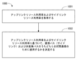
図2は、本実施形態に係る、リモートUE1からリレーUE2へのサイドリンク送信に無線リソースを割り当てる手順の一例(処理200)を示すフローチャートである。ステップ201では、サイドリンク制御エンティティは、リレーUE2のアップリンク品質メトリックを取得する。ここで、サイドリンク制御エンティティは、サイドリンク送信に使用される無線リソースを決定するよう構成されている。Scheduled resource allocationを使用する幾つかの実装において、当該サイドリンク制御エンティティはネットワーク(e.g., 基地局3)に配置されてもよい。一方、Autonomous resource selectionを使用する幾つかの実装において、当該サイドリンク制御エンティティは、リモートUE1に配置されてもよい。
FIG. 2 is a flowchart showing an example of a procedure (process 200) for allocating radio resources for side link transmission from the remote UE 1 to the relay UE 2 according to the present embodiment. In step 201, the side link control entity obtains the uplink quality metric of relay UE2. Here, the side link control entity is configured to determine radio resources used for side link transmission. In some implementations that use Scheduled resource allocation, the side link control entity may be located in the network (e.g., base station 3). On the other hand, in some implementations that use autonomous resource selection, the side link control entity may be located in the remote UE1.
リレーUE2のアップリンク品質メトリックは、リレーUE2から基地局3へのアップリンク送信の性能(e.g., 帯域又はスループット)に関する。リレーUE2のアップリンク品質メトリックは、例えば、アップリンクの推定帯域、アップリンクの推定スループット、アップリンクに割り当てられる推定無線リソース量、アップリンクに適用される推定Modulation and Coding Scheme(MCS)、及びリレーUE2から基地局3への推定パスロス、のうち少なくとも1つに基づく。
The uplink quality metric of relay UE2 relates to the performance (e.g., bandwidth or throughput) of uplink transmission from relay UE2 to base station 3. The uplink quality metric of the relay UE2 includes, for example, the estimated bandwidth of the uplink, the estimated throughput of the uplink, the estimated radio resource amount allocated to the uplink, the estimated Modulation and Coding Scheme (MCS) applied to the uplink, and the relay Based on at least one of the estimated path loss from the UE 2 to the base station 3.
サイドリンク制御エンティティは、リレーUE2のアップリンク品質メトリックをリレーUE2から受信してもよい。サイドリンク制御エンティティがリモートUE1に実装される場合は、サイドリンク制御エンティティは、リレーUE2のアップリンク品質メトリックを基地局3から受信してもよい。これらに代えて、サイドリンク制御エンティティは、アップリンク品質メトリックを自ら推定してもよい。
The side link control entity may receive the uplink quality metric of relay UE2 from relay UE2. If the side link control entity is implemented in the remote UE1, the side link control entity may receive the uplink quality metric of the relay UE2 from the base station 3. Alternatively, the side link control entity may itself estimate the uplink quality metric.
ステップ202では、サイドリンク制御エンティティは、リレーUE2のアップリンク品質メトリックを考慮して、リモートUE1からリレーUE2へのサイドリンク送信に割り当てる無線リソースを決定する。幾つかの実装において、サイドリンク制御エンティティは、リモートUE1からリレーUE2へのサイドリンク送信の性能(e.g., 帯域又はスループット)がリレーUE2から基地局3へのアップリンク送信の性能と整合(consistent)するように、当該サイドリンク送信に割り当てる無線リソースを決定してもよい。言い換えると、サイドリンク制御エンティティは、1つのリレーUE2に関係する1又はそれ以上のサイドリンク送信の性能(e.g., 帯域又はスループット)が当該リレーUE2のアップリンク送信の性能と同程度かそれ以下となるように、サイドリンク送信に割り当てる無線リソースを決定してもよい。
In step 202, the side link control entity considers the uplink quality metric of the relay UE2, and determines the radio resource to be allocated for the side link transmission from the remote UE1 to the relay UE2. In some implementations, the side link control entity ensures that the performance (eg, bandwidth or throughput) of the side link transmission from the remote UE 1 to the relay UE 2 is consistent with the performance of the uplink transmission from the relay UE 2 to the base station 3. As such, radio resources to be allocated to the side link transmission may be determined. In other words, the side link control entity has the performance (eg, bandwidth or throughput) of one or more side link transmissions related to one relay UE2 being equal to or less than the uplink transmission performance of the relay UE2. As such, radio resources to be allocated for side link transmission may be determined.
具体的には、サイドリンク制御エンティティは、少なくとも1つのリモートUE1の各々とリレーUE2との間の各サイドリンクの目標帯域又は目標スループットを当該リレーUE2のアップリンクの推定帯域又は推定スループットに基づいて決定してもよい。そして、サイドリンク制御エンティティは、決定した目標帯域又は目標スループットに基づいて、各D2D送信に割り当てる無線リソースを決定してもよい。1つのリレーUE2が複数のリモートUE1にリレーを提供する場合、サイドリンク制御エンティティは、複数のリモートUE1からリレーUE2への複数のサイドリンク送信の平均帯域又は平均スループットの和がリレーUE2のアップリンク送信の推定帯域又は推定スループットを超えないようにサイドリンク無線リソースを決定してもよい。
Specifically, the side link control entity determines the target bandwidth or target throughput of each side link between each of the at least one remote UE1 and the relay UE2 based on the estimated bandwidth or estimated throughput of the uplink of the relay UE2. You may decide. Then, the side link control entity may determine a radio resource to be allocated to each D2D transmission based on the determined target band or target throughput. When one relay UE2 provides relays to a plurality of remote UEs 1, the side link control entity is configured such that the sum of the average bandwidth or the average throughput of the plurality of side link transmissions from the plurality of remote UEs 1 to the relay UE2 is the uplink of the relay UE2. The side link radio resource may be determined so as not to exceed the estimated transmission band or estimated throughput.
以上の説明から理解されるように、図2を用いて説明された無線リソース割り当て手順では、リモートUE1からリレーUE2へのサイドリンク送信への無線リソース割り当てにおいて、リレーUE2のアップリンク品質メトリック(i.e.,リレーUE2のアップリンク送信の性能)が考慮される。したがって、リモートUE1からリレーUE2へのサイドリンク送信の性能(e.g., 帯域又はスループット)がリレーUE2から基地局3へのアップリンク送信の性能と整合(consistent)するように、サイドリンク送信の無線リソースを決定することができる。よって、図2を用いて説明された無線リソース割り当て手順は、リモートUE1からリレーUE2へのサイドリンク送信とリレーUE2から基地局3へのアップリンク送信との間の性能(e.g., 帯域、スループット)の不整合(inconsistency)を回避することに寄与できる。
As understood from the above description, in the radio resource allocation procedure described with reference to FIG. 2, in the radio resource allocation from the remote UE 1 to the side link transmission to the relay UE 2, the uplink quality metric (ie, relay UE 2) , Performance of uplink transmission of relay UE2). Therefore, the radio resources of the side link transmission so that the performance (eg, bandwidth or throughput) of the side link transmission from the remote UE 1 to the relay UE 2 is consistent with the performance of the uplink transmission from the relay UE 2 to the base station 3. Can be determined. Therefore, the radio resource allocation procedure described with reference to FIG. 2 is based on the performance (eg, bandwidth, throughput) between the side link transmission from the remote UE 1 to the relay UE 2 and the uplink transmission from the relay UE 2 to the base station 3. This can contribute to avoiding inconsistency.
図3は、図2に示した無線リソース割り当て手順のより具体的な例(処理300)を示している。図3の手順は、scheduled resource allocationを実行する基地局3によって行われる。ステップ301では、サイドリンク制御エンティティとしての基地局3は、サイドリンク無線リソースを割り当てられるリモートUE1を選択する。なお、既に説明したように、1つのリモートUE1(e.g., 図1に示されたリモートUE1B)は、複数のサイドリンク送信を同時に行うよう構成されてもよい。したがって、ステップ301では、サイドリンク無線リソースを割り当てられる1つのサイドリンク送信が選択されてもよい。
FIG. 3 shows a more specific example (process 300) of the radio resource allocation procedure shown in FIG. The procedure of FIG. 3 is performed by the base station 3 that executes scheduledsresource allocation. In step 301, the base station 3 as a side link control entity selects a remote UE 1 to which a side link radio resource is allocated. As already described, one remote UE 1 (e.g., remote UE 1B shown in FIG. 1) may be configured to simultaneously perform a plurality of side link transmissions. Accordingly, in step 301, one side link transmission to which side link radio resources are assigned may be selected.
ステップ302では、基地局3は、ステップ301で選択されたリモートUE1(又はサイドリンク送信)が利用することができるリレーUE2のアップリンク帯域を推定する。例えば、基地局3は、セルラーカバレッジ31内の他のUEsに割り当てられるアップリンク無線リソースと、リレーUE2から基地局3への推定アップリンク・パスロスとに基づいて、当該リレーUE2の推定アップリンク帯域を計算する。当該リレーUE2が関係する他のサイドリンク送信に既に無線リソースを割り当てている場合、基地局3は、これら他のサイドリンク送信に関するデータを転送するために消費されるアップリンク帯域を更に考慮する。
In step 302, the base station 3 estimates the uplink band of the relay UE2 that can be used by the remote UE1 (or side link transmission) selected in step 301. For example, the base station 3 determines the estimated uplink bandwidth of the relay UE 2 based on the uplink radio resources allocated to other UEs in the cellular coverage 31 and the estimated uplink path loss from the relay UE 2 to the base station 3. Calculate If the radio resource has already been allocated to other side link transmissions to which the relay UE2 is concerned, the base station 3 further considers the uplink bandwidth consumed to transfer data relating to these other side link transmissions.
ステップ303では、基地局3は、ステップ302で求めた推定アップリンク帯域を考慮して、対象のリモートUE1(又はサイドリンク送信)の目標サイドリンク帯域を決定する。例えば、基地局3は、対象のリモートUE1(又はサイドリンク送信)の保証帯域と推定アップリンク帯域のうちの最小値と同じかそれ以下に目標サイドリンク帯域を設定する。
In step 303, the base station 3 determines the target side link band of the target remote UE 1 (or side link transmission) in consideration of the estimated uplink band obtained in step 302. For example, the base station 3 sets the target side link band to be equal to or less than the minimum value of the guaranteed band and the estimated uplink band of the target remote UE 1 (or side link transmission).
ステップ304では、基地局3は、ステップ303で決定した目標サイドリンク帯域に応じた無線リソースを対象のリモートUE1(又はサイドリンク送信)に割り当てる。余りサイドリンク無線リソースが存在する場合、基地局3は、ステップ301に戻ってサイドリンク無線リソースの割り当てを続ける(ステップ305)。
In step 304, the base station 3 allocates a radio resource corresponding to the target side link band determined in step 303 to the target remote UE 1 (or side link transmission). If there are more side link radio resources, the base station 3 returns to step 301 and continues to allocate side link radio resources (step 305).
なお、図3の手順は、一例に過ぎない。例えば、ステップ302及びステップ303を含む目標サイドリンク帯域の決定手順は、ステップ301、ステップ304、及びステップ305を含むサイドリンク無線リソース割り当て手順に先立って又は並行して行われてもよい。この場合、ステップ302及びステップ303を含む目標サイドリンク帯域の決定手順は、ステップ301、ステップ304、及びステップ305を含むサイドリンク無線リソース割り当て手順とは別のエンティティ(e.g., コンピュータ)によって実行されてもよい。
Note that the procedure in FIG. 3 is merely an example. For example, the target side link bandwidth determination procedure including steps 302 and 303 may be performed prior to or in parallel with the side link radio resource allocation procedure including steps 301, 304, and 305. In this case, the procedure for determining the target side link bandwidth including steps 302 and 303 is executed by an entity (eg, a computer) different from the side link radio resource allocation procedure including steps 301, 304, and 305. Also good.
<第2の実施形態>
本実施形態では、第1の実施形態で説明されたサイドリンク送信への無線リソース割り当て手順の変形例が説明される。本実施形態に係る無線通信ネットワークの構成例は、図1と同様である。 <Second Embodiment>
In this embodiment, a modification of the radio resource allocation procedure for side link transmission described in the first embodiment will be described. A configuration example of the wireless communication network according to the present embodiment is the same as that shown in FIG.
本実施形態では、サイドリンク制御エンティティ(e.g., 基地局3)は、複数のリモートUE1から複数のリレーUE2への複数のサイドリンク送信の間の無線リソース割り当てに関する優先度を、基地局3のセルラーカバレッジ31内でのアップリンク無線リソースの使用状況及びサイドリンク無線リソースの使用状況の一方又は両方を考慮して決定するよう構成されている。アップリンク無線リソースの使用状況は、セルラーカバレッジ31内でのアップリンク無線リソースの利用量または利用率であってもよい。同様に、サイドリンク無線リソースの使用状況は、セルラーカバレッジ31内でのサイドリンク無線リソースの利用量または利用率であってもよい。
In the present embodiment, the side link control entity (eg, base station 3) determines the priority regarding the radio resource allocation during the transmission of the plurality of side links from the plurality of remote UEs 1 to the plurality of relay UEs 2 to the cellular station 3. The determination is made in consideration of one or both of the usage status of the uplink radio resource and the usage status of the side link radio resource in the coverage 31. The usage status of the uplink radio resource may be a usage amount or a usage rate of the uplink radio resource in the cellular coverage 31. Similarly, the usage status of the side link radio resource may be the usage amount or usage rate of the side link radio resource in the cellular coverage 31.
例えば、セルカバッレジ31内のアップリンク無線リソースの利用率が高い状況下では、アップリンク品質が高いリレーUE2に関係するサイドリンク送信に対して、アップリンク品質が低いリレーUE2に関係するサイドリンク送信よりも優先してサイドリンク無線リソースを割り当てることが好ましい。なぜなら、アップリンク品質が高いリレーUE2は、アップリンク品質が低い他のリレーUE2よりもリソースブロック当たりのスループットが高いためである。したがって、アップリンク品質が高いリレーUE2は、少ない余りアップリンク無線リソースをリレー通信のために有効に使用できる。
For example, in a situation where the utilization rate of the uplink radio resource in the cell coverage 31 is high, the side link transmission related to the relay UE2 having a high uplink quality is compared with the side link transmission related to the relay UE2 having a low uplink quality. It is preferable to assign side link radio resources with priority. This is because the relay UE2 having a high uplink quality has a higher throughput per resource block than the other relay UE2 having a low uplink quality. Therefore, the relay UE2 with high uplink quality can effectively use a little uplink radio resource for relay communication.
これに対して、セルカバッレジ31内のサイドリンク無線リソースの利用率が高い状況下では、サイドリンク品質が高いサイドリンク送信に対して、サイドリンク品質が低いサイドリンク送信よりも優先してサイドリンク無線リソースを割り当てることが好ましい。なぜなら、サイドリンク品質が高いサイドリンクは、サイドリンク品質が低い他のサイドリンクよりもリソースブロック当たりのスループットが高いためである。サイドリンク品質が高いサイドリンクは、少ない余りサイドリンク無線リソースをリレー通信のために有効に使用できる。
On the other hand, in a situation where the utilization rate of the side link radio resources in the cell coverage 31 is high, the side link radio is given priority over the side link transmission having a high side link quality over the side link transmission having a low side link quality. It is preferable to allocate resources. This is because a side link with high side link quality has a higher throughput per resource block than other side links with low side link quality. A side link with high side link quality can effectively use less side link radio resources for relay communication.
図4は、本実施形態に係る、リモートUE1からリレーUE2へのサイドリンク送信に無線リソースを割り当てる手順の一例(処理400)を示すフローチャートである。ステップ401では、サイドリンク制御エンティティ(e.g., 基地局3)は、セルラーカバレッジ31内のアップリンク無線リソース利用率およびサイドリンク無線リソース利用率を取得する。ステップ402では、サイドリンク制御エンティティは、アップリンク無線リソース利用率およびサイドリンク無線リソース利用率に基づいて、複数のサイドリンク送信の間でのリソース割り当てに関する優先度を決定する。ステップ403では、サイドリンク制御エンティティは、ステップ402で決定した優先度に従い、リレーUE2のアップリンク品質メトリック(e.g., スループット又は帯域)を考慮して、各サイドリンク送信に割り当てる無線リソースを決定する。
FIG. 4 is a flowchart showing an example of a procedure (processing 400) for allocating radio resources for side link transmission from the remote UE 1 to the relay UE 2 according to the present embodiment. In step 401, the side link control entity (e.g., base station 3) acquires the uplink radio resource utilization rate and the side link radio resource utilization rate in the cellular coverage 31. In step 402, the side link control entity determines priorities for resource allocation among multiple side link transmissions based on the uplink radio resource utilization and the side link radio resource utilization. In step 403, according to the priority determined in step 402, the side link control entity determines radio resources to be allocated to each side link transmission in consideration of the uplink quality metric (e.g., 無線 throughput or bandwidth) of the relay UE2.
図5は、図4に示した無線リソース割り当て手順のより具体的な例(処理500)を示している。図5の手順は、scheduled resource allocationを実行する基地局3によって行われる。ステップ501では、サイドリンク制御エンティティとしての基地局3は、アップリンク無線リソース利用率およびサイドリンク無線リソース利用率に基づいて、サイドリンク無線リソースを割り当てられるリモート端末(又はサイドリンク送信)を選択する。ステップ502~505は、図3に示されたステップ302~305と同様である。
FIG. 5 shows a more specific example (process 500) of the radio resource allocation procedure shown in FIG. The procedure of FIG. 5 is performed by the base station 3 that executes scheduledsresource allocation. In step 501, the base station 3 as a side link control entity selects a remote terminal (or side link transmission) to which a side link radio resource is allocated based on the uplink radio resource usage rate and the side link radio resource usage rate. . Steps 502 to 505 are the same as steps 302 to 305 shown in FIG.
ステップ501では、例えば、基地局3は、アップリンク無線リソースの利用率とサイドリンク無線リソースの利用率を比較し、これら2つの利用率のうちどちらが高いかを判定してもよい。アップリンク無線リソースの利用率がサイドリンク無線リソースの利用率よりも高い場合、基地局3は、リソースブロック当たりの推定アップリンク・スループット(又は推定帯域)が最大のリレーUE2に関係するサイドリンク送信から順に選択する。これにより、アップリンク無線リソースの消費量を抑制できる。一方、サイドリンク無線リソースの利用率がアップリンク無線リソースの利用率よりも高い場合、基地局3は、リソースブロック当たりの推定サイドリンク・スループット(又は推定帯域)が最大のサイドリンクから順に選択する。これにより、サイドリンク無線リソースの消費量を抑制できる。
In step 501, for example, the base station 3 may compare the utilization rate of the uplink radio resource and the utilization rate of the side link radio resource, and determine which of these two utilization rates is higher. When the utilization rate of the uplink radio resource is higher than the utilization rate of the side link radio resource, the base station 3 transmits the side link related to the relay UE 2 having the maximum estimated uplink throughput (or estimated bandwidth) per resource block. Select in order. Thereby, the consumption of an uplink radio | wireless resource can be suppressed. On the other hand, when the utilization rate of the side link radio resource is higher than the utilization rate of the uplink radio resource, the base station 3 selects the estimated side link throughput (or estimated bandwidth) per resource block in order from the side link with the maximum. . Thereby, the consumption of a side link radio | wireless resource can be suppressed.
<第3の実施形態>
本実施形態では、第1及び第2の実施形態で説明されたサイドリンク送信への無線リソース割り当て手順の変形例が説明される。本実施形態に係る無線通信ネットワークの構成例は、図1と同様である。 <Third Embodiment>
In the present embodiment, a modification of the radio resource allocation procedure for side link transmission described in the first and second embodiments will be described. A configuration example of the wireless communication network according to the present embodiment is the same as that shown in FIG.
本実施形態では、サイドリンク制御エンティティ(e.g., 基地局3)は、複数のリモートUE1から複数のリレーUE2への複数のサイドリンク送信の間での無線リソースの割り当て比(allocation ratio)を、これら複数のリレーUE2から基地局3への複数のアップリンク送信の間でのアップリンク品質メトリックの比に応じて決定するよう構成されている。既に説明したように、各リレーUE2のアップリンク品質メトリックは、リレーUE2から基地局3へのアップリンク送信の性能(e.g., 帯域又はスループット)に関する。各リレーUE2のアップリンク品質メトリックは、例えば、アップリンクの推定帯域、アップリンクの推定スループット、アップリンクに割り当てられる推定無線リソース量、アップリンクに適用される推定Modulation and Coding Scheme(MCS)、及びリレーUE2から基地局3への推定パスロス、のうち少なくとも1つに基づく。
In this embodiment, the side link control entity (eg, base station 3) determines the allocation ratio (allocation ratio) of radio resources between a plurality of side link transmissions from a plurality of remote UEs 1 to a plurality of relay UEs 2. It is comprised so that it may determine according to the ratio of the uplink quality metric between the some uplink transmission to the base station 3 from several relay UE2. As described above, the uplink quality metric of each relay UE2 relates to the performance (e.g., bandwidth or throughput) of uplink transmission from the relay UE2 to the base station 3. The uplink quality metric of each relay UE 2 includes, for example, an estimated uplink bandwidth, an estimated uplink throughput, an estimated radio resource amount allocated to the uplink, an estimated Modulation 、 andModCoding Scheme (MCS) applied to the uplink, and Based on at least one of the estimated path loss from the relay UE2 to the base station 3.
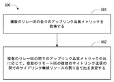
図6は、本実施形態に係る、リモートUE1からリレーUE2へのサイドリンク送信に無線リソースを割り当てる手順の一例(処理600)を示すフローチャートである。ステップ601では、サイドリンク制御エンティティ(e.g., 基地局3)は、複数のリレーUE2の各々のアップリンク品質メトリックを取得する。ステップ402では、サイドリンク制御エンティティは、複数のリレーUE2の間でのアップリンク品質メトリックの比を求める。さらに、サイドリンク制御エンティティは、複数のリレーUE2の間でのアップリンク品質メトリックの比に応じて、これら複数のリレーUE2に接続する複数のリモートUE1の間でのサイドリンク無線リソースの割り当て比を決定する。
FIG. 6 is a flowchart showing an example of a procedure (process 600) for allocating radio resources for side link transmission from the remote UE 1 to the relay UE 2 according to the present embodiment. In step 601, the side link control entity (e.g., eaves base station 3) acquires the uplink quality metric of each of the plurality of relay UEs 2. In step 402, the side link control entity determines an uplink quality metric ratio among the relays UE2. Further, the side link control entity determines the allocation ratio of the side link radio resources among the plurality of remote UEs 1 connected to the plurality of relay UEs 2 according to the ratio of the uplink quality metric among the plurality of relay UEs 2. decide.
例えば、図1に示された4つのリレーUE2A、2B、2C、及び2Dの4つのアップリンク121~124の間でのアップリンク品質(e.g., スループット)の比が1:2:3:4である場合、サイドリンク制御エンティティ(e.g., 基地局3)は、5つのサイドリンク(D2Dリンク)101~105の間でのサイドリンク無線リソースの割り当て比が1:2:3:2:2となるように、これら5つのサイドリンク送信への無線リソース割り当てを決定してもよい。
For example, the ratio of uplink quality (eg, throughput) between the four uplinks 121 to 124 of the four relays UE2A, 2B, 2C, and 2D shown in FIG. 1 is 1: 2: 3: 4. In some cases, the side link control entity (eg, base station 3) has a side link radio resource allocation ratio of 1: 2: 3: 2: 2 among the five side links (D2D links) 101-105. As such, radio resource allocation to these five side link transmissions may be determined.
なお、サイドリンク制御エンティティは、決定されたサイドリンク無線リソースの割り当て比を、各サイドリンク送信に無線リソースを割り当てる際の目標帯域または上限帯域を判定するために考慮してもよい。言い換えると、サイドリンク制御エンティティは、各リモートUE1が要求する帯域又はサイドリンクの品質に依存して各サイドリンク送信へ無線リソースを割り当ててもよく、決定されたリソース割り当て比に常に厳密に従う必要はない。
Note that the side link control entity may consider the determined side link radio resource allocation ratio in order to determine a target band or an upper limit band when radio resources are allocated to each side link transmission. In other words, the side link control entity may allocate radio resources to each side link transmission depending on the bandwidth required by each remote UE 1 or the quality of the side link, and need not always strictly follow the determined resource allocation ratio. Absent.
以上の説明から理解されるように、本実施形態に係るサイドリンク制御エンティティは、複数のリモートUE1から複数のリレーUE2への複数のサイドリンク送信の間での性能の比がこれら複数のリレーUE2の間でのアップリンク送信性能の比と整合(consistent)するように、サイドリンク送信の無線リソースを決定することができる。よって、本実施形態で説明された無線リソース割り当て手順は、リモートUE1からリレーUE2へのサイドリンク送信とリレーUE2から基地局3へのアップリンク送信との間の性能(e.g., 帯域、スループット)の不整合(inconsistency)を回避することに寄与できる。
As understood from the above description, the side link control entity according to the present embodiment has a performance ratio between a plurality of side link transmissions from a plurality of remote UEs 1 to a plurality of relay UEs 2. The radio resources for side link transmission can be determined to be consistent with the ratio of uplink transmission performance between the two. Therefore, the radio resource allocation procedure described in this embodiment is based on the performance (eg, bandwidth, throughput) between the side link transmission from the remote UE 1 to the relay UE 2 and the uplink transmission from the relay UE 2 to the base station 3. It can contribute to avoiding inconsistency.
なお、上述の第1の実施形態で説明された無線リソース割り当て手順は、一例において、1つのリレーUE2に関係する1又はそれ以上のサイドリンク送信の性能の和が当該リレーUE2のアップリンク送信の性能と同程度かそれ以下となるように、サイドリンク送信に割り当てる無線リソースを決定する。この手順によると、複数のリレーUE2のアップリンク送信の性能が総じて良くない場合に、未使用の余りのサイドリンク無線リソースが増える可能性がある。これに対して、本実施形態で説明された無線リソース割り当て手順は、複数のリレーUE2の間でのアップリンク品質の比に依存して各リモートUE1にサイドリンク無線リソースを割り当てる。したがって、本実施形態の無線リソース割り当て手順は、サイドリンク無線リソースの有効利用に寄与できる。
In addition, the radio | wireless resource allocation procedure demonstrated by the above-mentioned 1st Embodiment in the example WHEREIN: The sum of the performance of the 1 or more side link transmission relevant to one relay UE2 is the uplink transmission of the said relay UE2. Radio resources to be allocated to side link transmission are determined so as to be equal to or less than the performance. According to this procedure, when the performance of uplink transmission of a plurality of relay UEs 2 is generally not good, there is a possibility that unused unused side link radio resources increase. On the other hand, the radio resource allocation procedure described in the present embodiment allocates side link radio resources to each remote UE 1 depending on the ratio of uplink quality among the plurality of relay UEs 2. Therefore, the radio resource allocation procedure of this embodiment can contribute to the effective use of side link radio resources.
<第4の実施形態>
本実施形態では、第1~第3の実施形態で説明されたサイドリンク送信への無線リソース割り当て手順の変形例が説明される。本実施形態に係る無線通信ネットワークの構成例は、図1と同様である。 <Fourth Embodiment>
In this embodiment, a modification of the radio resource allocation procedure for side link transmission described in the first to third embodiments will be described. A configuration example of the wireless communication network according to the present embodiment is the same as that shown in FIG.
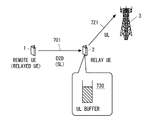
以下では、本実施形態に係る無線リソース割り当て手順の概要を図7を参照して説明する。図7では、リモートUE1は、サイドリンク701上でデータをリレーUE2に送信し、リレーUE2は、リモートUE1から受信したデータをアップリンク721上で基地局3に送信する。第1~第3の実施形態で説明したように、サイドリンク制御エンティティ(e.g., 基地局3又はリモートUE1)は、リモートUE1からリレーUE2へのサイドリンク送信に割り当てるサイドリンク無線リソースを、リレーUE2から基地局3へのアップリンクの品質メトリックを考慮して決定する。しかしながら、何らかの原因に起因して、リレーUE2のサイドリンク受信スループットがアップリンク送信スループットを超える状況が発生し得る。例えば、アップリンク721の品質の変動によって推定通りのアップリンク・スループットが得られないケースが考えられる。この場合、リレーUE2内のアップリンク送信バッファ730のバッファ量が増加し、最悪の場合バッファ・オーバフローによるパケット破棄が発生する可能性がある。なお、アップリンク送信バッファ730は、アップリンクで送信されるデータを格納するために使用される。アップリンク送信バッファ730は、送信待ちのアップリンクデータを格納する。
Hereinafter, an outline of a radio resource allocation procedure according to this embodiment will be described with reference to FIG. In FIG. 7, the remote UE 1 transmits data to the relay UE 2 on the side link 701, and the relay UE 2 transmits data received from the remote UE 1 to the base station 3 on the uplink 721. As described in the first to third embodiments, the side link control entity (eg, base station 3 or remote UE1) assigns the sidelink radio resource allocated to the sidelink transmission from the remote UE1 to the relay UE2 to the relay UE2. To the base station 3 in consideration of the uplink quality metric. However, for some reason, a situation may occur in which the side link reception throughput of the relay UE2 exceeds the uplink transmission throughput. For example, there may be a case where the uplink throughput as estimated cannot be obtained due to the fluctuation of the quality of the uplink 721. In this case, the buffer amount of the uplink transmission buffer 730 in the relay UE2 increases, and in the worst case, packet discard may occur due to buffer overflow. The uplink transmission buffer 730 is used to store data transmitted on the uplink. The uplink transmission buffer 730 stores uplink data waiting for transmission.
この問題に対処するため、本実施形態に係るサイドリンク制御エンティティ(e.g., 基地局3又はリモートUE1)は、リモートUE1に割り当てるサイドリンク無線リソースを決定するために、リレーUE2内のアップリンク送信バッファ730のバッファ状態をさらに考慮する。
In order to cope with this problem, the side link control entity (eg, base station 3 or remote UE1) according to the present embodiment uses an uplink transmission buffer in the relay UE2 to determine a sidelink radio resource to be allocated to the remote UE1. Consider further 730 buffer states.
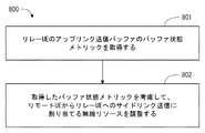
図8は、本実施形態に係る、サイドリンク送信に無線リソースを割り当てる手順の一例(処理800)を示すフローチャートである。ステップ801では、サイドリンク制御エンティティは、リレーUE2のアップリンク送信バッファ730に関するバッファ状態メトリックを取得する。バッファ状態メトリックは、アップリンク送信バッファ730に格納されている送信待ちのアップリンクデータの量またはアップリンク送信バッファ730の占有レベルを示す。
FIG. 8 is a flowchart illustrating an example of a procedure (process 800) for allocating radio resources to side link transmission according to the present embodiment. In step 801, the side link control entity obtains a buffer state metric for the uplink transmission buffer 730 of relay UE2. The buffer status metric indicates the amount of uplink data waiting for transmission stored in the uplink transmission buffer 730 or the occupation level of the uplink transmission buffer 730.
サイドリンク制御エンティティは、バッファ状態メトリックを含むバッファ状態報告をリレーUE2から受信してもよい。バッファ状態報告は、周期的に、又は所定のトリガーイベントに応じて非周期的に送信されてもよい。これに代えて、サイドリンク制御エンティティは、バッファ状態メトリックを自ら計算してもよい。例えば、サイドリンク制御エンティティとしての基地局3は、リモートUE1に割り当てたサイドリンク無線リソース履歴とリレーUE2に割り当てたアップリンク無線リソース履歴に基づいて、リレーUE2内のアップリンク送信バッファ730のバッファ状態メットリックを計算してもよい。
The side link control entity may receive a buffer status report including a buffer status metric from the relay UE2. The buffer status report may be sent periodically or in response to a predetermined trigger event. Alternatively, the side link control entity may calculate the buffer state metric itself. For example, the base station 3 as the side link control entity may determine the buffer status of the uplink transmission buffer 730 in the relay UE 2 based on the side link radio resource history assigned to the remote UE 1 and the uplink radio resource history assigned to the relay UE 2. You may calculate a metric.
ステップ802では、サイドリンク制御エンティティは、取得したバッファ状態メトリックを考慮して、リモートUE1からリレーUE2へのサイドリンク送信に割り当てる無線リソースを調整する。幾つかの実装において、サイドリンク制御エンティティは、アップリンク送信バッファ730のバッファ状態メトリックが所定の閾値を超える場合に、リモートUE1からリレーUE2へのサイドリンク送信に対する無線リソースの割当量を減らしてもよい。これにより、アップリンク送信バッファ730のオーバフローの抑制に寄与できる。
In step 802, the side link control entity adjusts the radio resource allocated to the side link transmission from the remote UE1 to the relay UE2 in consideration of the acquired buffer state metric. In some implementations, the side link control entity may reduce the radio resource allocation for side link transmissions from the remote UE1 to the relay UE2 if the buffer state metric of the uplink transmission buffer 730 exceeds a predetermined threshold. Good. Thereby, it can contribute to suppression of the overflow of the uplink transmission buffer 730.
例えば、サイドリンク制御エンティティは、図3のステップ302又は図5のステップ502に示された推定アップリンク帯域の計算においてアップリンク送信バッファ730のバッファ状態メットリックを使用してもよい。具体的には、サイドリンク制御エンティティは、アップリンク送信バッファ730のバッファ状態メットリックの増加に応答して、つまりリレーUE2内で保留されているアップリンクデータの量の増加に応答して、リレーUE2の推定アップリンク帯域を減らしてもよい。
For example, the side link control entity may use the buffer status metric of the uplink transmission buffer 730 in calculating the estimated uplink bandwidth shown in step 302 of FIG. 3 or step 502 of FIG. Specifically, the side link control entity responds to an increase in the buffer status metric of the uplink transmit buffer 730, i.e., in response to an increase in the amount of uplink data that is reserved in the relay UE2. The estimated uplink bandwidth of UE2 may be reduced.
<第5の実施形態>
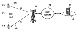
本実施形態では、第2の実施形態の変形例が説明される。図9は、本実施形態に係る無線通信ネットワークの構成例を示している。UE91A及び91Bの各々は、少なくとも1つの無線トランシーバを有し、基地局93とのセルラー通信を行うよう構成されている。UE91A及び91Bは、基地局93及びコアネットワーク94を含むセルラーネットワークを経由して外部ネットワーク95内のノード96と通信することができる。さらに、UE91A及び91Bは、基地局93を介さずにD2D通信(サイドリンク通信)を行うよう構成されている。 <Fifth Embodiment>
In the present embodiment, a modification of the second embodiment will be described. FIG. 9 shows a configuration example of a wireless communication network according to the present embodiment. Each of the UEs 91 </ b> A and 91 </ b> B includes at least one wireless transceiver and is configured to perform cellular communication with thebase station 93. The UEs 91 </ b> A and 91 </ b> B can communicate with a node 96 in the external network 95 via a cellular network including the base station 93 and the core network 94. Further, the UEs 91A and 91B are configured to perform D2D communication (side link communication) without using the base station 93.
本実施形態では、第2の実施形態の変形例が説明される。図9は、本実施形態に係る無線通信ネットワークの構成例を示している。UE91A及び91Bの各々は、少なくとも1つの無線トランシーバを有し、基地局93とのセルラー通信を行うよう構成されている。UE91A及び91Bは、基地局93及びコアネットワーク94を含むセルラーネットワークを経由して外部ネットワーク95内のノード96と通信することができる。さらに、UE91A及び91Bは、基地局93を介さずにD2D通信(サイドリンク通信)を行うよう構成されている。 <Fifth Embodiment>
In the present embodiment, a modification of the second embodiment will be described. FIG. 9 shows a configuration example of a wireless communication network according to the present embodiment. Each of the UEs 91 </ b> A and 91 </ b> B includes at least one wireless transceiver and is configured to perform cellular communication with the
続いて以下では、本実施形態に係るUE91Aの通信経路を制御する手順について説明する。ここでは、UE91AからUE91Bへのデータ送信を考える。図10は、本実施形態に係るサイドリンク制御エンティティ(e.g., 基地局93、UE91A)によって行われる手順の一例(処理1000)を示している。
Subsequently, a procedure for controlling the communication path of the UE 91A according to the present embodiment will be described below. Here, data transmission from UE 91A to UE 91B is considered. FIG. 10 shows an example of a procedure (process 1000) performed by the side link control entity (e.g., base station 93, UE 91A) according to the present embodiment.
ステップ1001では、サイドリンク制御エンティティは、基地局93のセル内でのアップリンク無線リソースの使用状況及びサイドリンク無線リソースの使用状況を取得する。第2の実施形態と同様に、アップリンク無線リソースの使用状況は、セルラーカバレッジ31内でのアップリンク無線リソースの利用量または利用率であってもよい。同様に、サイドリンク無線リソースの使用状況は、セルラーカバレッジ31内でのサイドリンク無線リソースの利用量または利用率であってもよい。
In step 1001, the side link control entity acquires the usage status of the uplink radio resource and the usage status of the side link radio resource in the cell of the base station 93. Similar to the second embodiment, the usage state of the uplink radio resource may be the usage amount or the utilization rate of the uplink radio resource in the cellular coverage 31. Similarly, the usage status of the side link radio resource may be the usage amount or usage rate of the side link radio resource in the cellular coverage 31.
ステップ1002では、サイドリンク制御エンティティは、UE91A及び91Bの間の直接パス(i.e., サイドリンク901)と基地局93を経由する非直接パスのうちどちらをUE91AからUE91Bへのデータ送信のために使用するかを、取得したアップリンク無線リソースの使用状況及びサイドリンク無線リソースの使用状況を考慮して決定する。なお、非直接パスは、UE91Aから基地局93へのアップリンク921及び基地局93からUE91Bへのダウンリンク931を含む。さらに、非直接パスは、コアネットワーク94、外部ネットワーク95、及びノード96を経由してもよい。すなわち、非直接パスを用いたUE91A及び91Bの間の通信は、ノード96を介して行われてもよい。
In step 1002, the side link control entity uses either a direct path between UEs 91A and 91B (ie, side link 901) or a non-direct path via base station 93 for data transmission from UE 91A to UE 91B. To determine whether to use the acquired uplink radio resource usage status and side link radio resource usage status. The indirect path includes an uplink 921 from the UE 91A to the base station 93 and a downlink 931 from the base station 93 to the UE 91B. Further, the non-direct path may pass through the core network 94, the external network 95, and the node 96. That is, communication between the UEs 91 </ b> A and 91 </ b> B using a non-direct path may be performed via the node 96.
例えば、基地局93のセル内のアップリンク無線リソースの利用率が高い状況下では、サイドリンク901が使用されることが好ましい。これにより、アップリンク無線リソースの消費量を抑制できる。これに対して、基地局93のセル内のサイドリンク無線リソースの利用率が高い状況下では、非直接パスが使用されることが好ましい。これにより、サイドリンク無線リソースの消費量を抑制できる。
For example, the side link 901 is preferably used in a situation where the utilization rate of the uplink radio resource in the cell of the base station 93 is high. Thereby, the consumption of an uplink radio | wireless resource can be suppressed. On the other hand, in a situation where the utilization rate of the side link radio resource in the cell of the base station 93 is high, it is preferable to use a non-direct path. Thereby, the consumption of a side link radio | wireless resource can be suppressed.
より具体的には、サイドリンク制御エンティティは、アップリンク無線リソースの利用率とサイドリンク無線リソースの利用率を比較し、これら2つの利用率のうちどちらが高いかを判定してもよい。アップリンク無線リソースの利用率がサイドリンク無線リソースの利用率よりも高い場合、サイドリンク制御エンティティは、UE91AからUE91Bへのデータ送信のためにサイドリンク901での直接送信を使用してもよい。一方、サイドリンク無線リソースの利用率がアップリンク無線リソースの利用率よりも高い場合、サイドリンク制御エンティティは、UE91AからUE91Bへのデータ送信のために非直接パスを使用してもよい。
More specifically, the side link control entity may compare the utilization rate of the uplink radio resource and the utilization rate of the side link radio resource, and determine which of these two utilization rates is higher. If the uplink radio resource utilization is higher than the side link radio resource utilization, the side link control entity may use direct transmission on the side link 901 for data transmission from the UE 91A to the UE 91B. On the other hand, when the utilization rate of the side link radio resource is higher than the utilization rate of the uplink radio resource, the side link control entity may use a non-direct path for data transmission from the UE 91A to the UE 91B.
サイドリンク制御エンティティが基地局93に実装される場合、UE91Aによるデータ送信を通信経路の選択結果に従わせるために以下のように動作してもよい。一例において、基地局93は、非直接パスを介して送信するようUE91Aにトリガーするために、UE91Aからのサイドリンクリソース要求を拒否してもよい。これに代えて、基地局93は、非直接パスでの送信をUE91AにトリガーするメッセージをUE91Aに送信してもよい。当該メッセージは、(a)サイドリンク送信が一時的に停止されること、(b)サイドリンクリソース要求の基地局93への送信が抑止されること、又は(c)非直接パスでの送信が推奨されること、を示してもよい。
When the side link control entity is installed in the base station 93, the data transmission by the UE 91A may be operated as follows in order to follow the communication path selection result. In one example, the base station 93 may reject the side link resource request from the UE 91A in order to trigger the UE 91A to transmit via a non-direct path. Instead, the base station 93 may transmit to the UE 91A a message that triggers the UE 91A to transmit on the non-direct path. The message includes (a) side link transmission being temporarily stopped, (b) side link resource request transmission to the base station 93 being suppressed, or (c) non-direct path transmission. It may indicate that it is recommended.
基地局93は、サイドリンク901を介して送信するようUE91Aにトリガーするために、所定のメッセージをUE91Aに送信してもよい。当該メッセージは、(a)アップリンク・リソース要求の基地局93への送信が抑止されること、又は(b)サイドリンク送信が推奨されること、を示してもよい。
The base station 93 may transmit a predetermined message to the UE 91A in order to trigger the UE 91A to transmit via the side link 901. The message may indicate that (a) transmission of an uplink resource request to the base station 93 is suppressed or (b) side link transmission is recommended.
本実施形態は、第1~第4の実施形態と組み合わせて実施されることができる。さらに、本実施形態は、第1~第4の実施形態とは独立に実施されることができることに留意されるべきである。すなわち、本実施形態に係るUE91の通信経路を制御する手順は、第1~第4の実施形態で説明されたサイドリンク無線リソースの割り当て手順とは独立に実施されることができ、第1~第4の実施形態で説明されたサイドリンク無線リソースの割り当て手順のそれとは異なる特有の効果をもたらすことができる。
This embodiment can be implemented in combination with the first to fourth embodiments. Furthermore, it should be noted that this embodiment can be implemented independently of the first to fourth embodiments. That is, the procedure for controlling the communication path of the UE 91 according to this embodiment can be performed independently of the side link radio resource allocation procedure described in the first to fourth embodiments. A unique effect different from that of the side link radio resource allocation procedure described in the fourth embodiment can be provided.
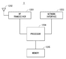
最後に、上述の複数の実施形態に係るリモートUE1、リレーUE2、基地局3、UE91、及び基地局93の構成例について説明する。図11は、リモートUE1の構成例を示すブロック図である。リレーUE2及びUE91も、図11に示されているのと同様の構成を有してもよい。Radio Frequency(RF)トランシーバ1101は、基地局3と通信するためにアナログRF信号処理を行う。RFトランシーバ1101により行われるアナログRF信号処理は、周波数アップコンバージョン、周波数ダウンコンバージョン、及び増幅を含む。RFトランシーバ1101は、アンテナ1102及びベースバンドプロセッサ1103と結合される。すなわち、RFトランシーバ1101は、変調シンボルデータ(又はOFDMシンボルデータ)をベースバンドプロセッサ1103から受信し、送信RF信号を生成し、送信RF信号をアンテナ1102に供給する。また、RFトランシーバ1101は、アンテナ1102によって受信された受信RF信号に基づいてベースバンド受信信号を生成し、これをベースバンドプロセッサ1103に供給する。
Finally, configuration examples of the remote UE1, the relay UE2, the base station 3, the UE 91, and the base station 93 according to the above-described embodiments will be described. FIG. 11 is a block diagram illustrating a configuration example of the remote UE 1. Relays UE2 and UE91 may also have the same configuration as that shown in FIG. The Radio Frequency (RF) transceiver 1101 performs analog RF signal processing to communicate with the base station 3. Analog RF signal processing performed by the RF transceiver 1101 includes frequency up-conversion, frequency down-conversion, and amplification. RF transceiver 1101 is coupled with antenna 1102 and baseband processor 1103. That is, the RF transceiver 1101 receives modulation symbol data (or OFDM symbol data) from the baseband processor 1103, generates a transmission RF signal, and supplies the transmission RF signal to the antenna 1102. Further, the RF transceiver 1101 generates a baseband received signal based on the received RF signal received by the antenna 1102 and supplies this to the baseband processor 1103.
RFトランシーバ1101は、他のUEとのサイドリンク通信のためにも使用されてもよい。RFトランシーバ1101は、複数のトランシーバを含んでもよい。
The RF transceiver 1101 may also be used for side link communication with other UEs. The RF transceiver 1101 may include multiple transceivers.
ベースバンドプロセッサ1103は、無線通信のためのデジタルベースバンド信号処理(データプレーン処理)とコントロールプレーン処理を行う。デジタルベースバンド信号処理は、(a) データ圧縮/復元、(b) データのセグメンテーション/コンカテネーション、(c) 伝送フォーマット(伝送フレーム)の生成/分解、(d) 伝送路符号化/復号化、(e) 変調(シンボルマッピング)/復調、及び(f) Inverse Fast Fourier Transform(IFFT)によるOFDMシンボルデータ(ベースバンドOFDM信号)の生成などを含む。一方、コントロールプレーン処理は、レイヤ1(e.g., 送信電力制御)、レイヤ2(e.g., 無線リソース管理、及びhybrid automatic repeat request(HARQ)処理)、及びレイヤ3(e.g., アタッチ、モビリティ、及び通話管理に関するシグナリング)の通信管理を含む。
The baseband processor 1103 performs digital baseband signal processing (data plane processing) and control plane processing for wireless communication. Digital baseband signal processing consists of (a) data compression / decompression, (b) data segmentation / concatenation, (c) 生成 transmission format (transmission frame) generation / decomposition, and (d) transmission path encoding / decoding. , (E) modulation (symbol mapping) / demodulation, and (f) generation of OFDM symbol data (baseband OFDM signal) by Inverse Fast Fourier Transform (IFFT). On the other hand, control plane processing includes layer 1 (eg, transmission power control), layer 2 (eg, radio resource management, hybrid automatic repeat request (HARQ) processing), and layer 3 (eg, attach, mobility, and call management). Communication management).
例えば、LTEおよびLTE-Advancedの場合、ベースバンドプロセッサ1103によるデジタルベースバンド信号処理は、Packet Data Convergence Protocol(PDCP)レイヤ、Radio Link Control(RLC)レイヤ、MACレイヤ、およびPHYレイヤの信号処理を含んでもよい。また、ベースバンドプロセッサ1103によるコントロールプレーン処理は、Non-Access Stratum(NAS)プロトコル、RRCプロトコル、及びMAC CEの処理を含んでもよい。
For example, in the case of LTE and LTE-Advanced, the digital baseband signal processing by the baseband processor 1103 includes signal processing of Packet Data Convergence Protocol (PDCP) layer, Radio Link Control (RLC) layer, MAC layer, and PHY layer. But you can. Further, the control plane processing by the baseband processor 1103 may include Non-Access Stratum (NAS) protocol, RRC protocol, and MAC 処理 CE processing.
ベースバンドプロセッサ1103は、デジタルベースバンド信号処理を行うモデム・プロセッサ(e.g., Digital Signal Processor(DSP))とコントロールプレーン処理を行うプロトコルスタック・プロセッサ(e.g., Central Processing Unit(CPU)、又はMicro Processing Unit(MPU))を含んでもよい。この場合、コントロールプレーン処理を行うプロトコルスタック・プロセッサは、後述するアプリケーションプロセッサ1104と共通化されてもよい。
The baseband processor 1103 includes a modem processor (eg, Digital Signal Processor (DSP)) that performs digital baseband signal processing and a protocol stack processor (eg, Central Processing Unit (CPU) that performs control plane processing, or Micro Processing Unit. (MPU)). In this case, a protocol stack processor that performs control plane processing may be shared with an application processor 1104 described later.
アプリケーションプロセッサ1104は、CPU、MPU、マイクロプロセッサ、又はプロセッサコアとも呼ばれる。アプリケーションプロセッサ1104は、複数のプロセッサ(複数のプロセッサコア)を含んでもよい。アプリケーションプロセッサ1104は、メモリ1106又は図示されていないメモリから読み出されたシステムソフトウェアプログラム(Operating System(OS))及び様々なアプリケーションプログラム(例えば、通話アプリケーション、WEBブラウザ、メーラ、カメラ操作アプリケーション、音楽再生アプリケーション)を実行することによって、リモートUE1の各種機能を実現する。
The application processor 1104 is also called a CPU, MPU, microprocessor, or processor core. The application processor 1104 may include a plurality of processors (a plurality of processor cores). The application processor 1104 is a system software program (Operating System (OS)) read from the memory 1106 or a memory (not shown) and various application programs (for example, a call application, a web browser, a mailer, a camera operation application, music playback) By executing the application, various functions of the remote UE 1 are realized.
いくつかの実装において、図11に破線(1105)で示されているように、ベースバンドプロセッサ1103及びアプリケーションプロセッサ1104は、1つのチップ上に集積されてもよい。言い換えると、ベースバンドプロセッサ1103及びアプリケーションプロセッサ1104は、1つのSystem on Chip(SoC)デバイス1105として実装されてもよい。SoCデバイスは、システムLarge Scale Integration(LSI)またはチップセットと呼ばれることもある。
In some implementations, the baseband processor 1103 and the application processor 1104 may be integrated on a single chip, as indicated by the dashed line (1105) in FIG. In other words, the baseband processor 1103 and the application processor 1104 may be implemented as one System on Chip (SoC) device 1105. An SoC device is sometimes called a system Large Scale Integration (LSI) or chipset.
メモリ1106は、揮発性メモリ若しくは不揮発性メモリ又はこれらの組合せである。メモリ1106は、物理的に独立した複数のメモリデバイスを含んでもよい。揮発性メモリは、例えば、Static Random Access Memory(SRAM)若しくはDynamic RAM(DRAM)又はこれらの組み合わせである。不揮発性メモリは、マスクRead Only Memory(MROM)、Electrically Erasable Programmable ROM(EEPROM)、フラッシュメモリ、若しくはハードディスクドライブ、又はこれらの任意の組合せである。例えば、メモリ1106は、ベースバンドプロセッサ1103、アプリケーションプロセッサ1104、及びSoC1105からアクセス可能な外部メモリデバイスを含んでもよい。メモリ1106は、ベースバンドプロセッサ1103内、アプリケーションプロセッサ1104内、又はSoC1105内に集積された内蔵メモリデバイスを含んでもよい。さらに、メモリ1106は、Universal Integrated Circuit Card(UICC)内のメモリを含んでもよい。
The memory 1106 is a volatile memory, a nonvolatile memory, or a combination thereof. The memory 1106 may include a plurality of physically independent memory devices. The volatile memory is, for example, Static Random Access Memory (SRAM), Dynamic RAM (DRAM), or a combination thereof. The non-volatile memory is a mask Read Only Memory (MROM), Electrically Erasable Programmable ROM (EEPROM), flash memory, hard disk drive, or any combination thereof. For example, the memory 1106 may include an external memory device accessible from the baseband processor 1103, the application processor 1104, and the SoC 1105. Memory 1106 may include an embedded memory device integrated within baseband processor 1103, application processor 1104, or SoC 1105. Further, the memory 1106 may include a memory in a Universal Integrated Circuit Card (UICC).
メモリ1106は、上述の複数の実施形態で説明されたリモートUE1による処理を行うための命令群およびデータを含むソフトウェアモジュール(コンピュータプログラム)を格納してもよい。いくつかの実装において、ベースバンドプロセッサ1103又はアプリケーションプロセッサ1104は、当該ソフトウェアモジュールをメモリ1106から読み出して実行することで、上述の実施形態で図面を用いて説明されたリモートUE1の処理を行うよう構成されてもよい。
The memory 1106 may store a software module (computer program) including an instruction group and data for performing processing by the remote UE 1 described in the plurality of embodiments. In some implementations, the baseband processor 1103 or the application processor 1104 is configured to read and execute the software module from the memory 1106 to perform the processing of the remote UE 1 described with reference to the drawings in the above-described embodiment. May be.
図12は、上述の実施形態に係る基地局3の構成例を示すブロック図である。基地局93も、図12に示されているのと同様の構成を有してもよい。図12を参照すると、基地局3は、RFトランシーバ1201、ネットワークインターフェース1203、プロセッサ1204、及びメモリ1205を含む。RFトランシーバ1201は、リモートUE1及びリレーUE2と通信するためにアナログRF信号処理を行う。RFトランシーバ1201は、複数のトランシーバを含んでもよい。RFトランシーバ1201は、アンテナ1202及びプロセッサ1204と結合される。RFトランシーバ1201は、変調シンボルデータ(又はOFDMシンボルデータ)をプロセッサ1204から受信し、送信RF信号を生成し、送信RF信号をアンテナ1202に供給する。また、RFトランシーバ1201は、アンテナ1202によって受信された受信RF信号に基づいてベースバンド受信信号を生成し、これをプロセッサ1204に供給する。
FIG. 12 is a block diagram illustrating a configuration example of the base station 3 according to the above-described embodiment. The base station 93 may also have a configuration similar to that shown in FIG. Referring to FIG. 12, the base station 3 includes an RF transceiver 1201, a network interface 1203, a processor 1204, and a memory 1205. The RF transceiver 1201 performs analog RF signal processing to communicate with the remote UE1 and the relay UE2. The RF transceiver 1201 may include multiple transceivers. RF transceiver 1201 is coupled to antenna 1202 and processor 1204. The RF transceiver 1201 receives modulation symbol data (or OFDM symbol data) from the processor 1204, generates a transmission RF signal, and supplies the transmission RF signal to the antenna 1202. Further, the RF transceiver 1201 generates a baseband received signal based on the received RF signal received by the antenna 1202 and supplies this to the processor 1204.
ネットワークインターフェース1203は、ネットワークノード(e.g., Mobility Management Entity (MME)およびServing Gateway (S-GW))と通信するために使用される。ネットワークインターフェース1203は、例えば、IEEE 802.3 seriesに準拠したネットワークインターフェースカード(NIC)を含んでもよい。
The network interface 1203 is used to communicate with network nodes (e.g., Mobility Management Entity (MME) and Serving Gateway (S-GW)). The network interface 1203 may include, for example, a network interface card (NIC) compliant with IEEE 802.3 series.
プロセッサ1204は、無線通信のためのデジタルベースバンド信号処理(データプレーン処理)とコントロールプレーン処理を行う。例えば、LTEおよびLTE-Advancedの場合、プロセッサ1204によるデジタルベースバンド信号処理は、PDCPレイヤ、RLCレイヤ、MACレイヤ、およびPHYレイヤの信号処理を含んでもよい。また、プロセッサ1204によるコントロールプレーン処理は、S1プロトコル、RRCプロトコル、及びMAC CEの処理を含んでもよい。
The processor 1204 performs digital baseband signal processing (data plane processing) and control plane processing for wireless communication. For example, in the case of LTE and LTE-Advanced, the digital baseband signal processing by the processor 1204 may include signal processing of a PDCP layer, an RLC layer, a MAC layer, and a PHY layer. Further, the control plane processing by the processor 1204 may include S1 protocol, RRC protocol, and MAC-CE processing.
プロセッサ1204は、複数のプロセッサを含んでもよい。例えば、プロセッサ1204は、デジタルベースバンド信号処理を行うモデム・プロセッサ(e.g., DSP)とコントロールプレーン処理を行うプロトコルスタック・プロセッサ(e.g., CPU又はMPU)を含んでもよい。
The processor 1204 may include a plurality of processors. For example, the processor 1204 may include a modem processor (e.g., DSP) that performs digital baseband signal processing and a protocol stack processor (e.g., CPU or MPU) that performs control plane processing.
メモリ1205は、揮発性メモリ及び不揮発性メモリの組み合わせによって構成される。揮発性メモリは、例えば、SRAM若しくはDRAM又はこれらの組み合わせである。不揮発性メモリは、例えば、MROM、PROM、フラッシュメモリ、若しくはハードディスクドライブ、又はこれらの組合せである。メモリ1205は、プロセッサ1204から離れて配置されたストレージを含んでもよい。この場合、プロセッサ1204は、ネットワークインターフェース1203又は図示されていないI/Oインタフェースを介してメモリ1205にアクセスしてもよい。
The memory 1205 is configured by a combination of a volatile memory and a nonvolatile memory. The volatile memory is, for example, SRAM or DRAM or a combination thereof. The non-volatile memory is, for example, an MROM, PROM, flash memory, hard disk drive, or a combination thereof. Memory 1205 may include storage located remotely from processor 1204. In this case, the processor 1204 may access the memory 1205 via the network interface 1203 or an I / O interface not shown.
メモリ1205は、上述の複数の実施形態で説明された基地局3による処理を行うための命令群およびデータを含むソフトウェアモジュール(コンピュータプログラム)を格納してもよい。いくつかの実装において、プロセッサ1204は、当該ソフトウェアモジュールをメモリ1205から読み出して実行することで、上述の実施形態で図面を用いて説明された基地局3の処理を行うよう構成されてもよい。
The memory 1205 may store a software module (computer program) including an instruction group and data for performing processing by the base station 3 described in the above-described embodiments. In some implementations, the processor 1204 may be configured to perform the processing of the base station 3 described with reference to the drawings in the above-described embodiment by reading the software module from the memory 1205 and executing the software module.
図11及び図12を用いて説明したように、上述の実施形態に係るリモートUE1、リレーUE2、基地局3、UE91、及び基地局93が有するプロセッサの各々は、図面を用いて説明されたアルゴリズムをコンピュータに行わせるための命令群を含む1又は複数のプログラムを実行する。このプログラムは、様々なタイプの非一時的なコンピュータ可読媒体(non-transitory computer readable medium)を用いて格納され、コンピュータに供給することができる。非一時的なコンピュータ可読媒体は、様々なタイプの実体のある記録媒体(tangible storage medium)を含む。非一時的なコンピュータ可読媒体の例は、磁気記録媒体(例えばフレキシブルディスク、磁気テープ、ハードディスクドライブ)、光磁気記録媒体(例えば光磁気ディスク)、Compact Disc Read Only Memory(CD-ROM)、CD-R、CD-R/W、半導体メモリ(例えば、マスクROM、Programmable ROM(PROM)、Erasable PROM(EPROM)、フラッシュROM、Random Access Memory(RAM))を含む。また、プログラムは、様々なタイプの一時的なコンピュータ可読媒体(transitory computer readable medium)によってコンピュータに供給されてもよい。一時的なコンピュータ可読媒体の例は、電気信号、光信号、及び電磁波を含む。一時的なコンピュータ可読媒体は、電線及び光ファイバ等の有線通信路、又は無線通信路を介して、プログラムをコンピュータに供給できる。
As described with reference to FIGS. 11 and 12, each of the processors included in the remote UE 1, the relay UE 2, the base station 3, the UE 91, and the base station 93 according to the above-described embodiment is described with reference to the drawings. One or a plurality of programs including a group of instructions for causing a computer to execute the above are executed. The program can be stored and supplied to a computer using various types of non-transitory computer readable media. Non-transitory computer readable media include various types of tangible storage media (tangible storage medium). Examples of non-transitory computer-readable media are magnetic recording media (eg flexible disks, magnetic tapes, hard disk drives), magneto-optical recording media (eg magneto-optical discs), Compact Disc Read Only Memory (CD-ROM), CD-ROM R, CD-R / W, semiconductor memory (for example, mask ROM, Programmable ROM (PROM), Erasable PROM (EPROM), flash ROM, Random Access Memory (RAM)). The program may also be supplied to the computer by various types of temporary computer-readable media. Examples of transitory computer readable media include electrical signals, optical signals, and electromagnetic waves. The temporary computer-readable medium can supply the program to the computer via a wired communication path such as an electric wire and an optical fiber, or a wireless communication path.
<その他の実施形態>
上述の施形態は、各々独立に実施されてもよいし、適宜組み合わせて実施されてもよい。 <Other embodiments>
The above-described embodiments may be implemented independently or may be implemented in combination as appropriate.
上述の施形態は、各々独立に実施されてもよいし、適宜組み合わせて実施されてもよい。 <Other embodiments>
The above-described embodiments may be implemented independently or may be implemented in combination as appropriate.
上述の実施形態で説明されたサイドリンク無線リソースの割り当てを含む基地局3により行われる処理及び動作は、Cloud Radio Access Network(C-RAN)アーキテクチャに含まれるDigital Unit(DU)又はDU及びRadio Unit(RU)の組み合せによって提供されてもよい。DUは、Baseband Unit(BBU)と呼ばれる。RUは、Remote Radio Head(RRH)又はRemote Radio Equipment(RRE)とも呼ばれる。すなわち、上述の実施形態で説明された基地局3により行われる処理及び動作は、任意の1又は複数の無線局(RANノード)によって提供されてもよい。
The processing and operation performed by the base station 3 including the allocation of the side link radio resource described in the above-described embodiment is the Digital Unit (DU) or DU and Radio Unit included in the Cloud Radio Access Network (C-RAN) architecture. (RU) may be provided in combination. DU is called Baseband Unit (BBU). RU is also called Remote Radio Head (RRH) or Remote Radio Equipment (RRE). That is, the process and operation performed by the base station 3 described in the above embodiment may be provided by any one or a plurality of radio stations (RAN nodes).
さらに、上述した実施形態は本件発明者により得られた技術思想の適用に関する例に過ぎない。すなわち、当該技術思想は、上述した実施形態のみに限定されるものではなく、種々の変更が可能であることは勿論である。
Furthermore, the above-described embodiments are merely examples relating to application of the technical idea obtained by the present inventors. That is, the technical idea is not limited to the above-described embodiment, and various changes can be made.
例えば、上記の実施形態の一部又は全部は、以下の付記のようにも記載され得るが、以下には限られない。
For example, a part or all of the above embodiment can be described as in the following supplementary notes, but is not limited thereto.
(付記1)
メモリと、
前記メモリに結合された少なくとも1つのプロセッサと、
を備え、
前記少なくとも1つのプロセッサは、少なくとも1つのリモート端末から第1のリレー端末への1又はそれ以上のデバイス・ツー・デバイス(D2D)送信に割り当てるD2D無線リソースを、前記第1のリレー端末から基地局へのアップリンクの品質メトリックを考慮して決定するよう構成されている、
デバイス・ツー・デバイス通信を制御するための装置。 (Appendix 1)
Memory,
At least one processor coupled to the memory;
With
The at least one processor allocates D2D radio resources from the first relay terminal to a base station to allocate one or more device-to-device (D2D) transmissions from at least one remote terminal to the first relay terminal. Configured to take into account the uplink quality metric to
An apparatus for controlling device-to-device communication.
(付記2)
前記品質メトリックは、前記アップリンクの推定帯域、前記アップリンクの推定スループット、前記アップリンクに割り当てられる推定無線リソース量、前記アップリンクに適用される推定Modulation and Coding Scheme(MCS)、及び前記第1のリレー端末から前記基地局への推定パスロスのうち少なくとも1つに基づく、
付記1に記載の装置。 (Appendix 2)
The quality metric includes the uplink estimated bandwidth, the uplink estimated throughput, the estimated radio resource amount allocated to the uplink, the estimated modulation and coding scheme (MCS) applied to the uplink, and the first Based on at least one of the estimated path loss from the relay terminal to the base station,
The apparatus according toappendix 1.
前記品質メトリックは、前記アップリンクの推定帯域、前記アップリンクの推定スループット、前記アップリンクに割り当てられる推定無線リソース量、前記アップリンクに適用される推定Modulation and Coding Scheme(MCS)、及び前記第1のリレー端末から前記基地局への推定パスロスのうち少なくとも1つに基づく、
付記1に記載の装置。 (Appendix 2)
The quality metric includes the uplink estimated bandwidth, the uplink estimated throughput, the estimated radio resource amount allocated to the uplink, the estimated modulation and coding scheme (MCS) applied to the uplink, and the first Based on at least one of the estimated path loss from the relay terminal to the base station,
The apparatus according to
(付記3)
前記品質メトリックは、前記アップリンクの推定帯域又は推定スループットを含み、
前記少なくとも1つのプロセッサは、前記少なくとも1つのリモート端末の各々と前記第1のリレー端末との間の各D2Dリンクの目標帯域又は目標スループットを前記アップリンクの前記推定帯域又は前記推定スループットに基づいて決定し、前記目標帯域又は目標スループットに基づいて各D2D送信に割り当てるD2D無線リソースを決定するよう構成されている、
付記1又は2に記載の装置。 (Appendix 3)
The quality metric includes an estimated bandwidth or estimated throughput of the uplink;
The at least one processor determines a target band or target throughput of each D2D link between each of the at least one remote terminal and the first relay terminal based on the estimated band or estimated throughput of the uplink. Configured to determine and determine a D2D radio resource to assign to each D2D transmission based on the target bandwidth or target throughput;
The apparatus according to appendix 1 or 2.
前記品質メトリックは、前記アップリンクの推定帯域又は推定スループットを含み、
前記少なくとも1つのプロセッサは、前記少なくとも1つのリモート端末の各々と前記第1のリレー端末との間の各D2Dリンクの目標帯域又は目標スループットを前記アップリンクの前記推定帯域又は前記推定スループットに基づいて決定し、前記目標帯域又は目標スループットに基づいて各D2D送信に割り当てるD2D無線リソースを決定するよう構成されている、
付記1又は2に記載の装置。 (Appendix 3)
The quality metric includes an estimated bandwidth or estimated throughput of the uplink;
The at least one processor determines a target band or target throughput of each D2D link between each of the at least one remote terminal and the first relay terminal based on the estimated band or estimated throughput of the uplink. Configured to determine and determine a D2D radio resource to assign to each D2D transmission based on the target bandwidth or target throughput;
The apparatus according to
(付記4)
前記品質メトリックは、前記アップリンクの推定帯域又は推定スループットを含み、
前記少なくとも1つのリモート端末は、複数のリモート端末を含み、
前記少なくとも1つのプロセッサは、前記複数のリモート端末と前記第1のリレー端末との間の複数のD2Dリンクの平均帯域又は平均スループットの和が前記アップリンクの推定帯域又は推定スループットを超えないように前記D2D無線リソースを決定するよう構成されている、
付記1~3のいずれか1項に記載の装置。 (Appendix 4)
The quality metric includes an estimated bandwidth or estimated throughput of the uplink;
The at least one remote terminal includes a plurality of remote terminals;
The at least one processor prevents a sum of an average band or average throughput of a plurality of D2D links between the plurality of remote terminals and the first relay terminal from exceeding an estimated band or estimated throughput of the uplink. Configured to determine the D2D radio resource;
The apparatus according to any one ofappendices 1 to 3.
前記品質メトリックは、前記アップリンクの推定帯域又は推定スループットを含み、
前記少なくとも1つのリモート端末は、複数のリモート端末を含み、
前記少なくとも1つのプロセッサは、前記複数のリモート端末と前記第1のリレー端末との間の複数のD2Dリンクの平均帯域又は平均スループットの和が前記アップリンクの推定帯域又は推定スループットを超えないように前記D2D無線リソースを決定するよう構成されている、
付記1~3のいずれか1項に記載の装置。 (Appendix 4)
The quality metric includes an estimated bandwidth or estimated throughput of the uplink;
The at least one remote terminal includes a plurality of remote terminals;
The at least one processor prevents a sum of an average band or average throughput of a plurality of D2D links between the plurality of remote terminals and the first relay terminal from exceeding an estimated band or estimated throughput of the uplink. Configured to determine the D2D radio resource;
The apparatus according to any one of
(付記5)
前記少なくとも1つのプロセッサは、複数のリモート端末から前記第1のリレー端末を含む複数のリレー端末への複数のサイドリンク送信の間のD2D無線リソース割り当てに関する優先度を、前記基地局のセル内でのアップリンク無線リソースの使用状況及びD2D無線リソースの使用状況の一方又は両方を考慮して決定するよう構成されている、
付記1~4のいずれか1項に記載の装置。 (Appendix 5)
The at least one processor prioritizes D2D radio resource allocation during a plurality of side link transmissions from a plurality of remote terminals to a plurality of relay terminals including the first relay terminal within a cell of the base station. Configured to consider one or both of uplink radio resource usage and D2D radio resource usage,
The apparatus according to any one ofappendices 1 to 4.
前記少なくとも1つのプロセッサは、複数のリモート端末から前記第1のリレー端末を含む複数のリレー端末への複数のサイドリンク送信の間のD2D無線リソース割り当てに関する優先度を、前記基地局のセル内でのアップリンク無線リソースの使用状況及びD2D無線リソースの使用状況の一方又は両方を考慮して決定するよう構成されている、
付記1~4のいずれか1項に記載の装置。 (Appendix 5)
The at least one processor prioritizes D2D radio resource allocation during a plurality of side link transmissions from a plurality of remote terminals to a plurality of relay terminals including the first relay terminal within a cell of the base station. Configured to consider one or both of uplink radio resource usage and D2D radio resource usage,
The apparatus according to any one of
(付記6)
前記少なくとも1つのプロセッサは、複数のリモート端末から前記第1のリレー端末を含む複数のリレー端末への複数のサイドリンク送信の間でのD2D無線リソース割り当ての比を、前記複数のリレー端末から前記基地局への複数のアップリンクの間での品質メトリックの比に応じて決定するよう構成されている、
付記1~5のいずれか1項に記載の装置。 (Appendix 6)
The at least one processor is configured to determine a ratio of D2D radio resource allocation among a plurality of side link transmissions from a plurality of remote terminals to a plurality of relay terminals including the first relay terminal from the plurality of relay terminals. Configured to determine depending on a ratio of quality metrics among multiple uplinks to the base station;
The apparatus according to any one ofappendices 1 to 5.
前記少なくとも1つのプロセッサは、複数のリモート端末から前記第1のリレー端末を含む複数のリレー端末への複数のサイドリンク送信の間でのD2D無線リソース割り当ての比を、前記複数のリレー端末から前記基地局への複数のアップリンクの間での品質メトリックの比に応じて決定するよう構成されている、
付記1~5のいずれか1項に記載の装置。 (Appendix 6)
The at least one processor is configured to determine a ratio of D2D radio resource allocation among a plurality of side link transmissions from a plurality of remote terminals to a plurality of relay terminals including the first relay terminal from the plurality of relay terminals. Configured to determine depending on a ratio of quality metrics among multiple uplinks to the base station;
The apparatus according to any one of
(付記7)
前記少なくとも1つのプロセッサは、前記D2D無線リソースを決定するために、前記アップリンクで送信されるデータを格納するために使用される前記第1のリレー端末内のアップリンク送信バッファのバッファ状態をさらに考慮するよう構成されている、
付記1~6のいずれか1項に記載の装置。 (Appendix 7)
The at least one processor further determines a buffer state of an uplink transmission buffer in the first relay terminal used to store data transmitted on the uplink to determine the D2D radio resource. Configured to take into account,
The apparatus according to any one ofappendices 1 to 6.
前記少なくとも1つのプロセッサは、前記D2D無線リソースを決定するために、前記アップリンクで送信されるデータを格納するために使用される前記第1のリレー端末内のアップリンク送信バッファのバッファ状態をさらに考慮するよう構成されている、
付記1~6のいずれか1項に記載の装置。 (Appendix 7)
The at least one processor further determines a buffer state of an uplink transmission buffer in the first relay terminal used to store data transmitted on the uplink to determine the D2D radio resource. Configured to take into account,
The apparatus according to any one of
(付記8)
前記少なくとも1つのプロセッサは、前記アップリンク送信バッファに格納されている送信待ちのアップリンクデータの量又は前記アップリンク送信バッファの占有レベルに関するバッファ状態メトリックが所定の閾値を超える場合に、前記D2D無線リソースの割当量を減らすよう構成されている、
付記7に記載の装置。 (Appendix 8)
The at least one processor may receive the D2D radio when a buffer state metric related to an amount of uplink data waiting to be transmitted stored in the uplink transmission buffer or a buffer state metric regarding an occupation level of the uplink transmission buffer exceeds a predetermined threshold. Configured to reduce resource quota,
The apparatus according to appendix 7.
(付記9)
前記少なくとも1つのプロセッサは、前記バッファ状態に基づいて前記品質メトリックを補正し、前記補正された品質メトリックに基づいて前記D2D無線リソースを決定するよう構成されている、
付記7に記載の装置。 (Appendix 9)
The at least one processor is configured to correct the quality metric based on the buffer state and determine the D2D radio resource based on the corrected quality metric;
The apparatus according to appendix 7.
(付記10)
前記少なくとも1つのプロセッサは、第1及び第2の端末の間のデバイス・ツー・デバイス(D2D)リンクと前記基地局を経由する非直接パスのうちどちらを前記第1の端末から前記第2の端末へのデータ送信のために使用するかを、前記基地局のセル内でのアップリンク無線リソースの使用状況及びD2D無線リソースの使用状況を考慮して決定するよう構成されている、
前記非直接パスは、前記第1の端末から前記基地局へのアップリンク及び前記基地局から前記第2の端末へのダウンリンクを含む、
付記1~9のいずれか1項に記載の装置。 (Appendix 10)
The at least one processor is configured to send either a device-to-device (D2D) link between a first and a second terminal or a non-direct path via the base station from the first terminal to the second terminal. It is configured to determine whether to use for data transmission to a terminal in consideration of the usage status of uplink radio resources and the usage status of D2D radio resources in the cell of the base station,
The non-direct path includes an uplink from the first terminal to the base station and a downlink from the base station to the second terminal,
The apparatus according to any one ofappendices 1 to 9.
前記少なくとも1つのプロセッサは、第1及び第2の端末の間のデバイス・ツー・デバイス(D2D)リンクと前記基地局を経由する非直接パスのうちどちらを前記第1の端末から前記第2の端末へのデータ送信のために使用するかを、前記基地局のセル内でのアップリンク無線リソースの使用状況及びD2D無線リソースの使用状況を考慮して決定するよう構成されている、
前記非直接パスは、前記第1の端末から前記基地局へのアップリンク及び前記基地局から前記第2の端末へのダウンリンクを含む、
付記1~9のいずれか1項に記載の装置。 (Appendix 10)
The at least one processor is configured to send either a device-to-device (D2D) link between a first and a second terminal or a non-direct path via the base station from the first terminal to the second terminal. It is configured to determine whether to use for data transmission to a terminal in consideration of the usage status of uplink radio resources and the usage status of D2D radio resources in the cell of the base station,
The non-direct path includes an uplink from the first terminal to the base station and a downlink from the base station to the second terminal,
The apparatus according to any one of
(付記11)
前記装置は前記基地局に実装される、付記1~9のいずれか1項に記載の装置。 (Appendix 11)
The apparatus according to any one ofappendices 1 to 9, wherein the apparatus is implemented in the base station.
前記装置は前記基地局に実装される、付記1~9のいずれか1項に記載の装置。 (Appendix 11)
The apparatus according to any one of
(付記12)
前記第1のリレー端末は、前記第1のリレー端末と前記基地局との間のバックホールリンクを介して、前記少なくとも1つのリモート端末と前記基地局との間でトラフィックを中継する、
付記1~11のいずれか1項に記載の装置。 (Appendix 12)
The first relay terminal relays traffic between the at least one remote terminal and the base station via a backhaul link between the first relay terminal and the base station;
The apparatus according to any one ofappendices 1 to 11.
前記第1のリレー端末は、前記第1のリレー端末と前記基地局との間のバックホールリンクを介して、前記少なくとも1つのリモート端末と前記基地局との間でトラフィックを中継する、
付記1~11のいずれか1項に記載の装置。 (Appendix 12)
The first relay terminal relays traffic between the at least one remote terminal and the base station via a backhaul link between the first relay terminal and the base station;
The apparatus according to any one of
(付記13)
第1のリレー端末から基地局へのアップリンクの品質メトリックを得ること、及び
少なくとも1つのリモート端末から前記第1のリレー端末への1又はそれ以上のデバイス・ツー・デバイス(D2D)送信に割り当てるD2D無線リソースを前記品質メトリックを考慮して決定することを備える、
デバイス・ツー・デバイス通信を制御するための方法。 (Appendix 13)
Obtaining an uplink quality metric from a first relay terminal to a base station, and assigning to one or more device-to-device (D2D) transmissions from at least one remote terminal to the first relay terminal Determining D2D radio resources in view of the quality metric,
A method for controlling device-to-device communication.
(付記14)
前記品質メトリックは、前記アップリンクの推定帯域、前記アップリンクの推定スループット、前記アップリンクに割り当てられる推定無線リソース量、前記アップリンクに適用される推定Modulation and Coding Scheme(MCS)、及び前記第1のリレー端末から前記基地局への推定パスロスのうち少なくとも1つに基づく、
付記13に記載の方法。 (Appendix 14)
The quality metric includes the uplink estimated bandwidth, the uplink estimated throughput, the estimated radio resource amount allocated to the uplink, the estimated modulation and coding scheme (MCS) applied to the uplink, and the first Based on at least one of the estimated path loss from the relay terminal to the base station,
The method according to appendix 13.
(付記15)
前記品質メトリックは、前記アップリンクの推定帯域又は推定スループットを含み、
前記決定することは、
前記少なくとも1つのリモート端末の各々と前記第1のリレー端末との間の各D2Dリンクの目標帯域又は目標スループットを前記アップリンクの前記推定帯域又は前記推定スループットに基づいて決定すること、及び
前記目標帯域又は目標スループットに基づいて前記各D2D送信に割り当てるD2D無線リソースを決定すること、
を含む、
付記13又は14に記載の方法。 (Appendix 15)
The quality metric includes an estimated bandwidth or estimated throughput of the uplink;
The determination is
Determining a target bandwidth or target throughput of each D2D link between each of the at least one remote terminal and the first relay terminal based on the estimated bandwidth or the estimated throughput of the uplink; and Determining a D2D radio resource to allocate to each D2D transmission based on bandwidth or target throughput;
including,
The method according to appendix 13 or 14.
(付記16)
前記品質メトリックは、前記アップリンクの推定帯域又は推定スループットを含み、
前記少なくとも1つのリモート端末は、複数のリモート端末を含み、
前記決定することは、前記複数のリモート端末と前記第1のリレー端末との間の複数のD2Dリンクの平均帯域又は平均スループットの和が前記アップリンクの推定帯域又は推定スループットを超えないように前記D2D無線リソースを決定することを含む、
付記13~15のいずれか1項に記載の方法。 (Appendix 16)
The quality metric includes an estimated bandwidth or estimated throughput of the uplink;
The at least one remote terminal includes a plurality of remote terminals;
The determining is performed so that a sum of an average band or average throughput of a plurality of D2D links between the plurality of remote terminals and the first relay terminal does not exceed an estimated band or throughput of the uplink. Determining D2D radio resources;
The method according to any one of appendices 13 to 15.
(付記17)
複数のリモート端末から前記第1のリレー端末を含む複数のリレー端末への複数のサイドリンク送信の間のD2D無線リソース割り当てに関する優先度を、前記基地局のセル内でのアップリンク無線リソースの使用状況及びD2D無線リソースの使用状況の一方又は両方を考慮して決定することをさらに備える、
付記13~16のいずれか1項に記載の方法。 (Appendix 17)
Priorities for D2D radio resource allocation during a plurality of side link transmissions from a plurality of remote terminals to a plurality of relay terminals including the first relay terminal are used to determine the use of uplink radio resources in the cell of the base station. Further comprising determining one or both of a situation and a usage situation of D2D radio resources,
The method according to any one of appendices 13 to 16.
(付記18)
複数のリモート端末から前記第1のリレー端末を含む複数のリレー端末への複数のサイドリンク送信の間のD2D無線リソースの割り当て比を、前記複数のリレー端末から前記基地局への複数のアップリンクの間での品質メトリックの比に応じて決定することをさらに備える、
付記13~17のいずれか1項に記載の方法。 (Appendix 18)
An allocation ratio of D2D radio resources during a plurality of side link transmissions from a plurality of remote terminals to a plurality of relay terminals including the first relay terminal, and a plurality of uplinks from the plurality of relay terminals to the base station Further comprising determining according to a ratio of quality metrics between
The method according to any one of appendices 13 to 17.
(付記19)
前記決定することは、前記D2D無線リソースを決定するために、前記アップリンクで送信されるデータを格納するために使用される前記第1のリレー端末内のアップリンク送信バッファのバッファ状態をさらに考慮することを含む、
付記13~18のいずれか1項に記載の方法。 (Appendix 19)
The determining further considers a buffer state of an uplink transmission buffer in the first relay terminal used to store data transmitted on the uplink to determine the D2D radio resource. Including
The method according to any one of appendices 13 to 18.
(付記20)
前記バッファ状態を考慮することは、前記アップリンク送信バッファに格納されている送信待ちのアップリンクデータの量又は前記アップリンク送信バッファの占有レベルに関するバッファ状態メトリックが所定の閾値を超える場合に、前記D2D無線リソースの割当量を減らすことを含む、
付記19に記載の方法。 (Appendix 20)
Taking into account the buffer state, the buffer state metric related to the amount of uplink data waiting to be transmitted stored in the uplink transmission buffer or the occupation level of the uplink transmission buffer exceeds a predetermined threshold, Reducing the allocated amount of D2D radio resources,
The method according to appendix 19.
(付記21)
前記バッファ状態を考慮することは、前記バッファ状態に基づいて前記品質メトリックを補正し、前記補正された品質メトリックに基づいて前記D2D無線リソースを決定することを含む、
付記19に記載の方法。 (Appendix 21)
Considering the buffer status includes correcting the quality metric based on the buffer status and determining the D2D radio resource based on the corrected quality metric.
The method according to appendix 19.
(付記22)
デバイス・ツー・デバイス通信を制御するための方法をコンピュータに行わせるためのプログラムであって、
前記方法は、
第1のリレー端末から基地局へのアップリンクの品質メトリックを得ること、及び
少なくとも1つのリモート端末から前記第1のリレー端末への1又はそれ以上のデバイス・ツー・デバイス(D2D)送信に割り当てるD2D無線リソースを前記品質メトリックを考慮して決定すること、
を含む、プログラム。 (Appendix 22)
A program for causing a computer to perform a method for controlling device-to-device communication,
The method
Obtaining an uplink quality metric from a first relay terminal to a base station, and assigning to one or more device-to-device (D2D) transmissions from at least one remote terminal to the first relay terminal Determining a D2D radio resource in consideration of the quality metric;
Including the program.
(付記23)
メモリと、
前記メモリに結合された少なくとも1つのプロセッサと、
を備え、
前記少なくとも1つのプロセッサは、第1の端末から第2の端末へのデータ送信のために前記第1及び第2の端末の間のデバイス・ツー・デバイス(D2D)リンクと基地局を経由する非直接パスのうちどちらを使用するかを、前記基地局のセル内でのアップリンク無線リソースの使用状況及びD2D無線リソースの使用状況を考慮して決定するよう構成されている、
前記非直接パスは、前記第1の端末から前記基地局へのアップリンク及び前記基地局から前記第2の端末へのダウンリンクを含む、
デバイス・ツー・デバイス通信を制御するための装置。 (Appendix 23)
Memory,
At least one processor coupled to the memory;
With
The at least one processor is configured to transmit data from a first terminal to a second terminal via a device-to-device (D2D) link and a base station between the first and second terminals. It is configured to determine which one of the direct paths is used in consideration of the usage status of uplink radio resources and the usage status of D2D radio resources in the cell of the base station,
The non-direct path includes an uplink from the first terminal to the base station and a downlink from the base station to the second terminal,
An apparatus for controlling device-to-device communication.
この出願は、2016年3月23日に出願された日本出願特願2016-058487を基礎とする優先権を主張し、その開示の全てをここに取り込む。
This application claims priority based on Japanese Patent Application No. 2016-058487 filed on Mar. 23, 2016, the entire disclosure of which is incorporated herein.
1 リモートUE
2 リレーUE
3 基地局
91 UE
93 基地局
94 コアネットワーク
95 外部ネットワーク
96 ノード
1101 radio frequency(RF)トランシーバ
1103 ベースバンドプロセッサ
1104 アプリケーションプロセッサ
1106 メモリ
1204 プロセッサ
1205 メモリ 1 Remote UE
2 Relay UE
3 Base station 91 UE
93base station 94 core network 95 external network 96 node 1101 radio frequency (RF) transceiver 1103 baseband processor 1104 application processor 1106 memory 1204 processor 1205 memory
2 リレーUE
3 基地局
91 UE
93 基地局
94 コアネットワーク
95 外部ネットワーク
96 ノード
1101 radio frequency(RF)トランシーバ
1103 ベースバンドプロセッサ
1104 アプリケーションプロセッサ
1106 メモリ
1204 プロセッサ
1205 メモリ 1 Remote UE
2 Relay UE
3 Base station 91 UE
93
Claims (22)
- メモリと、
前記メモリに結合された少なくとも1つのプロセッサと、
を備え、
前記少なくとも1つのプロセッサは、少なくとも1つのリモート端末から第1のリレー端末への1又はそれ以上のデバイス・ツー・デバイス(D2D)送信に割り当てるD2D無線リソースを、前記第1のリレー端末から基地局へのアップリンクの品質メトリックを考慮して決定するよう構成されている、
デバイス・ツー・デバイス通信を制御するための装置。 Memory,
At least one processor coupled to the memory;
With
The at least one processor allocates D2D radio resources from the first relay terminal to a base station to allocate one or more device-to-device (D2D) transmissions from at least one remote terminal to the first relay terminal. Configured to take into account the uplink quality metric to
An apparatus for controlling device-to-device communication. - 前記品質メトリックは、前記アップリンクの推定帯域、前記アップリンクの推定スループット、前記アップリンクに割り当てられる推定無線リソース量、前記アップリンクに適用される推定Modulation and Coding Scheme(MCS)、及び前記第1のリレー端末から前記基地局への推定パスロスのうち少なくとも1つに基づく、
請求項1に記載の装置。 The quality metric includes the uplink estimated bandwidth, the uplink estimated throughput, the estimated radio resource amount allocated to the uplink, the estimated modulation and coding scheme (MCS) applied to the uplink, and the first Based on at least one of the estimated path loss from the relay terminal to the base station,
The apparatus of claim 1. - 前記品質メトリックは、前記アップリンクの推定帯域又は推定スループットを含み、
前記少なくとも1つのプロセッサは、前記少なくとも1つのリモート端末の各々と前記第1のリレー端末との間の各D2Dリンクの目標帯域又は目標スループットを前記アップリンクの前記推定帯域又は前記推定スループットに基づいて決定し、前記目標帯域又は目標スループットに基づいて各D2D送信に割り当てるD2D無線リソースを決定するよう構成されている、
請求項1又は2に記載の装置。 The quality metric includes an estimated bandwidth or estimated throughput of the uplink;
The at least one processor determines a target band or target throughput of each D2D link between each of the at least one remote terminal and the first relay terminal based on the estimated band or estimated throughput of the uplink. Configured to determine and determine a D2D radio resource to assign to each D2D transmission based on the target bandwidth or target throughput;
The apparatus according to claim 1 or 2. - 前記品質メトリックは、前記アップリンクの推定帯域又は推定スループットを含み、
前記少なくとも1つのリモート端末は、複数のリモート端末を含み、
前記少なくとも1つのプロセッサは、前記複数のリモート端末と前記第1のリレー端末との間の複数のD2Dリンクの平均帯域又は平均スループットの和が前記アップリンクの推定帯域又は推定スループットを超えないように前記D2D無線リソースを決定するよう構成されている、
請求項1~3のいずれか1項に記載の装置。 The quality metric includes an estimated bandwidth or estimated throughput of the uplink;
The at least one remote terminal includes a plurality of remote terminals;
The at least one processor prevents a sum of an average band or average throughput of a plurality of D2D links between the plurality of remote terminals and the first relay terminal from exceeding an estimated band or estimated throughput of the uplink. Configured to determine the D2D radio resource;
The device according to any one of claims 1 to 3. - 前記少なくとも1つのプロセッサは、複数のリモート端末から前記第1のリレー端末を含む複数のリレー端末への複数のサイドリンク送信の間のD2D無線リソース割り当てに関する優先度を、前記基地局のセル内でのアップリンク無線リソースの使用状況及びD2D無線リソースの使用状況の一方又は両方を考慮して決定するよう構成されている、
請求項1~4のいずれか1項に記載の装置。 The at least one processor prioritizes D2D radio resource allocation during a plurality of side link transmissions from a plurality of remote terminals to a plurality of relay terminals including the first relay terminal within a cell of the base station. Configured to consider one or both of uplink radio resource usage and D2D radio resource usage,
The apparatus according to any one of claims 1 to 4. - 前記少なくとも1つのプロセッサは、複数のリモート端末から前記第1のリレー端末を含む複数のリレー端末への複数のサイドリンク送信の間でのD2D無線リソース割り当ての比を、前記複数のリレー端末から前記基地局への複数のアップリンクの間での品質メトリックの比に応じて決定するよう構成されている、
請求項1~5のいずれか1項に記載の装置。 The at least one processor is configured to determine a ratio of D2D radio resource allocation among a plurality of side link transmissions from a plurality of remote terminals to a plurality of relay terminals including the first relay terminal from the plurality of relay terminals. Configured to determine depending on a ratio of quality metrics among multiple uplinks to the base station;
The device according to any one of claims 1 to 5. - 前記少なくとも1つのプロセッサは、前記D2D無線リソースを決定するために、前記アップリンクで送信されるデータを格納するために使用される前記第1のリレー端末内のアップリンク送信バッファのバッファ状態をさらに考慮するよう構成されている、
請求項1~6のいずれか1項に記載の装置。 The at least one processor further determines a buffer state of an uplink transmission buffer in the first relay terminal used to store data transmitted on the uplink to determine the D2D radio resource. Configured to take into account,
The apparatus according to any one of claims 1 to 6. - 前記少なくとも1つのプロセッサは、前記アップリンク送信バッファに格納されている送信待ちのアップリンクデータの量又は前記アップリンク送信バッファの占有レベルに関するバッファ状態メトリックが所定の閾値を超える場合に、前記D2D無線リソースの割当量を減らすよう構成されている、
請求項7に記載の装置。 The at least one processor may receive the D2D radio when a buffer state metric related to an amount of uplink data waiting to be transmitted stored in the uplink transmission buffer or a buffer state metric regarding an occupation level of the uplink transmission buffer exceeds a predetermined threshold. Configured to reduce resource quota,
The apparatus according to claim 7. - 前記少なくとも1つのプロセッサは、前記バッファ状態に基づいて前記品質メトリックを補正し、前記補正された品質メトリックに基づいて前記D2D無線リソースを決定するよう構成されている、
請求項7に記載の装置。 The at least one processor is configured to correct the quality metric based on the buffer state and determine the D2D radio resource based on the corrected quality metric;
The apparatus according to claim 7. - 前記少なくとも1つのプロセッサは、第1及び第2の端末の間のデバイス・ツー・デバイス(D2D)リンクと前記基地局を経由する非直接パスのうちどちらを前記第1の端末から前記第2の端末へのデータ送信のために使用するかを、前記基地局のセル内でのアップリンク無線リソースの使用状況及びD2D無線リソースの使用状況を考慮して決定するよう構成されている、
前記非直接パスは、前記第1の端末から前記基地局へのアップリンク及び前記基地局から前記第2の端末へのダウンリンクを含む、
請求項1~9のいずれか1項に記載の装置。 The at least one processor is configured to send either a device-to-device (D2D) link between a first and a second terminal or a non-direct path via the base station from the first terminal to the second terminal. It is configured to determine whether to use for data transmission to a terminal in consideration of the usage status of uplink radio resources and the usage status of D2D radio resources in the cell of the base station,
The non-direct path includes an uplink from the first terminal to the base station and a downlink from the base station to the second terminal,
The apparatus according to any one of claims 1 to 9. - 前記装置は前記基地局に実装される、請求項1~9のいずれか1項に記載の装置。 The apparatus according to any one of claims 1 to 9, wherein the apparatus is mounted on the base station.
- 前記第1のリレー端末は、前記第1のリレー端末と前記基地局との間のバックホールリンクを介して、前記少なくとも1つのリモート端末と前記基地局との間でトラフィックを中継する、
請求項1~11のいずれか1項に記載の装置。 The first relay terminal relays traffic between the at least one remote terminal and the base station via a backhaul link between the first relay terminal and the base station;
The apparatus according to any one of claims 1 to 11. - 第1のリレー端末から基地局へのアップリンクの品質メトリックを得ること、及び
少なくとも1つのリモート端末から前記第1のリレー端末への1又はそれ以上のデバイス・ツー・デバイス(D2D)送信に割り当てるD2D無線リソースを前記品質メトリックを考慮して決定することを備える、
デバイス・ツー・デバイス通信を制御するための方法。 Obtaining an uplink quality metric from a first relay terminal to a base station, and assigning to one or more device-to-device (D2D) transmissions from at least one remote terminal to the first relay terminal Determining D2D radio resources in view of the quality metric,
A method for controlling device-to-device communication. - 前記品質メトリックは、前記アップリンクの推定帯域、前記アップリンクの推定スループット、前記アップリンクに割り当てられる推定無線リソース量、前記アップリンクに適用される推定Modulation and Coding Scheme(MCS)、及び前記第1のリレー端末から前記基地局への推定パスロスのうち少なくとも1つに基づく、
請求項13に記載の方法。 The quality metric includes the uplink estimated bandwidth, the uplink estimated throughput, the estimated radio resource amount allocated to the uplink, the estimated modulation and coding scheme (MCS) applied to the uplink, and the first Based on at least one of the estimated path loss from the relay terminal to the base station,
The method of claim 13. - 前記品質メトリックは、前記アップリンクの推定帯域又は推定スループットを含み、
前記決定することは、
前記少なくとも1つのリモート端末の各々と前記第1のリレー端末との間の各D2Dリンクの目標帯域又は目標スループットを前記アップリンクの前記推定帯域又は前記推定スループットに基づいて決定すること、及び
前記目標帯域又は目標スループットに基づいて前記各D2D送信に割り当てるD2D無線リソースを決定すること、
を含む、
請求項13又は14に記載の方法。 The quality metric includes an estimated bandwidth or estimated throughput of the uplink;
The determination is
Determining a target bandwidth or target throughput of each D2D link between each of the at least one remote terminal and the first relay terminal based on the estimated bandwidth or the estimated throughput of the uplink; and Determining a D2D radio resource to allocate to each D2D transmission based on bandwidth or target throughput;
including,
15. A method according to claim 13 or 14. - 前記品質メトリックは、前記アップリンクの推定帯域又は推定スループットを含み、
前記少なくとも1つのリモート端末は、複数のリモート端末を含み、
前記決定することは、前記複数のリモート端末と前記第1のリレー端末との間の複数のD2Dリンクの平均帯域又は平均スループットの和が前記アップリンクの推定帯域又は推定スループットを超えないように前記D2D無線リソースを決定することを含む、
請求項13~15のいずれか1項に記載の方法。 The quality metric includes an estimated bandwidth or estimated throughput of the uplink;
The at least one remote terminal includes a plurality of remote terminals;
The determining is performed so that a sum of an average band or average throughput of a plurality of D2D links between the plurality of remote terminals and the first relay terminal does not exceed an estimated band or throughput of the uplink. Determining D2D radio resources;
The method according to any one of claims 13 to 15. - 複数のリモート端末から前記第1のリレー端末を含む複数のリレー端末への複数のサイドリンク送信の間のD2D無線リソース割り当てに関する優先度を、前記基地局のセル内でのアップリンク無線リソースの使用状況及びD2D無線リソースの使用状況の一方又は両方を考慮して決定することをさらに備える、
請求項13~16のいずれか1項に記載の方法。 Priorities for D2D radio resource allocation during a plurality of side link transmissions from a plurality of remote terminals to a plurality of relay terminals including the first relay terminal are used to determine the use of uplink radio resources in the cell of the base station. Further comprising determining one or both of a situation and a usage situation of D2D radio resources,
The method according to any one of claims 13 to 16. - 複数のリモート端末から前記第1のリレー端末を含む複数のリレー端末への複数のサイドリンク送信の間のD2D無線リソースの割り当て比を、前記複数のリレー端末から前記基地局への複数のアップリンクの間での品質メトリックの比に応じて決定することをさらに備える、
請求項13~17のいずれか1項に記載の方法。 An allocation ratio of D2D radio resources during a plurality of side link transmissions from a plurality of remote terminals to a plurality of relay terminals including the first relay terminal, and a plurality of uplinks from the plurality of relay terminals to the base station Further comprising determining according to a ratio of quality metrics between
The method according to any one of claims 13 to 17. - 前記決定することは、前記D2D無線リソースを決定するために、前記アップリンクで送信されるデータを格納するために使用される前記第1のリレー端末内のアップリンク送信バッファのバッファ状態をさらに考慮することを含む、
請求項13~18のいずれか1項に記載の方法。 The determining further considers a buffer state of an uplink transmission buffer in the first relay terminal used to store data transmitted on the uplink to determine the D2D radio resource. Including
The method according to any one of claims 13 to 18. - 前記バッファ状態を考慮することは、前記アップリンク送信バッファに格納されている送信待ちのアップリンクデータの量又は前記アップリンク送信バッファの占有レベルに関するバッファ状態メトリックが所定の閾値を超える場合に、前記D2D無線リソースの割当量を減らすことを含む、
請求項19に記載の方法。 Taking into account the buffer state, the buffer state metric related to the amount of uplink data waiting to be transmitted stored in the uplink transmission buffer or the occupation level of the uplink transmission buffer exceeds a predetermined threshold, Reducing the allocated amount of D2D radio resources,
The method of claim 19. - 前記バッファ状態を考慮することは、前記バッファ状態に基づいて前記品質メトリックを補正し、前記補正された品質メトリックに基づいて前記D2D無線リソースを決定することを含む、
請求項19に記載の方法。 Considering the buffer status includes correcting the quality metric based on the buffer status and determining the D2D radio resource based on the corrected quality metric.
The method of claim 19. - デバイス・ツー・デバイス通信を制御するための方法をコンピュータに行わせるためのプログラムを格納した非一時的なコンピュータ可読媒体であって、
前記方法は、
第1のリレー端末から基地局へのアップリンクの品質メトリックを得ること、及び
少なくとも1つのリモート端末から前記第1のリレー端末への1又はそれ以上のデバイス・ツー・デバイス(D2D)送信に割り当てるD2D無線リソースを前記品質メトリックを考慮して決定すること、
を含む、非一時的なコンピュータ可読媒体。 A non-transitory computer-readable medium storing a program for causing a computer to perform a method for controlling device-to-device communication,
The method
Obtaining an uplink quality metric from a first relay terminal to a base station, and assigning to one or more device-to-device (D2D) transmissions from at least one remote terminal to the first relay terminal Determining a D2D radio resource in consideration of the quality metric;
A non-transitory computer readable medium including:
Priority Applications (2)
| Application Number | Priority Date | Filing Date | Title |
|---|---|---|---|
| US16/086,039 US11452118B2 (en) | 2016-03-23 | 2017-01-12 | Apparatus and method for controlling device-to-device communication |
| JP2018507058A JP6911832B2 (en) | 2016-03-23 | 2017-01-12 | Devices and methods for controlling device-to-device communication |
Applications Claiming Priority (2)
| Application Number | Priority Date | Filing Date | Title |
|---|---|---|---|
| JP2016058487 | 2016-03-23 | ||
| JP2016-058487 | 2016-03-23 |
Publications (1)
| Publication Number | Publication Date |
|---|---|
| WO2017163545A1 true WO2017163545A1 (en) | 2017-09-28 |
Family
ID=59901001
Family Applications (1)
| Application Number | Title | Priority Date | Filing Date |
|---|---|---|---|
| PCT/JP2017/000759 WO2017163545A1 (en) | 2016-03-23 | 2017-01-12 | Device and method for controlling device-to-device communication |
Country Status (3)
| Country | Link |
|---|---|
| US (1) | US11452118B2 (en) |
| JP (1) | JP6911832B2 (en) |
| WO (1) | WO2017163545A1 (en) |
Cited By (5)
| Publication number | Priority date | Publication date | Assignee | Title |
|---|---|---|---|---|
| CN112385284A (en) * | 2018-11-30 | 2021-02-19 | 松下电器(美国)知识产权公司 | Communication apparatus and communication method for 5G NR-based V2X communication |
| KR20210042369A (en) * | 2018-08-10 | 2021-04-19 | 다탕 모바일 커뮤니케이션즈 이큅먼트 코포레이션 리미티드 | Direct link unicast connection establishment method, terminal and device |
| CN112740781A (en) * | 2018-09-19 | 2021-04-30 | 富士通株式会社 | Communication device, base station device, and communication system |
| JP7408797B2 (en) | 2019-11-07 | 2024-01-05 | エルジー エレクトロニクス インコーポレイティド | Method and apparatus for channel status reporting in a wireless communication system |
| JP7432017B2 (en) | 2020-10-23 | 2024-02-15 | 中信科智聯科技有限公司 | Resource selection method, equipment and terminal equipment |
Families Citing this family (12)
| Publication number | Priority date | Publication date | Assignee | Title |
|---|---|---|---|---|
| JP2018191130A (en) * | 2017-05-02 | 2018-11-29 | ソニー株式会社 | Communication apparatus and communication method |
| US11219035B2 (en) * | 2017-11-14 | 2022-01-04 | Lg Electronics Inc. | Method and apparatus for deprioritizing duplicated packet transmission in wireless communication system |
| CN110166198A (en) * | 2018-02-12 | 2019-08-23 | 北京三星通信技术研究有限公司 | By-passing signal sending method and equipment |
| EP3629660A1 (en) * | 2018-09-26 | 2020-04-01 | FRAUNHOFER-GESELLSCHAFT zur Förderung der angewandten Forschung e.V. | Method and system for sharing / managing resources |
| WO2020077645A1 (en) * | 2018-10-19 | 2020-04-23 | Oppo广东移动通信有限公司 | Parameter configuration method, terminal device, and storage medium |
| KR20200086920A (en) * | 2019-01-10 | 2020-07-20 | 삼성전자주식회사 | Apparatus and method for granting radio resources for direct communication between user equipments in wireless communication system |
| US11476899B2 (en) * | 2019-04-18 | 2022-10-18 | Huawei Technologies Co., Ltd. | Uplink multi-user equipment (UE) cooperative transmission |
| US20220225158A1 (en) * | 2019-06-21 | 2022-07-14 | Lg Electronics Inc. | Method for transmitting and receiving signal by terminal in wireless communication system |
| US11924895B2 (en) * | 2020-02-14 | 2024-03-05 | Qualcomm Incorporated | Techniques for new radio layer two relay |
| US11558803B2 (en) * | 2020-03-16 | 2023-01-17 | Qualcomm Incorporated | Path selection for sidelink relay |
| US20230090671A1 (en) * | 2021-09-23 | 2023-03-23 | Qualcomm Incorporated | Configuration and signaling techniques for scheduled wireless communications |
| CN115801860B (en) * | 2023-02-03 | 2023-05-05 | 北京智芯微电子科技有限公司 | Method and device for communication between side terminals of power distribution network |
Citations (1)
| Publication number | Priority date | Publication date | Assignee | Title |
|---|---|---|---|---|
| JP2013532430A (en) * | 2010-06-17 | 2013-08-15 | アルカテル−ルーセント | Method for managing a wireless telecommunications network |
Family Cites Families (13)
| Publication number | Priority date | Publication date | Assignee | Title |
|---|---|---|---|---|
| KR101879593B1 (en) * | 2010-12-27 | 2018-07-19 | 한국전자통신연구원 | Method for device-to-device direct communications and relaying by user equipment |
| WO2013181394A1 (en) * | 2012-05-31 | 2013-12-05 | Interdigital Patent Holdings, Inc. | Device-to-device (d2d) link adaptation |
| US10321370B2 (en) * | 2012-10-29 | 2019-06-11 | Kyocera Corporation | Mobile communication system, user terminal, base station, processor, and communication control method |
| JP5986324B2 (en) * | 2012-12-31 | 2016-09-06 | エヌイーシー(チャイナ)カンパニー, リミテッドNEC(China)Co.,Ltd. | Resource sharing method and apparatus for device-to-device and cellular communications |
| US9538439B2 (en) * | 2013-05-10 | 2017-01-03 | Qualcomm Incorporated | Method and apparatus for estimating an achievable link throughput based on assistance information |
| WO2015141778A1 (en) * | 2014-03-20 | 2015-09-24 | シャープ株式会社 | Terminal device, integrated circuit and wireless communication method |
| WO2015199490A1 (en) * | 2014-06-27 | 2015-12-30 | 엘지전자 주식회사 | Efficient relay transmission method and device in wireless access system supporting device to device communication |
| EP3651542B1 (en) * | 2014-08-08 | 2023-12-20 | Innovative Technology Lab Co., Ltd. | Method, wireless device, non-transitory computer readable medium and system for managing buffer state report in wireless communication system supporting device to device communication |
| US20160212721A1 (en) * | 2015-01-16 | 2016-07-21 | Sharp Laboratories Of America, Inc. | Method and apparatus for selecting a synchronization signal source for sidelink communcations |
| KR20160134438A (en) * | 2015-05-15 | 2016-11-23 | 주식회사 아이티엘 | Method for operating relay device in wireless communication system and device using the method |
| US10567068B2 (en) * | 2015-07-12 | 2020-02-18 | Lg Electronics Inc. | Method for transmitting or receiving D2D signal in wireless communication system and device therefor |
| US10390357B2 (en) * | 2015-07-13 | 2019-08-20 | Lg Electronics Inc. | Method and apparatus for transmitting or receiving data in wireless communication system |
| CN106454992B (en) * | 2015-08-07 | 2020-06-30 | 上海诺基亚贝尔股份有限公司 | Method for selecting a relay terminal, corresponding remote terminal and relay terminal |
-
2017
- 2017-01-12 US US16/086,039 patent/US11452118B2/en active Active
- 2017-01-12 WO PCT/JP2017/000759 patent/WO2017163545A1/en active Application Filing
- 2017-01-12 JP JP2018507058A patent/JP6911832B2/en active Active
Patent Citations (1)
| Publication number | Priority date | Publication date | Assignee | Title |
|---|---|---|---|---|
| JP2013532430A (en) * | 2010-06-17 | 2013-08-15 | アルカテル−ルーセント | Method for managing a wireless telecommunications network |
Non-Patent Citations (1)
| Title |
|---|
| LG ELECTRONICS: "Operation in Mode 1 resource allocation for D2D communication", 3GPP TSG RAN WG1 MEETING #76BIS R1-141352, 22 March 2014 (2014-03-22), XP050787024 * |
Cited By (8)
| Publication number | Priority date | Publication date | Assignee | Title |
|---|---|---|---|---|
| KR20210042369A (en) * | 2018-08-10 | 2021-04-19 | 다탕 모바일 커뮤니케이션즈 이큅먼트 코포레이션 리미티드 | Direct link unicast connection establishment method, terminal and device |
| KR102500392B1 (en) * | 2018-08-10 | 2023-02-16 | 다탕 모바일 커뮤니케이션즈 이큅먼트 코포레이션 리미티드 | Direct link unicast connection establishment method, terminal and apparatus |
| US11723091B2 (en) | 2018-08-10 | 2023-08-08 | Datang Mobile Communications Equipment Co., Ltd. | Unicast connection establishment method for direct link, terminal and device |
| CN112740781A (en) * | 2018-09-19 | 2021-04-30 | 富士通株式会社 | Communication device, base station device, and communication system |
| CN112385284A (en) * | 2018-11-30 | 2021-02-19 | 松下电器(美国)知识产权公司 | Communication apparatus and communication method for 5G NR-based V2X communication |
| CN112385284B (en) * | 2018-11-30 | 2023-10-20 | 松下电器(美国)知识产权公司 | Communication apparatus and communication method for V2X communication based on 5G NR |
| JP7408797B2 (en) | 2019-11-07 | 2024-01-05 | エルジー エレクトロニクス インコーポレイティド | Method and apparatus for channel status reporting in a wireless communication system |
| JP7432017B2 (en) | 2020-10-23 | 2024-02-15 | 中信科智聯科技有限公司 | Resource selection method, equipment and terminal equipment |
Also Published As
| Publication number | Publication date |
|---|---|
| JP6911832B2 (en) | 2021-07-28 |
| US11452118B2 (en) | 2022-09-20 |
| US20200296738A1 (en) | 2020-09-17 |
| JPWO2017163545A1 (en) | 2019-01-31 |
Similar Documents
| Publication | Publication Date | Title |
|---|---|---|
| JP6911832B2 (en) | Devices and methods for controlling device-to-device communication | |
| JP7414650B2 (en) | User equipment (UE) and its method | |
| JP7044057B2 (en) | Devices and methods for controlling device-to-device communication | |
| US20200296745A1 (en) | Apparatus and method for resource scheduling related to device-to-device communication | |
| JP6756332B2 (en) | Base station and scheduling method | |
| JP7010227B2 (en) | Devices, methods, and programs for wireless communication | |
| JP6908054B2 (en) | Wireless terminals, wireless communication systems, and programs for wireless communication | |
| JP6610656B2 (en) | Apparatus and method for proximity service communication | |
| JP6631351B2 (en) | Apparatus and method for resource scheduling for device-to-device communication | |
| JP2022542792A (en) | Method, apparatus and system for triggering sidelink scheduling requests | |
| JP6784326B2 (en) | Processing equipment, methods, and programs | |
| WO2017187713A1 (en) | Apparatus and method for wireless communication | |
| WO2016078054A1 (en) | Data transmission method and station supporting device-to-device communication |
Legal Events
| Date | Code | Title | Description |
|---|---|---|---|
| WWE | Wipo information: entry into national phase |
Ref document number: 2018507058 Country of ref document: JP |
|
| NENP | Non-entry into the national phase |
Ref country code: DE |
|
| 121 | Ep: the epo has been informed by wipo that ep was designated in this application |
Ref document number: 17769592 Country of ref document: EP Kind code of ref document: A1 |
|
| 122 | Ep: pct application non-entry in european phase |
Ref document number: 17769592 Country of ref document: EP Kind code of ref document: A1 |