WO2017158949A1 - Object detection device, object detection method, and program - Google Patents
Object detection device, object detection method, and program Download PDFInfo
- Publication number
- WO2017158949A1 WO2017158949A1 PCT/JP2016/086219 JP2016086219W WO2017158949A1 WO 2017158949 A1 WO2017158949 A1 WO 2017158949A1 JP 2016086219 W JP2016086219 W JP 2016086219W WO 2017158949 A1 WO2017158949 A1 WO 2017158949A1
- Authority
- WO
- WIPO (PCT)
- Prior art keywords
- detection
- detection signal
- signal waveform
- time
- units
- Prior art date
Links
Images


Classifications
-
- G—PHYSICS
- G01—MEASURING; TESTING
- G01S—RADIO DIRECTION-FINDING; RADIO NAVIGATION; DETERMINING DISTANCE OR VELOCITY BY USE OF RADIO WAVES; LOCATING OR PRESENCE-DETECTING BY USE OF THE REFLECTION OR RERADIATION OF RADIO WAVES; ANALOGOUS ARRANGEMENTS USING OTHER WAVES
- G01S17/00—Systems using the reflection or reradiation of electromagnetic waves other than radio waves, e.g. lidar systems
- G01S17/02—Systems using the reflection of electromagnetic waves other than radio waves
- G01S17/06—Systems determining position data of a target
- G01S17/08—Systems determining position data of a target for measuring distance only
-
- G—PHYSICS
- G01—MEASURING; TESTING
- G01S—RADIO DIRECTION-FINDING; RADIO NAVIGATION; DETERMINING DISTANCE OR VELOCITY BY USE OF RADIO WAVES; LOCATING OR PRESENCE-DETECTING BY USE OF THE REFLECTION OR RERADIATION OF RADIO WAVES; ANALOGOUS ARRANGEMENTS USING OTHER WAVES
- G01S17/00—Systems using the reflection or reradiation of electromagnetic waves other than radio waves, e.g. lidar systems
- G01S17/87—Combinations of systems using electromagnetic waves other than radio waves
-
- G—PHYSICS
- G01—MEASURING; TESTING
- G01S—RADIO DIRECTION-FINDING; RADIO NAVIGATION; DETERMINING DISTANCE OR VELOCITY BY USE OF RADIO WAVES; LOCATING OR PRESENCE-DETECTING BY USE OF THE REFLECTION OR RERADIATION OF RADIO WAVES; ANALOGOUS ARRANGEMENTS USING OTHER WAVES
- G01S17/00—Systems using the reflection or reradiation of electromagnetic waves other than radio waves, e.g. lidar systems
- G01S17/88—Lidar systems specially adapted for specific applications
- G01S17/89—Lidar systems specially adapted for specific applications for mapping or imaging
-
- G—PHYSICS
- G01—MEASURING; TESTING
- G01S—RADIO DIRECTION-FINDING; RADIO NAVIGATION; DETERMINING DISTANCE OR VELOCITY BY USE OF RADIO WAVES; LOCATING OR PRESENCE-DETECTING BY USE OF THE REFLECTION OR RERADIATION OF RADIO WAVES; ANALOGOUS ARRANGEMENTS USING OTHER WAVES
- G01S17/00—Systems using the reflection or reradiation of electromagnetic waves other than radio waves, e.g. lidar systems
- G01S17/88—Lidar systems specially adapted for specific applications
- G01S17/93—Lidar systems specially adapted for specific applications for anti-collision purposes
- G01S17/931—Lidar systems specially adapted for specific applications for anti-collision purposes of land vehicles
-
- G—PHYSICS
- G01—MEASURING; TESTING
- G01S—RADIO DIRECTION-FINDING; RADIO NAVIGATION; DETERMINING DISTANCE OR VELOCITY BY USE OF RADIO WAVES; LOCATING OR PRESENCE-DETECTING BY USE OF THE REFLECTION OR RERADIATION OF RADIO WAVES; ANALOGOUS ARRANGEMENTS USING OTHER WAVES
- G01S7/00—Details of systems according to groups G01S13/00, G01S15/00, G01S17/00
- G01S7/48—Details of systems according to groups G01S13/00, G01S15/00, G01S17/00 of systems according to group G01S17/00
- G01S7/4802—Details of systems according to groups G01S13/00, G01S15/00, G01S17/00 of systems according to group G01S17/00 using analysis of echo signal for target characterisation; Target signature; Target cross-section
-
- G—PHYSICS
- G06—COMPUTING; CALCULATING OR COUNTING
- G06V—IMAGE OR VIDEO RECOGNITION OR UNDERSTANDING
- G06V10/00—Arrangements for image or video recognition or understanding
- G06V10/10—Image acquisition
- G06V10/12—Details of acquisition arrangements; Constructional details thereof
- G06V10/14—Optical characteristics of the device performing the acquisition or on the illumination arrangements
- G06V10/143—Sensing or illuminating at different wavelengths
-
- G—PHYSICS
- G06—COMPUTING; CALCULATING OR COUNTING
- G06V—IMAGE OR VIDEO RECOGNITION OR UNDERSTANDING
- G06V10/00—Arrangements for image or video recognition or understanding
- G06V10/10—Image acquisition
- G06V10/12—Details of acquisition arrangements; Constructional details thereof
- G06V10/14—Optical characteristics of the device performing the acquisition or on the illumination arrangements
- G06V10/145—Illumination specially adapted for pattern recognition, e.g. using gratings
-
- G—PHYSICS
- G06—COMPUTING; CALCULATING OR COUNTING
- G06V—IMAGE OR VIDEO RECOGNITION OR UNDERSTANDING
- G06V20/00—Scenes; Scene-specific elements
- G06V20/50—Context or environment of the image
- G06V20/56—Context or environment of the image exterior to a vehicle by using sensors mounted on the vehicle
- G06V20/58—Recognition of moving objects or obstacles, e.g. vehicles or pedestrians; Recognition of traffic objects, e.g. traffic signs, traffic lights or roads
-
- G—PHYSICS
- G08—SIGNALLING
- G08G—TRAFFIC CONTROL SYSTEMS
- G08G1/00—Traffic control systems for road vehicles
- G08G1/16—Anti-collision systems
-
- G—PHYSICS
- G08—SIGNALLING
- G08G—TRAFFIC CONTROL SYSTEMS
- G08G1/00—Traffic control systems for road vehicles
- G08G1/16—Anti-collision systems
- G08G1/167—Driving aids for lane monitoring, lane changing, e.g. blind spot detection
-
- G—PHYSICS
- G01—MEASURING; TESTING
- G01S—RADIO DIRECTION-FINDING; RADIO NAVIGATION; DETERMINING DISTANCE OR VELOCITY BY USE OF RADIO WAVES; LOCATING OR PRESENCE-DETECTING BY USE OF THE REFLECTION OR RERADIATION OF RADIO WAVES; ANALOGOUS ARRANGEMENTS USING OTHER WAVES
- G01S7/00—Details of systems according to groups G01S13/00, G01S15/00, G01S17/00
- G01S7/02—Details of systems according to groups G01S13/00, G01S15/00, G01S17/00 of systems according to group G01S13/00
- G01S7/41—Details of systems according to groups G01S13/00, G01S15/00, G01S17/00 of systems according to group G01S13/00 using analysis of echo signal for target characterisation; Target signature; Target cross-section
-
- G—PHYSICS
- G06—COMPUTING; CALCULATING OR COUNTING
- G06F—ELECTRIC DIGITAL DATA PROCESSING
- G06F18/00—Pattern recognition
- G06F18/20—Analysing
- G06F18/23—Clustering techniques
-
- G—PHYSICS
- G08—SIGNALLING
- G08G—TRAFFIC CONTROL SYSTEMS
- G08G1/00—Traffic control systems for road vehicles
- G08G1/16—Anti-collision systems
- G08G1/166—Anti-collision systems for active traffic, e.g. moving vehicles, pedestrians, bikes
Definitions
- the present invention relates to an object detection apparatus that recognizes an object existing around and executes a predetermined process.
- a system that recognizes an obstacle around a moving body such as a vehicle and moves the moving body automatically or semi-automatically is known.
- an advanced driver assistance system such as an automatic emergency brake (Advanced Driver Assistance System, ADAS) that automatically activates a brake of a moving object on behalf of an operator of the moving object when an obstacle and the moving object come close to each other It has been known.
- ADAS Advanced Driver Assistance System
- the above system uses information obtained from sensors that detect obstacles such as oncoming vehicles and pedestrians to calculate the relative positional relationship between the moving object to be controlled and the above obstacles, The moving body is controlled based on the positional relationship.
- the light is projected using light such as infrared light, reflected by the object, and based on the time until the object returns.
- the distance between is measured.
- a sensor for measuring such a distance generally has a plurality of light detection elements arranged in an array in order to obtain information that can recognize the shape of an object.
- data as a set of two-dimensional coordinates for projecting the detected object onto predetermined plane coordinates is obtained by the sensor.
- Each of the two-dimensional coordinates is associated with data indicating depth after the light is output until the light is reflected by the object and returned (this data is referred to as “distance image”. Call).
- Patent Document 1 discloses a method for detecting a three-dimensional image having a depth and a shape of the image from a distance image. In this method, in a distance image, an object included in the distance image is recognized on the assumption that a set of coordinate values whose data indicating the depth is within a predetermined range forms one object.
- the object is recognized in units of one pixel (sensor detection element unit) included in the distance image. Therefore, the detection accuracy of the object boundary depends on the degree of integration of the detection elements provided in the sensor. In addition, when the values of the data indicating the depth are different at close values, whether or not a plurality of objects are arranged at different depth positions, or whether one object exists continuously, could not be clearly determined.
- An object of the present invention is to detect the position and arrangement state of an object that does not depend on the degree of integration of detection elements included in the sensor in an object detection device that recognizes an object existing in the vicinity and executes predetermined processing. .
- An object detection apparatus includes an output unit, a plurality of detection units, a data acquisition unit, and an object information determination unit.
- the output unit outputs the first signal toward the object.
- Each of the plurality of detection units detects the second signal as a signal representing the distance to the object and the shape of the object present in the observed region.
- the second signal is a signal generated when the first signal is reflected by an object.
- the data acquisition unit acquires a detection signal waveform expressed as a temporal change in the intensity of the second signal.
- the object information determination unit determines whether any two or more detection units correspond to the same object or different objects based on the detection signal waveform. Determine the existence range.
- an output unit outputs a first signal
- each of the plurality of detection units observes a second signal generated by reflecting the first signal on the object.
- the data acquisition unit acquires a detection signal waveform representing a temporal change in the intensity of the second signal.
- the object information determination unit determines whether any two or more detection units correspond to the same object or different objects based on the detection signal waveform. By determining, the existence range of the object is determined.
- the detection signal waveform used to determine the arrangement state of the object is continuous information that is a temporal change in the intensity of the second signal.
- the object detection apparatus can determine the distance and the arrangement state of the object detected by the detection unit with high accuracy without depending on the degree of integration of the detection unit.
- the two or more arbitrary detection units described above may be adjacent to each other on the detection surface. Thereby, it can be determined with high accuracy whether it is determined whether any two or more detection units correspond to the same object or different objects.
- the object information determination unit may determine whether any two or more detection units correspond to the same object or different objects based on the shape pattern of the detection signal waveform. Good.
- the object information determination unit further calculates the distance between the detection unit and the object based on the time when the edge occurs in the detection signal waveform. Accordingly, the object information determination unit determines whether any two or more detection units correspond to the same object or different objects based on the shape of the detection signal waveform, The distance to the object can be calculated.
- the object information determination unit has one or more intensity maxima in the detection signal waveform detected by one of the two or more detection units, and the detection signal waveform detected by another detection unit When the time at which the maximum of the intensity is taken coincides with one of the times at which the maximum of 1 or more is taken, any two or more detection units may be determined to correspond to the same object. Thereby, it is possible to determine that the objects detected by the plurality of detection units are the same object.
- the object information determination unit has a maximum in which the detection signal waveform detected by any two or more detection units has a constant intensity over a long period of time or changes slowly with respect to time, and Any two or more detection units are the same object when the intensity is constant over a long period of time or when the time zones in which detection signal waveforms having a maximum that gradually changes with time are generated overlap. It may be determined that it corresponds to.
- the object information determination unit has one or more intensity maxima in the detection signal waveform detected by one of the two or more detection units, and the detection signal waveform detected by another detection unit If the time at which the intensity maximum is taken does not coincide with any of the times at which the one or more maximums are taken, it may be determined that any two or more detection units correspond to different objects.
- the detection signal waveform detected by any two or more detection units has a maximum that the intensity is constant over a long period of time or changes slowly with respect to time.
- the intensity is constant over a long period of time, or when the detection signal waveforms having a maximum that changes slowly with time do not overlap, any two or more detectors can handle different objects Then, it may be determined.
- the object information determination unit adds the respective detection signal waveforms for any two or more detection units, and if a signal waveform whose intensity is constant over a long time is obtained, the two or more detection units are the same You may determine with corresponding to an object.
- An object detection method is an object detection method in an object detection apparatus including a plurality of detection units.
- the object detection method includes the following steps. A step of outputting the first signal toward the object.
- the detection signal waveform used to determine the arrangement state of the object is continuous information that is a temporal change in the intensity of the second signal.
- the object detection apparatus can determine the distance and the arrangement state of the object detected by the detection unit with high accuracy without depending on the degree of integration of the detection unit.
- a program according to still another aspect of the present invention is a program that causes a computer to execute the object detection method described above.
- the position and arrangement state of the object can be detected without depending on the degree of integration of detection elements of the sensor.
- the figure which shows the structure of a mobile body system The figure which shows the structure of an object detection sensor.
- movement of an object detection apparatus The figure which shows an example of the object which exists ahead of a mobile body system.
- positioned in a different position are detected.
- the figure which shows an example of the process which clusters 1st data with a detection signal waveform The figure which shows an example of the process which clusters 1st data with a detection signal waveform.
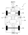
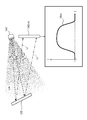
- FIG. 1 is a diagram illustrating a configuration of a mobile system in which an object detection device is used.
- the object detection apparatus 100 according to the first embodiment is an apparatus that assists an operation by a driver of a moving body such as an automobile, for example.
- the mobile system 1 includes a main body 11.
- the main body 11 constitutes the main body of the mobile system 1.
- the mobile system 1 includes wheels 12a, 12b, 12c, and 12d.
- the wheels 12a and 12b are attached to an output rotation shaft of a drive unit (for example, an engine and / or an electric motor) so as to be rotatable around an axis via a reduction mechanism at a front portion of the main body 11 in a straight traveling direction (FIG. 1). It has been.
- the wheels 12c and 12d are attached to the rear part of the main body 11 in the straight traveling direction so as to be rotatable around the axis.
- the moving body system 1 includes a moving body control unit 13.
- the moving body control unit 13 is connected to a brake drive mechanism, a drive unit drive mechanism (for example, an accelerator or a motor control device) provided on the wheels 12a and 12b, and / or a handle drive mechanism. It is a computer system capable of controlling the mechanism. Based on the determined positional relationship between the object O and the main body 11, the moving body control unit 13 controls the above driving mechanism on behalf of the driver of the moving body system 1 as necessary.
- the moving body control unit 13 determines whether or not the detected object O exists in the vicinity of the moving body system 1 (main body 11) based on the real space data VD (described later). When it is determined that the object O is present in the vicinity of the mobile system 1, the mobile control unit 13 controls the brake system and the drive unit, for example, to stop the mobile system 1 (main body 11). A mobile control signal is output.
- the mobile body system 1 includes four object detection sensors 14a, 14b, 14c, and 14d. As shown in FIG. 1, the object detection sensor 14 a is attached to the forefront portion of the main body 11 in the straight traveling direction, and detects an object existing in front of the main body 11. The object detection sensor 14 b is attached to the rearmost part of the main body 11 in the straight direction, and detects an object existing behind the main body 11.
- the object detection sensor 14 c is attached to the left side surface of the main body 11 in the straight traveling direction, and detects an object existing on the left side of the main body 11.
- the object detection sensor 14 d is attached to the right side surface of the main body 11 in the straight traveling direction, and detects an object present on the right side of the main body 11.
- the object detection sensors 14a to 14d are TOF (Time Of Flight) sensors that measure the distance to the object O to be detected.
- the object detection sensor is not limited to this.
- another type of distance measurement sensor such as a laser range finder (LRF) that measures a distance from an image difference between two left and right cameras may be used.
- LRF laser range finder
- the mobile system 1 includes a control unit 15.
- the control unit 15 includes a CPU (Central Processing Unit), a storage device (RAM (Random Access Memory), ROM (Read Only Memory), SSD (Solid State Drive), HDD (Hard Disk Drive, etc.) and the like.
- CPU Central Processing Unit
- RAM Random Access Memory
- ROM Read Only Memory
- SSD Solid State Drive
- HDD Hard Disk Drive, etc.
- it is a computer system provided with A / D, D / A converter, etc.
- the control unit 15 receives detection signals from the object detection sensors 14a to 14d, and determines the positional relationship between the object O and the main body 11 present in the surroundings based on the detection signals.
- the configuration of the control unit 15 will be described in detail later.
- the mobile system 1 can assist the driving of the mobile system 1 by the driver based on the positional relationship between the object O and the main body 11 detected by the object detection sensors 14a to 14d.
- the object detection sensors 14a to 14d and the control unit 15 constitute the object detection device 100.
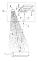
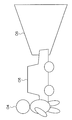
- FIG. 2 is a diagram illustrating a configuration of the object detection sensor. Since the four object detection sensors 14a to 14d have the same configuration, the configuration of the object detection sensor 14a will be described below as an example.
- the object detection sensor 14a has an output unit 141.
- the output unit 141 is, for example, a light source that outputs measurement light Lm (an example of a first signal) in the infrared region toward the object O that is a detection target. As shown in FIG. 2, in the present embodiment, the output unit 141 preferably outputs the measurement light Lm that has spread over a wide range in which the mobile body system 1 moves. This is because the object detection sensor 14a can simultaneously detect the object O in a wide range of the space in which the mobile body system 1 moves.
- the object detection sensor 14a includes a plurality of detection units 143-1, 143-2, ... 143-n.
- Each of the plurality of detection units 143-1, 143-2,... 143-n is disposed at a predetermined position on the detection surface DS (semiconductor substrate), for example, and the measurement light Lm is reflected by the object O.
- the reflected light Lr (an example of the second signal) generated by the detection is detected.
- the detection units 143-1 to 143-n are, for example, charge coupled devices (Charge Coupled Devices) or CMOS (Complementary MOS) devices.
- the plurality of detection units 143-1 to 143-n are arranged in the vertical direction and the horizontal direction on the detection surface DS to form an array. Accordingly, the plurality of detection units 143-1 to 143-n can form a CCD image sensor or a CMOS image sensor on the detection surface DS.
- a switching element for example, a MOS-FET
- an address line is connected to the switching element, and when a signal is applied to the address line, the switching element is turned on, and the detection unit connected to the switched switching element and the control unit 15 include Signal transmission / reception becomes possible.
- the object detection sensor 14a has a lens 145.
- the lens 145 condenses the reflected light Lr in a region of the detection surface DS where the plurality of detection units 143-1 to 143-n are formed.
- an image of the object O in the real space can be formed in an area where the plurality of detection units 143-1 to 143-n are formed.
- the plurality of detection units 143-1 to 143-n and the real space region are associated with each other.
- the object detection sensor 14a can acquire distance data by projecting the object O in the real space onto the predetermined coordinates in association with the detection units 143-1 to 143-n. . That is, each of the detectors 143-1 to 143-n is configured to detect the reflected light Lr generated when the measurement light Lm is reflected by the object O, the distance to the object O existing in the observation area, and the object. It can be detected as a signal representing the shape of O.
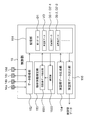
- FIG. 3 is a diagram illustrating a configuration of the control unit.
- a part or all of the functions of each element of the control unit 15 described below may be realized as a program that can be executed by a computer system constituting the control unit 15. At this time, the program may be stored in a storage area formed in a storage device of the computer system. In addition, some or all of the functions of each element of the control unit 15 may be realized in hardware by a custom IC or the like.
- the control unit 15 includes a storage unit 151.
- the storage unit 151 stores various data, for example, a part of a storage area provided in a storage device of a computer system.
- the control unit 15 includes a data acquisition unit 152.
- the data acquisition unit 152 generates a detection signal waveform expressed as a temporal change in the intensity of the reflected light Lr as the first data D1.
- the first data D1 includes coordinate values obtained by projecting the arrangement positions of the detection units 143-1 to 143-n on the detection surface DS to predetermined coordinates (referred to as first coordinates), and reflected light Lr at the detection units. Is a set of a plurality of first position information associated with detection signal waveforms representing temporal changes in the intensity of the first position information.
- the data acquisition unit 152 first applies the first detection unit 143-to the address line corresponding to the first detection unit 143-1 for a predetermined time longer than the detection signal waveform can be acquired. 1 and the data acquisition unit 152 are connected for the predetermined time. While the detection unit 143-1 and the data acquisition unit 152 are connected, the data acquisition unit 152 determines whether or not the detection unit 143-1 has detected the reflected light Lr at a time interval shorter than the predetermined time. A signal indicating that (voltage signal or current signal) is input.
- the data acquisition unit 152 can acquire a detection signal waveform that is a temporal change in the intensity of the signal indicating whether the detection unit 143-1 has detected the reflected light Lr (corresponding to the intensity of the reflected light Lr). .
- the detection signal waveform is set to 0 because there is no signal input from the detection unit 143-1.
- the data acquisition unit 152 executes the above-described process for all the other detection units 143-2 to 143-n by sequentially changing the address lines to which the signal is applied, so that n detection signal waveforms W1 are obtained. , W2,... Wn.
- the data acquisition unit 152 After acquiring the detection signal waveform, the data acquisition unit 152 has coordinate values (x1, y1), (x2, y2), which are obtained by projecting the arrangement positions of the detection units 143-1 to 143-n on the detection surface DS to the first coordinates. ... (Xn, yn) and the corresponding detection signal waveforms W1 to Wn obtained in the respective detectors are associated with each other to obtain first position information (x1, y1, W1), (x2, y2, W2). ,... (Xn, yn, Wn) is generated as the first data D1.
- the control unit 15 includes an object information determination unit 153.
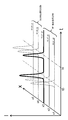
- the object information determination unit 153 determines the distance between the detection units 143-1 to 143-n and the object O based on the detection signal waveforms W1 to Wn included in the first data D1, and the detection units 143-1 to 143. Determine the arrangement state of the object O with respect to -n. For example, as shown in FIG. 4A, the detection signal waveform Wm (detection signal waveform acquired by the detection unit 143-m) has two maximum values P1 and P2 at times t1 and t2 with respect to the intensity of the reflected light Lr. In this case, the object information determination unit 153 determines that the reflected light Lr is generated from two places having different distances.
- FIG. 4A is a diagram illustrating an example of a detection signal waveform in a case where each of two objects is disposed at a separate location.
- the object information determination unit 153 has a boundary between the two objects O1 at the position in the real space corresponding to the coordinate value on the first coordinate where the detection signal waveform having the two maximum values P1 and P2 appears, It is determined that there is a further object O2 after that.
- the object information determination unit 153 has a boundary between the two objects O1 at the position in the real space corresponding to the coordinate value on the first coordinate where the detection signal waveform having the two maximum values P1 and P2 appears, It is determined that there is a further object O2 after that.
- the detection unit 143-m when there are a plurality of local maximums of the intensity of the reflected light Lr in the detection signal waveform Wm, it is determined that there are a plurality of objects having different distances from the detection unit 143-m.
- the boundaries of the plurality of objects O can be determined with high accuracy without depending on the degree of integration of 143-1 to 143-n.
- the detection signal waveform Wm is a waveform in which the intensity of the reflected light Lr is substantially constant over a long period of time or has a maximum that gradually changes with time.
- the object information determination unit 153 determines that the distance between the reflection surface of the object O3 that has generated the reflected light Lr and the detection surface DS is continuously changing. That is, it is determined that one object O3 detected by the detection unit 143-m is inclined with respect to the detection surface DS.
- FIG. 4B is a diagram illustrating an example of a detection signal waveform when one object is inclined with respect to the detection surface.
- the detection signal waveform Wm is inclined with respect to the detection unit 143-m.
- one object O3 is arranged to be inclined with respect to the detection units 143-1 to 143-n (detection surface DS). It can be determined with high accuracy without depending on the integration degree of -n.
- the object information determination unit 153 uses the above detection signal waveform characteristics to detect the boundary between adjacent objects when an object is detected by the plurality of detection units 143-1 to 143-n. Confirm. Specifically, the object information determination unit 153 includes a projection image data extraction unit 1531.
- the projection image data extraction unit 1531 extracts a plurality of pieces of first position information whose distance indicated by the detection signal waveform is within a predetermined range from the first data D1, and generates projection image data D2.
- the projection image data extraction unit 1531 associates, from the first data D1, a detection signal waveform having a non-zero intensity at a time within a range earlier or later by a predetermined value than a predetermined central time.
- Projection image data D2 is generated by extracting one position information group as second position information.
- first clustering processing Such extraction processing of projection image data based on the distance from the detection units 143-1 to 143-n (object detection sensor 14a) to the object is referred to as “first clustering processing”.
- the object information determination unit 153 includes a determination unit 1533.
- the determination unit 1533 determines the boundary of the projection image data D2 using the characteristics of the detection signal waveform. Specifically, the determination unit 1533 first calculates a first detection signal waveform existing on a line crossing two pieces of projection image data (referred to as first projection image data and second projection image data). Extracted from one projection image data, a second detection signal waveform existing on the line is extracted from the second projection image data. In this way, the determination unit 1533 can select any two or more detection units corresponding to the first projection image data and the second projection image data. This is because each pixel included in the projection image data D2 (first data D1) corresponds to one detection unit.
- the determination unit 1533 determines the boundary between the two adjacent projection image data based on the comparison between the extracted first detection signal waveform and the second detection signal waveform. That is, based on the relationship between the first detection signal waveform and the second detection signal waveform, the determination unit 1533 determines that the two or more detection units selected above correspond to the same object or different objects. The existence range of the object O is determined by determining whether it corresponds. Such a process of determining the boundary of the projection image data based on the comparison of the detection signal waveforms will be referred to as a “second clustering process”.
- the object information determination unit 153 has a positional relationship between the first object and the second object (the two object's relationship) when the detection surface DS includes a plurality of detection units 143-1 to 143-n.
- the arrangement position and arrangement state) can be determined with high accuracy without depending on the degree of integration of the plurality of detection units 143-1 to 143-n.
- the control unit 15 includes a real space data generation unit 154.
- the real space data generation unit 154 uses the projection image data D2 generated by the second clustering process to generate real space data VD that represents the arrangement position of the detected object O in the real space in which the mobile body system 1 moves. Generate.
- the control unit 15 includes a real space data output unit 155.
- the real space data output unit 155 outputs the real space data VD to the moving body control unit 13.
- the mobile body control unit 13 determines that there is an object O that needs to be avoided, such as the object O in the vicinity of the mobile body system 1, the braking function, power function, and a mobile body control signal for controlling the rotation function of the steering wheel or the like is output, and the mobile body system 1 can be controlled on behalf of the driver of the mobile body system 1 as necessary.
- the moving body control unit 13 determines that the object O exists in the vicinity of the moving body system 1, the moving body system 13 stops the moving body system 1 (main body 11) or moves a motion that avoids the object O.
- the body system 1 is executed.
- the control unit 15 does not depend on the degree of integration of the plurality of detection units 143-1 to 143-n included in the object detection sensor 14a or the like, and does not depend on the detection units 143-1 to 143-n.
- the arrangement state (boundary) of the detected object can be determined with high accuracy.
- (4) Operation of Object Detection Device (4-1) Overall Operation of Object Detection Device
- the operation of the object detection device 100 provided in the mobile system 1 will be described below. First, the overall operation of the object detection apparatus 100 will be described with reference to FIG.
- FIG. 5 is a flowchart showing the overall operation of the object detection apparatus. In the following description, since the four object detection sensors 14a to 14d have the same configuration, the operation of the object detection sensor 14a will be described as an example.
- the data acquisition unit 152 instructs the output unit 141 of the object detection sensor 14a to output the measurement light Lm at every predetermined time during which the mobile system 1 is moving in real space (step S1). Almost simultaneously with the output of the measurement light Lm, the data acquisition unit 152 sequentially applies a signal to the address line corresponding to each detection unit of the object detection sensor 14a, and outputs a signal indicating the intensity of the reflected light Lr from each detection unit. By acquiring only the period of time, the temporal change in the intensity of the reflected light Lr detected by each detection unit is acquired as a detection signal waveform (step S2).
- the data acquisition unit 152 generates an aggregate of a plurality of first position information by associating the acquired detection signal waveform and the coordinate value of each detection unit on the first coordinate with respect to the object detection sensor 14a. It memorize
- the projection image data extraction unit 1531 has a non-zero intensity at a time within a range earlier or later than the predetermined center time by a first value from the first data D1 by the first clustering process.
- the first position information group associated with the detection signal waveform Wm is extracted as second position information to generate projection image data D2 (step S4).
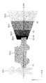
- FIG. 6 is a diagram illustrating an example of an object existing in front of the mobile system.
- the object detection sensor 14a is configured to output a plurality of projection image data D2-1 to D2-1 based on the distance from the object detection sensor 14a as shown in FIG. Assume that D2-6 is obtained.
- the object O4 and the object O5 are clustered by the projection image data D2-1 and D2-2, respectively.
- there is an overlapping portion between the projection image data D2-1 and the projection image data D2-2 and the boundary between the object O4 and the object O5 at the overlapping portion is not fixed.
- the projection image data D2-2 and the projection image data D2-6 have an overlapping portion, and the boundary at the overlapping portion is not fixed.
- the object O6 is clustered with the four projection image data D2-3 to D2-6 by the first clustering process.
- the first clustering process is a process of extracting data representing an object (part) whose distance from the detection surface DS is within a predetermined range as one projection image data. Therefore, when a plurality of projection image data D2-1 to D2-6 are generated, in the first clustering process, the plurality of projection image data D2-1 to D2-6 are moved in the distance direction from the detection surface DS. It cannot be determined whether a plurality of objects arranged at different positions (in the real space Z-axis direction) or a single object extending in an inclined manner in the Z-axis direction is represented.
- the determination unit 1533 uses the detection signal waveform characteristics described above to determine the boundaries for the projection image data D2-1 to D2-6.
- a second clustering process for determining the boundaries of the data D2-1 to D2-6 is executed (step S5). The second clustering process will be described in detail later.
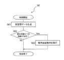
- step S6 After executing the second clustering process, the control unit 15 controls the mobile body system 1 using the projection image data D2 whose boundary is determined in the second clustering process (step S6).
- the control of the mobile system 1 executed in step S6 will be described in detail later.
- the process returns to step S1 unless the driver of the mobile body system 1 or the like instructs to stop the operation of the object detection device 100 (in the case of “No” in step S7).
- the object detection device 100 continues to operate.
- step S7 when the driver of the mobile system 1 or the like instructs to stop the operation of the object detection device 100 (in the case of “Yes” in step S7), the object detection device 100 stops the operation.
- the object detected by the object detection sensor 14a is not dependent on the degree of integration of the plurality of detection units 143-1 to 143-n provided in the object detection sensor 14a. The boundary can be determined with high accuracy.
- step S5 is a flowchart showing the flow of the second clustering process.
- the determination unit 1533 scans the second position information included in the projection image data D2 in the x-axis direction of the first coordinates, thereby generating projection image data.
- the boundary of D2 is determined. Specifically, as shown by the dotted line in FIG. 9, when the y-coordinate value of the second position information included in the projection image data D2 is set to yi and the x-coordinate value is changed in the positive direction, first, the determination unit In step 1533, the projection image data D2-1 is selected as the first projection image data and the projection image data D2-2 is selected as the second projection image data in order from the smallest x coordinate value.
- FIG. 9 is a diagram illustrating an example of the scanning direction when the boundary of the projection image data is determined.
- the detected detection signal waveform is extracted as a second detection signal waveform (step S52). Thereby, one or more detection parts which detected the detection signal waveform contained in the 2nd projection image data are selected.
- the determination unit 1533 compares the plurality of first detection signal waveforms with the plurality of second detection signal waveforms (step S53).
- the coordinate values (x1, yi), (x2, yi), and (x3, yi) of the second position information The detection signal waveforms W (x1, yi), W (x2, yi), and W (x3, yi) associated with each of () are extracted as the first detection signal waveforms. That is, the three detection units arranged at the coordinate values (x1, yi), (x2, yi), and (x3, yi) of the first coordinates are respectively connected to the first detection signal waveform W (x1, yi), It is assumed that W (x2, yi) and W (x3, yi) are detected.
- the detection signal waveforms W (x4, yi) and W (x3, yi) associated with the coordinate values (x4, yi) and (x5, yi) of the second position information are respectively It is assumed that the second detection signal waveform is extracted. That is, the two detection units arranged at the coordinate values (x4, yi) and (x5, yi) of the first coordinates respectively generate the second detection signal waveforms W (x4, yi) and W (x5, yi). Suppose that it is detected.
- the determination unit 1533 determines the first detection signal waveform and the first detection signal waveform based on the shape pattern of the first detection signal waveform and the first detection signal waveform. It is determined whether any two or more detection units that have detected the second detection signal waveform correspond to the same object or different objects. Specifically, as a result of the comparison between the first detection signal waveform and the second detection signal waveform, for example, as shown in FIG. 10A, the first detection signal waveform W (x3, yi) detected by one detection unit.
- the unit 1533 determines that the boundary between the first projection image data D2-1 and the second projection image data D2-2 exists in the coordinate value (x3, yi) of the first coordinate.
- FIG. 10A is a diagram illustrating an example of a plurality of detection signal waveforms in the vicinity of the boundary when one detection signal waveform having two maximum values exists. Further, as shown in FIG. 10A, the time t3 when the intensity is maximized in the first detection signal waveforms W (x1, yi) and W (x2, yi) detected by the other detection units is the first detection signal. This coincides with the time t3 at which one of the two maxima included in the waveform W (x3, yi) is taken. In such a case, the determination unit 1533 detects the first detection signal waveforms W (x1, yi), W (x2, yi), and W (x3, yi) as the same object O4 (first object ).
- the time t4 when the intensity is maximized in the first detection signal waveforms W (x4, yi) and W (x5, yi) detected by the other detection units is the first detection signal waveform W (x3 , Yi) coincides with time t4 at which one of the two maxima included in yi) is taken.
- the determination unit 1533 detects that the first detection signal waveforms W (x3, yi), W (x4, yi), and W (x5, yi) are the same object O5 (second object ).
- the determination unit 1533 corresponds to the coordinate value (x3, yi) on the first coordinate where the detection signal waveform W (x3, yi) having two maximum values (maximum values appearing at times t3 and t4) appears.
- the existence range of the objects O4 and O5 can be determined. Note that the range that can be detected by one detection unit of the object detection sensor 14a is generally wide. That is, the waveform acquired by the object detection sensor 14a represents the intensity of the reflected light Lr detected in the region of x3 ′ ⁇ x3 ⁇ x3 ′′ and yi ′ ⁇ yi ⁇ yi ′′.
- the determination unit 1533 uses, for example, the center point ((x3 ′ + x3 ′′) / 2, (yi ′ + yi ′′) / 2) of the above region as the first projection image data D2 ⁇ . 1 and the coordinate point where the boundary between the second projection image data D2-2 exists. After determining the coordinate point where the boundary exists as described above, the determination unit 1533, for example, sets x3 of the second position information (x3, yi, W (x3, yi)) of the first projection image data D2-1 to ( x3 ′ + x3 ′′) / 2 is replaced with (yi ′ + yi ′′) / 2 to determine the boundary of the first projection image data D2-1.
- new second position information ((x3 ′ + x3 ′′) / 2, (yi ′ + yi ′′) / 2, W (x3, yi)) is added to the second projected image data D2-2. Then, the boundary of the second projection image data D2-2 is determined (step S54). As described above, either the first detection signal waveform or the second detection signal waveform (in the above example, the first detection signal waveform W (x3, yi)) corresponds to the first object and the second object. If there are two local maxima, the object information determination unit 153 (determination unit 1533) indicates that the first object (object O4) and the second object (object O5) are mutually detected from the detection units 143-1 to 143-n. By determining that the individual objects have different distances, the first object and the second object can be arranged with high accuracy without depending on the degree of integration of the detection units 143-1 to 143-n. Can be determined to be different objects.
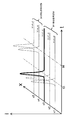
- FIG. 10B is a diagram illustrating an example of a plurality of detection signal waveforms when three objects arranged at different positions are detected.
- the detection unit that detects the first detection signal waveforms W (x1, yi), W (x2, yi), and W (x3, yi) corresponds to one object at a distance corresponding to time t3.
- the detection unit that detects the first detection signal waveform W (x3, yi) corresponds to one small object (detected by only one detection unit) at a distance corresponding to time t4, and
- a detection unit that detects one detection signal waveform W (x4, yi) and W (x5, yi) corresponds to one object at a distance corresponding to time t5. That is, the existence ranges of three objects arranged at different distances from the detection surface DS are determined by the five detection units.
- the determination unit 1533 adds the extracted first detection signal waveform and second detection signal waveform and adds them.
- a waveform W ′ is calculated (step S55). For example, in the vicinity of the boundary V3 between the projection image data D2-5 (first projection image data) and the projection image data D2-4 (second projection image data), there are no two maximum values as shown in FIG. 10C.
- the first detection signal waveform and the second detection signal waveforms W (x6, yi) to W (x10, yi) whose intensity is constant over a long time are extracted, and the intensity is constant over a long period of time.
- FIG. 10C is a diagram illustrating an example in the case where there is a detection signal waveform having a constant intensity over a long period of time.
- FIG. 10C When the first detection signal waveform and the second detection signal waveform as shown in FIG. 10C are extracted, when the respective detection signal waveforms are added to the first detection signal waveform and the second detection signal waveform, FIG. An added waveform W ′ having a constant intensity over a long time is calculated as shown in FIG.
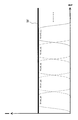
- the determination unit 1533 detects the detection signal waveforms W (x6, yi) to W The detection unit that detects (x10, yi) determines to correspond to the same object.
- the determination unit 1533 does not have a boundary between the projection image data D2-5 and the projection image data D2-4 in the coordinate value (x8, yi) of the first coordinate, and the two projection image data D2-4. And D2-5 are determined to be data for one object.
- FIG. 11 is a diagram illustrating an example when an added waveform having a constant intensity over a long time is calculated.
- the determination unit 1533 can determine the existence range of the object O6.
- the added waveform W ′ whose intensity is constant over a long time is not calculated (in the case of “No” in step S55), for example, as shown in FIG. 10D, the extracted first detection signal waveform and second detection signal waveform Each of the signal waveforms has only one maximum value, but the time at which one maximum value of the first detection signal waveform appears (time t3) is the time at which one maximum value of the second detection signal waveform appears (time t4).
- the determination unit 1533 maintains the boundary between the two projection image data determined by the first clustering process as it is, and the detection unit that has detected the first detection signal waveform and the second detection signal waveform is 2 It is determined that it corresponds to one object (step S57).
- FIG. 10D shows a case where the time when one maximum value of the first detection signal waveform appears does not coincide with the time when one maximum value of the second detection signal waveform appears, and two objects are detected by a plurality of detection units. It is a figure which shows an example.
- the determination unit 1533 has a time zone in which the first detection signal waveform is generated although the first detection signal waveform and the second detection signal waveform are both constant in intensity over a long period of time. Even when the time zone in which the second detection signal waveform occurs does not overlap, the detection unit that detects the first detection signal waveform and the second detection signal waveform determines that it corresponds to a different object.
- the time zone in which the first detection signal waveform W (x8, yi) is generated does not overlap the time zone in which the second detection signal waveform W (x9, yi) is generated.
- the determinator 1533 corresponds to one object tilted with respect to the Z-axis direction of the real space by detecting the first detection signal waveforms W (x6, yi) to W (x8, yi).
- the detection unit that detects the second detection signal waveforms W (x9, yi) and W (x10, yi) corresponds to another object tilted with respect to the Z-axis direction of the real space, the existence range of the two objects Confirm.
- FIG. 10E is a diagram illustrating an example in which a time zone in which the first detection signal waveform is generated and a time zone in which the second detection signal waveform is generated do not overlap and two objects are detected by a plurality of detection units. It is.
- first detection signal waveforms W (x11, yi) and W (x12, yi) having only at time t4
- second detection signal waveforms W ( x14, yi) and W (x15, yi) exist.
- FIG. 12 is a diagram illustrating an example in which a detection signal waveform having two different waveforms exists in the vicinity of the boundary.
- the determinator 1533 executes the above-described steps S51 to S57, so that the first projection image data D2-2 and the second projection image data D2 are set to the coordinate values (x13, yi) of the first coordinates. It can be determined that a boundary with ⁇ 6 exists, and the object represented by the second projection image data D2-6 can be determined to be an inclined object.
- the boundary of the plurality of projection image data exists along the x axis, or the surface of the object represented by the projection image data is present. It can be considered to be substantially parallel to the x-axis.
- the determination unit 1533 determines all the regions of the first coordinates ( That is, it is determined whether or not the boundaries of the projection image data have been determined for the plurality of detection units 143-1 to 143-n) (step S59).
- step S59 If the above steps S51 to S57 are not executed for all y coordinate values (in the case of “No” in step S59), the second clustering process assumes that there is a y coordinate value whose boundary should be determined. The process returns to step S51. On the other hand, when the boundaries of the projection image data are determined for all possible y coordinate values (in the case of “Yes” in step S59), the second clustering process is terminated.
- steps S51 to S59 are performed by the first clustering process in step S4 (that is, one object O6 is formed as a plurality of clusters).
- step S4 that is, one object O6 is formed as a plurality of clusters.
- step S4 that is, one object O6 is formed as a plurality of clusters.
- step S4 that is, one object O6 is formed as a plurality of clusters.
- step S4 that is, one object O6 is formed as a plurality of clusters.
- one object can be determined as one cluster with high accuracy.
- three projection image data D2'-1 to D2'-3 can be generated for the three objects O4 to O6, respectively, by the second clustering process.
- FIG. 13 is a diagram illustrating an example of the clustering result after executing the second clustering process.
- the second clustering process using the detection signal waveform described above can determine the boundary of the object with higher accuracy than the accuracy determined in the position information unit (that is, the detection unit unit) of the first data. For this reason, for example, an object composed of a thin member such as a fence (conventionally, it has been apt to be recognized as a cavity or a non-existent object) is also generated as the projection image data D2 generated by the second clustering process. In 'is recognized. (4-3) Control of Mobile System Next, control of the mobile system 1 executed in step S6 will be described with reference to FIG.
- FIG. 14 is a flowchart showing the flow of control of the mobile system.
- a case where the traveling function of the mobile body system 1 is controlled based on the determined positional relationship between the detected object O and the main body 11 will be described as an example.
- the real space data generation unit 154 When the control of the mobile body system 1 is started, the real space data generation unit 154 generates projection image data generated by the second clustering process in order to determine the arrangement position of the object O in the real space where the mobile body system 1 moves. Using D2′-1 to D′ 2-3, real space data VD representing the arrangement position of the detected object O in the real space is generated (step S61). Specifically, the real space data generation unit 154 expands the second position information included in the projection image data D2′-1 to D2′-3 into the real space coordinate system (XYZ coordinates). Real space data VD is generated.
- the time for calculating the distance to the object O is not limited to the time at which the maximum value appears as described above, and the time for calculating the distance to the object is the time at which an edge occurs in the detection signal waveform Wp. It is good. Specifically, for example, the rising timing or falling timing of the detection signal waveform Wp can be selected as the time for calculating the distance to the object O.
- the detection signal waveform Wp has two local maximum values at time tp1 and time tp2 (assuming tp1 ⁇ tp2) (for example, on the boundary between the projection image data D2′-1 and the projection image data D2′-2).
- dp c * (tp1) / 2 in the projection image data D2′-1 closer to the object detection sensor 14a, and the projection image data D2 ′ farther away.
- the real space data generation unit 154 when the detection signal waveform Wp has a waveform whose intensity is constant over a long period of time (or has a maximum that changes gradually with respect to time), the real space data generation unit 154, for example, Are extracted over a long time with a rising time (referred to as tp1 ′) and a falling time (referred to as tp2 ′), that is, a time when an edge occurs in the detection signal waveform Wp.
- the real space data generation unit 154 uses these two times in the same manner as described above, and the two real space coordinate values (Xp, Yp, Zp1 ′) and (Xp, Yp, Zp2 ′). And calculate.
- the real space data generation unit 154 After that, the real space data generation unit 154 generates a line connecting the above two coordinate values (a line parallel to the normal line of the XY plane) in the Z-axis direction existing in (Xp, Yp) of the real space. Can be a boundary.
- the detection signal waveform Wp rises and the intensity stabilizes at a substantially constant value, and / or when the detection signal waveform Wp starts to fall from a state where the detection signal waveform Wp stabilizes at a substantially constant value, the detection signal waveform Wp It may be the time when an edge occurs.
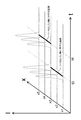
- the real space data generation unit 154 performs the above calculation of the coordinate values of the real space for the three projection image data D2′-1 to D2′-3 generated after the execution of the second clustering process. For example, as shown in FIG. 15, real space data VD in which each object is arranged in a real space coordinate system (XYZ coordinate system) can be generated.
- FIG. 15 is a diagram illustrating an example of real space data.
- the real space data VD is generated using the three projection image data D2′-1 to D2′-3 generated after the execution of the second clustering process, thereby arranging the objects O4 to O6.
- the real space data VD can reflect the position and the state where the object O6 is inclined in the Z direction as one object.
- the real space data output unit 155 outputs the generated real space data VD to the moving body control unit 13.
- the mobile control unit 13 that has received the real space data VD determines whether or not the object O exists in the vicinity of the main body 11 (step S62).
- the moving body control unit 13 determines that the real space data VD has a coordinate value that falls within a predetermined distance from the coordinate value of the main body 11 in the real space data VD. It is determined that there is an object O that needs to be avoided in the vicinity of (mobile system 1).
- the mobile body control unit 13 When it is determined that there is an object O that needs to be avoided in the vicinity of the mobile body system 1 (in the case of “Yes” in step S62), the mobile body control unit 13 outputs a mobile body control command (step S63).
- the moving body control command is, for example, a command for stopping the moving body system 1 (main body 11) in front of the object O and avoiding a collision between the object O and the main body 11.
- the moving body control unit 13 outputs, as a moving body control signal, a command to apply a brake and / or a command to set the accelerator opening (or the output control mechanism of the engine and / or electric motor) to 0. To do.
- the moving body control unit 13 may output a moving body control command for steering the handle in a direction to avoid the object O existing in the vicinity of the main body 11.
- the mobile body control signal which cut
- a collision between the object O and the main body 11 can be avoided by performing the control of the mobile system 1 on behalf of the driver as necessary.
- the mobile body control unit 13 ends the control of the mobile body system 1. In this case, the mobile body system 1 can continue to move according to the driver's operation. 2.
- the maximum values of the detection signal waveforms W1 to Wn are obtained when the distances between the detection units 143-1 to 143-n and the object O are obtained. Seeking. The following method is also conceivable as a method for obtaining the maximum value.
- the normal distribution is obtained by associating the intensity of the reflected light Lr with the time when the intensity of the reflected light Lr is acquired. Fit the function. In this case, it is desirable to extract a portion of the data whose intensity is 0 or more.
- the center value obtained as a result may be the time when the maximum value appears. Further, it may be determined that the maximum is a maximum that gradually changes with time based on the standard deviation.
- the distance (the time at which the maximum value appears) indicated in the first position information with respect to the first data D1 is first set.
- the first clustering process is performed, and then the second clustering process using the characteristics of the detection signal waveform is performed on the projection image data D2 generated by executing the first clustering process, thereby achieving high accuracy.
- Projection image data D2 ′ subjected to clustering was generated.
- projection image data D2 ′ subjected to high-precision clustering can be generated by performing the second clustering process directly on the first data D1 without going through the first clustering process.
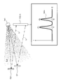
- the detection signal waveform associated with the first position information is scanned in the x-axis direction.
- the coordinate value at time t appears as a maximum value in the detection signal waveform.
- two straight lines parallel to the x axis corresponding to each maximum value are defined.
- FIG. 16B when a detection signal waveform having a waveform with a constant intensity over a long time appears, for example, the rise time and fall time of the intensity of the waveform (that is, the detection signal)
- a straight line perpendicular to the x-axis connecting the edges of the waveform) can be defined.
- FIG. 16C a straight line connecting a straight line between the rise time and the fall time of the waveform having a constant intensity over a long time may be defined.
- FIGS. 16A to 16C are diagrams illustrating an example of a process of clustering the first data with the detection signal waveform.
- FIGS. 16A to 16C are diagrams illustrating an example of a process of clustering the first data with the detection signal waveform.
- the intensity of the detection signal waveform is 0 in the x coordinate values in the range of x ⁇ x1 ′ and x> x4 ′.
- projection image data D2′-1 projection image data (1)
- projection image data D2′-2 projection image data (2)
- projection image data (3) projection image data (3)
- three projection image data can be determined.
- data clustering can be executed on all the first position information included in the first data D1.
- the clustering using the detection signal waveform is performed on the first data D1, it does not depend on the degree of integration of the plurality of detection units 143-1 to 143-n of the object detection sensor 14a.
- One projection image data can be determined with high accuracy for one detected object.
- the present invention can be widely applied to an object detection apparatus that recognizes an object existing around and executes a predetermined process.
- Object detection apparatus 1 Moving body system 11 Main body 12a, 12b, 12c, 12d Wheel 13 Moving body control part 14a, 14b, 14c, 14d Object detection sensor 141 Output part 143-1 to 143-n Detection part 145 Lens 15 Control part 151 Storage Unit 152 Data Acquisition Unit 153 Object Information Determination Unit 1531 Projected Image Data Extraction Unit 1533 Determination Unit 154 Real Space Data Generation Unit 155 Real Space Data Output Unit D1 First Data D2, D2 ′ Projection Image Data DS Detection Surface Lm Measurement Light Lr Reflected light O Object VD Real space data W Detection signal waveform
Landscapes
- Engineering & Computer Science (AREA)
- Physics & Mathematics (AREA)
- General Physics & Mathematics (AREA)
- Electromagnetism (AREA)
- Remote Sensing (AREA)
- Radar, Positioning & Navigation (AREA)
- Computer Networks & Wireless Communication (AREA)
- Multimedia (AREA)
- Theoretical Computer Science (AREA)
- Artificial Intelligence (AREA)
- Computer Vision & Pattern Recognition (AREA)
- Optical Radar Systems And Details Thereof (AREA)
- Traffic Control Systems (AREA)
- Length Measuring Devices By Optical Means (AREA)
- Geophysics And Detection Of Objects (AREA)
Abstract
Description
また、上記のセンサによって、検出した物体を所定の平面座標に投影する二次元座標の集合体としてのデータが得られる。当該二次元座標のそれぞれには、光を出力してから当該光が物体に反射されて戻ってくるまでの時間が奥行きを示すデータとして関連付けられている(このようなデータを「距離画像」と呼ぶ)。 In the above-described system, generally, the light is projected using light such as infrared light, reflected by the object, and based on the time until the object returns. The distance between is measured. A sensor for measuring such a distance generally has a plurality of light detection elements arranged in an array in order to obtain information that can recognize the shape of an object.
In addition, data as a set of two-dimensional coordinates for projecting the detected object onto predetermined plane coordinates is obtained by the sensor. Each of the two-dimensional coordinates is associated with data indicating depth after the light is output until the light is reflected by the object and returned (this data is referred to as “distance image”. Call).
本発明の一見地に係る物体検出装置は、出力部と、複数の検出部と、データ取得部と、物体情報確定部と、を備える。出力部は、物体に向けて第1信号を出力する。複数の検出部のそれぞれは、第2信号を、観測している領域に存在する物体までの距離および物体の形状を表す信号として検出する。第2信号は、第1信号が物体にて反射されることにより発生する信号である。データ取得部は、第2信号の強度の時間的変化として表される検出信号波形を取得する。物体情報確定部は、検出信号波形に基づいて、任意の2以上の検出部が同じ物体に対応するか、または、異なる物体に対応するか、のいずれであるかを判定することにより、物体の存在範囲を確定する。 Hereinafter, a plurality of modes will be described as means for solving the problems. These aspects can be arbitrarily combined as necessary.
An object detection apparatus according to an aspect of the present invention includes an output unit, a plurality of detection units, a data acquisition unit, and an object information determination unit. The output unit outputs the first signal toward the object. Each of the plurality of detection units detects the second signal as a signal representing the distance to the object and the shape of the object present in the observed region. The second signal is a signal generated when the first signal is reflected by an object. The data acquisition unit acquires a detection signal waveform expressed as a temporal change in the intensity of the second signal. The object information determination unit determines whether any two or more detection units correspond to the same object or different objects based on the detection signal waveform. Determine the existence range.
上記の任意の2以上の検出部は、検出面上で互いに隣接していてもよい。これにより、任意の2以上の検出部が同じ物体に対応するか、または、異なる物体に対応するか、のいずれであるかを判定するかを、精度よく確定できる。 In the above-described object detection device, the detection signal waveform used to determine the arrangement state of the object is continuous information that is a temporal change in the intensity of the second signal. Thereby, the object detection apparatus can determine the distance and the arrangement state of the object detected by the detection unit with high accuracy without depending on the degree of integration of the detection unit.
The two or more arbitrary detection units described above may be adjacent to each other on the detection surface. Thereby, it can be determined with high accuracy whether it is determined whether any two or more detection units correspond to the same object or different objects.
これにより、物体情報確定部は、検出信号波形の形状に基づいて、任意の2以上の検出部が、同じ物体に対応するか、または、異なる物体に対応するかを判定するとともに、検出部と当該物体との距離を算出できる。 The object information determination unit may determine whether any two or more detection units correspond to the same object or different objects based on the shape pattern of the detection signal waveform. Good. The object information determination unit further calculates the distance between the detection unit and the object based on the time when the edge occurs in the detection signal waveform.
Accordingly, the object information determination unit determines whether any two or more detection units correspond to the same object or different objects based on the shape of the detection signal waveform, The distance to the object can be calculated.
これにより、複数の検出部にて検出された物体を、同一の物体であると確定できる。 The object information determination unit has one or more intensity maxima in the detection signal waveform detected by one of the two or more detection units, and the detection signal waveform detected by another detection unit When the time at which the maximum of the intensity is taken coincides with one of the times at which the maximum of 1 or more is taken, any two or more detection units may be determined to correspond to the same object.
Thereby, it is possible to determine that the objects detected by the plurality of detection units are the same object.
物体情報確定部は、任意の2以上の検出部のうち、1の検出部にて検出した検出信号波形中に強度の極大が1以上存在し、他の検出部にて検出した検出信号波形中に強度の極大をとる時刻が、当該1以上の極大をとる時刻のいずれとも一致しない場合に、任意の2以上の検出部は異なる物体に対応すると判定してもよい。 Thereby, the object detected by the some detection part can be decided with one inclined object, for example.
The object information determination unit has one or more intensity maxima in the detection signal waveform detected by one of the two or more detection units, and the detection signal waveform detected by another detection unit If the time at which the intensity maximum is taken does not coincide with any of the times at which the one or more maximums are taken, it may be determined that any two or more detection units correspond to different objects.
物体情報確定部は、任意の2以上の検出部にて検出した検出信号波形が、強度が長時間にわたり一定であるか、又は、時間に対して緩やかに変化する極大を有しているが、当該強度が長時間にわたり一定であるか、又は、時間に対して緩やかに変化する極大を有する検出信号波形が発生する時間帯が重ならない場合に、任意の2以上の検出部は異なる物体に対応すると判定してもよい。 Thereby, it is possible to determine that the objects detected by the plurality of detection units are different objects.
In the object information determination unit, the detection signal waveform detected by any two or more detection units has a maximum that the intensity is constant over a long period of time or changes slowly with respect to time. When the intensity is constant over a long period of time, or when the detection signal waveforms having a maximum that changes slowly with time do not overlap, any two or more detectors can handle different objects Then, it may be determined.
物体情報確定部は、任意の2以上の検出部について、それぞれの検出信号波形を加算することにより、強度が長時間にわたり一定である信号波形が得られれば、任意の2以上の検出部は同じ物体に対応すると判定してもよい。 Thereby, for example, it is possible to determine that the objects detected by the plurality of detection units are different inclined objects.
The object information determination unit adds the respective detection signal waveforms for any two or more detection units, and if a signal waveform whose intensity is constant over a long time is obtained, the two or more detection units are the same You may determine with corresponding to an object.
本発明の他の見地に係る物体検出方法は、複数の検出部を備える物体検出装置における物体検出方法である。物体検出方法は、以下のステップを含む。
◎物体に向けて第1信号を出力するステップ。 As a result, the object detected by the plurality of detection units can be determined as one inclined object.
An object detection method according to another aspect of the present invention is an object detection method in an object detection apparatus including a plurality of detection units. The object detection method includes the following steps.
A step of outputting the first signal toward the object.
◎第2信号の強度の時間的変化として表される検出信号波形を取得するステップ。
◎検出信号波形に基づいて、任意の2以上の検出部が同じ物体に対応するか、または、異なる物体に対応するか、のいずれであるかを判定することにより、物体の存在範囲を確定するステップ。 A step of detecting, by a plurality of detection units, a second signal generated when the first signal is reflected by the object as a signal representing the distance to the object and the shape of the object present in the observed region.
A step of obtaining a detection signal waveform expressed as a temporal change in the intensity of the second signal.
◎ Based on the detection signal waveform, it is determined whether any two or more detectors correspond to the same object or different objects, thereby determining the existence range of the object. Step.
本発明のさらに他の見地に係るプログラムは、上記の物体検出方法を、コンピュータに実行させるプログラムである。 In the object detection method described above, the detection signal waveform used to determine the arrangement state of the object is continuous information that is a temporal change in the intensity of the second signal. Thereby, the object detection apparatus can determine the distance and the arrangement state of the object detected by the detection unit with high accuracy without depending on the degree of integration of the detection unit.
A program according to still another aspect of the present invention is a program that causes a computer to execute the object detection method described above.
(1)物体検出装置が用いられる移動体システムの構成
以下、第1実施形態に係る物体検出装置100が用いられる移動体システム1の構成について、図1を用いて説明する。図1は、物体検出装置が用いられる移動体システムの構成を示す図である。第1実施形態に係る物体検出装置100は、例えば、自動車などの移動体の運転者による操作をアシストする装置である。 1. First Embodiment (1) Configuration of Mobile System Using Object Detection Device Hereinafter, a configuration of a
移動体システム1は、4つの物体検出センサ14a、14b、14c、14dを備える。図1に示すように、物体検出センサ14aは、本体11の直進方向の最前部に取り付けられ、本体11の前方に存在する物体を検出する。物体検出センサ14bは、本体11の直進方向の最後部に取り付けられ、本体11の後方に存在する物体を検出する。物体検出センサ14cは、本体11の直進方向の左側面に取り付けられ、本体11の左側方に存在する物体を検出する。物体検出センサ14dは、本体11の直進方向の右側面に取り付けられ、本体11の右側方に存在する物体を検出する。 In addition, when it is determined that the object O exists in the vicinity of the
The
上記の構成を備えることにより、移動体システム1は、物体検出センサ14a~14dにより検出された物体Oと本体11との位置関係に基づいて、移動体システム1の運転者による運転をアシストできる。また、本実施形態においては、物体検出センサ14a~14dと制御部15とが、物体検出装置100を構成する。
(2)物体検出センサの構成
次に、本実施形態に係る物体検出装置100にて用いられる物体検出センサ14a~14dの構成について、図2を用いて説明する。図2は、物体検出センサの構成を示す図である。4つの物体検出センサ14a~14dは同じ構成を有しているので、物体検出センサ14aの構成を例にとって以下説明する。 The
With the above configuration, the
(2) Configuration of Object Detection Sensor Next, the configuration of the
複数の検出部143-1~143-nのそれぞれには、当該検出部と外部の制御部15とを接続/切断するためのスイッチング素子(例えば、MOS-FET)が接続されている。また、スイッチング素子にはアドレス線が接続されており、アドレス線に信号が印加されたときに、当該スイッチング素子はONされ、ONされたスイッチング素子に接続された検出部と、制御部15とが信号送受信可能となる。 Further, as shown in FIG. 2, the plurality of detection units 143-1 to 143-n are arranged in the vertical direction and the horizontal direction on the detection surface DS to form an array. Accordingly, the plurality of detection units 143-1 to 143-n can form a CCD image sensor or a CMOS image sensor on the detection surface DS.
A switching element (for example, a MOS-FET) for connecting / disconnecting the detection unit and the
(3)制御部の構成
以下、本実施形態に係る物体検出装置100の制御部15の構成を、図3を用いて説明する。図3は、制御部の構成を示す図である。以下に説明する制御部15の各要素の機能の一部又は全部は、制御部15を構成するコンピュータシステムにて実行可能なプログラムとして実現されていてもよい。このとき、当該プログラムは、コンピュータシステムの記憶装置に形成された記憶領域に記憶されていてもよい。また、制御部15の各要素の機能の一部又は全部は、カスタムICなどによりハードウェア的に実現されていてもよい。 With the above configuration, the
(3) Configuration of Control Unit The configuration of the
制御部15は、データ取得部152を有する。データ取得部152は、反射光Lrの強度の時間的変化として表される検出信号波形を、第1データD1として生成する。第1データD1は、各検出部143-1~143-nの検出面DSにおける配置位置を所定の座標(第1座標と呼ぶ)に投影した座標値と、当該各検出部にける反射光Lrの強度の時間的変化を表す検出信号波形と、が関連付けられた複数の第1位置情報の集合体である。 The
The
検出部143-1とデータ取得部152とを接続している間、データ取得部152は、当該所定の時間よりも短い時間間隔にて、検出部143-1が反射光Lrを検出したか否かを示す信号(電圧信号又は電流信号)を入力する。この結果、データ取得部152は、検出部143-1が反射光Lrを検出したか否かを示す信号の強度(反射光Lrの強度に対応)の時間的変化である検出信号波形を取得できる。 Hereinafter, a case where the first data D1 of the
While the detection unit 143-1 and the
データ取得部152は、信号を印加するアドレス線を順次変更することにより、上記の工程を他の全ての検出部143-2~143-nに対して実行して、n個の検出信号波形W1、W2、・・・Wnを得る。 If the reflected light Lr is not detected, the detection signal waveform is set to 0 because there is no signal input from the detection unit 143-1.
The
例えば、図4Aに示すように、検出信号波形Wm(検出部143-mにて取得された検出信号波形)が、反射光Lrの強度について2つの極大値P1、P2を時刻t1、t2において有する場合、物体情報確定部153は、反射光Lrが異なる距離を有する2箇所から発生したと確定する。すなわち、出力部141から測定光Lmを出力した時刻を0として、検出部143-mにて検出された物体O1、O2が、それぞれ、距離c*t1/2(c:光速)の位置及び距離c*t2/2の位置に、検出面DSと平行に配置されていると確定する。図4Aは、2つの物体のそれぞれが個別の場所に配置されている場合の検出信号波形の一例を示す図である。 The
For example, as shown in FIG. 4A, the detection signal waveform Wm (detection signal waveform acquired by the detection unit 143-m) has two maximum values P1 and P2 at times t1 and t2 with respect to the intensity of the reflected light Lr. In this case, the object
このように、検出信号波形Wm中に反射光Lrの強度の極大が複数存在する場合に、検出部143-mからの距離が異なる複数の物体が存在していると確定することにより、検出部143-1~143-nの集積度などに依存することなく、複数の物体Oの境界を高精度に確定できる。 Further, the object
As described above, when there are a plurality of local maximums of the intensity of the reflected light Lr in the detection signal waveform Wm, it is determined that there are a plurality of objects having different distances from the detection unit 143-m. The boundaries of the plurality of objects O can be determined with high accuracy without depending on the degree of integration of 143-1 to 143-n.
具体的には、物体情報確定部153は、投影像データ抽出部1531を有する。投影像データ抽出部1531は、第1データD1から、検出信号波形に示される距離が所定の範囲内にある複数の第1位置情報を抽出し、投影像データD2を生成する。 In the present embodiment, the object
Specifically, the object
上記の構成を有することにより、物体情報確定部153は、検出面DSが複数の検出部143-1~143-nを有する場合において、第1物体と第2物体の位置関係(2つの物体の配置位置や配置状態)を、複数の検出部143-1~143-nの集積度などに依存することなく高い精度で確定できる。 The second clustering process executed by the
With the above-described configuration, the object
制御部15は、実空間データ出力部155を有する。実空間データ出力部155は、実空間データVDを移動体制御部13に出力する。 The
The
例えば、移動体制御部13は、移動体システム1の近傍に物体Oが存在すると判定した場合に、移動体システム1(本体11)を停止させるか、又は、当該物体Oを回避する運動を移動体システム1に対して実行させる。 Accordingly, when the mobile
For example, when the moving
(4)物体検出装置の動作
(4-1)物体検出装置の全体的な動作
以下、移動体システム1に備わった物体検出装置100の動作について説明する。まず、物体検出装置100の全体的な動作について、図5を用いて説明する。図5は、物体検出装置の全体的な動作を示すフローチャートである。なお、以下の説明においては、4つの物体検出センサ14a~14dは同じ構成を有しているので、物体検出センサ14aの動作を例にとって以下説明する。 With the above-described configuration, the
(4) Operation of Object Detection Device (4-1) Overall Operation of Object Detection Device The operation of the
測定光Lmの出力とほぼ同時に、データ取得部152は、物体検出センサ14aの各検出部に対応するアドレス線に順次信号を印加し、当該各検出部から反射光Lrの強度を示す信号を所定の時間だけ取得することにより、各検出部にて検出された反射光Lrの強度の時間的変化を検出信号波形として取得する(ステップS2)。 The
Almost simultaneously with the output of the measurement light Lm, the
第1データD1を生成後、投影像データ抽出部1531が、第1クラスタリング処理により、第1データD1から、所定の中心時刻から所定の値だけ早い又は遅い範囲内の時刻において0でない強度を有する検出信号波形Wmが関連付けられている第1位置情報群を、第2位置情報として抽出して、投影像データD2を生成する(ステップS4)。 Thereafter, the
After generating the first data D1, the projection image
この場合、上記のステップS1~S4を実行することにより、物体検出センサ14aについては、例えば、図7に示すような、物体検出センサ14aからの距離に基づき、複数の投影像データD2-1~D2-6が得られたとする。 For example, at the moment when the
In this case, by executing the above steps S1 to S4, the
上記のステップS1~S6を実行後、移動体システム1の運転者などにより、物体検出装置100の動作を停止するよう指令されない限り(ステップS7において「No」の場合)、プロセスはステップS1に戻り、物体検出装置100は動作を継続する。 After executing the second clustering process, the
After performing the above steps S1 to S6, the process returns to step S1 unless the driver of the
上記のステップS1~S7を実行することにより、物体検出センサ14aに備わる複数の検出部143-1~143-nの集積度などに依存することなく、物体検出センサ14aにて検出された物体の境界を高精度に確定できる。
(4-2)第2クラスタリング処理
次に、上記のステップS5において実行される第2クラスタリング処理について、図8を用いて説明する。図8は、第2クラスタリング処理の流れを示すフローチャートである。 On the other hand, when the driver of the
By executing the above steps S1 to S7, the object detected by the
(4-2) Second Clustering Process Next, the second clustering process executed in step S5 will be described with reference to FIG. FIG. 8 is a flowchart showing the flow of the second clustering process.
具体的には、図9の点線にて示すように、投影像データD2に含まれる第2位置情報のy座標値をyiとしx座標値を正方向に変化させていく場合、まず、確定部1533は、x座標値の小さい方から順に、投影像データD2-1を第1投影像データとして選択し、投影像データD2-2を第2投影像データとして選択する。図9は、投影像データの境界を確定する際の走査方向の一例を示す図である。 In the second clustering process described below, in the present embodiment, the
Specifically, as shown by the dotted line in FIG. 9, when the y-coordinate value of the second position information included in the projection image data D2 is set to yi and the x-coordinate value is changed in the positive direction, first, the determination unit In
複数の第1検出信号波形と複数の第2検出信号波形とを抽出後、確定部1533は、当該複数の第1検出信号波形と複数の第2検出信号波形とを比較する(ステップS53)。 Further, the
After extracting the plurality of first detection signal waveforms and the plurality of second detection signal waveforms, the
また、図10Aに示すように、他の検出部にて検出した第1検出信号波形W(x1,yi)及びW(x2,yi)中の強度の極大をとる時刻t3は、第1検出信号波形W(x3,yi)に含まれる2つの極大のうち1つの極大をとる時刻t3と一致している。このような場合、確定部1533は、第1検出信号波形W(x1,yi)、W(x2,yi)、及びW(x3,yi)を検出した検出部は、同じ物体O4(第1物体)に対応すると判定する。 FIG. 10A is a diagram illustrating an example of a plurality of detection signal waveforms in the vicinity of the boundary when one detection signal waveform having two maximum values exists.
Further, as shown in FIG. 10A, the time t3 when the intensity is maximized in the first detection signal waveforms W (x1, yi) and W (x2, yi) detected by the other detection units is the first detection signal. This coincides with the time t3 at which one of the two maxima included in the waveform W (x3, yi) is taken. In such a case, the
なお、物体検出センサ14aの1つの検出部により検出できる範囲は、一般的には広がりがある。すなわち、物体検出センサ14aが取得する波形は、x3’<x3<x3’’、かつ、yi’<yi<yi’’の領域内で検出された反射光Lrの強度を表す。 Thereby, the
Note that the range that can be detected by one detection unit of the
上記のように境界が存在する座標点を確定後、確定部1533は、例えば、第1投影像データD2-1の第2位置情報(x3,yi,W(x3,yi))のx3を(x3’+x3’’)/2に、yiを(yi’+yi’’)/2と置き換えて、第1投影像データD2-1の境界を確定する。 Therefore, in this embodiment, the
After determining the coordinate point where the boundary exists as described above, the
上記のように、第1検出信号波形又は第2検出信号波形のいずれか(上記の例では、第1検出信号波形W(x3,yi))が、第1物体と第2物体とに対応する2つの極大を有していれば、物体情報確定部153(確定部1533)が、第1物体(物体O4)と第2物体(物体O5)とは互いに検出部143-1~143-nからの距離が異なる個別の物体であると確定することにより、検出部143-1~143-nの集積度などに依存することなく、高い精度にて、第1物体と第2物体とが配置位置が異なる個別の物体であると確定できる。 Also, new second position information ((x3 ′ + x3 ″) / 2, (yi ′ + yi ″) / 2, W (x3, yi)) is added to the second projected image data D2-2. Then, the boundary of the second projection image data D2-2 is determined (step S54).
As described above, either the first detection signal waveform or the second detection signal waveform (in the above example, the first detection signal waveform W (x3, yi)) corresponds to the first object and the second object. If there are two local maxima, the object information determination unit 153 (determination unit 1533) indicates that the first object (object O4) and the second object (object O5) are mutually detected from the detection units 143-1 to 143-n. By determining that the individual objects have different distances, the first object and the second object can be arranged with high accuracy without depending on the degree of integration of the detection units 143-1 to 143-n. Can be determined to be different objects.
例えば、投影像データD2-5(第1投影像データ)と投影像データD2-4(第2投影像データ)との境界近傍V3において、図10Cに示すように、2つの極大値を有しない長時間にわたり強度が一定値となっている第1検出信号波形及び第2検出信号波形W(x6,yi)~W(x10,yi)が抽出され、かつ、これらの長時間にわたり強度が一定値となって検出信号波形W(x6,yi)~W(x10,yi)が発生する時間帯が重なっているとする。また、第1クラスタリング処理によって、第1座標の座標値(x8,yi)に、投影像データD2-5と投影像データD2-4との境界が存在すると判定されているとする。図10Cは、長時間にわたり強度が一定値となっている検出信号波形が存在する場合の一例を示す図である。 On the other hand, when there is no detection signal waveform having two maximum values (“No” in step S53), the
For example, in the vicinity of the boundary V3 between the projection image data D2-5 (first projection image data) and the projection image data D2-4 (second projection image data), there are no two maximum values as shown in FIG. 10C. The first detection signal waveform and the second detection signal waveforms W (x6, yi) to W (x10, yi) whose intensity is constant over a long time are extracted, and the intensity is constant over a long period of time. It is assumed that the time zones in which the detection signal waveforms W (x6, yi) to W (x10, yi) are generated overlap. Further, it is assumed that it is determined by the first clustering process that the boundary between the projection image data D2-5 and the projection image data D2-4 exists in the coordinate value (x8, yi) of the first coordinate. FIG. 10C is a diagram illustrating an example in the case where there is a detection signal waveform having a constant intensity over a long period of time.
図11に示すような長時間にわたり一定の強度を有する加算波形W’が算出された場合(ステップS55において「Yes」の場合)、確定部1533は、検出信号波形W(x6,yi)~W(x10,yi)を検出した検出部は、同じ物体に対応すると判定する。すなわち、確定部1533は、第1座標の座標値(x8,yi)には、投影像データD2-5と投影像データD2-4との境界は存在せず、2つの投影像データD2-4及びD2-5が1つの物体についてのデータであると確定する。この場合、確定部1533は、例えば、2つの投影像データD2-5とD2-4とを連結(合体)して、1つの物体についての新たな1つの投影像データD2を、y=yiにおいて生成する(ステップS56)。 When the first detection signal waveform and the second detection signal waveform as shown in FIG. 10C are extracted, when the respective detection signal waveforms are added to the first detection signal waveform and the second detection signal waveform, FIG. An added waveform W ′ having a constant intensity over a long time is calculated as shown in FIG.
When the addition waveform W ′ having a constant intensity as shown in FIG. 11 is calculated (in the case of “Yes” in step S55), the
なお、本実施形態においては、図10Cに示すような第1検出信号波形及び第2検出信号波形が、投影像データD2-4と投影像データD2-3との境界近傍V4、及び、投影像データD2-6と投影像データD2-5との境界近傍V5においても得られているので、確定部1533は、最終的に、4つの投影像データD2-3~D2-6を連結して、物体O6について、新たな1つの投影像データD2を、y=yiにおいて生成できる。 FIG. 11 is a diagram illustrating an example when an added waveform having a constant intensity over a long time is calculated.
In the present embodiment, the first detection signal waveform and the second detection signal waveform as shown in FIG. 10C are the boundary vicinity V4 between the projection image data D2-4 and the projection image data D2-3, and the projection image. Since it is also obtained near the boundary V5 between the data D2-6 and the projection image data D2-5, the
一方、長時間にわたり強度が一定となる加算波形W’が算出されない場合(ステップS55において「No」の場合)、例えば、図10Dに示すように、抽出された第1検出信号波形及び第2検出信号波形のそれぞれが1つの極大値のみを有するが、第1検出信号波形の1つの極大値が現れる時刻(時刻t3)が、第2検出信号波形の1つの極大値が現れる時刻(時刻t4)と一致しない場合、確定部1533は、第1クラスタリング処理により決定された2つの投影像データの境界をそのまま維持して、第1検出信号波形及び第2検出信号波形を検出した検出部が、2つの物体に対応すると確定する(ステップS57)。 In this way, the
On the other hand, when the added waveform W ′ whose intensity is constant over a long time is not calculated (in the case of “No” in step S55), for example, as shown in FIG. 10D, the extracted first detection signal waveform and second detection signal waveform Each of the signal waveforms has only one maximum value, but the time at which one maximum value of the first detection signal waveform appears (time t3) is the time at which one maximum value of the second detection signal waveform appears (time t4). If not, the
また、確定部1533は、図10Eに示すように、第1検出信号波形及び第2検出信号波形が、いずれも、強度が長時間にわたり一定であるが、第1検出信号波形が発生する時間帯と第2検出信号波形が発生する時間帯とが重ならない場合にも、当該第1検出信号波形及び第2検出信号波形を検出した検出部は、異なる物体に対応すると判定する。 FIG. 10D shows a case where the time when one maximum value of the first detection signal waveform appears does not coincide with the time when one maximum value of the second detection signal waveform appears, and two objects are detected by a plurality of detection units. It is a figure which shows an example.
Further, as shown in FIG. 10E, the
なお、例えば、投影像データD2-2(第1投影像データ)と投影像データD2-6(第2投影像データ)との境界近傍V2においては、図12に示すように、1つの極大値を時刻t4においてのみ有する2つの第1検出信号波形W(x11,yi)及びW(x12,yi)が存在し、長時間にわたり強度が一定値となっている2つの第2検出信号波形W(x14,yi)及びW(x15,yi)が存在する。また、2つの異なる波形を有する第1検出信号波形W(x13,yi)が存在する。 FIG. 10E is a diagram illustrating an example in which a time zone in which the first detection signal waveform is generated and a time zone in which the second detection signal waveform is generated do not overlap and two objects are detected by a plurality of detection units. It is.
For example, in the vicinity of the boundary V2 between the projection image data D2-2 (first projection image data) and the projection image data D2-6 (second projection image data), as shown in FIG. There are two first detection signal waveforms W (x11, yi) and W (x12, yi) having only at time t4, and the two second detection signal waveforms W ( x14, yi) and W (x15, yi) exist. Further, there is a first detection signal waveform W (x13, yi) having two different waveforms.
このような場合、確定部1533は、上記のステップS51~S57を実行することにより、第1座標の座標値(x13,yi)に、第1投影像データD2-2と第2投影像データD2-6との境界が存在すると確定し、第2投影像データD2-6にて表される物体は傾斜した物体であると確定できる。 FIG. 12 is a diagram illustrating an example in which a detection signal waveform having two different waveforms exists in the vicinity of the boundary.
In such a case, the
上記のステップS51~S57を実行後、確定部1533は、y=yiの線上において、全ての投影像データD2-1~D2-6の境界を確定したか否かを判断する(ステップS58)。 In such a case, the
After executing steps S51 to S57, the
一方、y=yiの線上の全てのx座標値について上記のステップS51~S57を実行した場合(ステップS58において「Yes」の場合)、確定部1533は、さらに、第1座標の全ての領域(すなわち、複数の検出部143-1~143-n)について投影像データの境界を確定したか否かを判断する(ステップS59)。 When the above steps S51 to S57 are not executed for all the x coordinate values on the line y = yi (in the case of “No” in step S58), the x coordinate values whose boundaries should be determined on the line y = yi are Assuming that it exists, the second clustering process returns to step S51.
On the other hand, when the above steps S51 to S57 are executed for all the x coordinate values on the line y = yi (in the case of “Yes” in step S58), the
一方、全ての取りうるy座標値について投影像データの境界を確定した場合(ステップS59において「Yes」の場合)、第2クラスタリング処理を終了する。 If the above steps S51 to S57 are not executed for all y coordinate values (in the case of “No” in step S59), the second clustering process assumes that there is a y coordinate value whose boundary should be determined. The process returns to step S51.
On the other hand, when the boundaries of the projection image data are determined for all possible y coordinate values (in the case of “Yes” in step S59), the second clustering process is terminated.
図13は、第2クラスタリング処理を実行後のクラスタリング結果の一例を示す図である。 As described above, since the detection signal waveform Wp is continuous information that is a temporal change in the intensity of the second signal, the
FIG. 13 is a diagram illustrating an example of the clustering result after executing the second clustering process.
(4-3)移動体システムの制御
次に、上記のステップS6において実行される移動体システム1の制御について、図14を用いて説明する。図14は、移動体システムの制御の流れを示すフローチャートである。以下においては、検出した物体Oと本体11との間の決定した位置関係に基づいて、移動体システム1の走行機能を制御する場合を例にとって説明する。 Further, the second clustering process using the detection signal waveform described above can determine the boundary of the object with higher accuracy than the accuracy determined in the position information unit (that is, the detection unit unit) of the first data. For this reason, for example, an object composed of a thin member such as a fence (conventionally, it has been apt to be recognized as a cavity or a non-existent object) is also generated as the projection image data D2 generated by the second clustering process. In 'is recognized.
(4-3) Control of Mobile System Next, control of the
具体的には、実空間データ生成部154は、投影像データD2’-1~D2’-3に含まれる第2位置情報を実空間座標系(X-Y-Z座標)に展開することにより、実空間データVDを生成する。 When the control of the
Specifically, the real space
第2クラスタリング処理の実行後に生成された3つの投影像データD2’-1~D2’-3に対して、上記の実空間の座標値の算出を実行することにより、実空間データ生成部154は、例えば、図15に示すような、各物体を実空間座標系(X-Y-Z座標系)に配置した実空間データVDを生成できる。図15は、実空間データの一例を示す図である。 In addition, when the detection signal waveform Wp rises and the intensity stabilizes at a substantially constant value, and / or when the detection signal waveform Wp starts to fall from a state where the detection signal waveform Wp stabilizes at a substantially constant value, the detection signal waveform Wp It may be the time when an edge occurs.
The real space
実空間データVDを生成後、実空間データ出力部155は、生成した実空間データVDを移動体制御部13へ出力する。実空間データVDを受け取った移動体制御部13は、本体11の近傍に物体Oが存在するか否かを判定する(ステップS62)。具体的には、移動体制御部13は、実空間データVDに、本体11の座標値から所定の距離以下の範囲内に入る座標値が、実空間データVD内に存在するときに、本体11(移動体システム1)の近傍に衝突回避の必要な物体Oが存在すると判定する。 As shown in FIG. 15, the real space data VD is generated using the three projection image data D2′-1 to D2′-3 generated after the execution of the second clustering process, thereby arranging the objects O4 to O6. The real space data VD can reflect the position and the state where the object O6 is inclined in the Z direction as one object.
After generating the real space data VD, the real space
上記の移動体システム1の制御を必要に応じて運転者に代わって行うことにより、物体Oと本体11との衝突を回避できる。
一方、移動体システム1の近傍に物体Oが存在しないと判定された場合(ステップS62において「No」の場合)、移動体制御部13は、移動体システム1の制御を終了する。この場合には、移動体システム1は、運転者の操作に従って、移動を継続できる。
2.他の実施形態
以上、本発明の一実施形態について説明したが、本発明は上記実施形態に限定されるものではなく、発明の要旨を逸脱しない範囲で種々の変更が可能である。特に、本明細書に書かれた複数の実施形態及び変形例は必要に応じて任意に組み合せ可能である。
(A)検出信号波形についての他の実施形態
上記の第1実施形態において、検出部143-1~143-nと物体Oとの間の距離を求めるに当たり、検出信号波形W1~Wnの極大値を求めている。極大値を求める方法としては次のような方法も考えられる。 In addition, you may output the mobile body control signal which cut | disconnects the clutch between an engine and / or an electric motor, and the
A collision between the object O and the
On the other hand, when it is determined that the object O does not exist in the vicinity of the mobile body system 1 (in the case of “No” in step S62), the mobile
2. Other Embodiments Although one embodiment of the present invention has been described above, the present invention is not limited to the above embodiment, and various modifications can be made without departing from the scope of the invention. In particular, a plurality of embodiments and modifications described in this specification can be arbitrarily combined as necessary.
(A) Other Embodiments Regarding the Detection Signal Waveform In the first embodiment described above, the maximum values of the detection signal waveforms W1 to Wn are obtained when the distances between the detection units 143-1 to 143-n and the object O are obtained. Seeking. The following method is also conceivable as a method for obtaining the maximum value.
(B)第1データのクラスタリングについての他の実施形態
上記の第1実施形態においては、最初に第1データD1に対して第1位置情報に示された距離(極大値が出現する時刻)に基づく第1クラスタリング処理が実行され、次に、当該第1クラスタリング処理を実行して生成された投影像データD2について検出信号波形の特性を用いた第2クラスタリング処理を実行することにより、高精度のクラスタリングがなされた投影像データD2’が生成されていた。 For example, assuming that the temporal change in the intensity of the reflected light Lr can be expressed by a normal distribution function, the normal distribution is obtained by associating the intensity of the reflected light Lr with the time when the intensity of the reflected light Lr is acquired. Fit the function. In this case, it is desirable to extract a portion of the data whose intensity is 0 or more. The center value obtained as a result may be the time when the maximum value appears. Further, it may be determined that the maximum is a maximum that gradually changes with time based on the standard deviation.
(B) Other Embodiments for Clustering of First Data In the first embodiment described above, the distance (the time at which the maximum value appears) indicated in the first position information with respect to the first data D1 is first set. The first clustering process is performed, and then the second clustering process using the characteristics of the detection signal waveform is performed on the projection image data D2 generated by executing the first clustering process, thereby achieving high accuracy. Projection image data D2 ′ subjected to clustering was generated.
例えば、第1データD1の第1位置情報のy座標値をy=yi’に固定して、第1位置情報に関連付けられている検出信号波形をx軸方向に走査する場合を考える。このとき、図16Aのように半値幅が狭い急峻な波形を有する検出信号波形が出現した場合には、例えば、x-t座標系において、時刻tの座標値を検出信号波形において極大値が現れる時刻としたx軸に平行な直線(図16Aでは、t=t3とした直線と、t=t4とした直線)を、当該検出信号波形が現れたx座標値に対して定義する。 However, the present invention is not limited to this, and projection image data D2 ′ subjected to high-precision clustering can be generated by performing the second clustering process directly on the first data D1 without going through the first clustering process.
For example, consider a case where the y-coordinate value of the first position information of the first data D1 is fixed to y = yi ′, and the detection signal waveform associated with the first position information is scanned in the x-axis direction. At this time, when a detection signal waveform having a steep waveform with a narrow half-value width appears as shown in FIG. 16A, for example, in the xt coordinate system, the coordinate value at time t appears as a maximum value in the detection signal waveform. A straight line parallel to the x-axis as time (in FIG. 16A, a straight line with t = t3 and a straight line with t = t4) is defined for the x-coordinate value at which the detection signal waveform appears.
一方、図16Bに示すように、長時間にわたり強度が一定値となる波形を有する検出信号波形が出現した場合には、例えば、当該波形の強度の立ち上がり時刻と立ち下がり時刻と(すなわち、検出信号波形のエッジの時刻)を結んだx軸に垂直な直線を定義できる。または、図16Cに示すように、長時間にわたり強度が一定値となる波形の立ち上がり時刻と立ち下がり時刻の中間の時刻を直線で結ぶ直線を定義してもよい。 In addition, in the x coordinate value in which two maximum values exist, two straight lines parallel to the x axis corresponding to each maximum value are defined.
On the other hand, as shown in FIG. 16B, when a detection signal waveform having a waveform with a constant intensity over a long time appears, for example, the rise time and fall time of the intensity of the waveform (that is, the detection signal) A straight line perpendicular to the x-axis connecting the edges of the waveform) can be defined. Alternatively, as shown in FIG. 16C, a straight line connecting a straight line between the rise time and the fall time of the waveform having a constant intensity over a long time may be defined.
上記の図16A~図16Cに示すようにして第1データD1をクラスタリングすると、例えば、図17の上図のような第1データD1が得られた場合には、図17の下図に示すようなクラスタリング結果がy=yi’において得られる。図17は、第1データに対して検出信号波形によるクラスタリングを実行した結果の一例を示す図である。 16A to 16C are diagrams illustrating an example of a process of clustering the first data with the detection signal waveform.
When the first data D1 is clustered as shown in FIGS. 16A to 16C, for example, when the first data D1 as shown in the upper diagram of FIG. 17 is obtained, as shown in the lower diagram of FIG. A clustering result is obtained at y = yi ′. FIG. 17 is a diagram illustrating an example of a result of executing clustering based on the detection signal waveform with respect to the first data.
このような急激な時刻の変化を検出(例えば、クラスタリング結果をx座標値について微分することにより検出できる)して、y=yi’については、x1’≦x≦x2’の範囲の投影像データD2’-1(投影像データ(1))、x2’≦x≦x3’の範囲の投影像データD2’-2(投影像データ(2))、及び、x3’≦x≦x4’の範囲の投影像データD2’-3(投影像データ(3))と、3つの投影像データを確定できる。 In the clustering result shown in the lower diagram of FIG. 17, the intensity of the detection signal waveform is 0 in the x coordinate values in the range of x <x1 ′ and x> x4 ′. On the other hand, when x = x2 ′ and x3 ′, a straight line break is observed. That is, in the clustering result shown in FIG. 17, a rapid change in time is observed in the x coordinate values x1 ′ to x4 ′.
Such a sudden change in time is detected (for example, it can be detected by differentiating the clustering result with respect to the x-coordinate value), and for y = yi ′, projection image data in the range of x1 ′ ≦ x ≦ x2 ′. D2′-1 (projection image data (1)), projection image data D2′-2 (projection image data (2)) in the range of x2 ′ ≦ x ≦ x3 ′, and range of x3 ′ ≦ x ≦ x4 ′ Projection image data D2′-3 (projection image data (3)) and three projection image data can be determined.
上記のように、検出信号波形を用いたクラスタリングを第1データD1に対して実行しても、物体検出センサ14aの複数の検出部143-1~143-nの集積度などに依存することなく、検出された1つの物体に対して1つの投影像データを高精度に確定できる。 By performing the above operation on all the y coordinate values that can be taken by the first position information, data clustering can be executed on all the first position information included in the first data D1.
As described above, even if the clustering using the detection signal waveform is performed on the first data D1, it does not depend on the degree of integration of the plurality of detection units 143-1 to 143-n of the
1 移動体システム
11 本体
12a、12b、12c、12d 車輪
13 移動体制御部
14a、14b、14c、14d 物体検出センサ
141 出力部
143-1~143-n 検出部
145 レンズ
15 制御部
151 記憶部
152 データ取得部
153 物体情報確定部
1531 投影像データ抽出部
1533 確定部
154 実空間データ生成部
155 実空間データ出力部
D1 第1データ
D2、D2' 投影像データ
DS 検出面
Lm 測定光
Lr 反射光
O 物体
VD 実空間データ
W 検出信号波形 DESCRIPTION OF
Claims (10)
- 物体に向けて第1信号を出力する出力部と、
それぞれが、前記第1信号が前記物体にて反射されることにより発生する第2信号を、観測している領域に存在する物体までの距離および当該物体の形状を表す信号として検出する複数の検出部と、
前記第2信号の強度の時間的変化として表される検出信号波形を取得するデータ取得部と、
前記検出信号波形に基づいて、任意の2以上の検出部が同じ物体に対応するか、または、異なる物体に対応するか、のいずれであるかを判定することにより、物体の存在範囲を確定する物体情報確定部と、
を備える、物体検出装置。 An output unit for outputting the first signal toward the object;
A plurality of detections each detecting a second signal generated by the reflection of the first signal by the object as a signal representing the distance to the object existing in the observed region and the shape of the object And
A data acquisition unit for acquiring a detection signal waveform represented as a temporal change in intensity of the second signal;
Based on the detection signal waveform, it is determined whether any two or more detection units correspond to the same object or different objects, thereby determining the existence range of the object. An object information determination unit;
An object detection apparatus comprising: - 前記任意の2以上の検出部は検出面上で互いに隣接している、請求項1の物体検出装置。 The object detection apparatus according to claim 1, wherein the two or more arbitrary detection units are adjacent to each other on a detection surface.
- 前記物体情報確定部は、前記検出信号波形の形状パターンに基づいて、前記任意の2以上の検出部が同じ物体に対応するか、または、異なる物体に対応するか、のいずれであるかを判定し、
前記検出信号波形にエッジが発生する時刻に基づいて前記検出部と前記物体の間の距離を算出する、請求項1または2の物体検出装置。 The object information determination unit determines whether the two or more detection units correspond to the same object or different objects based on the shape pattern of the detection signal waveform. And
The object detection apparatus according to claim 1, wherein a distance between the detection unit and the object is calculated based on a time at which an edge occurs in the detection signal waveform. - 前記物体情報確定部は、前記任意の2以上の検出部のうち、1の検出部にて検出した前記検出信号波形中に強度の極大が1以上存在し、他の検出部にて検出した前記検出信号波形中の強度の極大をとる時刻が、当該1以上の極大をとる時刻のいずれかと一致する場合に、前記任意の2以上の検出部は同じ物体に対応すると判定する、請求項1~3のいずれかに記載の物体検出装置。 The object information determination unit has one or more intensity maxima in the detection signal waveform detected by one of the two or more detection units, and the detection by the other detection unit. The arbitrary two or more detection units are determined to correspond to the same object when the time when the intensity maximum in the detection signal waveform coincides with any one of the one or more local maximum times. 4. The object detection device according to any one of 3.
- 前記物体情報確定部は、前記任意の2以上の検出部にて検出した前記検出信号波形が、強度が長時間にわたり一定であるか、又は、時間に対して緩やかに変化する極大を有しており、かつ、当該強度が長時間にわたり一定であるか、又は、時間に対して緩やかに変化する極大を有する検出信号波形が発生する時間帯が重なっている場合に、前記任意の2以上の検出部は同じ物体に対応すると判定する、請求項1~3のいずれかに記載の物体検出装置。 The object information determination unit has a maximum in which the detection signal waveform detected by any two or more detection units has a constant intensity over a long period of time or changes gradually with respect to time. And the two or more detections are performed when the intensity is constant over a long period of time, or when the time zones in which the detection signal waveforms having a maximum that gradually changes with time are generated overlap. The object detection apparatus according to any one of claims 1 to 3, wherein the units are determined to correspond to the same object.
- 前記物体情報確定部は、前記任意の2以上の検出部のうち、1の検出部にて検出した前記検出信号波形中に強度の極大が1以上存在し、他の検出部にて検出した前記検出信号波形中に強度の極大をとる時刻が、当該1以上の極大をとる時刻のいずれとも一致しない場合に、前記任意の2以上の検出部は異なる物体に対応すると判定する、請求項1~3のいずれかに記載の物体検出装置。 The object information determination unit has one or more intensity maxima in the detection signal waveform detected by one of the two or more detection units, and the detection by the other detection unit. The arbitrary two or more detection units are determined to correspond to different objects when the time at which the intensity maximum is detected in the detection signal waveform does not coincide with any of the time at which the one or more maximums are taken. 4. The object detection device according to any one of 3.
- 前記物体情報確定部は、前記任意の2以上の検出部にて検出した前記検出信号波形が、強度が長時間にわたり一定であるか、又は、時間に対して緩やかに変化する極大を有しているが、当該強度が長時間にわたり一定であるか、又は、時間に対して緩やかに変化する極大を有する検出信号波形が発生する時間帯が重ならない場合に、前記任意の2以上の検出部は異なる物体に対応すると判定する、請求項1~3のいずれかに記載の物体検出装置。 The object information determination unit has a maximum in which the detection signal waveform detected by any two or more detection units has a constant intensity over a long period of time or changes gradually with respect to time. However, when the intensity is constant over a long period of time, or when time periods in which detection signal waveforms having a maximum that changes gradually with respect to time are not generated, the two or more arbitrary detection units are The object detection apparatus according to claim 1, wherein the object detection apparatus determines that the object corresponds to a different object.
- 前記物体情報確定部は、前記任意の2以上の検出部について、それぞれの検出信号波形を加算することにより、強度が長時間にわたり一定である信号波形が得られれば、前記任意の2以上の検出部は同じ物体に対応すると判定する、請求項1~3のいずれかに記載の物体検出装置。 The object information determination unit adds the detection signal waveforms of the two or more arbitrary detection units, and if the signal waveform having a constant intensity over a long period of time is obtained, the two or more arbitrary detection units are detected. The object detection apparatus according to any one of claims 1 to 3, wherein the units are determined to correspond to the same object.
- 複数の検出部を備える物体検出装置における物体検出方法であって、
物体に向けて第1信号を出力するステップと、
前記第1信号が前記物体にて反射されることにより発生する第2信号を、前記複数の検出部により、観測している領域に存在する物体までの距離および物体の形状を表す信号として検出するステップと、
前記第2信号の強度の時間的変化として表される検出信号波形を取得するステップと、
前記検出信号波形に基づいて、任意の2以上の検出部が同じ物体に対応するか、または、異なる物体に対応するか、のいずれであるかを判定することにより、物体の存在範囲を確定するステップと、
を含む、物体検出方法。 An object detection method in an object detection apparatus including a plurality of detection units,
Outputting a first signal toward the object;
The second signal generated by the reflection of the first signal by the object is detected as a signal representing the distance to the object and the shape of the object existing in the observed region by the plurality of detection units. Steps,
Obtaining a detection signal waveform represented as a temporal change in intensity of the second signal;
Based on the detection signal waveform, it is determined whether any two or more detection units correspond to the same object or different objects, thereby determining the existence range of the object. Steps,
An object detection method including: - 請求項9に記載の物体検出方法を、コンピュータに実行させるプログラム。 A program for causing a computer to execute the object detection method according to claim 9.
Priority Applications (4)
| Application Number | Priority Date | Filing Date | Title |
|---|---|---|---|
| US15/751,152 US10656270B2 (en) | 2016-03-15 | 2016-12-06 | Object detection device, object detection method, and program |
| EP16894566.5A EP3432033B1 (en) | 2016-03-15 | 2016-12-06 | Object detection device, object detection method, and program |
| CN201680046921.9A CN107923978B (en) | 2016-03-15 | 2016-12-06 | Object detection device, object detection method, and recording medium |
| KR1020187004094A KR20180116212A (en) | 2016-03-15 | 2016-12-06 | Object detecting apparatus, object detecting method, and program |
Applications Claiming Priority (2)
| Application Number | Priority Date | Filing Date | Title |
|---|---|---|---|
| JP2016-050942 | 2016-03-15 | ||
| JP2016050942A JP6672915B2 (en) | 2016-03-15 | 2016-03-15 | Object detection device, object detection method, and program |
Publications (1)
| Publication Number | Publication Date |
|---|---|
| WO2017158949A1 true WO2017158949A1 (en) | 2017-09-21 |
Family
ID=59852187
Family Applications (1)
| Application Number | Title | Priority Date | Filing Date |
|---|---|---|---|
| PCT/JP2016/086219 WO2017158949A1 (en) | 2016-03-15 | 2016-12-06 | Object detection device, object detection method, and program |
Country Status (6)
| Country | Link |
|---|---|
| US (1) | US10656270B2 (en) |
| EP (1) | EP3432033B1 (en) |
| JP (1) | JP6672915B2 (en) |
| KR (1) | KR20180116212A (en) |
| CN (1) | CN107923978B (en) |
| WO (1) | WO2017158949A1 (en) |
Families Citing this family (5)
| Publication number | Priority date | Publication date | Assignee | Title |
|---|---|---|---|---|
| CN108766005A (en) * | 2018-06-08 | 2018-11-06 | 北京洪泰同创信息技术有限公司 | The control method of the vehicles, apparatus and system |
| JP7059956B2 (en) * | 2019-02-08 | 2022-04-26 | コベルコ建機株式会社 | Obstacle detector for construction machinery |
| CN109917418B (en) * | 2019-03-28 | 2023-04-07 | 安徽理工大学 | Method for measuring non-reflection area of laser radar |
| JP7379021B2 (en) | 2019-08-29 | 2023-11-14 | 株式会社東芝 | Distance measuring device, distance measuring method, and speed measuring device |
| CN115436899A (en) * | 2022-08-31 | 2022-12-06 | 中国第一汽车股份有限公司 | Method, device, equipment and storage medium for processing millimeter wave radar detection data |
Citations (5)
| Publication number | Priority date | Publication date | Assignee | Title |
|---|---|---|---|---|
| JP2003270348A (en) * | 2002-03-12 | 2003-09-25 | Nissan Motor Co Ltd | Object type determination method for reflective object on traveling route |
| JP2011017666A (en) * | 2009-07-10 | 2011-01-27 | Nippon Signal Co Ltd:The | Optical range finder |
| US8009871B2 (en) | 2005-02-08 | 2011-08-30 | Microsoft Corporation | Method and system to segment depth images and to detect shapes in three-dimensionally acquired data |
| US20120307065A1 (en) * | 2009-12-22 | 2012-12-06 | Yvan Mimeault | Active 3d monitoring system for traffic detection |
| JP2013246087A (en) * | 2012-05-28 | 2013-12-09 | Denso Corp | Object detecting device |
Family Cites Families (15)
| Publication number | Priority date | Publication date | Assignee | Title |
|---|---|---|---|---|
| JP3630077B2 (en) * | 2000-06-09 | 2005-03-16 | 日産自動車株式会社 | Center axis detection method and apparatus for vehicular radar |
| JP2002311138A (en) * | 2001-04-06 | 2002-10-23 | Mitsubishi Electric Corp | Distance measuring device for vehicle |
| JP2003307603A (en) * | 2002-02-15 | 2003-10-31 | Omron Corp | Optical element and optical part using the same |
| US7640122B2 (en) * | 2007-11-07 | 2009-12-29 | Institut National D'optique | Digital signal processing in optical systems used for ranging applications |
| JP5483961B2 (en) * | 2009-09-02 | 2014-05-07 | キヤノン株式会社 | Image processing apparatus, subject discrimination method, program, and storage medium |
| CN102450006A (en) * | 2010-03-03 | 2012-05-09 | 松下电器产业株式会社 | Object position estimation apparatus, object position estimation method, and object position estimation program |
| US9235988B2 (en) * | 2012-03-02 | 2016-01-12 | Leddartech Inc. | System and method for multipurpose traffic detection and characterization |
| CN102968817A (en) * | 2012-10-10 | 2013-03-13 | 韩晓刚 | Three-dimensional electronic eye with two cameras |
| JP2014092434A (en) * | 2012-11-02 | 2014-05-19 | Denso Corp | Target detection device and contact avoidance system using the same |
| WO2014098064A1 (en) | 2012-12-21 | 2014-06-26 | 奥野製薬工業株式会社 | Conductive coating film forming bath |
| JP5979020B2 (en) * | 2013-01-23 | 2016-08-24 | 株式会社デンソー | Object recognition device |
| US9268012B2 (en) * | 2013-07-12 | 2016-02-23 | Princeton Optronics Inc. | 2-D planar VCSEL source for 3-D imaging |
| CN103364790B (en) * | 2013-07-18 | 2015-09-02 | 武汉海达数云技术有限公司 | A kind of method that pulsed laser ranging system analyzed based on waveform time domain registration is found range |
| KR101480651B1 (en) * | 2013-12-09 | 2015-01-09 | 현대자동차주식회사 | Method for Object Processing and Vehicle supporting the same |
| CN104700624B (en) * | 2015-03-16 | 2017-07-07 | 电子科技大学 | The monitoring method of the vehicle flowrate on-line monitoring system based on phase sensitivity optical time domain reflectometer |
-
2016
- 2016-03-15 JP JP2016050942A patent/JP6672915B2/en not_active Expired - Fee Related
- 2016-12-06 US US15/751,152 patent/US10656270B2/en active Active
- 2016-12-06 EP EP16894566.5A patent/EP3432033B1/en active Active
- 2016-12-06 KR KR1020187004094A patent/KR20180116212A/en not_active Application Discontinuation
- 2016-12-06 WO PCT/JP2016/086219 patent/WO2017158949A1/en active Application Filing
- 2016-12-06 CN CN201680046921.9A patent/CN107923978B/en active Active
Patent Citations (5)
| Publication number | Priority date | Publication date | Assignee | Title |
|---|---|---|---|---|
| JP2003270348A (en) * | 2002-03-12 | 2003-09-25 | Nissan Motor Co Ltd | Object type determination method for reflective object on traveling route |
| US8009871B2 (en) | 2005-02-08 | 2011-08-30 | Microsoft Corporation | Method and system to segment depth images and to detect shapes in three-dimensionally acquired data |
| JP2011017666A (en) * | 2009-07-10 | 2011-01-27 | Nippon Signal Co Ltd:The | Optical range finder |
| US20120307065A1 (en) * | 2009-12-22 | 2012-12-06 | Yvan Mimeault | Active 3d monitoring system for traffic detection |
| JP2013246087A (en) * | 2012-05-28 | 2013-12-09 | Denso Corp | Object detecting device |
Non-Patent Citations (1)
| Title |
|---|
| See also references of EP3432033A4 |
Also Published As
| Publication number | Publication date |
|---|---|
| CN107923978A (en) | 2018-04-17 |
| US20180239020A1 (en) | 2018-08-23 |
| EP3432033A4 (en) | 2019-11-27 |
| EP3432033A1 (en) | 2019-01-23 |
| KR20180116212A (en) | 2018-10-24 |
| JP2017166907A (en) | 2017-09-21 |
| CN107923978B (en) | 2021-07-23 |
| JP6672915B2 (en) | 2020-03-25 |
| US10656270B2 (en) | 2020-05-19 |
| EP3432033B1 (en) | 2020-12-02 |
Similar Documents
| Publication | Publication Date | Title |
|---|---|---|
| WO2017158949A1 (en) | Object detection device, object detection method, and program | |
| US11845473B2 (en) | Autonomous driving apparatus including a driving state switcher | |
| US10839248B2 (en) | Information acquisition apparatus and information acquisition method | |
| JP2020164162A (en) | Vehicle state display system | |
| JP2019078716A (en) | Distance measuring device, distance measuring system, imaging apparatus, mobile body, method for controlling distance measuring device, and program | |
| JP2007098967A (en) | Vehicle circumference monitor and sensor unit | |
| WO2017158948A1 (en) | Object detection device, object detection method, and program | |
| JP2014228943A (en) | Vehicular external environment sensing device, and axial shift correction program and method therefor | |
| JP2019067116A (en) | Solid object ground discrimination device | |
| JP6186863B2 (en) | Ranging device and program | |
| RU2737641C1 (en) | Parking assistance method and parking assistance device | |
| US20220381913A1 (en) | Distance measurement sensor, signal processing method, and distance measurement module | |
| WO2017158951A1 (en) | Object detection system, abnormality determination method, and program | |
| JP2018179782A (en) | Obstacle detection system | |
| US10921119B2 (en) | Three dimensional image measurement system | |
| US20230341556A1 (en) | Distance measurement sensor, signal processing method, and distance measurement module | |
| US20220381917A1 (en) | Lighting device, method for controlling lighting device, and distance measurement module | |
| JP2016014610A (en) | Camera system, distance measurement method, and program | |
| KR102288635B1 (en) | Obstacle detection apparatus of autonomous driving robot | |
| JP2011177334A (en) | Step detecting device and electric-powered vehicle equipped with the same | |
| WO2024111324A1 (en) | Display control device | |
| JP2023009480A (en) | Distance measurement device and distance measurement method | |
| JP2021015558A (en) | Three-dimensional data analytical device and three-dimensional data analytical method |
Legal Events
| Date | Code | Title | Description |
|---|---|---|---|
| WWE | Wipo information: entry into national phase |
Ref document number: 15751152 Country of ref document: US |
|
| ENP | Entry into the national phase |
Ref document number: 20187004094 Country of ref document: KR Kind code of ref document: A |
|
| WWE | Wipo information: entry into national phase |
Ref document number: 1020187004094 Country of ref document: KR |
|
| NENP | Non-entry into the national phase |
Ref country code: DE |
|
| 121 | Ep: the epo has been informed by wipo that ep was designated in this application |
Ref document number: 16894566 Country of ref document: EP Kind code of ref document: A1 |