WO2017156815A1 - 一种改进的面向3d打印的半色调投影与模型生成方法 - Google Patents
一种改进的面向3d打印的半色调投影与模型生成方法 Download PDFInfo
- Publication number
- WO2017156815A1 WO2017156815A1 PCT/CN2016/079176 CN2016079176W WO2017156815A1 WO 2017156815 A1 WO2017156815 A1 WO 2017156815A1 CN 2016079176 W CN2016079176 W CN 2016079176W WO 2017156815 A1 WO2017156815 A1 WO 2017156815A1
- Authority
- WO
- WIPO (PCT)
- Prior art keywords
- projection
- printing
- model
- hole
- circle
- Prior art date
- Legal status (The legal status is an assumption and is not a legal conclusion. Google has not performed a legal analysis and makes no representation as to the accuracy of the status listed.)
- Ceased
Links
Images
Classifications
-
- G—PHYSICS
- G06—COMPUTING OR CALCULATING; COUNTING
- G06T—IMAGE DATA PROCESSING OR GENERATION, IN GENERAL
- G06T17/00—Three-dimensional [3D] modelling for computer graphics
- G06T17/30—Polynomial surface description
-
- B—PERFORMING OPERATIONS; TRANSPORTING
- B29—WORKING OF PLASTICS; WORKING OF SUBSTANCES IN A PLASTIC STATE IN GENERAL
- B29C—SHAPING OR JOINING OF PLASTICS; SHAPING OF MATERIAL IN A PLASTIC STATE, NOT OTHERWISE PROVIDED FOR; AFTER-TREATMENT OF THE SHAPED PRODUCTS, e.g. REPAIRING
- B29C67/00—Shaping techniques not covered by groups B29C39/00 - B29C65/00, B29C70/00 or B29C73/00
- B29C67/0007—Manufacturing coloured articles not otherwise provided for, e.g. by colour change
-
- B—PERFORMING OPERATIONS; TRANSPORTING
- B33—ADDITIVE MANUFACTURING TECHNOLOGY
- B33Y—ADDITIVE MANUFACTURING, i.e. MANUFACTURING OF THREE-DIMENSIONAL [3D] OBJECTS BY ADDITIVE DEPOSITION, ADDITIVE AGGLOMERATION OR ADDITIVE LAYERING, e.g. BY 3D PRINTING, STEREOLITHOGRAPHY OR SELECTIVE LASER SINTERING
- B33Y10/00—Processes of additive manufacturing
-
- G—PHYSICS
- G06—COMPUTING OR CALCULATING; COUNTING
- G06T—IMAGE DATA PROCESSING OR GENERATION, IN GENERAL
- G06T15/00—Three-dimensional [3D] image rendering
- G06T15/50—Lighting effects
- G06T15/506—Illumination models
-
- G—PHYSICS
- G06—COMPUTING OR CALCULATING; COUNTING
- G06T—IMAGE DATA PROCESSING OR GENERATION, IN GENERAL
- G06T15/00—Three-dimensional [3D] image rendering
- G06T15/50—Lighting effects
- G06T15/55—Radiosity
Definitions
- the present invention relates to an improved halftone projection and model generation method for 3D printing.
- 3D Printing also known as Additive Manufacturing (AM), Rapid Prototyping, etc.
- AM Additive Manufacturing
- Rapid Prototyping etc.
- 3D printing can be made of metal, photosensitive resin, plastic and other materials, directly using digital model files as input to create 3D solids of any complex shape, suitable for customizable manufacturing.
- Continuously tuned image refers to a true color image in which the hue, brightness, and saturation continuously change on an image, and the continuous change is composed of the density of the image material particles per unit area, such as a CRT display.
- the depth change of the continuous tone image is stepless.
- the corresponding halftone image also known as the mesh image, exhibits a relatively small hue, and the image detail changes discontinuously, such as an inkjet type printer, by the size of the dots or the level of sparsely expressed images.
- a method of generating a halftone image from a continuous tone image may be referred to as a halftone image generation technique, or a halftone technique.
- Halftone technology has been widely used in traditional paper printing and digital display. At its core are problems such as tone reproduction, structure retention, dot density and image resolution matching. After decades of exploration and research, many halftone generation methods have emerged. In order to maintain the relative color of the original image, domestic and foreign research researchers have proposed a number of corresponding halftone techniques.
- Patent No. CN201410420912.4 proposes a halftone projection and model generation method for 3D printing. By controlling the position, size and length of each hole, a macroscopically complete projection image is obtained, and feature layers and tones are introduced. The layers respectively generate corresponding holes, and finally the two layers are merged and printed to generate a model.
- its projection effect may be discontinuous with discrete light halves.
- the model Compared with this patent, the model generates calculations using completely different techniques, and can obtain more continuous grayscale projection images without visible visible light spots.
- the final projection effect is significantly better than the patent CN201410420912.4.
- the technology proposed in this patent is directed to the field of 3D printing, in which a spot formed by direct projection of light is used as a basic unit constituting a halftone image, and a continuous projection image having a progressive gradation change is projected in a three-dimensional space.
- Improved existing adoption The above problem is solved by optimizing the geometry of the object to obtain various related techniques of light and shadow effects, and using a technique of refracting light to obtain a specified projected image.
- the present invention proposes an improved halftone projection and model generation method for 3D printing.
- the method sets a surface on the surface of the three-dimensional solid model according to any grayscale image and three-dimensional solid model given by the user.
- An improved halftone projection and model generation method for 3D printing comprising the following steps:
- the specific method of the projection simulation method includes:
- the correction method in the step (1-4) is corrected by Gamma.
- a specific method for calculating a projected reference image includes:
- satisfying the printability condition means that the radius of the hole in the three-dimensional model is not less than the minimum radius of the hole that can be printed in the selected printing technique, and the distance between the holes is not less than the Printing technology prints the minimum distance between two holes.
- the density map is calculated, and specifically includes the following steps:
- the shading rate of the corresponding three-dimensional model is set according to the irradiance of the illuminance, and the corresponding target circle radius is calculated according to the shading rate;
- the target circle radius corresponding to each point of the illuminance map is mapped to the corresponding density value, and normalized to obtain a density map.
- the specific method for calculating the optimal circle arrangement includes the following steps:
- (3-1) calculating the optimal target circle number according to the accumulated density value of the density map, the number of circles of the projected reference image, and the accumulated density value;
- the specific method includes:
- the desired hole type includes an enlarged hole and a slanted hole.
- the method is: nesting an inscribed circle that reduces a safe distance in a maximum inscribed circle of the Voronoi region.
- the inscribed circle is projected on the outer surface and the inner surface of the three-dimensional shell model by central projection, respectively forming two intersecting ellipse, and the enlarged hole is formed by connecting an ellipse of the inner and outer surfaces with a cylindrical structure.
- the method is: inserting an inscribed circle that reduces a safe distance in a maximum inscribed circle of the Voronoi region. Selecting a random direction to place two minimum circles D 1 and D 2 satisfying the printable condition in the inscribed circle, respectively projecting D 1 and D 2 on the inner surface of the three-dimensional shell model by central projection and The outer surface forms two intersecting ellipse, respectively, and the elliptical shape connecting the inner and outer surfaces is formed by a cylindrical structure to form the inclined hole.
- the present invention proposes a halftone projection and model generation method for extending a medium in a halftone technique from digital printing ink to projection light;
- the model generated by the present invention causes the light source to form a continuous grayscale image closest to a given grayscale image on the projection receiving surface through the hole in the model, and no visible discrete spot is visible;
- the invention directly generates a physical model satisfying 3D printing constraints for 3D printing, and supports the user to customize any model shape and target projection image;
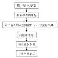
- Figure 1 is a flow chart of the present invention
- Figure 3 (a) is an arrangement pattern of holes arranged to satisfy the most closely arranged printable conditions
- Figure 3 (b) is a projection projection image generated by calling a projection simulation method
- Figure 3 (c) is a corresponding projected image obtained by actual shooting
- Figure 5 is a view showing an application of the present invention.
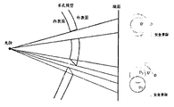
- Fig. 6 is an analytical diagram showing the generation of enlarged holes and inclined holes.
- a halftone projection and model generation method for 3D printing includes the following steps:
- the user specifies the three-dimensional model, the projection receiving surface and the position and size range of the light source, and the projection reference image B 0 is calculated by the projection simulation method;
- the projection simulation method specifically includes the following steps:
- the total irradiance E v (p) of the projection receiving point p is the sum of the illuminances of all the point sources to the point.
- r i is the Euclidean distance from the point p to the light source l i
- ⁇ i and ⁇ p are the straight lines connecting the points p and l i and the normals at the points p and l i with
- the angle of the intersection, V(p, l i ) is the visible relationship between points p and l i , the value of 0 means invisible, and the value of 1 means visible;
- the projection reference image is calculated, and specifically includes the following steps:
- the holes having the smallest radius of the printability condition are closely arranged on the three-dimensional model, as shown in Fig. 3(a). Satisfying the printability condition here means that the radius of the hole in the three-dimensional model is not less than r min , and the distance between the holes is not less than d min .
- r min is the minimum radius at which a particular printing technique can print holes
- d min is the minimum distance between two holes that the printing technique can print.
- the holes that meet the printable conditions are arranged closely.
- the holes with a radius of r min are arranged in the most closely arranged arrangement with the spacing d min , as shown in Fig. 3(a);
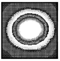
- Fig. 3(b) The projection simulation method is called to generate a projection reference image B 0 as shown in Fig. 3(b).
- Fig. 3(c) is a corresponding projected image obtained by actual shooting.
- the projected reference image B 0 is the lowest gray value that the enlarged hole can reach. If the brightness value of the specific region of the input image I t is not lower than B 0 , it is necessary to arrange the enlarged holes; if the brightness value of the specific region below the input image I t is lower than B 0 , it is necessary to arrange the inclined holes.
- the density map M is calculated, which specifically includes the following steps:
- the illuminance map is obtained by inverse Gamma correction for a given grayscale image I t .
- the corresponding irradiance is E v (p).
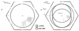
- K can be expressed as a functional form of r. As shown in FIG 4, r of the inscribed circle radius of the largest regular hexagonal modification, r min is the minimum radius of the holes may be printed, d min is the minimum printable distance between the two holes.
- the radius of the largest inscribed circle is expected to be r.
- r is the radius of the maximum inscribed circle corresponding to the upper surface of the three-dimensional model, which receives the projection facing r is the radius of the circle to be W, the respective position of the projection-receiving surface of the circle of radius r W at point p (x, y)
- the projected area at the corresponding three-dimensional model is equal to the area of the circle having the radius r;
- the optimal circle arrangement is calculated, which specifically includes the following steps:
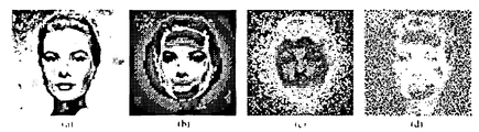
- the CCVT is calculated by calling the method of de Goes. Calculating its maximum inscribed circle in each Voronoi region of the resulting CCVT results in a set of circular arrangements. For a certain Voronoi region, it corresponds to a certain block region of the density map M, and the mean value of the radius r w corresponding to all the points in the region is taken as the desired circle size of the region. It is thus determined whether the maximum inscribed circle of the region has reached its desired circle size. With the target circle number N as the upper bound, the binary search is used to find the CCVT that achieves the optimal circle correct rate. As shown in Fig. 5, 5(a) is the user input grayscale image, 5(b) is the corresponding density map M, 5(c) is the CCVT calculated by the method of de Goes, and 5(d) is the calculated optimal circle. arrangement.
- step (4) determining the size, position and relative light source orientation of the corresponding holes, specifically including the following steps:
- step 3 From step 3, the CCVT and its corresponding circle arrangement can be obtained to achieve the optimal correct rate.
- Any point in the density map M records its corresponding density value ⁇ w (x, y) and its desired hole type, enlarged hole or inclined hole.
- the hole type of the surface of most points in the region is taken as the type of the corresponding hole of the Voronoi region.
- 3D printing can be directly performed according to the model.
- the printed model allows the light source to be projected through the holes in the model on the projection receiving surface to form a continuous grayscale image that is closest to the given grayscale image of the user.
Landscapes
- Engineering & Computer Science (AREA)
- Physics & Mathematics (AREA)
- General Physics & Mathematics (AREA)
- Theoretical Computer Science (AREA)
- Computer Graphics (AREA)
- Mathematical Optimization (AREA)
- Pure & Applied Mathematics (AREA)
- Mathematical Physics (AREA)
- Mathematical Analysis (AREA)
- Geometry (AREA)
- Software Systems (AREA)
- Algebra (AREA)
- Manufacturing & Machinery (AREA)
- Chemical & Material Sciences (AREA)
- Materials Engineering (AREA)
- Mechanical Engineering (AREA)
Abstract
一种改进的面向3D打印的半色调投影与模型生成方法,根据给定的三维模型、投影接收面以及光源的基本参数,利用投影模拟方法,计算投影参考图像,将给定的灰度图像进行校正,得到照度图,将照度图的点与投影参考图像相对应,进行归一化处理后,计算得到密度图;利用带容量约束的Voronoi划分的方法,根据密度图进行最优圆排列;根据最优圆排列确定的孔洞类型,确定相应孔洞的大小、位置和相对光源朝向角度,生成物理模型,进行3D打印。通过本方法,使光源透过模型上的孔洞在投影接收面上形成一幅与给定灰度图像最相近的连续灰度图像,无明显的离散光斑可见。
Description
本发明涉及一种改进的面向3D打印的半色调投影与模型生成方法。
3D打印(3D Printing),又称增材制造(Additive Manufacturing,AM),快速原型制造(Rapid Prototyping)等,是一种基于离散-堆积原理,采用材料逐层累加的方法制造实体零件的技术。3D打印可采用金属、光敏树脂、塑料等多种材料,直接以数字模型文件为输入制造任意复杂形状的三维实体,适用于可定制化的制造。
连续调图像是指在一幅图像上,存在着色调、亮度与饱和度连续变化的真彩色图像,其连续变化是以单位面积成像物质颗粒的密度构成的,如CRT显示器。连续调图像的深浅变化是无级的。与之对应的半色调图像,又称为网目图像,表现的色调则相对少一些,通过网点的大小或稀疏表达图像的层次,图像细节的变化不连续,如喷墨类型的打印机。由连续调图像生成半色调图像的方法,可称之为半色调图像生成技术,或半色调技术。
半色调技术已经广泛应用于传统的纸面印刷和数字显示等领域。其核心在于色调再现,结构保持,点密度和图像分辨率的匹配等问题。经过几十年的探索研究,出现了很多半色调生成方法。以保持原始图像的相对色调为目的,国内外的研究学者们提出了很多相应的半色调技术。
但是,已有的半色调图像生成的技术,所面向的是数字半色调图像生成或者给定图像的点刻画表达。
申请号为CN201410420912.4的专利,提出一种面向3D打印的半色调投影与模型生成方法,通过控制每个孔的位置,大小和长度,得到宏观完整的投影图像,并引入了特征层和色调层分别生成对应孔洞,最终将两层融合并打印生成模型。但是,其投影效果可能存在不连续、有离散光半点。
本专利与之相比采用完全不同的技术进行模型生成计算,并且能得到更连续的灰度投影图像,无明显可见的离散光斑点,最终投影效果显著优于专利CN201410420912.4。
本专利提出的技术面向3D打印领域,以光通过直射投影所形成的光斑作为组成半色调图像的基本单元,在三维空间中投影出有渐进灰度变化的连续投影图像。改进了现有的通过
优化调整物体的几何结构得到各种不同的光影效果的相关技术、利用光线折射得到指定的投影图像的技术,解决了上述问题。
发明内容
本发明为了解决上述问题,提出了一种改进的面向3D打印的半色调投影与模型生成方法,本方法根据用户给定的任一灰度图片和三维实体模型,通过在三维实体模型表面设置一组不同大小,位置和相对光源朝向角度的孔洞,分别使用扩大型孔洞和倾斜型孔洞投影表示灰度图像中较高亮度和较低亮度的区域,使光源透过这些孔洞在投影接收面上形成一幅与给定灰度图像最相近的连续灰度图像。
为了实现上述目的,本发明采用如下技术方案:
一种改进的面向3D打印的半色调投影与模型生成方法,包括以下步骤:
(1)根据给定的三维模型、投影接收面以及光源的基本参数,利用投影模拟方法,计算投影参考图像;
(2)将给定的灰度图像进行校正,得到照度图,将照度图的点与投影参考图像相对应,进行归一化处理后,计算得到密度图;
(3)利用带容量约束的Voronoi划分的方法,根据密度图进行最优圆排列;
(4)根据最优圆排列确定的孔洞类型,确定相应孔洞的大小、位置和相对光源朝向角度,生成物理模型,进行3D打印。
所述步骤(1)中,投影模拟方法的具体方法包括:
(1-1)将光源离散化为若干个点光源;
(1-2)在投影接收面的投影区域离散采样为若干个的投影接收点;
(1-3)在多孔模型的遮挡作用下,计算投影接收点的所有点光源的总辐射照度;
(1-4)对投影接收点的总辐射照度进行校正,得到投影模拟图像灰度值。
进一步的,所述步骤(1-4)中校正方法为通过Gamma校正。
所述步骤(1)中,计算投影参考图像的具体方法包括:
(1-a)在三维模型上紧密排列满足可打印性条件半径最小的孔洞;
(1-b)使用投影模拟方法,在孔洞最紧密排列的约束条件下,生成投影参考图像。
所述步骤(1-a)中,满足可打印性条件指的是三维模型上的孔洞的半径不小于选择的打印技术中能够打印的孔洞的最小半径,同时,孔洞之间的距离不小于该打印技术可打印两孔洞间的最小距离。
所述步骤(2)中,对于输入的任一灰度图像,计算密度图,具体包括以下步骤:
(2-1)将给定的灰度图像,通过逆校正得到照度图;
(2-2)对于照度图的每一点,根据其辐射照度设定对应的三维模型处遮光率,根据遮光率计算其对应的目标圆半径;
(2-3)将照度图每点对应的目标圆半径映射为相应密度值,进行归一化处理,得到密度图。
所述步骤(3)中,计算最优圆排列的具体方法包括以下步骤:
(3-1)根据密度图的累加密度值、投影参考图像的圆个数和累加密度值,计算最优目标圆个数;
(3-2)根据密度图和目标圆个数,通过二分搜索查找达到最优圆正确率的带容量约束的Voronoi划分。
所述步骤(4)中,具体方法包括:
(4-1)根据得到的最优正确率的Voronoi区域和其对应圆排列,将其对应的密度图的区域中多数点标明的孔洞类型作为该Voronoi区域期望的孔洞类型;
(4-2)根据任意Voronoi区域期望的孔洞类型,在其三维模型的对应位置生成相应的孔洞。
所述步骤(4-1)中,期望的孔洞类型包括扩大型孔洞和倾斜型孔洞。
进一步的,所述步骤(4-2)中,若某Voronoi区域对应的孔洞类型为扩大型孔洞,生成方法为:在该Voronoi区域的最大内切圆嵌套一个缩小一个安全距离的内切圆,将该内切圆通过中心投影的方式投影在三维壳状模型的外表面和内表面,分别形成两个相交的椭圆,使用一个圆柱形结构连接内外表面的椭圆形成该扩大型孔洞。
进一步的,所述步骤(4-2)中,若某Voronoi区域对应的孔洞类型为倾斜型孔洞,生成方法为:在该Voronoi区域的最大内切圆嵌套一个缩小一个安全距离的内切圆,在该内切圆内选一个随机方向放置两个半径满足可打印条件的最小圆D1和D2,分别将D1和D2通过中心投影的方式投影在三维壳状模型的内表面和外表面,分别形成两个相交的椭圆,使用一个圆柱形结构连接内外表面的椭圆形成该倾斜型孔洞。
本发明的有益效果为:
(1)本发明提出半色调投影与模型生成方法,将半色调技术中的介质由数字印刷墨水推广到投影光线;
(2)本发明生成的模型,使光源透过模型上的孔洞在投影接收面上形成一幅与给定灰度图像最相近的连续灰度图像,无明显的离散光斑可见;
(3)本发明直接面向3D打印生成满足3D打印约束的物理模型,支持用户个性化定制任意的模型外形和目标投影图像;
(4)应用范围广泛,适用于灯光艺术造型,灯具定制等多种场合。
图1为本发明的流程图;
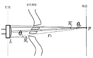
图2为投影模拟方法解析图;
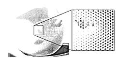
图3(a)为满足可打印条件最紧密排列的孔洞的排布方式排列图像;
图3(b)为调用投影模拟方法生成投影参考图像;
图3(c)为对应的实际拍摄得到的投影图像;
图4为扩大型孔洞和倾斜型孔洞遮光率解析图;
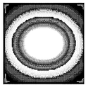
图5为本发明的适用实例图;
图6为扩大型孔洞和倾斜型孔洞生成解析图。
下面结合附图与实施例对本发明作进一步说明。
如图1所示,一种面向3D打印的半色调投影与模型生成方法,包括以下步骤:
(1)用户指定三维模型,投影接收面及光源的位置大小范围等参数,通过投影模拟方法,计算投影参考图像B0;
(2)对于输入的任一灰度图像It,结合投影参考图像B0,计算一幅密度图M;
(3)根据密度图M,应用带容量约束的Voronoi划分(CCVT)的方法计算最优圆排列;
(4)根据这组圆排列,生成相应的扩大型孔洞和倾斜型孔洞。
所述步骤(1)中,投影模拟方法,具体包括以下步骤:
(1-1)将光通量为Φ的光源L离散化为n个点光源 每个点光源li的光通量为
(1-2)在投影接收面的投影区域离散采样有限个数的投影接收点,如图2中的点p;
(1-3)如图2,在多孔模型(lampshade)的遮挡作用下,计算投影接收点p的总辐射照度Ev(p)为:

投影接收点p的总辐射照度Ev(p)为所有点光源到该点的辐射照度累加和。如图2中,ri为点p到光源li的欧式距离,θi和θp为连接点p和li的直线和点p和li处法线 和
和 的夹角,V(p,li)为点p和li的可见关系,取值为0代表不可见,取值为1代表可见;
(1-4)将投影接收点的总辐射照度Ev(p),通过Gamma校正得到投影模拟图像灰度值
It(p)=g(Ev(p))=(Ev(p))1/γ,其中g(.)表示Gamma校正过程,通常Gamma函数γ取值为2.2。
所述步骤(1)中,计算投影参考图像,具体包括以下步骤:
(1-1)在三维模型上紧密排列满足可打印性条件半径最小的孔洞,如图3(a)。在此满足可打印性条件指的是三维模型上的孔洞的半径不小于rmin,孔洞之间的距离不小于dmin。其中,rmin为某特定打印技术可打印孔洞的最小半径,dmin为该打印技术可打印两孔洞间的最小距离。满足可打印条件最紧密排列的孔洞为一组半径为rmin的孔洞按照间距为dmin的最紧密的排布方式排列,如图3(a)所示;
(1-2)调用投影模拟方法生成投影参考图像B0,如图3(b)。图3(c)为其对应的实际拍摄得到的投影图像。在孔洞最紧密排列的约束条件下,投影参考图像B0为扩大型孔洞能到达的最低灰度值。若输入图像It特定区域的亮度值不低于B0,需要排列扩大型孔洞;若低于输入图像It特定区域的亮度值低于B0,则需要排列倾斜型孔洞。
所述步骤(2)中,对于输入的任一灰度图像It,计算密度图M,具体包括以下步骤:
(2-1)将给定的灰度图像It,通过逆Gamma校正得到照度图。对于灰度图像It上某一点p(x,y)的灰度It(p(x,y)),辐射照度Ev(p)=g-1(It(p)),其中g-1(.)为逆Gamma校正过程。
(2-2)对于照度图的每一点p(x,y),其对应辐射照度为Ev(p)。为达到辐射照度Ev(p),在点p(x,y)对应三维模型处遮光率设为K,有 其中,
其中, 为点p(x,y)在没有任何三维模型遮挡的情况下的总辐射照度
 K表示点p(x,y)对应三维模型处对应的遮光率,K=Area(unoccluded)/Area(Cell)。可将K表示为r的
函数形式。如图4,r为正六变形内最大内切圆的半径,rmin为可打印孔洞的最小半径,dmin为可打印两孔洞间的最小距离。
K表示点p(x,y)对应三维模型处对应的遮光率,K=Area(unoccluded)/Area(Cell)。可将K表示为r的
函数形式。如图4,r为正六变形内最大内切圆的半径,rmin为可打印孔洞的最小半径,dmin为可打印两孔洞间的最小距离。
若It(p(x,y))≥B0(p(x,y)),需要排列扩大型孔洞,有:

若It(p(x,y))<B0(p(x,y)),需要排列倾斜型孔洞,有:

由上述公式可得,对于照度图上点p(x,y),为达到Ev(p),期望最大内切圆的半径为r。r为三维模型表面上相应最大内切圆的半径,其在投影接收面对应圆的半径为rw,使投影接收面上相应位置上半径为rw的圆在点p(x,y)对应三维模型处的投影面积与半径为r的圆的面积相等;
(2-3)对于照度图上点p(x,y),其相应的投影接收面上圆半径为rw,定义点p(x,y)处密度 经过归一化,得到密度图M。
所述步骤(3)中,计算最优圆排列,具体包括以下步骤:
(3-1)计算最优目标圆个数N=ρmN0/ρ0,其中ρm为密度图M的累加密度值,ρ0为B0的累加密度值,N0为B0的圆个数。
(3-2)给定密度图M和目标圆个数N,通过调用de Goes的方法计算CCVT。在结果CCVT的每个Voronoi区域中计算其最大内切圆得到一组圆排列。对于某个Voronoi区域,其对应密度图M的某一块区域,将该区域中所有点对应的半径rw的均值作为该区域的期望圆大小。由此判定该区域的最大内切圆是否达到其期望圆大小。以目标圆个数N为上界,通过二分搜索查找达到最优圆正确率的CCVT。如图5,5(a)为用户输入灰度图像,5(b)为对应密度图M,5(c)为de Goes的方法计算得到的CCVT,5(d)为计算得到的最优圆排列。
所述步骤(4)中,确定相应孔洞的大小,位置和相对光源朝向角度,具体包括以下步骤:
(4-1)由步骤3可得达到最优正确率的CCVT及其对应圆排列。密度图M中任一点记录了其对应的密度值ρw(x,y)及其期望的孔洞类型,扩大型孔洞或者倾斜型孔洞。对于某个Voronoi区域,其对应的密度图的某块区域,将该区域中多数点表面的孔洞类型作为该Voronoi区域对应孔洞的类型。
(4-2)如图6所示,若某Voronoi区域对应的孔洞类型为扩大型孔洞,该Voronoi区域的最大内切圆为D,D中嵌套一个缩小一个安全距离的D′,安全距离为0.5dmin。将D′通过中心投影的方式投影在三维壳状模型的外表面和内表面,分别形成两个相交的椭圆,使用一个圆柱形结构连接内外表面的椭圆形成该扩大型孔洞。
(4-3)如图6所示,若某Voronoi区域对应的孔洞类型为倾斜型孔洞,在D′选一个随机方向放置两个半径满足可打印条件的最小圆D1和D2,分别将D1和D2通过中心投影的方式投影在三维壳状模型的内表面和外表面,分别形成两个相交的椭圆,使用一个圆柱形结构连接内外表面的椭圆形成该倾斜型孔洞。
生成半色调投影模型后,可依照该模型直接进行3D打印。打印得到的模型可使光源透过模型上的孔洞在投影接收面上投影形成一幅与用户给定灰度图像最相近的连续灰度图像。
上述虽然结合附图对本发明的具体实施方式进行了描述,但并非对本发明保护范围的限制,所属领域技术人员应该明白,在本发明的技术方案的基础上,本领域技术人员不需要付出创造性劳动即可做出的各种修改或变形仍在本发明的保护范围以内。
Claims (10)
- 一种改进的面向3D打印的半色调投影与模型生成方法,其特征是:包括以下步骤:(1)根据给定的三维模型、投影接收面以及光源的基本参数,利用投影模拟方法,计算投影参考图像;(2)将给定的灰度图像进行校正,得到照度图,将照度图的点与投影参考图像相对应,进行归一化处理后,计算得到密度图;(3)利用带容量约束的Voronoi划分的方法,根据密度图进行最优圆排列;(4)根据最优圆排列确定的孔洞类型,确定相应孔洞的大小、位置和相对光源朝向角度,生成物理模型,进行3D打印。
- 如权利要求1所述的一种改进的面向3D打印的半色调投影与模型生成方法,其特征是:所述步骤(1)中,投影模拟方法的具体方法包括:(1-1)将光源离散化为若干个点光源;(1-2)在投影接收面的投影区域离散采样为若干个的投影接收点;(1-3)在多孔模型的遮挡作用下,计算投影接收点的所有点光源的总辐射照度;(1-4)对投影接收点的总辐射照度进行校正,得到投影模拟图像灰度值。
- 如权利要求2所述的一种改进的面向3D打印的半色调投影与模型生成方法,其特征是:所述步骤(1-4)中校正方法为通过Gamma校正。
- 如权利要求1所述的一种改进的面向3D打印的半色调投影与模型生成方法,其特征是:所述步骤(1)中,计算投影参考图像的具体方法包括:(1-a)在三维模型上紧密排列满足可打印性条件半径最小的孔洞;(1-b)使用投影模拟方法,在孔洞最紧密排列的约束条件下,生成投影参考图像。
- 如权利要求1所述的一种改进的面向3D打印的半色调投影与模型生成方法,其特征是:所述步骤(1-a)中,满足可打印性条件指的是三维模型上的孔洞的半径不小于选择的打印技术中能够打印的孔洞的最小半径,同时,孔洞之间的距离不小于该打印技术可打印两孔洞间的最小距离。
- 如权利要求1所述的一种改进的面向3D打印的半色调投影与模型生成方法,其特征是:所述步骤(2)中,对于输入的任一灰度图像,计算密度图,具体包括以下步骤:(2-1)将给定的灰度图像,通过逆校正得到照度图;(2-2)对于照度图的每一点,根据其辐射照度设定对应的三维模型处遮光率,根据遮光率计算其对应的目标圆半径;(2-3)将照度图每点对应的目标圆半径映射为相应密度值,进行归一化处理,得到密度图。
- 如权利要求1所述的一种改进的面向3D打印的半色调投影与模型生成方法,其特征是:所述步骤(3)中,计算最优圆排列的具体方法包括以下步骤:(3-1)根据密度图的累加密度值、投影参考图像的圆个数和累加密度值,计算最优目标圆个数;(3-2)根据密度图和目标圆个数,通过二分搜索查找达到最优圆正确率的带容量约束的Voronoi划分。
- 如权利要求1所述的一种改进的面向3D打印的半色调投影与模型生成方法,其特征是:所述步骤(4)中,具体方法包括:(4-1)根据得到的最优正确率的Voronoi区域和其对应圆排列,将其对应的密度图的区域中多数点标明的孔洞类型作为该Voronoi区域期望的孔洞类型;(4-2)根据任意Voronoi区域期望的孔洞类型,在其三维模型的对应位置生成相应的孔洞。
- 如权利要求8所述的一种改进的面向3D打印的半色调投影与模型生成方法,其特征是:所述步骤(4-2)中,若某Voronoi区域对应的孔洞类型为扩大型孔洞,生成方法为:在该Voronoi区域的最大内切圆嵌套一个缩小一个安全距离的内切圆,将该内切圆通过中心投影的方式投影在三维壳状模型的外表面和内表面,分别形成两个相交的椭圆,使用一个圆柱形结构连接内外表面的椭圆形成该扩大型孔洞。
- 如权利要求8所述的一种改进的面向3D打印的半色调投影与模型生成方法,其特征是:所述步骤(4-2)中,若某Voronoi区域对应的孔洞类型为倾斜型孔洞,生成方法为:在该Voronoi区域的最大内切圆嵌套一个缩小一个安全距离的内切圆,在该内切圆选一个随机方向放置两个半径满足可打印条件的最小圆D1和D2,分别将D1和D2通过中心投影的方式投影在三维壳状模型的内表面和外表面,分别形成两个相交的椭圆,使用一个圆柱形结构连接内外表面的椭圆形成该倾斜型孔洞。
Applications Claiming Priority (2)
| Application Number | Priority Date | Filing Date | Title |
|---|---|---|---|
| CN201610150875.9 | 2016-03-16 | ||
| CN201610150875.9A CN105844712B (zh) | 2016-03-16 | 2016-03-16 | 一种改进的面向3d打印的半色调投影与模型生成方法 |
Publications (1)
| Publication Number | Publication Date |
|---|---|
| WO2017156815A1 true WO2017156815A1 (zh) | 2017-09-21 |
Family
ID=56587933
Family Applications (1)
| Application Number | Title | Priority Date | Filing Date |
|---|---|---|---|
| PCT/CN2016/079176 Ceased WO2017156815A1 (zh) | 2016-03-16 | 2016-04-13 | 一种改进的面向3d打印的半色调投影与模型生成方法 |
Country Status (2)
| Country | Link |
|---|---|
| CN (1) | CN105844712B (zh) |
| WO (1) | WO2017156815A1 (zh) |
Cited By (3)
| Publication number | Priority date | Publication date | Assignee | Title |
|---|---|---|---|---|
| CN111757790A (zh) * | 2018-02-20 | 2020-10-09 | 本地汽车知识产权有限责任公司 | 用于增材制造的方法和设备 |
| CN114290683A (zh) * | 2022-01-07 | 2022-04-08 | 宁波智造数字科技有限公司 | 利用圆柱体的光固化3d打印均匀度调整流程方法 |
| CN119313695A (zh) * | 2024-12-19 | 2025-01-14 | 上海交通大学四川研究院 | 基于局部像素值统计阈值的打孔图像圆边缘检测算法 |
Families Citing this family (5)
| Publication number | Priority date | Publication date | Assignee | Title |
|---|---|---|---|---|
| CN108257112B (zh) | 2017-12-27 | 2020-08-18 | 北京七鑫易维信息技术有限公司 | 过滤光斑的方法和装置 |
| CN111914974B (zh) * | 2020-07-07 | 2022-02-18 | 山东大学 | 一种面向3d打印的立体二维码生成方法及系统 |
| CN113261973B (zh) * | 2021-04-13 | 2022-09-02 | 山东师范大学 | 加权多尺度有限穿越可视图辨识房颤心电信号方法及系统 |
| CN113946987B (zh) * | 2021-12-20 | 2022-03-22 | 浙江闪铸三维科技有限公司 | 一种基于模型相似性的3d模型嵌套摆放方法 |
| CN119205730B (zh) * | 2024-11-22 | 2025-04-25 | 中国传媒大学 | 一种基于圆堆叠的计算机点刻方法 |
Citations (3)
| Publication number | Priority date | Publication date | Assignee | Title |
|---|---|---|---|---|
| US20110075944A1 (en) * | 2009-09-28 | 2011-03-31 | Yuan Xiaoru | Sample based tone mapping method for high dynamic range images |
| CN103978690A (zh) * | 2014-05-28 | 2014-08-13 | 山东大学 | 一种面向3d打印的物体内部结构优化方法 |
| CN105023296A (zh) * | 2014-08-22 | 2015-11-04 | 山东大学 | 一种面向3d打印的半色调投影与模型生成方法 |
Family Cites Families (1)
| Publication number | Priority date | Publication date | Assignee | Title |
|---|---|---|---|---|
| US20140032448A1 (en) * | 2012-07-24 | 2014-01-30 | Telefonica, S.A. | Method, computer programs and a use for the prediction of the socioeconomic level of a region |
-
2016
- 2016-03-16 CN CN201610150875.9A patent/CN105844712B/zh active Active
- 2016-04-13 WO PCT/CN2016/079176 patent/WO2017156815A1/zh not_active Ceased
Patent Citations (3)
| Publication number | Priority date | Publication date | Assignee | Title |
|---|---|---|---|---|
| US20110075944A1 (en) * | 2009-09-28 | 2011-03-31 | Yuan Xiaoru | Sample based tone mapping method for high dynamic range images |
| CN103978690A (zh) * | 2014-05-28 | 2014-08-13 | 山东大学 | 一种面向3d打印的物体内部结构优化方法 |
| CN105023296A (zh) * | 2014-08-22 | 2015-11-04 | 山东大学 | 一种面向3d打印的半色调投影与模型生成方法 |
Non-Patent Citations (3)
| Title |
|---|
| LIANG, GUANGHUI ET AL.: "Poisson disk sampling through disk packing", COMPUTATIONAL VISUAL MEDIA, vol. 1, no. 1, 31 March 2015 (2015-03-31), XP055424061 * |
| LU , LIN ET AL.: "Build-to-Last:Strength to Weight 3D printed Objects", ACM TRANSACTION ON GRAPHICS, vol. 33, no. 4, 31 July 2014 (2014-07-31), XP058051982 * |
| ZHAO, - HAISEN ET AL.: "Printed Perforated Lampshades for Continuous Projective Images", ARXIV E-PRINTS ABSTRACT SERVICE, 31 October 2015 (2015-10-31), XP058259728 * |
Cited By (3)
| Publication number | Priority date | Publication date | Assignee | Title |
|---|---|---|---|---|
| CN111757790A (zh) * | 2018-02-20 | 2020-10-09 | 本地汽车知识产权有限责任公司 | 用于增材制造的方法和设备 |
| CN114290683A (zh) * | 2022-01-07 | 2022-04-08 | 宁波智造数字科技有限公司 | 利用圆柱体的光固化3d打印均匀度调整流程方法 |
| CN119313695A (zh) * | 2024-12-19 | 2025-01-14 | 上海交通大学四川研究院 | 基于局部像素值统计阈值的打孔图像圆边缘检测算法 |
Also Published As
| Publication number | Publication date |
|---|---|
| CN105844712A (zh) | 2016-08-10 |
| CN105844712B (zh) | 2018-11-13 |
Similar Documents
| Publication | Publication Date | Title |
|---|---|---|
| WO2017156815A1 (zh) | 一种改进的面向3d打印的半色调投影与模型生成方法 | |
| US11657470B2 (en) | Generating signal bearing art using Stipple, Voronoi and Delaunay methods and reading same | |
| CN107223085B (zh) | 三维物体子结构 | |
| CN105023296B (zh) | 一种面向3d打印的半色调投影与模型生成方法 | |
| CN111340734B (zh) | 一种利用卷积神经网络模型的图像紫边校正方法 | |
| US8681383B2 (en) | 2nd generation dot-off-dot stochastic halftone | |
| US20120274984A1 (en) | Polygonal-boundary-based halftone method | |
| CN107527340B (zh) | 一种基于图像处理技术的快速评判及优化导光板发光质量的方法 | |
| JP5807489B2 (ja) | 画像処理装置及び画像処理方法、並びにプログラム | |
| EP3458893B1 (en) | Optic, luminaire, method for fabricating optic and non- transitory computer readable storage medium | |
| Zhao et al. | Printed perforated lampshades for continuous projective images | |
| US8576449B2 (en) | Parametrically controlled halftone spot function for an irregular halftone grid | |
| CN112416293A (zh) | 一种神经网络增强方法、系统及其应用 | |
| US20250014381A1 (en) | Artwork authenticity systems and methods | |
| CN111160371A (zh) | 一种orb均匀提取特征点方法 | |
| CN117828737B (zh) | 一种数字孪生园林景观设计方法 | |
| CN103198448A (zh) | 基于顶点曲率的三维模型数字水印嵌入与盲检测方法 | |
| CN113281901B (zh) | 用于抑制规则噪声的衍射光学元件设计方法 | |
| CN109409381B (zh) | 基于人工智能的家具顶视图的分类方法及系统 | |
| CN109154991B (zh) | 三维物体子结构 | |
| CN113222828A (zh) | 一种基于零参考的工业物联网监控平台图像增强方法 | |
| JP6486096B2 (ja) | プリントデータ生成装置、プリントデータ生成方法およびプログラム | |
| CN119477775A (zh) | 一种图像处理方法、装置、电子设备及介质 | |
| Khan et al. | High-quality 2D mesh generation without obtuse and small angles | |
| WO2023103548A1 (zh) | 一种汽车参数化纹理生成方法与系统、存储介质 |
Legal Events
| Date | Code | Title | Description |
|---|---|---|---|
| NENP | Non-entry into the national phase |
Ref country code: DE |
|
| 121 | Ep: the epo has been informed by wipo that ep was designated in this application |
Ref document number: 16893978 Country of ref document: EP Kind code of ref document: A1 |
|
| 122 | Ep: pct application non-entry in european phase |
Ref document number: 16893978 Country of ref document: EP Kind code of ref document: A1 |