WO2017154858A1 - Wireless communication device - Google Patents

Wireless communication device Download PDF

Info

Publication number
WO2017154858A1
WO2017154858A1 PCT/JP2017/008879 JP2017008879W WO2017154858A1 WO 2017154858 A1 WO2017154858 A1 WO 2017154858A1 JP 2017008879 W JP2017008879 W JP 2017008879W WO 2017154858 A1 WO2017154858 A1 WO 2017154858A1
Authority
WO
WIPO (PCT)
Prior art keywords
transmission
dmg
pseudo
sta
omni
Prior art date
Application number
PCT/JP2017/008879
Other languages
French (fr)
Japanese (ja)
Inventor
ヤオ ハン ガイアス ウィー
マイケル ホン チェン シム
誠隆 入江
Original Assignee
パナソニック インテレクチュアル プロパティ コーポレーション オブ アメリカ
Priority date (The priority date is an assumption and is not a legal conclusion. Google has not performed a legal analysis and makes no representation as to the accuracy of the date listed.)
Filing date
Publication date
Priority to EP17763198.3A priority Critical patent/EP3429095B1/en
Priority to CONC2018/0009392A priority patent/CO2018009392A2/en
Application filed by パナソニック インテレクチュアル プロパティ コーポレーション オブ アメリカ filed Critical パナソニック インテレクチュアル プロパティ コーポレーション オブ アメリカ
Priority to KR1020217022260A priority patent/KR102316676B1/en
Priority to RU2018132195A priority patent/RU2692230C1/en
Priority to CN202210236255.2A priority patent/CN114513238A/en
Priority to PL17763198T priority patent/PL3429095T3/en
Priority to EP21191174.8A priority patent/EP3926855A1/en
Priority to CA3017092A priority patent/CA3017092A1/en
Priority to KR1020187026166A priority patent/KR102280375B1/en
Priority to CN201780013408.4A priority patent/CN108702193B/en
Priority to MYPI2018702863A priority patent/MY193560A/en
Priority to ES17763198T priority patent/ES2901172T3/en
Priority to BR112018016904A priority patent/BR112018016904A2/en
Priority to MX2018010621A priority patent/MX2018010621A/en
Publication of WO2017154858A1 publication Critical patent/WO2017154858A1/en
Priority to US16/125,007 priority patent/US10791453B2/en
Priority to US17/001,961 priority patent/US11523266B2/en
Priority to US18/053,690 priority patent/US20230060962A1/en

Links

Images

Classifications

    • HELECTRICITY
    • H04ELECTRIC COMMUNICATION TECHNIQUE
    • H04WWIRELESS COMMUNICATION NETWORKS
    • H04W8/00Network data management
    • H04W8/005Discovery of network devices, e.g. terminals
    • HELECTRICITY
    • H04ELECTRIC COMMUNICATION TECHNIQUE
    • H04BTRANSMISSION
    • H04B7/00Radio transmission systems, i.e. using radiation field
    • H04B7/02Diversity systems; Multi-antenna system, i.e. transmission or reception using multiple antennas
    • H04B7/04Diversity systems; Multi-antenna system, i.e. transmission or reception using multiple antennas using two or more spaced independent antennas
    • H04B7/08Diversity systems; Multi-antenna system, i.e. transmission or reception using multiple antennas using two or more spaced independent antennas at the receiving station
    • H04B7/0868Hybrid systems, i.e. switching and combining
    • H04B7/088Hybrid systems, i.e. switching and combining using beam selection
    • HELECTRICITY
    • H04ELECTRIC COMMUNICATION TECHNIQUE
    • H04BTRANSMISSION
    • H04B7/00Radio transmission systems, i.e. using radiation field
    • H04B7/02Diversity systems; Multi-antenna system, i.e. transmission or reception using multiple antennas
    • H04B7/04Diversity systems; Multi-antenna system, i.e. transmission or reception using multiple antennas using two or more spaced independent antennas
    • H04B7/06Diversity systems; Multi-antenna system, i.e. transmission or reception using multiple antennas using two or more spaced independent antennas at the transmitting station
    • H04B7/0613Diversity systems; Multi-antenna system, i.e. transmission or reception using multiple antennas using two or more spaced independent antennas at the transmitting station using simultaneous transmission
    • H04B7/0615Diversity systems; Multi-antenna system, i.e. transmission or reception using multiple antennas using two or more spaced independent antennas at the transmitting station using simultaneous transmission of weighted versions of same signal
    • H04B7/0617Diversity systems; Multi-antenna system, i.e. transmission or reception using multiple antennas using two or more spaced independent antennas at the transmitting station using simultaneous transmission of weighted versions of same signal for beam forming
    • HELECTRICITY
    • H04ELECTRIC COMMUNICATION TECHNIQUE
    • H04BTRANSMISSION
    • H04B7/00Radio transmission systems, i.e. using radiation field
    • H04B7/02Diversity systems; Multi-antenna system, i.e. transmission or reception using multiple antennas
    • H04B7/04Diversity systems; Multi-antenna system, i.e. transmission or reception using multiple antennas using two or more spaced independent antennas
    • H04B7/0491Diversity systems; Multi-antenna system, i.e. transmission or reception using multiple antennas using two or more spaced independent antennas using two or more sectors, i.e. sector diversity
    • HELECTRICITY
    • H04ELECTRIC COMMUNICATION TECHNIQUE
    • H04BTRANSMISSION
    • H04B7/00Radio transmission systems, i.e. using radiation field
    • H04B7/02Diversity systems; Multi-antenna system, i.e. transmission or reception using multiple antennas
    • H04B7/04Diversity systems; Multi-antenna system, i.e. transmission or reception using multiple antennas using two or more spaced independent antennas
    • H04B7/06Diversity systems; Multi-antenna system, i.e. transmission or reception using multiple antennas using two or more spaced independent antennas at the transmitting station
    • H04B7/0686Hybrid systems, i.e. switching and simultaneous transmission
    • H04B7/0695Hybrid systems, i.e. switching and simultaneous transmission using beam selection
    • HELECTRICITY
    • H04ELECTRIC COMMUNICATION TECHNIQUE
    • H04BTRANSMISSION
    • H04B7/00Radio transmission systems, i.e. using radiation field
    • H04B7/02Diversity systems; Multi-antenna system, i.e. transmission or reception using multiple antennas
    • H04B7/04Diversity systems; Multi-antenna system, i.e. transmission or reception using multiple antennas using two or more spaced independent antennas
    • H04B7/08Diversity systems; Multi-antenna system, i.e. transmission or reception using multiple antennas using two or more spaced independent antennas at the receiving station
    • H04B7/0837Diversity systems; Multi-antenna system, i.e. transmission or reception using multiple antennas using two or more spaced independent antennas at the receiving station using pre-detection combining
    • H04B7/0842Weighted combining
    • H04B7/086Weighted combining using weights depending on external parameters, e.g. direction of arrival [DOA], predetermined weights or beamforming
    • HELECTRICITY
    • H04ELECTRIC COMMUNICATION TECHNIQUE
    • H04LTRANSMISSION OF DIGITAL INFORMATION, e.g. TELEGRAPHIC COMMUNICATION
    • H04L1/00Arrangements for detecting or preventing errors in the information received
    • H04L1/12Arrangements for detecting or preventing errors in the information received by using return channel
    • H04L1/16Arrangements for detecting or preventing errors in the information received by using return channel in which the return channel carries supervisory signals, e.g. repetition request signals
    • H04L1/1607Details of the supervisory signal
    • H04L1/1657Implicit acknowledgement of correct or incorrect reception, e.g. with a moving window
    • HELECTRICITY
    • H04ELECTRIC COMMUNICATION TECHNIQUE
    • H04WWIRELESS COMMUNICATION NETWORKS
    • H04W48/00Access restriction; Network selection; Access point selection
    • H04W48/08Access restriction or access information delivery, e.g. discovery data delivery
    • HELECTRICITY
    • H04ELECTRIC COMMUNICATION TECHNIQUE
    • H04WWIRELESS COMMUNICATION NETWORKS
    • H04W48/00Access restriction; Network selection; Access point selection
    • H04W48/08Access restriction or access information delivery, e.g. discovery data delivery
    • H04W48/14Access restriction or access information delivery, e.g. discovery data delivery using user query or user detection
    • HELECTRICITY
    • H04ELECTRIC COMMUNICATION TECHNIQUE
    • H04WWIRELESS COMMUNICATION NETWORKS
    • H04W16/00Network planning, e.g. coverage or traffic planning tools; Network deployment, e.g. resource partitioning or cells structures
    • H04W16/24Cell structures
    • H04W16/28Cell structures using beam steering
    • HELECTRICITY
    • H04ELECTRIC COMMUNICATION TECHNIQUE
    • H04WWIRELESS COMMUNICATION NETWORKS
    • H04W48/00Access restriction; Network selection; Access point selection
    • H04W48/16Discovering, processing access restriction or access information
    • HELECTRICITY
    • H04ELECTRIC COMMUNICATION TECHNIQUE
    • H04WWIRELESS COMMUNICATION NETWORKS
    • H04W84/00Network topologies
    • H04W84/02Hierarchically pre-organised networks, e.g. paging networks, cellular networks, WLAN [Wireless Local Area Network] or WLL [Wireless Local Loop]
    • H04W84/10Small scale networks; Flat hierarchical networks
    • H04W84/12WLAN [Wireless Local Area Networks]
    • YGENERAL TAGGING OF NEW TECHNOLOGICAL DEVELOPMENTS; GENERAL TAGGING OF CROSS-SECTIONAL TECHNOLOGIES SPANNING OVER SEVERAL SECTIONS OF THE IPC; TECHNICAL SUBJECTS COVERED BY FORMER USPC CROSS-REFERENCE ART COLLECTIONS [XRACs] AND DIGESTS
    • Y02TECHNOLOGIES OR APPLICATIONS FOR MITIGATION OR ADAPTATION AGAINST CLIMATE CHANGE
    • Y02DCLIMATE CHANGE MITIGATION TECHNOLOGIES IN INFORMATION AND COMMUNICATION TECHNOLOGIES [ICT], I.E. INFORMATION AND COMMUNICATION TECHNOLOGIES AIMING AT THE REDUCTION OF THEIR OWN ENERGY USE
    • Y02D30/00Reducing energy consumption in communication networks
    • Y02D30/70Reducing energy consumption in communication networks in wireless communication networks

Landscapes

  • Engineering & Computer Science (AREA)
  • Computer Networks & Wireless Communication (AREA)
  • Signal Processing (AREA)
  • Computer Security & Cryptography (AREA)
  • Databases & Information Systems (AREA)
  • Mobile Radio Communication Systems (AREA)
  • Small-Scale Networks (AREA)

Abstract

An Access Point (AP)/Personal basic service set Central Point (PCP) or a station (STA) (wireless communication device) provided with: a frame constitution unit 103 for generating a transmission frame that includes a plurality of directional multi-gigabit (DMG) beacons; and a transmission wireless unit 105 for performing, in a beacon transmission interval (BTI), directional transmission using one or more transmission sectors by making a first phase adjustment to one or more first DMG beacons among the plurality of DMG beacons, and performing pseudo-omni transmission by making a second phase adjustment to one or more second DMG beacons among the plurality of DMG beacons.

Description

無線通信装置Wireless communication device
 本開示は、無線通信装置に関する。 The present disclosure relates to a wireless communication device.
 IEEE 802.11adにおいて、ミリ波帯域を用いて無線通信を行う無線通信装置は、DMG(directional multi-gigabit)ビーコンによるデバイス発見手順では、ビーコン送信間隔(Beacon Transmission Interval:BTI)を次のように使用する。 In IEEE 802.11ad, a wireless communication device that performs wireless communication using a millimeter wave band uses a beacon transmission interval (BTI) in a device discovery procedure using a DMG (directional multi-gigabit) beacon as follows. To do.
 (1)DMGに対応したSTA(station)(以後、DMG-STA、またはSTA)は、DMGに対応したAP(アクセスポイント)/PCP(Personal basic service set Central Point)(以後、DMG-AP/PCP、または、AP/PCP)、のBTIにおいてDMGビーコンを受信する。 (1) A STA (station) corresponding to DMG (hereinafter DMG-STA or STA) is an AP (access point) / PCP (Personal basic service set Central Point) (hereinafter DMG-AP / PCP) corresponding to DMG. , Or AP / PCP), receive the DMG beacon.
 (2)DMG-STAは、発見モードフィールドを1に設定したDMGビーコン(以下では「発見DMGビーコン」)を、DMG-STAのBTIにおいて送信する。 (2) The DMG-STA transmits a DMG beacon in which the discovery mode field is set to 1 (hereinafter “discovery DMG beacon”) in the BTI of the DMG-STA.
 (3)DMGにおける指向性を考慮して、BTIは、送信セクタスイープとして送信される1つ以上の(最大128の)DMGビーコンにより構成される。 (3) In consideration of directivity in DMG, BTI is composed of one or more (up to 128) DMG beacons transmitted as a transmission sector sweep.
 (4)オーバーヘッドを減らすため、DMGビーコンでは、発見に必要なフィールド(例:SSID(Service Set IDentifier)、DMG能力)を含むいくつかのフィールドが省略される。 (4) In order to reduce overhead, in the DMG beacon, some fields including fields necessary for discovery (eg, SSID (Service Set IDentifier), DMG capability) are omitted.
 しかしながら、従来のミリ波帯域を用いた通信において、DMGビーコンによる発見では、発見対象であるSTAが増加した場合、高速な発見(200msec未満)については、十分考慮されていなかった。 However, in the conventional communication using the millimeter wave band, in the discovery by the DMG beacon, when the number of STAs to be discovered increases, high-speed discovery (less than 200 msec) has not been sufficiently considered.
 本開示の非限定的な実施例は、DMGビーコンによる発見において、発見対象であるSTAが増加した場合であっても、高速な発見(200msec未満)を実現することができる無線通信装置の提供に資する。 A non-limiting example of the present disclosure is to provide a wireless communication device capable of realizing high-speed discovery (less than 200 msec) even when the number of STAs to be discovered increases in discovery using DMG beacons. To contribute.
 本開示の一態様に係る無線通信装置は、複数のDMGビーコンを含む送信フレームを生成するフレーム構成部と、BTIにおいて、前記複数のDMGビーコンのうち、1つ以上の第1のDMGビーコンに対して、第1の位相調整を行うことによって指向性送信を1つ以上の送信セクタを用いて行い、前記複数のDMGビーコンのうち、1つ以上の第2のDMGビーコンに対して、第2の位相調整を行うことによって疑似オムニ送信を行う、送信無線部と、を含む。 A wireless communication device according to an aspect of the present disclosure includes a frame configuration unit that generates a transmission frame including a plurality of DMG beacons, and one or more first DMG beacons among the plurality of DMG beacons in the BTI. Then, the first phase adjustment is performed to perform directional transmission using one or more transmission sectors, and one or more second DMG beacons out of the plurality of DMG beacons A transmission radio unit that performs pseudo-omni transmission by performing phase adjustment.
 なお、これらの包括的または具体的な態様は、システム、方法、集積回路、コンピュータプログラム、または、記録媒体で実現されてもよく、システム、装置、方法、集積回路、コンピュータプログラムおよび記録媒体の任意な組み合わせで実現されてもよい。 Note that these comprehensive or specific aspects may be realized by a system, method, integrated circuit, computer program, or recording medium. Any of the system, apparatus, method, integrated circuit, computer program, and recording medium may be used. It may be realized by various combinations.
 本開示の一態様によれば、DMGビーコンによる発見において、発見対象であるSTAが増加した場合であっても、高速な発見(200msec未満)を実現することができる。 According to one aspect of the present disclosure, high-speed discovery (less than 200 msec) can be realized even when STAs that are discovery targets increase in discovery using DMG beacons.
 本開示の一態様における更なる利点および効果は、明細書および図面から明らかにされる。かかる利点および/または効果は、いくつかの実施形態並びに明細書および図面に記載された特徴によってそれぞれ提供されるが、1つまたはそれ以上の同一の特徴を得るために必ずしも全てが提供される必要はない。 Further advantages and effects of one aspect of the present disclosure will become apparent from the specification and drawings. Such advantages and / or effects are provided by some embodiments and features described in the description and drawings, respectively, but all need to be provided in order to obtain one or more identical features. There is no.
本開示に係る指向性送信によるDMGビーコンを用いたデバイス発見手順の一例を示す図The figure which shows an example of the device discovery procedure using the DMG beacon by the directional transmission which concerns on this indication 本開示に係る指向性送信によるDMGビーコンを用いたデバイス発見手順の他の一例を示す図The figure which shows another example of the device discovery procedure using the DMG beacon by the directional transmission which concerns on this indication 本開示に係る指向性送信によるDMGビーコンを用いたデバイス発見手順の他の一例を示す図The figure which shows another example of the device discovery procedure using the DMG beacon by the directional transmission which concerns on this indication 本開示の実施の形態1に係るAP/PCPまたはSTAの構成を示す図The figure which shows the structure of AP / PCP or STA which concerns on Embodiment 1 of this indication. 本開示の実施の形態1に係る疑似オムニ送信によるDMGビーコンを用いたデバイス発見手順の一例を示す図The figure which shows an example of the device discovery procedure using the DMG beacon by pseudo omni transmission which concerns on Embodiment 1 of this indication 本開示の実施の形態1に係るSSWフィールド(DMGビーコン:DBcn)のフォーマットの一例を示す図The figure which shows an example of a format of the SSW field (DMG beacon: DBcn) which concerns on Embodiment 1 of this indication. 本開示の実施の形態2に係る疑似オムニ送信によるDMGビーコンを用いたデバイス発見手順の他の一例を示す図The figure which shows another example of the device discovery procedure using the DMG beacon by pseudo omni transmission which concerns on Embodiment 2 of this indication. 本開示の実施の形態3に係る疑似オムニ送信によるDMGビーコンを用いたデバイス発見手順の他の一例を示す図The figure which shows another example of the device discovery procedure using the DMG beacon by pseudo omni transmission which concerns on Embodiment 3 of this indication. 本開示の実施の形態3に係るSSWフィールド(DMGビーコン:DBcn)のフォーマットの一例を示す図The figure which shows an example of a format of the SSW field (DMG beacon: DBcn) which concerns on Embodiment 3 of this indication.
 多くのアプリケーションでは高速な発見(200ms未満)が望ましい。このため、高速な発見のためにはパッシブ(静的)スキャンは理想的ではない。 For many applications, fast discovery (less than 200 ms) is desirable. For this reason, passive scanning is not ideal for fast discovery.
 なお、AP/PCPは、発見情報が含まれる送信セクタスイープの頻度を増加することによってオーバーヘッドが大きくなる。 Note that AP / PCP increases overhead by increasing the frequency of transmission sector sweeps that include discovery information.
 このため、アクティブ(動的)スキャンでは、プローブ応答を取得する前にビームフォーミングを実施するため、発見時間が増大する。 For this reason, in the active (dynamic) scan, since the beam forming is performed before the probe response is acquired, the discovery time increases.
 図1は、指向性送信によるDMGビーコンを用いたデバイス発見手順の一例を示す図である。 FIG. 1 is a diagram showing an example of a device discovery procedure using a DMG beacon by directional transmission.
 図1では、STAはビームフォーミング(A-BFT:Association BeamForming Training)を実行する。なぜならBTIには発見情報を含まないためである。なお、A-BFTは省略してもよい。 In FIG. 1, the STA performs beam forming (A-BFT: Association BeamForming Training). This is because the BTI does not include discovery information. A-BFT may be omitted.
 A-BFTを頻繁に実行する場合、オーバーヘッドが加わる(少なくとも99.1μs/BI)ためである。このため、いくつかのデバイス(STA,AP/PCP)が,A-BFTの使用する場合、衝突率が上昇し、結果としてさらなる遅延が生じる。 This is because when A-BFT is frequently executed, overhead is added (at least 99.1 μs / BI). For this reason, when some devices (STA, AP / PCP) use A-BFT, the collision rate increases, resulting in further delay.
 図3は、DTIにおけるSLS(Sector Level Sweep)を示す図である。ここで、図3では、DTIにおいて、SLS(Sector Level Sweep)を実行する。STAは、図3のSLSによって、発見情報を得ることができるが、少なくとも数ミリ秒かかる。 FIG. 3 is a diagram showing SLS (Sector Level Sweep) in DTI. Here, in FIG. 3, SLS (SectorSLevel Sweep) is executed in the DTI. The STA can obtain discovery information through the SLS of FIG. 3, but it takes at least a few milliseconds.
 図2は、指向性送信によるDMGビーコンを用いたデバイス発見手順の他の一例を示す図である。 FIG. 2 is a diagram showing another example of a device discovery procedure using a DMG beacon by directional transmission.
 図2では、STAは、BTIにおいて、発見モードを1に設定するため、A-BFTにおいて、ピアSTAから応答を予測するが、例えば、割り当てられたにおいて、他のSTAとの衝突が発生し、ピアSTA(AP/PCP)がA-BFTを使用困難となる場合がある。 In FIG. 2, the STA predicts a response from the peer STA in the A-BFT to set the discovery mode to 1 in the BTI, but for example, when assigned, a collision with another STA occurs, A peer STA (AP / PCP) may have difficulty using A-BFT.
 また、AP/PCPは、基地局装置としての動作を優先させる可能性が高く、STAによるビームフォーミングを遅らせることがある。このため、複数のデバイス(STA)がA-BFTの使用を試みる場合、衝突率が上昇し、結果としてさらなる遅延が生じる。 Also, the AP / PCP is highly likely to prioritize the operation as a base station apparatus, and may delay the beam forming by the STA. Thus, when multiple devices (STAs) attempt to use A-BFT, the collision rate increases, resulting in further delay.
 なお、STAは、AP/PCPがビームフォーミングを開始するまでAP/PCPを認識しない。 Note that the STA does not recognize the AP / PCP until the AP / PCP starts beamforming.
 ここで、完全なオムニ(全方位)送信をDMGにおいて達成することは困難であり、擬似オムニ送信は、指向性送信の十分な範囲をカバーすることも困難である。なお、擬似オムニ送信とは、オムニ送信の一部のエリアについて送信するビームであり、1つの送信セクタに送信する指向性送信よりも、広いエリアに送信する、つまり、複数の送信セクタに送信することを意味する。 Here, it is difficult to achieve complete omnidirectional transmission in the DMG, and pseudo-omni transmission is also difficult to cover a sufficient range of directional transmission. The pseudo omni transmission is a beam transmitted for a part of the omni transmission, and is transmitted in a wider area than the directional transmission transmitted to one transmission sector, that is, transmitted to a plurality of transmission sectors. Means that.
 (実施の形態1)
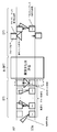
 図4は、AP/PCPまたはSTA(無線通信装置)の構成を示す図である。
(Embodiment 1)
FIG. 4 is a diagram illustrating a configuration of an AP / PCP or STA (wireless communication apparatus).
 AP/PCPまたはSTAは、制御部101、フレーム信号生成部102、フレーム構成部103、変調部104、送信無線部105、送信アンテナ部106、受信アンテナ部107、受信無線部108、復調部109、フレーム解析部110、を含む。 The AP / PCP or STA includes a control unit 101, a frame signal generation unit 102, a frame configuration unit 103, a modulation unit 104, a transmission radio unit 105, a transmission antenna unit 106, a reception antenna unit 107, a reception radio unit 108, a demodulation unit 109, A frame analysis unit 110.
 制御部101は、送信するフレーム構成をフレーム信号生成部102に指示し、送信フレームに合わせて、送信無線部105を制御して、送信アンテナ部106及び受信アンテナ部107に指向性送信、疑似オムニ送信を実行させる。また、制御部101は、受信無線部108及び復調部109を制御して受信処理を実行させる。なお、制御部101は、発見情報を図示しない上位層に報告し、報告に基づく接続命令が入力される。なお、接続命令は、上位層での判断であってもよいし、ユーザによる決定であってもよい。ユーザの決定は、図示しない外部入力部から入力される。 The control unit 101 instructs the frame signal generation unit 102 to transmit a frame structure, controls the transmission radio unit 105 in accordance with the transmission frame, and transmits directional transmission and pseudo omnidirectional signals to the transmission antenna unit 106 and the reception antenna unit 107. Execute transmission. In addition, the control unit 101 controls the reception wireless unit 108 and the demodulation unit 109 to execute reception processing. The control unit 101 reports discovery information to an upper layer (not shown), and a connection command based on the report is input. Note that the connection command may be a determination in an upper layer or a determination by the user. The user's decision is input from an external input unit (not shown).
 フレーム信号生成部102は、制御部101の指示に従い、送信フレームに用いるフレーム構成信号を生成する。 The frame signal generation unit 102 generates a frame configuration signal used for a transmission frame in accordance with an instruction from the control unit 101.
 フレーム構成部103は、フレーム構成信号及びデータを用いて、送信フレームを生成する。 The frame configuration unit 103 generates a transmission frame using the frame configuration signal and data.
 変調部104は、制御部101の指示に従い、送信フレームを、例えば、QPSKなどの変調方式を用いて、変調信号を生成する。 The modulation unit 104 generates a modulation signal from the transmission frame, for example, using a modulation method such as QPSK, in accordance with an instruction from the control unit 101.
 送信無線部105は、送信アンテナ部106から任意の送信セクタに指向性送信または、疑似オムニ送信を行うために、変調信号の位相調整を行い、位相調整後の変調信号の周波数変換を行い無線信号に変換する。 The transmission radio unit 105 performs phase adjustment of the modulation signal to perform directional transmission or pseudo omni transmission from the transmission antenna unit 106 to an arbitrary transmission sector, performs frequency conversion of the modulated signal after phase adjustment, and performs radio signal conversion. Convert to
 送信アンテナ部106は、無線信号を、指向性送信または疑似オムニ送信によって送信する。 The transmission antenna unit 106 transmits a radio signal by directional transmission or pseudo-omni transmission.
 受信アンテナ部107は、指向性送信または疑似オムニ送信によって送信された無線信号を、任意の受信セクタにおいて指向性受信または疑似オムニ受信することによって、受信する。受信無線部108は、制御部101の指示に従い、受信した無線信号を、周波数変換を行い、ベースバンド信号に変換する。 The receiving antenna unit 107 receives a radio signal transmitted by directional transmission or pseudo omni transmission by receiving directional reception or pseudo omni reception in an arbitrary reception sector. The reception radio unit 108 performs frequency conversion on the received radio signal according to an instruction from the control unit 101 and converts the received radio signal into a baseband signal.
 復調部109は、制御部101の指示に従い、ベースバンド信号を、復調し、送信フレームを出力する。 The demodulator 109 demodulates the baseband signal and outputs a transmission frame in accordance with an instruction from the controller 101.
 フレーム解析部110は、送信フレームに含まれるフレーム構成信号を解析し、発見情報(プローブ要求、プローブ応答、発見DMGビーコン(DBcn))を制御部101に出力する。 The frame analysis unit 110 analyzes the frame configuration signal included in the transmission frame, and outputs discovery information (probe request, probe response, discovery DMG beacon (DBcn)) to the control unit 101.
 図5は、疑似オムニ送信によるDMGビーコンを用いたデバイス発見手順の一例を示す図である。 FIG. 5 is a diagram showing an example of a device discovery procedure using a DMG beacon by pseudo omni transmission.
 デバイス発見を実行するSTAが、BTI中にDMGビーコンの擬似オムニ送信を含める。DMGビーコン(DBcn)は、例えば、発見モードフィールドを1に設定することによって、STAが発見用に使用されることを示す。各DMGビーコンの1ビットを使用して、BTIに1つ以上の擬似オムニ送信が含まれるか否かを示す。 STA that performs device discovery includes pseudo-omni transmission of DMG beacon in BTI. The DMG beacon (DBcn) indicates that the STA is used for discovery, for example by setting the discovery mode field to 1. One bit of each DMG beacon is used to indicate whether the BTI includes one or more pseudo omni transmissions.
 なお、STAの擬似オムニ送信するDMGビーコンは、制御MCSで送信される。例えば、制御MCSは、11adで規定されているMCS0でもよい。疑似オムニ送信は、MSC0を用いることで、送信エリアを最大限拡大することができる。 Note that the DMG beacon transmitted by the STA pseudo omni is transmitted by the control MCS. For example, the control MCS may be MCS0 defined by 11ad. For pseudo omni transmission, the transmission area can be expanded to the maximum by using MSC0.
 図6は、SSWフィールドのフォーマットの一例を示す図である。例えば、BTIにおいて予約されているRXSS長さフィールドの2ビットを使用して、BTIに1つ以上の擬似オムニ送信が含まれるか否かを示す。なお、SSWフィールドは、BTIにおけるDMGビーコン(DMGビーコン)の一構成要素としても使用でき、A-BFTにおけるSSWフレームの一構成要素としても使用できる。 FIG. 6 is a diagram showing an example of the format of the SSW field. For example, two bits of the RXSS length field reserved in BTI are used to indicate whether the BTI includes one or more pseudo omni transmissions. The SSW field can also be used as a component of a DMG beacon (DMG beacon) in BTI, and can also be used as a component of an SSW frame in A-BFT.
 図5において、STAは、擬似オムニ送信DMGビーコンを、BTIの少なくとも最後に送信し、APからのプローブ応答を(暗黙的または明示的に)要求する。 In FIG. 5, the STA transmits a pseudo omni transmission DMG beacon at least at the end of the BTI and requests a probe response (implicitly or explicitly) from the AP.
 ここで、APは、複数の指向性送信と1つ以上の擬似オムニ送信とによるDMGビーコンを受信する場合、例えば、別のデバイスとの衝突、または、APのスケジュールとの矛盾によって、STAによるA-BFTビームフォーミングを完了しない。 Here, when the AP receives a DMG beacon with a plurality of directional transmissions and one or more pseudo-omni transmissions, for example, due to a collision with another device or an inconsistency with the AP schedule, -Do not complete BFT beamforming.
 なお、衝突は、限られた時間に複数のSTAが一斉にAPにアクセスを行うことによって生じる状態を指す。また矛盾は、APが指定していたスケジュール(SLSを送信するSTAの順番)があるにも関わらず、スケジュールを知らないSTAが任意の時刻にビームフォーミングトレーニングを行うことによって生じる状態を指す。 Note that a collision refers to a state that occurs when a plurality of STAs access the AP simultaneously in a limited time. Contradiction refers to a state that occurs when an STA that does not know the schedule performs beamforming training at an arbitrary time, in spite of the schedule (the order of STAs that transmit SLS) specified by the AP.
 次に、DTIにおいて、APは、相互アンテナトレーニングを実行するためのTRN-Rシーケンスを付加した(例えば1つの)擬似オムニ送信によって、プローブ応答を送信する。なお、TRN-Rシーケンスは、擬似オムニ送信の範囲において、指向性送信としてスイープしてもよい。 Next, in DTI, the AP transmits a probe response by (for example, one) pseudo omni transmission to which a TRN-R sequence for performing mutual antenna training is added. The TRN-R sequence may be swept as directional transmission in the range of pseudo omni transmission.
 STAは、プローブ応答を受信し、なお、TRN-Rシーケンスを付加したACKを指向性送信で応答してもよい。STAは、TRN-Rシーケンスの受信から最良の受信セクタを識別して格納し、アンテナの相互関係に基づいて最良の受信セクタから最良の送信セクタを識別して格納する。 The STA may receive the probe response and respond with an ACK to which the TRN-R sequence is added by directional transmission. The STA identifies and stores the best receiving sector from reception of the TRN-R sequence, and identifies and stores the best transmitting sector from the best receiving sector based on antenna correlation.
 なお、STAは、時間内に求めることができた場合、最良の送信セクタによってACKを送り、そうでない場合、擬似オムニ送信として送る。 Note that the STA sends an ACK by the best transmission sector if it can be obtained in time, and sends it as a pseudo omni transmission otherwise.
 APは、ACKを受信し、TRN-Rシーケンスの受信から最良の受信セクタを識別して格納する。なお、APは、アンテナの相互関係に基づいて最良の受信セクタから最良の送信セクタを識別して格納する。 The AP receives the ACK, identifies the best receiving sector from the reception of the TRN-R sequence, and stores it. Note that the AP identifies and stores the best transmitting sector from the best receiving sector based on the correlation between the antennas.
 以上より、STAは、BTIにおける(DMGビーコンの)送信セクタスイープ(TXSS)に含まれる擬似オムニ送信を、DMGビーコンフレームとすることができる。 From the above, the STA can set the pseudo omni transmission included in the transmission sector sweep (TXSS) (in the DMG beacon) in the BTI as the DMG beacon frame.
 なお、相互アンテナトレーニングのために指向性送信されるTRNシーケンスを、DTIにおいて、DMGビーコンの擬似オムニ送信に付加してもよい。 In addition, you may add the TRN sequence transmitted directionally for mutual antenna training to the pseudo-omni transmission of a DMG beacon in DTI.
 また、DMGビーコンの擬似オムニ送信によって、ピアデバイス(ピアSTA)からのプローブ応答を要求することができる。 Also, a probe response from the peer device (peer STA) can be requested by pseudo-omni transmission of the DMG beacon.
 また、DMGビーコンの擬似オムニ送信は、STAが擬似オムニ送信であることを示すことができる。 Also, the pseudo omni transmission of the DMG beacon can indicate that the STA is a pseudo omni transmission.
 また、擬似オムニ送信の位置が固定されている場合(例:BTIの最後)、明示的な指示情報(例えば、発見モードに1を設定すること)を含まなくてもよい。 Also, when the position of the pseudo omni transmission is fixed (for example, at the end of BTI), explicit instruction information (for example, setting 1 to the discovery mode) may not be included.
 DMGビーコンの擬似オムニ送信は、擬似オムニ送信の数を示す、または複数の擬似オムニ送信が1つのBTIに含まれることを示すことができる。 The pseudo-omni transmission of the DMG beacon can indicate the number of pseudo-omni transmissions, or can indicate that a plurality of pseudo-omni transmissions are included in one BTI.
 DMGビーコンの指向性送信は、BTI/TXSSに擬似オムニ送信が含まれることを示すことができる。 The directional transmission of the DMG beacon can indicate that pseudo omni transmission is included in BTI / TXSS.
 DMGビーコンの指向性送信は、1つ以上のBTIにわたり断片化(フラグメンテーション)することができ、1つ以上のBTIにDMGビーコンの擬似オムニ送信が含まれてもよい。 The directional transmission of the DMG beacon can be fragmented over one or more BTIs, and the one or more BTIs may include a pseudo omni transmission of the DMG beacons.
 デバイス発見を実行するSTAは、BTIにおいてDMGビーコンを送信することができる(図5参照)。 STA that performs device discovery can transmit a DMG beacon in BTI (see FIG. 5).
 デバイス(STA、AP/PCP)は、1つ以上のDMGビーコンに対して擬似オムニ送信を用いた場合(図5参照)、A-BFTに対して、全てのDMGビーコンに対して指向性送信を用いた場合(図1、図2参照)とは異なる設定(長さ/頻度/存在の有無/その他)を示すことができる。 When a device (STA, AP / PCP) uses pseudo omni transmission for one or more DMG beacons (see FIG. 5), it transmits directional transmission to all DMG beacons for A-BFT. Different settings (length / frequency / presence / absence / others) from the case of use (see FIGS. 1 and 2) can be shown.
 デバイス(AP)は、図5のBTIにおいて、送信セクタスイープ(TXSS)の一部として、擬似オムニ送信によって送信される1つ以上のDMGビーコンを受信する。 The device (AP) receives one or more DMG beacons transmitted by pseudo-omni transmission as part of a transmission sector sweep (TXSS) in the BTI of FIG.
 図5において、擬似オムニ送信が受信された場合、デバイス(AP)は、正常なビームフォーミング交換の前(A-BFTでのSLSが衝突、矛盾の発生なしに完了すること)に、フレーム(例えば、プローブ応答、ACK返信)を送信することができる。なお、送信するフレーム(APにプローブ応答)は、制御MCSにおける擬似オムニ送信とすることができる。 In FIG. 5, if a pseudo omni transmission is received, the device (AP) may receive a frame (eg, SLS at A-BFT completes without collision, inconsistency) before a normal beamforming exchange. , Probe response, ACK reply) can be transmitted. Note that the frame to be transmitted (probe response to the AP) can be a pseudo omni transmission in the control MCS.
 STAは、受信された擬似オムニ送信のプローブ応答に指向性TRNシーケンスが含まれている場合、送信するフレーム(図5ではDTIにおけるACK)を指向性送信とすることができる。 When the STA receives the directional TRN sequence in the received pseudo-omni transmission probe response, the STA can set the frame to be transmitted (ACK in DTI in FIG. 5) as directional transmission.
 送信するフレームは、発見情報を要求するフレーム、または、発見情報を含むフレーム、例えば、プローブ要求、プローブ応答、発見DMGビーコン(DBcn)である。 The frame to be transmitted is a frame requesting discovery information or a frame including discovery information, for example, a probe request, a probe response, and a discovery DMG beacon (DBcn).
 図5のDTIにおいて、APは、送信するフレーム(プローブ応答)に、TRN-Rシーケンスの代わりに、ビーム微調整を要求/開始するBRP(beam refinement protocol)フレームを付加してもよい。 In the DTI of FIG. 5, the AP may add a BRP (beam definition protocol) frame for requesting / starting beam fine adjustment instead of the TRN-R sequence to the frame (probe response) to be transmitted.
 送信するフレームは、ピアデバイスへのビームフォーミングフィードバック、例えば、最良の送信セクタを含めることができる。 The frame to transmit can include beamforming feedback to the peer device, eg, the best transmission sector.
 送信するフレームは、相互アンテナトレーニングのために指向性送信されるTRNシーケンスを付加することができる。 A TRN sequence transmitted in a directional direction for mutual antenna training can be added to the frame to be transmitted.
 擬似オムニDMGビーコンが受信されない場合、デバイス(STA)はピアデバイス(AP)への擬似オムニ送信を回避してもよく、ピアデバイスの発見及びピアデバイスへの接続を回避してもよい。 If the pseudo omni DMG beacon is not received, the device (STA) may avoid pseudo omni transmission to the peer device (AP), and may avoid discovery of the peer device and connection to the peer device.
 以上より、APは、制御MCSによる疑似オムニ送信の範囲内のデバイス(STA)を、高速に発見することができる。 From the above, the AP can quickly find a device (STA) within the range of pseudo omni transmission by the control MCS.
 また、BTIにおいて擬似オムニ送信を含めることによって、ピアデバイス(AP)は、デバイス(STA)の発見及びデバイス(STA)との接続を実行するかどうか否かを認識することができる。 Also, by including pseudo omni transmission in the BTI, the peer device (AP) can recognize whether or not to perform discovery of the device (STA) and connection to the device (STA).
 また、デバイス(STA)が、BTIにおいて、擬似オムニ送信に発見情報を含めることによって、ピアデバイス(AP)は、最小限のオーバーヘッドでデバイス(STA)を発見することができる。 In addition, when the device (STA) includes discovery information in the pseudo omni transmission in the BTI, the peer device (AP) can discover the device (STA) with minimum overhead.
 (実施の形態2)
 実施の形態1では、BTIにおいて、指向性送信によるDMGビーコンの送信の後に、STAによる、疑似オムニ送信によるDMGビーコンの送信について説明したが、実施の形態2では、指向性送信によるDMGビーコンの送信のそれぞれに、STAによる1つ以上のTRNシーケンスを付加について説明する。
(Embodiment 2)
In Embodiment 1, transmission of DMG beacon by pseudo omni transmission by STA is described after transmission of DMG beacon by directional transmission in BTI. However, in Embodiment 2, transmission of DMG beacon by directional transmission is described. The addition of one or more TRN sequences by the STA will be described.
 図7は、疑似オムニ送信によるDMGビーコンを用いたデバイス発見手順の他の一例を示す図である。 FIG. 7 is a diagram showing another example of a device discovery procedure using a DMG beacon by pseudo omni transmission.
 図7のBTIでは、まず、デバイス発見を実行するSTAが、BTIにおいて指向性送信DMGビーコンそれぞれに、1つ以上のTRNシーケンスを付加し、制御MCSによって疑似オムニ送信される。 In the BTI of FIG. 7, first, a STA that performs device discovery adds one or more TRN sequences to each of the directional transmission DMG beacons in the BTI, and is pseudo-omni transmitted by the control MCS.
 DMGビーコンは、例えば、発見モードフィールドを1に設定することによって、STAの発見に使用されることを示し、また、PHYヘッダ内に付加される1×TRN(例:TRN-T)シーケンスを含む。なお、TRN-Tは複数のシーケンスであってもよい。 The DMG beacon indicates that it is used for STA discovery, for example by setting the discovery mode field to 1, and includes a 1 × TRN (eg TRN-T) sequence appended in the PHY header . Note that TRN-T may be a plurality of sequences.
 なお、DMGビーコンは、APからのプローブ応答を暗黙的または明示的に要求する。 Note that the DMG beacon implicitly or explicitly requests a probe response from the AP.
 次に、APは、1つ以上の指向性送信DMGビーコンとそれぞれに付加された1つ以上のTRN-Tシーケンスを受信し、1つの以上のTRN-Tシーケンスを擬似オムニ送信において使用することを認識する。 Next, the AP receives one or more directional transmission DMG beacons and one or more TRN-T sequences attached to each, and uses one or more TRN-T sequences in the pseudo-omni transmission. recognize.
 次に、APは、DTIにおいて、例えば複数の擬似オムニ送信によってプローブ応答を送信する。 Next, the AP transmits a probe response in DTI, for example, by a plurality of pseudo omni transmissions.
 STAは、プローブ応答を受信する。なお、STAがACKで応答した場合、APがACKを受信する。 STA receives the probe response. When the STA responds with an ACK, the AP receives the ACK.
 これによって、A-BFTにおいて、衝突、矛盾が発生した場合であっても、ビームフォーミングトレーニング(TRN)シーケンスを、BTIにおける指向性送信される複数のDMGビーコンに付加することができる。 Thus, even when a collision or inconsistency occurs in A-BFT, a beamforming training (TRN) sequence can be added to a plurality of DMG beacons transmitted in a directional manner in BTI.
 また、TRNシーケンスの送信を、複数のBTIにわたって断片化(フラグメンテーション)、つまり、DTIに続くBTIにおいても、TRNシーケンスを送信することができる。 Also, the TRN sequence can be transmitted in a fragmentation (fragmentation) over a plurality of BTIs, that is, in the BTI following the DTI.
 なお、TRNシーケンスの擬似オムニ送信が付加された指向性送信されるDMGビーコンは、TRNシーケンスのために擬似オムニ送信が使用されることを明示的に示さなくてもよい。 Note that a DMG beacon transmitted in a directional manner to which pseudo-omni transmission of a TRN sequence is added may not explicitly indicate that pseudo-omni transmission is used for the TRN sequence.
 また、STAは、TRNシーケンスの擬似オムニ送信が付加された指向性送信されるDMGビーコンによって、ピアデバイスからのプローブ応答を要求することができる。 Also, the STA can request a probe response from the peer device by a DMG beacon transmitted in a directional manner to which a pseudo omni transmission of a TRN sequence is added.
 以上より、制御MCSによる擬似オムニ送信の範囲内のデバイスを、高速または優先的に発見することができる。 From the above, devices within the range of pseudo omni transmission by the control MCS can be discovered at high speed or preferentially.
 なお、BTIにおいて擬似オムニ送信を含めることによって、ピアデバイスは、デバイスの発見/デバイスとの接続を実行するかどうかを認識することができる。 Note that by including the pseudo omni transmission in the BTI, the peer device can recognize whether to perform device discovery / connection with the device.
 APは、BTIにおける擬似オムニ送信に発見情報を含めることによって、最小限のオーバーヘッドで、デバイス(STA)を発見することができる。 The AP can discover a device (STA) with minimum overhead by including discovery information in the pseudo omni transmission in the BTI.
 (実施の形態3)
 実施の形態3は、BTIにおいて、APによる疑似オムニ送信によるDMGビーコンの送信について説明する。
(Embodiment 3)
In the third embodiment, transmission of a DMG beacon by pseudo omni transmission by an AP in BTI will be described.
 図8は、疑似オムニ送信によるDMGビーコンを用いたデバイス発見手順の他の一例を示す図である。 FIG. 8 is a diagram showing another example of a device discovery procedure using a DMG beacon by pseudo omni transmission.
 APは、BTIにおけるDMGビーコンに1つ以上の擬似オムニ送信を含める。なお、DMGビーコンは、各DMGビーコンの1ビットを使用して、BTIに擬似オムニ送信が含まれるか否かを示す。なお、DMGビーコンは、各DMGビーコンの1ビットを使用して、フレームが擬似オムニ送信であるか否かを示してもよい。なお、各DMGビーコンの擬似オムニ送信の送信セクタは、送信毎に異なってもよい。 The AP includes one or more pseudo omni transmissions in the DMG beacon in the BTI. The DMG beacon indicates whether or not pseudo omni transmission is included in the BTI using one bit of each DMG beacon. Note that the DMG beacon may indicate whether or not the frame is pseudo-omni transmission using one bit of each DMG beacon. In addition, the transmission sector of the pseudo omni transmission of each DMG beacon may be different for each transmission.
 図9は、SSWフィールドのフォーマットの一例を示す図である。擬似オムニ送信DMGビーコンの1ビット、例えば、(BTIにおいて予約されている)RXSS長さフィールドの3ビットを使用することによって、複数の擬似オムニ送信を示す。なお、SSWフィールドは、BTIにおけるDMGビーコンの一構成要素としても使用でき、A-BFTにおけるSSWフレームの一構成要素としても使用できる。 FIG. 9 is a diagram showing an example of the format of the SSW field. Pseudo omni transmission Indicates multiple pseudo omni transmissions by using one bit of the DMG beacon, eg, 3 bits of the RXSS length field (reserved in the BTI). Note that the SSW field can be used as a component of the DMG beacon in BTI, and can also be used as a component of the SSW frame in A-BFT.
 なお、擬似オムニ送信DMGビーコンは、BTIの先頭において送信され、迅速な発見のため、SSID、DMG能力、および、その他の情報を含み、相互アンテナトレーニングに用いるTRN-Rシーケンスが付加される。なお、TRN-Rシーケンスは、例えば、疑似オムニ送信の範囲において指向性送信される。 The pseudo omni transmission DMG beacon is transmitted at the head of the BTI, and includes a SRN, DMG capability, and other information for quick discovery, and a TRN-R sequence used for mutual antenna training is added. The TRN-R sequence is transmitted in a directional manner within the range of pseudo omni transmission, for example.
 なお、擬似オムニ送信DMGビーコンの後段において送信される指向性送信DMGビーコンは、BTIの時間長を短くするために、SSID、DMG能力、およびその他の情報を省略してもよい。 The directional transmission DMG beacon transmitted after the pseudo omni transmission DMG beacon may omit the SSID, the DMG capability, and other information in order to shorten the BTI time length.
 次に、STAは、1つ以上の擬似オムニ送信および1つ以上の指向性送信であるDMGビーコンを受信し、擬似オムニ送信の範囲において指向性送信されたTRN-Rシーケンスの受信から最良の受信セクタを識別して格納する。なお、STAは、アンテナの相互関係に基づいて最良の受信セクタから最良の送信セクタを識別して格納する。 The STA then receives a DMG beacon that is one or more pseudo omni transmissions and one or more directional transmissions, and receives the best reception from reception of a directional transmitted TRN-R sequence in the range of pseudo omni transmissions. Identify and store sectors. Note that the STA identifies and stores the best transmitting sector from the best receiving sector based on the correlation between antennas.
 STAは、発見情報を、例えば、上位層、または、サプリカントなどの接続管理ソフトウェアに報告し、AP/PCPへの接続命令を上位層、接続管理ソフトウェアまたは、ユーザから受信する。 The STA reports the discovery information to, for example, an upper layer or connection management software such as a supplicant, and receives a connection command to the AP / PCP from the upper layer, connection management software, or the user.
 次いで、DTIにおいて、STAは、TRN-Rシーケンスを付加したアソシエーション要求を、APに指向性送信することによって接続する。なお、STAは、TRN-Rシーケンスを疑似オムニ送信する。 Next, in the DTI, the STA connects by transmitting the association request with the TRN-R sequence added to the AP in a directional manner. Note that the STA performs pseudo-omni transmission of the TRN-R sequence.
 APは、擬似オムニ受信によって、アソシエーション要求を受信し、TRN-Rシーケンスの受信から最良の受信セクタを識別して格納する。なお、APは、アンテナの相互関係に基づいて最良の受信セクタから最良の送信セクタを識別して格納する。 The AP receives an association request through pseudo-omni reception, and identifies and stores the best receiving sector from the reception of the TRN-R sequence. Note that the AP identifies and stores the best transmitting sector from the best receiving sector based on the correlation between the antennas.
 APは、STAからのアソシエーション要求に対してACKを指向性送信し、その後、アソシエーション応答を送信することによって、STAの要求に応答する。 The AP responds to the STA request by transmitting ACK directionally in response to the association request from the STA, and then transmitting an association response.
 STAは、アソシエーション要求に対するACKおよびアソシエーション応答を受信し、APからのアソシエーション応答に対してACKで応答する。 The STA receives the ACK and the association response for the association request, and responds with an ACK to the association response from the AP.
 APは、アソシエーション応答に対するACKを受信することで、STAおよびAPが、接続確立を完了する。 The AP receives the ACK for the association response, and the STA and AP complete the connection establishment.
 以上より、DMGビーコンフレームを擬似オムニ送信する、または、指向性送信されるビームフォーミングトレーニング(TRN)シーケンスをDMGビーコンフレームに付加することができる。 From the above, it is possible to add a beam forming training (TRN) sequence in which a DMG beacon frame is transmitted in a pseudo-omni or directional transmission to the DMG beacon frame.
 相互アンテナトレーニングのために指向性送信されるTRNシーケンスを、BTIにおいて、DMGビーコンの擬似オムニ送信に付加してもよい。 A TRN sequence that is transmitted directionally for mutual antenna training may be added to the pseudo-omni transmission of the DMG beacon in the BTI.
 また、擬似オムニ送信の位置が固定されている場合(例:BTIの先頭)、明示的な指示情報を含まなくてもよい。 Also, when the position of the pseudo omni transmission is fixed (for example, the head of BTI), explicit instruction information may not be included.
 例えば、A-BFTを省略する場合、擬似オムニ送信に、デバイスの発見に用いる追加情報を含めることができる。 For example, when A-BFT is omitted, additional information used for device discovery can be included in the pseudo-omni transmission.
 追加情報を含むDMGビーコンの擬似オムニ送信は、BTIの先頭において送信することができる。これにより、例えば、レガシーデバイスが追加情報を解析できる。 The pseudo omni transmission of the DMG beacon including additional information can be transmitted at the head of the BTI. Thereby, for example, the legacy device can analyze the additional information.
 デバイス(STA)は、送信するフレームを、リンク確立フレーム(例:アソシエーション要求)とすることができる。 The device (STA) can set a frame to be transmitted as a link establishment frame (eg, association request).
 以上より、制御MCSによる擬似オムニ送信の範囲内のデバイスを、高速または優先的に発見することができる。 From the above, devices within the range of pseudo omni transmission by the control MCS can be discovered at high speed or preferentially.
 ピアデバイス(AP)は、BTIにおいて擬似オムニ送信を含めることによって、デバイスの発見/デバイスとの接続を実行するかどうかを認識することができる。 Peer device (AP) can recognize whether to perform device discovery / connection with device by including pseudo omni transmission in BTI.
 ピアデバイス(AP)は、BTIの擬似オムニ送信に発見情報を含めることによって、最小限のオーバーヘッドでデバイス(STA)を発見することができる。 The peer device (AP) can discover the device (STA) with minimum overhead by including discovery information in the pseudo omni transmission of BTI.
 ピアデバイスは、擬似オムニ送信および指向性TRNシーケンスを使用することにより、A-BFTを省略できるため、ビームフォーミング時間を短縮することができる。 Since the peer device can omit the A-BFT by using the pseudo omni transmission and the directional TRN sequence, the beam forming time can be shortened.
 なお、ピアデバイスによって複数の擬似オムニ送信が使用される場合、デバイスは、ピアデバイスの発見/ピアデバイスへの応答を優先させることができる。 Note that if multiple pseudo-omni transmissions are used by the peer device, the device can prioritize discovery of the peer device / response to the peer device.
 上記各実施の形態では、本開示はハードウェアを用いて構成する例にとって説明したが、本開示はハードウェアとの連携においてソフトウェアでも実現することも可能である。 In each of the above embodiments, the present disclosure has been described with respect to an example configured using hardware. However, the present disclosure can also be realized by software in cooperation with hardware.
 また、上記各実施の形態の説明に用いた各機能ブロックは、典型的には集積回路であるLSIとして実現される。集積回路は、上記実施の形態の説明に用いた各機能ブロックを制御し、入力と出力を備えてもよい。これらは個別に1チップ化されてもよいし、一部または全てを含むように1チップ化されてもよい。ここでは、LSIとしたが、集積度の違いにより、IC、システムLSI、スーパーLSI、ウルトラLSIと呼称されることもある。 Further, each functional block used in the description of each of the above embodiments is typically realized as an LSI which is an integrated circuit. The integrated circuit may control each functional block used in the description of the above embodiment, and may include an input and an output. These may be individually made into one chip, or may be made into one chip so as to include a part or all of them. The name used here is LSI, but it may also be called IC, system LSI, super LSI, or ultra LSI depending on the degree of integration.
 また、集積回路化の手法はLSIに限るものではなく、専用回路または汎用プロセッサを用いて実現してもよい。LSI製造後に、プログラムすることが可能なFPGA(Field Programmable Gate Array)、LSI内部の回路セルの接続又は設定を再構成可能なリコンフィギュラブル プロセッサ(Reconfigurable Processor)を利用してもよい。 Further, the method of circuit integration is not limited to LSI, and implementation using a dedicated circuit or a general-purpose processor is also possible. An FPGA (Field Programmable Gate Array) that can be programmed after manufacturing the LSI, and a Reconfigurable Processor that can reconfigure the connection or setting of circuit cells inside the LSI may be used.
 さらには、半導体技術の進歩又は派生する別技術により、LSIに置き換わる集積回路化の技術が登場すれば、当然、その技術を用いて機能ブロックを集積化してもよい。バイオ技術の適用等が可能性としてありえる。 Furthermore, if integrated circuit technology that replaces LSI emerges as a result of advances in semiconductor technology or other derived technologies, it is naturally also possible to integrate function blocks using this technology. Biotechnology can be applied.
 本開示に係る実施の形態の種々の態様として、以下のものが含まれる。 The following are included as various aspects of the embodiments according to the present disclosure.
 本開示の第1の開示に係る無線通信装置は、複数のDMGビーコンを含む送信フレームを生成するフレーム構成部と、BTIにおいて、前記複数のDMGビーコンのうち、1つ以上の第1のDMGビーコンに対して、第1の位相調整を行うことによって指向性送信を1つ以上の送信セクタを用いて行い、前記複数のDMGビーコンのうち、1つ以上の第2のDMGビーコンに対して、第2の位相調整を行うことによって疑似オムニ送信を行う、送信無線部と、を含む。 A wireless communication apparatus according to a first disclosure of the present disclosure includes a frame configuration unit that generates a transmission frame including a plurality of DMG beacons, and one or more first DMG beacons among the plurality of DMG beacons in the BTI. In contrast, directional transmission is performed using one or more transmission sectors by performing a first phase adjustment, and one or more second DMG beacons among the plurality of DMG beacons is And a transmission radio unit that performs pseudo-omni transmission by performing phase adjustment of 2.
 本開示の第2の開示に係る無線通信装置は、DTIにおいて、前記複数のDMGビーコンを送信した通信相手より、疑似オムニ送信により送信されたプローブ応答及び相互アンテナトレーニングに用いるシーケンス信号を受信する受信部と、前記シーケンス信号に示される通信相手の受信セクタに対応する送信セクタを前記1つ以上の送信セクタから選択する制御部と、を含む。 A wireless communication device according to a second disclosure of the present disclosure receives a probe response transmitted by pseudo omni transmission and a sequence signal used for mutual antenna training from a communication partner that transmitted the plurality of DMG beacons in DTI. And a control unit that selects, from the one or more transmission sectors, a transmission sector corresponding to the reception sector of the communication partner indicated in the sequence signal.
 本開示の第3の開示に係る無線通信装置は、前記フレーム構成部は、前記プローブ応答に対するack信号を生成し、前記送信無線部は、前記ack信号を前記選択した送信セクタを用いて、指向性送信を行う。 In the wireless communication device according to the third disclosure of the present disclosure, the frame configuration unit generates an ack signal in response to the probe response, and the transmission radio unit directs the ack signal using the selected transmission sector. Sexual transmission.
 本開示は、無線通信装置に用いるのに好適である。 The present disclosure is suitable for use in a wireless communication device.
 101 制御部
 102 フレーム信号生成部
 103 フレーム構成部
 104 変調部
 105 送信無線部
 106 送信アンテナ部
 107 受信アンテナ部
 108 受信無線部
 109 復調部
 110 フレーム解析部
DESCRIPTION OF SYMBOLS 101 Control part 102 Frame signal generation part 103 Frame structure part 104 Modulation part 105 Transmission radio | wireless part 106 Transmission antenna part 107 Reception antenna part 108 Reception radio part 109 Demodulation part 110 Frame analysis part

Claims (3)

  1.  複数のDMGビーコンを含む送信フレームを生成するフレーム構成部と、
     BTIにおいて、
     前記複数のDMGビーコンのうち、1つ以上の第1のDMGビーコンに対して、第1の位相調整を行うことによって指向性送信を1つ以上の送信セクタを用いて行い、
     前記複数のDMGビーコンのうち、1つ以上の第2のDMGビーコンに対して、第2の位相調整を行うことによって疑似オムニ送信を行う、
     送信無線部と、
     を含む、無線通信装置。
    A frame configuration unit for generating a transmission frame including a plurality of DMG beacons;
    In BTI,
    Performing directional transmission using one or more transmission sectors by performing a first phase adjustment on one or more first DMG beacons among the plurality of DMG beacons,
    A pseudo omni transmission is performed by performing a second phase adjustment on one or more second DMG beacons among the plurality of DMG beacons.
    A transmission radio unit;
    A wireless communication device.
  2.  DTIにおいて、前記複数のDMGビーコンを送信した通信相手より、疑似オムニ送信により送信されたプローブ応答及び相互アンテナトレーニングに用いるシーケンス信号を受信する受信部と、
     前記シーケンス信号に示される通信相手の受信セクタに対応する送信セクタを前記1つ以上の送信セクタから選択する制御部と、
     を含む、
     請求項1に記載の無線通信装置。
    In DTI, from a communication partner that has transmitted the plurality of DMG beacons, a receiving unit that receives a probe response transmitted by pseudo omni transmission and a sequence signal used for mutual antenna training;
    A control unit that selects a transmission sector corresponding to the reception sector of the communication partner indicated in the sequence signal from the one or more transmission sectors;
    including,
    The wireless communication apparatus according to claim 1.
  3.  前記フレーム構成部は、前記プローブ応答に対するack信号を生成し、
     前記送信無線部は、前記ack信号を前記選択した送信セクタを用いて、指向性送信を行う、
     請求項2に記載の無線通信装置。
    The frame configuration unit generates an ack signal for the probe response,
    The transmission radio unit performs directional transmission of the ack signal using the selected transmission sector.
    The wireless communication apparatus according to claim 2.
PCT/JP2017/008879 2016-03-11 2017-03-07 Wireless communication device WO2017154858A1 (en)

Priority Applications (17)

Application Number Priority Date Filing Date Title
BR112018016904A BR112018016904A2 (en) 2016-03-11 2017-03-07 wireless communication device and wireless communication method
CA3017092A CA3017092A1 (en) 2016-03-11 2017-03-07 Wireless communication apparatus and wireless communication method
KR1020217022260A KR102316676B1 (en) 2016-03-11 2017-03-07 Wireless communication device
RU2018132195A RU2692230C1 (en) 2016-03-11 2017-03-07 Wireless communication device and wireless communication method
CN202210236255.2A CN114513238A (en) 2016-03-11 2017-03-07 Communication apparatus and communication method
PL17763198T PL3429095T3 (en) 2016-03-11 2017-03-07 Wireless communication device
EP21191174.8A EP3926855A1 (en) 2016-03-11 2017-03-07 Wireless communication device
EP17763198.3A EP3429095B1 (en) 2016-03-11 2017-03-07 Wireless communication device
KR1020187026166A KR102280375B1 (en) 2016-03-11 2017-03-07 Wireless communication device and communication method
MYPI2018702863A MY193560A (en) 2016-03-11 2017-03-07 Wireless communication apparatus and wireless communication method
CN201780013408.4A CN108702193B (en) 2016-03-11 2017-03-07 Wireless communication device
ES17763198T ES2901172T3 (en) 2016-03-11 2017-03-07 wireless communication device
CONC2018/0009392A CO2018009392A2 (en) 2016-03-11 2017-03-07 Wireless communication device
MX2018010621A MX2018010621A (en) 2016-03-11 2017-03-07 Wireless communication device.
US16/125,007 US10791453B2 (en) 2016-03-11 2018-09-07 Wireless communication apparatus and wireless communication method
US17/001,961 US11523266B2 (en) 2016-03-11 2020-08-25 Wireless communication apparatus and wireless communication method
US18/053,690 US20230060962A1 (en) 2016-03-11 2022-11-08 Wireless communication apparatus and wireless communication method

Applications Claiming Priority (4)

Application Number Priority Date Filing Date Title
US201662307281P 2016-03-11 2016-03-11
US62/307281 2016-03-11
JP2017038599A JP7007093B2 (en) 2016-03-11 2017-03-01 Communication device and communication method
JP2017-038599 2017-03-01

Related Child Applications (1)

Application Number Title Priority Date Filing Date
US16/125,007 Continuation US10791453B2 (en) 2016-03-11 2018-09-07 Wireless communication apparatus and wireless communication method

Publications (1)

Publication Number Publication Date
WO2017154858A1 true WO2017154858A1 (en) 2017-09-14

Family

ID=59790480

Family Applications (1)

Application Number Title Priority Date Filing Date
PCT/JP2017/008879 WO2017154858A1 (en) 2016-03-11 2017-03-07 Wireless communication device

Country Status (8)

Country Link
US (1) US20230060962A1 (en)
JP (2) JP7007093B2 (en)
CN (2) CN114513238A (en)
ES (1) ES2901172T3 (en)
MY (1) MY193560A (en)
PL (1) PL3429095T3 (en)
RU (1) RU2769963C2 (en)
WO (1) WO2017154858A1 (en)

Families Citing this family (1)

* Cited by examiner, † Cited by third party
Publication number Priority date Publication date Assignee Title
BR112019012770A2 (en) 2016-12-28 2019-12-10 Panasonic Ip Corp America communication method for using wireless terminal device, communication method for using wireless base station device, wireless terminal device and wireless base station device

Citations (1)

* Cited by examiner, † Cited by third party
Publication number Priority date Publication date Assignee Title
JP2011514107A (en) * 2008-03-11 2011-04-28 インテル・コーポレーション Beacon and frame structure for directional antenna communication

Family Cites Families (6)

* Cited by examiner, † Cited by third party
Publication number Priority date Publication date Assignee Title
KR100689508B1 (en) * 2003-09-04 2007-03-02 삼성전자주식회사 Method for performing handover in a communication system
RU2286030C1 (en) * 2005-05-27 2006-10-20 Федеральное государственное унитарное предприятие "Научно-производственное предприятие "Полет" High frequency system and method for exchanging packet data
US8089947B2 (en) * 2007-08-31 2012-01-03 Intel Corporation Spatial reuse in directional antenna systems
US8239694B2 (en) * 2008-03-31 2012-08-07 Qualcomm, Incorporated Dynamic frequency scaling of a switched mode power supply
CN104969588A (en) * 2013-02-07 2015-10-07 交互数字专利控股公司 Long-range device discovery with directional transmissions
KR101800804B1 (en) * 2013-11-11 2017-11-27 인텔렉추얼디스커버리 주식회사 Station and wireless link configuration method therefor

Patent Citations (1)

* Cited by examiner, † Cited by third party
Publication number Priority date Publication date Assignee Title
JP2011514107A (en) * 2008-03-11 2011-04-28 インテル・コーポレーション Beacon and frame structure for directional antenna communication

Non-Patent Citations (2)

* Cited by examiner, † Cited by third party
Title
NITSCHE THOMAS ET AL.: "IEEE 802.11ad: directional 60 GHz communication for multi-Gigabit-per-second Wi-Fi", IEEE COMMUNICATIONS MAGAZINE,, vol. 52, no. 12, 11 December 2014 (2014-12-11), pages 132 - 141, XP011567636 *
WEE GAIUS ET AL.: "Fast BSS Discovery", IEEE 802.11-16/1571R0, 22 December 2016 (2016-12-22), XP068112300 *

Also Published As

Publication number Publication date
RU2019116776A3 (en) 2021-10-11
PL3429095T3 (en) 2022-02-14
JP7007093B2 (en) 2022-01-24
US20230060962A1 (en) 2023-03-02
RU2769963C2 (en) 2022-04-11
CN108702193A (en) 2018-10-23
JP7307209B2 (en) 2023-07-11
ES2901172T3 (en) 2022-03-21
CN114513238A (en) 2022-05-17
JP2017163540A (en) 2017-09-14
MY193560A (en) 2022-10-19
CN108702193B (en) 2022-03-18
RU2019116776A (en) 2019-06-13
JP2022050525A (en) 2022-03-30

Similar Documents

Publication Publication Date Title
US11523266B2 (en) Wireless communication apparatus and wireless communication method
US20200396583A1 (en) Multi-band millimeter wave discovery in wlan distribution networks
JP5073066B2 (en) Configuration for performing association and reassociation in a wireless network
US8755302B2 (en) Method and system for ad-hoc communications over millimeter wave wireless channels in wireless systems
EP3782389B1 (en) Scheduled and triggered mmw discovery assistance by lower band signaling
JP2021536165A (en) Communication device and communication method for multi-band operation
US9967019B2 (en) Communication system, communication method, base station device, and terminal device
CN107645322B (en) Random access method and equipment based on beamforming
KR100725418B1 (en) Wireless communication device and method for searching the wireless communication device
JP2018093482A (en) Wireless communication method and wireless communication device
KR20150054624A (en) Access point, station and method of connecting the access point and the station
US11601994B2 (en) Unassigned slots announcement in TDD SP channel access WLAN networks
US20230060962A1 (en) Wireless communication apparatus and wireless communication method
US8842525B2 (en) System and method for extending a wireless communication coverage area of a cellular base transceiver station (BTS)
JP2009055350A (en) Radio communication system and method
TWI741083B (en) Wireless communication method and wireless communication device
WO2023165360A1 (en) Method and apparatus for realizing sensing
WO2023179368A1 (en) Sensing method and device

Legal Events

Date Code Title Description
REG Reference to national code

Ref country code: BR

Ref legal event code: B01A

Ref document number: 112018016904

Country of ref document: BR

WWE Wipo information: entry into national phase

Ref document number: MX/A/2018/010621

Country of ref document: MX

ENP Entry into the national phase

Ref document number: 3017092

Country of ref document: CA

ENP Entry into the national phase

Ref document number: 20187026166

Country of ref document: KR

Kind code of ref document: A

NENP Non-entry into the national phase

Ref country code: DE

WWE Wipo information: entry into national phase

Ref document number: 2017763198

Country of ref document: EP

ENP Entry into the national phase

Ref document number: 2017763198

Country of ref document: EP

Effective date: 20181011

121 Ep: the epo has been informed by wipo that ep was designated in this application

Ref document number: 17763198

Country of ref document: EP

Kind code of ref document: A1

ENP Entry into the national phase

Ref document number: 112018016904

Country of ref document: BR

Kind code of ref document: A2

Effective date: 20180817