WO2017154596A1 - 脳機能計測装置と脳機能計測方法 - Google Patents
脳機能計測装置と脳機能計測方法 Download PDFInfo
- Publication number
- WO2017154596A1 WO2017154596A1 PCT/JP2017/006858 JP2017006858W WO2017154596A1 WO 2017154596 A1 WO2017154596 A1 WO 2017154596A1 JP 2017006858 W JP2017006858 W JP 2017006858W WO 2017154596 A1 WO2017154596 A1 WO 2017154596A1
- Authority
- WO
- WIPO (PCT)
- Prior art keywords
- light
- scalp
- brain function
- function measuring
- tissue
- Prior art date
- Legal status (The legal status is an assumption and is not a legal conclusion. Google has not performed a legal analysis and makes no representation as to the accuracy of the status listed.)
- Ceased
Links
Images





Classifications
-
- A—HUMAN NECESSITIES
- A61—MEDICAL OR VETERINARY SCIENCE; HYGIENE
- A61B—DIAGNOSIS; SURGERY; IDENTIFICATION
- A61B5/00—Measuring for diagnostic purposes; Identification of persons
- A61B5/02—Detecting, measuring or recording for evaluating the cardiovascular system, e.g. pulse, heart rate, blood pressure or blood flow
- A61B5/026—Measuring blood flow
-
- A—HUMAN NECESSITIES
- A61—MEDICAL OR VETERINARY SCIENCE; HYGIENE
- A61B—DIAGNOSIS; SURGERY; IDENTIFICATION
- A61B10/00—Instruments for taking body samples for diagnostic purposes; Other methods or instruments for diagnosis, e.g. for vaccination diagnosis, sex determination or ovulation-period determination; Throat striking implements
-
- A—HUMAN NECESSITIES
- A61—MEDICAL OR VETERINARY SCIENCE; HYGIENE
- A61B—DIAGNOSIS; SURGERY; IDENTIFICATION
- A61B5/00—Measuring for diagnostic purposes; Identification of persons
- A61B5/145—Measuring characteristics of blood in vivo, e.g. gas concentration or pH-value ; Measuring characteristics of body fluids or tissues, e.g. interstitial fluid or cerebral tissue
- A61B5/1455—Measuring characteristics of blood in vivo, e.g. gas concentration or pH-value ; Measuring characteristics of body fluids or tissues, e.g. interstitial fluid or cerebral tissue using optical sensors, e.g. spectral photometrical oximeters
Definitions
- the present invention relates to an apparatus and a method for measuring a brain function.
- fNIRS functional near-infrared spectroscopy
- This is a method for estimating changes in the concentration of oxygenated or deoxygenated hemoglobin in the blood due to changes in local cerebral blood flow caused by neuronal activity of the brain based on the difference in spectral characteristics of each molecular species. Is a device that employs.
- an incident probe and a detection probe are arranged on the scalp to constitute a measurement point, that is, a channel between the two probes, and a change in absorbance due to a change in hemoglobin concentration can be measured.
- a problem with the above-mentioned devices that have been commercially available in the past is that signal components resulting from changes other than changes in local cerebral blood flow are mixed with changes in absorbance.
- the inventor according to the present application proposed a multiple arrangement method as a method of extracting blood flow fluctuations in brain tissue located deeper than the surface layer tissue of the head in Patent Document 1.
- the inventor proposed a blood flow dynamic separation method as a method for extracting a signal fluctuation characteristic only for blood flow fluctuation caused by brain function activity.
- the inventor confirmed that the extracted waveforms matched very well by an experimental example in which both the multiple placement method and the hemodynamic separation method were applied at the same time. The fact that it was proved was disclosed.
- the above multiple arrangement method requires not only a detection probe but also a reference probe in order to obtain a measurement value in each channel, which increases the manufacturing cost of the measurement device and attaches the measurement device to the head. There is a problem that it becomes difficult.
- the present invention has been made to solve the above-described problems, and an object thereof is to provide an apparatus and a method for measuring brain activity with higher accuracy.
- the present invention is a light irradiation unit that irradiates light toward the subject's scalp, a detection unit that detects the intensity of light emitted from the scalp via the tissue in the subject's head, A support unit that supports the light irradiation unit and the detection unit, a reflectance control unit that is disposed so as to cover the scalp between the light irradiation unit and the detection unit, and that changes a reflectance with respect to light emitted from the scalp;
- a brain function measuring device comprising:
- this invention uses the light irradiation part, the 1st step which irradiates light toward a test subject's scalp, and a detection part, It passes through a test subject's internal tissue.
- the second step of detecting the first intensity of light emitted from the scalp and the reflectance control means disposed so as to cover the scalp between the light irradiating unit and the detecting unit are emitted from the scalp.
- a third step of detecting a second intensity of light emitted from the scalp by calculating a change in a physical quantity in the tissue in the head from the first intensity and the second intensity.
- a brain function measuring method including a fourth step.
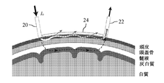
- FIG. 1 is a block diagram showing an overall configuration of a brain function measuring apparatus 1 according to an embodiment of the present invention. It is sectional drawing which shows the structure of the detection part 3 shown by FIG.
- FIG. 3 is a cross-sectional view illustrating a first configuration example of a holder 24 illustrated in FIG. 2.
- FIG. 3 is a cross-sectional view illustrating a second configuration example of the holder 24 illustrated in FIG. 2.
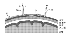
- It is a top view which shows the structure of the shutter 50 shown by FIG.
- It is a figure which shows the 5th structural example of the holder 24 shown by FIG.
- FIG. 1 is a block diagram showing an overall configuration of a brain function measuring apparatus 1 according to an embodiment of the present invention.
- the brain function measurement apparatus 1 includes a measurement terminal 2 and a detection unit 3, and the measurement terminal 2 includes a control unit 10, a data measurement unit 11, a storage unit 12, an operation unit 13, and a display unit 14. And the light source unit 15.
- the detection unit 3 and the light source unit 15 are connected by a light irradiation wire 5, and the detection unit 3 and the data measurement unit 11 are connected by a data wire 7.
- the detection unit 3 is connected to the control unit 10.
- the control unit 10 is connected to the data measurement unit 11, the storage unit 12, the operation unit 13, the display unit 14, and the light source unit 15, and the storage unit 12 is further connected to the data measurement unit 11 and the display unit 14.
- the display unit 14 is also connected to the operation unit 13.
- the brain function measuring device 1 having the above-described configuration utilizes the property that hemoglobin during oxygen transportation and non-transportation has different spectral absorption characteristics in the near infrared region.
- the detection unit 3 placed on the scalp as shown in FIG. 2, the light source probe 20 and the detection probe 22 are fixed at a predetermined distance apart, and emitted from the light source probe 20 with an intensity of 10 and within the head.
- Oxyhemoglobin during oxygen transportation and non-transportation by measuring the time change (intensity change in absorbance) of near-infrared light indicated by the broken line that propagates through the living tissue and enters the detection probe 22 The amount of change in deoxyhemoglobin in this tissue is estimated.
- a holder (support) that is disposed between the light source probe 20 and the detector probe 22 that are separated from each other so as to cover the scalp and supports the light source probe 20 and the detector probe 22.
- Part 24 is provided.
- the holder 24 is configured by a device that can arbitrarily change the reflectance of light by being controlled from the outside, and has a function of changing the path in the living tissue of light emitted from the scalp.
- the dimming device shown in FIGS. 7 and 8 of Japanese Patent No. 5166347 is employed, and therefore, the dimming device will be described below.
- FIG. 3 is a cross-sectional view showing a first configuration example of the holder 24 shown in FIG.
- the holder 24 shown in FIG. 3 includes an atmosphere controller 30, sealing members 31 and 32, glass plates 33 and 34, a light control layer 35, a catalyst layer 36, and a gas filling chamber 37.
- a light control layer 35 and a catalyst layer 36 are sequentially formed on one glass plate 33, and are sealed between the catalyst layer 36 and the other glass plate 34 by being sealed with seal members 31 and 32.
- a gas filling chamber 37 is provided. The gas filling chamber 37 is filled with argon gas in advance.
- the atmosphere controller 30 can reversibly control both the transparent state and the reflective state by controlling the atmosphere of the gas filling chamber 37 in accordance with the supplied control signal Sc.
- FIG. 4 is a cross-sectional view showing a second configuration example of the holder 24 shown in FIG. As shown in FIG. 4, in another configuration example, in addition to the glass plates 33 and 34, the light control layer 35, and the catalyst layer 36, transparent electrodes 41 and 42 are provided. In the meantime, the electrolytic solution 43 is filled.
- the light control layer 35 when a negative voltage is applied to the transparent electrode 41 with respect to the transparent electrode 41, the light control layer 35 is hydrogenated to be in a transparent state, and conversely, when a positive voltage is applied, the light control is performed. Layer 35 is dehydrogenated and becomes reflective. Therefore, by controlling the voltage between the transparent electrodes 41 and 42 according to the control signal Sc, both the transparent state and the reflective state can be reversibly controlled.
- step S1 light is irradiated toward the subject's scalp using light irradiation means.
- the light irradiation means for example, the light source unit 15, the light irradiation wire 5, and the light source probe 20 controlled by the control unit 10 shown in FIG. 1 are employed.
- step S2 the first intensity of light emitted from the scalp via the tissue in the head of the subject is detected using the detection means.
- the detecting means for example, the detector probe 22 shown in FIG. 2, the data wire 7 shown in FIG. 1, and the data measuring unit 11 are employed.
- FIG. 2 among the light incident on the subject's head tissue from the light source probe 20, the light that passes through the gray matter and is emitted from the scalp to the detector probe 22, and advances in the scalp while being attenuated. Only the light emitted from the scalp to the detector probe 22 is shown in broken lines, but the light traveling through the tissue in the head can take various paths. The same applies to FIG.
- step S3 the reflectance with respect to the light of the support means disposed so as to cover the scalp between the light irradiation means and the detection means separated from each other and supporting the light irradiation means and the detection means is changed.
- the second intensity of light emitted from the scalp is detected.
- the holder 24 shown in FIG. 2 is employed as the support means.
- the control unit 10 shown in FIG. 1 is employed as a means for changing the reflectance.
- the first intensity of the light is detected by setting the reflectance of the holder 24 to 0 percent (transmission state), and the second intensity of the light is changed by changing the reflectance of the holder 24 to 100 percent (reflection state).
- transmission state the reflectance of the holder 24 to 0 percent
- second intensity of the light is changed by changing the reflectance of the holder 24 to 100 percent (reflection state).
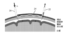
- the path of light traveling through the scalp is re-entered into the head due to reflection at the holder 24 as shown in FIG.
- Light is absorbed or scattered by tissue in the head. Therefore, the path of light incident on the detector probe 22 when the holder 24 is in the transmission state and the path of light incident on the detector probe 22 when the holder 24 is in the reflection state are considerably different. Conceivable.
- step S4 a change in physical quantity in the tissue in the head is calculated from the first intensity and the second intensity of the light.
- the physical quantity is the concentration of oxygenated or deoxygenated hemoglobin in the local cerebral blood flow change in the head.
- the human head has a multilayer structure composed of tissues having different optical characteristics such as scalp, skull, cerebrospinal fluid, cerebral gray matter, and cerebral white matter.
- the change in the absorbance A measured by the brain function measuring apparatus 1 is expressed by the following equation.
- ⁇ is the wavelength of the incident light
- l is the partial effective optical path length in each tissue layer
- ⁇ is the absorption coefficient
- the subscripts sc, sk, csf, gm, and wm are the scalp, skull, and cerebrospinal fluid, respectively. , Showing gray matter and white matter tissue layer. Among these, the temporal change of light absorption is small in the skull and cerebrospinal fluid. Further, it has been found that the white matter has an extremely small partial effective optical path length as compared with other tissues. For this reason, the following approximate expression which extracted the main term of Formula (1) can be used.
- the change in blood flow that occurs in the scalp and cerebral gray matter shows a transient response with a relaxation time of about several seconds, but the switching between the transmission state and the reflection state of the holder 24 shown in FIGS. 2 and 6 is much faster than this. By doing so, the following two measurements can be realized in substantially the same blood flow state.
- the blood flow change ⁇ ⁇ gm derived from the cerebral gray matter is converted into the blood flow change ⁇ ⁇ sc derived from the scalp. It is possible to separate and extract from.
- the concentration change of oxygenated or deoxygenated hemoglobin in the local cerebral blood flow change can be calculated as follows.
- O and D are changes in oxygenated or deoxygenated hemoglobin concentration
- ⁇ H and ⁇ are the molecular extinction coefficients at the wavelength ⁇ of hemoglobin in each state
- the superscript with a superscript + is the inverse matrix of this matrix or general Indicates that it is a generalized inverse matrix.
- the brain function measuring method according to the embodiment of the present invention as described above is a brain function that changes the reflectance of light using a mechanical shutter as the holder 24 shown in FIGS. It can also be realized by using a measuring device.
- the reflection state can be realized by closing the mechanical shutter according to the control signal Sc, and the above-described reflection state can be realized by opening the shutter according to the signal. Can be realized.
- the shutter 50 shown in FIGS. 7 and 8 is used as a mechanical shutter that realizes the above function.
- the shutter 50 is formed of a disk having a radius between the light source probe 20 and the detector probe 22 and is stored in a transparent holder 24.
- the shutter 50 is mirror-finished so that the lower surface reflects light in the reflection part 51 of the semicircular part, and transmits light in the transmission part 52 of the remaining semicircular part.
- the shutter 50 having such a configuration is rotated around the light source probe 20 according to the control signal Sc, and when the scalp between the light source probe 20 and the detector probe 22 is covered with the transmission part 52, it is shown in FIG. As shown in FIGS. 6 and 7, when a part of the light incident on the tissue in the head is radiated into the air, the light is radiated into the air as shown in FIGS. Without being reflected by the lower surface of the reflecting portion 51.
- the mechanical shutter is configured such that a fan-shaped plate having a mirror-finished lower surface is movable around the light source probe 20 in the holder 24 instead of the shutter 50 shown in FIGS. Also good.
- the shutter having such a configuration when the plate is placed at a position covering the scalp between the light source probe 20 and the detector probe 22 according to the control signal Sc, it is shown in FIG. 6 and FIG.
- the plate when the light is reflected by the lower surface without being emitted into the air, the plate is placed at a position not covering the scalp between the light source probe 20 and the detector probe 22 according to the signal. As shown in FIG. 2, a part of the light incident on the tissue in the head is emitted into the air.
- an open / close type shutter that shields light by protruding in such a manner that a plurality of shielding plates, which are stored in the holder 24 and whose bottom surfaces are mirror-finished, overlap toward the center may be used.
- the shutter having such a configuration when the shutter is closed according to the control signal Sc, the light is reflected on the lower surface without being emitted into the air as shown in FIGS.
- the shutter is opened in response to the signal, a part of the light incident on the tissue in the head is radiated into the air as shown in FIG.
- the state in which a part of the light incident on the tissue in the head is radiated into the air as shown in FIG. 2 means that the holder 24 itself absorbs all the light that attempts to pass through the holder 24. Can also be realized.
- the shutter 50 shown in FIG. 8 may have its transmissive part 52 made of a transparent material, and the surface may be painted black.
- the portion that changes the reflectance with respect to the light emitted from the scalp is configured to support the light source probe 20 and the detector probe 22. ing. That is, although these components are integrated, they need not be integrated, and a specific example will be shown below.
- FIG. 9 is a diagram showing another configuration example of the holder 24 shown in FIG. 2, and shows a planar configuration viewed from above and a cross-sectional configuration viewed from the side.
- the support member 60 supports the light source probe 20 and the detector probe 22, and in the lower layer of the support member 60, there are two fan-shaped reflecting portions 51 corresponding to the shutter 50. It rotates around the light source probe 20.
- the amount of light detected by the detector probe 22 differs depending on whether or not the reflecting portion 51 covers the region between the light source probe 20 and the detector probe 22.
- the dimming device 70 shown in FIGS. 3 and 4 is arranged between the light source probe 20 and the detector probe 22 in place of the reflector 51 shown in FIG. Similar effects can be obtained by providing the same.
- the brain function measuring apparatus 1 according to the embodiment of the present invention shown in FIG. 1 and the brain function measuring method according to the embodiment of the present invention shown in FIG. Based on only the optical properties and the anatomical form of the head without being influenced by the above, only the blood flow change derived from the brain functional activity can be accurately measured by a simple device or method.
- SYMBOLS 1 Brain function measuring device 10 Control part, 11 Data measurement part, 15 Light source part, 20 Light source probe, 22 Detector probe, 24 Holder (support part), 50 Shutter, 51 Reflection part, 52 Transmission part, 60 Support member, 70 Dimming device.
Landscapes
- Health & Medical Sciences (AREA)
- Life Sciences & Earth Sciences (AREA)
- Physics & Mathematics (AREA)
- Heart & Thoracic Surgery (AREA)
- Molecular Biology (AREA)
- Veterinary Medicine (AREA)
- Public Health (AREA)
- Pathology (AREA)
- Engineering & Computer Science (AREA)
- Biomedical Technology (AREA)
- General Health & Medical Sciences (AREA)
- Medical Informatics (AREA)
- Animal Behavior & Ethology (AREA)
- Surgery (AREA)
- Biophysics (AREA)
- Physiology (AREA)
- Hematology (AREA)
- Cardiology (AREA)
- Spectroscopy & Molecular Physics (AREA)
- Optics & Photonics (AREA)
- Measurement Of The Respiration, Hearing Ability, Form, And Blood Characteristics Of Living Organisms (AREA)
Abstract
本発明は、脳の活動をより精度良く計測するための装置及び方法を提供することを目的とする。 本目的を実現するため、本発明は被験者の頭皮に向けて光を照射する光源プローブ(20)と、被験者の頭部内組織を経由して頭皮から射出される光の強度を検出する検出器プローブ(22)と、光源プローブ(20)と検出器プローブ(22)を支持すると共に、光源プローブ(20)と検出器プローブ(22)との間で頭皮を覆うように配設され、上記頭皮から射出される光に対する反射率を変化させるホルダ(24)とを備えた脳機能計測装置を提供する。
Description
本発明は、脳の機能を計測するための装置及び方法に関するものである。
近年、生体透過性が比較的高い近赤外光を用いて頭皮上から非侵襲的に脳活動を計測する機能的近赤外分光法(functional near-infrared spectroscopy: fNIRS)と、この方法を用いた測定装置が普及し利用されている。
これは、脳の神経活動に伴って生じる局所脳血流変化における血液中の酸素化若しくは脱酸素化ヘモグロビンの濃度変化を各分子種の分光特性の違いに基づいて推定する方法であり、本方法を採用した装置である。
この方法若しくは装置によれば、頭皮上に入射プローブと検出プローブを配置して両プローブ間の計測点、すなわちチャネルを構成し、ヘモグロビンの濃度変化に起因する吸光度の変化を計測することができる。
従来から市販されている上記装置の問題点は、吸光度変化に局所脳血流変化以外に起因する信号成分が混在してしまうことであった。これに対し、本願に係る発明者は、特許文献1において、頭部の表層組織よりも深部に位置する脳組織での血流変動を抽出する方法として多重配置法を提案した。また、同発明者は、特許文献2において、脳機能活動で生じる血流変動にのみ特徴的な信号変動を抽出する方法として血流動態分離法を提案した。
さらに、同発明者は、非特許文献1において、多重配置法と血流動態分離法の双方を同時に適用した実験例により、抽出波形が非常によく一致することを確認し、両方法の有用性を実証した旨を開示した。
Yamada T., Umeyama S., and Matsuda K., "Separation of fNIRS Signals into Functional and Systemic Components Based on Differences in Hemodynamic Modalities," PLOS ONE, 7, e50271 (2012)
しかし、上記の多重配置法では、各チャネルにおいて測定値を得るために、検出プローブのみならず参照プローブも必要とするため、測定装置の製造コストが高くなると共に、当該測定装置は頭部に装着しづらくなるという問題がある。
また、このような問題を解決した上記の血流動態分離法でも、前提となる脳機能活動に伴う血流動態のあり方が、疾病状態下や他の脳領野でも同様であるかは検証されていないため、リハビリテーション中の脳疾患患者を対象とする場合などにも有効であるか否かは明らかでないという問題がある。
本発明は、上記のような問題を解決するためになされたもので、脳の活動をより精度良く計測するための装置及び方法を提供することを目的とする。
上記課題を解決するため、本発明は被験者の頭皮に向けて光を照射する光照射部と、被験者の頭部内組織を経由して頭皮から射出される光の強度を検出する検出部と、光照射部と検出部を支持する支持部と、光照射部と検出部との間で頭皮を覆うように配設され、上記頭皮から射出される光に対する反射率を変化させる反射率制御部とを備えた脳機能計測装置を提供する。
また、上記課題を解決するため、本発明は光照射部を用いて、被験者の頭皮に向けて光を照射する第1のステップと、検出部を用いて、被験者の頭部内組織を経由して頭皮から射出される光の第1の強度を検出する第2のステップと、光照射部と検出部との間で頭皮を覆うように配設された反射率制御手段の上記頭皮から射出される光に対する反射率を変化させ、頭皮から射出される光の第2の強度を検出する第3のステップと、第1の強度と第2の強度から頭部内組織における物理量の変化を算出する第4のステップとを有する脳機能計測方法を提供する。
本発明によれば、脳の活動をより精度良く計測するための装置及び方法を提供すること ができる。
以下において、本発明の実施の形態を図面を参照しつつ詳しく説明する。なお、図中同一符号は同一又は相当部分を示す。
図1は、本発明の実施の形態に係る脳機能計測装置1の全体構成を示すブロック図である。図1に示されるように、脳機能計測装置1は、計測端末2と検知部3とを備え、計測端末2は制御部10、データ計測部11、記憶部12、操作部13、表示部14、及び光源部15を含む。
図1は、本発明の実施の形態に係る脳機能計測装置1の全体構成を示すブロック図である。図1に示されるように、脳機能計測装置1は、計測端末2と検知部3とを備え、計測端末2は制御部10、データ計測部11、記憶部12、操作部13、表示部14、及び光源部15を含む。
ここで、検知部3と光源部15とは光照射用ワイヤ5により接続され、検知部3とデータ計測部11とはデータ用ワイヤ7により接続される。また、検知部3は制御部10に接続される。
制御部10は、データ計測部11、記憶部12、操作部13、表示部14、及び光源部15に接続され、記憶部12はさらにデータ計測部11及び表示部14に接続される。また、表示部14は操作部13にも接続される。
上記のような構成を有する脳機能計測装置1は、酸素運搬時と非運搬時のヘモグロビンが近赤外領域での分光吸収特性を異にするという性質を利用したものであり、具体的には、頭皮上に置かれた検知部3において、図2に示されるように、所定の距離だけ隔てて光源プローブ20と検出プローブ22が固定され、光源プローブ20から強度I0で射出され頭部内の生体組織中を伝搬して検出プローブ22に入射する破線で示された近赤外光の強度の時間変化(吸光度の時間変化)を計測することによって、酸素運搬時におけるオキシヘモグロビンと非運搬時におけるデオキシヘモグロビンの本組織中での変化量を推定するものである。
また、図2に示されるように、互いに離れた光源プローブ20と検出器プローブ22との間には、頭皮を覆うように配設されて光源プローブ20と検出器プローブ22を支持するホルダ(支持部)24が備えられる。
ここで、ホルダ24は、外部から制御することにより光の反射率を任意に変化させることのできるデバイスにより構成され、頭皮から射出される光の生体組織における経路を変化させる機能を奏するものである。具体的には、例えば特許第5166347号公報の図7及び図8に示された調光デバイスが採用されるため、以下においては本調光デバイスについて説明する。
図3は、図2に示されたホルダ24の第1構成例を示す断面図である。図3に示されるホルダ24は、雰囲気制御器30とシール部材31,32、ガラス板33,34、調光層35、触媒層36、及びガス充填室37とを備える。
ここで、一方のガラス板33の上には順次調光層35、触媒層36が形成され、シール部材31,32で封止されることにより触媒層36と他方のガラス板34との間にガス充填室37が設けられる。そして、ガス充填室37には予めアルゴンガスが封入される。
また、制御部10から供給される制御信号Scにより制御される雰囲気制御器30により、ガス充填室37において水素、及び、酸素若しくは空気が給排気される。
このような構成を有する調光デバイスにおいて、水素がガス充填室37に供給されると調光層35が水素化されて透明状態になり、酸素若しくは空気がガス充填室37に供給されると調光層35が脱水素化されて反射状態になる。従って、雰囲気制御器30が、供給された制御信号Scに応じてガス充填室37の雰囲気を制御することにより、透明状態と反射状態の両状態を可逆的に制御することができる。
図4は、図2に示されたホルダ24の第2構成例を示す断面図である。図4に示されるように、他の構成例においては、ガラス板33,34、調光層35、触媒層36の他、透明電極41,42が備えられ、透明電極41と触媒層36との間には電解液43が満たされる。
そして、制御部10から供給される制御信号Scにより制御される電源により、二つの透明電極41,42間に電圧が印加される。
このような構成を有する調光デバイスにおいて、透明電極42へ透明電極41に対して負の電圧を印加すると調光層35が水素化されて透明状態となり、逆に正の電圧を印加すると調光層35が脱水素化されて反射状態になる。従って、両透明電極41,42間の電圧が制御信号Scに応じて制御されることにより、透明状態と反射状態の両状態を可逆的に制御することができる。
以下において、以上のような構成を有する脳機能計測装置1を用いた脳機能計測方法について、図5を参照しつつ詳しく説明する。
最初にステップS1において、光照射手段を用いて、被験者の頭皮に向けて光を照射する。ここで、光照射手段としては、例えば、図1に示された制御部10により制御される光源部15、光照射用ワイヤ5、及び光源プローブ20が採用される。
次に、ステップS2において、検出手段を用いて、被験者の頭部内組織を経由して頭皮から射出される光の第1の強度を検出する。ここで、検出手段としては、例えば、図2に示された検出器プローブ22、図1に示されたデータ用ワイヤ7、及びデータ計測部11が採用される。
図2においては、光源プローブ20から被験者の頭部内組織へ入射された光のうち、灰白質を通過して頭皮から検出器プローブ22へ射出される光と、減衰しながら頭皮内を進んで頭皮から検出器プローブ22へ射出される光だけが破線で図示されているが、頭部内組織を進む光は種々の経路をとりうる。なお、図6においても同様である。
次に、ステップS3において、互いに離れた光照射手段と検出手段との間で頭皮を覆うように配設され、光照射手段と検出手段とを支持する支持手段の上記光に対する反射率を変化させ、頭皮から射出される光の第2の強度を検出する。ここで、支持手段としては、例えば、図2に示されたホルダ24が採用される。また、反射率を変化させるための手段としては、例えば、図1に示された制御部10が採用される。
以下において、ホルダ24の反射率を0パーセント(透過状態)として上記光の第1の強度を検出し、ホルダ24の反射率を100パーセント(反射状態)に変化させて上記光の第2の強度を検出した場合を一例として説明する。
まず、ホルダ24が透過状態にあるときは、図2に示されるように、光源プローブ20から頭部内組織へ入射された光のうち頭皮を伝搬する光の一部は検出器プローブ22へ到達することなく空中へ放射され、再び本組織に戻ることはない。そして、組織内を進む光はこのような散逸の他、吸収、若しくは散乱されて、上記のように減衰された光が検出器プローブ22に受光されることになる。
一方、ホルダ24が反射状態にあるときは、図6に示されるように、頭皮を進む光の進路が図2に示された場合と異なり、ホルダ24での反射により頭部内に再入射した光が頭部内組織により吸収、若しくは散乱される。従って、ホルダ24が透過状態にあるときに検出器プローブ22へ入射する光の経路と、ホルダ24が反射状態にあるときに検出器プローブ22へ入射する光の経路とは相当程度に異なるものと考えられる。
次に、ステップS4において上記光の第1の強度と第2の強度から、頭部内組織における物理量の変化を算出する。以下において、一例として、上記物理量が、頭部内における局所脳血流変化における酸素化若しくは脱酸素化ヘモグロビンの濃度である場合について詳しく説明する。
人の頭部は、図2や図6に示されるように、頭皮、頭蓋骨、髄液、大脳灰白質、大脳白質など、光学的特性が異なる組織からなる多層構造を持つ。このため、上記の脳機能計測装置1で計測される吸光度Aの変化は以下の式で表される。

ここで、λは入射光の波長、l(エル)は各組織層での部分実効光路長、μは吸収係数、添え字のsc、sk、csf、gm、wmはそれぞれ頭皮、頭蓋骨、髄液、灰白質、白質の組織層を示す。この中で、頭蓋骨、髄液では光吸収の時間変化が少ない。また、白質は他の組織に比べて部分実効光路長が極端に小さな値をとることが分かっている。このため、式(1)の主要項を抽出した以下のような近似式を用いることができる。

頭皮及び大脳灰白質で生じる血流変化は数秒程度の緩和時間を持つ過渡的応答を示すが、図2や図6に示したホルダ24の透過状態と反射状態の切り替えをこれよりも十分に素早く行うことにより、ほぼ同一の血流状態において、以下のような二つの測定を実現できる。

そして、式(3)に示された連立方程式を解くことにより、以下の式(4)に示されるように、大脳灰白質由来の血流変化Δμλ
gmを頭皮由来の血流変化Δμλ
scから分離して抽出することが可能となる。

このようにして得られた各測定波長でのΔμλ
gmを用いて、局所脳血流変化における酸素化若しくは脱酸素化ヘモグロビンの濃度変化を以下のように計算できる。
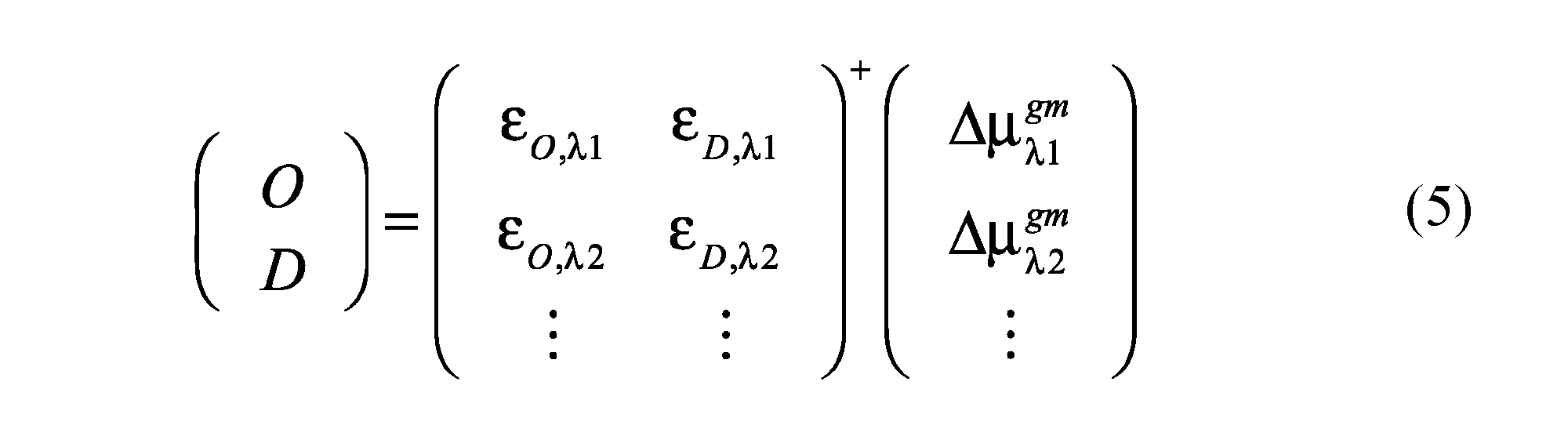
ここで、O,Dは酸素化若しくは脱酸素化ヘモグロビンの濃度変化、εH,λは各状態におけるヘモグロビンの波長λにおける分子吸光係数、行列の肩付き添え字+は本行列の逆行列若しくは一般化逆行列であることを示す。
なお、以上のような本発明の実施の形態に係る脳機能計測方法は、図2及び図6に示されたホルダ24として、機械的シャッタを用いて光の反射率を変化させるような脳機能計測装置を用いることによっても実現することができる。
すなわち、このような脳機能計測装置を用いる場合には、制御信号Scに応じて機械的シャッタを閉じることにより上記の反射状態を実現することができ、同信号に応じてシャッタを開けることにより上記の透過状態を実現することができる。
一例として、上記機能を実現する機械的シャッタとして、図7及び図8に示されたシャッタ50が使用される。図7及び図8に示されるように、シャッタ50は光源プローブ20と検出器プローブ22の間隔を半径とする円板からなり、透明なホルダ24に格納される。
ここで、シャッタ50は、半円部分の反射部51において下面が光を反射するよう鏡面加工され、残りの半円部分の透過部52において光を透過する。
ここで、シャッタ50は、半円部分の反射部51において下面が光を反射するよう鏡面加工され、残りの半円部分の透過部52において光を透過する。
このような構成を有するシャッタ50は、制御信号Scに応じて光源プローブ20の周りに回転され、光源プローブ20と検出器プローブ22の間の頭皮が透過部52で覆われるときには、図2に示されるように頭部内組織へ入射された光の一部が空中へ放射される一方、反射部51で覆われるときには、図6及び図7に示されるように当該光は空中へ放射されることなく反射部51の下面で反射される。
なお、上記機械的シャッタとしては、図7及び図8に示されたシャッタ50の替わりに、下面が鏡面加工された扇形の板をホルダ24内において光源プローブ20の周りに可動させるような構成としても良い。このような構成を有するシャッタを用いた場合、制御信号Scに応じて当該板が光源プローブ20と検出器プローブ22の間の頭皮を覆う位置に置かれたときには、図6及び図7に示されるように、当該光は空中へ放射されることなく当該下面で反射される一方、同信号に応じて当該板が光源プローブ20と検出器プローブ22の間の頭皮を覆わない位置に置かれたときには、図2に示されるように、頭部内組織へ入射された光の一部が空中へ放射される。
また、上記機械的シャッタとしては、ホルダ24内に格納され、下面が鏡面加工された複数の遮蔽板が中心に向かって重なるようにせり出すことにより光を遮蔽する開閉型シャッタを用いても良い。このような構成を有するシャッタを用いた場合、制御信号Scに応じてシャッタが閉じられたときには、図6及び図7に示されるように、当該光は空中へ放射されることなく当該下面で反射される一方、同信号に応じてシャッタが開かれたときには、図2に示されるように、頭部内組織へ入射された光の一部が空中へ放射される。
なお、上記において、頭部内組織へ入射された光の一部が図2に示されるように空中へ放射される状態は、ホルダ24自体がホルダ24を透過しようとする光を全て吸収することによっても実現できる。
従って、例えば、図8に示されたシャッタ50は、その透過部52を透明材質で構成するほか、表面を黒色に塗装するようにしてもよい。
また、図2に示されたホルダ24については、上記いずれの構成例においても、頭皮から射出される光に対する反射率を変化させる部分が、光源プローブ20及び検出器プローブ22を支持する構成となっている。すなわち、これらの構成要素は一体となっているが、必ずしも一体でなくても良いため、以下において具体例を示す。
図9は、図2に示されたホルダ24の他の構成例を示す図であり、上方から見た平面構成と横から見た断面構成を示すものである。図9に示された構成例では、支持部材60が光源プローブ20及び検出器プローブ22を支持すると共に、支持部材60の下層において、上記シャッタ50に相当する二つの扇型からなる反射部51が光源プローブ20を中心に回転する。
このことから、光源プローブ20と検出器プローブ22の間の領域を反射部51が覆った場合と、そうでない場合とで検出器プローブ22により検出される光量が異なることになる。
従って、頭皮から射出される光に対する反射率を変化させる反射部51を光源プローブ20及び検出器プローブ22を支持する支持部材60と別体としても、これまでに説明した上記ホルダ24と同様な作用効果を得ることができる。
さらに、図10に示されるように、図9に示された反射部51に替えて、光源プローブ20と検出器プローブ22の各間に図3や図4に示された調光デバイス70を配設することによっても、同様な作用効果を得ることができる。
以上より、図1に示された本発明の実施の形態に係る脳機能計測装置1、及び図5に示された本発明の実施の形態に係る脳機能計測方法によれば、頭皮における血流による影響を受けることなく頭部の光学的性質と解剖学的形態のみに基づき、脳機能活動に由来する血流変化のみを、簡易な装置若しくは方法によって精度よく測定することができる。
1 脳機能計測装置、10 制御部、11 データ計測部、15 光源部、20 光源プローブ、22 検出器プローブ、24 ホルダ(支持部)、50 シャッタ、51 反射部、52 透過部、60 支持部材、70 調光デバイス。
Claims (7)
- 被験者の頭皮に向けて光を照射する光照射手段と、
前記被験者の頭部内組織を経由して前記頭皮から射出される光の強度を検出する検出手段と、
前記光照射手段と前記検出手段を支持する支持手段と、
前記光照射手段と前記検出手段との間で前記頭皮を覆うように配設され、前記頭皮から射出される光に対する反射率を変化させる反射率制御手段とを備えた脳機能計測装置。 - 前記支持手段は、前記反射率制御手段を兼ねる、請求項1に記載の脳機能計測装置。
- 前記支持手段は、調光素子である、請求項1又は2に記載の脳機能計測装置。
- 前記支持手段は、シャッタである、請求項1又は2に記載の脳機能計測装置。
- 光照射手段を用いて、被験者の頭皮に向けて光を照射する第1のステップと、
検出手段を用いて、前記被験者の頭部内組織を経由して前記頭皮から射出される光の第1の強度を検出する第2のステップと、
前記光照射手段と前記検出手段との間で前記頭皮を覆うように配設された反射率制御手段の前記頭皮から射出される光に対する反射率を変化させ、前記頭皮から射出される光の第2の強度を検出する第3のステップと、
前記第1の強度と前記第2の強度から前記頭部内組織における物理量の変化を算出する第4のステップとを有する脳機能計測方法。 - 前記光は、近赤外光である請求項5に記載の脳機能計測方法。
- 前記頭部内組織における物理量は、前記頭部内組織を流れる血液中において酸素と結合若しくは離脱したヘモグロビン濃度である請求項5に記載の脳機能計測方法。
Priority Applications (1)
| Application Number | Priority Date | Filing Date | Title |
|---|---|---|---|
| JP2018504359A JP6654325B2 (ja) | 2016-03-08 | 2017-02-23 | 脳機能計測装置と脳機能計測方法 |
Applications Claiming Priority (2)
| Application Number | Priority Date | Filing Date | Title |
|---|---|---|---|
| JP2016044579 | 2016-03-08 | ||
| JP2016-044579 | 2016-03-08 |
Publications (1)
| Publication Number | Publication Date |
|---|---|
| WO2017154596A1 true WO2017154596A1 (ja) | 2017-09-14 |
Family
ID=59790437
Family Applications (1)
| Application Number | Title | Priority Date | Filing Date |
|---|---|---|---|
| PCT/JP2017/006858 Ceased WO2017154596A1 (ja) | 2016-03-08 | 2017-02-23 | 脳機能計測装置と脳機能計測方法 |
Country Status (2)
| Country | Link |
|---|---|
| JP (1) | JP6654325B2 (ja) |
| WO (1) | WO2017154596A1 (ja) |
Citations (3)
| Publication number | Priority date | Publication date | Assignee | Title |
|---|---|---|---|---|
| WO2003063704A1 (en) * | 2002-01-25 | 2003-08-07 | Matsushita Electric Industrial Co., Ltd. | Optical biological information measuring method and optical biological information measuring instrument |
| JP2010066747A (ja) * | 2008-08-12 | 2010-03-25 | National Institute Of Advanced Industrial Science & Technology | 反射型調光素子、並びに、反射型調光素子を用いた反射型調光部材及び複層ガラス |
| JP2011239863A (ja) * | 2010-05-17 | 2011-12-01 | Hitachi Ltd | 生体光計測装置及び生体光計測方法 |
-
2017
- 2017-02-23 WO PCT/JP2017/006858 patent/WO2017154596A1/ja not_active Ceased
- 2017-02-23 JP JP2018504359A patent/JP6654325B2/ja active Active
Patent Citations (3)
| Publication number | Priority date | Publication date | Assignee | Title |
|---|---|---|---|---|
| WO2003063704A1 (en) * | 2002-01-25 | 2003-08-07 | Matsushita Electric Industrial Co., Ltd. | Optical biological information measuring method and optical biological information measuring instrument |
| JP2010066747A (ja) * | 2008-08-12 | 2010-03-25 | National Institute Of Advanced Industrial Science & Technology | 反射型調光素子、並びに、反射型調光素子を用いた反射型調光部材及び複層ガラス |
| JP2011239863A (ja) * | 2010-05-17 | 2011-12-01 | Hitachi Ltd | 生体光計測装置及び生体光計測方法 |
Also Published As
| Publication number | Publication date |
|---|---|
| JP6654325B2 (ja) | 2020-02-26 |
| JPWO2017154596A1 (ja) | 2018-11-22 |
Similar Documents
| Publication | Publication Date | Title |
|---|---|---|
| ES3046787T3 (en) | Sensor for tissue measurements | |
| O'doherty et al. | Sub‐epidermal imaging using polarized light spectroscopy for assessment of skin microcirculation | |
| Stamatas et al. | Non‐invasive measurements of skin pigmentation in situ | |
| US9924874B2 (en) | Measurement device, measurement method, program and recording medium | |
| US20170303830A1 (en) | System and method for noninvasive analysis of subcutaneous tissue | |
| CN103735274B (zh) | 一种局部脑组织血氧血容绝对量检测装置及检测方法 | |
| CN104780832B (zh) | 被检体信息获取装置及被检体信息获取装置的控制方法 | |
| JP2011523059A5 (ja) | ||
| Rajaram et al. | Experimental validation of the effects of microvasculature pigment packaging on in vivo diffuse reflectance spectroscopy | |
| CA2958667A1 (en) | System and method for noninvasive analysis of tissue | |
| Kikuchi et al. | Imaging of hemoglobin oxygen saturation ratio in the face by spectral camera and its application to evaluate dark circles | |
| Li et al. | Capillary flow homogenization during functional activation revealed by optical coherence tomography angiography based capillary velocimetry | |
| WO2011091280A2 (en) | Methods and systems for analyte measurement | |
| US20080269580A1 (en) | System for Non-Invasive Measurement of Bloold Glucose Concentration | |
| Ahn et al. | Emerging optical spectroscopy techniques for biomedical applications—A brief review of recent progress | |
| Masuda et al. | An innovative method to measure skin pigmentation | |
| Veenstra et al. | Quantification of total haemoglobin concentrations in human whole blood by spectroscopic visible-light optical coherence tomography | |
| US10448876B2 (en) | Hyperspectral imaging systems and related methods | |
| Karpienko et al. | Blood equivalent phantom vs whole human blood, a comparative study | |
| ES2924301T3 (es) | Oxímetro retiniano con precisión mejorada | |
| Nteroli et al. | Two octaves spanning photoacoustic microscopy | |
| JP6654325B2 (ja) | 脳機能計測装置と脳機能計測方法 | |
| Dremin et al. | In vivo fluorescence measurements of biological tissue viability | |
| JP2014173997A (ja) | 近赤外イメージング装置校正用ファントム | |
| Kleshnin et al. | Method of measuring blood oxygenation based on spectroscopy of diffusely scattered light |
Legal Events
| Date | Code | Title | Description |
|---|---|---|---|
| WWE | Wipo information: entry into national phase |
Ref document number: 2018504359 Country of ref document: JP |
|
| NENP | Non-entry into the national phase |
Ref country code: DE |
|
| 121 | Ep: the epo has been informed by wipo that ep was designated in this application |
Ref document number: 17762936 Country of ref document: EP Kind code of ref document: A1 |
|
| 122 | Ep: pct application non-entry in european phase |
Ref document number: 17762936 Country of ref document: EP Kind code of ref document: A1 |