WO2017154247A1 - Broadcast receiving device and mobile information terminal - Google Patents
Broadcast receiving device and mobile information terminal Download PDFInfo
- Publication number
- WO2017154247A1 WO2017154247A1 PCT/JP2016/078439 JP2016078439W WO2017154247A1 WO 2017154247 A1 WO2017154247 A1 WO 2017154247A1 JP 2016078439 W JP2016078439 W JP 2016078439W WO 2017154247 A1 WO2017154247 A1 WO 2017154247A1
- Authority
- WO
- WIPO (PCT)
- Prior art keywords
- broadcast
- unit
- information
- broadcast receiving
- program
- Prior art date
Links
Images


Classifications
-
- H—ELECTRICITY
- H04—ELECTRIC COMMUNICATION TECHNIQUE
- H04N—PICTORIAL COMMUNICATION, e.g. TELEVISION
- H04N21/00—Selective content distribution, e.g. interactive television or video on demand [VOD]
- H04N21/40—Client devices specifically adapted for the reception of or interaction with content, e.g. set-top-box [STB]; Operations thereof
- H04N21/43—Processing of content or additional data, e.g. demultiplexing additional data from a digital video stream; Elementary client operations, e.g. monitoring of home network or synchronising decoder's clock; Client middleware
- H04N21/434—Disassembling of a multiplex stream, e.g. demultiplexing audio and video streams, extraction of additional data from a video stream; Remultiplexing of multiplex streams; Extraction or processing of SI; Disassembling of packetised elementary stream
- H04N21/4345—Extraction or processing of SI, e.g. extracting service information from an MPEG stream
-
- H—ELECTRICITY
- H04—ELECTRIC COMMUNICATION TECHNIQUE
- H04N—PICTORIAL COMMUNICATION, e.g. TELEVISION
- H04N21/00—Selective content distribution, e.g. interactive television or video on demand [VOD]
- H04N21/40—Client devices specifically adapted for the reception of or interaction with content, e.g. set-top-box [STB]; Operations thereof
- H04N21/45—Management operations performed by the client for facilitating the reception of or the interaction with the content or administrating data related to the end-user or to the client device itself, e.g. learning user preferences for recommending movies, resolving scheduling conflicts
- H04N21/462—Content or additional data management, e.g. creating a master electronic program guide from data received from the Internet and a Head-end, controlling the complexity of a video stream by scaling the resolution or bit-rate based on the client capabilities
-
- H—ELECTRICITY
- H04—ELECTRIC COMMUNICATION TECHNIQUE
- H04H—BROADCAST COMMUNICATION
- H04H20/00—Arrangements for broadcast or for distribution combined with broadcast
- H04H20/28—Arrangements for simultaneous broadcast of plural pieces of information
-
- H—ELECTRICITY
- H04—ELECTRIC COMMUNICATION TECHNIQUE
- H04H—BROADCAST COMMUNICATION
- H04H60/00—Arrangements for broadcast applications with a direct linking to broadcast information or broadcast space-time; Broadcast-related systems
- H04H60/09—Arrangements for device control with a direct linkage to broadcast information or to broadcast space-time; Arrangements for control of broadcast-related services
- H04H60/14—Arrangements for conditional access to broadcast information or to broadcast-related services
- H04H60/23—Arrangements for conditional access to broadcast information or to broadcast-related services using cryptography, e.g. encryption, authentication, key distribution
-
- H—ELECTRICITY
- H04—ELECTRIC COMMUNICATION TECHNIQUE
- H04H—BROADCAST COMMUNICATION
- H04H60/00—Arrangements for broadcast applications with a direct linking to broadcast information or broadcast space-time; Broadcast-related systems
- H04H60/27—Arrangements for recording or accumulating broadcast information or broadcast-related information
-
- H—ELECTRICITY
- H04—ELECTRIC COMMUNICATION TECHNIQUE
- H04H—BROADCAST COMMUNICATION
- H04H60/00—Arrangements for broadcast applications with a direct linking to broadcast information or broadcast space-time; Broadcast-related systems
- H04H60/68—Systems specially adapted for using specific information, e.g. geographical or meteorological information
- H04H60/72—Systems specially adapted for using specific information, e.g. geographical or meteorological information using electronic programme guides [EPG]
-
- H—ELECTRICITY
- H04—ELECTRIC COMMUNICATION TECHNIQUE
- H04H—BROADCAST COMMUNICATION
- H04H60/00—Arrangements for broadcast applications with a direct linking to broadcast information or broadcast space-time; Broadcast-related systems
- H04H60/76—Arrangements characterised by transmission systems other than for broadcast, e.g. the Internet
- H04H60/78—Arrangements characterised by transmission systems other than for broadcast, e.g. the Internet characterised by source locations or destination locations
- H04H60/80—Arrangements characterised by transmission systems other than for broadcast, e.g. the Internet characterised by source locations or destination locations characterised by transmission among terminal devices
-
- H—ELECTRICITY
- H04—ELECTRIC COMMUNICATION TECHNIQUE
- H04N—PICTORIAL COMMUNICATION, e.g. TELEVISION
- H04N21/00—Selective content distribution, e.g. interactive television or video on demand [VOD]
- H04N21/20—Servers specifically adapted for the distribution of content, e.g. VOD servers; Operations thereof
- H04N21/23—Processing of content or additional data; Elementary server operations; Server middleware
- H04N21/236—Assembling of a multiplex stream, e.g. transport stream, by combining a video stream with other content or additional data, e.g. inserting a URL [Uniform Resource Locator] into a video stream, multiplexing software data into a video stream; Remultiplexing of multiplex streams; Insertion of stuffing bits into the multiplex stream, e.g. to obtain a constant bit-rate; Assembling of a packetised elementary stream
- H04N21/2362—Generation or processing of Service Information [SI]
-
- H—ELECTRICITY
- H04—ELECTRIC COMMUNICATION TECHNIQUE
- H04N—PICTORIAL COMMUNICATION, e.g. TELEVISION
- H04N21/00—Selective content distribution, e.g. interactive television or video on demand [VOD]
- H04N21/40—Client devices specifically adapted for the reception of or interaction with content, e.g. set-top-box [STB]; Operations thereof
- H04N21/43—Processing of content or additional data, e.g. demultiplexing additional data from a digital video stream; Elementary client operations, e.g. monitoring of home network or synchronising decoder's clock; Client middleware
- H04N21/431—Generation of visual interfaces for content selection or interaction; Content or additional data rendering
- H04N21/4312—Generation of visual interfaces for content selection or interaction; Content or additional data rendering involving specific graphical features, e.g. screen layout, special fonts or colors, blinking icons, highlights or animations
-
- H—ELECTRICITY
- H04—ELECTRIC COMMUNICATION TECHNIQUE
- H04N—PICTORIAL COMMUNICATION, e.g. TELEVISION
- H04N21/00—Selective content distribution, e.g. interactive television or video on demand [VOD]
- H04N21/40—Client devices specifically adapted for the reception of or interaction with content, e.g. set-top-box [STB]; Operations thereof
- H04N21/43—Processing of content or additional data, e.g. demultiplexing additional data from a digital video stream; Elementary client operations, e.g. monitoring of home network or synchronising decoder's clock; Client middleware
- H04N21/44—Processing of video elementary streams, e.g. splicing a video clip retrieved from local storage with an incoming video stream, rendering scenes according to MPEG-4 scene graphs
- H04N21/4402—Processing of video elementary streams, e.g. splicing a video clip retrieved from local storage with an incoming video stream, rendering scenes according to MPEG-4 scene graphs involving reformatting operations of video signals for household redistribution, storage or real-time display
- H04N21/440263—Processing of video elementary streams, e.g. splicing a video clip retrieved from local storage with an incoming video stream, rendering scenes according to MPEG-4 scene graphs involving reformatting operations of video signals for household redistribution, storage or real-time display by altering the spatial resolution, e.g. for displaying on a connected PDA
-
- H—ELECTRICITY
- H04—ELECTRIC COMMUNICATION TECHNIQUE
- H04N—PICTORIAL COMMUNICATION, e.g. TELEVISION
- H04N21/00—Selective content distribution, e.g. interactive television or video on demand [VOD]
- H04N21/40—Client devices specifically adapted for the reception of or interaction with content, e.g. set-top-box [STB]; Operations thereof
- H04N21/43—Processing of content or additional data, e.g. demultiplexing additional data from a digital video stream; Elementary client operations, e.g. monitoring of home network or synchronising decoder's clock; Client middleware
- H04N21/44—Processing of video elementary streams, e.g. splicing a video clip retrieved from local storage with an incoming video stream, rendering scenes according to MPEG-4 scene graphs
- H04N21/4402—Processing of video elementary streams, e.g. splicing a video clip retrieved from local storage with an incoming video stream, rendering scenes according to MPEG-4 scene graphs involving reformatting operations of video signals for household redistribution, storage or real-time display
- H04N21/440281—Processing of video elementary streams, e.g. splicing a video clip retrieved from local storage with an incoming video stream, rendering scenes according to MPEG-4 scene graphs involving reformatting operations of video signals for household redistribution, storage or real-time display by altering the temporal resolution, e.g. by frame skipping
-
- H—ELECTRICITY
- H04—ELECTRIC COMMUNICATION TECHNIQUE
- H04N—PICTORIAL COMMUNICATION, e.g. TELEVISION
- H04N21/00—Selective content distribution, e.g. interactive television or video on demand [VOD]
- H04N21/40—Client devices specifically adapted for the reception of or interaction with content, e.g. set-top-box [STB]; Operations thereof
- H04N21/45—Management operations performed by the client for facilitating the reception of or the interaction with the content or administrating data related to the end-user or to the client device itself, e.g. learning user preferences for recommending movies, resolving scheduling conflicts
- H04N21/462—Content or additional data management, e.g. creating a master electronic program guide from data received from the Internet and a Head-end, controlling the complexity of a video stream by scaling the resolution or bit-rate based on the client capabilities
- H04N21/4623—Processing of entitlement messages, e.g. ECM [Entitlement Control Message] or EMM [Entitlement Management Message]
-
- H—ELECTRICITY
- H04—ELECTRIC COMMUNICATION TECHNIQUE
- H04N—PICTORIAL COMMUNICATION, e.g. TELEVISION
- H04N21/00—Selective content distribution, e.g. interactive television or video on demand [VOD]
- H04N21/40—Client devices specifically adapted for the reception of or interaction with content, e.g. set-top-box [STB]; Operations thereof
- H04N21/47—End-user applications
- H04N21/482—End-user interface for program selection
- H04N21/4821—End-user interface for program selection using a grid, e.g. sorted out by channel and broadcast time
-
- H—ELECTRICITY
- H04—ELECTRIC COMMUNICATION TECHNIQUE
- H04N—PICTORIAL COMMUNICATION, e.g. TELEVISION
- H04N21/00—Selective content distribution, e.g. interactive television or video on demand [VOD]
- H04N21/80—Generation or processing of content or additional data by content creator independently of the distribution process; Content per se
- H04N21/83—Generation or processing of protective or descriptive data associated with content; Content structuring
- H04N21/84—Generation or processing of descriptive data, e.g. content descriptors
-
- H—ELECTRICITY
- H04—ELECTRIC COMMUNICATION TECHNIQUE
- H04H—BROADCAST COMMUNICATION
- H04H60/00—Arrangements for broadcast applications with a direct linking to broadcast information or broadcast space-time; Broadcast-related systems
- H04H60/09—Arrangements for device control with a direct linkage to broadcast information or to broadcast space-time; Arrangements for control of broadcast-related services
- H04H60/14—Arrangements for conditional access to broadcast information or to broadcast-related services
- H04H60/15—Arrangements for conditional access to broadcast information or to broadcast-related services on receiving information
-
- H—ELECTRICITY
- H04—ELECTRIC COMMUNICATION TECHNIQUE
- H04H—BROADCAST COMMUNICATION
- H04H60/00—Arrangements for broadcast applications with a direct linking to broadcast information or broadcast space-time; Broadcast-related systems
- H04H60/09—Arrangements for device control with a direct linkage to broadcast information or to broadcast space-time; Arrangements for control of broadcast-related services
- H04H60/14—Arrangements for conditional access to broadcast information or to broadcast-related services
- H04H60/21—Billing for the use of broadcast information or broadcast-related information
- H04H60/22—Billing for the use of broadcast information or broadcast-related information per use
-
- H—ELECTRICITY
- H04—ELECTRIC COMMUNICATION TECHNIQUE
- H04N—PICTORIAL COMMUNICATION, e.g. TELEVISION
- H04N21/00—Selective content distribution, e.g. interactive television or video on demand [VOD]
- H04N21/80—Generation or processing of content or additional data by content creator independently of the distribution process; Content per se
- H04N21/81—Monomedia components thereof
- H04N21/8126—Monomedia components thereof involving additional data, e.g. news, sports, stocks, weather forecasts
- H04N21/814—Monomedia components thereof involving additional data, e.g. news, sports, stocks, weather forecasts comprising emergency warnings
Definitions
- the present invention relates to a broadcast receiving apparatus and a portable information terminal.
- One of the extended functions of the digital broadcasting service is data broadcasting that transmits digital data using broadcast waves and displays various information such as weather forecasts, news, and recommended programs.
- Many television receivers capable of receiving data broadcasts are already on the market, and many techniques related to data broadcast reception have been disclosed, including Patent Document 1 below.
- TV receivers are also required to expand various functions.
- requests for distribution of content and cooperative applications using a broadband network environment such as the Internet and requests for high resolution / high definition of video content.
- An object of the present invention is to provide a broadcast receiving apparatus capable of executing a function with higher added value and a portable information terminal capable of cooperating with the broadcast receiving apparatus.
- a broadcast receiving apparatus capable of receiving digital broadcast broadcast data, which receives broadcast data including encoded video data related to a digital broadcast broadcast program and control information related to the broadcast program.
- a video decoding unit that decodes the encoded video data received by the broadcast receiving unit and reproduces program video information
- a display unit that displays the program video information reproduced by the video decoding unit, and the broadcast
- viewing permission request data is transmitted to a predetermined portable information terminal, and the portable information terminal responds to the viewing permission request data.
- a communication unit that receives the response data, an authentication information storage unit that stores terminal identification information and authentication information that can identify the predetermined portable information terminal, and a control unit.
- the control unit includes a terminal identification in which the response data received by the communication unit is a display permission response, and both the terminal identification information and the authentication information included in the display permission response are stored in the authentication information storage unit.
- a response received by the communication unit by controlling the video decoding unit or the display unit so as not to restrict viewing of a broadcast program desired by the user of the broadcast receiving device when the information and the authentication information match. Even if the data is a display permission response, if any of the terminal identification information and the authentication information included in the display permission response does not match the terminal identification information and the authentication information stored in the authentication information storage unit,
- the broadcast receiving apparatus wherein the video decoding unit or the display unit is controlled so as to limit viewing of a broadcast program desired by a user of the broadcast receiving device. , It is used.
- FIG. 1 is a configuration diagram of a broadcast communication system including a broadcast receiving apparatus according to Embodiment 1.
- FIG. It is explanatory drawing of the component of the encoding signal in MMT. It is a block diagram of MPU in MMT. It is a block diagram of the MMTP packet in MMT. It is a conceptual diagram of the protocol stack of the broadcasting system using MMT. It is a hierarchical block diagram of the control information used with a broadcast system. It is a list of tables used in the TLV-SI of the broadcasting system. It is a list of descriptors used in the TLV-SI of the broadcasting system. It is a list of messages used in the MMT-SI of the broadcasting system.
- FIG. 1 is a block diagram of a broadcast receiving apparatus according to Embodiment 1.
- FIG. 1 is a block diagram of the logical plane structure of the presentation function of the broadcast receiver which concerns on Example 1.
- FIG. 1 is a software configuration diagram of a broadcast receiving apparatus according to Embodiment 1.
- FIG. 1 is a block diagram of a broadcast station server according to Embodiment 1.
- FIG. 1 is a block diagram of a service provider server according to Embodiment 1.
- FIG. 1 is a block diagram of a portable information terminal according to Embodiment 1.
- FIG. 1 is a software configuration diagram of a portable information terminal according to Embodiment 1.
- FIG. 1 is a system configuration diagram of clock synchronization / presentation synchronization of a broadcast receiving apparatus according to Embodiment 1.
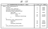
- FIG. It is a figure which shows the data structure of the NTP format of a broadcast system. It is a figure which shows the data structure of MH-TOT of a broadcast system. It is a figure which shows the format of the JST_time parameter of a broadcast system. It is a figure which shows the data structure of the time information of the TMCC extension information area
- FIG. 3 is an operation sequence diagram at the time of channel selection of the broadcast receiving apparatus according to the first embodiment. It is a conceptual diagram explaining the reference of MPT of each package by PLT of a broadcasting system. It is a figure which shows the data structure of PLT of a broadcast system.
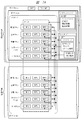
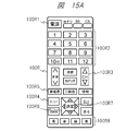
- FIG. 1 is an external view of a remote control capable of controlling a broadcast receiving device according to Embodiment 1.
- FIG. It is a figure which shows the data structure of the remote control key descriptor of a broadcasting system. It is a figure explaining the channel selection process of a multi organization channel. It is a figure explaining the angle selection process of a multi view corresponding program. It is a figure which shows the data structure of LCT of a broadcast system. It is a figure which shows the data structure of the MPU presentation area
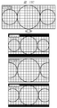
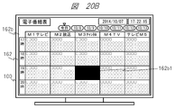
- FIG. It is a screen display figure of the EPG screen of the broadcast receiving apparatus which concerns on Example 1.
- FIG. It is a screen display figure of the EPG screen of the broadcast receiving apparatus which concerns on Example 1.
- FIG. It is a screen display figure of the EPG screen of the broadcast receiving apparatus which concerns on Example 1.
- FIG. It is a screen display figure at the time of the emergency alert broadcast display of the broadcast receiver which concerns on Example 1.
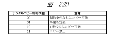
- FIG. It is a figure which shows the data structure of the content copy control descriptor of a broadcasting system. It is a figure which shows the meaning of the copy control information of a content copy control descriptor. It is a figure which shows the data structure of the content utilization control descriptor of a broadcasting system.
- 6 is a block diagram of a broadcast receiving apparatus according to Embodiment 2.
- FIG. It is a figure explaining inconsistency of the present time display at the time of broadcast service switching. It is a figure explaining operation
- FIG. FIG. 9 is an operation sequence diagram of current time information update processing according to the second embodiment. It is a screen display figure of the EPG screen of the broadcast receiving apparatus which concerns on Example 2.
- FIG. It is a screen display figure of the EPG screen of the broadcast receiving apparatus which concerns on Example 2.
- FIG. It is a figure explaining the outline
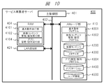
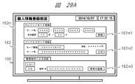
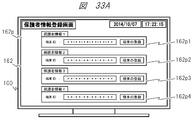
- FIG. 10 is an operation sequence diagram of registration processing of a portable information terminal used for authentication processing according to the third embodiment. It is a screen display figure of the notification screen of the authentication use permission request
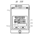
- FIG. It is a screen display figure of the authentication information input screen of the portable information terminal which concerns on Example 3.
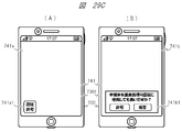
- FIG. 12 is an operation sequence diagram of a charging process when receiving paid content according to the third embodiment. It is a screen display figure of the charge permission screen of the portable information terminal which concerns on Example 3.
- FIG. FIG. 12 is an operation sequence diagram of a charging process when receiving paid content according to the third embodiment. It is a figure which shows the data structure of the MH-parental rate descriptor of a broadcasting system.
- FIG. 10 is a screen display diagram of a viewing restriction setting menu display screen of a broadcast receiving apparatus according to a fourth embodiment. It is a screen display figure of the guardian information registration screen of the broadcast receiver which concerns on Example 4.
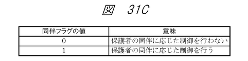
- FIG. 10 is an operation sequence diagram of viewing restriction control processing when receiving restricted viewing content according to Embodiment 4;
- FIG. 1 is a system configuration diagram illustrating an example of a broadcast communication system including a broadcast receiving apparatus according to the present embodiment.
- the broadcast communication system of this embodiment includes a broadcast receiver 100 and an antenna 100a, a broadband network such as the Internet 200, a router 200r and an access point 200a, a radio tower 300t and a broadcast satellite (or communication satellite) 300s, a broadcast station A server 300, a service provider server 400, other application servers 500, a mobile telephone communication server 600, a base station 600b of a mobile telephone communication network, and a portable information terminal 700.
- the broadcast receiving apparatus 100 receives the broadcast wave transmitted from the radio tower 300t via the broadcast satellite (or communication satellite) 300s and the antenna 100a. Alternatively, the broadcast wave transmitted from the radio tower 300t may be received directly from the antenna 100a without passing through the broadcast satellite (or communication satellite) 300s.
- the broadcast receiving apparatus 100 can be connected to the Internet 200 via the router apparatus 200r, and can transmit and receive data by communication with each server apparatus and other communication devices on the Internet 200.
- the router device 200r is connected to the Internet 200 by wired communication, is connected to the broadcast receiving device 100 by wired communication or wireless communication, and is connected to the portable information terminal 700 by wireless communication.
- a method such as Wi-Fi (registered trademark) may be used.
- Wi-Fi registered trademark
- each server device and other communication devices on the Internet 200, the broadcast receiving device 100, and the portable information terminal 700 can mutually transmit and receive data via the router device 200r.
- the communication between the broadcast receiving device 100 and the portable information terminal 700 may be performed directly using a method such as BlueTooth (registered trademark) or NFC (Near Field Communication) without using the router device 200r.
- the radio tower 300t is a broadcasting facility of a broadcasting station, and transmits broadcast waves including encoded data of broadcast programs, caption information, other applications, general-purpose data, and the like.
- the broadcast satellite (or communication satellite) 300s receives the broadcast wave transmitted from the radio tower 300t of the broadcast station, performs appropriate frequency conversion, etc., and then broadcasts the antenna 100a connected to the broadcast receiving device 100 to the antenna 100a. It is a repeater that retransmits waves.
- the broadcasting station includes a broadcasting station server 300.
- the broadcast station server 300 stores metadata such as broadcast programs (video content, etc.) and program titles, program IDs, program outlines, performer information, broadcast date and time of each broadcast program, and the video content and each metadata are stored. Based on the contract, it can be provided to the service provider.
- the provision of the moving image content and each metadata to the service provider may be performed through an API (Application Programming Interface) included in the broadcast station server 300.
- Service provider server 400 is a server device prepared by a service provider, and is capable of providing various services linked to broadcast programs distributed from broadcast stations.
- the service provider server 400 also stores, manages, and distributes video content and metadata provided from the broadcast station server 300, various contents and applications linked to broadcast programs, and the like.
- it in response to an inquiry from a television receiver or the like, it also has a function of searching for available contents and applications and providing a list.
- the storage, management and distribution of the content and metadata and the storage, management and distribution of the application may be performed by different server devices.
- the broadcasting station and the service provider may be the same or different.
- a plurality of service provider servers 400 may be prepared for different services.
- the function of the service provider server 400 may be provided by the broadcast station server 300.
- Other application server 500 is a known server device that stores, manages, and distributes other general applications, operation programs, contents, data, and the like. There may be a plurality of other application servers 500 on the Internet 200.
- the mobile telephone communication server 600 is connected to the Internet 200, and is connected to the portable information terminal 700 via the base station 600b.
- the mobile telephone communication server 600 manages telephone communication (call) and data transmission / reception via the mobile telephone communication network of the portable information terminal 700, and each server device and other communication devices on the portable information terminal 700 and the Internet 200. Data can be sent and received through communication with the.
- the communication between the base station 600b and the portable information terminal 700 is W-CDMA (Wideband Code Division Multiple Access) (registered trademark) method, GSM (Global System for Mobile communications) (registered trademark) method, LTE (LongTerm Term) method. Alternatively, it may be performed by other communication methods.
- the portable information terminal 700 has a function of telephone communication (call) and data transmission / reception via a mobile telephone communication network and a function of wireless communication by Wi-Fi (registered trademark) or the like.
- the portable information terminal 700 can be connected to the Internet 200 via the router device 200r and the access point 200a, or via the mobile phone communication network base station 600b and the mobile phone communication server 600. It is possible to send and receive data by communication with each server device and other communication devices.
- the access point 200a is connected to the Internet 200 by wired communication, and is connected to the portable information terminal 700 by wireless communication. For the wireless communication, a method such as Wi-Fi (registered trademark) may be used. Communication between portable information terminal 700 and broadcast receiving apparatus 100 is performed via access point 200a and Internet 200 and router apparatus 200r, or through base station 600b and mobile telephone communication server 600, Internet 200 and router apparatus 200r. It may be carried out via.
- the broadcast receiving apparatus 100 shown in FIG. 1 is defined by the MPEG (Moving Picture Experts Group) -2 system, which is widely adopted in conventional digital broadcasting systems, as a media transport system for transmitting data such as video and audio. It is assumed that the television receiver is compatible with MMT (MPEG Media Transport) instead of TS (Transport Stream) (hereinafter referred to as MPEG2-TS). It may be a television receiver that can support both MPEG2-TS and MMT.
- MPEG2TS Transmission Stream
- MPEG2-TS is characterized in that components such as video and audio constituting a program are multiplexed into one stream together with a control signal and a clock. Since it is handled as one stream including a clock, it is suitable for transmitting one content through one transmission path in which transmission quality is ensured, and has been adopted in many conventional digital broadcasting systems.
- the function of MPEG2-TS in response to environmental changes related to content distribution such as recent diversification of content, diversification of devices that use content, diversification of transmission paths for content distribution, diversification of content storage environment, etc. Therefore, MMT is a newly developed media transport system.
- FIG. 2A shows an example of an outline of the encoded signal in the MMT of the present embodiment.
- the MMT of this embodiment has an MFU (Media Fragment Unit), an MPU (Media Processing Unit), an MMTP (MMT Protocol) payload, and an MMTP packet as elements constituting the encoded signal.
- MFU Media Fragment Unit
- MPU Media Processing Unit
- MMTP MMT Protocol
- MFU is a format when transmitting video or audio, and may be configured in units of NAL (Network Abstraction Layer) units or access units.
- the MPU includes one or more access units, and can perform video and audio decoding processing by the MPU alone.
- the MPU may be composed of MPU metadata including information on the configuration of the entire MPU, movie fragment metadata including information of encoded media data, and sample data that is encoded media data. A plurality of movie fragment data and sample data may exist in one MPU. Further, it is assumed that MFU can be extracted from the sample data.
- FIG. 2B shows an example of the configuration of the MPU.
- any MPU can be distinguished from other MPUs by the asset ID for identifying the asset and the MPU sequence number.
- the presentation time and decoding time may be specified in units of MPUs or access units.
- the MMTP packet includes a header part and an MMTP payload, and transmits MFU and MMT control information.
- the MMTP payload includes a payload header corresponding to the content (data unit) stored in the payload portion.
- FIG. 2C shows an example of the outline from the construction of the MFU from the video / audio signal, further storing it in the MMTP payload, and configuring the MMTP packet. Note that, in a video signal that is encoded using inter-frame prediction, it is desirable to configure the MPU in GOP (Group Of Pictures) units. Further, when the size of the MFU to be transmitted is small, one MFU may be stored in one payload part, or a plurality of MFUs of the same type may be stored in one payload part.
- GOP Group Of Pictures
- one MFU may be divided into a plurality of payload parts and stored. Further, the MMTP packet may be protected using a technique such as AL-FEC (Application Layer Forward Error Correction) or ARQ (Automatic Repeat Request) in order to recover the packet loss on the transmission path.
- AL-FEC Application Layer Forward Error Correction
- ARQ Automatic Repeat Request
- MPEG-H HEVC High Efficiency Video Coding
- MPEG-4 AAC Advanced Audio Coding
- MPEG-4 ALS Audio Lossless
- Coding is used.
- the encoded data such as video and audio of the broadcast program encoded by the above-mentioned methods is in the MFU or MPU format, is further carried on the MMTP payload, is converted into an MMTP packet, and is transmitted as an IP (Internet Protocol) packet.
- IP Internet Protocol
- data contents related to a broadcast program may be in the MFU or MPU format, further MMTP packetized on the MMTP payload, and transmitted by IP packet.
- the data content transmission method includes (1) a caption / text super transmission method used for streaming data synchronized with broadcasting, (2) an application transmission method used for data transmission service asynchronous with broadcasting, and (3) from a broadcasting station.
- UDP / IP User Datagram Protocol / Internet Protocol
- UDP / IP or TCP / IP Transmission Control Protocol / Internet Protocol
- TLV Type Length Value
- FIG. 1 An example of the protocol stack of the broadcasting system of the present embodiment is shown in FIG. In the figure, (A) is an example of a protocol stack in a broadcast transmission path, and (B) is an example of a protocol stack in a communication line.
- MMT-SI MMT-Signaling Information
- TLV-SI TLV-Signaling Information
- time information is transmitted in order to provide absolute time.
- MPEG2-TS indicates the component display time based on a different clock for each TS
- MMT indicates the component display time based on the Coordinated Universal Time (UTC).
- UTC Coordinated Universal Time
- the control information includes the TLV-SI related to the TLV multiplexing method for multiplexing IP packets and the MMT that is the media transport method. Prepare the relevant MMT-SI.
- the TLV-SI provides information for the broadcast receiving apparatus 100 to demultiplex the IP packet multiplexed on the broadcast transmission path.
- the TLV-SI is composed of a “table” and a “descriptor”. The “table” is transmitted in the section format, and the “descriptor” is arranged in the “table”.
- the MMT-SI is transmission control information indicating information related to the configuration of the MMT package and the broadcast service.
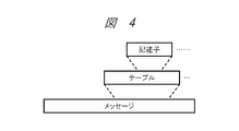
- MMT-SI is composed of three levels: “message” for storing “table” and “descriptor”, “table” having elements and attributes indicating specific information, and “descriptor” indicating more detailed information. Shall be.
- An example of the hierarchical structure of the control information used in the broadcasting system of this embodiment is shown in FIG.
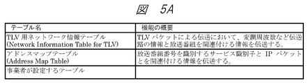
- FIG. 5A shows a list of “tables” used in the TLV-SI of the broadcasting system supported by the broadcast receiving apparatus 100 of the present embodiment.
- the following table is used as a “table” of TLV-SI.
- TLV-NIT The network information table for TLV (Network Information Table for TLV: TLV-NIT) represents information on the physical configuration of the TLV stream transmitted by the network and the characteristics of the network itself.
- AMT Address Map Table
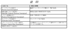
- FIG. 5B shows a list of “descriptors” arranged in the TLV-SI of the broadcasting system to which the broadcast receiving apparatus 100 of the present embodiment corresponds. In this embodiment, the following are used as “descriptors” of TLV-SI.
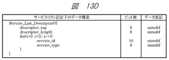
- Service list descriptor The service list descriptor provides a list of services according to service identification and service type.
- Satellite distribution system descriptor The satellite distribution system descriptor indicates the physical conditions of the satellite transmission path.
- System management descriptor The system management descriptor is used to identify broadcast and non-broadcast.
- the network name descriptor describes the network name using character codes.
- Remote control key descriptor The remote control key descriptor is used to set a service to be assigned to the one-touch channel selection button of the receiver remote control.
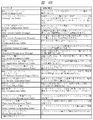
- FIG. 6A shows a list of “messages” used in the MMT-SI of the broadcast system supported by the broadcast receiving apparatus 100 of the present embodiment.
- the following message is used as a “message” of MMT-SI.
- PA message The Package Access (PA) message is used to transmit various tables.
- M2 section message The M2 section message is used to transmit the section extension format of MPEG-2 Systems.
- CA message The CA message is used to transmit a table for identifying the conditional access system.
- M2 short section message is used to transmit the section short format of MPEG-2 Systems.
- the data transmission message is a message for storing a table relating to data transmission.
- FIG. 6B shows a list of “tables” used in the MMT-SI of the broadcast system supported by the broadcast receiving apparatus 100 of the present embodiment.
- the table is control information having elements and attributes indicating specific information, and is stored in a message and transmitted by an MMTP packet.
- the message for storing the table may be determined according to the table.
- the following table is used as the “table” of MMT-SI.
- MPT MMT package table
- the MPT may be stored in the PA message.
- PLT Packet List Table
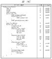
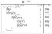
- LCT Layout Configuration Table
- ECM Entity Control Message
- EMM Entity Management Message
- the Entity Management Message transmits individual information including contract information for each subscriber and key information for decrypting ECM (common information).
- the EMM may be stored in the M2 section message.
- CAT Supplemental Access Table: CAT (MH) is used to store a descriptor for identifying a conditional access system.
- CAT (MH) may be stored in the CA message.
- DCM Download Control Message
- the Download Control Message transmits key related information including a key for decrypting a transmission path cipher for downloading.
- the DCM may be stored in the M2 section message.
- DMM Download Management Message transmits key-related information including a download key for decrypting DCM.
- the DMM may be stored in the M2 section message.
- MH-EIT MH-Event Information Table: MH-EIT
- MH-EIT is time-series information regarding events included in each service.
- the MH-EIT may be stored in the M2 section message.
- MH-AIT MH-Application Information Table
- the MH-AIT stores all information related to the application, an activation state required for the application, and the like.
- the MH-AIT may be stored in the M2 section message.
- MH-BIT An MH-Broadcaster Information Table (MH-BIT) is used to present information on broadcasters existing on the network.
- the MH-BIT may be stored in the M2 section message.
- MH-SDTT The MH-software download trigger table (MH-Software Download Trigger Table: MH-SDTT) is used for download notification information.
- the MH-SDTT may be stored in the M2 section message.
- MH-SDT MH-Service Description Table (MH-Service Description Table: MH-SDT) has a sub-table representing a service included in a specific TLV stream, and information related to the organization channel such as the name of the organization channel and the name of the broadcaster. Is transmitted.
- the MH-SDT may be stored in the M2 section message.
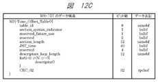
- MH-TOT The MH-Time Offset Table (MH-TOT) transmits JST time and date (modified Julian date) information.
- the MH-TOT may be stored in the M2 short section message.
- MH-CDT The MH-Common Data Table (MH-CDT) is used to transmit the common data to be stored in the non-volatile memory in a section format for all receivers that receive the MH-Common Data Table (MH-CDT).
- the MH-CDT may be stored in the M2 section message.
- the data directory management table (Data Directory Management Table: DDM table) provides a directory structure of files constituting an application in order to separate the file structure of the application from the structure for file transmission.
- the DDM table may be stored in the data transmission message.
- DAM table The data asset management table (Data Asset Management Table: DAM table) provides the configuration of the MPU in the asset and version information for each MPU.
- the DAM table may be stored in the data transmission message.
- DCC Table The data content management table (Data Content Configuration Table: DCC table) provides file configuration information as data content in order to realize flexible and effective cache control.
- the DCC table may be stored in the data transmission message.
- EMT Event Message Table
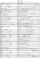
- FIG. 6C, FIG. 6D and FIG. 6E show a list of “descriptors” arranged in the MMT-SI of the broadcasting system to which the broadcast receiving apparatus 100 of this embodiment corresponds.
- the descriptor is control information that provides more detailed information and is arranged in a table. Note that the table in which the descriptor is arranged may be determined according to the descriptor. In this embodiment, the following are used as “descriptors” of MMT-SI.
- Asset group descriptor provides asset group relationships and priorities within groups.
- the asset group descriptor may be located in the MPT.
- Event package descriptor provides a correspondence between an event representing a program and a package.
- the event package descriptor may be arranged in the MH-EIT transmitted in the M2 section message.
- the background color specification descriptor provides the backmost background color in the layout specification.
- the background color designation descriptor may be arranged in the LCT.
- the MPU presentation area designation descriptor provides a position for presenting an MPU.
- the MPU presentation area designation descriptor may be arranged in the MPT.
- MPU time stamp descriptor indicates the presentation time of the first access unit in the presentation order in the MPU.
- the MPU timestamp descriptor may be located in the MPT.
- the dependency descriptor provides an asset ID of an asset having a dependency relationship.
- the dependency descriptor may be arranged in the MPT.
- Access control descriptor provides information for identifying the conditional access system.
- the access control descriptor may be located in MPT or CAT (MH).
- the scramble method descriptor provides information for identifying the type of encryption target and encryption algorithm at the time of scrambling.
- the scramble method descriptor may be arranged in MPT or CAT (MH).
- the message authentication scheme descriptor provides information for identifying the message authentication scheme when performing message authentication.
- the message authentication scheme descriptor may be arranged in MPT or CAT (MH).
- the emergency information descriptor (MH) is used when emergency alert broadcasting is performed.
- the emergency information descriptor (MH) may be located in the MPT.
- the MH-MPEG-4 audio descriptor describes basic information for specifying an encoding parameter of an ISO / IEC 14496-3 (MPEG-4 audio) audio stream. Use for.
- the MH-MPEG-4 audio descriptor may be located in the MPT.
- MH-MPEG-4 Audio Extension Descriptor The MH-MPEG-4 audio extension descriptor is used to describe the profile and level of the MPEG-4 audio stream and the settings specific to the encoding method.
- the MH-MPEG-4 audio extension descriptor may be located in the MPT.
- the MH-HEVC video descriptor is an ITU-T recommendation H.264 standard. H.265
- the MH-HEVC video descriptor may be located in the MPT.
- the MH-Link Descriptor identifies a service provided when a viewer requests additional information related to a certain thing described in the program sequence information system.
- the MH-link descriptor may be arranged in MPT, MH-EIT, MH-SDT, etc.
- MH-event group descriptor is used to indicate that these event groups are grouped when there is a relationship between a plurality of events.
- the MH-event group descriptor may be located in the MH-EIT.
- the MH-Service List Descriptor provides a service list according to service identification and service type.
- the MH-service list descriptor may be located in the MH-BIT.
- MH-short format event descriptor represents an event name and a short description of the event in a text format.
- the MH-short form event descriptor may be located in the MH-EIT.
- the MH-extended format event descriptor is used in addition to the MH-short format event descriptor to provide a detailed description of the event.
- the MH-extended event descriptor may be located in the MH-EIT.
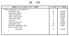
- Video Component Descriptor indicates parameters and explanations related to the video component, and is also used to represent an elementary stream in a character format.
- the video component descriptor may be located in MPT or MH-EIT.
- the MH-stream identification descriptor is used to label the component stream of the service and to refer to the description content indicated by the video component descriptor in the MH-EIT. .
- the MH-stream identification descriptor may be arranged in the MPT.
- the MH-content descriptor indicates the genre of the event.
- the MH-content descriptor may be located in the MH-EIT.
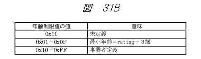
- the MH-Parental Rate Descriptor represents viewing restrictions based on age, and is used to extend based on other restriction conditions.
- the MH-parental rate descriptor may be located in MPT or MH-EIT.
- the MH-voice component descriptor indicates each parameter of the voice elementary stream, and is also used to represent the elementary stream in a character format.
- the MH-voice component descriptor may be located in MPT or MH-EIT.
- the MH-target area descriptor is used to describe a target area for a program or a part of streams constituting the program.
- the MH-target area descriptor may be located in the MPT.
- the MH-series descriptor is used to identify a series program.
- the MH-series descriptor may be located in the MH-EIT.
- the MH-SI transmission parameter descriptor is used to indicate a transmission parameter of SI.
- the MH-SI transmission parameter descriptor may be arranged in the MH-BIT.
- the MH-Broadcaster name descriptor describes the name of the broadcaster.
- the MH-Broadcaster name descriptor may be located in the MH-BIT.
- the MH-Service Descriptor represents the organization channel name and its operator name with a character code together with the service type.
- the MH-service descriptor may be located in the MH-SDT.
- IP Data Flow Descriptor provides information on the IP data flow constituting the service.
- the IP data flow descriptor may be located in MH-SDT.
- the MH-CA activation descriptor describes activation information for activating a CAS program on the CAS infrastructure.
- the MH-CA activation descriptor may be located in MPT or CAT (CA).
- the MH-Type descriptor indicates the type of a file transmitted by the application transmission method.
- the MH-Type descriptor may be placed in the DAM table.
- the MH-Info descriptor describes information related to the MPU or item.
- the MH-Info descriptor may be placed in the DAM table.
- the MH-Expire descriptor describes the expiration date of an item.
- the MH-Expire descriptor may be placed in the DAM table.
- MH-Compression Type descriptor means that the item to be transmitted is compressed, and indicates the compression algorithm and the number of bytes of the item before compression.
- the MH-Compression Type descriptor may be placed in the DAM table.
- the MH-data encoding scheme descriptor is used to identify a data encoding scheme.
- the MH-data encoding scheme descriptor may be arranged in the MPT.
- UTC-NPT Reference Descriptor The UTC-NPT reference descriptor is used to convey the relationship between NPT (Normal Play Time) and UTC.
- the UTC-NPT reference descriptor may be located in the EMT.
- Event message descriptor conveys information related to event messages in general.
- the event message descriptor may be located in the EMT.
- the MH-local time offset descriptor is used to give a certain offset value to the actual time (for example, UTC + 9 hours) and the display time to the human system during the daylight saving time.
- the MH-local time offset descriptor may be located in the MH-TOT.
- the MH-component group descriptor defines and identifies a combination of components in an event.
- the MH-component group descriptor may be located in the MH-EIT.
- the MH-logo transmission descriptor is used to describe a character string for a simple logo, pointing to a CDT format logo, and the like.
- the MH-logo transmission descriptor may be located in the MH-SDT.
- MPU extended time stamp descriptor provides the decoding time of the access unit in the MPU.
- the MPU extended timestamp descriptor may be placed in the MPT.
- MPU download content descriptor is used to describe attribute information of content downloaded using the MPU.
- the MPU download content descriptor may be arranged in MH-SDTT.
- the MH-Network Download Content Descriptor is used to describe attribute information of content downloaded using the network.
- the MH-network download content descriptor may be located in the MH-SDTT.
- the MH-application descriptor describes application information.
- the MH-application descriptor may be located in the MH-AIT.
- the MH-Transmission Protocol Descriptor is used for designating a transmission protocol such as broadcasting or communication and indicating location information of an application depending on the transmission protocol.
- the MH-Transmission Protocol Descriptor may be located in the MH-AIT.
- MH Simple Application Location Descriptor
- the MH is described to indicate details of an application acquisition destination.
- the MH-simple application location descriptor may be located in the MH-AIT.
- the MH-application boundary authority setting descriptor is described in order to set an application boundary and to set a broadcast resource access authority for each area (URL).
- the MH-application boundary authority setting descriptor may be arranged in the MH-AIT.
- the MH-activation priority information descriptor is described for designating the application activation priority.
- the MH-activation priority information descriptor may be arranged in the MH-AIT.
- MH-cache information descriptor The MH-cache information descriptor is described to be used for cache control when the resources constituting the application are cached and held when the application is assumed to be reused. .
- the MH-cache information descriptor may be located in the MH-AIT.
- the MH-Probabilistic Application Delay Descriptor is used to delay the application control timing by a stochastically set delay amount assuming load distribution of server access for application acquisition. Describe in.
- the MH-stochastic application delay descriptor may be placed in the MH-AIT.
- Link destination PU descriptor describes another presentation unit that may transition from the presentation unit (PU).
- the link destination PU descriptor may be arranged in the DCC table.
- Lock cache specification descriptor describes the specification of a file to be cached and locked in the presentation unit.
- the lock cache designation descriptor may be arranged in the DCC table.
- Unlock cache specification descriptor describes the specification of the file to be unlocked among the files locked in the presentation unit.
- the unlock cache specification descriptor may be arranged in the DCC table.
- the MH-Download Protection Descriptor describes the location information and transmission information of the MMTP packet that transmits DCM and DMM.
- the MH-download protection descriptor may be located in MPT or MH-SDTT.
- Application service descriptor describes entry information of an application related to the service.
- the application service descriptor may be located in the MPT.
- MPU node descriptor indicates that the MPU corresponds to a directory node specified in the data directory management table.
- the MPU node descriptor may be placed in the DAM table.
- the PU configuration descriptor indicates a list of MPUs constituting the presentation unit as mapping information between the presentation unit and the transmission unit.
- the PU configuration descriptor may be placed in the DCC table.
- the MH-hierarchical coding descriptor describes information for identifying a video stream component subjected to hierarchical coding.
- the MH-hierarchical coding descriptor may be located in the MPT.
- the content copy control descriptor indicates information for controlling the copy generation in the digital recording device for the entire service.
- the broadcast station (copyright) Used by the user) to communicate information about the copy or the maximum transmission rate to the digital recording device.
- the content copy control descriptor may be arranged in MPT, MH-EIT, MH-SDT, etc.
- the content usage control descriptor indicates information related to copy control and remote viewing control when a program is stored in a hard disk or when a video / audio signal is output from a receiver. Used for.
- the content usage control descriptor may be arranged in MPT, MH-EIT, MH-SDT, or the like.
- a component is defined as an asset, and in the following, the component may be expressed as an asset.
- data transmission can be performed through a plurality of paths such as a TLV stream via a broadcast transmission path and an IP data flow via a communication line.
- the TLV stream includes a TLV-SI such as TLV-NIT or AMT, and an IP data flow that is a data flow of an IP packet.
- the IP data flow includes video assets including a series of video MPUs and audio assets including a series of audio MPUs.
- a subtitle asset including a series of subtitle MPUs, a character super asset including a series of character super MPUs, a data asset including a series of data MPUs, and the like may be included in the IP data flow.
- MPT MMT package table
- the association may be performed by describing a package ID for identifying a package in the MPT and an asset ID for identifying each asset included in the package.
- FIG. 7B shows an example of the data structure of MPT.
- the “MMT_package_id_byte” parameter in the figure corresponds to the package ID
- the “asset_id_byte” parameter corresponds to the asset ID.
- Assets that make up the package can be only assets in the TLV stream, but as shown in FIG. 7A, assets transmitted in the IP data flow of the communication line can also be included. This is because the location information of the asset is described in the MPT together with the asset ID for identifying each asset included in the package so that the broadcast receiving apparatus 100 of this embodiment can grasp the reference destination of each asset. realizable.
- the location information is specified by “MMT_general_location_info ()” in the MPT data structure shown in FIG. 7B.
- FIG. 7C shows an example of the data structure of the location information.
- the broadcast receiving device 100 can refer to various data transmitted through various transmission paths.
- (1) is, for example, an IP data flow included in a TLV stream of a digital broadcast signal received by the broadcast receiving apparatus 100 of the present embodiment via the antenna 100a.
- the reference destination in (1) may be an IP data flow received via the communication line.
- (2), (3), (5), and (6) are IP data flows received by the broadcast receiving apparatus 100 of this embodiment via a communication line.
- (4) for example, a receiving function for receiving a digital broadcast signal using the MMT method and a digital broadcast signal using the MPEG2-TS method are received as in the broadcast receiving device 800 of Example 2 described later.
- MPEG2-received by a reception function for receiving a digital broadcast signal using the MPEG2-TS system based on MPT location information included in the digital broadcast signal using the MMT system can be used when referring to data multiplexed in a TS.
- presentation time and decoding time can be specified in units of MPUs and access units.
- Information regarding the presentation time and the decoding time is described in the MPT as an MPU time stamp descriptor or an MPU extended time stamp descriptor.
- FIG. 7D shows an example of a data structure of an MPU time stamp descriptor describing information on the presentation time.
- the presentation time information of each MPU is specified by the “mpu_presentation_time” parameter of the MPU time stamp descriptor.
- the MPU to be designated can be identified by the “mpu_sequence_number” parameter.
- a plurality of MPUs designated by the MPT are presented (displayed and output) in conjunction with a clock based on NTP, which is time information expressed in UTC. Etc.).
- NTP time information expressed in UTC. Etc.
- the information related to the decoding time is described by the MPU extended time stamp descriptor, but detailed description thereof is omitted.
- the presentation control of various data using a clock based on the NTP will be described later.
- a series of data in units of “packages” corresponds to “services” of digital broadcasting.
- the “service” is a series of “programs” sent according to a schedule.
- the “program” is treated as an “event” in the MMT system.
- Each event has a start time and duration specified by MH-EIT.
- the ID of the MMT package corresponding to each event is specified by the event package descriptor arranged in the MH-EIT.
- FIG. 7E shows an example of the data structure of MH-EIT.
- the start time is specified by the “start_time” parameter in the figure, and the duration is specified by the “duration” parameter.
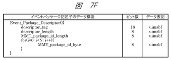
- FIG. 7F shows an example of the data structure of the event package descriptor.
- Correspondence between each event and the MMT package can be designated by the “MMT_package_id_byte” parameter of the event package descriptor arranged in the MH-EIT.
- the MH-EIT performs various processes in units of the “event” in the broadcast receiving apparatus 100 of this embodiment (for example, electronic program guide generation processing, recording reservation and viewing reservation control, copyright management processing such as temporary storage, etc. ) And the like.
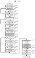
- FIG. 8A is a block diagram illustrating an example of an internal configuration of the broadcast receiving apparatus 100.
- the broadcast receiving apparatus 100 includes a main control unit 101, a system bus 102, a ROM 103, a RAM 104, a storage (storage) unit 110, a LAN communication unit 121, an expansion interface unit 124, a digital interface unit 125, a tuner / demodulation unit 131, and a separation unit 132.
- Video decoder 141 Video decoder 141, video color gamut conversion unit 142, audio decoder 143, character super decoder 144, subtitle decoder 145, subtitle synthesis unit 146, subtitle color gamut conversion unit 147, data decoder 151, cache unit 152, application control unit 153, A browser unit 154, an application color gamut conversion unit 155, a sound source unit 156, a video synthesis unit 161, a monitor unit 162, a video output unit 163, a voice synthesis unit 164, a speaker unit 165, a voice output unit 166, and an operation input unit 170. Is done.
- the main control unit 101 is a microprocessor unit that controls the entire broadcast receiving apparatus 100 according to a predetermined operation program.
- a system bus 102 is a data communication path for transmitting and receiving data between the main control unit 101 and each operation block in the broadcast receiving apparatus 100.
- a ROM (Read Only Memory) 103 is a non-volatile memory in which a basic operation program such as an operating system and other operation programs are stored. For example, a rewritable ROM such as an EEPROM (Electrically Erasable Programmable ROM) or a flash ROM is provided. Used. The ROM 103 may store operation setting values necessary for the operation of the broadcast receiving apparatus 100.
- a RAM (Random Access Memory) 104 serves as a work area for executing a basic operation program and other operation programs. The ROM 103 and the RAM 104 may be integrated with the main control unit 101. Further, the ROM 103 may not use an independent configuration as shown in FIG. 8A but may use a partial storage area in the storage (accumulation) unit 110.
- the storage (accumulation) unit 110 stores an operation program and an operation setting value of the broadcast receiving apparatus 100, personal information of the user of the broadcast receiving apparatus 100, and the like. Further, it is possible to store an operation program downloaded via the Internet 200 and various data created by the operation program. It is also possible to store content such as moving images, still images, and audio obtained from broadcast waves or downloaded via the Internet 200. All or some of the functions of the ROM 103 may be replaced by a partial area of the storage (storage) unit 110. Further, the storage (accumulation) unit 110 needs to hold stored information even when power is not supplied to the broadcast receiving apparatus 100 from the outside. Therefore, for example, a device such as a nonvolatile semiconductor element memory such as a flash ROM or SSD (Solid State Drive), a magnetic disk drive such as an HDD (Hard Disc Drive), or the like is used.
- a nonvolatile semiconductor element memory such as a flash ROM or SSD (Solid State Drive), a magnetic disk drive such as an HDD (Hard Disc Drive), or
- each operation program stored in the ROM 103 or the storage (accumulation) unit 110 can be added, updated, and expanded in function by download processing from each server device on the Internet 200.
- a LAN (Local Area Network) communication unit 121 is connected to the Internet 200 via the router device 200r, and transmits / receives data to / from each server device and other communication devices on the Internet 200. It is also assumed that an MMT data string (or a part thereof) of a program transmitted via a communication line is acquired.
- the connection with the router device 200r may be a wired connection or a wireless connection such as Wi-Fi (registered trademark).
- the LAN communication unit 121 includes an encoding circuit, a decoding circuit, and the like.
- the broadcast receiving apparatus 100 may further include other communication units such as a BlueTooth (registered trademark) communication unit, an NFC communication unit, and an infrared communication unit.
- the tuner / demodulator 131 receives the broadcast wave transmitted from the radio tower 300t via the antenna 100a, and tunes (tunes) to the channel of the service desired by the user based on the control of the main controller 101. Further, the tuner / demodulator 131 demodulates the received broadcast signal to obtain an MMT data string.
- FIG. 8A a configuration with one tuner / demodulation unit is illustrated. However, for the purpose of simultaneous display of a plurality of screens, back program recording, and the like, the broadcast receiving apparatus 100 includes a tuner / demodulation unit. It is good also as a structure mounted in multiple numbers.
- the separation unit 132 is an MMT decoder, and a video data sequence, an audio data sequence, a character super data sequence, a caption data sequence, etc., which are real-time presentation elements based on a control signal in the input MMT data sequence, are respectively converted into a video decoder 141.
- the voice decoder 143, the character super decoder 144, the subtitle decoder 145, etc. are distributed.
- the data input to the demultiplexing unit 132 includes an MMT data sequence transmitted through a broadcast transmission path and demodulated by the tuner / demodulation unit 131, or MMT data transmitted through a communication line and received by the LAN communication unit 121. It can be a line.
- the separation unit 132 reproduces the multimedia application and file system data that is a component of the multimedia application, and temporarily stores them in the cache unit 152.
- the separation unit 132 extracts general-purpose data and outputs the data to the data decoder 151 for use in streaming data for use with a player that presents data other than video / audio subtitles or data for an application.
- the separation unit 132 may perform error correction, access restriction control, and the like on the input MMT data string based on the control of the main control unit 101.
- the video decoder 141 decodes the video data sequence input from the separation unit 132 and outputs video information.
- the video color gamut conversion unit 142 performs color space conversion processing on the video information decoded by the video decoder 141 as needed for video synthesis processing by the video synthesis unit 161.
- the audio decoder 143 decodes the audio data sequence input from the separation unit 132 and outputs audio information. Further, even when streaming data obtained from the Internet 200 via the LAN communication unit 121, for example, MPEG-DASH (MPEG-Dynamic Adaptive Streaming HTTP) format or the like is input to the video decoder 141 and the audio decoder 143. good.
- a plurality of video decoders 141, video color gamut conversion units 142, audio decoders 143, and the like may be provided in order to simultaneously decode a plurality of types of video data sequences and audio data sequences.
- the character super decoder 144 decodes the character super data string input from the separation unit 132 and outputs character super information.
- the caption decoder 145 decodes the caption data string input from the separation unit 132 and outputs caption information.
- the superimposing information output from the character super decoder 144 and the subtitle information output from the subtitle decoder 145 are subjected to the synthesizing process in the subtitle synthesizing unit 146, and further, the subtitle color gamut converting unit 147 performs the synthesis in the video synthesizing unit 161. For the video composition process, a color space conversion process is performed as necessary.
- subtitles those related to the content of the video are referred to as subtitles, and other services are referred to as character supermarkets. To do. If they are not distinguished, they are collectively referred to as subtitles.
- the browser unit 154 transmits the multimedia application file acquired from the server device on the Internet 200 via the cache unit 152 or the LAN communication unit 121 and the file system data that is a component of the multimedia application file to the control information or LAN included in the MMT data string.
- the control information acquired from the server device on the Internet 200 via the communication unit 121 is presented according to an instruction from the application control unit 153 that interprets the control information.
- the multimedia application file may be an HTML (Hyper Text Markup Language) document, a BML (Broadcast Markup Language) document, or the like.
- the application information output from the browser unit 154 is further subjected to color space conversion processing in the application color gamut conversion unit 155 as necessary for the video composition processing in the video composition unit 161.
- the browser unit 154 also plays the application audio information by acting on the sound source unit 156.
- the video composition unit 161 receives the video information output from the video color gamut conversion unit 142, the caption information output from the subtitle color gamut conversion unit 147, the application information output from the application color gamut conversion unit 155, and the like. Processing such as selection and / or superposition is performed.
- the video composition unit 161 includes a video RAM (not shown), and the monitor unit 162 and the like are driven based on video information and the like input to the video RAM.
- the video composition unit 161 is based on the control of the main control unit 101, and an EPG (Electronic Program Guide) created based on information such as scaling processing and MH-EIT included in the MMT-SI as necessary. Electronic program guide) Superimposes screen information.
- EPG Electronic Program Guide
- the monitor unit 162 is a display device such as a liquid crystal panel, for example, and provides video information selected and / or superimposed by the video composition unit 161 to the user of the broadcast receiving apparatus 100.
- the video output unit 163 is a video output interface that outputs the video information that has been selected and / or superimposed by the video composition unit 161.
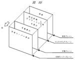
- the presentation function of the broadcast receiving apparatus 100 of the present embodiment has a logical plane structure in order to display the multimedia service as intended by the provider.
- FIG. 8B shows an example of the configuration of the logical plane structure provided in the presentation function of the broadcast receiving apparatus 100 of the present embodiment.
- a character super plane for displaying a character super is arranged on the foreground
- a subtitle plane for displaying a subtitle is arranged on the next layer.
- a multimedia plane for displaying a broadcast video, a multimedia application, or a composite video thereof is arranged, and a background plane is arranged on the backmost surface.
- the caption synthesizing unit 146 and the video synthesizing unit 161 drawing of the character super information on the character super plane, drawing of the subtitle information on the subtitle plane, and drawing on the multimedia plane such as video information and application information are performed.
- the background color is drawn on the background plane based on LCT included in the MMT-SI. Note that a plurality of multimedia planes in the third layer can be prepared according to the number of video decoders 141. However, even when there are a plurality of multimedia planes, the application information and the like output from the application color gamut conversion unit 155 is output only to the foreground multimedia plane.
- the voice synthesizer 164 inputs the voice information output from the voice decoder 143 and the application voice information reproduced by the sound source unit 156, and performs processing such as selection and / or mixing as appropriate.
- the speaker unit 165 provides the user of the broadcast receiving apparatus 100 with the audio information that has been selected and / or mixed by the voice synthesis unit 164.
- the audio output unit 166 is an audio output interface that outputs audio information that has been selected and / or mixed by the audio synthesis unit 164.
- the extension interface unit 124 is an interface group for extending the function of the broadcast receiving apparatus 100.
- the extension interface unit 124 includes an analog video / audio interface, a USB (Universal Serial Bus) interface, a memory interface, and the like.
- the analog video / audio interface performs input of analog video signals / audio signals from external video / audio output devices, output of analog video signals / audio signals to external video / audio input devices, and the like.
- the USB interface is connected to a PC or the like to transmit / receive data.
- a broadcast program or content may be recorded by connecting an HDD.
- a keyboard or other USB device may be connected.
- the memory interface transmits and receives data by connecting a memory card and other memory media.
- the digital interface unit 125 is an interface for outputting or inputting encoded digital video data and / or digital audio data.
- the digital interface unit 125 can output the MMT data sequence obtained by demodulation by the tuner / demodulation unit 131, the MMT data sequence acquired via the LAN communication unit 121, or the mixed data of the MMT data sequences as they are. Shall. Further, the MMT data string input from the digital interface unit 125 may be controlled to be input to the separation unit 132. Output of digital content stored in the storage (storage) unit 110 or storage of digital content in the storage (storage) unit 110 may be performed via the digital interface unit 125.
- the digital interface unit 125 is a DVI terminal, an HDMI (registered trademark) terminal, a Display Port (registered trademark) terminal, or the like. It may be a thing. It may be output or input in the form of serial data conforming to the IEEE 1394 specification or the like. Further, it may be configured as an IP interface that performs digital interface output via hardware such as Ethernet (registered trademark) or wireless LAN. In this case, the digital interface unit 125 and the LAN communication unit 121 may share the hardware configuration.
- the operation input unit 170 is an instruction input unit that inputs an operation instruction to the broadcast receiving apparatus 100.
- a remote control receiving unit that receives a command transmitted from a remote controller (not shown) and a button switch are arranged. It shall consist of operation keys. Either one may be sufficient.
- the operation input unit 170 may be replaced with a touch panel arranged on the monitor unit 162.
- a keyboard connected to the extension interface unit 124 may be substituted.
- the remote controller (not shown) may be replaced with a portable information terminal 700 having a remote command transmission function.
- the broadcast receiving apparatus 100 may be a television receiver, an optical disc drive recorder such as a DVD (Digital Versatile Disc) recorder, a magnetic disc drive recorder such as an HDD recorder, an STB (Set Top Box), or the like. It may be a PC (Personal Computer), a tablet terminal, a navigation device, a game machine or the like having a digital broadcast receiving function or a broadcast communication cooperation function.
- the monitor unit 162 and the speaker unit 165 may not be provided.
- FIG. 8C is a software configuration diagram of the broadcast receiving apparatus 100 of the present embodiment, and shows a software configuration in the ROM 103, the RAM 104, and the storage (storage) unit 110.
- a basic operation program 1001 and other operation programs are stored in the ROM 103
- a reception function program 1002, a cooperation function program 1003, a recording / playback function program 1004, and other operations are stored in the storage (accumulation) unit 110.
- the program is stored.
- the storage unit 110 also stores a content storage area 1200 that stores content such as moving images, still images, and audio, and authentication information that is necessary when accessing an external mobile terminal device or each server device. It is assumed that an information storage area 1300 and various information storage areas for storing various other information are provided.
- the basic operation program 1001 stored in the ROM 103 is expanded in the RAM 104, and the main control unit 101 executes the expanded basic operation program 1001 to constitute a basic operation execution unit 1101.
- the reception function program 1002, the linkage function program 1003, and the recording / playback function program 1004 stored in the storage (accumulation) unit 110 are expanded in the RAM 104, and the main control unit 101 further expands the reception function program 1002 and By executing the linkage function program 1003 and the recording / playback function program 1004, the reception function execution unit 1102, the linkage function execution unit 1103, and the recording / playback function execution unit 1104 are configured.
- the RAM 104 is provided with a temporary storage area that temporarily holds data created when each operation program is executed as necessary.
- the main control unit 101 executes a basic operation process to control each operation block by developing the basic operation program 1001 stored in the ROM 103 in the RAM 104 and executing it.
- the unit 1101 is described as performing control of each operation block. The same description is made for other operation programs.
- the reception function execution unit 1102 controls each operation block of the broadcast receiving apparatus 100 in order to reproduce components such as video and audio transmitted in the broadcast system of the present embodiment.
- the transport processing unit 1102a mainly controls the MMT decoder function of the separation unit 132, and distributes the video data sequence, the audio data sequence, and the like separated from the MMT data sequence to the corresponding decoding processing units.
- the AV decoding processing unit 1102b mainly controls the video decoder 141, the audio decoder 143, and the like.
- the application processing unit 1102c mainly controls the cache unit 152, the application control unit 153, the browser unit 154, and the sound source unit 156.
- the character super processing unit 1102d mainly controls the character super decoder 144.
- the caption processing unit 1102e mainly controls the caption decoder 145.
- the general-purpose data processing unit 1102f mainly controls the data decoder 151.
- the EPG generation unit 1102g generates an EPG screen by interpreting description contents such as MH-EIT included in the MMT-SI.
- the presentation processing unit 1102h is based on the logical plane structure, and the video color gamut conversion unit 142, the subtitle synthesis unit 146, the subtitle color gamut conversion unit 147, the application color gamut conversion unit 155, the video synthesis unit 161, and the audio synthesis unit 164. Is mainly controlled.
- the cooperation function execution unit 1103 manages device authentication and connection, transmission / reception of each data, and the like when the broadcast receiving apparatus 100 performs a cooperation operation with an external apparatus such as the portable information terminal 700.
- the recording / playback function execution unit 1104 stores a broadcast program acquired from a digital broadcast wave of this broadcast system, content acquired from each server device on the network, the content storage area 1200 of the storage (storage) unit 110, and the extended interface unit 124. Control is performed when recording in an external storage or the like connected to or when reproducing the broadcast program or content.
- the operation programs may be stored in advance in the ROM 103 and / or the storage (accumulation) unit 110 at the time of product shipment. It may be acquired from the other application server 500 on the Internet 200 via the LAN communication unit 121 after the product is shipped. Further, each operation program stored in a memory card, an optical disk or the like may be acquired via the expansion interface unit 124 or the like.
- FIG. 9 is a block diagram illustrating an example of the internal configuration of the broadcast station server 300.
- the broadcast station server 300 includes a main control unit 301, a system bus 302, a RAM 304, a storage unit 310, a LAN communication unit 321 and a digital broadcast signal transmission unit 360.
- the main control unit 301 is a microprocessor unit that controls the entire broadcast station server 300 in accordance with a predetermined operation program.
- a system bus 302 is a data communication path for performing data transmission / reception between the main control unit 301 and each operation block in the broadcast station server 300.
- the RAM 304 serves as a work area when executing each operation program.
- the storage unit 310 stores a basic operation program 3001, a broadcast content management / distribution program 3002, and a broadcast content transmission program 3003, and further includes a broadcast content storage area 3200 and a metadata storage area 3300.
- the broadcast content storage area 3200 stores program content and the like of each broadcast program broadcast by the broadcast station.
- the metadata storage area 3300 stores metadata such as the program title, program ID, program overview, performers, broadcast date and time, copy control information related to each program content, and the like of each broadcast program.
- the basic operation program 3001, the broadcast content management / distribution program 3002, and the broadcast content transmission program 3003 stored in the storage unit 310 are expanded in the RAM 304, and the main control unit 301 executes the expanded programs.
- a basic operation execution unit 3101, a broadcast content management / distribution execution unit 3102, and a broadcast content transmission execution unit 3103 are configured.
- the broadcast content management / distribution execution unit 3102 manages the program content and the like of each broadcast program stored in the broadcast content storage area 3200 and the metadata storage area 3300, the program content of each broadcast program, and the like. Performs control when providing metadata to service providers based on contracts. Furthermore, the broadcast content management / distribution execution unit 3102 provides a service provider based on the contract as necessary when providing the service provider with the program content of each broadcast program and each metadata. Authentication processing of the server 400 may be performed.
- the broadcast content transmission execution unit 3103 displays the program content of the broadcast program stored in the broadcast content storage area 3200, the program title of the broadcast program stored in the metadata storage area 3300, the program ID, copy control information of the program content, and the like. Time schedule management and the like are performed when an MMT data string including the MMT data string is transmitted from the radio tower 300t via the digital broadcast signal transmission unit 360.
- the LAN communication unit 321 is connected to the Internet 200 and communicates with the service provider server 400 and the like on the Internet 200.
- the LAN communication unit 321 includes a coding circuit, a decoding circuit, and the like.
- the digital broadcast signal transmission unit 360 modulates the MMT data sequence composed of the video data sequence, the audio data sequence, the program information data sequence, etc. of the program content of each broadcast program stored in the broadcast content storage area 3200.
- the digital broadcast wave is transmitted through the radio tower 300t.
- FIG. 10 is a block diagram illustrating an example of the internal configuration of the service provider server 400.
- the service provider server 400 includes a main control unit 401, a system bus 402, a RAM 404, a storage unit 410, and a LAN communication unit 421.
- the main control unit 401 is a microprocessor unit that controls the entire service provider server 400 according to a predetermined operation program.
- a system bus 402 is a data communication path for transmitting and receiving data between the main control unit 401 and each operation block in the service provider server 400.
- the RAM 404 becomes a work area when each operation program is executed.
- the storage unit 410 stores a basic operation program 4001, a video content management / distribution program 4002, and an application management / distribution program 4004, and further stores a video content storage area 4200, a metadata storage area 4300, an application storage area 4400, and user information storage.
- An area 4500 is provided.
- the video content storage area 4200 stores program content of a broadcast program provided from the broadcast station server 300 as video content.
- the video content produced by the service provider is stored.
- the metadata storage area 4300 stores each metadata provided from the broadcast station server 300, metadata about video content produced by the service provider, and the like.
- the application storage area 4400 stores various applications for realizing a service linked to a broadcast program for distribution in response to a request from each television receiver.
- the user information storage area 4500 stores information (such as personal information and authentication information) related to users who are permitted to access the service provider server 400.
- the basic operation program 4001, the video content management / distribution program 4002 and the application management / distribution program 4004 stored in the storage unit 410 are expanded in the RAM 404, and the main control unit 401 further expands the basic operation program and the video.
- a basic operation execution unit 4101, a video content management / distribution execution unit 4102, and an application management / distribution execution unit 4104 are configured.
- the video content management / distribution execution unit 4102 obtains the program content and the metadata of the broadcast program from the broadcasting station server 300, the video content stored in the video content storage area 4200 and the metadata storage area 4300, and each metadata. And the distribution of the video content etc. and each metadata to each television receiver. Furthermore, the video content management / distribution execution unit 4102 performs authentication processing and the like of each television receiver as necessary when delivering each video content and each metadata to each television receiver. You can go.
- the application management / distribution execution unit 4104 performs management of each application stored in the application storage area 4400 and control when each application is distributed in response to a request from each television receiver. Furthermore, the application management / distribution execution unit 4104 may perform authentication processing of each television receiver as necessary when distributing each application to each television receiver.
- the LAN communication unit 421 is connected to the Internet 200 and communicates with the broadcast receiving device 100 via the broadcast station server 300 on the Internet 200 and the router device 200r.
- the LAN communication unit 421 includes a coding circuit, a decoding circuit, and the like.
- FIG. 11A is a block diagram illustrating an example of an internal configuration of the portable information terminal 700.
- the portable information terminal 700 includes a main control unit 701, a system bus 702, a ROM 703, a RAM 704, a storage unit 710, a communication processing unit 720, an expansion interface unit 724, an operation unit 730, an image processing unit 740, an audio processing unit 750, and a sensor unit 760. , Is composed.
- the main control unit 701 is a microprocessor unit that controls the entire portable information terminal 700 according to a predetermined operation program.
- a system bus 702 is a data communication path for transmitting and receiving data between the main control unit 701 and each operation block in the portable information terminal 700.
- the ROM 703 is a memory in which a basic operation program such as an operating system and other operation programs are stored. For example, a rewritable ROM such as an EEPROM or a flash ROM is used.
- the RAM 704 serves as a work area when the basic operation program and other operation programs are executed.
- the ROM 703 and the RAM 704 may be integrated with the main control unit 701.
- the ROM 703 does not have an independent configuration as illustrated in FIG. 11A, and may use a partial storage area in the storage unit 710.
- the storage unit 710 stores an operation program and an operation setting value of the portable information terminal 700, personal information of the user of the portable information terminal 700, and the like. Further, it is possible to store an operation program downloaded via the Internet 200 and various data created by the operation program. In addition, contents such as moving images, still images, and audio downloaded via the Internet 200 can be stored. All or part of the functions of the ROM 703 may be replaced by a partial area of the storage unit 710. In addition, the storage unit 710 needs to hold stored information even when power is not supplied to the portable information terminal 700 from the outside. Therefore, for example, a device such as a nonvolatile semiconductor element memory such as a flash ROM or SSD, a magnetic disk drive such as an HDD, or the like is used.
- operation programs stored in the ROM 703 and the storage unit 710 can be added, updated, and expanded in function by download processing from each server device on the Internet 200.
- the communication processing unit 720 includes a LAN communication unit 721, a mobile telephone network communication unit 722, and an NFC communication unit 723.
- the LAN communication unit 721 is connected to the Internet 200 via the router device 200r and the access point 200a, and transmits / receives data to / from each server device and other communication devices on the Internet 200. It is assumed that connection with the router device 200r and the access point 200a is performed by wireless connection such as Wi-Fi (registered trademark).
- the mobile telephone network communication unit 722 performs telephone communication (call) and data transmission / reception by wireless communication with the base station 600b of the mobile telephone communication network.
- the NFC communication unit 723 performs wireless communication when close to the corresponding reader / writer.
- the LAN communication unit 721, the mobile telephone network communication unit 722, and the NFC communication unit 723 are each provided with a coding circuit, a decoding circuit, an antenna, and the like.
- the communication processing unit 720 may further include another communication unit such as a BlueTooth (registered trademark) communication unit or an infrared communication unit.
- the extended interface unit 724 is an interface group for extending the functions of the portable information terminal 700, and in this embodiment, is configured by a video / audio interface, a USB interface, a memory interface, and the like.
- the video / audio interface performs input of video signals / audio signals from external video / audio output devices, output of video signals / audio signals to external video / audio input devices, and the like.
- the USB interface is connected to a PC or the like to transmit / receive data. A keyboard or other USB device may be connected.
- the memory interface transmits and receives data by connecting a memory card and other memory media.
- the operation unit 730 is an instruction input unit that inputs an operation instruction to the portable information terminal 700.
- the operation unit 730 includes a touch panel 730t arranged on the display unit 741 and an operation key 730k in which button switches are arranged. Shall. Either one may be sufficient.
- the portable information terminal 700 may be operated using a keyboard or the like connected to the extension interface unit 724.
- the portable information terminal 700 may be operated using a separate terminal device connected by wired communication or wireless communication. That is, the portable information terminal 700 may be operated from the broadcast receiving device 100.
- the touch panel function may be provided in the display unit 741.
- the image processing unit 740 includes a display unit 741, an image signal processing unit 742, a first image input unit 743, and a second image input unit 744.
- the display unit 741 is a display device such as a liquid crystal panel, for example, and provides the image data processed by the image signal processing unit 742 to the user of the portable information terminal 700.
- the image signal processing unit 742 includes a video RAM (not shown), and the display unit 741 is driven based on the image data input to the video RAM.
- the image signal processing unit 742 has a function of performing format conversion, menu and other OSD (On Screen Display) signal superimposing processing as necessary.
- the first image input unit 743 and the second image input unit 744 convert light input from a lens into an electrical signal using an electronic device such as a CCD (Charge Coupled Device) or a CMOS (Complementary Metal Oxide Semiconductor) sensor.
- an electronic device such as a CCD (Charge Coupled Device) or a CMOS (Complementary Metal Oxide Semiconductor) sensor.
- a camera unit for inputting image data of surroundings and objects.
- the audio processing unit 750 includes an audio output unit 751, an audio signal processing unit 752, and an audio input unit 753.
- the audio output unit 751 is a speaker, and provides the audio signal processed by the audio signal processing unit 752 to the user of the portable information terminal 700.
- the voice input unit 753 is a microphone, and converts a user's voice and the like into voice data and inputs the voice data.
- the sensor unit 760 is a sensor group for detecting the state of the portable information terminal 700, and in this embodiment, the GPS receiving unit 761, the gyro sensor 762, the geomagnetic sensor 763, the acceleration sensor 764, the illuminance sensor 765, and the proximity sensor 766. , Composed of. With these sensor groups, it is possible to detect the position, inclination, direction, movement, ambient brightness, proximity of surrounding objects, and the like of the portable information terminal 700.
- the portable information terminal 700 may further include other sensors such as a barometric pressure sensor.
- the portable information terminal 700 may be a mobile phone, a smart phone, a tablet terminal, or the like. It may be a PDA (Personal Digital Assistant) or a notebook PC. Further, it may be a digital still camera, a video camera capable of shooting moving images, a portable game machine, a navigation device, or other portable digital devices.
- PDA Personal Digital Assistant
- notebook PC Portable Computer System
- the configuration example of the portable information terminal 700 illustrated in FIG. 11A includes a number of configurations that are not essential to the present embodiment, such as the sensor unit 760, but the present embodiment may be configured without these components. There is no loss of effect. Further, a configuration not shown in the figure such as a digital broadcast receiving function and an electronic money settlement function may be further added.
- FIG. 11B is a software configuration diagram of the portable information terminal 700 of the present embodiment, and shows a software configuration in the ROM 703, the RAM 704, and the storage unit 710.
- a basic operation program 7001 and other operation programs are stored in the ROM 703, and a cooperation control program 7002 and other operation programs are stored in the storage unit 710.
- the storage unit 710 includes a content storage area 7200 for storing contents such as moving images, still images, and audio, an authentication information storage area 7300 for storing authentication information necessary for accessing the television receiver and each server device, It is assumed that various information storage areas for storing other various information are provided.
- the basic operation program 7001 stored in the ROM 703 is expanded in the RAM 704, and the main control unit 701 executes the expanded basic operation program to constitute a basic operation execution unit 7101.
- the cooperative control program 7002 stored in the storage unit 710 is also expanded in the RAM 704, and the main control unit 701 executes the expanded cooperative control program to configure the cooperative control execution unit 7102.
- the RAM 704 includes a temporary storage area that temporarily stores data created when each operation program is executed as necessary.
- the main control unit 701 executes the basic operation execution by executing the basic operation program 7001 stored in the ROM 703 by expanding the basic operation program 7001 in the RAM 704 and executing it. It is described that the unit 7101 controls each operation block. The same description is made for other operation programs.
- the cooperation control execution unit 7102 performs management such as device authentication and connection and transmission / reception of each data when the portable information terminal 700 performs a cooperation operation with the television receiver.
- the cooperation control execution unit 7102 includes a browser engine function for executing an application that works in conjunction with the television receiver.
- the operation programs may be stored in advance in the ROM 703 and / or the storage unit 710 at the time of product shipment. After the product is shipped, it may be acquired from another application server 500 on the Internet 200 via the LAN communication unit 721 or the mobile telephone network communication unit 722. Further, each operation program stored in a memory card, an optical disk, or the like may be acquired via the expansion interface unit 724 or the like.
- the broadcast receiving apparatus 100 of the present embodiment has two types of time management functions.
- the first time management function is a time management function based on NTP
- the second time management function is a time management function based on MH-TOT.
- the two types of time management functions will be described.
- FIG. 12A is an example of a system configuration for clock synchronization / presentation synchronization in a broadcast system supported by the broadcast receiving apparatus 100 of the present embodiment.
- UTC is transmitted from the broadcast transmission system to a receiver (such as the broadcast receiving device 100 of the present embodiment) in the 64-bit NTP timestamp format.
- NTP timestamp format “seconds or more” of UTC is represented by 32 bits, and “less than seconds” is represented by 32 bits.
- a system clock for synchronizing the video system and a system clock for operating an NTP clock for example, as shown in the figure, “2 24” Hz (about 16.8 MHz)
- the frequency may be used.
- the number of “2 24” to “2 28” is about 2 It is desirable to employ a power frequency as the system clock.
- the system clock is set to a power of 2 such as “2 24” to “2 28” as described above on the broadcast transmission system side or the receiver side, it is received from the broadcast transmission system side.
- a PLL system On the broadcast transmission system side, when time information in NTP format is obtained from the outside, a PLL system is configured with a 32 + n-bit counter by a VCO (Voltage Controlled Oscillator) of “2 to the power of 2” Hz, and the time information given from the outside Realizing a synchronized sending system clock. Further, the entire signal processing system is operated in synchronization with a system clock of “2 to the power of n” Hz. Further, the output of the transmission system clock is periodically transmitted to the receiver side through the broadcast transmission path as time information in the NTP length format. In the time information in the NTP length format transmitted to the receiver side, the lower “32-n” bits may be fixed to “0” or “1” out of 32 bits representing “less than second”. That is, the system clock counter on the broadcast transmission system side is composed of 32 + n bits.
- VCO Voltage Controlled Oscillator
- time information in the NTP length format is received via the broadcast transmission path, and the reception system clock is reproduced by a PLL system based on a VCO of “2n” Hz, similarly to the broadcast transmission system side.
- the reception system clock becomes a clock synchronized with the broadcast transmission system side.
- clock synchronization between the broadcast transmission system side and the receiver side is realized, and stable signal reproduction is possible.
- the decoding time and presentation time for each presentation unit of the video / audio signal are set on the broadcast transmission system side based on the time information in the NTP format.
- the decoding time is specified by an MPU extended time stamp descriptor (not shown) stored in the MPT.
- the presentation time is specified by an MPU time stamp descriptor (see FIG. 7D) stored in the MPT.
- the “mpu_sequence_number (MPU sequence number)” parameter in the MPU time stamp descriptor indicates the sequence number of the MPU describing the time stamp
- the “mpu_presentation_time (MPU presentation time)” parameter indicates the MPU presentation time as a 64-bit NTP timestamp. Shown in format. In other words, the receiver can control the presentation (display, output, etc.) timing of each MPU such as a video / audio signal, subtitles, and character superimpose by referring to the MPU time stamp descriptor stored in the MPT. Become.
- the video / audio signal is synchronized even with a clock of about "2 to the 16th power" Hz (about 65.5 KHz).
- a clock of “2 to the power of m” generated by dividing the system clock is used to control the decoding timing and presentation timing
- the “32-m” bit need not be referenced. Therefore, the lower “32-m” bits of the NTP timestamp format described in the MPU timestamp descriptor or the like may be fixed to “0” or “1”.
- FIG. 12B shows an example of the configuration of time information transmitted in the NTP format in the time management function based on NTP described above.
- the “reference_timestamp” parameter, the “transmit_timestamp” parameter, and the like in the NTP format are time data in a 64-bit NTP length format, and the “mpu_presentation_time” parameter in the MPU time stamp descriptor shown in FIG. 7D is also 64 bits long.
- Time data in the NTP timestamp format The time data in the NTP length format and the time data in the NTP timestamp format are data in which “seconds or more” of UTC is represented by 32 bits and “sub-seconds” is represented by 32 bits.
- time information up to “less than second” can be transmitted as time information in the NTP format.
- time information in the NTP format is expressed in UTC, unlike the time management in the conventional digital broadcasting, as shown in FIG. 3, it is distributed via the data flow and communication line transmitted through the broadcast transmission path. By managing both of the data flows using the time information in the NTP format, it is possible to easily match both the data.
- time information transmitted by MH-TOT is as follows.
- Fig. 12C shows an example of the data structure of MH-TOT.
- the broadcast receiving apparatus 100 can acquire the current date and the current time from the “JST_time” parameter of the MH-TOT.
- the “JST_time” parameter includes the lower 16 bits of the encoded data of the current date based on the modified Julian date (Modified Julian Date: MJD) and six standard times (Japan Standard Time: JST). Assume that it includes 24-bit information expressed in binary-coded decimal (BCD). It is possible to calculate the current date by performing a predetermined operation on the 16-bit encoded data of MJD.
- BCD binary-coded decimal
- 4-bit binary-coded decimal numbers represent “hour” in two decimal digits by the first two 4-bit binary-coded decimal numbers, and 10 by the next two 4-bit binary-coded decimal numbers. “Minute” is represented by two decimal digits, and “second” is represented by two decimal digits by the last two 4-bit binary-coded decimal numbers.
- the difference between the time management based on the NTP format and the time management based on the MH-TOT is that the time management based on the former NTP format can transmit time information up to “less than second” as described above. In the latter time management based on the MH-TOT, only time information up to “second unit” in JST can be transmitted.
- the broadcast receiving apparatus 100 has a time management function based on NTP, which is time information in UTC notation, and decoding and display synchronization processing of video, audio, subtitles, text super, and other presentation data that are broadcast signal contents.
- NTP time information in UTC notation
- decoding and display synchronization processing of video, audio, subtitles, text super, and other presentation data that are broadcast signal contents.
- video, audio, subtitles, text super, or other data which is content received as a broadcast signal
- video, audio acquired through a communication line path by referring to information in UTC not the clock notation of the broadcasting station
- a time management function based on “JST_time” including 24-bit information represented by 6 4-bit binary-coded decimal numbers of MH-TOT is provided.
- the present invention may be used for the presentation processing or each processing for handling the MH-EIT shown in FIG. 7E.
- accuracy to less than a second is rarely required.
- Each time information described in the MH-EIT is 24-bit information represented by 6 4-bit binary-coded decimal numbers, like the EIT of the conventional digital broadcast transmitted by the MPEG2-TS system. Stored in “hour”, “minute”, and “second” in two decimal digits.
- each process that handles the MH-EIT includes, for example, an electronic program guide generation process, a recording reservation / viewing reservation control, a copyright management process such as temporary storage, and the like. This is because the accuracy of subseconds is rarely required for any processing, and accuracy in units of one second is sufficient.
- copyright management processing such as electronic program guide generation processing, recording reservation and viewing reservation control, temporary storage, and the like are also installed in a receiver of a conventional digital broadcasting system using the MPEG2-TS system. It is. Then, in the broadcasting system of the present embodiment as well, the conventional MPEG2-TS digital broadcasting system in processing such as electronic program guide generation processing, recording reservation and viewing reservation control, copyright management processing such as temporary storage, etc.
- a broadcast receiving apparatus having both a conventional MPEG2-TS digital broadcast reception function and an MMT digital broadcast reception function. This eliminates the need to design processing algorithms separately in these processes (electronic program guide generation processing, recording reservation and viewing reservation control, copyright management processing such as temporary storage, etc.) Can be lowered.
- a receiver having no conventional MPEG2-TS digital broadcast reception function and only an MMT digital broadcast reception function can generate an electronic program guide and control recording reservation and viewing reservation. Even if the algorithm for copyright management processing such as temporary storage is not completely newly created, the algorithm of the function installed in the receiver of the conventional digital broadcasting system using the MPEG2-TS system can be diverted. Can be developed at lower cost.
- the time management function based on the “JST_time” parameter of MH-TOT is used for these processes (electronic program guide generation process, recording reservation and viewing reservation control, copyright management process such as temporary storage).
- the broadcast receiving apparatus 100 has a time management function using two types of time information with different accuracy. That is, the first time information is notation time information consistent with the conventional digital broadcasting system, and the second time information is time information with higher resolution than the first time information.
- the second time information is time information with higher resolution than the first time information.
- the broadcast receiving apparatus 100 can realize both higher-level information presentation processing and cost reduction by providing the two types of time management functions described above.
- the broadcast receiving apparatus 100 is configured to use the information related to the estimated delay time to correct the system clock of the time management function based on NTP. Also good.
- information on the estimated delay time is not in the TLV multiplexed stream of the protocol stack in the broadcast transmission path shown in FIG. 3A, but in the TMCC (Transmission and Multiplexing Configuration Control) area outside the TLV multiplexed stream. You may comprise so that it may transmit. If the transmission is performed in the TMCC area, the broadcast receiving apparatus 100 can extract information on the estimated delay time without going through a TLV multiplexed stream separation process (demux process). That is, it is possible to acquire information that is not easily affected by the delay caused by the separation process in the broadcast receiving apparatus 100, and therefore it is possible to perform a highly accurate system clock correction process.
- TLV multiplexed stream separation process tandem process
- the time information may be stored in the TMCC extended information area and transmitted.
- the “delta” parameter is an estimated value of transmission delay from a time management server that delivers UTC or a server device that creates a TMCC signal to a general broadcast receiving device. Expressed in 32-bit signed fixed point. The upper 16 bits describe the integer part and the lower 16 bits describe the decimal part.
- the “transmit_timestamp” parameter is a transmission time stamp, and describes the time when the TMCC signal is transmitted from the server device in the NTP time stamp length format. The upper 32 bits represent the integer part, and the lower 32 bits represent the decimal part.
- the broadcast receiving apparatus 100 includes information on the estimated delay time described in the time information stored and transmitted in the TMCC extended information area (for example, the above-described “delta”).
- the system clock of the time management function based on the NTP used for the synchronization processing of each content data of the broadcast signal can be corrected with higher accuracy.
- the broadcast receiving apparatus 100 of the present embodiment has a time management function for acquiring the current date and the Japan standard time based on information transmitted by the MH-TOT and managing the time.
- the current date and Japan standard time acquired by the information transmitted by the MH-TOT are superimposed on the video information, application information, and the like by the video composition unit 161 of the broadcast receiving apparatus 100, thereby being displayed on the monitor unit 162 and the video output unit 163. It can be output and provided to the user.
- the MH-TOT has the data structure shown in FIG. 12C, and the broadcast receiving apparatus 100 can acquire the current date and the current time from the “JST_time” parameter of the MH-TOT.
- the date after “April 23, 2038” is expressed by switching the calculation method between the case where the value of MJD is greater than or equal to the predetermined value and the case where it is less than the predetermined value. It shall be controlled as possible.
- FIG. 12F shows an example of a first calculation method used when the MJD value is equal to or greater than a predetermined value and a second calculation method used when the MJD value is less than the predetermined value.
- the predetermined value is “32768 (0x8000)”
- the MJD is “32768” or more
- the current date is calculated using the first calculation method
- the MJD is less than “32768”.
- the case where MJD is less than “32768” is equivalent to the case where the most significant bit of 16-bit data of MJD is “0”. Thereby, in the broadcast receiving apparatus 100 of the present embodiment, it is possible to represent dates after “April 23, 2038”.
- the predetermined value can be arbitrarily set, and the predetermined value may be set to “16384 (0x4000)”, “49152 (0xC000)”, or the like.
- the calculation method switching condition may be that the upper 2 bits of the 16-bit data of MJD are “00” and the upper 2 bits of the 16-bit data of MJD are not “11”.
- the “reserved” parameter in the MH-TOT data structure shown in FIG. You may make it switch said 1st calculation method and said 2nd calculation method according to the flag which replaced a part or all, or the newly added flag. For example, when the most significant bit of MJD 16-bit encoded data is “0”, the flag is set to “1” if the MJD indicates “April 23, 2038” or later. If it does not indicate “April 23, 2038” or later, “0” may be set. When the flag is “1”, the second calculation method shown in FIG. 12F may be used, and when the flag is “0”, the first calculation method may be used. Alternatively, a descriptor having the same meaning as the flag may be newly prepared and placed in the MH-TOT.
- the broadcast system of this embodiment transmits NTP format absolute time
- the broadcast receiving apparatus 100 of this embodiment has a time management function based on the NTP.
- the decoding timing and presentation for each presentation unit of the video / audio signal are referred to by referring to the NTP timestamps described in the MPU timestamp descriptor set for each MPU.
- the timing is controlled.
- the time information in the NTP format has the configuration shown in FIG. 12B.
- the MPU time stamp descriptor has the configuration shown in FIG. 7D.
- the “reference_timestamp” parameter, the “transmit_timestamp” parameter, the “mpu_presentation_time” parameter, or the like is referred to, and the first reference is made according to the value of the referenced time data or the like.
- the calculation methods and the second calculation method may be selected. That is, for example, when the most significant bit of the time data in the NTP length format of 64 bits is “0”, the second calculation method is used, and when it is not “0”, the first calculation method is used. And so on.
- the broadcast receiving apparatus 100 can represent dates after “April 23, 2038”.
- the AMT of the broadcasting system provides a list of multicast groups of IP packets for receiving IP packets transmitted by the TLV multiplexing method as distinctly as possible from IP packets transmitted through a communication line. Shall. It is possible to list a plurality of IP multicast groups in one service identification. In addition, an address mask can be used to efficiently describe successive IP addresses.
- a list of services acquired from the TLV-NIT is stored in a nonvolatile memory such as the ROM 103 or the storage unit 110 at the time of channel scanning at the time of initial setting or at the time of rescanning for setting change.
- a list of IP multicast groups corresponding to the services can be stored in the nonvolatile memory in association with the services as IP related information. To do.
- FIG. 13A is a diagram illustrating an example of an operation sequence at the time of channel scanning (rescanning) in the broadcast receiving apparatus 100 of the present embodiment.
- the reception function execution unit 1102 sets an initial frequency value to the tuner / demodulation unit 131 and instructs the tuner / demodulation unit 131 to perform tuning to the frequency value (S101).
- the reception function execution unit 1102 next acquires TLV-NIT from the received signal (S103).
- the reception function execution unit 1102 acquires information such as a TLV stream ID and an original network ID from the acquired TLV-NIT. (S105).
- FIG. 13B shows an example of the data structure of TLV-NIT.
- the TLV stream ID information can be acquired from the “tlv_stream_id” parameter, and the original network ID information can be acquired from the “original_network_id” parameter.
- distribution system information regarding the physical conditions of the broadcast transmission path corresponding to each TLV stream ID / original network ID is acquired from the distribution system descriptor (S106), and a list of service IDs is acquired from the service list descriptor ( S107).
- FIG. 13C shows an example of the data structure of the satellite distribution system descriptor.
- FIG. 13D shows an example of the data structure of the service list descriptor. If the TLV-NIT has a plurality of different data such as a TLV stream ID, original network ID, distribution system information, and service ID list, the processes of S105 to S107 are repeated. Next, the reception function execution unit 1102 creates a service list based on data such as the TLV stream ID, original network ID, distribution system information, and service ID list acquired in the processes of S105 to S107. The service list is stored in the ROM 103 or the storage unit 110 (updated when rescanning) (S108).
- the reception function execution unit 1102 acquires the AMT from the received signal (S109), and further acquires a list of IP multicast groups related to each service ID stored in the service list (S110).
- FIG. 13E shows an example of the data structure of AMT. If the AMT has a list of IP multicast groups related to a plurality of service IDs, the process of S110 is repeated. If there are a plurality of AMTs having a list of IP multicast groups related to different service IDs, the processes of S109 to S110 are repeated.
- the reception function execution unit 1102 stores the IP multicast group list acquired in the process of S110 as IP related information in association with the service ID in the ROM 103 or the storage unit 110 (updated when rescanning). (S111).
- the tuner / demodulation unit 131 has not succeeded in locking to the set frequency value in the process of S102 (S102: No), and the TLV-NIT acquired in the process of S103 is not valid data. In the case (S104: No), the processing of S105 to S111 is not performed.
- the reception function execution unit 1102 ends the processing if the frequency value set in the tuner / demodulation unit 131 is the final frequency value in the channel scan range (S112: Yes). On the other hand, if the set frequency value is not the final frequency value in the channel scan range (S112: No), the frequency value set in the tuner / demodulator 131 is increased (S113), and the processing of S102 to S111 is performed. repeat. Note that if one TLV-NIT can acquire service IDs for all the services constituting the broadcast network and further can acquire an AMT having a list of IP multicast groups related to the service IDs, S112 to S113 No processing is required.
- the broadcast receiving apparatus 100 can store a list of services (service list) constituting the broadcast network at the time of channel scanning at the time of initial setting or at the time of rescanning for setting change. Simultaneously with the creation / update, a list of IP multicast groups (IP related information) corresponding to each service can be created / updated, and further stored in a non-volatile memory such as the ROM 103 or the storage unit 110.
- service list a list of services constituting the broadcast network at the time of channel scanning at the time of initial setting or at the time of rescanning for setting change.
- IP multicast groups IP related information
- the rescan for changing the setting is automatically performed when it is detected that the information in the table has changed by referring to the “version_number” parameter of TLV-NIT or AMT. May be.
- the “version_number” parameter of one of TLV-NIT and AMT is detected, only information relating to the table in which the change in the parameter is detected may be automatically updated.
- the above-described automatic update it is desirable to notify the user that the rescan has been automatically performed.
- the user may be notified that information in the table has changed, and the user may be allowed to select whether or not to perform the rescan.
- FIG. 14A is a diagram illustrating an example of an operation sequence at the time of channel selection (channel switching) in the broadcast receiving apparatus 100 of the present embodiment.
- reception function execution unit 1102 interprets the command transmitted from the remote controller and designates the service ID of the target service (S201). Next, reception function execution section 1102 starts acquiring AMT from the received signal of tuner / demodulation section 131. If acquisition of the AMT is successful within a predetermined time (S202: Yes), information on a list of IP multicast groups corresponding to the service ID is acquired from the acquired AMT (S204). On the other hand, if acquisition of the AMT is not successful within a predetermined time (S202: No), the IP corresponding to the service ID is referred to by referring to the IP related information stored in the ROM 103 or the storage unit 110 (S203). Information about the list of multicast groups is acquired (S204). Note that the IP-related information stored in the ROM 103 or the storage unit 110 may be always referred to without performing the determination process in S202.
- the reception function execution unit 1102 starts acquiring TLV-NIT from the reception signal of the tuner / demodulation unit 131.
- distribution system information for acquiring an IP data flow corresponding to the service ID is acquired from the acquired TLV-NIT (S207).
- the service ID stored in the ROM 103 or the storage unit 110 is referred to (S206), and the service ID is supported.
- Distribution system information for acquiring an IP data flow is acquired (S207). Note that the service list stored in the ROM 103 or the storage unit 110 may always be referred to without performing the determination process of S205.
- the reception function execution unit 1102 When the distribution system information is acquired in the process of S207, the reception function execution unit 1102 next controls the tuner / demodulation unit 131 with the frequency value indicated by the acquired distribution system information, and the service ID (S208), an MMT data string is extracted from the received IP data flow and output to the separation unit 132.
- the transport processing unit 1102a acquires an MMTP packet with a packet ID “0” from the input MMT data string (S209), and further acquires an MPT included in the acquired MMTP packet. (S210). Next, the transport processing unit 1102a refers to the “MMT_package_id_byte” parameter of the acquired MPT, and confirms whether the lower 16 bits of the “MMT_package_id_byte” parameter have the same value as the service ID. In the example of the MPT data structure shown in FIG.
- the transport processing unit 1102a acquires the PLT again (S212), and checks the acquired PLT, thereby checking the packet ID of the MMTP packet that transmits the MPT having the “MMT_package_id_byte” parameter corresponding to the service ID. (X is assumed) is confirmed (S213).
- the transport processing unit 1102a acquires an MMTP packet whose packet ID is “x” from the input MMT data string (S214), and acquires the MPT included in the acquired MMTP packet (S215). Furthermore, the MFU acquisition process is started based on the information that the acquired MPT has.
- processing of S212 to S215 may always be performed without performing the processing of S209 to S211.
- the processing time can be shortened.
- the MMTP packet with the packet ID “0” indicates that a PA message is transmitted.
- this PA message includes a PLT (package list table).
- the PLT has a list of packet IDs of MMTP packets that transmit PA messages including MPTs of other packages, and by checking the PLT, the PA message including the MPT that is the entry point of each service from the package ID. It is possible to specify the MMTP packet that transmits.
- FIG. 14C shows an example of the data structure of PLT. It is assumed that the location information for transmitting the PA message of the package indicated by the “MMT_package_id_byte” parameter is specified by “MMT_general_location_info ()”.
- the transport processing unit 1102a refers to the MPT acquired in the process of S210 or S215, and acquires the IP address and packet ID of the IP data flow that transmits the desired MFU (S216). . Further, the MPU presentation time is obtained from the MPU time stamp descriptor arranged in the MPT, and the MPU layout number is obtained from the MPU presentation area designation descriptor arranged in the MPT (S217, S218). An MFU is acquired based on the IP address and packet ID of the acquired IP data flow (S219).
- encoded video data, encoded audio data, and the like are extracted from the acquired MFU, video / audio decoding processing is performed based on the control of the AV decoding processing unit 1102b, and the acquisition is performed by control of the presentation processing unit 1102h A presentation process based on information on presentation time and information on layout control is performed (S220).
- the program output processing (that is, the processing of S216 to S220) based on the data of the MMTP packet with the packet ID “0” acquired in the processing of S210 may be performed. . In this case, a message indicating that the program corresponding to the service ID selected by the user could not be displayed may be displayed.
- the broadcast receiving apparatus 100 of the present embodiment can execute a channel selection (channel switching) operation.
- a service list and IP-related information are created at the time of channel scanning at the time of initial setting or at the time of re-scanning for setting change, and the ROM 103 and the storage unit 110, which is stored in a non-volatile memory such as 110, and can always be referred to, and at the time of channel selection (channel switching), by referring to the service list and IP related information stored in the non-volatile memory such as the ROM 103 and the storage unit 110,
- FIG. 15A shows an example of the appearance of a remote control (remote controller) 100R used for inputting operation instructions to the broadcast receiving apparatus 100 of the present embodiment.
- the remote controller 100R includes at least a power key 100R1, a numeric keypad 100R2, a channel up / down key 100R3, a menu key 100R4, an EPG key 100R5, a cursor key 100R6, an enter key 100R7, and a color key 100R8.
- a volume up / down key, a network switching key, an input switching key, a recording key, a playback key, and the like may be further provided.
- the first method is to directly input and specify a service ID of a desired channel (service) by pressing the numeric keypad 100R2 a plurality of times.
- the second method is a method of performing forward (or backward) channel transmission until a desired channel (service) is displayed by repeatedly pressing the channel up / down key 100R3 as necessary.
- the third method is a method of performing so-called one-touch tuning, in which a predetermined channel (service) associated with each key of the numeric keypad 100R2 is called by pressing the numeric keypad 100R2 only once.
- the one-touch channel selection which is the third method is an easy-to-use channel selection method, but it is necessary to set the association of a predetermined channel (service) to each key of the numeric keypad 100R2 in the broadcast receiving apparatus 100 in advance. is there.
- the broadcast receiving apparatus 100 corresponding to the broadcast system of this embodiment can automatically perform the association setting based on control information included in the digital broadcast wave received by the tuner / demodulator 131. And That is, the broadcasting system of this embodiment provides a remote control key descriptor as a TLV-SI descriptor. The association may be set by referring to the remote control key descriptor.
- FIG. 15B shows an example of the data structure of the remote control key descriptor.
- the “service_id” parameter in the figure is a service ID for identifying a channel (service).
- the “remote_control_key_id” parameter is a recommended value of a remote control button number for assigning a channel (service) identified by the service ID.
- the channel (service) identified by the “service_id” parameter may be associated with the key specified by the value of the “remote_control_key_id” parameter of the numeric keypad 100R2 according to the value of each parameter.
- the channels (services) may be assigned to keys other than the numeric keypad 100R2.
- a predetermined channel (service) is assigned to the color key 100R8.
- a numerical value corresponding to the “remote_control_key_id” parameter may be assigned to each key of the color key 100R8 in advance.
- the remote control key descriptor may be described as a TLV-NIT descriptor. Therefore, for example, when the TLV-NIT acquired in the processing of S103 in the operation sequence at the time of channel scanning shown in FIG.
- the association may be set by storing the contents in a ROM 103 or a non-volatile memory such as the storage unit 110 of the broadcast receiving apparatus 100.
- the user In addition to the method of setting the association according to the description content of the remote control key descriptor as described above, the user appropriately assigns a service of an arbitrary channel to each key of the ten key 100R2 according to his / her preference It may be done depending on the situation. Further, both the association setting according to the description content of the remote control key descriptor and the association setting assigned by the user according to preference are stored in the nonvolatile memory of the broadcast receiving apparatus 100 at the same time. Depending on the selection, only one setting may be used. In this case, the association setting assigned by the user according to preference may be preferentially used.
- the association setting according to the description content of the remote control key descriptor is prioritized over the association setting assigned by the user according to preference. And may be used.
- the priority flag may be set by using a part or all of the “reserved” parameter of the remote control key descriptor shown in FIG. 15B, or may be set by adding a new parameter. In this case, the priority flag value may be controllable for each service ID.
- the association setting assigned by the user according to preference is stored in the nonvolatile memory
- the association setting according to the description content of the remote control key descriptor is not stored in the nonvolatile memory. May be.
- the nonvolatile memory of the broadcast receiving apparatus 100 only the association setting assigned by the user according to the preference is stored, and when the remote control key descriptor is described in the receiving TLV-NIT. If the remote control key descriptor is not described in the receiving TLV-NIT using the association setting according to the description content of the remote control key descriptor, the association assigned by the user according to preference is used. You may make it use a setting.
- the process of changing the association of a predetermined channel (service) with each key of the numeric keypad 100R2 according to the description content of the remote control key descriptor is described in the service list descriptor in the network specified by TLV-NIT. It may be performed for all services at the same time, or may be performed only for some services. When the above process is performed only for a part of services, the old setting may be held as it is for other services. Further, when the “service_id” parameter is a predetermined value (for example, 999), the setting designated by the “remote_control_key_id” parameter among the set contents stored in the nonvolatile memory of the broadcast receiving apparatus 100 You may make it erase only about.
- the broadcast receiving apparatus 100 it is possible to set association of a predetermined channel (service) to each key of the numeric keypad 100R2.
- Multi-channel selection processing Also in the broadcasting system of the present embodiment, it is assumed that multi-organization in which a plurality of programs are broadcast in parallel on one channel (service) is possible.
- simultaneous broadcasting of a plurality of programs by multi-organization is performed, it is conceivable that the above-described one-touch channel selection is possible only for a main channel of multi-organization and not for a sub-channel of multi-organization. That is, when selecting a multi-organization sub-channel, a method of directly inputting and specifying a service ID is used, or after selecting a multi-organization main channel by one-touch tuning, the channel up / down key 100R3 is used. It is necessary to use a method of selecting a desired subchannel by pressing, and there is a problem that the operation becomes complicated.
- the one-touch channel selection function is expanded and the numeric keypad 100R2 to which a predetermined service ID is assigned is repeatedly pressed several times within a predetermined time. Therefore, it is possible to directly select multi-channel sub-channels.
- the 011 channel service is assigned in advance to the “1” key of the numeric keypad 100R2 of the remote controller 100R.
- the channel selection operation is in a state where multi-knitting is not performed (see (A) in the figure)
- the 011 channel is selected regardless of the number of times the “1” key is pressed.
- pressing the “1” key only once selects channel 011 and the first “1” key. If the “1” key is pressed again within a predetermined time from the pressing, the 012 channel is selected. Similarly, when the “1” key is pressed three times within a predetermined time, the 013 channel is selected. If the “1” key is pressed again after a predetermined time from the first pressing of the “1” key, the 011 channel may remain selected.
- the broadcast receiving apparatus 100 By enabling the operations as described above, the broadcast receiving apparatus 100 according to the present embodiment enables direct channel selection of subchannels during multi-organization with a simpler operation.
- angle selection of a multi-view compatible program and selection of a predetermined video asset from a plurality of video assets may be performed by repeatedly pressing the ten key 100R2 a plurality of times.
- the service ID of the multi-view compatible program is assigned to the “1” key of the numeric keypad 100R2 of the remote controller 100R
- the multi-view compatible program is selected by pressing the “1” key only once. Assume that the main view is displayed. Further, when the “1” key is pressed again within a predetermined time after the first “1” key is pressed, the subview 1 of the multi-view compatible program is displayed.
- the subview 2 of the multi-view compatible program is displayed. If the “1” key is pressed again after a predetermined time has elapsed since the first “1” key is pressed, the main view of the multi-view compatible program may remain displayed. Selection of a predetermined video asset from a plurality of video assets may be possible by the same operation as described above.
- the broadcast receiving apparatus 100 of the present embodiment can select the angle of a multi-view compatible program or select a predetermined video asset from a plurality of video assets with a simpler operation. It is said.
- one or more programs at the time of multi-organization are multi-view compatible programs or programs having a plurality of assets
- only one of the above operations may be validated and the other may be invalidated.
- direct channel selection of sub-channels at the time of multi-organization is performed by pressing the same key multiple times within a predetermined time. To be assigned to the process. Which operation is valid or invalid may be determined in advance or may be selected by the user.
- FIG. 17A shows an example of the data structure of LCT.
- FIG. 17B shows an example of the data structure of the MPU presentation area designation descriptor.
- the “left_top_pos_x” parameter and the “right_down_pos_x” parameter indicate the horizontal position at the upper left and the lower right when the left side of the full screen display is “0” / the right side is “100”.
- the horizontal position is indicated by a ratio to the total number of pixels in the horizontal direction.
- the “left_top_pos_y” parameter and the “right_down_pos_y” parameter indicate the vertical position at the upper left and the lower right of the area when the upper side of the full screen display is “0” / lower side is “100”. It shall be shown by the ratio with respect to the total number of pixels.
- the “layer_order” parameter indicates the relative position in the depth direction of the region.
- FIG. 17C shows a default layout setting of the broadcast receiving apparatus 100 of the present embodiment, in which only one area is set on the entire screen.
- FIG. 17D shows an example in which the entire screen is divided into three areas, and the areas are “area 0”, “area 1”, and “area 2”. For example, when the number of pixels of the entire screen is set to 7680 horizontal / vertical 4320 pixels, “Region 0” has a “left_top_pos_x” parameter of “0”, a “left_top_pos_y” parameter of “0”, and a “right_down_pos_x” parameter of “80”.
- ”And“ right_down_pos_y ”parameters are“ 80 ”, and are set in the range of (0, 0) ⁇ (6143, 3455). Similarly, “area 1” is set in the range of (6144,0) ⁇ (7679,4319), and “area 2” is set in the range of (0,3456) ⁇ (6143,4319).
- FIG. 17E is an example in which three areas are set in the same manner as FIG. 17D, but “area 0” is set in the range of (0,0) ⁇ (7679,4319), “area 1” and “area “2” is in the same range as described above, and is arranged in front of “area 0” according to the setting of the “layer_order” parameter.
- FIG. 17F shows that “area 0” is set in device 0 (default device: broadcast receiving apparatus 100 in this embodiment), and “area 1” is set in device 1 (mobile information terminal 700 in this embodiment). This is an example of the case.
- a predetermined background color designated by the background color designation descriptor described in the LCT may be displayed in an area where the program video or data screen is not displayed by the screen layout control described above. Further, when the background color designation descriptor is not included in the LCT, when the broadcast receiving apparatus 100 cannot correctly obtain the background color designation descriptor, the predetermined background color designated by the background color designation descriptor is If the display is not possible due to hardware restrictions, the video display device 100 may display a predetermined pattern in the area. Further, the region may be used as a notification display region from the video display device 100 to the user. The notice may be arbitrary information.
- fractions after the decimal point generated when the screen is divided according to the set value of the parameter such as “left_top_pos_x” may be rounded up or down. Rounding off (or rounding to zero in a binary number) may be used.
- the number of pixels of the entire screen is 7680 pixels / vertical 4320 pixels
- the “left_top_pos_x” parameter of “region 0” is “0”
- the “left_top_pos_y” parameter is “0”
- the “right_down_pos_x” parameter is “51”
- “right_down_pos_y_ When the parameter is “51”, “Region 0” may be set in the range of (0,0) ⁇ (3916,2203) by rounding up processing, or (0,0) ⁇ (3915, 2202) may be set to “area 0”. Further, rounding up / down processing in units of 8 pixels or 16 pixels may be performed in consideration of a macroblock in video compression processing. By the processing, it is possible to efficiently perform region setting based on LCT and resolution conversion processing of multimedia content in the region.
- the setting value of the parameter such as “left_top_pos_x” may be limited to “multiple of 5” or “multiple of 10” in the range of “0” to “100”. Also in this case, the region setting can be suitably performed.
- the content displayed in each area is specified by the MPU presentation area specification descriptor shown in FIG. 17B. It is assumed that the content of the MPU whose sequence number is specified by the “mpu_sequence_number” parameter in the figure is related to the LCT description by the “layout_number” parameter and the “region_number” parameter.
- FIG. 18A shows an example of the operation of exception processing for screen layout control based on LCT.
- the screen layout control similar to that of FIG. 17D is performed by the description of LCT, the broadcast program video is displayed in “Area 0”, and the program linkage data linked to the broadcast program is broadcasted in “Area 1” and “Area 2”.
- the broadcast receiving apparatus 100 describes the LCT description as shown in FIG. 18A (A).
- the screen layout setting is returned to the default setting (that is, the screen layout control similar to that in FIG. 17C is performed), and the EPG screen is controlled to be displayed on the entire screen.
- the screen layout control according to the description content of the LCT is re-executed.
- the EPG screen can be displayed larger than the case where the EPG screen is displayed while maintaining the area control of the screen layout as shown in FIG. 18A (B). It is possible to improve visibility.
- the broadcast content display area is changed from the entire screen to only the sub-screen portion at the lower right of the screen.
- the broadcast content display area is changed from the entire screen to only the divided screen portion on the left side of the middle stage of the screen.
- the area control of the screen layout is maintained in the display area (that is, the area division is performed). It is not preferable from the viewpoint of visual recognition that a plurality of broadcast contents are displayed at the same time.
- the broadcast receiving apparatus 100 of the present embodiment only the broadcast content of “area 0” is selected and displayed in the display area in the above situation.
- the broadcast content of “region 1” or “region 2” may be selected and displayed according to the immediately preceding region selection situation.
- the aspect ratio of the video signal in the TV broadcasting service includes “4: 3” used in the conventional SDTV, “16: 9” used in the recent HDTV, and “21: 9” suitable for movie contents. ”, Etc.
- Information on the aspect ratio of the video signal may be described by a video component descriptor in the broadcasting system of the present embodiment.
- FIG. 19A shows an example of the data structure of the video component descriptor.
- the “video_aspect_ratio” parameter is information relating to the aspect ratio of the video signal.
- FIG. 19B shows an example of the meaning of the “video_aspect_ratio” parameter. An aspect ratio different from that shown may be further assigned.
- the aspect ratio of the display unit of a television receiver (such as the broadcast receiving device 100 of this embodiment) that can receive the television broadcast service is generally “16: 9”. That is, when displaying video content with an aspect ratio of “4: 3” or “21: 9” on a general television receiver, an aspect ratio conversion process may be performed.
- Whether or not to perform the aspect ratio conversion process may be determined by comparing the specification of the monitor unit 162 of the broadcast receiving apparatus 100 with the “video_aspect_ratio” parameter of the video component descriptor. For example, when the aspect ratio of the monitor unit 162 of the broadcast receiving apparatus 100 is “16: 9” (3840 pixels ⁇ 2160 pixels, etc.), the value of the “video_aspect_ratio” parameter is “0”, “2”, “ If “3”, the aspect ratio conversion process is not performed, and if “1” or “5”, the aspect ratio conversion process is performed.
- the aspect ratio of the monitor unit 162 of the broadcast receiving apparatus 100 is “21: 9” (width 5040 pixels ⁇ length 2160 pixels, etc.)
- the value of the “video_aspect_ratio” parameter is “0” or “5”. Then, the aspect ratio conversion process is not performed, and if “1”, “2”, or “3”, the aspect ratio conversion process may be performed.
- FIGS. 19C and 19D An example of the aspect ratio conversion process when the aspect ratio of the monitor unit 162 of the broadcast receiving apparatus 100 is “16: 9” and the value of the “video_aspect_ratio” parameter is “5” is shown in FIGS. 19C and 19D.
- video content having an aspect ratio of “21: 9” is displayed on the monitor unit 162 having an aspect ratio of “16: 9”
- the aspect ratio May be converted to “16: 9” (display A in the figure).
- the entire area of the original video content can be displayed without distortion.
- only the central portion of the video content having the aspect ratio “21: 9” may be cut out and displayed on the monitor unit 162 (display B in the figure).
- a little black band may be added to the top and bottom of the video content having the aspect ratio “21: 9”, and the entire area may be displayed by further compressing the left and right ends (display E in the figure). In this way, the entire area of the original video content can be enlarged and displayed with less distortion at the left and right ends.
- the aspect ratio “21: 9” includes an aspect ratio of approximately “21: 9” such as “2.35: 1” of a so-called cinemascope. The same applies to other aspect ratio values.
- EPG display of broadcast receiver In the broadcasting system of the present embodiment, it is assumed that time-series information regarding events (so-called programs) included in each service constituting the broadcasting network is transmitted by MH-EIT.
- the MH-EIT shown in FIG. 7E is identified into two classes by the table ID (corresponding to the “talbe_id” parameter in the figure), and information on the current / next event of the own TLV stream and each event of the own TLV stream. It is possible to show schedule information.
- the broadcast receiving apparatus 100 of this embodiment refers to the MH-EIT or the like, and performs identification by service ID (corresponding to the “service_id” parameter in the figure), so that information such as the start time and broadcast time of each event is obtained.
- the EPG screen can be created by acquiring the EPG, and the created EPG can be displayed on the monitor unit 162 by superimposing the created EPG on the video information or the like by the video composition unit 161.
- FIG. 20A is a diagram illustrating an example of an EPG screen in the broadcast receiving apparatus 100 of the present embodiment.
- the EPG screen 162a has a matrix shape with the vertical axis representing time and the horizontal axis representing service ID (channel), and displays detailed information of broadcast programs broadcast on each channel in each time slot.
- the detailed information 162a1 of each broadcast program is mainly composed of a title area 162a2 and a detailed description area 162a3.
- the detailed information 162a1 of each broadcast program may display program information described in the MH-short format event descriptor or the MH-extended event descriptor and distributed.
- a program title of the broadcast program, a symbol representing the attribute of the broadcast program, and the like are displayed.
- the symbol or the like indicating the attribute of the broadcast program is, for example, a symbol / character indicating a new program, a symbol / character indicating a re-broadcast program, or the like.
- it may be a sign or the like that symbolizes “data” meaning that it corresponds to data broadcasting by a broadcasting service.
- the mark 162a4 etc. which symbolized "NetWork” which means that the content, application, etc. relevant to the said broadcast program are acquirable from a network may be sufficient.
- symbols or the like representing the attributes of the broadcast program may be substituted.
- each control information (message, table, descriptor, etc.) in the broadcasting system of the present embodiment indicates that content, application, etc. related to the broadcast program can be acquired from the network.
- the mark 162a4 symbolized “NetWork” is used. Etc. may be controlled not to be displayed.
- the broadcast program is a distribution program distributed via the Internet 200 and cannot be obtained only from the broadcast wave.
- the broadcast receiving device 100 is connected to each server device on the network.
- the detailed information 162b1 displayed on the EPG screen 162b may be grayed out as shown in FIG. 20B. That is, control is performed so as not to display the detailed information of the distribution program that cannot be viewed.
- the background color of the detailed information 162b1 may be differentiated from the others to replace the grayout process.
- a message such as “This program cannot be viewed” may be displayed in the detailed explanation area 162a3 of the distributed program.
- the broadcast receiving device 100 When the detailed information 162b1 is selected by operating the remote controller (not shown), the broadcast receiving device 100 is in a state where it cannot access each server device on the network, or the distribution program associated with the detailed information 162b1 is viewed. You may make it alert
- the broadcast receiving apparatus 100 can provide program information of each broadcast program in a format that is less uncomfortable to the user according to the network connection status.
- FIG. 20C is a diagram illustrating another example of the EPG screen in the broadcast receiving apparatus 100 according to the present embodiment.
- “M1 TV”, “M2 Broadcast”, “M3 Channel”, “M4TV”, “TV M5”, etc. are broadcast station names of each channel. It is assumed that a broadcast program to be distributed and a distribution program distributed via the Internet 200 (frame information 162c1 indicated by “net broadcast” in the figure) are provided simultaneously.
- the above-described controls make it possible for the user of the broadcast receiving apparatus 100 to make it unnecessary to check information on channels that he / she cannot view.
- the broadcast receiving apparatus 100 performs emergency alert broadcast reception processing when the emergency alert broadcast activation control signal bit of the TMCC signal included in the transmission data including the TLV stream changes from “0” to “1”. It shall be possible to do.
- the emergency alert broadcast may be provided as a broadcast program of a dedicated channel (service ID), may be provided as a full-screen display application, or may be provided at a character supermarket as character information.
- service ID a dedicated channel
- the emergency alert broadcast is provided as text information at the text superimpose, it is preferable to display the text information of the text supermarket regardless of the state of the broadcast receiving apparatus 100 immediately before receiving the emergency alert broadcast. That is, as shown in FIG. 21, when a user views a normal broadcast program and receives an emergency warning broadcast in a state where the broadcast program screen 162e is displayed on the monitor unit 162, the emergency warning broadcast The character information 162e1 is displayed superimposed on the program screen 162e.
- the broadcast receiving apparatus 100 of the present embodiment even when the user selects and displays an EPG screen, various setting screens, a recorded program list screen, an Internet browser, etc., an emergency warning broadcast Is received, it is possible to avoid overlooking important text information based on the emergency alert broadcast. Note that this control may be performed on character information of a normal character supermarket that is not based on emergency alert broadcasting.
- the emergency alert broadcast channel (service ID) is set regardless of the channel (service ID) of the currently viewed program. Automatic tuning may be performed.
- an external portable terminal device (in this embodiment) is linked under the control of the linkage function execution unit 1103. , The emergency warning broadcast program or application may be distributed to the portable information terminal 700 or the like.
- the broadcast receiving device 100 when the broadcast receiving device 100 is not turned on when the emergency alert broadcast is delivered, the broadcast receiving device 100 may be automatically turned on. Alternatively, control may be performed so as to transmit a notification that emergency warning broadcasting has started to the portable information terminal 700 that has a history of cooperation with the broadcast receiving apparatus 100.
- the broadcast receiving apparatus 100 of the present embodiment can avoid overlooking display of important broadcast programs and application images based on the emergency warning broadcast.
- the broadcast receiving apparatus 100 may perform exception processing as described below, for example, when data transmitted through a route other than the TLV stream cannot be acquired among the data configuring the same package.
- the data acquired from the TLV stream and the TLV stream based on the location information stored in the MPT (see FIG. 7C).
- Data acquired from other routes can be included in the same package.
- data transmitted via a data transmission path other than the TLV stream (for example, IPv4 data flow or IPv6 data flow of a communication line, MPEG2-TS of broadcasting, etc.) indicated by the location information has a TLV / MMT stream reception function. Is data acquired by another receiving function. Therefore, even when the broadcast receiving apparatus 100 is in operation, the reception function of these transmission paths is not operating, or the relay apparatus on the transmission path is operating even though the receiving function itself is operating. Data acquisition from these transmission paths, such as a situation where there is no wired or wireless connection of these transmission paths, or a situation where the broadcast receiving apparatus 100 is installed in an environment where these transmission paths cannot be connected in the first place There may be situations where you can't.
- the location information stored in the MPT receives an event indicating that data acquired from the TLV stream and data acquired from a route other than the TLV stream are associated with each other so as to be included in the same package.
- the broadcast receiving apparatus 100 may perform the following operation.
- the LCT sets a plurality of areas in the screen, displays a program video based on the data acquired from the TLV stream in “area 0”, and displays “area 1” and
- “area 2” is associated with content based on data acquired from a transmission path other than the TLV stream, other than the TLV stream to be displayed in “area 1” or “area 2”
- the layout display of a plurality of areas designated by the LCT may be prohibited. Specifically, even if the LCT is received, the program video based on the data acquired from the TLV stream is displayed in “area 0” of the default layout display shown in FIG. What is necessary is just not to shift to the layout display of such multiple areas.
- the default layout display illustrated in FIG. Switching to a data broadcasting screen may be performed so as not to shift to a layout display of a plurality of areas as shown in FIGS. 17D and 17E.
- the LCT sets a plurality of areas in the screen, displays a program video based on the data acquired from the TLV stream in “area 0”, and displays “area 1” and When “area 2” is associated with content based on data acquired through a transmission path other than the TLV stream, other than the TLV stream to be displayed in “area 1” or “area 2”
- the display frames of the plurality of areas shown in FIGS. 17D and 17E indicated by the LCT are temporarily displayed, and the background colors of “area 1” and “area 2” are displayed.
- the default still picture shown in FIG. 17C is displayed. It may be subjected to a display switching back to the tray-out display of the state. In this case, the TLV stream is also transferred to “area 0” of each layout when the layout of FIG. 17C is changed to the layout of FIG. 17D or 17E and when the layout of FIG. 17D or 17E is changed to the layout of FIG. 17C. If it operates so that the program video based on the data acquired from can be continuously displayed, it is preferable because the user can continue watching the program video.
- the broadcast receiving apparatus 100 since the data of the transmission path other than the TLV stream to be displayed in “area 1” or “area 2” cannot be acquired, the data acquired from the TLV stream in “area 0” of the default layout display illustrated in FIG.
- the operation of various communication functions and various reception functions of the broadcast receiving apparatus 100 according to the present embodiment is started when the program video based on the program is displayed, and the communication environment / communication status and various reception functions of the various communication functions are started.
- the broadcast receiving apparatus 100 according to the present embodiment immediately switches from the default layout display shown in FIG.
- the program video based on the data acquired from the TLV stream may be displayed, and the content based on the data acquired from the transmission path other than the TLV stream may be displayed in “area 1” or “area 2”.
- the layout change may be executed after an instruction to change from the default layout to the layout indicated by the LCT is input from the operation input unit 170 without performing the layout change immediately. In this case, it is preferable to notify the user by OSD display or the like that the layout can be changed.
- the broadcast receiving apparatus 100 stores the content in the storage (storage) unit 110, records it on a removable recording medium, outputs it to an external device, and sends it to an external device according to the copy control information. It may be configured to control copying, moving processing to an external device, and the like.
- the target of the accumulation process is not only the storage (accumulation) unit 110 inside the broadcast receiving apparatus 100 but also a removable recording medium subjected to a protection process such as an encryption process that can be reproduced only by the broadcast receiving apparatus 100,
- An external device etc. may be included.
- an external recording device such as an HDD connected to the extension interface unit 124 that can be recorded and reproduced only by the broadcast receiving device 100 is included.
- the broadcast receiving apparatus 100 of the present embodiment accumulates in the storage (accumulation) unit 110, records in a removable recording medium, and externally.
- the output to the device, the copy to the external device, the move process to the external device, etc. may be performed without limitation.
- the control based on the copy control information is divided into “unlimited copy is possible and encryption processing is required for storage and output” and “unlimited copy is possible and encryption processing is not required for storage and output”.
- the broadcast receiving apparatus 100 When the copy control information included in the MPT or the like indicates “copying is possible for only one generation”, the broadcast receiving apparatus 100 according to the present embodiment stores encrypted data in the storage (storage) unit 110 or receives broadcast data. Recording on a removable recording medium that has been subjected to protection processing such as encryption processing that can be reproduced only by the apparatus 100 may be possible.
- protection processing such as encryption processing that can be reproduced only by the apparatus 100
- the stored content is output to an external device for viewing, the content is encrypted and output together with copy control information of “copy prohibited”.
- a so-called move process to an external device (a process of copying content to the external device and making the content in the storage (storage) unit 110 of the broadcast receiving apparatus 100 unplayable by an erasure process or the like) is possible.
- the broadcast receiving apparatus 100 When the copy control information included in the MPT or the like indicates “copying is allowed a predetermined number of times”, the broadcast receiving apparatus 100 according to the present embodiment encrypts and stores the data in the storage (accumulation) unit 110 and broadcast reception. Processing for recording on a removable recording medium subjected to protection processing such as encryption processing that can be reproduced only by the apparatus 100 may be possible.
- protection processing such as encryption processing that can be reproduced only by the apparatus 100 may be possible.
- the stored content is output to an external device for viewing, the content is encrypted and output together with copy control information of “copy prohibited”.
- a predetermined number of times of copying and moving to an external device may be possible. In the case of so-called “dubbing 10”, it is possible to perform nine copies to an external device and one move process.
- the broadcast receiving apparatus 100 of this embodiment prohibits accumulation (copying) in the storage (accumulation) unit 110 or the like.
- the broadcast receiving apparatus 100 stores (accumulates) only for a predetermined time determined in advance or for a predetermined time specified by control information included in the broadcast signal (for example, based on an MH-Expire descriptor, a content use control descriptor, etc.).
- It may be configured to have a “temporary storage” mode that enables holding in the unit 110 or the like.
- the broadcast receiving apparatus 100 can temporarily hold the content in the storage (storage) unit 110 or the like even when the copy control information included in the MPT or the like indicates “copy prohibited”.
- the content is encrypted and output together with the copy control information “copy prohibited”.
- the output for viewing to the external device described above is transmitted via the video output unit 163 and the audio output unit 166 of the broadcast receiving apparatus 100 of the present embodiment, the digital I / F unit 125, the LAN communication unit 121, or the like. Just do it.
- the copying or moving process to the external device described above may be performed via the digital I / F unit 125, the LAN communication unit 121, or the like.
- FIG. 22A shows an example of the data structure of the content copy control descriptor in the broadcasting system of the present embodiment.
- the “digital_recording_control_data” parameter in the figure is digital copy control information, and indicates information for controlling the copy generation of the content.
- FIG. 22B shows an example of parameter values of the digital copy control information and their meanings. For example, when the parameter is “00”, it indicates “unlimited copying is possible”, when the parameter is “01”, it can be defined by a business operator, “Copying only one generation” is indicated, and when the parameter is “11”, “copy prohibited” is indicated.
- FIG. 23 shows an example of the data structure of the content usage control descriptor in the broadcasting system of this embodiment. It is assumed that the “copy_restriction_mode” parameter in the figure is the copy restriction mode and indicates whether or not the number-limited copy is possible.
- the digital copy control information is “01”, it is possible to execute a storage process that allows a predetermined number of copies to be made by a broadcaster in advance.
- the digital copy control information is not “11” and the copy restriction mode indicates that the number-restricted copy is permitted, it is possible to execute a storage process that allows a predetermined number of copies to be made in advance determined by the broadcaster. Also good.
- the number of copies that can be made for each content may be specified by using a part or all of the “reserved_future_use” parameter of the digital content usage descriptor.
- the broadcast receiving apparatus 100 can realize the content copy control of “copying a predetermined number of times” described above.
- the “retention_mode” parameter in the content usage control descriptor shown in FIG. 23 is a temporary storage control bit and the digital copy control information indicates “copy prohibited”, temporary storage of the target content is permitted. It indicates whether or not to do.
- the “retention_state” parameter is the temporary storage allowable time, and the temporary storage allowable bit indicates the temporary storage allowable time when the target content is temporarily stored.
- the temporary copy when the digital copy control information of each content indicates “copy prohibited” by referring to the information of the temporary storage control bit and the temporary storage allowable time. It is possible to control whether or not the data can be stored and its storage time.
- the “image_constraint_token” parameter is a resolution restriction bit, and indicates whether or not image quality restriction is necessary when outputting content to an external device.
- the broadcast receiving apparatus 100 performs image quality restriction on the target content when outputting the target content to an external device.
- the image quality restriction is not necessary when storing in the storage (storage) unit 110 or the like.
- the image quality limitation is, for example, converted from received (or accumulated) UHD (7680 pixels ⁇ 4320 pixels) video content to SHD (3840 pixels ⁇ 2160 pixels) video, or output HD (1920 pixels ⁇ 1080).
- Pixel video is converted into SD (640 pixels ⁇ 480 pixels) video and output, and so on. It should be noted that to what extent the image quality of the target content is restricted, that is, to which resolution the image quality after the image quality restriction is to be specified is specified by using a part or all of the “reserved_future_use” parameter of the digital content usage descriptor. You may do it.
- a frame rate limit bit and a pixel resolution limit bit are prepared using part or all of the “reserved_future_use” parameter, and when outputting content to an external device, the frame rate limit and the pixel resolution limit are set. You may make it control.
- the broadcast receiving apparatus 100 limits the frame rate of the target content when outputting the target content to an external device. Assumed to be performed. For example, video content with a frame rate of 120 Hz is converted to a frame rate of 60 Hz and output.
- each pixel of the target content when outputting the target content to the external device, each pixel of the target content.
- the resolution is limited. For example, each pixel of video content in which each pixel is composed of 12 bits is converted into 8 bits and output.
- a resolution limiting control flag, a frame rate limiting control flag, and a pixel resolution limiting control flag are prepared by using a part or all of the “reserved_future_use” parameter, and the resolution limiting control flag, the frame rate limiting control flag, the pixel Whether or not to limit the image quality, the frame rate, or the pixel resolution may be controlled according to the resolution limit control flag.
- the resolution restriction control flag indicates that the resolution restriction control is performed according to the interface specification
- the image quality restriction is not performed if the interface for outputting the target content has a predetermined content protection technology. If the content protection technology is not provided, control may be performed so as to perform the image quality restriction.
- the HDMI interface of the external device is HDCP (High-bandwidth Digital). (Content Protection) version 2.2 or later, the target content is output without performing the image quality restriction, and if the HDMI interface HDCP version of the external device is less than 2.2, the image quality restriction is performed.
- HDCP High-bandwidth Digital
- the target content is output without performing the image quality restriction, and if the HDMI interface HDCP version of the external device is less than 2.2, the image quality restriction is performed.
- To output the target content that is, depending on whether the interface for outputting the target content is provided with a predetermined content protection technology, or depending on the version of the content protection technology if the content protection technology is provided. It is sufficient to control whether or not to limit the image quality of the target content.
- the resolution restriction control flag does not indicate that the resolution restriction control is performed according to the interface specification
- the presence / absence of the image quality restriction may be controlled according to only the resolution restriction bit. Similar processing may be performed for the frame rate limiting control flag and the pixel resolution limiting control flag.
- the above-described copy control information indicates that content that indicates copy restrictions such as “copying is allowed for only one generation”, “copying for a predetermined number of times”, “copying prohibited”, etc., to the external device via the LAN communication unit 121.
- Copy processing is possible only when the IP address of the external device that is the destination of the transmission packet from the broadcast receiving device 100 is in the same subnet as the IP address of the broadcast receiving device 100, and the IP address of the external device is broadcast. If it is outside the same subnet as the IP address of the receiving apparatus 100, it may be prohibited.
- Content whose copy control information is “unlimited copy is possible and encryption processing is required during storage and output” may be handled in the same manner.
- the content in which the above-mentioned copy control information indicates copy restrictions such as “copying is possible for only one generation”, “copying is allowed a predetermined number of times”, “unlimited copying is possible and encryption processing is required during storage and output”, etc.
- the IP address of the external device that is the destination of the transmission packet from the broadcast receiving device 100 is also used for the move processing and copy processing to the external device via the LAN communication unit 121. This is possible only when the address is within the same subnet as the IP address of the broadcast receiving apparatus 100, and may be prohibited when the IP address of the external device is outside the same subnet as the IP address of the broadcast receiving apparatus 100.
- viewing video output and audio output for content stored in the storage (storage) unit 110 of the broadcast receiving apparatus 100 are, in principle, the IP address of the external device that is the destination of the transmission packet from the broadcast receiving apparatus 100, This is possible only when the IP address of the broadcast receiving apparatus 100 is within the same subnet, and is prohibited when the IP address of the external device is outside the same subnet as the IP address of the broadcast receiving apparatus 100.
- Unit 110 may be configured to enable viewing video output and audio output for content stored in unit 110. In this case, the viewing video output and audio output are performed by encrypting the content.
- the encryption process may be controlled according to the value of the “encryption_mode” parameter of the content use control descriptor shown in FIG. That is, when the value of the “encryption_mode” parameter indicates that the output protection of the IP interface output is required, the encryption process is performed, and the output protection of the IP interface output is not required
- the viewing video output and audio output may be performed without performing the encryption process.
- the value of the “encryption_mode” parameter indicates that output protection of the IP interface output is required
- the encryption processing is performed by using a part or all of the “reserved_future_use” parameter of the content usage control descriptor.
- An IP address range of an external device that can perform the viewing video output and audio output without performing the above may be designated. That is, for a predetermined IP address determined in advance, even if the IP address is not in the same subnet as the IP address of the broadcast receiving apparatus 100, it is possible to perform viewing video output and audio output.
- a period during which the registration process (pairing) is valid may be specified by using a part or all of the “reserved_future_use” parameter of the content usage control descriptor. In this case, if the date and time when the external device registration processing (pairing) is performed is within the specified period, the external device is included even if the external device is outside the same subnet as the IP address of the broadcast receiving device 100. Control may be performed so that viewing video output and audio output to the device are allowed and not allowed outside the specified period.
- the above-described move processing, copy processing, output processing, and the like of content to the external device via the LAN communication unit 121 may be controlled according to the value of the “remote_view_mode” parameter of the content usage control descriptor. . That is, if the value of the “remote_view_mode” parameter does not permit remote viewing of the target content, all of the content move processing, copy processing, output processing, etc. to the external device via the LAN communication unit 121 are performed. You may control to prohibit.
- the first digital copy control information (the “digital_recording_control_data” parameter located immediately after “descriptor_length”) is copy generation control information related to the entire content.
- the second digital copy control information (the “digital_recording_control_data” parameter located immediately after “component_tag”) is copy generation control information for each component constituting the content. Note that each component is specified by a “component_tag” parameter.
- the broadcasting system of the present embodiment when the copy generation of the entire content (program) is controlled, only the first digital copy control information is described in the content copy control descriptor, and the first digital copy The copy generation is controlled by the control information.
- the control information when performing copy generation control for each component constituting the content, describe both the first digital copy control information and the second digital copy control information in the content copy control descriptor, Control copy generation.
- the broadcast receiving apparatus 100 of the present embodiment may perform the following operation.
- the copy generation control indicated in the first digital copy control information is performed. This is a method of performing control based on the above. In this case, simple copy generation control common to each component constituting the same content can be performed.
- the copy generation indicated in the second digital copy control information is displayed.
- control is performed so as to operate based on the control. In this case, even for components constituting the same content, different copy generation control is possible for each component, that is, more precise copy generation control is possible.
- the stricter condition of the two different digital copy control information This is a method for performing control based on digital copy control information. For example, when one is “unlimited copy is possible” and the other is “1 generation can be copied”, the information of “1 generation can be copied” is followed. Or, when one is “copying a predetermined number of times” and the other is “copy prohibited”, the information of “copy prohibited” is followed. Or, in the case of both “copying a predetermined number of times”, the information of the smaller number of times that can be copied is specified separately. In this case, stricter copy generation control is possible.
- the broadcast receiving apparatus 100 can operate favorably even when two different digital copy control information are described in the content copy control descriptor.
- a path different from the data acquired in the TLV stream of the broadcast path is determined by the location information in the MPT (see FIG. 7C).
- Data acquired by (IPv4, IPv6, MPEG2-TS, URL, etc.) can also be included in the same package and the same event as the data acquired by the TLV stream, but at this time, copy control information is included in the MPT etc.
- the data included in the same package and the same event in the location information is different from the data acquired by the TLV stream of the broadcast route (IPv4, IPv6, MPEG2-TS, URL, Etc.) may be controlled according to the copy control information included in the TLV stream.
- the copy control status of the specified content based on these copy control information is “Unlimited copy allowed” (“Unlimited copy allowed and encryption required during storage and output”) and “Unlimited copy allowed”
- it may be divided into two types, “no encryption processing is required at the time of storage and output”), “copying is possible for only one generation”, “copying for a predetermined number of times” (for example, copying is possible 9 times + movement is allowed once) “Dubbing 10”), “copy prohibited”, etc. can be specified.
- the MPEG2-TS data is associated with the copy control information even in another digital broadcast signal. Being broadcast. Then, according to which information the copy control of the MPEG2-TS data is performed (whether it follows the copy control information included in the TLV / MMT stream or the copy control information included in the MPEG2-TS) becomes a problem. .
- the broadcast receiving apparatus 100 may perform any one of the following solutions.
- ⁇ Operation example 1> when the copy control information is included in the MPT or the like, and the data included in the same package and location in the location information includes MPEG2-TS data transmitted by another digital broadcast signal, the MPEG2 -The copy control state indicated by the copy control information included in the TLV stream is controlled with priority over the copy control state indicated by the copy control information included in the TS.
- the copy control status indicated by the copy control information included in the TLV stream is “1 generation copy is permitted”, and the copy control status indicated by the copy control information included in the MPEG2-TS is “predetermined to be copied a predetermined number of times”. If there is, even if the data is acquired through a different route (MPEG2-TS transmission format digital broadcasting) from the data acquired by the TLV stream, the copy control may be performed as the content of “one generation copy is possible”. For example, the copy control state indicated by the copy control information included in the TLV stream is “unlimited copying is permitted”, and the copy control state indicated by the copy control information included in the MPEG2-TS is “predetermined to allow multiple times of copying”. If there is, even if the data is acquired through a different route (MPEG2-TS transmission format digital broadcasting) from the data acquired by the TLV stream, the copy control may be performed as the content of “unlimited copying”.
- the data acquired through a route other than the TLV stream can be set to a copy state that the broadcast receiving apparatus 100 of this embodiment wants to manage in the broadcasting system.
- ⁇ Operation example 2> when the copy control information is included in the MPT or the like, and the data included in the same package and the same event in the location information includes MPEG2-TS data transmitted by another digital broadcast signal, the TLV The copy control state indicated by the copy control information included in the stream is compared with the copy control state indicated by the copy control information included in the MPEG2-TS, and the copy control state indicated by the copy control information included in the MPEG2-TS is compared. If this is stricter than the copy control state indicated by the copy control information included in the TLV stream, the storage process to the storage (storage) unit 110, the recording process to the removable recording medium, or the output process from the digital interface is performed. Process the MPEG2-TS data It operates to exclude the elephants content.
- copying on the broadcast receiving apparatus 100 of this embodiment is performed while respecting the original copy control information set in the broadcast system that transmits the data. Duplicate control states can be eliminated.
- copy control may be performed as content in the copy control state indicated by the copy control information included in the TLV stream.
- copying on the broadcast receiving apparatus 100 of this embodiment is performed while respecting the original copy control information set in the broadcast system that transmits the data. Duplicate control states can be eliminated.
- the copyright protection function of the broadcast receiving apparatus 100 has been described as being performed based on the copy control information included in the MPT.
- the table for arranging copy control information is not limited to MPT.
- a broadcast receiver that supports MMT digital broadcasting can be provided.
- Example 2 of the present invention will be described. Note that the configuration, processing, effects, and the like in this embodiment are the same as those in the first embodiment unless otherwise specified. For this reason, below, the difference between a present Example and Example 1 is mainly demonstrated, and in order to avoid duplication about a common point, description is abbreviate
- the broadcast receiving apparatus of this embodiment is a television receiver that supports both the MMT system and the MPEG2-TS system as the media transport system.
- FIG. 24 is a block diagram illustrating an example of an internal configuration of the broadcast receiving apparatus 800.
- the broadcast receiving apparatus 800 includes a main control unit 801, a system bus 802, a ROM 803, a RAM 804, a storage unit 810, a LAN communication unit 821, an expansion interface unit 824, a digital interface unit 825, a first tuner / demodulation unit 831, a second tuner / Demodulator 832, MMT decode processor 841, MPEG2-TS decode processor 842, video synthesizer 861, monitor 862, video output 863, audio synthesizer 864, speaker 865, audio output 866, operation input 870 , Is composed.
- Main control unit 801, system bus 802, ROM 803, RAM 804, storage unit 810, expansion interface unit 824, digital interface unit 825, monitor unit 862, video output unit 863, speaker unit 865, audio output unit 866, operation input unit 870, Are the main control unit 101, system bus 102, ROM 103, RAM 104, storage (storage) unit 110, expansion interface unit 124, digital interface unit 125, monitor unit 162, video output unit 163 in the broadcast receiving apparatus 100 of the first embodiment.
- the speaker unit 165, the audio output unit 166, the operation input unit 170, and the like have the same functions, and detailed description thereof is omitted.
- the first tuner / demodulator 831 receives a broadcast wave of a broadcast service that employs MMT as a media transport method via an antenna (not shown), and a service desired by the user based on the control of the main controller 801. (Tune to) the selected channel. Further, the first tuner / demodulator 831 demodulates the received broadcast signal to acquire an MMT data string, and outputs it to the MMT decode processor 841.
- the second tuner / demodulation unit 832 receives a broadcast wave of a broadcast service that employs MPEG2-TS as a media transport method via an antenna (not shown), and receives a user's request based on the control of the main control unit 801. Tune in (tune to) the channel of the service you want to use. Further, the second tuner / demodulation unit 832 demodulates the received broadcast signal to obtain an MPEG2-TS data sequence, and outputs the MPEG2-TS data sequence to the MPEG2-TS decode processing unit 842.
- the MMT decoding processing unit 841 receives the MMT data sequence output from the first tuner / demodulation unit 831 and, based on the control signal included in the MMT data sequence, a video data sequence, an audio data sequence, which are real-time presentation elements, Separation processing, decoding processing, and the like of the character super data sequence and the caption data sequence are performed.
- the MMT decoding processing unit 841 includes a separation unit 132, a video decoder 141, a video color gamut conversion unit 142, an audio decoder 143, a character super decoder 144, a subtitle decoder 145, a subtitle synthesis unit 146, in the broadcast receiving apparatus 100 of the first embodiment.
- the MMT decoding processing unit 841 can perform various processes described in the first embodiment. The details of the various processes are the same as those described in the first embodiment, and a description thereof will be omitted.
- the MPEG2-TS decoding processing unit 842 receives the MPEG2-TS data sequence output from the second tuner / demodulation unit 832 and, based on the control signal included in the MPEG2-TS data sequence, video data that is a real-time presentation element Separation processing, decoding processing, and the like of columns, audio data sequences, character super data sequences, subtitle data sequences, and the like are performed.
- the MPEG2-TS decoding processing unit 842 has the same function as an IRD (Integrated Receiver Decoder) unit of a conventional television receiver that receives broadcast waves of a broadcasting service that employs MPEG2-TS as a media transport method. Detailed description is omitted.
- IRD Integrated Receiver Decoder
- the video composition unit 861 receives the video information, subtitle information, and application information output from the MMT decode processing unit 841, and the video information, subtitle information, and application information output from the MPEG2-TS decode processing unit 842. Processing such as selection and / or superimposition is performed as appropriate.
- the video composition unit 861 includes a video RAM (not shown), and the monitor unit 862 and the like are driven based on video information and the like input to the video RAM.
- the video composition unit 861 performs scaling processing, EPG screen information superimposition processing, and the like as necessary based on the control of the main control unit 801.
- the voice synthesis unit 164 receives the voice information output from the MMT decoding processing unit 841 and the voice information output from the MPEG2-TS decoding processing unit 842, and appropriately performs processing such as selection and / or mixing.
- the LAN communication unit 821 is connected to the Internet 200 via the router device 200r, and transmits / receives data to / from each server device and other communication devices on the Internet 200. Also, an MMT data string (or part thereof) and an MPEG2-TS data string (or part thereof) of a program transmitted via a communication line are acquired, and the MMT decoding processing unit 841 and MPEG2-TS are appropriately selected. The data is output to the decoding processing unit 842.
- the current date and the current time can be displayed on the EPG screen and various setting screens.
- the information on the current date and current time is transmitted by MH-TOT or the like in a broadcast service that employs MMT as a media transport system, and MPEG- in a broadcast service that employs MPEG2-TS as a media transport system. 2 is transmitted by TOT (Time Offset Table) or the like provided in SI (Service Information) defined in the system.
- the broadcast receiving apparatus 800 can acquire information on the current date and current time by referring to the MH-TOT and the TOT.
- the video composition unit 861 mainly selects the video information output from the MMT decoding processing unit 841, the information on the current date and the current time acquired from the MH-TOT is displayed.
- the video composition unit 861 mainly selects the video information and the like output from the MPEG2-TS decode processing unit 842, the information related to the current date and the current time obtained from the TOT is superposed on the video information. What is necessary is just to control so that it may superimpose on video information etc.
- control is performed so that information relating to the current date and the current time acquired from the TOT is superimposed on the video information and the like. That is, control is performed so as to superimpose the current time information provided by the broadcast service adopting MPEG2-TS as the media transport method on the content of the broadcast service adopting MMT as the media transport method.
- the broadcast receiving apparatus 800 of the present embodiment By performing the control, the broadcast receiving apparatus 800 of the present embodiment always displays the current time information acquired by referring to the TOT when displaying the current time. Therefore, even when switching between a broadcast service that employs MMT as the media transport method and a broadcast service that employs MPEG2-TS as the media transport method, the user feels a visual discomfort due to inconsistent display of the current time. Can be prevented.
- FIG. 26A shows an example of the selection control of the current time information reference source according to the reception status of each broadcast service in the broadcast receiving apparatus 800 of the present embodiment.
- the broadcast receiving apparatus 800 of this embodiment when the broadcast service adopting MPEG2-TS as a media transport system is in a state capable of being received, the current time information is always obtained by referring to the TOT.
- the MH-TOT can be used only when the broadcast service using MPEG2-TS as a media transport system cannot be received and when the broadcast service using MMT as a media transport system can be received. To obtain the current time information.
- the current time information provided by the broadcast service adopting MMT as the media transport method is superimposed on the content of the broadcast service adopting MPEG2-TS as the media transport method. Even if controlled, the same effect as described above can be obtained.
- the current time information can be corrected by referring to the “delta” parameter of the time information in the TMCC extended information area. Is possible.
- the MH-TOT or TOT transmitted by each broadcast service constituting the network is There is a possibility that the transmission side system has an error due to a malfunction or a transmission error.
- the broadcast receiving apparatus 800 of the present embodiment as a countermeasure against the error of the MH-TOT or TOT, when it is determined that the MH-TOT or TOT acquired from the service being received has an error, Has a function to update the time information of the built-in clock by acquiring the MH-TOT or TOT from any broadcasting service of any other network or referring to the current time information And
- FIG. 26B shows an example of update processing of current time information when the broadcast receiving apparatus 800 of this embodiment receives a broadcast service that employs MPEG2-TS as the media transport method. Even when a broadcast service that employs MMT as the media transport method is being received, the same processing as that shown in FIG.
- MPEG2 of the broadcast service (broadcast service adopting MPEG2-TS as the media transport system) currently being received by the reception function execution unit 1102.
- -A TOT is acquired from the TS data string (S301), and the current time information is acquired by referring to the acquired TOT (S302).
- the reception function execution unit 1102 performs a process of comparing the current time information acquired in the process of S302 with the time information of the built-in clock.
- the reception function execution unit 1102 When the difference between the current time information acquired in the process of S302 and the time information of the internal clock is within a predetermined value (for example, within 3 minutes) (S303: Yes), the reception function execution unit 1102 The time information of the built-in clock is updated using the current time information acquired in the process of S302 (S306).
- the reception function execution unit 1102 acquires the TOT from the MPEG2-TS data sequence of another broadcast service in the same network, or any other network MH-TOT is acquired from the MMT data string of the broadcast service (broadcast service adopting MMT as the media transport system) (S304), and further, current time information is acquired from the acquired TOT or MH-TOT (S305). .
- the reception function execution unit 1102 may perform the comparison process of S303 again using the current time information acquired in the process of S305.
- the broadcast receiving apparatus 800 of this embodiment determines that the MH-TOT or TOT acquired from the service being received has an error, the broadcast receiving apparatus 800 receives another broadcast service from the same network or other By acquiring MH-TOT or TOT from any broadcasting service of the network and referring to the current time information, it is possible to update the time information of the built-in clock.
- the current time information whose difference from the time information of the built-in clock is within the predetermined range cannot be acquired by repeating the processing of S304 to S305, such as at the time of initial setting after factory shipment, it is acquired by the processing of S302.
- the time information of the built-in clock may be set again with the current time information. In this way, it is possible to cope with a case where there is an error in the time information side of the built-in clock of the broadcast receiving apparatus 800 of this embodiment.
- Event schedule information of a broadcast service that employs MMT as a media transport method is transmitted by MH-EIT or the like.
- event schedule information of a broadcast service that employs MPEG2-TS as a media transport system is transmitted by an EIT (Event Information Table) included in SI defined in the MPEG-2 system. Therefore, in general, when displaying video information or the like provided by a broadcast service adopting MMT as a media transport method, event schedule information (MH-EIT) of the broadcast service adopting the MMT is displayed. ) Can be obtained, and when displaying video information provided by a broadcast service employing MPEG2-TS as a media transport method, event schedule information of the broadcast service employing MPEG2-TS is displayed. (EIT) can be acquired.
- the broadcast receiving apparatus 800 displays the video information provided by the broadcast service adopting the MMT as the media transport system, or the MPEG2-TS as the media transport system. Even when displaying video information and the like provided by a broadcasting service that adopts the above, both the MH-EIT and the EIT can be acquired, improving usability for the user.
- FIG. 27A shows an example of an EPG screen in the broadcast receiving apparatus 800 of the present embodiment.
- an EPG screen 162i is an EPG screen created based on the MH-EIT of a broadcast service that employs MMT as a media transport method.
- ”,“ TV M5 ”, and the like are broadcast station names of broadcast services that employ MMT as the media transport method.
- the EPG screen 162j is an EPG screen created based on the EIT of a broadcast service that employs MPEG2-TS as a media transport system.
- “TV TA” and the like are broadcast station names of broadcast services that employ MPEG2-TS as the media transport system.
- an initial screen of the EPG screen (shown) (Omitted) is displayed.
- the initial screen of the EPG screen is an EPG screen created based on the MH-EIT of a broadcasting service that employs MMT as a media transport method.
- Detailed information on the broadcast program of each channel “Nearby current time” is displayed.
- the user desires to check the detailed information of the broadcast program of each channel “October 9th” of “October 9, 2014”, and operates the remote controller (not shown) to instruct to update the EPG screen.
- the EPG screen 162i is displayed.
- the EPG A screen 162j is displayed.
- the initial screen of the EPG screen created based on the EIT of the broadcast service adopting MPEG2-TS as the media transport system ie, “October 7, 2014 ”17: 00 ⁇ ” (detailed information on the broadcast program of each channel), but the same time zone as the EPG screen 162i displayed immediately before (ie, “October 9, 2014” ])
- the EPG screen 162i displayed immediately before ie, “October 9, 2014”
- the above-described control allows the user to continuously check detailed information regarding broadcast programs on the same day and the same time zone of a plurality of networks with different media transport methods by a simple operation. That is, the usability of the broadcast receiving apparatus 800 is improved.
- FIG. 27B is a diagram showing an example different from the above-described EPG screen in the broadcast receiving apparatus 800 of the present embodiment.
- the EPG screen 162k shows a state where the EPG screen 162i shown in FIG. 27A is scrolled in the channel direction (lateral direction) by operating the remote controller (not shown). That is, in the example shown in FIG. 27B, the channel information and media created based on the MH-EIT of the broadcast service adopting MMT as the media transport method by scrolling the EPG screen in the channel direction (lateral direction).
- Channel information created based on EIT of a broadcast service that employs MPEG2-TS as a transport method is displayed seamlessly on the same time axis.
- the user creates based on the EIT of the broadcast service adopting MPEG2-TS as the media transport method while the user confirms the channel information created based on the MH-EIT of the broadcast service adopting MMT as the media transport method. Even when it is desired to confirm the channel information, an instruction to switch the network by operating a remote controller (not shown) can be made unnecessary. Furthermore, the user can simultaneously confirm detailed information regarding broadcast programs in the same day and same time zone of a plurality of networks having different media transport methods. That is, the usability of the broadcast receiving apparatus 800 is improved.
- Example 3 of the present invention will be described. Note that the configuration, processing, effects, and the like in this embodiment are the same as those in the first embodiment unless otherwise specified. For this reason, below, the difference between a present Example and Example 1 is mainly demonstrated, and in order to avoid duplication about a common point, description is abbreviate
- FIG. 28A shows an outline of transmission of a time-direction hierarchically encoded HEVC bitstream in the broadcasting system of the present embodiment.
- the HEVC temporal direction sub-bitstream for 60 Hz decoding display and the subset for 120 Hz decoding display can be separate assets.
- the former is “Asset 1” and the latter is “Asset 2”. Since they are separate assets, the asset 1 and asset 2 access units may be transmitted in MMTP packets with different packet IDs.
- MPUs including access units of a 120 Hz decoding display subset are assigned the same MPU sequence numbers as MPUs including access units of a 60 Hz decoding sub-bitstream of the GOP to which those access units belong.
- the receiving terminal the broadcast receiving apparatus 100 of this embodiment, etc.
- the decoding of asset 2 depends on asset 1. Therefore, a dependency descriptor is inserted into a descriptor area that describes information on asset 2 in the MP table (MPT), and the asset ID of asset 1 is described as a dependency destination.
- FIG. 28B shows an example of the data structure of the dependency descriptor.
- an MPU time stamp descriptor and an MPU extended time stamp descriptor are added to both asset 1 and asset 2.
- asset 2 is layered data for improving the frame frequency of content from 60 Hz to 120 Hz. Improvement), or layered data for bit depth improvement (for example, improvement from 8 bits for each pixel to 12 bits for each pixel, etc.).
- bit depth improvement for example, improvement from 8 bits for each pixel to 12 bits for each pixel, etc.
- a different method may be used for content encoding.
- asset 1 and asset 2 may be transmitted via a broadcast transmission path, and asset 2 may be distributed via a communication line. Both asset 1 and asset 2 may be transmitted via a broadcast transmission path or distributed via a communication line. Furthermore, in this embodiment, the asset 1 transmitted via the broadcast transmission path is provided free of charge, and the asset 2 distributed via the communication line is provided for a fee. That is, 60 Hz video information reproduced using only the 60 Hz decoding sub-bitstream of asset 1 can be viewed free of charge, while 120 Hz video information reproduced using the 120 Hz decoding display subset of asset 2 is viewed. Shall be charged.
- the broadcast receiving apparatus 100 can store a credit card number and the like necessary for billing processing when receiving paid content in a personal information storage area (not shown) of the storage unit 110. Shall.
- FIG. 29A is a diagram illustrating an example of a personal information registration screen of the broadcast receiving apparatus 100 of the present embodiment.
- the personal information registration screen 162m includes a credit card information registration area 162m1, a prepaid card information registration area 162m2, and a mobile terminal authentication process setting area 162m3. Only one of the credit card information registration area 162m1 and the prepaid card information registration area 162m2 may be provided.
- Credit card information and the like can be input to the credit card information registration area 162m1 by using a remote controller (not shown), and stored in the personal information storage area or the like of the storage unit 110 by selecting the “Register” icon. It is possible to make it.
- Prepaid card information or the like can be input to the prepaid card information registration area 162m2 by using a remote controller or the like (not shown), and can be stored in the personal information storage area or the like of the storage unit 110 by selecting the “input” icon. It is possible to make it.
- the credit card information and the prepaid card information are preferably encrypted and stored in a personal information storage area of the storage unit 110.
- the personal information storage area of the storage unit 110 may be an encrypted area. The encryption may be performed using a known technique.
- the mobile terminal authentication process setting area 162m3 when “No” is selected for authentication by the mobile terminal, the credit card information, the prepaid card information, etc. can be viewed by the broadcast receiving apparatus 100 storing these information. It can be used automatically when performing However, in the setting of the menu or the like, the setting as to whether or not to charge for the charged content may be preferentially followed. On the other hand, when “to perform” authentication by the mobile terminal is selected, even if charging for the paid content is permitted in the setting of the menu, etc. It is not allowed to use credit card information or prepaid card information.
- the billing process is not only performed based on the above-mentioned credit card information or prepaid card information, but also based on a contract number associated with a digital broadcast CAS (Conditional Access System). It may be performed together with the collection of the fee.
- a digital broadcast CAS Consumer Access System
- the “Register terminal” icon is enabled, and if the mobile information terminal used for authentication processing has already been registered, the registered mobile information terminal is identified. Possible terminal identification information is displayed.
- the terminal identification information may be an IP address, a MAC (Media Access Control) address, or the like, or may be a portable information terminal type and serial number, a nickname arbitrarily designated by the user, or the like. In addition, the information may be different from the above as long as the information can uniquely identify the portable information terminal.
- the personal information registration screen 162m is preferably protected by a password or the like. In other words, it is preferable that input, registration, change, and the like of each information on the personal information registration screen 162m can be prevented from being performed without inputting a password or the like. Although it is possible to display only without entering a password or the like, it is desirable to display credit card information or the like as a hidden character.
- FIG. 29B shows an example of an operation sequence of processing for registering the portable information terminal used for authentication processing in the broadcast receiving apparatus 100 of the present embodiment.
- the registration process is started by selecting the “terminal registration” icon on the personal information registration screen 162m.
- the information may be updated.
- the linkage function execution unit 1103 of the broadcast receiving apparatus 100 first searches for a portable information terminal capable of communicating with the broadcast receiving apparatus 100 on the network (S401). A list of the results is displayed (S402).
- the network may not be a wide area network such as the Internet 200 but a narrow area network such as a home.
- the linkage function execution unit 1103 uses the selected portable information terminal 700 for authentication. A permission request is transmitted (S404).
- the portable information terminal 700 displays a notification (icon, message, etc.) indicating that the authentication use permission request has been received on the display unit 741 (S405).
- the user may be the same person as the user who selected the portable information terminal in the process of S403 does not want to register the portable information terminal 700 as the portable information terminal used for the authentication process (S406: No) In this case, a rejection response is made to the notification displayed in the process of S405 (S407), or the notification is ignored.
- the portable information terminal 700 may be registered as a portable information terminal used for the authentication process (S406: Yes)
- a permission response is made to the notification (S408).
- FIG. 29C shows an example of the notification display screen displayed in the process of S405.
- FIG. 5A shows an example in which notification that the authentication use permission request has been received is made with an icon.
- the portable information terminal 700 may be registered as a portable information terminal used for the authentication process, the user may tap the icon. If the user does not want to register the portable information terminal 700 as the portable information terminal used for the authentication process, the user may flick the icon off the screen or ignore the icon.
- FIG. 5B shows an example in which a notification that the authentication use permission request has been received is made by a message.
- the portable information terminal 700 may be registered as a portable information terminal used for the authentication process, the user may tap “permit” in the message. If the user does not want to register the portable information terminal 700 as the portable information terminal used for the authentication process, the user may tap “Reject” in the message or ignore the message.
- the broadcast receiving apparatus 100 receives a rejection response from the portable information terminal 700 or does not receive any response for a predetermined time (S409: Yes), it is not possible to use the portable information terminal 700 for the authentication process. It is determined that there is not, and a notification of cancellation of the authentication use permission request is transmitted to the portable information terminal 700 (S410). Note that the cancellation notice of the authentication use permission request does not necessarily need to be transmitted.
- the broadcast receiving apparatus 100 displays a display on the monitor unit 162 for allowing the user to determine whether or not to cancel the registration process of the portable information terminal used for the authentication process, and when the user selects to cancel the process ( In S411: Yes), the registration process of the portable information terminal used for the authentication process is stopped. On the other hand, if the user has not selected to cancel the process (S411: No), the process returns to S402, and the search results of the portable information terminal are displayed again as a list.
- the broadcast receiving apparatus 100 determines that the portable information terminal 700 can be used for the authentication processing, and then performs portable information.
- An authentication information transmission request is transmitted to the terminal 700 (S412).
- the portable information terminal 700 that has received the authentication information transmission request displays an authentication information input screen on the display unit 741 (S413), and prompts the user to input authentication information.
- FIG. 29D shows an example of the authentication information input screen 741c.
- the portable information terminal 700 uses the input authentication information to identify the broadcast receiving device 100. And stored in the authentication information storage area 7300 of the storage unit 710 (S415).
- the device identification information may be information transmitted from the broadcast receiving device 100 in the process of S404 or the process of S412.
- the portable information terminal 700 transmits the input authentication information to the broadcast receiving apparatus 100 together with terminal identification information that can identify the portable information terminal 700 (S416).
- the broadcast receiving apparatus 100 uses the received authentication information and terminal identification information as the credit card information registration area of the personal information registration screen 162m.
- the information is stored in the authentication information storage area 1300 of the storage unit 110 or the personal information storage area in association with the credit card information input in 162m1 or the prepaid card information input in the prepaid card information storage area 162m2 (S417).
- the credit card information and prepaid card information stored in the personal information storage area may be encrypted using the authentication information and terminal identification information received in the process of S416. Note that terminal identification information that can identify the portable information terminal 700 is appropriately displayed in the portable terminal authentication process setting area 162m3.
- the broadcast receiving apparatus 100 can register the portable information terminal used for the billing authentication processing for the paid content.
- FIG. 30A shows an example of an operation sequence of billing processing when receiving video content including pay data.
- the reception function execution unit 1102 of the broadcast receiving apparatus 100 refers to various control information such as MMT-SI to confirm whether or not the content of the channel that the user desires to view is pay content.
- the paid content may be either a case where a part of assets constituting the content is provided for a fee or a case where all assets are provided for a fee as described with reference to FIG. 28A. good.
- the link function execution unit 1103 of the broadcast receiving device 100 provides the mobile information terminal 700 with A billing permission request is transmitted together with device identification information that can identify the broadcast receiving device 100 (S511). You may further transmit program identification information, such as a program name of a content.
- the portable information terminal 700 that is the transmission destination of the charging permission request may be a portable information terminal registered in the portable terminal authentication process setting area 162m3 of the personal information registration screen 162m.
- the charging permission request may be transmitted only when the portable information terminal 700 is in a state where it can communicate with the broadcast receiving apparatus 100. When the portable information terminal 700 is not in a state where communication with the broadcast receiving apparatus 100 is possible, the same processing as that described later when charging for the paid content is not permitted may be performed.
- the mobile information terminal 700 that has received the charge permission request displays a charge permission screen on the display unit 741 (S512), and prompts the user to determine whether or not to allow charging for the paid content.
- FIG. 30B shows an example of the charging permission screen 741d.
- the charging permission screen 741d may display device identification information transmitted in S511, program identification information such as a content program name (not shown), and a confirmation message 741d1.
- the user can input authentication information such as a password stored in the processing of S414 to S415 in FIG. 29B on the charging permission screen 741d and tap “permit”. good. If charging for the paid content is not permitted, “deny” may be tapped without entering authentication information such as the password.
- the portable information terminal 700 transmits a charge rejection response to the broadcast receiving apparatus 100 (S514).
- the portable information terminal 700 receives authentication information such as a password input on the charging permission screen 741d and terminal identification information that can identify the portable information terminal 700. Then, it transmits to the broadcast receiving apparatus 100 as a charging permission response (S515).
- the broadcast receiving apparatus 100 When receiving the charging permission response from the portable information terminal 700, the broadcast receiving apparatus 100 next transmits the authentication information and the terminal identification information included in the received charging permission response to the authentication information storage area 1300 of the storage unit 110 or The authentication information and terminal identification information stored in the personal information storage area are compared (S516).
- the authentication information and the terminal identification information included in the charging permission response received in the process of S515 are the authentication information stored in the authentication information storage area 1300 or the personal information storage area of the storage unit 110, and If it matches the terminal identification information, it is determined that the user of the portable information terminal 700 is allowed to charge for the paid content. On the other hand, if they do not match, it is determined that charging for the paid content is not permitted.
- the credit card information registered in the credit card information registration area 162m1 of FIG. 29A Or the prepaid card information registered in the prepaid card information registration area 162m2, and the reception function executing unit 1102 of the broadcast receiving apparatus 100 further includes the paid asset of the content that the user desires to view and the charged Presentation time information, layout control information, and the like related to the asset are acquired (S518). Furthermore, the free asset of the content that the user desires to view and the presentation time information and layout control information related to the free asset are acquired (S591), and the MFU decoding process is performed together with the paid asset acquired in the process of S518.
- S592 and MFU presentation processing (S593) are performed. Note that the processing of S518 and S591 to S593 may be the same as the processing of S217 to S220 in FIG. 14A, and detailed description thereof is omitted. If the content is composed only of assets that are provided for a fee, the process of S591 is not necessary.
- the timing for performing the charging process based on the credit card information or the prepaid card information may be after the process of S518 (acquisition of paid assets), or the process of S593 (content including paid assets) After the presentation).
- the billing process is not only performed based on the above-mentioned credit card information or prepaid card information, but is performed together with the collection of the basic viewing fee for digital broadcasting based on the contract number associated with the CAS for digital broadcasting. May be used.
- the broadcast receiving apparatus 100 can receive video content including paid data with an authentication process for charging.
- the user who performs the channel selection instruction in the process of S501 (the user of the broadcast receiving apparatus 100) and the user who determines whether or not to charge for the charged content in S513 (the user of the portable information terminal 700) are different.
- the processing of S511 to S517 may be performed in advance. The same effect can be obtained even if the viewing process in the above description is replaced with a recording process.
- FIG. 30C shows an example different from the above-described operation sequence of the billing process when receiving video content including pay data. Differences from the operation sequence described with reference to FIG. 30A will be mainly described, and common points will be omitted as much as possible to avoid duplication.
- the reception function execution unit 1102 of the broadcast receiving apparatus 100 refers to various control information such as MMT-SI to confirm whether or not the content of the channel that the user desires to view is pay content. (S502).
- the link function execution unit 1103 of the broadcast receiving device 100 provides the mobile information terminal 700 with A billing permission request is transmitted together with device identification information that can identify the broadcast receiving device 100 (S521).
- the portable information terminal 700 that has received the charging permission request compares the device identification information received in the processing of S521 with the device identification information stored in the processing of S414 to S415 of FIG. ) Transmits a charge rejection response to the broadcast receiving apparatus 100 (S523).
- the portable information terminal 700 further displays FIG.
- the authentication information such as the password stored in association with the device identification information in the processes of S414 to S415 is read from the authentication information storage area 7300 of the storage unit 710 (S524).
- the portable information terminal 700 transmits the authentication information read out in the process of S524 and terminal identification information that can identify the portable information terminal 700 to the broadcast receiving apparatus 100 as a charging permission response (S525).
- the broadcast receiving apparatus 100 When receiving the charging permission response from the portable information terminal 700, the broadcast receiving apparatus 100 next transmits the authentication information and the terminal identification information included in the received charging permission response to the authentication information storage area 1300 of the storage unit 110 or Compared with the authentication information and terminal identification information stored in the personal information storage area (S526), it is determined whether or not the user of the portable information terminal 700 is allowed to charge for the charged content. Thereafter, the processing of S527 to S528 and the processing of S591 to S593 are the same as the operation sequence described with reference to FIG.
- the broadcast receiving apparatus 100 can receive video content including paid data with an authentication process for charging.
- control of permission / inhibition of charging using the portable information terminal 700 is performed. This can be done automatically without bothering the user of the portable information terminal 700. However, it is not preferable that the control for permitting or not permitting the accounting is automatically performed in all situations.
- the portable information terminal 700 can be configured to control whether or not to permit the charging. For example, it may be possible to make a setting so as to always return a charge rejection response when a charge permission request is received by setting a menu or the like.
- the user of the portable information terminal 700 may enable the setting to always return a charging rejection response when receiving the charging permission request when going out and disable the setting when at home.
- the user of the portable information terminal 700 is permitted to view the content if the user is at home. You can allow it and not allow it if you are out. That is, only when the user of the portable information terminal 700 is at home and the user of the broadcast receiving apparatus 100 can confirm what kind of program the user wants to view is allowed to charge for charged content It is possible to control as possible.
- the broadcast receiving apparatus 100 may transmit a charge permission request to the portable information terminal 700.
- the same narrow area network may be determined based on whether or not the IP address of the portable information terminal 700 and the IP address of the broadcast receiving apparatus 100 are in the same subnet. In this way, as described above, when the user of the portable information terminal 700 is only at home, the user of the broadcast receiving device 100 uses the broadcast receiving device 100 to view paid content. It becomes possible to control so that charging for the content can be permitted.
- a charging permission response can be transmitted in response to a charging permission request transmitted from the broadcast receiving device 100, and the position range If it is outside, a charging rejection response may always be transmitted in response to a charging permission request transmitted from the broadcast receiving apparatus 100.
- the predetermined position range may be set with the user's home of the portable information terminal 700 as the center, and the position may be confirmed using a known technique using the GPS receiving unit 761 or the like.
- the portable information terminal 700 can acquire the EPG of the broadcasting service of the present embodiment from the broadcasting station server 300, the service provider server 400, etc. via the Internet 200, and using the acquired EPG, It may be possible to set, for each program, whether a charging permission response can be transmitted or a charging rejection response is transmitted in response to a charging permission request transmitted from the broadcast receiving apparatus 100. That is, the program identification information such as the program name of the content transmitted together with the charge permission request in the process of S521 is referred to, and the content is set to transmit a charge rejection response according to the program identification information such as the program name. If the content is a program set to be able to transmit a charging permission response, the charging rejection response is transmitted based on the processing of S522 to S525 in the above-described operation sequence. Any one of the charging permission responses may be transmitted.
- the portable information terminal 700 is in a state where it can communicate with the broadcast receiving apparatus 100 and the portable information terminal 700 and the broadcast receiving apparatus 100 are simultaneously present on the same narrow area network.
- control based on the operation sequence shown in FIG. 30C is performed. In other cases, control based on the operation sequence shown in FIG. 30A is performed. You may make it do.
- Example 4 of the present invention will be described. Note that the configuration, processing, effects, and the like in this embodiment are the same as those in the first embodiment unless otherwise specified. For this reason, below, the difference between a present Example and Example 1 is mainly demonstrated, and in order to avoid duplication about a common point, description is abbreviate
- FIG. 31A shows an example of the data structure of the MH-parental rate descriptor in the broadcasting service of this embodiment.
- the “country_code” parameter represents the country name using a three-letter code.
- the “rating” parameter is an age limit value, and indicates the recommended minimum age of the viewer in the content to which this descriptor is added.
- FIG. 31B shows an example of the meaning of the “rating” parameter value.
- the “accompaniing_flag” parameter is a companion flag, and indicates that viewing can be permitted on the condition that the guardian is accompanied even if the age of the viewer is lower than the value specified by the “rating” parameter.
- FIG. 31C shows an example of the meaning of the “accompaniing_flag” parameter value.
- the broadcast service of this embodiment by using the MH-parental rate descriptor, it is possible to control viewing restrictions based on age for each content.
- FIG. 32 shows an example of a screen display diagram of the viewing restriction setting menu display screen 162n.
- the viewing restriction age may be set by setting the age of the youngest among users who mainly use the broadcast receiving apparatus 100. For example, as shown in the figure, when the “viewing restriction” is set to “Yes” and the “viewing restriction age” is set to “15 years old”, the broadcast receiving apparatus 100 of this embodiment uses the MH-parental rate. It is assumed that control is performed so as to restrict viewing (display) of content whose “rating” parameter of the descriptor is in the range of “0x0D” to “0x0F”.
- each information of the viewing restriction setting menu 162n1 is preferably protected by a password or the like. That is, it is preferable that input, registration, change, and the like of each information of the viewing restriction setting menu 162n1 cannot be executed without performing authentication by inputting a personal identification number or the like.
- the broadcast receiving apparatus 100 by referring to the “accompaniing_flag” parameter (accompaniment flag) of the MH-parental rate descriptor, viewing (display) of content according to the presence or absence of the guardian is accompanied. It is assumed that restriction control can be performed. Hereinafter, details of control of restriction on viewing (display) of content in accordance with presence / absence of a guardian will be described.
- FIG. 33A is a diagram illustrating an example of a guardian information registration screen of the broadcast receiving apparatus 100 according to the present embodiment.
- the guardian information registration screen 162p is composed of guardian information registration areas 162p1-4. In the example shown in the figure, it is assumed that guardian information for four persons can be registered. Further, more guardian information may be registered, and less guardian information can be registered than in the example of FIG.
- a portable information terminal owned by a person registered as a guardian can be registered. If the portable information terminal has been registered, the registered portable information terminal can be identified. Terminal identification information is displayed.
- the terminal identification information may be an IP address, a MAC address, or the like, or may be a model and serial number of a portable information terminal, a nickname arbitrarily designated by the user, or the like. In addition, the information may be different from the above as long as the information can uniquely identify the portable information terminal.
- the mobile information terminal registered in the guardian information registration area 162p1-4 is used.
- authentication based on the guardian's companion is performed, the user of the broadcast receiving apparatus 100 can view the content even if the content to be viewed is content that is subject to age-based viewing restrictions. It ’s good.
- a guardian information registration process (terminal identification information that can identify a portable information terminal owned by a person registered as a guardian) Registration process) is started.
- the registration process may be the same as the operation sequence shown in FIG. 29B, and detailed description thereof is omitted.
- FIG. 33B shows an example of an operation sequence for controlling the restriction of viewing (display) of content according to the presence or absence of a guardian when receiving video content with viewing restrictions.
- the reception function execution unit 1102 of the broadcast receiving apparatus 100 refers to the control information such as the MH-parental rate descriptor and the setting value of the viewing restriction setting menu 162n1, so that the user desires to view. It is confirmed whether or not the channel content is content that should be subject to viewing restrictions (S602).
- the content to which the viewing restriction is imposed is, as described above, when “viewing restriction” is set to “execute” and “viewing restriction age” is set to “15 years old” in the viewing restriction setting menu 162n1.
- the “rating” parameter is a value in the range of “0x01” to “0x0C”
- the content is not subject to viewing restrictions.
- the combination of the setting value of the “viewing restriction age” and the value of the “rating” parameter may be changed as appropriate, and is not limited to the above combination.
- the viewing restriction should be imposed regardless of the value of the “rating” parameter and the presence or absence of the MH-parental rate descriptor. It is not content. Further, in the case of content not accompanied by an MH-parental rate descriptor, the content that should not be subject to the viewing restriction is not set regardless of the setting of the viewing restriction setting menu 162n1. Even when the value of the “rating” parameter is “undefined” or the like, the content to be subject to the viewing restriction does not have to be imposed.
- the broadcast receiving apparatus 100 next desires the user to view.
- the value of the accompanying flag (“accompanying_flag” parameter) of the MH-parental rate descriptor related to the channel content is confirmed (S603).
- the accompanying flag is set to “1” as shown in FIG. 31C, the content associated with the MH-parental rate descriptor having the accompanying flag is controlled according to the accompanying guardian. It indicates that the content can be performed.
- the cooperation function execution unit 1103 of the broadcast receiving device 100 transmits a viewing permission request to the portable information terminal 700 together with device identification information that can identify the broadcast receiving device 100.
- the portable information terminal 700 that is the transmission destination of the viewing permission request may be each portable information terminal registered in the guardian information registration areas 162p1 to 162p4 of the guardian information registration screen 162p.
- the viewing permission request may be transmitted to all portable information terminals registered in the guardian information registration area 162p1 to 4 on the guardian information registration screen 162p, or only to one selected portable information terminal.
- the viewing permission request may be transmitted.
- the viewing permission request is issued when the portable information terminal 700 is communicable with the broadcast receiving apparatus 100 and the portable information terminal 700 and the broadcast receiving apparatus 100 are simultaneously present on the same narrow area network. Only need to send.
- the same narrow area network may be determined based on whether or not the IP address of the portable information terminal 700 and the IP address of the broadcast receiving apparatus 100 are in the same subnet. Or you may make it transmit only when the portable information terminal 700 exists in the predetermined position range defined beforehand.
- the predetermined position range may be set with the center of the home of the user of the portable information terminal 700, the installation location of the broadcast receiving apparatus 100, etc. as the center, and the GPS reception unit 761 or the like is used for confirmation of the position.
- a known technique may be used. That is, the viewing permission request is issued only when the user of the portable information terminal 700 can confirm that he / she can be accompanied with the user who wants to view the content to be restricted by using the broadcast receiving device 100. Should be sent.
- the portable information terminal 700 may periodically transmit position information to the broadcast receiving apparatus 100.
- the mobile information terminal 700 that has received the viewing permission request compares the device identification information received in the processing of S604 with the device identification information stored in the registration process of the guardian information, and does not match (S605: No) ), A display rejection response is transmitted to the broadcast receiving apparatus 100 (S606).
- the portable information terminal 700 further displays the guardian.
- Authentication information such as a password stored in association with the device identification information during the information registration process is read from the authentication information storage area 7300 of the storage unit 710 (S607).
- the portable information terminal 700 transmits the authentication information read out in the process of S607 and terminal identification information that can identify the portable information terminal 700 to the broadcast receiving apparatus 100 as a display permission response (S608).
- a display permission response can be transmitted in response to a viewing permission request transmitted from the broadcast receiving device 100, and the mobile information terminal 700 is outside the position range.
- the display rejection response may always be transmitted in response to the viewing permission request transmitted from the broadcast receiving apparatus 100, as in the case of the operation sequence illustrated in FIG. 30C.
- the broadcast receiving apparatus 100 When the display permission response is received from the portable information terminal 700, the broadcast receiving apparatus 100 next transmits the authentication information and the terminal identification information included in the received display permission response to the authentication information storage area 1300 of the storage unit 110 or The authentication information and terminal identification information stored in the personal information storage area are compared (S609).
- the authentication information and the terminal identification information included in the display permission response received in the processing of S608 are the authentication information stored in the authentication information storage area 1300 of the storage unit 110 or the personal information storage area, and If it matches the terminal identification information, it is determined that the user of the portable information terminal 700 is permitted to display the content to be subject to the viewing restriction. On the other hand, if they do not match, it is determined that the display of the content to be subject to the viewing restriction is not permitted.
- the reception function execution unit 1102 of the broadcast receiving device 100 If it is determined in the process of S609 that the user of the portable information terminal 700 is allowed to display the content to be subject to the viewing restriction (S610: Yes), the reception function execution unit 1102 of the broadcast receiving device 100 then The asset of the content that the user desires to view and the presentation time information and layout control information related to the asset are acquired (S611), and the MFU decoding process (S612) and the MFU presentation process (S613) are performed. Note that the processing of S611 to S613 may be the same as the processing of S217 to S220 of FIG. 14A, and detailed description thereof is omitted.
- the processes of S611 to S613 are not performed.
- the processing of S611 may be performed and the processing of S612 to S613 may not be performed.
- the processing of S611 to S612 may be performed and the processing of S613 may not be performed.
- the monitor unit 162 may display a black screen, a gray screen, a message indicating that content is not displayed due to viewing restrictions, and the like.
- the accompanying flag confirmation process of S603 is not performed, that is, the value of the accompanying flag Regardless of the presence or absence of the accompanying flag, the processing of S604 to S610 may always be performed.
- the broadcast receiving apparatus 100 of the present embodiment it is possible to perform display control of content with viewing restrictions depending on the presence or absence of a guardian.
- the functions and the like of the present invention described above may be realized by hardware by designing a part or all of them with, for example, an integrated circuit. Further, the microprocessor unit or the like may be realized by software by interpreting and executing an operation program that realizes each function or the like. Hardware and software may be used together.
- the software that controls the broadcast receiving apparatus 100 may be stored in advance in the ROM 103 and / or the storage (storage) unit 110 of the broadcast receiving apparatus 100 at the time of product shipment. It may be acquired from another application server 500 on the Internet 200 via the LAN communication unit 121 after product shipment. Further, the software stored in a memory card, an optical disk, or the like may be acquired via the expansion interface unit 124 or the like.
- control lines and information lines shown in the figure are those that are considered necessary for the explanation, and not all control lines and information lines on the product are necessarily shown. Actually, it may be considered that almost all the components are connected to each other.
- DESCRIPTION OF SYMBOLS 100,800 ... Broadcast receiving apparatus 100a ... Antenna, 101, 801 ... Main control part, 102, 802 ... System bus, 103, 803 ... ROM, 104, 804 ... RAM, 110, 810 ... Storage part, 121, 821 ... LAN communication unit, 124, 824 ... extended interface unit, 125, 825 ... digital interface unit, 131, 831, 832 ... tuner / demodulation unit, 132 ... separation unit, 141 ... video decoder, 142 ... video color gamut conversion unit, 143 ... Audio decoder, 144 ... Character super decoder, 145 ... Subtitle decoder, 146 ...
- Subtitle synthesis unit 147 ... Subtitle color gamut conversion unit, 151 ... Data decoder, 152 ... Cache unit, 153 ... Application control unit, 154 ... Browser unit, 155 ... Application color gamut conversion unit, 156 ... Sound source unit 161,861 ... Video synthesis unit, 162,862 ... Monitor unit, 163,863 ... Video output unit, 164,864 ... Sound synthesis unit, 165,865 ... Speaker unit, 166,866 ... Audio output unit, 170,870 ... Operation input unit, 841... MMT decode processing unit, 842... MPEG2-TS decode processing unit, 200... Internet, 200r... Router device, 200a. ... broadcast station server, 400 ... service provider server, 500 ... other application server, 600 ... mobile telephone communication server, 600b ... base station, 700 ... portable information terminal.
Abstract
In order to provide a digital broadcast receiver which can implement functions with a greater added value, a broadcast receiving device, capable of receiving broadcast data of a digital broadcast, is used which is characterized by being provided with: a broadcast receiving unit which receives broadcast data that includes encoded video data relating to a broadcast program of a digital broadcast and control information relating to said broadcast program; a video decoding unit which decodes the encoded image data received by the broadcast receiving unit and plays the program video information; a display unit which displays the program video information played by the video decoding unit; a communication unit which transmits view permission request data to a prescribed mobile information terminal if the broadcast program which the user of the broadcast receiving device wishes to view is subject to viewing restrictions, and, from the mobile information terminal, receives response data depending on the view permission request data; an authentication information storage unit which stores authentication information and terminal identification information capable of identifying the prescribed mobile information terminal; and a control unit; wherein, if the response data received by the communication unit is a display permission response, in the case that both the authentication information and the terminal identification information included in the display permission response both match the terminal identification information and the authentication information stored in the authentication information storage unit, then the control unit controls the video decoding unit or the display unit so as not to restrict viewing of the broadcast program that the user of the broadcast receiving device wishes to view; in the case that either the terminal identification information or the authentication information included in the display permission response does not match the terminal identification information and the authentication information stored in the authentication information storage unit, then, even if the response data received by the communication unit is a display permission response, the control unit controls the video decoding unit or the display unit so as to restrict viewing of the broadcast program that the user of the broadcast receiving device wishes to view.
Description
本発明は、放送受信装置および携帯情報端末に関する。
The present invention relates to a broadcast receiving apparatus and a portable information terminal.
デジタル放送サービスの拡張機能の1つに、放送波でデジタルデータを送信し、天気予報やニュース、おすすめ番組等の各種情報を表示するデータ放送がある。データ放送を受信可能なテレビ受信機は既に多数市販されており、また、データ放送受信に関する技術も下記特許文献1をはじめ多数が公表されている。
One of the extended functions of the digital broadcasting service is data broadcasting that transmits digital data using broadcast waves and displays various information such as weather forecasts, news, and recommended programs. Many television receivers capable of receiving data broadcasts are already on the market, and many techniques related to data broadcast reception have been disclosed, including Patent Document 1 below.
近年のコンテンツ配信に関する環境変化に対して、テレビ受信機も様々な機能拡張を求められている。特にインターネット等のブロードバンドネットワーク環境を利用したコンテンツや連携アプリケーションの配信に対する要求、および、映像コンテンツの高解像度化/高精細化に対する要求、等が多い。しかしながら、現行のテレビ受信機が備えるデータ放送受信機能等のみの流用、あるいは、前記データ放送受信機能等の機能拡張のみでは、前記要求に応え得る高付加価値のテレビ受信機を提供することは難しい。
In response to recent environmental changes related to content distribution, TV receivers are also required to expand various functions. In particular, there are many requests for distribution of content and cooperative applications using a broadband network environment such as the Internet, and requests for high resolution / high definition of video content. However, it is difficult to provide a high-value-added television receiver that can meet the above requirements only by diverting only the data broadcast receiving function or the like provided in the current television receiver, or only by expanding the function of the data broadcast receiving function or the like. .
本発明の目的は、より付加価値の高い機能を実行可能な放送受信装置および前記放送受信装置と連携可能な携帯情報端末を提供することである。
An object of the present invention is to provide a broadcast receiving apparatus capable of executing a function with higher added value and a portable information terminal capable of cooperating with the broadcast receiving apparatus.
前記課題を解決するための手段として、特許請求の範囲に記載の技術を用いる。
The techniques described in the claims are used as means for solving the above-mentioned problems.
一例を挙げるならば、デジタル放送の放送データを受信可能な放送受信装置であって、デジタル放送の放送番組に関する符号化映像データと前記放送番組に係る制御情報とを含む放送データを受信する放送受信部と、前記放送受信部で受信した前記符号化映像データを復号して番組映像情報を再生する映像復号部と、前記映像復号部で再生した前記番組映像情報を表示する表示部と、前記放送受信装置のユーザが視聴を所望する放送番組が視聴制限を課すべき番組である場合に所定の携帯情報端末に対して視聴許可要求データを送信し、前記携帯情報端末から前記視聴許可要求データに応じた応答データを受信する通信部と、前記所定の携帯情報端末を識別可能な端末識別情報および認証情報を記憶する認証情報記憶部と、制御部と、を備え、前記制御部は、前記通信部が受信した応答データが表示許可応答であって、前記表示許可応答に含まれる端末識別情報および認証情報の両方が前記認証情報記憶部に記憶されている端末識別情報および認証情報とそれぞれ一致する場合に、前記放送受信装置のユーザが視聴を所望する放送番組の視聴を制限しないように前記映像復号部または前記表示部を制御し、前記通信部が受信した応答データが表示許可応答であっても、前記表示許可応答に含まれる端末識別情報および認証情報の何れかが前記認証情報記憶部に記憶されている端末識別情報および認証情報と一致しない場合には、前記放送受信装置のユーザが視聴を所望する放送番組の視聴を制限するように前記映像復号部または前記表示部を制御することを特徴とする放送受信装置、を用いる。
As an example, a broadcast receiving apparatus capable of receiving digital broadcast broadcast data, which receives broadcast data including encoded video data related to a digital broadcast broadcast program and control information related to the broadcast program. A video decoding unit that decodes the encoded video data received by the broadcast receiving unit and reproduces program video information, a display unit that displays the program video information reproduced by the video decoding unit, and the broadcast When a broadcast program that the user of the receiving device desires to view is a program that should be subject to viewing restrictions, viewing permission request data is transmitted to a predetermined portable information terminal, and the portable information terminal responds to the viewing permission request data. A communication unit that receives the response data, an authentication information storage unit that stores terminal identification information and authentication information that can identify the predetermined portable information terminal, and a control unit. The control unit includes a terminal identification in which the response data received by the communication unit is a display permission response, and both the terminal identification information and the authentication information included in the display permission response are stored in the authentication information storage unit. A response received by the communication unit by controlling the video decoding unit or the display unit so as not to restrict viewing of a broadcast program desired by the user of the broadcast receiving device when the information and the authentication information match. Even if the data is a display permission response, if any of the terminal identification information and the authentication information included in the display permission response does not match the terminal identification information and the authentication information stored in the authentication information storage unit, The broadcast receiving apparatus, wherein the video decoding unit or the display unit is controlled so as to limit viewing of a broadcast program desired by a user of the broadcast receiving device. , It is used.
本発明の技術を用いることにより、より付加価値の高い機能を実行可能な放送受信装置および前記放送受信装置と連携可能な携帯情報端末を提供することができる。
By using the technology of the present invention, it is possible to provide a broadcast receiving apparatus capable of executing a function with higher added value and a portable information terminal capable of cooperating with the broadcast receiving apparatus.
以下、本発明の実施形態の例を、図面を用いて説明する。
Hereinafter, an example of an embodiment of the present invention will be described with reference to the drawings.
(実施例1)
[システム構成]
図1は、本実施例の放送受信装置を含む放送通信システムの一例を示すシステム構成図である。本実施例の放送通信システムは、放送受信装置100とアンテナ100a、インターネット200等のブロードバンドネットワークおよびルータ装置200rとアクセスポイント200a、放送局の電波塔300tと放送衛星(または通信衛星)300s、放送局サーバ300、サービス事業者サーバ400、その他のアプリケーションサーバ500、移動体電話通信サーバ600と移動体電話通信網の基地局600b、携帯情報端末700、で構成される。 (Example 1)
[System configuration]
FIG. 1 is a system configuration diagram illustrating an example of a broadcast communication system including a broadcast receiving apparatus according to the present embodiment. The broadcast communication system of this embodiment includes abroadcast receiver 100 and an antenna 100a, a broadband network such as the Internet 200, a router 200r and an access point 200a, a radio tower 300t and a broadcast satellite (or communication satellite) 300s, a broadcast station A server 300, a service provider server 400, other application servers 500, a mobile telephone communication server 600, a base station 600b of a mobile telephone communication network, and a portable information terminal 700.
[システム構成]
図1は、本実施例の放送受信装置を含む放送通信システムの一例を示すシステム構成図である。本実施例の放送通信システムは、放送受信装置100とアンテナ100a、インターネット200等のブロードバンドネットワークおよびルータ装置200rとアクセスポイント200a、放送局の電波塔300tと放送衛星(または通信衛星)300s、放送局サーバ300、サービス事業者サーバ400、その他のアプリケーションサーバ500、移動体電話通信サーバ600と移動体電話通信網の基地局600b、携帯情報端末700、で構成される。 (Example 1)
[System configuration]
FIG. 1 is a system configuration diagram illustrating an example of a broadcast communication system including a broadcast receiving apparatus according to the present embodiment. The broadcast communication system of this embodiment includes a
放送受信装置100は、電波塔300tから送出された放送波を、放送衛星(または通信衛星)300sおよびアンテナ100aを介して受信する。あるいは、電波塔300tから送出された放送波を、放送衛星(または通信衛星)300sを介さずに、直接アンテナ100aから受信しても良い。また、放送受信装置100は、ルータ装置200rを介してインターネット200と接続可能であり、インターネット200上の各サーバ装置やその他の通信機器との通信によるデータの送受信が可能である。
The broadcast receiving apparatus 100 receives the broadcast wave transmitted from the radio tower 300t via the broadcast satellite (or communication satellite) 300s and the antenna 100a. Alternatively, the broadcast wave transmitted from the radio tower 300t may be received directly from the antenna 100a without passing through the broadcast satellite (or communication satellite) 300s. The broadcast receiving apparatus 100 can be connected to the Internet 200 via the router apparatus 200r, and can transmit and receive data by communication with each server apparatus and other communication devices on the Internet 200.
ルータ装置200rは、インターネット200と有線通信により接続され、また、放送受信装置100とは有線通信または無線通信で、携帯情報端末700とは無線通信で接続される。前記無線通信は、Wi-Fi(登録商標)等の方式が使用されて良い。これにより、インターネット200上の各サーバ装置やその他の通信機器と放送受信装置100と携帯情報端末700とが、ルータ装置200rを介して、データの送受信を相互に行うことが可能となる。なお、放送受信装置100と携帯情報端末700との通信は、ルータ装置200rを介さずに、BlueTooth(登録商標)やNFC(Near Field Communication)等の方式で直接通信を行っても良い。
The router device 200r is connected to the Internet 200 by wired communication, is connected to the broadcast receiving device 100 by wired communication or wireless communication, and is connected to the portable information terminal 700 by wireless communication. For the wireless communication, a method such as Wi-Fi (registered trademark) may be used. As a result, each server device and other communication devices on the Internet 200, the broadcast receiving device 100, and the portable information terminal 700 can mutually transmit and receive data via the router device 200r. Note that the communication between the broadcast receiving device 100 and the portable information terminal 700 may be performed directly using a method such as BlueTooth (registered trademark) or NFC (Near Field Communication) without using the router device 200r.
電波塔300tは、放送局の放送設備であり、放送番組の符号化データや字幕情報、その他のアプリケーション、汎用データ、等を含む放送波を送出する。放送衛星(または通信衛星)300sは、放送局の電波塔300tから送信された放送波を受信し、適宜周波数変換等を行った後に、放送受信装置100に接続されたアンテナ100aに対して前記放送波を再送信する中継器である。また、前記放送局は放送局サーバ300を備えるものとする。放送局サーバ300は、放送番組(動画コンテンツ等)および各放送番組の番組タイトル、番組ID、番組概要、出演者情報、放送日時、等のメタデータを記憶し、前記動画コンテンツや各メタデータを、契約に基づいて、サービス事業者に対して提供することが可能であるものとする。なお、サービス事業者に対する前記動画コンテンツおよび各メタデータの提供は、放送局サーバ300が備えるAPI(Application Programming Interface)を通して行われるものであって良い。
The radio tower 300t is a broadcasting facility of a broadcasting station, and transmits broadcast waves including encoded data of broadcast programs, caption information, other applications, general-purpose data, and the like. The broadcast satellite (or communication satellite) 300s receives the broadcast wave transmitted from the radio tower 300t of the broadcast station, performs appropriate frequency conversion, etc., and then broadcasts the antenna 100a connected to the broadcast receiving device 100 to the antenna 100a. It is a repeater that retransmits waves. The broadcasting station includes a broadcasting station server 300. The broadcast station server 300 stores metadata such as broadcast programs (video content, etc.) and program titles, program IDs, program outlines, performer information, broadcast date and time of each broadcast program, and the video content and each metadata are stored. Based on the contract, it can be provided to the service provider. The provision of the moving image content and each metadata to the service provider may be performed through an API (Application Programming Interface) included in the broadcast station server 300.
サービス事業者サーバ400は、サービス事業者が用意するサーバ装置であり、放送局から配信される放送番組に連携した各種サービスを提供することが可能であるものとする。また、サービス事業者サーバ400は、放送局サーバ300から提供された動画コンテンツおよびメタデータや、放送番組に連携する各種コンテンツおよびアプリケーション等の記憶、管理および配信等を行う。また、テレビ受信機等からの問い合わせに対して、提供可能なコンテンツやアプリケーション等の検索や一覧の提供を行う機能も有するものとする。なお、前記コンテンツおよびメタデータの記憶、管理および配信と、前記アプリケーションの記憶、管理および配信は、異なるサーバ装置が行うものであっても良い。前記放送局と前記サービス事業者は同一であっても良いし、異なっていても良い。サービス事業者サーバ400は、異なるサービス毎に複数用意されても良い。また、サービス事業者サーバ400の機能は、放送局サーバ300が兼ね備えるものであっても良い。
Service provider server 400 is a server device prepared by a service provider, and is capable of providing various services linked to broadcast programs distributed from broadcast stations. The service provider server 400 also stores, manages, and distributes video content and metadata provided from the broadcast station server 300, various contents and applications linked to broadcast programs, and the like. In addition, in response to an inquiry from a television receiver or the like, it also has a function of searching for available contents and applications and providing a list. The storage, management and distribution of the content and metadata and the storage, management and distribution of the application may be performed by different server devices. The broadcasting station and the service provider may be the same or different. A plurality of service provider servers 400 may be prepared for different services. Moreover, the function of the service provider server 400 may be provided by the broadcast station server 300.
その他のアプリケーションサーバ500は、その他の一般的なアプリケーションや動作プログラム、コンテンツ、データ、等の記憶、管理および配信等を行う公知のサーバ装置である。その他のアプリケーションサーバ500は、インターネット200上に複数あっても良い。
Other application server 500 is a known server device that stores, manages, and distributes other general applications, operation programs, contents, data, and the like. There may be a plurality of other application servers 500 on the Internet 200.
移動体電話通信サーバ600は、インターネット200と接続され、一方、基地局600bを介して携帯情報端末700と接続される。移動体電話通信サーバ600は、携帯情報端末700の移動体電話通信網を介した電話通信(通話)およびデータ送受信を管理し、携帯情報端末700とインターネット200上の各サーバ装置やその他の通信機器との通信によるデータの送受信を可能とする。基地局600bと携帯情報端末700との通信は、W-CDMA(Wideband Code Division Multiple Access)(登録商標)方式やGSM(Global System for Mobile communications)(登録商標)方式、LTE(Long Term Evolution)方式、あるいはその他の通信方式によって行われるものであって良い。
The mobile telephone communication server 600 is connected to the Internet 200, and is connected to the portable information terminal 700 via the base station 600b. The mobile telephone communication server 600 manages telephone communication (call) and data transmission / reception via the mobile telephone communication network of the portable information terminal 700, and each server device and other communication devices on the portable information terminal 700 and the Internet 200. Data can be sent and received through communication with the. The communication between the base station 600b and the portable information terminal 700 is W-CDMA (Wideband Code Division Multiple Access) (registered trademark) method, GSM (Global System for Mobile communications) (registered trademark) method, LTE (LongTerm Term) method. Alternatively, it may be performed by other communication methods.
携帯情報端末700は、移動体電話通信網を介した電話通信(通話)およびデータ送受信の機能やWi-Fi(登録商標)等による無線通信の機能を有するものとする。携帯情報端末700は、ルータ装置200rやアクセスポイント200aを介して、あるいは、移動体電話通信網の基地局600bおよび移動体電話通信サーバ600を介して、インターネット200と接続可能であり、インターネット200上の各サーバ装置やその他の通信機器との通信によるデータの送受信が可能である。アクセスポイント200aは、インターネット200と有線通信により接続され、また、携帯情報端末700とは無線通信で接続される。前記無線通信は、Wi-Fi(登録商標)等の方式が使用されて良い。なお、携帯情報端末700と放送受信装置100との通信は、アクセスポイント200aおよびインターネット200とルータ装置200rを介して、あるいは、基地局600bと移動体電話通信サーバ600およびインターネット200とルータ装置200rを介して行われるものであっても良い。
The portable information terminal 700 has a function of telephone communication (call) and data transmission / reception via a mobile telephone communication network and a function of wireless communication by Wi-Fi (registered trademark) or the like. The portable information terminal 700 can be connected to the Internet 200 via the router device 200r and the access point 200a, or via the mobile phone communication network base station 600b and the mobile phone communication server 600. It is possible to send and receive data by communication with each server device and other communication devices. The access point 200a is connected to the Internet 200 by wired communication, and is connected to the portable information terminal 700 by wireless communication. For the wireless communication, a method such as Wi-Fi (registered trademark) may be used. Communication between portable information terminal 700 and broadcast receiving apparatus 100 is performed via access point 200a and Internet 200 and router apparatus 200r, or through base station 600b and mobile telephone communication server 600, Internet 200 and router apparatus 200r. It may be carried out via.
[MMT方式の概要]
図1に示した放送受信装置100は、映像や音声等のデータを伝送するメディアトランスポート方式として、従来のデジタル放送システムで多く採用されているMPEG(Moving Picture Experts Group)-2システムで規定されたTS(Transport Stream)(以下、MPEG2-TSと記述する。)に代替して、MMT(MPEG Media Transport)に対応可能なテレビ受信機であるものとする。MPEG2-TSとMMTの双方に対応可能なテレビ受信機であっても良い。 [Outline of MMT method]
Thebroadcast receiving apparatus 100 shown in FIG. 1 is defined by the MPEG (Moving Picture Experts Group) -2 system, which is widely adopted in conventional digital broadcasting systems, as a media transport system for transmitting data such as video and audio. It is assumed that the television receiver is compatible with MMT (MPEG Media Transport) instead of TS (Transport Stream) (hereinafter referred to as MPEG2-TS). It may be a television receiver that can support both MPEG2-TS and MMT.
図1に示した放送受信装置100は、映像や音声等のデータを伝送するメディアトランスポート方式として、従来のデジタル放送システムで多く採用されているMPEG(Moving Picture Experts Group)-2システムで規定されたTS(Transport Stream)(以下、MPEG2-TSと記述する。)に代替して、MMT(MPEG Media Transport)に対応可能なテレビ受信機であるものとする。MPEG2-TSとMMTの双方に対応可能なテレビ受信機であっても良い。 [Outline of MMT method]
The
MPEG2-TSは、番組を構成する映像や音声等のコンポーネントを、制御信号やクロックと共に1つのストリームに多重することを特徴とする。クロックも含めて1つのストリームとして扱うため、伝送品質が確保された1つの伝送路で1つのコンテンツを伝送するのに適しており、従来の多くのデジタル放送システムで採用された。一方、近年のコンテンツの多様化、コンテンツを利用する機器の多様化、コンテンツを配信する伝送路の多様化、コンテンツ蓄積環境の多様化、等、コンテンツ配信に関する環境変化に対してMPEG2-TSの機能に限界があることから、新たに策定されたメディアトランスポート方式がMMTである。
MPEG2-TS is characterized in that components such as video and audio constituting a program are multiplexed into one stream together with a control signal and a clock. Since it is handled as one stream including a clock, it is suitable for transmitting one content through one transmission path in which transmission quality is ensured, and has been adopted in many conventional digital broadcasting systems. On the other hand, the function of MPEG2-TS in response to environmental changes related to content distribution, such as recent diversification of content, diversification of devices that use content, diversification of transmission paths for content distribution, diversification of content storage environment, etc. Therefore, MMT is a newly developed media transport system.
図2Aに、本実施例のMMTにおける符号化信号の概要の一例を示す。同図に示したように、本実施例のMMTは、符号化信号を構成する要素として、MFU(Media Fragment Unit)、MPU(Media Processing Unit)、MMTP(MMT Protocol)ペイロード、MMTPパケットを有するものとする。
FIG. 2A shows an example of an outline of the encoded signal in the MMT of the present embodiment. As shown in the figure, the MMT of this embodiment has an MFU (Media Fragment Unit), an MPU (Media Processing Unit), an MMTP (MMT Protocol) payload, and an MMTP packet as elements constituting the encoded signal. And
MFUは、映像や音声等の伝送時の形式であり、NAL(Network Abstraction Layer)ユニット単位やアクセスユニット単位で構成されて良い。MPUは、1つ以上のアクセスユニットを含み、MPU単体で映像や音声の復号処理を行うことが可能であるものとする。MPUは、MPU全体の構成に関する情報を含むMPUメタデータと、符号化したメディアデータの情報を含むムービーフラグメントメタデータと、符号化したメディアデータであるサンプルデータと、で構成されて良い。1つのMPUにムービーフラグメントデータとサンプルデータが複数存在しても良い。また、サンプルデータからはMFUを取り出すことが可能であるものとする。図2Bに、MPUの構成の一例を示す。なお、同一のアセットに属するMPU毎にシーケンス番号を付加することにより、アセットを識別するアセットIDとMPUのシーケンス番号で、任意のMPUを他のMPUと区別可能であるものとする。また、映像コンポーネントや音声コンポーネント等のメディアの場合、MPU単位やアクセスユニット単位で提示時刻や復号時刻が指定されても良い。
MFU is a format when transmitting video or audio, and may be configured in units of NAL (Network Abstraction Layer) units or access units. The MPU includes one or more access units, and can perform video and audio decoding processing by the MPU alone. The MPU may be composed of MPU metadata including information on the configuration of the entire MPU, movie fragment metadata including information of encoded media data, and sample data that is encoded media data. A plurality of movie fragment data and sample data may exist in one MPU. Further, it is assumed that MFU can be extracted from the sample data. FIG. 2B shows an example of the configuration of the MPU. Note that, by adding a sequence number to each MPU belonging to the same asset, any MPU can be distinguished from other MPUs by the asset ID for identifying the asset and the MPU sequence number. In the case of media such as video components and audio components, the presentation time and decoding time may be specified in units of MPUs or access units.
MMTPパケットは、ヘッダ部とMMTPペイロードで構成され、MFUおよびMMTの制御情報を伝送するものとする。MMTPペイロードは、ペイロード部に格納する内容(データユニット)に応じたペイロードヘッダを備えるものとする。図2Cに、映像/音声信号からMFUを構成し、更にMMTPペイロードに格納して、MMTPパケットを構成するまでの概要の一例を示す。なお、フレーム間予測を用いて符号化を行う映像信号では、MPUをGOP(Group Of Pictures)単位で構成することが望ましい。また、伝送するMFUの大きさが小さい場合、1つのペイロード部に1つのMFUを格納しても良いし、1つのペイロード部に同一種類の複数のMFUを格納しても良い。また、伝送するMFUの大きさが大きい場合には、1つのMFUを複数のペイロード部に分割して格納しても良い。また、MMTPパケットは、伝送路上におけるパケットロスを回復するために、AL-FEC(Application Layer Forward Error Correction)やARQ(Automatic Repeat Request)等の技術を用いて保護されて良い。
The MMTP packet includes a header part and an MMTP payload, and transmits MFU and MMT control information. The MMTP payload includes a payload header corresponding to the content (data unit) stored in the payload portion. FIG. 2C shows an example of the outline from the construction of the MFU from the video / audio signal, further storing it in the MMTP payload, and configuring the MMTP packet. Note that, in a video signal that is encoded using inter-frame prediction, it is desirable to configure the MPU in GOP (Group Of Pictures) units. Further, when the size of the MFU to be transmitted is small, one MFU may be stored in one payload part, or a plurality of MFUs of the same type may be stored in one payload part. When the size of the MFU to be transmitted is large, one MFU may be divided into a plurality of payload parts and stored. Further, the MMTP packet may be protected using a technique such as AL-FEC (Application Layer Forward Error Correction) or ARQ (Automatic Repeat Request) in order to recover the packet loss on the transmission path.
本実施例の放送システムにおいては、映像符号化方式としてMPEG-H HEVC(High Efficiency Video Coding)が用いられ、音声符号化方式としてMPEG-4 AAC(Advanced Audio Coding)またはMPEG-4 ALS(Audio Lossless Coding)が用いられるものとする。前記各方式により符号化された、放送番組の映像や音声等の符号化データは、MFUやMPUの形式とし、更にMMTPペイロードに乗せてMMTPパケット化して、IP(Internet Protocol)パケットで伝送するものとする。また、放送番組に関連するデータコンテンツに関してもMFUやMPUの形式とし、更にMMTPペイロードに乗せてMMTPパケット化して、IPパケットで伝送して良い。データコンテンツの伝送方式としては、(1)放送に同期したデータのストリーミングに用いる字幕/文字スーパー伝送方式、(2)放送と非同期のデータ伝送サービスに用いるアプリケーション伝送方式、(3)放送局からのテレビ受信機上で動作するアプリケーションに対する同期/非同期のメッセージ通知に用いるイベントメッセージ伝送方式、(4)その他の汎用データを同期型/非同期型で伝送する汎用データ伝送方式、の四種類が用意されるものとする。
In the broadcasting system of the present embodiment, MPEG-H HEVC (High Efficiency Video Coding) is used as the video encoding method, and MPEG-4 AAC (Advanced Audio Coding) or MPEG-4 ALS (Audio Lossless) is used as the audio encoding method. Coding) is used. The encoded data such as video and audio of the broadcast program encoded by the above-mentioned methods is in the MFU or MPU format, is further carried on the MMTP payload, is converted into an MMTP packet, and is transmitted as an IP (Internet Protocol) packet. And Further, data contents related to a broadcast program may be in the MFU or MPU format, further MMTP packetized on the MMTP payload, and transmitted by IP packet. The data content transmission method includes (1) a caption / text super transmission method used for streaming data synchronized with broadcasting, (2) an application transmission method used for data transmission service asynchronous with broadcasting, and (3) from a broadcasting station. There are four types of event message transmission methods used for synchronous / asynchronous message notification to applications running on a television receiver, and (4) general-purpose data transmission methods for transmitting other general-purpose data in a synchronous / asynchronous manner. Shall.
MMTPパケットの伝送には、放送伝送路ではUDP/IP(User Datagram Protocol/Internet Protocol)が用いられ、通信回線ではUDP/IPまたはTCP/IP(Transmission Control Protocol/Internet Protocol)が用いられるものとする。また、放送伝送路においては、IPパケットの効率的な伝送のためにTLV(Type Length Value)多重化方式が用いられるものとする。本実施例の放送システムのプロトコルスタックの一例を図3に示す。図中、(A)は放送伝送路におけるプロトコルスタックの一例であり、(B)は通信回線におけるプロトコルスタックの一例である。
For transmission of MMTP packets, UDP / IP (User Datagram Protocol / Internet Protocol) is used in the broadcast transmission path, and UDP / IP or TCP / IP (Transmission Control Protocol / Internet Protocol) is used in the communication line. . In the broadcast transmission path, a TLV (Type Length Value) multiplexing scheme is used for efficient transmission of IP packets. An example of the protocol stack of the broadcasting system of the present embodiment is shown in FIG. In the figure, (A) is an example of a protocol stack in a broadcast transmission path, and (B) is an example of a protocol stack in a communication line.
本実施例の放送システムでは、MMT-SI(MMT-Signaling Information)とTLV-SI(TLV-Signaling Information)の二種類の制御情報を伝送する仕組みを用意するものとする。MMT-SIは、放送番組の構成等を示す制御情報である。MMTの制御メッセージの形式とし、MMTPペイロードに乗せてMMTPパケット化して、IPパケットで伝送するものとする。TLV-SIは、IPパケットの多重に関する制御情報であり、選局のための情報やIPアドレスとサービスの対応情報を提供するものとする。
In the broadcasting system of this embodiment, a mechanism for transmitting two types of control information, MMT-SI (MMT-Signaling Information) and TLV-SI (TLV-Signaling Information), is prepared. MMT-SI is control information indicating the configuration of a broadcast program. It is assumed that the format of the MMT control message is MMTP packet on the MMTP payload, and is transmitted as an IP packet. TLV-SI is control information related to multiplexing of IP packets, and provides information for channel selection and correspondence information between IP addresses and services.
また、MMTを用いた放送システムにおいても、絶対時刻を提供するために時刻情報を伝送するものとする。なお、MPEG2-TSがTS毎に異なるクロックをベースとしてコンポーネントの表示時刻を示していたのに対し、MMTでは、協定世界時刻(Coordinated Universal Time:UTC)をベースとしてコンポーネントの表示時刻を示すものとする。これらの仕組みにより、異なる送信点から異なる伝送路で伝送されたコンポーネントを端末機器が同期して表示することが可能となる。UTCを提供するために、NTP(Network Time Protocol)形式のIPパケットを用いるものとする。
Also, in a broadcasting system using MMT, time information is transmitted in order to provide absolute time. In addition, while MPEG2-TS indicates the component display time based on a different clock for each TS, MMT indicates the component display time based on the Coordinated Universal Time (UTC). To do. With these mechanisms, it is possible for the terminal device to synchronously display components transmitted from different transmission points through different transmission paths. In order to provide the UTC, an NTP (Network Time Protocol) format IP packet is used.
[MMTを用いる放送システムの制御情報]
本実施例の放送受信装置100が対応する放送システムでは、前述したように、制御情報として、IPパケットの多重のためのTLV多重化方式に関わるTLV-SIと、メディアトランスポート方式であるMMTに関わるMMT-SIを用意する。TLV-SIは、放送伝送路に多重化されたIPパケットを、放送受信装置100が多重解除するための情報を提供する。TLV-SIは、『テーブル』と『記述子』で構成される。『テーブル』はセクション形式で伝送され、『記述子』は『テーブル』内に配置されるものとする。MMT-SIは、MMTのパッケージの構成や放送サービスに関連する情報を示す伝送制御情報である。MMT-SIは、『テーブル』や『記述子』を格納する『メッセージ』、特定の情報を示す要素や属性を持つ『テーブル』、より詳細な情報を示す『記述子』の三階層で構成されるものとする。本実施例の放送システムで用いる制御情報の階層構成の一例を図4に示す。 [Control information of broadcasting system using MMT]
In the broadcast system supported by thebroadcast receiving apparatus 100 according to the present embodiment, as described above, the control information includes the TLV-SI related to the TLV multiplexing method for multiplexing IP packets and the MMT that is the media transport method. Prepare the relevant MMT-SI. The TLV-SI provides information for the broadcast receiving apparatus 100 to demultiplex the IP packet multiplexed on the broadcast transmission path. The TLV-SI is composed of a “table” and a “descriptor”. The “table” is transmitted in the section format, and the “descriptor” is arranged in the “table”. The MMT-SI is transmission control information indicating information related to the configuration of the MMT package and the broadcast service. MMT-SI is composed of three levels: “message” for storing “table” and “descriptor”, “table” having elements and attributes indicating specific information, and “descriptor” indicating more detailed information. Shall be. An example of the hierarchical structure of the control information used in the broadcasting system of this embodiment is shown in FIG.
本実施例の放送受信装置100が対応する放送システムでは、前述したように、制御情報として、IPパケットの多重のためのTLV多重化方式に関わるTLV-SIと、メディアトランスポート方式であるMMTに関わるMMT-SIを用意する。TLV-SIは、放送伝送路に多重化されたIPパケットを、放送受信装置100が多重解除するための情報を提供する。TLV-SIは、『テーブル』と『記述子』で構成される。『テーブル』はセクション形式で伝送され、『記述子』は『テーブル』内に配置されるものとする。MMT-SIは、MMTのパッケージの構成や放送サービスに関連する情報を示す伝送制御情報である。MMT-SIは、『テーブル』や『記述子』を格納する『メッセージ』、特定の情報を示す要素や属性を持つ『テーブル』、より詳細な情報を示す『記述子』の三階層で構成されるものとする。本実施例の放送システムで用いる制御情報の階層構成の一例を図4に示す。 [Control information of broadcasting system using MMT]
In the broadcast system supported by the
<TLV-SIで使用されるテーブル>
図5Aに、本実施例の放送受信装置100が対応する放送システムのTLV-SIで使用される『テーブル』の一覧を示す。本実施例では、TLV-SIの『テーブル』として以下に示すものが用いられるものとする。 <Table used in TLV-SI>
FIG. 5A shows a list of “tables” used in the TLV-SI of the broadcasting system supported by thebroadcast receiving apparatus 100 of the present embodiment. In this embodiment, the following table is used as a “table” of TLV-SI.
図5Aに、本実施例の放送受信装置100が対応する放送システムのTLV-SIで使用される『テーブル』の一覧を示す。本実施例では、TLV-SIの『テーブル』として以下に示すものが用いられるものとする。 <Table used in TLV-SI>
FIG. 5A shows a list of “tables” used in the TLV-SI of the broadcasting system supported by the
(1)TLV-NIT
TLV用ネットワーク情報テーブル(Network Information Table for TLV:TLV-NIT)は、ネットワークにより伝送されるTLVストリームの物理的構成に関する情報およびネットワーク自身の特性を表すものである。 (1) TLV-NIT
The network information table for TLV (Network Information Table for TLV: TLV-NIT) represents information on the physical configuration of the TLV stream transmitted by the network and the characteristics of the network itself.
(2)AMT
アドレスマップテーブル(Address Map Table:AMT)は、ネットワークにおいて伝送される各サービスを構成するIPパケットのマルチキャストグループの一覧を提供する。 (2) AMT
The address map table (Address Map Table: AMT) provides a list of multicast groups of IP packets constituting each service transmitted in the network.
アドレスマップテーブル(Address Map Table:AMT)は、ネットワークにおいて伝送される各サービスを構成するIPパケットのマルチキャストグループの一覧を提供する。 (2) AMT
The address map table (Address Map Table: AMT) provides a list of multicast groups of IP packets constituting each service transmitted in the network.
(3)事業者が設定するテーブル
その他、サービス事業者等が独自に設定したテーブルを用意することが可能である。 (3) Table set by the operator It is also possible to prepare a table uniquely set by the service operator.
その他、サービス事業者等が独自に設定したテーブルを用意することが可能である。 (3) Table set by the operator It is also possible to prepare a table uniquely set by the service operator.
<TLV-SIで使用される記述子>
図5Bに、本実施例の放送受信装置100が対応する放送システムのTLV-SIに配置される『記述子』の一覧を示す。本実施例では、TLV-SIの『記述子』として以下に示すものが用いられるものとする。 <Descriptors used in TLV-SI>
FIG. 5B shows a list of “descriptors” arranged in the TLV-SI of the broadcasting system to which thebroadcast receiving apparatus 100 of the present embodiment corresponds. In this embodiment, the following are used as “descriptors” of TLV-SI.
図5Bに、本実施例の放送受信装置100が対応する放送システムのTLV-SIに配置される『記述子』の一覧を示す。本実施例では、TLV-SIの『記述子』として以下に示すものが用いられるものとする。 <Descriptors used in TLV-SI>
FIG. 5B shows a list of “descriptors” arranged in the TLV-SI of the broadcasting system to which the
(1)サービスリスト記述子
サービスリスト記述子は、サービス識別とサービス形式種別によるサービスの一覧を提供する。 (1) Service list descriptor The service list descriptor provides a list of services according to service identification and service type.
サービスリスト記述子は、サービス識別とサービス形式種別によるサービスの一覧を提供する。 (1) Service list descriptor The service list descriptor provides a list of services according to service identification and service type.
(2)衛星分配システム記述子
衛星分配システム記述子は、衛星伝送路の物理的条件を示す。 (2) Satellite distribution system descriptor The satellite distribution system descriptor indicates the physical conditions of the satellite transmission path.
衛星分配システム記述子は、衛星伝送路の物理的条件を示す。 (2) Satellite distribution system descriptor The satellite distribution system descriptor indicates the physical conditions of the satellite transmission path.
(3)システム管理記述子
システム管理記述子は、放送と非放送を識別するために使用される。 (3) System management descriptor The system management descriptor is used to identify broadcast and non-broadcast.
システム管理記述子は、放送と非放送を識別するために使用される。 (3) System management descriptor The system management descriptor is used to identify broadcast and non-broadcast.
(4)ネットワーク名記述子
ネットワーク名記述子は、文字符号によりネットワーク名を記述する。 (4) Network name descriptor The network name descriptor describes the network name using character codes.
ネットワーク名記述子は、文字符号によりネットワーク名を記述する。 (4) Network name descriptor The network name descriptor describes the network name using character codes.
(5)リモートコントロールキー記述子
リモートコントロールキー記述子は、受信機用リモコンのワンタッチ選局ボタンに割り当てるサービスを設定するために使用される。 (5) Remote control key descriptor The remote control key descriptor is used to set a service to be assigned to the one-touch channel selection button of the receiver remote control.
リモートコントロールキー記述子は、受信機用リモコンのワンタッチ選局ボタンに割り当てるサービスを設定するために使用される。 (5) Remote control key descriptor The remote control key descriptor is used to set a service to be assigned to the one-touch channel selection button of the receiver remote control.
(6)事業者が設定する記述子
その他、サービス事業者等が独自に設定した記述子を用意することが可能である。 (6) Descriptors set by service providers In addition, it is possible to prepare descriptors uniquely set by service service providers.
その他、サービス事業者等が独自に設定した記述子を用意することが可能である。 (6) Descriptors set by service providers In addition, it is possible to prepare descriptors uniquely set by service service providers.
<MMT-SIで使用されるメッセージ>
図6Aに、本実施例の放送受信装置100が対応する放送システムのMMT-SIで使用される『メッセージ』の一覧を示す。本実施例では、MMT-SIの『メッセージ』として以下に示すものが用いられるものとする。 <Messages used in MMT-SI>
FIG. 6A shows a list of “messages” used in the MMT-SI of the broadcast system supported by thebroadcast receiving apparatus 100 of the present embodiment. In the present embodiment, the following message is used as a “message” of MMT-SI.
図6Aに、本実施例の放送受信装置100が対応する放送システムのMMT-SIで使用される『メッセージ』の一覧を示す。本実施例では、MMT-SIの『メッセージ』として以下に示すものが用いられるものとする。 <Messages used in MMT-SI>
FIG. 6A shows a list of “messages” used in the MMT-SI of the broadcast system supported by the
(1)PAメッセージ
Package Access(PA)メッセージは、種々のテーブルを伝送するために用いる。 (1) PA message The Package Access (PA) message is used to transmit various tables.
Package Access(PA)メッセージは、種々のテーブルを伝送するために用いる。 (1) PA message The Package Access (PA) message is used to transmit various tables.
(2)M2セクションメッセージ
M2セクションメッセージは、MPEG-2 Systemsのセクション拡張形式を伝送するために用いる。 (2) M2 section message The M2 section message is used to transmit the section extension format of MPEG-2 Systems.
M2セクションメッセージは、MPEG-2 Systemsのセクション拡張形式を伝送するために用いる。 (2) M2 section message The M2 section message is used to transmit the section extension format of MPEG-2 Systems.
(3)CAメッセージ
CAメッセージは、限定受信方式の識別のためのテーブルを伝送するために用いる。 (3) CA message The CA message is used to transmit a table for identifying the conditional access system.
CAメッセージは、限定受信方式の識別のためのテーブルを伝送するために用いる。 (3) CA message The CA message is used to transmit a table for identifying the conditional access system.
(4)M2短セクションメッセージ
M2短セクションメッセージは、MPEG-2 Systemsのセクション短形式を伝送するために用いる。 (4) M2 short section message The M2 short section message is used to transmit the section short format of MPEG-2 Systems.
M2短セクションメッセージは、MPEG-2 Systemsのセクション短形式を伝送するために用いる。 (4) M2 short section message The M2 short section message is used to transmit the section short format of MPEG-2 Systems.
(5)データ伝送メッセージ
データ伝送メッセージは、データ伝送に関するテーブルを格納するメッセージである。 (5) Data transmission message The data transmission message is a message for storing a table relating to data transmission.
データ伝送メッセージは、データ伝送に関するテーブルを格納するメッセージである。 (5) Data transmission message The data transmission message is a message for storing a table relating to data transmission.
(6)事業者が設定するメッセージ
その他、サービス事業者等が独自に設定したメッセージを用意することが可能である。 (6) Message set by the operator In addition, it is possible to prepare a message uniquely set by the service operator.
その他、サービス事業者等が独自に設定したメッセージを用意することが可能である。 (6) Message set by the operator In addition, it is possible to prepare a message uniquely set by the service operator.
<MMT-SIで使用されるテーブル>
図6Bに、本実施例の放送受信装置100が対応する放送システムのMMT-SIで使用される『テーブル』の一覧を示す。テーブルは、特定の情報を示す要素や属性を持つ制御情報であり、メッセージに格納してMMTPパケットで伝送するものとする。なお、テーブルを格納するメッセージはテーブルに応じて決まっていても良い。本実施例では、MMT-SIの『テーブル』として以下に示すものが用いられるものとする。 <Table used in MMT-SI>
FIG. 6B shows a list of “tables” used in the MMT-SI of the broadcast system supported by thebroadcast receiving apparatus 100 of the present embodiment. The table is control information having elements and attributes indicating specific information, and is stored in a message and transmitted by an MMTP packet. The message for storing the table may be determined according to the table. In this embodiment, the following table is used as the “table” of MMT-SI.
図6Bに、本実施例の放送受信装置100が対応する放送システムのMMT-SIで使用される『テーブル』の一覧を示す。テーブルは、特定の情報を示す要素や属性を持つ制御情報であり、メッセージに格納してMMTPパケットで伝送するものとする。なお、テーブルを格納するメッセージはテーブルに応じて決まっていても良い。本実施例では、MMT-SIの『テーブル』として以下に示すものが用いられるものとする。 <Table used in MMT-SI>
FIG. 6B shows a list of “tables” used in the MMT-SI of the broadcast system supported by the
(1)MPT
MMTパッケージテーブル(MMT Package Table:MPT)は、アセットのリストやアセットのネットワーク上の位置などのパッケージを構成する情報を与える。MPTはPAメッセージに格納されて良い。 (1) MPT
The MMT package table (MPT) provides information constituting the package such as a list of assets and a position of the assets on the network. The MPT may be stored in the PA message.
MMTパッケージテーブル(MMT Package Table:MPT)は、アセットのリストやアセットのネットワーク上の位置などのパッケージを構成する情報を与える。MPTはPAメッセージに格納されて良い。 (1) MPT
The MMT package table (MPT) provides information constituting the package such as a list of assets and a position of the assets on the network. The MPT may be stored in the PA message.
(2)PLT
パッケージリストテーブル(Package List Table:PLT)は、放送サービスとして提供されるMMTパッケージのPAメッセージを伝送するIPデータフローおよびパケットID並びにIPサービスを伝送するIPデータフローの一覧を示す。PLTはPAメッセージに格納されて良い。 (2) PLT
A package list table (Packet List Table: PLT) shows a list of IP data flows and packet IDs that transmit PA messages of MMT packages provided as broadcasting services, and IP data flows that transmit IP services. The PLT may be stored in the PA message.
(3)LCT
レイアウト設定テーブル(Layout Configuration Table:LCT)は、提示のためのレイアウト情報をレイアウト番号に対応付けるために用いる。LCTはPAメッセージに格納されて良い。 (3) LCT
A layout setting table (Layout Configuration Table: LCT) is used to associate layout information for presentation with a layout number. The LCT may be stored in the PA message.
レイアウト設定テーブル(Layout Configuration Table:LCT)は、提示のためのレイアウト情報をレイアウト番号に対応付けるために用いる。LCTはPAメッセージに格納されて良い。 (3) LCT
A layout setting table (Layout Configuration Table: LCT) is used to associate layout information for presentation with a layout number. The LCT may be stored in the PA message.
(4)ECM
Entitlement Control Message(ECM)は、番組情報および制御情報からなる共通情報であり、スクランブルを解除するための鍵情報などを配送する。ECMはM2セクションメッセージに格納されて良い。 (4) ECM
The Entity Control Message (ECM) is common information composed of program information and control information, and delivers key information for descrambling. The ECM may be stored in the M2 section message.
(5)EMM
Entitlement Management Message(EMM)は、加入者毎の契約情報やECM(共通情報)の暗号を解くための鍵情報などを含む個別情報を伝送する。EMMはM2セクションメッセージに格納されて良い。 (5) EMM
The Entity Management Message (EMM) transmits individual information including contract information for each subscriber and key information for decrypting ECM (common information). The EMM may be stored in the M2 section message.
(6)CAT(MH)
CAテーブル(Conditional Access Table:CAT)(MH)は、限定受信方式の識別のための記述子を格納するために用いる。CAT(MH)はCAメッセージに格納されて良い。 (6) CAT (MH)
A CA table (Conditional Access Table: CAT) (MH) is used to store a descriptor for identifying a conditional access system. CAT (MH) may be stored in the CA message.
CAテーブル(Conditional Access Table:CAT)(MH)は、限定受信方式の識別のための記述子を格納するために用いる。CAT(MH)はCAメッセージに格納されて良い。 (6) CAT (MH)
A CA table (Conditional Access Table: CAT) (MH) is used to store a descriptor for identifying a conditional access system. CAT (MH) may be stored in the CA message.
(7)DCM
Download Control Message(DCM)は、ダウンロードのための伝送路暗号を復号するための鍵などからなる鍵関連情報を伝送する。DCMはM2セクションメッセージに格納されて良い。 (7) DCM
The Download Control Message (DCM) transmits key related information including a key for decrypting a transmission path cipher for downloading. The DCM may be stored in the M2 section message.
Download Control Message(DCM)は、ダウンロードのための伝送路暗号を復号するための鍵などからなる鍵関連情報を伝送する。DCMはM2セクションメッセージに格納されて良い。 (7) DCM
The Download Control Message (DCM) transmits key related information including a key for decrypting a transmission path cipher for downloading. The DCM may be stored in the M2 section message.
(8)DMM
Download Management Message(DMM)は、DCMの暗号を解くためのダウンロード鍵などからなる鍵関連情報を伝送する。DMMはM2セクションメッセージに格納されて良い。 (8) DMM
Download Management Message (DMM) transmits key-related information including a download key for decrypting DCM. The DMM may be stored in the M2 section message.
Download Management Message(DMM)は、DCMの暗号を解くためのダウンロード鍵などからなる鍵関連情報を伝送する。DMMはM2セクションメッセージに格納されて良い。 (8) DMM
Download Management Message (DMM) transmits key-related information including a download key for decrypting DCM. The DMM may be stored in the M2 section message.
(9)MH-EIT
MH-イベント情報テーブル(MH-Event Information Table:MH-EIT)は、各サービスに含まれるイベントに関する時系列情報である。MH-EITはM2セクションメッセージに格納されて良い。 (9) MH-EIT
The MH-event information table (MH-Event Information Table: MH-EIT) is time-series information regarding events included in each service. The MH-EIT may be stored in the M2 section message.
(10)MH-AIT
MH-アプリケーション情報テーブル(MH-Application Information Table:MH-AIT)は、アプリケーションに関する全ての情報およびアプリケーションに要求される起動状態等を格納する。MH-AITはM2セクションメッセージに格納されて良い。 (10) MH-AIT
The MH-application information table (MH-Application Information Table: MH-AIT) stores all information related to the application, an activation state required for the application, and the like. The MH-AIT may be stored in the M2 section message.
(11)MH-BIT
MH-ブロードキャスタ情報テーブル(MH-Broadcaster Information Table:MH-BIT)は、ネットワーク上に存在するブロードキャスタの情報を提示するために用いる。MH-BITはM2セクションメッセージに格納されて良い。 (11) MH-BIT
An MH-Broadcaster Information Table (MH-BIT) is used to present information on broadcasters existing on the network. The MH-BIT may be stored in the M2 section message.
(12)MH-SDTT
MH-ソフトウェアダウンロードトリガテーブル(MH-Software Download Trigger Table:MH-SDTT)は、ダウンロードの告知情報のために用いる。MH-SDTTはM2セクションメッセージに格納されて良い。 (12) MH-SDTT
The MH-software download trigger table (MH-Software Download Trigger Table: MH-SDTT) is used for download notification information. The MH-SDTT may be stored in the M2 section message.
(13)MH-SDT
MH-サービス記述テーブル(MH-Service Description Table:MH-SDT)は、特定のTLVストリームに含まれるサービスを表すサブテーブルを有し、編成チャンネルの名称、放送事業者の名称など、編成チャンネルに関する情報を伝送する。MH-SDTはM2セクションメッセージに格納されて良い。 (13) MH-SDT
MH-Service Description Table (MH-Service Description Table: MH-SDT) has a sub-table representing a service included in a specific TLV stream, and information related to the organization channel such as the name of the organization channel and the name of the broadcaster. Is transmitted. The MH-SDT may be stored in the M2 section message.
(14)MH-TOT
MH-タイムオフセットテーブル(MH-Time Offset Table:MH-TOT)は、JST時刻と日付(修正ユリウス日)情報を伝送する。MH-TOTはM2短セクションメッセージに格納されて良い。 (14) MH-TOT
The MH-Time Offset Table (MH-TOT) transmits JST time and date (modified Julian date) information. The MH-TOT may be stored in the M2 short section message.
MH-タイムオフセットテーブル(MH-Time Offset Table:MH-TOT)は、JST時刻と日付(修正ユリウス日)情報を伝送する。MH-TOTはM2短セクションメッセージに格納されて良い。 (14) MH-TOT
The MH-Time Offset Table (MH-TOT) transmits JST time and date (modified Julian date) information. The MH-TOT may be stored in the M2 short section message.
(15)MH-CDT
MH-共通データテーブル(MH-Common Data Table:MH-CDT)は、これを受信する全ての受信機を対象として、不揮発性メモリに格納すべき共通データをセクション形式で伝送するために用いる。MH-CDTはM2セクションメッセージに格納されて良い。 (15) MH-CDT
The MH-Common Data Table (MH-CDT) is used to transmit the common data to be stored in the non-volatile memory in a section format for all receivers that receive the MH-Common Data Table (MH-CDT). The MH-CDT may be stored in the M2 section message.
(16)DDMテーブル
データディレクトリ管理テーブル(Data Directory Management Table:DDMテーブル)は、アプリケーションのファイル構成とファイル伝送のための構成を分離するために、アプリケーションを構成するファイルのディレクトリ構成を提供する。DDMテーブルはデータ伝送メッセージに格納されて良い。 (16) DDM table The data directory management table (Data Directory Management Table: DDM table) provides a directory structure of files constituting an application in order to separate the file structure of the application from the structure for file transmission. The DDM table may be stored in the data transmission message.
データディレクトリ管理テーブル(Data Directory Management Table:DDMテーブル)は、アプリケーションのファイル構成とファイル伝送のための構成を分離するために、アプリケーションを構成するファイルのディレクトリ構成を提供する。DDMテーブルはデータ伝送メッセージに格納されて良い。 (16) DDM table The data directory management table (Data Directory Management Table: DDM table) provides a directory structure of files constituting an application in order to separate the file structure of the application from the structure for file transmission. The DDM table may be stored in the data transmission message.
(17)DAMテーブル
データアセット管理テーブル(Data Asset Management Table:DAMテーブル)は、アセット内のMPUの構成とMPU毎のバージョン情報を提供する。DAMテーブルはデータ伝送メッセージに格納されて良い。 (17) DAM table The data asset management table (Data Asset Management Table: DAM table) provides the configuration of the MPU in the asset and version information for each MPU. The DAM table may be stored in the data transmission message.
データアセット管理テーブル(Data Asset Management Table:DAMテーブル)は、アセット内のMPUの構成とMPU毎のバージョン情報を提供する。DAMテーブルはデータ伝送メッセージに格納されて良い。 (17) DAM table The data asset management table (Data Asset Management Table: DAM table) provides the configuration of the MPU in the asset and version information for each MPU. The DAM table may be stored in the data transmission message.
(18)DCCテーブル
データコンテント管理テーブル(Data Content Configuration Table:DCCテーブル)は、柔軟で有効なキャッシュ制御を実現するため、データコンテンツとしてのファイルの構成情報を提供する。DCCテーブルはデータ伝送メッセージに格納されて良い。 (18) DCC Table The data content management table (Data Content Configuration Table: DCC table) provides file configuration information as data content in order to realize flexible and effective cache control. The DCC table may be stored in the data transmission message.
データコンテント管理テーブル(Data Content Configuration Table:DCCテーブル)は、柔軟で有効なキャッシュ制御を実現するため、データコンテンツとしてのファイルの構成情報を提供する。DCCテーブルはデータ伝送メッセージに格納されて良い。 (18) DCC Table The data content management table (Data Content Configuration Table: DCC table) provides file configuration information as data content in order to realize flexible and effective cache control. The DCC table may be stored in the data transmission message.
(19)EMT
イベントメッセージテーブル(Event Message Table:EMT)は、イベントメッセージに関する情報を伝送するために用いる。EMTはM2セクションメッセージに格納されて良い。 (19) EMT
An event message table (Event Message Table: EMT) is used to transmit information about event messages. The EMT may be stored in the M2 section message.
イベントメッセージテーブル(Event Message Table:EMT)は、イベントメッセージに関する情報を伝送するために用いる。EMTはM2セクションメッセージに格納されて良い。 (19) EMT
An event message table (Event Message Table: EMT) is used to transmit information about event messages. The EMT may be stored in the M2 section message.
(20)事業者が設定するテーブル
その他、サービス事業者等が独自に設定したテーブルを用意することが可能である。 (20) Table set by service provider In addition, it is possible to prepare a table uniquely set by the service service provider.
その他、サービス事業者等が独自に設定したテーブルを用意することが可能である。 (20) Table set by service provider In addition, it is possible to prepare a table uniquely set by the service service provider.
<MMT-SIで使用される記述子>
図6C、図6Dおよび図6Eに、本実施例の放送受信装置100が対応する放送システムのMMT-SIに配置される『記述子』の一覧を示す。記述子は、より詳細な情報を提供する制御情報であり、テーブルに配置されるものとする。なお、記述子を配置するテーブルは記述子に応じて決まっていても良い。本実施例では、MMT-SIの『記述子』として以下に示すものが用いられるものとする。 <Descriptors used in MMT-SI>
FIG. 6C, FIG. 6D and FIG. 6E show a list of “descriptors” arranged in the MMT-SI of the broadcasting system to which thebroadcast receiving apparatus 100 of this embodiment corresponds. The descriptor is control information that provides more detailed information and is arranged in a table. Note that the table in which the descriptor is arranged may be determined according to the descriptor. In this embodiment, the following are used as “descriptors” of MMT-SI.
図6C、図6Dおよび図6Eに、本実施例の放送受信装置100が対応する放送システムのMMT-SIに配置される『記述子』の一覧を示す。記述子は、より詳細な情報を提供する制御情報であり、テーブルに配置されるものとする。なお、記述子を配置するテーブルは記述子に応じて決まっていても良い。本実施例では、MMT-SIの『記述子』として以下に示すものが用いられるものとする。 <Descriptors used in MMT-SI>
FIG. 6C, FIG. 6D and FIG. 6E show a list of “descriptors” arranged in the MMT-SI of the broadcasting system to which the
(1)アセットグループ記述子
アセットグループ記述子は、アセットのグループ関係とグループ内での優先度を提供する。アセットグループ記述子はMPTに配置されて良い。 (1) Asset group descriptor The asset group descriptor provides asset group relationships and priorities within groups. The asset group descriptor may be located in the MPT.
アセットグループ記述子は、アセットのグループ関係とグループ内での優先度を提供する。アセットグループ記述子はMPTに配置されて良い。 (1) Asset group descriptor The asset group descriptor provides asset group relationships and priorities within groups. The asset group descriptor may be located in the MPT.
(2)イベントパッケージ記述子
イベントパッケージ記述子は、番組を表すイベントとパッケージの対応を提供する。イベントパッケージ記述子はM2セクションメッセージにて伝送されるMH-EITに配置されて良い。 (2) Event package descriptor The event package descriptor provides a correspondence between an event representing a program and a package. The event package descriptor may be arranged in the MH-EIT transmitted in the M2 section message.
イベントパッケージ記述子は、番組を表すイベントとパッケージの対応を提供する。イベントパッケージ記述子はM2セクションメッセージにて伝送されるMH-EITに配置されて良い。 (2) Event package descriptor The event package descriptor provides a correspondence between an event representing a program and a package. The event package descriptor may be arranged in the MH-EIT transmitted in the M2 section message.
(3)背景色指定記述子
背景色指定記述子は、レイアウト指定における最背面の背景色を提供する。背景色指定記述子はLCTに配置されて良い。 (3) Background Color Specification Descriptor The background color specification descriptor provides the backmost background color in the layout specification. The background color designation descriptor may be arranged in the LCT.
背景色指定記述子は、レイアウト指定における最背面の背景色を提供する。背景色指定記述子はLCTに配置されて良い。 (3) Background Color Specification Descriptor The background color specification descriptor provides the backmost background color in the layout specification. The background color designation descriptor may be arranged in the LCT.
(4)MPU提示領域指定記述子
MPU提示領域指定記述子は、MPUを提示する位置を提供する。MPU提示領域指定記述子はMPTに配置されて良い。 (4) MPU presentation area designation descriptor The MPU presentation area designation descriptor provides a position for presenting an MPU. The MPU presentation area designation descriptor may be arranged in the MPT.
MPU提示領域指定記述子は、MPUを提示する位置を提供する。MPU提示領域指定記述子はMPTに配置されて良い。 (4) MPU presentation area designation descriptor The MPU presentation area designation descriptor provides a position for presenting an MPU. The MPU presentation area designation descriptor may be arranged in the MPT.
(5)MPUタイムスタンプ記述子
MPUタイムスタンプ記述子は、MPUにおいて提示順序で最初のアクセスユニットの提示時刻を示す。MPUタイムスタンプ記述子はMPTに配置されて良い。 (5) MPU time stamp descriptor The MPU time stamp descriptor indicates the presentation time of the first access unit in the presentation order in the MPU. The MPU timestamp descriptor may be located in the MPT.
MPUタイムスタンプ記述子は、MPUにおいて提示順序で最初のアクセスユニットの提示時刻を示す。MPUタイムスタンプ記述子はMPTに配置されて良い。 (5) MPU time stamp descriptor The MPU time stamp descriptor indicates the presentation time of the first access unit in the presentation order in the MPU. The MPU timestamp descriptor may be located in the MPT.
(6)依存関係記述子
依存関係記述子は、依存関係にあるアセットのアセットIDを提供する。依存関係記述子はMPTに配置されて良い。 (6) Dependency Descriptor The dependency descriptor provides an asset ID of an asset having a dependency relationship. The dependency descriptor may be arranged in the MPT.
依存関係記述子は、依存関係にあるアセットのアセットIDを提供する。依存関係記述子はMPTに配置されて良い。 (6) Dependency Descriptor The dependency descriptor provides an asset ID of an asset having a dependency relationship. The dependency descriptor may be arranged in the MPT.
(7)アクセス制御記述子
アクセス制御記述子は、限定受信方式を識別するための情報を提供する。アクセス制御記述子はMPTまたはCAT(MH)に配置されて良い。 (7) Access control descriptor The access control descriptor provides information for identifying the conditional access system. The access control descriptor may be located in MPT or CAT (MH).
アクセス制御記述子は、限定受信方式を識別するための情報を提供する。アクセス制御記述子はMPTまたはCAT(MH)に配置されて良い。 (7) Access control descriptor The access control descriptor provides information for identifying the conditional access system. The access control descriptor may be located in MPT or CAT (MH).
(8)スクランブル方式記述子
スクランブル方式記述子は、スクランブル時の暗号化対象および暗号アルゴリズムの種別を識別するための情報を提供する。スクランブル方式記述子はMPTまたはCAT(MH)に配置されて良い。 (8) Scramble method descriptor The scramble method descriptor provides information for identifying the type of encryption target and encryption algorithm at the time of scrambling. The scramble method descriptor may be arranged in MPT or CAT (MH).
スクランブル方式記述子は、スクランブル時の暗号化対象および暗号アルゴリズムの種別を識別するための情報を提供する。スクランブル方式記述子はMPTまたはCAT(MH)に配置されて良い。 (8) Scramble method descriptor The scramble method descriptor provides information for identifying the type of encryption target and encryption algorithm at the time of scrambling. The scramble method descriptor may be arranged in MPT or CAT (MH).
(9)メッセージ認証方式記述子
メッセージ認証方式記述子は、メッセージ認証を行う場合にメッセージ認証方式を識別するための情報を提供する。メッセージ認証方式記述子はMPTまたはCAT(MH)に配置されて良い。 (9) Message Authentication Scheme Descriptor The message authentication scheme descriptor provides information for identifying the message authentication scheme when performing message authentication. The message authentication scheme descriptor may be arranged in MPT or CAT (MH).
メッセージ認証方式記述子は、メッセージ認証を行う場合にメッセージ認証方式を識別するための情報を提供する。メッセージ認証方式記述子はMPTまたはCAT(MH)に配置されて良い。 (9) Message Authentication Scheme Descriptor The message authentication scheme descriptor provides information for identifying the message authentication scheme when performing message authentication. The message authentication scheme descriptor may be arranged in MPT or CAT (MH).
(10)緊急情報記述子(MH)
緊急情報記述子(MH)は、緊急警報放送を行う場合に用いる。緊急情報記述子(MH)はMPTに配置されて良い。 (10) Emergency information descriptor (MH)
The emergency information descriptor (MH) is used when emergency alert broadcasting is performed. The emergency information descriptor (MH) may be located in the MPT.
緊急情報記述子(MH)は、緊急警報放送を行う場合に用いる。緊急情報記述子(MH)はMPTに配置されて良い。 (10) Emergency information descriptor (MH)
The emergency information descriptor (MH) is used when emergency alert broadcasting is performed. The emergency information descriptor (MH) may be located in the MPT.
(11)MH-MPEG-4オーディオ記述子
MH-MPEG-4オーディオ記述子は、ISO/IEC 14496-3(MPEG-4オーディオ)のオーディオストリームの符号化パラメータを特定するための基本情報を記述するために用いる。MH-MPEG-4オーディオ記述子はMPTに配置されて良い。 (11) MH-MPEG-4 Audio Descriptor The MH-MPEG-4 audio descriptor describes basic information for specifying an encoding parameter of an ISO / IEC 14496-3 (MPEG-4 audio) audio stream. Use for. The MH-MPEG-4 audio descriptor may be located in the MPT.
MH-MPEG-4オーディオ記述子は、ISO/IEC 14496-3(MPEG-4オーディオ)のオーディオストリームの符号化パラメータを特定するための基本情報を記述するために用いる。MH-MPEG-4オーディオ記述子はMPTに配置されて良い。 (11) MH-MPEG-4 Audio Descriptor The MH-MPEG-4 audio descriptor describes basic information for specifying an encoding parameter of an ISO / IEC 14496-3 (MPEG-4 audio) audio stream. Use for. The MH-MPEG-4 audio descriptor may be located in the MPT.
(12)MH-MPEG-4オーディオ拡張記述子
MH-MPEG-4オーディオ拡張記述子は、MPEG-4オーディオストリームのプロファイルとレベルおよび符号化方式固有の設定を記述するために用いる。MH-MPEG-4オーディオ拡張記述子はMPTに配置されて良い。 (12) MH-MPEG-4 Audio Extension Descriptor The MH-MPEG-4 audio extension descriptor is used to describe the profile and level of the MPEG-4 audio stream and the settings specific to the encoding method. The MH-MPEG-4 audio extension descriptor may be located in the MPT.
MH-MPEG-4オーディオ拡張記述子は、MPEG-4オーディオストリームのプロファイルとレベルおよび符号化方式固有の設定を記述するために用いる。MH-MPEG-4オーディオ拡張記述子はMPTに配置されて良い。 (12) MH-MPEG-4 Audio Extension Descriptor The MH-MPEG-4 audio extension descriptor is used to describe the profile and level of the MPEG-4 audio stream and the settings specific to the encoding method. The MH-MPEG-4 audio extension descriptor may be located in the MPT.
(13)MH-HEVCビデオ記述子
MH-HEVCビデオ記述子は、ITU-T勧告H.265|ISO/IEC 23008-2の映像ストリーム(HEVCストリーム)の基本的な符号化パラメータを記述するために用いる。MH-HEVCビデオ記述子はMPTに配置されて良い。 (13) MH-HEVC video descriptor The MH-HEVC video descriptor is an ITU-T recommendation H.264 standard. H.265 | Used to describe basic encoding parameters of ISO / IEC 23008-2 video stream (HEVC stream). The MH-HEVC video descriptor may be located in the MPT.
MH-HEVCビデオ記述子は、ITU-T勧告H.265|ISO/IEC 23008-2の映像ストリーム(HEVCストリーム)の基本的な符号化パラメータを記述するために用いる。MH-HEVCビデオ記述子はMPTに配置されて良い。 (13) MH-HEVC video descriptor The MH-HEVC video descriptor is an ITU-T recommendation H.264 standard. H.265 | Used to describe basic encoding parameters of ISO / IEC 23008-2 video stream (HEVC stream). The MH-HEVC video descriptor may be located in the MPT.
(14)MH-リンク記述子
MH-リンク記述子は、番組配列情報システムに記載されているある特定のものに関連した追加情報を視聴者が要求した場合に提供されるサービスを識別する。MH-リンク記述子は、MPT、MH-EIT、MH-SDT、等に配置されて良い。 (14) MH-Link Descriptor The MH-Link Descriptor identifies a service provided when a viewer requests additional information related to a certain thing described in the program sequence information system. The MH-link descriptor may be arranged in MPT, MH-EIT, MH-SDT, etc.
MH-リンク記述子は、番組配列情報システムに記載されているある特定のものに関連した追加情報を視聴者が要求した場合に提供されるサービスを識別する。MH-リンク記述子は、MPT、MH-EIT、MH-SDT、等に配置されて良い。 (14) MH-Link Descriptor The MH-Link Descriptor identifies a service provided when a viewer requests additional information related to a certain thing described in the program sequence information system. The MH-link descriptor may be arranged in MPT, MH-EIT, MH-SDT, etc.
(15)MH-イベントグループ記述子
MH-イベントグループ記述子は、複数のイベント間に関係がある場合にそれらのイベント群がグループ化されていることを示すために用いる。MH-イベントグループ記述子はMH-EITに配置されて良い。 (15) MH-event group descriptor The MH-event group descriptor is used to indicate that these event groups are grouped when there is a relationship between a plurality of events. The MH-event group descriptor may be located in the MH-EIT.
MH-イベントグループ記述子は、複数のイベント間に関係がある場合にそれらのイベント群がグループ化されていることを示すために用いる。MH-イベントグループ記述子はMH-EITに配置されて良い。 (15) MH-event group descriptor The MH-event group descriptor is used to indicate that these event groups are grouped when there is a relationship between a plurality of events. The MH-event group descriptor may be located in the MH-EIT.
(16)MH-サービスリスト記述子
MH-サービスリスト記述子は、サービス識別とサービス形式種別によるサービスの一覧を提供する。MH-サービスリスト記述子はMH-BITに配置されて良い。 (16) MH-Service List Descriptor The MH-Service List Descriptor provides a service list according to service identification and service type. The MH-service list descriptor may be located in the MH-BIT.
MH-サービスリスト記述子は、サービス識別とサービス形式種別によるサービスの一覧を提供する。MH-サービスリスト記述子はMH-BITに配置されて良い。 (16) MH-Service List Descriptor The MH-Service List Descriptor provides a service list according to service identification and service type. The MH-service list descriptor may be located in the MH-BIT.
(17)MH-短形式イベント記述子
MH-短形式イベント記述子は、イベント名およびそのイベントの短い記述をテキスト形式で表す。MH-短形式イベント記述子はMH-EITに配置されて良い。 (17) MH-short format event descriptor The MH-short format event descriptor represents an event name and a short description of the event in a text format. The MH-short form event descriptor may be located in the MH-EIT.
MH-短形式イベント記述子は、イベント名およびそのイベントの短い記述をテキスト形式で表す。MH-短形式イベント記述子はMH-EITに配置されて良い。 (17) MH-short format event descriptor The MH-short format event descriptor represents an event name and a short description of the event in a text format. The MH-short form event descriptor may be located in the MH-EIT.
(18)MH-拡張形式イベント記述子
MH-拡張形式イベント記述子は、MH-短形式イベント記述子に付け加えて使用され、イベントの詳細記述を提供する。MH-拡張形式イベント記述子はMH-EITに配置されて良い。 (18) MH-extended format event descriptor The MH-extended format event descriptor is used in addition to the MH-short format event descriptor to provide a detailed description of the event. The MH-extended event descriptor may be located in the MH-EIT.
MH-拡張形式イベント記述子は、MH-短形式イベント記述子に付け加えて使用され、イベントの詳細記述を提供する。MH-拡張形式イベント記述子はMH-EITに配置されて良い。 (18) MH-extended format event descriptor The MH-extended format event descriptor is used in addition to the MH-short format event descriptor to provide a detailed description of the event. The MH-extended event descriptor may be located in the MH-EIT.
(19)映像コンポーネント記述子
映像コンポーネント記述子は、映像コンポーネントに関するパラメータや説明を示し、エレメンタリストリームを文字形式で表現するためにも利用される。映像コンポーネント記述子はMPTまたはMH-EITに配置されて良い。 (19) Video Component Descriptor The video component descriptor indicates parameters and explanations related to the video component, and is also used to represent an elementary stream in a character format. The video component descriptor may be located in MPT or MH-EIT.
映像コンポーネント記述子は、映像コンポーネントに関するパラメータや説明を示し、エレメンタリストリームを文字形式で表現するためにも利用される。映像コンポーネント記述子はMPTまたはMH-EITに配置されて良い。 (19) Video Component Descriptor The video component descriptor indicates parameters and explanations related to the video component, and is also used to represent an elementary stream in a character format. The video component descriptor may be located in MPT or MH-EIT.
(20)MH-ストリーム識別記述子
MH-ストリーム識別記述子は、サービスのコンポーネントストリームにラベルを付け、このラベルによってMH-EIT内の映像コンポーネント記述子で示される記述内容を参照できるために使用する。MH-ストリーム識別記述子はMPTに配置されて良い。 (20) MH-stream identification descriptor The MH-stream identification descriptor is used to label the component stream of the service and to refer to the description content indicated by the video component descriptor in the MH-EIT. . The MH-stream identification descriptor may be arranged in the MPT.
MH-ストリーム識別記述子は、サービスのコンポーネントストリームにラベルを付け、このラベルによってMH-EIT内の映像コンポーネント記述子で示される記述内容を参照できるために使用する。MH-ストリーム識別記述子はMPTに配置されて良い。 (20) MH-stream identification descriptor The MH-stream identification descriptor is used to label the component stream of the service and to refer to the description content indicated by the video component descriptor in the MH-EIT. . The MH-stream identification descriptor may be arranged in the MPT.
(21)MH-コンテント記述子
MH-コンテント記述子は、イベントのジャンルを示す。MH-コンテント記述子はMH-EITに配置されて良い。 (21) MH-content descriptor The MH-content descriptor indicates the genre of the event. The MH-content descriptor may be located in the MH-EIT.
MH-コンテント記述子は、イベントのジャンルを示す。MH-コンテント記述子はMH-EITに配置されて良い。 (21) MH-content descriptor The MH-content descriptor indicates the genre of the event. The MH-content descriptor may be located in the MH-EIT.
(22)MH-パレンタルレート記述子
MH-パレンタルレート記述子は、年齢に基づいた視聴制限を表し、また、他の制限条件に基づくよう拡張するために用いる。MH-パレンタルレート記述子はMPTまたはMH-EITに配置されて良い。 (22) MH-Parental Rate Descriptor The MH-Parental Rate Descriptor represents viewing restrictions based on age, and is used to extend based on other restriction conditions. The MH-parental rate descriptor may be located in MPT or MH-EIT.
MH-パレンタルレート記述子は、年齢に基づいた視聴制限を表し、また、他の制限条件に基づくよう拡張するために用いる。MH-パレンタルレート記述子はMPTまたはMH-EITに配置されて良い。 (22) MH-Parental Rate Descriptor The MH-Parental Rate Descriptor represents viewing restrictions based on age, and is used to extend based on other restriction conditions. The MH-parental rate descriptor may be located in MPT or MH-EIT.
(23)MH-音声コンポーネント記述子
MH-音声コンポーネント記述子は、音声エレメンタリストリームの各パラメータを示し、エレメンタリストリームを文字形式で表現するためにも利用される。MH-音声コンポーネント記述子はMPTまたはMH-EITに配置されて良い。 (23) MH-voice component descriptor The MH-voice component descriptor indicates each parameter of the voice elementary stream, and is also used to represent the elementary stream in a character format. The MH-voice component descriptor may be located in MPT or MH-EIT.
MH-音声コンポーネント記述子は、音声エレメンタリストリームの各パラメータを示し、エレメンタリストリームを文字形式で表現するためにも利用される。MH-音声コンポーネント記述子はMPTまたはMH-EITに配置されて良い。 (23) MH-voice component descriptor The MH-voice component descriptor indicates each parameter of the voice elementary stream, and is also used to represent the elementary stream in a character format. The MH-voice component descriptor may be located in MPT or MH-EIT.
(24)MH-対象地域記述子
MH-対象地域記述子は、番組または番組を構成する一部のストリームが対象とする地域を記述するために使用される。MH-対象地域記述子はMPTに配置されて良い。 (24) MH-Target Area Descriptor The MH-target area descriptor is used to describe a target area for a program or a part of streams constituting the program. The MH-target area descriptor may be located in the MPT.
MH-対象地域記述子は、番組または番組を構成する一部のストリームが対象とする地域を記述するために使用される。MH-対象地域記述子はMPTに配置されて良い。 (24) MH-Target Area Descriptor The MH-target area descriptor is used to describe a target area for a program or a part of streams constituting the program. The MH-target area descriptor may be located in the MPT.
(25)MH-シリーズ記述子
MH-シリーズ記述子は、シリーズ番組を識別するために用いる。MH-シリーズ記述子はMH-EITに配置されて良い。 (25) MH-series descriptor The MH-series descriptor is used to identify a series program. The MH-series descriptor may be located in the MH-EIT.
MH-シリーズ記述子は、シリーズ番組を識別するために用いる。MH-シリーズ記述子はMH-EITに配置されて良い。 (25) MH-series descriptor The MH-series descriptor is used to identify a series program. The MH-series descriptor may be located in the MH-EIT.
(26)MH-SI伝送パラメータ記述子
MH-SI伝送パラメータ記述子は、SIの伝送パラメータを示すために用いる。MH-SI伝送パラメータ記述子はMH-BITに配置されて良い。 (26) MH-SI transmission parameter descriptor The MH-SI transmission parameter descriptor is used to indicate a transmission parameter of SI. The MH-SI transmission parameter descriptor may be arranged in the MH-BIT.
MH-SI伝送パラメータ記述子は、SIの伝送パラメータを示すために用いる。MH-SI伝送パラメータ記述子はMH-BITに配置されて良い。 (26) MH-SI transmission parameter descriptor The MH-SI transmission parameter descriptor is used to indicate a transmission parameter of SI. The MH-SI transmission parameter descriptor may be arranged in the MH-BIT.
(27)MH-ブロードキャスタ名記述子
MH-ブロードキャスタ名記述子は、ブロードキャスタの名称を記述する。MH-ブロードキャスタ名記述子はMH-BITに配置されて良い。 (27) MH-Broadcaster name descriptor The MH-Broadcaster name descriptor describes the name of the broadcaster. The MH-Broadcaster name descriptor may be located in the MH-BIT.
MH-ブロードキャスタ名記述子は、ブロードキャスタの名称を記述する。MH-ブロードキャスタ名記述子はMH-BITに配置されて良い。 (27) MH-Broadcaster name descriptor The MH-Broadcaster name descriptor describes the name of the broadcaster. The MH-Broadcaster name descriptor may be located in the MH-BIT.
(28)MH-サービス記述子
MH-サービス記述子は、編成チャンネル名とその事業者名をサービス形式種別と共に文字符号で表す。MH-サービス記述子はMH-SDTに配置されて良い。 (28) MH-Service Descriptor The MH-Service Descriptor represents the organization channel name and its operator name with a character code together with the service type. The MH-service descriptor may be located in the MH-SDT.
MH-サービス記述子は、編成チャンネル名とその事業者名をサービス形式種別と共に文字符号で表す。MH-サービス記述子はMH-SDTに配置されて良い。 (28) MH-Service Descriptor The MH-Service Descriptor represents the organization channel name and its operator name with a character code together with the service type. The MH-service descriptor may be located in the MH-SDT.
(29)IPデータフロー記述子
IPデータフロー記述子は、サービスを構成するIPデータフローの情報を提供する。IPデータフロー記述子はMH-SDTに配置されて良い。 (29) IP Data Flow Descriptor The IP data flow descriptor provides information on the IP data flow constituting the service. The IP data flow descriptor may be located in MH-SDT.
IPデータフロー記述子は、サービスを構成するIPデータフローの情報を提供する。IPデータフロー記述子はMH-SDTに配置されて良い。 (29) IP Data Flow Descriptor The IP data flow descriptor provides information on the IP data flow constituting the service. The IP data flow descriptor may be located in MH-SDT.
(30)MH-CA起動記述子
MH-CA起動記述子は、CAS基盤上のCASプログラムを起動するための起動情報を記載する。MH-CA起動記述子はMPTまたはCAT(CA)に配置されて良い。 (30) MH-CA activation descriptor The MH-CA activation descriptor describes activation information for activating a CAS program on the CAS infrastructure. The MH-CA activation descriptor may be located in MPT or CAT (CA).
MH-CA起動記述子は、CAS基盤上のCASプログラムを起動するための起動情報を記載する。MH-CA起動記述子はMPTまたはCAT(CA)に配置されて良い。 (30) MH-CA activation descriptor The MH-CA activation descriptor describes activation information for activating a CAS program on the CAS infrastructure. The MH-CA activation descriptor may be located in MPT or CAT (CA).
(31)MH-Type記述子
MH-Type記述子は、アプリケーション伝送方式で伝送されるファイルの型を示す。MH-Type記述子はDAMテーブルに配置されて良い。 (31) MH-Type descriptor The MH-Type descriptor indicates the type of a file transmitted by the application transmission method. The MH-Type descriptor may be placed in the DAM table.
MH-Type記述子は、アプリケーション伝送方式で伝送されるファイルの型を示す。MH-Type記述子はDAMテーブルに配置されて良い。 (31) MH-Type descriptor The MH-Type descriptor indicates the type of a file transmitted by the application transmission method. The MH-Type descriptor may be placed in the DAM table.
(32)MH-Info記述子
MH-Info記述子は、MPUまたはアイテムに関する情報を記述する。MH-Info記述子はDAMテーブルに配置されて良い。 (32) MH-Info Descriptor The MH-Info descriptor describes information related to the MPU or item. The MH-Info descriptor may be placed in the DAM table.
MH-Info記述子は、MPUまたはアイテムに関する情報を記述する。MH-Info記述子はDAMテーブルに配置されて良い。 (32) MH-Info Descriptor The MH-Info descriptor describes information related to the MPU or item. The MH-Info descriptor may be placed in the DAM table.
(33)MH-Expire記述子
MH-Expire記述子は、アイテムの有効期限を記述する。MH-Expire記述子はDAMテーブルに配置されて良い。 (33) MH-Expire descriptor The MH-Expire descriptor describes the expiration date of an item. The MH-Expire descriptor may be placed in the DAM table.
MH-Expire記述子は、アイテムの有効期限を記述する。MH-Expire記述子はDAMテーブルに配置されて良い。 (33) MH-Expire descriptor The MH-Expire descriptor describes the expiration date of an item. The MH-Expire descriptor may be placed in the DAM table.
(34)MH-Compression Type記述子
MH-Compression Type記述子は、伝送するアイテムが圧縮されていることを意味し、その圧縮アルゴリズムと圧縮前のアイテムのバイト数を示す。MH-Compression Type記述子はDAMテーブルに配置されて良い。 (34) MH-Compression Type Descriptor The MH-Compression Type descriptor means that the item to be transmitted is compressed, and indicates the compression algorithm and the number of bytes of the item before compression. The MH-Compression Type descriptor may be placed in the DAM table.
MH-Compression Type記述子は、伝送するアイテムが圧縮されていることを意味し、その圧縮アルゴリズムと圧縮前のアイテムのバイト数を示す。MH-Compression Type記述子はDAMテーブルに配置されて良い。 (34) MH-Compression Type Descriptor The MH-Compression Type descriptor means that the item to be transmitted is compressed, and indicates the compression algorithm and the number of bytes of the item before compression. The MH-Compression Type descriptor may be placed in the DAM table.
(35)MH-データ符号化方式記述子
MH-データ符号化方式記述子は、データ符号化方式を識別するために使用される。MH-データ符号化方式記述子はMPTに配置されて良い。 (35) MH-data encoding scheme descriptor The MH-data encoding scheme descriptor is used to identify a data encoding scheme. The MH-data encoding scheme descriptor may be arranged in the MPT.
MH-データ符号化方式記述子は、データ符号化方式を識別するために使用される。MH-データ符号化方式記述子はMPTに配置されて良い。 (35) MH-data encoding scheme descriptor The MH-data encoding scheme descriptor is used to identify a data encoding scheme. The MH-data encoding scheme descriptor may be arranged in the MPT.
(36)UTC-NPT参照記述子
UTC-NPT参照記述子は、NPT(Normal Play Time)とUTCの関係を伝達するために用いる。UTC-NPT参照記述子はEMTに配置されて良い。 (36) UTC-NPT Reference Descriptor The UTC-NPT reference descriptor is used to convey the relationship between NPT (Normal Play Time) and UTC. The UTC-NPT reference descriptor may be located in the EMT.
UTC-NPT参照記述子は、NPT(Normal Play Time)とUTCの関係を伝達するために用いる。UTC-NPT参照記述子はEMTに配置されて良い。 (36) UTC-NPT Reference Descriptor The UTC-NPT reference descriptor is used to convey the relationship between NPT (Normal Play Time) and UTC. The UTC-NPT reference descriptor may be located in the EMT.
(37)イベントメッセージ記述子
イベントメッセージ記述子は、イベントメッセージ一般に関する情報を伝達する。イベントメッセージ記述子はEMTに配置されて良い。 (37) Event message descriptor The event message descriptor conveys information related to event messages in general. The event message descriptor may be located in the EMT.
イベントメッセージ記述子は、イベントメッセージ一般に関する情報を伝達する。イベントメッセージ記述子はEMTに配置されて良い。 (37) Event message descriptor The event message descriptor conveys information related to event messages in general. The event message descriptor may be located in the EMT.
(38)MH-ローカル時間オフセット記述子
MH-ローカル時間オフセット記述子は、サマータイム実施時に実際の時刻(例えば、UTC+9時間)と人間系への表示時刻に一定のオフセット値を持たせるときに用いる。MH-ローカル時間オフセット記述子はMH-TOTに配置されて良い。 (38) MH-local time offset descriptor The MH-local time offset descriptor is used to give a certain offset value to the actual time (for example, UTC + 9 hours) and the display time to the human system during the daylight saving time. The MH-local time offset descriptor may be located in the MH-TOT.
MH-ローカル時間オフセット記述子は、サマータイム実施時に実際の時刻(例えば、UTC+9時間)と人間系への表示時刻に一定のオフセット値を持たせるときに用いる。MH-ローカル時間オフセット記述子はMH-TOTに配置されて良い。 (38) MH-local time offset descriptor The MH-local time offset descriptor is used to give a certain offset value to the actual time (for example, UTC + 9 hours) and the display time to the human system during the daylight saving time. The MH-local time offset descriptor may be located in the MH-TOT.
(39)MH-コンポーネントグループ記述子
MH-コンポーネントグループ記述子は、イベント内のコンポーネントの組み合わせを定義して識別する。MH-コンポーネントグループ記述子はMH-EITに配置されて良い。 (39) MH-component group descriptor The MH-component group descriptor defines and identifies a combination of components in an event. The MH-component group descriptor may be located in the MH-EIT.
MH-コンポーネントグループ記述子は、イベント内のコンポーネントの組み合わせを定義して識別する。MH-コンポーネントグループ記述子はMH-EITに配置されて良い。 (39) MH-component group descriptor The MH-component group descriptor defines and identifies a combination of components in an event. The MH-component group descriptor may be located in the MH-EIT.
(40)MH-ロゴ伝送記述子
MH-ロゴ伝送記述子は、簡易ロゴ用文字列、CDT形式のロゴへのポインティングなどを記述するために用いる。MH-ロゴ伝送記述子はMH-SDTに配置されて良い。 (40) MH-logo transmission descriptor The MH-logo transmission descriptor is used to describe a character string for a simple logo, pointing to a CDT format logo, and the like. The MH-logo transmission descriptor may be located in the MH-SDT.
MH-ロゴ伝送記述子は、簡易ロゴ用文字列、CDT形式のロゴへのポインティングなどを記述するために用いる。MH-ロゴ伝送記述子はMH-SDTに配置されて良い。 (40) MH-logo transmission descriptor The MH-logo transmission descriptor is used to describe a character string for a simple logo, pointing to a CDT format logo, and the like. The MH-logo transmission descriptor may be located in the MH-SDT.
(41)MPU拡張タイムスタンプ記述子
MPU拡張タイムスタンプ記述子は、MPU内のアクセスユニットの復号時刻を提供する。MPU拡張タイムスタンプ記述子はMPTに配置されて良い。 (41) MPU extended time stamp descriptor The MPU extended time stamp descriptor provides the decoding time of the access unit in the MPU. The MPU extended timestamp descriptor may be placed in the MPT.
MPU拡張タイムスタンプ記述子は、MPU内のアクセスユニットの復号時刻を提供する。MPU拡張タイムスタンプ記述子はMPTに配置されて良い。 (41) MPU extended time stamp descriptor The MPU extended time stamp descriptor provides the decoding time of the access unit in the MPU. The MPU extended timestamp descriptor may be placed in the MPT.
(42)MPUダウンロードコンテンツ記述子
MPUダウンロードコンテンツ記述子は、MPUを用いてダウンロードされるコンテンツの属性情報を記述するために用いる。MPUダウンロードコンテンツ記述子はMH-SDTTに配置されて良い。 (42) MPU download content descriptor The MPU download content descriptor is used to describe attribute information of content downloaded using the MPU. The MPU download content descriptor may be arranged in MH-SDTT.
MPUダウンロードコンテンツ記述子は、MPUを用いてダウンロードされるコンテンツの属性情報を記述するために用いる。MPUダウンロードコンテンツ記述子はMH-SDTTに配置されて良い。 (42) MPU download content descriptor The MPU download content descriptor is used to describe attribute information of content downloaded using the MPU. The MPU download content descriptor may be arranged in MH-SDTT.
(43)MH-ネットワークダウンロードコンテンツ記述子
MH-ネットワークダウンロードコンテンツ記述子は、ネットワークを用いてダウンロードされるコンテンツの属性情報を記述するために用いる。MH-ネットワークダウンロードコンテンツ記述子はMH-SDTTに配置されて良い。 (43) MH-Network Download Content Descriptor The MH-Network Download Content Descriptor is used to describe attribute information of content downloaded using the network. The MH-network download content descriptor may be located in the MH-SDTT.
MH-ネットワークダウンロードコンテンツ記述子は、ネットワークを用いてダウンロードされるコンテンツの属性情報を記述するために用いる。MH-ネットワークダウンロードコンテンツ記述子はMH-SDTTに配置されて良い。 (43) MH-Network Download Content Descriptor The MH-Network Download Content Descriptor is used to describe attribute information of content downloaded using the network. The MH-network download content descriptor may be located in the MH-SDTT.
(44)MH-アプリケーション記述子
MH-アプリケーション記述子は、アプリケーションの情報を記述する。MH-アプリケーション記述子はMH-AITに配置されて良い。 (44) MH-application descriptor The MH-application descriptor describes application information. The MH-application descriptor may be located in the MH-AIT.
MH-アプリケーション記述子は、アプリケーションの情報を記述する。MH-アプリケーション記述子はMH-AITに配置されて良い。 (44) MH-application descriptor The MH-application descriptor describes application information. The MH-application descriptor may be located in the MH-AIT.
(45)MH-伝送プロトコル記述子
MH-伝送プロトコル記述子は、放送や通信等の伝送プロトコルの指定と伝送プロトコルに依存したアプリケーションのロケーション情報を示すために用いる。MH-伝送プロトコル記述子はMH-AITに配置されて良い。 (45) MH-Transmission Protocol Descriptor The MH-Transmission Protocol Descriptor is used for designating a transmission protocol such as broadcasting or communication and indicating location information of an application depending on the transmission protocol. The MH-Transmission Protocol Descriptor may be located in the MH-AIT.
MH-伝送プロトコル記述子は、放送や通信等の伝送プロトコルの指定と伝送プロトコルに依存したアプリケーションのロケーション情報を示すために用いる。MH-伝送プロトコル記述子はMH-AITに配置されて良い。 (45) MH-Transmission Protocol Descriptor The MH-Transmission Protocol Descriptor is used for designating a transmission protocol such as broadcasting or communication and indicating location information of an application depending on the transmission protocol. The MH-Transmission Protocol Descriptor may be located in the MH-AIT.
(46)MH-簡易アプリケーションロケーション記述子
MH-簡易アプリケーションロケーション記述子は、アプリケーションの取得先の詳細を指示するために記述する。MH-簡易アプリケーションロケーション記述子はMH-AITに配置されて良い。 (46) MH—Simple Application Location Descriptor The MH—Simple Application Location Descriptor is described to indicate details of an application acquisition destination. The MH-simple application location descriptor may be located in the MH-AIT.
MH-簡易アプリケーションロケーション記述子は、アプリケーションの取得先の詳細を指示するために記述する。MH-簡易アプリケーションロケーション記述子はMH-AITに配置されて良い。 (46) MH—Simple Application Location Descriptor The MH—Simple Application Location Descriptor is described to indicate details of an application acquisition destination. The MH-simple application location descriptor may be located in the MH-AIT.
(47)MH-アプリケーション境界権限設定記述子
MH-アプリケーション境界権限設定記述子は、アプリケーションバウンダリを設定し、かつ領域(URL)毎に放送リソースアクセスの権限を設定するために記述する。MH-アプリケーション境界権限設定記述子はMH-AITに配置されて良い。 (47) MH-application boundary authority setting descriptor The MH-application boundary authority setting descriptor is described in order to set an application boundary and to set a broadcast resource access authority for each area (URL). The MH-application boundary authority setting descriptor may be arranged in the MH-AIT.
MH-アプリケーション境界権限設定記述子は、アプリケーションバウンダリを設定し、かつ領域(URL)毎に放送リソースアクセスの権限を設定するために記述する。MH-アプリケーション境界権限設定記述子はMH-AITに配置されて良い。 (47) MH-application boundary authority setting descriptor The MH-application boundary authority setting descriptor is described in order to set an application boundary and to set a broadcast resource access authority for each area (URL). The MH-application boundary authority setting descriptor may be arranged in the MH-AIT.
(48)MH-起動優先情報記述子
MH-起動優先情報記述子は、アプリケーションの起動優先度を指定するために記述する。MH-起動優先情報記述子はMH-AITに配置されて良い。 (48) MH-Activation Priority Information Descriptor The MH-activation priority information descriptor is described for designating the application activation priority. The MH-activation priority information descriptor may be arranged in the MH-AIT.
MH-起動優先情報記述子は、アプリケーションの起動優先度を指定するために記述する。MH-起動優先情報記述子はMH-AITに配置されて良い。 (48) MH-Activation Priority Information Descriptor The MH-activation priority information descriptor is described for designating the application activation priority. The MH-activation priority information descriptor may be arranged in the MH-AIT.
(49)MH-キャッシュ情報記述子
MH-キャッシュ情報記述子は、アプリケーションの再利用が想定される場合に、アプリケーションを構成するリソースをキャッシュし保持しておく場合のキャッシュ制御に用いるために記述する。MH-キャッシュ情報記述子はMH-AITに配置されて良い。 (49) MH-cache information descriptor The MH-cache information descriptor is described to be used for cache control when the resources constituting the application are cached and held when the application is assumed to be reused. . The MH-cache information descriptor may be located in the MH-AIT.
MH-キャッシュ情報記述子は、アプリケーションの再利用が想定される場合に、アプリケーションを構成するリソースをキャッシュし保持しておく場合のキャッシュ制御に用いるために記述する。MH-キャッシュ情報記述子はMH-AITに配置されて良い。 (49) MH-cache information descriptor The MH-cache information descriptor is described to be used for cache control when the resources constituting the application are cached and held when the application is assumed to be reused. . The MH-cache information descriptor may be located in the MH-AIT.
(50)MH-確率的適用遅延記述子
MH-確率的適用遅延記述子は、アプリケーション取得のサーバアクセスの負荷分散を想定して、アプリケーション制御を行うタイミングを確率的に設定した遅延量だけ遅らせるために記述する。MH-確率的適用遅延記述子はMH-AITに配置されて良い。 (50) MH-Probabilistic Application Delay Descriptor The MH-Probabilistic Application Delay Descriptor is used to delay the application control timing by a stochastically set delay amount assuming load distribution of server access for application acquisition. Describe in. The MH-stochastic application delay descriptor may be placed in the MH-AIT.
MH-確率的適用遅延記述子は、アプリケーション取得のサーバアクセスの負荷分散を想定して、アプリケーション制御を行うタイミングを確率的に設定した遅延量だけ遅らせるために記述する。MH-確率的適用遅延記述子はMH-AITに配置されて良い。 (50) MH-Probabilistic Application Delay Descriptor The MH-Probabilistic Application Delay Descriptor is used to delay the application control timing by a stochastically set delay amount assuming load distribution of server access for application acquisition. Describe in. The MH-stochastic application delay descriptor may be placed in the MH-AIT.
(51)リンク先PU記述子
リンク先PU記述子は、当該プレゼンテーションユニット(PU)から遷移する可能性のある他のプレゼンテーションユニットを記述する。リンク先PU記述子はDCCテーブルに配置されて良い。 (51) Link destination PU descriptor The link destination PU descriptor describes another presentation unit that may transition from the presentation unit (PU). The link destination PU descriptor may be arranged in the DCC table.
リンク先PU記述子は、当該プレゼンテーションユニット(PU)から遷移する可能性のある他のプレゼンテーションユニットを記述する。リンク先PU記述子はDCCテーブルに配置されて良い。 (51) Link destination PU descriptor The link destination PU descriptor describes another presentation unit that may transition from the presentation unit (PU). The link destination PU descriptor may be arranged in the DCC table.
(52)ロックキャッシュ指定記述子
ロックキャッシュ指定記述子は、当該プレゼンテーションユニットにおいてキャッシュし、かつロックする対象のファイルの指定を記述する。ロックキャッシュ指定記述子はDCCテーブルに配置されて良い。 (52) Lock cache specification descriptor The lock cache specification descriptor describes the specification of a file to be cached and locked in the presentation unit. The lock cache designation descriptor may be arranged in the DCC table.
ロックキャッシュ指定記述子は、当該プレゼンテーションユニットにおいてキャッシュし、かつロックする対象のファイルの指定を記述する。ロックキャッシュ指定記述子はDCCテーブルに配置されて良い。 (52) Lock cache specification descriptor The lock cache specification descriptor describes the specification of a file to be cached and locked in the presentation unit. The lock cache designation descriptor may be arranged in the DCC table.
(53)アンロックキャッシュ指定記述子
アンロックキャッシュ指定記述子は、当該プレゼンテーションユニットにおいてロックされているファイルのうちのアンロックするファイルの指定を記述する。アンロックキャッシュ指定記述子はDCCテーブルに配置されて良い。 (53) Unlock cache specification descriptor The unlock cache specification descriptor describes the specification of the file to be unlocked among the files locked in the presentation unit. The unlock cache specification descriptor may be arranged in the DCC table.
アンロックキャッシュ指定記述子は、当該プレゼンテーションユニットにおいてロックされているファイルのうちのアンロックするファイルの指定を記述する。アンロックキャッシュ指定記述子はDCCテーブルに配置されて良い。 (53) Unlock cache specification descriptor The unlock cache specification descriptor describes the specification of the file to be unlocked among the files locked in the presentation unit. The unlock cache specification descriptor may be arranged in the DCC table.
(54)MH-ダウンロード保護記述子
MH-ダウンロード保護記述子は、DCMやDMMを伝送するMMTPパケットのロケーション情報および伝送情報を記述する。MH-ダウンロード保護記述子はMPTまたはMH-SDTTに配置されて良い。 (54) MH-Download Protection Descriptor The MH-Download Protection Descriptor describes the location information and transmission information of the MMTP packet that transmits DCM and DMM. The MH-download protection descriptor may be located in MPT or MH-SDTT.
MH-ダウンロード保護記述子は、DCMやDMMを伝送するMMTPパケットのロケーション情報および伝送情報を記述する。MH-ダウンロード保護記述子はMPTまたはMH-SDTTに配置されて良い。 (54) MH-Download Protection Descriptor The MH-Download Protection Descriptor describes the location information and transmission information of the MMTP packet that transmits DCM and DMM. The MH-download protection descriptor may be located in MPT or MH-SDTT.
(55)アプリケーションサービス記述子
アプリケーションサービス記述子は、サービスに関連するアプリケーションのエントリー情報等を記述する。アプリケーションサービス記述子はMPTに配置されて良い。 (55) Application service descriptor The application service descriptor describes entry information of an application related to the service. The application service descriptor may be located in the MPT.
アプリケーションサービス記述子は、サービスに関連するアプリケーションのエントリー情報等を記述する。アプリケーションサービス記述子はMPTに配置されて良い。 (55) Application service descriptor The application service descriptor describes entry information of an application related to the service. The application service descriptor may be located in the MPT.
(56)MPUノード記述子
MPUノード記述子は、当該MPUがデータディレクトリ管理テーブルにて規定されるディレクトリノードに対応することを示す。MPUノード記述子はDAMテーブルに配置されて良い。 (56) MPU node descriptor The MPU node descriptor indicates that the MPU corresponds to a directory node specified in the data directory management table. The MPU node descriptor may be placed in the DAM table.
MPUノード記述子は、当該MPUがデータディレクトリ管理テーブルにて規定されるディレクトリノードに対応することを示す。MPUノード記述子はDAMテーブルに配置されて良い。 (56) MPU node descriptor The MPU node descriptor indicates that the MPU corresponds to a directory node specified in the data directory management table. The MPU node descriptor may be placed in the DAM table.
(57)PU構成記述子
PU構成記述子は、当該プレゼンテーションユニットと伝送単位とのマッピング情報として、プレゼンテーションユニットを構成するMPUのリストを示す。PU構成記述子はDCCテーブルに配置されて良い。 (57) PU configuration descriptor The PU configuration descriptor indicates a list of MPUs constituting the presentation unit as mapping information between the presentation unit and the transmission unit. The PU configuration descriptor may be placed in the DCC table.
PU構成記述子は、当該プレゼンテーションユニットと伝送単位とのマッピング情報として、プレゼンテーションユニットを構成するMPUのリストを示す。PU構成記述子はDCCテーブルに配置されて良い。 (57) PU configuration descriptor The PU configuration descriptor indicates a list of MPUs constituting the presentation unit as mapping information between the presentation unit and the transmission unit. The PU configuration descriptor may be placed in the DCC table.
(58)MH-階層符号化記述子
MH-階層符号化記述子は、階層符号化された映像ストリームコンポーネントを識別するための情報を記述する。MH-階層符号化記述子はMPTに配置されて良い。 (58) MH-hierarchical coding descriptor The MH-hierarchical coding descriptor describes information for identifying a video stream component subjected to hierarchical coding. The MH-hierarchical coding descriptor may be located in the MPT.
MH-階層符号化記述子は、階層符号化された映像ストリームコンポーネントを識別するための情報を記述する。MH-階層符号化記述子はMPTに配置されて良い。 (58) MH-hierarchical coding descriptor The MH-hierarchical coding descriptor describes information for identifying a video stream component subjected to hierarchical coding. The MH-hierarchical coding descriptor may be located in the MPT.
(59)コンテンツコピー制御記述子
コンテンツコピー制御記述子は、サービス全体に対する、デジタル記録機器におけるコピー世代を制御する情報を示し、デジタル記録が行われることが想定される場合に、放送局(著作権者側)がコピーに関する情報あるいは最大伝送レートをデジタル記録機器に伝えるために用いられる。コンテンツコピー制御記述子はMPT、MH-EIT、MH-SDT、等に配置されて良い。 (59) Content copy control descriptor The content copy control descriptor indicates information for controlling the copy generation in the digital recording device for the entire service. When digital recording is assumed to be performed, the broadcast station (copyright) Used by the user) to communicate information about the copy or the maximum transmission rate to the digital recording device. The content copy control descriptor may be arranged in MPT, MH-EIT, MH-SDT, etc.
コンテンツコピー制御記述子は、サービス全体に対する、デジタル記録機器におけるコピー世代を制御する情報を示し、デジタル記録が行われることが想定される場合に、放送局(著作権者側)がコピーに関する情報あるいは最大伝送レートをデジタル記録機器に伝えるために用いられる。コンテンツコピー制御記述子はMPT、MH-EIT、MH-SDT、等に配置されて良い。 (59) Content copy control descriptor The content copy control descriptor indicates information for controlling the copy generation in the digital recording device for the entire service. When digital recording is assumed to be performed, the broadcast station (copyright) Used by the user) to communicate information about the copy or the maximum transmission rate to the digital recording device. The content copy control descriptor may be arranged in MPT, MH-EIT, MH-SDT, etc.
(60)コンテンツ利用制御記述子
コンテンツ利用制御記述子は、番組に対して、ハードディスク等に蓄積する場合や受信機から映像/音声信号を出力する場合に、コピー制御、リモート視聴制御に関する情報を示すために用いられる。コンテンツ利用制御記述子はMPT、MH-EIT、MH-SDT、等に配置されて良い。 (60) Content usage control descriptor The content usage control descriptor indicates information related to copy control and remote viewing control when a program is stored in a hard disk or when a video / audio signal is output from a receiver. Used for. The content usage control descriptor may be arranged in MPT, MH-EIT, MH-SDT, or the like.
コンテンツ利用制御記述子は、番組に対して、ハードディスク等に蓄積する場合や受信機から映像/音声信号を出力する場合に、コピー制御、リモート視聴制御に関する情報を示すために用いられる。コンテンツ利用制御記述子はMPT、MH-EIT、MH-SDT、等に配置されて良い。 (60) Content usage control descriptor The content usage control descriptor indicates information related to copy control and remote viewing control when a program is stored in a hard disk or when a video / audio signal is output from a receiver. Used for. The content usage control descriptor may be arranged in MPT, MH-EIT, MH-SDT, or the like.
(61)事業者が設定する記述子
その他、サービス事業者等が独自に設定した記述子を用意することが可能である。 (61) Descriptor set by the provider In addition, it is possible to prepare a descriptor uniquely set by the service provider.
その他、サービス事業者等が独自に設定した記述子を用意することが可能である。 (61) Descriptor set by the provider In addition, it is possible to prepare a descriptor uniquely set by the service provider.
<MMT方式におけるデータ伝送と各制御情報の関係>
ここで、図7Aを用いて、本実施例の放送受信装置100が対応する放送システムにより伝送される映像や音声等の各コンポーネントとMMT-SIの代表的なテーブルとの関係について説明する。なお、MMT方式においては、コンポーネントをアセットと定義しており、以下では、コンポーネントをアセットと表記する場合がある。 <Relationship between data transmission and control information in MMT system>
Here, with reference to FIG. 7A, the relationship between each component such as video and audio transmitted by the broadcast system supported by thebroadcast receiving apparatus 100 of this embodiment and a typical table of MMT-SI will be described. In the MMT method, a component is defined as an asset, and in the following, the component may be expressed as an asset.
ここで、図7Aを用いて、本実施例の放送受信装置100が対応する放送システムにより伝送される映像や音声等の各コンポーネントとMMT-SIの代表的なテーブルとの関係について説明する。なお、MMT方式においては、コンポーネントをアセットと定義しており、以下では、コンポーネントをアセットと表記する場合がある。 <Relationship between data transmission and control information in MMT system>
Here, with reference to FIG. 7A, the relationship between each component such as video and audio transmitted by the broadcast system supported by the
本実施例の放送受信装置100が対応する放送システムでは、放送伝送路を介したTLVストリームや通信回線を介したIPデータフロー等、複数の経路でデータ伝送を行うことができる。TLVストリームには、TLV-NITやAMTなどのTLV-SIと、IPパケットのデータフローであるIPデータフローが含まれている。IPデータフロー内には一連の映像MPUを含む映像アセットや一連の音声MPUを含む音声アセットが含まれている。同様に、IPデータフロー内には一連の字幕MPUを含む字幕アセット、一連の文字スーパーMPUを含む文字スーパーアセット、一連のデータMPUを含むデータアセットなどが含まれても良い。
In the broadcast system supported by the broadcast receiving apparatus 100 according to the present embodiment, data transmission can be performed through a plurality of paths such as a TLV stream via a broadcast transmission path and an IP data flow via a communication line. The TLV stream includes a TLV-SI such as TLV-NIT or AMT, and an IP data flow that is a data flow of an IP packet. The IP data flow includes video assets including a series of video MPUs and audio assets including a series of audio MPUs. Similarly, a subtitle asset including a series of subtitle MPUs, a character super asset including a series of character super MPUs, a data asset including a series of data MPUs, and the like may be included in the IP data flow.
これらの各種アセットは、PAメッセージに格納されて伝送されるMPT(MMTパッケージテーブル)の記述により、『パッケージ』に関連付けられる。具体的には、MPTにパッケージを識別するパッケージIDと当該パッケージに含まれる各アセットを識別するアセットIDとを記述することにより、前記関連付けを行えば良い。図7BにMPTのデータ構造の一例を示す。図中の『MMT_package_id_byte』パラメータが前記パッケージIDに対応し、『asset_id_byte』パラメータが前記アセットIDに対応する。
These various assets are associated with the “package” by the description of the MPT (MMT package table) transmitted in the PA message. Specifically, the association may be performed by describing a package ID for identifying a package in the MPT and an asset ID for identifying each asset included in the package. FIG. 7B shows an example of the data structure of MPT. The “MMT_package_id_byte” parameter in the figure corresponds to the package ID, and the “asset_id_byte” parameter corresponds to the asset ID.
パッケージを構成するアセットはTLVストリーム内のアセットのみとすることもできるが、図7Aに示したように、通信回線のIPデータフローで伝送されるアセットを含めることもできる。これは、当該パッケージに含まれる各アセットを識別するアセットIDと共に前記アセットのロケーション情報をMPT内に記述して、本実施例の放送受信装置100が各アセットの参照先を把握可能とすることにより実現できる。前記ロケーション情報は、図7Bに示したMPTのデータ構造における『MMT_general_location_info()』により指定される。図7Cにロケーション情報のデータ構造の一例を示す。
Assets that make up the package can be only assets in the TLV stream, but as shown in FIG. 7A, assets transmitted in the IP data flow of the communication line can also be included. This is because the location information of the asset is described in the MPT together with the asset ID for identifying each asset included in the package so that the broadcast receiving apparatus 100 of this embodiment can grasp the reference destination of each asset. realizable. The location information is specified by “MMT_general_location_info ()” in the MPT data structure shown in FIG. 7B. FIG. 7C shows an example of the data structure of the location information.
なお、前記ロケーション情報の『location_type』パラメータの値に応じて、
(1)MPTと同一のIPデータフローに多重されているデータ
(location_type=0x00)
(2)IPv4データフローに多重されているデータ
(location_type=0x01)
(3)IPv6データフローに多重されているデータ
(location_type=0x02)
(4)放送のMPEG2-TSに多重されているデータ
(location_type=0x03)
(5)IPデータフロー内にMPEG2-TS形式で多重されているデータ
(location_type=0x04)
(6)指定するURLにあるデータ
(location_type=0x05)
など、様々な伝送経路で伝送される各種データを、放送受信装置100が参照できるように構成することが可能となる。 Depending on the value of the “location_type” parameter of the location information,
(1) Data multiplexed in the same IP data flow as MPT (location_type = 0x00)
(2) Data multiplexed in IPv4 data flow (location_type = 0x01)
(3) Data multiplexed in the IPv6 data flow (location_type = 0x02)
(4) Data multiplexed in broadcast MPEG2-TS (location_type = 0x03)
(5) Data multiplexed in the MPEG2-TS format in the IP data flow (location_type = 0x04)
(6) Data at the specified URL (location_type = 0x05)
For example, thebroadcast receiving device 100 can refer to various data transmitted through various transmission paths.
(1)MPTと同一のIPデータフローに多重されているデータ
(location_type=0x00)
(2)IPv4データフローに多重されているデータ
(location_type=0x01)
(3)IPv6データフローに多重されているデータ
(location_type=0x02)
(4)放送のMPEG2-TSに多重されているデータ
(location_type=0x03)
(5)IPデータフロー内にMPEG2-TS形式で多重されているデータ
(location_type=0x04)
(6)指定するURLにあるデータ
(location_type=0x05)
など、様々な伝送経路で伝送される各種データを、放送受信装置100が参照できるように構成することが可能となる。 Depending on the value of the “location_type” parameter of the location information,
(1) Data multiplexed in the same IP data flow as MPT (location_type = 0x00)
(2) Data multiplexed in IPv4 data flow (location_type = 0x01)
(3) Data multiplexed in the IPv6 data flow (location_type = 0x02)
(4) Data multiplexed in broadcast MPEG2-TS (location_type = 0x03)
(5) Data multiplexed in the MPEG2-TS format in the IP data flow (location_type = 0x04)
(6) Data at the specified URL (location_type = 0x05)
For example, the
前述の参照先のうち、(1)は、例えば、本実施例の放送受信装置100がアンテナ100aを介して受信するデジタル放送信号のTLVストリームに含まれるIPデータフローである。但し、MPTを通信回線側のIPデータフローにも含めて伝送する場合は、(1)の参照先が通信回線を介して受信するIPデータフローになる場合もある。また、前記(2)、(3)、(5)、(6)は本実施例の放送受信装置100が通信回線を介して受信するIPデータフローである。また、前記(4)は、例えば、後述する実施例2の放送受信装置800のように、MMT方式を用いるデジタル放送信号を受信する受信機能と、MPEG2-TS方式を用いるデジタル放送信号を受信する受信機能の両者を有する放送受信装置の場合に、MMT方式を用いるデジタル放送信号に含まれるMPTのロケーション情報に基づいて、MPEG2-TS方式を用いるデジタル放送信号を受信する受信機能で受信するMPEG2-TSに多重されているデータを参照する場合に用いることができる。
Among the above-mentioned reference destinations, (1) is, for example, an IP data flow included in a TLV stream of a digital broadcast signal received by the broadcast receiving apparatus 100 of the present embodiment via the antenna 100a. However, when the MPT is transmitted including the IP data flow on the communication line side, the reference destination in (1) may be an IP data flow received via the communication line. Also, (2), (3), (5), and (6) are IP data flows received by the broadcast receiving apparatus 100 of this embodiment via a communication line. In (4), for example, a receiving function for receiving a digital broadcast signal using the MMT method and a digital broadcast signal using the MPEG2-TS method are received as in the broadcast receiving device 800 of Example 2 described later. In the case of a broadcast receiving apparatus having both reception functions, MPEG2-received by a reception function for receiving a digital broadcast signal using the MPEG2-TS system based on MPT location information included in the digital broadcast signal using the MMT system. It can be used when referring to data multiplexed in a TS.
また、映像コンポーネントや音声コンポーネント等のメディアでは、MPU単位やアクセスユニット単位で提示時刻や復号時刻を指定可能である。前記提示時刻や復号時刻に関する情報は、MPUタイムスタンプ記述子やMPU拡張タイムスタンプ記述子としてMPTに記述される。図7Dに、前記提示時刻に関する情報を記述するMPUタイムスタンプ記述子のデータ構造の一例を示す。各MPUの提示時刻情報は、前記MPUタイムスタンプ記述子の『mpu_presentation_time』パラメータで指定される。また、前記指定の対象となるMPUは、『mpu_sequence_number』パラメータにより識別可能である。本実施例の放送受信装置100では、当該提示時刻情報を用いて、MPTが指定する複数のMPUを、UTC表記の時刻情報であるNTPに基づくクロックを基準に、連動して提示(表示、出力など)することが可能となる。また、前記復号時刻に関する情報も、同様に、MPU拡張タイムスタンプ記述子によって記述されるが、詳細説明は省略する。なお、当該NTPに基づくクロックを用いた各種データの提示制御については後述する。
Also, for media such as video components and audio components, presentation time and decoding time can be specified in units of MPUs and access units. Information regarding the presentation time and the decoding time is described in the MPT as an MPU time stamp descriptor or an MPU extended time stamp descriptor. FIG. 7D shows an example of a data structure of an MPU time stamp descriptor describing information on the presentation time. The presentation time information of each MPU is specified by the “mpu_presentation_time” parameter of the MPU time stamp descriptor. Further, the MPU to be designated can be identified by the “mpu_sequence_number” parameter. In the broadcast receiving apparatus 100 according to the present embodiment, using the presentation time information, a plurality of MPUs designated by the MPT are presented (displayed and output) in conjunction with a clock based on NTP, which is time information expressed in UTC. Etc.). Similarly, the information related to the decoding time is described by the MPU extended time stamp descriptor, but detailed description thereof is omitted. The presentation control of various data using a clock based on the NTP will be described later.
本実施例の放送システムにおいて、前記『パッケージ』単位の一連のデータがデジタル放送の『サービス』に対応する。また、前記『サービス』は、スケジュールに従って送出される『番組』の連続である。前記『番組』は、MMT方式において、『イベント』として扱われる。各イベントは、MH-EITにより開始時刻や継続時間を指定される。また、MH-EITに配置されるイベントパッケージ記述子により、各イベントが対応するMMTパッケージのIDが指定される。図7Eに、MH-EITのデータ構造の一例を示す。図中の『start_time』パラメータにより前記開始時刻が指定され、『duration』パラメータにより前記継続時間が指定される。図7Fに、イベントパッケージ記述子のデータ構造の一例を示す。MH-EITに配置される前記イベントパッケージ記述子の『MMT_package_id_byte』パラメータにより各イベントとMMTパッケージの対応が指定可能となる。MH-EITは、本実施例の放送受信装置100において当該『イベント』単位での各種処理(例えば、電子番組表の生成処理や、録画予約や視聴予約の制御、一時蓄積などの著作権管理処理)などに用いることができる。
In the broadcasting system of this embodiment, a series of data in units of “packages” corresponds to “services” of digital broadcasting. The “service” is a series of “programs” sent according to a schedule. The “program” is treated as an “event” in the MMT system. Each event has a start time and duration specified by MH-EIT. Further, the ID of the MMT package corresponding to each event is specified by the event package descriptor arranged in the MH-EIT. FIG. 7E shows an example of the data structure of MH-EIT. The start time is specified by the “start_time” parameter in the figure, and the duration is specified by the “duration” parameter. FIG. 7F shows an example of the data structure of the event package descriptor. Correspondence between each event and the MMT package can be designated by the “MMT_package_id_byte” parameter of the event package descriptor arranged in the MH-EIT. The MH-EIT performs various processes in units of the “event” in the broadcast receiving apparatus 100 of this embodiment (for example, electronic program guide generation processing, recording reservation and viewing reservation control, copyright management processing such as temporary storage, etc. ) And the like.
[放送受信装置のハードウェア構成]
図8Aは、放送受信装置100の内部構成の一例を示すブロック図である。放送受信装置100は、主制御部101、システムバス102、ROM103、RAM104、ストレージ(蓄積)部110、LAN通信部121、拡張インタフェース部124、デジタルインタフェース部125、チューナ/復調部131、分離部132、映像デコーダ141、映像色域変換部142、音声デコーダ143、文字スーパーデコーダ144、字幕デコーダ145、字幕合成部146、字幕色域変換部147、データデコーダ151、キャッシュ部152、アプリケーション制御部153、ブラウザ部154、アプリケーション色域変換部155、音源部156、映像合成部161、モニタ部162、映像出力部163、音声合成部164、スピーカ部165、音声出力部166、操作入力部170、で構成される。 [Hardware configuration of broadcast receiver]
FIG. 8A is a block diagram illustrating an example of an internal configuration of thebroadcast receiving apparatus 100. The broadcast receiving apparatus 100 includes a main control unit 101, a system bus 102, a ROM 103, a RAM 104, a storage (storage) unit 110, a LAN communication unit 121, an expansion interface unit 124, a digital interface unit 125, a tuner / demodulation unit 131, and a separation unit 132. , Video decoder 141, video color gamut conversion unit 142, audio decoder 143, character super decoder 144, subtitle decoder 145, subtitle synthesis unit 146, subtitle color gamut conversion unit 147, data decoder 151, cache unit 152, application control unit 153, A browser unit 154, an application color gamut conversion unit 155, a sound source unit 156, a video synthesis unit 161, a monitor unit 162, a video output unit 163, a voice synthesis unit 164, a speaker unit 165, a voice output unit 166, and an operation input unit 170. Is done.
図8Aは、放送受信装置100の内部構成の一例を示すブロック図である。放送受信装置100は、主制御部101、システムバス102、ROM103、RAM104、ストレージ(蓄積)部110、LAN通信部121、拡張インタフェース部124、デジタルインタフェース部125、チューナ/復調部131、分離部132、映像デコーダ141、映像色域変換部142、音声デコーダ143、文字スーパーデコーダ144、字幕デコーダ145、字幕合成部146、字幕色域変換部147、データデコーダ151、キャッシュ部152、アプリケーション制御部153、ブラウザ部154、アプリケーション色域変換部155、音源部156、映像合成部161、モニタ部162、映像出力部163、音声合成部164、スピーカ部165、音声出力部166、操作入力部170、で構成される。 [Hardware configuration of broadcast receiver]
FIG. 8A is a block diagram illustrating an example of an internal configuration of the
主制御部101は、所定の動作プログラムに従って放送受信装置100全体を制御するマイクロプロセッサユニットである。システムバス102は主制御部101と放送受信装置100内の各動作ブロックとの間でデータ送受信を行うためのデータ通信路である。
The main control unit 101 is a microprocessor unit that controls the entire broadcast receiving apparatus 100 according to a predetermined operation program. A system bus 102 is a data communication path for transmitting and receiving data between the main control unit 101 and each operation block in the broadcast receiving apparatus 100.
ROM(Read Only Memory)103は、オペレーティングシステムなどの基本動作プログラムやその他の動作プログラムが格納された不揮発性メモリであり、例えばEEPROM(Electrically Erasable Programmable ROM)やフラッシュROMのような書き換え可能なROMが用いられる。ROM103には、放送受信装置100の動作に必要な動作設定値が記憶されても良い。RAM(Random Access Memory)104は基本動作プログラムやその他の動作プログラム実行時のワークエリアとなる。ROM103およびRAM104は主制御部101と一体構成であっても良い。また、ROM103は、図8Aに示したような独立構成とはせず、ストレージ(蓄積)部110内の一部記憶領域を使用するようにしても良い。
A ROM (Read Only Memory) 103 is a non-volatile memory in which a basic operation program such as an operating system and other operation programs are stored. For example, a rewritable ROM such as an EEPROM (Electrically Erasable Programmable ROM) or a flash ROM is provided. Used. The ROM 103 may store operation setting values necessary for the operation of the broadcast receiving apparatus 100. A RAM (Random Access Memory) 104 serves as a work area for executing a basic operation program and other operation programs. The ROM 103 and the RAM 104 may be integrated with the main control unit 101. Further, the ROM 103 may not use an independent configuration as shown in FIG. 8A but may use a partial storage area in the storage (accumulation) unit 110.
ストレージ(蓄積)部110は、放送受信装置100の動作プログラムや動作設定値、放送受信装置100のユーザの個人情報等を記憶する。また、インターネット200を介してダウンロードした動作プログラムや前記動作プログラムで作成した各種データ等を記憶可能である。また、放送波から取得した、あるいは、インターネット200を介してダウンロードした、動画、静止画、音声等のコンテンツも記憶可能である。ストレージ(蓄積)部110の一部領域を以ってROM103の機能の全部または一部を代替しても良い。また、ストレージ(蓄積)部110は、放送受信装置100に外部から電源が供給されていない状態であっても記憶している情報を保持する必要がある。従って、例えば、フラッシュROMやSSD(Solid State Drive)などの不揮発性半導体素子メモリ、HDD(Hard Disc Drive)などの磁気ディスクドライブ、等のデバイスが用いられる。
The storage (accumulation) unit 110 stores an operation program and an operation setting value of the broadcast receiving apparatus 100, personal information of the user of the broadcast receiving apparatus 100, and the like. Further, it is possible to store an operation program downloaded via the Internet 200 and various data created by the operation program. It is also possible to store content such as moving images, still images, and audio obtained from broadcast waves or downloaded via the Internet 200. All or some of the functions of the ROM 103 may be replaced by a partial area of the storage (storage) unit 110. Further, the storage (accumulation) unit 110 needs to hold stored information even when power is not supplied to the broadcast receiving apparatus 100 from the outside. Therefore, for example, a device such as a nonvolatile semiconductor element memory such as a flash ROM or SSD (Solid State Drive), a magnetic disk drive such as an HDD (Hard Disc Drive), or the like is used.
なお、ROM103やストレージ(蓄積)部110に記憶された前記各動作プログラムは、インターネット200上の各サーバ装置からのダウンロード処理により、追加、更新および機能拡張することが可能であるものとする。
It should be noted that each operation program stored in the ROM 103 or the storage (accumulation) unit 110 can be added, updated, and expanded in function by download processing from each server device on the Internet 200.
LAN(Local Area Network)通信部121は、ルータ装置200rを介してインターネット200と接続され、インターネット200上の各サーバ装置やその他の通信機器とデータの送受信を行う。また、通信回線を介して伝送される番組のMMTデータ列(あるいは、その一部)の取得も行うものとする。ルータ装置200rとの接続は有線接続であっても良いし、Wi-Fi(登録商標)等の無線接続であっても良い。LAN通信部121は符号回路や復号回路等を備えるものとする。また、放送受信装置100が、BlueTooth(登録商標)通信部やNFC通信部、赤外線通信部等、他の通信部を更に備えていても良い。
A LAN (Local Area Network) communication unit 121 is connected to the Internet 200 via the router device 200r, and transmits / receives data to / from each server device and other communication devices on the Internet 200. It is also assumed that an MMT data string (or a part thereof) of a program transmitted via a communication line is acquired. The connection with the router device 200r may be a wired connection or a wireless connection such as Wi-Fi (registered trademark). The LAN communication unit 121 includes an encoding circuit, a decoding circuit, and the like. The broadcast receiving apparatus 100 may further include other communication units such as a BlueTooth (registered trademark) communication unit, an NFC communication unit, and an infrared communication unit.
チューナ/復調部131は、アンテナ100aを介して電波塔300tから送信された放送波を受信し、主制御部101の制御に基づいてユーザの所望するサービスのチャンネルに同調(選局)する。更に、チューナ/復調部131は、受信した放送信号を復調してMMTデータ列を取得する。なお、図8Aに示した例では、チューナ/復調部が1つである構成を例示しているが、複数画面同時表示や裏番組録画等を目的として、放送受信装置100がチューナ/復調部を複数搭載する構成としても良い。
The tuner / demodulator 131 receives the broadcast wave transmitted from the radio tower 300t via the antenna 100a, and tunes (tunes) to the channel of the service desired by the user based on the control of the main controller 101. Further, the tuner / demodulator 131 demodulates the received broadcast signal to obtain an MMT data string. In the example shown in FIG. 8A, a configuration with one tuner / demodulation unit is illustrated. However, for the purpose of simultaneous display of a plurality of screens, back program recording, and the like, the broadcast receiving apparatus 100 includes a tuner / demodulation unit. It is good also as a structure mounted in multiple numbers.
分離部132はMMTデコーダであり、入力したMMTデータ列中の制御信号に基づいてリアルタイム提示要素である映像データ列、音声データ列、文字スーパーデータ列、字幕データ列、等を、それぞれ映像デコーダ141、音声デコーダ143、文字スーパーデコーダ144、字幕デコーダ145、等に分配する。分離部132に入力されるデータは、放送伝送路を介して伝送されてチューナ/復調部131で復調されたMMTデータ列や、通信回線を介して伝送されてLAN通信部121で受信したMMTデータ列であって良い。また、分離部132は、マルチメディアアプリケーションやその構成要素であるファイル系データを再生し、キャッシュ部152で一時的に蓄積する。また、分離部132は、映像音声字幕以外のデータの提示を行うプレーヤで利用するデータ若しくはアプリケーションに対するデータのストリーミングに用いるために、汎用データを抽出してデータデコーダ151に出力する。また、分離部132は、主制御部101の制御に基づいて、前記入力したMMTデータ列に対するエラー訂正やアクセス制限の制御等を行っても良い。
The separation unit 132 is an MMT decoder, and a video data sequence, an audio data sequence, a character super data sequence, a caption data sequence, etc., which are real-time presentation elements based on a control signal in the input MMT data sequence, are respectively converted into a video decoder 141. The voice decoder 143, the character super decoder 144, the subtitle decoder 145, etc. are distributed. The data input to the demultiplexing unit 132 includes an MMT data sequence transmitted through a broadcast transmission path and demodulated by the tuner / demodulation unit 131, or MMT data transmitted through a communication line and received by the LAN communication unit 121. It can be a line. In addition, the separation unit 132 reproduces the multimedia application and file system data that is a component of the multimedia application, and temporarily stores them in the cache unit 152. In addition, the separation unit 132 extracts general-purpose data and outputs the data to the data decoder 151 for use in streaming data for use with a player that presents data other than video / audio subtitles or data for an application. Further, the separation unit 132 may perform error correction, access restriction control, and the like on the input MMT data string based on the control of the main control unit 101.
映像デコーダ141は、分離部132から入力した映像データ列を復号して映像情報を出力する。映像色域変換部142は、映像デコーダ141で復号した映像情報に対して、映像合成部161での映像合成処理のために、必要に応じて色空間変換処理を施す。音声デコーダ143は、分離部132から入力した音声データ列を復号して音声情報を出力する。また、映像デコーダ141および音声デコーダ143には、LAN通信部121を介してインターネット200上から取得した、例えば、MPEG-DASH(MPEG-Dynamic Adaptive Streaming over HTTP)形式等のストリーミングデータが入力されても良い。また、映像デコーダ141、映像色域変換部142、音声デコーダ143、等は、複数種類の映像データ列や音声データ列を同時に復号処理するために、複数備えられても良い。
The video decoder 141 decodes the video data sequence input from the separation unit 132 and outputs video information. The video color gamut conversion unit 142 performs color space conversion processing on the video information decoded by the video decoder 141 as needed for video synthesis processing by the video synthesis unit 161. The audio decoder 143 decodes the audio data sequence input from the separation unit 132 and outputs audio information. Further, even when streaming data obtained from the Internet 200 via the LAN communication unit 121, for example, MPEG-DASH (MPEG-Dynamic Adaptive Streaming HTTP) format or the like is input to the video decoder 141 and the audio decoder 143. good. A plurality of video decoders 141, video color gamut conversion units 142, audio decoders 143, and the like may be provided in order to simultaneously decode a plurality of types of video data sequences and audio data sequences.
文字スーパーデコーダ144は、分離部132から入力した文字スーパーデータ列を復号して文字スーパー情報を出力する。字幕デコーダ145は、分離部132から入力した字幕データ列を復号して字幕情報を出力する。文字スーパーデコーダ144から出力された文字スーパー情報と字幕デコーダ145から出力された字幕情報は、字幕合成部146において合成処理を施され、更に、字幕色域変換部147において、映像合成部161での映像合成処理のために、必要に応じて色空間変換処理を施される。なお、本実施例においては、放送番組の映像と同時に提示される、文字情報を中心とするサービスのうち、映像の内容と関連するものを字幕と呼称し、それ以外のものを文字スーパーと呼称する。また、それらを区別しない場合は、字幕と総称するものとする。
The character super decoder 144 decodes the character super data string input from the separation unit 132 and outputs character super information. The caption decoder 145 decodes the caption data string input from the separation unit 132 and outputs caption information. The superimposing information output from the character super decoder 144 and the subtitle information output from the subtitle decoder 145 are subjected to the synthesizing process in the subtitle synthesizing unit 146, and further, the subtitle color gamut converting unit 147 performs the synthesis in the video synthesizing unit 161. For the video composition process, a color space conversion process is performed as necessary. In the present embodiment, among the services centered on character information that are presented simultaneously with the broadcast program video, those related to the content of the video are referred to as subtitles, and other services are referred to as character supermarkets. To do. If they are not distinguished, they are collectively referred to as subtitles.
ブラウザ部154は、キャッシュ部152若しくはLAN通信部121を介してインターネット200上のサーバ装置から取得したマルチメディアアプリケーションファイルやその構成要素であるファイル系データを、MMTデータ列に含まれる制御情報やLAN通信部121を介してインターネット200上のサーバ装置から取得した制御情報を解釈するアプリケーション制御部153の指示に従って提示する。なお、前記マルチメディアアプリケーションファイルは、HTML(Hyper Text Markup Language)文書やBML(Broadcast Markup Language)文書等であって良い。ブラウザ部154から出力されたアプリケーション情報は、更に、アプリケーション色域変換部155において、映像合成部161での映像合成処理のために、必要に応じて色空間変換処理を施される。また、ブラウザ部154は、音源部156に働きかけることにより、アプリケーション音声情報の再生も行うものとする。
The browser unit 154 transmits the multimedia application file acquired from the server device on the Internet 200 via the cache unit 152 or the LAN communication unit 121 and the file system data that is a component of the multimedia application file to the control information or LAN included in the MMT data string. The control information acquired from the server device on the Internet 200 via the communication unit 121 is presented according to an instruction from the application control unit 153 that interprets the control information. The multimedia application file may be an HTML (Hyper Text Markup Language) document, a BML (Broadcast Markup Language) document, or the like. The application information output from the browser unit 154 is further subjected to color space conversion processing in the application color gamut conversion unit 155 as necessary for the video composition processing in the video composition unit 161. The browser unit 154 also plays the application audio information by acting on the sound source unit 156.
映像合成部161は、映像色域変換部142から出力された映像情報と字幕色域変換部147から出力された字幕情報とアプリケーション色域変換部155から出力されたアプリケーション情報等を入力し、適宜選択および/または重畳等の処理を行う。映像合成部161は図示を省略したビデオRAMを備え、前記ビデオRAMに入力された映像情報等に基づいてモニタ部162等が駆動される。また、映像合成部161は、主制御部101の制御に基づいて、必要に応じて、スケーリング処理やMMT-SIに含まれるMH-EIT等の情報に基づいて作成されたEPG(Electronic Program Guide:電子番組表)画面情報の重畳処理等を行う。モニタ部162は、例えば液晶パネル等の表示デバイスであり、映像合成部161で選択および/または重畳処理を施された映像情報を放送受信装置100のユーザに提供する。映像出力部163は、映像合成部161で選択および/または重畳処理を施された映像情報を出力する映像出力インタフェースである。
The video composition unit 161 receives the video information output from the video color gamut conversion unit 142, the caption information output from the subtitle color gamut conversion unit 147, the application information output from the application color gamut conversion unit 155, and the like. Processing such as selection and / or superposition is performed. The video composition unit 161 includes a video RAM (not shown), and the monitor unit 162 and the like are driven based on video information and the like input to the video RAM. In addition, the video composition unit 161 is based on the control of the main control unit 101, and an EPG (Electronic Program Guide) created based on information such as scaling processing and MH-EIT included in the MMT-SI as necessary. Electronic program guide) Superimposes screen information. The monitor unit 162 is a display device such as a liquid crystal panel, for example, and provides video information selected and / or superimposed by the video composition unit 161 to the user of the broadcast receiving apparatus 100. The video output unit 163 is a video output interface that outputs the video information that has been selected and / or superimposed by the video composition unit 161.
なお、本実施例の放送受信装置100の提示機能は、マルチメディアサービスを提供者の意図通りに表示させるために、論理的プレーン構造を備えるものとする。図8Bに、本実施例の放送受信装置100の提示機能が備える論理的プレーン構造の構成の一例を示す。前記論理的プレーン構造では、最前面に文字スーパーの表示を行う文字スーパープレーンを配置し、次層に字幕の表示を行う字幕プレーンを配置する。三層目に放送映像やマルチメディアアプリケーション、またはその合成映像の表示を行うマルチメディアプレーンを配置し、最背面に背景プレーンを配置する。字幕合成部146および映像合成部161において、文字スーパー情報の文字スーパープレーンへの描画、字幕情報の字幕プレーンへの描画、映像情報やアプリケーション情報等のマルチメディアプレーンへの描画が行われる。また、MMT-SIに含まれるLCT等に基づいて背景色が背景プレーンに描画される。なお、三層目のマルチメディアプレーンは、映像デコーダ141の数に応じて複数用意することが可能であるものとする。但し、マルチメディアプレーンが複数ある場合でも、アプリケーション色域変換部155から出力されたアプリケーション情報等は、最前面のマルチメディアプレーンにのみ出力されるものとする。
Note that the presentation function of the broadcast receiving apparatus 100 of the present embodiment has a logical plane structure in order to display the multimedia service as intended by the provider. FIG. 8B shows an example of the configuration of the logical plane structure provided in the presentation function of the broadcast receiving apparatus 100 of the present embodiment. In the logical plane structure, a character super plane for displaying a character super is arranged on the foreground, and a subtitle plane for displaying a subtitle is arranged on the next layer. In the third layer, a multimedia plane for displaying a broadcast video, a multimedia application, or a composite video thereof is arranged, and a background plane is arranged on the backmost surface. In the caption synthesizing unit 146 and the video synthesizing unit 161, drawing of the character super information on the character super plane, drawing of the subtitle information on the subtitle plane, and drawing on the multimedia plane such as video information and application information are performed. In addition, the background color is drawn on the background plane based on LCT included in the MMT-SI. Note that a plurality of multimedia planes in the third layer can be prepared according to the number of video decoders 141. However, even when there are a plurality of multimedia planes, the application information and the like output from the application color gamut conversion unit 155 is output only to the foreground multimedia plane.
音声合成部164は、音声デコーダ143から出力された音声情報および音源部156で再生されたアプリケーション音声情報を入力して、適宜選択および/またはミックス等の処理を行う。スピーカ部165は、音声合成部164で選択および/またはミックス処理を施された音声情報を放送受信装置100のユーザに提供する。音声出力部166は、音声合成部164で選択および/またはミックス処理を施された音声情報を出力する音声出力インタフェースである。
The voice synthesizer 164 inputs the voice information output from the voice decoder 143 and the application voice information reproduced by the sound source unit 156, and performs processing such as selection and / or mixing as appropriate. The speaker unit 165 provides the user of the broadcast receiving apparatus 100 with the audio information that has been selected and / or mixed by the voice synthesis unit 164. The audio output unit 166 is an audio output interface that outputs audio information that has been selected and / or mixed by the audio synthesis unit 164.
拡張インタフェース部124は、放送受信装置100の機能を拡張するためのインタフェース群であり、本実施例では、アナログ映像/音声インタフェース、USB(Universal Serial Bus)インタフェース、メモリインタフェース等で構成されるものとする。アナログ映像/音声インタフェースは、外部映像/音声出力機器からのアナログ映像信号/音声信号の入力、外部映像/音声入力機器へのアナログ映像信号/音声信号の出力、等を行う。USBインタフェースは、PC等と接続してデータの送受信を行う。HDDを接続して放送番組やコンテンツの記録を行っても良い。また、キーボードやその他のUSB機器の接続を行っても良い。メモリインタフェースはメモリカードやその他のメモリ媒体を接続してデータの送受信を行う。
The extension interface unit 124 is an interface group for extending the function of the broadcast receiving apparatus 100. In this embodiment, the extension interface unit 124 includes an analog video / audio interface, a USB (Universal Serial Bus) interface, a memory interface, and the like. To do. The analog video / audio interface performs input of analog video signals / audio signals from external video / audio output devices, output of analog video signals / audio signals to external video / audio input devices, and the like. The USB interface is connected to a PC or the like to transmit / receive data. A broadcast program or content may be recorded by connecting an HDD. A keyboard or other USB device may be connected. The memory interface transmits and receives data by connecting a memory card and other memory media.
デジタルインタフェース部125は、符号化されたデジタル映像データおよび/またはデジタル音声データを出力若しくは入力するインタフェースである。デジタルインタフェース部125は、チューナ/復調部131で復調して得たMMTデータ列やLAN通信部121を介して取得したMMTデータ列、あるいは、前記各MMTデータ列の混合データをそのまま出力可能であるものとする。また、デジタルインタフェース部125から入力したMMTデータ列を分離部132に入力するように制御しても良い。ストレージ(蓄積)部110に記憶したデジタルコンテンツの出力、あるいは、ストレージ(蓄積)部110へのデジタルコンテンツの記憶を、デジタルインタフェース部125を介して行っても良い。
The digital interface unit 125 is an interface for outputting or inputting encoded digital video data and / or digital audio data. The digital interface unit 125 can output the MMT data sequence obtained by demodulation by the tuner / demodulation unit 131, the MMT data sequence acquired via the LAN communication unit 121, or the mixed data of the MMT data sequences as they are. Shall. Further, the MMT data string input from the digital interface unit 125 may be controlled to be input to the separation unit 132. Output of digital content stored in the storage (storage) unit 110 or storage of digital content in the storage (storage) unit 110 may be performed via the digital interface unit 125.
デジタルインタフェース部125は、DVI端子やHDMI(登録商標)端子やDisplay Port(登録商標)端子等であって、DVI仕様やHDMI仕様やDisplay Port仕様等に準拠した形式でデータの出力あるいは入力がなされるものであって良い。IEEE1394仕様等に準拠したシリアルデータの形式で出力あるいは入力されても良い。また、イーサネット(登録商標)や無線LAN等のハードウェアを介してデジタルインタフェース出力を行うIPインタフェースとして構成しても良い。この場合、デジタルインタフェース部125とLAN通信部121とはそのハードウェア構成を共有しても良い。
The digital interface unit 125 is a DVI terminal, an HDMI (registered trademark) terminal, a Display Port (registered trademark) terminal, or the like. It may be a thing. It may be output or input in the form of serial data conforming to the IEEE 1394 specification or the like. Further, it may be configured as an IP interface that performs digital interface output via hardware such as Ethernet (registered trademark) or wireless LAN. In this case, the digital interface unit 125 and the LAN communication unit 121 may share the hardware configuration.
操作入力部170は、放送受信装置100に対する操作指示の入力を行う指示入力部であり、本実施例では、図示を省略したリモコンから送信されるコマンドを受信するリモコン受信部とボタンスイッチを並べた操作キーで構成されるものとする。何れか一方のみであっても良い。また、操作入力部170は、モニタ部162に重ねて配したタッチパネルで代替しても良い。拡張インタフェース部124に接続したキーボード等で代替しても良い。前記図示を省略したリモコンは、リモコンコマンド送信機能を備えた携帯情報端末700で代替しても良い。
The operation input unit 170 is an instruction input unit that inputs an operation instruction to the broadcast receiving apparatus 100. In this embodiment, a remote control receiving unit that receives a command transmitted from a remote controller (not shown) and a button switch are arranged. It shall consist of operation keys. Either one may be sufficient. Further, the operation input unit 170 may be replaced with a touch panel arranged on the monitor unit 162. A keyboard connected to the extension interface unit 124 may be substituted. The remote controller (not shown) may be replaced with a portable information terminal 700 having a remote command transmission function.
なお、前述のように、放送受信装置100がテレビ受信機等である場合、映像出力部163および音声出力部166は本発明に必須の構成ではない。また、放送受信装置100は、テレビ受信機の他、DVD(Digital Versatile Disc)レコーダなどの光ディスクドライブレコーダ、HDDレコーダなどの磁気ディスクドライブレコーダ、STB(Set Top Box)等であっても良い。デジタル放送受信機能や放送通信連携機能を備えたPC(Personal Computer)やタブレット端末、ナビゲーション装置、ゲーム機等であっても良い。放送受信装置100がDVDレコーダ、HDDレコーダ、STB等である場合、モニタ部162およびスピーカ部165は備えなくとも良い。映像出力部163および音声出力部166あるいはデジタルインタフェース部125に、外部モニタおよび外部スピーカを接続することにより、本実施例の放送受信装置100と同様の動作が可能となる。
As described above, when the broadcast receiving apparatus 100 is a television receiver or the like, the video output unit 163 and the audio output unit 166 are not essential components of the present invention. The broadcast receiving apparatus 100 may be a television receiver, an optical disc drive recorder such as a DVD (Digital Versatile Disc) recorder, a magnetic disc drive recorder such as an HDD recorder, an STB (Set Top Box), or the like. It may be a PC (Personal Computer), a tablet terminal, a navigation device, a game machine or the like having a digital broadcast receiving function or a broadcast communication cooperation function. When the broadcast receiving apparatus 100 is a DVD recorder, HDD recorder, STB, or the like, the monitor unit 162 and the speaker unit 165 may not be provided. By connecting an external monitor and an external speaker to the video output unit 163, the audio output unit 166, or the digital interface unit 125, an operation similar to that of the broadcast receiving apparatus 100 of the present embodiment is possible.
[放送受信装置のソフトウェア構成]
図8Cは、本実施例の放送受信装置100のソフトウェア構成図であり、ROM103、RAM104およびストレージ(蓄積)部110におけるソフトウェアの構成を示す。本実施例においては、ROM103に基本動作プログラム1001およびその他の動作プログラムが記憶されており、ストレージ(蓄積)部110に受信機能プログラム1002、連携機能プログラム1003、録画再生機能プログラム1004、およびその他の動作プログラムが記憶されている。また、ストレージ(蓄積)部110は、動画や静止画や音声等のコンテンツを記憶するコンテンツ記憶領域1200、外部の携帯端末機器や各サーバ装置にアクセスする際に必要な認証情報等を記憶する認証情報記憶領域1300、その他の各種情報を記憶する各種情報記憶領域を備えるものとする。 [Broadcast receiving device software configuration]
FIG. 8C is a software configuration diagram of thebroadcast receiving apparatus 100 of the present embodiment, and shows a software configuration in the ROM 103, the RAM 104, and the storage (storage) unit 110. In this embodiment, a basic operation program 1001 and other operation programs are stored in the ROM 103, and a reception function program 1002, a cooperation function program 1003, a recording / playback function program 1004, and other operations are stored in the storage (accumulation) unit 110. The program is stored. The storage unit 110 also stores a content storage area 1200 that stores content such as moving images, still images, and audio, and authentication information that is necessary when accessing an external mobile terminal device or each server device. It is assumed that an information storage area 1300 and various information storage areas for storing various other information are provided.
図8Cは、本実施例の放送受信装置100のソフトウェア構成図であり、ROM103、RAM104およびストレージ(蓄積)部110におけるソフトウェアの構成を示す。本実施例においては、ROM103に基本動作プログラム1001およびその他の動作プログラムが記憶されており、ストレージ(蓄積)部110に受信機能プログラム1002、連携機能プログラム1003、録画再生機能プログラム1004、およびその他の動作プログラムが記憶されている。また、ストレージ(蓄積)部110は、動画や静止画や音声等のコンテンツを記憶するコンテンツ記憶領域1200、外部の携帯端末機器や各サーバ装置にアクセスする際に必要な認証情報等を記憶する認証情報記憶領域1300、その他の各種情報を記憶する各種情報記憶領域を備えるものとする。 [Broadcast receiving device software configuration]
FIG. 8C is a software configuration diagram of the
ROM103に記憶された基本動作プログラム1001はRAM104に展開され、更に主制御部101が前記展開された基本動作プログラム1001を実行することにより、基本動作実行部1101を構成する。また、ストレージ(蓄積)部110に記憶された受信機能プログラム1002や連携機能プログラム1003や録画再生機能プログラム1004も同様にRAM104に展開され、更に主制御部101が前記展開された受信機能プログラム1002や連携機能プログラム1003や録画再生機能プログラム1004を実行することにより、受信機能実行部1102や連携機能実行部1103や録画再生機能実行部1104を構成する。また、RAM104は、各動作プログラム実行時に作成したデータを、必要に応じて一時的に保持する一時記憶領域を備えるものとする。
The basic operation program 1001 stored in the ROM 103 is expanded in the RAM 104, and the main control unit 101 executes the expanded basic operation program 1001 to constitute a basic operation execution unit 1101. Similarly, the reception function program 1002, the linkage function program 1003, and the recording / playback function program 1004 stored in the storage (accumulation) unit 110 are expanded in the RAM 104, and the main control unit 101 further expands the reception function program 1002 and By executing the linkage function program 1003 and the recording / playback function program 1004, the reception function execution unit 1102, the linkage function execution unit 1103, and the recording / playback function execution unit 1104 are configured. The RAM 104 is provided with a temporary storage area that temporarily holds data created when each operation program is executed as necessary.
なお、以下では、説明を簡単にするために、主制御部101がROM103に格納された基本動作プログラム1001をRAM104に展開して実行することにより各動作ブロックの制御を行う処理を、基本動作実行部1101が各動作ブロックの制御を行うものとして記述する。他の動作プログラムに関しても同様の記述を行う。
In the following, in order to simplify the explanation, the main control unit 101 executes a basic operation process to control each operation block by developing the basic operation program 1001 stored in the ROM 103 in the RAM 104 and executing it. The unit 1101 is described as performing control of each operation block. The same description is made for other operation programs.
受信機能実行部1102は、本実施例の放送システムで伝送される映像や音声等のコンポーネントを再生するために放送受信装置100の各動作ブロックを制御する。特に、トランスポート処理部1102aは、分離部132のMMTデコーダ機能を主として制御し、MMTデータ列から分離した映像データ列や音声データ列等をそれぞれ対応するデコード処理部に分配する。AVデコード処理部1102bは、映像デコーダ141や音声デコーダ143等を主として制御する。アプリケーション処理部1102cは、キャッシュ部152やアプリケーション制御部153やブラウザ部154や音源部156を主として制御する。文字スーパー処理部1102dは、文字スーパーデコーダ144を主として制御する。字幕処理部1102eは、字幕デコーダ145を主として制御する。汎用データ処理部1102fは、データデコーダ151を主として制御する。EPG生成部1102gは、MMT-SIに含まれるMH-EIT等の記述内容を解釈してEPG画面を生成する。提示処理部1102hは、前記論理的プレーン構造に基づいて、映像色域変換部142や字幕合成部146や字幕色域変換部147やアプリケーション色域変換部155や映像合成部161や音声合成部164を主として制御する。
The reception function execution unit 1102 controls each operation block of the broadcast receiving apparatus 100 in order to reproduce components such as video and audio transmitted in the broadcast system of the present embodiment. In particular, the transport processing unit 1102a mainly controls the MMT decoder function of the separation unit 132, and distributes the video data sequence, the audio data sequence, and the like separated from the MMT data sequence to the corresponding decoding processing units. The AV decoding processing unit 1102b mainly controls the video decoder 141, the audio decoder 143, and the like. The application processing unit 1102c mainly controls the cache unit 152, the application control unit 153, the browser unit 154, and the sound source unit 156. The character super processing unit 1102d mainly controls the character super decoder 144. The caption processing unit 1102e mainly controls the caption decoder 145. The general-purpose data processing unit 1102f mainly controls the data decoder 151. The EPG generation unit 1102g generates an EPG screen by interpreting description contents such as MH-EIT included in the MMT-SI. The presentation processing unit 1102h is based on the logical plane structure, and the video color gamut conversion unit 142, the subtitle synthesis unit 146, the subtitle color gamut conversion unit 147, the application color gamut conversion unit 155, the video synthesis unit 161, and the audio synthesis unit 164. Is mainly controlled.
また、連携機能実行部1103は、放送受信装置100が携帯情報端末700等の外部装置との連携動作を行う際の、機器認証および接続、各データの送受信、等の管理を行う。録画再生機能実行部1104は、本放送システムのデジタル放送波から取得した放送番組やネットワーク上の各サーバ装置から取得したコンテンツ等を、ストレージ(蓄積)部110のコンテンツ記憶領域1200や拡張インタフェース部124に接続された外部ストレージ等に記録する際の、あるいは、前記放送番組やコンテンツ等を再生する際の制御を行う。
Also, the cooperation function execution unit 1103 manages device authentication and connection, transmission / reception of each data, and the like when the broadcast receiving apparatus 100 performs a cooperation operation with an external apparatus such as the portable information terminal 700. The recording / playback function execution unit 1104 stores a broadcast program acquired from a digital broadcast wave of this broadcast system, content acquired from each server device on the network, the content storage area 1200 of the storage (storage) unit 110, and the extended interface unit 124. Control is performed when recording in an external storage or the like connected to or when reproducing the broadcast program or content.
前記各動作プログラムは、製品出荷の時点で、予めROM103および/またはストレージ(蓄積)部110に格納された状態であっても良い。製品出荷後に、インターネット200上のその他のアプリケーションサーバ500等からLAN通信部121を介して取得するものであっても良い。また、メモリカードや光ディスク等に格納された前記各動作プログラムを、拡張インタフェース部124等を介して取得するものであっても良い。
The operation programs may be stored in advance in the ROM 103 and / or the storage (accumulation) unit 110 at the time of product shipment. It may be acquired from the other application server 500 on the Internet 200 via the LAN communication unit 121 after the product is shipped. Further, each operation program stored in a memory card, an optical disk or the like may be acquired via the expansion interface unit 124 or the like.
[放送局サーバの構成]
図9は、放送局サーバ300の内部構成の一例を示すブロック図である。放送局サーバ300は、主制御部301、システムバス302、RAM304、ストレージ部310、LAN通信部321、デジタル放送信号送出部360、で構成される。 [Broadcasting station server configuration]
FIG. 9 is a block diagram illustrating an example of the internal configuration of thebroadcast station server 300. The broadcast station server 300 includes a main control unit 301, a system bus 302, a RAM 304, a storage unit 310, a LAN communication unit 321 and a digital broadcast signal transmission unit 360.
図9は、放送局サーバ300の内部構成の一例を示すブロック図である。放送局サーバ300は、主制御部301、システムバス302、RAM304、ストレージ部310、LAN通信部321、デジタル放送信号送出部360、で構成される。 [Broadcasting station server configuration]
FIG. 9 is a block diagram illustrating an example of the internal configuration of the
主制御部301は、所定の動作プログラムに従って放送局サーバ300全体を制御するマイクロプロセッサユニットである。システムバス302は主制御部301と放送局サーバ300内の各動作ブロックとの間でデータ送受信を行うためのデータ通信路である。RAM304は各動作プログラム実行時のワークエリアとなる。
The main control unit 301 is a microprocessor unit that controls the entire broadcast station server 300 in accordance with a predetermined operation program. A system bus 302 is a data communication path for performing data transmission / reception between the main control unit 301 and each operation block in the broadcast station server 300. The RAM 304 serves as a work area when executing each operation program.
ストレージ部310は、基本動作プログラム3001および放送コンテンツ管理/配信プログラム3002と放送コンテンツ送出プログラム3003を記憶し、更に、放送コンテンツ記憶領域3200およびメタデータ記憶領域3300を備える。放送コンテンツ記憶領域3200は放送局が放送する各放送番組の番組コンテンツ等を記憶する。メタデータ記憶領域3300は前記各放送番組の番組タイトル、番組ID、番組概要、出演者、放送日時、各番組コンテンツに係るコピー制御情報、等のメタデータを記憶する。
The storage unit 310 stores a basic operation program 3001, a broadcast content management / distribution program 3002, and a broadcast content transmission program 3003, and further includes a broadcast content storage area 3200 and a metadata storage area 3300. The broadcast content storage area 3200 stores program content and the like of each broadcast program broadcast by the broadcast station. The metadata storage area 3300 stores metadata such as the program title, program ID, program overview, performers, broadcast date and time, copy control information related to each program content, and the like of each broadcast program.
また、ストレージ部310に記憶された基本動作プログラム3001および放送コンテンツ管理/配信プログラム3002と放送コンテンツ送出プログラム3003はそれぞれRAM304に展開され、更に主制御部301が前記展開された各プログラムを実行することにより、基本動作実行部3101、放送コンテンツ管理/配信実行部3102、放送コンテンツ送出実行部3103を構成する。
The basic operation program 3001, the broadcast content management / distribution program 3002, and the broadcast content transmission program 3003 stored in the storage unit 310 are expanded in the RAM 304, and the main control unit 301 executes the expanded programs. Thus, a basic operation execution unit 3101, a broadcast content management / distribution execution unit 3102, and a broadcast content transmission execution unit 3103 are configured.
なお、以下では、説明を簡単にするために、主制御部301がストレージ部310に格納された基本動作プログラム3001をRAM304に展開して実行することにより各動作ブロックの制御を行う処理を、基本動作実行部3101が各動作ブロックの制御を行うものとして記述する。他の動作プログラムに関しても同様の記述を行う。
In the following, in order to simplify the description, a process for controlling each operation block by the main control unit 301 by expanding the basic operation program 3001 stored in the storage unit 310 into the RAM 304 and executing it is executed. The operation execution unit 3101 is described as performing control of each operation block. The same description is made for other operation programs.
放送コンテンツ管理/配信実行部3102は、放送コンテンツ記憶領域3200およびメタデータ記憶領域3300に蓄積された各放送番組の番組コンテンツ等および各メタデータの管理と、前記各放送番組の番組コンテンツ等および各メタデータを契約に基づいてサービス事業者に提供する際の制御を行う。更に、放送コンテンツ管理/配信実行部3102は、前記サービス事業者に対して前記各放送番組の番組コンテンツ等および各メタデータの提供を行う際に、必要に応じて前記契約に基づいたサービス事業者サーバ400の認証処理等を行っても良い。
The broadcast content management / distribution execution unit 3102 manages the program content and the like of each broadcast program stored in the broadcast content storage area 3200 and the metadata storage area 3300, the program content of each broadcast program, and the like. Performs control when providing metadata to service providers based on contracts. Furthermore, the broadcast content management / distribution execution unit 3102 provides a service provider based on the contract as necessary when providing the service provider with the program content of each broadcast program and each metadata. Authentication processing of the server 400 may be performed.
放送コンテンツ送出実行部3103は、放送コンテンツ記憶領域3200に蓄積された放送番組の番組コンテンツや、メタデータ記憶領域3300に蓄積された放送番組の番組タイトル、番組ID、番組コンテンツのコピー制御情報等を含むMMTデータ列を、デジタル放送信号送出部360を介して電波塔300tから送出する際のタイムスケジュール管理等を行う。
The broadcast content transmission execution unit 3103 displays the program content of the broadcast program stored in the broadcast content storage area 3200, the program title of the broadcast program stored in the metadata storage area 3300, the program ID, copy control information of the program content, and the like. Time schedule management and the like are performed when an MMT data string including the MMT data string is transmitted from the radio tower 300t via the digital broadcast signal transmission unit 360.
LAN通信部321は、インターネット200と接続され、インターネット200上のサービス事業者サーバ400等と通信を行う。LAN通信部321は符号回路や復号回路等を備えるものとする。デジタル放送信号送出部360は、放送コンテンツ記憶領域3200に蓄積された各放送番組の番組コンテンツ等の映像データ列や音声データ列、番組情報データ列、等で構成されたMMTデータ列を変調して、電波塔300tを介して、デジタル放送波として送出する。
The LAN communication unit 321 is connected to the Internet 200 and communicates with the service provider server 400 and the like on the Internet 200. The LAN communication unit 321 includes a coding circuit, a decoding circuit, and the like. The digital broadcast signal transmission unit 360 modulates the MMT data sequence composed of the video data sequence, the audio data sequence, the program information data sequence, etc. of the program content of each broadcast program stored in the broadcast content storage area 3200. The digital broadcast wave is transmitted through the radio tower 300t.
[サービス事業者サーバの構成]
図10は、サービス事業者サーバ400の内部構成の一例を示すブロック図である。サービス事業者サーバ400は、主制御部401、システムバス402、RAM404、ストレージ部410、LAN通信部421、で構成される。 [Service provider server configuration]
FIG. 10 is a block diagram illustrating an example of the internal configuration of theservice provider server 400. The service provider server 400 includes a main control unit 401, a system bus 402, a RAM 404, a storage unit 410, and a LAN communication unit 421.
図10は、サービス事業者サーバ400の内部構成の一例を示すブロック図である。サービス事業者サーバ400は、主制御部401、システムバス402、RAM404、ストレージ部410、LAN通信部421、で構成される。 [Service provider server configuration]
FIG. 10 is a block diagram illustrating an example of the internal configuration of the
主制御部401は、所定の動作プログラムに従ってサービス事業者サーバ400全体を制御するマイクロプロセッサユニットである。システムバス402は主制御部401とサービス事業者サーバ400内の各動作ブロックとの間でデータ送受信を行うためのデータ通信路である。RAM404は各動作プログラム実行時のワークエリアとなる。
The main control unit 401 is a microprocessor unit that controls the entire service provider server 400 according to a predetermined operation program. A system bus 402 is a data communication path for transmitting and receiving data between the main control unit 401 and each operation block in the service provider server 400. The RAM 404 becomes a work area when each operation program is executed.
ストレージ部410は、基本動作プログラム4001および映像コンテンツ管理/配信プログラム4002とアプリケーション管理/配布プログラム4004を記憶し、更に、映像コンテンツ記憶領域4200およびメタデータ記憶領域4300、アプリケーション記憶領域4400、ユーザ情報記憶領域4500を備える。映像コンテンツ記憶領域4200は、放送局サーバ300から提供された放送番組の番組コンテンツを映像コンテンツとして記憶する。また、前記サービス事業者が制作した映像コンテンツ等を記憶する。メタデータ記憶領域4300は、放送局サーバ300から提供された各メタデータや、前記サービス事業者が制作した映像コンテンツに関するメタデータ等を記憶する。アプリケーション記憶領域4400は、各テレビ受信機からの要求に応じて配布するための、放送番組に連携したサービスを実現するための各種アプリケーション等を記憶する。ユーザ情報記憶領域4500は、サービス事業者サーバ400へのアクセスが許可されたユーザに関する情報(個人情報や認証情報等)を記憶する。
The storage unit 410 stores a basic operation program 4001, a video content management / distribution program 4002, and an application management / distribution program 4004, and further stores a video content storage area 4200, a metadata storage area 4300, an application storage area 4400, and user information storage. An area 4500 is provided. The video content storage area 4200 stores program content of a broadcast program provided from the broadcast station server 300 as video content. In addition, the video content produced by the service provider is stored. The metadata storage area 4300 stores each metadata provided from the broadcast station server 300, metadata about video content produced by the service provider, and the like. The application storage area 4400 stores various applications for realizing a service linked to a broadcast program for distribution in response to a request from each television receiver. The user information storage area 4500 stores information (such as personal information and authentication information) related to users who are permitted to access the service provider server 400.
また、ストレージ部410に記憶された基本動作プログラム4001および映像コンテンツ管理/配信プログラム4002とアプリケーション管理/配布プログラム4004はそれぞれRAM404に展開され、更に主制御部401が前記展開された基本動作プログラムおよび映像コンテンツ管理/配信プログラムとアプリケーション管理/配布プログラムを実行することにより、基本動作実行部4101、映像コンテンツ管理/配信実行部4102、アプリケーション管理/配布実行部4104を構成する。
The basic operation program 4001, the video content management / distribution program 4002 and the application management / distribution program 4004 stored in the storage unit 410 are expanded in the RAM 404, and the main control unit 401 further expands the basic operation program and the video. By executing the content management / distribution program and the application management / distribution program, a basic operation execution unit 4101, a video content management / distribution execution unit 4102, and an application management / distribution execution unit 4104 are configured.
なお、以下では、説明を簡単にするために、主制御部401がストレージ部410に格納された基本動作プログラム4001をRAM404に展開して実行することにより各動作ブロックの制御を行う処理を、基本動作実行部4101が各動作ブロックの制御を行うものとして記述する。他の動作プログラムに関しても同様の記述を行う。
In the following, in order to simplify the description, a process for controlling each operation block by the main control unit 401 by developing the basic operation program 4001 stored in the storage unit 410 in the RAM 404 and executing the basic operation program 4001 will be described. It is described that the operation execution unit 4101 controls each operation block. The same description is made for other operation programs.
映像コンテンツ管理/配信実行部4102は、放送局サーバ300からの放送番組の番組コンテンツ等およびメタデータの取得、映像コンテンツ記憶領域4200およびメタデータ記憶領域4300に蓄積された映像コンテンツ等および各メタデータの管理、および各テレビ受信機に対する前記映像コンテンツ等および各メタデータの配信の制御を行う。更に、映像コンテンツ管理/配信実行部4102は、前記各テレビ受信機に対して前記各映像コンテンツ等および各メタデータの配信を行う際に、必要に応じて前記各テレビ受信機の認証処理等を行っても良い。また、アプリケーション管理/配布実行部4104は、アプリケーション記憶領域4400に蓄積された各アプリケーションの管理と、前記各アプリケーションを各テレビ受信機からの要求に応じて配布する際の制御と、を行う。更に、アプリケーション管理/配布実行部4104は、前記各テレビ受信機に対して前記各アプリケーションの配布を行う際に、必要に応じて前記各テレビ受信機の認証処理等を行っても良い。
The video content management / distribution execution unit 4102 obtains the program content and the metadata of the broadcast program from the broadcasting station server 300, the video content stored in the video content storage area 4200 and the metadata storage area 4300, and each metadata. And the distribution of the video content etc. and each metadata to each television receiver. Furthermore, the video content management / distribution execution unit 4102 performs authentication processing and the like of each television receiver as necessary when delivering each video content and each metadata to each television receiver. You can go. The application management / distribution execution unit 4104 performs management of each application stored in the application storage area 4400 and control when each application is distributed in response to a request from each television receiver. Furthermore, the application management / distribution execution unit 4104 may perform authentication processing of each television receiver as necessary when distributing each application to each television receiver.
LAN通信部421は、インターネット200と接続され、インターネット200上の放送局サーバ300や、ルータ装置200rを介して放送受信装置100と通信を行う。LAN通信部421は符号回路や復号回路等を備えるものとする。
The LAN communication unit 421 is connected to the Internet 200 and communicates with the broadcast receiving device 100 via the broadcast station server 300 on the Internet 200 and the router device 200r. The LAN communication unit 421 includes a coding circuit, a decoding circuit, and the like.
[携帯情報端末のハードウェア構成]
図11Aは、携帯情報端末700の内部構成の一例を示すブロック図である。携帯情報端末700は、主制御部701、システムバス702、ROM703、RAM704、ストレージ部710、通信処理部720、拡張インタフェース部724、操作部730、画像処理部740、音声処理部750、センサ部760、で構成される。 [Hardware configuration of portable information terminal]
FIG. 11A is a block diagram illustrating an example of an internal configuration of theportable information terminal 700. The portable information terminal 700 includes a main control unit 701, a system bus 702, a ROM 703, a RAM 704, a storage unit 710, a communication processing unit 720, an expansion interface unit 724, an operation unit 730, an image processing unit 740, an audio processing unit 750, and a sensor unit 760. , Is composed.
図11Aは、携帯情報端末700の内部構成の一例を示すブロック図である。携帯情報端末700は、主制御部701、システムバス702、ROM703、RAM704、ストレージ部710、通信処理部720、拡張インタフェース部724、操作部730、画像処理部740、音声処理部750、センサ部760、で構成される。 [Hardware configuration of portable information terminal]
FIG. 11A is a block diagram illustrating an example of an internal configuration of the
主制御部701は、所定の動作プログラムに従って携帯情報端末700全体を制御するマイクロプロセッサユニットである。システムバス702は主制御部701と携帯情報端末700内の各動作ブロックとの間でデータ送受信を行うためのデータ通信路である。
The main control unit 701 is a microprocessor unit that controls the entire portable information terminal 700 according to a predetermined operation program. A system bus 702 is a data communication path for transmitting and receiving data between the main control unit 701 and each operation block in the portable information terminal 700.
ROM703は、オペレーティングシステムなどの基本動作プログラムやその他の動作プログラムが格納されたメモリであり、例えばEEPROMやフラッシュROMのような書き換え可能なROMが用いられる。RAM704は基本動作プログラムやその他の動作プログラム実行時のワークエリアとなる。ROM703およびRAM704は主制御部701と一体構成であっても良い。また、ROM703は、図11Aに示したような独立構成とはせず、ストレージ部710内の一部記憶領域を使用するようにしても良い。
The ROM 703 is a memory in which a basic operation program such as an operating system and other operation programs are stored. For example, a rewritable ROM such as an EEPROM or a flash ROM is used. The RAM 704 serves as a work area when the basic operation program and other operation programs are executed. The ROM 703 and the RAM 704 may be integrated with the main control unit 701. In addition, the ROM 703 does not have an independent configuration as illustrated in FIG. 11A, and may use a partial storage area in the storage unit 710.
ストレージ部710は、携帯情報端末700の動作プログラムや動作設定値、携帯情報端末700のユーザの個人情報等を記憶する。また、インターネット200を介してダウンロードした動作プログラムや前記動作プログラムで作成した各種データ等を記憶可能である。また、インターネット200を介してダウンロードした、動画、静止画、音声等のコンテンツも記憶可能である。ストレージ部710の一部領域を以ってROM703の機能の全部または一部を代替しても良い。また、ストレージ部710は、携帯情報端末700に外部から電源が供給されていない状態であっても記憶している情報を保持する必要がある。従って、例えば、フラッシュROMやSSDなどの不揮発性半導体素子メモリ、HDDなどの磁気ディスクドライブ、等のデバイスが用いられる。
The storage unit 710 stores an operation program and an operation setting value of the portable information terminal 700, personal information of the user of the portable information terminal 700, and the like. Further, it is possible to store an operation program downloaded via the Internet 200 and various data created by the operation program. In addition, contents such as moving images, still images, and audio downloaded via the Internet 200 can be stored. All or part of the functions of the ROM 703 may be replaced by a partial area of the storage unit 710. In addition, the storage unit 710 needs to hold stored information even when power is not supplied to the portable information terminal 700 from the outside. Therefore, for example, a device such as a nonvolatile semiconductor element memory such as a flash ROM or SSD, a magnetic disk drive such as an HDD, or the like is used.
なお、ROM703やストレージ部710に記憶された前記各動作プログラムは、インターネット200上の各サーバ装置からのダウンロード処理により、追加、更新および機能拡張することが可能であるものとする。
It should be noted that the operation programs stored in the ROM 703 and the storage unit 710 can be added, updated, and expanded in function by download processing from each server device on the Internet 200.
通信処理部720は、LAN通信部721、移動体電話網通信部722、NFC通信部723、で構成される。LAN通信部721は、ルータ装置200rやアクセスポイント200aを介してインターネット200と接続され、インターネット200上の各サーバ装置やその他の通信機器とデータの送受信を行う。ルータ装置200rやアクセスポイント200aとの接続はWi-Fi(登録商標)等の無線接続で行われるものとする。移動体電話網通信部722は、移動体電話通信網の基地局600bとの無線通信により、電話通信(通話)およびデータの送受信を行う。NFC通信部723は対応するリーダ/ライタとの近接時に無線通信を行う。LAN通信部721、移動体電話網通信部722、NFC通信部723は、それぞれ符号回路や復号回路、アンテナ等を備えるものとする。また、通信処理部720が、BlueTooth(登録商標)通信部や赤外線通信部等、他の通信部を更に備えていても良い。
The communication processing unit 720 includes a LAN communication unit 721, a mobile telephone network communication unit 722, and an NFC communication unit 723. The LAN communication unit 721 is connected to the Internet 200 via the router device 200r and the access point 200a, and transmits / receives data to / from each server device and other communication devices on the Internet 200. It is assumed that connection with the router device 200r and the access point 200a is performed by wireless connection such as Wi-Fi (registered trademark). The mobile telephone network communication unit 722 performs telephone communication (call) and data transmission / reception by wireless communication with the base station 600b of the mobile telephone communication network. The NFC communication unit 723 performs wireless communication when close to the corresponding reader / writer. The LAN communication unit 721, the mobile telephone network communication unit 722, and the NFC communication unit 723 are each provided with a coding circuit, a decoding circuit, an antenna, and the like. The communication processing unit 720 may further include another communication unit such as a BlueTooth (registered trademark) communication unit or an infrared communication unit.
拡張インタフェース部724は、携帯情報端末700の機能を拡張するためのインタフェース群であり、本実施例では、映像/音声インタフェース、USBインタフェース、メモリインタフェース等で構成されるものとする。映像/音声インタフェースは、外部映像/音声出力機器からの映像信号/音声信号の入力、外部映像/音声入力機器への映像信号/音声信号の出力、等を行う。USBインタフェースは、PC等と接続してデータの送受信を行う。また、キーボードやその他のUSB機器の接続を行っても良い。メモリインタフェースはメモリカードやその他のメモリ媒体を接続してデータの送受信を行う。
The extended interface unit 724 is an interface group for extending the functions of the portable information terminal 700, and in this embodiment, is configured by a video / audio interface, a USB interface, a memory interface, and the like. The video / audio interface performs input of video signals / audio signals from external video / audio output devices, output of video signals / audio signals to external video / audio input devices, and the like. The USB interface is connected to a PC or the like to transmit / receive data. A keyboard or other USB device may be connected. The memory interface transmits and receives data by connecting a memory card and other memory media.
操作部730は、携帯情報端末700に対する操作指示の入力を行う指示入力部であり、本実施例では、表示部741に重ねて配置したタッチパネル730tおよびボタンスイッチを並べた操作キー730kで構成されるものとする。何れか一方のみであっても良い。拡張インタフェース部724に接続したキーボード等を用いて携帯情報端末700の操作を行っても良い。有線通信または無線通信により接続された別体の端末機器を用いて携帯情報端末700の操作を行っても良い。即ち、放送受信装置100から携帯情報端末700の操作を行っても良い。また、前記タッチパネル機能は表示部741が備え持っているものであっても良い。
The operation unit 730 is an instruction input unit that inputs an operation instruction to the portable information terminal 700. In the present embodiment, the operation unit 730 includes a touch panel 730t arranged on the display unit 741 and an operation key 730k in which button switches are arranged. Shall. Either one may be sufficient. The portable information terminal 700 may be operated using a keyboard or the like connected to the extension interface unit 724. The portable information terminal 700 may be operated using a separate terminal device connected by wired communication or wireless communication. That is, the portable information terminal 700 may be operated from the broadcast receiving device 100. The touch panel function may be provided in the display unit 741.
画像処理部740は、表示部741、画像信号処理部742、第一画像入力部743、第二画像入力部744、で構成される。表示部741は、例えば液晶パネル等の表示デバイスであり、画像信号処理部742で処理した画像データを携帯情報端末700のユーザに提供する。画像信号処理部742は図示を省略したビデオRAMを備え、前記ビデオRAMに入力された画像データに基づいて表示部741が駆動される。また、画像信号処理部742は、必要に応じてフォーマット変換、メニューやその他のOSD(On Screen Display)信号の重畳処理等を行う機能を有するものとする。第一画像入力部743および第二画像入力部744は、CCD(Charge Coupled Device)やCMOS(Complementary Metal Oxide Semiconductor)センサ等の電子デバイスを用いてレンズから入力した光を電気信号に変換することにより、周囲や対象物の画像データを入力するカメラユニットである。
The image processing unit 740 includes a display unit 741, an image signal processing unit 742, a first image input unit 743, and a second image input unit 744. The display unit 741 is a display device such as a liquid crystal panel, for example, and provides the image data processed by the image signal processing unit 742 to the user of the portable information terminal 700. The image signal processing unit 742 includes a video RAM (not shown), and the display unit 741 is driven based on the image data input to the video RAM. In addition, the image signal processing unit 742 has a function of performing format conversion, menu and other OSD (On Screen Display) signal superimposing processing as necessary. The first image input unit 743 and the second image input unit 744 convert light input from a lens into an electrical signal using an electronic device such as a CCD (Charge Coupled Device) or a CMOS (Complementary Metal Oxide Semiconductor) sensor. A camera unit for inputting image data of surroundings and objects.
音声処理部750は、音声出力部751、音声信号処理部752、音声入力部753、で構成される。音声出力部751はスピーカであり、音声信号処理部752で処理した音声信号を携帯情報端末700のユーザに提供する。音声入力部753はマイクであり、ユーザの声などを音声データに変換して入力する。
The audio processing unit 750 includes an audio output unit 751, an audio signal processing unit 752, and an audio input unit 753. The audio output unit 751 is a speaker, and provides the audio signal processed by the audio signal processing unit 752 to the user of the portable information terminal 700. The voice input unit 753 is a microphone, and converts a user's voice and the like into voice data and inputs the voice data.
センサ部760は、携帯情報端末700の状態を検出するためのセンサ群であり、本実施例では、GPS受信部761、ジャイロセンサ762、地磁気センサ763、加速度センサ764、照度センサ765、近接センサ766、で構成される。これらのセンサ群により、携帯情報端末700の位置、傾き、方角、動き、および周囲の明るさ、周囲物の近接状況、等を検出することが可能となる。また、携帯情報端末700が、気圧センサ等、他のセンサを更に備えていても良い。
The sensor unit 760 is a sensor group for detecting the state of the portable information terminal 700, and in this embodiment, the GPS receiving unit 761, the gyro sensor 762, the geomagnetic sensor 763, the acceleration sensor 764, the illuminance sensor 765, and the proximity sensor 766. , Composed of. With these sensor groups, it is possible to detect the position, inclination, direction, movement, ambient brightness, proximity of surrounding objects, and the like of the portable information terminal 700. The portable information terminal 700 may further include other sensors such as a barometric pressure sensor.
携帯情報端末700は、携帯電話やスマートホン、タブレット端末等であって良い。PDA(Personal Digital Assistants)やノート型PCであっても良い。また、デジタルスチルカメラや動画撮影可能なビデオカメラ、携帯型ゲーム機やナビゲーション装置等、またはその他の携帯用デジタル機器であっても良い。
The portable information terminal 700 may be a mobile phone, a smart phone, a tablet terminal, or the like. It may be a PDA (Personal Digital Assistant) or a notebook PC. Further, it may be a digital still camera, a video camera capable of shooting moving images, a portable game machine, a navigation device, or other portable digital devices.
なお、図11Aに示した携帯情報端末700の構成例は、センサ部760等、本実施例に必須ではない構成も多数含んでいるが、これらが備えられていない構成であっても本実施例の効果を損なうことはない。また、デジタル放送受信機能や電子マネー決済機能等、図示していない構成が更に加えられていても良い。
Note that the configuration example of the portable information terminal 700 illustrated in FIG. 11A includes a number of configurations that are not essential to the present embodiment, such as the sensor unit 760, but the present embodiment may be configured without these components. There is no loss of effect. Further, a configuration not shown in the figure such as a digital broadcast receiving function and an electronic money settlement function may be further added.
[携帯情報端末のソフトウェア構成]
図11Bは、本実施例の携帯情報端末700のソフトウェア構成図であり、ROM703、RAM704およびストレージ部710におけるソフトウェアの構成を示す。本実施例においては、ROM703に基本動作プログラム7001およびその他の動作プログラムが記憶されており、ストレージ部710に連携制御プログラム7002およびその他の動作プログラムが記憶されている。また、ストレージ部710は、動画、静止画、音声等のコンテンツを記憶するコンテンツ記憶領域7200、テレビ受信機や各サーバ装置にアクセスする際に必要な認証情報等を記憶する認証情報記憶領域7300、その他の各種情報を記憶する各種情報記憶領域を備えるものとする。 [Software configuration of portable information terminal]
FIG. 11B is a software configuration diagram of theportable information terminal 700 of the present embodiment, and shows a software configuration in the ROM 703, the RAM 704, and the storage unit 710. In this embodiment, a basic operation program 7001 and other operation programs are stored in the ROM 703, and a cooperation control program 7002 and other operation programs are stored in the storage unit 710. In addition, the storage unit 710 includes a content storage area 7200 for storing contents such as moving images, still images, and audio, an authentication information storage area 7300 for storing authentication information necessary for accessing the television receiver and each server device, It is assumed that various information storage areas for storing other various information are provided.
図11Bは、本実施例の携帯情報端末700のソフトウェア構成図であり、ROM703、RAM704およびストレージ部710におけるソフトウェアの構成を示す。本実施例においては、ROM703に基本動作プログラム7001およびその他の動作プログラムが記憶されており、ストレージ部710に連携制御プログラム7002およびその他の動作プログラムが記憶されている。また、ストレージ部710は、動画、静止画、音声等のコンテンツを記憶するコンテンツ記憶領域7200、テレビ受信機や各サーバ装置にアクセスする際に必要な認証情報等を記憶する認証情報記憶領域7300、その他の各種情報を記憶する各種情報記憶領域を備えるものとする。 [Software configuration of portable information terminal]
FIG. 11B is a software configuration diagram of the
ROM703に記憶された基本動作プログラム7001はRAM704に展開され、更に主制御部701が前記展開された基本動作プログラムを実行することにより、基本動作実行部7101を構成する。また、ストレージ部710に記憶された連携制御プログラム7002も同様にRAM704に展開され、更に主制御部701が前記展開された連携制御プログラムを実行することにより、連携制御実行部7102を構成する。また、RAM704は、各動作プログラム実行時に作成したデータを、必要に応じて一時的に保持する一時記憶領域を備えるものとする。
The basic operation program 7001 stored in the ROM 703 is expanded in the RAM 704, and the main control unit 701 executes the expanded basic operation program to constitute a basic operation execution unit 7101. Similarly, the cooperative control program 7002 stored in the storage unit 710 is also expanded in the RAM 704, and the main control unit 701 executes the expanded cooperative control program to configure the cooperative control execution unit 7102. The RAM 704 includes a temporary storage area that temporarily stores data created when each operation program is executed as necessary.
なお、以下では、説明を簡単にするために、主制御部701がROM703に格納された基本動作プログラム7001をRAM704に展開して実行することにより各動作ブロックの制御を行う処理を、基本動作実行部7101が各動作ブロックの制御を行うものとして記述する。他の動作プログラムに関しても同様の記述を行う。
In the following, in order to simplify the explanation, the main control unit 701 executes the basic operation execution by executing the basic operation program 7001 stored in the ROM 703 by expanding the basic operation program 7001 in the RAM 704 and executing it. It is described that the unit 7101 controls each operation block. The same description is made for other operation programs.
連携制御実行部7102は、携帯情報端末700がテレビ受信機との連携動作を行う際の、機器認証および接続、各データの送受信、等の管理を行う。また、連携制御実行部7102は、前記テレビ受信機と連動するアプリケーションを実行するためのブラウザエンジン機能を備えるものとする。
The cooperation control execution unit 7102 performs management such as device authentication and connection and transmission / reception of each data when the portable information terminal 700 performs a cooperation operation with the television receiver. In addition, the cooperation control execution unit 7102 includes a browser engine function for executing an application that works in conjunction with the television receiver.
前記各動作プログラムは、製品出荷の時点で、予めROM703および/またはストレージ部710に格納された状態であっても良い。製品出荷後に、インターネット200上のその他のアプリケーションサーバ500等からLAN通信部721または移動体電話網通信部722を介して取得するものであっても良い。また、メモリカードや光ディスク等に格納された前記各動作プログラムを、拡張インタフェース部724等を介して取得するものであっても良い。
The operation programs may be stored in advance in the ROM 703 and / or the storage unit 710 at the time of product shipment. After the product is shipped, it may be acquired from another application server 500 on the Internet 200 via the LAN communication unit 721 or the mobile telephone network communication unit 722. Further, each operation program stored in a memory card, an optical disk, or the like may be acquired via the expansion interface unit 724 or the like.
[放送受信装置の時刻管理]
本実施例の放送受信装置100は二種類の時刻管理機能を備える。第一の時刻管理機能は、NTPに基づく時刻管理機能であり、第二の時刻管理機能は、MH-TOTに基づく時刻管理機能である。以下では、前記二種類の時刻管理機能について説明を行う。 [Time management of broadcast receivers]
Thebroadcast receiving apparatus 100 of the present embodiment has two types of time management functions. The first time management function is a time management function based on NTP, and the second time management function is a time management function based on MH-TOT. Hereinafter, the two types of time management functions will be described.
本実施例の放送受信装置100は二種類の時刻管理機能を備える。第一の時刻管理機能は、NTPに基づく時刻管理機能であり、第二の時刻管理機能は、MH-TOTに基づく時刻管理機能である。以下では、前記二種類の時刻管理機能について説明を行う。 [Time management of broadcast receivers]
The
<NTPに基づく時刻管理機能>
まず、NTPに基づく時刻管理機能に関して説明する。 <Time management function based on NTP>
First, a time management function based on NTP will be described.
まず、NTPに基づく時刻管理機能に関して説明する。 <Time management function based on NTP>
First, a time management function based on NTP will be described.
図12Aは、本実施例の放送受信装置100が対応する放送システムにおけるクロック同期/提示同期のためのシステム構成の一例である。本実施例の放送システムでは、UTCを64ビット長のNTPタイムスタンプ形式で、放送送出システムから受信機(本実施例の放送受信装置100等)に伝送する。前記NTPタイムスタンプ形式においては、UTCの『秒以上』を32ビットで表し、また、『秒未満』を32ビットで表すものとする。しかしながら、実際には、1秒を32ビット精度で再現することは困難である。このため、映像システムの同期をとるためのシステムクロックやNTP形式の時計を動作させるためのシステムクロックとしては、例えば同図に示したような、『2の24乗』Hz(約16.8MHz)の周波数を用いるようにしても良い。なお、従来の放送システムにおけるシステムクロックが27MHzであったことおよび受信機のハードウェア構成を簡便に構築できること等を考慮すると、『2の24乗』~『2の28乗』程度の、2のべき乗の周波数をシステムクロックとして採用することが望ましい。
FIG. 12A is an example of a system configuration for clock synchronization / presentation synchronization in a broadcast system supported by the broadcast receiving apparatus 100 of the present embodiment. In the broadcast system of the present embodiment, UTC is transmitted from the broadcast transmission system to a receiver (such as the broadcast receiving device 100 of the present embodiment) in the 64-bit NTP timestamp format. In the NTP timestamp format, “seconds or more” of UTC is represented by 32 bits, and “less than seconds” is represented by 32 bits. However, in practice, it is difficult to reproduce 1 second with 32-bit accuracy. For this reason, as a system clock for synchronizing the video system and a system clock for operating an NTP clock, for example, as shown in the figure, “2 24” Hz (about 16.8 MHz) The frequency may be used. In consideration of the fact that the system clock in the conventional broadcasting system is 27 MHz and the hardware configuration of the receiver can be easily constructed, the number of “2 24” to “2 28” is about 2 It is desirable to employ a power frequency as the system clock.
なお、放送送出システム側や受信機側において、システムクロックを前述のように『2の24乗』~『2の28乗』程度の2のべき乗の周波数に設定した場合、放送送出システム側から受信機側に伝送されるNTPタイムスタンプ形式における、前記システムクロックやNTP形式の時計を再生するためのPLL(Phase Locked Loop)系に参照されない下位の8~4ビットは、『0』あるいは『1』に固定するようにしても良い。即ち、システムクロックが『2のn乗』Hz(図12Aの例ではn=24、以下同様)であれば、NTPタイムスタンプ形式の下位『32-n』ビットを『0』あるいは『1』に固定するようにしても良い。あるいは、受信機側において、前記NTPタイムスタンプ形式の下位『32-n』ビットを無視するように処理しても良い。
If the system clock is set to a power of 2 such as “2 24” to “2 28” as described above on the broadcast transmission system side or the receiver side, it is received from the broadcast transmission system side. The lower 8 to 4 bits that are not referred to in the PLL (Phase Locked Loop) system for reproducing the system clock or the NTP clock in the NTP timestamp format transmitted to the machine side are “0” or “1”. You may make it fix to. That is, if the system clock is “2 to the power of n” Hz (n = 24 in the example of FIG. 12A, the same applies hereinafter), the lower “32-n” bits of the NTP timestamp format are set to “0” or “1”. It may be fixed. Alternatively, the receiver may process so as to ignore the lower “32-n” bits of the NTP timestamp format.
放送送出システム側では、NTP形式の時刻情報を外部から得ると、『2のn乗』HzのVCO(Voltage Controlled Oscillator)による32+nビットカウンタでPLL系を構成し、外部から与えられた時刻情報に同期する送出システム時計を実現する。また、『2のn乗』Hzのシステムクロックに同期して全体の信号処理系を動作させる。更に、前記送出システム時計の出力をNTP長形式の時刻情報として放送伝送路を介して受信機側に周期的に伝送する。なお、受信機側に伝送する前記NTP長形式の時刻情報も、『秒未満』を表す32ビットのうち、下位『32-n』ビットを『0』あるいは『1』に固定して良い。即ち、放送送出システム側のシステムクロックカウンタが32+nビットで構成されるためである。
On the broadcast transmission system side, when time information in NTP format is obtained from the outside, a PLL system is configured with a 32 + n-bit counter by a VCO (Voltage Controlled Oscillator) of “2 to the power of 2” Hz, and the time information given from the outside Realizing a synchronized sending system clock. Further, the entire signal processing system is operated in synchronization with a system clock of “2 to the power of n” Hz. Further, the output of the transmission system clock is periodically transmitted to the receiver side through the broadcast transmission path as time information in the NTP length format. In the time information in the NTP length format transmitted to the receiver side, the lower “32-n” bits may be fixed to “0” or “1” out of 32 bits representing “less than second”. That is, the system clock counter on the broadcast transmission system side is composed of 32 + n bits.
受信機側では、放送伝送路を介してNTP長形式の時刻情報を受信し、放送送出システム側と同様に、『2のn乗』HzのVCOに基づくPLL系により受信システム時計を再生する。これにより、受信システム時計は、放送送出システム側と同期した時計となる。また、『2のn乗』Hzのシステムクロックに同期して受信機の信号処理系を動作させることにより、放送送出システム側と受信機側のクロック同期が実現され、安定した信号再生が可能となる。
At the receiver side, time information in the NTP length format is received via the broadcast transmission path, and the reception system clock is reproduced by a PLL system based on a VCO of “2n” Hz, similarly to the broadcast transmission system side. Thereby, the reception system clock becomes a clock synchronized with the broadcast transmission system side. In addition, by operating the signal processing system of the receiver in synchronization with the system clock of “2 to the power of n” Hz, clock synchronization between the broadcast transmission system side and the receiver side is realized, and stable signal reproduction is possible. Become.
また、映像/音声信号の提示単位毎の復号時刻および提示時刻が、放送送出システム側において、前記NTP形式の時刻情報に基づいて設定される。前記復号時刻は、MPTに格納されたMPU拡張タイムスタンプ記述子(図示省略)により指定される。また、前記提示時刻は、MPTに格納されたMPUタイムスタンプ記述子(図7D参照)により指定される。前記MPUタイムスタンプ記述子における『mpu_sequence_number(MPUシーケンス番号)』パラメータがタイムスタンプを記述するMPUのシーケンス番号を示し、『mpu_presentation_time(MPU提示時刻)』パラメータがMPUの提示時刻を64ビットのNTPタイムスタンプ形式で示している。即ち、受信機はMPTに格納されるMPUタイムスタンプ記述子を参照することにより、映像/音声信号や字幕、文字スーパー等のMPU毎の提示(表示、出力など)タイミングを制御することが可能となる。
Also, the decoding time and presentation time for each presentation unit of the video / audio signal are set on the broadcast transmission system side based on the time information in the NTP format. The decoding time is specified by an MPU extended time stamp descriptor (not shown) stored in the MPT. The presentation time is specified by an MPU time stamp descriptor (see FIG. 7D) stored in the MPT. The “mpu_sequence_number (MPU sequence number)” parameter in the MPU time stamp descriptor indicates the sequence number of the MPU describing the time stamp, and the “mpu_presentation_time (MPU presentation time)” parameter indicates the MPU presentation time as a 64-bit NTP timestamp. Shown in format. In other words, the receiver can control the presentation (display, output, etc.) timing of each MPU such as a video / audio signal, subtitles, and character superimpose by referring to the MPU time stamp descriptor stored in the MPT. Become.
なお、前述の映像/音声信号等の提示単位毎の復号タイミングおよび提示タイミングの制御に着目した場合、『2の16乗』Hz(約65.5KHz)程度のクロックによっても映像/音声信号の同期は確保可能であり、この場合は、MPUタイムスタンプ記述子等に記述されるNTPタイムスタンプ形式の下位16ビットは参照しなくとも良い。即ち、復号タイミングおよび提示タイミングの制御にシステムクロックの分周等により生成した『2のm乗』Hzのクロックを用いた場合は、MPUタイムスタンプ記述子等に記述されるNTPタイムスタンプ形式の下位『32-m』ビットは参照しなくとも良い。従って、MPUタイムスタンプ記述子等に記述されるNTPタイムスタンプ形式の下位『32-m』ビットは『0』あるいは『1』に固定するようにしても良い。
When focusing on the decoding timing and presentation timing control for each presentation unit such as the video / audio signal described above, the video / audio signal is synchronized even with a clock of about "2 to the 16th power" Hz (about 65.5 KHz). In this case, it is not necessary to refer to the lower 16 bits of the NTP timestamp format described in the MPU timestamp descriptor or the like. In other words, when a clock of “2 to the power of m” generated by dividing the system clock is used to control the decoding timing and presentation timing, the lower order of the NTP timestamp format described in the MPU timestamp descriptor etc. The “32-m” bit need not be referenced. Therefore, the lower “32-m” bits of the NTP timestamp format described in the MPU timestamp descriptor or the like may be fixed to “0” or “1”.
<MH-TOTに基づく時刻管理機能>
前述で説明したNTPに基づく時刻管理機能における、NTP形式で伝送する時刻情報の構成の一例を図12Bに示す。前記NTP形式における『reference_timestamp』パラメータや『transmit_timestamp』パラメータ等は、64ビット長のNTP長形式の時刻データであり、また、図7Dに示したMPUタイムスタンプ記述子における『mpu_presentation_time』パラメータも64ビット長のNTPタイムスタンプ形式の時刻データである。前記NTP長形式の時刻データや前記NTPタイムスタンプ形式の時刻データは、UTCの『秒以上』を32ビットで、『秒未満』を32ビットで表したデータである。即ち、NTP形式の時刻情報は、『秒未満』までの時刻情報を伝送可能である。更にNTP形式の時刻情報はUTC表記であるため、従来のデジタル放送における時刻管理と異なり、図3に示したように、放送伝送路を介して送信されるデータフローと通信回線を介して配信されるデータフローの双方を前記NTP形式の時刻情報で管理することにより、容易に前記双方のデータの整合をとることができる。 <Time management function based on MH-TOT>
FIG. 12B shows an example of the configuration of time information transmitted in the NTP format in the time management function based on NTP described above. The “reference_timestamp” parameter, the “transmit_timestamp” parameter, and the like in the NTP format are time data in a 64-bit NTP length format, and the “mpu_presentation_time” parameter in the MPU time stamp descriptor shown in FIG. 7D is also 64 bits long. Time data in the NTP timestamp format. The time data in the NTP length format and the time data in the NTP timestamp format are data in which “seconds or more” of UTC is represented by 32 bits and “sub-seconds” is represented by 32 bits. That is, time information up to “less than second” can be transmitted as time information in the NTP format. Furthermore, since the time information in the NTP format is expressed in UTC, unlike the time management in the conventional digital broadcasting, as shown in FIG. 3, it is distributed via the data flow and communication line transmitted through the broadcast transmission path. By managing both of the data flows using the time information in the NTP format, it is possible to easily match both the data.
これに対し、MH-TOTで伝送される時刻情報は以下の通りである。
In contrast, the time information transmitted by MH-TOT is as follows.
図12Cに、MH-TOTのデータ構造の一例を示す。本実施例の放送受信装置100は、前記MH-TOTの『JST_time』パラメータから現在日付および現在時刻を取得可能である。『JST_time』パラメータは、図12Dに示すように、修正ユリウス日(Modified Julian Date:MJD)による現在日付の符号化データの下位16ビットと、日本標準時(Japan Standard Time:JST)を6個の4ビット2進化10進数(Binary-Coded Decimal:BCD)で表した24ビットの情報を含むものとする。前記MJDの16ビット符号化データに所定の演算を施すことにより、現在日付を算出することが可能である。また、6個の4ビット2進化10進数は、最初の2個の4ビット2進化10進数により10進法2桁で『時』を表し、次の2個の4ビット2進化10進数により10進法2桁で『分』を表し、最後の2個の4ビット2進化10進数により10進法2桁で『秒』を表すものである。
Fig. 12C shows an example of the data structure of MH-TOT. The broadcast receiving apparatus 100 according to the present embodiment can acquire the current date and the current time from the “JST_time” parameter of the MH-TOT. As shown in FIG. 12D, the “JST_time” parameter includes the lower 16 bits of the encoded data of the current date based on the modified Julian date (Modified Julian Date: MJD) and six standard times (Japan Standard Time: JST). Assume that it includes 24-bit information expressed in binary-coded decimal (BCD). It is possible to calculate the current date by performing a predetermined operation on the 16-bit encoded data of MJD. In addition, six 4-bit binary-coded decimal numbers represent “hour” in two decimal digits by the first two 4-bit binary-coded decimal numbers, and 10 by the next two 4-bit binary-coded decimal numbers. “Minute” is represented by two decimal digits, and “second” is represented by two decimal digits by the last two 4-bit binary-coded decimal numbers.
即ち、NTP形式に基づく時刻管理とMH-TOTに基づく時刻管理との相違点は、前者のNTP形式に基づく時刻管理が前述のように『秒未満』までの時刻情報を伝送できるのに対し、後者のMH-TOTに基づく時刻管理では、JST表記の『秒単位』までの時刻情報のみを伝送できるという点である。
That is, the difference between the time management based on the NTP format and the time management based on the MH-TOT is that the time management based on the former NTP format can transmit time information up to “less than second” as described above. In the latter time management based on the MH-TOT, only time information up to “second unit” in JST can be transmitted.
本実施例の放送受信装置100は、UTC表記の時刻情報であるNTPに基づく時刻管理機能を、放送信号のコンテンツである映像、音声、字幕、文字スーパー、その他提示データのデコードおよび表示の同期処理に用いることにより、より高精度の同期処理を実現できる。更に放送局のクロック表記ではなく、UTC表記の情報を参照することにより、放送信号で受信するコンテンツである映像、音声、字幕、文字スーパー、またはその他データと、通信回線経路で取得する映像、音声、字幕、文字スーパー、またはその他データとのデコードおよび表示の同期処理を行うこともできる。
The broadcast receiving apparatus 100 according to the present embodiment has a time management function based on NTP, which is time information in UTC notation, and decoding and display synchronization processing of video, audio, subtitles, text super, and other presentation data that are broadcast signal contents. As a result, it is possible to realize a more accurate synchronization process. Furthermore, video, audio, subtitles, text super, or other data, which is content received as a broadcast signal, and video, audio acquired through a communication line path, by referring to information in UTC not the clock notation of the broadcasting station In addition, it is possible to perform decoding and display synchronization processing with subtitles, superimpose characters, or other data.
更に、本実施例の放送受信装置100では、MH-TOTの6個の4ビット2進化10進数で表した24ビットの情報を含む『JST_time』に基づく時刻管理機能を、ユーザへの現在時刻の提示処理または図7Eに示したMH-EITを扱う各処理に用いても良い。一般的に、放送受信装置におけるユーザへの現在時刻の提示処理においては、秒未満までの精度が要求されることはほとんどない。また、MH-EITに記述される各時間情報は、MPEG2-TS方式で伝送される従来のデジタル放送のEITと同様に、6個の4ビット2進化10進数で表した24ビットの情報で、10進法2桁ずつの『時』、『分』、『秒』で格納されている。このため、本実施例の放送受信装置100におけるMH-TOTに基づく時刻管理機能は、MH-EITを扱う各処理と整合し易いためである。MH-EITを扱う各処理とは具体的には、例えば、電子番組表の生成処理や、録画予約や視聴予約の制御、一時蓄積などの著作権管理処理等である。何れの処理も秒未満までの精度が要求されることは稀であり、1秒単位の精度で十分だからである。
Furthermore, in the broadcast receiving apparatus 100 of the present embodiment, a time management function based on “JST_time” including 24-bit information represented by 6 4-bit binary-coded decimal numbers of MH-TOT is provided. The present invention may be used for the presentation processing or each processing for handling the MH-EIT shown in FIG. 7E. In general, in the process of presenting the current time to the user in the broadcast receiving device, accuracy to less than a second is rarely required. Each time information described in the MH-EIT is 24-bit information represented by 6 4-bit binary-coded decimal numbers, like the EIT of the conventional digital broadcast transmitted by the MPEG2-TS system. Stored in “hour”, “minute”, and “second” in two decimal digits. For this reason, the time management function based on MH-TOT in the broadcast receiving apparatus 100 of the present embodiment is easy to match with each process that handles MH-EIT. Specifically, each process that handles the MH-EIT includes, for example, an electronic program guide generation process, a recording reservation / viewing reservation control, a copyright management process such as temporary storage, and the like. This is because the accuracy of subseconds is rarely required for any processing, and accuracy in units of one second is sufficient.
また、当該電子番組表の生成処理や、録画予約や視聴予約の制御、一時蓄積などの著作権管理処理等は、従来のMPEG2-TS方式を用いたデジタル放送システムの受信機でも搭載される機能である。すると、本実施例の放送システムにおいても、電子番組表の生成処理や、録画予約や視聴予約の制御、一時蓄積などの著作権管理処理等の処理において、従来のMPEG2-TS方式のデジタル放送システムと整合性がある時刻管理処理で対応できるように構成しておけば、従来のMPEG2-TS方式のデジタル放送の受信機能とMMT方式のデジタル放送の受信機能との両者を有する放送受信装置を構成する際に、これらの処理(電子番組表の生成処理や、録画予約や視聴予約の制御、一時蓄積などの著作権管理処理等の処理)において、処理アルゴリズムを別々に設計する必要がなくなり、コストを低くすることができる。
In addition, copyright management processing such as electronic program guide generation processing, recording reservation and viewing reservation control, temporary storage, and the like are also installed in a receiver of a conventional digital broadcasting system using the MPEG2-TS system. It is. Then, in the broadcasting system of the present embodiment as well, the conventional MPEG2-TS digital broadcasting system in processing such as electronic program guide generation processing, recording reservation and viewing reservation control, copyright management processing such as temporary storage, etc. A broadcast receiving apparatus having both a conventional MPEG2-TS digital broadcast reception function and an MMT digital broadcast reception function. This eliminates the need to design processing algorithms separately in these processes (electronic program guide generation processing, recording reservation and viewing reservation control, copyright management processing such as temporary storage, etc.) Can be lowered.
また、従来のMPEG2-TS方式のデジタル放送の受信機能を持たずMMT方式のデジタル放送の受信機能のみを有する受信機であっても、電子番組表の生成処理や、録画予約や視聴予約の制御、一時蓄積などの著作権管理処理等の処理のアルゴリズムを完全に新規に作成しなくとも、従来のMPEG2-TS方式を用いたデジタル放送システムの受信機でも搭載される機能のアルゴリズムを流用できるので、より低コストに開発することができる。
In addition, even a receiver having no conventional MPEG2-TS digital broadcast reception function and only an MMT digital broadcast reception function can generate an electronic program guide and control recording reservation and viewing reservation. Even if the algorithm for copyright management processing such as temporary storage is not completely newly created, the algorithm of the function installed in the receiver of the conventional digital broadcasting system using the MPEG2-TS system can be diverted. Can be developed at lower cost.
よって、MH-TOTの『JST_time』パラメータに基づく時刻管理機能をこれらの処理(電子番組表の生成処理や、録画予約や視聴予約の制御、一時蓄積などの著作権管理処理等の処理)に用いる構成にすることにより、MMT方式のデジタル放送の放送受信装置であっても、従来方式の放送システムとの整合性を高めることにより、より低コストに提供することが可能となる。
Therefore, the time management function based on the “JST_time” parameter of MH-TOT is used for these processes (electronic program guide generation process, recording reservation and viewing reservation control, copyright management process such as temporary storage). By adopting the configuration, even an MMT digital broadcast broadcast receiving apparatus can be provided at a lower cost by improving the consistency with the conventional broadcast system.
以上説明した通り、本実施例の放送受信装置100は、精度の異なる二種類の時刻情報を用いた時刻管理機能を備える。即ち、第一の時刻情報は従来のデジタル放送システムと整合性のある表記の時刻情報であり、第二の時刻情報は前記第一の時刻情報よりも分解能の高い時刻情報である。第二の時刻情報を放送信号の各コンテンツデータの同期処理に用いることにより従来の放送システムよりも高度な情報提示処理を実現し、第一の時刻情報を電子番組表の生成処理や、録画予約や視聴予約の制御、一時蓄積などの著作権管理処理等に用いることにより放送受信装置を安価に提供することができる。
As described above, the broadcast receiving apparatus 100 according to the present embodiment has a time management function using two types of time information with different accuracy. That is, the first time information is notation time information consistent with the conventional digital broadcasting system, and the second time information is time information with higher resolution than the first time information. By using the second time information for the synchronization processing of each content data of the broadcast signal, the information presentation processing that is more advanced than the conventional broadcasting system is realized. By using it for copyright management processing such as control of viewing reservations, temporary storage, etc., it is possible to provide a broadcast receiving apparatus at low cost.
よって、本実施例の放送受信装置100では、以上説明した二種類の時刻管理機能を備えることにより、より高度な情報提示処理の実現と低コスト化とを両立することが可能である。
Therefore, the broadcast receiving apparatus 100 according to the present embodiment can realize both higher-level information presentation processing and cost reduction by providing the two types of time management functions described above.
[時刻管理の第一の変形例]
次に、本実施例の放送システムにおける時刻管理の第一の変形例を以下に説明する。 [First modification of time management]
Next, a first modification of time management in the broadcasting system of the present embodiment will be described below.
次に、本実施例の放送システムにおける時刻管理の第一の変形例を以下に説明する。 [First modification of time management]
Next, a first modification of time management in the broadcasting system of the present embodiment will be described below.
第一の変形例では、図12Aを用いて既に説明したNTPに基づく時刻管理機能の当該管理時刻の精度を高めるために、時刻管理サーバ(図示省略)または放送局サーバ300から放送受信装置100までの時刻情報伝送における想定遅延時間に関する情報を放送信号に含めて送信し、放送受信装置100において、当該想定遅延時間に関する情報をNTPに基づく時刻管理機能のシステム時計の修正に用いるように構成しても良い。
In the first modification, from the time management server (not shown) or the broadcast station server 300 to the broadcast receiving device 100 in order to increase the accuracy of the management time of the time management function based on NTP already described with reference to FIG. The information related to the estimated delay time in the time information transmission is transmitted by including in the broadcast signal, and the broadcast receiving apparatus 100 is configured to use the information related to the estimated delay time to correct the system clock of the time management function based on NTP. Also good.
この際、当該想定遅延時間に関する情報は図3(A)に示した放送伝送路におけるプロトコルスタックのTLV多重化ストリーム内ではなく、TLV多重化ストリーム外のTMCC(Transmission and Multiplexing Configuration Control)領域内で伝送するように構成しても良い。TMCC領域内で伝送すれば、放送受信装置100において、TLV多重化ストリームの分離処理(デマックス処理)を経ることなしに当該想定遅延時間に関する情報を抽出することが可能となる。即ち、放送受信装置100における前記分離処理による遅延の影響を受けにくい情報取得が可能であり、従って、高精度なシステム時計の修正処理を行うことができる。当該TMCC信号で伝送される時刻情報のデータ構造の一例を、図12Eを用いて説明する。当該時刻情報は、例えば、TMCC拡張情報領域に格納して伝送すれば良い。同図に示したTMCC拡張情報領域の時刻情報において、『delta』パラメータは、UTCを配信する時刻管理サーバまたはTMCC信号を作成するサーバ装置から一般的な放送受信装置までの伝送遅延の想定値を32ビットの符号付き固定小数点で表す。なお、上位16ビットは整数部を、下位16ビットは小数点以下を記述するものである。『transmit_timestamp』パラメータは、送信タイムスタンプであり、本TMCC信号が前記サーバ装置から送出される時刻をNTPタイムスタンプ長形式で記述するものである。上位32ビットは整数部を、下位32ビットは小数点以下を表す。
At this time, information on the estimated delay time is not in the TLV multiplexed stream of the protocol stack in the broadcast transmission path shown in FIG. 3A, but in the TMCC (Transmission and Multiplexing Configuration Control) area outside the TLV multiplexed stream. You may comprise so that it may transmit. If the transmission is performed in the TMCC area, the broadcast receiving apparatus 100 can extract information on the estimated delay time without going through a TLV multiplexed stream separation process (demux process). That is, it is possible to acquire information that is not easily affected by the delay caused by the separation process in the broadcast receiving apparatus 100, and therefore it is possible to perform a highly accurate system clock correction process. An example of the data structure of time information transmitted by the TMCC signal will be described with reference to FIG. 12E. For example, the time information may be stored in the TMCC extended information area and transmitted. In the time information in the TMCC extension information area shown in the figure, the “delta” parameter is an estimated value of transmission delay from a time management server that delivers UTC or a server device that creates a TMCC signal to a general broadcast receiving device. Expressed in 32-bit signed fixed point. The upper 16 bits describe the integer part and the lower 16 bits describe the decimal part. The “transmit_timestamp” parameter is a transmission time stamp, and describes the time when the TMCC signal is transmitted from the server device in the NTP time stamp length format. The upper 32 bits represent the integer part, and the lower 32 bits represent the decimal part.
当該第一の変形例では、本実施例の放送受信装置100は、TMCC拡張情報領域に格納して伝送された当該時刻情報に記述された前記想定遅延時間に関する情報(例えば、前述の『delta』パラメータおよび/または『transmit_timestamp』パラメータ)を用いて、放送信号の各コンテンツデータの同期処理に用いるNTPに基づく時刻管理機能のシステム時計を、より高精度に修正することができる。
In the first modification, the broadcast receiving apparatus 100 according to the present embodiment includes information on the estimated delay time described in the time information stored and transmitted in the TMCC extended information area (for example, the above-described “delta”). By using the parameter and / or “transmit_timestamp” parameter), the system clock of the time management function based on the NTP used for the synchronization processing of each content data of the broadcast signal can be corrected with higher accuracy.
[時刻管理の第二の変形例]
次に、本実施例の放送システムにおける時刻管理の第二の変形例を以下に説明する。 [Second modification of time management]
Next, a second modification of time management in the broadcasting system of the present embodiment will be described below.
次に、本実施例の放送システムにおける時刻管理の第二の変形例を以下に説明する。 [Second modification of time management]
Next, a second modification of time management in the broadcasting system of the present embodiment will be described below.
前述の通り、本実施例の放送受信装置100においては、MH-TOTで伝送される情報により現在日付と日本標準時刻を取得して時刻を管理する時刻管理機能を有する。MH-TOTで伝送される情報により取得した現在日付と日本標準時刻は、放送受信装置100の映像合成部161で映像情報やアプリケーション情報等に重畳することにより、モニタ部162や映像出力部163に出力してユーザに提供可能である。前述の通り、MH-TOTは図12Cに示したデータ構造を有しており、放送受信装置100は、前記MH-TOTの『JST_time』パラメータから現在日付および現在時刻を取得可能である。
As described above, the broadcast receiving apparatus 100 of the present embodiment has a time management function for acquiring the current date and the Japan standard time based on information transmitted by the MH-TOT and managing the time. The current date and Japan standard time acquired by the information transmitted by the MH-TOT are superimposed on the video information, application information, and the like by the video composition unit 161 of the broadcast receiving apparatus 100, thereby being displayed on the monitor unit 162 and the video output unit 163. It can be output and provided to the user. As described above, the MH-TOT has the data structure shown in FIG. 12C, and the broadcast receiving apparatus 100 can acquire the current date and the current time from the “JST_time” parameter of the MH-TOT.
しかしながら、前述の『JST_time』パラメータでは、MJDの符号化データの下位16ビットのみを使用しているため、『2038年4月22日』を以って桁あふれを生じることとなり、前記所定の演算のみでは『2038年4月23日』以降の日付を表現することができない。そこで、本実施例の第二の変形例では、MJDの値が所定値以上の場合と所定値未満の場合とで演算方法を切り替えることにより、『2038年4月23日』以降の日付を表現できるように制御するものとする。
However, since the above-mentioned “JST_time” parameter uses only the lower 16 bits of the encoded data of MJD, an overflow occurs with “April 22, 2038”, and the predetermined calculation is performed. The date after “April 23, 2038” alone cannot be expressed. Therefore, in the second modification of the present embodiment, the date after “April 23, 2038” is expressed by switching the calculation method between the case where the value of MJD is greater than or equal to the predetermined value and the case where it is less than the predetermined value. It shall be controlled as possible.
図12Fに、MJDの値が所定値以上の場合に使用する第一の演算方法と、MJDの値が所定値未満の場合に使用する第二の演算方法の一例を示す。例えば、前記所定値を『32768(0x8000)』とした場合、MJDが『32768』以上の場合には前記第一の演算方法を用いて現在日付を算出し、MJDが『32768』未満の場合には前記第二の演算方法を用いて現在日付を算出する。なお、MJDが『32768』未満の場合とは、MJDの16ビットデータの最上位ビットが『0』の場合と等価である。これにより、本実施例の放送受信装置100においては、『2038年4月23日』以降の日付を表現することが可能となる。但し、前記所定値は任意に設定することが可能であり、前記所定値を『16384(0x4000)』や『49152(0xC000)』等と設定しても良い。前記演算方法の切り替え条件は、MJDの16ビットデータの上位2ビットが『00』の場合、MJDの16ビットデータの上位2ビットが『11』ではない場合、としても良い。なお、前記所定値を『32768』として前述の手段を用いた場合、『1948年9月4日』以前の日付を表現できなくなるが、テレビ受信機としての実用上、特に問題となることはない。
FIG. 12F shows an example of a first calculation method used when the MJD value is equal to or greater than a predetermined value and a second calculation method used when the MJD value is less than the predetermined value. For example, when the predetermined value is “32768 (0x8000)”, when the MJD is “32768” or more, the current date is calculated using the first calculation method, and when the MJD is less than “32768”. Calculates the current date using the second calculation method. The case where MJD is less than “32768” is equivalent to the case where the most significant bit of 16-bit data of MJD is “0”. Thereby, in the broadcast receiving apparatus 100 of the present embodiment, it is possible to represent dates after “April 23, 2038”. However, the predetermined value can be arbitrarily set, and the predetermined value may be set to “16384 (0x4000)”, “49152 (0xC000)”, or the like. The calculation method switching condition may be that the upper 2 bits of the 16-bit data of MJD are “00” and the upper 2 bits of the 16-bit data of MJD are not “11”. When the above-mentioned means is used with the predetermined value being “32768”, dates before “September 4, 1948” cannot be expressed, but there is no particular problem in practical use as a television receiver. .
また、MJDと前記所定値との比較結果に応じて前記第一の演算方法と前記第二の演算方法を切り替えるのではなく、図12Cに示したMH-TOTのデータ構造における『reserved』パラメータの一部または全部を置き換えたフラグあるいは新たに追加したフラグに応じて前記第一の演算方法と前記第二の演算方法を切り替えるようにしても良い。例えば、前記フラグは、MJDの16ビット符号化データの最上位ビットが『0』である場合に、前記MJDが『2038年4月23日』以降を示すものであるならば『1』をセットし、『2038年4月23日』以降を示すものでないならば『0』をセットするようにすれば良い。そして、前記フラグが『1』の場合には図12Fに示した前記第二の演算方法を用い、前記フラグが『0』の場合には前記第一の演算方法を用いるようにすれば良い。または、前記フラグと同様の意味を有する記述子を新たに用意して、MH-TOT内に配置しても良い。
Also, instead of switching between the first calculation method and the second calculation method according to the comparison result between MJD and the predetermined value, the “reserved” parameter in the MH-TOT data structure shown in FIG. You may make it switch said 1st calculation method and said 2nd calculation method according to the flag which replaced a part or all, or the newly added flag. For example, when the most significant bit of MJD 16-bit encoded data is “0”, the flag is set to “1” if the MJD indicates “April 23, 2038” or later. If it does not indicate “April 23, 2038” or later, “0” may be set. When the flag is “1”, the second calculation method shown in FIG. 12F may be used, and when the flag is “0”, the first calculation method may be used. Alternatively, a descriptor having the same meaning as the flag may be newly prepared and placed in the MH-TOT.
また、本実施例の放送システムでは、前述の通り、NTP形式の絶対時刻を伝送し、本実施例の放送受信装置100は、当該NTPに基づく時刻管理機能を有する。更に、本実施例の放送受信装置100では、MPU単位に設定されるMPUタイムスタンプ記述子に記載されたNTPタイムスタンプ等を参照することにより、映像/音声信号の提示単位毎の復号タイミングおよび提示タイミングを制御している。前述の通り、前記NTP形式の時刻情報は、図12Bに示した構成を有している。また、前記MPUタイムスタンプ記述子は図7Dに示した構成を有している。
Further, as described above, the broadcast system of this embodiment transmits NTP format absolute time, and the broadcast receiving apparatus 100 of this embodiment has a time management function based on the NTP. Furthermore, in the broadcast receiving apparatus 100 according to the present embodiment, the decoding timing and presentation for each presentation unit of the video / audio signal are referred to by referring to the NTP timestamps described in the MPU timestamp descriptor set for each MPU. The timing is controlled. As described above, the time information in the NTP format has the configuration shown in FIG. 12B. The MPU time stamp descriptor has the configuration shown in FIG. 7D.
このため、本実施例の放送受信装置100においては、前記『reference_timestamp』パラメータや『transmit_timestamp』パラメータ、あるいは、『mpu_presentation_time』パラメータ等を参照し、前記参照した時刻データ等の値に応じて、前記第一の演算方法と前記第二の演算方法の何れを使用するかを選択するようにしても良い。即ち、例えば、前記64ビット長のNTP長形式の時刻データの最上位ビットが『0』の場合は前記第二の演算方法を使用し、『0』でない場合は前記第一の演算方法を使用する、等とすれば良い。
For this reason, in the broadcast receiving apparatus 100 according to the present embodiment, the “reference_timestamp” parameter, the “transmit_timestamp” parameter, the “mpu_presentation_time” parameter, or the like is referred to, and the first reference is made according to the value of the referenced time data or the like. Either one of the calculation methods and the second calculation method may be selected. That is, for example, when the most significant bit of the time data in the NTP length format of 64 bits is “0”, the second calculation method is used, and when it is not “0”, the first calculation method is used. And so on.
前記何れの方法によっても、本実施例の放送受信装置100においては、『2038年4月23日』以降の日付を表現することが可能となる。
In any of the above methods, the broadcast receiving apparatus 100 according to the present embodiment can represent dates after “April 23, 2038”.
[放送受信装置の選局処理(初期スキャン)]
本実施例の放送システムのAMTは、TLV多重化方式で伝送されるIPパケットを通信回線で伝送されるIPパケットと可能な限り区別なく受信するための、IPパケットのマルチキャストグループの一覧を提供するものとする。1つのサービス識別には、複数のIPマルチキャストグループをリストすることが可能である。また、連続するIPアドレスを効率的に記述するために、アドレスマスクを用いることが可能である。 [Broadcast receiving device channel selection processing (initial scan)]
The AMT of the broadcasting system according to the present embodiment provides a list of multicast groups of IP packets for receiving IP packets transmitted by the TLV multiplexing method as distinctly as possible from IP packets transmitted through a communication line. Shall. It is possible to list a plurality of IP multicast groups in one service identification. In addition, an address mask can be used to efficiently describe successive IP addresses.
本実施例の放送受信装置100では、初期設定の際のチャンネルスキャン時に、あるいは、設定変更のための再スキャン時に、TLV-NITから取得したサービスの一覧をROM103やストレージ部110等の不揮発性メモリに記憶させることが可能であり、更に、前記各サービスに対応するIPマルチキャストグループの一覧を、IP関連情報として、前記各サービスに関連付けて、前記不揮発性メモリに記憶させることが可能であるものとする。前記サービスの一覧およびIP関連情報を不揮発性メモリに記憶させ、常時参照可能とすることにより、チャンネル切り替え時等に、TLV-NITやAMTを取得し直す必要がなくなり、放送コンテンツの取得を効率よく行うことが可能となる。
In the broadcast receiving apparatus 100 of the present embodiment, a list of services acquired from the TLV-NIT is stored in a nonvolatile memory such as the ROM 103 or the storage unit 110 at the time of channel scanning at the time of initial setting or at the time of rescanning for setting change. And a list of IP multicast groups corresponding to the services can be stored in the nonvolatile memory in association with the services as IP related information. To do. By storing the list of services and IP related information in a non-volatile memory so that they can always be referenced, there is no need to re-acquire TLV-NIT or AMT when switching channels, etc., and broadcast content can be acquired efficiently. Can be done.
図13Aは、本実施例の放送受信装置100におけるチャンネルスキャン(再スキャン)時の動作シーケンスの一例を示す図である。
FIG. 13A is a diagram illustrating an example of an operation sequence at the time of channel scanning (rescanning) in the broadcast receiving apparatus 100 of the present embodiment.
チャンネルスキャンが開始されると、受信機能実行部1102は、チューナ/復調部131に対して周波数初期値を設定し、前記周波数値へのチューニングを行うように指示する(S101)。チューナ/復調部131において、前記設定された周波数値へのロックに成功する(S102:Yes)と、次に、受信機能実行部1102は、受信信号からTLV-NITを取得する(S103)。
When the channel scan is started, the reception function execution unit 1102 sets an initial frequency value to the tuner / demodulation unit 131 and instructs the tuner / demodulation unit 131 to perform tuning to the frequency value (S101). When the tuner / demodulation unit 131 succeeds in locking to the set frequency value (S102: Yes), the reception function execution unit 1102 next acquires TLV-NIT from the received signal (S103).
S103の処理で取得したTLV-NITが有効なデータである場合(S104:Yes)、受信機能実行部1102は、前記取得したTLV-NITからTLVストリームID、オリジナルネットワークID、等の情報を取得する(S105)。図13Bに、TLV-NITのデータ構造の一例を示す。前記TLVストリームIDの情報は『tlv_stream_id』パラメータから、前記オリジナルネットワークIDの情報は『original_network_id』パラメータから、それぞれ取得可能であるものとする。更に、分配システム記述子から、各TLVストリームID/オリジナルネットワークIDに対応する放送伝送路の物理的条件に関する分配システム情報を取得し(S106)、サービスリスト記述子からサービスIDの一覧を取得する(S107)。
When the TLV-NIT acquired in the process of S103 is valid data (S104: Yes), the reception function execution unit 1102 acquires information such as a TLV stream ID and an original network ID from the acquired TLV-NIT. (S105). FIG. 13B shows an example of the data structure of TLV-NIT. The TLV stream ID information can be acquired from the “tlv_stream_id” parameter, and the original network ID information can be acquired from the “original_network_id” parameter. Furthermore, distribution system information regarding the physical conditions of the broadcast transmission path corresponding to each TLV stream ID / original network ID is acquired from the distribution system descriptor (S106), and a list of service IDs is acquired from the service list descriptor ( S107).
図13Cに、衛星分配システム記述子のデータ構造の一例を示す。図13Dに、サービスリスト記述子のデータ構造の一例を示す。なお、TLV-NITが、TLVストリームID、オリジナルネットワークID、分配システム情報、サービスIDの一覧、等の異なるデータを複数有している場合は、S105~S107の処理を繰り返す。次に、受信機能実行部1102は、S105~S107の処理で取得したTLVストリームID、オリジナルネットワークID、分配システム情報、サービスIDの一覧、等のデータに基づいてサービスリストを作成し、前記作成したサービスリストをROM103またはストレージ部110等に記憶(再スキャン時は更新)する(S108)。
FIG. 13C shows an example of the data structure of the satellite distribution system descriptor. FIG. 13D shows an example of the data structure of the service list descriptor. If the TLV-NIT has a plurality of different data such as a TLV stream ID, original network ID, distribution system information, and service ID list, the processes of S105 to S107 are repeated. Next, the reception function execution unit 1102 creates a service list based on data such as the TLV stream ID, original network ID, distribution system information, and service ID list acquired in the processes of S105 to S107. The service list is stored in the ROM 103 or the storage unit 110 (updated when rescanning) (S108).
次に、受信機能実行部1102は、受信信号からAMTを取得し(S109)、更に、前記サービスリストに記憶された各サービスIDに関するIPマルチキャストグループの一覧を取得する(S110)。図13Eに、AMTのデータ構造の一例を示す。なお、AMTが複数のサービスIDに関するIPマルチキャストグループの一覧を有している場合は、S110の処理を繰り返す。異なるサービスIDに関するIPマルチキャストグループの一覧を有するAMTが複数ある場合には、S109~S110の処理を繰り返す。次に、受信機能実行部1102は、S110の処理で取得したIPマルチキャストグループの一覧を、IP関連情報として、前記サービスIDと関連付けて、ROM103またはストレージ部110等に記憶(再スキャン時は更新)する(S111)。
Next, the reception function execution unit 1102 acquires the AMT from the received signal (S109), and further acquires a list of IP multicast groups related to each service ID stored in the service list (S110). FIG. 13E shows an example of the data structure of AMT. If the AMT has a list of IP multicast groups related to a plurality of service IDs, the process of S110 is repeated. If there are a plurality of AMTs having a list of IP multicast groups related to different service IDs, the processes of S109 to S110 are repeated. Next, the reception function execution unit 1102 stores the IP multicast group list acquired in the process of S110 as IP related information in association with the service ID in the ROM 103 or the storage unit 110 (updated when rescanning). (S111).
なお、S102の処理で、チューナ/復調部131が前記設定された周波数値へのロックに成功しなかった場合(S102:No)、および、S103の処理で取得したTLV-NITが有効なデータでない場合(S104:No)、S105~S111の処理は行わない。
If the tuner / demodulation unit 131 has not succeeded in locking to the set frequency value in the process of S102 (S102: No), and the TLV-NIT acquired in the process of S103 is not valid data. In the case (S104: No), the processing of S105 to S111 is not performed.
S111の処理を終えると、受信機能実行部1102は、チューナ/復調部131に設定されている周波数値がチャンネルスキャン範囲の最終周波数値であれば(S112:Yes)、処理を終了する。一方、前記設定されている周波数値がチャンネルスキャン範囲の最終周波数値でなければ(S112:No)、チューナ/復調部131に設定された周波数値をアップさせて(S113)、S102~S111の処理を繰り返す。なお、1つのTLV-NITで、当該放送ネットワークを構成する全てのサービスに関するサービスIDを取得でき、更に、前記サービスIDに関するIPマルチキャストグループの一覧を有するAMTを取得できる場合には、S112~S113の処理が不要である。
When the processing of S111 is completed, the reception function execution unit 1102 ends the processing if the frequency value set in the tuner / demodulation unit 131 is the final frequency value in the channel scan range (S112: Yes). On the other hand, if the set frequency value is not the final frequency value in the channel scan range (S112: No), the frequency value set in the tuner / demodulator 131 is increased (S113), and the processing of S102 to S111 is performed. repeat. Note that if one TLV-NIT can acquire service IDs for all the services constituting the broadcast network and further can acquire an AMT having a list of IP multicast groups related to the service IDs, S112 to S113 No processing is required.
前述の一連の処理により、本実施例の放送受信装置100は、初期設定の際のチャンネルスキャン時に、あるいは、設定変更のための再スキャン時に、放送ネットワークを構成するサービスの一覧(サービスリスト)の作成/更新と同時に、前記各サービスに対応するIPマルチキャストグループの一覧(IP関連情報)の作成/更新を行い、更に、ROM103やストレージ部110等の不揮発性メモリに記憶させることが可能となる。
Through the series of processes described above, the broadcast receiving apparatus 100 according to the present exemplary embodiment can store a list of services (service list) constituting the broadcast network at the time of channel scanning at the time of initial setting or at the time of rescanning for setting change. Simultaneously with the creation / update, a list of IP multicast groups (IP related information) corresponding to each service can be created / updated, and further stored in a non-volatile memory such as the ROM 103 or the storage unit 110.
なお、前記設定変更のための再スキャンは、TLV-NITやAMTの『version_number』パラメータを参照することにより、テーブル内の情報に変化があったことを検出した場合に、自動的に行うようにしても良い。TLV-NITとAMTの一方の『version_number』パラメータの変化を検出した場合に、前記パラメータの変化が検出されたテーブルに関する情報のみを自動的に更新するようにしても良い。但し、前述の自動更新を行った場合、再スキャンを自動的に行った旨をユーザに通知することが望ましい。また、前記テーブル内の情報に変化があったことをユーザに報知し、ユーザに前記再スキャンを行うか否かを選択させるようにしても良い。
The rescan for changing the setting is automatically performed when it is detected that the information in the table has changed by referring to the “version_number” parameter of TLV-NIT or AMT. May be. When a change in the “version_number” parameter of one of TLV-NIT and AMT is detected, only information relating to the table in which the change in the parameter is detected may be automatically updated. However, when the above-described automatic update is performed, it is desirable to notify the user that the rescan has been automatically performed. In addition, the user may be notified that information in the table has changed, and the user may be allowed to select whether or not to perform the rescan.
[放送受信装置の選局処理(チャンネル切り替え)]
図14Aは、本実施例の放送受信装置100における選局(チャンネル切り替え)時の動作シーケンスの一例を示す図である。 [Broadcast receiving device channel selection processing (channel switching)]
FIG. 14A is a diagram illustrating an example of an operation sequence at the time of channel selection (channel switching) in thebroadcast receiving apparatus 100 of the present embodiment.
図14Aは、本実施例の放送受信装置100における選局(チャンネル切り替え)時の動作シーケンスの一例を示す図である。 [Broadcast receiving device channel selection processing (channel switching)]
FIG. 14A is a diagram illustrating an example of an operation sequence at the time of channel selection (channel switching) in the
ユーザが図示を省略したリモコン等を操作してチャンネルの切り替えを指示すると、受信機能実行部1102が前記リモコンから送信されたコマンドを解釈して目的のサービスのサービスIDを指定する(S201)。次に、受信機能実行部1102は、チューナ/復調部131の受信信号からのAMTの取得を開始する。所定時間以内にAMTの取得に成功した場合(S202:Yes)、前記取得したAMTから前記サービスIDに対応するIPマルチキャストグループの一覧に関する情報を取得する(S204)。一方、所定時間以内にAMTの取得に成功しなかった場合(S202:No)、ROM103またはストレージ部110等に記憶されたIP関連情報を参照することにより(S203)、前記サービスIDに対応するIPマルチキャストグループの一覧に関する情報を取得する(S204)。なお、S202の判断処理を行わず、常にROM103またはストレージ部110等に記憶されたIP関連情報を参照するようにしても良い。
When the user operates a remote controller (not shown) to instruct channel switching, the reception function execution unit 1102 interprets the command transmitted from the remote controller and designates the service ID of the target service (S201). Next, reception function execution section 1102 starts acquiring AMT from the received signal of tuner / demodulation section 131. If acquisition of the AMT is successful within a predetermined time (S202: Yes), information on a list of IP multicast groups corresponding to the service ID is acquired from the acquired AMT (S204). On the other hand, if acquisition of the AMT is not successful within a predetermined time (S202: No), the IP corresponding to the service ID is referred to by referring to the IP related information stored in the ROM 103 or the storage unit 110 (S203). Information about the list of multicast groups is acquired (S204). Note that the IP-related information stored in the ROM 103 or the storage unit 110 may be always referred to without performing the determination process in S202.
次に、受信機能実行部1102は、チューナ/復調部131の受信信号からのTLV-NITの取得を開始する。所定時間以内にTLV-NITの取得に成功した場合(S205:Yes)、前記取得したTLV-NITから前記サービスIDに対応するIPデータフローを取得するための分配システム情報を取得する(S207)。一方、所定時間以内にTLV-NITの取得に成功しなかった場合(S205:No)、ROM103またはストレージ部110等に記憶されたサービスリストを参照することにより(S206)、前記サービスIDに対応するIPデータフローを取得するための分配システム情報を取得する(S207)。なお、S205の判断処理を行わず、常にROM103またはストレージ部110等に記憶されたサービスリストを参照するようにしても良い。
Next, the reception function execution unit 1102 starts acquiring TLV-NIT from the reception signal of the tuner / demodulation unit 131. When acquisition of TLV-NIT is successful within a predetermined time (S205: Yes), distribution system information for acquiring an IP data flow corresponding to the service ID is acquired from the acquired TLV-NIT (S207). On the other hand, when the acquisition of TLV-NIT is not successful within a predetermined time (S205: No), the service ID stored in the ROM 103 or the storage unit 110 is referred to (S206), and the service ID is supported. Distribution system information for acquiring an IP data flow is acquired (S207). Note that the service list stored in the ROM 103 or the storage unit 110 may always be referred to without performing the determination process of S205.
S207の処理で分配システム情報を取得すると、次に、受信機能実行部1102は、前記取得した分配システム情報にて指示される周波数値を以ってチューナ/復調部131を制御し、前記サービスIDに対応するIPデータフローを受信し(S208)、前記受信したIPデータフローからMMTデータ列を抽出して、分離部132に出力する。
When the distribution system information is acquired in the process of S207, the reception function execution unit 1102 next controls the tuner / demodulation unit 131 with the frequency value indicated by the acquired distribution system information, and the service ID (S208), an MMT data string is extracted from the received IP data flow and output to the separation unit 132.
分離部132において、トランスポート処理部1102aは、前記入力したMMTデータ列からパケットIDが『0』であるMMTPパケットを取得し(S209)、更に、前記取得したMMTPパケットに含まれるMPTを取得する(S210)。次に、トランスポート処理部1102aは、前記取得したMPTが有する『MMT_package_id_byte』パラメータを参照し、前記『MMT_package_id_byte』パラメータの下位16ビットが前記サービスIDと同一値か否かを確認する。図7Bに示したMPTのデータ構造の一例において、前記『MMT_package_id_byte』パラメータの下位16ビットが前記サービスIDと同一値である場合(S211:Yes)、前記パケットIDが『0』であるMMTPパケットが前記サービスIDに対応する番組のデータを有するMMTPパケットであるものと判断し、前記取得したMPTの有する情報に基づいてMFUの取得処理に移行する。
In the separation unit 132, the transport processing unit 1102a acquires an MMTP packet with a packet ID “0” from the input MMT data string (S209), and further acquires an MPT included in the acquired MMTP packet. (S210). Next, the transport processing unit 1102a refers to the “MMT_package_id_byte” parameter of the acquired MPT, and confirms whether the lower 16 bits of the “MMT_package_id_byte” parameter have the same value as the service ID. In the example of the MPT data structure shown in FIG. 7B, when the lower 16 bits of the “MMT_package_id_byte” parameter have the same value as the service ID (S211: Yes), the MMTP packet whose packet ID is “0” It is determined that the packet is an MMTP packet having program data corresponding to the service ID, and the process proceeds to MFU acquisition processing based on the information of the acquired MPT.
一方、前記『MMT_package_id_byte』パラメータの下位16ビットが前記サービスIDと同一値でない場合(S211:No)、前記パケットIDが『0』であるMMTPパケットは前記サービスIDに対応する番組のデータを有するMMTPパケットではないと判断する。この場合、トランスポート処理部1102aは、あらためてPLTを取得し(S212)、前記取得したPLTを確認することにより、前記サービスIDに対応する『MMT_package_id_byte』パラメータを有するMPTを伝送するMMTPパケットのパケットID(xとする)を確認する(S213)。更に、トランスポート処理部1102aは、前記入力したMMTデータ列からパケットIDが『x』であるMMTPパケットを取得し(S214)、前記取得したMMTPパケットに含まれるMPTを取得する(S215)。更に、前記取得したMPTの有する情報に基づいて、MFUの取得処理を開始する。
On the other hand, if the lower 16 bits of the “MMT_package_id_byte” parameter are not the same value as the service ID (S211: No), the MMTP packet whose packet ID is “0” has the program data corresponding to the service ID. Judge that it is not a packet. In this case, the transport processing unit 1102a acquires the PLT again (S212), and checks the acquired PLT, thereby checking the packet ID of the MMTP packet that transmits the MPT having the “MMT_package_id_byte” parameter corresponding to the service ID. (X is assumed) is confirmed (S213). Further, the transport processing unit 1102a acquires an MMTP packet whose packet ID is “x” from the input MMT data string (S214), and acquires the MPT included in the acquired MMTP packet (S215). Furthermore, the MFU acquisition process is started based on the information that the acquired MPT has.
なお、S209~S211の処理を行わず、常にS212~S215の処理を行うようにしても良い。この場合、前記サービスIDに対応する番組のデータがパケットID『0』以外のMMTPパケットに格納されている際に、処理時間の短縮が可能となる。
Note that the processing of S212 to S215 may always be performed without performing the processing of S209 to S211. In this case, when the program data corresponding to the service ID is stored in the MMTP packet other than the packet ID “0”, the processing time can be shortened.
ここで、前述の、PLTを確認することにより、前記サービスIDに対応する番組のデータを有するMMTPパケットのパケットIDを特定して、MPTを取得する処理に関して説明する。パケットIDが『0』のMMTPパケットは、PAメッセージを伝送することを示すものとする。複数のパッケージを多重する場合、図14Bに示すように、このPAメッセージにPLT(パッケージリストテーブル)が含まれる。PLTは、他のパッケージのMPTを含むPAメッセージを伝送するMMTPパケットのパケットIDのリストを有しており、PLTを確認することにより、パッケージIDから各サービスのエントリーポイントとなるMPTを含むPAメッセージを伝送するMMTPパケットを特定することが可能となる。図14CにPLTのデータ構造の一例を示す。『MMT_package_id_byte』パラメータで示されるパッケージのPAメッセージを伝送するロケーション情報が、『MMT_general_location_info()』で指定されるものとする。
Here, the process for specifying the packet ID of the MMTP packet having the program data corresponding to the service ID by confirming the PLT and acquiring the MPT will be described. The MMTP packet with the packet ID “0” indicates that a PA message is transmitted. When a plurality of packages are multiplexed, as shown in FIG. 14B, this PA message includes a PLT (package list table). The PLT has a list of packet IDs of MMTP packets that transmit PA messages including MPTs of other packages, and by checking the PLT, the PA message including the MPT that is the entry point of each service from the package ID. It is possible to specify the MMTP packet that transmits. FIG. 14C shows an example of the data structure of PLT. It is assumed that the location information for transmitting the PA message of the package indicated by the “MMT_package_id_byte” parameter is specified by “MMT_general_location_info ()”.
図14Aに示した動作シーケンスの説明に戻る。前記MFUの取得処理では、まず、トランスポート処理部1102aが、S210またはS215の処理で取得したMPTを参照し、所望のMFUを伝送するIPデータフローのIPアドレスおよびパケットIDを取得する(S216)。また、前記MPTに配置されたMPUタイムスタンプ記述子からMPUの提示時刻を、前記MPTに配置されたMPU提示領域指定記述子からMPUのレイアウト番号を、それぞれ取得し(S217、S218)、更に、前記取得したIPデータフローのIPアドレスおよびパケットIDに基づいてMFUを取得する(S219)。次に、前記取得したMFUから符号化映像データや符号化音声データ等を抽出し、AVデコード処理部1102bの制御に基づく映像/音声デコード処理を行い、提示処理部1102hの制御により、前記取得した提示時刻に関する情報やレイアウト制御に関する情報に基づく提示処理が行われる(S220)。
Returning to the description of the operation sequence shown in FIG. 14A. In the MFU acquisition process, first, the transport processing unit 1102a refers to the MPT acquired in the process of S210 or S215, and acquires the IP address and packet ID of the IP data flow that transmits the desired MFU (S216). . Further, the MPU presentation time is obtained from the MPU time stamp descriptor arranged in the MPT, and the MPU layout number is obtained from the MPU presentation area designation descriptor arranged in the MPT (S217, S218). An MFU is acquired based on the IP address and packet ID of the acquired IP data flow (S219). Next, encoded video data, encoded audio data, and the like are extracted from the acquired MFU, video / audio decoding processing is performed based on the control of the AV decoding processing unit 1102b, and the acquisition is performed by control of the presentation processing unit 1102h A presentation process based on information on presentation time and information on layout control is performed (S220).
なお、S212の処理でPLTを取得できなかった場合、S213の処理で前記サービスIDに一致する『MMT_package_id_byte』パラメータを確認できなかった場合、S215の処理でパケットIDが『x』であるMMTPパケットを取得できなかった場合、等は、S210の処理で取得したパケットIDが『0』であるMMTPパケットのデータに基づいた番組出画処理(即ち、S216~S220の処理)を行うようにしても良い。また、この場合、ユーザが選択したサービスIDに対応する番組を表示できなかった旨のメッセージを表示するようにすると良い。
If the PLT cannot be acquired in the process of S212, and the “MMT_package_id_byte” parameter that matches the service ID cannot be confirmed in the process of S213, the MMTP packet whose packet ID is “x” is processed in the process of S215. If it cannot be obtained, etc., the program output processing (that is, the processing of S216 to S220) based on the data of the MMTP packet with the packet ID “0” acquired in the processing of S210 may be performed. . In this case, a message indicating that the program corresponding to the service ID selected by the user could not be displayed may be displayed.
以上の一連の処理により、本実施例の放送受信装置100は、選局(チャンネル切り替え)動作を実行することが可能である。特に、図13Aおよび図14Aを用いて説明したように、初期設定の際のチャンネルスキャン時に、あるいは、設定変更のための再スキャン時に、サービスリストやIP関連情報を作成して、ROM103やストレージ部110等の不揮発性メモリに記憶させて常時参照可能とし、選局(チャンネル切り替え)時に、ROM103やストレージ部110等の不揮発性メモリに記憶させた前記サービスリストやIP関連情報を参照することにより、選局(チャンネル切り替え)時の動作の効率向上を可能とする。即ち、選局(チャンネル切り替え)時にAMTやTLV-NITの再取得を行う場合と比較して、選局(チャンネル切り替え)開始から選局(チャンネル切り替え)終了までの時間を短縮することが可能となる。
Through the series of processes described above, the broadcast receiving apparatus 100 of the present embodiment can execute a channel selection (channel switching) operation. In particular, as described with reference to FIGS. 13A and 14A, a service list and IP-related information are created at the time of channel scanning at the time of initial setting or at the time of re-scanning for setting change, and the ROM 103 and the storage unit 110, which is stored in a non-volatile memory such as 110, and can always be referred to, and at the time of channel selection (channel switching), by referring to the service list and IP related information stored in the non-volatile memory such as the ROM 103 and the storage unit 110, This makes it possible to improve the operation efficiency during channel selection (channel switching). That is, it is possible to shorten the time from the start of channel selection (channel switching) to the end of channel selection (channel switching), compared to the case where AMT and TLV-NIT are reacquired during channel selection (channel switching). Become.
[放送受信装置のリモコンキー設定処理]
本実施例の放送受信装置100に対する操作指示の入力に用いるリモコン(リモートコントローラ)100Rの外観の一例を図15Aに示す。リモコン100Rは、少なくとも電源キー100R1、テンキー100R2、チャンネルアップ/ダウンキー100R3、メニューキー100R4、EPGキー100R5、カーソルキー100R6、決定キー100R7、カラーキー100R8、を備えるものとする。音量アップ/ダウンキーやネットワーク切替キー、入力切替キー、録画キー、再生キー、等を、更に備えても良い。 [Remote control key setting process of broadcast receiver]
FIG. 15A shows an example of the appearance of a remote control (remote controller) 100R used for inputting operation instructions to thebroadcast receiving apparatus 100 of the present embodiment. The remote controller 100R includes at least a power key 100R1, a numeric keypad 100R2, a channel up / down key 100R3, a menu key 100R4, an EPG key 100R5, a cursor key 100R6, an enter key 100R7, and a color key 100R8. A volume up / down key, a network switching key, an input switching key, a recording key, a playback key, and the like may be further provided.
本実施例の放送受信装置100に対する操作指示の入力に用いるリモコン(リモートコントローラ)100Rの外観の一例を図15Aに示す。リモコン100Rは、少なくとも電源キー100R1、テンキー100R2、チャンネルアップ/ダウンキー100R3、メニューキー100R4、EPGキー100R5、カーソルキー100R6、決定キー100R7、カラーキー100R8、を備えるものとする。音量アップ/ダウンキーやネットワーク切替キー、入力切替キー、録画キー、再生キー、等を、更に備えても良い。 [Remote control key setting process of broadcast receiver]
FIG. 15A shows an example of the appearance of a remote control (remote controller) 100R used for inputting operation instructions to the
例えば、図14Aに示した選局時の動作シーケンスのS201の処理において、リモコン100Rを用いて、本実施例の放送受信装置100に対してチャンネルの切り替えを指示する場合、以下の三通りの方法が用いられて良い。第一の方法は、テンキー100R2を複数回押下することにより、所望のチャンネル(サービス)のサービスIDを直接入力して指定する方法である。第二の方法は、チャンネルアップ/ダウンキー100R3の押下を必要に応じて繰り返すことにより、所望のチャンネル(サービス)が表示されるまでチャンネルの順送り(または逆送り)を行う方法である。第三の方法は、テンキー100R2を一回のみ押下することにより、テンキー100R2の各キーに関連付けられた所定のチャンネル(サービス)を呼び出す、いわゆるワンタッチ選局を行う方法である。前記第三の方法であるワンタッチ選局は使い勝手の良い選局方法であるが、テンキー100R2の各キーへの所定のチャンネル(サービス)の関連付けの設定を予め放送受信装置100に行っておく必要がある。
For example, in the process of S201 of the operation sequence at the time of channel selection shown in FIG. 14A, when the remote control 100R is used to instruct the broadcast receiving apparatus 100 of this embodiment to switch channels, the following three methods are used. May be used. The first method is to directly input and specify a service ID of a desired channel (service) by pressing the numeric keypad 100R2 a plurality of times. The second method is a method of performing forward (or backward) channel transmission until a desired channel (service) is displayed by repeatedly pressing the channel up / down key 100R3 as necessary. The third method is a method of performing so-called one-touch tuning, in which a predetermined channel (service) associated with each key of the numeric keypad 100R2 is called by pressing the numeric keypad 100R2 only once. The one-touch channel selection which is the third method is an easy-to-use channel selection method, but it is necessary to set the association of a predetermined channel (service) to each key of the numeric keypad 100R2 in the broadcast receiving apparatus 100 in advance. is there.
本実施例の放送システムに対応する放送受信装置100は、前記関連付けの設定を、チューナ/復調部131で受信したデジタル放送波に含まれる制御情報に基づいて自動的に行うことが可能であるものとする。即ち、本実施例の放送システムは、TLV-SIの記述子としてリモートコントロールキー記述子を用意している。前記関連付けの設定は、リモートコントロールキー記述子を参照することにより行えば良い。
The broadcast receiving apparatus 100 corresponding to the broadcast system of this embodiment can automatically perform the association setting based on control information included in the digital broadcast wave received by the tuner / demodulator 131. And That is, the broadcasting system of this embodiment provides a remote control key descriptor as a TLV-SI descriptor. The association may be set by referring to the remote control key descriptor.
図15Bに、リモートコントロールキー記述子のデータ構造の一例を示す。図中の『service_id』パラメータがチャンネル(サービス)を識別するサービスIDである。『remote_control_key_id』パラメータが前記サービスIDで識別されるチャンネル(サービス)を割り当てるリモコンボタン番号の推奨値である。前記各パラメータの値に応じて、テンキー100R2の『remote_control_key_id』パラメータの値で指定されるキーに『service_id』パラメータで識別されるチャンネル(サービス)を関連付けるようにすれば良い。
FIG. 15B shows an example of the data structure of the remote control key descriptor. The “service_id” parameter in the figure is a service ID for identifying a channel (service). The “remote_control_key_id” parameter is a recommended value of a remote control button number for assigning a channel (service) identified by the service ID. The channel (service) identified by the “service_id” parameter may be associated with the key specified by the value of the “remote_control_key_id” parameter of the numeric keypad 100R2 according to the value of each parameter.
なお、同一ネットワーク内におけるチャンネル(サービス)の数が多い場合、前記チャンネル(サービス)をテンキー100R2以外のキーに割り当てるようにしても良い。例えば、カラーキー100R8に所定のチャンネル(サービス)を割り当てる、等である。この場合、予めカラーキー100R8の各キーにも『remote_control_key_id』パラメータに対応する数値を割り当てておけば良い。
If the number of channels (services) in the same network is large, the channels (services) may be assigned to keys other than the numeric keypad 100R2. For example, a predetermined channel (service) is assigned to the color key 100R8. In this case, a numerical value corresponding to the “remote_control_key_id” parameter may be assigned to each key of the color key 100R8 in advance.
リモートコントロールキー記述子は、TLV-NITの記述子として記述されて良い。従って、例えば、図13Aに示したチャンネルスキャン時の動作シーケンスのS103の処理で取得したTLV-NITが有効なデータである場合に、S105~S107の処理と併せて、リモートコントロールキー記述子の記述内容を放送受信装置100のROM103またはストレージ部110等の不揮発メモリに記憶させることにより、前記関連付けの設定を行えば良い。
The remote control key descriptor may be described as a TLV-NIT descriptor. Therefore, for example, when the TLV-NIT acquired in the processing of S103 in the operation sequence at the time of channel scanning shown in FIG. The association may be set by storing the contents in a ROM 103 or a non-volatile memory such as the storage unit 110 of the broadcast receiving apparatus 100.
なお、前記関連付けの設定は、前述のようにリモートコントロールキー記述子の記述内容に応じて行う方法の他、ユーザが自らの好みに応じてテンキー100R2の各キーに任意のチャンネルのサービスを適宜割り当てることにより行っても良い。また、放送受信装置100の不揮発メモリに前記リモートコントロールキー記述子の記述内容に応じた関連付けの設定とユーザが好みに応じて割り当てた関連付けの設定の双方を同時に記憶しておき、メニュー操作等の選択により、一方の設定のみを使用するようにしても良い。また、この場合、前記ユーザが好みに応じて割り当てた関連付けの設定が優先的に使用されて良い。また、リモートコントロールキー記述子に記述された優先フラグの値に応じて、前記ユーザが好みに応じて割り当てた関連付けの設定よりも前記リモートコントロールキー記述子の記述内容に応じた関連付けの設定を優先して使用するようにしても良い。前記優先フラグは、図15Bに示したリモートコントロールキー記述子の『reserved』パラメータの一部あるいは全部を用いることにより設定しても良いし、新たなパラメータを追加することにより設定しても良い。なお、この場合、サービスID毎に前記優先フラグの値を制御可能であって良い。
In addition to the method of setting the association according to the description content of the remote control key descriptor as described above, the user appropriately assigns a service of an arbitrary channel to each key of the ten key 100R2 according to his / her preference It may be done depending on the situation. Further, both the association setting according to the description content of the remote control key descriptor and the association setting assigned by the user according to preference are stored in the nonvolatile memory of the broadcast receiving apparatus 100 at the same time. Depending on the selection, only one setting may be used. In this case, the association setting assigned by the user according to preference may be preferentially used. Further, according to the value of the priority flag described in the remote control key descriptor, the association setting according to the description content of the remote control key descriptor is prioritized over the association setting assigned by the user according to preference. And may be used. The priority flag may be set by using a part or all of the “reserved” parameter of the remote control key descriptor shown in FIG. 15B, or may be set by adding a new parameter. In this case, the priority flag value may be controllable for each service ID.
また、前記不揮発メモリにユーザが好みに応じて割り当てた関連付けの設定が記憶されている場合には、前記リモートコントロールキー記述子の記述内容に応じた関連付けの設定を前記不揮発メモリに記憶させないようにしても良い。また、放送受信装置100の不揮発メモリには前記ユーザが好みに応じて割り当てた関連付けの設定のみを記憶しておき、受信中のTLV-NITにリモートコントロールキー記述子が記述されている場合には前記リモートコントロールキー記述子の記述内容に応じた関連付けの設定を使用し、受信中のTLV-NITにリモートコントロールキー記述子が記述されていない場合には前記ユーザが好みに応じて割り当てた関連付けの設定を使用するようにしても良い。
In addition, when the association setting assigned by the user according to preference is stored in the nonvolatile memory, the association setting according to the description content of the remote control key descriptor is not stored in the nonvolatile memory. May be. Further, in the nonvolatile memory of the broadcast receiving apparatus 100, only the association setting assigned by the user according to the preference is stored, and when the remote control key descriptor is described in the receiving TLV-NIT. If the remote control key descriptor is not described in the receiving TLV-NIT using the association setting according to the description content of the remote control key descriptor, the association assigned by the user according to preference is used. You may make it use a setting.
なお、リモートコントロールキー記述子の記述内容に応じてテンキー100R2の各キーに所定のチャンネル(サービス)を関連付けを変更する処理は、TLV-NITで指定されるネットワークにおいてサービスリスト記述子に記述される全てのサービスに対して同時に行われても良いし、一部のサービスに対してのみ行われても良い。前記処理を一部のサービスに対してのみ行う場合、その他のサービスに関しては旧設定をそのまま保持するようにしても良い。また、前記『service_id』パラメータが所定の値(例えば、999等)である場合には、放送受信装置100の不揮発メモリに記憶されている設定済み内容のうち、『remote_control_key_id』パラメータで指定される設定に関してのみ消去するようにしても良い。
The process of changing the association of a predetermined channel (service) with each key of the numeric keypad 100R2 according to the description content of the remote control key descriptor is described in the service list descriptor in the network specified by TLV-NIT. It may be performed for all services at the same time, or may be performed only for some services. When the above process is performed only for a part of services, the old setting may be held as it is for other services. Further, when the “service_id” parameter is a predetermined value (for example, 999), the setting designated by the “remote_control_key_id” parameter among the set contents stored in the nonvolatile memory of the broadcast receiving apparatus 100 You may make it erase only about.
即ち、本実施例の放送受信装置100では、テンキー100R2の各キーへの所定のチャンネル(サービス)の関連付けの設定を行うことが可能となる。
That is, in the broadcast receiving apparatus 100 according to the present embodiment, it is possible to set association of a predetermined channel (service) to each key of the numeric keypad 100R2.
[マルチ編成チャンネルの選局処理]
本実施例の放送システムにおいても、一つのチャンネル(サービス)で複数の番組を並行して放送するマルチ編成が可能であるものとする。マルチ編成による複数番組の同時放送を行う場合、前述のワンタッチ選局はマルチ編成のメインチャンネルに対してのみ可能であって、マルチ編成のサブチャンネルに対しては可能ではないことが考えられる。即ち、マルチ編成のサブチャンネルを選局する場合、サービスIDを直接入力して指定する方法を用いるか、あるいはワンタッチ選局により一旦マルチ編成のメインチャンネルを選局した後にチャンネルアップ/ダウンキー100R3の押下により所望のサブチャンネルを選局する方法を用いる必要があり、操作が煩雑となる問題がある。 [Multi-channel selection processing]
Also in the broadcasting system of the present embodiment, it is assumed that multi-organization in which a plurality of programs are broadcast in parallel on one channel (service) is possible. When simultaneous broadcasting of a plurality of programs by multi-organization is performed, it is conceivable that the above-described one-touch channel selection is possible only for a main channel of multi-organization and not for a sub-channel of multi-organization. That is, when selecting a multi-organization sub-channel, a method of directly inputting and specifying a service ID is used, or after selecting a multi-organization main channel by one-touch tuning, the channel up / down key 100R3 is used. It is necessary to use a method of selecting a desired subchannel by pressing, and there is a problem that the operation becomes complicated.
前記問題を解決するために、本実施例の放送受信装置100においては、ワンタッチ選局の機能を拡張し、所定のサービスIDを割り当てたテンキー100R2を、所定時間内に複数回繰り返して押下することにより、マルチ編成のサブチャンネルの直接選局を可能としている。
In order to solve the above problem, in the broadcast receiving apparatus 100 of the present embodiment, the one-touch channel selection function is expanded and the numeric keypad 100R2 to which a predetermined service ID is assigned is repeatedly pressed several times within a predetermined time. Therefore, it is possible to directly select multi-channel sub-channels.
図16Aを用いて説明する。例えば、リモコン100Rのテンキー100R2の『1』キーに011チャンネルのサービスが予め割り当てられているものとする。この場合、マルチ編成を行っていない状態(図中(A)参照)での選局操作であれば、前記『1』キーの押下回数によらず、011チャンネルが選局される。一方、マルチ編成を行っている状態(図中(B)参照)での選局操作の場合、前記『1』キーを一回のみ押下すると011チャンネルが選局され、一回目の『1』キー押下から所定時間以内に再度『1』キーを押下すると012チャンネルが選局されるようにする。同様に、所定時間内に『1』キーが三回押下された場合には、013チャンネルが選局されるようにする。なお、一回目の『1』キー押下から所定時間を超えて再度『1』キーが押下された場合には、011チャンネルが選局されたままとして良い。
This will be described with reference to FIG. 16A. For example, it is assumed that the 011 channel service is assigned in advance to the “1” key of the numeric keypad 100R2 of the remote controller 100R. In this case, if the channel selection operation is in a state where multi-knitting is not performed (see (A) in the figure), the 011 channel is selected regardless of the number of times the “1” key is pressed. On the other hand, in the case of a channel selection operation in a multi-knitting state (see (B) in the figure), pressing the “1” key only once selects channel 011 and the first “1” key. If the “1” key is pressed again within a predetermined time from the pressing, the 012 channel is selected. Similarly, when the “1” key is pressed three times within a predetermined time, the 013 channel is selected. If the “1” key is pressed again after a predetermined time from the first pressing of the “1” key, the 011 channel may remain selected.
前述のような操作を可能とすることにより、本実施例の放送受信装置100においては、より簡単な操作でマルチ編成時のサブチャンネルの直接選局を可能としている。
By enabling the operations as described above, the broadcast receiving apparatus 100 according to the present embodiment enables direct channel selection of subchannels during multi-organization with a simpler operation.
同様に、マルチビュー対応番組のアングル選択や複数の映像アセットからの所定の映像アセットの選択をテンキー100R2の複数回繰り返し押下により行う様にしても良い。図16Bに示すように、マルチビュー対応番組のサービスIDがリモコン100Rのテンキー100R2の『1』キーに割り当てられている場合、前記『1』キーを一回のみ押下すると前記マルチビュー対応番組が選局されてメインビューが表示されるものとする。また、一回目の『1』キー押下から所定時間以内に再度『1』キーを押下すると前記マルチビュー対応番組のサブビュー1が表示されるものとする。同様に、所定時間内に『1』キーが三回押下された場合には、前記マルチビュー対応番組のサブビュー2が表示されるものとする。なお、一回目の『1』キー押下から所定時間を超えて再度『1』キーが押下された場合には、前記マルチビュー対応番組のメインビューが表示されたままとして良い。複数の映像アセットからの所定の映像アセットの選択も前述と同様の操作により可能であって良い。
Similarly, angle selection of a multi-view compatible program and selection of a predetermined video asset from a plurality of video assets may be performed by repeatedly pressing the ten key 100R2 a plurality of times. As shown in FIG. 16B, when the service ID of the multi-view compatible program is assigned to the “1” key of the numeric keypad 100R2 of the remote controller 100R, the multi-view compatible program is selected by pressing the “1” key only once. Assume that the main view is displayed. Further, when the “1” key is pressed again within a predetermined time after the first “1” key is pressed, the subview 1 of the multi-view compatible program is displayed. Similarly, when the “1” key is pressed three times within a predetermined time, the subview 2 of the multi-view compatible program is displayed. If the “1” key is pressed again after a predetermined time has elapsed since the first “1” key is pressed, the main view of the multi-view compatible program may remain displayed. Selection of a predetermined video asset from a plurality of video assets may be possible by the same operation as described above.
前述のような操作を可能とすることにより、本実施例の放送受信装置100においては、より簡単な操作でマルチビュー対応番組のアングル選択や複数の映像アセットからの所定の映像アセットの選択を可能としている。
By enabling the operations as described above, the broadcast receiving apparatus 100 of the present embodiment can select the angle of a multi-view compatible program or select a predetermined video asset from a plurality of video assets with a simpler operation. It is said.
なお、マルチ編成時の一つ以上の番組がマルチビュー対応番組や複数アセットを有する番組である場合は、前述の操作の一方のみを有効とし、他方を無効とすれば良い。例えば、マルチ編成時の一つ以上の番組がマルチビュー対応番組や複数アセットを有する番組である場合は、同一キーの所定時間内の複数回押下の操作をマルチ編成時のサブチャンネルの直接選局の処理に割り当てるようにする。何れの操作を有効とし、また、無効とするかは、予め定めておいても良いし、ユーザが選択するようにしても良い。
In addition, when one or more programs at the time of multi-organization are multi-view compatible programs or programs having a plurality of assets, only one of the above operations may be validated and the other may be invalidated. For example, if one or more programs at the time of multi-organization are multi-view compatible programs or programs having a plurality of assets, direct channel selection of sub-channels at the time of multi-organization is performed by pressing the same key multiple times within a predetermined time. To be assigned to the process. Which operation is valid or invalid may be determined in advance or may be selected by the user.
[放送受信装置の画面レイアウト制御]
本実施例の放送受信装置100では、LCTの記述に基づいた画面レイアウト制御が可能であるものとする。図17AにLCTのデータ構造の一例を示す。図17BにMPU提示領域指定記述子のデータ構造の一例を示す。 [Screen layout control of broadcast receiver]
In thebroadcast receiving apparatus 100 of the present embodiment, it is assumed that screen layout control based on the description of LCT is possible. FIG. 17A shows an example of the data structure of LCT. FIG. 17B shows an example of the data structure of the MPU presentation area designation descriptor.
本実施例の放送受信装置100では、LCTの記述に基づいた画面レイアウト制御が可能であるものとする。図17AにLCTのデータ構造の一例を示す。図17BにMPU提示領域指定記述子のデータ構造の一例を示す。 [Screen layout control of broadcast receiver]
In the
前記LCTのデータ構造において、特に、『left_top_pos_x』パラメータと『right_down_pos_x』パラメータは、全画面表示の左側を『0』/右側を『100』とした場合の、領域の左上の水平位置と右下の水平位置を、それぞれ水平方向の全画素数に対する割合で示すものとする。『left_top_pos_y』パラメータと『right_down_pos_y』パラメータは、全画面表示の上側を『0』/下側を『100』とした場合の、領域の左上の垂直位置と右下の垂直位置を、それぞれ垂直方向の全画素数に対する割合で示すものとする。また、『layer_order』パラメータは、領域の奥行き方向の相対位置を示すものとする。
In the LCT data structure, in particular, the “left_top_pos_x” parameter and the “right_down_pos_x” parameter indicate the horizontal position at the upper left and the lower right when the left side of the full screen display is “0” / the right side is “100”. The horizontal position is indicated by a ratio to the total number of pixels in the horizontal direction. The “left_top_pos_y” parameter and the “right_down_pos_y” parameter indicate the vertical position at the upper left and the lower right of the area when the upper side of the full screen display is “0” / lower side is “100”. It shall be shown by the ratio with respect to the total number of pixels. The “layer_order” parameter indicates the relative position in the depth direction of the region.
前記各パラメータの設定に基づいた、レイアウト番号へのレイアウトの割当の例を、前記各パラメータの設定値と共に、以下で説明する。
An example of layout allocation to layout numbers based on the setting of each parameter will be described below together with the setting values of each parameter.
図17Cは、本実施例の放送受信装置100のデフォルトのレイアウト設定であり、全画面に1つの領域のみを設定する例である。図17Dは、全画面を三つの領域に分割し、それぞれの領域を『領域0』、『領域1』、『領域2』とした場合の例である。例えば、全画面の画素数を水平7680画素/垂直4320画素とした場合、『領域0』は、『left_top_pos_x』パラメータが『0』、『left_top_pos_y』パラメータが『0』、『right_down_pos_x』パラメータが『80』、『right_down_pos_y』パラメータが『80』であることから、(0,0)-(6143,3455)の範囲に設定される。同様に、『領域1』は、(6144,0)-(7679,4319)の範囲に設定され、『領域2』は、(0,3456)-(6143,4319)の範囲に設定される。
FIG. 17C shows a default layout setting of the broadcast receiving apparatus 100 of the present embodiment, in which only one area is set on the entire screen. FIG. 17D shows an example in which the entire screen is divided into three areas, and the areas are “area 0”, “area 1”, and “area 2”. For example, when the number of pixels of the entire screen is set to 7680 horizontal / vertical 4320 pixels, “Region 0” has a “left_top_pos_x” parameter of “0”, a “left_top_pos_y” parameter of “0”, and a “right_down_pos_x” parameter of “80”. ”And“ right_down_pos_y ”parameters are“ 80 ”, and are set in the range of (0, 0) − (6143, 3455). Similarly, “area 1” is set in the range of (6144,0) − (7679,4319), and “area 2” is set in the range of (0,3456) − (6143,4319).
図17Eは、図17Dと同様に三つの領域を設定する例であるが、『領域0』は、(0,0)-(7679,4319)の範囲に設定され、『領域1』と『領域2』は前述と同様の範囲で、『layer_order』パラメータの設定に応じて、『領域0』の前面に配置される。図17Fは、デバイス0(デフォルトのデバイス:本実施例では放送受信装置100)に『領域0』が設定され、デバイス1(本実施例においては、携帯情報端末700)に『領域1』が設定される場合の例である。
FIG. 17E is an example in which three areas are set in the same manner as FIG. 17D, but “area 0” is set in the range of (0,0) − (7679,4319), “area 1” and “area “2” is in the same range as described above, and is arranged in front of “area 0” according to the setting of the “layer_order” parameter. FIG. 17F shows that “area 0” is set in device 0 (default device: broadcast receiving apparatus 100 in this embodiment), and “area 1” is set in device 1 (mobile information terminal 700 in this embodiment). This is an example of the case.
前述のように、本実施例の放送システムにおいては、LCTを用いることにより、マルチメディアサービスを受信機上でサービス提供者の意図通りに表示するための画面レイアウト制御を行うことが可能となる。
As described above, in the broadcasting system of the present embodiment, by using LCT, it is possible to perform screen layout control for displaying a multimedia service on the receiver as intended by the service provider.
なお、前述の画面レイアウト制御により番組映像やデータ画面が表示されない領域は、LCT内に記述された背景色指定記述子により指定された所定の背景色が表示されて良い。また、LCTに前記背景色指定記述子が含まれていない場合、放送受信装置100が前記背景色指定記述子を正しく取得できなかった場合、背景色指定記述子により指定された所定の背景色がハードウェア制限により表示できないものである場合、等には、映像表示装置100が予め定めた所定のパターンを前記領域に表示するようにしても良い。また、映像表示装置100からユーザに対してのお知らせ表示領域として前記領域を使用しても良い。なお、前記お知らせは任意の情報であって良い。
It should be noted that a predetermined background color designated by the background color designation descriptor described in the LCT may be displayed in an area where the program video or data screen is not displayed by the screen layout control described above. Further, when the background color designation descriptor is not included in the LCT, when the broadcast receiving apparatus 100 cannot correctly obtain the background color designation descriptor, the predetermined background color designated by the background color designation descriptor is If the display is not possible due to hardware restrictions, the video display device 100 may display a predetermined pattern in the area. Further, the region may be used as a notification display region from the video display device 100 to the user. The notice may be arbitrary information.
なお、前記『left_top_pos_x』等のパラメータの設定値に応じて画面を分割する際に生じた小数点以下の端数は、切り上げ若しくは切り捨て等の処理を行えば良い。四捨五入(あるいは、二進数における零捨一入)の処理でも良い。例えば、全画面の画素数が7680画素/垂直4320画素で、『領域0』の『left_top_pos_x』パラメータが『0』、『left_top_pos_y』パラメータが『0』、『right_down_pos_x』パラメータが『51』、『right_down_pos_y』パラメータが『51』の場合、切り上げ処理により(0,0)-(3916,2203)の範囲に『領域0』を設定しても良いし、切り捨て処理により(0,0)-(3915,2202)の範囲に『領域0』を設定しても良い。また、映像圧縮処理の際のマクロブロックを考慮して、8画素単位や16画素単位等での切り上げ/切り捨て処理を行うようにしても良い。前記処理により、LCTに基づく領域設定や、前記領域におけるマルチメディアコンテンツの解像度変換処理を効率的に行うことが可能となる。
It should be noted that fractions after the decimal point generated when the screen is divided according to the set value of the parameter such as “left_top_pos_x” may be rounded up or down. Rounding off (or rounding to zero in a binary number) may be used. For example, the number of pixels of the entire screen is 7680 pixels / vertical 4320 pixels, the “left_top_pos_x” parameter of “region 0” is “0”, the “left_top_pos_y” parameter is “0”, the “right_down_pos_x” parameter is “51”, “right_down_pos_y_ When the parameter is “51”, “Region 0” may be set in the range of (0,0) − (3916,2203) by rounding up processing, or (0,0) − (3915, 2202) may be set to “area 0”. Further, rounding up / down processing in units of 8 pixels or 16 pixels may be performed in consideration of a macroblock in video compression processing. By the processing, it is possible to efficiently perform region setting based on LCT and resolution conversion processing of multimedia content in the region.
あるいは、前記『left_top_pos_x』等のパラメータの設定値を、『0』から『100』の範囲の『5の倍数』若しくは『10の倍数』のみに制限するようにしても良い。この場合も、前記領域設定を好適に行うことが可能となす。
Alternatively, the setting value of the parameter such as “left_top_pos_x” may be limited to “multiple of 5” or “multiple of 10” in the range of “0” to “100”. Also in this case, the region setting can be suitably performed.
なお、前記各領域に表示されるコンテンツは、図17Bに示したMPU提示領域指定記述子により指定される。図中の『mpu_sequence_number』パラメータでシーケンス番号を指定されるMPUのコンテンツが、『layout_number』パラメータおよび『region_number』パラメータにより、前記LCTの記述に関連付けられるものとする。
The content displayed in each area is specified by the MPU presentation area specification descriptor shown in FIG. 17B. It is assumed that the content of the MPU whose sequence number is specified by the “mpu_sequence_number” parameter in the figure is related to the LCT description by the “layout_number” parameter and the “region_number” parameter.
また、MPU提示領域指定記述子の記述の第一の『for』ループ内において、一つの『mpu_sequence_number』パラメータに対して複数の『layout_number』パラメータおよび『region_number』パラメータを記述し、何れの記述に従ってレイアウト制御を行うかをユーザに選択させるようにしても良い。例えば、第一の『for』ループ内において、所定の『mpu_sequence_number』パラメータに対して『layout_number1』パラメータ、『region_number1』パラメータ、『layout_number2』パラメータ、『region_number2』パラメータ、が記述されている場合、前記『mpu_sequence_number』パラメータで指定されるMPUのレイアウト制御を、『layout_number1』パラメータおよび『region_number1』パラメータに基づいて行うか、『layout_number2』パラメータおよび『region_number2』パラメータに基づいて行うか、をユーザに選択させる、等である。このようにすれば、ユーザは映像番組に関するレイアウト制御を好みに応じて行うことが可能となる。
In addition, in the first “for” loop of the description of the MPU presentation area specification descriptor, a plurality of “layout_number” parameters and “region_number” parameters are described for one “mpu_sequence_number” parameter, and layout is performed according to any description. The user may be allowed to select whether to perform control. For example, in the first “for” loop, when the “layout_number1” parameter, the “region_number1” parameter, the “layout_number2” parameter, and the “region_number2” parameter are described for a predetermined “mpu_sequence_number” parameter, Let the user select whether to perform layout control of the MPU specified by the “mpu_sequence_number” parameter based on the “layout_number1” parameter and the “region_number1” parameter, or based on the “layout_number2” parameter and the “region_number2” parameter, etc. It is. In this way, the user can perform layout control related to the video program according to his / her preference.
[放送受信装置の画面レイアウト制御の例外処理]
本実施例の放送受信装置100においては、前述のLCTにより画面レイアウトの領域制御が行われている場合であっても、ユーザによりEPG画面の表示が指示された場合等には、例外処理として、前記LCTの記述内容を無視した画面レイアウト制御を行うことが可能であるものとする。図18Aに、LCTに基づく画面レイアウト制御の例外処理の動作の一例を示す。 [Exceptional processing for screen layout control of broadcast receivers]
In thebroadcast receiving apparatus 100 of the present embodiment, even when the area control of the screen layout is performed by the above-described LCT, when the display of the EPG screen is instructed by the user, as an exception process, It is possible to perform screen layout control ignoring the description content of the LCT. FIG. 18A shows an example of the operation of exception processing for screen layout control based on LCT.
本実施例の放送受信装置100においては、前述のLCTにより画面レイアウトの領域制御が行われている場合であっても、ユーザによりEPG画面の表示が指示された場合等には、例外処理として、前記LCTの記述内容を無視した画面レイアウト制御を行うことが可能であるものとする。図18Aに、LCTに基づく画面レイアウト制御の例外処理の動作の一例を示す。 [Exceptional processing for screen layout control of broadcast receivers]
In the
LCTの記述により図17Dと同様の画面レイアウト制御が行われ、『領域0』に放送番組映像が表示され、『領域1』および『領域2』に前記放送番組に連携する番組連携データ等の放送コンテンツが表示されている状態で、ユーザが図示を省略したリモコンによりEPG画面の表示を指示した場合、本実施例の放送受信装置100では、図18A(A)に示したように、LCTの記述内容に関わらず画面レイアウト設定をデフォルトの設定(即ち、図17Cと同様の画面レイアウト制御が行われている状態)に戻し、EPG画面を画面全体に表示するように制御するものとする。更に、ユーザがEPG画面の表示終了を指示した場合に、LCTの記述内容に従った画面レイアウト制御を再実行するようにする。
The screen layout control similar to that of FIG. 17D is performed by the description of LCT, the broadcast program video is displayed in “Area 0”, and the program linkage data linked to the broadcast program is broadcasted in “Area 1” and “Area 2”. When the user instructs display of the EPG screen with a remote controller (not shown) while the content is displayed, the broadcast receiving apparatus 100 according to the present embodiment describes the LCT description as shown in FIG. 18A (A). Regardless of the content, the screen layout setting is returned to the default setting (that is, the screen layout control similar to that in FIG. 17C is performed), and the EPG screen is controlled to be displayed on the entire screen. Further, when the user instructs the display end of the EPG screen, the screen layout control according to the description content of the LCT is re-executed.
前述の制御を行うことにより、図18A(B)に示したような、画面レイアウトの領域制御を維持したままEPG画面の表示を行う場合と比較して、EPG画面を大きく表示することができ、見易さを向上させることが可能である。
By performing the above-described control, the EPG screen can be displayed larger than the case where the EPG screen is displayed while maintaining the area control of the screen layout as shown in FIG. 18A (B). It is possible to improve visibility.
なお、前記画面レイアウト制御の例外処理は、EPG画面の表示を行う際にのみ適用されるものではなく、図18Bに示すように、放送受信装置100の各種設定画面(図示の例では録画設定画面)の子画面表示時や二画面表示時に適用されても良い。
Note that the exception process of the screen layout control is not applied only when the EPG screen is displayed. As shown in FIG. ) May be applied when a sub-screen is displayed or when a two-screen is displayed.
同図(A)に示した録画設定画面の場合、放送コンテンツの表示エリアは画面全体から画面右下の子画面部分のみに変更される。同様に、同図(B)に示した二画面表示の場合、放送コンテンツの表示エリアは画面全体から画面中段左側の分割画面部分のみに変更される。何れの場合も、放送コンテンツを表示するための表示エリアが、画面全体を使用する場合と比較して狭くなるため、前記表示エリア内で画面レイアウトの領域制御を維持したまま(即ち、領域分割を行って複数の放送コンテンツを同時に表示したまま)とすることは視認上好ましくはない。従って、本実施例の放送受信装置100においては、前記状況の際には、前記表示エリアに『領域0』の放送コンテンツのみを選択して表示するようにする。なお、直前の領域選択状況に応じて、『領域1』や『領域2』の放送コンテンツを選択して表示するようにしても良い。
In the case of the recording setting screen shown in FIG. 4A, the broadcast content display area is changed from the entire screen to only the sub-screen portion at the lower right of the screen. Similarly, in the case of the two-screen display shown in FIG. 5B, the broadcast content display area is changed from the entire screen to only the divided screen portion on the left side of the middle stage of the screen. In any case, since the display area for displaying the broadcast content is narrower than when the entire screen is used, the area control of the screen layout is maintained in the display area (that is, the area division is performed). It is not preferable from the viewpoint of visual recognition that a plurality of broadcast contents are displayed at the same time. Therefore, in the broadcast receiving apparatus 100 of the present embodiment, only the broadcast content of “area 0” is selected and displayed in the display area in the above situation. Note that the broadcast content of “region 1” or “region 2” may be selected and displayed according to the immediately preceding region selection situation.
前述の制御を行うことにより、画面レイアウトの領域制御を維持したまま各種放送コンテンツの表示を行う場合と比較して、前記放送コンテンツの見易さを向上させることが可能となる。録画番組一覧画面における子画面表示やインターネットコンテンツのブラウザ表示時、等においても同様である。
By performing the above-described control, it is possible to improve the visibility of the broadcast content as compared with the case where various broadcast content is displayed while maintaining the area control of the screen layout. The same applies to the sub-screen display on the recorded program list screen and the browser display of Internet content.
[映像信号のアスペクト比変換処理]
テレビ放送サービスにおける映像信号のアスペクト比には、従来のSDTVで用いられた『4:3』、近年のHDTVで用いられている『16:9』の他、映画コンテンツに適した『21:9』、等がある。前記映像信号のアスペクト比の情報は、本実施例の放送システムにおいては、映像コンポーネント記述子により記述されて良い。図19Aに、映像コンポーネント記述子のデータ構造の一例を示す。図中、『video_aspect_ratio』パラメータが前記映像信号のアスペクト比に関する情報である。図19Bに、前記『video_aspect_ratio』パラメータの意味の一例を示す。図示とは異なるアスペクト比を更に割り当てても良い。 [Video signal aspect ratio conversion processing]
The aspect ratio of the video signal in the TV broadcasting service includes “4: 3” used in the conventional SDTV, “16: 9” used in the recent HDTV, and “21: 9” suitable for movie contents. ”, Etc. Information on the aspect ratio of the video signal may be described by a video component descriptor in the broadcasting system of the present embodiment. FIG. 19A shows an example of the data structure of the video component descriptor. In the figure, the “video_aspect_ratio” parameter is information relating to the aspect ratio of the video signal. FIG. 19B shows an example of the meaning of the “video_aspect_ratio” parameter. An aspect ratio different from that shown may be further assigned.
一方、前記テレビ放送サービスを受信可能なテレビ受信機(本実施例の放送受信装置100、等)の表示部のアスペクト比は『16:9』であることが一般的である。即ち、アスペクト比が『4:3』や『21:9』の映像コンテンツを一般的なテレビ受信機に表示する際には、アスペクト比変換処理を行って良い。
On the other hand, the aspect ratio of the display unit of a television receiver (such as the broadcast receiving device 100 of this embodiment) that can receive the television broadcast service is generally “16: 9”. That is, when displaying video content with an aspect ratio of “4: 3” or “21: 9” on a general television receiver, an aspect ratio conversion process may be performed.
前記アスペクト比変換処理を行うか否かは、放送受信装置100のモニタ部162の仕様と映像コンポーネント記述子の『video_aspect_ratio』パラメータとを比較することにより、判断すれば良い。例えば、放送受信装置100のモニタ部162のアスペクト比が『16:9』(横3840画素×縦2160画素、等)の場合、前記『video_aspect_ratio』パラメータの値が『0』や『2』や『3』ならばアスペクト比変換処理を行わないようにし、『1』や『5』ならばアスペクト比変換処理を行うようにすれば良い。また、例えば、放送受信装置100のモニタ部162のアスペクト比が『21:9』(横5040画素×縦2160画素、等)の場合、前記『video_aspect_ratio』パラメータの値が『0』や『5』ならばアスペクト比変換処理を行わないようにし、『1』や『2』や『3』ならばアスペクト比変換処理を行うようにすれば良い。
Whether or not to perform the aspect ratio conversion process may be determined by comparing the specification of the monitor unit 162 of the broadcast receiving apparatus 100 with the “video_aspect_ratio” parameter of the video component descriptor. For example, when the aspect ratio of the monitor unit 162 of the broadcast receiving apparatus 100 is “16: 9” (3840 pixels × 2160 pixels, etc.), the value of the “video_aspect_ratio” parameter is “0”, “2”, “ If “3”, the aspect ratio conversion process is not performed, and if “1” or “5”, the aspect ratio conversion process is performed. For example, when the aspect ratio of the monitor unit 162 of the broadcast receiving apparatus 100 is “21: 9” (width 5040 pixels × length 2160 pixels, etc.), the value of the “video_aspect_ratio” parameter is “0” or “5”. Then, the aspect ratio conversion process is not performed, and if “1”, “2”, or “3”, the aspect ratio conversion process may be performed.
放送受信装置100のモニタ部162のアスペクト比が『16:9』で前記『video_aspect_ratio』パラメータの値が『5』の場合のアスペクト比変換処理の一例を図19Cおよび図19Dに示す。アスペクト比『21:9』の映像コンテンツをアスペクト比『16:9』のモニタ部162に表示する場合、アスペクト比『21:9』の映像コンテンツの上下に黒帯を追加することにより、アスペクト比を『16:9』に変換しても良い(図中の表示A)。このようにすれば、オリジナルの映像コンテンツの全域を歪なく表示することが可能となる。また、アスペクト比『21:9』の映像コンテンツの中央部分のみを切り出してモニタ部162に表示するようにしても良い(図中の表示B)。このようにすれば、オリジナルの映像コンテンツの主要部分を大きく表示することが可能となる。また、アスペクト比『21:9』の映像コンテンツの上下に黒帯を少し追加して、更に中央部分を切り出すようにしても良い(図中の表示C)。このようにすれば、オリジナルの映像コンテンツの大部分を大きく表示することが可能となる。また、アスペクト比『21:9』の映像コンテンツの左右端を圧縮して全域を表示するようにしても良い(図中の表示D)。このようにすれば、オリジナルの映像コンテンツの全域を大きく、更に主要部分は歪なく表示することが可能となる。また、アスペクト比『21:9』の映像コンテンツの上下に黒帯を少し追加して、更に左右端を圧縮して全域を表示するようにしても良い(図中の表示E)。このようにすれば、オリジナルの映像コンテンツの全域を大きく、更に左右端の歪を少なく表示することが可能となる。
An example of the aspect ratio conversion process when the aspect ratio of the monitor unit 162 of the broadcast receiving apparatus 100 is “16: 9” and the value of the “video_aspect_ratio” parameter is “5” is shown in FIGS. 19C and 19D. When video content having an aspect ratio of “21: 9” is displayed on the monitor unit 162 having an aspect ratio of “16: 9”, by adding black bands above and below the video content having an aspect ratio of “21: 9”, the aspect ratio May be converted to “16: 9” (display A in the figure). In this way, the entire area of the original video content can be displayed without distortion. Alternatively, only the central portion of the video content having the aspect ratio “21: 9” may be cut out and displayed on the monitor unit 162 (display B in the figure). In this way, it is possible to display a large part of the original video content. Further, a little black band may be added to the top and bottom of the video content having the aspect ratio “21: 9” to further cut out the center portion (display C in the figure). In this way, it is possible to display a large portion of the original video content. Further, the left and right ends of the video content having the aspect ratio “21: 9” may be compressed to display the entire area (display D in the figure). In this way, the entire area of the original video content can be enlarged and the main part can be displayed without distortion. Further, a little black band may be added to the top and bottom of the video content having the aspect ratio “21: 9”, and the entire area may be displayed by further compressing the left and right ends (display E in the figure). In this way, the entire area of the original video content can be enlarged and displayed with less distortion at the left and right ends.
アスペクト比変換処理をどのように行うかは、メニュー等の設定によりユーザが選択可能として良い。あるいは、リモコン等の所定のキーの押下により切り換えられるようにしても良い。なお、前述のアスペクト比『21:9』は、いわゆるシネマスコープの『2.35:1』等、概略で『21:9』となる縦横比率のものを含むものとする。他のアスペクト比の数値に関しても同様である。
¡How the aspect ratio conversion process is performed may be selectable by the user by setting the menu or the like. Alternatively, it may be switched by pressing a predetermined key on a remote controller or the like. Note that the aspect ratio “21: 9” includes an aspect ratio of approximately “21: 9” such as “2.35: 1” of a so-called cinemascope. The same applies to other aspect ratio values.
[放送受信装置のEPG表示]
本実施例の放送システムでは、放送ネットワークを構成する各サービスに含まれるイベント(いわゆる番組)に関する時系列情報をMH-EITで伝送するものとする。図7Eに示したMH-EITは、テーブルID(図中の『talbe_id』パラメータに対応)により2つのクラスに識別され、自TLVストリームの現在/次のイベントの情報と自TLVストリームの各イベントのスケジュール情報を示すことが可能であるものとする。本実施例の放送受信装置100は、前記MH-EIT等を参照してサービスID(図中の『service_id』パラメータに対応)による識別を行うことにより、各イベントの開始時間や放送時間等の情報を取得してEPG画面を作成することが可能であり、前記作成したEPGを映像合成部161で映像情報等に重畳してモニタ部162に表示することが可能であるものとする。 [EPG display of broadcast receiver]
In the broadcasting system of the present embodiment, it is assumed that time-series information regarding events (so-called programs) included in each service constituting the broadcasting network is transmitted by MH-EIT. The MH-EIT shown in FIG. 7E is identified into two classes by the table ID (corresponding to the “talbe_id” parameter in the figure), and information on the current / next event of the own TLV stream and each event of the own TLV stream. It is possible to show schedule information. Thebroadcast receiving apparatus 100 of this embodiment refers to the MH-EIT or the like, and performs identification by service ID (corresponding to the “service_id” parameter in the figure), so that information such as the start time and broadcast time of each event is obtained. The EPG screen can be created by acquiring the EPG, and the created EPG can be displayed on the monitor unit 162 by superimposing the created EPG on the video information or the like by the video composition unit 161.
本実施例の放送システムでは、放送ネットワークを構成する各サービスに含まれるイベント(いわゆる番組)に関する時系列情報をMH-EITで伝送するものとする。図7Eに示したMH-EITは、テーブルID(図中の『talbe_id』パラメータに対応)により2つのクラスに識別され、自TLVストリームの現在/次のイベントの情報と自TLVストリームの各イベントのスケジュール情報を示すことが可能であるものとする。本実施例の放送受信装置100は、前記MH-EIT等を参照してサービスID(図中の『service_id』パラメータに対応)による識別を行うことにより、各イベントの開始時間や放送時間等の情報を取得してEPG画面を作成することが可能であり、前記作成したEPGを映像合成部161で映像情報等に重畳してモニタ部162に表示することが可能であるものとする。 [EPG display of broadcast receiver]
In the broadcasting system of the present embodiment, it is assumed that time-series information regarding events (so-called programs) included in each service constituting the broadcasting network is transmitted by MH-EIT. The MH-EIT shown in FIG. 7E is identified into two classes by the table ID (corresponding to the “talbe_id” parameter in the figure), and information on the current / next event of the own TLV stream and each event of the own TLV stream. It is possible to show schedule information. The
図20Aは、本実施例の放送受信装置100におけるEPG画面の一例を示す図である。EPG画面162aは、縦軸を時間表示、横軸をサービスID(チャンネル)表示としたマトリクス形状で、各時間帯に各チャンネルで放送される放送番組の詳細情報を表示するものとする。また、各放送番組の詳細情報162a1は、主としてタイトル領域162a2と詳細説明領域162a3で構成される。各放送番組の詳細情報162a1には、MH-短形式イベント記述子やMH-拡張形式イベント記述子に記述されて配信された番組情報等が表示されて良い。前記各記述子に記述された番組情報等の容量が多い場合には、通常時には省略表示を行い、図示を省略したリモコンの操作による選択時にはポップアップ等で全番組情報を表示するようにしても良い。あるいは、選択時には前記各記述子に記述された番組情報等を連携動作中の携帯情報端末700に送信し、表示部741に表示させるように携帯情報端末700に指示しても良い。
FIG. 20A is a diagram illustrating an example of an EPG screen in the broadcast receiving apparatus 100 of the present embodiment. The EPG screen 162a has a matrix shape with the vertical axis representing time and the horizontal axis representing service ID (channel), and displays detailed information of broadcast programs broadcast on each channel in each time slot. The detailed information 162a1 of each broadcast program is mainly composed of a title area 162a2 and a detailed description area 162a3. The detailed information 162a1 of each broadcast program may display program information described in the MH-short format event descriptor or the MH-extended event descriptor and distributed. When there is a large amount of program information or the like described in each of the descriptors, abbreviated display is normally performed, and all program information may be displayed by a pop-up or the like when selected by operating a remote controller (not shown). . Alternatively, at the time of selection, the program information described in each descriptor may be transmitted to the portable information terminal 700 that is operating in cooperation, and the portable information terminal 700 may be instructed to be displayed on the display unit 741.
各放送番組の詳細情報162a1のタイトル領域162a2には、前記放送番組の番組タイトルおよび前記放送番組の属性を表す記号等を表示する。前記放送番組の属性を表す記号等とは、例えば、新番組であることを示す記号/文字や、再放送番組であることを示す記号/文字、等である。あるいは、放送サービスによるデータ放送に対応していることを意味する『data』を記号化した印等でも良い。また、前記放送番組に関連するコンテンツやアプリケーション等をネットワーク上から取得可能であることを意味する『NetWork』を記号化した印162a4等であっても良い。また、詳細情報162a1の背景色を他と差別化することにより、あるいは、太枠で詳細情報162a1の表示領域を囲むことにより、前記放送番組の属性を表す記号等を代替しても良い。
In the title area 162a2 of the detailed information 162a1 of each broadcast program, a program title of the broadcast program, a symbol representing the attribute of the broadcast program, and the like are displayed. The symbol or the like indicating the attribute of the broadcast program is, for example, a symbol / character indicating a new program, a symbol / character indicating a re-broadcast program, or the like. Alternatively, it may be a sign or the like that symbolizes “data” meaning that it corresponds to data broadcasting by a broadcasting service. Moreover, the mark 162a4 etc. which symbolized "NetWork" which means that the content, application, etc. relevant to the said broadcast program are acquirable from a network may be sufficient. Further, by distinguishing the background color of the detailed information 162a1 from others, or by surrounding the display area of the detailed information 162a1 with a thick frame, symbols or the like representing the attributes of the broadcast program may be substituted.
なお、本実施例の放送システムにおける各制御情報(メッセージ、テーブル、記述子、等)が、前記放送番組に関連するコンテンツやアプリケーション等がネットワーク上から取得可能であることを示している場合であっても、放送受信装置100のLAN通信部121にLANケーブルが接続されていない等、ネットワーク上の各サーバ装置へのアクセスができない状態である場合には、前記『NetWork』を記号化した印162a4等を表示しないように制御しても良い。
This is a case where each control information (message, table, descriptor, etc.) in the broadcasting system of the present embodiment indicates that content, application, etc. related to the broadcast program can be acquired from the network. However, if the LAN communication unit 121 of the broadcast receiving apparatus 100 is not connected to the LAN communication unit 121 and cannot access each server apparatus on the network, the mark 162a4 symbolized “NetWork” is used. Etc. may be controlled not to be displayed.
また、前記放送番組がインターネット200を介して配信される配信番組であり、放送波のみからの取得ができない場合であって、更に、前述と同様に、放送受信装置100がネットワーク上の各サーバ装置へアクセスできない状態である場合等には、図20Bに示すように、EPG画面162b上に表示される詳細情報162b1の部分をグレーアウトするように制御しても良い。即ち、視聴できない配信番組の詳細情報は表示しないように制御する。また、詳細情報162b1の背景色を他と差別化することにより、前記グレーアウト処理の代替としても良い。あるいは、前記配信番組の詳細説明領域162a3に、『この番組は視聴できません』等のメッセージを表示するようにしても良い。図示を省略したリモコンの操作により詳細情報162b1を選択した場合に、放送受信装置100がネットワーク上の各サーバ装置へアクセスできない状態である旨を、あるいは、詳細情報162b1に関連付けられた配信番組を視聴できない旨を、ポップアップ等によりユーザに報知するようにしても良い。
In addition, the broadcast program is a distribution program distributed via the Internet 200 and cannot be obtained only from the broadcast wave. Further, as described above, the broadcast receiving device 100 is connected to each server device on the network. For example, when it is in an inaccessible state, the detailed information 162b1 displayed on the EPG screen 162b may be grayed out as shown in FIG. 20B. That is, control is performed so as not to display the detailed information of the distribution program that cannot be viewed. Further, the background color of the detailed information 162b1 may be differentiated from the others to replace the grayout process. Alternatively, a message such as “This program cannot be viewed” may be displayed in the detailed explanation area 162a3 of the distributed program. When the detailed information 162b1 is selected by operating the remote controller (not shown), the broadcast receiving device 100 is in a state where it cannot access each server device on the network, or the distribution program associated with the detailed information 162b1 is viewed. You may make it alert | report to a user by a popup etc. that it cannot do.
前述の各制御により、放送受信装置100は、ネットワーク接続状況に応じて、ユーザに対してより違和感のない形式で各放送番組の番組情報を提供することが可能となる。
According to each control described above, the broadcast receiving apparatus 100 can provide program information of each broadcast program in a format that is less uncomfortable to the user according to the network connection status.
図20Cは、本実施例の放送受信装置100におけるEPG画面の別の一例を示す図である。図中、『M1テレビ』、『M2放送』、『M3チャンネル』、『M4TV』、『テレビM5』等は、各チャンネルの放送局名称であり、特に、『M2放送』局は、放送波により配信される放送番組とインターネット200を介して配信される配信番組(図中の『ネット放送』で示される枠の情報162c1)を同時に提供しているものとする。
FIG. 20C is a diagram illustrating another example of the EPG screen in the broadcast receiving apparatus 100 according to the present embodiment. In the figure, “M1 TV”, “M2 Broadcast”, “M3 Channel”, “M4TV”, “TV M5”, etc. are broadcast station names of each channel. It is assumed that a broadcast program to be distributed and a distribution program distributed via the Internet 200 (frame information 162c1 indicated by “net broadcast” in the figure) are provided simultaneously.
同図に示したように、インターネット200を介して配信する配信番組のみを有するチャンネルがある場合、通常時は同図(A)のEPG画面162cに示すように(情報162c1を含む)全てのチャンネルの情報を表示するように制御する。一方、放送受信装置100がネットワーク上の各サーバ装置へアクセスできない状態である場合等には、同図(B)のEPG画面162dに示すように、インターネット200を介して配信する配信番組のみを有する『M2放送(ネット放送)』のチャンネルの情報(同図(A)における情報162c1)を表示しないように制御しても良い。
As shown in the figure, when there is a channel having only a distribution program distributed via the Internet 200, all channels (including information 162c1) are normally displayed as shown in the EPG screen 162c of FIG. Control to display the information. On the other hand, when the broadcast receiving device 100 cannot access each server device on the network, as shown in the EPG screen 162d of FIG. Control may be performed so that the channel information (information 162c1 in FIG. 2A) of the “M2 broadcast (net broadcast)” is not displayed.
前述の各制御により、放送受信装置100のユーザは、自分の視聴できないチャンネルの情報の確認を不要とすることが可能となる。
The above-described controls make it possible for the user of the broadcast receiving apparatus 100 to make it unnecessary to check information on channels that he / she cannot view.
[放送受信装置の緊急警報放送表示]
本実施例の放送受信装置100は、TLVストリームを含む伝送データに含まれるTMCC信号の緊急警報放送起動制御信号ビットが『0』から『1』になった場合に、緊急警報放送の受信処理を行うことが可能であるものとする。 [Emergency warning broadcast display of broadcast receiver]
Thebroadcast receiving apparatus 100 according to the present embodiment performs emergency alert broadcast reception processing when the emergency alert broadcast activation control signal bit of the TMCC signal included in the transmission data including the TLV stream changes from “0” to “1”. It shall be possible to do.
本実施例の放送受信装置100は、TLVストリームを含む伝送データに含まれるTMCC信号の緊急警報放送起動制御信号ビットが『0』から『1』になった場合に、緊急警報放送の受信処理を行うことが可能であるものとする。 [Emergency warning broadcast display of broadcast receiver]
The
前記緊急警報放送は、専用のチャンネル(サービスID)の放送番組として提供されても良いし、全画面表示のアプリケーションとして提供されても良いし、文字情報として文字スーパーで提供されても良い。前記緊急警報放送が文字情報として文字スーパーで提供されている場合、緊急警報放送の受信直前の放送受信装置100の状態に関わらず、前記文字スーパーの文字情報を表示することが好ましい。即ち、図21に示すように、ユーザが通常の放送番組を視聴し、モニタ部162に前記放送番組の番組画面162eが表示されている状態で緊急警報放送を受信した場合、前記緊急警報放送による文字情報162e1を番組画面162eに重畳して表示するようにする。同様に、ユーザがEPG画面の表示を指示し、モニタ部162にEPG画面162fが表示されている状態で緊急警報放送を受信した場合、前記緊急警報放送による文字情報162f1をEPG画面162fに重畳して表示するように制御する。
The emergency alert broadcast may be provided as a broadcast program of a dedicated channel (service ID), may be provided as a full-screen display application, or may be provided at a character supermarket as character information. When the emergency alert broadcast is provided as text information at the text superimpose, it is preferable to display the text information of the text supermarket regardless of the state of the broadcast receiving apparatus 100 immediately before receiving the emergency alert broadcast. That is, as shown in FIG. 21, when a user views a normal broadcast program and receives an emergency warning broadcast in a state where the broadcast program screen 162e is displayed on the monitor unit 162, the emergency warning broadcast The character information 162e1 is displayed superimposed on the program screen 162e. Similarly, when the user instructs display of the EPG screen and the emergency warning broadcast is received while the EPG screen 162f is displayed on the monitor unit 162, the character information 162f1 by the emergency warning broadcast is superimposed on the EPG screen 162f. Control to display.
前述の制御により、本実施例の放送受信装置100においては、ユーザがEPG画面や各種設定画面、録画番組一覧画面、インターネットブラウザ等を選択して表示させている場合であっても、緊急警報放送を受信した際には、前記緊急警報放送に基づく重要な文字情報の見逃しを回避することが可能となる。なお、この制御は、緊急警報放送によらない通常の文字スーパーの文字情報に対して行われても良い。
By the above-described control, in the broadcast receiving apparatus 100 of the present embodiment, even when the user selects and displays an EPG screen, various setting screens, a recorded program list screen, an Internet browser, etc., an emergency warning broadcast Is received, it is possible to avoid overlooking important text information based on the emergency alert broadcast. Note that this control may be performed on character information of a normal character supermarket that is not based on emergency alert broadcasting.
また、前記緊急警報放送が専用のチャンネル(サービスID)の放送番組として提供される場合、現在視聴している番組のチャンネル(サービスID)に関わらず、前記緊急警報放送のチャンネル(サービスID)を自動選局するようにしても良い。また、前記緊急警報放送が専用のチャンネル(サービスID)の放送番組として提供される場合やアプリケーションとして提供される場合、連携機能実行部1103の制御により、連携する外部の携帯端末機器(本実施例においては、携帯情報端末700等)に前記緊急警報放送の放送番組やアプリケーションを配信するようにしても良い。
Further, when the emergency alert broadcast is provided as a broadcast program of a dedicated channel (service ID), the emergency alert broadcast channel (service ID) is set regardless of the channel (service ID) of the currently viewed program. Automatic tuning may be performed. Further, when the emergency alert broadcast is provided as a broadcast program of a dedicated channel (service ID) or as an application, an external portable terminal device (in this embodiment) is linked under the control of the linkage function execution unit 1103. , The emergency warning broadcast program or application may be distributed to the portable information terminal 700 or the like.
また、前記緊急警報放送が配信された際に放送受信装置100の電源がオンでない場合、自動的に放送受信装置100の電源をオンするように制御を行っても良い。あるいは、放送受信装置100との連携動作の履歴がある携帯情報端末700に対して緊急警報放送が開始された旨の通知を送信するように制御を行っても良い。
Also, when the broadcast receiving device 100 is not turned on when the emergency alert broadcast is delivered, the broadcast receiving device 100 may be automatically turned on. Alternatively, control may be performed so as to transmit a notification that emergency warning broadcasting has started to the portable information terminal 700 that has a history of cooperation with the broadcast receiving apparatus 100.
前述の制御により、本実施例の放送受信装置100においては、前記緊急警報放送に基づく重要な放送番組やアプリケーションの映像の表示の見逃しを回避することが可能となる。
By the above-described control, the broadcast receiving apparatus 100 of the present embodiment can avoid overlooking display of important broadcast programs and application images based on the emergency warning broadcast.
[表示制御の例外処理]
本実施例の放送受信装置100は、同一のパッケージを構成する各データのうち、TLVストリーム以外の経路で伝送されるデータが取得できない場合、例えば、下記の様な例外処理を行っても良い。 [Display control exception handling]
Thebroadcast receiving apparatus 100 according to the present embodiment may perform exception processing as described below, for example, when data transmitted through a route other than the TLV stream cannot be acquired among the data configuring the same package.
本実施例の放送受信装置100は、同一のパッケージを構成する各データのうち、TLVストリーム以外の経路で伝送されるデータが取得できない場合、例えば、下記の様な例外処理を行っても良い。 [Display control exception handling]
The
図7Aを用いて説明した通り、本実施例の放送受信装置100が対応する放送システムにおいては、MPTに格納されるロケーション情報(図7C参照)に基づいて、TLVストリームから取得するデータとTLVストリーム以外の経路から取得するデータとを同一のパッケージに含めることができる。しかしながら、ロケーション情報が指し示す、TLVストリーム以外のデータ伝送経路(例えば、通信回線のIPv4データフローやIPv6データフロー、放送のMPEG2-TSなど)で伝送されるデータは、TLV/MMTストリームの受信機能とは別の受信機能で取得するデータある。よって、放送受信装置100の動作中であっても、これらの伝送経路の受信機能が動作していない状況や、受信機能自体は動作していても前記伝送経路上の中継装置等が動作していない状況や、これらの伝送経路の有線または無線接続がされていない状況や、そもそもこれらの伝送経路を接続できない環境に放送受信装置100が設置されている状況など、これらの伝送経路からのデータ取得ができない状況もありうる。
As described with reference to FIG. 7A, in the broadcast system supported by the broadcast receiving apparatus 100 of the present embodiment, the data acquired from the TLV stream and the TLV stream based on the location information stored in the MPT (see FIG. 7C). Data acquired from other routes can be included in the same package. However, data transmitted via a data transmission path other than the TLV stream (for example, IPv4 data flow or IPv6 data flow of a communication line, MPEG2-TS of broadcasting, etc.) indicated by the location information has a TLV / MMT stream reception function. Is data acquired by another receiving function. Therefore, even when the broadcast receiving apparatus 100 is in operation, the reception function of these transmission paths is not operating, or the relay apparatus on the transmission path is operating even though the receiving function itself is operating. Data acquisition from these transmission paths, such as a situation where there is no wired or wireless connection of these transmission paths, or a situation where the broadcast receiving apparatus 100 is installed in an environment where these transmission paths cannot be connected in the first place There may be situations where you can't.
このような状況下で、MPTに格納されるロケーション情報が、TLVストリームから取得するデータとTLVストリーム以外の経路から取得するデータとを同一のパッケージに含めるように対応付けることを示しているイベントを受信した場合、本実施例の放送受信装置100は、以下のような動作を行っても良い。
Under such circumstances, the location information stored in the MPT receives an event indicating that data acquired from the TLV stream and data acquired from a route other than the TLV stream are associated with each other so as to be included in the same package. In this case, the broadcast receiving apparatus 100 according to the present embodiment may perform the following operation.
例えば、LCTが、図17Dや図17Eのように、画面内に複数の領域を設定しており、『領域0』にTLVストリームから取得したデータに基づく番組映像を表示し、『領域1』や『領域2』にTLVストリーム以外の伝送経路から取得したデータに基づくコンテンツが表示されるように対応付けられている場合であって、『領域1』や『領域2』に表示すべきTLVストリーム以外の伝送経路のデータが取得できない場合、LCTが指定する複数領域のレイアウト表示を禁止しても良い。具体的には、当該LCTを受信しても図17Cに示したデフォルトレイアウト表示の『領域0』にTLVストリームから取得したデータに基づく番組映像を表示した状態のままとし、図17Dや図17Eのような複数領域のレイアウト表示に移行しないようにすれば良い。また、更にこの状態で、デフォルトレイアウトからLCTの示すレイアウトへの変更指示が放送受信装置100の操作入力部170に入力されたとしても、図17Cに示したデフォルトレイアウト表示のままとしたり、その他のデータ放送画面に切り替えるなどして、図17Dや図17Eのような複数領域のレイアウト表示に移行しないようにしても良い。
For example, as shown in FIGS. 17D and 17E, the LCT sets a plurality of areas in the screen, displays a program video based on the data acquired from the TLV stream in “area 0”, and displays “area 1” and When “area 2” is associated with content based on data acquired from a transmission path other than the TLV stream, other than the TLV stream to be displayed in “area 1” or “area 2” If the transmission path data cannot be acquired, the layout display of a plurality of areas designated by the LCT may be prohibited. Specifically, even if the LCT is received, the program video based on the data acquired from the TLV stream is displayed in “area 0” of the default layout display shown in FIG. What is necessary is just not to shift to the layout display of such multiple areas. Further, in this state, even if an instruction to change from the default layout to the layout indicated by the LCT is input to the operation input unit 170 of the broadcast receiving apparatus 100, the default layout display illustrated in FIG. Switching to a data broadcasting screen may be performed so as not to shift to a layout display of a plurality of areas as shown in FIGS. 17D and 17E.
また、LCTが、図17Dや図17Eのように、画面内に複数の領域を設定しており、『領域0』にTLVストリームから取得したデータに基づく番組映像を表示し、『領域1』や『領域2』にTLVストリーム以外の伝送経路で取得したデータに基づくコンテンツが表示されるように対応付けられている場合であって、『領域1』や『領域2』に表示すべきTLVストリーム以外の伝送経路のデータが取得できない場合の別の動作例としては、一旦、LCTが示す図17Dや図17Eの複数領域の表示枠を表示し、『領域1』や『領域2』については背景色や所定の静止画を表示しておき、所定時間を経過してもMPTのロケーション情報が示すTLVストリーム以外の伝送経路のデータが取得できない場合は、図17Cに示したデフォルトレイアウト表示の状態に戻す表示切り替えを行っても良い。この場合は、図17Cのレイアウトから図17Dや図17Eのレイアウトへの変更時および図17Dや図17Eのレイアウトから図17Cのレイアウトへの変更時も、それぞれのレイアウトの『領域0』にTLVストリームから取得したデータに基づく番組映像が継続して表示されるように動作すれば、ユーザの番組映像視聴自体は継続可能なので好ましい。
Also, as shown in FIG. 17D and FIG. 17E, the LCT sets a plurality of areas in the screen, displays a program video based on the data acquired from the TLV stream in “area 0”, and displays “area 1” and When “area 2” is associated with content based on data acquired through a transmission path other than the TLV stream, other than the TLV stream to be displayed in “area 1” or “area 2” As another example of the operation when the data of the transmission path cannot be acquired, the display frames of the plurality of areas shown in FIGS. 17D and 17E indicated by the LCT are temporarily displayed, and the background colors of “area 1” and “area 2” are displayed. If the data of the transmission path other than the TLV stream indicated by the MPT location information cannot be acquired even after a predetermined time is displayed, the default still picture shown in FIG. 17C is displayed. It may be subjected to a display switching back to the tray-out display of the state. In this case, the TLV stream is also transferred to “area 0” of each layout when the layout of FIG. 17C is changed to the layout of FIG. 17D or 17E and when the layout of FIG. 17D or 17E is changed to the layout of FIG. 17C. If it operates so that the program video based on the data acquired from can be continuously displayed, it is preferable because the user can continue watching the program video.
また、『領域1』や『領域2』に表示すべきTLVストリーム以外の伝送経路のデータが取得できないことにより、図17Cに示したデフォルトレイアウト表示の『領域0』にTLVストリームから取得したデータに基づく番組映像を表示した状態となっているときに、本実施例の放送受信装置100の各種通信機能や各種受信機能の動作が開始したり、各種通信機能の通信環境/通信状況や各種受信機能の受信環境/受信状況が変化したことにより、『領域1』や『領域2』に表示すべきTLVストリーム以外の伝送経路のデータが取得できる状況になることもありうる。この場合、本実施例の放送受信装置100は、ただちに、図17Cに示したデフォルトレイアウト表示から、LCTが示す図17Dや図17Eに示したような複数領域のレイアウトに切り替えて、『領域0』にTLVストリームから取得したデータに基づく番組映像を表示し、『領域1』や『領域2』にTLVストリーム以外の伝送経路から取得したデータに基づくコンテンツを表示するように切り替えても良い。あるいは、当該レイアウト変更をすぐには行わずに、デフォルトレイアウトからLCTの示すレイアウトへの変更指示が操作入力部170から入力されてから当該レイアウト変更を実行しても良い。この場合、レイアウト変更が可能となった旨をOSD表示等によりユーザに報知するようにすることが好ましい。
In addition, since the data of the transmission path other than the TLV stream to be displayed in “area 1” or “area 2” cannot be acquired, the data acquired from the TLV stream in “area 0” of the default layout display illustrated in FIG. The operation of various communication functions and various reception functions of the broadcast receiving apparatus 100 according to the present embodiment is started when the program video based on the program is displayed, and the communication environment / communication status and various reception functions of the various communication functions are started. As the reception environment / reception status of the network changes, there may be a situation where data on a transmission path other than the TLV stream to be displayed in “area 1” or “area 2” can be acquired. In this case, the broadcast receiving apparatus 100 according to the present embodiment immediately switches from the default layout display shown in FIG. 17C to the layout of a plurality of areas shown in FIG. 17D and FIG. The program video based on the data acquired from the TLV stream may be displayed, and the content based on the data acquired from the transmission path other than the TLV stream may be displayed in “area 1” or “area 2”. Alternatively, the layout change may be executed after an instruction to change from the default layout to the layout indicated by the LCT is input from the operation input unit 170 without performing the layout change immediately. In this case, it is preferable to notify the user by OSD display or the like that the layout can be changed.
[著作権保護機能]
本実施例の放送受信装置100が対応するデジタル放送システムにおいて、MPT等にコピー制御情報を含めて伝送することにより、例えば、『無制限にコピー可』(『無制限にコピー可かつ蓄積および出力時に暗号化処理要』と『無制限にコピー可かつ蓄積および出力時に暗号化処理不要』の2種類に分けても良い)、『1世代のみコピー可』、『所定複数回数コピー可』(例えば、9回コピー可+ムーブ1回可ならいわゆる『ダビング10』)、『コピー禁止』など、MPT等が参照するコンテンツのコピー制御状態を示しても良い。この場合、本実施例の放送受信装置100は、当該コピー制御情報に応じて、当該コンテンツのストレージ(蓄積)部110への蓄積、リムーバブル記録媒体への記録、外部機器への出力、外部機器へのコピー、外部機器へのムーブ処理などを制御するように構成しても良い。 [Copyright protection function]
In the digital broadcasting system supported by thebroadcast receiving apparatus 100 according to the present embodiment, by transmitting the MPT or the like including the copy control information, for example, “unlimited copying is possible” (“unlimited copying is possible and encryption is performed during storage and output. Can be divided into two types: “copying required without limitation and encryption processing not required during storage and output”), “copying for only one generation”, “copying a predetermined number of times” (for example, 9 times) The copy control state of the content referred to by the MPT or the like may be indicated, such as “copy possible + movable once”, so-called “dubbing 10”) or “copy prohibited”. In this case, the broadcast receiving apparatus 100 according to the present embodiment stores the content in the storage (storage) unit 110, records it on a removable recording medium, outputs it to an external device, and sends it to an external device according to the copy control information. It may be configured to control copying, moving processing to an external device, and the like.
本実施例の放送受信装置100が対応するデジタル放送システムにおいて、MPT等にコピー制御情報を含めて伝送することにより、例えば、『無制限にコピー可』(『無制限にコピー可かつ蓄積および出力時に暗号化処理要』と『無制限にコピー可かつ蓄積および出力時に暗号化処理不要』の2種類に分けても良い)、『1世代のみコピー可』、『所定複数回数コピー可』(例えば、9回コピー可+ムーブ1回可ならいわゆる『ダビング10』)、『コピー禁止』など、MPT等が参照するコンテンツのコピー制御状態を示しても良い。この場合、本実施例の放送受信装置100は、当該コピー制御情報に応じて、当該コンテンツのストレージ(蓄積)部110への蓄積、リムーバブル記録媒体への記録、外部機器への出力、外部機器へのコピー、外部機器へのムーブ処理などを制御するように構成しても良い。 [Copyright protection function]
In the digital broadcasting system supported by the
なお、蓄積処理の対象は、放送受信装置100内部のストレージ(蓄積)部110のみならず、放送受信装置100のみで再生可能となるような暗号化処理等の保護処理を施したリムーバブル記録媒体や外部機器等を含んでも良い。具体的には、例えば、拡張インタフェース部124に接続されたHDD等の外付けの記録装置などのうち、放送受信装置100のみで記録再生可能な状態にしたものなどが含まれる。
The target of the accumulation process is not only the storage (accumulation) unit 110 inside the broadcast receiving apparatus 100 but also a removable recording medium subjected to a protection process such as an encryption process that can be reproduced only by the broadcast receiving apparatus 100, An external device etc. may be included. Specifically, for example, an external recording device such as an HDD connected to the extension interface unit 124 that can be recorded and reproduced only by the broadcast receiving device 100 is included.
<コンテンツコピー制御>
当該コピー制御情報に基づくコンテンツコピー制御の処理の具体例を以下に説明する。 <Content copy control>
A specific example of content copy control processing based on the copy control information will be described below.
当該コピー制御情報に基づくコンテンツコピー制御の処理の具体例を以下に説明する。 <Content copy control>
A specific example of content copy control processing based on the copy control information will be described below.
まず、MPT等に含まれるコピー制御情報が『無制限にコピー可』を示す場合は、本実施例の放送受信装置100は、ストレージ(蓄積)部110への蓄積、リムーバブル記録媒体への記録、外部機器への出力、外部機器へのコピー、外部機器へのムーブ処理等を制限なしに行って構わない。但し、前記コピー制御情報に基づく制御が『無制限にコピー可かつ蓄積および出力時に暗号化処理要』と『無制限にコピー可かつ蓄積および出力時に暗号化処理不要』とに分かれている場合であって、『無制限にコピー可かつ蓄積および出力時に暗号化処理要』を示す場合には、ストレージ(蓄積)部110への蓄積、リムーバブル記録媒体への記録、外部機器への出力、外部機器へのコピー、外部機器へのムーブ処理等を制限なしに行うことができるが、何れも暗号化処理を施す必要がある。
First, when the copy control information included in the MPT or the like indicates “unlimited copying is possible”, the broadcast receiving apparatus 100 of the present embodiment accumulates in the storage (accumulation) unit 110, records in a removable recording medium, and externally. The output to the device, the copy to the external device, the move process to the external device, etc. may be performed without limitation. However, the control based on the copy control information is divided into “unlimited copy is possible and encryption processing is required for storage and output” and “unlimited copy is possible and encryption processing is not required for storage and output”. , When “Unlimited copy is possible and encryption is required during storage and output”, storage in the storage (storage) unit 110, recording on a removable recording medium, output to an external device, copy to an external device The move processing to the external device can be performed without limitation, but all of them need to be encrypted.
また、MPT等に含まれるコピー制御情報が『1世代のみコピー可』を示す場合は、本実施例の放送受信装置100は、ストレージ(蓄積)部110への暗号化しての蓄積や、放送受信装置100のみで再生可能となるような暗号化処理等の保護処理を施したリムーバブル記録媒体への記録を可能として良い。また、蓄積後のコンテンツを外部機器へ視聴用に出力する場合には、『コピー禁止』のコピー制御情報とともに暗号化して出力することとする。また、外部機器へのいわゆるムーブ処理(外部機器へコンテンツをコピーし、放送受信装置100のストレージ(蓄積)部110等のコンテンツは消去処理などにより再生不能化する処理)は可能とする。
When the copy control information included in the MPT or the like indicates “copying is possible for only one generation”, the broadcast receiving apparatus 100 according to the present embodiment stores encrypted data in the storage (storage) unit 110 or receives broadcast data. Recording on a removable recording medium that has been subjected to protection processing such as encryption processing that can be reproduced only by the apparatus 100 may be possible. In addition, when the stored content is output to an external device for viewing, the content is encrypted and output together with copy control information of “copy prohibited”. In addition, a so-called move process to an external device (a process of copying content to the external device and making the content in the storage (storage) unit 110 of the broadcast receiving apparatus 100 unplayable by an erasure process or the like) is possible.
また、MPT等に含まれるコピー制御情報が『所定複数回数コピー可』を示す場合は、本実施例の放送受信装置100は、ストレージ(蓄積)部110へ暗号化して蓄積する処理や、放送受信装置100のみで再生可能となるような暗号化処理等の保護処理を施したリムーバブル記録媒体への記録する処理を可能として良い。また、蓄積後のコンテンツを外部機器へ視聴用に出力する場合には、『コピー禁止』のコピー制御情報とともに暗号化して出力することとする。また、外部機器への予め定められた所定回数のコピーとムーブ処理を可能として良い。いわゆる『ダビング10』規定の場合は、外部機器への9回のコピーと1回のムーブ処理を行うことが可能である。
When the copy control information included in the MPT or the like indicates “copying is allowed a predetermined number of times”, the broadcast receiving apparatus 100 according to the present embodiment encrypts and stores the data in the storage (accumulation) unit 110 and broadcast reception. Processing for recording on a removable recording medium subjected to protection processing such as encryption processing that can be reproduced only by the apparatus 100 may be possible. In addition, when the stored content is output to an external device for viewing, the content is encrypted and output together with copy control information of “copy prohibited”. Further, a predetermined number of times of copying and moving to an external device may be possible. In the case of so-called “dubbing 10”, it is possible to perform nine copies to an external device and one move process.
また、MPT等に含まれるコピー制御情報が『コピー禁止』を示す場合は、本実施例の放送受信装置100は、ストレージ(蓄積)部110等への蓄積(コピー)を禁止する。但し、放送受信装置100は、予め定められた所定時間または放送信号に含まれる制御情報(例えば、MH-Expire記述子やコンテンツ利用制御記述子等による)により指定される所定時間のみ、ストレージ(蓄積)部110等への保持を可能とする『一時蓄積』モードを有するように構成して良い。この場合には、放送受信装置100は、MPT等に含まれるコピー制御情報が『コピー禁止』を示す場合であっても、ストレージ(蓄積)部110等への当該コンテンツの一時的な保持を可能とする。MPT等に含まれるコピー制御情報が『コピー禁止』の当該コンテンツを外部機器へ視聴用として出力する場合には、『コピー禁止』のコピー制御情報とともに暗号化して出力することとする。
Further, when the copy control information included in the MPT or the like indicates “copy prohibited”, the broadcast receiving apparatus 100 of this embodiment prohibits accumulation (copying) in the storage (accumulation) unit 110 or the like. However, the broadcast receiving apparatus 100 stores (accumulates) only for a predetermined time determined in advance or for a predetermined time specified by control information included in the broadcast signal (for example, based on an MH-Expire descriptor, a content use control descriptor, etc.). ) It may be configured to have a “temporary storage” mode that enables holding in the unit 110 or the like. In this case, the broadcast receiving apparatus 100 can temporarily hold the content in the storage (storage) unit 110 or the like even when the copy control information included in the MPT or the like indicates “copy prohibited”. And When the content whose copy control information included in MPT or the like is “copy prohibited” is output to an external device for viewing, the content is encrypted and output together with the copy control information “copy prohibited”.
なお、前述の外部機器への視聴用の出力は、本実施例の放送受信装置100の映像出力部163と音声出力部166、あるいは、デジタルI/F部125やLAN通信部121などを介して行えば良い。前述の外部機器へのコピーまたはムーブ処理は、デジタルI/F部125やLAN通信部121などを介して行えば良い。
Note that the output for viewing to the external device described above is transmitted via the video output unit 163 and the audio output unit 166 of the broadcast receiving apparatus 100 of the present embodiment, the digital I / F unit 125, the LAN communication unit 121, or the like. Just do it. The copying or moving process to the external device described above may be performed via the digital I / F unit 125, the LAN communication unit 121, or the like.
図22Aに、本実施例の放送システムにおけるコンテンツコピー制御記述子のデータ構造の一例を示す。図中の『digital_recording_control_data』パラメータがデジタルコピー制御情報であり、コンテンツのコピー世代を制御する情報を示すものとする。また、図22Bに前記デジタルコピー制御情報のパラメータ値とその意味の一例を示す。例えば、前記パラメータが『00』の場合には『無制限にコピー可』を示し、前記パラメータが『01』の場合には事業者による定義が可能であり、前記パラメータが『10』の場合には『1世代のみコピー可』を示し、前記パラメータが『11』の場合には『コピー禁止』を示すものとする。また、図23に、本実施例の放送システムにおけるコンテンツ利用制御記述子のデータ構造の一例を示す。図中の『copy_restriction_mode』パラメータがコピー制限モードであり、個数制限コピーが可能か否かを示すものとする。
FIG. 22A shows an example of the data structure of the content copy control descriptor in the broadcasting system of the present embodiment. The “digital_recording_control_data” parameter in the figure is digital copy control information, and indicates information for controlling the copy generation of the content. FIG. 22B shows an example of parameter values of the digital copy control information and their meanings. For example, when the parameter is “00”, it indicates “unlimited copying is possible”, when the parameter is “01”, it can be defined by a business operator, “Copying only one generation” is indicated, and when the parameter is “11”, “copy prohibited” is indicated. FIG. 23 shows an example of the data structure of the content usage control descriptor in the broadcasting system of this embodiment. It is assumed that the “copy_restriction_mode” parameter in the figure is the copy restriction mode and indicates whether or not the number-limited copy is possible.
本実施例の放送受信装置100においては、前記デジタルコピー制御情報が『01』の場合に予め放送事業者によって定められた所定回数のコピーが可能な蓄積処理を実行可能であるものとする。あるいは、前記デジタルコピー制御情報が『11』ではなくかつ前記コピー制限モードが個数制限コピー可を示している場合に予め放送事業者によって定められた所定回数のコピーが可能な蓄積処理を実行可能としても良い。または、この場合、デジタルコンテンツ利用記述子の『reserved_future_use』パラメータの一部または全部を用いる等によりコンテンツ毎のコピー可能回数を指定しても良い。
In the broadcast receiving apparatus 100 of the present embodiment, it is assumed that when the digital copy control information is “01”, it is possible to execute a storage process that allows a predetermined number of copies to be made by a broadcaster in advance. Alternatively, when the digital copy control information is not “11” and the copy restriction mode indicates that the number-restricted copy is permitted, it is possible to execute a storage process that allows a predetermined number of copies to be made in advance determined by the broadcaster. Also good. Alternatively, in this case, the number of copies that can be made for each content may be specified by using a part or all of the “reserved_future_use” parameter of the digital content usage descriptor.
以上の処理により、本実施例の放送受信装置100は、前述の『所定複数回数コピー可』のコンテンツコピー制御を実現することが可能となる。
Through the above processing, the broadcast receiving apparatus 100 according to the present embodiment can realize the content copy control of “copying a predetermined number of times” described above.
また、図23に示したコンテンツ利用制御記述子における『retention_mode』パラメータが一時蓄積制御ビットであり、前記デジタルコピー制御情報が『コピー禁止』を示している場合に対象コンテンツの一時的な蓄積を許容するか否かを示すものである。また、『retention_state』パラメータが一時蓄積許容時間であり、前記一時蓄積許容ビットが対象コンテンツの一時的な蓄積の許容をしてしている場合の一時蓄積許容時間を示すものである。
Further, when the “retention_mode” parameter in the content usage control descriptor shown in FIG. 23 is a temporary storage control bit and the digital copy control information indicates “copy prohibited”, temporary storage of the target content is permitted. It indicates whether or not to do. In addition, the “retention_state” parameter is the temporary storage allowable time, and the temporary storage allowable bit indicates the temporary storage allowable time when the target content is temporarily stored.
本実施例の放送受信装置100においては、前記一時蓄積制御ビットおよび一時蓄積許容時間の各情報を参照することにより、各コンテンツのデジタルコピー制御情報が『コピー禁止』を示している場合の一時的な蓄積の可否およびその蓄積時間を制御することが可能となる。
In the broadcast receiving apparatus 100 according to the present embodiment, the temporary copy when the digital copy control information of each content indicates “copy prohibited” by referring to the information of the temporary storage control bit and the temporary storage allowable time. It is possible to control whether or not the data can be stored and its storage time.
以上説明した処理によれば、コンテンツと対応付けられたコピー制御情報に応じて、適切なコンテンツ保護を実現することができる。
According to the processing described above, appropriate content protection can be realized according to the copy control information associated with the content.
<コンテンツ出力制御>
次に、コンテンツの外部機器への出力制御の処理の具体例を以下に説明する。 <Content output control>
Next, a specific example of processing for controlling output of content to an external device will be described below.
次に、コンテンツの外部機器への出力制御の処理の具体例を以下に説明する。 <Content output control>
Next, a specific example of processing for controlling output of content to an external device will be described below.
図23に示したコンテンツ利用制御記述子において、『image_constraint_token』パラメータは解像度制限ビットであり、コンテンツを外部機器に出力する際に画質制限が必要か否かを示すものである。前記解像度制限ビットが画質制限が必要であることを示している場合、本実施例の放送受信装置100は、対象コンテンツを外部機器に出力する際に前記対象コンテンツの画質制限を行うものとする。なお、ストレージ(蓄積)部110等への蓄積を行う際には前記画質制限は必要ないものとして良い。前記画質制限は、例えば、受信した(あるいは、蓄積した)UHD(7680画素×4320画素)映像コンテンツをSHD(3840画素×2160画素)映像に変換して出力する、あるいは、HD(1920画素×1080画素)映像をSD(640画素×480画素)映像に変換して出力する、等である。なお、対象コンテンツの画質制限をどの程度まで行うか、即ち、画質制限後の画質をどの解像度にするかは、デジタルコンテンツ利用記述子の『reserved_future_use』パラメータの一部または全部を用いる等により指定するようにしても良い。
In the content usage control descriptor shown in FIG. 23, the “image_constraint_token” parameter is a resolution restriction bit, and indicates whether or not image quality restriction is necessary when outputting content to an external device. When the resolution restriction bit indicates that image quality restriction is necessary, the broadcast receiving apparatus 100 according to the present embodiment performs image quality restriction on the target content when outputting the target content to an external device. It should be noted that the image quality restriction is not necessary when storing in the storage (storage) unit 110 or the like. The image quality limitation is, for example, converted from received (or accumulated) UHD (7680 pixels × 4320 pixels) video content to SHD (3840 pixels × 2160 pixels) video, or output HD (1920 pixels × 1080). Pixel) video is converted into SD (640 pixels × 480 pixels) video and output, and so on. It should be noted that to what extent the image quality of the target content is restricted, that is, to which resolution the image quality after the image quality restriction is to be specified is specified by using a part or all of the “reserved_future_use” parameter of the digital content usage descriptor. You may do it.
前述と同様に、例えば『reserved_future_use』パラメータの一部または全部を用いてフレームレート制限ビットや画素分解能制限ビットを用意し、コンテンツを外部機器に出力する際にフレームレートの制限や画素分解能の制限を制御するようにしても良い。前記フレームレート制限ビットがフレームレートの制限が必要であることを示している場合、本実施例の放送受信装置100は、対象コンテンツを外部機器に出力する際に前記対象コンテンツのフレームレートの制限を行うものとする。例えば、フレームレート120Hzの映像コンテンツをフレームレート60Hzに変換して出力する、等である。また、前記画素分解能制限ビットが画素分解能の制限が必要であることを示している場合、本実施例の放送受信装置100は、対象コンテンツを外部機器に出力する際に前記対象コンテンツの各画素の分解能の制限を行うものとする。例えば、各画素が12ビットで構成された映像コンテンツの各画素を8ビットに変換して出力する、等である。
Similar to the above, for example, a frame rate limit bit and a pixel resolution limit bit are prepared using part or all of the “reserved_future_use” parameter, and when outputting content to an external device, the frame rate limit and the pixel resolution limit are set. You may make it control. When the frame rate limit bit indicates that the frame rate needs to be limited, the broadcast receiving apparatus 100 according to the present embodiment limits the frame rate of the target content when outputting the target content to an external device. Assumed to be performed. For example, video content with a frame rate of 120 Hz is converted to a frame rate of 60 Hz and output. In addition, when the pixel resolution limit bit indicates that the pixel resolution needs to be limited, the broadcast receiving device 100 according to the present embodiment, when outputting the target content to the external device, each pixel of the target content. The resolution is limited. For example, each pixel of video content in which each pixel is composed of 12 bits is converted into 8 bits and output.
また、更に、『reserved_future_use』パラメータの一部または全部を用いる等により解像度制限制御フラグやフレームレート制限制御フラグや画素分解能制限制御フラグを用意し、前記解像度制限制御フラグやフレームレート制限制御フラグや画素分解能制限制御フラグに応じて前記画質制限やフレームレートの制限や画素分解能の制限を行うか否かを制御するようにしても良い。例えば、前記解像度制限制御フラグが解像度制限制御をインタフェース仕様に応じて行うことを示している場合、対象コンテンツを出力するインタフェースが所定のコンテンツ保護技術を備えていれば前記画質制限を行わず、所定のコンテンツ保護技術を備えていなければ前記画質制限を行うように、制御を行っても良い。
Further, a resolution limiting control flag, a frame rate limiting control flag, and a pixel resolution limiting control flag are prepared by using a part or all of the “reserved_future_use” parameter, and the resolution limiting control flag, the frame rate limiting control flag, the pixel Whether or not to limit the image quality, the frame rate, or the pixel resolution may be controlled according to the resolution limit control flag. For example, when the resolution restriction control flag indicates that the resolution restriction control is performed according to the interface specification, the image quality restriction is not performed if the interface for outputting the target content has a predetermined content protection technology. If the content protection technology is not provided, control may be performed so as to perform the image quality restriction.
具体的には、例えば、デジタルインタフェース部125がHDMIインタフェースであって、前記HDMIインタフェースに接続された外部機器に対象コンテンツの出力を行う場合、前記外部機器の有するHDMIインタフェースがHDCP(High-bandwidth Digital Content Protection)バージョン2.2以降に対応していれば前記画質制限を行わずに対象コンテンツの出力を行い、前記外部機器のHDMIインタフェースのHDCPバージョンが2.2未満であれば前記画質制限を行って対象コンテンツの出力を行うようにする。即ち、対象コンテンツの出力を行うインタフェースが予め定めた所定のコンテンツ保護技術を備えているか否かに応じて、あるいは、前記コンテンツ保護技術を備えている場合には前記コンテンツ保護技術のバージョンに応じて、前記対象コンテンツの画質制限を行うか否かを制御するようにすれば良い。なお、前記解像度制限制御フラグが解像度制限制御をインタフェース仕様に応じて行うことを示していない場合には、前記解像度制限ビットのみに応じて前記画質制限の有無を制御して良い。前記フレームレート制限制御フラグや画素分解能制限制御フラグに関しても同様の処理を行って良い。
Specifically, for example, when the digital interface unit 125 is an HDMI interface and the target content is output to an external device connected to the HDMI interface, the HDMI interface of the external device is HDCP (High-bandwidth Digital). (Content Protection) version 2.2 or later, the target content is output without performing the image quality restriction, and if the HDMI interface HDCP version of the external device is less than 2.2, the image quality restriction is performed. To output the target content. That is, depending on whether the interface for outputting the target content is provided with a predetermined content protection technology, or depending on the version of the content protection technology if the content protection technology is provided. It is sufficient to control whether or not to limit the image quality of the target content. When the resolution restriction control flag does not indicate that the resolution restriction control is performed according to the interface specification, the presence / absence of the image quality restriction may be controlled according to only the resolution restriction bit. Similar processing may be performed for the frame rate limiting control flag and the pixel resolution limiting control flag.
また、前述のコピー制御情報が、『1世代のみコピー可』、『所定複数回数コピー可』、『コピー禁止』などのコピー制限を示しているコンテンツのLAN通信部121を介した外部機器へのコピー処理については、放送受信装置100からの送信パケットの宛先である外部機器のIPアドレスが、放送受信装置100のIPアドレスと同一サブネット内にある場合のみ可能とし、外部機器のIPアドレスが、放送受信装置100のIPアドレスと同一サブネット外にある場合は、禁止しても良い。コピー制御情報が『無制限にコピー可かつ蓄積および出力時に暗号化処理要』のコンテンツも同様に扱っても良い。
In addition, the above-described copy control information indicates that content that indicates copy restrictions such as “copying is allowed for only one generation”, “copying for a predetermined number of times”, “copying prohibited”, etc., to the external device via the LAN communication unit 121. Copy processing is possible only when the IP address of the external device that is the destination of the transmission packet from the broadcast receiving device 100 is in the same subnet as the IP address of the broadcast receiving device 100, and the IP address of the external device is broadcast. If it is outside the same subnet as the IP address of the receiving apparatus 100, it may be prohibited. Content whose copy control information is “unlimited copy is possible and encryption processing is required during storage and output” may be handled in the same manner.
同様に、前述のコピー制御情報が、『1世代のみコピー可』、『所定複数回数コピー可』、『無制限にコピー可かつ蓄積および出力時に暗号化処理要』などのコピー制限を示しているコンテンツを一度ストレージ(蓄積)部110へ蓄積した後の、LAN通信部121を介して外部機器へのムーブ処理やコピー処理等についても、放送受信装置100からの送信パケットの宛先である外部機器のIPアドレスが、放送受信装置100のIPアドレスと同一サブネット内にある場合のみ可能とし、外部機器のIPアドレスが、放送受信装置100のIPアドレスと同一サブネット外にある場合は、禁止しても良い。
Similarly, the content in which the above-mentioned copy control information indicates copy restrictions such as “copying is possible for only one generation”, “copying is allowed a predetermined number of times”, “unlimited copying is possible and encryption processing is required during storage and output”, etc. Is stored in the storage (storage) unit 110, and the IP address of the external device that is the destination of the transmission packet from the broadcast receiving device 100 is also used for the move processing and copy processing to the external device via the LAN communication unit 121. This is possible only when the address is within the same subnet as the IP address of the broadcast receiving apparatus 100, and may be prohibited when the IP address of the external device is outside the same subnet as the IP address of the broadcast receiving apparatus 100.
また、放送受信装置100のストレージ(蓄積)部110へ蓄積したコンテンツについての視聴用映像出力および音声出力は、原則として、放送受信装置100からの送信パケットの宛先である外部機器のIPアドレスが、放送受信装置100のIPアドレスと同一サブネット内にある場合のみ可能とし、外部機器のIPアドレスが、放送受信装置100のIPアドレスと同一サブネット外にある場合は禁止する。但し、当該外部機器が所定期間以内に、放送受信装置100のIPアドレスと同一サブネット内で接続されており、かつ、放送受信装置100のIPアドレスと同一サブネット外でも視聴可能な機器としての登録処理(ペアリング)がなされた機器である場合には、外部機器のIPアドレスが、放送受信装置100のIPアドレスと同一サブネット外であっても、当該外部機器への放送受信装置100のストレージ(蓄積)部110へ蓄積したコンテンツについての視聴用映像出力および音声出力を可能とするように構成しても良い。この場合、当該視聴用映像出力および音声出力はコンテンツに暗号化を施して行う。
In addition, viewing video output and audio output for content stored in the storage (storage) unit 110 of the broadcast receiving apparatus 100 are, in principle, the IP address of the external device that is the destination of the transmission packet from the broadcast receiving apparatus 100, This is possible only when the IP address of the broadcast receiving apparatus 100 is within the same subnet, and is prohibited when the IP address of the external device is outside the same subnet as the IP address of the broadcast receiving apparatus 100. However, registration processing as a device in which the external device is connected within the same subnet as the IP address of the broadcast receiving device 100 within a predetermined period and can be viewed outside the same subnet as the IP address of the broadcast receiving device 100 In the case of a (paired) device, even if the IP address of the external device is outside the same subnet as the IP address of the broadcast receiving device 100, storage (accumulation) of the broadcast receiving device 100 to the external device is performed. ) Unit 110 may be configured to enable viewing video output and audio output for content stored in unit 110. In this case, the viewing video output and audio output are performed by encrypting the content.
但し、前記暗号化の処理は、図23に示したコンテンツ利用制御記述子の『encryption_mode』パラメータの値に応じて制御されても良い。即ち、前記『encryption_mode』パラメータの値がIPインタフェース出力の出力保護を要することを示している場合には前記暗号化処理を行うこととし、IPインタフェース出力の出力保護を要しないことを示している場合には前記暗号化処理を行わずに前記視聴用映像出力および音声出力を行うこととして良い。また、前記『encryption_mode』パラメータの値がIPインタフェース出力の出力保護を要することを示している場合には、コンテンツ利用制御記述子の『reserved_future_use』パラメータの一部または全部を用いる等により、暗号化処理を施さずに前記視聴用映像出力および音声出力を行うことが可能な外部機器のIPアドレスの範囲を指定するようにしても良い。即ち、予め定められた所定のIPアドレスに対しては、前記IPアドレスが放送受信装置100のIPアドレスと同一のサブネット内でなくとも、視聴用映像出力および音声出力を行うことが可能となる。
However, the encryption process may be controlled according to the value of the “encryption_mode” parameter of the content use control descriptor shown in FIG. That is, when the value of the “encryption_mode” parameter indicates that the output protection of the IP interface output is required, the encryption process is performed, and the output protection of the IP interface output is not required The viewing video output and audio output may be performed without performing the encryption process. Also, when the value of the “encryption_mode” parameter indicates that output protection of the IP interface output is required, the encryption processing is performed by using a part or all of the “reserved_future_use” parameter of the content usage control descriptor. An IP address range of an external device that can perform the viewing video output and audio output without performing the above may be designated. That is, for a predetermined IP address determined in advance, even if the IP address is not in the same subnet as the IP address of the broadcast receiving apparatus 100, it is possible to perform viewing video output and audio output.
また、コンテンツ利用制御記述子の『reserved_future_use』パラメータの一部または全部を用いる等により前記登録処理(ペアリング)を有効とする期間を指定するようにしても良い。この場合、外部機器の登録処理(ペアリング)を実行した日時が前記指定された期間以内であれば、前記外部機器が放送受信装置100のIPアドレスと同一のサブネット外にある場合でも、前記外部機器に対する視聴用映像出力および音声出力を許容し、前記指定された期間外であれば許容しないように制御して良い。
Also, a period during which the registration process (pairing) is valid may be specified by using a part or all of the “reserved_future_use” parameter of the content usage control descriptor. In this case, if the date and time when the external device registration processing (pairing) is performed is within the specified period, the external device is included even if the external device is outside the same subnet as the IP address of the broadcast receiving device 100. Control may be performed so that viewing video output and audio output to the device are allowed and not allowed outside the specified period.
また、前述の、コンテンツのLAN通信部121を介した外部機器へのムーブ処理、コピー処理、出力処理、等は、コンテンツ利用制御記述子の『remote_view_mode』パラメータの値に応じて制御されても良い。即ち、前記『remote_view_mode』パラメータの値が対象コンテンツのリモート視聴を許容していない場合には、コンテンツのLAN通信部121を介した外部機器へのムーブ処理、コピー処理、出力処理、等の一切を禁止するように制御しても良い。
Further, the above-described move processing, copy processing, output processing, and the like of content to the external device via the LAN communication unit 121 may be controlled according to the value of the “remote_view_mode” parameter of the content usage control descriptor. . That is, if the value of the “remote_view_mode” parameter does not permit remote viewing of the target content, all of the content move processing, copy processing, output processing, etc. to the external device via the LAN communication unit 121 are performed. You may control to prohibit.
以上説明した処理によれば、コンテンツを外部機器に出力する際にも、適切なコンテンツ保護を実現することができる。
According to the processing described above, appropriate content protection can be realized even when content is output to an external device.
<コンテンツコピー制御の例外処理1>
図22Aに示したコンテンツコピー制御記述子のデータ構造において、第一のデジタルコピー制御情報(『descriptor_length』の直後に位置する『digital_recording_control_data』パラメータ)は、コンテンツ全体に関するコピー世代の制御情報であり、第二のデジタルコピー制御情報(『component_tag』の直後に位置する『digital_recording_control_data』パラメータ)は、前記コンテンツを構成する各コンポーネントのそれぞれに関するコピー世代の制御情報である。なお、各コンポーネントの指定は、『component_tag』パラメータによって為されるものとする。 <Exception processing forcontent copy control 1>
In the data structure of the content copy control descriptor shown in FIG. 22A, the first digital copy control information (the “digital_recording_control_data” parameter located immediately after “descriptor_length”) is copy generation control information related to the entire content. The second digital copy control information (the “digital_recording_control_data” parameter located immediately after “component_tag”) is copy generation control information for each component constituting the content. Note that each component is specified by a “component_tag” parameter.
図22Aに示したコンテンツコピー制御記述子のデータ構造において、第一のデジタルコピー制御情報(『descriptor_length』の直後に位置する『digital_recording_control_data』パラメータ)は、コンテンツ全体に関するコピー世代の制御情報であり、第二のデジタルコピー制御情報(『component_tag』の直後に位置する『digital_recording_control_data』パラメータ)は、前記コンテンツを構成する各コンポーネントのそれぞれに関するコピー世代の制御情報である。なお、各コンポーネントの指定は、『component_tag』パラメータによって為されるものとする。 <Exception processing for
In the data structure of the content copy control descriptor shown in FIG. 22A, the first digital copy control information (the “digital_recording_control_data” parameter located immediately after “descriptor_length”) is copy generation control information related to the entire content. The second digital copy control information (the “digital_recording_control_data” parameter located immediately after “component_tag”) is copy generation control information for each component constituting the content. Note that each component is specified by a “component_tag” parameter.
本実施例の放送システムでは、コンテンツ(番組)全体のコピー世代の制御を行う場合には、前記第一のデジタルコピー制御情報のみを前記コンテンツコピー制御記述子に記述し、前記第一のデジタルコピー制御情報によりコピー世代の制御を行う。一方、前記コンテンツを構成するコンポーネント毎にコピー世代の制御を行う場合には、前記第一のデジタルコピー制御情報と前記第二のデジタルコピー制御情報の双方を前記コンテンツコピー制御記述子に記述し、コピー世代の制御を行う。更に、前記コンテンツを構成するコンポーネント毎にコピー世代の制御を行う場合、前記コンテンツコピー制御記述子に記述された前記第一のデジタルコピー制御情報と前記第二のデジタルコピー制御情報の記述が一致しない状況が考えられる。前述の状況においては、本実施例の放送受信装置100は、以下に示すような動作を行う様にすれば良い。
In the broadcasting system of the present embodiment, when the copy generation of the entire content (program) is controlled, only the first digital copy control information is described in the content copy control descriptor, and the first digital copy The copy generation is controlled by the control information. On the other hand, when performing copy generation control for each component constituting the content, describe both the first digital copy control information and the second digital copy control information in the content copy control descriptor, Control copy generation. Further, when copy generation control is performed for each component constituting the content, the descriptions of the first digital copy control information and the second digital copy control information described in the content copy control descriptor do not match. The situation is possible. In the situation described above, the broadcast receiving apparatus 100 of the present embodiment may perform the following operation.
まず、第一の動作例は、前記第一のデジタルコピー制御情報と前記第二のデジタルコピー制御情報の記述が一致しない場合には、前記第一のデジタルコピー制御情報に示されたコピー世代制御に基づいて動作するように制御を行う方法である。この場合、同一のコンテンツを構成する各コンポーネントに共通した簡便なコピー世代制御が可能となる。
First, in the first operation example, when the descriptions of the first digital copy control information and the second digital copy control information do not match, the copy generation control indicated in the first digital copy control information is performed. This is a method of performing control based on the above. In this case, simple copy generation control common to each component constituting the same content can be performed.
次に、第二の動作例は、前記第一のデジタルコピー制御情報と前記第二のデジタルコピー制御情報の記述が一致しない場合には、前記第二のデジタルコピー制御情報に示されたコピー世代制御に基づいて動作するように制御を行う方法である。この場合、同一のコンテンツを構成するコンポーネントであっても、コンポーネント毎に異なるコピー世代制御が可能となり、即ち、より精緻なコピー世代制御が可能となる。
Next, in the second operation example, when the descriptions of the first digital copy control information and the second digital copy control information do not match, the copy generation indicated in the second digital copy control information is displayed. In this method, control is performed so as to operate based on the control. In this case, even for components constituting the same content, different copy generation control is possible for each component, that is, more precise copy generation control is possible.
更に、第三の動作例は、前記第一のデジタルコピー制御情報と前記第二のデジタルコピー制御情報の記述が一致しない場合には、前記2つの異なるデジタルコピー制御情報のうちのより厳しい条件のデジタルコピー制御情報に基づいて動作するように制御を行う方法である。例えば、一方が『無制限にコピー可』で他方が『1世代のみコピー可』の場合、『1世代のみコピー可』の情報に従う。または、一方が『所定複数回数コピー可』で他方が『コピー禁止』の場合、『コピー禁止』の情報に従う。または、双方ともに『所定複数回数コピー可』の場合、別途指定されるコピー可能回数の少ない方の情報に従う。この場合、より厳密なコピー世代制御が可能となる。
Further, in the third operation example, when the descriptions of the first digital copy control information and the second digital copy control information do not match, the stricter condition of the two different digital copy control information This is a method for performing control based on digital copy control information. For example, when one is “unlimited copy is possible” and the other is “1 generation can be copied”, the information of “1 generation can be copied” is followed. Or, when one is “copying a predetermined number of times” and the other is “copy prohibited”, the information of “copy prohibited” is followed. Or, in the case of both “copying a predetermined number of times”, the information of the smaller number of times that can be copied is specified separately. In this case, stricter copy generation control is possible.
以上の処理を行うことにより、本実施例の放送受信装置100においては、コンテンツコピー制御記述子に異なる2つのデジタルコピー制御情報が記載されている場合においても好適に動作することが可能となる。
By performing the above processing, the broadcast receiving apparatus 100 according to the present embodiment can operate favorably even when two different digital copy control information are described in the content copy control descriptor.
<コンテンツコピー制御の例外処理2>
図7Aを用いて説明したように、本実施例の放送受信装置100が対応するデジタル放送システムでは、MPT内のロケーション情報(図7C参照)により、放送経路のTLVストリームで取得したデータと違う経路(IPv4、IPv6、MPEG2-TS、URL、等)で取得したデータもTLVストリームで取得したデータと同一パッケージかつ同一イベントに含まれることがありうるが、このときMPT等にコピー制御情報が含められている場合のコンテンツ保護について説明する。 <Exception processing forcontent copy control 2>
As described with reference to FIG. 7A, in the digital broadcasting system supported by thebroadcast receiving apparatus 100 of the present embodiment, a path different from the data acquired in the TLV stream of the broadcast path is determined by the location information in the MPT (see FIG. 7C). Data acquired by (IPv4, IPv6, MPEG2-TS, URL, etc.) can also be included in the same package and the same event as the data acquired by the TLV stream, but at this time, copy control information is included in the MPT etc. Content protection in the case of
図7Aを用いて説明したように、本実施例の放送受信装置100が対応するデジタル放送システムでは、MPT内のロケーション情報(図7C参照)により、放送経路のTLVストリームで取得したデータと違う経路(IPv4、IPv6、MPEG2-TS、URL、等)で取得したデータもTLVストリームで取得したデータと同一パッケージかつ同一イベントに含まれることがありうるが、このときMPT等にコピー制御情報が含められている場合のコンテンツ保護について説明する。 <Exception processing for
As described with reference to FIG. 7A, in the digital broadcasting system supported by the
まず、MPT等にコピー制御情報が含まれる場合、ロケーション情報で同一パッケージかつ同一イベントに含まれるデータは、放送経路のTLVストリームで取得したデータと違う経路(IPv4、IPv6、MPEG2-TS、URL、等)で取得したデータであっても、TLVストリームに含まれるコピー制御情報に従って、制御するようにしても良い。これらのコピー制御情報によって、指定されるコンテンツのコピー制御状態としては、前述の通り、『無制限にコピー可』(『無制限にコピー可かつ蓄積および出力時に暗号化処理要』と『無制限にコピー可かつ蓄積および出力時に暗号化処理不要』の2種類に分けても良い)、『1世代のみコピー可』、『所定複数回数コピー可』(例えば、9回コピー可+ムーブ1回可ならいわゆる『ダビング10』)、『コピー禁止』などを指定可能とする。
First, when copy control information is included in MPT or the like, the data included in the same package and the same event in the location information is different from the data acquired by the TLV stream of the broadcast route (IPv4, IPv6, MPEG2-TS, URL, Etc.) may be controlled according to the copy control information included in the TLV stream. As described above, the copy control status of the specified content based on these copy control information is “Unlimited copy allowed” (“Unlimited copy allowed and encryption required during storage and output”) and “Unlimited copy allowed” In addition, it may be divided into two types, “no encryption processing is required at the time of storage and output”), “copying is possible for only one generation”, “copying for a predetermined number of times” (for example, copying is possible 9 times + movement is allowed once) “Dubbing 10”), “copy prohibited”, etc. can be specified.
ここで、ロケーション情報が示すデータの位置が、他のデジタル放送信号で伝送されるMPEG2-TSのデータを含む場合、当該MPEG2-TSのデータは、他のデジタル放送信号でもコピー制御情報と対応付けられて放送されている。すると、当該MPEG2-TSのデータのコピー制御をどの情報に従ってどのように行うか(TLV/MMTストリームに含まれるコピー制御情報に従うのか、MPEG2-TSに含まれるコピー制御情報に従うのか)が問題となる。
Here, when the data position indicated by the location information includes MPEG2-TS data transmitted by another digital broadcast signal, the MPEG2-TS data is associated with the copy control information even in another digital broadcast signal. Being broadcast. Then, according to which information the copy control of the MPEG2-TS data is performed (whether it follows the copy control information included in the TLV / MMT stream or the copy control information included in the MPEG2-TS) becomes a problem. .
本実施例のデジタル放送システムでは、この課題の解決策として、放送受信装置100において、下記複数の解決策の何れかの動作を行うようにすれば良い。
In the digital broadcasting system of this embodiment, as a solution to this problem, the broadcast receiving apparatus 100 may perform any one of the following solutions.
<動作例1>
第一の動作例では、MPT等にコピー制御情報が含まれ、ロケーション情報で同一パッケージかつ同一イベントに含まれるデータに他のデジタル放送信号で伝送されるMPEG2-TSのデータを含む場合に、MPEG2-TSに含まれるコピー制御情報により示されるコピー制御状態よりも、TLVストリームに含まれるコピー制御情報により示されるコピー制御状態を優先して制御する。 <Operation example 1>
In the first operation example, when the copy control information is included in the MPT or the like, and the data included in the same package and location in the location information includes MPEG2-TS data transmitted by another digital broadcast signal, the MPEG2 -The copy control state indicated by the copy control information included in the TLV stream is controlled with priority over the copy control state indicated by the copy control information included in the TS.
例えば、TLVストリームに含まれるコピー制御情報により示されるコピー制御状態が『1世代コピー可』であり、MPEG2-TSに含まれるコピー制御情報により示されるコピー制御状態が『所定複数回コピー可』であれば、TLVストリームで取得したデータと違う経路(MPEG2-TS伝送形式のデジタル放送)で取得したデータであっても、『1世代コピー可』のコンテンツとしてコピー制御を行っても良い。例えば、TLVストリームに含まれるコピー制御情報により示されるコピー制御状態が『無制限にコピー可』であり、MPEG2-TSに含まれるコピー制御情報により示されるコピー制御状態が『所定複数回コピー可』であれば、TLVストリームで取得したデータと違う経路(MPEG2-TS伝送形式のデジタル放送)で取得したデータであっても、『無制限にコピー可』のコンテンツとしてコピー制御を行っても良い。
For example, the copy control status indicated by the copy control information included in the TLV stream is “1 generation copy is permitted”, and the copy control status indicated by the copy control information included in the MPEG2-TS is “predetermined to be copied a predetermined number of times”. If there is, even if the data is acquired through a different route (MPEG2-TS transmission format digital broadcasting) from the data acquired by the TLV stream, the copy control may be performed as the content of “one generation copy is possible”. For example, the copy control state indicated by the copy control information included in the TLV stream is “unlimited copying is permitted”, and the copy control state indicated by the copy control information included in the MPEG2-TS is “predetermined to allow multiple times of copying”. If there is, even if the data is acquired through a different route (MPEG2-TS transmission format digital broadcasting) from the data acquired by the TLV stream, the copy control may be performed as the content of “unlimited copying”.
この動作の場合、TLVストリーム以外の経路で取得したデータについても本実施例の放送受信装置100が対応する放送システムにおいて管理したいコピー状態にすることができる。
In the case of this operation, the data acquired through a route other than the TLV stream can be set to a copy state that the broadcast receiving apparatus 100 of this embodiment wants to manage in the broadcasting system.
<動作例2>
第二の動作例では、MPT等にコピー制御情報が含まれ、ロケーション情報で同一パッケージかつ同一イベントに含まれるデータに他のデジタル放送信号で伝送されるMPEG2-TSのデータを含む場合に、TLVストリームに含まれるコピー制御情報により示されるコピー制御状態とMPEG2-TSに含まれるコピー制御情報により示されるコピー制御状態とを比較し、MPEG2-TSに含まれるコピー制御情報により示されるコピー制御状態の方がTLVストリームに含まれるコピー制御情報により示されるコピー制御状態よりも厳しい場合は、ストレージ(蓄積)部110などへの蓄積処理、リムーバブル記録媒体への記録処理、またはデジタルインタフェースからの出力処理をする際に、当該MPEG2-TSのデータを処理対象コンテンツから除外するように動作する。 <Operation example 2>
In the second operation example, when the copy control information is included in the MPT or the like, and the data included in the same package and the same event in the location information includes MPEG2-TS data transmitted by another digital broadcast signal, the TLV The copy control state indicated by the copy control information included in the stream is compared with the copy control state indicated by the copy control information included in the MPEG2-TS, and the copy control state indicated by the copy control information included in the MPEG2-TS is compared. If this is stricter than the copy control state indicated by the copy control information included in the TLV stream, the storage process to the storage (storage)unit 110, the recording process to the removable recording medium, or the output process from the digital interface is performed. Process the MPEG2-TS data It operates to exclude the elephants content.
第二の動作例では、MPT等にコピー制御情報が含まれ、ロケーション情報で同一パッケージかつ同一イベントに含まれるデータに他のデジタル放送信号で伝送されるMPEG2-TSのデータを含む場合に、TLVストリームに含まれるコピー制御情報により示されるコピー制御状態とMPEG2-TSに含まれるコピー制御情報により示されるコピー制御状態とを比較し、MPEG2-TSに含まれるコピー制御情報により示されるコピー制御状態の方がTLVストリームに含まれるコピー制御情報により示されるコピー制御状態よりも厳しい場合は、ストレージ(蓄積)部110などへの蓄積処理、リムーバブル記録媒体への記録処理、またはデジタルインタフェースからの出力処理をする際に、当該MPEG2-TSのデータを処理対象コンテンツから除外するように動作する。 <Operation example 2>
In the second operation example, when the copy control information is included in the MPT or the like, and the data included in the same package and the same event in the location information includes MPEG2-TS data transmitted by another digital broadcast signal, the TLV The copy control state indicated by the copy control information included in the stream is compared with the copy control state indicated by the copy control information included in the MPEG2-TS, and the copy control state indicated by the copy control information included in the MPEG2-TS is compared. If this is stricter than the copy control state indicated by the copy control information included in the TLV stream, the storage process to the storage (storage)
この動作の場合、TLVストリーム以外の経路で取得したデータについては、当該データを伝送する放送システムで設定されたオリジナルのコピー制御情報を尊重しながら、本実施例の放送受信装置100上でのコピー制御状態の重複を解消することができる。
In the case of this operation, for data acquired through a route other than the TLV stream, copying on the broadcast receiving apparatus 100 of this embodiment is performed while respecting the original copy control information set in the broadcast system that transmits the data. Duplicate control states can be eliminated.
また、当該比較の結果、MPEG2-TSに含まれるコピー制御情報により示されるコピー制御状態が、TLVストリームに含まれるコピー制御情報により示されるコピー制御状態と同じ状態または、より緩いコピー制御状態の場合は、当該ロケーション情報で同一パッケージかつ同一イベントに含まれるMPEG2-TSのデータについても、TLVストリームに含まれるコピー制御情報により示されるコピー制御状態のコンテンツとしてコピー制御を行えば良い。
Further, as a result of the comparison, when the copy control state indicated by the copy control information included in the MPEG2-TS is the same as the copy control state indicated by the copy control information included in the TLV stream or a looser copy control state For the MPEG2-TS data included in the same package and the same event in the location information, copy control may be performed as content in the copy control state indicated by the copy control information included in the TLV stream.
この動作の場合、TLVストリーム以外の経路で取得したデータについては、当該データを伝送する放送システムで設定されたオリジナルのコピー制御情報を尊重しながら、本実施例の放送受信装置100上でのコピー制御状態の重複を解消することができる。
In the case of this operation, for data acquired through a route other than the TLV stream, copying on the broadcast receiving apparatus 100 of this embodiment is performed while respecting the original copy control information set in the broadcast system that transmits the data. Duplicate control states can be eliminated.
以上の説明において、本実施例の放送受信装置100の著作権保護機能は、MPTに含まれるコピー制御情報に基づいて行うこととして説明した。しかし、コピー制御情報を配置するテーブルはMPTに限定されない。MPT以外にも、図6Bで説明したMH-サービス記述テーブル(MH-SDT)やMH-イベント情報テーブル(MH-EIT)、あるいはその他のテーブルに配置して伝送し、放送受信装置100はこれらに従って著作権保護処理を行っても良い。
In the above description, the copyright protection function of the broadcast receiving apparatus 100 according to the present embodiment has been described as being performed based on the copy control information included in the MPT. However, the table for arranging copy control information is not limited to MPT. In addition to MPT, the MH-service description table (MH-SDT), MH-event information table (MH-EIT) described in FIG. You may perform a copyright protection process.
以上説明した本実施例によれば、MMTのデジタル放送に対応した放送受信機を提供することができる。
According to the present embodiment described above, a broadcast receiver that supports MMT digital broadcasting can be provided.
(実施例2)
以下では、本発明の実施例2に関して説明する。なお、本実施例における構成、処理および効果等は特に断りのない限り実施例1と同様であるものとする。このため、以下では、本実施例と実施例1との相違点を主に説明し、共通する点については重複を避けるため極力説明を省略する。また、本実施例の放送受信装置は、メディアトランスポート方式として、MMT方式とMPEG2-TS方式の双方に対応するテレビ受信機であるものとして、以下、説明を行う。 (Example 2)
Hereinafter, Example 2 of the present invention will be described. Note that the configuration, processing, effects, and the like in this embodiment are the same as those in the first embodiment unless otherwise specified. For this reason, below, the difference between a present Example and Example 1 is mainly demonstrated, and in order to avoid duplication about a common point, description is abbreviate | omitted as much as possible. In the following description, the broadcast receiving apparatus of this embodiment is a television receiver that supports both the MMT system and the MPEG2-TS system as the media transport system.
[放送受信装置のハードウェア構成]
図24は、放送受信装置800の内部構成の一例を示すブロック図である。放送受信装置800は、主制御部801、システムバス802、ROM803、RAM804、ストレージ部810、LAN通信部821、拡張インタフェース部824、デジタルインタフェース部825、第一チューナ/復調部831、第二チューナ/復調部832、MMTデコード処理部841、MPEG2-TSデコード処理部842、映像合成部861、モニタ部862、映像出力部863、音声合成部864、スピーカ部865、音声出力部866、操作入力部870、で構成される。 [Hardware configuration of broadcast receiver]
FIG. 24 is a block diagram illustrating an example of an internal configuration of thebroadcast receiving apparatus 800. The broadcast receiving apparatus 800 includes a main control unit 801, a system bus 802, a ROM 803, a RAM 804, a storage unit 810, a LAN communication unit 821, an expansion interface unit 824, a digital interface unit 825, a first tuner / demodulation unit 831, a second tuner / Demodulator 832, MMT decode processor 841, MPEG2-TS decode processor 842, video synthesizer 861, monitor 862, video output 863, audio synthesizer 864, speaker 865, audio output 866, operation input 870 , Is composed.
図24は、放送受信装置800の内部構成の一例を示すブロック図である。放送受信装置800は、主制御部801、システムバス802、ROM803、RAM804、ストレージ部810、LAN通信部821、拡張インタフェース部824、デジタルインタフェース部825、第一チューナ/復調部831、第二チューナ/復調部832、MMTデコード処理部841、MPEG2-TSデコード処理部842、映像合成部861、モニタ部862、映像出力部863、音声合成部864、スピーカ部865、音声出力部866、操作入力部870、で構成される。 [Hardware configuration of broadcast receiver]
FIG. 24 is a block diagram illustrating an example of an internal configuration of the
主制御部801、システムバス802、ROM803、RAM804、ストレージ部810、拡張インタフェース部824、デジタルインタフェース部825、モニタ部862、映像出力部863、スピーカ部865、音声出力部866、操作入力部870、等は、実施例1の放送受信装置100における主制御部101、システムバス102、ROM103、RAM104、ストレージ(蓄積)部110、拡張インタフェース部124、デジタルインタフェース部125、モニタ部162、映像出力部163、スピーカ部165、音声出力部166、操作入力部170、等とそれぞれ同等の機能を有するものとし、詳細な説明を省略する。
Main control unit 801, system bus 802, ROM 803, RAM 804, storage unit 810, expansion interface unit 824, digital interface unit 825, monitor unit 862, video output unit 863, speaker unit 865, audio output unit 866, operation input unit 870, Are the main control unit 101, system bus 102, ROM 103, RAM 104, storage (storage) unit 110, expansion interface unit 124, digital interface unit 125, monitor unit 162, video output unit 163 in the broadcast receiving apparatus 100 of the first embodiment. The speaker unit 165, the audio output unit 166, the operation input unit 170, and the like have the same functions, and detailed description thereof is omitted.
第一チューナ/復調部831は、図示を省略したアンテナを介して、メディアトランスポート方式としてMMTを採用した放送サービスの放送波を受信し、主制御部801の制御に基づいてユーザの所望するサービスのチャンネルに同調(選局)する。更に、第一チューナ/復調部831は、受信した放送信号を復調してMMTデータ列を取得し、MMTデコード処理部841に出力する。第二チューナ/復調部832は、図示を省略したアンテナを介して、メディアトランスポート方式としてMPEG2-TSを採用した放送サービスの放送波を受信し、主制御部801の制御に基づいてユーザの所望するサービスのチャンネルに同調(選局)する。更に、第二チューナ/復調部832は、受信した放送信号を復調してMPEG2-TSデータ列を取得し、MPEG2-TSデコード処理部842に出力する。
The first tuner / demodulator 831 receives a broadcast wave of a broadcast service that employs MMT as a media transport method via an antenna (not shown), and a service desired by the user based on the control of the main controller 801. (Tune to) the selected channel. Further, the first tuner / demodulator 831 demodulates the received broadcast signal to acquire an MMT data string, and outputs it to the MMT decode processor 841. The second tuner / demodulation unit 832 receives a broadcast wave of a broadcast service that employs MPEG2-TS as a media transport method via an antenna (not shown), and receives a user's request based on the control of the main control unit 801. Tune in (tune to) the channel of the service you want to use. Further, the second tuner / demodulation unit 832 demodulates the received broadcast signal to obtain an MPEG2-TS data sequence, and outputs the MPEG2-TS data sequence to the MPEG2-TS decode processing unit 842.
MMTデコード処理部841は、第一チューナ/復調部831から出力されたMMTデータ列を入力し、前記MMTデータ列に含まれる制御信号に基づいてリアルタイム提示要素である映像データ列、音声データ列、文字スーパーデータ列、字幕データ列、等の分離処理、および復号処理等を行う。MMTデコード処理部841は、実施例1の放送受信装置100における、分離部132、映像デコーダ141、映像色域変換部142、音声デコーダ143、文字スーパーデコーダ144、字幕デコーダ145、字幕合成部146、字幕色域変換部147、データデコーダ151、キャッシュ部152、アプリケーション制御部153、ブラウザ部154、アプリケーション色域変換部155、音源部156、等に相当する機能を備えるものとする。MMTデコード処理部841は、実施例1で説明した各種処理を行うことが可能である。なお、前記各種処理の詳細は実施例1で説明した通りであるので、説明を省略する。
The MMT decoding processing unit 841 receives the MMT data sequence output from the first tuner / demodulation unit 831 and, based on the control signal included in the MMT data sequence, a video data sequence, an audio data sequence, which are real-time presentation elements, Separation processing, decoding processing, and the like of the character super data sequence and the caption data sequence are performed. The MMT decoding processing unit 841 includes a separation unit 132, a video decoder 141, a video color gamut conversion unit 142, an audio decoder 143, a character super decoder 144, a subtitle decoder 145, a subtitle synthesis unit 146, in the broadcast receiving apparatus 100 of the first embodiment. It is assumed that functions equivalent to a caption color gamut conversion unit 147, a data decoder 151, a cache unit 152, an application control unit 153, a browser unit 154, an application color gamut conversion unit 155, a sound source unit 156, and the like are provided. The MMT decoding processing unit 841 can perform various processes described in the first embodiment. The details of the various processes are the same as those described in the first embodiment, and a description thereof will be omitted.
MPEG2-TSデコード処理部842は、第二チューナ/復調部832から出力されたMPEG2-TSデータ列を入力し、前記MPEG2-TSデータ列に含まれる制御信号に基づいてリアルタイム提示要素である映像データ列、音声データ列、文字スーパーデータ列、字幕データ列、等の分離処理、および復号処理等を行う。MPEG2-TSデコード処理部842は、メディアトランスポート方式としてMPEG2-TSを採用した放送サービスの放送波を受信する従来のテレビ受信機のIRD(Integrated Receiver Decoder)部と同等の機能を備えるものとし、詳細な説明を省略する。
The MPEG2-TS decoding processing unit 842 receives the MPEG2-TS data sequence output from the second tuner / demodulation unit 832 and, based on the control signal included in the MPEG2-TS data sequence, video data that is a real-time presentation element Separation processing, decoding processing, and the like of columns, audio data sequences, character super data sequences, subtitle data sequences, and the like are performed. The MPEG2-TS decoding processing unit 842 has the same function as an IRD (Integrated Receiver Decoder) unit of a conventional television receiver that receives broadcast waves of a broadcasting service that employs MPEG2-TS as a media transport method. Detailed description is omitted.
映像合成部861は、MMTデコード処理部841から出力された映像情報や字幕情報やアプリケーション情報と、MPEG2-TSデコード処理部842から出力された映像情報や字幕情報やアプリケーション情報と、を入力し、適宜選択および/または重畳等の処理を行う。映像合成部861は図示を省略したビデオRAMを備え、前記ビデオRAMに入力された映像情報等に基づいてモニタ部862等が駆動される。また、映像合成部861は、主制御部801の制御に基づいて、必要に応じて、スケーリング処理やEPG画面情報の重畳処理等を行う。音声合成部164は、MMTデコード処理部841から出力された音声情報とMPEG2-TSデコード処理部842から出力された音声情報を入力し、適宜選択および/またはミックス等の処理を行う。
The video composition unit 861 receives the video information, subtitle information, and application information output from the MMT decode processing unit 841, and the video information, subtitle information, and application information output from the MPEG2-TS decode processing unit 842. Processing such as selection and / or superimposition is performed as appropriate. The video composition unit 861 includes a video RAM (not shown), and the monitor unit 862 and the like are driven based on video information and the like input to the video RAM. In addition, the video composition unit 861 performs scaling processing, EPG screen information superimposition processing, and the like as necessary based on the control of the main control unit 801. The voice synthesis unit 164 receives the voice information output from the MMT decoding processing unit 841 and the voice information output from the MPEG2-TS decoding processing unit 842, and appropriately performs processing such as selection and / or mixing.
LAN通信部821は、ルータ装置200rを介してインターネット200と接続され、インターネット200上の各サーバ装置やその他の通信機器とデータの送受信を行う。また、通信回線を介して伝送される番組のMMTデータ列(あるいは、その一部)やMPEG2-TSデータ列(あるいは、その一部)を取得し、適宜、MMTデコード処理部841やMPEG2-TSデコード処理部842に出力する。
The LAN communication unit 821 is connected to the Internet 200 via the router device 200r, and transmits / receives data to / from each server device and other communication devices on the Internet 200. Also, an MMT data string (or part thereof) and an MPEG2-TS data string (or part thereof) of a program transmitted via a communication line are acquired, and the MMT decoding processing unit 841 and MPEG2-TS are appropriately selected. The data is output to the decoding processing unit 842.
[放送受信装置の時刻表示]
本実施例の放送受信装置800では、EPG画面や各種設定画面等において、現在日付や現在時刻を表示可能であるものとする。前記現在日付や現在時刻に関する情報は、メディアトランスポート方式としてMMTを採用した放送サービスにおいてはMH-TOT等により送信され、また、メディアトランスポート方式としてMPEG2-TSを採用した放送サービスにおいてはMPEG-2システムに規定されたSI(Service Information)が備えるTOT(Time Offset Table)等により送信される。放送受信装置800は、前記MH-TOTや前記TOTを参照することにより、前記現在日付や現在時刻に関する情報を取得可能である。 [Time display of broadcast receiver]
In thebroadcast receiving apparatus 800 of the present embodiment, the current date and the current time can be displayed on the EPG screen and various setting screens. The information on the current date and current time is transmitted by MH-TOT or the like in a broadcast service that employs MMT as a media transport system, and MPEG- in a broadcast service that employs MPEG2-TS as a media transport system. 2 is transmitted by TOT (Time Offset Table) or the like provided in SI (Service Information) defined in the system. The broadcast receiving apparatus 800 can acquire information on the current date and current time by referring to the MH-TOT and the TOT.
本実施例の放送受信装置800では、EPG画面や各種設定画面等において、現在日付や現在時刻を表示可能であるものとする。前記現在日付や現在時刻に関する情報は、メディアトランスポート方式としてMMTを採用した放送サービスにおいてはMH-TOT等により送信され、また、メディアトランスポート方式としてMPEG2-TSを採用した放送サービスにおいてはMPEG-2システムに規定されたSI(Service Information)が備えるTOT(Time Offset Table)等により送信される。放送受信装置800は、前記MH-TOTや前記TOTを参照することにより、前記現在日付や現在時刻に関する情報を取得可能である。 [Time display of broadcast receiver]
In the
また、一般的には、映像合成部861がMMTデコード処理部841から出力された映像情報等を主として選択している場合には、前記MH-TOTから取得した現在日付や現在時刻に関する情報を前記映像情報等に重畳し、映像合成部861がMPEG2-TSデコード処理部842から出力された映像情報等を主として選択している場合には、前記TOTから取得した現在日付や現在時刻に関する情報を前記映像情報等に重畳するように制御すれば良い。
In general, when the video composition unit 861 mainly selects the video information output from the MMT decoding processing unit 841, the information on the current date and the current time acquired from the MH-TOT is displayed. When the video composition unit 861 mainly selects the video information and the like output from the MPEG2-TS decode processing unit 842, the information related to the current date and the current time obtained from the TOT is superposed on the video information. What is necessary is just to control so that it may superimpose on video information etc.
しかしながら、メディアトランスポート方式としてMMTを採用した放送サービスとメディアトランスポート方式としてMPEG2-TSを採用した放送サービスとでは、符号化処理/復号処理や伝送経路等に差異があるため、特に現在時刻表示において、メディアトランスポート方式としてMMTを採用した放送サービスの選択時とメディアトランスポート方式としてMPEG2-TSを採用した放送サービスの選択時とで、不整合を生じる可能性がある。例えば、図25に示すように、メディアトランスポート方式としてMMTを採用した放送サービスのチャンネル情報を表示するEPG画面162gからメディアトランスポート方式としてMPEG2-TSを採用した放送サービスのチャンネル情報を表示するEPG画面162hに画面表示を切り替えた際に、現在時刻の表示が現在時刻表示162g1から現在時刻表示162h1に切り替わることによる不整合によって、視覚的違和感をユーザに覚えさせる可能性を有するものである。
However, there is a difference in encoding processing / decoding processing, transmission path, etc. between a broadcasting service that employs MMT as a media transport method and a broadcasting service that employs MPEG2-TS as a media transport method. However, there is a possibility of inconsistency between the selection of a broadcast service that employs MMT as the media transport method and the selection of a broadcast service that employs MPEG2-TS as the media transport method. For example, as shown in FIG. 25, from an EPG screen 162g that displays channel information of a broadcast service that employs MMT as a media transport method, an EPG that displays channel information of a broadcast service that employs MPEG2-TS as a media transport method. When the screen display is switched to the screen 162h, there is a possibility of causing the user to feel a visual discomfort due to a mismatch caused by switching the current time display from the current time display 162g1 to the current time display 162h1.
本実施例の放送受信装置800では、前記ユーザの視覚的違和感を防止するために、映像合成部861がMMTデコード処理部841から出力された映像情報等を主として選択している場合であっても、前記TOTから取得した現在日付や現在時刻に関する情報を前記映像情報等に重畳するように制御する。即ち、メディアトランスポート方式としてMMTを採用した放送サービスのコンテンツに、メディアトランスポート方式としてMPEG2-TSを採用した放送サービスで提供される現在時刻情報を重畳するように制御するものである。
In the broadcast receiving apparatus 800 according to the present embodiment, even when the video composition unit 861 mainly selects video information output from the MMT decoding processing unit 841 in order to prevent the user from having a visual discomfort. , Control is performed so that information relating to the current date and the current time acquired from the TOT is superimposed on the video information and the like. That is, control is performed so as to superimpose the current time information provided by the broadcast service adopting MPEG2-TS as the media transport method on the content of the broadcast service adopting MMT as the media transport method.
前記制御を行うことにより、本実施例の放送受信装置800は、現在時刻を表示する際に、常に前記TOTを参照して取得した現在時刻情報を表示するようになる。従って、メディアトランスポート方式としてMMTを採用した放送サービスとメディアトランスポート方式としてMPEG2-TSを採用した放送サービスとを切り替えた際にも、現在時刻の表示の不整合による視覚的違和感をユーザに覚えさせることを防止することが可能となる。
By performing the control, the broadcast receiving apparatus 800 of the present embodiment always displays the current time information acquired by referring to the TOT when displaying the current time. Therefore, even when switching between a broadcast service that employs MMT as the media transport method and a broadcast service that employs MPEG2-TS as the media transport method, the user feels a visual discomfort due to inconsistent display of the current time. Can be prevented.
なお、図26Aに、本実施例の放送受信装置800における、各放送サービスの受信状況に応じた現在時刻情報参照元の選択制御の一例を示す。本実施例の放送受信装置800では、メディアトランスポート方式としてMPEG2-TSを採用した放送サービスの受信が可能な状態にある場合には、常に前記TOTを参照して現在時刻情報を取得するようにし、メディアトランスポート方式としてMPEG2-TSを採用した放送サービスの受信が不可の状態で、かつメディアトランスポート方式としてMMTを採用した放送サービスの受信が可能な状態にある場合にのみ、前記MH-TOTを参照して現在時刻情報を取得するように制御する。
FIG. 26A shows an example of the selection control of the current time information reference source according to the reception status of each broadcast service in the broadcast receiving apparatus 800 of the present embodiment. In the broadcast receiving apparatus 800 of this embodiment, when the broadcast service adopting MPEG2-TS as a media transport system is in a state capable of being received, the current time information is always obtained by referring to the TOT. The MH-TOT can be used only when the broadcast service using MPEG2-TS as a media transport system cannot be received and when the broadcast service using MMT as a media transport system can be received. To obtain the current time information.
また、前述の制御とは逆に、メディアトランスポート方式としてMPEG2-TSを採用した放送サービスのコンテンツに、メディアトランスポート方式としてMMTを採用した放送サービスで提供される現在時刻情報を重畳するように制御しても、前述と同様の効果が得られる。
Contrary to the control described above, the current time information provided by the broadcast service adopting MMT as the media transport method is superimposed on the content of the broadcast service adopting MPEG2-TS as the media transport method. Even if controlled, the same effect as described above can be obtained.
なお、前述のように、メディアトランスポート方式としてMMTを採用した放送サービスのコンテンツに、メディアトランスポート方式としてMPEG2-TSを採用した放送サービスで提供される現在時刻情報を重畳するように制御する場合と、メディアトランスポート方式としてMPEG2-TSを採用した放送サービスのコンテンツに、メディアトランスポート方式としてMMTを採用した放送サービスで提供される現在時刻情報を重畳するように制御する場合の、何れの場合においても、実施例1の[放送受信装置の時刻管理]での説明と同様に、前記TMCC拡張情報領域の時刻情報の『delta』パラメータを参照することにより、前記現在時刻情報を補正することが可能である。
In addition, as described above, when control is performed so that the current time information provided by the broadcast service adopting MPEG2-TS as the media transport method is superimposed on the content of the broadcast service adopting MMT as the media transport method. And any case of controlling to superimpose the current time information provided by the broadcast service adopting MMT as the media transport method on the content of the broadcast service adopting MPEG2-TS as the media transport method In the same manner as in the description of [Broadcast receiving apparatus time management] in the first embodiment, the current time information can be corrected by referring to the “delta” parameter of the time information in the TMCC extended information area. Is possible.
また、メディアトランスポート方式としてMMTを採用した放送サービスとメディアトランスポート方式としてMPEG2-TSを採用した放送サービスの何れの場合においても、ネットワークを構成する各放送サービスが伝送するMH-TOTまたはTOTが送信側システムの不具合や伝送エラー等による誤りを有する可能性が考えられる。本実施例の放送受信装置800では、前記MH-TOTまたはTOTの前記誤りに対する対策として、受信中のサービスから取得したMH-TOTまたはTOTが誤りを有すると判断した場合には、同一ネットワークの他の放送サービスから、あるいは、他のネットワークの任意の放送サービスから、MH-TOTまたはTOTを取得して現在時刻情報を参照することにより、内蔵クロックの時刻情報の更新処理を行うよう機能を有するものとする。
Also, in any case of a broadcast service that employs MMT as a media transport system and a broadcast service that employs MPEG2-TS as a media transport system, the MH-TOT or TOT transmitted by each broadcast service constituting the network is There is a possibility that the transmission side system has an error due to a malfunction or a transmission error. In the broadcast receiving apparatus 800 of the present embodiment, as a countermeasure against the error of the MH-TOT or TOT, when it is determined that the MH-TOT or TOT acquired from the service being received has an error, Has a function to update the time information of the built-in clock by acquiring the MH-TOT or TOT from any broadcasting service of any other network or referring to the current time information And
図26Bに、本実施例の放送受信装置800における、メディアトランスポート方式としてMPEG2-TSを採用した放送サービスを受信している際の、現在時刻情報の更新処理の一例を示す。なお、メディアトランスポート方式としてMMTを採用した放送サービスを受信している際であっても、同図に示した処理と同様の処理が可能である。
FIG. 26B shows an example of update processing of current time information when the broadcast receiving apparatus 800 of this embodiment receives a broadcast service that employs MPEG2-TS as the media transport method. Even when a broadcast service that employs MMT as the media transport method is being received, the same processing as that shown in FIG.
本実施例の放送受信装置800において内蔵クロックの時刻情報を更新する場合、まず、受信機能実行部1102が現在受信中の放送サービス(メディアトランスポート方式としてMPEG2-TSを採用した放送サービス)のMPEG2-TSデータ列からTOTを取得し(S301)、更に、前記取得したTOTを参照することにより、現在時刻情報を取得する(S302)。次に、受信機能実行部1102はS302の処理で取得した前記現在時刻情報と内蔵クロックの時刻情報を比較する処理を行う。
In the case of updating the time information of the built-in clock in the broadcast receiving apparatus 800 of the present embodiment, first, MPEG2 of the broadcast service (broadcast service adopting MPEG2-TS as the media transport system) currently being received by the reception function execution unit 1102. -A TOT is acquired from the TS data string (S301), and the current time information is acquired by referring to the acquired TOT (S302). Next, the reception function execution unit 1102 performs a process of comparing the current time information acquired in the process of S302 with the time information of the built-in clock.
前記比較処理の結果、S302の処理で取得した前記現在時刻情報と内蔵クロックの時刻情報の差が所定値以内(例えば、3分以内)の場合(S303:Yes)、受信機能実行部1102は、S302の処理で取得した前記現在時刻情報を以って、内蔵クロックの時刻情報の更新を行う(S306)。一方、前記比較処理の結果、S302の処理で取得した前記現在時刻情報と内蔵クロックの時刻情報の差が所定値以内ではない場合(S303:No)、あるいは、S301で取得したTOTがデータ内にエラーがあることを示すフラグ等を有している場合、受信機能実行部1102は、同一ネットワーク内の他の放送サービスのMPEG2-TSデータ列からTOTを取得し、あるいは、他のネットワークの任意の放送サービス(メディアトランスポート方式としてMMTを採用した放送サービス)のMMTデータ列からMH-TOTを取得し(S304)、更に、前記取得したTOTまたはMH-TOTから現在時刻情報を取得する(S305)。受信機能実行部1102は、S305の処理で取得した現在時刻情報を以って、再度S303の比較処理を行うようにすれば良い。
As a result of the comparison process, when the difference between the current time information acquired in the process of S302 and the time information of the internal clock is within a predetermined value (for example, within 3 minutes) (S303: Yes), the reception function execution unit 1102 The time information of the built-in clock is updated using the current time information acquired in the process of S302 (S306). On the other hand, if the difference between the current time information acquired in the process of S302 and the time information of the built-in clock is not within a predetermined value as a result of the comparison process (S303: No), or the TOT acquired in S301 is included in the data When it has a flag or the like indicating that there is an error, the reception function execution unit 1102 acquires the TOT from the MPEG2-TS data sequence of another broadcast service in the same network, or any other network MH-TOT is acquired from the MMT data string of the broadcast service (broadcast service adopting MMT as the media transport system) (S304), and further, current time information is acquired from the acquired TOT or MH-TOT (S305). . The reception function execution unit 1102 may perform the comparison process of S303 again using the current time information acquired in the process of S305.
以上の処理により、本実施例の放送受信装置800は、受信中のサービスから取得したMH-TOTまたはTOTが誤りを有すると判断した場合には、同一ネットワークの他の放送サービスから、あるいは、他のネットワークの任意の放送サービスから、MH-TOTまたはTOTを取得して現在時刻情報を参照することにより、内蔵クロックの時刻情報の更新処理を行うことが可能となる。
Through the above processing, when the broadcast receiving apparatus 800 of this embodiment determines that the MH-TOT or TOT acquired from the service being received has an error, the broadcast receiving apparatus 800 receives another broadcast service from the same network or other By acquiring MH-TOT or TOT from any broadcasting service of the network and referring to the current time information, it is possible to update the time information of the built-in clock.
なお、工場出荷後の初期設定時等、S304~S305の処理の繰り返しで内蔵クロックの時刻情報との差が所定範囲内となる現在時刻情報を取得できなかった場合には、S302の処理で取得した現在時刻情報を以って、あらためて内蔵クロックの時刻情報を設定するようにすれば良い。このようにすれば、本実施例の放送受信装置800の内蔵クロックの時刻情報側に誤りがある場合も対応することが可能となる。
If the current time information whose difference from the time information of the built-in clock is within the predetermined range cannot be acquired by repeating the processing of S304 to S305, such as at the time of initial setting after factory shipment, it is acquired by the processing of S302. The time information of the built-in clock may be set again with the current time information. In this way, it is possible to cope with a case where there is an error in the time information side of the built-in clock of the broadcast receiving apparatus 800 of this embodiment.
[放送受信装置のEPG表示]
メディアトランスポート方式としてMMTを採用した放送サービスのイベントスケジュール情報はMH-EIT等により伝送される。一方、メディアトランスポート方式としてMPEG2-TSを採用した放送サービスのイベントスケジュール情報はMPEG-2システムに規定されたSIが備えるEIT(Event Information Table)等により伝送される。従って、一般的には、メディアトランスポート方式としてMMTを採用した放送サービスで提供される映像情報等の表示を行っている際には、前記MMTを採用した放送サービスのイベントスケジュール情報(MH-EIT)が取得可能であり、メディアトランスポート方式としてMPEG2-TSを採用した放送サービスで提供される映像情報等の表示を行っている際には、前記MPEG2-TSを採用した放送サービスのイベントスケジュール情報(EIT)が取得可能である。 [EPG display of broadcast receiver]
Event schedule information of a broadcast service that employs MMT as a media transport method is transmitted by MH-EIT or the like. On the other hand, event schedule information of a broadcast service that employs MPEG2-TS as a media transport system is transmitted by an EIT (Event Information Table) included in SI defined in the MPEG-2 system. Therefore, in general, when displaying video information or the like provided by a broadcast service adopting MMT as a media transport method, event schedule information (MH-EIT) of the broadcast service adopting the MMT is displayed. ) Can be obtained, and when displaying video information provided by a broadcast service employing MPEG2-TS as a media transport method, event schedule information of the broadcast service employing MPEG2-TS is displayed. (EIT) can be acquired.
しかしながら、本実施例の放送受信装置800は、メディアトランスポート方式としてMMTを採用した放送サービスで提供される映像情報等の表示を行っている際にも、あるいは、メディアトランスポート方式としてMPEG2-TSを採用した放送サービスで提供される映像情報等の表示を行っている際にも、前記MH-EITと前記EITの双方を取得可能とし、ユーザにとっての使い勝手を向上させている。
However, the broadcast receiving apparatus 800 according to the present embodiment displays the video information provided by the broadcast service adopting the MMT as the media transport system, or the MPEG2-TS as the media transport system. Even when displaying video information and the like provided by a broadcasting service that adopts the above, both the MH-EIT and the EIT can be acquired, improving usability for the user.
図27Aに、本実施例の放送受信装置800におけるEPG画面の一例を示す。図中、EPG画面162iはメディアトランスポート方式としてMMTを採用した放送サービスのMH-EITに基づいて作成されたEPG画面であり、『M1テレビ』、『M2放送』、『M3チャンネル』、『M4TV』、『テレビM5』等は、それぞれメディアトランスポート方式としてMMTを採用した放送サービスの放送局名称であるものとする。また、EPG画面162jはメディアトランスポート方式としてMPEG2-TSを採用した放送サービスのEITに基づいて作成されたEPG画面であり、『T6テレビ』、『T7放送』、『T8チャンネル』、『T9TV』、『テレビTA』等は、それぞれメディアトランスポート方式としてMPEG2-TSを採用した放送サービスの放送局名称であるものとする。
FIG. 27A shows an example of an EPG screen in the broadcast receiving apparatus 800 of the present embodiment. In the figure, an EPG screen 162i is an EPG screen created based on the MH-EIT of a broadcast service that employs MMT as a media transport method. ”,“ TV M5 ”, and the like are broadcast station names of broadcast services that employ MMT as the media transport method. The EPG screen 162j is an EPG screen created based on the EIT of a broadcast service that employs MPEG2-TS as a media transport system. “TV TA” and the like are broadcast station names of broadcast services that employ MPEG2-TS as the media transport system.
例えば、ユーザがメディアトランスポート方式としてMMTを採用した放送サービスで提供される放送番組を視聴中に、図示を省略したリモコンを操作してEPG画面の表示を指示すると、EPG画面の初期画面(図示省略)が表示される。前記EPG画面の初期画面は、メディアトランスポート方式としてMMTを採用した放送サービスのMH-EITに基づいて作成されたEPG画面であり、『2014年10月7日(今日)』の『17時~(現在時刻の近隣)』の各チャンネルの放送番組の詳細情報が表示される。次に、ユーザが『2014年10月9日』の『20時~』の各チャンネルの放送番組の詳細情報を確認したいと所望し、図示を省略したリモコンを操作してEPG画面の更新を指示すると、EPG画面162iが表示される。
For example, when a user operates a remote controller (not shown) to instruct display of an EPG screen while viewing a broadcast program provided by a broadcast service that employs MMT as a media transport method, an initial screen of the EPG screen (shown) (Omitted) is displayed. The initial screen of the EPG screen is an EPG screen created based on the MH-EIT of a broadcasting service that employs MMT as a media transport method. Detailed information on the broadcast program of each channel “Nearby current time” is displayed. Next, the user desires to check the detailed information of the broadcast program of each channel “October 9th” of “October 9, 2014”, and operates the remote controller (not shown) to instruct to update the EPG screen. Then, the EPG screen 162i is displayed.
更に、ユーザがメディアトランスポート方式としてMPEG2-TSを採用した放送サービスで提供される放送番組の詳細情報を確認したいと所望し、図示を省略したリモコンを操作してネットワークの切り替えを指示すると、EPG画面162jが表示される。この際、本実施例の放送受信装置800においては、メディアトランスポート方式としてMPEG2-TSを採用した放送サービスのEITに基づいて作成されたEPG画面の初期画面(即ち、『2014年10月7日』の『17時~』の各チャンネルの放送番組の詳細情報)ではなく、直前に表示されていたEPG画面162iと同日同時間帯(即ち、『2014年10月9日』の『20時~』)の各チャンネルの放送番組の詳細情報を表示するように制御する。
Further, when the user desires to confirm detailed information of a broadcast program provided by a broadcast service adopting MPEG2-TS as a media transport method and operates a remote controller (not shown) to instruct network switching, the EPG A screen 162j is displayed. At this time, in the broadcast receiving apparatus 800 of the present embodiment, the initial screen of the EPG screen created based on the EIT of the broadcast service adopting MPEG2-TS as the media transport system (ie, “October 7, 2014 ”17: 00 ~” (detailed information on the broadcast program of each channel), but the same time zone as the EPG screen 162i displayed immediately before (ie, “October 9, 2014” ]) To display the detailed information of the broadcast program of each channel.
前述の制御により、ユーザは、メディアトランスポート方式の異なる複数のネットワークの同日同時間帯の放送番組に関する詳細情報を、簡便な操作で、連続的に、確認することが可能となる。即ち、放送受信装置800の使い勝手が向上する。
The above-described control allows the user to continuously check detailed information regarding broadcast programs on the same day and the same time zone of a plurality of networks with different media transport methods by a simple operation. That is, the usability of the broadcast receiving apparatus 800 is improved.
図27Bは、本実施例の放送受信装置800におけるEPG画面の前述とは異なる一例を示す図である。EPG画面162kは、図27Aに示したEPG画面162iが表示された状態から、図示を省略したリモコンの操作により、チャンネル方向(横方向)にスクロールさせた状態を示している。即ち、図27Bに示した例では、EPG画面をチャンネル方向(横方向)にスクロールさせることにより、メディアトランスポート方式としてMMTを採用した放送サービスのMH-EITに基づいて作成されたチャンネル情報とメディアトランスポート方式としてMPEG2-TSを採用した放送サービスのEITに基づいて作成されたチャンネル情報とが、同一時間軸上でシームレスに表示される。
FIG. 27B is a diagram showing an example different from the above-described EPG screen in the broadcast receiving apparatus 800 of the present embodiment. The EPG screen 162k shows a state where the EPG screen 162i shown in FIG. 27A is scrolled in the channel direction (lateral direction) by operating the remote controller (not shown). That is, in the example shown in FIG. 27B, the channel information and media created based on the MH-EIT of the broadcast service adopting MMT as the media transport method by scrolling the EPG screen in the channel direction (lateral direction). Channel information created based on EIT of a broadcast service that employs MPEG2-TS as a transport method is displayed seamlessly on the same time axis.
従って、ユーザがメディアトランスポート方式としてMMTを採用した放送サービスのMH-EITに基づいて作成されたチャンネル情報の確認中にメディアトランスポート方式としてMPEG2-TSを採用した放送サービスのEITに基づいて作成されたチャンネル情報を確認したいと所望した場合においても、図示を省略したリモコンの操作によるネットワークの切り替えの指示等を不要とすることができる。更に、ユーザは、メディアトランスポート方式の異なる複数のネットワークの同日同時間帯の放送番組に関する詳細情報を、同時に確認することが可能となる。即ち、放送受信装置800の使い勝手が向上する。
Therefore, created based on the EIT of the broadcast service adopting MPEG2-TS as the media transport method while the user confirms the channel information created based on the MH-EIT of the broadcast service adopting MMT as the media transport method. Even when it is desired to confirm the channel information, an instruction to switch the network by operating a remote controller (not shown) can be made unnecessary. Furthermore, the user can simultaneously confirm detailed information regarding broadcast programs in the same day and same time zone of a plurality of networks having different media transport methods. That is, the usability of the broadcast receiving apparatus 800 is improved.
(実施例3)
以下では、本発明の実施例3に関して説明する。なお、本実施例における構成、処理および効果等は特に断りのない限り実施例1と同様であるものとする。このため、以下では、本実施例と実施例1との相違点を主に説明し、共通する点については重複を避けるため極力説明を省略する。 (Example 3)
Hereinafter, Example 3 of the present invention will be described. Note that the configuration, processing, effects, and the like in this embodiment are the same as those in the first embodiment unless otherwise specified. For this reason, below, the difference between a present Example and Example 1 is mainly demonstrated, and in order to avoid duplication about a common point, description is abbreviate | omitted as much as possible.
図28Aに、本実施例の放送システムにおける時間方向階層符号化HEVCビットストリームの伝送に関する概要を示す。パッケージを構成する際、60Hz復号表示用のHEVC時間方向サブビットストリームと120Hz復号表示用サブセットは別々のアセットとすることが可能であるものとする。同図においては、一例として、前者を『アセット1』、後者を『アセット2』としている。別々のアセットであるため、アセット1とアセット2のアクセスユニットは、別々のパケットIDのMMTPパケットで伝送されて良い。
FIG. 28A shows an outline of transmission of a time-direction hierarchically encoded HEVC bitstream in the broadcasting system of the present embodiment. When configuring a package, it is assumed that the HEVC temporal direction sub-bitstream for 60 Hz decoding display and the subset for 120 Hz decoding display can be separate assets. In the figure, as an example, the former is “Asset 1” and the latter is “Asset 2”. Since they are separate assets, the asset 1 and asset 2 access units may be transmitted in MMTP packets with different packet IDs.
また、120Hz復号表示用サブセットのアクセスユニットを含むMPUは、それらのアクセスユニットが属するGOPの60Hz復号用サブビットストリームのアクセスユニットを含むMPUと同一のMPUシーケンス番号を付加することとする。時間的に関係のあるMPUを同一のMPUシーケンス番号とすることで、受信端末(本実施例の放送受信装置100、等)はこれらのアセットが同一のGOPに属するアクセスユニットを含むことを識別することが可能であるものとする。また、同図に示した例では、アセット2はアセット1に復号が依存することとなる。そのため、MPテーブル(MPT)におけるアセット2の情報を記述する記述子領域に依存関係記述子を挿入し、依存先としてアセット1のアセットIDを記述するようにする。図28Bに、依存関係記述子のデータ構造の一例を示す。また、アセット1とアセット2の何れにもMPUタイムスタンプ記述子とMPU拡張タイムスタンプ記述子を付加することとする。
Also, MPUs including access units of a 120 Hz decoding display subset are assigned the same MPU sequence numbers as MPUs including access units of a 60 Hz decoding sub-bitstream of the GOP to which those access units belong. By setting MPUs that are temporally related to the same MPU sequence number, the receiving terminal (the broadcast receiving apparatus 100 of this embodiment, etc.) identifies that these assets include access units belonging to the same GOP. It shall be possible. In the example shown in the figure, the decoding of asset 2 depends on asset 1. Therefore, a dependency descriptor is inserted into a descriptor area that describes information on asset 2 in the MP table (MPT), and the asset ID of asset 1 is described as a dependency destination. FIG. 28B shows an example of the data structure of the dependency descriptor. Also, an MPU time stamp descriptor and an MPU extended time stamp descriptor are added to both asset 1 and asset 2.
なお、前述の例では、アセット2はコンテンツのフレーム周波数を60Hzから120Hzに向上させるための階層化データとしているが、アセット2を解像度向上(例えば、3840画素×2160画素から7680画素×4320画素に向上、等)用階層化データあるいはビット深度向上(例えば、各画素8ビットから各画素12ビットに向上、等)用階層化データとして用意しても良い。また、この場合、コンテンツの符号化に異なる方式を用いても良い。
In the above example, asset 2 is layered data for improving the frame frequency of content from 60 Hz to 120 Hz. Improvement), or layered data for bit depth improvement (for example, improvement from 8 bits for each pixel to 12 bits for each pixel, etc.). In this case, a different method may be used for content encoding.
アセット1とアセット2が伝送されるネットワークおよびパケットIDは、MPテーブルのロケーション情報によりアセット毎に示すことが可能であるものとする。即ち、図7Aを用いて説明したように、アセット1を放送伝送路経由で送信し、アセット2を通信回線経由で配信するようにしても良い。アセット1とアセット2の双方を放送伝送路経由で送信または通信回線経由で配信しても良い。更に、本実施例においては、前記放送伝送路経由で送信されるアセット1は無料で、また、通信回線経由で配信されるアセット2は有料で、提供されるものする。即ち、アセット1の60Hz復号用サブビットストリームのみを用いて再生した60Hzの映像情報は無料で視聴可能であり、一方、アセット2の120Hz復号表示用サブセットも用いて再生した120Hzの映像情報は視聴に課金を要するものとする。
Suppose that the network and packet ID in which asset 1 and asset 2 are transmitted can be indicated for each asset by location information in the MP table. That is, as described with reference to FIG. 7A, asset 1 may be transmitted via a broadcast transmission path, and asset 2 may be distributed via a communication line. Both asset 1 and asset 2 may be transmitted via a broadcast transmission path or distributed via a communication line. Furthermore, in this embodiment, the asset 1 transmitted via the broadcast transmission path is provided free of charge, and the asset 2 distributed via the communication line is provided for a fee. That is, 60 Hz video information reproduced using only the 60 Hz decoding sub-bitstream of asset 1 can be viewed free of charge, while 120 Hz video information reproduced using the 120 Hz decoding display subset of asset 2 is viewed. Shall be charged.
以下では、前述のような放送サービスを受信する際の放送受信装置100の動作の例に関して説明する。
Hereinafter, an example of the operation of the broadcast receiving apparatus 100 when receiving the broadcast service as described above will be described.
[課金情報登録処理]
本実施例の放送受信装置100は、ストレージ部110の個人情報記憶領域(但し、図示省略)等に、有料コンテンツを受信する際の課金処理等に必要となるクレジットカード番号等を記憶可能であるものとする。 [Billing information registration process]
Thebroadcast receiving apparatus 100 according to the present embodiment can store a credit card number and the like necessary for billing processing when receiving paid content in a personal information storage area (not shown) of the storage unit 110. Shall.
本実施例の放送受信装置100は、ストレージ部110の個人情報記憶領域(但し、図示省略)等に、有料コンテンツを受信する際の課金処理等に必要となるクレジットカード番号等を記憶可能であるものとする。 [Billing information registration process]
The
図29Aは、本実施例の放送受信装置100の個人情報登録画面の一例を示す図である。個人情報登録画面162mは、クレジットカード情報登録領域162m1とプリペイドカード情報登録領域162m2と携帯端末認証処理設定領域162m3で構成される。クレジットカード情報登録領域162m1とプリペイドカード情報登録領域162m2は何れか一方のみであっても良い。
FIG. 29A is a diagram illustrating an example of a personal information registration screen of the broadcast receiving apparatus 100 of the present embodiment. The personal information registration screen 162m includes a credit card information registration area 162m1, a prepaid card information registration area 162m2, and a mobile terminal authentication process setting area 162m3. Only one of the credit card information registration area 162m1 and the prepaid card information registration area 162m2 may be provided.
クレジットカード情報等は、図示を省略したリモコン等を用いることにより、クレジットカード情報登録領域162m1に入力可能であり、『登録』アイコンを選択することにより、ストレージ部110の個人情報記憶領域等に記憶させることが可能である。プリペイドカード情報等は、図示を省略したリモコン等を用いることにより、プリペイドカード情報登録領域162m2に入力可能であり、『入力』アイコンを選択することにより、ストレージ部110の個人情報記憶領域等に記憶させることが可能である。なお、前記クレジットカード情報等およびプリペイドカード情報等は、暗号化してストレージ部110の個人情報記憶領域等に記憶させることが望ましい。若しくは、ストレージ部110の個人情報記憶領域等を暗号化された領域としておけば良い。前記暗号化は公知の技術を用いて行うものであって良い。
Credit card information and the like can be input to the credit card information registration area 162m1 by using a remote controller (not shown), and stored in the personal information storage area or the like of the storage unit 110 by selecting the “Register” icon. It is possible to make it. Prepaid card information or the like can be input to the prepaid card information registration area 162m2 by using a remote controller or the like (not shown), and can be stored in the personal information storage area or the like of the storage unit 110 by selecting the “input” icon. It is possible to make it. The credit card information and the prepaid card information are preferably encrypted and stored in a personal information storage area of the storage unit 110. Alternatively, the personal information storage area of the storage unit 110 may be an encrypted area. The encryption may be performed using a known technique.
携帯端末認証処理設定領域162m3において、携帯端末による認証を『しない』ことを選択した場合、前記クレジットカード情報等やプリペイドカード情報等は、これらの情報を記憶した放送受信装置100で有料コンテンツの視聴を行う際に自動的に利用されて良いものとする。但し、メニュー等の設定において、有料コンテンツに対する課金を許可するか否かの設定に優先的に従っても良い。一方、携帯端末による認証を『する』ことを選択した場合、メニュー等の設定において有料コンテンツに対する課金が許可されている場合であっても、予め登録した携帯情報端末による認証処理に基づかずに前記クレジットカード情報等やプリペイドカード情報等を利用することを許容しないものとする。
In the mobile terminal authentication process setting area 162m3, when “No” is selected for authentication by the mobile terminal, the credit card information, the prepaid card information, etc. can be viewed by the broadcast receiving apparatus 100 storing these information. It can be used automatically when performing However, in the setting of the menu or the like, the setting as to whether or not to charge for the charged content may be preferentially followed. On the other hand, when “to perform” authentication by the mobile terminal is selected, even if charging for the paid content is permitted in the setting of the menu, etc. It is not allowed to use credit card information or prepaid card information.
また、前記課金処理は、前述のクレジットカード情報やプリペイドカード情報に基づいて行われるのみではなく、デジタル放送のCAS(Conditional Access System)に関連付けられた契約番号に基づいてデジタル放送の基本的な視聴料金の徴収と共に行われるものであっても良い。
The billing process is not only performed based on the above-mentioned credit card information or prepaid card information, but also based on a contract number associated with a digital broadcast CAS (Conditional Access System). It may be performed together with the collection of the fee.
前記携帯端末による認証を『する』ことを選択した場合、『端末の登録』アイコンが有効化され、更に、認証処理に用いる携帯情報端末が登録済みであれば前記登録済みの携帯情報端末を識別可能な端末識別情報が表示される。前記端末識別情報は、IPアドレスやMAC(Media Access Control)アドレス等であっても良いし、携帯情報端末の型式および製造番号、ユーザが任意に指定した愛称等であっても良い。その他、携帯情報端末を一意に識別可能な情報であれば前述と異なっても良い。
If “Yes” is selected for authentication by the mobile terminal, the “Register terminal” icon is enabled, and if the mobile information terminal used for authentication processing has already been registered, the registered mobile information terminal is identified. Possible terminal identification information is displayed. The terminal identification information may be an IP address, a MAC (Media Access Control) address, or the like, or may be a portable information terminal type and serial number, a nickname arbitrarily designated by the user, or the like. In addition, the information may be different from the above as long as the information can uniquely identify the portable information terminal.
なお、個人情報登録画面162mの表示の可否は、パスワード等により保護されることが望ましい。即ち、パスワード等の入力を行わずに、個人情報登録画面162mの各情報の入力、登録、および、変更、等は、実行できないようにすると良い。表示のみは、パスワード等の入力なく可能としても良いが、クレジットカード情報等は伏字として表示することが望ましい。
It should be noted that whether or not the personal information registration screen 162m can be displayed is preferably protected by a password or the like. In other words, it is preferable that input, registration, change, and the like of each information on the personal information registration screen 162m can be prevented from being performed without inputting a password or the like. Although it is possible to display only without entering a password or the like, it is desirable to display credit card information or the like as a hidden character.
図29Bに、本実施例の放送受信装置100における、認証処理に用いる携帯情報端末を登録する処理の動作シーケンスの一例を示す。前記登録処理は、個人情報登録画面162mにおいて、前記『端末の登録』アイコンを選択することにより開始される。なお、既に認証処理に用いる携帯情報端末が登録済みの場合は、情報の更新が行われて良い。
FIG. 29B shows an example of an operation sequence of processing for registering the portable information terminal used for authentication processing in the broadcast receiving apparatus 100 of the present embodiment. The registration process is started by selecting the “terminal registration” icon on the personal information registration screen 162m. In addition, when the portable information terminal used for the authentication process has already been registered, the information may be updated.
『端末の登録』アイコンが選択されると、放送受信装置100の連係機能実行部1103は、まず、ネットワーク上において放送受信装置100と通信可能な携帯情報端末の検索を行い(S401)、前記検索の結果を一覧表示する(S402)。なお、前記ネットワークは、インターネット200等の広域ネットワークではなく、宅内等の狭域ネットワークであって良い。ユーザが図示を省略したリモコン等を用いて前記一覧表示から認証処理に用いる携帯情報端末700を選択する(S403)と、連携機能実行部1103は前記選択された携帯情報端末700に対して認証使用許可要求を送信する(S404)。
When the “terminal registration” icon is selected, the linkage function execution unit 1103 of the broadcast receiving apparatus 100 first searches for a portable information terminal capable of communicating with the broadcast receiving apparatus 100 on the network (S401). A list of the results is displayed (S402). The network may not be a wide area network such as the Internet 200 but a narrow area network such as a home. When the user selects a portable information terminal 700 to be used for authentication processing from the list display using a remote controller (not shown) or the like (S403), the linkage function execution unit 1103 uses the selected portable information terminal 700 for authentication. A permission request is transmitted (S404).
携帯情報端末700は、前記認証使用許可要求を受信した旨の通知(アイコンやメッセージ等)を表示部741に表示する(S405)。ユーザ(S403の処理で携帯情報端末の選択を行ったユーザと同一人物であって良い。)は、携帯情報端末700を前記認証処理に用いる携帯情報端末として登録したくない場合(S406:No)には、S405の処理で表示された前記通知に対して拒否応答を行う(S407)か、あるいは、前記通知を無視する。一方、携帯情報端末700を前記認証処理に用いる携帯情報端末として登録しても良い場合(S406:Yes)には、前記通知に対して許可応答を行うようにする(S408)。
The portable information terminal 700 displays a notification (icon, message, etc.) indicating that the authentication use permission request has been received on the display unit 741 (S405). The user (may be the same person as the user who selected the portable information terminal in the process of S403) does not want to register the portable information terminal 700 as the portable information terminal used for the authentication process (S406: No) In this case, a rejection response is made to the notification displayed in the process of S405 (S407), or the notification is ignored. On the other hand, when the portable information terminal 700 may be registered as a portable information terminal used for the authentication process (S406: Yes), a permission response is made to the notification (S408).
図29Cに、S405の処理で表示される前記通知の表示画面の一例を示す。同図(A)は、前記認証使用許可要求を受信した旨の通知をアイコンで行う場合の例である。携帯情報端末700を前記認証処理に用いる携帯情報端末として登録しても良い場合、ユーザは前記アイコンをタップすれば良い。携帯情報端末700を前記認証処理に用いる携帯情報端末として登録したくない場合、ユーザは前記アイコンを画面外に弾き出すようにフリックするか、前記アイコンを無視すれば良い。同図(B)は、前記認証使用許可要求を受信した旨の通知をメッセージで行う場合の例である。携帯情報端末700を前記認証処理に用いる携帯情報端末として登録しても良い場合、ユーザは前記メッセージにて『許可』をタップすれば良い。携帯情報端末700を前記認証処理に用いる携帯情報端末として登録したくない場合、ユーザは前記メッセージにて『拒否』をタップするか、前記メッセージを無視すれば良い。
FIG. 29C shows an example of the notification display screen displayed in the process of S405. FIG. 5A shows an example in which notification that the authentication use permission request has been received is made with an icon. When the portable information terminal 700 may be registered as a portable information terminal used for the authentication process, the user may tap the icon. If the user does not want to register the portable information terminal 700 as the portable information terminal used for the authentication process, the user may flick the icon off the screen or ignore the icon. FIG. 5B shows an example in which a notification that the authentication use permission request has been received is made by a message. When the portable information terminal 700 may be registered as a portable information terminal used for the authentication process, the user may tap “permit” in the message. If the user does not want to register the portable information terminal 700 as the portable information terminal used for the authentication process, the user may tap “Reject” in the message or ignore the message.
図29Bの動作シーケンスの説明に戻る。放送受信装置100は、携帯情報端末700から拒否応答を受信するか、所定の時間何れの応答も受信しなかった場合(S409:Yes)、携帯情報端末700を前記認証処理に用いることが可能ではないと判断し、認証使用許可要求の取り消し通知を携帯情報端末700に送信する(S410)。なお、前記認証使用許可要求の取り消し通知は必ずしも送信を必要としない。更に、放送受信装置100は、認証処理に用いる携帯情報端末の登録処理を中止するか否かをユーザに判断させるための表示をモニタ部162に表示し、ユーザが処理の中止を選択した場合(S411:Yes)には、前記認証処理に用いる携帯情報端末の登録処理を中止する。一方、ユーザが処理の中止を選択しなかった場合(S411:No)には、S402に戻って、携帯情報端末の検索結果を再度一覧表示する。
Returning to the explanation of the operation sequence in FIG. 29B. When the broadcast receiving apparatus 100 receives a rejection response from the portable information terminal 700 or does not receive any response for a predetermined time (S409: Yes), it is not possible to use the portable information terminal 700 for the authentication process. It is determined that there is not, and a notification of cancellation of the authentication use permission request is transmitted to the portable information terminal 700 (S410). Note that the cancellation notice of the authentication use permission request does not necessarily need to be transmitted. Furthermore, the broadcast receiving apparatus 100 displays a display on the monitor unit 162 for allowing the user to determine whether or not to cancel the registration process of the portable information terminal used for the authentication process, and when the user selects to cancel the process ( In S411: Yes), the registration process of the portable information terminal used for the authentication process is stopped. On the other hand, if the user has not selected to cancel the process (S411: No), the process returns to S402, and the search results of the portable information terminal are displayed again as a list.
また、放送受信装置100は、携帯情報端末700から許可応答を受信した場合(S409:No)、携帯情報端末700を前記認証処理に用いることが可能であるものと判断し、次に、携帯情報端末700に対して認証情報送信要求を送信する(S412)。
In addition, when receiving a permission response from the portable information terminal 700 (S409: No), the broadcast receiving apparatus 100 determines that the portable information terminal 700 can be used for the authentication processing, and then performs portable information. An authentication information transmission request is transmitted to the terminal 700 (S412).
前記認証情報送信要求を受信した携帯情報端末700は、認証情報入力画面を表示部741に表示し(S413)、ユーザに認証情報の入力を促す。図29Dに、認証情報入力画面741cの一例を示す。ユーザが認証処理に用いるパスワード等の認証情報を前記認証情報入力画面に入力する(S414)と、携帯情報端末700は、前記入力された認証情報を、放送受信装置100を識別可能な装置識別情報と関連付けて、ストレージ部710の認証情報記憶領域7300に記憶する(S415)。前記装置識別情報は、S404の処理またはS412の処理で放送受信装置100から送信されたものであって良い。更に、携帯情報端末700は、前記入力された認証情報を、携帯情報端末700を識別可能な端末識別情報と共に、放送受信装置100に送信する(S416)。
The portable information terminal 700 that has received the authentication information transmission request displays an authentication information input screen on the display unit 741 (S413), and prompts the user to input authentication information. FIG. 29D shows an example of the authentication information input screen 741c. When the user inputs authentication information such as a password used for the authentication process on the authentication information input screen (S414), the portable information terminal 700 uses the input authentication information to identify the broadcast receiving device 100. And stored in the authentication information storage area 7300 of the storage unit 710 (S415). The device identification information may be information transmitted from the broadcast receiving device 100 in the process of S404 or the process of S412. Furthermore, the portable information terminal 700 transmits the input authentication information to the broadcast receiving apparatus 100 together with terminal identification information that can identify the portable information terminal 700 (S416).
S416の処理で携帯情報端末700から送信された認証情報および端末識別情報を受信すると、放送受信装置100は、前記受信した認証情報および端末識別情報を、個人情報登録画面162mのクレジットカード情報登録領域162m1に入力されたクレジットカード情報やプリペイドカード情報記憶領域162m2に入力されたプリペイドカード情報等と関連付けて、ストレージ部110の認証情報記憶領域1300または前記個人情報記憶領域に記憶する(S417)。また、前記個人情報記憶領域に記憶された前記クレジットカード情報やプリペイドカード情報は、S416の処理で受信した前記認証情報や端末識別情報を用いて暗号化されても良い。なお、携帯情報端末700を識別可能な端末識別情報は、携帯端末認証処理設定領域162m3に適宜表示するものとする。
When receiving the authentication information and terminal identification information transmitted from the portable information terminal 700 in the process of S416, the broadcast receiving apparatus 100 uses the received authentication information and terminal identification information as the credit card information registration area of the personal information registration screen 162m. The information is stored in the authentication information storage area 1300 of the storage unit 110 or the personal information storage area in association with the credit card information input in 162m1 or the prepaid card information input in the prepaid card information storage area 162m2 (S417). The credit card information and prepaid card information stored in the personal information storage area may be encrypted using the authentication information and terminal identification information received in the process of S416. Note that terminal identification information that can identify the portable information terminal 700 is appropriately displayed in the portable terminal authentication process setting area 162m3.
以上の処理により、本実施例の放送受信装置100においては、有料コンテンツに対する課金の認証処理に用いる携帯情報端末の登録を行うことが可能となる。
Through the above processing, the broadcast receiving apparatus 100 according to the present embodiment can register the portable information terminal used for the billing authentication processing for the paid content.
[有料コンテンツの受信処理1]
図30Aに、有料データを含む映像コンテンツを受信する際の課金処理の動作シーケンスの一例を示す。 [Paid content reception processing 1]
FIG. 30A shows an example of an operation sequence of billing processing when receiving video content including pay data.
図30Aに、有料データを含む映像コンテンツを受信する際の課金処理の動作シーケンスの一例を示す。 [Paid content reception processing 1]
FIG. 30A shows an example of an operation sequence of billing processing when receiving video content including pay data.
ユーザが図示を省略したリモコン等を操作してチャンネルの切り替えを指示すると、まず、図14AのS201~S216と同様の処理が実行される(S501)。次に、放送受信装置100の受信機能実行部1102は、MMT-SI等の各種制御情報を参照することにより、ユーザが視聴を所望するチャンネルのコンテンツが有料コンテンツであるか否かの確認を行う(S502)。なお、前記有料コンテンツは、図28Aを用いて説明したような、コンテンツを構成するアセットの一部が有料で提供される場合と、全てのアセットが有料で提供される場合の何れであっても良い。
When the user operates a remote controller (not shown) to instruct channel switching, first, processing similar to S201 to S216 in FIG. 14A is executed (S501). Next, the reception function execution unit 1102 of the broadcast receiving apparatus 100 refers to various control information such as MMT-SI to confirm whether or not the content of the channel that the user desires to view is pay content. (S502). The paid content may be either a case where a part of assets constituting the content is provided for a fee or a case where all assets are provided for a fee as described with reference to FIG. 28A. good.
ユーザが視聴を所望するチャンネルのコンテンツが有料で提供されるアセットを含むコンテンツである場合(S502:Yes)には、放送受信装置100の連係機能実行部1103が、携帯情報端末700に対して、放送受信装置100を識別可能な装置識別情報と共に課金許可要求を送信する(S511)。コンテンツの番組名等の番組識別情報を更に送信しても良い。なお、前記課金許可要求の送信先となる携帯情報端末700は、個人情報登録画面162mの携帯端末認証処理設定領域162m3に登録された携帯情報端末とすれば良い。また、前記課金許可要求は、携帯情報端末700が放送受信装置100と通信可能な状態にある場合にのみ送信されるようにして良い。携帯情報端末700が放送受信装置100と通信可能な状態にない場合には、後述の、前記有料コンテンツへの課金が許可されなかった場合と同様の処理を行うようにすれば良い。
When the content of the channel that the user desires to view is content that includes assets that are provided for a fee (S502: Yes), the link function execution unit 1103 of the broadcast receiving device 100 provides the mobile information terminal 700 with A billing permission request is transmitted together with device identification information that can identify the broadcast receiving device 100 (S511). You may further transmit program identification information, such as a program name of a content. The portable information terminal 700 that is the transmission destination of the charging permission request may be a portable information terminal registered in the portable terminal authentication process setting area 162m3 of the personal information registration screen 162m. The charging permission request may be transmitted only when the portable information terminal 700 is in a state where it can communicate with the broadcast receiving apparatus 100. When the portable information terminal 700 is not in a state where communication with the broadcast receiving apparatus 100 is possible, the same processing as that described later when charging for the paid content is not permitted may be performed.
前記課金許可要求を受信した携帯情報端末700は、課金許可画面を表示部741に表示し(S512)、ユーザに対して前記有料コンテンツへの課金を許可するか否かの判断を促す。図30Bに、課金許可画面741dの一例を示す。課金許可画面741dには、S511で送信された装置識別情報やコンテンツの番組名等の番組識別情報(但し、図示省略)と確認メッセージ741d1が表示されて良い。
The mobile information terminal 700 that has received the charge permission request displays a charge permission screen on the display unit 741 (S512), and prompts the user to determine whether or not to allow charging for the paid content. FIG. 30B shows an example of the charging permission screen 741d. The charging permission screen 741d may display device identification information transmitted in S511, program identification information such as a content program name (not shown), and a confirmation message 741d1.
前記有料コンテンツへの課金を許可する場合、ユーザは、前記課金許可画面741dにおいて、図29BのS414~S415の処理で記憶させたパスワード等の認証情報を入力した後、『許可』をタップすれば良い。前記有料コンテンツへの課金を許可しない場合は、前記パスワード等の認証情報を入力せずに、『拒否』をタップすれば良い。ユーザが、『拒否』をタップした場合(S513:No)には、携帯情報端末700は、放送受信装置100に対して課金拒否応答を送信する(S514)。一方、ユーザが『許可』をタップした場合(S513:Yes)、携帯情報端末700は、課金許可画面741dで入力されたパスワード等の認証情報と、携帯情報端末700を識別可能な端末識別情報を、課金許可応答として、放送受信装置100に送信する(S515)。
When permitting charging for the paid content, the user can input authentication information such as a password stored in the processing of S414 to S415 in FIG. 29B on the charging permission screen 741d and tap “permit”. good. If charging for the paid content is not permitted, “deny” may be tapped without entering authentication information such as the password. When the user taps “Reject” (S513: No), the portable information terminal 700 transmits a charge rejection response to the broadcast receiving apparatus 100 (S514). On the other hand, when the user taps “permit” (S513: Yes), the portable information terminal 700 receives authentication information such as a password input on the charging permission screen 741d and terminal identification information that can identify the portable information terminal 700. Then, it transmits to the broadcast receiving apparatus 100 as a charging permission response (S515).
携帯情報端末700から前記課金許可応答を受信すると、次に、放送受信装置100は、前記受信した課金許可応答に含まれる前記認証情報および前記端末識別情報をストレージ部110の認証情報記憶領域1300または前記個人情報記憶領域に記憶されている認証情報および端末識別情報と比較する(S516)。S516の処理において、S515の処理で受信した前記課金許可応答に含まれる前記認証情報および前記端末識別情報がストレージ部110の認証情報記憶領域1300または前記個人情報記憶領域に記憶されている認証情報および端末識別情報と一致する場合には、携帯情報端末700のユーザにより前記有料コンテンツへの課金が許可されたと判断する。一方、一致しない場合には、前記有料コンテンツへの課金が許可されなかったと判断する。
When receiving the charging permission response from the portable information terminal 700, the broadcast receiving apparatus 100 next transmits the authentication information and the terminal identification information included in the received charging permission response to the authentication information storage area 1300 of the storage unit 110 or The authentication information and terminal identification information stored in the personal information storage area are compared (S516). In the process of S516, the authentication information and the terminal identification information included in the charging permission response received in the process of S515 are the authentication information stored in the authentication information storage area 1300 or the personal information storage area of the storage unit 110, and If it matches the terminal identification information, it is determined that the user of the portable information terminal 700 is allowed to charge for the paid content. On the other hand, if they do not match, it is determined that charging for the paid content is not permitted.
S516の処理で、携帯情報端末700のユーザにより前記有料コンテンツへの課金が許可されたと判断した場合(S517:Yes)、次に、図29Aのクレジットカード情報登録領域162m1に登録されたクレジットカード情報やプリペイドカード情報登録領域162m2に登録されたプリペイドカード情報に基づいて課金処理を行い、更に、放送受信装置100の受信機能実行部1102は、前記ユーザが視聴を所望するコンテンツの有料アセットおよび前記有料アセットに関する提示時刻情報やレイアウト制御情報等を取得する(S518)。更に、前記ユーザが視聴を所望するコンテンツの無料アセットおよび前記無料アセットに関する提示時刻情報やレイアウト制御情報等を取得し(S591)、S518の処理で取得した有料アセット等と併せて、MFUの復号処理(S592)とMFUの提示処理(S593)を行う。なお、S518およびS591~S593の処理は、図14AのS217~S220の処理と同様であって良く、詳細の説明を省略する。なお、コンテンツが有料で提供されるアセットのみで構成される場合には、S591の処理は不要である。
If it is determined in the process of S516 that the user of the portable information terminal 700 is allowed to charge for the charged content (S517: Yes), then the credit card information registered in the credit card information registration area 162m1 of FIG. 29A Or the prepaid card information registered in the prepaid card information registration area 162m2, and the reception function executing unit 1102 of the broadcast receiving apparatus 100 further includes the paid asset of the content that the user desires to view and the charged Presentation time information, layout control information, and the like related to the asset are acquired (S518). Furthermore, the free asset of the content that the user desires to view and the presentation time information and layout control information related to the free asset are acquired (S591), and the MFU decoding process is performed together with the paid asset acquired in the process of S518. (S592) and MFU presentation processing (S593) are performed. Note that the processing of S518 and S591 to S593 may be the same as the processing of S217 to S220 in FIG. 14A, and detailed description thereof is omitted. If the content is composed only of assets that are provided for a fee, the process of S591 is not necessary.
S514の処理で放送受信装置100が携帯情報端末700から課金拒否応答を受信した場合や、S516の処理で携帯情報端末700のユーザにより前記有料コンテンツへの課金が許可されなかったと判断した場合(S517:No)には、S518の処理を行わずに、S591~S593の処理のみを行う。なお、前述において、ユーザが視聴を所望するチャンネルのコンテンツが有料アセットのみで構成されている場合は、S591~S593の処理も行わなくて良い。
When the broadcast receiving apparatus 100 receives a charge rejection response from the portable information terminal 700 in the process of S514, or when it is determined in the process of S516 that the user of the portable information terminal 700 is not allowed to charge for the charged content (S517) : No), only the processing of S591 to S593 is performed without performing the processing of S518. In the above description, if the content of the channel that the user desires to view is composed of only paid assets, the processing of S591 to S593 may not be performed.
また、メニュー等の設定において有料コンテンツに対する課金を許可していない場合や、ユーザが視聴を所望するチャンネルのコンテンツが有料で提供されるアセットを含まないコンテンツである場合(S502:No)には、図中の破線で囲まれたS510の処理(即ち、S511~S518の一連の処理)を行わずに、S591~S593の処理のみを行えば良い。
In addition, when charging for paid content is not permitted in the setting of the menu or the like, or when the content of the channel that the user desires to view is content that does not include assets provided for a fee (S502: No), Only the processing of S591 to S593 may be performed without performing the processing of S510 surrounded by the broken line in the drawing (that is, the series of processing of S511 to S518).
なお、クレジットカード情報やプリペイドカード情報に基づいて課金処理を行うタイミングは、前述の他、S518の処理(有料アセットの取得)の後であっても良いし、S593の処理(有料アセットを含むコンテンツの提示)の後であっても良い。また、前記課金処理は、前述のクレジットカード情報やプリペイドカード情報に基づいて行われるのみではなく、デジタル放送のCASに関連付けられた契約番号に基づいてデジタル放送の基本的な視聴料金の徴収と共に行われるものであっても良い。
In addition to the above, the timing for performing the charging process based on the credit card information or the prepaid card information may be after the process of S518 (acquisition of paid assets), or the process of S593 (content including paid assets) After the presentation). The billing process is not only performed based on the above-mentioned credit card information or prepaid card information, but is performed together with the collection of the basic viewing fee for digital broadcasting based on the contract number associated with the CAS for digital broadcasting. May be used.
以上の処理により、本実施例の放送受信装置100においては、有料データを含む映像コンテンツの受信を、課金に対する認証処理を伴って、行うことが可能となる。
Through the above processing, the broadcast receiving apparatus 100 according to the present embodiment can receive video content including paid data with an authentication process for charging.
特に、前述の動作例においては、S501の処理で選局指示を行うユーザ(放送受信装置100のユーザ)とS513で有料コンテンツに対する課金の可否を判断するユーザ(携帯情報端末700のユーザ)は異なっていても良い。即ち、例えば、携帯情報端末700のユーザは、放送受信装置100のユーザが放送受信装置100を使用して有料コンテンツの視聴を行なおうとしていることに対して、外出先で、放送受信装置100のユーザの前記有料コンテンツの視聴に対する課金の許可の可否を制御することが可能となる。なお、前記有料コンテンツに対して視聴予約を行う場合には、S511~S517の処理を予め行うようにしても良い。また、前述の説明における視聴処理を録画処理に置き換えても同様の効果を得ることが可能である。
In particular, in the above-described operation example, the user who performs the channel selection instruction in the process of S501 (the user of the broadcast receiving apparatus 100) and the user who determines whether or not to charge for the charged content in S513 (the user of the portable information terminal 700) are different. May be. That is, for example, the user of the portable information terminal 700 is away from the broadcast receiving device 100 while the user of the broadcast receiving device 100 is using the broadcast receiving device 100 to view paid content. It is possible to control whether or not the user is allowed to charge for viewing the paid content. Note that when viewing reservation is made for the paid content, the processing of S511 to S517 may be performed in advance. The same effect can be obtained even if the viewing process in the above description is replaced with a recording process.
[有料コンテンツの受信処理2]
図30Cに、有料データを含む映像コンテンツを受信する際の課金処理の動作シーケンスの、前述とは異なる一例を示す。図30Aを用いて説明した前記動作シーケンスとの相違点を主に説明し、共通する点については重複を避けるため極力説明を省略する。 [Paid content reception processing 2]
FIG. 30C shows an example different from the above-described operation sequence of the billing process when receiving video content including pay data. Differences from the operation sequence described with reference to FIG. 30A will be mainly described, and common points will be omitted as much as possible to avoid duplication.
ユーザが図示を省略したリモコン等を操作してチャンネルの切り替えを指示すると、まず、図14AのS201~S216と同様の処理が実行される(S501)。次に、放送受信装置100の受信機能実行部1102は、MMT-SI等の各種制御情報を参照することにより、ユーザが視聴を所望するチャンネルのコンテンツが有料コンテンツであるか否かの確認を行う(S502)。
When the user operates a remote controller (not shown) to instruct channel switching, first, processing similar to S201 to S216 in FIG. 14A is executed (S501). Next, the reception function execution unit 1102 of the broadcast receiving apparatus 100 refers to various control information such as MMT-SI to confirm whether or not the content of the channel that the user desires to view is pay content. (S502).
ユーザが視聴を所望するチャンネルのコンテンツが有料で提供されるアセットを含むコンテンツである場合(S502:Yes)には、放送受信装置100の連係機能実行部1103が、携帯情報端末700に対して、放送受信装置100を識別可能な装置識別情報と共に課金許可要求を送信する(S521)。
When the content of the channel that the user desires to view is content that includes assets that are provided for a fee (S502: Yes), the link function execution unit 1103 of the broadcast receiving device 100 provides the mobile information terminal 700 with A billing permission request is transmitted together with device identification information that can identify the broadcast receiving device 100 (S521).
前記課金許可要求を受信した携帯情報端末700は、S521の処理で受信した前記装置識別情報を図29BのS414~S415の処理で記憶させた装置識別情報と比較し、一致しない場合(S522:No)には、放送受信装置100に対して課金拒否応答を送信する(S523)。一方、S521の処理で受信した前記装置識別情報と図29BのS414~S415の処理で記憶させた装置識別情報が一致する場合(S522:Yes)には、携帯情報端末700は、更に、図29BのS414~S415の処理で装置識別情報と関連付けて記憶させたパスワード等の認証情報をストレージ部710の認証情報記憶領域7300から読み出す(S524)。更に、携帯情報端末700は、S524の処理で読み出した前記認証情報と、携帯情報端末700を識別可能な端末識別情報を、課金許可応答として、放送受信装置100に送信する(S525)。
The portable information terminal 700 that has received the charging permission request compares the device identification information received in the processing of S521 with the device identification information stored in the processing of S414 to S415 of FIG. ) Transmits a charge rejection response to the broadcast receiving apparatus 100 (S523). On the other hand, when the device identification information received in the processing of S521 and the device identification information stored in the processing of S414 to S415 of FIG. 29B match (S522: Yes), the portable information terminal 700 further displays FIG. The authentication information such as the password stored in association with the device identification information in the processes of S414 to S415 is read from the authentication information storage area 7300 of the storage unit 710 (S524). Furthermore, the portable information terminal 700 transmits the authentication information read out in the process of S524 and terminal identification information that can identify the portable information terminal 700 to the broadcast receiving apparatus 100 as a charging permission response (S525).
携帯情報端末700から前記課金許可応答を受信すると、次に、放送受信装置100は、前記受信した課金許可応答に含まれる前記認証情報および前記端末識別情報をストレージ部110の認証情報記憶領域1300または前記個人情報記憶領域に記憶されている認証情報および端末識別情報と比較して(S526)、携帯情報端末700のユーザにより前記有料コンテンツへの課金が許可されたか否かを判断する。以降、S527~S528の処理およびS591~S593の処理は図30Aを用いて説明した前記動作シーケンスと同様であるので、説明を省略する。
When receiving the charging permission response from the portable information terminal 700, the broadcast receiving apparatus 100 next transmits the authentication information and the terminal identification information included in the received charging permission response to the authentication information storage area 1300 of the storage unit 110 or Compared with the authentication information and terminal identification information stored in the personal information storage area (S526), it is determined whether or not the user of the portable information terminal 700 is allowed to charge for the charged content. Thereafter, the processing of S527 to S528 and the processing of S591 to S593 are the same as the operation sequence described with reference to FIG.
以上の処理により、本実施例の放送受信装置100においては、有料データを含む映像コンテンツの受信を、課金に対する認証処理を伴って、行うことが可能となる。
Through the above processing, the broadcast receiving apparatus 100 according to the present embodiment can receive video content including paid data with an authentication process for charging.
なお、前述の動作シーケンスにおいては、放送受信装置100のユーザが放送受信装置100を使用して有料コンテンツの視聴を行おうとする際の、携帯情報端末700を用いた課金の許可の可否の制御を、携帯情報端末700のユーザの手を煩わせることなく自動で行うことが可能となる。但し、全ての状況において前記課金の許可の可否の制御が自動で行われてしまうことは好ましくない。
Note that, in the above-described operation sequence, when the user of the broadcast receiving apparatus 100 tries to view paid content using the broadcast receiving apparatus 100, control of permission / inhibition of charging using the portable information terminal 700 is performed. This can be done automatically without bothering the user of the portable information terminal 700. However, it is not preferable that the control for permitting or not permitting the accounting is automatically performed in all situations.
したがって、前述の動作シーケンスによる制御を行う場合には、併せて、携帯情報端末700側で前記課金の許可の可否の制御を行うか否かの設定を可能とすることが望ましい。例えば、メニュー等の設定により、課金許可要求を受信した場合に常に課金拒否応答を返すように設定することを可能とすれば良い。携帯情報端末700のユーザは、外出時には前記課金許可要求を受信した場合に常に課金拒否応答を返すようにする設定を有効にし、在宅時には前記設定を無効にすれば良い。このようにすれば、放送受信装置100のユーザが放送受信装置100を使用して有料コンテンツの視聴を行おうとした際に、携帯情報端末700のユーザが在宅中であれば前記コンテンツの視聴を許可可能とし、外出中であれば許可しないようにすることができる。即ち、携帯情報端末700のユーザが在宅中で、放送受信装置100のユーザが視聴しようとする番組がどのような種類のものであるかを確認可能である場合にのみ、有料コンテンツに対する課金を許可できるように制御することが可能となる。
Therefore, when performing the control according to the above-described operation sequence, it is desirable that the portable information terminal 700 can be configured to control whether or not to permit the charging. For example, it may be possible to make a setting so as to always return a charge rejection response when a charge permission request is received by setting a menu or the like. The user of the portable information terminal 700 may enable the setting to always return a charging rejection response when receiving the charging permission request when going out and disable the setting when at home. In this way, when the user of the broadcast receiving device 100 tries to view paid content using the broadcast receiving device 100, the user of the portable information terminal 700 is permitted to view the content if the user is at home. You can allow it and not allow it if you are out. That is, only when the user of the portable information terminal 700 is at home and the user of the broadcast receiving apparatus 100 can confirm what kind of program the user wants to view is allowed to charge for charged content It is possible to control as possible.
また、例えば、携帯情報端末700が放送受信装置100と通信可能な状態にあり、かつ、携帯情報端末700と放送受信装置100とが同一の狭域ネットワーク上に同時に存在する場合にのみ、S521の処理において、放送受信装置100が課金許可要求を携帯情報端末700に送信するようにしても良い。なお、前記同一の狭域ネットワークは、携帯情報端末700のIPアドレスと放送受信装置100のIPアドレスが同一サブネット内にあるか否か等により判断すれば良い。このようにすれば、前述と同様に、携帯情報端末700のユーザが在宅中にのみ、放送受信装置100のユーザが放送受信装置100を使用して有料コンテンツの視聴を行おうとした際に、有料コンテンツに対する課金を許可できるように制御することが可能となる。
Further, for example, only when the portable information terminal 700 is communicable with the broadcast receiving apparatus 100 and the portable information terminal 700 and the broadcast receiving apparatus 100 exist on the same narrow area network at the same time, In the processing, the broadcast receiving apparatus 100 may transmit a charge permission request to the portable information terminal 700. The same narrow area network may be determined based on whether or not the IP address of the portable information terminal 700 and the IP address of the broadcast receiving apparatus 100 are in the same subnet. In this way, as described above, when the user of the portable information terminal 700 is only at home, the user of the broadcast receiving device 100 uses the broadcast receiving device 100 to view paid content. It becomes possible to control so that charging for the content can be permitted.
また、例えば、携帯情報端末700が予め定めた所定の位置範囲内にある場合にのみ、放送受信装置100から送信された課金許可要求に対して課金許可応答を送信可能なようにし、前記位置範囲外にある場合には、放送受信装置100から送信された課金許可要求に対して常に課金拒否応答を送信するようにしても良い。前記予め定めた所定の位置範囲は携帯情報端末700のユーザの自宅等を概略中心に設定すれば良く、また、前記位置の確認はGPS受信部761等を用いた公知技術を使用すれば良い。
Further, for example, only when the portable information terminal 700 is within a predetermined position range determined in advance, a charging permission response can be transmitted in response to a charging permission request transmitted from the broadcast receiving device 100, and the position range If it is outside, a charging rejection response may always be transmitted in response to a charging permission request transmitted from the broadcast receiving apparatus 100. The predetermined position range may be set with the user's home of the portable information terminal 700 as the center, and the position may be confirmed using a known technique using the GPS receiving unit 761 or the like.
また、例えば、携帯情報端末700がインターネット200を介して放送局サーバ300やサービス事業者サーバ400等から本実施例の放送サービスのEPGを取得可能であるものとし、前記取得したEPGを用いて、放送受信装置100から送信された課金許可要求に対して課金許可応答を送信可能とするか課金拒否応答を送信するかを、番組毎に設定可能としても良い。即ち、S521の処理で課金許可要求と共に送信されたコンテンツの番組名等の番組識別情報を参照し、前記番組名等の番組識別情報に応じて、前記コンテンツが課金拒否応答を送信するように設定された番組であれば常に課金拒否応答を送信するようにし、前記コンテンツが課金許可応答を送信可能に設定された番組であれば前述の動作シーケンスのS522~S525の処理に基づいて課金拒否応答か課金許可応答の何れか送信するようにすれば良い。
Further, for example, it is assumed that the portable information terminal 700 can acquire the EPG of the broadcasting service of the present embodiment from the broadcasting station server 300, the service provider server 400, etc. via the Internet 200, and using the acquired EPG, It may be possible to set, for each program, whether a charging permission response can be transmitted or a charging rejection response is transmitted in response to a charging permission request transmitted from the broadcast receiving apparatus 100. That is, the program identification information such as the program name of the content transmitted together with the charge permission request in the process of S521 is referred to, and the content is set to transmit a charge rejection response according to the program identification information such as the program name. If the content is a program set to be able to transmit a charging permission response, the charging rejection response is transmitted based on the processing of S522 to S525 in the above-described operation sequence. Any one of the charging permission responses may be transmitted.
また、前述のように、携帯情報端末700が放送受信装置100と通信可能な状態にありかつ携帯情報端末700と放送受信装置100とが同一の狭域ネットワーク上に同時に存在する場合や、携帯情報端末700が予め定めた所定の位置範囲内にある場合には、図30Cに示した動作シーケンスに基づいた制御を行い、それ以外の場合には、図30Aに示した動作シーケンスに基づいた制御を行うようにしても良い。
In addition, as described above, the portable information terminal 700 is in a state where it can communicate with the broadcast receiving apparatus 100 and the portable information terminal 700 and the broadcast receiving apparatus 100 are simultaneously present on the same narrow area network. When the terminal 700 is within a predetermined position range determined in advance, control based on the operation sequence shown in FIG. 30C is performed. In other cases, control based on the operation sequence shown in FIG. 30A is performed. You may make it do.
以上説明した本実施例によれば、MMTのデジタル放送に対応したより付加価値の高い放送受信装置を提供することができる。
According to the present embodiment described above, it is possible to provide a broadcast receiving apparatus with higher added value corresponding to MMT digital broadcasting.
(実施例4)
以下では、本発明の実施例4に関して説明する。なお、本実施例における構成、処理および効果等は特に断りのない限り実施例1と同様であるものとする。このため、以下では、本実施例と実施例1との相違点を主に説明し、共通する点については重複を避けるため極力説明を省略する。 (Example 4)
Hereinafter, Example 4 of the present invention will be described. Note that the configuration, processing, effects, and the like in this embodiment are the same as those in the first embodiment unless otherwise specified. For this reason, below, the difference between a present Example and Example 1 is mainly demonstrated, and in order to avoid duplication about a common point, description is abbreviate | omitted as much as possible.
[視聴者年齢による視聴制限処理]
図31Aに、本実施例の放送サービスにおけるMH-パレンタルレート記述子のデータ構造の一例を示す。 [Viewing restriction processing based on viewer age]
FIG. 31A shows an example of the data structure of the MH-parental rate descriptor in the broadcasting service of this embodiment.
図31Aに、本実施例の放送サービスにおけるMH-パレンタルレート記述子のデータ構造の一例を示す。 [Viewing restriction processing based on viewer age]
FIG. 31A shows an example of the data structure of the MH-parental rate descriptor in the broadcasting service of this embodiment.
図中、『country_code』パラメータは、アルファベット三文字コードを使用して国名を表す。『rating』パラメータは年齢制限値であり、この記述子を付加されたコンテンツにおける、視聴者の推奨最低年齢を示す。図31Bに、『rating』パラメータの値の意味の一例を示す。『accompanying_flag』パラメータは同伴フラグであり、視聴者の年齢が『rating』パラメータで指定された値を下回る場合であっても、保護者の同伴を条件に視聴が許容されて良いことを示す。図31Cに、『accompanying_flag』パラメータの値の意味の一例を示す。本実施例の放送サービスにおいては、前記MH-パレンタルレート記述子を用いることにより、コンテンツ毎に、年齢に基づいた視聴制限の制御を行うことが可能となる。
In the figure, the “country_code” parameter represents the country name using a three-letter code. The “rating” parameter is an age limit value, and indicates the recommended minimum age of the viewer in the content to which this descriptor is added. FIG. 31B shows an example of the meaning of the “rating” parameter value. The “accompaniing_flag” parameter is a companion flag, and indicates that viewing can be permitted on the condition that the guardian is accompanied even if the age of the viewer is lower than the value specified by the “rating” parameter. FIG. 31C shows an example of the meaning of the “accompaniing_flag” parameter value. In the broadcast service of this embodiment, by using the MH-parental rate descriptor, it is possible to control viewing restrictions based on age for each content.
なお、『accompanying_flag』パラメータを用いずに、『rating』パラメータのみで保護者の同伴を条件に視聴が許容されて良いか否かの設定を行うようにしても良い。この場合、例えば、『rating』パラメータの値が『0x01』~『0x0F』の場合は、視聴者の推奨最低年齢を示し、かつ、保護者の同伴に応じた制御を行わないことを示すようにすれば良い。また、『rating』パラメータの値が『0x11』~『0x1F』の場合は、視聴者の推奨最低年齢を示し、かつ、保護者の同伴に応じた制御を行うことを示すようにすれば良い。即ち、『rating』パラメータの4SB(The 4th Significant Bit)を『accompanying_flag』パラメータ(同伴フラグ)の代替とする。前述の場合の『rating』パラメータの値の意味の一例を図31Dに示す。
It should be noted that it is possible to set whether or not viewing can be allowed on the condition that the parent is accompanied by a guardian only with the “rating” parameter, without using the “accompaniing_flag” parameter. In this case, for example, when the value of the “rating” parameter is “0x01” to “0x0F”, the recommended minimum age of the viewer is indicated, and the control according to the accompanying guardian is not performed. Just do it. In addition, when the value of the “rating” parameter is “0x11” to “0x1F”, the recommended minimum age of the viewer may be indicated, and control corresponding to the accompanying guardian may be performed. That is, 4SB (The 4th Significant Bit) of the “rating” parameter is substituted for the “accompaniing_flag” parameter (accompanying flag). An example of the meaning of the “rating” parameter value in the above case is shown in FIG. 31D.
本実施例の放送受信装置100では、前記視聴制限の制御を実現するために、視聴制限設定メニューを用意するものとする。図32に、視聴制限設定メニュー表示画面162nの画面表示図の一例を示す。視聴制限設定メニュー162n1では、MH-パレンタルレート記述子を参照することによる視聴制限の制御を行うか否か、および、視聴制限の制御を行う際の視聴制限年齢を設定することが可能であるものとする。前記視聴制限年齢の設定は、放送受信装置100を主として使用するユーザのうちの最年少者の年齢を設定すれば良い。例えば、同図に示したように、『視聴制限』を『する』、『視聴制限年齢』を『15歳』、に設定した場合、本実施例の放送受信装置100は、MH-パレンタルレート記述子の『rating』パラメータが『0x0D』~『0x0F』の範囲であるコンテンツの視聴(表示)を制限するように制御を行うものとする。
In the broadcast receiving apparatus 100 of the present embodiment, a viewing restriction setting menu is prepared in order to realize the viewing restriction control. FIG. 32 shows an example of a screen display diagram of the viewing restriction setting menu display screen 162n. In the viewing restriction setting menu 162n1, it is possible to set whether or not to perform viewing restriction control by referring to the MH-parental rate descriptor, and the viewing restriction age when performing the viewing restriction control. Shall. The viewing limit age may be set by setting the age of the youngest among users who mainly use the broadcast receiving apparatus 100. For example, as shown in the figure, when the “viewing restriction” is set to “Yes” and the “viewing restriction age” is set to “15 years old”, the broadcast receiving apparatus 100 of this embodiment uses the MH-parental rate. It is assumed that control is performed so as to restrict viewing (display) of content whose “rating” parameter of the descriptor is in the range of “0x0D” to “0x0F”.
なお、視聴制限設定メニュー162n1の各情報は、暗証番号等により保護されることが望ましい。即ち、暗証番号等の入力による認証を行わずに、視聴制限設定メニュー162n1の各情報の入力、登録、および、変更、等は、実行できないようにすると良い。
It should be noted that each information of the viewing restriction setting menu 162n1 is preferably protected by a password or the like. That is, it is preferable that input, registration, change, and the like of each information of the viewing restriction setting menu 162n1 cannot be executed without performing authentication by inputting a personal identification number or the like.
更に、本実施例の放送受信装置100では、MH-パレンタルレート記述子の『accompanying_flag』パラメータ(同伴フラグ)を参照することにより、保護者の同伴の有無に応じたコンテンツの視聴(表示)の制限の制御を行うことが可能であるものとする。以下に、保護者の同伴の有無に応じたコンテンツの視聴(表示)の制限の制御の詳細を説明する。
Furthermore, in the broadcast receiving apparatus 100 according to the present embodiment, by referring to the “accompaniing_flag” parameter (accompaniment flag) of the MH-parental rate descriptor, viewing (display) of content according to the presence or absence of the guardian is accompanied. It is assumed that restriction control can be performed. Hereinafter, details of control of restriction on viewing (display) of content in accordance with presence / absence of a guardian will be described.
[保護者情報登録処理]
保護者の同伴の有無に応じたコンテンツの視聴(表示)の制限の制御を行う場合、本実施例の放送受信装置100では、予め保護者情報の登録処理を行っておくものとする。図33Aは、本実施例の放送受信装置100の保護者情報登録画面の一例を示す図である。保護者情報登録画面162pは、保護者情報登録領域162p1~4で構成される。同図に示した例では、4名分の保護者情報を登録可能であるものとする。更に多くの保護者情報を登録可能としても良いし、登録可能な保護者情報が同図の例より少なくても良い。 [Parent information registration process]
In the case of controlling the restriction of viewing (display) of content according to the presence or absence of a guardian, thebroadcast receiving apparatus 100 of the present embodiment performs a guardian information registration process in advance. FIG. 33A is a diagram illustrating an example of a guardian information registration screen of the broadcast receiving apparatus 100 according to the present embodiment. The guardian information registration screen 162p is composed of guardian information registration areas 162p1-4. In the example shown in the figure, it is assumed that guardian information for four persons can be registered. Further, more guardian information may be registered, and less guardian information can be registered than in the example of FIG.
保護者の同伴の有無に応じたコンテンツの視聴(表示)の制限の制御を行う場合、本実施例の放送受信装置100では、予め保護者情報の登録処理を行っておくものとする。図33Aは、本実施例の放送受信装置100の保護者情報登録画面の一例を示す図である。保護者情報登録画面162pは、保護者情報登録領域162p1~4で構成される。同図に示した例では、4名分の保護者情報を登録可能であるものとする。更に多くの保護者情報を登録可能としても良いし、登録可能な保護者情報が同図の例より少なくても良い。 [Parent information registration process]
In the case of controlling the restriction of viewing (display) of content according to the presence or absence of a guardian, the
保護者情報登録領域162p1~4には、それぞれ、保護者として登録する人物の所有する携帯情報端末を登録可能であり、携帯情報端末が登録済みであれば前記登録済みの携帯情報端末を識別可能な端末識別情報が表示される。前記端末識別情報は、IPアドレスやMACアドレス等であっても良いし、携帯情報端末の型式および製造番号、ユーザが任意に指定した愛称等であっても良い。その他、携帯情報端末を一意に識別可能な情報であれば前述と異なっても良い。
In the guardian information registration areas 162p1 to 162p4, a portable information terminal owned by a person registered as a guardian can be registered. If the portable information terminal has been registered, the registered portable information terminal can be identified. Terminal identification information is displayed. The terminal identification information may be an IP address, a MAC address, or the like, or may be a model and serial number of a portable information terminal, a nickname arbitrarily designated by the user, or the like. In addition, the information may be different from the above as long as the information can uniquely identify the portable information terminal.
放送受信装置100のユーザが放送受信装置100を使用して年齢に基づく視聴制限を課されたコンテンツの視聴を行おうとしている場合、保護者情報登録領域162p1~4に登録された携帯情報端末の何れかにより、前記視聴に対する、保護者の同伴に基づく認証を行うことが可能であるものとする。保護者の同伴に基づく認証が行われた場合、放送受信装置100のユーザは、視聴を行おうとしているコンテンツが年齢に基づく視聴制限を課されたコンテンツであっても、前記コンテンツの視聴が可能となって良い。
When the user of the broadcast receiving device 100 is using the broadcast receiving device 100 to view content that is subject to age-based viewing restrictions, the mobile information terminal registered in the guardian information registration area 162p1-4 is used. In any case, it is possible to perform authentication based on a guardian's companion for the viewing. When authentication based on the guardian's companion is performed, the user of the broadcast receiving apparatus 100 can view the content even if the content to be viewed is content that is subject to age-based viewing restrictions. It ’s good.
保護者情報登録領域162p1~4の各領域において『端末の登録』アイコンを選択することにより、保護者情報の登録処理(保護者として登録する人物の所有する携帯情報端末を識別可能な端末識別情報の登録処理)が開始される。なお、前記登録処理は、図29Bに示した動作シーケンスと同様であって良く、詳細の説明を省略する。
By selecting a “terminal registration” icon in each of the guardian information registration areas 162p1 to 162p1, a guardian information registration process (terminal identification information that can identify a portable information terminal owned by a person registered as a guardian) Registration process) is started. The registration process may be the same as the operation sequence shown in FIG. 29B, and detailed description thereof is omitted.
[視聴制限コンテンツの受信処理]
図33Bに、視聴制限を課された映像コンテンツを受信する際の、保護者の同伴の有無に応じたコンテンツの視聴(表示)の制限の制御の動作シーケンスの一例を示す。 [Reception processing of viewing restricted content]
FIG. 33B shows an example of an operation sequence for controlling the restriction of viewing (display) of content according to the presence or absence of a guardian when receiving video content with viewing restrictions.
ユーザが図示を省略したリモコン等を操作してチャンネルの切り替えを指示すると、まず、図14AのS201~S216と同様の処理が実行される(S601)。次に、放送受信装置100の受信機能実行部1102は、MH-パレンタルレート記述子等の制御情報と、前記視聴制限設定メニュー162n1の設定値とを参照することにより、ユーザが視聴を所望するチャンネルのコンテンツが視聴制限を課すべきコンテンツであるか否かの確認を行う(S602)。
When the user operates a remote controller (not shown) to instruct channel switching, first, processing similar to S201 to S216 in FIG. 14A is executed (S601). Next, the reception function execution unit 1102 of the broadcast receiving apparatus 100 refers to the control information such as the MH-parental rate descriptor and the setting value of the viewing restriction setting menu 162n1, so that the user desires to view. It is confirmed whether or not the channel content is content that should be subject to viewing restrictions (S602).
なお、前記視聴制限を課すべきコンテンツとは、前述のように、視聴制限設定メニュー162n1において、『視聴制限』を『する』、『視聴制限年齢』を『15歳』、と設定した場合の、『rating』パラメータが『0x0D』~『0x0F』の範囲の値に設定されたMH-パレンタルレート記述子を有するコンテンツ等である。前記『rating』パラメータが『0x01』~『0x0C』の範囲の値の場合等では、視聴制限を課すべきコンテンツとはならない。但し、前記『視聴制限年齢』の設定値と前記『rating』パラメータの値の組み合わせは適宜変更されて良く、前述の組み合わせに限られるものではない。また、視聴制限設定メニュー162n1において、『視聴制限』を『しない』、と設定した場合は、『rating』パラメータの値やMH-パレンタルレート記述子の有無によらず、前記視聴制限を課すべきコンテンツとはならない。また、MH-パレンタルレート記述子を伴わないコンテンツの場合、視聴制限設定メニュー162n1の設定によらず、前記視聴制限を課すべきコンテンツとはならない。『rating』パラメータの値が『未定義』等の場合も前記視聴制限を課すべきコンテンツとしなくて良い。
Note that the content to which the viewing restriction is imposed is, as described above, when “viewing restriction” is set to “execute” and “viewing restriction age” is set to “15 years old” in the viewing restriction setting menu 162n1. Content having an MH-parental rate descriptor in which the “rating” parameter is set to a value in the range of “0x0D” to “0x0F”. When the “rating” parameter is a value in the range of “0x01” to “0x0C”, the content is not subject to viewing restrictions. However, the combination of the setting value of the “viewing restriction age” and the value of the “rating” parameter may be changed as appropriate, and is not limited to the above combination. In addition, when “viewing restriction” is set to “not” in the viewing restriction setting menu 162n1, the viewing restriction should be imposed regardless of the value of the “rating” parameter and the presence or absence of the MH-parental rate descriptor. It is not content. Further, in the case of content not accompanied by an MH-parental rate descriptor, the content that should not be subject to the viewing restriction is not set regardless of the setting of the viewing restriction setting menu 162n1. Even when the value of the “rating” parameter is “undefined” or the like, the content to be subject to the viewing restriction does not have to be imposed.
S602の処理において、ユーザが視聴を所望するチャンネルのコンテンツが視聴制限を課すべきコンテンツであると確認された場合(S602:Yes)、放送受信装置100は、次に、前記ユーザが視聴を所望するチャンネルのコンテンツに関連するMH-パレンタルレート記述子の同伴フラグ(『accompanying_flag』パラメータ)の値を確認する(S603)。前記同伴フラグは、図31Cに示したように、『1』に設定されている場合、前記同伴フラグを有するMH-パレンタルレート記述子が関連付けられたコンテンツが保護者の同伴に応じた制御を行うことが可能なコンテンツであることを示すものとする。『0』に設定されている場合、前記同伴フラグを有するMH-パレンタルレート記述子が関連付けられたコンテンツが保護者の同伴に応じた制御を行わないコンテンツであることを示すものとする。なお、前記コンテンツに関連付けられたMH-パレンタルレート記述子が同伴フラグを有していない場合は、後述の『同伴フラグ=0』の場合と同様の処理を行えば良い。
In the process of S602, when it is confirmed that the content of the channel that the user desires to view is the content that should be subject to viewing restrictions (S602: Yes), the broadcast receiving apparatus 100 next desires the user to view. The value of the accompanying flag (“accompanying_flag” parameter) of the MH-parental rate descriptor related to the channel content is confirmed (S603). When the accompanying flag is set to “1” as shown in FIG. 31C, the content associated with the MH-parental rate descriptor having the accompanying flag is controlled according to the accompanying guardian. It indicates that the content can be performed. When set to “0”, it is indicated that the content associated with the MH-parental rate descriptor having the accompanying flag is a content that is not controlled according to the accompanying guardian. If the MH-parental rate descriptor associated with the content does not have a companion flag, the same processing as in the case of “accompaniment flag = 0” described later may be performed.
S603の同伴フラグ確認処理の結果、前記同伴フラグの値が『1』に設定されている場合(S603:Yes)、ユーザが視聴を所望するチャンネルのコンテンツは保護者の同伴に応じた制御を行うことが可能なコンテンツであるため、次に、保護者によるコンテンツ視聴に対する認証処理を行う。
If the value of the accompanying flag is set to “1” as a result of the accompanying flag confirmation process in S603 (S603: Yes), the content of the channel that the user desires to view is controlled according to the accompanying guardian. Next, authentication processing for content viewing by the guardian is performed.
保護者によるコンテンツ視聴に対する認証処理では、まず、放送受信装置100の連携機能実行部1103が、携帯情報端末700に対して、放送受信装置100を識別可能な装置識別情報と共に視聴許可要求を送信する(S604)。なお、前記視聴許可要求の送信先となる携帯情報端末700は、保護者情報登録画面162pの保護者情報登録領域162p1~4に登録された各携帯情報端末とすれば良い。保護者情報登録画面162pの保護者情報登録領域162p1~4に登録された全ての携帯情報端末に対して前記視聴許可要求を送信しても良いし、選択した一つの携帯情報端末に対してのみ前記視聴許可要求を送信しても良い。
In the authentication process for content viewing by the guardian, first, the cooperation function execution unit 1103 of the broadcast receiving device 100 transmits a viewing permission request to the portable information terminal 700 together with device identification information that can identify the broadcast receiving device 100. (S604). The portable information terminal 700 that is the transmission destination of the viewing permission request may be each portable information terminal registered in the guardian information registration areas 162p1 to 162p4 of the guardian information registration screen 162p. The viewing permission request may be transmitted to all portable information terminals registered in the guardian information registration area 162p1 to 4 on the guardian information registration screen 162p, or only to one selected portable information terminal. The viewing permission request may be transmitted.
また、前記視聴許可要求は、携帯情報端末700が放送受信装置100と通信可能な状態にあり、かつ、携帯情報端末700と放送受信装置100とが同一の狭域ネットワーク上に同時に存在する場合にのみ、送信するようにすれば良い。なお、前記同一の狭域ネットワークは、携帯情報端末700のIPアドレスと放送受信装置100のIPアドレスが同一サブネット内にあるか否か等により判断すれば良い。あるいは、携帯情報端末700が予め定めた所定の位置範囲内にある場合にのみ、送信するようにしても良い。前記予め定めた所定の位置範囲は携帯情報端末700のユーザの自宅や放送受信装置100の設置場所等を概略中心に設定すれば良く、また、前記位置の確認はGPS受信部761等を用いた公知技術を使用すれば良い。即ち、携帯情報端末700のユーザが放送受信装置100を使用して視聴制限を課すべきコンテンツの視聴を行おうとするユーザと同伴可能な位置にいることが確認可能な場合にのみ、前記視聴許可要求を送信するようにすれば良い。
The viewing permission request is issued when the portable information terminal 700 is communicable with the broadcast receiving apparatus 100 and the portable information terminal 700 and the broadcast receiving apparatus 100 are simultaneously present on the same narrow area network. Only need to send. The same narrow area network may be determined based on whether or not the IP address of the portable information terminal 700 and the IP address of the broadcast receiving apparatus 100 are in the same subnet. Or you may make it transmit only when the portable information terminal 700 exists in the predetermined position range defined beforehand. The predetermined position range may be set with the center of the home of the user of the portable information terminal 700, the installation location of the broadcast receiving apparatus 100, etc. as the center, and the GPS reception unit 761 or the like is used for confirmation of the position. A known technique may be used. That is, the viewing permission request is issued only when the user of the portable information terminal 700 can confirm that he / she can be accompanied with the user who wants to view the content to be restricted by using the broadcast receiving device 100. Should be sent.
なお、携帯情報端末700が放送受信装置100と通信可能な状態にない場合や、携帯情報端末700が予め定めた所定の位置範囲内にない場合には、後述の、前記視聴制限を課すべきコンテンツの表示が許可されなかった場合と同様の処理を行うようにすれば良い。また、本実施例においては、携帯情報端末700は、周期的に位置情報を放送受信装置100に対して送信するようにして良い。
If the portable information terminal 700 is not in a state where it can communicate with the broadcast receiving apparatus 100 or if the portable information terminal 700 is not within a predetermined position range, the content to be subjected to the viewing restriction described later will be imposed. It is sufficient to perform the same processing as when the display is not permitted. In the present embodiment, the portable information terminal 700 may periodically transmit position information to the broadcast receiving apparatus 100.
前記視聴許可要求を受信した携帯情報端末700は、S604の処理で受信した前記装置識別情報を保護者情報の登録処理の際に記憶させた装置識別情報と比較し、一致しない場合(S605:No)には、放送受信装置100に対して表示拒否応答を送信する(S606)。一方、S604の処理で受信した前記装置識別情報と保護者情報の登録処理の際に記憶させた装置識別情報が一致する場合(S605:Yes)には、携帯情報端末700は、更に、保護者情報の登録処理の際に装置識別情報と関連付けて記憶させたパスワード等の認証情報をストレージ部710の認証情報記憶領域7300から読み出す(S607)。更に、携帯情報端末700は、S607の処理で読み出した前記認証情報と、携帯情報端末700を識別可能な端末識別情報を、表示許可応答として、放送受信装置100に送信する(S608)。
The mobile information terminal 700 that has received the viewing permission request compares the device identification information received in the processing of S604 with the device identification information stored in the registration process of the guardian information, and does not match (S605: No) ), A display rejection response is transmitted to the broadcast receiving apparatus 100 (S606). On the other hand, when the device identification information received in the processing of S604 matches the device identification information stored in the registration processing of the guardian information (S605: Yes), the portable information terminal 700 further displays the guardian. Authentication information such as a password stored in association with the device identification information during the information registration process is read from the authentication information storage area 7300 of the storage unit 710 (S607). Furthermore, the portable information terminal 700 transmits the authentication information read out in the process of S607 and terminal identification information that can identify the portable information terminal 700 to the broadcast receiving apparatus 100 as a display permission response (S608).
なお、携帯情報端末700が予め定めた所定の位置範囲内にある場合にのみ、放送受信装置100から送信された視聴許可要求に対して表示許可応答を送信可能なようにし、前記位置範囲外にある場合には、放送受信装置100から送信された視聴許可要求に対して常に表示拒否応答を送信するようにしても良いことは、図30Cに示した動作シーケンスの場合と同様である。
In addition, only when the portable information terminal 700 is within a predetermined position range determined in advance, a display permission response can be transmitted in response to a viewing permission request transmitted from the broadcast receiving device 100, and the mobile information terminal 700 is outside the position range. In some cases, the display rejection response may always be transmitted in response to the viewing permission request transmitted from the broadcast receiving apparatus 100, as in the case of the operation sequence illustrated in FIG. 30C.
携帯情報端末700から前記表示許可応答を受信すると、次に、放送受信装置100は、前記受信した表示許可応答に含まれる前記認証情報および前記端末識別情報をストレージ部110の認証情報記憶領域1300または前記個人情報記憶領域に記憶されている認証情報および端末識別情報と比較する(S609)。S609の処理において、S608の処理で受信した前記表示許可応答に含まれる前記認証情報および前記端末識別情報がストレージ部110の認証情報記憶領域1300または前記個人情報記憶領域に記憶されている認証情報および端末識別情報と一致する場合には、携帯情報端末700のユーザにより前記視聴制限を課すべきコンテンツの表示が許可されたと判断する。一方、一致しない場合には、前記視聴制限を課すべきコンテンツの表示が許可されなかったと判断する。
When the display permission response is received from the portable information terminal 700, the broadcast receiving apparatus 100 next transmits the authentication information and the terminal identification information included in the received display permission response to the authentication information storage area 1300 of the storage unit 110 or The authentication information and terminal identification information stored in the personal information storage area are compared (S609). In the processing of S609, the authentication information and the terminal identification information included in the display permission response received in the processing of S608 are the authentication information stored in the authentication information storage area 1300 of the storage unit 110 or the personal information storage area, and If it matches the terminal identification information, it is determined that the user of the portable information terminal 700 is permitted to display the content to be subject to the viewing restriction. On the other hand, if they do not match, it is determined that the display of the content to be subject to the viewing restriction is not permitted.
S609の処理で、携帯情報端末700のユーザにより前記視聴制限を課すべきコンテンツの表示が許可されたと判断した場合(S610:Yes)、次に、放送受信装置100の受信機能実行部1102は、前記ユーザが視聴を所望するコンテンツのアセットおよび前記アセットに関する提示時刻情報やレイアウト制御情報等を取得し(S611)、MFUの復号処理(S612)とMFUの提示処理(S613)を行う。なお、S611~S613の処理は、図14AのS217~S220の処理と同様であって良く、詳細の説明を省略する。
If it is determined in the process of S609 that the user of the portable information terminal 700 is allowed to display the content to be subject to the viewing restriction (S610: Yes), the reception function execution unit 1102 of the broadcast receiving device 100 then The asset of the content that the user desires to view and the presentation time information and layout control information related to the asset are acquired (S611), and the MFU decoding process (S612) and the MFU presentation process (S613) are performed. Note that the processing of S611 to S613 may be the same as the processing of S217 to S220 of FIG. 14A, and detailed description thereof is omitted.
S609の処理で、携帯情報端末700のユーザにより前記視聴制限を課すべきコンテンツの表示が許可されなかったと判断した場合(S610:No)、前記S611~S613の処理は行われないものとする。あるいは、前記S611の処理を行って前記S612~S613の処理を行わないようにしても良い。あるいは、前記S611~S612の処理を行って前記S613の処理を行わないようにしても良い。この場合、モニタ部162には、黒画面やグレー画面と、視聴制限によりコンテンツの表示が行われない旨のメッセージ等を表示するようにすれば良い。
If it is determined in the process of S609 that the user of the portable information terminal 700 is not allowed to display the content that should be subject to viewing restrictions (S610: No), the processes of S611 to S613 are not performed. Alternatively, the processing of S611 may be performed and the processing of S612 to S613 may not be performed. Alternatively, the processing of S611 to S612 may be performed and the processing of S613 may not be performed. In this case, the monitor unit 162 may display a black screen, a gray screen, a message indicating that content is not displayed due to viewing restrictions, and the like.
また、S603の同伴フラグ確認処理の結果、前記同伴フラグの値が『0』に設定されている場合(S603:No)、ユーザが視聴を所望するチャンネルのコンテンツは保護者の同伴に応じた制御を行わないコンテンツであるため、S602の処理における、前記コンテンツに関連するMH-パレンタルレート記述子等の制御情報と、図32に示した視聴制限設定メニュー162n1の設定値との参照結果にのみ基づいた視聴制限の制御を行う。即ち、ユーザが視聴を所望するチャンネルのコンテンツは視聴(表示)を制限されて、モニタ部162には、黒画面やグレー画面と、視聴制限によりコンテンツの表示が行われない旨のメッセージ等を表示するようにすれば良い。
Further, as a result of the accompanying flag confirmation processing in S603, when the value of the accompanying flag is set to “0” (S603: No), the content of the channel that the user desires to view is controlled according to the accompanying guardian. Therefore, only the reference result of the control information such as the MH-parental rate descriptor related to the content and the setting value of the viewing restriction setting menu 162n1 shown in FIG. 32 in the processing of S602. Control viewing restrictions based on this. That is, viewing (display) of the content of the channel that the user desires to view is restricted, and the monitor unit 162 displays a black screen, a gray screen, a message that the content is not displayed due to viewing restriction, and the like. You should do it.
また、S602の処理において、ユーザが視聴を所望するチャンネルのコンテンツが視聴制限処理を課すべきコンテンツであると確認された場合に、S603の同伴フラグ確認処理を行わず、即ち、前記同伴フラグの値や前記同伴フラグの有無によらず、常にS604~S610の処理を行うようにしても良い。
Also, in the process of S602, when it is confirmed that the content of the channel that the user desires to view is the content that should be subject to the viewing restriction process, the accompanying flag confirmation process of S603 is not performed, that is, the value of the accompanying flag Regardless of the presence or absence of the accompanying flag, the processing of S604 to S610 may always be performed.
また、S602の処理において、ユーザが視聴を所望するチャンネルのコンテンツが視聴制限を課すべきコンテンツではないと確認された場合(S602:No)、S603~S610の処理は行われず、S611~S613の処理が行われて良い。
Also, in the processing of S602, when it is confirmed that the content of the channel that the user desires to view is not the content that should be subject to viewing restriction (S602: No), the processing of S603 to S610 is not performed, and the processing of S611 to S613 is performed. May be done.
以上の処理により、本実施例の放送受信装置100においては、視聴制限の課されたコンテンツの表示制御を、保護者の同伴の有無に応じて行うことが可能となる。特に、保護者情報登録画面162pで複数登録した保護者情報の何れかの携帯情報端末にて前記視聴を課すべきコンテンツに対する視聴の認証を制御することが可能であり、有用である。即ち、より付加価値の高い機能を実行可能な放送受信装置を提供することができる。
Through the above processing, in the broadcast receiving apparatus 100 of the present embodiment, it is possible to perform display control of content with viewing restrictions depending on the presence or absence of a guardian. In particular, it is possible and useful to control viewing authentication for the content to be subject to viewing on any portable information terminal of the guardian information registered in plural on the guardian information registration screen 162p. That is, it is possible to provide a broadcast receiving apparatus that can execute a function with higher added value.
以上、本発明の実施形態の例を、実施例1~4を用いて説明したが、本発明の技術を実現する構成は前記実施例に限られるものではなく、様々な変形例が考えられる。例えば、ある実施例の構成の一部を他の実施例の構成と置き換えることが可能であり、また、ある実施例の構成に他の実施例の構成を加えることも可能である。これらは全て本発明の範疇に属するものである。また、文中や図中に現れる数値やメッセージ等もあくまでも一例であり、異なるものを用いても本発明の効果を損なうことはない。
As mentioned above, although the example of the embodiment of the present invention has been described using Examples 1 to 4, the configuration for realizing the technology of the present invention is not limited to the above-described example, and various modifications can be considered. For example, a part of the configuration of one embodiment can be replaced with the configuration of another embodiment, and the configuration of another embodiment can be added to the configuration of one embodiment. These all belong to the category of the present invention. In addition, numerical values, messages, and the like appearing in sentences and drawings are merely examples, and the use of different ones does not impair the effects of the present invention.
前述した本発明の機能等は、それらの一部または全部を、例えば集積回路で設計する等によりハードウェアで実現しても良い。また、マイクロプロセッサユニット等がそれぞれの機能等を実現する動作プログラムを解釈して実行することによりソフトウェアで実現しても良い。ハードウェアとソフトウェアを併用しても良い。
The functions and the like of the present invention described above may be realized by hardware by designing a part or all of them with, for example, an integrated circuit. Further, the microprocessor unit or the like may be realized by software by interpreting and executing an operation program that realizes each function or the like. Hardware and software may be used together.
なお、放送受信装置100を制御する前記ソフトウェアは、製品出荷の時点で予め放送受信装置100のROM103および/またはストレージ(蓄積)部110等に格納された状態であっても良い。製品出荷後にインターネット200上のその他のアプリケーションサーバ500等からLAN通信部121を介して取得するものであっても良い。また、メモリカードや光ディスク等に格納された前記ソフトウェアを、拡張インタフェース部124等を介して取得しても良い。
Note that the software that controls the broadcast receiving apparatus 100 may be stored in advance in the ROM 103 and / or the storage (storage) unit 110 of the broadcast receiving apparatus 100 at the time of product shipment. It may be acquired from another application server 500 on the Internet 200 via the LAN communication unit 121 after product shipment. Further, the software stored in a memory card, an optical disk, or the like may be acquired via the expansion interface unit 124 or the like.
また、図中に示した制御線や情報線は説明上必要と考えられるものを示しており、必ずしも製品上の全ての制御線や情報線を示しているとは限らない。実際にはほとんど全ての構成が相互に接続されていると考えても良い。
Also, the control lines and information lines shown in the figure are those that are considered necessary for the explanation, and not all control lines and information lines on the product are necessarily shown. Actually, it may be considered that almost all the components are connected to each other.
100,800…放送受信装置、100a…アンテナ、101,801…主制御部、102,802…システムバス、103,803…ROM、104,804…RAM、110,810…ストレージ部、121,821…LAN通信部、124,824…拡張インタフェース部、125,825…デジタルインタフェース部、131,831,832…チューナ/復調部、132…分離部、141…映像デコーダ、142…映像色域変換部、143…音声デコーダ、144…文字スーパーデコーダ、145…字幕デコーダ、146…字幕合成部、147…字幕色域変換部、151…データデコーダ、152…キャッシュ部、153…アプリケーション制御部、154…ブラウザ部、155…アプリケーション色域変換部、156…音源部、161,861…映像合成部、162,862…モニタ部、163,863…映像出力部、164,864…音声合成部、165,865…スピーカ部、166,866…音声出力部、170,870…操作入力部、841…MMTデコード処理部、842…MPEG2-TSデコード処理部、200…インターネット、200r…ルータ装置、200a…アクセスポイント、300t…電波塔、300s…放送衛星(または通信衛星)、300…放送局サーバ、400…サービス事業者サーバ、500…その他のアプリケーションサーバ、600…移動体電話通信サーバ、600b…基地局、700…携帯情報端末。
DESCRIPTION OF SYMBOLS 100,800 ... Broadcast receiving apparatus, 100a ... Antenna, 101, 801 ... Main control part, 102, 802 ... System bus, 103, 803 ... ROM, 104, 804 ... RAM, 110, 810 ... Storage part, 121, 821 ... LAN communication unit, 124, 824 ... extended interface unit, 125, 825 ... digital interface unit, 131, 831, 832 ... tuner / demodulation unit, 132 ... separation unit, 141 ... video decoder, 142 ... video color gamut conversion unit, 143 ... Audio decoder, 144 ... Character super decoder, 145 ... Subtitle decoder, 146 ... Subtitle synthesis unit, 147 ... Subtitle color gamut conversion unit, 151 ... Data decoder, 152 ... Cache unit, 153 ... Application control unit, 154 ... Browser unit, 155 ... Application color gamut conversion unit, 156 ... Sound source unit 161,861 ... Video synthesis unit, 162,862 ... Monitor unit, 163,863 ... Video output unit, 164,864 ... Sound synthesis unit, 165,865 ... Speaker unit, 166,866 ... Audio output unit, 170,870 ... Operation input unit, 841... MMT decode processing unit, 842... MPEG2-TS decode processing unit, 200... Internet, 200r... Router device, 200a. ... broadcast station server, 400 ... service provider server, 500 ... other application server, 600 ... mobile telephone communication server, 600b ... base station, 700 ... portable information terminal.
Claims (11)
- デジタル放送の放送データを受信可能な放送受信装置であって、
デジタル放送の放送番組に関する符号化映像データと前記放送番組に係る制御情報とを含む放送データを受信する放送受信部と、
前記放送受信部で受信した前記符号化映像データを復号して番組映像情報を再生する映像復号部と、
前記映像復号部で再生した前記番組映像情報を表示する表示部と、
前記放送受信装置のユーザが視聴を所望する放送番組が視聴制限を課すべき番組である場合に所定の携帯情報端末に対して視聴許可要求データを送信し、前記携帯情報端末から前記視聴許可要求データに応じた応答データを受信する通信部と、
前記所定の携帯情報端末を識別可能な端末識別情報および認証情報を記憶する認証情報記憶部と、
制御部と、
を備え、
前記制御部は、
前記通信部が受信した応答データが表示許可応答であって、前記表示許可応答に含まれる端末識別情報および認証情報の両方が前記認証情報記憶部に記憶されている端末識別情報および認証情報とそれぞれ一致する場合に、前記放送受信装置のユーザが視聴を所望する放送番組の視聴を制限しないように前記映像復号部または前記表示部を制御し、
前記通信部が受信した応答データが表示許可応答であっても、前記表示許可応答に含まれる端末識別情報および認証情報の何れかが前記認証情報記憶部に記憶されている端末識別情報および認証情報と一致しない場合には、前記放送受信装置のユーザが視聴を所望する放送番組の視聴を制限するように前記映像復号部または前記表示部を制御する、放送受信装置。 A broadcast receiver capable of receiving digital broadcast broadcast data,
A broadcast receiving unit for receiving broadcast data including encoded video data relating to a broadcast program of digital broadcast and control information relating to the broadcast program;
A video decoding unit that reproduces program video information by decoding the encoded video data received by the broadcast receiving unit;
A display unit for displaying the program video information reproduced by the video decoding unit;
When a broadcast program that the user of the broadcast receiving device desires to view is a program that should be subject to viewing restrictions, viewing permission request data is transmitted to a predetermined portable information terminal, and the viewing permission request data is transmitted from the portable information terminal. A communication unit that receives response data according to
An authentication information storage unit for storing terminal identification information and authentication information capable of identifying the predetermined portable information terminal;
A control unit;
With
The controller is
The response data received by the communication unit is a display permission response, and both terminal identification information and authentication information included in the display permission response are stored in the authentication information storage unit and terminal identification information and authentication information, respectively. In the case of coincidence, the video decoding unit or the display unit is controlled so as not to restrict viewing of the broadcast program that the user of the broadcast receiving device desires to view,
Even if the response data received by the communication unit is a display permission response, any one of the terminal identification information and the authentication information included in the display permission response is stored in the authentication information storage unit. A broadcast receiving device that controls the video decoding unit or the display unit to restrict viewing of a broadcast program that the user of the broadcast receiving device desires to view. - 前記通信部は、
前記所定の携帯情報端末が前記放送受信装置と通信可能な状態にあり、かつ、前記所定の携帯情報端末のIPアドレスと前記放送受信装置のIPアドレスとが同一のサブネット内にある場合に前記携帯情報端末に対して前記視聴許可要求データを送信し、
前記制御部は、
前記通信部が前記携帯情報端末に対して前記視聴許可要求データを送信しなかった場合に、前記放送受信装置のユーザが視聴を所望する放送番組の視聴を制限するように前記映像復号部または前記表示部を制御する、請求項1に記載の放送受信装置。 The communication unit is
The portable information terminal is in a state where it can communicate with the broadcast receiving apparatus and the IP address of the predetermined portable information terminal and the IP address of the broadcast receiving apparatus are in the same subnet. Sending the viewing permission request data to the information terminal;
The controller is
When the communication unit does not transmit the viewing permission request data to the portable information terminal, the video decoding unit or the video decoding unit or the The broadcast receiving apparatus according to claim 1, wherein the broadcast receiving apparatus controls the display unit. - デジタル放送の放送データを受信する放送受信装置と通信可能な携帯情報端末であって、
認証情報を入力する操作部と、
前記放送受信装置を識別可能な装置識別情報と前記操作部で入力された認証情報とを記憶する認証情報記憶部と、
前記放送受信装置のユーザが視聴を所望する放送番組が視聴制限を課すべき番組である場合に送信される視聴許可要求データを受信し、前記視聴許可要求データに対応する応答データを前記放送受信装置に対して送信する通信部と、
制御部と、
を備え、
前記制御部は、
前記視聴許可要求データに含まれる前記放送受信装置を識別可能な装置識別情報が前記認証情報記憶部に記憶されている装置識別情報と一致する場合に、前記認証情報記憶部に記憶された前記認証情報と前記携帯情報端末を識別可能な端末識別情報とを含む表示許可応答を前記応答データとして前記放送受信装置に対して送信するように前記通信部を制御し、
前記視聴許可要求データに含まれる前記放送受信装置を識別可能な装置識別情報が前記認証情報記憶部に記憶されている装置識別情報と一致しない場合に、表示拒否応答を前記応答データとして前記放送受信装置に対して送信するように前記通信部を制御する、携帯情報端末。 A portable information terminal capable of communicating with a broadcast receiving device that receives digital broadcast broadcast data,
An operation unit for inputting authentication information;
An authentication information storage unit for storing device identification information capable of identifying the broadcast receiving device and authentication information input by the operation unit;
The broadcast receiving apparatus receives viewing permission request data transmitted when a broadcast program desired to be viewed by the user of the broadcast receiving apparatus is a program to be subject to viewing restriction, and receives response data corresponding to the viewing permission request data. A communication unit that transmits to
A control unit;
With
The controller is
The authentication stored in the authentication information storage unit when the device identification information that can identify the broadcast receiving device included in the viewing permission request data matches the device identification information stored in the authentication information storage unit Controlling the communication unit to transmit a display permission response including information and terminal identification information capable of identifying the portable information terminal as the response data to the broadcast receiving device;
When the device identification information that can identify the broadcast receiving device included in the viewing permission request data does not match the device identification information stored in the authentication information storage unit, a display rejection response is used as the response data to receive the broadcast. A portable information terminal that controls the communication unit to transmit to a device. - 前記携帯情報端末は、
位置情報を取得する位置情報取得部を更に備え、
前記制御部は、
前記位置情報取得部で取得した位置情報が予め定めた所定の位置範囲内にあり、かつ、前記視聴許可要求データに含まれる前記放送受信装置を識別可能な装置識別情報が前記認証情報記憶部に記憶されている装置識別情報と一致する場合には、前記認証情報記憶部に記憶された前記認証情報と前記携帯情報端末を識別可能な端末識別情報とを含む表示許可応答を前記応答データとして前記放送受信装置に対して送信するように前記通信部を制御し、
前記視聴許可要求データに含まれる前記放送受信装置を識別可能な装置識別情報が前記認証情報記憶部に記憶されている装置識別情報と一致しない場合に、表示拒否応答を前記応答データとして前記放送受信装置に対して送信するように前記通信部を制御する、請求項3に記載の携帯情報端末。 The portable information terminal
It further comprises a location information acquisition unit that acquires location information,
The controller is
Device identification information that can identify the broadcast receiving device included in the viewing permission request data is included in the authentication information storage unit and the position information acquired by the position information acquisition unit is within a predetermined position range. When it matches the stored device identification information, a display permission response including the authentication information stored in the authentication information storage unit and terminal identification information that can identify the portable information terminal is used as the response data. Controlling the communication unit to transmit to the broadcast receiving device;
When the device identification information that can identify the broadcast receiving device included in the viewing permission request data does not match the device identification information stored in the authentication information storage unit, a display rejection response is used as the response data to receive the broadcast. The portable information terminal according to claim 3, wherein the communication unit is controlled to transmit to a device. - デジタル放送の放送データを受信可能な放送受信装置であって、
デジタル放送の放送番組を構成するアセットと放送サービスに係る制御情報とを含む放送データを受信する放送受信部と、
前記放送受信部で受信した前記アセットを前記制御情報に基づいて復号して番組映像情報を再生する映像復号部と、
前記映像復号部で再生した前記番組映像情報を表示する表示部と、
前記放送受信装置のユーザが視聴を所望する放送番組が課金を要するアセットを含むことを制御情報が示している場合に所定の携帯情報端末に対して課金許可要求データを送信し、前記携帯情報端末から前記課金許可要求データに応じた応答データを受信する通信部と、
前記所定の携帯情報端末を識別可能な端末識別情報および認証情報を記憶する認証情報記憶部と、
制御部と、
を備え、
前記制御部は、
前記通信部が受信した応答データが課金許可応答であって、前記課金許可応答に含まれる端末識別情報および認証情報の両方が前記認証情報記憶部に記憶されている端末識別情報および認証情報とそれぞれ一致する場合に、前記放送受信装置のユーザが視聴を所望する放送番組の課金を要するアセットの復号処理を行うように前記映像復号部を制御し、
前記通信部が受信した応答データが課金拒否応答である場合に、前記放送受信装置のユーザが視聴を所望する放送番組の課金を要するアセットの復号処理を行わないように前記映像復号部を制御する、放送受信装置。 A broadcast receiver capable of receiving digital broadcast broadcast data,
A broadcast receiving unit that receives broadcast data including assets constituting a broadcast program of digital broadcasting and control information related to the broadcast service;
A video decoding unit for decoding the asset received by the broadcast receiving unit based on the control information and reproducing program video information;
A display unit for displaying the program video information reproduced by the video decoding unit;
When the control information indicates that the broadcast program that the user of the broadcast receiving device desires to view includes an asset that requires billing, billing permission request data is transmitted to a predetermined portable information terminal, and the portable information terminal A communication unit that receives response data corresponding to the charging permission request data from
An authentication information storage unit for storing terminal identification information and authentication information capable of identifying the predetermined portable information terminal;
A control unit;
With
The controller is
The response data received by the communication unit is a charging permission response, and both the terminal identification information and the authentication information included in the charging permission response are stored in the authentication information storage unit and the terminal identification information and the authentication information, respectively. The video decoding unit is controlled so as to perform a decoding process of an asset that requires charging of a broadcast program that the user of the broadcast receiving device desires to view, if they match,
When the response data received by the communication unit is a charge rejection response, the video decoding unit is controlled so as not to perform a decoding process of an asset requiring a charge for a broadcast program that the user of the broadcast receiving device desires to view. Broadcast receiving device. - 前記放送受信装置のユーザが視聴を所望する放送番組が課金を要するアセットと課金を要しないアセットとで構成されている場合、
前記制御部は、
前記通信部が受信した応答データが課金許可応答であって、前記課金許可応答に含まれる端末識別情報および認証情報の両方が前記認証情報記憶部に記憶されている端末識別情報および認証情報とそれぞれ一致する場合に、前記放送受信装置のユーザが視聴を所望する放送番組の課金を要するアセットと課金を要しないアセットの両方の復号処理を行うように前記映像復号部を制御し、
前記通信部が受信した応答データが課金拒否応答である場合に、前記放送受信装置のユーザが視聴を所望する放送番組の課金を要するアセットの復号処理を行わず、前記放送受信装置のユーザが視聴を所望する放送番組の課金を要しないアセットの復号処理を行うように前記映像復号部を制御する、請求項5に記載の放送受信装置。 When the broadcast program that the user of the broadcast receiving apparatus desires to watch is configured with assets that require charging and assets that do not require charging,
The controller is
The response data received by the communication unit is a charging permission response, and both the terminal identification information and the authentication information included in the charging permission response are stored in the authentication information storage unit and the terminal identification information and the authentication information, respectively. The video decoding unit controls the video decoding unit to perform decoding processing of both an asset that requires charging for a broadcast program that the user of the broadcast receiving device desires to view and an asset that does not require charging, if they match,
When the response data received by the communication unit is a billing rejection response, the broadcast receiving device user does not perform the decryption process of the asset that requires billing of the broadcast program that the user of the broadcast receiving device desires to view. The broadcast receiving apparatus according to claim 5, wherein the video decoding unit is controlled so as to perform an asset decoding process that does not require billing for a broadcast program desired to be received. - 前記通信部は、
前記所定の携帯情報端末が前記放送受信装置と通信可能な状態にある場合に前記携帯情報端末に対して前記課金許可要求データを送信し、
前記制御部は、
前記通信部が前記携帯情報端末に対して前記課金許可要求データを送信しなかった場合に、前記放送受信装置のユーザが視聴を所望する放送番組の課金を要するアセットの復号処理を行わないように前記映像復号部を制御する、請求項5に記載の放送受信装置。 The communication unit is
Transmitting the billing permission request data to the portable information terminal when the predetermined portable information terminal is in a state capable of communicating with the broadcast receiving device;
The controller is
When the communication unit does not transmit the charging permission request data to the portable information terminal, the user of the broadcast receiving device does not perform the decryption process of the asset that requires charging for the broadcast program that the user desires to view. The broadcast receiving apparatus according to claim 5, wherein the broadcast decoding apparatus controls the video decoding unit. - 前記通信部は、
前記所定の携帯情報端末が前記放送受信装置と通信可能な状態にあり、かつ、前記所定の携帯情報端末のIPアドレスと前記放送受信装置のIPアドレスとが同一のサブネット内にある場合に前記携帯情報端末に対して前記課金許可要求データを送信する、請求項7に記載の放送受信装置。 The communication unit is
The portable information terminal is in a state where it can communicate with the broadcast receiving apparatus and the IP address of the predetermined portable information terminal and the IP address of the broadcast receiving apparatus are in the same subnet. The broadcast receiving apparatus according to claim 7, wherein the billing permission request data is transmitted to an information terminal. - デジタル放送の放送データを受信する放送受信装置と通信可能な携帯情報端末であって、
認証情報を入力する操作部と、
前記放送受信装置を識別可能な装置識別情報および前記操作部で入力された認証情報を記憶する認証情報記憶部と、
前記放送受信装置のユーザが視聴を所望する放送番組が課金を要するアセットを含む場合に送信される課金許可要求データを受信し、前記課金許可要求データに対応する応答データを前記放送受信装置に対して送信する通信部と、
制御部と、
を備え、
前記制御部は、
前記課金許可要求データに含まれる前記放送受信装置を識別可能な装置識別情報が前記認証情報記憶部に記憶されている装置識別情報と一致する場合に、前記認証情報記憶部に記憶された前記認証情報と前記携帯情報端末を識別可能な端末識別情報とを含む課金許可応答を前記応答データとして前記放送受信装置に対して送信するように前記通信部を制御し、
前記課金許可要求データに含まれる前記放送受信装置を識別可能な装置識別情報が前記認証情報記憶部に記憶されている装置識別情報と一致しない場合に、課金拒否応答を前記応答データとして前記放送受信装置に対して送信するように前記通信部を制御する、携帯情報端末。 A portable information terminal capable of communicating with a broadcast receiving device that receives digital broadcast broadcast data,
An operation unit for inputting authentication information;
An authentication information storage unit for storing device identification information capable of identifying the broadcast receiving device and authentication information input by the operation unit;
Billing permission request data transmitted when a broadcast program that the user of the broadcast receiving apparatus desires to view includes assets that require billing, and response data corresponding to the billing permission request data is sent to the broadcast receiving apparatus. A communication unit that transmits
A control unit;
With
The controller is
The authentication stored in the authentication information storage unit when the device identification information that can identify the broadcast receiving device included in the billing permission request data matches the device identification information stored in the authentication information storage unit Controlling the communication unit to transmit a charging permission response including information and terminal identification information capable of identifying the portable information terminal as the response data to the broadcast receiving device;
When the device identification information that can identify the broadcast receiving device included in the billing permission request data does not match the device identification information stored in the authentication information storage unit, a billing rejection response is used as the response data to receive the broadcast. A portable information terminal that controls the communication unit to transmit to a device. - 前記携帯情報端末は、
位置情報を取得する位置情報取得部を更に備え、
前記制御部は、
前記位置情報取得部で取得した位置情報が予め定めた所定の位置範囲内にあり、かつ、前記課金許可要求データに含まれる前記放送受信装置を識別可能な装置識別情報が前記認証情報記憶部に記憶されている装置識別情報と一致する場合に、前記認証情報記憶部に記憶された前記認証情報と前記携帯情報端末を識別可能な端末識別情報とを含む課金許可応答を前記応答データとして前記放送受信装置に対して送信するように前記通信部を制御し、
前記位置情報取得部で取得した位置情報が予め定めた所定の位置範囲内にない場合には、課金拒否応答を前記応答データとして前記放送受信装置に対して送信するように前記通信部を制御する、請求項9に記載の携帯情報端末。 The portable information terminal
It further comprises a location information acquisition unit that acquires location information,
The controller is
Device identification information that can identify the broadcast receiving device included in the billing permission request data is stored in the authentication information storage unit when the position information acquired by the position information acquisition unit is within a predetermined predetermined range. When it matches with the stored device identification information, the broadcast permission is sent as a response to the billing permission response including the authentication information stored in the authentication information storage unit and the terminal identification information capable of identifying the portable information terminal. Controlling the communication unit to transmit to the receiving device;
When the position information acquired by the position information acquisition unit is not within a predetermined position range determined in advance, the communication unit is controlled to transmit a charge rejection response as the response data to the broadcast receiving apparatus. The portable information terminal according to claim 9. - 前記携帯情報端末は、
前記デジタル放送の番組予定表を取得する番組予定表取得部と、
前記番組予定表取得部で取得した番組予定表に基づいて番組毎の課金可否を設定可能な番組毎課金可否設定部と、
を更に備え、
前記制御部は、
前記課金許可要求データに含まれる番組名が前記番組毎課金可否設定部で課金を許容するように設定された番組であり、かつ、前記課金許可要求データに含まれる前記放送受信装置を識別可能な装置識別情報が前記認証情報記憶部に記憶されている装置識別情報と一致する場合に、前記認証情報記憶部に記憶された前記認証情報と前記携帯情報端末を識別可能な端末識別情報とを含む課金許可応答を前記応答データとして前記放送受信装置に対して送信するように前記通信部を制御し、
前記課金許可要求データに含まれる番組名が前記番組毎課金可否設定部で課金を許容するように設定された番組ではない場合に、課金拒否応答を前記応答データとして前記放送受信装置に対して送信するように前記通信部を制御する、請求項9に記載の携帯情報端末。 The portable information terminal
A program schedule acquisition unit for acquiring the digital broadcast program schedule;
A chargeable / non-programmable setting unit for each program that can set the chargeability of each program based on the program schedule acquired by the program schedule acquisition unit;
Further comprising
The controller is
The program name included in the billing permission request data is a program set to allow billing by the billing permission setting unit for each program, and the broadcast receiving device included in the billing permission request data can be identified When the device identification information matches the device identification information stored in the authentication information storage unit, the authentication information stored in the authentication information storage unit and the terminal identification information capable of identifying the portable information terminal are included. Controlling the communication unit to transmit a charging permission response as the response data to the broadcast receiving device;
When the program name included in the billing permission request data is not a program set to allow billing by the billing permission setting unit for each program, a billing rejection response is transmitted as the response data to the broadcast receiving device The portable information terminal according to claim 9, wherein the communication unit is controlled to do so.
Priority Applications (5)
| Application Number | Priority Date | Filing Date | Title |
|---|---|---|---|
| CN201680083354.4A CN108886637B (en) | 2016-03-10 | 2016-09-27 | Broadcast receiving apparatus and portable information terminal |
| US16/083,403 US11115715B2 (en) | 2016-03-10 | 2016-09-27 | Broadcast receiving apparatus and portable information terminal |
| US17/395,058 US11445251B2 (en) | 2016-03-10 | 2021-08-05 | Broadcast receiving apparatus and portable information terminal |
| US17/881,296 US11627376B2 (en) | 2016-03-10 | 2022-08-04 | Broadcast receiving apparatus and portable information terminal |
| US18/188,131 US20230224543A1 (en) | 2016-03-10 | 2023-03-22 | Broadcast receiving apparatus and portable information terminal |
Applications Claiming Priority (4)
| Application Number | Priority Date | Filing Date | Title |
|---|---|---|---|
| JP2016-047223 | 2016-03-10 | ||
| JP2016047223A JP6833325B2 (en) | 2016-03-10 | 2016-03-10 | Mobile information terminal |
| JP2016048464A JP6833326B2 (en) | 2016-03-11 | 2016-03-11 | Mobile information terminal |
| JP2016-048464 | 2016-03-11 |
Related Child Applications (2)
| Application Number | Title | Priority Date | Filing Date |
|---|---|---|---|
| US16/083,403 A-371-Of-International US11115715B2 (en) | 2016-03-10 | 2016-09-27 | Broadcast receiving apparatus and portable information terminal |
| US17/395,058 Continuation US11445251B2 (en) | 2016-03-10 | 2021-08-05 | Broadcast receiving apparatus and portable information terminal |
Publications (1)
| Publication Number | Publication Date |
|---|---|
| WO2017154247A1 true WO2017154247A1 (en) | 2017-09-14 |
Family
ID=59789175
Family Applications (1)
| Application Number | Title | Priority Date | Filing Date |
|---|---|---|---|
| PCT/JP2016/078439 WO2017154247A1 (en) | 2016-03-10 | 2016-09-27 | Broadcast receiving device and mobile information terminal |
Country Status (3)
| Country | Link |
|---|---|
| US (4) | US11115715B2 (en) |
| CN (3) | CN113660519A (en) |
| WO (1) | WO2017154247A1 (en) |
Cited By (3)
| Publication number | Priority date | Publication date | Assignee | Title |
|---|---|---|---|---|
| JP2020010274A (en) * | 2018-07-12 | 2020-01-16 | マクセル株式会社 | Digital broadcast modulated wave transmission method |
| JP2020014036A (en) * | 2018-07-13 | 2020-01-23 | マクセル株式会社 | Method for transmitting digital broadcast modulation wave |
| EP3843414A4 (en) * | 2018-08-24 | 2022-06-01 | Nippon Telegraph And Telephone Corporation | Video transmission device and video transmission method |
Families Citing this family (1)
| Publication number | Priority date | Publication date | Assignee | Title |
|---|---|---|---|---|
| CN110463209B (en) * | 2017-03-29 | 2022-04-19 | 三星电子株式会社 | Apparatus and method for transmitting and receiving signal in multimedia system |
Citations (3)
| Publication number | Priority date | Publication date | Assignee | Title |
|---|---|---|---|---|
| JP2007180698A (en) * | 2005-12-27 | 2007-07-12 | Matsushita Electric Ind Co Ltd | Image output system and program |
| JP2010093682A (en) * | 2008-10-10 | 2010-04-22 | Funai Electric Co Ltd | Digital broadcast recording and playback apparatus |
| WO2015098376A1 (en) * | 2013-12-27 | 2015-07-02 | 日立マクセル株式会社 | Broadcast reception device and video display method |
Family Cites Families (10)
| Publication number | Priority date | Publication date | Assignee | Title |
|---|---|---|---|---|
| JP3639761B2 (en) | 1999-12-27 | 2005-04-20 | 財団法人エヌエイチケイサービスセンター | Broadcasting method of data broadcasting in television broadcasting |
| WO2003104922A2 (en) | 2002-06-07 | 2003-12-18 | Thomson Licensing S.A. | Method and apparatus for controlling the distribution of digitally encoded data in a network |
| JP2008103786A (en) * | 2006-10-17 | 2008-05-01 | Sharp Corp | Pay program providing system and television broadcast receiving device |
| CN100505906C (en) * | 2006-12-28 | 2009-06-24 | 中兴通讯股份有限公司 | An access method for integrating mobile multi-media broadcast channel in the network |
| JP4416013B2 (en) | 2007-06-20 | 2010-02-17 | ソニー株式会社 | Content viewing system, content viewing apparatus, and viewing approval apparatus |
| JP2009171433A (en) | 2008-01-18 | 2009-07-30 | Sharp Corp | Television receiver |
| US20130031585A1 (en) * | 2011-07-29 | 2013-01-31 | Hitachi Consumer Electronics Co., Ltd. | Portable terminal, system, information processing method and program |
| JP5865939B2 (en) | 2014-04-09 | 2016-02-17 | 日立マクセル株式会社 | Content transmitting apparatus and content transmitting method |
| US10110608B2 (en) * | 2016-01-07 | 2018-10-23 | Google Llc | Authorizing transaction on a shared device using a personal device |
| US10095876B2 (en) * | 2016-02-09 | 2018-10-09 | Rovi Guides, Inc. | Systems and methods for allowing a user to access blocked media |
-
2016
- 2016-09-27 WO PCT/JP2016/078439 patent/WO2017154247A1/en active Application Filing
- 2016-09-27 US US16/083,403 patent/US11115715B2/en active Active
- 2016-09-27 CN CN202110941746.2A patent/CN113660519A/en active Pending
- 2016-09-27 CN CN201680083354.4A patent/CN108886637B/en active Active
- 2016-09-27 CN CN202110941709.1A patent/CN113660518A/en active Pending
-
2021
- 2021-08-05 US US17/395,058 patent/US11445251B2/en active Active
-
2022
- 2022-08-04 US US17/881,296 patent/US11627376B2/en active Active
-
2023
- 2023-03-22 US US18/188,131 patent/US20230224543A1/en not_active Abandoned
Patent Citations (3)
| Publication number | Priority date | Publication date | Assignee | Title |
|---|---|---|---|---|
| JP2007180698A (en) * | 2005-12-27 | 2007-07-12 | Matsushita Electric Ind Co Ltd | Image output system and program |
| JP2010093682A (en) * | 2008-10-10 | 2010-04-22 | Funai Electric Co Ltd | Digital broadcast recording and playback apparatus |
| WO2015098376A1 (en) * | 2013-12-27 | 2015-07-02 | 日立マクセル株式会社 | Broadcast reception device and video display method |
Cited By (5)
| Publication number | Priority date | Publication date | Assignee | Title |
|---|---|---|---|---|
| JP2020010274A (en) * | 2018-07-12 | 2020-01-16 | マクセル株式会社 | Digital broadcast modulated wave transmission method |
| JP7199856B2 (en) | 2018-07-12 | 2023-01-06 | マクセル株式会社 | Transmission method of digital broadcasting modulated wave |
| JP2020014036A (en) * | 2018-07-13 | 2020-01-23 | マクセル株式会社 | Method for transmitting digital broadcast modulation wave |
| JP7201351B2 (en) | 2018-07-13 | 2023-01-10 | マクセル株式会社 | Transmission method of digital broadcasting modulated wave |
| EP3843414A4 (en) * | 2018-08-24 | 2022-06-01 | Nippon Telegraph And Telephone Corporation | Video transmission device and video transmission method |
Also Published As
| Publication number | Publication date |
|---|---|
| US20220377420A1 (en) | 2022-11-24 |
| US11115715B2 (en) | 2021-09-07 |
| US20190090018A1 (en) | 2019-03-21 |
| CN108886637A (en) | 2018-11-23 |
| CN108886637B (en) | 2021-09-03 |
| US11445251B2 (en) | 2022-09-13 |
| US20210368236A1 (en) | 2021-11-25 |
| CN113660519A (en) | 2021-11-16 |
| US20230224543A1 (en) | 2023-07-13 |
| US11627376B2 (en) | 2023-04-11 |
| CN113660518A (en) | 2021-11-16 |
Similar Documents
| Publication | Publication Date | Title |
|---|---|---|
| JP6301849B2 (en) | Display and temporary storage processing method | |
| JP2016144020A (en) | Broadcast reception device and broadcast reception method | |
| US20230224543A1 (en) | Broadcast receiving apparatus and portable information terminal | |
| WO2017022281A1 (en) | Broadcast receiving device, output video information generating method, broadcast receiving method and video recording method | |
| WO2017212983A1 (en) | Broadcast reception device | |
| JP2017038313A (en) | Broadcast receiver and recording method | |
| JP7065218B2 (en) | Broadcast receiver | |
| JP6833325B2 (en) | Mobile information terminal | |
| WO2018047622A1 (en) | Broadcast receiving system | |
| JP7071561B2 (en) | Broadcast receiver | |
| JP6726341B2 (en) | Broadcast receiver and content protection processing method | |
| JP6727383B2 (en) | Content protection processing method | |
| JP2017220786A (en) | Broadcast reception device | |
| JP6560160B2 (en) | Broadcast receiver | |
| JP6560643B2 (en) | Broadcast receiving apparatus and content protection processing method | |
| JP2017183820A (en) | Broadcast receiver | |
| JP2017183831A (en) | Broadcast receiver | |
| JP2017034618A (en) | Broadcast receiver and output video information generation method | |
| JP2017038288A (en) | Broadcast receiver and output video information generation method | |
| JP2022186846A (en) | Content protection processing method | |
| JP2022107669A (en) | Broadcast reception method | |
| JP2022191436A (en) | Content protection processing method | |
| JP2022173423A (en) | Copy control method for content of broadcast program | |
| JP2020058083A (en) | Method for outputting broadcast program | |
| JP2019205206A (en) | Output control method and broadcast receiver |
Legal Events
| Date | Code | Title | Description |
|---|---|---|---|
| NENP | Non-entry into the national phase |
Ref country code: DE |
|
| 121 | Ep: the epo has been informed by wipo that ep was designated in this application |
Ref document number: 16893571 Country of ref document: EP Kind code of ref document: A1 |
|
| 122 | Ep: pct application non-entry in european phase |
Ref document number: 16893571 Country of ref document: EP Kind code of ref document: A1 |