WO2017153246A1 - A compressor wherein ease of assembly is provided between movable components - Google Patents
A compressor wherein ease of assembly is provided between movable components Download PDFInfo
- Publication number
- WO2017153246A1 WO2017153246A1 PCT/EP2017/054903 EP2017054903W WO2017153246A1 WO 2017153246 A1 WO2017153246 A1 WO 2017153246A1 EP 2017054903 W EP2017054903 W EP 2017054903W WO 2017153246 A1 WO2017153246 A1 WO 2017153246A1
- Authority
- WO
- WIPO (PCT)
- Prior art keywords
- locking pin
- piston
- channel
- compressor
- pin hole
- Prior art date
- Legal status (The legal status is an assumption and is not a legal conclusion. Google has not performed a legal analysis and makes no representation as to the accuracy of the status listed.)
- Ceased
Links
Images



Classifications
-
- F—MECHANICAL ENGINEERING; LIGHTING; HEATING; WEAPONS; BLASTING
- F04—POSITIVE - DISPLACEMENT MACHINES FOR LIQUIDS; PUMPS FOR LIQUIDS OR ELASTIC FLUIDS
- F04B—POSITIVE-DISPLACEMENT MACHINES FOR LIQUIDS; PUMPS
- F04B39/00—Component parts, details, or accessories, of pumps or pumping systems specially adapted for elastic fluids, not otherwise provided for in, or of interest apart from, groups F04B25/00 - F04B37/00
- F04B39/0005—Component parts, details, or accessories, of pumps or pumping systems specially adapted for elastic fluids, not otherwise provided for in, or of interest apart from, groups F04B25/00 - F04B37/00 adaptations of pistons
-
- F—MECHANICAL ENGINEERING; LIGHTING; HEATING; WEAPONS; BLASTING
- F04—POSITIVE - DISPLACEMENT MACHINES FOR LIQUIDS; PUMPS FOR LIQUIDS OR ELASTIC FLUIDS
- F04B—POSITIVE-DISPLACEMENT MACHINES FOR LIQUIDS; PUMPS
- F04B39/00—Component parts, details, or accessories, of pumps or pumping systems specially adapted for elastic fluids, not otherwise provided for in, or of interest apart from, groups F04B25/00 - F04B37/00
- F04B39/14—Provisions for readily assembling or disassembling
Definitions
- the present invention relates to a compressor comprising a channel that joins the piston locking pin hole and the core gap.
- the circulation of the refrigerant liquid used for refrigeration is provided by a compressor.
- the crankpin In the assembly of the movable components such as piston, crankpin and connecting rod, the crankpin is mounted so as to pass through the piston crankpin hole and the connecting rod crankpin hole while the connecting rod is in the core gap.
- a locking pin passes through the locking pin hole on the piston to enter the locking pin hole on the crankpin so as to be locked.
- the length of the crankpin is selected so as to match the piston locking pin hole and comprise the crankpin locking pin hole.
- the locking pin passes through both and can be locked in the crankpin locking pin hole in a snap-fit manner.
- the locking pin hole on the piston can be produced by boring or directly in the mold wherein the piston is produced with powder metallurgy.
- the wall thickness between the piston locking pin hole and the upper surface of the core gap is referred to as the plane.
- the plane distance can be increased by decreasing the core gap or moving the position of the piston locking pin hole upwards. In the first one of the said solutions, decreasing the core gap will cause the bearing length of the connecting rod crankpin hole to decrease.
- the aim of the present invention is the realization of a compressor wherein the position of the piston locking pin hole is kept the same while the plane distance is decreased.
- the compressor realized in order to attain the aim of the present invention, explicated in the first claim and the respective claims thereof, comprises a channel that opens between the piston locking pin hole and the core gap and that joins the piston locking pin hole and the core gap.
- the width of the channel is equal to the diameter of the locking pin at the most.
- the width of the channel is smaller than the diameter of the locking pin.
- the sides of the channel are parallel to each other.
- the sides of the channel are inclined and in an embodiment, the sides gets closer towards the piston locking pin hole and in another embodiment the sides gets away from each other.
- the channel extends along the piston locking pin hole.
- the channel extends along the core gap.
- the position of the piston locking pin hole is kept the same, the minimum plane distance remaining between the hole and the core gap upper surface is decreased and the hole gets closer to the core gap.
- the width of the channel to be opened should be smaller than or equal to the diameter of the locking pin. Although the opened channel decreases the plane distance, the piston locking pin hole is further moved closer to the core gap upper surface and the piston locking pin hole can be easily produced in the powder metallurgy mold.
- Figure 1 – is the schematic view of the compressor of the present invention.
- Figure 2 - is the schematic view of the crank, the piston, the crankpin, the connecting rod and the locking pin.
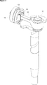
- Figure 3 - is the perspective schematic view of the piston, the piston locking pin hole, the core gap and the channel.
- Figure 4 - is the front schematic view of the piston, the piston locking pin hole, the core gap and the channel.
- Figure 5 - is the schematic view of the crankpin and the crankpin locking pin hole.
- Figure 6 — is the schematic view of the connecting rod.
- the compressor (1) comprises an upper casing (2) that covers the movable components and a lower casing (3) that contains the oil on the base thereof and that supports the components therein; a motor (4) that is composed of two components, that is a stator (5) and a rotor (6); a cylinder (7) that provides the pumping of the refrigerant gas; a cylinder block (8); a piston (11) that enables the refrigerant gas to be compressed in the cylinder (7); a crank (10) that transfers the movement received from the motor (4); a connecting rod (12) that transfers the movement received from the crank (10) to the piston (11); a crankpin (13) that connects the connecting rod (12) and the piston (11) to each other, and a bearing (9) that enables the crank (10) to be borne to the cylinder block (8) in the radial direction ( Figure 1, Figure 5 and Figure 6).
- the compressor (1) furthermore comprises
- crankpin (13) is mounted so as to pass through the piston crankpin hole (16) and the connecting rod crankpin hole (17) of the compressor (1) while the connecting rod (12) is in the core gap (20).
- the compressor (1) comprises a locking pin (14) that keeps the said three components (11, 12 and 13) together.
- the locking pin (14) passes through the piston locking pin hole (18) so as to enter the crankpin locking pin hole (19) and locks all the components to each other.
- the length of the crankpin (13) is selected so as to match the piston locking pin hole (18) and comprise the crankpin locking pin hole (19).
- the locking pin (14) passes through both and can be locked in the crankpin locking pin hole (19) in a snap-fit manner ( Figure 2).
- the plane (21) distance is decreased by means of the channel (15) opened between the piston locking pin hole (18) and the core gap (20).
- the piston locking pin hole (18) is enabled to be taken out of the mold with the minimum plane (21) distance.
- a shorter crankpin (13) can be used with the plane (21) distance decreasing. Using a shorter crankpin (13) means a lighter movable mass and this provides increase in mechanical efficiency and decrease in vibrations while the inertia forces decrease.
- the width of the channel (15) is smaller than or at the most equal to the diameter of the locking pin (14).
- the opposite sides of the channel (15) are parallel to each other.
- the opposite sides of the channel (15) are inclined towards each other. In a version of this embodiment, the inclination of the sides gets closer towards the piston locking pin hole (18). In another version, the inclination of the sides moves away from each other towards the piston locking pin hole (18).
- the channel (15) extends along the core gap (20) upper surface.
- the channel (15) extends along the piston locking pin hole (18).
- the piston (11) extends so as to pass the crankpin hole (16) longitudinally.
Landscapes
- Engineering & Computer Science (AREA)
- Mechanical Engineering (AREA)
- General Engineering & Computer Science (AREA)
- Compressor (AREA)
Abstract
The present invention relates to a compressor (1) comprising an upper casing (2) that covers the movable components and a lower casing (3) that contains the oil on the base thereof and that supports the components therein; a motor (4) that is composed of two components, that is a stator (5) and a rotor (6); a cylinder (7) that provides the pumping of the refrigerant gas; a cylinder block (8); a piston (11) that enables the refrigerant gas to be compressed in the cylinder (7); a crank (10) that transfers the movement received from the motor (4); a connecting rod (12) that transfers the movement received from the crank (10) to the piston (11); a crankpin (13) that connects the connecting rod (12) and the piston (11) to each other, and a bearing (9) that enables the crank (10) to be borne to the cylinder block (8) in the radial direction.
Description
The present invention relates to a compressor comprising a channel that joins the piston locking pin hole and the core gap.
In cooling devices, the circulation of the refrigerant liquid used for refrigeration is provided by a compressor. In the assembly of the movable components such as piston, crankpin and connecting rod, the crankpin is mounted so as to pass through the piston crankpin hole and the connecting rod crankpin hole while the connecting rod is in the core gap. In order to keep the said three components together, a locking pin passes through the locking pin hole on the piston to enter the locking pin hole on the crankpin so as to be locked. The length of the crankpin is selected so as to match the piston locking pin hole and comprise the crankpin locking pin hole. Thus, the locking pin passes through both and can be locked in the crankpin locking pin hole in a snap-fit manner. The locking pin hole on the piston can be produced by boring or directly in the mold wherein the piston is produced with powder metallurgy.
In the state of the art, the wall thickness between the piston locking pin hole and the upper surface of the core gap is referred to as the plane. As the distance of the plane decreases, production problems such as the ricocheting of the drill during the boring process or the hole not being produced in the mold may arise. Due to the said problems, there is minimum value limitation for the plane distance. A similar limitation is also present when the piston locking pin hole is desired to be produced in the powder metallurgy mold since the producer demands a minimum plane in this section. The plane distance can be increased by decreasing the core gap or moving the position of the piston locking pin hole upwards. In the first one of the said solutions, decreasing the core gap will cause the bearing length of the connecting rod crankpin hole to decrease. In the second solution, since the locking pin hole on the crankpin is required to move upwards when the position of the locking pin hole on the piston changes, the length of the crankpin increases. This causes the mass of the crankpin to increase and causes the crankpin to be close to the body cylinder inner surface.
In the state of the art Japanese Patent Application No. JP2010242592, a piston locking pin hole is disclosed.
The aim of the present invention is the realization of a compressor wherein the position of the piston locking pin hole is kept the same while the plane distance is decreased.
The compressor realized in order to attain the aim of the present invention, explicated in the first claim and the respective claims thereof, comprises a channel that opens between the piston locking pin hole and the core gap and that joins the piston locking pin hole and the core gap. In an embodiment of the present invention, the width of the channel is equal to the diameter of the locking pin at the most. In the preferred embodiment of the present invention, the width of the channel is smaller than the diameter of the locking pin. When the locking pin is placed into the piston locking pin hole, a space as much as the width of the channel remains between the locking pin and the core gap.
In an embodiment of the present invention, the sides of the channel are parallel to each other.
In another embodiment of the present invention, the sides of the channel are inclined and in an embodiment, the sides gets closer towards the piston locking pin hole and in another embodiment the sides gets away from each other.
In another embodiment of the present invention, the channel extends along the piston locking pin hole.
In another embodiment of the present invention, the channel extends along the core gap.
By opening a channel between the piston locking pin hole and the core gap, the position of the piston locking pin hole is kept the same, the minimum plane distance remaining between the hole and the core gap upper surface is decreased and the hole gets closer to the core gap. The width of the channel to be opened should be smaller than or equal to the diameter of the locking pin. Although the opened channel decreases the plane distance, the piston locking pin hole is further moved closer to the core gap upper surface and the piston locking pin hole can be easily produced in the powder metallurgy mold.
The model embodiments related to the compressor realized in order to attain the aim of the present invention are shown in the attached figures where
Figure 1 – is the schematic view of the compressor of the present invention.
Figure 2 - is the schematic view of the crank, the piston, the crankpin, the connecting rod and the locking pin.
Figure 3 - is the perspective schematic view of the piston, the piston locking pin hole, the core gap and the channel.
Figure 4 - is the front schematic view of the piston, the piston locking pin hole, the core gap and the channel.
Figure 5 - is the schematic view of the crankpin and the crankpin locking pin hole.
Figure 6 – is the schematic view of the connecting rod.
The elements in the figures are numbered as follows:
- Compressor
- Upper casing
- Lower casing
- Motor
- Stator
- Rotor
- Cylinder
- Cylinder block
- Bearing
- Crank
- Piston
- Connecting rod
- Crankpin
- Locking pin
- Channel
- Piston crankpin hole
- Connecting rod crankpin hole
- Piston locking pin hole
- Crankpin locking pin hole
- Core gap
- Plane
The compressor (1) comprises an upper casing (2) that covers the movable components and a lower casing (3) that contains the oil on the base thereof and that supports the components therein; a motor (4) that is composed of two components, that is a stator (5) and a rotor (6); a cylinder (7) that provides the pumping of the refrigerant gas; a cylinder block (8); a piston (11) that enables the refrigerant gas to be compressed in the cylinder (7); a crank (10) that transfers the movement received from the motor (4); a connecting rod (12) that transfers the movement received from the crank (10) to the piston (11); a crankpin (13) that connects the connecting rod (12) and the piston (11) to each other, and a bearing (9) that enables the crank (10) to be borne to the cylinder block (8) in the radial direction (Figure 1, Figure 5 and Figure 6).
The compressor (1) furthermore comprises
- a core gap (20) wherein the connecting rod (12) enters,
- a piston locking pin hole (18) that is arranged on the piston (11) and that extends parallel to the core gap (20),
- a plane (21) that remains between the piston locking pin hole (18) and the core gap (20), and
- a channel (15) that extends on the plane (21) between the piston locking pin hole (18) and the core gap (20) and that joins the piston locking pin hole (18) and the core gap (20)
(Figure 3 and Figure 4).
In the assembly of the components such as the piston (11), the crankpin (13) and the connecting rod (12), the crankpin (13) is mounted so as to pass through the piston crankpin hole (16) and the connecting rod crankpin hole (17) of the compressor (1) while the connecting rod (12) is in the core gap (20). The compressor (1) comprises a locking pin (14) that keeps the said three components (11, 12 and 13) together. The locking pin (14) passes through the piston locking pin hole (18) so as to enter the crankpin locking pin hole (19) and locks all the components to each other. The length of the crankpin (13) is selected so as to match the piston locking pin hole (18) and comprise the crankpin locking pin hole (19). Thus, the locking pin (14) passes through both and can be locked in the crankpin locking pin hole (19) in a snap-fit manner (Figure 2).
The plane (21) distance is decreased by means of the channel (15) opened between the piston locking pin hole (18) and the core gap (20). Thus, with requiring to be processed during the production, the piston locking pin hole (18) is enabled to be taken out of the mold with the minimum plane (21) distance. Moreover, a shorter crankpin (13) can be used with the plane (21) distance decreasing. Using a shorter crankpin (13) means a lighter movable mass and this provides increase in mechanical efficiency and decrease in vibrations while the inertia forces decrease.
In the preferred embodiment of the present invention, the width of the channel (15) is smaller than or at the most equal to the diameter of the locking pin (14). When the locking pin (14) is placed into the piston locking pin hole (18), a space as much as the width of the channel (15) remains between the locking pin (14) and the core gap (20).
In an embodiment of the present invention, the opposite sides of the channel (15) are parallel to each other.
In another embodiment of the present invention, the opposite sides of the channel (15) are inclined towards each other. In a version of this embodiment, the inclination of the sides gets closer towards the piston locking pin hole (18). In another version, the inclination of the sides moves away from each other towards the piston locking pin hole (18).
In another embodiment of the present invention, the channel (15) extends along the core gap (20) upper surface.
In another embodiment of the present invention, the channel (15) extends along the piston locking pin hole (18). In this embodiment of the present invention, the piston (11) extends so as to pass the crankpin hole (16) longitudinally.
Claims (10)
- A compressor (1) comprising an upper casing (2) that covers the movable components and a lower casing (3) that contains the oil on the base thereof and that supports the components therein; a motor (4) that is composed of two components, that is a stator (5) and a rotor (6); a cylinder (7) that provides the pumping of the refrigerant gas; a cylinder block (8); a piston (11) that enables the refrigerant gas to be compressed in the cylinder (7); a crank (10) that transfers the movement received from the motor (4); a connecting rod (12) that transfers the movement received from the crank (10) to the piston (11); a crankpin (13) that connects the connecting rod (12) and the piston (11) to each other, and a bearing (9) that enables the crank (10) to be borne to the cylinder block (8) in the radial direction, characterized by- a core gap (20) wherein the connecting rod (12) enters,- a piston locking pin hole (18) that is arranged on the piston (11) and that extends parallel to the core gap (20),- a plane (21) that remains between the piston locking pin hole (18) and the core gap (20), and- a channel (15) that extends on the plane (21) between the piston locking pin hole (18) and the core gap (20) and that joins the piston locking pin hole (18) and the core gap (20).
- A compressor (1) as in Claim 1, characterized by the channel (15) the width of which is smaller than or at the most equal to the diameter of the locking pin (14).
- A compressor (1) as in Claim 1 or 2, characterized by the channel (15) providing that a space as much as the width of the channel (15) remains between the locking pin (14) and the core gap (20) when the locking pin (14) is placed into the piston locking pin hole (18).
- A compressor (1) as in Claim 1 or 2, characterized by the channel (15) the opposite sides of which are parallel to each other.
- A compressor (1) as in Claim 1 or 2, characterized by the channel (15) the opposite sides of which are inclined towards each other.
- A compressor (1) as in Claim 5, characterized by the channel (15) the sides of which have an inclination that gets closer towards the piston locking pin hole (18).
- A compressor (1) as in Claim 5, characterized by the channel (15) the sides of which have an inclination that moves away from each other towards the piston locking pin hole (18).
- A compressor (1) as in Claim 1, characterized by the channel (15) that extends along the core gap (20) upper surface.
- A compressor (1) as in Claim 1, characterized by the channel (15) that extends along the piston locking pin hole (18).
- A compressor (1) as in Claim 1, characterized by the channel (15) that extends so as to pass through the piston crankpin hole (16) longitudinally.
Applications Claiming Priority (2)
| Application Number | Priority Date | Filing Date | Title |
|---|---|---|---|
| TR2016/02945 | 2016-03-07 | ||
| TR201602945 | 2016-03-07 |
Publications (1)
| Publication Number | Publication Date |
|---|---|
| WO2017153246A1 true WO2017153246A1 (en) | 2017-09-14 |
Family
ID=58192318
Family Applications (1)
| Application Number | Title | Priority Date | Filing Date |
|---|---|---|---|
| PCT/EP2017/054903 Ceased WO2017153246A1 (en) | 2016-03-07 | 2017-03-02 | A compressor wherein ease of assembly is provided between movable components |
Country Status (1)
| Country | Link |
|---|---|
| WO (1) | WO2017153246A1 (en) |
Citations (3)
| Publication number | Priority date | Publication date | Assignee | Title |
|---|---|---|---|---|
| US5542341A (en) * | 1994-08-24 | 1996-08-06 | Bristol Compressors, Inc. | Wrist pin construction |
| CN101354031A (en) * | 2007-07-24 | 2009-01-28 | 三星光州电子株式会社 | hermetic compressor |
| JP2010242592A (en) | 2009-04-03 | 2010-10-28 | Panasonic Corp | Hermetic compressor |
-
2017
- 2017-03-02 WO PCT/EP2017/054903 patent/WO2017153246A1/en not_active Ceased
Patent Citations (3)
| Publication number | Priority date | Publication date | Assignee | Title |
|---|---|---|---|---|
| US5542341A (en) * | 1994-08-24 | 1996-08-06 | Bristol Compressors, Inc. | Wrist pin construction |
| CN101354031A (en) * | 2007-07-24 | 2009-01-28 | 三星光州电子株式会社 | hermetic compressor |
| JP2010242592A (en) | 2009-04-03 | 2010-10-28 | Panasonic Corp | Hermetic compressor |
Similar Documents
| Publication | Publication Date | Title |
|---|---|---|
| US3606594A (en) | Hermetically sealed motor/compressor apparatus | |
| EP3163084B1 (en) | Rotary compressor having two cylinders | |
| KR20090041719A (en) | Linear compressor | |
| CN108386335B (en) | Reciprocating compressor | |
| EP3141749B1 (en) | Sealed compressor and refrigeration device | |
| KR101465867B1 (en) | Hermetic compressor and refrigeration cycle device including same | |
| EP3168474A1 (en) | Sealed compressor and refrigeration device using the same | |
| US11473571B2 (en) | Sealed refrigerant compressor and refrigeration device | |
| WO2017153246A1 (en) | A compressor wherein ease of assembly is provided between movable components | |
| KR20060087521A (en) | compressor | |
| JP6573845B2 (en) | Cryogenic refrigerator | |
| CN106852168A (en) | Ultra-low temperature refrigerating device | |
| CN102338058A (en) | Reciprocating compressor | |
| JP2006144683A (en) | Compressor | |
| JP6480142B2 (en) | Hermetic compressor, refrigeration apparatus including the hermetic compressor, and refrigerator including the hermetic compressor | |
| JP2017120162A (en) | Cryogenic refrigerator and rotary valve mechanism | |
| US20200158100A1 (en) | Refrigerant compressor | |
| US20160131137A1 (en) | Rotary compressor | |
| JP6854617B2 (en) | Compressor and refrigeration cycle equipment | |
| JP2009504956A (en) | Hermetic compressor | |
| WO2014053361A1 (en) | A hermetic compressor with reduced vibration | |
| US8601933B2 (en) | Hermetic compressor and fridge-freezer | |
| JP2014156803A (en) | Hermetic compressor and refrigerator using the same | |
| KR20060091653A (en) | Piston of linear compressor | |
| KR20120103744A (en) | Fluid machinery |
Legal Events
| Date | Code | Title | Description |
|---|---|---|---|
| NENP | Non-entry into the national phase |
Ref country code: DE |
|
| 121 | Ep: the epo has been informed by wipo that ep was designated in this application |
Ref document number: 17708261 Country of ref document: EP Kind code of ref document: A1 |
|
| 122 | Ep: pct application non-entry in european phase |
Ref document number: 17708261 Country of ref document: EP Kind code of ref document: A1 |