WO2017150282A1 - 無線通信システム、送信装置、及び、通信方法 - Google Patents
無線通信システム、送信装置、及び、通信方法 Download PDFInfo
- Publication number
- WO2017150282A1 WO2017150282A1 PCT/JP2017/006401 JP2017006401W WO2017150282A1 WO 2017150282 A1 WO2017150282 A1 WO 2017150282A1 JP 2017006401 W JP2017006401 W JP 2017006401W WO 2017150282 A1 WO2017150282 A1 WO 2017150282A1
- Authority
- WO
- WIPO (PCT)
- Prior art keywords
- antenna
- communication system
- frequency
- wireless communication
- antennas
- Prior art date
- Legal status (The legal status is an assumption and is not a legal conclusion. Google has not performed a legal analysis and makes no representation as to the accuracy of the status listed.)
- Ceased
Links
Images







Classifications
-
- H—ELECTRICITY
- H04—ELECTRIC COMMUNICATION TECHNIQUE
- H04B—TRANSMISSION
- H04B1/00—Details of transmission systems, not covered by a single one of groups H04B3/00 - H04B13/00; Details of transmission systems not characterised by the medium used for transmission
- H04B1/69—Spread spectrum techniques
- H04B1/713—Spread spectrum techniques using frequency hopping
-
- H—ELECTRICITY
- H04—ELECTRIC COMMUNICATION TECHNIQUE
- H04B—TRANSMISSION
- H04B7/00—Radio transmission systems, i.e. using radiation field
- H04B7/02—Diversity systems; Multi-antenna system, i.e. transmission or reception using multiple antennas
- H04B7/04—Diversity systems; Multi-antenna system, i.e. transmission or reception using multiple antennas using two or more spaced independent antennas
- H04B7/06—Diversity systems; Multi-antenna system, i.e. transmission or reception using multiple antennas using two or more spaced independent antennas at the transmitting station
-
- H—ELECTRICITY
- H04—ELECTRIC COMMUNICATION TECHNIQUE
- H04B—TRANSMISSION
- H04B7/00—Radio transmission systems, i.e. using radiation field
- H04B7/02—Diversity systems; Multi-antenna system, i.e. transmission or reception using multiple antennas
- H04B7/04—Diversity systems; Multi-antenna system, i.e. transmission or reception using multiple antennas using two or more spaced independent antennas
- H04B7/08—Diversity systems; Multi-antenna system, i.e. transmission or reception using multiple antennas using two or more spaced independent antennas at the receiving station
-
- H—ELECTRICITY
- H04—ELECTRIC COMMUNICATION TECHNIQUE
- H04B—TRANSMISSION
- H04B7/00—Radio transmission systems, i.e. using radiation field
- H04B7/02—Diversity systems; Multi-antenna system, i.e. transmission or reception using multiple antennas
- H04B7/10—Polarisation diversity; Directional diversity
Definitions
- the present invention relates to a wireless communication system, a transmission device, and a communication method.
- a wireless communication system including a transmitting device that transmits a wireless signal and a receiving device that receives a wireless signal is known (for example, Patent Document 1).
- a transmission device transmits a wireless signal by using an antenna that radiates linearly polarized waves and sequentially using a plurality of different frequencies as the carrier frequency of the wireless signal.
- the radio signal transmitted by the transmitter is reflected or diffracted by a surrounding object (in other words, a scatterer). Thereby, the polarization direction of the radio signal received by the receiving device may change.
- the attitude of the antenna of the transmitting device with respect to the receiving device may change.
- the posture of the antenna with respect to the receiving device is likely to change as the posture of the living body changes or the transmitting device moves in the living body.
- the transmission device is attached to the surface of a living body, the posture of the antenna with respect to the receiving device is likely to change as the posture of the living body changes. In this way, the polarization direction of the radio signal received by the receiving device may change.
- the quality (in other words, communication quality) of the radio signal received by the receiving device changes according to the polarization direction of the radio signal. Therefore, when a radio signal transmitted by radiating a linearly polarized wave having a specific polarization direction to the transmitting device is received by the receiving device, the time during which the communication quality is not sufficiently high continues. There was a possibility that it would become excessively long.
- One of the objects of the present invention is to increase the probability that the communication quality is sufficiently high.
- a wireless communication system includes a transmitting device that transmits a wireless signal and a receiving device that receives the wireless signal.
- the transmitter is A plurality of antennas each radiating a plurality of linearly polarized waves having different polarization directions;
- a control unit configured by an antenna and a frequency and sequentially using a plurality of different sets; Is provided.
- the use of the set is the transmission of the radio signal by using the antennas constituting the set and using the frequency constituting the set as the frequency of the carrier wave of the radio signal.
- the antennas constituting the set are selected from the plurality of antennas, and the frequencies constituting the set are selected from the plurality of frequencies included in the frequency group for the antennas constituting the set. Selected.
- the transmission device transmits a radio signal.
- the transmitter is A plurality of antennas each radiating a plurality of linearly polarized waves having different polarization directions;
- a control unit configured by an antenna and a frequency and sequentially using a plurality of different sets; Is provided.
- the use of the set is the transmission of the radio signal by using the antennas constituting the set and using the frequency constituting the set as the frequency of the carrier wave of the radio signal.
- the antennas constituting the set are selected from the plurality of antennas, and the frequencies constituting the set are selected from the plurality of frequencies included in the frequency group for the antennas constituting the set. Selected.
- the communication method is: A transmission apparatus including a plurality of antennas that respectively radiate a plurality of linearly polarized waves having different polarization directions uses a plurality of different sets composed of antennas and frequencies in order. And transmitting the radio signal by using the frequency constituting the set as the frequency of the carrier wave of the radio signal, and each of the plurality of sets includes an antenna constituting the set, The frequency that is selected from the plurality of antennas and that constitutes the set is selected from the plurality of frequencies that are included in the frequency group for the antenna that constitutes the set, In this method, the receiving device receives the radio signal transmitted by the transmitting device.
- the probability that the communication quality is sufficiently high can be increased.
- 10 is a graph illustrating an example of a cumulative probability distribution of changes in received power in FIGS. 7 to 9.
- wireless communications system of the 1st modification of 1st Embodiment. 12 is a flowchart illustrating processing executed by the receiving device in FIG. 11. It is a flowchart showing the process which the transmitter of FIG. 11 performs. It is a flowchart showing the process which the transmitter of the 2nd modification of 1st Embodiment performs.
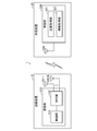
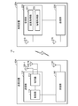
- the wireless communication system 1 includes a transmission device 10 and a reception device 20.
- the number of transmission apparatuses included in the wireless communication system 1 may be two or more.
- the number of receiving devices included in the wireless communication system 1 may be two or more.
- the transmission device 10 transmits a radio signal according to a predetermined communication method.
- the receiving device 20 receives the radio signal transmitted by the transmitting device 10 according to the communication method.
- the communication method is a method compliant with at least a part of a standard called Bluetooth. “BLUETOOTH” is a registered trademark.
- the communication method may be a method different from the above method.
- the transmission device 10 may be configured to be introduced into a living body (for example, a human body).
- the transmission device 10 may be attached to a preparation such as a capsule or a tablet, or may constitute at least a part of the preparation.
- the transmission device 10 may be configured to be attachable to the surface of a living body.
- the transmission device 10 may be attached to a preparation such as a patch, or may constitute at least a part of the preparation.
- the transmission device 10 may be attached to a sensor that detects a physical quantity, or may constitute at least a part of the sensor.
- the transmission device 10 may constitute at least a part of a mobile phone, a smartphone, a personal computer, or the like.
- the transmission apparatus 10 includes a transmission unit 110 and N antennas 120-1, ..., 120-N.
- N represents an integer of 2 or more.
- N represents 2.
- the antenna 120-n is also referred to as the antenna 120 when it is not necessary to distinguish between them.
- n represents each integer of 1 to N.
- At least a part of the transmission device 10 is configured by an LSI (Large Scale Integration) circuit.
- LSI Large Scale Integration
- at least a part of the transmission device 10 may be configured by a programmable logic circuit (for example, PLD or FPGA).
- PLD is an abbreviation for Programmable Logic Device.
- FPGA is an abbreviation for Field-Programmable Gate Array.
- the transmission device 10 may include a processing device and a storage device, and the processing device may implement at least a part of the functions of the transmission device 10 by executing a program stored in the storage device.
- the processing device may include a CPU (Central Processing Unit), an MPU (Micro Processing Unit), or a DSP (Digital Signal Processor).
- the storage device may include a RAM (Random Access Memory), a semiconductor memory, or an organic memory.
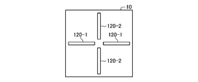
- the N antennas 120-1,..., 120-N radiate N linearly polarized waves having different polarization directions.
- the antenna 120-n is a dipole antenna having a linear shape.
- the antenna 120-1 and the antenna 120-2 extend along two directions orthogonal to each other. Therefore, in this example, the two antennas 120-1 and 120-2 each radiate two linearly polarized waves whose polarization directions are orthogonal to each other.
- the antenna 120-n may be an antenna different from the dipole antenna (for example, a patch antenna, a loop antenna, a plate antenna, or a planar antenna).
- the transmission unit 110 includes a control unit 111 and a switch 112.
- the switch 112 connects one antenna 120-n of the N antennas 120-1,..., 120-N and the control unit 111, and is connected to the control unit 111 according to control by the control unit 111.
- Antenna 120-n is switched among N antennas 120-1,..., 120-N.
- the control unit 111 generates transmission information.
- the transmission information includes an identifier that identifies the transmission device 10.
- the transmission information includes information indicating the physical quantity detected by the sensor.
- the physical quantity is temperature, humidity, illuminance, pH, acceleration, angular velocity, pressure, or the concentration of an object.
- the object is digestive fluid (eg, saliva, gastric fluid, intestinal fluid, pancreatic juice, etc.), blood, glucose, cholesterol, resident bacteria, or infectious substance (eg, bacteria, virus, etc.). .
- the control unit 111 generates a radio signal in which a carrier wave is modulated so as to represent the transmission information based on the generated transmission information.
- the control unit 111 transmits the generated radio signal via the antenna 120-n connected by the switch 112.
- the control unit 111 uses M antenna frequency sets in order.
- M represents an integer of 2 or more.
- the antenna frequency set includes an antenna 120 and a frequency.
- the use of the antenna frequency set is transmission of the radio signal by using the antenna 120 constituting the antenna frequency set and using the frequency constituting the antenna frequency set as the frequency of the carrier wave of the radio signal.
- use of the antenna 120-n includes control of the switch 112 for connecting the control unit 111 and the antenna 120-n to the switch 112.
- the M antenna frequency sets include a plurality of subsets for each of the N antennas 120-1, ..., 120-N.
- the plurality of subsets for the antenna 120-n are constituted by the antenna 120-n and are respectively constituted by a plurality of frequencies included in the frequency group set for the antenna 120-n.
- the M antenna frequency sets are different from each other.
- the frequency group is common to N antennas 120-1, ..., 120-N.
- the frequency group matches a fundamental frequency group composed of P frequencies.
- P represents an integer of 2 or more.
- P represents 79.
- P frequencies may be included in 2402 MHz to 2480 MHz.
- the frequency group may be a part of the fundamental frequency group. Further, the frequency group may be different between the antennas 120.
- the M antenna frequency sets are an antenna selected from N antennas 120-1,..., 120-N and a frequency selected from P frequencies included in the frequency group. , All combinations.
- the antenna frequency set includes an antenna identifier A n identifying the antenna 120-n, may be represented by a frequency identifier f np identifies the frequency. p represents each integer of 1 to P.
- the number M of antenna frequency sets is the product of the number N of antennas 120 and the number P of frequencies that constitute the fundamental frequency group.
- the control unit 111 changes the antenna frequency set to be used every time a predetermined unit transmission time elapses.
- the unit transmission time may be 1/1600 seconds.
- the control unit 111 successively uses a plurality of subsets for the antenna 120-n for each of the N antennas 120-1, ..., 120-N.
- the control unit 111 uses the same antenna 120-n for each of the N antennas 120-1, ..., 120-N over the frequency group usage time,
- Each of a plurality of frequencies (P frequencies in this example) included in the frequency group for the antenna 120-n is used. Therefore, in this example, the frequency group usage time is a time obtained by multiplying the unit transmission time by P.
- the frequency use order which is the order in which a plurality of frequencies included in the frequency group are used, is predetermined.
- the frequency use order is an order in which the frequency increases or an order in which the frequency decreases.
- the frequency use order may be determined based on a pseudo random number.
- control unit 111 repeatedly provides a plurality of periods in which the N antennas 120-1,.
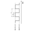
- the control unit 111 uses the antenna 120-1 (in other words, the first antenna) and the antenna 120-2 (in other words, the second antenna). And a period for using are repeatedly provided in order on the time axis.
- the control unit 111 alternately provides a period for using the antenna 120-1 and a period for using the antenna 120-2 on the time axis.
- T p represents the period of the period in which each of the N antennas 120-1,..., 120-N is used.
- T s represents the frequency group usage time.
- the frequency group usage time T s is a period in which all of a plurality of frequencies (P frequencies in this example) included in the frequency group for the antenna 120-n are used once.
- the time obtained by dividing the period T p by the number N of antennas 120 is equal to the frequency group usage time T s .
- the relationship between the period T p and the frequency group usage time T s is expressed by Equation 1.
- the coefficient k represents 1.
- the coefficient k may be a value larger than 1.
- the frequency group usage time T s is longer than the time obtained by multiplying the unit transmission time by P.
- the control unit 111 uses at least one of the P frequencies a plurality of times during a period in which the use of a certain antenna 120-n is continued.
- control unit 111 does not have to continuously use a plurality of subsets for the antenna 120-n for each of the N antennas 120-1, ..., 120-N.
- the control unit 111 uses the same frequency for each of the P frequencies over the frequency usage time, and each of the N antennas 120-1, ..., 120-N. May be used.
- the frequency use time is a time obtained by multiplying the unit transmission time by N. According to this, the frequency with which the used frequency changes can be suppressed.
- control unit 111 matches transmission information represented by M radio signals transmitted by using M antenna frequency sets. In other words, in this example, the control unit 111 transmits M radio signals representing the same transmission information by using M antenna frequency sets. Note that the control unit 111 may use different transmission information represented by the M radio signals transmitted by using the M antenna frequency sets.
- the transmission apparatus 10 includes the switch 112, but may not include the switch 112.
- the control unit 111 includes N ports to which N antennas 120-1,..., 120-N are connected, respectively, and the control unit 111 has ports for outputting radio signals.
- the antenna 120 to be used may be switched by switching among the N ports.
- switching of the antenna 120 used by the transmission device 10 may be regarded as switching of the polarization direction of the radio signal transmitted by the transmission device 10.
- switching the antenna 120 used by the transmission apparatus 10 may be expressed as polarization switching diversity.
- the reception device 20 includes an antenna 210 and a reception unit 220.
- the receiving device 20 is configured by an LSI circuit.
- the transmission device 10 may be configured by a programmable logic circuit.
- the receiving device 20 may include a processing device and a storage device, and the processing device may implement at least a part of the function of the receiving device 20 by executing a program stored in the storage device.
- the receiving unit 220 receives the radio signal transmitted from the transmission device 10 via the antenna 210.
- the receiving unit 220 includes a quality acquisition unit 221 and an information acquisition unit 222.
- the quality acquisition unit 221 acquires, for each of the M antenna frequency sets, a quality parameter indicating the quality of the radio signal received during the period in which the antenna frequency set is used.
- the quality parameter represents the strength of the received radio signal (in other words, the reception strength).
- the reception strength may be the amplitude or power of the received radio signal.
- the quality of the radio signal increases as the reception strength increases.
- the quality parameter may be an incorrect amount of information included in transmission information acquired by demodulating a received radio signal. For example, an information error is detected based on an error correction code or an error detection code. In this case, the quality of the radio signal increases as the amount of erroneous information decreases.
- the information acquisition unit 222 selects at least one set from the M antenna frequency sets based on the quality parameter acquired by the quality acquisition unit 221. In this example, the information acquisition unit 222 selects an antenna frequency set having the highest quality represented by the quality parameter acquired by the quality acquisition unit 221 from among the M antenna frequency sets.
- the information acquisition unit 222 acquires transmission information represented by the radio signal based on the radio signal received during the period in which the selected at least one antenna frequency set is used. In this example, the information acquisition unit 222 acquires transmission information by demodulating the received radio signal.
- the receiving unit 220 may be regarded as acquiring transmission information by performing selective combining. Note that the receiving unit 220 may perform equal gain combining or maximum ratio combining in place of or in addition to the selective combining.
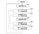
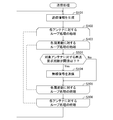
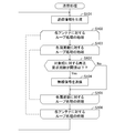
- the transmission device 10 executes the transmission process shown in FIG. Hereinafter, the transmission process will be described.
- the transmission device 10 generates transmission information (step S101 in FIG. 4).
- the transmitting apparatus 10 executes a first loop process (step S102 to step S106 in FIG. 4) using the N antennas 120-1,.
- the transmitting apparatus 10 uses a plurality of frequencies (P frequencies in this example) included in the frequency group for the antenna 120-n to be processed as processing targets one by one.
- a second loop process (steps S103 to S105 in FIG. 4) is executed.
- the transmitting apparatus 10 transmits a radio signal by using the antenna 120-n that is the processing target and the frequency that is the processing target (step S104 in FIG. 4). .
- the transmission device 10 transmits a radio signal whose carrier frequency matches the frequency to be processed via the antenna 120-n to be processed.
- the transmitting apparatus 10 performs the second loop process on all of the plurality of frequencies included in the frequency group for the antenna 120-n to be processed, and then proceeds to step S106.
- the transmitting apparatus 10 performs the first loop process on all of the N antennas 120-1,..., 120-N, and then returns to step S101 and repeats the processes of steps S101 to S106. Execute.
- the receiving device 20 executes the receiving process shown in FIG. Hereinafter, the reception process will be described.
- the receiving device 20 receives the radio signal transmitted by the transmitting device 10 for each of the M antenna frequency sets (step S201 in FIG. 5). Next, the receiving apparatus 20 acquires quality parameters for each of the M antenna frequency sets (step S202 in FIG. 5).
- the receiving apparatus 20 selects an antenna frequency set having the highest quality represented by the acquired quality parameter from among the M antenna frequency sets, and the radio signal received during the period in which the selected antenna frequency set is used.
- the transmission information represented by the radio signal is acquired by demodulating (step S203 in FIG. 5). Thereafter, the receiving device 20 returns to step S201, and repeatedly executes the processing from step S201 to step S203.
- the transmitter 10 transmits N antennas 120-1,..., 120 that respectively radiate N linearly polarized waves having different polarization directions. -N provided. Furthermore, the transmission apparatus 10 includes a control unit 111 that transmits a radio signal by sequentially using a plurality of different antenna frequency sets that are configured by the antenna 120 and the frequency. In each of the plurality of antenna frequency sets, the antenna 120-n constituting the antenna frequency set is selected from N antennas 120-1,..., 120-N, and the frequency constituting the antenna frequency set is set. Is selected from a plurality of frequencies included in the frequency group for the antenna 120-n constituting the antenna frequency set.
- the plurality of antenna frequency sets are configured by the antenna 120-n for each of the N antennas 120-1,..., 120-N. , Including a plurality of subsets each constituted by a plurality of frequencies included in the frequency group for the antenna 120-n.
- each of the combinations of N antennas 120-1,..., 120-N and a plurality of frequencies included in the frequency group is used in order.
- the probability that communication quality will become high enough can be raised.
- control unit 111 uses a plurality of subsets successively for each of the N antennas 120-1,..., 120-N.
- the frequency with which the used antenna 120 changes can be suppressed.
- control unit 111 repeatedly provides a plurality of periods in which the N antennas 120-1,.
- the period in which each antenna 120 is used can be uniformly distributed. Accordingly, it is possible to increase the probability that the communication quality is sufficiently higher than when the period in which each antenna 120 is used is unevenly distributed.
- the receiving device 20 sets, for each of a plurality of antenna frequency sets, a quality parameter indicating the quality of the radio signal received during the period in which the antenna frequency set is used. get.
- the reception apparatus 20 selects at least one antenna frequency set from among the plurality of antenna frequency sets based on the acquired quality parameter, and a period during which the selected at least one antenna frequency set is used.
- the information represented by the radio signal is acquired based on the radio signal received in step.
- information can be acquired based on a high-quality radio signal. Thereby, information can be reliably transmitted from the transmitter 10 to the receiver 20.
- the receiving device 20 selects an antenna frequency set having the highest quality represented by the acquired quality parameter from among a plurality of antenna frequency sets, and selects the selected antenna.
- Information represented by the radio signal is acquired based on the radio signal received in the period in which the frequency set is used.
- information can be acquired based on the radio signal having the highest quality. Thereby, information can be reliably transmitted from the transmitter 10 to the receiver 20.
- control unit 111 matches information represented by a plurality of wireless signals respectively transmitted by using a plurality of antenna frequency sets.
- Transmitting apparatus 10 is equivalent to a human body so that antenna 120-1 radiates linearly polarized waves whose polarization direction is vertical, and antenna 120-2 radiates linearly polarized waves whose polarization direction is horizontal. Mounted on the surface of the phantom.
- the human body equivalent phantom is a model that simulates the shape and electrical characteristics of the human body (in this example, relative permittivity and electrical conductivity).
- the receiving device 20 is separated from the transmitting device 10 by a predetermined distance (5 m in this example).
- the antenna 210 of the receiving device 20 is a dipole antenna extending along the vertical direction.
- the receiving device 20 is stationary.
- the unit transmission time is 100/79 ms.
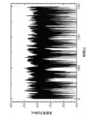
- a curve C1 in FIG. 6 indicates that the power of the radio signal transmitted by the transmitting apparatus 10 using the antenna 120-1 and received by the receiving apparatus 20 (in other words, the received power) with respect to the used frequency. Represents change.
- the curve C2 in FIG. 6 is used for the power of the radio signal transmitted by the transmitting apparatus 10 using the antenna 120-2 and received by the receiving apparatus 20 (in other words, the received power). It represents the change with respect to the frequency.
- the reception power of the radio signal transmitted from the antenna 120-1 As shown in FIG. 6, in a state where the receiving device 20 is stationary, the reception power of the radio signal transmitted from the antenna 120-1, the reception power of the radio signal transmitted from the antenna 120-2, The relationship varies depending on the frequency.
- the transmitting apparatus 10 radiates linearly polarized waves whose polarization direction is the vertical direction, while the antenna 120-1 emits linearly polarized waves whose polarization direction is the horizontal direction. Is attached to the surface of the human body equivalent phantom so that it radiates.
- the receiving device 20 is separated from the transmitting device 10 by a predetermined distance (5 m in this example).
- the antenna 210 of the receiving device 20 is a dipole antenna that extends along a straight line.
- the receiving device 20 rotates at a predetermined rotation speed.
- the unit transmission time is 100/79 ms.
- FIG. 7 shows the change of the power of the radio signal received by the receiving device 20 (in other words, the received power) with respect to time when the transmitting device 10 repeats the use of M antenna frequency sets only 1500 times. To express.
- FIG. 8 shows a period in which the antenna 120-1 is continuously used when the transmitter 10 repeats the use of the M antenna frequency sets only 1500 times (in other words, P antennas for the antenna 120-1). This represents a change with respect to time of the maximum value of received power in the period for each period in which the subset is used.
- FIG. 8 may be regarded as representing a change with time of the received power of the radio signal selectively combined by the receiving apparatus 20 when only one antenna 120-1 is used.
- FIG. 9 shows a period in which the M antenna frequency sets are used when the transmitter 10 repeats the use of the M antenna frequency sets only 1500 times (in other words, P parts for the antenna 120-1). This represents a change with respect to time of the maximum value of the received power in the period for each period (a period in which the pair is used and a period in which P subsets for the antenna 120-2 are used).
- FIG. 9 may be regarded as representing a change with time of the reception power of the radio signal selectively synthesized by the reception device 20 when the two antennas 120-1 and 120-2 are switched and used.
- Curves D1 to D3 in FIG. 10 represent cumulative probability distributions of changes in received power in FIGS. 7 to 9, respectively.
- the received powers in FIGS. 7 to 9 in the cumulative probability distribution of ⁇ 20 dB are ⁇ 81.1 dBm, ⁇ 60.6 dBm, and ⁇ 57.5 dBm, respectively. Therefore, the gain of the received power in FIG. 8 with respect to the received power in FIG. 7 is 20.5 dB, and the gain of the received power in FIG. 9 with respect to the received power in FIG. 8 is 3.1 dB.
- the probability that the communication quality is sufficiently high can be increased.
- the wireless communication system 1 ⁇ / b> A includes a transmission device 10 ⁇ / b> A and a reception device 20 ⁇ / b> A instead of the transmission device 10 and the reception device 20.
- the transmitting apparatus 10A includes an antenna 130 and a receiving unit 140 in addition to the configuration included in the transmitting apparatus 10 of the first embodiment.
- 20 A of receiving apparatuses are provided with the transmission part 230 and the antenna 240 in addition to the structure with which the receiving apparatus 20 of 1st Embodiment is provided.
- the transmitting apparatus 10A may use at least one of the N antennas 120-1, ..., 120-N for both transmission and reception without providing the antenna 130.
- the receiving apparatus 20A may use the antenna 210 for both transmission and reception without including the antenna 240.
- control unit 111 uses the M antenna frequency sets to make the transmission information represented by the M radio signals transmitted different from each other. In other words, in this example, the control unit 111 transmits M radio signals representing transmission information different from each other by using M antenna frequency sets.
- the information acquisition unit 222 acquires, for each of the M antenna frequency sets, transmission information represented by the radio signal based on the radio signal received during the period in which the antenna frequency set is used. In this example, the information acquisition unit 222 acquires transmission information by demodulating the received radio signal.
- the transmission information includes an error detection code.
- the transmission information may include an error correction code instead of the error detection code.
- the quality acquisition unit 221 detects whether there is an error in the acquired transmission information based on an error detection code included in the transmission information. In this example, whether there is an error in the transmission information corresponds to a quality parameter indicating the quality of the received radio signal.
- the transmission unit 230 transmits a retransmission request for requesting retransmission of the transmission information to the transmission device 10A via the antenna 240.
- the retransmission request may be a signal (for example, a NACK (Negative Acknowledgment) signal) indicating that transmission information could not be received normally.
- the transmission unit 230 indicates that the transmission information has been successfully received (for example, an ACK (Positive Acknowledgment) signal). May be transmitted to the transmitting apparatus 10A via the antenna 240.
- ACK Positive Acknowledgment
- the wireless communication system 1A may use the reception strength as a quality parameter instead of the presence or absence of transmission information error or in addition to the presence or absence of transmission information error.
- the transmission unit 230 sends a retransmission request for requesting retransmission of a radio signal that is a basis of the reception strength to the transmission device 10A via the antenna 240. May be sent.
- the receiving unit 140 receives the retransmission request transmitted by the receiving device 20A via the antenna 130.
- the control unit 111 retransmits the transmission information requested to be retransmitted by the retransmission request.
- control unit 111 uses the number of times the retransmission request is received by the receiving unit 140 (in other words, the number of retransmission requests) for transmitting a radio signal indicating transmission information requested to be retransmitted by the retransmission request. Count for each frequency. The control unit 111 stops using the antenna frequency set that is configured by the frequency whose number of retransmission requests counted is larger than a predetermined threshold among the M antenna frequency sets.
- the receiving device 20A executes the receiving process shown in FIG. 12 instead of the receiving process shown in FIG. Hereinafter, the reception process will be described.
- the receiving apparatus 20A receives the radio signal transmitted by the transmitting apparatus 10A by using one antenna frequency set (step S301 in FIG. 12). Next, the receiving apparatus 20A demodulates the received radio signal to obtain transmission information represented by the radio signal (step S302 in FIG. 12).
- the receiving device 20A detects the presence / absence of an error in the acquired transmission information based on the error detection code included in the transmission information, and determines whether there is an error in the transmission information (step in FIG. 12). S303).
- the reception device 20A determines “Yes” and transmits a retransmission request for requesting retransmission of the transmission information to the transmission device 10A via the antenna 240 (step in FIG. 12). S304). Thereafter, the receiving device 20A returns to step S301, and repeatedly executes the processes of steps S301 to S304. On the other hand, when there is no transmission information error, the receiving apparatus 20A determines “No”, and returns to step S301 without executing the process of step S304.
- the transmitting apparatus 10A executes the transmission process shown in FIG. 13 instead of the transmission process shown in FIG. 13 is a process in which the process of step S401 is added between the process of step S103 and the process of step S104 in the transmission process of FIG.
- the transmission process will be described.
- the transmitting apparatus 10A determines whether or not the number of retransmission requests for the frequency to be processed (in other words, the target frequency) is equal to or less than the threshold (step S401 in FIG. 13).
- the transmitting apparatus 10A determines “Yes”, and uses the antenna 120-n that is the processing target and the frequency that is the processing target to thereby generate a radio signal. Is transmitted (step S104 in FIG. 13). On the other hand, if the number of retransmission requests for the target frequency is greater than the threshold, the transmitting apparatus 10A determines “No” and proceeds to step S105 without executing the process of step S104.
- the transmitting apparatus 10A stops using the antenna frequency set constituted by the frequency of the M antenna frequency sets whose counted number of retransmission requests is larger than the threshold value.
- the wireless communication system 1A of the first modification of the first embodiment is configured so that, for each of a plurality of frequencies included in the frequency group, the radio signal received by the receiving device 20A during the period in which the frequency is used. A quality parameter representing quality is acquired.
- the wireless communication system 1A selects at least one frequency from a plurality of frequencies included in the frequency group based on the acquired quality parameter, and stops using the selected at least one frequency. To do.
- the use of the frequency used for transmitting the low-quality radio signal is stopped. Thereby, compared with the case where the use of the said frequency continues, the probability that communication quality will become high enough can be raised.
- the control unit 111 uses the number of times a retransmission request is received by the receiving unit 140 (in other words, the number of retransmission requests) for transmission of a radio signal representing transmission information requested to be retransmitted by the retransmission request. It counts for every antenna 120 made. The control unit 111 stops using the antenna frequency set constituted by the antenna 120 having the counted number of retransmission requests larger than a predetermined threshold among the M antenna frequency sets.
- the transmitting apparatus 10A executes the transmission process shown in FIG. 14 instead of the transmission process shown in FIG.
- the transmission process of FIG. 14 is a process in which the process of step S501 is added between the process of step S103 and the process of step S104 in the transmission process of FIG.
- the transmission process will be described.
- the transmitting apparatus 10A determines whether or not the number of retransmission requests for the antenna 120 to be processed (in other words, the target antenna) is equal to or less than a threshold (step S501 in FIG. 14).
- the transmitting apparatus 10A determines “Yes”, and uses the antenna 120-n that is the processing target and the frequency that is the processing target to thereby generate a radio signal. Is transmitted (step S104 in FIG. 14). On the other hand, when the number of retransmission requests for the target antenna is larger than the threshold, the transmitting apparatus 10A determines “No” and proceeds to step S105 without executing the process of step S104.
- the transmitting apparatus 10A stops using the antenna frequency set constituted by the antenna 120 among the M antenna frequency sets whose counted number of retransmission requests is larger than the threshold.
- the wireless communication system 1A of the second modified example of the first embodiment the same operations and effects as the wireless communication system 1 of the first embodiment can be achieved. Furthermore, the wireless communication system 1A of the second modification example of the first embodiment is configured such that the receiving device is used for each of the N antennas 120-1,. A quality parameter representing the quality of the radio signal received by 20A is acquired. In addition, the wireless communication system 1A selects at least one antenna 120 from among the N antennas 120-1,..., 120-N based on the acquired quality parameter, and the selected at least one antenna The use of the antenna 120 is stopped.
- the use of the antenna 120 used for transmitting a low-quality radio signal is stopped. Thereby, compared with the case where use of the said antenna 120 continues, the probability that communication quality will become high enough can be raised.
- the wireless communication system of the third modification example of the first embodiment is different from the wireless communication system of the first modification example of the first embodiment in that the use of the antenna frequency set selected based on the quality parameter is stopped. It is different.
- the difference will be mainly described.
- symbol used in the 1st modification of 1st Embodiment is the same or substantially the same.
- the control unit 111 uses the number of times a retransmission request is received by the receiving unit 140 (in other words, the number of retransmission requests) for transmission of a radio signal representing transmission information requested to be retransmitted by the retransmission request. Count for each set of antenna frequencies. The control unit 111 stops using the antenna frequency set in which the counted number of retransmission requests is larger than a predetermined threshold among the M antenna frequency sets.
- the transmitting apparatus 10A executes the transmission process shown in FIG. 15 instead of the transmission process shown in FIG.
- the transmission process of FIG. 15 is a process in which the process of step S601 is added between the process of step S103 and the process of step S104 in the transmission process of FIG.
- the transmission process will be described.
- the transmitting apparatus 10A determines that the number of retransmission requests for the antenna frequency set (in other words, the target set) including the antenna 120-n to be processed and the frequency to be processed is equal to or less than a threshold value Is determined (step S601 in FIG. 15).
- the transmitting apparatus 10A determines “Yes”, and uses the antenna 120-n that is the processing target and the frequency that is the processing target to thereby generate a radio signal. Is transmitted (step S104 in FIG. 15). On the other hand, when the number of retransmission requests for the target group is larger than the threshold, the transmitting apparatus 10A determines “No” and proceeds to step S105 without executing the process of step S104.
- the transmitting apparatus 10A stops using the antenna frequency set having the counted number of retransmission requests larger than the threshold among the M antenna frequency sets.
- the wireless communication system 1A of the third modified example of the first embodiment is configured to transmit, for each of the M antenna frequency sets, radio signals received by the reception device 20A during the period in which the antenna frequency set is used. A quality parameter representing quality is acquired.
- the wireless communication system 1A selects at least one antenna frequency set from among the M antenna frequency sets based on the acquired quality parameter, and uses the selected at least one antenna frequency set. Cancel.
- the use of the antenna frequency set used for transmitting the low-quality radio signal is stopped. Thereby, compared with the case where use of the said antenna frequency set continues, the probability that communication quality will become high enough can be raised.
- the radio communication system according to the second embodiment is different from the radio communication system according to the first embodiment in that transmission information is transmitted based on radio signals received by the reception device during a period in which the antenna selected based on the quality parameter is used. It differs in the point to acquire.
- the difference will be mainly described.
- symbol used in 1st Embodiment is the same or substantially the same.
- the control unit 111 uses the N antennas 120-1,..., 120-N to match the transmission information represented by the N radio signals transmitted respectively.
- the control unit 111 uses different transmission information represented by a plurality (P in this example) of radio signals transmitted by using the same antenna 120, and uses the same frequency. By doing so, transmission information represented by a plurality (N in this example) of radio signals respectively transmitted is matched with each other.
- the quality acquisition unit 221 for each of the N antennas 120-1,..., 120-N, shows the quality indicating the quality of the radio signal received during the period in which the antenna 120-n is used Get parameters.
- the quality parameter represents the strength of the received radio signal (in other words, the reception strength).
- the reception strength may be the amplitude or power of the received radio signal.
- the quality parameter for the antenna 120-n may represent an average value of reception strength during a period in which the antenna 120-n is used.
- the quality parameter may be an erroneous amount of information included in transmission information acquired by demodulating a received radio signal.
- the quality parameter for the antenna 120-n may represent the sum or average value of the amount of erroneous information during the period in which the antenna 120-n is used.
- the information acquisition unit 222 selects at least one antenna 120 from among the N antennas 120-1,..., 120-N based on the quality parameter acquired by the quality acquisition unit 221.
- the information acquisition unit 222 selects the antenna 120-n having the highest quality represented by the quality parameter acquired by the quality acquisition unit 221 from among the N antennas 120-1, ..., 120-N.
- the selected antenna 120-n may be represented as a selected antenna.
- the information acquisition unit 222 acquires transmission information represented by the radio signal based on the radio signal received during the period in which the selected at least one antenna 120 is used. In this example, the information acquisition unit 222 acquires transmission information by demodulating the received radio signal.
- the transmission apparatus 10 performs the transmission process represented by FIG. 4 similarly to 1st Embodiment.
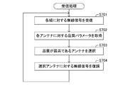
- the receiving device 20 executes the receiving process shown in FIG. 16 instead of the receiving process shown in FIG. Hereinafter, the reception process will be described.
- the receiving device 20 receives the radio signal transmitted by the transmitting device 10 for each of the M antenna frequency sets (step S701 in FIG. 16). Next, the receiving apparatus 20 acquires quality parameters for each of the N antennas 120-1,..., 120-N (step S702 in FIG. 16).
- the receiving apparatus 20 selects the antenna 120-n having the highest quality represented by the acquired quality parameter from the N antennas 120-1,..., 120-N (step S703 in FIG. 16).
- the receiving device 20 demodulates each of a plurality (P in this example) of radio signals received in a period in which the selected antenna 120-n is used, thereby representing each of the plurality of radio signals. Transmission information is acquired (step S704 in FIG. 16). Thereafter, the receiving device 20 returns to step S701, and repeatedly executes the processing of steps S701 to S704.
- the receiving apparatus 20 of the second embodiment represents the quality of the radio signal received for each of the N antennas 120-1,..., 120-N during the period in which the antenna 120-n is used. Get quality parameters.
- the receiving device 20 selects at least one antenna 120 from the N antennas 120-1,..., 120-N based on the acquired quality parameter, and the selected at least one antenna. Information represented by the radio signal is acquired based on the radio signal received during the period 120 is used.
- information can be acquired based on a high-quality radio signal. Thereby, information can be reliably transmitted from the transmitter 10 to the receiver 20.
- control unit 111 uses the N antennas 120-1,..., 120-N to match information represented by a plurality of radio signals transmitted respectively.
- the radio signal transmitted by one antenna 120-n among the N antennas 120-1,..., 120-N is used for information acquisition in the receiving device 20.
- the loss of information can be avoided.
- the wireless communication system 1 ⁇ / b> B includes a transmission device 10 ⁇ / b> B and a reception device 20 ⁇ / b> B instead of the transmission device 10 and the reception device 20.
- the transmission device 10B includes an antenna 130 and a reception unit 140 in addition to the configuration included in the transmission device 10 of the second embodiment.
- the receiving device 20B includes a transmission unit 230 and an antenna 240 in addition to the configuration included in the receiving device 20 of the second embodiment.
- the transmitting apparatus 10B may use at least one of the N antennas 120-1, ..., 120-N for both transmission and reception without providing the antenna 130.
- the receiving apparatus 20B may use the antenna 210 for both transmission and reception without including the antenna 240.
- the information acquisition unit 222 cancels the selection of the antenna 120 during a period (in other words, the maintenance period) from when the antenna 120 was selected last time until a predetermined maintenance time has elapsed.
- the transmission unit 230 transmits a selection notification including an antenna identifier for identifying the selected antenna 120-n to the transmission device 10B via the antenna 240.
- the receiving unit 140 receives the selection notification transmitted by the receiving device 20B via the antenna 130.
- the control unit 111 among the N antennas 120-1, ..., 120-N, the antenna 120-n identified by the antenna identifier included in the selection notification.
- the use of the antenna frequency set constituted by the antennas 120 other than is stopped.
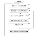
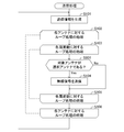
- the receiving device 20B executes the receiving process shown in FIG. 18 instead of the receiving process shown in FIG.
- the reception process of FIG. 18 includes a process of step S801 added between the process of step S701 and the process of step S702 in the reception process of FIG. 16, and the process of step S703 and the process of step S704. , The process of step S802 is added.
- the reception process will be described.
- the receiving device 20B determines whether or not the maintenance time has elapsed since the last time the antenna 120 was selected (step S801 in FIG. 18). When the maintenance time has elapsed since the last time the antenna 120 was selected, the reception device 20B determines “Yes”, executes the processing of steps S702 and S703, and also newly selects the antenna 120. A selection notification including an antenna identifier for identifying -n is transmitted to the transmission device 10B via the antenna 240 (step S802 in FIG. 18).
- the receiving apparatus 20B demodulates each of a plurality (P in this example) of radio signals received in a period in which the selected antenna 120-n is used, thereby representing each of the plurality of radio signals. Transmission information is acquired (step S704 in FIG. 18). Thereafter, the receiving device 20B returns to step S701, and repeatedly executes the processes of steps S701 to S704.
- step S801 determines “No” in step S801, and executes the processing in steps S702, S703, and S802. Without proceeding, the process proceeds to step S704.
- the transmission process of FIG. 19 is a process in which the process of step S901 is added between the process of step S103 and the process of step S104 in the transmission process of FIG.
- the transmission process will be described.
- the transmitting apparatus 10B determines that the antenna 120 to be processed (in other words, the target antenna) is the antenna 120-n (in other words, the selected antenna) that is identified by the antenna identifier included in the latest selection notification. ) (Step S901 in FIG. 19).
- the transmitting apparatus 10B determines “Yes” and transmits the radio signal by using the antenna 120-n that is the processing target and the frequency that is the processing target ( Step S104 in FIG. 19). On the other hand, when the target antenna is not the selected antenna, the transmitting apparatus 10B determines “No”, and proceeds to step S105 without executing the process of step S104.
- the transmitting apparatus 10B stops using the antenna 120 that has not been selected by the receiving apparatus 20B among the N antennas 120-1, ..., 120-N.
- the receiving apparatus 20B according to the first modified example of the second embodiment has a period during which the selected antenna 120-n is used in a maintenance period from when the antenna 120 is selected until a predetermined time elapses.
- the information represented by the radio signal is acquired based on the radio signal received at, and the selection of the antenna 120 is stopped.
- the frequency with which the antenna 120 is selected can be suppressed.
- the processing load for selecting the antenna 120 can be suppressed.
- control unit 111 stops using the antenna 120 that has not been selected from the N antennas 120-1,..., 120-N during the maintenance period.
- control unit 111 may continue to use the antenna 120 that has not been selected among the N antennas 120-1,..., 120-N during the maintenance period. In this case, the control unit 111 may execute the transmission process of FIG. 4 instead of the transmission process of FIG.
- the wireless communication system according to the third embodiment is transmitted to the wireless communication system according to the first embodiment on the basis of a wireless signal received by the reception device during a period in which the antenna frequency set selected based on the quality parameter is used. It is different in that information is acquired.
- the difference will be mainly described.
- symbol used in 1st Embodiment is the same or substantially the same.
- the control unit 111 of the third embodiment uses the N antennas 120-1,..., 120-N to match the transmission information represented by the N radio signals transmitted respectively.
- the control unit 111 uses different transmission information represented by a plurality (P in this example) of radio signals transmitted by using the same antenna 120, and uses the same frequency. By doing so, transmission information represented by a plurality (N in this example) of radio signals respectively transmitted is matched with each other.
- the quality acquisition unit 221 of the third embodiment acquires, for each of the M antenna frequency sets, a quality parameter that represents the quality of the radio signal received during the period in which the antenna frequency set is used.
- the quality parameter represents the strength of the received radio signal (in other words, the reception strength).
- the reception strength may be the amplitude or power of the received radio signal.
- the quality parameter may be an erroneous amount of information included in transmission information acquired by demodulating a received radio signal.
- the information acquisition unit 222 selects at least one antenna frequency set from the M antenna frequency sets based on the quality parameter acquired by the quality acquisition unit 221.
- the information acquisition unit 222 selects an antenna frequency set whose quality represented by the quality parameter acquired by the quality acquisition unit 221 is equal to or higher than a predetermined threshold from M antenna frequency sets.
- the selected antenna frequency set may be represented as a selected set.
- the information acquisition unit 222 acquires transmission information represented by the radio signal based on the radio signal received during the period in which the selected at least one antenna frequency set is used. In this example, the information acquisition unit 222 acquires transmission information by demodulating the received radio signal.
- the transmission apparatus 10 performs the transmission process represented by FIG. 4 similarly to 1st Embodiment.
- the receiving device 20 executes the receiving process shown in FIG. 20 instead of the receiving process shown in FIG. Hereinafter, the reception process will be described.
- the receiving apparatus 20 receives the radio signal transmitted by the transmitting apparatus 10 for each of the M antenna frequency sets (step S1001 in FIG. 20). Next, the receiving apparatus 20 acquires quality parameters for each of the M antenna frequency sets (step S1002 in FIG. 20).
- the receiving device 20 selects at least one antenna frequency set whose quality represented by the acquired quality parameter is equal to or higher than the threshold from the M antenna frequency sets (step S1003 in FIG. 20).
- the receiving apparatus 20 demodulates each of the at least one radio signal received in the period in which the selected at least one antenna frequency set is used, thereby transmitting information represented by each of the at least one radio signal. Is acquired (step S1004 in FIG. 20). Thereafter, the receiving apparatus 20 returns to step S1001 and repeatedly executes the processes of steps S1001 to S1004.
- the receiving device 20 acquires, for each of the M antenna frequency sets, a quality parameter indicating the quality of the radio signal received during the period in which the antenna frequency set is used.
- the receiving apparatus 20 selects at least one antenna frequency set from among the M antenna frequency sets based on the acquired quality parameter, and the selected at least one antenna frequency set is used. Information represented by the radio signal is acquired based on the radio signal received in the period.
- information can be acquired based on a high-quality radio signal. Thereby, information can be reliably transmitted from the transmitter 10 to the receiver 20.
- the wireless communication system 1 ⁇ / b> C includes a transmission device 10 ⁇ / b> C and a reception device 20 ⁇ / b> C instead of the transmission device 10 and the reception device 20.
- the transmitting device 10C includes an antenna 130 and a receiving unit 140 in addition to the configuration included in the transmitting device 10 of the third embodiment.
- 20 C of receiving apparatuses are provided with the transmission part 230 and the antenna 240 in addition to the structure with which the receiving apparatus 20 of 3rd Embodiment is provided.
- the transmitting apparatus 10C may use at least one of the N antennas 120-1, ..., 120-N for both transmission and reception without providing the antenna 130.
- the receiving apparatus 20C may use the antenna 210 for both transmission and reception without including the antenna 240.
- the information acquisition unit 222 selects the antenna frequency set in a period (in other words, the maintenance period) from when the antenna frequency set was selected last time until a predetermined maintenance time elapses. Cancel.
- the transmission unit 230 sends a selection notification including a set identifier for identifying each of the selected at least one antenna frequency set via the antenna 240. Transmit to the transmitting apparatus 10C.
- the receiving unit 140 receives the selection notification transmitted by the receiving device 20C via the antenna 130.
- the control unit 111 includes an antenna frequency set other than the antenna frequency set identified by each of the set identifiers included in the selection notification among the M antenna frequency sets ( In other words, the use of the antenna frequency set not selected by the receiving apparatus 20C is stopped.
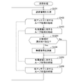
- the receiving device 20C executes the receiving process shown in FIG. 22 instead of the receiving process shown in FIG.
- the reception process of FIG. 22 is the same as the reception process of FIG. 20 except that the process of step S1101 is added between the process of step S1001 and the process of step S1002, and the process of step S1003 and the process of step S1004. , The process of step S1102 is added.
- the reception process will be described.
- step S1001 the receiving apparatus 20C determines whether or not the maintenance time has elapsed since the last time the antenna frequency set was selected (step S1101 in FIG. 22).
- the receiving device 20C determines “Yes”, executes the processing of step S1002 and step S1003, and newly selects, A selection notification including a set identifier for identifying each of at least one antenna frequency set is transmitted to the transmitting apparatus 10C via the antenna 240 (step S1102 in FIG. 22).
- the receiving apparatus 20C demodulates each of the at least one radio signal received in the selected period in which at least one antenna frequency set is used, thereby transmitting information represented by each of the at least one radio signal. Is acquired (step S1004 in FIG. 22). Thereafter, the receiving device 20C returns to step S1001, and repeatedly executes the processes of steps S1001 to S1004.
- step S1101 determines “No” in step S1101, and executes the processes of steps S1002, S1003, and S1102. Without proceeding to step S1004.
- the transmission process of FIG. 23 is a process in which the process of step S1201 is added between the process of step S103 and the process of step S104 in the transmission process of FIG.
- the transmission process will be described.
- the transmitting device 10C has an antenna frequency set (in other words, an antenna 120 that is a processing target (in other words, a target antenna) and a frequency that is a processing target (in other words, a target frequency). Then, it is determined whether or not the target group is an antenna frequency group (in other words, a selected group) identified by the group identifier included in the latest selection notification (step S1201 in FIG. 23).
- the transmission device 10C determines “Yes” and transmits the radio signal by using the antenna 120-n that is the processing target and the frequency that is the processing target ( Step S104 in FIG. 23). On the other hand, when the target group is not the selected group, the transmitting apparatus 10C determines “No” and proceeds to step S105 without executing the process of step S104.
- the transmitting apparatus 10C stops using the antenna frequency group that has not been selected by the receiving apparatus 20C among the M antenna frequency groups.
- the same operations and effects as the wireless communication system 1 of the third embodiment can be achieved. Furthermore, in the receiving apparatus 20C according to the first modification of the third embodiment, the period during which the selected antenna frequency set is used in the maintenance period from when the antenna frequency set is selected until a predetermined time elapses. The information represented by the radio signal is acquired based on the radio signal received at, and the selection of the antenna frequency set is stopped.
- control unit 111 stops using the antenna frequency group that has not been selected from the M antenna frequency groups during the maintenance period.
- control unit 111 may continue to use an unselected antenna frequency set among the M antenna frequency sets in the maintenance period. In this case, the control unit 111 may execute the transmission process of FIG. 4 instead of the transmission process of FIG.
Landscapes
- Engineering & Computer Science (AREA)
- Computer Networks & Wireless Communication (AREA)
- Signal Processing (AREA)
- Radio Transmission System (AREA)
- Mobile Radio Communication Systems (AREA)
Abstract
無線通信システム(1)は、無線信号を送信する送信装置(10)と、上記無線信号を受信する受信装置(20)と、を備える。送信装置(10)は、偏波方向が互いに異なる複数の直線偏波をそれぞれ放射する複数のアンテナ(120)と、アンテナ(120)及び周波数により構成された、互いに異なる複数の組を順に使用する制御部(111)と、を備える。上記組の使用は、当該組を構成するアンテナ(120)を使用するとともに当該組を構成する周波数を上記無線信号の搬送波の周波数として使用することによる当該無線信号の送信である。上記複数の組のそれぞれは、当該組を構成するアンテナ(120)が、複数のアンテナ(120)から選択され、且つ、当該組を構成する周波数が、当該組を構成するアンテナ(120)に対する周波数群に含まれる複数の周波数から選択される。
Description
本発明は、無線通信システム、送信装置、及び、通信方法に関する。
無線信号を送信する送信装置と、無線信号を受信する受信装置と、を備える無線通信システムが知られている(例えば、特許文献1等)。無線通信システムにおいて、送信装置は、直線偏波を放射するアンテナを使用するとともに、無線信号の搬送波の周波数として、互いに異なる複数の周波数を順に使用することにより無線信号を送信する。
送信装置により送信された無線信号は、周囲の物体(換言すると、散乱体)により反射され、又は、回折する。これにより、受信装置によって受信される無線信号の偏波方向が変化することがある。
また、受信装置に対する、送信装置のアンテナの姿勢が変化することがある。例えば、送信装置が生体の内部に位置する場合、生体の姿勢の変化、又は、送信装置の生体内の移動に伴って、受信装置に対するアンテナの姿勢は変化しやすい。また、例えば、送信装置が生体の表面に取り付けられた場合、生体の姿勢の変化に伴って、受信装置に対するアンテナの姿勢は変化しやすい。このようにして、受信装置により受信される無線信号の偏波方向が変化することがある。
ところで、受信装置により受信される無線信号の品質(換言すると、通信品質)は、当該無線信号の偏波方向に応じて変化する。従って、送信装置に対して特定の偏波方向を有する直線偏波が放射されることにより送信された無線信号が受信装置により受信された場合、通信品質が十分に高くない状態が継続する時間が過度に長くなる虞があった。
本発明の目的の一つは、通信品質が十分に高くなる確率を高めることにある。
一つの側面では、無線通信システムは、無線信号を送信する送信装置と、上記無線信号を受信する受信装置と、を備える。
上記送信装置は、
偏波方向が互いに異なる複数の直線偏波をそれぞれ放射する複数のアンテナと、
アンテナ及び周波数により構成された、互いに異なる複数の組を順に使用する制御部と、
を備える。
上記組の使用は、当該組を構成するアンテナを使用するとともに当該組を構成する周波数を上記無線信号の搬送波の周波数として使用することによる当該無線信号の送信である。
上記複数の組のそれぞれは、当該組を構成するアンテナが、上記複数のアンテナから選択され、且つ、当該組を構成する周波数が、当該組を構成するアンテナに対する周波数群に含まれる複数の周波数から選択される。
上記送信装置は、
偏波方向が互いに異なる複数の直線偏波をそれぞれ放射する複数のアンテナと、
アンテナ及び周波数により構成された、互いに異なる複数の組を順に使用する制御部と、
を備える。
上記組の使用は、当該組を構成するアンテナを使用するとともに当該組を構成する周波数を上記無線信号の搬送波の周波数として使用することによる当該無線信号の送信である。
上記複数の組のそれぞれは、当該組を構成するアンテナが、上記複数のアンテナから選択され、且つ、当該組を構成する周波数が、当該組を構成するアンテナに対する周波数群に含まれる複数の周波数から選択される。
他の一つの側面では、送信装置は、無線信号を送信する。
上記送信装置は、
偏波方向が互いに異なる複数の直線偏波をそれぞれ放射する複数のアンテナと、
アンテナ及び周波数により構成された、互いに異なる複数の組を順に使用する制御部と、
を備える。
上記組の使用は、当該組を構成するアンテナを使用するとともに当該組を構成する周波数を上記無線信号の搬送波の周波数として使用することによる当該無線信号の送信である。
上記複数の組のそれぞれは、当該組を構成するアンテナが、上記複数のアンテナから選択され、且つ、当該組を構成する周波数が、当該組を構成するアンテナに対する周波数群に含まれる複数の周波数から選択される。
上記送信装置は、
偏波方向が互いに異なる複数の直線偏波をそれぞれ放射する複数のアンテナと、
アンテナ及び周波数により構成された、互いに異なる複数の組を順に使用する制御部と、
を備える。
上記組の使用は、当該組を構成するアンテナを使用するとともに当該組を構成する周波数を上記無線信号の搬送波の周波数として使用することによる当該無線信号の送信である。
上記複数の組のそれぞれは、当該組を構成するアンテナが、上記複数のアンテナから選択され、且つ、当該組を構成する周波数が、当該組を構成するアンテナに対する周波数群に含まれる複数の周波数から選択される。
他の一つの側面では、通信方法は、
偏波方向が互いに異なる複数の直線偏波をそれぞれ放射する複数のアンテナを備える送信装置が、アンテナ及び周波数により構成された、互いに異なる複数の組を順に使用し、上記組の使用が、当該組を構成するアンテナを使用するとともに当該組を構成する周波数を無線信号の搬送波の周波数として使用することによる当該無線信号の送信であり、上記複数の組のそれぞれは、当該組を構成するアンテナが、上記複数のアンテナから選択され、且つ、当該組を構成する周波数が、当該組を構成するアンテナに対する周波数群に含まれる複数の周波数から選択され、
受信装置が、上記送信装置により送信された無線信号を受信する方法である。
偏波方向が互いに異なる複数の直線偏波をそれぞれ放射する複数のアンテナを備える送信装置が、アンテナ及び周波数により構成された、互いに異なる複数の組を順に使用し、上記組の使用が、当該組を構成するアンテナを使用するとともに当該組を構成する周波数を無線信号の搬送波の周波数として使用することによる当該無線信号の送信であり、上記複数の組のそれぞれは、当該組を構成するアンテナが、上記複数のアンテナから選択され、且つ、当該組を構成する周波数が、当該組を構成するアンテナに対する周波数群に含まれる複数の周波数から選択され、
受信装置が、上記送信装置により送信された無線信号を受信する方法である。
通信品質が十分に高くなる確率を高めることができる。
以下、本発明の、無線通信システム、送信装置、及び、通信方法、に関する各実施形態について図1乃至図23を参照しながら説明する。
<第1実施形態>
(構成)
図1に表されるように、第1実施形態の無線通信システム1は、送信装置10と、受信装置20と、を備える。なお、無線通信システム1が備える送信装置の数は、2以上であってもよい。また、無線通信システム1が備える受信装置の数は、2以上であってもよい。
(構成)
図1に表されるように、第1実施形態の無線通信システム1は、送信装置10と、受信装置20と、を備える。なお、無線通信システム1が備える送信装置の数は、2以上であってもよい。また、無線通信システム1が備える受信装置の数は、2以上であってもよい。
送信装置10は、予め定められた通信方式に従って無線信号を送信する。受信装置20は、送信装置10により送信された無線信号を、当該通信方式に従って受信する。例えば、通信方式は、Bluetoothと呼ばれる規格の少なくとも一部に準拠した方式である。「BLUETOOTH」は、登録商標である。なお、通信方式は、上記方式と異なる方式であってもよい。
例えば、送信装置10は、生体(例えば、人体)の内部に導入可能に構成されてもよい。この場合、送信装置10は、カプセル剤又は錠剤等の製剤に取り付けられてもよいし、当該製剤の少なくとも一部を構成してもよい。また、例えば、送信装置10は、生体の表面に取り付け可能に構成されてもよい。この場合、送信装置10は、貼付剤等の製剤に取り付けられてもよいし、当該製剤の少なくとも一部を構成してもよい。
また、例えば、送信装置10は、物理量を検出するセンサに取り付けられてもよいし、当該センサの少なくとも一部を構成してもよい。また、例えば、送信装置10は、携帯電話機、スマートフォン、又は、パーソナルコンピュータ等の少なくとも一部を構成してもよい。
(構成:送信装置)
送信装置10は、送信部110と、N個のアンテナ120-1,…,120-Nと、を備える。Nは、2以上の整数を表す。本例では、Nは、2を表す。また、以下において、アンテナ120-nは、区別される必要がない場合、アンテナ120とも表される。nは、1からNの各整数を表す。
送信装置10は、送信部110と、N個のアンテナ120-1,…,120-Nと、を備える。Nは、2以上の整数を表す。本例では、Nは、2を表す。また、以下において、アンテナ120-nは、区別される必要がない場合、アンテナ120とも表される。nは、1からNの各整数を表す。
本例では、送信装置10の少なくとも一部は、LSI(Large Scale Integration)回路により構成される。なお、送信装置10の少なくとも一部は、プログラム可能な論理回路(例えば、PLD、又は、FPGA)により構成されてもよい。PLDは、Programmable Logic Deviceの略記である。FPGAは、Field-Programmable Gate Arrayの略記である。
また、送信装置10は、処理装置と記憶装置とを備え、処理装置が、記憶装置に記憶されたプログラムを実行することにより、送信装置10の機能の少なくとも一部を実現してもよい。例えば、処理装置は、CPU(Central Processing Unit)、MPU(Micro Processing Unit)、又は、DSP(Digital Signal Processor)を含んでもよい。また、記憶装置は、RAM(Random Access Memory)、半導体メモリ、又は、有機メモリを含んでもよい。
N個のアンテナ120-1,…,120-Nは、偏波方向が互いに異なるN個の直線偏波をそれぞれ放射する。本例では、図2に表されるように、アンテナ120-nは、直線形状を有するダイポールアンテナである。アンテナ120-1とアンテナ120-2とは、互いに直交する2つの方向に沿ってそれぞれ延びる。従って、本例では、2個のアンテナ120-1,120-2は、偏波方向が互いに直交する2つの直線偏波をそれぞれ放射する。なお、アンテナ120-nは、ダイポールアンテナと異なるアンテナ(例えば、パッチアンテナ、ループアンテナ、板状アンテナ、又は、平面アンテナ等)であってもよい。
送信部110は、制御部111と、切替器112と、を備える。
切替器112は、N個のアンテナ120-1,…,120-Nのうちの1つのアンテナ120-nと制御部111とを接続するとともに、制御部111による制御に従って、制御部111に接続されるアンテナ120-nを、N個のアンテナ120-1,…,120-Nの中で切り替える。
切替器112は、N個のアンテナ120-1,…,120-Nのうちの1つのアンテナ120-nと制御部111とを接続するとともに、制御部111による制御に従って、制御部111に接続されるアンテナ120-nを、N個のアンテナ120-1,…,120-Nの中で切り替える。
制御部111は、送信情報を生成する。例えば、送信情報は、送信装置10を識別する識別子を含む。例えば、送信情報は、送信装置10が物理量を検出するセンサを備える場合、当該センサにより検出された物理量を表す情報を含む。例えば、物理量は、温度、湿度、照度、pH、加速度、角速度、圧力、又は、対象物の濃度等である。例えば、対象物は、消化液(例えば、唾液、胃液、腸液、又は、膵液等)、血液、グルコース、コレステロール、常在菌、又は、感染性物質(例えば、細菌、又は、ウイルス等)である。
制御部111は、生成した送信情報に基づいて、当該送信情報を表すように搬送波が変調された無線信号を生成する。制御部111は、生成した無線信号を、切替器112により接続されたアンテナ120-nを介して送信する。
ここで、制御部111が、無線信号の送信に使用する、搬送波の周波数及びアンテナ120について説明を加える。
制御部111は、M個のアンテナ周波数組を順に使用する。Mは、2以上の整数を表す。アンテナ周波数組は、アンテナ120及び周波数により構成される。アンテナ周波数組の使用は、当該アンテナ周波数組を構成するアンテナ120を使用するとともに、当該アンテナ周波数組を構成する周波数を無線信号の搬送波の周波数として使用することによる当該無線信号の送信である。本例では、アンテナ120-nの使用は、制御部111と当該アンテナ120-nとを切替器112に接続させるための切替器112の制御を含む。
M個のアンテナ周波数組は、N個のアンテナ120-1,…,120-Nのそれぞれに対する複数の部分組を含む。アンテナ120-nに対する複数の部分組は、アンテナ120-nにより構成されるとともに、当該アンテナ120-nに対して設定された周波数群に含まれる複数の周波数によりそれぞれ構成される。本例では、M個のアンテナ周波数組は、互いに異なる。
本例では、周波数群は、N個のアンテナ120-1,…,120-Nに共通する。本例では、周波数群は、P個の周波数からなる基本周波数群に一致する。Pは、2以上の整数を表す。本例では、Pは、79を表す。例えば、P個の周波数は、2402MHz乃至2480MHzに含まれてよい。なお、周波数群は、基本周波数群の一部であってもよい。また、周波数群は、アンテナ120間で異なっていてもよい。
換言すると、本例では、M個のアンテナ周波数組は、N個のアンテナ120-1,…,120-Nから選択されるアンテナと、周波数群に含まれるP個の周波数から選択される周波数と、のすべての組み合わせである。本例では、アンテナ周波数組は、アンテナ120-nを識別するアンテナ識別子Anと、周波数を識別する周波数識別子fnpと、により表されてもよい。pは、1からPの各整数を表す。
本例では、アンテナ周波数組の数Mは、アンテナ120の数Nと、基本周波数群を構成する周波数の数Pと、の積である。
本例では、アンテナ周波数組の数Mは、アンテナ120の数Nと、基本周波数群を構成する周波数の数Pと、の積である。
制御部111は、使用されるアンテナ周波数組を、予め定められた単位送信時間が経過する毎に変更する。例えば、単位送信時間は、1/1600秒であってよい。
制御部111は、N個のアンテナ120-1,…,120-Nのそれぞれに対して、当該アンテナ120-nに対する複数の部分組を連続して使用する。換言すると、本例では、制御部111は、N個のアンテナ120-1,…,120-Nのそれぞれに対して、周波数群使用時間に亘って、同一のアンテナ120-nを使用するとともに、当該アンテナ120-nに対する周波数群に含まれる複数の周波数(本例では、P個の周波数)のそれぞれを使用する。従って、本例では、周波数群使用時間は、単位送信時間をP倍した時間である。
本例では、周波数群に含まれる複数の周波数が使用される順序である周波数使用順序は、予め定められる。例えば、周波数使用順序は、周波数が高くなる順序、又は、周波数が低くなる順序である。また、周波数使用順序は、疑似乱数に基づいて決定されてもよい。
更に、制御部111は、N個のアンテナ120-1,…,120-Nがそれぞれ使用される複数の期間を、時間軸において順に且つ繰り返し設ける。本例では、図3に表されるように、制御部111は、アンテナ120-1(換言すると、第1のアンテナ)を使用する期間と、アンテナ120-2(換言すると、第2のアンテナ)を使用する期間と、を時間軸において順に且つ繰り返し設ける。換言すると、制御部111は、アンテナ120-1を使用する期間と、アンテナ120-2を使用する期間と、を時間軸において交互に設ける。
Tpは、N個のアンテナ120-1,…,120-Nのそれぞれが使用される期間の周期を表す。Tsは、周波数群使用時間を表す。本例では、周波数群使用時間Tsは、アンテナ120-nに対する周波数群に含まれる複数の周波数(本例では、P個の周波数)のすべてが1回ずつ使用される期間である。本例では、周期Tpをアンテナ120の数Nにより除した時間は、周波数群使用時間Tsと等しい。本例では、周期Tpと、周波数群使用時間Tsと、の関係は、数式1により表される。本例では、係数kは、1を表す。

なお、係数kは、1よりも大きい値であってもよい。この場合、周波数群使用時間Tsは、単位送信時間をP倍した時間よりも長い。この場合、制御部111は、あるアンテナ120-nの使用を継続している期間において、P個の周波数のうちの少なくとも1つの周波数を複数回、使用する。
なお、制御部111は、N個のアンテナ120-1,…,120-Nのそれぞれに対して、当該アンテナ120-nに対する複数の部分組を連続して使用しなくてもよい。この場合、例えば、制御部111は、P個の周波数のそれぞれに対して、周波数使用時間に亘って、同一の周波数を使用するとともに、N個のアンテナ120-1,…,120-Nのそれぞれを使用してもよい。この場合、周波数使用時間は、単位送信時間をN倍した時間である。これによれば、使用される周波数が変化する頻度を抑制できる。
本例では、制御部111は、M個のアンテナ周波数組を使用することによりそれぞれ送信されるM個の無線信号が表す送信情報を互いに一致させる。換言すると、本例では、制御部111は、M個のアンテナ周波数組を使用することにより、同一の送信情報を表すM個の無線信号をそれぞれ送信する。なお、制御部111は、M個のアンテナ周波数組を使用することによりそれぞれ送信されるM個の無線信号が表す送信情報を互いに異ならせてもよい。
本例では、送信装置10は、切替器112を備えるが、切替器112を備えていなくてもよい。この場合、送信装置10は、制御部111が、N個のアンテナ120-1,…,120-Nがそれぞれ接続されたN個のポートを備えるとともに、制御部111が無線信号を出力するポートをN個のポートの中で切り替えることにより、使用するアンテナ120を切り替えてよい。
本例では、送信装置10が使用するアンテナ120の切り替えは、送信装置10により送信される無線信号の偏波方向の切り替えである、と捉えられもよい。また、送信装置10が使用するアンテナ120を切り替えることは、偏波切替ダイバーシティと表されてもよい。
(構成:受信装置)
図1に表されるように、受信装置20は、アンテナ210と、受信部220と、を備える。
本例では、受信装置20の少なくとも一部は、LSI回路により構成される。なお、送信装置10の少なくとも一部は、プログラム可能な論理回路により構成されてもよい。
また、受信装置20は、処理装置と記憶装置とを備え、処理装置が、記憶装置に記憶されたプログラムを実行することにより、受信装置20の機能の少なくとも一部を実現してもよい。
図1に表されるように、受信装置20は、アンテナ210と、受信部220と、を備える。
本例では、受信装置20の少なくとも一部は、LSI回路により構成される。なお、送信装置10の少なくとも一部は、プログラム可能な論理回路により構成されてもよい。
また、受信装置20は、処理装置と記憶装置とを備え、処理装置が、記憶装置に記憶されたプログラムを実行することにより、受信装置20の機能の少なくとも一部を実現してもよい。
受信部220は、送信装置10により送信された無線信号を、アンテナ210を介して受信する。
受信部220は、品質取得部221と、情報取得部222と、を備える。
品質取得部221は、M個のアンテナ周波数組のそれぞれに対して、当該アンテナ周波数組が使用される期間において受信した無線信号の品質を表す品質パラメータを取得する。
受信部220は、品質取得部221と、情報取得部222と、を備える。
品質取得部221は、M個のアンテナ周波数組のそれぞれに対して、当該アンテナ周波数組が使用される期間において受信した無線信号の品質を表す品質パラメータを取得する。
本例では、品質パラメータは、受信した無線信号の強度(換言すると、受信強度)を表す。例えば、受信強度は、受信した無線信号の、振幅又は電力等であってよい。無線信号の品質は、受信強度が大きくなるほど高くなる。なお、品質パラメータは、受信した無線信号を復調することにより取得された送信情報に含まれる、誤った情報の量であってもよい。例えば、情報の誤りは、誤り訂正符号、又は、誤り検出符号に基づいて検出される。この場合、無線信号の品質は、誤った情報の量が少なくなるほど高くなる。
情報取得部222は、品質取得部221により取得された品質パラメータに基づいて、M個のアンテナ周波数組の中から少なくとも1つの組を選択する。本例では、情報取得部222は、品質取得部221により取得された品質パラメータが表す品質が最も高いアンテナ周波数組を、M個のアンテナ周波数組の中から選択する。
更に、情報取得部222は、選択した少なくとも1つのアンテナ周波数組が使用される期間において受信した無線信号に基づいて、無線信号が表す送信情報を取得する。本例では、情報取得部222は、受信した無線信号を復調することにより送信情報を取得する。
本例では、受信部220は、選択合成を行なうことにより送信情報を取得する、と捉えられてもよい。なお、受信部220は、選択合成に代えて、又は、選択合成に加えて、等利得合成、又は、最大比合成を行なってもよい。
(動作)
次に、無線通信システム1の動作について、図4及び図5を参照しながら説明する。
送信装置10は、図4に表される送信処理を実行する。以下、送信処理について説明を加える。
次に、無線通信システム1の動作について、図4及び図5を参照しながら説明する。
送信装置10は、図4に表される送信処理を実行する。以下、送信処理について説明を加える。
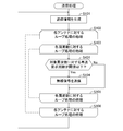
送信装置10は、送信情報を生成する(図4のステップS101)。次いで、送信装置10は、N個のアンテナ120-1,…,120-Nを1つずつ順に処理対象として用いる第1のループ処理(図4のステップS102乃至ステップS106)を実行する。
更に、第1のループ処理において、送信装置10は、処理対象であるアンテナ120-nに対する周波数群に含まれる複数の周波数(本例では、P個の周波数)を1つずつ順に処理対象として用いる第2のループ処理(図4のステップS103乃至ステップS105)を実行する。
加えて、第2のループ処理において、送信装置10は、処理対象であるアンテナ120-nと、処理対象である周波数と、を使用することにより、無線信号を送信する(図4のステップS104)。換言すると、第2のループ処理において、送信装置10は、処理対象であるアンテナ120-nを介して、処理対象である周波数に搬送波の周波数が一致する無線信号を送信する。
そして、送信装置10は、処理対象であるアンテナ120-nに対する周波数群に含まれる複数の周波数のすべてに対して、第2のループ処理を実行した後、ステップS106へ進む。
更に、送信装置10は、N個のアンテナ120-1,…,120-Nのすべてに対して、第1のループ処理を実行した後、ステップS101へ戻り、ステップS101乃至ステップS106の処理を繰り返し実行する。
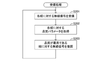
一方、受信装置20は、図5に表される受信処理を実行する。以下、受信処理について説明を加える。
受信装置20は、M個のアンテナ周波数組のそれぞれに対して送信装置10により送信された無線信号を受信する(図5のステップS201)。次いで、受信装置20は、M個のアンテナ周波数組のそれぞれに対する品質パラメータを取得する(図5のステップS202)。
そして、受信装置20は、取得された品質パラメータが表す品質が最も高いアンテナ周波数組を、M個のアンテナ周波数組の中から選択し、選択したアンテナ周波数組が使用される期間において受信した無線信号を復調することにより、無線信号が表す送信情報を取得する(図5のステップS203)。
その後、受信装置20は、ステップS201へ戻り、ステップS201乃至ステップS203の処理を繰り返し実行する。
その後、受信装置20は、ステップS201へ戻り、ステップS201乃至ステップS203の処理を繰り返し実行する。
以上、説明したように、第1実施形態の無線通信システム1において、送信装置10は、偏波方向が互いに異なるN個の直線偏波をそれぞれ放射するN個のアンテナ120-1,…,120-Nを備える。更に、送信装置10は、アンテナ120及び周波数により構成された、互いに異なる複数のアンテナ周波数組を順に使用することにより無線信号を送信する制御部111を備える。上記複数のアンテナ周波数組のそれぞれは、当該アンテナ周波数組を構成するアンテナ120-nが、N個のアンテナ120-1,…,120-Nから選択され、且つ、当該アンテナ周波数組を構成する周波数が、当該アンテナ周波数組を構成するアンテナ120-nに対する周波数群に含まれる複数の周波数から選択される。
これによれば、互いに異なる複数のアンテナ周波数組が順に使用される。これにより、送信装置10に対して特定の偏波方向を有する直線偏波のみが使用される場合と比較して、通信品質が十分に高くなる確率を高めることができる。
更に、第1実施形態の無線通信システム1において、上記複数のアンテナ周波数組は、N個のアンテナ120-1,…,120-Nのそれぞれに対して、当該アンテナ120-nにより構成されるとともに、当該アンテナ120-nに対する周波数群に含まれる複数の周波数によりそれぞれ構成された複数の部分組を含む。
これによれば、N個のアンテナ120-1,…,120-Nと、周波数群に含まれる複数の周波数と、の組み合わせのそれぞれが順に使用される。これにより、特定のアンテナ周波数組のみが使用される場合と比較して、通信品質が十分に高くなる確率を高めることができる。
更に、第1実施形態の無線通信システム1において、制御部111は、N個のアンテナ120-1,…,120-Nのそれぞれに対して、複数の部分組を連続して使用する。
これによれば、使用されるアンテナ120が変化する頻度を抑制できる。
更に、第1実施形態の無線通信システム1において、制御部111は、N個のアンテナ120-1,…,120-Nがそれぞれ使用される複数の期間を、時間軸において順に且つ繰り返し設ける。
これによれば、各アンテナ120が使用される期間を均一に分散できる。これにより、各アンテナ120が使用される期間が偏在する場合よりも、通信品質が十分に高くなる確率を高めることができる。
更に、第1実施形態の無線通信システム1において、受信装置20は、複数のアンテナ周波数組のそれぞれに対して、当該アンテナ周波数組が使用される期間において受信した無線信号の品質を表す品質パラメータを取得する。加えて、受信装置20は、取得された品質パラメータに基づいて、複数のアンテナ周波数組の中から少なくとも1つのアンテナ周波数組を選択し、且つ、選択した少なくとも1つのアンテナ周波数組が使用される期間において受信した無線信号に基づいて、無線信号が表す情報を取得する。
これによれば、品質が高い無線信号に基づいて情報を取得できる。これにより、送信装置10から受信装置20へ情報を確実に伝達できる。
更に、第1実施形態の無線通信システム1において、受信装置20は、取得された品質パラメータが表す品質が最も高いアンテナ周波数組を、複数のアンテナ周波数組の中から選択し、且つ、選択したアンテナ周波数組が使用される期間において受信した無線信号に基づいて、無線信号が表す情報を取得する。
これによれば、品質が最も高い無線信号に基づいて情報を取得できる。これにより、送信装置10から受信装置20へ情報を確実に伝達できる。
更に、第1実施形態の無線通信システム1において、制御部111は、複数のアンテナ周波数組を使用することによりそれぞれ送信される複数の無線信号が表す情報を互いに一致させる。
これによれば、複数のアンテナ周波数組のうちの1つのアンテナ周波数組により送信された無線信号のみが、受信装置20における情報の取得に用いられる場合であっても、情報が消失することを回避できる。
(第1実験例)
次に、本発明に関する第1実験例について説明する。
送信装置10は、偏波方向が鉛直方向である直線偏波をアンテナ120-1が放射するとともに、偏波方向が水平方向である直線偏波をアンテナ120-2が放射するように、人体等価ファントムの表面に取り付けられる。人体等価ファントムは、人体の形状及び電気特性(本例では、比誘電率、及び、導電率)を模擬した模型である。
次に、本発明に関する第1実験例について説明する。
送信装置10は、偏波方向が鉛直方向である直線偏波をアンテナ120-1が放射するとともに、偏波方向が水平方向である直線偏波をアンテナ120-2が放射するように、人体等価ファントムの表面に取り付けられる。人体等価ファントムは、人体の形状及び電気特性(本例では、比誘電率、及び、導電率)を模擬した模型である。
受信装置20は、送信装置10と所定の距離(本例では、5m)だけ隔てられる。受信装置20のアンテナ210は、鉛直方向に沿って延びるダイポールアンテナである。第1実験例においては、受信装置20は、静止している。
第1実験例において、単位送信時間は、100/79msである。
第1実験例において、単位送信時間は、100/79msである。
図6における曲線C1は、送信装置10がアンテナ120-1を使用することにより送信され、且つ、受信装置20により受信された無線信号の電力(換言すると、受信電力)の、使用された周波数に対する変化を表す。同様に、図6における曲線C2は、送信装置10がアンテナ120-2を使用することにより送信され、且つ、受信装置20により受信された無線信号の電力(換言すると、受信電力)の、使用された周波数に対する変化を表す。
図6に表されるように、受信装置20が静止している状態において、アンテナ120-1から送信された無線信号の受信電力と、アンテナ120-2から送信された無線信号の受信電力と、の関係は、周波数に応じて変化する。
(第2実験例)
次に、本発明に関する第2実験例について説明する。
送信装置10は、第1実験例と同様に、偏波方向が鉛直方向である直線偏波をアンテナ120-1が放射するとともに、偏波方向が水平方向である直線偏波をアンテナ120-2が放射するように、人体等価ファントムの表面に取り付けられる。
次に、本発明に関する第2実験例について説明する。
送信装置10は、第1実験例と同様に、偏波方向が鉛直方向である直線偏波をアンテナ120-1が放射するとともに、偏波方向が水平方向である直線偏波をアンテナ120-2が放射するように、人体等価ファントムの表面に取り付けられる。
受信装置20は、第1実験例と同様に、送信装置10と所定の距離(本例では、5m)だけ隔てられる。受信装置20のアンテナ210は、直線に沿って延びるダイポールアンテナである。第2実験例においては、受信装置20は、所定の回転速度にて回転している。
第2実験例において、単位送信時間は、100/79msである。
第2実験例において、単位送信時間は、100/79msである。
図7は、送信装置10が、M個のアンテナ周波数組の使用を1500回だけ繰り返した場合において、受信装置20により受信された無線信号の電力(換言すると、受信電力)の、時間に対する変化を表す。
図8は、送信装置10が、M個のアンテナ周波数組の使用を1500回だけ繰り返した場合において、アンテナ120-1が連続して使用される期間(換言すると、アンテナ120-1に対するP個の部分組が使用される期間)毎の、当該期間における受信電力の最大値の、時間に対する変化を表す。
図8は、1つのアンテナ120-1のみが使用された場合において受信装置20により選択合成された無線信号の受信電力の時間に対する変化を表す、と捉えられてよい。
図8は、1つのアンテナ120-1のみが使用された場合において受信装置20により選択合成された無線信号の受信電力の時間に対する変化を表す、と捉えられてよい。
図9は、送信装置10が、M個のアンテナ周波数組の使用を1500回だけ繰り返した場合において、M個のアンテナ周波数組が使用される期間(換言すると、アンテナ120-1に対するP個の部分組が使用される期間と、アンテナ120-2に対するP個の部分組が使用される期間と、を合わせた期間)毎の、当該期間における受信電力の最大値の、時間に対する変化を表す。
図9は、2つのアンテナ120-1,120-2が切り替えられて使用された場合において受信装置20により選択合成された無線信号の受信電力の時間に対する変化を表す、と捉えられてよい。
図9は、2つのアンテナ120-1,120-2が切り替えられて使用された場合において受信装置20により選択合成された無線信号の受信電力の時間に対する変化を表す、と捉えられてよい。
図10における曲線D1乃至D3は、図7乃至図9における受信電力の変化の累積確率分布をそれぞれ表す。
図10において、-20dBである累積確率分布における、図7乃至図9における受信電力は、それぞれ、-81.1dBm、-60.6dBm、及び、-57.5dBmである。従って、図7における受信電力に対する、図8における受信電力の利得は、20.5dBであり、図8における受信電力に対する、図9における受信電力の利得は、3.1dBである。
図10において、-20dBである累積確率分布における、図7乃至図9における受信電力は、それぞれ、-81.1dBm、-60.6dBm、及び、-57.5dBmである。従って、図7における受信電力に対する、図8における受信電力の利得は、20.5dBであり、図8における受信電力に対する、図9における受信電力の利得は、3.1dBである。
以上により、第1実施形態の無線通信システム1によれば、通信品質が十分に高くなる確率を高めることができる。
<第1実施形態の第1変形例>
次に、第1実施形態の第1変形例の無線通信システムについて説明する。第1実施形態の第1変形例の無線通信システムは、第1実施形態の無線通信システムに対して、品質パラメータに基づいて選択された周波数の使用を中止する点において相違している。以下、相違点を中心として説明する。なお、第1実施形態の第1変形例の説明において、第1実施形態にて使用した符号と同じ符号を付したものは、同一又はほぼ同様のものである。
次に、第1実施形態の第1変形例の無線通信システムについて説明する。第1実施形態の第1変形例の無線通信システムは、第1実施形態の無線通信システムに対して、品質パラメータに基づいて選択された周波数の使用を中止する点において相違している。以下、相違点を中心として説明する。なお、第1実施形態の第1変形例の説明において、第1実施形態にて使用した符号と同じ符号を付したものは、同一又はほぼ同様のものである。
(構成)
図11に表されるように、第1実施形態の第1変形例の無線通信システム1Aは、送信装置10及び受信装置20に代えて、送信装置10Aと、受信装置20Aと、を備える。
送信装置10Aは、第1実施形態の送信装置10が備える構成に加えて、アンテナ130と、受信部140と、を備える。
受信装置20Aは、第1実施形態の受信装置20が備える構成に加えて、送信部230と、アンテナ240と、を備える。
図11に表されるように、第1実施形態の第1変形例の無線通信システム1Aは、送信装置10及び受信装置20に代えて、送信装置10Aと、受信装置20Aと、を備える。
送信装置10Aは、第1実施形態の送信装置10が備える構成に加えて、アンテナ130と、受信部140と、を備える。
受信装置20Aは、第1実施形態の受信装置20が備える構成に加えて、送信部230と、アンテナ240と、を備える。
なお、送信装置10Aは、アンテナ130を備えることなく、N個のアンテナ120-1,…,120-Nの少なくとも1つを送信及び受信の両方に用いてもよい。また、受信装置20Aは、アンテナ240を備えることなく、アンテナ210を送信及び受信の両方に用いてもよい。
本例では、制御部111は、M個のアンテナ周波数組を使用することによりそれぞれ送信されるM個の無線信号が表す送信情報を互いに異ならせる。換言すると、本例では、制御部111は、M個のアンテナ周波数組を使用することにより、互いに異なる送信情報を表すM個の無線信号をそれぞれ送信する。
本例では、情報取得部222は、M個のアンテナ周波数組のそれぞれに対して、当該アンテナ周波数組が使用される期間において受信した無線信号に基づいて、無線信号が表す送信情報を取得する。本例では、情報取得部222は、受信した無線信号を復調することにより送信情報を取得する。
本例では、送信情報は、誤り検出符号を含む。なお、送信情報は、誤り検出符号に代えて、誤り訂正符号を含んでいてもよい。品質取得部221は、取得した送信情報の誤りの有無を、当該送信情報に含まれる誤り検出符号に基づいて検出する。本例では、送信情報の誤りの有無は、受信された無線信号の品質を表す品質パラメータに対応する。
送信部230は、品質取得部221により、送信情報の誤りが存在することが検出された場合、当該送信情報の再送信を要求する再送要求を、アンテナ240を介して送信装置10Aへ送信する。例えば、再送要求は、送信情報を正常に受信できなかったことを表す信号(例えば、NACK(Negative Acknowledgement)信号)であってよい。
また、送信部230は、品質取得部221により、送信情報の誤りが存在しないことが検出された場合、当該送信情報を正常に受信できたことを表す信号(例えば、ACK(Positive Acknowledgement)信号)を、アンテナ240を介して送信装置10Aへ送信してもよい。
なお、無線通信システム1Aは、品質パラメータとして、送信情報の誤りの有無に代えて、又は、送信情報の誤りの有無に加えて、受信強度を用いてもよい。この場合において、送信部230は、受信強度が予め定められた閾値よりも小さい場合、当該受信強度の基となる無線信号の再送信を要求する再送要求を、アンテナ240を介して送信装置10Aへ送信してよい。
受信部140は、受信装置20Aにより送信された再送要求を、アンテナ130を介して受信する。
制御部111は、受信部140により再送要求が受信された場合、当該再送要求により再送信が要求された送信情報を再送信する。
制御部111は、受信部140により再送要求が受信された場合、当該再送要求により再送信が要求された送信情報を再送信する。
更に、制御部111は、受信部140により再送要求が受信された回数(換言すると、再送要求回数)を、当該再送要求により再送信が要求された送信情報を表す無線信号の送信に使用された周波数毎に計数する。制御部111は、M個のアンテナ周波数組のうちの、計数された再送要求回数が、予め定められた閾値よりも大きい周波数により構成されるアンテナ周波数組の使用を中止する。
(動作)
次に、無線通信システム1Aの動作について、図12及び図13を参照しながら説明する。
受信装置20Aは、図5に表される受信処理に代えて、図12に表される受信処理を実行する。以下、受信処理について説明を加える。
次に、無線通信システム1Aの動作について、図12及び図13を参照しながら説明する。
受信装置20Aは、図5に表される受信処理に代えて、図12に表される受信処理を実行する。以下、受信処理について説明を加える。
受信装置20Aは、1つのアンテナ周波数組を使用することにより送信装置10Aにより送信された無線信号を受信する(図12のステップS301)。次いで、受信装置20Aは、受信した無線信号を復調することにより、無線信号が表す送信情報を取得する(図12のステップS302)。
そして、受信装置20Aは、取得した送信情報の誤りの有無を、当該送信情報に含まれる誤り検出符号に基づいて検出し、送信情報の誤りが存在するか否かを判定する(図12のステップS303)。
送信情報の誤りが存在する場合、受信装置20Aは、「Yes」と判定し、当該送信情報の再送信を要求する再送要求を、アンテナ240を介して送信装置10Aへ送信する(図12のステップS304)。その後、受信装置20Aは、ステップS301へ戻り、ステップS301乃至ステップS304の処理を繰り返し実行する。
一方、送信情報の誤りが存在しない場合、受信装置20Aは、「No」と判定し、ステップS304の処理を実行することなく、ステップS301へ戻る。
一方、送信情報の誤りが存在しない場合、受信装置20Aは、「No」と判定し、ステップS304の処理を実行することなく、ステップS301へ戻る。
一方、送信装置10Aは、図4に表される送信処理に代えて、図13に表される送信処理を実行する。図13の送信処理は、図4の送信処理において、ステップS103の処理と、ステップS104の処理と、の間にステップS401の処理が追加された処理である。以下、送信処理について説明を加える。
送信装置10Aは、第2のループ処理において、処理対象である周波数(換言すると、対象周波数)に対する再送要求回数が閾値以下であるか否かを判定する(図13のステップS401)。
対象周波数に対する再送要求回数が閾値以下である場合、送信装置10Aは、「Yes」と判定し、処理対象であるアンテナ120-nと、処理対象である周波数と、を使用することにより、無線信号を送信する(図13のステップS104)。
一方、対象周波数に対する再送要求回数が閾値よりも大きい場合、送信装置10Aは、「No」と判定し、ステップS104の処理を実行することなく、ステップS105へ進む。
一方、対象周波数に対する再送要求回数が閾値よりも大きい場合、送信装置10Aは、「No」と判定し、ステップS104の処理を実行することなく、ステップS105へ進む。
このようにして、送信装置10Aは、M個のアンテナ周波数組のうちの、計数された再送要求回数が閾値よりも大きい周波数により構成されるアンテナ周波数組の使用を中止する。
以上、説明したように、第1実施形態の第1変形例の無線通信システム1Aによれば、第1実施形態の無線通信システム1と同様の作用及び効果を奏することができる。
更に、第1実施形態の第1変形例の無線通信システム1Aは、周波数群に含まれる複数の周波数のそれぞれに対して、当該周波数が使用される期間において受信装置20Aにより受信された無線信号の品質を表す品質パラメータを取得する。加えて、無線通信システム1Aは、取得した品質パラメータに基づいて、当該周波数群に含まれる複数の周波数の中から、少なくとも1つの周波数を選択し、且つ、選択した少なくとも1つの周波数の使用を中止する。
更に、第1実施形態の第1変形例の無線通信システム1Aは、周波数群に含まれる複数の周波数のそれぞれに対して、当該周波数が使用される期間において受信装置20Aにより受信された無線信号の品質を表す品質パラメータを取得する。加えて、無線通信システム1Aは、取得した品質パラメータに基づいて、当該周波数群に含まれる複数の周波数の中から、少なくとも1つの周波数を選択し、且つ、選択した少なくとも1つの周波数の使用を中止する。
これによれば、品質が低い無線信号の送信に使用された周波数の使用が中止される。これにより、当該周波数の使用が継続する場合と比較して、通信品質が十分に高くなる確率を高めることができる。
<第1実施形態の第2変形例>
次に、第1実施形態の第2変形例の無線通信システムについて説明する。第1実施形態の第2変形例の無線通信システムは、第1実施形態の第1変形例の無線通信システムに対して、品質パラメータに基づいて選択されたアンテナの使用を中止する点において相違している。以下、相違点を中心として説明する。なお、第1実施形態の第2変形例の説明において、第1実施形態の第1変形例にて使用した符号と同じ符号を付したものは、同一又はほぼ同様のものである。
次に、第1実施形態の第2変形例の無線通信システムについて説明する。第1実施形態の第2変形例の無線通信システムは、第1実施形態の第1変形例の無線通信システムに対して、品質パラメータに基づいて選択されたアンテナの使用を中止する点において相違している。以下、相違点を中心として説明する。なお、第1実施形態の第2変形例の説明において、第1実施形態の第1変形例にて使用した符号と同じ符号を付したものは、同一又はほぼ同様のものである。
本例では、制御部111は、受信部140により再送要求が受信された回数(換言すると、再送要求回数)を、当該再送要求により再送信が要求された送信情報を表す無線信号の送信に使用されたアンテナ120毎に計数する。制御部111は、M個のアンテナ周波数組のうちの、計数された再送要求回数が、予め定められた閾値よりも大きいアンテナ120により構成されるアンテナ周波数組の使用を中止する。
本例では、送信装置10Aは、図4に表される送信処理に代えて、図14に表される送信処理を実行する。図14の送信処理は、図4の送信処理において、ステップS103の処理と、ステップS104の処理と、の間にステップS501の処理が追加された処理である。以下、送信処理について説明を加える。
送信装置10Aは、第2のループ処理において、処理対象であるアンテナ120(換言すると、対象アンテナ)に対する再送要求回数が閾値以下であるか否かを判定する(図14のステップS501)。
対象アンテナに対する再送要求回数が閾値以下である場合、送信装置10Aは、「Yes」と判定し、処理対象であるアンテナ120-nと、処理対象である周波数と、を使用することにより、無線信号を送信する(図14のステップS104)。
一方、対象アンテナに対する再送要求回数が閾値よりも大きい場合、送信装置10Aは、「No」と判定し、ステップS104の処理を実行することなく、ステップS105へ進む。
一方、対象アンテナに対する再送要求回数が閾値よりも大きい場合、送信装置10Aは、「No」と判定し、ステップS104の処理を実行することなく、ステップS105へ進む。
このようにして、送信装置10Aは、M個のアンテナ周波数組のうちの、計数された再送要求回数が閾値よりも大きいアンテナ120により構成されるアンテナ周波数組の使用を中止する。
以上、説明したように、第1実施形態の第2変形例の無線通信システム1Aによれば、第1実施形態の無線通信システム1と同様の作用及び効果を奏することができる。
更に、第1実施形態の第2変形例の無線通信システム1Aは、N個のアンテナ120-1,…,120-Nのそれぞれに対して、当該アンテナ120-nが使用される期間において受信装置20Aにより受信された無線信号の品質を表す品質パラメータを取得する。加えて、無線通信システム1Aは、取得した品質パラメータに基づいて、N個のアンテナ120-1,…,120-Nの中から、少なくとも1つのアンテナ120を選択し、且つ、選択した少なくとも1つのアンテナ120の使用を中止する。
更に、第1実施形態の第2変形例の無線通信システム1Aは、N個のアンテナ120-1,…,120-Nのそれぞれに対して、当該アンテナ120-nが使用される期間において受信装置20Aにより受信された無線信号の品質を表す品質パラメータを取得する。加えて、無線通信システム1Aは、取得した品質パラメータに基づいて、N個のアンテナ120-1,…,120-Nの中から、少なくとも1つのアンテナ120を選択し、且つ、選択した少なくとも1つのアンテナ120の使用を中止する。
これによれば、品質が低い無線信号の送信に使用されたアンテナ120の使用が中止される。これにより、当該アンテナ120の使用が継続する場合と比較して、通信品質が十分に高くなる確率を高めることができる。
<第1実施形態の第3変形例>
次に、第1実施形態の第3変形例の無線通信システムについて説明する。第1実施形態の第3変形例の無線通信システムは、第1実施形態の第1変形例の無線通信システムに対して、品質パラメータに基づいて選択されたアンテナ周波数組の使用を中止する点において相違している。以下、相違点を中心として説明する。なお、第1実施形態の第3変形例の説明において、第1実施形態の第1変形例にて使用した符号と同じ符号を付したものは、同一又はほぼ同様のものである。
次に、第1実施形態の第3変形例の無線通信システムについて説明する。第1実施形態の第3変形例の無線通信システムは、第1実施形態の第1変形例の無線通信システムに対して、品質パラメータに基づいて選択されたアンテナ周波数組の使用を中止する点において相違している。以下、相違点を中心として説明する。なお、第1実施形態の第3変形例の説明において、第1実施形態の第1変形例にて使用した符号と同じ符号を付したものは、同一又はほぼ同様のものである。
本例では、制御部111は、受信部140により再送要求が受信された回数(換言すると、再送要求回数)を、当該再送要求により再送信が要求された送信情報を表す無線信号の送信に使用されたアンテナ周波数組毎に計数する。制御部111は、M個のアンテナ周波数組のうちの、計数された再送要求回数が、予め定められた閾値よりも大きいアンテナ周波数組の使用を中止する。
本例では、送信装置10Aは、図4に表される送信処理に代えて、図15に表される送信処理を実行する。図15の送信処理は、図4の送信処理において、ステップS103の処理と、ステップS104の処理と、の間にステップS601の処理が追加された処理である。以下、送信処理について説明を加える。
送信装置10Aは、第2のループ処理において、処理対象であるアンテナ120-nと、処理対象である周波数と、により構成されるアンテナ周波数組(換言すると、対象組)に対する再送要求回数が閾値以下であるか否かを判定する(図15のステップS601)。
対象組に対する再送要求回数が閾値以下である場合、送信装置10Aは、「Yes」と判定し、処理対象であるアンテナ120-nと、処理対象である周波数と、を使用することにより、無線信号を送信する(図15のステップS104)。
一方、対象組に対する再送要求回数が閾値よりも大きい場合、送信装置10Aは、「No」と判定し、ステップS104の処理を実行することなく、ステップS105へ進む。
一方、対象組に対する再送要求回数が閾値よりも大きい場合、送信装置10Aは、「No」と判定し、ステップS104の処理を実行することなく、ステップS105へ進む。
このようにして、送信装置10Aは、M個のアンテナ周波数組のうちの、計数された再送要求回数が閾値よりも大きいアンテナ周波数組の使用を中止する。
以上、説明したように、第1実施形態の第3変形例の無線通信システム1Aによれば、第1実施形態の無線通信システム1と同様の作用及び効果を奏することができる。
更に、第1実施形態の第3変形例の無線通信システム1Aは、M個のアンテナ周波数組のそれぞれに対して、当該アンテナ周波数組が使用される期間において受信装置20Aにより受信された無線信号の品質を表す品質パラメータを取得する。加えて、無線通信システム1Aは、取得した品質パラメータに基づいて、M個のアンテナ周波数組の中から、少なくとも1つのアンテナ周波数組を選択し、且つ、選択した少なくとも1つのアンテナ周波数組の使用を中止する。
更に、第1実施形態の第3変形例の無線通信システム1Aは、M個のアンテナ周波数組のそれぞれに対して、当該アンテナ周波数組が使用される期間において受信装置20Aにより受信された無線信号の品質を表す品質パラメータを取得する。加えて、無線通信システム1Aは、取得した品質パラメータに基づいて、M個のアンテナ周波数組の中から、少なくとも1つのアンテナ周波数組を選択し、且つ、選択した少なくとも1つのアンテナ周波数組の使用を中止する。
これによれば、品質が低い無線信号の送信に使用されたアンテナ周波数組の使用が中止される。これにより、当該アンテナ周波数組の使用が継続する場合と比較して、通信品質が十分に高くなる確率を高めることができる。
<第2実施形態>
次に、第2実施形態の無線通信システムについて説明する。第2実施形態の無線通信システムは、第1実施形態の無線通信システムに対して、受信装置が、品質パラメータに基づいて選択したアンテナが使用される期間において受信した無線信号に基づいて送信情報を取得する点において相違している。以下、相違点を中心として説明する。なお、第2実施形態の説明において、第1実施形態にて使用した符号と同じ符号を付したものは、同一又はほぼ同様のものである。
次に、第2実施形態の無線通信システムについて説明する。第2実施形態の無線通信システムは、第1実施形態の無線通信システムに対して、受信装置が、品質パラメータに基づいて選択したアンテナが使用される期間において受信した無線信号に基づいて送信情報を取得する点において相違している。以下、相違点を中心として説明する。なお、第2実施形態の説明において、第1実施形態にて使用した符号と同じ符号を付したものは、同一又はほぼ同様のものである。
第2実施形態の制御部111は、N個のアンテナ120-1,…,120-Nを使用することによりそれぞれ送信されるN個の無線信号が表す送信情報を互いに一致させる。本例では、制御部111は、同一のアンテナ120を使用することによりそれぞれ送信される複数(本例では、P個)の無線信号が表す送信情報を互いに異ならせ、且つ、同一の周波数を使用することによりそれぞれ送信される複数(本例では、N個)の無線信号が表す送信情報を互いに一致させる。
第2実施形態の品質取得部221は、N個のアンテナ120-1,…,120-Nのそれぞれに対して、当該アンテナ120-nが使用される期間において受信した無線信号の品質を表す品質パラメータを取得する。
本例では、品質パラメータは、受信した無線信号の強度(換言すると、受信強度)を表す。例えば、受信強度は、受信した無線信号の、振幅又は電力等であってよい。例えば、アンテナ120-nに対する品質パラメータは、当該アンテナ120-nが使用される期間における受信強度の平均値を表してもよい。また、品質パラメータは、受信した無線信号を復調することにより取得された送信情報に含まれる、誤った情報の量であってもよい。この場合、例えば、アンテナ120-nに対する品質パラメータは、当該アンテナ120-nが使用される期間における、誤った情報の量の総和又は平均値を表してもよい。
情報取得部222は、品質取得部221により取得された品質パラメータに基づいて、N個のアンテナ120-1,…,120-Nの中から少なくとも1つのアンテナ120を選択する。本例では、情報取得部222は、品質取得部221により取得された品質パラメータが表す品質が最も高いアンテナ120-nを、N個のアンテナ120-1,…,120-Nの中から選択する。選択されたアンテナ120-nは、選択アンテナと表されてもよい。
更に、情報取得部222は、選択した少なくとも1つのアンテナ120が使用される期間において受信した無線信号に基づいて、無線信号が表す送信情報を取得する。本例では、情報取得部222は、受信した無線信号を復調することにより送信情報を取得する。
(動作)
次に、第2実施形態の受信装置20の動作について、図16を参照しながら説明する。なお、送信装置10は、第1実施形態と同様に、図4に表される送信処理を実行する。
受信装置20は、図5に表される受信処理に代えて、図16に表される受信処理を実行する。以下、受信処理について説明を加える。
次に、第2実施形態の受信装置20の動作について、図16を参照しながら説明する。なお、送信装置10は、第1実施形態と同様に、図4に表される送信処理を実行する。
受信装置20は、図5に表される受信処理に代えて、図16に表される受信処理を実行する。以下、受信処理について説明を加える。
受信装置20は、M個のアンテナ周波数組のそれぞれに対して送信装置10により送信された無線信号を受信する(図16のステップS701)。次いで、受信装置20は、N個のアンテナ120-1,…,120-Nのそれぞれに対する品質パラメータを取得する(図16のステップS702)。
そして、受信装置20は、取得された品質パラメータが表す品質が最も高いアンテナ120-nを、N個のアンテナ120-1,…,120-Nの中から選択する(図16のステップS703)。次いで、受信装置20は、選択したアンテナ120-nが使用される期間において受信した複数(本例では、P個)の無線信号のそれぞれを復調することにより、当該複数の無線信号のそれぞれが表す送信情報を取得する(図16のステップS704)。
その後、受信装置20は、ステップS701へ戻り、ステップS701乃至ステップS704の処理を繰り返し実行する。
その後、受信装置20は、ステップS701へ戻り、ステップS701乃至ステップS704の処理を繰り返し実行する。
以上、説明したように、第2実施形態の無線通信システム1によれば、第1実施形態の無線通信システム1と同様の作用及び効果を奏することができる。
更に、第2実施形態の受信装置20は、N個のアンテナ120-1,…,120-Nのそれぞれに対して、当該アンテナ120-nが使用される期間において受信した無線信号の品質を表す品質パラメータを取得する。加えて、受信装置20は、取得された品質パラメータに基づいて、N個のアンテナ120-1,…,120-Nの中から少なくとも1つのアンテナ120を選択し、且つ、選択した少なくとも1つのアンテナ120が使用される期間において受信した無線信号に基づいて、無線信号が表す情報を取得する。
更に、第2実施形態の受信装置20は、N個のアンテナ120-1,…,120-Nのそれぞれに対して、当該アンテナ120-nが使用される期間において受信した無線信号の品質を表す品質パラメータを取得する。加えて、受信装置20は、取得された品質パラメータに基づいて、N個のアンテナ120-1,…,120-Nの中から少なくとも1つのアンテナ120を選択し、且つ、選択した少なくとも1つのアンテナ120が使用される期間において受信した無線信号に基づいて、無線信号が表す情報を取得する。
これによれば、品質が高い無線信号に基づいて情報を取得できる。これにより、送信装置10から受信装置20へ情報を確実に伝達できる。
更に、第2実施形態の制御部111は、N個のアンテナ120-1,…,120-Nを使用することによりそれぞれ送信される複数の無線信号が表す情報を互いに一致させる。
これによれば、N個のアンテナ120-1,…,120-Nのうちの1つのアンテナ120-nにより送信された無線信号のみが、受信装置20における情報の取得に用いられる場合であっても、情報が消失することを回避できる。
<第2実施形態の第1変形例>
次に、第2実施形態の第1変形例の無線通信システムについて説明する。第2実施形態の第1変形例の無線通信システムは、第2実施形態の無線通信システムに対して、選択されたアンテナに基づく情報の取得を所定の時間に亘って継続する点において相違している。以下、相違点を中心として説明する。なお、第2実施形態の第1変形例の説明において、第2実施形態にて使用した符号と同じ符号を付したものは、同一又はほぼ同様のものである。
次に、第2実施形態の第1変形例の無線通信システムについて説明する。第2実施形態の第1変形例の無線通信システムは、第2実施形態の無線通信システムに対して、選択されたアンテナに基づく情報の取得を所定の時間に亘って継続する点において相違している。以下、相違点を中心として説明する。なお、第2実施形態の第1変形例の説明において、第2実施形態にて使用した符号と同じ符号を付したものは、同一又はほぼ同様のものである。
(構成)
図17に表されるように、第2実施形態の第1変形例の無線通信システム1Bは、送信装置10及び受信装置20に代えて、送信装置10Bと、受信装置20Bと、を備える。
送信装置10Bは、第2実施形態の送信装置10が備える構成に加えて、アンテナ130と、受信部140と、を備える。
受信装置20Bは、第2実施形態の受信装置20が備える構成に加えて、送信部230と、アンテナ240と、を備える。
図17に表されるように、第2実施形態の第1変形例の無線通信システム1Bは、送信装置10及び受信装置20に代えて、送信装置10Bと、受信装置20Bと、を備える。
送信装置10Bは、第2実施形態の送信装置10が備える構成に加えて、アンテナ130と、受信部140と、を備える。
受信装置20Bは、第2実施形態の受信装置20が備える構成に加えて、送信部230と、アンテナ240と、を備える。
なお、送信装置10Bは、アンテナ130を備えることなく、N個のアンテナ120-1,…,120-Nの少なくとも1つを送信及び受信の両方に用いてもよい。また、受信装置20Bは、アンテナ240を備えることなく、アンテナ210を送信及び受信の両方に用いてもよい。
本例では、情報取得部222は、前回にアンテナ120の選択を実行した時点から、予め定められた維持時間が経過するまでの期間(換言すると、維持期間)において、アンテナ120の選択を中止する。
送信部230は、情報取得部222によりアンテナ120-nが選択された場合、選択されたアンテナ120-nを識別するアンテナ識別子を含む選択通知を、アンテナ240を介して送信装置10Bへ送信する。
送信部230は、情報取得部222によりアンテナ120-nが選択された場合、選択されたアンテナ120-nを識別するアンテナ識別子を含む選択通知を、アンテナ240を介して送信装置10Bへ送信する。
受信部140は、受信装置20Bにより送信された選択通知を、アンテナ130を介して受信する。
制御部111は、受信部140により選択通知が受信された場合、N個のアンテナ120-1,…,120-Nのうちの、当該選択通知に含まれるアンテナ識別子により識別されるアンテナ120-n以外のアンテナ120(換言すると、受信装置20Bにより選択されなかったアンテナ120)により構成されるアンテナ周波数組の使用を中止する。
制御部111は、受信部140により選択通知が受信された場合、N個のアンテナ120-1,…,120-Nのうちの、当該選択通知に含まれるアンテナ識別子により識別されるアンテナ120-n以外のアンテナ120(換言すると、受信装置20Bにより選択されなかったアンテナ120)により構成されるアンテナ周波数組の使用を中止する。
(動作)
次に、無線通信システム1Bの動作について、図18及び図19を参照しながら説明する。
受信装置20Bは、図16に表される受信処理に代えて、図18に表される受信処理を実行する。図18の受信処理は、図16の受信処理において、ステップS701の処理と、ステップS702の処理と、の間にステップS801の処理が追加され、且つ、ステップS703の処理と、ステップS704の処理と、の間にステップS802の処理が追加された処理である。以下、受信処理について説明を加える。
次に、無線通信システム1Bの動作について、図18及び図19を参照しながら説明する。
受信装置20Bは、図16に表される受信処理に代えて、図18に表される受信処理を実行する。図18の受信処理は、図16の受信処理において、ステップS701の処理と、ステップS702の処理と、の間にステップS801の処理が追加され、且つ、ステップS703の処理と、ステップS704の処理と、の間にステップS802の処理が追加された処理である。以下、受信処理について説明を加える。
受信装置20Bは、ステップS701の処理を実行した後、前回にアンテナ120の選択を実行した時点から維持時間が経過しているか否かを判定する(図18のステップS801)。
前回にアンテナ120の選択を実行した時点から維持時間が経過している場合、受信装置20Bは、「Yes」と判定し、ステップS702及びステップS703の処理を実行するとともに、新たに選択したアンテナ120-nを識別するアンテナ識別子を含む選択通知を、アンテナ240を介して送信装置10Bへ送信する(図18のステップS802)。
前回にアンテナ120の選択を実行した時点から維持時間が経過している場合、受信装置20Bは、「Yes」と判定し、ステップS702及びステップS703の処理を実行するとともに、新たに選択したアンテナ120-nを識別するアンテナ識別子を含む選択通知を、アンテナ240を介して送信装置10Bへ送信する(図18のステップS802)。
次いで、受信装置20Bは、選択したアンテナ120-nが使用される期間において受信した複数(本例では、P個)の無線信号のそれぞれを復調することにより、当該複数の無線信号のそれぞれが表す送信情報を取得する(図18のステップS704)。
その後、受信装置20Bは、ステップS701へ戻り、ステップS701乃至ステップS704の処理を繰り返し実行する。
その後、受信装置20Bは、ステップS701へ戻り、ステップS701乃至ステップS704の処理を繰り返し実行する。
一方、前回にアンテナ120の選択を実行した時点から維持時間が経過していない場合、受信装置20Bは、ステップS801にて「No」と判定し、ステップS702、ステップS703及びステップS802の処理を実行することなく、ステップS704へ進む。
一方、送信装置10Bは、図4に表される送信処理に代えて、図19に表される送信処理を実行する。図19の送信処理は、図4の送信処理において、ステップS103の処理と、ステップS104の処理と、の間にステップS901の処理が追加された処理である。以下、送信処理について説明を加える。
送信装置10Bは、第2のループ処理において、処理対象であるアンテナ120(換言すると、対象アンテナ)が、最新の選択通知に含まれるアンテナ識別子により識別されるアンテナ120-n(換言すると、選択アンテナ)であるか否かを判定する(図19のステップS901)。
対象アンテナが選択アンテナである場合、送信装置10Bは、「Yes」と判定し、処理対象であるアンテナ120-nと、処理対象である周波数と、を使用することにより、無線信号を送信する(図19のステップS104)。
一方、対象アンテナが選択アンテナでない場合、送信装置10Bは、「No」と判定し、ステップS104の処理を実行することなく、ステップS105へ進む。
一方、対象アンテナが選択アンテナでない場合、送信装置10Bは、「No」と判定し、ステップS104の処理を実行することなく、ステップS105へ進む。
このようにして、送信装置10Bは、N個のアンテナ120-1,…,120-Nのうちの、受信装置20Bにより選択されなかったアンテナ120の使用を中止する。
以上、説明したように、第2実施形態の第1変形例の無線通信システム1Bによれば、第2実施形態の無線通信システム1と同様の作用及び効果を奏することができる。
更に、第2実施形態の第1変形例の受信装置20Bは、アンテナ120の選択が実行されてから、所定の時間が経過するまでの維持期間において、選択したアンテナ120-nが使用される期間において受信した無線信号に基づいて、無線信号が表す情報を取得するとともに、アンテナ120の選択を中止する。
更に、第2実施形態の第1変形例の受信装置20Bは、アンテナ120の選択が実行されてから、所定の時間が経過するまでの維持期間において、選択したアンテナ120-nが使用される期間において受信した無線信号に基づいて、無線信号が表す情報を取得するとともに、アンテナ120の選択を中止する。
これによれば、アンテナ120の選択が実行される頻度を抑制できる。この結果、アンテナ120の選択を実行するための処理の負荷を抑制できる。
更に、第2実施形態の第1変形例の制御部111は、上記維持期間において、N個のアンテナ120-1,…,120-Nのうちの選択されなかったアンテナ120の使用を中止する。
これによれば、受信装置20Bにおいて情報の取得に用いられない無線信号が無駄に送信されることを抑制できる。
なお、制御部111は、上記維持期間において、N個のアンテナ120-1,…,120-Nのうちの選択されなかったアンテナ120の使用を継続してもよい。この場合、制御部111は、図19の送信処理に代えて、図4の送信処理を実行してよい。
<第3実施形態>
次に、第3実施形態の無線通信システムについて説明する。第3実施形態の無線通信システムは、第1実施形態の無線通信システムに対して、受信装置が、品質パラメータに基づいて選択したアンテナ周波数組が使用される期間において受信した無線信号に基づいて送信情報を取得する点において相違している。以下、相違点を中心として説明する。なお、第3実施形態の説明において、第1実施形態にて使用した符号と同じ符号を付したものは、同一又はほぼ同様のものである。
次に、第3実施形態の無線通信システムについて説明する。第3実施形態の無線通信システムは、第1実施形態の無線通信システムに対して、受信装置が、品質パラメータに基づいて選択したアンテナ周波数組が使用される期間において受信した無線信号に基づいて送信情報を取得する点において相違している。以下、相違点を中心として説明する。なお、第3実施形態の説明において、第1実施形態にて使用した符号と同じ符号を付したものは、同一又はほぼ同様のものである。
第3実施形態の制御部111は、N個のアンテナ120-1,…,120-Nを使用することによりそれぞれ送信されるN個の無線信号が表す送信情報を互いに一致させる。本例では、制御部111は、同一のアンテナ120を使用することによりそれぞれ送信される複数(本例では、P個)の無線信号が表す送信情報を互いに異ならせ、且つ、同一の周波数を使用することによりそれぞれ送信される複数(本例では、N個)の無線信号が表す送信情報を互いに一致させる。
第3実施形態の品質取得部221は、M個のアンテナ周波数組のそれぞれに対して、当該アンテナ周波数組が使用される期間において受信した無線信号の品質を表す品質パラメータを取得する。
本例では、品質パラメータは、受信した無線信号の強度(換言すると、受信強度)を表す。例えば、受信強度は、受信した無線信号の、振幅又は電力等であってよい。また、品質パラメータは、受信した無線信号を復調することにより取得された送信情報に含まれる、誤った情報の量であってもよい。
情報取得部222は、品質取得部221により取得された品質パラメータに基づいて、M個のアンテナ周波数組の中から少なくとも1つのアンテナ周波数組を選択する。本例では、情報取得部222は、品質取得部221により取得された品質パラメータが表す品質が予め定められた閾値以上であるアンテナ周波数組を、M個のアンテナ周波数組の中から選択する。選択されたアンテナ周波数組は、選択組と表されてもよい。
更に、情報取得部222は、選択した少なくとも1つのアンテナ周波数組が使用される期間において受信した無線信号に基づいて、無線信号が表す送信情報を取得する。本例では、情報取得部222は、受信した無線信号を復調することにより送信情報を取得する。
(動作)
次に、第3実施形態の受信装置20の動作について、図20を参照しながら説明する。なお、送信装置10は、第1実施形態と同様に、図4に表される送信処理を実行する。
受信装置20は、図5に表される受信処理に代えて、図20に表される受信処理を実行する。以下、受信処理について説明を加える。
次に、第3実施形態の受信装置20の動作について、図20を参照しながら説明する。なお、送信装置10は、第1実施形態と同様に、図4に表される送信処理を実行する。
受信装置20は、図5に表される受信処理に代えて、図20に表される受信処理を実行する。以下、受信処理について説明を加える。
受信装置20は、M個のアンテナ周波数組のそれぞれに対して送信装置10により送信された無線信号を受信する(図20のステップS1001)。次いで、受信装置20は、M個のアンテナ周波数組のそれぞれに対する品質パラメータを取得する(図20のステップS1002)。
そして、受信装置20は、取得された品質パラメータが表す品質が閾値以上である、少なくとも1つのアンテナ周波数組を、M個のアンテナ周波数組の中から選択する(図20のステップS1003)。次いで、受信装置20は、選択した、少なくとも1つのアンテナ周波数組が使用される期間において受信した、少なくとも1つの無線信号のそれぞれを復調することにより、当該少なくとも1つの無線信号のそれぞれが表す送信情報を取得する(図20のステップS1004)。
その後、受信装置20は、ステップS1001へ戻り、ステップS1001乃至ステップS1004の処理を繰り返し実行する。
その後、受信装置20は、ステップS1001へ戻り、ステップS1001乃至ステップS1004の処理を繰り返し実行する。
以上、説明したように、第3実施形態の無線通信システム1によれば、第1実施形態の無線通信システム1と同様の作用及び効果を奏することができる。
更に、第3実施形態の受信装置20は、M個のアンテナ周波数組のそれぞれに対して、当該アンテナ周波数組が使用される期間において受信した無線信号の品質を表す品質パラメータを取得する。加えて、受信装置20は、取得された品質パラメータに基づいて、M個のアンテナ周波数組の中から少なくとも1つのアンテナ周波数組を選択し、且つ、選択した少なくとも1つのアンテナ周波数組が使用される期間において受信した無線信号に基づいて、無線信号が表す情報を取得する。
更に、第3実施形態の受信装置20は、M個のアンテナ周波数組のそれぞれに対して、当該アンテナ周波数組が使用される期間において受信した無線信号の品質を表す品質パラメータを取得する。加えて、受信装置20は、取得された品質パラメータに基づいて、M個のアンテナ周波数組の中から少なくとも1つのアンテナ周波数組を選択し、且つ、選択した少なくとも1つのアンテナ周波数組が使用される期間において受信した無線信号に基づいて、無線信号が表す情報を取得する。
これによれば、品質が高い無線信号に基づいて情報を取得できる。これにより、送信装置10から受信装置20へ情報を確実に伝達できる。
<第3実施形態の第1変形例>
次に、第3実施形態の第1変形例の無線通信システムについて説明する。第3実施形態の第1変形例の無線通信システムは、第3実施形態の無線通信システムに対して、選択されたアンテナ周波数組に基づく情報の取得を所定の時間に亘って継続する点において相違している。以下、相違点を中心として説明する。なお、第3実施形態の第1変形例の説明において、第3実施形態にて使用した符号と同じ符号を付したものは、同一又はほぼ同様のものである。
次に、第3実施形態の第1変形例の無線通信システムについて説明する。第3実施形態の第1変形例の無線通信システムは、第3実施形態の無線通信システムに対して、選択されたアンテナ周波数組に基づく情報の取得を所定の時間に亘って継続する点において相違している。以下、相違点を中心として説明する。なお、第3実施形態の第1変形例の説明において、第3実施形態にて使用した符号と同じ符号を付したものは、同一又はほぼ同様のものである。
(構成)
図21に表されるように、第3実施形態の第1変形例の無線通信システム1Cは、送信装置10及び受信装置20に代えて、送信装置10Cと、受信装置20Cと、を備える。
送信装置10Cは、第3実施形態の送信装置10が備える構成に加えて、アンテナ130と、受信部140と、を備える。
受信装置20Cは、第3実施形態の受信装置20が備える構成に加えて、送信部230と、アンテナ240と、を備える。
図21に表されるように、第3実施形態の第1変形例の無線通信システム1Cは、送信装置10及び受信装置20に代えて、送信装置10Cと、受信装置20Cと、を備える。
送信装置10Cは、第3実施形態の送信装置10が備える構成に加えて、アンテナ130と、受信部140と、を備える。
受信装置20Cは、第3実施形態の受信装置20が備える構成に加えて、送信部230と、アンテナ240と、を備える。
なお、送信装置10Cは、アンテナ130を備えることなく、N個のアンテナ120-1,…,120-Nの少なくとも1つを送信及び受信の両方に用いてもよい。また、受信装置20Cは、アンテナ240を備えることなく、アンテナ210を送信及び受信の両方に用いてもよい。
本例では、情報取得部222は、前回にアンテナ周波数組の選択を実行した時点から、予め定められた維持時間が経過するまでの期間(換言すると、維持期間)において、アンテナ周波数組の選択を中止する。
送信部230は、情報取得部222により少なくとも1つのアンテナ周波数組が選択された場合、選択された、少なくとも1つのアンテナ周波数組のそれぞれを識別する組識別子を含む選択通知を、アンテナ240を介して送信装置10Cへ送信する。
送信部230は、情報取得部222により少なくとも1つのアンテナ周波数組が選択された場合、選択された、少なくとも1つのアンテナ周波数組のそれぞれを識別する組識別子を含む選択通知を、アンテナ240を介して送信装置10Cへ送信する。
受信部140は、受信装置20Cにより送信された選択通知を、アンテナ130を介して受信する。
制御部111は、受信部140により選択通知が受信された場合、M個のアンテナ周波数組のうちの、当該選択通知に含まれる組識別子のそれぞれにより識別されるアンテナ周波数組以外のアンテナ周波数組(換言すると、受信装置20Cにより選択されなかったアンテナ周波数組)の使用を中止する。
制御部111は、受信部140により選択通知が受信された場合、M個のアンテナ周波数組のうちの、当該選択通知に含まれる組識別子のそれぞれにより識別されるアンテナ周波数組以外のアンテナ周波数組(換言すると、受信装置20Cにより選択されなかったアンテナ周波数組)の使用を中止する。
(動作)
次に、無線通信システム1Cの動作について、図22及び図23を参照しながら説明する。
受信装置20Cは、図20に表される受信処理に代えて、図22に表される受信処理を実行する。図22の受信処理は、図20の受信処理において、ステップS1001の処理と、ステップS1002の処理と、の間にステップS1101の処理が追加され、且つ、ステップS1003の処理と、ステップS1004の処理と、の間にステップS1102の処理が追加された処理である。以下、受信処理について説明を加える。
次に、無線通信システム1Cの動作について、図22及び図23を参照しながら説明する。
受信装置20Cは、図20に表される受信処理に代えて、図22に表される受信処理を実行する。図22の受信処理は、図20の受信処理において、ステップS1001の処理と、ステップS1002の処理と、の間にステップS1101の処理が追加され、且つ、ステップS1003の処理と、ステップS1004の処理と、の間にステップS1102の処理が追加された処理である。以下、受信処理について説明を加える。
受信装置20Cは、ステップS1001の処理を実行した後、前回にアンテナ周波数組の選択を実行した時点から維持時間が経過しているか否かを判定する(図22のステップS1101)。
前回にアンテナ周波数組の選択を実行した時点から維持時間が経過している場合、受信装置20Cは、「Yes」と判定し、ステップS1002及びステップS1003の処理を実行するとともに、新たに選択した、少なくとも1つのアンテナ周波数組のそれぞれを識別する組識別子を含む選択通知を、アンテナ240を介して送信装置10Cへ送信する(図22のステップS1102)。
前回にアンテナ周波数組の選択を実行した時点から維持時間が経過している場合、受信装置20Cは、「Yes」と判定し、ステップS1002及びステップS1003の処理を実行するとともに、新たに選択した、少なくとも1つのアンテナ周波数組のそれぞれを識別する組識別子を含む選択通知を、アンテナ240を介して送信装置10Cへ送信する(図22のステップS1102)。
次いで、受信装置20Cは、選択した、少なくとも1つのアンテナ周波数組が使用される期間においてそれぞれ受信した少なくとも1つの無線信号のそれぞれを復調することにより、当該少なくとも1つの無線信号のそれぞれが表す送信情報を取得する(図22のステップS1004)。
その後、受信装置20Cは、ステップS1001へ戻り、ステップS1001乃至ステップS1004の処理を繰り返し実行する。
その後、受信装置20Cは、ステップS1001へ戻り、ステップS1001乃至ステップS1004の処理を繰り返し実行する。
一方、前回にアンテナ120の選択を実行した時点から維持時間が経過していない場合、受信装置20Cは、ステップS1101にて「No」と判定し、ステップS1002、ステップS1003及びステップS1102の処理を実行することなく、ステップS1004へ進む。
一方、送信装置10Cは、図4に表される送信処理に代えて、図23に表される送信処理を実行する。図23の送信処理は、図4の送信処理において、ステップS103の処理と、ステップS104の処理と、の間にステップS1201の処理が追加された処理である。以下、送信処理について説明を加える。
送信装置10Cは、第2のループ処理において、処理対象であるアンテナ120(換言すると、対象アンテナ)と、処理対象である周波数(換言すると、対象周波数)と、により構成されるアンテナ周波数組(換言すると、対象組)が、最新の選択通知に含まれる組識別子により識別されるアンテナ周波数組(換言すると、選択組)であるか否かを判定する(図23のステップS1201)。
対象組が選択組である場合、送信装置10Cは、「Yes」と判定し、処理対象であるアンテナ120-nと、処理対象である周波数と、を使用することにより、無線信号を送信する(図23のステップS104)。
一方、対象組が選択組でない場合、送信装置10Cは、「No」と判定し、ステップS104の処理を実行することなく、ステップS105へ進む。
一方、対象組が選択組でない場合、送信装置10Cは、「No」と判定し、ステップS104の処理を実行することなく、ステップS105へ進む。
このようにして、送信装置10Cは、M個のアンテナ周波数組のうちの、受信装置20Cにより選択されなかったアンテナ周波数組の使用を中止する。
以上、説明したように、第3実施形態の第1変形例の無線通信システム1Cによれば、第3実施形態の無線通信システム1と同様の作用及び効果を奏することができる。
更に、第3実施形態の第1変形例の受信装置20Cは、アンテナ周波数組の選択が実行されてから、所定の時間が経過するまでの維持期間において、選択したアンテナ周波数組が使用される期間において受信した無線信号に基づいて、無線信号が表す情報を取得するとともに、アンテナ周波数組の選択を中止する。
更に、第3実施形態の第1変形例の受信装置20Cは、アンテナ周波数組の選択が実行されてから、所定の時間が経過するまでの維持期間において、選択したアンテナ周波数組が使用される期間において受信した無線信号に基づいて、無線信号が表す情報を取得するとともに、アンテナ周波数組の選択を中止する。
これによれば、アンテナ周波数組の選択が実行される頻度を抑制できる。この結果、アンテナ周波数組の選択を実行するための処理の負荷を抑制できる。
更に、第3実施形態の第1変形例の制御部111は、上記維持期間において、M個のアンテナ周波数組のうちの選択されなかったアンテナ周波数組の使用を中止する。
これによれば、受信装置20Cにおいて情報の取得に用いられない無線信号が無駄に送信されることを抑制できる。
なお、制御部111は、上記維持期間において、M個のアンテナ周波数組のうちの選択されなかったアンテナ周波数組の使用を継続してもよい。この場合、制御部111は、図23の送信処理に代えて、図4の送信処理を実行してよい。
なお、本発明は、上述した実施形態に限定されない。例えば、上述した実施形態に、本発明の趣旨を逸脱しない範囲内において当業者が理解し得る様々な変更が加えられてよい。例えば、本発明の趣旨を逸脱しない範囲内において、上述した実施形態の他の変形例として、上述した実施形態及び変形例の任意の組み合わせが採用されてもよい。
1,1A,1B,1C 無線通信システム
10,10A,10B,10C 送信装置
110 送信部
111 制御部
112 切替器
120 アンテナ
130 アンテナ
140 受信部
20,20A,20B,20C 受信装置
210 アンテナ
220 受信部
221 品質取得部
222 情報取得部
230 送信部
240 アンテナ
10,10A,10B,10C 送信装置
110 送信部
111 制御部
112 切替器
120 アンテナ
130 アンテナ
140 受信部
20,20A,20B,20C 受信装置
210 アンテナ
220 受信部
221 品質取得部
222 情報取得部
230 送信部
240 アンテナ
Claims (18)
- 無線信号を送信する送信装置と、前記無線信号を受信する受信装置と、を備える無線通信システムであって、
前記送信装置は、
偏波方向が互いに異なる複数の直線偏波をそれぞれ放射する複数のアンテナと、
アンテナ及び周波数により構成された、互いに異なる複数の組を順に使用する制御部と、
を備え、
前記組の使用は、当該組を構成するアンテナを使用するとともに当該組を構成する周波数を前記無線信号の搬送波の周波数として使用することによる当該無線信号の送信であり、
前記複数の組のそれぞれは、当該組を構成するアンテナが、前記複数のアンテナから選択され、且つ、当該組を構成する周波数が、当該組を構成するアンテナに対する周波数群に含まれる複数の周波数から選択される、無線通信システム。 - 請求項1に記載の無線通信システムであって、
前記複数の組は、前記複数のアンテナのそれぞれに対して、当該アンテナにより構成されるとともに、当該アンテナに対する周波数群に含まれる複数の周波数によりそれぞれ構成された複数の部分組を含む、無線通信システム。 - 請求項2に記載の無線通信システムであって、
前記制御部は、前記複数のアンテナのそれぞれに対して、前記複数の部分組を連続して使用する、無線通信システム。 - 請求項3に記載の無線通信システムであって、
前記制御部は、前記複数のアンテナがそれぞれ使用される複数の期間を、時間軸において順に且つ繰り返し設ける、無線通信システム。 - 請求項1乃至請求項4のいずれか一項に記載の無線通信システムであって、
前記受信装置は、
前記複数の組のそれぞれに対して、当該組が使用される期間において受信した無線信号の品質を表す品質パラメータを取得する品質取得部と、
前記取得された品質パラメータに基づいて、前記複数の組の中から少なくとも1つの組を選択し、且つ、前記選択した少なくとも1つの組が使用される期間において受信した無線信号に基づいて、前記無線信号が表す情報を取得する情報取得部と、
を備える、無線通信システム。 - 請求項5に記載の無線通信システムであって、
前記情報取得部は、前記取得された品質パラメータが表す品質が最も高い組を、前記複数の組の中から選択し、且つ、前記選択した組が使用される期間において受信した無線信号に基づいて、前記無線信号が表す情報を取得する、無線通信システム。 - 請求項5又は請求項6に記載の無線通信システムであって、
前記制御部は、前記複数の組を使用することによりそれぞれ送信される複数の無線信号が表す情報を互いに一致させる、無線通信システム。 - 請求項5乃至請求項7のいずれか一項に記載の無線通信システムであって、
前記情報取得部は、前記組の選択が実行されてから、所定の時間が経過するまでの維持期間において、前記選択した組が使用される期間において受信した無線信号に基づいて、前記無線信号が表す情報を取得するとともに、前記組の選択を中止する、無線通信システム。 - 請求項8に記載の無線通信システムであって、
前記制御部は、前記維持期間において、前記複数の組のうちの前記選択されなかった組の使用を中止する、無線通信システム。 - 請求項1乃至請求項4のいずれか一項に記載の無線通信システムであって、
前記受信装置は、
前記複数のアンテナのそれぞれに対して、当該アンテナが使用される期間において受信した無線信号の品質を表す品質パラメータを取得する品質取得部と、
前記取得された品質パラメータに基づいて、前記複数のアンテナの中から少なくとも1つのアンテナを選択し、且つ、前記選択した少なくとも1つのアンテナが使用される期間において受信した無線信号に基づいて、前記無線信号が表す情報を取得する情報取得部と、
を備える、無線通信システム。 - 請求項10に記載の無線通信システムであって、
前記制御部は、前記複数のアンテナを使用することによりそれぞれ送信される複数の無線信号が表す情報を互いに一致させる、無線通信システム。 - 請求項10又は請求項11に記載の無線通信システムであって、
前記情報取得部は、前記アンテナの選択が実行されてから、所定の時間が経過するまでの維持期間において、前記選択したアンテナが使用される期間において受信した無線信号に基づいて、前記無線信号が表す情報を取得するとともに、前記アンテナの選択を中止する、無線通信システム。 - 請求項12に記載の無線通信システムであって、
前記制御部は、前記維持期間において、前記複数のアンテナのうちの前記選択されなかったアンテナの使用を中止する、無線通信システム。 - 請求項1乃至請求項4のいずれか一項に記載の無線通信システムであって、
前記周波数群に含まれる複数の周波数のそれぞれに対して、当該周波数が使用される期間において前記受信装置により受信された無線信号の品質を表す品質パラメータを取得し、前記取得した品質パラメータに基づいて、当該周波数群に含まれる複数の周波数の中から、少なくとも1つの周波数を選択し、且つ、前記選択した少なくとも1つの周波数の使用を中止する、無線通信システム。 - 請求項1乃至請求項4のいずれか一項に記載の無線通信システムであって、
前記複数のアンテナのそれぞれに対して、当該アンテナが使用される期間において前記受信装置により受信された無線信号の品質を表す品質パラメータを取得し、前記取得した品質パラメータに基づいて、前記複数のアンテナの中から、少なくとも1つのアンテナを選択し、且つ、前記選択した少なくとも1つのアンテナの使用を中止する、無線通信システム。 - 請求項1乃至請求項4のいずれか一項に記載の無線通信システムであって、
前記複数の組のそれぞれに対して、当該組が使用される期間において前記受信装置により受信された無線信号の品質を表す品質パラメータを取得し、前記取得した品質パラメータに基づいて、前記複数の組の中から、少なくとも1つの組を選択し、且つ、前記選択した少なくとも1つの組の使用を中止する、無線通信システム。 - 無線信号を送信する送信装置であって、
偏波方向が互いに異なる複数の直線偏波をそれぞれ放射する複数のアンテナと、
アンテナ及び周波数により構成された、互いに異なる複数の組を順に使用する制御部と、
を備え、
前記組の使用は、当該組を構成するアンテナを使用するとともに当該組を構成する周波数を前記無線信号の搬送波の周波数として使用することによる当該無線信号の送信であり、
前記複数の組のそれぞれは、当該組を構成するアンテナが、前記複数のアンテナから選択され、且つ、当該組を構成する周波数が、当該組を構成するアンテナに対する周波数群に含まれる複数の周波数から選択される、送信装置。 - 偏波方向が互いに異なる複数の直線偏波をそれぞれ放射する複数のアンテナを備える送信装置が、アンテナ及び周波数により構成された、互いに異なる複数の組を順に使用し、前記組の使用が、当該組を構成するアンテナを使用するとともに当該組を構成する周波数を無線信号の搬送波の周波数として使用することによる当該無線信号の送信であり、前記複数の組のそれぞれは、当該組を構成するアンテナが、前記複数のアンテナから選択され、且つ、当該組を構成する周波数が、当該組を構成するアンテナに対する周波数群に含まれる複数の周波数から選択され、
受信装置が、前記送信装置により送信された無線信号を受信する、通信方法。
Applications Claiming Priority (2)
| Application Number | Priority Date | Filing Date | Title |
|---|---|---|---|
| JP2016038083A JP6714272B2 (ja) | 2016-02-29 | 2016-02-29 | 無線通信システム、送信装置、及び、通信方法 |
| JP2016-038083 | 2016-02-29 |
Publications (1)
| Publication Number | Publication Date |
|---|---|
| WO2017150282A1 true WO2017150282A1 (ja) | 2017-09-08 |
Family
ID=59744040
Family Applications (1)
| Application Number | Title | Priority Date | Filing Date |
|---|---|---|---|
| PCT/JP2017/006401 Ceased WO2017150282A1 (ja) | 2016-02-29 | 2017-02-21 | 無線通信システム、送信装置、及び、通信方法 |
Country Status (2)
| Country | Link |
|---|---|
| JP (1) | JP6714272B2 (ja) |
| WO (1) | WO2017150282A1 (ja) |
Citations (2)
| Publication number | Priority date | Publication date | Assignee | Title |
|---|---|---|---|---|
| JPH07297738A (ja) * | 1994-04-22 | 1995-11-10 | Nec Corp | アンテナ方向調整装置 |
| JP2006303939A (ja) * | 2005-04-21 | 2006-11-02 | Nec Tokin Corp | 移動体識別装置 |
-
2016
- 2016-02-29 JP JP2016038083A patent/JP6714272B2/ja active Active
-
2017
- 2017-02-21 WO PCT/JP2017/006401 patent/WO2017150282A1/ja not_active Ceased
Patent Citations (2)
| Publication number | Priority date | Publication date | Assignee | Title |
|---|---|---|---|---|
| JPH07297738A (ja) * | 1994-04-22 | 1995-11-10 | Nec Corp | アンテナ方向調整装置 |
| JP2006303939A (ja) * | 2005-04-21 | 2006-11-02 | Nec Tokin Corp | 移動体識別装置 |
Also Published As
| Publication number | Publication date |
|---|---|
| JP6714272B2 (ja) | 2020-06-24 |
| JP2017157967A (ja) | 2017-09-07 |
Similar Documents
| Publication | Publication Date | Title |
|---|---|---|
| EP3894890B1 (en) | Framework and methods to acknowledge the ranging configuration for ieee 802.15.4z | |
| US10928498B1 (en) | Electronic device with circular radar-antenna array | |
| EP3966594B1 (en) | Framework and method for acknowledging multiple messages in uwb communication and ranging systems | |
| EP2591563B1 (en) | Devices and method of wireless communication over a beamformed communication link | |
| US11190990B2 (en) | Framework and method for dynamic channel selection for IEEE 802.15.4z | |
| US9887753B2 (en) | Device, system and method of wireless communication via a plurality of antennas | |
| CN105557052B (zh) | 针对lte网络中的d2d发现的资源分配方法和装置 | |
| EP3894891B1 (en) | Ranging-specific mac service and pib attributes for ieee 802.15.4z | |
| US20110149798A1 (en) | Device, system and method of communicating using configured transmission directionality | |
| CN112805936A (zh) | 动态时分双工环境中的小区间干扰减轻方法和用于该方法的电子装置 | |
| JP2011530942A5 (ja) | ||
| JP2018506252A5 (ja) | ||
| CN104796185A (zh) | 波束信息获取方法、导频波束发送方法、通信节点及系统 | |
| US11357042B2 (en) | Apparatus and method for flexible operational structures for UWB devices | |
| US10574298B2 (en) | Apparatus for securely configuring a target device and associated methods | |
| US20210096217A1 (en) | Virtual Array MIMO with Elongated Switching | |
| US20200351811A1 (en) | ENHANCEMENT OF FLEXIBILITY TO CHANGE STS INDEX/COUNTER FOR IEEE 802.15.4z | |
| TW201632007A (zh) | 改進的無線設備位置報告 | |
| KR102480351B1 (ko) | 실시간으로 안테나를 전환하기 위한 단말 방법 및 장치 | |
| KR102786843B1 (ko) | 전자 장치에서의 빔 실패 처리 방법 및 전자 장치 | |
| US20220070800A1 (en) | Electronic device for performing beamforming-based communication, and method therefor | |
| US11435467B2 (en) | Power-splitter-based virtual array | |
| US12464489B2 (en) | Electronic device for localization and method of operating the same | |
| JP6714272B2 (ja) | 無線通信システム、送信装置、及び、通信方法 | |
| CN108430090B (zh) | 确定和用于确定doa的方法以及接入网设备和终端 |
Legal Events
| Date | Code | Title | Description |
|---|---|---|---|
| NENP | Non-entry into the national phase |
Ref country code: DE |
|
| 121 | Ep: the epo has been informed by wipo that ep was designated in this application |
Ref document number: 17759748 Country of ref document: EP Kind code of ref document: A1 |
|
| 122 | Ep: pct application non-entry in european phase |
Ref document number: 17759748 Country of ref document: EP Kind code of ref document: A1 |